JP6300503B2 - Information processing apparatus, control method, and program - Google Patents

Information processing apparatus, control method, and program Download PDF

Info

Publication number
JP6300503B2
JP6300503B2 JP2013255209A JP2013255209A JP6300503B2 JP 6300503 B2 JP6300503 B2 JP 6300503B2 JP 2013255209 A JP2013255209 A JP 2013255209A JP 2013255209 A JP2013255209 A JP 2013255209A JP 6300503 B2 JP6300503 B2 JP 6300503B2
Authority
JP
Japan
Prior art keywords
job
post
display area
processing apparatus
displayed
Prior art date
Legal status (The legal status is an assumption and is not a legal conclusion. Google has not performed a legal analysis and makes no representation as to the accuracy of the status listed.)
Active
Application number
JP2013255209A
Other languages
Japanese (ja)
Other versions
JP2015114766A5 (en
JP2015114766A (en
Inventor
公生 林
公生 林
Current Assignee (The listed assignees may be inaccurate. Google has not performed a legal analysis and makes no representation or warranty as to the accuracy of the list.)
Canon Inc
Original Assignee
Canon Inc
Priority date (The priority date is an assumption and is not a legal conclusion. Google has not performed a legal analysis and makes no representation as to the accuracy of the date listed.)
Filing date
Publication date
Application filed by Canon Inc filed Critical Canon Inc
Priority to JP2013255209A priority Critical patent/JP6300503B2/en
Priority to US14/562,239 priority patent/US9483221B2/en
Publication of JP2015114766A publication Critical patent/JP2015114766A/en
Priority to US15/286,329 priority patent/US10061549B2/en
Publication of JP2015114766A5 publication Critical patent/JP2015114766A5/ja
Application granted granted Critical
Publication of JP6300503B2 publication Critical patent/JP6300503B2/en
Active legal-status Critical Current
Anticipated expiration legal-status Critical

Links

Images

Classifications

    • GPHYSICS
    • G06COMPUTING; CALCULATING OR COUNTING
    • G06FELECTRIC DIGITAL DATA PROCESSING
    • G06F3/00Input arrangements for transferring data to be processed into a form capable of being handled by the computer; Output arrangements for transferring data from processing unit to output unit, e.g. interface arrangements
    • G06F3/12Digital output to print unit, e.g. line printer, chain printer
    • G06F3/1201Dedicated interfaces to print systems
    • G06F3/1223Dedicated interfaces to print systems specifically adapted to use a particular technique
    • G06F3/1237Print job management
    • G06F3/1268Job submission, e.g. submitting print job order or request not the print data itself
    • G06F3/1272Digital storefront, e.g. e-ordering, web2print, submitting a job from a remote submission screen
    • GPHYSICS
    • G06COMPUTING; CALCULATING OR COUNTING
    • G06FELECTRIC DIGITAL DATA PROCESSING
    • G06F3/00Input arrangements for transferring data to be processed into a form capable of being handled by the computer; Output arrangements for transferring data from processing unit to output unit, e.g. interface arrangements
    • G06F3/12Digital output to print unit, e.g. line printer, chain printer
    • G06F3/1201Dedicated interfaces to print systems
    • G06F3/1202Dedicated interfaces to print systems specifically adapted to achieve a particular effect
    • G06F3/1211Improving printing performance
    • G06F3/1215Improving printing performance achieving increased printing speed, i.e. reducing the time between printing start and printing end
    • GPHYSICS
    • G06COMPUTING; CALCULATING OR COUNTING
    • G06FELECTRIC DIGITAL DATA PROCESSING
    • G06F3/00Input arrangements for transferring data to be processed into a form capable of being handled by the computer; Output arrangements for transferring data from processing unit to output unit, e.g. interface arrangements
    • G06F3/12Digital output to print unit, e.g. line printer, chain printer
    • G06F3/1201Dedicated interfaces to print systems
    • G06F3/1223Dedicated interfaces to print systems specifically adapted to use a particular technique
    • G06F3/1229Printer resources management or printer maintenance, e.g. device status, power levels
    • GPHYSICS
    • G06COMPUTING; CALCULATING OR COUNTING
    • G06FELECTRIC DIGITAL DATA PROCESSING
    • G06F3/00Input arrangements for transferring data to be processed into a form capable of being handled by the computer; Output arrangements for transferring data from processing unit to output unit, e.g. interface arrangements
    • G06F3/12Digital output to print unit, e.g. line printer, chain printer
    • G06F3/1201Dedicated interfaces to print systems
    • G06F3/1223Dedicated interfaces to print systems specifically adapted to use a particular technique
    • G06F3/1237Print job management
    • G06F3/124Parallel printing or parallel ripping
    • GPHYSICS
    • G06COMPUTING; CALCULATING OR COUNTING
    • G06FELECTRIC DIGITAL DATA PROCESSING
    • G06F3/00Input arrangements for transferring data to be processed into a form capable of being handled by the computer; Output arrangements for transferring data from processing unit to output unit, e.g. interface arrangements
    • G06F3/12Digital output to print unit, e.g. line printer, chain printer
    • G06F3/1201Dedicated interfaces to print systems
    • G06F3/1223Dedicated interfaces to print systems specifically adapted to use a particular technique
    • G06F3/1237Print job management
    • G06F3/125Page layout or assigning input pages onto output media, e.g. imposition
    • GPHYSICS
    • G06COMPUTING; CALCULATING OR COUNTING
    • G06FELECTRIC DIGITAL DATA PROCESSING
    • G06F3/00Input arrangements for transferring data to be processed into a form capable of being handled by the computer; Output arrangements for transferring data from processing unit to output unit, e.g. interface arrangements
    • G06F3/12Digital output to print unit, e.g. line printer, chain printer
    • G06F3/1201Dedicated interfaces to print systems
    • G06F3/1223Dedicated interfaces to print systems specifically adapted to use a particular technique
    • G06F3/1237Print job management
    • G06F3/126Job scheduling, e.g. queuing, determine appropriate device
    • G06F3/1264Job scheduling, e.g. queuing, determine appropriate device by assigning post-processing resources
    • GPHYSICS
    • G06COMPUTING; CALCULATING OR COUNTING
    • G06FELECTRIC DIGITAL DATA PROCESSING
    • G06F3/00Input arrangements for transferring data to be processed into a form capable of being handled by the computer; Output arrangements for transferring data from processing unit to output unit, e.g. interface arrangements
    • G06F3/12Digital output to print unit, e.g. line printer, chain printer
    • G06F3/1201Dedicated interfaces to print systems
    • G06F3/1278Dedicated interfaces to print systems specifically adapted to adopt a particular infrastructure
    • G06F3/1282High volume printer device
    • GPHYSICS
    • G06COMPUTING; CALCULATING OR COUNTING
    • G06FELECTRIC DIGITAL DATA PROCESSING
    • G06F3/00Input arrangements for transferring data to be processed into a form capable of being handled by the computer; Output arrangements for transferring data from processing unit to output unit, e.g. interface arrangements
    • G06F3/12Digital output to print unit, e.g. line printer, chain printer
    • G06F3/1201Dedicated interfaces to print systems
    • G06F3/1278Dedicated interfaces to print systems specifically adapted to adopt a particular infrastructure
    • G06F3/1285Remote printer device, e.g. being remote from client or server
    • G06F3/1287Remote printer device, e.g. being remote from client or server via internet
    • GPHYSICS
    • G06COMPUTING; CALCULATING OR COUNTING
    • G06FELECTRIC DIGITAL DATA PROCESSING
    • G06F3/00Input arrangements for transferring data to be processed into a form capable of being handled by the computer; Output arrangements for transferring data from processing unit to output unit, e.g. interface arrangements
    • G06F3/12Digital output to print unit, e.g. line printer, chain printer
    • G06F3/1201Dedicated interfaces to print systems
    • G06F3/1278Dedicated interfaces to print systems specifically adapted to adopt a particular infrastructure
    • G06F3/1285Remote printer device, e.g. being remote from client or server
    • G06F3/1288Remote printer device, e.g. being remote from client or server in client-server-printer device configuration
    • GPHYSICS
    • G06COMPUTING; CALCULATING OR COUNTING
    • G06FELECTRIC DIGITAL DATA PROCESSING
    • G06F2206/00Indexing scheme related to dedicated interfaces for computers
    • G06F2206/15Indexing scheme related to printer interfaces for computers, indexing schema related to group G06F3/12
    • G06F2206/1514Sub-job
    • GPHYSICS
    • G06COMPUTING; CALCULATING OR COUNTING
    • G06FELECTRIC DIGITAL DATA PROCESSING
    • G06F3/00Input arrangements for transferring data to be processed into a form capable of being handled by the computer; Output arrangements for transferring data from processing unit to output unit, e.g. interface arrangements
    • G06F3/12Digital output to print unit, e.g. line printer, chain printer
    • G06F3/1201Dedicated interfaces to print systems
    • G06F3/1223Dedicated interfaces to print systems specifically adapted to use a particular technique
    • G06F3/1275Print workflow management, e.g. defining or changing a workflow, cross publishing

Description

本発明は、例えばオンデマンド印刷における印刷及びフィニッシングジョブの生成から出力までの作業の効率化等を実現するための情報処理装置及び方法に関する。   The present invention relates to an information processing apparatus and method for realizing, for example, efficiency in work from generation and output of printing and finishing jobs in on-demand printing.

近年、インターネット経由の注文受注や画像形成装置といったデジタル化による印刷技術の向上により、オンデマンド印刷が実現されている。オンデマンド印刷の生産現場では、例えばフォトブックやフォトアルバム、マニュアル等のように表紙や本文といった少なくとも1つ以上の複数の部品で構成される成果物の注文を効率的に生産することが求められている。   In recent years, on-demand printing has been realized by the improvement of printing technology through digitization such as ordering orders via the Internet and image forming apparatuses. On-demand printing production sites are required to efficiently produce orders for deliverables composed of at least one or more parts such as a cover and text, such as photo books, photo albums, and manuals. ing.

ジョブ生成から出力までの作業を効率化するには、入稿された注文から印刷指示及び製本指示とからなるジョブを生成して、画像形成装置及び後加工装置へジョブを出力する技術が開示されている(例えば、特許文献1参照)。特に特許文献1では、入稿された注文から、成果物を構成する少なくとも1つ以上の部品それぞれに対してジョブを生成することを開示している。   In order to improve work efficiency from job generation to output, a technique for generating a job including a print instruction and a bookbinding instruction from a submitted order and outputting the job to an image forming apparatus and a post-processing apparatus is disclosed. (For example, refer to Patent Document 1). In particular, Patent Document 1 discloses generating a job for each of at least one or more parts constituting a deliverable from a submitted order.

特開2012―38107号公報JP 2012-38107 A

しかしながら、特許文献1の技術では、1台以上のデバイスを使用して成果物を生成する場合において、複数の部品のジョブごとにデバイス選択とジョブ出力操作が必要であり、操作負荷が増大するおそれがあった。   However, in the technique of Patent Document 1, when a product is generated using one or more devices, device selection and job output operation are required for each job of a plurality of parts, which may increase the operation load. was there.

本願発明における情報処理装置は、送信するジョブの候補として、成果物を構成するための印刷ジョブと後処理ジョブを含む合成ジョブを示す合成ジョブのオブジェクトを含む複数のジョブオブジェクトを第1の表示領域に表示し、送信先のデバイスの候補として、印刷装置と後処理装置とが割り当てられた論理デバイスを示す論理デバイスのオブジェクトを含む複数のデバイスオブジェクトを第2の表示領域に表示する表示制御手段と、送信するジョブとして、前記第1の表示領域に表示されたジョブオブジェクトを選択する第1の選択手段と、送信先のデバイスとして、前記第2の表示領域に表示されたデバイスオブジェクトを選択する第2の選択手段と、前記第1の選択手段によって、前記第1の表示領域に表示された合成ジョブのオブジェクトが選択され、かつ、前記第2の選択手段によって、前記第2の表示領域に表示された論理デバイスのオブジェクトが選択された場合、前記合成ジョブに含まれる印刷ジョブを、前記論理デバイスに割り当てられた前記印刷装置に送信し、前記合成ジョブに含まれる後処理ジョブを前記論理デバイスに割り当てられた前記後処理装置に送信する送信手段を有することを特徴とする。 The information processing apparatus according to the present invention provides, as job candidates to be transmitted, a plurality of job objects including a composite job object indicating a composite job including a print job and a post-processing job for configuring a product as a first display area Display control means for displaying, in the second display area, a plurality of device objects including logical device objects indicating logical devices to which the printing apparatus and the post-processing apparatus are assigned as transmission destination device candidates. , as a job to be transmitted, the selecting a first selection means for selecting a job object displayed in the first display area, as the destination of the device, the device object displayed on the second display region and second selecting means, wherein the first selection means, o of the first synthetic jobs displayed in the display area of the Object is selected and assigned the the second selection means, if the object of the second display region on the display logical device is selected, the print job included in the composite job, the logic device And a transmission unit configured to transmit the post-processing job included in the composite job to the post-processing device assigned to the logical device.

本発明によれば、複数の部品のそれぞれに対応する部品ジョブがまとめられた1つの論理ジョブが生成され、操作者は、その1つの論理ジョブを使って複数の部品の出力指示を行えるため、操作性が向上する。   According to the present invention, one logical job in which component jobs corresponding to each of a plurality of components are collected is generated, and the operator can issue an output instruction for a plurality of components using the one logical job. Operability is improved.

注文と成果物、部品の関係を示す図である。It is a figure which shows the relationship between an order, a deliverable, and parts. 注文の例を示す図である。It is a figure which shows the example of an order. 注文情報の例を示す図である。It is a figure which shows the example of order information. 情報処理システムのネットワーク構成を示す図である。It is a figure which shows the network structure of an information processing system. 管理サーバの構成を示す図である。It is a figure which shows the structure of a management server. 管理サーバのハードウェア構成を示す図である。It is a figure which shows the hardware constitutions of a management server. 管理サーバのソフトウェア構成を示す図である。It is a figure which shows the software structure of a management server. フォトブックの製造工程の例を示す図である。It is a figure which shows the example of the manufacturing process of a photo book. 部品と部品ジョブ、論理ジョブの関係を示す図である。It is a figure which shows the relationship between a component, a component job, and a logical job. 部品ジョブの例を示す図である。It is a figure which shows the example of a component job. 論理ジョブの例を示す図である。It is a figure which shows the example of a logical job. ジョブ生成処理フローを示す図である。It is a figure which shows a job production | generation process flow. ワークフロー管理ソフトウェアの画面例を示す図である。It is a figure which shows the example of a screen of workflow management software. 出力先デバイスの設定ファイルの例を示す図である。It is a figure which shows the example of the setting file of an output destination device. ジョブ出力処理のフローを示す図である。It is a figure which shows the flow of a job output process. ワークフロー管理ソフトウェアの画面例を示す図である。It is a figure which shows the example of a screen of workflow management software. ワークフロー管理ソフトウェアの画面例を示す図である。It is a figure which shows the example of a screen of workflow management software. ワークフロー管理ソフトウェアの画面例を示す図である。It is a figure which shows the example of a screen of workflow management software. ワークフロー管理ソフトウェアの画面例を示す図である。It is a figure which shows the example of a screen of workflow management software.

以下、本発明を実施するための最良の形態について図面を用いて説明する。   The best mode for carrying out the present invention will be described below with reference to the drawings.

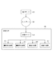
図1は、本実施形態の注文と成果物、部品の関係を示すブロック図である。注文100は少なくとも1つ以上の成果物で構成される。本実施形態においてはフォトブック101を成果物として想定している。フォトブック101は少なくとも1つ以上の部品で構成される。本実施形態においては、フォトブック101は本文102、表紙103、帯104、ジャケット105の部品で構成される。部品のコンテンツとしてPDF(Portable Document Format、以下PDF)が入稿され、前記PDF中に画像データが配置されている。   FIG. 1 is a block diagram showing the relationship between orders, deliverables, and parts in this embodiment. The order 100 is composed of at least one deliverable. In the present embodiment, the photo book 101 is assumed as a product. The photo book 101 is composed of at least one component. In the present embodiment, the photo book 101 is composed of a body 102, a cover 103, a band 104, and a jacket 105. A PDF (Portable Document Format, hereinafter referred to as PDF) is submitted as the content of the part, and image data is arranged in the PDF.

例えば、注文100には、少なくとも注文であることを示す記述と、成果物とを特定する情報(注文情報)が記述されていればよい。成果物を特定する情報には、例えば画像やレイアウト等の指定を含む成果物の内容、部品の種類、数量が含まれる。それら注文情報により成果物、注文100の例ではフォトブック101が特定され、また部品も特定することができる。図1の例では、注文100の内容に従って、部品は本文102,表紙103、帯104、ジャケット105となる。もちろん、それら部品に印刷される画像も注文100により特定されている。   For example, the order 100 only needs to describe at least a description indicating an order and information (order information) for specifying a deliverable. The information for identifying the deliverable includes, for example, the contents of the deliverable including designation of an image, a layout, and the like, the type of part, and the quantity. In the example of the deliverable and the order 100, the photobook 101 is specified by the order information, and the parts can also be specified. In the example of FIG. 1, the parts are a body 102, a cover 103, a band 104, and a jacket 105 according to the contents of the order 100. Of course, the image printed on these parts is also specified by the order 100.

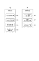
図2は、本実施形態の注文の例を示す。本実施形態において、インターネット経由で注文サーバから送られてくる注文100は図2に示すフォルダ構成となっている。最上位の注文フォルダ201直下に成果物フォルダ202がある。成果物フォルダ202直下に成果物のオプション設定や部品構成、発注者、配送先等が記述された注文情報203及び部品フォルダ204〜207がある。これらの部品フォルダ204〜207には、部品データのコンテンツとしてPDFが格納されており、前記PDF中に画像データが配置されている。   FIG. 2 shows an example of an order according to this embodiment. In the present embodiment, the order 100 sent from the order server via the Internet has a folder structure shown in FIG. There is a deliverable folder 202 directly under the highest order folder 201. Immediately under the deliverable folder 202, there are order information 203 and component folders 204 to 207 in which option settings for the deliverable, component configuration, ordering party, delivery destination, and the like are described. In these component folders 204 to 207, PDF is stored as the content of the component data, and image data is arranged in the PDF.

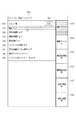
図3は、本実施形態の注文情報203の例を示す。   FIG. 3 shows an example of the order information 203 of this embodiment.

図3において、注文情報203には、注文番号や注文日を記述した注文詳細情報300を持つ。注文詳細情報300は、発注者情報301、配送方法302、成果物番号と成果物名、成果物種別番号を記述した成果物情報303、部品情報304を持つ。この注文詳細情報300により成果物や部品を特定できる。なお、ComponentIDが成果物番号であり、CatalogIDが成果物種別番号であり、DescriptiveNameが成果物名である。   In FIG. 3, the order information 203 has order detail information 300 describing the order number and order date. The order detail information 300 includes orderer information 301, a delivery method 302, product number and product name, product information 303 describing product type number, and part information 304. The order details information 300 can identify the deliverables and parts. Note that ComponentID is the product number, CatalogID is the product type number, and DescriptiveName is the product name.

図4は、本実施形態の情報処理システムのネットワーク構成を示す図である。図4のように、本実施形態にかかる情報処理システムのネットワーク構成は、まず大きくWAN等の401で注文サーバ400と印刷ラボ402が通信可能に接続されている。   FIG. 4 is a diagram illustrating a network configuration of the information processing system according to the present embodiment. As shown in FIG. 4, the network configuration of the information processing system according to the present embodiment is such that the order server 400 and the printing laboratory 402 are connected to each other via a 401 such as a WAN.

注文サーバ400は、Web経由の入稿システムとして機能するサーバコンピュータである。例えば、図1の例のフォトブック101をWeb経由で購入する場合、顧客は自宅からWebブラウザを起動し、注文サーバ400が提供するWebサイトにアクセスする。顧客は、希望する成果物を選択し、その成果物を作るために必要な写真を注文サーバ400にアップロードし、提示された金額を支払い、フォトブック101の注文をする。この注文が注文100に相当し、注文100に含まれる成果物や部品等を特定する注文情報が注文情報203となる。   The order server 400 is a server computer that functions as a Web-based submission system. For example, when purchasing the photo book 101 in the example of FIG. 1 via the Web, the customer starts a Web browser from home and accesses a Web site provided by the order server 400. The customer selects a desired deliverable, uploads a photo necessary for making the deliverable to the order server 400, pays the presented amount, and places an order for the photobook 101. This order corresponds to the order 100, and order information for specifying the deliverables and parts included in the order 100 is the order information 203.

印刷ラボ402は、管理サーバ403及び画像形成装置404、画像形成装置405、後加工装置406、後加工装置407を含む。後加工装置406と407は、LANに接続されている場合もあるし、接続されていない場合もある。本実施形態においては、後加工装置406と407はLANに接続されていることとする。   The printing laboratory 402 includes a management server 403, an image forming apparatus 404, an image forming apparatus 405, a post-processing apparatus 406, and a post-processing apparatus 407. The post-processing devices 406 and 407 may be connected to the LAN or may not be connected. In the present embodiment, the post-processing devices 406 and 407 are connected to the LAN.

管理サーバ403は、注文サーバ400から発行された注文100を受信し、受信した注文情報203に応じて、成果物を生産するための工程を記述したワークフローを生成する。管理サーバ403は、画像形成装置404、画像形成装置405による印刷及び後加工装置406、後加工装置207による後加工を管理する。画像形成装置404と405は、管理サーバ403と接続され、管理サーバ403により生成されるワークフローの各工程のうちの印刷工程、すなわち印刷ジョブを実行して、成果物である印刷物の部品を印刷する。また、後処理もワークフローを構成する工程として管理サーバからフィニッシングジョブが出力され、各後加工装置はそれらのフィニッシングジョブを実行する成果物が出力される。   The management server 403 receives the order 100 issued from the order server 400, and generates a workflow describing a process for producing a deliverable according to the received order information 203. A management server 403 manages printing by the image forming apparatus 404, the image forming apparatus 405, and post-processing by the post-processing apparatus 207 and post-processing by the post-processing apparatus 207. The image forming apparatuses 404 and 405 are connected to the management server 403 and execute a printing process, that is, a print job in each process of the workflow generated by the management server 403 to print a printed material part as a result. . In the post-processing, finishing jobs are output from the management server as a process constituting the workflow, and each post-processing apparatus outputs a product for executing those finishing jobs.

図5は、本実施形態の管理サーバ403の構成を示すブロック図である。管理サーバ403には、注文サーバ400からネットワーク401を経由して注文を受信する受注ソフトウェア500がインストールされている。さらに、受信した注文に係るジョブを画像形成装置404、画像形成装置405、後加工装置406、後加工装置407に出力するワークフロー管理ソフトウェア501がインストールされている。また、管理サーバ403は、受信した注文情報やコンテンツデータなどを格納するデータベース502を有する。なお本実施形態ではソフトウェアはプログラムと同義である。   FIG. 5 is a block diagram showing the configuration of the management server 403 of this embodiment. The management server 403 is installed with order receiving software 500 that receives orders from the order server 400 via the network 401. Further, workflow management software 501 for outputting a job related to the received order to the image forming apparatus 404, the image forming apparatus 405, the post-processing apparatus 406, and the post-processing apparatus 407 is installed. The management server 403 has a database 502 that stores received order information, content data, and the like. In the present embodiment, software is synonymous with a program.

ワークフロー管理ソフトウェア501は、受注ソフトウェア500から注文を受け取ると、当該注文のデータをデータベース502に登録し、さらに注文に係る印刷物の部品それぞれに対して、プリプレス処理やジョブ作成処理、ジョブ出力処理を行う。 ワークフロー管理ソフトウェア501は、プリプレス処理として、フォトブックの部品のコンテンツデータ内に配置された画像に対して画像補正処理を行う。また ワークフロー管理ソフトウェア501は、フォトブックの部品のコンテンツデータに対して、断裁加工時に使用するトンボや検品用のバーコードを負荷するPDFレイアウト処理を行う。 ワークフロー管理ソフトウェア501は、プリプレス処理の後、各部品の部品ジョブを作成し、作成した部品ジョブを画像形成装置404、画像形成装置405、後加工装置406、後加工装置407等に出力する。   When the workflow management software 501 receives an order from the order receiving software 500, the workflow management software 501 registers the data of the order in the database 502, and further performs prepress processing, job creation processing, and job output processing for each part of the printed matter related to the order. . The workflow management software 501 performs image correction processing on the image arranged in the content data of the parts of the photo book as prepress processing. In addition, the workflow management software 501 performs a PDF layout process that loads a register mark used at the time of cutting and a barcode for inspection on the content data of the parts of the photobook. After the prepress process, the workflow management software 501 creates a part job for each part, and outputs the created part job to the image forming apparatus 404, the image forming apparatus 405, the post-processing apparatus 406, the post-processing apparatus 407, and the like.

図6は、本実施形態の管理サーバ403のハードウェア構成を示すブロック図である。図6において、中央処理装置604は、受注ソフトウェア500やワークフロー管理ソフトウェア501などのプログラムおよび関連データを、CD−ROM、ICメモリカード等の記憶媒体から媒体読取装置605を介して読み込む。あるいは中央処理装置604は、ネットワーク401を介して上記プログラムおよび関連データを受信して、ハードディスクなどの補助記憶装置607に保存する。その後、中央処理装置604は、補助記憶装置607から主記憶装置600にロードされたアプリケーションプログラムを実行して、入力装置603から入力される情報を処理する。その結果、部品ジョブが、出力装置602やネットワークI/F606経由で画像形成装置404や画像形成装置405、後加工装置406、後加工装置407に出力される。なお、本実施形態では、出力装置602はディスプレイなどの表示装置であり、本来出力装置に含まれる画像形成装置404や画像形成装置405と区別する。また、入力装置603はキーボード、ポインティングデバイス等で構成されているものとする。なお、後述のフローチャートで示す手順は管理サーバ403の主記憶装置600、補助記憶装置607、ROM601のいずれかに記憶され、中央処理装置604により、通常、主記憶装置600に複製されてから実行される。   FIG. 6 is a block diagram illustrating a hardware configuration of the management server 403 according to the present embodiment. In FIG. 6, the central processing unit 604 reads a program such as the order receiving software 500 and the workflow management software 501 and related data from a storage medium such as a CD-ROM or an IC memory card via the medium reading device 605. Alternatively, the central processing unit 604 receives the program and related data via the network 401 and stores them in the auxiliary storage device 607 such as a hard disk. Thereafter, the central processing unit 604 executes an application program loaded from the auxiliary storage device 607 to the main storage device 600 and processes information input from the input device 603. As a result, the component job is output to the image forming apparatus 404, the image forming apparatus 405, the post-processing apparatus 406, and the post-processing apparatus 407 via the output apparatus 602 and the network I / F 606. In the present embodiment, the output device 602 is a display device such as a display, and is distinguished from the image forming device 404 and the image forming device 405 that are originally included in the output device. The input device 603 is assumed to be configured with a keyboard, a pointing device, and the like. The procedure shown in the flowchart described below is stored in one of the main storage device 600, auxiliary storage device 607, and ROM 601 of the management server 403, and is normally executed after being copied to the main storage device 600 by the central processing unit 604. The

さらに補助記憶装置607は、ハードディスク、光磁気ディスクで構成されるものであっていいし、これらの組み合わせで構成されるものであってもよい。またそれぞれの装置がネットワークを介して接続されていようとも、本発明を制約するものではない。   Further, the auxiliary storage device 607 may be configured with a hard disk or a magneto-optical disk, or may be configured with a combination thereof. Further, even if each device is connected via a network, the present invention is not limited.

図7は、本発明の一実施形態におけるワークフロー管理ソフトウェア501の説明の図である。図7は本実施形態における処理の特徴を表す図面である。   FIG. 7 is an explanatory diagram of the workflow management software 501 in an embodiment of the present invention. FIG. 7 is a diagram showing the characteristics of the processing in this embodiment.

図7において、ワークフロー管理ソフトウェア501は、入稿データ処理部700とプリプレス処理部701、出力先デバイス取得部702、部品ジョブ生成部703、論理ジョブ生成部704、出力先デバイス決定部705、ジョブ出力部706とを含む。これらの各部700−706は、中央処理装置604がワークフロー管理ソフトウェア501を実行することで実現される機能的なブロックを示し、各機能を実現する手段ということもできる。   In FIG. 7, the workflow management software 501 includes an input data processing unit 700, a prepress processing unit 701, an output destination device acquisition unit 702, a component job generation unit 703, a logical job generation unit 704, an output destination device determination unit 705, a job output. Part 706. Each of these units 700 to 706 indicates functional blocks realized by the central processing unit 604 executing the workflow management software 501, and can also be referred to as means for realizing each function.

入稿データ処理部700は、受注ソフトウェア500から注文を受け取ると、成果物を特定する情報である注文情報やコンテンツをデータベース502に登録する。例えば、図1の例の場合、入稿データ処理部700は、注文100の注文情報を受け取ると、当該注文情報からフォトブック101を特定し、さらにフォトブック101の部品である本文102、表紙103,帯104、ジャケット105を特定する。入稿データ処理部700は特定したフォトブック101とフォトブック101に関連した部品それぞれをデータベース502に登録する。なお、入稿データ処理部700は受注登録時、注文情報に記載された注文番号や注文日、成果物の仕様情報も登録する。さらに、各成果物に成果物番号を発番して、当該成果物番号も合わせてデータベース502に保存する。   When the received data processing unit 700 receives an order from the order receiving software 500, the received data processing unit 700 registers order information and contents, which are information for specifying a product, in the database 502. For example, in the case of the example in FIG. 1, the received data processing unit 700 receives the order information of the order 100, specifies the photo book 101 from the order information, and further, the body 102 and the cover 103 that are parts of the photo book 101. , Band 104 and jacket 105 are specified. The submitted data processing unit 700 registers the specified photo book 101 and the parts related to the photo book 101 in the database 502. The submitted data processing unit 700 also registers the order number, order date, and product specification information described in the order information at the time of order registration. Further, a product number is issued to each product, and the product number is also stored in the database 502.

プリプレス処理部701は、入稿データ処理部700が登録した部品のコンテンツそれぞれに対してプリプレス処理(具体的には画像補正処理とPDFレイアウト処理)を行う。本実施形態においては、プリプレス処理部701によるPDFレイアウト処理時に入稿データ処理部700によって発番された成果物番号をバーコードとして画像データに埋め込む。これにより後工程(例えばくるみ製本機)で本文102と表紙103を後処理する際、本文102と表紙103のバーコードを読取り、照合を行うことで、確実に同じ成果物を構成するための部品であることを保証できる。さらに、後加工機は、印刷物に印字されたバーコードをバーコードリーダーやセンサー等で読取ることで成果物番号を取得し、同じ成果物番号が記述されたジョブチケットを検索することで、後処理用のジョブチケットを特定できる。これにより、当該成果物の後加工を行う際、当該ジョブチケットを後加工機のパネル上で探す手間を省くことが出来る。   The prepress processing unit 701 performs prepress processing (specifically, image correction processing and PDF layout processing) for each of the component contents registered by the submitted data processing unit 700. In the present embodiment, the product number issued by the submitted data processing unit 700 during PDF layout processing by the prepress processing unit 701 is embedded in the image data as a barcode. As a result, when post-processing the body 102 and the cover 103 in a post-process (for example, a case binding machine), the barcode for the body 102 and the cover 103 is read and collated to ensure that the same product is configured. Can be guaranteed. Further, the post-processing machine acquires the product number by reading the barcode printed on the printed matter with a barcode reader or sensor, and searches for a job ticket in which the same product number is described. Job ticket can be specified. Thereby, when post-processing the product, it is possible to save the trouble of searching the job ticket on the panel of the post-processing machine.

出力先デバイス取得部702は、ジョブに記述するための出力先デバイス名および出力先デバイスの機種名を取得する。出力先デバイスの取得元は、例えばプリントMISがある。前記プリントMISの「MIS」とは、印刷業におけるManagement Information Systemの略で、経営情報システムと訳される。前記プリントMISを使うことにより、印刷ラボ402で稼働しているデバイスそれぞれに印刷ジョブやフィニッシングジョブを割付けた生産スケジュールを作成することができる。出力先デバイス取得部702は前記生産スケジュールをプリントMISから取得し、前記生産スケジュールから印刷ジョブとフィニッシングジョブの出力先デバイスを特定することができる。また、予め設定ファイルに成果物の生産に使用するデバイス名と機種名を記述しておき、その設定ファイルを基に成果物を生産するための印刷ジョブとフィニッシングジョブそれぞれの出力先デバイスを特定してもよい。なお、取得元は本発明を制約するものではない。本実施形態においては、前記設定ファイルから出力先デバイスを取得することとする。   The output destination device acquisition unit 702 acquires the output destination device name and the model name of the output destination device to be described in the job. An acquisition source of the output destination device is, for example, a print MIS. The “MIS” of the print MIS is an abbreviation of Management Information System in the printing industry, and is translated as a management information system. By using the print MIS, it is possible to create a production schedule in which a print job and a finishing job are assigned to each device operating in the printing laboratory 402. The output destination device acquisition unit 702 can acquire the production schedule from the print MIS, and can specify output destination devices of a print job and a finishing job from the production schedule. In addition, the device name and model name used to produce the product are described in the configuration file in advance, and the output destination devices for the print job and the finishing job for producing the product are specified based on the configuration file. May be. The acquisition source does not limit the present invention. In this embodiment, an output destination device is acquired from the setting file.

部品ジョブ生成部703は、入稿データ処理部700が登録した部品それぞれに対して、部品ジョブを生成する。ここでいう部品ジョブとは、画像形成装置に出力するための印刷ジョブと後加工装置に出力するためのフィニッシングジョブを指す。具体的には、部品ジョブ生成部703は、出力先デバイス取得部702が取得した出力先デバイスを印刷ジョブとフィニッシングジョブ内に記述し、なおかつデータベース502に保存された工程に関連づいた印刷設定や後加工処理設定を取得する。そして、入稿データ処理部700が登録した部品それぞれに対して印刷ジョブ及びフィニッシングジョブを生成する。そして、部品ジョブ生成部703は、生成した印刷ジョブとフィニッシングジョブをデータベース502に保存する。なお、生成された部品ジョブそれぞれには成果物と紐付けるための成果物番号が記述される。前記成果物番号は、入稿データ処理部700によって生成されたものを使用する。   The component job generation unit 703 generates a component job for each component registered by the submitted data processing unit 700. The component job here refers to a print job for output to the image forming apparatus and a finishing job for output to the post-processing apparatus. More specifically, the component job generation unit 703 describes the output destination device acquired by the output destination device acquisition unit 702 in the print job and the finishing job, and print settings related to the processes stored in the database 502. Get post-processing settings. Then, a print job and a finishing job are generated for each component registered by the submitted data processing unit 700. Then, the component job generation unit 703 stores the generated print job and finishing job in the database 502. Each generated part job is described with a product number to be associated with the product. The product number generated by the submitted data processing unit 700 is used.

なお、ワークフロー管理ソフトウェア501には、成果物の種類ごとに当該成果物を生産するための工程が予め定義されており、各工程それぞれに印刷設定や後加工処理設定が紐付いて保存されている。定義された工程はデータベース502に保存されている。前記工程に従い、印刷ジョブとフィニッシングジョブが生成される。例えば、印刷工程800としては、図8に示すとおり、図1の例のフォトブック101の場合、本文102と表紙103、帯104、ジャケット105それぞれに印刷工程801〜804が割り当てられている。そして、後加工工程808として、本文102と表紙103のくるみ製本工程806がある。また帯104とジャケット105にはカット(断裁)とクリース(スジ入れ)を行うので、帯104とジャケット105それぞれに対してカットクリース工程807と808が割り当てられている。印刷工程801〜804には印刷設定が関連付けられ、くるみ製本工程806、カットクリース工程807と808にはそれぞれ後加工処理設定が関連付けられている。   In the workflow management software 501, a process for producing a product for each product type is defined in advance, and print settings and post-processing settings are associated with each process and stored. The defined process is stored in the database 502. According to the above process, a print job and a finishing job are generated. For example, as shown in FIG. 8, as the printing process 800, in the case of the photo book 101 in the example of FIG. 1, printing processes 801 to 804 are assigned to the body 102, the cover 103, the band 104, and the jacket 105. As the post-processing step 808, there is a case binding step 806 for the text 102 and the cover 103. Further, since the band 104 and the jacket 105 are cut (cut) and creased (streaked), cut crease processes 807 and 808 are assigned to the band 104 and the jacket 105, respectively. The print settings 801 to 804 are associated with print settings, and the case binding process 806 and the cut crease processes 807 and 808 are respectively associated with post-processing settings.

論理ジョブ生成部704は、入稿データ処理部700が登録した成果物それぞれに対して、成果物を作るための論理ジョブを1つ生成する。具体的には、部品ジョブ生成部703が当該成果物の部品ジョブを全て生成しデータベース502に保存し終わった後、当該部品ジョブをすべて結合し、1つの論理ジョブを作成し、データベース502に保存する。なお、生成された論理ジョブには成果物と紐付けるための成果物番号が記述される。前記成果物番号は、入稿データ処理部700によって生成されたものを使用する。なお、論理ジョブは、複数の部品ジョブを合成することで生成されるため合成ジョブと呼ばれることもある。   The logical job generation unit 704 generates one logical job for creating a product for each product registered by the submitted data processing unit 700. Specifically, after the part job generation unit 703 generates all the part jobs for the product and saves them in the database 502, all the part jobs are combined to create one logical job and save it in the database 502. To do. The generated logical job describes a product number to be associated with the product. The product number generated by the submitted data processing unit 700 is used. Note that a logical job is sometimes called a composite job because it is generated by combining a plurality of component jobs.

なお、部品ジョブ生成部703と論理ジョブ生成部704が生成したジョブは、ワークフロー管理ソフトウェア501が提供するユーザーインターフェース上に表示され、ユーザーにより選択及び出力指示が可能である。   The jobs generated by the component job generation unit 703 and the logical job generation unit 704 are displayed on the user interface provided by the workflow management software 501 and can be selected and output by the user.

出力先デバイス決定部705は、ワークフロー管理ソフトウェア501が提供するユーザーインターフェース上でユーザーが選択したジョブの出力指示を行うときに、当該ユーザーにより指定されたデバイスに応じて、前記ジョブの出力先を決定する。   The output destination device determination unit 705 determines the output destination of the job according to the device designated by the user when the output instruction of the job selected by the user is issued on the user interface provided by the workflow management software 501. To do.

ジョブ出力部706は、部品ジョブ生成部703及び論理ジョブ生成部704により生成された前記ジョブを、出力先デバイス決定部705により決定されたデバイスに対して出力する。   The job output unit 706 outputs the job generated by the component job generation unit 703 and the logical job generation unit 704 to the device determined by the output destination device determination unit 705.

図9は、図1で例示した部品それぞれに対応する部品ジョブおよびフォトブック101を作るための論理ジョブの関係を示すブロック図である。ここでいう部品ジョブとは、前記部品それぞれに対して生成されるジョブであり、画像形成装置に出力される印刷ジョブと後加工装置に出力されるフィニッシングジョブにより構成される。前記部品それぞれに対して、部品ジョブ900−906が生成される。部品ジョブには、印刷ジョブ900−903と、フィニッシングジョブ904〜906が含まれる。つまり、フォトブック101を印刷するために7つの部品ジョブが生成されるので、これらのジョブを効率的に画像形成装置及び後加工装置に出力することが求められている。   FIG. 9 is a block diagram showing the relationship between a component job corresponding to each of the components illustrated in FIG. 1 and a logical job for creating the photo book 101. The component job referred to here is a job generated for each of the components, and includes a print job output to the image forming apparatus and a finishing job output to the post-processing apparatus. A part job 900-906 is generated for each of the parts. The component jobs include print jobs 900-903 and finishing jobs 904 to 906. That is, since seven component jobs are generated to print the photobook 101, it is required to output these jobs to the image forming apparatus and the post-processing apparatus efficiently.

本実施形態においては、前記部品ジョブがすべて作成された後、論理ジョブ907が本実施形態の情報処理装置(管理サーバ)により生成される。ここでいう論理ジョブ907とは、1つの成果物を作るための部品ジョブすべてをまとめたジョブを指す。本実施形態において、論理ジョブ907は、図1の例でいうとフォトブック101を作るために作成され、印刷ジョブ900〜903とくるみ製本ジョブ904、カットクリースジョブ905、カットクリースジョブ906により構成される。 図10は、本実施形態における部品ジョブの例を示す。図9で示した本文の印刷ジョブ900とくるみ製本ジョブ904、カットクリースジョブ905を部品ジョブの詳細を説明する例として用いる。   In this embodiment, after all the component jobs are created, a logical job 907 is generated by the information processing apparatus (management server) of this embodiment. Here, the logical job 907 indicates a job in which all component jobs for creating one product are collected. In this embodiment, the logical job 907 is created in order to create the photo book 101 in the example of FIG. 1, and includes a print job 900 to 903, a case binding job 904, a cut crease job 905, and a cut crease job 906. The FIG. 10 shows an example of a component job in this embodiment. The body print job 900, case binding job 904, and cut crease job 905 shown in FIG. 9 are used as examples for explaining the details of the component job.

印刷ジョブ900にはジョブ詳細情報1000−1004が記述されている。ジョブ詳細情報1000には印刷ジョブの印刷設定が記述される。前記印刷設定は印刷ジョブ900中に直接記述してもよいし、印刷設定を記述したファイルを参照するためのURLを記述してもよい。本実施形態では、印刷設定を記述したファイルを参照するためのURLが記述されている。ジョブ詳細情報1000に記述された印刷設定に従い、画像形成装置は印刷工程を実行する。ジョブ詳細情報1001はジョブ種別を記述しており、印刷ジョブであることを表す「PrintingJob」が記述されている。ジョブ詳細情報1002は出力先デバイス名であって、出力先デバイス取得部702が取得したデバイス名が記述され、一例として「画像形成装置404」が記述されている。ジョブ詳細情報1003は出力先デバイスの機種名であって、出力先デバイス取得部702が取得した機種名が記述され、一例として「オンデマンド印刷機」が記述されている。ジョブ詳細情報1004は、当該成果物の成果物番号が記述される。成果物番号はジョブ生成時に部品ジョブ生成部703により発番される成果物毎に一意な値である。   In the print job 900, detailed job information 1000-1004 is described. The job detailed information 1000 describes print settings for a print job. The print settings may be described directly in the print job 900, or a URL for referring to a file describing the print settings may be described. In the present embodiment, a URL for referring to a file describing print settings is described. In accordance with the print settings described in the detailed job information 1000, the image forming apparatus executes a printing process. The job detailed information 1001 describes a job type, and “PrintingJob” indicating a print job is described. The job detailed information 1002 is an output destination device name, in which the device name acquired by the output destination device acquisition unit 702 is described. As an example, “image forming apparatus 404” is described. The job detailed information 1003 is the model name of the output destination device, in which the model name acquired by the output destination device acquisition unit 702 is described. As an example, “on-demand printing machine” is described. The job detailed information 1004 describes the product number of the product. The product number is a unique value for each product issued by the component job generation unit 703 at the time of job generation.

くるみ製本ジョブ904には、ジョブ詳細情報1005−1008が記述されている。ジョブ詳細情報1005にはフィニッシングジョブの後加工処理設定が記述される。ここでも後加工処理設定を記述したファイルを参照するためのURLが記述されている。ジョブ詳細情報1006はジョブ種別を記述しており、フィニッシングジョブであることを表す「FinishingJob」が記述されている。ジョブ詳細情報1007と1008はそれぞれ出力先デバイス名と機種名で、1007には出力先デバイスとして「後加工装置406」が記述され、1008には機種名として「製本機」が記述されている。1009は印刷ジョブ900と同様に成果物番号が記述される。   In the case binding job 904, detailed job information 1005-1008 is described. The job detailed information 1005 describes finishing job post-processing setting. Again, a URL for referring to a file in which post-processing setting is described is described. The job detailed information 1006 describes a job type, and “Finishing Job” indicating that it is a finishing job is described. The detailed job information 1007 and 1008 are an output destination device name and a model name, respectively. In “1007”, “post-processing device 406” is described as an output destination device, and “bookbinding machine” is described in 1008 as a model name. 1009 describes the product number as in the print job 900.

カットクリースジョブ905の場合も先に説明した印刷ジョブ900とくるみ製本ジョブ904と同じ構造であり、ジョブ詳細情報1010−1014が含まれる。   The cut crease job 905 has the same structure as the print job 900 and the case binding job 904 described above, and includes detailed job information 1010-1014.

なお、画像形成装置や後加工装置により、読み取り可能な設定情報の形式が異なるため、本実施形態においてはジョブ出力部706が印刷設定1000や後加工処理設定1004、後加工処理設定1008を出力先デバイスに応じた形式に変換する。   Note that, since the format of readable setting information differs depending on the image forming apparatus and the post-processing apparatus, in this embodiment, the job output unit 706 outputs the print setting 1000, the post-processing setting 1004, and the post-processing setting 1008 to the output destination. Convert to a format appropriate for the device.

図11は、本実施形態における論理ジョブ907の例を示す。 前述のとおり、論理ジョブ907は1つの成果物を作るためのジョブである。図1の例の場合、成果物であるフォトブック101を作るためのジョブである。そして、論理ジョブ907は1つの成果物を構成する部品ジョブをまとめたジョブであるので、フォトブック101を作るための部品ジョブ900−906がまとめられている。例えば、印刷ジョブ900のジョブ詳細情報1000−1004が第一のブロック1102として記述されている。これと同様に、ブロック1103−1108はそれぞれ部品ジョブ901−906のジョブ詳細情報である。そして、1100はジョブ種別であって、当該ジョブが論理ジョブであることを特定するために用いられ、ここでは論理ジョブを表す「CombinedJob」が記述されている。また1101は入稿データ処理部700によって生成された成果物番号であって、成果物毎に一意な値が記述される。   FIG. 11 shows an example of a logical job 907 in this embodiment. As described above, the logical job 907 is a job for creating one product. In the case of the example in FIG. 1, the job is for creating a photo book 101 as a product. Since the logical job 907 is a job in which component jobs constituting one product are collected, component jobs 900 to 906 for creating the photo book 101 are collected. For example, detailed job information 1000-1004 of the print job 900 is described as the first block 1102. Similarly, blocks 1103-1108 are detailed job information of component jobs 901-906, respectively. A job type 1100 is used to specify that the job is a logical job. Here, “CombinedJob” representing the logical job is described. Reference numeral 1101 denotes a product number generated by the submitted data processing unit 700, and a unique value is described for each product.

図12は本実施形態におけるジョブ生成処理フローを示す図である。図7に示したワークフロー管理ソフトウェア501において、入稿データ処理部700がデータベース502に登録した注文に含まれる成果物および部品すべてに対してジョブを生成する。ただし、既にジョブが生成済みの成果物や部品はジョブ生成処理の対象外である。ジョブが未生成の成果物および部品に対してジョブ生成処理フローが適用される。   FIG. 12 is a diagram showing a job generation processing flow in the present embodiment. In the workflow management software 501 shown in FIG. 7, the submission data processing unit 700 generates jobs for all the deliverables and parts included in the order registered in the database 502. However, deliverables and parts for which a job has already been generated are not subject to job generation processing. A job generation processing flow is applied to a product and a part for which a job has not been generated.

まずS1200にて、ワークフロー管理ソフトウェア501はジョブ生成処理を開始する。   First, in step S1200, the workflow management software 501 starts job generation processing.

S1201にて、部品ジョブ生成部703は、ジョブ生成処理対象の1つの成果物に関して、データベース502から成果物情報を取得する。ここでいう成果物情報とは、例えば図3における成果物番号や成果物種別番号、成果物名などが記述された成果物情報303を指す。   In step S <b> 1201, the component job generation unit 703 acquires product information from the database 502 regarding one product to be processed for job generation. The product information here refers to product information 303 in which, for example, the product number, product type number, product name, and the like in FIG. 3 are described.

S1202にて、部品ジョブ生成部703は、前記成果物情報に記述された成果物種別を特定するための成果物種別番号を基に、当該成果物に設定された工程、例えば図8に示した印刷工程や後加工工程を取得する。   In step S1202, the part job generation unit 703 performs the process set for the product based on the product type number for specifying the product type described in the product information, for example, as illustrated in FIG. Acquire printing process and post-processing process.

S1203〜S1208にて、部品ジョブ生成部703は、S1202にて取得した前記工程すべてに対して部品ジョブを生成する。具体的には、S1203にて、部品ジョブ生成部703は前記工程が印刷工程か後加工工程かを判定する。当該工程が印刷工程の場合はS1204に進み、後加工工程の場合はS1209に進む。   In steps S1203 to S1208, the component job generation unit 703 generates component jobs for all the processes acquired in step S1202. Specifically, in step S1203, the component job generation unit 703 determines whether the process is a printing process or a post-processing process. If the process is a printing process, the process proceeds to S1204. If the process is a post-processing process, the process proceeds to S1209.

S1204にて、部品ジョブ生成部703は、印刷工程に関連づいた印刷設定を取得する。上述したように、ワークフロー管理ソフトウェア501は、成果物の種類ごとに工程が定義されており、各工程に対して印刷設定や後加工処理設定が紐づいて保存されている。図8の例では、印刷工程の中の本文、表紙、帯、ジャケットの各印刷工程に印刷設定が紐づいて保存されているため、部品ジョブ生成部703は、これらの印刷設定を取得する。   In step S1204, the component job generation unit 703 acquires print settings related to the printing process. As described above, in the workflow management software 501, a process is defined for each type of deliverable, and print settings and post-processing settings are associated with each process and stored. In the example of FIG. 8, since the print settings are stored in association with the text, cover, band, and jacket print processes in the print process, the component job generation unit 703 acquires these print settings.

S1205にて、部品ジョブ生成部703は、出力先デバイス取得部702が事前に取得し、データベース502に保存した印刷工程を実行するための出力先デバイス名と機種名を取得する。なお、図8の例では、4つの印刷工程が含まれているので、4つの印刷工程用の出力デバイス名と機種名が取得される。   In step S <b> 1205, the component job generation unit 703 acquires an output destination device name and a model name for executing the printing process acquired in advance by the output destination device acquisition unit 702 and stored in the database 502. In the example of FIG. 8, since four printing processes are included, output device names and model names for the four printing processes are acquired.

S1206にて、部品ジョブ生成部703は、S1204とS1205にて取得した印刷設定と出力先デバイス名、機種名を基に、印刷ジョブを生成する。印刷ジョブの例は、図10の印刷ジョブ900にて示したとおりである。この際、部品ジョブ生成部703は、S1204で取得した印刷設定を、データベース502に記憶し、記憶した場所を示すパスを印刷ジョブに記述しても良い。   In step S1206, the component job generation unit 703 generates a print job based on the print settings, the output destination device name, and the model name acquired in steps S1204 and S1205. An example of the print job is as shown in the print job 900 of FIG. At this time, the component job generation unit 703 may store the print setting acquired in step S1204 in the database 502 and describe a path indicating the stored location in the print job.

S1207にて、部品ジョブ生成部703は生成した部品ジョブ、例えば本文の印刷ジョブをデータベース502に保存する。   In step S <b> 1207, the component job generation unit 703 stores the generated component job, for example, a text print job, in the database 502.

また部品ジョブ生成部703は後加工工程に対しても印刷工程と同様にジョブ生成処理を行う。具体的には、S1208にて全工程に対するジョブ生成処理が完了したかどうかを判定し、後加工工程のジョブ生成が完了していないので、S1203及びS1209に進む。   In addition, the component job generation unit 703 performs job generation processing for the post-processing process as in the printing process. Specifically, in step S1208, it is determined whether job generation processing has been completed for all processes. Since job generation in the post-processing process has not been completed, the process advances to steps S1203 and S1209.

S1209にて、部品ジョブ生成部703は、後工程に関連づいた後加工処理設定を取得する。S1204で説明したように、ワークフロー管理ソフトウェア501は、成果物の種類ごとに工程が定義されており、各工程に対して後加工処理設定が紐づいて保存されている。図8の例では、3つの後加工工程に後加工処理設定が紐づいて保存されているため、部品ジョブ生成部703は、これらの後加工処理設定を取得する。   In step S1209, the component job generation unit 703 acquires the post-processing setting associated with the post-process. As described in S1204, the workflow management software 501 defines a process for each type of deliverable, and stores post-processing setting settings associated with each process. In the example of FIG. 8, since the post-processing setting is associated with three post-processing steps, the component job generation unit 703 acquires these post-processing settings.

S1210にて、部品ジョブ生成部703は、出力先デバイス取得部702が事前に取得し、データベース502に保存した後加工処理を実行するための出力先デバイス名と機種名を取得する。なお、図8の例では、3つの後加工工程が含まれているので、3つの後加工工程用の出力デバイス名と機種名が取得される。   In step S <b> 1210, the component job generation unit 703 acquires an output destination device name and a model name for executing post-processing processing acquired in advance by the output destination device acquisition unit 702 and stored in the database 502. In the example of FIG. 8, since three post-processing steps are included, output device names and model names for the three post-processing steps are acquired.

S1211にて、部品ジョブ生成部703は、S1209とS1210にて取得した後加工処理設定と出力先デバイス名、機種名を基に、フィニッシングジョブを生成する。フィニッシングジョブの例は、図10のくるみ製本ジョブ904とカットクリースジョブ905にて示したとおりである。この際、部品ジョブ生成部703は、S1209で取得した後加工処理設定を、データベース502に記憶し、記憶した場所を示すパスをフィニッシングジョブに記述しても良い。   In step S1211, the part job generation unit 703 generates a finishing job based on the post-processing setting, the output destination device name, and the model name acquired in steps S1209 and S1210. Examples of finishing jobs are as shown in the case binding job 904 and the cut crease job 905 in FIG. At this time, the part job generation unit 703 may store the post-processing setting acquired in S1209 in the database 502, and describe the path indicating the stored location in the finishing job.

すべての工程に対して、部品ジョブ900−907の生成が完了した後、ワークフロー管理ソフトウェア501は論理ジョブ生成を行う。   For all the processes, after the generation of the component jobs 900-907 is completed, the workflow management software 501 generates a logical job.

S1212にて、論理ジョブ生成部704は、データベース502に保存された部品ジョブ900−906と、それら部品ジョブのジョブ詳細情報を取得し、論理ジョブを生成する。論理ジョブの具体例は、図11の論理ジョブ907にて示したとおりである。   In step S <b> 1212, the logical job generation unit 704 acquires the component jobs 900 to 906 stored in the database 502 and detailed job information of these component jobs, and generates a logical job. A specific example of the logical job is as shown by the logical job 907 in FIG.

S1213にて、論理ジョブ生成部704は、生成した論理ジョブをデータベース502に保存する。   In step S1213, the logical job generation unit 704 stores the generated logical job in the database 502.

S1214にて、ワークフロー管理ソフトウェア501は、ジョブの生成処理が完了していない成果物があればS1201に移り、ジョブの生成処理が完了していない成果物がなければS1215に移り、ジョブ生成処理を完了する。   In step S1214, the workflow management software 501 proceeds to step S1201 if there is a product for which job generation processing has not been completed, and proceeds to step S1215 if there is no product for which job generation processing has not been completed. Complete.

以上で、本実施形態におけるジョブ生成処理フローが完了する。   This completes the job generation processing flow in the present embodiment.

図13は本実施形態におけるワークフロー管理ソフトウェア501の画面の一例を示す図である。   FIG. 13 is a diagram showing an example of the screen of the workflow management software 501 in the present embodiment.

本実施形態において、ワークフロー管理ソフトウェア501の画面は大きく4つに分けることができる。1つ目は1300であり、ワークフロー管理ソフトウェア501のタイトルバーである。2つ目は1301であり、ワークフロー管理ソフトウェア501が管理するジョブの一覧が表示されている。本実施形態において、ジョブ一覧1301には論理ジョブ907と部品ジョブ900−906が表示されている。3つ目は1303−1308までの出力先デバイスである。出力先デバイス1303−1308はアイコン(オブジェクト)として表示することもできるし、テキスト形式で一覧にしてもよい。本実施形態においてはアイコンを用いて出力先デバイスを画面に表示することとする。4つ目は出力ボタン1302であり、出力ボタン1302が押下されることにより、ジョブ一覧1301にて選択されたジョブが出力先デバイスに出力される。   In this embodiment, the screen of the workflow management software 501 can be roughly divided into four. The first is 1300, which is the title bar of the workflow management software 501. The second is 1301, and a list of jobs managed by the workflow management software 501 is displayed. In the present embodiment, the job list 1301 displays a logical job 907 and component jobs 900-906. The third is output destination devices up to 1303-1308. The output destination devices 1303-1308 can be displayed as icons (objects) or may be listed in a text format. In this embodiment, an output destination device is displayed on the screen using an icon. The fourth is an output button 1302, and when the output button 1302 is pressed, the job selected in the job list 1301 is output to the output destination device.

本実施形態において、出力先デバイスには論理デバイスA1303、論理デバイスB1304、画像形成装置404を出力先とする1305、画像形成装置405を出力先とする1306、後加工装置406を出力先とする1307、後加工装置407を出力先とする1308が用意されている。ここでいう論理デバイスとは、物理的に存在するデバイスではなく、物理デバイスのグループを表現するものである。または、出力対象のジョブに記述されたデバイスにジョブを出力するために使用される。一方、アイコン1305−1308は画像形成装置404や後加工装置406等、物理的なデバイスを指し示す。   In this embodiment, the output destination devices are the logical device A 1303, the logical device B 1304, the image forming apparatus 404 as the output destination 1305, the image forming apparatus 405 as the output destination 1306, and the post-processing apparatus 406 as the output destination 1307. 1308 having the post-processing device 407 as an output destination is prepared. The logical device here represents not a physically existing device but a group of physical devices. Alternatively, it is used to output a job to a device described in the job to be output. On the other hand, icons 1305-1308 indicate physical devices such as the image forming apparatus 404 and the post-processing apparatus 406.

図14は本実施形態における出力先デバイス設定ファイル1400の例を示す図である。本実施形態では、出力先デバイス設定ファイル1400はXML形式で表現され、ワークフロー管理ソフトウェア501のインストール時に設定が完了している。   FIG. 14 is a diagram showing an example of the output destination device setting file 1400 in the present embodiment. In this embodiment, the output destination device setting file 1400 is expressed in the XML format, and the setting is completed when the workflow management software 501 is installed.

出力先デバイス設定ファイル1400は、大きく2つに分けることができる。1つ目は1401で、論理デバイス定義一覧である。2つ目は1406で物理デバイス定義一覧である。   The output destination device setting file 1400 can be roughly divided into two. The first is 1401, which is a logical device definition list. The second is a physical device definition list 1406.

本実施形態において、論理デバイス定義一覧1401は、論理デバイス名や論理デバイスを構成する物理デバイスを定義した論理デバイス定義情報1402と1403にて構成される。論理デバイス定義情報は1402のように論理デバイス名のみ記述することもできるし、1403のように直下に物理デバイス指定情報1404および1405を記述することもできる。論理デバイス定義情報1402と1403に記述する論理デバイス名は、ワークフロー管理ソフトウェア501の画面に表示される。また物理デバイス指定情報1404と1405は出力先デバイス名と機種名をもつ。   In this embodiment, the logical device definition list 1401 is composed of logical device definition information 1402 and 1403 that define logical device names and physical devices constituting the logical device. In the logical device definition information, only the logical device name can be described as 1402, or the physical device designation information 1404 and 1405 can be described immediately below as 1403. The logical device names described in the logical device definition information 1402 and 1403 are displayed on the screen of the workflow management software 501. The physical device designation information 1404 and 1405 has an output destination device name and a model name.

本実施形態において、物理デバイス定義一覧1406は、物理デバイス定義情報1407−1410にて構成される。物理デバイス定義情報1407−1410はそれぞれ出力先デバイス名と機種名を持つ。   In the present embodiment, the physical device definition list 1406 includes physical device definition information 1407-1410. Each of the physical device definition information 1407-1410 has an output destination device name and a model name.

図15は本実施形態におけるジョブ出力処理のフローを示す図である。図13に示したワークフロー管理ソフトウェア501の画面上で出力ボタン1302が押下されることにより、ジョブ出力処理が実行される。ここでは、図13と図16−21を用いて、具体的な画面操作を基に、ジョブ出力処理フローを説明する。   FIG. 15 is a diagram showing a flow of job output processing in the present embodiment. When the output button 1302 is pressed on the screen of the workflow management software 501 shown in FIG. 13, a job output process is executed. Here, the job output processing flow will be described based on specific screen operations with reference to FIGS. 13 and 16-21.

S1500にて、ワークフロー管理ソフトウェア501の画面上にて出力ボタン1302が押下された時点で、ジョブ出力部706はジョブ出力処理を開始する。   In step S1500, when the output button 1302 is pressed on the screen of the workflow management software 501, the job output unit 706 starts job output processing.

論理ジョブ907が論理デバイスA1303に対して出力指示された場合を図11と図13、図14を用いて説明する。   A case where the logical job 907 is instructed to be output to the logical device A 1303 will be described with reference to FIGS. 11, 13, and 14.

S1501にて、ジョブ出力部706は、選択されたジョブが部品ジョブかどうかを判断する。例えば、図13の場合、ジョブ一覧1301にて論理ジョブ907が選択されているので、ジョブ出力部706は論理ジョブ907を受け取る。ジョブ出力部706は論理ジョブ907のジョブ種別1100を参照し、論理ジョブであることを特定し、S1505に進む。   In step S1501, the job output unit 706 determines whether the selected job is a component job. For example, in the case of FIG. 13, since the logical job 907 is selected in the job list 1301, the job output unit 706 receives the logical job 907. The job output unit 706 refers to the job type 1100 of the logical job 907, specifies that it is a logical job, and proceeds to S1505.

S1505にて、出力先デバイス決定部705は、物理デバイスが選択されているかどうかを判断する。例えば、図13の場合、論理デバイスA1303が選択されている。このとき、出力先デバイス決定部705は出力先デバイス設定ファイル1400を参照し、選択された「論理デバイスA」というデバイス名を出力先デバイス設定ファイル1400から検索する。その結果、選択された論理デバイスA1303のデバイス名「論理デバイスA」と論理デバイス定義情報1402の論理デバイス名「論理デバイスA」とが一致するので、出力先デバイス決定部705は、論理デバイスが選択されたと判断し、S1509に進む。   In step S1505, the output destination device determination unit 705 determines whether a physical device is selected. For example, in the case of FIG. 13, the logical device A 1303 is selected. At this time, the output destination device determination unit 705 refers to the output destination device setting file 1400 and searches the output destination device setting file 1400 for the selected device name “logical device A”. As a result, since the device name “logical device A” of the selected logical device A 1303 matches the logical device name “logical device A” of the logical device definition information 1402, the output device determination unit 705 selects the logical device. The process proceeds to S1509.

S1509にて、出力先デバイス決定部705は、選択された論理デバイスA1303の論理デバイス定義情報1402を参照し、物理デバイス指定情報が記述されているかを判断する。図14の論理デバイス定義情報1402に示したとおり、論理デバイスA1303用に物理デバイス指定情報は記述されていないので、S1513に移る。   In step S1509, the output destination device determination unit 705 refers to the logical device definition information 1402 of the selected logical device A 1303, and determines whether physical device designation information is described. As shown in the logical device definition information 1402 in FIG. 14, since physical device designation information is not described for the logical device A 1303, the process proceeds to S1513.

S1513にて、出力先デバイス決定部705は、論理ジョブ907に記述されたジョブ詳細情報1102−1108の出力先デバイス名を出力対象として決定する。   In step S <b> 1513, the output destination device determination unit 705 determines the output destination device name of the job detailed information 1102-1108 described in the logical job 907 as an output target.

S1504にて、ジョブ出力部706は、S1513にて出力先デバイス決定部705が決定した出力先デバイスに対してジョブを出力する。図13の例では、論理ジョブ907が出力対象として選択された。そのため、論理ジョブ907を構成する印刷ジョブ900−903は画像形成装置404に、くるみ製本ジョブ904は後加工装置406に、カットクリースジョブ905−906は後加工装置407に出力される。   In step S1504, the job output unit 706 outputs a job to the output destination device determined by the output destination device determination unit 705 in step S1513. In the example of FIG. 13, the logical job 907 is selected as an output target. Therefore, the print jobs 900 to 903 constituting the logical job 907 are output to the image forming apparatus 404, the case binding job 904 is output to the post-processing apparatus 406, and the cut crease job 905 to 906 is output to the post-processing apparatus 407.

以上で、論理ジョブ907が論理デバイスA1303に対して出力指示された場合の処理が完了する。   The processing when the logical job 907 is instructed to be output to the logical device A 1303 is completed.

論理ジョブ907が物理デバイス1306に対して出力指示された場合を図11と図14、図16を用いて説明する。論理ジョブが物理デバイスに対して出力指示されるユースケースとしては、例えば、生産スケジュールを作成した時点で割り当てられたデバイスが不調なので別のデバイスで出力したいといった場合が想定される。   A case where the logical job 907 is instructed to be output to the physical device 1306 will be described with reference to FIGS. 11, 14, and 16. As a use case in which a logical job is instructed to be output to a physical device, for example, it is assumed that the device assigned at the time of creating a production schedule is malfunctioning and it is desired to output it on another device.

S1501にて、ジョブ出力部706は、選択されたジョブが部品ジョブかどうかを判断する。例えば、図16の場合、ジョブ一覧1301にて論理ジョブ907が選択されているので、ジョブ出力部706は論理ジョブ907を受け取る。ジョブ出力部706は論理ジョブ907のジョブ種別1100を参照し、論理ジョブであることを特定し、S1505に進む。   In step S1501, the job output unit 706 determines whether the selected job is a component job. For example, in the case of FIG. 16, since the logical job 907 is selected in the job list 1301, the job output unit 706 receives the logical job 907. The job output unit 706 refers to the job type 1100 of the logical job 907, specifies that it is a logical job, and proceeds to S1505.

S1505にて、出力先デバイス決定部705は、物理デバイスが選択されているかどうかを判断する。例えば、図16の場合、物理デバイス1306が選択されている。このとき、出力先デバイス決定部705は出力先デバイス設定ファイル1400を参照し、選択された「画像形成装置405」というデバイス名が出力先デバイス設定ファイル1400から検索する。選択された物理デバイス1306のデバイス名「画像形成装置405」と物理デバイス定義情報1408の物理デバイス名「画像形成装置405」とが一致する。
その結果、出力先デバイス決定部705は、物理デバイスが選択されたと判断し、S1506に進む。
In step S1505, the output destination device determination unit 705 determines whether a physical device is selected. For example, in the case of FIG. 16, the physical device 1306 is selected. At this time, the output destination device determination unit 705 refers to the output destination device setting file 1400 and searches the output destination device setting file 1400 for the selected device name “image forming apparatus 405”. The device name “image forming apparatus 405” of the selected physical device 1306 matches the physical device name “image forming apparatus 405” of the physical device definition information 1408.
As a result, the output destination device determination unit 705 determines that a physical device has been selected, and proceeds to S1506.

S1506にて、出力先デバイス決定部705は、物理デバイス定義情報1408のデバイス種別「オンデマンド印刷機」が論理ジョブ907内に記述されたジョブ詳細情報のデバイス種別と一致するかどうかを判断する。図11の例では、ジョブ詳細情報1102−1105までのデバイス種別が物理デバイス定義情報1408のデバイス種別「オンデマンド印刷機」と一致するので、S1507に移る。ジョブ詳細情報1106−1108は一致しないので、S1508に移る。   In step S <b> 1506, the output destination device determination unit 705 determines whether the device type “on-demand printing machine” in the physical device definition information 1408 matches the device type in the job detailed information described in the logical job 907. In the example of FIG. 11, the device types up to the detailed job information 1102-1105 match the device type “on-demand printer” in the physical device definition information 1408, and thus the process proceeds to S 1507. Since the detailed job information 1106-1108 does not match, the process proceeds to S1508.

S1507にて、出力先デバイス決定部705は、デバイス種別が一致したジョブ詳細情報1102−1105までの出力先デバイス名を物理デバイス定義情報1408のデバイス名「画像形成装置405」に書き換える。   In step S <b> 1507, the output destination device determination unit 705 rewrites the output destination device names up to the job details information 1102-1105 having the matching device type with the device name “image forming apparatus 405” in the physical device definition information 1408.

S1508にて、出力先デバイス決定部705は、ジョブチケット内のジョブ詳細情報に対する処理がすべて完了したかどうかを判断し、完了していればS1504に移り、完了していなければS1506に移る。   In step S1508, the output destination device determination unit 705 determines whether all the processing for the detailed job information in the job ticket is completed. If completed, the process proceeds to step S1504. If not completed, the process proceeds to step S1506.

S1504にて、ジョブ出力部706は、S1507にて出力先デバイス決定部705が決定した出力先デバイスに対してジョブを出力する。図16の例では、論理ジョブ907が出力対象として選択される。そのため、論理ジョブ907を構成する印刷ジョブ900−903は画像形成装置405に、くるみ製本ジョブ904は後加工装置406に、カットクリースジョブ905−906は後加工装置407に出力される。   In step S1504, the job output unit 706 outputs a job to the output destination device determined by the output destination device determination unit 705 in step S1507. In the example of FIG. 16, a logical job 907 is selected as an output target. Therefore, the print jobs 900 to 903 constituting the logical job 907 are output to the image forming apparatus 405, the case binding job 904 is output to the post-processing apparatus 406, and the cut crease job 905 to 906 is output to the post-processing apparatus 407.

以上で、論理ジョブ907が物理デバイス1306に対して出力指示された場合の処理が完了する。   The processing when the logical job 907 is instructed to be output to the physical device 1306 is completed.

論理ジョブ907が論理デバイスB1304に対して出力指示された場合を図11と図14、図17を用いて説明する。論理デバイスB1304は図14の例では、出力先デバイス設定ファイル1400の論理デバイス定義情報1403として物理デバイス指定情報1404と1405が記述されている。物理デバイス指定情報1404には出力先デバイス名に「画像形成装置405」、機種名に「オンデマンド印刷機」が定義されている。物理デバイス指定情報1405には出力先デバイス名に「後加工装置406」、機種名に「製本機」が定義されている。   The case where the logical job 907 is instructed to be output to the logical device B 1304 will be described with reference to FIGS. 11, 14, and 17. FIG. In the example of FIG. 14, the logical device B 1304 describes physical device designation information 1404 and 1405 as the logical device definition information 1403 of the output destination device setting file 1400. The physical device designation information 1404 defines “image forming apparatus 405” as the output destination device name and “on-demand printing machine” as the model name. The physical device designation information 1405 defines “post-processing device 406” as the output destination device name and “bookbinding machine” as the model name.

図17の例の場合、S1509にて、出力先デバイス決定部705は、選択された論理デバイスB1304の論理デバイス定義情報1403を参照し、物理デバイス指定情報が記述されているかを判断する。図14の論理デバイス定義情報1403に示したとおり、論理デバイスB1304用に物理デバイス指定情報が記述されているので、S1510に移る。   In the case of the example of FIG. 17, in step S1509, the output destination device determination unit 705 refers to the logical device definition information 1403 of the selected logical device B 1304 and determines whether physical device designation information is described. As shown in the logical device definition information 1403 in FIG. 14, since physical device designation information is described for the logical device B 1304, the process proceeds to S1510.

S1510にて、出力先デバイス決定部705は、物理デバイス指定情報1404のデバイス種別「オンデマンド印刷機」が論理ジョブ907内に記述されたジョブ詳細情報のデバイス種別と一致するかどうかを判断する。図11の例では、ジョブ詳細情報1102−1105までのデバイス種別が物理デバイス指定情報1404のデバイス種別「オンデマンド印刷機」と一致するので、S1511に移る。ジョブ詳細情報1106−1108は一致しないので、S1512に移る。   In step S1510, the output destination device determination unit 705 determines whether the device type “on-demand printer” of the physical device designation information 1404 matches the device type of the job detailed information described in the logical job 907. In the example of FIG. 11, the device types up to the detailed job information 1102-1105 match the device type “on-demand printing machine” of the physical device designation information 1404, and the process proceeds to S 1511. Since the detailed job information 1106-1108 does not match, the process moves to S1512.

また、出力先デバイス決定部705は、物理デバイス指定情報1405のデバイス種別「製本機」が論理ジョブ907内に記述されたジョブ詳細情報のデバイス種別と一致するかどうかを判断する。図11の例では、ジョブ詳細情報1106のデバイス種別が物理デバイス指定情報1405のデバイス種別「製本機」と一致するので、S1511に移る。   Further, the output destination device determination unit 705 determines whether the device type “bookbinding machine” of the physical device designation information 1405 matches the device type of the job detailed information described in the logical job 907. In the example of FIG. 11, since the device type of the job detailed information 1106 matches the device type “bookbinding machine” of the physical device designation information 1405, the process proceeds to S1511.

S1511にて、出力先デバイス決定部705は、デバイス種別が一致したジョブ詳細情報1102−1105までの出力先デバイス名を物理デバイス指定情報1404のデバイス名「画像形成装置405」に書き換える。また、出力先デバイス決定部705は、デバイス種別が一致したジョブ詳細情報1106の出力先デバイス名を物理デバイス指定情報1405のデバイス名「後加工装置406」に書き換える。   In step S <b> 1511, the output destination device determination unit 705 rewrites the output destination device names up to the job details information 1102-1105 having the matching device type with the device name “image forming apparatus 405” of the physical device designation information 1404. Further, the output destination device determination unit 705 rewrites the output destination device name of the job detailed information 1106 with the matching device type to the device name “post-processing device 406” of the physical device designation information 1405.

S1512にて、出力先デバイス決定部705は、ジョブチケット内のジョブ詳細情報に対する処理がすべて完了したかどうかを判断し、完了していればS1504に移り、完了していなければS1510に移る。   In step S1512, the output destination device determination unit 705 determines whether all the processes for the job detailed information in the job ticket are completed. If completed, the process proceeds to step S1504. If not completed, the process proceeds to step S1510.

S1504にて、ジョブ出力部706は、S1511にて出力先デバイス決定部705が決定した出力先デバイスに対してジョブを出力する。図13の例では、論理ジョブ907が出力対象として選択された。そのため、論理ジョブ907を構成する印刷ジョブ900−903は画像形成装置405に、くるみ製本ジョブ904は後加工装置406に、カットクリースジョブ905−906は後加工装置407に出力される。   In step S1504, the job output unit 706 outputs a job to the output destination device determined by the output destination device determination unit 705 in step S1511. In the example of FIG. 13, the logical job 907 is selected as an output target. Therefore, the print jobs 900 to 903 constituting the logical job 907 are output to the image forming apparatus 405, the case binding job 904 is output to the post-processing apparatus 406, and the cut crease job 905 to 906 is output to the post-processing apparatus 407.

以上で、論理ジョブ907が論理デバイスB1304に対して出力指示された場合の処理が完了する。   The processing when the logical job 907 is instructed to be output to the logical device B 1304 is completed.

図18に示すように、部品ジョブ(図18の例では印刷ジョブ900)が論理デバイスA1303に対して出力指示された場合、S1501にて、ジョブ出力部706は、選択されたジョブが部品ジョブかどうかを判断する。例えば、図18の場合、ジョブ一覧1301にて印刷ジョブ900が選択されているので、ジョブ出力部706は印刷ジョブ900を受け取る。ジョブ出力部706は印刷ジョブ900のジョブ種別1001を参照し、印刷ジョブ、すなわち部品ジョブであることを特定し、S1502に進む。   As shown in FIG. 18, when a component job (print job 900 in the example of FIG. 18) is instructed to be output to the logical device A 1303, in step S1501, the job output unit 706 determines whether the selected job is a component job. Judge whether. For example, in the case of FIG. 18, since the print job 900 is selected in the job list 1301, the job output unit 706 receives the print job 900. The job output unit 706 refers to the job type 1001 of the print job 900, specifies that it is a print job, that is, a component job, and proceeds to S1502.

S1502にて、出力先デバイス決定部705は、S1505と同様に、物理デバイスが選択されているかどうかを判断する。図18の場合、論理デバイスA1303が選択されているので、物理デバイスが選択されていないと判断し、S1504に進む。S1504では、ジョブ出力部706は、印刷ジョブ900に記述されている画像形成装置404に印刷ジョブ900を出力する。   In step S1502, the output destination device determination unit 705 determines whether a physical device is selected as in step S1505. In the case of FIG. 18, since the logical device A 1303 is selected, it is determined that no physical device is selected, and the process proceeds to S1504. In step S <b> 1504, the job output unit 706 outputs the print job 900 to the image forming apparatus 404 described in the print job 900.

図19に示すように、印刷ジョブ900が物理デバイス1306に対して出力指示された場合、S1502にて、出力先デバイス決定部705は、S1505と同様に、物理デバイスが選択されているかどうかを判断する。図19の場合、物理デバイス1306が選択されているので、物理デバイスが選択されていると判断し、S1503に進む。   As illustrated in FIG. 19, when the print job 900 is instructed to be output to the physical device 1306, the output destination device determination unit 705 determines whether a physical device is selected in S 1502, as in S 1505. To do. In the case of FIG. 19, since the physical device 1306 has been selected, it is determined that a physical device has been selected, and the process advances to S1503.

S1503にて、出力先デバイス決定部705は、選択されている物理デバイス1306を出力先デバイスとして、印刷ジョブ900のデバイス名1002を「画像形成装置405」に書き換える。   In step S1503, the output destination device determination unit 705 rewrites the device name 1002 of the print job 900 to “image forming apparatus 405” using the selected physical device 1306 as the output destination device.

なお、選択されたデバイスの機種名とジョブに記述された機種名が異なる場合はエラーとし、出力先デバイス決定部705は画面上にエラーメッセージを表示する等の処理を行う。   Note that if the model name of the selected device is different from the model name described in the job, an error is determined, and the output destination device determination unit 705 performs processing such as displaying an error message on the screen.

以上で、ジョブ出力に関する処理が終了する。   This completes the processing related to job output.

このように本実施形態によれば、1台以上のデバイスを使用する場合において、少なくとも1つ以上の複数の部品で構成される成果物の注文を1日で大量に生産する場合、ジョブ数が多くなるが、作業者は論理ジョブを使って出力操作を行えばよい。すなわち、1つの成果物を作るための論理ジョブを扱うことで、複数の部品を印刷するために複数のデバイスを選択する操作負荷が軽減される。   As described above, according to the present embodiment, when one or more devices are used, when a large number of orders for deliverables composed of at least one or more parts are produced in one day, the number of jobs is Although the number of workers increases, the operator may perform the output operation using a logical job. That is, by handling a logical job for creating one product, the operation load for selecting a plurality of devices for printing a plurality of parts is reduced.

[その他の実施形態]
また、本発明は、以下の処理を実行することによっても実現される。即ち、上述した実施形態の機能を実現するソフトウェア(プログラム)を、ネットワーク又は各種記憶媒体を介してシステムあるいは装置に供給し、そのシステムあるいは装置のコンピュータ(またはCPUやMPU等)がプログラムを読みだして実行する処理である。
[Other Embodiments]
The present invention can also be realized by executing the following processing. That is, software (program) that realizes the functions of the above-described embodiment is supplied to a system or apparatus via a network or various storage media, and the computer (or CPU, MPU, etc.) of the system or apparatus reads the program. To be executed.

Claims (18)

送信するジョブの候補として、成果物を構成するための印刷ジョブと後処理ジョブを含む合成ジョブを示す合成ジョブのオブジェクトを含む複数のジョブオブジェクトを第1の表示領域に表示し、送信先のデバイスの候補として、印刷装置と後処理装置とが割り当てられた論理デバイスを示す論理デバイスのオブジェクトを含む複数のデバイスオブジェクトを第2の表示領域に表示する表示制御手段と、
送信するジョブとして、前記第1の表示領域に表示されたジョブオブジェクトを選択する第1の選択手段と、
送信先のデバイスとして、前記第2の表示領域に表示されたデバイスオブジェクトを選択する第2の選択手段と、
前記第1の選択手段によって、前記第1の表示領域に表示された合成ジョブのオブジェクトが選択され、かつ、前記第2の選択手段によって、前記第2の表示領域に表示された論理デバイスのオブジェクトが選択された場合、前記合成ジョブに含まれる印刷ジョブを、前記論理デバイスに割り当てられた前記印刷装置に送信し、前記合成ジョブに含まれる後処理ジョブを前記論理デバイスに割り当てられた前記後処理装置に送信する送信手段を有することを特徴とする情報処理装置。
A plurality of job objects including a composite job object indicating a composite job including a print job and a post-processing job for forming a deliverable are displayed in the first display area as transmission job candidates, and a transmission destination device Display control means for displaying a plurality of device objects including a logical device object indicating a logical device to which a printing apparatus and a post-processing apparatus are assigned as candidates in the second display area;
As a job to be transmitted, the first selecting means for selecting a job object displayed in the first display area,
As the destination of the device, a second selection means for selecting a device object displayed in the second display area,
The object of the composite job displayed in the first display area is selected by the first selection means, and the object of the logical device displayed in the second display area by the second selection means Is selected, the print job included in the composite job is transmitted to the printing apparatus assigned to the logical device, and the post-process job included in the composite job is transmitted to the post-process assigned to the logical device. An information processing apparatus comprising a transmission means for transmitting to an apparatus.
前記表示制御手段は、前記第1の表示領域と前記第2の表示領域を、同一画面上に表示することを特徴とする請求項1に記載の情報処理装置。The information processing apparatus according to claim 1, wherein the display control unit displays the first display area and the second display area on the same screen. 前記複数のジョブオブジェクトは、前記成果物を構成するための印刷ジョブを示す印刷ジョブのジョブオブジェクトをさらに含み、前記複数のデバイスオブジェクトは、前記印刷装置のデバイスオブジェクトをさらに含むことを特徴とする請求項1又は2に記載の情報処理装置。The plurality of job objects further include a job object of a print job indicating a print job for configuring the deliverable, and the plurality of device objects further include a device object of the printing apparatus. Item 3. The information processing apparatus according to item 1 or 2. 前記第1の選択手段によって、前記第1の表示領域に表示された印刷ジョブのジョブオブジェクトが選択され、かつ、前記第2の選択手段によって、前記第2の表示領域に表示された印刷装置のデバイスオブジェクトが選択された場合、前記選択された印刷ジョブを前記選択された印刷装置に送信する請求項3に記載の情報処理装置。The job object of the print job displayed in the first display area is selected by the first selection means, and the printing apparatus displayed in the second display area by the second selection means. The information processing apparatus according to claim 3, wherein, when a device object is selected, the selected print job is transmitted to the selected printing apparatus. 前記第1の選択手段によって、前記第1の表示領域に表示された合成ジョブのオブジェクトが選択され、かつ、前記第2の選択手段によって、前記第2の表示領域に表示された印刷装置のオブジェクトが選択された場合、前記送信手段は、前記合成ジョブに含まれる印刷ジョブを前記選択された印刷装置へ送信することを特徴とする請求項に記載の情報処理装置。 The composite job object displayed in the first display area is selected by the first selection means, and the printing apparatus object is displayed in the second display area by the second selection means. If is selected, the transmission unit, the information processing apparatus according to claim 3, characterized in that transmits the print job included in the composite job to the selected printing device. 前記複数のジョブオブジェクトは、前記成果物を構成するための後処理ジョブを示す後処理ジョブのオブジェクトをさらに含み、前記複数のデバイスオブジェクトは、前記後処理装置のオブジェクトをさらに含むことを特徴とする請求項1乃至5何れか1項に記載の情報処理装置。The plurality of job objects further includes a post-processing job object indicating a post-processing job for configuring the deliverable, and the plurality of device objects further include an object of the post-processing apparatus. The information processing apparatus according to claim 1. 前記第1の選択手段によって、前記第1の表示領域に表示された合成ジョブのオブジェクトが選択され、かつ、前記第2の選択手段によって、前記第2の表示領域に表示された後処理装置のオブジェクトが選択された場合、前記送信手段は、前記合成ジョブに含まれる後処理ジョブを前記選択された後処理装置へ送信することを特徴とする請求項に記載の情報処理装置。 By said first selection means, the object of the first synthetic jobs displayed in the display area of is selected and, by the second selection means, said second display area in the displayed post-processing apparatus If an object is selected, the transmission unit, the information processing apparatus according to claim 6, characterized in that sending a post-processing job included in the composite job to the selected post-processing apparatus. 前記第1の選択手段によって、前記第1の表示領域に表示された後処理ジョブのオブジェクトが選択され、かつ、前記第2の選択手段によって、前記第2の表示領域に表示された後処理装置のオブジェクトが選択された場合、前記送信手段は、前記後処理ジョブを前記後処理装置に送信することを特徴とする請求項6に記載の情報処理装置。 The post-processing device displayed in the second display area by the second selection means and the object of the post-processing job displayed in the first display area is selected by the first selection means. The information processing apparatus according to claim 6 , wherein when the object is selected, the transmission unit transmits the post-processing job to the post-processing apparatus. 前記複数のデバイスオブジェクトは、出力デバイスが割り当てられていないデバイスオブジェクトさらに含むことを特徴とする請求項1乃至8何れか1項に記載の情報処理装置。The information processing apparatus according to claim 1, wherein the plurality of device objects further include a device object to which no output device is assigned. 前記第1の選択手段によって、前記第1の表示領域に表示された合成ジョブのオブジェクトが選択され、かつ、前記第2の選択手段によって、前記第2の表示領域に表示された前記出力デバイスが割り当てられていないオブジェクトが選択された場合、前記送信手段は、前記合成ジョブに記述された出力デバイスに、前記合成ジョブを送信することを特徴とする請求項9に記載の情報処理装置。The composite job object displayed in the first display area is selected by the first selection means, and the output device displayed in the second display area is selected by the second selection means. The information processing apparatus according to claim 9, wherein, when an unassigned object is selected, the transmission unit transmits the composite job to an output device described in the composite job. 前記印刷ジョブは、製本を構成するための部品を印刷するジョブであり、前記後処理ジョブは、印刷物から前記製本を生成するためのジョブであることを特徴とする請求項1乃至10何れか1項に記載の情報処理装置。 The print job is a job for printing a component for constituting the bookbinding, the post job claim characterized in that it is a job for generating the bound from the printed matter 1 to 10 or 1 The information processing apparatus according to item. 情報処理装置の制御方法であって、
送信するジョブの候補として、成果物を構成するための印刷ジョブと後処理ジョブを含む合成ジョブを示す合成ジョブのオブジェクトを含む複数のジョブオブジェクトを第1の表示領域に表示し、送信先のデバイスの候補として、印刷装置と後処理装置とが割り当てられた論理デバイスを示す論理デバイスのオブジェクトを含む複数のデバイスオブジェクトを第2の表示領域に表示する表示制御工程と、
送信するジョブとして、前記第1の表示領域に表示されたジョブオブジェクトを選択する第1の選択工程と、
送信先のデバイスとして、前記第2の表示領域に表示されたデバイスオブジェクトを選択する第2の選択工程と、
前記第1の選択工程によって、前記第1の表示領域に表示された合成ジョブのオブジェクトが選択され、かつ、前記第2の選択工程によって、前記第2の表示領域に表示された論理デバイスのオブジェクトが選択された場合、前記第1の選択工程で選択された前記合成ジョブに含まれる印刷ジョブを、前記第2の選択工程で選択された論理デバイスに割り当てられた前記印刷装置に送信し、前記第1の選択工程で選択された前記合成ジョブに含まれる後処理ジョブを前記第2の選択工程で選択された論理デバイスに割り当てられた前記後処理装置に送信する送信工程とを有することを特徴とする情報処理装置の制御方法。
A method for controlling an information processing apparatus,
A plurality of job objects including a composite job object indicating a composite job including a print job and a post-processing job for forming a deliverable are displayed in the first display area as transmission job candidates, and a transmission destination device A display control step of displaying a plurality of device objects including a logical device object indicating a logical device to which a printing apparatus and a post-processing apparatus are assigned as candidates in the second display area;
A first selection step of selecting a job object displayed in the first display area as a job to be transmitted ;
A second selection step of selecting a device object displayed in the second display area as a destination device;
The composite job object displayed in the first display area is selected by the first selection step, and the logical device object displayed in the second display area by the second selection step. Is selected, the print job included in the composite job selected in the first selection step is transmitted to the printing apparatus assigned to the logical device selected in the second selection step, and A transmission step of transmitting a post-processing job included in the composite job selected in the first selection step to the post-processing apparatus assigned to the logical device selected in the second selection step. A method for controlling the information processing apparatus.
前記第1の表示領域と前記第2の表示領域を、同一画面上に表示することを特徴とする請求項12に記載の情報処理装置の制御方法。The method for controlling the information processing apparatus according to claim 12, wherein the first display area and the second display area are displayed on the same screen. 前記複数のジョブオブジェクトは、前記成果物を構成するための印刷ジョブを示す印刷ジョブのジョブオブジェクトをさらに含み、前記複数のデバイスオブジェクトは、前記印刷装置のデバイスオブジェクトをさらに含むことを特徴とする請求項12又は13に記載の情報処理装置の制御方法。The plurality of job objects further include a job object of a print job indicating a print job for configuring the deliverable, and the plurality of device objects further include a device object of the printing apparatus. Item 14. A method for controlling an information processing apparatus according to Item 12 or 13. 前記第1の選択工程で、前記第1の表示領域に表示された印刷ジョブのジョブオブジェクトが選択され、かつ、前記第2の選択工程で、前記第2の表示領域に表示された印刷装置のデバイスオブジェクトが選択された場合、前記選択された印刷ジョブを前記選択された印刷装置に送信する請求項14に記載の情報処理装置の制御方法。The job object of the print job displayed in the first display area is selected in the first selection step, and the printing apparatus displayed in the second display area in the second selection step. The method of controlling an information processing apparatus according to claim 14, wherein when the device object is selected, the selected print job is transmitted to the selected printing apparatus. 前記第1の選択工程で、前記合成ジョブのジョブオブジェクトが選択され、前記第2の選択工程で、前記印刷装置のデバイスオブジェクトが選択された場合、前記送信工程は、前記第1の選択工程で選択された前記合成ジョブに含まれる印刷ジョブを前記第2の選択工程で選択された印刷装置へ送信することを特徴とする請求項14に記載の情報処理装置の制御方法。 In the first selection step, the job object of the synthetic job is selected in the second selection step, if the device object of the printing device is selected, the transmission process, in the first selection step The method according to claim 14 , wherein a print job included in the selected composite job is transmitted to the printing apparatus selected in the second selection step. 前記印刷ジョブは、製本を構成するための部品を印刷するジョブであり、前記後処理ジョブは、印刷物から前記製本を生成するためのジョブであることを特徴とする請求項13乃至16何れか1項に記載の情報処理装置の制御方法。 The print job is a job for printing a component for constituting the bookbinding, the post job in any one of claims 13 to 16, characterized in that it is a job for generating the bound from the printed matter 1 A method for controlling the information processing apparatus according to item. 請求項1乃至11の何れか1項に記載の情報処理装置としてコンピュータを機能させるための該コンピュータで読み取り可能なプログラム。 A computer-readable program for causing a computer to function as the information processing apparatus according to any one of claims 1 to 11 .
JP2013255209A 2013-12-10 2013-12-10 Information processing apparatus, control method, and program Active JP6300503B2 (en)

Priority Applications (3)

Application Number Priority Date Filing Date Title
JP2013255209A JP6300503B2 (en) 2013-12-10 2013-12-10 Information processing apparatus, control method, and program
US14/562,239 US9483221B2 (en) 2013-12-10 2014-12-05 Information processing apparatus, control method, and storage medium for on-demand printing
US15/286,329 US10061549B2 (en) 2013-12-10 2016-10-05 Information processing apparatus, control method, and storage medium for on-demand printing of a composite job

Applications Claiming Priority (1)

Application Number Priority Date Filing Date Title
JP2013255209A JP6300503B2 (en) 2013-12-10 2013-12-10 Information processing apparatus, control method, and program

Publications (3)

Publication Number Publication Date
JP2015114766A JP2015114766A (en) 2015-06-22
JP2015114766A5 JP2015114766A5 (en) 2017-01-26
JP6300503B2 true JP6300503B2 (en) 2018-03-28

Family

ID=53271226

Family Applications (1)

Application Number Title Priority Date Filing Date
JP2013255209A Active JP6300503B2 (en) 2013-12-10 2013-12-10 Information processing apparatus, control method, and program

Country Status (2)

Country Link
US (2) US9483221B2 (en)
JP (1) JP6300503B2 (en)

Families Citing this family (5)

* Cited by examiner, † Cited by third party
Publication number Priority date Publication date Assignee Title
JP6300503B2 (en) * 2013-12-10 2018-03-28 キヤノン株式会社 Information processing apparatus, control method, and program
US10295321B2 (en) * 2016-11-17 2019-05-21 Yvonne Louise Braden Projectile tracking device
JP7171326B2 (en) 2018-09-07 2022-11-15 キヤノン株式会社 Information processing device and its control method
JP7404687B2 (en) * 2019-07-19 2023-12-26 富士フイルムビジネスイノベーション株式会社 Print management device and print management program
JP7321120B2 (en) * 2020-03-26 2023-08-04 富士フイルム株式会社 IMPOSITION APPARATUS, IMPOSITION METHOD AND PROGRAM, AND PRINTED PRODUCT MANUFACTURING METHOD

Family Cites Families (15)

* Cited by examiner, † Cited by third party
Publication number Priority date Publication date Assignee Title
US6977752B1 (en) * 1995-08-07 2005-12-20 Electronics For Imaging, Inc. Method and apparatus for determining toner level in electrophotographic print engines
US6727999B1 (en) * 1998-10-07 2004-04-27 Canon Kabushiki Kaisha Image formation system
JP4185761B2 (en) * 2002-12-06 2008-11-26 キヤノン株式会社 Printing system, control method therefor, and storage medium
US6962449B2 (en) * 2003-06-30 2005-11-08 Electronics For Imaging, Inc. Methods and apparatus for media selection in cluster printing systems
JP4708858B2 (en) * 2005-05-17 2011-06-22 キヤノン株式会社 Information processing apparatus and device selection method
US8289538B2 (en) * 2007-03-28 2012-10-16 Moore Wallace North America, Inc. Systems and methods for managing print jobs
JP5473237B2 (en) * 2008-03-10 2014-04-16 キヤノン株式会社 Printing apparatus, printing apparatus control method, and computer program
JP5528196B2 (en) * 2010-05-06 2014-06-25 キヤノン株式会社 Print control apparatus, print control method, and program
JP2012053865A (en) * 2010-08-05 2012-03-15 Canon Inc Information processing unit and control method thereof, and program
JP2012038107A (en) 2010-08-06 2012-02-23 Canon Inc Information processing device, bookbinding/printing method and program
JP5321929B2 (en) * 2010-11-26 2013-10-23 ブラザー工業株式会社 Universal device driver, device control program, information processing apparatus, server apparatus, and method
JP2012146019A (en) * 2011-01-07 2012-08-02 Canon Inc Printing control apparatus, printing control method, and computer program therefor
JP5759197B2 (en) * 2011-02-09 2015-08-05 キヤノン株式会社 Information processing apparatus and information processing method
JP2015001833A (en) * 2013-06-14 2015-01-05 キヤノン株式会社 Information processing device and method
JP6300503B2 (en) * 2013-12-10 2018-03-28 キヤノン株式会社 Information processing apparatus, control method, and program

Also Published As

Publication number Publication date
US20150160904A1 (en) 2015-06-11
JP2015114766A (en) 2015-06-22
US9483221B2 (en) 2016-11-01
US20170024175A1 (en) 2017-01-26
US10061549B2 (en) 2018-08-28

Similar Documents

Publication Publication Date Title
JP4618788B2 (en) Printing process management apparatus, program, recording medium, printing process management method for managing processes of printing process management apparatus
US7768667B2 (en) Information processing apparatus, control method therefor, and program
JP5188333B2 (en) Document management system, method and program
JP4393208B2 (en) Print control apparatus, control method, and program
JP6300503B2 (en) Information processing apparatus, control method, and program
JP2007164455A (en) Information processor, workflow generation method and program
JP2012123568A (en) Job control device and program
JP5210208B2 (en) Management apparatus, management method, and program
JP5676996B2 (en) Layout system, information processing apparatus, layout method, and program
KR102552245B1 (en) Information processing device and method for controlling the same
US8711387B2 (en) Non-transitory computer readable recording medium storing print management program, print management device, print management method, and print system
JP2011009980A (en) Method and device for displaying form information for print system
US11163512B2 (en) Information processing apparatus and method of controlling the same
US8958106B2 (en) Japanese hyphenation processing program, apparatus, method, and printing system
JP2008015917A (en) Information processor, job processing method, storage medium and program
JP2014093019A (en) Information processor, and method and program for controlling the same
JP7195878B2 (en) Information processing device and its control method
JP6100155B2 (en) Information processing apparatus, print control method, and program
US9910625B2 (en) Method for creating specifications for a combined print product processing system
JP2006123414A (en) Print processing system, finishing processor, and method of controlling them
JP4731813B2 (en) Electronic submission system, control method thereof, and control program
JP2016045539A (en) Information processing device and method
KR102649885B1 (en) Information processing apparatus and method for controlling the same
JP2020205466A (en) Commercial printing workflow setting system and program
JP2011095943A (en) Information processor, information processing method, information processing system and program for executing the information processing method

Legal Events

Date Code Title Description
A521 Written amendment

Free format text: JAPANESE INTERMEDIATE CODE: A523

Effective date: 20161209

A621 Written request for application examination

Free format text: JAPANESE INTERMEDIATE CODE: A621

Effective date: 20161209

A131 Notification of reasons for refusal

Free format text: JAPANESE INTERMEDIATE CODE: A131

Effective date: 20170822

A977 Report on retrieval

Free format text: JAPANESE INTERMEDIATE CODE: A971007

Effective date: 20170823

A521 Written amendment

Free format text: JAPANESE INTERMEDIATE CODE: A523

Effective date: 20171020

TRDD Decision of grant or rejection written
A01 Written decision to grant a patent or to grant a registration (utility model)

Free format text: JAPANESE INTERMEDIATE CODE: A01

Effective date: 20180130

A61 First payment of annual fees (during grant procedure)

Free format text: JAPANESE INTERMEDIATE CODE: A61

Effective date: 20180227

R151 Written notification of patent or utility model registration

Ref document number: 6300503

Country of ref document: JP

Free format text: JAPANESE INTERMEDIATE CODE: R151