JP5067883B2 - Image forming apparatus and control method thereof - Google Patents
Image forming apparatus and control method thereof Download PDFInfo
- Publication number
- JP5067883B2 JP5067883B2 JP2008196849A JP2008196849A JP5067883B2 JP 5067883 B2 JP5067883 B2 JP 5067883B2 JP 2008196849 A JP2008196849 A JP 2008196849A JP 2008196849 A JP2008196849 A JP 2008196849A JP 5067883 B2 JP5067883 B2 JP 5067883B2
- Authority
- JP
- Japan
- Prior art keywords
- cutting
- recording material
- length
- image
- width direction
- Prior art date
- Legal status (The legal status is an assumption and is not a legal conclusion. Google has not performed a legal analysis and makes no representation as to the accuracy of the status listed.)
- Active
Links
Images


Classifications
-
- G—PHYSICS
- G03—PHOTOGRAPHY; CINEMATOGRAPHY; ANALOGOUS TECHNIQUES USING WAVES OTHER THAN OPTICAL WAVES; ELECTROGRAPHY; HOLOGRAPHY
- G03G—ELECTROGRAPHY; ELECTROPHOTOGRAPHY; MAGNETOGRAPHY
- G03G15/00—Apparatus for electrographic processes using a charge pattern
- G03G15/50—Machine control of apparatus for electrographic processes using a charge pattern, e.g. regulating differents parts of the machine, multimode copiers, microprocessor control
-
- G—PHYSICS
- G03—PHOTOGRAPHY; CINEMATOGRAPHY; ANALOGOUS TECHNIQUES USING WAVES OTHER THAN OPTICAL WAVES; ELECTROGRAPHY; HOLOGRAPHY
- G03G—ELECTROGRAPHY; ELECTROPHOTOGRAPHY; MAGNETOGRAPHY
- G03G15/00—Apparatus for electrographic processes using a charge pattern
- G03G15/20—Apparatus for electrographic processes using a charge pattern for fixing, e.g. by using heat
- G03G15/2003—Apparatus for electrographic processes using a charge pattern for fixing, e.g. by using heat using heat
- G03G15/2014—Apparatus for electrographic processes using a charge pattern for fixing, e.g. by using heat using heat using contact heat
- G03G15/2039—Apparatus for electrographic processes using a charge pattern for fixing, e.g. by using heat using heat using contact heat with means for controlling the fixing temperature
- G03G15/2042—Apparatus for electrographic processes using a charge pattern for fixing, e.g. by using heat using heat using contact heat with means for controlling the fixing temperature specially for the axial heat partition
-
- G—PHYSICS
- G03—PHOTOGRAPHY; CINEMATOGRAPHY; ANALOGOUS TECHNIQUES USING WAVES OTHER THAN OPTICAL WAVES; ELECTROGRAPHY; HOLOGRAPHY
- G03G—ELECTROGRAPHY; ELECTROPHOTOGRAPHY; MAGNETOGRAPHY
- G03G2215/00—Apparatus for electrophotographic processes
- G03G2215/00362—Apparatus for electrophotographic processes relating to the copy medium handling
- G03G2215/00367—The feeding path segment where particular handling of the copy medium occurs, segments being adjacent and non-overlapping. Each segment is identified by the most downstream point in the segment, so that for instance the segment labelled "Fixing device" is referring to the path between the "Transfer device" and the "Fixing device"
- G03G2215/00417—Post-fixing device
- G03G2215/00426—Post-treatment device adding qualities to the copy medium product
-
- G—PHYSICS
- G03—PHOTOGRAPHY; CINEMATOGRAPHY; ANALOGOUS TECHNIQUES USING WAVES OTHER THAN OPTICAL WAVES; ELECTROGRAPHY; HOLOGRAPHY
- G03G—ELECTROGRAPHY; ELECTROPHOTOGRAPHY; MAGNETOGRAPHY
- G03G2215/00—Apparatus for electrophotographic processes
- G03G2215/00362—Apparatus for electrophotographic processes relating to the copy medium handling
- G03G2215/00535—Stable handling of copy medium
- G03G2215/00717—Detection of physical properties
- G03G2215/00734—Detection of physical properties of sheet size
-
- G—PHYSICS
- G03—PHOTOGRAPHY; CINEMATOGRAPHY; ANALOGOUS TECHNIQUES USING WAVES OTHER THAN OPTICAL WAVES; ELECTROGRAPHY; HOLOGRAPHY
- G03G—ELECTROGRAPHY; ELECTROPHOTOGRAPHY; MAGNETOGRAPHY
- G03G2221/00—Processes not provided for by group G03G2215/00, e.g. cleaning or residual charge elimination
- G03G2221/16—Mechanical means for facilitating the maintenance of the apparatus, e.g. modular arrangements and complete machine concepts
- G03G2221/1639—Mechanical means for facilitating the maintenance of the apparatus, e.g. modular arrangements and complete machine concepts for the fixing unit
-
- G—PHYSICS
- G03—PHOTOGRAPHY; CINEMATOGRAPHY; ANALOGOUS TECHNIQUES USING WAVES OTHER THAN OPTICAL WAVES; ELECTROGRAPHY; HOLOGRAPHY
- G03G—ELECTROGRAPHY; ELECTROPHOTOGRAPHY; MAGNETOGRAPHY
- G03G2221/00—Processes not provided for by group G03G2215/00, e.g. cleaning or residual charge elimination
- G03G2221/16—Mechanical means for facilitating the maintenance of the apparatus, e.g. modular arrangements and complete machine concepts
- G03G2221/1642—Mechanical means for facilitating the maintenance of the apparatus, e.g. modular arrangements and complete machine concepts for the transfer unit
Description
本発明は、画像形成された記録紙の特定領域を有効部分として活用する機能を備えた画像形成装置に関し、特に、記録紙を断裁して成果物を生成する機能を備えた画像形成装置及びその制御方法に関するものである。 The present invention relates to an image forming apparatus having a function of utilizing a specific area of an image-formed recording paper as an effective portion, and in particular, an image forming apparatus having a function of cutting a recording paper and generating a product and the same It relates to a control method.
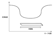
記録紙上に転写されたトナー像を定着ローラで加圧して熱定着を行う従来の画像形成装置では、小サイズの記録紙と大サイズの記録紙を混在してプリントした場合に、次のような制御を行っている。例えば、図43に示すように、小サイズの記録紙を連続通紙すると、定着ローラの中心と端部との温度が不均一となり、その後に大サイズの記録紙を通紙すると、画像濃度差や定着オフセットが生じることが知られている。図43は、記録紙(用紙)通紙後の定着温度の分布を示す図である。図43では、横軸に定着ローラの位置を示し、縦軸に定着温度を示す。 In a conventional image forming apparatus in which a toner image transferred onto a recording sheet is pressed by a fixing roller and heat-fixed, when printing a mixture of a small size recording sheet and a large size recording sheet, the following is performed: Control is in progress. For example, as shown in FIG. 43, when small size recording paper is continuously passed, the temperature at the center and end of the fixing roller becomes non-uniform, and when large size recording paper is subsequently passed, image density difference It is known that fixing offset occurs. FIG. 43 is a diagram showing the distribution of the fixing temperature after the recording paper (paper) is passed. In FIG. 43, the horizontal axis indicates the position of the fixing roller, and the vertical axis indicates the fixing temperature.
この対策として、例えば、特許文献1には、低コストで一般的な方法として、一旦プリント動作を停止し、定着ローラの温度が安定するまで定着調整を行う方法が提案されている。特許文献1の手法を用いる場合は、図44に示すように配光特性の異なる定着ヒータを用いて、定着ローラの温調を行う必要がある。図44は、定着ヒータの配光特性を説明するための図である。図44では、横軸に定着ローラの位置を示し、縦軸に配光特性を示す。
As a countermeasure against this, for example,
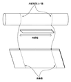
また、図45に示すように、紙の厚みが厚い記録紙を連続して通紙した場合、記録紙の紙コバによって定着ローラ表面に微少の傷跡が残り、その後に大サイズの記録紙を通紙すると、この傷跡部分によって画像上に微少な跡が残ることも知られている。図45は、用紙端部のコバ傷が発生する様子を示す図である。この対策として、特許文献2には、定着ローラ表面のクリーニングを行う方法が提案されている。
As shown in FIG. 45, when recording paper having a large thickness is continuously fed, a slight scar remains on the surface of the fixing roller due to the paper edge of the recording paper, and then a large size recording paper is passed. When paper is used, it is also known that minute marks remain on the image due to the scars. FIG. 45 is a diagram illustrating a state in which edge scratches at the end of the paper occur. As a countermeasure,
これらの定着調整やクリーニングは、画像品質を維持するためには不可欠であるが、その反面、一旦プリント動作を中断するため、生産性が低下する要因にもなっている。 These fixing adjustment and cleaning are indispensable for maintaining the image quality, but on the other hand, since the printing operation is temporarily interrupted, it also causes a decrease in productivity.
一方で、複写機などの画像形成装置においては、後処理装置を接続することによって、画像形成された記録紙を加工することが可能となっている。例えば、特許文献3には、複数枚の用紙からなる用紙束の片辺に糊付けを行う機能、糊付け面以外を断裁する断裁機能を取り付けることによって、製本処理を行う画像形成装置が提案されている。
しかしながら、上記従来技術には以下に記載する問題がある。例えば、小サイズの記録紙と大サイズの記録紙を混在してプリントした場合、1つのジョブ中に何度も小サイズと大サイズの記録紙が切り替わると、その都度定着調整やクリーニングを行うため、ジョブを中断する必要があった。 However, the above prior art has the following problems. For example, when a small size recording paper and a large size recording paper are mixed and printed, if a small size recording paper and a large size recording paper are switched many times in one job, fixing adjustment and cleaning are performed each time. There was a need to interrupt the job.
具体的には、図46を参照して説明する。図46は、異なる用紙サイズを用いたジョブにおける定着調整のタイミングを示す図である。図46では、異なるサイズの中紙束と表紙とによって製本処理を行う場合を想定している。例えば、このようなジョブには、小サイズの記録紙を複数枚集積して束とし、その束に大サイズの表紙を重ねて製本を作成するジョブが想定される。このような場合、図46に示すように、表紙の処理前に定着調整やクリーニングが入ってしまうため、生産性が著しく低下してしまうという問題がある。 Specifically, this will be described with reference to FIG. FIG. 46 is a diagram showing the timing of fixing adjustment in a job using different paper sizes. In FIG. 46, it is assumed that the bookbinding process is performed using a medium-sheet bundle and a cover sheet of different sizes. For example, such a job may be a job in which a plurality of small-size recording sheets are stacked to form a bundle, and a booklet is created by stacking a large-size cover on the bundle. In such a case, as shown in FIG. 46, since fixing adjustment and cleaning are performed before the cover is processed, there is a problem in that productivity is significantly reduced.
本発明は、上述の問題に鑑みて成されたものであり、異なるサイズの記録紙を連続して画像形成する場合に、当該画像形成に使用される定着装置等の調整動作を好適に実行し、画像品質を維持するとともに生産性の低下を抑制する画像形成装置を提供することを目的とする。 The present invention has been made in view of the above-described problems, and suitably performs an adjustment operation of a fixing device or the like used for image formation when recording images of different sizes are continuously formed. An object of the present invention is to provide an image forming apparatus that maintains image quality and suppresses a decrease in productivity.
本発明は、例えば、画像形成装置として実現できる。画像形成装置は、搬送される記録材にトナー画像を転写する転写手段と、前記転写手段により転写されたトナー画像を記録材に加熱定着させる定着手段と、前記トナー画像が加熱定着された記録材に対して断裁処理を実行する断裁手段と、記録材の搬送方向に対して直交する幅方向における、前記断裁手段により断裁される第1の記録材の断裁後の長さと、前記第1の記録材の直前に画像形成される第2の記録材の長さのいずれが長いかを判定する判定手段と、前記幅方向における前記定着手段の温度分布の不均一性を低減するための調整処理を実行する調整手段とを備え、前記調整手段は、前記判定手段により前記第2の記録材の前記幅方向の長さが前記第1の記録材の断裁後の前記幅方向の長さ未満であると判定された場合は、前記調整処理を実行し、前記判定手段により前記第2の記録材の前記幅方向の長さが前記第1の記録材の断裁後の前記幅方向の長さ以上であると判定された場合は、前記調整処理を実行しないことを特徴とする。
The present invention can be realized as an image forming apparatus, for example. An image forming apparatus includes: a transfer unit that transfers a toner image onto a recording material that is conveyed ; a fixing unit that heat-fixes the toner image transferred by the transfer unit to the recording material; and a recording material on which the toner image is heat-fixed A cutting unit that performs a cutting process on the first recording material, a length of the first recording material that is cut by the cutting unit in a width direction perpendicular to the conveyance direction of the recording material, and the first adjustment processing for reducing determining means for any length squid length of the second recording medium on which an image is formed immediately before the recording material, the non-uniformity of the temperature distribution of the fixing means in the width direction Adjusting means for executing the step, wherein the adjusting means determines that the width in the width direction of the second recording material is less than the length in the width direction after the cutting of the first recording material by the determining means. If it is determined that there is Running sense, if it is determined that the length of the width direction of the second recording material is equal to or greater than the length of said first of said width direction after cutting the recording material by the pre-Symbol judging means, The adjustment process is not executed.
また、本発明は、例えば、搬送される記録材にトナー画像を転写する転写手段と、前記転写手段により転写されたトナー画像を記録材に加熱定着させる定着手段と、前記トナー画像が加熱定着された記録材に対して断裁処理を実行する断裁手段とを備える画像形成装置の制御方法であって、記録材の搬送方向に対して直交する幅方向における、前記断裁手段により断裁される第1の記録材の断裁後の長さと、前記第1の記録材の直前に画像形成される第2の記録材の長さのいずれが長いかを判定する判定ステップと、前記幅方向に対して直交する方向における前記定着手段の温度分布の不均一性を低減するための調整処理を実行する調整ステップとを含み、前記調整ステップは、前記判定ステップで前記第2の記録材の前記幅方向の長さが前記第1の記録材の断裁後の前記幅方向の長さ未満であると判定された場合は、前記調整処理を実行し、前記判定ステップで前記第2の記録材の前記幅方向の長さが前記第1の記録材の断裁後の前記幅方向の長さ以上であると判定された場合は、前記調整処理を実行しないことを特徴とする。 Further, the present invention provides, for example, a transfer unit that transfers a toner image to a recording material that is conveyed, a fixing unit that heat-fixes the toner image transferred by the transfer unit to the recording material, and the toner image is heat-fixed. A method for controlling an image forming apparatus including a cutting unit that performs a cutting process on a recorded material, wherein the first cutting unit performs cutting by the cutting unit in a width direction orthogonal to the conveyance direction of the recording material . and the length after cutting of the recording material, said first second determination step of any Do long length of recording material on which an image is formed immediately before the recording material, perpendicular to the width direction An adjustment step for performing an adjustment process for reducing non-uniformity of the temperature distribution of the fixing unit in the direction in which the second recording material is moved in the width direction. of the previous If it is determined to be less than the length of the width direction after cutting the first recording medium, the length in the width direction of the adjustment process is executed, before Symbol wherein in the determination step the second recording medium Is determined to be greater than or equal to the length in the width direction after the cutting of the first recording material, the adjustment process is not executed.
本発明は、例えば、異なるサイズの記録紙を連続して画像形成する場合に、当該画像形成に使用される定着装置等の調整動作を好適に実行し、画像品質を維持するとともに生産性の低下を抑制する画像形成装置を提供できる。 In the present invention, for example, when recording images of different sizes of recording paper are continuously formed, an adjustment operation of a fixing device or the like used for the image formation is preferably executed to maintain image quality and reduce productivity. Can be provided.
以下に本発明の一実施形態を示す。以下で説明される個別の実施形態は、本発明の上位概念、中位概念及び下位概念など種々の概念を理解するために役立つであろう。また、本発明の技術的範囲は、特許請求の範囲によって確定されるのであって、以下の個別の実施形態によって限定されるわけではない。 An embodiment of the present invention is shown below. The individual embodiments described below will help to understand various concepts, such as superordinate concepts, intermediate concepts and subordinate concepts of the present invention. Further, the technical scope of the present invention is determined by the scope of the claims, and is not limited by the following individual embodiments.
<第1の実施形態>
<画像形成システムの全体構成>
まず、図1を参照して、画像形成システムの全体構成について説明する。図1は、第1の実施形態に係る画像形成システムの構成例を示す断面図である。画像形成システム1000は、画像形成装置10と、くるみ製本装置500及び後処理装置400などの後処理装置とを含んで構成されている。また、画像形成装置10は、原稿から画像を読み取るイメージリーダ200及び読み取った画像を用紙上に形成するプリンタ350を備える。また、以下では、画像を形成する用紙を、記録材、記録紙、シート等と称する。
<First Embodiment>
<Overall configuration of image forming system>
First, the overall configuration of the image forming system will be described with reference to FIG. FIG. 1 is a cross-sectional view illustrating a configuration example of an image forming system according to the first embodiment. The
イメージリーダ200には、原稿給送装置100が搭載されている。原稿給送装置100は、原稿トレイ上に上向きにセットされた原稿を先頭頁から順に1枚ずつ図1の左方向へ給紙し、湾曲したパスを介してプラテンガラス102上を左から流し読み取り位置を経て右へ搬送し、その後、外部の排紙トレイ112に向けて排出する。この原稿がプラテンガラス102上の流し読み取り位置を左から右へ向けて通過するときに、原稿画像が流し読み取り位置に対応する位置に保持されたスキャナユニット104により読み取られる。この読み取り方法は、一般に、原稿流し読みと呼ばれる方法である。具体的には、原稿が流し読み取り位置を通過する際に、原稿の読取面がスキャナユニット104のランプ103の光で照射され、その原稿からの反射光がミラー105、106、107を介してレンズ108に導かれる。このレンズ108を通過した光は、イメージセンサ109の撮像面に結像する。
A
このように、流し読み取り位置を左から右へ通過するように原稿を搬送することによって、原稿の搬送方向に対して直交する方向を主走査方向とし、搬送方向を副走査方向とする原稿読み取り走査が行われる。即ち、原稿が流し読み取り位置を通過する際に、主走査方向に原稿画像を1ライン毎にイメージセンサ109で読み取りながら、原稿を副走査方向に搬送することによって原稿画像全体の読み取りを行う。光学的に読み取られた画像は、イメージセンサ109によって画像データに変換されて出力される。イメージセンサ109から出力された画像データは、プリンタ350の露光制御部110にビデオ信号として入力される。
In this way, by transporting the document so that it passes from the left side to the right of the sink reading position, the document reading scan in which the direction orthogonal to the document transport direction is the main scanning direction and the transport direction is the sub-scanning direction. Is done. That is, when the document passes the flow reading position, the document image is read in the sub-scanning direction while reading the document image by the
なお、原稿給送装置100により原稿をプラテンガラス102上に搬送して所定位置に停止させ、この状態でスキャナユニット104を左から右へ走査させることにより原稿を読み取ることも可能である。この読み取り方法は、いわゆる原稿固定読みと呼ばれる方法である。
It is also possible to read the document by transporting the document onto the
原稿給送装置100を使用しないで原稿を読み取るときには、まず、ユーザにより原稿給送装置100を持ち上げてプラテンガラス102上に原稿を載置し、そして、スキャナユニット104を左から右へ走査させることにより原稿の読み取りを行う。即ち、原稿給送装置100を使用しないで原稿を読み取るときには、原稿固定読みが行われる。
When reading a document without using the
プリンタ350の露光制御部110は、イメージリーダ200から入力されたビデオ信号に基づきレーザ光を変調して出力する。当該レーザ光は、ポリゴンミラー110aにより走査されながら感光ドラム111上に照射される。感光ドラム111には走査されたレーザ光に応じた静電潜像が形成される。ここで、露光制御部110は、原稿固定読み時には、正しい画像(鏡像でない画像)が形成されるようにレーザ光を出力する。この感光ドラム111上の静電潜像は、現像器113から供給される現像剤によって現像剤像として可視像化される。
The
一方、プリンタ350内に装備されている上カセット114又は下カセット115からピックアップローラ127、128により給紙された用紙は、給紙ローラ129、130によりレジストローラ126まで搬送される。用紙の先端がレジストローラ126まで達したところで、レジストローラ126を任意のタイミングで駆動し、かつ、レーザ光の照射開始と同期したタイミングで、用紙を感光ドラム111と転写部116との間に搬送する。感光ドラム111に形成された現像剤像は、給紙された用紙上に転写部116により転写される。現像剤像が転写された用紙は、定着部117に搬送され、定着部117は、用紙を加熱及び加圧することによって現像剤像を用紙上に定着させる。定着部117を通過した用紙は、フラッパ121及び排出ローラ118を経てプリンタ350から画像形成装置本体外部(ここでは、くるみ製本装置500となる。)に向けて排出される。
On the other hand, sheets fed by the
ここで、用紙をその画像形成面が下向きになる状態(フェイスダウン)で排出するときには、定着部117を通過した用紙をフラッパ121の切換動作により一旦反転パス122内に導く。さらに、その用紙の後端がフラッパ121を通過した後に、用紙をスイッチバックさせて排出ローラ118によりプリンタ350から排出する。この排紙形態を反転排紙と称する。この反転排紙は、原稿給送装置100を使用して読み取った画像を形成するとき、又は、コンピュータから出力された画像を形成するときなどのように、先頭頁から順に画像形成するときに行われ、その排紙後の用紙順序は正しい頁順になる。
Here, when the sheet is discharged with its image forming surface facing down (face down), the sheet that has passed through the fixing
また、手差給紙部125からOHP用紙などの硬い用紙が給紙され、この用紙に画像を形成するときには、用紙を反転パス122に導くことなく、画像形成面を上向きにした状態(フェイスアップ)で排出ローラ118により排出する。さらに、用紙の両面に画像形成を行う両面形成が設定されている場合には、フラッパ121の切換動作により用紙を反転パス122に導いた後に両面搬送パス124へ搬送する。そして、両面搬送パス124へ導かれた用紙を上述したタイミングで感光ドラム111と転写部116との間に再度給紙する制御が行われる。
In addition, when a hard sheet such as an OHP sheet is fed from the manual
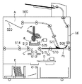
<くるみ製本装置の構成>
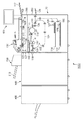
次に、図2を参照して、くるみ製本装置の構成について説明する。図2は、第1の実施形態に係るくるみ製本装置の構成例を示す断面図である。
<Configuration of case binding device>
Next, the configuration of the case binding apparatus will be described with reference to FIG. FIG. 2 is a cross-sectional view illustrating a configuration example of the case binding apparatus according to the first embodiment.
くるみ製本装置500は、用紙積載部A、糊付け部B、接着部C、断裁部D、及び製本排出部Eを有している。用紙積載部Aは、製本モードとして画像形成装置10から排出された記録紙を積載して用紙束を作成する。糊付け部Bは、積載された束に対して糊付けを行う。接着部Cは、糊付けされた積載束と表紙を接着する。断裁部Dは、表紙の接着後に、製本端面の整合を行うため、糊付け面以外の3方向を断裁する。製本排出部Eは、完成した製本を排出する。
The
ここで、一連の製本動作の流れについて説明する。なお、ここでは一連の製本動作の概要の説明のみに留め、各部の詳細な説明は後述する。 Here, a flow of a series of bookbinding operations will be described. Here, only the outline of a series of bookbinding operations will be described here, and a detailed description of each part will be described later.
用紙積載部Aは、製本モードにおいて、画像形成装置10から排出された記録紙を用紙積載トレイ520に積載して用紙束540を作成する部位である。用紙積載部Aによって仕上がった用紙束540は、糊付け部Bに移動され、糊容器525、糊塗布ローラ524、及び糊塗布ローラ制御モータ522によって、用紙束下側面に糊が塗布される。接着部Cは、糊付けされた用紙束540を画像形成装置10から排出された表紙Pに接着し、冊子570としてトリムグリッパ512に受け渡す工程を担う。そして、冊子570はトリムグリッパ512により断裁部Dに搬送される。断裁部Dではカッター制御モータ527によりカッター528を水平方向へ移動させ、冊子570の断裁を行う。断裁された断裁屑は断裁屑受箱533の中に落下し、一連の断裁動作が終了すると断裁屑箱532に断裁屑が回収される。断裁部において断裁が終了した冊子570は断裁部Dから製本排出部Eに搬送され、冊子570が排出される。
The paper stacking unit A is a part that stacks the recording paper discharged from the
以上の流れが製本モードにおける一連の製本動作であるが、製本モードの他に、製本を行わずに通常の排出モードを選択することもできる。 The above flow is a series of bookbinding operations in the bookbinding mode. However, in addition to the bookbinding mode, the normal discharge mode can be selected without performing bookbinding.
搬送ローラ対505の下流側には、切換フラッパ521が配置されている。切換フラッパ521は搬送ローラ対505により送られてきた用紙を用紙積載トレイ520、又は後処理装置400に選択的に導くためのフラッパである。
A switching
画像形成装置10から排出された用紙Pは、通常モード時は搬送ローラ対505、510、511、513、514、及び排紙ローラ515によって後処理装置400に排出される。後処理装置としては、製本機の下流装置として接続されているシート後処理装置、例えば、後処理装置400等の後処理装置において、束としての加工、つまり、束排出処理、綴じ処理、折り処理、製本処理などの後処理を施すことができる。
In the normal mode, the paper P discharged from the
また、製本モード時にあっては、画像形成装置10から排出された用紙Pは搬送ローラ対506、507、508、及び積載部排出ローラ509によって上述した用紙積載トレイ520に排紙され、整合されて用紙束540となる。
In the bookbinding mode, the paper P discharged from the
<用紙積載部Aの動作>
次に、図23乃至図26を参照して、くるみ製本装置500における用紙積載部Aの動作について説明する。図23及び図24は、くるみ製本装置における中紙の流れを説明する図である。図25及び図26は、くるみ製本装置における中紙及び表紙の流れを説明する図である。
<Operation of paper stacking section A>
Next, the operation of the paper stacking unit A in the
図23に示すように、くるみ製本装置500は、画像形成装置10から排出された用紙を搬送ローラ対505により内部に取り込み、搬送パス(a)へ導く。用紙束の中紙である場合、搬送ローラ対505により内部に取り込まれた用紙は、切換フラッパ521により搬送パス(b)へ導かれ、搬送ローラ対506、507、508及び積載部排出ローラ509により搬送される。用紙Pは、積載部排出ローラ509から用紙積載トレイ520へ排出される。中紙となる用紙全てが用紙積載トレイ520へ排出されると、中紙の用紙束540は糊付けグリッパ523によりグリップされ、図24の破線で示すように、用紙積載部Aから糊付け部Bの上方へ束の状態で移動される。
As shown in FIG. 23, the
糊付け部Bの上方へ移動した中紙の束は、図25に示すように、糊付けグリッパ523にグリップされた状態で垂直な方向に回転され、用紙束の背表紙となる側面が糊付け部Bと対向する位置となる。その後、詳細は後述するが、糊容器525及び糊塗布ローラ524が用紙束に沿って移動することで用紙束端部に糊付けが行われる。この間に、表紙となる表紙Pcが画像形成装置10から排出され、糊付け製本装置500へ搬送される。搬送ローラ対505により内部に取り込まれた用紙Pcは、切換フラッパ521が切り換えられており、搬送パス(a)から搬送パス(c)へと導かれ、搬送ローラ対510、511、513、514により搬送される。搬送パス(c)には、搬送ローラ対513の下流側に図示しないセンサが設けられており、図26に示すように、用紙束の表紙となる表紙Pcの先端部をセンサが検知してから所定距離搬送した後、表紙Pcの搬送を停止する。
As shown in FIG. 25, the bundle of intermediate sheets moved upward from the gluing section B is rotated in the vertical direction while being gripped by the gluing
表紙Pcが搬送パス(c)内で停止した時点で、表紙Pcの後端は切換フラッパ521を抜ける構成となっている。連続して用紙束を作成する場合は、表紙Pcが搬送パス(c)にある間でも、切換フラッパ521を切り換える。そして、次の用紙束に対する中紙を画像形成装置10から受け取り、搬送パス(a)から搬送パス(b)を経由して用紙積載トレイ520へと搬送を行う。その後、糊を塗布された用紙束に表紙をくるみ、下流へと搬送する部分に関する詳細は後述する。
When the cover sheet Pc stops in the transport path (c), the rear end of the cover sheet Pc is configured to pass through the switching
画像形成装置10から表紙を搬送する場合に関して上述したが、くるみ製本装置500の上部にはインサータ300が設けられており、表紙のみインサータ300から挿入することが可能となっている。
The case where the cover is conveyed from the
次に、図27及び図28を参照して、インサータ300から表紙を挿入して製本を行う場合の紙の流れについて説明する。図27及び図28は、くるみ製本装置におけるインサータから挿入した表紙の流れを説明する図である。
Next, with reference to FIG. 27 and FIG. 28, a flow of paper when bookbinding is performed by inserting a cover from the
中紙の流れは、図23乃至図26を用いて上述したように画像形成装置10が順次用紙を受け取り、用紙積載トレイ520で用紙束を作成し、糊付けグリッパ523により束ごと糊付け部Bへ移動する。一方、インサータ300から表紙Pcを挿入する場合、図27に示すように、中紙の束が糊付け部Bへ移動している間に、給紙ローラ301により給紙トレイ310上の最上紙から1枚給紙を行い、給紙された表紙Pcは、搬送ローラ対303、503、504で搬送される。さらに、切換フラッパ521によって、図28に示すように、搬送パス(d)から搬送パス(c)へと導かれる。
As described above with reference to FIGS. 23 to 26, the
<糊付け部Bの動作>
次に、図3及び図4を参照して、くりみ製本装置500の糊付け部Bにおける各動作の詳細を説明する。図3は、糊付け部Bの構成例を示す図である。図4は、糊付け部Bにおける糊付け動作の概要を示す図である。糊付け部Bは、用紙束をグリップする糊付けグリッパ523、糊を貯蔵する糊容器525、用紙束に糊を塗布する糊塗布ローラ524、及び糊塗布ローラ制御モータ522を備える。
<Operation of gluing part B>
Next, with reference to FIG.3 and FIG.4, the detail of each operation | movement in the glue part B of the trimming
糊容器525に浸漬されている糊塗布ローラ524は糊塗布ローラ制御モータ522の回転により、常に回転している状態にある。糊容器525、糊塗布ローラ524、糊塗布ローラ制御モータ522を有する糊付けユニット580は、糊付けグリッパ523によって直立状態にグリップされた用紙束540の下側面長手方向、即ち、用紙束と並行する方向に不図示の駆動部によって移動される。糊の塗布は糊付けユニットの往復動作によって行われる。図4に示すように、糊付けユニット580は糊付け製本装置500の背面側の初期位置から移動を開始し、糊付け製本装置500の前面の所定の位置で停止する。この時、糊付けユニット580による用紙束下側面への糊付けは行わない。用紙束への糊付けは、糊付け製本装置500の前面から背面へ移動する際に行われる。所定の位置で停止している糊付けユニット580は、用紙束の下側面に糊塗布ローラ524が当接する位置まで上昇する。そして糊付けユニット580が糊付け製本装置500の前面から背面へ移動しながら、糊塗布ローラ524によって用紙束540の下側面に糊を塗布する。
The
<接着部Cの動作>
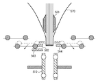
次に、図5乃至図12を参照して、接着部Cの動作について説明する。図5は、接着部Cの構成例を示す断面図である。接着部Cは、搬送ガイド560、561、加圧部材563、及び折り部材562、564を備える。搬送ガイド560、561は画像形成装置10から供給された表紙550を受容して搬送し、所定の位置に停止させる。加圧部材563は表紙550を用紙束540の糊塗布面に圧接させる。折り部材562、564は表紙を用紙束にくるむ際に用いられる。
<Operation of bonding part C>
Next, the operation of the bonding portion C will be described with reference to FIGS. FIG. 5 is a cross-sectional view illustrating a configuration example of the bonding portion C. The bonding portion C includes conveyance guides 560 and 561, a
用紙束540への糊付け動作が終了すると、駆動部(不図示)によって用紙束540をグリップした糊付けグリッパ523が糊付け部Bから下降してくる。そして、図5に示すように、搬送ガイド560、561によって水平方向に用意された表紙550に糊塗布面を接着させる。
When the gluing operation on the
接着後、糊付けグリッパ523が下降し、加圧部材563上に載置された表紙550の接着部は用紙束540の糊塗布面に圧接して接着される。なお、図6に示すように、用紙束540の下降による糊塗布面の圧接を行う前に搬送ガイド560上部、搬送ガイド561上部を退避させて用紙束540との干渉を防止することが望ましい。図6は、接着部Cにおいて、搬送ガイド上部を退避させた様子を示す図である。
After the bonding, the gluing
表紙550を用紙束540に接着したのち、折り部材562、564、搬送ガイド560下部、搬送ガイド561下部が駆動部によって加圧部材563の上斜め方向に上昇し、図7に示すように、破線位置から実線位置まで移動する。図7は、接着部Cにおいて、搬送ガイド下部を移動させる様子を示す図である。この折り部材562、564の上斜め方向への上昇によって、表紙550は上方に押し上げられる。これにより、表紙550が糊塗布面の側縁部から湾曲され、用紙束540をくるむくるみ処理が行われる。
After the
表紙550のくるみ処理が終了すると、図8に示すように、折り部材562、564、搬送ガイド560下部、搬送ガイド561下部が駆動部によって破線位置から実線位置まで退避する。図8は、接着部Cにおいて、搬送ガイド下部を移動させる様子を示す図である。同時に加圧部材563も、駆動部により水平方向に移動する。加圧部材563の水平移動によって、糊付けグリッパ523によって冊子570を下降するための空間が確保される。
When the cover processing of the
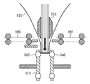
図9に示すように、糊付けグリッパ523によって搬送ガイド560、561の下方まで下降した冊子570は、冊子570の下端がトリムユニット受け渡しローラ565、566に当接する位置まで下降する。図9は、接着部Cにおいて、糊付けグリッパが下降する様子を示す図である。
As shown in FIG. 9, the
次に、図10に示すように、冊子570をグリップしていた糊付けグリッパ523が冊子570のグリップを解除し、同時にトリムユニット受け渡しローラ565、566によって冊子570は下方向に搬送される。図10は、接着部Cにおいて、糊付けグリッパが冊子を解除する様子を示す図である。
Next, as shown in FIG. 10, the
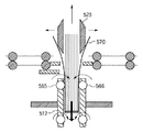
次に、図11に示すように、トリムユニット受け渡しローラ565、566によって下方への搬送が行われ、所定の位置まで搬送を行った後、冊子570の搬送を停止する。その後、トリムグリッパ512が図示しない駆動部によって冊子570をグリップする。図11は、接着部Cにおいて、トリムグリッパが冊子をグリップする様子を示す図である。
Next, as shown in FIG. 11, the trim
次に、図12に示すように、トリムグリッパ512が下降することによって冊子570が下方に下降し、断裁部Dの位置まで冊子570を下降させる。この時、水平方向に移動していた加圧部材563は表紙における接着部分の圧接を行える位置まで移動する。図12は、接着部Cにおいて、トリムグリッパが下降する様子を示す図である。
Next, as shown in FIG. 12, the
<断裁部Dの動作>
次に、図13乃至図18を参照して、断裁部Dの動作について説明する。図13は、断裁部Dの構成を示す断面図である。
<Operation of cutting part D>
Next, the operation of the cutting part D will be described with reference to FIGS. FIG. 13 is a cross-sectional view showing the configuration of the cutting part D.
図13に示すように、上述した接着部Cで中紙の用紙束と表紙が接着された冊子570は、トリムグリッパ512により断裁部Dに移動された後、トリムグリッパ512、カッター528、断裁屑受箱533が連動して各端部の断裁を行う。
As shown in FIG. 13, the
まず、断裁動作では、図14に示すように、カッター528による断裁を行う前に冊子570の下方に断裁屑受箱533が移動する。図14は、断裁部Dにおいて、断裁屑受箱が移動する様子を示す図である。
First, in the cutting operation, as shown in FIG. 14, the cutting
その後、カッター528が冊子570に対して出没し、一辺に対する断裁を行う。この時、断裁屑は、図15に示すように、冊子570の下方で待ち受けている断裁屑受箱533に収納される。図15は、断裁部Dにおいて、冊子を断裁する様子を示す図である。
After that, the
その後、図16に示すように、カッター528は逆方向に駆動されて、退避位置へと移動し、断裁屑受箱533も退避位置へと移動する。図16は、断裁部Dにおいて、カッター及び断裁屑受箱が退避する様子を示す図である。
Thereafter, as shown in FIG. 16, the
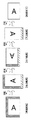
図17は、断裁の手順を説明する図である。図17では、冊子570に対して上述した断裁動作により、小口、及び天地の3辺の断裁を行う様子を示す。
FIG. 17 is a diagram illustrating a cutting procedure. FIG. 17 shows how the
具体的には、接着動作を行った冊子570は背表紙端部を下側にして移動されるため、回転可能なトリムグリッパ512を90度回転させて冊子570の向きを90度回転させた後、地辺の断裁を行う。次に、トリムグリッパ512を同一方向に90度回転させて断裁動作を行い、小口の断裁を行う。さらに、トリムグリッパ512を90度回転させて断裁動作を行い、天辺の断裁を行うことで背表紙部端部以外の断裁が終了する。但し、断裁後の冊子570の背表紙部を下方にして後述する製本排出部へ搬送させるために、断裁動作は行わず、トリムグリッパ512により冊子570を更に90度回転させる。
Specifically, since the
断裁屑受箱533は、断裁動作を行っていない時の退避位置と断裁動作中の屑受け位置との間を移動する。断裁屑受箱533の退避位置は、断裁屑箱532の上方に位置している。また、図18に示すように、断裁屑受箱533の底板部は開放可能な構成になっており、退避位置に移動すると断裁屑受箱533の底板部が開放され、断裁屑受箱533内の断裁屑が断裁屑箱532に収納される。図18は、断裁部Dにおける断裁した屑の流れを示す図である。
The cutting
<製本排出部Eの動作>
次に、図19乃至図22を参照して、製本排出部Eの動作について説明する。図19は、製本排出部Eの構成例を示す断面図である。製本排出部Eは、断裁部Dから製本排出部Eへの冊子の搬送を行うトリムグリッパ512、製本排出部Eへの冊子の搬送を行う排紙ローラ515、搬送された冊子を一時的に積載する製本積載板529を備える。製本排出部Eは、さらに、製本を縦方向に支持する製本支持板530、製本排出安定板534、及び、製本支持板530を水平方向に移動させる排出搬送ベルト531を備える。
<Operation of bookbinding discharge unit E>
Next, the operation of the bookbinding discharge unit E will be described with reference to FIGS. FIG. 19 is a cross-sectional view illustrating a configuration example of the bookbinding discharge unit E. The bookbinding discharge unit E includes a
断裁作業終了後の冊子570は、トリムグリッパ512が下降することによって断裁部D直下にある排紙ローラ515へ搬送される。そして、排紙ローラ515によって冊子570の搬送を行い、トリムグリッパ512は冊子570の支持を解除し、接着部Cの所定の位置へ移動する。この時、図19に示すように、製本排出部Eでは製本積載板529が右方向に倒れており、冊子570は排紙ローラ515によって製本積載板529に積載される。
The
その後、倒れていた製本積載板529は垂直方向に起立し、冊子570は製本支持板530により冊子570が縦になった状態で支持される。ここで、図20に示すように、排出搬送ベルト531の下方にある製本排出安定板534が上昇することにより、製本支持板530と製本排出安定板534で冊子570を支持する。図20は、製本排出部Eにおいて、冊子を支持する様子を示す図である。
Thereafter, the
その後、図21に示すように、製本支持板530は、排出搬送ベルト531によって左方向に移動し、次の冊子571が搬送されてきた場合の排出スペースを確保する。図21は、製本排出部Eにおいて、排出スペースを確保する様子を示す図である。冊子571の排出スペースを確保すると、図22に示すように、上述の排出動作を再度行うことによって、冊子570の隣に冊子571を縦積みすることが可能になる。図22は、製本排出部Eにおいて、冊子を縦積みする様子を示す図である。
After that, as shown in FIG. 21, the
<操作表示部の構成>
次に、図29を参照して、画像形成装置10における操作表示部600について説明する。図29は、画像形成装置に備えられる操作表示部の構成例を示す図である。
<Configuration of operation display unit>
Next, the
操作表示部600には、画像形成動作を開始するためのスタートキー602、画像形成動作を中断するためのストップキー603、及び、置数設定等を行うテンキー604〜612、614が配置されている。操作表示部600には更に、IDキー613、クリアキー615、リセットキー616などが配置されている。また、上部にタッチパネルが形成された液晶表示部620が配置されており、画面上にソフトキーを作成可能となっている。
The
例えば、本実施形態における画像形成装置10では、後処理装置400やくるみ製本装置500の後処理モードとして、ノンソートやソート、製本モードなどの各処理モードを有する。このような処理モードを設定する場合は操作表示部600からの入力操作により行われる。
For example, the
<全体システムブロック図>
次に、図47を参照して、画像形成装置10、くるみ製本装置500で構成される画像形成システム1000の各制御部の構成について説明する。図47は、第1の実施形態に係る画像形成システムの制御構成を示す図である。
<Overall system block diagram>
Next, the configuration of each control unit of the
801は、画像形成装置10の基本制御を行うCPUであり、制御プログラムが書き込まれたROM802、処理を行うためのRAM803、及び入出力ポート804と、アドレスバス、データバスにより接続されている。RAM803の一部の領域は電源OFFされてもデータが消去されないバックアップRAMとなっている。
A
入出力ポート804には、画像形成装置10が制御するモータ、クラッチ等の各種負荷装置や、紙の位置を検知するセンサ等の画像形成装置10への入力装置が接続されている。CPU801は、ROM802の制御プログラムの内容に従って、入出力ポート804を介して順次入出力の制御を行い、画像形成処理を実行する。
The input /
また、CPU801には図1及び図29に示す操作表示部600が接続されており、CPU801は操作表示部600の表示、及びキー入力を制御する。入力制御部812は操作表示部600に備えられている。詳細は後述する。さらにCPU801には、イメージセンサ109で電気信号に変換された信号を処理する画像処理部805と、処理された画像を蓄積する画像メモリ部806とが接続されている。
The
通信IF807は、CPU801と、くるみ製本装置500との間で通信するための通信IFであり、くるみ製本装置500側の通信IF907を介して、くるみ製本装置500のCPU901と通信する。
The communication IF 807 is a communication IF for communicating between the
調整判定部808は、画像形成開始時、又は、画像形成途中に調整の要否を判定する。ここでの調整とは、例えば、定着部117における調整を意味し、異なるサイズの用紙を連続して画像形成する場合に、行われる調整である。製本制御部810は、後述する束厚算出制御部811を備え、くるみ製本装置500の制御を統括的に行う。
The
901は、くるみ製本装置500の基本制御を行うCPUであり、制御プログラムが書き込まれたROM902、及び、処理を行うためのRAM903と、アドレスバス、データバスにより接続されている。RAM903の一部の領域は電源OFFされてもデータが消去されないバックアップRAMとなっている。くるみ製本装置500は、CPU901からの信号に基づき、後述する積載制御部913、糊付け制御部904、接着制御部910、及び、断裁制御部911を統括的に制御することで製本処理を実行する。以下では、各制御部について詳細に説明する。
A
<入力制御部>
まず、入力制御部812について詳細に説明する。製本制御部810は、必要な情報を、入力制御部812として備えられている操作表示部600に表示される中紙給紙段選択画面(図33)を介して設定された給紙段に格納されている用紙サイズから中紙サイズ情報を取得する。また、製本制御部810は、仕上がりサイズ指定画面(図35、図36)から設定された仕上がりサイズ情報と中紙サイズ情報の差分から中紙に対する断裁量情報を取得する。さらに、製本制御部810は、表紙給紙選択画面(図34)から設定された給紙段に格納されている用紙サイズから表紙サイズ情報を取得する。入力制御部812は、これらの表示画面を操作表示部600に表示し、当該表示画面を介して入力される情報を各制御部に伝達する。
<Input control unit>
First, the
<束厚算出制御部>
次に、束厚算出制御部811について詳細に説明する。束厚算出制御部811は、入力制御部812から設定された中紙サイズ情報、仕上がりサイズ、及び表紙サイズ情報と、装置機能として予め定められている最大断裁量とから製本できる束厚Zの範囲を以下に記載するパラメータを元に算出する。
表紙チェック閾値長さ:X1 = (A−B) × 2 + C
断裁量オーバ表紙基準長さ:X2 = (A−B + Dmax) × 2
表紙長さ足りず基準長さ:X3 = (A−B) × 2
A:中紙サイズ小口方向長さ
B:小口方向断裁量
C:最大中紙束厚
Dmax:最大断裁量
ここで、上記X1、X2、X3で算出した値と表紙長さとの関係により、表紙裁断量がオーバしてしまう場合、又は表紙の長さが足りない場合の2つの状況が発生する可能性がある。
<Bundle thickness calculation control unit>
Next, the bundle thickness
Cover check threshold length: X1 = (AB) × 2 + C
Cutting amount over cover reference length: X2 = (A−B + Dmax) × 2
Not enough cover length Standard length: X3 = (A−B) × 2
A: Medium paper size Edge direction length B: Edge direction cutting amount C: Maximum intermediate paper bundle thickness Dmax: Maximum cutting amount Here, the cover cutting is performed according to the relationship between the values calculated in X1, X2, and X3 and the cover length. Two situations can occur when the amount is over or when the cover is not long enough.
<表紙断裁量オーバの場合>
表紙長さYが、断裁量オーバ表紙基準長さX2を超える長さの場合(Y>X2)は、表紙の断裁量が最大断裁量Dmaxを超える可能性があると判定できる。この場合の束厚Zの範囲は、(Y−X2)≦Z≦Cであれば最大断裁量Dmaxを超えない。
<When the cover cutting amount is over>
If the cover length Y exceeds the cutting amount over cover reference length X2 (Y> X2), it can be determined that the cutting amount of the cover may exceed the maximum cutting amount Dmax. In this case, the range of the bundle thickness Z does not exceed the maximum cutting amount Dmax if (Y−X2) ≦ Z ≦ C.
<具体例>
ここで、以下のパラメータである場合の、束厚算出制御部811の制御の一例を示す。
表紙サイズ :ユーザ定義サイズ(297×450mm)
中紙サイズ :A4(210mm×279mm)
仕上がりサイズ:B5(182mm×257mm)
ここで、表紙サイズ/中紙サイズ/仕上がりサイズの設定値により、
A:中紙サイズ小口方向長さ = 210mm
B:小口方向断裁量 = 中紙サイズ−仕上がりサイズ = 210−182 = 28mm
C:最大中紙束厚 = 20mm
Dmax:最大断裁量 = 39mm
となる。最大中紙束厚/最大断裁量は装置の性能・構成により決まる値であり、設定値によらず同じ値となる。したがってX1、X2、X3はそれぞれ、以下のようになる。
表紙チェック閾値長さ:X1 = (A−B) × 2 + C = (210−28) × 2 + 20 = 384mm
断裁量オーバ表紙基準長さ: X2 = (A−B + Dmax) × 2 = (210−28 + 39) × 2 = 442mm
表紙長さ足りず基準長さ:X3 = (A−B) × 2 = (210−28) × 2 = 364mm
この時、(表紙長さY = 450mm) > (断裁量オーバ表紙基準長さX2 = 442mm)
の関係が成り立つため、表紙の断裁量が最大断裁量Dmaxを超える可能性があると判定できる。
この場合の束厚Zの範囲は、8mm(450mm−442mm) ≦Z≦ 20mmの範囲内であれば最大断裁量Dmax=39mmを超えない。
<Specific example>
Here, an example of control of the bundle thickness
Cover size: User-defined size (297 x 450 mm)
Medium paper size: A4 (210mm x 279mm)
Finished size: B5 (182mm x 257mm)
Here, depending on the set value of cover size / medium paper size / finished size,
A: Medium paper size edge direction length = 210 mm
B: Cutting amount in the edge direction = Medium paper size−Finished size = 210-182 = 28 mm
C: Maximum middle paper bundle thickness = 20 mm
Dmax: Maximum cutting amount = 39 mm
It becomes. The maximum medium sheet bundle thickness / maximum cutting amount is a value determined by the performance and configuration of the apparatus, and is the same value regardless of the set value. Therefore, X1, X2, and X3 are as follows.
Cover page check threshold length: X1 = (A−B) × 2 + C = (210−28) × 2 + 20 = 384 mm
Cutting length over cover reference length: X2 = (A−B + Dmax) × 2 = (210−28 + 39) × 2 = 442 mm
Not enough cover length Standard length: X3 = (A−B) × 2 = (210−28) × 2 = 364 mm
At this time, (cover length Y = 450 mm)> (cutting amount over cover reference length X2 = 442 mm)
Therefore, it can be determined that the cover cutting amount may exceed the maximum cutting amount Dmax.
In this case, the bundle thickness Z is within the range of 8 mm (450 mm−442 mm) ≦ Z ≦ 20 mm, and does not exceed the maximum cutting amount Dmax = 39 mm.
<表紙長さが足りない場合>
表紙長さYが、表紙チェック閾値長さX1未満の長さの場合(Y<X1)は、表紙の長さが断裁後の小口端面の内側に入る可能性があると判定できる。この場合の束厚Zの範囲がZ≦Y−X3であれば、小口端面の内側に表紙端面が入りこむことは発生しない。
<Insufficient cover length>
When the cover length Y is less than the cover check threshold length X1 (Y <X1), it can be determined that there is a possibility that the cover length may be inside the fore edge surface after cutting. If the range of the bundle thickness Z in this case is Z ≦ Y−X3, the cover end face does not enter the inside of the edge end face.
<具体例>
ここで、以下のパラメータである場合の、束厚算出制御部811の制御の一例を示す。
表紙サイズ :ユーザ定義サイズ(270×370mm)
中紙サイズ :A4(210mm×279mm)
仕上がりサイズ:B5(182mm×257mm)
とした場合の、束厚算出手段の一例を示す。ここで、表紙サイズ/中紙サイズ/仕上がりサイズの設定値により、
A:中紙サイズ小口方向長さ = 210mm
B:小口方向断裁量 = 中紙サイズ−仕上がりサイズ = 210−182 = 28mm
C:最大中紙束厚 = 20mm
Dmax:最大断裁量 = 39mm
となる。ここで、最大中紙束厚/最大断裁量は装置の性能・構成により決まる値であり、設定値によらず同じ値となる。X1、X2、X3はそれぞれ、以下のようになる。
<Specific example>
Here, an example of control of the bundle thickness
Cover size: User-defined size (270 x 370 mm)
Medium paper size: A4 (210mm x 279mm)
Finished size: B5 (182mm x 257mm)
An example of the bundle thickness calculation means is shown. Here, depending on the set value of cover size / medium paper size / finished size,
A: Medium paper size edge direction length = 210 mm
B: Cutting amount in the edge direction = Medium paper size−Finished size = 210-182 = 28 mm
C: Maximum middle paper bundle thickness = 20 mm
Dmax: Maximum cutting amount = 39 mm
It becomes. Here, the maximum middle sheet bundle thickness / maximum cutting amount is a value determined by the performance and configuration of the apparatus, and is the same value regardless of the set value. X1, X2, and X3 are as follows.
表紙チェック閾値長さ: X1 = (A−B) × 2 + C = (210−28) × 2 + 20 = 384mm
断裁量オーバ表紙基準長さ: X2 = (A−B + Dmax) × 2 = (210−28 + 39) × 2 = 442mm
表紙長さ足りず基準長さ:X3 = (A−B) × 2 = (210−28) × 2 = 364mm
この時、(表紙長さY = 370mm)<(表紙チェック閾値長さX1 = 384mm)
の関係が成り立つため、表紙の長さが断裁後の小口端面の内側に入る可能性があると判定できる。この場合の束厚Zの範囲がZ≦6mm(370mm−364mm)であれば、小口端面の内側に表紙端面が入りこむことは発生しない。
Cover check threshold length: X1 = (A−B) × 2 + C = (210−28) × 2 + 20 = 384 mm
Cutting length over cover reference length: X2 = (A−B + Dmax) × 2 = (210−28 + 39) × 2 = 442 mm
Not enough cover length Standard length: X3 = (A−B) × 2 = (210−28) × 2 = 364 mm
At this time, (cover length Y = 370 mm) <(cover check threshold length X1 = 384 mm)
Therefore, it can be determined that there is a possibility that the length of the cover may enter the inside of the edge edge surface after cutting. If the range of the bundle thickness Z in this case is Z ≦ 6 mm (370 mm-364 mm), the cover end face does not enter the inside of the end edge end face.
<調整判定部>
次に、調整判定部808の詳細について説明する。調整判定部808は、定着部117を通過する用紙サイズと、それまでに通過した用紙サイズの大小を比較し、調整の要否を判定する。後処理工程にて断裁処理が設定されている場合には、断裁後の仕上がりサイズを考慮して調整の要否を判定する。
<Adjustment determination unit>
Next, details of the
調整には次のようなものがある。例えば、小サイズの用紙を連続通紙した後に大サイズの用紙を通紙した場合に、定着ローラ中心部と端部の温度が不均一となることによって生じる、画像濃度差や定着オフセットを防止するためのものである。この場合、定着ローラの温度が安定するまで定着調整を行う。また、紙の厚みが厚い用紙を連続して通紙した際、用紙の紙コバによって定着ローラ表面に微少の傷跡が残ることがあるが、この傷跡部分で用紙上のトナー像を定着した場合に、画像上に微少な跡が残る現象を防止するためのものがある。この場合、定着ローラ表面に他のローラやブレードを当接するなどして、定着ローラ表面のクリーニングを行う。 Adjustments include the following. For example, when small-size paper is passed continuously and then large-size paper is passed, image density differences and fixing offsets caused by uneven temperature at the center and end of the fixing roller are prevented. Is for. In this case, fixing adjustment is performed until the temperature of the fixing roller is stabilized. In addition, when a thick paper is continuously fed, a slight scar may remain on the surface of the fixing roller due to the paper edge of the paper. When the toner image on the paper is fixed at this scar, In order to prevent a phenomenon in which minute traces remain on an image. In this case, the surface of the fixing roller is cleaned by bringing another roller or blade into contact with the surface of the fixing roller.
<製本モードの設定フロー>
次に、図48のフローチャートと図30乃至図42を参照して、製本モードの設定フローについて説明する。図48は、第1の実施形態に係る製本モードの設定手順を示す図フローチャートである。以下で説明する処理は、CPU801によって統括的に制御される。また、図30乃至図42は、操作表示部に表示される表示画面の一例である。なお、以下で説明する処理において、表示画面3000〜4200を介したユーザ入力は、入力制御部812によって取得される。
<Bookbinding mode setting flow>
Next, the bookbinding mode setting flow will be described with reference to the flowchart of FIG. 48 and FIGS. 30 to 42. FIG. 48 is a flowchart illustrating a bookbinding mode setting procedure according to the first embodiment. The processing described below is centrally controlled by the
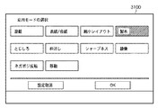
製本モードは操作表示部600の液晶表示部620に表示された図30に示す表示画面3000から設定を開始する。表示画面3000は、初期画面であり、ソフトキーである「応用モード」キーを選択すると、図31に示す表示画面3100に遷移される。表示画面3100は、応用モードの選択画面である。この応用モードのメニューの中から、「製本」のソフトキーを選択すると、製本モードの設定が開始される。
The bookbinding mode starts setting from a
製本モードの設定が開始されると、ステップS1001において、CPU801は、図32に示す表示画面3200を表示させ、成果物のとじ方向である「右開き」、「左開き」のいずれかを選択させる。ここで、「右開き」とは、本を開いたとき右側のページから左側のページへ増えていくとじ方を示す。一方、「左開き」とは、左側のページから右側のページへ増えていくとじ方を示す。
When the setting of the bookbinding mode is started, in step S1001, the
とじ方向が選択され、「次へ」のソフトキーが押下されると、ステップS1002において、CPU801は、中紙給紙段設定を行うための図33に示す表示画面3300を操作表示部600に表示させる。表示画面3300では、くるみ表紙で包まれる用紙束を給紙する給紙段が選択される。また、ユーザ定義として、任意のサイズを指定することが可能である。
When the binding direction is selected and the “Next” soft key is pressed, in step S1002, the
用紙束の給紙段が選択され、「次へ」のソフトキーが押下されると、ステップS1003において、CPU801は、図34に示す表示画面3400を表示し、くるみ表紙を給紙する給紙段を選択させる。表示画面3400では、くるみ表紙の給紙元を給紙カセットやインサータから選択する。また、ユーザ定義として、任意のサイズを指定することも可能となっている。
When the paper feed stage of the bundle of sheets is selected and the “Next” soft key is pressed, in step S1003, the
次に、ステップS1004において、CPU801は、図35及び図36に示す表示画面3500、3600を表示させ、仕上がりサイズの設定を行わせる。表示画面3500では、断裁後のサイズを規定のサイズから選択するか、又は「詳細設定」のソフトキーを押下して、表示画面3600に遷移し、任意のサイズを指定する。
Next, in step S1004, the
仕上がりサイズを設定して「設定」のソフトキーが押下されると、ステップS1005において、CPU801は、束厚算出制御部811に上述の計算処理を行わせる。続いて、ステップS1006において、CPU801は、表紙の断裁量が最大で断裁可能な最大断裁量より大きくなる可能性があるか否かを判定する。ここで、可能性がある場合には、ステップS1007に進み、CPU801は、ユーザへ製本可能な束厚情報を表示する図37の表示画面3700を表示させる。一方、可能性が無い場合には、ステップS1008に進み、CPU801は、小口方向の表紙端面が仕上がり製本サイズの小口端面より内側に入る可能性があるか否かを判定する。
When the finish size is set and the “SETTING” soft key is pressed, in step S1005, the
可能性がある場合には、ステップS1009に進み、CPU801は、ユーザへ製本可能な束厚情報を表示する図38に示す表示画面3800を表示させる。なお、表示画面3700、3800で表示される束厚情報は、使用される中紙の1枚毎の紙厚情報と、束厚算出制御部811により算出された束厚とから束枚数を算出した目安値を表示してもよい。
If there is a possibility, the process advances to step S1009, and the
続いて、ステップS1010において、CPU801は、表紙の給紙元がインサータであるか否かを判定する。ここで、インサータを給紙段として選択した場合には、ステップS1011に進み、CPU801は、表紙の給紙元をインサータとした場合の製本を行うモードを「インサータモード」に設定する。さらに、ステップS1012において、CPU801は、ユーザに対して原稿を原稿給送装置100へセットするよう促し、製本モードの設定を終了する。
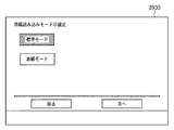
In step S1010, the
一方、ステップS1010で表紙の給紙元がインサータでない場合は、ステップS1013において、CPU801は、製本を行うモードを原稿読み込みモードに設定する。続いて、ステップS1014において、CPU801は、図39に示す表示画面3900を表示し、ユーザ入力を受け付けて、原稿読み込みモードが標準モードであるか、又は、表紙モードであるかを判定する。この判定は、くるみ表紙の原稿と中紙の原稿が分けられているかを判定するものである。したがって、表示画面3900において、分けられている場合には「表紙モード」が選択され、表紙/裏表紙と中紙の原稿が1つの束になっている場合は「標準モード」が選択される。
On the other hand, if it is determined in step S1010 that the cover sheet supply source is not an inserter, in step S1013, the
「標準モード」が選択された場合、ステップS1015に進み、CPU801は、原稿読み込みモードを標準モードに設定する。続いて、ステップS1012において、CPU801は、操作表示部600に図40に示す表示画面4000を表示させ、ユーザに対して原稿を原稿給送装置100へセットするよう促し、製本モードの設定を終了する。
If “standard mode” is selected, the process advances to step S1015, and the
一方、「表紙モード」が選択された場合、ステップS1016に進み、CPU801は、原稿読み込みモードを表紙モードに設定する。続いて、ステップS1017において、CPU801は、図41に示す表示画面4100を表示させ、くるみ表紙となる原稿を原稿給送装置100へセットし、スタートキー602を押下するように促す。スタートキー602が押下されると、ステップS1018において、CPU801は、表紙原稿の読み込みを開始させる。
On the other hand, if “cover mode” is selected, the process advances to step S1016, and the
表紙原稿の読み込みが完了すると、ステップS1019において、CPU801は、図42に示す表示画面4200を表示させ、ユーザに対して中紙の原稿を原稿給送装置100へセットするように促し、製本モードの設定を終了する。
When the reading of the cover original is completed, in step S1019, the
<プリント処理>
次に、図49を参照して、プリント処理実行時の動作について説明する。図49は、第1の実施形態に係るプリント処理の処理手順を示すフローチャートである。以下で説明する処理は、CPU801によって統括的に制御される。プリント処理は、図29のスタートキー602を押下されると開始される。
<Print processing>
Next, with reference to FIG. 49, the operation at the time of executing the print processing will be described. FIG. 49 is a flowchart illustrating a processing procedure of print processing according to the first embodiment. The processing described below is centrally controlled by the
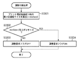
ステップS3101において、CPU801は、画像形成のための前準備を行う。次に、ステップS3102において、CPU801は、これから印字するページにおいて調整処理を実行する必要があるか否かを、後述する調整判定処理によって判定する。ステップS3103においてS3102の判定結果を確認し、調整処理の実行が必要である場合はステップS3104へ進み、調整処理の実行が不要である場合にはステップS3108に進む。
In step S <b> 3101, the
ステップS3104において、CPU801は、調整を行うための条件が成立するまで所定の処理を継続し、中断可能となった時点で画像形成中断処理を実行する。その後、ステップS3106において、CPU801は、所定の条件を満たすまで調整処理を実行する。調整処理が終了すると、ステップS3107において、CPU801は、画像形成復帰処理を実行し、ステップS3108に進む。
In step S <b> 3104, the
調整処理終了後、又は、調整処理の実行が不要であった場合、ステップS3108において、CPU801は、ページ印字処理を実行する。次に、ステップS3109において、CPU801は、全ページの処理が終了しているか否かを判定する。ここで全ページの処理が終了していない場合にはS3102に戻り、S3102〜S3109の処理を繰り返す。一方、S3109で全ページの処理が終了したと判定されると、ステップS3110に進み、CPU801は、画像形成後処理を行い、プリント処理を終了する。
After completion of the adjustment process or when the adjustment process is not necessary, the
<調整判定処理>
次に、図50を参照して、ステップS3102の調整判定処理の詳細について説明する。図50は、第1の実施形態に係る調整判定処理の処理手順を示すフローチャートである。以下で説明する処理は、CPU801によって統括的に制御される。また、調整判定処理は、図49のフローチャートにおけるS3102で毎ページ実行される。
<Adjustment judgment process>
Next, with reference to FIG. 50, the details of the adjustment determination processing in step S3102 will be described. FIG. 50 is a flowchart illustrating a processing procedure of adjustment determination processing according to the first embodiment. The processing described below is centrally controlled by the
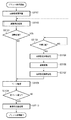
まず、ステップS3201において、CPU801は、判定するページが断裁設定されているか否かを判定する。断裁設定されていなかった場合にはステップS3202に進み、CPU801は、当該ページの仕上がりサイズを記録紙サイズに設定する。一方、S3201で断裁設定されていた場合には、ステップS3203に進み、CPU801は、仕上がりサイズを断裁後のサイズに設定する。これらの処理で、最終的な成果物のサイズが仕上がりサイズと設定される。ここで、CPU801は、画像形成する記録材のサイズを特定するサイズ特定手段の一例である。
First, in step S3201, the
次に、ステップS3204において、CPU801は、このページの仕上がりサイズが直前の記録紙サイズより大きいか否かを判定する。仕上がりサイズが直前の記録紙サイズより大きくない場合はS3205に進み、CPU801は、調整要求フラグをOFFに設定する。一方、大きい場合はS3206において、CPU801は、調整要求フラグをONに設定する。ここで、CPU801は、特定された記録材のサイズと、直前に画像形成された記録材のサイズとを用いて、画像品質を維持するための調整処理を実行する必要があるか否かを判定する調整判定手段の一例である。
Next, in step S3204, the
このように制御することで、これから印字するページの仕上がりサイズと、直前に通紙した記録紙サイズを比較して、定着部117の調整やクリーニングを行うか否か決定することができる。つまり、本画像形成装置は、不要な調整処理を防止することで、生産性の低下を抑制することができる。
By controlling in this way, it is possible to determine whether or not to perform adjustment or cleaning of the fixing
本実施形態によれば、小サイズの記録紙と大サイズの記録紙を混在してプリントした場合において、不要な定着調整やクリーニングを実施することを防止できるため、成果物としての画像品質を維持しつつ、生産性の低下抑制することができる。これにより、ユーザにとって使い勝手のよい画像形成装置を提供することができる。 According to the present embodiment, when a small size recording paper and a large size recording paper are mixedly printed, unnecessary fixing adjustment and cleaning can be prevented, so that the image quality as a product is maintained. However, it is possible to suppress a decrease in productivity. Thereby, it is possible to provide an image forming apparatus that is convenient for the user.
<第2の実施形態>
次に、図51を参照して、第2の実施形態について説明する。以下では、第1の実施形態と異なる技術についてのみ説明を記載する。図51は、第2の実施形態に係る調整判定処理の処理手順を示すフローチャートである。以下で説明する処理は、CPU801によって統括的に制御される。
<Second Embodiment>
Next, a second embodiment will be described with reference to FIG. In the following, only the technique different from the first embodiment will be described. FIG. 51 is a flowchart illustrating a processing procedure of adjustment determination processing according to the second embodiment. The processing described below is centrally controlled by the
まず、ステップS3301において、CPU801は、プリント動作開始後、直前の10枚分の記録紙サイズのうち、最小サイズとなる記録紙サイズを算出する。最新10枚分とするのは一例であり、記録紙を通紙した際に、後続の記録紙に影響を及ぼす所定枚数分とすれば良い。
First, in step S3301, after starting the printing operation, the
続いて、ステップS3302において、CPU801は、仕上がりサイズがS3301で算出した最小記録紙サイズより大きいか否かを判定する。仕上がりサイズが最小記録紙サイズより大きくない場合は、ステップS3303に進み、CPU801は、調整要求フラグをOFFに設定する。一方、大きい場合はS3304に進み、CPU801は、調整要求フラグをONに設定する。
In step S3302, the
このように制御することで、これから印字するページに影響を及ぼす直前の数枚のページサイズと、仕上がりサイズとの関係によって調整やクリーニングを行うか否か決定することが可能となる。 By controlling in this way, it is possible to determine whether or not to perform adjustment or cleaning depending on the relationship between the finished page size and the size of several pages immediately before affecting the page to be printed.
また、第1の実施形態及び第2の実施形態における調整判定処理の実行を、ユーザの製本成果物の作成フローに応じて切り換えてもよい。 Further, the execution of the adjustment determination process in the first embodiment and the second embodiment may be switched according to a user's bookbinding product creation flow.
10 画像形成装置
100 自動原稿送り装置
200 イメージリーダ
300 インサータ
350 プリンタ
400 後処理装置
500 くるみ製本装置
600 操作表示部
512 トリムグリッパ
520 用紙積載トレイ
522 糊付けローラ制御モータ
523 糊付けグリッパ
524 糊付けローラ
525 糊容器
527 カッター制御モータ
528 カッター
532 断裁屑箱
533 断裁屑受箱
529 積載板
530 製本支持板
534 製本排出安定板
DESCRIPTION OF
Claims (3)
前記転写手段により転写されたトナー画像を記録材に加熱定着させる定着手段と、
前記トナー画像が加熱定着された記録材に対して断裁処理を実行する断裁手段と、
記録材の搬送方向に対して直交する幅方向における、前記断裁手段により断裁される第1の記録材の断裁後の長さと、前記第1の記録材の直前に画像形成される第2の記録材の長さのいずれが長いかを判定する判定手段と、
前記幅方向における前記定着手段の温度分布の不均一性を低減するための調整処理を実行する調整手段とを備え、
前記調整手段は、前記判定手段により前記第2の記録材の前記幅方向の長さが前記第1の記録材の断裁後の前記幅方向の長さ未満であると判定された場合は、前記調整処理を実行し、前記判定手段により前記第2の記録材の前記幅方向の長さが前記第1の記録材の断裁後の前記幅方向の長さ以上であると判定された場合は、前記調整処理を実行しないことを特徴とする画像形成装置。 Transfer means for transferring a toner image to a recording material to be conveyed ;
Fixing means for heating and fixing the toner image transferred by the transfer means to a recording material;
Cutting means for performing a cutting process on the recording material on which the toner image is heat-fixed;
The length after cutting of the first recording material cut by the cutting means in the width direction perpendicular to the conveyance direction of the recording material and the second image formed immediately before the first recording material. determining means any is a squid length of the length of the recording material,
Adjusting means for performing adjustment processing for reducing non-uniformity of the temperature distribution of the fixing means in the width direction;
When the determination unit determines that the length in the width direction of the second recording material is less than the length in the width direction after the cutting of the first recording material, run the adjustment process, if the length of the width direction of the second recording medium is determined to be equal to or greater than the length of said first of said width direction after cutting the recording material by the pre-Symbol judging means An image forming apparatus that does not execute the adjustment process.
記録材の搬送方向に対して直交する幅方向における、前記断裁手段により断裁される第1の記録材の断裁後の長さと、前記第1の記録材の直前に画像形成される第2の記録材の長さのいずれが長いかを判定する判定ステップと、
前記幅方向に対して直交する方向における前記定着手段の温度分布の不均一性を低減するための調整処理を実行する調整ステップとを含み、
前記調整ステップは、前記判定ステップで前記第2の記録材の前記幅方向の長さが前記第1の記録材の断裁後の前記幅方向の長さ未満であると判定された場合は、前記調整処理を実行し、前記判定ステップで前記第2の記録材の前記幅方向の長さが前記第1の記録材の断裁後の前記幅方向の長さ以上であると判定された場合は、前記調整処理を実行しないことを特徴とする画像形成装置の制御方法。 Transfer means for transferring a toner image to a recording material to be conveyed, fixing means for heat fixing the toner image transferred by the transfer means to the recording material, and cutting processing for the recording material on which the toner image is heat fixed A method for controlling an image forming apparatus, comprising:
The length after cutting of the first recording material cut by the cutting means in the width direction perpendicular to the conveyance direction of the recording material and the second image formed immediately before the first recording material. A determination step for determining which of the lengths of the recording material is longer ;
An adjustment step for performing an adjustment process for reducing non-uniformity of the temperature distribution of the fixing unit in a direction orthogonal to the width direction,
In the adjustment step, when it is determined in the determination step that the length in the width direction of the second recording material is less than the length in the width direction after the cutting of the first recording material, run the adjustment process, before SL when the length in the width direction of the second recording medium in the determination step is determined to be greater than or equal to the length of the width direction after cutting of the first recording material A method for controlling an image forming apparatus, wherein the adjustment process is not executed.
Priority Applications (5)
| Application Number | Priority Date | Filing Date | Title |
|---|---|---|---|
| JP2008196849A JP5067883B2 (en) | 2008-07-30 | 2008-07-30 | Image forming apparatus and control method thereof |
| US12/500,271 US8145081B2 (en) | 2008-07-30 | 2009-07-09 | Image forming apparatus and control method for the same |
| EP09165595.1A EP2157485B1 (en) | 2008-07-30 | 2009-07-15 | Image forming apparatus and control method for the same |
| CN2009101622398A CN101639641B (en) | 2008-07-30 | 2009-07-30 | Image forming apparatus and control method for the same |
| US13/370,632 US8260162B2 (en) | 2008-07-30 | 2012-02-10 | Image forming apparatus and control method for the same |
Applications Claiming Priority (1)
| Application Number | Priority Date | Filing Date | Title |
|---|---|---|---|
| JP2008196849A JP5067883B2 (en) | 2008-07-30 | 2008-07-30 | Image forming apparatus and control method thereof |
Related Child Applications (1)
| Application Number | Title | Priority Date | Filing Date |
|---|---|---|---|
| JP2011152336A Division JP4902804B2 (en) | 2011-07-08 | 2011-07-08 | Image forming apparatus |
Publications (3)
| Publication Number | Publication Date |
|---|---|
| JP2010032913A JP2010032913A (en) | 2010-02-12 |
| JP2010032913A5 JP2010032913A5 (en) | 2011-02-03 |
| JP5067883B2 true JP5067883B2 (en) | 2012-11-07 |
Family
ID=41429469
Family Applications (1)
| Application Number | Title | Priority Date | Filing Date |
|---|---|---|---|
| JP2008196849A Active JP5067883B2 (en) | 2008-07-30 | 2008-07-30 | Image forming apparatus and control method thereof |
Country Status (4)
| Country | Link |
|---|---|
| US (2) | US8145081B2 (en) |
| EP (1) | EP2157485B1 (en) |
| JP (1) | JP5067883B2 (en) |
| CN (1) | CN101639641B (en) |
Families Citing this family (8)
| Publication number | Priority date | Publication date | Assignee | Title |
|---|---|---|---|---|
| JP2010107942A (en) * | 2008-09-30 | 2010-05-13 | Kyocera Mita Corp | Image forming apparatus |
| JP5677071B2 (en) * | 2010-12-15 | 2015-02-25 | キヤノン株式会社 | Sheet processing apparatus, sheet processing method, and program |
| JP5637162B2 (en) * | 2012-03-16 | 2014-12-10 | コニカミノルタ株式会社 | Image forming apparatus |
| US8967611B2 (en) | 2013-05-31 | 2015-03-03 | Hewlett-Packard Indigo B.V. | Initiating an alignment correction cycle |
| JP6918580B2 (en) | 2017-05-31 | 2021-08-11 | キヤノン株式会社 | Image forming device, image forming system, transfer abnormality detection method |
| JP7204384B2 (en) | 2018-09-07 | 2023-01-16 | キヤノン株式会社 | Information processing device and its control method |
| JP7171326B2 (en) | 2018-09-07 | 2022-11-15 | キヤノン株式会社 | Information processing device and its control method |
| JP7323992B2 (en) * | 2018-09-11 | 2023-08-09 | キヤノン株式会社 | Information processing device, workflow editing method and program |
Family Cites Families (20)
| Publication number | Priority date | Publication date | Assignee | Title |
|---|---|---|---|---|
| JPH08234620A (en) * | 1995-02-28 | 1996-09-13 | Canon Inc | Image forming device |
| JPH0980956A (en) * | 1995-09-08 | 1997-03-28 | Canon Inc | Image forming device |
| JP2000118849A (en) * | 1998-08-11 | 2000-04-25 | Fuji Xerox Co Ltd | Image forming device, sheet humidifying device and bookbinding system |
| JP2001039614A (en) * | 1999-07-30 | 2001-02-13 | Canon Inc | Image forming device |
| JP2001201978A (en) * | 2000-01-18 | 2001-07-27 | Ricoh Co Ltd | Fixing device |
| US6188868B1 (en) * | 2000-02-18 | 2001-02-13 | Toshiba Tec Kabushiki Kaisha | Image forming apparatus |
| CN100403187C (en) | 2000-10-27 | 2008-07-16 | 株式会社理光 | Imaging method and device |
| JP2002202639A (en) * | 2000-10-30 | 2002-07-19 | Ricoh Co Ltd | Image forming device and image forming method |
| JP4031923B2 (en) * | 2000-10-27 | 2008-01-09 | 株式会社リコー | Image forming apparatus and image forming method |
| JP2002189388A (en) * | 2000-12-20 | 2002-07-05 | Canon Inc | Image forming device, method for controlling the same and storage medium |
| JP2003021982A (en) * | 2001-07-06 | 2003-01-24 | Canon Inc | Image heating device and image forming device |
| JP3933116B2 (en) * | 2003-09-30 | 2007-06-20 | コニカミノルタビジネステクノロジーズ株式会社 | Induction heating apparatus, induction heating fixing apparatus, and image forming apparatus |
| JP2005104063A (en) * | 2003-10-01 | 2005-04-21 | Canon Finetech Inc | Sheet processing apparatus and image forming apparatus |
| US7046937B2 (en) * | 2004-03-23 | 2006-05-16 | Kabushiki Kaisha Toshiba | Fixing device of image forming apparatus employing electro-photographic process and controlling method of the same |
| US20070071528A1 (en) * | 2005-07-15 | 2007-03-29 | Fuji Photo Film Co., Ltd. | Image recording apparatus |
| JP4577148B2 (en) * | 2005-08-12 | 2010-11-10 | 富士ゼロックス株式会社 | Image forming apparatus and image forming method |
| JP2007065031A (en) * | 2005-08-29 | 2007-03-15 | Canon Inc | Image forming apparatus |
| JP2007192930A (en) * | 2006-01-17 | 2007-08-02 | Fuji Xerox Co Ltd | Image forming apparatus |
| JP2008026709A (en) * | 2006-07-24 | 2008-02-07 | Canon Inc | Bright image forming system and apparatus |
| JP5205801B2 (en) * | 2007-05-10 | 2013-06-05 | 富士ゼロックス株式会社 | Image forming apparatus and image processing apparatus |
-
2008
- 2008-07-30 JP JP2008196849A patent/JP5067883B2/en active Active
-
2009
- 2009-07-09 US US12/500,271 patent/US8145081B2/en active Active
- 2009-07-15 EP EP09165595.1A patent/EP2157485B1/en active Active
- 2009-07-30 CN CN2009101622398A patent/CN101639641B/en active Active
-
2012
- 2012-02-10 US US13/370,632 patent/US8260162B2/en active Active
Also Published As
| Publication number | Publication date |
|---|---|
| EP2157485B1 (en) | 2015-11-11 |
| JP2010032913A (en) | 2010-02-12 |
| CN101639641A (en) | 2010-02-03 |
| US8145081B2 (en) | 2012-03-27 |
| US8260162B2 (en) | 2012-09-04 |
| US20120148276A1 (en) | 2012-06-14 |
| CN101639641B (en) | 2012-05-30 |
| EP2157485A1 (en) | 2010-02-24 |
| US20100028035A1 (en) | 2010-02-04 |
Similar Documents
| Publication | Publication Date | Title |
|---|---|---|
| JP5067883B2 (en) | Image forming apparatus and control method thereof | |
| JP5464790B2 (en) | Bookbinding system and bookbinding apparatus | |
| JP4384097B2 (en) | Bookbinding apparatus and bookbinding system | |
| JP5473423B2 (en) | Inserter and image forming system | |
| JP4911680B2 (en) | Image forming apparatus and image forming system | |
| US7726641B2 (en) | Image forming apparatus, sheet processing apparatus, and method of controlling the sheet processing apparatus | |
| US8027630B2 (en) | Sheet processing apparatus, sheet processing method, and image forming system | |
| JP4747138B2 (en) | Image forming system and image forming apparatus | |
| JP4324141B2 (en) | Image forming apparatus | |
| JP4123204B2 (en) | Paper post-processing apparatus and control method thereof | |
| JP2008132728A (en) | Casing-in bookbinding equipment, casing-in bookbinding method, and program | |
| JP4684929B2 (en) | Post-processing apparatus and image forming system | |
| JP2007118351A (en) | Imaging system | |
| JP2007050526A (en) | Image forming system, image forming apparatus, method for controlling image forming system and image forming method | |
| JP2006346903A (en) | Image forming system and method for controlling the same | |
| JP2007268744A (en) | Bookbinding equipment and image forming system | |
| JP4902804B2 (en) | Image forming apparatus | |
| JP2008133124A (en) | Bookbinding device and its control method, image forming device and its control method, and control program | |
| US10926568B2 (en) | Image forming apparatus | |
| JP2007160856A (en) | Bookbinding apparatus, sheet processor and image forming apparatus | |
| JP4259451B2 (en) | Image forming system and post-processing apparatus | |
| JP2021098306A (en) | Cover attachment apparatus and image forming system | |
| JP2009126611A (en) | Image forming system | |
| JP2008094024A (en) | Image forming system | |
| JP2006021900A (en) | Sheet handling device and image forming device |
Legal Events
| Date | Code | Title | Description |
|---|---|---|---|
| A521 | Request for written amendment filed |
Free format text: JAPANESE INTERMEDIATE CODE: A523 Effective date: 20101210 |
|
| A621 | Written request for application examination |
Free format text: JAPANESE INTERMEDIATE CODE: A621 Effective date: 20101210 |
|
| A871 | Explanation of circumstances concerning accelerated examination |
Free format text: JAPANESE INTERMEDIATE CODE: A871 Effective date: 20101210 |
|
| A975 | Report on accelerated examination |
Free format text: JAPANESE INTERMEDIATE CODE: A971005 Effective date: 20110107 |
|
| A131 | Notification of reasons for refusal |
Free format text: JAPANESE INTERMEDIATE CODE: A131 Effective date: 20110114 |
|
| A521 | Request for written amendment filed |
Free format text: JAPANESE INTERMEDIATE CODE: A523 Effective date: 20110315 |
|
| A131 | Notification of reasons for refusal |
Free format text: JAPANESE INTERMEDIATE CODE: A131 Effective date: 20110509 |
|
| A521 | Request for written amendment filed |
Free format text: JAPANESE INTERMEDIATE CODE: A523 Effective date: 20110708 |
|
| A02 | Decision of refusal |
Free format text: JAPANESE INTERMEDIATE CODE: A02 Effective date: 20110812 |
|
| A521 | Request for written amendment filed |
Free format text: JAPANESE INTERMEDIATE CODE: A523 Effective date: 20120511 |
|
| A01 | Written decision to grant a patent or to grant a registration (utility model) |
Free format text: JAPANESE INTERMEDIATE CODE: A01 |
|
| A61 | First payment of annual fees (during grant procedure) |
Free format text: JAPANESE INTERMEDIATE CODE: A61 Effective date: 20120809 |
|
| FPAY | Renewal fee payment (event date is renewal date of database) |
Free format text: PAYMENT UNTIL: 20150824 Year of fee payment: 3 |
|
| R151 | Written notification of patent or utility model registration |
Ref document number: 5067883 Country of ref document: JP Free format text: JAPANESE INTERMEDIATE CODE: R151 |
|
| FPAY | Renewal fee payment (event date is renewal date of database) |
Free format text: PAYMENT UNTIL: 20150824 Year of fee payment: 3 |