JP7204367B2 - Vehicle power control device - Google Patents
Vehicle power control device Download PDFInfo
- Publication number
- JP7204367B2 JP7204367B2 JP2018146065A JP2018146065A JP7204367B2 JP 7204367 B2 JP7204367 B2 JP 7204367B2 JP 2018146065 A JP2018146065 A JP 2018146065A JP 2018146065 A JP2018146065 A JP 2018146065A JP 7204367 B2 JP7204367 B2 JP 7204367B2
- Authority
- JP
- Japan
- Prior art keywords
- power storage
- storage device
- power
- temperature
- vehicle
- Prior art date
- Legal status (The legal status is an assumption and is not a legal conclusion. Google has not performed a legal analysis and makes no representation as to the accuracy of the status listed.)
- Active
Links
Images


Classifications
-
- B—PERFORMING OPERATIONS; TRANSPORTING
- B60—VEHICLES IN GENERAL
- B60L—PROPULSION OF ELECTRICALLY-PROPELLED VEHICLES; SUPPLYING ELECTRIC POWER FOR AUXILIARY EQUIPMENT OF ELECTRICALLY-PROPELLED VEHICLES; ELECTRODYNAMIC BRAKE SYSTEMS FOR VEHICLES IN GENERAL; MAGNETIC SUSPENSION OR LEVITATION FOR VEHICLES; MONITORING OPERATING VARIABLES OF ELECTRICALLY-PROPELLED VEHICLES; ELECTRIC SAFETY DEVICES FOR ELECTRICALLY-PROPELLED VEHICLES
- B60L1/00—Supplying electric power to auxiliary equipment of vehicles
-
- H—ELECTRICITY
- H02—GENERATION; CONVERSION OR DISTRIBUTION OF ELECTRIC POWER
- H02J—ELECTRIC POWER NETWORKS; CIRCUIT ARRANGEMENTS OR SYSTEMS FOR SUPPLYING OR DISTRIBUTING ELECTRIC POWER; SYSTEMS FOR STORING ELECTRIC ENERGY
- H02J7/00—Circuit arrangements for charging or discharging batteries or for supplying loads from batteries
- H02J7/14—Circuit arrangements for charging or discharging batteries or for supplying loads from batteries for charging batteries from dynamo-electric generators driven at varying speed, e.g. on vehicle
- H02J7/1423—Circuit arrangements for charging or discharging batteries or for supplying loads from batteries for charging batteries from dynamo-electric generators driven at varying speed, e.g. on vehicle with multiple batteries
-
- H—ELECTRICITY
- H02—GENERATION; CONVERSION OR DISTRIBUTION OF ELECTRIC POWER
- H02J—ELECTRIC POWER NETWORKS; CIRCUIT ARRANGEMENTS OR SYSTEMS FOR SUPPLYING OR DISTRIBUTING ELECTRIC POWER; SYSTEMS FOR STORING ELECTRIC ENERGY
- H02J7/00—Circuit arrangements for charging or discharging batteries or for supplying loads from batteries
- H02J7/865—Battery or charger load switching, e.g. concurrent charging and load supply
-
- Y—GENERAL TAGGING OF NEW TECHNOLOGICAL DEVELOPMENTS; GENERAL TAGGING OF CROSS-SECTIONAL TECHNOLOGIES SPANNING OVER SEVERAL SECTIONS OF THE IPC; TECHNICAL SUBJECTS COVERED BY FORMER USPC CROSS-REFERENCE ART COLLECTIONS [XRACs] AND DIGESTS
- Y02—TECHNOLOGIES OR APPLICATIONS FOR MITIGATION OR ADAPTATION AGAINST CLIMATE CHANGE
- Y02T—CLIMATE CHANGE MITIGATION TECHNOLOGIES RELATED TO TRANSPORTATION
- Y02T10/00—Road transport of goods or passengers
- Y02T10/60—Other road transportation technologies with climate change mitigation effect
- Y02T10/62—Hybrid vehicles
-
- Y—GENERAL TAGGING OF NEW TECHNOLOGICAL DEVELOPMENTS; GENERAL TAGGING OF CROSS-SECTIONAL TECHNOLOGIES SPANNING OVER SEVERAL SECTIONS OF THE IPC; TECHNICAL SUBJECTS COVERED BY FORMER USPC CROSS-REFERENCE ART COLLECTIONS [XRACs] AND DIGESTS
- Y02—TECHNOLOGIES OR APPLICATIONS FOR MITIGATION OR ADAPTATION AGAINST CLIMATE CHANGE
- Y02T—CLIMATE CHANGE MITIGATION TECHNOLOGIES RELATED TO TRANSPORTATION
- Y02T10/00—Road transport of goods or passengers
- Y02T10/60—Other road transportation technologies with climate change mitigation effect
- Y02T10/70—Energy storage systems for electromobility, e.g. batteries
-
- Y—GENERAL TAGGING OF NEW TECHNOLOGICAL DEVELOPMENTS; GENERAL TAGGING OF CROSS-SECTIONAL TECHNOLOGIES SPANNING OVER SEVERAL SECTIONS OF THE IPC; TECHNICAL SUBJECTS COVERED BY FORMER USPC CROSS-REFERENCE ART COLLECTIONS [XRACs] AND DIGESTS
- Y02—TECHNOLOGIES OR APPLICATIONS FOR MITIGATION OR ADAPTATION AGAINST CLIMATE CHANGE
- Y02T—CLIMATE CHANGE MITIGATION TECHNOLOGIES RELATED TO TRANSPORTATION
- Y02T10/00—Road transport of goods or passengers
- Y02T10/60—Other road transportation technologies with climate change mitigation effect
- Y02T10/7072—Electromobility specific charging systems or methods for batteries, ultracapacitors, supercapacitors or double-layer capacitors
-
- Y—GENERAL TAGGING OF NEW TECHNOLOGICAL DEVELOPMENTS; GENERAL TAGGING OF CROSS-SECTIONAL TECHNOLOGIES SPANNING OVER SEVERAL SECTIONS OF THE IPC; TECHNICAL SUBJECTS COVERED BY FORMER USPC CROSS-REFERENCE ART COLLECTIONS [XRACs] AND DIGESTS
- Y02—TECHNOLOGIES OR APPLICATIONS FOR MITIGATION OR ADAPTATION AGAINST CLIMATE CHANGE
- Y02T—CLIMATE CHANGE MITIGATION TECHNOLOGIES RELATED TO TRANSPORTATION
- Y02T10/00—Road transport of goods or passengers
- Y02T10/80—Technologies aiming to reduce greenhouse gasses emissions common to all road transportation technologies
- Y02T10/92—Energy efficient charging or discharging systems for batteries, ultracapacitors, supercapacitors or double-layer capacitors specially adapted for vehicles
-
- Y—GENERAL TAGGING OF NEW TECHNOLOGICAL DEVELOPMENTS; GENERAL TAGGING OF CROSS-SECTIONAL TECHNOLOGIES SPANNING OVER SEVERAL SECTIONS OF THE IPC; TECHNICAL SUBJECTS COVERED BY FORMER USPC CROSS-REFERENCE ART COLLECTIONS [XRACs] AND DIGESTS
- Y02—TECHNOLOGIES OR APPLICATIONS FOR MITIGATION OR ADAPTATION AGAINST CLIMATE CHANGE
- Y02T—CLIMATE CHANGE MITIGATION TECHNOLOGIES RELATED TO TRANSPORTATION
- Y02T90/00—Enabling technologies or technologies with a potential or indirect contribution to GHG emissions mitigation
- Y02T90/10—Technologies relating to charging of electric vehicles
- Y02T90/14—Plug-in electric vehicles
Landscapes
- Engineering & Computer Science (AREA)
- Power Engineering (AREA)
- Secondary Cells (AREA)
- Transportation (AREA)
- Mechanical Engineering (AREA)
- Charge And Discharge Circuits For Batteries Or The Like (AREA)
- Electric Propulsion And Braking For Vehicles (AREA)
- Tests Of Electric Status Of Batteries (AREA)
Description
本発明は、車両用電力制御装置に関する。 The present invention relates to a vehicle power control device.
一般に、ハイブリッド電気自動車や純粋な電気自動車は、リチウムイオン電池、ニッケル水素電池等の多数の二次電池が接続されてなる蓄電装置を備える(例えば特許文献1参照)。蓄電装置は、温度が低下すると充放電特性が悪化するため、電池の温度が低い場合に、交流電流を蓄電装置に印加することにより、蓄電装置を昇温する装置が知られている(例えば特許文献2参照)。 In general, hybrid electric vehicles and pure electric vehicles are provided with a power storage device in which a large number of secondary batteries such as lithium-ion batteries and nickel-metal hydride batteries are connected (see Patent Document 1, for example). Since the charging and discharging characteristics of a power storage device deteriorate when the temperature of the power storage device drops, there is a known device that raises the temperature of the power storage device by applying an alternating current to the power storage device when the temperature of the battery is low (for example, patent Reference 2).
しかしながら、特許文献1に記載の車両用電力制御装置では、平滑用のコンデンサが蓄電装置と並列に接続されるが、このコンデンサのインピーダンスは、蓄電装置のインピーダンスよりも低い。このため、例えば特許文献1に記載の車両の電力制御装置において、特許文献2に記載されているように、蓄電装置の両端に交流印加回路を接続した場合、交流電流は、主にインピーダンスの低いコンデンサに流れてしまい、蓄電装置に十分な交流電流を流すことが難しい。
However, in the vehicle power control device described in Patent Document 1, the smoothing capacitor is connected in parallel with the power storage device, but the impedance of this capacitor is lower than the impedance of the power storage device. For this reason, for example, in the vehicle power control device described in Patent Document 1, when an AC applying circuit is connected to both ends of the power storage device as described in
本発明の一態様である車両用電力制御装置は、複数の蓄電素子が直列接続されてなる蓄電装置と、蓄電装置に並列に接続されるコンデンサと、蓄電装置及びコンデンサに接続される電力変換装置と、交流電流を蓄電装置に印加する交流印加回路と、を備える。交流印加回路は、蓄電装置を構成する複数の蓄電素子間の一箇所に接続される第1接続部と、第1接続部とは異なる位置であって蓄電装置を構成する複数の蓄電素子間の一箇所に接続される第2接続部と、を有し、交流印加回路は、第1接続部と第2接続部との間の蓄電素子の直列数が、蓄電装置を構成する蓄電素子の総直列数の1/2となるように蓄電装置に接続される。
A vehicle power control device according to one aspect of the present invention includes a power storage device in which a plurality of power storage elements are connected in series , a capacitor connected in parallel to the power storage device, and a power conversion device connected to the power storage device and the capacitor. and an AC application circuit that applies an AC current to the power storage device. The AC applying circuit has a first connecting portion connected to one location between the plurality of power storage elements forming the power storage device, and a first connection portion connected to a location different from the first connecting portion between the plurality of power storage elements forming the power storage device. and a second connection portion connected to one point, wherein the number of series of storage elements between the first connection portion and the second connection portion is equal to the total number of storage elements constituting the storage device. The power storage devices are connected so that the number of series is 1/2.
本発明によれば、交流電流が、蓄電装置に並列に接続されるコンデンサに集中して流れてしまうことを抑制することができ、蓄電装置に十分な交流電流を供給することができる。 ADVANTAGE OF THE INVENTION According to this invention, it can suppress that alternating current flows in a capacitor connected in parallel with an electrical storage apparatus, and can supply sufficient alternating current to an electrical storage apparatus.
以下、図面を参照して、本発明の実施形態について説明する。本発明の実施形態に係る車両用電力制御装置は、回転電機のみによって走行する純粋な電気自動車や、エンジンと回転電機の双方によって駆動されるハイブリッド型の電気自動車等に適用できる。以下ではハイブリッド型の電気自動車に適用した例について説明する。 Hereinafter, embodiments of the present invention will be described with reference to the drawings. INDUSTRIAL APPLICABILITY A vehicle power control apparatus according to an embodiment of the present invention can be applied to a pure electric vehicle that runs only by a rotating electrical machine, a hybrid electric vehicle that is driven by both an engine and a rotating electrical machine, and the like. An example of application to a hybrid electric vehicle will be described below.
図1は、本発明の実施形態に係る車両用電力制御装置100を搭載した電気自動車の概略構成を示す電気回路図である。図1に示すように、ハイブリッド型の電気自動車(以下、車両)は、エンジン(不図示)と、第1の回転電機190Aと、第2の回転電機190Bと、車両用電力制御装置100と、を備える。車両用電力制御装置100は、複数の蓄電素子が接続されてなる蓄電装置110と、蓄電装置110に並列に接続されるコンデンサ131と、蓄電装置110及びコンデンサ131に接続される電力変換装置150と、交流電流を蓄電装置110に印加する交流印加回路120と、を備える。第1の回転電機190A及び第2の回転電機190Bは、同様の構成であるので、総称して回転電機190とも記す。回転電機190は、たとえば、永久磁石内蔵型の三相同期モータである。
FIG. 1 is an electric circuit diagram showing a schematic configuration of an electric vehicle equipped with a vehicle
蓄電装置110は、蓄電素子としてのリチウムイオン電池あるいはニッケル水素電池などの二次電池を複数有し、250ボルトから600ボルト、あるいはそれ以上の高電圧の直流電力を出力する。蓄電装置110を構成する複数の蓄電素子は、直列に接続される。蓄電装置110は、力行走行時には回転電機190に電力を供給し(放電)、回生走行時には回転電機190から電力を受ける(充電)。蓄電装置110と回転電機190との間の電力の授受は、電力変換装置150を介して行われる。
蓄電装置110の正極は、正極側の電源ラインである正極線PL1に接続される。蓄電装置110の負極は、負極側の電源ラインである負極線NL1に接続される。正極線PL1と負極線NL1との間には、コンバータ153の蓄電装置110側の電圧、すなわち昇圧前電圧を平滑化する平滑用のコンデンサ131が設けられる。コンデンサ131は、正極線PL1及び負極線NL1に接続される。コンデンサ131は、正極線PL1と負極線NL1との間の直流電圧に含まれる交流成分を低減する。
The positive electrode of
電力変換装置150は、コントローラ180からのトルク指令に基づき、指令通りのトルク出力あるいは発電電力が発生するように回転電機190を制御する。電力変換装置150は、第1の回転電機190Aのための第1のインバータ151Aと、第2の回転電機190Bのための第2のインバータ151Bと、コンバータ153と、を備える。第1のインバータ151A及び第2のインバータ151Bは、同様の構成であるので、総称してインバータ151とも記す。
Based on the torque command from the
コンバータ153は、正極線PL1及び負極線NL1と、正極側の電源ラインである正極線PL2及び負極側の電源ラインである負極線NL2との間に設けられ、正極線PL1,PL2及び負極線NL1,NL2に接続される。正極線PL2と負極線NL2との間には、平滑用のコンデンサ132が設けられる。コンデンサ132は、正極線PL2及び負極線NL2に接続される。コンデンサ132は、コンバータ153によって昇圧された電圧を平滑化する。
The
第1のインバータ151Aは、正極線PL2及び負極線NL2と第1の回転電機190Aとの間に設けられ、正極線PL2及び負極線NL2、第1の回転電機190Aに接続される。第2のインバータ151Bは、正極線PL2及び負極線NL2と第2の回転電機190Bとの間に設けられ、正極線PL2及び負極線NL2、第2の回転電機190Bに接続される。
コンバータ153は、リアクトル53と、上アームを構成するパワー半導体素子Q1及びダイオードD1と、下アームを構成するパワー半導体素子Q2及びダイオードD2と、を備える。上アーム及び下アームは直列に接続される。
Converter 153 includes a
リアクトル53の一方端は正極線PL1に接続され、他方端はパワー半導体素子Q1とパワー半導体素子Q2との中間点、すなわち、パワー半導体素子Q1のエミッタ電極とパワー半導体素子Q2のコレクタ電極との間に接続される。
One end of
本実施形態では、パワー半導体素子としてIGBT(絶縁ゲート型バイポーラトランジスタ)を用いている。IGBTは、コレクタ電極、エミッタ電極およびゲート電極の3つの電極を備える。上アームのパワー半導体素子Q1のコレクタ電極は正極線PL2に接続され、下アームのパワー半導体素子Q2のエミッタ電極は負極線NL1,NL2に接続される。各パワー半導体素子Q1,Q2のコレクタ電極とエミッタ電極との間には、エミッタ電極側からコレクタ電極側へ電流を流すダイオードD1,D2がそれぞれ配置されている。なお、パワー半導体素子としては、MOSFET(金属酸化物半導体型電界効果トランジスタ)を用いてもよい。 In this embodiment, an IGBT (insulated gate bipolar transistor) is used as the power semiconductor element. An IGBT has three electrodes: a collector electrode, an emitter electrode and a gate electrode. The collector electrode of power semiconductor element Q1 in the upper arm is connected to positive line PL2, and the emitter electrode of power semiconductor element Q2 in the lower arm is connected to negative lines NL1 and NL2. Diodes D1 and D2 are arranged between the collector electrodes and the emitter electrodes of the power semiconductor elements Q1 and Q2, respectively, to allow current to flow from the emitter electrode side to the collector electrode side. A MOSFET (metal oxide semiconductor field effect transistor) may be used as the power semiconductor element.
インバータ151は、三相ブリッジ回路を備えており、三相に対応した直列回路がそれぞれ正極線PL2と負極線NL2に並列に接続される。第1のインバータ151Aは、U相アーム161Aと、V相アーム162Aと、W相アーム163Aと、を備える。U相アーム161A、V相アーム162A、及びW相アーム163Aは、正極線PL2と負極線NL2との間に並列に設けられる。
U相アーム161Aは、直列接続されたパワー半導体素子Q3,Q4を有し、V相アーム162Aは、直列接続されたパワー半導体素子Q5,Q6を有し、W相アーム163Aは、直列接続されたパワー半導体素子Q7,Q8を有する。各パワー半導体素子Q3~Q8のコレクタ電極とエミッタ電極と間には、エミッタ電極側からコレクタ電極側へ電流を流すダイオードD3~D8がそれぞれ接続される。
U-phase
第1のインバータ151Aの各相アームの中間点は、第1の回転電機190Aの三相コイルの各相端に接続される。つまり、第1の回転電機190Aは、U,V,W相の3つのコイルの一方端が中性点に共通接続され、U相コイルの他方端がパワー半導体素子Q3,Q4の中間点に、V相コイルの他方端がパワー半導体素子Q5,Q6の中間点に、W相コイルの他方端がパワー半導体素子Q7,Q8の中間点にそれぞれ接続される。
The midpoint of each phase arm of
第2のインバータ151Bは、コンデンサ132の両端に第1のインバータ151Aと並列に接続される。第2のインバータ151Bは、U相アーム161Bと、V相アーム162Bと、W相アーム163Bと、を備える。U相アーム161B、V相アーム162B、W相アーム163Bは、正極線PL2と負極線NL2との間に並列に設けられる。
The
U相アーム161Bは、直列接続されたパワー半導体素子Q9,Q10を有し、V相アーム162Bは、直列接続されたパワー半導体素子Q11,Q12を有し、W相アーム163Bは、直列接続されたパワー半導体素子Q13,Q14を有する。各パワー半導体素子Q9~Q14のコレクタ電極とエミッタ電極との間には、エミッタ電極側からコレクタ電極側へ電流を流すダイオードD9~D14がそれぞれ接続される。
U-phase
第2のインバータ151Bの各相アームの中間点は、第2の回転電機190Bの三相コイルの各相端に接続される。つまり、第2の回転電機190Bは、U,V,W相の3つのコイルの一方端が中性点に共通接続され、U相コイルの他方端がパワー半導体素子Q9,Q10の中間点に、V相コイルの他方端がパワー半導体素子Q11,Q12の中間点に、W相コイルの他方端がパワー半導体素子Q13,Q14の中間点にそれぞれ接続される。
The midpoint of each phase arm of
電力変換装置150は、コントローラ180からの指令に基づき、パワー半導体素子Q1~Q14のスイッチング動作を制御する。パワー半導体素子Q1~Q14のスイッチング動作により、回転電機190は電動機としてあるいは発電機として運転される。
回転電機190を電動機として運転する場合は、蓄電装置110からの直流電力が電力変換装置150のインバータ151の直流端子に供給される。電力変換装置150は、コントローラ180からの指令に基づいて、パワー半導体素子Q3~Q14のスイッチング動作を制御して供給された直流電力を三相交流電力に変換し、回転電機190に供給する。
When rotating
一方、回転電機190を発電機として運転する場合には、回転子が外部から加えられる回転トルクで回転駆動され、固定子コイルに三相交流電力が発生する。発生した三相交流電力は電力変換装置150で直流電力に変換され、その直流電力が蓄電装置110に供給されることにより、蓄電装置110が充電される。
On the other hand, when the rotating
本実施形態に係る車両用電力制御装置100には、蓄電装置110のインピーダンスの計測及び蓄電装置110の昇温のために、蓄電装置110に交流を印加する交流印加回路120が設けられる。
The vehicle
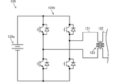
交流印加回路120は、交流電源129に接続される一次回路121と、蓄電装置110に接続される二次回路122と、変圧器(トランス)123と、コンデンサ124と、を備える。変圧器123は、一次巻線と二次巻線の巻数比に対応した昇圧比で、一次回路121に入力される交流電力の電圧を変圧して、二次回路122に出力する。コンデンサ124は、蓄電装置110の両端が直流的に短絡してしまうことを防止するために設けられる。
図2は、交流電源129の構成を示す回路図である。図2に示すように、交流電源129は、例えば、バッテリ129aと、バッテリ129aの直流電力を交流電力に変換するインバータ回路として、4つのパワー半導体素子を含むフルブリッジ回路129bと、を備える。フルブリッジ回路129bを構成する各パワー半導体素子は、コントローラ180からの制御信号に基づいて、オン・オフ制御され、入力される直流電力を交流電力に変換する。なお、フルブリッジ回路に代えて、ハーフブリッジ回路などの他の回路を用いてもよい。
FIG. 2 is a circuit diagram showing the configuration of the
図1に示すように、交流印加回路120を構成する二次回路122は、蓄電装置110の一方端側としての負極側に接続される第1接続部122aと、第1接続部122aとは異なる位置であって、蓄電装置110を構成する複数の蓄電素子間に接続される第2接続部122bと、を有する。
As shown in FIG. 1, the
直列に接続される複数の蓄電素子は、第2接続部122bによって二分される。本実施形態では、第2接続部122bと正極線PL1との間において直列接続される蓄電素子の数と、第2接続部122bと負極線NL1との間において直列接続される蓄電素子の数は、同じである。つまり、第2接続部122bは、蓄電装置110を構成する複数の蓄電素子を等分するように複数の蓄電素子間に接続される。なお、各蓄電素子の仕様(公称容量、公称電圧、エネルギー密度等)は同じである。このため、第2接続部122bによって二分される第1分割蓄電部110aの端子電圧と第2分割蓄電部110bの端子電圧は、ほぼ同じになる。
The plurality of power storage elements connected in series are divided into two by the
コントローラ180は、動作回路としてのCPU(Central Processing Unit)、ROM(Read Only Memory)、RAM(Random Access Memory)等の記憶部及び入出力インタフェース(I/Oインタフェース)、その他の周辺回路を備えたマイクロコンピュータで構成される。コントローラ180は、複数のマイクロコンピュータで構成することも可能である。
The
コントローラ180には、温度センサ171と、電圧センサ172と、電流センサ173と、が接続される。温度センサ171は、蓄電装置110の温度を検出し、検出信号をコントローラ180に出力する。電圧センサ172は、蓄電装置110の端子電圧を検出し、検出信号をコントローラ180に出力する。電流センサ173は、蓄電装置110に流れる電流を検出し、検出信号をコントローラ180に出力する。
A
蓄電装置110を構成する複数の蓄電素子は、温度が低下すると充放電特性が低下する。例えば、リチウムイオン電池においては、低温時に充電されると負極においてリチウムが析出し、その結果、電池の容量が低下する等の性能劣化が起こる。このため、電池の温度が低い場合には、速やかに電池を昇温する必要がある。また、蓄電装置110の状態を適切に管理するためには、蓄電装置110のインピーダンスを計測する必要がある。そこで、本実施形態では、交流印加回路120により、蓄電装置110に交流電流を印加することにより、蓄電装置110を昇温する。また、交流印加回路120により、蓄電装置110に交流電流を印加することにより、蓄電装置110のインピーダンスを計測する。
The charge/discharge characteristics of the plurality of power storage elements forming
コントローラ180は、機能的構成として、判定部181と、第1駆動部182と、入力部183と、第2駆動部184と、インピーダンス演算部185とを有する。判定部181及び第1駆動部182は、蓄電装置110に対する昇温を制御する昇温制御部188を構成する。入力部183、第2駆動部184及びインピーダンス演算部185は、蓄電装置110に印加される交流電流に基づいて、蓄電装置110のインピーダンスを計測する計測部189を構成する。
The
判定部181は、温度センサ171で検出された蓄電装置110の温度Tが、所定温度T0未満であるか否かを判定する。第1駆動部182は、判定部181での判定結果に基づき、交流電源129を駆動する。所定温度T0は、蓄電装置110の温度が、蓄電装置110の充放電特性が悪化する低温度範囲にあるか否かを判定するための閾値であり、予めコントローラ180の記憶部に記憶されている。
判定部181により蓄電装置110の温度Tが所定温度T0未満であると判定されると、第1駆動部182は、交流電源129を構成するフルブリッジ回路129bに駆動制御信号を出力し、交流電流を蓄電装置110に印加する。これにより、蓄電装置110を発熱させ、昇温することができる。判定部181により蓄電装置110の温度Tが所定温度T0以上であると判定されると、第1駆動部182は、交流電源129を構成するフルブリッジ回路129bに停止信号を出力し、蓄電装置110に対する交流電流の印加を停止する。
When the determining
入力部183には、インピーダンスの計測を指示する信号(計測指令)が入力される。第2駆動部184は、入力部183での入力結果に基づき、交流電源129を駆動する。入力部183にインピーダンスの計測を指示する信号が入力されると、第2駆動部184は、交流電源129を構成するフルブリッジ回路129bに駆動制御信号を出力し、交流電流を蓄電装置110に印加する。第2駆動部184は、予め定められた時間だけ交流電源129を駆動し、その後、交流電源129を構成するフルブリッジ回路129bに停止信号を出力し、蓄電装置110に対する交流電流の印加を停止する。なお、第2駆動部184は、インピーダンスの計測を終了する信号が入力部183に入力されるまで、蓄電装置110に交流電流を印加する構成とすることもできる。
A signal (measurement command) instructing measurement of impedance is input to the
インピーダンス演算部185は、周知の交流法により蓄電装置110のインピーダンスZを演算する。蓄電装置110のインピーダンスZは、実部(抵抗成分R)と虚部(リアクタンス成分jX)とからなる。交流法では、交流信号の周波数を変化させたときのインピーダンスの時間依存性を測定することにより、抵抗成分Rとリアクタンス成分jXとを抽出することができる。
インピーダンス演算部185で演算された蓄電装置110のインピーダンスZは、蓄電装置110の状態の管理に用いられる。蓄電装置110のインピーダンスZは、例えば、発電機として機能する回転電機190からの電力による充電制御及び回転電機190に電力を供給することにより、回転電機190を電動機として機能させる際の放電制御に用いられる。
The impedance Z of
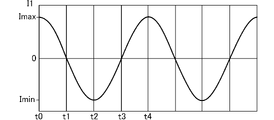
図3は、蓄電装置110に印加される交流電流について説明する図であり、図4A~図4Cは、各部位における交流電流波形図である。特に図4Aは、二次回路122に供給される電流波形の一例を示す図であり、図4Bは、第1分割蓄電部110aに流れる電流波形の一例を示す図であり、図4Cは、第2分割蓄電部110bに流れる電流波形の一例を示す図である。
FIG. 3 is a diagram for explaining alternating current applied to
図3に示す蓄電装置110の両端に接続される平滑用のコンデンサ131のインピーダンスは、蓄電装置110のインピーダンスに比べて小さい。また、交流印加回路120のコンデンサ124のインピーダンスは、コンデンサ131のインピーダンスに比べて小さい。
The impedance of smoothing
図3及び図4A~図4Cに示すように、交流電流源としての変圧器123から二次回路122に入力される電流I1は、時点t0で最大値Imax[A](>0)であり、時間の経過に伴って減少し、時点t1で0[A]となる。さらに、電流I1は、時点t1から時間の経過に伴って減少し、時点t2で最小値Imin[A](<0)となる。その後、電流I1は、時点t2から時間の経過に伴って増加し、時点t3で0[A]となる。さらに、電流I1は、時点t3から時間の経過に伴って増加し、時点t4で最大値Imax[A]となる。
As shown in FIGS. 3 and 4A to 4C, the current I1 input from the
第1分割蓄電部110aに流れる電流I2は、時点t0で(1/2)Imin[A]となり、時間の経過に伴って増加し、時点t1で0[A]となる。さらに、電流I2は、時点t1から時間の経過に伴って増加し、時点t2で(1/2)Imax[A]となる。その後、電流I2は、時点t2から時間の経過に伴って減少し、時点t3で0[A]となる。さらに、電流I2は、時点t3から時間の経過に伴って減少し、時点t4で(1/2)Imin[A]となる。
Current I2 flowing through first divided
第2分割蓄電部110bに流れる電流I3は、時点t0で(1/2)Imax[A]となり、時間の経過に伴って減少し、時点t1で0[A]となる。さらに、電流I3は、時点t1から時間の経過に伴って減少し、時点t2で(1/2)Imin[A]となる。その後、電流I3は、時点t2から時間の経過に伴って増加し、時点t3で0[A]となる。さらに、電流I3は、時点t3から時間の経過に伴って増加し、時点t4で(1/2)Imax[A]となる。
Current I3 flowing through second divided
したがって、時点t0から時点t1までは、第1分割蓄電部110aは放電を行い、第2分割蓄電部110bは充電を行う。時点t1から時点t3までは、第1分割蓄電部110aは充電を行い、第2分割蓄電部110bは放電を行う。時点t3から時点t4までは、第1分割蓄電部110aは放電を行い、第2分割蓄電部110bは充電を行う。以降、同様の挙動が繰り返される。このように、本実施形態では、第1分割蓄電部110a及び第2分割蓄電部110bは、電流波形が同じで位相が180度異なっている。
Therefore, from time t0 to time t1, first divided
本実施形態に係る交流印加回路120を設けたことによる作用効果を、図5及び図6に示す本実施形態の比較例と比較して具体的に説明する。図5は、本実施形態の比較例1に係る車両用電力制御装置900Aを搭載した電気自動車の構成を示す回路図である。図6は、本実施形態の比較例2に係る車両用電力制御装置900Bを搭載した電気自動車の構成を示す回路図である。
The effects of providing the
図5に示すように、本実施形態の比較例1に係る車両用電力制御装置900Aでは、交流印加回路120が、蓄電装置110と並列に接続される。つまり、交流印加回路120と、蓄電装置110と、平滑用のコンデンサ131とが並列に接続されている。ここで、コンデンサ131のインピーダンスは、蓄電装置110のインピーダンスよりも低い。このため、交流印加回路120で生成される交流電流は、主にインピーダンスの低いコンデンサ131に流れてしまう。蓄電装置110に十分な交流電流を流すことができないため、比較例1では、蓄電装置110を効果的に昇温することができないおそれがある。また、蓄電装置110のインピーダンスを精度良く測定することができないおそれがある。
As shown in FIG. 5 , in a vehicle
これに対して、本実施形態に係る車両用電力制御装置100では、蓄電装置110の一方端側、及び、蓄電装置110を構成する複数の蓄電素子間に交流印加回路120が接続される。このため、本実施形態では、交流印加回路120により蓄電装置110に交流電流を印加したときに、交流電流が、蓄電装置110に並列に接続されるコンデンサ131に集中して流れてしまうことを抑制することができ、蓄電装置110に十分な交流電流を供給することができる。
On the other hand, in the vehicle
図6に示すように、本実施形態の比較例2に係る車両用電力制御装置900Bでは、交流印加回路120が、蓄電装置110と直列に接続される。車両用電力制御装置900Bでは、蓄電装置110と電力変換装置150との間を流れる直流電流が大きく、さらに直流電流によって変圧器123のコアが飽和してしまうおそれがある。このため、交流印加回路120の配線径および変圧器を大きくする必要が生じ、車両用電力制御装置900Bがコスト高となるおそれがある。
As shown in FIG. 6 , in a vehicle
これに対して、本実施形態に係る車両用電力制御装置100では、蓄電装置110の一方端側、及び、蓄電装置110を構成する複数の蓄電素子間に交流印加回路120が接続される。このため、本実施形態では、変圧器123に大きな直流電流が流れないため、コアの飽和を抑制することができる。したがって、本実施形態では、比較例2に比べて、交流印加回路120の配線径および変圧器を小さくできるので、車両用電力制御装置100のコストを低減することができる。
On the other hand, in the vehicle
本実施形態によれば以下のような作用効果を奏することができる。
(1)本実施形態に係る車両用電力制御装置100は、複数の蓄電素子が接続されてなる蓄電装置110と、蓄電装置110に並列に接続されるコンデンサ131と、蓄電装置110及びコンデンサ131に接続される電力変換装置150と、交流電流を蓄電装置110に印加する交流印加回路120と、を備える(図1)。交流印加回路120は、蓄電装置110の一方端側に接続される第1接続部122aと、第1接続部122aとは異なる位置であって、蓄電装置110を構成する複数の蓄電素子間に接続される第2接続部122bと、を有する(図1)。
According to this embodiment, the following effects can be obtained.
(1) A vehicle
このように本実施形態では、蓄電装置110の一端側、及び、蓄電装置110を構成する複数の蓄電素子間に交流印加回路120が接続される。したがって、交流印加回路120により蓄電装置110に交流電流を印加したときに、交流電流が、蓄電装置110に並列に接続されるコンデンサ131に集中して流れてしまうことを抑制することができ、蓄電装置110に十分な交流電流を供給することができる。
As described above, in the present embodiment, the
(2)第2接続部122bは、複数の蓄電素子を等分するように複数の蓄電素子間に接続される(図1)。換言すれば、交流印加回路120は、第1接続部122aと第2接続部122bとの間の蓄電素子の直列数が、蓄電装置110を構成する蓄電素子の総直列数の1/2となるように、蓄電装置110に接続される。つまり、第2接続部122bによって、蓄電装置110は、第1分割蓄電部110aと、第1分割蓄電部110aと同数の蓄電素子を有する第2分割蓄電部110bと、に分割される。これにより、第1分割蓄電部110a及び第2分割蓄電部110bに均等に交流電流を印加することができる。
(2) The second connecting
(3)車両用電力制御装置100は、蓄電装置110の温度を検出する温度センサ171と、温度センサ171で検出された蓄電装置110の温度Tが、予め定められた温度T0未満の場合に、蓄電装置110に交流電流を印加することにより、蓄電装置110を昇温する昇温制御部188と、を備える(図1)。本実施形態では、上記(1)で説明したように、交流電流が、蓄電装置110に並列に接続されるコンデンサ131に集中して流れてしまうことを抑制することができ、蓄電装置110に十分な交流電流を供給することができるので、効果的に蓄電装置110を昇温することができる。また、上記(2)で説明したように、第1分割蓄電部110a及び第2分割蓄電部110bに均等に交流電流を印加することができるので、蓄電装置110における温度分布のばらつきを抑えることができる。つまり、蓄電装置110を均一に昇温することができるので、蓄電装置110の充放電特性の向上を図ることができる。
(3) Vehicle
(4)車両用電力制御装置100は、蓄電装置110に印加される交流電流に基づいて、蓄電装置110のインピーダンスを計測する計測部189を備える(図1)。交流法によりインピーダンスを計測することにより、蓄電装置110の状態を管理することができる。本実施形態では、上記(1)で説明したように、交流電流が、蓄電装置110に並列に接続されるコンデンサ131に集中して流れてしまうことを抑制することができ、蓄電装置110に十分な交流電流を供給することができる。また、上記(2)で説明したように、第1分割蓄電部110a及び第2分割蓄電部110bに均等に交流電流を印加することができる。その結果、蓄電装置110のインピーダンスを精度よく計測することができる。
(4) Vehicle
(5)本実施形態に係る交流印加回路120は、上記(3)及び上記(4)のとおり、蓄電装置110を昇温する昇温機能と、蓄電装置110のインピーダンスを計測する計測機能と、を備える。このため、蓄電装置110を昇温するための専用の昇温装置及び蓄電装置110のインピーダンスを計測するための専用の計測装置を個別に設ける場合に比べて、部品点数を低減することができる。その結果、車両用電力制御装置100の小型化及び低コスト化を図ることができる。
(5) As described in (3) and (4) above, the
なお、上記実施形態では、蓄電装置110を構成する複数の蓄電素子を等分するように、複数の蓄電素子間に交流印加回路120の第2接続部122bを接続する例について説明したが、本発明はこれに限定されない。第1分割蓄電部110aの蓄電素子の数と、第2分割蓄電部110bの蓄電素子の数とは異なっていてもよい。上記実施形態では、蓄電装置110の負極側に交流印加回路120の第1接続部122aを接続する例について説明したが、交流印加回路120の接続形態はこれに限定されない。例えば図7に示すように、蓄電装置110の一方端側としての正極側に交流印加回路120の第1接続部122aを接続してもよい。
In the above-described embodiment, an example is described in which the
さらに、蓄電装置110の一方端側(正極側または負極側)に交流印加回路120の第1接続部122aを接続することに限定されることもない。例えば、図8及び図9に示すように、第1接続部122aが、蓄電装置110を構成する複数の蓄電素子間に接続され、第2接続部122bが、第1接続部122aとは異なる位置であって蓄電装置110を構成する複数の蓄電素子間に接続されるようにしてもよい。
Furthermore, it is not limited to connecting the first connecting
図8及び図9に示す例では、交流印加回路120が蓄電装置110に接続されることにより、蓄電装置110が、第1分割蓄電部110a、第2分割蓄電部110b及び第3分割蓄電部110cに3分割される。図8及び図9に示す交流印加回路120は、上記実施形態(図1)と同様、第1接続部122aと第2接続部122bとの間の第2分割蓄電部110bを構成する蓄電素子の直列数が、蓄電装置110を構成する蓄電素子の総直列数の1/2となるように蓄電装置110に接続される。このような接続形態を採用した場合(図7~図9)にも、上記実施形態と同様、コンデンサ124のインピーダンスを十分に低く設定することにより、蓄電装置110を構成する複数の蓄電素子に均等に交流電流を印加することができる。
In the example shown in FIGS. 8 and 9, by connecting the
上記実施形態では、蓄電装置110の温度を検出する温度検出部として温度センサ171を設ける例について説明したが、本発明はこれに限定されない。蓄電装置110の充放電時間、蓄電装置110のインピーダンス等に基づいて、蓄電装置110の温度を推定する温度検出部を設けてもよい。上記実施形態では、蓄電装置110を構成する蓄電素子として、リチウムイオン電池、ニッケル水素電池等の二次電池を用いる例について説明したが、本発明はこれに限定されない。蓄電装置110を構成する蓄電素子として、電気二重層コンデンサ等の大容量キャパシタを用いてもよい。上記実施形態において、第1分割蓄電部110a及び第2分割蓄電部110bの蓄電素子の数は、それぞれ1つとすることもできる。
In the above embodiment, an example in which
以上の説明はあくまで一例であり、本発明の特徴を損なわない限り、上述した実施形態および変形例により本発明が限定されるものではない。上記実施形態と変形例の1つまたは複数を任意に組み合わせることも可能であり、変形例同士を組み合わせることも可能である。 The above description is merely an example, and the present invention is not limited by the above-described embodiments and modifications as long as the features of the present invention are not impaired. It is also possible to arbitrarily combine one or more of the above embodiments and modifications, and it is also possible to combine modifications with each other.
100 車両用電力制御装置、110 蓄電装置、110a 第1分割蓄電部、110b 第2分割蓄電部、120 交流印加回路、122a 第1接続部、122b 第2接続部、123 変圧器、124 コンデンサ、129 交流電源、131 コンデンサ、132 コンデンサ、150 電力変換装置、171 温度センサ、172 電圧センサ、173 電流センサ、180 コントローラ、181 判定部、182 第1駆動部、183 入力部、184 第2駆動部、185 インピーダンス演算部、188 昇温制御部、189 計測部、190 回転電機、T0 所定温度
Claims (4)
前記蓄電装置に並列に接続されるコンデンサと、
前記蓄電装置及び前記コンデンサに接続される電力変換装置と、
交流電流を前記蓄電装置に印加する交流印加回路と、を備え、
前記交流印加回路は、前記蓄電装置を構成する前記複数の蓄電素子間の一方端側の一箇所に接続される第1接続部と、前記第1接続部とは異なる位置であって前記蓄電装置を構成する前記複数の蓄電素子間の一箇所に接続される第2接続部と、を有し、
前記交流印加回路は、前記第1接続部と前記第2接続部との間の蓄電素子の直列数が、前記蓄電装置を構成する蓄電素子の総直列数の1/2となるように前記蓄電装置に接続されることを特徴とする車両用電力制御装置。 a power storage device in which a plurality of power storage elements are connected in series ;
a capacitor connected in parallel to the power storage device;
a power conversion device connected to the power storage device and the capacitor;
an alternating current application circuit that applies an alternating current to the power storage device,
The alternating-current applying circuit has a first connecting portion connected to a point on one end side between the plurality of power storage elements constituting the power storage device, and a position different from the first connecting portion and the power storage device. and a second connecting portion connected to one place between the plurality of storage elements constituting the
The alternating-current applying circuit is arranged such that the number of series-connected storage elements between the first connection portion and the second connection portion is 1/2 of the total number of series-connected storage elements constituting the electricity storage device. A power control device for a vehicle, characterized by being connected to a device.
前記第1接続部は、前記第2接続部よりも前記蓄電装置の正極側に接続され、
前記交流印加回路は、前記第1接続部と前記第2接続部との間の蓄電素子の直列数が、前記第1接続部と前記コンデンサの正極との間の蓄電素子の直列数と、前記第2接続部と前記コンデンサの負極との間の蓄電素子の直列数との合計値と同じになるように前記蓄電装置に接続されることを特徴とする車両用電力制御装置。 In the vehicle power control device according to claim 1,
the first connection portion is connected to the positive electrode side of the power storage device rather than the second connection portion;
In the AC applying circuit, the number of storage elements in series between the first connection portion and the second connection portion is equal to the number of storage elements in series between the first connection portion and the positive electrode of the capacitor. A power control device for a vehicle, wherein the power storage device is connected to the power storage device so as to be the same as the total number of the power storage elements connected in series between the second connection portion and the negative electrode of the capacitor .
前記蓄電装置の温度を検出する温度検出部と、
前記温度検出部で検出された前記蓄電装置の温度が、予め定められた温度未満の場合に、前記蓄電装置に交流電流を印加することにより、前記蓄電装置を昇温する昇温制御部と、を備えることを特徴とする車両用電力制御装置。 In the vehicle power control device according to claim 1 or claim 2 ,
a temperature detection unit that detects the temperature of the power storage device;
a temperature rise control unit that increases the temperature of the power storage device by applying an alternating current to the power storage device when the temperature of the power storage device detected by the temperature detection unit is lower than a predetermined temperature; A vehicle power control device comprising:
前記蓄電装置に印加される交流電流に基づいて、前記蓄電装置のインピーダンスを計測する計測部を備えることを特徴とする車両用電力制御装置。 In the vehicle power control device according to any one of claims 1 to 3 ,
A power control device for a vehicle, comprising: a measuring unit that measures impedance of the power storage device based on an alternating current applied to the power storage device.
Priority Applications (2)
| Application Number | Priority Date | Filing Date | Title |
|---|---|---|---|
| JP2018146065A JP7204367B2 (en) | 2018-08-02 | 2018-08-02 | Vehicle power control device |
| CN201910644473.8A CN110789345B (en) | 2018-08-02 | 2019-07-17 | Power control device for vehicle |
Applications Claiming Priority (1)
| Application Number | Priority Date | Filing Date | Title |
|---|---|---|---|
| JP2018146065A JP7204367B2 (en) | 2018-08-02 | 2018-08-02 | Vehicle power control device |
Publications (2)
| Publication Number | Publication Date |
|---|---|
| JP2020022312A JP2020022312A (en) | 2020-02-06 |
| JP7204367B2 true JP7204367B2 (en) | 2023-01-16 |
Family
ID=69427384
Family Applications (1)
| Application Number | Title | Priority Date | Filing Date |
|---|---|---|---|
| JP2018146065A Active JP7204367B2 (en) | 2018-08-02 | 2018-08-02 | Vehicle power control device |
Country Status (2)
| Country | Link |
|---|---|
| JP (1) | JP7204367B2 (en) |
| CN (1) | CN110789345B (en) |
Families Citing this family (5)
| Publication number | Priority date | Publication date | Assignee | Title |
|---|---|---|---|---|
| CN111660832B (en) * | 2020-06-18 | 2021-07-02 | 中车青岛四方车辆研究所有限公司 | Tramcar redundant super capacitor control method and control system |
| JP7483567B2 (en) | 2020-09-09 | 2024-05-15 | 本田技研工業株式会社 | Energy Storage System |
| JP7300483B2 (en) * | 2021-08-31 | 2023-06-29 | 本田技研工業株式会社 | AC generating circuit and AC generator |
| JP7218468B1 (en) * | 2022-08-15 | 2023-02-06 | 正一 田中 | Alternating current supply circuit for batteries |
| JP7301208B1 (en) * | 2022-12-05 | 2023-06-30 | 正一 田中 | Alternating current supply circuit for batteries |
Citations (7)
| Publication number | Priority date | Publication date | Assignee | Title |
|---|---|---|---|---|
| JP2009142069A (en) | 2007-12-06 | 2009-06-25 | Gs Yuasa Corporation:Kk | Temperature regulator of battery pack and temperature regulation method of battery pack |
| JP2009296847A (en) | 2008-06-09 | 2009-12-17 | Toyota Motor Corp | Power supply of vehicle and method of controlling the same |
| JP2011185619A (en) | 2010-03-04 | 2011-09-22 | Electric Power Dev Co Ltd | Device and method of evaluating storage battery |
| JP2012518875A (en) | 2009-02-20 | 2012-08-16 | ローベルト ボツシユ ゲゼルシヤフト ミツト ベシユレンクテル ハフツング | Storage cell heating method and storage cell heating apparatus |
| JP2013037859A (en) | 2011-08-05 | 2013-02-21 | Toshiba Corp | Storage battery device |
| US20150222140A1 (en) | 2012-08-14 | 2015-08-06 | Robert Bosch Gmbh | Switchable energy storage device and method for operating a switchable energy storage device |
| JP2016026949A (en) | 2014-06-25 | 2016-02-18 | トヨタ自動車株式会社 | Vehicle control unit |
Family Cites Families (6)
| Publication number | Priority date | Publication date | Assignee | Title |
|---|---|---|---|---|
| US2442380A (en) * | 1942-02-25 | 1948-06-01 | John P Schrodt | Method and system for warming dry batteries |
| US4171508A (en) * | 1977-12-08 | 1979-10-16 | Lucas Industries Limited | Circuits for heating storage batteries |
| JP4081855B2 (en) * | 1998-05-14 | 2008-04-30 | 日産自動車株式会社 | Battery temperature riser |
| JP5502603B2 (en) * | 2010-06-04 | 2014-05-28 | 本田技研工業株式会社 | Vehicle battery heating device |
| CN103209856B (en) * | 2010-11-10 | 2015-05-27 | 丰田自动车株式会社 | Electric vehicle power supply system, control method thereof, and electric vehicle |
| CN104249629B (en) * | 2013-06-28 | 2016-09-07 | 比亚迪股份有限公司 | Electric automobile, the dynamical system of electric automobile and the charging method of electrokinetic cell |
-
2018
- 2018-08-02 JP JP2018146065A patent/JP7204367B2/en active Active
-
2019
- 2019-07-17 CN CN201910644473.8A patent/CN110789345B/en active Active
Patent Citations (7)
| Publication number | Priority date | Publication date | Assignee | Title |
|---|---|---|---|---|
| JP2009142069A (en) | 2007-12-06 | 2009-06-25 | Gs Yuasa Corporation:Kk | Temperature regulator of battery pack and temperature regulation method of battery pack |
| JP2009296847A (en) | 2008-06-09 | 2009-12-17 | Toyota Motor Corp | Power supply of vehicle and method of controlling the same |
| JP2012518875A (en) | 2009-02-20 | 2012-08-16 | ローベルト ボツシユ ゲゼルシヤフト ミツト ベシユレンクテル ハフツング | Storage cell heating method and storage cell heating apparatus |
| JP2011185619A (en) | 2010-03-04 | 2011-09-22 | Electric Power Dev Co Ltd | Device and method of evaluating storage battery |
| JP2013037859A (en) | 2011-08-05 | 2013-02-21 | Toshiba Corp | Storage battery device |
| US20150222140A1 (en) | 2012-08-14 | 2015-08-06 | Robert Bosch Gmbh | Switchable energy storage device and method for operating a switchable energy storage device |
| JP2016026949A (en) | 2014-06-25 | 2016-02-18 | トヨタ自動車株式会社 | Vehicle control unit |
Also Published As
| Publication number | Publication date |
|---|---|
| CN110789345A (en) | 2020-02-14 |
| CN110789345B (en) | 2023-02-28 |
| JP2020022312A (en) | 2020-02-06 |
Similar Documents
| Publication | Publication Date | Title |
|---|---|---|
| JP7204367B2 (en) | Vehicle power control device | |
| Aghabali et al. | 800-V electric vehicle powertrains: Review and analysis of benefits, challenges, and future trends | |
| CN105762434B (en) | A kind of power-supply system and vehicle with self heating function | |
| JP6426426B2 (en) | Motor drive | |
| JP7032249B2 (en) | Power system | |
| US12199465B2 (en) | System for charging battery for vehicle using motor driving system | |
| JP7136056B2 (en) | charging device | |
| JP6773365B2 (en) | Power converter | |
| JP2010051092A (en) | Charge system and vehicle including the same | |
| JP2016131426A (en) | Power conversion device | |
| JP2021005944A (en) | Charging system | |
| JP5358309B2 (en) | Multifunctional converter for vehicles | |
| CN119652126A (en) | Isolated high voltage DC/DC converter with battery current control module components | |
| CN118928083A (en) | Integrated vehicle power converter and battery charger | |
| JP2010166671A (en) | Vehicle fault detecting device | |
| JP7063745B2 (en) | Power system | |
| JP7201488B2 (en) | Inverter protection device | |
| CN115520046A (en) | Vehicle battery charging system utilizing motor drive system | |
| CN104118331B (en) | Hybrid electric vehicle motor drive circuit | |
| US12319156B2 (en) | Magnetic integration of high voltage to low voltage DC/DC power converter with inverter system controller battery current control module system | |
| US20250038649A1 (en) | Configurable active ripple energy storage circuit with intermediate bus for integrated inverter system controller-battery current control module system | |
| CN118618069A (en) | A charging and discharging system for a vehicle, a vehicle, and a charging and discharging method for a vehicle | |
| CN110620462A (en) | Common mode current reduction hybrid drive system | |
| JP4475138B2 (en) | Internal combustion engine starter and vehicle | |
| JP7711546B2 (en) | charging device |
Legal Events
| Date | Code | Title | Description |
|---|---|---|---|
| A621 | Written request for application examination |
Free format text: JAPANESE INTERMEDIATE CODE: A621 Effective date: 20201130 |
|
| A977 | Report on retrieval |
Free format text: JAPANESE INTERMEDIATE CODE: A971007 Effective date: 20211011 |
|
| A131 | Notification of reasons for refusal |
Free format text: JAPANESE INTERMEDIATE CODE: A131 Effective date: 20211116 |
|
| A521 | Request for written amendment filed |
Free format text: JAPANESE INTERMEDIATE CODE: A523 Effective date: 20220111 |
|
| A131 | Notification of reasons for refusal |
Free format text: JAPANESE INTERMEDIATE CODE: A131 Effective date: 20220614 |
|
| A521 | Request for written amendment filed |
Free format text: JAPANESE INTERMEDIATE CODE: A523 Effective date: 20220802 |
|
| TRDD | Decision of grant or rejection written | ||
| A01 | Written decision to grant a patent or to grant a registration (utility model) |
Free format text: JAPANESE INTERMEDIATE CODE: A01 Effective date: 20221025 |
|
| R155 | Notification before disposition of declining of application |
Free format text: JAPANESE INTERMEDIATE CODE: R155 |
|
| A61 | First payment of annual fees (during grant procedure) |
Free format text: JAPANESE INTERMEDIATE CODE: A61 Effective date: 20221228 |
|
| R150 | Certificate of patent or registration of utility model |
Ref document number: 7204367 Country of ref document: JP Free format text: JAPANESE INTERMEDIATE CODE: R150 |