JP6645407B2 - Drive system - Google Patents
Drive system Download PDFInfo
- Publication number
- JP6645407B2 JP6645407B2 JP2016236147A JP2016236147A JP6645407B2 JP 6645407 B2 JP6645407 B2 JP 6645407B2 JP 2016236147 A JP2016236147 A JP 2016236147A JP 2016236147 A JP2016236147 A JP 2016236147A JP 6645407 B2 JP6645407 B2 JP 6645407B2
- Authority
- JP
- Japan
- Prior art keywords
- inverter
- power supply
- electric machine
- rotating electric
- threshold
- Prior art date
- Legal status (The legal status is an assumption and is not a legal conclusion. Google has not performed a legal analysis and makes no representation as to the accuracy of the status listed.)
- Active
Links
- 238000000034 method Methods 0.000 claims description 170
- 238000004804 winding Methods 0.000 claims description 55
- 238000013459 approach Methods 0.000 claims description 3
- 238000007599 discharging Methods 0.000 claims description 3
- 239000013598 vector Substances 0.000 description 38
- 230000001172 regenerating effect Effects 0.000 description 28
- 238000001514 detection method Methods 0.000 description 21
- 230000007423 decrease Effects 0.000 description 13
- 239000003990 capacitor Substances 0.000 description 12
- 230000000694 effects Effects 0.000 description 6
- 230000006870 function Effects 0.000 description 6
- 238000010248 power generation Methods 0.000 description 6
- 230000002265 prevention Effects 0.000 description 6
- RYGMFSIKBFXOCR-UHFFFAOYSA-N Copper Chemical compound [Cu] RYGMFSIKBFXOCR-UHFFFAOYSA-N 0.000 description 5
- 229910052802 copper Inorganic materials 0.000 description 5
- 239000010949 copper Substances 0.000 description 5
- 239000004065 semiconductor Substances 0.000 description 4
- 230000003247 decreasing effect Effects 0.000 description 3
- 239000000446 fuel Substances 0.000 description 3
- HBBGRARXTFLTSG-UHFFFAOYSA-N Lithium ion Chemical compound [Li+] HBBGRARXTFLTSG-UHFFFAOYSA-N 0.000 description 2
- 230000005540 biological transmission Effects 0.000 description 2
- 238000010586 diagram Methods 0.000 description 2
- 229910001416 lithium ion Inorganic materials 0.000 description 2
- 230000001360 synchronised effect Effects 0.000 description 2
- 238000002485 combustion reaction Methods 0.000 description 1
- 239000002131 composite material Substances 0.000 description 1
- 239000000498 cooling water Substances 0.000 description 1
- 230000006698 induction Effects 0.000 description 1
- 238000004519 manufacturing process Methods 0.000 description 1
- 229910052987 metal hydride Inorganic materials 0.000 description 1
- 230000007935 neutral effect Effects 0.000 description 1
- 230000010363 phase shift Effects 0.000 description 1
- 230000035939 shock Effects 0.000 description 1
Images


Classifications
-
- B—PERFORMING OPERATIONS; TRANSPORTING
- B60—VEHICLES IN GENERAL
- B60L—PROPULSION OF ELECTRICALLY-PROPELLED VEHICLES; SUPPLYING ELECTRIC POWER FOR AUXILIARY EQUIPMENT OF ELECTRICALLY-PROPELLED VEHICLES; ELECTRODYNAMIC BRAKE SYSTEMS FOR VEHICLES IN GENERAL; MAGNETIC SUSPENSION OR LEVITATION FOR VEHICLES; MONITORING OPERATING VARIABLES OF ELECTRICALLY-PROPELLED VEHICLES; ELECTRIC SAFETY DEVICES FOR ELECTRICALLY-PROPELLED VEHICLES
- B60L9/00—Electric propulsion with power supply external to the vehicle
- B60L9/16—Electric propulsion with power supply external to the vehicle using ac induction motors
- B60L9/18—Electric propulsion with power supply external to the vehicle using ac induction motors fed from dc supply lines
-
- B—PERFORMING OPERATIONS; TRANSPORTING
- B60—VEHICLES IN GENERAL
- B60L—PROPULSION OF ELECTRICALLY-PROPELLED VEHICLES; SUPPLYING ELECTRIC POWER FOR AUXILIARY EQUIPMENT OF ELECTRICALLY-PROPELLED VEHICLES; ELECTRODYNAMIC BRAKE SYSTEMS FOR VEHICLES IN GENERAL; MAGNETIC SUSPENSION OR LEVITATION FOR VEHICLES; MONITORING OPERATING VARIABLES OF ELECTRICALLY-PROPELLED VEHICLES; ELECTRIC SAFETY DEVICES FOR ELECTRICALLY-PROPELLED VEHICLES
- B60L50/00—Electric propulsion with power supplied within the vehicle
- B60L50/50—Electric propulsion with power supplied within the vehicle using propulsion power supplied by batteries or fuel cells
- B60L50/51—Electric propulsion with power supplied within the vehicle using propulsion power supplied by batteries or fuel cells characterised by AC-motors
-
- B—PERFORMING OPERATIONS; TRANSPORTING
- B60—VEHICLES IN GENERAL
- B60L—PROPULSION OF ELECTRICALLY-PROPELLED VEHICLES; SUPPLYING ELECTRIC POWER FOR AUXILIARY EQUIPMENT OF ELECTRICALLY-PROPELLED VEHICLES; ELECTRODYNAMIC BRAKE SYSTEMS FOR VEHICLES IN GENERAL; MAGNETIC SUSPENSION OR LEVITATION FOR VEHICLES; MONITORING OPERATING VARIABLES OF ELECTRICALLY-PROPELLED VEHICLES; ELECTRIC SAFETY DEVICES FOR ELECTRICALLY-PROPELLED VEHICLES
- B60L50/00—Electric propulsion with power supplied within the vehicle
- B60L50/50—Electric propulsion with power supplied within the vehicle using propulsion power supplied by batteries or fuel cells
- B60L50/75—Electric propulsion with power supplied within the vehicle using propulsion power supplied by batteries or fuel cells using propulsion power supplied by both fuel cells and batteries
-
- B—PERFORMING OPERATIONS; TRANSPORTING
- B60—VEHICLES IN GENERAL
- B60L—PROPULSION OF ELECTRICALLY-PROPELLED VEHICLES; SUPPLYING ELECTRIC POWER FOR AUXILIARY EQUIPMENT OF ELECTRICALLY-PROPELLED VEHICLES; ELECTRODYNAMIC BRAKE SYSTEMS FOR VEHICLES IN GENERAL; MAGNETIC SUSPENSION OR LEVITATION FOR VEHICLES; MONITORING OPERATING VARIABLES OF ELECTRICALLY-PROPELLED VEHICLES; ELECTRIC SAFETY DEVICES FOR ELECTRICALLY-PROPELLED VEHICLES
- B60L53/00—Methods of charging batteries, specially adapted for electric vehicles; Charging stations or on-board charging equipment therefor; Exchange of energy storage elements in electric vehicles
- B60L53/20—Methods of charging batteries, specially adapted for electric vehicles; Charging stations or on-board charging equipment therefor; Exchange of energy storage elements in electric vehicles characterised by converters located in the vehicle
-
- G—PHYSICS
- G01—MEASURING; TESTING
- G01R—MEASURING ELECTRIC VARIABLES; MEASURING MAGNETIC VARIABLES
- G01R19/00—Arrangements for measuring currents or voltages or for indicating presence or sign thereof
- G01R19/165—Indicating that current or voltage is either above or below a predetermined value or within or outside a predetermined range of values
- G01R19/16533—Indicating that current or voltage is either above or below a predetermined value or within or outside a predetermined range of values characterised by the application
- G01R19/16538—Indicating that current or voltage is either above or below a predetermined value or within or outside a predetermined range of values characterised by the application in AC or DC supplies
- G01R19/16542—Indicating that current or voltage is either above or below a predetermined value or within or outside a predetermined range of values characterised by the application in AC or DC supplies for batteries
-
- H—ELECTRICITY
- H02—GENERATION; CONVERSION OR DISTRIBUTION OF ELECTRIC POWER
- H02M—APPARATUS FOR CONVERSION BETWEEN AC AND AC, BETWEEN AC AND DC, OR BETWEEN DC AND DC, AND FOR USE WITH MAINS OR SIMILAR POWER SUPPLY SYSTEMS; CONVERSION OF DC OR AC INPUT POWER INTO SURGE OUTPUT POWER; CONTROL OR REGULATION THEREOF
- H02M1/00—Details of apparatus for conversion
- H02M1/32—Means for protecting converters other than automatic disconnection
-
- H—ELECTRICITY
- H02—GENERATION; CONVERSION OR DISTRIBUTION OF ELECTRIC POWER
- H02M—APPARATUS FOR CONVERSION BETWEEN AC AND AC, BETWEEN AC AND DC, OR BETWEEN DC AND DC, AND FOR USE WITH MAINS OR SIMILAR POWER SUPPLY SYSTEMS; CONVERSION OF DC OR AC INPUT POWER INTO SURGE OUTPUT POWER; CONTROL OR REGULATION THEREOF
- H02M3/00—Conversion of dc power input into dc power output
- H02M3/02—Conversion of dc power input into dc power output without intermediate conversion into ac
- H02M3/04—Conversion of dc power input into dc power output without intermediate conversion into ac by static converters
- H02M3/10—Conversion of dc power input into dc power output without intermediate conversion into ac by static converters using discharge tubes with control electrode or semiconductor devices with control electrode
- H02M3/145—Conversion of dc power input into dc power output without intermediate conversion into ac by static converters using discharge tubes with control electrode or semiconductor devices with control electrode using devices of a triode or transistor type requiring continuous application of a control signal
- H02M3/155—Conversion of dc power input into dc power output without intermediate conversion into ac by static converters using discharge tubes with control electrode or semiconductor devices with control electrode using devices of a triode or transistor type requiring continuous application of a control signal using semiconductor devices only
- H02M3/156—Conversion of dc power input into dc power output without intermediate conversion into ac by static converters using discharge tubes with control electrode or semiconductor devices with control electrode using devices of a triode or transistor type requiring continuous application of a control signal using semiconductor devices only with automatic control of output voltage or current, e.g. switching regulators
- H02M3/158—Conversion of dc power input into dc power output without intermediate conversion into ac by static converters using discharge tubes with control electrode or semiconductor devices with control electrode using devices of a triode or transistor type requiring continuous application of a control signal using semiconductor devices only with automatic control of output voltage or current, e.g. switching regulators including plural semiconductor devices as final control devices for a single load
-
- H—ELECTRICITY
- H02—GENERATION; CONVERSION OR DISTRIBUTION OF ELECTRIC POWER
- H02M—APPARATUS FOR CONVERSION BETWEEN AC AND AC, BETWEEN AC AND DC, OR BETWEEN DC AND DC, AND FOR USE WITH MAINS OR SIMILAR POWER SUPPLY SYSTEMS; CONVERSION OF DC OR AC INPUT POWER INTO SURGE OUTPUT POWER; CONTROL OR REGULATION THEREOF
- H02M7/00—Conversion of ac power input into dc power output; Conversion of dc power input into ac power output
- H02M7/42—Conversion of dc power input into ac power output without possibility of reversal
- H02M7/44—Conversion of dc power input into ac power output without possibility of reversal by static converters
- H02M7/48—Conversion of dc power input into ac power output without possibility of reversal by static converters using discharge tubes with control electrode or semiconductor devices with control electrode
- H02M7/493—Conversion of dc power input into ac power output without possibility of reversal by static converters using discharge tubes with control electrode or semiconductor devices with control electrode the static converters being arranged for operation in parallel
-
- H—ELECTRICITY
- H02—GENERATION; CONVERSION OR DISTRIBUTION OF ELECTRIC POWER
- H02M—APPARATUS FOR CONVERSION BETWEEN AC AND AC, BETWEEN AC AND DC, OR BETWEEN DC AND DC, AND FOR USE WITH MAINS OR SIMILAR POWER SUPPLY SYSTEMS; CONVERSION OF DC OR AC INPUT POWER INTO SURGE OUTPUT POWER; CONTROL OR REGULATION THEREOF
- H02M7/00—Conversion of ac power input into dc power output; Conversion of dc power input into ac power output
- H02M7/42—Conversion of dc power input into ac power output without possibility of reversal
- H02M7/44—Conversion of dc power input into ac power output without possibility of reversal by static converters
- H02M7/48—Conversion of dc power input into ac power output without possibility of reversal by static converters using discharge tubes with control electrode or semiconductor devices with control electrode
- H02M7/53—Conversion of dc power input into ac power output without possibility of reversal by static converters using discharge tubes with control electrode or semiconductor devices with control electrode using devices of a triode or transistor type requiring continuous application of a control signal
- H02M7/537—Conversion of dc power input into ac power output without possibility of reversal by static converters using discharge tubes with control electrode or semiconductor devices with control electrode using devices of a triode or transistor type requiring continuous application of a control signal using semiconductor devices only, e.g. single switched pulse inverters
- H02M7/5387—Conversion of dc power input into ac power output without possibility of reversal by static converters using discharge tubes with control electrode or semiconductor devices with control electrode using devices of a triode or transistor type requiring continuous application of a control signal using semiconductor devices only, e.g. single switched pulse inverters in a bridge configuration
- H02M7/53871—Conversion of dc power input into ac power output without possibility of reversal by static converters using discharge tubes with control electrode or semiconductor devices with control electrode using devices of a triode or transistor type requiring continuous application of a control signal using semiconductor devices only, e.g. single switched pulse inverters in a bridge configuration with automatic control of output voltage or current
-
- H—ELECTRICITY
- H02—GENERATION; CONVERSION OR DISTRIBUTION OF ELECTRIC POWER
- H02M—APPARATUS FOR CONVERSION BETWEEN AC AND AC, BETWEEN AC AND DC, OR BETWEEN DC AND DC, AND FOR USE WITH MAINS OR SIMILAR POWER SUPPLY SYSTEMS; CONVERSION OF DC OR AC INPUT POWER INTO SURGE OUTPUT POWER; CONTROL OR REGULATION THEREOF
- H02M7/00—Conversion of ac power input into dc power output; Conversion of dc power input into ac power output
- H02M7/66—Conversion of ac power input into dc power output; Conversion of dc power input into ac power output with possibility of reversal
- H02M7/68—Conversion of ac power input into dc power output; Conversion of dc power input into ac power output with possibility of reversal by static converters
- H02M7/72—Conversion of ac power input into dc power output; Conversion of dc power input into ac power output with possibility of reversal by static converters using discharge tubes with control electrode or semiconductor devices with control electrode
- H02M7/79—Conversion of ac power input into dc power output; Conversion of dc power input into ac power output with possibility of reversal by static converters using discharge tubes with control electrode or semiconductor devices with control electrode using devices of a triode or transistor type requiring continuous application of a control signal
- H02M7/797—Conversion of ac power input into dc power output; Conversion of dc power input into ac power output with possibility of reversal by static converters using discharge tubes with control electrode or semiconductor devices with control electrode using devices of a triode or transistor type requiring continuous application of a control signal using semiconductor devices only
-
- H—ELECTRICITY
- H02—GENERATION; CONVERSION OR DISTRIBUTION OF ELECTRIC POWER
- H02P—CONTROL OR REGULATION OF ELECTRIC MOTORS, ELECTRIC GENERATORS OR DYNAMO-ELECTRIC CONVERTERS; CONTROLLING TRANSFORMERS, REACTORS OR CHOKE COILS
- H02P27/00—Arrangements or methods for the control of AC motors characterised by the kind of supply voltage
- H02P27/04—Arrangements or methods for the control of AC motors characterised by the kind of supply voltage using variable-frequency supply voltage, e.g. inverter or converter supply voltage
- H02P27/06—Arrangements or methods for the control of AC motors characterised by the kind of supply voltage using variable-frequency supply voltage, e.g. inverter or converter supply voltage using dc to ac converters or inverters
-
- H—ELECTRICITY
- H02—GENERATION; CONVERSION OR DISTRIBUTION OF ELECTRIC POWER
- H02P—CONTROL OR REGULATION OF ELECTRIC MOTORS, ELECTRIC GENERATORS OR DYNAMO-ELECTRIC CONVERTERS; CONTROLLING TRANSFORMERS, REACTORS OR CHOKE COILS
- H02P5/00—Arrangements specially adapted for regulating or controlling the speed or torque of two or more electric motors
- H02P5/46—Arrangements specially adapted for regulating or controlling the speed or torque of two or more electric motors for speed regulation of two or more dynamo-electric motors in relation to one another
-
- H—ELECTRICITY
- H02—GENERATION; CONVERSION OR DISTRIBUTION OF ELECTRIC POWER
- H02M—APPARATUS FOR CONVERSION BETWEEN AC AND AC, BETWEEN AC AND DC, OR BETWEEN DC AND DC, AND FOR USE WITH MAINS OR SIMILAR POWER SUPPLY SYSTEMS; CONVERSION OF DC OR AC INPUT POWER INTO SURGE OUTPUT POWER; CONTROL OR REGULATION THEREOF
- H02M1/00—Details of apparatus for conversion
- H02M1/0048—Circuits or arrangements for reducing losses
-
- H—ELECTRICITY
- H02—GENERATION; CONVERSION OR DISTRIBUTION OF ELECTRIC POWER
- H02M—APPARATUS FOR CONVERSION BETWEEN AC AND AC, BETWEEN AC AND DC, OR BETWEEN DC AND DC, AND FOR USE WITH MAINS OR SIMILAR POWER SUPPLY SYSTEMS; CONVERSION OF DC OR AC INPUT POWER INTO SURGE OUTPUT POWER; CONTROL OR REGULATION THEREOF
- H02M1/00—Details of apparatus for conversion
- H02M1/0067—Converter structures employing plural converter units, other than for parallel operation of the units on a single load
- H02M1/007—Plural converter units in cascade
-
- H—ELECTRICITY
- H02—GENERATION; CONVERSION OR DISTRIBUTION OF ELECTRIC POWER
- H02M—APPARATUS FOR CONVERSION BETWEEN AC AND AC, BETWEEN AC AND DC, OR BETWEEN DC AND DC, AND FOR USE WITH MAINS OR SIMILAR POWER SUPPLY SYSTEMS; CONVERSION OF DC OR AC INPUT POWER INTO SURGE OUTPUT POWER; CONTROL OR REGULATION THEREOF
- H02M1/00—Details of apparatus for conversion
- H02M1/0067—Converter structures employing plural converter units, other than for parallel operation of the units on a single load
- H02M1/0077—Plural converter units whose outputs are connected in series
-
- H—ELECTRICITY
- H02—GENERATION; CONVERSION OR DISTRIBUTION OF ELECTRIC POWER
- H02M—APPARATUS FOR CONVERSION BETWEEN AC AND AC, BETWEEN AC AND DC, OR BETWEEN DC AND DC, AND FOR USE WITH MAINS OR SIMILAR POWER SUPPLY SYSTEMS; CONVERSION OF DC OR AC INPUT POWER INTO SURGE OUTPUT POWER; CONTROL OR REGULATION THEREOF
- H02M1/00—Details of apparatus for conversion
- H02M1/32—Means for protecting converters other than automatic disconnection
- H02M1/327—Means for protecting converters other than automatic disconnection against abnormal temperatures
-
- Y—GENERAL TAGGING OF NEW TECHNOLOGICAL DEVELOPMENTS; GENERAL TAGGING OF CROSS-SECTIONAL TECHNOLOGIES SPANNING OVER SEVERAL SECTIONS OF THE IPC; TECHNICAL SUBJECTS COVERED BY FORMER USPC CROSS-REFERENCE ART COLLECTIONS [XRACs] AND DIGESTS
- Y02—TECHNOLOGIES OR APPLICATIONS FOR MITIGATION OR ADAPTATION AGAINST CLIMATE CHANGE
- Y02T—CLIMATE CHANGE MITIGATION TECHNOLOGIES RELATED TO TRANSPORTATION
- Y02T10/00—Road transport of goods or passengers
- Y02T10/60—Other road transportation technologies with climate change mitigation effect
- Y02T10/70—Energy storage systems for electromobility, e.g. batteries
-
- Y—GENERAL TAGGING OF NEW TECHNOLOGICAL DEVELOPMENTS; GENERAL TAGGING OF CROSS-SECTIONAL TECHNOLOGIES SPANNING OVER SEVERAL SECTIONS OF THE IPC; TECHNICAL SUBJECTS COVERED BY FORMER USPC CROSS-REFERENCE ART COLLECTIONS [XRACs] AND DIGESTS
- Y02—TECHNOLOGIES OR APPLICATIONS FOR MITIGATION OR ADAPTATION AGAINST CLIMATE CHANGE
- Y02T—CLIMATE CHANGE MITIGATION TECHNOLOGIES RELATED TO TRANSPORTATION
- Y02T10/00—Road transport of goods or passengers
- Y02T10/60—Other road transportation technologies with climate change mitigation effect
- Y02T10/7072—Electromobility specific charging systems or methods for batteries, ultracapacitors, supercapacitors or double-layer capacitors
-
- Y—GENERAL TAGGING OF NEW TECHNOLOGICAL DEVELOPMENTS; GENERAL TAGGING OF CROSS-SECTIONAL TECHNOLOGIES SPANNING OVER SEVERAL SECTIONS OF THE IPC; TECHNICAL SUBJECTS COVERED BY FORMER USPC CROSS-REFERENCE ART COLLECTIONS [XRACs] AND DIGESTS
- Y02—TECHNOLOGIES OR APPLICATIONS FOR MITIGATION OR ADAPTATION AGAINST CLIMATE CHANGE
- Y02T—CLIMATE CHANGE MITIGATION TECHNOLOGIES RELATED TO TRANSPORTATION
- Y02T10/00—Road transport of goods or passengers
- Y02T10/60—Other road transportation technologies with climate change mitigation effect
- Y02T10/72—Electric energy management in electromobility
-
- Y—GENERAL TAGGING OF NEW TECHNOLOGICAL DEVELOPMENTS; GENERAL TAGGING OF CROSS-SECTIONAL TECHNOLOGIES SPANNING OVER SEVERAL SECTIONS OF THE IPC; TECHNICAL SUBJECTS COVERED BY FORMER USPC CROSS-REFERENCE ART COLLECTIONS [XRACs] AND DIGESTS
- Y02—TECHNOLOGIES OR APPLICATIONS FOR MITIGATION OR ADAPTATION AGAINST CLIMATE CHANGE
- Y02T—CLIMATE CHANGE MITIGATION TECHNOLOGIES RELATED TO TRANSPORTATION
- Y02T10/00—Road transport of goods or passengers
- Y02T10/80—Technologies aiming to reduce greenhouse gasses emissions common to all road transportation technologies
- Y02T10/92—Energy efficient charging or discharging systems for batteries, ultracapacitors, supercapacitors or double-layer capacitors specially adapted for vehicles
-
- Y—GENERAL TAGGING OF NEW TECHNOLOGICAL DEVELOPMENTS; GENERAL TAGGING OF CROSS-SECTIONAL TECHNOLOGIES SPANNING OVER SEVERAL SECTIONS OF THE IPC; TECHNICAL SUBJECTS COVERED BY FORMER USPC CROSS-REFERENCE ART COLLECTIONS [XRACs] AND DIGESTS
- Y02—TECHNOLOGIES OR APPLICATIONS FOR MITIGATION OR ADAPTATION AGAINST CLIMATE CHANGE
- Y02T—CLIMATE CHANGE MITIGATION TECHNOLOGIES RELATED TO TRANSPORTATION
- Y02T90/00—Enabling technologies or technologies with a potential or indirect contribution to GHG emissions mitigation
- Y02T90/10—Technologies relating to charging of electric vehicles
- Y02T90/14—Plug-in electric vehicles
-
- Y—GENERAL TAGGING OF NEW TECHNOLOGICAL DEVELOPMENTS; GENERAL TAGGING OF CROSS-SECTIONAL TECHNOLOGIES SPANNING OVER SEVERAL SECTIONS OF THE IPC; TECHNICAL SUBJECTS COVERED BY FORMER USPC CROSS-REFERENCE ART COLLECTIONS [XRACs] AND DIGESTS
- Y02—TECHNOLOGIES OR APPLICATIONS FOR MITIGATION OR ADAPTATION AGAINST CLIMATE CHANGE
- Y02T—CLIMATE CHANGE MITIGATION TECHNOLOGIES RELATED TO TRANSPORTATION
- Y02T90/00—Enabling technologies or technologies with a potential or indirect contribution to GHG emissions mitigation
- Y02T90/40—Application of hydrogen technology to transportation, e.g. using fuel cells
Landscapes
- Engineering & Computer Science (AREA)
- Power Engineering (AREA)
- Transportation (AREA)
- Mechanical Engineering (AREA)
- Life Sciences & Earth Sciences (AREA)
- Sustainable Development (AREA)
- Sustainable Energy (AREA)
- Physics & Mathematics (AREA)
- General Physics & Mathematics (AREA)
- Electric Propulsion And Braking For Vehicles (AREA)
- Inverter Devices (AREA)
- Control Of Multiple Motors (AREA)
Description
本発明は、交流回転電機を備える駆動システムに関する。 The present invention relates to a drive system including an AC rotating electric machine.
この種の駆動システムとしては、例えば下記特許文献1に見られるように、オープンデルタ型の電機子巻線を有する交流回転電機を備えるものが知られている。この駆動システムでは、交流回転電機を構成する各相巻線の両端のうち第1端側には、第1インバータを介して第1直流電源が接続されている。また、交流回転電機を構成する各相巻線の両端のうち第2端側には、第2インバータを介して、第1直流電源とは異なる第2直流電源が接続されている。交流回転電機に2つの直流電源から電力を供給する上述した駆動システムによれば、交流回転電機に大容量の電力を供給することができる。
As this type of drive system, for example, as disclosed in
上述した駆動システムに、別の交流回転電機がさらに備えられる駆動システムがある。この駆動システムは、第1交流回転電機、第2交流回転電機及び第1〜第3インバータに加え、第4インバータを備えている。 The drive system described above includes a drive system further provided with another AC rotating electric machine. This drive system includes a fourth inverter in addition to the first AC rotating electric machine, the second AC rotating electric machine, and the first to third inverters.
詳しくは、第1交流回転電機を構成する各相巻線の両端のうち第1端側には、第1インバータを介して第1直流電源が接続され、第2交流回転電機を構成する各相巻線の両端のうち第1端側には、第2インバータを介して第1直流電源が接続されている。 Specifically, a first DC power supply is connected via a first inverter to a first end side of both ends of each phase winding constituting the first AC rotating electric machine, and each phase constituting a second AC rotating electric machine. A first DC power supply is connected to a first end side of both ends of the winding via a second inverter.
一方、第2交流回転電機を構成する各相巻線の両端のうち第2端側には、第3インバータを介して、第1直流電源とは異なる第2直流電源が接続され、第1交流回転電機を構成する各相巻線の両端のうち第2端側には、第4インバータを介して第2直流電源が接続されている。 On the other hand, a second DC power supply different from the first DC power supply is connected via a third inverter to a second end of both ends of each phase winding constituting the second AC rotating electric machine, A second DC power supply is connected via a fourth inverter to a second end of both ends of each phase winding constituting the rotating electric machine.
ここで、第1,第2交流回転電機のうち、一方の回転電機の発電電力を他方の回転電機に供給する場合、第1交流回転電機及び第2交流回転電機の間を接続する電気経路の電位差が大きくなり得る。この場合、上記電気経路に大きな電流が流れ、上記電気経路に電流が流れることに起因して発生する損失が増加する懸念がある。 Here, when the generated power of one of the first and second AC rotating electrical machines is supplied to the other rotating electrical machine, an electric path connecting the first AC rotating electrical machine and the second AC rotating electrical machine is connected. The potential difference can be large. In this case, a large current flows in the electric path, and there is a concern that a loss caused by the current flowing in the electric path may increase.
また、第1,第2交流回転電機を備える駆動システムでは、電流循環が発生し得る。電流循環とは、第1〜第4インバータ及び第1,第2交流回転電機の各相巻線を含む閉回路に電流が流れることである。電流循環は、例えば、第1,第2交流回転電機のそれぞれの発電電力を第1直流電源に供給して第1直流電源を充電する場合に生じ得る。具体的には例えば、第2交流回転電機の発電電圧が第1交流回転電機の発電電圧よりも低い場合、第1〜第4インバータの制御状態によっては、第1交流回転電機の出力電流が、第1直流電源に流れず、上記閉回路に流れる。電流循環が発生すると、第1,第2交流回転電機の制御量の制御性が低下し得る。 Further, in a drive system including the first and second AC rotating electric machines, current circulation may occur. The current circulation means that a current flows through a closed circuit including the first to fourth inverters and each phase winding of the first and second AC rotating electric machines. Current circulation may occur, for example, when the first DC power supply is charged by supplying the respective generated powers of the first and second AC rotating electric machines to the first DC power supply. Specifically, for example, when the generated voltage of the second AC rotating electrical machine is lower than the generated voltage of the first AC rotating electrical machine, depending on the control state of the first to fourth inverters, the output current of the first AC rotating electrical machine is: It does not flow to the first DC power supply, but flows to the closed circuit. When the current circulation occurs, the controllability of the control amount of the first and second AC rotating electric machines may be reduced.
本発明は、駆動システムにおける損失を低減し、第1,第2交流回転電機の制御量の制御性の低下を防止できる駆動システムを提供することを主たる目的とする。 An object of the present invention is to provide a drive system capable of reducing a loss in the drive system and preventing a decrease in controllability of a control amount of the first and second AC rotating electric machines.
第1の発明は、第1交流回転電機(20)及び第2交流回転電機(30)を備える駆動システムであって、前記第1交流回転電機に電気的に接続され、前記第1交流回転電機を駆動する第1インバータ(51)と、前記第2交流回転電機を構成する各相巻線(30U,30V,30W)の両端のうち第1端側に電気的に接続され、前記第2交流回転電機を駆動する第2インバータ(52)と、第1直流電源(60;60a)に電気的に接続可能な電源側接続部(Cb1,Cb2)と、前記第1インバータに第1電気経路(LH1,LL1)を介して電気的に接続されてかつ前記第2インバータに第2電気経路(LH2,LL2)を介して電気的に接続されたインバータ側接続部(Ci1,Ci2)と、を有し、前記第1直流電源の出力電圧を昇圧して前記第1インバータ及び前記第2インバータのそれぞれに出力する昇圧コンバータ(50)と、前記第2交流回転電機を構成する各相巻線の両端のうち第2端側に電気的に接続され、前記第1直流電源とは異なる第2直流電源(61)との間で電力を伝達して前記第2交流回転電機を駆動する第3インバータ(53)と、を備える。第1の発明では、前記第2直流電源と前記第1交流回転電機とが、単一の接続ルートで接続されるように構成されている。第1の発明は、前記第1インバータ、前記第2インバータ、前記第3インバータ、前記昇圧コンバータ、前記第1直流電源及び前記第2直流電源のうち少なくとも1つの状態に基づいて、前記第1インバータ、前記第2インバータ、前記第3インバータ及び前記昇圧コンバータのうち少なくとも1つの制御状態を変更する処理を行う処理部(85)を備える。 A first invention is a drive system including a first AC rotary electric machine (20) and a second AC rotary electric machine (30), wherein the drive system is electrically connected to the first AC rotary electric machine, and is connected to the first AC rotary electric machine. , And electrically connected to a first end of both ends of each phase winding (30U, 30V, 30W) constituting the second AC rotating electric machine, A second inverter (52) for driving the rotating electric machine, power supply side connection parts (Cb1, Cb2) electrically connectable to the first DC power supply (60; 60a), and a first electric path ( LH1, LL1) and an inverter-side connection portion (Ci1, Ci2) electrically connected to the second inverter via a second electric path (LH2, LL2). And the output voltage of the first DC power supply is A boost converter (50) for compressing and outputting the voltage to each of the first inverter and the second inverter, and electrically connected to a second end of both ends of each phase winding constituting the second AC rotating electric machine. A third inverter (53) for transmitting power between the first DC power supply and a second DC power supply (61) different from the first DC power supply to drive the second AC rotary electric machine. In the first invention, the second DC power supply and the first AC rotating electric machine are configured to be connected by a single connection route. A first invention is based on at least one of the first inverter, the second inverter, the third inverter, the step-up converter, the first DC power supply, and the second DC power supply. And a processing unit (85) for performing a process of changing a control state of at least one of the second inverter, the third inverter, and the boost converter.
第1の発明では、昇圧コンバータは、電源側接続部を介して供給された第1直流電源の出力電圧を昇圧する。昇圧コンバータは、インバータ側接続部及び第1電気経路を介して、昇圧した電圧を第1インバータに出力し、また、インバータ側接続部及び第2電気経路を介して、昇圧した電圧を第2インバータに出力する。このため、駆動システムに昇圧コンバータが備えられず、第1直流電源の出力電圧が第1,第2インバータに直接印加される構成である関連技術と比較して、第1,第2電気経路の電圧を高めることができる。これにより、第1,第2交流回転電機のうち一方から他方へと発電電力を供給する場合において、同じ発電電力を供給するために第1,第2電気経路に流れる電流を上記関連技術よりも低減できる。その結果、第1,第2電気経路に電流が流れることに起因して発生する損失を低減できる。 In the first invention, the boost converter boosts the output voltage of the first DC power supply supplied via the power supply side connection. The boost converter outputs the boosted voltage to the first inverter via the inverter-side connection and the first electric path, and outputs the boosted voltage to the second inverter via the inverter-side connection and the second electric path. Output to Therefore, the drive system is not provided with a boost converter, and the output voltage of the first DC power supply is directly applied to the first and second inverters. The voltage can be increased. Thereby, when the generated power is supplied from one of the first and second AC rotating electric machines to the other, the current flowing through the first and second electric paths to supply the same generated power is smaller than that of the related art. Can be reduced. As a result, it is possible to reduce the loss that occurs due to the current flowing through the first and second electric paths.
また第1の発明は、第2直流電源と第1交流回転電機とが、単一の接続ルートで接続されるように構成されている。このため、第1〜第3インバータ及び第1,第2交流回転電機の各相巻線を含む閉回路が形成されず、電流循環の発生を防止することができる。その結果、第1,第2交流回転電機の制御性の低下を防止することができる。 Further, the first invention is configured so that the second DC power supply and the first AC rotating electric machine are connected by a single connection route. For this reason, a closed circuit including the first to third inverters and the phase windings of the first and second AC rotating electric machines is not formed, and the occurrence of current circulation can be prevented. As a result, it is possible to prevent the controllability of the first and second AC rotary electric machines from decreasing.
さらに第1の発明は、処理部を備えている。このため、駆動システムを構成する第1インバータ等の機器の状態に応じて、駆動システムを構成する機器を適正に制御することができる。 Further, the first invention includes a processing unit. Therefore, it is possible to appropriately control the devices constituting the drive system according to the state of the devices such as the first inverter constituting the drive system.
第2の発明では、前記第1直流電源の過放電状態を判定するための閾値が第1過放電閾値(SLth1)として設定されており、前記第2直流電源の過充電状態を判定するための閾値が第2過充電閾値(SHth2)として設定されており、前記処理部は、前記第1直流電源の状態として前記第1直流電源の充電率である第1充電率を取得し、また、前記第2直流電源の状態として前記第2直流電源の充電率である第2充電率を取得し、前記処理部は、前記第1充電率が前記第1過放電閾値以下であると判定して、かつ、前記第2充電率が前記第2過充電閾値以上であると判定した場合、前記制御状態を変更する処理として、前記第2直流電源の放電電力によって前記第1直流電源が充電されるように、前記第2直流電源から前記第3インバータを通じて前記第2交流回転電機に供給される電力を増加させて、かつ、前記第2交流回転電機から前記第2インバータを通じて前記第1直流電源に供給される発電電力を増加させる処理を行う。 In the second invention, a threshold for determining an overdischarge state of the first DC power supply is set as a first overdischarge threshold (SLth1), and a threshold for determining an overcharge state of the second DC power supply is set. The threshold value is set as a second overcharge threshold value (SHth2), the processing unit acquires a first charging rate that is a charging rate of the first DC power supply as a state of the first DC power supply, A second charging rate, which is a charging rate of the second DC power supply, is acquired as a state of the second DC power supply, and the processing unit determines that the first charging rate is equal to or less than the first overdischarge threshold, And when it is determined that the second charging rate is equal to or greater than the second overcharge threshold, the first DC power supply is charged by the discharge power of the second DC power supply as a process of changing the control state. The third DC power supply to the third inverter; Increasing the power supplied to the second AC rotating electric machine through data, and performs a process of increasing the generated power to be supplied to the first DC power source from said second AC rotating electric machine through the second inverter.
第2の発明によれば、過充電状態であると判定された第2直流電源の放電電力と、第2交流回転電機の発電電力とによって、過放電状態であると判定された第1直流電源を充電できる。このため、第2直流電源の余剰電力を有効利用して、第1直流電源が過放電状態となること及び第2直流電源が過充電状態となることの双方を防止することができる。 According to the second aspect, the first DC power supply determined to be in the overdischarge state based on the discharge power of the second DC power supply determined to be in the overcharge state and the power generated by the second AC rotating electric machine Can be charged. Therefore, it is possible to effectively use the surplus power of the second DC power supply to prevent both the first DC power supply from being over-discharged and the second DC power supply from being over-charged.
第3の発明では、前記第1直流電源の過放電状態を判定するための閾値が第1過放電閾値(SLth1)として設定されており、前記第2直流電源の過充電状態を判定するための閾値が第2過充電閾値(SHth2)として設定されており、前記処理部は、前記第1充電率が前記第1過放電閾値以下であると判定して、かつ、前記第2充電率が前記第2過充電閾値未満であると判定した場合、前記制御状態を変更する処理として、前記第1交流回転電機の発電電力によって前記第1直流電源が充電されるように、前記第1交流回転電機から前記第1インバータに供給される発電電力を増加させる処理を行う。 In the third invention, a threshold for determining an overdischarge state of the first DC power supply is set as a first overdischarge threshold (SLth1), and a threshold for determining an overcharge state of the second DC power supply is set. The threshold is set as a second overcharge threshold (SHth2), the processing unit determines that the first charge rate is equal to or less than the first overdischarge threshold, and the second charge rate When it is determined that the current is less than the second overcharge threshold, the first AC rotating electric machine is charged with the power generated by the first AC rotating electric machine as the process of changing the control state. To increase the generated power supplied to the first inverter.
第3の発明によれば、第1交流回転電機の発電電力によって、過放電状態であると判定された第1直流電源を充電できる。このため、第1直流電源が過放電状態となることを防止することができる。 According to the third aspect, the first DC power supply determined to be in the overdischarge state can be charged by the power generated by the first AC rotating electric machine. For this reason, it is possible to prevent the first DC power supply from being in an overdischarge state.
第4の発明では、前記第1直流電源の過充電状態を判定するための閾値が第1過充電閾値(SHth1)として設定されており、前記第2直流電源の過放電状態を判定するための閾値が第2過放電閾値(SLth2)として設定されており、前記処理部は、前記第1充電率が前記第1過充電閾値以上であると判定して、かつ、前記第2充電率が前記第2過放電閾値以下であると判定した場合、前記制御状態を変更する処理として、前記第1直流電源の放電電力によって前記第2直流電源が充電されるように、前記第2インバータから前記第2交流回転電機に供給される電力を増加させて、かつ、前記第2交流回転電機から前記第3インバータに供給される発電電力を増加させる処理を行う。 In the fourth invention, a threshold for determining an overcharge state of the first DC power supply is set as a first overcharge threshold (SHth1), and a threshold for determining an overdischarge state of the second DC power supply is set. The threshold is set as a second overdischarge threshold (SLth2), the processing unit determines that the first charge rate is equal to or greater than the first overcharge threshold, and the second charge rate When it is determined that the second DC power supply is equal to or less than the second overdischarge threshold, the second inverter supplies the second DC power so that the second DC power is charged by the discharge power of the first DC power. A process is performed to increase the power supplied to the 2 AC rotating electric machine and increase the generated power supplied to the third inverter from the second AC rotating electric machine.
第4の発明によれば、過充電状態であると判定された第1直流電源の放電電力と、第2交流回転電機の発電電力とによって、過放電状態であると判定された第2直流電源を充電できる。このため、第1直流電源の余剰電力を有効利用して、第2直流電源が過放電状態となること及び第1直流電源が過充電状態となることの双方を防止することができる。 According to the fourth aspect, the second DC power supply determined to be in the overdischarge state based on the discharge power of the first DC power supply determined to be in the overcharge state and the power generated by the second AC rotating electric machine Can be charged. Therefore, it is possible to effectively use the surplus power of the first DC power supply to prevent both the second DC power supply from being over-discharged and the first DC power supply from being over-charged.
第5の発明では、前記第1直流電源の過充電状態を判定するための閾値が第1過充電閾値(SHth1)として設定されており、前記第2直流電源の過放電状態を判定するための閾値が第2過放電閾値(SLth2)として設定されており、前記処理部は、前記第1充電率が前記第1過充電閾値以上であると判定して、かつ、前記第2充電率が前記第2過放電閾値よりも大きいと判定した場合、前記制御状態を変更する処理として、前記第1直流電源から放電されるように前記第1交流回転電機から前記第1インバータに供給される発電電力を減少させる処理、及び前記第1直流電源から放電されるように前記第2インバータから前記第2交流回転電機に供給される電力を増加させる処理のうち少なくとも一方の処理を行う。 In the fifth invention, a threshold for determining an overcharge state of the first DC power supply is set as a first overcharge threshold (SHth1), and a threshold for determining an overdischarge state of the second DC power supply is set. The threshold is set as a second overdischarge threshold (SLth2), the processing unit determines that the first charge rate is equal to or greater than the first overcharge threshold, and the second charge rate If it is determined that the control state is greater than the second overdischarge threshold value, the process of changing the control state includes generating power supplied from the first AC rotating electric machine to the first inverter so as to be discharged from the first DC power supply. And / or a process of increasing power supplied from the second inverter to the second AC rotating electric machine so as to be discharged from the first DC power supply.
第5の発明によれば、過充電状態であると判定された第1直流電源から放電されるように、第1インバータ及び第2インバータのうち少なくとも一方の制御状態が変更される。このため、第1直流電源が過充電状態となることを防止することができる。 According to the fifth aspect, the control state of at least one of the first inverter and the second inverter is changed so as to be discharged from the first DC power supply determined to be in the overcharged state. Therefore, it is possible to prevent the first DC power supply from being overcharged.
第6の発明では、前記第1直流電源の過放電状態を判定するための閾値が第1過放電閾値(SLth1)として設定され、前記第1直流電源の過充電状態を判定するための閾値であってかつ前記第1過放電閾値よりも大きい閾値が第1過充電閾値(SHth1)として設定されており、前記第2直流電源の過充電状態を判定するための閾値が第2過充電閾値(SHth2)として設定されており、前記処理部は、前記第1充電率が前記第1過放電閾値よりも大きくてかつ前記第1過充電閾値よりも小さいと判定するとともに、前記第2充電率が前記第2過充電閾値以上であると判定した場合、前記制御状態を変更する処理として、前記第2直流電源から放電されるように、前記第2インバータから前記第2交流回転電機に供給される電力を減少させて、かつ、前記第3インバータから前記第2交流回転電機に供給される電力を増加させる処理を行う。 In the sixth invention, a threshold for determining an overdischarge state of the first DC power supply is set as a first overdischarge threshold (SLth1), and the threshold for determining an overcharge state of the first DC power supply is a threshold. And a threshold larger than the first overdischarge threshold is set as a first overcharge threshold (SHth1), and a threshold for determining an overcharge state of the second DC power supply is a second overcharge threshold (SHth1). SHth2), the processing unit determines that the first charge rate is greater than the first overdischarge threshold and smaller than the first overcharge threshold, and the second charge rate is When it is determined that the control state is equal to or more than the second overcharge threshold, as the process of changing the control state, the control state is supplied from the second inverter to the second AC rotating electric machine so as to be discharged from the second DC power supply. Reduce power By, and performs a process of increasing the power supplied to the second AC rotating electric machine from said third inverter.
第6の発明では、過充電状態であると判定された第2直流電源から放電されるように、第2インバータ及び第3インバータの制御状態が変更される。このため、第2直流電源が過充電状態となることを防止することができる。 In the sixth invention, the control states of the second inverter and the third inverter are changed such that the second DC power supply determined to be in the overcharge state discharges. For this reason, it is possible to prevent the second DC power supply from being overcharged.
第7の発明では、前記第1直流電源の過放電状態を判定するための閾値が第1過放電閾値(SLth1)として設定され、前記第1直流電源の過充電状態を判定するための閾値であってかつ前記第1過放電閾値よりも大きい閾値が第1過充電閾値(SHth1)として設定されており、前記第2直流電源の過放電状態を判定するための閾値が第2過放電閾値(SLth2)として設定されており、前記処理部は、前記第1充電率が前記第1過放電閾値よりも大きくてかつ前記第1過充電閾値よりも小さいと判定するとともに、前記第2充電率が前記第2過放電閾値以下であると判定した場合、前記制御状態を変更する処理として、前記第2交流回転電機の発電電力によって前記第2直流電源が充電されるように、前記第2交流回転電機から前記第3インバータに供給される発電電力を増加させる処理を行う。 In the seventh invention, a threshold for determining an overdischarge state of the first DC power supply is set as a first overdischarge threshold (SLth1), and the threshold for determining an overcharge state of the first DC power supply is a threshold. And a threshold larger than the first overdischarge threshold is set as a first overcharge threshold (SHth1), and a threshold for determining an overdischarge state of the second DC power supply is a second overdischarge threshold (SHth1). SLth2), the processing unit determines that the first charge rate is greater than the first overdischarge threshold and smaller than the first overcharge threshold, and the second charge rate is When it is determined that the second AC power is equal to or less than the second overdischarge threshold, the process for changing the control state includes the second AC rotating so that the second DC power supply is charged by the power generated by the second AC rotating electric machine. From the electric machine The process of increasing the generated power is supplied to the third inverter performs.
第7の発明では、過放電状態であると判定された第2直流電源に充電されるように、第3インバータの制御状態が変更される。このため、第2直流電源が過放電状態となることを防止することができる。 In the seventh invention, the control state of the third inverter is changed such that the second DC power supply determined to be in the overdischarge state is charged. For this reason, it is possible to prevent the second DC power supply from being over-discharged.
第8の発明では、前記駆動システムは、車両に搭載されており、前記第2交流回転電機は、前記車両の車輪(41)と動力伝達可能に接続されており、前記処理部は、前記制御状態を変更する処理の実行前後において前記第2交流回転電機のトルクを変化させないように、前記制御状態を変更する処理を行う。 In an eighth aspect, the drive system is mounted on a vehicle, the second AC rotating electric machine is connected to wheels (41) of the vehicle so as to be able to transmit power, and the processing unit is configured to control the control by the control unit. The process of changing the control state is performed so as not to change the torque of the second AC rotating electric machine before and after the execution of the process of changing the state.
第8の発明によれば、制御状態を変更する処理の実行前後において車両の走行動力源となる第2交流回転電機のトルクを変化させないようにすることができる。このため、制御状態を変更する処理の実行によって車両のユーザに違和感を与えることを防止できる。 According to the eighth aspect, it is possible to prevent the torque of the second AC rotating electric machine serving as the driving power source of the vehicle from changing before and after execution of the process of changing the control state. Therefore, it is possible to prevent the user of the vehicle from feeling uncomfortable by executing the process of changing the control state.
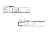
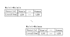
第9の発明は、前記昇圧コンバータにおいて前記インバータ側接続部の電圧を複数の電圧候補値のそれぞれに設定する電圧設定部(85)と、前記インバータ側接続部の電圧が、前記電圧設定部により設定された前記電圧候補値とされる場合に、前記昇圧コンバータ、前記第1インバータ、前記第2インバータ、前記第3インバータ、前記第1交流回転電機及び前記第2交流回転電機のうち少なくとも1つで発生することが想定される損失を算出する損失算出部(85)と、を備え、前記処理部は、前記制御状態を変更する処理として、前記各電圧候補値について前記損失算出部により算出された損失のうち、最小となる損失に対応する前記電圧候補値をコンバータ電圧指令値に設定し、設定した前記コンバータ電圧指令値に前記インバータ側接続部の電圧が近づくように前記昇圧コンバータを制御する処理を行う。 In a ninth aspect, in the boost converter, a voltage setting unit (85) that sets a voltage of the inverter-side connection unit to each of a plurality of voltage candidate values, and a voltage of the inverter-side connection unit is set by the voltage setting unit. When the voltage candidate value is set, at least one of the boost converter, the first inverter, the second inverter, the third inverter, the first AC rotating electric machine, and the second AC rotating electric machine A loss calculation unit (85) for calculating a loss expected to occur in the control unit, wherein the processing unit calculates the voltage candidate value by the loss calculation unit for each of the voltage candidate values as a process of changing the control state. Among the losses, the voltage candidate value corresponding to the minimum loss is set as a converter voltage command value, and the set converter voltage command value is set to the inverter value. Performs a process of controlling said boost converter such that the voltage of the connection part is approached.
インバータ側接続部の電圧に応じて、駆動システムを構成する昇圧コンバータ等の機器で発生する損失が変化する。そこで第9の発明では、電圧設定部により、昇圧コンバータにおいてインバータ側接続部の電圧が、複数の電圧候補値のそれぞれに設定される。そして、インバータ側接続部の電圧が、電圧設定部により設定された電圧候補値とされる場合に、昇圧コンバータ、第1インバータ、第2インバータ、第3インバータ、第1交流回転電機及び第2交流回転電機のうち少なくとも1つで発生することが想定される損失が損失算出部により算出される。そして、損失最小部により算出された損失のうち、最小となる損失に対応する電圧候補値がコンバータ電圧指令値に設定される。そして、設定されたコンバータ電圧指令値にインバータ側接続部の電圧が近づくように昇圧コンバータが制御される。このため、駆動システムで発生する損失を低減することができる。 The loss that occurs in a device such as a boost converter that forms the drive system changes according to the voltage of the inverter-side connection. Therefore, in the ninth invention, the voltage of the inverter-side connection portion in the boost converter is set to each of the plurality of voltage candidate values by the voltage setting portion. Then, when the voltage of the inverter side connection unit is set to the voltage candidate value set by the voltage setting unit, the boost converter, the first inverter, the second inverter, the third inverter, the first AC rotating electric machine, and the second AC A loss calculated by at least one of the rotating electric machines is calculated by a loss calculator. Then, a voltage candidate value corresponding to the minimum loss among the losses calculated by the loss minimum unit is set as the converter voltage command value. Then, the boost converter is controlled such that the voltage of the inverter side connection portion approaches the set converter voltage command value. For this reason, the loss generated in the drive system can be reduced.
ここで第9の発明は、具体的には第10の発明のように具体化することができる。第10の発明では、前記損失算出部は、前記インバータ側接続部の電圧が、前記電圧設定部により設定された前記電圧候補値とされる場合に、前記昇圧コンバータ、前記第1インバータ、前記第2インバータ、前記第3インバータ、前記第1交流回転電機及び前記第2交流回転電機のそれぞれで発生する損失を含む合計損失を算出する。第10の発明によれば、駆動システムで発生する損失の低減効果を高めることができる。 Here, the ninth invention can be embodied specifically as the tenth invention. In a tenth aspect, when the voltage of the inverter-side connection unit is set to the voltage candidate value set by the voltage setting unit, the loss calculation unit may include the step-up converter, the first inverter, A total loss including a loss generated in each of the two inverters, the third inverter, the first AC rotating electric machine, and the second AC rotating electric machine is calculated. According to the tenth aspect, the effect of reducing loss generated in the drive system can be enhanced.
第11の発明では、前記電源側接続部の電圧に対する前記インバータ側接続部の電圧の比が前記昇圧コンバータの昇圧比として定義されており、前記昇圧コンバータの昇圧比が取り得る最大値に前記第1直流電源の出力電圧が取り得る最大値を乗算した値である昇圧上限電圧が、前記インバータ側接続部の印加電圧が取り得る最大値よりも低くされており、前記処理部は、前記第1交流回転電機及び前記第2交流回転電機のうち一方から他方へと発電電力を供給する場合において、前記インバータ側接続部の印加電圧が前記昇圧上限電圧を超えると判定したとき、前記制御状態を変更する処理として、前記昇圧コンバータの動作を停止させる処理を行う。 In the eleventh invention, a ratio of a voltage of the inverter side connection portion to a voltage of the power supply side connection portion is defined as a boost ratio of the boost converter. (1) The boosted upper limit voltage, which is a value obtained by multiplying the maximum value that the output voltage of the DC power supply can take, is set lower than the maximum value that the applied voltage of the inverter-side connection unit can take, and the processing unit In the case where the generated power is supplied from one of the AC rotating electric machine and the second AC rotating electric machine to the other, the control state is changed when it is determined that the voltage applied to the inverter-side connection portion exceeds the boost upper limit voltage. As a process to perform the operation, a process for stopping the operation of the boost converter is performed.
第11の発明では、昇圧上限電圧が、インバータ側接続部の印加電圧が取り得る最大値よりも低くされている。これにより、昇圧コンバータの体格を小さくし、また、昇圧コンバータのコストを低減している。 In the eleventh invention, the boost upper limit voltage is set lower than the maximum value that can be taken by the voltage applied to the inverter-side connection portion. As a result, the size of the boost converter is reduced, and the cost of the boost converter is reduced.
また第11の発明では、例えば、第1交流回転電機から第2交流回転電機へと発電電力を供給する場合において、第1インバータからインバータ側接続部に出力される電圧が、昇圧上限電圧を超えるとき、昇圧コンバータの動作が停止させられる。これにより、インバータ側接続部の電圧が昇圧コンバータの動作によって制御されなくなるため、その制御の制約を受けずに第1,第2交流回転電機のいずれかの発電電圧を高めることができる。その結果、第1,第2電気経路に電流が流れることに起因して発生する損失を低減できる。 In the eleventh invention, for example, when the generated electric power is supplied from the first AC rotating electric machine to the second AC rotating electric machine, the voltage output from the first inverter to the inverter-side connection portion exceeds the boost upper limit voltage. At this time, the operation of the boost converter is stopped. As a result, the voltage of the inverter-side connection is no longer controlled by the operation of the boost converter, so that the power generation voltage of either the first or second AC rotating electric machine can be increased without being restricted by the control. As a result, it is possible to reduce the loss that occurs due to the current flowing through the first and second electric paths.
第12の発明では、前記昇圧コンバータは、前記インバータ側接続部から入力される直流電圧を降圧して前記電源側接続部から前記第1直流電源に供給する降圧動作を実施可能に構成されている。第12の発明は、前記第1直流電源の充電要求があるか否かを判定する要求判定部(85)を備え、前記処理部は、前記要求判定部により充電要求があると判定されている場合、前記インバータ側接続部の印加電圧が前記昇圧上限電圧以下となるように前記第1インバータ及び前記第2インバータのうち少なくとも一方の発電電力を制御するとともに該発電電力によって前記第1直流電源が充電されるように前記昇圧コンバータに前記降圧動作をさせる。 In a twelfth aspect, the boost converter is configured to be capable of performing a step-down operation of stepping down a DC voltage input from the inverter side connection part and supplying the stepped down power supply to the first DC power supply from the power supply side connection part. . A twelfth invention includes a request determination unit (85) that determines whether there is a request to charge the first DC power supply, and the processing unit determines that there is a charge request by the request determination unit. In this case, the power generated by at least one of the first inverter and the second inverter is controlled so that the voltage applied to the inverter-side connection portion is equal to or lower than the boost upper limit voltage, and the first DC power is generated by the generated power. The step-up converter performs the step-down operation so as to be charged.
第12の発明では、第1直流電源の充電要求があると判定された場合、インバータ側接続部の印加電圧が昇圧上限電圧以下となるようにされる。その結果、昇圧コンバータに降圧動作を行わせることができ、第1直流電源を充電できる。これにより、第1直流電源が過放電状態となることを防止できる。 In the twelfth aspect, when it is determined that there is a request for charging the first DC power supply, the voltage applied to the inverter-side connection portion is set to be equal to or lower than the boost upper limit voltage. As a result, the step-up converter can perform the step-down operation, and the first DC power supply can be charged. This can prevent the first DC power supply from being in an overdischarged state.
第13の発明は、前記第1交流回転電機、前記第2交流回転電機、前記第1インバータ、前記第2インバータ、前記第3インバータ及び前記昇圧コンバータのうち少なくとも1つである対象機器の温度を判定温度として取得する温度取得部(85)を備え、前記対象機器が過熱状態であることを判定するための閾値が過熱閾値として設定されており、前記処理部は、前記判定温度が前記過熱閾値を上回ると判定した場合、前記制御状態を変更する処理として、前記対象機器の電力を減少させて前記対象機器の温度を低下させる処理を行う。 According to a thirteenth aspect, a temperature of a target device which is at least one of the first AC rotating electric machine, the second AC rotating electric machine, the first inverter, the second inverter, the third inverter, and the boost converter is adjusted. A temperature acquisition unit (85) for acquiring the target temperature as a determination temperature, a threshold for determining that the target device is in an overheated state is set as an overheat threshold, and the processing unit sets the determination temperature to the overheat threshold. When it is determined that the temperature of the target device is exceeded, a process of reducing the power of the target device to lower the temperature of the target device is performed as the process of changing the control state.
第13の発明によれば、駆動システムを構成する対象機器が過熱状態となることを防止でき、対象機器の信頼性の低下を防止することができる。 According to the thirteenth aspect, it is possible to prevent the target device included in the drive system from being overheated, and to prevent a decrease in the reliability of the target device.
第14の発明は、前記第1交流回転電機、前記第2交流回転電機、前記第1インバータ、前記第2インバータ、前記第3インバータ及び前記昇圧コンバータのうち少なくとも1つである対象機器の温度を判定温度として取得する温度取得部(85)を備え、前記対象機器が低温状態であることを判定するための閾値が低温閾値として設定されており、前記処理部は、前記判定温度が前記低温閾値を下回ると判定した場合、前記制御状態を変更する処理として、前記対象機器の電力を増加させて前記対象機器の温度を上昇させる処理を行う。 According to a fourteenth aspect, a temperature of a target device, which is at least one of the first AC rotating electric machine, the second AC rotating electric machine, the first inverter, the second inverter, the third inverter, and the boost converter, is adjusted. A temperature acquisition unit (85) for acquiring the target temperature as a determination temperature, a threshold for determining that the target device is in a low temperature state is set as a low temperature threshold, and the processing unit sets the determination temperature to the low temperature threshold. If it is determined that the temperature of the target device is lower than the threshold value, a process of increasing the power of the target device to increase the temperature of the target device is performed as the process of changing the control state.
第14の発明によれば、駆動システムを構成する対象機器が低温状態となることを防止でき、対象機器の信頼性の低下を防止することができる。 According to the fourteenth aspect, it is possible to prevent a target device included in the drive system from being in a low temperature state, and to prevent a decrease in reliability of the target device.
(第1実施形態)
以下、本発明に係る駆動システムを、走行動力源としてエンジン及び回転電機を備えるハイブリッド車両に適用した第1実施形態について、図面を参照しつつ説明する。
(1st Embodiment)
Hereinafter, a first embodiment in which a drive system according to the present invention is applied to a hybrid vehicle including an engine and a rotating electric machine as running power sources will be described with reference to the drawings.
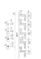
図1に示すように、車両は、エンジン10、第1モータジェネレータ20、第2モータジェネレータ30及び遊星歯車機構40を備えている。本実施形態では、第1モータジェネレータ20及び第2モータジェネレータ30として、3相交流回転電機を用いており、より具体的には、永久磁石同期回転機を用いている。
As shown in FIG. 1, the vehicle includes an
第2モータジェネレータ30は、エンジン10とともに車両の走行動力源となり、また、回生駆動制御による発電機能を有している。第1モータジェネレータ20は、エンジン10を動力供給源とする発電機、及びエンジン10の始動時においてエンジン10の出力軸10aに対して初期回転を付与する電動機の機能を有している。
The
遊星歯車機構40は、エンジン10、第1モータジェネレータ20、第2モータジェネレータ30及び駆動輪41の間で互いに動力伝達を可能とするための部材である。遊星歯車機構40は、リングギア、サンギア、プラネタリキャリア、並びにサンギア及びリングギア間の動力伝達を可能とする複数のピニオンギアを備えている。プラネタリキャリアの回転軸には、エンジン10の出力軸10aが機械的に接続されており、リングギアの回転軸には、駆動軸42と、第2モータジェネレータ30のロータの回転軸とが機械的に接続されている。駆動軸42には、デファレンシャルギア43を介して駆動輪41に連結されている。サンギアの回転軸には、第1モータジェネレータ20のロータの回転軸が機械的に接続されている。サンギア、キャリア及びリングギアの回転速度の順に、これら回転速度は共線図上において一直線上に並ぶこととなる。
The
第1モータジェネレータ20が発電機として機能する場合、エンジン10の出力軸10aからキャリアへと入力される動力が、サンギア及びリングギアのそれぞれに入力されるべく分割され、サンギアに入力された動力が第1モータジェネレータ20の駆動源となる。一方、第1モータジェネレータ20が電動機として機能する場合、第1モータジェネレータ20からサンギアへと入力される動力が、キャリアを介してエンジン10の出力軸10aに入力されることで、出力軸10aに初期回転が付与される。
When the
車両は、昇圧コンバータ50、第1インバータ51、第2インバータ52及び第3インバータ53を備えている。本実施形態では、第1インバータ51、第2インバータ52及び第3インバータ53として、3相インバータを用いている。
The vehicle includes a
車両は、第1電源60及び第2電源61を備えている。本実施形態では、第1電源60及び第2電源61として2次電池を用いており、具体的にはリチウムイオン蓄電池を用いている。なお、第2電源61の定格電圧(例えば200V)は、例えば、第1電源60の定格電圧(例えば300V)よりも低く設定することができる。
The vehicle includes a
昇圧コンバータ50は、第1電源60の出力電圧を昇圧して第1インバータ51及び第2インバータ52に出力する機能を有している。また、昇圧コンバータ50は、第1インバータ51及び第2インバータ52の少なくとも一方から出力された直流電圧を降圧して第1電源60に供給することで第1電源60を充電する。なお、第1電源60に車載補機が電気的に接続されていてもよい。
The
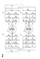
続いて図2を用いて、車載駆動システムの電気的構成について説明する。 Next, the electrical configuration of the vehicle-mounted drive system will be described with reference to FIG.
昇圧コンバータ50は、リアクトル50a、第1コンデンサ50b、第2コンデンサ50c及び上,下アーム昇圧スイッチScp,Scnの直列接続体を備えている。本実施形態では、各昇圧スイッチScp,Scnとして、電圧制御形の半導体スイッチング素子を用いており、具体的にはIGBTを用いている。このため、各昇圧スイッチScp,Scnの高電位側端子がコレクタであり、低電位側端子がエミッタである。各昇圧スイッチScp,Scnには、各フリーホイールダイオードDcp,Dcnが逆並列に接続されている。
The
リアクトル50aの第1端には、昇圧コンバータ50の第1電源側端子Cb1が接続されており、リアクトル50aの第2端には、上アーム昇圧スイッチScpのエミッタ及び下アーム昇圧スイッチScnのコレクタが接続されている。下アーム昇圧スイッチScnのエミッタには、昇圧コンバータ50の第2電源側端子Cb2が接続されている。第1電源側端子Cb1と第2電源側端子Cb2とは、第1コンデンサ50bによって接続されている。第1電源側端子Cb1には、第1電源60の正極端子が接続され、第2電源側端子Cb2には、第1電源60の負極端子が接続されている。なお本実施形態において、第1電源側端子Cb1及び第2電源側端子Cb2が「電源側接続部」に相当する。
A first power supply terminal Cb1 of the
上アーム昇圧スイッチScpのコレクタには、昇圧コンバータ50の第1インバータ側端子Ci1が接続されており、下アーム昇圧スイッチScnのエミッタには、昇圧コンバータ50の第2インバータ側端子Ci2が接続されている。第1インバータ側端子Ci1と第2インバータ側端子Ci2とは、第2コンデンサ50cによって接続されている。なお本実施形態において、第1インバータ側端子Ci1及び第2インバータ側端子Ci2が「インバータ側接続部」に相当する。
The collector of the upper arm boost switch Scp is connected to the first inverter side terminal Ci1 of the
第1インバータ51は、U,V,W相それぞれに対応した上アーム第1スイッチS1p及び下アーム第1スイッチS1nの直列接続体を備えている。本実施形態では、各第1スイッチS1p,S1nとして、電圧制御形の半導体スイッチング素子を用いており、具体的にはIGBTを用いている。各第1スイッチS1p,S1nには、各フリーホイールダイオードD1p,D1nが逆並列に接続されている。
The
U相の上,下アーム第1スイッチS1p,S1nの接続点には、第1モータジェネレータ20のU相巻線20Uの第1端が接続されている。V相の上,下アーム第1スイッチS1p,S1nの接続点には、第1モータジェネレータ20のV相巻線20Vの第1端が接続されている。W相の上,下アーム第1スイッチS1p,S1nの接続点には、第1モータジェネレータ20のW相巻線20Wの第1端が接続されている。U,V,W相巻線20U,20V,20Wの第2端は、中性点で接続されている。本実施形態において、U,V,W相巻線20U,20V,20Wは、電気角で位相が120度ずつずらされて配置されている。
The first end of the U-phase winding 20U of the
第1インバータ51の端子である第1高電位側端子CH1には、各上アーム第1スイッチS1pのコレクタが接続されている。第1高電位側端子CH1には、第1高電位電気経路LH1を介して昇圧コンバータ50の第1インバータ側端子Ci1が接続されている。第1インバータ51の端子である第1低電位側端子CL1には、各下アーム第1スイッチS1nのエミッタが接続されている。第1低電位側端子CL1には、第1低電位電気経路LL1を介して昇圧コンバータ50の第2インバータ側端子Ci2が接続されている。
The collector of each upper arm first switch S1p is connected to a first high potential side terminal CH1 which is a terminal of the
第2インバータ52は、U,V,W相それぞれに対応した上アーム第2スイッチS2p及び下アーム第2スイッチS2nの直列接続体を備えている。本実施形態では、各第2スイッチS2p,S2nとして、電圧制御形の半導体スイッチング素子を用いており、具体的にはIGBTを用いている。各第2スイッチS2p,S2nには、各フリーホイールダイオードD2p,D2nが逆並列に接続されている。
The
第2インバータ52の端子である第2高電位側端子CH2には、各上アーム第2スイッチS2pのコレクタが接続されている。第2高電位側端子CH2には、第2高電位電気経路LH2を介して第1インバータ側端子Ci1に接続されている。第2インバータ52の端子である第2低電位側端子CL2には、各下アーム第2スイッチS2nのエミッタが接続されている。第2低電位側端子CL2には、第2低電位電気経路LL2を介して第2インバータ側端子Ci2が接続されている。
The collector of each upper arm second switch S2p is connected to a second high potential side terminal CH2 which is a terminal of the
U相の上,下アーム第2スイッチS2p,S2nの接続点には、第2モータジェネレータ30のU相巻線30Uの第1端が接続されている。V相の上,下アーム第2スイッチS2p,S2nの接続点には、第2モータジェネレータ30のV相巻線30Vの第1端が接続されている。W相の上,下アーム第2スイッチS2p,S2nの接続点には、第2モータジェネレータ30のW相巻線30Wの第1端が接続されている。本実施形態において、U,V,W相巻線30U,30V,30Wは、電気角で位相が120度ずつずらされて配置されている。
A first end of a U-phase winding 30U of the
第3インバータ53は、U,V,W相それぞれに対応した上アーム第3スイッチS3p及び下アーム第3スイッチS3nの直列接続体を備えている。本実施形態では、各第3スイッチS3p,S3nとして、電圧制御形の半導体スイッチング素子を用いており、具体的にはIGBTを用いている。各第3スイッチS3p,S3nには、各フリーホイールダイオードD3p,D3nが逆並列に接続されている。
The
U相の上,下アーム第3スイッチS3p,S3nの接続点には、U相巻線30Uの第2端が接続されている。V相の上,下アーム第2スイッチS3p,S3nの接続点には、V相巻線30Vの第2端が接続されている。W相の上,下アーム第3スイッチS3p,S3nの接続点には、W相巻線30Wの第2端が接続されている。 The second end of the U-phase winding 30U is connected to a connection point of the U-phase upper and lower arm third switches S3p and S3n. The second end of the V-phase winding 30V is connected to a connection point between the V-phase upper and lower arm second switches S3p and S3n. The second end of the W-phase winding 30W is connected to a connection point between the W-phase upper and lower arm third switches S3p and S3n.
第3インバータ53の端子である第3高電位側端子CH3には、各上アーム第3スイッチS3pのコレクタが接続されている。第3高電位側端子CH3には、第2電源61の正極端子が接続されている。第3インバータ53の端子である第3低電位側端子CL3には、各下アーム第3スイッチS3nのエミッタが接続されている。第3低電位側端子CL3には、第2電源61の負極端子が接続されている。第3高電位側端子CH3と第3低電位側端子CL3とは、第3コンデンサ55によって接続されている。
The collector of each upper arm third switch S3p is connected to the third high potential side terminal CH3 which is the terminal of the
続いて図3を用いて、車両に搭載される各制御装置について説明する。 Next, each control device mounted on the vehicle will be described with reference to FIG.
車両は、エンジン10を制御するエンジンECU80、昇圧コンバータ50を制御するコンバータECU81、第1インバータ51を制御する第1インバータECU82、第2インバータ52を制御する第2インバータECU83及び第3インバータ53を制御する第3インバータECU84を備えている。
The vehicle controls an
車両は、各ECU80〜84の上位の制御装置である統括ECU85を備えている。本実施形態において、統括ECU85は「処理部」を含む。統括ECU85は、エンジン10の冷却水温THW及びエンジン10の現在の出力Wengを含む情報をエンジンECU80から取得する。統括ECU85は、取得した情報に基づいて、エンジントルク指令値Tetgt及びエンジン回転速度指令値Netgtを含む情報をエンジンECU80に出力する。エンジンECU80は、統括ECU85から取得した情報に基づいて、エンジン10の実際のトルクをエンジントルク指令値Tetgtに制御して、かつ、エンジン10の実際の回転速度をエンジン回転速度指令値Netgtに制御すべく、エンジン10の燃焼制御を行う。
The vehicle includes a
統括ECU85は、昇圧コンバータ50の温度Tcnv、第1コンデンサ50bの端子電圧である第1コンバータ電圧Vcnv1及び第2コンデンサ50cの端子電圧である第2コンバータ電圧Vcnv2を含む情報をコンバータECU81から取得する。ここで、昇圧コンバータ50の温度は、例えば各昇圧スイッチScp,Scnの温度である。統括ECU85は、取得した情報に基づいて、コンバータ電圧指令値Vcvout,コンバータ電力指令値Wcvoutを含む情報をコンバータECU81に出力する。コンバータECU81は、昇圧コンバータ50に昇圧動作を行わせる場合、第2コンバータ電圧Vcnv2をコンバータ電圧指令値Vcvoutに制御して、かつ、第1,第2インバータ側端子Ci1,Ci2からの出力電力をコンバータ電力指令値Wcvoutにフィードバック制御すべく、下アーム昇圧スイッチScnをオンオフ制御する。なお本実施形態において、昇圧動作時においては、上アーム昇圧スイッチScpはオフのままである。
一方、コンバータECU81は、昇圧コンバータ50に降圧動作を行わせる場合、第1コンバータ電圧Vcnv1をコンバータ電圧指令値Vcvoutに制御して、かつ、第1,第2電源側端子Cb1,Cb2からの出力電力をコンバータ電力指令値Wcvoutにフィードバック制御すべく、上アーム昇圧スイッチScpをオンオフ制御する。なお本実施形態において、降圧動作時においては、下アーム昇圧スイッチScnはオフのままである。
On the other hand, converter ECU 81 controls first converter voltage Vcnv1 to converter voltage command value Vcvout and causes output power from first and second power supply terminals Cb1 and Cb2 to cause
統括ECU85は、第1電源60の温度を検出する第1温度検出部の温度検出値TT1、第1電源60の充電率(SOC)である第1充電率SOC1、第2電源61の温度を検出する第2温度検出部の温度検出値TT2、及び第2電源61の充電率である第2充電率SOC2を含む情報を取得する。
The
統括ECU85は、第1モータジェネレータ20の温度TM1及び第2モータジェネレータ30の温度TM2を取得する。統括ECU85は、第1インバータ51の温度Tiv1、及び第1高,低電位側端子CH1,CL1の間の電位差である第1電源電圧Viv1を第1インバータECU82から取得し、第2インバータ52の温度Tiv2、及び第2高,低電位側端子CH2,CL2の間の電位差である第2電源電圧Viv2を第2インバータECU83から取得する。統括ECU85は、第3インバータ53の温度Tiv3、及び第3高,低電位側端子CH3,CL3の間の電位差である第3電源電圧Viv3を第3インバータECU84から取得する。
統括ECU85は、取得した各種情報に基づいて、第1トルク指令値T1tgt及び第1回転速度指令値N1tgtを含む情報を第1インバータECU82に出力する。第1インバータECU82は、統括ECU85から取得した情報に基づいて、第1モータジェネレータ20の実際のトルクを第1トルク指令値T1tgtに制御して、かつ、第1モータジェネレータ20の実際の回転速度を第1回転速度指令値N1tgtに制御すべく、第1インバータ51を構成する各スイッチS1p,S1nを制御する。これにより本実施形態では、第1モータジェネレータ20の各相巻線20U,20V,20Wに電気角で位相が120度ずれた正弦波状の相電流が流れる。
The
統括ECU85は、取得した各種情報に基づいて、第2トルク指令値T2tgt及び第2回転速度指令値N2tgtを含む情報を第2インバータECU83に出力する。統括ECU85は、取得した各種情報に基づいて、第3トルク指令値T3tgt及び第2回転速度指令値N2tgtを含む情報を第3インバータECU84に出力する。第2,第3インバータECU83,84は、統括ECU85から取得した情報に基づいて、第2モータジェネレータ30の実際のトルクを第2トルク指令値T2tgt及び第3トルク指令値T3tgtの合計トルクに制御して、かつ、第2モータジェネレータ30の実際の回転速度を第2回転速度指令値N2tgtに制御すべく、第2,第3インバータ52,53を構成する各スイッチS2p,S2n,S3p,S3nを制御する。これにより本実施形態では、第2モータジェネレータ30の各相巻線30U,30V,30Wに電気角で位相が120度ずれた正弦波状の相電流が流れる。
The
本実施形態において、第2インバータECU83及び第3インバータECU84は、図4に示すように、第2インバータ52の出力電圧ベクトルである第2出力電圧ベクトルVtr2の位相と、第3インバータ53の出力電圧ベクトルである第3出力電圧ベクトルVtr3の位相とが電気角で180度異なるように、第2,第3インバータ52,53を構成する各スイッチS2p,S2n,S3p,S3nを制御する。これにより、第2モータジェネレータ30の各相巻線への印加電圧を増加させ、第2モータジェネレータ30の出力トルクを増加させている。なお図5には、各有効電圧ベクトルV1〜V6と各無効電圧ベクトルV0,V7とのそれぞれに対応した上,下アームスイッチの駆動態様を示した。
In the present embodiment, as shown in FIG. 4, the second inverter ECU 83 and the
続いて、本実施形態の効果について説明する。 Subsequently, effects of the present embodiment will be described.
本実施形態によれば、電流循環が発生せず、第1モータジェネレータ20及び第2モータジェネレータ30のトルク及び回転速度の制御性の低下を防止できるといった効果を奏することができる。以下、この効果について、関連技術と比較しつつ説明する。図6に、関連技術を示す。なお図6において、先の図2に示した構成と同一の構成については、便宜上、同一の符号を付している。
According to the present embodiment, it is possible to achieve an effect that current circulation does not occur and a decrease in controllability of the torque and the rotation speed of the
図6に示すように、車両は、第1モータジェネレータ90及び第4インバータ56を備えている。第1モータジェネレータ90の構成は、第2モータジェネレータ30と同様な構成であり、第4インバータ56の構成は、第3インバータ53の構成と同様な構成である。
As shown in FIG. 6, the vehicle includes a
U相の上,下アーム第1スイッチS1p,S1nの接続点には、第1モータジェネレータ90のU相巻線90Uの第1端が接続されている。V相の上,下アーム第1スイッチS1p,S1nの接続点には、第1モータジェネレータ90のV相巻線90Vの第1端が接続されている。W相の上,下アーム第1スイッチS1p,S1nの接続点には、第1モータジェネレータ90のW相巻線90Wの第1端が接続されている。
A first end of a U-phase winding 90U of the
U相巻線90Uの第2端には、第4インバータ56を構成するU相の上,下アーム第4スイッチS4p,S4nの接続点が接続されている。V相巻線90Vの第2端には、第4インバータ56を構成するV相の上,下アーム第4スイッチS4p,S4nの接続点が接続されている。W相巻線90Wの第2端には、第4インバータ56を構成するW相の上,下アーム第4スイッチS4p,S4nの接続点が接続されている。なお、各第4スイッチS4p,S4nには、各フリーホイールダイオードD4p,D4nが逆並列に接続されている。
A connection point of the U-phase upper and lower arm fourth switches S4p and S4n constituting the
上アーム第4スイッチS4pのコレクタと下アーム第4スイッチS4nのエミッタとは、第4コンデンサ56aによって接続されている。また、上アーム第4スイッチS4pのコレクタには、第2電源61の正極端子が接続され、下アーム第4スイッチS4nのエミッタには、第2電源61の負極端子が接続されている。
The collector of the upper arm fourth switch S4p and the emitter of the lower arm fourth switch S4n are connected by a
関連技術では、第1インバータ51の出力電圧ベクトルである第1出力電圧ベクトルの位相と、第4インバータ56の出力電圧ベクトルである第4出力電圧ベクトルの位相とが電気角で180度異なるように、第1,第4インバータ51,56を構成する各スイッチS1p,S1n,S4p,S4nが制御される。
In the related technique, the phase of the first output voltage vector, which is the output voltage vector of the
ここで、関連技術では、電流循環が発生し得る。電流循環とは、第1モータジェネレータ90の巻線、第1インバータ51、第2モータジェネレータ30の巻線、第3インバータ53及び第4インバータ56を含む閉回路に電流が流れることである。以下、図6を用いて、U相を例にして電流循環について説明する。
Here, in the related art, current circulation may occur. The current circulation means that a current flows through a closed circuit including the winding of the
図6には、第1モータジェネレータ90及び第2モータジェネレータ30のそれぞれの回生発電電力を第1電源60に供給して第1電源60を充電する場合の例を示す。また図6には、第1モータジェネレータ90の回生発電電圧(例えば50V)が第2モータジェネレータ30の回生発電電圧(例えば100V)よりも低い場合を示している。
FIG. 6 shows an example in which regenerative power generated by each of
図6に示す例では、第2出力電圧ベクトルVtr2の位相と第3出力電圧ベクトルVtr3の位相とが180度異なっている。このため、図6に破線にて示すように、U相について、上アーム第2スイッチS2p、U相巻線30U、第3インバータ53のフリーホイールダイオードD3p、第2電源61、第4インバータ56のフリーホイールダイオードD4n、U相巻線90U及び第1インバータ51のフリーホイールダイオードD1pを含む閉回路に電流が流れる電流循環が発生する。この場合、第1モータジェネレータ90及び第2モータジェネレータ30のトルク,回転速度の制御性が低下してしまう。
In the example shown in FIG. 6, the phase of the second output voltage vector Vtr2 is different from the phase of the third output voltage vector Vtr3 by 180 degrees. Therefore, as shown by the broken line in FIG. 6, for the U phase, the upper arm second switch S2p, the U-phase winding 30U, the freewheel diode D3p of the
これに対し本実施形態では、先の図2に示すように、第2電源61と第1モータジェネレータ20とが、第3インバータ53、第2モータジェネレータ30の巻線、第2インバータ52及び第1インバータ51を介さずに電気的に接続されないように単一の接続ルートで接続されるように構成されている。言い換えれば、第1モータジェネレータ20、第1インバータ51、第2インバータ52、第2モータジェネレータ30の巻線、第3インバータ53は、この順にI字状に接続され、O字状に接続されない。このため本実施形態では、第2電源61と第1モータジェネレータ20とが直接接続されず、第3インバータ53と第1モータジェネレータ20とが第2モータジェネレータ30を通るルートのみでしか接続されないので、第1モータジェネレータ20から第1直流電源60を充電する場合に、電流循環が発生しない。また、本実施形態では、第2モータジェネレータ30から第2直流電源61を充電する場合にも電流循環が発生しない。すなわち、2つの交流発電機間は単一の接続ルートで接続されているので、交流発電機の1つから直流電源を充電する場合に電流循環が発生しない。したがって、第1,第2モータジェネレータ20,30のトルク及び回転速度の制御性の低下を防止することができる。
On the other hand, in the present embodiment, as shown in FIG. 2, the
また本実施形態によれば、各電気経路LH1,LL1,LH2,LL2に電流が流れることに起因して発生する銅損を低減できるといった効果を奏することができる。以下、この効果について、関連技術と比較しつつ説明する。 Further, according to the present embodiment, it is possible to achieve an effect that the copper loss generated due to the current flowing through each of the electric paths LH1, LL1, LH2, and LL2 can be reduced. Hereinafter, this effect will be described in comparison with the related art.
関連技術において、第1モータジェネレータ90が発生する回生発電電力をPWとする。また、関連技術において、第1電源60の出力電圧が300Vに設定されているとし、本実施形態において、第2コンデンサ50cの端子電圧が昇圧コンバータ50により600Vに昇圧されているとする。さらに、関連技術において第1インバータ51から第1電源60側へと流れる電流をI2とし、本実施形態において第1インバータ51から昇圧コンバータ50側に流れる電流をI1とする。この場合において、関連技術の第1モータジェネレータ90の回生発電電力と、本実施形態の第1モータジェネレータ20の回生発電電力とがPWで同一であるとすると、「PW=300[V]×I2=600[V]×I1」が成立する。この場合、本実施形態に係る電流I1は、関連技術に係る電流I2の半分となる。したがって本実施形態によれば、各電気経路LH1,LL1,LH2,LL2に電流が流れることに起因して発生する銅損を低減することができる。そして銅損の低減により、熱損失による駆動システムにおける効率の低下を防止し、また、各電気経路LH1,LL1,LH2,LL2として径の大きい配線を用いることを不要にできる。
In the related art, the regenerative power generated by the
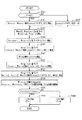
続いて図7を用いて、第1電源60及び第2電源61の過放電及び過充電を防止する充電状態制御処理を説明する。この処理は、統括ECU85により例えば所定周期毎に繰り返し実行される。
Next, a charge state control process for preventing overdischarge and overcharge of the
この一連の処理では、まずステップS10において、第1充電率SOC1が第1過放電閾値SLth1以下であるか否かを判定する。本実施形態において、第1過放電閾値SLth1は、第1電源60の信頼性の低下を防止できる第1充電率SOC1の下限値に設定されている。本実施形態において、第1過放電閾値SLth1は、図8に示すように、第1電源60が取り得る充電率の下限値(0%)よりも大きくて、かつ、第1電源60が取り得る充電率の上限値(100%)よりも小さく値に設定されている。なお、第1過放電閾値SLth1は、例えば、第1電源60の温度検出値TT1に基づいて可変設定されてもよい。
In this series of processing, first, in step S10, it is determined whether the first state of charge SOC1 is equal to or less than the first overdischarge threshold SLth1. In the present embodiment, the first overdischarge threshold value SLth1 is set to the lower limit value of the first state of charge SOC1 that can prevent a decrease in the reliability of the
ステップS10において肯定判定した場合には、第1電源60が過放電状態になるおそれがあると判定し、ステップS12に進む。ステップS12では、第2充電率SOC2が第2過充電閾値SHth2以上であるか否かを判定する。本実施形態において、第2過充電閾値SHth2は、第2電源61の信頼性の低下を防止できる第2充電率SOC2の上限値に設定されている。本実施形態において、第2過充電閾値SHth2は、図8に示すように、第2電源61が取り得る充電率の下限値(0%)よりも大きくて、かつ、第2電源61が取り得る充電率の上限値(100%)よりも小さく値に設定されている。なお、第2過充電閾値SHth2は、例えば、第2電源61の温度検出値TT2に基づいて可変設定されてもよい。
When an affirmative determination is made in step S10, it is determined that the
ステップS12において肯定判定した場合には、第2電源61が過充電状態になるおそれがあると判定し、ステップS14に進む。ステップS14では、第2電源61から第1電源60に給電されるように、第3インバータ53から第2モータジェネレータ30へと供給される力行電力を増加させる処理と、第2モータジェネレータ30から第2インバータ52へと供給される回生電力を増加させる処理とを行う。また、昇圧コンバータ50を降圧動作させる処理も行う。第3インバータ53から第2モータジェネレータ30へと供給される力行電力は、第2モータジェネレータ30において消費される電力である。第2モータジェネレータ30から第2インバータ52へと出力される回生電力は、第2モータジェネレータ30において発電される電力である。
When an affirmative determination is made in step S12, it is determined that the
本実施形態では、力行電力を増加させる処理として、第2モータジェネレータ30の消費電力を増加させる側に第2トルク指令値T2tgtを変更する処理を行う。変更された第2トルク指令値T2tgtに基づいて、第2インバータECU83は、第2インバータ52を制御する。
In the present embodiment, as a process of increasing the powering power, a process of changing the second torque command value T2tgt to the side that increases the power consumption of the
また本実施形態では、回生電力を増加させる処理として、第2モータジェネレータ30の発電電力を増加させる側に第3トルク指令値T3tgtを変更する処理を行う。変更された第3トルク指令値T3tgtに基づいて、第3インバータECU84は、第3インバータ53を制御する。
Further, in the present embodiment, as a process of increasing the regenerative power, a process of changing the third torque command value T3tgt to the side that increases the power generated by the
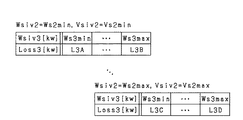
また本実施形態では、第3インバータ53から第2モータジェネレータ30へと供給される力行電力を増加させて、かつ、第2モータジェネレータ30から第2インバータ52へと供給される回生電力を増加させる前後において、第2出力電圧ベクトルVtr2と第3出力電圧ベクトルVtr3の合成ベクトルの振幅が変化しないように第2トルク指令値T2tgt及び第3トルク指令値T3tgtを変更する。これにより、トルク指令値の変更に起因したトルクショックの発生を防止し、ドライバビリティの低下を防止する。以下、図9を用いて、トルク指令値の変更方法について説明する。
In the present embodiment, the power running power supplied from
図9(a)に、第2トルク指令値T2tgt及び第3トルク指令値T3tgtを変更する前の第2出力電圧ベクトルVtr2及び第3出力電圧ベクトルVtr3を示す。なお、図9では、第2出力電圧ベクトルVtr2と第3出力電圧ベクトルVtr3とが、電圧ベクトル空間において無効電圧ベクトルV0,V7を示す点を基準に示されている。 FIG. 9A shows the second output voltage vector Vtr2 and the third output voltage vector Vtr3 before changing the second torque command value T2tgt and the third torque command value T3tgt. In FIG. 9, the second output voltage vector Vtr2 and the third output voltage vector Vtr3 are shown with reference to the points indicating the invalid voltage vectors V0 and V7 in the voltage vector space.
第2モータジェネレータ30の消費電力を増加させる側に第2トルク指令値T2tgtが変更され、第2モータジェネレータ30の発電電力を増加させる側に第3トルク指令値T3tgtが変更される。これにより、図9(b)に示すように、第2,第3出力電圧ベクトルVtr2,Vtr3の合成ベクトルの振幅がVamtに維持されつつ、第2出力電圧ベクトルVtr2の振幅が減少し、第3出力電圧ベクトルVtr3の振幅が増加する。
The second torque command value T2tgt is changed to increase the power consumption of the
第2モータジェネレータ30の消費電力を増加させる側に第2トルク指令値T2tgtがさらに変更され、第2モータジェネレータ30の発電電力を増加させる側に第3トルク指令値T3tgtがさらに変更される。これにより、図9(c)に示すように、第2,第3出力電圧ベクトルVtr2,Vtr3の合成ベクトルの振幅がVamtに維持されつつ、第3出力電圧ベクトルVtr3の振幅がさらに増加するとともに、第2出力電圧ベクトルVtr2の振幅の符号が、力行駆動を示す符号から回生駆動を示す符号に反転する。
The second torque command value T2tgt is further changed to increase the power consumption of the
ステップS14の処理によれば、第2電源61の放電電力が増加し、第2電源61が過充電状態となるのを防止できる。またステップS14の処理によれば、第1電源60の充電電力が増加し、第1電源60が過放電状態となるのを防止できる。
According to the processing in step S14, the discharge power of the
先の図7の説明に戻り、ステップS12においてに否定判定した場合には、第2電源61が過充電状態になるおそれがないと判定し、ステップS16に進む。ステップS16では、第1電源60に給電されるように、第1モータジェネレータ20から第1インバータ51へと供給される回生電力を増加させる処理を行う。また、昇圧コンバータ50を降圧動作させる処理も行う。本実施形態では、第1インバータ51へと供給される回生電力を増加させる処理として、第1モータジェネレータ20の回生発電電力を増加させる側に第1トルク指令値T1tgtを変更する処理を行う。変更された第1トルク指令値T1tgtに基づいて、第1インバータECU82は、第1インバータ51を制御する。ステップS16の処理によれば、第1電源60の充電電力が増加し、第1電源60が過放電状態となるのを防止できる。
Returning to the description of FIG. 7, if a negative determination is made in step S12, it is determined that there is no possibility that the
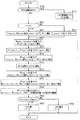
ステップS10において否定判定した場合には、第1電源60が過放電状態になるおそれがないと判定し、ステップS18に進む。ステップS18では、第1充電率SOC1が第1過充電閾値SHth1以上であるか否かを判定する。本実施形態において、第1過充電閾値SHth1は、第1電源60の信頼性の低下を防止できる第1充電率SOC1の上限値に設定されている。本実施形態において、第1過充電閾値SHth1は、図8に示すように、第1過放電閾値SLth1よりも大きくて、かつ、第1電源60が取り得る充電率の上限値よりも小さく値に設定されている。なお、第1過充電閾値SHth1は、例えば、第1電源60の温度検出値TT1に基づいて可変設定されてもよい。
If a negative determination is made in step S10, it is determined that the
ステップS18において肯定判定した場合には、第1電源60が過充電状態になるおそれがあると判定し、ステップS20に進む。ステップS20では、第2充電率SOC2が第2過放電閾値SLth2以下であるか否かを判定する。本実施形態において、第2過放電閾値SLth2は、第2電源60の信頼性の低下を防止できる第2充電率SOC2の下限値に設定されている。本実施形態において、第2過放電閾値SLth2は、図8に示すように、第2電源61が取り得る充電率の下限値よりも大きくて、かつ、第2過充電閾値SHth2よりも小さく値に設定されている。なお、第2過放電閾値SLth2は、例えば、第2電源61の温度検出値TT2に基づいて可変設定されてもよい。
When an affirmative determination is made in step S18, it is determined that the
ステップS20において否定判定した場合には、第2電源61が過放電状態になるおそれがないと判定し、ステップS22に進む。ステップS22では、第1電源60から放電されるように、第1モータジェネレータ20から第1インバータ51に供給される回生電力を減少させる処理、又は第2インバータ52から第2モータジェネレータ30に供給される力行電力を増加させる処理のいずれかを行う。また、昇圧コンバータ50を昇圧動作させる処理も行う。
If a negative determination is made in step S20, it is determined that there is no possibility that the
本実施形態では、第1インバータ51に供給される回生電力を減少させる処理として、第1モータジェネレータ20の発電電力を減少させる側に第1トルク指令値T1tgtを変更する処理を行う。一方、第2モータジェネレータ30に供給される力行電力を増加させる処理として、第2モータジェネレータ30の消費電力を増加させる側に第2トルク指令値T2tgtを変更する処理を行う。ステップS22の処理によれば、第1電源60の放電電力が増加し、第1電源60が過充電状態となるのを防止できる。
In the present embodiment, as a process of reducing the regenerative power supplied to the
ちなみにステップS22において、第1モータジェネレータ20から第1インバータ51に供給される回生電力を減少させる処理と、第2インバータ52から第2モータジェネレータ30に供給される力行電力を増加させる処理との双方を行ってもよい。
Incidentally, in step S22, both the process of reducing the regenerative power supplied from the
ステップS20において肯定判定した場合には、第2電源61が過放電状態になるおそれがあると判定し、ステップS24に進む。ステップS24では、第1電源60から第2電源61に給電されるように、第2インバータ52から第2モータジェネレータ30に供給される力行電力を増加させる処理と、第2モータジェネレータ30から第3インバータ53に供給される回生電力を増加させる処理とを行う。また、昇圧コンバータ50を昇圧動作させる処理も行う。
When an affirmative determination is made in step S20, it is determined that the
本実施形態では、第2モータジェネレータ30に供給される力行電力を増加させる処理として、第2モータジェネレータ30の消費電力を増加させる側に第2トルク指令値T2tgtを変更する処理を行う。また本実施形態では、第3インバータ53に供給される回生電力を増加させる処理として、第2モータジェネレータ30の発電電力を増加させる側に第3トルク指令値T3tgtを変更する処理を行う。ステップS24の処理によれば、第1電源60の放電電力及び第2電源61の充電電力が増加するため、第1電源60が過充電状態になること及び第2電源61が過放電状態になることを防止することができる。
In the present embodiment, as a process of increasing the power running power supplied to the
また本実施形態では、第2インバータ52から第2モータジェネレータ30に供給される力行電力を増加させて、かつ、第2モータジェネレータ30から第3インバータ53に供給される回生電力を増加させる前後において、第2出力電圧ベクトルVtr2と第3出力電圧ベクトルVtr3の合成ベクトルの振幅が変化しないように第2トルク指令値T2tgt及び第3トルク指令値T3tgtを変更する。
In the present embodiment, the power running power supplied from the
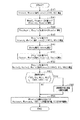
一方、ステップS18において否定判定した場合には、第1電源60が過充電状態になるおそれがないと判定し、ステップS26に進む。ステップS26では、第2充電率SOC2が第2過放電閾値SLth2以下であるか否かを判定する。
On the other hand, if a negative determination is made in step S18, it is determined that there is no possibility that the
ステップS26において肯定判定した場合には、第2電源61が過放電状態になるおそれがあると判定し、ステップS28に進む。ステップS28では、第2電源61に給電されるように、第2モータジェネレータ30から第3インバータ53に供給される回生電力を増加させる処理を行う。本実施形態では、第3インバータ53に供給される回生電力を増加させる処理として、第2モータジェネレータ30の発電電力を増加させる側に第3トルク指令値T3tgtを変更する処理を行う。ステップS28の処理によれば、第2電源61の充電電力が増加し、第2電源61が過放電状態となるのを防止できる。
When an affirmative determination is made in step S26, it is determined that the
一方、ステップS26において否定判定した場合には、第2電源61が過放電状態になるおそれがないと判定し、ステップS30に進む。ステップS30では、第2充電率SOC2が第2過充電閾値SHth2以上であるか否かを判定する。
On the other hand, if a negative determination is made in step S26, it is determined that there is no possibility that the
ステップS30において肯定判定した場合には、第2電源61が過充電状態になるおそれがあると判定し、ステップS32に進む。ステップS32では、第2電源61から放電されるように、第2インバータ52から第2モータジェネレータ30に供給される力行電力を減少させる処理と、第3インバータ53から第2モータジェネレータ30に供給される力行電力を増加させる処理とを行う。
When an affirmative determination is made in step S30, it is determined that the
本実施形態では、第2モータジェネレータ30に供給される力行電力を減少させる処理として、第2モータジェネレータ30の消費電力を減少させる側に第2トルク指令値T2tgtを変更する処理を行う。また本実施形態では、第2モータジェネレータ30に供給される力行電力を増加させる処理として、第2モータジェネレータ30の消費電力を増加させる側に第3トルク指令値T3tgtを変更する処理を行う。ステップS32の処理によれば、第2電源61の放電電力が増加し、第2電源61が過充電状態となるのを防止できる。
In the present embodiment, as a process of reducing the power running power supplied to the
また本実施形態では、第2インバータ52から第2モータジェネレータ30に供給される力行電力を減少させて、かつ、第3インバータ53から第2モータジェネレータ30に供給される力行電力を増加させる前後において、第2出力電圧ベクトルVtr2と第3出力電圧ベクトルVtr3の合成ベクトルの振幅が変化しないように第2トルク指令値T2tgt及び第3トルク指令値T3tgtを変更する。
In the present embodiment, before and after the powering power supplied from the
なお、ステップS30において否定判定した場合には、第1電源60及び第2電源61のそれぞれが過充電状態及び過放電状態になるおそれがないと判定し、第1〜第3インバータ51〜53の制御状態が変更されない。
If a negative determination is made in step S30, it is determined that there is no possibility that each of the
以上説明した充電状態制御処理によれば、第1電源60及び第2電源61が過放電状態又は過充電状態となることを防止できる。
According to the charge state control process described above, the
(第2実施形態)
以下、第2実施形態について、上記第1実施形態との相違点を中心に図面を参照しつつ説明する。本実施形態において、統括ECU85は、昇圧コンバータ50の昇圧動作時におけるコンバータ電圧指令値Vcvoutを、駆動システムの損失が最小となるように設定する損失最小化処理を行う。なお本実施形態において、統括ECU85が「電圧設定部」及び「損失算出部」を含む。
(2nd Embodiment)
Hereinafter, the second embodiment will be described with reference to the drawings, focusing on differences from the first embodiment. In the present embodiment, the
図10に、損失最小化処理の手順を示す。この処理は、統括ECU85により例えば所定周期毎に繰り返し実行される。
FIG. 10 shows the procedure of the loss minimizing process. This process is repeatedly executed by the
この一連の処理では、まずステップS40において、昇圧コンバータ50の複数の出力電圧候補値Vsoutの中から1つを選択し、昇圧コンバータ50の複数の出力電力候補値Wsoutの中から1つを選択する。ステップS40において、昇圧コンバータ50の出力電圧は、第1インバータ側端子Ci1及び第2インバータ側端子Ci2の間の電位差であり、昇圧コンバータ50の出力電力は、第1インバータ側端子Ci1及び第2インバータ側端子Ci2から出力される電力である。そしてステップS40では、昇圧コンバータ50の出力電圧が、選択した出力電圧候補値Vsoutとされて、かつ、昇圧コンバータ50の出力電力が、選択した出力電力候補値Wsoutとされる場合に発生することが想定される第1損失Loss1を算出する。本実施形態において、第1損失Loss1は、第1電源60の放電時において第1電源60で発生する損失と、昇圧コンバータ50が昇圧動作を行う場合に昇圧コンバータ50で発生する損失との合計値である。本実施形態において、ステップS40では、複数の出力電圧候補値Vsout及び複数の出力電力候補値Wsoutの組み合わせ全てに対して第1損失Loss1を算出する。
In this series of processing, first, in step S40, one is selected from a plurality of output voltage candidate values Vsout of
本実施形態では、出力電圧候補値Vsoutの範囲の上限値Vsmaxを、第1電源60の現在の端子電圧である第1コンバータ電圧Vcnv1に昇圧コンバータ50の最大昇圧比を乗算した値に設定する。ここで昇圧比とは、第1電源60の端子電圧「Vin」に対する第2コンデンサ50cの端子電圧「Vout」の比「Vout/Vin」のことである。
In the present embodiment, the upper limit value Vsmax of the range of the output voltage candidate value Vsout is set to a value obtained by multiplying the first converter voltage Vcnv1, which is the current terminal voltage of the
また本実施形態では、出力電力候補値Wsoutの範囲の上限値Wsmaxを、出力電圧候補値Vsoutの範囲の上限値に、昇圧コンバータ50に流れる電流の許容上限値を乗算した値に設定する。この許容上限値は、昇圧コンバータ50の信頼性の低下を防止できる値に設定されている。
In the present embodiment, the upper limit value Wsmax of the range of the output power candidate value Wsout is set to a value obtained by multiplying the upper limit value of the range of the output voltage candidate value Vsout by the allowable upper limit value of the current flowing through the
なお、第1損失Loss1は、例えば図11に示すように、出力電圧候補値Vsout及び出力電力候補値Wsoutと関係付けられて第1損失Loss1が規定されたマップ情報に基づいて算出されればよい。図11では、出力電圧候補値Vsoutの下限値をVsminにて示し、出力電力候補値Wsoutの下限値をWsminにて示した。第1損失Loss1は、例えば、出力電圧候補値Vsoutが高くなったり、出力電力候補値Wsoutが大きくなったりするほど、大きくなる傾向にある。図11に示すマップ情報は、例えば、統括ECU85が備えるメモリ等の記憶部に記憶されていればよい。
The first loss Loss1, for example, as shown in FIG. 11, may be calculated based on map information in which the first loss Loss1 is defined in association with the output voltage candidate value Vsout and the output power candidate value Wsout. . In FIG. 11, the lower limit of the output voltage candidate value Vsout is indicated by Vsmin, and the lower limit of the output power candidate value Wsout is indicated by Wsmin. The first loss Loss1, for example, tends to increase as the output voltage candidate value Vsout increases or the output power candidate value Wsout increases. The map information illustrated in FIG. 11 may be stored in a storage unit such as a memory included in the
先の図10の説明に戻り、続くステップS42では、力行駆動時に要求される第2モータジェネレータ30の消費電力又は回生駆動時に要求される第2モータジェネレータ30の発電電力のいずれかである第2モータ要求電力Wmg2と、第2電源61が出力可能な電力範囲Rngbat2とに基づいて、第2要求電力範囲Rngiv2及び第3要求電力範囲Rngiv3を算出する。本実施形態において、第2要求電力範囲Rngiv2は、第2インバータ52と第2モータジェネレータ30との間で伝達される電力の範囲であり、第3要求電力範囲Rngiv3は、第3インバータ53と第2モータジェネレータ30との間で伝達される電力の範囲である。また、第2電源61が出力可能な電力範囲Rngbat2の上限値は、第2電源61が過放電状態になることを防止できる値に設定されている。なお、第2モータ要求電力Wmg2は、例えば、第2トルク指令値T2tgt、第3トルク指令値T3tgt及び第2回転速度指令値N2tgtに基づいて算出されればよい。
Returning to the description of FIG. 10, in the succeeding step S <b> 42, the second power that is either the power consumption of the
続くステップS44では、第1電源60が出力可能な電力範囲Rngbat1と、ステップS42で算出した第2要求電力範囲Rngiv2とに基づいて、第1インバータ52と第1モータジェネレータ20との間で伝達される電力の範囲である第1要求電力範囲Rngiv1を算出する。ここで、第1要求電力範囲Rngiv1の上限値は、第1電源60が出力可能な電力範囲Rngbat1の上限値から第2要求電力範囲Rngiv2の上限値を差し引いた値以下となるように算出されればよい。
In the following step S44, the power is transmitted between the
続くステップS46では、昇圧コンバータ50の複数の出力電圧候補値Vsoutの中から1つを選択し、複数の第1電力候補値Wsiv1の中から1つを選択する。ステップS46において、第1電力候補値Wsiv1は、第1インバータ51と第1モータジェネレータ20との間で伝達される電力の候補値である。複数の第1電力候補値Wsiv1のうち、その上限値及び下限値は、ステップS44で算出した第1要求電力範囲Rngiv1に含まれる。本実施形態では、複数の第1電力候補値Wsiv1のうち、その上限値が第1要求電力範囲Rngiv1の上限値に設定され、その下限値が第1要求電力範囲Rngiv1の下限値に設定されている。
In subsequent step S46, one is selected from a plurality of output voltage candidate values Vsout of
そしてステップS46では、昇圧コンバータ50の出力電圧が、選択した出力電圧候補値Vsoutとされて、かつ、第1インバータ51と第1モータジェネレータ20との間で伝達される電力が、選択した第1電力候補値Wsiv1とされる場合に発生することが想定される第2損失Loss2を算出する。本実施形態において、第2損失Loss2は、第1インバータ51と第1モータジェネレータ20との間で電力が伝達される場合に第1インバータ51及び第1モータジェネレータ20のそれぞれで発生する損失の合計値である。本実施形態において、ステップS46では、複数の出力電圧候補値Vsout及び複数の第1電力候補値Wsiv1の組み合わせ全てに対して第2損失Loss2を算出する。
In step S46, the output voltage of
なお本実施形態において、第2損失Loss2は、例えば図12に示すように、出力電圧候補値Vsout及び第1電力候補値Wsiv1と関係付けられて第2損失Loss2が規定されたマップ情報に基づいて算出されればよい。図12では、第1電力候補値Wsiv1の下限値をWs1minにて示し、第1電力候補値Wsiv1の上限値をWs1maxにて示した。図12に示すマップ情報は、例えば、第1モータジェネレータ20及び第1インバータ51の特性に基づいて作成されればよい。また、図12に示すマップ情報は、例えば上記記憶部に記憶されていればよい。
In the present embodiment, the second loss Loss2 is based on map information in which the second loss Loss2 is defined in association with the output voltage candidate value Vsout and the first power candidate value Wsiv1, as shown in FIG. 12, for example. It only has to be calculated. In FIG. 12, the lower limit of the first power candidate value Wsiv1 is indicated by Ws1min, and the upper limit of the first power candidate value Wsiv1 is indicated by Ws1max. The map information shown in FIG. 12 may be created based on the characteristics of the
先の図10の説明に戻り、続くステップS48では、エンジン10の複数のエンジン出力候補値Wsegの中から1つを選択する。そして、エンジン10の出力が、選択したエンジン出力候補値Wsegとされる場合にエンジン10で発生すると想定される損失であるエンジン損失Lossegを算出する。本実施形態において、ステップS48では、複数のエンジン出力候補値Wseg全てに対してエンジン損失Lossegを算出する。
Returning to the description of FIG. 10, in a succeeding step S48, one of a plurality of engine output candidate values Wseg of the
なお、エンジン損失Lossegは、例えば図13に示すように、エンジン出力候補値Wsegと関係付けられてエンジン損失Lossegが規定されたマップ情報に基づいて算出されればよい。図13では、エンジン出力候補値Wsegの下限値をWseminにて示し、エンジン出力候補値Wsegの上限値をWsemaxにて示した。図13に示すマップ情報は、例えば上記記憶部に記憶されていればよい。 Note that the engine loss Losseg may be calculated based on map information in which the engine loss Losseg is defined in association with the engine output candidate value Wseg, as shown in FIG. 13, for example. In FIG. 13, the lower limit value of the engine output candidate value Wseg is indicated by Wsemin, and the upper limit value of the engine output candidate value Wseg is indicated by Wsemax. The map information shown in FIG. 13 may be stored in the storage unit, for example.
先の図10の説明に戻り、続くステップS50では、昇圧コンバータ50の複数の出力電圧候補値Vsoutの中から1つを選択し、複数の第2電力候補値Wsiv2の中から1つを選択する。ステップS50において、第2電力候補値Wsiv2は、第2インバータ52と第2モータジェネレータ30との間で伝達される電力の候補値である。複数の第2電力候補値Wsiv2のうち、その上限値及び下限値は、ステップS42で算出した第2要求電力範囲Rngiv2に含まれる。本実施形態では、複数の第2電力候補値Wsiv2のうち、その上限値が第2要求電力範囲Rngiv2の上限値に設定され、その下限値が第2要求電力範囲Rngiv2の下限値に設定されている。
Returning to the description of FIG. 10, in a succeeding step S50, one is selected from a plurality of output voltage candidate values Vsout of the
そしてステップS50では、昇圧コンバータ50の出力電圧が、選択した出力電圧候補値Vsoutとされて、かつ、第2インバータ52と第2モータジェネレータ30との間で伝達される電力が、選択した第2電力候補値Wsiv2とされる場合において、発生することが想定される第2インバータ損失Lossiv2と、第2インバータ52の出力電圧が取り得る値である第2インバータ電圧Vsiv2とを算出する。本実施形態において、第2インバータ損失Lossiv2は、第2インバータ52と第2モータジェネレータ30との間で電力が伝達される場合に第2インバータ52で発生する損失である。また本実施形態において、第2インバータ電圧Vsiv2は、第2インバータ52から第2モータジェネレータ30に印加される交流電圧の振幅である。本実施形態において、ステップS50では、複数の出力電圧候補値Vsout及び複数の第2電力候補値Wsiv2の組み合わせ全てに対して、第2インバータ損失Lossiv2及び第2インバータ電圧Vsiv2を算出する。
In step S50, the output voltage of
なお本実施形態において、第2インバータ損失Lossiv2及び第2インバータ電圧Vsiv2は、例えば図14に示すように、出力電圧候補値Vsout及び第2電力候補値Wsiv2と関係付けられて第2インバータ損失Lossiv2及び第2インバータ電圧Vsiv2が規定されたマップ情報に基づいて算出されればよい。図14では、第2電力候補値Wsiv2の下限値をWs2minにて示し、第2電力候補値Wsiv2の上限値をWs2maxにて示した。図14に示すマップ情報は、例えば、第2モータジェネレータ30及び第2インバータ52の特性に基づいて作成されればよい。また、図14に示すマップ情報は、例えば上記記憶部に記憶されていればよい。
In the present embodiment, the second inverter loss Lossiv2 and the second inverter voltage Vsiv2 are related to the output voltage candidate value Vsout and the second power candidate value Wsiv2, for example, as shown in FIG. The second inverter voltage Vsiv2 may be calculated based on the defined map information. In FIG. 14, the lower limit of the second power candidate value Wsiv2 is indicated by Ws2min, and the upper limit of the second candidate power value Wsiv2 is indicated by Ws2max. The map information shown in FIG. 14 may be created based on the characteristics of the
先の図10の説明に戻り、続くステップS52では、複数の第2電力候補値Wsiv2の中から1つを選択する。また、ステップS50で算出した複数の第2インバータ電圧Vsiv2の中から、第2インバータ52と第2モータジェネレータ30との間で伝達される電力が、ステップS52で選択した第2電力候補値Wsiv2とされる場合に取り得る第2インバータ電圧Vsiv2を1つ選択する。また、複数の第3電力候補値Wsiv3の中から1つを選択する。ステップS52において、第3電力候補値Wsiv3は、第3インバータ53と第2モータジェネレータ30との間で伝達される電力の候補値である。複数の第3電力候補値Wsiv3のうち、その上限値及び下限値は、ステップS42で算出した第3要求電力範囲Rngiv3に含まれる。
Returning to the description of FIG. 10, in a succeeding step S52, one is selected from a plurality of second power candidate values Wsiv2. Further, from among the plurality of second inverter voltages Vsiv2 calculated in step S50, the power transmitted between the
そしてステップS52では、第2インバータ52と第2モータジェネレータ30との間で伝達される電力が、選択した第2電力候補値Wsiv2とされて、かつ、第2インバータ52の出力電圧が、選択した第2インバータ電圧Vsiv2とされて、かつ、第3インバータ53と第2モータジェネレータ30との間で伝達される電力が、選択した第3電力候補値Wsiv3とされる場合に発生すると想定される第3損失Loss3を算出する。本実施形態において、第3損失Loss3は、第2電源61の放電時において第2電源61で発生する損失と、第3インバータ53と第2モータジェネレータ30との間で電力が伝達される場合に第3インバータ53及び第2モータジェネレータ30のそれぞれで発生する損失との合計値である。本実施形態において、ステップS52では、複数の出力電圧候補値Vsout、複数の第2インバータ電圧Vsiv2及び複数の第3電力候補値Wsiv3の組み合わせ全てに対して第3損失Loss3を算出する。
Then, in step S52, the power transmitted between
なお、第3損失Loss3は、例えば図15に示すように、第2電力候補値Wsiv2、第2インバータ電圧Vsiv2及び第3電力候補値Wsiv3と関係付けられて第3損失Loss3が規定されたマップ情報に基づいて算出されればよい。図15では、第2インバータ電圧Vsiv2の下限値をVs2minにて示し、第2インバータ電圧Vsiv2の上限値をVs2maxにて示した。また、図15に示すマップ情報は、例えば上記記憶部に記憶されていればよい。 Note that the third loss Loss3 is, for example, as shown in FIG. 15, map information in which the third loss Loss3 is defined in association with the second power candidate value Wsiv2, the second inverter voltage Vsiv2, and the third power candidate value Wsiv3. It should just be calculated based on. In FIG. 15, the lower limit of the second inverter voltage Vsiv2 is indicated by Vs2min, and the upper limit of the second inverter voltage Vsiv2 is indicated by Vs2max. The map information shown in FIG. 15 may be stored in the storage unit, for example.
先の図10の説明に戻り、続くステップS54では、ステップS40で算出した第1損失Loss1、ステップS46で算出した第2損失Loss2、ステップS48で算出したエンジン損失Losseg、ステップS50で算出した第2インバータ損失Lossiv2及びステップS52で算出した第3損失Loss3の合計値である合計損失Wtotalが最小となる出力電圧候補値Vsout及び出力電力候補値Wsoutを選択する。そして、選択した出力電圧候補値Vsoutをコンバータ電圧指令値Vcvoutに設定し、選択した出力電力候補値Wsoutをコンバータ電力指令値Wcvoutに設定する。また、選択した出力電圧候補値Vsoutに基づいて、第1インバータ51及び第1モータジェネレータ20の間で伝達される電力の指令値である第1電力指令値、第2インバータ52及び第2モータジェネレータ30の間で伝達される電力の指令値である第2電力指令値、第3インバータ53及び第2モータジェネレータ30の間で伝達される電力の指令値である第3電力指令値、並びにエンジン10の出力の指令値であるエンジン出力指令値を設定する。そして、第1指令値に基づいて、第1モータジェネレータ20の動作点を規定する第1トルク指令値T1tgt及び第1回転速度指令値N1tgtを設定し、第2指令値及び第3指令値に基づいて、第2モータジェネレータ30の動作点を規定する第2トルク指令値T2tgt、第3トルク指令値T3tgt及び第2回転速度指令値N2tgtを設定する。また、エンジン出力指令値に基づいて、エンジン10の動作点を規定するエンジントルク指令値Tetgt及びエンジン回転速度指令値Netgtを設定する。
Returning to the description of FIG. 10, in the subsequent step S54, the first loss Loss1 calculated in step S40, the second loss Loss2 calculated in step S46, the engine loss Losseg calculated in step S48, and the second loss calculated in step S50. An output voltage candidate value Vsout and an output power candidate value Wsout that minimize the total loss Wtotal, which is the sum of the inverter loss Lossiv2 and the third loss Loss3 calculated in step S52, are selected. Then, the selected output voltage candidate value Vsout is set to converter voltage command value Vcvout, and the selected output power candidate value Wsout is set to converter power command value Wcvout. Also, based on the selected output voltage candidate value Vsout, a first power command value that is a command value of power transmitted between the
以上説明した本実施形態によれば、合計損失Wtotalを最小化するように、昇圧コンバータ50の出力電圧、各モータジェネレータ20,30の動作点及びエンジン10の動作点を定めることができる。これにより、駆動システムで発生する損失を低減することができる。
According to the present embodiment described above, the output voltage of
(第3実施形態)
以下、第3実施形態について、上記第2実施形態との相違点を中心に図面を参照しつつ説明する。本実施形態において、統括ECU85は、設定したコンバータ電圧指令値Vcvoutが昇圧上限電圧Vmaxを超えた場合、昇圧コンバータ50の動作を停止させる処理を行う。本実施形態において、昇圧上限電圧Vmaxは、昇圧コンバータ50の昇圧比が取り得る最大値(例えば1.5)に第1電源60の出力電圧が取り得る最大値を乗算した値に設定されている。また本実施形態において、昇圧上限電圧Vmaxは、第1インバータ51の第1高電位側端子CH1,第1低電位側端子CL1から出力される回生発電電圧が取り得る最大値、及び第2インバータ52の第2高電位側端子CH2,第2低電位側端子CL2から出力される回生発電電圧が取り得る最大値よりも低く設定されている。
(Third embodiment)
Hereinafter, the third embodiment will be described with reference to the drawings, focusing on the differences from the second embodiment. In this embodiment, when the set converter voltage command value Vcvout exceeds the boost upper limit voltage Vmax, the
図16に、昇圧コンバータ50を停止させる処理の手順を示す。この処理は、統括ECU85により例えば所定周期毎に繰り返し実行される。なお図16において、先の図10に示した処理と同一の処理については、便宜上、同一のステップ番号を付している。
FIG. 16 shows a procedure of a process for stopping
この一連の処理では、まずステップS60において、判定フラグFの値が0であるか否かを判定する。判定フラグFは、1によって昇圧コンバータ50の動作が停止されていることを示し、0によって昇圧コンバータ50が動作中であることを示す。なお本実施形態では、判定フラグFの初期値が0とされている。
In this series of processing, first, in step S60, it is determined whether or not the value of the determination flag F is 0. The determination flag F indicates 1 that the operation of the
ステップS60において肯定判定した場合には、ステップS40に進む。一方、ステップS60において否定判定した場合には、ステップS62に進み、第1損失Loss1を0として算出する。ステップS40,S62の処理の完了後、ステップS42に進む。 If an affirmative determination is made in step S60, the process proceeds to step S40. On the other hand, when a negative determination is made in step S60, the process proceeds to step S62, and the first loss Loss1 is calculated as 0. After the processing of steps S40 and S62 is completed, the process proceeds to step S42.
ステップS54の処理の完了後、ステップS64に進み、ステップS54で設定したコンバータ電圧指令値Vcvoutが昇圧上限電圧Vmaxを超えているか否かを判定する。ステップS64において否定判定した場合には、ステップS66に進み、昇圧コンバータ50の動作を継続させ、また、判定フラグFの値を0とする。一方、ステップS64において肯定判定した場合には、ステップS68に進み、昇圧コンバータ50の動作を停止させ、また、判定フラグFの値を1とする。
After the process of step S54 is completed, the process proceeds to step S64, and it is determined whether the converter voltage command value Vcvout set in step S54 exceeds the boost upper limit voltage Vmax. If a negative determination is made in step S64, the process proceeds to step S66, where the operation of the
このように本実施形態によれば、ステップS54で設定されたコンバータ電圧指令値Vcvoutが昇圧上限電圧Vmaxを超えていると判定された場合、昇圧コンバータ50の動作が停止させられる。このため、昇圧コンバータ50の出力電圧が制御されなくなり、その制御の制約を受けずに、統括ECU85は、第1モータジェネレータ20及び第2モータジェネレータ30のいずれかの発電電圧を高めることができる。これにより、第1インバータ51を介して昇圧コンバータ50及び第1モータジェネレータ20の間で電力が伝達される場合において、各電気経路LH1,LL1に流れる電流を低減でき、各電気経路LH1,LL1に電流が流れることに起因して発生する銅損を低減できる。また、第2インバータ52を介して昇圧コンバータ50及び第2モータジェネレータ30の間で電力が伝達される場合において、各電気経路LH2,LL2に流れる電流を低減でき、各電気経路LH2,LL2に電流が流れることに起因して発生する銅損を低減することができる。
As described above, according to the present embodiment, when it is determined that converter voltage command value Vcvout set in step S54 exceeds boost upper limit voltage Vmax, operation of
(第4実施形態)
以下、第4実施形態について、上記第3実施形態との相違点を中心に図面を参照しつつ説明する。本実施形態において、統括ECU85は、第1電源60の充電要求がある場合、昇圧コンバータ50を降圧動作させて第1電源60を充電する処理を行う。この処理の手順を図17に示す。この処理は、統括ECU85により例えば所定周期毎に繰り返し実行される。なお図17において、先の図16に示した処理と同一の処理については、便宜上、同一のステップ番号を付している。
(Fourth embodiment)
Hereinafter, the fourth embodiment will be described with reference to the drawings, focusing on differences from the third embodiment. In the present embodiment, when there is a request for charging the
この一連の処理では、まずステップS70において、第1電源60の充電要求があるか否かを判定する。ここでは、例えば、第1充電率SOC1が第1過放電閾値SLth1以下であると判定した場合、第1電源60の充電要求があると判定すればよい。なお本実施形態において、ステップS70の処理が「要求判定部」に相当する。
In this series of processing, first, in step S70, it is determined whether or not there is a request for charging the
ステップS70において充電要求がないと判定した場合には、ステップS60に進む。一方、ステップS70において充電要求があると判定した場合には、ステップS72に進む。ステップS72では、昇圧コンバータ50を降圧動作させて第1電源60を充電する。この際、第2コンデンサ50cの端子電圧である第2コンバータ電圧Vcnv2が昇圧上限電圧Vmax以下となるように第1,第2モータジェネレータ20,30の回生発電電力を調整すべく、第1,第2インバータ51,52を制御する。これにより、昇圧コンバータ50に降圧動作を行わせることができる。
If it is determined in step S70 that there is no charging request, the process proceeds to step S60. On the other hand, if it is determined in step S70 that there is a charging request, the process proceeds to step S72. In step S72, the
以上説明した本実施形態によれば、第1電源60が過放電状態となることを防止することができる。
According to the present embodiment described above, it is possible to prevent the
(第5実施形態)
以下、第5実施形態について、上記第2実施形態との相違点を中心に図面を参照しつつ説明する。本実施形態において、統括ECU85は、駆動システムの構成機器が過熱状態であると判定した場合、過熱状態であると判定した機器の温度を低下させる過熱状態防止処理を行う。
(Fifth embodiment)
Hereinafter, the fifth embodiment will be described with reference to the drawings, focusing on differences from the second embodiment. In the present embodiment, when it is determined that the components of the drive system are in an overheated state, the
図18に、過熱状態防止処理の手順を示す。この処理は、統括ECU85により例えば所定周期毎に繰り返し実行される。なお図18において、先の図10に示した処理と同一の処理については、便宜上、同一のステップ番号を付している。
FIG. 18 shows the procedure of the overheat state prevention processing. This process is repeatedly executed by the
この一連の処理では、ステップS52の処理の完了後、ステップS80において、第1電源60、第2電源61、第1モータジェネレータ20、第2モータジェネレータ30、昇圧コンバータ50、第1インバータ51、第2インバータ52及び第3インバータ53の中に、過熱状態である機器があるか否かを判定する。具体的には、取得した第1電源60の温度検出値TT1、第2電源61の温度検出値TT2、第1モータジェネレータ20の温度検出値TM1、第2モータジェネレータ30の温度検出値TM2、昇圧コンバータ50の温度検出値Tcnv、第1インバータ51の温度検出値Tiv1、第2インバータ52の温度検出値Tiv2及び第3インバータ53の温度検出値Tiv3の少なくとも1つが、過熱閾値を超えていると判定した場合、過熱状態である機器があると判定する。
In this series of processing, after the processing in step S52 is completed, in step S80, the
ステップS80において過熱状態である機器がないと判定した場合には、ステップS54に進む。一方、ステップS80において過熱状態である機器があると判定した場合には、ステップS82に進む。ステップS82では、ステップS40〜S52までにおける第1損失Loss1、第2損失Loss2、第3損失Loss3及び第2インバータ損失Lossiv2のいずれかの算出時において、過熱状態であると判定した機器の損失を強制的に低減させる。 If it is determined in step S80 that there is no overheated device, the process proceeds to step S54. On the other hand, if it is determined in step S80 that there is a device in an overheated state, the process proceeds to step S82. In step S82, when any of the first loss Loss1, the second loss Loss2, the third loss Loss3, and the second inverter loss Lossiv2 is calculated in steps S40 to S52, the loss of the device determined to be in the overheat state is forcibly performed. To be reduced.
ここでは、例えば、第1電源60が過熱状態であると判定した場合、第1電源60の出力電力を低下させるとともに、低下させた電力だけ第2電源61の出力電力を増加させることができる。これにより、第2モータジェネレータ30の出力変化を防止できる。
Here, for example, when it is determined that the
以上説明した本実施形態によれば、駆動システムを構成する機器が過熱状態となることを防止でき、機器の寿命が短くなるのを防止できる。 According to the present embodiment described above, it is possible to prevent devices constituting the drive system from being overheated, and to prevent the life of the devices from being shortened.
(第6実施形態)
以下、第6実施形態について、上記第5実施形態との相違点を中心に図面を参照しつつ説明する。本実施形態において、統括ECU85は、駆動システムの構成機器が低温状態であると判定した場合、低温状態であると判定した機器の温度を上昇させる低温状態防止処理を行う。
(Sixth embodiment)
Hereinafter, the sixth embodiment will be described with reference to the drawings, focusing on differences from the fifth embodiment. In the present embodiment, when determining that the components of the drive system are in the low temperature state, the
図19に、低温状態防止処理の手順を示す。この処理は、統括ECU85により例えば所定周期毎に繰り返し実行される。なお図19において、先の図10に示した処理と同一の処理については、便宜上、同一のステップ番号を付している。
FIG. 19 shows the procedure of the low-temperature state prevention processing. This process is repeatedly executed by the
この一連の処理では、ステップS52の処理の完了後、ステップS90において、第1電源60、第2電源61、第1モータジェネレータ20、第2モータジェネレータ30、昇圧コンバータ50、第1インバータ51、第2インバータ52、第3インバータ53及びエンジン10の中に、低温状態である機器があるか否かを判定する。具体的には、取得した第1電源60の温度検出値TT1、第2電源61の温度検出値TT2、第1モータジェネレータ20の温度検出値TM1、第2モータジェネレータ30の温度検出値TM2、昇圧コンバータ50の温度検出値Tcnv、第1インバータ51の温度検出値Tiv1、第2インバータ52の温度検出値Tiv2及び第3インバータ53の温度検出値Tiv3の少なくとも1つが低温閾値未満であると判定した場合、低温状態である機器があると判定する。ここで低温閾値は、上記第5実施形態の過熱閾値よりも小さい値に設定されている。
In this series of processing, after the processing in step S52 is completed, in step S90, the
ステップS90において低温状態である機器がないと判定した場合には、ステップS54に進む。一方、ステップS90において低温状態である機器があると判定した場合には、ステップS92に進む。ステップS92では、ステップS40〜S52までにおける第1損失Loss1、第2損失Loss2、第3損失Loss3及び第2インバータ損失Lossiv2のいずれかの算出時において、低温状態であると判定した機器の損失を増加させる。例えば、エンジン10が低温状態であると判定した場合、エンジン10の損失を増加させてエンジン10を昇温させる。これにより、エンジン10の出力軸10a等を回転させる場合における粘性抵抗を減らすことができる。
If it is determined in step S90 that there is no device in a low temperature state, the process proceeds to step S54. On the other hand, if it is determined in step S90 that there is a device in a low temperature state, the process proceeds to step S92. In step S92, when any of the first loss Loss1, the second loss Loss2, the third loss Loss3, and the second inverter loss Lossiv2 is calculated in steps S40 to S52, the loss of the device determined to be in the low temperature state is increased. Let it. For example, when it is determined that the
なお、第1電源60及び第2電源61が低温状態であると判定した場合、車両の停車時において、第1電源60及び第2電源61との間で交互に充放電が実施されるように昇圧コンバータ50、第2インバータ52及び第3インバータ53を制御してもよい。これにより、第1電源60及び第2電源61を昇温させる。
When it is determined that the
以上説明した本実施形態によれば、駆動システムを構成する機器が低温状態となることを防止でき、機器の信頼性の低下を防止することができる。 According to the present embodiment described above, it is possible to prevent a device constituting the drive system from being in a low temperature state, and to prevent a decrease in reliability of the device.
(その他の実施形態)
なお、上記各実施形態は、以下のように変更して実施してもよい。
(Other embodiments)
The above embodiments may be modified and implemented as follows.
・図1の第3インバータ53と第1モータジェネレータ20との間にスイッチ付の電気経路が設けられていてもよい。この場合、スイッチを導通させて第2電源61の出力電圧が第3インバータ53に印加されるようにするとともに、第1モータジェネレータ20から第1電源60を充電する場合にはそのスイッチを遮断して電流循環が発生しないように、例えば統括ECU85によりスイッチが制御されてもよい。この場合にも、第1モータジェネレータ20から第1電源60を充電する場合に、また、第2モータジェネレータ30から第2電源61を充電する場合に、第2電源61と第1モータジェネレータ20とが、単一の接続ルートで接続される。
An electric path with a switch may be provided between the
・上記第2実施形態では、コンバータ電圧指令値Vcvoutの設定に際し、昇圧コンバータ50、各インバータ51〜53、各モータジェネレータ20,30及びエンジン10のそれぞれで発生する損失の合計値を算出したがこれに限らない。例えば、コンバータ電圧指令値Vcvoutの設定に際し、昇圧コンバータ50、各インバータ51〜53、各モータジェネレータ20,30及びエンジン10のうち、一部であってかつ少なくとも1つの機器で発生する損失を算出してもよい。
In the second embodiment, when setting the converter voltage command value Vcvout, the total value of the loss generated in each of the
また、上記第5実施形態において、コンバータ電圧指令値Vcvoutの設定に際し、第1電源60、第2電源61、昇圧コンバータ50、各インバータ51〜53及び各モータジェネレータ20,30のうち、一部であってかつ少なくとも1つの機器で発生する損失を算出してもよい。この場合、例えば、統括ECU85は、第1電源60、第2電源61、第1モータジェネレータ20、第2モータジェネレータ30、昇圧コンバータ50、第1インバータ51、第2インバータ52及び第3インバータ53のうち、過熱状態であると判定した機器の損失の合計値が最小となるような出力電圧候補値Vsoutをコンバータ電圧指令値Vcvoutに設定してもよい。以下、図20を用いて、この設定方法の一例について説明する。
In the fifth embodiment, when the converter voltage command value Vcvout is set, some of the
図20に示す例では、統括ECU85は、第1インバータ51及び第1モータジェネレータ20の少なくとも一方が過熱状態であると判定している。この場合、統括ECU85は、算出した合計損失Wtotalのうちその値が最小となる出力電圧候補値Vsoutではなく、算出した第2損失Loss2のうちその値が最小となる出力電圧候補値Vsoutをコンバータ電圧指令値Vcvoutに設定する。
In the example shown in FIG. 20, the
・上記第6実施形態において、コンバータ電圧指令値Vcvoutの設定に際し、第1電源60、第2電源61、昇圧コンバータ50、各インバータ51〜53、各モータジェネレータ20,30及びエンジン10のうち、一部であってかつ少なくとも1つの機器で発生する損失を算出してもよい。この場合、例えば、統括ECU85は、第1電源60、第2電源61、第1モータジェネレータ20、第2モータジェネレータ30、昇圧コンバータ50、第1インバータ51、第2インバータ52、第3インバータ53及びエンジン10のうち、低温状態であると判定した機器の損失の合計値が最大となるような出力電圧候補値Vsoutをコンバータ電圧指令値Vcvoutに設定してもよい。以下、図21を用いて、この設定方法の一例について説明する。
In the sixth embodiment, when setting the converter voltage command value Vcvout, one of the
図21に示す例では、統括ECU85は、昇圧コンバータ50及び第1電源60の少なくとも一方が低温状態であると判定している。この場合、統括ECU85は、算出した合計損失Wtotalのうちその値が最小となる出力電圧候補値Vsoutではなく、合計損失Wtotalが2番目に小さい値であっても、算出した第1損失Loss1のうちその値が最大となる出力電圧候補値Vsoutをコンバータ電圧指令値Vcvoutに設定する。
In the example illustrated in FIG. 21, the
・上記第5実施形態において、過熱状態の判定対象を、第1電源60、第2電源61、第1モータジェネレータ20、第2モータジェネレータ30、昇圧コンバータ50、第1インバータ51、第2インバータ52及び第3インバータ53のうち、一部であってかつ少なくとも1つとしてもよい。また、先の図13において、過熱状態である機器があるか否かの判定がステップS40の前で行われてもよい。
In the fifth embodiment, the determination target of the overheat state is the
・上記第6実施形態において、低温状態の判定対象を、第1電源60、第2電源61、第1モータジェネレータ20、第2モータジェネレータ30、昇圧コンバータ50、第1インバータ51、第2インバータ52、第3インバータ53及びエンジン10のうち、一部であってかつ少なくとも1つとしてもよい。また上記第6実施形態において、低温状態の判定対象から、例えばエンジン10を除外してもよい。また、先の図14において、低温状態である機器があるか否かの判定がステップS40の前に行われてもよい。
In the sixth embodiment, the determination target of the low temperature state is the
・上記各実施形態において、第1電源及び第2電源として用いられる電源を、2次電池及びキャパシタの組み合わせ以外の組み合わせとしてもよい。この組み合わせとしては、例えば、燃料電池等の1次電池と2次電池との組み合わせが挙げられる。ここでは例えば、電源の種類として、第2電源として燃料電池を用い、第1電源として2次電池を用いることができる。この場合、回生発電電力によって第1電源を充電できる。 In the above embodiments, the power source used as the first power source and the second power source may be a combination other than the combination of the secondary battery and the capacitor. Examples of this combination include a combination of a primary battery such as a fuel cell and a secondary battery. Here, for example, as the type of power source, a fuel cell can be used as the second power source, and a secondary battery can be used as the first power source. In this case, the first power supply can be charged with the regenerative power.
・第1電源60及び第2電源61としては、リチウムイオン蓄電池に限らず、例えばニッケル水素蓄電池が用いられてもよい。また、電源としては、2次電池に限らず、燃料電池等の1次電池が用いられてもよい。
The
・回転電機としては、永久磁石界磁型のものに限らず、例えば巻線界磁型のものであってもよい。また、回転電機としては、同期機に限らず、例えば誘導機であってもよい。 -The rotating electric machine is not limited to the permanent magnet field type, and may be, for example, a winding field type. The rotating electric machine is not limited to a synchronous machine, but may be, for example, an induction machine.
・車両としては、エンジンを備えず、走行動力源としてモータジェネレータのみ備えるものであってもよい。 The vehicle may not include the engine, and may include only the motor generator as the driving power source.
・駆動システムとしては、車両に搭載されるものに限らない。 -The drive system is not limited to the one mounted on the vehicle.
20…第1モータジェネレータ、30…第2モータジェネレータ、50…昇圧コンバータ、51…第1インバータ、52…第2インバータ、53…第3インバータ。 20: first motor generator, 30: second motor generator, 50: boost converter, 51: first inverter, 52: second inverter, 53: third inverter.
Claims (20)
前記第1交流回転電機に電気的に接続され、前記第1交流回転電機を駆動する第1インバータ(51)と、
前記第2交流回転電機を構成する各相巻線(30U,30V,30W)の両端のうち第1端側に電気的に接続され、前記第2交流回転電機を駆動する第2インバータ(52)と、
第1直流電源(60;60a)に電気的に接続可能な電源側接続部(Cb1,Cb2)と、前記第1インバータに第1電気経路(LH1,LL1)を介して電気的に接続されてかつ前記第2インバータに第2電気経路(LH2,LL2)を介して電気的に接続されたインバータ側接続部(Ci1,Ci2)と、を有し、前記第1直流電源の出力電圧を昇圧して前記第1インバータ及び前記第2インバータのそれぞれに出力する昇圧コンバータ(50)と、
前記第2交流回転電機を構成する各相巻線の両端のうち第2端側に電気的に接続され、前記第1直流電源とは異なる第2直流電源(61)との間で電力を伝達して前記第2交流回転電機を駆動する第3インバータ(53)と、を備え、
前記第2直流電源と前記第1交流回転電機とが、単一の接続ルートで接続されるように構成されており、
前記第1インバータ、前記第2インバータ、前記第3インバータ、前記昇圧コンバータ、前記第1直流電源及び前記第2直流電源のうち少なくとも1つの状態に基づいて、前記第1インバータ、前記第2インバータ、前記第3インバータ及び前記昇圧コンバータのうち少なくとも1つの制御状態を変更する処理を行う処理部(85)を備え、
前記第1直流電源の過放電状態を判定するための閾値が第1過放電閾値(SLth1)として設定されており、
前記第2直流電源の過充電状態を判定するための閾値が第2過充電閾値(SHth2)として設定されており、
前記処理部は、前記第1直流電源の状態として前記第1直流電源の充電率である第1充電率を取得し、また、前記第2直流電源の状態として前記第2直流電源の充電率である第2充電率を取得し、
前記処理部は、前記第1充電率が前記第1過放電閾値以下であると判定して、かつ、前記第2充電率が前記第2過充電閾値以上であると判定した場合、前記制御状態を変更する処理として、前記第2直流電源の放電電力によって前記第1直流電源が充電されるように、前記第2直流電源から前記第3インバータを通じて前記第2交流回転電機に供給される電力を増加させて、かつ、前記第2交流回転電機から前記第2インバータを通じて前記第1直流電源に供給される発電電力を増加させる処理を行う駆動システム。 A drive system including a first AC rotating electric machine (20) and a second AC rotating electric machine (30),
A first inverter (51) electrically connected to the first AC rotating electric machine and driving the first AC rotating electric machine;
A second inverter (52) electrically connected to a first end of both ends of each phase winding (30U, 30V, 30W) constituting the second AC rotating electric machine to drive the second AC rotating electric machine; When,
A power supply side connection part (Cb1, Cb2) electrically connectable to the first DC power supply (60; 60a); and a power supply side connection part (Cb1, Cb2) electrically connected to the first inverter via a first electric path (LH1, LL1). And an inverter-side connection part (Ci1, Ci2) electrically connected to the second inverter via a second electric path (LH2, LL2), and boosts an output voltage of the first DC power supply. A boost converter (50) for outputting to each of the first inverter and the second inverter.
Electric power is transmitted to and from a second DC power supply (61) different from the first DC power supply and electrically connected to a second end of both ends of each phase winding constituting the second AC rotating electric machine. And a third inverter (53) for driving the second AC rotating electric machine.
The second DC power supply and the first AC rotating electric machine are configured to be connected by a single connection route,
The first inverter, the second inverter, the second inverter, A processing unit (85) for performing a process of changing a control state of at least one of the third inverter and the boost converter ;
A threshold for determining an overdischarge state of the first DC power supply is set as a first overdischarge threshold (SLth1),
A threshold for determining an overcharge state of the second DC power supply is set as a second overcharge threshold (SHth2),
The processing unit obtains a first charging rate that is a charging rate of the first DC power supply as a state of the first DC power supply, and obtains a charging rate of the second DC power supply as a state of the second DC power supply. Get a certain second charge rate,
If the processing unit determines that the first charge rate is equal to or less than the first overdischarge threshold and determines that the second charge rate is equal to or greater than the second overcharge threshold, the processing state As a process for changing the power, the power supplied from the second DC power supply to the second AC rotating electric machine through the third inverter so that the first DC power supply is charged by the discharge power of the second DC power supply. A drive system that performs a process of increasing and increasing generated power supplied from the second AC rotating electric machine to the first DC power supply through the second inverter .
前記第1交流回転電機に電気的に接続され、前記第1交流回転電機を駆動する第1インバータ(51)と、A first inverter (51) electrically connected to the first AC rotating electric machine and driving the first AC rotating electric machine;
前記第2交流回転電機を構成する各相巻線(30U,30V,30W)の両端のうち第1端側に電気的に接続され、前記第2交流回転電機を駆動する第2インバータ(52)と、A second inverter (52) electrically connected to a first end of both ends of each phase winding (30U, 30V, 30W) constituting the second AC rotating electric machine to drive the second AC rotating electric machine; When,
第1直流電源(60;60a)に電気的に接続可能な電源側接続部(Cb1,Cb2)と、前記第1インバータに第1電気経路(LH1,LL1)を介して電気的に接続されてかつ前記第2インバータに第2電気経路(LH2,LL2)を介して電気的に接続されたインバータ側接続部(Ci1,Ci2)と、を有し、前記第1直流電源の出力電圧を昇圧して前記第1インバータ及び前記第2インバータのそれぞれに出力する昇圧コンバータ(50)と、A power supply side connection part (Cb1, Cb2) electrically connectable to the first DC power supply (60; 60a); and a power supply side connection part (Cb1, Cb2) electrically connected to the first inverter via a first electric path (LH1, LL1). And an inverter-side connection part (Ci1, Ci2) electrically connected to the second inverter via a second electric path (LH2, LL2), and boosts an output voltage of the first DC power supply. A boost converter (50) for outputting to each of the first inverter and the second inverter.
前記第2交流回転電機を構成する各相巻線の両端のうち第2端側に電気的に接続され、前記第1直流電源とは異なる第2直流電源(61)との間で電力を伝達して前記第2交流回転電機を駆動する第3インバータ(53)と、を備え、Power is transmitted between a second DC power supply (61) different from the first DC power supply and electrically connected to a second end of both ends of each phase winding constituting the second AC rotating electric machine. And a third inverter (53) for driving the second AC rotating electric machine,
前記第2直流電源と前記第1交流回転電機とが、単一の接続ルートで接続されるように構成されており、The second DC power supply and the first AC rotating electric machine are configured to be connected by a single connection route,
前記第1インバータ、前記第2インバータ、前記第3インバータ、前記昇圧コンバータ、前記第1直流電源及び前記第2直流電源のうち少なくとも1つの状態に基づいて、前記第1インバータ、前記第2インバータ、前記第3インバータ及び前記昇圧コンバータのうち少なくとも1つの制御状態を変更する処理を行う処理部(85)を備え、The first inverter, the second inverter, the second inverter, and the second inverter, based on at least one of the states of the first inverter, the second inverter, the third inverter, the boost converter, the first DC power supply, and the second DC power supply. A processing unit (85) for performing a process of changing a control state of at least one of the third inverter and the boost converter;
前記第1直流電源の過放電状態を判定するための閾値が第1過放電閾値(SLth1)として設定されており、A threshold for determining an overdischarge state of the first DC power supply is set as a first overdischarge threshold (SLth1),
前記第2直流電源の過充電状態を判定するための閾値が第2過充電閾値(SHth2)として設定されており、A threshold for determining an overcharge state of the second DC power supply is set as a second overcharge threshold (SHth2),
前記処理部は、前記第1直流電源の状態として前記第1直流電源の充電率である第1充電率を取得し、また、前記第2直流電源の状態として前記第2直流電源の充電率である第2充電率を取得し、The processing unit acquires a first charging rate which is a charging rate of the first DC power supply as a state of the first DC power supply, and obtains a charging rate of the second DC power supply as a state of the second DC power supply. Get a certain second charge rate,
前記処理部は、前記第1充電率が前記第1過放電閾値以下であると判定して、かつ、前記第2充電率が前記第2過充電閾値未満であると判定した場合、前記制御状態を変更する処理として、前記第1交流回転電機の発電電力によって前記第1直流電源が充電されるように、前記第1交流回転電機から前記第1インバータに供給される発電電力を増加させる処理を行う駆動システム。When the processing unit determines that the first charge rate is equal to or less than the first overdischarge threshold and determines that the second charge rate is less than the second overcharge threshold, the processing state Is a process of increasing the generated power supplied from the first AC rotating electrical machine to the first inverter such that the first DC power supply is charged by the generated power of the first AC rotating electrical machine. Drive system to do.
前記第2直流電源の過放電状態を判定するための閾値が第2過放電閾値(SLth2)として設定されており、
前記処理部は、前記第1充電率が前記第1過充電閾値以上であると判定して、かつ、前記第2充電率が前記第2過放電閾値以下であると判定した場合、前記制御状態を変更する処理として、前記第1直流電源の放電電力によって前記第2直流電源が充電されるように、前記第2インバータから前記第2交流回転電機に供給される電力を増加させて、かつ、前記第2交流回転電機から前記第3インバータに供給される発電電力を増加させる処理を行う請求項1〜3のいずれか1項に記載の駆動システム。 A threshold for determining an overcharged state of the first DC power supply is set as a first overcharge threshold (SHth1),
A threshold for determining an overdischarge state of the second DC power supply is set as a second overdischarge threshold (SLth2),
Pre Symbol processing unit, the first charging rate is determined to be equal to or greater than the first overcharge threshold and if the second charging rate is equal to or less than the second over-discharge threshold value, the control As the process of changing the state, the power supplied from the second inverter to the second AC rotating electric machine is increased so that the second DC power is charged by the discharge power of the first DC power, and The drive system according to any one of claims 1 to 3, wherein a process for increasing power generated from the second AC rotating electric machine to the third inverter is performed.
前記第1交流回転電機に電気的に接続され、前記第1交流回転電機を駆動する第1インバータ(51)と、A first inverter (51) electrically connected to the first AC rotating electric machine and driving the first AC rotating electric machine;
前記第2交流回転電機を構成する各相巻線(30U,30V,30W)の両端のうち第1端側に電気的に接続され、前記第2交流回転電機を駆動する第2インバータ(52)と、A second inverter (52) electrically connected to a first end of both ends of each phase winding (30U, 30V, 30W) constituting the second AC rotating electric machine to drive the second AC rotating electric machine; When,
第1直流電源(60;60a)に電気的に接続可能な電源側接続部(Cb1,Cb2)と、前記第1インバータに第1電気経路(LH1,LL1)を介して電気的に接続されてかつ前記第2インバータに第2電気経路(LH2,LL2)を介して電気的に接続されたインバータ側接続部(Ci1,Ci2)と、を有し、前記第1直流電源の出力電圧を昇圧して前記第1インバータ及び前記第2インバータのそれぞれに出力する昇圧コンバータ(50)と、A power supply side connection part (Cb1, Cb2) electrically connectable to the first DC power supply (60; 60a); and a power supply side connection part (Cb1, Cb2) electrically connected to the first inverter via a first electric path (LH1, LL1). And an inverter-side connection part (Ci1, Ci2) electrically connected to the second inverter via a second electric path (LH2, LL2), and boosts an output voltage of the first DC power supply. A boost converter (50) for outputting to each of the first inverter and the second inverter.
前記第2交流回転電機を構成する各相巻線の両端のうち第2端側に電気的に接続され、前記第1直流電源とは異なる第2直流電源(61)との間で電力を伝達して前記第2交流回転電機を駆動する第3インバータ(53)と、を備え、Power is transmitted between a second DC power supply (61) different from the first DC power supply and electrically connected to a second end of both ends of each phase winding constituting the second AC rotating electric machine. And a third inverter (53) for driving the second AC rotating electric machine,
前記第2直流電源と前記第1交流回転電機とが、単一の接続ルートで接続されるように構成されており、The second DC power supply and the first AC rotating electric machine are configured to be connected by a single connection route,
前記第1インバータ、前記第2インバータ、前記第3インバータ、前記昇圧コンバータ、前記第1直流電源及び前記第2直流電源のうち少なくとも1つの状態に基づいて、前記第1インバータ、前記第2インバータ、前記第3インバータ及び前記昇圧コンバータのうち少なくとも1つの制御状態を変更する処理を行う処理部(85)を備え、The first inverter, the second inverter, the second inverter, and the second inverter, based on at least one of the states of the first inverter, the second inverter, the third inverter, the boost converter, the first DC power supply, and the second DC power supply. A processing unit (85) for performing a process of changing a control state of at least one of the third inverter and the boost converter;
前記第1直流電源の過充電状態を判定するための閾値が第1過充電閾値(SHth1)として設定されており、A threshold for determining an overcharge state of the first DC power supply is set as a first overcharge threshold (SHth1),
前記第2直流電源の過放電状態を判定するための閾値が第2過放電閾値(SLth2)として設定されており、A threshold for determining an overdischarge state of the second DC power supply is set as a second overdischarge threshold (SLth2),
前記処理部は、前記第1直流電源の状態として前記第1直流電源の充電率である第1充電率を取得し、また、前記第2直流電源の状態として前記第2直流電源の充電率である第2充電率を取得し、The processing unit acquires a first charging rate which is a charging rate of the first DC power supply as a state of the first DC power supply, and obtains a charging rate of the second DC power supply as a state of the second DC power supply. Get a certain second charge rate,
前記処理部は、前記第1充電率が前記第1過充電閾値以上であると判定して、かつ、前記第2充電率が前記第2過放電閾値以下であると判定した場合、前記制御状態を変更する処理として、前記第1直流電源の放電電力によって前記第2直流電源が充電されるように、前記第2インバータから前記第2交流回転電機に供給される電力を増加させて、かつ、前記第2交流回転電機から前記第3インバータに供給される発電電力を増加させる処理を行う駆動システム。If the processing unit determines that the first charge rate is equal to or greater than the first overcharge threshold and determines that the second charge rate is equal to or less than the second overdischarge threshold, the control state As a process of changing, the power supplied from the second inverter to the second AC rotating electric machine is increased so that the second DC power supply is charged by the discharge power of the first DC power supply, and A drive system that performs a process of increasing generated power supplied from the second AC rotating electric machine to the third inverter.
前記第2直流電源の過放電状態を判定するための閾値が第2過放電閾値(SLth2)として設定されており、
前記処理部は、前記第1充電率が前記第1過充電閾値以上であると判定して、かつ、前記第2充電率が前記第2過放電閾値よりも大きいと判定した場合、前記制御状態を変更する処理として、前記第1直流電源から放電されるように前記第1交流回転電機から前記第1インバータに供給される発電電力を減少させる処理、及び前記第1直流電源から放電されるように前記第2インバータから前記第2交流回転電機に供給される電力を増加させる処理のうち少なくとも一方の処理を行う請求項1〜5のいずれか1項に記載の駆動システム。 A threshold for determining an overcharge state of the first DC power supply is set as a first overcharge threshold (SHth1),
A threshold for determining an overdischarge state of the second DC power supply is set as a second overdischarge threshold (SLth2),
Pre Symbol processing unit, the first charging rate is determined to be equal to or greater than the first overcharge threshold and if the second charging rate is determined to be greater than the second over-discharge threshold value, the control The process of changing the state includes a process of reducing the generated power supplied from the first AC rotating electric machine to the first inverter so as to be discharged from the first DC power supply, and a process of discharging from the first DC power supply. The drive system according to any one of claims 1 to 5 , wherein at least one of a process of increasing power supplied from the second inverter to the second AC rotating electric machine is performed.
前記第1交流回転電機に電気的に接続され、前記第1交流回転電機を駆動する第1インバータ(51)と、A first inverter (51) electrically connected to the first AC rotating electric machine and driving the first AC rotating electric machine;
前記第2交流回転電機を構成する各相巻線(30U,30V,30W)の両端のうち第1端側に電気的に接続され、前記第2交流回転電機を駆動する第2インバータ(52)と、A second inverter (52) electrically connected to a first end of both ends of each phase winding (30U, 30V, 30W) constituting the second AC rotating electric machine to drive the second AC rotating electric machine; When,
第1直流電源(60;60a)に電気的に接続可能な電源側接続部(Cb1,Cb2)と、前記第1インバータに第1電気経路(LH1,LL1)を介して電気的に接続されてかつ前記第2インバータに第2電気経路(LH2,LL2)を介して電気的に接続されたインバータ側接続部(Ci1,Ci2)と、を有し、前記第1直流電源の出力電圧を昇圧して前記第1インバータ及び前記第2インバータのそれぞれに出力する昇圧コンバータ(50)と、A power supply side connection part (Cb1, Cb2) electrically connectable to the first DC power supply (60; 60a); and a power supply side connection part (Cb1, Cb2) electrically connected to the first inverter via a first electric path (LH1, LL1). And an inverter-side connection part (Ci1, Ci2) electrically connected to the second inverter via a second electric path (LH2, LL2), and boosts an output voltage of the first DC power supply. A boost converter (50) for outputting to each of the first inverter and the second inverter.
前記第2交流回転電機を構成する各相巻線の両端のうち第2端側に電気的に接続され、前記第1直流電源とは異なる第2直流電源(61)との間で電力を伝達して前記第2交流回転電機を駆動する第3インバータ(53)と、を備え、Power is transmitted between a second DC power supply (61) different from the first DC power supply and electrically connected to a second end of both ends of each phase winding constituting the second AC rotating electric machine. And a third inverter (53) for driving the second AC rotating electric machine,
前記第2直流電源と前記第1交流回転電機とが、単一の接続ルートで接続されるように構成されており、The second DC power supply and the first AC rotating electric machine are configured to be connected by a single connection route,
前記第1インバータ、前記第2インバータ、前記第3インバータ、前記昇圧コンバータ、前記第1直流電源及び前記第2直流電源のうち少なくとも1つの状態に基づいて、前記第1インバータ、前記第2インバータ、前記第3インバータ及び前記昇圧コンバータのうち少なくとも1つの制御状態を変更する処理を行う処理部(85)を備え、The first inverter, the second inverter, the second inverter, and the second inverter, based on at least one of the states of the first inverter, the second inverter, the third inverter, the boost converter, the first DC power supply, and the second DC power supply. A processing unit (85) for performing a process of changing a control state of at least one of the third inverter and the boost converter;
前記第1直流電源の過充電状態を判定するための閾値が第1過充電閾値(SHth1)として設定されており、A threshold for determining an overcharge state of the first DC power supply is set as a first overcharge threshold (SHth1),
前記第2直流電源の過放電状態を判定するための閾値が第2過放電閾値(SLth2)として設定されており、A threshold for determining an overdischarge state of the second DC power supply is set as a second overdischarge threshold (SLth2),
前記処理部は、前記第1直流電源の状態として前記第1直流電源の充電率である第1充電率を取得し、また、前記第2直流電源の状態として前記第2直流電源の充電率である第2充電率を取得し、The processing unit acquires a first charging rate which is a charging rate of the first DC power supply as a state of the first DC power supply, and obtains a charging rate of the second DC power supply as a state of the second DC power supply. Get a certain second charge rate,
前記処理部は、前記第1充電率が前記第1過充電閾値以上であると判定して、かつ、前記第2充電率が前記第2過放電閾値よりも大きいと判定した場合、前記制御状態を変更する処理として、前記第1直流電源から放電されるように前記第1交流回転電機から前記第1インバータに供給される発電電力を減少させる処理、及び前記第1直流電源から放電されるように前記第2インバータから前記第2交流回転電機に供給される電力を増加させる処理のうち少なくとも一方の処理を行う駆動システム。When the processing unit determines that the first charging rate is equal to or greater than the first overcharge threshold and determines that the second charging rate is greater than the second overdischarge threshold, As a process of changing the power generated from the first AC rotating electric machine to the first inverter so as to be discharged from the first DC power supply, and a process of discharging the power from the first DC power supply. A drive system that performs at least one of a process of increasing electric power supplied from the second inverter to the second AC rotating electric machine.
前記第2直流電源の過充電状態を判定するための閾値が第2過充電閾値(SHth2)として設定されており、
前記処理部は、前記第1充電率が前記第1過放電閾値よりも大きくてかつ前記第1過充電閾値よりも小さいと判定するとともに、前記第2充電率が前記第2過充電閾値以上であると判定した場合、前記制御状態を変更する処理として、前記第2直流電源から放電されるように、前記第2インバータから前記第2交流回転電機に供給される電力を減少させて、かつ、前記第3インバータから前記第2交流回転電機に供給される電力を増加させる処理を行う請求項1〜7のいずれか1項に記載の駆動システム。 A threshold for determining an overdischarge state of the first DC power supply is set as a first overdischarge threshold (SLth1), and is a threshold for determining an overcharge state of the first DC power supply, and A threshold larger than the overdischarge threshold is set as a first overcharge threshold (SHth1),
A threshold for determining an overcharge state of the second DC power supply is set as a second overcharge threshold (SHth2),
Prior Symbol processor, together with the first charging rate is determined to be smaller than the larger and the first over-charge threshold value than the first overdischarge threshold, the second charging rate is more than the second over-charge threshold value If it is determined that the control state is changed, the power supplied from the second inverter to the second AC rotating electric machine is reduced so as to be discharged from the second DC power supply, and The drive system according to any one of claims 1 to 7 , wherein a process for increasing electric power supplied from the third inverter to the second AC rotating electric machine is performed.
前記第1交流回転電機に電気的に接続され、前記第1交流回転電機を駆動する第1インバータ(51)と、A first inverter (51) electrically connected to the first AC rotating electric machine and driving the first AC rotating electric machine;
前記第2交流回転電機を構成する各相巻線(30U,30V,30W)の両端のうち第1端側に電気的に接続され、前記第2交流回転電機を駆動する第2インバータ(52)と、A second inverter (52) electrically connected to a first end of both ends of each phase winding (30U, 30V, 30W) constituting the second AC rotating electric machine to drive the second AC rotating electric machine; When,
第1直流電源(60;60a)に電気的に接続可能な電源側接続部(Cb1,Cb2)と、前記第1インバータに第1電気経路(LH1,LL1)を介して電気的に接続されてかつ前記第2インバータに第2電気経路(LH2,LL2)を介して電気的に接続されたインバータ側接続部(Ci1,Ci2)と、を有し、前記第1直流電源の出力電圧を昇圧して前記第1インバータ及び前記第2インバータのそれぞれに出力する昇圧コンバータ(50)と、A power supply side connection part (Cb1, Cb2) electrically connectable to the first DC power supply (60; 60a); and a power supply side connection part (Cb1, Cb2) electrically connected to the first inverter via a first electric path (LH1, LL1). And an inverter-side connection part (Ci1, Ci2) electrically connected to the second inverter via a second electric path (LH2, LL2), and boosts an output voltage of the first DC power supply. A boost converter (50) for outputting to each of the first inverter and the second inverter.
前記第2交流回転電機を構成する各相巻線の両端のうち第2端側に電気的に接続され、前記第1直流電源とは異なる第2直流電源(61)との間で電力を伝達して前記第2交流回転電機を駆動する第3インバータ(53)と、を備え、Power is transmitted between a second DC power supply (61) different from the first DC power supply and electrically connected to a second end of both ends of each phase winding constituting the second AC rotating electric machine. And a third inverter (53) for driving the second AC rotating electric machine,
前記第2直流電源と前記第1交流回転電機とが、単一の接続ルートで接続されるように構成されており、The second DC power supply and the first AC rotating electric machine are configured to be connected by a single connection route,
前記第1インバータ、前記第2インバータ、前記第3インバータ、前記昇圧コンバータ、前記第1直流電源及び前記第2直流電源のうち少なくとも1つの状態に基づいて、前記第1インバータ、前記第2インバータ、前記第3インバータ及び前記昇圧コンバータのうち少なくとも1つの制御状態を変更する処理を行う処理部(85)を備え、The first inverter, the second inverter, the second inverter, and the second inverter, based on at least one of the states of the first inverter, the second inverter, the third inverter, the boost converter, the first DC power supply, and the second DC power supply. A processing unit (85) for performing a process of changing a control state of at least one of the third inverter and the boost converter;
前記第1直流電源の過放電状態を判定するための閾値が第1過放電閾値(SLth1)として設定され、前記第1直流電源の過充電状態を判定するための閾値であってかつ前記第1過放電閾値よりも大きい閾値が第1過充電閾値(SHth1)として設定されており、A threshold for determining an overdischarge state of the first DC power supply is set as a first overdischarge threshold (SLth1), and is a threshold for determining an overcharge state of the first DC power supply, and A threshold larger than the overdischarge threshold is set as a first overcharge threshold (SHth1),
前記第2直流電源の過充電状態を判定するための閾値が第2過充電閾値(SHth2)として設定されており、A threshold for determining an overcharge state of the second DC power supply is set as a second overcharge threshold (SHth2),
前記処理部は、前記第1直流電源の状態として前記第1直流電源の充電率である第1充電率を取得し、また、前記第2直流電源の状態として前記第2直流電源の充電率である第2充電率を取得し、The processing unit acquires a first charging rate which is a charging rate of the first DC power supply as a state of the first DC power supply, and obtains a charging rate of the second DC power supply as a state of the second DC power supply. Get a certain second charge rate,
前記処理部は、前記第1充電率が前記第1過放電閾値よりも大きくてかつ前記第1過充電閾値よりも小さいと判定するとともに、前記第2充電率が前記第2過充電閾値以上であると判定した場合、前記制御状態を変更する処理として、前記第2直流電源から放電されるように、前記第2インバータから前記第2交流回転電機に供給される電力を減少させて、かつ、前記第3インバータから前記第2交流回転電機に供給される電力を増加させる処理を行う駆動システム。The processing unit determines that the first charge rate is larger than the first overdischarge threshold and smaller than the first overcharge threshold, and that the second charge rate is equal to or greater than the second overcharge threshold. When it is determined that there is, as the process of changing the control state, the power supplied from the second inverter to the second AC rotating electric machine is reduced so as to be discharged from the second DC power supply, and A drive system for performing a process of increasing electric power supplied from the third inverter to the second AC rotating electric machine.
前記第2直流電源の過放電状態を判定するための閾値が第2過放電閾値(SLth2)として設定されており、
前記処理部は、前記第1充電率が前記第1過放電閾値よりも大きくてかつ前記第1過充電閾値よりも小さいと判定するとともに、前記第2充電率が前記第2過放電閾値以下であると判定した場合、前記制御状態を変更する処理として、前記第2交流回転電機の発電電力によって前記第2直流電源が充電されるように、前記第2交流回転電機から前記第3インバータに供給される発電電力を増加させる処理を行う請求項1〜9のいずれか1項に記載の駆動システム。 A threshold for determining an overdischarge state of the first DC power supply is set as a first overdischarge threshold (SLth1), and is a threshold for determining an overcharge state of the first DC power supply, and A threshold larger than the overdischarge threshold is set as a first overcharge threshold (SHth1),
A threshold for determining an overdischarge state of the second DC power supply is set as a second overdischarge threshold (SLth2),
Prior Symbol processor, together with the first charging rate is determined to be smaller than the larger and the first over-charge threshold value than the first overdischarge threshold, the second charging rate is below the second over-discharge threshold When it is determined that the control state is changed, the second AC rotating electric machine is connected to the third inverter such that the second DC power supply is charged by the power generated by the second AC rotating electric machine. The drive system according to any one of claims 1 to 9 , wherein the drive system performs a process of increasing supplied power generated.
前記第1交流回転電機に電気的に接続され、前記第1交流回転電機を駆動する第1インバータ(51)と、A first inverter (51) electrically connected to the first AC rotating electric machine and driving the first AC rotating electric machine;
前記第2交流回転電機を構成する各相巻線(30U,30V,30W)の両端のうち第1端側に電気的に接続され、前記第2交流回転電機を駆動する第2インバータ(52)と、A second inverter (52) electrically connected to a first end of both ends of each phase winding (30U, 30V, 30W) constituting the second AC rotating electric machine to drive the second AC rotating electric machine; When,
第1直流電源(60;60a)に電気的に接続可能な電源側接続部(Cb1,Cb2)と、前記第1インバータに第1電気経路(LH1,LL1)を介して電気的に接続されてかつ前記第2インバータに第2電気経路(LH2,LL2)を介して電気的に接続されたインバータ側接続部(Ci1,Ci2)と、を有し、前記第1直流電源の出力電圧を昇圧して前記第1インバータ及び前記第2インバータのそれぞれに出力する昇圧コンバータ(50)と、A power supply side connection part (Cb1, Cb2) electrically connectable to the first DC power supply (60; 60a); And an inverter-side connection part (Ci1, Ci2) electrically connected to the second inverter via a second electric path (LH2, LL2), and boosts an output voltage of the first DC power supply. A boost converter (50) for outputting to each of the first inverter and the second inverter.
前記第2交流回転電機を構成する各相巻線の両端のうち第2端側に電気的に接続され、前記第1直流電源とは異なる第2直流電源(61)との間で電力を伝達して前記第2交流回転電機を駆動する第3インバータ(53)と、を備え、Power is transmitted between a second DC power supply (61) different from the first DC power supply and electrically connected to a second end of both ends of each phase winding constituting the second AC rotating electric machine. And a third inverter (53) for driving the second AC rotating electric machine,
前記第2直流電源と前記第1交流回転電機とが、単一の接続ルートで接続されるように構成されており、The second DC power supply and the first AC rotating electric machine are configured to be connected by a single connection route,
前記第1インバータ、前記第2インバータ、前記第3インバータ、前記昇圧コンバータ、前記第1直流電源及び前記第2直流電源のうち少なくとも1つの状態に基づいて、前記第1インバータ、前記第2インバータ、前記第3インバータ及び前記昇圧コンバータのうち少なくとも1つの制御状態を変更する処理を行う処理部(85)を備え、The first inverter, the second inverter, the second inverter, and the second inverter, based on at least one of the states of the first inverter, the second inverter, the third inverter, the boost converter, the first DC power supply, and the second DC power supply. A processing unit (85) for performing a process of changing a control state of at least one of the third inverter and the boost converter;
前記第1直流電源の過放電状態を判定するための閾値が第1過放電閾値(SLth1)として設定され、前記第1直流電源の過充電状態を判定するための閾値であってかつ前記第1過放電閾値よりも大きい閾値が第1過充電閾値(SHth1)として設定されており、A threshold for determining an overdischarge state of the first DC power supply is set as a first overdischarge threshold (SLth1), and is a threshold for determining an overcharge state of the first DC power supply, and A threshold larger than the overdischarge threshold is set as a first overcharge threshold (SHth1),
前記第2直流電源の過放電状態を判定するための閾値が第2過放電閾値(SLth2)として設定されており、A threshold for determining an overdischarge state of the second DC power supply is set as a second overdischarge threshold (SLth2),
前記処理部は、前記第1直流電源の状態として前記第1直流電源の充電率である第1充電率を取得し、また、前記第2直流電源の状態として前記第2直流電源の充電率である第2充電率を取得し、The processing unit acquires a first charging rate which is a charging rate of the first DC power supply as a state of the first DC power supply, and obtains a charging rate of the second DC power supply as a state of the second DC power supply. Get a certain second charge rate,
前記処理部は、前記第1充電率が前記第1過放電閾値よりも大きくてかつ前記第1過充電閾値よりも小さいと判定するとともに、前記第2充電率が前記第2過放電閾値以下であると判定した場合、前記制御状態を変更する処理として、前記第2交流回転電機の発電電力によって前記第2直流電源が充電されるように、前記第2交流回転電機から前記第3インバータに供給される発電電力を増加させる処理を行う駆動システム。The processing unit determines that the first charge rate is larger than the first overdischarge threshold and smaller than the first overcharge threshold, and that the second charge rate is equal to or less than the second overdischarge threshold. When it is determined that there is, the process of changing the control state includes supplying the second AC power from the second AC rotating electric machine to the third inverter such that the second DC power supply is charged by the power generated by the second AC rotating electric machine. Drive system that performs processing to increase the generated power that is generated.
前記第2交流回転電機は、前記車両の車輪(41)と動力伝達可能に接続されており、
前記処理部は、前記制御状態を変更する処理の実行前後において前記第2交流回転電機のトルクを変化させないように、前記制御状態を変更する処理を行う請求項1,4,5,8,9のいずれか1項に記載の駆動システム。 The drive system is mounted on a vehicle,
The second AC rotating electric machine is connected to wheels (41) of the vehicle so as to be able to transmit power,
10. The processing unit changes the control state so as not to change the torque of the second AC rotary electric machine before and after the processing of changing the control state is performed. 11. The drive system according to claim 1.
前記インバータ側接続部の電圧が、前記電圧設定部により設定された前記電圧候補値とされる場合に、前記昇圧コンバータ、前記第1インバータ、前記第2インバータ、前記第3インバータ、前記第1交流回転電機及び前記第2交流回転電機のうち少なくとも1つで発生することが想定される損失を算出する損失算出部(85)と、を備え、
前記処理部は、前記制御状態を変更する処理として、前記各電圧候補値について前記損失算出部により算出された損失のうち、最小となる損失に対応する前記電圧候補値をコンバータ電圧指令値に設定し、設定した前記コンバータ電圧指令値に前記インバータ側接続部の電圧が近づくように前記昇圧コンバータを制御する処理を行う請求項1〜12のいずれか1項に記載の駆動システム。 A voltage setting unit (85) for setting the voltage of the inverter-side connection unit to each of a plurality of voltage candidate values in the boost converter;
When the voltage of the inverter side connection unit is the voltage candidate value set by the voltage setting unit, the boost converter, the first inverter, the second inverter, the third inverter, and the first AC A loss calculator (85) that calculates a loss that is assumed to occur in at least one of the rotating electric machine and the second AC rotating electric machine,
The processing unit sets the voltage candidate value corresponding to the minimum loss among the losses calculated by the loss calculation unit for each of the voltage candidate values as a converter voltage command value as a process of changing the control state. The drive system according to any one of claims 1 to 12 , wherein a process of controlling the boost converter is performed such that a voltage of the inverter-side connection unit approaches the set converter voltage command value.
前記第1交流回転電機に電気的に接続され、前記第1交流回転電機を駆動する第1インバータ(51)と、A first inverter (51) electrically connected to the first AC rotating electric machine and driving the first AC rotating electric machine;
前記第2交流回転電機を構成する各相巻線(30U,30V,30W)の両端のうち第1端側に電気的に接続され、前記第2交流回転電機を駆動する第2インバータ(52)と、A second inverter (52) electrically connected to a first end of both ends of each phase winding (30U, 30V, 30W) constituting the second AC rotating electric machine to drive the second AC rotating electric machine; When,
第1直流電源(60;60a)に電気的に接続可能な電源側接続部(Cb1,Cb2)と、前記第1インバータに第1電気経路(LH1,LL1)を介して電気的に接続されてかつ前記第2インバータに第2電気経路(LH2,LL2)を介して電気的に接続されたインバータ側接続部(Ci1,Ci2)と、を有し、前記第1直流電源の出力電圧を昇圧して前記第1インバータ及び前記第2インバータのそれぞれに出力する昇圧コンバータ(50)と、A power supply side connection part (Cb1, Cb2) electrically connectable to a first DC power supply (60; 60a); And an inverter-side connection part (Ci1, Ci2) electrically connected to the second inverter via a second electric path (LH2, LL2), and boosts an output voltage of the first DC power supply. A boost converter (50) for outputting to each of the first inverter and the second inverter.
前記第2交流回転電機を構成する各相巻線の両端のうち第2端側に電気的に接続され、前記第1直流電源とは異なる第2直流電源(61)との間で電力を伝達して前記第2交流回転電機を駆動する第3インバータ(53)と、を備え、Power is transmitted between a second DC power supply (61) different from the first DC power supply and electrically connected to a second end of both ends of each phase winding constituting the second AC rotating electric machine. And a third inverter (53) for driving the second AC rotating electric machine.
前記第2直流電源と前記第1交流回転電機とが、単一の接続ルートで接続されるように構成されており、The second DC power supply and the first AC rotating electric machine are configured to be connected by a single connection route,
前記第1インバータ、前記第2インバータ、前記第3インバータ、前記昇圧コンバータ、前記第1直流電源及び前記第2直流電源のうち少なくとも1つの状態に基づいて、前記第1インバータ、前記第2インバータ、前記第3インバータ及び前記昇圧コンバータのうち少なくとも1つの制御状態を変更する処理を行う処理部(85)と、The first inverter, the second inverter, the second inverter, and the second inverter, based on at least one of the states of the first inverter, the second inverter, the third inverter, the boost converter, the first DC power supply, and the second DC power supply. A processing unit (85) for performing a process of changing a control state of at least one of the third inverter and the boost converter;
前記昇圧コンバータにおいて前記インバータ側接続部の電圧を複数の電圧候補値のそれぞれに設定する電圧設定部(85)と、A voltage setting unit (85) for setting the voltage of the inverter-side connection unit to each of a plurality of voltage candidate values in the boost converter;
前記インバータ側接続部の電圧が、前記電圧設定部により設定された前記電圧候補値とされる場合に、前記昇圧コンバータ、前記第1インバータ、前記第2インバータ、前記第3インバータ、前記第1交流回転電機及び前記第2交流回転電機のうち少なくとも1つで発生することが想定される損失を算出する損失算出部(85)と、を備え、When the voltage of the inverter side connection unit is the voltage candidate value set by the voltage setting unit, the boost converter, the first inverter, the second inverter, the third inverter, and the first AC A loss calculator (85) that calculates a loss that is assumed to occur in at least one of the rotating electric machine and the second AC rotating electric machine,
前記処理部は、前記制御状態を変更する処理として、前記各電圧候補値について前記損失算出部により算出された損失のうち、最小となる損失に対応する前記電圧候補値をコンバータ電圧指令値に設定し、設定した前記コンバータ電圧指令値に前記インバータ側接続部の電圧が近づくように前記昇圧コンバータを制御する処理を行う駆動システム。The processing unit sets the voltage candidate value corresponding to the minimum loss among the losses calculated by the loss calculation unit for each of the voltage candidate values as a converter voltage command value as a process of changing the control state. And a drive system that performs a process of controlling the boost converter so that the voltage of the inverter-side connection unit approaches the set converter voltage command value.
前記昇圧コンバータの昇圧比が取り得る最大値に前記第1直流電源の出力電圧が取り得る最大値を乗算した値である昇圧上限電圧が、前記インバータ側接続部の印加電圧が取り得る最大値よりも低くされており、
前記処理部は、前記第1交流回転電機及び前記第2交流回転電機のうち一方から他方へと発電電力を供給する場合において、前記インバータ側接続部の印加電圧が前記昇圧上限電圧を超えると判定したとき、前記制御状態を変更する処理として、前記昇圧コンバータの動作を停止させる処理を行う請求項1〜15のいずれか1項に記載の駆動システム。 The ratio of the voltage of the inverter side connection to the voltage of the power supply side connection is defined as a boost ratio of the boost converter,
The boost upper limit voltage, which is a value obtained by multiplying the maximum value that the boost ratio of the boost converter can take by the maximum value that the output voltage of the first DC power supply can take, is greater than the maximum value that the applied voltage of the inverter side connection can take. Has also been lowered,
The processing unit determines that the voltage applied to the inverter-side connection unit exceeds the boosted upper-limit voltage when the generated power is supplied from one of the first AC rotating electric machine and the second AC rotating electric machine to the other. The drive system according to any one of claims 1 to 15 , wherein when the control is performed, a process of stopping the operation of the boost converter is performed as the process of changing the control state.
前記第1交流回転電機に電気的に接続され、前記第1交流回転電機を駆動する第1インバータ(51)と、A first inverter (51) electrically connected to the first AC rotating electric machine and driving the first AC rotating electric machine;
前記第2交流回転電機を構成する各相巻線(30U,30V,30W)の両端のうち第1端側に電気的に接続され、前記第2交流回転電機を駆動する第2インバータ(52)と、A second inverter (52) electrically connected to a first end of both ends of each phase winding (30U, 30V, 30W) constituting the second AC rotating electric machine to drive the second AC rotating electric machine; When,
第1直流電源(60;60a)に電気的に接続可能な電源側接続部(Cb1,Cb2)と、前記第1インバータに第1電気経路(LH1,LL1)を介して電気的に接続されてかつ前記第2インバータに第2電気経路(LH2,LL2)を介して電気的に接続されたインバータ側接続部(Ci1,Ci2)と、を有し、前記第1直流電源の出力電圧を昇圧して前記第1インバータ及び前記第2インバータのそれぞれに出力する昇圧コンバータ(50)と、A power supply side connection part (Cb1, Cb2) electrically connectable to the first DC power supply (60; 60a); And an inverter-side connection part (Ci1, Ci2) electrically connected to the second inverter via a second electric path (LH2, LL2), and boosts an output voltage of the first DC power supply. A step-up converter (50) for outputting to each of the first inverter and the second inverter,
前記第2交流回転電機を構成する各相巻線の両端のうち第2端側に電気的に接続され、前記第1直流電源とは異なる第2直流電源(61)との間で電力を伝達して前記第2交流回転電機を駆動する第3インバータ(53)と、を備え、Power is transmitted between a second DC power supply (61) different from the first DC power supply and electrically connected to a second end of both ends of each phase winding constituting the second AC rotating electric machine. And a third inverter (53) for driving the second AC rotating electric machine,
前記第2直流電源と前記第1交流回転電機とが、単一の接続ルートで接続されるように構成されており、The second DC power supply and the first AC rotating electric machine are configured to be connected by a single connection route,
前記第1インバータ、前記第2インバータ、前記第3インバータ、前記昇圧コンバータ、前記第1直流電源及び前記第2直流電源のうち少なくとも1つの状態に基づいて、前記第1インバータ、前記第2インバータ、前記第3インバータ及び前記昇圧コンバータのうち少なくとも1つの制御状態を変更する処理を行う処理部(85)を備え、The first inverter, the second inverter, the second inverter, and the second inverter, based on at least one of the states of the first inverter, the second inverter, the third inverter, the boost converter, the first DC power supply, and the second DC power supply. A processing unit (85) for performing a process of changing a control state of at least one of the third inverter and the boost converter;
前記電源側接続部の電圧に対する前記インバータ側接続部の電圧の比が前記昇圧コンバータの昇圧比として定義されており、The ratio of the voltage of the inverter side connection to the voltage of the power supply side connection is defined as a boost ratio of the boost converter,
前記昇圧コンバータの昇圧比が取り得る最大値に前記第1直流電源の出力電圧が取り得る最大値を乗算した値である昇圧上限電圧が、前記インバータ側接続部の印加電圧が取り得る最大値よりも低くされており、The boost upper limit voltage, which is a value obtained by multiplying the maximum value that the boost ratio of the boost converter can take by the maximum value that the output voltage of the first DC power supply can take, is larger than the maximum value that the applied voltage of the inverter-side connection unit can take. Has also been lowered,
前記処理部は、前記第1交流回転電機及び前記第2交流回転電機のうち一方から他方へと発電電力を供給する場合において、前記インバータ側接続部の印加電圧が前記昇圧上限電圧を超えると判定したとき、前記制御状態を変更する処理として、前記昇圧コンバータの動作を停止させる処理を行う駆動システム。The processing unit determines that the voltage applied to the inverter-side connection unit exceeds the boost upper limit voltage when the generated power is supplied from one of the first AC rotating electric machine and the second AC rotating electric machine to the other. A driving system that performs a process of stopping the operation of the boost converter as a process of changing the control state when the control state is changed.
前記昇圧コンバータは、前記インバータ側接続部から入力される直流電圧を降圧して前記電源側接続部から前記第1直流電源に供給する降圧動作を実施可能に構成されており、
前記処理部は、前記要求判定部により充電要求があると判定されている場合、前記インバータ側接続部の印加電圧が前記昇圧上限電圧以下となるように前記第1インバータ及び前記第2インバータのうち少なくとも一方の発電電力を制御するとともに該発電電力によって前記第1直流電源が充電されるように前記昇圧コンバータに前記降圧動作をさせる請求項16又は17に記載の駆動システム。 A request determining unit (85) for determining whether there is a request for charging the first DC power supply;
The boost converter is configured to be capable of performing a step-down operation of stepping down a DC voltage input from the inverter-side connection unit and supplying the step-down converter to the first DC power supply from the power supply-side connection unit,
The processing unit, when the request determination unit determines that there is a charging request, among the first inverter and the second inverter such that an applied voltage of the inverter-side connection unit is equal to or lower than the boost upper limit voltage. The drive system according to claim 16 or 17 , wherein at least one of the generated powers is controlled, and the step-up converter performs the step-down operation such that the first DC power supply is charged by the generated power.
前記対象機器が過熱状態であることを判定するための閾値が過熱閾値として設定されており、
前記処理部は、前記判定温度が前記過熱閾値を上回ると判定した場合、前記制御状態を変更する処理として、前記対象機器の電力を減少させて前記対象機器の温度を低下させる処理を行う請求項1〜18のいずれか1項に記載の駆動システム。 Temperature at which the temperature of a target device that is at least one of the first AC rotating electrical machine, the second AC rotating electrical machine, the first inverter, the second inverter, the third inverter, and the boost converter is acquired as a determination temperature. An acquisition unit (85),
A threshold for determining that the target device is in an overheated state is set as an overheat threshold,
The processing unit, when determining that the determination temperature exceeds the overheat threshold, performing a process of reducing the power of the target device to lower the temperature of the target device as the process of changing the control state. The drive system according to any one of claims 1 to 18 .
前記対象機器が低温状態であることを判定するための閾値が低温閾値として設定されており、
前記処理部は、前記判定温度が前記低温閾値を下回ると判定した場合、前記制御状態を変更する処理として、前記対象機器の電力を増加させて前記対象機器の温度を上昇させる処理を行う請求項1〜19のいずれか1項に記載の駆動システム。 Temperature at which the temperature of a target device that is at least one of the first AC rotating electrical machine, the second AC rotating electrical machine, the first inverter, the second inverter, the third inverter, and the boost converter is acquired as a determination temperature. An acquisition unit (85),
A threshold for determining that the target device is in a low temperature state is set as a low temperature threshold,
When the determination unit determines that the determination temperature is lower than the low temperature threshold, the processing unit performs a process of increasing the power of the target device and increasing the temperature of the target device as the process of changing the control state. 20. The drive system according to any one of 1 to 19 ,
Priority Applications (3)
| Application Number | Priority Date | Filing Date | Title |
|---|---|---|---|
| JP2016236147A JP6645407B2 (en) | 2016-12-05 | 2016-12-05 | Drive system |
| PCT/JP2017/040751 WO2018105323A1 (en) | 2016-12-05 | 2017-11-13 | Drive system |
| US16/432,063 US10836264B2 (en) | 2016-12-05 | 2019-06-05 | Drive system |
Applications Claiming Priority (1)
| Application Number | Priority Date | Filing Date | Title |
|---|---|---|---|
| JP2016236147A JP6645407B2 (en) | 2016-12-05 | 2016-12-05 | Drive system |
Publications (3)
| Publication Number | Publication Date |
|---|---|
| JP2018093648A JP2018093648A (en) | 2018-06-14 |
| JP2018093648A5 JP2018093648A5 (en) | 2019-03-07 |
| JP6645407B2 true JP6645407B2 (en) | 2020-02-14 |
Family
ID=62490960
Family Applications (1)
| Application Number | Title | Priority Date | Filing Date |
|---|---|---|---|
| JP2016236147A Active JP6645407B2 (en) | 2016-12-05 | 2016-12-05 | Drive system |
Country Status (3)
| Country | Link |
|---|---|
| US (1) | US10836264B2 (en) |
| JP (1) | JP6645407B2 (en) |
| WO (1) | WO2018105323A1 (en) |
Families Citing this family (10)
| Publication number | Priority date | Publication date | Assignee | Title |
|---|---|---|---|---|
| JP7032249B2 (en) * | 2018-06-27 | 2022-03-08 | 株式会社Soken | Power system |
| JP7139756B2 (en) * | 2018-07-27 | 2022-09-21 | 株式会社デンソー | Rotating electric machine control system |
| JP7099132B2 (en) * | 2018-07-27 | 2022-07-12 | 株式会社デンソー | Rotating electric machine control system |
| JP7222687B2 (en) * | 2018-12-11 | 2023-02-15 | 株式会社Soken | Charging system and programming of the charging system |
| WO2020240742A1 (en) * | 2019-05-29 | 2020-12-03 | 東芝三菱電機産業システム株式会社 | Power conversion system |
| BR112022000927A2 (en) * | 2019-07-18 | 2022-04-19 | Univ Hosei | Rotary machine system, rotary machine control apparatus and rotary machine control method |
| JP7508044B2 (en) * | 2020-11-24 | 2024-07-01 | 株式会社エフ・シー・シー | Electric vehicles |
| JP7479631B2 (en) * | 2020-11-24 | 2024-05-09 | 株式会社エフ・シー・シー | Electric vehicles |
| KR20220164343A (en) * | 2021-06-04 | 2022-12-13 | 현대자동차주식회사 | Motor driving apparatus and method for controlling the same |
| CN116317816B (en) * | 2023-03-23 | 2024-01-16 | 蜂巢传动科技邳州有限公司 | Control system, method, equipment and storage medium for internal circuit of motor controller |
Family Cites Families (6)
| Publication number | Priority date | Publication date | Assignee | Title |
|---|---|---|---|---|
| JP3352182B2 (en) | 1993-11-09 | 2002-12-03 | 三菱電機株式会社 | Inverter device |
| US7199535B2 (en) | 2005-01-26 | 2007-04-03 | General Motors Corporation | Doubled-ended inverter drive system topology for a hybrid vehicle |
| JP4349447B2 (en) * | 2007-07-19 | 2009-10-21 | トヨタ自動車株式会社 | Inverter control device and vehicle |
| US9059652B2 (en) | 2011-08-03 | 2015-06-16 | Toyota Jidosha Kabushiki Kaisha | Motor drive system |
| JP5776636B2 (en) * | 2012-06-20 | 2015-09-09 | 株式会社デンソー | Temperature detection device |
| JP6426427B2 (en) * | 2014-10-10 | 2018-11-21 | 株式会社デンソー | Motor drive |
-
2016
- 2016-12-05 JP JP2016236147A patent/JP6645407B2/en active Active
-
2017
- 2017-11-13 WO PCT/JP2017/040751 patent/WO2018105323A1/en active Application Filing
-
2019
- 2019-06-05 US US16/432,063 patent/US10836264B2/en active Active
Also Published As
| Publication number | Publication date |
|---|---|
| US10836264B2 (en) | 2020-11-17 |
| JP2018093648A (en) | 2018-06-14 |
| WO2018105323A1 (en) | 2018-06-14 |
| US20190288628A1 (en) | 2019-09-19 |
Similar Documents
| Publication | Publication Date | Title |
|---|---|---|
| JP6645407B2 (en) | Drive system | |
| US11214153B2 (en) | Driving system | |
| US7486036B2 (en) | Power control apparatus, electrically powered vehicle and power control method of power system | |
| US8035252B2 (en) | Power supply system, vehicle with the same, temperature increase control method for power storage device and computer-readable recording medium bearing program for causing computer to execute temperature increase control of power storage device | |
| RU2413352C1 (en) | Device of power supply for transport vehicle | |
| US8659182B2 (en) | Power supply system and electric powered vehicle including power supply system, and method for controlling power supply system | |
| JP5099230B2 (en) | Electric vehicle power supply system and control method thereof | |
| US7486034B2 (en) | Power supply device for vehicle and method of controlling the same | |
| US7989978B2 (en) | Power supply system, vehicle with the same, control method of power supply system and computer-readable recording medium bearing program causing computer to execute control method of power supply system | |
| US7755306B2 (en) | Electric power control device, electric powered vehicle including the same, and method for controlling electric power of electric vehicle | |
| JP6426426B2 (en) | Motor drive | |
| US20090115251A1 (en) | Charging Device, Electric-Powered Vehicle, and Charging System | |
| JP7160007B2 (en) | power supply | |
| JP2008109840A (en) | Power supply system, vehicle with the same, control method of power supply system, and computer readable recording medium which records program for making computer execute the control method | |
| US8798826B2 (en) | Power supply system, vehicle including the same, control method for power supply system, and computer-readable recording medium recording program for causing computer to execute the control method | |
| JP6773365B2 (en) | Power converter | |
| JP6636905B2 (en) | Power converter | |
| CN108482102B (en) | Hybrid power driving system | |
| JP2007174867A (en) | Power supply unit for vehicle | |
| JP2020005389A (en) | Power supply system | |
| JP2009038958A (en) | Vehicle control device and method | |
| JP2011172306A (en) | Pwm inverter device, and pwm inverter control method | |
| JP2014139038A (en) | Vehicle | |
| JP2010022174A (en) | Power source system |
Legal Events
| Date | Code | Title | Description |
|---|---|---|---|
| A521 | Request for written amendment filed |
Free format text: JAPANESE INTERMEDIATE CODE: A523 Effective date: 20190124 |
|
| A621 | Written request for application examination |
Free format text: JAPANESE INTERMEDIATE CODE: A621 Effective date: 20190124 |
|
| TRDD | Decision of grant or rejection written | ||
| A01 | Written decision to grant a patent or to grant a registration (utility model) |
Free format text: JAPANESE INTERMEDIATE CODE: A01 Effective date: 20191210 |
|
| A61 | First payment of annual fees (during grant procedure) |
Free format text: JAPANESE INTERMEDIATE CODE: A61 Effective date: 20191223 |
|
| R151 | Written notification of patent or utility model registration |
Ref document number: 6645407 Country of ref document: JP Free format text: JAPANESE INTERMEDIATE CODE: R151 |
|
| R250 | Receipt of annual fees |
Free format text: JAPANESE INTERMEDIATE CODE: R250 |
|
| R250 | Receipt of annual fees |
Free format text: JAPANESE INTERMEDIATE CODE: R250 |