JP7203052B2 - medical assistance device - Google Patents
medical assistance device Download PDFInfo
- Publication number
- JP7203052B2 JP7203052B2 JP2019570288A JP2019570288A JP7203052B2 JP 7203052 B2 JP7203052 B2 JP 7203052B2 JP 2019570288 A JP2019570288 A JP 2019570288A JP 2019570288 A JP2019570288 A JP 2019570288A JP 7203052 B2 JP7203052 B2 JP 7203052B2
- Authority
- JP
- Japan
- Prior art keywords
- winding
- medical
- medical device
- support
- section
- Prior art date
- Legal status (The legal status is an assumption and is not a legal conclusion. Google has not performed a legal analysis and makes no representation as to the accuracy of the status listed.)
- Active
Links
- 238000004804 winding Methods 0.000 claims description 180
- 238000011282 treatment Methods 0.000 claims description 60
- 238000001514 detection method Methods 0.000 claims description 22
- 239000012530 fluid Substances 0.000 claims description 6
- 238000003825 pressing Methods 0.000 description 18
- 210000001367 artery Anatomy 0.000 description 15
- 230000002093 peripheral effect Effects 0.000 description 12
- 238000003384 imaging method Methods 0.000 description 10
- 230000007246 mechanism Effects 0.000 description 10
- 210000004204 blood vessel Anatomy 0.000 description 8
- 238000002583 angiography Methods 0.000 description 7
- 210000003141 lower extremity Anatomy 0.000 description 7
- 238000013459 approach Methods 0.000 description 6
- 238000003780 insertion Methods 0.000 description 5
- 230000037431 insertion Effects 0.000 description 5
- 239000002872 contrast media Substances 0.000 description 4
- 230000008878 coupling Effects 0.000 description 4
- 238000010168 coupling process Methods 0.000 description 4
- 238000005859 coupling reaction Methods 0.000 description 4
- 239000007789 gas Substances 0.000 description 4
- 238000009434 installation Methods 0.000 description 4
- 238000002608 intravascular ultrasound Methods 0.000 description 4
- 210000002414 leg Anatomy 0.000 description 4
- 238000000034 method Methods 0.000 description 4
- 230000004048 modification Effects 0.000 description 4
- 238000012986 modification Methods 0.000 description 4
- 238000013146 percutaneous coronary intervention Methods 0.000 description 4
- 239000002504 physiological saline solution Substances 0.000 description 4
- 239000003814 drug Substances 0.000 description 3
- 229940079593 drug Drugs 0.000 description 3
- 230000005611 electricity Effects 0.000 description 3
- 238000012277 endoscopic treatment Methods 0.000 description 3
- 210000001105 femoral artery Anatomy 0.000 description 3
- 230000037452 priming Effects 0.000 description 3
- 210000002321 radial artery Anatomy 0.000 description 3
- 230000009471 action Effects 0.000 description 2
- 230000000740 bleeding effect Effects 0.000 description 2
- 230000002612 cardiopulmonary effect Effects 0.000 description 2
- 238000007887 coronary angioplasty Methods 0.000 description 2
- 210000004351 coronary vessel Anatomy 0.000 description 2
- 238000003745 diagnosis Methods 0.000 description 2
- 238000002059 diagnostic imaging Methods 0.000 description 2
- 230000000694 effects Effects 0.000 description 2
- 239000000284 extract Substances 0.000 description 2
- 239000007924 injection Substances 0.000 description 2
- 238000002347 injection Methods 0.000 description 2
- 230000003447 ipsilateral effect Effects 0.000 description 2
- 230000003902 lesion Effects 0.000 description 2
- 210000005259 peripheral blood Anatomy 0.000 description 2
- 239000011886 peripheral blood Substances 0.000 description 2
- 238000005086 pumping Methods 0.000 description 2
- 208000031481 Pathologic Constriction Diseases 0.000 description 1
- 244000208734 Pisonia aculeata Species 0.000 description 1
- 210000003484 anatomy Anatomy 0.000 description 1
- 210000000709 aorta Anatomy 0.000 description 1
- 230000002238 attenuated effect Effects 0.000 description 1
- 230000008901 benefit Effects 0.000 description 1
- 210000000013 bile duct Anatomy 0.000 description 1
- 230000017531 blood circulation Effects 0.000 description 1
- 230000036772 blood pressure Effects 0.000 description 1
- 210000002302 brachial artery Anatomy 0.000 description 1
- 239000011248 coating agent Substances 0.000 description 1
- 239000000470 constituent Substances 0.000 description 1
- 229940039231 contrast media Drugs 0.000 description 1
- 238000005516 engineering process Methods 0.000 description 1
- 210000003238 esophagus Anatomy 0.000 description 1
- 210000004013 groin Anatomy 0.000 description 1
- 239000001307 helium Substances 0.000 description 1
- 229910052734 helium Inorganic materials 0.000 description 1
- SWQJXJOGLNCZEY-UHFFFAOYSA-N helium atom Chemical compound [He] SWQJXJOGLNCZEY-UHFFFAOYSA-N 0.000 description 1
- 230000006872 improvement Effects 0.000 description 1
- 239000007788 liquid Substances 0.000 description 1
- 238000007888 peripheral angioplasty Methods 0.000 description 1
- 238000002360 preparation method Methods 0.000 description 1
- 238000012545 processing Methods 0.000 description 1
- 230000000284 resting effect Effects 0.000 description 1
- 239000000243 solution Substances 0.000 description 1
- 230000036262 stenosis Effects 0.000 description 1
- 208000037804 stenosis Diseases 0.000 description 1
- 238000001356 surgical procedure Methods 0.000 description 1
- 238000002560 therapeutic procedure Methods 0.000 description 1
- 210000003437 trachea Anatomy 0.000 description 1
- 210000001364 upper extremity Anatomy 0.000 description 1
- 210000000689 upper leg Anatomy 0.000 description 1
- 210000003708 urethra Anatomy 0.000 description 1
Images


Classifications
-
- A—HUMAN NECESSITIES
- A61—MEDICAL OR VETERINARY SCIENCE; HYGIENE
- A61M—DEVICES FOR INTRODUCING MEDIA INTO, OR ONTO, THE BODY; DEVICES FOR TRANSDUCING BODY MEDIA OR FOR TAKING MEDIA FROM THE BODY; DEVICES FOR PRODUCING OR ENDING SLEEP OR STUPOR
- A61M25/00—Catheters; Hollow probes
- A61M25/01—Introducing, guiding, advancing, emplacing or holding catheters
- A61M25/0105—Steering means as part of the catheter or advancing means; Markers for positioning
- A61M25/0113—Mechanical advancing means, e.g. catheter dispensers
-
- A—HUMAN NECESSITIES
- A61—MEDICAL OR VETERINARY SCIENCE; HYGIENE
- A61M—DEVICES FOR INTRODUCING MEDIA INTO, OR ONTO, THE BODY; DEVICES FOR TRANSDUCING BODY MEDIA OR FOR TAKING MEDIA FROM THE BODY; DEVICES FOR PRODUCING OR ENDING SLEEP OR STUPOR
- A61M25/00—Catheters; Hollow probes
- A61M25/01—Introducing, guiding, advancing, emplacing or holding catheters
- A61M25/09—Guide wires
- A61M25/09041—Mechanisms for insertion of guide wires
-
- A—HUMAN NECESSITIES
- A61—MEDICAL OR VETERINARY SCIENCE; HYGIENE
- A61M—DEVICES FOR INTRODUCING MEDIA INTO, OR ONTO, THE BODY; DEVICES FOR TRANSDUCING BODY MEDIA OR FOR TAKING MEDIA FROM THE BODY; DEVICES FOR PRODUCING OR ENDING SLEEP OR STUPOR
- A61M39/00—Tubes, tube connectors, tube couplings, valves, access sites or the like, specially adapted for medical use
- A61M39/08—Tubes; Storage means specially adapted therefor
-
- A—HUMAN NECESSITIES
- A61—MEDICAL OR VETERINARY SCIENCE; HYGIENE
- A61B—DIAGNOSIS; SURGERY; IDENTIFICATION
- A61B90/00—Instruments, implements or accessories specially adapted for surgery or diagnosis and not covered by any of the groups A61B1/00 - A61B50/00, e.g. for luxation treatment or for protecting wound edges
- A61B90/36—Image-producing devices or illumination devices not otherwise provided for
- A61B90/37—Surgical systems with images on a monitor during operation
- A61B2090/376—Surgical systems with images on a monitor during operation using X-rays, e.g. fluoroscopy
-
- A—HUMAN NECESSITIES
- A61—MEDICAL OR VETERINARY SCIENCE; HYGIENE
- A61M—DEVICES FOR INTRODUCING MEDIA INTO, OR ONTO, THE BODY; DEVICES FOR TRANSDUCING BODY MEDIA OR FOR TAKING MEDIA FROM THE BODY; DEVICES FOR PRODUCING OR ENDING SLEEP OR STUPOR
- A61M2205/00—General characteristics of the apparatus
- A61M2205/33—Controlling, regulating or measuring
- A61M2205/332—Force measuring means
-
- A—HUMAN NECESSITIES
- A61—MEDICAL OR VETERINARY SCIENCE; HYGIENE
- A61M—DEVICES FOR INTRODUCING MEDIA INTO, OR ONTO, THE BODY; DEVICES FOR TRANSDUCING BODY MEDIA OR FOR TAKING MEDIA FROM THE BODY; DEVICES FOR PRODUCING OR ENDING SLEEP OR STUPOR
- A61M2205/00—General characteristics of the apparatus
- A61M2205/33—Controlling, regulating or measuring
- A61M2205/3327—Measuring
-
- A—HUMAN NECESSITIES
- A61—MEDICAL OR VETERINARY SCIENCE; HYGIENE
- A61M—DEVICES FOR INTRODUCING MEDIA INTO, OR ONTO, THE BODY; DEVICES FOR TRANSDUCING BODY MEDIA OR FOR TAKING MEDIA FROM THE BODY; DEVICES FOR PRODUCING OR ENDING SLEEP OR STUPOR
- A61M5/00—Devices for bringing media into the body in a subcutaneous, intra-vascular or intramuscular way; Accessories therefor, e.g. filling or cleaning devices, arm-rests
- A61M5/007—Devices for bringing media into the body in a subcutaneous, intra-vascular or intramuscular way; Accessories therefor, e.g. filling or cleaning devices, arm-rests for contrast media
Landscapes
- Health & Medical Sciences (AREA)
- Life Sciences & Earth Sciences (AREA)
- Heart & Thoracic Surgery (AREA)
- Hematology (AREA)
- Engineering & Computer Science (AREA)
- Anesthesiology (AREA)
- Biomedical Technology (AREA)
- Pulmonology (AREA)
- Animal Behavior & Ethology (AREA)
- General Health & Medical Sciences (AREA)
- Public Health (AREA)
- Veterinary Medicine (AREA)
- Biophysics (AREA)
- Media Introduction/Drainage Providing Device (AREA)
- Infusion, Injection, And Reservoir Apparatuses (AREA)
- Surgical Instruments (AREA)
Description
本発明は、生体管腔内の処置に用いられる医療用デバイスに接続される医療補助デバイスに関する。 TECHNICAL FIELD The present invention relates to a medical assistance device connected to a medical device used for treatment within a biological lumen.
近年、例えば、血管、胆管、気管、食道、尿道などの生体管腔内における治療や診断などの処置においては、外科的手術と比較して低侵襲なカテーテル治療が推奨されている。カテーテル治療は、カテーテルが人体に挿入される部位(穿刺部位)に応じて、例えば、経橈骨動脈カテーテル術(TRI:Trans-Radial Intervention)と、経大腿動脈カテーテル術(TFI:Trans-Femoral Intervention)と、などに分類される。 In recent years, catheter treatment, which is less invasive than surgical operation, has been recommended for treatment and diagnosis in biological lumens such as blood vessels, bile ducts, trachea, esophagus, and urethra. Catheter therapy, depending on the site (puncture site) where the catheter is inserted into the human body, for example, trans-radial artery catheterization (TRI: Trans-Radial Intervention) and trans-femoral artery catheterization (TFI: Trans-Femoral Intervention) and etc.
一般的に、橈骨動脈の血管径は大腿動脈の血管径よりも小さい。また、血管内における血流の速さ、および血管内における血圧は、橈骨動脈と大腿動脈とにおいて互いに異なっている。そのため、経大腿動脈カテーテル術と比較すると、経橈骨動脈カテーテル術では、穿刺部位における出血が少ない。そのため、経橈骨動脈カテーテル術では、穿刺部位の止血が容易であり、安静拘束時間を短縮することができる。そのため、病状によっては、入院から退院までの期間を短縮することができたり、日帰り手術を実現できたりする。このように、経橈骨動脈カテーテル術では、患者の身体的負担や経済的負担を軽減することができる。これにより、経大腿動脈カテーテル術と比較して、経橈骨動脈カテーテル術の優位性が認められている。 In general, the diameter of the radial artery is smaller than that of the femoral artery. In addition, the velocity of blood flow in the blood vessel and the blood pressure in the blood vessel are different between the radial artery and the femoral artery. Therefore, compared to transfemoral catheterization, transradial catheterization results in less bleeding at the puncture site. Therefore, in transradial artery catheterization, it is easy to stop bleeding at the puncture site, and the resting restraint time can be shortened. Therefore, depending on the condition of the patient, the period from admission to discharge can be shortened, and day surgery can be realized. Thus, transradial artery catheterization can reduce the physical and economic burden on the patient. Thus, the superiority of transradial artery catheterization compared to transfemoral artery catheterization has been recognized.
経皮的冠動脈インターベーション(PCI:冠動脈形成術)においては、下肢の大腿動脈または上肢の橈骨動脈や上腕動脈から「カテーテル」という細い管が挿入され、大動脈を通過して冠動脈の狭窄部まで送達される。このようして、冠動脈の血管内における処置が行われる。この場合において、病変部などの処置部位まで処置デバイスを送達するカテーテルの長さは、例えば、100cm~110cmである。処置デバイスの長さは、例えば、120cm~135cmである。カテーテルおよび処置デバイスと一緒に用いられるガイドワイヤの長さは、180cm~280cmにも及ぶ。なお、各医療用デバイスの長さは、一例であり、患者の身長や体型により変わることがある。 In percutaneous coronary intervention (PCI: coronary angioplasty), a thin tube called a "catheter" is inserted from the femoral artery of the lower extremity or the radial or brachial artery of the upper extremity, and is delivered through the aorta to the stenosis of the coronary artery. be done. Thus, intravascular procedures of the coronary arteries are performed. In this case, the length of the catheter that delivers the treatment device to the treatment site such as the lesion is, for example, 100 cm to 110 cm. The length of the treatment device is, for example, 120 cm to 135 cm. Guidewire lengths used with catheters and treatment devices range from 180 cm to 280 cm. Note that the length of each medical device is an example, and may vary depending on the patient's height and body type.
一方で、末梢動脈形成術(EVT)において、従来、下肢の生体管腔(末梢血管)内の処置では、経大腿動脈カテーテル術が採用されている。経大腿動脈カテーテル術の場合には、処置部位が存在する足と同じ足からアプローチを行う同側アプローチと、処置部位が存在する足に対向するもう一方の足からアプローチを行う対側アプローチと、がある。同側アプローチでは、処置部位まで処置デバイスを送達するカテーテルの長さは、例えば、45cmである。処置デバイスの長さは、例えば、80cmである。カテーテルおよび処置デバイスと一緒に用いられるガイドワイヤの長さは、180cmにも及ぶ。同様に、対側アプローチでは、処置部位まで処置デバイスを送達するカテーテルの長さは、例えば、90cmである。処置デバイスの長さは、例えば、135cmである。カテーテルおよび処置デバイスと一緒に用いられるガイドワイヤの長さは、260cmにも及ぶ。 On the other hand, in peripheral arterioplasty (EVT), transfemoral artery catheterization has conventionally been adopted for treatment within the body lumen (peripheral blood vessel) of the lower extremities. In the case of transfemoral artery catheterization, an ipsilateral approach in which the approach is performed from the same leg as the leg on which the treatment site exists, and a contralateral approach in which the approach is performed from the other leg opposite to the leg on which the treatment site exists, There is In the ipsilateral approach, the length of the catheter delivering the treatment device to the treatment site is, for example, 45 cm. The length of the treatment device is, for example, 80 cm. Guidewire lengths used with catheters and treatment devices can range up to 180 cm. Similarly, for a contralateral approach, the length of the catheter delivering the treatment device to the treatment site is, for example, 90 cm. The length of the treatment device is, for example, 135 cm. Guidewire lengths used with catheters and treatment devices can range up to 260 cm.
しかしながら、下肢の生体管腔内の処置においても、医療経済性や患者のQOL(Quality Of Life)の向上を鑑みて、経橈骨動脈カテーテル術を採用しようとすると、処置部位まで処置デバイスを送達するカテーテルの長さは、例えば、150cmになることが想定される。処置デバイスの長さは、例えば、200cmになることが想定される。カテーテルおよび処置デバイスと一緒に用いられるガイドワイヤの長さは、380cmにも及ぶことが想定される。このように、下肢の生体管腔内の処置において経橈骨動脈カテーテル術を採用しようとすると、各医療用デバイスの長さは、患者や術者等の身長よりも長くなることがあるだけでなく、長手方向の全長が330cm程度のカテーテルテーブルよりも長くなることがある。そのため、下肢の生体管腔内の処置において経橈骨動脈カテーテル術を採用しようとすると、医療用デバイスの取り回しが難しくなり、結果として医療用デバイスの操作が難しくなることがある。 However, even in treatment within the body lumen of the lower extremities, considering the improvement of medical economy and patient's QOL (Quality Of Life), when trying to adopt transradial artery catheterization, it is necessary to deliver the treatment device to the treatment site. The length of the catheter is envisioned to be, for example, 150 cm. The length of the treatment device is envisioned to be, for example, 200 cm. Guidewire lengths used with catheters and treatment devices are envisioned to be as long as 380 cm. As described above, when transradial artery catheterization is adopted for treatment in the body lumen of the lower extremities, the length of each medical device not only becomes longer than the height of the patient or operator, but also , longer than a catheter table with a total longitudinal length of about 330 cm. Therefore, when transradial artery catheterization is used for treatment in the body lumen of the lower extremities, handling of the medical device becomes difficult, and as a result, the operation of the medical device may become difficult.
また、カテーテル治療は、カテーテル室において行われる。カテーテル室には、血管造影装置(アンギオ装置)や、カテーテルテーブルや、デジタルイメージング装置や、心電図(ポリグラフ)や、造影剤自動注入装置(インジェクタ)などが設置されている。また、必要に応じて、除細動器や、大動脈バルーンパンピング装置や、経皮的心肺補助装置や、体外式ペースメーカや、人口呼吸器や、救急薬剤セットなどが設置されている。そのため、カテーテル室において術者や補助者などが活動できる空間は、あまり広くなく限られている。このように、カテーテル室の限られた空間の中でカテーテル治療が行われる状況において、医療用デバイスが長くなると、医療用デバイスの取り回しや操作が難しくなることがある。医療用デバイスの取り回しや操作が難しいと、術者や補助者の意図に反してあるいは不用意により、医療用デバイスがカテーテル室の床などの不潔野に接触したり、カテーテル室に設置された装置や患者および術者等に接触したりするおそれがある。 Catheterization is also performed in a catheterization lab. The catheter room is equipped with an angiography device (angio device), a catheter table, a digital imaging device, an electrocardiogram (polygraph), an automatic contrast agent injection device (injector), and the like. In addition, a defibrillator, an aortic balloon pumping device, a percutaneous cardiopulmonary assist device, an external pacemaker, a ventilator, an emergency drug set, etc. are installed as necessary. Therefore, the space in the catheterization room where operators and assistants can work is not very wide and limited. Thus, in situations where catheter treatment is performed in the limited space of the catheterization room, if the medical device becomes long, it may become difficult to handle and operate the medical device. If it is difficult to handle or operate the medical device, the medical device may come into contact with the dirty field such as the floor of the catheterization room, or the equipment installed in the catheterization room, against the intention or carelessness of the operator or assistant. There is a risk of contact with the patient, operator, etc.
特許文献1には、内視鏡に挿通される内視鏡用処置具の挿入部を巻き取る巻取部材を備えた巻き取りリールが開示されている。特許文献1に記載された巻き取りリールの巻取部材では、挿入部の巻き取り方向に沿って湾曲する湾曲部が離間して複数配置されている。このような巻き取りリールで内視鏡用処置具を巻き取ると、湾曲されつつ巻き取られる部分が少なくなる。そして、内視鏡用処置具の挿入部への負担を軽減することができる。
しかし、特許文献1に記載された巻き取りリールは、内視鏡用処置具の挿入部を巻き取る装置であり、カテーテル室のような限られた狭い空間の中で使用されるものではない。また、血管などの細い生体管腔内の処置に用いられる医療用デバイスに対して内視鏡用処置具の挿入部を巻き取る巻き取りリールを適用することは不可能である。そのため、生体管腔内の処置に用いられる医療用デバイスが長い場合において、特許文献1に記載された技術を医療用デバイスに適用しただけでは、医療用デバイスの取り回しや操作が難しいという課題を解決することは不可能である。
However, the take-up reel described in
本発明は、前記課題を解決するためになされたものであり、医療用デバイスの取り回しや操作を向上させることができる医療補助デバイスを提供することを目的とする。 SUMMARY OF THE INVENTION The present invention has been made to solve the above problems, and an object of the present invention is to provide a medical assistance device capable of improving handling and operation of medical devices.
前記課題は、本発明によれば、生体管腔内に挿入され前記生体管腔内の処置に用いられる医療用デバイスに接続される医療補助デバイスであって、支持体と、前記支持体に対して支持軸を中心として回転可能に設けられ前記医療用デバイスを巻き取る巻き取り部と、前記巻き取り部に設けられ前記医療用デバイスの端部に接続される接続部と、を備えたことを特徴とする医療補助デバイスにより解決される。 According to the present invention, the above-described problem is achieved by providing a medical assistance device inserted into a biological lumen and connected to a medical device used for treatment within the biological lumen, comprising a support, and and a winding section that is rotatable around a support shaft and winds the medical device; and a connecting section that is provided on the winding section and connected to an end of the medical device. It is solved by a medical assistance device that features.
前記構成によれば、巻き取り部は、支持体に対して支持軸を中心として回転可能に設けられている。また、巻き取り部には、医療用デバイスの端部に接続される接続部が設けられている。つまり、巻き取り部は、接続部を介して医療用デバイスに接続される。そして、巻き取り部は、医療用デバイスを巻き取ることができる。これにより、医療用デバイスが長い場合であっても、本発明の医療補助デバイスは、巻き取り部が医療用デバイスを巻き取ることにより、医療用デバイスの取り回しや操作を向上させることができる。そのため、術者や補助者の意図に反してあるいは不用意により、医療用デバイスがカテーテル室の床などの不潔野に接触したり、カテーテル室に設置された装置や患者および術者等に接触したりするおそれを抑えることができる。 According to the above configuration, the winding section is provided rotatably about the support shaft with respect to the support. Moreover, the winding part is provided with a connection part that is connected to the end part of the medical device. That is, the winding portion is connected to the medical device via the connecting portion. The winding section can then wind the medical device. As a result, even if the medical device is long, the medical assistance device of the present invention can improve handling and operation of the medical device by allowing the winding unit to wind the medical device. Therefore, the medical device may come into contact with the dirty field such as the floor of the catheterization room, or may come into contact with the equipment installed in the catheterization room, the patient, or the operator, etc. You can reduce the risk of falling.
好ましくは、前記巻き取り部は、回転操作可能な把持部を有することを特徴とする。 Preferably, the winding section has a rotatable grip section.
前記構成によれば、巻き取り部が回転操作可能な把持部を有するため、電気が供給されていない場合であっても、術者は、把持部を操作することにより巻き取り部を回転させ医療用デバイスを巻き取ることができる。 According to the above configuration, since the winding section has a rotatably operable grasping section, the operator can rotate the winding section by operating the grasping section even when electricity is not supplied. device can be wound up.
好ましくは、前記支持体および前記巻き取り部に接続され、前記医療用デバイスを巻き取る方向に前記巻き取り部を付勢する付勢手段をさらに備えたことを特徴とする。 Preferably, the medical device further comprises biasing means connected to the support and the winding section and biasing the winding section in a direction in which the medical device is wound.
前記構成によれば、医療用デバイスを巻き取る方向に巻き取り部を付勢する付勢手段がさらに設けられているため、巻き取り部は、医療用デバイスを容易に巻き取ることができる。 According to the above configuration, since the urging means for urging the winding section in the direction of winding the medical device is further provided, the winding section can easily wind the medical device.
好ましくは、前記支持体に設けられ、前記付勢手段により付勢された前記巻き取り部の回転動作を停止させるロック機構をさらに備えたことを特徴とする。 Preferably, the apparatus further comprises a lock mechanism provided on the support for stopping the rotation of the winding section biased by the biasing means.
前記構成によれば、巻き取り部が付勢手段により付勢されている場合であっても、ロック機構は、巻き取り部の回転動作を停止させることができる。そのため、術者は、医療用デバイスに適宜たわみを持たせた状態で手技を行うことができる。 According to the above configuration, even when the winding section is biased by the biasing means, the lock mechanism can stop the rotation of the winding section. Therefore, the operator can perform the procedure while the medical device is properly flexed.
好ましくは、前記支持体に設けられ、電圧が供給されると前記巻き取り部を回転させる回転力を発生する回転駆動部をさらに備えたことを特徴とする。 Preferably, the apparatus further comprises a rotation driving unit provided on the support and generating a rotation force for rotating the winding unit when a voltage is supplied.
前記構成によれば、巻き取り部は、術者が巻き取り部を手動で操作しなくとも、電圧を供給されることにより自動で回転し医療用デバイスを巻き取ることができる。 According to the above configuration, the winding unit can automatically rotate and wind up the medical device by being supplied with a voltage without the operator manually operating the winding unit.
好ましくは、前記巻き取り部の回転角を検出する回転検出部と、前記回転検出部から送信された信号を受信し、前記回転検出部により検出された前記回転角に基づいて前記医療用デバイスが所定位置から巻き取られた長さおよび繰り出された長さを算出する制御部と、をさらに備えたことを特徴とする。 Preferably, a rotation detection unit that detects a rotation angle of the winding unit, a signal transmitted from the rotation detection unit is received, and the medical device operates based on the rotation angle detected by the rotation detection unit. and a control unit for calculating the length wound up from a predetermined position and the length unrolled.
前記構成によれば、医療用デバイスの少なくとも一部が巻き取り部に巻き取られた状態であっても、術者は、制御部に算出された長さに基づいて、生体管腔内の処置中において体内に挿入された医療用デバイスの長さや、医療用デバイスのたわみ量(バッファ量)の取り方を把握することができる。 According to the above configuration, even when at least a part of the medical device is wound around the winding unit, the operator can perform treatment in the body lumen based on the length calculated by the control unit. It is possible to grasp the length of the medical device inserted into the body and how to take the deflection amount (buffer amount) of the medical device.
好ましくは、前記制御部は、前記回転検出部により検出された前記回転角に基づいて、前記医療用デバイスが繰り出される方向の力を検出すると前記回転駆動部を制御して前記医療用デバイスを繰り出し、前記医療用デバイスが巻き取られる方向の力を検出すると前記回転駆動部を制御して前記医療用デバイスを巻き取ることを特徴とする。 Preferably, the control section controls the rotation drive section to extend the medical device when detecting a force in a direction in which the medical device is extended based on the rotation angle detected by the rotation detection section. and detecting a force in a direction in which the medical device is wound up, controlling the rotation drive unit to wind up the medical device.
前記構成によれば、制御部は、回転駆動部を制御することにより、術者が医療用デバイスを繰り出したり巻き取ったりする操作や動作を補助することができる。これにより、本発明の医療補助デバイスは、生体管腔内の処置をサポートすることができる。 According to the above configuration, the control section can assist the operator's operation or motion of extending or winding up the medical device by controlling the rotation drive section. Thereby, the medical assistance device of the present invention can support the treatment inside the body lumen.
好ましくは、前記巻き取り部を回転させる回転力は、第1回転力であり、前記第1回転力を発生する前記回転駆動部は、第1回転駆動部であり、前記接続部に接続される前記医療用デバイスの軸の中心として前記医療用デバイスを回転させる第2回転力を発生する第2回転駆動部をさらに備えたことを特徴とする。 Preferably, the rotational force that rotates the winding unit is a first rotational force, and the rotational driving unit that generates the first rotational force is a first rotational driving unit and is connected to the connection unit. It is characterized by further comprising a second rotation driving part for generating a second rotation force for rotating the medical device about the axis of the medical device.
前記構成によれば、第2回転駆動部は、第2回転力を発生し、接続部に接続される医療用デバイスの軸の中心として医療用デバイスを回転させることができる。これにより、生体管腔内の処置の選択肢を広げることができる。例えば、医療用デバイスが画像診断用カテーテル(例えば、IVUSカテーテル:Intra Vascular Ultra Sound catheter)である場合には、第2回転駆動部は、医療用デバイスの軸の中心として医療用デバイスを生体管腔内において回転させ、患部の画像を周方向に亘って取得させることができる。あるいは、例えば、医療用デバイスがガイドワイヤである場合には、第2回転駆動部は、医療用デバイスの軸の中心として医療用デバイスを生体管腔内において回転させ、血管の分岐部における血管選択性を向上させることができる。 According to the above configuration, the second rotation drive section can generate the second rotation force and rotate the medical device connected to the connection section about the axis of the medical device. This can expand treatment options within the biological lumen. For example, when the medical device is a catheter for diagnostic imaging (e.g., IVUS catheter: Intra Vascular Ultra Sound catheter), the second rotation driving section rotates the medical device as the center of the axis of the medical device into the biological lumen. It can be rotated inside so that an image of the affected area can be acquired circumferentially. Alternatively, for example, when the medical device is a guidewire, the second rotation drive section rotates the medical device within the biological lumen about the axis of the medical device to select a blood vessel at a bifurcation of the blood vessel. can improve sexuality.
好ましくは、前記支持体および前記巻き取り部の少なくともいずれかは、前記接続部と空間的に接続された導入部であって前記医療用デバイスとは異なる他の医療用デバイスが挿入されるまたは前記処置の際に使用される作動流体が送り込まれる導入部を有することを特徴とする。 Preferably, at least one of the support and the winding portion is an introduction portion spatially connected to the connection portion, into which another medical device different from the medical device is inserted, or into which the medical device is inserted. It is characterized by having an introduction part into which a working fluid used during treatment is fed.
前記構成によれば、術者は、導入部を通して、他の医療用デバイスを挿入したり、作動流体を送り込んだりすることができる。例えば、医療用デバイスがカテーテルである場合において、術者は、導入部を通してガイドワイヤをカテーテルの管腔内に挿入することができる。あるいは、例えば、医療用デバイスがカテーテルである場合において、術者は、導入部を通してプライミングのための生理食塩水をカテーテルの管腔内に送り込むことができる。 According to the above configuration, the operator can insert other medical devices or feed working fluid through the introduction section. For example, when the medical device is a catheter, the operator can insert a guidewire into the lumen of the catheter through the introduction section. Alternatively, for example, when the medical device is a catheter, the operator can send physiological saline for priming into the lumen of the catheter through the introducer.
本発明によれば、医療用デバイスの取り回しや操作を向上させることができる医療補助デバイスを提供することができる。 ADVANTAGE OF THE INVENTION According to this invention, the medical assistance device which can improve handling and operation of a medical device can be provided.
以下に、本発明の好ましい実施形態を、図面を参照して詳しく説明する。
なお、以下に説明する実施形態は、本発明の好適な具体例であるから、技術的に好ましい種々の限定が付されているが、本発明の範囲は、以下の説明において特に本発明を限定する旨の記載がない限り、これらの態様に限られるものではない。また、各図面中、同様の構成要素には同一の符号を付して詳細な説明は適宜省略する。Preferred embodiments of the invention are described in detail below with reference to the drawings.
Since the embodiments described below are preferred specific examples of the present invention, various technically preferable limitations are applied. Unless otherwise stated, the invention is not limited to these modes. Further, in each drawing, the same constituent elements are denoted by the same reference numerals, and detailed description thereof will be omitted as appropriate.
図1は、本発明の実施形態に係る医療補助デバイスが設置されたカテーテル室における処置前の状況を例示する斜視図である。
図2は、本実施形態に係る医療補助デバイスが設置されたカテーテル室における処置中の状況を例示する斜視図である。FIG. 1 is a perspective view illustrating a situation before treatment in a catheterization room in which a medical assistance device according to an embodiment of the present invention is installed.
FIG. 2 is a perspective view illustrating a situation during treatment in a catheterization room in which the medical assistance device according to this embodiment is installed.
本実施形態に係る医療補助デバイス4は、生体管腔内の処置に用いられるカテーテルやガイドワイヤなどの医療用デバイスに接続される。医療補助デバイス4は、経皮的冠動脈インターベーション(PCI:冠動脈形成術)や末梢動脈形成術(EVT)などの手技の違いによらず、また経橈骨動脈カテーテル術(TRI:Trans-Radial Intervention)や、経大腿動脈カテーテル術(TFI:Trans-Femoral Intervention)などの穿刺部位の違いによらず、使用可能とされている。これは、図6~図10に関して後述する医療補助デバイス4A、4B、4C、4D、4E、4Fにおいても同様である。
The
図1および図2に表したように、カテーテルやガイドワイヤなどの医療用デバイス51を用いた生体管腔内の治療や診断などの処置が行われるカテーテル室2には、例えば、血管造影装置(アンギオ装置)21、カテーテルテーブル22、デジタルイメージング装置23、心電図(ポリグラフ)24、および造影剤自動注入装置(インジェクタ:図示せず)などが設置されている。また、必要に応じて、除細動器や、大動脈バルーンパンピング装置や、経皮的心肺補助装置や、体外式ペースメーカや、人口呼吸器や、救急薬剤セットなどが設置されている。
As shown in FIGS. 1 and 2, the
なお、図1および図2に表したカテーテル室2においては、説明の便宜上、術者32および補助者33は、デジタルイメージング装置23のモニタに背を向けている。ただし、実際のカテーテル室2においては、術者32および補助者33(以下、説明の便宜上「術者32等」と称する)は、デジタルイメージング装置23のモニタを確認しながら処置を行う。例えば、術者32等は、デジタルイメージング装置23のモニタを確認できる位置に移動し、モニタを確認しながら処置を行う。あるいは、例えば、術者32等は、デジタルイメージング装置23のモニタを確認できる位置にモニタを移動させ、モニタを確認しながら処置を行う。
1 and 2, the
血管造影装置21は、X線を発生させるX線管と、患者31を透過したX線を受信し画像情報に変換する平面検出器(FPD:Flat Panel Detector)と、を有し、X線管から患者31を透過したX線が患者31の解剖学的構造と造影剤とによって減衰したX線画像を平面検出器によりデジタル画像信号に変換してデジタルイメージング装置23に送信する。カテーテルテーブル22は、患者31が横臥する台であり、患者31が横臥した状態で天板部分の昇降移動や前後左右方向への移動を行うことができる。デジタルイメージング装置23は、血管造影装置21から送信されたX線画像を受信し、X線画像をデジタル記録するとともに参照モニタに自動再生する。また、デジタルイメージング装置23は、X線画像のスロー再生や静止を行ったり、病変部のズームアップを行ったりすることができる。
The
このように、種々の装置がカテーテル室2に設置されているため、カテーテル室2において術者32や補助者33などが活動できる空間は、あまり広くなく限られている。図1に表したように、術者32等は、カテーテル室2の限られた狭い空間の中でカテーテルなどの医療用デバイス51をカテーテルホルダなどの医療用デバイスホルダ52から抜き出し、生体管腔内の処置の準備(スタートアップやセットアップ)を行う。また、図2に表したように、術者32等は、カテーテル室2の限られた空間の中で医療用デバイス51を操作したり、血管造影装置21およびカテーテルテーブル22などを操作したりすることにより、生体管腔内の処置を行う。
As described above, since various devices are installed in the
例えば、下肢の生体管腔(末梢血管)内の処置において経橈骨動脈カテーテル術を採用しようとすると、医療用デバイス51の長さは、患者31や術者32等の身長よりも長くなることがあるだけでなく、長手方向の全長が330cm程度のカテーテルテーブル22よりも長くなることがある。そのため、下肢の生体管腔内の処置において経橈骨動脈カテーテル術を採用しようとすると、医療用デバイス51の取り回しが難しくなり、結果として医療用デバイス51の操作が難しくなることがある。
For example, when transradial artery catheterization is used for treatment in the body lumen (peripheral blood vessel) of the lower extremities, the length of the
これに対して、本実施形態に係る医療補助デバイス4は、医療用デバイス51に接続され、医療用デバイス51を巻き取ることができる。図1および図2では、医療補助デバイス4は、患者31の股間や大腿部またはその付近に置かれているが、カテーテルテーブル22に設置されていてもよい。例えば、医療補助デバイス4は、カテーテルテーブル22の所定箇所に固定されていてもよい。あるいは、医療補助デバイス4は、カテーテルテーブル22の所定箇所に対して着脱自在に取り付けられてもよい。医療補助デバイス4の設置形態は、特に限定されるわけではない。
On the other hand, the
本実施形態に係る医療補助デバイス4は、医療用デバイス51が長い場合であっても、医療用デバイス51を巻き取ることにより、医療用デバイス51の取り回しや操作を向上させることができる。そのため、術者32や補助者33の意図に反してあるいは不用意により、医療用デバイス51がカテーテル室2の床などの不潔野に接触したり、カテーテル室2に設置された装置や患者31および術者32等に接触したりするおそれを抑えることができる。以下、本実施形態に係る医療補助デバイス4を、図面を参照して詳しく説明する。
Even if the
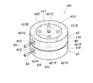
図3および図4は、本発明の第1実施形態に係る医療補助デバイスを表す斜視図である。
図5は、本実施形態に係る医療補助デバイスの内部構造を表す断面図である。
なお、図4は、他の医療用デバイス53(例えば、ガイドワイヤ)が、導入部413を通して医療用デバイス51(例えば、カテーテル)に挿入された状態を表している。3 and 4 are perspective views showing the medical assistance device according to the first embodiment of the present invention.
FIG. 5 is a cross-sectional view showing the internal structure of the medical assistance device according to this embodiment.
Note that FIG. 4 shows a state in which another medical device 53 (eg, guide wire) is inserted into the medical device 51 (eg, catheter) through the
本実施形態に係る医療補助デバイス4は、支持体41と、巻き取り部42と、接続部43と、を備える。
支持体41は、医療補助デバイス4の本体として設けられ、支持軸411を有する。図3~図5に表した支持体41は、内部空間が設けられたハウジングの構造を有する。ただし、本実施形態の支持体41は、内部空間を有することには限定されず、巻き取り部42を回転可能に支持する限りにおいて、巻き取り部42を支持体41の外部に露出させていてもよい。支持体41は、開口部412を有する。接続部43は、支持体41の開口部412を通して支持体41の外部に配置されている。なお、巻き取り部42の大部分が支持体41の外部に露出している場合には、支持体41は、必ずしも開口部412を有していなくともよい。A
The
支持軸411の一方の端部には、導入部413が設けられている。支持軸411の他方の端部には、導出部414が設けられている。導入部413は、支持軸411の内部および導出部414を介して接続部43と空間的に接続されている。これにより、図4に表したように、術者32は、支持軸411の導入部413と、支持軸411の内部と、支持軸411の導出部414と、を通してガイドワイヤなどの医療用デバイス53を接続部43の内部に挿入したり、プライミングのための生理食塩水を接続部43の内部に送り込んだりすることができる。なお、導入部413および導出部414は、支持軸411に設けられていることには限定されず、巻き取り部42の他の部分、あるいは支持体41に設けられていてもよい。
An
巻き取り部42は、図3に表した矢印A1および矢印A2のように、支持体41に対して支持体41の支持軸411を中心として回転可能に設けられている。なお、支持軸411は、支持体41に設けられていることには限定されず、巻き取り部42に設けられていてもよい。すなわち、巻き取り部42は、支持体41および巻き取り部42の少なくともいずれかに設けられた支持軸411を中心として支持体41に対して回転可能に設けられていればよい。これは、図6~図10に関して後述する医療補助デバイス4A、4B、4C、4D、4E、4Fにおいても同様である。
The winding
巻き取り部42は、把持部421を有する。把持部421は、巻き取り部42の表面から外側に突出し、巻き取り部42の回転動作を補助する。すなわち、術者32等は、巻き取り部42の把持部421を把持し操作することにより、巻き取り部42を容易に回転させることができる。なお、把持部421は、必ずしも突起部でなくともよく、指を挿入可能な凹部であってもよい。
The winding
図5に表したように、接続部43は、巻き取り部42に設けられている。具体的には、接続部43の一方の端部は、巻き取り部42の外周部に接続されている。そのため、巻き取り部42が回転すると、接続部43は、巻き取り部42の外周部に沿って巻き取り部42とともに回転する。図4に表したように、接続部43の他方の端部は、医療用デバイス51の基端部に接続される。なお、本願明細書では、生体の管腔に挿入される側を「先端」若しくは「先端側」、術者により操作される手元側を「基端」若しくは「基端側」と称することとする。
As shown in FIG. 5 , the connecting
接続部43の構造や形態は、特に限定されない。例えば、接続部43の外径は、接続される医療用デバイス51の基端部の外径と同じであってもよく、医療用デバイス51の基端部の外径よりも大きくとも小さくともよい。また、接続部43は、巻き取り部42と医療用デバイス51とに接続され接続部43を介して巻き取り部42と医療用デバイス51とを互いに接続させる限りにおいて、ワイヤやチューブなどの長尺体を必ずしも有していなくともよい。例えば、接続部43は、医療用デバイス51の基端部に接続可能な端子が巻き取り部42の外周部に直接的に固定された構造を有していてもよい。
The structure and form of the connecting
続いて、本実施形態に係る医療補助デバイス4の作用を説明する。
図1に表したように、術者32等は、医療用デバイス51の基端部を医療用デバイスホルダ52から抜き出し、医療補助デバイス4の接続部43に接続する。そして、術者32等は、巻き取り部42の把持部421を把持し、図3に表した矢印A1の方向に巻き取り部42を回転させる。そうすると、接続部43が巻き取り部42の外周部に沿って巻き取り部42とともに回転する。これにより、図5に表した二点鎖線の医療用デバイス51のように、医療用デバイス51は、医療用デバイスホルダ52から抜き出されるとともに、巻き取り部42の外周部に巻き取られる。術者32等は、接続部43に接続された医療用デバイス51を使用するときには、医療用デバイス51を引っ張ることにより、医療用デバイス51を支持体41から繰り出すことができる。Next, the action of the
As shown in FIG. 1 , the
本実施形態によれば、医療補助デバイス4は、医療用デバイス51が長い場合であっても、医療用デバイス51を巻き取ることにより、医療用デバイス51の取り回しや操作を向上させることができる。そのため、術者32等の意図に反してあるいは不用意により、医療用デバイス51がカテーテル室2の床などの不潔野に接触したり、カテーテル室2に設置された装置や患者31および術者32等に接触したりするおそれを抑えることができる。また、術者32等は、生体管腔内の処置の準備(スタートアップやセットアップ)のときに医療補助デバイス4を使用することにより、医療用デバイス51が長い場合であってもスタートアップやセットアップにおける煩雑さを解消することができる。
According to this embodiment, even if the
また、巻き取り部42が回転操作可能な把持部421を有するため、電気が供給されていない場合であっても、術者32等は、把持部421を操作することにより巻き取り部42を回転させ医療用デバイス51を巻き取ることができる。
Further, since the winding
また、前述したように、支持軸411の一方の端部には、接続部43と空間的に接続された導入部413が設けられている。そのため、術者32等は、導入部413を通して、他の医療用デバイス53を挿入したり、作動流体を送り込んだりすることができる。本願明細書における「作動流体」としては、例えば、空気、ヘリウムガス、CO2ガス、O2ガス等の気体や、造影剤、薬液、コーティング剤、生理食塩水等の液体が挙げられる。例えば、医療用デバイス51がカテーテルである場合において、術者32等は、導入部413を通してガイドワイヤをカテーテルの管腔内に挿入することができる。あるいは、例えば、医療用デバイス51がカテーテルである場合において、術者32等は、導入部413を通してプライミングのための生理食塩液をカテーテルの管腔内に送り込むことができる。Further, as described above, one end of the
なお、図3~図5に表した医療補助デバイス4では、巻き取り部42は、鉛直方向に延びた支持軸411を中心として支持体41に対して回転可能に設けられている。ただし、巻き取り部42の設置形態は、これだけに限定されるわけではない。例えば、巻き取り部42は、水平方向に延びた支持軸411を中心として支持体41に対して回転可能に設けられていてもよい。これは、図6および図7に関して後述する医療用デバイス4A、および図8に関して後述する医療補助デバイス4Bにおいても同様である。
In addition, in the
次に、本実施形態の変形例に係る医療補助デバイスについて説明する。
なお、本変形例に係る医療補助デバイス4Aの構成要素が、図3~図5に関して前述した本実施形態に係る医療補助デバイス4の構成要素と同様である場合には、重複する説明は適宜省略し、以下、相違点を中心に説明する。Next, a medical assistance device according to a modified example of this embodiment will be described.
If the components of the
図6および図7は、本実施形態の変形例に係る医療補助デバイスを表す断面図である。
なお、図6は、巻き取り部のロックが設定された状態を表す断面図である。図7は、巻き取り部のロックが解除された状態を表す断面図である。6 and 7 are cross-sectional views showing medical assistance devices according to modifications of the present embodiment.
Note that FIG. 6 is a cross-sectional view showing a state in which the winding unit is locked. FIG. 7 is a cross-sectional view showing a state in which the winding section is unlocked.
本変形例に係る医療補助デバイス4Aは、図3~図5に関して前述した医療補助デバイス4と比較して、付勢手段44と、ロック機構45と、をさらに備える。付勢手段44は、支持体41Aの支持軸411と巻き取り部42とに接続され、医療用デバイス51を巻き取る方向(図7に表した矢印A5の方向)に巻き取り部42を付勢する。そのため、術者32等は、接続部43に接続された医療用デバイス51を支持体41Aから繰り出す場合には、付勢手段44の付勢力に対抗して医療用デバイス51を引っ張ることになる。付勢手段44としては、例えば、ぜんまいや板ばねなどが挙げられる。
The
ロック機構45は、操作部451と、ローラ452と、押さえ部453と、を有する。操作部451は、支持体41Aに設けられた第1軸454を中心として支持体41Aに対して回転可能に設けられている。また、操作部451は、ローラ452が押さえ部453に向かう方向へ付勢されている。ローラ452が押さえ部453に向かう方向へ操作部451を付勢する付勢手段としては、例えば、ねじりコイルばねなどが挙げられる。ローラ452は、操作部451の先端部において、操作部451に設けられた第2軸455を中心として操作部451に対して回転可能に設けられている。押さえ部453は、支持体41Aの内面に固定されている。
The
図7に表したように、押さえ部453と、巻き取り部42の外周部と、の隙間は、付勢手段44の付勢方向(医療用デバイス51の巻き取り方向:矢印A5の方向)に向かうにつれて狭くなる。すなわち、押さえ部453と、巻き取り部42の外周部と、の隙間は、くさび状を呈する。そして、付勢手段44の付勢方向に向かうと、押さえ部453と巻き取り部42の外周部との間隔は、ローラ452の外径よりも短くなる。
As shown in FIG. 7, the gap between the
図6に表したように、ローラ452が押さえ部453と巻き取り部42との間に挟まった状態では、巻き取り部42のロックが設定される。つまり、図6に表した状態では、ロック機構45は、付勢手段44により付勢された巻き取り部42の回転動作を停止させる。図6に表した状態から、操作部451が図7に表した矢印A3の方向に押されると、操作部451は、図7に表した矢印A4の方向に第1軸454を中心として回転する。そうすると、ローラ452は、第2軸455を中心として回転しながら、押さえ部453から離れる。これにより、巻き取り部42のロックが解除される。図7に表した状態において、巻き取り部42は、付勢手段44から与えられた付勢力により医療用デバイス51を巻き取る方向(図7に表した矢印A5の方向)に回転する。
As shown in FIG. 6, when the
前述したように、操作部451は、ローラ452が押さえ部453に向かう方向へ付勢されている。そのため、図7に表した矢印A3の方向の力が操作部451から解除されると、操作部451は、図7に表した矢印A4とは反対方向に第1軸454を中心として回転する。そして、ローラ452は、押さえ部453と、巻き取り部42の外周部と、の間に再び挟まる。これにより、巻き取り部42のロックが再び設定される。
As described above, the operating
続いて、本変形例に係る医療補助デバイス4Aの作用を説明する。
図1に表したように、術者32等は、医療用デバイス51の基端部を医療用デバイスホルダ52から抜き出し、医療補助デバイス4の接続部43に接続する。そして、術者32等が操作部451を図7に表した矢印A3の方向に押すと、巻き取り部42は、付勢手段44から与えられた付勢力により図7に表した矢印A5の方向に回転する。これにより、医療用デバイス51は、医療用デバイスホルダ52から抜き出されるとともに、巻き取り部42の外周部に巻き取られる(図5参照)。術者32等が操作部451を押す力を解除すると、ローラ452が押さえ部453と巻き取り部42の外周部との間に挟まることにより、巻き取り部42のロックが設定される。Next, the action of the
As shown in FIG. 1 , the
術者32等は、接続部43に接続された医療用デバイス51を支持体41Aから繰り出すときには、付勢手段44の付勢力に対抗して医療用デバイス51を引っ張る。そうすると、巻き取り部42が図7に表した矢印A6の方向に回転する。そうすると、ローラ452と、巻き取り部42の外周部と、の間に生ずる摩擦力により、操作部451は、図7に表した矢印A4の方向に第1軸454を中心として回転する。そうすると、ローラ452は、第2軸455を中心として回転しながら、押さえ部453から離れる。これにより、巻き取り部42のロックが解除され、医療用デバイス51が支持体41Aから繰り出される。
The
術者32等が必要な長さの医療用デバイス51を支持体41Aから繰り出し、医療用デバイス51を引っ張る力を解除すると、巻き取り部42は、付勢手段44から与えられた付勢力により図7に表した矢印A5の方向に回転しようとする。このとき、ローラ452が押さえ部453に向かう方向へ操作部451が付勢されているため、操作部451は、図7に表した矢印A4とは反対方向に第1軸454を中心として回転する。そして、ローラ452は、押さえ部453と、巻き取り部42の外周部と、の間に再び挟まる。これにより、巻き取り部42のロックが再び設定される。
When the
本変形例に係る医療補助デバイス4Aによれば、医療用デバイス51を巻き取る方向に巻き取り部42を付勢する付勢手段44が設けられているため、巻き取り部42は、医療用デバイス51を容易に巻き取ることができる。また、巻き取り部42が付勢手段44により付勢されている場合であっても、ロック機構45は、巻き取り部42の回転動作を停止させることができる。そのため、術者32等は、医療用デバイス51に適宜たわみを持たせた状態で手技を行うことができる。
According to the
なお、本変形例では、ロック機構45が操作部451とローラ452と押さえ部453とを有する場合を例に挙げた。ただし、本変形例のロック機構は、図6および図7に表した例には限定されず、例えば、術者32等が医療用デバイス51を引っ張ると巻き取り部42のロックが設定され、術者32等が医療用デバイス51を再度引っ張ると巻き取り部42のロックが解除されて巻き取り部42が医療用デバイス51を巻き取る自動巻き取り式の機構であってもよい。
In this modified example, the
次に、本発明の第2実施形態に係る医療補助デバイスについて説明する。
なお、第2実施形態に係る医療補助デバイス4Bの構成要素が、図3~図5に関して前述した第1実施形態に係る医療補助デバイス4の構成要素、ならびに図6および図7に関した変形例に係る医療補助デバイス4Aの構成要素と同様である場合には、重複する説明は適宜省略し、以下、相違点を中心に説明する。Next, a medical assistance device according to a second embodiment of the present invention will be described.
The components of the
図8は、本発明の第2実施形態に係る医療補助デバイスを表す斜視図である。
本実施形態に係る医療補助デバイス4Bは、支持体41と、巻き取り部42と、接続部43と、第1回転駆動部461と、回転検出部462と、制御部463と、第2回転駆動部464と、を備える。図3~図5に関して前述した把持部421は、設けられていてもよく、設けられていなくともよい。図8に表した例では、把持部421は、設けられていない。FIG. 8 is a perspective view showing a medical assistance device according to a second embodiment of the invention.
The
第1回転駆動部461は、支持体41に設けられるとともに巻き取り部42に接続され、電圧が供給されると巻き取り部42を回転させる回転力(第1回転力)を発生する。本実施形態の第1回転駆動部461が発生する回転力は、本発明の「第1回転力」に相当する。例えば、第1回転駆動部461は、モータであり、所定のギヤ列を介して巻き取り部42に接続されている。第1回転駆動部461は、制御部463から送信された制御信号に基づいて駆動し、巻き取り部42を回転させる。第1回転駆動部461がステッピングモータである場合には、高い精度で巻き取り部42の位置を決定することができる。
The first
回転検出部462は、支持体41に設けられ、巻き取り部42の回転角を検出する。回転検出部462は、検出した巻き取り部42の回転角に関する検出信号を制御部463に送信する。回転検出部462としては、例えば、ロータリーエンコーダやポテンショメータなどが挙げられる。あるいは、回転検出部462としては、巻き取り部42に生ずるトルクを検出する圧力センサなどが挙げられる。
The
制御部463は、第1回転駆動部461および第2回転駆動部464に対して制御信号を送信し、第1回転駆動部461および第2回転駆動部464の動作を制御する。また、制御部463は、回転検出部462から送信された検出信号を受信し、所定の処理を実行する。
The
具体的には、制御部463は、回転検出部462により検出された巻き取り部42の回転角に基づいて、医療用デバイス51が所定位置から巻き取られた長さおよび繰り出された長さを算出する。これによれば、医療用デバイス51の少なくとも一部が巻き取り部42に巻き取られた状態であっても、術者32等は、制御部463に算出された長さに基づいて、生体管腔内の処置中において体内に挿入された医療用デバイス51の長さや、医療用デバイス51のたわみ量(バッファ量)の取り方を把握することができる。
Specifically, based on the rotation angle of the winding
また、制御部463は、回転検出部462により検出された巻き取り部42の回転角に基づいて、医療用デバイス51が繰り出される方向(図3に表した矢印A2の方向)の力を検出すると、第1回転駆動部461を制御して医療用デバイス51を繰り出す。つまり、制御部463は、第1回転駆動部461を制御し、医療用デバイス51を繰り出す方向(図3に表した矢印A2の方向)に巻き取り部42を回転させる。一方で,制御部463は、回転検出部462により検出された巻き取り部42の回転角に基づいて、医療用デバイス51が巻き取られる方向(図3に表した矢印A1の方向)の力を検出すると、第1回転駆動部461を制御して医療用デバイス51を巻き取る。つまり、制御部463は、第1回転駆動部461を制御し、医療用デバイス51を巻き取る方向(図3に表した矢印A1の方向)に巻き取り部42を回転させる。
Further, the
これによれば、制御部463は、第1回転駆動部461を制御することにより、術者32等が医療用デバイス51を繰り出したり巻き取ったりする操作や動作を補助することができる。これにより、本実施形態に係る医療補助デバイス4Bは、生体管腔内の処置をサポートすることができる。
According to this, the
第2回転駆動部464は、支持体41に設けられるとともに接続部43に接続され、電圧が供給されると医療用デバイス51の軸の中心として医療用デバイス51を回転させる回転力(第2回転力)を発生する。本実施形態の第2回転駆動部464が発生する回転力は、本発明の「第2回転力」に相当する。例えば、第2回転駆動部464は、モータであり、所定のギヤ列を介して接続部43に接続されている。第2回転駆動部464は、制御部463から送信された制御信号に基づいて駆動し、接続部43を介して医療用デバイス51を回転させる。第2回転駆動部464がステッピングモータである場合には、高い精度で接続部43および医療用デバイス51の回転位置を決定することができる。
The second
本実施形態に係る医療補助デバイス4Bによれば、巻き取り部42は、術者32等が巻き取り部42を手動で操作しなくとも、電圧を供給されることにより自動で回転し医療用デバイス51を巻き取ることができる。
According to the
また、前述したように、第2回転駆動部464は、接続部43に接続される医療用デバイス51の軸の中心として医療用デバイス51を回転させることができる。これにより、生体管腔内の処置の選択肢を広げることができる。例えば、医療用デバイス51が画像診断用カテーテル(例えば、IVUSカテーテル:Intra Vascular Ultra Sound catheter)である場合には、第2回転駆動部464は、医療用デバイス51の軸の中心として医療用デバイス51を生体管腔内において回転させ、患部の画像を周方向に亘って取得させることができる。あるいは、例えば、医療用デバイス51がガイドワイヤである場合には、第2回転駆動部464は、医療用デバイス51の軸の中心として医療用デバイス51を生体管腔内において回転させ、血管の分岐部における血管選択性を向上させることができる。また、図3~図5に関して前述した第1実施形態に係る医療補助デバイス4の効果と同様の効果が得られる。
Further, as described above, the second
なお、本実施形態に係る医療補助デバイス4Bは、医療補助デバイス4Bを保持するとともに医療補助デバイス4Bを駆動させる外部駆動装置に接続されていてもよい。例えば、外部駆動装置は、医療補助デバイス4Bに連結され、医療用デバイス51のフォワードおよびプルバックの動作を行ったり、医療用デバイス51の軸の中心として医療用デバイス51を回転させたりすることができる。
The
本実施形態に係る医療補助デバイス4Bでは、図3~図5に関して前述した把持部421が設けられていてもよい。把持部421が設けられている場合には、術者32等は、巻き取り部42を手動で回転させることができる。さらに、この場合において、把持部421により巻き取り部42を手動で回転させる手動モードと、第1回転駆動部461により巻き取り部42を電動で回転させる電動モードと、を切り替え可能な切替部が設けられていてもよい。
The
次に、本発明の第3実施形態に係る医療補助デバイスについて説明する。
なお、第3実施形態に係る医療補助デバイス4Cの構成要素が、図3~図5に関して前述した第1実施形態に係る医療補助デバイス4の構成要素、および図8に関して前述した第2実施形態に係る医療補助デバイス4Bの構成要素と同様である場合には、重複する説明は適宜省略し、以下、相違点を中心に説明する。Next, a medical assistance device according to a third embodiment of the present invention will be described.
The components of the
図9は、本発明の第3実施形態に係る医療補助デバイスを表す斜視図である。
本実施形態に係る医療補助デバイス4Cは、支持体41Cと、2つの巻き取り部42と、2つの接続部43と、2つの第1回転駆動部461と、2つの回転検出部462と、制御部463と、2つの第2回転駆動部464と、を備える。2つの巻き取り部42は、互いに独立して回転することができる。例えば、2つの巻き取り部42は、互いに同軸上に配置された2つの支持軸411を中心として支持体41Cに対して回転可能に設けられている。あるいは、例えば、2つの巻き取り部42は、2つの巻き取り部42に共通する1つの支持軸411を中心として支持体41Cに対して回転可能に設けられていてもよい。FIG. 9 is a perspective view showing a medical assistance device according to a third embodiment of the invention.
The
一方の第1回転駆動部461は、支持体41Cに設けられるとともに一方の巻き取り部42に接続され、電圧が供給されると一方の巻き取り部42を回転させる回転力(第1回転力)を発生する。一方の回転検出部462は、支持体41Cに設けられ、一方の巻き取り部42の回転角を検出する。一方の第2回転駆動部464は、支持体41Cに設けられるとともに一方の接続部43に接続され、電圧が供給されると医療用デバイス51の軸の中心として医療用デバイス51を回転させる回転力(第2回転力)を発生する。
One of the first
他方の第1回転駆動部461は、支持体41Cに設けられるとともに他方の巻き取り部42に接続され、電圧が供給されると他方の巻き取り部42を回転させる回転力(第1回転力)を発生する。他方の回転検出部462は、支持体41Cに設けられ、他方の巻き取り部42の回転角を検出する。他方の第2回転駆動部464は、支持体41Cに設けられるとともに他方の接続部43に接続され、電圧が供給されると医療用デバイス51の軸の中心として医療用デバイス51を回転させる回転力(第2回転力)を発生する。
The other first
本実施形態によれば、2つの巻き取り部42は、互いに異なる種類の医療用デバイス51を巻き取ることができる。例えば、図9に表した医療補助デバイス4Cにおいて、一方の巻き取り部42は、カテーテルを巻き取ることができる。また、他方の巻き取り部42は、ガイドワイヤを巻き取ることができる。これにより、生体管腔内の処置の選択肢を広げることができる。
According to this embodiment, the two winding
前述したように、2つの巻き取り部42は、互いに独立して回転することができる。そのため、制御部463は、2つの第1回転駆動部461を個別に制御することにより、2つの医療用デバイス51が巻き取られる長さおよび繰り出される長さを個別に制御することができる。また、制御部463は、2つの第2回転駆動部464を個別に制御することにより、2つの医療用デバイス51がそれぞれの軸の中心として回転する角度を個別に制御することができる。
As previously mentioned, the two
なお、本実施形態に係る医療補助デバイス4Cでは、2つの巻き取り部42が互いに固定されていてもよい。この場合には、2つの巻き取り部42は、互いに連動して回転することができる。また、この場合には、1つの第1回転駆動部461および1つの回転検出部462が設けられていればよい。これによれば、制御部463は、互いに異なる種類の2つの医療用デバイス51が巻き取られる長さおよび繰り出される長さを合わせることができる。なお、本実施形態の巻き取り部42の数は、2つには限定されず、3つ以上であってもよい。
In addition, in the
また、図9に表した医療補助デバイス4Cでは、2つの巻き取り部42は、鉛直方向に延びた支持軸411を中心として支持体41Cに対して回転可能に設けられている。ただし、2つの巻き取り部42の設置形態は、これだけに限定されるわけではない。例えば、2つの巻き取り部42は、水平方向に延びた支持軸411を中心として支持体41Cに対して回転可能に設けられていてもよい。この場合には、2つの巻き取り部42は、上下方向ではなく水平方向に並んで配置されることが好ましい。
In addition, in the
次に、本発明の第4実施形態に係る医療補助デバイスについて説明する。
なお、第4実施形態に係る医療補助デバイスDの構成要素が、図3~図5に関して前述した第1実施形態に係る医療補助デバイス4の構成要素、図8に関して前述した第2実施形態に係る医療補助デバイス4Bの構成要素、および図9に関して前述した第3実施形態に係る医療補助デバイス4Cの構成要素と同様である場合には、重複する説明は適宜省略し、以下、相違点を中心に説明する。Next, a medical assistance device according to a fourth embodiment of the present invention will be described.
The components of the medical assistance device D according to the fourth embodiment are the components of the
図10は、本発明の第4実施形態に係る医療補助デバイスを表す斜視図である。
本実施形態に係る医療補助デバイス4Dは、複数の医療補助デバイスが積層され互いに結合された構造を有する。図9に表した例では、2つの医療補助デバイス4E、4Fが、支持軸411の軸方向に沿って積層され互いに結合されている。2つの医療補助デバイス4E、4Fは、互いに着脱可能とされている。なお、本実施形態では、積層される医療補助デバイスの数は、2つには限定されず、3つ以上であってもよい。FIG. 10 is a perspective view showing a medical assistance device according to a fourth embodiment of the invention.
A
相対的に上段に配置された医療補助デバイス4Eは、支持体41Eと、巻き取り部42Eと、接続部43と、を備える。巻き取り部42Eは、上面に設けられた凹部421Eを有する。術者32等は、巻き取り部42Eの凹部421Eに指を挿入することにより、支持軸411を中心として巻き取り部42Eを支持体41Eに対して回転させることができる。巻き取り部42Eの下面には、下側に向かって突出した結合部46が設けられている。結合部46は、相対的に下段に配置された医療補助デバイス4Fの凹部421Fに挿入されている。
The
下段の医療補助デバイス4Fは、支持体41Fと、巻き取り部42Fと、接続部43と、を備える。巻き取り部42Fは、上面に設けられた凹部421Fを有する。凹部421Fには、上段の医療補助デバイス4Eの巻き取り部42Eに設けられた結合部46が挿入されている。
The lower
結合部46は、巻き取り部42Eの下面に固定されており、巻き取り部42Eが回転すると巻き取り部42Eとともに支持軸411を中心として支持体41Eに対して回転する。そのため、術者32等が上段の医療補助デバイス4Eの凹部421Eに指を挿入し巻き取り部42Eを回転させると、下段の医療補助デバイス4Fの巻き取り部42Fは、凹部421Fに挿入された結合部46から力を受け、上段の医療補助デバイス4Eの巻き取り部42Eとともに支持軸411を中心として回転する。つまり、2つの巻き取り部42E、42Fは、互いに連動して回転する。
The
本実施形態によれば、2つの巻き取り部42E、42Fは、互いに異なる種類の医療用デバイス51を巻き取ることができる。例えば、図10に表した医療補助デバイス4Dにおいて、上段の医療補助デバイス4Eは、カテーテルを巻き取ることができる。また、下段の医療補助デバイス4Fは、ガイドワイヤを巻き取ることができる。これにより、生体管腔内の処置の選択肢を広げることができる。また、電気が供給されていない場合であっても、術者32等は、上段の巻き取り部42Eの凹部421Eを利用して巻き取り部42Eを回転させることにより、下段の巻き取り部42Fを回転させ、互いに異なる種類の医療用デバイス51を巻き取ることができる。
According to this embodiment, the two winding
なお、術者32等は、上段の医療補助デバイス4Eおよび下段の医療補助デバイス4Fを互いに外すと、上段の巻き取り部42Eおよび下段の巻き取り部42Fを互いに独立して回転させることができる。また、凹部421Eおよび凹部421Fのそれぞれの数は、4つには限定されず、3つ以下であってもよく、5つ以上であってもよい。
When the
また、図10に表した医療補助デバイス4Dでは、2つの巻き取り部42E、42Fは、鉛直方向に延びた支持軸411を中心として支持体41E、41Fに対して回転可能に設けられている。ただし、2つの巻き取り部42E、42Fの設置形態は、これだけに限定されるわけではない。例えば、2つの巻き取り部42E、42Fは、水平方向に延びた支持軸411を中心として支持体41E、41Fに対して回転可能に設けられていてもよい。この場合には、2つの巻き取り部42E、42Fは、上下方向ではなく水平方向に並んで配置されることが好ましい。すなわち、この場合には、2つの医療補助デバイス4E、4Fは、上下方向ではなく水平方向に積層され互いに結合されることが好ましい。
In addition, in the
これによれば、術者32等は、巻き取り部42Eの凹部421Eおよび巻き取り部42Fの凹部421Fの両方に指を容易に挿入し、巻き取り部42Eおよび巻き取り部42Fの両方を容易に回転させることができる。また、この場合には、2つの巻き取り部42E、42Fのそれぞれは、表面から外側に突出した把持部421(図3参照)を有することができる。これにより、術者32等は、2つの巻き取り部42E、42Fのそれぞれに設けられた把持部421を容易に把持することができ、2つの巻き取り部42E、42Fを容易に回転させることができる。
According to this, the
以上、本発明の実施形態について説明した。しかし、本発明は、上記実施形態に限定されず、特許請求の範囲を逸脱しない範囲で種々の変更を行うことができる。上記実施形態の構成は、その一部を省略したり、上記とは異なるように任意に組み合わせたりすることができる。 The embodiments of the present invention have been described above. However, the present invention is not limited to the above embodiments, and various modifications can be made without departing from the scope of the claims. Some of the configurations of the above embodiments may be omitted, or may be arbitrarily combined in a manner different from the above.
2・・・カテーテル室、 4、4A、4B、4C、4D、4E、4F・・・医療補助デバイス、 21・・・血管造影装置、 22・・・カテーテルテーブル、 23・・・デジタルイメージング装置、 24・・・心電図、 31・・・患者、 32・・・術者、 33・・・補助者、 41、41A、41C、41E、41F・・・支持体、 42、42E、42F・・・巻き取り部、 43・・・接続部、 44・・・付勢手段、 45・・・ロック機構、 46・・・結合部、 51・・・医療用デバイス、 52・・・医療用デバイスホルダ、 53・・・他の医療用デバイス、 411・・・支持軸、 412・・・開口部、 413・・・導入部、 414・・・導出部、 421・・・把持部、 421E、421F・・・凹部、 451・・・操作部、 452・・・ローラ、 453・・・押さえ部、 454・・・第1軸、 455・・・第2軸、 461・・・第1回転駆動部、 462・・・回転駆動部、 463・・・制御部、 464・・・第2回転駆動部
2
Claims (5)
支持体と、
前記支持体に対して支持軸を中心として回転可能に設けられ前記医療用デバイスを巻き取る巻き取り部と、
前記巻き取り部に設けられ前記医療用デバイスの端部に接続される接続部と、
前記支持体に設けられ、電圧が供給されると前記巻き取り部を回転させる回転力を発生する回転駆動部と、
前記巻き取り部の回転角を検出する回転検出部と、
前記回転検出部から送信された信号を受信し、前記回転検出部により検出された前記回転角に基づいて前記医療用デバイスが所定位置から巻き取られた長さおよび繰り出された長さを算出する制御部と、
を備えたことを特徴とする医療補助デバイス。 A medical assistance device inserted into a biological lumen and connected to a medical device used for treatment within the biological lumen,
a support;
a winding unit that is rotatable about a support shaft with respect to the support and that winds the medical device;
a connecting portion provided on the winding portion and connected to an end portion of the medical device;
a rotation drive unit provided on the support and generating a rotational force to rotate the winding unit when a voltage is supplied;
a rotation detection unit that detects the rotation angle of the winding unit;
receiving the signal transmitted from the rotation detection unit, and calculating the length by which the medical device is wound up and the length by which the medical device is extended from a predetermined position based on the rotation angle detected by the rotation detection unit; a control unit;
A medical assistance device comprising:
前記第1回転力を発生する前記回転駆動部は、第1回転駆動部であり、
前記接続部に接続される前記医療用デバイスの軸の中心として前記医療用デバイスを回転させる第2回転力を発生する第2回転駆動部をさらに備えたことを特徴とする請求項1または2に記載の医療補助デバイス。 The rotational force that rotates the winding unit is a first rotational force,
The rotational drive section that generates the first rotational force is a first rotational drive section,
3. The apparatus according to claim 1 or 2 , further comprising a second rotation driving section that generates a second rotational force that rotates the medical device connected to the connection section about an axis of the medical device. A paramedical device as described.
支持体と、
前記支持体に対して支持軸を中心として回転可能に設けられ前記カテーテルを巻き取る巻き取り部と、
前記巻き取り部に設けられ前記カテーテルの端部に接続される接続部と、
を備え、
前記支持体および前記巻き取り部の少なくともいずれかは、前記接続部と空間的に接続された導入部であって前記カテーテルとは異なる他のカテーテルが挿入されるまたは前記処置の際に使用される作動流体またはガイドワイヤが送り込まれる導入部を有し、
前記導入部は、医療用補助デバイスの外面に設けられたことを特徴とする医療補助デバイス。
A medical assistance device inserted into a biological lumen and connected to a catheter used for treatment within the biological lumen,
a support;
a winding unit that is rotatable about a support shaft with respect to the support and that winds the catheter ;
a connecting portion provided on the winding portion and connected to an end portion of the catheter ;
with
At least one of the support and the winding portion is an introduction portion that is spatially connected to the connection portion and into which another catheter different from the catheter is inserted or used during the treatment. having an introduction portion into which a working fluid or guidewire is fed;
A medical assistance device, wherein the introduction portion is provided on an outer surface of the medical assistance device.
Applications Claiming Priority (3)
| Application Number | Priority Date | Filing Date | Title |
|---|---|---|---|
| JP2018020553 | 2018-02-07 | ||
| JP2018020553 | 2018-02-07 | ||
| PCT/JP2018/034993 WO2019155676A1 (en) | 2018-02-07 | 2018-09-21 | Medical assistance device |
Publications (2)
| Publication Number | Publication Date |
|---|---|
| JPWO2019155676A1 JPWO2019155676A1 (en) | 2021-01-28 |
| JP7203052B2 true JP7203052B2 (en) | 2023-01-12 |
Family
ID=67548357
Family Applications (1)
| Application Number | Title | Priority Date | Filing Date |
|---|---|---|---|
| JP2019570288A Active JP7203052B2 (en) | 2018-02-07 | 2018-09-21 | medical assistance device |
Country Status (5)
| Country | Link |
|---|---|
| US (1) | US11529496B2 (en) |
| EP (1) | EP3682933B1 (en) |
| JP (1) | JP7203052B2 (en) |
| CN (1) | CN111542366B (en) |
| WO (1) | WO2019155676A1 (en) |
Families Citing this family (3)
| Publication number | Priority date | Publication date | Assignee | Title |
|---|---|---|---|---|
| US20190321595A1 (en) * | 2018-04-20 | 2019-10-24 | Becton, Dickinson And Company | Instrument delivery device having a rotary element |
| JP7393910B2 (en) * | 2019-10-17 | 2023-12-07 | テルモ株式会社 | Medical long body winding device |
| CN117899301B (en) * | 2024-03-20 | 2024-06-04 | 杭州坦帕医疗科技有限公司 | Self-adaptive transfusion port |
Citations (4)
| Publication number | Priority date | Publication date | Assignee | Title |
|---|---|---|---|---|
| JP2005514095A (en) | 2001-12-28 | 2005-05-19 | メドトロニック ミニメド インコーポレイテッド | Variable length flexible conduit feeder |
| WO2008074039A1 (en) | 2006-12-20 | 2008-06-26 | Ami Agency For Medical Innovations Gmbh | Infusion port with windable tube |
| JP2016510606A (en) | 2013-03-07 | 2016-04-11 | ロボカツRobocath | A medical robot for guiding particularly flexible medical parts |
| US20160136391A1 (en) | 2013-07-23 | 2016-05-19 | Hollister Incorporated | Urinary Catheter Deployment Cassettes |
Family Cites Families (15)
| Publication number | Priority date | Publication date | Assignee | Title |
|---|---|---|---|---|
| US3995628A (en) * | 1975-04-25 | 1976-12-07 | Travenol Laboratories, Inc. | Catheter insertion device |
| JPS63162495A (en) * | 1986-12-24 | 1988-07-06 | 株式会社 富永製作所 | Lubricating device |
| JP2517982Y2 (en) * | 1993-04-06 | 1996-11-20 | 富士システムズ株式会社 | Device for winding and storing catheter |
| US20040051019A1 (en) * | 2002-09-02 | 2004-03-18 | Mogensen Lasse Wesseltoft | Apparatus for and a method of adjusting the length of an infusion tube |
| US7594909B2 (en) * | 2002-09-02 | 2009-09-29 | Unomedical, A/S | Apparatus and method for adjustment of the length of an infusion tubing |
| JP2005319083A (en) | 2004-05-10 | 2005-11-17 | Olympus Corp | Winding reel of treatment appliance for endoscope, treatment appliance for endoscope and treatment appliance system for endoscope |
| IL162318A (en) * | 2004-06-03 | 2011-07-31 | Tal Wenderow | Transmission for a remote catheterization system |
| WO2009125744A1 (en) * | 2008-04-10 | 2009-10-15 | Ntn株式会社 | Linear object operation controller which controls operation of linear object by operator |
| US8191551B2 (en) * | 2009-07-17 | 2012-06-05 | Joan Skovgard | Oxygen delivery system |
| EP2386327A1 (en) * | 2010-05-12 | 2011-11-16 | F. Hoffmann-La Roche AG | Device for adjusting the length of infusion tubing |
| EP2623151A4 (en) * | 2010-09-28 | 2014-04-16 | Terumo Corp | Introducer sheath, placement device for blood vessel treatment instrument, and method for shortening introducer sheath |
| JP6254956B2 (en) * | 2012-03-07 | 2017-12-27 | デカ・プロダクツ・リミテッド・パートナーシップ | Infusion pump assembly |
| JP6670758B2 (en) * | 2014-12-26 | 2020-03-25 | テルモ株式会社 | Container |
| JP6706480B2 (en) * | 2015-10-22 | 2020-06-10 | カナエ工業株式会社 | Infusion tube winding device and infusion device |
| CN206597189U (en) * | 2015-12-04 | 2017-10-31 | 中国人民解放军第二军医大学 | A kind of Infusion support |
-
2018
- 2018-09-21 CN CN201880085041.1A patent/CN111542366B/en active Active
- 2018-09-21 WO PCT/JP2018/034993 patent/WO2019155676A1/en unknown
- 2018-09-21 JP JP2019570288A patent/JP7203052B2/en active Active
- 2018-09-21 EP EP18904745.9A patent/EP3682933B1/en active Active
-
2020
- 2020-07-27 US US16/939,365 patent/US11529496B2/en active Active
Patent Citations (4)
| Publication number | Priority date | Publication date | Assignee | Title |
|---|---|---|---|---|
| JP2005514095A (en) | 2001-12-28 | 2005-05-19 | メドトロニック ミニメド インコーポレイテッド | Variable length flexible conduit feeder |
| WO2008074039A1 (en) | 2006-12-20 | 2008-06-26 | Ami Agency For Medical Innovations Gmbh | Infusion port with windable tube |
| JP2016510606A (en) | 2013-03-07 | 2016-04-11 | ロボカツRobocath | A medical robot for guiding particularly flexible medical parts |
| US20160136391A1 (en) | 2013-07-23 | 2016-05-19 | Hollister Incorporated | Urinary Catheter Deployment Cassettes |
Also Published As
| Publication number | Publication date |
|---|---|
| US11529496B2 (en) | 2022-12-20 |
| CN111542366B (en) | 2023-05-16 |
| EP3682933B1 (en) | 2022-06-29 |
| EP3682933A4 (en) | 2020-12-02 |
| CN111542366A (en) | 2020-08-14 |
| JPWO2019155676A1 (en) | 2021-01-28 |
| EP3682933A1 (en) | 2020-07-22 |
| WO2019155676A1 (en) | 2019-08-15 |
| US20200353214A1 (en) | 2020-11-12 |
Similar Documents
| Publication | Publication Date | Title |
|---|---|---|
| JP7203053B2 (en) | medical assistance device | |
| JP7159393B2 (en) | Systems for guide carousel control | |
| US11529496B2 (en) | Medical assistance device | |
| US7060033B2 (en) | Ultrasound imaging guidewire with static central core and tip | |
| JP2021176555A (en) | System for controlling hemostasis valve | |
| JP2002513607A (en) | Combined motor drive and longitudinal position automatic translator for ultrasound imaging systems | |
| JP2004097286A (en) | Catheter | |
| US11890135B2 (en) | Integrated imaging and device deployment platform | |
| US10792475B2 (en) | Medical tube and medical device | |
| JP4312009B2 (en) | catheter | |
| JP6826847B2 (en) | Medical device | |
| CN110916746A (en) | Pusher and intervene conveying system | |
| JP7528110B2 (en) | Medical instrument set and tubular member | |
| CN215458616U (en) | Surgical robot system | |
| JP2023521894A (en) | Systems and methods for mechanical displacement of the esophagus | |
| JP2018102608A (en) | Medical device and treatment method | |
| JP2018042823A (en) | Medical device |
Legal Events
| Date | Code | Title | Description |
|---|---|---|---|
| A621 | Written request for application examination |
Free format text: JAPANESE INTERMEDIATE CODE: A621 Effective date: 20210610 |
|
| A131 | Notification of reasons for refusal |
Free format text: JAPANESE INTERMEDIATE CODE: A131 Effective date: 20220511 |
|
| A601 | Written request for extension of time |
Free format text: JAPANESE INTERMEDIATE CODE: A601 Effective date: 20220711 |
|
| A521 | Request for written amendment filed |
Free format text: JAPANESE INTERMEDIATE CODE: A523 Effective date: 20220905 |
|
| TRDD | Decision of grant or rejection written | ||
| A01 | Written decision to grant a patent or to grant a registration (utility model) |
Free format text: JAPANESE INTERMEDIATE CODE: A01 Effective date: 20221205 |
|
| A61 | First payment of annual fees (during grant procedure) |
Free format text: JAPANESE INTERMEDIATE CODE: A61 Effective date: 20221226 |
|
| R150 | Certificate of patent or registration of utility model |
Ref document number: 7203052 Country of ref document: JP Free format text: JAPANESE INTERMEDIATE CODE: R150 |