JP7202680B2 - game machine - Google Patents
game machine Download PDFInfo
- Publication number
- JP7202680B2 JP7202680B2 JP2020160568A JP2020160568A JP7202680B2 JP 7202680 B2 JP7202680 B2 JP 7202680B2 JP 2020160568 A JP2020160568 A JP 2020160568A JP 2020160568 A JP2020160568 A JP 2020160568A JP 7202680 B2 JP7202680 B2 JP 7202680B2
- Authority
- JP
- Japan
- Prior art keywords
- game
- state
- mode
- combination
- bonus
- Prior art date
- Legal status (The legal status is an assumption and is not a legal conclusion. Google has not performed a legal analysis and makes no representation as to the accuracy of the status listed.)
- Active
Links
Images


Description
本発明は、パチスロ機やパチンコ機等の遊技機に関する。 The present invention relates to gaming machines such as pachislot machines and pachinko machines.
従来の遊技機において、サウンドデータをバッファに書き込み、バッファからサウンドデータを読み出して出力する遊技機が提案されている(例えば、特許文献1参照)。 Among conventional gaming machines, there has been proposed a gaming machine that writes sound data to a buffer and reads and outputs the sound data from the buffer (see, for example, Patent Document 1).
しかしながら、このような遊技機では、バッファの数が不足するとサウンドデータを出力することができなくなるという問題があった。 However, such a game machine has a problem that sound data cannot be output if the number of buffers is insufficient .
本発明は、このような点に鑑みてなされたものであり、サウンドデータを出力することができなくなることを防止することができる遊技機を提供することを目的とする。 SUMMARY OF THE INVENTION It is an object of the present invention to provide a game machine capable of preventing the inability to output sound data .
上記目的を達成するために、本実施形態に係る遊技機によれば、以下のような構成の遊技機を提供することができる。 In order to achieve the above object, according to the gaming machine according to the present embodiment, it is possible to provide a gaming machine having the following configuration.
音声による演出を行う出音手段(例えば、スピーカ920L,920R)と、
前記出音手段を制御するための出音制御手段(例えば、サウンド制御タスクを実行するサブCPU981)と、
前記出音手段から音声を出音させるための音声データを一時的に格納するための複数のデータ格納領域(例えば、サウンドバッファ)と、を備え、
前記出音制御手段は、
前記音声データに基づく音声を前記出音手段に出音させる場合、前記データ格納領域を確保して、確保した前記データ格納領域に前記音声データを格納する音声データ格納手段と、
前記複数のデータ格納領域のうち解放条件が成立している前記データ格納領域を解放する格納領域解放手段(例えば、サウンドバッファチェック処理を実行するサブCPU981)と、を有し、
前記格納領域解放手段は、解放されている前記データ格納領域の数が特定数未満となったら、前記解放条件が成立している前記データ格納領域を解放し、
前記解放条件は、前記複数のデータ格納領域のうち、再生中であるが出力チャネルに供給されていない音声データが格納されているデータ格納領域に対して成立する
ことを特徴とする遊技機。
Sound output means (for example,
Sound output control means for controlling the sound output means (for example, a
a plurality of data storage areas (e.g., sound buffers) for temporarily storing audio data for outputting audio from the sound output means;
The sound output control means is
audio data storage means for securing the data storage area and storing the audio data in the secured data storage area when causing the sound output means to output audio based on the audio data;
a storage area release means (for example, a
the storage area release means releases the data storage area satisfying the release condition when the number of the released data storage areas becomes less than a specific number;
The gaming machine , wherein the release condition is established for a data storage area storing audio data that is being reproduced but is not supplied to an output channel, among the plurality of data storage areas .
上記構成の遊技機によれば、サウンドデータを出力することができなくなることを防止することができる。 According to the gaming machine with the above configuration, it is possible to prevent the sound data from being unable to be output .
以下、図面を参照して、本実施形態に係る遊技機について説明する。なお、本実施形態では、遊技機としてパチスロ機を例に挙げて説明する。 A gaming machine according to the present embodiment will be described below with reference to the drawings. In this embodiment, a pachislot machine will be described as an example of a game machine.
[1.パチスロ機の構造]
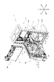
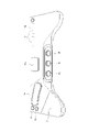
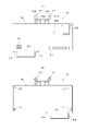
まず、図1及び図2を参照して、パチスロ機1の構造について説明する。なお、図1は、パチスロ機1の外部構造を示す図であり、図2は、パチスロ機1の内部構造を示す図である。また、説明の便宜上、以下の外部構造の説明において、内部構造の一部を説明する場合があり、内部構造の説明において、外部構造の一部を説明する場合がある。
[1. Structure of pachislot machine]
First, the structure of the pachi-
[1-1.外部構造]
[1-1-1.筐体]
パチスロ機1は、矩形箱状の筐体2により構成されている。また、筐体2は、遊技機本体として前面側に矩形状の開口を有する金属製のキャビネットGと、キャビネットGの前面上部に配置された上ドア機構UDと、キャビネットGの前面下部に配置された下ドア機構DDとを有している。
[1-1. External structure]
[1-1-1. Housing]
A pachi-
キャビネットGは、中間支持板G1と、左右一対の側面壁G2と、背面壁G3と、上面壁G4と、底面壁G5とを有している。なお、図1及び図2においては、背面壁G3及び底面壁G5の図示を省略している。また、キャビネットGの上面壁G4には、左右方向に所定の間隔を空けて、上下方向に貫通する2つの開口G4aが形成されている。そして、この2つの開口G4aそれぞれを塞ぐように木製の板部材G4bが上面壁G4に取付けられている。 The cabinet G has an intermediate support plate G1, a pair of left and right side walls G2, a rear wall G3, a top wall G4, and a bottom wall G5. In addition, in FIG.1 and FIG.2, illustration of the back wall G3 and the bottom wall G5 is abbreviate|omitted. In addition, two openings G4a are formed in the upper surface wall G4 of the cabinet G so as to penetrate in the vertical direction at a predetermined interval in the horizontal direction. A wooden plate member G4b is attached to the top wall G4 so as to block the two openings G4a.
なお、板部材G4bは、パチスロ機1を遊技店に設置する際に遊技島(不図示)に固定するために用いられるが、このような固定の方法が確保される限り、金属材や樹脂材で構成することもできるし、上面壁G4と一体に形成することもできる。また、キャビネットGについて一定の強度が確保される限り、各構成部材の一部又は全部を木材や樹脂材で構成することもできる。
The plate member G4b is used to fix the pachi-
また、キャビネットGは、その内部において、中間支持板G1を挟んで上側に、前方に開口する上側開口部G101が形成されており、中間支持板G1を挟んで下側に、前方に開口する下側開口部G102が形成されている。すなわち、キャビネットG内は、中間支持板G1を挟んで上部空間と下部空間とに仕切られており、中間支持板G1は、キャビネットG内を上部空間と下部空間とに仕切る仕切板として機能している。上部空間は、キャビネットG内の上ドア機構UDの後側となる空間であり、後述のメイン表示装置210等が収容される。また、下部空間は、キャビネットG内の下ドア機構DDの後側となる空間であり、後述のリールユニットRUや主制御基板71等が収容される。
Inside the cabinet G, an upper opening G101 is formed that opens forward with the intermediate support plate G1 interposed therebetween. A side opening G102 is formed. That is, the interior of the cabinet G is partitioned into an upper space and a lower space with an intermediate support plate G1 interposed therebetween, and the intermediate support plate G1 functions as a partition plate that partitions the interior of the cabinet G into the upper space and the lower space. there is The upper space is a space on the rear side of the upper door mechanism UD inside the cabinet G, and accommodates a
なお、キャビネットGは、必ずしも中間支持板G1を含んで構成されていなくともよい。すなわち、キャビネットG内において各装置等が適切に収容される限り、上部空間と下部空間を仕切らない構成としてもよい。また、キャビネットGは、単に「箱体」や「本体」と称することもできるし、上ドア機構UD及び下ドア機構DDを支持、あるいは固定する枠体として機能するため、「本体枠」、「支持体」、「支持枠」、あるいは「固定枠」等と称することもできる。 Note that the cabinet G does not necessarily have to include the intermediate support plate G1. That is, as long as each device and the like can be properly accommodated in the cabinet G, the upper space and the lower space may not be partitioned. Further, the cabinet G can be simply referred to as a "box" or "main body", and functions as a frame for supporting or fixing the upper door mechanism UD and the lower door mechanism DD. It can also be referred to as a "support", "support frame", or "fixed frame".
[1-1-2.前面扉]
上ドア機構UD及び下ドア機構DDは、キャビネットGの開口の形状及び大きさに対応するように形成され、キャビネットGにおける開口の上部空間及び下部空間を閉塞可能に設けられている。すなわち、上ドア機構UD及び下ドア機構DDは、パチスロ機1の前面側に設けられた前面扉(フロントドア)として機能している。
[1-1-2. front door]
The upper door mechanism UD and the lower door mechanism DD are formed so as to correspond to the shape and size of the opening of the cabinet G, and are provided so as to be able to block the upper and lower spaces of the opening in the cabinet G. As shown in FIG. That is, the upper door mechanism UD and the lower door mechanism DD function as front doors provided on the front side of the pachi-
また、上ドア機構UD及び下ドア機構DDのそれぞれは、例えば、左側の側面壁G2に設けられたヒンジ等の開閉機構(不図示)によって、キャビネットGに対して開閉自在に取付けられている。なお、上ドア機構UD及び下ドア機構DDのいずれか一方については上述の開閉機構によって開閉自在とし、他方については一方のドア機構が開放状態となったときにのみ着脱可能となるように構成することもできる。 Each of the upper door mechanism UD and the lower door mechanism DD is attached to the cabinet G so as to be openable and closable, for example, by an opening/closing mechanism (not shown) such as a hinge provided on the left side wall G2. Either one of the upper door mechanism UD and the lower door mechanism DD can be opened and closed by the opening/closing mechanism described above, and the other can be attached and detached only when one of the door mechanisms is in an open state. can also
上ドア機構UDは、その中央部に設けられた演出表示窓UD1と、演出表示窓UD1の上部に設けられた上部ランプ23とを有している。演出表示窓UD1は、例えば、樹脂製の透明パネルとして構成され、その背面側に設けられた後述のメイン表示装置210を構成するスクリーン装置Cに表示された演出画像を視認可能としている。なお、本実施形態では、演出表示窓UD1を介して演出表示を行うメイン表示装置210を、メイン演出表示部21として説明する場合がある。
The upper door mechanism UD has an effect display window UD1 provided at its center and an
下ドア機構DDは、その上部の略中央部に設けられたメイン表示窓4と、メイン表示窓4の背面側であって、キャビネットGの内部側に取付けられたリールユニットRUとを有している。
The lower door mechanism DD has a
リールユニットRUは、3個のリール3L(左リール),3C(中リール),3R(右リール)を主体に構成されている。各リール3L,3C,3Rは、例えば、円筒状に形成されたリール本体と、リール本体の周面に装着された透光性のリール帯から構成され、リール帯には、複数(例えば、20個)の図柄がリールの回転方向に沿って所定の間隔を空けて描かれている。また、各リール3L,3C,3Rは、それぞれが縦方向に一定の速度で回転できるように並列状態(横一列)に配設される。メイン表示窓4は、例えば、樹脂製の透明パネルとして構成され、各リール3L,3C,3Rの周面上の図柄について少なくとも一部(例えば、3個)を視認可能としている。また、各リール3L,3C,3Rの内部には、少なくともメイン表示窓4から図柄が視認される位置に光源(後述のランプ・LED類に含まれるリールランプ)が設けられ、少なくとも各リール3L,3C,3Rが回転中であるときにはこれらを内部から一定の輝度で照明することで、図柄の視認性を確保している。
The reel unit RU is mainly composed of three
また、下ドア機構DDは、メイン表示窓4の左側に設けられたサブ演出表示部22と、メイン表示窓4の右側に設けられた演出用ボタン10bとを有している。サブ演出表示部22は、後述のサブ表示装置220に表示された演出画像を表示する。なお、サブ演出表示部22をタッチパネルとして構成し、演出表示を行う機能のみならず、演出用ボタンの1つとして機能させることもできる。演出用ボタン10bは、遊技者の演出用の操作(演出操作)を受付ける操作部である。
Further, the lower door mechanism DD has a sub
また、下ドア機構DDは、メイン表示窓4の下方に形成された略水平面の台座部において、左側に設けられたMAXベットボタン6a,1ベットボタン6b,精算ボタン9と、略中央部に設けられた演出用ボタン10aと、右側に設けられたメダル投入口5とを有している。
In addition, the lower door mechanism DD is provided substantially in the center of the substantially horizontal pedestal formed below the
MAXベットボタン6a及び1ベットボタン6bは、パチスロ機1の内部に預けられている(クレジットされている)メダルを使用するための遊技者の遊技操作(ベット操作。「投入操作」や「掛け操作」等と称することもできる)を受付ける操作部である。MAXベットボタン6aが操作された場合、現在のベット数が最大ベット数(例えば、3枚)未満であり、クレジットされているメダルがその差分以上ある場合には、最大ベット数のメダルがベットされる。一方、クレジットされているメダルがその差分以上ない場合には、メダルはベットされない。また、1ベットボタン6bが操作された場合、現在のベット数が最大ベット数未満であり、クレジットされているメダルが1枚以上ある場合には、1枚のメダルがベットされる。
The
精算ボタン9は、クレジットされているメダルを返却(精算)するための遊技者の遊技操作(精算操作)を受付ける操作部である。なお、クレジットされているメダルがない状態で精算ボタン9が操作された場合、投入され、あるいは払出されるメダルに関し、クレジット可能数(例えば、50枚)の範囲内において、当該メダルをクレジットするクレジットモード(Cモード)と、当該メダルをクレジットしないペイモード(Pモード)とのいずれかのモードを選択可能とするための遊技者の遊技操作(C/Pモード選択操作)を受付可能としてもよい。すなわち、精算ボタン9をいわゆるC/Pボタンとして機能させることもできる。演出用ボタン10aは、遊技者の演出用の操作(演出操作)を受付ける操作部である。
The
メダル投入口5は、遊技者によって外部からパチスロ機1に投入されるメダルを受入れる。受入れたメダルは、後述のセレクタ31によって検出されるとともに、適正なメダルであるか否かが判定される。受入れた1枚のメダルが適正なものでない場合、受入れたメダルが後述のメダル払出口11から返却される。また、受入れた1枚のメダルが適正なものである場合、現在のベット数が最大ベット数未満である場合には、1枚のメダルがベットされる。現在のベット数が最大ベット数であり、クレジットされているメダルがクレジット可能数に到達していない場合には、1枚のメダルがクレジットされる。一方、クレジットされているメダルがクレジット可能数に到達している場合には、受入れたメダルが後述のメダル払出口11から返却される。
The
また、下ドア機構DDは、メイン表示窓4と上述の台座部との間に設けられた情報表示部14を有している。情報表示部14は、複数のランプ(LED)や7セグメントLEDを含んで構成され、その点灯態様により遊技に関する情報を表示する。
Further, the lower door mechanism DD has an
また、下ドア機構DDは、上述の台座部の下方において、左側に設けられたスタートレバー7と、略中央部に設けられた3個のストップボタン8L,8C,8Rと、右側に設けられた施錠機構15とを有している。スタートレバー7は、所定の角度範囲で傾動自在に取付けられ、遊技を開始させるための遊技者の遊技操作(開始操作)を受付ける操作部である。各ストップボタン8L,8C,8Rは、各リール3L,3C,3Rに対応して設けられ、それぞれの回転を停止させるための遊技者の遊技操作(停止操作)を受付ける操作部である。
Further, the lower door mechanism DD includes a
施錠機構15は、例えば、キーシリンダー錠から構成され、下ドア機構DDが閉鎖状態であるとき、遊技店側の管理者(例えば、遊技店の店員等。以下同じ)が鍵穴にドアキー(不図示)を挿入した状態で右に回すと解錠し、下ドア機構DDが開放状態となる。なお、施錠機構15には、ドア機構の開閉を管理する機能のみならず、リセットスイッチとしての機能をもたせてもよい。例えば、遊技店側の管理者が鍵穴にドアキーを挿入した状態で左に回した場合には、後述のリセットスイッチ53と同様のリセット操作を検出可能としてもよい。また、本実施形態では、下ドア機構DDが開放状態となったとき、これに連動して上ドア機構UDも開放状態となるように構成することもできるし、上ドア機構UDに対応する施錠機構を別途設けるようにし、それぞれ独立して開閉を管理可能とすることもできる。
The
また、下ドア機構DDは、その下部の中央部に設けられた腰部パネル13と、腰部パネル13の下方に設けられたメダル受皿12と、メダル受皿12の上方に設けられたメダル払出口11と、メダル払出口11の左右に設けられた透音孔24a,24bとを有している。
In addition, the lower door mechanism DD includes a
腰部パネル13は、例えば、機種の名称を表すロゴやモチーフを表すキャラクタ等の機種情報が描かれた装飾パネルと、この装飾パネルを背面側から照明するための光源(後述のランプ・LED類に含まれる腰部ランプ)から構成される。メダル受皿12は、メダル払出口11から払出されたメダルを貯留する。メダル払出口11は、パチスロ機1の内部から払出される(あるいは返却される)メダルを外部に排出する。なお、メダル払出口11から排出されるメダルは、後述のホッパー装置32から払出されたものと、後述のセレクタ31からキャンセルシュート(不図示)を通って返却されたものとがある。透音孔24a,24bは、それぞれの背面側であって、キャビネットGの内部側に取付けられたスピーカ35a,35b(スピーカ35aは図2において符号省略)から出力される効果音やBGM等の音声をパチスロ機1の前面側に向かって透過する。
The
なお、本実施形態では、キャビネットG内が上部空間と下部空間とに仕切られていることに対応して上ドア機構UD及び下ドア機構DDを設けることとしているが、キャビネットGにおける開口を適切に開閉可能とする限り、単一のドア機構として構成することもできるし、3つ以上のドア機構として構成することもできる。また、前後方向に二重に構成されたドア機構(例えば、外扉と内扉等)として構成することもできる。また、上ドア機構UD及び下ドア機構DDは、単に「扉」や「ドア」と称することもできるし、キャビネットGにおける開口を開閉可能とする部材として機能するため、「開閉部材」、「扉部材」、あるいは「ドア部材」等と称することもできる。 In this embodiment, an upper door mechanism UD and a lower door mechanism DD are provided in correspondence with the fact that the inside of the cabinet G is divided into an upper space and a lower space. As long as it can be opened and closed, it can be configured as a single door mechanism, or it can be configured as three or more door mechanisms. Moreover, it can also be configured as a double door mechanism (for example, an outer door and an inner door) in the front-rear direction. Further, the upper door mechanism UD and the lower door mechanism DD can be simply referred to as "doors" or "doors", and since they function as members capable of opening and closing the opening in the cabinet G, they can be referred to as "opening/closing members" or "doors." It can also be called a "member", or a "door member" or the like.
[1-1-3.変動表示部]
上述のとおり、パチスロ機1は、各リール3L,3C,3R及びメイン表示窓4を備える。各リール3L,3C,3Rは、スタートレバー7が操作されると(遊技者によって開始操作が行われると)、後述のステッピングモータ51L,51C,51Rが駆動制御されることにより回転を開始する。これにより、メイン表示窓4に表示される図柄が変動表示される。また、各リール3L,3C,3Rは、各ストップボタン8L,8C,8Rが操作されると(遊技者によって停止操作が行われると)、後述のステッピングモータ51L,51C,51Rが駆動制御されることによりそれぞれの回転を停止する。これにより、メイン表示窓4に表示される図柄が停止表示される。
[1-1-3. Fluctuation display]
As described above, the pachi-
すなわち、各リール3L,3C,3R及びメイン表示窓4は、複数の図柄を複数列に変動表示(及び停止表示)可能な変動表示部(手段)、あるいは複数の図柄を変動表示(及び停止表示)可能な複数の変動表示部(手段)を構成する。なお、変動表示部(手段)は、「図柄表示部(手段)」や「可変表示部(手段)」等と称することもできる。また、図柄は、「絵柄」や「柄」等と称することもできるし、遊技者が視認により識別可能な情報であればよいことから、その意味において「識別情報」等と称することもできる。
That is, each of the
また、メイン表示窓4は、各リール3L,3C,3Rの回転が停止されたとき、それぞれについて連続して配置された3個の図柄がその枠内に表示されるように構成されている。すなわち、メイン表示窓4は、各列において上段、中段及び下段の各領域にそれぞれ1個の図柄(合計で3個)を表示する(メイン表示窓4の枠内には、3行×3列の態様で図柄が表示される)。なお、メイン表示窓4は、「図柄表示領域」や「窓部」等と称されることがある。
Further, the
また、メイン表示窓4には、有効ラインが定義される。有効ラインは、遊技者の停止操作に応じて全ての列の図柄が停止表示されたときに、規定された図柄の組合せが表示されたか否かを判定するためのラインである。その意味において、有効ラインは、「入賞ライン」や「判定ライン」等と称することもできる。また、有効ラインは、各列の各領域のいずれかを結ぶラインとして構成される。すなわち、メイン表示窓4が3行×3列の態様で図柄を表示するように構成される場合、最大27通りの有効ラインを定義することが可能である。もっとも、実際には、そのうちの一又は複数通りのラインを有効ラインとして定義し、他のラインは有効ラインではない無効ラインとして定義することができる。
A valid line is defined in the
なお、例えば、リール3Lの中段領域、リール3Cの中段領域、及びリール3Rの中段領域を結ぶラインは「センターライン」、リール3Lの上段領域、リール3Cの上段領域、及びリール3Rの上段領域を結ぶラインは「トップライン」、リール3Lの下段領域、リール3Cの下段領域、及びリール3Rの下段領域を結ぶラインは「ボトムライン」、リール3Lの下段領域、リール3Cの中段領域、及びリール3Rの上段領域を結ぶラインは「クロスアップライン」、リール3Lの上段領域、リール3Cの中段領域、及びリール3Rの下段領域を結ぶラインは「クロスダウンライン」等と称され、これらは各列の各領域を一直線で結ぶラインであることから、これらのうちの一又は複数通りのラインが有効ラインとして定義されることが多い。もっとも、上述のとおり、各列の各領域を折れ線で結ぶ、いわゆる変則ラインを有効ラインとして定義することもできる。
For example, the line connecting the middle area of the
また、有効ラインが有効化されるためには、遊技者の開始操作に先立って、今回の遊技に必要な分の(遊技開始可能枚数分の)メダルがベットされている必要があるが、有効化される有効ライン数は、ベット数にかかわらず同じであってもよいし、ベット数に応じて変動してもよい。例えば、上述の「センターライン」、「トップライン」、及び「ボトムライン」の3通りのラインが有効ラインとして定義されているとした場合、前者の場合には、ベット数が1~3のいずれであっても「センターライン」、「トップライン」、及び「ボトムライン」が有効化されるようにする。一方、後者の場合には、ベット数が1であれば「センターライン」のみが有効化され、ベット数が2であれば「センターライン」及び「トップライン」が有効化され、ベット数が3(最大ベット数)であれば「センターライン」、「トップライン」、及び「ボトムライン」が有効化されるようにする。 In addition, in order for the activated line to be activated, it is necessary to bet as many medals as necessary for the current game (as many as the number of medals that can be used to start the game) prior to the player's start operation. The number of activated lines to be converted may be the same regardless of the number of bets, or may vary according to the number of bets. For example, assuming that the above-mentioned three lines of "center line", "top line", and "bottom line" are defined as active lines, in the former case, the number of bets is any of 1 to 3. Even if the 'center line', 'top line', and 'bottom line' are enabled. On the other hand, in the latter case, if the number of bets is 1, only the "center line" is activated, and if the number of bets is 2, the "center line" and "top line" are activated, and the number of bets is 3. If (maximum number of bets), "center line", "top line" and "bottom line" are enabled.
なお、本実施形態では、変動表示部が、3個のリール3L,3C,3Rと、各列において3個ずつの図柄を表示可能とするメイン表示窓4とを有することで、3行×3列の態様で図柄を表示するものとしていたが、変動表示部における図柄表示態様はこれに限られない。例えば、リール数を1個、2個、あるいは4個以上とし、また、例えば、各列における図柄の表示数を1個、2個、あるいは4個以上とすることで上述の態様とは異なる態様で図柄を表示することもできる。また、この場合、定義可能な有効ライン数も適宜増減する。
In this embodiment, the variable display section has three
また、本実施形態では、変動表示部が、各リール3L,3C,3Rを回転させることによって図柄を変動表示するものとしていたが、変動表示部の構成はこれに限られない。例えば、後述のメイン表示装置210やサブ表示装置220と同様の画像表示装置を用いた構成としてもよいし、その他の表示装置(例えば、有機ELや7セグメントLED等)を用いた構成としてもよい。また、例えば、その他の物理的装置(例えば、ベルト等)を用いた構成としてもよい。また、変動表示部の配置や大きさ等は適宜変更可能である。
Further, in the present embodiment, the variable display section variably displays the symbols by rotating the
また、本実施形態では、変動表示部が、後述の主制御回路100によって制御される、遊技に直接関連するメイン側表示部として機能とするものとしていたが、これとともに、後述の副制御回路200によって制御される、遊技に直接関連しない演出に関連するサブ側表示部としての変動表示部を設けるようにしてもよい。なお、サブ側表示部は、例えば、メイン表示装置210やサブ表示装置220を用いた構成とすることができる。すなわち、遊技者の開始操作(あるいは、その他開始条件の成立)に応じて図柄を変動表示させ、遊技者の停止操作(あるいは、その他停止条件の成立)に応じて図柄を停止表示させる変動表示部として、メイン側表示部のみならず、サブ側表示部を設けるようにしてもよい。なお、この場合、遊技者が変動表示部について遊技に直接関連するものであるか否かを識別可能とするため、メイン側表示部の近傍には、「回胴」ないし「メインリール」といった文字が表示された識別表示を付しておき、当該変動表示部がメイン側表示部であることを識別可能とすればよい。なお、このような識別表示は、メイン表示装置210やサブ表示装置220において表示されるようにしてもよい。
Further, in the present embodiment, the variable display section functions as a main side display section that is directly related to the game and is controlled by the
[1-1-4.メダル投入口]
上述のとおり、パチスロ機1は、遊技者によって外部からパチスロ機1に投入されるメダルを受け入れるメダル投入口5を備える。なお、メダル投入口5及び後述のセレクタ31は、MAXベットボタン6aや1ベットボタン6bと同様に、1回の遊技に必要なメダル数をベットする機能を有することから、このような投入動作は、例えば、ベット操作と換言することもできる。したがって、メダル投入口5は、遊技者のベット操作を検出可能なベット操作検出部(手段)であるともいえる。なお、メダル投入口の形状、配置及び大きさ等は適宜変更可能である。また、パチスロ機1が、後述のメダルレス遊技機として構成される場合には、必ずしも必須の構成とはならない。
[1-1-4. Medal slot]
As described above, the pachi-
なお、本実施形態では、遊技に使用し、あるいは遊技結果に応じて付与される遊技価値として、遊技媒体としてのメダルを用いることを一例として説明しているが、このように用いられる遊技価値はこれに限られない。例えば、コイン、遊技球、遊技用のポイントデータ又はトークン等を用いることもできる。また、遊技価値は、単に「価値」、あるいは「遊技用価値」等と称することもできる。 In the present embodiment, as an example of the game value that is used in the game or given according to the game result, medals are used as game media. It is not limited to this. For example, coins, game balls, game point data or tokens, etc. may be used. Also, the game value can be simply referred to as "value" or "game value".
[1-1-5.操作部]
パチスロ機1は、遊技者が操作可能な操作部として、例えば、以下に示す各操作部を備える。なお、以下に示す各操作部はあくまで一例であって、これらとは異なる操作部を備える構成としてもよいし、これらのうち必ずしも必須のものでない操作部については、これを備えない構成としてもよい。
[1-1-5. Operation part]
The pachi-
[1-1-5-1.ベットボタン]
上述のとおり、パチスロ機1は、その内部に預けられている(クレジットされている)メダルを使用するための遊技者のベット操作を受付けるMAXベットボタン6a及び1ベットボタン6bを備える。また、このようなベット操作は、後述のベットスイッチ6Sによって検出される。したがって、MAXベットボタン6a及び1ベットボタン6b、並びにベットスイッチ6Sは、遊技者のベット操作を検出可能なベット操作検出部(手段)を構成する。なお、ベットボタンは、あくまで遊技者のベット操作を検出可能であればよく、その形状、配置及び大きさ等は適宜変更可能である。また、本実施形態では、MAXベットボタン6a及び1ベットボタン6bを設けているが、1ベットボタン6bを設けることなくMAXベットボタン6aのみを設けるようにしてもよい。また、2枚のメダルがベットされる2ベットボタンを別途設けるようにしてもよい。
[1-1-5-1. bet button]
As described above, the pachi-
[1-1-5-2.スタートレバー]
上述のとおり、パチスロ機1は、遊技を開始させるための遊技者の開始操作を受付けるスタートレバー7を備える。また、このような開始操作は、後述のスタートスイッチ7Sによって検出される。したがって、スタートレバー7及びスタートスイッチ7Sは、遊技者の開始操作を検出可能な開始操作検出部(手段)を構成する。なお、スタートレバーは、あくまで遊技者の開始操作を検出可能であればよく、その形状、配置及び大きさ等は適宜変更可能である。
[1-1-5-2. start lever]
As described above, the pachi-
[1-1-5-3.ストップボタン]
上述のとおり、パチスロ機1は、各リール3L,3C,3Rに対応して設けられ、それぞれの回転を停止させるための遊技者の停止操作を受付ける各ストップボタン8L,8C,8Rを備える。また、このような開始操作は、後述のストップスイッチ8Sによって検出される。したがって、各ストップボタン8L,8C,8R及びストップスイッチ8Sは、遊技者の停止操作を検出可能な停止操作検出部(手段)を構成する。なお、ストップボタンは、あくまで遊技者の停止操作を検出可能であればよく、その形状、配置及び大きさ等は適宜変更可能である。
[1-1-5-3. stop button]
As described above, the pachi-
[1-1-5-4.精算ボタン]
上述のとおり、パチスロ機1は、クレジットされているメダルを返却(精算)するための遊技者の精算操作(返却操作)を受付ける精算ボタン9を備える。また、このような精算操作は、後述の精算スイッチ9Sによって検出される。したがって、精算ボタン9及び精算スイッチ9Sは、遊技者の精算操作を検出可能な精算操作検出部(手段)を構成する。なお、精算ボタンは、あくまで遊技者の精算操作を検出可能であればよく、その形状、配置及び大きさ等は適宜変更可能である。
[1-1-5-4. Settlement button]
As described above, the pachi-
[1-1-5-5.演出用ボタン]
上述のとおり、パチスロ機1は、遊技者の演出操作を受付ける演出用ボタン10a,10bを備える。なお、このような演出操作は、それぞれの演出用ボタンに対応して設けられた検出スイッチ(不図示)によって検出される。したがって、演出用ボタン10a,10b及び当該検出スイッチは、遊技者の演出操作を検出可能な演出操作検出部(手段)を構成する。なお、演出用ボタンは、あくまで遊技者の演出操作を検出可能であればよく、その形状、配置及び大きさ等は適宜変更可能である。また、本実施形態では、2個の演出用ボタン10a,10bを設けているが、これらのいずれも設けることなく構成することもできるし、これらのうちいずれかのみを設けるように構成することもできる。また、3個以上の演出用ボタンを設けるように構成することもできる。
[1-1-5-5. production button]
As described above, the pachi-
なお、演出用ボタンの主な用途としては、特定の演出(例えば、後述の操作連動演出)実行時に演出態様を変化させること、後述のユーザーメニューにおいて選択・決定操作を行うこと等である。したがって、用途に応じた演出用ボタンを設けるように構成することもできる。例えば、前者の用途では演出用ボタン10a,10bが使用されるものとし、後者の用途では上述のタッチパネルを使用するように構成することもできる。なお、後者の用途で用いるために、別の演出用ボタンとして、選択・決定操作を受付可能なジョグダイヤルや十字キー等を設けるように構成することもできる。
The main uses of the production buttons are to change the production mode when executing a specific production (for example, an operation-linked production described later), and to perform a selection/decision operation in the user menu described later. Therefore, it is also possible to configure so as to provide a presentation button according to the application. For example, for the former purpose, the
[1-1-6.メダル払出口]
上述のとおり、パチスロ機1は、パチスロ機1の内部から払出される(あるいは返却される)メダルを外部に排出するメダル払出口11を備える。なお、入賞が発生してメダルを払出す場合、メダル払出口11は、後述のホッパー装置32から払出されたメダルを遊技者に付与するものであることから、遊技者に特典を付与する特典付与手段の一部であるともいえる。また、メダル払出口の形状、配置及び大きさ等は適宜変更可能である。また、パチスロ機1が、後述のメダルレス遊技機として構成される場合には、必ずしも必須の構成とはならない。
[1-1-6. medal outlet]
As described above, the pachi-
[1-1-7.メダル受皿]
上述のとおり、パチスロ機1は、メダル払出口11から払出されたメダルを貯留するメダル受皿12を備える。すなわち、メダル受皿12は、付与された遊技価値を貯留可能な貯留部(手段)を構成する。なお、メダル受皿の形状、配置及び大きさ等は適宜変更可能である。また、パチスロ機1が、後述のメダルレス遊技機として構成される場合には、必ずしも必須の構成とはならない。
[1-1-7. Medal tray]
As described above, the pachi-
[1-1-8.腰部パネル]
上述のとおり、パチスロ機1は、例えば、機種情報が描かれた装飾パネルと、この装飾パネルを背面側から照明するための腰部ランプから構成される腰部パネル13を備える。なお、腰部パネル13は、基本的にはそのパチスロ機1がどういった機種であるかを遊技者にわかりやすく示すものであるが、例えば、腰部ランプの点灯態様により、あるいは、腰部パネル13そのものを画像表示装置等で構成することにより演出を実行可能な演出実行手段の1つとして構成することもできる。
[1-1-8. waist panel]
As described above, the pachi-
[1-1-9.情報表示部]
上述のとおり、パチスロ機1は、その点灯態様により遊技に関する情報を表示する情報表示部14を備える。すなわち、情報表示部14は、遊技に関する情報を表示可能な情報表示部(手段)を構成する。
[1-1-9. Information display]
As described above, the pachi-
情報表示部14は、例えば、インサートランプと、スタートランプと、リプレイランプと、ベット数ランプと、クレジットランプと、払出数ランプと、指示モニタと、リミットランプ等を含んで構成される。
The
インサートランプは、点灯することでメダルの投入が可能であることを表示する。スタートランプは、点灯することでスタートレバー7の操作にともなって遊技の開始が可能であることを表示する。リプレイランプは、点灯することで再遊技の作動によりメダルが自動投入されたことを表示する。ベット数ランプは、点灯することでベットされたメダル数を表示する。クレジットランプは、その点灯態様によりクレジットされているメダル数を表示する。払出数ランプは、その点灯態様により遊技結果に応じて払出されたメダル数(払出数)を表示する。
The insert lamp lights up to indicate that medals can be inserted. The start lamp indicates that the game can be started by operating the
また、指示モニタは、報知ランプ(停止操作表示部)と、区間ランプ(状態表示部)と、を含んで構成される。報知ランプは、遊技者に対して停止操作の情報が報知される状況下(例えば、AT状態)において、報知する停止操作の情報と一義的に対応する態様で点灯することで、停止操作の情報を表示する。なお、「報知する停止操作の情報と一義的に対応する態様」とは、例えば、押し順(本実施形態では、これを「打順」として説明する場合がある)「1st(第1停止操作をリール3Lに対して行うこと)」を報知する場合には指示モニタに数値「1」を表示し、押し順「2nd(第1停止操作をリール3Cに対して行うこと)」を報知する場合には指示モニタに数値「2」を表示し、押し順「3rd(第1停止操作をリール3Rに対して行うこと)」を報知する場合には指示モニタに数値「3」を表示する等の態様のことである。なお、報知ランプは、クレジットランプや払出数ランプとは必ずしも別に設けられていなくともよい。例えば、クレジットランプ又は払出数ランプのいずれかを用いて、停止操作の情報を表示してもよい。
Further, the instruction monitor includes a notification lamp (stop operation display section) and a section lamp (state display section). The notification lamp lights up in a manner uniquely corresponding to the information of the stop operation to be notified under a situation (for example, AT state) in which the information of the stop operation is notified to the player, so that the information of the stop operation is displayed. display. It should be noted that the "mode uniquely corresponding to the information of the stop operation to be notified" is, for example, the pressing order (in the present embodiment, this may be described as the "batting order"), "1st (the first stop operation is In the case of informing the operation of the
このように、本実施形態では、遊技者に対して停止操作の情報が報知される状況下においては、後述の副制御回路200によって制御されるサブ側報知手段(例えば、メイン演出表示部21)のみならず、後述の主制御回路100によって制御されるメイン側報知手段としての指示モニタにおいても停止操作の情報が報知される。なお、メイン側報知手段における報知の態様と、サブ側報知手段における報知の態様とは、互いに異なる態様であってもよい。すなわち、メイン側報知手段では、報知する停止操作の情報と一義的に対応する態様で報知すればよく、必ずしも、停止操作の情報を直接的に報知する必要はない。例えば、押し順「1st」を報知する場合、指示モニタにおいて数値「1」が表示されたとしても、遊技者によっては報知内容を特定できない可能性もある。一方、サブ側報知手段では、停止操作の情報を直接的に報知すればよい。例えば、押し順「1st」を報知する場合、メイン演出表示部21では、リール3Lに対して第1停止操作を行わせるための指示情報を直接的に報知すればよい。
As described above, in the present embodiment, in a situation where the information of the stop operation is notified to the player, the sub-side notification means (for example, the main effect display section 21) controlled by the
また、区間ランプは、点灯することで現在の状態が後述の有利区間中であることを表示する。区間ランプは、例えば、後述の非有利区間から有利区間に移行するとき、当該有利区間の遊技が開始されるまでの任意のタイミングで点灯し、当該有利区間が終了して非有利区間に移行するとき、当該非有利区間の遊技が開始されるまでの任意のタイミングで消灯する。なお、区間ランプの点灯タイミングはこれに限られない。例えば、非有利区間又は有利区間における後述の演出区間(通常有利区間)から最初に有利区間における後述の増加区間(AT状態)に移行するとき、当該増加区間の遊技が開始されるまでの任意のタイミングで点灯するものとしてもよい。すなわち、区間ランプは、演出区間であるか増加区間であるかを問わず有利区間中であることを報せるものであってもよいし、少なくとも最初の増加区間の開始からこれを含めた有利区間が終了するまでの期間を報せるものであってもよい。 In addition, the section lamp indicates that the current state is in an advantageous section, which will be described later, by turning on. For example, when transitioning from a non-advantageous section described later to an advantageous section, the section lamp lights up at an arbitrary timing until the game in the advantageous section starts, and the advantageous section ends and shifts to the non-advantageous section. , the lights are turned off at an arbitrary timing until the game in the non-advantageous section is started. Note that the lighting timing of the section lamp is not limited to this. For example, when the production section (normal advantageous section) described later in the non-advantageous section or the advantageous section first shifts to the increased section (AT state) described later in the advantageous section, any time until the game in the increased section is started It is good also as what lights up at timing. That is, the section lamp may indicate that it is in an advantageous section regardless of whether it is a production section or an increase section, or at least the advantageous section including this from the start of the first increase section It may be one that informs the period until the end of.
また、リミットランプは、その点灯態様により後述のリミット処理が実行されたこと、あるいはその可能性を表示する。例えば、リミット処理が実行された場合に点灯することで遊技者に有利な状態(例えば、AT状態)がリミット処理の実行によって強制的に終了されたことを報せる。また、例えば、リミット処理の実行が近い場合に点滅することで当該有利な状態がリミット処理の実行によって強制的に終了される可能性が高いことを報せる。なお、これら以外にも点灯、点滅又は消灯の契機を設けることで、リミット処理に関するその他の情報を適宜報せることもできる。 In addition, the limit lamp indicates that the limit processing described later has been executed or the possibility thereof, depending on its lighting mode. For example, when the limit process is executed, the lighting informs the player that a state advantageous to the player (for example, the AT state) has been forcibly terminated by the execution of the limit process. In addition, for example, when the execution of the limit process is near, by blinking, it is reported that there is a high possibility that the advantageous state will be forcibly terminated by the execution of the limit process. In addition to these, other information related to the limit processing can be appropriately notified by providing a trigger for lighting, blinking, or extinguishing.
[1-1-10.演出表示部]
上述のとおり、パチスロ機1は、演出画像を表示するメイン演出表示部21及びサブ演出表示部22を備える。メイン演出表示部21及びサブ演出表示部22は、演出表示を行うことが可能な演出表示部(手段)を構成する。また、遊技者に対し視覚的な観点での演出を実行可能な演出実行手段の1つとして構成される。
[1-1-10. Effect display section]
As described above, the pachi-
メイン演出表示部21は、演出表示窓UD1を介して演出表示を行うメイン表示装置210を含んで構成される。また、メイン表示装置210は、キャビネットG内の中間支持板G1上に交換可能に載置された表示ユニットAと、画像表示用の照射光を出射する照射ユニットBと、照射ユニットBからの照射光が照射されることにより画像を出現させるスクリーン装置Cとを有するいわゆるプロジェクションマッピング装置として構成される。なお、本実施形態では、メイン表示装置210をこのように構成することで、高度で、かつ迫力のある演出表示を可能としているが、メイン表示装置210の構成はこれに限られない。すなわち、遊技者に対し視覚的な観点での演出を実行可能であればよく、液晶表示装置や有機EL等の画像表示装置や7セグメントLED等の表示装置として構成することもできるし、サブリール等の変動表示装置やドット表示装置として構成することもできる。また、このような観点より、その形状、配置及び大きさ等も適宜変更可能である。また、パチスロ機1が、例えば、いわゆる出目によって楽しませることを主体とする遊技性である等の場合には、メイン演出表示部21を設けないように構成することもできる(サブ演出表示部22も同様)。
The main
サブ演出表示部22は、サブ表示装置220を含んで構成される。また、サブ表示装置220は、液晶表示装置として構成される。なお、サブ表示装置220もメイン表示装置210と同様に、他の画像表示装置や表示装置として構成することができるし、変動表示装置やドット表示装置として構成することもできる。また、このような観点より、その形状、配置及び大きさ等も適宜変更可能である。また、メイン演出表示部21は、大画面で構成されていることから、押し順の報知や当り報知、あるいは連続演出等といった今回の遊技と密接に関連する演出を主として表示し、サブ演出表示部22は、小画面で構成されていることから、遊技履歴等といった今回の遊技とはそこまで密接に関連しない演出を主として表示するといったように、目的に応じて表示内容を分けて表示することが可能である。また、本実施形態では、メイン演出表示部21及びサブ演出表示部22の2個の演出表示部を設けるように構成しているが、これらのいずれも設けることなく構成することもできるし、これらのうちいずれかのみを設けるように構成することもできる。また、3個以上の演出表示部を設けるように構成することもできる。
The sub
[1-1-11.ランプ]
上述のとおり、パチスロ機1は、一例として挙げた上部ランプ23のように、その発光態様(点灯、点滅、あるいは消灯のみならず、フルカラーLEDとして構成される場合にはその輝度や発光色を含む)によって演出を行うことが可能な一又は複数のランプ(発光手段)を備える。また、このような発光手段は、遊技者に対し視覚的な観点での演出を実行可能な演出実行手段の1つとして構成される。なお、このような観点より、その数、形状、配置及び大きさ等も適宜変更可能である。
[1-1-11. lamp]
As described above, the pachi-
なお、後述のランプ・LED類に含まれるその他のランプとしては、例えば、上ドア機構UDの両側端面や下ドア機構DDの両側端面に設けられたサイドランプや各操作部内に設けられた操作部ランプ等を挙げることができる。なお、後者は、それぞれの操作部が操作可能であるか否かを遊技者に報せる機能を含むことから、このような機能を発揮させる場合には演出内容に応じて発光態様を変動させず、一義的な発光態様によって発光するように制御することができる。 Other lamps included in lamps and LEDs to be described later include, for example, side lamps provided on both side end surfaces of the upper door mechanism UD and both side end surfaces of the lower door mechanism DD, and operation units provided in each operation unit. A lamp etc. can be mentioned. The latter includes a function to inform the player whether or not each operation unit can be operated. , can be controlled to emit light according to a unique lighting mode.
[1-1-12.スピーカ]
上述のとおり、パチスロ機1は、効果音やBGM等の音声を出力するスピーカ35a,35bを備える。スピーカ35a,35bは、音声の出力によって演出を行うことが可能な音声出力手段を構成する。また、遊技者に対し聴覚的な観点での演出を実行可能な演出実行手段の1つとして構成される。なお、このような観点より、その数、形状、配置及び大きさ等も適宜変更可能である。
[1-1-12. speaker]
As described above, the pachi-
[1-1-13.その他演出装置]
なお、パチスロ機1では、上述の各種演出装置(演出実行手段)以外の演出装置を設けることもできる。例えば、いわゆる役物といった可動演出装置、振動により演出を行う振動演出装置、あるいは空気を噴射することで演出を行うエアー演出装置等の演出装置を設け、演出を実行することも可能である。すなわち、遊技者の五感(視覚、聴覚、触覚、味覚、嗅覚)のいずれかに訴えかけることができる(遊技者に演出が実行されていることを認識可能とさせる)演出を実行可能な演出装置であれば、それらのうちいずれを用いることもできる。したがって、本実施形態において「演出を実行する」とは、特段の説明がない限り、上述の各種演出装置(演出実行手段)のうち、一又は複数の演出装置のいずれの演出装置を用いて演出を実行してもよいこと示している。
[1-1-13. Other production equipment]
Incidentally, the pachi-
[1-2.内部構造]
[1-2-1.セレクタ]
セレクタ31(図2において符号省略)は、メダル投入口5から投入されたメダルの流下路であって、下ドア機構DDの背面側に設けられている。セレクタ31は、例えば、後述のメダルセンサ31Sと、振分装置とを有している。
[1-2. Internal structure]
[1-2-1. selector]
The selector 31 (not numbered in FIG. 2) is a downstream passage for medals inserted from the
メダルセンサ31Sは、メダル投入口5から投入されたメダルを検出するとともに、検出されたメダルが適切なメダルであるか否かを判定する。振分装置は、メダルセンサ31Sにより、検出されたメダルが適切なメダルであると判定された場合であって、メダルの受入れが可能な状態である場合、当該メダルが後述のホッパー装置32側に案内されるように駆動制御される。なお、この場合、ベット数あるいはクレジット数が1加算される。一方、振分装置は、メダルセンサ31Sにより、検出されたメダルが適切なメダルでないと判定された場合、及びメダルの受入れが可能な状態でない場合、当該メダルがキャンセルシュートを通ってメダル払出口11から返却されるように駆動制御される。メダルセンサ31Sによるメダルの検出に異常が発生した場合にはセレクタエラーが発生する。なお、この場合、異常の発生要因(例えば、メダル詰まり)を解消した上で、リセット操作が行われると当該エラー状態が解除される。
The
すなわち、セレクタ31は、投入された遊技媒体を検出可能な遊技媒体検出部(手段)を構成する。また、セレクタ31は、投入された遊技媒体が適正であるか否かを判定可能な判定手段を構成する。また、セレクタ31は、投入された遊技媒体が適正である場合には内部に貯留する一方、投入された遊技媒体が適正でない場合には外部に排出する振分手段を構成する。また、セレクタ31の構成、配置及び大きさ等は適宜変更可能である。また、パチスロ機1が、後述のメダルレス遊技機として構成される場合には、必ずしも必須の構成とはならない。
That is, the
[1-2-2.ホッパー装置]
ホッパー装置32は、キャビネットG内の下部空間に設けられている。ホッパー装置32は、例えば、メダル投入口5から投入され、セレクタ31によって案内されたメダルを貯留するバケット部と、バケット部の底部に設けられ、バケット部に貯留されたメダルを撹拌するとともに、1枚ずつ排出部に案内するディスク部と、ディスク部によって案内されたメダルを1枚ずつ排出する排出部と、排出部から排出されたメダルをカウントするカウントセンサとを有している。
[1-2-2. Hopper device]
The
バケット部は、一定数のメダルを貯留可能に構成される。一定数を超えたメダルは、上面側に設けられた案内通路を通って後述のメダル補助収納庫33に案内される。なお、バケット部に貯留されたメダルが空となった場合にはホッパーエンプティエラーが発生する。なお、この場合、メダルを補充した上で、リセット操作が行われると当該エラー状態が解除される。
The bucket section is configured to be able to store a fixed number of medals. Medals exceeding a certain number are guided to a medal
ディスク部は、中心から放射状にメダル形状のくり抜き部が複数形成され、駆動信号にしたがって中心軸が回転駆動されることで、くり抜き部に嵌ったメダルを1枚ずつ排出部に案内する。なお、ディスク部が回転することでバケット部に貯留されたメダルが撹拌される。また、ディスク部の回転に異常が発生した場合にはホッパージャムエラーが発生する。なお、この場合、異常の発生要因(例えば、メダル詰まり)を解消した上で、リセット操作が行われると当該エラー状態が解除される。 The disc portion has a plurality of medal-shaped cutouts radially formed from the center, and the central shaft is rotated according to a drive signal to guide the medals fitted in the cutouts to the discharge portion one by one. Note that the medals stored in the bucket section are agitated by the rotation of the disk section. Also, when an abnormality occurs in the rotation of the disk portion, a hopper jam error occurs. In this case, the error state is canceled when the reset operation is performed after eliminating the cause of the abnormality (for example, medal jam).
カウントセンサは、排出部から排出されたメダルを検出するとともに、その枚数をカウントする。例えば、1枚のメダルを払出す場合、ディスク部が回転を開始し、続いてカウントセンサが1枚のメダルの払出をカウントしたことに応じてディスク部の回転が停止する。このようにして、適正枚数のメダルが払出されるようにしている。 The count sensor detects the medals discharged from the discharge section and counts the number of medals. For example, when one medal is to be paid out, the disk portion starts rotating, and then the disk portion stops rotating when the count sensor counts one medal payout. In this manner, an appropriate number of medals are paid out.
すなわち、ホッパー装置32は、遊技媒体を払出可能な遊技媒体払出部(手段)を構成する。また、上述のとおり、遊技者に特典を付与する特典付与手段の一部であるともいえる。また、ホッパー装置32の構成、配置及び大きさ等は適宜変更可能である。また、パチスロ機1が、後述のメダルレス遊技機として構成される場合には、必ずしも必須の構成とはならない。
That is, the
[1-2-3.メダル補助収納庫]
メダル補助収納庫33は、キャビネットG内の下部空間に設けられている。メダル補助収納庫33は、例えば、ホッパー装置32のバケット部から案内されたメダルを収納する収納部と、収納部の近傍に設けられ、収納部に収納されたメダルの容量を検出するメダル補助収納庫スイッチ33Sとを有している。
[1-2-3. Auxiliary storage for medals]
The medal
収納部は、一定数のメダルを収納可能に構成される。メダル補助収納庫スイッチ33Sにより、当該一定数以上のメダルが収納されたと判定された場合にはメダル補助収納庫エラーが発生する。なお、この場合、収納部に収納されたメダルを少なくとも一定数未満に減らした上で、リセット操作が行われると当該エラー状態が解除される。
The storage section is configured to be able to store a certain number of medals. When it is determined by the medal
すなわち、メダル補助収納庫33は、余剰の遊技媒体を貯留可能な余剰遊技媒体貯留部(手段)を構成する。なお、メダル補助収納庫33の構成、配置及び大きさ等は適宜変更可能である。また、パチスロ機1が、後述のメダルレス遊技機として構成される場合には、必ずしも必須の構成とはならない。
That is, the auxiliary
[1-2-4.電源装置]
電源装置34は、キャビネットG内の下部空間に設けられている。電源装置34は、例えば、電源基板34aと、電源スイッチ34bとを有しており、電源スイッチ34bがオンされることに応じてパチスロ機1に電力を供給する。なお、電源装置34は、家庭用電気製品等と同じく電源ケーブル(不図示)から供給された交流電圧100Vの電力を各部で必要な直流電圧の電力に変換して、変換した電力を各部へ供給する。すなわち、電源装置34は、必要な電力を遊技機に供給可能な電源部(手段)を構成する。なお、電源装置34の構成、配置及び大きさ等は適宜変更可能である。
[1-2-4. power supply]
The
なお、本実施形態では、後述の設定用鍵型スイッチ52やリセットスイッチ53が主制御基板71(より詳細には後述の主制御基板ケース上)に設けられるように構成しているが、これらのスイッチを電源装置34に設けるように構成することもできる。
In this embodiment, the setting key-
[1-2-5.基板]
パチスロ機1は、各種制御に必要な基板として、例えば、以下に示す各基板を備える。なお、以下に示す各基板はあくまで一例であって、これらとは異なる基板を備える構成としてもよいし、これらのうち必ずしも必須のものでない基板については、これを備えない構成としてもよい。
[1-2-5. substrate]
The pachi-
[1-2-5-1.主制御基板]
主制御基板71は、キャビネットG内において、リールユニットRUの背面側に取付けられている。なお、主制御基板71は、遊技に関する制御を行う遊技制御基板であり、その状態が視認可能となるように透明(あるいは略透明)に構成された樹脂製の主制御基板ケース(不図示)内に収容されている。主制御基板71の電気的構成については後述する。
[1-2-5-1. Main control board]
The
なお、主制御基板71の仕様には種々の制約があり、基本的に各種電子部品がDIP実装されて構成されるものとなっているが、各種電子部品の一部又は全部についてSMT実装(表面実装)されて構成されるものとしてもよい。また、この場合、テスターやオシロスコープを用いて動作確認を行うためのテストポイントを設けるようにしてもよい。また、各種電子部品の一部又は全部について6平方mmを超えない小さい電子部品を使用してもよい。また、主制御基板71の基板面を多層化して構成してもよい。
There are various restrictions on the specifications of the
[1-2-5-2.副制御基板]
副制御基板72は、キャビネットG内において、中間支持板G1の裏面側に取付けられている。なお、副制御基板72は、演出に関する制御を行う演出制御基板であり、樹脂製の副制御基板ケース(不図示)内に収容されている。なお、副制御基板ケースは、主制御基板ケースと同様に透明(あるいは略透明)に構成された樹脂製のケースとして構成することもできるし、不透明(あるいは略不透明)に構成された他の材料を用いたケースとして構成することもできる。副制御基板72の電気的構成については後述する。
[1-2-5-2. Sub control board]
The
[1-2-5-3.その他基板]
(主中継基板)
主中継基板73(図2において符号省略)は、キャビネットG内の特定位置(例えば、下ドア機構DDの背面側)に取付けられており、主中継基板73に接続された各種デバイス等と主制御基板71との間、及び主制御基板71と副制御基板72との間を中継するための中間制御基板である。なお、主中継基板73は、制御効率や配線効率の便宜から主制御基板71とは別の基板として構成されたものであるため、特段の支障がなければ主中継基板73の機能を全て主制御基板71にもたせ、主中継基板73を設けない構成とすることもできる。また、このような観点より、主中継基板73をさらに複数の中継基板に分割し、制御効率や配線効率の向上を図るようにしてもよい。すなわち、主中継基板として複数の基板を設けるようにしてもよい。
[1-2-5-3. Other substrates]
(main relay board)
The main relay board 73 (reference numerals omitted in FIG. 2) is attached to a specific position (for example, the back side of the lower door mechanism DD) in the cabinet G, and various devices connected to the
(副中継基板)
副中継基板74は、キャビネットG内の特定位置(例えば、下ドア機構DDの背面側)に取付けられており、副中継基板74に接続された各種デバイス等と副制御基板72との間、及び主制御基板71と副制御基板72との間を中継するための中間制御基板である。なお、副中継基板74は、制御効率や配線効率の便宜から副制御基板72とは別の基板として構成されたものであるため、特段の支障がなければ副中継基板74の機能を全て副制御基板72にもたせ、副中継基板74を設けない構成とすることもできる。また、このような観点より、副中継基板74をさらに複数の中継基板に分割し、制御効率や配線効率の向上を図るようにしてもよい。すなわち、副中継基板として複数の基板を設けるようにしてもよい。
(Secondary relay board)
The
(外部集中端子板)
外部集中端子板55は、キャビネットG内の特定位置(例えば、下部空間の奥側)に取付けられており、例えば、メダル投入信号、メダル払出信号、外部信号1~4及びセキュリティ信号等の信号をパチスロ機1の外部へ出力する。なお、外部信号1~4は、その出力開始条件及び出力終了条件を適宜設定可能であり、その遊技性に応じてパチスロ機1の内部状態(例えば、ボーナス状態やAT状態)の遷移を外部に報せることを可能としている。そして、外部集中端子板55は、通常、外部のデータ表示機やホールコンピュータに接続されることから、これらの機器においても、パチスロ機1におけるメダルの投入・払出状況やエラーの発生状況のみならず、そのような内部状態の遷移状況が認識可能となっている。
(External collective terminal board)
The external centralized
(試験機用インターフェースボード)
試験機用第1インターフェースボード301及び試験機用第2インターフェースボード302は、ともにパチスロ機1の検定試験(試射試験)において、遊技に関する各種信号を試験機に出力する際に用いられる中継基板である(なお、販売用のリリース製品としてのパチスロ機1にはこれらの中継基板は搭載されていないので、販売用の主制御基板71には、試験機用第1インターフェースボード301及び試験機用第2インターフェースボード302に接続するために必要な各種電子部品もまた実装されていない)。例えば、遊技に係る主要な動作(例えば、内部抽籤、リール停止制御等)を制御するための試験信号は、試験機用第1インターフェースボード301を介して出力され、また、主制御基板71で決定された押し順ナビに係る試験信号等は、試験機用第2インターフェースボード302を介して出力される。
(Interface board for testing machine)
The first interface board for testing
[2.パチスロ機の電気的構成]
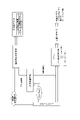
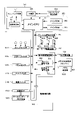
続いて、図3を参照して、パチスロ機1の電気的構成について説明する。なお、図3は、パチスロ機1の電気的構成を示すブロック図である。
[2. Electrical Configuration of Pachislot Machine]
Next, the electrical configuration of the pachi-
上述のとおり、パチスロ機1は、主制御基板71と、副制御基板72と、主中継基板73と、副中継基板74とを有している。主制御基板71と主中継基板73、主中継基板73と副中継基板74、及び副中継基板74と副制御基板72は、それぞれ電気的に接続されている。また、主制御基板71と副制御基板72は、主中継基板73及び副中継基板74を介して、主制御基板71から副制御基板72に対して一方向のシリアル通信が可能となるように電気的に接続されている。
As described above, the pachi-
主制御基板71には、遊技に関する制御を行う遊技制御部としての主制御回路100が実装されている。主制御回路100は、例えば、メインCPU101、メインROM102、メインRAM103、クロックパルス発生回路(不図示)、乱数回路(不図示)等を含んで構成される。メインROM102には、メインCPU101により実行される各種制御プログラム、各種データテーブル、副制御回路200に対して各種制御指令(コマンド)を送信するためのデータ等が記憶される。メインRAM103には、制御プログラムの実行により決定された内部当籤役等の各種データを格納する格納領域が設けられる。クロックパルス発生回路は、メインCPU101作動用のクロックパルス信号を生成する。乱数回路は、予め定められた範囲の乱数(例えば、0~65535又は0~255等)を発生させる。メインCPU101は、生成されたクロックパルス信号に基づいて各種制御プログラムを実行する。また、発生された乱数の中から必要に応じて一又は複数の値を乱数値として抽出する。このようにして、遊技動作全般に係る制御を行う。
The main
副制御基板72には、演出に関する制御を行う演出制御部としての副制御回路200が実装されている。副制御回路200は、例えば、サブCPU201、サブRAM203等を含んで構成される。また、副制御基板72には、ロムカートリッジ基板202が接続されている。ロムカートリッジ基板202には、サブCPU201により実行される各種制御プログラム、各種データテーブル、各種演出データ(例えば、メイン表示装置210に係る映像データや駆動データ、サブ表示装置220に係る映像データ、ランプ・LED群に係るランプデータ、スピーカ群に係るサウンドデータ等)等が記憶される。サブRAM203には、制御プログラムの実行により決定された演出内容や各種演出データを登録する格納領域や、主制御基板71から送信される各種制御指令(コマンド)に係るデータを格納する格納領域等が設けられる。なお、演出に係る演出用乱数値については、予め定められた範囲の乱数(例えば、0~32767等)の中から、サブCPU201内で発生及び抽出が行われるようにしてもよいし、主制御回路100と同様に乱数回路を設けることでその発生及び抽出が行われるようにしてもよい。また、ロムカートリッジ基板202ではなく、副制御回路200内にサブROMが含まれるようにし、各種制御プログラム等はサブROMに記憶されるように構成してもよい。また、ロムカートリッジ基板202に各種演出データを記憶させ、副制御回路200内のサブROMに各種制御プログラム及び各種データテーブルを記憶させるように構成してもよい。また、副制御回路200には、GPU等の画像専用のマイクロプロセッサ(例えば、「VDP」とも称される)が含まれるようにし、これによってメイン表示装置210やサブ表示装置220で表示される映像を生成(編集)するように構成してもよい。
A
主制御基板71には、ステッピングモータ51L,51C,51R、設定用鍵型スイッチ52、リセットスイッチ53、役比モニタ装置54、外部集中端子板55、ホッパー装置32、メダル補助収納庫スイッチ33S、電源装置34が電気的に接続されている。また、主制御基板71には、主中継基板73を介して、ドア開閉監視スイッチ56、メダルセンサ31S、ベットスイッチ6S、スタートスイッチ7S、ストップスイッチ8S、精算スイッチ9S、情報表示装置14が電気的に接続されている。なお、仮に試験機用第1インターフェースボード301及び試験機用第2インターフェースボード302が搭載される場合には、例えば、主中継基板73を介して主制御基板71に電気的に接続される。
The
なお、外部集中端子板55、ホッパー装置32、メダル補助収納庫スイッチ33S、電源装置34、メダルセンサ31S、ベットスイッチ6S、スタートスイッチ7S、ストップスイッチ8S、精算スイッチ9S、情報表示装置14、試験機用第1インターフェースボード301及び試験機用第2インターフェースボード302についてはすでに説明したため、ここでの説明は省略する。
In addition, the external collective
各ステッピングモータ51L,51C,51Rは、それぞれ所定の減速比をもったギアを介して各リール3L,3C,3Rに接続され、その駆動により各リール3L,3C,3Rを回転及び停止させる。なお、各ステッピングモータ51L,51C,51Rに対して1回のパルスが出力されるごとに、各リール3L,3C,3Rが一定の角度で回転することから、メインCPU101は、各ステッピングモータ51L,51C,51Rに対してパルスを出力した回数をカウントし、このカウント結果に基づいて各リール3L,3C,3Rの図柄位置を管理する。また、各リール3L,3C,3Rには、このような管理を行うための初期位置を定めるリールインデックス(不図示)と、リールインデックスの位置を検出するためのインデックスセンサ(不図示)が設けられる。
Each stepping
設定用鍵型スイッチ52は、パチスロ機1の設定値(例えば、6段階の設定1~設定6)を変更するとき(設定変更)、もしくは、パチスロ機1の設定を確認するとき(設定確認)に使用される。ここで、設定値は、遊技に関する遊技者の有利さの度合いを示すものであり、通常は、設定値が低いほど(例えば、設定1に近いほど)遊技者の有利さの度合いが相対的に低くなり、設定値が高いほど(例えば、設定6に近いほど)遊技者の有利さの度合いが相対的に高くなる。設定用鍵型スイッチ52は、例えば、遊技店側の管理者が鍵穴に設定キー(不図示)を挿入して初期位置から左に回すとオン状態となり、左に回した状態から初期位置に戻すとオフ状態となる。なお、パチスロ機1の電源がオフ状態のとき、設定用鍵型スイッチ52をオン状態としてから電源をオン状態とすると設定変更が可能な状態となり、パチスロ機1の電源がオン状態のままで設定用鍵型スイッチ52をオン状態とすると設定確認が可能な状態となる。
The setting key-
リセットスイッチ53は、遊技店側の管理者によるリセット操作を検出可能としている。リセット操作は、各種のエラー状態を解除するための操作である。また、リセットスイッチ53は、設定変更が可能な状態において、遊技店側の管理者による設定値決定操作を検出可能としている。なお、設定変更が可能な状態においてリセットスイッチ53が操作されると、操作される度に設定値が順次1ずつ増加する(設定6まで到達すると次は設定1に戻る)。このようにして、設定値決定操作が行えるようになっている。また、このように決定された設定値は、その後スタートレバー7が1回操作されると確定する。すなわち、スタートスイッチ7Sは、遊技店側の管理者による設定値確定操作を検出可能としている。このように、設定変更を行う場合には、設定用鍵型スイッチ52をオン状態とし、リセットスイッチ53を操作して設定値を選択し、スタートレバー7を操作して選択した設定値を確定させた後、設定用鍵型スイッチ52をオフ状態とするといった設定変更操作が必要となっている。なお、これは、設定変更操作の一例であり、他の操作によって設定変更を行い得るように構成することもできる。また、設定変更や設定確認に際しては、例えば、上述のクレジットランプあるいは払出数ランプにおいて現在の設定値が表示されるものすればよい。
The
役比モニタ装置54は、例えば、4桁の7セグメントLEDにより構成され、主制御基板ケースの内部に設けられる。役比モニタ装置54は、メインCPU101によって集計・算出された遊技に関する各種割合情報を順次表示する。これらの割合情報は、遊技店の管理者がパチスロ機1に不正改造がないかを確認する際等に使用される。なお、役比モニタ装置54は、主制御基板71上に実装されるようにしてもよいし、主制御基板71に接続された他の基板(例えば、割合表示基板)上に実装されるようにしてもよい。また、キャビネットG内であれば、他の場所に設けられるようにしてもよい。例えば、主制御基板ケース上に設けられるようにしてもよい。また、役比モニタ装置54における表示を開始させ、あるいはその内容を切替えるための管理スイッチをキャビネットG内に設けるようにし、これが操作された場合に上述の各種割合情報が表示されるようにしてもよい。また、このような管理スイッチを使用することを前提として、例えば、情報表示装置14を役比モニタ装置54と兼用して用いる構成としてもよい。また、電源投入直後又は電源投入から所定時間(例えば、10秒程度。主制御回路100及び副制御回路200の立ち上げに要する時間を考慮したバッファとなる時間)の経過後に、役比モニタ装置54の4桁の7セグメントLEDが正常に機能していることを確認可能とするため、例えば、「8.8.」といったようなテストパターン(全てのセグ及びデシマルのLEDが点灯するパターン)で所定期間点灯(ないし点滅)させる構成とすることが望ましい。
The role
役比モニタ装置54では、例えば、上位2桁にはその割合情報の種類が表示され、下位2桁にはその割合情報を示す値(%)が表示される。ここで、役比モニタ装置54に表示される各種割合情報には、例えば、累計の特定区間割合情報、直近6000ゲーム間の連続役物割合情報及び役物割合情報、累計の連続役物割合情報及び役物割合情報等がある。
In the role
特定区間割合情報とは、対象の遊技数(例えば、「累計」であれば175000ゲーム。「直近6000ゲーム」であれば6000ゲーム。以下同じ)の遊技区間のうち、遊技者に有利な停止操作の情報の報知が行われていた遊技区間(例えば、AT状態)の遊技数(あるいは、単に有利区間中の遊技数であってもよい)の割合を示す情報である。また、連続役物割合情報とは、対象の遊技数の遊技区間において払出されたメダル数のうち、第一種特別役物(RB)の作動中(第一種特別役物に係る役物連続作動装置(BB)が作動している状態における第一種特別役物(RB)の作動中を含む)に払出されたメダル数の割合を示す情報である。また、役物割合情報は、対象の遊技数の遊技区間において払出されたメダル数のうち、第一種特別役物(RB)、第二種特別役物(CB)、及び普通役物(SB)の作動中に払出されたメダル数の割合を示す情報であり、ここでの第一種特別役物(RB)の作動中とは、第一種特別役物に係る役物連続作動装置(BB)が作動している状態における第一種特別役物(RB)の作動中を含む概念であり、また、第二種特別役物(CB)の作動中とは、第二種特別役物に係る役物連続作動装置(MB)が作動している状態における第二種特別役物(CB)の作動中を含む概念である。 The specific section ratio information refers to a stop operation that is advantageous to the player among the game sections of the target number of games played (for example, 175,000 games for "total"; 6,000 games for "last 6,000 games"; the same applies hereinafter). Information indicating the ratio of the number of games played in the game section (for example, AT state) (or simply the number of games in the advantageous section may be used) in which the information of . In addition, the continuous role ratio information means that among the number of medals paid out in the game section of the number of games to be played, the first type special role (RB) is in operation It is information indicating the ratio of the number of medals paid out (including during operation of the first class special bonus (RB) in the state where the operating device (BB) is operating). In addition, the accessory ratio information is the number of medals paid out in the game section of the target number of games, the first type special accessory (RB), the second type special accessory (CB), and the normal accessory (SB ) is information indicating the ratio of the number of medals paid out during the operation of the first class special bonus (RB). BB) is in operation and the first class special bonus (RB) is in operation, and the second class special bonus (CB) is in operation It is a concept that includes the operation of the second type special role product (CB) in the state where the role product continuous operation device (MB) is operating.
なお、遊技者に有利な停止操作の情報の報知が行われていた遊技区間(例えば、AT状態)を役物の作動中、あるいは役物連続作動装置の作動中としてとらえ、それぞれの割合情報において集計・算出の対象とすることもできる。すなわち、役比モニタ装置54は、必要な割合情報を適切に表示するものであればよく、表示可能な各種割合情報はこれらに限定されない。また、例えば、第一種特別役物(RB)が搭載されていない機種において連続役物割合情報を表示する場合、あるいは有利区間機能(AT機能)が搭載されていない機種において特定区間割合情報を表示する場合等、該当する数値情報(対応情報)が存在しない機種においては、当該項目の表示時に、4桁の7セグメントLEDのうちの数値情報(割合を示す%情報)を表示する下2桁の7セグメントLEDにおいて、例えば、「- -」といったように、中央の縦棒2本を点灯表示させる等の非対応情報用識別表示を行うことで、対応情報が存在しない機種である点を確認者が一目で認識可能とすることが望ましい。
In addition, the game section (for example, AT state) in which the information of the stop operation that is advantageous to the player is performed is regarded as the operation of the accessory or the operation of the accessory continuous operation device, and in the respective ratio information It can also be subject to aggregation and calculation. In other words, the role
ドア開閉監視スイッチ56は、例えば、下ドア機構DDの開閉側(右側)に設けられる。なお、下ドア機構DDの背面側に設けられるように構成してもよいし、キャビネットG側に設けられるように構成してもよい。また、上ドア機構UDにも同様のドア開閉監視スイッチが設けられるように構成してもよい。ドア開閉監視スイッチ56は、下ドア機構DDが開放状態となったときにオン状態となり、閉鎖状態となったときにオフ状態となることで、下ドア機構DDの開閉を監視する。なお、ドア開閉監視スイッチ56がオン状態となるとドア開放エラーが発生する。この場合、下ドア機構DDを閉鎖状態とすると当該エラー状態が解除される。
The door opening/
副制御基板72には、ロムカートリッジ基板202、メイン表示装置210、サブ表示装置220が電気的に接続されている。また、副制御基板72には、副中継基板74を介して、24hドア開閉監視ユニット61、演出用ボタン10a,10b等の演出用ボタン群、上部ランプ23等のランプ・LED類、スピーカ35a,35b等のスピーカ群が電気的に接続されている。
The
なお、ロムカートリッジ基板202、メイン表示装置210、サブ表示装置220、演出用ボタン群、ランプ・LED類及びスピーカ群についてはすでに説明したため、ここでの説明は省略する。
Since the
24hドア開閉監視ユニット61は、ドア開閉監視スイッチ56と同様に、例えば、下ドア機構DDの開閉側(右側)に設けられる。なお、下ドア機構DDの開閉を監視するという機能を有する点においてはドア開閉監視スイッチ56と同じであるが、このような監視を副制御回路200側でも行い得るようにすることで、さらに下ドア機構DDの開閉履歴を一定期間保存することができるようにしている。なお、この開閉履歴は、後述のホールメニューから確認することができる。したがって、例えば、営業時間外であって、遊技店の管理者が退出した後に開放履歴があった場合や、営業時間内において長時間にわたって開放された開閉履歴があった場合には、これにより不正行為が行われた可能性が高いことを認識できるようになっている。
Like the door opening/
[3.パチスロ機の機能フロー]
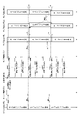
続いて、図4を参照して、パチスロ機1の機能フローについて説明する。なお、図4は、パチスロ機1の機能フローを説明するための図である。
[3. Function Flow of Pachislot Machine]
Next, a functional flow of the pachi-
遊技者によりパチスロ機1にメダルが投入され(ベット操作が行われ)、スタートレバー7が操作される(開始操作が行われる)と、予め定められた範囲(例えば、0~65535)の乱数から1つの乱数値(本実施形態では、これを「内部抽籤用乱数値」として説明する場合がある)が抽出される。 When the player inserts medals into the pachi-slot machine 1 (performs a bet operation) and operates the start lever 7 (performs a start operation), random numbers are generated from a predetermined range (for example, 0 to 65535). One random number (in this embodiment, this may be described as an "internal lottery random number") is extracted.
内部抽籤手段(後述の内部抽籤処理を行うメインCPU101)は、抽出された乱数値に基づいて抽籤を行い、内部当籤役を決定する。内部当籤役の決定により、有効ライン上に表示されることが許可される図柄の組合せが事前に決定される。なお、図柄の組合せの種別としては、メダルの払い出し、再遊技(リプレイ)の作動、ボーナスの作動等といった特典が遊技者に与えられる「入賞」に係るものと、それ以外のいわゆる「はずれ」に係るものとが設けられる。なお、メダルの払い出しに係る役を「小役」と称し、再遊技(リプレイ)の作動に係る役を「リプレイ役」と称し、ボーナス(ボーナス状態)の作動に係る役を「ボーナス役」と称する。また、内部当籤し得る役(すなわち、成立が許可される図柄の組合せ)は、単に「役」と称されることがある。また、内部当籤役は、「当籤役」、「事前決定結果」、あるいは「導出許容条件」等と称されることがある。また、内部抽籤手段は、「役決定手段」、「当籤役決定手段」、「事前決定手段」、あるいは「導出許容条件決定手段」等と称されることがある。
The internal lottery means (the
また、スタートレバー7が操作される(開始操作が行われる)と、複数のリールの回転が行われる。その後、遊技者によりリール(各リール3L,3C,3R)に対応するストップボタン(各ストップボタン8L,8C,8R)が操作される(停止操作が行われる)と、リール停止制御手段(後述のリール停止制御処理を行うメインCPU101)は、内部当籤役とストップボタンが押されたタイミング(あるいはその押し順を含む)とに基づいて、該当するリールの回転を停止する制御を行う。なお、開始操作を行うための操作手段は、スタートレバー7のようにレバー形状をしたものに限られず、遊技者が開始操作を行うことが可能であれば、どのような操作手段であってもよい。また、停止操作を行うための操作手段は、各ストップボタン8L,8C,8Rのようにボタン形状をしたものに限られず、遊技者が停止操作を行うことが可能であれば、どのような操作手段であってもよい。
Further, when the
パチスロ機1では、基本的に、ストップボタンが押されたときから規定時間(190msec)内に、該当するリールの回転を停止する制御が行われる。本実施形態では、この規定時間内にリールの回転にともなって移動する図柄の数を「滑り駒数」という。そして、本実施形態では、規定期間が190msecである場合には、滑り駒数の最大数(最大滑り駒数)を図柄4個分に定める。
In the pachi-
リール停止制御手段は、入賞に係る図柄の組合せの表示を許可する内部当籤役が決定されているときは、通常、190msec(図柄4駒分)の規定時間内に、その図柄の組合せが有効ライン上に極力表示されるようにリールの回転を停止させる。また、リール停止制御手段は、規定時間を利用して、内部当籤役によってその表示が許可されていない図柄の組合せが有効ライン上に表示されないようにリールの回転を停止させる。なお、リールの回転が停止したときに表示された図柄は、「停止表示」、あるいは「表示結果」等と称されることがある。また、リールの回転が停止したときに図柄が表示されることは、「停止表示の導出」、あるいは「表示結果の導出」等と称されることがある。 When an internal winning combination that permits the display of a winning combination of symbols is determined, the reel stop control means normally displays the combination of symbols on the effective line within a specified time of 190 msec (for 4 symbols). Stop the rotation of the reel so that it is displayed at the top as much as possible. Further, the reel stop control means stops the rotation of the reels by using the specified time so that the combination of symbols whose display is not permitted by the internal winning combination is not displayed on the effective line. The symbols displayed when the rotation of the reels is stopped are sometimes referred to as "stop display" or "display result". Also, the display of symbols when the rotation of the reels stops is sometimes referred to as "derivation of stop display" or "derivation of display result".
また、リール停止制御手段は、リールが回転してから、予め定められた自動停止時間が経過した場合には、遊技者が停止操作を行っていない場合でも、自動的に各リールを停止させる自動停止制御を行うようにしてもよい。この場合には、遊技者の停止操作を介さずにリールが停止することとなるため、いずれかの内部当籤役が決定されている場合であっても、いずれの入賞に係る図柄の組合せも有効ラインに沿って表示されていないようにリールの回転を停止させることが望ましい。 Further, the reel stop control means automatically stops each reel when a predetermined automatic stop time has passed since the reels are rotated, even if the player does not perform a stop operation. Stop control may be performed. In this case, since the reels are stopped without intervention of the player's stop operation, even if any internal winning combination is determined, any winning combination of symbols is valid. It is desirable to stop spinning the reels so that they are not displayed along the line.
このようにして、複数のリールの回転が全て停止されると、入賞判定手段(後述の入賞作動判定処理を行うメインCPU101)は、有効ライン上に表示された図柄の組合せが、入賞に係るもの(あるいは、その他予め定められたもの)であるか否かの判定を行う。すなわち、入賞に係る図柄の組合せ(あるいは、その他予め定められた図柄の組合せ)が成立したか否かの判定を行う。そして、表示された図柄の組合せが、入賞判定手段により入賞に係るもの(あるいは、その他予め定められたもの)である(すなわち、入賞に係る図柄の組合せ(あるいは、その他予め定められた図柄の組合せ)が成立した)と判定されると、メダルの払い出し等の特典が遊技者に与えられ、あるいは、それを契機として各種の制御が行われる。パチスロ機1では、一例として、以上のような一連の流れで1回の遊技(単位遊技)として行われる。
In this way, when all of the plurality of reels stop rotating, the winning determination means (the
なお、入賞判定手段は、有効ライン上に表示された図柄の組合せが、単に予め定められた複数の図柄の組合せのうちのいずれかの図柄の組合せに該当するか否かを判定するものであってもよいし、内部抽籤手段によって決定された内部当籤役に係る図柄の組合せに該当するか否かを判定するものであってもよい。すなわち、前者では、内部当籤役と切り離して、入賞に係る図柄の組合せであるか否かを判定するものであってもよい。この場合、リール停止制御手段によって適切に停止制御が行われる限り、誤入賞の発生の防止は十分に担保され得ることから、誤入賞検知に係る制御負担を低減させることが可能となる。一方、後者では、入賞に係る図柄の組合せが、入賞が許可されていた図柄の組合せであるか否かも判定可能とすることで、リールの不具合等により誤入賞が発生した場合に、その誤入賞を検知することができるため、セキュリティ性を向上させることが可能となる。 Note that the winning judgment means judges whether or not the combination of symbols displayed on the activated line corresponds to any combination of symbols among a plurality of predetermined combinations of symbols. Alternatively, it may be determined whether or not the symbol combination corresponds to the internal winning combination determined by the internal lottery means. That is, in the former, it may be determined whether or not there is a winning combination of symbols separately from the internal winning combination. In this case, as long as the stop control is appropriately performed by the reel stop control means, it is possible to sufficiently ensure the prevention of the occurrence of false winnings, so it is possible to reduce the control load related to false winning detection. On the other hand, in the latter, by making it possible to determine whether or not the combination of symbols related to winning is a combination of symbols for which winning was permitted, even if an erroneous winning occurs due to a problem with the reels, etc. can be detected, security can be improved.
また、パチスロでは、前述した一連の遊技動作の流れの中で、表示装置(例えば、メイン表示装置210やサブ表示装置220等)による映像の表示、各種ランプ(例えば、上部ランプ23等)による光の出力、スピーカ(例えば、スピーカ35a,35b等)による音の出力、或いは、これらの組合せを利用して様々な演出が行われる。すなわち、これらは演出を実行する演出実行手段である。なお、演出実行手段により実行される演出の内容は、主制御回路100側(メイン側)で決定される場合もあれば、副制御回路200側(サブ側)で決定される場合もある。すなわち、これらはそのいずれもが演出内容決定手段となり得る。
In addition, in pachislot, in the flow of the series of game operations described above, images are displayed by the display device (for example, the
例えば、スタートレバー7が操作される(開始操作が行われる)と、内部抽籤用乱数値とは別に、演出用乱数値が抽出される。演出用乱数値が抽出されると、演出内容決定手段は、内部当籤役に対応付けられた複数種類の演出内容の中から今回実行する演出を抽籤によって(あるいは予め定められた決定条件にしたがって)決定する。
For example, when the
次いで、演出内容決定手段により演出内容が決定されると、演出実行手段は、リールの回転開始時、各リールの回転停止時、入賞の有無の判定時等の各契機に連動させて対応する演出を実行する。このように、パチスロ機1では、例えば、内部当籤役に対応付けられた演出内容を実行することによって、決定された内部当籤役(狙うべき図柄の組合せや操作すべき押し順等と換言することもできる)を知る機会又は予想する機会が遊技者に提供され、遊技者の興味の向上を図ることができる。
Next, when the effect content is determined by the effect content determining means, the effect executing means performs a corresponding effect in conjunction with each opportunity such as when the reels start rotating, when each reel stops rotating, and when it is determined whether or not a prize is awarded. to run. In this way, in the pachi-
[4.パチスロ機の遊技性に関する基本仕様]
続いて、パチスロ機1の遊技性に関する基本仕様について説明する。
[4. Basic specifications related to playability of pachislot machines]
Next, the basic specifications of the pachi-
[4-1.図柄配置]
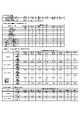
上述のとおり、パチスロ機1では、複数の図柄が変動表示及び停止表示されることで遊技が行われる仕様となっている。したがって、主制御回路100は、各リール3L,3C,3Rにおいて、どの図柄がどの位置に配置されているかを把握可能に構成されている必要がある。このため、メインROM102には、少なくとも各リール3L,3C,3Rそれぞれの各図柄位置にある図柄の種類を識別するためのデータが記憶されている。なお、このような目的が達成される限り、そのデータ構成は種々の構成を採用することができるが、本実施形態では、その一例として後述の図柄配置テーブル(図9参照)を用いている。
[4-1. Pattern arrangement]
As described above, the pachi-
図柄配置テーブルには、各リール3L,3C,3Rそれぞれの回転方向における各図柄位置を示す図柄位置データ(例えば、「0」~「19」)が規定されている。また、各図柄位置データに対して図柄の種類を特定するためのデータ(例えば、図柄コード)が対応付けられている。また、図柄配置テーブルでは、リールインデックスが検出されたときにメイン表示窓4の枠内における各リールの中段領域に位置する図柄の位置を「0」と規定している。なお、各列の図柄数、図柄の種類数、あるいは最大滑り駒数等は適宜変更して規定可能である。
The symbol arrangement table defines symbol position data (for example, "0" to "19") indicating each symbol position in the rotation direction of each
[4-2.図柄組合せ]
上述のとおり、パチスロ機1では、表示された図柄の組合せが遊技結果に影響を与える仕様となっている。すなわち、パチスロ機1は、表示された図柄の組合せに応じて、各種特典を付与したり、現在の状態から相対的に有利な状態に移行させたり、現在の状態から相対的に不利な状態に移行させたりすることを可能としている。したがって、主制御回路100は、このような図柄の組合せについて把握可能に構成されている必要がある。このため、メインROM102には、このような図柄の組合せを特定するためのデータが規定されている。なお、このような目的が達成される限り、そのデータ構成は種々の構成を採用することができるが、本実施形態では、その一例として後述の図柄組合せテーブル(図11~図14参照)を用いている。
[4-2. Pattern combination]
As described above, the pachi-
図柄組合せテーブルには、有効ライン上に表示され得る図柄の組合せのうちで予め定められた複数の図柄の組合せの種類を示すデータ(例えば、「表示役」あるいは「入賞作動フラグ」)が規定されている。なお、それぞれの図柄の組合せを構成する図柄は、例えば、上述の図柄コード等を用いて特定することができる。また、各図柄の組合せに対して特典等の種類を示すデータ(例えば、「払出等」)が対応付けられている。また、図柄組合せテーブルは、基本的に後述の当籤フラグ格納領域、入賞作動フラグ格納領域、及び図柄コード格納領域(図17参照)と対応するデータ構成となっている。なお、図柄の組合せの種類数、あるいは特典の付与内容等は適宜変更して規定可能である。 The symbol combination table defines data (for example, "display combination" or "winning operation flag") indicating the type of combination of a plurality of predetermined symbols among the combinations of symbols that can be displayed on the activated line. ing. It should be noted that the symbols forming each combination of symbols can be specified using, for example, the above-described symbol code or the like. In addition, data indicating the type of privilege (for example, "payout etc.") is associated with each combination of symbols. The symbol combination table basically has a data structure corresponding to a winning flag storage area, a winning operation flag storage area, and a symbol code storage area (see FIG. 17), which will be described later. It should be noted that the number of types of combinations of symbols, the content of benefits to be provided, and the like can be appropriately changed and stipulated.
[4-3.内部当籤役]
上述のとおり、パチスロ機1では、いずれの図柄の組合せが表示されることが許可されるか(事前に決定されるか)が遊技結果に影響を与える仕様となっている。すなわち、パチスロ機1は、遊技者の停止操作に先立って(事前に)、内部当籤役(すなわち、表示され得る図柄の組合せの種類(あるいは、付与され得る特典の種類))を決定することを可能としている。したがって、主制御回路100は、このような内部当籤役について把握可能に構成されている必要がある。このため、メインROM102には、このような内部当籤役を特定するためのデータが規定されている。なお、このような目的が達成される限り、そのデータ構成は種々の構成を採用することができるが、本実施形態では、その一例として後述の内部抽籤テーブル(図10参照)を用いている。
[4-3. Internal winning role]
As described above, the pachi-
内部抽籤テーブルには、予め定められた複数の内部当籤役の種類を示すデータ(例えば、「No.」あるいは「当籤番号」)と、各遊技状態において各内部当籤役が決定される抽籤値とが規定される。なお、抽籤値は、設定された設定値によっても変動する場合がある。また、各内部当籤役に対して表示が許可される(対応する)図柄の組合せの種類が対応付けられている。なお、パチスロ機1では、1つの内部当籤役に対して複数の図柄の組合せを対応付けることを可能としており、このような内部当籤役が決定された場合、いずれの図柄の組合せが表示されるかは停止制御によって決定されるものとなっている。
The internal lottery table contains data indicating the types of a plurality of predetermined internal winning combinations (for example, "No." or "winning number"), and lottery values for determining each internal winning combination in each gaming state. is defined. Note that the lottery value may also vary depending on the set value. Also, each internal winning combination is associated with a type of symbol combination permitted (corresponding) to be displayed. In the pachi-
ここで、例えば、本実施形態の後述の内部抽籤処理(図26参照。より詳細には、S64の内部当籤役決定処理)では、まず、乱数回路によって予め定められた数値の範囲(例えば、0~65535)から抽出された乱数値を、各内部当籤役に対応して規定された抽籤値で順次加算更新する。次いで、抽籤結果(抽籤値+乱数値)が65535を超えたか否か(抽籤結果がオーバーフローしたか否か)の判定を行う。そして、所定の内部当籤役において、当該判定の結果が65535を超えた場合、当該内部当籤役に当籤させる(当該内部当籤役を決定する)。もっとも、全ての内部当籤役について当該判定を行っても65535を超えるものがなかった場合、今回の遊技における内部当籤役は「はずれ」となる。なお、これはあくまで内部抽籤処理の一例であり、抽籤値(当籤確率)に応じて適切な抽籤が行われる限り、その抽籤処理の手法は種々の手法を採用することができる。例えば、抽出された乱数値を、各内部当籤役に対応して規定された抽籤値で順次減算更新し、次いで、減算結果(抽籤結果)が0を下回ったか否か(抽籤結果がアンダーフローしたか否か)を判定して、内部当籤役を決定してもよい。 Here, for example, in the later-described internal lottery process (see FIG. 26; more specifically, the internal winning combination determination process in S64) of the present embodiment, first, a numerical range predetermined by a random number circuit (for example, 0 65535) is sequentially added and updated with a lottery value defined for each internal winning combination. Next, it is determined whether or not the lottery result (lottery value+random number) exceeds 65535 (whether or not the lottery result overflows). Then, in a predetermined internal winning combination, when the result of the determination exceeds 65535, the internal winning combination is won (the internal winning combination is determined). However, if none of the internal winning combinations exceeds 65535 even after the determination is performed for all the internal winning combinations, the internal winning combination in the current game is "lost". Note that this is just an example of internal lottery processing, and various methods can be employed for the lottery processing as long as an appropriate lottery is performed according to the lottery value (winning probability). For example, the extracted random numbers are sequentially subtracted and updated with the lottery values specified for each internal winning combination, and then whether or not the subtraction result (lottery result) is less than 0 (lottery result underflows). or not) to determine an internal winning combination.
このように、内部抽籤テーブルにおいては、規定されている抽籤値の数値が大きい内部当籤役ほど決定される確率(当籤確率)が高くなる。なお、各内部当籤役の当籤確率は、「各当籤番号に規定された抽籤値/抽出される可能性のある全ての乱数値の個数(乱数分母:65536)」によって表すことができる。 In this way, in the internal lottery table, the probability (winning probability) of an internal winning combination having a larger defined lottery value is higher. The winning probability of each internal winning combination can be represented by "the lottery value defined for each winning number/the number of all possible random numbers to be extracted (random number denominator: 65536)".
[4-4.停止制御]
上述のとおり、パチスロ機1では、内部当籤役の決定によって表示されることが許可された図柄の組合せのうち、遊技者の停止操作によって最終的にいずれの図柄の組合せを表示させるかが遊技結果に影響を与える仕様となっている。すなわち、パチスロ機1は、決定された内部当籤役の種類のみならず、遊技者の停止操作タイミングや押し順(「停止操作態様」や「停止操作手順」とも称される)によって最終的に表示される図柄の組合せの種類を変動させる(決定する)制御(停止制御)を行うことを可能としている。したがって、主制御回路100は、各内部当籤役に対して、遊技者の停止操作態様に応じてどのような態様で停止制御を行うかを把握可能に構成されている必要がある。このため、メインROM102には、このような停止制御の態様を特定するためのデータが規定されている。なお、このような目的が達成される限り、そのデータ構成は種々の構成を採用することができるが、本実施形態では、その一例として停止テーブルや引込優先順位テーブル(不図示)等を用いている。
[4-4. stop control]
As described above, in the pachi-
停止テーブルには、各リール3L,3C,3Rの各図柄位置データに対して、図柄の移動量を示すデータ(例えば、「滑り駒数」)が規定されている。例えば、所定の内部当籤役が決定された遊技において所定の停止テーブルが選択されたとする。次いで、回転中のリール3Lに対して停止操作が行われたとする。このとき、停止開始位置(停止操作が行われたときのリール3Lの中段領域の図柄位置データ)が「0」であったとする。そして、所定の停止テーブルにおいて、図柄位置データ「0」に規定された滑り駒数が「4」であったとする。そうすると、主制御回路100は、4図柄分移動した図柄位置(図柄位置データ「4」の位置)でリール3Lを停止させる(停止予定位置が「4」となる)ように制御を行う。このように、停止テーブルには、停止させる位置を直接的に決定することを可能とするデータ(滑り駒数)が規定されている。なお、このようなデータ構成もあくまで一例である。また、このような停止テーブルを用いて停止制御を行うことは、一般的に「テーブル制御」と称される。
In the stop table, data indicating the amount of symbol movement (for example, "number of sliding symbols") is defined for each symbol position data of each of the
引込優先順位テーブルには、表示されることが許可された図柄の組合せが複数ある場合に、いずれの図柄の組合せを優先的に表示させるか(引込むか)を示すデータ(例えば、「引込優先順位」)が規定されている。例えば、所定の内部当籤役が決定された遊技において所定の引込優先順位テーブルが選択されたとする。ここで、所定の内部当籤役は、図柄組合せAと図柄組合せBの表示を許可するものとし、所定の引込優先順位テーブルは、図柄組合せAよりも図柄組合せBを優先的に表示させるように引込優先順位が規定されているものとする。次いで、回転中のリール3Lに対して停止操作が行われたとする。このとき、停止開始位置が「0」であったとする。
In the attraction priority table, when there are multiple combinations of symbols permitted to be displayed, data indicating which combination of symbols should be preferentially displayed (whether to attract) (for example, "attraction priority ”) is stipulated. For example, assume that a predetermined attraction priority table is selected in a game in which a predetermined internal winning combination is determined. Here, it is assumed that the predetermined internal winning combination permits the display of the symbol combination A and the symbol combination B, and the predetermined pull-in priority table is such that the symbol combination B is preferentially displayed over the symbol combination A. An order of priority shall be specified. Next, it is assumed that a stop operation is performed on the
そうすると、主制御回路100は、停止開始位置を含めた最大滑り駒数(例えば、「4」)の範囲内の各図柄位置について、図柄組合せAを構成する図柄と図柄組合せBを構成する図柄があるかどうかを検索する。双方の図柄がなければ、予め定められたルール(例えば、より近い位置で停止させる、より遠い位置で停止させる等)にしたがって停止させる位置を決定する。図柄組合せAを構成する図柄のみがあれば、当該図柄に対応する位置で停止させることを決定する。図柄組合せBを構成する図柄のみがあれば、当該図柄に対応する位置で停止させることを決定する。双方の図柄があれば、図柄組合せAよりも図柄組合せBを優先的に表示させるのであるから、図柄組合せBを構成する図柄に対応する位置で停止させることを決定する。なお、引込優先順位は、選択された引込優先順位テーブルにしたがって、対象となるリールの回転中に全図柄位置について格納されるようにしてもよいし、対象となるリールに対して停止操作が行われたときに、停止開始位置を含めた最大滑り駒数の範囲内の各図柄位置について格納されるようにしてもよい。また、このようなデータ構成もあくまで一例である。また、このような引込優先順位テーブルを用いて停止制御を行うことは、一般的に「コントロール制御」と称される。
Then, the
なお、本実施形態では、「テーブル制御」のみを行うことによって停止制御を実行する構成とすることもできるし、「コントロール制御」のみを行うことによって停止制御を実行する構成とすることもできる。あるいは、まず「テーブル制御」を行うことによって停止させる位置を仮決定し、次に「コントロール制御」を行うことによってより適切な停止位置があるかを検索し、検索結果によっては停止させる位置を変更することを可能とする停止制御を実行する構成とすることもできる。 In this embodiment, it is possible to adopt a configuration in which stop control is executed by performing only "table control", or a configuration in which stop control is executed by performing only "control control". Alternatively, first perform "table control" to tentatively determine the stop position, then perform "control control" to search for a more appropriate stop position, and change the stop position depending on the search results. It can also be configured to execute stop control that enables to
このように、パチスロ機1では、最終的に有効ライン上に表示される図柄の組合せがどの図柄の組合せとなるかは、例えば、以下の3つの要素に基づいて決定される。
As described above, in the pachi-
第1の要素は、決定された内部当籤役(内部抽籤処理の抽籤結果)である。例えば、内部抽籤処理の結果が「はずれ」であった場合、いずれかのリプレイ役に係る図柄の組合せ、小役に係る図柄の組合せ又はボーナス役に係る図柄の組合せが最終的に有効ライン上に表示されることはない。なお、「はずれ」は、内部当籤役の1つであると捉えることもできるし、内部当籤役が決定されなかった抽籤結果であると捉えることもできる。 The first element is the determined internal winning combination (lottery result of internal lottery processing). For example, if the result of the internal lottery process is "lost", any combination of symbols related to the replay hand, the combination of symbols related to the small hand, or the combination of symbols related to the bonus hand will finally be on the effective line. It is never displayed. Note that "lose" can be regarded as one of the internal winning combinations, or can be regarded as a lottery result in which no internal winning combination is determined.
第2の要素は、遊技者の停止操作タイミング(遊技者がいずれかのストップボタンを操作したときの図柄の位置(押下位置))である。例えば、本実施形態においては、最大滑り駒数として図柄4個分が定められているため、内部抽籤処理の結果、いずれかの内部当籤役に当籤していたとしても、表示が許可されている図柄の組合せを構成する図柄が有効ライン(複数ある場合には各有効ライン)に対して図柄4個分を超えて配置されていた場合には、遊技者の停止操作タイミングによっては当該図柄の組合せが表示されない場合がある。これをいわゆる「取りこぼし」という。 The second factor is the timing of the player's stop operation (the position of the symbol (depression position) when the player operates any of the stop buttons). For example, in the present embodiment, the maximum number of sliding symbols is set to 4 symbols, so display is permitted even if one of the internal winning combinations is won as a result of the internal lottery process. If the symbols constituting the combination of symbols are arranged in excess of 4 symbols on the effective line (each effective line if there are more than one), the combination of the relevant symbols depends on the timing of the player's stop operation. may not be displayed. This is so-called "dropping".
第3の要素は、遊技者の押し順(遊技者がストップボタンを操作した順番)である。例えば、本実施形態においては、複数の図柄の組合せが対応付けられた内部当籤役が決定される場合があり、この場合には、遊技者の押し順に応じて最終的に有効ライン上に表示される図柄の組合せが変動する場合がある。なお、このような内部当籤役を「押し順役」といい、それがリプレイ役の場合には「押し順リプレイ」と称されることがあり、小役の場合には「押し順小役」と称されることがある。 The third factor is the player's pressing order (the order in which the player operates the stop buttons). For example, in this embodiment, there is a case where an internal winning combination associated with a combination of multiple symbols is determined, and in this case, it is finally displayed on the activated line according to the player's pressing order. The combination of symbols to be played may change. Such an internal winning combination is called a "push-order combination", and if it is a replay combination, it is sometimes called a "push-order replay", and if it is a small combination, it is called a "push-order small combination". It is sometimes called
[4-5.遊技状態]
パチスロ機1では、遊技者の有利度合いを変動させるため、あるいは企図した遊技性とするために、遊技を行う状態として種々の遊技状態を設けることが可能となっている。以下、その遊技状態の一例について説明する。
[4-5. game state]
In the pachi-
[4-5-1.ボーナス状態]
パチスロ機1では、ボーナス役に当籤し、当該ボーナス役に係る図柄の組合せが有効ライン上に表示された場合に、ボーナス状態に移行させる(ボーナス状態を作動させる)ことが可能となっている。なお、このようなボーナス状態を設けないように構成することもできる。また、複数種類のボーナス役を設けることで、複数のボーナス状態を設けるように構成することもできる。ボーナス役に当籤すると、当該ボーナス役に係る図柄の組合せが有効ライン上に表示されるまで複数回の遊技にわたって当該ボーナス役が内部当籤役として持越された状態(持越状態)が発生する。このようなボーナス役は「持越役」と称されることがある。また、このような持越状態は「(ボーナス)フラグ間」や「(ボーナス)内部中」等と称されることがある。
[4-5-1. Bonus state]
In the pachi-
ボーナス状態は、ボーナス状態が作動していない状態(非ボーナス状態)に対して小役の抽籤態様(当籤確率やその内容、あるいは停止制御の態様等も含む。以下同じ)を変動させることが可能な状態となっている(リプレイ役の抽籤態様を変動させることが可能な状態ともなっているため、ボーナス状態を後述のRT状態の一態様として捉えることもできる)。したがって、このような抽籤態様が遊技者に相対的に有利な抽籤態様となる場合には、ボーナス状態は非ボーナス状態よりも有利な遊技状態となる。一方、このような抽籤態様が遊技者に相対的に不利な抽籤態様となる場合には、ボーナス状態は非ボーナス状態よりも不利な遊技状態となる。 In the bonus state, it is possible to change the lottery mode (including the winning probability and its content, or the mode of stop control, etc.; hereinafter the same) for minor wins with respect to the state in which the bonus state is not activated (non-bonus state). (Because it is also possible to change the lottery mode of the replay combination, the bonus state can be regarded as one mode of the RT state described later). Therefore, when such a lottery mode becomes a relatively advantageous lottery mode for the player, the bonus state becomes a more advantageous game state than the non-bonus state. On the other hand, if such a lottery mode becomes a relatively disadvantageous lottery mode for the player, the bonus state becomes a game state more disadvantageous than the non-bonus state.
ボーナス役としては、例えば、第一種特別役物(RB)、第一種特別役物に係る役物連続作動装置(BB)、第二種特別役物(CB)(ただし持越役ではない)、第二種特別役物に係る役物連続作動装置(MB)、及び普通役物(SB)(ただし持越役ではない)等を挙げることができる。また、例えば、各ボーナス役に対応するボーナス状態は以下のように構成される。RB状態は、予め定められた任意の入賞回数(例えば、上限は8回)又は予め定められた任意の遊技回数(例えば、上限は12回)の遊技が行われた場合に終了する遊技状態として構成される。BB状態は、予め定められた任意の払出数(例えば、上限は285枚)を超えるメダルの払出があった場合に終了する遊技状態として構成される。 As a bonus role, for example, the first class special role (RB), the first class special role continuous operation device (BB), the second kind special role (CB) (but not the carryover role) , Accessory continuous operation device (MB) related to the second type special accessory, and ordinary accessory (SB) (but not carryover role), etc. can be mentioned. Also, for example, the bonus state corresponding to each bonus combination is configured as follows. The RB state is a game state that ends when a predetermined number of winnings (for example, the upper limit is 8 times) or a predetermined number of games (for example, the upper limit is 12 times) are played. Configured. The BB state is configured as a game state in which the game ends when the payout of medals exceeds an arbitrary predetermined payout number (for example, the upper limit is 285).
CB状態は、1回の遊技が行われた場合に終了する遊技状態として構成される。MB状態は、予め定められた任意の払出数(例えば、上限は153枚)を超えるメダルの払出があった場合、あるいはMB状態中にRBやSBに当籤した場合に終了する遊技状態として構成される。SB状態は、1回の遊技が行われた場合に終了する遊技状態として構成される。 The CB state is configured as a game state that ends when one game is played. The MB state is configured as a game state that ends when the payout of medals exceeds an arbitrary predetermined payout number (for example, the upper limit is 153), or when RB or SB is won during the MB state. be. The SB state is configured as a game state that ends when one game is played.
なお、ボーナス状態の作動条件は、ボーナス役に係る図柄の組合せが有効ライン上に表示されたことのみに限られない。例えば、第一種特別役物に係る役物連続作動装置(BB)の作動中においては、第一種特別役物に係る役物連続作動装置(BB)の作動開始時、第一種特別役物の作動中ではない場合の遊技開始時、あるいは第一種特別役物の作動終了時等において自動的に第一種特別役物(RB)を作動させるように構成することもできる。すなわち、RBに係る図柄の組合せを規定することなく、BBの作動中は常にRBの作動中となるように制御することもできる。ここで、BB作動中のRBは「JAC」等と称されることがあり、このように自動的にBB作動中のRBが作動する仕様は「オートJAC」等と称されることがある。また、BBの作動中においては、規定されたRBに係る図柄の組合せが有効ライン上に表示されたことをもってRBの作動中となるように制御することもできる。このように対応する図柄の組合せの表示に基づいてRBが作動する仕様は「マニュアルJAC」等と称されることがある。また、第二種特別役物に係る役物連続作動装置(MB)と、第二種特別役物(CB)との関係も同様である。すなわち、CBに係る図柄の組合せを規定することなく、MBの作動中は常にCBの作動中となるように制御することもできるし、MBの作動中においては、規定されたCBに係る図柄の組合せが有効ライン上に表示されたことをもってCBの作動中となるように制御することもできる。 Note that the operating condition of the bonus state is not limited to the fact that the combination of symbols for the bonus combination is displayed on the active line. For example, during the operation of the accessory continuous operation device (BB) related to the first class special accessory, at the start of operation of the accessory continuous operation device (BB) related to the first class special accessory, the first type special role It is also possible to configure such that the first class special role (RB) is automatically activated at the start of the game when the object is not in action, or at the end of the operation of the first class special role. That is, it is possible to perform control so that RB is always in operation while BB is in operation without defining the combination of symbols related to RB. Here, the RB during BB operation is sometimes referred to as "JAC" or the like, and such a specification in which the RB during BB operation automatically operates is sometimes referred to as "auto JAC" or the like. Also, during the operation of BB, it is possible to control so that RB is in operation when a specified combination of symbols related to RB is displayed on the activated line. The specification in which the RB operates based on the display of the combination of corresponding symbols is sometimes called "manual JAC" or the like. The same applies to the relationship between the accessory continuous operating device (MB) relating to the second type special accessory and the second type special accessory (CB). That is, without specifying the combination of symbols related to the CB, it is possible to control so that the CB is always in operation during the operation of the MB, and during the operation of the MB, the specified symbols related to the CB It is also possible to control so that the CB is in operation when the combination is displayed on the effective line.
[4-5-2.RT状態]
パチスロ機1では、予め定められた移行条件が成立した場合に、RT状態に移行させる(RT状態を作動させる)ことが可能となっている。なお、このようなRT状態を設けないように構成することもできる。また、複数のRT状態を設けるように構成することもできる。RT状態は、RT状態が作動していない状態(非RT状態)に対してリプレイ役の抽籤態様を変動させることが可能な状態となっている。したがって、このような抽籤態様が遊技者に相対的に有利な抽籤態様となる場合には、RT状態は非RT状態よりも有利な遊技状態となる。一方、このような抽籤態様が遊技者に相対的に不利な抽籤態様となる場合には、RT状態は非RT状態よりも不利な遊技状態となる。また、複数のRT状態を設ける場合、当該複数のRT状態間についても同様である。なお、この場合、リプレイ役の抽籤態様(特に、当籤確率)が遊技者に相対的に有利なRT状態は「高RT状態」や「高確率再遊技状態」等と称され、リプレイ役の抽籤態様(特に、当籤確率)が遊技者に相対的に不利なRT状態は「低RT状態」や「低確率再遊技状態」等と称されることがある。
[4-5-2. RT state]
In the pachi-
RT状態は、例えば、以下のいずれの移行条件の成立によって移行させることができる。また、複数のRT状態を設ける場合、当該複数のRT状態間についても同様である。
(1)RB、BB又はMBに当籤したとき
(2)RB、BB又はMBに係る図柄の組合せが表示されたとき
(3)RB状態、BB状態又はMB状態が終了したとき
(4)RB、BB又はMBに当籤しておらず(持越されておらず)、RB状態、BB状態又はMB状態中でもない場合において、特定の図柄の組合せが表示されたとき
(5)(3)又は(4)の移行条件成立後に予め定められた回数の遊技が行われたとき
The RT state can be transitioned to, for example, when any of the following transition conditions are satisfied. Moreover, when a plurality of RT states are provided, the same applies to between the plurality of RT states.
(1) When RB, BB or MB is won (2) When a combination of symbols related to RB, BB or MB is displayed (3) When RB state, BB state or MB state ends (4) RB, (5) (3) or (4) when a specific combination of symbols is displayed when BB or MB has not been won (not carried over) and neither RB, BB or MB has been won. When a predetermined number of games have been played after the transition condition is established
[4-5-3.AT状態]
パチスロ機1では、予め定められた移行条件が成立した場合に、AT状態に移行させる(AT状態を作動させる)ことが可能となっている。なお、このようなAT状態を設けないように構成することもできる。また、複数のAT状態を設けるように構成することもできる。AT状態は、例えば、上述の押し順役に当籤したときに、遊技者に有利な停止操作の情報が報知されることにより、AT状態が作動していない状態(非AT状態)よりも有利な状態として構成される遊技状態である。
[4-5-3. AT state]
The pachi-
なお、複数のAT状態を設ける場合、それぞれのAT状態の遊技期間(当該期間の延長(あるいは「上乗せ」ともいう。以下同じ)を可能とする場合には延長のされやすさ等を含む)、停止操作の情報が報知される報知対象役の種類、あるいは停止操作の情報の報知が発生する発生確率等をそれぞれ異なるものとすることで、遊技者の有利度合いを変動させることができる。また、AT状態の移行条件及び終了条件は、遊技性に応じて適宜設定可能である(ただし後述のリミット処理の実行による終了を除く)。また、AT状態は、あたかも上述のボーナス状態と同様に扱われる場合があり、この場合には「疑似ボーナス状態」等と称されることがある。 In the case where multiple AT states are provided, the game period of each AT state (including the ease of extension, etc., if the period can be extended (or "additional"; the same applies hereinafter)), The degree of advantage of the player can be varied by varying the type of the notification target combination for which the stop operation information is notified, or the probability of occurrence of the notification of the stop operation information. Also, the conditions for transitioning to the AT state and the conditions for ending the game can be appropriately set according to game characteristics (however, the end due to the execution of limit processing, which will be described later, is excluded). Also, the AT state may be handled in the same way as the bonus state described above, and in this case may be referred to as a "pseudo-bonus state" or the like.
また、AT状態の遊技期間は、当該期間が適切に管理される限り、ゲーム数(遊技回数)によって管理されるようにしてもよく(ゲーム数管理)、所定ゲーム数を1セットとし、セット数によって管理されるようにしてもよい(セット数管理)。また、AT状態中の払出数や純増数(差枚数)によって管理されるようにしてもよい(払出数管理、差枚数管理)。また、AT状態においてメダルの払出に影響を与える報知(例えば、押し順小役当籤時の押し順ナビ)を行った回数(ナビ回数)によって管理されるようにしてもよい(ナビ回数管理)。また、AT状態が延長される場合も同様である。また、AT状態に移行したときに付与される遊技期間と、AT状態が延長されるときに付与される遊技期間とは異なる管理手法によって管理されるようにしてもよい。また、複数のAT状態を設ける場合、同じ管理手法によって管理されるようにしてもよく、異なる管理手法によって管理されるようにしてもよい。 In addition, the AT state game period may be managed by the number of games (number of games played) as long as the period is appropriately managed (game number management). may be managed by (set number management). In addition, it may be managed by the number of payouts or the number of net increase (number of difference) during the AT state (number of payouts management, difference number management). In addition, it may be managed by the number of times (navigation count) that notification (for example, push order navigation at the time of winning a push order minor role) that affects the payout of medals in the AT state is performed (navigation count management). The same applies when the AT state is extended. Also, the game period given when shifting to the AT state and the game period given when the AT state is extended may be managed by different management methods. Moreover, when a plurality of AT states are provided, they may be managed by the same management method, or may be managed by different management methods.
[4-5-4.ART状態]
パチスロ機1では、予め定められた移行条件が成立した場合に、上述の高RT状態とAT状態を組合せたART状態に移行させる(ART状態を作動させる)ことが可能となっている。すなわち、ART状態とは、高RT状態において行われるAT状態を意味するものであるから、RT状態として少なくとも低RT状態と高RT状態とを設け、高RT状態に移行させる(あるいは低RT状態に移行することが回避される)制御が行われる点でAT状態と相違するものの、基本的な制御はAT状態と同様である(遊技者に有利な停止操作の情報が報知される結果として高RT状態に移行する(あるいは低RT状態に移行することが回避される)ものであれば、AT状態と同義であるともいえる)。なお、ART状態の移行条件が成立した場合、まずAT状態に移行し、その後高RT状態に移行することでART状態に移行するものであってもよいし、高RT状態及びAT状態に同時(あるいは略同時)に移行することでART状態に移行するものであってもよい。
[4-5-4. ART state]
In the pachi-
[4-5-5.その他遊技状態]
なお、パチスロ機1では、上述の各種遊技状態以外の遊技状態を設けることもできる。例えば、後述の有利区間中の各モード(図5及び図6参照)であるが、これらも遊技者が遊技を行う状態であって、疑似ボーナス状態としてのAT状態に移行するか否かの有利度合いを変動させ得るものであることから、これらを遊技状態として捉えることができる。また、同様の観点より、例えば、ボーナス状態に移行するか否かの有利度合いを変動させ得る遊技状態を設けることができる。例えば、ボーナス役に当籤している(持越されている)場合に、停止制御によってボーナス役に係る図柄の組合せが表示されやすい遊技状態と、これよりも当該ボーナス役に係る図柄の組合せが相対的に表示されにくい遊技状態とを設けることで、遊技者の有利度合いを変動させ得るように構成することもできる。また、例えば、ボーナス役が所定の確率で当籤する(当籤しやすい)遊技状態と、当該ボーナス役が当該所定の確率よりも低い確率で当籤する(相対的に当籤しにくい)遊技状態とを設けることで、遊技者の有利度合いを変動させ得るように構成することもできる。
[4-5-5. Other game state]
It should be noted that the pachi-
また、AT状態に移行するか否か(AT状態において当該AT状態の遊技期間を延長するか否かも含み得る。以下同じ)の有利度合いを変動させ得る手法としては、以下のような手法を採用することもできる。例えば、内部当籤役として「特定役」が決定され得るようにする。当該特定役は、遊技者の停止操作態様(停止操作タイミングであってもよいし、押し順であってもよいし、これらの組合せであってもよい)に応じて付与されるメダル数が変動するものとする(例えば、停止操作態様が適切(正解)であれば8枚の払出、不適切(不正解)であれば1枚の払出又は払出なし)。 In addition, as a method for changing the degree of advantage of whether or not to shift to the AT state (including whether or not to extend the game period of the AT state in the AT state, the same applies hereinafter), the following method is adopted. You can also For example, a "special combination" can be determined as an internal winning combination. For the specific combination, the number of medals awarded varies depending on the player's stop operation mode (stop operation timing, pressing order, or a combination thereof). (For example, if the stop operation mode is appropriate (correct answer), 8 coins will be paid out, and if inappropriate (wrong answer), 1 coin will be paid out or no payout will be made).
そして、特定の遊技状態において当該特定役に当籤した場合、8枚の払出があった場合には今回の遊技においてAT状態に移行するか否かの有利度合いを有利なものに変動させるか否かの決定(直接AT状態に移行させるか否か、あるいは直接当該AT状態の遊技期間を延長するか否かの決定も含み得る。以下「有利決定」として説明する)を行わない。一方、8枚の払出がなかった場合には今回の遊技において当該有利決定を行う。あるいは、上述の特定の遊技状態において当該特定役に当籤した場合、8枚の払出があった場合には今回の遊技において当該有利決定を行う。一方、8枚の払出がなかった場合には今回の遊技において当該有利決定を行わない。 Then, when the specific combination is won in a specific game state, if 8 coins are paid out, whether or not the advantage degree of whether to shift to the AT state in the current game is changed to an advantageous one. (This may also include the determination of whether or not to directly shift to the AT state, or whether or not to directly extend the game period of the AT state. Hereinafter, it will be described as “advantageous determination”). On the other hand, if 8 coins are not paid out, the advantageous decision is made in the current game. Alternatively, if the specific combination is won in the above-described specific game state, and 8 coins are paid out, the advantageous decision is made in the current game. On the other hand, if 8 coins are not paid out, the advantageous decision is not made in the current game.
このように、遊技者が特定の遊技方法で遊技を行った場合に、その遊技結果として今回の遊技において有利決定が行われる場合と、当該有利決定が行わない(有利決定が行われることが制限される)場合とがあるように構成することもできる。なお、今回の遊技と次回の遊技で遊技者が替わる場合もあり、このような制限が次回の遊技以降も継続する場合には、(次の)遊技者が著しい不利益を被るおそれがあることから、このような制限は今回の遊技限りとし、次回の遊技以降には継続しないものとすることが望ましい。また、このような制限は「ペナルティ」と称されることがある。 In this way, when a player plays a game in a specific game method, there are cases where an advantageous decision is made in the current game as a result of the game, and where the advantageous decision is not made (the advantageous decision is restricted). It can also be configured so that there is a case where the In addition, the player may change between the current game and the next game, and if such restrictions continue after the next game, the (next) player may suffer a significant disadvantage. Therefore, it is desirable that such restrictions be limited to the current game and not to continue after the next game. Such restrictions are also sometimes referred to as "penalties."
[4-6.遊技区間]
パチスロ機1では、射幸性が過度に高くなってしまうことを抑制するために、上述の遊技状態とは異なる概念で遊技を行う状態として種々の遊技区間を設けることが可能となっている。以下、その遊技区間の一例について説明する。なお、遊技区間は、大別すると非有利区間と有利区間から構成される。
[4-6. Game section]
In the pachi-
(非有利区間)
非有利区間は、遊技者に有利な停止操作態様の報知が可能でない遊技期間として構成され、以下の要件を備える。なお、以下の要件はあくまで一例であり、少なくともいずれかの要件について緩和ないし厳格化される場合には、それにともなって適宜変更可能である。
(Non-advantageous section)
The non-advantageous section is configured as a game period in which it is not possible to notify the player of a stop operation mode that is advantageous to the player, and has the following requirements. The following requirements are only examples, and if at least one of the requirements is relaxed or tightened, it can be changed accordingly.
(1)遊技者に対して有利な停止操作態様の報知(例えば、押し順ナビ等)を行うことはできない。したがって、上述のAT状態やART状態に制御することはできない。
(2)設定値が変更(設定変更)された場合、あるいは後述の「RAM異常」等の初期化条件が成立した場合、初期状態として非有利区間が設定される。
(3)有利区間において後述のリミット処理が実行された場合(すなわち、有利区間中の遊技の進行にともなって更新される所定値(例えば、後述の有利区間ゲーム数カウンタや有利区間払出数カウンタの値)が規定値(例えば、1500ゲームや2400枚)となった場合)、初期状態として非有利区間が設定される。なお、当該所定値を参照し、当該所定値が規定値となる前であっても特定の更新値となっている場合にはそれを条件として非有利区間が設定されるようにしてもよい。また、有利区間中に所定終了条件が成立して終了決定された場合(例えば、有利区間終了抽籤が行われるように構成した場合であって、これに当籤した場合等)にはそれを条件として非有利区間が設定されるようにしてもよい。
(4)非有利区間では、有利区間に関する処理(例えば、有利区間に移行させるか否かの判定処理等)は、決定された内部当籤役を参照した処理のみが可能であって、導出された結果表示(図柄の組合せ)や非有利区間(あるいは移行前の有利区間)中のゲーム数等の内部当籤役以外の各種パラメータを参照した処理を行うことはできない。なお、いずれの内部当籤役が決定されたかは、当籤番号等の直接的に内部当籤役を示すデータを参照することもできるし、内部当籤役のデータから生成あるいは変換されたサブフラグ(複数の役を1つの判定対象データとしたもの)等の間接的に内部当籤役を示すデータを参照することもできる。
(5)非有利区間は基本的に1の状態であり、非有利区間内で複数の状態を設定することはできない。例えば、有利区間終了後の非有利区間を非有利区間A、設定変更後の非有利区間を非有利区間Bというように異なる状態として設定することはできない。
(1) It is not possible to notify the player of advantageous stop operation modes (for example, push order navigation, etc.). Therefore, it is not possible to control to the AT state or ART state described above.
(2) When the set value is changed (changed in setting), or when an initialization condition such as "RAM abnormality" described later is met, a non-advantageous interval is set as an initial state.
(3) When the limit process described later is executed in the advantageous interval (that is, a predetermined value updated as the game progresses during the advantageous interval (for example, the advantageous interval game number counter and the advantageous interval payout counter described later) value) reaches a specified value (for example, 1500 games or 2400 sheets), a non-advantageous section is set as an initial state. Note that the predetermined value may be referred to, and if the predetermined value reaches a specific update value even before the predetermined value reaches the specified value, the non-advantageous section may be set on that condition. In addition, if a predetermined end condition is satisfied during the advantageous section and the end is determined (for example, if the configuration is such that a lottery for the end of the advantageous section is performed and the lottery is won, etc.), that condition will be used. A non-advantageous section may be set.
(4) In a non-advantageous section, processing related to an advantageous section (for example, processing for determining whether to transition to an advantageous section) can only refer to the determined internal winning combination. It is not possible to perform processing referring to various parameters other than the internal winning combination, such as result display (combination of symbols) and the number of games in the non-advantageous section (or the advantageous section before transition). To determine which internal winning combination has been determined, it is possible to refer to data directly indicating the internal winning combination, such as the winning number, or sub-flag (multiple roles) generated or converted from the data of the internal winning combination. as one piece of determination target data), it is also possible to indirectly refer to data indicating an internal winning combination.
(5) A non-advantageous section basically has one state, and multiple states cannot be set within the non-advantageous section. For example, it is not possible to set different states such that the non-advantageous section A after the end of the advantageous section is the non-advantageous section A, and the non-advantageous section B is the non-advantageous section after the setting change.
(有利区間)
有利区間は、遊技者に有利な停止操作態様の報知が可能である遊技期間として構成され、以下の要件を備える。なお、以下の要件はあくまで一例であり、少なくともいずれかの要件について緩和ないし厳格化される場合には、それにともなって適宜変更可能である。
(advantageous section)
The advantageous section is configured as a game period in which it is possible to notify the player of a stop operation mode that is advantageous to the player, and has the following requirements. The following requirements are only examples, and if at least one of the requirements is relaxed or tightened, it can be changed accordingly.
(1)遊技者に対して有利な停止操作態様の報知(例えば、押し順ナビ等)を行うことができる。したがって、上述のAT状態やART状態に制御することができる。
(2)設定値が変更(設定変更)された場合、あるいは後述の「RAM異常」等の初期化条件が成立した場合、その初期状態として有利区間を設定することはできない。
(3)有利区間において後述のリミット処理が実行された場合、当該有利区間を終了させる必要がある。
(4)有利区間では、有利区間に関する処理(例えば、有利区間中に遊技状態(モード)を移行させるか否か、あるいは特定の遊技状態(モード)を延長させるか否かの判定処理等)は、決定された内部当籤役を参照した処理のみならず、導出された結果表示(図柄の組合せ)や有利区間中のゲーム数等の内部当籤役以外の各種パラメータを参照した処理を行うことができる。なお、参照可能な各種パラメータの他の例としては、例えば、上述の各種パラメータに応じて付与可能なポイント等の特典情報、ボーナス状態の種類、RT状態の種類、いずれかのリールの停止操作タイミング、あるいは押し順等を挙げることができる。
(5)有利区間内で複数の状態を設定することができる。例えば、遊技者にとって不利な通常状態、AT状態へ移行しやすいCZ状態、あるいは報知にしたがって停止操作を行った場合にメダル増加の期待値がプラスとなるAT状態等の状態を設定可能である。また、例えば、通常状態においてCZ状態移行が決定されたことに応じ、実際にCZ状態に移行するまでの待機状態として設定され、CZ状態への移行が示唆される前兆演出が行われ得るCZ前兆状態、あるいは通常状態若しくはCZ状態においてAT状態移行が決定されたことに応じ、実際にAT状態に移行するまでの待機状態として設定され、AT状態への移行が示唆される前兆演出が行われ得るAT前兆状態等の状態も遊技性に応じて設定可能である。
(6)非有利区間及び有利区間のいずれの区間であるかを報知可能な区間ランプ(状態表示部)の点灯により、有利区間中であることを報知することができる(区間ランプが消灯していれば非有利区間中であることを報知することができる)。なお、区間ランプの点灯開始タイミングについては、上述のとおり、ある程度任意のタイミングに設定することが可能である。基本的に非有利区間から有利区間に移行したときに点灯を開始し、非有利区間に移行するまで点灯を継続するものとしてもよいし、非有利区間から有利区間に移行した(有利区間が開始された)が、移行した有利区間が通常状態であれば点灯を開始せず、最初にAT状態となったときから点灯を開始するものとしてもよい。なお、移行した有利区間がAT状態であれば、そのときから点灯を開始すればよい。
(1) It is possible to notify the player of advantageous stop operation modes (for example, push order navigation, etc.). Therefore, it is possible to control to the above-described AT state or ART state.
(2) When the set value is changed (changed in setting), or when an initialization condition such as "RAM abnormality" described later is met, the advantageous section cannot be set as the initial state.
(3) When the limit process described later is executed in an advantageous section, it is necessary to terminate the advantageous section.
(4) In the advantageous section, processing related to the advantageous section (for example, determination processing of whether to shift the game state (mode) during the advantageous section, or whether to extend a specific game state (mode), etc.) , not only processing referring to the determined internal winning combination, but also processing referring to various parameters other than the internal winning combination, such as the derived result display (combination of symbols) and the number of games in the advantageous interval. . Other examples of the various parameters that can be referred to include, for example, privilege information such as points that can be given according to the various parameters described above, the type of bonus state, the type of RT state, and the stop operation timing of one of the reels. , or the order of pressing.
(5) A plurality of states can be set within the advantageous section. For example, it is possible to set a state such as a normal state that is disadvantageous to the player, a CZ state that easily shifts to the AT state, or an AT state in which the expected value of increased medals is positive when a stop operation is performed according to the notification. Further, for example, in response to the decision to shift to the CZ state in the normal state, the CZ precursor may be set as a standby state until the transition to the CZ state actually occurs, and a precursor effect suggesting a transition to the CZ state may be performed. In response to the decision to shift to the AT state in the state, normal state or CZ state, the state is set as a waiting state until the actual shift to the AT state, and an indication effect suggesting the shift to the AT state can be performed. A state such as an AT precursor state can also be set according to game characteristics.
(6) It is possible to notify that the area is in an advantageous section by turning on the section lamp (status display unit) that can notify whether it is a non-advantageous section or an advantageous section (the section lamp is not lit). If you do, you can notify that you are in a non-advantageous section). It should be noted that the lighting start timing of the section lamp can be set to some arbitrary timing as described above. Basically, lighting may be started when a non-advantageous section transitions to an advantageous section, and lighting may continue until the transition to a non-advantageous section. However, if the transitioned advantageous section is in the normal state, the lighting may not be started, and the lighting may be started when the AT state is first entered. If the transitioned advantageous section is in the AT state, lighting may be started from that time.
[4-7.リミッタ]
パチスロ機1では、有利区間が長く継続し過ぎることに起因して射幸性が過度に高くなってしまうことを抑制するために、有利区間が連続して継続する期間について上限(制限)を設けることが可能となっている。このような上限は「リミッタ」と称される。また、本実施形態では、このようなリミッタにより有利区間を終了することを、リミット処理の実行、あるいはリミッタの作動として説明している。以下、そのリミッタの一例について説明する。
[4-7. limiter]
In the pachi-
(ゲーム数リミッタ)
ゲーム数リミッタは、有利区間中のゲーム数(遊技回数)が「1500」回となったときにリミット処理が実行されるリミッタとして構成されている。例えば、後述の有利区間ゲーム数カウンタは、有利区間が開始されたときからカウントを開始し、1回の遊技が消化される度に1ずつカウントを加算していく。そして、有利区間ゲーム数カウンタの値が規定値(例えば、「1500」以上)となったことに基づいて(例えば、AT状態の遊技期間が残存する場合であっても)有利区間を強制的に終了させ、非有利区間に移行させる。なお、ゲーム数リミッタが作動するゲーム数は、上限である「1500」回以下のゲーム数であれば任意のゲーム数を設定可能である。また、このようなゲーム数リミッタの要件について緩和ないし厳格化される場合には、それにともなって適宜変更可能である。また、有利区間中のゲーム数に応じて段階的に射幸性を抑制していくものであってもよい。
(game number limiter)
The number-of-games limiter is configured as a limiter that executes limit processing when the number of games (the number of games played) in the advantageous interval reaches "1500". For example, the advantageous interval game number counter, which will be described later, starts counting when the advantageous interval starts, and increments the count by one each time one game is completed. Then, based on the value of the advantageous interval game number counter reaching a specified value (for example, "1500" or more), the advantageous interval is forcibly played (for example, even if the AT state gaming period remains). Terminate it and move to a non-advantageous section. It should be noted that the number of games for which the game number limiter is activated can be set to any number of games up to the upper limit of "1500". Also, if the requirement for such a game number limiter is relaxed or tightened, it can be changed accordingly. Also, the gambling aspect may be suppressed step by step according to the number of games in the advantageous section.
(払出数リミッタ)
払出数リミッタは、有利区間中のメダルの払出数が「2400」枚となったときにリミット処理が実行されるリミッタとして構成されている。例えば、後述の有利区間払出数カウンタは、有利区間が開始されたときからカウントを開始し、メダルの払出がある度に対応する枚数分(より詳細には、払出数からベット数を減じた純増数分)カウントを加算していく。そして、有利区間払出数カウンタの値が規定値(例えば、「2400」以上)となったことに基づいて(例えば、AT状態の遊技期間が残存する場合であっても)有利区間を強制的に終了させ、非有利区間に移行させる。なお、払出数リミッタが作動する払出数は、上限である「2400」枚以下の払出数であれば任意の払出数を設定可能である。また、このような払出数リミッタの要件について緩和ないし厳格化される場合には、それにともなって適宜変更可能である。また、有利区間中のメダルの払出数に応じて段階的に射幸性を抑制していくものであってもよい。
(Payout number limiter)
The payout number limiter is configured as a limiter that executes limit processing when the number of payout medals in the advantageous section reaches "2400". For example, the advantageous section payout counter, which will be described later, starts counting from the start of the advantageous section, and each time medals are paid out, the corresponding number of medals (more specifically, the number of payouts minus the number of bets) a few minutes) add up the count. Then, based on the fact that the value of the advantageous section payout number counter reaches a specified value (for example, "2400" or more), the advantageous section is forced (for example, even if the AT state game period remains). Terminate it and move to a non-advantageous section. The number of payouts for which the number-of-payouts limiter operates can be set to an arbitrary number of payouts as long as the number of payouts is equal to or less than the upper limit of "2400". Also, if the requirements for such a payout number limiter are relaxed or tightened, it can be changed accordingly. Alternatively, the gambling aspect may be suppressed in stages according to the number of medals paid out during the advantageous section.
また、例えば、後述の有利区間払出数カウンタは、有利区間の開始時から最もメダル数の絶対値が減った地点を最下点(起点)として、直近の最下点からのプラス分をカウントする(すなわち、払出がなかった場合にはカウントを減算していく等)ように構成してもよい。すなわち、払出数リミッタは、有利区間中においてメダルが増加することとなったとき(例えば、AT状態が開始されたとき)から最大「2400」枚のメダルの払出があったときにリミット処理が実行されるリミッタとして構成することもできる。また、例えば、後述の有利区間払出数カウンタは、上述の純増数ではなく、単に実払出数(すなわち、払出数からベット数を減じないもの)をカウントするものであってもよい。 Also, for example, the advantageous section payout number counter, which will be described later, counts the positive amount from the most recent lowest point, with the lowest point (starting point) at which the absolute value of the number of medals has decreased the most since the start of the advantageous section. (That is, if there is no payout, the count is decremented, etc.). In other words, the payout number limiter executes limit processing when a maximum of "2400" medals are paid out from when the number of medals increases during the advantageous section (for example, when the AT state is started). It can also be configured as a limiter that Further, for example, the advantageous section payout number counter, which will be described later, may simply count the actual payout number (that is, the payout number without subtracting the bet number) instead of the above-described net increase.
なお、パチスロ機1は、ゲーム数リミッタのみを用いて有利区間のリミット処理を実行してもよく、払出数リミッタのみを用いて有利区間のリミット処理を実行してもよく、ゲーム数リミッタと払出数リミッタの双方を用いて有利区間のリミット処理を実行してもよい。なお、双方のリミッタを用いる場合、有利区間が開始してから何れか一方のリミッタの作動条件を満たした場合に、有利区間を終了させることが望ましい。
The pachi-
また、リミッタの種類も、上述のゲーム数リミッタ及び払出数リミッタのみに限られない。例えば、AT状態中の押し順小役のナビ回数(すなわち、メダルの払出に係る役について遊技者に有利な停止操作の情報が報知された回数)が所定回数(例えば、「400」回)となったときにリミット処理が実行されるナビ回数リミッタを設けるようにしてもよい。すなわち、射幸性を適切に抑制することができる限り、遊技に関する各種の条件を用いてリミット処理を実行することが可能である。 Also, the types of limiters are not limited to the game number limiter and payout number limiter described above. For example, the number of times of navigating the push-order minor combination during the AT state (that is, the number of times the information of the stop operation that is advantageous to the player for the combination related to the payout of medals) is a predetermined number (for example, "400" times). A navigation count limiter may be provided for executing limit processing when the number of times of navigation is reached. That is, as long as the gambling aspect can be appropriately suppressed, it is possible to execute limit processing using various game-related conditions.
[4-8.外部信号]
上述のとおり、パチスロ機1では、複数種類の外部信号を外部に出力可能な仕様となっている。例えば、ボーナス状態が開始されたことに基づいて外部信号1をオン状態とし、ボーナス状態が終了されたことに基づいて当該外部信号1をオフ状態とすれば、外部のデータ表示機においてもこれに連動したボーナス状態中演出を行うことができる。また、例えば、BB状態が開始されたことに基づいて外部信号1をオン状態とし、BB状態が終了されたことに基づいて当該外部信号1をオフ状態とし、MB状態が開始されたことに基づいて外部信号2をオン状態とし、MB状態が終了されたことに基づいて当該外部信号2をオフ状態とすれば、外部のデータ表示機においても上述のボーナス状態中演出を行うのみならず、ボーナス回数をその種類別にカウントすることができる。
[4-8. External signal]
As described above, the pachi-
また、例えば、AT状態が開始されたことに基づいて外部信号1をオン状態とし、AT状態が終了されたことに基づいて当該外部信号1をオフ状態とすれば、外部のデータ表示機においてもこれに連動したAT状態中演出を行うことができる。また、例えば、所定のAT状態が開始されたことに基づいて外部信号1をオン状態とし、所定のAT状態が終了されたことに基づいて当該外部信号1をオフ状態とし、特定のAT状態が開始されたことに基づいて外部信号2をオン状態とし、特定のAT状態が終了されたことに基づいて当該外部信号2をオフ状態とすれば、外部のデータ表示機においても上述のAT状態中演出を行うのみならず、AT回数をその種類別にカウントすることができる。
Further, for example, if the
また、例えば、AT状態をセット数管理のAT状態として構成し、最初の1セット目のAT状態が開始されたことに基づいて外部信号1をオン状態とし、2セット目以降は当該セットが開始される度に外部信号2をオン状態とすれば、外部のデータ表示機においてもAT状態の初当り回数と、AT状態の延長回数とをカウントすることができる。なお、各外部信号についてオン状態とするタイミングとオフ状態とするタイミングは適宜設定可能である。すなわち、外部のデータ表示機やホールコンピュータ等によって状況が適切に認識される限り、各外部信号の出力態様は適宜設定可能である。例えば、オフ状態からオン状態となって再度オフ状態なるまでの期間は、所定時間、1回の遊技の間、状態が変化するまで等の種々の条件を採用することができる。
Also, for example, the AT state is configured as an AT state for managing the number of sets, and when the first AT state of the first set is started, the
[4-9.コマンド]
上述のとおり、パチスロ機1では、複数種類のコマンドを主制御回路100から副制御回路200に送信可能な仕様となっている。なお、パチスロ機1では、主制御回路100と副制御回路200とが相互に通信を行うことはできず、主制御回路100から副制御回路200の一方向にのみ通信を行うことが要件となっている。したがって、主制御回路100は、パチスロ機1における状態の変化等を報せるための情報(コマンド)を適時副制御回路200に送信する必要がある。以下にこのようなコマンドの一例について説明する。
[4-9. command]
As described above, the pachi-
主制御回路100は、副制御回路200に対し、例えば、設定変更操作が行われたときには初期化コマンドを送信する。初期化コマンドは、設定値や遊技状態等を特定するパラメータを含んで構成される。また、例えば、ベット操作が行われたときにはメダル投入コマンドを送信する。メダル投入コマンドは、ベット数等を特定するためのパラメータを含んで構成される。また、例えば、開始操作が行われたときにはスタートコマンドを送信する。スタートコマンドは、内部当籤役や遊技状態等を特定するパラメータを含んで構成される。また、例えば、ロック演出が行われるときにはロックコマンドを送信する。ロックコマンドは、ロック演出の内容等を特定するパラメータを含んで構成される。また、例えば、各リール3L,3C,3Rの回転が開始するときにはリール回転開始コマンドを送信する。リール回転開始コマンドは、リールの回転が開始されたこと等を特定するパラメータを含んで構成される。
The
また、例えば、停止操作が行われたときにはリール停止コマンドを送信する。リール停止コマンドは、停止されるリールや当該リールが停止される位置等を特定するパラメータを含んで構成される。また、例えば、全てのリールが停止され、表示役(入賞作動フラグ)が確定したときには入賞作動コマンドを送信する。入賞作動コマンドは、表示役の種類や付与される特典の内容等を特定するパラメータを含んで構成される。また、例えば、有利区間を開始するときには有利区間開始コマンドを送信する。有利区間開始コマンドは、有利区間を開始することやモード(遊技状態)等を特定するパラメータを含んで構成される。また、例えば、有利区間を終了するときには有利区間終了コマンドを送信する。有利区間終了コマンドは、有利区間を終了することやその終了要因等を特定するパラメータを含んで構成される。また、例えば、精算操作が行われたときには精算コマンドを送信する。精算コマンドは、返却数等を特定するためのパラメータを含んで構成される。なお、これらはあくまで一例であり、これら以外のコマンドを必要に応じて送信することもできるし、これらのうち不要なコマンドについては送信しないようにすることもできる。 Also, for example, when a stop operation is performed, a reel stop command is transmitted. The reel stop command includes parameters specifying the reel to be stopped, the position at which the reel is to be stopped, and the like. Further, for example, when all the reels are stopped and the display combination (winning operation flag) is determined, the winning operation command is transmitted. The winning operation command includes parameters specifying the type of display combination, the content of the privilege to be given, and the like. Also, for example, when starting an advantageous interval, an advantageous interval start command is transmitted. The advantageous interval start command includes parameters for specifying the start of the advantageous interval, the mode (game state), and the like. Also, for example, when ending the advantageous section, an advantageous section end command is transmitted. The advantageous section end command includes parameters for specifying the termination of the advantageous section, the cause of the termination, and the like. Further, for example, when a settlement operation is performed, a settlement command is transmitted. The settlement command includes parameters for specifying the number of returned items and the like. Note that these are merely examples, and commands other than these can be transmitted as necessary, and unnecessary commands among these can be prevented from being transmitted.
[4-10.演出]
上述のとおり、パチスロ機1では、遊技の興趣を高めるため、有益な情報を遊技者に報せるため、あるいは企図した遊技性とするために、種々の演出を種々の演出装置を用いて実行することが可能となっている。以下、そのような演出の一例について説明する。
[4-10. staging]
As described above, in the pachi-
[4-10-1.メイン側演出]
パチスロ機1では、主制御回路100側(メイン側)の制御により、例えば、以下のような演出を行い得る。なお、上述のとおり、パチスロ機1では、指示モニタによって停止操作の情報の報知を行うことを可能としているが、これも広義の意味において演出に含まれる。
[4-10-1. Main side production]
In the pachi-
(ロック演出)
パチスロ機1では、予め定められた実行条件が成立した場合に、遊技の進行を所定期間停止させる(遊技者の遊技操作を所定期間無効にする)演出を行い得る。このような演出は、「ロック演出(あるいは単に「ロック」)」と称される他、「フリーズ演出(あるいは単に「フリーズ」)」等とも称される。なお、このようなロック演出が行われないように構成することもできるし、複数種類のロック演出を行い得るように構成することもできる。
(Rock production)
In the pachi-
また、無効とする対象の遊技操作は、例えば、開始操作であってもよいし、停止操作であってもよいし、他の操作であってもよい。例えば、開始操作が所定期間無効にされる場合には、全ての停止操作が行われた後の所定期間において遊技の進行が停止される。また、例えば、停止操作が所定期間無効にされる場合には、開始操作が行われた後の所定期間において遊技の進行が停止される。また、複数種類のロック演出を設ける場合には、ロック演出ごとに、遊技の進行が停止される期間(遊技者の遊技操作を無効にする期間)や無効とする遊技操作の種類等が設定されるようにすればよい。 Also, the game operation to be invalidated may be, for example, a start operation, a stop operation, or any other operation. For example, when the start operation is disabled for a predetermined period of time, the progress of the game is stopped for a predetermined period of time after all stop operations have been performed. Further, for example, when the stop operation is disabled for a predetermined period of time, the progress of the game is stopped for a predetermined period of time after the start operation is performed. In addition, when multiple types of lock effects are provided, the period during which the progress of the game is stopped (the period during which the player's game operation is disabled), the type of game operation to be disabled, etc. are set for each lock effect. You can do so.
(リール演出)
パチスロ機1では、予め定められた実行条件が成立した場合に、上述のロック演出の実行中において各リール3L,3C,3Rの演出表示態様(変動表示態様のみならず、停止表示態様との組合せを含む)による演出を行い得る。このような演出は、「リール演出」と称される他、「図柄演出」等とも称される。なお、このようなリール演出が行われないように構成することもできるし、複数種類のリール演出を行い得るように構成することもできる。また、「ロック演出を行う(実行する)」という場合には、これに加えてリール演出が行われる場合と行われない場合のいずれもが含まれるものとする。
(reel production)
In the pachi-
リール演出は、要するに、遊技者の遊技操作を無効とした期間中において、遊技者の遊技操作によらずして各リール3L,3C,3Rを回転させたり、停止(仮停止)させたりすることで演出を行うものである。したがって、回転速度や最大滑り駒数等を考慮することなく、このような演出動作を行わせる動作パターンを設定することができる。また、動作パターンを複数設定すれば、複数種類のリール演出を設けることができる。また、複数種類のリール演出と複数種類のロック演出との組合せによって、さらに多岐にわたる演出パターンを設定することができる。なお、リール演出に用いられるのは、各リール3L,3C,3Rのうちの任意の1個のみでもよいし、任意の2個であってもよいし、3個全てであってもよい。
The reel effect is, in short, to rotate or stop (temporarily stop) each of the
(疑似遊技)
パチスロ機1では、予め定められた実行条件が成立した場合に、上述のロック演出の実行中において疑似的な遊技を行わせる演出を行い得る。このような演出は、「疑似遊技」と称される。なお、このような疑似遊技が行われないように構成することもできるし、複数種類の疑似遊技を行い得るように構成することもできる。また、「ロック演出を行う(実行する)」という場合には、これに加えて疑似遊技が行われる場合と行われない場合のいずれもが含まれる。
(pseudo game)
In the pachi-
疑似遊技は、要するに、遊技者の遊技操作を無効とした期間中において、遊技者の遊技操作を疑似的に受付け、これによって各リール3L,3C,3Rを回転させたり、停止(仮停止)させたりすることで演出を行うものである。すなわち、上述のリール演出について、さらに遊技者の遊技操作を介在させて演出を行うものである。なお、例えば、MAXベットボタン6a、1ベットボタン6b、スタートレバー7、各ストップボタン8L,8C,8R、及び精算ボタン9等は、基本的に遊技操作に使用されること目的として設けられるものであることから、これ以外の目的で使用されることは本来的には望ましくない。しかしながら、疑似遊技においては、実際の遊技中であると遊技者が誤認しないための措置がなされることを前提として、これらの操作を受付けることを可能としている。
In short, the pseudo game accepts the game operation of the player in a pseudo manner during the period in which the game operation of the player is invalidated, thereby rotating or stopping (temporarily stopping) the
ここで、疑似遊技の流れについて、一例を挙げて説明する。疑似遊技は、例えば、以下のような流れで行われる。
(1)遊技者の実際の開始操作(ここで実行条件が成立して疑似遊技開始)
(2)疑似的に各リールが回転(疑似遊技中)
(3)疑似的に停止操作を受付け、これによって各リールが仮停止(疑似遊技中)
(4)ランダム遅延処理を経てから実際に各リールが回転開始(疑似遊技が終了して実際の遊技開始)
Here, an example is given and demonstrated about the flow of a pseudo-game. Pseudo-games, for example, are performed in the following flow.
(1) The player's actual start operation (where the execution condition is established and the pseudo-game starts)
(2) Pseudo-rotation of each reel (during pseudo-game)
(3) Receiving a pseudo stop operation, thereby temporarily stopping each reel (during pseudo game)
(4) After random delay processing, each reel actually starts spinning (actual game starts after simulated game ends)
なお、ランダム遅延処理とは、例えば、上述の(3)の状況で特定の図柄が並んで表示された状態となり、そのまま上述の(4)の状況で各リールが通常回転を開始すると、遊技者が特定の図柄を目印として停止操作しやすくなってしまう(いわゆる「目押し」の補助となってしまう)場合があることから、これを是正するために各リールそれぞれに対してランダムに遅延期間を発生させてから回転を開始させるための処理である(このような遅延期間は「再配置期間」とも称される)。また、上述の(3)及び(4)の状況で各リールが仮停止している場合には、完全に停止していると誤認されないように、各ステッピングモータの励磁制御における位相信号は必ず所定時間(例えば、500ms)未満としてリールを順方向と逆方向とに交互に変化させるようにすることが望ましい。 Note that the random delay process is, for example, a state in which specific symbols are displayed side by side in the above situation (3), and when each reel starts rotating normally in the above situation (4), the player can make it easier to stop using a specific symbol as a mark (it may help the so-called "eye-pressing"), so to correct this, a random delay period is set for each reel. This is a process for starting the rotation after generating it (such a delay period is also called a "rearrangement period"). In addition, when each reel is temporarily stopped in the situations (3) and (4) described above, the phase signal in the excitation control of each stepping motor must always be a predetermined value so as not to misunderstand that it is completely stopped. It is desirable to alternate the reels forward and reverse for less than a period of time (eg, 500ms).
上述の措置の1つとしては、例えば、上述の(3)の状況で任意の図柄の組合せが仮停止した場合(3個目のリールが仮停止して全てのリールが仮停止した場合)、上述の(4)の状況でランダム遅延処理が開始されるまでの間、各リールを上下に微振動させる(揺動させる)ことが挙げられる。なお、位相信号が上述の所定時間未満で変化するものである限り、1個目のリールが仮停止したとき、2個目のリールが仮停止したときには、このような揺動は行われないようにしてもよい。 As one of the measures described above, for example, when any combination of symbols is temporarily stopped in the above situation (3) (when the third reel is temporarily stopped and all the reels are temporarily stopped), Until the random delay process is started in the above situation (4), each reel may be slightly vibrated (swayed) up and down. As long as the phase signal changes in less than the above-mentioned predetermined time, when the first reel is temporarily stopped and when the second reel is temporarily stopped, such swinging is not performed. can be
また、上述の措置の1つとしては、例えば、疑似遊技中であることを報せるための疑似遊技ランプを設け、上述の(1)の状況で疑似遊技が開始されてから、上述の(4)の状況でランダム遅延処理が開始されるまでの間、当該疑似遊技ランプを点灯させることが挙げられる。なお、疑似遊技ランプは、遊技者の遊技操作を受付ける操作部よりも上方、かつ遊技中に視認可能な位置に設置されることが望ましい。また、疑似遊技ランプは、他の用途に使用しない独立したランプであり、当該疑似遊技ランプの表示部全体は単色の縁で覆われていることが望ましい。また、疑似遊技ランプは、当該疑似遊技ランプの説明部分を含めた表示範囲が一定の表面積(例えば、1辺が10mmを超え、かつ表面積が642平方mmを超えること等)を有することが望ましい。また、疑似遊技ランプの説明部分は、当該疑似遊技ランプが疑似遊技中であることを報せるためのランプであることが認識できる記載(例えば、「FREEPLAY」、「疑似遊技演出中」、あるいは「リール自動演出中」等の記載)であることが望ましく、また、このような記載部分は、表面積の1/3以上を占めることが望ましい。なお、疑似遊技ランプを制御するのは、主制御回路100であってもよいし、副制御回路200であってもよい。
In addition, as one of the above-mentioned measures, for example, a pseudo-game lamp is provided to notify that a pseudo-game is in progress, and after the pseudo-game is started in the above-mentioned (1) situation, the above-mentioned (4 ) until the random delay process is started in the situation, the pseudo-game lamp is lit. It is desirable that the pseudo-game lamp be installed above the operation unit that receives the game operation of the player and at a position that can be visually recognized during the game. Also, the pseudo-game lamp is an independent lamp that is not used for other purposes, and it is desirable that the entire display portion of the pseudo-game lamp is covered with a monochromatic border. In addition, it is desirable that the pseudo-game lamp has a certain surface area (for example, one side exceeds 10 mm and the surface area exceeds 642 square mm, etc.) including the explanation part of the pseudo-game lamp. In addition, the description part of the pseudo-game lamp is a description that can be recognized as a lamp for notifying that the pseudo-game lamp is in the pseudo-game (for example, "FREEPLAY", "pseudo-game effect", or " It is desirable that such a description portion occupies ⅓ or more of the surface area. It should be noted that the pseudo-game lamp may be controlled by the
また、上述の措置の1つとしては、例えば、疑似遊技中であることを報せるための疑似遊技中表示を、上述の(1)の状況で疑似遊技が開始されてから、上述の(4)の状況でランダム遅延処理が開始されるまでの間、メイン表示装置210又はサブ表示装置220(あるいはその双方)で行うことが挙げられる。なお、疑似遊技中表示は、遊技者の遊技操作を受付ける操作部よりも上方、かつ遊技中に視認可能な位置に表示されることが望ましい(本実施形態では、メイン表示装置210及びサブ表示装置220のいずれもが操作部よりも上方となっているため、いずれを使用してもよい)。また、疑似遊技中表示は、その説明部分を含めた表示範囲が一定の表面積(例えば、1辺が10mmを超えること、表示画面が7インチ未満である場合には表面積が642平方mmを超えること、表示画面が7インチ以上である場合には表面積が画面全体の8.2%以上となること等)を有することが望ましい。また、疑似遊技中表示の説明部分は、当該疑似遊技中表示が疑似遊技中であることを報せるための表示であることが認識できる記載(例えば、「FREEPLAY」、「疑似遊技演出中」、あるいは「リール自動演出中」等の記載)であることが望ましく、また、隠蔽等されることなく遊技者が読み取れる大きさであることが望ましい。
In addition, as one of the above-mentioned measures, for example, after the pseudo-game is started in the above-mentioned (1) situation, the above-mentioned (4 ), the
また、例えば、疑似遊技中(例えば、上述の(1)の状況で疑似遊技が開始されてから、上述の(4)の状況でランダム遅延処理が開始されるまでの間)は、指示モニタにおいて停止操作の情報が報知されないように構成する(当該遊技で指示モニタに停止操作の情報を表示する必要がある場合には、ランダム遅延処理が開始されるタイミングで表示を開始する)ことが望ましい。このようにすれば、疑似遊技中において実際の遊技中であると遊技者が誤認してしまうことをさらに抑制することができる。なお、上述のいずれかの措置がなされていれば、疑似遊技中において、サブ側の演出装置(例えば、メイン表示装置210やサブ表示装置220)では停止操作の情報が報知されるようにしてもよい。また、同様に、疑似遊技中において、サブ側の演出装置では疑似遊技の遊技結果にしたがった(疑似的な遊技操作に連動した)演出が行われるようにしてもよい。
Also, for example, during the pseudo-game (for example, after the pseudo-game is started in the above-described (1) situation until the random delay process is started in the above-described (4) situation), the instruction monitor It is desirable to configure so that the information of the stop operation is not reported (if it is necessary to display the information of the stop operation on the instruction monitor in the game, the display is started at the timing when the random delay process is started). In this way, it is possible to further prevent the player from erroneously recognizing that the actual game is being played during the pseudo-game. It should be noted that, if any of the above measures are taken, during the pseudo-game, even if the sub-side effect device (for example, the
また、実際の遊技では、試験機用第1インターフェースボード301を介して遊技者の遊技操作、あるいは当該遊技操作が可能な状態となったことに対応する試験信号が出力されるが、疑似遊技中は、遊技者の疑似的な遊技操作あるいは当該疑似的な遊技操作が可能な状態となったことに対応する試験信号は出力されない。したがって、疑似遊技中は、試験機側で疑似遊技中であることを認識可能とするための試験信号(疑似遊技信号)が出力されるようにしてもよい。なお、試験機用第1インターフェースボード301は、主制御基板71から疑似遊技信号を受信した場合、疑似遊技進行制御用の信号を主制御基板71に出力することで、主制御基板71側で疑似遊技が進行されるようにしてもよい(すなわち、試験機用第1インターフェースボード301に疑似遊技進行機能をもたせてもよい)。また、試験機用第1インターフェースボード301にこのような疑似遊技進行機能をもたせる場合、当該機能のオン・オフを切替え可能な切替スイッチを設けるようにしてもよい。これにより、パチスロ機1の検定試験(試射試験)において、疑似遊技の演出内容を確認するか否かを任意に設定することが可能となる。
In addition, in an actual game, a test signal corresponding to the game operation of the player or the state in which the game operation becomes possible is output via the
[4-10-2.サブ側演出]
パチスロ機1では、副制御回路200側(サブ側)の制御により、例えば、以下のような演出を行い得る。なお、上述のとおり、パチスロ機1では、メイン表示装置210等によって停止操作の情報の報知を行うことを可能としているが、これも広義の意味において演出に含まれる。
[4-10-2. Sub side production]
In the pachi-
(通常演出)
パチスロ機1では、予め定められた実行条件が成立した場合に、今回の遊技において完結する(すなわち、1ゲームで終了する)演出を行い得る。このような演出は、「通常演出」と称される他、「単発演出」等とも称される。なお、このような通常演出が行われないように構成することもできるし、複数種類の通常演出を行い得るように構成することもできる。
(Normal performance)
In the pachi-
(連続演出)
パチスロ機1では、予め定められた実行条件が成立した場合に、複数回の遊技にわたって連続する(すなわち、複数ゲームの間継続する)演出を行い得る。このような演出は、「連読演出」と称される他、「継続演出」等とも称される。なお、このような連続演出が行われないように構成することもできるし、複数種類の連続演出を行い得るように構成することもできる。
(Continuous production)
In the pachi-
(操作連動演出)
パチスロ機1では、予め定められた実行条件が成立した場合に、遊技者の演出操作に応じて演出内容を変化させることが可能な演出を行い得る。このような演出は、「操作連動演出」と称される他、「ボタン演出」等とも称される。なお、このような操作連動演出が行われないように構成することもできるし、複数種類の操作連動演出を行い得るように構成することもできる。また、操作連動演出は、通常演出として構成することもできるし、連続演出として構成することもできる。また、演出操作は、演出用ボタン群に対する操作のみならず、各種遊技操作を含むものとすることができる。
(Operation linked production)
In the pachi-
なお、上述の各種演出は、種々の用途に用いることができる。例えば、設定値、内部当籤役、遊技状態、遊技区間、特典の付与内容、特典が付与されるまでの期間等の示唆ないし報知を行うために用いることができる。また、これらの有利度合いの示唆ないし報知を行うために用いることができる。また、これらの用途もあくまで一例である。 Note that the various effects described above can be used for various purposes. For example, it can be used to suggest or notify a set value, an internal winning combination, a game state, a game section, details of awarding of a privilege, a period until the awarding of a privilege, and the like. It can also be used to suggest or notify the degree of advantage. Moreover, these uses are only examples.
(その他演出)
パチスロ機1では、上述の各種演出以外の演出を行うこともできる。例えば、上述の用途以外に用いられるものとして、遊技者又は遊技店に対する各種の報知(例えば、のめり込み防止報知や忘れ物防止報知、エラー状態報知、デモ状態報知等)も広義の意味において演出に含まれる。なお、のめり込み防止報知は、例えば、有利区間が終了したときに、その旨を示す警告等が報知されるものとすることができる。また、忘れ物防止報知は、例えば、有利区間が終了したときや精算操作が行われたときに、その旨を示す警告等が報知されるものとすることができる。また、エラー状態報知は、エラーが発生してから解消されるまで、その旨を示す警告等が報知されるものとすることができる。また、デモ状態報知は、遊技されていない期間が所定期間となったときや精算操作が行われたときに、空き台であること等が報知されるものとすることができる。
(Other performances)
The pachi-
[5.第1の遊技機]
続いて、図5~図22を参照して、パチスロ機1の遊技性に関する仕様の一具体例について、これを「第1の遊技機」として説明する。なお、本実施形態において第1の遊技機として説明する各種の仕様や機能等については、その一部又は全部を、本実施形態において他の遊技機として説明するものに適用可能であり、また、本実施形態において他の遊技機として説明する各種の仕様や機能等については、その一部又は全部を、本実施形態において第1の遊技機として説明するものに適用可能である。すなわち、これらを適宜組合せたものを本実施形態に係る発明とすることができる。
[5. First gaming machine]
Next, with reference to FIGS. 5 to 22, a specific example of the specifications relating to game characteristics of the pachi-
まず、第1の遊技機では、有効ラインが、上述の「センターライン」の1ラインのみと定義される。また、第1の遊技機では、遊技状態として、非ボーナス状態と、ボーナス状態とが設けられる。また、非ボーナス状態は、後述の「F_2BB」(2枚ベット状態でのみ当籤可能なボーナス役。以下、単に「2BB」として説明する場合がある)が持越されている2BBフラグ間と、後述の「F_3BB」(3枚ベット状態でのみ当籤可能なボーナス役。以下、単に「3BB」として説明する場合がある)が持越されている3BBフラグ間と、いずれのボーナス役も当籤していない(持越されていない)非フラグ間とを含んで構成される。また、ボーナス状態は、2BBに係る図柄の組合せが表示されたことに応じて移行する2BB状態と、3BBに係る図柄の組合せが表示されたことに応じて移行する3BB状態とを含んで構成される。 First, in the first gaming machine, the activated line is defined as only one line of the above-mentioned "center line". In the first gaming machine, a non-bonus state and a bonus state are provided as game states. In addition, the non-bonus state is between 2BB flags in which "F_2BB" (a bonus combination that can be won only when two cards are bet. Hereinafter, it may be simply referred to as "2BB") described later, and between 2BB flags described later. Between the 3BB flags in which "F_3BB" (a bonus combination that can be won only in a 3-card bet state; hereinafter sometimes simply referred to as "3BB") is carried over not flagged). Also, the bonus state includes a 2BB state that shifts when a combination of 2BB symbols is displayed, and a 3BB state that shifts when a combination of 3BB symbols is displayed. be.
また、第1の遊技機では、2枚のメダルをベットした状態(2枚ベット状態)と、3枚のメダルをベットした状態(3枚ベット状態)とで遊技を行うことが可能となっている。なお、「ベット」とは、遊技に供するため、遊技者が2枚又は3枚のメダルをメダル投入口5に対して投入すること、遊技者がMAXベットボタン6a又は1ベットボタン6bを操作してクレジットから2枚又は3枚分のメダルを掛けること、及びリプレイ役の入賞によって自動的に2枚又は3枚分のメダルが掛けられることのいずれもが含まれる。
Further, in the first gaming machine, it is possible to play a game with two medals bet (2 medals bet state) and with three medals bet (3 medals bet state). there is Note that "bet" means that the player inserts two or three medals into the
[5-1.第1の遊技機の遊技性]
続いて、図5~図8を参照して、第1の遊技機における遊技の流れについて説明する。なお、図5は、第1の遊技機における非有利区間及び有利区間における遊技状態の遷移フローの一例を示す図であり、図6は、第1の遊技機における各モードの一例を説明するための図であり、図7及び図8は、第1の遊技機における各種テーブルの一例を示す図である。
[5-1. Game Features of the First Gaming Machine]
Next, the game flow in the first gaming machine will be described with reference to FIGS. 5 to 8. FIG. FIG. 5 is a diagram showing an example of a game state transition flow in a non-advantageous section and an advantageous section in the first gaming machine, and FIG. 6 is for explaining an example of each mode in the first gaming machine. FIG. 7 and FIG. 8 are diagrams showing examples of various tables in the first gaming machine.
図5に示すように、第1の遊技機では、遊技者が遊技を行う状態として、非有利区間及び有利区間に大別され、有利区間には、さらに演出区間(有利区間・通常遊技)及び増加区間(有利区間・疑似ボーナス)が設けられる。非有利区間は、遊技者にとって有利な停止操作の情報が報知されない遊技状態(非AT状態)であり、遊技者にとって不利な遊技状態である。演出区間は、遊技者にとって有利な停止操作の情報が報知されない遊技状態(非AT状態)であり、遊技者にとって不利な遊技状態である点は非有利区間と同様であるが、後述するように、モード移行が行われる点において非有利区間とは異なる。 As shown in FIG. 5, in the first gaming machine, the state in which a player plays a game is roughly divided into a non-advantageous section and an advantageous section. Increased sections (advantageous sections/pseudo bonuses) are provided. The non-advantageous section is a game state (non-AT state) in which information on a stop operation that is advantageous to the player is not notified, and is a game state that is disadvantageous to the player. The performance section is a game state (non-AT state) in which information about the stop operation that is advantageous to the player is not notified, and is similar to the non-advantageous section in that it is a game state that is disadvantageous to the player. , differs from the non-advantageous section in that mode transition is performed.
すなわち、非有利区間は、有利区間での遊技が終了したとき、設定変更操作が行われたとき、その他の初期化条件が成立したとき、あるいは工場出荷時等の場合に制御される初期状態としての制御状態であり、演出区間は、モード移行等によって増加区間移行(付与)の期待度を変動可能とし、遊技者が通常遊技を行う通常状態としての制御状態である。 That is, the non-advantageous section is the initial state that is controlled when the game in the advantageous section is completed, when a setting change operation is performed, when other initialization conditions are satisfied, or when the factory is shipped. The effect section is a control state as a normal state in which the player can play a normal game by changing the expectation level of the increase section transition (given) by mode transition or the like.
一方、増加区間は、遊技者にとって有利な停止操作の情報が報知される遊技状態(AT状態)であり、遊技者にとって有利な遊技状態である。すなわち、増加区間は、遊技者がメダルを増加させることができる有利状態としての制御状態である。なお、演出区間と増加区間とはともに有利区間であり、これらの区間を相互に移行することで一連の有利区間として構成されるものである。 On the other hand, the increasing section is a game state (AT state) in which information of a stop operation that is advantageous to the player is notified, and is a game state that is advantageous to the player. That is, the increase interval is a control state as an advantageous state in which the player can increase medals. Note that both the performance section and the increase section are advantageous sections, and a series of advantageous sections are formed by shifting between these sections.
なお、第1の遊技機では、図7の(a)に示すように、非有利区間において、内部当籤役(後述の図10参照)に応じた二次情報(サブフラグ)としての非有利区間サブフラグが決定される。なお、サブフラグは、主制御回路100による遊技性に関する各種抽籤(有利区間に関連する各種処理)において、同様の役割(抽籤対象役であるか否かやその当籤確率等)を担う内部当籤役をグループ化して同じ情報を割り当てることで、そのグループを識別可能とするための情報である。これにより、内部当籤役ごとに各種データテーブルを設ける必要がなくなることから、データ量を圧縮することができ、メインROM102の容量の圧迫を回避することができる。非有利区間では、この非有利区間サブフラグを用いた抽籤が行われる。
In the first gaming machine, as shown in FIG. 7A, non-advantageous section sub-flags as secondary information (sub-flags) corresponding to internal winning combinations (see FIG. 10 to be described later) in non-advantageous sections is determined. It should be noted that the sub-flag indicates an internal winning combination that plays a similar role (whether or not it is a lottery target combination, its winning probability, etc.) in various lotteries (various processes related to advantageous sections) related to game characteristics by the
非有利区間サブフラグ「リプベル」は、内部当籤役が「F_リプレイA」(No.「3」)、「F_リプレイB」(No.「4」)、及び「F_ベル123A1」~「F_ベル321B2」(No.「10」~No.「33」)のいずれかであるときに決定される。非有利区間サブフラグ「弱チェ」は、内部当籤役が「F_チェリー」(No.「5」)であるときに決定される。非有利区間サブフラグ「スイカ」は、内部当籤役が「F_スイカ」(No.「9」)であるときに決定される。非有利区間サブフラグ「確定役」は、内部当籤役が「F_確定チェリー」(No.「6」)及び「F_リーチ目」(No.「8」)のいずれかであるときに決定される。非有利区間サブフラグ「中チェ」は、内部当籤役が「F_中段チェリー」(No.「7」)であるときに決定される。なお、非有利区間においても、有利区間と同様に、当籤時サブフラグと入賞時サブフラグが決定され得るように構成することもできる。また、これらの対応関係も上述のものに限られない。 The non-advantageous section sub-flag “Ripbell” has internal winning combinations of “F_Replay A” (No. “3”), “F_Replay B” (No. “4”), and “F_Bell 123A1” to “F_Bell 321B2”. ” (No. “10” to No. “33”). The non-advantageous section sub-flag “Weak Che” is determined when the internal winning combination is “F_Cherry” (No. “5”). The non-advantageous section sub-flag “Watermelon” is determined when the internal winning combination is “F_Watermelon” (No. “9”). The non-advantageous section sub-flag “definite combination” is determined when the internal winning combination is either “F_definite cherry” (No. “6”) or “F_reach” (No. “8”). The non-advantageous interval sub-flag “Medium Che” is determined when the internal winning combination is “F_Middle Cherry” (No. “7”). It should be noted that, in the non-advantageous section, as in the advantageous section, the winning sub-flag and the winning sub-flag can be determined. Moreover, these correspondence relationships are not limited to those described above.
また、第1の遊技機では、図7の(a)に示すように、有利区間において、内部当籤役(後述の図10参照)に応じた二次情報(サブフラグ)としての有利区間当籤時サブフラグが決定される。さらに、有利区間においては、表示された図柄の組合せに応じた二次情報(サブフラグ)としての有利区間入賞時サブフラグが決定される。有利区間では、これらの有利区間当籤時サブフラグ及び有利区間入賞時サブフラグを用いた抽籤が行われる。 Further, in the first gaming machine, as shown in FIG. 7(a), in the advantageous section, an advantageous section winning sub-flag as secondary information (sub-flag) corresponding to an internal winning combination (see FIG. 10 described later) is determined. Further, in the advantageous section, an advantageous section winning time sub-flag is determined as secondary information (sub-flag) according to the combination of displayed symbols. In the advantageous section, a lottery is performed using these sub-flags for winning an advantageous section and sub-flags for winning an advantageous section.
有利区間当籤時サブフラグ「ベル」は、内部当籤役が「F_ベル123A1」~「F_ベル321B2」(No.「10」~No.「33」)のいずれかであるときに決定される。有利区間当籤時サブフラグ「弱チェ」は、内部当籤役が「F_チェリー」(No.「5」)であるときに決定される。有利区間当籤時サブフラグ「スイカ」は、内部当籤役が「F_スイカ」(No.「9」)であるときに決定される。有利区間当籤時サブフラグ「確定役」は、内部当籤役が「F_確定チェリー」(No.「6」)及び「F_リーチ目」(No.「8」)のいずれかであるときに決定される。有利区間当籤時サブフラグ「中チェ」は、内部当籤役が「F_中段チェリー」(No.「7」)であるときに決定される。 The sub-flag “Bell” at the time of winning the advantageous section is determined when the internal winning combination is any one of “F_Bell 123A1” to “F_Bell 321B2” (No. “10” to No. “33”). The sub-flag “Weak Che” at the time of winning an advantageous section is determined when the internal winning combination is “F_Cherry” (No. “5”). The sub-flag “Watermelon” at the time of winning the advantageous section is determined when the internal winning combination is “F_Watermelon” (No. “9”). The sub-flag “fixed combination” at the time of advantageous section winning is determined when the internal winning combination is either “F_fixed cherry” (No. “6”) or “F_reach” (No. “8”). . The sub-flag “middle che” at the time of advantageous section winning is determined when the internal winning combination is “F_middle cherry” (No. “7”).
有利区間入賞時サブフラグ「通リプ1」は、内部当籤役が「F_リプレイA」(No.「3」)及び「F_リプレイB」(No.「4」)のいずれかであるとき、「右上がりリプ」の図柄の組合せが表示された場合(すなわち、入賞役が「右上がりリプ」である場合)に決定される。有利区間入賞時サブフラグ「通リプ2」は、内部当籤役が「F_リプレイA」(No.「3」)及び「F_リプレイB」(No.「4」)のいずれかであるとき、「平行リプ」の図柄の組合せが表示された場合(すなわち、入賞役が「平行リプ」である場合)に決定される。
Advantageous section winning sub-flag "
ここで、第1の遊技機では、後述するように、内部当籤役が「F_リプレイA」(No.「3」)であるとき、3BBフラグ間では、「右上がりリプ」の図柄の組合せが表示され、2BBフラグ間及び非フラグ間では、「平行リプ」の図柄の組合せが表示されるようになっている。 Here, in the first gaming machine, as will be described later, when the internal winning combination is "F_Replay A" (No. "3"), the symbol combination of "rising to the right" is between the 3BB flags. Between the 2BB flags and between the non-flags, a combination of "parallel lips" symbols is displayed.
すなわち、内部当籤役が「F_リプレイA」(No.「3」)であるとき、3BBフラグ間では有利区間入賞時サブフラグとして「通リプ1」が決定され、2BBフラグ間及び非フラグ間では有利区間入賞時サブフラグとして「通リプ2」が決定されるようになっている。そして、第1の遊技機では、このように有利区間入賞時サブフラグが異なる場合、後述する各種抽籤(例えば、図7の(c)に示す疑似ボーナス移行抽籤テーブルを用いた疑似ボーナス移行抽籤や図8(f)に示すモード移行抽籤テーブルを用いたモード移行抽籤)における有利度合いを変動させるようにしている。
That is, when the internal winning combination is "F_Replay A" (No. "3"), "
なお、第1の遊技機では、例えば、3BBフラグ間であるか、あるいは2BBフラグ間であるかに応じて、有利区間入賞時サブフラグが変動する役として「F_リプレイA」(No.「3」)を例に挙げて説明しているが、有利区間入賞時サブフラグが変動する態様はこれに限られない。例えば、後述するように、内部当籤役が「F_ベル123B1」(No.「12」)であるとき、3BBフラグ間である場合と、2BBフラグ間である場合とで停止制御を異ならせることにしているので、このような役に当籤した場合、メダルの払出数を変動させず(あるいは変動させるようにしてもよい)、表示される図柄の組合せが異なるようにし、これによって異なる有利区間入賞時サブフラグが決定されるようにしてもよい。そして、有利区間入賞時サブフラグが異なることに応じて、後述する各種抽籤における有利度合いを変動させるようにすればよい。 In addition, in the first gaming machine, for example, depending on whether it is between 3BB flags or between 2BB flags, "F_Replay A" (No. ) has been described as an example, but the manner in which the sub-flags fluctuate at the time of winning the advantageous section is not limited to this. For example, as will be described later, when the internal winning combination is "F_Bell 123B1" (No. "12"), the stop control is made different between 3BB flags and 2BB flags. Therefore, when such a winning combination is won, the number of medals to be paid out is not changed (or may be changed), and the combination of displayed symbols is made different. A sub-flag may be determined. Then, the degree of advantage in various lotteries, which will be described later, may be changed in accordance with the difference in the sub-flag at the time of winning the advantageous section.
また、例えば、後述するように、内部当籤役が「F_スイカ」(No.「9」)であるとき、いずれのフラグ間(非フラグ間)であるかにかかわらず、押下位置(停止操作タイミング)が適切であれば「スイカ」の図柄の組合せが表示され、押下位置が適切でなければ取りこぼしが発生して「スイカこぼし」の図柄の組合せが表示されるようにしているので、このような役に当籤した場合、取りこぼしが発生することなく入賞させることができた場合と、取りこぼしが発生した場合とで異なる有利区間入賞時サブフラグが決定されるようにしてもよい。そして、有利区間入賞時サブフラグが異なることに応じて、後述する各種抽籤における有利度合いを変動させるようにすればよい。 Further, for example, as will be described later, when the internal winning combination is "F_Watermelon" (No. "9"), regardless of which flag (between non-flags) the pressed position (stop operation timing) ) is appropriate, the combination of "watermelon" symbols is displayed. When a winning combination is won, different advantageous section winning time sub-flags may be determined depending on whether a prize can be won without any omissions or when omissions occur. Then, the degree of advantage in various lotteries, which will be described later, may be changed in accordance with the difference in the sub-flag at the time of winning the advantageous section.
また、例えば、内部当籤役が「F_リプレイA」(No.「3」)であるとき、3BBフラグ間では、停止操作が特定の態様(この特定の態様は、例えば、停止操作が予め定義された打順(正解押し順)で行われる態様、押下位置(停止操作のタイミング)が適切である態様、及びこれらの組合せの態様、いずれの態様であってもよい)で行われた場合には「平行リプ」の図柄の組合せが表示され、特定の態様で行われなかった場合には「右上がりリプ」の図柄の組合せが表示されるようにし、これにより異なる有利区間入賞時サブフラグが決定されるようにしてもよい。そして、有利区間入賞時サブフラグが異なることに応じて、後述する各種抽籤における有利度合いを変動させるようにすればよい。 Further, for example, when the internal winning combination is "F_Replay A" (No. "3"), between the 3BB flags, the stop operation is in a specific manner (this particular manner is, for example, a predetermined stop operation It may be performed in any manner, such as a manner in which the hitting order (correct pressing order) is performed, a manner in which the pressing position (timing of the stop operation) is appropriate, and a manner in which these are combined), " A combination of symbols of "parallel lips" is displayed, and if it is not performed in a specific manner, a combination of symbols of "rising to the right" is displayed, thereby determining a sub-flag at the time of winning a different advantageous section You may do so. Then, the degree of advantage in various lotteries, which will be described later, may be changed in accordance with the difference in the sub-flag at the time of winning the advantageous section.
すなわち、第1の遊技機では、特定役に関し、ベット数、遊技状態、停止操作の態様、あるいはこれらのうちいずれかの組合せによって、最終的な停止表示態様が異なる場合があることを可能とし、異なった停止表示態様に応じて異なる二次情報を決定可能とし、それによって有利度合いを変動可能とする態様全てを適用することができる。 That is, in the first gaming machine, it is possible for the final stop display mode to differ depending on the number of bets, the game state, the mode of the stop operation, or a combination of any of these regarding the specific combination, It is possible to apply all modes that make it possible to determine different secondary information according to different stop display modes, thereby varying the degree of advantage.
第1の遊技機の遊技性の説明に戻る。非有利区間では、遊技毎に、有利区間移行抽籤が行われる。具体的には、図7の(b)に示す有利区間移行抽籤テーブルが参照され、内部当籤役が決定され、当該内部当籤役に応じて非有利区間サブフラグが決定された以降の当該遊技中の所定のタイミングで、非遊技区間サブフラグに応じて、移行先モード等が決定される。なお、この決定に際しては、有利区間に移行した際のモードの種別のみが決定される場合(図5中、「有利区間開始」)と、当該モードの種別のみならず疑似ボーナスに移行することも決定される場合(図5中、「有利区間開始+疑似ボーナス開始」)とがある。もっとも、非有利区間においては、疑似ボーナスに移行することが決定されない仕様とすることもできる。 Returning to the description of the game characteristics of the first gaming machine. In the non-advantageous section, an advantageous section transition lottery is performed for each game. Specifically, the advantageous section transition lottery table shown in (b) of FIG. At a predetermined timing, a transition destination mode or the like is determined according to the non-game section sub-flag. In addition, when making this decision, if only the type of mode when shifting to the advantageous section is determined (in FIG. 5, "advantageous section start"), not only the type of the mode but also the pseudo bonus can be selected. There is a case where it is determined (in FIG. 5, “advantageous section start+pseudo bonus start”). However, in the non-advantageous section, it is also possible to have a specification in which it is not decided to shift to the pseudo bonus.
ここで、図6を参照して、第1の遊技機における各モードについて説明する。第1の遊技機において、モードは、演出区間(通常遊技)における増加区間(疑似ボーナス)移行(付与)の期待度を変動させるための制御情報(遊技状態や制御状態と言い換えてもよい)であり、演出区間(通常遊技)においては、このモードにしたがって、疑似ボーナス移行の有無が決定されたり、有利区間を維持させたり、有利区間を終了させて非有利区間に移行させることが決定されたりするようになっている。 Here, with reference to FIG. 6, each mode in the first game machine will be described. In the first gaming machine, the mode is control information (which may be called a game state or a control state) for varying the degree of expectation of transition (granting) to an increase section (pseudo bonus) in the performance section (normal game). Yes, in the production section (normal game), according to this mode, it is decided whether or not to transition to a pseudo bonus, to maintain the advantageous section, or to end the advantageous section and move to the non-advantageous section It is designed to
スタートモードは、非有利区間から有利区間(演出区間)に移行するときに滞在しやすく、相対的に不利なモードとなっており、疑似ボーナスに移行する期待度は相対的に低く(後述の図7の(c)参照)、また、より有利なモードに移行する期待度も相対的に低い(後述の図8の(f)参照)。なお、図示は省略しているが、スタートモードでは、天井ゲーム数が「965ゲーム」に設定される。天井ゲーム数は、疑似ボーナスに移行しない期間が一定期間となったとき、強制的に疑似ボーナスに移行させるために用いられる。それゆえ、天井ゲーム数が少ないほど遊技者に有利であり、天井ゲーム数が多いほど遊技者に不利となる。 The start mode is a relatively disadvantageous mode because it is easy to stay when transitioning from a non-advantageous section to an advantageous section (production section), and the expectation of shifting to a pseudo-bonus is relatively low (Fig. 7 (c)), and the likelihood of shifting to a more advantageous mode is relatively low (see FIG. 8 (f), which will be described later). Although not shown, the number of ceiling games is set to "965 games" in the start mode. The number of ceiling games is used to forcibly shift to the pseudo bonus when the period during which the transition to the pseudo bonus is not made reaches a certain period. Therefore, the smaller the number of ceiling games, the more advantageous the player, and the larger the number of ceiling games, the more disadvantageous the player.
通常Aモードは、遊技者が遊技を行う上で最も滞在しやすく、相対的に不利なモードとなっており、疑似ボーナスに移行する期待度は相対的に低く(後述の図7の(c)参照)、また、より有利なモードに移行する期待度も相対的に低い(後述の図8の(f)参照)。なお、通常Aモードでは、天井ゲーム数が「965ゲーム」に設定される。また、図6中、「疑似ボーナス後約999G」とあるのは、疑似ボーナス終了後に、後述の終了Aモード又は終了Bモードに移行し、当該モードにて疑似ボーナスに移行することなく32ゲームの遊技が行われ、一度非有利区間に移行した後、非有利区間から有利区間に移行する際にこの通常Aモードが選択された場合、見かけ上の天井ゲーム数は、「965ゲーム」+終了Aモード又は終了Bモードでの遊技期間「32ゲーム」+非有利区間から有利区間に移行するのに要したゲーム数となるため、これを表現したものである。以下、通常Bモード、天国準備モード、チャンスモードにおいても同様である。 The normal A mode is the easiest mode for a player to stay in the game, and is a relatively disadvantageous mode. (see FIG. 8(f)), and the likelihood of shifting to a more advantageous mode is relatively low (see FIG. 8(f) described later). In the normal A mode, the number of ceiling games is set to "965 games". In FIG. 6, "approximately 999 G after the pseudo-bonus" means that after the pseudo-bonus is over, the game is shifted to an end A mode or an end-B mode, which will be described later, and 32 games are played in this mode without transitioning to the pseudo-bonus. After a game has been played and the normal A mode is selected when shifting from the non-advantageous section to the advantageous section after the game is played, the apparent ceiling number of games is "965 games" + end A. This is expressed because it is the game period "32 games" in the mode or the end B mode + the number of games required to shift from the non-advantageous section to the advantageous section. The same applies to the normal B mode, heaven preparation mode, and chance mode.
通常Bモードは、遊技者が遊技を行う上で比較的滞在しやすく、相対的に不利なモードではあるが、通常Aモードよりは有利なモードとなっており、疑似ボーナスに移行する期待度は相対的に低く(後述の図7の(c)参照)、また、より有利なモードに移行する期待度も相対的に低い(後述の図8の(f)参照)。なお、通常Bモードでは、天井ゲーム数が「965ゲーム」に設定される。 The normal B mode is relatively easy for the player to stay in the game and is a relatively disadvantageous mode, but it is a more advantageous mode than the normal A mode, and the expectation of shifting to the pseudo bonus is high. It is relatively low (see (c) of FIG. 7 described below), and the degree of expectation for shifting to a more advantageous mode is also relatively low (see (f) of FIG. 8 described below). In the normal B mode, the number of ceiling games is set to "965 games".
天国準備モードは、疑似ボーナスに移行する期待度は相対的に低い(後述の図7の(c)参照)ものの、天井ゲーム数は「466ゲーム」に設定され、また、疑似ボーナスに移行した場合、その終了後は天国モードに移行することが確定するため(後述の図8の(f)参照)、その意味において相対的に有利なモードとなっている。 In the heaven preparation mode, although the expectation of shifting to the pseudo-bonus is relatively low (see (c) of FIG. 7 described later), the number of ceiling games is set to "466 games", and when shifting to the pseudo-bonus , and after that, it is determined that the mode will shift to heaven mode (see (f) of FIG. 8, which will be described later), so this mode is relatively advantageous in that sense.
チャンスモードは、疑似ボーナスに移行する期待度は相対的に高く(後述の図7の(c)参照)、天井ゲーム数は「222ゲーム」に設定されているため、その意味において相対的に有利なモードとなっている。もっとも、天国モードに移行する期待度は高いものとはなっていない(後述の図8の(f)参照)。 Chance mode has a relatively high degree of expectation for shifting to a pseudo-bonus (see (c) of FIG. 7 described below), and the ceiling number of games is set to "222 games", so in that sense it is relatively advantageous. mode. However, the degree of expectation for shifting to heaven mode is not high (see (f) of FIG. 8 described later).
終了Aモードは、疑似ボーナスに移行した場合、その終了後に天国モード(天国準備モードを含む)に移行しない場合に滞在しやすく、相対的に不利なモードとなっており、疑似ボーナスに移行する期待度は最も低く(後述の図7の(c)参照)、また、より有利なモードに移行する期待度も相対的に低い(後述の図8の(f)参照)。当該終了Aモードでは、疑似ボーナス終了後に疑似ボーナスに移行することなく32ゲームの遊技が行われると、有利区間そのものが終了し、非有利区間に移行する。 End A mode is a relatively disadvantageous mode because it is easy to stay if you do not transition to heaven mode (including heaven preparation mode) after transitioning to a pseudo bonus, and it is expected to transition to a pseudo bonus. is the lowest (see (c) of FIG. 7 described later), and the expectation of shifting to a more advantageous mode is also relatively low (see (f) of FIG. 8 described later). In the end A mode, when 32 games are played without transitioning to the pseudo bonus after the pseudo bonus ends, the advantageous section itself ends and the game shifts to the non-advantageous section.
終了Bモードは、疑似ボーナスに移行した場合、その終了後に天国モード(天国準備モードを含む)に移行しない場合に滞在しやすく、相対的に不利なモードではあるが、終了Aモードよりは有利なモードとなっており、疑似ボーナスに移行する期待度は相対的に低く(後述の図7の(c)参照)、また、より有利なモードに移行する期待度も相対的に低い(後述の図8の(f)参照)。当該終了Bモードでは、終了Aモードと同様、疑似ボーナス終了後に疑似ボーナスに移行することなく32ゲームの遊技が行われると、有利区間そのものが終了し、非有利区間に移行する。なお、終了Aモード及び終了Bモードは、「終了モード」と総称することもできる。 End B mode is a relatively disadvantageous mode, but it is more advantageous than End A mode because it is easy to stay if you do not shift to Heaven mode (including Heaven preparation mode) after transitioning to a pseudo-bonus. mode, and the expectation of shifting to a pseudo-bonus is relatively low (see (c) in Fig. 7 below), and the expectation of shifting to a more advantageous mode is relatively low (Fig. 8 (f)). In the end B mode, as in the end A mode, when 32 games are played without shifting to the pseudo bonus after the end of the pseudo bonus, the advantageous section itself ends and shifts to the non-advantageous section. Note that the end A mode and the end B mode can also be collectively referred to as "end mode".
保障モードは、天国Cモードが終了した場合に滞在するモードであり、疑似ボーナスに移行する期待度は相対的に高く(後述の図7の(c)参照)、天井ゲーム数は「32ゲーム」に設定されているため、その意味において相対的に有利なモードとなっている。もっとも、天国モードに移行する期待度は高いものとはなっていない(後述の図8の(f)参照)。すなわち、天国Cモードが終了したとき、それによる興趣の低下を防止するため、一定期間は相対的に有利な状態を維持(保障)しようするモードとして位置付けられる。 The security mode is a mode in which the player stays when Heaven C mode ends, and the degree of expectation for shifting to the pseudo-bonus is relatively high (see (c) of FIG. 7 described later), and the number of ceiling games is "32 games." , so it is a relatively advantageous mode in that sense. However, the degree of expectation for shifting to heaven mode is not high (see (f) of FIG. 8 described later). That is, when Heaven C mode ends, it is positioned as a mode for maintaining (guaranteeing) a relatively advantageous state for a certain period of time in order to prevent a decline in interest due to this.
天国Aモードは、疑似ボーナスが連荘する(AT状態が、AT状態中に延長(上乗せ)の決定が行われることによって継続する仕様の場合には、当該延長(上乗せ)することも含み得る。以下同じ)ことが期待できるモードであり、疑似ボーナスに移行する期待度は相対的に高く(後述の図7の(c)参照)、天井ゲーム数は「32ゲーム」に設定され、また、天井モードが維持される確率(天国モードループ率)が中程度に設定された相対的に有利なモードとなっている。なお、図6においては図示を省略しているが、例えば、この天井モードループ率には設定差を設けるようにすることもできる。例えば、設定値が奇数(1,3,5)であるとき、天井モードループ率が75%程度となり、設定値が偶数(2,4,6)であるとき、天井モードループ率が67%程度となるように抽籤値を設定することもできるし、単に設定値が高いほど天井モードループ率も高くなるように抽籤値を設定することもできる。後述の天国Bモード及び天国Cモードにおいても同様であり、天井モードループ率に設定差を設けることもできる。 Heaven A mode can also include the extension (addition) in the case of the specification that the pseudo bonus continues (AT state continues by determining extension (addition) during AT state. The same applies hereinafter), the degree of expectation to shift to a pseudo bonus is relatively high (see (c) of FIG. 7 described later), the number of ceiling games is set to "32 games", and the ceiling It is a relatively advantageous mode in which the probability of maintaining the mode (heaven mode loop rate) is set to a medium level. Although not shown in FIG. 6, for example, the ceiling mode loop rate may have a set difference. For example, when the set values are odd numbers (1, 3, 5), the ceiling mode loop rate is about 75%, and when the set values are even numbers (2, 4, 6), the ceiling mode loop rate is about 67%. The lottery value can also be set such that the higher the set value, the higher the ceiling mode loop rate. The same applies to Heaven B mode and Heaven C mode, which will be described later, and it is possible to provide a set difference in the ceiling mode loop rate.
天国Bモードは、疑似ボーナスが連荘することが期待できるモードであり、疑似ボーナスに移行する期待度は相対的に高く(後述の図7の(c)参照)、天井ゲーム数は「32ゲーム」に設定され、また、天井モードが維持される確率(天国モードループ率)が高く設定された相対的に有利なモードとなっている。すなわち、天井モードループ率の点で、天国Aモードよりもさらに有利なモードとなっている。 Heaven B mode is a mode in which a series of pseudo-bonuses can be expected. , and the probability that the ceiling mode is maintained (heaven mode loop rate) is set high, making it a relatively advantageous mode. That is, in terms of ceiling mode loop rate, this mode is more advantageous than Heaven A mode.
天国Cモードは、疑似ボーナスが連荘することが期待できるモードであり、疑似ボーナスに移行する期待度は相対的に高く(後述の図7の(c)参照)、天井ゲーム数は「32ゲーム」に設定され、また、天井モードが維持される確率(天国モードループ率)がかなり高く設定された相対的に有利なモードとなっている。すなわち、天井モードループ率の点で、天国Aモード及び天国Bモードよりもさらに有利なモードとなっている。なお、天国Aモード、天国Bモード、及び天国Cモードは、「天国モード」と総称することができる。 Heaven C mode is a mode in which a series of pseudo bonuses can be expected. ”, and the probability of maintaining the ceiling mode (heaven mode loop rate) is set to be relatively high, making it a relatively advantageous mode. That is, in terms of the ceiling mode loop rate, this mode is more advantageous than Heaven A mode and Heaven B mode. The heaven A mode, the heaven B mode, and the heaven C mode can be generically called "heaven mode".
なお、上述の各モードは、あくまでも一例を示すものであり、モードの構成はこれに限られない。上述の各モード以外のモードを設定することもできるし、上述の各モードのうち一部のモードを設定しないようにすることもできる。 Each of the modes described above is merely an example, and the configuration of the mode is not limited to this. Modes other than the above-described modes can be set, and some of the above-described modes can be set not to be set.
また、ここまで、非有利区間は有利区間に比べて相対的に有利度が低い状態として説明したが、非有利区間と有利区間との関係はこのような態様に限定されない。例えば、非有利区間である場合のほうが、有利区間において少なくとも1つ以上のモードが設定されている場合よりも増加区間への移行割合が高かったり、増加区間への移行に要する平均ゲーム数が短くしたりする等の仕様、あるいは非有利区間が最も増加区間にしやすい仕様とすることもできる。このようにすることで、設定変更後等の非有利区間であることが確定する状態においても遊技を行うインセンティブが生まれるため、開店時からでも遊技を開始する動機づけとなる。また、疑似ボーナス終了後32ゲームを経過したときに区間ランプの点灯が終了した場合であっても、最も不利な状態となることが確定しないため、このようなときでも遊技が継続される動機づけとなる。また、ここまで、演出区間は遊技者にとって有利な停止操作の情報が報知されない遊技状態であるとして説明したが、増加区間と比べて不利な態様(例えば、報知の頻度を下げたり、報知の対象となる役を変更したりする等)であれば、停止操作の情報が報知される遊技状態とすることもできる。 Further, although the non-advantageous section has been described as being relatively less advantageous than the advantageous section, the relationship between the non-advantageous section and the advantageous section is not limited to such a mode. For example, when it is a non-advantageous section, the transition rate to the increased section is higher than when at least one or more modes are set in the advantageous section, or the average number of games required to transition to the increased section is shorter. It is also possible to set a specification such as that the non-advantageous section is most likely to be an increase section. By doing so, an incentive to play a game is generated even in a state where the non-advantageous section is confirmed after a setting change or the like. In addition, even if the lighting of the section lamp ends when 32 games have passed after the end of the pseudo-bonus, the most unfavorable state is not confirmed, so even in such a case, there is a motivation to continue the game. becomes. Also, so far, the presentation section has been described as a game state in which the information of the stop operation that is advantageous for the player is not notified, but compared to the increase section, a disadvantageous aspect (for example, reducing the frequency of notification or ), it is also possible to set the game state in which the information of the stop operation is notified.
第1の遊技機の遊技性の説明に戻る。演出区間(通常遊技)では、まず、遊技毎に、有利区間当籤時サブフラグを参照して、疑似ボーナス移行抽籤(当籤時)が行われる。具体的には、図7の(c)に示す疑似ボーナス移行抽籤テーブルが参照され、内部当籤役が決定され、当該内部当籤役に応じて有利区間当籤時サブフラグが決定された以降の当該遊技中の所定のタイミングで、有利区間当籤時サブフラグに応じて、疑似ボーナスに移行させるか否かが決定される。なお、図7の(c)中、「非当籤」は、疑似ボーナスに移行させないことを意味し、「当籤(今回遊技)」は、今回の遊技から疑似ボーナスに移行させることを意味し、「当籤(次回遊技)」は、次回の遊技から疑似ボーナスに移行させることを意味する。 Returning to the description of the game characteristics of the first gaming machine. In the performance section (normal game), first, a pseudo-bonus transition lottery (at the time of winning) is performed with reference to the sub-flag at the time of advantageous section winning for each game. Specifically, the pseudo bonus transition lottery table shown in (c) of FIG. 7 is referred to, the internal winning combination is determined, and during the game after the advantageous zone winning sub-flag is determined according to the internal winning combination. At a predetermined timing, it is determined whether or not to shift to a pseudo bonus according to the sub-flag at the time of advantageous section winning. In addition, in (c) of FIG. 7, "non-winning" means not to shift to the pseudo bonus, "winning (current game)" means to shift to the pseudo bonus from the current game, and " "Winning (next game)" means shifting to a pseudo bonus from the next game.
なお、第1の遊技機では、「当籤(今回遊技)」が決定された場合には今回遊技の開始時に、「当籤(次回遊技)」が決定された場合には次回遊技の開始時に、遊技操作(停止操作)が一定期間無効とされるとともに、当該無効期間において、メイン表示窓4に「赤7」図柄が揃って表示されるリール演出(「赤7揃い」演出)が行われた後、疑似ボーナスが開始され、「赤7揃い」演出が行われた遊技で、停止操作の情報を報知する必要がある場合には、少なくとも当該無効期間が終了して遊技操作(停止操作)が有効となるとき(それ以前でもよいが、上述のランダム遅延処理が開始されるよりも前のタイミングではないとき)に、停止操作の情報の報知が行われるようになっている。
In addition, in the first gaming machine, when "winning (current game)" is determined, the game is started at the start of the current game, and when "winning (next game)" is determined, the game is started at the start of the next game. After the operation (stop operation) is disabled for a certain period of time, and during the disabled period, a reel effect (“red 7 aligned” effect) is performed in which “red 7” symbols are displayed in alignment on the
演出区間(通常遊技)において、疑似ボーナス移行抽籤(当籤時)の結果、疑似ボーナスに移行させることが決定された場合、モード移行抽籤(当籤時)が行われる。具体的には、図8の(f)に示すモード移行抽籤テーブルが参照され、現在のモード及び有利区間当籤時サブフラグに応じて、移行先モードが決定される。なお、この移行先モードは、疑似ボーナス中を含めたモードであってもよいし、疑似ボーナス終了後のモードであってもよい。また、疑似ボーナス移行抽籤(当籤時)の結果、疑似ボーナスに移行させることが決定され、モード移行抽籤(当籤時)が行われた場合、後述の疑似ボーナス移行抽籤(入賞時)、モード移行抽籤(入賞時)、及びモード移行抽籤(天井時)は行われない。 In the performance section (normal game), as a result of the pseudo-bonus transition lottery (at the time of winning), when it is determined to shift to the pseudo-bonus, a mode transition lottery (at the time of winning) is performed. Specifically, the mode transition lottery table shown in (f) of FIG. 8 is referred to, and the transition destination mode is determined according to the current mode and the advantageous section winning sub-flag. Note that this transition destination mode may be a mode including a pseudo-bonus, or a mode after the pseudo-bonus is finished. Also, as a result of the pseudo-bonus transition lottery (at the time of winning), it is decided to shift to the pseudo-bonus, and if the mode transition lottery (at the time of winning) is performed, the pseudo-bonus transition lottery (at the time of winning) and mode transition lottery, which will be described later. (at the time of winning) and mode transition lottery (at the ceiling) are not performed.
演出区間(通常遊技)において、疑似ボーナス移行抽籤(当籤時)の結果、疑似ボーナスに移行させることが決定されなかった場合、遊技ごとに(より詳細には、「F_リプレイA」又は「F_リプレイB」に当籤した遊技において)、有利区間入賞時サブフラグを参照して、疑似ボーナス移行抽籤(入賞時)が行われる。具体的には、図7の(c)に示す疑似ボーナス移行抽籤テーブルが参照され、入賞役が決定され、当該入賞役に応じて有利区間入賞時サブフラグが決定された以降の当該遊技中(次回遊技開始前)の所定のタイミングで、有利区間入賞時サブフラグに応じて、疑似ボーナスに移行させるか否かが決定される。 In the production section (normal game), as a result of the pseudo-bonus transition lottery (at the time of winning), if it is not decided to move to the pseudo-bonus, for each game (more specifically, "F_replay A" or "F_replay B”), a pseudo-bonus shift lottery (at the time of winning) is performed with reference to the sub-flag at the time of winning in the advantageous section. Specifically, the pseudo-bonus transition lottery table shown in (c) of FIG. At a predetermined timing (before the start of the game), it is determined whether or not to shift to a pseudo-bonus according to the advantageous zone winning sub-flag.
なお、図7の(c)に示す疑似ボーナス移行抽籤テーブルでは、有利区間入賞時サブフラグとして「通リプ1」が決定された場合よりも、有利区間入賞時サブフラグとして「通リプ2」が決定された場合のほうが、疑似ボーナスに移行させることが決定される割合が高くなっている。もっとも、「通リプ2」を「通リプ1」よりも優遇させる態様はこれに限られない。例えば、有利区間入賞時サブフラグとして「通リプ2」が決定された場合には、所定確率で疑似ボーナスに移行させることが決定され得るが、有利区間入賞時サブフラグとして「通リプ1」が決定された場合には、疑似ボーナスに移行させることが決定され得ないようにしてもよい。
In the pseudo-bonus transition lottery table shown in (c) of FIG. 7, the sub-flag at the time of winning in the advantageous section "Tsut-
演出区間(通常遊技)において、疑似ボーナス移行抽籤(入賞時)の結果、疑似ボーナスに移行させることが決定された場合、モード移行抽籤(入賞時)が行われる。具体的には、図8の(f)に示すモード移行抽籤テーブルが参照され、現在のモード及び有利区間入賞時サブフラグに応じて、移行先モードが決定される。なお、この移行先モードは、疑似ボーナス中を含めたモードであってもよいし、疑似ボーナス終了後のモードであってもよい。また、疑似ボーナス移行抽籤(入賞時)の結果、疑似ボーナスに移行させることが決定され、モード移行抽籤(入賞時)が行われた場合、後述のモード移行抽籤(天井時)は行われない。 In the performance section (normal game), as a result of the pseudo-bonus transition lottery (at the time of winning), when it is determined to shift to the pseudo-bonus, a mode transition lottery (at the time of winning) is performed. Specifically, the mode transition lottery table shown in (f) of FIG. 8 is referred to, and the transition destination mode is determined according to the current mode and the advantageous zone winning sub-flag. Note that this transition destination mode may be a mode including a pseudo-bonus, or a mode after the pseudo-bonus is finished. As a result of the pseudo-bonus transition lottery (at the time of winning), it is decided to shift to the pseudo-bonus, and when the mode transition lottery (at the time of winning) is performed, the later-described mode transition lottery (at the ceiling) is not performed.
なお、図8の(f)に示すモード移行抽籤テーブルでは、有利区間入賞時サブフラグとして「通リプ1」が決定された場合よりも、有利区間入賞時サブフラグとして「通リプ2」が決定された場合のほうが、遊技者に相対的に有利なモードに移行させることが決定される割合が高くなっている。もっとも、「通リプ2」を「通リプ1」よりも優遇させる態様はこれに限られない。例えば、有利区間入賞時サブフラグとして「通リプ2」が決定された場合には、所定確率で遊技者に相対的に有利なモードに移行させることが決定され得るが、有利区間入賞時サブフラグとして「通リプ1」が決定された場合には、遊技者に相対的に有利なモードに移行させることが決定され得ないようにしてもよい。
In addition, in the mode transition lottery table shown in (f) of FIG. 8, "
演出区間(通常遊技)において、疑似ボーナス移行抽籤(入賞時)の結果、疑似ボーナスに移行させることが決定されなかった場合、天井ゲーム数を更新し(加算方式でも減算方式でもよい)、天井ゲーム数が現在のモードに対応付けられた(あるいは、有利区間移行時等において予め決定された)天井ゲーム数に達した場合には、疑似ボーナスに移行させることが決定される。この場合、必ず「当籤(今回遊技)」が決定されるようにすることもできるし、必ず「当籤(次回遊技)」が決定されるようにすることもできる。また、抽籤によりこれらのいずれが決定されるようにすることもできる。 In the effect section (normal game), as a result of the pseudo-bonus transition lottery (at the time of winning), if it is not decided to move to the pseudo-bonus, the number of ceiling games is updated (additional method or subtraction method), and the ceiling game When the number reaches the number of ceiling games associated with the current mode (or previously determined at the time of transition to an advantageous section, etc.), it is decided to shift to a pseudo-bonus. In this case, it is possible to make sure that the "win (current game)" is determined, or that the "win (next game)" is always determined. Alternatively, any one of these may be determined by lottery.
演出区間(通常遊技)において、天井ゲーム数の到達により、疑似ボーナスに移行させることが決定された場合、モード移行抽籤(天井時)が行われる。具体的には、図8の(f)に示すモード移行抽籤テーブルが参照され、現在のモードに応じて、移行先モードが決定される。なお、この移行先モードは、疑似ボーナス中を含めたモードであってもよいし、疑似ボーナス終了後のモードであってもよい。 When it is determined to shift to a pseudo bonus due to the number of ceiling games being reached in the performance section (normal game), a mode transition lottery (at the ceiling) is performed. Specifically, the mode transition lottery table shown in (f) of FIG. 8 is referred to, and the transition destination mode is determined according to the current mode. Note that this transition destination mode may be a mode including during the pseudo bonus, or may be a mode after the pseudo bonus is finished.
なお、疑似ボーナス移行抽籤(当籤時)及び疑似ボーナス移行抽籤(入賞時)に係る処理は、サブフラグの種類が異なるだけで、あとは同一の処理内容であることから、同一の抽籤テーブルや制御フローを用いて制御することができる。また、モード移行抽籤(当籤時)及びモード移行抽籤(入賞時)に係る処理は、サブフラグの種類が異なるだけで、あとは同一の処理内容であることから、同一の抽籤テーブルや制御フローを用いて制御することができる。 It should be noted that the processing related to the pseudo-bonus transition lottery (at the time of winning) and the pseudo-bonus transition lottery (at the time of winning) differ only in the type of sub-flag, and the rest is the same processing content, so the same lottery table and control flow can be controlled using In addition, the processing related to the mode transition lottery (at the time of winning) and the mode transition lottery (at the time of winning) differ only in the type of sub-flag, and the rest is the same processing content, so the same lottery table and control flow are used. can be controlled by
また、仮に、疑似ボーナスの当籤の種類として「当籤(今回遊技)」を設けないのであれば、有利区間入賞時サブフラグが決定されるタイミングでは、有利区間当籤時サブフラグも決定済みであり、また、天井ゲーム数も更新済みとすることができるため、疑似ボーナス移行抽籤(当籤時)、疑似ボーナス移行抽籤(入賞時)及び天井到達時の疑似ボーナス移行処理を1回の処理でまとめて行うこともできる。また、同様に、モード移行抽籤(当籤時)、モード移行抽籤(入賞時)及びモード移行抽籤(天井時)を1回の処理でまとめて行うこともできる。 Further, if "winning (current game)" is not provided as the type of winning of the pseudo-bonus, at the timing when the advantageous zone winning sub-flag is determined, the advantageous zone winning sub-flag has already been determined, and Since the number of ceiling games can also be updated, the pseudo-bonus transition lottery (at the time of winning), the pseudo-bonus transition lottery (at the time of winning), and the pseudo-bonus transition processing when reaching the ceiling can be performed together in one process. can. Similarly, the mode transition lottery (at the time of winning), the mode transition lottery (at the time of winning), and the mode transition lottery (at the ceiling) can be collectively performed in one process.
第1の遊技機の遊技性の説明に戻る。上述のとおり、演出区間(通常遊技)において、疑似ボーナスに移行させることが決定され、疑似ボーナスが開始された場合(図5中、「疑似ボーナス開始」)、増加区間(疑似ボーナス)に移行する。また、上述のとおり、演出区間(通常遊技)において、終了Aモード又は終了Bモードに制御され、疑似ボーナスに移行することなく32ゲームの遊技が消化された場合(図5中、「有利区間終了(終了A・B経由)」)、非有利区間に移行する。また、後述の図16に示すリミット処理の条件が成立した場合には、有利区間は強制的に終了されることになり(図5中、「有利区間終了(リミット処理)」)、その結果、非有利区間に移行する。 Returning to the description of the game characteristics of the first gaming machine. As described above, in the production section (normal game), it is decided to shift to the pseudo bonus, and when the pseudo bonus is started ("pseudo bonus start" in FIG. 5), the shift to the increase section (pseudo bonus) . Also, as described above, in the effect section (normal game), if the end A mode or the end B mode is controlled and 32 games are completed without transitioning to the pseudo bonus (in FIG. 5, "advantageous section end (Via end A/B)”) and move to a non-advantageous section. Further, when the conditions for the limit processing shown in FIG. 16, which will be described later, are met, the advantageous section is forcibly ended ("End of advantageous section (limit processing)" in FIG. 5), and as a result, Move to a non-advantageous section.
増加区間(疑似ボーナス)では、当該疑似ボーナスが開始されるときに、天井短縮抽籤が行われる。具体的には、図8の(e)に示す天井短縮抽籤テーブルが参照され、現在のモードに応じて、当該疑似ボーナス終了後の天井ゲーム数を短縮するか否かが決定される。なお、図8の(e)中、「非当籤」は、天井ゲーム数を短縮させないことを意味し、「当籤(天井ゲーム数=0更新)」は、当該疑似ボーナス終了後、モードにかかわらず、セットされる天井ゲーム数を「0」とする(短縮させる)ことを意味する。なお、天井短縮抽籤は、疑似ボーナスが開始されるときのみならず、疑似ボーナス中は毎遊技行われるようにすることもできる。 In the increase section (pseudo-bonus), when the pseudo-bonus is started, a ceiling reduction lottery is performed. Specifically, the ceiling reduction lottery table shown in (e) of FIG. 8 is referred to, and whether or not to reduce the number of ceiling games after the end of the pseudo-bonus is determined according to the current mode. In (e) of FIG. 8, "non-winning" means that the ceiling game number is not shortened, and "winning (ceiling game number = 0 update)" means that after the pseudo bonus ends, regardless of the mode , means that the ceiling game number to be set is set to "0" (reduced). Note that the ceiling shortening lottery can be performed not only when the pseudo bonus is started, but also every game during the pseudo bonus.
天井短縮抽籤の結果、天井ゲーム数を短縮させないことが決定された場合、疑似ボーナスが終了したときに、後述の1G連ストックも保有していない場合には、現在のモードに応じて天井ゲーム数がセットされ(終了モードの場合には、32ゲーム経過後に有利区間が終了する(これにともなってクリアされる)ためセットされないが、ここで天井ゲーム数が仮セットされるようにしてもよい)、疑似ボーナスが終了し(図5中、「疑似ボーナス終了」)、演出区間(通常遊技)に移行する。一方、天井短縮抽籤の結果、天井ゲーム数を短縮させることが決定された場合、疑似ボーナスが終了したときに、天井ゲーム数として「0ゲーム」がセットされる。これにより、疑似ボーナス終了後の次回遊技から再度疑似ボーナスが開始されることとなる。なお、この場合、天井ゲーム数の到達により疑似ボーナスが開始されたことになるため、上述のモード移行抽籤(天井時)が行われる。 As a result of the ceiling reduction lottery, if it is decided not to shorten the number of ceiling games, when the pseudo bonus ends, if you do not have the 1G consecutive stock described later, the number of ceiling games will be reduced according to the current mode. is set (in the end mode, it is not set because the advantageous section ends after 32 games have elapsed (it is cleared accordingly), but the number of ceiling games may be temporarily set here) , the pseudo-bonus ends ("pseudo-bonus ends" in FIG. 5), and the game shifts to the production section (normal game). On the other hand, if it is decided to reduce the number of ceiling games as a result of the ceiling reduction lottery, "0 games" is set as the number of ceiling games when the pseudo-bonus ends. As a result, the pseudo bonus is started again from the next game after the pseudo bonus is finished. In this case, since the pseudo bonus is started when the ceiling game number is reached, the mode transition lottery (at the ceiling) is performed.
増加区間(疑似ボーナス)では、遊技ごとに(より詳細には、有利区間当籤時サブフラグとして「確定役」又は「中チェ」が決定された遊技において)、モード移行抽籤(当籤時)が行われる。具体的には、図8の(f)に示すモード移行抽籤テーブルが参照され、現在のモード及び有利区間当籤時サブフラグに応じて、移行先モードが決定される。なお、上記以外の有利区間当籤時サブフラグが決定された場合にも、移行先モードが決定されるようにしてもよいが、この場合、原則として現在のモードよりも相対的に不利なモードが移行先モードとして決定されないようにするため、図8の(f)に示すモード移行抽籤テーブルとは抽籤値が異なる別のモード移行抽籤テーブルが参照されるようにしてもよい。 In the increase section (pseudo bonus), a mode transition lottery (at the time of winning) is performed for each game (more specifically, in a game in which "fixed hand" or "medium check" is determined as a sub-flag at the time of advantageous section winning). . Specifically, the mode transition lottery table shown in (f) of FIG. 8 is referred to, and the transition destination mode is determined according to the current mode and the advantageous section winning sub-flag. It should be noted that the transition destination mode may be determined even when a sub-flag at the time of winning an advantageous section other than the above is determined, but in this case, in principle, a relatively disadvantageous mode than the current mode will be transitioned. In order not to be determined as the first mode, another mode transition lottery table having a lottery value different from the mode transition lottery table shown in (f) of FIG. 8 may be referred to.
増加区間(疑似ボーナス)では、遊技ごとに(より詳細には、「F_リプレイA」又は「F_リプレイB」に当籤した遊技において)、モード移行抽籤(入賞時)が行われる。具体的には、図8の(f)に示すモード移行抽籤テーブルが参照され、現在のモード及び有利区間入賞時サブフラグに応じて、移行先モードが決定される。なお、この場合、上記と同様、原則として現在のモードよりも相対的に不利なモードが移行先モードとして決定されないようにするため、図8の(f)に示すモード移行抽籤テーブルとは抽籤値が異なる別のモード移行抽籤テーブルが参照されるようにしてもよい。 In the increase section (pseudo bonus), a mode transition lottery (at the time of winning) is performed for each game (more specifically, in the game in which "F_Replay A" or "F_Replay B" is won). Specifically, the mode transition lottery table shown in (f) of FIG. 8 is referred to, and the transition destination mode is determined according to the current mode and the advantageous zone winning sub-flag. In this case, similarly to the above, in principle, the mode transition lottery table shown in FIG. A different mode transition lottery table may be referred to.
増加区間(疑似ボーナス)では、遊技ごとに、1G連抽籤が行われる。具体的には、図7の(d)に示す1G連抽籤テーブルが参照され、現在のモード及び有利区間当籤時サブフラグ又は有利区間入賞時サブフラグに応じて、1G連を発生させるか否かが決定される。なお、図7の(d)中、「非当籤」は、1G連を発生させないことを意味し、「当籤(1G連+1)」は、1G連を発生させる権利(1G連ストック)が1個付与される(1G連ストックカウンタが1加算される)ことを意味する。なお、1G連ストックは、1G連ストックカウンタによって複数個(最大255個)ストック(貯留)されることが可能となっている。したがって、1回の疑似ボーナス中に複数個の1G連ストックが付与される場合もある。また、1回の1G連抽籤で、複数個の1G連ストックが付与され得るように、1G連抽籤テーブルを構成することもできる。 In the increase section (pseudo bonus), 1G consecutive lottery is performed for each game. Specifically, the 1G-run lottery table shown in (d) of FIG. 7 is referred to, and whether or not to generate a 1G-run is determined according to the current mode and the sub-flag at the time of advantageous section winning or the sub-flag at the time of advantageous section winning. be done. In (d) of FIG. 7, "non-winning" means that 1G-runs are not generated, and "winning (1G-runs + 1)" means that the right to generate 1G-runs (1G-run stock) is one. It means that it is granted (the 1G ream stock counter is incremented by 1). A plurality of 1G ream stocks (up to 255 reams) can be stocked (stored) by a 1G ream stock counter. Therefore, a plurality of 1G ream stocks may be granted during one pseudo-bonus. Also, the 1G-run lottery table can be configured so that a plurality of 1G-run stocks can be awarded in one 1G-run lottery.
疑似ボーナスが終了したときに、1G連ストックカウンタの値が1以上である場合(すなわち、1G連ストックを保有している場合)には、1G連ストックが1つ消化され(1G連ストックカウンタが1減算され)、疑似ボーナス終了後の次回遊技から再度疑似ボーナスが開始されることとなる。なお、この場合、1G連ストックという権利に応じた疑似ボーナスの開始となるため、上述のモード移行抽籤は行われない。一方、疑似ボーナスが終了したときに、1G連ストックカウンタの値が1以上でない場合(すなわち、1G連ストックを保有していない場合)、上述の天井短縮抽籤にも当籤していない場合には、現在のモードに応じて天井ゲーム数がセットされ(終了モードの場合には、32ゲーム経過後に有利区間が終了する(これにともなってクリアされる)ためセットされないが、ここで天井ゲーム数が仮セットされるようにしてもよい)、疑似ボーナスが終了し(図5中、「疑似ボーナス終了」)、演出区間(通常遊技)に移行する。 When the pseudo bonus ends, if the value of the 1G-run stock counter is 1 or more (that is, if you have 1G-run stock), one 1G-run stock is consumed (1G-run stock counter is 1 is subtracted), and the pseudo bonus is started again from the next game after the pseudo bonus is finished. In this case, since the pseudo bonus corresponding to the right of 1G ream stock starts, the mode transition lottery described above is not performed. On the other hand, when the pseudo-bonus ends, if the value of the 1G-run stock counter is not 1 or more (that is, if you do not own 1G-run stock), and if you have not won the above-mentioned ceiling reduction lottery, The ceiling game number is set according to the current mode (in the end mode, the advantageous section ends after 32 games have passed (and is cleared accordingly), so it is not set, but here the ceiling game number is assumed to be may be set), the pseudo-bonus ends (“pseudo-bonus ends” in FIG. 5), and the production section (normal game) is entered.
なお、天井短縮抽籤に当籤し、1G連ストックも保有している場合、天井短縮抽籤の結果が優先され、天井短縮に応じた疑似ボーナスが実行された後、1G連ストックに応じた疑似ボーナスが実行されるようにしてもよいし、1G連ストックが優先され、1G連ストックに応じた疑似ボーナスが実行された後、天井短縮に応じた疑似ボーナスが実行されるようにしてもよい。後者の場合、天井短縮があることを持越せる情報を別途記憶しておけばよい。 In addition, if you win the ceiling shortening lottery and you also have 1G consecutive stock, the result of the ceiling shortening lottery will be prioritized, and after the pseudo bonus according to the ceiling shortening is executed, the pseudo bonus according to the 1G consecutive stock will be given. Alternatively, the 1G ream stock may be given priority, and after the pseudo bonus corresponding to the 1G ream stock is executed, the pseudo bonus corresponding to the ceiling reduction may be executed. In the latter case, it is sufficient to separately store information that can carry over the fact that the ceiling is shortened.
第1の遊技機では、増加区間(疑似ボーナス)の構成として、「55ゲーム」間継続し、最大275枚獲得可能としたものを一例として挙げているが、疑似ボーナスの構成はこれに限られない。例えば、当該疑似ボーナスを「疑似BB(ビッグボーナス)」として構成し、他に「22ゲーム」間継続し、最大110枚獲得可能とした疑似ボーナスである「疑似RB(レギュラーボーナス)」を搭載するようにしてもよい。この場合、上述の疑似ボーナス移行抽籤、天井到達時、1G連抽籤において、疑似ボーナスに移行させること(権利を付与すること)が決定される際には、その種類(例えば、「疑似BB」とするのか、「疑似RB」とするのか)が所定確率(例えば、50%ずつ)で決定されるようにすればよい。なお、「疑似RB」は、「疑似BB」との間で価値が異なる(より詳細には、「疑似BB」よりも価値が低い)ものとすればよいため、例えば、継続ゲーム数は「疑似BB」と同じであるが、ベルナビ率(停止操作の情報が報知される報知確率)を低いものとすることで、最大獲得可能枚数に差をつけ、価値が異なるようにすることもできる。また、「疑似RB」を開始させる際には、メイン表示窓4に「BAR」図柄が揃って表示されるリール演出、あるいは「赤7-赤7-BAR」が表示されるリール演出が行われるようにすればよい。さらに、増加区間は疑似ボーナスとして構成されるものに限られない。例えば、継続する遊技数(遊技期間)を変化させることが可能なAT状態やART状態として構成することもできる。
In the first game machine, as an example of the configuration of the increase section (pseudo-bonus), it is possible to obtain a maximum of 275 cards by continuing for "55 games", but the configuration of the pseudo-bonus is limited to this. Absent. For example, the pseudo-bonus is configured as a "pseudo BB (big bonus)", and a "pseudo-RB (regular bonus)", which is a pseudo-bonus that continues for "22 games" and allows up to 110 cards to be obtained, is installed. You may do so. In this case, in the above-mentioned pseudo-bonus transition lottery, when reaching the ceiling, and 1G consecutive lottery, when it is decided to move to a pseudo-bonus (to grant rights), the type (for example, "pseudo BB" and or "pseudo RB") is determined with a predetermined probability (for example, each 50%). It should be noted that the value of the "pseudo RB" differs from that of the "pseudo BB" (more specifically, the value of the "pseudo BB" is lower than that of the "pseudo BB"). BB", but by lowering the bernavi rate (probability of notification of stop operation information), it is possible to make a difference in the maximum obtainable number of sheets and to make the value different. Further, when the "pseudo RB" is started, a reel effect in which "BAR" symbols are displayed together in the
また、疑似ボーナス中に、後述の図16に示すリミット処理の実行条件が成立した場合には、有利区間は強制的に終了されることになり(図5中、「リミット処理による有利区間終了」)、その結果、非有利区間に移行する。 Also, during the pseudo-bonus, if the condition for executing limit processing shown in FIG. ), and as a result, it shifts to a non-advantageous section.
なお、第1の遊技機において、上述の遊技の流れは、基本的に3枚ベット状態で遊技が行われることを前提としたものである。したがって、2枚ベット状態で遊技が行われる場合には、例えば、図7の(a)~(d)、図8の(e)及び(f)等を用いた各種抽籤は行われず、また、天井ゲーム数も更新されない。また、疑似ボーナス中に2枚ベット状態で遊技が行われた場合、2枚ベット状態ではメダルが増加しないように構成されていることから、疑似ボーナス中が増加区間とはならない。すなわち、第1の遊技機では、2枚ベット状態で遊技を行うと基本的に遊技者は不利となるように構成されている。 In addition, in the first gaming machine, the above-described game flow is based on the premise that the game is basically played in a three-coin bet state. Therefore, when a game is played with two bets, various lotteries using, for example, (a) to (d) of FIG. 7, (e) and (f) of FIG. The number of ceiling games is not updated either. In addition, when a game is played with two coins bet during the pseudo bonus, since the number of medals is not increased in the state of two bets, the interval during the pseudo bonus is not increased. In other words, the first gaming machine is configured such that the player is basically at a disadvantage when playing a game in a two-coin bet state.
ここで、2枚ベット状態で遊技が行われる場合には、有利区間(AT)に関する抽籤(例えば、図7の(a)~(d)、図8の(e)及び(f)等を用いた各種抽籤)や処理(例えば、天井ゲーム数の更新等)は行われないものの、上述のゲーム数リミッタ用の有利区間ゲーム数カウンタや、上述の払出数リミッタ用の有利区間払出数カウンタの更新は行われるものとすることが望ましい。これらのリミッタは、有利区間の滞在ゲーム数や獲得枚数の上限を制限することで射幸性を適切に抑制する機能を有するものであることから、仮に、2枚ベット状態ではこれらのカウンタが更新されないものとすると、2枚ベット状態での遊技が介在することで設定された有利区間の滞在ゲーム数や獲得枚数の上限を超えてしまう場合が生じ、その結果適切に射幸性を抑制できない場合が生じ得るためである。それゆえ、リミッタ用のカウンタは、ベット数不問で毎ゲーム更新可能に構成されることが望ましい。 Here, when the game is played with two bets, lotteries related to the advantageous section (AT) (for example, (a) to (d) in FIG. 7, (e) and (f) in FIG. 8, etc. are used). Although various lotteries and processing (for example, updating the ceiling game number, etc.) are not performed, the advantageous section game number counter for the above-mentioned game number limiter and the advantageous section payout number counter for the above-mentioned payout number limiter are updated. should be carried out. These limiters have the function of appropriately suppressing gambling by limiting the upper limit of the number of games you can stay in the advantageous section and the number of winning cards, so if you bet two cards, these counters will not be updated. As a result, there may be cases where the upper limit of the number of staying games or the number of winning cards in the set advantageous section is exceeded due to the intervening game with two bets, and as a result, the gambling aspect cannot be suppressed appropriately. in order to obtain Therefore, the limiter counter is desirably configured so that it can be updated every game regardless of the number of bets.
また、第1の遊技機において、上述の遊技の流れは、基本的に非ボーナス状態で遊技が行われることを前提としたものである。したがって、ボーナス状態(2BB状態及び3BB状態)で遊技が行われる場合には、例えば、図7の(a)~(d)、図8の(e)及び(f)等を用いた各種抽籤は行われず、また、天井ゲーム数も更新されない。また、疑似ボーナス中にボーナス状態となった場合、ボーナス状態は非ボーナス状態(より詳細には非ボーナス状態の3枚ベット状態)よりもメダルの増加期待値が低い状態として構成されていることから、疑似ボーナス中が増加区間とはならない場合もある。すなわち、第1の遊技機では、ボーナス状態で遊技を行うと遊技者は不利となる場合があるように構成されている。 Further, in the first gaming machine, the above-described game flow is basically based on the premise that the game is played in the non-bonus state. Therefore, when a game is played in the bonus state (2BB state and 3BB state), for example, various lotteries using (a) to (d) in FIG. 7, (e) and (f) in FIG. It is not performed, and the number of ceiling games is not updated. In addition, when the bonus state occurs during the pseudo-bonus, the bonus state is configured as a state in which the expected increase in medals is lower than in the non-bonus state (more specifically, in the non-bonus state with three bets). , In some cases, the pseudo bonus does not become an increase section. That is, the first gaming machine is constructed so that the player may be at a disadvantage if he/she plays the game in the bonus state.
それゆえ、第1の遊技機では、2BBフラグ間の3枚ベット状態で遊技を行うことが推奨される構成となっている(本実施形態では、2BBフラグ間の3枚ベット状態を「推奨遊技状態」として説明し、その他の状態を「非推奨遊技状態」として説明する場合がある)。すなわち、第1の遊技機では、2BBは2枚ベット状態でのみ当籤するボーナス役であり、2BBフラグ間において2BBに係る図柄の組合せは2枚ベット状態でのみ入賞し、3枚ベット状態では入賞しない構成となっている。また、3BBは3枚ベット状態でのみ当籤するボーナス役であり、3BBフラグ間において3BBに係る図柄の組合せは3枚ベット状態でのみ入賞し、2枚ベット状態では入賞しない構成となっている。また、2BBフラグ間では3BBが当籤する場合はなく、3BBフラグ間では2BBが当籤する場合はない構成となっている。 Therefore, in the first gaming machine, it is recommended to play a game with a 3-card bet state between 2BB flags (in this embodiment, the 3-card bet state between 2BB flags is referred to as a "recommended game state”, and other states may be described as “non-recommended gaming states”). That is, in the first gaming machine, 2BB is a bonus combination that is won only when 2 symbols are bet, and between the 2BB flags, the combination of symbols related to 2BB wins only when 2 symbols are bet, and wins when 3 symbols are bet. It is configured not to Also, 3BB is a bonus combination that is won only when 3 symbols are bet, and between the 3BB flags, the combination of symbols related to 3BB wins only when 3 symbols are bet, and does not win when 2 symbols are bet. In addition, there is no case where 3BB wins between 2BB flags, and there is no case where 2BB wins between 3BB flags.
そして、第1の遊技機では、これらの構成を用いて、例えば、非フラグ間の2枚ベット状態で2BBを当籤させて(2BBを入賞させず)2BBフラグ間とした後、3枚ベット状態で遊技を行えば、ボーナス役を入賞させるか否かを気にすることなく、上述の推奨遊技状態で遊技を行うことが可能となっている。 Then, in the first gaming machine, using these configurations, for example, 2BB is won in the 2-card bet state between non-flags (2BB is not won), and then 3-card bet state after 2BB flags are won. , the game can be played in the above-described recommended game state without worrying about whether or not the bonus combination is won.
上述のとおり、第1の遊技機では、疑似ボーナス中において、天井短縮抽籤が行われる。ここで、図8の(e)に示す天井短縮抽籤テーブルをみると、現在のモードが、保障モード、天国Aモード、天国Bモード、及び天国Cモードのいずかのモードであるとき、1/8(32/256)の確率で天井短縮抽籤に当籤する一方、その他のモードであるときには天井短縮抽籤に当籤しないようになっている。すなわち、天井ゲーム数が「32ゲーム」であるモードの場合には、その「32ゲーム」が「0ゲーム」に短縮される場合があり、天井ゲーム数がそれよりも多いモードの場合には、天井ゲーム数が短縮される場合がないようになっている。 As described above, in the first gaming machine, the ceiling reduction lottery is performed during the pseudo bonus. Here, looking at the ceiling shortening lottery table shown in FIG. While the ceiling reduction lottery is won with a probability of /8 (32/256), the ceiling reduction lottery is not won in other modes. That is, in the case of a mode with a ceiling number of games of "32 games", the "32 games" may be shortened to "0 games", and in the case of a mode with a ceiling number of games greater than that, There is no case where the number of ceiling games is shortened.
なお、天井ゲーム数が「32ゲーム」よりも多いモードの場合であっても、天井ゲーム数が「32ゲーム」であるモードの場合よりも低い確率(例えば、1/64)で、天井ゲーム数が短縮されることが決定されるようにしてもよい。 Note that even in a mode in which the number of ceiling games is greater than "32 games", the number of ceiling games is lower than in a mode in which the number of ceiling games is "32 games" (for example, 1/64). may be determined to be shortened.
また、天井ゲーム数を短縮する態様も上述のものに限られない。例えば、「32ゲーム」をそれより少ない所定ゲーム(0~31ゲーム)に短縮すれば、同様の作用効果を発揮できることから、天井短縮抽籤に当籤したときに短縮するゲーム数がさらに決定されるようにしてもよいし、天井短縮抽籤において、何ゲーム分短縮するのかを予め決定するようにしてもよい。 Also, the manner in which the number of ceiling games is shortened is not limited to that described above. For example, if the "32 games" are shortened to a smaller predetermined number of games (0 to 31 games), the same action and effect can be achieved. Alternatively, in the ceiling reduction lottery, the number of games to be shortened may be determined in advance.
また、天井短縮抽籤が行われる契機も上述のものに限られない。例えば、疑似ボーナス中には、遊技ごとに天井短縮抽籤が行われるようにしてもよい。また、有利区間(通常遊技)において、現在のモードが、保障モード、天国Aモード、天国Bモード、及び天国Cモードのいずかのモードであるときには、遊技ごとに天井短縮抽籤が行われるようにしてもよい。これらの場合には、有利区間当籤時サブフラグや有利区間入賞時サブフラグが参照されて、天井短縮抽籤に当籤するか否かが決定されるようにすればよい。 Further, the trigger for performing the ceiling reduction lottery is not limited to the above. For example, during the pseudo-bonus, a ceiling-shortening lottery may be performed for each game. Also, in the advantageous section (normal game), when the current mode is one of the security mode, heaven A mode, heaven B mode, and heaven C mode, a ceiling shortening lottery will be performed for each game. can be In these cases, the sub-flag for advantageous section winning and the sub-flag for advantageous section winning may be referenced to determine whether or not the ceiling reduction lottery is won.
また、上述のとおり、第1の遊技機では、疑似ボーナス中において、1G連抽籤が行われる。ここで、図7の(d)に示す1G連抽籤テーブルをみると、現在のモードがいずれのモードであっても、1G連ストックが付与される場合があるようになっている。すなわち、天井ゲーム数が「32ゲーム」であるモードであるか否かにかかわらず、疑似ボーナスを継続させるための権利が付与可能となっている。 Further, as described above, in the first gaming machine, a 1G consecutive lottery is performed during the pseudo bonus. Here, looking at the 1G run lottery table shown in (d) of FIG. 7, 1G run stock may be awarded regardless of the current mode. That is, the right to continue the pseudo-bonus can be granted regardless of whether the mode is the ceiling game number of "32 games" or not.
なお、当該権利を付与する態様は上述のものに限られない。例えば、天井ゲーム数が「32ゲーム」であるモードであるときには、天井短縮抽籤が行われることを考慮して1G連抽籤が行われないようにし、天井ゲーム数が「32ゲーム」よりも多いモードであるときに1G連抽籤が行われるようにすることで、遊技の射幸性が過度に高くなってしまうことを抑制してもよい。 Note that the mode of granting the right is not limited to the one described above. For example, when the number of ceiling games is "32 games", the 1G consecutive lottery is not performed in consideration of the fact that the ceiling short lottery is performed, and the number of ceiling games is greater than that of "32 games". By performing the 1G consecutive lottery when , it is possible to prevent the gambling aspect of the game from becoming excessively high.
また、1G連抽籤が行われる契機も上述のものに限られない。例えば、疑似ボーナス以外の有利区間(演出区間)においても、1G連抽籤が行われるようにし、その結果ストックされた1G連ストックは、次の疑似ボーナスにおいて消化されるようにしてもよい。 Further, the trigger for performing the 1G consecutive lottery is not limited to the one described above. For example, a 1G run lottery may be performed even in an advantageous section (performance section) other than the pseudo bonus, and the 1G run stock stocked as a result may be consumed in the next pseudo bonus.
なお、図5~図8においては図示を省略しているが、第1の遊技機では、疑似ボーナスの開始時、あるいは疑似ボーナス中において、現在のモードが天国モードであるとき、有利な状態であることを示唆するための特別ボーナス中演出が所定確率で実行されるようになっている。したがって、特別ボーナス中演出が実行された場合、天井短縮抽籤が実行されることを期待させることができる。また、この特別ボーナス中演出は、天井短縮抽籤に当籤したときには100%の確率で実行されるようにしてもよい。このようにすれば、例えば、疑似ボーナスの開始時に特別ボーナス中演出が実行された場合、少なくとも天国モードに滞在していることが示唆され、さらに天井短縮抽籤にも当籤したかもしれないとの期待感を抱かせることができる。また、この特別ボーナス中演出は、疑似ボーナス中に1G連抽籤に当籤したときにも、所定確率であるいは100%の確率で実行されるようにしてもよい。このようにすれば、(1)天国モードのみ、(2)天国モード+天井短縮当籤、(3)天国モード+1G連当籤、(4)天国モード+天井短縮当籤+1G連当籤、(5)1G連当籤のみ、等の様々な可能性を示唆することでき、遊技の興趣を向上させることができる。 Although illustration is omitted in FIGS. 5 to 8, in the first gaming machine, when the current mode is heaven mode at the start of the pseudo-bonus or during the pseudo-bonus, it is in an advantageous state. A special bonus mid-effect for suggesting something is executed with a predetermined probability. Therefore, when the special bonus middle effect is executed, it is possible to expect that the ceiling reduction lottery will be executed. In addition, the effect during the special bonus may be executed with a probability of 100% when the ceiling reduction lottery is won. In this way, for example, when the special bonus mid-effect is executed at the start of the pseudo-bonus, it is suggested that the player is staying in the heaven mode at least, and furthermore, it is expected that the player may have won the ceiling reduction lottery. can make you feel. Further, the effect during the special bonus may be executed at a predetermined probability or at a probability of 100% even when the 1G consecutive lottery is won during the pseudo bonus. In this way, (1) heaven mode only, (2) heaven mode + ceiling short lottery, (3) heaven mode + 1G consecutive lottery, (4) heaven mode + ceiling short lottery + 1G consecutive lottery, (5) 1G consecutive lottery Various possibilities, such as winning only, can be suggested, and the amusement of the game can be improved.
このように、第1の遊技機では、有利状態(例えば、疑似ボーナス)が終了してから所定期間(例えば、32ゲーム)内に再度有利状態に制御されることが確定している場合(例えば、天国モードの場合)、その期間をさらに短縮できる場合があることから、一連の有利区間の遊技期間が制限される場合(例えば、リミット処理が実行される場合)であっても、遊技者がなるべく有利度合いの高い状態で遊技を行えるようにして遊技の興趣の低下を防止することができる。 Thus, in the first gaming machine, when it is confirmed that the advantageous state (for example, pseudo-bonus) will be controlled again within a predetermined period (for example, 32 games) after the end of the advantageous state (for example, , heaven mode), the period can be further shortened, so even if the game period of a series of advantageous intervals is limited (for example, when limit processing is executed), the player can It is possible to prevent the loss of interest in the game by allowing the game to be played in a state in which the degree of advantage is as high as possible.
また、第1の遊技機では、有利状態が終了してから所定期間内に再度有利状態に制御されることが確定していない場合(例えば、終了モードの場合)であっても、権利(例えば、1G連ストック)の付与によって再度有利状態が開始される場合があることから、遊技者の期待感を高めて遊技の興趣を向上させることができる。 In addition, in the first gaming machine, even if it is not confirmed that the advantageous state will be controlled again within a predetermined period after the advantageous state ends (for example, in the end mode), the right (for example, , 1G ream stock) may start the advantageous state again, so the expectation of the player can be heightened and the interest in the game can be improved.
また、図5~図8においては図示を省略しているが、第1の遊技機では、有利区間当籤時サブフラグとして「確定役」が決定された場合(すなわち、「F_確定チェリー」又は「F_リーチ目」が内部当籤役として決定された場合)であって、上述のモード移行抽籤の結果、天国Cモードに移行することが決定された場合には、1/2の確率(この確率は任意である)で特別ロック演出が実行可能となっている。なお、遊技者は、有利区間当籤時サブフラグ「中チェ」が決定された場合(すなわち、「F_中段チェリー」が内部当籤役として決定された場合)にも、有利区間当籤時サブフラグとして「確定役」が決定された場合と同様の恩恵を受けることができることから、有利区間当籤時サブフラグ「中チェ」が決定された場合には、有利区間当籤時サブフラグとして「確定役」が決定された場合と同様に、特別ロック演出を実行可能としてもよい。 Also, although not shown in FIGS. 5 to 8, in the first gaming machine, when a “fixed combination” is determined as a sub-flag at the time of winning an advantageous section (that is, “F_fixed cherry” or “F_ If "reach" is determined as an internal winning combination), and as a result of the above mode transition lottery, if it is determined to shift to heaven C mode, the probability is 1/2 (this probability is arbitrary ), a special lock effect can be executed. It should be noted that even when the advantageous section winning sub-flag "Medium Che" is determined (that is, when "F_Middle Cherry" is determined as the internal winning combination), the player can set the advantageous section winning sub-flag "Fixed hand". ” is determined, so if the sub-flag “Medium Che” is determined when winning the advantageous section, it is possible to receive the same benefits as when “fixed hand” is determined as the sub-flag when winning the advantageous section. Similarly, a special lock effect may be made executable.
ここで、「確定役」は、疑似ボーナス移行も確定する役であることから(図7の(c)参照)、遊技者は特別ロック演出が実行されると、疑似ボーナス移行及び天国Cモード移行があったことが認識できるようになっており、遊技者にとって非常に興趣が高まるようになっている。特別ロック演出は、例えば、遊技開始時に約20秒間にわたって遊技操作(停止操作)が無効とされる演出として構成される。なお、この間には、各リールが振動したり、逆回転したりする特別リール演出が行われるようにしてもよいし、メイン演出表示部21において、通常は表示されない特別映像等が表示されるようにしてもよい。また、通常は出力されない特別楽曲が出力されるようにしてもよい。むろん、これらの組合せによって演出を行うこともできる。また、遊技操作は無効とされないが、遊技者が次の遊技操作を行うまで、これらの演出が行われるようにすることもできる(すなわち、演出を最後まで実行させるか、あるいは中途でキャンセルして遊技を進行させるかの決定を遊技者に委ねることもできる)。
Here, since the "fixed combination" is a combination that also confirms the transition to the pseudo-bonus (see (c) in FIG. 7), when the special lock effect is executed, the player can transition to the pseudo-bonus and heaven C mode. It is possible to recognize that there was a problem, and the interest of the player is greatly increased. The special lock effect is configured as, for example, an effect in which the game operation (stop operation) is disabled for about 20 seconds at the start of the game. During this period, a special reel effect may be performed in which each reel vibrates or rotates in the reverse direction, or a special image or the like that is not normally displayed may be displayed on the main
ただし、第1の遊技機では、後述の図16に示すように、例えば、天国Cモードに滞在していたとしても、リミット処理の実行によって有利区間が強制的に終了される場合があることから、上述の特別ロック演出を何度も実行することが望ましくない場合もある。 However, in the first gaming machine, as shown in FIG. 16, which will be described later, for example, even if the user stays in Heaven C mode, the execution of limit processing may force the advantageous section to end. , it may not be desirable to perform the special lock effect described above many times.
そこで、第1の遊技機では、同じ一連の有利区間内では、特別ロック演出は一度しか実行されないようになっている。具体的には、一連の有利区間内において、最初に特別ロック演出を実行することが決定された場合には特別ロック演出が実行されるが、それ以降同じ一連の有利区間内では、同じ条件が成立した場合であっても特別ロック演出が実行されないように制御する。なお、手法としては、一度特別ロック演出が実行された場合、その旨を示す情報を格納しておき、それ以降同じ一連の有利区間内において当該情報が格納されている場合には、そもそも特別ロック演出を実行するか否かの決定が行われないようにしてもよいし、当該決定は行われるが、当該情報が格納されている場合にはその決定結果が実行することを示すものであっても、実行しないことを示すものに書き換えるようにしてもよい。そして、格納された当該情報は、有利区間が終了するときにクリアされるようにすればよい。 Therefore, in the first gaming machine, the special lock effect is executed only once within the same series of advantageous sections. Specifically, in a series of advantageous sections, when it is decided to execute a special lock effect first, the special lock effect is executed, but after that, within the same series of advantageous sections, the same conditions apply. To control so that a special lock performance is not executed even when it is established. In addition, as a method, when the special lock effect is executed once, information indicating that fact is stored, and after that, if the information is stored in the same series of advantageous sections, the special lock effect is performed in the first place. The decision as to whether or not to execute the effect may not be made, or the decision may be made, but when the information is stored, the result of the decision indicates that the effect is to be executed. may be rewritten to indicate that it is not executed. Then, the stored information may be cleared when the advantageous section ends.
なお、特別ロック演出の実行が制限される態様は上述のものに限られない。例えば、特別ロック演出の実行が制限される上限の回数を「1回」ではなく、「2回」や「3回」として定めてもよい。すなわち、特別ロック演出の実行は制限されるが、その上限は複数回として定めてもよい。これは、特別ロック演出1回あたりの出玉の期待値に応じて適宜設定することができる。 Note that the manner in which execution of the special lock effect is restricted is not limited to the above. For example, the upper limit number of times that the execution of the special lock effect is restricted may be set as "two times" or "three times" instead of "one time". That is, the execution of the special lock effect is limited, but the upper limit may be set as multiple times. This can be appropriately set according to the expected value of the number of balls to be released per special lock effect.
また、特別ロック演出が実行されるか否かの決定が行われる条件も上述のものに限られない。すなわち、上記では、「確定役」の当籤を契機として、モード移行が行われ、当該モードが天国Cモードであったことを条件として、特別ロック演出が実行されるか否かの決定を行うようにしているが、例えば、「確定役」の当籤以外の契機によっても天国Cモードに移行する場合があることから(図8の(f)参照)、これらの場合にも特別ロック演出が実行されるか否かの決定が行われるものとし、所定確率(「確定役」の当籤を契機とする場合と同じ確率であってもよいし、異なる確率であってもよい)で特別ロック演出が実行されることが決定されるようにしてもよい。 Further, the conditions for determining whether or not the special lock effect is to be executed are not limited to those described above. That is, in the above, the mode transition is performed with the winning of the "fixed combination" as a trigger, and on the condition that the mode is Heaven C mode, it is determined whether or not the special lock effect is to be executed. However, for example, there are cases where the transition to heaven C mode is triggered by a trigger other than the winning of the "fixed hand" (see (f) in FIG. 8), so the special lock effect is executed in these cases as well. A special lock effect is executed with a predetermined probability (the probability may be the same as in the case of winning a “fixed hand”, or the probability may be different). It may be determined that
また、例えば、「確定役」の当籤を契機として、まず、特別ロック演出が実行されるか否かの決定が行われるものとし、特別ロック演出が実行されることが決定された場合に、天国Cモードに移行させるようにしてもよい。すなわち、天国Cモードに移行することが決定されたことに応じて特別ロック演出が実行されるようにしてもよいし、特別ロック演出が実行されることが決定されたことに応じて天国Cモードに移行させるようにしてもよい。 Further, for example, it is assumed that, with the winning of the "definite win" as a trigger, it is first determined whether or not the special lock effect is to be executed, and if it is determined that the special lock effect is to be executed, the heaven You may make it transfer to C mode. That is, the special lock effect may be executed in response to the determination to shift to the heaven C mode, or the heaven C mode may be executed in response to the determination to perform the special lock effect. You may make it shift to .
また、例えば、特別ロック演出が実行されるか否かの決定が行われる条件として、有利区間中の遊技の進行度合いを採用してもよい。例えば、後述の有利区間ゲーム数カウンタないし制御用ゲーム数カウンタの値が「750」未満であるとき、あるいは後述の有利区間払出数カウンタないし制御用払出数カウンタの値が「1201」未満であるときには、上記のように特別ロック演出が実行されるか否かの決定が行われ、後述の有利区間ゲーム数カウンタないし制御用ゲーム数カウンタの値が「750」以上となったとき、あるいは後述の有利区間払出数カウンタないし制御用払出数カウンタの値が「1201」以上となったときには、以降同じ一連の有利区間においては、特別ロック演出が実行されるか否かの決定が行われないようにすることもできる。 Further, for example, the degree of progress of the game during the advantageous section may be employed as the condition for determining whether or not the special lock effect is to be executed. For example, when the value of the advantageous section game number counter or the control game number counter, which will be described later, is less than "750", or when the value of the advantageous section payout number counter, or the control game number counter, which will be described later is less than "1201". , it is determined whether or not the special lock effect is to be executed as described above, and when the value of the advantageous section game number counter or the control game number counter described later becomes "750" or more, or when the advantageous game number counter described later becomes "750" or more When the value of the section payout number counter or the payout number counter for control reaches '1201' or more, it is not determined whether or not the special lock performance is to be executed in the same series of advantageous sections thereafter. can also
このように、第1の遊技機では、一連の有利区間の遊技期間が一定期間に制限される(後述の図16参照)。そして、同じ一連の有利区間内においては、遊技者にとって有利度合いの高い制御情報(例えば、天国Cモード)が複数回設定される場合であっても、その都度特別演出(例えば、特別ロック演出)が行われることがないように制御される。したがって、遊技の射幸性が過度に高くなってしまうことを抑制しつつも、遊技の興趣の低下を防止することができる。 Thus, in the first gaming machine, the game period of the series of advantageous sections is limited to a fixed period (see FIG. 16 described later). In the same series of advantageous sections, even if control information with a high degree of advantage for the player (for example, heaven C mode) is set multiple times, a special effect (for example, a special lock effect) is generated each time. is controlled so as not to occur. Therefore, it is possible to prevent the game from becoming less interesting while preventing the gambling aspect of the game from becoming excessively high.
また、第1の遊技機では、一連の有利区間内においては、特定役(例えば、「確定役」)の当籤を契機として、有利状態(例えば、疑似ボーナス)に制御されることが確定するとともに、遊技者にとって有利度合いの高い制御情報(例えば、天国Cモード)が設定される場合がある。そして、同じ一連の有利区間内においては、このような場合が複数回発生する場合であっても、その都度特別演出(例えば、特別ロック演出)が行われることがないように制御される。したがって、遊技の射幸性が過度に高くなってしまうことを抑制しつつも、遊技の興趣の低下を防止することができる。 Further, in the first gaming machine, in a series of advantageous sections, it is determined that control is performed in an advantageous state (for example, a pseudo-bonus) upon winning of a specific combination (for example, a "fixed combination"). , control information that is highly advantageous to the player (for example, Heaven C mode) may be set. Even if such a case occurs multiple times within the same series of advantageous sections, control is performed so that the special effect (for example, special lock effect) is not performed each time. Therefore, it is possible to prevent the game from becoming less interesting while preventing the gambling aspect of the game from becoming excessively high.
また、第1の遊技機では、決定された内部当籤役に応じた二次情報(例えば、有利区間当籤時サブフラグ)を決定可能であるとともに、表示される図柄の組合せに応じた二次情報(例えば、有利区間入賞時サブフラグ)を決定可能とし、それぞれ決定された二次情報に応じて、遊技者の停止操作に関する情報が報知される有利状態(例えば、疑似ボーナス)を付与するか否かを決定可能としている。 Further, in the first gaming machine, it is possible to determine secondary information (for example, a sub-flag at the time of advantageous section winning) according to the determined internal winning combination, and secondary information according to the combination of displayed symbols ( For example, it is possible to determine an advantageous zone winning sub-flag), and whether or not to give an advantageous state (for example, pseudo bonus) in which information about the player's stop operation is notified according to the determined secondary information It is determinable.
このように、第1の遊技機では、内部当籤役が決定された際のみならず、図柄の組合せが表示された際にも有利状態の付与に関する期待感を与えることができるため、有利状態の付与に関する遊技性を多様化することができる。 As described above, in the first gaming machine, not only when the internal winning combination is determined, but also when the combination of symbols is displayed, it is possible to give a sense of expectation regarding the provision of an advantageous state. It is possible to diversify the playability related to giving.
また、第1の遊技機では、決定された内部当籤役に対応する情報と、表示された図柄の組合せに対応する情報と、をともに共通の二次情報として管理しているため、有利状態の付与に関する制御負荷や情報量が増大してしまうことを抑制することができる。 Further, in the first gaming machine, information corresponding to the determined internal winning combination and information corresponding to the combination of displayed symbols are both managed as common secondary information. It is possible to suppress an increase in the control load and the amount of information regarding provision.
また、第1の遊技機では、ベットされた遊技価値が第1の量(例えば、3枚)である場合、第1特別役(例えば3BB)を当籤可能とする一方、第2特別役(例えば、2BB)を当籤可能としない。また、ベットされた遊技価値が第2の量(例えば、2枚)である場合、第2特別役を当籤可能とする一方、第1特別役を当籤可能としない。また、特定役(例えば、「F_リプレイA」)に当籤した場合、第1特別許可状態(例えば3BBフラグ間)であれば所定図柄の組合せ(例えば、「右上がりリプ」)を表示させ、第2特別許可状態(例えば2BBフラグ間)であれば特定図柄の組合せ(例えば、「平行リプ」)を表示させることを可能としている(後述の図15参照)。 Further, in the first gaming machine, when the gaming value bet is the first amount (for example, 3 coins), the first special role (for example, 3BB) can be won, while the second special role (for example, , 2BB) are not allowed to be won. Further, when the gaming value bet is the second amount (for example, 2), the second special combination is allowed to be won, but the first special combination is not allowed to be won. Further, when a specific combination (for example, "F_replay A") is won, if the first special permission state (for example, between 3BB flags) is displayed, a combination of predetermined symbols (for example, "rising right") is displayed. If there are two special permission states (for example, between two BB flags), it is possible to display a combination of specific symbols (for example, "parallel lips") (see FIG. 15, which will be described later).
そして、第1の遊技機では、所定図柄の組合せが表示された場合と、特定図柄の組合せが表示された場合と、で異なる二次情報を決定可能としている。すなわち、第1の遊技機では、いずれの特別許可状態となっているかに応じて、同じ特定役が決定された場合であっても有利状態の付与に関する決定内容を変動させることができるため、有利状態の付与に関する制御負荷や情報量が増大してしまうことを抑制しつつ、その遊技性をさらに多様化することができる。 In the first gaming machine, different secondary information can be determined depending on whether a combination of predetermined symbols is displayed or a combination of specific symbols is displayed. That is, in the first gaming machine, even if the same special role is determined, the content of the decision regarding the granting of the advantageous state can be changed according to which special permission state it is in. It is possible to further diversify the playability while suppressing an increase in the control load and the amount of information regarding the provision of states.
また、第1の遊技機では、少なくとも特定役に当籤した場合であって特定図柄の組合せが表示された場合に、有利状態を付与するか否かを決定可能とする。 Further, in the first gaming machine, it is possible to determine whether or not to provide an advantageous state at least when a specific combination is won and a combination of specific symbols is displayed.
ここで、第1の遊技機では、所定図柄の組合せと特定図柄の組合せとは、ともに再遊技に係る図柄の組合せであることから、いずれが表示された場合であっても再遊技の作動という同じ特典が付与されることとなる。 Here, in the first gaming machine, since both the combination of the predetermined symbols and the combination of the specific symbols are combinations of symbols related to replay, even if either one is displayed, it is called an operation of replay. The same benefits will be granted.
なお、同じ特典を付与する態様は上述のものに限られない。例えば、特定役を遊技価値の付与に係る特定小役として構成する。そして、特定小役に当籤した場合、例えば、第1特別許可状態であれば、1枚(この値は任意であり、ベットされた遊技価値以下の他の値であってもよいし、ベットされた遊技価値を超える値であってもよい)の遊技価値が付与される所定図柄の組合せ(「右上がりリプ」に相当する遊技価値の付与に係る図柄の組合せ)を表示させ、第2特別許可状態であれば、所定図柄の組合せが表示された場合と同数の遊技価値が付与される特定図柄の組合せ(「平行リプ」に相当する遊技価値の付与に係る図柄の組合せ)を表示させるようにしてもよい。 Note that the manner in which the same privilege is granted is not limited to the above. For example, the specific winning combination is configured as a specific small winning combination for giving a game value. Then, when a specific minor combination is won, for example, in the first special permission state, one coin (this value is arbitrary, and may be another value equal to or lower than the bet gaming value, or bet display a combination of predetermined symbols (combination of symbols pertaining to the granting of game value corresponding to "rising to the right") to which a game value is awarded (which may be a value exceeding the game value of the second special permission); If so, the combination of specific symbols (combination of symbols related to the granting of game value equivalent to "parallel lip") that gives the same number of game values as when the combination of predetermined symbols is displayed is displayed. may
また、所定図柄の組合せと特定図柄の組合せとをともに「はずれ」の図柄の組合せ(もっとも、有利状態を付与するか否かを決定可能とするため、純粋な「はずれ」の場合とは異なる図柄の組合せであることは識別可能な図柄の組合せとする)として構成するようにしてもよい。この場合であっても、価値が同じである点にかわりはない。 In addition, both the combination of predetermined symbols and the combination of specific symbols are combinations of “lost” symbols (however, since it is possible to determine whether or not to give an advantageous state, a different symbol from the case of pure “losing”) A combination of identifiable symbols may be used). Even in this case, the value remains the same.
このように、第1の遊技機では、いずれの特別許可状態となっているかに応じて、同じ特定役が決定された場合であっても有利状態の付与に関する決定内容を変動させることができるため、有利状態の付与に関する制御負荷や情報量が増大してしまうことを抑制しつつ、その遊技性を多様化することができる。また、特定役が決定された遊技では、いずれの特別許可状態となっていても同じ特典が付与されることから、遊技性を変動させる場合であっても、遊技者が直接的な不利益を被ってしまうこと防止することができる。 As described above, in the first gaming machine, even when the same special combination is determined, depending on which special permission state it is in, the content of determination regarding the provision of an advantageous state can be changed. , it is possible to diversify the playability while suppressing an increase in the control load and the amount of information regarding the provision of the advantageous state. In addition, in a game in which a specific combination is determined, the same privilege is granted regardless of the special permission state, so even if the game characteristics are changed, the player will not be directly disadvantaged. It is possible to prevent it from being covered.
また、第1の遊技機では、特定役に当籤した場合、第2特別許可状態である場合に、特定の態様で停止操作が行われるときには特定図柄の組合せを表示させることを可能とし、特定の態様で停止操作が行われないときには特定図柄の組合せを表示させることを可能しないように構成してもよい。 Further, in the first gaming machine, when the specific combination is won, when the second special permission state is established, when the stop operation is performed in the specific mode, the combination of the specific symbols can be displayed. It may be configured so as not to allow the combination of specific symbols to be displayed when the stop operation is not performed in the mode.
そして、少なくとも特定役に当籤した場合であって特定図柄の組合せが表示された場合に、有利状態を付与するか否かを決定可能としてもよい。特定役が内部当籤役として決定された場合、特定図柄の組合せが表示されたときと、特定図柄の組合せが表示されなかったときとで有利状態の付与に関する有利度を異ならせることを可能としてもよい。 Then, it may be possible to decide whether or not to give an advantageous state at least when a specific combination is won and a combination of specific symbols is displayed. If the specific combination is determined as an internal winning combination, even if it is possible to make the degree of advantage in giving an advantageous state different between when the combination of specific symbols is displayed and when the combination of specific symbols is not displayed. good.
また、特定役に当籤した場合、第1特別許可状態である場合には、停止操作態様にかかわらず所定図柄の組合せを表示させ、第2特別許可状態である場合に、特定の態様で停止操作が行われるときには特定図柄の組合せを表示させ、特定の態様で停止操作が行われないときには所定図柄の組合せを表示させるようにしてもよい。 Further, when a specific combination is won, if the first special permission state is established, a combination of predetermined symbols is displayed regardless of the stop operation mode, and if the second special permission state is established, the stop operation is performed in a specific mode. is performed, a combination of specific symbols may be displayed, and when a stop operation is not performed in a specific mode, a combination of predetermined symbols may be displayed.
この場合、特定役は、少なくとも1つのリールにおいて、停止操作のタイミングが適切である場合(本実施形態では、これを「押下位置○」や「押下位置正解」等として説明する場合がある)に特定図柄の組合せが表示され、停止操作のタイミングが適切でない場合(本実施形態では、これを「押下位置×」や「押下位置不正解」等として説明する場合がある)に所定図柄の組合せが表示されるものとして構成することができる。これにより、遊技者の停止操作(のタイミング)に起因して有利状態の付与に関する有利度を変動させることができるため、遊技者はより遊技に集中することとなり、遊技の興趣を向上させることができる。 In this case, the specific combination is determined when the timing of the stop operation is appropriate for at least one reel (in this embodiment, this may be described as "pressed position ○" or "correct pressed position"). When a combination of specific symbols is displayed and the timing of the stop operation is not appropriate (in this embodiment, this may be described as "pressed position x" or "incorrect pressed position"), the combination of predetermined symbols is displayed. Can be configured as displayed. As a result, the degree of advantage in giving an advantageous state can be varied due to (the timing of) the player's stop operation, so the player can concentrate more on the game, and the interest in the game can be improved. can.
また、上述のとおり、特定役は特定小役として構成することも可能であり、この場合、少なくとも1つのリールにおいて、停止操作のタイミングが適切である場合(押下位置○の場合)に特定図柄の組合せが表示されて所定数の遊技価値が付与され、停止操作のタイミングが適切でない場合(押下位置×の場合)に所定図柄の組合せが表示されて特定数の遊技価値が付与されるものとして構成することができる。なお、この場合、所定数は特定数と同じ(すなわち、同じ特典)としてもよい。また、所定数のほうが特定数よりも多い遊技価値が付与されるものとしてもよい。また、所定数のほうが特定数よりも少ない遊技価値が付与されるものとしてもよい。また、特定図柄の組合せ及び所定図柄の組合せの少なくともいずれかを取りこぼしが発生したときの図柄の組合せとしてもよい。すなわち、所定数及び特定数のいずれかを「0」に設定するようにしてもよい。これにより、遊技者の停止操作(のタイミング)に起因して有利状態の付与に関する有利度を変動させることができるのみならず、直接的な特典の内容も変動させることができるため、遊技者はより遊技に集中することとなり、また遊技性をさらに多様化させることができ、遊技の興趣を向上させることができる。 Further, as described above, the specific combination can also be configured as a specific small combination. In this case, when the timing of the stop operation is appropriate for at least one reel (in the case of the pressed position ◯), the specific symbol is displayed. A combination is displayed and a predetermined number of game values are awarded, and when the timing of the stop operation is not appropriate (in the case of the pressed position x), a combination of predetermined symbols is displayed and a specific number of game values are awarded. can do. In this case, the predetermined number may be the same as the specific number (that is, the same privilege). Also, a predetermined number of game values may be awarded that is greater than the specific number. Alternatively, a predetermined number of game values may be awarded that is smaller than the specific number. Also, at least one of the combination of the specific symbols and the combination of the predetermined symbols may be used as the combination of symbols when a failure occurs. That is, either the predetermined number or the specific number may be set to "0". As a result, it is possible not only to change the degree of advantage related to the provision of an advantageous state due to (the timing of) the player's stop operation, but also to directly change the content of the privilege, so that the player can The player can concentrate more on the game, further diversify the playability, and improve the amusement of the game.
また、特定役が1種類であると、停止操作のタイミングが適切となるタイミングも限定されてしまうため、停止操作のタイミングが適切となるタイミングが異なる複数の特定役を設けることが望ましい。例えば、1つのリールにおいて、停止操作のタイミングが第1のタイミングであるとき、適切な停止操作となって特定図柄の組合せが表示され、第1のタイミング以外のタイミングであるとき、適切な停止操作とならずに特定図柄の組合せは表示されない第1特定役と、停止操作のタイミングが第1のタイミングとは異なる第2のタイミングであるとき、適切な停止操作となって特定図柄の組合せが表示され、第2のタイミング以外のタイミングであるとき、適切な停止操作とならずに特定図柄の組合せは表示されない第2特定役と、停止操作のタイミングが第1のタイミング及び第2のタイミングとは異なる第3のタイミングであるとき、適切な停止操作となって特定図柄の組合せが表示され、第3のタイミング以外のタイミングであるとき、適切な停止操作とならずに特定図柄の組合せは表示されない第3特定役と、が設けられ、これらが同じ当籤確率で当籤するようにすればよい。 Also, if there is only one type of specific combination, the timing at which the stop operation is appropriate is limited, so it is desirable to provide a plurality of specific combinations with different timings at which the stop operation is appropriate. For example, in one reel, when the timing of the stop operation is the first timing, an appropriate stop operation is performed and a combination of specific symbols is displayed, and when the timing is other than the first timing, the appropriate stop operation is performed. When the timing of the stop operation is the second timing different from the first timing, the proper stop operation is performed and the combination of the specific symbols is displayed. When the timing is other than the second timing, there is no proper stop operation and the combination of specific symbols is not displayed, and the timing of the stop operation is the first timing and the second timing. When the third timing is different, an appropriate stop operation is performed and the combination of the specific symbols is displayed, and when the timing is other than the third timing, the appropriate stop operation is not performed and the combination of the specific symbols is not displayed. A third special combination may be provided, and these may be won with the same winning probability.
また、この場合、特定役は、打順が適切である場合(正解押し順の場合)に特定図柄の組合せが表示され、打順が適切でない場合(不正解押し順の場合)に所定図柄の組合せが表示されるものとして構成することができる。これにより、遊技者の停止操作(の手順)に起因して有利状態の付与に関する有利度を変動させることができるため、遊技者はより遊技に集中することとなり、遊技の興趣を向上させることができる。 Also, in this case, for the specific combination, a combination of specific symbols is displayed when the batting order is appropriate (in the case of correct pressing order), and a combination of predetermined symbols is displayed when the batting order is not appropriate (in the case of incorrect pressing order). Can be configured as displayed. As a result, the degree of advantage for giving an advantageous state can be changed due to the player's stop operation (procedure), so the player can concentrate more on the game, and the interest in the game can be improved. can.
また、特定役は、上述のとおり特定小役として構成することも可能であり、この場合、打順が適切である場合(正解押し順の場合)に特定図柄の組合せが表示されて所定数の遊技価値が付与され、打順が適切でない場合(不正解押し順の場合)に所定図柄の組合せが表示されて特定数の遊技価値が付与されるものとして構成することができる。なお、この場合、所定数は特定数と同じ(すなわち、同じ特典)としてもよい。また、所定数のほうが特定数よりも多い遊技価値が付与されるものとしてもよい。また、所定数のほうが特定数よりも少ない遊技価値が付与されるものとしてもよい。また、特定図柄の組合せ及び所定図柄の組合せの少なくともいずれかを、取りこぼしが発生したときの図柄の組合せとしてもよい。すなわち、所定数及び特定数のいずれかを「0」に設定するようにしてもよい。これにより、遊技者の停止操作(の手順)に起因して有利状態の付与に関する有利度を変動させることができるのみならず、直接的な特典の内容も変動させることができるため、遊技者はより遊技に集中することとなり、また遊技性をさらに多様化させることができ、遊技の興趣を向上させることができる。 In addition, the specific combination can be configured as a specific small combination as described above. In this case, when the batting order is appropriate (in the case of the correct pressing order), a combination of specific symbols is displayed and a predetermined number of games are played. Values are given, and when the batting order is not appropriate (in the case of incorrect answer pressing order), a combination of predetermined symbols is displayed and a specific number of game values are given. In this case, the predetermined number may be the same as the specific number (that is, the same privilege). Also, a predetermined number of game values may be awarded that is greater than the specific number. Alternatively, a predetermined number of game values may be awarded that is smaller than the specific number. Also, at least one of the combination of the specific symbols and the combination of the predetermined symbols may be used as the combination of symbols when a drop occurs. That is, either the predetermined number or the specific number may be set to "0". As a result, it is possible not only to change the degree of advantage related to the provision of an advantageous state due to the player's stop operation (procedure), but also to directly change the content of the privilege, so that the player can The player can concentrate more on the game, further diversify the playability, and improve the amusement of the game.
また、特定役が1種類であると、適切となる打順も限定されてしまうため、適切となる打順が異なる複数の特定役を設けることが望ましい。例えば、左第1停止であるとき、適切な停止操作となって特定図柄の組合せが表示され、中・右第1停止であるとき、適切な停止操作とならずに特定図柄の組合せは表示されない第1特定役と、中第1停止であるとき、適切な停止操作となって特定図柄の組合せが表示され、左・右第1停止であるとき、適切な停止操作とならずに特定図柄の組合せは表示されない第2特定役と、右第1停止であるとき、適切な停止操作となって特定図柄の組合せが表示され、左・中第1停止であるとき、適切な停止操作とならずに特定図柄の組合せは表示されない第3特定役とが設けられ、これらが同じ当籤確率で当籤するようにすればよい。 Also, if there is only one specific combination, the appropriate batting order is also limited, so it is desirable to provide a plurality of specific combinations with different appropriate batting orders. For example, when it is the first stop on the left, an appropriate stop operation is performed and a combination of specific symbols is displayed, and when it is the first stop on the center and right, an appropriate stop operation is not performed and the combination of specific symbols is not displayed. When it is the first specific combination and the middle first stop, the combination of specific symbols is displayed as an appropriate stop operation, and when it is the left/right first stop, the specific symbols are displayed without an appropriate stop operation. The second special combination is not displayed, and when it is the first stop on the right, it is an appropriate stop operation and the combination of specific symbols is displayed, and when it is the first stop on the left and middle, it is not an appropriate stop operation. A third specific combination in which a combination of specific symbols is not displayed is provided in the third combination, and these can be won with the same winning probability.
ここまで、特定役に当籤した単位遊技において、停止操作態様(停止操作のタイミングや打順のうち、少なくとも一方又は両方)に起因して、非有利区間における有利区間への移行判定処理や、有利区間における有利状態の付与に関する判定処理(疑似ボーナス移行抽籤やモード移行抽籤、その他有利区間における遊技状況の有利度を変化させるための処理を含む)を変化させることを述べたが、このような変化のうち、遊技者に相対的に不利となる(結果的に不利となる場合がある)変化は上述のペナルティと捉えることができる。したがって、そのような変化が発生した場合には、注意喚起をするための任意の演出(警告報知)を発生可能な構成としてもよい。 Up to this point, in the unit game in which the specific role is won, due to the stop operation mode (at least one or both of the timing of the stop operation and the batting order), the transition determination process to the advantageous section in the non-advantageous section, and the advantageous section (Including pseudo-bonus transition lottery, mode transition lottery, and other processing for changing the advantage of the gaming situation in the advantageous section) regarding the granting of an advantageous state. Of these, changes that are relatively disadvantageous to the player (which may be disadvantageous as a result) can be regarded as the aforementioned penalty. Therefore, when such a change occurs, the configuration may be such that an arbitrary effect (warning notification) for calling attention can be generated.
また、第1の遊技機では、特定役に当籤した場合、所定図柄の組合せが表示された場合よりも、特定図柄の組合せが表示された場合のほうが、有利状態が付与される可能性が高くなっている。すなわち、3枚ベットすることを前提とすれば、第2特別許可状態(例えば、2BBフラグ間)は、第1特別許可状態(例えば、3BBフラグ間)よりも有利状態の付与が優遇される状態である。 In addition, in the first gaming machine, when a specific winning combination is won, the possibility of providing an advantageous state is higher when a combination of specific symbols is displayed than when a combination of predetermined symbols is displayed. It's becoming That is, assuming that three cards are bet, the second special permission state (for example, between 2BB flags) is a state in which an advantageous state is given more preferentially than the first special permission state (for example, between 3BB flags). is.
また、第1の遊技機では、所定役(例えば、後述の「押し順ベルB」)に当籤した場合、第1特別許可状態であれば打順不問で付与図柄の組合せ(例えば、8枚の払出となる図柄の組合せ)が表示される一方、第2特別許可状態であれば、打順が予め定義された正解押し順であった場合には付与図柄の組合せが表示されるが、打順が予め定義された正解押し順でなかった場合には付与図柄の組合せは表示されず、遊技価値が付与されない取りこぼしとなるか、又は付与図柄の組合せが表示された場合よりも少ない量の遊技価値しか付与されない図柄の組合せ(例えば、1枚の払出となる図柄の組合せ)が表示されるように構成されている。すなわち、有利状態の作動を考慮しなければ、第1特別許可状態は、第2特別許可状態よりも遊技価値の付与が優遇される状態である。 In addition, in the first gaming machine, when a predetermined combination (for example, "push order bell B" described later) is won, if the first special permission state is met, the combination of given symbols (for example, 8 payouts) regardless of the batting order While the combination of symbols to become) is displayed, in the second special permission state, if the hitting order is the predefined correct answer pressing order, the combination of the given symbols is displayed, but the hitting order is predefined If it is not in the given correct order of pressing, the combination of given symbols is not displayed, and the game value is not given, or only a smaller amount of game value is given than when the combination of given symbols is displayed. It is configured to display a combination of symbols (for example, a combination of symbols that results in one payout). That is, if the operation of the advantageous state is not taken into consideration, the first special permission state is a state in which the provision of game value is given more preferentially than the second special permission state.
すなわち、遊技者が、非推奨遊技状態であっても3BBフラグ間の3枚ベット状態で遊技を行えば、有利状態の付与確率は優遇されないものの、有利状態が作動していないときの遊技価値の付与確率は優遇されるため、有利状態が作動しているときと作動していないときとの傾斜値の差が相対的に少ない状態で遊技を進めることができる。このように、遊技者が急激に遊技価値を増加させることができる可能性は少なくなるものの、遊技者の遊技価値が減りにくいといった状態は、例えば、「安定状態」と定義することができる。 That is, even if the player is in a non-recommended gaming state, if the player plays the game with three bets between the 3BB flags, although the probability of giving the advantageous state is not favored, the game value when the advantageous state is not activated is increased. Since the award probability is given preferential treatment, the game can be played with a relatively small difference in slope value between when the advantageous state is activated and when it is not activated. In this way, a state in which the player's gaming value is less likely to decrease, although the possibility of the player's gaming value being able to increase rapidly decreases, can be defined as, for example, a "stable state."
一方、遊技者が、推奨遊技状態で遊技を行えば、有利状態の付与確率は優遇されるものの、有利状態が作動していないときの遊技価値の付与確率は優遇されないため、有利状態が作動しているときと作動していないときとの傾斜値の差が相対的に多い状態で遊技を進めることができる。このように、遊技者が急激に遊技価値を増加させることができる可能性は高くなるものの、遊技者の遊技価値が減りやすいといった状態は、例えば、「荒波状態」と定義することができる。 On the other hand, if the player plays the game in the recommended game state, the probability of giving the advantageous state is preferential, but the probability of giving the game value when the advantageous state is not activated is not favored, so the advantageous state is activated. The game can be played in a state in which the difference in the tilt value between when it is activated and when it is not activated is relatively large. In this way, a state in which the player is likely to be able to rapidly increase the game value, but the game value of the player is likely to decrease can be defined as, for example, a “stormy state”.
ここで、安定状態と荒波状態の2つの状態を創出する手法は上述のものに限られない。例えば、「安定状態」では、上述の疑似ボーナス移行抽籤において、疑似ボーナスの移行確率を「荒波状態」よりも高める一方、上述のモード移行抽籤において、天国モードの移行確率を「荒波状態」よりも低める。また、「荒波状態」では、上述の疑似ボーナス移行抽籤において、疑似ボーナスの移行確率を「安定状態」よりも低める一方、上述のモード移行抽籤において、天国モードの移行確率を「安定状態」よりも高める。このようにすれば、「安定状態」では、疑似ボーナスに初当りしやすいが、連荘しにくいという状態を創出でき、「荒波状態」では、疑似ボーナスに初当りしにくいが、連荘しやすいという状態を創出できる。なお、所定役の停止制御については、上述のとおり、2BBフラグ間と3BBフラグ間とで変動するものとしてもよいし、これとは異なる(すなわち、3BBフラグ間で優遇しない)ものとしてもよい。 Here, the method for creating the two states of the stable state and the rough sea state is not limited to the one described above. For example, in the "stable state", in the above-mentioned pseudo-bonus transition lottery, while raising the probability of transition of the pseudo-bonus more than "rough sea state", in the above-mentioned mode transition lottery, the probability of transition to heaven mode is higher than "rough sea state" Lower. In addition, in the "rough sea state", in the above-mentioned pseudo-bonus transition lottery, while lowering the transition probability of the pseudo-bonus than in the "stable state", in the above-mentioned mode transition lottery, the transition probability of heaven mode Increase. In this way, in the "steady state", it is easy to hit the pseudo bonus at first, but it is difficult to repeat the game. state can be created. As described above, the stop control of the predetermined combination may vary between the 2BB flags and the 3BB flags, or may be different (that is, no preferential treatment between the 3BB flags).
[5-2.第1の遊技機の図柄配置構成]
続いて、図9を参照して、第1の遊技機の図柄配置構成について説明する。図9は、第1の遊技機の図柄配置テーブルの一例を示す図である。図9に示すように、第1の遊技機では、「赤7」、「BAR」、「リプレイ」、「ベル」、「スイカ」、「チェリー」、「赤ブランク」、「黄ブランク」、「白ブランク1」及び「白ブランク2」の10種類の図柄が、各リール3L,3C,3Rそれぞれにおいて図9に示す位置に配置されている。また、図柄コード表に示すように、各図柄には図柄コード1~10が割り当てられている。
[5-2. Symbol arrangement configuration of the first gaming machine]
Next, referring to FIG. 9, the symbol arrangement configuration of the first gaming machine will be described. FIG. 9 is a diagram showing an example of the symbol arrangement table of the first gaming machine. As shown in FIG. 9, in the first gaming machine, "red 7", "BAR", "replay", "bell", "watermelon", "cherry", "red blank", "yellow blank", " 10 kinds of patterns of "white blank 1" and "white blank 2" are arranged at the positions shown in FIG. 9 on each of the
[5-3.第1の遊技機の内部当籤役構成]
続いて、図10~図15を参照して、第1の遊技機の内部当籤役構成について説明する。図10は、第1の遊技機の内部抽籤テーブルの一例を示す図である。また、図11~図14は、第1の遊技機の図柄組合せテーブルの一例を示す図である。また、図15は、第1の遊技機の内部当籤役と停止操作態様と表示役等との対応関係の一例を示す図である。すなわち、以下では、第1の遊技機において抽籤される内部当籤役の種類や、それぞれの内部当籤役に当籤した場合に停止操作態様(すなわち、打順や停止操作タイミング等)に応じていずれの図柄の組合せ(表示役、入賞役、停止表示態様、表示結果等と換言することもできる)が表示されるのか等について説明する。
[5-3. Internal Winning Combination Configuration of First Gaming Machine]
Next, with reference to FIGS. 10 to 15, the internal winning combination configuration of the first gaming machine will be described. FIG. 10 is a diagram showing an example of the internal lottery table of the first gaming machine. 11 to 14 are diagrams showing an example of the symbol combination table of the first gaming machine. Also, FIG. 15 is a diagram showing an example of the correspondence relationship between the internal winning combination, the stop operation mode, the display combination, etc., of the first gaming machine. That is, hereinafter, which symbol is selected according to the type of internal winning combination that is drawn by lottery in the first gaming machine, and the stop operation mode (that is, the batting order, stop operation timing, etc.) when each internal winning combination is won. (which can also be rephrased as a display combination, a winning combination, a stop display mode, a display result, etc.) will be displayed.
まず、第1の遊技機では、後述の内部抽籤処理(図26参照)において、図10に示す各内部当籤役が、図10に示す確率(抽籤値/確率分母:65536)で当籤する。なお、それぞれの内部当籤役に当籤した場合に表示が許可される図柄の組合せは、図10中、「対応する図柄組合せ」に示したとおりである。また、図11~図14中、「BB」はボーナス役に係る図柄の組合せを示し、「REP」は、リプレイ役に係る図柄の組合せを示し、「FRU」は、小役に係る図柄の組合せを示している。 First, in the first gaming machine, in the internal lottery process (see FIG. 26) described later, each internal winning combination shown in FIG. 10 is won with the probability shown in FIG. Combinations of symbols permitted to be displayed when each internal winning combination is won are as shown in "corresponding symbol combination" in FIG. In FIGS. 11 to 14, "BB" indicates a combination of symbols for a bonus hand, "REP" indicates a combination of symbols for a replay hand, and "FRU" indicates a combination of symbols for a small hand. is shown.
「F_2BB」は、非ボーナス状態(より詳細には、非フラグ間)において、2枚ベット状態で遊技が行われた場合に内部当籤役として決定可能である一方、3枚ベット状態で遊技が行われた場合には内部当籤役として決定されないように構成されている。2枚ベット状態で、「F_2BB」が当籤した遊技、あるいは2BBフラグ間で「はずれ」となった遊技において、各リールについて押下位置○であれば「BB01」が表示され、2BB状態(2BBに基づくボーナス状態)に移行する。一方、2BBフラグ間であっても3枚ベット状態では「BB01」が表示される場合はない。 "F_2BB" can be determined as an internal winning combination when a game is played in a non-bonus state (more specifically, between non-flags) in a 2-coin bet state, while a game is played in a 3-coin bet state. It is configured not to be determined as an internal winning combination when the winning combination is determined. In a game in which "F_2BB" is won in a two-bet state, or in a game in which "losing" between 2BB flags, "BB01" is displayed if the pressed position is ○ for each reel, and a 2BB state (based on 2BB) is displayed. bonus state). On the other hand, even between two BB flags, "BB01" is not displayed when three cards are bet.
「F_3BB」は、非ボーナス状態(より詳細には、非フラグ間)において、3枚ベット状態で遊技が行われた場合に内部当籤役として決定可能である一方、2枚ベット状態で遊技が行われた場合には内部当籤役として決定されないように構成されている。3枚ベット状態で、「F_3BB」が当籤した遊技、あるいは3BBフラグ間で「はずれ」となった遊技において、各リールについて押下位置○であれば「BB02」が表示され、3BB状態(3BBに基づくボーナス状態)に移行する。一方、3BBフラグ間であっても2枚ベット状態では「BB02」が表示される場合はない。 "F_3BB" can be determined as an internal winning combination when a game is played in a non-bonus state (more specifically, between non-flags) in a 3-coin bet state, while a game is played in a 2-coin bet state. It is configured not to be determined as an internal winning combination when the winning combination is determined. In a game in which "F_3BB" is won in a three-bet state, or in a game in which "lost" between 3BB flags, "BB02" is displayed if the pressed position is ○ for each reel, and a 3BB state (based on 3BB) is displayed. bonus status). On the other hand, even between the 3BB flags, "BB02" is not displayed when two cards are bet.
なお、2BB状態及び3BB状態では、図10中、「ボーナス状態」の列の抽籤値が参照され、内部当籤役が決定される(遊技開始可能枚数は3枚ベットのみ)。2BB状態及び3BB状態中は、常に第一種特別役物であるRBが作動している状態(RB状態)に制御される。なお、RB状態は、作動してから2回の入賞が発生又は2回の遊技が行われた場合に一旦終了して再び作動するといった制御が繰り返される。また、第1の遊技機において、2BB状態の終了条件は、2BB状態において1枚を超えるメダルが払出されたことと規定されており、3BB状態の終了条件は、3BB状態において176枚を超えるメダルが払出されたことと規定されている。 In the 2BB state and the 3BB state, the lottery value in the "bonus state" column in FIG. 10 is referred to determine the internal winning combination (the number of possible coins to start the game is only 3 bets). During the 2BB state and the 3BB state, it is always controlled to the state (RB state) in which the RB, which is the first class special item, is in operation. In addition, in the RB state, control is repeated such that when winning occurs twice or the game is played twice after activation, the control is once terminated and then activated again. In addition, in the first gaming machine, the condition for ending the 2BB state is that more than one medal has been paid out in the 2BB state, and the condition for ending the 3BB state is that more than 176 medals have been paid out in the 3BB state. has been paid out.
ここで、2BB状態又は3BB状態が終了したときには、特殊モード移行処理が行われる。例えば、ボーナス状態に移行したとき(ボーナス状態中は、モード移行が行われないため、ボーナス状態が終了したときと同義)のモード、すなわち、現在のモードが「スタートモード」であれば、移行先のモードは「スタートモード」となる。また、現在のモードが「通常Aモード」「通常Bモード」「天国準備モード」「チャンスモード」のいずれかであれば、移行先のモードは「通常Aモード」となる。また、現在のモードが「終了Aモード」「終了Bモード」のいずれかであれば、移行先のモードは「終了Aモード」となる。また、現在のモードが「保障モード」「天国Aモード」「天国Bモード」「天国Cモード」のいずれかであれば、移行先のモードは「保障モード」となる。 Here, when the 2BB state or the 3BB state ends, special mode transition processing is performed. For example, when transitioning to the bonus state (during the bonus state, the mode transition is not performed, so it is synonymous with when the bonus state ends), that is, if the current mode is the "start mode", the transition destination mode is "start mode". Also, if the current mode is one of the "normal A mode", "normal B mode", "paradise preparation mode", and "chance mode", the transition destination mode is the "normal A mode". Also, if the current mode is either "end A mode" or "end B mode", the transition destination mode is "end A mode". Also, if the current mode is any one of "guaranteed mode", "heaven A mode", "heaven B mode", and "heaven C mode", the destination mode will be "guaranteed mode".
「F_リプレイA」は、非ボーナス状態において、ベット数にかかわらず内部当籤役として決定可能に構成されている。内部当籤役として決定された場合、非フラグ間及び2BBフラグ間では、停止操作態様にかかわらず「REP64」~「REP72」のいずれか(これらは、「リプレイ」図柄を下段一直線、あるいは中段一直線に表示させるものであることから、これらを「平行リプ」と総称することができる。また、「REP64」~「REP71」は、「下段リプ」と総称することができ、「REP72」は、「中段リプ」と称することができる)が表示され、再遊技が付与される。一方、3BBフラグ間では、停止操作態様にかかわらず「REP73」(これは、「リプレイ」図柄を右上がりに表示させるものであることから、これを「右上がりリプ」と称することができる)が表示され、再遊技が付与される。 "F_Replay A" is configured to be determined as an internal winning combination regardless of the number of bets in the non-bonus state. If it is determined as an internal winning combination, between non-flags and between 2BB flags, regardless of the stop operation mode, one of "REP64" to "REP72" Since these are to be displayed, they can be collectively called “parallel lips.” Also, “REP64” to “REP71” can be collectively called “lower stage lips.” ) is displayed and replay is awarded. On the other hand, between the 3BB flags, regardless of the stop operation mode, "REP73" (because this is to display the "Replay" symbol in an upward-sloping manner, this can be called an "upward-sloping lip"). It is displayed and replay is granted.
「F_リプレイB」は、非ボーナス状態において、ベット数にかかわらず内部当籤役として決定可能に構成されている。なお、3枚ベット状態では内部当籤役として決定可能であるが、2枚ベット状態では内部当籤役として決定されないように構成することもできる。内部当籤役として決定された場合、いずれの状態であっても停止操作態様にかかわらず「平行リプ」が表示され、再遊技が付与される。 "F_Replay B" is configured to be determined as an internal winning combination regardless of the number of bets in the non-bonus state. It should be noted that the internal winning combination can be determined in the 3-coin bet state, but it can be configured so that the internal winning combination is not determined in the 2-coin bet state. When the internal winning combination is determined, "parallel replay" is displayed regardless of the stop operation mode in any state, and a replay is awarded.
「F_チェリー」は、非ボーナス状態において、ベット数にかかわらず内部当籤役として決定可能に構成されている。なお、3枚ベット状態では内部当籤役として決定可能であるが、2枚ベット状態では内部当籤役として決定されないように構成することもできる。内部当籤役として決定された場合、2枚ベット状態では停止操作態様にかかわらず「中段リプ」が表示され、再遊技が付与される。3枚ベット状態では、少なくとも左リール3Lについて押下位置○であれば「REP28」、「REP60」~「REP63」のいずれか(これらは、左リール3Lにおいて「チェリー」図柄を下段に表示させるものであることから、これらを「チェリーリプ」と総称することができる)が表示され、再遊技が付与される。一方、押下位置×であれば、その他リプ(例えば、「REP57」~「REP59」)が表示され、再遊技が付与される。
"F_Cherry" is configured to be determined as an internal winning combination regardless of the number of bets in the non-bonus state. It should be noted that the internal winning combination can be determined in the 3-coin bet state, but it can be configured so that the internal winning combination is not determined in the 2-coin bet state. When the internal winning combination is determined, in the double-bet state, the "middle stage reply" is displayed regardless of the stop operation mode, and a replay is awarded. In the 3-card bet state, any one of "REP28", "REP60" to "REP63" if the pressed position is ○ for at least the
「F_確定チェリー」は、非ボーナス状態において、ベット数にかかわらず内部当籤役として決定可能に構成されている。なお、3枚ベット状態では内部当籤役として決定可能であるが、2枚ベット状態では内部当籤役として決定されないように構成することもできる。内部当籤役として決定された場合、2枚ベット状態では停止操作態様にかかわらず「中段リプ」が表示され、再遊技が付与される。3枚ベット状態では、押し順が「打順1」~「打順4」のいずれかである場合、少なくとも左リール3Lについて押下位置○であれば「REP42」~「REP56」のいずれか(これらは、左リール3Lにおいて「チェリー」図柄を下段に表示させるものであって、例えば、「REP42」のように、他のリールにおいて遊技者が期待を高めることができる図柄も表示されることから、これらを「確定チェリーリプ」と総称することができる)が表示され、再遊技が付与される。一方、押下位置×であれば、その他リプ(例えば、上述の「チェリーリプ」や「REP29」~「REP41」)が表示され、再遊技が付与される。また、押し順が「打順5」及び「打順6」のいずれかである場合、停止操作態様にかかわらず「中段リプ」が表示され、再遊技が付与される。
"F_definite cherry" is configured to be determined as an internal winning combination regardless of the number of bets in the non-bonus state. It should be noted that the internal winning combination can be determined in the 3-coin bet state, but it can be configured so that the internal winning combination is not determined in the 2-coin bet state. When the internal winning combination is determined, in the double-bet state, the "middle stage reply" is displayed regardless of the stop operation mode, and a replay is awarded. In the 3-card bet state, if the pressing order is any of "
「F_中段チェリー」は、非ボーナス状態において、ベット数にかかわらず内部当籤役として決定可能に構成されている。なお、3枚ベット状態では内部当籤役として決定可能であるが、2枚ベット状態では内部当籤役として決定されないように構成することもできる。内部当籤役として決定された場合、2枚ベット状態では停止操作態様にかかわらず「中段リプ」が表示され、再遊技が付与される。3枚ベット状態では、押し順が「打順1」~「打順4」のいずれかである場合、少なくとも左リール3Lについて押下位置○であれば「REP15」~「REP19」のいずれか(これらは、左リール3Lにおいて「チェリー」図柄を中段に表示させるものであることから、これらを「中段チェリーリプ」と総称することができる)が表示され、再遊技が付与される。一方、押下位置×であれば、その他リプ(例えば、「REP20」~「REP27」)が表示され、再遊技が付与される。また、押し順が「打順5」及び「打順6」のいずれかである場合、停止操作態様にかかわらず「中段リプ」が表示され、再遊技が付与される。
"F_middle cherry" is configured to be determined as an internal winning combination regardless of the number of bets in the non-bonus state. It should be noted that the internal winning combination can be determined in the 3-coin bet state, but it can be configured so that the internal winning combination is not determined in the 2-coin bet state. When the internal winning combination is determined, in the double-bet state, the "middle stage reply" is displayed regardless of the stop operation mode, and a replay is awarded. In the 3-card bet state, if the pressing order is any of "
「F_リーチ目」は、非ボーナス状態において、ベット数にかかわらず内部当籤役として決定可能に構成されている。なお、3枚ベット状態では内部当籤役として決定可能であるが、2枚ベット状態では内部当籤役として決定されないように構成することもできる。内部当籤役として決定された場合、2枚ベット状態では停止操作態様にかかわらず「中段リプ」が表示され、再遊技が付与される。3枚ベット状態では、押し順が「打順1」~「打順4」のいずれかである場合、停止操作態様にかかわらず「REP01」~「REP14」のいずれか(これらは、慣習上、遊技者にとって有利な状態への移行を確定報知する(ないし示唆する)ことが可能な図柄の組合せとして構成されており、これらを「リーチ目リプ」を総称することができる)が表示され、再遊技が付与される。また、押し順が「打順5」及び「打順6」のいずれかである場合、停止操作態様にかかわらず「中段リプ」が表示され、再遊技が付与される。
"F_Reach" is configured to be determined as an internal winning combination regardless of the number of bets in the non-bonus state. It should be noted that the internal winning combination can be determined in the 3-coin bet state, but it can be configured so that the internal winning combination is not determined in the 2-coin bet state. When the internal winning combination is determined, in the double-bet state, the "middle stage reply" is displayed regardless of the stop operation mode, and a replay is awarded. In the 3-bet state, if the pressing order is any of "
「F_スイカ」は、非ボーナス状態において、ベット数にかかわらず内部当籤役として決定可能に構成されている。内部当籤役として決定された場合、各リールについて押下位置○であれば、「FRU10」~「FRU12」のいずれか(これらは、「スイカ」図柄を並んで表示させるものであることから、これらを「スイカ」と総称することができる)が表示され、3枚ベット状態であれば3枚のメダルが払出され、2枚ベット状態であれば2枚のメダルが払出される。一方、押下位置×であれば、「FRU08」及び「FRU09」のいずれか(これらは、「スイカ」図柄を並んで表示されるものでないため、これらを「スイカこぼし」と総称することができる)が表示され、1枚のメダルが払出される。なお、押下位置×の場合、取りこぼしを発生させてメダルの払出が0枚となるように構成することもできる。 "F_Watermelon" is configured to be determined as an internal winning combination regardless of the number of bets in the non-bonus state. If it is determined as an internal winning combination, if the pressed position is ◯ for each reel, one of “FRU10” to “FRU12” (since these are displayed side by side with “watermelon” symbols, these are selected). "watermelon") is displayed, and three medals are paid out if three medals are bet, and two medals are paid out if two medals are bet. On the other hand, if the pressed position is x, either "FRU08" or "FRU09" (because these are not displayed with "watermelon" symbols side by side, they can be collectively called "watermelon spill"). is displayed and one medal is paid out. In addition, in the case of the pressed position x, it is also possible to cause a dropout to occur so that no medals are paid out.
「F_ベル123A1」、「F_ベル123A2」、「F_ベル132A1」、「F_ベル132A2」、「F_ベル213A1」、「F_ベル213A2」、「F_ベル231A1」、「F_ベル231A2」、「F_ベル312A1」、「F_ベル312A2」、「F_ベル321A1」、及び「F_ベル321A2」は、非ボーナス状態において、ベット数にかかわらず内部当籤役として決定可能に構成されている。なお、これらは、「押し順ベルA」と総称することができる。 "F_bell 123A1", "F_bell 123A2", "F_bell 132A1", "F_bell 132A2", "F_bell 213A1", "F_bell 213A2", "F_bell 231A1", "F_bell 231A2", "F_ "Bell 312A1", "F_Bell 312A2", "F_Bell 321A1", and "F_Bell 321A2" can be determined as internal winning combinations regardless of the number of bets in the non-bonus state. It should be noted that these can be collectively referred to as "push order bell A".
図15に示すように、「押し順ベルA」は6択(「打順1」~「打順6」のうちいずれか1つの打順が正解押し順となっている)の押し順小役となっており、内部当籤役として決定された場合、対応する正解押し順で停止操作が行われた場合には、「右下がりベル」(「FRU03」)、「上段ベル」(「FRU01」及び「FRU02」)、「中段ベル」(「FRU04」)、「右上がりベル」(「FRU05」)、「小山ベル」(「FRU06」)、及び「下段ベル」(「FRU07」)のいずれかの「ベル」が表示され、3枚ベット状態であれば8枚のメダルが払出され、2枚ベット状態であれば2枚のメダルが払出される。一方、対応する正解押し順で停止操作が行われなかった場合には、第1停止操作が正解していれば、残りの停止操作において1/2の確率で押下位置○となり、押下位置○であれば当籤している「1枚役」(「FRU13」~「FRU116」)のうちいずれが表示され、1枚のメダルが払出される。一方、押下位置×であれば取りこぼしが発生してメダルは払出されない。また、第1停止操作が正解していなければ、残りの停止操作において1/8の確率で押下位置○となり、押下位置○であれば当籤している「1枚役」のうちいずれが表示され、1枚のメダルが払出される。一方、押下位置×であれば取りこぼしが発生してメダルは払出されない。
As shown in FIG. 15, "push order bell A" is a small push order combination with 6 choices (any one of "hitting
「F_ベル123B1」、「F_ベル123B2」、「F_ベル132B1」、「F_ベル132B2」、「F_ベル213B1」、「F_ベル213B2」、「F_ベル231B1」、「F_ベル231B2」、「F_ベル312B1」、「F_ベル312B2」、「F_ベル321B1」、及び「F_ベル321B2」は、非ボーナス状態において、ベット数にかかわらず内部当籤役として決定可能に構成されている。なお、これらは、「押し順ベルB」と総称することができる。 "F_bell 123B1", "F_bell 123B2", "F_bell 132B1", "F_bell 132B2", "F_bell 213B1", "F_bell 213B2", "F_bell 231B1", "F_bell 231B2", "F_ "Bell 312B1", "F_Bell 312B2", "F_Bell 321B1", and "F_Bell 321B2" can be determined as internal winning combinations regardless of the number of bets in the non-bonus state. It should be noted that these can be collectively referred to as "push order bell B".
図15に示すように、「押し順ベルB」は、2枚ベット状態、及び3枚ベット状態の3BBフラグ間においては押し順小役となっていない。内部当籤役として決定された場合、停止操作態様にかかわらず上述のいずれかの「ベル」が表示され、3枚ベット状態であれば8枚のメダルが払出され、2枚ベット状態であれば2枚のメダルが払出される。 As shown in FIG. 15, the "push order bell B" does not have a small push order win between the 3BB flags in the 2-bet state and the 3-bet state. When an internal winning combination is determined, one of the above-described "bells" is displayed regardless of the stop operation mode, and if 3 medals are bet, 8 medals are paid out, and if 2 medals are bet, 2 medals are paid out. medals are paid out.
また、図15に示すように、「押し順ベルB」は、3枚ベット状態の3BBフラグ間以外の状態(3枚ベット状態の非フラグ間、3枚ベット状態の2BBフラグ間)においては押し順小役となっており、内部当籤役として決定された場合、対応する正解押し順で停止操作が行われた場合には、上述のいずれかの「ベル」が表示され、8枚のメダルが払出される。一方、対応する正解押し順で停止操作が行われなかった場合には、第1停止操作が正解していれば、残りの停止操作において1/2の確率で押下位置○となり、押下位置○であれば当籤している「1枚役」のうちいずれが表示され、1枚のメダルが払出される。一方、押下位置×であれば取りこぼしが発生してメダルは払出されない。また、第1停止操作が正解していなければ、残りの停止操作において1/8の確率で押下位置○となり、押下位置○であれば当籤している「1枚役」のうちいずれが表示され、1枚のメダルが払出される。一方、押下位置×であれば取りこぼしが発生してメダルは払出されない。 Further, as shown in FIG. 15, the "push order bell B" is pressed in states other than between the 3BB flags in the 3-bet state (between the non-flags in the 3-bet state and between the 2BB flags in the 3-bet state). If the winning combination is determined as an internal winning combination, and if the stop operation is performed in the corresponding correct order, one of the above-described "bells" will be displayed and eight medals will be awarded. paid out. On the other hand, when the stop operation is not performed in the corresponding correct order of pressing, if the first stop operation is correct, the rest of the stop operations have a probability of 1/2 at the pressed position ◯, and at the pressed position ◯. If there is, one of the winning "one-coin roles" is displayed, and one medal is paid out. On the other hand, if the pressed position is x, a drop occurs and medals are not paid out. Also, if the first stop operation is not correct, the rest of the stop operations have a probability of 1/8 that the pressed position will be ◯, and if the pressed position is ◯, which one of the winning “one-card roles” will be displayed. , one medal is paid out. On the other hand, if the pressed position is x, a drop occurs and medals are not paid out.
「F_RB役8枚」は、ボーナス状態において、内部当籤役として決定可能に構成されている。内部当籤役として決定された場合、停止操作態様にかかわらず上述のいずれかの「ベル」が表示され、8枚のメダルが払出される。
"
「F_RB役1枚」は、ボーナス状態において、内部当籤役として決定可能に構成されている。内部当籤役として決定された場合、停止操作態様にかかわらず上述のいずれかの「1枚役」(より詳細には、「FRU117」~「FRU120」が追加されている)が表示され、1枚のメダルが払出される。 "One F_RB combination" is configured to be determinable as an internal winning combination in the bonus state. When it is determined as an internal winning combination, one of the above-mentioned "one-card combinations" (more specifically, "FRU117" to "FRU120" are added) is displayed regardless of the stop operation mode, and one card is displayed. medals are paid out.
なお、図10に示す内部抽籤テーブル、図11~図14に示す図柄組合せテーブル、及び図15に示す内部当籤役と停止操作態様と表示役等との対応関係はあくまで一例であり、これらに示した態様に限定されるものではない。 The internal lottery table shown in FIG. 10, the symbol combination table shown in FIGS. 11 to 14, and the correspondence relationship between the internal winning combination, the stop operation mode, and the display combination shown in FIG. It is not limited to the embodiment.
例えば、第1の遊技機では、純粋な「はずれ」のとき、「BB01」が表示可能な2ベット状態において、「BB01」を取りこぼして「はずれ」となったとき、「BB02」が表示可能な3ベット状態において、「BB02」を取りこぼして「はずれ」となったとき、2BBフラグ間において3ベット状態であることに起因して「はずれ」となったとき、3BBフラグ間において2ベット状態であることに起因して「はずれ」となったとき、「押し順小役」を取りこぼして「はずれ」となったとき等、様々な状態で「はずれ」が発生することがある。そこで、これらのうち一部又は全部の場合にそれぞれ「はずれ」として表示される図柄の組合せを異ならせるため、これら異なる図柄の組合せを図柄組合せテーブルにおいて予め規定しておき、決定された内部当籤役に応じてこれらも「対応する図柄の組合せ」として表示が許可されるようにすることで、状態等に応じて表示される「はずれ」に係る図柄の組合せを異ならせるようにすることもできる。 For example, in the first game machine, in a 2-bet state in which ``BB01'' can be displayed when ``losing'', ``BB02'' can be displayed when ``BB01'' is missed and ``losing''. In the 3-bet state, when ``BB02'' is dropped and ``losing'' occurs, and when ``losing'' occurs due to 3-betting between 2BB flags, 2-betting occurs between 3BB flags. "Loss" may occur in various situations, such as when "losing" due to an event, or "losing" due to missing a "lower winning combination". Therefore, in order to make the combinations of symbols displayed as "lost" different in some or all of these cases, combinations of these different symbols are defined in advance in the symbol combination table, and the determined internal winning combinations are determined. By allowing these to be displayed as ``combination of corresponding symbols'' depending on the condition, the combination of symbols related to ``missing'' displayed according to the state etc. can be changed.
[5-4.第1の遊技機のリミット処理構成]
続いて、図16を参照して、第1の遊技機のリミット処理構成について説明する。図16は、第1の遊技機における各リミット処理の一例を説明するための図である。図16に示すように、第1の遊技機では、通常リミット処理(ゲーム数)、通常リミット処理(払出数)、特殊リミット処理(ゲーム数)、特殊リミット処理(払出数)、準リミット処理(ゲーム数)、及び準リミット処理(払出数)の各リミット処理が実行されるようになっている。なお、これは、実行可能なリミット処理の一例であり、これらの各リミット処理以外のリミット処理が実行されるようにすることもできるし、これらの各リミット処理のうち一部のリミット処理は実行されないようにすることもできる。
[5-4. Limit processing configuration of the first gaming machine]
Next, with reference to FIG. 16, the limit processing configuration of the first gaming machine will be described. FIG. 16 is a diagram for explaining an example of each limit process in the first gaming machine. As shown in FIG. 16, in the first gaming machine, normal limit processing (number of games), normal limit processing (number of payouts), special limit processing (number of games), special limit processing (number of payouts), semi-limit processing ( Number of games) and semi-limit processing (number of payouts) are executed. Note that this is an example of executable limit processing, and limit processing other than each of these limit processing can be executed. You can also prevent it from happening.
通常リミット処理(ゲーム数)は、有利区間ゲーム数カウンタの値が「1500」以上となったとき(すなわち、有利区間中の遊技が連続して1500回行われたとき)に実行される。なお、有利区間ゲーム数カウンタは、有利区間(演出区間を含む)が開始されたときから遊技回数の計数を開始し、有利区間が終了されたとき(当該リミット処理の作動による終了を含む)にその計数を終了してクリア(初期化)されるようになっている。また、有利区間ゲーム数カウンタは、ベット数が2枚及び3枚のいずれの場合にもその計数を行う。また、有利区間ゲーム数カウンタは、2BB状態及び3BB状態においてもその計数を行う。 The normal limit process (the number of games) is executed when the value of the advantageous interval game number counter becomes "1500" or more (that is, when the games in the advantageous interval are played 1500 times in succession). In addition, the advantageous section game number counter starts counting the number of games played when the advantageous section (including the effect section) starts, and when the advantageous section ends (including the end due to the operation of the limit process) It is designed to be cleared (initialized) after completing the counting. Also, the number-of-games-in-advantage-zone counter counts whether the number of bets is two or three. In addition, the advantageous section game number counter performs the counting even in the 2BB state and the 3BB state.
通常リミット処理(ゲーム数)が実行される(作動する)と、演出区間中であるか、増加区間(疑似ボーナス)中であるかにかかわらず、有利区間を強制的に終了させ、非有利区間に移行させる。また、このとき、有利区間に関する情報(例えば、演出区間や増加区間に制御するための情報、現在のモードに係る情報、疑似ボーナスの遊技期間に係る情報、天井ゲーム数や天井短縮の有無に係る情報、1G連ストックカウンタの値等の当該有利区間中に得られた各種情報や当該有利区間を制御するために必要であった各種情報)も全てクリア(初期化)される。 When the normal limit processing (number of games) is executed (activated), regardless of whether it is during the production section or during the increase section (pseudo bonus), the advantageous section is forcibly ended, and the non-advantageous section move to Also, at this time, information on the advantageous section (for example, information for controlling the effect section or the increase section, information on the current mode, information on the game period of the pseudo bonus, information on the number of ceiling games and whether or not the ceiling is shortened) Information, various information obtained during the advantageous interval such as the value of the 1G ream stock counter, and various information necessary for controlling the advantageous interval) are all cleared (initialized).
通常リミット処理(払出数)は、有利区間払出数カウンタの値が「2401」以上となったとき(すなわち、有利区間中に払出されたメダル数が2400枚を超えたとき)に実行される。なお、有利区間払出数カウンタは、有利区間(演出区間を含む)が開始されたときから払出されたメダル数(ここでは、例えば、「純増数(差枚数)」)の計数を開始し、有利区間が終了されたとき(当該リミット処理の作動による終了を含む)にその計数を終了してクリア(初期化)されるようになっている。また、有利区間払出数カウンタは、ベット数が2枚及び3枚いずれの場合にもその計数を行う。また、有利区間払出数カウンタは、2BB状態及び3BB状態においてもその計数を行う。また、有利区間払出数カウンタは、例えば、有利区間中に「はずれ」や「取りこぼし」が発生した際、実払出数(例えば、「-2枚」又は「-3枚」等)にしたがって適宜計数する値が減算される。したがって、有利区間が開始してからメダルが増加せず減少していった等の場合には、負の値となることもある(あるいは、負の値となる場合には常に「0」が維持されるように構成することもできる)。すなわち、有利区間払出数カウンタは、有利区間中の払出されたメダル数の最下点から定義された最高点(差枚数:2400枚)までを計数することが可能となっている。 The normal limit process (number of payouts) is executed when the value of the advantageous section payout number counter becomes "2401" or more (that is, when the number of medals paid out during the advantageous section exceeds 2400). The advantageous section payout number counter starts counting the number of medals paid out (here, for example, "net increase (difference number)") from the start of the advantageous section (including the performance section). When the interval ends (including the end due to the operation of the limit processing), the count is ended and cleared (initialized). Also, the advantageous section payout number counter counts both when the number of bets is 2 and 3. In addition, the advantageous section payout number counter performs the counting even in the 2BB state and the 3BB state. In addition, the advantageous section payout number counter counts appropriately according to the actual number of payouts (for example, "-2" or "-3") when, for example, "lose" or "dropout" occurs during the advantageous section. value is subtracted. Therefore, if the number of medals does not increase and decreases after the advantageous section starts, the value may be negative (or if the value is negative, "0" is always maintained). can also be configured to be That is, the advantageous section payout number counter can count the number of medals paid out in the advantageous section from the lowest point to the defined highest point (difference number: 2400 medals).
通常リミット処理(払出数)が実行される(作動する)と、演出区間中であるか、増加区間(疑似ボーナス)中であるかにかかわらず、有利区間を強制的に終了させ、非有利区間に移行させる。また、このとき、上述の有利区間に関する情報も全てクリア(初期化)される。 When the normal limit processing (number of payouts) is executed (actuated), regardless of whether it is in the production section or in the increase section (pseudo bonus), the advantageous section is forcibly terminated, and the non-advantageous section move to Also, at this time, all the information about the above-mentioned advantageous section is cleared (initialized).
特殊リミット処理(ゲーム数)は、制御用ゲーム数カウンタの値が「1445」以上となったとき(すなわち、有利区間中の遊技が連続して1445回行われたとき)に実行される。なお、制御用ゲーム数カウンタは、有利区間(演出区間を含む)が開始されたときから遊技回数の計数を開始し、有利区間が終了されたとき(当該リミット処理の作動による終了を含む)にその計数を終了してクリア(初期化)されるようになっている。また、制御用ゲーム数カウンタは、ベット数が3枚であるときにその計数を行い、ベット数が2枚であるときにはその計数を行わない。また、制御用ゲーム数カウンタは、非ボーナス状態であるときにその計数を行い、2BB状態及び3BB状態であるときにはその計数を行わない。もっとも、制御用ゲーム数カウンタを、有利区間ゲーム数カウンタと同様の構成とすることもできる。 The special limit process (the number of games) is executed when the value of the control game number counter becomes "1445" or more (that is, when the games in the advantageous section are played 1445 times in succession). In addition, the control game number counter starts counting the number of games played when the advantageous section (including the performance section) starts, and when the advantageous section ends (including the end due to the operation of the limit process) It is designed to be cleared (initialized) after completing the counting. Also, the control game number counter counts when the number of bets is three, and does not count when the number of bets is two. In addition, the control game number counter performs the counting in the non-bonus state, and does not perform the counting in the 2BB state and 3BB state. Of course, the control game number counter may have the same configuration as the advantageous section game number counter.
特殊リミット処理(ゲーム数)が実行される(作動する)と、疑似ボーナス中であれば(すなわち、増加区間中であれば)、当該疑似ボーナスを途中で強制的に終了させることなく、疑似ボーナスが終了されたときにそれにしたがって有利区間を強制的に終了させ、非有利区間に移行させる。また、このとき、上述の有利区間に関する情報も全てクリア(初期化)される。 When the special limit processing (the number of games) is executed (activated), if it is during the pseudo bonus (that is, if it is during the increase section), the pseudo bonus is performed without forcibly ending the pseudo bonus in the middle. is terminated, the advantageous section is forcibly terminated and shifted to the non-advantageous section. Also, at this time, all the information about the above-mentioned advantageous section is cleared (initialized).
一方、疑似ボーナス中でなければ(すなわち、演出区間中であれば)、まず、疑似ボーナスに強制的に移行させる。すなわち、疑似ボーナス移行抽籤に当籤しなくとも、この特殊リミット処理(ゲーム数)の実行によって疑似ボーナスに移行させる。そして、移行させた疑似ボーナスが終了されたときにそれにしたがって有利区間を強制的に終了させ、非有利区間に移行させる。また、このとき、上述の有利区間に関する情報も全てクリア(初期化)される。 On the other hand, if it is not during the pseudo bonus (that is, if it is during the performance section), first, the game is forcibly shifted to the pseudo bonus. That is, even if the pseudo-bonus transfer lottery is not won, the special limit process (the number of games) is executed to transfer to the pseudo-bonus. Then, when the transferred pseudo-bonus is finished, the advantageous section is forcibly ended and transferred to the non-advantageous section. At this time, all the information about the above-mentioned advantageous section is also cleared (initialized).
ここで、通常リミット処理(ゲーム数)が実行される(作動する)有利区間ゲーム数カウンタの値は「1500」であるのに対し、特殊リミット処理(ゲーム数)が実行される(作動する)制御用ゲーム数カウンタの値は「1445」である点に着目すると、第1の遊技機では、疑似ボーナス中の最大遊技数(継続可能期間)は「55ゲーム」となっていることから(図5参照)、この差は、疑似ボーナス中の遊技可能期間が考慮されたものとなっている。 Here, the value of the advantageous section game number counter for which the normal limit process (number of games) is executed (activated) is "1500", whereas the special limit process (number of games) is executed (activated). Focusing on the point that the value of the control game number counter is "1445", the maximum number of games (continuable period) during the pseudo-bonus is "55 games" in the first gaming machine (Fig. 5), this difference takes into consideration the playable period during the pseudo bonus.
すなわち、通常リミット処理(ゲーム数)は、遊技の射幸性が過度に高くなってしまう抑制するため、有利区間において予め定められた規制期間分の遊技が行われた場合に実行されるものであるが、例えば、疑似ボーナスが開始された直後やその途中にこの通常リミット処理(ゲーム数)が実行されてしまうと、遊技者は不信感や喪失感等を抱き、遊技の興趣を低下させてしまう場合がある。そこで、第1の遊技機では、通常リミット処理(ゲーム数)が実行される遊技よりも、増加区間1回あたりの継続可能期間(55ゲーム)分手前の遊技で特殊リミット処理(ゲーム数)を実行することで、疑似ボーナスが途中で終了して遊技者が不信感や喪失感等を抱いてしまうことを防止している。 That is, the normal limit processing (the number of games) is executed when the game is played for a predetermined regulation period in the advantageous section in order to suppress the gambling nature of the game from becoming excessively high. However, for example, if this normal limit processing (the number of games) is executed immediately after or during the start of the pseudo-bonus, the player will have a sense of distrust and loss, and the interest in the game will decrease. Sometimes. Therefore, in the first gaming machine, the special limit processing (number of games) is performed in the game that is before the game in which the normal limit processing (number of games) is executed by the continuation possible period (55 games) per increase section. By executing this, it is possible to prevent the player from having a sense of distrust or a sense of loss due to the fact that the pseudo bonus ends in the middle.
なお、このような観点からは、特殊リミット処理(ゲーム数)が実行される(作動する)タイミングは上述のものに限られない。例えば、通常リミット処理(ゲーム数)が実行される遊技よりも、増加区間2回あたりの継続可能期間(55ゲーム×2セット=110ゲーム)分手前の遊技で特殊リミット処理(ゲーム数)が実行されるようにしてもよい。また、例えば、若干の猶予期間を与えるために、通常リミット処理(ゲーム数)が実行される遊技よりも、増加区間1回あたりの継続可能期間(55ゲーム)+猶予期間(2ゲーム)分手前の遊技で特殊リミット処理(ゲーム数)が実行されるようにしてもよい。また、例えば、疑似ボーナスに移行する前に前兆状態を経由する等の仕様の場合であって、この前兆状態の最大遊技数が「4ゲーム」である場合、通常リミット処理(ゲーム数)が実行される遊技よりも、増加区間1回あたりの継続可能期間(55ゲーム)+最大前兆期間(4ゲーム)分手前の遊技で特殊リミット処理(ゲーム数)が実行されるようにしてもよい。すなわち、特殊リミット処理(ゲーム数)が実行される(作動する)タイミングは、通常リミット処理(ゲーム数)が実行されるタイミングよりも前のタイミングであればいずれのタイミングであってもよく、個別の遊技仕様等に応じて適宜設定可能であるものとする。 From this point of view, the timing at which the special limit process (the number of games) is executed (activated) is not limited to the above. For example, the special limit processing (number of games) is executed in the game that is before the normal limit processing (number of games) by the continuation possible period (55 games x 2 sets = 110 games) per two increases. may be made. In addition, for example, in order to give a slight grace period, the continuation possible period (55 games) + grace period (2 games) per increase section is before the game in which the normal limit processing (number of games) is executed. Special limit processing (the number of games) may be executed in the game of . Also, for example, in the case of specifications such as passing through a precursor state before transitioning to a pseudo bonus, and if the maximum number of games in this precursor state is "4 games", normal limit processing (number of games) is executed. The special limit process (the number of games) may be executed in a game that is before the game in which the continuation possible period (55 games) per increase section + the maximum sign period (4 games) is before the game. That is, the timing at which the special limit processing (number of games) is executed (actuated) may be any timing before the timing at which the normal limit processing (number of games) is executed. It is assumed that it can be set as appropriate according to the game specifications.
特殊リミット処理(払出数)は、制御用払出数カウンタの値が「2126」以上となったとき(すなわち、有利区間中に払出されたメダル数が2125枚を超えたとき)に実行される。なお、制御用払出数カウンタは、有利区間(演出区間を含む)が開始されたときから払出されたメダル数(ここでは、例えば、「純増数(差枚数)」)の計数を開始し、有利区間が終了されたとき(当該リミット処理の作動による終了を含む)にその計数を終了してクリア(初期化)されるようになっている。また、制御用払出数カウンタは、ベット数が3枚であるときにその計数を行い、ベット数が2枚であるときにはその計数を行わない。また、制御用払出数カウンタは、非ボーナス状態であるときにその計数を行い、2BB状態及び3BB状態であるときにはその計数を行わない。 The special limit process (number of payouts) is executed when the value of the number-of-payouts counter for control becomes "2126" or more (that is, when the number of medals paid out during the advantageous interval exceeds 2125). Note that the payout number counter for control starts counting the number of medals paid out (here, for example, "net increase (difference number)") from the start of the advantageous section (including the performance section). When the interval ends (including the end due to the operation of the limit processing), the count is ended and cleared (initialized). Also, the control payout counter counts when the number of bets is 3, and does not count when the number of bets is 2. Also, the control payout number counter performs the counting in the non-bonus state, and does not perform the counting in the 2BB state and 3BB state.
また、制御用払出数カウンタは、有利区間中に「はずれ」が発生した際、実払出数(例えば、「-3枚」等)にしたがって適宜計数する値が減算される。もっとも、制御用払出数カウンタは、有利区間中に「取りこぼし」発生した際(少なくとも、メダルの払出数の最大値から差分が発生した際)には、「取りこぼし」(あるいは、差分)が生じなかったものとして、メダルの払出数を計数する。具体的には、例えば、3枚ベットで「押し順ベルA」に当籤した遊技において、打順が適切である場合にはメダルの払出数(最大値)は「8枚」(差枚数としては「+5枚」)となる一方、打順が適切でない場合、押下位置が適切であればメダルの払出数は「1枚」(差枚数としては「-2枚」)となり、押下位置が適切でなければ取りこぼしが発生してメダルの払出数は「0枚」(差枚数としては「-3枚」)となるが、制御用払出数カウンタは、当該遊技においていずれの場合であっても、差枚数「+5枚」を計数する。 In addition, the control payout number counter is decremented by a value that is appropriately counted according to the actual payout number (for example, "-3", etc.) when a "loss" occurs during the advantageous interval. However, the control payout number counter does not cause a "dropout" (or a difference) when a "dropout" occurs during the advantageous section (at least when a difference occurs from the maximum value of the medal payout number). count the number of medals paid out. Specifically, for example, in a game in which "push order bell A" is won with a three-bet, if the batting order is appropriate, the payout number (maximum value) of medals is "8" (the difference is "8"). +5”), while if the batting order is not appropriate, if the pressing position is appropriate, the number of medals paid out will be “1” (“-2” as the difference), and if the pressing position is not appropriate. The number of medals to be paid out will be "0" ("-3" as the difference number) due to the occurrence of a dropout, but the control payout counter will indicate the difference number " + 5 sheets" are counted.
また、例えば、2BB状態や3BB状態が作動する等して、有利区間払出数カウンタの値が制御用払出数カウンタの値よりも大きくなった場合には、制御用払出数カウンタの値は、有利区間払出数カウンタの値に補正される。なお、制御用払出数カウンタを、有利区間払出数カウンタと同様の構成とすることもできる。 Further, for example, when the value of the advantageous section payout counter becomes larger than the value of the control payout counter due to the activation of the 2BB state or the 3BB state, etc., the value of the control payout counter becomes the advantageous section payout counter. Corrected to the value of the section payout number counter. It should be noted that the control payout number counter may have the same configuration as the advantageous section payout number counter.
特殊リミット処理(払出数)が実行される(作動する)と、疑似ボーナス中であれば(すなわち、増加区間中であれば)、当該疑似ボーナスを途中で強制的に終了させることなく、疑似ボーナスが終了されたときにそれにしたがって有利区間を強制的に終了させ、非有利区間に移行させる。また、このとき、上述の有利区間に関する情報も全てクリア(初期化)される。 When the special limit processing (the number of payouts) is executed (actuated), if it is during the pseudo bonus (that is, if it is during the increase section), the pseudo bonus is not forcibly terminated in the middle. is terminated, the advantageous section is forcibly terminated and shifted to the non-advantageous section. Also, at this time, all the information about the above-mentioned advantageous section is cleared (initialized).
一方、疑似ボーナス中でなければ(すなわち、演出区間中であれば)、まず、疑似ボーナスに強制的に移行させる。すなわち、疑似ボーナス移行抽籤に当籤しなくとも、この特殊リミット処理(払出数)の実行によって疑似ボーナスに移行させる。そして、移行させた疑似ボーナスが終了されたときにそれにしたがって有利区間を強制的に終了させ、非有利区間に移行させる。また、このとき、上述の有利区間に関する情報も全てクリア(初期化)される。 On the other hand, if it is not during the pseudo bonus (that is, if it is during the performance section), first, the game is forcibly shifted to the pseudo bonus. That is, even if the pseudo-bonus transfer lottery is not won, the special limit process (the number of payouts) is executed to transfer to the pseudo-bonus. Then, when the transferred pseudo-bonus is finished, the advantageous section is forcibly ended and transferred to the non-advantageous section. Also, at this time, all the information about the above-mentioned advantageous section is cleared (initialized).
ここで、通常リミット処理(払出数)が実行される(作動する)有利区間払出数カウンタの値は「2401」であるのに対し、特殊リミット処理(払出数)が実行される(作動する)制御用ゲーム数カウンタの値は「2126」である点に着目すると、第1の遊技機では、疑似ボーナス中の最大獲得枚数(付与可能遊技価値量)は「275枚」となっていることから(図5参照)、この差は、疑似ボーナス中の付与可能遊技価値量が考慮されたものとなっている。 Here, the value of the advantageous section payout number counter for which the normal limit process (payout number) is executed (operated) is "2401", whereas the special limit process (payout number) is executed (operated). Focusing on the fact that the value of the number-of-games-for-control counter is "2126", in the first gaming machine, the maximum number of coins obtained in the pseudo bonus (amount of game value that can be given) is "275". (See FIG. 5), this difference takes into consideration the amount of game value that can be given in the pseudo bonus.
すなわち、通常リミット処理(払出数)は、遊技の射幸性が過度に高くなってしまう抑制するため、有利区間において予め定められた規制遊技価値量分の遊技価値が付与された場合に実行されるものであるが、例えば、疑似ボーナスが開始された直後やその途中にこの通常リミット処理(払出数)が実行されてしまうと、遊技者は不信感や喪失感を抱き、遊技の興趣が低下してしまう場合がある。そこで、第1の遊技機では、通常リミット処理(払出数)が実行される遊技価値量よりも、増加区間1回あたりの付与可能遊技価値量(275枚)分少ない遊技価値量が付与されたときに特殊リミット処理(払出数)を実行することで、疑似ボーナスが途中で終了して遊技者が不信感や喪失感を抱いてしまうことを防止している。 That is, the normal limit processing (the number of payouts) is performed when a predetermined amount of game value is granted in the advantageous section in order to suppress the gambling nature of the game from becoming excessively high. However, for example, if this normal limit processing (payout amount) is executed immediately after the start of the pseudo-bonus or during it, the player will have a sense of distrust and loss, and the interest in the game will decrease. may be lost. Therefore, in the first gaming machine, a game value amount that is less than the game value amount for which the normal limit processing (payout number) is executed is given by the amount of game value that can be given per increase section (275 coins). By executing special limit processing (the number of payouts) at times, it is possible to prevent the player from having a sense of distrust or loss due to the pseudo bonus ending in the middle.
なお、このような観点からは、特殊リミット処理(払出数)が実行される(作動する)タイミングは上述のものに限られない。例えば、通常リミット処理(払出数)が実行される遊技価値量よりも、増加区間2回あたりの付与可能遊技価値量(275枚×2セット=550枚)分少ない遊技価値量が付与されたときに特殊リミット処理(払出数)が実行されるようにしてもよい。また、例えば、若干の猶予期間を与えるために、通常リミット処理(払出数)が実行される遊技価値量よりも、増加区間1回あたりの付与可能遊技価値量(275枚)+猶予期間に相当する遊技価値量(8枚)分少ない遊技価値量が付与されたときに特殊リミット処理(ゲーム数)が実行されるようにしてもよい。すなわち、特殊リミット処理(払出数)が実行される(作動する)タイミングは、通常リミット処理(払出数)が実行されるタイミングよりも前のタイミングであればいずれのタイミングであってもよく、個別の遊技仕様等に応じて適宜設定可能であるものとする。 From this point of view, the timing at which the special limit process (number of payouts) is executed (actuated) is not limited to the above. For example, when a game value amount that is less than the game value amount for which normal limit processing (payout number) is executed is given by the amount of game value that can be granted per two increases (275 coins x 2 sets = 550 coins) A special limit process (number of payouts) may be executed. Also, for example, in order to give a slight grace period, the amount of game value that can be granted per increase section (275 coins) + grace period is greater than the amount of game value for which normal limit processing (number of payouts) is executed. The special limit process (the number of games) may be executed when a game value amount that is less than the game value amount (8 cards) to be played is awarded. That is, the timing at which the special limit processing (payout amount) is executed (actuated) may be any timing before the timing at which the normal limit processing (payout amount) is executed. It is assumed that it can be set as appropriate according to the game specifications.
準リミット処理(ゲーム数)は、制御用ゲーム数カウンタの値に、1G連カウンタの値(天井短縮抽籤に当籤して「天井短縮あり」となっている場合にはさらに「1」を加算する)に「55」(すなわち、疑似ボーナスの継続可能期間)を乗じた値を加算し、加算結果が「1390」以上となったときに実行される。例えば、1G連カウンタの値が「1」であり、「天井短縮あり」となっている場合、後者の値は「55×2=110」となるから、制御用ゲーム数カウンタの値が「1280」となったときに準リミット処理(ゲーム数)が実行される(作動する)こととなる。 In semi-limit processing (the number of games), the value of the control game number counter is added to the value of the 1G consecutive counter (if the ceiling reduction lottery is won and the ceiling is shortened, "1" is added). ) is multiplied by “55” (that is, the period during which the pseudo bonus can be continued), and the result is “1390” or more. For example, if the value of the 1G run counter is "1" and "the ceiling is shortened", the value of the latter is "55×2=110", so the value of the control game number counter is "1280". , semi-limit processing (number of games) is executed (activated).
準リミット処理(払出数)は、制御用払出数カウンタの値に、1G連カウンタの値(天井短縮抽籤に当籤して「天井短縮あり」となっている場合にはさらに「1」を加算する)に「275」(すなわち、疑似ボーナスの付与可能遊技価値量)を乗じた値を加算し、加算結果が「1851」以上となったときに実行される。例えば、1G連カウンタの値が「1」であり、「天井短縮あり」となっている場合、後者の値は「275×2=550」となるから、制御用払出数カウンタの値が「1301」となったときに準リミット処理(払出数)が実行される(作動する)こととなる。なお、準リミット処理(ゲーム数)と準リミット処理(払出数)とは、ともに同じ内容の規制を行うものであるから、一方の作動条件が成立して作動した後は、もう一方の作動条件が成立したとしても重複して作動する必要ないものとなっている。 In the semi-limit process (number of payouts), the value of the control payout counter is added to the value of the 1G counter (if the ceiling reduction lottery is won and the result is "with ceiling reduction", "1" is added ) is multiplied by “275” (that is, the amount of gaming value that can be imparted with the pseudo bonus), and is executed when the result of the addition becomes “1851” or more. For example, if the value of the 1G counter is ``1'' and ``with ceiling reduction'', the value of the latter is ``275×2=550'', so the value of the payout number counter for control is ``1301''. ”, the quasi-limit process (the number of payouts) is executed (activated). In addition, since the semi-limit process (number of games) and the semi-limit process (number of payouts) both regulate the same content, after one operating condition is satisfied and activated, the other operating condition Even if is established, it is not necessary to operate redundantly.
準リミット処理(ゲーム数)、又は準備リミット処理(払出数)が実行される(作動する)と、以後の一連の有利区間において、疑似ボーナス中は、上述の1G連抽籤及び天井短縮抽籤が実行されなくなる。すなわち、増加区間における遊技期間の延長が抑制される。なお、増加区間における遊技期間の延長が抑制される手法はこれに限られない。例えば、上述の1G連抽籤において、1G連の当籤確率が通常よりも低くなるようにしてもよいし、上述の天井短縮抽籤において、天井短縮の当籤確率が通常よりも低くなるようにしてもよい。すなわち、上述の1G連抽籤及び天井短縮抽籤そのものは実行されるが、これらの抽籤に当籤しにくくなるようにしてもよい。また、例えば、準リミット処理(ゲーム数)の実行後の演出区間では、疑似ボーナス移行抽籤において当籤となる抽籤値を低くして、疑似ボーナスに移行しにくくしてもよい。あるいは、モード移行抽籤において遊技者に有利なモード移行が決定される抽籤値を低くして、疑似ボーナスが連荘しにくくしてもよい。 When semi-limit processing (number of games) or preparation limit processing (number of payouts) is executed (activated), the above-mentioned 1G consecutive lottery and ceiling reduction lottery are executed during the pseudo bonus in a series of subsequent advantageous sections. will not be. That is, the extension of the game period in the increasing interval is suppressed. Note that the method of suppressing the extension of the game period in the increasing interval is not limited to this. For example, in the above-mentioned 1G run lottery, the winning probability of the 1G run may be lower than usual, and in the above-mentioned ceiling reduction lottery, the winning probability of the ceiling reduction may be lower than usual. . That is, although the above-described 1G consecutive lottery and ceiling reduction lottery itself are executed, it may be made difficult to win these lotteries. Further, for example, in the performance section after execution of the semi-limit process (the number of games), the lottery value to be won in the pseudo-bonus transition lottery may be lowered to make it difficult to shift to the pseudo-bonus. Alternatively, the lottery value for determining a mode transition advantageous to the player in the mode transition lottery may be lowered to make it difficult for the pseudo bonuses to continue.
また、準リミット処理(ゲーム数)、又は準リミット処理(払出数)が実行される(作動する)と、以後の一連の有利区間において、演出区間中は、「確定役」(図7の(a)参照)の当籤時に特殊処理が行われるようになっている。以下、この特殊処理について、「確定役」が「F_確定チェリー」(以下、単に「確定チェリー」として説明する場合がある)である場合を例に挙げて説明する。 In addition, when semi-limit processing (number of games) or semi-limit processing (payout number) is executed (operated), in a series of subsequent advantageous sections, during the production section, the "fixed hand" (( Special processing is performed when a) is won. In the following, this special processing will be described by taking as an example a case where the "fixed hand" is "F_fixed cherry" (hereinafter sometimes simply referred to as "fixed cherry").
準リミット処理(ゲーム数)及び準リミット処理(払出数)のいずれも作動していないとき、演出区間中(増加区間中であってもよい)に「確定チェリー」が当籤すると、疑似ボーナス移行抽籤において「当籤(次回遊技)」が決定される(図7の(c)参照)。また、第1の遊技機では、左リール3Lの「チェリー」図柄が遊技者にとって期待度の高い図柄となっているので、停止操作の情報が報知されない遊技にあっては、遊技者は左第1停止で、かつ「チェリー」図柄を狙って(目安として「BAR」図柄を狙って)して停止操作を行うことが一般的な手順となっている。したがって、一般的な手順で遊技が行われる場合、「確定チェリー」当籤時には、まず、左第1停止で左リール3Lの下段に「チェリー」図柄が停止される。なお、準リミット処理(ゲーム数)及び準リミット処理(払出数)のいずれも作動していないとき、「確定チェリー」が当籤した場合には、左第1停止(「打順1」及び「打順2」)をすべき旨の報知が行われるようにしてもよい。また、「当籤(次回遊技)」は、次回遊技から疑似ボーナスが開始されるものに限られず、次回遊技以降の遊技から疑似ボーナスが開始されるものであってもよい。
When neither the semi-limit process (number of games) nor the semi-limit process (number of payouts) is activated, if the "fixed cherry" is won during the production section (may be during the increase section), a pseudo-bonus transition lottery At , "win (next game)" is determined (see (c) in FIG. 7). In addition, in the first gaming machine, since the "cherry" symbol on the
ここで、技量のある遊技者は、さらに「弱チェ」であるか「確定チェリー」であるかを判別するために、例えば、中リール3C及び右リール3Rにおいても「BAR」図柄を狙って停止操作を行う。その結果、各リールの中段に「BAR」図柄が揃い、「確定チェリー」に当籤したことが認識できる(例えば、図11中、「REP42」参照)。一方、技量のない遊技者は、例えば、中リール3C及び右リール3Rにおいて「BAR」図柄を狙って停止操作を行わない、あるいは行えないことにより、停止表示態様からは「弱チェ」であるか「確定チェリー」であるかを判別できない場合がある(例えば、図11中、「REP28」参照)。
Here, a skillful player stops aiming at the "BAR" symbol on the
なお、第1の遊技機では、準リミット処理(ゲーム数)及び準リミット処理(払出数)のいずれも作動していないとき、「確定チェリー」に当籤した場合であって、「確定チェリーリプ」の図柄の組合せが表示された場合、特別入賞音が出力されるようになっている。また、「確定チェリー」に当籤した場合であって、「確定チェリーリプ」の図柄の組合せは表示されなかったが、「チェリーリプ」の図柄の組合せが表示された場合にも、特別入賞音が出力されるようになっている。なお、特別入賞音の出力は、100%の確率で行われるようにしてもよいし、所定確率(例えば、50%の確率)で行われるようにしてもよい。 In the first gaming machine, when neither the semi-limit processing (number of games) nor the semi-limit processing (payout number) is in operation, the "fixed cherry" is won and the "fixed cherry" is won. symbol combination is displayed, a special winning sound is output. In addition, when "Definite Cherry" was won, the combination of "Definite Cherry Lip" symbols was not displayed, but even if the combination of "Cherry Lip" symbols was displayed, the special winning sound It is designed to be output. Note that the special winning sound may be output with a probability of 100%, or may be output with a predetermined probability (for example, a probability of 50%).
いずれにしても、準リミット処理(ゲーム数)及び準リミット処理(払出数)のいずれも作動していないとき、「確定チェリー」に当籤した場合には、次回遊技の開始時において「赤7揃い」演出が行われて疑似ボーナスが開始されることが報知され、疑似ボーナスが開始されることとなる。 In any case, when neither semi-limit processing (number of games) nor semi-limit processing (number of payouts) is in operation, if a "fixed cherry" is won, "red 7 matching" will be performed at the start of the next game. ' effect is performed to inform that the pseudo bonus is to be started, and the pseudo bonus is to be started.
一方、準リミット処理(ゲーム数)及び準リミット処理(払出数)のいずれかが作動した後、演出区間中(増加区間中であってもよい)に「確定チェリー」が当籤すると、疑似ボーナス移行抽籤において一旦、「当籤(次回遊技)」は決定されるものの(図7の(c)参照)、特殊処理の実行により、この決定結果が「当籤(今回遊技)」に書き換えられる。そして、今回遊技の開始時において「赤7揃い」演出が行われて疑似ボーナスが開始されることが報知され、疑似ボーナスが開始されることとなる。 On the other hand, after either semi-limit processing (number of games) or semi-limit processing (number of payouts) has been activated, if "fixed cherry" is won during the production section (may be during the increase section), the pseudo-bonus transition Although "winning (next game)" is determined once in the lottery (see (c) in FIG. 7), this determination result is rewritten to "winning (current game)" by executing special processing. Then, at the start of the game this time, it is notified that the pseudo bonus is started by performing the "red 7 matching" effect, and the pseudo bonus is started.
このとき、今回遊技においては、「確定チェリーリプ」の図柄の組合せ(「チェリーリプ」の図柄の組合せを含む)を表示させず、「中段リプ」の図柄の組合せを表示させるための停止操作の情報の報知(特殊報知)が行われる。例えば、第1の遊技機では、右第1停止(「打順5」及び「打順6」)をすべき旨の特殊報知が行われる(図15参照)。これにより、準リミット処理(ゲーム数)及び準リミット処理(払出数)のいずれも作動していないときには、「確定チェリーリプ」表示→次回遊技から疑似ボーナス開始といった遊技の流れであったものが、準リミット処理(ゲーム数)及び準リミット処理(払出数)のいずれかの作動後にあっては、今回遊技から疑似ボーナス開始→特殊報知にしたがって停止操作が行われることにより「中段リプ」表示という遊技の流れに変更される。なお、特殊報知は、メイン(主制御基板71)側の制御によって行われるようにしてもよいし、結果として疑似ボーナスに移行することにかわりなく遊技者が不利益を被らないという観点から、サブ(副制御基板72)側のみの制御によって行われるようにしてもよい。
At this time, in this game, the stop operation for displaying the symbol combination of "middle stage" without displaying the combination of "determined cherry lips" (including the combination of "cherry lips"). Information notification (special notification) is performed. For example, in the first gaming machine, a special notification is given to the effect that the right first stop ("
なお、準リミット処理(ゲーム数)及び準リミット処理(払出数)のいずれかが作動した後、「確定チェリー」に当籤した場合であって、特殊報知が行われたにもかかわらず、「確定チェリーリプ」の図柄の組合せが表示された場合には、特別入賞音は出力さない。 In addition, after either the semi-limit process (number of games) or the semi-limit process (number of payouts) has been activated, even if the "fixed cherry" is won, the "fixed cherry" is issued despite the special notification. When the symbol combination of "cherry lips" is displayed, no special winning sound is output.
また、第1の遊技機では、「F_リプレイA」又は「F_リプレイB」が内部当籤役として決定された場合、基本的には停止操作の手順が報知されない。このため、停止操作の手順が報知されて「中段リプ」が表示されるのが上述の特殊報知が行われた場合のみであるとすると、このような状態が発生した場合には、いずれかの準リミット処理が作動したことを遊技者に明確に認識されてしまい、その結果遊技の興趣を低下させてしまう可能性もある。したがって、有利区間中においては、いずれかの準リミット処理が作動しているか否かにかかわらず(あるいは、いずれかの準リミット処理の作動後からであってもよい)、「F_リプレイA」又は「F_リプレイB」が内部当籤役として決定された場合に、所定確率で特殊報知と同様の報知が行われるようにしてもよい。このようにすれば、特殊報知が行われることに対して遊技者が不自然に感じてしまうこと防止することができる。また、「F_リプレイA」又は「F_リプレイB」が内部当籤役として決定された場合に特殊報知と同様の報知が行われるのは、疑似ボーナス移行抽籤に当籤した場合としてもよい。また、この場合、「F_リプレイA」又は「F_リプレイB」が内部当籤役として決定された場合の疑似ボーナス移行抽籤では、所定確率で「当籤(今回遊技)」が決定され得るようにしてもよい。 Further, in the first gaming machine, when "F_Replay A" or "F_Replay B" is determined as an internal winning combination, basically, the stop operation procedure is not reported. For this reason, assuming that the stop operation procedure is notified and the "middle comment" is displayed only when the above-mentioned special notification is performed, if such a state occurs, one of the The player clearly recognizes that the quasi-limit processing has been activated, and as a result, there is a possibility that the interest in the game is reduced. Therefore, during the advantageous section, regardless of whether any semi-limit process is in operation (or after any semi-limit process has been activated), "F_replay A" or When "F_Replay B" is determined as the internal winning combination, the same notification as the special notification may be made with a predetermined probability. By doing so, it is possible to prevent the player from feeling unnatural about the special notification. Also, when "F_Replay A" or "F_Replay B" is determined as an internal winning combination, the notification similar to the special notification may be performed when the pseudo-bonus transition lottery is won. Further, in this case, in the pseudo-bonus transition lottery when "F_Replay A" or "F_Replay B" is determined as the internal winning combination, even if "winning (current game)" can be determined with a predetermined probability. good.
ここまで、通常リミット処理、特殊リミット処理、及び準リミット処理を作動させるため、「ゲーム数」及び「払出数」を用いて有利区間の遊技期間を監視することを例に挙げて説明したが、各リミット処理が実行される条件は上述のものに限られず、適宜変更可能であるものとする。例えば、各リミット処理が実行されるとした、有利区間ゲーム数カウンタの値、有利区間払出数カウンタの値、制御用ゲーム数カウンタの値、制御用払出数カウンタの値、並びに1G連カウンタの値及び天井短縮の有無(すなわち、準リミット処理を作動させるための変数)等は、遊技仕様や市場動向等に応じて適宜変更可能である。 So far, in order to activate the normal limit process, the special limit process, and the semi-limit process, the explanation has been given by taking the example of monitoring the game period of the advantageous section using the "number of games" and the "number of payouts". The conditions for executing each limit process are not limited to those described above, and can be changed as appropriate. For example, the value of the advantageous section game number counter, the value of the advantageous section payout number counter, the value of the control game number counter, the value of the control payout number counter, and the value of the 1G run counter, when each limit process is executed. And whether or not to shorten the ceiling (that is, variables for activating the semi-limit process) can be appropriately changed according to game specifications, market trends, and the like.
また、有利区間の遊技期間を監視するための手法も上述のものに限られない。例えば、有利区間の遊技期間を監視するために「ナビ回数」を用いるとしたならば、上記と同様に、通常リミット処理(ナビ回数)や特殊リミット処理(ナビ回数)、あるいは準リミット処理(ナビ回数)が実行されるようにすることもできる。すなわち、有利区間の遊技期間を監視するために値を計数可能な要素(パラメータ)であればどのような要素も採用することができ、採用した要素に対して、通常リミット処理が実行される値と、特殊リミット処理が実行される値と、準リミット処理が実行される値と、を規定することで、上述のものと同様に、各リミット処理が実行されるものとすることができる。 Also, the method for monitoring the game period of the advantageous section is not limited to the one described above. For example, if the "navigation count" is used to monitor the game period of the advantageous section, normal limit processing (navigation count), special limit processing (navigation count), or semi-limit processing (navigation count) number of times) can also be executed. That is, any element (parameter) can be adopted as long as it is an element (parameter) whose value can be counted in order to monitor the gaming period of the advantageous section, and the adopted element is the value for which normal limit processing is performed. , a value for which special limit processing is executed, and a value for which semi-limit processing is executed, each limit processing can be executed in the same manner as described above.
上述のとおり、第1の遊技機では、有利状態(例えば、疑似ボーナス)及び特定状態(例えば、演出区間)は一連の有利区間として制御され、この一連の有利区間における遊技期間が所定期間(例えば、有利区間ゲーム数カウンタの値が「1500」以上)となったとき、又はこの一連の有利区間において付与された遊技価値量が所定量(例えば、有利区間払出数カウンタの値が「2401」以上)となったときには、この一連の有利区間が強制的に終了されるが、この一連の有利区間における遊技期間が所定期間よりも短い特定期間(例えば、制御用ゲーム数カウンタの値が「1445」以上)となったとき、又はこの一連の有利区間において付与された遊技価値量が所定量よりも少ない特定量(例えば、制御用払出数カウンタの値が「2126」以上)となったときに、有利状態である場合には、特定状態に移行するときに、一連の有利区間を終了させるようにしている。 As described above, in the first gaming machine, the advantageous state (for example, pseudo-bonus) and the specific state (for example, production section) are controlled as a series of advantageous sections, and the game period in this series of advantageous sections is a predetermined period (for example, , the value of the advantageous interval game number counter is "1500" or more), or the gaming value given in the series of advantageous intervals reaches a predetermined amount (for example, the value of the advantageous interval payout number counter is "2401" or more). ), this series of advantageous intervals is forcibly ended, but the game period in this series of advantageous intervals is a specific period shorter than a predetermined period (for example, the value of the control game number counter is "1445"). or more), or when the amount of gaming value given in this series of advantageous intervals becomes a specific amount smaller than a predetermined amount (for example, the value of the control payout number counter is "2126" or more), If it is in an advantageous state, the series of advantageous sections is terminated when shifting to a specific state.
すなわち、第1の遊技機では、有利状態の途中で一連の有利区間が強制的に終了されることがなく、有利状態の終了にともなった自然な流れで一連の有利区間を一定期間内に終了させることを可能としている。これにより、射幸性が過度に高くなってしまうことを抑制しつつも、遊技者が不信感や喪失感等を抱くことを防止することができるので、遊技者の感情にも配慮することを可能としている。 That is, in the first game machine, the series of advantageous intervals is not forcibly ended in the middle of the advantageous state, and the series of advantageous intervals is ended within a certain period of time in a natural flow following the end of the advantageous state. It is possible to let As a result, it is possible to prevent the player from having a sense of distrust or loss while suppressing the gambling nature from becoming excessively high, so it is possible to consider the player's emotions. and
また、第1の遊技機では、有利状態(例えば、疑似ボーナス)及び特定状態(例えば、演出区間)は一連の有利区間として制御され、この一連の有利区間における遊技期間が所定期間(例えば、有利区間ゲーム数カウンタの値が「1500」以上)となったとき、又はこの一連の有利区間において付与された遊技価値量が所定量(例えば、有利区間払出数カウンタの値が「2401」以上)となったときには、この一連の有利区間が強制的に終了されるが、この一連の有利区間における遊技期間が所定期間よりも短い特定期間(例えば、制御用ゲーム数カウンタの値が「1445」以上)となったとき、又はこの一連の有利区間において付与された遊技価値量が所定量よりも少ない特定量(例えば、制御用払出数カウンタの値が「2126」以上)となったときに、有利状態でない場合には有利状態に移行させ、移行させた有利状態が終了して特定状態に移行するときに、一連の有利区間を終了させるようにしている。 In addition, in the first gaming machine, the advantageous state (for example, pseudo-bonus) and the specific state (for example, production section) are controlled as a series of advantageous sections, and the game period in this series of advantageous sections lasts for a predetermined period (for example, advantageous When the value of the section game number counter is "1500" or more), or when the amount of gaming value awarded in the series of advantageous sections is a predetermined amount (for example, the value of the advantageous section payout number counter is "2401" or more). When this occurs, the series of advantageous intervals is forcibly terminated, but the game period in the series of advantageous intervals is a specific period shorter than a predetermined period (for example, the value of the control game number counter is "1445" or more). , or when the amount of game value awarded in this series of advantageous intervals reaches a specific amount smaller than a predetermined amount (for example, the value of the control payout number counter is "2126" or more), the advantageous state is reached. If not, it is shifted to an advantageous state, and when the shifted advantageous state ends and shifts to a specific state, the series of advantageous sections is terminated.
すなわち、第1の遊技機では、有利状態の途中で一連の有利区間が強制的に終了されることがなく、有利状態の終了にともなった自然な流れで一連の有利区間を一定期間内に終了させることを可能としている。また、このようにして一連の有利区間を終了させる際には、有利状態でなければ有利状態に移行させた上で終了させるようにしている。これにより、射幸性が過度に高くなってしまうことを抑制しつつも、遊技者が不信感や喪失感等を抱くことを防止することができるので、遊技者の感情にも配慮することを可能としている。 That is, in the first game machine, the series of advantageous intervals is not forcibly ended in the middle of the advantageous state, and the series of advantageous intervals is ended within a certain period of time in a natural flow upon termination of the advantageous state. It is possible to let In addition, when ending a series of advantageous sections in this way, if it is not in an advantageous state, it is ended after shifting to an advantageous state. As a result, it is possible to prevent the player from having a sense of distrust or loss while suppressing the gambling nature from becoming excessively high, so it is possible to consider the player's emotions. and
また、第1の遊技機では、特定期間又は特定量は、有利状態の継続可能期間(例えば、「55ゲーム」)又は付与可能遊技価値量(例えば、「275枚」)を考慮して設定されているため、遊技者の感情に配慮しつつも、遊技者に付与される遊技価値量が極端に規制されることを防止することができる。 Further, in the first gaming machine, the specific period or specific amount is set in consideration of the period during which the advantageous state can be continued (for example, "55 games") or the amount of game value that can be given (for example, "275 cards"). Therefore, it is possible to prevent the amount of game value given to the player from being extremely restricted while considering the player's emotions.
また、第1の遊技機では、有利状態は付与された権利(例えば、「1G連ストック」及び「天井短縮」)によって延長される場合があるが、一連の有利区間における遊技期間が、特定期間よりも短く、付与された権利数に応じて設定された特別期間となったとき(例えば、制御用ゲーム数カウンタの値が準リミット処理(ゲーム数)が実行される値となったとき)、又は一連の有利区間において付与された遊技価値量が、特定量よりも少なく、付与された権利数に応じて設定された特別量となったとき(例えば、制御用払出数カウンタの値が準リミット処理(払出数)が実行される値となったとき)には、以後の一連の有利区間において権利の付与が抑制されるようになっている。これにより、例えば、遊技者が消費しきれないほどの権利が付与され、このような状態で一連の有利区間が強制的に終了される結果、遊技者が不信感や喪失感等を抱いてしまうことを防止できるので、射幸性が過度に高くなってしまうことを抑制しつつも、遊技者の感情にも配慮することを可能としている。 In addition, in the first gaming machine, the advantageous state may be extended by granted rights (for example, "1G consecutive stock" and "ceiling reduction"), but the game period in a series of advantageous sections is limited to a specific period When a special period set according to the number of granted rights is reached (for example, when the value of the control game number counter reaches a value at which semi-limit processing (number of games) is executed), Or when the amount of gaming value granted in a series of advantageous sections is less than a specific amount and becomes a special amount set according to the number of rights granted (for example, the value of the payout number counter for control is a semi-limit When the processing (the number of payouts) reaches a value to be executed), granting of rights is suppressed in a series of subsequent advantageous intervals. As a result, for example, the player is given more rights than they can consume, and as a result of the forced termination of a series of advantageous sections in such a state, the player feels distrust and loss. Therefore, it is possible to prevent the gambling nature from becoming excessively high and to consider the emotions of the player.
また、第1の遊技機では、上述の「特定量」や「特別量」を計数する上では、例えば、遊技者の操作ミスや指示の無視等に起因して、本来付与されるはずであった遊技価値量と実際に付与された遊技価値量との間で差分が生じた場合であっても、この差分を考慮せず、本来付与されるはずであった遊技価値量を基準として計数が行われるようになっている。これにより、このような遊技者の行為によって一連の有利区間が必要以上に延長されてしまうことや、このような行為を行った遊技者と行っていない遊技者との間で不公平が生じてしまうことを防止することができるので、射幸性が過度に高くなってしまうことを抑制しつつも、遊技者の感情にも配慮することを可能としている。 In addition, in the first gaming machine, in counting the above-mentioned "specific amount" and "special amount", for example, due to the player's operation error or ignoring the instruction, etc. Even if there is a difference between the amount of game value that was actually given and the amount of game value that was actually given, the calculation is based on the amount of game value that was originally supposed to be given without considering this difference. It is supposed to be done. As a result, a series of advantageous intervals may be extended more than necessary due to such behavior of the player, and unfairness may arise between the player who has performed such behavior and the player who has not. Since it is possible to prevent the game from being put away, it is possible to consider the emotions of the player while suppressing the gambling nature from becoming excessively high.
また、第1の遊技機では、権利の付与が抑制されている状態(例えば、準リミット処理作動後の状態)において有利状態への移行が確定する確定役(例えば、「確定チェリー」)に当籤したときには、この確定役の当籤が明確に認識できる特別図柄の組合せ(例えば、「確定チェリーリプ」)を表示させないための特殊報知が行われるようになっている。これにより、例えば、確定役の当籤が無駄な当籤であった等といった感情を遊技者が抱いてしまうことを防止できる。すなわち、権利の付与が抑制されている状態では有利状態が開始された契機を遊技者に明確に認識させないようにすることで、射幸性が過度に高くなってしまうことを抑制しつつも、遊技者の感情にも配慮することを可能としている。なお、特殊報知を行うのはいずれの演出実行手段を用いてもよい。 In addition, in the first gaming machine, a winning combination (for example, "certain cherry") in which the transition to an advantageous state is confirmed in a state where granting of rights is suppressed (for example, after semi-limit processing is activated) is won. When the player does, a special notification is made so as not to display a combination of special symbols (for example, "Determined Cherry Lip") that clearly recognizes the winning of the determined combination. As a result, it is possible to prevent the player from feeling that the winning of the fixed combination was a useless win, for example. That is, by preventing the player from clearly recognizing the opportunity to start the advantageous state in a state where the granting of rights is suppressed, it is possible to prevent the gambling nature from becoming excessively high. It also makes it possible to consider people's emotions. Note that any effect executing means may be used to perform the special notification.
また、第1の遊技機では、特殊報知が行われる場合、本来次回遊技から開始されるはずであった有利状態を、今回遊技から開始するようにしている。これにより、遊技者に自然な流れで特殊報知にしたがった停止操作を行わせることができるので、このような特殊報知を行う場合であっても、遊技者が違和感等を抱いてしまうことを防止できる。 In addition, in the first game machine, when the special notification is made, the advantageous state that should have been originally started from the next game is started from the current game. As a result, the player can naturally perform the stop operation according to the special notification, thereby preventing the player from having a sense of incongruity even when such a special notification is given. can.
また、第1の遊技機では、権利の付与が抑制されていない状態で、確定役に当籤して特別図柄の組合せが表示された場合には特別報知(例えば、特別入賞音の出力)を行うことを可能とする一方、権利の付与が抑制されている状態で、確定役に当籤して特別図柄の組合せが表示された場合には特別報知を行うことを可能としないようになっている。これにより、例えば、確定役の当籤が無駄な当籤であった等といった感情を遊技者が抱いてしまうことを防止できる。すなわち、権利の付与が抑制されている状態では有利状態が開始された契機を遊技者に明確に認識させないようにすることで、射幸性が過度に高くなってしまうことを抑制しつつも、遊技者の感情にも配慮することを可能としている。なお、特別報知を行うのはいずれの演出実行手段を用いてもよい。 Further, in the first gaming machine, when a winning combination of special symbols is displayed in a state in which granting of rights is not suppressed, a special notification (e.g., output of a special winning sound) is performed. On the other hand, in a state in which the granting of the right is suppressed, it is not possible to make a special notification when a winning combination is won and a combination of special symbols is displayed. As a result, it is possible to prevent the player from feeling that the winning of the fixed combination was a useless win, for example. That is, by preventing the player from clearly recognizing the opportunity to start the advantageous state in a state where the granting of rights is suppressed, it is possible to prevent the gambling nature from becoming excessively high. It also makes it possible to consider people's emotions. Note that any effect execution means may be used to perform the special notification.
また、第1の遊技機では、確定役に当籤したか否か、特別図柄の組合せが表示されたか否か、及び特殊報知が行われたか否かに応じて、特別報知を行うか否かを決定するようにしている。これにより、特別報知が行われる状況をより適切に管理することができる。 Further, in the first gaming machine, it is determined whether or not a special notification is to be made, depending on whether or not a winning combination has been won, whether or not a combination of special symbols has been displayed, and whether or not a special notification has been made. I am trying to decide. This makes it possible to more appropriately manage the situation in which the special notification is made.
また、第1の遊技機では、有利区間ゲーム数カウンタ及び有利区間払出数カウンタは、ベットされた遊技価値量にかかわらず計数を行う結果、3枚ベット状態のみならず2枚ベット状態においても、通常リミット処理(ゲーム数)及び通常リミット処理(払出数)が実行されることを可能としている。 In addition, in the first gaming machine, the advantageous interval game number counter and the advantageous interval payout number counter perform counting regardless of the amount of gaming value betted. Normal limit processing (number of games) and normal limit processing (payout number) can be executed.
また、第1の遊技機では、制御用ゲーム数カウンタ及び制御用払出数カウンタは、3枚ベット状態では計数を行うが、2枚ベット状態では計数を行わない。したがって、3枚ベット状態では、特殊リミット処理(ゲーム数)及び特殊リミット処理(払出数)が実行されることを可能としているが、2枚ベット状態では、特殊リミット処理(ゲーム数)及び特殊リミット処理(払出数)が実行されることを可能としていない。したがって、2枚ベット状態では、通常リミット処理(ゲーム数)又は通常リミット処理(払出数)の実行によって、疑似ボーナス中であっても一連の有利区間が強制的に終了してしまう場合がある。 In addition, in the first gaming machine, the control game number counter and the control payout number counter perform counting in the 3-coin bet state, but do not count in the 2-coin betting state. Therefore, in the three-bet state, special limit processing (number of games) and special limit processing (payout number) can be executed, but in the two-bet state, special limit processing (number of games) and special limit It does not allow the transaction (payout number) to be performed. Therefore, in a two-bet state, the execution of the normal limit process (number of games) or the normal limit process (number of payouts) may forcibly end a series of advantageous intervals even during the pseudo bonus.
なお、第1の遊技機では、3枚ベット状態と2枚ベット状態とでは、例えば、小役の当籤確率、及びメダルの払出数が異なる結果(図10~図15参照)、3枚ベット状態で遊技を行う場合よりも2枚ベット状態で遊技を行う場合のほうが、遊技者に不利となっている。もっとも、このように、2枚ベット状態で遊技を行う場合のほうが遊技者に不利となる手法はこれに限られない。例えば、疑似ボーナス中に2枚ベット状態で遊技が行われた場合には、停止操作の手順が報知されないようすることで、遊技者に不利となるように構成してもよい。 In the first gaming machine, for example, the odds of winning a small combination and the number of medals to be paid out are different between the 3-coin bet state and the 2-coin bet state (see FIGS. 10 to 15). Playing a game with two bets is more disadvantageous to the player than playing a game with . However, the method in which the player is more disadvantaged when playing a game with two bets is not limited to this. For example, if a game is played with two bets during the pseudo bonus, the procedure for the stop operation may not be reported, thereby disadvantageous to the player.
このように、第1の遊技機では、第1の量(例えば、「3枚」)の遊技価値がベットされて遊技が行われた場合には、有利状態の途中で一連の有利区間が強制的に終了されることがなく、有利状態の終了にともなった自然な流れで一連の有利区間を一定期間内に終了させることを可能としている。これにより、射幸性が過度に高くなってしまうことを抑制しつつも、遊技者が不信感や喪失感等を抱くことを防止することができるので、遊技者の感情にも配慮することを可能としている。一方、第2の量(例えば、「2枚」)の遊技価値がベットされて遊技が行われた場合には、有利状態の途中で一連の有利区間が強制的に終了される場合があることから、これによって遊技者に企図された遊技方法で遊技を行わなかったことを気付かせることができるので、遊技者に対して企図された遊技方法で遊技を行うことを促すことができる。 As described above, in the first gaming machine, when a game is played with a first amount (for example, "three") of game value betted, a series of advantageous intervals is forced in the middle of an advantageous state. A series of advantageous intervals can be ended within a certain period of time in a natural flow following the end of an advantageous state without being terminated suddenly. As a result, it is possible to prevent the player from having a sense of distrust or loss while suppressing the gambling nature from becoming excessively high, so it is possible to consider the player's emotions. and On the other hand, when a game is played with a second amount of gaming value (for example, "two") betted, a series of advantageous intervals may be forcibly terminated in the middle of an advantageous state. Therefore, it is possible to make the player realize that he or she did not play the game by the intended game method, so that the player can be urged to play the game by the intended game method.
なお、一連の有利区間において、第1の量の遊技価値がベットされて遊技が行われる場合よりも、第2の量の遊技価値がベットされて遊技が行われる場合のほうが、遊技者にとって不利となっているので、このような注意喚起を可能にすることで、遊技者により有利な状態で遊技を行うべきであることも促すことができ、遊技者が企図しない遊技方法で遊技を行うことに起因して遊技の興趣が低下してしまうことを防止することができる。 It should be noted that, in the series of advantageous intervals, the case where the game is played with the second amount of game value betted is more disadvantageous to the player than the case where the game is played with the first amount of game value betted. Therefore, by enabling such a warning, it is possible to encourage the player to play the game in a more advantageous state, and to prevent the player from playing the game in a game method not intended by the player. It is possible to prevent the interest of the game from being lowered due to.
[5-5.第1の遊技機の格納領域構成]
続いて、図17~図22を参照して、第1の遊技機の格納領域構成について説明する。図17は、第1の遊技機の当籤フラグ格納領域、入賞作動フラグ格納領域、及び図柄コード格納領域の一例を示す図である。また、図18は、第1の遊技機の持越役格納領域の一例を示す図である。また、図19は、第1の遊技機の遊技状態フラグ格納領域の一例を示す図である。また、図20は、第1の遊技機のモードフラグ格納領域の一例を示す図である。また、図21は、第1の遊技機の作動ストップボタン格納領域の一例を示す図である。また、図22は、第1の遊技機の押下順序格納領域の一例を示す図である。
[5-5. Storage area configuration of the first gaming machine]
Next, referring to FIGS. 17 to 22, the storage area configuration of the first game machine will be described. FIG. 17 is a diagram showing an example of a winning flag storage area, a winning operation flag storage area, and a symbol code storage area of the first gaming machine. Also, FIG. 18 is a diagram showing an example of the carryover combination storing area of the first gaming machine. Also, FIG. 19 is a diagram showing an example of the game state flag storage area of the first gaming machine. Also, FIG. 20 is a diagram showing an example of the mode flag storage area of the first gaming machine. Also, FIG. 21 is a diagram showing an example of the operation stop button storage area of the first gaming machine. Also, FIG. 22 is a diagram showing an example of the pressing order storage area of the first gaming machine.
(当籤フラグ格納領域、入賞作動フラグ格納領域、及び図柄コード格納領域)
まず、図17を参照して、当籤フラグ格納領域(内部当籤役格納領域)、入賞作動フラグ格納領域(表示役格納領域)、及び図柄コード格納領域の構成について説明する。なお、第1の遊技機では、当籤フラグ格納領域と、入賞作動フラグ格納領域と、図柄コード格納領域とが同じデータ構成となっている。
(Winning flag storage area, winning operation flag storage area, and pattern code storage area)
First, with reference to FIG. 17, configurations of a winning flag storage area (internal winning combination storage area), a prize operation flag storage area (display combination storage area), and a symbol code storage area will be described. In addition, in the first game machine, the winning flag storage area, the winning operation flag storage area, and the symbol code storage area have the same data structure.
上述の各格納領域は、それぞれ1バイトのデータにより表される格納領域1~26で構成される。なお、各格納領域に格納されるデータは、図17中の「データ」欄の1バイトデータのみであるが、図17では、説明の便宜上、各格納領域のビットに対応付けられた図柄組合せを示す「コンビネーション」(図17中では、リール3Lの図柄、リール3Cの図柄及びリール3Rの図柄の順で記載)及びその内容(図11~図14参照)も併せて記載する。
Each storage area described above is composed of
当籤フラグ格納領域に格納されるデータは、メインCPU101が、内部当籤役に対応する図柄の組合せの種類(すなわち、今回の遊技において表示されることが許可された図柄の組合せの種類)を識別可能とするために用いられる。例えば、今回の遊技において2BBに当籤した場合(持越されている場合)、格納領域1のビット0に「1」が格納される。
The data stored in the winning flag storage area allows the
入賞作動フラグ格納領域に格納されるデータは、メインCPU101が、表示役に対応する図柄の組合せの種類(すなわち、今回の遊技において有効ライン上に表示された図柄の組合せの種類)を識別可能とするために用いられる。例えば、今回の遊技において2BBに係る図柄の組合せが有効ライン上に表示された場合、格納領域1のビット0に「1」が格納される。
The data stored in the winning operation flag storage area allows the
図柄コード格納領域に格納されるデータは、メインCPU101が、少なくともいずれかのリールの回転中において、今回の遊技において未だ有効ライン上に表示可能となっている図柄の組合せの種類を識別可能とするために用いられる。例えば、今回の遊技において少なくともいずれかのリールが回転しているときに、2BBに係る図柄の組合せが有効ライン上に表示され得るものとなっている場合、格納領域1のビット0に「1」が格納される。
The data stored in the symbol code storage area enables the
(持越役格納領域)
続いて、図18を参照して、持越役格納領域の構成について説明する。持越役格納領域は、1バイトのデータにより表される格納領域で構成される。
(Storage area for carryover combination)
Next, referring to FIG. 18, the configuration of the carryover combination storing area will be described. The carryover combination storage area is composed of a storage area represented by 1-byte data.
内部抽籤処理の結果、「F_2BB」(2BB)又は「F_3BB」(3BB)のボーナス役が内部当籤役として決定されたときには、これらのボーナス役は、持越役として持越役格納領域に格納される(対応するビットに「1」が格納される)。持越役格納領域に格納された持越役は、対応する図柄の組合せが有効ライン上に表示されるまでクリアされずに保持される。また、持越役格納領域に持越役が格納されている間、内部抽籤処理によって決定された内部当籤役(小役・リプレイ役)に加えて、持越役(ボーナス役)が当籤フラグ要求格納領域に格納される。 As a result of the internal lottery process, when a bonus combination of "F_2BB" (2BB) or "F_3BB" (3BB) is determined as an internal winning combination, these bonus combinations are stored as carryover combinations in the carryover combination storage area ( "1" is stored in the corresponding bit). The carryover combination stored in the carryover combination storage area is held without being cleared until the corresponding symbol combination is displayed on the activated line. In addition, while the carryover combination is stored in the carryover combination storage area, in addition to the internal winning combination (small combination/replay combination) determined by the internal lottery process, the carryover combination (bonus combination) is stored in the winning flag request storage area. Stored.
(遊技状態フラグ格納領域)
続いて、図19を参照して、遊技状態フラグ格納領域の構成について説明する。遊技状態フラグ格納領域は、1バイトのデータにより表される格納領域で構成される。例えば、現在の遊技状態が2BB状態である場合、格納領域のビット0に「1」が格納される。
(Game state flag storage area)
Next, with reference to FIG. 19, the configuration of the game state flag storage area will be described. The game state flag storage area is composed of a storage area represented by 1-byte data. For example, if the current gaming state is the 2BB state, "1" is stored in
なお、第1の遊技機では、RT状態が設けられていないので、図19に示す遊技状態フラグ格納領域にはRT状態の種類を示す領域は設けられていないが、例えば、RT状態が設けられている場合には、現在のRT状態に対応する格納領域のビットに「1」が格納される。なお、第1の遊技機では、有利区間中の遊技状態(モード)の種類を示すデータを別途後述のモードフラグ格納領域に格納するものとしているが、この遊技状態フラグ格納領域において格納して管理することもできる。また、非有利区間及び有利区間の遊技区間についても同様である。図示しない有利区間フラグ格納領域を設けて管理することもできるし、この遊技状態フラグ格納領域において格納して管理することもできる。また、AT状態やART状態等の遊技状態についても同様である。図示しないAT状態(ART状態)フラグ格納領域を設けて管理することもできるし、この遊技状態フラグ格納領域において格納して管理することもできる。 In addition, since the RT state is not provided in the first gaming machine, the area indicating the type of the RT state is not provided in the game state flag storage area shown in FIG. If so, "1" is stored in the bit of the storage area corresponding to the current RT state. In the first game machine, data indicating the type of game state (mode) during the advantageous section is separately stored in a mode flag storage area described later, and is stored and managed in this game state flag storage area. You can also The same applies to the non-advantageous and advantageous game sections. It can be managed by providing an advantageous section flag storage area (not shown), or it can be stored and managed in this game state flag storage area. The same applies to game states such as AT state and ART state. An AT state (ART state) flag storage area (not shown) may be provided for management, or may be stored and managed in this game state flag storage area.
(モードフラグ格納領域)
続いて、図20を参照して、モードフラグ格納領域の構成について説明する。モードフラグ格納領域は、それぞれ1バイトのデータにより表される格納領域1及び格納領域2で構成される。例えば、現在のモードがスタートモードである場合、格納領域1のビット0に「1」が格納される。また、例えば、現在のモードが天国Aモードである場合、格納領域2のビット0に「1」が格納される。なお、第1の遊技機では、疑似ボーナス状態もモードの1つとして管理している。
(mode flag storage area)
Next, the configuration of the mode flag storage area will be described with reference to FIG. The mode flag storage area is composed of a
(作動ストップボタン格納領域)
次に、図21を参照して、作動ストップボタン格納領域の構成について説明する。作動ストップボタン格納領域は、1バイトのデータにより表される格納領域で構成される。なお、作動ストップボタン格納領域のビット0~2は、すでに操作されたストップボタンの種類(停止したリールの種類)を示すデータを格納し、ビット4~6は、未だ操作されていないストップボタンの種類(回転中のリールの種類)を示すデータを格納する。
(operation stop button storage area)
Next, referring to FIG. 21, the configuration of the operation stop button storage area will be described. The operation stop button storage area is composed of a storage area represented by 1-byte data.
例えば、ストップボタン8Lが今回押されたストップボタン、すなわち、作動ストップボタンである場合には、作動ストップボタン格納領域のビット0に「1」が格納される。また、例えば、ストップボタン8Lが未だ押されていないストップボタン、すなわち、有効ストップボタンである場合には、ビット4に「1」が格納される。メインCPU101は、作動ストップボタン格納領域に格納されているデータに基づいて、今回押されたストップボタンと未だ押されていないストップボタンとを識別する。
For example, if the
(押下順序格納領域)
次に、図22を参照して、押下順序格納領域の構成について説明する。押下順序格納領域は、1バイトのデータにより表される格納領域で構成される。なお、押下順序は、ストップボタンが押された順序、すなわち、押し順(打順)を示すものである。
(Press order storage area)
Next, referring to FIG. 22, the configuration of the pressing order storage area will be described. The pressing order storage area is composed of a storage area represented by 1-byte data. The pressing order indicates the pressing order of the stop buttons, that is, the pressing order (hitting order).
例えば、全てのリールが回転中であるときには、押下順序格納領域のビット0~5に「1」が格納される。次いで、ストップボタン8Lが押されたときには(「左」第1停止であるから)、ビット0及び1には「1」が格納されたままとなるが、ビット2~5には「0」が格納されるようになる。次いで、ストップボタン8Cが押されたときには(「左」第1停止、「中」第2停止であることから)、ビット0には「1」が格納されたままとなるが、ビット1には「0」が格納されるようになる。メインCPU101は、押下順序格納領域に格納されているデータに基づいて、今回の遊技の押し順を識別する。
For example, when all the reels are rotating, "1" is stored in
[6.主制御回路による処理]
続いて、図23~図32を参照して、主制御回路100のメインCPU101が各プログラムを用いて実行する各種処理の内容について説明する。なお、以下に示す各種処理の説明では、第1の遊技機の仕様を用いてその処理内容の一具体例を説明する場合があるが、以下に示す各種処理の処理内容はこれに限定されるものではない。
[6. Processing by main control circuit]
Next, contents of various processes executed by the
[6-1.メイン処理]
まず、図23を参照して、主制御回路100のメインCPU101により実行されるメイン処理(主要動作処理)について説明する。なお、図23は、メイン処理の手順の一例を示すフローチャートである。また、図23においては、メイン処理の開始に先立って実行される電源投入時処理についても併せて示している。
[6-1. Main processing]
First, with reference to FIG. 23, main processing (main operation processing) executed by
まず、メインCPU101は、パチスロ機1に電力が供給されると(電源が投入されると)、電源投入時処理を行う(S1)。この処理では、電源投入時に必要な各種処理を行う。なお、電源投入時処理の詳細については後述する。
First, when power is supplied to the pachi-slot machine 1 (when the power is turned on), the
続いて、メインCPU101は、一遊技終了時の初期化処理を行う(S2)。この処理では、メインRAM103における指定格納領域のデータをクリアする。なお、ここでの指定格納領域は、例えば、当籤フラグ格納領域や入賞作動フラグ格納領域等の1回の単位遊技(ゲーム)ごとにデータの消去が必要な格納領域である。
Subsequently, the
続いて、メインCPU101は、メダル受付・スタートチェック処理を行う(S3)。この処理では、例えば、メダルセンサ31S、ベットスイッチ6、及びスタートスイッチ7S等の入力状態をチェックし、遊技開始時に必要な各種処理を行う。なお、メダル受付・スタートチェック処理の詳細については後述する。
Subsequently, the
続いて、メインCPU101は、乱数値取得処理を行う(S4)。この処理では、内部抽籤用乱数値(例えば、0~65535の範囲)や遊技性に関する各種抽籤で用いられる演出用乱数値(その他抽籤用乱数値)(例えば、0~65535の範囲、あるいは0~255の範囲)等を抽出し、抽出した各種乱数値をメインRAM103に設けられた乱数値格納領域(不図示)に格納する。なお、各種乱数値の取得態様は上述のものに限られない。それぞれ予め定められた数値範囲(例えば、0~65535の範囲、0~32767の範囲、0~255の範囲、あるいは0~127の範囲等)から必要な個数の乱数値を適宜取得することができる。
Subsequently, the
続いて、メインCPU101は、内部抽籤処理を行う(S5)。この処理では、現在の遊技状態等に応じた内部抽籤テーブルや内部抽籤用乱数値に基づいて内部当籤役を決定するために必要な各種処理を行う。なお、内部抽籤処理の詳細については後述する。
Subsequently, the
続いて、メインCPU101は、遊技開始時状態制御処理を行う(S6)。この処理では、各種遊技状態について、遊技を開始するときに、(例えば、決定された内部当籤役等に基づいて)移行条件が成立する場合には成立した移行条件にしたがって遊技状態を移行させるため、あるいは現在の遊技状態の遊技期間を管理するために必要な各種処理を行う。なお、遊技開始時状態制御処理の詳細については後述する。
Subsequently, the
続いて、メインCPU101は、スタートコマンド生成格納処理を行う(S7)。この処理では、副制御回路200に送信するスタートコマンドのデータを生成し、生成したデータをメインRAM103に設けられた通信データ格納領域(不図示)に格納する。なお、通信データ格納領域に格納されたデータは、後述の通信データ送信処理(図32のS204参照)において主制御回路100から副制御回路200に送信される。また、その他のコマンドのデータの生成、格納、及び送信手法も基本的に同様である。
Subsequently, the
続いて、メインCPU101は、遊技開始時メイン側演出制御処理を行う(S8)。この処理では、遊技を開始するときに、主制御回路100側(メイン側)の制御による各種演出を行う場合、当該演出を行うために必要な各種処理を行う。例えば、遊技開始時にロック演出が行われる場合には当該ロック演出の実行を制御する。また、これが疑似遊技を含むものであれば当該疑似遊技の進行(あるいは疑似遊技に関する報知)を制御する。また、例えば、AT状態であって指示モニタによって停止操作の情報を報知する場合にはその報知態様を制御する。また、詳細は省略するが、ロック演出が行われる場合には、この処理においてロックコマンド生成格納処理が行われる。
Subsequently, the
続いて、メインCPU101は、リール停止初期設定処理を行う(S9)。この処理では、内部当籤役や遊技状態等に基づいて、今回の遊技で使用する停止テーブルの種類や引込優先順位テーブルの種類等の停止制御に必要な各種情報を設定する。
Subsequently, the
続いて、メインCPU101は、リール回転開始処理を行う(S10)。この処理では、全てのリールの回転開始を要求する。そして、全てのリールの回転開始が要求されると、後述のリール制御処理(図32のS203参照)により、各ステッピングモータ51L,51C,51Rの駆動が制御され、各リール3L,3C,3Rの回転が開始される。回転を開始した各リールは、その回転速度が一定速度に達するまで加速制御され、その後、当該一定速度が維持される。また、詳細は省略するが、この処理においてはリール回転開始コマンド生成格納処理が行われる。
Subsequently, the
続いて、メインCPU101は、引込優先順位格納処理を行う(S11)。この処理では、回転中のリール(この場合は全てのリール)の各図柄(図柄位置)に対して、設定された内部当籤役と設定された引込優先順位テーブルとを参照して引込優先順位を示すデータを取得し、引込優先順位データ格納領域(不図示)に格納する。なお、図示は省略するが、この処理に先立って後述の図柄コード格納処理が行われる。
Subsequently, the
続いて、メインCPU101は、リール停止制御処理を行う(S12)。この処理では、決定された内部当籤役(あるいはこれに応じて設定された各種停止制御に係る情報)と各ストップボタン8L,8C,8Rの停止操作態様と基づいて該当するリールの回転を停止させるために必要な各種処理を行う。なお、リール停止制御処理の詳細については後述する。
Subsequently, the
続いて、メインCPU101は、入賞作動判定処理を行う(S13)。この処理では、有効ライン上に表示された図柄の組合せが、図柄組合せテーブルに規定されたいずれかの図柄の組合せであるか否かを判定する。例えば、入賞作動フラグ格納領域において「1」が格納されているビットがあるか否かを判定する。また、詳細は省略するが、この処理においては入賞作動コマンド生成格納処理が行われる。
Subsequently, the
続いて、メインCPU101は、メダル払出・再遊技作動処理を行う(S14)。この処理では、上述の入賞作動判定処理において判定された図柄の組合せが、小役に係る図柄の組合せであればこれに対応するメダル数を払出し、リプレイ役に係る図柄の組合せであれば次回の遊技において再遊技を作動させるために必要な各種処理を行う。なお、例えば、上述の入賞作動判定処理において判定された図柄の組合せがリプレイ役に係る図柄の組合せである場合には、今回の遊技におけるベット数と同数の値を後述の自動投入メダルカウンタにセットする処理を行う。また、この処理では、払出すメダル数に応じたメダル払出信号を外部集中端子板55から出力する。
Subsequently, the
続いて、メインCPU101は、遊技終了時状態制御処理を行う(S15)。この処理では、各種遊技状態について、遊技が終了するときに、(例えば、表示された図柄の組合せ等に基づいて)移行条件が成立する場合には成立した移行条件にしたがって遊技状態を移行させるため、あるいは現在の遊技状態の遊技期間を管理するために必要な各種処理を行う。なお、遊技終了時状態制御処理の詳細については後述する。
Subsequently, the
続いて、メインCPU101は、遊技終了時メイン側演出制御処理を行う(S16)。この処理では、遊技が終了するときに、主制御回路100側(メイン側)の制御による各種演出を行う場合、当該演出を行うために必要な各種処理を行う。例えば、遊技終了時にロック演出が行われる場合には当該ロック演出の実行を制御する。また、これが疑似遊技を含むものであれば当該疑似遊技の進行(あるいは疑似遊技に関する報知)を制御する。また、詳細は省略するが、ロック演出が行われる場合には、この処理においてロックコマンド生成格納処理が行われる。
Subsequently, the
このように、パチスロ機1では、上述のS2~S16の処理が行われることで1回の単位遊技が制御され、また、これらの処理が繰り返されることで遊技の進行が制御される。なお、必要に応じてこれらの処理以外の処理が適宜行われるように構成することもできるし、これらの処理のうち一部の処理については行われないように構成することもできる。すなわち、上述の各種処理はあくまで一例である。
Thus, in the pachi-
(電源投入時処理)
続いて、図24を参照して、上述のメイン処理のS2において行われる電源投入時処理について説明する。なお、図24は、電源投入時処理の手順の一例を示すフローチャートである。
(Processing at power-on)
Next, with reference to FIG. 24, the power-on process performed in S2 of the main process described above will be described. Note that FIG. 24 is a flowchart showing an example of the procedure of the power-on process.
まず、メインCPU101は、図示しない電源投入時の初期化処理を行った後、メインRAM103の書込みテストを行い、当該テストの結果、メインRAM103への書込みが正常に行われたか否かを判定する(S21)。すなわち、メインCPU101は、メインRAM103に異常が発生していないか否かを判定する。
First, the
メインCPU101は、メインRAM103への書込みが正常に行われたと判定した場合(S21がYES)、設定用鍵型スイッチ52がオン状態であるか否かを判定する(S22)。すなわち、メインCPU101は、設定変更が可能な状態であるか否かを判定する。
When the
メインCPU101は、設定用鍵型スイッチ52がオン状態であると判定した場合(S22がYES)、設定変更時の初期化処理を行う(S23)。この処理では、メインRAM103における指定格納領域のデータをクリアする。なお、ここでの指定格納領域は、例えば、持越役格納領域、遊技状態フラグ格納領域やモードフラグ格納領域等の設定変更時にデータの消去が必要な格納領域である。
When the
続いて、メインCPU101は、初期化コマンド生成格納処理を行う(S24)。この処理では、副制御回路200に送信する設定変更処理が開始されたことを示す初期化コマンドのデータを生成し、生成したデータを通信データ格納領域に格納する。
Subsequently, the
続いて、メインCPU101は、設定変更処理を行う(S25)。この処理では、上述の設定値決定操作や設定値確定操作を受付けることにより、メインRAM103が初期化された後、新たな設定値がメインRAM103の設定値格納領域(不図示)に設定(格納)される。続いて、メインCPU101は、設定用鍵型スイッチ52がオフ状態となったか否かを判定する(S26)。すなわち、メインCPU101は、新たに設定値が設定された後、設定変更が可能な状態が終了したか否かを判定する。
Subsequently, the
メインCPU101は、設定用鍵型スイッチ52がオフ状態となっていないと判定した場合(S26がNO)、設定用鍵型スイッチ52がオフ状態となるまで処理を待機する。一方、設定用鍵型スイッチ52がオフ状態となったと判定した場合(S26がYES)、初期化コマンド生成格納処理を行う(S27)。この処理では、副制御回路200に送信する設定変更処理が終了したことを示す初期化コマンドのデータを生成し、生成したデータを通信データ格納領域に格納する。そして、メインCPU101は、この処理の後、電源投入時処理を終了する。
When the
メインCPU101は、S22において、設定用鍵型スイッチ52がオン状態でないと判定した場合(S22がNO)、バックアップデータが正常であるか否かを判定する(S28)。すなわち、メインCPU101は、パチスロ機1への電力の供給が断たれたとき(電断時)にバックアップされた各種情報が正常であるか否かを判定する。
When the
メインCPU101は、バックアップデータが正常であると判定した場合(S28がYES)、遊技復帰処理を行う(S29)。この処理では、パチスロ機1を電断前の状態に復帰させる処理を行う。そして、メインCPU101は、この処理の後、電源投入時処理を終了する。
When the
メインCPU101は、S21において、メインRAM103への書込みが正常に行わなかったと判定した場合(S21がNO)、及びS28において、バックアップデータが正常でないと判定した場合(S28がNO)、電源投入時エラー処理を行う(S30)。なお、この電源投入時エラー処理によって発生したエラーは、上述のリセット操作によっては解消されず、新たに設定値が設定されたことに応じて解消するものとなっている。したがって、メインCPU101は、電源投入時エラー処理の後、一度パチスロ機1の電源がオフとなり、その後、新たに設定値が設定されるまで(上述のS22~S26の処理が行われるまで)通常の処理(図23のS2以降)に移行しない。
If the
(メダル受付・スタートチェック処理)
続いて、図25を参照して、上述のメイン処理のS3において行われるメダル受付・スタートチェック処理について説明する。なお、図25は、メダル受付・スタートチェック処理の手順の一例を示すフローチャートである。
(Medal reception/start check processing)
Next, referring to FIG. 25, the medal acceptance/start check process performed in S3 of the main process described above will be described. Note that FIG. 25 is a flow chart showing an example of the medal reception/start check process procedure.
まず、メインCPU101は、自動投入メダルカウンタの値が「0」であるか否かを判定する(S41)。すなわち、メインCPU101は、前回の単位遊技でリプレイ役に入賞したか(再遊技が作動したか)否かを判定する。
First, the
メインCPU101は、自動投入メダルカウンタの値が「0」でないと判定した場合(S41がNO)、自動投入処理を行う(S42)。この処理では、前回の単位遊技で投入されたメダルと同数のメダルが自動投入される。また、詳細は省略するが、自動投入が行われる場合には、この処理においてメダル投入コマンド生成格納処理が行われる。また、この処理では、メダル投入信号を外部集中端子板55から出力する。
When the
メインCPU101は、S41において、自動投入メダルカウンタの値が「0」であると判定した場合(S41がYES)、及びS42の処理の後、メダル補助収納庫スイッチチェック処理を行う(S43)。この処理では、メダル補助収納庫スイッチ33Sがオン状態となっているか(すなわち、メダル補助収納庫33に一定数以上のメダルが収納されているか)否かを判定し、メダル補助収納庫スイッチ33Sがオン状態となっていると判定した場合にはメダル補助収納庫エラーを発生させる。この場合、当該エラーが解消されるまで処理が待機される。また、メダル補助収納庫スイッチ33Sがオン状態となっていないと判定した場合には、この処理を終了する。
When the
続いて、メインCPU101は、メダル投入状態チェック処理を行う(S44)。この処理では、現在のベット数やクレジット数のチェックを行うとともに、メダルの受付が禁止されているか、あるいはセレクタエラーが発生しているか等も判定し、メダルの受付が可能であれば、メダルの受付が可能な状態(ベット操作を受付可能な状態)とする(メダルの受付を許可する)。なお、セレクタエラーが発生している場合には、当該エラーが解消されるまで処理が待機される。
Subsequently, the
続いて、メインCPU101は、メダルの受付が可能な状態であるか否かを判定する(S45)。メインCPU101は、メダルの受付が可能な状態であると判定した場合(S45がYES)、メダル投入チェック処理を行う(S46)。この処理では、メダルセンサ31Sの検出結果やベットスイッチ6Sの検出結果に基づいてベット数やクレジット数を更新する。また、詳細は省略するが、ベット操作が行われた場合には、この処理においてメダル投入コマンド生成格納処理が行われる。また、この処理では、メダル投入信号を外部集中端子板55から出力する。
Subsequently, the
続いて、メインCPU101は、メダルの投入又はクレジットが可能な状態であるか否かを判定する(S47)。すなわち、メインCPU101は、ベット数が「3」枚であって、かつクレジット数も「50」枚となっていないか否かを判定する。メインCPU101は、メダルの投入又はクレジットが可能な状態でない(すなわち、ベット数が「3」枚であって、かつクレジット数も「50」枚となっている)と判定した場合(S49がNO)、メダルの受付を禁止する(S48)。すなわち、メインCPU101は、メダルの受付が可能でない状態(ベット操作を受付可能としない状態)とする。
Subsequently, the
メインCPU101は、S45において、メダルの受付が可能な状態でないと判定した場合(S45がNO)、S47において、メダルの投入又はクレジットが可能な状態であると判定した場合(S47がYES)、及びS48の処理の後、投入枚数が遊技開始可能枚数であるか否かを判定する(S49)。なお、第1の遊技機の場合、この処理では、例えば、現在のベット数が「2」又は「3」枚であるか否かが判定される。
If the
メインCPU101は、投入枚数が遊技開始可能枚数であると判定した場合(S49がYES)、スタートスイッチ7Sがオン状態となったか否かを判定する(S50)。すなわち、メインCPU101は、遊技者によって開始操作が行われたか否かを判定する。
When the
メインCPU101は、スタートスイッチ7Sがオン状態となったと判定した場合(S50がYES)、メダルの受付を禁止する(S51)。そして、メインCPU101は、この処理の後、メダル受付・スタートチェック処理を終了する。
When the
メインCPU101は、S49において、投入枚数が遊技開始可能枚数でないと判定した場合(S49がNO)、及びS50において、スタートスイッチ7Sがオン状態となっていないと判定した場合(S50がNO)、処理をS44に戻す。
If the
(内部抽籤処理)
続いて、図26を参照して、上述のメイン処理のS5において行われる内部抽籤処理について説明する。なお、図26は、内部抽籤処理の手順の一例を示すフローチャートである。
(Internal lottery process)
Next, with reference to FIG. 26, the internal lottery process performed in S5 of the main process described above will be described. Note that FIG. 26 is a flow chart showing an example of the procedure of the internal lottery process.
まず、メインCPU101は、設定値・メダル投入枚数チェック処理を行う(S61)。この処理では、今回の単位遊技における設定値及びベット数のチェックを行う。続いて、メインCPU101は、設定値、ベット数及び遊技状態等に応じた内部抽籤テーブルをセットする(S62)。続いて、メインCPU101は、乱数値格納領域から内部抽籤用乱数値を取得する(S63)。すなわち、メインCPU101は、上述のメイン処理のS4で取得した内部抽籤用乱数値のデータを取得する。なお、この処理において、設定値が「1」~「6」以外又はベット数が「1」~「3」以外であると判定された場合には、メインCPU101は、重篤なエラーが発生したと判断し、上述の電源投入時エラー処理(図24のS30参照)を実行する。
First, the
続いて、メインCPU101は、内部当籤役決定処理を行う(S64)。この処理では、取得した内部抽籤用乱数値を、セットされた内部抽籤テーブルに規定された各内部当籤役の抽籤値を用いて順次更新(例えば、加算更新)し、更新結果が所定結果となったか(例えば、オーバーフローしたか)否かを判定する。所定結果となった場合にはその内部当籤役を今回の単位遊技の内部当籤役として決定する。なお、全ての内部当籤役について判定しても所定結果とならなかった場合には、今回の単位遊技の結果は「はずれ」となる(内部当籤役として「はずれ」が決定される)。
Subsequently, the
続いて、メインCPU101は、内部当籤役が決定されたか否かを判定する(S65)。メインCPU101は、内部当籤役が決定されなかったと判定した場合(S65がNO)、処理をS64に戻す。すなわち、メインCPU101は、判定対象となる内部当籤役を順次更新し(内部抽籤用乱数値も順次更新し)、全ての内部当籤役について判定が行われるまで(あるいは、その中途で内部当籤役が決定されるまで)S64の処理を繰り返す。
Subsequently, the
メインCPU101は、内部当籤役が決定されたと判定した場合(S65がYES)、決定された内部当籤役が持越非対象役であるか(すなわち、持越役であるボーナス役でなく、小役又はリプレイ役であるか)否かを判定する(S66)。メインCPU101は、決定された内部当籤役が持越非対象役であると判定した場合(S66がYES)、当籤フラグ格納領域を更新する(S67)。この処理では、S64の処理で決定された内部当籤役に基づいて当籤フラグ格納領域のデータを更新する。すなわち、メインCPU101は、当籤フラグ格納領域において、決定された内部当籤役に対応して表示が許可される図柄の組合せに対応するデータにビットに「1」を格納する。
If the
メインCPU101は、S66において、決定された内部当籤役が持越非対象役でないと判定した場合(S66がNO)、及びS67の処理の後、決定された内部当籤役が持越対象役であるか(すなわち、持越役であるボーナス役であるか)否かを判定する(S68)。
When the
メインCPU101は、決定された内部当籤役が持越対象役であると判定した場合(S68がYES)、持越役格納領域のデータが「0」であるか否かを判定する(S69)。すなわち、メインCPU101は、未だいずれのボーナス役も持越されていないか否かを判定する。メインCPU101は、持越役格納領域のデータが「0」であると判定した場合(S69がYES)、持越役格納領域を更新する(S70)。この処理では、S64の処理で決定された内部当籤役に基づいて持越役格納領域のデータを更新する。すなわち、メインCPU101は、持越役格納領域において、決定された内部当籤役に対応して表示が許可される図柄の組合せに対応するデータにビットに「1」を格納する。
When the
メインCPU101は、S68において、決定された内部当籤役が持越対象役でないと判定した場合(S68がNO)、S69において、持越役格納領域のデータが「0」でないと判定した場合(S69がNO)、及びS70の処理の後、再度、持越役格納領域のデータが「0」であるか否かを判定する(S71)。
When the
メインCPU101は、持越役格納領域のデータが「0」でないと判定した場合(S71がNO)、当籤フラグ格納領域を更新する(S72)。この処理では、持越役格納領域に格納されているデータを当籤フラグ格納領域のデータに反映させる。すなわち、メインCPU101は、ボーナス役が持越されている(あるいは今回の単位遊技で当籤した)場合、当籤フラグ格納領域において、当該ボーナス役に対応して表示が許可される図柄の組合せに対応するデータにビットに「1」を格納する。
When the
メインCPU101は、S71において、持越役格納領域のデータが「0」であると判定した場合(S71がYES)、及びS72の処理の後、サブフラグ等設定処理を行う(S73)。なお、第1の遊技機の場合、この処理では、例えば、内部当籤役に基づいて非有利区間サブフラグや有利区間当籤時サブフラグが設定される。なお、この処理では、例えば、AT状態であるとき、指示モニタによって報知される停止操作の情報に対応する情報等が設定されるようにしてもよい。そして、メインCPU101は、この処理の後、内部抽籤処理を終了する。
When the
(遊技開始時状態制御処理)
続いて、図27を参照して、上述のメイン処理のS6において行われる遊技開始時状態制御処理について説明する。なお、図27は、遊技開始時状態制御処理の手順の一例を示すフローチャートである。
(State control process at game start)
Next, with reference to FIG. 27, the game start state control process performed in S6 of the main process described above will be described. FIG. 27 is a flow chart showing an example of the procedure of the game start state control process.
まず、メインCPU101は、遊技状態移行条件成立チェック処理を行う(S81)。この処理では、遊技を開始するときに、いずれかの遊技状態からいずれかの遊技状態に移行させるための移行条件が成立したか否かのチェックを行う。例えば、所定のボーナス役に当籤したことに基づいて所定のRT状態としてのフラグ間に移行させる場合、この処理において所定のボーナス役に当籤したか否かのチェックを行う。なお、第1の遊技機の場合、フラグ間はRT状態として(すなわち、遊技状態フラグ格納領域に格納される遊技状態として)構成されていないため、ここでのチェックは不要となる。また、例えば、特定の移行条件の成立から特定の遊技数の遊技を行ったことにより開始又は終了する特定のRT状態がある場合、この処理においてこの特定の遊技数を管理することもできる。
First, the
続いて、メインCPU101は、いずれかの遊技状態に移行させるための移行条件が成立したか否かを判定する(S82)。メインCPU101は、いずれかの遊技状態に移行させるための移行条件が成立したと判定した場合(S82がYES)、遊技状態フラグ格納領域を更新する(S83)。すなわち、メインCPU101は、成立した移行条件にしたがって遊技状態をセットする。続いて、メインCPU101は、セットされた遊技状態に応じた設定処理を行う(S84)。この処理では、遊技状態が移行したことに応じて、例えば、当該遊技状態の遊技期間を設定したり、内部抽籤処理以外の各種抽籤処理における抽籤値(抽籤テーブル)を設定したりする必要がある場合に、このような設定処理を適宜行う。
Subsequently, the
メインCPU101は、S82において、いずれかの遊技状態に移行させるための移行条件が成立していないと判定した場合(S82がNO)、及びS84の処理の後、現在の遊技区間が非有利区間であるか否かを判定する(S85)。メインCPU101は、現在の遊技区間が非有利区間であると判定した場合(S85がYES)、有利区間開始条件成立チェック処理を行う(S86)。この処理では、遊技を開始するときに、非有利区間から有利区間に移行させるための移行条件(有利区間の開始条件)が成立したか否かのチェックを行う。なお、第1の遊技機の場合、この処理では、例えば、上述の有利区間移行抽籤を行い、この抽籤結果が有利区間を開始させるものであるか否かがチェックされる。
When the
続いて、メインCPU101は、有利区間の開始条件が成立したか否かを判定する(S87)。メインCPU101は、有利区間の開始条件が成立していないと判定した場合(S87がNO)、遊技開始時状態制御処理を終了する。また、メインCPU101は、有利区間の開始条件が成立したと判定した場合(S87がYES)、有利区間開始時の設定処理を行う(S88)。すなわち、メインCPU101は、有利区間を開始させる(セットする)。この処理では、有利区間が開始したことに応じて、例えば、各種リミット処理に係る各種カウンタ(図16参照)のカウントを開始する(すなわち、一連の有利区間の遊技期間の監視を開始する)等の設定処理を適宜行う。
Subsequently, the
続いて、メインCPU101は、モードフラグ格納領域を更新する(S89)。すなわち、メインCPU101は、開始された有利区間中のモード(遊技状態)をセットする。なお、第1の遊技機の場合、この処理では、例えば、上述の有利区間移行抽籤の抽籤結果にしたがって決定された移行先モードがセットされる。
Subsequently, the
続いて、メインCPU101は、セットされたモードに応じた設定処理を行う(S90)。この処理では、セットされたモードに応じて、当該モードの遊技期間(天井ゲーム数等も含む)を設定したり、内部抽籤処理以外の各種抽籤処理における抽籤値(抽籤テーブル)を設定したりする必要がある場合に、このような設定処理を適宜行う。なお、第1の遊技機の場合、この処理では、例えば、セットされた移行先モードにしたがい、疑似ボーナスに移行する場合にはその遊技期間として「55ゲーム」が設定され、終了モードに移行する場合にはその遊技期間として「32ゲーム」が設定され、それ以外のモードに移行する場合にはそれぞれに対応する天井ゲーム数が設定される。また、各種抽籤(図7及び図8等参照)における抽籤値(抽籤テーブル)が設定される。そして、メインCPU101は、この処理の後、遊技開始時状態制御処理を終了する。
Subsequently, the
メインCPU101は、S85において、現在の遊技区間が非有利区間でない(すなわち、有利区間である)と判定した場合(S85がNO)、有利区間中遊技開始時処理を行う(S91)。なお、有利区間中遊技開始時処理の詳細については後述する。
When the
続いて、メインCPU101は、有利区間終了条件成立チェック処理を行う(S92)。この処理では、遊技を開始するときに、有利区間から非有利区間に移行させるための移行条件(有利区間の終了条件)が成立したか否かのチェックを行う。なお、第1の遊技機の場合、この処理では、例えば、有利区間中のゲーム数に基づいて各種リミット処理の作動条件を満たしたか(図16参照)、あるいは現在のモードが終了モードである場合において32ゲームが経過したか等がチェックされる。
Subsequently, the
続いて、メインCPU101は、有利区間の終了条件が成立したか否かを判定する(S93)。メインCPU101は、有利区間の終了条件が成立したと判定した場合(S93がYES)、有利区間終了時の初期化処理を行う(S94)。すなわち、メインCPU101は、有利区間を終了させて非有利区間をセットする。この処理では、有利区間が終了したことに応じて、例えば、各種リミット処理に係る各種カウンタ(図16参照)、有利区間中のモード(遊技状態)、及び当該モードの遊技期間(天井ゲーム数等も含む)等に関する情報(すなわち、有利区間に関する情報)を全てクリアする初期化処理を行う。そして、メインCPU101は、この処理の後、遊技開始時状態制御処理を終了する。また、メインCPU101は、有利区間の終了条件が成立していないと判定した場合(S93がNO)、遊技開始時状態制御処理を終了する。
Subsequently, the
(有利区間中遊技開始時処理)
続いて、図28を参照して、上述の遊技開始時状態制御処理のS91において行われる有利区間中遊技開始時処理について説明する。なお、図28は、有利区間中遊技開始時処理の手順の一例を示すフローチャートである。
(Processing at the start of the game during the advantageous section)
Next, with reference to FIG. 28, the process at the start of the game during the advantageous section, which is performed in S91 of the above-described state control process at the time of game start, will be described. Note that FIG. 28 is a flow chart showing an example of the procedure of the process at the start of a game during an advantageous interval.
まず、メインCPU101は、各種カウンタ更新処理(遊技開始時)を行う(S101)。この処理では、例えば、有利区間中のゲーム数に基づいて各種リミット処理に係る各種カウンタ(図16参照)、有利区間中の各種モード(遊技状態)等の遊技期間を管理する各種カウンタ、あるいはその他有利度合いを管理する各種カウンタを所定の更新条件(例えば、1ゲームにつき1ずつ減算(加算)する等)にしたがって更新する。
First, the
続いて、メインCPU101は、特定モード(AT状態)中であるか否かを判定する(S102)。メインCPU101は、特定モード中であると判定した場合(S102がYES)、AT期間管理処理(遊技開始時)を行う(S103)。この処理では、例えば、遊技開始時において、AT状態の遊技期間の延長(例えば、ゲーム数延長やセット数上乗せ等)を可能とする場合に、このような延長の実行条件が成立するか否かを判定したり、この判定結果に基づいて当該遊技期間を延長したりする等の処理を行う(仮に、AT状態の遊技期間短縮を可能とする場合には当該短縮に関する処理を行う)。また、この処理では、延長されるか否かにかかわらずAT状態の遊技期間を管理してもよいし、AT状態の遊技期間は上述のS101の処理において管理し、この処理では延長に関する処理のみが行われるようにしてもよい。なお、第1の遊技機の場合、この処理では、例えば、有利区間当籤時サブフラグに基づいて上述の1G連抽籤が行われ、1G連抽籤が行われ、この抽籤結果にしたがって疑似ボーナスを延長させるための処理が行われる。
Subsequently, the
続いて、メインCPU101は、ナビ設定処理を行う(S104)。この処理では、指示モニタによって報知される停止操作の情報に対応する情報やスタートコマンドに含ませる停止操作の情報に対応する情報等を設定する。なお、この処理では、ナビを発生させるか否かを決定可能としてもよい。すなわち、AT状態において報知対象役が当籤した場合に、必ずしもナビが発生しない場合があってもよく、この処理においてナビ発生の可否を所定条件(例えば、報知対象役の種類や予め定められたナビ発生確率)にしたがって決定するようにしてもよい。
Subsequently, the
メインCPU101は、S102において、特定モード中でないと判定した場合(S102がNO)、及びS104の後、モード移行条件が成立したか否かを判定する(S105)。なお、第1の遊技機の場合、この処理では、例えば、例えば、有利区間当籤時サブフラグに基づく上述のモード移行抽籤の抽籤結果にしたがって移行先モードが決定されたか否かを判定する。
If the
メインCPU101は、モード移行条件が成立したと判定した場合(S105がYES)、モードフラグ格納領域を更新する(S106)。すなわち、メインCPU101は、移行した有利区間中のモード(遊技状態)をセットする。なお、第1の遊技機の場合、この処理では、例えば、有利区間当籤時サブフラグに基づく上述のモード移行抽籤の抽籤結果にしたがって決定された移行先モードがセットされる。
When the
続いて、メインCPU101は、セットされたモードに応じた設定処理を行う(S107)。この処理では、セットされたモードに応じて、当該モードの遊技期間(天井ゲーム数等も含む)を設定したり、内部抽籤処理以外の各種抽籤処理における抽籤値(抽籤テーブル)を設定したりする必要がある場合に、このような設定処理を適宜行う。なお、第1の遊技機の場合、この処理では、例えば、上述のS90の処理と同様の処理が行われる。そして、メインCPU101は、この処理の後、有利区間中遊技開始時処理を終了する。また、メインCPU101は、モード移行条件が成立していないと判定した場合(S105がNO)、有利区間中遊技開始時処理を終了する。
Subsequently, the
なお、図27に示す遊技開始時状態制御処理と図30に示す遊技終了時状態制御処理、及び図28に示す有利区間中遊技開始時処理と図31に示す有利区間中遊技終了時処理は、基本的にほとんど同様の処理構成となっている。これは、遊技を開始するとき、又は遊技が終了するときのいずれで処理を行ってもよいもの(例えば、遊技状態やモードの移行等、決定された内部当籤役を参照する処理であるが、処理結果が今回の遊技が終了するまで(あるいは、次回の遊技が開始されるまで)に反映されればよい処理等)については、いずれか一方で行われればよいことを意味し、双方で同様の処理が重複して行われることを意味するものではない。したがって、このような処理については、遊技を開始するとき、又は遊技が終了するときのいずれで行われるようにしてもよい。 27, the state control processing at the end of the game shown in FIG. 30, the processing at the start of the game during the advantageous interval shown in FIG. 28, and the processing at the end of the game during the advantageous interval shown in FIG. Basically, they have almost the same processing configuration. This process may be performed either when the game is started or when the game is finished (for example, a game state or mode transition, etc., which refers to a determined internal winning combination. As for the processing that should be reflected until the current game ends (or until the next game starts), it means that it can be performed on either side, and the same applies to both. It does not mean that the processing of is performed redundantly. Therefore, such processing may be performed either when the game is started or when the game is finished.
これに対し、遊技を開始するときに処理が行われる必要があるもの(例えば、上述のナビ設定処理等)については、遊技を開始するときに行われるものとし、また、遊技が終了するときに処理が行われる必要があるもの(例えば、表示された図柄の組合せを参照する処理等)については、遊技が終了するときに行われるものとすればよい。また、例えば、遊技開始後であって遊技終了前の所定時期に処理が行われる必要があるもの、あるいは処理を行ったほうがよいもの(例えば、第1停止操作の停止操作態様を参照する処理等)については、そのときに行われるものとすればよい。 On the other hand, those that need to be processed when starting the game (for example, the above-mentioned navigation setting processing, etc.) are assumed to be executed when the game starts, and when the game ends. Those that need to be processed (for example, the process of referring to the combination of displayed symbols, etc.) may be executed when the game ends. Further, for example, a process that needs to be performed at a predetermined time after the start of the game but before the end of the game, or a process that should be performed (for example, a process that refers to the stop operation mode of the first stop operation, etc.) ) can be assumed to be performed at that time.
(リール停止制御処理)
続いて、図29を参照して、上述のメイン処理のS12において行われるリール停止制御処理について説明する。なお、図29は、リール停止制御処理の手順の一例を示すフローチャートである。
(reel stop control process)
Next, referring to FIG. 29, the reel stop control process performed in S12 of the main process described above will be described. Note that FIG. 29 is a flowchart showing an example of the procedure of the reel stop control process.
まず、メインCPU101は、全てのリールの回転速度が所定の一定速度(例えば、80回転/1分)に到達したか(すなわち、定速回転しているか)否かを判定する(S111)。メインCPU101は、全てのリールが定速回転していないと判定した場合(S111がNO)、全てのリールが定速回転するまで処理を待機する。一方、全てのリールが定速回転していると判定した場合(S111がYES)、各リールの停止を許可する(S112)。すなわち、メインCPU101は、各ストップボタンを有効化する。また、これにともなって作動ストップボタン格納領域が更新される(第1の遊技機の場合、例えば、作動ストップボタン格納領域のビット4~6に「1」が格納される)。
First, the
続いて、メインCPU101は、有効なストップボタンが操作されたか否かを判定する(S113)。メインCPU101は、有効なストップボタンが操作されていないと判定した場合(S113がNO)、有効なストップボタンが操作されるまで処理を待機する。なお、自動停止制御を行う場合には、この待機時間を計測し、計測結果が所定時間となったときに自動停止制御を行うように構成することができる。
Subsequently, the
メインCPU101は、有効なストップボタンが操作されたと判定した場合(S113がYES)、作動ストップボタン格納領域及び押下順序格納領域を更新する(S114)。なお、第1の遊技機の場合、例えば、リール3Lに対して第1停止操作が行われた場合(ストップボタン8Lが押された場合)には、この処理では、作動ストップボタン格納領域のビット0に「1」が格納され、ビット4が「0」に更新される。また、押下順序格納領域のビット2~5が「0」に更新される。
When determining that a valid stop button has been operated (YES in S113), the
続いて、メインCPU101は、作動ストップボタンから制御対象リールを決定する(S115)。この処理では、例えば、ストップボタン8Lが押された場合、リール3Lを制御対象リールとして決定する。
Subsequently, the
続いて、メインCPU101は、図柄カウンタから停止開始位置を格納する(S116)。図柄カウンタは、図柄位置データ(例えば、「0」~「19」)を把握するためのカウンタとして構成される。この処理では、例えば、ストップボタン8Lが押された場合、ストップボタン8Lが押されたときのリール3Lの中段領域の図柄位置データを停止開始位置として格納する。
Subsequently, the
続いて、メインCPU101は、滑り駒数決定処理を行う(S117)。この処理では、例えば、上述の停止テーブルに規定された滑り駒数や上述の引込優先順位データ格納領域のデータ等を参照し、最も適切な滑り駒数(図柄の移動量)を決定する。
Subsequently, the
続いて、メインCPU101は、停止開始位置及び滑り駒数から停止予定位置を格納する(S118)。この処理では、上述のS116の処理で格納された停止開始位置と、上述のS117の処理で決定された滑り駒数から最終的に図柄が停止する位置の図柄位置データを停止予定位置として格納する。
Subsequently, the
続いて、メインCPU101は、リール停止コマンド生成格納処理を行う(S119)。この処理では、副制御回路200に送信するリール停止コマンドコマンドのデータを生成し、生成したデータをメインRAM103に設けられた通信データ格納領域に格納する。なお、リール停止コマンドは、停止予定位置のみならず、停止開始位置や滑り駒数が特定できるパラメータを含んで構成することができる。
Subsequently, the
続いて、メインCPU101は、図柄コード格納処理を行う(S120)。この処理では、すでに停止予定位置が決定されたリールにおける停止予定位置の図柄の種類(図柄コード)も参照しながら、図柄コード格納領域を更新する。続いて、メインCPU101は、有効なストップボタンがあるか否かを判定する(S121)。すなわち、メインCPU101は、未だ回転中のリールがあるか(全てのリールに対して停止操作が行われていないか)否かを判定する。
Subsequently, the
メインCPU101は、有効なストップボタンがあると判定した場合(S121がYES)、制御変更処理を行う(S122)。この処理では、ここまでの遊技者の停止操作態様に応じて、例えば、上述のリール停止初期設定処理で設定された停止テーブルや引込優先順位テーブル等の変更が必要である場合に、このような停止制御に必要な各種情報を再設定する。
When the
続いて、メインCPU101は、引込優先順位格納処理を行う(S123)。この処理では、回転中のリールの各図柄(図柄位置)に対して、すでに停止予定位置が決定されたリールにおける停止予定位置の図柄の種類も参照しながら、設定された内部当籤役と設定された引込優先順位テーブルとを参照して引込優先順位を示すデータを取得し、引込優先順位データ格納領域に格納する。そして、メインCPU101は、この処理の後、処理をS113に戻す。また、メインCPU101は、有効なストップボタンがないと判定した場合(S121がNO)、リール停止制御処理を終了する。
Subsequently, the
(遊技終了時状態制御処理)
続いて、図30を参照して、上述のメイン処理のS15において行われる遊技終了時状態制御処理について説明する。なお、図30は、遊技終了時状態制御処理の手順の一例を示すフローチャートである。
(State control process at game end)
Next, with reference to FIG. 30, the state control process at the end of the game, which is performed in S15 of the main process described above, will be described. Note that FIG. 30 is a flow chart showing an example of the procedure of the state control process at the end of the game.
まず、メインCPU101は、遊技状態移行条件成立チェック処理を行う(S131)。この処理では、遊技が終了するときに、いずれかの遊技状態からいずれかの遊技状態に移行させるための移行条件が成立したか否かのチェックを行う。例えば、所定の図柄の組合せが表示されたことに基づいて所定のRT状態や所定のボーナス状態に移行させる場合、この処理において所定の図柄の組合せが表示されたか否かのチェックを行う。また、所定のRT状態や所定のボーナス状態である場合、この処理においてこれらの遊技状態の終了条件が成立したか否かのチェックを行う。なお、第1の遊技機の場合、この処理では、例えば、2BB又は3BBに係る図柄の組合せが表示されたか否かのチェックを行う。また、例えば、2BB状態又は3BB状態である場合、メダルの払出によってこれらの遊技状態の終了条件が成立したか否かのチェックを行う。
First, the
続いて、メインCPU101は、いずれかの遊技状態に移行させるための移行条件が成立したか否かを判定する(S132)。メインCPU101は、いずれかの遊技状態に移行させるための移行条件が成立したと判定した場合(S132がYES)、遊技状態フラグ格納領域を更新する(S133)。すなわち、メインCPU101は、成立した移行条件にしたがって遊技状態をセットする。なお、第1の遊技機の場合、この処理では、例えば、2BB又は3BBに係る図柄の組合せが表示された場合、遊技状態フラグ格納領域のビット0又はビット1に「1」を格納し、2BB状態又は3BB状態をセットする。また、例えば、2BB状態又は3BB状態である場合に、これらの遊技状態の終了条件が成立した場合には、遊技状態フラグ格納領域のビット0又はビット1を「0」に更新する。
Subsequently, the
続いて、メインCPU101は、セットされた遊技状態に応じた設定処理を行う(S134)。この処理では、遊技状態が移行したことに応じて、例えば、当該遊技状態の遊技期間を設定したり、内部抽籤処理以外の各種抽籤処理における抽籤値(抽籤テーブル)を設定したりする必要がある場合に、このような設定処理を適宜行う。なお、第1の遊技機の場合、この処理では、例えば、2BB状態がセットされた場合であればその終了条件としての払出数に「1」を設定し、3BB状態がセットされた場合であればその終了条件としての払出数に「176」を設定する。
Subsequently, the
メインCPU101は、S132において、いずれかの遊技状態に移行させるための移行条件が成立していないと判定した場合(S132がNO)、及びS134の処理の後、現在の遊技区間が非有利区間であるか否かを判定する(S135)。メインCPU101は、現在の遊技区間が非有利区間であると判定した場合(S135がYES)、有利区間開始条件成立チェック処理を行う(S136)。なお、上述のとおり、非有利区間では決定された内部当籤役を参照した処理のみが可能となっているため、この処理は上述のS86の処理(遊技開始時状態制御処理)と同様となる。
When the
続いて、メインCPU101は、有利区間の開始条件が成立したか否かを判定する(S137)。メインCPU101は、有利区間の開始条件が成立していないと判定した場合(S137がNO)、遊技終了時状態制御処理を終了する。また、メインCPU101は、有利区間の開始条件が成立したと判定した場合(S137がYES)、有利区間開始時の設定処理を行う(S138)。なお、上述のとおり、非有利区間では決定された内部当籤役を参照した処理のみが可能となっているため、この処理は上述のS88の処理(遊技開始時状態制御処理)と同様となる。
Subsequently, the
続いて、メインCPU101は、モードフラグ格納領域を更新する(S139)。すなわち、メインCPU101は、開始された有利区間中のモード(遊技状態)をセットする。なお、上述のとおり、非有利区間では決定された内部当籤役を参照した処理のみが可能となっているため、この処理は上述のS89の処理(遊技開始時状態制御処理)と同様となる。
Subsequently, the
続いて、メインCPU101は、セットされたモードに応じた設定処理を行う(S140)。この処理では、セットされたモードに応じて、当該モードの遊技期間(天井ゲーム数等も含む)を設定したり、内部抽籤処理以外の各種抽籤処理における抽籤値(抽籤テーブル)を設定したりする必要がある場合に、このような設定処理を適宜行う。なお、上述のとおり、非有利区間では決定された内部当籤役を参照した処理のみが可能となっているため、この処理は上述のS90の処理(遊技開始時状態制御処理)と同様となる。
Subsequently, the
メインCPU101は、S135において、現在の遊技区間が非有利区間でない(すなわち、有利区間である)と判定した場合(S135がNO)、有利区間中遊技終了時処理を行う(S141)。なお、有利区間中遊技終了時処理の詳細については後述する。
When the
続いて、メインCPU101は、有利区間終了条件成立チェック処理を行う(S142)。この処理では、遊技が終了するときに、有利区間から非有利区間に移行させるための移行条件(有利区間の終了条件)が成立したか否かのチェックを行う。なお、第1の遊技機の場合、この処理では、例えば、有利区間中の払出数に基づいて各種リミット処理の作動条件を満たしたか(図16参照)、あるいは現在のモードが終了モードである場合において32ゲームが経過したか等がチェックされる。
Subsequently, the
続いて、メインCPU101は、有利区間の終了条件が成立したか否かを判定する(S143)。メインCPU101は、有利区間の終了条件が成立したと判定した場合(S143がYES)、有利区間終了時の初期化処理を行う(S144)。すなわち、メインCPU101は、有利区間を終了させて非有利区間をセットする。この処理では、有利区間が終了したことに応じて、例えば、各種リミット処理に係る各種カウンタ(図16参照)、有利区間中のモード(遊技状態)、及び当該モードの遊技期間(天井ゲーム数等も含む)等に関する情報(すなわち、有利区間に関する情報)を全てクリアする初期化処理を行う。そして、メインCPU101は、この処理の後、遊技終了時状態制御処理を終了する。また、メインCPU101は、有利区間の終了条件が成立していないと判定した場合(S143がNO)、遊技終了時状態制御処理を終了する。
Subsequently, the
(有利区間中遊技終了時処理)
続いて、図31を参照して、上述の遊技終了時状態制御処理のS141において行われる有利区間中遊技終了時処理について説明する。なお、図31は、有利区間中遊技終了時処理の手順の一例を示すフローチャートである。
(Processing at the end of the game during the advantageous section)
Next, referring to FIG. 31, the process at the end of the game during the advantageous interval performed at S141 of the above-described state control process at the time of game end will be described. Note that FIG. 31 is a flow chart showing an example of the procedure of the process at the end of the game during the advantageous interval.
まず、メインCPU101は、各種カウンタ更新処理(遊技終了時)を行う(S151)。この処理では、例えば、有利区間中の払出数に基づいて各種リミット処理に係る各種カウンタ(図16参照)、有利区間中の各種モード(遊技状態)等の遊技期間を管理する各種カウンタ、あるいはその他有利度合いを管理する各種カウンタを所定の更新条件(例えば、払出数、所定の図柄の組合せの表示回数や停止操作態様等)にしたがって更新する。
First, the
続いて、メインCPU101は、特定モード(AT状態)中であるか否かを判定する(S152)。メインCPU101は、特定モード中であると判定した場合(S152がYES)、AT期間管理処理(遊技終了時)を行う(S153)。この処理では、例えば、遊技終了時において、AT状態の遊技期間の延長(例えば、ゲーム数延長やセット数上乗せ等)を可能とする場合に、このような延長の実行条件が成立するか否かを判定したり、この判定結果に基づいて当該遊技期間を延長したりする等の処理を行う(仮に、AT状態の遊技期間短縮を可能とする場合には当該短縮に関する処理を行う)。また、この処理では、延長されるか否かにかかわらずAT状態の遊技期間を管理してもよいし、AT状態の遊技期間は上述のS151の処理において管理し、この処理では延長に関する処理のみが行われるようにしてもよい。なお、第1の遊技機の場合、この処理では、例えば、有利区間入賞時サブフラグに基づいて上述の1G連抽籤が行われ、この抽籤結果にしたがって疑似ボーナスを延長させるための処理が行われる。
Subsequently, the
メインCPU101は、特定モード中でないと判定した場合(S152がNO)、及びS153の後、モード移行条件が成立したか否かを判定する(S154)。なお、第1の遊技機の場合、この処理では、例えば、有利区間入賞時サブフラグに基づく上述のモード移行抽籤の抽籤結果にしたがって移行先モードが決定されたか否かを判定する。
When the
メインCPU101は、モード移行条件が成立したと判定した場合(S154がYES)、モードフラグ格納領域を更新する(S155)。すなわち、メインCPU101は、移行した有利区間中のモード(遊技状態)をセットする。なお、第1の遊技機の場合、この処理では、例えば、有利区間入賞時サブフラグに基づく上述のモード移行抽籤の抽籤結果にしたがって決定された移行先モードがセットされる。
When the
続いて、メインCPU101は、セットされたモードに応じた設定処理を行う(S156)。この処理では、セットされたモードに応じて、当該モードの遊技期間(天井ゲーム数等も含む)を設定したり、内部抽籤処理以外の各種抽籤処理における抽籤値(抽籤テーブル)を設定したりする必要がある場合に、このような設定処理を適宜行う。なお、第1の遊技機の場合、この処理では、例えば、上述のS140の処理と同様の処理が行われる。そして、メインCPU101は、この処理の後、有利区間中遊技終了時処理を終了する。また、メインCPU101は、モード移行条件が成立していないと判定した場合(S154がNO)、有利区間中遊技終了時処理を終了する。
Subsequently, the
[6-2.定期割込処理]
まず、図32を参照して、主制御回路100のメインCPU101により実行される定期割込処理について説明する。なお、図32は、定期割込処理の手順の一例を示すフローチャートである。
[6-2. Periodical interrupt processing]
First, with reference to FIG. 32, the periodic interrupt processing executed by the
ここで、本実施形態では、定期割込処理の周期(1割込時間)を「1.1172ms」としている。もっとも、定期割込処理の周期はこれに限られない。例えば、これとは異なる周期で定期割込処理が実行されるようにしてもよいし、あるいは、これと同じ周期が設定されていても、一部又は全部の処理について実際に処理が行われる割込回数を「2」以上とすることにより、結果的にこれとは異なる周期で定期割込処理が実行されるようにしてもよい。 Here, in the present embodiment, the periodic interrupt process cycle (one interrupt time) is set to "1.1172 ms". However, the periodic interrupt processing cycle is not limited to this. For example, the periodic interrupt processing may be executed at a cycle different from this, or even if the same cycle is set as this, some or all of the processing may be interrupted by an actual processing. By setting the number of times of interruption to "2" or more, the periodical interruption process may be executed at a period different from this.
まず、メインCPU101は、レジスタの退避処理を行う(S201)。続いて、メインCPU101は、入力ポートチェック処理を行う(S202)。この処理では、主制御基板71に接続された(主中継基板73を介して接続されたものを含む)各種センサやスイッチの入力状態(オン状態又はオフ状態)のチェックを行う。例えば、前回の割込時の入力状態と今回の割込時の入力状態とを比較し、入力状態に変化があったか否かのチェックを行い、入力状態に変化があった場合、メインRAM103の入力ポート格納領域0(不図示)にその変化を格納し、変化にかかわらない入力状態についてはそのままメインRAM103の入力ポート格納領域1(不図示)に格納する。
First, the
続いて、メインCPU101は、リール制御処理を行う(S203)。この処理では、各ステッピングモータ51L,51C,51Rの駆動を制御し、各リール3L,3C,3Rの回転及び停止を制御する。続いて、メインCPU101は、通信データ送信処理を行う(S204)。この処理では、通信データ格納領域に格納された各コマンドの各パラメータを副制御回路200に送信する。なお、この処理では、通信データ格納領域にコマンドデータが格納されていない場合、入力ポート格納領域0及び入力ポート格納領域1に格納されているデータを入力状態コマンドとして副制御回路200に送信する。
Subsequently, the
なお、本実施形態では、各種コマンドデータが一旦通信データ格納領域に格納された後、定期割込処理において副制御回路200に送信する構成としているが、例えば、各種コマンドデータを通信データ格納領域に格納することなく、主制御回路100内に設けられた通信回路(不図示)に直接格納して副制御回路200に送信する構成としてもよい。また、本実施形態では、詳細な説明は省略しているが、各種コマンドデータがシリアル通信によって副制御回路200に送信される構成としているが、例えば、各種コマンドデータがパラレル通信によって副制御回路200に送信される構成としてもよい。
In the present embodiment, after various command data are once stored in the communication data storage area, they are transmitted to the
続いて、メインCPU101は、7セグLED駆動処理を行う(S205)。この処理では、主制御基板71に接続された(主中継基板73を介して接続されたものを含む)、例えば、情報表示装置14等の表示内容を制御する。続いて、メインCPU101は、タイマ更新処理を行う(S206)。この処理では、主制御回路100で管理される各種タイマを更新する。
Subsequently, the
続いて、メインCPU101は、エラー検知処理を行う(S207)。この処理では、上述のS202でチェックされた入力状態等に基づいて、各種エラー状態が発生しているか否かを検知する。続いて、メインCPU101は、ドア開閉チェック処理を行う(S208)。この処理では、例えば、ドア開閉監視スイッチ56の入力状態に基づいて、下ドア機構DD開閉状態のチェックを行う。なお、各種エラー状態が発生している場合、及びドア開閉監視スイッチ56の入力状態が開状態(オフ状態)の場合、外部集中端子板55からセキュリティ信号が出力される。
Subsequently, the
続いて、メインCPU101は、レジスタの復帰処理を行う(S209)。そして、メインCPU101は、この処理の後、定期割込処理を終了する。
Subsequently, the
[7.副制御回路による処理]
続いて、図33を参照して、副制御回路200のサブCPU201が各プログラムを用いて実行するサブ側制御処理の概要について説明する。図33は、サブ側制御処理の概要の一例を示すフローチャートである。
[7. Processing by sub control circuit]
Next, with reference to FIG. 33, an overview of the sub-side control processing executed by the
なお、パチスロ機1では、不正行為や不正改造防止の観点より、主制御回路100側(主制御基板71及び主制御基板ケースを含む)には種々の制約が設けられているが、副制御回路200側(副制御基板72及び副制御基板ケースを含む)にはそれほどの制約は設けられていない。したがって、副制御基板72(及び副制御回路200)は、接続される演出装置の種類、その数、あるいはその演出装置によって行われる演出の種類等と、製造コスト等との兼ね合いに応じて種々の構成を用いることが可能となっている。図33において「概要」としているのはそのためである。
In the pachi-
まず、サブCPU201は、電源投入時にはメインCPU101と同様、電源投入時処理を行う(S301及びS302)。この処理では、電源投入時に異常が発生しているか否かを検知したり、サブRAM203に格納されているデータを初期化したり、また、後述の各種演出実行制御処理を行うために必要な各種タスクを起動させたりする等の処理が行われる。
First, when the power is turned on, the
また、サブCPU201は、主制御回路100から送信されたコマンドを受信した場合、コマンド受信時演出実行制御処理を行う(S303及びS304)。この処理では、例えば、初期化コマンドを受信した場合、受信した初期化コマンドのパラメータの情報を参照し、設定変更がされていればサブ側でも適宜初期化処理が実行され、設定変更されていなければサブ側でも電断前の状態に復帰させる処理が実行される。
Further, when receiving a command transmitted from the
また、例えば、スタートコマンドを受信した場合、受信したスタートコマンドのパラメータの情報を参照し、非AT状態であれば、内部当籤役や遊技状態等を示唆ないし報知する演出の内容を(必要に応じて抽籤により)決定し、決定した内容の演出が実行されるように各種演出装置を制御する。また、AT状態であれば、これに加え、有利な停止操作態様を報知する演出の内容を決定し、決定した内容の演出が実行されるように各種演出装置を制御する。 Also, for example, when a start command is received, the parameter information of the received start command is referred to, and if the non-AT state, the content of the effect that suggests or notifies the internal winning combination, game state, etc. (as necessary (by lottery), and controls various production devices so that the production of the decided content is executed. In addition, if it is in the AT state, it determines the content of the effect for notifying the advantageous stop operation mode, and controls various effect devices so that the determined content of the effect is executed.
また、例えば、ロックコマンドを受信した場合、受信したロックコマンドのパラメータの情報を参照し、ロック演出の内容と連動する演出の内容を決定し、決定した内容の演出が実行されるように各種演出装置を制御する。また、例えば、リール停止コマンドを受信した場合、受信したリール停止コマンドのパラメータの情報を参照し、停止開始位置や停止予定位置(あるいは、単に何番目の停止操作が行われたか等)と連動する演出の内容を決定し、決定した内容の演出が実行されるように各種演出装置を制御する。また、例えば、入賞作動コマンドを受信した場合、受信した入賞作動コマンドのパラメータの情報を参照し、特典が付与される場合に、付与される特典と連動する演出の内容を決定し、決定した内容の演出が実行されるように各種演出装置を制御する。 In addition, for example, when a lock command is received, the parameter information of the received lock command is referred to, the content of the effect linked with the content of the lock effect is determined, and various effects are performed so that the effect of the determined content is executed. control the device. Also, for example, when a reel stop command is received, the parameter information of the received reel stop command is referred to, and the stop start position and the planned stop position (or simply what stop operation was performed, etc.). To determine the content of performance and control various performance devices so that the performance of the determined content is executed. Further, for example, when a winning operation command is received, the parameter information of the received winning operation command is referred to, and when a privilege is granted, the content of the effect linked with the privilege to be granted is determined, and the determined content Control various production devices so that the production of is executed.
また、サブCPU201は、副制御基板72に接続された(副中継基板74を介して接続されたものを含む)、例えば、演出用ボタン10a,10bが操作された場合、演出ボタン操作時演出実行制御処理を行う(S305及びS306)。この処理では、例えば、操作連動演出の実行中に、当該演出に沿った演出用ボタンが操作された場合、操作連動演出の内容が変化するように各種演出装置を制御する。また、例えば、非遊技中に、後述のユーザーメニュー呼出のために演出用ボタンが操作された場合、ユーザーメニューを表示するための制御を行う。また、ユーザーメニューの表示中に、選択・決定操作のために演出用ボタンが操作された場合、これらの操作にしたがった制御を行う。
Further, the
また、サブCPU201は、上述の契機以外の契機が成立した場合、その他演出実行制御処理を行う(S307)。この処理では、例えば、遊技に関する操作及びユーザーメニューに関する操作が行われていない非操作期間が所定期間(例えば、30秒程度)となった場合、デモ状態報知に係る演出の内容を決定し、決定した内容の演出が実行されるように各種演出装置を制御する。
In addition, the
[8.パチスロ機のその他の機能]
上述のとおり、パチスロ機1は、遊技を制御する各種機能及び演出を制御する各種機能、並びにこれらの機能を実現するための各種構成を備えるものであるが、例えば、以下に示すようなその他の機能を備えることもできる。なお、以下では、遊技者側のその他の機能の一例と、遊技店側のその他の機能の一例について説明する。
[8. Other functions of the pachislot machine]
As described above, the pachi-
[8-1.遊技者側]
例えば、遊技者の演出操作によってユーザーメニューが表示され、当該ユーザーメニューにおいて所望のメニューが選択され、さらに、選択されたメニューについて適宜選択・決定操作が行われると、遊技者は各種情報を得たり、各種設定を行ったりすることが可能となっている。
[8-1. Player side]
For example, when a user menu is displayed by a player's performance operation, a desired menu is selected in the user menu, and further selection/decision operations are performed on the selected menu as appropriate, the player can obtain various information. , various settings can be made.
例えば、「配列・配当表」が選択・決定された場合には、パチスロ機1における図柄配列と、規定された図柄組合せ及びその入賞時の配当(特典の内容)等を示す遊技情報が確認可能となる情報画面が演出表示部において表示される。
For example, when the "arrangement/payout table" is selected and determined, it is possible to confirm the game information indicating the arrangement of symbols in the
また、例えば、「音量・光量調整」が選択・決定された場合には、パチスロ機1における各種表示装置の輝度、スピーカ群から出力される音の音量、あるいはランプ・LED群の光量等が設定可能となる設定画面が演出表示部において表示される。なお、このような設定時においては、より詳細な設定を可能とするため、あるいはより簡単に設定に係る操作の受付を可能とするため、遊技者の遊技操作を受付ける各種操作部を、当該設定に係る操作を受付ける操作部(すなわち、演出操作を受付ける操作部)の一部として使用することができるものとする。
Also, for example, when "volume/light intensity adjustment" is selected/determined, the brightness of various display devices in the
また、例えば、「カスタム」が選択・決定された場合には、パチスロ機1における演出態様(例えば、演出に用いられるキャラクタの種類(当該キャラクタ(表示態様)自体の種類、当該キャラクタに対応する音声の種類、あるいは当該キャラクタに係る衣装やアイテム(個別表示態様)の種類等も含む)、演出発生確率(演出発生時の期待度の種類等も含む)、あるいは示唆ないし報知の態様(演出実行タイミング等も含む)等)が設定可能となる設定画面が演出表示部において表示される。なお、このような設定時においては、より詳細な設定を可能とするため、あるいはより簡単に設定に係る操作の受付を可能とするため、遊技者の遊技操作を受付ける各種操作部を、当該設定に係る操作を受付ける操作部(すなわち、演出操作を受付ける操作部)の一部として使用することができるものとする。 Further, for example, when "custom" is selected and determined, the performance mode in the pachislot machine 1 (for example, the type of character used for the performance (the type of the character (display mode) itself, the voice corresponding to the character or the type of costume or item (individual display mode) related to the character), the probability of occurrence of production (including the type of expectation at the time of occurrence of production, etc.), or the mode of suggestion or notification (performance execution timing etc.) is displayed in the effect display section. In order to enable more detailed settings or to accept operations related to settings more easily at the time of such settings, various operation units for receiving the game operations of the player are can be used as a part of the operation unit that receives the operation related to (that is, the operation unit that receives the effect operation).
また、例えば、「ユニメモ」が選択・決定された場合には、遊技者の携帯端末(例えば、携帯電話やスマートフォン等)を利用した情報提供サービスを受けること可能となっている。このような情報提供サービスでは、例えば、遊技者がログイン操作して遊技を開始し(ログイン操作なしに遊技を開始させた場合でもよい)、遊技終了時にログアウト操作することで、遊技履歴情報(例えば、累計何ゲーム遊技したか、有利な遊技状態を何回発生させたか、最高獲得枚数は何枚かなど種々の遊技の結果に応じた情報)を確認、あるいは取得できる。 Also, for example, when "Unimemo" is selected and determined, it is possible to receive information providing services using the player's portable terminal (for example, mobile phone, smart phone, etc.). In such an information providing service, for example, a player performs a login operation to start a game (the game may be started without a login operation), and when the game ends, a logout operation is performed to obtain game history information (for example, , how many games have been played in total, how many times an advantageous game state has occurred, how many cards have been obtained at maximum, etc.).
また、例えば、遊技履歴情報には、遊技の結果(開放条件の成立)に応じて、遊技中に表示可能となったキャラクタの種類や出力可能となった楽曲の種類を示す情報、遊技者の携帯端末上で表示可能となったキャラクタの種類や出力可能となった楽曲の種類を示す情報など、付帯する特典に関する情報も含まれる。 In addition, for example, the game history information includes information indicating the types of characters that can be displayed during the game and the types of music that can be output according to the result of the game (satisfaction of the release condition). It also includes information about accompanying benefits, such as information indicating the types of characters that can be displayed on the mobile terminal and the types of music that can be output.
なお、このような情報提供サービスにおけるログイン・ログアウトの手法は種々の手法を採用することができる。例えば、遊技者の端末を利用し、遊技者に演出表示部上に表示される二次元コードを読み取らせることでログイン・ログアウトが行われるようにしてもよいし、また、遊技者にパスワードを入力させ、あるいはパスワードを記憶させる(具体的には、例えば、遊技終了時のログアウト時には、二次元コードにかえて、4ケタ~10ケタ程度の文字列を次回入力用パスワードとして表示可能とし、それを遊技者が紙媒体でメモしたり、携帯端末で写真として撮影したり等によって取得可能とし、次回の遊技開始前のログイン時には、このようにして取得されたパスワードを入力可能とする)ことでログイン・ログアウトが行われるようにしてもよい。また、これらの手法を適宜組み合わせてログイン・ログアウトが行われるようにすることもできる。 It should be noted that various methods can be employed for the login/logout method in such an information providing service. For example, login/logout may be performed by using the player's terminal and having the player read a two-dimensional code displayed on the effect display unit, or the player may enter a password. or store the password (specifically, for example, when logging out at the end of the game, instead of the two-dimensional code, a character string of about 4 to 10 digits can be displayed as the password for the next input, and The password can be obtained by the player taking notes on paper or taking a picture with a mobile terminal, etc., and the password obtained in this way can be entered at the next login before the start of the game). - Logout may be performed. Further, it is also possible to perform login/logout by appropriately combining these methods.
[8-2.遊技店側]
例えば、遊技店側の管理者の設定確認操作(設定変更操作、あるいは遊技店側の管理者によるその他の操作であってもよい)によってホールメニューが表示され、当該ホールメニューにおいて所望のメニューが選択され、さらに、選択されたメニューについて適宜選択・決定操作が行われると、遊技店側の管理者は各種情報を得たり、各種設定を行ったりすることが可能となっている。
[8-2. Amusement store side]
For example, a hall menu is displayed by a setting confirmation operation (setting change operation or other operation by the amusement hall manager) by the manager of the game parlor, and a desired menu is selected in the hall menu. Furthermore, when the selection/decision operation is appropriately performed for the selected menu, the manager of the game parlor can obtain various information and make various settings.
例えば、「時刻設定」が選択・決定された場合には、パチスロ機1における日時等が設定可能となる設定画面が演出表示部において表示される。なお、日時は、例えば、上述のサブ側電源投入時処理(図33のS302参照)において自動的に更新されるように構成することもできる。
For example, when "time setting" is selected and determined, a setting screen is displayed on the effect display section, which enables setting of the date and time in the pachi-
また、例えば、「トータルメダル情報」が選択・決定された場合には、パチスロ機1における所定期間内(例えば、7営業日分の各営業日)の投入枚数及び払出枚数等を示す履歴情報が確認可能となる情報画面が演出表示部において表示される。なお、このようなメニューは、ユーザーメニューにおけるメニューとして構成することもできる。
Further, for example, when "total medal information" is selected/determined, history information indicating the number of inserted and the number of dispensed within a predetermined period (for example, each business day for seven business days) in the pachi-
また、例えば、「設定変更・確認履歴」が選択・決定された場合には、パチスロ機1における所定期間内(例えば、7営業日分の各営業日)の設定変更操作及び設定確認操作回数等を示す履歴情報が確認可能となる情報画面が演出表示部において表示される。また、例えば、「エラー情報履歴」が選択・決定された場合には、パチスロ機1における所定期間内(例えば、7営業日分の各営業日)のエラー発生日時やその内容等を示す履歴情報が確認可能となる情報画面が演出表示部において表示される。
Further, for example, when "setting change/confirmation history" is selected/determined, the number of setting change operations and setting confirmation operations within a predetermined period (for example, each business day for seven business days) in the
また、例えば、「監視履歴」が選択・決定された場合には、パチスロ機1における所定期間内(例えば、7営業日分の各営業日)のドア開放日時やその期間等を示す履歴情報が確認可能となる情報画面が演出表示部において表示される。また、例えば、「警告設定」が選択・決定された場合には、パチスロ機1における各種警告報知の態様や頻度等が設定可能となる設定画面が演出表示部において表示される。
Further, for example, when "monitoring history" is selected and determined, the history information indicating the date and time when the door is opened within a predetermined period (for example, each business day for seven business days) in the pachi-
また、例えば、「省電力モード設定」が選択・決定された場合には、パチスロ機1における省電力機能を作動させるか否か等が設定可能となる設定画面が演出表示部において表示される。なお、このようなメニューは、ユーザーメニューにおけるメニューとして構成することもできる。また、このような設定時においては、より詳細な設定を可能とするため、あるいはより簡単に設定に係る操作の受付を可能とするため、遊技者の遊技操作を受付ける各種操作部を、当該設定に係る操作を受付ける操作部(すなわち、演出操作を受付ける操作部)の一部として使用することができるものとする。
Further, for example, when the "power saving mode setting" is selected and determined, a setting screen is displayed on the effect display section to allow setting of whether or not to activate the power saving function of the pachi-
また、例えば、「打ち止め設定」が選択・決定された場合には、パチスロ機1における打ち止め機能を作動させるか否か等が設定可能となる設定画面が演出表示部において表示される。なお、打ち止め機能は、所定の作動条件が成立した場合に、遊技店の管理者の解除操作(例えば、リセット操作)がなされるまで遊技不能状態とする機能をいう。また、所定の作動条件は、例えば、有利区間が上述のリミット処理の実行によって強制的に終了したときに成立するようにしてもよいし、特定の状態(例えば、ボーナス状態や増加区間、あるいは有利区間(演出区間を含む)のいずれか)が終了したときに成立するようにしてもよい。また、打ち止め機能がオン状態に設定された場合、これに連動して後述の自動精算機能もオン状態に設定されるようにしてもよい。
Further, for example, when "stop setting" is selected/determined, a setting screen is displayed on the effect display section to enable setting of whether or not to activate the stop function of the pachi-
また、例えば、「自動精算設定」が選択・決定された場合には、パチスロ機1における自動精算機能を作動させるか否か等が設定可能となる設定画面が演出表示部において表示される。なお、自動精算機能は、所定の作動条件が成立した場合に、自動的にクレジットが精算される(すなわち、クレジットされていた遊技価値全てが自動的に返却される)機能をいう。また、所定の作動条件は、例えば、有利区間が上述のリミット処理の実行によって強制的に終了したときに成立するようにしてもよいし、特定の状態(例えば、ボーナス状態や増加区間、あるいは有利区間(演出区間を含む)のいずれか)が終了したときに成立するようにしてもよい。また、自動精算機能がオン状態に設定された場合、これに連動して上述の打ち止め機能もオン状態に設定されるようにしてもよい。
Further, for example, when "automatic settlement setting" is selected/determined, a setting screen is displayed in the effect display section to enable setting of whether or not to activate the automatic settlement function in the pachi-
なお、打ち止め機能や自動精算機能の設定時においては、より詳細な設定を可能とするため、あるいはより簡単に設定に係る操作の受付を可能とするため、遊技者の遊技操作を受付ける各種操作部を、当該設定に係る操作を受付ける操作部(すなわち、演出操作を受付ける操作部)の一部として使用することができるものとする。もっとも、この場合、いたずらに受付可能とする操作部を増加させることも望ましくないので、特定の操作部(例えば、ストップボタン)のみを当該設定に係る操作を受付ける操作部の一部として使用することができるものとしてもよい。 In addition, when setting the stop function and automatic settlement function, in order to enable more detailed settings, or to enable reception of operations related to settings more easily, various operation units that accept game operations of the player can be used as part of the operation unit that receives the operation related to the setting (that is, the operation unit that receives the effect operation). However, in this case, it is not desirable to unnecessarily increase the number of operation units that can be accepted, so only a specific operation unit (for example, a stop button) should be used as part of the operation unit that accepts operations related to the setting. It is good to be able to do it.
[9.拡張例]
ここまで、本実施形態に係る発明が適用可能な遊技機として、パチスロ機1を一例に挙げて説明したが、本実施形態に係る発明が適用可能な遊技機はこれに限定されない。例えば、いわゆる「パチンコ機」や「スロットマシン」等と称される遊技機にも適用可能であり、同様の作用効果が得られる。すなわち、本実施形態に係る発明は、遊技者の遊技動作(操作)に応じて遊技を行う(遊技制御を行う)ことが可能な遊技機であれば、その全てに適用することができる。また、パチスロ機1を含む遊技機について、その構成やその機能等も上述のものに限定されず、種々の変更・拡張が可能である。以下、あくまで一例であるが、このような拡張例について説明する。
[9. Extension example]
So far, the
(パチンコ機)
パチンコ機は、例えば、遊技球が転動流下可能な遊技領域を有する遊技盤、遊技領域を外部から視認可能としつつ保護する保護ガラスを含むガラスドア、遊技領域の所定領域に設けられる演出表示装置(遊技領域外に設けられるものであってもよい)、遊技球を払出す払出ユニット、及び、遊技や演出に関する各種制御を行う各種制御基板を含む基板ユニット等を有し、これらは枠体(単に「枠」等と称される場合もある)によって支持される。
(pachinko machine)
A pachinko machine includes, for example, a game board having a game area where game balls can roll and flow down, a glass door including protective glass that protects the game area while making it visible from the outside, and an effect display device provided in a predetermined area of the game area. (It may be provided outside the game area), a payout unit that pays out game balls, and a board unit including various control boards that perform various controls related to games and effects. (sometimes simply referred to as a “frame” or the like).
また、パチンコ機の前面側には、例えば、遊技者の操作手段の一つとしての発射ハンドル、遊技に供する遊技球を貯留可能な上皿、及び、払出された遊技球を貯留可能な下皿等が設けられている。なお、上述した演出用ボタンや可動演出装置が設けられているものも多い。また、遊技領域には、例えば、遊技球が通過可能な始動領域(「始動口」等と称される場合もある)や特定領域(「V入賞口」等と称される場合もある)、遊技球が入賞しやすい状態と入賞しにくい状態との間で変移可能な可変入賞装置(「大入賞口」等と称される場合もある)、及び、識別情報(「図柄」等と称される場合があり、「特別図柄」と「普通図柄」を含む)を可変表示可能な可変表示装置等が設けられる。 In addition, on the front side of the pachinko machine, for example, there are a shooting handle as one of the player's operation means, an upper tray capable of storing game balls to be played, and a lower tray capable of storing paid-out game balls. etc. are provided. It should be noted that many of them are provided with the above-described production buttons and movable production devices. In addition, the game area includes, for example, a starting area through which a game ball can pass (sometimes referred to as a "starting opening"), a specific area (sometimes referred to as a "V winning opening", etc.), A variable winning device (sometimes referred to as a "large winning opening") that can change between a state in which a game ball is easy to win and a state in which it is difficult to win, and identification information (referred to as "symbols" A variable display device that can variably display (including "special design" and "normal design") is provided.
そして、パチンコ機では、遊技者は発射ハンドルを操作し、遊技球を遊技領域に発射することで遊技を行う。例えば、発射された遊技球が始動領域を通過すると、可変表示が開始される。また、このとき、現在の状態(例えば、当り確率が相対的に高い確変遊技状態であるか等)や始動領域の種類等に応じた確率で、遊技状態を移行させるか否か(例えば、遊技者に有利な大当り遊技状態や小当り遊技状態に移行させるか否か)が決定される(すなわち、遊技状態を移行させるか否かが抽籤(あるいは、判定)される)。その後、可変表示の停止条件(例えば、設定された変動時間が終了したこと)が成立すると、上記決定結果に応じた停止態様で可変表示が停止する。このとき、上記決定結果が遊技状態を移行させるもの(当り)であれば、停止される停止態様も当該当りに対応する表示結果となり、当該表示結果が表示されたことに応じて当該当りに対応する遊技状態に移行する。一方、上記決定結果が遊技状態を移行させないもの(はずれ)であれば、停止される停止態様もはずれに対応する表示結果となり、遊技状態は移行しない。なお、例えば、発射された遊技球が特定領域を通過すると(特定領域は、通常は遊技球の通過が困難な状態におかれていることが多い)、可変表示装置によらず、遊技状態を移行させることが決定される。 In the pachinko machine, a player operates a shooting handle to shoot game balls into a game area to play a game. For example, when the launched game ball passes through the starting area, the variable display is started. Also, at this time, the current state (for example, whether the probability variation game state is relatively high hit probability) and the probability according to the type of the start region, etc., whether to transition the game state (for example, game It is determined whether or not to shift to a big hit game state or a small hit game state that is advantageous to the player (that is, it is determined by lottery (or determination) whether or not to shift the game state). After that, when a condition for stopping the variable display (for example, the end of the set variable time period) is established, the variable display is stopped in a stop mode according to the determination result. At this time, if the determination result is to shift the game state (hit), the stop mode to be stopped also becomes a display result corresponding to the hit, and when the display result is displayed, it corresponds to the hit. Move to the game state to play. On the other hand, if the determination result does not cause the game state to shift (loss), the stop mode to be stopped will also be a display result corresponding to the loss, and the game state will not shift. In addition, for example, when the launched game ball passes through a specific area (the specific area is usually placed in a state where it is difficult for the game ball to pass through), the game state is displayed regardless of the variable display device. It is decided to migrate.
すなわち、パチスロ機1は、必要なメダルをベットし、遊技者が開始操作することを開始契機として遊技が開始されるのに対し、パチンコ機は、遊技者が必要な遊技球を発射ハンドルの操作によって発射し、例えば、これによって始動領域を遊技球が通過したことを開始契機として遊技が開始される点においては異なるものの、ともに遊技者の遊技動作によって遊技が開始される点においては共通する。また、パチスロ機1とパチンコ機とは、その開始契機が成立したときに、最終的に表示が許可される停止態様(換言すれば、付与される特典の内容)が決定される点において共通する。
That is, in the
また、パチスロ機1は、基本的には遊技者の停止操作によって可変表示が停止されるのに対し、パチンコ機は、停止条件が成立したことによって(遊技者の停止操作によらずして)可変表示が停止される点においては異なるものの、ともに事前の決定結果にしたがって可変表示を停止させ、停止した停止態様に応じた特典を付与する点においては共通する。また、パチスロ機1とパチンコ機とは、遊技に関連する演出を実行可能な点において共通する。例えば、上記演出表示装置は、上述した演出表示部や情報表示部として機能する。また、パチンコ機においても、上述したランプ、スピーカ、あるいはその他演出装置等の演出実行手段を設け、これらによって演出を実行してもよいことはもちろんである。
In addition, in the
なお、パチンコ機では、上記演出表示装置において、装飾図柄(これも「識別情報」等と称される場合がある)が変動表示されるものが多い。上述のとおり、本来の遊技結果は上記可変表示装置にて表示されるものであるが、上記可変表示装置は小型に構成され、また、その表示結果も複数個のLEDの点灯パターンで表示されるため、遊技者が遊技結果を認識し難くなっているものが多い。このため、パチンコ機では、上記可変表示装置の可変表示に連動するように、上記演出表示装置上で装飾図柄を変動表示(及び停止表示)させることで遊技を行うようにしたものが主流である。そして、このような装飾図柄の変動表示は、(演出上、開始契機が成立したときに一定期間遅延してから変動表示を開始したり、あるいは停止条件の成立前に仮停止したりする場合もあるが)基本的には上記可変表装置と同様、遊技の進行にしたがって識別情報を変動表示あるいは停止表示するものである(例えば、当りの場合には装飾図柄が特別停止態様(例えば、図柄揃い)で停止表示される一方、はずれの場合には装飾図柄が非特別停止態様(例えば、バラケ目)で停止表示される)ことから、これを上述した変動表示部の一態様であるとして、本実施形態に係る発明を適用することも可能である。 In many pachinko machines, decorative patterns (which may also be referred to as "identification information" or the like) are variably displayed in the effect display device. As described above, the original game result is displayed on the variable display device, but the variable display device is configured to be small, and the display result is also displayed by the lighting pattern of a plurality of LEDs. Therefore, in many cases, it is difficult for the player to recognize the game result. For this reason, in pachinko machines, it is the mainstream to play a game by variably displaying (and stopping) decorative symbols on the performance display device so as to interlock with the variable display of the variable display device. . In addition, such a variable display of decorative patterns may be performed after a certain period of delay when the start opportunity is met, or may be temporarily stopped before the stop condition is met. However, basically, similar to the above-mentioned variable table device, identification information is displayed variably or stopped according to the progress of the game (for example, in the case of winning, decorative patterns are displayed in a special stop mode (for example, ) is stopped and displayed, and in the case of a failure, the decorative pattern is stopped and displayed in a non-special stop mode (for example, loose stitches)). It is also possible to apply the invention according to the embodiment.
すなわち、本実施形態において、パチスロ機1の外部構造あるいは内部構造の構成として説明する各種事項は、パチスロ機1独特の性質があるもの(例えば、メダルを必須とし、遊技球には置き換えできないもの等)を除き、パチンコ機の外部構造あるいは内部構造の構成として適用することができる。
That is, in the present embodiment, the various matters described as the configuration of the external structure or internal structure of the pachi-
また、パチンコ機においても、遊技に関する各種制御は、主制御基板に実装された遊技制御部としての主制御回路によって行われ(一部、払出に関する制御は、主制御基板に電気的に接続された払出制御基板に実装された払出制御回路によって行われる場合があるが、これを含む)、演出に関する各種制御は、副制御基板に実装された演出制御部としての副制御回路によって行われることから、パチスロ機1の電気的構成として説明する各種事項は、パチスロ機1独特の性質があるもの(例えば、停止操作に関するもの等)を除き、パチンコ機の電気的構成として適用することができる。
Also, in the pachinko machine, various controls related to the game are performed by a main control circuit as a game control unit mounted on the main control board (part of the control related to payout is (Although it may be performed by the payout control circuit mounted on the payout control board, including this), various controls related to the effect are performed by the sub control circuit as the effect control unit mounted on the sub control board. Various items described as the electrical configuration of the pachi-
また、パチスロ機1においては、上述のとおり、遊技者に相対的に有利な(あるいは、その構成内容によっては不利となる場合もあり得るが)遊技状態として、ボーナス状態、RT状態、AT状態、これらを組み合わせたART状態等を設けることが可能となっている。例えば、ボーナス状態では、小役の抽籤態様を非ボーナス状態よりも有利とすることで、メダルが付与されやすい(増加する)状態を一定期間継続させることを可能とし、RT状態では、リプレイ役の抽籤態様を非RT状態よりも有利とすることで、はずれが発生しにくい(結果として、メダルが減少しにくい)状態を一定期間継続させることを可能とし、AT状態では、有利な停止操作態様が報知されることで、メダルが付与されやすい(増加する)状態を一定期間継続させることを可能としている。
In the pachi-
これに対し、パチンコ機においても、これらと同様の性質を有する各種遊技状態を設けることが可能となっている。例えば、大当り遊技状態や小当り遊技状態では、上記可変入賞装置について通常とは異なる制御が行われることで、遊技球が入賞しやすい状態に変移することを可能とし、これによって遊技球が付与されやすい(増加する)状態を一定期間継続させることを可能としている。また、例えば、時短遊技状態(「電サポ状態」等と称される場合がある)では、普通図柄について通常とは異なる制御が行われることで、始動領域を遊技球が通過しやすい状態とすることを可能とし、これによって上記可変表示装置による抽籤頻度を高めるとともに、遊技球が減少しにくい状態を一定期間継続させることを可能としている。また、例えば、確変遊技状態では、特別図柄について通常とは異なる制御が行われることで、上記可変表示装置による当籤確率が高まる(結果として、遊技球が増加しやすい)状態を一定期間継続させることを可能としている。 On the other hand, in a pachinko machine, it is possible to provide various game states having properties similar to these. For example, in a big win game state or a small win game state, the variable winning device is controlled differently than usual, so that the game ball can be changed to a state where it is easy to win, thereby giving the game ball. It is possible to continue the state of easy (increase) for a certain period of time. Also, for example, in a time-saving game state (sometimes referred to as an "electric sapo state"), normal symbols are controlled differently than usual, making it easier for game balls to pass through the starting area. This makes it possible to increase the lottery frequency of the variable display device and to maintain a state in which the number of game balls is difficult to decrease for a certain period of time. Also, for example, in the probability variable gaming state, the special symbol is controlled differently than usual, so that the winning probability by the variable display device is increased (as a result, the number of game balls tends to increase) The state is continued for a certain period of time. is possible.
すなわち、本実施形態において、パチスロ機1の遊技性として、遊技状態の遷移(あるいは、移行)に関する制御の構成として説明する各種事項は、パチスロ機1独特の性質があるもの(例えば、遊技区間の移行をともなうもの等)を除き、パチンコ機の遊技状態の遷移(あるいは、移行)に関する制御の構成として適用することができる。また、パチスロ機1の遊技性として他に説明する各種事項についても同様である。
That is, in the present embodiment, as the game characteristics of the pachi-
なお、時短遊技状態であるが、パチンコ機においても、非時短遊技状態(通常遊技状態)中の遊技回数が規定回数となったことに応じて、時短遊技状態に移行することが可能となっている。すなわち、パチンコ機においても、天井機能(有利状態(例えば、大当り遊技状態)に移行することなく不利状態(例えば、通常遊技状態)が所定期間(例えば、900ゲーム(回転))継続した場合に、ハマリ救済として有利状態(例えば、時短遊技状態)に移行させることができる機能)を搭載することができるため、パチスロ機1の天井機能に関する構成として説明する各種事項は、パチンコ機の天井機能に関する構成として適用することができる。
In addition, although it is a time-saving game state, even in pachinko machines, it is possible to shift to a time-saving game state when the number of games during a non-time-saving game state (normal game state) reaches a specified number of times. there is That is, even in a pachinko machine, if a disadvantageous state (for example, normal game state) continues for a predetermined period (for example, 900 games (rotation)) without shifting to a ceiling function (advantageous state (for example, jackpot game state)) Since it is possible to install a function that can shift to an advantageous state (for example, a time-saving gaming state) as a remedy for addiction, various items described as the configuration related to the ceiling function of the
また、時短遊技状態であるが、パチンコ機においても、非時短遊技状態(通常遊技状態)中において、上記可変表示装置の停止態様が特定のはずれに対応する表示結果となった場合には、これを契機として時短遊技状態に移行することが可能となっている。すなわち、パチンコ機においても、特定の表示結果(特定の図柄の組合せ)の表示による(大当り遊技状態等への移行を契機としない)遊技状態の遷移(移行)が可能となっているため、例えば、パチスロ機1の特定の図柄の組合せの表示によるRT状態の遷移(移行)に関する構成として説明する各種事項は、パチンコ機の特定の表示結果の表示による時短遊技状態の遷移(移行)に関する構成として適用することができる。
In addition, although it is a time-saving game state, even in a pachinko machine, in a non-time-saving game state (normal game state), if the stop mode of the variable display device becomes a display result corresponding to a specific loss, this It is possible to shift to a time-saving game state with this as an opportunity. That is, even in the pachinko machine, it is possible to transition (transition) the game state (not triggered by the transition to the jackpot game state) by displaying a specific display result (combination of specific symbols). , Various items described as the configuration related to the transition (transition) of the RT state by displaying a specific combination of symbols of the
(メダルレス遊技機)
本実施形態のパチスロ機1では、遊技者のベット操作(すなわち、手持ちのメダルをメダル投入口5に対して投入してベットする操作、あるいは、クレジットされたメダルをMAXベットボタン6a又は1ベットボタン6bを操作してベットする操作)があることを開始条件の1つとして遊技を開始し、遊技が終了したときにメダルの払出がある場合には、ホッパー装置32を駆動させてメダル払出口11からメダルを払出し、あるいは、クレジットされる形態について説明したが、パチスロ機1の構成はこれに限られない。
(Medalless machine)
In the pachi-
例えば、遊技者によって遊技に必要な遊技価値がベットされ、それに基づいて遊技が行われ、その遊技の結果に基づいて特典が付与(例えば、遊技価値が付与される)形態全てについて、本実施形態に係る発明を適用可能である。すなわち、遊技者の動作によって物理的にメダルが投入され(掛けられ)、メダルが払出される形態のみならず、パチスロ機1の内部で、遊技者が保有する遊技価値を電磁的に管理し(あるいは、電磁的でなくとも、少なくとも遊技者が遊技価値に直接接触できない態様で管理し)、メダルレスで遊技を可能とするものにも適用可能である。ここでは、このようなパチスロ機1を「メダルレス遊技機」と称する。なお、メダルレス遊技機は、「管理遊技機」や「封入式遊技機」等と称されることがある。
For example, the game player bets the game value necessary for the game, the game is played based on the bet, and a privilege is given (for example, the game value is given) based on the result of the game. The invention according to is applicable. In other words, not only is medals physically thrown in and paid out by the action of the player, but also the gaming value possessed by the player is electromagnetically managed within the pachislot machine 1 ( Alternatively, even if it is not electromagnetic, at least it is managed in a manner that prevents the player from directly contacting the game value), and it can be applied to a game that can be played without medals. Here, such a pachi-
なお、遊技者が保有する遊技価値を電磁的に管理するのは、主制御回路100(主制御基板71)自体であってもよいし、主制御回路100(主制御基板71)に装着される(接続される)遊技価値管理装置(以下では、このような管理装置を「メダル数制御基板」として説明する場合がある)であってもよい。以下では、この遊技価値管理装置が設けられる一例を説明する。 It should be noted that it may be the main control circuit 100 (main control board 71) itself that electromagnetically manages the gaming value held by the player, or it may be attached to the main control circuit 100 (main control board 71). It may be a (connected) game value management device (hereinafter, such a management device may be referred to as a "medal count control board"). An example in which this game value management device is provided will be described below.
遊技価値管理装置は、少なくともROM及びRWM(あるいは、RAM)を備え、パチスロ機1に設けられる装置であって、通信装置(以下では、このような通信装置を「接続端子板」として説明する場合がある)を介して外部の遊技価値提供装置(以下では、このような遊技価値提供装置を「通信専用ユニット」として説明する場合がある)と双方向通信可能に接続される。遊技価値管理装置は、外部の遊技価値提供装置との間で必要な通信を行うことにより、遊技価値の貸出動作(すなわち、遊技者が遊技価値のベット操作を行う上で必要な遊技価値を提供する動作)、遊技価値の付与動作(すなわち、遊技価値の付与に係る役に入賞(当該役が成立)した等の場合に遊技者に対して付与に係る遊技価値を提供する動作)、及びこれらの動作によって提供された遊技価値を電磁的に記録する動作等を行い得るものとする。なお、遊技価値提供装置は、「遊技価値(遊技媒体)取扱装置」、「遊技価値(遊技媒体)貸出装置」あるいは「サンド」等と称されることがある
The gaming value management device comprises at least ROM and RWM (or RAM), is provided in the pachi-
また、外部の遊技価値提供装置は、外部の出玉管理装置(出玉管理サーバ)に接続されており、遊技価値管理装置は、外部の出玉管理装置に対し、通信装置及び外部の遊技価値提供装置を介して出玉管理情報を送信可能に構成される。ここで、出玉管理情報は、外部の出玉管理装置が出玉の管理を可能とするために必要な各種の情報で構成される。なお、出玉管理情報の一例については後述する。また、外部の遊技価値提供装置と外部の出玉管理装置との間は、例えば、インターネット回線によって接続される。 Also, the external game value providing device is connected to an external ball output management device (ball output management server). It is configured to be able to transmit the payout management information via the providing device. Here, the paid ball management information is composed of various kinds of information necessary for enabling an external paid ball management device to manage the paid balls. An example of the paid ball management information will be described later. Also, the external game value providing device and the external ball management device are connected via, for example, an internet line.
ここで、「出玉」とは、直接的には払出された遊技媒体数を意味するものであるが、本実施形態では、例えば、払出数からベット数を減じた差枚数(純増数)等の遊技者に対する特典の付与度合い(例えば、遊技者がどの程度プラスとなったか(遊技店がどの程度マイナスとなったか)、あるいは遊技者がどの程度マイナスとなったか(遊技店がどの程度プラスとなったか等)や、有利状態(例えば、ボーナス状態、AT状態、あるいは一連の有利区間等)の継続度合い、あるいはこれらの組合せによって想定される射幸性の程度等も含む概念となっている。 Here, the term "balls paid out" directly means the number of game media paid out. (for example, how much the player has become positive (how much the game store has become negative), or how much the player has become negative (how much the game store has become positive) ), the degree of continuation of advantageous states (for example, bonus state, AT state, or a series of advantageous sections, etc.), or the degree of gambling assumed by a combination of these.
また、例えば、パチスロ機1の前面側に、保有する遊技価値数を表示する保有遊技価値数表示装置(不図示)を設けることとし、遊技価値管理装置は、その遊技価値数の管理結果に基づいてこの保有遊技価値数表示装置に表示される遊技価値数を管理するようにしてもよい。すなわち、遊技価値管理装置は、遊技者が遊技の用に供することができる遊技価値の総数を電磁的方法により記録するのみならず、当該記録結果の表示を制御可能なものとして構成してもよい。なお、この場合、遊技価値管理装置は、遊技者が、記録された遊技価値数を示す信号を外部の遊技価値提供装置に対して自由に送信させることできる性能を有し、また、遊技者が直接操作する場合以外には記録された遊技価値数を減ずることができない性能を有し、また、記録された遊技価値数を示す信号は、通信装置を介してでなければ送信できない性能を有することが望ましい。
Further, for example, a possessed game value number display device (not shown) for displaying the number of possessed game values is provided on the front side of the pachi-
なお、遊技価値管理装置は、外部の遊技価値提供装置を用いて遊技者の遊技価値を電磁的に管理する機能のみならず、遊技者の物理的動作によってベットされる遊技価値数やパチスロ機1の物理的動作によって払出される遊技価値数を管理する機能を有していてもよい。すなわち、従来のパチスロ機1における実際のメダルの投入や払出の管理をも可能とするものであってもよい。このようにすれば、パチスロ機1を従来の手法によって制御することもできるし、上述のメダルレス遊技機のような手法によって制御することもできるため、パチスロ機1がいずれの仕様となった場合であっても共通の構成とすることができる。また、この場合、遊技価値管理装置が、上述のセレクタ31やホッパー装置32を直接的に制御する方式を採用することもできるし、これらが主制御回路100(主制御基板71)によって制御され、その制御結果が送信されることにより間接的に制御する方式を採用することもできる。
It should be noted that the gaming value management device not only has the function of electromagnetically managing the gaming value of the player using an external gaming value providing device, but also the number of gaming values betted by the physical actions of the player and the number of gaming values of the
また、パチスロ機1には上記の他、遊技者が操作可能な貸出操作手段や返却(精算)操作手段等のメダルレス遊技機の動作に必要な各種操作手段が設けられるものとすればよい。また、遊技価値提供装置には、紙幣等の有価価値の投入口、記録媒体(例えばICカード)の挿入口、携帯端末から電子マネー等の入金を行うための非接触通信アンテナ等の各種装置に加え、遊技者が操作可能な貸出操作手段や返却操作手段等のメダルレス遊技機の動作に必要な各種操作手段が設けられるものとすればよい(いずれも不図示)。なお、挿入可能な記録媒体には、遊技店で当日発行される非会員記録媒体のみならず、遊技店の会員が保有する会員記録媒体も含まれる。非会員記録媒体に記録された遊技価値は当日限り有効となる(翌日以降は無効となる)が、会員記録媒体に記録された遊技価値は翌日以降も有効となる。
In addition to the above, the pachi-
この場合の遊技の流れの一例を説明する。例えば、まず、遊技者は遊技価値提供装置に対しいずれかの方法で有価価値を入金する。遊技価値提供装置は、遊技者のいずれかの貸出操作手段への操作に応じて、所定数の有価価値を減算し、減算した有価価値に対応する遊技価値をパチスロ機1に提供する。そして、遊技者は遊技を行い、さらに遊技価値が必要となった場合には上記操作を繰り返し行う。その後、遊技の結果によって所定数の遊技価値を獲得してから遊技を終了する際には、遊技者はいずれかの返却操作手段を操作する。遊技価値管理装置は、遊技者のいずれかの返却操作手段への操作に応じて、遊技価値提供装置に対し遊技価値数を送信する。遊技価値提供装置は、送信された遊技価値数を記録した記録媒体を排出する。遊技価値管理装置は、遊技価値数を送信したときに自身が記憶する遊技価値数をクリアする。遊技者は、排出された記録媒体を景品に交換するために景品交換所等に持っていくこともできるし、また、排出された記録媒体を他のパチスロ機1に対応する遊技価値提供装置に挿入することで、台移動して遊技を続けることもできる。また、排出された記録媒体が会員記録媒体であれば、翌日以降も有効であるため、ここで遊技をやめることもできる。
An example of the game flow in this case will be described. For example, first, the player deposits valuable value into the game value providing device by any method. The game value providing device subtracts a predetermined number of value values in response to the operation of any of the lending operation means by the player, and provides the pachi-
なお、上記の一例では、遊技者の返却操作に応じて、遊技価値管理装置が遊技価値提供装置に対して全遊技価値数を送信するものとしていたが、遊技者の返却操作の態様により、遊技者が所望する遊技価値数のみを送信可能に構成してもよい。すなわち、遊技者が保有する遊技価値を分割できるようにしてもよい。また、遊技価値提供装置は、送信された遊技価値数を記録媒体に記録して排出するものとしていたが、上述の非接触通信アンテナ等を用いて遊技者の携帯端末にこれと同様の価値となる情報を送信してもよいし、また、同等の価値となるものを遊技者に提供するものである限り、例えば、現金又は現金等価物を排出するようにしてもよい。 In the above example, the game value management device transmits the total number of game values to the game value providing device in response to the player's return operation. Only the number of game values desired by the player may be transmitted. That is, the game value owned by the player may be divided. In addition, although the game value providing device records the transmitted game value number on a recording medium and discharges it, the above-mentioned non-contact communication antenna or the like is used to transfer the same value and value to the player's mobile terminal. For example, cash or cash equivalents may be dispensed as long as it provides something of equal value to the player.
また、パチスロ機1又は遊技価値提供装置において、遊技者が操作可能なロック操作手段を設け、このロック操作手段への操作に応じて、遊技価値管理装置と遊技価値提供装置との間で通信できない状態(ロック状態)に制御可能としてもよい。なお、この場合、パチスロ機1又は遊技価値提供装置において、例えば、暗証番号の設定(及び設定した暗証番号の入力)、ワンタイムパスワードの発行(及び発行したワンタイムパスワードの入力)、あるいは生体認証等の認証処理が行い得るようにし、当該認証処理の結果が正常である場合に当該ロック状態が解除されるように構成すればよい。
Further, the pachi-
ここまで説明したメダルレス遊技機によれば、遊技媒体が物理的に遊技に供される場合と比べて、例えば、メダル投入口5やメダル払出口11等の一部の外部構造、あるいはセレクタ31やホッパー装置32等の一部の内部構造についてはこれを設ける必要がなくなることから、遊技機の原価や製造コストを削減することができるのみならず、遊技機の消費電力を減らすことができる。また、遊技機の内部にアクセスすることがより困難となることから、遊技機に対する不正行為を防止することができる。さらに、遊技者が遊技媒体に直接的に接触しないことから、遊技環境が改善し、騒音も減らすことができる。すなわち、遊技機をとりまく種々の環境を改善することができる遊技機を提供することが可能となる。
According to the medalless gaming machine described so far, compared to the case where the game medium is physically provided for the game, for example, a part of the external structure such as the
(メダルレス遊技機の構成例)
続いて、図34を参照して、パチスロ機1をメダルレス遊技機として構成した場合の構成例について説明する。図34は、メダルレス遊技機の構成の一例を示す図である。なお、以下では、主として、メダル数制御基板(遊技価値管理装置)が設けられた場合の構成例について説明する。
(Configuration example of a medalless game machine)
Next, with reference to FIG. 34, a configuration example when the pachi-
上述のとおり、メダル数制御基板は、主制御基板71に接続され、遊技者が保有するメダル数(遊技価値数)を管理する。また、メダル数制御基板は、接続端子板(通信装置)を介して通信専用ユニット(遊技価値提供装置)に接続される。また、メダル数制御基板は、接続端子板及び通信専用ユニットを介し、出玉管理装置に対して出玉管理情報を送信する。また、メダル数制御基板には、メダル数制御回路(不図示)が搭載される。また、メダル数制御回路は、例えば、メダル数制御CPU(不図示)と、メダル数制御ROM(不図示)と、メダル数制御RWM(不図示)とを含んで構成される。
As described above, the medal number control board is connected to the
なお、出玉管理装置は、例えば、遊技機メーカが加入する組合(の情報センタ)が管理する出玉管理用のサーバであり、送信された出玉管理情報が出玉管理装置に蓄積されることで、各遊技機の射幸性が適切なものであるか否か(出玉性能)を監視可能にする目的で設けられるものである。 The ball-out management device is, for example, a server for management of ball-out managed by (the information center of) an association to which the gaming machine maker joins, and the transmitted ball-out management information is accumulated in the ball-out management device. Thus, it is provided for the purpose of making it possible to monitor whether the gambling nature of each gaming machine is appropriate (ball output performance).
したがって、このような観点より、メダル数制御基板及び接続端子板は、主制御基板71と同様にパチスロ機1において重要な機能を担うものであることから、不正行為や不正改造を防止できる態様でパチスロ機1の内部に設けられている必要がある。図34に示す構成例1及び構成例2は、そのような態様の一例を示している。
Therefore, from such a point of view, the medal count control board and the connection terminal board, like the
<構成例1>
図34に示す構成例1は、メダル数制御基板及び接続端子板が、主制御基板71と同様に、主制御基板ケース内に収容されていることを示している。ここで、主制御基板ケースには、通常、その開放(あるいは取り外し)を困難とするため、あるいは開放された痕跡(あるいは開放された回数)を認識できるようにするための種々の封印処理が施されている(例えば、かしめによる封印や封印シールの貼付、あるいはかしめを切断した記録を記載するかしめシールの貼付等)。
<Configuration example 1>
Configuration example 1 shown in FIG. 34 shows that the medal number control board and the connection terminal board are accommodated in the main control board case, like the
したがって、メダル数制御基板及び接続端子板を主制御基板ケース内に収容すれば、主制御基板71と同様のセキュリティ効果を得ることができ、不正行為や不正改造を適切に防止できる。
Therefore, if the medal number control board and the connection terminal board are accommodated in the main control board case, the same security effect as that of the
<構成例2>
図34に示す構成例2は、メダル数制御基板及び接続端子板が、上述の構成例1とは異なり、主制御基板ケースとは別体に設けられたメダル数制御基板ケース内に収容されていることを示している。なお、メダル数制御基板ケースは、主制御基板ケースと同様に透明(あるいは略透明)に構成された樹脂製のケースとして構成されるものとし、その内部に収容されたメダル数制御基板及び接続端子板が、容易に視認可能な状態で収容されるものとする。
<Configuration example 2>
In configuration example 2 shown in FIG. 34, unlike configuration example 1 described above, the medal count control board and the connection terminal plate are accommodated in a medal count control board case provided separately from the main control board case. indicates that there is The medal count control board case is configured as a transparent (or substantially transparent) resin case similar to the main control board case. The plate shall be housed in a readily visible condition.
ここで、構成例2のメダル数制御基板ケースでは、主制御基板ケースと同様の封印処理が施される構成とすることもできるし、少なくともその一部の封印処理のみが施される構成とすることもできる。例えば、メダル数制御基板ケースでは、主制御基板ケースと同様にかしめによる封印は行われるが、封印シールは貼付されないといった構成としてもよい。また、例えば、主制御基板ケースでは、予め定められたかしめシールを使用することが義務付けられるが、メダル数制御基板ケースでは、かしめシールとして任意のシールを使用することができるようにしてもよい。 Here, in the medal number control board case of configuration example 2, the same sealing process as in the main control board case can be performed, or at least a part of the sealing process can be performed. can also For example, the medal number control board case may be sealed by caulking in the same manner as the main control board case, but no sealing seal is attached. Also, for example, in the main control board case, it is obligatory to use a predetermined crimped seal, but in the medal number control board case, any seal may be used as the crimped seal.
<蓄積データ例>
図34に示す蓄積データ例は、出玉管理装置に蓄積される各種データの一例を示している。すなわち、メダル数制御基板が、接続端子板及び通信専用ユニットを介して出玉管理装置に送信する出玉管理情報の一例を示している。なお、これはあくまで一例であり、図34に示す各種の情報のうち、その一部を送信しない構成とすることもできるし、図34に示す各種の情報以外の情報を送信する構成とすることもできる。
<Example of accumulated data>
The accumulated data example shown in FIG. 34 shows an example of various data accumulated in the paid-out ball management device. That is, it shows an example of the payout ball management information that the medal number control board transmits to the payout ball management device via the connection terminal board and the dedicated communication unit. It should be noted that this is only an example, and it is possible to adopt a configuration in which some of the various types of information shown in FIG. 34 are not transmitted, or a configuration in which information other than the various types of information shown in FIG. 34 is transmitted. can also
また、メダル数制御基板が通信専用ユニットに情報を送信するタイミングも任意であるし、通信専用ユニットが出玉管理装置に情報を送信するタイミングも任意である。出玉管理装置により、少なくとも一単位(例えば、遊技店の1営業日)ごとに各遊技機の出玉性能を監視可能とする態様であれば、いずれのタイミングで送信されるようにしてもよい。例えば、メダル数制御基板が通信専用ユニットに情報を送信するタイミングと、通信専用ユニットが出玉管理装置に情報を送信するタイミングとは異なるタイミングであってもよい。また、例えば、メダル数制御基板が通信専用ユニットに情報を送信するタイミングは、情報の種類に応じて異なるタイミングであってもよい。 Also, the timing for the medal count control board to transmit information to the communication dedicated unit is arbitrary, and the timing for the communication dedicated unit to transmit information to the payout management device is also arbitrary. It may be transmitted at any timing as long as the ball payout management device can monitor the ball payout performance of each gaming machine for at least one unit (for example, one business day of the game parlor). . For example, the timing at which the medal count control board transmits information to the communication-dedicated unit and the timing at which the communication-dedicated unit transmits information to the ball management apparatus may be different timings. Also, for example, the timing at which the medal number control board transmits information to the communication dedicated unit may be different timing depending on the type of information.
蓄積データ「総投入枚数」は、各遊技機の電源が投入されてからの一単位あたりの累積投入枚数である。例えば、メダル数制御基板は、再遊技の作動によってベットされたものを除き、遊技者のベット操作によってベットされた遊技価値数の情報を所定のタイミング(例えば、単位遊技ごと)で通信専用ユニットに送信し、通信専用ユニットは、当該情報の累計を所定のタイミング(例えば、遊技店の営業終了時点)で出玉管理装置に送信する。 The accumulated data “total number of inserted coins” is the accumulated number of inserted coins per unit after the power of each gaming machine is turned on. For example, the medal number control board sends information on the number of game values betted by the player's betting operation to the communication dedicated unit at a predetermined timing (for example, for each unit game), excluding the bets made by the replay operation. The dedicated communication unit transmits the cumulative total of the information to the payout management device at a predetermined timing (for example, at the end of business hours of the amusement arcade).
蓄積データ「総払出枚数」は、各遊技機の電源が投入されてからの一単位あたりの累積払出枚数である。例えば、メダル数制御基板は、再遊技の作動によって付与されたものを除き、遊技機の払出処理によって付与された遊技価値数の情報を所定のタイミング(例えば、単位遊技ごと)で通信専用ユニットに送信し、通信専用ユニットは、当該情報の累計を所定のタイミング(例えば、遊技店の営業終了時点)で出玉管理装置に送信する。 The accumulated data "total number of payouts" is the cumulative number of payouts per unit since each gaming machine was powered on. For example, the number-of-medals control board sends the information on the number of game values given by the payout process of the gaming machine to the communication dedicated unit at a predetermined timing (for example, for each unit game), excluding those given by the operation of replaying. The dedicated communication unit transmits the cumulative total of the information to the payout management device at a predetermined timing (for example, at the end of business hours of the amusement arcade).
蓄積データ「MY」は、各遊技機の電源が投入されてからの一単位中に発生した最大差枚数(要するに、一単位中において最も遊技価値が増加した期間で得られた差枚数。これを「MY」と称する)である。例えば、メダル数制御基板は、このような最大差枚数を算出し、算出した情報を所定のタイミング(例えば、遊技店の営業終了時点)で通信専用ユニットに送信し、通信専用ユニットは、当該情報を所定のタイミング(例えば、遊技店の営業終了時点)で出玉管理装置に送信する。 Accumulated data "MY" is the maximum number of difference generated in one unit after the power of each gaming machine is turned on (in other words, the number of difference obtained during the period when the game value increased most in one unit. (referred to as "MY"). For example, the medal number control board calculates such a maximum number of difference number, and transmits the calculated information to the communication dedicated unit at a predetermined timing (for example, when the amusement arcade closes), and the communication dedicated unit receives the information is transmitted to the payout management device at a predetermined timing (for example, at the end of business hours of the amusement arcade).
蓄積データ「役物総払出枚数」は、各遊技機の電源が投入されてからの一単位あたりの累積払出枚数であって、かつ、各種役物の作動中に払出された累積払出枚数である。例えば、メダル数制御基板は、各種役物の作動中に遊技機の払出処理によって付与された遊技価値数の情報を所定のタイミング(例えば、各種役物の作動中の単位遊技ごと)で通信専用ユニットに送信し、通信専用ユニットは、当該情報の累計を所定のタイミング(例えば、遊技店の営業終了時点)で出玉管理装置に送信する。 The accumulated data "total payout number of accessories" is the cumulative number of payouts per unit after the power of each gaming machine is turned on, and the cumulative number of payouts paid out during the operation of various accessories. . For example, the medal number control board is dedicated to communication of information on the number of game values given by the payout process of the gaming machine during operation of various roles at a predetermined timing (for example, for each unit game during operation of various roles). unit, and the communication-dedicated unit transmits the cumulative total of the information to the pay-out management device at a predetermined timing (for example, when the amusement arcade closes).
蓄積データ「連続役物総払出枚数」は、各遊技機の電源が投入されてからの一単位あたりの累積払出枚数であって、かつ、連続役物(RB。BB作動中のRBに含む)の作動中に払出された累積払出枚数である。例えば、メダル数制御基板は、連続役物の作動中に遊技機の払出処理によって付与された遊技価値数の情報を所定のタイミング(例えば、連続役物の作動中の単位遊技ごと)で通信専用ユニットに送信し、通信専用ユニットは、当該情報の累計を所定のタイミング(例えば、遊技店の営業終了時点)で出玉管理装置に送信する。 Accumulated data "total number of continuous bonuses paid out" is the cumulative number of payouts per unit after the power of each gaming machine is turned on, and the number of consecutive bonuses (RB, included in RB during BB operation). It is the cumulative number of payouts paid out during the operation of. For example, the medal number control board is dedicated to communication of information on the number of game values given by the payout process of the gaming machine during operation of the continuous role at a predetermined timing (for example, for each unit game during operation of the continuous role). unit, and the communication-dedicated unit transmits the cumulative total of the information to the pay-out management device at a predetermined timing (for example, when the amusement arcade closes).
また、メダル数制御基板は、役比モニタ装置54に表示可能な各種の情報を所定のタイミング(例えば、役比モニタ装置54での算出時点)で通信専用ユニットに送信し、通信専用ユニットは、当該情報を所定のタイミング(例えば、メダル数制御基板からの送信時点)で出玉管理装置に送信する。なお、蓄積データ「役物比率」は、例えば、上述の役物割合情報に相当し、蓄積データ「連続役物比率」は、例えば、上述の連続役物割合情報に相当し、蓄積データ「有利区間比率」は、例えば、上述の特定区間割合情報に相当し、蓄積データ「指示込役物比率」は、例えば、AT状態中も集計・算出の対象とした上述の役物割合情報に相当し、蓄積データ「役物等状態比率」は、例えば、各種役物の作動中も集計・算出の対象とした上述の特定区間割合情報に相当するものである。
In addition, the medal number control board transmits various information that can be displayed on the role
蓄積データ「遊技回数」は、各遊技機の電源が投入されてからの一単位あたりの累積遊技回数である。例えば、メダル数制御基板は、遊技が行われた遊技数の情報を所定のタイミング(例えば、単位遊技ごと)で通信専用ユニットに送信し、通信専用ユニットは、当該情報の累計を所定のタイミング(例えば、遊技店の営業終了時点)で出玉管理装置に送信する。 The accumulated data “number of times played” is the accumulated number of times played per unit since each gaming machine was powered on. For example, the medal number control board transmits information on the number of games played at a predetermined timing (for example, each unit game) to the communication dedicated unit, and the communication dedicated unit calculates the cumulative total of the information at a predetermined timing ( For example, it is transmitted to the pay-out control device at the end of business hours of the amusement arcade.
蓄積データ「主制御チップID番号」は、各遊技機の主制御回路100の個体識別番号(「CPUID」ともいう。これを「チップID番号」と称する)である。例えば、メダル数制御基板は、通信専用ユニットに各種情報を送信する際、この個体識別番号を含む情報を送信し、通信専用ユニットは、出玉管理装置に各種情報を送信する際、送信されたこの個体識別番号を含む情報を送信する。
The accumulated data "main control chip ID number" is the individual identification number (also called "CPUID", which is called "chip ID number") of the
蓄積データ「主制御チップメーカコード」は、各遊技機の主制御回路100のメインROM102の管理エリアに記録されたメーカコードである。例えば、メダル数制御基板は、通信専用ユニットに各種情報を送信する際、このメーカコードを含む情報を送信し、通信専用ユニットは、出玉管理装置に各種情報を送信する際、送信されたこのメーカコードを含む情報を送信する。
The accumulated data "main control chip maker code" is a maker code recorded in the management area of the
蓄積データ「主制御チップ製品コード」は、各遊技機の主制御回路100のメインROM102の管理エリアに記録された製品コードである。例えば、メダル数制御基板は、通信専用ユニットに各種情報を送信する際、この製品コードを含む情報を送信し、通信専用ユニットは、出玉管理装置に各種情報を送信する際、送信されたこの製品コードを含む情報を送信する。
The accumulated data "main control chip product code" is a product code recorded in the management area of the
蓄積データ「メダル数制御チップID番号」は、各遊技機のメダル数制御回路の個体識別番号である。例えば、メダル数制御基板は、通信専用ユニットに各種情報を送信する際、この個体識別番号を含む情報を送信し、通信専用ユニットは、出玉管理装置に各種情報を送信する際、送信されたこの個体識別番号を含む情報を送信する。なお、メダル数制御基板を設けることなく、主制御基板71によって各種情報が通信専用ユニットに送信されるように構成した場合、当該情報は「0」となる。
The accumulated data “medal number control chip ID number” is the individual identification number of the medal number control circuit of each gaming machine. For example, when the medal number control board transmits various information to the communication dedicated unit, it transmits information including this individual identification number. Information including this individual identification number is transmitted. If the
蓄積データ「メダル数制御チップメーカコード」は、各遊技機のメダル数制御回路のメダル数制御ROMの管理エリアに記録されたメーカコードである。例えば、メダル数制御基板は、通信専用ユニットに各種情報を送信する際、このメーカコードを含む情報を送信し、通信専用ユニットは、出玉管理装置に各種情報を送信する際、送信されたこのメーカコードを含む情報を送信する。なお、メダル数制御基板を設けることなく、主制御基板71によって各種情報が通信専用ユニットに送信されるように構成した場合、当該情報は「0」となる。
The accumulated data "medal number control chip maker code" is a maker code recorded in the management area of the medal number control ROM of the medal number control circuit of each gaming machine. For example, when the medal number control board transmits various information to the communication dedicated unit, it transmits information including this manufacturer code, and the communication dedicated unit transmits this transmitted information when transmitting various information to the ball management device. Send information including the manufacturer code. If the
蓄積データ「メダル数制御チップ製品コード」は、各遊技機のメダル数制御回路のメダル数制御ROMの管理エリアに記録された製品コードである。例えば、メダル数制御基板は、通信専用ユニットに各種情報を送信する際、この製品コードを含む情報を送信し、通信専用ユニットは、出玉管理装置に各種情報を送信する際、送信されたこの製品コードを含む情報を送信する。なお、メダル数制御基板を設けることなく、主制御基板71によって各種情報が通信専用ユニットに送信されるように構成した場合、当該情報は「0」となる。
The accumulated data "medal number control chip product code" is a product code recorded in the management area of the medal number control ROM of the medal number control circuit of each gaming machine. For example, when the medal number control board transmits various information to the communication dedicated unit, it transmits information including this product code. Send information, including product codes. If the
このように、出玉管理装置は、遊技機から送信された各種の情報(出玉管理情報)を蓄積可能としている。また、出玉管理情報には、遊技機の個体を識別可能な複数の個体識別情報(例えば、上述の「主制御チップID番号」~「メダル数制御チップ製品コード」)が含まれる。したがって、出玉管理装置は、これらの個体識別情報によって送信元の遊技機を特定することができるとともに、例えば、あるときから、「主制御チップID番号」と「メダル数制御チップID番号」との対応関係が異なるものとなった場合には、いずれかの制御基板が交換された可能性(すなわち、不正行為や不正改造が行われた可能性)を認識することができる。 In this way, the paid-out ball management device can store various information (discharged-ball management information) transmitted from the gaming machine. The ball management information also includes a plurality of pieces of individual identification information (for example, the above-described “main control chip ID number” to “medal number control chip product code”) that can identify individual gaming machines. Therefore, the ball management device can identify the gaming machine that is the transmission source by these pieces of individual identification information. are different, it is possible to recognize the possibility that one of the control boards has been replaced (that is, the possibility of fraud or unauthorized modification).
また、出玉管理情報には、一単位あたりの出玉性能を識別可能な複数の出玉情報(例えば、上述の「総投入枚数」~「遊技回数」)が含まれる。したがって、出玉管理装置は、これらの出玉情報によって送信元の遊技機の射幸性が適切な範囲のものとなっているかを認識することができる。例えば、あるときから、「総払出枚数」や「指示込役物比率」が著しく高い値となった場合には、不正行為や不正改造が行われた可能性、あるいはそもそもの仕様設計に何らかの不備があった可能性等を認識することができる。 In addition, the put-out ball management information includes a plurality of pieces of put-out ball information (for example, the above-described “total number of inserted balls” to “number of times played”) that can identify the performance of one unit of put-out balls. Therefore, the paid-out ball management device can recognize whether the gambling nature of the gaming machine of the transmission source is within an appropriate range based on the paid-out ball information. For example, if the "total number of payouts" or "instructed accessory ratio" becomes extremely high from a certain point, there is a possibility that fraudulent acts or unauthorized modifications have been made, or that there is some flaw in the specification design in the first place. It is possible to recognize the possibility that there was
そして、出玉管理装置によって上述のような可能性が認識された場合には、遊技店あるいは遊技機メーカ等にその結果が知らされ、適切な対処が行われることが期待できる。すなわち、複数の管理遊技機と、管理遊技機から送信された出玉管理情報を出玉管理装置に送信する遊技価値提供装置(通信専用ユニット)と、送信された出玉管理情報に基づいて各管理遊技機の出玉性能を管理する出玉管理装置とを含む管理システムが構築されることで、管理下にある全ての管理遊技機を適切に管理することを可能としている。 Then, when the above-mentioned possibility is recognized by the paid-out ball management device, it can be expected that the result will be notified to the game parlor or the game machine maker, and appropriate countermeasures will be taken. That is, a plurality of management gaming machines, a game value providing device (communication dedicated unit) that transmits the payout management information transmitted from the management gaming machines to the payout management device, and based on the transmitted payout management information, each By constructing a management system including a payout management device that manages the payout performance of managed gaming machines, it is possible to appropriately manage all managed gaming machines.
<変形例1>
上述のとおり、メダルレス遊技機では、メダル数制御基板によって、遊技者の保有する遊技価値数が管理されるように構成することができる。したがって、このような管理状況、あるいはその他の情報を遊技店の管理者が把握できるように、メダル数制御基板には、メダル数モニタ装置(不図示)が設けられるようにしてもよい。
<
As described above, the medalless gaming machine can be configured so that the number of game values possessed by the player is managed by the medal number control board. Therefore, the medal count control board may be provided with a medal count monitor device (not shown) so that the administrator of the game parlor can grasp such management status or other information.
メダル数モニタ装置は、例えば、4桁の7セグメントLEDにより構成され、メダル数制御基板ケースの内部に設けられる。メダル数モニタ装置は、メダル数制御CPU(あるいは、メインCPU101であってもよい)によって集計・算出された遊技価値数に関する各種の情報(例えば、上述の出玉管理情報の一部又は全部)を順次表示する。なお、メダル数モニタ装置によって役比モニタ装置54の表示内容が全て表示されるのであれば、役比モニタ装置54を設けないようにしてもよい。あるいは、役比モニタ装置54をメダル数モニタ装置と兼用して用いる構成としてもよい。
The medal number monitor device is composed of, for example, a 4-digit 7-segment LED, and is provided inside the medal number control board case. The medal number monitor device displays various information (for example, part or all of the above-described ball output management information) regarding the number of game values aggregated and calculated by the medal number control CPU (or may be the main CPU 101). Display sequentially. If the display contents of the role
また、メダル数モニタ装置は、メダル数制御基板上に実装されるようにしてもよいし、メダル数制御基板に接続された他の基板(例えば、接続端子板)上に実装されるようにしてもよい。また、キャビネットG内であれば、他の場所に設けられるようにしてもよい。例えば、メダル数制御基板ケース上に設けられるようにしてもよい。また、メダル数モニタ装置における表示を開始させ、あるいはその内容を切替えるための管理スイッチをキャビネットG内に設けるようにし、これが操作された場合に各種の情報が表示されるようにしてもよい。また、このような管理スイッチを使用することを前提として、例えば、情報表示装置14をメダル数モニタ装置と兼用して用いる構成としてもよい。
Further, the medal count monitor device may be mounted on the medal count control board, or may be mounted on another board (for example, a connection terminal board) connected to the medal count control board. good too. Moreover, as long as it is inside the cabinet G, it may be provided in another place. For example, it may be provided on the medal count control board case. Also, a management switch may be provided in the cabinet G for starting the display on the medal number monitor device or for switching the content, and various information may be displayed when this switch is operated. Further, on the premise of using such a management switch, for example, the
なお、メダル数モニタ装置は、自身に関連する各種エラー状態が発生したとき、発生したエラー状態の種類を表示するものとしてもよい。例えば、主制御基板71との通信エラーが発生した場合、接続端子板との通信エラーが発生した場合、遊技価値提供装置との通信エラーが発生した場合、あるいはメダル数制御RWMに異常が発生した場合等の場合には、これに対応する数値を表示するものとしてもよい。なお、この場合、表示された数値がいずれのエラー状態に対応するものであるかを遊技店の管理者が容易に認識可能とするため、メダル数制御基板ケース又はその近傍に、その対応関係を示す説明部(シールの貼付や印字等)を設けるようにすればよい。
The medal number monitor device may display the type of error state that has occurred when various error states related to itself have occurred. For example, when a communication error occurs with the
<変形例2>
上述のとおり、メダルレス遊技機では、メダル数制御基板は接続端子板を介して外部に出玉管理情報を送信するように構成することができる。ここで、本実施形態では、外部に情報を送信するものとして他に外部集中端子板55が設けられている。したがって、接続端子板と外部集中端子板55とを、例えば、以下のように構成することができる。
<
As described above, in the medalless game machine, the medal number control board can be configured to transmit the ball output management information to the outside via the connection terminal board. Here, in this embodiment, an external collective
例えば、接続端子板と外部集中端子板55とを共通の端子板として構成する。これにより、部品点数を削減することができるのみならず、外部に向けた配線も削減することができるため、セキュリティ効果を高めることができる。
For example, the connection terminal board and the external collective
また、例えば、接続端子板と外部集中端子板55とを1つのユニットとして構成する。また、例えば、接続端子板と外部集中端子板55とを少なくともキャビネットG内において近傍に配置する。これにより、接続時の作業効率を高めることができる。また、配線の長さを一定のものとすることができ、また、配線箇所を限定することもできるため、セキュリティ効果を高めることができる。
Also, for example, the connection terminal plate and the external collective
<変形例3>
上述のとおり、メダルレス遊技機では、出玉管理装置に対して出玉管理情報が送信されるように構成することができる。また、出玉管理装置では、送信された出玉管理情報によって各メダルレス遊技機の出玉性能を適切に管理することができる。したがって、このようにして出玉性能が適切に管理され得ることを前提として、上述のリミッタを設けないようにしてもよい。すなわち、一定の規制条件が成立したことに基づいて有利区間を強制的に終了させる機能を有しないものとしてもよい。
<
As described above, the medalless gaming machine can be configured to transmit the paid ball management information to the paid ball management device. In addition, in the payout management device, it is possible to appropriately manage the payout performance of each medalless game machine based on the received payout management information. Therefore, on the premise that ball output performance can be appropriately managed in this manner, the above-described limiter may not be provided. That is, it may not have the function of forcibly ending the advantageous section based on the establishment of a certain regulation condition.
また、出玉性能を適切に管理する機能をメダル数制御基板にもたせるようにし、このようにして出玉性能が適切に管理され得ることを前提として、上述のリミッタを設けないようにしてもよい。すなわち、一定の規制条件が成立したことに基づいて有利区間を強制的に終了させる機能を有しないものとしてもよい。 Alternatively, the medal number control board may be provided with a function to appropriately manage the ball payout performance, and on the premise that the ball payout performance can be appropriately managed in this manner, the above limiter may not be provided. . That is, it may not have the function of forcibly ending the advantageous section based on the establishment of a certain regulation condition.
例えば、メダル数制御基板が、出玉監視用RWM(上述のメダル数制御RWMであってもよいし、別のRWMであってもよい)を含んで構成されるようにする。出玉監視用RWMは、例えば、設定変更時には初期化されるが、有利区間終了時には初期化されないようにして出玉を監視する。そして、監視した出玉が一定の閾値を超えた場合には、例えば、有利区間自体は強制的に終了させないが、ナビ発生確率を低下させたり、AT状態が延長される確率を低下させたり、あるいはAT状態自体は終了させたりして出玉性能を低下させる制御を行い得るものとする。このようにしても、出玉性能を適切に管理することが可能となる。なお、この場合、このような制御結果を出玉管理情報として出玉管理装置に送信可能としてもよい。すなわち、メダル数制御基板と出玉管理装置との双方において、各メダルレス遊技機の出玉性能を管理し得る構成としてもよい。 For example, the medal count control board is configured to include a ball output monitoring RWM (which may be the medal count control RWM described above, or may be another RWM). The ball-out monitoring RWM is initialized, for example, when the setting is changed, but is not initialized at the end of the advantageous section to monitor the ball-out. Then, when the monitored ball output exceeds a certain threshold, for example, the advantage section itself is not forcibly terminated, but the navigation occurrence probability is lowered, the AT state is extended, the probability is lowered, Alternatively, it is assumed that the AT state itself can be terminated to reduce the performance of putting out balls. Even in this way, it is possible to appropriately manage the ball output performance. In this case, it may be possible to transmit such a control result to the paid ball management device as the paid ball management information. That is, both the medal count control board and the ball management device may be configured to manage the ball output performance of each medalless game machine.
(パチスロ機の主制御基板の構成例)
続いて、図35を参照して、パチスロ機1の主制御基板71の構成例について説明する。図35は、主制御基板71の構成の一例を示す図である。なお、以下では、主として、主制御基板71のリユース(再利用)の構成例について説明する。
(Configuration example of the main control board of a pachislot machine)
Next, a configuration example of the
上述のとおり、パチスロ機1では、主制御基板71の仕様には種々の制約があり、その1つとして、主制御基板71上には、製造業者名及び基板管理番号を印字することが必要となっている。製造業者名は、パチスロ機1を製造する遊技機メーカ名であり、管理番号は、主制御基板71の型式を特定するための番号である。
As described above, in the pachi-
<構成例1>
図35に示す構成例1は、主制御基板71において、製造業者名及び基板管理番号を従来のように文字にて印字していることを示している。ここで、図35に示す構成例1では、まず、株式会社BBによって当該主制御基板71が搭載されたパチスロ機1(以下、「機種A」として説明する)が製造されたものとする。このとき、当初は、下段の製造業者名「株式会社BB」及び基板管理番号「BB-00-11-22」しか印字されていない。その後、機種Aが遊技店から撤去され、例えば、株式会社AAが当該主制御基板71をリユースして異なるパチスロ機1(以下、「機種B」として説明する)を製造しようとした場合、株式会社AAは、印字されていた下段の製造業者名及び基板管理番号をレーザー刻印で削除し、違うスペースに自社に係る製造番号及び基板管理番号(例えば、図35に示す構成例1の上段の製造業者名「株式会社AA」及び基板管理番号「AA-00-11-22」)を新たに印字しなければならない。
<Configuration example 1>
Configuration example 1 shown in FIG. 35 indicates that the manufacturer's name and the board control number are printed in characters on the
そして、その後、機種Bが遊技店から撤去され、仮に、例えば、株式会社BBが当該主制御基板71をリユースして異なるパチスロ機1(以下、「機種C」として説明する)を製造しようとした場合、株式会社BBは、印字されていた上段の製造業者名及び基板管理番号をレーザー刻印で削除し、違うスペースに自社に係る製造番号及び基板管理番号を新たに印字しなければならないわけであるが、図35に示す構成例1ではもう空きスペースがないため、ハードウェア的にはまだ十分にリユースが可能であるにもかかわらず、上述のような制約のために当該主制御基板71をリユースできない場合があるという問題があった。
After that, model B was withdrawn from the amusement arcade, and, for example, BB Co., Ltd. attempted to reuse the
なお、これは、当初から複数の製造業者名及び基板管理番号を印字していた場合であっても同様である。例えば、株式会社AAと株式会社BBの双方に係る製造番号及び基板管理番号が予め印字されていたとしても、機種Aを製造する時点で株式会社AAに係る製造番号及び基板管理番号はレーザー刻印で削除されてしまうからである。よって、株式会社BBではリユースできる可能性はあるものの、株式会社AAではリユースできなくなってしまう。これに対し、以下の構成例2及び構成例3では上述のような問題を解消することが期待できる。すなわち、主制御基板71のような遊技の制御に用いる基板について、そのリユース性を高めることができる。
This is the same even when a plurality of manufacturer names and board control numbers are printed from the beginning. For example, even if the serial number and board control number for both AA Co., Ltd. and BB Co., Ltd. are printed in advance, the serial number and board control number for AA Co., Ltd. are laser-engraved at the time of manufacturing model A. This is because it will be deleted. Therefore, although there is a possibility that BB Co., Ltd. can reuse it, AA Co., Ltd. cannot reuse it. On the other hand, in Configuration Examples 2 and 3 described below, it can be expected that the problems described above can be resolved. That is, the reusability of a board used for game control, such as the
<構成例2>
図35に示す構成例2は、製造業者名及び基板管理番号を含む符号を印刷することを示している。なお、図35に示す構成例2では、製造業者名及び基板管理番号を含む符号の一例として、二次元コードであるQRコード(登録商標)を用いているが、JANコード(バーコード)や他のコードを用いることができる。すなわち、符号(コード)は、確認者が何らかの手段(例えば、携帯端末等)によって一義的に製造業者名及び基板管理番号を特定可能な情報を含むものであれば、どのようなものであってもよい。
<Configuration example 2>
Configuration example 2 shown in FIG. 35 indicates that a code including the manufacturer's name and board control number is printed. Note that in configuration example 2 shown in FIG. 35, a QR code (registered trademark), which is a two-dimensional code, is used as an example of a code containing a manufacturer name and a board management number. code can be used. That is, the code may be of any kind as long as it includes information that enables the confirmer to uniquely identify the manufacturer name and board control number by some means (e.g., mobile terminal, etc.). good too.
図35に示す構成例2では、まず、株式会社BBによって機種Aが製造されたものとしたとき、右から1番目の符号が印刷される。右から1番目の符号には、株式会社BBに係る製造番号及び基板管理番号を特定可能な情報が含まれる。その後、機種Aが遊技店から撤去され、例えば、株式会社AAが機種Bを製造しようとしたとき、右から2番目の符号が印刷され、右から1番目の符号はレーザー刻印で削除される。右から2番目の符号には、株式会社AAに係る製造番号及び基板管理番号を特定可能な情報が含まれる。 In configuration example 2 shown in FIG. 35, first, assuming that model A is manufactured by BB Corporation, the first code from the right is printed. The first code from the right contains information that can identify the manufacturing number and board control number of BB Corporation. After that, when model A is withdrawn from the amusement arcade and, for example, AA Co., Ltd. intends to manufacture model B, the second code from the right is printed and the first code from the right is deleted by laser engraving. The second code from the right contains information that can identify the manufacturing number and board control number of AA Co., Ltd.
その後、機種Bが遊技店から撤去され、例えば、株式会社BBが機種Cを製造しようとしたとき、右から3番目の符号が印刷され、右から2番目の符号はレーザー刻印で削除される。右から3番目の符号には、株式会社BBに係る製造番号及び基板管理番号を特定可能な情報が含まれる。その後、機種Cが遊技店から撤去され、例えば、株式会社AAが当該主制御基板71をリユースして異なるパチスロ機1を製造しようとしたときであっても、株式会社AAは、右から3番目の符号をレーザー刻印で削除し、右から4番目の符号を印刷し、右から4番目の符号には、株式会社AAに係る製造番号及び基板管理番号を特定可能な情報が含まれるようにすれば、さらに新たなパチスロ機1に当該主制御基板71をリユースすることが可能となる。
After that, when the model B is withdrawn from the amusement arcade and, for example, BB Co., Ltd. tries to manufacture the model C, the third code from the right is printed and the second code from the right is deleted by laser engraving. The third code from the right contains information that can identify the manufacturing number and board control number of BB Corporation. After that, even when model C was withdrawn from the amusement arcade and, for example, AA Co., Ltd. reused the
すなわち、図35に示す構成例2では、製造業者名及び基板管理番号を含む符号を印刷することで、主制御基板71の表面において、製造業者名及び基板管理番号の1個あたりの印字(印刷)スペースを節約することができるので、図35に示す構成例1と比べて、そのリユース性を高めることが可能となっている。 That is, in the configuration example 2 shown in FIG. 35, by printing the code including the manufacturer name and the board control number, the manufacturer name and the board control number are printed (printed) per one on the surface of the main control board 71. ) Since the space can be saved, it is possible to improve the reusability as compared with the configuration example 1 shown in FIG.
<構成例3>
図35に示す構成例3は、上述の構成例2と同様に、製造業者名及び基板管理番号を含む符号を印刷することを示している。なお、図35に示す構成例3では、当初から複数(例えば、4個)の符号が印刷されている。例えば、株式会社AA分及び株式会社BB分がそれぞれ2個ずつ印刷されているものとする。また、主制御基板71の表面(あるいは、これに対応する主制御基板ケース上であってもよい)において、各符号に対応する箇所を、例えば、帯状部材等によってかしめることにより、符号を読み取り不可能な状態に固定することを可能としている。また、例えば、帯状部材等を切断することにより、固定を解除して符号を読み取り可能な状態とすることを可能としている。
<Configuration example 3>
Configuration example 3 shown in FIG. 35 indicates that a code including a manufacturer name and a board control number is printed in the same manner as in configuration example 2 described above. Note that, in configuration example 3 shown in FIG. 35, a plurality of (for example, four) codes are printed from the beginning. For example, it is assumed that two each of AA Co., Ltd. and BB Co., Ltd. are printed. In addition, on the surface of the main control board 71 (or on the corresponding main control board case), the code is read by crimping a portion corresponding to each code with, for example, a belt-like member. It makes it possible to fix an impossible state. Further, for example, by cutting the belt-like member or the like, it is possible to release the fixation and make the code readable.
図35に示す構成例3では、まず、株式会社BBによって機種Aが製造されたものとしたとき、右から1番目の符号のみが読み取り可能な状態とされ、右から2番目~4番目の符号は読み取り不可能な状態とされる。右から1番目の符号には、株式会社BBに係る製造番号及び基板管理番号を特定可能な情報が含まれる。その後、機種Aが遊技店から撤去され、例えば、株式会社AAが機種Bを製造しようとしたとき、右から2番目の符号のみが読み取り可能な状態とされ、右から1番目、3番目及び4番目の符号は読み取り不可能な状態とされる。右から2番目の符号には、株式会社AAに係る製造番号及び基板管理番号を特定可能な情報が含まれる。 In configuration example 3 shown in FIG. 35, first, assuming that model A is manufactured by BB Co., Ltd., only the first code from the right is readable, and the second to fourth codes from the right are readable. is rendered unreadable. The first code from the right contains information that can identify the manufacturing number and board control number of BB Corporation. After that, when model A was withdrawn from the amusement arcade and, for example, AA Co., Ltd. tried to manufacture model B, only the second code from the right was made readable, and the first, third and fourth codes from the right were made readable. The second code is rendered unreadable. The second code from the right contains information that can identify the manufacturing number and board control number of AA Co., Ltd.
その後、機種Bが遊技店から撤去され、例えば、株式会社BBが機種Cを製造しようとしたとき、右から3番目の符号のみが読み取り可能な状態とされ、右から1番目、2番目及び4番目の符号は読み取り不可能な状態とされる。右から3番目の符号には、株式会社BBに係る製造番号及び基板管理番号を特定可能な情報が含まれる。その後、機種Cが遊技店から撤去され、例えば、株式会社AAが当該主制御基板71をリユースして異なるパチスロ機1を製造しようとしたときであっても、株式会社AAは、右から4番目の符号のみを読み取り可能な状態とし、右から1番目~3番目の符号を読み取り不可能な状態とすれば、さらに新たなパチスロ機1に当該主制御基板71をリユースすることが可能となる。
After that, when model B was withdrawn from the amusement arcade, for example, when BB Co., Ltd. tried to manufacture model C, only the third code from the right was made readable, and the first, second, and fourth codes from the right were made readable. The second code is rendered unreadable. The third code from the right contains information that can identify the manufacturing number and board control number of BB Corporation. After that, even when model C was withdrawn from the amusement arcade and, for example, AA Co., Ltd. reused the
また、図35に示す構成例3では、少なくとも1つの符号を読み取り可能な状態とし、それ以外の符号読み取り不可能な状態とすればよいのであるから、さらなるリユースも可能であり、また、より多くの遊技機メーカでリユースすることも可能である。なお、図35に示す構成例3においても、かしめ穴だけを設けておき、リユースの度にかしめ穴に対応する箇所に符号を印刷していくように構成することもできる。 Further, in the configuration example 3 shown in FIG. 35, at least one code can be read and other codes cannot be read. can be reused by game machine manufacturers. Also in the configuration example 3 shown in FIG. 35, only caulking holes may be provided, and a code may be printed at a location corresponding to the caulking holes each time the device is reused.
[10.第2の遊技機]
続いて、図36~図46を参照して、パチスロ機1の遊技性に関する仕様の他の一具体例について、これを「第2の遊技機」として説明する。なお、第2の遊技機については、第1の遊技機との相違点を説明する。
なお、第2の遊技機は、メダルレス遊技機であり、パチスロ機1の構成は、図34と同じとなる。
また、第2の遊技機は、遊技媒体であるメダルを使用しない遊技であるため以下の説明の「メダル」は遊技価値を表す通称である。
[10. Second game machine]
Next, with reference to FIGS. 36 to 46, another specific example of the specifications relating to the playability of the pachi-
The second gaming machine is a medalless gaming machine, and the configuration of the pachi-
Further, since the second gaming machine is a game that does not use medals, which are game media, "medals" in the following description is a common name representing game value.
[10-1.主制御回路]
図36を参照して、主制御回路100の構成について詳細に説明する。
[10-1. Main control circuit]
Referring to FIG. 36, the configuration of
図36に示すように、主制御回路100は、メインCPU101と、メインROM102と、メインRAM103とに加えて、外部バスインターフェース104と、クロック回路105と、リセットコントローラ106と、演算回路107と、乱数回路110と、パラレルポート111と、割込みコントローラ112と、タイマ回路113と、第1シリアル通信回路114と、第2シリアル通信回路115と、を有する。主制御回路100を構成するこれらの各部は信号バス116を介して互いに接続されている。
As shown in FIG. 36, the
外部バスインターフェース104は、主制御回路100の外部に設けられた各種構成部(例えば、各リール等)が接続された外部信号バス(不図示)と、主制御回路100とを電気的に接続するためのインターフェース回路である。
The
クロック回路105は、例えば分周器(不図示)等を含んで構成され、クロックパルス発生回路(不図示)から入力されたCPU作動用のクロックパルス信号を、その他の構成部(例えば、タイマ回路113)で使用される周波数のクロックパルス信号に変換する。
The
クロック回路105で生成されたクロックパルス信号は、メインCPU101に出力される。メインCPU101は、クロック回路105から出力されたクロックパルス信号に基づいて、各種制御プログラムを実行して、遊技動作全般に係る制御を行う。クロック回路105で生成されたクロックパルス信号は、リセットコントローラ106にも出力される。
A clock pulse signal generated by the
リセットコントローラ106は、電源管理回路93から入力されたリセット信号に基づいて、IAT(Illegal Address Trap)やWDT(watchdog timer)のリセットを行う。演算回路107は、乗算回路及び除算回路を含んで構成される。
The
乱数回路110は、予め定められた範囲の乱数(例えば、0~65535又は0~255)を発生させる。また、図示しないが、乱数回路110は、2バイトのハードラッチ乱数を得るための乱数レジスタ0と、2バイトのソフトラッチ乱数を得るための乱数レジスタ1~3と、1バイトのソフトラッチ乱数を得るための乱数レジスタ4~7とで構成されている。なお、メインCPU101は、乱数回路110で発生させた所定範囲の乱数の中から1つの値を、例えば内部抽籤用の乱数値として抽出する。
パラレルポート111は、主制御回路100と、主制御回路100の外部に設けられた各種回路(例えば、電源管理回路93等)との間で入出力される信号のポート(メモリーマップI/O)である。パラレルポート111は、乱数回路110及び割込みコントローラ112にも接続される。
The
割込みコントローラ112は、パラレルポート111を介して電源管理回路93から入力される電断検知信号、又は、タイマ回路113から1.1172ms周期で入力されるタイムアウト信号に基づいて、メインCPU101による割込処理の実行タイミングを制御する。
The interrupt
電源管理回路93から電断検知信号が入力された場合、又は、タイマ回路113からタイムアウト信号が入力された場合には、割込みコントローラ112は、割込処理開始指令を示す割込要求信号をメインCPU101に出力する。
When a power failure detection signal is input from the
メインCPU101は、タイマ回路103からのタイムアウト信号に応じて割込みコントローラ112から入力される割込要求信号に基づいて、定期割込処理(図32参照)を行う。
The
タイマ回路113(PTC)は、クロック回路105で生成されたクロックパルス信号(メインCPU作動用のクロックパルス信号を分周器(不図示)で分周された周波数のクロックパルス信号)で動作する(経過時間をカウントする)。タイマ回路113は、1.1172msecの周期で割込みコントローラ112にタイムアウト信号(トリガー信号)を出力する。
The timer circuit 113 (PTC) operates on the clock pulse signal generated by the clock circuit 105 (a clock pulse signal with a frequency obtained by dividing the main CPU operating clock pulse signal by a frequency divider (not shown)). counting elapsed time). The
第1シリアル通信回路114は、主制御基板71から副制御基板72にデータ(各種制御指令(コマンド))を送信する際のシリアル送信動作を制御する回路である。第2シリアル通信回路115は、主制御基板71から試験機用第2インターフェースボード302にデータを送信する際のシリアル送信動作を制御する回路である。
The first
第1の遊技機は、実際のメダルが投入又はMAXベットボタン6aが押下され、スタートレバー7(図1参照)がオンになると、内部抽籤用乱数値を抽出するが、第2の遊技機は、スタートレバー7がオンに維持されている状態でも乱数値を抽出する。
The first game machine extracts a random number for internal lottery when actual medals are inserted or the
第2の遊技機において、パラレルポート111の入力ポートPI1には、MAXベットボタン6a(図1参照)の検出信号がベットスイッチ6S(図3参照)から入力される。パラレルポート111の入力ポートPI2には、1ベットボタン6b(図1参照)の検出信号がベットスイッチ6Sから入力される。パラレルポート111の入力ポートPI3には、スタートスイッチ7Sの検出信号が入力される。
In the second game machine, the input port PI1 of the
このように、ベットスイッチ6Sは、ベット操作を検出する決定操作検出部を構成し、詳細には、MAXベットボタン6aの操作を検出する第1決定操作検出部と、1ベットボタン6bの操作を検出する第2決定操作検出部を構成する。
In this way, the
また、メインCPU101は、ベットスイッチ6Sの検出信号(MAXベットボタン6aの検出信号、1ベットボタン6bの検出信号)の検出信号、精算スイッチ9S(図3参照)の検出信号及び自動投入されるベット数に基づきベット数(遊技価値数)を決定する遊技価値数決定部を構成する。
In addition, the
パラレルポート111の入力ポートPI0には、図37に示すラッチ信号生成回路からラッチ信号が入力される。ラッチ信号生成回路は、MAXベットボタン6aの検出信号と1ベットボタン6bの検出信号との排他的論理和をとるXOR回路(第1回路)140と、XOR回路140の出力信号とスタートスイッチ7Sの検出信号との論理積をとるAND回路(第2回路)141とによって構成される。
A latch signal is input to the input port PI0 of the
図36において、乱数回路110では、ラッチ信号が入力されることにより乱数更新回路(不図示)がラッチされ、2バイトのハードラッチ乱数が乱数レジスタ0にセットされる。乱数レジスタ0にセットされたハードラッチ乱数は、乱数値取得処理(図23のS4参照)において、メインCPU101によって内部抽籤用乱数値として取得される。
In FIG. 36, in
メインCPU101は、パラレルポート111の入力ポートPI1~PI3に入力された各信号のレベルに基づいて、パラレルポート111の入力ポートPI0に入力されたラッチ信号が遊技の進行に対して有効であるか否かを判定する。
Based on the level of each signal input to the input ports PI1 to PI3 of the
例えば、メインCPU101は、図37に示したラッチ信号生成回路により入力ポートPI0のラッチ信号が有効か否かを判定するため、入力ポートP13(スタートスイッチ7S)がオン状態か否かを判断し、オン状態なら入力ポートP11(MAXベットボタン6a)、または、入力ポートP12(1ベットボタン6b)のいずれか一方がオン状態か否かを判定し、いずれか一方がオン状態なら入力ポートPI0に入力されたラッチ信号は有効と判断し、入力ポートP13がオフ状態、入力ポートP11と入力ポートP12がオフ状態、又は、入力ポートP11と入力ポートP12がオン状態なら入力ポートPI0のラッチ信号は無効と判断する。
For example, the
パラレルポート111の入力ポートPI0に入力されたラッチ信号が有効であると判定した場合、メインCPU101は、内部抽籤処理(図23のS5参照)の実行が許可された状態になる。このように、メインCPU101は、ラッチ信号判定手段を構成する。
When determining that the latch signal input to the input port PI0 of the
パラレルポート111の入力ポートPI0に入力されたラッチ信号が有効でないと判定した場合、メインCPU101は、内部抽籤処理の実行が許可された状態にならない。
When determining that the latch signal input to the input port PI0 of the
[10-2.遊技の流れ]
第1の遊技機は、実際のメダルが投入又はMAXベット6aが押下され、スタートレバー7がオンになると、遊技を開始するが、第2の遊技機は、スタートレバー7がオンに維持されている状態でも遊技を開始する。以下、図38~図41に示すタイムチャートを参照して、第2の遊技機の遊技の流れについて説明する。
[10-2. Game flow]
The first gaming machine starts a game when actual medals are inserted or the
[10-2-1.スタートレバーがオフである状態から遊技が開始される場合の遊技の流れ]
図38に示すタイムチャートを参照して、スタートレバー7がオフである状態から再遊技を除く遊技が開始される場合の遊技の流れについて説明する。図38において、横軸は、時間経過を表し、縦軸は、上から、再遊技の作動状態(図中、再遊技)、ベットスイッチ6Sの検出状態(図中、MAXBET)、投入処理の実行状態、スタートレバー7の有効状態(図中、回胴回転装置の受付状態)、スタートレバー7の操作状態(図中、回胴回転装置の入力状態)、遊技の開始(図中、回胴回転装置の作動状態)、乱数値取得処理(図23のS4参照、図中、乱数取得処理)の実行期間、内部抽籤処理(図23のS5参照、図中、抽せん処理)の実行期間、リール回転開始時の処理(図23のS6~S11参照、図中、回転処理)の実行期間、リール停止時の処理(図23のS12参照、図中、停止処理)の実行期間、リール停止後の処理(図23のS13~S16、S2参照、図中、停止後処理)の実行期間を表している。
[10-2-1. Flow of the game when the game is started from the state where the start lever is off]
With reference to the time chart shown in FIG. 38, the flow of the game when the game except the replay is started from the state where the
時刻t1で、例えば、MAXベットボタン6aがオンになると、投入処理が開始され、最大ベット数(規定数)がセットされる。時刻t2で、投入処理が終了すると、スタートレバー7(回胴回転装置)が有効状態になる。
At time t1, for example, when the
時刻t3で、スタートレバー7がオンになると、遊技が開始され、スタートレバー7が無効状態になり、乱数取得処理が実行され、その後、内部抽籤処理、リール回転開始処理、リール停止制御処理、リール停止後の処理が順次実行される。
At time t3, when the
[10-2-2.スタートレバーがオフである状態から再遊技が開始される場合の遊技の流れ]
図39に示すタイムチャートを参照して、スタートレバー7がオフである状態から再遊技が開始される場合の遊技の流れについて説明する。図39の横軸及び縦軸は、図38の横軸及び縦軸と同様である。
[10-2-2. Flow of game when replay is started from the state where the start lever is off]
With reference to the time chart shown in FIG. 39, the flow of the game when the replay is started from the state where the
再遊技の作動状態において、時刻t11で、自動投入による投入処理が開始され、時刻t12で、投入処理が終了すると、スタートレバー7が有効状態になる。時刻t13で、スタートレバー7がオンになると、遊技が開始され、スタートレバー7が無効状態になり、乱数取得処理が実行され、その後、内部抽籤処理、リール回転開始処理、リール停止制御処理、リール停止後の処理が順次実行される。
In the replay operation state, at time t11, the insertion process by automatic insertion is started, and at time t12, when the insertion process is completed, the
[10-2-3.スタートレバーがオンである状態から遊技が開始される場合の遊技の流れ]
図40に示すタイムチャートを参照して、スタートレバー7がオンである状態から再遊技を除く遊技が開始される場合の遊技の流れについて説明する。図40の横軸及び縦軸は、図38の横軸及び縦軸と同様である。
[10-2-3. Flow of the game when the game is started from the state where the start lever is on]
With reference to the time chart shown in FIG. 40, the flow of the game when the game except the replay is started from the state where the
スタートレバー7がオンである状態において、時刻t21で、例えば、MAXベットボタン6aがオンになると、投入処理が開始され、最大ベット数(規定数)がセットされる。時刻t22で、投入処理が終了すると、スタートレバー7が有効状態になる。
When, for example, the
時刻t23で、MAXベットボタン6aがオフになると、遊技が開始され、スタートレバー7が無効状態になり、乱数取得処理が実行され、その後、内部抽籤処理、リール回転開始処理、リール停止制御処理、リール停止後の処理が順次実行される。
At time t23, when the
図40において、時刻t21で、1ベットボタン6bがオンになった場合には、時刻t23で、1ベットボタン6bがオフになっても、遊技が開始されない。同様に、時刻t21で、最大ベット数未満の場合も、遊技が開始されない。但し、遊技の開始時点で、ベット数が1で遊技が実行できる遊技状態であれば、1ベットボタン6bがオフになれば遊技が開始される。
In FIG. 40, when the 1-
このように遊技が開始されない場合には、現在のベット数で遊技が可能であれば、スタートレバー7がオフになり、スタートレバー7が改めてオンになったことを契機として遊技が開始される。また、スタートレバー7がオンのままであっても、MAXベットボタン6aのオン、又は、1ベットボタン6bのオンによりベット数が最大ベット数となったことを契機としても遊技が開始される。
When the game is not started in this way, if the game can be played with the current bet number, the
また、1遊技が終了した次の遊技が最大ベット数未満で実行することが可能であり、かつ、スタートレバー7がオンであれば、メインCPU101は、副中継基板74に接続されたスピーカ群や副制御基板72に接続されたメイン表示装置210などの報知部に対して、スタートレバー7のオフを促すメッセージを報知させる。
In addition, when one game is completed and the next game can be executed with less than the maximum bet number and the
このように報知することにより、最大ベット数未満で遊技することが有利な場合、及び、最大ベット数未満で遊技することが不利にならない場合などにおいて、遊技者にベット数の変更の余地を与えることができる。 By notifying in this way, the player is allowed to change the number of bets when it is advantageous to play with less than the maximum number of bets and when it is not disadvantageous to play with less than the maximum number of bets. be able to.
[10-2-4.スタートレバーがオンである状態から再遊技が開始される場合の遊技の流れ]
図41に示すタイムチャートを参照して、スタートレバー7がオンである状態から再遊技が開始される場合の遊技の流れについて説明する。図41の横軸及び縦軸は、図38の横軸及び縦軸と同様である。
[10-2-4. Flow of game when replay is started from the state where the start lever is on]
With reference to the time chart shown in FIG. 41, the flow of the game when the replay is started from the state where the
1遊技目で作動した再遊技でスタートレバー7がオンである状態において、時刻t31で、自動投入による投入処理が開始され、時刻t32で、投入処理が終了すると、スタートレバー7が有効状態になる。
In the state where the
時刻t33で、例えば、MAXベットボタン6aがオンになり、時刻t34で、MAXベットボタン6aがオフになると、遊技が開始され、スタートレバー7が無効状態になり、乱数取得処理が実行され、その後、内部抽籤処理、リール回転開始処理、リール停止制御処理、リール停止後の処理が順次実行される。
At time t33, for example, the
なお、図41において、スタートレバー7が有効状態になっているときに、スタートレバー7がオフになっても、遊技が開始され、スタートレバー7が無効状態になり、乱数取得処理が実行され、その後、内部抽籤処理、リール回転開始処理、リール停止制御処理、リール停止後の処理が順次実行される。
In FIG. 41, even if the
また、図41において、時刻t32で、投入処理が終了すると、スタートレバー7が有効状態になることなく、遊技が開始され、乱数取得処理が実行され、その後、内部抽籤処理、リール回転開始処理、リール停止制御処理、リール停止後の処理が順次実行されるようにしてもよい。
Also, in FIG. 41, at time t32, when the input process ends, the game starts without the
[10-3.主制御回路と副制御回路との間の通信の確認]
前述したように、主制御回路100から副制御回路200には、入力状態コマンド、入賞作動コマンド、メダル投入(ベット)コマンド、スタートコマンド及び初期化コマンド等の各種コマンドが送信される。入力状態コマンドには、MAXベットボタン6aの検出状態、1ベットボタン6bの検出状態及びスタートスイッチ7Sの検出状態等を表す各種データが含まれる。
[10-3. Confirmation of communication between the main control circuit and the sub control circuit]
As described above, from the
副制御回路200のサブCPU201は、初期化コマンド又は入賞作動コマンドを受信した後、第1コマンドに相当するメダル投入コマンド及び入力状態コマンドに含まれる各種データに基づいて、遊技が開始されたか否かを判定する。
After receiving the initialization command or the winning operation command, the
具体的には、メダル投入コマンドにより最大ベット数(規定数)となったことが確認され、入力状態コマンドに含まれるMAXベットボタン6a(入力ポートP11)の検出状態、1ベットボタン6b(入力ポートP12)の検出状態及びスタートスイッチ7S(入力ポートP13)の検出状態から、第1の遊技の開始条件として、スタートスイッチ7Sがオン状態であり、MAXベットボタン6aがオン状態からオフ状態に変化した場合、第2の遊技の開始条件として、スタートスイッチ7Sがオン状態であり、1ベットボタン6bがオン状態からオフ状態に変化した場合、第3の遊技の開始条件としてMAXベットボタン6a及び1ベットボタン6bがオフ状態であり、スタートスイッチ7Sがオフ状態からオン状態に変化した場合に、遊技が開始されたと判定する。
Specifically, it is confirmed that the maximum number of bets (specified number) has been reached by the medal insertion command, the detection state of the
サブCPU201は、遊技が開始されたと判定してから一定時間(例えば、10msec~100msecの間の好適な時間)以上経過しても第2コマンドに相当するスタートコマンドが受信されない場合、主制御回路100と副制御回路200との間の通信エラーを報知する等のエラー処理を実行する。
If the
遊技が開始されたとは、タイムチャートの図38の時刻t3、図39の時刻t13、図40の時刻t23、図41の時刻t34、図44の時刻t42、及び、図45時刻t52が該当する。 Time t3 in FIG. 38, time t13 in FIG. 39, time t23 in FIG. 40, time t34 in FIG. 41, time t42 in FIG. 44, and time t52 in FIG.
通信エラー処理において、サブCPU201は、例えば、副中継基板74に接続されたスピーカ群、LED群や副制御基板72に接続されたメイン表示装置210又は/及びサブ表示装置220にエラーメッセージを出力させる。
In the communication error process, the
[10-4.メイン処理]
図42を参照して、第2の遊技機における主制御回路100のメインCPU101により実行されるメイン処理(主要動作処理)について説明する。
[10-4. Main processing]
With reference to FIG. 42, main processing (main operation processing) executed by the
まず、ステップS401において、メインCPU101は、ベットスイッチ6Sの検出状態がオフからオンになったか否かを判断する。例えば、メインCPU101は、MAXベットボタン6aのオンエッジを検知したか否かを判断する。
First, in step S401, the
ベットスイッチ6Sの検出状態がオフからオンになったと判断した場合には(YES)、ステップS402の処理を実行する。ベットスイッチ6Sの検出状態がオフからオンになっていないと判断した場合には(NO)、メインCPU101は、ステップS401の処理を実行する。
When it is determined that the detection state of the
ステップS402において、メインCPU101は、投入処理を実行する。投入処理で実行される処理は、図25に示したメダル受付・スタートチェック処理のステップS41~S49の処理に相当する。ステップS402の処理を実行した後、メインCPU101は、ステップS403の処理を実行する。
In step S402, the
ステップS403において、メインCPU101は、精算ボタンチェック処理を実行する。精算ボタンチェック処理において、メインCPU101は、メダル数制御基板にクレジットされている遊技価値数(第1の遊技機では「メダル」)及びベットされている遊技価値数(1~規定数)を送信するとともに、クレジット数及びベット数を0にリセットする。メダル数制御基板は、クレジットされている遊技価値数及びベットされている遊技価値数を遊技価値提供装置(サンド)に返却する。
In step S403, the
なお、再遊技の作動状態においては、メインCPU101は精算ボタンチェック処理をスキップする。ステップS403の処理を実行した後、メインCPU101は、ステップS404の処理を実行する。
In addition, in the replay operation state, the
ステップS404において、メインCPU101は、スタートスイッチ7Sの検出状態がオフからオンになったか否かを判断する。すなわち、メインCPU101は、スタートレバー7(回胴回転装置)のオンエッジを検知したか否かを判断する。
In step S404, the
スタートスイッチ7Sの検出状態がオフからオンになったと判断した場合には(YES)、メインCPU101は、ステップS407の処理を実行する。スタートスイッチ7Sの検出状態がオフからオンになっていないと判断した場合には(NO)、メインCPU101は、ステップS405の処理を実行する。
When determining that the detected state of the
ステップS405において、メインCPU101は、スタートスイッチ7Sの検出状態がオンであるか否かを判断する。すなわち、メインCPU101は、スタートレバー7がオンであるか否かを判断する。
In step S405, the
スタートスイッチ7Sの検出状態がオンであると判断した場合には(YES)、メインCPU101は、ステップS406の処理を実行する。スタートスイッチ7Sの検出状態がオンでないと判断した場合には(NO)、メインCPU101は、ステップS403の処理を実行する。
When determining that the detection state of the
ステップS406において、メインCPU101は、ベットスイッチ6Sの検出状態がオンからオフになったか否かを判断する。例えば、メインCPU101は、MAXベットボタン6aのオフエッジを検知したか否かを判断する。
In step S406, the
ベットスイッチ6Sの検出状態がオンからオフになったと判断した場合には(YES)、ステップS407の処理を実行する。ベットスイッチ6Sの検出状態がオンからオフになっていないと判断した場合には(NO)、メインCPU101は、ステップS403の処理を実行する。
When it is determined that the detection state of the
ステップS407において、メインCPU101は、乱数取得処理を実行する。乱数取得処理で実行される処理は、図23に示したメイン処理のステップS4の処理に相当する、但し、内部抽籤用乱数値は、図36及び図37で説明したように乱数レジスタ0から2バイトのハードラッチ乱数を取得する。ステップS407の処理を実行した後、メインCPU101は、ステップS408の処理を実行する。
In step S407, the
ステップS408において、メインCPU101は、抽せん処理を実行する。抽せん処理で実行される処理は、図23に示したメイン処理のステップS5の処理に相当する。ステップS408の処理を実行した後、メインCPU101は、ステップS409の処理を実行する。
In step S408, the
ステップS409において、メインCPU101は、回転処理を実行する。回転処理で実行される処理は、図23に示したメイン処理のステップS6~S11の処理に相当する。ステップS409の処理を実行した後、メインCPU101は、ステップS410の処理を実行する。
In step S409, the
ステップS410において、メインCPU101は、停止処理を実行する。停止処理で実行される処理は、図23に示したメイン処理のステップS12~S16及びS2の処理に相当する。ステップS410の処理を実行した後、メインCPU101は、ステップS411の処理を実行する。
In step S410, the
ステップS411において、メインCPU101は、再遊技が作動したか否かを判断する。再遊技が作動したと判断した場合には(YES)、メインCPU101は、ステップS402の処理を実行する。再遊技が作動しなかったと判断した場合には(NO)、メインCPU101は、ステップS401の処理を実行する。
In step S411, the
[10-5.外部構造]
図43を参照して、第2の遊技機の好適な外部構造について説明する。なお、第2の遊技機は、図1に示した外部構造を有していてもよい。
[10-5. External structure]
A preferred external structure of the second gaming machine will be described with reference to FIG. The second gaming machine may have the external structure shown in FIG.
図43において、スタートレバー7は、遊技者が片手(第2の遊技機においては左手)を置くことができるパームレストとして機能する。スタートレバー7は、付勢部材などにより上方に付勢されている状態で、台座部に設けられている。
In FIG. 43, the
スタートレバー7は、何も置かれていない無負荷状態では、台座部と上面が連続する第1位置に位置し、遊技者の左手が置かれるなどの負荷状態では、所定の角度(例えば、10°~30°の何れかの好適な角度)範囲で下方に傾動した第2位置に位置する。
The
スタートスイッチ7S(図3参照)は、フォトインタラプタによって構成され、スタートレバー7が第1位置にあれば、スタートレバー7がオフであると検出し、スタートレバー7が第2位置にあれば、スタートレバー7がオンであると検出する。
The
このようにスタートレバー7及びスタートスイッチ7Sを構成することにより、遊技者が左手をスタートレバー7に置いておくだけで、スタートレバー7がオンに維持される。
By configuring the
MAXベットボタン6a及び1ベットボタン6bは、遊技者が左手をスタートレバー7に置いている状態で、左手の指先で容易に押下できる位置に設けられている。ベットスイッチ6S(図3参照)は、フォトインタラプタによって構成され、第1の遊技機のベットスイッチ6Sと同様に機能する。
The
第1の遊技機と同様に、情報表示部14は、クレジットランプ14aを含んで構成される。第2の遊技機において、クレジットランプ14aは、クレジットされている遊技価値数を表示する。クレジットランプ14aには、0~99999等の適切な値を上限とした遊技価値数が表示される。
As in the first gaming machine, the
以上に説明した外部構造により、遊技者が左手をスタートレバー7に置いている状態で、左手の指先でMAXベットボタン6a又は1ベットボタン6bを適宜押下することによって、容易に遊技を進行させることができる。
With the external structure described above, the game can be easily progressed by appropriately pressing the
なお、図43では、台座部の左側にスタートレバー7、MAXベットボタン6a、1ベットボタン6b及び精算ボタン9を配置し、台座部の右側に情報表示部14を配置した例を図示したが、台座部の右側にスタートレバー7、MAXベットボタン6a、1ベットボタン6b及び精算ボタン9を配置してもよく、台座部の左側に情報表示部14を配置してもよい。
Note that FIG. 43 illustrates an example in which the
[10-6.作用効果]
以上に説明したように、第2の遊技機は、スタートスイッチ7Sにより開始操作が検出されている状態であっても、ベット数が最大ベット数に決定されてから、ベット操作が検出されなくなったことを契機として遊技を開始することによって、ベット操作よりも前にスタートレバー7が操作されてもスタートレバー7の操作が無効にならない。このため、第2の遊技機は、スタートレバー7がオンの状態のまま遊技者に遊技を進行させることも可能となるため、遊技操作を円滑に行わせることができる。
[10-6. Action effect]
As described above, in the second gaming machine, even when the start operation is detected by the
また、第2の遊技機は、再遊技の作動状態において、スタートスイッチ7Sにより開始操作が検出されている状態であっても、自動投入が完了した後にベットスイッチ6Sの検出状態がオンからオフになったことを契機として遊技を開始するため、再遊技の作動状態においても遊技操作を円滑に行わせることができる。
In addition, in the second gaming machine, even if the start operation is detected by the
また、第2の遊技機は、再遊技の作動状態において、スタートスイッチ7Sにより開始操作が検出されている状態であっても、自動投入が完了した後にベットスイッチ6Sの検出状態がオンからオフになったこと又はスタートスイッチ7Sにより開始操作が検出されなくなったことを契機として遊技を開始するため、再遊技の作動状態においても遊技操作を円滑に行わせることができる。
In addition, in the second gaming machine, even if the start operation is detected by the
また、第2の遊技機は、スタートスイッチ7Sにより開始操作が検出されている状態であっても、ベット数が最大ベット数未満である場合、現在のベット数で遊技が可能であれば、スタートスイッチ7Sにより開始操作が改めて検出されたことを契機として遊技を開始するため、最大ベット数未満で遊技を開始させたいといった意図がある遊技者に対しても遊技操作を円滑に行わせることができる。
In addition, even when the start operation is detected by the
また、第2の遊技機は、スタートスイッチ7Sにより開始操作が検出されている状態において、ベット数が最大ベット数未満である場合、ベット数が最大ベット数に決定されたことを契機として遊技を開始するため、遊技操作を円滑に行わせることができる。
Further, in the state where the start operation is detected by the
また、第2の遊技機は、1遊技が終了した次の遊技が最大ベット数未満で遊技可能であり、且つ、スタートスイッチ7Sにより開始操作が検出されている状態であれば、スタートレバー7のオフを促すメッセージを報知するため、最大ベット数未満で遊技することが有利な場合、及び、最大ベット数未満で遊技することが不利にならない場合などにおいて、遊技者にベット数の変更の余地を与えることができる。
Further, in the second gaming machine, if the next game after one game is finished can be played with less than the maximum bet number and the start operation is detected by the
また、第2の遊技機は、図37に示したラッチ信号生成回路によって生成されたラッチ信号によって、乱数回路110で発生された乱数をラッチし、ラッチした乱数に基づき内部当籤役を決定するため、スタートスイッチ7Sにより開始操作が検出されている状態で遊技が開始された場合でも、遊技が開始されたタイミングで内部当籤役を決定することができる。
Further, the second gaming machine latches the random number generated by the
また、第2の遊技機は、MAXベットボタン6aの検出信号、1ベットボタン6bの検出信号及びスタートスイッチ7Sの検出信号に基づいて、ラッチ信号が遊技の進行に対して有効であると判定した場合に内部当籤役を決定するため、無効なラッチ信号に基づいて内部当籤役を決定してしまうことを防止することができる。
Further, the second gaming machine determines that the latch signal is effective for progress of the game based on the detection signal of the
また、第2の遊技機は、初期化コマンド又は入賞作動コマンドを受信した後、メダル投入コマンド及び入力状態コマンドに含まれる各種データに基づいて、遊技が開始されたと判定してから一定時間以上経過してもスタートコマンドが受信されない場合、主制御回路100と副制御回路200との間の通信エラーを報知する等の通信エラー処理を実行するため、主制御回路100と副制御回路200との間の通信の状態を確認させることができる。 Further, after receiving the initialization command or the winning operation command, the second gaming machine judges that the game has started based on various data included in the medal insertion command and the input state command, and a predetermined time or more has elapsed since it was determined. If the start command is not received even if the communication status can be checked.
[10-7.変形例]
以上に説明した第2の遊技機は、スタートレバー7がオンに維持されている状態でベットスイッチ6Sの検出状態がオンからオフになったこと(オフエッジ)を契機に遊技を開始するが、変形例では、スタートレバー7がオンに維持されている状態で最大ベット数がセットされたことを契機に遊技を開始する。
[10-7. Modification]
The second gaming machine described above starts a game when the detection state of the
[10-7-1.遊技の流れ(変形例)]
以下、図44~図45に示すタイムチャートを参照して、第2の遊技機の変形例の遊技の流れについて説明する。なお、スタートレバーがオフである状態から遊技又は再遊技が開始される場合の遊技の流れについては、図38~図39に示す各タイムチャートを参照して説明した遊技の流れと同様であるため、説明を省略する。
[10-7-1. Game Flow (Modification)]
Hereinafter, the game flow of the modification of the second gaming machine will be described with reference to the time charts shown in FIGS. 44 and 45. FIG. The flow of the game when the game or replay is started from the state where the start lever is off is the same as the flow of the game described with reference to the time charts shown in FIGS. , the description is omitted.
[10-7-1-1.スタートレバーがオンである状態から遊技が開始される場合の遊技の流れ]
図44に示すタイムチャートを参照して、スタートレバー7がオンである状態から再遊技を除く遊技が開始される場合の遊技の流れについて説明する。図44の横軸及び縦軸は、図38の横軸及び縦軸と同様である。
[10-7-1-1. Flow of the game when the game is started from the state where the start lever is on]
With reference to the time chart shown in FIG. 44, the flow of the game when the game except the replay is started from the state where the
スタートレバー7がオンである状態において、時刻t41で、例えば、MAXベットボタン6aがオンになると、投入処理が開始され、最大ベット数(規定数)がセットされる。
When, for example, the
時刻t42で、投入処理が終了すると、スタートレバー7が有効状態になり、遊技が開始され、スタートレバー7が無効状態になり、乱数取得処理が実行され、その後、内部抽籤処理、リール回転開始処理、リール停止制御処理、リール停止後の処理が順次実行される。
At time t42, when the insertion process ends, the
図44において、時刻t41で、1ベットボタン6bがオンになった場合には、時刻t43で、1ベットボタン6bがオフになっても、遊技が開始されない。同様に、時刻t41で、最大ベット数未満の場合も、遊技が開始されない。但し、遊技の開始時点で、ベット数が1で遊技が実行できる遊技状態であれば、1ベットボタン6bがオフになれば遊技が開始される。
In FIG. 44, when the 1-
このように遊技が開始されない場合には、現在のベット数で遊技が可能であれば、スタートレバー7がオフになり、スタートレバー7が改めてオンになったことを契機として遊技が開始される。また、スタートレバー7がオンのままであっても、MAXベットボタン6aのオン、又は、1ベットボタン6bのオンによりベット数が最大ベット数となったことを契機としても遊技が開始される。
When the game is not started in this way, if the game can be played with the current bet number, the
また、1遊技が終了した次の遊技が最大ベット数未満で実行することが可能であり、かつ、スタートレバー7がオンであれば、メインCPU101は、副中継基板74に接続されたスピーカ群や副制御基板72に接続されたメイン表示装置210などの報知部に対して、スタートレバー7のオフを促すメッセージを報知させる。
In addition, when one game is completed and the next game can be executed with less than the maximum bet number and the
[10-7-1-2.スタートレバーがオンである状態から再遊技が開始される場合の遊技の流れ]
図45に示すタイムチャートを参照して、スタートレバー7がオンである状態から再遊技が開始される場合の遊技の流れについて説明する。図45の横軸及び縦軸は、図38の横軸及び縦軸と同様である。
[10-7-1-2. Flow of game when replay is started from the state where the start lever is on]
With reference to the time chart shown in FIG. 45, the game flow when the replay is started from the state where the
1遊技目で作動した再遊技でスタートレバー7がオンである状態において、時刻t51で、自動投入による投入処理が開始され、時刻t52で、投入処理が終了すると、スタートレバー7が有効状態になり、遊技が開始され、スタートレバー7が無効状態になり、乱数取得処理が実行され、その後、内部抽籤処理、リール回転開始処理、リール停止制御処理、リール停止後の処理が順次実行される。
In the state where the
[10-7-2.メイン処理(変形例)]
図46を参照して、第2の遊技機の変形例における主制御回路100のメインCPU101により実行されるメイン処理(主要動作処理)について説明する。
[10-7-2. Main processing (modified example)]
With reference to FIG. 46, main processing (main operation processing) executed by the
まず、ステップS421において、メインCPU101は、ベットスイッチ6Sの検出状態がオフからオンになったか否かを判断する。例えば、メインCPU101は、MAXベットボタン6aのオンエッジを検知したか否かを判断する。
First, in step S421, the
ベットスイッチ6Sの検出状態がオフからオンになったと判断した場合には(YES)、ステップS422の処理を実行する。ベットスイッチ6Sの検出状態がオフからオンになっていないと判断した場合には(NO)、メインCPU101は、ステップS421の処理を実行する。
When it is determined that the detection state of the
ステップS422において、メインCPU101は、投入処理を実行する。投入処理で実行される処理は、図25に示したメダル受付・スタートチェック処理のステップS41~S49の処理に相当する。ステップS422の処理を実行した後、メインCPU101は、ステップS423の処理を実行する。
In step S422, the
ステップS423において、メインCPU101は、精算ボタンチェック処理を実行する。なお、再遊技の作動状態においては、メインCPU101は精算ボタンチェック処理をスキップする。ステップS423の処理を実行した後、メインCPU101は、ステップS424の処理を実行する。
In step S423, the
ステップS424において、メインCPU101は、スタートスイッチ7Sの検出状態がオンであるか否かを判断する。すなわち、メインCPU101は、スタートレバー7がオンであるか否かを判断する。
In step S424, the
スタートスイッチ7Sの検出状態がオンであると判断した場合には(YES)、メインCPU101は、ステップS425の処理を実行する。スタートスイッチ7Sの検出状態がオンでないと判断した場合には(NO)、メインCPU101は、ステップS423の処理を実行する。
When determining that the detection state of the
ステップS425において、メインCPU101は、乱数取得処理を実行する。乱数取得処理で実行される処理は、図23に示したメイン処理のステップS4の処理に相当する。但し、内部抽籤用乱数値は、図36及び図37で説明したように乱数レジスタ0から2バイトのハードラッチ乱数を取得する。ステップS425の処理を実行した後、メインCPU101は、ステップS426の処理を実行する。
In step S425, the
ステップS426において、メインCPU101は、抽せん処理を実行する。抽せん処理で実行される処理は、図23に示したメイン処理のステップS5の処理に相当する。ステップS426の処理を実行した後、メインCPU101は、ステップS427の処理を実行する。
In step S426, the
ステップS427において、メインCPU101は、回転処理を実行する。回転処理で実行される処理は、図23に示したメイン処理のステップS6~S11の処理に相当する。ステップS427の処理を実行した後、メインCPU101は、ステップS428の処理を実行する。
In step S427, the
ステップS428において、メインCPU101は、停止処理を実行する。停止処理で実行される処理は、図23に示したメイン処理のステップS12~S16及びS2の処理に相当する。ステップS428の処理を実行した後、メインCPU101は、ステップS429の処理を実行する。
In step S428, the
ステップS429において、メインCPU101は、再遊技が作動したか否かを判断する。再遊技が作動したと判断した場合には(YES)、メインCPU101は、ステップS422の処理を実行する。再遊技が作動しなかったと判断した場合には(NO)、メインCPU101は、ステップS421の処理を実行する。
In step S429, the
[10-7-3.作用効果(変形例)]
以上に説明したように、第2の遊技機の変形例は、スタートスイッチ7Sにより開始操作が検出されている状態であっても、ベット数が最大ベット数に決定されたことを契機として遊技を開始することによって、ベット操作よりも前にスタートレバー7が操作されてもスタートレバー7の操作が無効にならない。このため、第2の遊技機は、スタートレバー7がオンの状態のまま遊技者に遊技を進行させることも可能となるため、遊技操作を円滑に行わせることができる。
[10-7-3. Effect (modification)]
As described above, in the modification of the second gaming machine, even when the start operation is detected by the
また、第2の遊技機の変形例は、再遊技の作動状態において、スタートスイッチ7Sにより開始操作が検出されている状態であっても、自動投入が完了したことを契機として遊技を開始するため、再遊技の作動状態においても遊技操作を円滑に行わせることができる。
In addition, in the modification of the second game machine, even if the start operation is detected by the
<付記>
従来の遊技機において、ベットボタン等が操作されることによって遊技媒体が投入された後にスタートレバーが操作されることにより遊技が開始されるものが特開2015-202330号公報に提案されている。
<Appendix>
Japanese Laid-Open Patent Publication No. 2015-202330 proposes a conventional gaming machine in which a game is started by operating a start lever after game media are inserted by operating a bet button or the like.
しかしながら、このような遊技機では、遊技媒体の投入が完了するよりも前にスタートレバーが操作されてしまうと、スタートレバーの操作が無効になってしまうため、遊技者によっては遊技操作を円滑に行えないことがあるという問題があった。 However, in such a gaming machine, if the start lever is operated before the game medium is completely inserted, the operation of the start lever is invalidated. There was a problem that it could not be done.
本発明は、このような点に鑑みてなされたものであり、遊技操作を円滑に行わせることができる遊技機を提供することを目的とする。 SUMMARY OF THE INVENTION It is an object of the present invention to provide a game machine that enables smooth game operations.
上記目的を達成するために、本実施形態に係る遊技機によれば、以下のような構成の遊技機を提供することができる。 In order to achieve the above object, according to the gaming machine according to the present embodiment, it is possible to provide a gaming machine having the following configuration.
《第1の発明》
遊技に使用するための遊技価値数を決定する遊技価値数決定部(例えば、メインCPU101)と、
遊技の開始操作を検出する開始操作検出部(例えば、スタートスイッチ7S)と、
遊技に関する制御を行う遊技制御部(例えば、主制御回路100)と、
を備え、
前記遊技制御部は、
前記開始操作検出部により前記開始操作が検出されていない状態では、前記遊技価値数決定部によって遊技価値数が決定された後に、前記開始操作検出部により前記開始操作が検出されたことを契機として遊技を開始する
ことを特徴とする遊技機。
《第2の発明》
前記遊技制御部は、前記開始操作検出部により前記開始操作が検出されている状態では、前記遊技価値数決定部によって遊技価値数が規定数(例えば、最大ベット数)に決定されたことを契機として遊技を開始する
ことを特徴とする上記に記載の遊技機。
《第3の発明》
前記遊技制御部は、
再遊技の作動状態において、前記開始操作検出部により前記開始操作が検出されている状態では、前記遊技価値数決定部によって前記再遊技に使用する遊技価値数が前記再遊技を作動させた遊技に使用された遊技価値数に決定されたことを契機として遊技を開始する
ことを特徴とする上記に記載の遊技機。
《第4の発明》
前記遊技機に預けられている遊技価値数から遊技に使用する遊技価値数を前記遊技価値数決定部に決定させる決定操作を検出する決定操作検出部(例えば、ベットスイッチ6S)を備え、
前記遊技制御部は、
前記開始操作検出部により前記開始操作が検出されている状態で、前記遊技価値数決定部によって遊技価値数が前記規定数に決定されてから、前記決定操作検出部によって前記決定操作が引き続き検出されている場合、前記決定操作検出部によって前記決定操作が検出されなくなったことを契機として遊技を開始する
ことを特徴とする上記に記載の遊技機。
《第5の発明》
前記遊技制御部は、
再遊技の作動状態において、前記開始操作検出部により前記開始操作が検出されている状態では、前記決定操作検出部によって前記決定操作が検出された状態から検出されない状態になったことを契機として前記再遊技を開始する
ことを特徴とする上記に記載の遊技機。
《第6の発明》
前記遊技制御部は、
再遊技の作動状態において、前記開始操作検出部により前記開始操作が検出されている状態では、前記開始操作検出部により前記開始操作が検出されなくなったことを契機として前記再遊技を開始する
ことを特徴とする上記に記載の遊技機。
《第7の発明》
前記規定数は、遊技に使用することができる遊技価値数の最大数であり、
前記遊技制御部は、前記開始操作検出部により前記開始操作が検出されている状態で前記遊技価値数決定部によって決定されている遊技価値数が前記最大数未満である場合、前記開始操作検出部により前記開始操作が改めて検出されたことを契機として前記遊技を開始する
ことを特徴とする上記に記載の遊技機。
《第8の発明》
前記遊技制御部は、前記開始操作検出部により前記開始操作が検出されている状態で前記遊技価値数決定部によって決定されている遊技価値数が前記最大数未満である場合、前記遊技価値数決定部により遊技価値数が前記最大数に決定されたことを契機として前記遊技を開始する
ことを特徴とする上記に記載の遊技機。
《第9の発明》
遊技者に対する報知を行う報知部(例えば、スピーカ群、メイン表示装置210)を備え、
前記遊技制御部は、1遊技が終了した次の遊技が前記最大数未満の遊技価値数で遊技可能であり、且つ、前記開始操作検出部により前記開始操作が検出されている状態であれば、前記開始操作の中断を促すメッセージを報知部に報知させる
ことを特徴とする上記に記載の遊技機。
《第10の発明》
前記遊技機に預けられている遊技価値数から遊技に使用する遊技価値数を前記規定数に決定するための第1決定操作を検出する第1決定操作検出部(例えば、MAXベットボタン6aの決定操作を検出するベットスイッチ6S)と、
前記遊技機に預けられている遊技価値数から遊技に使用する遊技価値数を前記規定数以下の所定数(例えば、1)に決定するための第2決定操作を検出する第2決定操作検出部(例えば、1ベットボタン6bの決定操作を検出するベットスイッチ6S)と、を備え、
前記遊技制御部は、
前記第1決定操作検出部の検出信号と前記第2決定操作検出部の検出信号との排他的論理和からなる第1信号を生成する第1回路(例えば、XOR回路140)と、
前記開始操作検出部の検出信号と前記第1信号の論理積からなるラッチ信号を生成する第2回路(例えば、AND回路141)と、
所定の周期で乱数を発生する乱数回路(例えば、乱数回路110)と、を有し、
前記乱数回路は、前記ラッチ信号によって前記所定の周期で生成した乱数をラッチし、
前記遊技制御部は、前記ラッチ信号によってラッチされた乱数に基づき遊技の当籤役を決定する
ことを特徴とする上記に記載の遊技機。
《第11の発明》
前記遊技制御部は、前記第1決定操作検出部の検出信号、前記第2決定操作検出部の検出信号及び前記開始操作検出部の検出信号のレベルに基づき前記ラッチ信号が有効であるか否かを判定するラッチ信号判定手段を更に有し、
前記遊技制御部は、前記ラッチ信号が有効であると判定した場合に、前記当籤役を決定する
ことを特徴とする上記に記載の遊技機。
《第12の発明》
演出に関する制御を行う演出制御部(例えば、副制御回路200)を備え、
前記遊技制御部は、
前記遊技価値数決定部及び前記開始操作検出部の状態を表す第1コマンド(例えば、入力状態コマンド)と、
遊技が開始されたことを表す第2コマンド(例えば、スタートコマンド)と、を前記演出制御部に送信し、
前記演出制御部は、
前記第1コマンドに基づき遊技が開始されたと判定してから一定時間(例えば、1ms)以上経過しても前記第2コマンドが受信されない場合、エラー処理を実行する
ことを特徴とする上記に記載の遊技機。
<<First Invention>>
a game value number determination unit (for example, the main CPU 101) that determines the number of game values to be used in a game;
A start operation detection unit (for example, a
A game control unit (for example, the main control circuit 100) that controls the game,
with
The game control unit is
In a state where the start operation is not detected by the start operation detection unit, the start operation is detected by the start operation detection unit after the game value number is determined by the game value number determination unit. A game machine characterized by starting a game.
<<Second invention>>
In a state where the start operation is detected by the start operation detection unit, the game control unit is triggered when the game value number is determined to be a specified number (for example, maximum bet number) by the game value number determination unit. The gaming machine according to the above, characterized in that the game is started as
<<Third Invention>>
The game control unit is
In the replay operation state, when the start operation is detected by the start operation detection unit, the game value number to be used for the replay is determined by the game value number determination unit for the game in which the replay was activated. The gaming machine described above, characterized in that the game is started when the number of game values used is determined.
<<Fourth Invention>>
A determination operation detection unit (e.g.,
The game control unit is
In a state where the start operation is detected by the start operation detection unit, the determination operation is continuously detected by the determination operation detection unit after the game value number is determined to be the specified number by the game value determination unit. The gaming machine according to the above, wherein the game is started when the determination operation is no longer detected by the determination operation detection unit.
<<Fifth invention>>
The game control unit is
In the replay operation state, in a state where the start operation is detected by the start operation detection unit, the determination operation is detected by the determination operation detection unit when the determination operation is changed from a state of being detected to a state of not being detected. The gaming machine as described above, characterized in that replay is started.
<<Sixth Invention>>
The game control unit is
In a state where the start operation is detected by the start operation detection unit in a replay operation state, the replay is started when the start operation is no longer detected by the start operation detection unit. A gaming machine as described above, characterized in that:
<<Seventh Invention>>
The prescribed number is the maximum number of game values that can be used in a game,
When the game value number determined by the game value number determination unit is less than the maximum number in a state where the start operation is detected by the start operation detection unit, the game control unit controls the start operation detection unit. The gaming machine according to the above, wherein the game is started when the start operation is detected again.
<<Eighth invention>>
When the game value number determined by the game value determination unit is less than the maximum number while the start operation is detected by the start operation detection unit, the game control unit determines the game value number. The gaming machine described above, wherein the game is started when the game value number is determined to be the maximum number by the unit.
<<Ninth invention>>
A notification unit (for example, a speaker group, a main display device 210) that notifies the player,
If the game control unit is in a state where the next game after one game is completed can be played with a game value number less than the maximum number, and the start operation is detected by the start operation detection unit, The gaming machine as described above, wherein a notification unit is caused to notify a message prompting interruption of the start operation.
<<Tenth invention>>
A first determination operation detection unit (for example, determination of
A second determination operation detection unit for detecting a second determination operation for determining the number of game values to be used in a game from the number of game values deposited in the gaming machine to a predetermined number (for example, 1) equal to or less than the predetermined number. (For example, a
The game control unit is
a first circuit (e.g., XOR circuit 140) that generates a first signal consisting of the exclusive OR of the detection signal of the first determination operation detection section and the detection signal of the second determination operation detection section;
a second circuit (for example, an AND circuit 141) that generates a latch signal that is a logical AND of the detection signal of the start operation detection unit and the first signal;
a random number circuit (for example, random number circuit 110) that generates random numbers at a predetermined cycle;
The random number circuit latches the random number generated at the predetermined period by the latch signal,
The gaming machine described above, wherein the game control unit determines a winning combination of the game based on the random number latched by the latch signal.
<<11th invention>>
The game control unit determines whether the latch signal is valid based on the levels of the detection signal of the first determination operation detection unit, the detection signal of the second determination operation detection unit, and the detection signal of the start operation detection unit. further comprising latch signal determination means for determining
The gaming machine described above, wherein the game control unit determines the winning combination when determining that the latch signal is valid.
<<Twelfth invention>>
A production control unit (for example, a sub control circuit 200) that performs control related to production,
The game control unit is
a first command (for example, an input state command) representing the state of the game value determination unit and the start operation detection unit;
A second command (for example, a start command) representing that the game has started is transmitted to the effect control unit,
The production control unit is
An error process is executed if the second command is not received even after a certain period of time (for example, 1 ms) has passed since it was determined that the game was started based on the first command. game machine.
上記構成の遊技機によれば、遊技操作を円滑に行わせることができる。 According to the gaming machine having the above configuration, the game operation can be performed smoothly.
[11.第3の遊技機]
続いて、図47~図60を参照して、パチスロ機1とは異なる構成のパチスロ機であって、主制御基板ケースの保持構造、セレクタ、及びホッパー装置に特徴を有するパチスロ機401について、これを「第3の遊技機」として説明する。
[11. Third gaming machine]
Next, referring to FIGS. 47 to 60, a pachi-
[11-1.外観構造]
図47は、パチスロ機401の外部構造を示す斜視図である。図48は、パチスロ機401の外部構造を示す正面図である。
[11-1. Appearance structure]
47 is a perspective view showing the external structure of the pachi-
図47に示すように、パチスロ機401は、遊技機本体の一具体例を示す外装体402を備えている。外装体402は、リールや回路基板等を収容するキャビネット402aと、キャビネット402aに対して開閉可能に取り付けられるフロントドア402bとを有している。
As shown in FIG. 47, a pachi-
キャビネット402aの両側面には、把手407が設けられている(図47では一側面の把手407のみを示す)。この把手407は、パチスロ機401を運搬するときに手をかける凹部である。
キャビネット402aの内部には、3つのリール403L,403C,403Rが横並びに設けられている。以下、各リール403L,403C,403Rを、それぞれ左リール403L、中リール403C、右リール403Rという。各リール403L,403C,403Rは、円筒状に形成されたリール本体と、リール本体の周面に装着された透光性のシート材と、リール本体の内側からシート材に光を照射するリール用光源とを有している。シート材の表面には、複数(例えば21個)の図柄が周方向に沿って所定の間隔をあけて描かれている。
Inside the
フロントドア402bは、ドア本体409と、フロントパネル410と、発光表示装置411とを備えている。
The
ドア本体409は、ヒンジ(不図示)を用いてキャビネット402aに開閉可能に取り付けられている。ヒンジは、パチスロ機401の前方からドア本体409を見た場合に、ドア本体409における左側の端部に設けられている。
The
図47に示すように、発光表示装置411は、ドア本体409の上部に設けられている。この発光表示装置411は、マトリックス状に配置された複数の光源部によって形成されたドットマトリクス部519(図48参照)と、フロントパネル410のドットマトリクス部519に対向する発光カバーから構成されている。
As shown in FIG. 47, the light-emitting
ドットマトリクス部519は、任意の箇所の光源部を点灯(点滅)することで、フロントパネル410に施されたデザインの任意の箇所(本実施の形態では花火の絵柄)を背面から照明する。これにより、フロントパネル410に施されたデザインの任意の箇所を発光させる演出が行われる。
The
発光表示装置411の下方には、3つのリール403L,403C,403Rに描かれた図柄を表示する表示窓404L,404C,404Rが設けられている。以下、各表示窓404L,404C,404Rを、それぞれ左表示窓404L、中表示窓404C、右表示窓404Rという。
表示窓404L,404C,404Rは、例えばアクリル板等の透明な部材で形成されている。この表示窓404L,404C,404Rは、正面(遊技者側)から見て、3つのリールの配置領域と重畳する位置に設けられ、かつ、3つのリールより手前(遊技者側)に位置するように設けられる。したがって、遊技者は、表示窓404L,404C,404Rを介して、表示窓404L,404C,404Rの背後に設けられた3つのリールを視認することができる。
The
第3の遊技機では、表示窓404L,404C,404Rは、その背後に設けられた対応するリールの回転が停止したとき、各リールに描かれた複数種類の図柄のうち、連続して配置された3つの図柄を表示できる大きさに設定されている。すなわち、表示窓404L,404C,404Rの枠内には、リール毎に上段、中段及び下段の各領域が設けられ、各領域に1個の図柄が表示される。
In the third gaming machine, the
フロントパネル410は、ドア本体409の上部に取り付けられている。図48に示すように、フロントパネル410は、上表示部501と、リール照明部502と、リールサイド演出表示部503A,503Bと、エッジ演出表示部504A,504Bと、リール下表示部505とを有している。
The
上表示部501は、発光表示装置411の上方に配置されており、リール照明部502は、リール403L,403C,403Rと発光表示装置411との間に配置されている。リールサイド演出表示部503A,503Bは、リール403L,403C,403Rの側方に配置されており、エッジ演出表示部504A,504Bは、リールサイド演出表示部503A,503Bの側方に配置されている。リール下表示部505は、リール403L,403C,403Rの下方に配置されている。
The
上表示部501、リール照明部502、リールサイド演出表示部503A,503B、エッジ演出表示部504A,504B及びリール下表示部505は、ドア本体409に設けられた図示しない各種ランプ群を覆っている。そして、これら上表示部501,リール照明部502、リールサイド演出表示部503A,503B、104A,104Bエッジ演出表示部504A,504B及びリール下表示部505は、各種ランプ群からの光が照射されて発光する。
The
例えば、リールサイド演出表示部503Aには、上下方向に並ぶ3つのBET発光部が設けられている。3つのBET発光部の点灯する数は、1回の遊技に使用する遊技媒体としてのメダルの数を示す。
For example, the reel side
第3の遊技機では、1回の遊技に使用するメダルの数を1~3に設定している。例えば、1回の遊技に使用するメダルの数を「1」にした場合は、1つのBET発光部(例えば一番下に位置するBET発光部)が点灯し、その他BET発光部(真ん中と一番上に位置するBET発光部)が消灯する。 In the third gaming machine, the number of medals used for one game is set to 1-3. For example, when the number of medals used in one game is set to "1", one BET light emitting portion (for example, the lowest BET light emitting portion) lights up, and the other BET light emitting portions (middle and one in line) light up. The BET light emitting part located at the top) goes out.
図47に示すように、ドア本体409の中央には、台座部412が形成されている。この台座部412には、遊技者の操作対象となる各種装置(メダル投入口413、MAXベットボタン414、1ベットボタン415、スタートレバー416、ストップボタン417L,417C,417R)が設けられている。
As shown in FIG. 47, a
メダル投入口413は、遊技者によって外部からパチスロ機401に投下されるメダルを受け入れるために設けられる。メダル投入口413から受け入れられたメダルは、予め設定された枚数(例えば3枚)を上限として1回の遊技に使用され、予め設定された枚数を超えた分は、パチスロ機401の内部に預けることができる(いわゆるクレジット機能)。
A
メダル投入口413の近傍には、リジェクトボタン413aが設けられている。遊技者によって投下されるメダルが後述するセレクタ700で詰まった場合に、リジェクトボタン413aを操作することで、詰まったメダルをメダル払出口418から排出することができる。
A
MAXベットボタン414及び1ベットボタン415は、パチスロ機401の内部に預けられているメダルから1回の遊技に使用する枚数を決定するために設けられる。なお、図2には示さないが、台座部412には、精算ボタンが設けられる。この精算ボタンは、パチスロ機401の内部に預けられているメダルを外部に引き出す(排出する)ために設けられる。
A
スタートレバー416は、全てのリール(403L,403C,403R)の回転を開始するために設けられる。ストップボタン417L,417C,417Rは、それぞれ、左リール403L、中リール403C、右リール403Rに対応づけて設けられ、各ストップボタンは対応するリールの回転を停止するために設けられる。以下、ストップボタン417L,417C,417Rを、それぞれ左ストップボタン417L、中ストップボタン417C、右ストップボタン417Rという。
A
また、台座部412には、7セグメントLED(Light Emitting Diode)からなる7セグ表示器406が設けられている。この7セグ表示器406は、特典として遊技者に対して払い出すメダルの枚数(以下、払出枚数)、パチスロ機401の内部に預けられているメダルの枚数(以下、クレジット枚数)、遊技を行うためのメダルの投入枚数(以下、BET枚数)等の情報をデジタル表示する。
A 7-
ドア本体409の下部には、メダル払出口418、メダル受皿419、スピーカ420L,420R等が設けられている。メダル払出口418は、後述するホッパー装置800の駆動により排出されるメダルを外部に導く。メダル受皿419は、メダル払出口418から排出されたメダルを貯める。また、スピーカ420L,420Rは、演出内容に対応する効果音や楽曲等の音を出力する。
A
また、ドア本体409には、腰部パネル表示部506が設けられている。この腰部パネル表示部506は、スピーカ420L,420Rの上方に配置されている。腰部パネル表示部506は、ドア本体409に設けられた光源部を覆っている。そして、腰部パネル表示部506は、光源部からの光が照射されて発光する。
Further, the
[11-2.内部構造]
次に、パチスロ機401の内部構造を、図49を参照しながら説明する。
図49は、パチスロ機401のフロントドア402bを外した状態の正面図である。
[11-2. Internal structure]
Next, the internal structure of the pachi-
FIG. 49 is a front view of the pachi-
図49に示すように、キャビネット402aは、正面側の一面が開口された略直方体状に形成されている。このキャビネット402a内の上部には、図示しない主制御回路を構成する回路基板としての主制御基板を収容した基板ケースとしての主制御基板ケース601が取り付けられている。主制御回路は、内部当籤役の決定、各リールの回転及び停止、入賞の有無の判定等の、パチスロ機401における遊技の主な動作及び該動作間の流れを制御する回路である。
As shown in FIG. 49, the
キャビネット402a内の中央部には、3つのリール(左リール403L、中リール403C及び右リール403R)が設けられている。なお、図49には示さないが、各リールは、所定の減速比を有する歯車を介して対応する不図示のステッピングモータに接続される。
Three reels (a
キャビネット402a内の下部には、多量のメダルを収容可能であり、かつ、それらを1枚ずつ排出可能な構造を有するホッパー装置800が設けられている。また、キャビネット402a内における、ホッパー装置800の一方の側部(図49に示す例では向かって左側)には、パチスロ機401が有する各装置に対して必要な電力を供給する電源装置434が設けられている。
A
なお、フロントドア402bの裏面側(表示画面側とは反対側の部分)における上部には、図示しない副制御回路を構成する副基板が設けられている。副制御回路は、映像の表示等による演出の実行を制御する回路である。
A sub-board, which constitutes a sub-control circuit (not shown), is provided on the upper portion of the back side of the
さらに、フロントドア402bの裏面側における略中央部には、後述するセレクタ700(図53参照)が設けられている。セレクタ700は、メダル投入口413(図47参照)を介して外部から投入されたメダルの材質や形状等が適正である否かを選別する装置であり、適正であると判定したメダルをホッパー装置800に案内する。また、セレクタ700内においてメダルが通過する経路上には、適正なメダルが通過したことを検出する後述のメダル検出センサ715(図54参照)が設けられている。
Further, a selector 700 (see FIG. 53), which will be described later, is provided at substantially the center of the back side of the
[11-3.主制御基板ケースの保持構造]
次に、図50~図52を参照して、第3の遊技機の主制御基板ケース601の保持構造について、詳しく説明する。
[11-3. Main control board case holding structure]
Next, referring to FIGS. 50 to 52, the holding structure of the main
第3の遊技機において、主制御基板ケース601は、図50(C)に示すように、箱状部材としての保護部材650に固定された保持部材としてのブラケット630に保持された状態で保護部材650がキャビネット402aの取付部位としての後壁内面402cに固定されることで、キャビネット402aに保持される。
In the third game machine, as shown in FIG. 50(C), the main
[11-3-1.主制御基板ケース]
図51(A)に示すように、主制御基板ケース601は、水平方向で互いに重ね合されて略長方形の筐体状に形成される第1部材602及び第2部材603から構成されている。この主制御基板ケース601の内部には、図示しない主制御基板が収容されている。
[11-3-1. Main control board case]
As shown in FIG. 51(A), the main
また、第1部材602と第2部材603は、主制御基板の視認性を妨げないように、無色透明な樹脂材料(光透過性樹脂)によって形成されている。主制御基板は、IC(集積回路)、設定キーシリンダーや設定変更ボタン等が実装される実装面を、第1部材602の内面に対向した状態でネジなどにより複数箇所固定されて取り付けられている。
Also, the
第1部材602は、略長方形の板状に形成された正面部602aを有し、この正面部602aに複数のコネクタ用開口部611、図示しない設定キーシリンダー用開口及び設定変更ボタン用開口が形成されている。複数のコネクタ用開口部611、設定キーシリンダー用開口及び設定変更ボタン用開口は、主制御基板に実装された電源コネクタや通信用コネクタ等のコネクタ、設定キーシリンダー用開口及び設定変更ボタン用開口を露出させる。また、第1部材602には、設定キーシリンダー用開口及び設定変更ボタン用開口を覆うカバー部材610が備えられている。カバー部材610は、第1部材602にヒンジを介して支持されており、上下方向に開閉可能である。なお、カバー部材610は、左右方向に開閉可能であってもよいし、上下方向又は左右方向に開閉するスライド式であってもよい。
The
第1部材602の下部には、第1封印部612が設けられている。この第1封印部612は、第2部材603の後述する第2封印部616と図示しないねじによって締結され、第1部材602と第2部材603の結合状態を封印する。また、第1封印部612及び第2封印部616の一部を覆うように封印シール615が貼り付けられている。第1封印部612及び第2封印部616にアクセスするためには、封印シール615を剥がす、又は破らなければならないため、主制御基板ケース601を開封しようとすると、封印シール615による痕跡が残るようになっている。さらに、封印シール615を第1部材602の正面側から覆うように封印シールカバー619が設けられている。封印シールカバー619は、主制御基板ケース601の背面側から図示しないねじにより、第1部材602に締結されている。
A
また、第2部材603の上部には、第1締結部613が設けられている。この第1締結部613は、ブラケット630の後述する第2締結部636と封印用のねじ613aによって締結され、主制御基板ケース601とブラケット630の結合状態を封印する。また、封印用のねじ613aを覆うように、無職透明な樹脂材料で形成されたねじ穴カバー613aが取り付けられている。封印用のねじ613aにアクセスするためには、ねじ穴カバー613aを破壊しなければならないため、封印用のねじ613aを取り外そうとした痕跡が残るようになっている。
A
また、図51(B)に示すように、第2部材603の背面には、4つのフック部617が設けられている。フック部617は、第2部材603の背面の4つの角近傍にそれぞれ配置されている。これら4つのフック部617は、ブラケット630の後述する4つの係合穴637のそれぞれに係合するようになっている。具体的には、フック部617は、係合穴637の上方で嵌め合わされた後、下方にスライドされることで係合穴637に係合される。これにより、主制御基板ケース601がブラケット630に対して保持される。なお、フック部617を上方から下方にスライドして係合されるように係合穴637を形成しているが、左右方向にスライドして係合されるように係合穴637を形成してもよい。
Further, as shown in FIG. 51(B), four
[11-3-2.ブラケット]
図52に示すように、ブラケット630は、主制御基板ケース601を保持するものであり、主制御基板ケース601に対向する平板状の平板部631を有するとともに、主制御基板ケース601が開口された箱型形状に形成されている。ブラケット630は、無色透明な樹脂材料(光透過性樹脂)によって形成されている。ブラケット630は、有色な樹脂材料によって形成されていてもよい。
[11-3-2. bracket]
As shown in FIG. 52, the
ブラケット630の平板部631には、上述した主制御基板ケース601の4つのフック部617がそれぞれ嵌る4つの係合穴637が形成されている。係合穴637は、平板部631の表面(主制御基板ケース601に対向する面)側と裏面(保護部材650に対向する面)側とを連通しており、上方が大きく開口され、下方が小さく開口されている。このため、フック部617が係合穴637の上方において嵌めやすく、係合穴637の下方においてぐらつくことなく安定して保持される。なお、係合穴637は、左方が大きく開口され、右方が小さく開口されるように形成されていてもよく、また、係合穴637は、右方が大きく開口され、左方が小さく開口されるように形成されていてもよい。
The
また、ブラケット630の平板部631には、締結用のねじ620を通すための貫通穴632が形成されている。ブラケット630は、ねじ620の軸部を貫通穴632に通して保護部材650の後述する締結穴652に螺合することにより、保護部材650に締結固定される。
In addition, a through
また、ブラケット630の平板部631には、平板部631の主制御基板ケース601側と保護部材650側とを連通する連通穴633が形成されている。連通穴633は、保護部材650を締結部材としてのねじ621によってキャビネット402aの後壁内面402cに取り付けるために開口された穴である。
In addition, a
連通穴633は、ねじ621のねじ頭の直径より大きな直径に形成され、前述の貫通穴632の上方に配置されている。また、連通穴633は、保護部材650の後述する筒状部653の配置箇所に対応するようにして設けられている。
The
また、ブラケット630の上部には、平板部631から上方に突出した凸状部635が設けられている。凸状部635は、平板部631の裏面(保護部材650に対向する面)から保護部材650側に厚みを有する。
A
凸状部635には、上述した主制御基板ケース601の第1締結部613が締結される締結部としての第2締結部636が設けられている。
The
[11-3-3.保護部材]
保護部材650は、ブラケット630側に開口651を有する箱状に形成されている。保護部材650は、キャビネット402aの後壁内面402cに対向する底壁部655を有している。
[11-3-3. Protection member]
The
保護部材650は、開口651がブラケット630を挟んで主制御基板ケース601に対向するとともに、底壁部655がキャビネット402aの後壁内面402cに固定されている。
The
保護部材650は、ブラケット630を挟んで主制御基板ケース601に対向する対向面656を有している。この対向面656は、底壁部655の内側面(主制御基板ケース601に対向する面)によって構成されている。
The
対向面656の面積は、ブラケット630を挟んで保護部材650に対向する主制御基板ケース601の対向面(第2部材603の背面)の面積よりも大きい。
The area of the facing
保護部材650は、キャビネット402aの後壁内面402cから主制御基板ケース601に向かう方向(奥行方向)の厚みが主制御基板ケース601の厚みより厚くなるように、奥行方向の寸法が設定されている。
The
また、保護部材650は、主制御基板ケース601の色と異なる色の部材からなる。第3の遊技機においては、主制御基板ケース601及びブラケット630が無色透明な樹脂材料(光透過性樹脂)からなるのに対して、保護部材650は有色な樹脂材料からなる。なお、保護部材650は無色透明な樹脂材料(光透過性樹脂)から構成されてもよい。
Moreover, the
また、保護部材650は、ブラケット630の平板部631に対向する本体部660と、本体部660から上方に突出した突出部661と、を有している。突出部661は、ブラケット630の凸状部635に対向する位置に設けられている。
The
保護部材650の本体部660には、格子状にリブ670が設けられている。リブ670は、底壁部655の内側面からブラケット630側に向かって延在するように、底壁部655の内側面に立設されている。
A
リブ670は、本体部660の内側を上下方向に延在する複数の縦リブ670Aと、本体部660の内側を左右方向に延在する複数の横リブ670Bと、からなる。縦リブ670Aは、上下の両端が本体部660の上壁及び下壁にそれぞれ接続されている。横リブ670Bは、左右の両端が本体部660の左壁及び右壁にそれぞれ接続されている。
The
また、保護部材650は、底壁部655の内側面に立設され、保護部材650をキャビネット402aの後壁内面402cに取り付けるためのねじ621を通す筒状部653を有している。図50(A)、(B)に示すように、保護部材650は、キャビネット402aの後壁内面402cに、ねじ621で固定されている。
The
筒状部653は、中空な筒状に形成されており、その内径がねじ621のねじ頭の直径よりも大きな寸法で形成されている。筒状部653の底壁部655の内側面側(筒状部653の底面)には、ねじ621を螺合するための図示しない締結穴が形成されている。
The
また、筒状部653は、リブ670と一体に形成されており、第3の遊技機においては上下方向に延在する縦リブ670Aと一体に形成されている。なお、筒状部653は、横リブ670Bと一体に形成されていてもよい。
Further, the
[11-4.セレクタ]
次に、図53から図55を参照して、第3の遊技機のセレクタ700について、詳しく説明する。
[11-4. selector]
Next, the
図53に示すように、セレクタ700は、保持手段であるブラケット750に対して、後述する着脱機構によって着脱可能に構成されている。ブラケット750は、複数箇所に固定用のネジ孔751が形成されており、これらのネジ孔751にビス等を差し込むことによって、フロントドア402b(図47参照)の内部フレームの所定位置に装着される。
As shown in FIG. 53, the
ブラケット750には、セレクタ700によって真正と判断されたメダルを、所定の位置(第3の遊技機では、パチスロ機401のキャビネット402a側に設置されたホッパー装置800(図49参照)の後述するバケット802に案内する案内路753aを具備したスロープ753が一体形成されている。
In the
また、ブラケット750には、セレクタ700を着脱可能にする着脱機構が形成されており、第3の遊技機の着脱機構は、セレクタ700の矩形状のセレクタ本体731の対向する壁面の両サイドに予め設けられた4本のピン部材731a,731b,731c,731dが係合するように構成されている。
The
具体的には、ブラケット750には、セレクタ本体731の一側面側に突設されたピン部材731a,731bが差し込まれる係合孔755(ピン部材731bが差し込まれる係合孔については図示されていない)と、セレクタ本体731の他側面側に突設されたピン部材731c,731d(図54参照)が係合される係合部材757とを備えている。
Specifically, the
この係合部材757は、ブラケット750に設置された図示しない弾性部材によって保持される上下一対の回動片759a(下方の回動片は図示していない)と、ピン部材731c,731d(図54参照)が係合する上下一対の係合部760a(下方の係合部は図示していない)と、を備えている。
The engaging
係合部材757は、ピン部材731c,731d(図54参照)を回動片759aの傾斜面に押し付け、回動片759aを、弾性部材の付勢力に抗して、セレクタ700側から後方に押し広げることで、ピン部材731c,731dを係合部760aに係合させるようになっている。
The engaging
すなわち、セレクタ700のブラケット750に対する装着は、セレクタ本体731に設けられたピン部材31a,31bを、それぞれブラケットの係合孔755に差し込んだ後、ピン部材731c,731d(図54参照)を、それぞれ回動片759aの傾斜面に押し付けて回動片759aを広げ、係合部760aに係合させることで行われる。そして、セレクタ700のブラケット750からの取り外しは、回動片759aを弾性部材の付勢力に抗して押し広げ、ピン部材731c,731d(図54参照)を係合部760aから外し、かつピン部材731a,731bをブラケット750の係合孔755から外すことで行われる。
That is, the
セレクタ700は、セレクタ内でメダルを案内する案内通路710が形成されたセレクタ本体731と、前述の案内通路710を構成し案内通路710を開放可能なプレート部材としてのサブプレート732と、を備えている。サブプレート732は、セレクタ本体731に対して着脱可能、かつ、所定の支点を回動支点としてセレクタ本体731に対して回動可能に構成されている。
The
セレクタ本体731の上面部には、側部がサブプレート732によって覆われ、メダル投入口413(図47参照)から落下するメダルを受け入れるメダル入口735が設けられている。
The upper surface of the selector
このメダル入口735から入り込むメダルは、セレクタ本体731に形成された案内通路710に沿って案内されるようになっている。この案内通路710の中間位置には、正規の大きさのメダルのみをガイドするセレクトプレート739が配置されている。
A medal entering from the
また、セレクトプレート739が配置されている部分の案内通路710(後述する第2の案内通路712)の表面には、通過するメダルによって押し込まれるメダルプレッシャ740が配置されている。
A
セレクトプレート739及びメダルプレッシャ740は、投入されたメダルが規格寸法よりも小さいと、そのメダルをセレクトプレート739で案内することなく、メダルプレッシャ740によってキャンセルシュータ742に押し出す機能を有する。キャンセルシュータ742は、上述したフロントドア402b(図47参照)の正面下部のメダル払出口418に接続されている。
The
また、投入されたメダルが適正なものである場合、そのメダルは、セレクトプレート739に沿って案内され、メダルプレッシャ740を押し込みながら、案内通路710の下流側に案内される。案内通路710の下流側に案内されたメダルは、セレクタ本体731の側面に形成されたメダル出口720からセレクタ700の外部に設けられたスロープ753の案内路753aに排出される。
Also, if the inserted medal is proper, the medal is guided along the
セレクトプレート739は、セレクタ本体731の背面側に設けられた図示しないソレノイドによって、メダルガイド位置又はメダル排出位置との間で変位可能に構成されている。
The
メダルガイド位置は、セレクトプレート739の下辺から第2の案内通路712の下辺までの最小距離が最短寸法となっている。この最短寸法とは、メダルの規格寸法の許容最小直径より僅かに小さい寸法である。このため、第2の案内通路712とセレクトプレート739との間を通過するメダルが規格寸法通りであれば、当該メダルの端部がセレクトプレート739に引っ掛かり、セレクトプレート739によりガイドされ、メダル出口720まで到達する。通常、セレクトプレート739は、メダルガイド位置に保持されている。
The minimum distance from the lower side of the
また、案内通路710の経路には、図示しない磁石が配置されており、当該磁石に吸着するメダル(規格外のメダル)を投入した場合、それを吸着して、不正操作を防止するようにしている。案内通路710の詳細については後述する。
In addition, a magnet (not shown) is placed in the route of the
メダルプレッシャ740の近傍には、図示しないフォトセンサが配置されており、メダルプレッシャ740がメダルの通過によって押圧されている間、メダル通過信号をパチスロ機401の制御基板に出力する。この場合、メダルが詰まったり、不正操作等が行われると、メダルプレッシャ740が押し込まれる時間が長くなって検知信号が変化することとなり、制御基板側で異常が検出される。
A photosensor (not shown) is arranged near the
上述したように、セレクトプレート739は、通常、ソレノイドによって、メダルガイド位置に保持されているが、所定の条件の場合(例えば、規定枚数のメダルが既に投入されている場合、エラー発生中の場合、遊技が開始されている場合等)、メダル排出位置に保持され、メダル投入口413(図47参照)から投入されるメダルを強制的にキャンセルシュータ742に排出する。
As described above, the
図54に示すように、案内通路710の下流側の表面には、アフタメダルプレッシャ745、及びセレクトプレートメダルストッパ部746が設置されている。メダル排出位置に保持されたセレクトプレート739によってガイドされることのないメダルは、メダルプッシャ740に押され、更に、突出したアフタメダルプレッシャ745、及びセレクトプレートメダルストッパ部746に当接してキャンセルシュータ742に排出される。
As shown in FIG. 54, an after
[11-4-1.案内通路]
次に、図54及び図55を参照して、セレクタ700の案内通路710の詳細な構成について説明する。
[11-4-1. Guidance passage]
Next, with reference to FIGS. 54 and 55, a detailed configuration of
図54に示すように、案内通路710は、メダル投入口413(図47参照)側の第1の案内通路711と、メダル出口720(図55参照)側の第2の案内通路712と、を含んで構成されている。
As shown in FIG. 54, the
第1の案内通路711は、セレクタ本体731の前側面(サブプレート732に対向する面)とサブプレート732の後側面(セレクタ本体731に対向する面)とにより構成されている。
The
以下、第1の案内通路711のサブプレート732側の面を、サブプレート732側の通路面711a(図55(B)参照)といい、第1の案内通路711のセレクタ本体731側の面を、セレクタ本体731側の通路面711b(図55(B)参照)という。
Hereinafter, the sub-plate 732 side surface of the
第2の案内通路712は、サブプレート732によって開放されるとメダルが下方に排出されるよう構成されている。例えば、セレクタ700内でメダル詰まり等が生じた場合には、リジェクトボタン413aを操作することで、ブラケット750に備えられた可動部材760の一端部が押され、可動部材760の他端部が連動することで、セレクタ本体731の裏側に設けられた図示しない回動部材を回動させ、サブプレート732をセレクタ本体731から離れる方向に移動させることによって、第2の案内通路712からメダルを下方に排出してメダル詰まりを解消することができる。
The
図55(A)に示すように、第2の案内通路712は、図55(A)中、二点鎖線で示す垂直面Vに対してサブプレート732側に前傾している。すなわち、第2の案内通路712は、その上部から下部に向かうに従いセレクタ本体731の内側に向けて傾斜している。垂直面Vは、パチスロ機401(図47参照)の前後方向に対して直交する平面である。
As shown in FIG. 55(A), the
図55(B)に示すように、第1の案内通路711は、サブプレート732側に向けて凸状となるように湾曲している。
As shown in FIG. 55(B), the
具体的には、第1の案内通路711は、サブプレート732側の通路面711aがサブプレート732の前面側(セレクタ本体731側と反対側)に向けて凹状に湾曲している。また、第1の案内通路711は、セレクタ本体731側の通路面711bがサブプレート732側に向けて凸状に湾曲している。これにより、第1の案内通路711が湾曲した形状に形成される。
Specifically, in the
ここで、第1の案内通路711は、セレクタ本体731側の通路面711bよりもサブプレート732側の通路面711aの方が湾曲度合いが大きくなるように形成されている。
Here, the
さらに、第1の案内通路711は、サブプレート732側の通路面711aが一様(連続的)に湾曲した形状をなしているのに対して、セレクタ本体731側の通路面711bの一部に平面部711cを有している。
Further, the
平面部711cは、セレクタ本体731側の通路面711bのうち、メダル入口735側と第2の案内通路712側との間、すなわち上下方向の中間部分に設けられている。
The
図54に示すように、第1の案内通路711は、下方において屈曲して第2の案内通路712に接続されている。また、第1の案内通路711は、第1の案内通路711の下方におけるサブプレート732側の通路面711aが、第2の案内通路712と同一の傾斜角度となるよう形成されている。換言すれば、図55(B)に示すように、第1の案内通路711は、サブプレート732側の通路面711aのうち、下方側の通路面711dが第2の案内通路712と同一の傾斜角度に形成されている。
As shown in FIG. 54, the
また、図54に示すように、セレクタ700のメダル出口720の近傍には、第2の案内通路712を通過するメダルを検出するメダル検出手段としてのメダル検出センサ715が設けられている。
Further, as shown in FIG. 54, near the
図55(A)に示すように、メダル検出センサ715は、発光素子716と受光素子717とを有するフォトセンサから構成されている。これら、発光素子716と受光素子717とは、発光面及び受光面を同一方向(サブプレート732側)に向けて配置されている。
As shown in FIG. 55(A), the
発光素子716は、第2の案内通路712の上部であって受光素子717よりもサブプレート732側に配置されている。なお、発光素子716は、受光素子717よりもサブプレート732側に配置されていなくてもよい。
The
受光素子717は、第2の案内通路712上に配置されている。具体的には、受光素子717は、第2の案内通路712に形成された開口712aを介して第2の案内通路712に受光面が露出するように設けられている。
A
また、メダル検出センサ715は、発光素子716から出射された光(図55(A)中、一点鎖線で示す)を受光素子717に向けて反射させるリフレクタ718を有している。リフレクタ718は、受光素子717の前方(サブプレート732側)に配置されている。なお、リフレクタ718は、反射させて受光素子717に向かわせる発光素子716の光が第2の案内通路712上のメダルの通過領域を通るような配置とすることが望ましい。
The
メダル検出センサ715は、上述した発光素子716、受光素子717及びリフレクタ718をセンサ筐体719に収容してユニット化されている。メダル検出センサ715は、発光素子716から出射された光をメダルが遮ることにより第2の案内通路712を通過するメダルを検出する。
The
[11-5.ホッパー装置]
次に、図56から図60を参照して、第3の遊技機のホッパー装置800について、詳しく説明する。
[11-5. Hopper device]
Next, referring to FIGS. 56 to 60, the
図56に示すように、ホッパー装置800は、メダルを貯留可能なバケット802と、バケット802内に貯留されたメダルを、メダル払出口418(図47参照)から1枚ずつ外部に放出して払い出すメダル払出ユニット803と、バケット802及びメダル払出ユニット803を搭載するベース部材804と、を含んで構成されている。バケット802及びベース部材804は、有色な、例えば黒色の樹脂材料から形成されている。
As shown in FIG. 56, the
バケット802は、メダルを投入するための平面視ほぼ四角形状で、壁面がほぼ垂直な上端開口部821と、この上端開口部821の下縁から内方に向けて一定の角度で傾斜する側壁822a~822dを有する角錐状のバケット主体823と、このバケット主体823をベース部材804に取付けるための取付け台827とから構成されている。
The
また、バケット802は、一つの側壁、例えば側壁822aの幅方向中央部の下端部には、後述するメダル払出ユニット803を構成する回転部材としてのメダルディスク831の上面部を顕出させるための円形の開口部(図示せず)が形成されている。
In addition, the
また、側壁822aの幅方向の一端側には、パチスロ機401のメダル投入口413(図47参照)に入れられ、セレクタ700(図51参照)を経由してバケット802内に投入されたメダルと衝突し、メダルをバケット802の下部に落下させるためのメダル衝突部824が設けられている。メダル衝突部824の近傍には、バケット802から溢れるメダルをバケット802の外部に排出する図示しない排出口が形成されている。
In addition, at one end of the
メダル払出ユニット803は、バケット802内に貯留されたメダルを受け入れ、受け入れたメダルを回転しながら順次搬送するメダルディスク831と、メダルディスク831の周縁部を覆うカバー832と、ユニット本体833とから構成されている。
The
メダルディスク831には、メダルを受け入れるためのメダル受孔831dが複数(例えば4個)設けられ、これらメダル受孔831dがメダルディスク831上において周方向に所定間隔をおいて環状に配置されている。
The
このメダル受孔831dは、メダルの外径よりもやや大きな径を有し、メダルディスク831の中央において上方に膨れ上がった膨出部831bから滑り落ちてきたメダルや、隣接するメダル受孔831d間に落下したメダルがメダル受孔831d内部にスムーズに滑り落ちるように、その開口部周縁を外側に向けて緩やかに傾斜させながら拡径させている。
This
ユニット本体833は、メダルディスク831が載置される載置板834と、膨出部831bに取付けられてメダルディスク831の回転中心となるディスク回転軸835と、このディスク回転軸835を回転させるモータ833bと、を含んで構成されている。また、ユニット本体833には、メダルディスク831で搬送されるメダルをメダル払出口418(図47参照)から排出する図示しないメダル払出装置が収容されている。さらに、ユニット本体833には、外部からの電力の供給や主制御基板との通信を行うための図示しないコネクタが備えられている。
The
ディスク回転軸835には、図示しないが、モータ出力軸833cに噛み合う歯車が固定されており、当該歯車を介してモータ833bの回転が伝達されるようになっている。これにより、メダルディスク831は、上記歯車を介して伝達されたモータ833bの駆動力によりディスク回転軸835を回転中心として一定方向に一定速度で回転する。
A gear (not shown) that meshes with the
メダルディスク831が回転することによりメダル受孔831dがその回転軌道上に配置された図示しないメダル払出装置まで移動し、収容したメダルをメダル払出口418(図47参照)から排出する。
As the
また、載置板834には、メダルディスク831が載置される載置面と載置板834の裏面(載置面と反対側の面)とを貫通する貫通孔834aが複数形成されている。貫通孔834aは、載置板834上を含むバケット802内のゴミや埃等のメダル以外の異物を下方(載置板834の下)に落下(排出)させるための塵落とし用の孔である。貫通孔834aは、複数でなくともよい。
Further, the mounting
上記のように構成されたメダル払出ユニット803は、メダルディスク831がバケット802の下端からバケット802の上端開口部821を臨むようにして、バケット802に取付けられる。
The
ベース部材804は、バケット802及びメダル払出ユニット803を支持している。ベース部材804は、上面が傾斜しており、上面の中央部にはメダル払出ユニット803を取付けるための凹状の装着部841が形成されている。メダル払出ユニット803は、ベース部材804の傾斜した設置面に対して、その上面がベース部材804の上面とほぼ同じ角度で傾斜するよう装着部841に取付けられる。なお、メダル払出ユニット803は、保守・点検などのため装着部841に対し、着脱できるように取付けられるものである。
A
ベース部材804の底面には、ガイド片842が設けられており、パチスロ機401のキャビネット402a(図49参照)の底面に設けられた図示しないガイドレールに案内されることにより着脱自在に取り付けられている。これにより、ホッパー装置800がキャビネット402aに着脱自在に収容される。また、ベース部材804は、底部が開口されている。
A
さらに、ベース部材804には、載置板834に形成された複数の貫通孔834aを通じてバケット802内から排出された異物を回収するための異物回収ケース805が取り付けられている。異物回収ケース805は、ベース部材804の底部に対向するようにして設置されている。
Further, the
異物回収ケース805は、上面側、すなわちメダル払出ユニット803側が開口された箱型形状に形成されている。異物回収ケース805は、底板部805aと、底板部805aの周縁に形成された周壁805bと、を有している。
The foreign
異物回収ケース805は、ベース部材804の底部の開口全てを覆うように設けられている。異物回収ケース805は、無色透明な樹脂材料(光透過性樹脂)によって形成されている。なお、異物回収ケース805は、有色な樹脂材料によって形成されていてもよい。
A foreign
図57に示すように、異物回収ケース805の底板部805aには、モータ833bの後述する駆動用基板851(図57参照)を収容する基板ケース850が設けられている。基板ケース850は、異物回収ケース805の底板部805aに一体形成されている。基板ケース850は、異物回収ケース805と別体に構成され、異物回収ケース805の底板部805aに取り付けられる構成であってもよい。
As shown in FIG. 57, the
基板ケース850は、載置板834の貫通孔834a(図56参照)の下方の領域C(図57中、破線で囲んだ箇所)に対してオフセットされた位置に配置されている。
The
具体的には、基板ケース850は、載置板834の貫通孔834a(図56参照)の下方の領域C(図57中、破線で囲んだ箇所)より後方に配置されている。載置板834の貫通孔834a(図56参照)の下方の領域Cには、複数の貫通孔834aを通じてバケット802内から排出された異物が堆積しやすい箇所である。
Specifically, the
基板ケース850は、異物回収ケース805の底板部805aから立設された周壁850a、850b、850c、850dを有し、上面が開口された箱型形状に形成されている。基板ケース850の底面は、異物回収ケース805の底板部805aの上面から構成されている。すなわち、異物回収ケース805の底板部805aの上面が基板ケース850の底面を兼ねている。
The
基板ケース850の周壁850dには、駆動用基板851の後述するコネクタ851aの接続を行うためのコネクタ接続用の開口850fが形成されている。換言すれば、コネクタ接続用の開口850fは、基板ケース850の周壁のうち、載置板834の貫通孔834a(図56参照)の下方側に位置する周壁850aと反対側の周壁850dに設けられている。
A
図58に示すように、基板ケース850の周壁850a、850b、850c、850dそれぞれの内面には、基板ケース850の内方に向かって突出する突起850gが形成されている。突起850gは、周壁850a、850dにはそれぞれ2つずつ、周壁850b、850cにはそれぞれ1つずつ設けられている。なお、いずれの周壁に突起850gをいくつ設けるかは任意であるし、少なくとも対抗する周壁に設けられていればよく、例えば、周壁850a、850dにだけ設けてもよい。
As shown in FIG. 58 ,
図57に示すように、突起850gの高さ方向の長さは、周壁850a、850b、850c、850dの高さよりも短く設定されている。周壁850a、850b、850c、850dそれぞれに設けられた各突起850gは、全て高さ方向の長さが同一である。
As shown in FIG. 57, the length of the
各突起850gには、駆動用基板851が載置されるようになっている。したがって、駆動用基板851は、各突起850gに載置されることで、基板ケース850の底面(底板部805aの上面)から所定高さ位置において基板ケース850に保持されている。
A driving
駆動用基板851には、外部から電力や駆動信号の供給を受けるためのコネクタ851aが設けられている。
The
基板ケース850は、上部開口850eがカバー部材852により閉塞されている。基板ケース850は、図示しないネジによって基板ケース850の上面に取り付けられる。
The
図57及び図59に示すように、カバー部材852は、基板ケース850の上部開口850eを覆う平板部853と、平板部853の下面から下方に向けて突出するように形成された内壁部852a、852b、852c、852dと、を有している。
As shown in FIGS. 57 and 59, the
カバー部材852の内壁部852dは、駆動用基板851のコネクタ851aに重なる箇所に、内方に向けて凹状に窪んだ凹部852eを有している。図60に示すように、この内壁部852dの凹部852eには、コネクタ851a(図57参照)の高さに応じた開口852fが形成されている。基板ケース850にカバー部材852が取り付けられた状態においては、内壁部852dの凹部852eからコネクタ851a(図57参照)が基板ケース850の外部に露出することとなる。
An
図57に示すように、カバー部材852の内壁部852a、852b、852c、852dは、基板ケース850の内面に対してインロー嵌合されるよう構成されている。また、基板ケース850にカバー部材852が取り付けられた状態では、カバー部材852の内壁部852a、852b、852c、852dは、その下端が駆動用基板851の上面に当接又は近接するようになっている。
As shown in FIG. 57 ,
したがって、駆動用基板851は、周壁850a、850b、850c、850dそれぞれに設けられた各突起850gに載置された状態で、カバー部材852の内壁部852a、852b、852c、852dの下端により上下方向の移動が規制される。
Therefore, the
また、図59に示すように、カバー部材852の平板部853には、コネクタ接続用の開口850f(図57参照)の上部から外方に突出したひさし部854が設けられている。
Further, as shown in FIG. 59, the
さらに、図57に示すように、カバー部材852の平板部853には、駆動用基板851のコネクタ851aに接続される図示しないハーネスを拘束するためのフック片855が設けられている。フック片855は、カバー部材852の平板部853に一体形成されている。
Further, as shown in FIG. 57, the
また、異物回収ケース805の底板部805aには、前述のフック片855と係合するガイド片856が設けられている。ガイド片856は、ガイド片856に引っ掛けられたハーネスが外れないように規制できれば、必ずしもガイド片856に係合していなくてもよい。例えば、ガイド片856は、ガイド片856に対して所定間隔を空けて設けられていてもよい。
A
[11-6-1.主制御基板ケースの保持構造に係る作用効果]
以上に説明したように、第3の遊技機は、キャビネット402aの後壁内面402cとブラケット630との間に保護部材650が設けられ、ブラケット630が保護部材650を介してキャビネット402aの後壁内面402cに取り付けられているので、キャビネット402aの外部から主制御基板にアクセスしようと不正器具等が差し込まれても、保護部材650を障害にすることができる。また、保護部材650を設けた分だけ、キャビネット402aの外部から主制御基板までの距離が長くなる。
[11-6-1. Effect of Retaining Structure of Main Control Board Case]
As described above, in the third game machine, the
したがって、パチスロ機401に設けられる主制御基板に対して不正器具を用いて不正にアクセスされることを防止することができる。また、主制御基板ケース601及びブラケット630がキャビネット402aの後壁内面402cよりも手前に配置されるので、主制御基板ケース601又はブラケット630の交換を保護部材650がない場合と比較して容易に行うことも可能である。
Therefore, it is possible to prevent unauthorized access to the main control board provided in the pachi-
また、第3の遊技機は、主制御基板ケース601に対向する保護部材650の対向面656の面積が、保護部材650に対向する主制御基板ケース601の対向面(第2部材603の背面)の面積よりも大きいので、主制御基板ケース601を保護部材650で覆うことができる。これにより、保護部材650が、主制御基板に対する不正器具を用いた不正アクセスへの障害となることができる。
In addition, in the third game machine, the area of the facing
また、第3の遊技機において、保護部材650は、キャビネット402aの後壁内面402cから主制御基板ケース601に向かう方向の厚みが、主制御基板ケース601の厚みより厚いので、キャビネット402aの外部から主制御基板までの距離を長くすることができる。
In addition, in the third gaming machine, the thickness of the
また、第3の遊技機において、保護部材650は、格子状にリブ670を有するので、保護部材650の強度を向上できるとともに、ブラケット630の背面(保護部材650に対向する面)を保護部材650に当接させることができ安定してブラケット630を保持することができる。
In addition, in the third game machine, since the
また、第3の遊技機は、保護部材650が開口651を有する箱状に形成されており、その開口651がブラケット630を挟んで主制御基板ケース601に対向するとともに、保護部材650の底壁部655がキャビネット402aの後壁内面402cに固定されている。このため、保護部材650を複雑な形状とすることなく、後方及び側方から主制御基板ケース601の背面へ不正にアクセスされることを防止できる。
In the third gaming machine, the
また、第3の遊技機において、ブラケット630の平板部631には、保護部材650をねじ621によってキャビネット402aの後壁内面402cに取り付けるための締結箇所に対応して、平板部631の主制御基板ケース601側と保護部材650側とを連通する連通穴633が形成されている。このため、ブラケット630を保護部材650に固定したままで、キャビネット402aの後壁内面402cに対して保護部材650を取り付けたり、取り外したりすることができる。したがって、保護部材650の取り付け、取り外し作業を容易に行うことができる。
Further, in the third game machine, the
また、第3の遊技機において、ブラケット630は、主制御基板ケース601が固着される第2締結部636を有し、第2締結部636は、ブラケット630の平板部631から突出した凸状部635に設けられている。また、保護部材650は、ブラケット630の平板部631に対向する本体部660と、本体部660から突出した突出部661とを有し、突出部661がブラケット630の凸状部635に対向する位置に設けられている。このため、保護部材650の突出部661が第2締結部636へのアクセスの障害となるので、背面側から第1締結部613と第2締結部636との固着が破られることを防止することができる。
Also, in the third gaming machine, the
また、第3の遊技機において、保護部材650をキャビネット402aの後壁内面402cに取り付けるためのねじ621を通す筒状部653がリブ670と一体に設けられているので、筒状部653の強度を向上することができる。
In addition, in the third game machine, since the
さらに、筒状部653が、上下方向に延在する縦リブ670Aと一体に設けられているので、キャビネット402aの後壁内面402cに取り付けられた主制御基板ケース601、ブラケット630及び保護部材650の荷重を、筒状部653を介して縦リブ670Aで受けることができる。これにより、保護部材650が変形するようなことを防止することができる。
Furthermore, since the
[11-6-2.セレクタに係る作用効果]
以上に説明したように、第3の遊技機は、セレクタ700の第2の案内通路712が垂直面V(図55(A)中、二点鎖線で示す)に対してサブプレート732側に前傾しているので、メダルも前傾する姿勢となる。このため、サブプレート732を回動させて第2の案内通路712を開放した際には、メダルが落下しやすい。したがって、第3の遊技機は、セレクタ700内の案内通路710に詰まったメダルの排出を容易に行うことができる。
[11-6-2. Actions and effects related to the selector]
As described above, in the third gaming machine, the
また、第3の遊技機において、セレクタ700の第1の案内通路711は、サブプレート732側の通路面711aがサブプレート732の前面側(セレクタ本体731側と反対側)に向けて凹状に湾曲しているので、メダル投入口413(図47参照)から投入されたメダルの速度を抑えることができる。これにより、投入されたメダルを第1の案内通路711から第2の案内通路712に円滑に案内することができる。
Further, in the third game machine, the
また、第3の遊技機において、第1の案内通路711は、第1の案内通路711の下方におけるサブプレート732側の通路面711aが、第2の案内通路712と同一の傾斜角度となるよう形成されているので、第1の案内通路711から第2の案内通路712にメダルをスムーズに流すことができる。
In addition, in the third game machine, the
また、第3の遊技機において、第1の案内通路711は、セレクタ本体731側の通路面711bがサブプレート732側に向けて凸状に湾曲しているので、サブプレート732側の通路面711aと同様、メダル投入口413(図47参照)から投入されたメダルの速度を抑えることができる。
In addition, in the third game machine, the
また、第3の遊技機において、第1の案内通路711は、サブプレート732側に向けて凸状となるように湾曲しているので、メダル投入口413(図47参照)から投入されたメダルの速度をより抑えることができる。これにより、投入されたメダルを第1の案内通路711から第2の案内通路712により円滑に案内することができる。
Also, in the third game machine, the
また、第3の遊技機において、セレクタ本体731側の通路面711bよりもサブプレート732側の通路面711aの方が湾曲度合いが大きいので、下方におけるサブプレート732側の通路面711aの傾斜角度を第2の案内通路712と同一の傾斜角度に合わせやすくなる。
In addition, in the third game machine, since the
また、第3の遊技機において、第1の案内通路711は、サブプレート732側の通路面711aが一様(連続的)に湾曲した形状をなしているのに対して、セレクタ本体731側の通路面711bの一部に平面部711cを有しているので、メダル投入口413(図47参照)から投入されたメダルの姿勢を平面部711cで安定させることができる。
In addition, in the third game machine, the
また、第3の遊技機において、セレクタ700は、メダル出口720の近傍に、第2の案内通路712を通過するメダルを検出するメダル検出センサ715が設けられている。このメダル検出センサ715は、発光素子716と受光素子717とを有するフォトセンサから構成され、発光素子716と受光素子717とが同一方向を向いて配置されるとともに、発光素子716から出射された光(図55(A)中、一点鎖線で示す)を受光素子717に向けて反射させるリフレクタ718を有している。また、メダル検出センサ715は、発光素子716から出射された光をメダルが遮ることにより第2の案内通路712を通過するメダルを検出するように構成されている。
Further, in the third gaming machine, the
このメダル検出センサ715によれば、発光素子716と受光素子717とが同一方向を向いて配置されるので、発光素子と受光素子とを対向させて配置する構成と比較して、発光素子716の光の出射方向の厚みを抑えることができる。これにより、セレクタ700内において、メダル検出センサ715を設置するスペースに制約がある場合であってもメダル検出センサ715を設置することができる。
According to this
また、第3の遊技機において、メダル検出センサ715は、受光素子717が第2の案内通路712上に配置され、発光素子716が第2の案内通路712の上部に配置され、リフレクタ718が受光素子717の前方に配置されているので、コンパクトな構成のメダル検出センサ715とすることができる。
In the third gaming machine, the
[11-6-2.ホッパー装置に係る作用効果]
以上に説明したように、第3の遊技機において、ホッパー装置800は、載置板834に形成された複数の貫通孔834aを通じてバケット802内から排出された異物を回収するよう、載置板834側が開口した異物回収ケース805がベース部材804の底部に対向するようにして設置されている。このため、異物回収ケース805によって、ホッパー装置800の塵落とし用の貫通孔834aから排出された埃等の異物が拡散することを防止することができる。
[11-6-2. Effects of the hopper device]
As described above, in the third game machine, the
また、第3の遊技機において、異物回収ケース805がベース部材804の底部の開口全てを覆うように設けられているので、ホッパー装置800の塵落とし用の貫通孔834aから排出された埃等の異物を確実に回収することができるうえに、回収した異物をホッパー装置800内に留めておくことができる。
In addition, in the third game machine, since the foreign
また、第3の遊技機において、異物回収ケース805が無色透明な樹脂材料から構成されているので、回収された異物があるか否かや、異物の量を目視しやすく、メンテナンスの有無を容易に判断しやすい。
In addition, in the third game machine, since the foreign
また、第3の遊技機において、異物回収ケース805の底板部805aには、モータ833bの駆動用基板851を収容する基板ケース850が設けられているので、異物回収ケース805をユニット化して利便性を高めることができる。
In addition, in the third game machine, the
また、第3の遊技機において、基板ケース850が載置板834の貫通孔834aの下方の領域C(図57中、破線で囲んだ箇所)に対してオフセットされた位置に配置されているので、貫通孔834aを通じて落下する異物が直接、基板ケース850に降りかかることを防止することができる。
In addition, in the third game machine, since the
また、第3の遊技機において、駆動用基板851は、各突起850gに載置されることで、基板ケース850の底面(底板部805aの上面)から所定高さ位置において基板ケース850に保持されている。このため、駆動用基板851の放熱に適するとともに、異物回収ケース805の底板部805aに落下しているゴミや埃等との接触を回避することができる。
In addition, in the third game machine, the driving
また、第3の遊技機において、基板ケース850の上部開口850eがカバー部材852により閉塞されているので、貫通孔834aを通じて落下する異物や拡散したゴミや埃等が基板ケース850内に侵入することを防止でき、これら異物、ゴミ及び埃等から駆動用基板851を守ることができる。
In addition, in the third game machine, since the
また、第3の遊技機において、駆動用基板851は、周壁850a、850b、850c、850dそれぞれに設けられた各突起850gに載置された状態で、カバー部材852の内壁部852a、852b、852c、852dの下端により上下方向の移動が規制されるよう構成されている。これにより、駆動用基板851を締結又は固定するための締結部材を要することなく、簡単な構成で駆動用基板851を基板ケース850に固定することができる。
Further, in the third game machine, the driving
また、第3の遊技機において、カバー部材852の平板部853には、コネクタ接続用の開口850fの上部から外方に突出したひさし部854が設けられているので、貫通孔834aを通じて落下する異物や拡散したゴミや埃等がコネクタ851aに降りかかることを防止することができる。
In the third game machine, the
また、第3の遊技機において、コネクタ接続用の開口850fは、基板ケース850の周壁のうち、載置板834の貫通孔834aの下方側に位置する周壁850aと反対側の周壁850dに設けられているので、貫通孔834aを通じて落下する異物がコネクタ接続用の開口850fを介して基板ケース850内に侵入することを防止することができる。
Further, in the third game machine, the
また、第3の遊技機において、カバー部材852の平板部853には、駆動用基板851のコネクタ851aに接続される図示しないハーネスを拘束するためのフック片855が設けられているので、ハーネスを容易にまとめて拘束することができる。
In addition, in the third game machine, the
さらに、フック片855がカバー部材852の平板部853に一体形成されているので、部品点数を削減することができる。
Furthermore, since the
<付記>
従来の遊技機において、回路基板を収納するベース体及びカバー体とからなる基板ケースを、遊技機の筐体に回動自在に取り付けられた可動ベースに固定したものが特開2016-105799号公報に提案されている。
<Appendix>
In a conventional game machine, a board case consisting of a base body and a cover body for storing a circuit board is fixed to a movable base rotatably attached to the housing of the game machine. has been proposed to
しかしながら、このような遊技機では、基板ケースが可動ベースを介して遊技機の筐体の背面側内壁に固定されているだけのため、回路基板に対して筐体の裏面側から不正器具を用いて不正にアクセスされるおそれがあるという問題があった。 However, in such a game machine, since the circuit board case is only fixed to the inner wall on the back side of the housing of the game machine via the movable base, it is possible to use the illegal device against the circuit board from the back side of the housing. There was a problem that there was a risk of unauthorized access by
本発明は、このような点に鑑みてなされたものであり、遊技機に設けられる回路基板に対して不正器具を用いて不正にアクセスされることを防止することができる遊技機を提供することを目的とする。 SUMMARY OF THE INVENTION It is an object of the present invention to provide a gaming machine capable of preventing unauthorized access to a circuit board provided in the gaming machine using an unauthorized device. With the goal.
上記目的を達成するために、本実施形態に係る遊技機によれば、以下のような構成の遊技機を提供することができる。 In order to achieve the above object, according to the gaming machine according to the present embodiment, it is possible to provide a gaming machine having the following configuration.
《第1の発明》
回路基板が収納された基板ケースと、
前記基板ケースを保持する保持部材と、
前記保持部材を固定する箱状部材と、を備える
ことを特徴とする遊技機。
《第2の発明》
遊技機の取付部位と前記保持部材との間に前記箱状部材が設けられ、
前記保持部材は、前記箱状部材を介して前記取付部位に取り付けられている
ことを特徴とする請求項1に記載の遊技機。
《第3の発明》
前記箱状部材は、前記基板ケースに対向する対向面を有し、
前記箱状部材の対向面の面積が、前記箱状部材に対向する前記基板ケースの対向面の面積よりも大きい
ことを特徴とする請求項2に記載の遊技機。
《第4の発明》
前記箱状部材は、前記取付部位から前記基板ケースに向かう方向の厚みが、前記基板ケースの厚みより厚い
ことを特徴とする請求項2又は請求項3に記載の遊技機。
《第5の発明》
前記箱状部材の色は、前記基板ケースの色と異なる
ことを特徴とする請求項2から請求項4のいずれか1項に記載の遊技機。
《第6の発明》
前記箱状部材は、有色な部材から構成され、
前記基板ケース及び前記保持部材は、無色な部材から構成される
ことを特徴とする請求項2から請求項5のいずれか1項に記載の遊技機。
《第7の発明》
前記箱状部材は、格子状にリブを有する
ことを特徴とする請求項2から請求項6のいずれか1項に記載の遊技機。
《第8の発明》
前記箱状部材は、開口を有し、
前記開口が前記基板ケースに対向するとともに、前記箱状部材の底壁部が前記取付部位に固定されている
ことを特徴とする請求項2から請求項7のいずれか1項に記載の遊技機。
《第9の発明》
前記保持部材は、前記基板ケースを保持する平板部を有し、
前記平板部には、前記箱状部材を締結部材によって前記取付部位に取り付けるための締結箇所に対応して、前記平板部の前記基板ケース側と前記箱状部材側とを連通する連通穴が形成されている
ことを特徴とする請求項2から請求項8のいずれか1項に記載の遊技機。
《第10の発明》
前記保持部材は、前記基板ケースが締結される締結部を有し、
前記締結部は、前記保持部材の前記平板部から突出した凸状部に設けられており、
前記箱状部材は、
前記保持部材の前記平板部に対向する本体部と、
前記本体部から突出した突出部と、を有し、
前記突出部は、前記保持部材の前記凸状部に対向する位置に設けられている
ことを特徴とする請求項9に記載の遊技機。
《第11の発明》
前記箱状部材は、前記底壁部に立設され、前記箱状部材を前記取付部位に取り付けるための締結部材を通す筒状部を有し、
前記箱状部材は、格子状にリブを有し、
前記筒状部が前記リブと一体に設けられている
ことを特徴とする請求項8に記載の遊技機。
《第12の発明》
前記筒状部は、上下方向に延在するリブと一体に設けられている
ことを特徴とする請求項11に記載の遊技機。
<<First Invention>>
a board case containing the circuit board;
a holding member that holds the substrate case;
and a box-shaped member that fixes the holding member.
<<Second invention>>
The box-shaped member is provided between the mounting portion of the game machine and the holding member,
The game machine according to
<<Third Invention>>
The box-shaped member has a facing surface facing the substrate case,
3. The game machine according to
<<Fourth Invention>>
4. The game machine according to
<<Fifth Invention>>
5. The game machine according to any one of
<<Sixth Invention>>
The box-shaped member is composed of a colored member,
The game machine according to any one of
<<Seventh Invention>>
The gaming machine according to any one of
<<Eighth Invention>>
The box-shaped member has an opening,
8. The game machine according to any one of
<<Ninth invention>>
The holding member has a flat plate portion that holds the substrate case,
The flat plate portion is formed with a communication hole that communicates between the substrate case side and the box-shaped member side of the flat plate portion corresponding to a fastening portion for attaching the box-shaped member to the attachment portion by a fastening member. 9. The gaming machine according to any one of
<<Tenth invention>>
The holding member has a fastening portion to which the substrate case is fastened,
The fastening portion is provided on a convex portion protruding from the flat plate portion of the holding member,
The box-shaped member is
a body portion facing the flat plate portion of the holding member;
a projecting portion projecting from the main body,
10. The game machine according to
<<11th Invention>>
The box-shaped member has a tubular portion erected on the bottom wall portion and through which a fastening member for attaching the box-shaped member to the attachment portion is inserted,
The box-shaped member has ribs in a grid pattern,
9. The game machine according to
<<Twelfth Invention>>
12. The game machine according to
上記構成の遊技機によれば、遊技機に設けられる回路基板に対して不正器具を用いて不正にアクセスされることを防止することができる。また、基板ケース及び保持部材が遊技機の取付部位よりも手前に配置されるので、基板ケース又は保持部材の交換を箱状部材がない場合と比較して容易に行うことも可能である。 According to the gaming machine having the above configuration, it is possible to prevent unauthorized access to the circuit board provided in the gaming machine using an unauthorized device. In addition, since the board case and the holding member are arranged in front of the mounting portion of the game machine, it is possible to replace the board case or the holding member more easily than when there is no box-shaped member.
従来の遊技機において、メダルセレクタ内のメダル通路でメダル詰まりが発生した場合に、メダル返却ボタンの操作に応じてメダル返却装置がメダル通路を開放することでメダル通路に詰まったメダルをシュート内に落下させてメダル受皿に返却するものが特開2007-89939号公報に提案されている。 In a conventional game machine, when a medal passage inside a medal selector is clogged with medals, the medal returning device opens the medal passage in response to the operation of a medal return button so that the medals stuck in the medal passage are released into the chute. Japanese Patent Application Laid-Open No. 2007-89939 proposes to drop the medal and return it to the medal receiving tray.
しかしながら、このような遊技機では、メダルセレクタ内のメダル通路のうちメダル返却装置により開放可能なメダル通路を構成し当該メダル返却装置に対向するガイド面が垂直であるため、メダル通路に詰まったメダルの排出が困難となるおそれがあるという問題があった。 However, in such a game machine, the medal passage in the medal selector constitutes a medal passage that can be opened by the medal returning device, and the guide surface facing the medal returning device is vertical. However, there is a problem that it may be difficult to discharge the
本発明は、このような点に鑑みてなされたものであり、セレクタ内の案内通路に詰まったメダルの排出を容易に行うことができる遊技機を提供することを目的とする。 SUMMARY OF THE INVENTION It is an object of the present invention to provide a game machine that can easily eject medals stuck in a guide passage in a selector.
上記目的を達成するために、本実施形態に係る遊技機によれば、以下のような構成の遊技機を提供することができる。 In order to achieve the above object, according to the gaming machine according to the present embodiment, it is possible to provide a gaming machine having the following configuration.
《第1の発明》
メダル投入口に投入されたメダルの選別を行うセレクタを備えた遊技機であって、
前記セレクタは、
前記セレクタ内でメダルを案内する案内通路が形成されたセレクタ本体と、
前記案内通路を構成し、前記案内通路を開放可能なプレート部材と、を有し、
前記案内通路は、
前記メダル投入口側の第1の案内通路と、
前記セレクタの出口側の第2の案内通路と、を有し、
前記第2の案内通路は、前記プレート部材によって開放されると前記メダルが下方に排出されるよう構成され、
前記第2の案内通路が垂直面に対して前記プレート部材側に前傾している
ことを特徴とする遊技機。
《第2の発明》
前記第1の案内通路は、前記プレート部材側の通路面が前記プレート部材の前面側に向けて凹状に湾曲している
ことを特徴とする請求項1に記載の遊技機。
《第3の発明》
前記第1の案内通路は、下方において屈曲して前記第2の案内通路に接続されており、
前記第1の案内通路の下方における前記プレート部材側の通路面が、前記第2の案内通路と同一の傾斜角度となるよう形成されている
ことを特徴とする請求項2に記載の遊技機。
《第4の発明》
前記第1の案内通路は、前記セレクタ本体側の通路面が前記プレート部材側に向けて凸状に湾曲している
ことを特徴とする請求項1から請求項3のいずれか1項に記載の遊技機。
《第5の発明》
前記第1の案内通路は、前記セレクタ本体側の通路面の一部に平面部を有する
ことを特徴とする請求項4に記載の遊技機。
《第6の発明》
前記第1の案内通路は、前記プレート部材側に向けて凸状となるように湾曲している
ことを特徴とする請求項1又は請求項2に記載の遊技機。
《第7の発明》
前記第1の案内通路は、前記セレクタ本体側の通路面よりも前記プレート部材側の通路面の方が湾曲度合いが大きい
ことを特徴とする請求項6に記載の遊技機。
《第8の発明》
前記セレクタの出口近傍に、前記第2の案内通路を通過するメダルを検出するメダル検出手段が設けられ、
前記メダル検出手段は、
発光素子と受光素子とを有するフォトセンサから構成され、
前記発光素子と前記受光素子とが同一方向を向いて配置されるとともに、前記発光素子から出射された光を前記受光素子に向けて反射させるリフレクタを有し、
前記発光素子から出射された光をメダルが遮ることにより前記第2の案内通路を通過するメダルを検出する
ことを特徴とする請求項1から請求項7のいずれか1項に記載の遊技機。
《第9の発明》
前記受光素子は、前記第2の案内通路上に配置され、
前記発光素子は、前記第2の案内通路の上部に配置され、
前記リフレクタは、前記受光素子の前方に配置されている
ことを特徴とする請求項8に記載の遊技機。
《第10の発明》
前記受光素子は、前記発光素子から出射され前記リフレクタで反射された光を受光面に対して斜め上方から受光する
ことを特徴とする請求項9に記載の遊技機。
<<First Invention>>
A gaming machine equipped with a selector for sorting medals inserted into a medal slot,
The selector is
a selector body formed with a guide passage for guiding medals in the selector;
a plate member that configures the guide passage and can open the guide passage;
The guide passage is
a first guide passage on the medal slot side;
a second guide passage on the exit side of the selector;
The second guide passage is configured to discharge the medals downward when opened by the plate member,
A gaming machine, wherein the second guide passage is inclined forward toward the plate member with respect to a vertical plane.
<<Second invention>>
2. The game machine according to
<<Third Invention>>
The first guide passage is bent downward and connected to the second guide passage,
3. The game machine according to
<<Fourth Invention>>
The first guide passage according to any one of
<<Fifth invention>>
5. The game machine according to
<<Sixth invention>>
3. The game machine according to
<<Seventh Invention>>
7. The game machine according to
<<Eighth invention>>
Medal detection means for detecting medals passing through the second guide path is provided near the exit of the selector,
The medal detection means is
Consists of a photosensor having a light-emitting element and a light-receiving element,
The light-emitting element and the light-receiving element are arranged facing the same direction, and a reflector is provided for reflecting the light emitted from the light-emitting element toward the light-receiving element,
The gaming machine according to any one of
<<Ninth invention>>
The light receiving element is arranged on the second guide passage,
The light emitting element is arranged above the second guide passage,
9. The game machine according to
<<Tenth Invention>>
10. The game machine according to
上記構成の遊技機によれば、セレクタ内の案内通路に詰まったメダルの排出を容易に行うことができる。 According to the gaming machine having the above configuration, it is possible to easily discharge medals stuck in the guide passage in the selector.
従来の遊技機において、筐体内部にメダルを払い出すためのホッパー装置内のゴミ対策として、ホッパー装置内部のメダルを送り出す回転板の支持板に塵落とし用の孔を設けたものが特開2012-10721号公報に提案されている。 In a conventional gaming machine, as a countermeasure against dust in a hopper device for paying out medals inside the housing, there is provided a hole for removing dust in the supporting plate of the rotating plate for sending out the medals inside the hopper device. -10721 proposed.
しかしながら、このような遊技機では、ホッパー装置の塵落とし用の孔から排出された埃等の異物が、ホッパー装置が設置される筐体の底板上面に溜まったり、拡散したりすることによって電気的なトラブルの原因となるおそれがあるという問題があった。 However, in such a game machine, foreign matter such as dust discharged from the dust removal hole of the hopper device accumulates or spreads on the upper surface of the bottom plate of the housing where the hopper device is installed, causing electrical damage. There was a problem that it might cause serious trouble.
本発明は、このような点に鑑みてなされたものであり、ホッパー装置の塵落とし用の孔から排出された埃等の異物が拡散することを防止することができる遊技機を提供することを目的とする。 SUMMARY OF THE INVENTION It is an object of the present invention to provide a game machine capable of preventing the diffusion of foreign matter such as dust discharged from the dust removal hole of the hopper device. aim.
上記目的を達成するために、本実施形態に係る遊技機によれば、以下のような構成の遊技機を提供することができる。 In order to achieve the above object, according to the gaming machine according to the present embodiment, it is possible to provide a gaming machine having the following configuration.
《第1の発明》
遊技媒体を貯留可能なバケットと、
前記バケット内に貯留された遊技媒体を受け入れ順次搬送する回転部材と、
前記回転部材を回転させるモータと、
前記回転部材が載置される載置板と、
前記バケット及び前記載置板を支持するとともに遊技機の筐体に対して着脱自在に取り付けられるベース部材と、を有し、
前記回転部材が回転することにより前記遊技媒体を払出口から外部に払い出すホッパー装置を備えた遊技機であって、
前記ホッパー装置は、前記バケット内に侵入した異物を回収する異物回収ケースを備える
ことを特徴とする遊技機。
《第2の発明》
前記異物回収ケースは、前記ベース部材の底部に対向するようにして設置されている
ことを特徴とする請求項1に記載の遊技機。
《第3の発明》
前記異物回収ケースが透明な部材から構成されている
ことを特徴とする請求項1又は請求項2に記載の遊技機。
《第4の発明》
前記異物回収ケースは、前記ベース部材の底部の開口全てを覆うように設けられている
ことを特徴とする請求項1から請求項3のいずれか1項に記載の遊技機。
《第5の発明》
前記ホッパー装置は、前記モータの駆動用基板をさらに有し、
前記異物回収ケースには、前記駆動用基板を収容する基板ケースが設けられている
ことを特徴とする請求項1から請求項4のいずれか1項に記載の遊技機。
《第6の発明》
前記載置板には、前記回転部材が載置される載置面と前記載置板の裏面とを貫通する貫通孔が形成され、
前記基板ケースは、前記貫通孔の下方に対してオフセットされた位置に配置されている
ことを特徴とする請求項5に記載の遊技機。
《第7の発明》
前記基板ケースは、周壁の内面に複数の突起を有し、
前記駆動用基板は、前記複数の突起に載置されることで、前記基板ケースの底面から所定高さ位置において前記基板ケースに保持されている
ことを特徴とする請求項5又は請求項6に記載の遊技機。
《第8の発明》
前記基板ケースは、上部開口がカバー部材により閉塞されている
ことを特徴とする請求項7に記載の遊技機。
《第9の発明》
前記カバー部材は、
前記基板ケースの上部開口を覆う平板部と、
前記平板部の下面から下方に向けて突出するように形成された内壁部と、を有し、
前記内壁部は、前記基板ケースの内面に対してインロー嵌合されるよう構成され、
前記駆動用基板は、前記複数の突起に載置された状態で、前記内壁部の下端により上下方向の移動が規制される
ことを特徴とする請求項8に記載の遊技機。
《第10の発明》
前記基板ケースの周壁の一部には、前記駆動用基板のコネクタ接続用の開口が設けられており、
前記カバー部材の前記平板部には、前記コネクタ接続用の開口の上部から外方に突出したひさし部が設けられている
ことを特徴とする請求項9に記載の遊技機。
《第11の発明》
前記コネクタ接続用の開口は、前記基板ケースの周壁のうち、前記貫通孔の下方側に位置する周壁と反対側の周壁に設けられている
ことを特徴とする請求項10に記載の遊技機。
《第12の発明》
前記カバー部材には、前記駆動用基板のコネクタに接続されるハーネスを拘束するためのフック片が設けられており、
前記異物回収ケースには、前記フック片と係合するガイド片が設けられており、
前記フック片は、前記カバー部材の前記平板部に一体形成されている
ことを特徴とする請求項10又は請求項11に記載の遊技機。
<<First Invention>>
a bucket capable of storing game media;
a rotating member for receiving and sequentially transporting game media stored in the bucket;
a motor that rotates the rotating member;
a mounting plate on which the rotating member is mounted;
a base member that supports the bucket and the mounting plate and is detachably attached to the housing of the gaming machine;
A gaming machine comprising a hopper device that pays out the game media from a payout opening by rotating the rotating member,
A gaming machine, wherein the hopper device includes a foreign matter recovery case for recovering foreign matter that has entered the bucket.
<<Second Invention>>
2. The game machine according to
<<Third Invention>>
3. The game machine according to
<<Fourth Invention>>
4. The game machine according to any one of
<<Fifth Invention>>
The hopper device further has a substrate for driving the motor,
5. The game machine according to any one of
<<Sixth invention>>
The mounting plate is formed with a through hole penetrating the mounting surface on which the rotating member is mounted and the rear surface of the mounting plate,
6. The game machine according to
<<Seventh Invention>>
The board case has a plurality of protrusions on the inner surface of the peripheral wall,
7. The drive substrate is held by the substrate case at a predetermined height from the bottom surface of the substrate case by being placed on the plurality of projections. The game machine described.
<<Eighth invention>>
8. The game machine according to
<<Ninth invention>>
The cover member is
a flat plate portion covering the upper opening of the substrate case;
an inner wall portion formed to protrude downward from the lower surface of the flat plate portion;
The inner wall portion is configured to be spigot-fitted to the inner surface of the substrate case,
9. The game machine according to
<<Tenth invention>>
A part of the peripheral wall of the board case is provided with an opening for connector connection of the driving board,
10. The gaming machine according to
<<11th invention>>
11. The game machine according to
<<Twelfth invention>>
The cover member is provided with a hook piece for restraining a harness connected to a connector of the drive substrate,
The foreign object recovery case is provided with a guide piece that engages with the hook piece,
12. The game machine according to
上記構成の遊技機によれば、ホッパー装置の塵落とし用の孔から排出された埃等の異物が拡散することを防止することができる。 According to the gaming machine having the above configuration, it is possible to prevent foreign matter such as dust discharged from the dust removing hole of the hopper device from diffusing.
[12.第4の遊技機]
以下、図61~図108を参照して、パチスロ機1の他の一具体例について、これを「第4の遊技機」として説明する。なお、第4の遊技機については、第1の遊技機との相違点を説明する。例えば、第4の遊技機の遊技性については、第1の遊技機と同様であるため、説明を省略する。
[12. Fourth gaming machine]
Hereinafter, another specific example of the pachi-
[12-1.外観構造]
次に、図61~図62を参照して、第4の遊技機としてのパチスロ機901の構造について説明する。図61は、パチスロ機901の外部構造を示す斜視図である。図62は、パチスロ機901におけるパチスロ機901のフロントパネル910を外した状態の正面図である。
[12-1. Appearance structure]
Next, the structure of the pachi-
図61に示すように、パチスロ機901は、外装体902を備えている。外装体902は、リールや回路基板等を収容するキャビネット902aと、キャビネット902aに対して開閉可能に取り付けられるフロントドア902bとを有している。
As shown in FIG. 61, a pachi-
キャビネット902aの両側面には、把手907が設けられている(図61では一側面の把手907のみを示す)。この把手907は、パチスロ機901を運搬するときに手をかける凹部である。
キャビネット902aの内部には、3つのリール903L,903C,903Rが横並びに設けられている。以下、各リール903L,903C,903Rを、それぞれ左リール903L、中リール903C、右リール903Rという。各リール903L,903C,903Rは、円筒状に形成されたリール本体と、リール本体の周面に装着された透光性のシート材と、リール本体の内側からシート材に光を照射するリール用光源とを有している。シート材の表面には、複数(例えば21個)の図柄が周方向に沿って所定の間隔をあけて描かれている。ここで、赤7図柄(不図示)の一部分は半透明部分とされている。また、リール本体には、シート材の背面に光を照射するリールバックライトが設けられている。このリールバックライトは、後述の副制御回路942によって制御されて点灯及び消灯する。
Inside the
フロントドア902bは、ドア本体909と、フロントパネル910と、発光表示装置911とを備えている。ドア本体909は、ヒンジ(不図示)を用いてキャビネット902aに開閉可能に取り付けられている。ヒンジは、パチスロ機901の前方からドア本体909を見た場合に、ドア本体909における左側の端部に設けられている。
The
図61に示すように、発光表示装置911は、ドア本体909の上部に設けられている。この発光表示装置911は、マトリクス状に配置された複数の光源部によって形成されたドットマトリクス部1019(図62参照)と、フロントパネル910のドットマトリクス部1019に対向する部分から構成されている。
As shown in FIG. 61, the light-emitting
ドットマトリクス部1019は、任意の箇所の光源部を点灯(点滅)することで、フロントパネル910に施されたデザインの任意の箇所(パチスロ機901では花火の絵柄)を背面から照明する。これにより、フロントパネル910に施されたデザインの任意の箇所を発光させる演出が行われる。
The
発光表示装置911の下方には、3つのリール903L,903C,903Rに描かれた図柄を表示する表示窓904L,904C,904Rが設けられている。以下、各表示窓904L,904C,904Rを、それぞれ左表示窓904L、中表示窓904C、右表示窓904Rという。
表示窓904L,904C,904Rは、例えばアクリル板等の透明な部材で形成されている。この表示窓904L,904C,904Rは、正面(遊技者側)から見て、3つのリール903L,903C,903Rの配置領域と重畳する位置に設けられ、かつ、3つのリール903L,903C,903Rより手前(遊技者側)に位置するように設けられる。したがって、遊技者は、表示窓904L,904C,904Rを介して、表示窓904L,904C,904Rの背後に設けられた3つのリール903L,903C,903Rを視認することができる。
The
パチスロ機901では、表示窓904L,904C,904Rは、その背後に設けられた対応するリール903L,903C,903Rの回転が停止したとき、各リール903L,903C,903Rに描かれた複数種類の図柄のうち、連続して配置された3つの図柄を表示できる大きさに設定されている。すなわち、表示窓904L,904C,904Rの枠内には、リール903L,903C,903R毎に上段、中段及び下段の各領域が設けられ、各領域に1個の図柄が表示される。
In the pachi-
フロントパネル910は、ドア本体909の上部に取り付けられている。このフロントパネル910は、上表示部1001と、リール照明部1002と、リールサイド演出表示部1003A,1003Bと、エッジ演出表示部1004A,1004Bと、リール下表示部1005と、特定情報表示部1006A,1006Bとを有している。
A
上表示部1001は、発光表示装置911の上方に配置されており、リール照明部1002は、リール903L,903C,903Rと発光表示装置911との間に配置されている。リールサイド演出表示部1003A,1003Bは、リール903L,903C,903Rの側方に配置されており、エッジ演出表示部1004A,1004Bは、リール横演出表示部1003の側方に配置されている。リール下表示部1005は、リール903L,903C,903Rの下方に配置されている。特定情報表示部1006A,1006Bは、上表示部1001の上方に配置されている。
The
上表示部1001、リール照明部1002、リールサイド演出表示部1003A,1003B、エッジ演出表示部1004A,1004B、リール下表示部1005及び特定情報表示部1006A,1006Bは、ドア本体909に設けられた後述する各種ランプ群1011~1018を覆っている。そして、これら上表示部1001,リール照明部1002,リールサイド演出表示部1003A,1003B,エッジ演出表示部1004A,1004B,リール下表示部1005,特定情報表示部1006A,1006Bは、各種ランプ群1011~1018からの光が照射されて発光する。
例えば、リールサイド演出表示部1003Aには、上下方向に並ぶ3つのBET発光部が設けられている。3つのBET発光部の点灯する数は、1回の遊技に使用するメダルの数を示す。
For example, the reel side
パチスロ機901では、1回の遊技に使用するメダルの数を1~3に設定している。例えば、1回の遊技に使用するメダルの数を「1」にした場合は、1つのBET発光部(例えば一番下に位置するBET発光部)が点灯し、その他BET発光部(真ん中と一番上に位置するBET発光部)が消灯する。
In the pachi-
図61に示すように、ドア本体909の中央には、台座部912が形成されている。この台座部912には、遊技者の操作対象となる各種装置(メダル投入口913、MAXベットボタン914、1ベットボタン915、スタートレバー916、ストップボタン917L,917C,917R)が設けられている。
As shown in FIG. 61, a
メダル投入口913は、遊技者によって外部からパチスロ機901に投下されるメダルを受け入れるために設けられる。メダル投入口913から受け入れられたメダルは、予め設定された枚数(例えば3枚)を上限として1回の遊技に使用され、予め設定された枚数を超えた分は、パチスロ機901の内部に預けることができる(いわゆるクレジット機能)。
A
MAXベットボタン914及び1ベットボタン915は、パチスロ機901の内部に預けられているメダルから1回の遊技に使用する枚数を決定するために設けられる。台座部912の下方には、精算ボタン921が設けられる。精算ボタン921は、パチスロ機901の内部に預けられているメダルを外部に引き出す(排出する)ために設けられる。
A
スタートレバー916は、全てのリール(903L,903C,903R)の回転を開始するために設けられる。ストップボタン917L,917C,917Rは、それぞれ、左リール903L、中リール903C、右リール903Rに対応づけて設けられ、各ストップボタンは対応するリールの回転を停止するために設けられる。以下、ストップボタン917L,917C,917Rを、それぞれ左ストップボタン917L、中ストップボタン917C、右ストップボタン917Rという。
A
また、台座部912には、7セグメントLED(Light Emitting Diode)からなる7セグ表示器906が設けられている。この7セグ表示器906は、特典として遊技者に対して払い出すメダルの枚数(以下、払出枚数)、パチスロ機901の内部に預けられているメダルの枚数(以下、クレジット枚数)、遊技を行うためのメダルの投入枚数(以下、BET枚数)等の情報をデジタル表示する。
A 7-
ドア本体909の下部には、メダル払出口918、メダル受皿919、スピーカ920L,920R等が設けられている。メダル払出口918は、後述のメダル払出装置933の駆動により排出されるメダルを外部に導く。メダル受皿919は、メダル払出口918から排出されたメダルを貯める。また、スピーカ920L,920Rは、演出内容に対応する効果音や楽曲等の音を出力する出音手段を構成する。
A
また、ドア本体909には、腰部パネル表示部1006が設けられている。この腰部パネル表示部1006は、スピーカ920L,920Rの上方に配置されている。腰部パネル表示部1006は、ドア本体909に設けられた後述する光源部(No.53のポート)を覆っている。そして、腰部パネル表示部1006は、光源部(No.53のポート)からの光が照射されて発光する。
Further, the
[12-2.各種ランプ群]
図63は、パチスロ機901におけるLED配置ポート図である。
[12-2. Various lamp groups]
FIG. 63 is an LED arrangement port diagram in the pachi-
図63に示すように、ドア本体909には、339ポートの光源部が設けられている。各光源部には、発光体として少なくとも1つのLEDが配置されている。なお、各光源部には、有機エレクトロルミネッセンス等の他の発光体を配置してもよい。
As shown in FIG. 63, the
No.0~No.30のポートに係る光源部は、第1ランプ群1011を形成している。この第1ランプ群1011は、上表示部1001(図62参照)に光を照射する。No.49~No.52のポートに係る光源部は、第2ランプ群1012を形成している。この第2ランプ群1012は、リール照明部1002(図62参照)に光を照射する。
The light source units associated with ports No. 0 to No. 30 form a
No.66~No.70のポートに係る光源部は、第3ランプ群1013を形成し、No.71~No.75のポートに係る光源部は、第4ランプ群1014を形成している。第3ランプ群1013は、リールサイド演出表示部1003A(図62参照)に光を照射し、第4ランプ群1014は、リールサイド演出表示部1003B(図62参照)に光を照射する。第3ランプ群1013のNo.68~No.70のポートに係る光源部は、上述した3つのBET発光部に対向し、点灯することでそれぞれ対向するBET発光部を発光させる。
The light source units associated with ports No. 66 to No. 70 form a
No.54~No.59のポートに係る光源部は、第5ランプ群1015を形成し、No.60~No.65のポートに係る光源部は、第6ランプ群1016を形成している。第5ランプ群1015は、エッジ演出表示部1004A(図62参照)に光を照射し、第6ランプ群1016は、エッジ演出表示部1004B(図62参照)に光を照射する。
The light source units associated with ports No. 54 to No. 59 form a
No.108~No.156のポートに係る光源部は、第7ランプ群1017を形成している。第7ランプ群1017は、リール下表示部1005(図62参照)に光を照射する。第7ランプ群1017のNo.108~No.121のポートに係る光源部は、例えば、パチスロ機901の内部に預けられているメダルの枚数である貯留枚数を表示する。
The light source units associated with ports No. 108 to No. 156 form a
第7ランプ群1017のNo.122~No.142のポートに係る光源部は、例えば、ボーナス中のメダルの獲得枚数を表示する。第7ランプ群1017のNo.143~No.156のポートに係る光源部は、例えば、メダルの払出枚数を表示する。
The light source units associated with ports No. 122 to No. 142 of the
No.31~No.48及びNo.76~No.93のポートに係る光源部は、第8ランプ群1018を形成している。第8ランプ群1018のNo.31~No.36のポートに係る光源部は、左リール903Lのリール用光源(リールバックライト)として機能する。また、No.37~No.42のポートに係る光源部は、中リール903Cのリール用光源(リールバックライト)として機能し、No.43~No.48のポートに係る光源部は、右リール903Rのリール用光源(リールバックライト)として機能する。
The light source units associated with ports No. 31 to No. 48 and No. 76 to No. 93 form an
No.53のポートに係る光源部は、腰部パネル表示部1006(図62参照)に光を照射する。No.157のポートに係る光源部は、MAXベットボタン914に光を照射する。No.158のポートに係る光源部は、左ストップボタン917Lに光を照射する。No.159のポートに係る光源部は、中ストップボタン917Cに光を照射する。No.160のポートに係る光源部は、右ストップボタン917Rに光を照射する。
The light source unit associated with the No. 53 port illuminates the waist panel display unit 1006 (see FIG. 62). The light source unit associated with the No. 157 port irradiates the
No.161~No.337のポートに係る光源部は、ドットマトリクス部1019を形成している。このドットマトリクス部1019は、発光表示装置911の光源として機能する。ドットマトリクス部1019の各ポートには、1個のLEDが設けられている。
The light source units associated with ports No. 161 to No. 337 form a
No.400~No.401のポートに係る光源部1120a,1120bは、特殊ランプ群1120を形成している。光源部1120a,1120bは、それぞれ第1発光部及び第2発光部を構成し、特殊ランプ群1120は、特定発光部を構成する。
The
各光源部1120a,1120bは、特定情報表示部1006A,1006B(図62参照)の下方から各特定情報表示部1006A,1006B(図62参照)に光を照射する。
The
光源部1120a,1120bは、それぞれ、フルカラーLEDによって構成されている。光源部1120a,1120bを構成する各LEDは、例えば、周波数が110Hzであり、デューティ比が50%のスタティック点灯により点滅するよう制御される。
Each of the
光源部1120a,1120bは、パチスロ機901の状態に応じた色で点灯させることが可能に設けられている。すなわち、光源部1120aの発光色と光源部1120bの発光色との組合せがパチスロ機901の状態と対応するように、光源部1120a,1120bが後述するサブCPU981(図66参照)によって制御される。
The
このように、光源部1120a,1120bを構成することにより、例えば、CMOSイメージセンサなどのカメラを有するデータ表示機(不図示)をパチスロ機901の上方の島設備に設け、データ表示機のカメラに特定情報表示部1006A,1006Bを撮影させることにより、データ表示機にパチスロ機901の状態を認識させることができる。
By configuring the
パチスロ機901の状態を認識することにより、データ表示機は、遊技データの表示、演出の実行、管理サーバ(不図示)に対するパチスロ機901に関する情報の送信などを行うことができるようなる。光源部1120a,1120bの発光態様については、図71及び図72を参照して後述する。
By recognizing the state of the pachi-
[12-3.内部構造]
次に、パチスロ機901の内部構造を、図64を参照しながら説明する。図64は、パチスロ機901の内部構造を示す斜視図である。
[12-3. Internal structure]
Next, the internal structure of the pachi-
キャビネット902aは、正面側の一面が開口された略直方体状に形成されている。このキャビネット902a内の上部には、後述の主制御回路941(図65参照)を構成する主基板931が設けられている。主制御回路941は、内部当籤役の決定、各リールの回転及び停止、入賞の有無の判定等の、パチスロ機901における遊技の主な動作及び該動作間の流れを制御する回路である。なお、主制御回路941の具体的な構成は後述する。
The
キャビネット902a内の中央部には、3つのリール(左リール903L、中リール903C及び右リール903R)が設けられている。なお、図64には示さないが、各リールは、所定の減速比を有する歯車を介して対応する後述のステッピングモータ(図65中のステッピングモータ961L,961C,961Rのいずれか)に接続される。
Three reels (a
キャビネット902a内の下部には、多量のメダルを収容可能であり、かつ、それらを1枚ずつ排出可能な構造を有するメダル払出装置933(以下、ホッパー933という)が設けられている。
A medal payout device 933 (hereinafter referred to as a hopper 933) having a structure capable of accommodating a large amount of medals and discharging them one by one is provided in the lower part of the
キャビネット902a内における、ホッパー933の一方の側部(図64に示す例では右側)には、ホッパー933から溢れたメダルを収容するメダル補助庫937が設けられている。
On one side of the hopper 933 (the right side in the example shown in FIG. 64) in the
キャビネット902a内における、ホッパー933の他方の側部(図64に示す例では左側)には、パチスロ機901が有する各装置に対して必要な電力を供給する電源装置934が設けられている。
On the other side of the hopper 933 (the left side in the example shown in FIG. 64) in the
フロントドア902bの裏面側(表示画面側とは反対側の部分)における上部には、後述の副制御回路942(図65及び図66参照)を構成する副基板932が設けられている。副制御回路942は、映像の表示等による演出の実行を制御する回路である。なお、副制御回路942の具体的な構成は後述する。
A sub-board 932 that constitutes a sub-control circuit 942 (see FIGS. 65 and 66), which will be described later, is provided on the upper portion of the back side (the portion opposite to the display screen side) of the
さらに、フロントドア902bの裏面側における略中央部には、セレクタ935が設けられている。セレクタ935は、メダル投入口913(図61参照)を介して外部から投入されたメダルの材質や形状等が適正である否かを選別する装置であり、適正であると判定したメダルをホッパー933に案内する。また、図64には示さないが、セレクタ935内においてメダルが通過する経路上には、適正なメダルが通過したことを検出するメダルセンサ935S(図65参照)が設けられている。
Further, a
[12-3-1.パチスロ機の電気的構成]
次に、パチスロ機901が備える回路の構成について、図65及び図66を参照して説明する。図65は、パチスロ機901が備える回路全体のブロック構成図である。図66は、副制御回路の内部構成を示すブロック構成図である。
[12-3-1. Electrical Configuration of Pachislot Machine]
Next, the configuration of the circuits provided in the pachi-
パチスロ機901は、主制御回路941、副制御回路942、及び、これらの回路と電気的に接続される周辺装置(アクチュエータ)を備える。
The pachi-
[12-3-1-1.主制御回路]
主制御回路941は、主に、回路基板(主基板931)上に設置されたマイクロコンピュータ950により構成される。それ以外の構成要素として、主制御回路941は、クロックパルス発生回路954、分周器955、乱数発生器956、サンプリング回路957、表示部駆動回路964、ホッパー駆動回路965、及び、払出完了信号回路966を含む。
[12-3-1-1. Main control circuit]
The
マイクロコンピュータ950は、メインCPU951、メインROM(Read Only Memory)952、メインRAM(Random Access Memory)953及び、各種内蔵回路(不図示)により構成されるいわゆるワンチップマイクロコンピュータである。
The
メインROM952には、メインCPU951により実行される各種処理の制御プログラム、内部抽籤テーブル等のデータテーブル、副制御回路942に対して各種制御指令(コマンド)を送信するためのデータ等が記憶されている。メインRAM953には、制御プログラムの実行により決定された内部当籤役等の各種データを格納する格納領域が設けられている。
The main ROM 952 stores control programs for various processes executed by the
メインCPU951には、クロックパルス発生回路954、分周器955、乱数発生器956及びサンプリング回路957が接続されている。クロックパルス発生回路954及び分周器955は、クロックパルスを発生する。なお、メインCPU951は、発生されたクロックパルスに基づいて、制御プログラムを実行する。また、乱数発生器956は、予め定められた範囲の乱数(例えば、0~65535)を発生する。そして、サンプリング回路957は、発生された乱数の中から1つの値を抽出する。
A clock
マイクロコンピュータ950の入力ポートには、各種スイッチ及びセンサ等が接続される。メインCPU951は、各種スイッチ等からの入力信号を受けて、ステッピングモータ961L,961C,961R等の周辺装置の動作を制御する。
Various switches and sensors are connected to the input port of the
ストップスイッチ917Sは、本発明に係る停止操作検出手段の一具体例を示すものであり、左ストップボタン917L、中ストップボタン917C、右ストップボタン917Rのそれぞれが遊技者により押されたこと(停止操作)を検出する。スタートスイッチ916Sは、本発明に係る開始操作検出手段の一具体例を示すものであり、スタートレバー916が遊技者により操作されたこと(開始操作)を検出する。精算スイッチ914Sは、精算ボタン921が遊技者により押されたことを検出する。
The
メダルセンサ935Sは、本発明に係る投入操作検出手段の一具体例を示すものであり、メダル投入口913に投入されたメダルがセレクタ935内を通過したことを検出する。また、ベットスイッチ912Sは、ベットボタン(MAXベットボタン914又は1ベットボタン915)が遊技者により押されたことを検出する。
The
また、マイクロコンピュータ950により動作が制御される周辺装置としては、3つのステッピングモータ961L,961C,961R、7セグ表示器906及びホッパー933がある。また、マイクロコンピュータ950の出力ポートには、各周辺装置の動作を制御するための駆動回路が接続される。
Peripheral devices whose operations are controlled by the
モータ駆動回路62は、左リール903L、中リール903C、右リール903Rに対応してそれぞれ設けられた3つのステッピングモータ961L,961C,961Rの駆動を制御する。リール位置検出回路63は、センサ発光部とセンサ受光部とを有する光センサにより、リールが一回転したことを示すリールインデックスをリール毎に検出する。
The
3つのステッピングモータ961L,961C,961Rのそれぞれは、その運動量がパルスの出力数に比例し、回転軸を指定された角度で停止させることが可能な構成を有する。また、各ステッピングモータの駆動力は、所定の減速比を有する歯車を介して、対応するリールに伝達される。そして、各ステッピングモータに対して1回のパルスが出力されるごとに、対応するリールは一定の角度で回転する。3つのリール903L,903C,903R及び3つのステッピングモータ961L,961C,961Rは、本発明に係る変動表示手段の一具体例を示すものである。
Each of the three stepping
メインCPU951は、各リールのリールインデックスを検出してから対応するステッピングモータに対してパルスが出力された回数をカウントすることによって、各リールの回転角度(具体的には、リールが図柄何個分だけ回転したか)を管理する。
After detecting the reel index of each reel, the
ここで、各リールの回転角度の管理を具体的に説明する。各ステッピングモータに対して出力されたパルスの数は、メインRAM953に設けられたパルスカウンタ(不図示)によって計数される。そして、図柄1個分の回転に必要な所定回数(例えば16回)のパルスの出力がパルスカウンタで計数されるごとに、メインRAM953に設けられた図柄カウンタ(不図示)の値に、「1」が加算される。なお、図柄カウンタは、リール毎に設けられる。そして、図柄カウンタの値は、リール位置検出回路63によってリールインデックスが検出されるとクリアされる。
Here, management of the rotation angle of each reel will be specifically described. The number of pulses output to each stepping motor is counted by a pulse counter (not shown) provided in the
すなわち、パチスロ機901では、図柄カウンタの値を管理することにより、リールインデックスが検出されてから図柄何個分の回転動作が行われたのかを管理する。それゆえ、各リールの各図柄の位置は、リールインデックスが検出される位置を基準として検出される。
That is, in the pachi-
なお、表示部駆動回路964は、7セグ表示器906の動作を制御する。ホッパー駆動回路965は、ホッパー933の動作を制御する。払出完了信号回路966は、ホッパー933に設けられたメダル検出部933Sが行うメダルの検出を管理し、ホッパー933から外部に排出されたメダルが所定の払出枚数に達したか否かをチェックする。また、主制御回路941には、外部端子板918Sが接続されている。主制御回路941は、外部端子板918Sを介してホールコンピュータ又は呼出装置1000に接続されている。
Note that the
[12-3-1-2.副制御回路]
図66に示すように、副制御回路942は、主制御回路941と電気的に接続され、主制御回路941から送信されるコマンドに基づいて演出内容の決定や実行等の処理を行う。副制御回路942は、サブCPU981、サブROM982、サブRAM983(演算記憶手段)、発振回路984、バックアップRAM985、RTC(Real-Time Clock)986、バッテリ987及びサウンドIC988を含んで構成される。
[12-3-1-2. Sub control circuit]
As shown in FIG. 66 , the
サブCPU981は、主制御回路941から送信されたコマンドに応じて、サブROM982に記憶されている制御プログラムに従い、音、光の出力制御を行う。サブCPU981は、発光制御手段及び演算処理手段を構成する。
The
サブROM982は、本発明の遊技機に係る記憶手段の一具体例を示すものであり、基本的には、プログラム記憶領域及びデータ記憶領域を有する。このように、サブROM982は、サブCPU981を動作させるためのプログラム及びデータが記憶された第1記憶手段を構成する。
The
プログラム記憶領域には、サブCPU981が実行する各種制御プログラムが記憶される。なお、プログラム記憶領域に格納される制御プログラムには、例えば、主制御回路941との通信を制御するための主基板通信タスク、演出用乱数値を抽出して演出内容(演出データ)の決定及び登録を行うための演出登録タスク、決定した演出内容に基づいて発光表示装置911のドットマトリクス部1019及び各種ランプ群による光の出力を制御するためのランプ制御タスク、スピーカ920L,920Rによる音の出力を制御するためのサウンド制御タスク等のプログラムが含まれる。
Various control programs executed by the
データ記憶領域には、例えば、各種データテーブルを記憶する記憶領域、各種演出内容を構成する演出データを記憶する記憶領域、BGMや効果音に関するサウンドデータを記憶する記憶領域、光の点消灯のパターンに関するランプデータを記憶する記憶領域等の各種記憶領域が含まれる。なお、サウンドデータについては、図74を参照して後述し、ランプデータについては、図73及び図76~図80を参照して後述する。 The data storage area includes, for example, a storage area for storing various data tables, a storage area for storing effect data that constitutes various effect contents, a storage area for storing sound data related to BGM and sound effects, and a light on/off pattern. Various storage areas are included, such as a storage area for storing lamp data related to. The sound data will be described later with reference to FIG. 74, and the lamp data will be described later with reference to FIGS. 73 and 76-80.
サブRAM983は、サブROM982よりもアクセス速度が高く、かつ、書き換え可能な第2記憶手段を構成し、例えば、DRAM(Dynamic Random Access Memory)、又は、SRAM(Static Random Access Memory)によって構成されている。
The
サブRAM983は、決定された演出内容や演出データを登録する格納領域や、主制御回路941から送信される遊技状態や内部当籤役等の各種データを格納する演出状態格納領域などを有する。発振回路984は、サブCPU981を動作させるための所定周波数、例えば、22MHzのクロックを生成(発振)するクロック生成手段を構成する。
The
バックアップRAM985は、例えば、電源が不要な書き換え可能な不揮発性メモリであるFRAM(Ferroelectric Random Access Memory)(登録商標)によって構成されている。なお、バックアップRAM985は、RTC986に電源を供給するバッテリ987をSRAMにも接続することにより構成してもよい。
The
バックアップRAM985には、RTC986が計測する日時を記憶する日時記憶領域と、副制御回路942の遊技状態に関する情報、及び演出に関する情報が記憶される遊技情報領域と、エラー情報履歴を格納する格納領域と、ホールメニューで設定するパチスロ機901の各種設定を格納する格納領域と、を有する。
The
なお、バックアップRAM985の遊技情報領域には、任意のタイミング(例えば、副制御回路942への電源供給が断たれた時(電断発生時)、スタートコマンドを受信した時など)で、サブRAM983の演出状態格納領域がコピーされる。
In addition, in the game information area of the
また、バックアップRAM985の遊技情報領域は、電源投入処理(図90参照)の直後に、サブRAM983の演出状態格納領域にコピーされる。パチスロ機901は、バックアップRAM985の遊技情報領域をサブRAM983の演出状態格納領域にコピーすることで、電源投入前に実行されていた遊技の演出を再開することが可能となる。
Also, the game information area of the
RTC986は、パチスロ機901の電源がオン状態であれば、副制御回路942に搭載された電子部品と同じく電源基板(不図示)から供給される電力で動作し、パチスロ機901の電源がオフ状態であれば、バッテリ987から供給される電力によって動作し、日時を計時する計時手段を構成する。
When the pachi-
RTC986は、サブCPU981とI2C(Inter-Integrated Circuit)によって接続され、サブCPU981からの要求に応じて計測した日時を表す日時データをサブCPU981に送信する。バッテリ987は、コイン形リチウム電池などの一次電池、又は、リチウムイオン二次電池などによって構成される。
The
サウンドIC988には、スピーカ920L,920Rが接続されている。サウンドIC988は、サブCPU981から送信されたサウンドデータにしたがってBGM等の音声(「ステレオ」又は「モノラル」)信号をスピーカ920L,920Rから出力させる。
具体的には、サウンドIC988は、デジタルアンプであり、サブCPU981とシリアルバス通信で接続され、受信したサウンドデータを、後述の電源投入処理(図92参照)のS461の初期化処理で設定されたボリュームと、サブRAM983に格納されたボリュームに応じて音声信号に変換(及び「増幅」)する。
Specifically, the
副制御回路942は、第8ランプ群1018を駆動するためのドライバIC1028a~1028cと、第1ランプ群1011を駆動するためのドライバIC1021a~1021bと、第7ランプ群1017を駆動するためのドライバIC1027a~1027dと、ドットマトリクス部1019を駆動するためのドライバIC1029a~1029gと、特殊ランプ群1120を駆動するためのドライバIC1029hとを更に含んで構成される。
The
これらのドライバICとサブCPU981は、シリアルバス通信によって接続されている。サブCPU981にはシリアルバス通信用の通信回路(不図示)が2回線内蔵され、チャネル0にはドライバIC1028a~1028c、ドライバIC1021a~1021b及びドライバIC1027a~1027dに接続され、チャネル1にはドライバIC1029a~1029hが接続されている。
These driver ICs and the
パチスロ機901において、第1ランプ群1011、第7ランプ群1017、第8ランプ群1018、ドットマトリクス部1019及び特殊ランプ群1120は、発光手段を構成する。ドライバIC1028a~1028c、ドライバIC1021a~1021b、ドライバIC1027a~1027d及びドライバIC1029a~1029h(以下、単に総称して「ドライバIC」ともいう)は、発光駆動手段を構成する。
In the pachi-
パチスロ機901において、各ドライバICは、24個の出力端子を有する。したがって、各ドライバICは、チャネル0からチャネル23の24系統のLEDを駆動することができる。
In the pachi-
各ドライバICは、出力設定端子を有する。各ドライバICは、出力設定端子の状態(High/Low)に応じて、出力端子の出力を定電流出力とシンク出力とのいずれかに設定する。したがって、各ドライバICの出力端子は、LEDの接続状態に応じて、定電流出力とシンク出力とのいずれかに設定することができる。 Each driver IC has an output setting terminal. Each driver IC sets the output of the output terminal to either constant current output or sink output according to the state (High/Low) of the output setting terminal. Therefore, the output terminal of each driver IC can be set to either constant current output or sink output according to the connection state of the LED.
各ドライバICは、各チャネルに対応する6ビットのレジスタを内蔵し、レジスタに設定された値に応じたデューティ比の駆動信号を各チャネルに対して63μs周期で出力する。 Each driver IC incorporates a 6-bit register corresponding to each channel, and outputs a drive signal having a duty ratio corresponding to the value set in the register to each channel at a cycle of 63 μs.
例えば、レジスタの値が63の場合には、ドライバICから該当チャネルにデューティ比が100%(すなわち、パルス幅が63μs)の駆動信号が出力され、該当チャネルのLEDが最も高い輝度で発光する。 For example, when the register value is 63, the driver IC outputs a drive signal with a duty ratio of 100% (that is, a pulse width of 63 μs) to the corresponding channel, and the LED of the corresponding channel emits light with the highest luminance.
一方、レジスタの値が0の場合には、ドライバICから該当チャネルにデューティ比が0%(すなわち、パルス幅が0)の駆動信号が出力され、該当チャネルのLEDが消灯する。 On the other hand, when the register value is 0, the driver IC outputs a drive signal with a duty ratio of 0% (that is, a pulse width of 0) to the corresponding channel, and the LED of the corresponding channel is turned off.
パチスロ機901では、サブCPU981と各ドライバICとがシリアルバス通信方式により通信を行う。シリアルバス通信は、データ線・クロック線の2線、又は、データ線・クロック線・セレクト線の3線を用いた同期式シリアル通信により、各ドライバICに各ランプ群1011,1017,1018,1020、ドットマトリクス部1019のLEDの発光態様を制御させるための制御データが送信される。
In the pachi-
サブCPU981は、制御データを出力するための複数の出力ポートを有し、各出力ポートから複数のドライバICに、制御データを送信することができる。パチスロ機901において、サブCPU981は、制御データを出力するための第1ポートと第2ポートとを有する。第1ポートには、ドライバIC1028a~1028c、ドライバIC1021a~1021b及びドライバIC1027a~1027dが接続されている。第2ポートには、ドライバIC1029a~1029hが接続されている。
The
各ドライバICは、複数のアドレス端子を有し、各アドレス端子のレベル(High/Low)によって、サブCPU981の出力ポート内で、ユニークなアドレスが割り当てられている。
Each driver IC has a plurality of address terminals, and a unique address is assigned within the output port of the
図67~図69を参照してそれぞれ説明するように、サブCPU981の各出力ポートから送信される制御データは、各ドライバICに全チャネルのLEDの輝度を設定する第1モードと、指定したチャネルのLEDの輝度を設定する第2モードと、全チャネルのLEDを消灯させるコマンドを含む第3モードとの3つのモードがある。
As will be described with reference to FIGS. 67 to 69, the control data transmitted from each output port of the
なお、図67~図69において、1行目は、制御データにおけるビット順序を表し、2行目は、制御データに含まれる各パラメータの種別を表し、3行目は、後述するエラー検出用データEを表している。 67 to 69, the first line represents the bit order in the control data, the second line represents the type of each parameter included in the control data, and the third line represents error detection data to be described later. represents E.
エラー検出用データEは、制御データにおける各パラメータの位置によらずに、制御データの所定の位置に挿入される。このため、図67~図69においては、制御データに含まれる各パラメータの種別と、エラー検出用データEとを2行に分けて示している。すなわち、図67~図69において、3行目に「E」が示されている各ビットは、エラー検出用データEに相当し、3行目に「E」が示されていない各ビットは、2行目に示すパラメータに相当する。 The error detection data E is inserted at a predetermined position of the control data regardless of the position of each parameter in the control data. Therefore, in FIGS. 67 to 69, the type of each parameter included in the control data and the error detection data E are shown in two lines. That is, in FIGS. 67 to 69, each bit indicated by "E" in the third line corresponds to error detection data E, and each bit not indicated by "E" in the third line is It corresponds to the parameter shown in the second line.
図67~図69において、4行目は、サブCPU981の各出力ポートから実際に送信される制御データを表す。なお、4行目に示す制御データにおいて、「*」は、制御データに応じて設定される値(「0」又は「1」)を表す。
67 to 69, the fourth line represents control data actually transmitted from each output port of the
(第1モード)
図67に示すように、第1モードにおける制御データは、ヘッダとして、先頭検出ビットHDと、デバイス識別子DEVと、アドレスADRと、モードMDと、所定の位置に挿入されるエラー検出用データE(例えば、固定値「0」)とを含む。
(first mode)
As shown in FIG. 67, the control data in the first mode includes, as a header, head detection bit HD, device identifier DEV, address ADR, mode MD, and error detection data E ( For example, a fixed value "0").
具体的には、第1モードにおける制御データのヘッダは、22ビットよりなる。先頭検出ビットHDは、1ビット目から9ビット目の9ビットに割り当てられている。先頭検出ビットHDは、図示したように、固定値である。 Specifically, the header of the control data in the first mode consists of 22 bits. The head detection bit HD is assigned to 9 bits from the 1st bit to the 9th bit. The head detection bit HD is a fixed value as shown.
デバイス識別子DEVは、11ビット目から14ビット目の4ビットに割り当てられている。デバイス識別子DEVは、各ドライバICの種別を表す。したがって、同種のドライバICであれば同一な値となる。 The device identifier DEV is assigned to four bits from the 11th bit to the 14th bit. The device identifier DEV represents the type of each driver IC. Therefore, driver ICs of the same type have the same value.
アドレスADRは、15ビット目から18ビット目及び20ビット目の5ビットに割り当てられている。アドレスADRは、ドライバICを識別するためのアドレスを表す。すなわち、アドレスADRは、制御データの送信先とするドライバICのアドレス端子に設定されたアドレスを表す。 The address ADR is assigned to 5 bits from the 15th bit to the 18th bit and the 20th bit. Address ADR represents an address for identifying the driver IC. That is, the address ADR represents the address set to the address terminal of the driver IC to which the control data is to be transmitted.
具体的には、ドライバIC1028a~1028cのそれぞれにアドレス設定用の5つの端子(不図示)があり、5つの端子それぞれを+5V電源側(PullUp)又は、グランド側(PullDown)に接続すると、ドライバICを識別するためのアドレスが設定される。
Specifically, each of the
モードMDは、21ビット目の1ビットに割り当てられている。モードMDは、制御データが第1モードであるか、第2モードであるかを表す。パチスロ機901においては、モードMDには、第1モードの場合には「0」が設定され、第2モードの場合には「1」が設定される。
Mode MD is assigned to 1 bit of the 21st bit. Mode MD indicates whether the control data is in the first mode or the second mode. In the pachi-
エラー検出用データEは、10ビット目、19ビット目及び22ビット目の各1ビットに割り当てられている。パチスロ機901において、エラー検出用データEは、固定値とし、例えば、「0」とする。なお、エラー検出用データEは、固定値以外に、所定の法則に基づく値(例えば、所定周期の循環値)でもよく、パリティビットでもよい。
The error detection data E is assigned to each of the 10th, 19th and 22nd bits. In the pachi-
第1モードにおける制御データは、ペイロードとして、チャネル0からチャネル23の各輝度データL(図中、Lの添え字は、チャネル番号を表す)と、エラー検出用データEと、エンドビットENDとを含む。
The control data in the first mode includes, as a payload, luminance data L for
チャネル0からチャネル23の各輝度データL0~L23は、ペイロードの先頭から6ビット単位で割り当てられている。エラー検出用データEは、ヘッダのエラー検出用データEと同様であり、ペイロードの9ビット目から9ビット周期で挿入されている。エンドビットENDは、制御データの最後のビットを表す。パチスロ機901において、エンドビットENDは、固定値とし、例えば、「0」とする。
Each of the luminance data L0 to L23 of
このように、第1モードにおける制御データのペイロードは、エラー検出用データEの周期を輝度データLの周期に同期させないことにより、輝度データLのデータパターンの影響を受けることなく、シリアルバス通信の異常を制御データの受信側で検出させることができるように規定されている。 As described above, the payload of the control data in the first mode is not affected by the data pattern of the luminance data L by not synchronizing the period of the error detection data E with the period of the luminance data L. It is defined so that anomalies can be detected on the receiving side of the control data.
第1モードの制御データを受信したドライバICは、割り当てられたアドレスと制御データのアドレスADRとが等しく、予め登録されたデバイス識別子とデバイス識別子DEVとが等しければ、チャネル0からチャネル23に対応するレジスタの値を輝度データL0~L23に更新する。 The driver IC that has received the control data in the first mode corresponds to channel 0 to channel 23 if the assigned address is equal to the address ADR of the control data, and if the device identifier registered in advance is equal to the device identifier DEV. The register values are updated to luminance data L0 to L23.
(第2モード)
図68に示すように、第2モードにおける制御データのヘッダは、第1モードにおける制御データのヘッダと同様であるため、説明を省略する。
(second mode)
As shown in FIG. 68, the header of the control data in the second mode is the same as the header of the control data in the first mode, so the description is omitted.
第2モードにおける制御データは、ペイロードとして、チャネル数CHNと、チャネル番号CH(図中、CHの添え字は、aから順次付されている)と、輝度データL(図中、Lの添え字は、aから順次付されている)と、エラー検出用データEと、エンドビットENDとを含む。 The control data in the second mode includes, as a payload, the number of channels CHN, the channel number CH (the suffix of CH in the figure is sequentially assigned from a), and the luminance data L (the suffix of L in the figure are sequentially attached from a), error detection data E, and an end bit END.
チャネル数CHNは、ペイロードの先頭から5ビットに割り当てられている。チャネル数CHNは、更新対象のチャネルの数を表す。すなわち、チャネル数CHNは、以降に続く、チャネル番号CHと輝度データLとの組の数を表す。 The number of channels CHN is assigned to 5 bits from the beginning of the payload. The number of channels CHN represents the number of channels to be updated. That is, the number of channels CHN represents the number of pairs of channel number CH and luminance data L that follow.
チャネル番号CHは、5ビットで表され、チャネル0からチャネル23のいずれかのチャネルの番号を表す。各輝度データLa~Lgは、チャネル番号CHに続く6ビットで表されている。
The channel number CH is represented by 5 bits and represents any channel number from
エラー検出用データEは、第1モードの制御データにおけるエラー検出用データEと同様であり、ペイロードの9ビット目から9ビット周期で挿入されている。エンドビットENDは、第1モードの制御データにおけるエンドビットENDと同様である。 The error detection data E is the same as the error detection data E in the first mode control data, and is inserted from the 9th bit of the payload at a 9-bit cycle. The end bit END is the same as the end bit END in the first mode control data.
このように、第2モードにおける制御データのペイロードは、エラー検出用データEの周期を輝度データLの周期に同期させないことにより、輝度データLのデータパターンの影響を受けることなく、シリアルバス通信の異常を制御データの受信側で検出させることができるように規定されている。 As described above, the payload of the control data in the second mode is not affected by the data pattern of the luminance data L by not synchronizing the period of the error detection data E with the period of the luminance data L. It is defined so that anomalies can be detected on the receiving side of the control data.
第2モードの制御データを受信したドライバICは、割り当てられたアドレスと制御データのアドレスADRとが等しく、予め登録されたデバイス識別子とデバイス識別子DEVとが等しければ、各チャネル番号CHに対応するレジスタの値を各輝度データLに更新する。 If the assigned address is equal to the address ADR of the control data and the device identifier DEV is equal to the device identifier registered in advance, the driver IC receives the control data of the second mode. is updated to each luminance data L.
(第3モード)
図69に示すように、第3モードにおける制御データは、先頭検出ビットHDと、リセットコマンドRSTと、エラー検出用データEと、エンドビットENDとを含む。
(Third mode)
As shown in FIG. 69, the control data in the third mode includes head detection bit HD, reset command RST, error detection data E, and end bit END.
先頭検出ビットHDは、第1モードの制御データのヘッダにおける先頭検出ビットHDと同様であり、1ビット目から9ビット目の9ビットに割り当てられている。リセットコマンドRSTは、11ビット目から18ビット目の8ビットに割り当てられている。パチスロ機901において、リセットコマンドRSTは、図示したように、固定値である。
The head detection bit HD is the same as the head detection bit HD in the header of the control data in the first mode, and is assigned to 9 bits from the 1st bit to the 9th bit. The reset command RST is assigned to 8 bits from the 11th bit to the 18th bit. In the pachi-
エラー検出用データEは、第1モードの制御データのヘッダにおける先頭検出ビットHDと同様であり、10ビット目の1ビットに割り当てられている。エンドビットENDは、第1モードの制御データにおけるエンドビットENDと同様である。第3モードの制御データを受信したドライバICは、全チャネルに対応するレジスタの値を0に更新する。 The error detection data E is the same as the head detection bit HD in the header of the control data in the first mode, and is assigned to the 1st bit of the 10th bit. The end bit END is the same as the end bit END in the first mode control data. The driver IC that receives the control data of the third mode updates the values of the registers corresponding to all channels to zero.
このように、チャネルを個別に制御する場合には、第2モードで制御データを送信することによって、第1モードと比較して制御データのデータ長を短くすることができる。一方、チャネルを全体的に制御する場合には、チャネル番号を必要としない第1モードで制御データを送信することによって、第2モードと比較して制御データのデータ長を短くすることができる。 In this way, when the channels are individually controlled, the data length of the control data can be shortened compared to the first mode by transmitting the control data in the second mode. On the other hand, when controlling the channel as a whole, the data length of the control data can be shortened compared to the second mode by transmitting the control data in the first mode which does not require the channel number.
また、全てのチャネルのLEDを消灯させる場合には、第3モードで制御データを送信することによって、第1モード及び第2モードと比較して制御データのデータ長を短くすることができる。 Also, when the LEDs of all channels are to be turned off, by transmitting the control data in the third mode, the data length of the control data can be shortened compared to the first and second modes.
以上のように、ドライバICが駆動する発光体の用途に応じて、制御データのデータ長が短くなるモードを選択することにより、サブCPU981とドライバICとの間の伝送負荷を低減させることができ、LEDの応答性を向上させることができる。
As described above, the transmission load between the
パチスロ機901において、ドットマトリクス部1019を構成するLEDは、第1発光体群を構成し、各第1ランプ群1011、第7ランプ群1017、第8ランプ群1018、特殊ランプ群1120を構成するLEDは、第2発光体群を構成する。
In the pachi-
サブCPU981は、第1発光体群のLEDを駆動するドライバICには、第2ポートから制御データを第2モードで送信する。サブCPU981は、第2発光体群のLEDを駆動するドライバICには、第1ポートから制御データを第1モードで送信する。サブCPU981は、電源投入時や演出の切り替え時などのようにLEDを全消灯させる場合、該当ポートから制御データを第3モードで送信する。
The
なお、第2ランプ群1012、第3ランプ群1013、第4ランプ群1014、第5ランプ群1015、第6ランプ群1016、特殊ランプ群1120、及び、その他のポートに係る光源部は、それぞれ不図示のドライバICを介してサブCPU981によって制御される。
The
[12-3-1-3.サブROMに記憶されているデータテーブル]
次に、サブROM982に記憶されている各種データテーブルの構成について説明する。
[12-3-1-3. Data table stored in sub ROM]
Next, configurations of various data tables stored in the
[12-3-1-3-1.月別日テーブル]
図70に示すように、月別日テーブルは、閏年であるときの日数と閏年でないときの日数とが月ごとに対応付けられている。月別日テーブルは、後述する日時更新処理(図97参照)を実行するサブCPU981によって参照される。このように、月別日テーブルを記憶するサブROM982は、月別日テーブル記憶手段を構成する。
[12-3-1-3-1. Monthly day table]
As shown in FIG. 70, in the monthly day table, the number of days in a leap year and the number of days in a non-leap year are associated with each month. The month-by-month table is referred to by the
[12-3-1-3-2.特殊ランプ群の点灯パターンテーブル(その1)]
図71に示すように、特殊ランプ群1120の点灯パターンテーブルは、パターン番号と、光源部1120a(図中、「LED左」、図63参照)の発光色と、光源部1120b(図中、「LED右」、図63参照)の発光色とが対応付けられている。なお、図71においては、発明を理解しやすくするため、パチスロ機901の状態及びパターン種別が示されている。
[12-3-1-3-2. Lighting pattern table of special lamp group (Part 1)]
As shown in FIG. 71, the lighting pattern table of the
以下に説明するように、特殊ランプ群の点灯パターンテーブルで定められた点灯パターンは、パチスロ機901の状態を表す。「LED左」は、パチスロ機901の状態の種別を表し、「LED右」は、「LED左」が表す状態の内容を表す。すなわち、「LED左」は、情報の種別を表し、「LED右」は、情報の内容を表す。
As will be described below, the lighting pattern defined in the special lamp group lighting pattern table represents the state of the pachi-
このように「LED左」及び「LED右」に割り当てることによって、特殊ランプ群1120の点灯パターンがパチスロ機901のどのような状態を表しているか(パターン種別)を「LED左」によって判別することができ、その内容を「LED右」によって判別することができる。
By assigning "LED left" and "LED right" in this way, it is possible to determine what kind of state (pattern type) of the
すなわち、パチスロ機901の大まかな状態が「LED左」によって判別することができ、その詳細な状態が「LED右」によって判別することができる。したがって、前述したようにパチスロ機901にデータ表示機(不図示)を設けなくても、パチスロ機901の状態を特定情報表示部1006A,1006B(図62参照)の目視によって把握させることができる。
That is, the general state of the pachi-
特定情報表示部1006A,1006Bの目視によってパチスロ機901の状態を把握させることを目的とするのであれば、特定情報表示部1006A,1006Bは、図62に示したように、上表示部1001の上方でなくても、パチスロ機901の他の位置に設け、特定情報表示部1006A,1006Bの位置に対応して、光源部1120a,1120bを設けてもよい。
If the purpose is to allow the user to grasp the state of the
例えば、特定情報表示部1006A,1006Bは、上表示部1001、リール下表示部1005又は発光表示装置911(図62参照)の一部によって構成してもよく、これに応じて、第1ランプ群1011、第7ランプ群1017又はドットマトリクス部1019に光源部1120a,1120bを含めてもよい。
For example, the specific
図71において、「パターン1」では、光源部1120aが赤色に発光し、光源部1120bが青緑色に発光する。「パターン1」は、電源がOFFとなっている状態でフロントドア902b(図61参照)が開けられたことが検知されたことを表す。
In FIG. 71, in "
なお、電源がOFFのときには光源部1120a及び光源部1120bを点灯させることができないところ、電源が投入されたときに常時監視の(ドアの開閉状態を常時監視している)ドア監視ユニット(不図示)によりフロントドア902b(図61参照)が開けられたことが検知された旨の情報をサブCPU981が受けた場合に、電源投入後の所定のタイミングにて、光源部1120a及び光源部1120bが「パターン1」で点灯することとなる。
Since the
「パターン2」では、光源部1120aが赤色に発光し、光源部1120bが緑色に発光する。「パターン2」は、フロントドア902b(図61参照)が閉じられた状態で設定変更又は設定確認が行われた可能性が検知されたことを表す。
In "
「パターン3」では、光源部1120aが赤色に発光し、光源部1120bが赤紫色に発光する。「パターン3」は、ホッパーエンプティ(ホッパーエンプティエラー)が発生したことが検知されたことを表す。パチスロ機1で説明したように、ホッパーエンプティは、ホッパー933(図64参照)のメダルが空となったことを指す。
In "
「パターン4」では、光源部1120aが赤色に発光し、光源部1120bが黄緑色に発光する。「パターン4」は、メダルオーバーフロー(メダル補助収納庫エラー)が発生したことが検知されたことを表す。パチスロ機1で説明したように、メダルオーバーフローは、メダル補助庫937(図64参照)が一杯になることを指す。
In "
「パターン1」~「パターン4」は、それぞれ、「エラー用パターン」の一例である。エラー用パターンは、パチスロ機901の作動状態として異常(エラー)が検知された状態であることを表す。
“
なお、この点灯パターンテーブルでは、パチスロ機901の、その他のエラーは、記載されていないが、必要に応じて「パターン5」~「パターン9」にエラーを割り当てることができる。
Although other errors of the pachi-
「パターン10」以降は、パチスロ機901の遊技状態を表す。「パターン10」では、光源部1120aが黄色に発光し、光源部1120bが赤色に発光する。「パターン10」は、キャラクタAによるカスタム遊技が開始されたことを表す。
"
「パターン11」では、光源部1120aが黄色に発光し、光源部1120bが黄緑色に発光する。「パターン11」は、キャラクタBによるカスタム遊技が開始されたことを表す。
In "
「パターン12」では、光源部1120aが黄色に発光し、光源部1120bが緑色に発光する。「パターン12」は、キャラクタCによるカスタム遊技が開始されたことを表す。
In "
「パターン10」~「パターン12」は、それぞれ、「カスタム開始用パターン」の一例である。カスタム開始用パターンは、カスタム遊技が開始されたことを表す。カスタム遊技は、例えば、ドットマトリクス部1019(図62参照)に表示される演出用のキャラクタとしてキャラクタA~キャラクタCのなかからいずれかのキャラクタが選択されたことによって開始される。
“
パチスロ機901においては、例えば、単位遊技が開始されていない状態で、MAXベットボタン914、1ベットボタン915及びストップボタン917L,917C,917R(図61参照)などを用いてキャラクタの選択を行うことができる。
In the pachi-
「パターン20」では、光源部1120aが黄色に発光し、光源部1120bが桃色に発光する。「パターン20」は、「カスタム終了用パターン」の一例である。カスタム終了用パターンは、カスタム遊技が終了されたことを表す。カスタム遊技は、例えば、ドットマトリクス部1019(図62参照)に表示される演出用のキャラクタとしてデフォルトのキャラクタが選択されたことによって終了する。
In "
「パターン30」では、光源部1120aが黄緑色に発光し、光源部1120bが桃色に発光する。「パターン30」は、AT中且つカスタム遊技が行われていない状態であることを表す。
In "
「パターン31」では、光源部1120aが黄緑色に発光し、光源部1120bが緑色に発光する。「パターン31」は、AT中且つキャラクタAによるカスタム遊技が行われている状態であることを表す。
In "
「パターン32」では、光源部1120aが黄緑色に発光し、光源部1120bが青緑色に発光する。「パターン32」は、AT中且つキャラクタBによるカスタム遊技が行われている状態であることを表す。
In "
「パターン33」では、光源部1120aが黄緑色に発光し、光源部1120bが青色に発光する。「パターン33」は、AT中且つキャラクタCによるカスタム遊技が行われている状態であることを表す。
In "
「パターン30」~「パターン33」は、それぞれ、「AT中用パターン」の一例である。AT中用パターンは、AT中であることを表す。AT中用パターンは、遊技中演出用パターン(遊技中に行われる演出に応じた点灯パターン)の一例である。なお、AT中には、ドットマトリクス部1019(図62参照)やスピーカ920L,920R(図62参照)等により所定の演出が行われるため、AT中用パターンは、所定の演出が行われることを表すと言うこともできる。
“
「パターン40」では、光源部1120aが緑色に発光し、光源部1120bが桃色に発光する。「パターン40」は、カスタム遊技が行われていない状態でATが開始されることを表す。
In "
「パターン41」では、光源部1120aが緑色に発光し、光源部1120bが赤色に発光する。「パターン41」は、キャラクタAによるカスタム遊技が行われている状態でATが開始されることを表す。
In "
「パターン42」では、光源部1120aが緑色に発光し、光源部1120bが黄色に発光する。「パターン42」は、キャラクタBによるカスタム遊技が行われている状態でATが開始されることを表す。
In "
「パターン43」では、光源部1120aが緑色に発光し、光源部1120bが黄緑色に発光する。「パターン43」は、キャラクタCによるカスタム遊技が行われている状態でATが開始されることを表す。
In "
「パターン40」~「パターン43」は、それぞれ、「AT開始用パターン」の一例である。AT開始用パターンは、ATが開始される(ATに突入する)ことを表す。AT開始用パターンは、遊技中演出用パターンの一例である。なお、ATが開始されるときには、ドットマトリクス部1019(図62参照)やスピーカ920L,920R(図62参照)等により所定の演出が行われるため、AT開始用パターンは、所定の演出が行われることを表すと言うこともできる。
"
「パターン50」では、光源部1120aが赤紫色に発光し、光源部1120bが赤色に発光する。「パターン50」は、演出Aが行われることを表す。「パターン51」では、光源部1120aが赤紫色に発光し、光源部1120bが黄色に発光する。「パターン51」は、演出Bが行われることを表す。「パターン52」では、光源部1120aが赤紫色に発光し、光源部1120bが黄緑色に発光する。「パターン52」は、演出Cが行われることを表す。
In "
「パターン50」~「パターン52」は、それぞれ、「遊技中演出用パターン」の一例である。演出A~Cは、スタートレバー916(図61参照)が操作されたときに内部当籤役の種別に基づいて行われる演出である。演出A~Cとしては、例えば、ATへの移行が確定する役やレア役、ボーナス役等が内部当籤役として決定されたときに行われる演出を採用することができる。
“
以上に説明したように、特殊ランプ群の点灯パターンテーブルには、所定の遊技状態(例えば、AT、ART、BB等)中であることを表すパターン、所定の遊技状態(例えば、AT、ART、BB等)が開始することを表すパターン、スタートレバーが操作されたことを表すパターンの他、所定の遊技状態(例えば、AT、ART、BB等)が終了することを表すパターンや、有効ラインに沿って図柄の組合せが停止表示されたことを表すパターン等が規定されている。 As described above, the lighting pattern table of the special lamp group includes patterns indicating that a predetermined game state (for example, AT, ART, BB, etc.), predetermined game states (for example, AT, ART, BB, etc.) BB, etc.), a pattern indicating that the start lever is operated, a pattern indicating that a predetermined game state (for example, AT, ART, BB, etc.) ends, and a pattern indicating that the active line A pattern or the like indicating that a combination of symbols has been stopped is defined along the line.
また、遊技中演出用パターンには、光源部1120a及び光源部1120bが所定の色で点灯した状態が1回の単位遊技のなかで発生する(当該状態が次回の単位遊技に持ち越されない)点灯パターン、及び、光源部1120a及び光源部1120bが所定の色で点灯した状態が複数の単位遊技に亘って継続する点灯パターンが含まれる。
In addition, in the in-game effect pattern, a state in which the
例えば、「パターン50」~「パターン52」は、光源部1120a及び光源部1120bが所定の色で点灯した状態が1回の単位遊技のなかで発生する点灯パターンであり、「パターン50」では、スタートレバー916(図61参照)が操作されたことを契機として光源部1120aが赤紫色に発光し光源部1120bが赤色に発光した後、当該単位遊技が終了するまでに、光源部1120aの赤紫色での発光及び光源部1120bの赤色での発光は終了する。
For example, "
また、「パターン30」~「パターン33」は、光源部1120a及び光源部1120bが所定の色で点灯した状態が複数回の単位遊技に亘って継続し、「パターン30」では、光源部1120aの黄緑色での発光及び光源部1120bの桃色での発光が、ATが終了するまで継続する。
Further, in "
なお、図示しないが、デモ画面の表示中や、非カスタム時の通常中(キャラクタのカスタマイズが行われておらず、且つ、特定の演出が発生しない場合)には、光源部1120a及び光源部1120bがともに白色に発光する。
Although not shown, during display of the demo screen or during normal non-customization (when the character is not customized and no specific effect occurs), the
特定の演出は、図71に示した特殊ランプ群の点灯パターンテーブルに基づくパターンで光源部1120a及び光源部1120bを点灯させる契機(点灯パターンの変更要因)となる演出である。すなわち、カスタム遊技が行われていない状態においては、基本的に、光源部1120a及び光源部1120bがともに白色に点灯することとなる。
The specific effect is a effect that serves as a trigger (a factor for changing the lighting pattern) to light the
[12-3-1-3-3.特殊ランプ群の点灯パターンテーブル(その2)]
図72に示す特殊ランプ群の点灯パターンテーブルは、起動用パターンの一例である。起動用パターンは、パチスロ機901の作動状態が起動直後の状態であることを表す。
[12-3-1-3-3. Lighting Pattern Table of Special Lamp Group (Part 2)]
The lighting pattern table of the special lamp group shown in FIG. 72 is an example of the activation pattern. The activation pattern indicates that the operating state of the pachi-
図72に示すように、特殊ランプ群の点灯パターンテーブルは、ステップ番号と、光源部1120a(図中、「LED左」、図63参照)の発光色と、光源部1120b(図中、「LED右」、図63参照)の発光色と、出力秒数(発光時間)が対応付けられている。なお、図72においては、発明を理解しやすくするため、用途が示されている。
As shown in FIG. 72, the lighting pattern table of the special lamp group includes the step number, the emission color of the
パチスロ機901において電源が投入され、所定の初期化処理が実行された後、図72に示すパターンで光源部1120a及び光源部1120bが点灯する。まず、第1ステップとして、光源部1120aが白色に発光するとともに光源部1120bが白色に発光し、その状態が10秒間継続する。
After power is turned on in the pachi-
続いて、第2ステップとして、光源部1120aが青緑色に発光するとともに光源部1120bが青緑色に発光した状態が1秒間継続し、同様に、第3ステップとして、光源部1120aが桃色に発光するとともに光源部1120bが桃色に発光した状態が1秒間継続し、第4ステップとして、光源部1120aが緑色に発光するとともに光源部1120bが緑色に発光した状態が1秒間継続し、第5ステップとして、光源部1120aが赤紫色に発光するとともに光源部1120bが赤紫色に発光した状態が1秒間継続し、第6ステップとして、光源部1120aが黄緑色に発光するとともに光源部1120bが黄緑色に発光した状態が1秒間継続し、第7ステップとして、光源部1120aが紫色に発光するとともに光源部1120bが紫色に発光した状態が1秒間継続し、第8ステップとして、光源部1120aが黄色に発光するとともに光源部1120bが黄色に発光した状態が1秒間継続し、第9ステップとして、光源部1120aが青色に発光するとともに光源部1120bが青色に発光した状態が1秒間継続し、第10ステップとして、光源部1120aが赤色に発光するとともに光源部1120bが赤色に発光した状態が1秒間継続する。このように、第1ステップから第10ステップは、所定の初期化処理が実行された後であることを表す。
Subsequently, in the second step, the
上述したように、第1ステップから第10ステップでは、光源部1120a及び光源部1120bが10の発光色で順次発光する。例えば、前述したようにパチスロ機901にデータ表示機(不図示)を設ける場合、光源部1120a及び光源部1120bが10の発光色で順次発光することによって、データ表示機において、撮影画像における特定情報表示部1006A,1006Bの色を学習(登録)させることができる。なお、第10ステップは、第11ステップが開始されることを表すヘッダとしての用途もある。
As described above, in the first step to the tenth step, the
続いて、第11ステップとして、光源部1120aが青色に発光するとともに光源部1120bが青色に発光した状態が1秒間継続し、第12ステップとして、光源部1120aが赤色に発光するとともに光源部1120bが青色に発光した状態が1秒間継続し、第13ステップとして、光源部1120aが青色に発光するとともに光源部1120bが赤色に発光した状態が1秒間継続する。
Subsequently, as an eleventh step, the state in which the
第11ステップにおける点灯パターンは、パチスロ機901を製造したメーカー(メーカー情報)に対応しており、例えば、第11ステップとして光源部1120aが青色に発光するとともに光源部1120bが青色に発光することは、パチスロ機901が遊技機メーカーX社の製品であることを示している。
The lighting pattern in the eleventh step corresponds to the manufacturer (manufacturer information) that manufactured the pachi-
第12ステップ及び第13ステップにおける点灯パターンは、パチスロ機901の属する機種(機種情報)に対応しており、例えば、第12ステップとして光源部1120aが赤色に発光するとともに光源部1120bが青色に発光し、第13ステップとして光源部1120aが青色に発光するとともに光源部1120bが赤色に発光することは、パチスロ機901が機種Aに属することを示している。
The lighting patterns in the twelfth step and the thirteenth step correspond to the model (model information) to which the
なお、特殊ランプ群の点灯パターンテーブルは、パチスロ機901の起動直後に実行されるが、例えば、一定時間以上、遊技がなされていない(AT、ART、BB中ではない、所謂、通常遊技中、且つ、メダルが投入されない時間が、3分以上継続した)場合の、デモ状態報知がされるタイミングで、第1ステップから第13ステップを実行してもよい。
Note that the lighting pattern table of the special lamp group is executed immediately after the pachinko-
[12-3-1-3-4.ランプデータ]
サブROM982には、光の点(増減含む)消灯のパターンに関する演出シーケンスを表す複数のランプデータ(「発光データ」とも称す)と、複数のパーツデータとが格納されている。
[12-3-1-3-4. lamp data]
The sub-ROM 982 stores a plurality of lamp data (also referred to as “light emission data”) representing an effect sequence related to a pattern of extinguishing (including increase/decrease) of light points, and a plurality of parts data.
図73に示すように、各パーツデータは、パーツデータを識別するための識別情報と、パーツデータの属性を示す属性データと、光の点(増減含む)消灯のパターンを表すパターンデータとを含む。各ランプデータは、ランプデータを識別するためのリクエスト番号と、パーツデータの識別情報の順序とを表す。 As shown in FIG. 73, each part data includes identification information for identifying the part data, attribute data indicating the attribute of the part data, and pattern data indicating the pattern of turning off the points of light (including increase/decrease). . Each lamp data indicates a request number for identifying the lamp data and the order of the identification information of the parts data.
パターンデータは、再生順に順序付けられた複数の輝度パターンよりなる。各輝度パターンは、制御対象とする各ドライバICの各チャネルに設定する輝度を表す。各輝度パターンにおいて、ドライバICのチャネルに設定する輝度は、パターンデータの汎用性が考慮され、8ビットで表されている。 The pattern data consists of a plurality of luminance patterns ordered in reproduction order. Each luminance pattern represents the luminance to be set for each channel of each driver IC to be controlled. In each luminance pattern, the luminance set in the channel of the driver IC is represented by 8 bits in consideration of the versatility of the pattern data.
なお、ドライバICのチャネルに設定する輝度は、パターンデータの汎用性が担保されれば、16ビット、32ビット又は64ビットなどで表されていてもよい。パターンデータにおける最後の輝度パターンは、エンドブロックを表す。 Note that the brightness set to the channel of the driver IC may be represented by 16 bits, 32 bits, or 64 bits, as long as the versatility of the pattern data is ensured. The last luminance pattern in the pattern data represents the end block.
パーツデータの属性データとしては、ショットと、ショット+チェインと、ループとがある。属性データがショットのパーツデータは、1のランプデータにおいて、一度しか再生されない。 Attribute data of part data includes shot, shot+chain, and loop. The part data whose attribute data is shot is reproduced only once in the lamp data of 1.
ショット+チェインは、連続再生を表す。属性データがショット+チェインのパーツデータは、1のランプデータにおいて、連続再生される。したがって、1のランプデータにおいて、属性データがショット+チェインのパーツデータが連続する場合には、属性データがショット+チェインの一連のパーツデータが繰り返し再生される。 Shot+Chain represents continuous play. Parts data whose attribute data is shot+chain are continuously reproduced in ramp data of 1. Therefore, in one ramp data, if the parts data whose attribute data is shot+chain are continuous, the series of parts data whose attribute data is shot+chain is repeatedly reproduced.
すなわち、ランプデータにおける最後の識別情報に対応するパーツデータが再生された後、ランプデータにおける最後の識別情報に対応するパーツデータに含まれる属性データがショット+チェインを表す場合には、ランプデータが表す識別情報の先頭から属性データがショット+チェインを表すパーツデータが検索され、検出されたパーツデータから連続再生が開始される。 That is, after the parts data corresponding to the last identification information in the lamp data is reproduced, if the attribute data included in the parts data corresponding to the last identification information in the lamp data represents shot + chain, the lamp data is Part data whose attribute data indicates shot+chain is searched from the beginning of the identification information, and continuous reproduction is started from the detected part data.
ループは、繰り返し再生を表す。属性データがループのパーツデータは、1のランプデータにおいて、繰り返し再生される。すなわち、属性データがループのパーツデータの識別情報がランプデータに含まれている場合、このパーツデータが繰り返し再生される。 A loop represents repeated playback. The part data whose attribute data is a loop is repeatedly reproduced in the lamp data of 1. That is, when the identification information of the part data whose attribute data is a loop is included in the lamp data, this part data is repeatedly reproduced.
[12-3-1-3-5.サウンドデータ]
サブROM982には、複数のサウンドパーツと、サウンドに関する演出シーケンスを表す複数のサウンドデータとが格納されている。
[12-3-1-3-5. sound data]
The sub-ROM 982 stores a plurality of sound parts and a plurality of sound data representing production sequences relating to sound.
各サウンドパーツは、サウンドを表すサウンドパーツデータ(以下、単に「サウンド」ともいう)を含み、メタ情報として、サウンドパーツデータを識別するためのサウンドID(インデックス、ファイル名又はアドレス)と、サウンドパーツデータの再生時間を表す再生時間データとを含む。 Each sound part includes sound part data representing a sound (hereinafter also simply referred to as "sound"), and as meta information, a sound ID (index, file name or address) for identifying the sound part data, a sound part and playback time data representing the playback time of the data.
図74に示すように、各サウンドデータは、サウンドデータを識別するためのリクエスト番号と、出力チャネルと、イントロ用のサウンドパーツデータ(以下、単に「ショットサウンド」ともいう)のサウンドIDと、ループ再生用のサウンドパーツデータ(以下、単に「ループサウンド」ともいう)のサウンドIDとを含む。出力チャネルは、論理的な仮想チャネルとするが、物理チャネルであってもよい。 As shown in FIG. 74, each sound data includes a request number for identifying the sound data, an output channel, a sound ID of sound part data for intro (hereinafter also simply referred to as "shot sound"), and a loop. and a sound ID of sound part data for reproduction (hereinafter also simply referred to as "loop sound"). The output channel is assumed to be a logical virtual channel, but may be a physical channel.
なお、サウンドパーツは、実際のサウンドデータ(.WAVファイル、.mp3ファイル等で代表される音声データ)が、サブROM982に格納されている。さらに、サウンドパーツデータは、PCM方式、又は、WAV形式又はMP3形式で圧縮された音声データである。
As for the sound parts, actual sound data (audio data represented by .WAV files, .mp3 files, etc.) is stored in the
このようなデータ構造のサウンドデータが再生される場合、ショットサウンドの再生が開始され、ショットサウンドが出力チャネルに供給される。ショットサウンドの再生が終了すると、ループサウンドの再生が開始され、ループサウンドが出力チャネルに供給される。ループサウンドの再生が終了すると、ループサウンドの再生が再度開始される。 When sound data having such a data structure is played, shot sound playback is started and shot sound is supplied to the output channel. When the shot sound finishes playing, the loop sound starts playing and is supplied to the output channel. When the looped sound finishes playing, the looped sound starts playing again.
各サウンドデータには、複数のショットサウンドを含めることができる。例えば、ショットサウンドとして、サウンド1~3の識別情報と、ループサウンドとして、サウンド4の識別情報とがサウンドデータに含まれている場合、サウンド1~3が順次再生された後に、サウンド4が繰り返し再生される。
Each sound data can contain multiple shot sounds. For example, if sound data includes identification information for
サブROM982には、ショットサウンドの識別情報を含み、ループサウンドの識別情報を含まないサウンドデータ、及び、ショットサウンドの識別情報を含まず、ループサウンドの識別情報を含むサウンドデータも格納されている。
The
なお、図74に示すサウンドデータでは、リクエスト番号に対して、出力チャネルと、ショットサウンドのサウンドIDと、ループサウンドのサウンドIDとが対応付けられているが、ショットサウンドのサウンドIDとループサウンドのサウンドIDとに対して出力チャネルがそれぞれ対応付けられていてもよい。 In the sound data shown in FIG. 74, the request number is associated with the output channel, the sound ID of the shot sound, and the sound ID of the loop sound. An output channel may be associated with each sound ID.
また、図74に示すサウンドデータでは、リクエスト番号に対して、出力チャネルと、ショットサウンドのサウンドIDと、ループサウンドのサウンドIDとが対応付けられているが、出力チャネルは、サウンドデータに代えて、サウンドパーツに含まれていてもよい。 In the sound data shown in FIG. 74, the request number is associated with the output channel, the sound ID of the shot sound, and the sound ID of the loop sound. , may be included in the sound part.
サウンドパーツが出力チャネルを含む場合には、各サウンドパーツは、出力チャネル単位に、サウンドパーツデータを含む。サウンドパーツが出力チャネル単位にサウンドパーツデータを含むことにより、各サウンドパーツに基づき複数の出力チャネルにサウンドパーツデータをそれぞれ供給することができるようになる。 When sound parts include output channels, each sound part includes sound part data for each output channel. Since the sound parts contain sound part data for each output channel, it is possible to supply sound part data to a plurality of output channels based on each sound part.
[12-3-1-4.サブRAMに割り当てられる格納領域]
次に、サブRAM983に割り当てられる各種格納領域について説明する。
[12-3-1-4. Storage area allocated to sub-RAM]
Next, various storage areas assigned to the sub-RAM 983 will be described.
[12-3-1-4-1.日時格納領域]
図75に示すように、日時格納領域は、「年」、「月」、「日」、「曜日」、「時」、「分」及び「秒」をそれぞれ格納するための各領域がサブRAM983に割り当てられる。すなわち、日時格納領域には、日時データが記憶される。
[12-3-1-4-1. Date and time storage area]
As shown in FIG. 75, the
以下の説明において、日時格納領域を構成する各領域の値を日時格納領域(年)、日時格納領域(月)、日時格納領域(日)、日時格納領域(曜日)、日時格納領域(時)、日時格納領域(分)、日時格納領域(秒)という。日時格納領域は、後述する日時更新処理(図97参照)を実行するサブCPU981によって使用される。
In the following explanation, the values of the fields that make up the date/time storage area are represented as date/time storage area (year), date/time storage area (month), date/time storage area (day), date/time storage area (day of the week), and date/time storage area (hour). , date and time storage area (minutes), and date and time storage area (seconds). The date/time storage area is used by the
[12-3-1-4-2.再生状態管理格納領域]
サブCPU981は、実行する演出に応じたランプデータをサブROM982に格納されたランプデータのなかから選択し、図76に示すサブRAM983の再生状態管理格納領域に読み込む。
[12-3-1-4-2. Playback state management storage area]
The
図76において、再生状態管理格納領域には、再生中のパーツデータを識別するための識別情報(パーツ番号)を格納するエントリパーツ番号格納領域と、パーツデータを識別するための識別情報であるパーツ番号を格納するパーツ番号格納領域と、ランプデータの最後を表すエンドコードを格納するエンドコード格納領域と、ランプデータが表す識別情報のパーツデータに、属性データがショット+チェイン又はループであるパーツデータが含まれているか否かを表すチェイン/ループ設定領域とが含まれる。なお、再生状態管理格納領域に含まれるパーツ番号格納領域の数は、ランプデータが表すパーツデータの数と等しくなる。 In FIG. 76, the reproduction state management storage area includes an entry parts number storage area for storing identification information (part number) for identifying part data being reproduced, and a part number storage area for storing identification information for identifying part data. A part number storage area for storing a number, an end code storage area for storing an end code representing the end of lamp data, parts data for identification information represented by lamp data, and parts data whose attribute data is shot + chain or loop. and a chain/loop setting area indicating whether or not is included. The number of parts number storage areas included in the reproduction state management storage area is equal to the number of parts data represented by the lamp data.
図77は、再生状態管理格納領域の具体例を示している。図77に示す例において、エントリパーツ番号格納領域には、エントリパーツ番号として「1」(イントロが割り当てられた番号)が格納され、パーツ番号格納領域には、パーツ番号として「1」~「8」がそれぞれ格納され、エンドコード格納領域には、エンドコードが格納され、チェイン/ループ設定領域には、「TRUE」が格納されている。 FIG. 77 shows a specific example of the playback state management storage area. In the example shown in FIG. 77, the entry part number storage area stores "1" (the number assigned to the intro) as the entry part number, and the part number storage area stores "1" to "8" as the part numbers. , the end code is stored in the end code storage area, and "TRUE" is stored in the chain/loop setting area.
なお、ランプデータが表す識別情報のパーツデータに、属性データがショット+チェイン又はループであるパーツデータが含まれていない場合には、チェイン/ループ設定領域には、「FALSE」が格納されている。また、チェイン/ループ設定領域に、「FALSE」が格納されている場合、属性データを検索することなく、パーツデータの繰り返し再生は行われない。(1回限りの再生) If the part data of the identification information represented by the lamp data does not include part data whose attribute data is shot + chain or loop, "FALSE" is stored in the chain/loop setting area. . Further, when "FALSE" is stored in the chain/loop setting area, repeated reproduction of the part data is not performed without retrieving the attribute data. (One-time playback)
図78は、図77に示した再生状態管理格納領域に基づくランプデータの再生例を示す。パーツ番号が「1」のパーツデータは、属性データにショットが設定され、パターンデータに、例えば30秒分のイントロ演出を表す輝度パターンが設定されている。 FIG. 78 shows an example of reproduction of lamp data based on the reproduction state management storage area shown in FIG. The part data with the part number "1" has shot set in the attribute data, and a brightness pattern representing an intro effect for 30 seconds, for example, set in the pattern data.
パーツ番号が「2」~「8」の各パーツデータは、属性データにショット+チェインが設定され、パターンデータに、例えば30秒分の連続演出を表す輝度パターンが設定されている。なお、図示の例では、パーツ番号が「1」~「8」の全てのパーツデータの再生時間が30秒となっているが、パーツデータの長さは、互いに異なっていてもよい。 Each part data having a part number of "2" to "8" has shot+chain set as attribute data, and a brightness pattern representing, for example, 30 seconds of continuous performance is set as pattern data. In the illustrated example, the reproduction time of all the part data with the part numbers "1" to "8" is 30 seconds, but the length of the part data may be different from each other.
図中、矢印で示すように、ランプデータの再生が開始されると、パーツ番号が「1」のパーツデータが30秒にわたって再生され、次いで、パーツ番号が「2」~「8」の各パーツデータが30秒にわたって再生される。その際、パーツ番号が「1」から「2」への更新は、再生状態管理格納領域のエントリパーツ番号格納領域の値が、「1」から「2」へとの更新されることで管理される。 As indicated by the arrows in the figure, when lamp data reproduction is started, the part data with the part number "1" is reproduced for 30 seconds, and then the parts with the part numbers "2" to "8" are reproduced. Data is played for 30 seconds. At this time, updating the part number from "1" to "2" is managed by updating the value of the entry part number storage area of the playback state management storage area from "1" to "2". be.
エントリパーツ番号格納領域の値を基にエンドコードが検出されると、最後に再生されたパーツ番号が「8」のパーツデータの属性データがショット+チェインであるため、ランプデータの先頭であるパーツ番号が「1」のパーツデータから、属性データがショット+チェインであるパーツデータが検索される。 When the end code is detected based on the value of the entry part number storage area, the attribute data of the part data whose part number is "8" that was played last is shot + chain, so the part at the beginning of the lamp data Parts data whose attribute data is shot+chain are searched from the parts data numbered "1".
図示の例では、パーツ番号が「2」のパーツデータが検出される。したがって、エントリパーツ番号格納領域に「2」がセットされ、図中、矢印で示すように、パーツ番号が「2」のパーツデータからパーツ番号が「2」~「8」の一連のパーツデータが連続して再生される。以降、ランプデータが更新されない限り、パーツ番号が「2」~「8」の一連のパーツデータが繰り返し再生される。 In the illustrated example, part data with a part number of "2" is detected. Therefore, "2" is set in the entry part number storage area, and a series of part data with part numbers "2" to "8" is generated from the part data with the part number "2" as indicated by the arrow in the figure. Plays continuously. Thereafter, a series of part data with part numbers "2" to "8" are repeatedly reproduced unless the lamp data is updated.
ランプデータの再生中にパチスロ機901のエラーが検出された場合、サブCPU981は、エラー用のランプデータを再生する。したがって、エラー検出時に再生していたランプデータの再生は、中断する。エラー復帰時には、サブCPU981は、エラー検出時に再生していたランプデータを再生する。
When an error in the pachi-
このときに、中断したランプデータを最初から再生すると、演出内容が遊技状態にそぐわなくなってしまうことがある。このため、サブROM982には、ランプデータに対応して、中断復帰用ランプデータが格納されている。中断復帰用ランプデータは、通常のランプデータに対して、属性データがショット+チェインを表していないパーツデータのパーツ番号が除かれている。 At this time, if the interrupted ramp data is reproduced from the beginning, the content of the effect may not match the game state. Therefore, the sub-ROM 982 stores lamp data for recovery from interruption corresponding to the lamp data. The lamp data for recovery from interruption is different from the normal lamp data in that the part number of the part data whose attribute data does not represent shot+chain is removed.
図79は、中断復帰用ランプデータが格納された再生状態管理格納領域を示している。図79に示す再生状態管理格納領域には、再生状態管理格納領域に「2」が格納され、図77に示した再生状態管理格納領域に格納されたランプデータに対して属性データがショット+チェインを表していないパーツデータのパーツ番号である「1」(イントロが割り当てられた番号)が除かれている。 FIG. 79 shows a reproduction state management storage area in which lamp data for recovery from interruption is stored. In the reproduction state management storage area shown in FIG. 79, "2" is stored in the reproduction state management storage area, and the attribute data for the lamp data stored in the reproduction state management storage area shown in FIG. "1" (the number to which the intro is assigned), which is the part number of the part data that does not represent the , is removed.
したがって、図80に示すように、中断復帰用ランプデータは、属性データがショット+チェインを表す先頭のパーツ番号が「2」のパーツデータから再生が開始される。このように、サブCPU981は、エラー復帰時に中断復帰用ランプデータの再生を開始することによって、演出内容が遊技状態にそぐわなくなってしまうこと(演出の途中にも関わらずイントロが再生すること)を防止している。
Therefore, as shown in FIG. 80, the reproduction of the interrupt recovery ramp data starts from the part data whose attribute data indicates shot+chain and whose part number is "2". In this way, the
なお、サブCPU981は、後述の属性検索頭出処理(図101のS592)で再生状態管理格納領域を使用して、繰り返し再生を行うための頭出しを行っている。図77から図80は、属性検索頭出処理の具体例でもある。
The
なお、サブROM982にランプデータに対応する中断復帰用ランプデータを格納するのに代えて、サブCPU981は、エラー復帰時に、エラー検出時に再生していたランプデータを中断復帰用ランプデータに変換するようにしてもよい。
Instead of storing the lamp data for recovery from interruption corresponding to the lamp data in the
具体的には、サブCPU981は、再生状態管理格納領域に格納されたランプデータに対して属性データがショット+チェインを表していないパーツデータのパーツ番号を除くことにより、中断復帰用ランプデータに変換するようにしてもよい。
Specifically, the
[12-3-1-4-3.サウンドバッファ管理領域]
パチスロ機901において、サブRAM983には、サウンド再生用にサウンドバッファ#0からサウンドバッファ#43の44のサウンドバッファが割り当てられる。これらサウンドバッファは、データ格納領域を構成する。また、サブRAM983には、サウンドバッファを管理するためのサウンドバッファ管理領域が割り当てられる。
[12-3-1-4-3. Sound buffer management area]
In the pachi-
図81に示すように、サウンドバッファ管理領域では、各サウンドバッファに対して、サウンドパーツデータのサウンドID(図74参照)と、出力チャネル(図74参照)と、再生状態とが対応付けられる。 As shown in FIG. 81, in the sound buffer management area, each sound buffer is associated with a sound ID of sound parts data (see FIG. 74), an output channel (see FIG. 74), and a playback state.
再生状態は、「再生」、「停止」、「非出力」及び「再生終了」のいずれかの状態が設定される。「再生」は、対応するサウンドバッファに格納されているサウンドパーツデータ(ショットサウンド又はループサウンド)が再生中であることを表す。「停止」は、対応するサウンドバッファに格納されているサウンドパーツデータが再生待ち状態であることを表す。 The playback state is set to one of "playback", "stop", "non-output" and "playback end". "Playback" indicates that the sound part data (shot sound or loop sound) stored in the corresponding sound buffer is being played. "Stop" indicates that the sound part data stored in the corresponding sound buffer is waiting for playback.
「非出力」は、対応するサウンドバッファに格納されているサウンドパーツデータが再生中であるが、チャネルにサウンドパーツデータが供給されていないことを表す。「再生終了」は、対応するサウンドバッファに格納されているサウンドパーツデータの再生が終了している、又は、対応するサウンドバッファにサウンドパーツデータが格納されていないことを表す。 "Non-output" indicates that the sound part data stored in the corresponding sound buffer is being reproduced, but no sound part data is supplied to the channel. “End of playback” indicates that playback of sound parts data stored in the corresponding sound buffer has ended, or that sound parts data is not stored in the corresponding sound buffer.
図82は、図81に示したサウンドバッファ管理領域におけるサウンドバッファ#1(図中、「バッファ1」と記す)のサウンドIDが「ショットサウンドNo.1」を表す値に設定され、サウンドバッファ#1の出力チャネルが出力チャネル1に設定されている場合の例を示している。
In FIG. 82, the sound ID of sound buffer #1 (denoted as "
図82に示す例において、図81に示したサウンドバッファ管理領域におけるサウンドバッファ#1の再生状態は、時刻t1から時刻t2までの間、「再生」に設定され、時刻t2になると「再生終了」に設定される。
In the example shown in FIG. 82, the playback state of
時刻t1で「ショットサウンドNo.1」の再生が開始されると、サウンドバッファ#1が確保され、「ショットサウンドNo.1」がサウンドバッファ#1を介して出力チャネル1に出力される。
When playback of "shot sound No. 1" is started at time t1,
時刻t2で「ショットサウンドNo.1」の再生が終了すると、サウンドバッファ#1が解放される。このように、時刻t1から時刻t2までの間、サウンドバッファ#1は、「ショットサウンドNo.1」の再生用に維持される。
When the reproduction of "shot sound No. 1" ends at time t2, the
なお、「ショットサウンドNo.1」のサウンドパーツの再生時間データ(図74)は、時刻t1~時刻t2までの時間に該当し、以下も同様である。 The reproduction time data (FIG. 74) of the sound part of "shot sound No. 1" corresponds to the time from time t1 to time t2, and so on.
図83は、図81に示したサウンドバッファ管理領域におけるサウンドバッファ#1(図中、「バッファ1」と記す)のサウンドIDが「ショットサウンドNo.1」を表す値に設定され、サウンドバッファ#1の出力チャネルが出力チャネル1に設定され、サウンドバッファ#2(図中、「バッファ2」と記す)のサウンドIDが「ショットサウンドNo.2」を表す値に設定され、サウンドバッファ#2の出力チャネルが出力チャネル1に設定されている場合の例を示している。
In FIG. 83, the sound ID of sound buffer #1 (denoted as "
図83に示す例において、図81に示したサウンドバッファ管理領域におけるサウンドバッファ#1の再生状態は、時刻t11から時刻t12までの間、「再生」に設定され、時刻t12から時刻t13までの間、「非出力」に設定され、時刻t13になると「再生終了」に設定される。
In the example shown in FIG. 83, the playback state of
また、図83に示す例において、図81に示したサウンドバッファ管理領域におけるサウンドバッファ#2の再生状態は、時刻t12から時刻t14までの間、「再生」に設定され、時刻t14になると「再生終了」に設定される。
In the example shown in FIG. 83, the playback state of
すなわち、図83は、出力チャネル1に供給される「ショットサウンドNo.1」が再生され、その後、出力チャネル1(同一チャネル)に供給される「ショットサウンドNo.2」が再生される例を示している。
That is, FIG. 83 shows an example in which "shot sound No. 1" supplied to
時刻t11で「ショットサウンドNo.1」の再生が開始されると、サウンドバッファ#1が確保され、「ショットサウンドNo.1」がサウンドバッファ#1を介して出力チャネル1に出力される。
When playback of "shot sound No. 1" is started at time t11,
時刻t12で「ショットサウンドNo.2」の再生が開始されると、サウンドバッファ#2が確保され、「ショットサウンドNo.2」がサウンドバッファ#2を介して出力チャネル1に出力されるとともに、同一の出力チャネルを使用しているサウンドバッファ#1が非出力状態となる。
When playback of "shot sound No. 2" is started at time t12,
時刻t13で「ショットサウンドNo.1」の再生が終了すると、サウンドバッファ#1が解放される。このように、時刻t11から時刻t13までの間、サウンドバッファ#1は、「ショットサウンドNo.1」の再生用に維持される。
When the reproduction of "shot sound No. 1" ends at time t13, the
時刻t14で「ショットサウンドNo.2」の再生が終了すると、サウンドバッファ#2が解放される。このように、時刻t12から時刻t14までの間、サウンドバッファ#2は、「ショットサウンドNo.2」の再生用に維持される。
When the reproduction of "shot sound No. 2" ends at time t14, the
このように、「ショットサウンドNo.1」の再生中に、同一チャネルに供給する「ショットサウンドNo.2」の再生が開始されると、「ショットサウンドNo.1」が出力チャネル1に対して非出力となるが、サウンドバッファ#1は、「ショットサウンドNo.2」の再生が開始されても、「ショットサウンドNo.1」の再生用に維持され、「ショットサウンドNo.1」の再生が終了すると解放される。
Thus, when playback of "shot sound No. 2" supplied to the same channel is started while "shot sound No. 1" is being played back, "shot sound No. 1" is sent to
図84は、図81に示したサウンドバッファ管理領域におけるサウンドバッファ#1(図中、「バッファ1」と記す)のサウンドIDが「ショットサウンドNo.1」を表す値に設定され、サウンドバッファ#1の出力チャネルが出力チャネル1に設定され、サウンドバッファ#2(図中、「バッファ2」と記す)のサウンドIDが「ショットサウンドNo.2」を表す値に設定され、サウンドバッファ#2の出力チャネルが出力チャネル2に設定されている場合の例を示している。
In FIG. 84, the sound ID of sound buffer #1 (denoted as "
図84に示す例において、図81に示したサウンドバッファ管理領域におけるサウンドバッファ#1の再生状態は、時刻t21から時刻t23までの間、「再生」に設定され、時刻t23になると「再生終了」に設定される。
In the example shown in FIG. 84, the playback state of
また、図84に示す例において、図81に示したサウンドバッファ管理領域におけるサウンドバッファ#2の再生状態は、時刻t22から時刻t24までの間、「再生」に設定され、時刻t24になると「再生終了」に設定される。
In the example shown in FIG. 84, the playback state of
すなわち、図84は、出力チャネル1に供給される「ショットサウンドNo.1」が再生され、その後、出力チャネル2に供給される「ショットサウンドNo.2」が再生される例を示している。
That is, FIG. 84 shows an example in which "shot sound No. 1" supplied to
時刻t21で「ショットサウンドNo.1」の再生が開始されると、サウンドバッファ#1が確保され、「ショットサウンドNo.1」がサウンドバッファ#1を介して出力チャネル1に出力される。
When playback of "shot sound No. 1" is started at time t21,
時刻t22で「ショットサウンドNo.2」の再生が開始されると、サウンドバッファ#2が確保され、「ショットサウンドNo.2」がサウンドバッファ#1を介して出力チャネル2に出力される。
When playback of "shot sound No. 2" is started at time t22,
時刻t23で「ショットサウンドNo.1」の再生が終了すると、サウンドバッファ#1が解放される。このように、時刻t21から時刻t23までの間、サウンドバッファ#1は、「ショットサウンドNo.1」の再生用に維持される。
When the reproduction of "shot sound No. 1" ends at time t23, the
時刻t24で「ショットサウンドNo.2」の再生が終了すると、サウンドバッファ#2が解放される。このように、時刻t22から時刻t24までの間、サウンドバッファ#2は、「ショットサウンドNo.2」の再生用に維持される。
When the reproduction of "shot sound No. 2" ends at time t24, the
図85は、図81に示したサウンドバッファ管理領域におけるサウンドバッファ#1(図中、「バッファ1」と記す)のサウンドIDが「ループサウンドNo.1」を表す値に設定され、サウンドバッファ#1の出力チャネルが出力チャネル1に設定されている場合の例を示している。
In FIG. 85, the sound ID of sound buffer #1 (denoted as "
図85に示す例において、図81に示したサウンドバッファ管理領域におけるサウンドバッファ#1の再生状態は、時刻t31から時刻t32までの間、「再生」に設定され、時刻t32から時刻t33までの間、「停止」に設定され、時刻t33になると「再生」に設定される。
In the example shown in FIG. 85, the playback state of
時刻t31で「ループサウンドNo.1」の再生が開始されると、サウンドバッファ#1が確保され、「ループサウンドNo.1」がサウンドバッファ#1を介して出力チャネル1に出力される。
When playback of "loop sound No. 1" is started at time t31,
時刻t32で「ループサウンドNo.1」の再生が停止されると、サウンドバッファ#1の再生が(一時)停止するため、サウンドがサウンドバッファ#1を介して出力チャネル1に出力されなくなる。
When the reproduction of "loop sound No. 1" is stopped at time t32, the reproduction of
時刻t33で「ループサウンドNo.1」の再生が再開すると、「ループサウンドNo.1」がサウンドバッファ#1に新たなサウンドが格納されるようになり、「ループサウンドNo.1」がサウンドバッファ#1を介して出力チャネル1に出力される。
When playback of "Loop Sound No. 1" resumes at time t33, "Loop Sound No. 1" is stored in
このように、時刻t32から時刻t33までの間、「ループサウンドNo.1」の再生が停止された場合であっても、「ループサウンドNo.1」の再生が終了までの間、サウンドバッファ#1は、「ループサウンドNo.1」の再生用に維持される。
Thus, even if the reproduction of "loop sound No. 1" is stopped from time t32 to time t33,
すなわち、サウンドバッファ#1は、「ループサウンドNo.1」の再生が停止されただけでは解放されないため、「ループサウンドNo.1」の再生が再開すると、新たに確保することなく、そのまま使用することができる。
That is,
図86は、図81に示したサウンドバッファ管理領域におけるサウンドバッファ#1(図中、「バッファ1」と記す)のサウンドIDが「ループサウンドNo.1」を表す値に設定され、サウンドバッファ#1の出力チャネルが出力チャネル1に設定され、サウンドバッファ#2(図中、「バッファ2」と記す)のサウンドIDが「ループサウンドNo.2」を表す値に設定され、サウンドバッファ#2の出力チャネルが出力チャネル1に設定されている場合の例を示している。
FIG. 86 shows that the sound ID of sound buffer #1 (denoted as "
図86に示す例において、図81に示したサウンドバッファ管理領域におけるサウンドバッファ#1の再生状態は、時刻t41から時刻t42までの間、「再生」に設定され、時刻t42から時刻t43までの間、「非出力」に設定され、時刻t43から時刻t44までの間、「再生」に設定され、時刻t44になると「停止」に設定される。
In the example shown in FIG. 86, the playback state of
また、図86に示す例において、図81に示したサウンドバッファ管理領域におけるサウンドバッファ#2の再生状態は、時刻t42から時刻t43までの間、「再生」に設定され、時刻t43から「非出力」に設定される。
Also, in the example shown in FIG. 86, the playback state of
すなわち、図86は、出力チャネル1に供給される「ループサウンドNo.1」が再生され、その後、出力チャネル1(同一チャネル)に供給される「ループサウンドNo.2」が再生され、再度、「ループサウンドNo.1」が再生される例を示している。
That is, in FIG. 86, "loop sound No. 1" supplied to
時刻t41で「ループサウンドNo.1」の再生が開始されると、サウンドバッファ#1が確保され、「ループサウンドNo.1」がサウンドバッファ#1を介して出力チャネル1に出力される。
When playback of "loop sound No. 1" is started at time t41,
時刻t42で「ループサウンドNo.2」の再生が開始されると、サウンドバッファ#2が確保され、「ループサウンドNo.2」がサウンドバッファ#2を介して出力チャネル1に出力されるとともに、サウンドバッファ#1が非出力状態となる。
When playback of "Loop Sound No. 2" is started at time t42,
時刻t43でサウンドバッファ#1が非出力状態から出力状態になると、「ループサウンドNo.1」がサウンドバッファ#1を介して出力チャネル1に出力されるとともに、サウンドバッファ#2が非出力状態となる。
At time t43, when
時刻t44で「ループサウンドNo.1」の再生が停止されると、サウンドバッファ#1の再生が(一時)停止するため、サウンドがサウンドバッファ#1を介して出力チャネル1に出力されなくなる。
When the reproduction of "loop sound No. 1" is stopped at time t44, the reproduction of
このように、時刻t42から時刻t43までの間、サウンドバッファ#1が非出力状態となった場合であっても、サウンドバッファ#1は、「ループサウンドNo.1」の再生用に維持される。すなわち、サウンドバッファ#1は、非出力状態となっただけでは、解放されないため、出力状態になったときに、新たに確保することなく、そのまま使用することができる。
Thus, even if the
同様に、時刻t43からサウンドバッファ#2が非出力状態となった場合であっても、サウンドバッファ#2は、「ループサウンドNo.2」の再生用に維持される。すなわち、サウンドバッファ#2は、非出力状態となっただけでは、解放されないため、出力状態になったときに、新たに確保することなく、そのまま使用することができる。
Similarly, even if
図87は、図81に示したサウンドバッファ管理領域におけるサウンドバッファ#1(図中、「バッファ1」と記す)のサウンドIDが「ループサウンドNo.1」を表す値に設定され、サウンドバッファ#1の出力チャネルが出力チャネル1に設定され、サウンドバッファ#2(図中、「バッファ2」と記す)のサウンドIDが「ループサウンドNo.2」を表す値に設定され、サウンドバッファ#2の出力チャネルが出力チャネル1に設定されている場合の例を示している。
FIG. 87 shows that the sound ID of sound buffer #1 (denoted as "
図87に示す例において、図81に示したサウンドバッファ管理領域におけるサウンドバッファ#1の再生状態は、時刻t51から時刻t52までの間、「再生」に設定され、時刻t52から時刻t53までの間、「非出力」に設定され、時刻t53から時刻t54までの間、「再生」に設定される。
In the example shown in FIG. 87, the playback state of
また、図87に示す例において、図81に示したサウンドバッファ管理領域におけるサウンドバッファ#2の再生状態は、時刻t52から時刻t53までの間、「再生」に設定される。
In the example shown in FIG. 87, the playback state of
すなわち、図87は、出力チャネル1に供給される「ループサウンドNo.1」が再生され、その後、出力チャネル1(同一チャネル)に供給される「ループサウンドNo.2」が再生され、再度、「ループサウンドNo.1」が再生される例を示している。
That is, in FIG. 87, "loop sound No. 1" supplied to
時刻t51で「ループサウンドNo.1」の再生が開始されると、サウンドバッファ#1が確保され、「ループサウンドNo.1」がサウンドバッファ#1を介して出力チャネル1に出力される。
When playback of "loop sound No. 1" is started at time t51,
時刻t52で「ループサウンドNo.2」の再生が開始されると、サウンドバッファ#2が確保され、「ループサウンドNo.2」がサウンドバッファ#2を介して出力チャネル1に出力されるとともに、サウンドバッファ#1が非出力状態となる。
When playback of "Loop Sound No. 2" is started at time t52,
時刻t53で出力チャネル1に対する消音がサウンドドライバ(ソフトウェア)に命令されると、サウンドドライバは、出力チャネル1を消音させるために、出力チャネル1に対して「再生」に設定されている全てのサウンドバッファを解放する。このため、サウンドバッファ#2が解放され、出力チャネル1には、サウンドが供給されなくなる。
When the sound driver (software) is instructed to mute the
時刻t54で「ループサウンドNo.1」の再生が再開すると、「ループサウンドNo.1」がサウンドバッファ#1を介して出力チャネル1に出力される。
When the reproduction of "loop sound No. 1" resumes at time t54, "loop sound No. 1" is output to
このように、時刻t53で出力チャネル1に対する消音コマンドがサウンドドライバ(ソフトウェア)に発行されると、出力チャネル1に対して「再生」に設定されているサウンドバッファ#2が解放されるが、出力チャネル1に対して「再生」に設定されていないサウンドバッファ#1は、解放されず、「ループサウンドNo.1」の再生用に維持される。このため、サウンドバッファ#1は、「ループサウンドNo.1」の再生を再開するときに、新たに確保することなく、そのまま使用することができる。
In this way, when a mute command for
図88は、図81に示したサウンドバッファ管理領域におけるサウンドバッファ#1(図中、「バッファ1」と記す)のサウンドIDが「ショットサウンドNo.1」を表す値に設定され、サウンドバッファ#1の出力チャネルが出力チャネル1に設定され、サウンドバッファ#2(図中、「バッファ2」と記す)のサウンドIDが「ループサウンドNo.1」を表す値に設定され、サウンドバッファ#2の出力チャネルが出力チャネル1に設定され、サウンドバッファ#3(図中、「バッファ3」と記す)のサウンドIDが「ループサウンドNo.2」を表す値に設定され、サウンドバッファ#3の出力チャネルが出力チャネル1に設定されている場合の例を示している。
FIG. 88 shows that the sound ID of sound buffer #1 (denoted as "
図88に示す例において、図81に示したサウンドバッファ管理領域におけるサウンドバッファ#1の再生状態は、時刻t61から時刻t62までの間、「再生」に設定され、時刻t62になると「停止」に設定される。
In the example shown in FIG. 88, the playback state of
また、図88に示す例において、図81に示したサウンドバッファ管理領域におけるサウンドバッファ#2の再生状態は、時刻t62から時刻t63までの間、「再生」に設定され、時刻t63になると「非出力」に設定される。また、図88に示す例において、図81に示したサウンドバッファ管理領域におけるサウンドバッファ#3の再生状態は、時刻t63になると「再生」に設定される。
In the example shown in FIG. 88, the playback status of
時刻t61で「ショットサウンドNo.1」の再生が開始されると、サウンドバッファ#1が確保され、「ショットサウンドNo.1」がサウンドバッファ#1を介して出力チャネル1に出力される。
When playback of "shot sound No. 1" is started at time t61,
時刻t62で「ショットサウンドNo.1」の再生が終了し、「ループサウンドNo.1」の再生が開始すると、サウンドバッファ#1が解放され、サウンドバッファ#2が確保され、「ループサウンドNo.1」がサウンドバッファ#2を介して出力チャネル1に出力される。
At time t62, when the reproduction of "shot sound No. 1" ends and the reproduction of "loop sound No. 1" starts,
時刻t63で「ループサウンドNo.2」の再生が開始されると、サウンドバッファ#3が確保され、「ループサウンドNo.2」がサウンドバッファ#3を介して出力チャネル1に出力されるとともに、サウンドバッファ#2が非出力状態となる。
When playback of "Loop Sound No. 2" is started at time t63,
時刻t64で後述するサウンドバッファチェック処理(図99参照)がサブCPU981によって実行されると、非出力状態となっているサウンドバッファ#2が解放される。このように、非出力状態となっているサウンドバッファは、非出力状態となった場合であっても、維持されるが、サウンドバッファチェック処理(図99参照)によって解放される。
When sound buffer check processing (see FIG. 99), which will be described later, is executed by the
図89は、図81に示したサウンドバッファ管理領域におけるサウンドバッファ#1(図中、「バッファ1」と記す)のサウンドIDが「ショットサウンドNo.1」を表す値に設定され、サウンドバッファ#1の出力チャネルが出力チャネル1に設定され、サウンドバッファ#2(図中、「バッファ2」と記す)のサウンドIDが「ループサウンドNo.1」を表す値に設定され、サウンドバッファ#2の出力チャネルが出力チャネル1に設定され、サウンドバッファ#3(図中、「バッファ3」と記す)のサウンドIDが「ループサウンドNo.2」を表す値に設定され、サウンドバッファ#3の出力チャネルが出力チャネル1に設定されている状態で、その後、サウンドバッファ#1のサウンドIDが「ループサウンドNo.3」を表す値に設定され、サウンドバッファ#4(図中、「バッファ4」と記す)のサウンドIDが「ループサウンドNo.4」を表す値に設定され、サウンドバッファ#4の出力チャネルが出力チャネル2に設定される場合の例を示している。
FIG. 89 shows that the sound ID of sound buffer #1 (denoted as "
図89に示す例において、図81に示したサウンドバッファ管理領域におけるサウンドバッファ#1の再生状態は、時刻t71から時刻t72までの間、「再生」に設定され、時刻t72になると「停止」に設定され、その後、時刻t74になると「再生」に設定される。
In the example shown in FIG. 89, the playback state of
また、図89に示す例において、図81に示したサウンドバッファ管理領域におけるサウンドバッファ#2の再生状態は、時刻t72から時刻t73までの間、「再生」に設定され、時刻t73になると「非出力」に設定される。
Also, in the example shown in FIG. 89, the playback state of
また、図89に示す例において、図81に示したサウンドバッファ管理領域におけるサウンドバッファ#3の再生状態は、時刻t73から時刻t74までの間、「再生」に設定され、時刻t74になると「非出力」に設定される。また、図89に示す例において、図81に示したサウンドバッファ管理領域におけるサウンドバッファ#4の再生状態は、時刻t75になると「再生」に設定される。
In the example shown in FIG. 89, the playback state of
時刻t71で「ショットサウンドNo.1」の再生が開始されると、サウンドバッファ#1が確保され、「ショットサウンドNo.1」がサウンドバッファ#1を介して出力チャネル1に出力される。
When playback of "shot sound No. 1" is started at time t71,
時刻t72で「ショットサウンドNo.1」の再生が終了し、「ループサウンドNo.1」の再生が開始すると、サウンドバッファ#1が解放され、サウンドバッファ#2が確保され、「ループサウンドNo.1」がサウンドバッファ#2を介して出力チャネル1に出力される。
At time t72, when the reproduction of "shot sound No. 1" ends and the reproduction of "loop sound No. 1" starts,
時刻t73で「ループサウンドNo.2」の再生が開始されると、サウンドバッファ#3が確保され、「ループサウンドNo.2」がサウンドバッファ#3を介して出力チャネル1に出力されるとともに、サウンドバッファ#2が非出力状態となる。
When playback of "Loop Sound No. 2" is started at time t73,
時刻t74で「ループサウンドNo.3」の再生が開始されると、時刻t72で解放されたサウンドバッファ#1が確保され、「ループサウンドNo.3」がサウンドバッファ#1を介して出力チャネル1に出力されるとともに、サウンドバッファ#3が非出力状態となる。
When playback of "Loop Sound No. 3" is started at time t74,
時刻t75で「ループサウンドNo.4」の再生が開始されると、サウンドバッファ#4が確保され、「ループサウンドNo.4」がサウンドバッファ#4を介して出力チャネル2に出力される。
When playback of "Loop Sound No. 4" is started at time t75,
図89に示した例のように、確保されているサウンドバッファが増加していき、ループサウンドの種類が確保可能なサウンドバッファの数を超えたり、ループサウンドと重複する期間に過剰な数のショットサウンドを再生したりすることによって、確保可能な数を超えたサウンドバッファを確保しようとしてしまう状況が起こり得る。 As in the example shown in FIG. 89, the number of secured sound buffers increases, and the number of types of loop sounds exceeds the number of sound buffers that can be secured, or an excessive number of shots occur during periods overlapping with loop sounds. A situation may arise in which, for example, by playing a sound, it is attempted to allocate more sound buffers than can be allocated.
このような状況では、新たなサウンドを再生しようとした場合、新たに再生しようとするサウンドのためのサウンドバッファを確保することに失敗して、新たなサウンドを再生できない。 In such a situation, when trying to play a new sound, it fails to allocate a sound buffer for the sound to be played, and the new sound cannot be played.
このため、図89において、サブCPU981は、図88に示した例のように、時刻t73で「ループサウンドNo.2」の再生が開始されるときに、サウンドバッファチェック処理(図99参照)を実行し、再生状態が「非出力」となっているサウンドバッファ#2を解放すれば、新たなサウンドを再生しようとした場合、新たに再生しようとするサウンドのためのサウンドバッファを確保することに失敗して、新たなサウンドを再生できないといった不具合(バグ)が発生することが無くなる。
Therefore, in FIG. 89, the
以上、サウンドバッファ管理領域及びサウンドバッファについて、出力チャネル1及び出力チャネル2を使用する例について説明したが、実際の出力チャネルは、出力チャネル1~出力チャネル64の64チャネルを使用することができる。そして、上記の説明は、64の出力チャネルの全てに適用される。
As described above, the sound buffer management area and the sound buffer are explained using the
[12-4.主制御回路の動作説明]
次に、図90を参照して、主制御回路941のメインCPU951が、プログラムを用いて実行する各種処理の内容について説明する。
[12-4. Explanation of the operation of the main control circuit]
Next, with reference to FIG. 90, the contents of various processes executed by the
[12-4-1.電源投入処理]
まず、メインCPU951の制御で行うパチスロ機901の主制御回路941の電源投入処理を、図90を参照しながら説明する。
[12-4-1. Power-on processing]
First, power-on processing of the
まず、パチスロ機901に電源が投入されると、メインCPU951は、電源投入時の初期化処理を行う(S431)。この初期化処理では、バックアップが正常に行われたか、設定変更が適切に行われたか等が判定され、その判定結果に対応した初期化が行われる。
First, when the power of the pachi-
次いで、メインCPU951は、一遊技終了時の初期化処理を行う(S432)。この初期化処理では、メインRAM953における指定格納領域のデータをクリアする。なお、ここでいう指定格納領域は、例えば、内部当籤役格納領域や表示役格納領域などの1回の遊技ごとにデータの消去が必要な格納領域である。
Next, the
次いで、メインCPU951は、メダル受付・スタートチェック処理を行う(S433)。この処理では、メダルセンサ935Sやスタートスイッチ916Sの入力のチェック等が行われる。
Next, the
具体的には、メインCPU951は、前回の遊技で再遊技(リプレイ役)に係る表示役が成立したときの自動投入による投入枚数のカウント、メダル投入口913から投入されたメダルによる投入枚数のカウント、及び、BETボタン(MAXBET、1BET)の押下に基づく投入枚数のカウント等が実行され、投入枚数が遊技開始可能枚数に達している場合には、スタートスイッチの状態を判別する。
Specifically, the
次いで、メインCPU951は、乱数発生器956の第1乱数レジスタ(不図示)から乱数値(0~65535)を抽出し、該抽出した乱数値をメインRAM953に設けられた乱数値格納領域(不図示)に格納する(S434)。次いで、メインCPU951は、乱数発生器956の第2乱数レジスタ(不図示)からリール演出及びロックの制御で用いる演出用乱数値を抽出し、該抽出した演出用乱数値をメインRAM953に設けられた演出用乱数値格納領域(不図示)に格納する(S435)。なお、パチスロ機901では、演出用乱数値は、0~127の範囲から抽出される。
Next, the
そして、抽出した各種乱数値が所定の乱数値格納領域に格納されると、メインCPU951は、内部抽籤処理を行う(S436)。この処理では、S434で抽出した乱数値に基づいた抽籤により内部当籤役の決定が行われる。
When the extracted random number values are stored in a predetermined random number storage area, the
次いで、メインCPU951は、遊技ロック抽籤処理を行う(S437)。遊技ロック抽籤処理において、メインCPU951は、遊技状態に応じた遊技ロック抽籤テーブル(不図示)を参照し、演出用乱数値に基づいて、遊技ロック抽籤を行う。
Next, the
次いで、メインCPU951は、リール停止初期設定処理を行う(S438)。リール停止初期設定処理において、メインCPU951は、内部当籤役に基づいて、リール停止初期設定テーブル(不図示)からルールの停止制御に係る各種情報を取得する。
Next, the
次いで、メインCPU951は、スタートコマンド送信処理を行う(S439)。具体的には、メインCPU951は、スタートコマンドを副制御回路942に送信する。なお、スタートコマンドは、内部当籤役等を特定するパラメータ、遊技ロックの種別及びロック時間等を含んで構成される。
Next, the
次いで、メインCPU951は、ウェイト処理を行う(S440)。この処理では、メインCPU951は、前回の遊技開始から所定時間(例えば、4.1秒)を経過していない場合、該所定時間が経過するまで待ち時間を消化する。
Next, the
次いで、メインCPU951は、リール回転開始処理を行う(S441)。この処理において、メインCPU951は、全リールの回転開始を要求する。リール回転開始処理において、メインCPU951は、全リールの回転開始を要求する。全リールの回転開始が要求されると、一定の周期(1.1172msec)で実行される後述の割込処理(図91参照)により、3つのステッピングモータ961L,961C,961Rの駆動が制御され、左リール903L、中リール903C及び右リール903Rの回転が開始される。
Next, the
次いで、メインCPU951は、引込優先順位格納処理を行う(S442)。この処理では、メインCPU951は、引込優先順位データを取得して、引込優先順位データ格納領域(不図示)に格納する。
Next, the
次いで、メインCPU951は、リール停止制御処理を行う(S443)。この処理では、左ストップボタン917L、中ストップボタン917C及び右ストップボタン917Rがそれぞれ押されたタイミングと内部当籤役とに基づいて該当するリールの回転が停止される。すなわち、パチスロ機901では、リール停止制御処理を実行する主制御回路941は停止制御手段を構成する。
Next, the
次いで、メインCPU951は、遊技ロック処理を行う(S444)。この処理において、メインCPU951は、遊技の進行を無効化する又は遅延させる。メインCPU951は、決定された遊技ロック種別を実行する期間に相当する値をロックタイマにセットし、ロックタイマの値が「0」になるまで待機する。その間、メインCPU951は、遊技者のあらゆる操作を受け付けない。
Next, the
次いで、メインCPU951は、入賞検索処理を行う(S445)。この処理では、メインCPU951は、図柄コード格納領域(不図示)のデータを表示役格納領域(不図示)に格納する。また、この処理では、左リール903L、中リール903C及び右リール903Rが全て停止した後に有効ライン(入賞判定ライン)に表示された図柄の組合せと、図柄組合せテーブル(不図示)とを照合する。そして、メインCPU951は、有効ラインに表示役が表示されたか否かを判定し、その判定結果を表示役格納領域に格納するようにしてもよい。
Next, the
次いで、メインCPU951は、メダル払出処理を行う(S446)。メダル払出処理は、本発明に係る遊技媒体付与手段の一具体例を示す。この処理では、S445において決定された表示役の払出枚数に基づいて、ホッパー933の駆動やクレジット枚数の更新が行われ、メダルの払い出しが行われる。この際、パチスロ機901では、図柄組合せテーブル(不図示)に示すように、メダルの投入枚数が1~3枚であり、メダルの払出枚数は表示役に応じて異なるが、その最大払出枚数(払出上限)は15枚である。
Next, the
次いで、メインCPU951は、RT制御処理を行う(S447)。この処理では、メインCPU951は、RT遊技状態を管理する。メインCPU951は、RT遷移テーブル(不図示)を参照し、移行元(現在)のRT遊技状態において成立し得るRT遊技状態の移行条件をチェックし、RT遊技状態の移行条件が成立していると判別したとき、RT遷移テーブル(不図示)を参照し、移行条件に基づいて、移行先のRT遊技状態に移行する。
Next, the
次いで、メインCPU951は、払出終了コマンド送信処理を行う(S448)。具体的には、メインCPU951は、払出終了コマンドを副制御回路942に送信する。
Next, the
次いで、メインCPU951は、ボーナス終了チェック処理を行う(S449)。この処理では、メインCPU951は、ボーナスゲームの終了契機を管理するための各種カウンタを参照して、ボーナスゲームの作動を終了するか否かをチェックする。
Next, the
次いで、メインCPU951は、ボーナス作動チェック処理を行う(S450)。この処理では、メインCPU951は、ボーナスゲームの作動を開始するか否か、及び、再遊技を行うか否かをチェックする。ボーナス作動チェック処理が終了すると、メインCPU951は、処理をS432に戻し、S432以降の処理を繰り返す。
Next, the
[12-4-2.メインCPUの制御による割込処理(1.1172msec)]
次に、図91を参照して、メインCPU951に内蔵されたタイマ(不図示)の制御による定周期(1.1172msec毎)に行われる割込処理について説明する。
[12-4-2. Interrupt processing under the control of the main CPU (1.1172 msec)]
Next, with reference to FIG. 91, interrupt processing performed at regular intervals (every 1.1172 msec) under the control of a timer (not shown) incorporated in the
まず、メインCPU951は、レジスタの退避を行う(S451)。次いで、メインCPU951は、入力ポートチェック処理を行う(S452)。この処理では、ストップスイッチ917S等の各種スイッチから入力される信号がチェックされる。
First, the
次いで、メインCPU951は、タイマ更新処理を行う(S453)。この処理では、メインCPU951は、例えば、割込処理毎にロックタイマの値を減算する処理を行う。次いで、メインCPU951は、通信データ送信処理を行う(S454)。この処理では、主に、各種コマンドを主制御回路941及び副制御回路942に適宜送信する。
Next, the
次いで、メインCPU951は、リール制御処理を行う(S455)。この処理では、メインCPU951は、全リールの回転開始が要求されたときに、左リール903L、中リール903C及び右リール903Rの回転を開始し、その後、各リールが一定速度で回転するように、3つのステッピングモータ961L,961C,961Rを駆動制御する。また、滑り駒数が決定されたときは、メインCPU951は、該当するリールの図柄カウンタを滑り駒数分だけ更新する。そして、メインCPU951は、更新された図柄カウンタが停止予定位置に対応する値に一致する(停止予定位置の図柄が表示窓の有効ライン(入賞判定ライン)上の領域に到達する)のを待って、該当するリールの回転の減速及び停止が行われるように、対応するステッピングモータを駆動制御する。また、パチスロ機901では、S455の処理において、前述した通常の加速処理、定速処理及び停止処理だけでなく、加速処理時にリール演出パターンが設定されている場合には、該リール演出パターンに対応するリール演出(リールアクション)及びロックの制御処理も行う。
Next, the
次いで、メインCPU951は、ランプ・7セグ駆動処理を行う(S456)。この処理では、メインCPU951は、7セグ表示器906を駆動制御して、払出枚数やクレジット枚数などを表示する。次いで、メインCPU951は、レジスタの復帰処理を行う(S457)。そして、その後、メインCPU951は、割込処理を終了する。
Next, the
[12-5.副制御回路の動作説明]
次に、図92~図108を参照して、副制御回路942のサブCPU981が、プログラムを用いて実行する各種処理(タスク)の内容について説明する。
[12-5. Explanation of the operation of the sub-control circuit]
Next, contents of various processes (tasks) executed by the
[12-5-1.電源投入処理]
図92は、電源投入時に実行される副制御回路942の電源投入処理を示すフローチャートである。
[12-5-1. Power-on processing]
FIG. 92 is a flow chart showing power-on processing of the
まず、サブCPU981は、初期化処理を実行する(S461)。初期化処理において、サブCPU981は、サブRAM983等のエラーチェックに加えて、各種ドライバの初期化を行う。
First, the
各種ドライバの初期化では、具体的には、サウンドIC988及び、ドライバIC1021a~c、ドライバIC1027a~d、ドライバIC1028a~1028c、ドライバIC1029a~1029hを使用できるようにするため、サウンドIC988及び、ドライバIC1021a~c、ドライバIC1027a~d、ドライバIC1028a~1028c、ドライバIC1029a~1029hにアクセスするのためのサウンドドライバ(デバイスドライバ、ソフトウェア)及びランプ用のドライバ(デバイスドライバ、ソフトウェア)、及び、サウンドIC988及び、ドライバIC1021a~c、ドライバIC1027a~d、ドライバIC1028a~1028c、ドライバIC1029a~1029hがリセットされ、その後、サウンドIC988の初期設定が実行される。
Specifically, in the initialization of various drivers, the
また、各種ドライバの初期化では、上述したサウンドバッファ管理領域及びサウンドバッファ#1~#43も初期化(「解放」又は「クリア」)され、後述する割込み制御処理(図108参照)において輝度値(RGB)が格納される制御データも初期化(クリア)される。
In the initialization of various drivers, the sound buffer management area and
S461で初期化されるタスクは、コマンド受信割込同期のタスクグループである主基板通信タスク(図93参照)、並びに、タイマ割込同期のタスクグループであるサウンド制御タスク(図98参照)及びランプ制御タスク(図101参照)等を含む。 The tasks initialized in S461 are the main board communication task (see FIG. 93), which is a command reception interrupt synchronous task group, and the sound control task (see FIG. 98), which is a timer interrupt synchronous task group, and a lamp task. Includes control tasks (see FIG. 101) and the like.
次に、サブCPU981は、ランプ制御タスクを起動する(S462)。ランプ制御タスクでは、サブCPU981は、2ms毎に送信されるタイマ割込イベントメッセージが受信されるのを待ち、タイマ割込イベントメッセージを受信したことに応じて、LED群21などの各種ランプの点灯状態を制御する。
Next, the
次に、サブCPU981は、サウンド制御タスクを起動する(S463)。サウンド制御タスクでは、サブCPU981は、ランプ制御タスクと同様に、スピーカ920L、920Rなどの各種スピーカの出音状態を制御する。
Next, the
次に、サブCPU981は、主基板通信タスクを起動する(S464)。主基板通信タスクでは、サブCPU981は、主制御回路941から送信されるコマンドに対する受信及び解析と解析したコマンドに基づいて演出を決定(抽籤)する。
Next, the
次に、サブCPU981は、RTC986から日時データを取得し、サブRAM983に割り当てられた日時格納領域(図75参照)に格納する(S465)。このように、サブCPU981は、日時取得手段を構成する。
Next, the
次に、サブCPU981は、サブCPU981に備えられたクロックカウンタ(不図示)からカウント値を取得しクロックカウントPとしてサブRAM983に格納する(S466)。S466の処理を実行した後、サブCPU981は、電源投入処理を終了する。なお、クロックカウンタとは、サブCPU981に内蔵され発振回路984(図66参照)が発振する所定周波数のクロックをカウントするカウンタ回路であり、発振回路984のクロックをカウントするクロックカウンタを備えるサブCPU981は、カウント手段を構成する。
Next, the
[12-5-2.主基板通信タスク]
次に、図93を参照して、サブCPU981により行われる主基板通信タスクについて説明する。
[12-5-2. Main board communication task]
Next, the main board communication task performed by the
まず、サブCPU981は、主制御回路941から送信されたコマンドの受信チェックを行う(S471)。次いで、サブCPU981は、受信チェックの結果に基づいて受信したコマンドが有効であるか否かを判別する(S472)。
First, the
例えば、サブCPU981は、受信したコマンドのデータ長が8Byteである第1条件と、受信したコマンドがスタートコマンド、リール停止コマンド、表示コマンド、払出終了コマンド、ボーナス開始コマンド、ボーナス終了コマンド及び無操作コマンドなど予め登録されたコマンドである第2条件と、受信したコマンドの8Byte目に格納されたサム値が正しい第3条件との3つの条件が成立した場合には、受信チェックのチェック結果に受信したコマンドが有効であると反映され、いずれかの条件が成立しなかった場合には、受信チェックのチェック結果に受信したコマンドが有効でないと反映される。
For example, the
S472において、サブCPU981が、受信したコマンドが有効でないと判別したとき(S472がNO判定の場合)、サブCPU981は、処理をS471に戻し、S471以降の処理を繰り返す。
In S472, when the
一方、S472において、サブCPU981が、受信したコマンドが有効であると判別したとき(S472がYES判定の場合)、サブCPU981は、受信したコマンドに基づいて、メッセージキューにメッセージを格納する(S473)。なお、メッセージキューとは、プロセス間で情報を交換するための機構である。そして、S473の処理後、サブCPU981は、処理をS471に戻し、S471以降の処理を繰り返す。
On the other hand, when the
[12-5-3.演出登録タスク]
次に、図94を参照して、サブCPU981により行われる演出登録タスクについて説明する。演出登録タスクを実行するサブCPU981は、発光データ生成指示手段を構成する。
[12-5-3. Production registration task]
Next, the effect registration task performed by the
まず、サブCPU981は、メッセージキューからメッセージを取り出す(S481)。次いで、サブCPU981は、メッセージキューにメッセージが有るか否かを判別する(S482)。S482において、サブCPU981が、メッセージキューにメッセージが無いと判別したとき(S482がNO判定のとき)、サブCPU981は、後述のS486の処理を行う。
First, the
なお、メッセージキューのメッセージは、主基板通信タスク(図93参照)により、サブCPU981が受信したコマンドに基づいてメッセージキューに格納されたメッセージである。
The message in the message queue is a message stored in the message queue based on the command received by the
一方、S482において、サブCPU981が、メッセージキューにメッセージが有ると判別したとき(S482がYES判定のとき)、サブCPU981は、メッセージから遊技情報を複写する(S483)。この処理では、例えば、パラメータによって特定される、内部当籤役、回転が停止したリールの種別、表示役、遊技状態フラグ等の各種データがサブRAM983に設けられた格納領域(不図示)に複写される。
On the other hand, when the
次いで、サブCPU981は、演出内容決定処理を行う(S484)。この処理では、サブCPU981は、S483でサブRAM983に複写された各種データと受信したコマンドの種別に応じて、演出内容の決定や演出データの登録等を行う。なお、演出内容決定処理の詳細については、後述の図95を参照しながら後で説明する。
Next, the
次いで、サブCPU981は、特殊ランプデータ編集処理を行う(S485)。この処理では、サブCPU981は、図71及び図72に示した特殊ランプ群の点灯パターンテーブルを参照し、S483でサブRAM983に複写された各種データと受信したコマンドの種別に応じたパターン番号を決定する。
Next, the
次いで、サブCPU981は、サウンドデータの登録を行う(S486)。次いで、サブCPU981は、ランプデータの登録を行う(S487)。なお、これらの登録処理は、S484の演出内容決定処理において登録された演出データに基づいて行われる。また、パチスロ機901において、サブCPU981は、サウンドデータのリクエスト番号が決定されていた場合に限りサウンドデータのリクエスト番号をサブRAM983の登録領域に記憶することでサウンドデータを登録し、ランプデータのリクエスト番号が決定されていた場合に限りランプデータのリクエスト番号をサブRAM983の登録領域に記憶することでランプデータを登録する。S487の後、サブCPU981は、処理をS481に戻し、S481以降の処理を繰り返す。
Next, the
[12-5-4.演出内容決定処理]
次に、図95を参照して、演出登録タスクのフローチャート(図94参照)中のS484で行う演出内容決定処理について説明する。
[12-5-4. Production content determination process]
Next, with reference to FIG. 95, the effect content determination process performed at S484 in the flow chart of the effect registration task (see FIG. 94) will be described.
まず、サブCPU981は、スタートコマンド受信時であるか否かを判別する(S491)。
First, the
S491において、サブCPU981が、スタートコマンド受信時であると判別したとき(S491がYES判定の場合)、サブCPU981は、スタートコマンド受信時処理を行う(S492)。この処理では、サブCPU981は、演出用乱数値を抽出し、内部当籤役等に基づいて演出番号を抽籤により決定して登録する。ここで、演出番号は、今回実行する演出内容を指定するデータである。
In S491, when the
次いで、サブCPU981は、登録されている演出番号に応じて、スタート時の演出データを登録する(S493)。演出データは、アニメーションデータ、サウンドデータ及びランプデータを指定するデータである。それゆえ、演出データが登録されると、対応するアニメーションデータ等が決定され、表示装置による表示等の演出が実行される。そして、S493の処理後、サブCPU981は、演出内容決定処理を終了する。
Next, the
一方、S491において、サブCPU981が、スタートコマンド受信時でないと判別したとき(S491がNO判定の場合)、サブCPU981は、リール停止コマンド受信時であるか否かを判別する(S494)。
On the other hand, when the
S494において、サブCPU981が、リール停止コマンド受信時であると判別したとき(S494がYES判定の場合)、サブCPU981は、登録されている演出番号及び作動ストップボタンの種別に応じて、停止時の演出データを選択する(S495)。その後、サブCPU981は、演出内容決定処理を終了する。
In S494, when the
一方、S494において、サブCPU981が、リール停止コマンド受信時でないと判別したとき(S494がNO判定の場合)、サブCPU981は、表示コマンド受信時であるか否かを判別する(S496)。
On the other hand, when the
S496において、サブCPU981が、表示コマンド受信時であると判別したとき(S496がYES判定の場合)、サブCPU981は、表示コマンド受信時処理を行う(S497)。この処理では、サブCPU981は、表示役等に基づいて演出番号を抽籤により決定して登録する。ここで、演出番号は、今回実行する演出内容を指定するデータである。その後、サブCPU981は、演出内容決定処理を終了する。
In S496, when the
一方、S496において、表示コマンド受信時でないと判別したとき(S496がNO判定の場合)、サブCPU981は、払出終了コマンド受信時であるか否かを判別する(S498)。S498において、サブCPU981は、払出終了コマンド受信時であると判別したとき(S498がYES判定の場合)、サブCPU981は、払出終了コマンド受信時処理を行う(S499)。その後、サブCPU981は、演出内容決定処理を終了する。
On the other hand, when it is determined in S496 that the display command is not received (NO determination in S496), the
一方、S498において、サブCPU981が、払出終了コマンド受信時でないと判別したとき(S498がNO判定の場合)、サブCPU981は、ボーナス開始コマンド受信時であるか否かを判別する(S500)。
On the other hand, when the
S500において、サブCPU981が、ボーナス開始コマンド受信時であると判別したとき(S500がYES判定の場合)、サブCPU981は、ボーナス開始用の演出データを登録する(S501)。その後、サブCPU981は、演出内容決定処理を終了する。
In S500, when the
一方、S500において、サブCPU981が、ボーナス開始コマンド受信時でないと判別したとき(S500がNO判定の場合)、サブCPU981は、ボーナス終了コマンド受信時であるか否かを判別する(S502)。S502において、サブCPU981が、ボーナス終了コマンド受信時であると判別したとき(S502がYES判定の場合)、サブCPU981は、ボーナス終了用の演出データを登録する(S503)。その後、サブCPU981は、演出内容決定処理を終了する。
On the other hand, when the
S502において、サブCPU981が、ボーナス終了コマンド受信時ではないと判別したとき(S502がNO判定の場合)、サブCPU981は、無操作コマンド受信時であるか否かを判別する(S504)。S504において、サブCPU981が、無操作コマンド受信時ではないと判別したとき(S504がNO判定の場合)、サブCPU981は、演出内容決定処理を終了する。
When the
一方、S504において、サブCPU981が、無操作コマンド受信時であると判別したとき(S504がYES判定の場合)、サブCPU981は、無操作コマンド受信時処理を行う(S505)。なお、無操作コマンド受信時処理の詳細については、後述の図96を参照しながら後で説明する。S505の処理後、サブCPU981は、演出内容決定処理を終了する。
On the other hand, when the
[12-5-5.無操作コマンド受信時処理]
次に、図96を参照して、演出内容決定処理のフローチャート(図95参照)中のS505で行う無操作コマンド受信時処理について説明する。
[12-5-5. Processing when no operation command is received]
Next, with reference to FIG. 96, the no-operation command reception processing performed at S505 in the flowchart of the effect content determination processing (see FIG. 95) will be described.
無操作コマンド受信時処理において、サブCPU981は、図97に示す日時更新処理を実行する(S511)。S511の処理を実行した後、サブCPU981は、無操作コマンド受信時処理を終了する。
In the no-operation command reception process, the
無操作コマンドは、約10msec周期で、主制御回路941から送信される。図97に示す日時更新処理は、無操作コマンド受信時処理に限らず、周期的に実行される他の処理やタスクから実行されるようにしてもよい。
The no-operation command is transmitted from the
[12-5-6.日時更新処理]
次に、図97を参照して、日時更新処理について説明する。
[12-5-6. Date and time update process]
Next, the date and time update process will be described with reference to FIG.
まず、サブCPU981は、クロックカウンタからカウント値を取得しクロックカウントCとしてサブRAM983に格納する(S521)。次に、サブCPU981は、クロックカウントCからクロックカウントPを減じたクロックカウントDを算出する(S522)。このように、サブCPU981は、経過時間算出手段を構成する。
First, the
次に、サブCPU981は、クロックカウントDが1秒に相当するクロックカウント値(以下、単に「1秒カウント」という)以上であるか否かを判断する(S523)。パチスロ機901において、サブCPU981は、22MHzのクロックで動作しているため、1秒カウントは、22,000,000(パルス)となる。
Next, the
S523において、クロックカウントDが1秒カウント以上ではないと判断した場合には(NO)、サブCPU981は、日時更新処理を終了する。S523において、クロックカウントDが1秒カウント以上であると判断した場合には(YES)、サブCPU981は、クロックカウントDから1秒カウントを減算する(S524)。
If it is determined in S523 that the clock count D is not equal to or greater than the one-second count (NO), the
S524の処理を実行した後、サブCPU981は、クロックカウントPに1秒カウントを加算する(S525)。次に、サブCPU981は、日時格納領域(秒)に1を加算する(S526)。
After executing the process of S524, the
次に、サブCPU981は、日時格納領域(秒)が60以上であるか否かを判断する(S527)。S527において、日時格納領域(秒)が60以上ではないと判断した場合には(NO)、サブCPU981は、S523の処理を実行する。
Next, the
S527において、日時格納領域(秒)が60以上であると判断した場合には(YES)、サブCPU981は、日時格納領域(秒)を0に更新し、日時格納領域(分)に1を加算する(S528)。
If it is determined in S527 that the date/time storage area (seconds) is 60 or more (YES), the
S528の処理を実行した後、サブCPU981は、日時格納領域(分)が60以上であるか否かを判断する(S529)。S529において、日時格納領域(分)が60以上ではないと判断した場合には(NO)、サブCPU981は、S523の処理を実行する。
After executing the process of S528, the
S529において、日時格納領域(分)が60以上であると判断した場合には(YES)、サブCPU981は、日時格納領域(分)を0に更新し、日時格納領域(時)に1を加算する(S530)。
If it is determined in S529 that the date and time storage area (minute) is 60 or more (YES), the
S530の処理を実行した後、サブCPU981は、日時格納領域(時)が24以上であるか否かを判断する(S531)。S531において、日時格納領域(時)が24以上ではないと判断した場合には(NO)、サブCPU981は、S523の処理を実行する。
After executing the processing of S530, the
S531において、日時格納領域(時)が24以上であると判断した場合には(YES)、サブCPU981は、日時格納領域(時)を0に更新し、日時格納領域(日)及び日時格納領域(曜日)に1を加算する(S532)。
In S531, when it is determined that the date and time storage area (hour) is 24 or more (YES), the
S532の処理を実行した後、サブCPU981は、日時格納領域(曜日)が7以上であるか否かを判断する(S533)。S533において、日時格納領域(曜日)が7以上であると判断した場合には(YES)、サブCPU981は、日時格納領域(曜日)を0に更新する(S534)。
After executing the processing of S532, the
S533において、日時格納領域(曜日)が7以上ではないと判断した場合(NO)、又は、S534の処理を実行した後、サブCPU981は、日時格納領域(年)が表す年が閏年であるか否かを算出する(S535)。
If it is determined in S533 that the date and time storage area (day of the week) is not equal to or greater than 7 (NO), or after executing the processing of S534, the
なお、閏年の算出は、西暦年を「4」、「100」及び「400」で除算して余りがない年(例えば、2000年等)、及び、西暦年を「4」を除算して余りがない、且つ、西暦年を「100」で除算して余りがある年(例えば、2020年等)が閏年となる。 Note that leap years are calculated for years with no remainder when the year is divided by "4", "100" and "400" (for example, the year 2000), and when the year is divided by "4" and the remainder is A leap year is a year in which there is no AD and there is a remainder when the year is divided by "100" (for example, the year 2020).
次に、サブCPU981は、月別日テーブル(図70参照)によって、S535の算出結果と、日時格納領域(月)とに対応付けられている日数(以下、「月日数」ともいう)を特定し、日時格納領域(日)が月日数以上であるか否かを判断する(S536)。
Next, the
S536において、日時格納領域(日)が月日数以上ではないと判断した場合には(NO)、サブCPU981は、S523の処理を実行する。S536において、日時格納領域(日)が月日数以上であると判断した場合には(YES)、サブCPU981は、日時格納領域(日)を1に更新し、日時格納領域(月)に1を加算する(S537)。
If it is determined in S536 that the date and time storage area (day) is not equal to or greater than the number of days in a month (NO), the
S537の処理を実行した後、サブCPU981は、日時格納領域(月)が12以上であるか否かを判断する(S538)。S538において、日時格納領域(月)が12以上ではないと判断した場合には(NO)、サブCPU981は、S523の処理を実行する。
After executing the processing of S537, the
S538において、日時格納領域(月)が12以上であると判断した場合には(YES)、サブCPU981は、日時格納領域(月)を1に更新し、日時格納領域(年)に1を加算する(S539)。S539の処理を実行した後、サブCPU981は、S523の処理を実行する。
If it is determined in S538 that the date and time storage area (month) is 12 or more (YES), the
このように、日時更新処理を実行するサブCPU981は、経過時間算出手段を構成する。日時更新処理は、日時格納領域に記憶された日時データに規定時間として1秒を加算していくことにより、日時データを更新する。したがって、本来であれば、RTC986から日時データを取得し、取得した日時データを日時格納領域に記憶することで、日時格納領域の日時データを更新するが、日時更新処理は、RTC986とシリアル通信を行うことなく日時格納領域の日時データを更新することにより、サブCPU981はRTC986との通信に係る処理負荷を省略することができる。
In this way, the
一般的に、クロックカウントから経過日時を算出する場合には、クロックカウントを1日相当のクロックカウントで除算し、その商から、経過年数、経過月数及び経過日数を算出し、その余りを1時間相当のクロックカウントで除算して経過時間を算出し、その余りを1分相当のクロックカウントで除算して経過分数を算出し、その余りを1秒相当のクロックカウントで除算して経過秒数を算出する。 In general, when calculating the elapsed date and time from the clock count, the clock count is divided by the clock count equivalent to one day, and from the quotient, the number of elapsed years, the number of elapsed months, and the number of elapsed days are calculated, and the remainder is 1. Divide by the clock count equivalent to time to calculate the elapsed time, divide the remainder by the clock count equivalent to 1 minute to calculate the elapsed minutes, divide the remainder by the clock count equivalent to 1 second to calculate the elapsed seconds Calculate
CPUによる除算処理は、浮動小数点演算又は繰り返し演算によって実行される。このため、除算は、四則演算のなかで、CPUにかかる処理負荷が最も高い。パチスロ機901における日時更新処理は、処理負荷が高い除算処理を行わずに加算処理だけで日時格納領域に記憶された日時データを更新することにより、サブCPU981にかかる負荷を低減させている。
Division processing by the CPU is performed by floating point arithmetic or iterative arithmetic. Therefore, division imposes the highest processing load on the CPU among the four arithmetic operations. The date and time update process in the pachi-
また、パチスロ機901では、電源投入処理(図92)でRTC986から日時データを取得し、クロックカウンタを用いて日時データを更新する説明をしたが、本発明はこれに限定されない、例えば、S530の換わりに1時間毎にRTC986から日時データを読み込むようにしてもよい。
In the pachi-
[12-5-7.サウンド制御タスク]
次に、図98を参照して、サブCPU981により行われるサウンド制御タスクについて説明する。サウンド制御タスクを実行するサブCPU981は、出音制御手段を構成する。
[12-5-7. Sound control task]
Next, the sound control task performed by the
S541において、サブCPU981は、解放スイッチがオンであるか否かを判断する。解放スイッチは、図88に示したように、非出力状態となっているサウンドバッファを解放するサウンドバッファチェック処理(図99参照)を実行するか否かを選択する。
In S541, the
パチスロ機901において、解放スイッチは、オン又はオフに設定された状態でサブROM982に記憶された定数である。なお、解放スイッチをサブRAM983に設けメンテナンス機能等で、オン又はオフに設定することができるようにしてもよい。また、解放スイッチを副制御回路42に含まれるディップスイッチなどの電気的スイッチによって構成してもよい。
In the pachi-
なお、図89を参照して説明したように、パチスロ機901の仕様により、確保可能な数を超えたサウンドバッファを確保しようとしてしまう状況が起こり得る場合には、解放スイッチは、オンに設定されている。
As described with reference to FIG. 89, the release switch is set to ON when the specification of the pachi-
一方、パチスロ機901の仕様により、確保可能な数を超えたサウンドバッファを確保しようとしてしまう状況が起こり得ない場合(例えば、ループサウンドの種類が少ない場合)には、解放スイッチは、オフに設定されている。
On the other hand, if the specification of the pachi-
解放スイッチがオフに設定されている場合には、後述するサウンドバッファチェック処理が実行されないため、解放スイッチがオンに設定されている場合と比較して、サウンドバッファの解放及び再度サウンドバッファを確保する処理が無くなるため処理速度は、高くなる。 When the release switch is set to off, the sound buffer check process described later is not executed, so compared to when the release switch is set to on, the sound buffer is released and the sound buffer is secured again. Since there is no processing, the processing speed is increased.
S541において、サブCPU981は、解放スイッチがオンであると判断した場合には(YES)、S542の処理を実行し、解放スイッチがオンではないと判断した場合には(NO)、S543の処理を実行する。
In S541, if the
S542において、サブCPU981は、サウンドバッファチェック処理を実行する。サウンドバッファチェック処理については、図99を参照して後述する。S542の処理を実行した後、サブCPU981は、S543の処理を実行する。
In S542, the
S543において、サブCPU981は、演出登録タスク(図94のS486参照)で登録されたサウンドデータ(図74参照)をサブROM982から取得するサウンドデータ取得処理を実行する。
In S543, the
サウンドデータ取得処理において、サブCPU981は、ショットサウンドをサブROM982から取得し、ショットサウンドの再生が終了するときに、ループサウンドをサブROM982から取得する。S543の処理を実行した後、サブCPU981は、S544の処理を実行する。
In the sound data acquisition process, the
S544において、サブCPU981は、サウンドデータが取得できたか否かを判断する。S544において、サブCPU981は、サウンドデータが取得できたと判断した場合には(YES)、S545の処理を実行し、サウンドデータが取得できなかったと判断した場合には(NO)、S547の処理を実行する。
In S544, the
S545において、サブCPU981は、サウンドデータ生成処理を実行する。サウンドデータ生成処理において、サブCPU981は、演出登録タスクのS486で登録されたリクエスト番号に応じたサウンドデータ(図74参照)、サウンドバッファを確保した後、確保したサウンドバッファに、サウンドデータ取得処理(S543)によりリクエスト番号に応じたサウンドデータから取得したサウンドパーツ(図74参照)(ショットサウンド又はループサウンド)を格納する。
In S545, the
サウンドデータ生成処理を実行するサブCPU981は、音声データ格納手段を構成する。S545の処理を実行した後、サブCPU981は、S546の処理を実行する。
The
S546において、サブCPU981は、同期監視開始処理を実行する。同期監視開始処理については、図100を参照して後述する。S546の処理を実行した後、サブCPU981は、S547の処理を実行する。
In S546, the
S547において、サブCPU981は、再生中サウンド(サウンドバッファに格納されたショットサウンド又はループサウンド)の停止条件が成立したか否かを判断する。再生中サウンドの停止条件は、例えば、遊技操作によって演出が中断されたときに成立する。
In S547, the
図82~図89を参照して説明したように、再生中サウンドの停止条件が成立し、再生中サウンドの再生が停止した場合、再生中サウンドが格納されていたサウンドバッファは、解放されない。 As described with reference to FIGS. 82 to 89, when the condition for stopping the sound being played is met and the sound being played is stopped, the sound buffer in which the sound being played is stored is not released.
S547において、サブCPU981は、再生中サウンドの停止条件が成立したと判断した場合には(YES)、S551の処理を実行し、再生中サウンドの停止条件が成立しなかったと判断した場合には(NO)、S548の処理を実行する。
In S547, if the
S548において、サブCPU981は、再生中サウンドの再生が終了したか否かを判断する。図82~図89を参照して説明したように、再生中サウンドの再生が終了した場合、再生中サウンドが格納されていたサウンドバッファは、解放される。
In S548, the
S548において、サブCPU981は、再生中サウンドの再生が終了したと判断した場合には(YES)、S549の処理を実行し、再生中サウンドの再生が終了していないと判断した場合には(NO)、S541の処理を実行する。
In S548, if the
S549において、サブCPU981は、再生中サウンドがループサウンドであるか否かを判断する。S549において、サブCPU981は、再生中サウンドがループサウンドであると判断した場合には(YES)、S550の処理を実行し、再生中サウンドがループサウンドではないと判断した場合には(NO)、S551の処理を実行する。
In S549, the
S550において、サブCPU981は、サウンドデータ頭出処理を実行する。サウンドデータ頭出処理において、サブCPU981は、ループサウンドの再生位置を先頭に戻す。S550の処理を実行した後、サブCPU981は、S541の処理を実行する。
In S550, the
S551において、サブCPU981は、同期監視終了処理を実行する。同期監視終了処理において、サブCPU981は、サウンドデータとランプデータとの同期を監視しているか否かを表す監視フラグをオフ(非監視状態)に設定する。S551の処理を実行した後、サブCPU981は、S541の処理を実行する。
In S551, the
上述したサウンド制御タスクにおいて、サブCPU981は、サウンド制御タスクの実行周期で(すなわち、一定時間が経過するたびに)サウンドバッファチェック処理を実行するものとして説明した。
In the sound control task described above, the
これに対し、サブCPU981は、サウンドバッファを新たに確保する場合に、サウンドバッファチェック処理を実行するようにしてもよい。例えば、図99において、サブCPU981は、S545の処理を実行する前に、S541及びS542の処理を実行するようにしてもよい。このように構成することにより、サウンド制御タスクを実行するサブCPU981の処理負荷を低減することができる。
On the other hand, the
[12-5-8.サウンドバッファチェック処理]
次に、図99を参照して、サブCPU981により行われるサウンドバッファチェック処理について説明する。サウンドバッファチェック処理を実行するサブCPU981は、格納領域解放手段を構成する。
[12-5-8. Sound buffer check process]
Next, sound buffer check processing performed by the
S561において、サブCPU981は、全てのサウンドバッファのチェックが完了したか否かを判断する。S561において、サブCPU981は、全てのサウンドバッファのチェックが完了したと判断した場合には(YES)、サウンドバッファチェック処理を終了し、全てのサウンドバッファのチェックが完了していないと判断した場合には(NO)、S562の処理を実行する。
In S561, the
S562において、サブCPU981は、サウンドバッファ管理領域(図81参照)を参照し、チェック対象のサウンドバッファの再生状態を取得する。S562の処理を実行した後、サブCPU981は、S563の処理を実行する。
In S562, the
S563において、サブCPU981は、チェック対象のサウンドバッファの再生状態が「非出力」であるか否かを判断する。ここで、サブCPU981は、チェック対象のサウンドバッファの再生状態が「非出力」であれば、チェック対象のサウンドバッファの解放条件が成立していると判断し、チェック対象のサウンドバッファの再生状態が「非出力」ではなければ、チェック対象のサウンドバッファの解放条件が成立していないと判断する。
In S563, the
S563において、サブCPU981は、チェック対象のサウンドバッファの再生状態が「非出力」であると判断した場合には(YES)、S564の処理を実行し、チェック対象のサウンドバッファの再生状態が「非出力」ではないと判断した場合には(NO)、S565の処理を実行する。
In S563, if the
S564において、サブCPU981は、チェック対象のサウンドバッファを解放する。チェック対象のサウンドバッファが解放されることにより、チェック対象のサウンドバッファの再生状態は、「再生終了」に更新される。S564の処理を実行した後、サブCPU981は、S565の処理を実行する。
In S564, the
S565において、サブCPU981は、次のサウンドバッファをチェック対象のサウンドバッファとする。S565の処理を実行した後、サブCPU981は、S561の処理を実行する。
In S565, the
上述したサウンドバッファチェック処理において、サブCPU981は、再生状態が「非出力」であるサウンドバッファを全て解放するものとして説明した。これに対し、サウンドバッファチェック処理を実行するサブCPU981の処理負荷を低減するために、以下に説明する変形例のように、サウンドバッファチェック処理を変形してもよい。
In the sound buffer check process described above, the
(サウンドバッファチェック処理の変形例1)
S561において、サブCPU981は、全てのサウンドバッファのチェックが完了したか否かを判断している。これに対し、サブCPU981は、規定数(例えば、5)のサウンドバッファを解放したらサウンドバッファチェック処理を終了するようにしてもよい。
(Modified example 1 of sound buffer check processing)
In S561, the
(サウンドバッファチェック処理の変形例2)
S561において、サブCPU981は、全てのサウンドバッファのチェックが完了したか否かを判断している。これに対し、サブCPU981は、解放されているサウンドバッファの数が保証解放数(例えば、5)となればサウンドバッファチェック処理を終了するようにしてもよい。この場合、サブCPU981は、カウンタ(変数)によって、解放されているサウンドバッファの数を管理する。
(Modified example 2 of sound buffer check processing)
In S561, the
(サウンドバッファチェック処理の変形例3)
サブCPU981は、解放されているサウンドバッファの数が特定数(例えば、8)以上であれば、サウンドバッファチェック処理を終了(すなわち、スキップ)するようにしてもよい。この場合、サブCPU981は、カウンタ(変数)によって、解放されているサウンドバッファの数を管理する。
(
The
(サウンドバッファチェック処理の変形例4)
サウンドバッファチェック処理の変形例3において、サブCPU981は、サウンドバッファチェック処理をスキップしない場合、再生状態が「非出力」であるサウンドバッファを全て解放したらサウンドバッファチェック処理を終了するようにしてもよい。
(
In the modified example 3 of the sound buffer check process, if the sound buffer check process is not skipped, the
(サウンドバッファチェック処理の変形例5)
サウンドバッファチェック処理の変形例3において、サブCPU981は、サウンドバッファチェック処理をスキップしない場合、再生状態が「非出力」である特定数のサウンドバッファを解放したらサウンドバッファチェック処理を終了するようにしてもよい。
(
In the modified example 3 of the sound buffer check process, the
(サウンドバッファチェック処理の変形例6)
サウンドバッファチェック処理の変形例3において、サブCPU981は、サウンドバッファチェック処理をスキップしない場合、解放されているサウンドバッファの数が特定数となればサウンドバッファチェック処理を終了するようにしてもよい。
(
In
(サウンドバッファチェック処理の変形例7)
サウンドバッファチェック処理の変形例3において、サブCPU981は、サウンドバッファチェック処理をスキップしない場合、解放されているサウンドバッファの数が特定数より大きい所定数(例えば、10)となればサウンドバッファチェック処理を終了するようにしてもよい。
(
In
(サウンドバッファチェック処理の変形例8)
サブCPU981は、再生状態が「非出力」のサウンドバッファの数が特定数(例えば、40)以上であれば、サウンドバッファチェック処理を実行するようにしてもよい。この場合、サブCPU981は、再生状態が「非出力」のサウンドバッファを全て解放してもよく、また、カウンタ(変数)によって、再生状態が「非出力」の解放されるサウンドバッファの数を管理してもよい。
(Modified example 8 of sound buffer check processing)
The
[12-5-9.同期監視開始処理]
次に、図100を参照して、サブCPU981により行われる同期監視開始処理について説明する。
[12-5-9. Synchronous monitoring start processing]
Synchronous monitoring start processing performed by the
S571において、サブCPU981は、同期設定が有効であるか否かを判断する。パチスロ機901において、同期設定は、完全同期、非完全同期又は非同期のいずれかに設定することができ、パチスロ機901の演出仕様に応じた最適なサウンドとランプの演出状態にすることができる。
In S571, the
例えば、ランプデータに基づくランプの点灯パターンによっては、サウンドとの間にズレが僅かでも発生すると、遊技者に違和感を与える(すなわち、サウンドとランプ点灯パターンが完全にマッチしている)場合がある。この場合、ランプデータに基づくランプの点灯パターンとサウンドとを完全に同期させる必要があるため、同期設定は、完全同期に設定される。 For example, depending on the lamp lighting pattern based on the lamp data, even a slight deviation from the sound may cause the player to feel uncomfortable (that is, the sound and the lamp lighting pattern are perfectly matched). . In this case, since it is necessary to perfectly synchronize the lighting pattern of the lamp based on the lamp data with the sound, the synchronization setting is set to perfect synchronization.
また、ランプデータに基づくランプの点灯パターンによっては、サウンドとの間に多少のズレが発生しても、遊技者に違和感を与えない(すなわち、サウンドとランプ点灯パターンがある程度マッチしている)場合がある。この場合、ランプデータに基づくランプの点灯パターンとサウンドとを完全に同期させる必要がないため、同期設定は、非完全同期に設定される。 Also, depending on the lighting pattern of the lamps based on the lamp data, even if there is some discrepancy with the sound, the player will not feel uncomfortable (that is, the sound and the lamp lighting pattern match to some extent). There is In this case, there is no need to completely synchronize the lighting pattern of the lamp and the sound based on the lamp data, so the synchronization setting is set to incomplete synchronization.
ランプデータに基づくランプの点灯パターンによっては、サウンドとの間にズレが発生しても、遊技者に違和感を与えない(すなわち、「ランプ点灯パターンが単調でマッチしていなくても問題ない」、又は、「サウンドが単調でマッチしていなくても問題ない」の、いずれか又はその両方)場合がある。この場合、ランプデータに基づくランプの点灯パターンとサウンドとを同期させる必要がないため、同期設定は、非同期に設定される。 Depending on the lighting pattern of the lamps based on the lamp data, even if there is a discrepancy with the sound, the player will not feel uncomfortable (that is, "there is no problem even if the lamp lighting pattern is monotonous and does not match"). Or "it doesn't matter if the sound is monotonous and unmatched", either or both). In this case, since it is not necessary to synchronize the lighting pattern of the lamp and the sound based on the lamp data, the synchronization setting is set to asynchronous.
パチスロ機901において、同期設定は、完全同期、非完全同期又は非同期のいずれかに設定された状態でサブROM982に記憶されていてもよい。また、同期設定をサブRAM983に設けメンテナンス機能等で、完全同期、非完全同期又は非同期のいずれかに設定することができるようにしてもよい。また、同期設定は、副制御回路42に含まれるディップスイッチなどの電気的スイッチによって完全同期、非完全同期又は非同期のいずれかが選択されるようにしてもよい。
In the pachi-
S571において、サブCPU981は、同期設定が完全同期又は非完全同期である場合、同期設定が有効であると判断し、同期設定が非同期である場合、同期設定が有効でないと判断する。
In S571, the
S571において、サブCPU981は、同期設定が有効であると判断した場合には(YES)、S572の処理を実行し、同期設定が有効ではないと判断した場合には(NO)、同期監視開始処理を終了する。
In S571, if the
S572において、サブCPU981は、後述するランプ・サウンド同期処理(図103参照)等において監視対象とするサウンドパーツデータのサウンドIDをサブRAM983に割り当てられた同期管理領域に保存する。S572の処理を実行した後、サブCPU981は、S573の処理を実行する。
In S572, the
S573において、サブCPU981は、同期管理領域から再生開始タイミングを取得する。S573の処理を実行した後、サブCPU981は、S574の処理を実行する。
In S573, the
S574において、サブCPU981は、再生開始タイミングと遅延時間とを加算することによって監視タイミングを算出する。遅延時間は、サウンドデータ生成処理(図98のS545参照)の実行時に同期管理領域に登録される。S574の処理を実行した後、サブCPU981は、S575の処理を実行する。
In S574, the
S575において、サブCPU981は、同期管理領域に監視タイミングを保存する。S575の処理を実行した後、サブCPU981は、S576の処理を実行する。
In S575, the
S576において、サブCPU981は、監視フラグをオンに設定する。S576の処理を実行した後、サブCPU981は、同期監視開始処理を終了する。
In S576, the
[12-5-10.ランプ制御タスク]
次に、図101を参照して、サブCPU981により行われるランプ制御タスクについて説明する。ランプ制御タスクを実行するサブCPU981は、発光データ生成手段を構成する。
[12-5-10. Lamp control task]
Next, the lamp control task performed by the
まず、サブCPU981は、演出登録タスク(図94のS487参照)等で登録されたランプデータをサブRAM983に読み込むランプデータ読み込み処理を実行する(S581)。ランプデータ読み込み処理については、図102を参照して後述する。
First, the
次に、サブCPU981は、ランプ・サウンド同期処理を実行する(S582)。ランプ・サウンド同期処理については、図103を参照して後述する。次に、サブCPU981は、ランプ再生開始処理を実行する(S583)。ランプ再生開始処理については、図105を参照して後述する。
Next, the
次に、サブCPU981は、再生状態管理格納領域(図76参照)のエントリパーツ番号格納領域の値に基づいて、ランプデータの再生中であるか否かを判断する(S584)。前述したように、ランプデータの再生中である場合には、再生状態管理格納領域のエントリパーツ番号格納領域に再生中のパーツデータを識別するためのパーツ番号が格納されている。一方、後述するように、ランプデータの再生中でない場合には、再生状態管理格納領域のエントリパーツ番号格納領域に特定値(例えば、「0」)が格納されている。
Next, the
このため、パチスロ機901におけるサブCPU981は、再生状態管理格納領域のエントリパーツ番号格納領域の値が特定値でなければ、ランプデータの再生中であると判断し、再生状態管理格納領域のエントリパーツ番号格納領域の値が特定値であれば、ランプデータの再生中でないと判断する。
For this reason, the
S584において、サブCPU981は、ランプデータの再生中であると判断した場合には(YES)、S585の処理を実行し、ランプデータの再生中ではないと判断した場合には(NO)、S581の処理を実行する。
In S584, if the
S585において、サブCPU981は、ランプデータにおける再生中のパーツデータの属性データを取得する。次に、サブCPU981は、再生中のパーツデータの再生位置における輝度パターンがエンドブロック(例えば、「-1」)であるか否かを判断する(S586)。
In S585, the
S586において、サブCPU981は、再生中のパーツデータの再生位置における輝度パターンがエンドブロックであると判断した場合には(YES)、S589の処理を実行し、エンドブロックではないと判断した場合には(NO)、S587の処理を実行する。
In S586, if the
S587において、サブCPU981は、再生中のパーツデータの再生位置における輝度パターンから制御データ(図67~図69参照)を生成するランプ制御データ生成処理を実行する。前述したように、パチスロ機901において、制御データは、6ビット(0~63の範囲)で輝度を表し、輝度パターンは、8ビット(0~255の範囲)で輝度を表す。
In S587, the
このため、サブCPU981は、輝度パターンにおける輝度値をビットシフトにより6ビットの輝度値に変換(8ビットデータである輝度値をLSB方向に2ビットシフト)して、変換した輝度値に基づいてシリアルバス通信用の通信回路のデータフォーマットに応じた制御データを生成する。すなわち、サブCPU981は、6ビットに変換した輝度値を制御データの該当する輝度データLに登録する。
Therefore, the
なお、パチスロ機901において、輝度パターンの輝度値を8ビットで表しているが、これは輝度値が8ビット又は7ビットに対応するドライバICを使用した場合であっても、輝度値を変換する処理を変更するだけで、輝度パターンを転用可能とするためであり、ドライバICの種類が異なってもランプデータを流用することが可能となる。
In the pachi-
S587の処理を実行した後、サブCPU981は、S588の処理を実行する。S588において、サブCPU981は、ランプ制御データ生成処理(S587)で生成した制御データをランプドライバ(ソフトウェア)のバッファに登録する。
After executing the process of S587, the
このように、制御データをランプドライバに登録することによって、ランプドライバの処理を実行するサブCPU981は、制御データをドライバICに送信する。S588の処理を実行した後、サブCPU981は、S581の処理を実行する。
By registering the control data in the lamp driver in this manner, the
S589において、サブCPU981は、再生状態管理格納領域(図76参照)のエントリパーツ番号格納領域とパーツ番号格納領域とを基に、再生中のパーツデータの次のパーツデータがあるか否かを判断する。S589において、サブCPU981は、次のパーツデータがあると判断した場合には(YES)、S590の処理を実行し、次のパーツデータがないと判断した場合(例えば、図78の場合、再生中パーツデータがパーツ番号:8、又はエンドコード格納領域(図76参照)のエンドコードを検出)には(NO)、S591の処理を実行する。
In S589, the
S590において、サブCPU981は、再生状態管理格納領域のエントリパーツ番号格納領域を次のパーツ番号格納領域の値に更新し、再生位置を次のパーツデータに移動させる。S591において、サブCPU981は、S585で取得した属性データがショット+チェインであるか否かを判断する。
In S590, the
S591において、サブCPU981は、属性データがショット+チェインであると判断した場合には(YES)、属性検索頭出処理を実行する(S592)。属性検索頭出処理において、サブCPU981は、再生状態管理格納領域(図76~図80参照)に記憶された内容に基づいて、チェイン/ループ設定領域に「TRUE」が格納されていれば、ランプデータが表す識別情報の先頭(例えば、図78の場合、パーツ番号:1)から属性データがショット+チェインを表すパーツデータを検索(例えば、図78の場合、パーツ番号:2)し、検出したパーツデータの先頭に再生位置を移動(例えば、図76のエントリパーツ番号格納領域の値が「2」にセット)させる。S592の処理を実行した後、サブCPU981は、S581の処理を実行する。
In S591, when the
S591において、属性データがショット+チェインではないと判断した場合には(NO)、サブCPU981は、S585で取得した属性データがループであるか否かを判断する(S593)。S593において、属性データがループではないと判断した場合には(NO)、サブCPU981は、S581の処理を実行する。
If it is determined in S591 that the attribute data is not shot+chain (NO), the
S593において、属性データがループであると判断した場合には(YES)、サブCPU981は、パーツ内頭出処理を実行する(S594)。属性検索頭出処理において、サブCPU981は、再生中のパーツデータの先頭に再生位置を移動させる。S594の処理を実行した後、サブCPU981は、S581の処理を実行する。
In S593, when it is determined that the attribute data is a loop (YES), the
なお、パーツ内頭出処理とは、属性データがループであり、パーツデータが「0」~「9」まで、昇順に変化するデータであれば、パーツデータの先頭である「0」に頭出しされ、「0」~「9」までを繰り返す、リピート機能である。 If the attribute data is a loop and the part data changes from "0" to "9" in ascending order, then the part data is cueed to "0" which is the beginning of the part data. It is a repeat function that repeats from "0" to "9".
[12-5-11.ランプデータ読み込み処理]
次に、図102を参照して、ランプデータ読み込み処理について説明する。
[12-5-11. Lamp data reading process]
Next, referring to FIG. 102, lamp data reading processing will be described.
まず、サブCPU981は、パチスロ機901のエラーが検出されたか否かを判断する(S601)。パチスロ機901のエラーには、ホッパー933(図64参照)が空になったことを表すホッパーエンプティエラー、メダル補助庫937(図64参照)に収容されたメダルが規定量に達したことを表す投入メダル補助収納庫満杯エラーなどがある。
First, the
メインCPU951は、これらのエラーを表すエラーコマンドを副制御回路942に送信する。サブCPU981は、このエラーコマンドに基づきパチスロ機901のエラーが検出されたか否かを判断する。
The
S601において、サブCPU981は、パチスロ機901のエラーが検出されたと判断した場合には(YES)、S602の処理を実行し、パチスロ機901のエラーが検出されなかったと判断した場合には(NO)、S604の処理を実行する。
In S601, if the
S602において、サブCPU981は、ランプデータの再生中であれば、再生中のランプデータのリクエスト番号をサブRAM983に保存する。S602の処理を実行した後、サブCPU981は、エラー用のランプデータを登録する(S603)。S603の処理を実行した後、サブCPU981は、S608の処理を実行する。
In S602, the
S604において、サブCPU981は、パチスロ機901のエラーが解除されたか否かを判断する(S604)。S604において、サブCPU981は、パチスロ機901のエラーが解除されたと判断した場合には(YES)、S605の処理を実行し、パチスロ機901のエラーが解除されていないと判断した場合には(NO)、S607の処理を実行する。
At S604, the
S605において、サブCPU981は、S602で保存したリクエスト番号に対応する中断復帰用ランプデータのリクエスト番号を特定する。S605の処理を実行した後、サブCPU981は、S605で特定したリクエスト番号のエラー用のランプデータを登録する(S606)。S606の処理を実行した後、サブCPU981は、S608の処理を実行する。
In S605, the
S607において、サブCPU981は、演出登録タスクのS487(図94参照)で登録されたランプデータが更新されたか否かを判断する(S607)。S607において、サブCPU981は、ランプデータが更新されたと判断した場合には(YES)、S608の処理を実行し、ランプデータが更新されていないと判断した場合には(NO)、ランプデータ読み込み処理を終了する。
At S607, the
なお、S607において、演出登録タスクのS487(図94参照)で登録されたランプデータが更新されたか否を判断しているが、新たにランプデータが登録された場合も、サブCPU981は、ランプデータが更新されたと判断する。 In S607, it is determined whether or not the lamp data registered in S487 (see FIG. 94) of the effect registration task has been updated. is determined to have been updated.
S608において、サブCPU981は、S603、S606又は演出登録タスクのS487で登録されたランプデータを取得する。S608の処理を実行した後、サブCPU981は、S608で取得したランプデータに基づきサブRAM983に再生状態管理格納領域(図76参照)を生成する再生データ生成処理を実行する(S609)。
In S608, the
パチスロ機901におけるサブCPU981は、ランプデータの再生を終了させる場合には、演出登録タスクのS487でブランクのランプデータを登録する。ブランクのランプデータを登録した場合には、サブCPU981は、エントリパーツ番号格納領域に特定値(例えば、「0」)が設定され、パーツ番号格納領域を含まない再生状態管理格納領域をS609で生成する。S609の処理を実行した後、サブCPU981は、ランプデータ読み込み処理を終了する。
The
[12-5-12.ランプ・サウンド同期処理]
次に、図103を参照して、ランプ・サウンド同期処理について説明する。
[12-5-12. Lamp/Sound Synchronization]
Next, referring to FIG. 103, lamp/sound synchronization processing will be described.
S611において、サブCPU981は、同期監視処理を実行する。同期監視処理から、監視対象とするサウンドパーツデータのサウンドIDを表す監視中サウンド番号を取得する。同期監視処理については、図104を参照して後述する。S611の処理を実行した後、サブCPU981は、S612の処理を実行する。
In S611, the
S612において、サブCPU981は、監視中サウンド番号が0であるか否かを判断する。監視中サウンド番号は、0である場合、監視対象とするサウンドパーツデータがない、又は、監視タイミングではないことを示す。
In S612, the
S612において、サブCPU981は、監視中サウンド番号が0であると判断した場合には(YES)、ランプ・サウンド同期処理を終了し、監視中サウンド番号が0ではないと判断した場合には(NO)、S613の処理を実行する。
In S612, if the
S613において、サブCPU981は、再生中のサウンドパーツデータのサウンドIDを再生中サウンド番号として取得する。S613の処理を実行した後、サブCPU981は、S614の処理を実行する。
In S613, the
S614において、サブCPU981は、再生中サウンド番号と監視中サウンド番号とが等しいか否かを判断する。S614において、サブCPU981は、再生中サウンド番号と監視中サウンド番号とが等しいと判断した場合には(YES)、S617の処理を実行し、再生中サウンド番号と監視中サウンド番号とが等しくないと判断した場合には(NO)、S615の処理を実行する。
In S614, the
S615において、サブCPU981は、再生状態管理格納領域のパーツ番号格納領域から再生中のサウンドパーツデータの再生経過時間に対応するランプのパーツ番号を検出する。S615の処理を実行した後、サブCPU981は、S616の処理を実行する。
In S615, the
S616において、サブCPU981は、S615で検出したランプのパーツ番号が表すパーツデータの先頭に再生位置を移動させる。S616の処理を実行した後、サブCPU981は、ランプ・サウンド同期処理を終了する。
In S616, the
S617において、サブCPU981は、同期設定が完全同期であるか否かを判断する。S617において、サブCPU981は、同期設定が完全同期であると判断した場合には(YES)、S620の処理を実行し、同期設定が完全同期ではないと判断した場合には(NO)、S618の処理を実行する。
In S617, the
S618において、サブCPU981は、再生中のランプのパーツデータの再生経過時間を取得し、再生経過時間から再生中のサウンドとのズレ時間を算出する。S618の処理を実行した後、サブCPU981は、S619の処理を実行する。
In S618, the
S619において、サブCPU981は、ランプの点灯パターンとループ再生中のサウンドとのズレ時間が所定時間よりも長いか否かを判断する。パチスロ機901において、所定時間を10msecとするが、所定時間は、4msec~100msecのなかの最適値とすればよい。
In S619, the
なお、再生中のサウンドの種類が、ループサウンドであり、且つ、頭出しのタイミングで、S619の判断が行われるため、再生中のランプのパーツデータの再生経過時間がからズレ時間を算出することができる。 It should be noted that the type of sound being reproduced is a loop sound, and since the determination in S619 is made at the cue timing, the lag time can be calculated from the reproduction elapsed time of the part data of the lamp being reproduced. can be done.
具体的には、サウンドが頭出しになったタイミングで、再生中のランプのパーツデータが既に頭出しが終わりループ再生が始まっていれば、再生経過がそのまま、ズレ時間になり、まだ、頭出しが行われていなければ、パーツデータの再生時間から経過再生時間を減算した時間がズレ時間となり、S618のズレ時間を算出することが出来る。 Specifically, at the timing when the sound cue, if the part data of the lamp being played has already cue and the loop playback has started, the playback progress will be the lag time as it is, and the cue will still occur. is not performed, the time difference obtained by subtracting the elapsed reproduction time from the reproduction time of the parts data is the time difference, and the time difference in S618 can be calculated.
S619において、サブCPU981は、ズレ時間が所定時間よりも長いと判断した場合には(YES)、S620の処理を実行し、ズレ時間が所定時間よりも長くないと判断した場合には(NO)、ランプ・サウンド同期処理を終了する。
In S619, if the
S620において、サブCPU981は、ランプのループ頭出処理を実行する。ループ頭出処理において、サブCPU981は、再生状態管理格納領域でショット+チェインの属性データによって接続された一連のパーツデータの先頭を検出し、検出した位置に再生位置を移動させる。S620の処理を実行した後、サブCPU981は、ランプ・サウンド同期処理を終了する。
In S620, the
(ランプ・サウンド同期処理の変形例)
ランプデータに基づくランプの点灯パターンによっては、サウンドとの間にズレが発生すると遊技者に違和感を与える場合、サウンドとの間に多少のズレが発生しても遊技者に違和感を与えない場合及びサウンドとの間にズレが発生しても遊技者に違和感を与えない場合がある。
(Modified example of lamp/sound synchronization processing)
Depending on the lighting pattern of the lamps based on the lamp data, there are cases where the player feels uncomfortable if there is a discrepancy with the sound, there are cases where the player does not feel uncomfortable even if there is a slight discrepancy with the sound. In some cases, the player does not feel uncomfortable even if there is a gap with the sound.
このため、上述したサウンドバッファチェック処理のS619において、サブCPU981は、所定時間を10msecなどの最適値としたが、所定時間は、ランプデータのリクエスト番号に対応して予め定められていてもよい。
Therefore, in S619 of the sound buffer check process described above, the
このように構成することで、サウンド制御タスク(図98参照)で繰り返し実行される出音演出と、ランプ制御タスク(図104参照)で繰り返し実行される発光演出との間のズレが遊技者に違和感を与えない範囲で、ランプ・サウンド同期処理を実行するサブCPU981の処理負荷を低減することができる。また、ランプ・サウンド同期処理は、上述の同期監視監視処理における、同期設定の効果を実際に実行させるための処理であり、同様の効果を有する。
By configuring in this way, the player can understand the difference between the sound output effect repeatedly executed in the sound control task (see FIG. 98) and the light emission effect repeatedly executed in the lamp control task (see FIG. 104). The processing load of the
[12-5-13.同期監視処理]
次に、図104を参照して、同期監視処理について説明する。
[12-5-13. Synchronous monitoring process]
Synchronization monitoring processing will now be described with reference to FIG.
S631において、サブCPU981は、監視中サウンド番号を0に初期化する。S631の処理を実行した後、サブCPU981は、S632の処理を実行する。
In S631, the
S632において、サブCPU981は、監視フラグがオンであるか否かを判断する。S632において、サブCPU981は、監視フラグがオンであると判断した場合には(YES)、S633の処理を実行する。
In S632, the
一方、S632において、サブCPU981は、監視フラグがオンではないと判断した場合には(NO)、同期監視処理を終了する。したがって、S632において、監視フラグがオンではない場合には(NO)、監視中サウンド番号は、0に維持される。
On the other hand, if the
S633において、サブCPU981は、同期管理領域から監視タイミングを取得する。S633の処理を実行した後、サブCPU981は、S634の処理を実行する。
In S633, the
S634において、サブCPU981は、監視タイミングであるか否かを判断する。サブCPU981は、同期監視開始処理(図100参照)のS575で同期管理領域に保存された監視タイミングが表す時間が経過した場合に監視タイミングであると判断する。
In S634, the
例えば、監視タイミングが100msecに設定されている場合、サブCPU981は、100msec以上経過した場合に監視タイミングであると判断する。なお、同期監視処理の処理周期は、約2msecなので、監視タイミングの誤差は0~2msec未満に収まる。
For example, if the monitoring timing is set to 100 msec, the
S634において、サブCPU981は、監視タイミングであると判断した場合には(YES)、S635の処理を実行し、監視タイミングではないと判断した場合には(NO)、同期監視処理を終了する。
In S634, if the
S635において、サブCPU981は、遅延中であるか否かを判断する。サブCPU981は、同期管理領域に登録された遅延時間内であれば遅延中であると判断し、遅延時間を経過していれば遅延中でないと判断する。
In S635, the
S635において、サブCPU981は、遅延中であると判断した場合には(YES)、S636の処理を実行し、遅延中ではないと判断した場合には(NO)、S638の処理を実行する。
In S635, if the
S636において、サブCPU981は、残りの遅延時間を算出する。S636の処理を実行した後、サブCPU981は、S637の処理を実行する。
In S636, the
S637において、サブCPU981は、同期管理領域に次の監視タイミングをセットする。すなわち、サブCPU981は、S636で算出した残りの遅延時間で同期管理領域に保存された監視タイミングを更新する。
In S637, the
S637の処理を実行した後、サブCPU981は、同期監視処理を終了する。したがって、S635において、サブCPU981が遅延中であると判断している間、監視中サウンド番号は、0に維持される。
After executing the process of S637, the
S638において、サブCPU981は、サウンドの再生開始タイミング、又は、サウンドのループ再生の頭出しタイミングであるか否かを判断する。S638において、サブCPU981は、サウンドの再生開始タイミング、又は、サウンドのループ再生の頭出しタイミングであると判断した場合には(YES)、S639の処理を実行する。
In S<b>638 , the
一方、S638において、サブCPU981は、サウンドの再生開始タイミング、及び、サウンドのループ再生の頭出しタイミングのいずれでもないと判断した場合には(NO)、同期監視処理を終了する。
On the other hand, in S638, if the
したがって、S638において、サウンドの再生開始タイミング、及び、サウンドのループ再生の頭出しタイミングのいずれでもない場合には(NO)、監視中サウンド番号は、0に維持される。 Therefore, in S638, if neither the sound reproduction start timing nor the loop reproduction cue timing of the sound (NO), the monitoring sound number is maintained at zero.
S639において、サブCPU981は、再生が開始される、又は、ループ再生の頭出しが行われるサウンドパーツデータのサウンドIDを監視中サウンド番号にセットする。S639の処理を実行した後、サブCPU981は、S640の処理を実行する。
In S639, the
S640において、サブCPU981は、同期管理領域に次の監視タイミングをセットする。すなわち、サブCPU981は、監視中のサウンドパーツデータがループサウンドである場合には、ループサウンドの再生時間に基づく再生終了タイミング、すなわち、頭出しタイミングで同期管理領域に保存された監視タイミングを更新する。
In S640, the
一方、サブCPU981は、監視中のサウンドパーツデータがショットサウンドである場合には、同期管理領域に保存された監視タイミングを無効な値(例えば、-1)に更新する。S640の処理を実行した後、サブCPU981は、同期監視処理を終了する。
On the other hand, when the sound part data being monitored is a shot sound, the
従って、再生中のサウンドが存在しても監視たイミング(再生開始又は頭出し)でなければ、監視中サウンド番号に再生サウンド番号がセットされることが無く、0が維持される。 Therefore, even if there is a sound being reproduced, if it is not the monitored timing (reproduction start or cue), the sound number being monitored is not set to the reproduced sound number, and 0 is maintained.
上述した同期監視処理のS640において、サブCPU981は、監視中のサウンドパーツデータがループサウンドである場合には、ループサウンドの再生時間に基づく頭出しタイミングで同期管理領域に保存された監視タイミングを更新するものとして説明した。これに対し、同期監視処理を実行するサブCPU981の処理負荷を低減するために、以下に説明する変形例のように、同期監視処理を変形してもよい。
In S640 of the synchronization monitoring process described above, if the sound part data being monitored is a loop sound, the
(同期監視処理の変形例1)
S640において、サブCPU981は、監視中のサウンドパーツデータがループサウンドである場合には、ループサウンドが所定回数N回再生されたときの総再生時間に基づく頭出しタイミングで同期管理領域に保存された監視タイミングを更新するようにしてもよい。
(
In S640, if the sound part data being monitored is a loop sound, the
(同期監視処理の変形例2)
ループサウンドによっては、ランプの点灯パターンとの間にズレが発生すると遊技者に違和感を与える場合、ランプの点灯パターンとの間に多少のズレが発生しても遊技者に違和感を与えない場合及びランプの点灯パターンとの間にズレが発生しても遊技者に違和感を与えない場合がある。このため、同期監視処理の変形例1において、所定回数Nは、ループサウンドに対応して予め定められていてもよい。
(
Depending on the loop sound, the player may feel uncomfortable if there is a deviation from the lighting pattern of the lamps, or the player may not feel discomfort even if there is a slight deviation from the lighting pattern of the lamps. Even if there is a deviation from the lighting pattern of the lamps, the player may not feel uncomfortable. Therefore, in the
(同期監視処理の変形例3)
同期監視処理の変形例1において、所定回数Nは、ループサウンドの再生時間に対応して予め定められていてもよい。すなわち、ループサウンドの再生時間が相対的に短い場合には、ランプ・サウンド同期処理(図103参照)でループ頭出処理(S620参照)を頻繁に行う必要がないため、所定回数Nを多く定めることにより、同期監視処理を実行するサブCPU981の処理負荷を低減することができる。
(
In
(同期監視処理の変形例4)
同期監視処理の変形例1において、所定回数Nは、ランプ・サウンド同期処理(図103参照)のS619で参照される再生経過時間、すなわち、ズレの大きさに応じてサブCPU981によって決定されるようにしてもよい。
(
In
例えば、ズレが小さい場合には、ランプ・サウンド同期処理(図103参照)でループ頭出処理(S620参照)を頻繁に行う必要がないため、サブCPU981は、所定回数Nを多く定めることにより、同期監視処理を実行するサブCPU981の処理負荷を低減する。
For example, when the deviation is small, there is no need to frequently perform the loop start processing (see S620) in the lamp/sound synchronization processing (see FIG. 103). Reduce the processing load on the
一方、ズレが相対的に大きい場合には、ランプ・サウンド同期処理(図103参照)でループ頭出処理(S620参照)を頻繁に行う必要があるため、サブCPU981は、所定回数Nを少なく定めることにより、遊技者に与える違和感を低減する。 On the other hand, if the deviation is relatively large, it is necessary to frequently perform the loop head processing (see S620) in the lamp/sound synchronization processing (see FIG. 103). This reduces the sense of discomfort given to the player.
[12-5-14.ランプ再生開始処理]
次に、図105を参照して、ランプ再生開始処理について説明する。
[12-5-14. Lamp regeneration start process]
Next, referring to FIG. 105, lamp regeneration start processing will be described.
S651において、サブCPU981は、ランプデータの再生中であるか否かを判断する。S651において、サブCPU981は、ランプデータの再生中であると判断した場合には(YES)、ランプ再生開始処理を終了し、ランプデータの再生中ではないと判断した場合には(NO)、S652の処理を実行する。なお、サブCPU981は、ランプデータ読み込み処理(図102参照)により、新たな再生データが生成された時点で、再生中のランプの再生を終了する。
In S651, the
S652において、サブCPU981は、生成されたランプデータがあるか否かを判断する。サブCPU981は、ランプデータ読み込み処理(図102参照)で登録されたランプデータに基づいて、生成されたランプデータがあるか否かを判断する。
In S652, the
S652において、サブCPU981は、生成されたランプデータがあると判断した場合には(YES)、S653の処理を実行し、生成されたランプデータがないと判断した場合には(NO)、ランプ再生開始処理を終了する。
In S652, if the
S653において、サブCPU981は、ランプデータがサウンドと同期しているか否かを判断する。サブCPU981は、登録又は生成されたランプデータに同期対象のサウンドがあれば、ランプデータがサウンドと同期していると判断し、登録又は生成されたランプデータに同期対象のサウンドがなければ、ランプデータがサウンドと同期していないと判断する。
In S653, the
S653において、サブCPU981は、ランプデータがサウンドと同期していると判断した場合には(YES)、S654の処理を実行し、ランプデータがサウンドと同期していないと判断した場合には(NO)、S655の処理を実行する。
In S653, if the
S654において、サブCPU981は、サウンドが遅延中又は未再生状態であるか否かを判断する。サブCPU981は、同期対象ではないサウンドの再生中であっても、同期対象のサウンドが再生されていなければ、ディレイ中(遅延中)又は未再生と判断する。
In S654, the
例えば、サウンドAの再生中にサウンドBが再生待ちであるときに、ランプデータがサウンドBを同期対象とする場合、ランプデータが登録された時点で、サウンドBは、未再生状態となるが、サウンドAは、スピーカ920L,920Rから出音されている。
For example, when sound B is waiting to be played while sound A is being played, if the lamp data synchronizes with sound B, sound B will be in an unplayed state when the lamp data is registered. Sound A is emitted from
S654において、サブCPU981は、サウンドが遅延中又は未再生状態であると判断した場合には(YES)、ランプ再生開始処理を終了し、サウンドが遅延中及び未再生状態のいずれでもないと判断した場合には(NO)、S655の処理を実行する。
In S654, if the
S655において、サブCPU981は、ランプデータの再生開始を指示する。S655の処理を実行した後、サブCPU981は、ランプ再生開始処理を終了する。
In S655, the
[12-5-15.ランプデータとサウンドデータとの同期]
ここで、図98を参照して説明したサウンド制御タスク、及び、図101を参照して説明したランプ制御タスクによって実現されるランプデータとサウンドデータとの同期について、図106及び図107を参照して改めて説明する。
[12-5-15. Synchronize lamp data and sound data]
Here, please refer to FIGS. 106 and 107 for the synchronization of lamp data and sound data realized by the sound control task described with reference to FIG. 98 and the lamp control task described with reference to FIG. I will explain again.
図106及び図107において、縦軸は、時間経過を表し、横軸は、左から、サウンド再生状態、サウンド制御タスク、同期管理領域、ランプ制御タスク及びランプ再生状態1~3を表している。 106 and 107, the vertical axis represents the passage of time, and the horizontal axis represents, from the left, the sound reproduction state, sound control task, synchronization management area, lamp control task, and lamp reproduction states 1-3.
ランプ再生状態1は、同期設定が非同期である状態を表し、ランプ再生状態2は、同期設定が完全同期である状態を表し、ランプ再生状態3は、同期設定が非完全同期である状態を表している。
図106において、サウンド再生状態は、「ループサウンドNo.1」が繰り返し再生されている状態を表している。サウンド制御タスクは、「ループサウンドNo.1」の再生を開始すると(図中、「再生リクエスト」)、同期管理領域に「ループサウンドNo.1」のサウンドIDを監視対象として登録する。サウンド制御タスクは、「ループサウンドNo.1」の再生が終了すると、「ループサウンドNo.1」の再生位置を先頭に戻す頭出しを行う。 In FIG. 106, the sound reproduction state represents a state in which "loop sound No. 1" is being repeatedly reproduced. When the sound control task starts playing "loop sound No. 1" ("playback request" in the figure), it registers the sound ID of "loop sound No. 1" in the synchronization management area as a monitoring target. When the reproduction of "loop sound No. 1" is completed, the sound control task performs cueing to return the reproduction position of "loop sound No. 1" to the beginning.
ランプ再生状態は、ショット+チェインの属性データによって接続された一連のパーツデータからなる「ループランプNo.1」が繰り返し再生されている状態を表している。「ループランプNo.1」は、「ループサウンドNo.1」よりも再生時間が僅かに短い(例えば、3msec程度)。 The lamp reproduction state represents a state in which "loop lamp No. 1", which is composed of a series of parts data connected by attribute data of shot+chain, is repeatedly reproduced. "Loop Lamp No. 1" has a slightly shorter reproduction time than "Loop Sound No. 1" (for example, about 3 msec).
ランプ制御タスクは、図103を参照して説明したランプ・サウンド同期処理によって同期管理領域を参照し、監視中サウンド番号を取得する。監視中サウンド番号は、監視タイミングで、「ループサウンドNo.1」のサウンドIDに設定され、監視タイミング以外では、0に設定される。 The lamp control task refers to the synchronization management area by the lamp/sound synchronization processing described with reference to FIG. 103, and acquires the monitored sound number. The monitored sound number is set to the sound ID of "loop sound No. 1" at the monitoring timing, and is set to 0 at times other than the monitoring timing.
ランプ再生状態1は、同期設定が非同期であることにより、「ループサウンドNo.1」に対して非同期に頭出しが行われるため、「ループサウンドNo.1」の再生開始タイミングと比較して、「ループランプNo.1」の再生開始タイミングが徐々に早くなり、「ループサウンドNo.1」に対する「ループランプNo.1」の再生開始タイミングのズレがd1、d2といったように再生回数に応じて蓄積される。
In
ランプ再生状態2は、同期設定が完全同期であることにより、「ループサウンドNo.1」の頭出しのタイミングで頭出しが行われるため、「ループサウンドNo.1」に対して「ループランプNo.1」が同期して再生される。
In
なお、ランプ再生状態2は、ランプ制御タスクで頭出しのタイミングを計る分だけズレが発生するが、ランプ制御タスクの実行周期(約2msec)が最大ズレ時間となるため、遊技者が認識できない程度のズレで収まる。
In the
ランプ再生状態3は、同期設定が非完全同期であることにより、「ループサウンドNo.1」の再生開始タイミングと比較して、「ループランプNo.1」の再生開始タイミングが徐々に早くなり、「ループサウンドNo.1」に対する「ループランプNo.1」の再生開始タイミングのズレがd1、d2といったように再生回数に応じて蓄積される。
In
ランプ再生状態3は、「ループサウンドNo.1」の頭出しのタイミングで「ループサウンドNo.1」に対する「ループランプNo.1」のズレd2が所定時間(例えば、10msec)を超えると、頭出しが行われるため、「ループサウンドNo.1」に対する「ループランプNo.1」の再生開始タイミングのズレが解消される。
In the
ランプ再生状態2は、全ての「ループサウンドNo.1」の頭出しのタイミングで頭出しが行われるのに対し、ランプ再生状態3は、「ループサウンドNo.1」の頭出しのタイミングで「ループサウンドNo.1」に対する「ループランプNo.1」のズレd2が所定時間を超えると、頭出しが行われるため、処理負荷がかからない。
In
ランプ再生状態3は、ズレの許容範囲(所定時間)を遊技者が認識できない程度に設定することで、ランプ再生状態2と同様に、「ループサウンドNo.1」に対して「ループランプNo.1」が同期して再生されていると遊技者に認識させることができる。
In the
図107において、サウンド再生状態は、「ループサウンドNo.2」が繰り返し再生されている状態を表している。サウンド制御タスクは、「ループサウンドNo.2」の再生を開始すると(図中、「再生リクエスト」)、同期管理領域に「ループサウンドNo.2」のサウンドIDを監視対象として登録する。サウンド制御タスクは、「ループサウンドNo.2」の再生が終了すると、「ループサウンドNo.2」の再生位置を先頭に戻す頭出しを行う。 In FIG. 107, the sound reproduction state represents a state in which "loop sound No. 2" is being repeatedly reproduced. When the sound control task starts playing "loop sound No. 2" ("playback request" in the figure), it registers the sound ID of "loop sound No. 2" in the synchronization management area as a monitoring target. When the reproduction of "loop sound No. 2" is completed, the sound control task performs cueing to return the reproduction position of "loop sound No. 2" to the beginning.
ランプ再生状態は、ショット+チェインの属性データによって接続された一連のパーツデータからなる「ループランプNo.2」が繰り返し再生されている状態を表している。「ループランプNo.2」は、「ループサウンドNo.2」よりも再生時間が僅かに長い(例えば、5msec程度)。 The lamp reproduction state represents a state in which "loop lamp No. 2", which is composed of a series of parts data connected by attribute data of shot+chain, is repeatedly reproduced. "Loop Lamp No. 2" has a slightly longer reproduction time than "Loop Sound No. 2" (for example, about 5 msec).
ランプ制御タスクは、図103を参照して説明したランプ・サウンド同期処理によって同期管理領域を参照し、監視中サウンド番号を取得する。監視中サウンド番号は、監視タイミングで、「ループサウンドNo.2」のサウンドIDに設定され、監視タイミング以外では、0に設定される。 The lamp control task refers to the synchronization management area by the lamp/sound synchronization processing described with reference to FIG. 103, and acquires the monitored sound number. The monitored sound number is set to the sound ID of "loop sound No. 2" at the monitoring timing, and is set to 0 at times other than the monitoring timing.
ランプ再生状態1は、同期設定が非同期であることにより、「ループサウンドNo.2」に対して非同期に頭出しが行われるため、「ループサウンドNo.2」の再生開始タイミングと比較して、「ループランプNo.2」の再生開始タイミングが徐々に遅くなり、「ループサウンドNo.2」に対する「ループランプNo.2」の再生開始タイミングのズレがd3、d4といったように再生回数に応じて蓄積される。
In
ランプ再生状態2は、同期設定が完全同期であることにより、「ループサウンドNo.2」の頭出しのタイミングで頭出しが行われるため、「ループサウンドNo.2」に対して「ループランプNo.2」が同期して再生される。
In
なお、ランプ再生状態2は、ランプ制御タスクで頭出しのタイミングを計る分だけズレが発生するが、ランプ制御タスクの実行周期(約2msec)が最大ズレ時間となるため、遊技者が認識できない程度のズレで収まる。
In the
ランプ再生状態3は、同期設定が非完全同期であることにより、「ループサウンドNo.2」の再生開始タイミングと比較して、「ループランプNo.2」の再生開始タイミングが徐々に遅くなり、「ループサウンドNo.2」に対する「ループランプNo.2」の再生開始タイミングのズレがd3、d4といったように再生回数に応じて蓄積される。
In
ランプ再生状態3は、「ループサウンドNo.2」の頭出しのタイミングで「ループサウンドNo.2」に対する「ループランプNo.2」のズレd4が所定時間(例えば、10msec)を超えると、頭出しが行われるため、「ループサウンドNo.2」に対する「ループランプNo.2」の再生開始タイミングのズレが解消される。
In the
ランプ再生状態2は、全ての「ループサウンドNo.2」の頭出しのタイミングで頭出しが行われるのに対し、ランプ再生状態3は、「ループサウンドNo.2」の頭出しのタイミングで「ループサウンドNo.2」に対する「ループランプNo.2」のズレd4が所定時間を超えると、頭出しが行われるため、処理負荷がかからない。
In
ランプ再生状態3は、ズレの許容範囲(所定時間)を遊技者が認識できない程度に設定することで、ランプ再生状態2と同様に、「ループサウンドNo.2」に対して「ループランプNo.2」が同期して再生されていると遊技者に認識させることができる。
In the
なお、図106及び図107において、ランプ制御タスクは、監視中サウンド番号を取得する際、出力チャネルも取得する。したがって、複数の出力チャネルに供給される各ループサウンドに同期させるループランプが選択されていれば、それぞれ個別に各ループサウンドとループランプとを同期させることができる。 Note that in FIGS. 106 and 107, the lamp control task also acquires the output channel when acquiring the monitored sound number. Therefore, if a loop ramp is selected to be synchronized with each loop sound supplied to a plurality of output channels, each loop sound and loop ramp can be synchronized individually.
なお、ループサウンドとループランプにズレが生じるのは、パチスロ機901の開発過程に原因がある。開発者又は設計者は、パチスロ機901の開発にあたって、開発する企画(コンテンツ、タイトル)や遊技(ゲーム)性に応じて、サウンドの種類及びランプに点灯パターンを決め、その再生時間も決めるが、必ずしも決めた通りの再生時間のサウンドデータや点灯パターンデータが作成されない場合が、多々発生する。
It should be noted that the reason for the discrepancy between the loop sound and the loop lamp is due to the development process of the
これは、主に、サウンドデータを作成する場合に、フレーズやサウンドデータの圧縮により、決められた再生時間よりわずかなズレが生じた再生時間のサウンドデータが作成されるが、ランプ点灯パターンは、決められた再生時間のランプデータが作成されるため、サウンドデータとランプデータの再生時間に僅かなズレ(数ミリ秒)が生じることになる。 This is mainly because, when creating sound data, due to compression of phrases and sound data, sound data is created with a playback time slightly different from the predetermined playback time, but the lamp lighting pattern is Since the ramp data is created for a predetermined playback time, there is a slight lag (several milliseconds) between the playback times of the sound data and the lamp data.
[12-5-16.割込み制御処理]
次に、図108を参照して、割込み制御処理について説明する。図108に示す割込み制御処理は、440fps、すなわち、約2.3msecの一定周期で実行される。割込み制御処理を実行するサブCPU981は、特定発光データ生成手段を構成する。
[12-5-16. Interrupt control processing]
Next, referring to FIG. 108, interrupt control processing will be described. The interrupt control process shown in FIG. 108 is executed at a constant cycle of 440 fps, that is, approximately 2.3 msec. A
S661において、サブCPU981は、エラー発生又はエラー中であるか否かを判断する。S661において、サブCPU981は、エラー発生又はエラー中であると判断した場合には(YES)、S662の処理を実行し、エラー発生及びエラー中のいずれでもないと判断した場合には(NO)、S663の処理を実行する。
In S661, the
S662において、サブCPU981は、光源部1120a(図63参照、以下、「特殊LED1」ともいう)及び光源部1120b(図63参照、以下、「特殊LED2」ともいう)のエラーの種別に応じた点灯パターンを生成する。
In S662, the
エラーの種別に応じた特殊LED1、2の点灯パターンは、図71に示した特殊ランプ群の点灯パターンテーブルにおける「エラー用パターン」に相当する。S662の処理を実行した後、サブCPU981は、S666の処理を実行する。
The lighting pattern of the
S663において、サブCPU981は、特殊発光状態であるか否かを判断する。特殊発光状態は、図72に示した特殊ランプ群の点灯パターンテーブルを参照して、特殊LED1、2の点灯パターンを決定する状態であり、例えば、電源が投入され、所定の初期化処理が実行された直後の状態である。
In S663, the
S663において、サブCPU981は、特殊発光状態であると判断した場合には(YES)、S664の処理を実行し、特殊発光状態ではないと判断した場合には(NO)、S665の処理を実行する。
In S663, if the
S664において、サブCPU981は、図72に示した特殊ランプ群の点灯パターンテーブルに基づいて、特殊発光状態における特殊LED1、2の時系列で変化する点灯パターンを生成する。S664の処理を実行した後、サブCPU981は、S666の処理を実行する。
In S664, the
S665において、サブCPU981は、図71に示した特殊ランプ群の点灯パターンテーブルを参照し、演出登録タスク(図94参照)の特殊ランプデータ編集処理(S485)で決定したパターン番号に応じた特殊LED1、2の点灯パターンを生成する。
At S665, the
なお、演出登録タスク(図94参照)の特殊ランプデータ編集処理(S485)で決定されるパターン番号は、図71に示した特殊ランプ群の点灯パターンテーブルにおける「カスタム開始用パターン」、「カスタム終了用パターン」、「AT中用パターン」、「AT開始用パターン」及び「遊技中演出用パターン」に相当するパターン番号に含まれる。S665の処理を実行した後、サブCPU981は、S666の処理を実行する。
The pattern numbers determined in the special lamp data editing process (S485) of the effect registration task (see FIG. 94) are the "custom start pattern" and "custom end pattern" in the lighting pattern table of the special lamp group shown in FIG. Pattern for use", "Pattern for use during AT", "Pattern for starting AT" and "Pattern for effect during game play". After executing the process of S665, the
S666において、サブCPU981は、特殊LED1、2の点灯パターンに応じて、特殊LED1、2用のRGB点灯用輝度値、すなわち、特定発光データを生成する。S666の処理を実行した後、サブCPU981は、S667の処理を実行する。
In S666, the
S667において、サブCPU981は、特殊LED1、2の消灯タイミングであるか否かを判断する。パチスロ機901において、特殊LED1、2は、9.12msecにわたって点灯し、9.12msecにわたって消灯する。
In S667, the
なお、特殊LED1、2を9.12msec毎に点灯・消灯させる目的は、データ表示機のカメラの撮影のため、遊技店(ホール)内の照明(主に、蛍光灯)が発するノイズ(フリッカ、東日本は50Hz、西日本は60Hz)に対する対策である。従って、9.12msecで点灯・消灯する特殊LED1、2を撮影するデータ表示機のカメラは、照明が発するノイズの影響が少なくなる。
The purpose of turning on and off the
S667において、サブCPU981は、特殊LED1、2の消灯タイミングであると判断した場合には(YES)、S668の処理を実行し、特殊LED1、2の消灯タイミングではないと判断した場合には(NO)、S669の処理を実行する。
In S667, if the
S668において、サブCPU981は、特殊LED1、2用のRGB消灯用輝度値を生成する。S668の処理を実行した後、サブCPU981は、S669の処理を実行する。
In S668, the
S669において、サブCPU981は、バックランプ演出中であるか否かを判断する。バックランプ演出において、サブCPU981は、通常時に点灯させているリールのバックライトに対して、入賞時のラインマスク処理を行い、入賞ラインに対応しないバックライト用LED(図63の「第8ランプ群1018のリールバックライト」参照)の輝度値を通常時よりも低い輝度値(例えば、0)に低下させる。または、入賞ラインに対応するバックライト用LEDを点滅するように輝度値を生成する。
In S669, the
また、入賞ラインには、実際の有効ラインと見かけ上の有効ラインが存在する。その場合、実際の有効ラインではなく見かけ上の有効ラインの入賞時のラインマスク処理を行ってもよい。 In addition, there are actual pay lines and apparent pay lines. In that case, line mask processing may be performed at the time of winning, not on the actual pay line, but on the apparent pay line.
S669において、サブCPU981は、バックランプ演出中であると判断した場合には(YES)、S670の処理を実行し、バックランプ演出中ではないと判断した場合には(NO)、S671の処理を実行する。
In S669, if the
S670において、サブCPU981は、ラインマスクのためのバックランプ用LEDへのLEDドライババッファのリールバックライト(図63「第8ランプ群1018」を参照)のエリアを指定し、制御データの輝度値(RGB)の書き換えを行う。S670の処理を実行した後、サブCPU981は、S671の処理を実行する。
In S670, the
S671において、サブCPU981は、LEDドライババッファの特殊LED1、2のエリアを指定し、輝度値(RGB)を制御データ(図67~図69参照)にセットする。S671の処理を実行した後、サブCPU981は、S672の処理を実行する。
In S671, the
なお、特殊LED1、2のエリアを指定し、制御データにセットする輝度値(RGB)は、S666で生成したRGB点灯用輝度値又ははS668で生成したRGB消灯用輝度値の何れか一方である。
The luminance value (RGB) that designates the areas of the
S672において、サブCPU981は、ランプドライバ(ソフトウェア)のバッファに対する制御データの登録が完了する前に、他のタスクや次回の割込み制御処理によってランプドライバ(ソフトウェア)のバッファが書き換えられてしまうことを防止するために、メモリバリアを実行する。S672の処理を実行した後、サブCPU981は、S673の処理を実行する。
In S672, the
S673において、サブCPU981は、LEDドライバ転送処理を実行する。LEDドライバ転送処理において、サブCPU981は、制御データをランプドライバ(ソフトウェア)のバッファに登録する。S673の処理を実行した後、サブCPU981は、割込み制御処理を終了する。
In S673, the
[12-6.各種効果]
以上に説明したように、本発明の実施形態に係るパチスロ機901は、サブCPU981の割込み制御処理(図108参照)において、ランプ制御タスク(図101参照)で生成された制御データに、特殊ランプ群1020の発光態様を表す発光データのために設けられたデータ領域に特定発光データをセットする構成を有する。
[12-6. Various effects]
As described above, the pachi-
この構成により、本発明の実施形態に係るパチスロ機901は、特殊ランプ群1020の発光態様を表す発光データのために制御データを新たに生成したり、特殊ランプ群1020の発光態様を表す発光データを含む制御データをランプ制御タスクで生成したりする必要がなくなるため、発光データを効率よく管理することができる。
With this configuration, the pachi-
また、本発明の実施形態に係るパチスロ機901は、発光演出と出音演出との間にズレが生じたと決定した場合、発光演出が出音演出に同期するように発光演出を制御するため、繰り返し実行される発光演出と出音演出との間のズレを解消することができる。
Further, when the pachi-
また、本発明の実施形態に係るパチスロ機901は、複数のサウンドバッファのうち、サウンドバッファの再生状態が「非出力」、すなわち、格納されているサウンドパーツデータが再生中であるが、チャネルに供給されていない状態である解放条件が成立するサウンドバッファを解放するため、サウンドバッファの数が不足してサウンドデータが出力することができなくなることを防止することができる。
Further, the pachi-
また、本発明の実施形態に係るパチスロ機901は、遊技機としてパチスロを例に挙げて説明したが、本発明の実施形態に係るパチスロ機901は、これに限定されない。例えば、本発明の実施形態に係るパチスロ機901は、[9.拡張例]に記載された、パチンコ機及びメダルレス遊技機にも適用可能であり、同様の効果が得られる。
Also, the pachi-
[12-7.付記]
[12-7-1.付記1]
[12-7. Note]
[12-7-1. Appendix 1]
従来の遊技機において、例えば、特開2004-076180号公報には、ランプデータ生成手段がランプデータを生成してレイヤーにランプデータを設定し、設定されたランプデータに基づいて演出用ランプの演出を実行する遊技機が提案されている。 In a conventional game machine, for example, in JP-A-2004-076180, a lamp data generation means generates lamp data, sets lamp data in a layer, and produces a production lamp based on the set lamp data. A gaming machine has been proposed that executes
しかしながら、このような遊技機では、設定されたランプデータ(以下、「発光データ」ともいう)と一部が異なる発光データによるランプ演出を実行する場合、一部が異なる別の発光データを用意しておかなければならず、大部分において重複した複数の発光データを管理しなければならなくなり、発光データを効率よく管理することができなくなるという問題があった。 However, in such a game machine, when executing a lamp effect using light emission data that is partly different from the set lamp data (hereinafter also referred to as "light emission data"), another light emission data that is partly different is prepared. Therefore, there is a problem that a plurality of emission data, which are mostly duplicated, must be managed, making it impossible to efficiently manage the emission data.
本発明は、このような点に鑑みてなされたものであり、発光データを効率よく管理することができる遊技機を提供することを目的とする。 SUMMARY OF THE INVENTION It is an object of the present invention to provide a game machine capable of efficiently managing light emission data.
上記目的を達成するために、本実施形態に係る遊技機によれば、以下のような構成の遊技機を提供することができる。 In order to achieve the above object, according to the gaming machine according to the present embodiment, it is possible to provide a gaming machine having the following configuration.
《第1の発明》
発光により演出を行う発光手段(例えば、第1ランプ群1011、第7ランプ群1017、第8ランプ群1018、ドットマトリクス部1019、特殊ランプ群1120)と、
前記発光手段を駆動するための発光駆動手段(例えば、ドライバIC1021a~1021b、ドライバIC1027a~1027d、ドライバIC1028a~1028c、ドライバIC1029a~1029h)と、
前記発光駆動手段に発光データ(例えば、制御データ)を出力することにより前記発光駆動手段の駆動制御を行う発光制御手段(例えば、サブCPU981)と、を備え、
前記発光手段は、特定発光部(例えば、特殊ランプ群1120)を含む複数の発光部を有し、
前記発光制御手段は、
前記複数の発光部の発光態様を表す前記発光データを生成する発光データ生成手段(例えば、ランプ制御タスクを実行するサブCPU981)と、
前記特定発光部の発光態様を表す特定発光データを生成する特定発光データ生成手段(例えば、割込み制御処理を実行するサブCPU981)と、を有し、
前記特定発光データ生成手段は、前記特定発光データのために前記発光データに設けられたデータ領域(例えば、割込み制御処理の「制御データ」又は「ランプドライバのバッファ」)に前記特定発光データをセットする
ことを特徴とする遊技機。
《第2の発明》
前記発光制御手段は、前記発光データ生成手段に前記発光データの生成を指示する発光データ生成指示手段(例えば、演出登録タスクを実行するサブCPU981)を有し、
前記発光データ生成手段は、前記発光データ生成指示手段からの指示に応じて前記発光データを生成し、
前記特定発光データ生成手段は、一定周期で前記特定発光データを生成する
ことを特徴とする上記に記載の遊技機。
《第3の発明》
前記特定発光データは、前記遊技機の状態を表す
ことを特徴とする上記に記載の遊技機。
《第4の発明》
前記特定発光データが表す前記遊技機の状態は、前記遊技機の遊技状態を含む
ことを特徴とする上記に記載の遊技機。
《第5の発明》
前記発光データ生成手段は、前記遊技機の遊技状態に応じて前記特定発光部の発光態様を決定し、
前記特定発光データ生成手段は、前記遊技機の遊技状態に応じて前記発光データ生成手段によって決定された前記特定発光部の発光態様を表す前記特定発光データを生成する
ことを特徴とする上記に記載の遊技機。
《第6の発明》
前記特定発光データが表す前記遊技機の状態は、前記遊技機の作動状態を含む
ことを特徴とする上記に記載の遊技機。
《第7の発明》
前記特定発光データ生成手段は、前記遊技機の作動状態に応じて前記特定発光部の発光態様を決定し、決定した前記特定発光部の発光態様を表す前記特定発光データを生成する
ことを特徴とする上記に記載の遊技機。
《第8の発明》
前記特定発光データが表す前記遊技機の作動状態は、前記遊技機のエラーが検知された状態を含む
ことを特徴とする上記に記載の遊技機。
《第9の発明》
前記特定発光データが表す前記遊技機の作動状態は、前記遊技機が起動直後の状態であることを含む
ことを特徴とする上記に記載の遊技機。
《第10の発明》
前記特定発光部は、第1発光部(例えば、光源部1120a)と、第2発光部(例えば、光源部1120b)と、を含み、
前記特定発光データ生成手段は、前記第1発光部の発光態様と、前記第2発光部の発光態様との組合せによって前記遊技機の状態を表すように前記特定発光データを生成する
ことを特徴とする上記に記載の遊技機。
《第11の発明》
前記特定発光データ生成手段は、
前記第1発光部の発光態様が前記遊技機の状態の種別を表し、
前記第2発光部の発光態様が前記遊技機の状態の内容を表すように前記特定発光データを生成する
ことを特徴とする上記に記載の遊技機。
<<First Invention>>
Light emitting means (for example, the
light emission drive means for driving the light emission means (for example, driver ICs 1021a to 1021b,
a light emission control means (e.g., sub CPU 981) that controls driving of the light emission drive means by outputting light emission data (e.g., control data) to the light emission drive means;
The light emitting means has a plurality of light emitting parts including a specific light emitting part (for example, special lamp group 1120),
The light emission control means is
a light emission data generation means (for example, a
a specific light emission data generation means (for example, a
The specific light emission data generating means sets the specific light emission data in a data area provided in the light emission data (for example, "control data" of interrupt control processing or "lamp driver buffer") for the specific light emission data. A gaming machine characterized by:
<<Second Invention>>
The light emission control means has light emission data generation instruction means (for example, a
The light emission data generation means generates the light emission data according to an instruction from the light emission data generation instruction means,
The gaming machine described above, wherein the specific light emission data generation means generates the specific light emission data at regular intervals.
<<Third Invention>>
The gaming machine described above, wherein the specific light emission data represents a state of the gaming machine.
<<Fourth Invention>>
The game machine described above, wherein the state of the game machine represented by the specific light emission data includes a game state of the game machine.
<<Fifth Invention>>
The light emission data generating means determines a light emission mode of the specific light emitting unit according to a game state of the gaming machine,
The above-described description, wherein the specific light emission data generation means generates the specific light emission data representing the light emission mode of the specific light emission section determined by the light emission data generation means in accordance with the gaming state of the gaming machine. game machine.
<<Sixth Invention>>
The game machine described above, wherein the state of the game machine indicated by the specific light emission data includes an operating state of the game machine.
<<Seventh Invention>>
The specific light emission data generation means determines a light emission mode of the specific light emission section according to an operating state of the game machine, and generates the specific light emission data representing the determined light emission mode of the specific light emission section. amusement machine as described above.
<<Eighth Invention>>
The gaming machine described above, wherein the operating state of the gaming machine represented by the specific light emission data includes a state in which an error of the gaming machine is detected.
<<Ninth invention>>
The gaming machine described above, wherein the operating state of the gaming machine represented by the specific light emission data includes a state immediately after the gaming machine is activated.
<<Tenth Invention>>
The specific light emitting unit includes a first light emitting unit (e.g.,
The specific light emission data generation means generates the specific light emission data so as to represent the state of the game machine by combining the light emission mode of the first light emission section and the light emission mode of the second light emission section. amusement machine as described above.
<<11th invention>>
The specific luminescence data generation means is
The light emission mode of the first light emitting unit represents the type of state of the gaming machine,
The game machine described above, wherein the specific light emission data is generated so that the light emission mode of the second light emission unit represents the content of the state of the game machine.
上記構成の遊技機によれば、発光データを効率よく管理することができる。
[12-7-1.付記2]
According to the gaming machine configured as described above, it is possible to efficiently manage the light emission data.
[12-7-1. Appendix 2]
従来の遊技機において、例えば、特開2007-061475号公報には、BGMをサンプリングして点灯データを生成し、生成した点灯データに基づいてBGMのイメージに即したライトの制御を行う遊技機が提案されている。 Among conventional game machines, for example, Japanese Patent Application Laid-Open No. 2007-061475 discloses a game machine that samples BGM to generate lighting data, and controls lights according to the BGM image based on the generated lighting data. Proposed.
しかしながら、このような遊技機では、BGMのような出音演出を繰り返し実行する場合、点灯データに基づいた発光演出も繰り返し再生するため、出音演出と発光演出との実行時間が僅かでも異なっていれば、出音演出と発光演出とを繰り返し実行する度に、出音演出と発光演出とのズレが累積的に大きくなってしまうという問題があった。 However, in such a game machine, when repeatedly executing a sound effect such as BGM, the light emission effect based on the lighting data is also repeatedly reproduced, so that even a slight difference in the execution time between the sound effect and the light effect occurs. If so, there is a problem that the difference between the sound output effect and the light emission effect increases cumulatively every time the sound output effect and the light emission effect are repeatedly executed.
本発明は、このような点に鑑みてなされたものであり、繰り返し実行される発光演出と出音演出との間のズレを解消することができる遊技機を提供することを目的とする。 SUMMARY OF THE INVENTION It is an object of the present invention to provide a game machine capable of eliminating the gap between the light emission effect and the sound output effect which are repeatedly executed.
上記目的を達成するために、本実施形態に係る遊技機によれば、以下のような構成の遊技機を提供することができる。 In order to achieve the above object, according to the gaming machine according to the present embodiment, it is possible to provide a gaming machine having the following configuration.
《第1の発明》
出音により演出を行う出音手段(例えば、スピーカ920L,920R)と、
発光により演出を行う発光手段(例えば、第1ランプ群1011、第7ランプ群1017、第8ランプ群1018、ドットマトリクス部1019)と、
前記発光手段を制御するための発光制御手段(例えば、サブCPU981)と、を備え、
前記発光制御手段は、前記発光手段により繰り返し実行される発光演出と、前記出音手段によって繰り返し実行される出音演出との間にズレが生じたと決定した場合、前記発光演出が前記出音演出に同期するように前記発光演出を制御する
ことを特徴とする遊技機。
《第2の発明》
前記発光制御手段は、前記発光演出と前記出音演出との再生タイミングのズレ時間が所定時間(例えば、10msec)を超えた場合に、前記発光演出と前記出音演出との間にズレが生じたと決定する
ことを特徴とする上記に記載の遊技機。
《第3の発明》
前記所定時間は、前記発光演出に応じて予め定められている
ことを特徴とする上記に記載の遊技機。
《第4の発明》
前記発光制御手段は、前記出音演出の頭出しタイミング毎に、前記発光演出と前記出音演出との間にズレが生じたか否かを決定する
ことを特徴とする上記に記載の遊技機。
《第5の発明》
前記発光制御手段は、前記出音演出が所定回数実行された後の頭出しタイミング毎に、前記発光演出と前記出音演出との間にズレが生じたか否かを決定する
ことを特徴とする上記に記載の遊技機。
《第6の発明》
前記所定回数は、前記出音演出に対応して予め定められている
ことを特徴とする上記に記載の遊技機。
《第7の発明》
前記所定回数は、前記出音演出の再生時間に応じて予め決定される
ことを特徴とする上記に記載の遊技機。
《第8の発明》
前記所定回数は、前記発光演出と前記出音演出との間のズレの大きさに応じて決定される
ことを特徴とする上記に記載の遊技機。
《第9の発明》
前記所定回数は、前記発光演出と前記出音演出との間のズレの大きさが大きいほど小さく決定され、前記発光演出と前記出音演出との間のズレの大きさが小さいほど大きく決定される
ことを特徴とする上記に記載の遊技機。
《第10の発明》
前記発光制御手段は、前記発光演出と前記出音演出との間にズレが生じたと決定した場合、前記発光演出の頭出しを行うことによって前記発光演出が前記出音演出に同期するように前記発光演出を制御する
ことを特徴とする上記に記載の遊技機。
《第11の発明》
前記出音手段を制御するための出音制御手段(例えば、サウンド制御タスクを実行するサブCPU981)を備え、
前記出音制御手段は、前記出音演出の実行を開始するタイミングで、前記頭出しタイミングを決定する
ことを特徴とする上記に記載の遊技機。
<<First Invention>>
Sound output means (for example,
light-emitting means (for example,
A light emission control means (for example, a sub CPU 981) for controlling the light emission means,
When the light emission control means determines that there is a discrepancy between the light emission effect repeatedly executed by the light emission means and the sound output effect repeatedly executed by the sound output means, the light emission effect is changed to the sound output effect. A game machine characterized in that it controls the light emission effect so as to synchronize with the light emission effect.
<<Second invention>>
The light emission control means generates a lag between the light emission effect and the sound output effect when the lag time between the light emission effect and the sound output effect exceeds a predetermined time (for example, 10 msec). The gaming machine described above, characterized in that it determines that
<<Third Invention>>
The gaming machine described above, wherein the predetermined time is predetermined according to the light emission effect.
<<Fourth Invention>>
The gaming machine as described above, wherein the light emission control means determines whether or not there is a gap between the light emission effect and the sound effect for each cue timing of the sound effect.
<<Fifth invention>>
The light emission control means determines whether or not there is a gap between the light emission effect and the sound effect at each cue timing after the sound effect is executed a predetermined number of times. The gaming machine described above.
<<Sixth invention>>
The gaming machine described above, wherein the predetermined number of times is determined in advance corresponding to the sound output effect.
<<Seventh Invention>>
The gaming machine described above, wherein the predetermined number of times is determined in advance according to the reproduction time of the sound effect.
<<Eighth invention>>
The gaming machine described above, wherein the predetermined number of times is determined according to the magnitude of the deviation between the light emission effect and the sound output effect.
<<Ninth invention>>
The predetermined number of times is determined to be smaller as the magnitude of the deviation between the light emitting effect and the sound output effect is greater, and is determined to be greater as the magnitude of the deviation between the light emitting effect and the sound output effect is smaller. The gaming machine described above, characterized in that
<<Tenth invention>>
When it is determined that there is a discrepancy between the light emission effect and the sound output effect, the light emission control means performs the cueing of the light emission effect so that the light emission effect is synchronized with the sound effect. The gaming machine as described above, characterized in that it controls lighting effects.
<<11th invention>>
A sound output control means (for example, a
The gaming machine described above, wherein the sound output control means determines the cue timing at the timing of starting execution of the sound output effect.
上記構成の遊技機によれば、繰り返し実行される発光演出と出音演出との間のズレを解消することができる。
[12-7-1.付記3]
According to the gaming machine having the above configuration, it is possible to eliminate the gap between the light emission effect and the sound output effect which are repeatedly executed.
[12-7-1. Appendix 3]
従来の遊技機において、例えば、特開2016-054753号公報には、サウンドデータをバッファに書き込み、バッファからサウンドデータを読み出して出力する遊技機が提案されている。 Among conventional game machines, for example, JP-A-2016-054753 proposes a game machine that writes sound data to a buffer, reads the sound data from the buffer, and outputs the sound data.
しかしながら、このような遊技機では、バッファの数が不足するとサウンドデータが出力することができなくなるという問題があった。 However, such a game machine has a problem that sound data cannot be output if the number of buffers is insufficient.
本発明は、このような点に鑑みてなされたものであり、サウンドデータが出力することができなくなることを防止することができる遊技機を提供することを目的とする。 SUMMARY OF THE INVENTION It is an object of the present invention to provide a gaming machine capable of preventing the inability to output sound data.
上記目的を達成するために、本実施形態に係る遊技機によれば、以下のような構成の遊技機を提供することができる。 In order to achieve the above object, according to the gaming machine according to the present embodiment, it is possible to provide a gaming machine having the following configuration.
《第1の発明》
音声による演出を行う出音手段(例えば、スピーカ920L,920R)と、
前記出音手段を制御するための出音制御手段(例えば、サウンド制御タスクを実行するサブCPU981)と、
前記出音手段から音声を出音させるための音声データを一時的に格納するための複数のデータ格納領域(例えば、サウンドバッファ)と、を備え、
前記出音制御手段は、
前記音声データに基づく音声を前記出音手段に出音させる場合、前記データ格納領域を確保して、確保した前記データ格納領域に前記音声データを格納する音声データ格納手段と、
前記複数のデータ格納領域のうち解放条件が成立する前記データ格納領域を解放する格納領域解放手段(例えば、サウンドバッファチェック処理を実行するサブCPU981)と、を有する
ことを特徴とする遊技機。
《第2の発明》
前記格納領域解放手段は、一定時間が経過するたびに、前記解放条件が成立する前記データ格納領域を解放する
ことを特徴とする上記に記載の遊技機。
《第3の発明》
前記格納領域解放手段は、前記データ格納領域を新たに確保する場合に、前記解放条件が成立する前記データ格納領域を解放する
ことを特徴とする上記に記載の遊技機。
《第4の発明》
前記格納領域解放手段は、前記解放条件が成立する全ての前記データ格納領域を解放する
ことを特徴とする上記に記載の遊技機。
《第5の発明》
前記格納領域解放手段は、前記解放条件が成立する規定数の前記データ格納領域を解放する
ことを特徴とする上記に記載の遊技機。
《第6の発明》
前記格納領域解放手段は、解放されている前記データ格納領域の数が保証解放数となるまで前記解放条件が成立する前記データ格納領域を解放する
ことを特徴とする上記に記載の遊技機。
《第7の発明》
前記格納領域解放手段は、解放されている前記データ格納領域の数が特定数未満となったら、前記解放条件が成立する前記データ格納領域を解放する
ことを特徴とする上記に記載の遊技機。
《第8の発明》
前記格納領域解放手段は、前記解放条件が成立する全ての前記データ格納領域を解放する
ことを特徴とする上記に記載の遊技機。
《第9の発明》
前記格納領域解放手段は、前記解放条件が成立する前記特定数の前記データ格納領域を解放する
ことを特徴とする上記に記載の遊技機。
《第10の発明》
前記格納領域解放手段は、解放されている前記データ格納領域の数が前記特定数となるまで、前記解放条件が成立する前記データ格納領域を解放する
ことを特徴とする上記に記載の遊技機。
《第11の発明》
前記格納領域解放手段は、解放されている前記データ格納領域の数が前記特定数より大きい所定数となるまで、前記解放条件が成立する前記データ格納領域を解放する
ことを特徴とする上記に記載の遊技機。
<<First Invention>>
Sound output means (for example,
Sound output control means for controlling the sound output means (for example, a
a plurality of data storage areas (e.g., sound buffers) for temporarily storing audio data for outputting audio from the sound output means;
The sound output control means is
audio data storage means for securing the data storage area and storing the audio data in the secured data storage area when causing the sound output means to output audio based on the audio data;
and storage area release means (for example, a
<<Second invention>>
The gaming machine described above, wherein the storage area release means releases the data storage area satisfying the release condition each time a predetermined period of time elapses.
<<Third Invention>>
The gaming machine as described above, wherein the storage area release means releases the data storage area satisfying the release condition when the data storage area is newly secured.
<<Fourth Invention>>
The gaming machine described above, wherein the storage area release means releases all the data storage areas that satisfy the release condition.
<<Fifth Invention>>
The gaming machine described above, wherein the storage area release means releases a specified number of the data storage areas that satisfy the release condition.
<<Sixth Invention>>
The gaming machine described above, wherein the storage area release means releases the data storage areas satisfying the release condition until the number of released data storage areas reaches the guaranteed release number.
<<Seventh Invention>>
The gaming machine described above, wherein the storage area release means releases the data storage areas satisfying the release condition when the number of released data storage areas becomes less than a specific number.
<<Eighth Invention>>
The gaming machine described above, wherein the storage area release means releases all the data storage areas that satisfy the release condition.
<<Ninth invention>>
The gaming machine described above, wherein the storage area release means releases the specific number of the data storage areas that satisfy the release condition.
<<Tenth Invention>>
The gaming machine described above, wherein the storage area release means releases the data storage areas satisfying the release condition until the number of released data storage areas reaches the specific number.
<<11th invention>>
The storage area release means releases the data storage areas satisfying the release condition until the number of released data storage areas reaches a predetermined number larger than the specific number. game machine.
上記構成の遊技機によれば、サウンドデータが出力することができなくなることを防止することができる。 According to the gaming machine with the above configuration, it is possible to prevent the sound data from being unable to be output.
920L,920R スピーカ(出音手段)
981 サブCPU(発光制御手段、発光データ生成手段、特定発光データ生成手段、発光データ生成指示手段、出音制御手段、音声データ格納手段、格納領域解放手段)
1011 第1ランプ群(発光手段)
1017 第7ランプ群(発光手段)
1018 第8ランプ群(発光手段)
1019 ドットマトリクス部(発光手段)
1020 特殊ランプ群(発光手段、特定発光部)
1120a 光源部(第1発光部)
1120b 光源部(第2発光部)
1021a~1021b、1027a~1027d、1028a~1028c、1029a~1029h ドライバIC(発光駆動手段)
920L, 920R speaker (sound output means)
981 sub CPU (light emission control means, light emission data generation means, specific light emission data generation means, light emission data generation instruction means, sound output control means, sound data storage means, storage area release means)
1011 first lamp group (light emitting means)
1017 seventh lamp group (light emitting means)
1018 8th lamp group (light emitting means)
1019 dot matrix section (light emitting means)
1020 special lamp group (light emitting means, specific light emitting part)
1120a light source unit (first light emitting unit)
1120b light source unit (second light emitting unit)
1021a to 1021b, 1027a to 1027d, 1028a to 1028c, 1029a to 1029h driver IC (light emission driving means)
Claims (1)
前記出音手段を制御するための出音制御手段と、
前記出音手段から音声を出音させるための音声データを一時的に格納するための複数のデータ格納領域と、を備え、
前記出音制御手段は、
前記音声データに基づく音声を前記出音手段に出音させる場合、前記データ格納領域を確保して、確保した前記データ格納領域に前記音声データを格納する音声データ格納手段と、
前記複数のデータ格納領域のうち解放条件が成立している前記データ格納領域を解放する格納領域解放手段と、を有し、
前記格納領域解放手段は、解放されている前記データ格納領域の数が特定数未満となったら、前記解放条件が成立している前記データ格納領域を解放し、
前記解放条件は、前記複数のデータ格納領域のうち、再生中であるが出力チャネルに供給されていない音声データが格納されているデータ格納領域に対して成立する
ことを特徴とする遊技機。 a sound output means for producing sound effects;
sound output control means for controlling the sound output means;
a plurality of data storage areas for temporarily storing audio data for outputting audio from the sound output means;
The sound output control means is
audio data storage means for securing the data storage area and storing the audio data in the secured data storage area when causing the sound output means to output audio based on the audio data;
a storage area release means for releasing the data storage area for which a release condition is satisfied among the plurality of data storage areas;
the storage area release means releases the data storage area satisfying the release condition when the number of the released data storage areas becomes less than a specific number;
The gaming machine , wherein the release condition is established for a data storage area storing audio data that is being reproduced but is not supplied to an output channel, among the plurality of data storage areas .
Priority Applications (1)
| Application Number | Priority Date | Filing Date | Title |
|---|---|---|---|
| JP2020160568A JP7202680B2 (en) | 2020-09-25 | 2020-09-25 | game machine |
Applications Claiming Priority (1)
| Application Number | Priority Date | Filing Date | Title |
|---|---|---|---|
| JP2020160568A JP7202680B2 (en) | 2020-09-25 | 2020-09-25 | game machine |
Publications (3)
| Publication Number | Publication Date |
|---|---|
| JP2022053765A JP2022053765A (en) | 2022-04-06 |
| JP2022053765A5 JP2022053765A5 (en) | 2022-07-15 |
| JP7202680B2 true JP7202680B2 (en) | 2023-01-12 |
Family
ID=80994090
Family Applications (1)
| Application Number | Title | Priority Date | Filing Date |
|---|---|---|---|
| JP2020160568A Active JP7202680B2 (en) | 2020-09-25 | 2020-09-25 | game machine |
Country Status (1)
| Country | Link |
|---|---|
| JP (1) | JP7202680B2 (en) |
Families Citing this family (1)
| Publication number | Priority date | Publication date | Assignee | Title |
|---|---|---|---|---|
| JP7202681B2 (en) * | 2020-09-25 | 2023-01-12 | 株式会社ユニバーサルエンターテインメント | game machine |
Citations (12)
| Publication number | Priority date | Publication date | Assignee | Title |
|---|---|---|---|---|
| JP2003311019A (en) | 2002-04-23 | 2003-11-05 | Konami Co Ltd | Game apparatus and program |
| JP2005137897A (en) | 2003-10-17 | 2005-06-02 | Heiwa Corp | Game machine |
| JP2006171442A (en) | 2004-12-16 | 2006-06-29 | Yamaha Corp | Method for controlling sound source, controller unit for the sound source, and program |
| JP2011230399A (en) | 2010-04-28 | 2011-11-17 | Oki Data Corp | Image processing apparatus and image forming apparatus |
| JP2017104667A (en) | 2017-03-15 | 2017-06-15 | 京楽産業.株式会社 | Game machine |
| JP2018094018A (en) | 2016-12-12 | 2018-06-21 | 株式会社平和 | Game machine |
| JP2019136168A (en) | 2018-02-07 | 2019-08-22 | 株式会社平和 | Game machine |
| JP7030922B2 (en) | 2020-09-25 | 2022-03-07 | 株式会社ユニバーサルエンターテインメント | Pachinko machine |
| JP2022053766A (en) | 2020-09-25 | 2022-04-06 | 株式会社ユニバーサルエンターテインメント | Game machine |
| JP7179366B2 (en) | 2020-09-25 | 2022-11-29 | 株式会社ユニバーサルエンターテインメント | game machine |
| JP7179365B2 (en) | 2020-09-25 | 2022-11-29 | 株式会社ユニバーサルエンターテインメント | game machine |
| JP7179367B2 (en) | 2020-09-25 | 2022-11-29 | 株式会社ユニバーサルエンターテインメント | game machine |
-
2020
- 2020-09-25 JP JP2020160568A patent/JP7202680B2/en active Active
Patent Citations (12)
| Publication number | Priority date | Publication date | Assignee | Title |
|---|---|---|---|---|
| JP2003311019A (en) | 2002-04-23 | 2003-11-05 | Konami Co Ltd | Game apparatus and program |
| JP2005137897A (en) | 2003-10-17 | 2005-06-02 | Heiwa Corp | Game machine |
| JP2006171442A (en) | 2004-12-16 | 2006-06-29 | Yamaha Corp | Method for controlling sound source, controller unit for the sound source, and program |
| JP2011230399A (en) | 2010-04-28 | 2011-11-17 | Oki Data Corp | Image processing apparatus and image forming apparatus |
| JP2018094018A (en) | 2016-12-12 | 2018-06-21 | 株式会社平和 | Game machine |
| JP2017104667A (en) | 2017-03-15 | 2017-06-15 | 京楽産業.株式会社 | Game machine |
| JP2019136168A (en) | 2018-02-07 | 2019-08-22 | 株式会社平和 | Game machine |
| JP7030922B2 (en) | 2020-09-25 | 2022-03-07 | 株式会社ユニバーサルエンターテインメント | Pachinko machine |
| JP2022053766A (en) | 2020-09-25 | 2022-04-06 | 株式会社ユニバーサルエンターテインメント | Game machine |
| JP7179366B2 (en) | 2020-09-25 | 2022-11-29 | 株式会社ユニバーサルエンターテインメント | game machine |
| JP7179365B2 (en) | 2020-09-25 | 2022-11-29 | 株式会社ユニバーサルエンターテインメント | game machine |
| JP7179367B2 (en) | 2020-09-25 | 2022-11-29 | 株式会社ユニバーサルエンターテインメント | game machine |
Also Published As
| Publication number | Publication date |
|---|---|
| JP2022053765A (en) | 2022-04-06 |
Similar Documents
| Publication | Publication Date | Title |
|---|---|---|
| JP7179365B2 (en) | game machine | |
| JP7179366B2 (en) | game machine | |
| JP7179367B2 (en) | game machine | |
| JP7166651B2 (en) | game machine | |
| JP7166648B2 (en) | game machine | |
| JP7166650B2 (en) | game machine | |
| JP7166649B2 (en) | game machine | |
| JP7136862B2 (en) | game machine | |
| JP7202680B2 (en) | game machine | |
| JP7202681B2 (en) | game machine | |
| JP7269657B2 (en) | game machine | |
| JP7242070B2 (en) | game machine | |
| JP7136857B2 (en) | game machine | |
| JP7300734B2 (en) | game machine | |
| JP7202684B2 (en) | game machine | |
| JP7202679B2 (en) | game machine | |
| JP7202682B2 (en) | game machine | |
| JP7136858B2 (en) | game machine | |
| JP7269656B2 (en) | game machine | |
| JP7202683B2 (en) | game machine | |
| JP7136860B2 (en) | game machine | |
| JP7202675B2 (en) | game machine | |
| JP7136861B2 (en) | game machine | |
| JP7242068B2 (en) | game machine | |
| JP7269658B2 (en) | game machine |
Legal Events
| Date | Code | Title | Description |
|---|---|---|---|
| A621 | Written request for application examination |
Free format text: JAPANESE INTERMEDIATE CODE: A621 Effective date: 20220217 |
|
| A521 | Request for written amendment filed |
Free format text: JAPANESE INTERMEDIATE CODE: A523 Effective date: 20220707 |
|
| A977 | Report on retrieval |
Free format text: JAPANESE INTERMEDIATE CODE: A971007 Effective date: 20221124 |
|
| TRDD | Decision of grant or rejection written | ||
| A01 | Written decision to grant a patent or to grant a registration (utility model) |
Free format text: JAPANESE INTERMEDIATE CODE: A01 Effective date: 20221206 |
|
| A61 | First payment of annual fees (during grant procedure) |
Free format text: JAPANESE INTERMEDIATE CODE: A61 Effective date: 20221219 |
|
| R150 | Certificate of patent or registration of utility model |
Ref document number: 7202680 Country of ref document: JP Free format text: JAPANESE INTERMEDIATE CODE: R150 |