(第1の実施形態)
以下、本発明の第1の実施形態に係るクリップカートリッジ、および医療機器の構成を、図1から図14を参照して説明する。
本実施形態に係る医療機器1は、図示しない内視鏡に形成されたチャンネルを通して患者の体内に挿入されて使用される。より詳しくは、本実施形態に係る医療機器1は、体内の標的組織を結紮するための結紮装置である。(First embodiment)
Hereinafter, configurations of a clip cartridge and a medical device according to a first embodiment of the present invention will be described with reference to FIGS. 1 to 14. FIG.
The medical device 1 according to this embodiment is used by being inserted into a patient's body through a channel formed in an endoscope (not shown). More specifically, the medical device 1 according to this embodiment is a ligation device for ligating target tissues in the body.
本明細書において、操作者が内視鏡を操作するための内視鏡操作部が位置する側を基端側と定義し、体内に挿入された内視鏡の先端部が位置する側を先端側と定義する。より具体的に、本実施形態に係る医療機器1における基端側は、医療機器1が内視鏡に形成されたチャンネルに挿入されたときに内視鏡操作部が位置する側として定義される。また、医療機器1における先端側は、医療機器1が内視鏡に形成されたチャンネルに挿入されたときに内視鏡の先端部が位置する側として定義される。
In this specification, the side on which the endoscope operation section for the operator to operate the endoscope is located is defined as the base end side, and the side on which the distal end portion of the endoscope inserted into the body is located is defined as the distal end side. side. More specifically, the proximal end side of the medical device 1 according to this embodiment is defined as the side on which the endoscope operation section is positioned when the medical device 1 is inserted into a channel formed in an endoscope. . Further, the distal end side of the medical device 1 is defined as the side on which the distal end portion of the endoscope is positioned when the medical device 1 is inserted into a channel formed in the endoscope.
本実施形態に係る医療機器1は、先端側に設けられたクリップユニット(処置部)10と、アプリケータ30とを備えて構成されている(図10参照)。以下、説明上の便宜のため、以下、クリップユニット10を、クリップ10と略称する。図13および図14に示すように、クリップ10は、後述するアプリケータ30の先端部に取り外し可能に連結されている。
A medical device 1 according to this embodiment includes a clip unit (treatment section) 10 provided on the distal end side and an applicator 30 (see FIG. 10). Hereinafter, the clip unit 10 will be abbreviated as the clip 10 for convenience of explanation. As shown in FIGS. 13 and 14, clip 10 is detachably connected to the distal end of applicator 30, which will be described later.
以下、図1から図3を参照し、本実施形態に係るクリップ10の構成を説明する。
図1は、本実施形態に係るクリップ10の斜視図である。図2は、本実施形態に係るクリップ10のアーム部材11の斜視図である。図3は、本実施形態に係るクリップ10の平面視における部分断面図である。
図1に示すように、本実施形態に係るクリップ10は、アーム部材11と、押さえ管31と、連結部(第1リンク)3とを備えて構成されている。The configuration of the clip 10 according to the present embodiment will be described below with reference to FIGS. 1 to 3. FIG.
FIG. 1 is a perspective view of a clip 10 according to this embodiment. FIG. 2 is a perspective view of the arm member 11 of the clip 10 according to this embodiment. FIG. 3 is a partial cross-sectional view of the clip 10 according to the present embodiment in plan view.
As shown in FIG. 1 , the clip 10 according to this embodiment includes an arm member 11 , a holding tube 31 , and a connecting portion (first link) 3 .
(アーム部材の構成)
図1および図2に示すように、アーム部材11は、第一アーム12と、第二アーム13と、中間部14とを有している。第一アーム12および第二アーム13は、基端側から先端側に向けて延びるとともに互いに対向して配置されている。アーム部材11は、第一アーム12および第二アーム13が互いに交差して構成されている。図3に示すように、第一アーム12と第二アーム13とは、押さえ管31の軸線C1に対して線対称の位置に形成されてもよい。(Structure of arm member)
As shown in FIGS. 1 and 2, the arm member 11 has a first arm 12, a second arm 13, and an intermediate portion . The first arm 12 and the second arm 13 are arranged to face each other while extending from the proximal side toward the distal side. The arm member 11 is configured by a first arm 12 and a second arm 13 crossing each other. As shown in FIG. 3 , the first arm 12 and the second arm 13 may be formed at symmetrical positions with respect to the axis C<b>1 of the pressing tube 31 .
中間部14は、第一アーム12の基端部と第二アーム13の基端部との間に位置する。より具体的に、図2に示すように、アーム部材11において、第一アーム12および第二アーム13が交差している交差部よりも基端側に位置する部分は、中間部14である。中間部14は、後述する連結部3の先端部3aによって引っ掛かることができるループ形状を有して形成されている。
The intermediate portion 14 is located between the base end portion of the first arm 12 and the base end portion of the second arm 13 . More specifically, as shown in FIG. 2 , the portion of the arm member 11 located on the proximal side of the crossing portion where the first arm 12 and the second arm 13 intersect is the intermediate portion 14 . The intermediate portion 14 is formed in a loop shape that can be hooked by the tip portion 3a of the connecting portion 3, which will be described later.
本実施形態において、第一アーム12および第二アーム13は、自然状態において、互いに離間し、かつ、基端側から先端側に向かう方向に沿って、互いの間の距離が大きくなる方向への弾性復元力を有している。本明細書において、「自然状態」とは、アーム部材11に外力が作用しない状態を意味する。第一アーム12の先端部には、第二アーム13側に向かって延びる爪12aが形成されている。第二アーム13の先端部には、第一アーム12側に向かって延びる爪13aが形成されている。アーム部材11は、第一アーム12および第二アーム13の弾性復元力により、中間部14に形成されたループ形状が拡大する方向へ付勢されている。アーム部材11が上述の構成を有することにより、例えば、中間部14が後述の押さえ管31の段差部31bよりも先端側の内壁(内周面)に当接した状態で押さえ管31に対して後退すると、第一アーム12および第二アーム13が交差している交差部が押さえ管31に進入するまで、中間部14が押さえ管31の内壁によって押圧されることにより、第一アーム12および第二アーム13の間の距離がより大きくなってもよい。また、第一アーム12および第二アーム13の交差部が押さえ管31に進入した状態で、第一アーム12および第二アーム13を押さえ管31に対してさらに基端側へ移動させると、第一アーム12および第二アーム13が押さえ管31の先端側の開口に形成されたテーパー面31aに当接しながら、その間の距離が減少する。すなわち、第一アーム12および第二アーム13は、互いに離間する開形態から、互いに接近して閉形態へ遷移することができる。
In this embodiment, the first arm 12 and the second arm 13 are separated from each other in a natural state, and extend in a direction in which the distance between them increases along the direction from the proximal side to the distal side. It has elastic restoring force. As used herein, the term “natural state” means a state in which no external force acts on the arm member 11 . A claw 12 a extending toward the second arm 13 is formed at the tip of the first arm 12 . A claw 13 a extending toward the first arm 12 is formed at the tip of the second arm 13 . The arm member 11 is biased in a direction in which the loop shape formed in the intermediate portion 14 expands due to the elastic restoring force of the first arm 12 and the second arm 13 . With the arm member 11 having the above-described configuration, for example, the intermediate portion 14 is in contact with the inner wall (inner peripheral surface) of the pressing tube 31 on the distal end side of the stepped portion 31b of the pressing tube 31 described later. When retreating, the intermediate portion 14 is pressed by the inner wall of the hold down tube 31 until the intersecting portion where the first arm 12 and the second arm 13 intersect enters the hold down tube 31, causing the first arm 12 and the second arm 12 to move. The distance between the two arms 13 may be greater. Further, when the first arm 12 and the second arm 13 are further moved to the proximal end side with respect to the holding tube 31 in a state where the intersection of the first arm 12 and the second arm 13 has entered the holding tube 31, the While the first arm 12 and the second arm 13 are in contact with the tapered surface 31a formed in the opening on the distal end side of the pressing tube 31, the distance therebetween decreases. That is, the first arm 12 and the second arm 13 can transition from the open configuration in which they are separated from each other to the closed configuration in which they are close to each other.
アーム部材11は、例えば、ステンレスなどの板バネ材などの金属材料を折り曲げることで第一アーム12および第二アーム13を形成させてから、第一アーム12および第二アーム13を交差させることにより形成されている。アーム部材11は、このように構成されることにより、後述する押さえ管31内に対して移動する際、押さえ管31の内壁に沿って摺動できる。
For the arm member 11, for example, the first arm 12 and the second arm 13 are formed by bending a metal material such as a plate spring material such as stainless steel, and then the first arm 12 and the second arm 13 are crossed. formed. With this configuration, the arm member 11 can slide along the inner wall of the holding tube 31 when moving inside the holding tube 31 , which will be described later.
アーム部材11の第一アーム12および第二アーム13において、一対の第一被係止部16、17が形成されている。より具体的に、一対の第一被係止部16、17は、アーム部材11の第一アーム12および第二アーム13が延びる長手方向に対して直交して突出している。一対の第一被係止部16、17は、アーム部材11が伸びる長手方向に軸線に対して線対称の位置に形成されてもよい。クリップ10の一対の第一被係止部16、17が形成されることにより、アーム部材11が押さえ管31内に引き込まれる際、押さえ管31の内壁に当接することにより、アーム部材11の押さえ管31に対する移動を制限することができる。本実施形態において、一対の第一被係止部16、17が押さえ管31の内壁に当接できれば、その形状は特に制限されない。ただし、後述するクリップ10を用いた標的組織を掴み直す作業がスムーズに行えるために、一対の第一被係止部16、17が押さえ管31の内壁に食い込まない形状で形成されることが好ましい。例えば、一対の第一被係止部16、17は、押さえ管31の内壁に当接する面が丸みを帯びた円弧形状などに形成されてもよい。
A pair of first engaged portions 16 and 17 are formed on the first arm 12 and the second arm 13 of the arm member 11 . More specifically, the pair of first engaged portions 16 and 17 protrude perpendicularly to the longitudinal direction in which the first arm 12 and the second arm 13 of the arm member 11 extend. The pair of first engaged portions 16 and 17 may be formed at positions symmetrical with respect to the axis in the longitudinal direction in which the arm member 11 extends. Since the pair of first engaged portions 16 and 17 of the clip 10 are formed, when the arm member 11 is drawn into the holding tube 31, the arm member 11 is held by contacting the inner wall of the holding tube 31. Movement relative to tube 31 can be restricted. In this embodiment, the shape is not particularly limited as long as the pair of first engaged portions 16 and 17 can contact the inner wall of the pressing tube 31 . However, it is preferable that the pair of first engaged portions 16 and 17 be formed in a shape that does not bite into the inner wall of the pressing tube 31 so that the operation of regrasping the target tissue using the clip 10, which will be described later, can be performed smoothly. . For example, the pair of first engaged portions 16 and 17 may be formed in a rounded arc shape on the surface that contacts the inner wall of the pressing tube 31 .
(押さえ管の構成)
本実施形態において、押さえ管31は、長手軸を有し、円筒状に形成されたパイプである。説明上の便宜を図るために、押さえ管31の長手軸が軸線C1である例を説明する。押さえ管31は、アーム部材11の中間部14が進入できる内径を有する。すなわち、押さえ管31には、アーム部材11の第一アーム12および第二アーム13が進入可能なルーメンが形成されている。押さえ管31に形成されたルーメンには、後述する連結部3の少なくとも一部も進入可能である。本実施形態において、押さえ管31は、外径が後述する挿入部65のシース66の内径よりも大きく形成されている。
本実施形態において、押さえ管31は、後述する操作ワイヤ62の先端に設けられたフック62aと連結部3の切欠部3gとが係合された状態で押さえ管31内に位置するとき、連結部3がフック62aに対して回動できない程度の内径を有して形成されている。より具体的に、図8から図10に示すように、上述の状態において、連結部3がフック62aに対して軸線C1方向に交差する方向に回動し、フック62aと連結部3との係合状態が解除されなければよく、連結部3がフック62aに対して全く回動しないという意味ではない。(Construction of holding tube)
In this embodiment, the hold down tube 31 is a cylindrically shaped pipe having a longitudinal axis. For convenience of explanation, an example in which the longitudinal axis of the pressing tube 31 is the axis C1 will be explained. The pressing tube 31 has an inner diameter that allows the intermediate portion 14 of the arm member 11 to enter. That is, the holding tube 31 is formed with a lumen into which the first arm 12 and the second arm 13 of the arm member 11 can enter. At least part of the connecting portion 3 described later can also enter the lumen formed in the pressing tube 31 . In this embodiment, the holding tube 31 has an outer diameter larger than an inner diameter of a sheath 66 of an insertion section 65, which will be described later.
In this embodiment, when the holding tube 31 is positioned in the holding tube 31 in a state in which a hook 62a provided at the tip of the operation wire 62 described later and the notch 3g of the connecting section 3 are engaged with each other, the connecting section 3 is formed to have an inner diameter to the extent that it cannot rotate with respect to the hook 62a. More specifically, as shown in FIGS. 8 to 10, in the above-described state, the connecting portion 3 rotates with respect to the hook 62a in a direction intersecting the direction of the axis C1, and the hook 62a and the connecting portion 3 are engaged. This does not mean that the connecting portion 3 does not rotate with respect to the hook 62a at all as long as the engaged state is not released.
アーム部材11を含め、クリップ10を構成するこれらの部材は、例えばコバルトクロム合金やチタン、ステンレス鋼などの材料から形成されている。クリップ10は、MRI(核磁気共鳴画像法)透視下での観察も可能に構成されている。
アーム部材11は、例えば、コバルトクロム合金などで形成された板材を、第一アーム12および第二アーム13、中間部14、一対の第一被係止部16、17を平面状に展開した形状に打抜くことで、一体に形成される。These members constituting the clip 10, including the arm member 11, are made of materials such as cobalt-chromium alloy, titanium, and stainless steel. The clip 10 is configured to allow observation under MRI (magnetic resonance imaging) fluoroscopy.
The arm member 11 is formed by flattening the first arm 12 and the second arm 13, the intermediate portion 14, and the pair of first engaged portions 16 and 17 from a plate material made of, for example, a cobalt-chromium alloy. It is integrally formed by punching out.
図3に示すように、押さえ管31の先端部の内壁には、テーパー面31aが全周にわたり形成されている。テーパー面31aは、先端側に向かうにしたがって拡径している。本実施形態において、押さえ管31は、例えば64チタン合金(Ti-6AL-4V)、コバルトクロム合金などの材料で一体に形成されていてもよい。
As shown in FIG. 3, the inner wall of the tip of the holding tube 31 is formed with a tapered surface 31a over the entire circumference. The tapered surface 31a expands in diameter toward the distal end side. In this embodiment, the holding tube 31 may be integrally formed of a material such as 64 titanium alloy (Ti-6AL-4V), cobalt chromium alloy, or the like.
本実施形態において、押さえ管31の内壁より押さえ管31の径方向内側へ突出する段差部31bが形成されている。押さえ管31は、段差部31bの先端側に位置する大径部31cと、段差部31bの基端側に位置する小径部31dを有して形成されている。すなわち、押さえ管31において、大径部31cが小径部31dよりも内径が大きい。押さえ管31の大径部31cは、アーム部材11の一対の第一被係止部16、17が進退自在に進入できる程度の内径を有している。さらに、押さえ管31の小径部31dは、アーム部材11における一対の第一被係止部16、17が形成された部位の幅よりも小さい内径を有している。このため、アーム部材11が押さえ管31内に引き込まれて段差部31bよりも基端側に位置するとき、アーム部材11の一対の第一被係止部16、17が押さえ管31の小径部31dの内壁に食い込むことにより、アーム部材11が押さえ管31に対する先端側への移動が制限される。
In the present embodiment, a stepped portion 31b is formed that protrudes radially inward of the pressing tube 31 from the inner wall of the pressing tube 31 . The holding tube 31 is formed to have a large-diameter portion 31c located on the distal end side of the stepped portion 31b and a small-diameter portion 31d located on the proximal end side of the stepped portion 31b. That is, in the pressing tube 31, the large diameter portion 31c has a larger inner diameter than the small diameter portion 31d. The large-diameter portion 31c of the pressing tube 31 has an inner diameter large enough to allow the pair of first engaged portions 16 and 17 of the arm member 11 to move forward and backward. Furthermore, the small diameter portion 31d of the pressing tube 31 has an inner diameter smaller than the width of the portion of the arm member 11 where the pair of first engaged portions 16 and 17 are formed. Therefore, when the arm member 11 is pulled into the holding tube 31 and positioned closer to the base end than the stepped portion 31 b , the pair of first locked portions 16 and 17 of the arm member 11 are pulled into the small diameter portion of the holding tube 31 . By biting into the inner wall of 31 d, movement of the arm member 11 toward the tip side with respect to the pressing tube 31 is restricted.
(連結部の構成)
本実施形態において、連結部(第1リンク)3は、図1および図3に示すように、先端部3a、棒状部3b、フック部3c、切欠部3g、挿入孔3e、および基端部3fを有して形成されている。連結部3は、所定の強度を有する樹脂材料を用いて射出成形などの方法によって形成されている。
図3に示すように、連結部3は、クリップ10のアーム部材11と後述する操作ワイヤ62とを連結するために構成されている。連結部3の先端部3aは、アーム部材11を連結するためのフック部3cを支持するために構成され、その形状は特に制限されない。フック部3cは、先端部3aから連結部3が延びる長手軸の方向に直交する方向に突出して形成され、アーム部材11の中間部14に形成されたループに引っ掛けることにより、連結部3にアーム部材11を連結することができる。(Structure of connecting part)
In this embodiment, as shown in FIGS. 1 and 3, the connecting portion (first link) 3 includes a distal end portion 3a, a rod-shaped portion 3b, a hook portion 3c, a notch portion 3g, an insertion hole 3e, and a proximal end portion 3f. is formed with The connecting portion 3 is formed by a method such as injection molding using a resin material having a predetermined strength.
As shown in FIG. 3, the connecting portion 3 is configured to connect the arm member 11 of the clip 10 and an operation wire 62, which will be described later. A tip portion 3a of the connecting portion 3 is configured to support a hook portion 3c for connecting the arm member 11, and its shape is not particularly limited. The hook portion 3c is formed so as to protrude from the tip portion 3a in a direction perpendicular to the direction of the longitudinal axis in which the connecting portion 3 extends. Members 11 can be connected.
図3に示すように、連結部3の基端部3fは、先端側から基端側へ向かって、二股に分岐されて形成されている。言い換えれば、基端部3fは、離間した一対のレッグと、一対のレッグの間に形成された挿入孔3eとを有して形成されている。より具体的に、図3に示すように、基端部3fの一対のレッグの間に、後述する操作ワイヤ62の先端に形成された矢尻状のフック62a(図6参照)が進入できる程度の幅を有する挿入孔3eが形成されている。詳細は後述するが、フック62aが基端部3fに形成された挿入孔3eに挿入されると、フック62aの外周面が上述の挿入孔3eの内周面に当接しながら押圧することにより、基端部3fの一対のレッグがそれぞれ連結部3の長手軸方向に対する径方向外側へ弾性変形する(図6参照)。このため、フック62aは、挿入孔3eを通過し、基端部3fの切欠部3gに進入できる。
As shown in FIG. 3, the proximal end portion 3f of the connecting portion 3 is bifurcated from the distal end side toward the proximal end side. In other words, the base end portion 3f is formed with a pair of spaced apart legs and an insertion hole 3e formed between the pair of legs. More specifically, as shown in FIG. 3, an arrowhead-shaped hook 62a (see FIG. 6) formed at the tip of an operation wire 62, which will be described later, can enter between the pair of legs of the proximal end 3f. An insertion hole 3e having a width is formed. Although the details will be described later, when the hook 62a is inserted into the insertion hole 3e formed in the base end portion 3f, the outer peripheral surface of the hook 62a presses while contacting the inner peripheral surface of the insertion hole 3e. A pair of legs of the base end portion 3f are elastically deformed radially outward with respect to the longitudinal axis direction of the connecting portion 3 (see FIG. 6). Therefore, the hook 62a can pass through the insertion hole 3e and enter the notch 3g of the proximal end 3f.
図1および図3に示すように、基端部3fには、一部が切り取られることにより、切欠部3gが形成されている。切欠部3gは、後述するフック62aが基端部3fに形成された挿入孔3eを経由して進入した状態で、フック62aを収容できる程度の幅Dを有している。
本実施形態において、連結部3の先端部3aと基端部3fとを連結する棒状部3bは、その他の部分よりも強度が低く設定されている。このため、詳細は後述するが、クリップ10を留置する際、操作者による所定の力量で操作ワイヤ62を引き戻すことで、連結部3は、棒状部3bで破断する。このとき、連結部3の先端部3aがクリップ10とともに体内に留置され、基端部3fがフック62aに係合された状態で操作ワイヤ62によって体内から抜去される連結部(図12参照)。As shown in FIGS. 1 and 3, a notch 3g is formed in the proximal end 3f by partially cutting it off. The notch 3g has a width D large enough to accommodate a hook 62a, which will be described later, inserted through an insertion hole 3e formed in the proximal end 3f.
In this embodiment, the rod-shaped portion 3b that connects the distal end portion 3a and the proximal end portion 3f of the connecting portion 3 is set to have a lower strength than the other portions. For this reason, although the details will be described later, when the clip 10 is retained, the operator pulls back the operation wire 62 with a predetermined amount of force, so that the connecting portion 3 is broken at the rod-like portion 3b. At this time, the distal end portion 3a of the connecting portion 3 is left inside the body together with the clip 10, and the connecting portion is removed from the body by the operation wire 62 while the proximal end portion 3f is engaged with the hook 62a (see FIG. 12).
本実施形態において、アーム部材11の第一アーム12および第二アーム13の弾性復元力により、アーム部材11の中間部14と係合する連結部3は、先端側へ移動する方向に付勢されている。また、連結部3が押さえ管31内に収容できる寸法を有するため、図1に示すように、外力が作用しない自然状態において、連結部3が押さえ管31内に収容される収容形態にある。また、図3に示すように、この状態において、基端部3fの外径が押さえ管31の小径部31dの内径よりわずかに小さい。このため、操作者が操作ワイヤ62のフック62aを挿入孔3eに挿入しても、基端部3fの一対のレッグが連結部3の長手軸方向に対して径方向外側へ弾性変形することができない。言い換えれば、連結部3が押さえ管31内に収容された収容形態にあるとき、クリップ10を後述する操作ワイヤ62に装着することはできない。
本実施形態において図示しませんが、連結部3が押さえ管31の大径部31c内に位置した状態において、基端部3fの外周面と押さえ管31の大径部31cの内周面との間に一定のクリアランスがある。このため、操作者が操作ワイヤ62のフック62aを挿入孔3eに挿入すると、基端部3fの一対のレッグが連結部3の長手軸方向に対して径方向外側へ少し弾性変形することができる。しかしながら、この状態においても、フック62aが少し拡径した挿入孔3eを挿通することができない。言い換えれば、本実施形態において、連結部3が押さえ管31内に位置した状態において、操作者が操作ワイヤ62のフック62aを連結部3の切欠部3gに挿入することにより、クリップ10を操作ワイヤ62に装着することができない。
さらに、本実施形態における押さえ管31が上述の構成を有することにより、フック62aが切欠部3gに係合された状態で押さえ管31内に位置するとき、意図せずにフック62aが切欠部3gから脱落することを防止できる。
説明上の便宜のため、本実施形態において、連結部3、押さえ管31、および後述する操作部100は、共通の長手軸C1に沿って配置されている。In the present embodiment, the elastic restoring force of the first arm 12 and the second arm 13 of the arm member 11 urges the connecting portion 3 that engages with the intermediate portion 14 of the arm member 11 in the direction of moving to the tip side. ing. In addition, since the connecting portion 3 has a size that can be accommodated in the holding tube 31, the connecting portion 3 is accommodated in the holding tube 31 in a natural state where no external force acts, as shown in FIG. Further, as shown in FIG. 3, in this state, the outer diameter of the proximal end portion 3f is slightly smaller than the inner diameter of the small diameter portion 31d of the pressing tube 31. As shown in FIG. Therefore, even if the operator inserts the hook 62a of the operation wire 62 into the insertion hole 3e, the pair of legs of the base end portion 3f is elastically deformed radially outward with respect to the longitudinal axis direction of the connecting portion 3. Can not. In other words, when the connecting portion 3 is in the accommodated form accommodated in the pressing tube 31, the clip 10 cannot be attached to the operation wire 62, which will be described later.
Although not shown in the present embodiment, when the connecting portion 3 is positioned inside the large-diameter portion 31c of the holding tube 31, there is a gap between the outer peripheral surface of the base end portion 3f and the inner peripheral surface of the large-diameter portion 31c of the holding tube 31. There is a certain amount of clearance between them. Therefore, when the operator inserts the hook 62a of the operation wire 62 into the insertion hole 3e, the pair of legs of the base end portion 3f can be slightly elastically deformed radially outward with respect to the longitudinal axis direction of the connecting portion 3. . However, even in this state, the hook 62a cannot be inserted through the slightly enlarged insertion hole 3e. In other words, in the present embodiment, when the operator inserts the hook 62a of the operating wire 62 into the notch 3g of the connecting part 3 while the connecting part 3 is positioned inside the pressing tube 31, the clip 10 is attached to the operating wire. 62 cannot be installed.
Furthermore, since the hold-down tube 31 in this embodiment has the above-described configuration, when the hook 62a is positioned in the hold-down tube 31 in a state in which the hook 62a is engaged with the notch 3g, the hook 62a is unintentionally pushed into the notch 3g. can be prevented from falling out.
For convenience of explanation, in the present embodiment, the connecting portion 3, the pressing tube 31, and the operation portion 100, which will be described later, are arranged along a common longitudinal axis C1.
(クリップカートリッジの構成)
次に、本実施形態に係るクリップカートリッジ80の構成を説明する。クリップカートリッジ80は、クリップ10が製造されてから実際使用されるまでの過程において、輸送を容易にし、かつ、外部環境に汚染されることを防ぐために構成されている。本実施形態に係るクリップカートリッジ80は、図4に示すように、クリップ10と、クリップ10を内部に収容可能に構成されたハウジング40とを有して構成されている。図4は、出荷時のクリップカートリッジ80において、クリップ10がハウジング40の内部に収容された状態を示す部分断面図である。(Structure of clip cartridge)
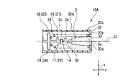
Next, the configuration of the clip cartridge 80 according to this embodiment will be described. The clip cartridge 80 is configured to facilitate transportation and prevent contamination with the external environment during the process from manufacture of the clip 10 to actual use. As shown in FIG. 4, the clip cartridge 80 according to the present embodiment includes a clip 10 and a housing 40 capable of accommodating the clip 10 therein. FIG. 4 is a partial cross-sectional view showing the clip 10 housed inside the housing 40 in the clip cartridge 80 at the time of shipment.
本実施形態において、図4は、クリップ10とハウジング40との配置関係のみを示すために用いられている。本実施形態に係るハウジング40は、図4に示す構成に限定されない。本実施形態に係るハウジング40は、クリップ10を好適に収容でき、かつ、操作者が持ちやすい大きさに形成されればよく、形状は特に限定されない。本実施形態に係るハウジング40は、例えば、特許文献1に記載されたクリップケースの形状および構成を採用してもよい。
In this embodiment, FIG. 4 is used only to show the positional relationship between the clip 10 and the housing 40. As shown in FIG. The housing 40 according to this embodiment is not limited to the configuration shown in FIG. The shape of the housing 40 according to the present embodiment is not particularly limited as long as it can suitably accommodate the clip 10 and is formed in a size that is easy for the operator to hold. The housing 40 according to the present embodiment may adopt the shape and configuration of the clip case described in Patent Literature 1, for example.
図4に示すように、本実施形態に係るハウジング40は、本体部39において、長手軸に沿って、クリップ収納部37と、ルーメン38とを有して形成されている。クリップ収納部37において、開形態にあるアーム部材11を収納できる内腔が形成されている。ルーメン38は、クリップ収納部37よりも基端側に設けられ、押さえ管31を収納できる。すなわち、ハウジング40は、クリップ収納部37およびルーメン38が図4に示された軸Y方向に沿って形成されている。クリップ収納部37において、図4に示された軸線X方向における内腔の寸法は、開形態にあるアーム部材11の第一アーム12および第二アーム13の間の距離の最大値以上であってもよい。ルーメン38において、軸線X方向における内径は、押さえ管31の外径よりも大きくてもよい。本実施形態に係るハウジング40の本体部39は、例えば、一定の硬さを有し、かつ透明な各種公知の樹脂材料で形成されることができる。
本実施形態に係るハウジング40は、上述のような構成を有することで、クリップ10がハウジング40に収納された状態で、長手軸方向(軸線C1に沿う方向)に沿って進退動作できる。As shown in FIG. 4, the housing 40 according to the present embodiment is formed with a clip accommodating portion 37 and a lumen 38 along the longitudinal axis in the body portion 39 . A lumen is formed in the clip storage portion 37 to accommodate the arm member 11 in the open configuration. The lumen 38 is provided closer to the proximal end than the clip storage portion 37 and can accommodate the holding tube 31 . That is, the housing 40 has the clip storage portion 37 and the lumen 38 formed along the axis Y direction shown in FIG. In the clip housing portion 37, the dimension of the lumen in the direction of the axis X shown in FIG. good too. The inner diameter of the lumen 38 in the direction of the axis X may be larger than the outer diameter of the pressing tube 31 . The body portion 39 of the housing 40 according to the present embodiment can be made of, for example, various known resin materials that have a certain degree of hardness and are transparent.
Since the housing 40 according to the present embodiment has the configuration described above, the clip 10 can move back and forth along the longitudinal axis direction (direction along the axis C1) while the clip 10 is housed in the housing 40.
図4に示すように、本実施形態に係るハウジング40は、本体部39の基端側において、2つのL字形状の溝391が形成されている。より具体的に、本体部39に形成された溝391は、長手軸方向に沿って延びて形成される横溝(第1の溝)392と、横溝392よりも先端側の位置に、横溝392に直交する方向に延びって形成される縦溝(第2の溝)393とを有している。本実施形態において、横溝392の基端側の端面を溝391の基端面と称し、縦溝393のハウジング40の径方向における外側の端面を溝391の先端面と称する。
As shown in FIG. 4 , the housing 40 according to this embodiment has two L-shaped grooves 391 formed on the base end side of the body portion 39 . More specifically, the grooves 391 formed in the body portion 39 include a lateral groove (first groove) 392 formed extending along the longitudinal axis direction, and a lateral groove 392 at a position on the tip side of the lateral groove 392 . and a longitudinal groove (second groove) 393 extending in an orthogonal direction. In this embodiment, the end surface of the lateral groove 392 on the proximal side is referred to as the proximal end surface of the groove 391 , and the outer end surface of the longitudinal groove 393 in the radial direction of the housing 40 is referred to as the distal end surface of the groove 391 .
図4に示すように、ハウジング40の基端側において、押さえ管31の基端面に当接する一対のストッパ36が設けられている。ストッパ36は、溝391に設けられたピン361と一体に形成されることができる。このため、一対のストッパ36は、一対のピン361によってそれぞれの移動方向が規制され、溝391に沿って移動することができる。詳細は後述するが、図5に示すように、操作者が一対のストッパ36を把持して、ハウジング40の長手軸方向(軸線C1に沿う方向)に沿ってストッパ36を先端側へ移動すると、ストッパ―36が押さえ管31の基端面に当接した状態で押さえ管31を先端側へ移動させることができる。
As shown in FIG. 4 , a pair of stoppers 36 are provided on the proximal end side of the housing 40 to contact the proximal end surface of the pressing tube 31 . The stopper 36 can be formed integrally with the pin 361 provided in the groove 391 . For this reason, the pair of stoppers 36 can move along the groove 391 with their movement directions restricted by the pair of pins 361 . Although the details will be described later, as shown in FIG. 5, when the operator grips the pair of stoppers 36 and moves the stoppers 36 toward the distal end side along the longitudinal axis direction of the housing 40 (the direction along the axis C1), With the stopper 36 in contact with the proximal end surface of the holding tube 31, the holding tube 31 can be moved to the distal side.
図4に示すように、説明の便宜のため、本実施形態において、ストッパ36は、長方形の形状を有して形成される例を説明するが、これに限定されない。本実施形態において、ストッパ36は、押さえ管31の基端面に当接し、押さえ管31を先端側へ移動させることができれば、その形状および大きさなどは特に限定されない。
As shown in FIG. 4, for convenience of explanation, in this embodiment, an example in which the stopper 36 is formed to have a rectangular shape will be described, but the present invention is not limited to this. In the present embodiment, the shape and size of the stopper 36 are not particularly limited as long as the stopper 36 abuts on the proximal end surface of the pressing tube 31 and can move the pressing tube 31 to the distal side.
図4に示すように、軸線X方向における一対のストッパ36の間の距離は、押さえ管31の大径部31cの内径よりも大きい。詳細は後述するが、本実施形態において、一対のストッパ36が横溝392に配置され、かつ、ストッパ36が押さえ管31の基端面に当接した状態で操作者が押さえ管31を先端側へ移動させることにより、連結部3の少なくとも基端部3fが押さえ管31の基端側の開口から突出した状態で、操作者が操作ワイヤ62のフック62aを連結部3の切欠部3gに挿入することができる(図6および図7参照)。言い換えれば、軸線X方向における一対のストッパ36の間の距離は、フック62aが挿入孔3eに挿入されるとき、基端部3fの一対のレッグが弾性変形することにより、基端部3fの軸線X方向における幅の最大値以上である。また、一対のストッパ36が横溝392に配置される状態において、軸線X方向における一対のストッパ36の間の距離は、押さえ管31の外径以下である。
本実施形態において、ハウジング40の長手軸C1に対して、一対のストッパ36および一対のL字溝391は、線対称で設けられてもよい。As shown in FIG. 4 , the distance between the pair of stoppers 36 in the direction of the axis X is greater than the inner diameter of the large-diameter portion 31 c of the pressing tube 31 . Although the details will be described later, in this embodiment, the pair of stoppers 36 are arranged in the lateral groove 392, and the operator moves the pressing tube 31 to the distal side in a state in which the stoppers 36 are in contact with the proximal end surface of the pressing tube 31. As a result, the operator can insert the hook 62a of the operation wire 62 into the notch 3g of the connecting portion 3 in a state in which at least the proximal end portion 3f of the connecting portion 3 protrudes from the opening on the proximal end side of the holding tube 31. (see FIGS. 6 and 7). In other words, when the hook 62a is inserted into the insertion hole 3e, the pair of legs of the proximal end portion 3f are elastically deformed so that the distance between the pair of stoppers 36 in the direction of the axis X is equal to the axial line of the proximal end portion 3f. It is greater than or equal to the maximum width in the X direction. In addition, when the pair of stoppers 36 are arranged in the lateral groove 392 , the distance between the pair of stoppers 36 in the direction of the axis X is equal to or less than the outer diameter of the pressing tube 31 .
In this embodiment, the pair of stoppers 36 and the pair of L-shaped grooves 391 may be provided line-symmetrically with respect to the longitudinal axis C1 of the housing 40 .
本実施形態において、ハウジング40の本体部39において、一対のストッパ36が設けられる構成を一例として説明するが、これに限定されない。ハウジング40が一対のストッパ36を備える構成により、後述する押さえ管31を先端側へ移動させる操作において、押さえ管31の基端面に均等的に力量を加えることができ、押さえ管31をスムーズに先端側へ移動させることができる。本実施形態において、押さえ管31を先端側へ移動させることができれば、ストッパ36が一つだけが設けられてもよい。
In the present embodiment, a configuration in which a pair of stoppers 36 are provided in the body portion 39 of the housing 40 will be described as an example, but the present invention is not limited to this. Due to the structure in which the housing 40 is provided with a pair of stoppers 36, in the operation of moving the holding tube 31 to the distal side, which will be described later, it is possible to uniformly apply the amount of force to the proximal end surface of the holding tube 31, thereby smoothly moving the holding tube 31 to the distal end. can be moved to the side. In this embodiment, only one stopper 36 may be provided as long as the pressing tube 31 can be moved to the distal end side.
図4に示すように、本体部39に形成された縦溝393には、弾性部材362が配置されている。弾性部材362は、縦溝393の軸線X方向における外側、すなわち、ハウジング40の径方向外側に位置する端面に固定されている。弾性部材362は、ハウジング40の長手軸に向かう方向、すなわち、ハウジング40の径方向内側へ付勢されている。
As shown in FIG. 4 , elastic members 362 are arranged in vertical grooves 393 formed in the main body portion 39 . The elastic member 362 is fixed to the outer side of the longitudinal groove 393 in the direction of the axis X, that is, the end face positioned radially outer of the housing 40 . The elastic member 362 is biased toward the longitudinal axis of the housing 40 , that is, radially inward of the housing 40 .
(アプリケータの構成)
続いて、図10を参照し、本実施形態に係るアプリケータ30の構成を説明する。図10に示すように、本実施形態に係るアプリケータ30は、挿入部65と、操作部100とを有して構成されている。(Applicator configuration)
Next, the configuration of the applicator 30 according to this embodiment will be described with reference to FIG. 10 . As shown in FIG. 10, the applicator 30 according to this embodiment includes an insertion portion 65 and an operation portion 100. As shown in FIG.
(挿入部の構成)
アプリケータ30の挿入部65は、シース66と、操作ワイヤ(ワイヤ)62とを備えている。操作ワイヤ62は、シース66内に進退可能に挿通されている。操作ワイヤ62は、操作者が基端側の操作部100を操作する(例えば、スライダ102を押し込む操作およびスライダ102を引き戻す操作)力量をクリップ10に伝達するために設けられている。(Structure of insertion section)
The insertion portion 65 of the applicator 30 has a sheath 66 and an operating wire (wire) 62 . The operating wire 62 is inserted through the sheath 66 so as to be able to move back and forth. The operation wire 62 is provided to transmit to the clip 10 the strength of the operator's operation of the operation portion 100 on the proximal end side (for example, the operation of pushing the slider 102 and the operation of pulling back the slider 102 ).
シース66は、例えば耐圧縮強度の高いSUS301などのステンレス鋼から形成されたコイルシースであってもよい。この場合、シース66は、不図示の素線を軸線方向Yに密巻きに巻回して形成したコイルを用いることができる。シース66は、可撓性を有するとともに、軸線方向Yの圧縮力に強い。
本実施形態において、シース66は、押さえ管31の小径部31dの内径と略同等の内径を有して形成されている(図8参照)。このため、シース66内において、クリップ10を操作ワイヤ62に装着することができない。また、フック62aが切欠部3gに係合された状態でシース66内に位置するとき、意図せずにフック62aが切欠部3gから脱落することを防止できる。The sheath 66 may be, for example, a coil sheath made of stainless steel such as SUS301 having high compressive strength. In this case, the sheath 66 can be a coil formed by tightly winding a wire (not shown) in the axial direction Y. As shown in FIG. The sheath 66 is flexible and resistant to compressive force in the axial direction Y. As shown in FIG.
In this embodiment, the sheath 66 is formed to have an inner diameter substantially equal to the inner diameter of the small diameter portion 31d of the holding tube 31 (see FIG. 8). Therefore, the clip 10 cannot be attached to the operation wire 62 inside the sheath 66 . Moreover, when the hook 62a is positioned within the sheath 66 in a state where the hook 62a is engaged with the notch 3g, it is possible to prevent the hook 62a from unintentionally falling out of the notch 3g.
本実施形態において操作ワイヤ62は、例えば金属製の単線や撚線で形成されている。操作ワイヤ62の先端側には、矢尻の形状に形成されたフック(第2リンク)62a、軸部62c、および固定部62bが連結されている。固定部62bは、例えば、ステンレスなどの金属材料からなる円筒状の部材である。操作ワイヤ62は、各種公知の方法、例えば、接着や溶接などの方法によって、固定部62bに固定されている。また、フック62aと固定部62bとは、棒状に形成された軸部62cによって連結されている。このため、本実施形態において、操作ワイヤ62と、フック62a、固定部62b、および軸部62cとは一体に形成されている。フック62aは、操作ワイヤ62の進退動作によって、操作ワイヤ62とともに進退動作できる。
In this embodiment, the operation wire 62 is formed of, for example, a metal single wire or twisted wire. An arrowhead-shaped hook (second link) 62a, a shaft portion 62c, and a fixing portion 62b are connected to the distal end side of the operation wire 62 . The fixing portion 62b is, for example, a cylindrical member made of a metal material such as stainless steel. The operation wire 62 is fixed to the fixing portion 62b by various known methods such as adhesion and welding. The hook 62a and the fixed portion 62b are connected by a rod-shaped shaft portion 62c. Therefore, in this embodiment, the operation wire 62, the hook 62a, the fixed portion 62b, and the shaft portion 62c are integrally formed. The hook 62 a can move back and forth together with the operation wire 62 by the back and forth movement of the operation wire 62 .
フック62aは、円錐形状に形成されている。図10に示すように、フック62aは、先端側に向かって外径が順次減少する斜面形状を有する外周面を有している。フック62aの基端面における外径(幅)dは、連結部3の基端部3fが弾性変形しない状態において、基端部3fに形成された挿入孔3eの直径よりも大きく、かつ、切欠部3gの幅D以下である。図7に示すように、本実施形態において、切欠部3gの幅Dがフック62aの幅dと略同等である例を説明するが、これに限定されない。
The hook 62a is formed in a conical shape. As shown in FIG. 10, the hook 62a has an outer peripheral surface having a sloping surface whose outer diameter gradually decreases toward the distal end. The outer diameter (width) d of the proximal end face of the hook 62a is larger than the diameter of the insertion hole 3e formed in the proximal end portion 3f of the connecting portion 3 when the proximal end portion 3f of the connecting portion 3 is not elastically deformed, and It is less than or equal to the width D of 3g. As shown in FIG. 7, in this embodiment, an example in which the width D of the notch 3g is substantially equal to the width d of the hook 62a will be described, but the present invention is not limited to this.
(操作部の構成)
操作部100は、図10に示すように、操作部本体(ハンドル)101と、スライダ102とを有して構成されている。
操作部本体101は、シース66の基端部に取付けられている。操作部本体101は、軸線方向Yに延びる棒状に形成され、基端部に指掛け部101aが設けられている。操作部本体101には、軸線方向Yに延びるスリット101bが形成されている。(Construction of operation unit)
As shown in FIG. 10, the operating section 100 includes an operating section main body (handle) 101 and a slider 102 .
The operating portion main body 101 is attached to the proximal end portion of the sheath 66 . The operation portion main body 101 is formed in a rod shape extending in the axial direction Y, and has a finger hook portion 101a at its base end portion. A slit 101b extending in the axial direction Y is formed in the operation portion main body 101 .
スライダ102は、操作部本体101に挿通されて設けられている。スライダ102は、操作部本体101に対して軸線Y方向にスライド(前進および後退移動)可能である。本実施形態において、スライダ102が軸線方向Yにおいて、前進あるいは後退操作されることにより、操作ワイヤ62および操作ワイヤ62の先端に固定されたフック62aが前進あるいは後退される。また、操作ワイヤ62と連結部3とが連結された状態において、クリップ10のアーム部材11は、操作ワイヤ62の前進あるいは後退操作により、操作ワイヤ62とともに前進あるいは後退することが可能である。その結果、アーム部材11の一対の第一アーム12および第二アーム13を開くあるいは閉じることが可能である。
The slider 102 is provided so as to be inserted through the operation portion main body 101 . The slider 102 is slidable (moves forward and backward) in the direction of the axis line Y with respect to the operation portion main body 101 . In this embodiment, the operation wire 62 and the hook 62a fixed to the tip of the operation wire 62 are advanced or retracted by advancing or retracting the slider 102 in the axial direction Y. As shown in FIG. Further, in a state where the operation wire 62 and the connecting portion 3 are connected, the arm member 11 of the clip 10 can move forward or backward together with the operation wire 62 by advancing or retracting the operation wire 62 . As a result, the pair of first arm 12 and second arm 13 of arm member 11 can be opened or closed.
スライダ102は、円筒状に形成されている。スライダ102の外周面には、全周にわたり凹部102aが形成されている。スライダ102には、軸線方向Yにおける先端側から基端側への順で、鍔部102b、凹部102a、および鍔部102cがこの順で形成されている。一対の鍔部102b、102cは、軸線方向Yに見たときに楕円形状となっている。これにより、スライダ102が握りやすくなり、操作部100を梱包するときに省スペース化が図れる。
スライダ102は、操作部本体101のスリット101bに係合することで、操作部本体101に対するスライダ102の軸線方向Yの移動範囲が制限されている。
本実施形態において、操作部100は、各種公知の内視鏡用処置具の操作部の構成を適宜用いることができる。The slider 102 is formed in a cylindrical shape. A concave portion 102a is formed on the outer peripheral surface of the slider 102 over the entire circumference. The slider 102 is formed with a flange portion 102b, a recessed portion 102a, and a flange portion 102c in this order from the distal end side to the proximal end side in the axial direction Y. As shown in FIG. The pair of flanges 102b and 102c has an elliptical shape when viewed in the axial direction Y. As shown in FIG. As a result, the slider 102 can be easily gripped, and space can be saved when the operation unit 100 is packed.
The slider 102 is engaged with the slit 101b of the operation portion main body 101, so that the movement range of the slider 102 in the axial direction Y with respect to the operation portion main body 101 is restricted.
In the present embodiment, the operating section 100 can appropriately use the configuration of the operating section of various known endoscopic treatment instruments.
(クリップをアプリケータに装着する操作)
以下、図4から図9を参照し、体内の標的組織を処置する前の準備として、本実施形態に係るクリップ10をアプリケータ30に装着する操作を説明する。
クリップ10は、図4に示すように、ハウジング40内に収容された状態で出荷される。この状態において、連結部3を含む押さえ管31は、ハウジング40のルーメン38内に位置している。(Operation of attaching the clip to the applicator)
The operation of attaching the clip 10 according to the present embodiment to the applicator 30 as a preparation before treating the target tissue in the body will be described below with reference to FIGS. 4 to 9 .
The clip 10 is shipped in a housing 40 as shown in FIG. In this state, the holding tube 31 including the connecting portion 3 is positioned within the lumen 38 of the housing 40 .
図4に示すように、クリップ10は、アーム部材11の第一アーム12および第二アーム13が押さえ管31の先端側に形成されたテーパー面31aに当接した状態で、押さえ管31の先端側の開口から突出し、互いに離間している開形態にある。アーム部材11の第一アーム12および第二アーム13は、先端側に設けられた一対の爪12aおよび13aがハウジング40のクリップ収納部の内壁に接触(当接)している。本実施形態に係るハウジング40のクリップ収納部37において、開形態にあるアーム部材11の第一アーム12および第二アーム13アームの間の距離の最大値よりも大きい寸法の内腔が形成されているため、アーム部材11の第一アーム12および第二アーム13がクリップ収納部の内壁に当接することにより折り曲げられることはない。
As shown in FIG. 4 , the clip 10 is configured such that the first arm 12 and the second arm 13 of the arm member 11 are in contact with the tapered surface 31 a formed on the distal end side of the pressing tube 31 . They project from side openings and are in an open configuration spaced apart from each other. The first arm 12 and the second arm 13 of the arm member 11 have a pair of claws 12a and 13a provided on the distal end side that contact (abut) the inner wall of the clip accommodating portion of the housing 40. As shown in FIG. In the clip storage portion 37 of the housing 40 according to this embodiment, a bore having a dimension larger than the maximum distance between the first arm 12 and the second arm 13 of the arm member 11 in the open configuration is formed. Therefore, the first arm 12 and the second arm 13 of the arm member 11 are not bent by coming into contact with the inner wall of the clip storage portion.
アーム部材11の中間部14は、ループ形状を形成し、連結部3のフック部3cに引っ掛かっている。すなわち、クリップ10と連結部3とは、中間部14がフック部3cに引っ掛かることにより、係合されている。アーム部材11の第一アーム12および第二アーム13の弾性復元力が連結部3に作用することにより、連結部3は、押さえ管31の内部に位置している。
The intermediate portion 14 of the arm member 11 forms a loop shape and is hooked on the hook portion 3c of the connecting portion 3. As shown in FIG. That is, the clip 10 and the connecting portion 3 are engaged by hooking the intermediate portion 14 on the hook portion 3c. The elastic restoring forces of the first arm 12 and the second arm 13 of the arm member 11 act on the connecting portion 3 , so that the connecting portion 3 is positioned inside the pressing tube 31 .
図4に示すように、一対のストッパ36は、ハウジング40の基端側に位置し、それぞれの先端面364が押さえ管31の基端面に接触(当接)している。押さえ管31は、先端側のテーパー面31aにおけるアーム部材11の第一アーム12および第二アーム13による押圧力と、基端面におけるストッパ36による規制力との両方を受けている。アーム部材11の第一アーム12および第二アーム13による押圧力は、押さえ管31を基端側へ移動させる作用がある。一方、押さえ管31が基端側へ移動することは、ストッパ36の先端面による規制力によって規制されている。言い換えれば、上述の2つの力量が釣り合う状態で同時に押さえ管31に作用することにより、押さえ管31は、ハウジング40に形成されたルーメン38内の位置に保持される。
As shown in FIG. 4 , the pair of stoppers 36 are located on the proximal end side of the housing 40 , and their distal end surfaces 364 are in contact with the proximal end surface of the pressing tube 31 . The pressing tube 31 receives both the pressing force from the first arm 12 and the second arm 13 of the arm member 11 on the tapered surface 31a on the distal end side and the restricting force from the stopper 36 on the proximal end surface. The pressing force by the first arm 12 and the second arm 13 of the arm member 11 has the effect of moving the pressing tube 31 toward the proximal end side. On the other hand, the movement of the pressing tube 31 toward the proximal side is restricted by the restricting force of the distal end surface of the stopper 36 . In other words, the pressure tube 31 is held in position within the lumen 38 formed in the housing 40 by the two forces described above acting simultaneously on the pressure tube 31 in a balanced manner.
次に、操作者は、一対のストッパ36を把持し、一対のストッパ36をピン361とともに先端側へ移動(スライド)させる。図5に示すように、押さえ管31の基端面に接触している一対のストッパ36の先端側への移動とともに、押さえ管31は、先端側へ移動する。この過程において、一対のストッパ36がハウジング40の長手軸方向に沿って横溝392内を移動するため、一対のストッパ36の間の距離は、一定である。上述したように、一対のストッパ36の間の距離が連結部3の幅よりも大きく設定されているため、押さえ管31は、先端側へ移動する過程において、連結部3と衝突することがない。
Next, the operator grips the pair of stoppers 36 and moves (slides) the pair of stoppers 36 together with the pin 361 to the tip side. As shown in FIG. 5, as the pair of stoppers 36 in contact with the proximal end face of the holding tube 31 moves to the distal side, the holding tube 31 moves to the distal side. In this process, the pair of stoppers 36 move in the lateral groove 392 along the longitudinal direction of the housing 40, so the distance between the pair of stoppers 36 is constant. As described above, since the distance between the pair of stoppers 36 is set larger than the width of the connecting portion 3, the holding tube 31 does not collide with the connecting portion 3 in the process of moving to the distal end side. .
図5に示すように、押さえ管31が先端側へ移動される過程において、クリップ10のアーム部材11の第一アーム12および第二アーム13は、押さえ管31の先端側に形成されたテーパー面31aに当接しながら押圧される。アーム部材11の第一アーム12および第二アーム13は、爪12a、13aがハウジング40のクリップ収納部37の内壁に沿って、互いの間の距離が小さくなる方向へ移動する。その結果、アーム部材11の第一アーム12および第二アーム13は、上述の開形態から、互いが接触する、あるいは互いの距離が略0である閉形態へ遷移することができる。このとき、アーム部材11の第一アーム12および第二アーム13は、一部が押さえ管31内に挿入される。
As shown in FIG. 5 , in the process of moving the holding tube 31 toward the distal side, the first arm 12 and the second arm 13 of the arm member 11 of the clip 10 move toward the tapered surface formed on the distal side of the holding tube 31 . 31a while being pressed. The first arm 12 and the second arm 13 of the arm member 11 move in a direction in which the claws 12a and 13a move along the inner wall of the clip accommodating portion 37 of the housing 40 so that the distance therebetween becomes smaller. As a result, the first arm 12 and the second arm 13 of the arm member 11 can transition from the above-described open configuration to a closed configuration in which they are in contact with each other or the distance therebetween is substantially zero. At this time, the first arm 12 and the second arm 13 of the arm member 11 are partially inserted into the holding tube 31 .
操作者が一対のストッパ36を保持した状態で移動させ、ピン361が横溝392の先端に到達すると、図5に示すように、連結部3は、押さえ管31の基端側の開口から突出する。本実施形態において、連結部3が押さえ管31の基端側の開口から突出する状態を、連結部3の突出形態と称する。連結部3が押さえ管31の基端側の開口から突出した突出形態において、少なくとも連結部3の切欠部3gを含む基端部3fの一部は、押さえ管31の基端側の開口から突出するが、これに限定されない。本実施形態において、連結部3の基端部3fの一部が押さえ管31から突出した位置において、後述する操作ワイヤ62の先端に設けられたフック62aを連結部3に連結する操作ができればよい。連結部3の押さえ管31からの突出量は、特に限定されない。
When the operator moves the pair of stoppers 36 while holding them and the pin 361 reaches the distal end of the lateral groove 392, the connecting portion 3 protrudes from the proximal end side opening of the pressing tube 31 as shown in FIG. . In this embodiment, the state in which the connecting portion 3 protrudes from the opening on the proximal end side of the pressing tube 31 is referred to as a projecting form of the connecting portion 3 . In the protruding form in which the connecting portion 3 protrudes from the proximal side opening of the pressing tube 31, at least a portion of the proximal portion 3f including the notch portion 3g of the connecting portion 3 protrudes from the proximal side opening of the pressing tube 31. However, it is not limited to this. In the present embodiment, it is sufficient that a hook 62a provided at the tip of an operation wire 62, which will be described later, can be connected to the connecting portion 3 at a position where a part of the proximal end portion 3f of the connecting portion 3 protrudes from the pressing tube 31. . The amount of protrusion of the connecting portion 3 from the pressing tube 31 is not particularly limited.
閉形態にあるアーム部材11の第一アーム12および第二アーム13の弾性復元力により、押さえ管31は、基端側へ移動しようとする。しかしながら、押さえ管31の基端面が一対のストッパ36の先端面364に当接され、かつ、ストッパ36が操作者によって位置が保持されているため、押さえ管31の基端側への移動が規制される。言い換えれば、ストッパ36および押さえ管31が当接することにより、連結部3の突出形態を維持することができる。言い換えれば、ストッパ36は、連結部3が押さえ管31から突出する突出形態から押さえ管31に収容される収容形態への遷移を規制することができる。
本実施形態において、ストッパ36がL字形状の溝391における横溝392に沿って移動することにより、連結部3と押さえ管31との相対位置を制御することができる。Due to the elastic restoring force of the first arm 12 and the second arm 13 of the arm member 11 in the closed state, the pressing tube 31 tries to move to the proximal end side. However, since the proximal end surface of the holding tube 31 is in contact with the distal end surfaces 364 of the pair of stoppers 36 and the position of the stoppers 36 is held by the operator, movement of the pressing tube 31 toward the proximal end side is restricted. be done. In other words, the contact between the stopper 36 and the pressing tube 31 allows the connecting portion 3 to maintain its protruding form. In other words, the stopper 36 can restrict the transition from the protruding form in which the connecting part 3 protrudes from the pressing tube 31 to the accommodation form in which the connecting part 3 is accommodated in the pressing tube 31 .
In the present embodiment, the stopper 36 moves along the lateral groove 392 in the L-shaped groove 391 to control the relative position between the connecting portion 3 and the pressing tube 31 .
本実施形態において、L字形状の溝391の縦溝393において、ハウジング40の径方向内側へ付勢されている弾性部材362が設けられているため、操作者がピン361を移動しない限り、ピン361がハウジング40の径方向外側へ縦溝393内を移動することはない。このため、ストッパ36と押さえ管31とが係合する状態がピン361の意図しない移動によって解除されることはない。
In this embodiment, since the longitudinal groove 393 of the L-shaped groove 391 is provided with an elastic member 362 that is biased inward in the radial direction of the housing 40 , the pin 361 will not move unless the operator moves the pin 361 . 361 does not move radially outwardly of housing 40 within flutes 393 . Therefore, the state in which the stopper 36 and the pressing tube 31 are engaged will not be released due to unintended movement of the pin 361 .
本実施形態において、操作者がストッパ36を把持することにより、ストッパ36が横溝392の先端に位置する状態が維持される例を説明したが、これに限定されない。横溝392およびピン361を適宜構成することにより、操作者がストッパ36を把持しなくても、ストッパ36の位置を維持することができる。
In the present embodiment, an example has been described in which the operator grips the stopper 36 to maintain the state where the stopper 36 is positioned at the tip of the lateral groove 392, but the present invention is not limited to this. By appropriately configuring the lateral groove 392 and the pin 361, the position of the stopper 36 can be maintained without the operator gripping the stopper 36. FIG.
例えば、横溝392の先端側の内壁において、弾性変形できる規制部材(不図示)を設けて、ピン361の基端側への移動を規制してもよい。このとき、横溝392における規制部材が設けられた位置では、横溝392の内径が細くなる箇所が形成される。操作者がストッパ36を操作し、ピン361が先端側へ横溝392内を移動する際、ピン361と規制部材とが当接することによって規制部材が弾性変形すると、ピン361が規制部材を乗り越えて横溝392と縦溝393との連結部に到達することができる。しかしながら、アーム部材11の第一アーム12および第二アーム13の弾性復元力に起因する、押さえ管31および押さえ管31に当接するストッパ36を基端側へ移動させる押圧力のみでは、ピン361が規制部材を乗り越えることができない。
このため、操作者がストッパ36を把持しなくても、ストッパ36が横溝392の先端に位置する状態を維持することができる。For example, an elastically deformable restricting member (not shown) may be provided on the inner wall of the lateral groove 392 on the distal end side to restrict the movement of the pin 361 toward the proximal end side. At this time, a portion where the inner diameter of the lateral groove 392 is narrowed is formed at the position where the regulating member is provided in the lateral groove 392 . When the operator operates the stopper 36 and the pin 361 moves toward the distal end side in the lateral groove 392, the pin 361 and the restricting member are elastically deformed due to the contact between the pin 361 and the restricting member. The junction of 392 and flute 393 can be reached. However, the pin 361 does not move with only the pressing force for moving the holding tube 31 and the stopper 36 in contact with the holding tube 31 to the proximal end side due to the elastic restoring force of the first arm 12 and the second arm 13 of the arm member 11 . Cannot climb over the restricting member.
Therefore, even if the operator does not grip the stopper 36 , the stopper 36 can be maintained at the tip of the lateral groove 392 .
例えば、横溝392の内壁とピン361の外周面との材質を適宜選択することにより、横溝392とピン361との間の摩擦力を増大させてもよい。この場合、横溝392とピン361との間の摩擦力によって、操作者がストッパ36を操作しない限り、ピン361が横溝392内における所望の位置に配されることができる。
For example, the frictional force between the lateral groove 392 and the pin 361 may be increased by appropriately selecting the materials for the inner wall of the lateral groove 392 and the outer peripheral surface of the pin 361 . In this case, the frictional force between the lateral groove 392 and the pin 361 allows the pin 361 to be arranged at a desired position within the lateral groove 392 unless the operator operates the stopper 36 .
ストッパ36が横溝392の先端に位置する状態で、次に、操作者は、アプリケータ30の操作部100(図10参照)を操作し、連結部3に向かって挿入部65のシース66を先端側へ移動し、シース66の先端面をストッパ36の基端面363に当接させる。
With the stopper 36 positioned at the distal end of the lateral groove 392 , the operator then operates the operating portion 100 (see FIG. 10 ) of the applicator 30 to move the sheath 66 of the insertion portion 65 toward the connecting portion 3 . side to bring the distal end surface of the sheath 66 into contact with the proximal end surface 363 of the stopper 36 .
この状態において、図6に示すように、連結部3の基端部3fの少なくとも一部が押さえ管31から基端側へ突出し、一対のストッパ36の間に位置する。この状態で、操作者が操作部本体101のスリット101bに沿って、スライダ102を先端側へ押し込む操作により、操作ワイヤ62の先端に設けられたフック62aは、操作ワイヤ62とともに前進し、連結部3の基端部3fの挿入孔3eに当接し押圧する。
In this state, as shown in FIG. 6, at least a portion of the proximal end portion 3f of the connecting portion 3 protrudes from the pressing tube 31 toward the proximal end side and is positioned between the pair of stoppers 36. As shown in FIG. In this state, the hook 62a provided at the tip of the operation wire 62 advances together with the operation wire 62 when the operator pushes the slider 102 toward the tip side along the slit 101b of the operation portion main body 101. 3 is brought into contact with and pressed against the insertion hole 3e of the base end 3f.
操作者がスライダ102を先端側へ押し込むことにより、図6に示すように、連結部3の基端部3fの一対のレッグが長手軸C1に対して径方向外側へ弾性変形する。フック62aは、連結部3の基端部3fに形成された挿入孔3eを通過し、連結部3の切欠部3gに進入する。図6に示すように、フック62aが連結部3の挿入孔3eを通過する際、連結部3の基端部3fの一対のレッグが弾性変形することにより、連結部3の基端部3fの軸線X方向における幅の最大値は、一対のストッパ36の間の距離以下であり、かつ、シース66の内径および押さえ管31における大径部31cおよび小径部31dのそれぞれの内径よりも大きい。言い換えれば、本実施形態において、図6に示すように、連結部3の基端部3fが押さえ管31およびシース66の内部に収容されていない状態のみ、操作ワイヤ62のフック62aが挿入孔3eを通過し切欠部3gに係合される。
その結果、図7に示すように、フック62aが連結部3の切欠部3gに係合され、連結部3とフック62aとが係合する連結部は、一対のストッパ36の間に位置し、押さえ管31の基端側の開口から突出する状態が維持されている。すなわち、連結部3は、突出形態が維持されている。When the operator pushes the slider 102 toward the distal end, as shown in FIG. 6, the pair of legs of the proximal end 3f of the connecting portion 3 are elastically deformed radially outward with respect to the longitudinal axis C1. The hook 62a passes through the insertion hole 3e formed in the proximal end portion 3f of the connecting portion 3 and enters the notch portion 3g of the connecting portion 3. As shown in FIG. As shown in FIG. 6, when the hook 62a passes through the insertion hole 3e of the connecting portion 3, the pair of legs of the base end portion 3f of the connecting portion 3 is elastically deformed, thereby causing the base end portion 3f of the connecting portion 3 to move. The maximum value of the width in the direction of the axis X is equal to or smaller than the distance between the pair of stoppers 36 and larger than the inner diameter of the sheath 66 and the inner diameters of the large diameter portion 31c and the small diameter portion 31d of the hold tube 31, respectively. In other words, in this embodiment, as shown in FIG. 6, the hook 62a of the operation wire 62 is inserted into the insertion hole 3e only when the proximal end 3f of the connecting portion 3 is not accommodated inside the holding tube 31 and the sheath 66. and is engaged with the notch 3g.
As a result, as shown in FIG. 7, the hook 62a is engaged with the notch 3g of the connecting portion 3, and the connecting portion where the connecting portion 3 and the hook 62a are engaged is located between the pair of stoppers 36. The state of protruding from the opening on the proximal end side of the pressing tube 31 is maintained. That is, the connecting portion 3 is maintained in a projecting form.
より具体的に、操作者がスライダ102を押し込む操作により、操作ワイヤ62の先端に設けられたフック62aを連結部3の基端部3fに形成された挿入孔3eに挿入する際、基端部3fが一部弾性変形する。このため、基端部3fが一部弾性変形することにより発生した弾性復元力は、操作ワイヤ62を経由して操作者に伝わることができる。また、フック62aが連結部3の基端部3fを乗り越えて切欠部3gに進入すると、基端部3fの形状が復元し、フック62aを切欠部3gに収容する。上述の操作により、操作ワイヤ62とクリップ10とは、連結部3によって連結される。
More specifically, when the operator pushes the slider 102 to insert the hook 62a provided at the distal end of the operating wire 62 into the insertion hole 3e formed in the proximal end portion 3f of the connecting portion 3, the proximal end portion 3f is partially elastically deformed. Therefore, the elastic restoring force generated by the partial elastic deformation of the base end portion 3 f can be transmitted to the operator via the operation wire 62 . Further, when the hook 62a climbs over the base end portion 3f of the connecting portion 3 and enters the notch portion 3g, the shape of the base end portion 3f is restored and the hook 62a is accommodated in the notch portion 3g. The operation wire 62 and the clip 10 are connected by the connecting portion 3 by the above operation.
フック62aを連結部3に係合するために、操作者によるスライダ102の押し込む操作において、操作者がスライダ102をスリット101bの先端面に接触するまで押し込むと、フック62aが連結部3の切欠部3gに進入し、係合できることは、操作者にとって確認しやすいため、好ましい。ただし、本発明は、これに限定されない。
When the operator pushes the slider 102 in order to engage the hook 62 a with the connecting portion 3 , when the operator pushes the slider 102 until it contacts the tip surface of the slit 101 b , the hook 62 a engages with the notch portion of the connecting portion 3 . Being able to enter and engage 3g is preferred because it is easier for the operator to confirm. However, the present invention is not limited to this.
すなわち、スライダ102がスリット101bに沿ってスリット101bの先端面に当接する前に、フック62aが連結部3の切欠部3gに進入し、係合されることも可能である。この際、フック62aが連結部3の切欠部3gに進入し、係合されるとき、操作部100におけるスライダ102がスリット101bにおける位置をスライダ102の最も前進した位置と見なすことができる。この場合、フック62aが切欠部3gに収容されるため、操作者がスライダ102を押し込んでも、切欠部3gによる抵抗が操作者に伝わって、同様に連結部3とフック62aが係合されていることを確認できる。
That is, the hook 62a can enter and engage with the notch 3g of the connecting portion 3 before the slider 102 contacts the tip end face of the slit 101b along the slit 101b. At this time, when the hook 62a enters and engages with the notch 3g of the connecting portion 3, the position of the slider 102 in the operating portion 100 at the slit 101b can be regarded as the most advanced position of the slider 102. FIG. In this case, since the hook 62a is accommodated in the notch portion 3g, even if the operator pushes the slider 102, the resistance of the notch portion 3g is transmitted to the operator, and the connecting portion 3 and the hook 62a are similarly engaged. I can confirm that.
操作ワイヤ62とクリップ10とが連結された状態では、操作者によるスライダ102の操作によって、クリップ10は、操作ワイヤ62とともに進退動作することが可能である。より具体的に、クリップ10のアーム部材11の第一アーム12および第二アーム13は、操作ワイヤ62の進退動作により、操作ワイヤ62とともに進退することができる。このとき、アーム部材11の第一アーム12および第二アーム13は、後述するように、押さえ管31に対して相対移動することができる。その結果、アーム部材11の第一アーム12および第二アーム13は、押さえ管31の先端側に設けられたテーパー面31aに当接しながら、その間におけるアーム部材11の開き幅が拡大または減少する。
In a state where the operation wire 62 and the clip 10 are connected, the clip 10 can move back and forth together with the operation wire 62 by operating the slider 102 by the operator. More specifically, the first arm 12 and the second arm 13 of the arm member 11 of the clip 10 can move back and forth together with the operation wire 62 by the back and forth movement of the operation wire 62 . At this time, the first arm 12 and the second arm 13 of the arm member 11 can move relative to the pressing tube 31 as described later. As a result, while the first arm 12 and the second arm 13 of the arm member 11 abut against the tapered surface 31a provided on the distal end side of the pressing tube 31, the opening width of the arm member 11 between them increases or decreases.
図7に示すように、操作ワイヤ62とクリップ10とが連結された状態で、操作者は、一対のストッパ36を縦溝393に沿ってハウジング40の径方向外側へ移動(スライド)させる。一対のストッパ36が縦溝393に沿ってハウジング40の径方向外側へ移動すると、押さえ管31の基端面とストッパ36の先端面364との係合が解除される。
As shown in FIG. 7 , the operator moves (slides) the pair of stoppers 36 radially outward of the housing 40 along the longitudinal grooves 393 while the operation wire 62 and the clip 10 are connected. When the pair of stoppers 36 move radially outward of the housing 40 along the longitudinal grooves 393, the engagement between the proximal end surface of the pressing tube 31 and the distal end surface 364 of the stopper 36 is released.
このとき、クリップ10のアーム部材11の第一アーム12および第二アーム13の弾性復元力により、押さえ管31が基端側へ移動する。上述したように、本実施形態に係る押さえ管31は、外径がシース66の内径よりも大きく形成されている。このため、押さえ管31は、基端面がシース66の先端面に当接するまで、基端側へ移動する。図8に示すように、連結部3と操作ワイヤ62とが係合している連結部は、押さえ管31内に収容される。この状態において、操作者がスライダ102を操作し、操作ワイヤ62を進退させても、連結部3とフック62aとの連結部が押さえ管31またはシース66内に位置するため、連結部3とフック62aとの係合が意図せずに解除されることはない。
At this time, the elastic restoring force of the first arm 12 and the second arm 13 of the arm member 11 of the clip 10 causes the pressing tube 31 to move to the proximal end side. As described above, the holding tube 31 according to this embodiment has an outer diameter larger than the inner diameter of the sheath 66 . Therefore, the holding tube 31 moves to the proximal end side until the proximal end surface abuts the distal end surface of the sheath 66 . As shown in FIG. 8 , the connecting portion where the connecting portion 3 and the operating wire 62 are engaged is housed inside the holding tube 31 . In this state, even if the operator operates the slider 102 to move the operation wire 62 back and forth, the connecting portion between the connecting portion 3 and the hook 62a is positioned inside the pressing tube 31 or the sheath 66. The engagement with 62a cannot be unintentionally released.
言い換えれば、操作者がストッパ36を縦溝393に沿ってハウジング40の径方向外側へ移動することにより、ストッパ36による連結部3の突出形態から収容形態への遷移に対する規制が解除される。このため、アーム部材11の第一アーム12および第二アーム13の弾性復元力により、押さえ管31は、シース66に向かって基端側へ移動し、シース66と当接する。一方、連結部3は、押さえ管31から突出する突出形態から、押さえ管31内に収容される収容形態へ遷移することができる。
本実施形態において、ストッパ36がL字形状の溝391の縦溝393に沿ってハウジング40の径方向外側へ移動することにより、ストッパ36による連結部3の突出形態から収容形態への遷移に対する規制は解除できる。このため、本実施形態に係るL字形状の溝391における縦溝393は、連結部3の突出形態から収容形態への遷移に対する規制を解除するためのリリース機構と言える。In other words, when the operator moves the stopper 36 radially outward of the housing 40 along the longitudinal groove 393 , the restriction of the transition of the connecting portion 3 from the protruded form to the accommodated form by the stopper 36 is released. Therefore, due to the elastic restoring force of the first arm 12 and the second arm 13 of the arm member 11 , the holding tube 31 moves toward the sheath 66 toward the proximal end side and contacts the sheath 66 . On the other hand, the connecting portion 3 can transition from the protruding form protruding from the holding tube 31 to the accommodating form housed inside the holding tube 31 .
In the present embodiment, the stopper 36 moves radially outward of the housing 40 along the longitudinal groove 393 of the L-shaped groove 391, thereby restricting the transition of the connecting portion 3 from the protruded form to the accommodated form by the stopper 36. can be released. Therefore, the longitudinal groove 393 in the L-shaped groove 391 according to this embodiment can be said to be a release mechanism for releasing the restriction on the transition of the connecting portion 3 from the protruded form to the accommodated form.
本実施形態において、弾性部材362が設けられていない場合、ピン361が縦溝393に進入すると、L字形状の溝391の先端面に向かう方向、すなわち、ハウジング40の径方向外側へ意図せず移動する場合がある。ピン361が移動すると、ピン361と一体に形成されるストッパ36も同じハウジング40の径方向外側へ移動する。このとき、ストッパ36と押さえ管31とが係合している状態が意図せず解除される。その結果、クリップ10のアーム部材11の弾性復元力が押さえ管31に作用し、押さえ管31を基端側へ移動させる。
In the present embodiment, when the elastic member 362 is not provided, when the pin 361 enters the vertical groove 393, the pin 361 unintentionally moves toward the tip surface of the L-shaped groove 391, that is, radially outward of the housing 40. may move. When the pin 361 moves, the stopper 36 integrally formed with the pin 361 also moves radially outward of the same housing 40 . At this time, the state in which the stopper 36 and the pressing tube 31 are engaged is released unintentionally. As a result, the elastic restoring force of the arm member 11 of the clip 10 acts on the holding tube 31 to move the holding tube 31 to the proximal side.
本実施形態において、弾性部材362は、ハウジング40の径方向外側へ、ピン361とともにストッパ36の意図しない移動を制限するために設けられている。弾性部材362は、各種公知のばねなどを用いることができる。ただし、操作者がストッパ36を把持してストッパ36の意図しない移動を規制できれば、弾性部材362を設ける必要がない。すなわち、弾性部材362は、ハウジング40の必須の構成ではない。
In this embodiment, the elastic member 362 is provided radially outwardly of the housing 40 to limit unintended movement of the stopper 36 together with the pin 361 . Various known springs or the like can be used for the elastic member 362 . However, if the operator can grip the stopper 36 to restrict unintended movement of the stopper 36, the elastic member 362 need not be provided. That is, elastic member 362 is not an essential component of housing 40 .
その後、操作者は、操作部100の操作部本体101を操作し、図9に示すように、操作ワイヤ62および操作ワイヤ62に係合されているクリップ10をハウジング40のルーメン38の基端側の開口から抜去することができる。この際、図9に示すように、操作者によってストッパ36が縦溝393におけるハウジング40の径方向外側の位置に保持されてもよいし、操作者によるストッパ36の把持が解除されてもよい。
以上の操作により、本実施形態に係るクリップ10は、アプリケータ30に装着される。図9に示すように、クリップ10がアプリケータ30に装着された状態では、連結部3は、押さえ管31内に収容された収容形態にある。After that, the operator operates the operation portion main body 101 of the operation portion 100, and as shown in FIG. can be withdrawn from the opening of the At this time, as shown in FIG. 9 , the operator may hold the stopper 36 in the vertical groove 393 at a radially outer position of the housing 40 , or the operator may release the grip of the stopper 36 .
The clip 10 according to the present embodiment is attached to the applicator 30 by the above operation. As shown in FIG. 9 , when the clip 10 is attached to the applicator 30 , the connecting portion 3 is in the accommodation configuration in which it is accommodated in the pressing tube 31 .
(医療機器による手技)
以下、図10から図12を参照し、上述の構成を有する本実施形態に係る医療機器1を用いて、標的組織Tを結紮する手技について説明する。
クリップ10がアプリケータ30に装着された状態でハウジング40から取り出される際、クリップ10のアーム部材11の第一アーム12および第二アーム13は、自身の弾性復元力により、図10に示すように、互いに離間した開形態にある。この状態において、基端側の操作部100において、スライダ102がスリット101bにおける最も前進した位置にある。図示しないが、例えば、スライダ102がスリット101bにおける先端面に当接した位置にあってもよいし、スライダ102がスリット101bにおいて、先端面から離間した基端側の位置にあってもよい。(Procedures using medical equipment)
A procedure for ligating the target tissue T using the medical device 1 according to this embodiment having the above-described configuration will be described below with reference to FIGS. 10 to 12 .
When the clip 10 attached to the applicator 30 is removed from the housing 40, the first arm 12 and the second arm 13 of the arm member 11 of the clip 10 are elastically restored as shown in FIG. , in an open configuration spaced apart from each other. In this state, in the operating portion 100 on the base end side, the slider 102 is at the most advanced position in the slit 101b. Although not shown, for example, the slider 102 may be in contact with the distal end surface of the slit 101b, or the slider 102 may be positioned on the proximal end side away from the distal end surface in the slit 101b.
上述のように、アーム部材11の第一アーム12および第二アーム13の弾性復元力は、押さえ管31を基端側へ移動させる作用がある。このため、図8から図9に示すように、押さえ管31の基端面は、シース66の先端面に当接している。ただし、押さえ管31は、外径がシース66の内径よりも大きく形成されているため、シース66に進入することはない。なお、この状態において、連結部3およびフック62aの連結部は、押さえ管31内に位置する。
As described above, the elastic restoring forces of the first arm 12 and the second arm 13 of the arm member 11 act to move the pressing tube 31 toward the proximal side. Therefore, as shown in FIGS. 8 and 9 , the proximal end surface of the hold down tube 31 is in contact with the distal end surface of the sheath 66 . However, since the holding tube 31 has an outer diameter larger than the inner diameter of the sheath 66 , it does not enter the sheath 66 . In this state, the connecting portion between the connecting portion 3 and the hook 62a is positioned inside the pressing tube 31. As shown in FIG.
操作者は、患者の体内に、不図示の内視鏡を挿入しておく。そして、操作者は、内視鏡のチャンネルの基端部から医療機器1を挿入し、内視鏡のチャンネルの先端部から医療機器1を突出させ、医療機器1を処置対象である標的組織Tの近傍まで移動させる。この過程において、操作者がスライダ102を保持し続けるなどの操作により、アーム部材11の第一アーム12および第二アーム13が閉じた閉形態を維持する。
An operator inserts an endoscope (not shown) into the patient's body. Then, the operator inserts the medical device 1 from the proximal end of the channel of the endoscope, protrudes the medical device 1 from the distal end of the channel of the endoscope, and moves the medical device 1 to the target tissue T to be treated. Move to the vicinity of In this process, the operator maintains the closed state in which the first arm 12 and the second arm 13 of the arm member 11 are closed by an operation such as continuing to hold the slider 102 .
操作者は、医療機器1を内視鏡のチャンネルを挿通し、標的組織Tの近傍まで移動させてから、アーム部材11を閉形態から開形態に遷移させる。
The operator inserts the medical device 1 through the channel of the endoscope, moves it to the vicinity of the target tissue T, and then transitions the arm member 11 from the closed configuration to the open configuration.
このとき、操作者は、スライダ102を進退操作することにより、標的組織Tのサイズに合わせて、アーム部材11の第一アーム12および第二アーム13の間の開き幅を最適値に調整することができる。その結果、図10に示すように、操作者は、アーム部材11の第一アーム12および第二アーム13の間の開き幅を標的組織Tのサイズに対して適宜の値に調整することができる。
At this time, the operator moves the slider 102 back and forth to adjust the opening width between the first arm 12 and the second arm 13 of the arm member 11 to an optimum value according to the size of the target tissue T. can be done. As a result, as shown in FIG. 10, the operator can adjust the opening width between the first arm 12 and the second arm 13 of the arm member 11 to an appropriate value for the size of the target tissue T. .
より具体的に、本実施形態において、操作者が操作部100のスライダ102を進退操作することにより、クリップ10が操作ワイヤ62とともに進退動作する。すなわち、クリップ10のアーム部材11の第一アーム12および第二アーム13は、操作ワイヤ62とともに進退することにより、押さえ管31に対して相対移動することができる。その結果、アーム部材11の第一アーム12および第二アーム13は、押さえ管31の先端側に設けられたテーパー面31aに当接しながら、その間におけるアーム部材11の開き幅が拡大または減少する。例えば、図10に示すように、操作者がスライダ102を基端側へ引き込むと、アーム部材11は、中間部14(第一アーム12および第二アーム13の交差する箇所よりも基端側の部分)が押さえ管31の大径部31c内に進入し、第一アーム12および第二アーム13がアーム部材11の径方向において、離間する。その結果、標的組織Tのサイズに合わせて、操作者がアーム部材11の開き幅を調整することができる。
More specifically, in this embodiment, the clip 10 advances and retreats together with the operation wire 62 when the operator advances and retreats the slider 102 of the operation section 100 . That is, the first arm 12 and the second arm 13 of the arm member 11 of the clip 10 can move relative to the pressing tube 31 by advancing and retreating together with the operation wire 62 . As a result, while the first arm 12 and the second arm 13 of the arm member 11 abut against the tapered surface 31a provided on the distal end side of the pressing tube 31, the opening width of the arm member 11 between them increases or decreases. For example, as shown in FIG. 10, when the operator pulls the slider 102 toward the proximal side, the arm member 11 moves toward the intermediate portion 14 (located toward the proximal side from the intersection of the first arm 12 and the second arm 13). portion) enters the large-diameter portion 31c of the holding tube 31, and the first arm 12 and the second arm 13 are separated in the radial direction of the arm member 11. As shown in FIG. As a result, the operator can adjust the opening width of the arm member 11 according to the size of the target tissue T. FIG.
次に、操作者は、不図示の内視鏡を操作し、クリップ10のアーム部材11の向きおよび姿勢を調整し、標的組織Tに向かってアーム部材11を押し付ける。このような操作により、標的組織Tは、開形態にあるアーム部材11の第一アーム12および第二アーム13の間に位置する。操作者は、第一アーム12および第二アーム13の間に標的組織Tが位置することを確認すると、内視鏡を操作してアーム部材11の第一アーム12および第二アーム13で標的組織Tを保持することができる。
Next, the operator operates the endoscope (not shown), adjusts the direction and posture of the arm member 11 of the clip 10, and presses the arm member 11 toward the target tissue T. FIG. By such manipulation, the target tissue T is positioned between the first arm 12 and the second arm 13 of the arm member 11 in the open configuration. After confirming that the target tissue T is positioned between the first arm 12 and the second arm 13 , the operator operates the endoscope to move the target tissue T between the first arm 12 and the second arm 13 of the arm member 11 . T can be held.
操作者は、標的組織Tが第一アーム12および第二アーム13の間に位置することを確認できたら、図10に示すように、操作部本体101を把持してスライダ102を基端側へ引き戻す。このとき、操作ワイヤ62と、互いに係合しているフック62aおよび連結部3と、第一アーム12および第二アーム13とは、一緒に基端側へ移動する。第一アーム12及び第二アーム13は、押さえ管31の先端側に設けられたテーパー面31aに接触しながら、第一アーム12が第二アーム13側に弾性変形し、第二アーム13が第一アーム12側に弾性変形する。その結果、第一アーム12の先端側に設けられた爪12aと第二アーム13の先端側に設けられた爪13Aとが接近する。言い換えれば、アーム部材11は、第一アーム12および第二アーム13の間の開き幅が縮小し、開形態から閉形態に遷移する。
After confirming that the target tissue T is positioned between the first arm 12 and the second arm 13, the operator grasps the operation portion main body 101 and moves the slider 102 toward the proximal end side, as shown in FIG. pull back. At this time, the operation wire 62, the hook 62a and the connecting portion 3 that are engaged with each other, and the first arm 12 and the second arm 13 move together toward the proximal end side. The first arm 12 and the second arm 13 are elastically deformed toward the second arm 13 while contacting the tapered surface 31a provided on the distal end side of the pressing tube 31, and the second arm 13 moves toward the second arm 13. It elastically deforms toward the one arm 12 side. As a result, the claw 12a provided on the tip side of the first arm 12 and the claw 13A provided on the tip side of the second arm 13 approach each other. In other words, the arm member 11 reduces the opening width between the first arm 12 and the second arm 13 and transitions from the open state to the closed state.
図10および図11に示すように、操作者がスライダ102を基端側へ引き戻す過程において、中間部14を含めるアーム部材11の基端部は、押さえ管31内において、基端側へ引き戻される。本実施形態では、アーム部材11の基端部に設けられた一対の第一被係止部16、17が押さえ管31内の段差部31bよりも先端側に位置する状態において、操作者がスライダ102を先端側へ押し込むことにより、アーム部材11を先端側へ移動させることができる。言い換えれば、アーム部材11における一対の第一被係止部16、17が段差部31bよりも先端側に位置する状態において、操作者がスライダ102を先端側へ押し込むことにより、アーム部材11を閉形態から開形態に遷移させることができる。この操作により、操作者は、アーム部材11を用いて、標的組織Tに対して掴み直すことができる。
As shown in FIGS. 10 and 11, when the operator pulls back the slider 102 to the proximal end side, the proximal end portion of the arm member 11 including the intermediate portion 14 is pulled back to the proximal end side inside the pressing tube 31. . In this embodiment, when the pair of first engaged portions 16 and 17 provided at the base end portion of the arm member 11 are located on the distal side of the stepped portion 31b in the pressing tube 31, the operator moves the slider. The arm member 11 can be moved to the tip side by pushing 102 to the tip side. In other words, in a state in which the pair of first engaged portions 16 and 17 of the arm member 11 are located on the distal end side of the stepped portion 31b, the operator pushes the slider 102 toward the distal end side to close the arm member 11. It is possible to transition from the form to the open form. By this operation, the operator can re-grasp the target tissue T using the arm member 11 .
すなわち、上述の状態までスライダ102が引き戻される過程において、操作者が内視鏡を操作することにより、改めて標的組織Tにクリップ10を対向させることができる。これ以降は前述の手順で、標的組織Tをクリップ10で掴み直すことができる。
That is, in the process in which the slider 102 is pulled back to the above state, the clip 10 can be made to face the target tissue T again by operating the endoscope by the operator. After this, the target tissue T can be re-grasped with the clip 10 in accordance with the procedure described above.
操作者がスライダ102を基端側に引き戻す結果、図11に示すように、標的組織Tの根元で第一アーム12および第二アーム13によって緊縛された状態で、アーム部材11に保持される。本実施形態において、第一アーム12および第二アーム13の間の距離が略0であるこの状態は、アーム部材11の閉形態にも含まれる。この過程において、フック62aと連結部3との連結部が押さえ管31内において基端側へ移動され、図11に示すように、一部がシース66内に進入する。本実施形態において、シース66の内径が押さえ管31の小径部31dの内径と略同等であるため、シース66内において、フック62aと連結部3との係合が意図せずに解除されることはない。
As a result of the operator pulling back the slider 102 to the proximal end side, as shown in FIG. 11, the base of the target tissue T is held by the arm member 11 while being tightly bound by the first arm 12 and the second arm 13 . In this embodiment, this state in which the distance between the first arm 12 and the second arm 13 is approximately 0 is also included in the closed state of the arm member 11 . In this process, the connecting portion between the hook 62a and the connecting portion 3 is moved proximally within the pressing tube 31, and partly enters the sheath 66 as shown in FIG. In this embodiment, since the inner diameter of the sheath 66 is substantially the same as the inner diameter of the small diameter portion 31d of the holding tube 31, the engagement between the hook 62a and the connecting portion 3 in the sheath 66 is not unintentionally released. no.
操作者は、標的組織Tが所望の状態で閉形態にあるアーム部材11に保持されることを確認すると、アーム部材11に設けられた一対の第一被係止部16、17が押さえ管31内の段差部31bを乗り越えて小径部31d内に位置するまで、スライダ102を基端側へ引き戻すことができる。この状態において、一対の第一被係止部16、17が押さえ管31の小径部31dの内壁に食い込むことにより、アーム部材11が押さえ管31に対して先端側へ移動することを規制する。言い換えれば、アーム部材11に設けられた一対の第一被係止部16、17が押さえ管31の小径部31dに位置すると、閉形態にあるアーム部材11が標的組織Tを保持する状態が維持される。
When the operator confirms that the target tissue T is held by the arm member 11 in the closed form in a desired state, the pair of first locked portions 16 and 17 provided on the arm member 11 is pushed into the holding tube 31. The slider 102 can be pulled back to the base end side until it gets over the inner stepped portion 31b and is positioned in the small diameter portion 31d. In this state, the pair of first engaged portions 16 and 17 bite into the inner wall of the small diameter portion 31 d of the pressing tube 31 , thereby restricting the arm member 11 from moving to the distal end side with respect to the pressing tube 31 . In other words, when the pair of first locked portions 16 and 17 provided on the arm member 11 are positioned at the small diameter portion 31d of the pressing tube 31, the state in which the arm member 11 in the closed configuration holds the target tissue T is maintained. be done.
本実施形態において、操作者がスライダ102を操作しても(先端側へ押し込むまたは基端側へ引き戻す)、連結部3とフック62aとの連結部が押さえ管31内またはシース66内に位置する状態が維持される。このため、本実施形態において、操作者は、スライダ102を操作してアーム部材11を用いて標的組織Tを掴み直しても、連結部3とフック62aとの係合が解除されることはない。
In this embodiment, even if the operator operates the slider 102 (pushing it toward the distal side or pulling it back toward the proximal side), the connecting portion between the connecting portion 3 and the hook 62 a is positioned inside the pressing tube 31 or inside the sheath 66 . state is maintained. Therefore, in the present embodiment, even if the operator operates the slider 102 to regrasp the target tissue T using the arm member 11, the engagement between the connecting portion 3 and the hook 62a is not released. .
操作者は、標的組織Tが閉状態にあるアーム部材11によって把持された状態を確認することができる。操作者は、クリップ10のアーム部材11によって標的組織Tが所望の状態で把持されたことを確認できれば、標的組織Tがクリップ10によって把持される状態をロックし、クリップ10を体内に留置する。
The operator can confirm that the target tissue T is gripped by the arm members 11 in the closed state. When the operator can confirm that the target tissue T is grasped in the desired state by the arm members 11 of the clip 10, the operator locks the state in which the target tissue T is grasped by the clip 10 and leaves the clip 10 in the body.
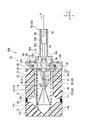
具体的に、操作者は、スライダ102をさらに基端側へ引き戻すことにより、図12に示すように、アーム部材11に設けられた一対の第一被係止部16、17が押さえ管31の小径部31dに位置する。この状態において、アーム部材11の第一アーム12および第二アーム13が押さえ管31の先端側のテーパー面31aに当接し、押圧される。このため、アーム部材11の第一アーム12および第二アーム13が閉じる閉形態で標的組織Tを把持する状態が維持される。このとき、操作者がスライダ102を基端側へ引き戻す力量が連結部3に集中することにより、連結部3における最も脆弱な棒状部3bが破断する。連結部連結部この結果、図12に示すように、標的組織Tがクリップ10によって緊縛された状態で、連結部連結部連結部3が棒状部3bで破断し、連結部3の先端部3aがクリップ10とともに体内に留置され、基端部3fがフック62aに係合された状態で操作ワイヤ62によって体内から抜去されることができる。
Specifically, the operator pulls back the slider 102 further toward the base end side, so that the pair of first engaged portions 16 and 17 provided on the arm member 11 are pulled out of the pressing tube 31 as shown in FIG. Located in the small diameter portion 31d. In this state, the first arm 12 and the second arm 13 of the arm member 11 come into contact with the tapered surface 31a on the distal end side of the pressing tube 31 and are pressed. Therefore, the target tissue T is maintained in the closed state in which the first arm 12 and the second arm 13 of the arm member 11 are closed. At this time, the strength of the operator pulling back the slider 102 to the base end side concentrates on the connecting portion 3, so that the most fragile rod-shaped portion 3b of the connecting portion 3 breaks. As a result, as shown in FIG. 12, with the target tissue T tightly bound by the clip 10, the connecting portion connecting portion connecting portion 3 is broken at the rod-shaped portion 3b, and the distal end portion 3a of the connecting portion 3 is broken. It is left in the body together with the clip 10, and can be removed from the body by the operation wire 62 while the proximal end 3f is engaged with the hook 62a.
標的組織Tを結紮したクリップ10が体内に留置された後、操作者は、内視鏡を操作し、内視鏡のチャンネルから医療機器1を取り出す。その後、操作者は、必要な処置を行い、一連の手技を終了する。
After the clip 10 that ligates the target tissue T is left in the body, the operator operates the endoscope to take out the medical device 1 from the channel of the endoscope. After that, the operator performs the necessary treatment and completes the series of procedures.
(作用)
図13および図14に示すように、仮に連結部3およびフック62aの連結部が押さえ管31の外部に位置する場合を想定する。この場合、矢印Dが示す方向に沿って、連結部3が軸線C1方向に対して交差する方向に回動すると、フック62aが連結部3の切欠き部3gの側方から抜くことができる。言い換えれば、連結部3およびフック62aの連結部が押さえ管31の外部に位置する場合、連結部3とフック62aの係合状態が意図せず解除される可能性がある。その結果、クリップ10は、アプリケータ30から意図せず脱落する可能性がある。(action)
As shown in FIGS. 13 and 14, it is assumed that the connecting portion between the connecting portion 3 and the hook 62a is positioned outside the pressing tube 31. As shown in FIG. In this case, the hook 62a can be pulled out from the side of the notch 3g of the connecting portion 3 when the connecting portion 3 rotates along the direction indicated by the arrow D in the direction crossing the direction of the axis C1. In other words, when the connecting portion between the connecting portion 3 and the hook 62a is positioned outside the pressing tube 31, the engagement state between the connecting portion 3 and the hook 62a may be released unintentionally. As a result, clip 10 may unintentionally fall off applicator 30 .
本実施形態に係る医療機器1によれば、上述のクリップ10をアプリケータ30に装着する操作において、操作ワイヤ62の先端に設けられたフック62aを連結部3の切欠部3gに係合してから、ストッパ36が縦溝393に沿ってハウジング40の径方向外側へ移動することにより、連結部3とフック62aとの連結部を押さえ管31内に収容することができる。連結部3とフック62aとの連結部が押さえ管31内に収容された状態では、連結部3がフック62aに対して回動できない。
According to the medical device 1 according to the present embodiment, in the operation of attaching the clip 10 to the applicator 30, the hook 62a provided at the tip of the operation wire 62 is engaged with the notch 3g of the connecting portion 3. , the stopper 36 moves radially outward of the housing 40 along the longitudinal groove 393 , so that the connecting portion between the connecting portion 3 and the hook 62 a can be accommodated in the pressing tube 31 . When the connecting portion between the connecting portion 3 and the hook 62a is accommodated in the pressing tube 31, the connecting portion 3 cannot rotate with respect to the hook 62a.
さらに、クリップ10がアプリケータ30に装着した状態で、標的組織Tを処置する過程において、操作者が操作部100のスライダ102を先端側へ押し込むまたは基端側へ引き戻す操作では、連結部3とフック62aとの連結部が押さえ管31内に収容された状態が維持される。
このため、本実施形態に係る医療機器1によれば、クリップ10のアプリケータ30からの意図しない脱落を防ぐことができる。Furthermore, in the process of treating the target tissue T with the clip 10 attached to the applicator 30, when the operator pushes the slider 102 of the operation unit 100 toward the distal side or pulls it back toward the proximal side, the connecting portion 3 and The state in which the connecting portion with the hook 62a is accommodated in the pressing tube 31 is maintained.
Therefore, according to the medical device 1 according to the present embodiment, it is possible to prevent the clip 10 from unintentionally coming off the applicator 30 .
本実施形態に係る医療機器1によれば、クリップ10を収容するハウジング40におけるストッパ36により、クリップ10に係合される連結部3と押さえ管31との相対位置を制御することができる。具体的に、ストッパ36が横溝392に沿って先端側へ移動すると、押さえ管31が連結部3に対して前進し、連結部3が押さえ管31の基端側の開口から突出する。一方、ストッパ36が横溝392に沿って基端側へ移動すると、押さえ管31が連結部3に対して後退し、連結部3、または互いに係合する連結部3およびフック62aが押さえ管31内に収容される。
According to the medical device 1 according to the present embodiment, the stopper 36 in the housing 40 that accommodates the clip 10 can control the relative position between the connecting portion 3 engaged with the clip 10 and the pressing tube 31 . Specifically, when the stopper 36 moves toward the distal side along the lateral groove 392 , the holding tube 31 moves forward with respect to the connecting portion 3 , and the connecting portion 3 protrudes from the opening on the proximal side of the holding tube 31 . On the other hand, when the stopper 36 moves toward the proximal side along the lateral groove 392 , the pressing tube 31 retreats with respect to the connecting portion 3 , and the connecting portion 3 or the connecting portion 3 and the hook 62 a that are engaged with each other move inside the pressing tube 31 . are housed in
本実施形態に係るクリップカートリッジ80によれば、クリップ10の構成を変更することなく、ハウジング40にL字形状の溝391およびストッパ36を設けることにより、クリップ10をアプリケータ30に装着する際、容易に連結部3を押さえ管31の基端側の開口から突出させることができる。一方、クリップ10をアプリケータ30に装着してから、容易に連結部3とフック62aとの連結部を押さえ管31内に収容することができる。すなわち、本実施形態に係るハウジング40のストッパ36によれば、連結部3の収容形態および突出形態の遷移と、連結部3が突出形態にあるとき、押さえ管31からの突出量とを制御することができる。
本実施形態に係るクリップカートリッジ80によれば、アプリケータ30に対して、クリップ10のリローダブル化と、標的組織Tの掴み直し操作との両方を両立できる。According to the clip cartridge 80 according to the present embodiment, by providing the L-shaped groove 391 and the stopper 36 in the housing 40 without changing the configuration of the clip 10, when attaching the clip 10 to the applicator 30, The connecting portion 3 can be easily protruded from the proximal end side opening of the pressing tube 31 . On the other hand, after attaching the clip 10 to the applicator 30 , the connecting portion between the connecting portion 3 and the hook 62 a can be easily accommodated in the pressing tube 31 . That is, according to the stopper 36 of the housing 40 according to the present embodiment, it is possible to control the transition of the connecting portion 3 between the accommodation form and the projecting form, and the amount of projection from the pressing tube 31 when the connecting part 3 is in the projecting form. be able to.
According to the clip cartridge 80 according to the present embodiment, both the reloadability of the clip 10 and the regrasping operation of the target tissue T can be achieved with respect to the applicator 30 .
本実施形態において、説明上の便宜を図るために、シース66の内径と押さえ管31の小径部31dの内径とが略同等である例を説明したが、これに限定されない。上述のように、本実施形態において、連結部3の基端部3fが押さえ管31またはシース66内に収容されていない状態のみ、操作ワイヤ62のフック62aが基端部3fの一対のレッグを押圧し弾性変形させることにより、切欠部3gに係合されればよい。例えば、シース66の内径と押さえ管31の内径との両方は、フック62aが連結部3の挿入孔3eに進入する際、連結部3の基端部3fの軸線X方向における幅よりも小さければよく、シース66の内径と押さえ管31の内径とが異なってもよい。
本実施形態に係る医療機器1によれば、ハウジング40は、各種公知の構成に、L字溝391およびストッパ36を設けることにより、簡単に構成できるため、製造も容易である。このため、低コストで医療機器1を製造できる。In this embodiment, for convenience of explanation, an example in which the inner diameter of the sheath 66 and the inner diameter of the small-diameter portion 31d of the holding tube 31 are substantially the same has been described, but the present invention is not limited to this. As described above, in this embodiment, the hook 62a of the operating wire 62 engages the pair of legs of the proximal end 3f only when the proximal end 3f of the connecting portion 3 is not housed in the holding tube 31 or the sheath 66. It may be engaged with the notch 3g by pressing and elastically deforming. For example, if both the inner diameter of the sheath 66 and the inner diameter of the holding tube 31 are smaller than the width of the proximal end 3f of the connecting portion 3 in the direction of the axis X when the hook 62a enters the insertion hole 3e of the connecting portion 3, Well, the inner diameter of the sheath 66 and the inner diameter of the holding tube 31 may be different.
According to the medical device 1 according to the present embodiment, the housing 40 can be simply configured by providing the L-shaped groove 391 and the stopper 36 in various known configurations, and thus can be easily manufactured. Therefore, the medical device 1 can be manufactured at low cost.
(変形例)
以下、図15Aから図19Cを参照し、本発明の第1の実施形態の変形例に係る医療機器の構成を説明する。以下、上記の実施形態に係る医療機器1と同じ構成は、同じ符号を付けて、その説明を省略し、上記の実施形態と異なる点を中心に説明する。(Modification)
Hereinafter, the configuration of the medical device according to the modified example of the first embodiment of the present invention will be described with reference to FIGS. 15A to 19C. Hereinafter, the same configurations as those of the medical device 1 according to the above-described embodiment are denoted by the same reference numerals, and descriptions thereof are omitted, and differences from the above-described embodiment are mainly described.
本変形例に係る医療機器1Aは、上記の実施形態に係る医療機器1に比較すると、クリップ10の代わりに、クリップ10Aを備える。クリップ10Aは、押さえ管31Aと、アーム部材11Aと、連結部3とを有している。アプリケータ30のシース66の先端部に、クリップ10Aを支持する支持部66Aが形成されている。本変形例に係る医療機器1Aは、上記の第1の実施形態に係る医療機器1のハウジング40を備えている。すなわち、本変形例に係るクリップカートリッジ80は、クリップ10Aをハウジング40に収容されて構成されている。
A medical device 1A according to this modified example includes a clip 10A instead of the clip 10 compared to the medical device 1 according to the above-described embodiment. The clip 10A has a holding tube 31A, an arm member 11A, and a connecting portion 3. As shown in FIG. A support portion 66A for supporting the clip 10A is formed at the distal end portion of the sheath 66 of the applicator 30. As shown in FIG. A medical device 1A according to this modification includes the housing 40 of the medical device 1 according to the first embodiment. That is, the clip cartridge 80 according to this modified example is constructed by accommodating the clip 10A in the housing 40 .
図15Aから図16Eは、本変形例に係る医療機器1Aにおいて、クリップ10Aをアプリケータ30Aに装着する操作を示す図である。図17Aから図19Cは、本変形例に係る医療機器1Aを用いた手技を示す図である。
FIGS. 15A to 16E are diagrams showing the operation of attaching the clip 10A to the applicator 30A in the medical device 1A according to this modification. 17A to 19C are diagrams showing a procedure using the medical device 1A according to this modification.
図15Aに示すように、本変形例に係る医療機器1Aのクリップ10Aは、押さえ管31A内に設けられた弾性部材35と係止部32とを有する。また、クリップ10Aのアーム部材11Aは、弾性部材35に接続される突部18、19、23、24と、係止部32に係止できる係止部16、17、21、22とを有している。
As shown in FIG. 15A, a clip 10A of a medical device 1A according to this modified example has an elastic member 35 and a locking portion 32 provided inside a holding tube 31A. The arm member 11A of the clip 10A has projections 18, 19, 23, and 24 connected to the elastic member 35, and locking portions 16, 17, 21, and 22 that can be locked to the locking portion 32. ing.
(弾性部材の構成)
弾性部材35は、押さえ管31A内において、先端部が突部18、19、23、24に係止されるとともに基端部が係止部32に係止されて構成されている。弾性部材35の基端部と係止部32とは、溶着などにより固定してもよい。
弾性部材35内には、第一アーム12における突部18、19よりも基端側の部分、第二アーム13における突部23、24よりも基端側の部分、および中間部14が挿通可能である。(Structure of elastic member)
The elastic member 35 is configured such that the distal end thereof is locked by the projections 18, 19, 23, and 24 and the base end thereof is locked by the locking portion 32 in the pressing tube 31A. The proximal end portion of the elastic member 35 and the engaging portion 32 may be fixed by welding or the like.
A portion of the first arm 12 closer to the proximal side than the protrusions 18 and 19, a portion of the second arm 13 closer to the proximal side than the protrusions 23 and 24, and the intermediate portion 14 can be inserted into the elastic member 35. is.
本変形例において、アーム部材11Aの第一アーム12および第二アーム13とともに、突部18、19、23、24が基端側に移動されたときに、弾性部材35は、軸線方向Yにおいて圧縮される。弾性部材35が圧縮されると、軸線方向Yにおいて、アーム部材11Aを押さえ管31Aから押し出す弾性力が発生する。本変形例において、弾性部材35は、例えば、つる巻きバネによって構成されてもよい。
本変形例において、弾性部材35が押さえ管31A内に構成されることにより、連結部材3の一対のレッグは、押さえ管31A内で弾性部材35に干渉し得るため、径方向外側へ弾性変形することができない。言い換えれば、本変形例において、上述の第1の実施形態同様、押さえ管31A内において、操作ワイヤ62のフック62aが連結部3の挿入孔3eを通過し切欠部3gに係合されることはない。In this modified example, the elastic member 35 is compressed in the axial direction Y when the protrusions 18, 19, 23, and 24 are moved to the base end side together with the first arm 12 and the second arm 13 of the arm member 11A. be done. When the elastic member 35 is compressed, an elastic force is generated in the axial direction Y to push the arm member 11A out of the pressing tube 31A. In this modified example, the elastic member 35 may be configured by, for example, a helical spring.
In this modification, since the elastic member 35 is configured inside the pressing tube 31A, the pair of legs of the connecting member 3 can interfere with the elastic member 35 inside the pressing tube 31A, so that they are elastically deformed radially outward. I can't. In other words, in this modified example, the hook 62a of the operating wire 62 passes through the insertion hole 3e of the connecting portion 3 and is engaged with the notch portion 3g in the pressing tube 31A, as in the first embodiment. Absent.
(アーム部材の構成)
図15Aに示すように、本変形例において、アーム部材11Aの第一アーム12の基端部には、二つの第一被係止部16、17が設けられている。第一被係止部16、17は、押さえ管31Aの長手軸に平行な平面上を、第一アーム12の側面から直交方向Zに突出して設けられている。第一被係止部16、17は、互いに逆となる向きに突出している。(Structure of arm member)
As shown in FIG. 15A, in this modification, two first locked portions 16 and 17 are provided at the proximal end portion of the first arm 12 of the arm member 11A. The first locked portions 16 and 17 are provided so as to protrude in the orthogonal direction Z from the side surface of the first arm 12 on a plane parallel to the longitudinal axis of the pressing tube 31A. The first locked portions 16 and 17 protrude in directions opposite to each other.
図15Bに示す平面視において、第一被係止部16と第一被係止部17とは、押さえ管31Aの長手軸に対して線対称で形成されている。第一被係止部16の基端面16aは、先端側に向かうにしたがって第一アーム12から離間し、第一アーム12が伸びる長手軸に対して傾斜している。第一被係止部16の先端面16bは、軸線方向Yに直交している。第一被係止部17の基端面17aと第一被係止部16の基端面16aとは、押さえ管31Aの長手軸に対して線対称である。第一被係止部17の先端面17bと第一被係止部16の先端面16bとは、押さえ管31Aの長手軸に対して線対称である。
In a plan view shown in FIG. 15B, the first locked portion 16 and the first locked portion 17 are formed line-symmetrically with respect to the longitudinal axis of the pressing tube 31A. A base end surface 16a of the first locked portion 16 is separated from the first arm 12 toward the distal end side and is inclined with respect to the longitudinal axis along which the first arm 12 extends. A tip surface 16b of the first locked portion 16 is orthogonal to the axial direction Y. As shown in FIG. The base end surface 17a of the first locked portion 17 and the base end surface 16a of the first locked portion 16 are line symmetrical with respect to the longitudinal axis of the pressing tube 31A. The front end surface 17b of the first locked portion 17 and the front end surface 16b of the first locked portion 16 are line symmetrical with respect to the longitudinal axis of the pressing tube 31A.
図15Aに示すように、第一アーム12において、二つの突部18、19は、第一被係止部16、17よりも先端側に設けられている。図15Bに示すように、突部18、19は、第一アーム12の側面から直交方向Zに突出している。突部18と突部19とは、平面視において押さえ管31Aの長手軸に対して線対称である。突部18、19が第一アーム12から突出する長さは、第一被係止部16、17が第一アーム12から直交方向Zに突出する長さよりも長くてもよい。
As shown in FIG. 15A, in the first arm 12, the two protrusions 18 and 19 are provided on the distal end side of the first engaged portions 16 and 17. As shown in FIG. As shown in FIG. 15B , the projections 18 and 19 protrude in the orthogonal direction Z from the side surface of the first arm 12 . The projecting portion 18 and the projecting portion 19 are line-symmetrical with respect to the longitudinal axis of the pressing tube 31A in plan view. The projections 18 and 19 projecting from the first arm 12 may be longer than the first engaged parts 16 and 17 projecting in the orthogonal direction Z from the first arm 12 .
第二アーム13には、第一アーム12の第一被係止部16、17、突部18、19と同様に形成された第二被係止部21、22、突部23、24が設けられている。すなわち、第二被係止部21、22は、第二アーム13の側面から第二アーム13に対して離間する方向である直交方向Zに突出している。突部23、24は、第二アーム13における第二被係止部21、22よりも先端側に、第二アーム13の側面から直交方向Zに突出する。第二被係止部21、22、並びに突部23、24と、第一被係止部16、17並びに突部18、19とは、対向方向Xにそれぞれ並べて配置されている。図15Bに示す平面視においては、第二被係止部21、22がそれぞれ第一被係止部16、17に重なり、突部23、24がそれぞれ突部18、19に重なる。
The second arm 13 is provided with second locked portions 21, 22 and projections 23, 24 which are formed in the same manner as the first locked portions 16, 17 and projections 18, 19 of the first arm 12. It is That is, the second locked portions 21 and 22 protrude from the side surface of the second arm 13 in the orthogonal direction Z, which is the direction away from the second arm 13 . The protrusions 23 and 24 protrude in the orthogonal direction Z from the side surface of the second arm 13 to the distal end side of the second locked portions 21 and 22 of the second arm 13 . The second locked portions 21, 22 and projections 23, 24, and the first locked portions 16, 17 and projections 18, 19 are arranged side by side in the facing direction X, respectively. 15B, the second locked portions 21 and 22 overlap the first locked portions 16 and 17, respectively, and the protrusions 23 and 24 overlap the protrusions 18 and 19, respectively.
(係止部の構成)
図15Aおよび図15Bに示すように、押さえ管31Aの基端部の内壁には、全周にわたり係止部32が突出して形成されている。図15Cに示すように、係止部32における軸線C1側の縁部32aは、押さえ管31Aと同軸の円形状に形成されている。図15Aおよび図15Bに示すように、係止部32の基端面(基端側端面)32bおよび先端面(先端側端面)32cは、軸線方向Yに直交している。係止部32には、第一アーム12における突部18、19よりも基端側の部分、第二アーム13における突部23、24よりも基端側の部分、および中間部14が挿通可能である。(Structure of locking portion)
As shown in FIGS. 15A and 15B, an engaging portion 32 is formed protruding from the inner wall of the proximal end portion of the pressing tube 31A over the entire circumference. As shown in FIG. 15C, an edge portion 32a of the locking portion 32 on the side of the axis C1 is formed in a circular shape coaxial with the pressing tube 31A. As shown in FIGS. 15A and 15B, a base end face (base end face) 32b and a tip end face (tip end face) 32c of the locking portion 32 are orthogonal to the axial direction Y. As shown in FIGS. A portion of the first arm 12 that is closer to the proximal side than the projections 18 and 19, a portion of the second arm 13 that is closer to the proximal side than the projections 23 and 24, and the intermediate portion 14 can be inserted into the locking portion 32. is.
(シースの構成)
図16Bに示すように、本変形例に係るアプリケータ30のシース66の先端側において、押さえ管31Aの基端部を支持する支持部66Aが形成されている。支持部66Aの内径は、押さえ管31Aの径方向における幅以上であってもよい。また、支持部66Aにおけるシース66の外径は、ハウジング40のルーメン38の内径よりも小さく形成されている。本変形例において、シース66がこのように構成することで、図16Bに示すように、ハウジング40のルーメン38に挿入し、ストッパ36と当接でき、かつ、押さえ管31Aを支持することができる。
本変形例において、説明上の便宜のため、シース66の支持部66Aにおける内径がシース66のその他の部分の内径よりも大きい例を説明するが、これに限定されない。例えば、シース66の先端部における内周面の一部を切り取ることにより、押さえ管31Aを支持する支持部を形成されてもよい。
本変形例において、シース66は、内径が押さえ管31A内に設けられた一対の弾性部材35の間の距離と略同等に形成されている。このため、本変形例において、シース66内において、操作ワイヤ62のフック62aが連結部3の挿入孔3eを通過し切欠部3gに係合することはできない。(Construction of sheath)
As shown in FIG. 16B, a support portion 66A that supports the proximal end portion of the pressing tube 31A is formed on the distal end side of the sheath 66 of the applicator 30 according to this modification. The inner diameter of the support portion 66A may be greater than or equal to the radial width of the pressing tube 31A. Also, the outer diameter of the sheath 66 at the support portion 66A is formed smaller than the inner diameter of the lumen 38 of the housing 40 . In this modified example, the sheath 66 is configured in this way, so that it can be inserted into the lumen 38 of the housing 40, contact the stopper 36, and support the pressing tube 31A, as shown in FIG. 16B. .
In this modified example, for convenience of explanation, an example in which the inner diameter of the support portion 66A of the sheath 66 is larger than the inner diameter of the other portion of the sheath 66 will be described, but it is not limited to this. For example, a support portion that supports the pressing tube 31A may be formed by cutting a part of the inner peripheral surface of the distal end portion of the sheath 66 .
In this modified example, the sheath 66 has an inner diameter that is substantially equal to the distance between the pair of elastic members 35 provided inside the pressing tube 31A. Therefore, in this modified example, the hook 62a of the operating wire 62 cannot pass through the insertion hole 3e of the connecting portion 3 and engage with the notch portion 3g inside the sheath 66 .
(クリップをアプリケータに装着する操作)
以下、図15Aから図16Eを参照し、本変形例に係るクリップ10Aをアプリケータ30に装着する操作を説明する。
図15Aは、本変形例に係るクリップ10Aがハウジング40に収納される状態を示す図である。図15Aに示すように、一対のストッパ36は、ハウジング40の基端側に位置し、それぞれの先端面364が押さえ管31Aの係止部32の基端面32bに当接している。この状態において、押さえ管31Aにおける弾性部材35は、例えば、押圧されない状態であってもよい。また、連結部3は、押さえ管31A内に収容された収容形態である。(Operation of attaching the clip to the applicator)
The operation of attaching the clip 10A according to this modified example to the applicator 30 will be described below with reference to FIGS. 15A to 16E.
FIG. 15A is a diagram showing a state in which the clip 10A according to this modification is accommodated in the housing 40. FIG. As shown in FIG. 15A, the pair of stoppers 36 are located on the proximal end side of the housing 40, and their distal end surfaces 364 are in contact with the proximal end surface 32b of the locking portion 32 of the pressing tube 31A. In this state, the elastic member 35 in the pressing tube 31A may be in a non-pressed state, for example. Moreover, the connection part 3 is the accommodation form accommodated in the holding tube 31A.
次に、操作者は、一対のストッパ36を把持し、横溝392に沿って先端側へ移動させる。この操作により、図16Aに示すように、押さえ管31Aの係合部32の基端面32bがストッパ36の先端面364に係合し、押さえ管31Aをクリップ10Aに対して先端側へ移動する。その結果、ストッパ36と一体に形成されたピン361が横溝392の先端に到達するとき、連結部3は、押さえ管31Aの基端側の開口から突出する突出形態にある。押さえ管31Aにおいて、弾性部材35が押さえ管31Aの長手軸方向において圧縮される。また、アーム部材11Aの第一アーム12および第二アーム13は、図15Aに示された開形態から閉形態に遷移される。
Next, the operator grips the pair of stoppers 36 and moves them along the lateral grooves 392 to the distal end side. By this operation, as shown in FIG. 16A, the proximal end surface 32b of the engaging portion 32 of the holding tube 31A is engaged with the distal end surface 364 of the stopper 36, and the holding tube 31A is moved to the distal side with respect to the clip 10A. As a result, when the pin 361 formed integrally with the stopper 36 reaches the distal end of the lateral groove 392, the connecting portion 3 is in a protruding form protruding from the proximal end side opening of the pressing tube 31A. In the pressing tube 31A, the elastic member 35 is compressed in the longitudinal direction of the pressing tube 31A. Also, the first arm 12 and the second arm 13 of the arm member 11A are transitioned from the open state shown in FIG. 15A to the closed state.
図16Aに示すように、連結部3が押さえ管31Aの基端側の開口から突出する状態では、操作者が操作ワイヤ62を押さえ管31Aに向かって移動させることにより、操作ワイヤ62の先端に設けられたフック62aを連結部3の挿入孔3eを経由し切欠部3gに係合することができる。図16Bに示すように、操作者は、アプリケータ30の操作部100を操作してシース66をハウジング40のルーメン38に挿入し、シース66の支持部66Aの先端面をストッパ36の基端面363に当接させる。この状態において、フック62aは、連結部3から離間した基端側の位置にある。
As shown in FIG. 16A, in a state where the connecting portion 3 protrudes from the opening on the proximal end side of the holding tube 31A, the operator moves the operating wire 62 toward the holding tube 31A so that the distal end of the operating wire 62 The provided hook 62a can be engaged with the notch 3g through the insertion hole 3e of the connecting portion 3. As shown in FIG. As shown in FIG. 16B , the operator operates the operating portion 100 of the applicator 30 to insert the sheath 66 into the lumen 38 of the housing 40 so that the distal end surface of the support portion 66A of the sheath 66 is aligned with the proximal end surface 363 of the stopper 36 . abut on. In this state, the hook 62a is located on the base end side away from the connecting portion 3. As shown in FIG.
その後、操作者は、操作部本体101のスリット101bに沿って、スライダ102を先端側へ押し込む。この操作により、図16Cに示すように、フック62aが連結部3に向かって、操作ワイヤ62とともに先端側へ移動される。フック62aは、連結部3の基端部3fに形成された挿入孔3eを通過し、連結部3の切欠部3gに進入する。このとき、フック62aが連結部3の基端部3fに形成された挿入孔3eの基端面に押圧し、連結部3の基端部3fの一対のレッグが径方向外側へ弾性変形することにより、挿入孔3eの幅が拡大する。変形した挿入孔3eの幅がフック62aの幅d以上になると、フック62aが挿入孔3eを通過し連結部3の切欠部3gに進入できる。図16Cに示すように、この状態において、連結部3の基端部3fの幅は、一対のストッパ36の間の距離よりも小さく、かつ、押さえ管31Aにおける一対の弾性部材35の間の距離またはシース66の内径よりも大きい。その結果、フック62aが連結部3の切欠部3gに係合されことにより、操作ワイヤ62とクリップ10Aとは、互いに係合された状態で連結される。
本変形例において、上述の第1の実施形態同様、連結部3の基端部3fの少なくとも一部が押さえ管31Aまたはシース66内に収容されておらず、外部に露出した(例えば、一対のストッパ56の間に位置する)状態のみ、操作者がフック62aを連結部3の切欠部3gに係合することができる。After that, the operator pushes the slider 102 toward the tip side along the slit 101b of the operation section main body 101 . By this operation, as shown in FIG. 16C, the hook 62a is moved toward the connecting portion 3 along with the operation wire 62 toward the distal end side. The hook 62a passes through the insertion hole 3e formed in the proximal end portion 3f of the connecting portion 3 and enters the notch portion 3g of the connecting portion 3. As shown in FIG. At this time, the hook 62a presses against the proximal end surface of the insertion hole 3e formed in the proximal end portion 3f of the connecting portion 3, and the pair of legs of the proximal end portion 3f of the connecting portion 3 is elastically deformed radially outward. , the width of the insertion hole 3e increases. When the width of the deformed insertion hole 3e becomes equal to or greater than the width d of the hook 62a, the hook 62a can pass through the insertion hole 3e and enter the notch 3g of the connecting portion 3. As shown in FIG. 16C, in this state, the width of the proximal end portion 3f of the connecting portion 3 is smaller than the distance between the pair of stoppers 36 and the distance between the pair of elastic members 35 in the pressing tube 31A. Or larger than the inner diameter of the sheath 66 . As a result, the hook 62a is engaged with the notch 3g of the connecting portion 3, so that the operation wire 62 and the clip 10A are connected while being engaged with each other.
In this modified example, as in the first embodiment described above, at least a portion of the proximal end portion 3f of the connecting portion 3 is not housed in the pressing tube 31A or the sheath 66 and is exposed to the outside (for example, a pair of The operator can engage the hook 62a with the notch 3g of the connecting portion 3 only when the hook 62a is positioned between the stoppers 56).
図16Dに示すように、フック62aが連結部3の切欠部3gに係合された状態で、操作者は、一対のストッパ36を縦溝393に沿ってハウジング40の径方向外側へ移動する。その結果、押さえ管31Aの基端面(係合部32の基端面32b)とストッパ36の先端面364との係合が解除される。図16Dに示すように、クリップ10のアーム部材11の第一アーム12および第二アーム13の弾性復元力が押さえ管31Aに作用することにより、押さえ管31Aが基端側へ移動し、押さえ管31Aの基端面とシース66の支持部66Aにおける先端側に向かう平面に当接する。すなわち、押さえ管31Aは、シース66の支持部66Aによって支持される。
As shown in FIG. 16D , the operator moves the pair of stoppers 36 radially outward of the housing 40 along the longitudinal grooves 393 while the hooks 62 a are engaged with the cutouts 3 g of the connecting portion 3 . As a result, the engagement between the proximal end surface of the pressing tube 31A (the proximal end surface 32b of the engaging portion 32) and the distal end surface 364 of the stopper 36 is released. As shown in FIG. 16D, the elastic restoring force of the first arm 12 and the second arm 13 of the arm member 11 of the clip 10 acts on the holding tube 31A, thereby moving the holding tube 31A toward the proximal end side. 31A and the support portion 66A of the sheath 66 are brought into contact with a flat surface facing the distal side. That is, the holding tube 31A is supported by the support portion 66A of the sheath 66. As shown in FIG.
この操作により、ストッパ36による連結部3の突出形態から収容形態への遷移に対する規制が解除され、押さえ管31Aが連結部3に対して基端側へ移動することにより、連結部3が突出形態から収容形態に遷移する。図16Dに示すように、連結部3およびフック62aの連結部は、押さえ管31A内に位置する。
By this operation, the restriction by the stopper 36 on the transition of the connecting portion 3 from the protruded form to the accommodated form is released, and the pressing tube 31A moves to the proximal end side with respect to the connecting part 3, thereby causing the connecting part 3 to protrude. transition from to containment mode. As shown in FIG. 16D, the connecting portion between the connecting portion 3 and the hook 62a is located inside the pressing tube 31A.
上記の第1の実施形態同様に、操作者は、操作部100の操作部本体101を操作し、図16Eに示すように、操作ワイヤ62および操作ワイヤ62に係合されているクリップ10Aをハウジング40のルーメン38の基端側の開口から抜去することができる。以上で、本変形例に係るクリップ10Aがアプリケータ30に装着される。図16Eに示すように、クリップ10Aがアプリケータ30に装着された状態では、連結部3は、押さえ管31A内に収容された収容形態にある。
As in the first embodiment described above, the operator operates the operation portion main body 101 of the operation portion 100, and as shown in FIG. It can be withdrawn through the proximal opening of lumen 38 at 40 . The clip 10A according to this modified example is attached to the applicator 30 as described above. As shown in FIG. 16E, when the clip 10A is attached to the applicator 30, the connecting portion 3 is in the accommodated configuration accommodated within the pressing tube 31A.
(医療機器による手技)
次に、図17Aから図19Cを参照し、本変形例に係る医療機器1Aによる標的組織Tを結紮する手技を説明する。
クリップ10Aのアーム部材11Aの第一アーム12および第二アーム13の弾性復元力により、クリップ10Aがハウジング40のから取り出される際、アーム部材11Aの第一アーム12および第二アーム13は、互いに離間した開形態にある。(Procedures using medical equipment)
Next, with reference to FIGS. 17A to 19C, a procedure for ligating the target tissue T by the medical device 1A according to this modification will be described.
Due to the elastic restoring force of the first arm 12 and the second arm 13 of the arm member 11A of the clip 10A, when the clip 10A is removed from the housing 40, the first arm 12 and the second arm 13 of the arm member 11A are separated from each other. It is in an open form.
この状態において、操作者は、上記の第1の実施形態同様に、医療機器1Aを処置対象である標的組織Tの近傍まで移動させる。その後、操作者は、スライダ102を操作することにより、標的組織Tのサイズに合わせて、アーム部材11Aの第一アーム12および第二アーム13の間の開き幅を調整し、図17Aに示すように、アーム部材11Aを標的組織Tに押し付ける。
In this state, the operator moves the medical device 1A to the vicinity of the target tissue T to be treated, as in the first embodiment. After that, the operator operates the slider 102 to adjust the opening width between the first arm 12 and the second arm 13 of the arm member 11A according to the size of the target tissue T, so that as shown in FIG. 17A. Then, the arm member 11A is pressed against the target tissue T.
操作者は、第一アーム12および第二アーム13の間に、標的組織Tが位置することを確認できると、操作部本体101を把持してスライダ102を引戻す。このとき、第一アーム12及び第二アーム13とは、操作ワイヤ62とともに基端側へ移動され、その間の開き幅が縮小する。この操作により、図17Bに示すように、アーム部材11Aの第一アーム12および第二アーム13が標的組織Tを把持することができる。
After confirming that the target tissue T is positioned between the first arm 12 and the second arm 13 , the operator grips the operation section body 101 and pulls back the slider 102 . At this time, the first arm 12 and the second arm 13 are moved to the base end side together with the operation wire 62, and the opening width therebetween is reduced. This operation allows the first arm 12 and the second arm 13 of the arm member 11A to grip the target tissue T as shown in FIG. 17B.
このとき、図17Cに示すように、押さえ管31A内の弾性部材35が圧縮され、アーム部材11Aの第一アーム12における第一被係止部16、17および第二アーム13における第二被係止部21、22が係止部32に一部進入している。より具体的に、例えば、第一被係止部16の基端面16aは、一部が係止部32の先端面32cより基端側に位置している。また、連結部3とフック62aの連結部を含む連結部3は、係止部32を乗り越えて、係止部32の基端面32bよりも基端側のシース66内に位置する。
At this time, as shown in FIG. 17C, the elastic member 35 in the pressing tube 31A is compressed, and the first engaged portions 16 and 17 of the first arm 12 and the second engaged portions of the second arm 13 of the arm member 11A are compressed. The stop portions 21 and 22 partially enter the locking portion 32 . More specifically, for example, a portion of the base end surface 16 a of the first locked portion 16 is positioned closer to the base end than the front end surface 32 c of the locking portion 32 . The connecting portion 3 including the connecting portion of the connecting portion 3 and the hook 62a is positioned within the sheath 66 on the proximal end side of the proximal end surface 32b of the locking portion 32 beyond the locking portion 32 .
操作者は、さらにスライダ102を基端側へ引き戻す操作により、図18Aから図18Cに示すように、アーム部材11Aの第一被係止部16、17および第二被係止部21、22が完全に係止部32に進入し、かつ、第一被係止部16、17および第二被係止部21、22の少なくとも一部が係止部32の基端面32bより先端側に位置する。このとき、図18Bに示すように、押さえ管31Aにおける弾性部材35がさらに圧縮され、例えば、第一被係止部16の基端面16aの先端は、係止部32の先端面32cよりも基端側に位置し、かつ、係止部32の基端面32bよりも先端側に位置している。
この状態において、アーム部材11Aの第一アーム12および第二アーム13の間における中間部14が圧縮され、第一アーム12の基端部および第二アーム13の基端部の間の距離が縮小する。より具体的に、図18Cに示すように、押さえ管31Aの長手軸の方向に沿ってクリップ10Aの基端側から見るとき、クリップ10Aの径方向における第一被係止部16、17と第二被係止部21、22との間の距離は、図15Cに示す状態よりも小さくなる。The operator further pulls back the slider 102 to the base end side, so that the first locked portions 16, 17 and the second locked portions 21, 22 of the arm member 11A are pulled back as shown in FIGS. 18A to 18C. Completely enters the locking portion 32, and at least a part of the first locked portions 16, 17 and the second locked portions 21, 22 is located on the distal side from the base end surface 32b of the locking portion 32. . At this time, as shown in FIG. 18B, the elastic member 35 of the pressing tube 31A is further compressed, and for example, the distal end of the base end surface 16a of the first locked portion 16 is more proximal than the distal end surface 32c of the locking portion 32. It is located on the end side and is located on the distal side of the base end face 32b of the engaging portion 32. As shown in FIG.
In this state, the intermediate portion 14 between the first arm 12 and the second arm 13 of the arm member 11A is compressed, and the distance between the base end portion of the first arm 12 and the base end portion of the second arm 13 is reduced. do. More specifically, as shown in FIG. 18C, when viewed from the proximal end side of the clip 10A along the direction of the longitudinal axis of the holding tube 31A, the first engaged portions 16 and 17 and the second engaged portions in the radial direction of the clip 10A. The distance between the two locked portions 21 and 22 is smaller than in the state shown in FIG. 15C.
本変形例において、図18Aから図18Cに示す状態までスライダ102が引き戻される過程において、操作者は、スライダ102を先端側へ押し込むことにより、操作ワイヤ62およびクリップ10Aを先端側に移動させることができる。このような操作により、クリップ10Aの第一アーム12および第二アーム13が再び閉形態から開形態に遷移することが可能である。すなわち、本変形例に係る医療機器1Aにおいて、操作者がスライダ102を操作するのみで、クリップ10Aを用いて標的組織Tを掴み直す操作が可能である。
In this modification, in the process of pulling back the slider 102 from FIG. 18A to the state shown in FIG. 18C, the operator can move the operation wire 62 and the clip 10A to the tip side by pushing the slider 102 to the tip side. can. Such an operation allows the first arm 12 and the second arm 13 of the clip 10A to transition again from the closed form to the open form. That is, in the medical device 1A according to this modification, the operator can re-grasp the target tissue T using the clip 10A simply by operating the slider 102 .
なお、クリップ10Aを用いて標的組織Tを掴み直す操作において、連結部3およびフック62aの連結部がシース66から先端側へ移動され、再度押さえ管31Aに収容される。また、弾性部材35の弾性力により、押さえ管31Aがシース66の支持部66Aによって支持される状態が維持される。このため、標的組織Tを掴み直す操作において、連結部3とフック62aとの連結部がシース66または押さえ管31の間に移動するが、外部に露出することはない。すなわち、クリップ10Aのアプリケータ30からの意図しない脱落を防止できる。
操作者は、アーム部材11Aによって標的組織Tが所望の状態で把持されることを確認できたら、さらにスライダ102を基端側へ引き戻すことにより、アーム部材11Aの第一被係止部16、17および第二被係止部21、22が押さえ管31Aの係止部32を乗り越えて係止部32よりも基端側の位置まで移動させることができる。In addition, in the operation of regrasping the target tissue T using the clip 10A, the connecting portion of the connecting portion 3 and the hook 62a is moved from the sheath 66 toward the distal end side and housed in the holding tube 31A again. Further, the elastic force of the elastic member 35 maintains the state in which the pressing tube 31A is supported by the support portion 66A of the sheath 66. As shown in FIG. Therefore, in the operation of regrasping the target tissue T, the connecting portion between the connecting portion 3 and the hook 62a moves between the sheath 66 or the holding tube 31, but is not exposed to the outside. That is, it is possible to prevent the clip 10A from unintentionally falling off from the applicator 30 .
After confirming that the target tissue T is gripped in a desired state by the arm member 11A, the operator further pulls back the slider 102 toward the proximal end side, so that the first engaged portions 16 and 17 of the arm member 11A are pulled back. And the second locked portions 21 and 22 can get over the locking portion 32 of the pressing tube 31A and can be moved to a position closer to the proximal side than the locking portion 32 .
図19Aから図19Bに示すように、このとき、第一被係止部16の先端面16bおよび第一被係止部17の先端面17bの両方ともが係止部32の基端面32bに当接し、第一被係止部16および第一被係止部17が係止部32に係止される。同様に、第二被係止部21の先端面(不図示)および第二被係止部22の先端面(不図示)の両方ともが係止部32の基端面32bに当接し、第二被係止部21および第二被係止部22が係止部32に係止される。このとき、アーム部材11Aは、第一アーム12および第二アーム13の間の距離が略ゼロである閉形態になる。すなわち、アーム部材11Aの第一アーム12および第二アーム13によって、標的組織Tの根元が緊縛されている。
As shown in FIGS. 19A and 19B, at this time, both the distal end surface 16b of the first locked portion 16 and the distal end surface 17b of the first locked portion 17 come into contact with the proximal end surface 32b of the locking portion 32. , and the first locked portion 16 and the first locked portion 17 are locked to the locking portion 32 . Similarly, both the distal end surface (not shown) of the second locked portion 21 and the distal end surface (not shown) of the second locked portion 22 are in contact with the proximal end surface 32b of the locking portion 32, The locked portion 21 and the second locked portion 22 are locked to the locking portion 32 . At this time, the arm member 11A is in a closed state in which the distance between the first arm 12 and the second arm 13 is substantially zero. That is, the base of the target tissue T is tightly bound by the first arm 12 and the second arm 13 of the arm member 11A.
図19Cに示すように、押さえ管31Aの長手軸の方向に沿ってクリップ10Aの基端側から見るとき、クリップ10Aの径方向における第一被係止部16、17と第二被係止部21、22との間の距離は、図15Cに示す状態と略同等であってもよい。
As shown in FIG. 19C, when viewed from the proximal end side of the clip 10A along the direction of the longitudinal axis of the holding tube 31A, the first locked portions 16 and 17 and the second locked portion in the radial direction of the clip 10A The distance between 21 and 22 may be substantially the same as shown in FIG. 15C.
この状態において、押さえ管31A内に設けられた弾性部材35は、軸線方向Yに隣り合う素線同士がほぼ密着した密巻き状態になる。クリップ10Aにおいて、第一被係止部16、17が係止部32の基端面32bに係止されることにより発生した係止力と、弾性部材35の弾性力とが釣り合う状態になる。このため、外力が作用しない限り、シース66の支持部66Aおよび押さえ管31Aが互いに接触するが、支持部66Aおよび押さえ管31Aが互いに押圧することはない。その結果、操作者がスライダ102を操作することにより、操作ワイヤ62およびクリップ10Aが一体に移動することができる。
In this state, the elastic member 35 provided inside the pressing tube 31A is in a tightly wound state in which the wires adjacent to each other in the axial direction Y are in close contact with each other. In the clip 10A, the locking force generated by locking the first locked portions 16 and 17 to the base end surface 32b of the locking portion 32 and the elastic force of the elastic member 35 are balanced. Therefore, unless an external force acts, the support portion 66A of the sheath 66 and the holding tube 31A contact each other, but the support portion 66A and the holding tube 31A do not press against each other. As a result, when the operator operates the slider 102, the operation wire 62 and the clip 10A can move together.
その後、操作者は、さらにスライダ102を基端側へ引き戻すと、押さえ管31Aがシース66の支持部66Aによって基端側へ移動することができないため、スライダ102を基端側へ引き戻す力量が連結部3に集中する。上記の第1の実施形態同様に、連結部3は、基端部3fにおいて破断する。これにより、標的組織Tが閉形態にあるクリップ10Aによって結紮された状態で、クリップ10Aが体内に留置できる。操作者は、必要な処置を行い、一連の手技を終了する。
After that, when the operator further pulls back the slider 102 toward the proximal end, the pressure tube 31A cannot be moved toward the proximal end by the support portion 66A of the sheath 66. Concentrate on Part 3. As in the first embodiment, the connecting portion 3 is broken at the proximal end portion 3f. As a result, the clip 10A can be left in the body while the target tissue T is ligated by the clip 10A in the closed configuration. The operator performs the necessary treatment and ends the series of procedures.
(作用)
本変形例に係るハウジング40は、上記の第1の実施形態に係るハウジング40と同様の作用を有する。本変形例に係る医療機器1Aによれば、上記の第1の実施形態に係る医療機器1と同様の作用を有する。
さらに、本変形例に係る医療機器1Aにおいて、押さえ管31Aの基端部の内壁には、全周にわたり係止部32が突出して形成されている。このため、図15Aに示すように、ストッパ36と押さえ管31Aとが当接する当接面の面積は、上記第1の実施形態に係る医療機器1よりも大きい。本変形例に係る医療機器1Aによれば、ストッパ36と押さえ管31Aとを当接させた状態でストッパ36を移動させる操作が簡便になる。(action)
The housing 40 according to this modification has the same function as the housing 40 according to the first embodiment. The medical device 1A according to this modified example has the same function as the medical device 1 according to the first embodiment.
Furthermore, in the medical device 1A according to this modified example, a locking portion 32 is formed protruding over the entire circumference of the inner wall of the proximal end portion of the holding tube 31A. Therefore, as shown in FIG. 15A, the area of the abutting surface between the stopper 36 and the pressing tube 31A is larger than that of the medical device 1 according to the first embodiment. According to the medical device 1A according to this modified example, the operation of moving the stopper 36 while the stopper 36 and the pressing tube 31A are in contact with each other is simplified.
(第2の実施形態)
以下、図20から図23を参照し、本発明の第2の実施形態に係るクリップカートリッジを説明する。以下、上記の第1の実施形態と同じ構成は、同じ符号を付けて、その説明を省略し、上記の第1の実施形態と異なる点を中心に説明する。
図20は、本発明の第2の実施形態に係るハウジング50にクリップ10Aが収容された状態を示す平面視における部分断面図である。図21から図23は、本実施形態に係るクリップ10Aをアプリケータ30に装着する操作を示す図である。(Second embodiment)
A clip cartridge according to a second embodiment of the present invention will be described below with reference to FIGS. 20 to 23. FIG. In the following, the same reference numerals are given to the same configurations as in the above-described first embodiment, and the description thereof will be omitted.
FIG. 20 is a partial cross-sectional view in plan view showing a state in which the clip 10A is accommodated in the housing 50 according to the second embodiment of the present invention. 21 to 23 are diagrams showing the operation of attaching the clip 10A according to this embodiment to the applicator 30. FIG.
図20に示すように、本実施形態に係るクリップカートリッジ80Aは、上述の第1の実施形態の変形例に係るクリップ10Aと、ハウジング50とを有して構成されている。ハウジング50は、先端本体部51と、基端本体部52と、先端本体部51および基端本体部52を連結する弾性部材53と、基端本体部52に形成された縦溝54と、ピン55と一体に形成されるストッパ56とを有している。本実施形態において、ピン55が縦溝54に配されることにより、ストッパ56は、縦溝54に沿ってハウジング50の径方向にスライドすることができる。
As shown in FIG. 20, a clip cartridge 80A according to this embodiment includes a clip 10A according to the modified example of the first embodiment and a housing 50. As shown in FIG. The housing 50 includes a distal body portion 51, a proximal body portion 52, an elastic member 53 connecting the distal body portion 51 and the proximal body portion 52, a vertical groove 54 formed in the proximal body portion 52, and a pin. 55 and a stopper 56 integrally formed therewith. In this embodiment, the pin 55 is arranged in the longitudinal groove 54 so that the stopper 56 can slide along the longitudinal groove 54 in the radial direction of the housing 50 .
上記の第1の実施形態同様、図20から図23は、クリップ10Aとハウジング50との配置関係のみを示すために用いられている。本実施形態に係るハウジング50は、これらの図に記載された構成に限定されない。
図20に示すように、クリップ10Aをアプリケータ30に装着する前の状態において、ハウジング50において、アーム部材11Aが先端本体部51と基端本体部52との間に形成されたクリップ収納部57に配置され、押さえ管31が基端本体部52に形成されたルーメン38に配置されている。20 to 23 are used to show only the positional relationship between the clip 10A and the housing 50, as in the first embodiment described above. The housing 50 according to this embodiment is not limited to the configuration shown in these drawings.
As shown in FIG. 20, in a state before the clip 10A is attached to the applicator 30, in the housing 50, the arm member 11A is formed between the distal end main body portion 51 and the base end main body portion 52. , and the hold-down tube 31 is disposed in a lumen 38 formed in the proximal body portion 52 .
図20に示すように、基端本体部52の基端側において、一対のストッパ56は、押さえ管31の基端面に当接して設けられている。一対のストッパ56は、操作者の操作によって、縦溝54に沿ってハウジング50の径方向外側へ移動することができる。一対のストッパ56が縦溝54に沿ってハウジング50の径方向外側へ移動すると、ストッパ56と押さえ管31との係合を解除できる。
As shown in FIG. 20 , a pair of stoppers 56 are provided on the proximal end side of the proximal body portion 52 so as to abut on the proximal end surface of the pressing tube 31 . The pair of stoppers 56 can be moved radially outward of the housing 50 along the longitudinal grooves 54 by an operator's operation. When the pair of stoppers 56 move radially outward of the housing 50 along the longitudinal groove 54, the engagement between the stoppers 56 and the pressing tube 31 can be released.
図20に示すように、基端本体部52と先端本体部51との間において、弾性部材53が設けられている。弾性部材53は、例えば、各種公知のばねを用いて構成することができるが、これに限定されない。例えば、弾性部材53は、自身の長手軸方向における圧力を受けると、一定の程度で弾性変形できる材料で形成されてもよい。
本実施形態に係るクリップ10Aおよびアプリケータ30は、上記の第1の実施形態の変形例と同じ構成である。As shown in FIG. 20 , an elastic member 53 is provided between the proximal body portion 52 and the distal body portion 51 . The elastic member 53 can be configured using, for example, various known springs, but is not limited to this. For example, the elastic member 53 may be made of a material that can be elastically deformed to a certain degree when subjected to pressure in its longitudinal direction.
A clip 10A and an applicator 30 according to this embodiment have the same configurations as those of the modified example of the first embodiment.
(クリップをアプリケータに装着する操作)
本実施形態において、クリップ10Aをアプリケータ30に装着するとき、図20に示す状態において、操作者は、基端本体部52を把持した状態で、ハウジング50の長手軸方向(軸線C1に沿う方向)において、先端本体部51に基端側へ押圧する。この操作により、先端本体部51と基端本体部52との間の弾性部材53が圧縮され、先端本体部51が基端本体部52に向かって基端側へ移動される。(Operation of attaching the clip to the applicator)
In this embodiment, when attaching the clip 10A to the applicator 30, in the state shown in FIG. ), the distal end main body portion 51 is pressed to the proximal end side. By this operation, the elastic member 53 between the distal body portion 51 and the proximal body portion 52 is compressed, and the distal body portion 51 is moved proximally toward the proximal body portion 52 .
図21に示すように、弾性部材53が圧縮され、先端本体部51と基端本体部52との距離は、図20に示すL0から、L0よりも小さい値であるL1になる。一方、クリップ10Aのアーム部材11Aの第一アーム12および第二アーム13の先端部に設けられた爪12aおよび爪13aは、クリップ収納部57の内壁に沿ってハウジング50の長手軸に近づく。すなわち、アーム部材11Aの第一アーム12および第二アーム13は、図20に示す開形態から閉じられていく。
As shown in FIG. 21, the elastic member 53 is compressed, and the distance between the distal body portion 51 and the proximal body portion 52 changes from L0 shown in FIG. 20 to L1, which is a value smaller than L0. On the other hand, the claws 12a and 13a provided at the distal ends of the first arm 12 and the second arm 13 of the arm member 11A of the clip 10A approach the longitudinal axis of the housing 50 along the inner wall of the clip housing portion 57. As shown in FIG. That is, the first arm 12 and the second arm 13 of the arm member 11A are closed from the open state shown in FIG.
本実施形態において、先端本体部51が押圧されて基端本体部52に向かって移動すると、押圧力は、アーム部材11Aおよび押さえ管31に作用する。しかしながら、押さえ管31は、基端本体部52の基端部に設けられたストッパ56によって基端側への移動が規制されている。このため、先端本体部51を押圧する押圧力がアーム部材11Aに作用し、アーム部材11Aおよびアーム部材11Aに係合する連結部3が押さえ管31に対して基端側へ移動する。
In this embodiment, when the distal end main body portion 51 is pressed and moves toward the proximal end main body portion 52 , the pressing force acts on the arm member 11</b>A and the pressing tube 31 . However, the pressing tube 31 is restricted from moving toward the proximal end by a stopper 56 provided at the proximal end portion of the proximal body portion 52 . As a result, the arm member 11A is pressed against the distal end main body portion 51, and the arm member 11A and the connecting portion 3 engaged with the arm member 11A move to the proximal end side with respect to the pressing tube 31. As shown in FIG.
図21に示すように、連結部3は、押さえ管31に対して基端側へ移動されることにより、押さえ管31の基端側の開口から突出されて係止部32よりも基端側の位置に移動される。この状態において、押さえ管31内における弾性部材35が圧縮されている。言い換えれば、先端本体部51を基端側へ押圧することにより、連結部3を押さえ管31内に収容される収容形態から、押さえ管31から突出する突出形態に遷移することができる。
As shown in FIG. 21 , by moving the connecting portion 3 toward the proximal end side with respect to the pressing tube 31 , the connecting portion 3 protrudes from the opening on the proximal side of the pressing tube 31 and is closer to the proximal side than the locking portion 32 . position. In this state, the elastic member 35 inside the holding tube 31 is compressed. In other words, by pressing the distal end main body 51 toward the base end side, the connecting portion 3 can be transitioned from the housed state in which the connecting portion 3 is housed in the pressing tube 31 to the projecting state in which the connecting portion 3 protrudes from the pressing tube 31 .
その後、図21および図22に示すように、上記の第1実施形態の変形例同様に、操作者は、不図示の操作部を操作し、シース66の先端部に設けられた支持部66Aをストッパ56に当接させる。その後、操作者は、不図示の操作部のスライダを先端側へ押し込むことにより、操作ワイヤ62の先端に設けられたフック62aを押さえ管31から突出した連結部3に係合することができる。図22に示すように、フック62aが連結部3の切欠部3gに進入し、連結部3と係合している状態において、一対のストッパ56が押さえ管31の基端面に当接しているため、連結部3の突出形態から収容形態への遷移が規制される。
本実施形態において、上述の第1の実施形態およいb第1の実施形態の変形例同様、連結部3の基端部3fの少なくとも一部が押さえ管31Aまたはシース66内に収容されておらず、外部に露出した(例えば、一対のストッパ56の間に位置する)状態のみ、操作者がフック62aを連結部3の切欠部3gに係合することができる。After that, as shown in FIGS. 21 and 22, the operator operates an operation portion (not shown) to move the support portion 66A provided at the distal end portion of the sheath 66, as in the modification of the first embodiment. It is brought into contact with the stopper 56 . After that, the operator can engage the hook 62a provided at the tip of the operation wire 62 with the connecting portion 3 projecting from the pressing tube 31 by pushing the slider of the operation portion (not shown) toward the tip side. As shown in FIG. 22, when the hook 62a enters the notch 3g of the connecting portion 3 and is engaged with the connecting portion 3, the pair of stoppers 56 are in contact with the proximal end surface of the pressing tube 31. , the transition of the connecting portion 3 from the projected form to the accommodated form is regulated.
In the present embodiment, at least part of the proximal end 3f of the connecting portion 3 is housed in the pressing tube 31A or the sheath 66, as in the first embodiment and the modification of the first embodiment. Instead, the operator can engage the hook 62a with the notch 3g of the connecting portion 3 only when it is exposed to the outside (for example, positioned between the pair of stoppers 56).
操作者は、フック62aが連結部3に係合することを確認できたら、図23に示すように、一対のストッパ56をピン55とともに縦溝54に沿って、ハウジング50の径方向外側へ移動する。その結果、一対のストッパ56と連結部3の基端面との係合が解除される。言い換えれば、一対のストッパ56による連結部3の突出形態から収容形態への遷移に対する規制が解除される。このため、図23に示すように、クリップ10Aのアーム部材11Aの第一アーム12および第二アーム13の弾性復元力により、押さえ管31は、基端面がシース66の先端面に当接するまで、シース66に向かって基端側へ移動する。連結部3は、押さえ管31によって収容される収容形態に遷移する。以上の操作により、本実施形態に係るクリップ10Aは、アプリケータ30に装着される。
その後、上記の第1の実施形態の変形例同様に、操作者は、不図示の操作部を操作し、クリップ10Aおよびアプリケータ30をハウジング50の基端側の開口から抜去し、標的組織Tに対して結紮処置を行うことができる。After confirming that the hook 62a is engaged with the connecting portion 3, the operator moves the pair of stoppers 56 together with the pin 55 along the longitudinal groove 54 radially outwardly of the housing 50 as shown in FIG. do. As a result, the engagement between the pair of stoppers 56 and the base end surface of the connecting portion 3 is released. In other words, the restriction on the transition of the connecting portion 3 from the projected form to the accommodated form by the pair of stoppers 56 is released. Therefore, as shown in FIG. 23, the elastic restoring force of the first arm 12 and the second arm 13 of the arm member 11A of the clip 10A causes the holding tube 31 to move until the proximal end surface abuts the distal end surface of the sheath 66. Move proximally toward sheath 66 . The connecting portion 3 transitions to the accommodation mode where it is accommodated by the pressing tube 31 . The clip 10A according to the present embodiment is attached to the applicator 30 by the above operation.
After that, as in the modification of the first embodiment, the operator operates the operation part (not shown) to remove the clip 10A and the applicator 30 from the opening on the proximal end side of the housing 50, and remove the target tissue T. can be ligated.
本実施形態に係るクリップカートリッジ80Aによれば、ハウジング50の弾性部材53の長手軸方向における長さを調整すれば、クリップ10Aの突出形態および収容形態の間の遷移と、クリップ10Aの突出形態における押さえ管31からの突出量とを制御することができる。本実施形態に係るクリップカートリッジ80Aによれば、上記の第1の実施形態および変形例同様に、クリップ10Aをアプリケータ30に装着する際、容易にクリップ10Aの連結部3を収容形態から突出形態に遷移させることができる。
According to the clip cartridge 80A according to the present embodiment, by adjusting the length of the elastic member 53 of the housing 50 in the longitudinal direction, the clip 10A transitions between the protruded form and the housed form, and the clip 10A in the protruded form. The amount of protrusion from the pressing tube 31 can be controlled. According to the clip cartridge 80A of this embodiment, when attaching the clip 10A to the applicator 30, the connecting portion 3 of the clip 10A can be easily protruded from the accommodated form, as in the first embodiment and the modification described above. can be transitioned to
(第3の実施形態)
次に、図24から図27を参照し、本発明の第3の実施形態に係るクリップカートリッジ80Bを説明する。以下、上記の各実施形態と同じ構成は、同じ符号を付けて、その説明を省略し、上記の各実施形態と異なる点を中心に説明する。本実施形態において、クリップ10Aおよびアプリケータ30は、上述の各実施形態と同様の構成を有している。
図24は、本実施形態に係るクリップカートリッジ80Bにおいて、ハウジング60にクリップ10Aが収容された状態を示す平面視における部分断面図である。図25から図27は、本実施形態に係るクリップ10Aをアプリケータ30に装着する操作を示す図である。(Third embodiment)
Next, a clip cartridge 80B according to a third embodiment of the invention will be described with reference to FIGS. 24 to 27. FIG. In the following, the same reference numerals are given to the same configurations as those of the above-described embodiments, and the description thereof will be omitted, and the points different from the above-described embodiments will be mainly described. In this embodiment, the clip 10A and the applicator 30 have the same configurations as those of the above embodiments.
FIG. 24 is a partial cross-sectional view in plan view showing a state in which the clip 10A is accommodated in the housing 60 in the clip cartridge 80B according to this embodiment. 25 to 27 are diagrams showing the operation of attaching the clip 10A according to this embodiment to the applicator 30. FIG.
図24に示すように、本実施形態に係るクリップカートリッジ80Bのハウジング60は、本体部61の先端側に、突出部61Aが設けられている。突出部61Aにおいて、クリップ10Aのアーム部材11Aの第一アーム12および第二アーム13のそれぞれの爪12aおよび13aに当接する制御機構63が構成されている。
本実施形態において、制御機構63は、一対のロッド63A、63Bがピン63Cで連結されて構成されている。一対のロッド63A、63Bは、ピン63Cを中心に回動できる。図24に示すように、一対のロッド63A、63Bは、バネなどの弾性部材によって、互いに離間する方向に付勢されている。言い換えれば、外力が作用しない状態において、図24に示すように、制御機構63の一対のロッド63A、63Bは、ハウジング60の径方向において、一定の距離をあけて離間している。As shown in FIG. 24, the housing 60 of the clip cartridge 80B according to this embodiment is provided with a projecting portion 61A on the distal end side of the body portion 61. As shown in FIG. The protruding portion 61A constitutes a control mechanism 63 that abuts on the claws 12a and 13a of the first arm 12 and the second arm 13 of the arm member 11A of the clip 10A.
In this embodiment, the control mechanism 63 is configured by connecting a pair of rods 63A and 63B with a pin 63C. A pair of rods 63A and 63B can rotate around a pin 63C. As shown in FIG. 24, the pair of rods 63A and 63B are biased away from each other by an elastic member such as a spring. In other words, when no external force acts, the pair of rods 63A and 63B of the control mechanism 63 are spaced apart from each other in the radial direction of the housing 60, as shown in FIG.
図24に示すように、制御機構63の一対のロッド63A、63Bの内側、すなわち、ハウジング60の長手軸に面する側において、突起631および突起632が形成されている。本実施形態において、突起631および突起632は、アーム部材11Aの第一アーム12および第二アーム13に接触可能な位置に形成されている。また、突起631および突起632は、滑り止めの材料で形成され、第一アーム12および第二アーム13のそれぞれと係合するとき、係合状態を安定して維持することができる。本実施形態において、後述するように、アーム部材11Aの第一アーム12および第二アーム13は、それぞれ爪12aおよび爪13aよりも基端側の部分が突起631および突起632に当接することができる。
制御機構63が上述の構成を有することで、アーム部材11Aの第一アーム12の爪12aおよび第二アーム13の爪13aに直接接触せず、アーム部材11Aを係止することができる。
本実施形態に係るハウジング60は、その他の構成は、上記の第2の実施形態に係るハウジング50と同じである。As shown in FIG. 24, projections 631 and 632 are formed inside the pair of rods 63A and 63B of the control mechanism 63, that is, on the side facing the longitudinal axis of the housing 60. As shown in FIG. In this embodiment, the protrusions 631 and 632 are formed at positions that can contact the first arm 12 and the second arm 13 of the arm member 11A. Moreover, the protrusions 631 and 632 are made of a non-slip material, and when engaged with the first arm 12 and the second arm 13 respectively, the engagement state can be stably maintained. In the present embodiment, as will be described later, the first arm 12 and the second arm 13 of the arm member 11A can abut on the projections 631 and 632 at the proximal end portions of the claws 12a and 13a, respectively. .
With the control mechanism 63 configured as described above, the arm member 11A can be locked without directly contacting the claw 12a of the first arm 12 and the claw 13a of the second arm 13 of the arm member 11A.
Other configurations of the housing 60 according to the present embodiment are the same as those of the housing 50 according to the second embodiment.
(クリップをアプリケータに装着する操作)
図24に示すように、クリップ10Aがハウジング60に収容された状態において、制御機構63のロッド63Aの突起631および63Bの突起632に、アーム部材11Aの第一アーム12の爪12aおよび第二アーム13の爪13aのそれぞれが当接している。アーム部材11Aは、第一アーム12および第二アーム13が離間している開き形態にある。クリップ10Aの連結部3は、本体部61に形成されたルーメン38内に位置する押さえ管31内に配される。また、一対のストッパ56は、ルーメン38内に突出した位置に配されることにより、押さえ管31の基端面に当接している。(Operation of attaching the clip to the applicator)
As shown in FIG. 24, when the clip 10A is accommodated in the housing 60, the protrusions 631 of the rod 63A of the control mechanism 63 and the protrusions 632 of the rod 63B of the control mechanism 63 are attached to the claws 12a and the second arm of the first arm 12 of the arm member 11A. Thirteen claws 13a are in contact with each other. Arm member 11A is in an open configuration in which first arm 12 and second arm 13 are spaced apart. The connecting portion 3 of the clip 10A is arranged inside the holding tube 31 positioned inside the lumen 38 formed in the body portion 61 . Also, the pair of stoppers 56 are in contact with the proximal end surface of the pressing tube 31 by being arranged at positions protruding into the lumen 38 .
操作者は、制御機構63の一対のロッド63Aおよび63Bを把持し押圧することにより、図25に示すように、制御機構63を閉じることができる。このとき、アーム部材11Aの第一アーム12および第二アーム13は、制御機構63とともに閉じていく。この過程において、制御機構63のロッド63Aが第一アーム12の爪12aより少し基端側の部分に当接し、制御機構63のアーム63Bが第二アーム13の爪13aより少し基端側の部分に当接している。すなわち、制御機構63のロッド63Aおよび63Bが直接アーム部材11Aの第一アーム12の爪12aおよび第二アーム13の爪13aに負荷を掛けることがない。その結果、操作者が制御機構63を操作し、アーム部材11Aの第一アーム12および第二アーム13を閉じる操作において、爪12aおよび13aが意図せず変形することを防ぐことができる。
The operator can close the control mechanism 63 by grasping and depressing the pair of rods 63A and 63B of the control mechanism 63, as shown in FIG. At this time, the first arm 12 and the second arm 13 of the arm member 11A are closed together with the control mechanism 63 . In this process, the rod 63A of the control mechanism 63 contacts the portion of the first arm 12 slightly closer to the proximal end than the claw 12a, and the arm 63B of the control mechanism 63 contacts the portion of the second arm 13 slightly closer to the proximal end than the claw 13a. is in contact with That is, the rods 63A and 63B of the control mechanism 63 do not directly apply a load to the claw 12a of the first arm 12 and the claw 13a of the second arm 13 of the arm member 11A. As a result, when the operator operates the control mechanism 63 to close the first arm 12 and the second arm 13 of the arm member 11A, the claws 12a and 13a can be prevented from being unintentionally deformed.
操作者が制御機構63を押圧し閉じることにより、アーム部材11Aを開形態から閉形態に遷移させるとともに、アーム部材11Aの中間部14が引っ掛かった連結部3がハウジング60の長手軸(軸線C1に沿う方向)に沿って基端側へ移動される。その結果、図25に示すように、連結部3は、押さえ管31に対して基端側へ移動し、押さえ管31内に収容された収容形態から、係止部32を乗り越えて押さえ管31の基端側の開口から突出する突出形態に遷移する。この状態において、押さえ管31の基端面がストッパ56に当接しているため、押さえ管31の基端側への移動は規制される。押さえ管31内において、弾性部材35が圧縮される。
When the operator presses and closes the control mechanism 63, the arm member 11A transitions from the open state to the closed state, and the connecting portion 3 on which the intermediate portion 14 of the arm member 11A is hooked is aligned with the longitudinal axis (axis line C1) of the housing 60. (along direction) is moved proximally. As a result, as shown in FIG. 25 , the connecting portion 3 moves toward the proximal end side with respect to the pressing tube 31 , moves over the locking portion 32 from the stored state stored in the pressing tube 31 , and moves toward the pressing tube 31 . transitions to a protruding form that protrudes from the opening on the proximal side of the . In this state, since the proximal end surface of the pressing tube 31 is in contact with the stopper 56, the proximal movement of the pressing tube 31 is restricted. Inside the holding tube 31, the elastic member 35 is compressed.
次に、上述の各実施形態同様に、操作者は、不図示の操作部を操作し、シース66の先端部に設けられた支持部66Aがストッパ56に当接するまで、アプリケータ30をハウジング60内に挿入する。支持部66Aがストッパ56に当接する状態で、操作者は、不図示の操作部のスライダを押し込むことにより、操作ワイヤ62の先端に設けられたフック62aを操作ワイヤ62とともに先端側へ移動させる。その結果、図26に示すように、フック62aが連結部3の切欠部3gに進入し、フック62aと連結部3とが係合される。
本実施形態において、上述の各実施形態および変形例同様、連結部3の基端部3fの少なくとも一部が押さえ管31Aまたはシース66内に収容されておらず、外部に露出した(例えば、一対のストッパ56の間に位置する)状態のみ、操作者がフック62aを連結部3の切欠部3gに係合することができる。Next, as in the above-described embodiments, the operator operates an operation portion (not shown) to move the applicator 30 to the housing 60 until the support portion 66A provided at the distal end portion of the sheath 66 abuts against the stopper 56. insert inside. With the support portion 66A in contact with the stopper 56, the operator pushes the slider of the operation portion (not shown) to move the hook 62a provided at the tip of the operation wire 62 together with the operation wire 62 to the tip side. As a result, as shown in FIG. 26, the hook 62a enters the notch 3g of the connecting portion 3, and the hook 62a and the connecting portion 3 are engaged.
In this embodiment, at least a part of the proximal end 3f of the connecting part 3 is not housed in the pressing tube 31A or the sheath 66, and is exposed to the outside (for example, a pair of The operator can engage the hook 62a with the notch 3g of the connecting portion 3 only in the state where the hook 62a is positioned between the stoppers 56 of the connecting portion 3a.
フック62aと連結部3とが係合されたことを確認できたら、操作者は、制御機構63を把持しながら、一対のストッパ56を縦溝54に沿ってハウジング60の径方向外側へ移動(スライド)させる。この操作により、押さえ管31とストッパ56との係合が解除される。言い換えれば、ストッパ56による押さえ管31の突出形態から収容形態への遷移に対する規制が解除される。その結果、アーム部材11Aの第一アーム12および第二アーム13の弾性復元力により、押さえ管31は、ハウジング60の長手軸方向に沿って、シース66に向かって基端側へ移動する。また、アーム部材11の第一アーム12および第二アーム13は、制御機構63との係合状態も解除され、アーム部材11Aと制御機構63とが離間していく。
After confirming that the hook 62a and the connecting portion 3 are engaged with each other, the operator moves the pair of stoppers 56 radially outward of the housing 60 along the longitudinal grooves 54 while gripping the control mechanism 63 ( slide). This operation releases the engagement between the pressing tube 31 and the stopper 56 . In other words, the restriction by the stopper 56 on the transition of the pressing tube 31 from the protruded form to the accommodated form is released. As a result, the elastic restoring force of the first arm 12 and the second arm 13 of the arm member 11A causes the pressing tube 31 to move toward the sheath 66 along the longitudinal axis direction of the housing 60 toward the proximal side. Also, the first arm 12 and the second arm 13 of the arm member 11 are released from the engagement state with the control mechanism 63, and the arm member 11A and the control mechanism 63 are separated.
図27に示すように、押さえ管31がシース66の先端の先端部に設けられた支持部66Aに当接するまで基端側へ移動することにより、連結部3は、押さえ管31内に収容される収容形態に遷移される。
その後、操作者は、不図示の操作部を操作し、アプリケータ30とともにアプリケータ30に装着されたクリップ10Aを抜去する。これで、本実施形態に係るクリップ10Aをアプリケータ30に装着する操作が終了する。As shown in FIG. 27, the connecting portion 3 is housed in the holding tube 31 by moving the holding tube 31 toward the proximal side until it abuts against the support portion 66A provided at the distal end portion of the sheath 66. is transitioned to the containment mode.
After that, the operator operates the operation part (not shown) to remove the clip 10A attached to the applicator 30 together with the applicator 30 . This completes the operation of attaching the clip 10A to the applicator 30 according to the present embodiment.
本実施形態に係るクリップカートリッジ80Bによれば、制御機構63およびストッパ56の組み合わせにより、クリップ10の連結部3の突出形態および収容形態の間の遷移と、連結部3が突出形態にあるとき、押さえ管31からの突出量とを制御することができる。本実施形態に係るハウジング60によれば、上記の各実施形態同様に、クリップ10Aをアプリケータ30に装着する際、容易にクリップ10Aの連結部3を収容形態から突出形態に遷移させることができる。
According to the clip cartridge 80B according to the present embodiment, the combination of the control mechanism 63 and the stopper 56 allows the transition between the projecting form and the housed form of the connecting part 3 of the clip 10, and when the connecting part 3 is in the projecting form, The amount of protrusion from the pressing tube 31 can be controlled. According to the housing 60 according to the present embodiment, when the clip 10A is attached to the applicator 30, the connecting portion 3 of the clip 10A can be easily changed from the accommodated form to the projecting form, as in the above embodiments. .
(第4の実施形態)
以下、図28Aから図31を参照し、本発明の第4の実施形態に係るクリップカートリッジ80Cを説明する。以下、上記の各実施形態と同じ構成は、同じ符号を付けて、その説明を省略し、上記の各実施形態と異なる点を中心に説明する。
図28Aは、本発明の第4の実施形態に係るハウジング70にクリップユニット10Bが収容された状態を示す平面視における部分断面図である。図28Bは、本実施形態に係るクリップカートリッジ80Cにクリップ10Bが収容された状態で、基端側からクリップ10Bを見る図である。図29から図31は、本実施形態に係るクリップユニット10Bをアプリケータ30に装着する操作を示す図である。(Fourth embodiment)
A clip cartridge 80C according to a fourth embodiment of the present invention will now be described with reference to FIGS. 28A to 31. FIG. In the following, the same reference numerals are given to the same configurations as those of the above-described embodiments, and the description thereof will be omitted, and the points different from the above-described embodiments will be mainly described.
FIG. 28A is a partial cross-sectional view in plan view showing a state in which the clip unit 10B is accommodated in the housing 70 according to the fourth embodiment of the present invention. FIG. 28B is a view of the clip 10B viewed from the base end side in a state where the clip 10B is accommodated in the clip cartridge 80C according to this embodiment. 29 to 31 are diagrams showing the operation of attaching the clip unit 10B according to this embodiment to the applicator 30. FIG.
図28Aおよび図28Bに示すように、本実施形態に係るクリップ10Bがクリップカートリッジ80Cのハウジング70に収容された状態において、アーム部材11Aの基端側に設けられた第一被係止部16、17および第二被係止部21、22が押さえ管31の基端部に設けられた係止部32の基端面32bに係合される。このため、アーム部材11Aが押さえ管31に対する先端側への移動が規制される。その結果、アーム部材11Aに連結された連結部3は、押さえ管31の基端側の開口より突出する状態が維持される。この状態において、押さえ管31内において、弾性部材35が圧縮される。
As shown in FIGS. 28A and 28B, when the clip 10B according to the present embodiment is accommodated in the housing 70 of the clip cartridge 80C, the first locked portion 16 provided on the proximal end side of the arm member 11A, 17 and the second locked portions 21 and 22 are engaged with the proximal end surface 32b of the locking portion 32 provided at the proximal end portion of the pressing tube 31 . Therefore, the movement of the arm member 11A toward the distal end side with respect to the pressing tube 31 is restricted. As a result, the connecting portion 3 connected to the arm member 11A is maintained in a state of protruding from the opening of the pressing tube 31 on the proximal end side. In this state, the elastic member 35 is compressed inside the pressing tube 31 .
本実施形態に係るハウジング70は、本体部71の基端側において、上述の各実施形態同様に、ストッパ56とピン55とが一体的に縦溝54に沿ってハウジング70の径方向に移動(スライド)することが可能である。図28Aに示すように、一対のストッパ56は、押さえ管31の係止部32の基端面32bに当接し、押さえ管31の基端側への移動を規制する。
In the housing 70 according to this embodiment, the stopper 56 and the pin 55 integrally move along the longitudinal groove 54 in the radial direction of the housing 70 ( slide). As shown in FIG. 28A , the pair of stoppers 56 abut on the proximal end surface 32b of the locking portion 32 of the pressing tube 31 to restrict movement of the pressing tube 31 to the proximal side.
本実施形態に係るハウジング70の上述の構成によれば、クリップ10Bをアプリケータ30に装着する操作において、操作者の操作によって連結部3を押さえ管31の基端側の開口から突出させる操作が不要である。後述するように、本実施形態において、操作者がストッパ56をハウジング70の径方向内側へ移動(スライド)させることにより、一対のストッパ56がアーム部材11Aの中間部14に当接し、アーム部材11Aの第一被係止部16、17および第二被係止部21、22と押さえ管31の係止部32の基端面32bとの係合を解除することができる。
According to the above-described configuration of the housing 70 according to the present embodiment, in the operation of attaching the clip 10B to the applicator 30, the operation by the operator to project the connecting portion 3 from the opening on the proximal end side of the pressing tube 31 is performed. No need. As will be described later, in this embodiment, when the operator moves (slides) the stoppers 56 radially inwardly of the housing 70, the pair of stoppers 56 come into contact with the intermediate portion 14 of the arm member 11A, thereby moving the arm member 11A. The engagement between the first locked portions 16, 17 and the second locked portions 21, 22 and the base end surface 32b of the locking portion 32 of the holding tube 31 can be released.
(クリップをアプリケータに装着する操作)
図28Aおよび図28Bに示すように、本実施形態に係るクリップ10Bがハウジング70に収容された状態において、第一被係止部16、17および第二被係止部21、22が押さえ管31の基端面に当接することにより、連結部3が押さえ管31の基端側の開口から突出した突出形態が維持される。操作者は、不図示の操作部を操作し、図29に示すように、シース66を先端側へ移動させて、シース66の先端部に設けられた支持部66Aをストッパ56に当接させる。この状態において、上述の各実施形態同様、連結部3の基端部3fは、支持部66A内の空間において、一対のストッパ56の間に位置する。その後、操作者が不図示の操作部のスライダを押し込むことにより、操作ワイヤ62の先端に設けられたフック62aを、押さえ管31の基端側の開口から突出した連結部3の切欠部3gに係合することができる。(Operation of attaching the clip to the applicator)
As shown in FIGS. 28A and 28B, when the clip 10B according to the present embodiment is housed in the housing 70, the first locked portions 16, 17 and the second locked portions 21, 22 are held by the pressing tube 31. As shown in FIGS. By abutting against the proximal end surface of the connecting portion 3, the protruding form in which the connecting portion 3 protrudes from the opening on the proximal end side of the pressing tube 31 is maintained. The operator operates an operation portion (not shown) to move the sheath 66 to the distal end side and bring the support portion 66A provided at the distal end portion of the sheath 66 into contact with the stopper 56 as shown in FIG. In this state, the base end portion 3f of the connecting portion 3 is located between the pair of stoppers 56 in the space inside the support portion 66A, as in the above embodiments. After that, the operator pushes the slider of the operation portion (not shown) so that the hook 62a provided at the tip of the operation wire 62 is engaged with the notch portion 3g of the connection portion 3 projecting from the opening on the proximal side of the holding tube 31. can engage.
操作者は、フック62aが連結部3に係合されたことを確認できたら、一対のストッパ56を把持し、縦溝54に沿って一対のストッパ56をハウジング70の径方向内側に移動(スライド)させる。この操作により、一対のストッパ56がアーム部材11Aの中間部14をハウジング70の径方向内側へ押圧する。
After confirming that the hooks 62 a are engaged with the connecting portion 3 , the operator grasps the pair of stoppers 56 and moves (slides) the pair of stoppers 56 radially inward of the housing 70 along the longitudinal grooves 54 . ). By this operation, the pair of stoppers 56 press the intermediate portion 14 of the arm member 11A radially inwardly of the housing 70 .
ストッパ56によるハウジング70の径方向内側への押圧力により、アーム部材11Aの中間部14が弾性変形し、中間部14が形成されたループ形状の内径が縮小する。その結果、ハウジング70の径方向におけるアーム部材11Aの第一被係止部16、17と第二被係止部21、22との間の距離が縮小する。操作者が一対のストッパ56を移動し、アーム部材11Aの第一被係止部16、17と第二被係止部21、22との間の距離が係止部32の縁部32aの内径以下になると、第一被係止部16、17および第二被係止部21、22と押さえ管31の係止部32の基端面32bとの係合が解除される(図18C参照)。
Due to the radially inward pressing force of the housing 70 by the stopper 56, the intermediate portion 14 of the arm member 11A is elastically deformed, and the loop-shaped inner diameter in which the intermediate portion 14 is formed is reduced. As a result, the distance between the first engaged portions 16, 17 and the second engaged portions 21, 22 of the arm member 11A in the radial direction of the housing 70 is reduced. When the operator moves the pair of stoppers 56, the distance between the first locked portions 16, 17 and the second locked portions 21, 22 of the arm member 11A becomes the inner diameter of the edge portion 32a of the locking portion 32. After that, the engagement between the first locked portions 16, 17 and the second locked portions 21, 22 and the base end surface 32b of the locking portion 32 of the pressing tube 31 is released (see FIG. 18C).
本実施形態において、第一被係止部16、17および第二被係止部21、22と押さえ管31の係止部32の基端面32bとの係合が解除されると、アーム部材11Aの第一アーム12および第二アーム13の弾性復元力と弾性部材35の弾性復元力とが連結部3に作用し、連結部3を先端側に移動させる。その結果、図30に示すように、連結部3は、押さえ管31の基端側の開口から突出した突出形態から、押さえ管31内に収容された収容形態に遷移する。このとき、押さえ管31の係止部32およびシース66の支持部66Aがそれぞれストッパ56の先端面および基端面に当接し、押さえ管31とシース66とは離間している。
In the present embodiment, when the first locked portions 16, 17 and the second locked portions 21, 22 are disengaged from the base end surface 32b of the locking portion 32 of the pressing tube 31, the arm member 11A is disengaged. The elastic restoring force of the first arm 12 and the second arm 13 and the elastic restoring force of the elastic member 35 act on the connecting portion 3 to move the connecting portion 3 to the distal end side. As a result, as shown in FIG. 30 , the connecting portion 3 transitions from the protruded form protruding from the opening on the proximal end side of the pressing tube 31 to the accommodating form housed inside the pressing tube 31 . At this time, the locking portion 32 of the holding tube 31 and the support portion 66A of the sheath 66 are in contact with the distal end surface and the proximal end surface of the stopper 56, respectively, and the holding tube 31 and the sheath 66 are separated.
その後、操作者は、縦溝54に沿って一対のストッパ56をハウジング70の径方向外側に移動(スライド)させる。図31に示すように、押さえ管31およびシース66のそれぞれと一対のストッパ56との係合が解除される。この状態において、上記の各実施形態同様に、アーム部材11Aの第一アーム12および第二アーム13の弾性復元力が押さえ管31に作用し、押さえ管31とシース66とが互いに係合する。
操作者は、不図示の操作部を操作し、アプリケータ30とともにアプリケータ30に装着されたクリップ10Bをハウジング70から抜去する。これで、本実施形態に係るクリップ10Bをアプリケータ30に装着する操作が終了する。Thereafter, the operator moves (slides) the pair of stoppers 56 radially outward of the housing 70 along the longitudinal grooves 54 . As shown in FIG. 31, the engagement between the pressing tube 31 and the sheath 66 and the pair of stoppers 56 is released. In this state, the elastic restoring forces of the first arm 12 and the second arm 13 of the arm member 11A act on the holding tube 31, and the holding tube 31 and the sheath 66 are engaged with each other, as in the above embodiments.
The operator removes the clip 10B attached to the applicator 30 together with the applicator 30 from the housing 70 by operating an operation unit (not shown). This completes the operation of attaching the clip 10B according to the present embodiment to the applicator 30 .
本実施形態に係るクリップカートリッジ80Cによれば、上記各実施形態同様に、クリップ10Bをアプリケータ30に装着する際、容易にクリップ10Bの連結部3を収容形態から突出形態に遷移させることができる。
本実施形態に係るクリップカートリッジ80Cによれば、クリップ10Bのアーム部材11Aに設けられた第一被係止部16、17および第二被係止部21、22によって、クリップ10Bがハウジング70に収容されたとき、連結部3が押さえ管31の基端側の開口から突出する突出形態が維持される。このため、操作者が連結部3を押さえ管31の基端側の開口から突出させる操作が不要となり、クリップ10の装着操作がより簡便になる。According to the clip cartridge 80C according to this embodiment, when attaching the clip 10B to the applicator 30, the connecting portion 3 of the clip 10B can be easily changed from the accommodated form to the projecting form, as in the above-described embodiments. .
According to the clip cartridge 80C of the present embodiment, the clip 10B is accommodated in the housing 70 by the first engaged portions 16, 17 and the second engaged portions 21, 22 provided on the arm member 11A of the clip 10B. When this is done, the projecting form in which the connecting part 3 projects from the opening on the proximal end side of the pressing tube 31 is maintained. This eliminates the need for the operator to protrude the connecting portion 3 from the opening on the proximal end side of the pressing tube 31, making the operation of attaching the clip 10 easier.
以上、本発明の各実施形態および変形例を説明したが、本発明の技術範囲は上記実施形態に限定されるものではなく、本発明の趣旨を逸脱しない範囲において各実施形態および変形例における構成要素の組み合わせを変えたり、各構成要素に種々の変更を加えたり、削除したりすることが可能である。本発明は前述した説明によって限定されることはなく、添付の請求の範囲によってのみ限定される。
Although the respective embodiments and modifications of the present invention have been described above, the technical scope of the present invention is not limited to the above-described embodiments. It is possible to change the combination of elements, add various changes to each component, or delete them. The present invention is not limited by the foregoing description, but only by the scope of the appended claims.
上述の各実施形態において、一対のアームを有するアーム部材を備える構成の例を説明したが、本発明は、このような構成に限定されない。例えば、図32に示すように、1本のアーム20のみを有するクリップユニットの構成も可能である。図32に示すように、クリップ10Cは、押さえ管31の先端面に固定し、押さえ管31の先端面から先端側へ突出する棒状部材400を有している。
In each of the embodiments described above, an example of a configuration including an arm member having a pair of arms has been described, but the present invention is not limited to such a configuration. For example, as shown in FIG. 32, a configuration of a clip unit having only one arm 20 is also possible. As shown in FIG. 32, the clip 10C has a rod-like member 400 fixed to the distal end surface of the pressing tube 31 and protruding from the distal end surface of the pressing tube 31 to the distal side.
このように構成されたクリップ10Cによれば、不図示の操作ワイヤを進退操作することにより、アーム20が押さえ管31の先端面に当接した状態で、操作ワイヤとともに進退する。例えば、操作者が操作ワイヤを基端側へ引き戻すと、操作ワイヤに連結されたアーム20は、押さえ管31の先端面に当接しながら、操作ワイヤとともに基端側へ引き戻される。その結果、アーム20と棒状部材400との間の距離は、アーム20が引き戻されることにしたがって、減少する。
According to the clip 10</b>C configured in this manner, by advancing and retreating the operating wire (not shown), the arm 20 is advanced and retracted together with the operating wire while being in contact with the distal end surface of the holding tube 31 . For example, when the operator pulls back the operation wire to the proximal side, the arm 20 connected to the operation wire is pulled back to the proximal side together with the operation wire while contacting the distal end surface of the holding tube 31 . As a result, the distance between arm 20 and bar member 400 decreases as arm 20 is pulled back.
言い換えれば、図32に示すクリップ10Cにおいて、アーム20および棒状部材400をそれぞれ上述の各実施形態に係るアーム部材の第一アームおよび第二アームに見なすと、アーム(第一アーム)20のみを押さえ管31に対して基端側へ移動させることにより、アーム部材を開形態から閉形態へ遷移させることができる。同じように、図32に示すクリップ10Cによれば、操作者が操作ワイヤを先端側へ押し込むことにより、アーム(第一アーム)20のみを押さえ管31に対して先端側へ移動させ、アーム部材を閉形態から開形態へ遷移させることができる。
クリップ10Cにおいて、アーム20のみが押さえ管31に対して移動することができるため、アーム20は、アーム部材における移動部と見なすことができる。図32に示すクリップ10Cの構成を、上述の各実施形態および変形例に適用することにより、同様の効果を有する。In other words, in the clip 10C shown in FIG. 32, if the arm 20 and the rod-like member 400 are regarded as the first arm and the second arm of the arm members according to the above-described embodiments, respectively, only the arm (first arm) 20 is held down. By moving proximally relative to tube 31, the arm member can be transitioned from the open configuration to the closed configuration. Similarly, according to the clip 10C shown in FIG. 32, when the operator pushes the operation wire to the distal side, only the arm (first arm) 20 is moved to the distal side with respect to the holding tube 31, and the arm member can be transitioned from the closed configuration to the open configuration.
In the clip 10C, only the arm 20 can move with respect to the pressing tube 31, so the arm 20 can be regarded as a moving part of the arm member. Similar effects are obtained by applying the configuration of the clip 10C shown in FIG. 32 to each of the above-described embodiments and modifications.
上述の各実施形態および変形例において、連結部とクリップのアーム部材とはそれぞれ形成され、分離可能に連結された例を説明したが、本発明は、これに限定されない。例えば、連結部は、アーム部材の一部として構成されてもよい。言い換えれば、連結部は、アーム部材と一体的に形成されてもよい。このとき、操作ワイヤが直接アーム部材の基端側に形成された連結部に係合することにより、クリップとアプリケータとを連結することができる。
In each of the above-described embodiments and modifications, the connecting portion and the arm member of the clip are respectively formed and detachably connected, but the present invention is not limited to this. For example, the connecting portion may be configured as part of the arm member. In other words, the connecting portion may be integrally formed with the arm member. At this time, the clip and the applicator can be connected by directly engaging the operating wire with the connecting portion formed on the base end side of the arm member.