JP7201633B2 - Thermal management system for electric vehicles - Google Patents
Thermal management system for electric vehicles Download PDFInfo
- Publication number
- JP7201633B2 JP7201633B2 JP2020050189A JP2020050189A JP7201633B2 JP 7201633 B2 JP7201633 B2 JP 7201633B2 JP 2020050189 A JP2020050189 A JP 2020050189A JP 2020050189 A JP2020050189 A JP 2020050189A JP 7201633 B2 JP7201633 B2 JP 7201633B2
- Authority
- JP
- Japan
- Prior art keywords
- heat
- temperature
- oil
- heat medium
- flow path
- Prior art date
- Legal status (The legal status is an assumption and is not a legal conclusion. Google has not performed a legal analysis and makes no representation as to the accuracy of the status listed.)
- Active
Links
Images


Classifications
-
- H—ELECTRICITY
- H02—GENERATION; CONVERSION OR DISTRIBUTION OF ELECTRIC POWER
- H02K—DYNAMO-ELECTRIC MACHINES
- H02K9/00—Arrangements for cooling or ventilating
- H02K9/19—Arrangements for cooling or ventilating for machines with closed casing and closed-circuit cooling using a liquid cooling medium, e.g. oil
-
- B—PERFORMING OPERATIONS; TRANSPORTING
- B60—VEHICLES IN GENERAL
- B60H—ARRANGEMENTS OF HEATING, COOLING, VENTILATING OR OTHER AIR-TREATING DEVICES SPECIALLY ADAPTED FOR PASSENGER OR GOODS SPACES OF VEHICLES
- B60H1/00—Heating, cooling or ventilating devices
- B60H1/00642—Control systems or circuits; Control members or indication devices for heating, cooling or ventilating devices
- B60H1/00814—Control systems or circuits characterised by their output, for controlling particular components of the heating, cooling or ventilating installation
- B60H1/00878—Control systems or circuits characterised by their output, for controlling particular components of the heating, cooling or ventilating installation the components being temperature regulating devices
- B60H1/00899—Controlling the flow of liquid in a heat pump system
-
- B—PERFORMING OPERATIONS; TRANSPORTING
- B60—VEHICLES IN GENERAL
- B60H—ARRANGEMENTS OF HEATING, COOLING, VENTILATING OR OTHER AIR-TREATING DEVICES SPECIALLY ADAPTED FOR PASSENGER OR GOODS SPACES OF VEHICLES
- B60H1/00—Heating, cooling or ventilating devices
- B60H1/00271—HVAC devices specially adapted for particular vehicle parts or components and being connected to the vehicle HVAC unit
- B60H1/00278—HVAC devices specially adapted for particular vehicle parts or components and being connected to the vehicle HVAC unit for the battery
-
- B—PERFORMING OPERATIONS; TRANSPORTING
- B60—VEHICLES IN GENERAL
- B60H—ARRANGEMENTS OF HEATING, COOLING, VENTILATING OR OTHER AIR-TREATING DEVICES SPECIALLY ADAPTED FOR PASSENGER OR GOODS SPACES OF VEHICLES
- B60H1/00—Heating, cooling or ventilating devices
- B60H1/00357—Air-conditioning arrangements specially adapted for particular vehicles
- B60H1/00385—Air-conditioning arrangements specially adapted for particular vehicles for vehicles having an electrical drive, e.g. hybrid or fuel cell
- B60H1/00392—Air-conditioning arrangements specially adapted for particular vehicles for vehicles having an electrical drive, e.g. hybrid or fuel cell for electric vehicles having only electric drive means
-
- B—PERFORMING OPERATIONS; TRANSPORTING
- B60—VEHICLES IN GENERAL
- B60H—ARRANGEMENTS OF HEATING, COOLING, VENTILATING OR OTHER AIR-TREATING DEVICES SPECIALLY ADAPTED FOR PASSENGER OR GOODS SPACES OF VEHICLES
- B60H1/00—Heating, cooling or ventilating devices
- B60H1/00357—Air-conditioning arrangements specially adapted for particular vehicles
- B60H1/00385—Air-conditioning arrangements specially adapted for particular vehicles for vehicles having an electrical drive, e.g. hybrid or fuel cell
- B60H1/004—Air-conditioning arrangements specially adapted for particular vehicles for vehicles having an electrical drive, e.g. hybrid or fuel cell for vehicles having a combustion engine and electric drive means, e.g. hybrid electric vehicles
-
- B—PERFORMING OPERATIONS; TRANSPORTING
- B60—VEHICLES IN GENERAL
- B60H—ARRANGEMENTS OF HEATING, COOLING, VENTILATING OR OTHER AIR-TREATING DEVICES SPECIALLY ADAPTED FOR PASSENGER OR GOODS SPACES OF VEHICLES
- B60H1/00—Heating, cooling or ventilating devices
- B60H1/00642—Control systems or circuits; Control members or indication devices for heating, cooling or ventilating devices
- B60H1/00814—Control systems or circuits characterised by their output, for controlling particular components of the heating, cooling or ventilating installation
- B60H1/00878—Control systems or circuits characterised by their output, for controlling particular components of the heating, cooling or ventilating installation the components being temperature regulating devices
- B60H1/00885—Controlling the flow of heating or cooling liquid, e.g. valves or pumps
-
- B—PERFORMING OPERATIONS; TRANSPORTING
- B60—VEHICLES IN GENERAL
- B60H—ARRANGEMENTS OF HEATING, COOLING, VENTILATING OR OTHER AIR-TREATING DEVICES SPECIALLY ADAPTED FOR PASSENGER OR GOODS SPACES OF VEHICLES
- B60H1/00—Heating, cooling or ventilating devices
- B60H1/32—Cooling devices
- B60H1/3204—Cooling devices using compression
- B60H1/3228—Cooling devices using compression characterised by refrigerant circuit configurations
- B60H1/32284—Cooling devices using compression characterised by refrigerant circuit configurations comprising two or more secondary circuits, e.g. at evaporator and condenser side
-
- B—PERFORMING OPERATIONS; TRANSPORTING
- B60—VEHICLES IN GENERAL
- B60K—ARRANGEMENT OR MOUNTING OF PROPULSION UNITS OR OF TRANSMISSIONS IN VEHICLES; ARRANGEMENT OR MOUNTING OF PLURAL DIVERSE PRIME-MOVERS IN VEHICLES; AUXILIARY DRIVES FOR VEHICLES; INSTRUMENTATION OR DASHBOARDS FOR VEHICLES; ARRANGEMENTS IN CONNECTION WITH COOLING, AIR INTAKE, GAS EXHAUST OR FUEL SUPPLY OF PROPULSION UNITS IN VEHICLES
- B60K1/00—Arrangement or mounting of electrical propulsion units
-
- B—PERFORMING OPERATIONS; TRANSPORTING
- B60—VEHICLES IN GENERAL
- B60K—ARRANGEMENT OR MOUNTING OF PROPULSION UNITS OR OF TRANSMISSIONS IN VEHICLES; ARRANGEMENT OR MOUNTING OF PLURAL DIVERSE PRIME-MOVERS IN VEHICLES; AUXILIARY DRIVES FOR VEHICLES; INSTRUMENTATION OR DASHBOARDS FOR VEHICLES; ARRANGEMENTS IN CONNECTION WITH COOLING, AIR INTAKE, GAS EXHAUST OR FUEL SUPPLY OF PROPULSION UNITS IN VEHICLES
- B60K11/00—Arrangement in connection with cooling of propulsion units
- B60K11/02—Arrangement in connection with cooling of propulsion units with liquid cooling
- B60K11/04—Arrangement or mounting of radiators, radiator shutters, or radiator blinds
-
- B—PERFORMING OPERATIONS; TRANSPORTING
- B60—VEHICLES IN GENERAL
- B60L—PROPULSION OF ELECTRICALLY-PROPELLED VEHICLES; SUPPLYING ELECTRIC POWER FOR AUXILIARY EQUIPMENT OF ELECTRICALLY-PROPELLED VEHICLES; ELECTRODYNAMIC BRAKE SYSTEMS FOR VEHICLES IN GENERAL; MAGNETIC SUSPENSION OR LEVITATION FOR VEHICLES; MONITORING OPERATING VARIABLES OF ELECTRICALLY-PROPELLED VEHICLES; ELECTRIC SAFETY DEVICES FOR ELECTRICALLY-PROPELLED VEHICLES
- B60L58/00—Methods or circuit arrangements for monitoring or controlling batteries or fuel cells, specially adapted for electric vehicles
- B60L58/10—Methods or circuit arrangements for monitoring or controlling batteries or fuel cells, specially adapted for electric vehicles for monitoring or controlling batteries
- B60L58/24—Methods or circuit arrangements for monitoring or controlling batteries or fuel cells, specially adapted for electric vehicles for monitoring or controlling batteries for controlling the temperature of batteries
- B60L58/26—Methods or circuit arrangements for monitoring or controlling batteries or fuel cells, specially adapted for electric vehicles for monitoring or controlling batteries for controlling the temperature of batteries by cooling
-
- B—PERFORMING OPERATIONS; TRANSPORTING
- B60—VEHICLES IN GENERAL
- B60L—PROPULSION OF ELECTRICALLY-PROPELLED VEHICLES; SUPPLYING ELECTRIC POWER FOR AUXILIARY EQUIPMENT OF ELECTRICALLY-PROPELLED VEHICLES; ELECTRODYNAMIC BRAKE SYSTEMS FOR VEHICLES IN GENERAL; MAGNETIC SUSPENSION OR LEVITATION FOR VEHICLES; MONITORING OPERATING VARIABLES OF ELECTRICALLY-PROPELLED VEHICLES; ELECTRIC SAFETY DEVICES FOR ELECTRICALLY-PROPELLED VEHICLES
- B60L58/00—Methods or circuit arrangements for monitoring or controlling batteries or fuel cells, specially adapted for electric vehicles
- B60L58/10—Methods or circuit arrangements for monitoring or controlling batteries or fuel cells, specially adapted for electric vehicles for monitoring or controlling batteries
- B60L58/24—Methods or circuit arrangements for monitoring or controlling batteries or fuel cells, specially adapted for electric vehicles for monitoring or controlling batteries for controlling the temperature of batteries
- B60L58/27—Methods or circuit arrangements for monitoring or controlling batteries or fuel cells, specially adapted for electric vehicles for monitoring or controlling batteries for controlling the temperature of batteries by heating
-
- H—ELECTRICITY
- H01—ELECTRIC ELEMENTS
- H01M—PROCESSES OR MEANS, e.g. BATTERIES, FOR THE DIRECT CONVERSION OF CHEMICAL ENERGY INTO ELECTRICAL ENERGY
- H01M10/00—Secondary cells; Manufacture thereof
- H01M10/60—Heating or cooling; Temperature control
- H01M10/61—Types of temperature control
- H01M10/615—Heating or keeping warm
-
- H—ELECTRICITY
- H01—ELECTRIC ELEMENTS
- H01M—PROCESSES OR MEANS, e.g. BATTERIES, FOR THE DIRECT CONVERSION OF CHEMICAL ENERGY INTO ELECTRICAL ENERGY
- H01M10/00—Secondary cells; Manufacture thereof
- H01M10/60—Heating or cooling; Temperature control
- H01M10/62—Heating or cooling; Temperature control specially adapted for specific applications
- H01M10/625—Vehicles
-
- H—ELECTRICITY
- H01—ELECTRIC ELEMENTS
- H01M—PROCESSES OR MEANS, e.g. BATTERIES, FOR THE DIRECT CONVERSION OF CHEMICAL ENERGY INTO ELECTRICAL ENERGY
- H01M10/00—Secondary cells; Manufacture thereof
- H01M10/60—Heating or cooling; Temperature control
- H01M10/63—Control systems
- H01M10/633—Control systems characterised by algorithms, flow charts, software details or the like
-
- H—ELECTRICITY
- H01—ELECTRIC ELEMENTS
- H01M—PROCESSES OR MEANS, e.g. BATTERIES, FOR THE DIRECT CONVERSION OF CHEMICAL ENERGY INTO ELECTRICAL ENERGY
- H01M10/00—Secondary cells; Manufacture thereof
- H01M10/60—Heating or cooling; Temperature control
- H01M10/63—Control systems
- H01M10/635—Control systems based on ambient temperature
-
- H—ELECTRICITY
- H01—ELECTRIC ELEMENTS
- H01M—PROCESSES OR MEANS, e.g. BATTERIES, FOR THE DIRECT CONVERSION OF CHEMICAL ENERGY INTO ELECTRICAL ENERGY
- H01M10/00—Secondary cells; Manufacture thereof
- H01M10/60—Heating or cooling; Temperature control
- H01M10/65—Means for temperature control structurally associated with the cells
- H01M10/656—Means for temperature control structurally associated with the cells characterised by the type of heat-exchange fluid
- H01M10/6567—Liquids
- H01M10/6568—Liquids characterised by flow circuits, e.g. loops, located externally to the cells or cell casings
-
- H—ELECTRICITY
- H05—ELECTRIC TECHNIQUES NOT OTHERWISE PROVIDED FOR
- H05K—PRINTED CIRCUITS; CASINGS OR CONSTRUCTIONAL DETAILS OF ELECTRIC APPARATUS; MANUFACTURE OF ASSEMBLAGES OF ELECTRICAL COMPONENTS
- H05K7/00—Constructional details common to different types of electric apparatus
- H05K7/20—Modifications to facilitate cooling, ventilating, or heating
- H05K7/20845—Modifications to facilitate cooling, ventilating, or heating for automotive electronic casings
- H05K7/20872—Liquid coolant without phase change
-
- H—ELECTRICITY
- H05—ELECTRIC TECHNIQUES NOT OTHERWISE PROVIDED FOR
- H05K—PRINTED CIRCUITS; CASINGS OR CONSTRUCTIONAL DETAILS OF ELECTRIC APPARATUS; MANUFACTURE OF ASSEMBLAGES OF ELECTRICAL COMPONENTS
- H05K7/00—Constructional details common to different types of electric apparatus
- H05K7/20—Modifications to facilitate cooling, ventilating, or heating
- H05K7/2089—Modifications to facilitate cooling, ventilating, or heating for power electronics, e.g. for inverters for controlling motor
- H05K7/20927—Liquid coolant without phase change
-
- B—PERFORMING OPERATIONS; TRANSPORTING
- B60—VEHICLES IN GENERAL
- B60H—ARRANGEMENTS OF HEATING, COOLING, VENTILATING OR OTHER AIR-TREATING DEVICES SPECIALLY ADAPTED FOR PASSENGER OR GOODS SPACES OF VEHICLES
- B60H1/00—Heating, cooling or ventilating devices
- B60H1/32—Cooling devices
- B60H2001/3286—Constructional features
- B60H2001/3288—Additional heat source
-
- B—PERFORMING OPERATIONS; TRANSPORTING
- B60—VEHICLES IN GENERAL
- B60K—ARRANGEMENT OR MOUNTING OF PROPULSION UNITS OR OF TRANSMISSIONS IN VEHICLES; ARRANGEMENT OR MOUNTING OF PLURAL DIVERSE PRIME-MOVERS IN VEHICLES; AUXILIARY DRIVES FOR VEHICLES; INSTRUMENTATION OR DASHBOARDS FOR VEHICLES; ARRANGEMENTS IN CONNECTION WITH COOLING, AIR INTAKE, GAS EXHAUST OR FUEL SUPPLY OF PROPULSION UNITS IN VEHICLES
- B60K1/00—Arrangement or mounting of electrical propulsion units
- B60K2001/003—Arrangement or mounting of electrical propulsion units with means for cooling the electrical propulsion units
- B60K2001/005—Arrangement or mounting of electrical propulsion units with means for cooling the electrical propulsion units the electric storage means
-
- B—PERFORMING OPERATIONS; TRANSPORTING
- B60—VEHICLES IN GENERAL
- B60K—ARRANGEMENT OR MOUNTING OF PROPULSION UNITS OR OF TRANSMISSIONS IN VEHICLES; ARRANGEMENT OR MOUNTING OF PLURAL DIVERSE PRIME-MOVERS IN VEHICLES; AUXILIARY DRIVES FOR VEHICLES; INSTRUMENTATION OR DASHBOARDS FOR VEHICLES; ARRANGEMENTS IN CONNECTION WITH COOLING, AIR INTAKE, GAS EXHAUST OR FUEL SUPPLY OF PROPULSION UNITS IN VEHICLES
- B60K1/00—Arrangement or mounting of electrical propulsion units
- B60K2001/003—Arrangement or mounting of electrical propulsion units with means for cooling the electrical propulsion units
- B60K2001/006—Arrangement or mounting of electrical propulsion units with means for cooling the electrical propulsion units the electric motors
-
- B—PERFORMING OPERATIONS; TRANSPORTING
- B60—VEHICLES IN GENERAL
- B60K—ARRANGEMENT OR MOUNTING OF PROPULSION UNITS OR OF TRANSMISSIONS IN VEHICLES; ARRANGEMENT OR MOUNTING OF PLURAL DIVERSE PRIME-MOVERS IN VEHICLES; AUXILIARY DRIVES FOR VEHICLES; INSTRUMENTATION OR DASHBOARDS FOR VEHICLES; ARRANGEMENTS IN CONNECTION WITH COOLING, AIR INTAKE, GAS EXHAUST OR FUEL SUPPLY OF PROPULSION UNITS IN VEHICLES
- B60K1/00—Arrangement or mounting of electrical propulsion units
- B60K2001/008—Arrangement or mounting of electrical propulsion units with means for heating the electrical propulsion units
-
- Y—GENERAL TAGGING OF NEW TECHNOLOGICAL DEVELOPMENTS; GENERAL TAGGING OF CROSS-SECTIONAL TECHNOLOGIES SPANNING OVER SEVERAL SECTIONS OF THE IPC; TECHNICAL SUBJECTS COVERED BY FORMER USPC CROSS-REFERENCE ART COLLECTIONS [XRACs] AND DIGESTS
- Y02—TECHNOLOGIES OR APPLICATIONS FOR MITIGATION OR ADAPTATION AGAINST CLIMATE CHANGE
- Y02E—REDUCTION OF GREENHOUSE GAS [GHG] EMISSIONS, RELATED TO ENERGY GENERATION, TRANSMISSION OR DISTRIBUTION
- Y02E60/00—Enabling technologies; Technologies with a potential or indirect contribution to GHG emissions mitigation
- Y02E60/10—Energy storage using batteries
-
- Y—GENERAL TAGGING OF NEW TECHNOLOGICAL DEVELOPMENTS; GENERAL TAGGING OF CROSS-SECTIONAL TECHNOLOGIES SPANNING OVER SEVERAL SECTIONS OF THE IPC; TECHNICAL SUBJECTS COVERED BY FORMER USPC CROSS-REFERENCE ART COLLECTIONS [XRACs] AND DIGESTS
- Y02—TECHNOLOGIES OR APPLICATIONS FOR MITIGATION OR ADAPTATION AGAINST CLIMATE CHANGE
- Y02T—CLIMATE CHANGE MITIGATION TECHNOLOGIES RELATED TO TRANSPORTATION
- Y02T10/00—Road transport of goods or passengers
- Y02T10/60—Other road transportation technologies with climate change mitigation effect
- Y02T10/70—Energy storage systems for electromobility, e.g. batteries
Landscapes
- Engineering & Computer Science (AREA)
- Mechanical Engineering (AREA)
- Chemical & Material Sciences (AREA)
- Thermal Sciences (AREA)
- Physics & Mathematics (AREA)
- Transportation (AREA)
- Combustion & Propulsion (AREA)
- Chemical Kinetics & Catalysis (AREA)
- Electrochemistry (AREA)
- Manufacturing & Machinery (AREA)
- General Chemical & Material Sciences (AREA)
- Life Sciences & Earth Sciences (AREA)
- Sustainable Development (AREA)
- Sustainable Energy (AREA)
- Microelectronics & Electronic Packaging (AREA)
- Power Engineering (AREA)
- Automation & Control Theory (AREA)
- Air-Conditioning For Vehicles (AREA)
- Cooling, Air Intake And Gas Exhaust, And Fuel Tank Arrangements In Propulsion Units (AREA)
- Arrangement Or Mounting Of Propulsion Units For Vehicles (AREA)
- Electric Propulsion And Braking For Vehicles (AREA)
Description
本明細書が開示する技術は、電気自動車用の熱管理システムに関する。本明細書における「電気自動車」には、ハイブリッド車、および、燃料電池車が含まれる。 TECHNICAL FIELD The technology disclosed herein relates to thermal management systems for electric vehicles. The term "electric vehicle" as used herein includes hybrid vehicles and fuel cell vehicles.
電気自動車では、走行用のモータの熱と外気の熱を適切に利用し、温度調整のための電気機器の消費電力を抑えることが航続距離の増加につながる。特許文献1、2には、外気の熱、モータとインバータとバッテリの熱を総合的に管理して電気自動車の各部の熱を適切に利用する熱管理システムが提案されている。
In an electric vehicle, the cruising distance can be increased by appropriately utilizing the heat of the motor for running and the heat of the outside air, and by suppressing the power consumption of the electrical equipment for temperature adjustment.
特許文献1の熱管理システムは、第1温度調整回路と第2温度調整回路を備える。第1温度調整回路は、走行用のモータと、モータに電力を供給する電力変換器を冷却する。第2温度調整回路は車室の温度を調整する。第1温度調整回路では、オイルクーラと、変換器冷却器と、ラジエータを第1熱媒が循環する。オイルクーラは、モータを冷却するオイルを第1熱媒で冷却する。第2温度調整回路では、車室空調用のチラーと空調室外機の間で第2熱媒が循環する。ラジエータと空調室外機が隣接配置されており、第1熱媒と第2熱媒との間でも熱が交換される。
The thermal management system of
特許文献1の熱管理システムでは、第1温度調整回路(モータと電力変換器の温度調整回路)のラジエータと第2温度調整回路(車室の温度調整回路)の空調室外機の間で熱を交換可能である。発明者らは、モータと電力変換器の熱の排出に用いるラジエータ(以下では第1熱交換器と称する)を、車室の温度調整に積極的に利用することを検討した。すなわち、第1温度調整回路の第1熱媒と第2温度調整回路の第2熱媒との間で熱交換する第2熱交換器と、第2流路と、流路弁を熱管理システムに組み込む。なお、オイルクーラと変換器冷却器と第1熱交換器をつなぐ流路を以下では第1流路と称する。
In the heat management system of
第2流路は、第2熱交換器を通過するとともに、第1熱交換器の入口と出口に接続される。第1流路も第1熱交換器の入口と出口に接続されている。第1熱交換器は第1流路の循環系と第2流路の循環系で共用される。流路弁は、第1流路を第1熱交換器に接続するとともに第2流路から第1熱交換器への第1熱媒の流れを遮断する第1弁位置と、第2流路を第1熱交換器に接続するとともに第1流路から第1熱交換器への熱媒の流れを遮断する第2弁位置を選択可能である。 A second flow path passes through the second heat exchanger and is connected to the inlet and outlet of the first heat exchanger. A first flow path is also connected to the inlet and outlet of the first heat exchanger. The first heat exchanger is shared by the circulation system of the first flow path and the circulation system of the second flow path. The flow path valve has a first valve position connecting the first flow path to the first heat exchanger and blocking flow of the first heat medium from the second flow path to the first heat exchanger, and a second flow path to the first heat exchanger and block the flow of heat medium from the first flow path to the first heat exchanger.
第1弁位置が選択されているとき、オイルクーラと変換器冷却器を通った熱媒は第1熱交換器にて外気と熱交換ができるが、第2熱交換器を通る第1熱媒は外気と熱交換できない。第2弁位置が選択されているとき、第2熱交換器を通った第1熱媒は第1熱交換器にて外気と熱交換ができるが、オイルクーラと変換器冷却器を通った第1熱媒は外気と熱交換できない。 When the first valve position is selected, the heat transfer medium that has passed through the oil cooler and converter cooler can exchange heat with the outside air in the first heat exchanger, but the first heat transfer medium that has passed through the second heat exchanger is cannot exchange heat with the outside air. When the second valve position is selected, the first heat medium that has passed through the second heat exchanger can exchange heat with the outside air in the first heat exchanger, but the first heat medium that has passed through the oil cooler and the converter cooler is 1 The heat medium cannot exchange heat with the outside air.
電力変換器の温度上昇に起因して第1熱媒の温度が上昇すると、流路弁が第1弁位置を選択し、電力変換器の熱が第1熱交換器で放出される。モータ(オイル)の温度が上昇に起因して熱媒の温度が上昇したときも、流路弁は第1弁位置を選択し、モータ(オイル)の熱が第1熱交換器で放出される。モータと第1熱媒はオイルを介して熱を交換する。それゆえ、電力変換器の温度上昇により第1熱媒の温度が上昇するタイミングと、モータの温度上昇により第1熱媒の温度が上昇するタイミングが相違する。電力変換器の温度上昇とモータの温度上昇のそれぞれに起因して第1弁位置が頻繁に選択されると、第2熱交換器と第1熱交換器の間で第1熱媒を循環させる機会が減る。本明細書が開示する技術は、上記の課題を解決する。特に、外気の熱を、第1熱媒を介して第2熱媒へ移すヒートポンプモードを実行可能な場合に、第2熱交換器と第1熱交換器の間で第1熱媒を循環させる機会を減らさない技術を提供する。 When the temperature of the first heat transfer medium rises due to the temperature rise of the power converter, the flow valve selects the first valve position and the heat of the power converter is released in the first heat exchanger. Even when the temperature of the heat transfer medium rises due to the rise in the temperature of the motor (oil), the passage valve selects the first valve position and the heat of the motor (oil) is released in the first heat exchanger. . The motor and the first heat medium exchange heat through oil. Therefore, the timing at which the temperature of the first heat medium rises due to the temperature rise of the power converter differs from the timing at which the temperature of the first heat medium rises due to the temperature rise of the motor. Circulating the first heat transfer medium between the second heat exchanger and the first heat exchanger when the first valve position is frequently selected due to an increase in temperature of the power converter and an increase in temperature of the motor, respectively. less opportunities. The technology disclosed in this specification solves the above problems. In particular, the first heat medium is circulated between the second heat exchanger and the first heat exchanger when the heat pump mode in which the heat of the outside air is transferred to the second heat medium via the first heat medium is executable. Provide technology that does not reduce opportunities.
本明細書が開示する熱管理システムは、電気自動車に用いられる。熱管理システムは、オイルクーラ、オイルポンプ、変換器冷却器、第1熱交換器、第2熱交換器、第1流路、第2流路、流路弁、バイパス流路、コントローラを備える。 The thermal management system disclosed herein is used in electric vehicles. A thermal management system includes an oil cooler, an oil pump, a converter cooler, a first heat exchanger, a second heat exchanger, a first flow path, a second flow path, a flow valve, a bypass flow path, and a controller.
オイルクーラは、走行用のモータを冷却するオイルを第1熱媒で冷却する。オイルポンプは、オイルクーラとモータの間でオイルを循環させる。変換器冷却器は、モータに電力を供給する電力変換器を第1熱媒で冷却する。第1熱交換器は、第1熱媒と外気の間で熱を交換する。第2熱交換器は、車室空調器の第2熱媒と第1熱媒との間で熱を交換する。第1流路は、オイルクーラと変換器冷却器を通過し、第1熱交換器の入口と出口に接続している。第2流路は、第2熱交換器を通過し、第1熱交換器の入口と出口に接続している。 The oil cooler cools the oil that cools the motor for running with the first heat medium. An oil pump circulates oil between the oil cooler and the motor. The converter cooler cools the power converter that supplies electric power to the motor with the first heat medium. The first heat exchanger exchanges heat between the first heat medium and outside air. The second heat exchanger exchanges heat between the second heat medium and the first heat medium of the vehicle air conditioner. A first flow path passes through the oil cooler and the converter cooler and connects to the inlet and outlet of the first heat exchanger. A second flow path passes through the second heat exchanger and connects to the inlet and outlet of the first heat exchanger.
流路弁は、第1弁位置と第2弁位置を選択可能である。第1弁位置では、流路弁は、第1流路を第1熱交換器に接続するとともに第2流路から第1熱交換器への第1熱媒の流れを遮断する。第2弁位置では、流路弁は、第2流路を第1熱交換器に接続するとともに第1流路から第1熱交換器への第1熱媒の流れを遮断する。バイパス流路は、第2弁位置が選択されているときに第1熱交換器をバイパスしてオイルクーラと変換器冷却器の間で第1熱媒を循環させる。コントローラは、流路弁に第2弁位置を選択させ、第1熱交換器にて外気から第1熱媒へ伝熱し、第2熱交換器で第1熱媒から第2熱媒へ伝熱するヒートポンプモードを実行可能である。 The channel valve is selectable between a first valve position and a second valve position. In the first valve position, the flow path valve connects the first flow path to the first heat exchanger and blocks the flow of the first heat medium from the second flow path to the first heat exchanger. In the second valve position, the flow path valve connects the second flow path to the first heat exchanger and blocks the flow of the first heat medium from the first flow path to the first heat exchanger. A bypass flow path bypasses the first heat exchanger to circulate the first heat transfer medium between the oil cooler and the converter cooler when the second valve position is selected. The controller causes the flow path valve to select the second valve position, transfers heat from the outside air to the first heat medium in the first heat exchanger, and transfers heat from the first heat medium to the second heat medium in the second heat exchanger. It is possible to run a heat pump mode that
コントローラは、ヒートポンプモードを実行中に、所定の周期で流路弁を第2弁位置から第1弁位置に切り替えるとともにオイルポンプを作動させ、所定の保持時間が経過したら流路弁を第1弁位置から第2弁位置に切り替えるとともにオイルポンプを停止する。 During execution of the heat pump mode, the controller switches the flow path valve from the second valve position to the first valve position at a predetermined cycle, operates the oil pump, and after a predetermined retention time elapses, switches the flow path valve to the first valve position. position to the second valve position and stop the oil pump.
本明細書が開示する熱管理システムでは、コントローラが所定の周期で流路弁を第2弁位置から第1弁位置に切り替えるとともにオイルポンプを作動させる。所定の周期でオイルの熱が第1熱媒へ伝達されるとともに第1熱媒の熱が第1熱交換器で外気に放出される。第1熱媒とオイルの温度がともに下がる。所定の周期が経過する前に、モータの温度上昇に起因して第1弁位置が選択される頻度が低下する。上述した熱管理システムによれば、第2熱交換器と第1熱交換器の間で第1熱媒を循環させる機会が減少することを抑制することができる。 In the thermal management system disclosed herein, the controller switches the flow path valve from the second valve position to the first valve position and actuates the oil pump at predetermined intervals. The heat of the oil is transferred to the first heat medium in a predetermined cycle, and the heat of the first heat medium is released to the outside air by the first heat exchanger. Both the temperatures of the first heat transfer medium and the oil decrease. Before the predetermined period elapses, the frequency with which the first valve position is selected due to the temperature rise of the motor decreases. According to the heat management system described above, it is possible to suppress a decrease in the chances of circulating the first heat medium between the second heat exchanger and the first heat exchanger.
本明細書が開示する技術の詳細とさらなる改良は以下の「発明を実施するための形態」にて説明する。 Details and further improvements of the technique disclosed in this specification are described in the following "Mode for Carrying Out the Invention".
本明細書が開示する熱管理装置の技術要素を、以下に列記する。なお、以下の各技術要素は、それぞれ独立して有用なものである。 The technical elements of the thermal management device disclosed in this specification are listed below. Each of the following technical elements is independently useful.
ヒートポンプモードでは、コントローラは、流路弁に第2弁位置を選択させ、外気の温度よりも低い温度の第1熱媒を第1熱交換器へ送り、外気から吸熱した第1熱媒の温度よりも低い温度の第2熱媒を第2熱交換器へ送る。本明細書が開示する熱管理システムは、ヒートポンプモードを実行中であって流路弁を第2弁位置に保持しているときにオイルの温度が第1流路内の第1熱媒の温度よりも高くなった場合にオイルポンプを作動させてもよい。例えば電気自動車の作動初期においては、モータの発熱よりも電力変換器の発熱の方が大きいことがある。この場合、オイルの温度よりも第1熱媒の温度の方が高い。この状態でオイルポンプを作動させると、第1熱媒はオイルを加熱することとなる。オイルの温度が第1流路内の第1熱媒の温度よりも高くなった場合にオイルポンプを作動させることで、オイルは第1熱媒により冷却される。流路弁が第1弁位置を選択する際、既にオイルが第1熱媒により冷却されている。その結果、所定の保持時間が経過して再び流路弁が第2弁位置を選択する際、オイルの温度が低くなる。これにより、オイル(モータ)の温度上昇を抑制することができる。また、第1熱交換器に霜が付くと、第1熱交換器の熱交換効率が低下する。所定の周期の経過した時点で既に電力変換器とモータ(オイル)の熱で温まった第1熱媒を第1熱交換器へ送ることで、霜を早期に除去することができる。 In the heat pump mode, the controller causes the flow path valve to select the second valve position, sends the first heat medium having a temperature lower than the temperature of the outside air to the first heat exchanger, and increases the temperature of the first heat medium that absorbs heat from the outside air. A second heat medium having a temperature lower than the temperature of the second heat medium is sent to the second heat exchanger. The thermal management system disclosed herein is such that when the heat pump mode is running and the flow path valve is held in the second valve position, the temperature of the oil is equal to the temperature of the first heat medium in the first flow path. You may operate an oil pump when it becomes higher than. For example, at the initial stage of operation of an electric vehicle, the heat generated by the power converter may be greater than the heat generated by the motor. In this case, the temperature of the first heat medium is higher than the temperature of the oil. When the oil pump is operated in this state, the first heat medium heats the oil. By operating the oil pump when the temperature of the oil becomes higher than the temperature of the first heat medium in the first flow path, the oil is cooled by the first heat medium. When the flow valve selects the first valve position, the oil has already been cooled by the first heat transfer medium. As a result, when the flow path valve again selects the second valve position after the predetermined holding time has elapsed, the temperature of the oil drops. As a result, it is possible to suppress the temperature rise of the oil (motor). Moreover, when the first heat exchanger is frosted, the heat exchange efficiency of the first heat exchanger is lowered. Frost can be removed early by sending the first heat medium already warmed by the heat of the power converter and the motor (oil) to the first heat exchanger when the predetermined period has elapsed.
コントローラは、ヒートポンプモードを実行中であって流路弁を第2弁位置に保持しているときに第1流路内の第1熱媒の温度が所定の上限温度を超えた場合、所定の周期に関わらずに、流路弁を第2弁位置から第1弁位置に切り替えるとともにオイルポンプを作動させてもよい。第1熱媒が所定の上限温度を超えた第1熱媒は、電力変換器や、オイルクーラを冷却できない。この場合に、流路弁を第2弁位置から第1弁位置に切り替えるとともにオイルポンプを作動させることで、第1熱媒とオイルを冷却する。 If the temperature of the first heat medium in the first flow path exceeds a predetermined upper limit temperature while the heat pump mode is being executed and the flow path valve is held at the second valve position, the controller Regardless of the period, the flow path valve may be switched from the second valve position to the first valve position and the oil pump may be operated. The first heat medium whose temperature exceeds the predetermined upper limit temperature cannot cool the power converter and the oil cooler. In this case, the first heat medium and the oil are cooled by switching the flow path valve from the second valve position to the first valve position and operating the oil pump.
コントローラは、保持時間が経過する前にオイルポンプの出力を徐々に低下させ、保持時間が経過したときにオイルポンプを停止してもよい。オイルポンプの出力が高いと、オイルと第1熱媒の熱交換が促進され、第1熱媒の温度が急上昇する。コントローラは、オイルポンプの出力を徐々に低下させることで、所定の周期を経過する前に第1熱媒の温度が急上昇することを抑制することができる。 The controller may gradually reduce the output of the oil pump before the hold time elapses and stop the oil pump when the hold time elapses. When the output of the oil pump is high, heat exchange between the oil and the first heat medium is promoted, and the temperature of the first heat medium rises sharply. By gradually reducing the output of the oil pump, the controller can suppress a sudden rise in the temperature of the first heat transfer medium before the predetermined period elapses.
コントローラは、ヒートポンプモードを実行していないときにはオイルの温度(オイル温度)が第1下限値を下回ったらオイルポンプを停止し、ヒートポンプモードを実行中はオイル温度が第1下限値よりも低い第2下限値を下回ったらオイルポンプを停止してもよい。ヒートポンプモードの際にはできるだけ第2流路と第1熱交換器が接続される時間を長くするのがよい。ヒートポンプのときのオイル温度の下限値を低くすることで、モータ(オイル)の温度が次に上限値に達するまでの時間を長くすることができる。その結果、第2流路と第1熱交換器が接続される時間が長くなる。 The controller stops the oil pump when the temperature of the oil (oil temperature) falls below the first lower limit when the heat pump mode is not being executed, and stops the oil pump when the oil temperature is lower than the first lower limit while the heat pump mode is being executed. The oil pump may be stopped when it falls below the lower limit. In the heat pump mode, it is preferable to lengthen the time during which the second flow path and the first heat exchanger are connected as much as possible. By lowering the lower limit of the oil temperature in the heat pump, it is possible to lengthen the time until the temperature of the motor (oil) reaches the upper limit next time. As a result, the time during which the second flow path and the first heat exchanger are connected becomes longer.
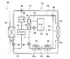
(第1実施例)図面を参照して第1実施例の熱管理システム100を説明する。図1に、熱管理システム100の回路図を示す。熱管理システム100は、電気自動車に搭載され、車載の機器と車室の温度を調整する。熱管理システム100は、走行用のモータ55、モータ55のための電力を蓄えるバッテリ51、モータ55に電力を供給するSPU(Smart Power Unit)46とPCU(Power Control Unit)47の温度を調整する。
(First Embodiment) A
バッテリ51の出力は、200ボルトを超える。バッテリ51が大きな電力を出力するとき、バッテリ51は発熱する。SPU46は、バッテリ51の電力を、PCU47を含むいくつかの機器に分配する。SPU46にはDCDCコンバータが内蔵されており、バッテリ51の電力を降圧して補機(車載の小電力機器)に供給する。PCU47は、バッテリ51の直流電力を交流電力に変換し、モータ55に供給する。SPU46とPCU47も、動作中に発熱する。SPU46のPCU47の主な発熱源は電力変換用のスイッチング素子である。
The output of
熱管理システム100は、モータ55、バッテリ51、SPU46、PCU47を冷却することが主要な機能であるが、寒冷地を走行する際にはそれらのデバイスを温めることもある。
The main function of the
熱管理システム100は、第1熱回路10、第2熱回路20、および、第3熱回路30を有している。第1熱回路10、第2熱回路20、および、第3熱回路30のそれぞれの内部に、熱媒が流れる。第1熱回路10、第2熱回路20、および、第3熱回路30の間で、熱媒の流路が独立している。第1熱回路10、第2熱回路20、および、第3熱回路30内の熱媒の材料は、同じであってもよいし、異なっていてもよい。例えば、熱媒として、ハイドロフルオロカーボンを用いることができる。本明細書では、第1熱回路10内を流れる熱媒を第1熱媒と称する。第2熱回路20内を流れる熱媒を第2熱媒とし、第3熱回路30内を流れる熱媒を第3熱媒と称する。
The
第1熱回路10が、車載の機器の温度を調整する。第2熱回路20と第3熱回路30が車室の温度を調整する。車載の機器を冷却する場合、第1熱回路10は、第1熱媒の熱を外気に放出する。車室の暖房スイッチが入れられた場合、第1熱回路10は、外気の熱を利用して第2熱媒を温めることがある。本明細書では、車室を暖房しつつ機器を冷却する場合に着目する。本実施例では、機器の昇温と、車室の冷房についての説明は割愛する。
A first
第1熱回路10は、第1流路11、第2流路12、バイパス流路13、バッテリ流路14を有している。先に述べたように、第1熱回路10は、SPU46、PCU47、モータ55、バッテリ51を冷却する。モータ55は、オイルを介して第1熱媒で冷却される。
The first
第1流路11は、SPU46、PCU47、オイルクーラ45を通過し、一端が低温ラジエータ41の入口41iに接続し、他端が低温ラジエータ41の出口41oに接続している。第1流路11にはポンプ48が設置されている。ポンプ48が、第1流路11内の第1熱媒を圧送する。ポンプ48を始点として、オイルクーラ45、低温ラジエータ41、SPU46、PCU47の順に第1熱媒が流れる。
The
SPU46の内部にSPU冷却器46cが備えられており、PCU47の内部にPCU冷却器47cが備えられている。第1流路11にSPU冷却器46cとPCU冷却器47cが接続されている。第1熱媒は、SPU冷却器46cとPCU冷却器47cを通り、SPU46とPCU47を冷却する。
An SPU cooler 46 c is provided inside the
オイルクーラ45には、オイル循環路18が接続されている。オイル循環路18は、トランスアクスル43の内部を通過する。トランスアクスル43はモータ55を内蔵している。オイル循環路18の一部は、モータ55の摺動部(すなわち、軸受部)を通過している。すなわち、オイル循環路18内のオイルは、モータ55の潤滑油を兼ねている。オイル循環路18には、オイルポンプ44が設置されている。オイルポンプ44は、オイル循環路18内のオイルを循環させる。モータ55を冷却したオイルはオイルクーラ45にて第1熱媒で冷却される。
An
SPU46、PCU47、モータ55(オイルクーラ45のオイル)を冷却した第1熱媒は、低温ラジエータ41を通る。第1熱媒の熱は、低温ラジエータ41にて外気に放出される。低温ラジエータ41は、第1熱媒と外気の間で熱を交換する。
The first heat medium that has cooled the
第1流路11にはバイパス流路13が接続されている。バイパス流路13の一端は、三方弁42を介して第1流路11の下流側に接続されており、他端は第1流路11の上流側に接続されている。
A
第1流路11は、三方弁42により、低温ラジエータ41とバイパス流路13の一方に接続される。三方弁42は、第1弁位置と第2弁位置を切り替え可能である。第1弁位置では、三方弁42は、第1流路11を低温ラジエータ41に接続するとともに、第1流路11をバイパス流路13から遮断する。第2弁位置では、三方弁42は、第1流路11をバイパス流路13に接続するとともに、第1流路11を低温ラジエータ41から遮断する。三方弁42が第1流路11を低温ラジエータ41に接続している状態(すなわち第1弁位置)でポンプ48が作動すると、第1熱媒は、SPU46、PCU47、オイルクーラ45、低温ラジエータ41を循環する。SPU46、PCU47、モータ55(オイル)の熱が、第1熱媒を介して外気に放出される。
The
三方弁42が第1流路11をバイパス流路13に接続している状態(すなわち、第2弁位置)でポンプ48が作動すると、第1熱媒は、低温ラジエータ41をバイパスしつつ、SPU46、PCU47、オイルクーラ45を循環する。SPU46、PCU47、モータ55(オイル)の熱により第1熱媒の温度が上昇する。三方弁42は、コントローラ80によって制御される。三方弁42の制御ついては後述する。
When the
第2流路12は、チラー52を通過し、一端が低温ラジエータ41の入口41iに接続し、他端が低温ラジエータ41の出口41oに接続している。低温ラジエータ41は、第1流路11と第2流路12で共用される。第2流路12にはポンプ53が設置されている。ポンプ53が、第2流路12内の第1熱媒を圧送する。チラー52には、第2熱回路20の循環路22が通っている。チラー52は、第1熱媒の熱を第2熱媒へ移す。すなわち、チラー52は、第1熱媒と第2熱媒の間で熱を交換する。チラーの役割については後述する。
The
第2流路には、バッテリ流路14が接続されている。バッテリ流路14はバッテリ51を通過している。バッテリ流路14の一端は、チラー52の下流にて三方弁49を介して第2流路12に接続されている。バッテリ流路14の他端は、ポンプ53の上流にて第2流路12に接続されている。
A
三方弁49により、チラー52は低温ラジエータ41とバッテリ流路14の一方と接続される。三方弁49は、第1弁位置と第2弁位置を切り替え可能である。第1弁位置では、三方弁49は、チラー52をバッテリ流路14に接続するとともに、チラー52を低温ラジエータ41から遮断する。第2弁位置では、三方弁49は、チラー52を低温ラジエータ41に接続するとともに、チラー52をバッテリ流路14から遮断する。三方弁49がチラー52をバッテリ流路14に接続している状態(すなわち、第1弁位置)でポンプ53が作動すると、第1熱媒は、チラー52とバッテリ51の間を循環する。第1熱媒はバッテリ51を冷却し、温度が高くなった第1熱媒はチラー52にて第2熱媒で冷却される。三方弁49がチラー52を低温ラジエータ41に接続している状態(すなわち、第2弁位置)でポンプ53が作動すると、第1熱媒は、第2流路12を流れ、チラー52と低温ラジエータ41の間で循環する。第1熱媒がチラー52と低温ラジエータ41の間で循環するのは後述するヒートポンプモードのときである。ヒートポンプモードについては後述する。
A three-
バッテリ流路14のバッテリ51よりも上流側にヒータ50が備えられている。寒冷地などでバッテリ51の温度が下がったときにはヒータ50で第1熱媒を温め、温度が高くなった第1熱媒でバッテリ51を温める。
A
先に述べたように、第2熱回路20と第3熱回路30は車室の温度を調整する。第2熱回路20は主に車室の空気を冷却するのに用いられる。第2熱回路20は、循環路22、エバポレータ63、コンプレッサ66、エバポレータプレッシャレギュレータ62(EPR62)、コンデンサ67、モジュレータ68を備えている。
As previously mentioned, the second
循環路22には三方弁65が備えられている。三方弁65は、第1弁位置と第2弁位置を切り替え可能である。第1弁位置のとき、三方弁65は、コンデンサ67とエバポレータ63を接続する。第2弁位置のとき、三方弁65は、コンデンサ67とチラー52を接続する。
A three-
車室を冷却するときには三方弁65は第1弁位置を選択する。コンプレッサ66で圧縮され、高温になった気体の第2熱媒は、コンデンサ67で冷却され、液体に変化する。モジュレータ68にて液体の第2熱媒のみが三方弁65へ流れる。液体の第2熱媒は膨張弁64とエバポレータ63を通り、気化するとともに急激に温度が下がる。温度の下がった第2熱媒により車室の空気が冷やされる。第2熱媒はEPR62を通過し、再びコンプレッサ66で圧縮される。
The three-
三方弁65は、ヒートポンプモードのときに第2弁位置に切り替えられ、コンデンサ67とチラー52を接続する。詳しくは後述するが、ヒートポンプモードは車室暖房のときに選択される。ヒートポンプモードのとき、コンプレッサ66で圧縮され、高温になった気体の第2熱媒は、コンデンサ67にて第3熱媒へ熱を放出し、液体に変化する。モジュレータ68にて液体の第2熱媒のみが三方弁65へ流れる。液体の第2熱媒は膨張弁61とチラー52を通り、気化するとともに急激に温度が下がる。温度の下がった第2熱媒は、チラー52を通過する第1熱媒から熱を吸収する。温度の上がった第2熱媒はコンプレッサ66で圧縮され、さらに温度が上昇する。温度が高くなった第2熱媒がコンデンサ67にて第3熱媒へ熱を放出する。
Three-
第3熱回路30は、主に車室の空気を温めるのに用いられる。第3熱回路30は、循環路32、電気ヒータ71、ヒータコア74、ポンプ72、高温ラジエータ75、三方弁73を備える。ヒータコア74を流れる高温の第3熱媒によって、車室の空気が温められる。
The
車室の空気を温める場合、三方弁73によって、コンデンサ67と電気ヒータ71とヒータコア74が接続される。先に述べたように、ヒートポンプモードのとき、コンデンサ67にて、高温の第2熱媒によって第3熱媒が温められる。温められた第3熱媒がヒータコア74を通過するときに車室の空気が温められる。第3熱媒の熱が不足するときには電気ヒータ71が第3熱媒を加熱する。
When warming the air in the passenger compartment, the three-
熱管理システム100で熱が余る場合には、三方弁73がコンデンサ67と高温ラジエータ75を接続する。コンデンサ67を介して第2熱媒から第3熱媒へ移された熱は、高温ラジエータ75にて外気へ放出される。
A three-
熱管理システム100において車室暖房モードが選択されると、先に述べたように、ヒータコア74を通過する第3熱媒によって車室の空気が温められる。車室暖房モードのときには外気の熱あるいはバッテリ51の熱も利用される。外気の熱あるいはバッテリ51の熱で第1熱回路10の第1熱媒が温められる。チラー52にて、高温の第1熱媒によって第2熱媒が温められる。チラー52を通過した第2熱媒はコンプレッサ66で圧縮され、さらに温度が上がる。高温の第2熱媒は、コンデンサ67にて第3熱媒を温める。第3熱媒はヒータコア74にて車室内の空気を温める。外気の熱を利用する場合をヒートポンプモードと称する。
When the vehicle compartment heating mode is selected in the
ヒートポンプモードについて説明する。ヒートポンプモードでは、低温ラジエータ41にて外気の熱で第1熱媒が温められ、高温の第1熱媒がチラー52にて第2熱媒を温める。第2熱媒の熱が車室の空気を温める過程は上述した通りである。本明細書では、外気の熱を車室空調用の第2熱媒へ移すまでの過程を説明する。なお、ヒートポンプモードは、チラー52で冷却される第1熱媒の温度が外気の温度よりも低いときに実施される。
The heat pump mode will be explained. In the heat pump mode, the low-
ヒートポンプモードは、コントローラ80によって実行される。ヒートポンプモードが選択されると、コントローラ80は、三方弁42、49を第2弁位置に保持する。このときの熱媒の流れを図2に示す。図2では、第2熱回路20の循環路22の一部を示し、第2熱回路20の他の構成、および、第3熱回路30の図示は省略した。
Heat pump mode is performed by the
ヒートポンプモードでは、コントローラ80は、三方弁42、49を同期して制御する。ヒートポンプモードのとき、コントローラ80は、三方弁42、49を共に第2位置に保持する。このときの第1熱媒の流れを図2に示す。図2では、第2熱回路20の一部(循環路22)のみを示してあり、第2熱回路20の残りと第3熱回路30は図示を省略した。
In heat pump mode, the
ヒートポンプモードのとき、コントローラ80は、三方弁42、49を第2弁位置に保持し、第2流路12を低温ラジエータ41に接続し、第1流路11から低温ラジエータ41への第1熱媒の流れを遮断する。第1熱媒は、図2の破線矢印F1で示すように、チラー52と低温ラジエータ41の間を循環する。このとき、第1流路11内の第1熱媒は低温ラジエータ41をバイパスし、SPU46とPCU47とオイルクーラ45を循環する。
When in heat pump mode, the
先に、第2流路12を流れる第1熱媒について説明する。チラー52で冷却された第1熱媒は、低温ラジエータ41に流入する。第1熱媒は、低温ラジエータ41を通過する間に、外気によって温められる。外気で温められた第1熱媒は、チラー52にて第2熱媒を温める。前述したように、第2熱媒の熱によって車室の空気が温められる。すなわち、ヒートポンプモードでは、外気の熱が車室の暖房に活用される。チラー52にて第1熱媒の温度が下がる。温度の下がった第1熱媒は低温ラジエータ41に戻り、再び外気から熱を吸収する。
First, the first heat medium flowing through the
ヒートポンプモードでは、図2にて破線矢印F2が示すように、第1流路11内の第1熱媒は低温ラジエータ41を通らない。第1流路11を流れる第1熱媒の温度は、上昇を続ける。第1流路11を流れる第1熱媒の温度が高くなりすぎるとSPU46、PCU47、モータ55を冷却できなくなる。第1熱回路10には、SPU46とPCU47の間に温度センサ15が備えられており、コントローラ80は、SPU冷却器46cを通過した第1熱媒の温度をモニタしている。SPU46を通過した第1熱媒の温度(温度センサ15の計測値)が温度上限値を超えた場合、コントローラ80は、三方弁42、49を第1弁位置に切り替える。
In the heat pump mode, the first heat medium in the
三方弁42、49が第1弁位置に切り替えられたときの第1熱媒の流れを図3に示す。三方弁42、49が第1弁位置に切り替えられると、第1流路11と低温ラジエータ41が接続され、第2流路12は低温ラジエータ41から遮断される。コントローラ80は、ポンプ48の作動を継続する。その結果、図3の破線矢印F3に示されるように、第1流路11内で温度上限値を超えた第1熱媒が低温ラジエータ41に流入する。低温ラジエータ41に流入する第1熱媒の温度は、外気の温度よりも高い。このため、低温ラジエータ41を通過する第1熱媒は外気に熱を放出する。外気に熱を放出して温度が下がった第1熱媒がSPU46とPCU47を冷却する。
FIG. 3 shows the flow of the first heat medium when the three-
コントローラ80は、第1流路11の三方弁42を第1弁位置に切り替える際、第2流路12の三方弁49も第1弁位置に切り替える。三方弁49が第1弁位置に切り替えられると、チラー52が低温ラジエータ41から遮断される。すなわち、第2流路12が低温ラジエータ41から遮断される。先に述べたように、ヒートポンプモードでは、第2流路12を流れる第1熱媒の温度は外気の温度よりも低く、第1流路11を流れる第1熱媒の温度は外気の温度よりも高い。第1流路11と第2流路12を流れる第1熱媒が合流すると、第2流路12を流れる第1熱媒の温度が上昇する。コントローラ80は、第1流路11が低温ラジエータ41と接続して、外気温よりも高温の第1熱媒と低温ラジエータ41が熱交換を行っている間、第2流路12と低温ラジエータ41を遮断する。これにより、第1流路11と第2流路12を流れる第1熱媒が合流することを防止する。
When switching the three-
三方弁42、49を第1弁位置に切り替えると、チラー52が低温ラジエータ41から遮断される。チラー52を通過した第1熱媒は低温ラジエータ41を通らない。三方弁42が第1弁位置を保持している間、ヒートポンプモードは中断される。
Switching the three-
コントローラ80は、ヒートポンプモードにおいて、三方弁42、49を第1弁位置に切り替えるとともにオイルポンプ44を作動させる。オイルポンプ44を作動させることで、モータ55の熱がオイルを介して第1熱媒に移る。SPU46とPCU47の熱を吸収し、さらにモータ55の熱を吸収した第1熱媒が低温ラジエータ41に流れ、放熱する。
The
コントローラ80は、オイルの温度が所定の上限値を超えた場合にオイルポンプを作動させる。しかし、ヒートポンプモードのとき、コントローラ80は、三方弁42を第1弁位置に切り替えるとともに、オイルの温度が上限値に達してなくてもオイルポンプ44を動作させる。そのような制御により、モータ55の熱が低温ラジエータ41にて放出される。
The
ヒートポンプモードにおいて、三方弁42を第1弁位置に切り替えるとともにオイルポンプ44を動作させる利点を、図4を参照して説明する。
The advantages of switching the three-
図4(A)は、温度センサ15(図1参照)が測定する第1熱媒の温度変化を示している。図4(B)は、オイル循環路18を循環するオイルの温度変化を示している。図4(C)は、オイルポンプのオンオフのタイミングを示している。なお、図4(A)~(C)では、ヒートポンプモードのときの各値の変化を実線で示しており、ヒートポンプモード以外のときの各値の変化を破線で示している。
FIG. 4A shows temperature changes of the first heat medium measured by the temperature sensor 15 (see FIG. 1). FIG. 4B shows temperature changes of the oil circulating in the
図2を参照して説明したように、ヒートポンプモードでは、コントローラ80は、三方弁42、49を第2弁位置に保持する。SPU46とPCU47とモータ55の発熱により、図4(A)に示されるように、第1流路11内の第1熱媒の温度は、徐々に上昇する。第1熱媒の温度が上限温度huを超えたとき(時刻t1)に、コントローラ80は、三方弁42、49を第2弁位置から第1弁位置に切り替える。第1流路11が低温ラジエータ41に接続され、SPU46などから熱を吸収した第1熱媒が低温ラジエータ41に流れる。第1流路11内の第1熱媒は、低温ラジエータ41によって冷却されてその温度が徐々に低下する。このとき、第2流路12は低温ラジエータ41から遮断され、ヒートポンプモードは中断する。
As described with reference to FIG. 2, in heat pump mode the
図4(B)に示されるように、オイルの温度は、モータ55の作動により、徐々に上昇する。最初に、ヒートポンプモード以外のときのオイルの温度変化について説明する。コントローラ80は、第1熱媒の温度が上限温度huを超えた場合(時刻t1)に、三方弁42、49を第1弁位置に切り替える。時刻t1以降、第1熱媒の温度は低下する。
As shown in FIG. 4(B), the temperature of the oil gradually rises due to the operation of the
モータ55の主な発熱源はコイルであり、SPU46とPCU47の主な発熱源はスイッチング素子である。モータ55の熱容量はSPU46とPCU47のスイッチング素子の熱容量よりも大きい。モータ55の熱容量が大きいので、オイルの温度は緩やかに上昇する。時刻t1にてオイルの温度が適正範囲の上限値ouを超えていなければ、コントローラ80はオイルポンプ44を動作させない。その結果、図4(B)の破線グラフに示されるように、時刻t1を過ぎてもオイルの温度は上昇する。
A main heat source of the
時刻t2にて、コントローラ80は、三方弁42、49を第2弁位置から第1弁位置に戻す。第1流路11は低温ラジエータ41から遮断される。第1流路11内の第1熱媒の温度は再び上昇する。一方、時刻t2以降、第2流路12が再び低温ラジエータ41に接続され、ヒートポンプモードが再開する。
At time t2,
時刻to1にて、オイルの温度が上限値ouを超える。オイルの温度が上限値ouを超えたので、コントローラ80は、オイルポンプ44を作動させる(図4(C)参照)。その結果、オイルは第1熱媒で冷却され、温度が低下する。コントローラ80は、オイルの温度が第1下限値od1を下回った場合(時刻to2)に、オイルポンプ44を停止する(図4(C)参照)。その結果、オイルクーラ45におけるオイルと第1熱媒の熱交換が終了し、オイルの温度は再度徐々に上昇する。コントローラ80は、オイルの温度が上限値ouを超える毎に、オイルポンプ44を作動させる(時刻to3、to5)。コントローラ80は、オイルの温度が第1下限値od1を下回ると、オイルポンプ44を停止する(時刻to4、to6)。
At time to1, the oil temperature exceeds the upper limit value ou. Since the oil temperature has exceeded the upper limit value ou, the
オイルポンプ44が動作している間、オイルの熱が第1熱媒に移り、第1熱媒の温度が上昇する(時刻to1からto2、時刻to3からto4、時刻to5からto6)。
While the
第1熱媒の温度は時刻t1、to2、to4、to6で上限温度huに達する。第1熱媒の温度が上限温度huに達する毎にコントローラ80は三方弁42、49を第2弁位置から第1弁位置へ切り替える。三方弁42、49は高い頻度で切り替えられることになる。三方弁42、49を第1弁位置に切り替える毎にヒートポンプモードが中断され、外気の熱の活用が中断される。暖房モードのときにヒートポンプモードが頻繁に中断されると、熱量を補うためにコントローラ80は電気ヒータ71(図1参照)を動作させる。電気ヒータ71で熱を発生させるために電力が消費される。
The temperature of the first heat medium reaches the upper limit temperature hu at times t1, to2, to4, and to6. Every time the temperature of the first heat medium reaches the upper limit temperature hu, the
上記の現象は、PCU47(SPU46)とモータ55の熱容量の違いにより、SPU46とPCU47が熱量を発生するタイミングよりも遅れてオイルの温度が上昇することに起因する。実施例の熱管理システム100では、コントローラ80は、ヒートポンプモードの際に、三方弁42、49が第1弁位置に切り替わる頻度を抑えるように、オイルポンプを制御する。
The above phenomenon is caused by the difference in heat capacity between the PCU 47 (SPU 46) and the
次に、本実施例においてヒートポンプモードのときのコントローラ80の制御について説明する。
Next, the control of the
実施例のコントローラ80は、ヒートポンプモードにおいて、三方弁42、49を第2弁位置から第1弁位置に切り替えると同時にオイルポンプ44を動作させる。ヒートポンプモードでは、コントローラ80は、第1熱媒の温度が上限温度huを超えたとき(時刻t1)、三方弁42、49の第1弁位置への切り替えに同期してオイルポンプ44を作動させる。その結果、オイルクーラ45を介してオイルの熱(モータ55の熱)が第1熱媒へ移る。SPU46とPCU47の熱とともにオイルの熱(モータ55の熱)を吸収した第1熱媒が低温ラジエータ41に流れ、それらの熱が外気へ放出される。第1熱媒を介してオイルの熱(モータ55の熱)も同時に外気へ放出される。
In the heat pump mode, the
コントローラ80は、オイルの温度が第2下限値оd2を下回った場合(時刻t2)に、オイルポンプ44を停止するとともに、三方弁42、49の双方を第2弁位置に切り替える。以後、第1熱媒の温度が上限温度huを超える毎にコントローラ80は三方弁42、49を第1弁位置に切り替えるとともにオイルポンプ44を動作させる(時刻t3)。オイルの温度が第2下限値оd2を下回ると、コントローラ80は、オイルポンプ44を停止するとともに、三方弁42、49の双方を第2弁位置に切り替える(時刻t4)。三方弁42、49が第2弁位置に切り替えられると、ヒートポンプモードが再開し、外気の熱が車室の暖房に利用される。
The
以上説明したように、コントローラ80は、ヒートポンプモードにおいて、三方弁42、49を第2弁位置から第1弁位置に切り替えるとともにオイルポンプ44を作動させる。そのような制御により、三方弁42、49を切り替える頻度が低下する。外気を効率よく車室暖房に活用することができる。
As described above, the
暖房モードが選択される状況では外気温が低い場合がある。外気温が低く、さらに外気温よりも温度が低い第1熱媒が低温ラジエータ41に流れると、霜が着くおそれがある。低温ラジエータ41に霜が着くと、低温ラジエータ41の熱交換効率が低下する。外気の熱の車室暖房への利用効率が低下する。着霜による熱交換効率の低下は、低温ラジエータ41の入口41iと出口41oにおける第1熱媒の温度の差に表れる。コントローラ80は、上述した制御に加え、低温ラジエータ41の入口41iと出口41oにおける第1熱媒の温度差が所定の温度差閾値を下回ったときに、三方弁42、49の双方を第1弁位置に切り替えるとともに、オイルポンプ44を作動させてもよい。オイルの熱を利用して低温ラジエータ41に付着した霜を溶かすことができる。
The outside temperature may be low in situations where the heating mode is selected. If the outside air temperature is low and the first heat medium having a temperature lower than the outside air temperature flows through the low-
(第2実施例)第2実施例の熱管理システムを説明する。第2実施例の熱管理システムの構造は第1実施例の熱管理システム(図1)と同じであるが、コントローラ80が実行する制御が第1実施例の場合と異なる。
(Second Embodiment) A heat management system of a second embodiment will be described. The structure of the thermal management system of the second embodiment is the same as that of the thermal management system of the first embodiment (FIG. 1), but the control performed by the
コントローラ80は、ヒートポンプモードを実行中に、低温ラジエータ41への着霜を避けるため、定期的に三方弁42、49を切り替える。ヒートポンプモードを実行中、コントローラ80は、所定の周期で三方弁42、49を第2弁位置から第1弁位置に切り替えるとともにオイルポンプ44を作動させる。コントローラ80は、所定の保持時間が経過したら三方弁42、49を第1弁位置から第2弁位置に切り替えるとともにオイルポンプを停止する。オイルから熱を得た高温の第1熱媒を所定の周期で低温ラジエータ41へ送ることで、着霜を防ぐことができる。
The
また、コントローラ80は、三方弁42、49を第1弁位置へ切り替える前、オイルの温度が第1熱媒の温度よりも高い場合にはオイルポンプ44を作動させ、オイルの熱で第1熱媒の温度を高める。三方弁42、49を第1弁位置に切り替えたときに高温の第1熱媒が低温ラジエータ41に流れる。より一層の除霜効果が期待できる。
Further, before switching the three-
図5を参照して、コントローラ80の処理の一例を具体的に説明する。図5(A)は、温度センサ15(図1参照)が測定する第1熱媒の温度変化を示している。図5(B)は、オイル循環路18を循環するオイルの温度変化を示している。図5(C)は、オイルポンプ44の出力変化を示している。図5(C)は、オイルポンプ44の出力を百分率で示してある。
An example of the processing of the
コントローラ80は、ヒートポンプモード実行中、三方弁42、49の双方を第2弁位置に保持し、外気の熱を利用して車室内を暖房する。コントローラ80は、ヒートポンプモードを実行中に、周期s1で三方弁42、49の双方を第1弁位置に切り替え、保持時間dsが経過したら、三方弁42、49の双方を第2弁位置に戻す。
The
図2を参照して説明したように、ヒートポンプモードでは、コントローラ80は、三方弁42、49を第2弁位置に保持する。図5(A)に示されるように、第1流路11内の第1熱媒の温度は、SPU46およびPCU47の熱により徐々に上昇する。モータ55も発熱し、オイルの温度が上昇する。図5の時刻t5に、オイルの温度が第1熱媒の温度よりも高くなる。オイルの温度が第1熱媒の温度を超えると、コントローラ80は、オイルポンプ44を動作させる。オイルクーラ45でオイルから第1熱媒に熱が伝達される。このとき(時刻t5以降)、コントローラ80は、図5(C)に示されるように、オイルポンプ44の出力Opを、最大(100%)に設定する。その結果、図5(A)の時刻t5から時刻t6の間に示されているように、第1熱媒の温度が急激に上昇する。一方、図5(B)に示されるように、時刻t5から時刻t6の間でオイルの温度上昇率は小さくなる。
As described with reference to FIG. 2, in heat pump mode the
第2実施形態の熱管理システム100のコントローラ80は、三方弁42、49を第1弁位置へ切り替える前にオイルポンプ44を作動し、オイルの熱で第1熱媒を加熱する。コントローラ80が三方弁42、49を第1弁位置へ切り替えると、オイルの熱を吸収した第1熱媒が低温ラジエータ41に流れる。第2実施形態の熱管理システム100は、オイルの熱も利用して低温ラジエータ41を除霜することができる。同時に、オイルの熱も外気に放熱される。
The
また、コントローラ80は、図5(C)に示されるように、時刻t6から、オイルポンプ44の出力を徐々に低下させる。その結果、オイル循環路18におけるオイルの流量が減少する。オイルクーラ45にてオイルから第1熱媒に伝達される熱量が減少する。このため、図5(B)に示されるように、オイルの温度上昇率は時刻t6から再度高くなる。一方、時刻t6以降は、第1熱媒がオイルから吸熱する熱量が減少するため、第1熱媒の温度上昇率は、時刻t5から時刻t6までの間に比して低くなる。その結果、第1熱媒の温度が上限温度huを超えるタイミングが遅くなる。図5の例では、周期s1が経過しても第1熱媒の温度は上限温度huに達しない。コントローラ80は、周期s1に関わらず、第1熱媒の温度が上限温度huを超えたら三方弁42、49を第1弁位置に切り替え、第1熱媒の熱を低温ラジエータ41で放出しなければならない。オイルポンプ44の出力を徐々に下げることで、第1熱媒の温度上昇率が下がり、周期s1の途中で三方弁42、49を切り替える必要がなくなる。すなわち、三方弁42、49の切り替え頻度が高くならない。
Further, the
なお、オイルの温度が上限値оuを超えている場合や、モータ55の温度が閾値を超えている場合等、オイルの冷却を優先すべき場合には、コントローラ80は、オイルポンプ44の出力を下げないでよい。
Note that when priority is given to cooling the oil, such as when the temperature of the oil exceeds the upper limit value ou or when the temperature of the
周期s1が経過すると(時刻ts)、コントローラ80は、三方弁42、49を第1弁位置に切り替える。三方弁の切り替えにより、第1流路11の第1熱媒が低温ラジエータ41に流入し、第1熱媒の熱が外気に放出される。その結果、図5(A)に示されるように、時刻ts以降は第1熱媒の温度が低下する。第1熱媒の温度が下がるので、図5(B)に示されるように、オイルの温度も低下する。コントローラ80は、その後、保持時間dsが経過すると(時刻t7)、三方弁42、49を第2弁位置に戻すとともに、オイルポンプ44を停止する。時刻t7以降、第1流路11内の第1熱媒とオイルの温度が再び上昇する。コントローラ80は、周期s1ごとに三方弁42、49を第2弁位置から第1弁位置に切り替える。
After the cycle s1 has passed (time ts), the
時刻t8で再びオイルの温度が第1熱媒の温度を超える。時刻t5から時刻t7における処理が、時刻t8から時刻t10でも繰り返される。第1流路11の第1熱媒が低温ラジエータ41に周期s1で繰り返し流れ、着霜が防止される。
At time t8, the temperature of the oil exceeds the temperature of the first heat medium again. The process from time t5 to time t7 is repeated from time t8 to time t10. The first heat medium in the
なお、コントローラ80は、保持時間dsが経過する前にオイルの温度が第2下限値を下回った場合は、オイルポンプ44を停止してもよい。オイルの温度が低下しすぎるのを防止することができる。また、周期s1および保持時間dsは、ポンプ48およびオイルポンプ44の能力、オイルおよび第1流路11の第1熱媒の設定温度等の条件によって異なる。例えば、モータ55の温度がオイルの温度に対して明らかに高い場合には、周期s1を短くして第1弁位置への切り替え頻度を上げることで、オイルポンプの出力を下げてもよい。
Note that the
実施例で説明した技術に関する留意点を述べる。SPU36、PCU47が「電力変換器」の一例であり、SPU冷却器46cとPCU冷却器47cが「変換器冷却器」の一例である。低温ラジエータ41が「第1熱交換器」の一例であり、チラー52が「第2熱交換器」の一例である。上述の実施形態では、三方弁42、49が「流路弁」を構成する。
Points to note regarding the technology described in the embodiment will be described. The SPU 36 and
上述した実施例の変形例を以下に列挙する。 Modifications of the embodiment described above are listed below.
(第1変形例)上述した第1実施例では、ヒートポンプモードを実行している場合のコントローラ80の制御について記載しているが、熱管理システム100は、図1の構成に限られない。例えば、第2熱交換器は、第2熱媒から第1熱媒へ伝熱するデバイスであってもよい。コントローラ80は、三方弁42、49を第2弁位置に保持し、第2流路12を低温ラジエータ41に接続し、第2熱媒の熱を第1熱媒を介して低温ラジエータ41から放出する。コントローラ80は、三方弁42、49を第1弁位置に切り替えるとともにオイルポンプ44を駆動する。オイルの熱を吸収した第1熱媒が低温ラジエータ41で冷却される。オイルの熱が効果的に外気へ放出される。
(First Modification) In the above-described first embodiment, the control of the
(第2変形例)第1実施例では、コントローラ80は、第1熱媒の低温ラジエータ41の入口41iと出口41oの温度差が温度差閾値を下回った場合に、低温ラジエータ41に着霜のリスクがあると判定する。コントローラ80は、着霜のリスクがあると判定した場合に、三方弁42、49を第2弁位置から第1弁位置に切り替えるとともにオイルポンプ44を作動させる。第2変形例では、コントローラ80は、例えば、低温ラジエータ41を通過する外気の風速によって着霜を判定してもよい。
(Second Modification) In the first embodiment, the
(第3変形例)上述した実施例では、コントローラ80は、ヒートポンプモードのときに第2下限値оd2を下回ったらオイルポンプ44の作動を停止する。第3変形例では、これに代えて、第1熱媒の温度が下限値を下回ったときにオイルポンプ44の作動を停止してもよい。
(Third Modification) In the embodiment described above, the
(第4変形例)上述した実施例では、2個の三方弁42、49を用いて第1熱媒の流れを制御しているが、これに限定されない。例えば、バッテリ流路14を備えていない熱管理システムでは、三方弁49に代えて、第2流路12を低温ラジエータ41から遮断する止め弁が設けられてもよい。
(Fourth Modification) In the above-described embodiment, the two three-
以上、本発明の具体例を詳細に説明したが、これらは例示に過ぎず、特許請求の範囲を限定するものではない。特許請求の範囲に記載の技術には、以上に例示した具体例を様々に変形、変更したものが含まれる。本明細書または図面に説明した技術要素は、単独であるいは各種の組合せによって技術的有用性を発揮するものであり、出願時請求項記載の組合せに限定されるものではない。また、本明細書または図面に例示した技術は複数目的を同時に達成し得るものであり、そのうちの一つの目的を達成すること自体で技術的有用性を持つものである。 Although specific examples of the present invention have been described in detail above, these are merely examples and do not limit the scope of the claims. The technology described in the claims includes various modifications and changes of the specific examples illustrated above. The technical elements described in this specification or in the drawings exhibit technical usefulness alone or in various combinations, and are not limited to the combinations described in the claims as of the filing. In addition, the techniques exemplified in this specification or drawings can simultaneously achieve a plurality of purposes, and achieving one of them has technical utility in itself.
10 :第1熱回路
11 :第1流路
12 :第2流路
13 :バイパス流路
14 :バッテリ流路
15 :温度センサ
20 :第2熱回路
22、32:循環路
30 :第3熱回路
41 :低温ラジエータ
41i :入口
41о :出口
42、49、65、73:三方弁
43 :トランスアクスル
44 :オイルポンプ
45 :オイルクーラ
46 :SPU
46c :SPU冷却器
47 :PCU
47c :PCU冷却器
48、53、72:ポンプ
50 :ヒータ
51 :バッテリ
52 :チラー
55 :モータ
61、64:膨張弁
63 :エバポレータ
66 :コンプレッサ
67 :コンデンサ
68 :モジュレータ
71 :電気ヒータ
74 :ヒータコア
75 :高温ラジエータ
80 :コントローラ
100 :熱管理システム
10: first heat circuit 11: first flow path 12: second flow path 13: bypass flow path 14: battery flow path 15: temperature sensor 20:
46c: SPU cooler 47: PCU
47c:
Claims (5)
走行用のモータを冷却するオイルを第1熱媒で冷却するオイルクーラと、
前記オイルクーラと前記モータの間でオイルを循環させるオイルポンプと、
前記モータに電力を供給する電力変換器を前記第1熱媒で冷却する変換器冷却器と、
前記第1熱媒と外気の間で熱を交換する第1熱交換器と、
車室空調器の第2熱媒と前記第1熱媒との間で熱を交換する第2熱交換器と、
前記第1熱媒が流れる流路であって、前記オイルクーラと前記変換器冷却器を通過しているとともに、前記第1熱交換器の入口と出口に接続している第1流路と、
前記第1熱媒が流れる流路であって、前記第2熱交換器を通過しているとともに、前記第1熱交換器の前記入口と前記出口に接続している第2流路と、
前記第1流路を前記第1熱交換器に接続するとともに前記第2流路から前記第1熱交換器への前記第1熱媒の流れを遮断する第1弁位置と、前記第2流路を前記第1熱交換器に接続するとともに前記第1流路から前記第1熱交換器への前記第1熱媒の流れを遮断する第2弁位置を選択可能な流路弁と、
前記第2弁位置が選択されているときに前記第1熱交換器をバイパスして前記オイルクーラと前記変換器冷却器の間で前記第1熱媒を循環させるバイパス流路と、
前記流路弁と前記オイルポンプを制御するコントローラと、
を備えており、
前記コントローラは、
前記流路弁に前記第2弁位置を選択させ、前記第1熱交換器にて前記外気から前記第1熱媒へ伝熱し、前記第2熱交換器で前記第1熱媒から前記第2熱媒へ伝熱するヒートポンプモードを実行可能であり、
前記ヒートポンプモードを実行中に、所定の周期で前記流路弁を前記第2弁位置から前記第1弁位置に切り替えるとともに前記オイルポンプを作動させ、所定の保持時間が経過したら前記流路弁を前記第1弁位置から前記第2弁位置に切り替えるとともに前記オイルポンプを停止する、熱管理システム。 A thermal management system for electric vehicles,
an oil cooler that cools the oil that cools the running motor with the first heat medium;
an oil pump for circulating oil between the oil cooler and the motor;
a converter cooler that cools a power converter that supplies power to the motor with the first heat medium;
a first heat exchanger that exchanges heat between the first heat medium and the outside air;
a second heat exchanger that exchanges heat between a second heat medium of a vehicle air conditioner and the first heat medium;
a first flow path through which the first heat medium flows, the first flow path passing through the oil cooler and the converter cooler and connected to an inlet and an outlet of the first heat exchanger;
a second flow path through which the first heat medium flows, passing through the second heat exchanger and connected to the inlet and the outlet of the first heat exchanger;
a first valve position connecting the first flow path to the first heat exchanger and blocking flow of the first heat medium from the second flow path to the first heat exchanger; and a channel valve capable of selecting a second valve position that connects a channel to the first heat exchanger and blocks flow of the first heat medium from the first channel to the first heat exchanger;
a bypass flow path that bypasses the first heat exchanger and circulates the first heat medium between the oil cooler and the converter cooler when the second valve position is selected;
a controller that controls the flow path valve and the oil pump;
and
The controller is
The flow path valve is caused to select the second valve position, heat is transferred from the outside air to the first heat medium in the first heat exchanger, and heat is transferred from the first heat medium to the second heat medium in the second heat exchanger. A heat pump mode that transfers heat to a heat medium can be executed,
During execution of the heat pump mode, the flow path valve is switched from the second valve position to the first valve position at a predetermined cycle, the oil pump is operated, and the flow path valve is closed after a predetermined holding time has elapsed. A thermal management system switching from the first valve position to the second valve position and shutting off the oil pump.
前記ヒートポンプモードを実行していないときには前記オイルの温度(オイル温度)が第1下限値を下回ったら前記オイルポンプを停止し、
前記ヒートポンプモードを実行中は前記オイル温度が前記第1下限値よりも低い第2下限値を下回ったら前記オイルポンプを停止する、請求項1から4のいずれか1項に記載の熱管理システム。 The controller is
stopping the oil pump when the temperature of the oil (oil temperature) falls below a first lower limit when the heat pump mode is not executed;
5. The thermal management system according to any one of claims 1 to 4, wherein the oil pump is stopped when the oil temperature falls below a second lower limit lower than the first lower limit during execution of the heat pump mode.
Priority Applications (3)
| Application Number | Priority Date | Filing Date | Title |
|---|---|---|---|
| JP2020050189A JP7201633B2 (en) | 2020-03-19 | 2020-03-19 | Thermal management system for electric vehicles |
| US17/178,007 US11575296B2 (en) | 2020-03-19 | 2021-02-17 | Heat management system for electric vehicle |
| CN202110288411.5A CN113492643B (en) | 2020-03-19 | 2021-03-18 | Thermal management systems for electric vehicles |
Applications Claiming Priority (1)
| Application Number | Priority Date | Filing Date | Title |
|---|---|---|---|
| JP2020050189A JP7201633B2 (en) | 2020-03-19 | 2020-03-19 | Thermal management system for electric vehicles |
Publications (2)
| Publication Number | Publication Date |
|---|---|
| JP2021146948A JP2021146948A (en) | 2021-09-27 |
| JP7201633B2 true JP7201633B2 (en) | 2023-01-10 |
Family
ID=77746748
Family Applications (1)
| Application Number | Title | Priority Date | Filing Date |
|---|---|---|---|
| JP2020050189A Active JP7201633B2 (en) | 2020-03-19 | 2020-03-19 | Thermal management system for electric vehicles |
Country Status (3)
| Country | Link |
|---|---|
| US (1) | US11575296B2 (en) |
| JP (1) | JP7201633B2 (en) |
| CN (1) | CN113492643B (en) |
Families Citing this family (8)
| Publication number | Priority date | Publication date | Assignee | Title |
|---|---|---|---|---|
| US11506306B2 (en) * | 2019-09-17 | 2022-11-22 | Ford Global Technologies, Llc | Thermal management system for electrified vehicle |
| JP7529615B2 (en) * | 2021-05-24 | 2024-08-06 | トヨタ自動車株式会社 | Thermal Management Systems for Electric Vehicles |
| KR20240030544A (en) * | 2022-08-31 | 2024-03-07 | 현대자동차주식회사 | Control system of vehicle incorporating battery thermal management and air conditioning |
| US12522106B2 (en) * | 2022-10-17 | 2026-01-13 | Ford Global Technologies, Llc | Thermal management system for electrified vehicle that provides battery and cabin heating off plug |
| JP2024127450A (en) * | 2023-03-09 | 2024-09-20 | トヨタ自動車株式会社 | Thermal Management System |
| JP2024127446A (en) * | 2023-03-09 | 2024-09-20 | トヨタ自動車株式会社 | Thermal Management System |
| JP2024127449A (en) * | 2023-03-09 | 2024-09-20 | トヨタ自動車株式会社 | Thermal Management System |
| DE102024113517A1 (en) * | 2024-05-15 | 2025-11-20 | Bayerische Motoren Werke Aktiengesellschaft | Method for operating a drive unit of a motor vehicle and motor vehicle |
Citations (5)
| Publication number | Priority date | Publication date | Assignee | Title |
|---|---|---|---|---|
| US20130175022A1 (en) | 2010-09-23 | 2013-07-11 | Jonathan King | Thermal management system for battery electric vehicle |
| JP2013256222A (en) | 2012-06-13 | 2013-12-26 | Toyota Motor Corp | Vehicle heat exchanging system |
| JP2019047548A (en) | 2017-08-30 | 2019-03-22 | ダイムラー・アクチェンゲゼルシャフトDaimler AG | Temperature management apparatus for vehicle |
| JP2019189083A (en) | 2018-04-26 | 2019-10-31 | 株式会社デンソー | Cooling device |
| JP2019213337A (en) | 2018-06-04 | 2019-12-12 | 株式会社デンソー | Cooling system |
Family Cites Families (16)
| Publication number | Priority date | Publication date | Assignee | Title |
|---|---|---|---|---|
| JP6060797B2 (en) * | 2012-05-24 | 2017-01-18 | 株式会社デンソー | Thermal management system for vehicles |
| CN203372029U (en) * | 2012-07-02 | 2014-01-01 | 福特环球技术公司 | Heating and cooling circulation system for electric car |
| JP6065481B2 (en) * | 2012-09-14 | 2017-01-25 | 日産自動車株式会社 | Air conditioner for vehicles |
| CN102941791B (en) * | 2012-11-08 | 2014-12-03 | 上海汽车集团股份有限公司 | Integrated thermal cycling system of electric vehicle |
| JP5962556B2 (en) * | 2013-03-19 | 2016-08-03 | 株式会社デンソー | Thermal management system for vehicles |
| JP2015186989A (en) * | 2014-03-12 | 2015-10-29 | カルソニックカンセイ株式会社 | On-vehicle temperature control device, vehicle air conditioner, and battery temperature control device |
| US9731578B2 (en) * | 2014-10-21 | 2017-08-15 | Atieva, Inc. | EV multi-mode thermal management system |
| JP6311622B2 (en) * | 2015-02-04 | 2018-04-18 | トヨタ自動車株式会社 | Vehicle thermal management system |
| DE102015220623B4 (en) * | 2015-10-22 | 2022-01-27 | Bayerische Motoren Werke Aktiengesellschaft | Warming system for an electric or hybrid vehicle |
| JP6558353B2 (en) * | 2016-12-06 | 2019-08-14 | トヨタ自動車株式会社 | vehicle |
| US10486494B2 (en) * | 2017-04-27 | 2019-11-26 | Ford Global Technologies, Llc | Vehicle heating and cooling system and control method |
| JP6838527B2 (en) * | 2017-08-31 | 2021-03-03 | 株式会社デンソー | Vehicle air conditioner |
| KR102496797B1 (en) * | 2017-12-11 | 2023-02-06 | 현대자동차 주식회사 | Heat pump system for vehicle |
| JP7024413B2 (en) | 2018-01-09 | 2022-02-24 | 株式会社デンソー | Thermal management system |
| US11072259B2 (en) * | 2018-03-29 | 2021-07-27 | GM Global Technology Operations LLC | Vehicle thermal systems low to high quality energy management, storage, recovery, and optimization |
| CN209126464U (en) * | 2018-08-02 | 2019-07-19 | 威马智慧出行科技(上海)有限公司 | Integrated electric automobile heat pump air-conditioning system |
-
2020
- 2020-03-19 JP JP2020050189A patent/JP7201633B2/en active Active
-
2021
- 2021-02-17 US US17/178,007 patent/US11575296B2/en active Active
- 2021-03-18 CN CN202110288411.5A patent/CN113492643B/en active Active
Patent Citations (5)
| Publication number | Priority date | Publication date | Assignee | Title |
|---|---|---|---|---|
| US20130175022A1 (en) | 2010-09-23 | 2013-07-11 | Jonathan King | Thermal management system for battery electric vehicle |
| JP2013256222A (en) | 2012-06-13 | 2013-12-26 | Toyota Motor Corp | Vehicle heat exchanging system |
| JP2019047548A (en) | 2017-08-30 | 2019-03-22 | ダイムラー・アクチェンゲゼルシャフトDaimler AG | Temperature management apparatus for vehicle |
| JP2019189083A (en) | 2018-04-26 | 2019-10-31 | 株式会社デンソー | Cooling device |
| JP2019213337A (en) | 2018-06-04 | 2019-12-12 | 株式会社デンソー | Cooling system |
Also Published As
| Publication number | Publication date |
|---|---|
| US20210296964A1 (en) | 2021-09-23 |
| CN113492643A (en) | 2021-10-12 |
| JP2021146948A (en) | 2021-09-27 |
| US11575296B2 (en) | 2023-02-07 |
| CN113492643B (en) | 2024-03-01 |
Similar Documents
| Publication | Publication Date | Title |
|---|---|---|
| JP7201633B2 (en) | Thermal management system for electric vehicles | |
| JP7239517B2 (en) | Thermal management system for electric vehicles | |
| CN111716987B (en) | Thermal system, electric or hybrid vehicle and method for operating a thermal system | |
| CN108284725B (en) | New energy vehicle distributed drive intelligent thermal management system | |
| JP5403766B2 (en) | Vehicle cooling system | |
| CN107323285B (en) | Electric vehicle thermal management system | |
| CN204987545U (en) | Three loop temperature control system | |
| US10589596B2 (en) | Thermal management for an electric or hybrid vehicle and a method for air-conditioning the interior of such a motor vehicle | |
| JP7115452B2 (en) | cooling system | |
| US11745561B2 (en) | Heat management device | |
| JP7543980B2 (en) | Vehicle temperature control system | |
| CN107848364A (en) | For carrying out the control system of air adjustment to vehicle | |
| CN103582580A (en) | Temperature adjustment apparatus for vehicle | |
| KR20160135333A (en) | Circulation system for extended-range electric bus | |
| JP2022180155A (en) | Heat management system of electric vehicle | |
| JP2009291008A (en) | Heat management system of electric drive vehicle | |
| US11607925B2 (en) | Method for a thermal management of a motor vehicle | |
| US11897315B2 (en) | Thermal management system for battery electric vehicle | |
| EP3350004B1 (en) | A cooling arrangement for an electric power unit in a vehicle | |
| CN116691293A (en) | Automobile heat management system and automobile | |
| WO2025017810A1 (en) | Heat management system | |
| KR101250278B1 (en) | Thermoelectric element device for using assistance cooling and heating device of automobile | |
| CN118528716A (en) | Thermal management system and vehicle | |
| CN118560226A (en) | Thermal management system, method and engineering machinery suitable for electric engineering machinery |
Legal Events
| Date | Code | Title | Description |
|---|---|---|---|
| A621 | Written request for application examination |
Free format text: JAPANESE INTERMEDIATE CODE: A621 Effective date: 20220303 |
|
| A977 | Report on retrieval |
Free format text: JAPANESE INTERMEDIATE CODE: A971007 Effective date: 20221031 |
|
| TRDD | Decision of grant or rejection written | ||
| A01 | Written decision to grant a patent or to grant a registration (utility model) |
Free format text: JAPANESE INTERMEDIATE CODE: A01 Effective date: 20221206 |
|
| A61 | First payment of annual fees (during grant procedure) |
Free format text: JAPANESE INTERMEDIATE CODE: A61 Effective date: 20221222 |
|
| R151 | Written notification of patent or utility model registration |
Ref document number: 7201633 Country of ref document: JP Free format text: JAPANESE INTERMEDIATE CODE: R151 |
|
| R250 | Receipt of annual fees |
Free format text: JAPANESE INTERMEDIATE CODE: R250 |