JP7201166B2 - Surgical device, information processing apparatus, system, information processing method, and program - Google Patents
Surgical device, information processing apparatus, system, information processing method, and program Download PDFInfo
- Publication number
- JP7201166B2 JP7201166B2 JP2018228341A JP2018228341A JP7201166B2 JP 7201166 B2 JP7201166 B2 JP 7201166B2 JP 2018228341 A JP2018228341 A JP 2018228341A JP 2018228341 A JP2018228341 A JP 2018228341A JP 7201166 B2 JP7201166 B2 JP 7201166B2
- Authority
- JP
- Japan
- Prior art keywords
- bone
- surgical device
- contact
- region
- model data
- Prior art date
- Legal status (The legal status is an assumption and is not a legal conclusion. Google has not performed a legal analysis and makes no representation as to the accuracy of the status listed.)
- Active
Links
Images


Landscapes
- Surgical Instruments (AREA)
Description
本発明の実施形態は、外科手術用デバイス、情報処理装置、システム、情報処理方法、およびプログラムに関する。 Embodiments of the present invention relate to surgical devices, information processing apparatuses, systems, information processing methods, and programs.
骨吸収抑制薬や抗ガン剤等の使用によって顎骨壊死が生じることがあり、病期によっては、壊死した顎骨の外科的切除が実施される。切除後は、顎骨が離断されるため、顎骨の連続性を保つために、チタン製のプレートによる骨再建手術が実施される。顎骨再建術の際には、分離した顎骨の位置を、術前の状態に正確に戻してプレートにより固定することが重要である。従来は、予め技工士により作製された外科手術用デバイス等を用いて、分断された顎骨の位置を元の位置に戻した後に、プレートで固定し顎骨再建術を実施していた。 Osteonecrosis of the jaw may occur due to the use of antiresorptive drugs, anticancer drugs, and the like, and surgical resection of the necrotic jawbone is performed depending on the disease stage. After resection, the jawbone is severed, so bone reconstructive surgery using a titanium plate is performed to maintain the continuity of the jawbone. During jawbone reconstruction, it is important to accurately return the position of the separated jawbone to its preoperative state and fix it with a plate. Conventionally, a surgical device or the like prepared in advance by a technician is used to restore the severed jawbone to its original position, and then fix the jawbone with a plate to perform jawbone reconstruction.
しかしながら、従来の外科手術用デバイスは、顎骨を分断した後に使用されるものが多く、離断前の顎骨の位置を正確に再現するのがしばしば困難であった。そのため、プレートを使用した顎骨再建術の際に、分断した顎骨どうしがずれ、術後における歯のかみ合わせがずれるなどの不具合が生じるケースがあった。 However, many of the conventional surgical devices are used after the jawbone is severed, and it is often difficult to accurately reproduce the position of the jawbone before the jawbone is severed. As a result, there have been cases of problems such as misalignment of the severed jawbones and misalignment of teeth after surgery during jawbone reconstruction surgery using plates.
本発明は、骨再建手術において、切除後の骨を切除前の位置に精度良く位置合わせすることができる外科手術用デバイス、情報処理装置、システム、情報処理方法、およびプログラムを提供することを目的とする。 It is an object of the present invention to provide a surgical device, an information processing apparatus, a system, an information processing method, and a program capable of accurately aligning bones after resection with the positions before resection in bone reconstructive surgery. and
上述した課題を解決し、目的を達成するために、本発明は、骨再建手術において骨に対してプレートを固定する際に用いられる外科手術用デバイスであって、被検体の前記骨に接触し、かつ前記骨に応じた部位を有する接触領域を有し、前記接触領域は、前記骨に固定するための固定部を有する。 In order to solve the above-described problems and achieve the object, the present invention provides a surgical device used for fixing a plate to a bone in bone reconstructive surgery, the device contacting the bone of a subject. and a contact area having a portion corresponding to the bone, and the contact area has a fixing portion for fixing to the bone.
また、本発明は、骨再建手術において骨に対してプレートを固定する際に用いられる外科手術用デバイスのモデルデータを生成する情報処理装置であって、被検体の骨を含む領域が撮像された画像データに基づいて、前記骨の外形データを含む骨形状情報を取得する取得部と、前記被検体の前記骨に接触し、かつ前記骨に応じた部位を有する接触領域を有する外科手術用デバイスのモデルデータを、前記骨形状情報に基づいて生成する生成部と、を備える。 Further, the present invention is an information processing apparatus for generating model data of a surgical device used for fixing a plate to a bone in bone reconstructive surgery, wherein a region including the bone of a subject is imaged. A surgical device having an acquisition unit that acquires bone shape information including outline data of the bone based on image data, and a contact area that contacts the bone of the subject and has a site corresponding to the bone. and a generation unit that generates model data of based on the bone shape information.
また、本発明は、情報処理装置と造形装置とを少なくとも備え、骨再建手術において骨に対してプレートを固定する際に用いられる外科手術用デバイスの造形するためのシステムであって、被検体の骨を含む領域が撮像された画像データに基づいて、前記骨の外形データを含む骨形状情報を取得する取得部と、前記被検体の前記骨に接触し、かつ前記骨に応じた部位を有する接触領域を有する外科手術用デバイスのモデルデータを、前記骨形状情報に基づいて生成する生成部と、前記モデルデータに基づいて、前記外科手術用デバイスを造形する造形装置と、を備える。 Further, the present invention provides a system for modeling a surgical device that includes at least an information processing device and a modeling device and is used for fixing a plate to a bone in bone reconstructive surgery. an acquisition unit that acquires bone shape information including outline data of the bone based on image data obtained by imaging a region including the bone; and a portion that is in contact with the bone of the subject and corresponds to the bone. A generating unit that generates model data of a surgical device having a contact area based on the bone shape information, and a modeling apparatus that models the surgical device based on the model data.
また、本発明は、骨再建手術において骨に対してプレートを固定する際に用いられる外科手術用デバイスのモデルデータを生成するための情報処理方法であって、被検体の骨を含む領域が撮像された画像データに基づいて、前記骨の外形データを含む骨形状情報を取得する取得ステップと、前記被検体の前記骨に接触し、かつ前記骨に応じた部位を有する接触領域を有する外科手術用デバイスのモデルデータを、前記骨形状情報に基づいて生成する生成ステップと、を含む。 The present invention also provides an information processing method for generating model data of a surgical device used when fixing a plate to a bone in bone reconstructive surgery, wherein a region including a bone of a subject is imaged. an acquisition step of acquiring bone shape information including outline data of the bone based on the obtained image data; and a generating step of generating model data of the device for use based on the bone shape information.
また、本発明は、骨再建手術において骨に対してプレートを固定する際に用いられる外科手術用デバイスのモデルデータを生成するためのプログラムであって、コンピュータに、被検体の骨を含む領域が撮像された画像データに基づいて、前記骨の外形データを含む骨形状情報を取得する取得ステップと、前記被検体の前記骨に接触し、かつ前記骨に応じた部位を有する接触領域を有する外科手術用デバイスのモデルデータを、前記骨形状情報に基づいて生成する生成ステップと、を実行させる。 The present invention also provides a program for generating model data of a surgical device used to fix a plate to a bone in bone reconstructive surgery, wherein a computer stores a region including a bone of a subject. an acquiring step of acquiring bone shape information including outline data of the bone based on the captured image data; and a generating step of generating model data of the surgical device based on the bone shape information.
本発明によれば、骨再建手術において、切除後の骨を切除前の位置に精度良く位置合わせすることができる外科手術用デバイス、情報処理装置、システム、情報処理方法、およびプログラムを提供することができる。 The present invention provides a surgical device, an information processing apparatus, a system, an information processing method, and a program capable of precisely aligning a post-resection bone to a pre-resection position in bone reconstruction surgery. can be done.
以下、添付図面を参照しながら、本発明にかかる外科手術用デバイス、情報処理装置、システム、情報処理方法、およびプログラムを説明する。なお、以下の実施形態は、以下の説明に限定されるものではない。以下の実施形態は、処理内容に矛盾が生じない範囲で他の実施形態や従来技術との組み合わせが可能である。 A surgical device, an information processing apparatus, a system, an information processing method, and a program according to the present invention will be described below with reference to the accompanying drawings. In addition, the following embodiments are not limited to the following description. The following embodiments can be combined with other embodiments and conventional techniques as long as there is no contradiction in the processing content.
〔実施形態〕
本実施形態は、被検体の骨として顎骨、特に下顎骨MBにおいて壊死した部分を切除する際に、切除前に下顎骨MBに固定される外科手術用デバイスを提供するものである。
[Embodiment]
This embodiment provides a surgical device that is fixed to the mandibular bone MB before excision when resecting necrotic portions of the jawbone, particularly the mandible MB, as the bone of the subject.
図1は、実施形態にかかるシステム1の概略構成の一例を示す図である。図1に示すように、実施形態にかかるシステム1は、医用画像診断装置10と、情報処理装置20と、造形装置30とを含む。図1に例示する各装置は、LAN(Local Area Network)やWAN(Wide Area Network)等のネットワークにより、直接的、又は間接的に相互に通信可能な状態となっている。
FIG. 1 is a diagram showing an example of a schematic configuration of a
医用画像診断装置10は、人体を傷つけることなく、通常は目視できない部分を画像化した画像データを生成する装置である。例えば、図1に示す医用画像診断装置10は、被検体の撮影部位における体表の輪郭と、撮影部位内に存在する骨とが少なくとも描出された3次元の画像データ(ボリュームデータ)を生成可能な装置である。例えば、医用画像診断装置10は、X線CT(Computed Tomography)装置、MRI(Magnetic Resonance Imaging)装置等である。なお、医用画像診断装置10としては、公知の如何なる医用画像診断装置が適用されても良い。以下、医用画像診断装置10の一例であるX線CT装置が行う撮影(撮像)について、簡単に説明する。 The medical image diagnostic apparatus 10 is an apparatus that generates image data of a portion that is normally invisible without damaging the human body. For example, the medical image diagnostic apparatus 10 shown in FIG. 1 can generate three-dimensional image data (volume data) in which at least the outline of the body surface of the imaging region of the subject and the bones present in the imaging region are depicted. device. For example, the medical image diagnostic apparatus 10 is an X-ray CT (Computed Tomography) apparatus, an MRI (Magnetic Resonance Imaging) apparatus, or the like. Any known medical image diagnostic apparatus may be applied as the medical image diagnostic apparatus 10 . Imaging (imaging) performed by an X-ray CT apparatus, which is an example of the medical image diagnostic apparatus 10, will be briefly described below.
X線CT装置は、X線を照射するX線管球と、被検体を透過したX線を検出するX線検出器とを対向する位置に支持して回転可能な回転フレームを有する架台装置により撮影を行う。X線CT装置は、X線管球からX線を照射させながら回転フレームを回転させることで、投影データを収集し、投影データからX線CT画像データを再構成する。X線CT画像データは、例えば、X線管球とX線検出器との回転面(アキシャル面)における断層像(2次元のX線CT画像データ)となる。 An X-ray CT apparatus supports an X-ray tube that emits X-rays and an X-ray detector that detects X-rays that have passed through a subject at opposing positions by means of a gantry having a rotatable rotating frame. take a picture. An X-ray CT apparatus acquires projection data by rotating a rotating frame while emitting X-rays from an X-ray tube, and reconstructs X-ray CT image data from the projection data. The X-ray CT image data is, for example, a tomogram (two-dimensional X-ray CT image data) on the plane of rotation (axial plane) between the X-ray tube and the X-ray detector.
X線検出器は、チャンネル方向に配列されたX線検出素子である検出素子列が、回転フレームの回転軸方向に沿って複数列配列されている。例えば、検出素子列が16列配列されたX線検出器を有するX線CT装置は、回転フレームが1回転することで収集された投影データから、被検体の体軸方向に沿った複数枚(例えば16枚)の断層像を再構成する。また、X線CT装置は、回転フレームを回転させるとともに、被検体又は架台装置を移動させるヘリカルスキャンにより、例えば、心臓全体を網羅した500枚の断層像を3次元のX線CT画像データとして再構成することができる。 In the X-ray detector, a plurality of rows of detection element rows, which are X-ray detection elements arranged in the channel direction, are arranged along the rotation axis direction of the rotating frame. For example, an X-ray CT apparatus having an X-ray detector with 16 arrays of detection element arrays obtains a plurality of images ( For example, 16 tomographic images are reconstructed. In addition, the X-ray CT apparatus rotates the rotating frame and performs helical scanning in which the subject or the gantry is moved to reproduce, for example, 500 tomographic images covering the entire heart as three-dimensional X-ray CT image data. Can be configured.
ここで、図1に示す医用画像診断装置10としてのX線CT装置は、立位、座位又は臥位の状態の被検体を撮影可能な装置である。かかるX線CT装置は、例えば、X線透過性の高い材質で作成された椅子に座った状態の被検体を撮影して、3次元のX線CT画像データを生成する。 Here, the X-ray CT apparatus as the medical image diagnostic apparatus 10 shown in FIG. 1 is an apparatus capable of imaging a subject in a standing, sitting or lying position. Such an X-ray CT apparatus images, for example, a subject sitting on a chair made of a material with high X-ray transparency to generate three-dimensional X-ray CT image data.
なお、MRI装置は、位相エンコード用傾斜磁場、スライス選択用傾斜磁場および周波数エンコード用傾斜磁場を変化させることで収集したMR(Magnetic Resonance)信号から、任意の1断面のMR画像データや、任意の複数断面のMR画像データ(ボリュームデータ)を再構成することができる。 Note that the MRI apparatus converts MR (Magnetic Resonance) signals acquired by changing a phase-encoding gradient magnetic field, a slice-selecting gradient magnetic field, and a frequency-encoding gradient magnetic field into MR image data of an arbitrary cross section, an arbitrary MR image data (volume data) of multiple slices can be reconstructed.
本実施形態では、医用画像診断装置10は、被検体の頭部を含む領域を撮影された3次元のX線CT画像データ(又はMR画像データ)を画像データとして生成する。そして、医用画像診断装置10は、生成した画像データを、情報処理装置20に送信する。 In this embodiment, the medical image diagnostic apparatus 10 generates, as image data, three-dimensional X-ray CT image data (or MR image data) obtained by imaging a region including the subject's head. The medical image diagnostic apparatus 10 then transmits the generated image data to the information processing apparatus 20 .
具体的には、医用画像診断装置10は、画像データを、DICOM(Digital Imaging and Communications in Medicine)規格に則った形式のDICOMデータにして、情報処理装置20へ送信する。なお、医用画像診断装置10は、画像データに付帯情報を付与したDICOMデータを作成する。付帯情報には、被検体が人体の場合、一意に識別可能な患者IDや、患者情報(氏名、性別、年齢等)、画像の撮影が行われた検査の種類、検査部位(撮影部位)、撮影時の患者の体位、画像サイズに関する情報等が含まれる。画像サイズに関する情報は、画像空間における長さを実空間における長さに変換する情報として用いられる。なお、実施形態は、医用画像診断装置10が、立位、座位又は臥位の状態の被検体の頭部を含んで撮影された3次元のX線CT画像データ(又はMR画像データ)を画像データとして情報処理装置20へ送信する場合であっても適用可能である。 Specifically, the medical image diagnostic apparatus 10 converts the image data into DICOM data in a format conforming to the DICOM (Digital Imaging and Communications in Medicine) standard, and transmits the data to the information processing apparatus 20 . Note that the medical image diagnostic apparatus 10 creates DICOM data in which additional information is added to image data. When the subject is a human body, the incidental information includes a uniquely identifiable patient ID, patient information (name, gender, age, etc.), type of examination in which the image was taken, examination site (image site), It includes information such as the patient's position at the time of imaging and image size. Information about the image size is used as information for converting the length in the image space to the length in the real space. In the embodiment, the medical image diagnostic apparatus 10 captures three-dimensional X-ray CT image data (or MR image data) including the head of a subject in a standing, sitting, or lying position. It is applicable even when it is transmitted to the information processing device 20 as data.
情報処理装置20は、被検体の画像データを医用画像診断装置10から取得する。例えば、情報処理装置20の操作者(医師等)は、被検体の患者IDを用いた検索を行う。これにより、情報処理装置20は、医用画像診断装置10から被検体の頭部を含んで撮影された3次元のX線CT画像データ(又はMR画像データ)を取得する。 The information processing device 20 acquires image data of the subject from the medical image diagnostic device 10 . For example, the operator (doctor, etc.) of the information processing apparatus 20 performs a search using the patient ID of the subject. Thereby, the information processing apparatus 20 acquires three-dimensional X-ray CT image data (or MR image data) captured including the subject's head from the medical image diagnostic apparatus 10 .
そして、情報処理装置20は、被検体の画像データから取得される各種情報を用いて、外科手術用デバイスを造形装置30で造形するために用いられるモデルデータを生成する。モデルデータを生成する処理内容については後述する。そして、情報処理装置20は、生成したモデルデータを造形装置30へ送る。 Then, the information processing apparatus 20 uses various information acquired from the image data of the subject to generate model data used for modeling the surgical device by the modeling apparatus 30 . Details of processing for generating model data will be described later. The information processing device 20 then sends the generated model data to the modeling device 30 .
造形装置30は、情報処理装置20から受け取ったモデルデータに基づいて、外科手術用デバイスを造形する装置である。造形装置30は、外科手術用デバイスを造形するために、造形部31を備える。 The modeling apparatus 30 is an apparatus that models surgical devices based on the model data received from the information processing apparatus 20 . Sculpting apparatus 30 includes a sculpting section 31 for sculpting a surgical device.
3次元プリンタの機能を提供するための造形部31の構成は、公知の様々な構成で実現可能である。例えば、造形部31は、粉末焼結方式を用いるものであり、材料、例えばナイロン粉末の焼結を行うレーザ、レーザを平面方向に移動するための移動機構、積層された材料により所望の形状のパターン層が形成される造形ステージ、造形ステージを平面方向と直交する方向に移動するための移動機構、各部を制御する制御部等を含んで構成される。造形部31は、モデルデータに基づいてパターン層を繰り返し積層することにより、モデルデータに対応する3次元構造体を造形する。なお、1つのパターン層は、モデルデータを構成する複数の断層画像のうち、該1つのパターン層と同じ位置に対応する1つの断層画像に基づいて形成される。 The configuration of the modeling unit 31 for providing the functions of a three-dimensional printer can be realized with various known configurations. For example, the modeling unit 31 uses a powder sintering method, and a laser for sintering nylon powder, a movement mechanism for moving the laser in a plane direction, and a desired shape by using laminated materials. It includes a modeling stage on which a pattern layer is formed, a movement mechanism for moving the modeling stage in a direction perpendicular to the planar direction, a control section for controlling each section, and the like. The modeling unit 31 models a three-dimensional structure corresponding to the model data by repeatedly laminating pattern layers based on the model data. One pattern layer is formed based on one tomographic image corresponding to the same position as the one pattern layer, among the plurality of tomographic images forming the model data.
次に、実施形態にかかる情報処理装置20について説明する。図2は、実施形態にかかる情報処理装置20のハードウェア構成の一例を示す図である。図2に示すように、情報処理装置20は、CPU(Central Processing Unit)21と、ROM(Read Only Memory)22と、RAM(Random Access Memory)23と、補助記憶装置24と、入力装置25と、表示装置26と、外部I/F(Interface)27と、を備える。
Next, the information processing device 20 according to the embodiment will be described. FIG. 2 is a diagram showing an example of the hardware configuration of the information processing device 20 according to the embodiment. As shown in FIG. 2, the information processing device 20 includes a CPU (Central Processing Unit) 21, a ROM (Read Only Memory) 22, a RAM (Random Access Memory) 23, an auxiliary storage device 24, and an
CPU21は、プログラムを実行することにより、情報処理装置20の動作を統括的に制御し、情報処理装置20が有する各種の機能を実現するプロセッサ(処理回路)である。情報処理装置20が有する各種の機能については後述する。
The
ROM22は、不揮発性のメモリであり、情報処理装置20を起動させるためのプログラムを含む各種データ(情報処理装置20の製造段階で書き込まれる情報)を記憶する。RAM23は、CPU21の作業領域を有する揮発性のメモリである。補助記憶装置24は、CPU21が実行するプログラム等の各種データを記憶する。補助記憶装置24は、例えばHDD(Hard Disc Drive)、SSD(Solid State Drive)等で構成される。
The
入力装置25は、情報処理装置20を使用する操作者が各種の操作を行うためのデバイスである。入力装置25は、例えばマウス、キーボード、タッチパネル又はハードウェアキーで構成される。なお、操作者は、例えば、医師や理学療法士等の医療関係者等に対応する。
The
表示装置26は、各種情報を表示する。例えば、表示装置26は、画像データやモデルデータ、操作者から各種操作を受け付けるためのGUI(Graphical User Interface)や、医用画像等を表示する。表示装置26は、例えば液晶ディスプレイ、有機EL(Electro Luminescence)ディスプレイ又はブラウン管ディスプレイで構成される。なお、例えばタッチパネルのような形態で、入力装置25と表示装置26とが一体に構成されても良い。
The
外部I/F27は、医用画像診断装置10や造形装置30等の外部装置と接続(通信)するためのインタフェースである。
The external I/
図3は、実施形態にかかる情報処理装置20が有する機能の一例を示す図である。なお、図3の例では、本実施形態に関する機能のみを例示しているが、情報処理装置20が有する機能はこれらに限られるものではない。 FIG. 3 is a diagram illustrating an example of functions of the information processing device 20 according to the embodiment. Note that although the example of FIG. 3 illustrates only the functions related to the present embodiment, the functions of the information processing apparatus 20 are not limited to these.
図3に示すように、情報処理装置20は、記憶部201、ユーザインタフェース部202、取得部203、生成部204、および出力部205を有する。記憶部201の機能は、例えば、図2に示す補助記憶装置24(例えばHDD)により実現される。ユーザインタフェース部202の機能は、例えば、入力装置25および表示装置26により実現される。取得部203、生成部204、および出力部205の各機能は、例えば、取得部203、生成部204、および出力部205の各処理をコンピュータに実行させるためのプログラムを読み出したCPU21により実現される。
As shown in FIG. 3 , the information processing device 20 has a
記憶部201は、モデルデータの生成に用いられる各種情報や、プログラム等を記憶する。また、記憶部201は、医用画像診断装置10により撮影された画像データ(DICOMデータ)を記憶することも可能である。
The
ユーザインタフェース部202は、表示部および受付部であり、操作者の入力を受け付ける機能、および、各種情報を出力する機能を有する。例えば、ユーザインタフェース部202は、操作者が入力装置25を介して行った入力操作を受け付けて、受け付けた入力操作を電気信号へ変換して情報処理装置20内の各部へ送る。また、ユーザインタフェース部202は、情報処理装置20内の各部から各種情報を受け取り、受け取った情報を記憶部201に格納したり、表示装置26に表示させたりする。また、ユーザインタフェース部202は、操作者により指定された情報を外部I/F27を経由して外部装置に送る。
The
ここで、例えば、ユーザインタフェース部202は、操作者から外科手術用デバイスを作成する被検体の画像データを呼び出すための操作を受け付けると、該操作により指定された画像データを記憶部201から読み出して表示装置26に表示する制御を行う。
Here, for example, when the
図4は、頭部の画像データが表示された画面の一例を示す図である。図4は、表示装置26の画面に表示された3次元のX線CT画像データを示している。図4に示す3次元のX線CT画像データは、被検体の頭部の体表面および頭部を構成する各種の骨の外形をサーフェスレンダリング処理により描出したものである。
FIG. 4 is a diagram showing an example of a screen displaying image data of the head. FIG. 4 shows three-dimensional X-ray CT image data displayed on the screen of the
なお、3次元の画像データを2次元の画面(例えば表示装置26)にて表示する際、ユーザインタフェース部202は、3次元の画像データに対して各種レンダリング処理を施す。レンダリング処理としては、ボリュームレンダリング処理やサーフェスレンダリング処理、断面再構成法(MPR:Multi Planar Reconstruction)等が挙げられる。ボリュームレンダリング処理では、ボリュームデータの3次元情報を反映した2次元画像を生成することができる。また、サーフェスレンダリング処理では、ボリュームデータから任意の部位(体表面、骨など)の表面情報を抽出して、2次元画像を生成することができる。また、MPRでは、ボリュームデータから任意の断面のMPR画像を再構成することができる。
When displaying the three-dimensional image data on a two-dimensional screen (for example, the display device 26), the
図3に戻って、取得部203は、外科手術用デバイス設計に要する種々のデータを取得する。例えば、ユーザインタフェース部202が患者IDを含む画像データの取得要求を受け付けると、取得部203は、患者IDに対応する画像データの送信要求を外部I/F27を介して医用画像診断装置10に送信する。外部I/F27は、医用画像診断装置10から受信した画像データを記憶部201に格納する。そして、取得部203は、記憶部201から画像データを取得する。
Returning to FIG. 3, the acquisition unit 203 acquires various data required for surgical device design. For example, when the
そして、取得部203は、画像データに基づく被検体の骨の外形データを含む骨形状情報を取得する。例えば、取得部203は、3次元のX線CT画像データに対して、エッジ検出処理等の公知の画像処理を行って、下顎骨の輪郭(骨表面)を抽出する。これにより、取得部203は、画像データから被検体の骨の表面形状を3次元で表す外形データを取得する。 Then, the acquiring unit 203 acquires bone shape information including outer shape data of the bone of the subject based on the image data. For example, the acquisition unit 203 performs known image processing such as edge detection processing on the three-dimensional X-ray CT image data to extract the contour (bone surface) of the mandible. Thereby, the acquiring unit 203 acquires the outline data representing the surface shape of the bone of the subject in three dimensions from the image data.
図5は、取得部203の処理を説明するための図である。図5には、下顎骨MBの画像40が表示装置26に表示された場合を例示する。
FIG. 5 is a diagram for explaining the processing of the acquisition unit 203. As shown in FIG. FIG. 5 illustrates a case where an
例えば、ユーザインタフェース部202がモデルデータの生成要求を受け付けると、その生成要求が取得部203に送られる。ここで、モデルデータの生成要求には、例えば、下顎骨壊死の患者(被検体)を識別するための識別情報(患者ID等)が含まれる。取得部203は、モデルデータの生成要求を受け付けると、記憶部201に記憶された様々な情報の中から、患者IDにより識別される被検体の画像データ(3次元のX線CT画像データ又はMR画像データ)を読み出す。そして、読み出しされた画像データは、ユーザインタフェース部202により各種レンダリング処理(図4の例ではサーフェスレンダリング処理)が施され、表示装置26に表示される。
For example, when the
更に、取得部203は、骨の種類と骨の形状と骨の位置情報とが関連付けて記憶されたデータベースを参照して、3次元のX線CT画像データから、骨の種類と骨の形状と骨の位置とに関する情報を含む頭部の骨データを取得する。まず、取得部203は、3次元のX線CT画像データに対して公知のセグメンテーション処理を行って、骨に対応する3次元領域(3次元骨領域)を抽出する。例えば、取得部203は、骨のCT値に対応するボクセルを所定の閾値で2値化して抽出することで、3次元骨領域を抽出する。そして、取得部203は、データベースを参照して、抽出した3次元骨領域に含まれる複数の骨それぞれの形状、種類、位置を特定する。 Furthermore, the acquiring unit 203 refers to a database in which bone types, bone shapes, and bone position information are stored in association with each other, and obtains bone types, bone shapes, and the like from the three-dimensional X-ray CT image data. Bone data of the head is obtained, including information about the location and location of the bones. First, the acquisition unit 203 performs known segmentation processing on the three-dimensional X-ray CT image data to extract a three-dimensional region corresponding to the bone (three-dimensional bone region). For example, the acquisition unit 203 extracts the three-dimensional bone region by binarizing and extracting the voxels corresponding to the CT values of the bone with a predetermined threshold value. The obtaining unit 203 then refers to the database to specify the shape, type, and position of each of the bones included in the extracted three-dimensional bone region.
本実施形態では、上記のデータベースは、記憶部201に格納されている。テンプレートは、頭蓋骨を構成する各種の骨をパターンマッチングにより検出するためのテンプレートである。テンプレートは、頭蓋骨を構成する各種の骨の形状を表している。また、テンプレートの各骨には、骨の種類を表す解剖学的名称が対応付けられている。例えば、データベースは、図4を参照にすると、頭蓋骨を正面から見た場合に、上から下へ順に、前頭骨、左右の鼻骨、左右の上顎骨、下顎骨であることを記憶している。また、データベースは、頭蓋骨を側面から見た場合に、上から下へ順に、前頭骨、頭頂骨、側頭骨、頬骨、上顎骨、下顎骨であることを記憶している。さらに、データベースは、頭蓋骨を構成する各骨の配置関係を記憶している。
In this embodiment, the above database is stored in the
取得部203は、テンプレートと、3次元のX線CT画像データからセグメンテーション処理により抽出した3次元骨領域とのパターンマッチングを行って、骨の種類と骨の形状と骨の位置とに関する情報を含む頭部の骨データを取得する。パターンマッチングの手法としては、所定のテンプレートデータと一致しているか否かを判定するテンプレートマッチングや、骨の種類と骨の形状と骨の位置に関する特徴量に基づき判定する多変量解析等が挙げられる。 The acquisition unit 203 performs pattern matching between the template and the three-dimensional bone region extracted from the three-dimensional X-ray CT image data by segmentation processing, and includes information on the type of bone, the shape of the bone, and the position of the bone. Get the bone data of the head. Examples of pattern matching methods include template matching, which determines whether or not the data matches predetermined template data, and multivariate analysis, which determines based on feature values related to bone types, bone shapes, and bone positions. .
なお、データベースは、「男性、8才~10才」のテンプレートや、「女性、20才~30才」のテンプレートのように、標準的な形状の頭蓋骨を表すテンプレートを性別および年齢ごとに記憶していても良い。この場合、取得部203は、DICOMデータの付帯情報から被検体の性別および年齢を取得し、取得した性別および年齢に該当するテンプレートをデータベースから読み出し、頭蓋骨の骨データを取得する。 The database stores templates representing standard-shaped skulls for each sex and age, such as a template for "male, 8 to 10 years old" and a template for "female, 20 to 30 years old". It's okay to be there. In this case, the acquisition unit 203 acquires the sex and age of the subject from the supplementary information of the DICOM data, reads out the template corresponding to the acquired sex and age from the database, and acquires the bone data of the skull.
ここで、例えば、操作者は、表示装置26に表示された画像から病変部位として壊死部位を発見し、入力装置25を介してその壊死部位を有する骨を選択、例えば下顎骨MBを選択する。下顎骨MBが選択されると、図5に示すように、下顎骨MBのみが表示装置26に表示される。操作者は、さらに、表示装置26に表示された下顎骨MBの画像から壊死部位Dを含む切除予定領域A1を設定する。ここで、切除予定領域A1は、切除予定領域A1を挟んで隣り合う残存領域A2,A3との間の領域であり、境界B1,B2の間の領域である。取得部203は、壊死部位Dに基づいて、切除予定領域データを含む骨形状情報を抽出する。そして、取得部203は、取得した骨形状情報を生成部204へ送る。
Here, for example, the operator finds a necrotic site as a lesion site from the image displayed on the
生成部204は、骨に応じた外形データを少なくとも有する外科手術用デバイスのモデルデータを、骨形状情報に基づいて生成する。例えば、生成部204は、取得部203によって取得された骨形状情報に基づいて、被検体の壊死部位Dを有する下顎骨MBの切除予定領域A1を切除する前に、残存領域A2,A3に固定される外科手術用デバイスのモデルデータを生成する。
The
図6は、生成部204の処理を説明するための図である。図6は、骨形状情報に基づいて生成されるモデルデータに基づいて造形された外科手術用デバイスの一例を示す。
FIG. 6 is a diagram for explaining the processing of the
生成部204は、骨形状情報に含まれる骨に応じた外形データおよび切除予定領域データに基づいて、骨に応じた外科手術用デバイスを造形するためのモデルデータを生成する。このモデルデータは、モデルデータに基づいて造形される外科手術用デバイスの少なくとも形状を規定する情報である。
The
ここで、本実施形態における外科手術用デバイス100は、図6に示すように、2つの接触領域101,102と、非接触領域103と、複数の貫通孔104,105とを有する。2つの接触領域101,102は、下顎骨MBに接触する領域であり、下顎骨MBに応じた部位を有する。下顎骨MBに応じた部位は、下顎骨MBの残存領域A2,A3における下側表面CS1,CS2にそれぞれ対応するものである。本実施形態における下顎骨MBに応じた部位は、下顎骨MBの残存領域A2,A3における下側表面CS1,CS2にそれぞれ追従して形成される接触面101a、102aである。非接触領域103は、隣り合う接触領域101,102の間に位置し、少なくとも切除予定領域A1と非接触である。つまり、非接触領域103は、後述するように外科手術用デバイス100が下顎骨MBに固定された固定状態において、下顎骨MBの切除予定領域A1との間に隙間Sを形成するものである。本実施形態における非接触領域103は、下顎骨MBに対して外科手術用デバイス100が固定された固定状態で、切除予定領域A1よりも前方(舌側と反対側の方向)に突出して形成されている。これにより、固定状態において、外科手術用デバイス100がのど元などの組織と接触することを抑制することができる。貫通孔104,105は、デバイス用固定具150、本実施形態ではネジが挿入されるものであり、接触領域101,102にそれぞれ1以上形成されている。貫通孔104は、接触領域101に形成されており、骨に対して接触領域101が接触する接触面101aまで貫通する。貫通孔105は、接触領域102に形成されており、骨に対して接触領域102が接触する接触面102aまで貫通する。貫通孔104,105は、デバイス用固定具150の頭頂部が接触する段差部が形成されている。また、貫通孔104,105は、デバイス用固定具150のネジ部の直径よりも大きな内径に形成されている。デバイス用固定具150は、下顎骨MBに外科手術用デバイス100を固定するものである。デバイス用固定具150は、各貫通孔104,105を貫通した状態で、先端部が接触面101a,102aから突出するものであり、下顎骨MBの下側表面CS1,CS2から下顎骨MBの内部に進入し、下顎骨MBに固定されることで、下顎骨MBに対して外科手術用デバイス100を固定する。なお、デバイス用固定具150は、後述するプレート400を下顎骨MBに固定するプレート用固定具と同一形状である。
Here, the
また、外科手術用デバイス100は、一時的に生体組織に接触しても、生体組織に影響がない材料、滅菌処理が可能である材料、分断された下顎骨MBに固定された状態で、少なくとも外力が作用しなければ変形しない強度を有する材料により構成される。本実施形態における外科手術用デバイス100は、例えばナイロンで構成されている。また、外科手術用デバイス100は、外表面が曲面で構成されており、略U字状の流線形状に形成されている。
In addition, the
モデルデータは、外科手術用デバイス100の2つの接触領域101,102に対応する2つの接触領域データと、非接触領域103に対応する非接触領域データと、複数の貫通孔104,105に対応する複数の貫通孔データと含む。
The model data are two contact area data corresponding to the two
生成部204は、骨に応じた外形データに基づいて2つ接触領域データを決定する。本実施形態における生成部204は、骨に応じた外形データおよび切除予定領域データに基づいて、2つの接触領域データを決定する。生成部204は、各接触領域データの範囲を下顎骨MBのうち、切除予定領域A1を除く残存領域A2,A3のそれぞれの範囲内に決定する。次に、生成部204は、2つの接触領域データにおいて、下顎骨MBのうち、残存領域A2,A3における下側表面と接触する接触面101a、102aに対応する接触面データを、骨に応じた外形データに基づいて、接触面101a、102aが残存領域A2,A3における下側表面に追従できる、すなわち下側表面を転写する形状となるデータに決定する。
The
次に、生成部204は、骨に応じた外形データおよび切除予定領域データに基づいて、非接触領域データを決定する。生成部204は、非接触領域データの範囲を少なくとも下顎骨MBのうち切除予定領域A1の範囲を含んで決定する。また、生成部204は、非接触領域データを、下顎骨MBのうち、切除予定領域A1の下側表面と非接触領域103との間に隙間Sが形成されるように決定する。
Next, the
次に、生成部204は、骨に応じた外形データに基づいて、複数の貫通孔データを決定する。生成部204は、接触領域101,102の範囲内おいてそれぞれ1以上に形成されるように決定する。また、生成部204は、予め設定されているデバイス用固定具150の外形データに基づいて、複数の貫通孔データを貫通孔104,105の段差部および内径がデバイス用固定具150に対応して形成されるように決定する。なお、生成部204は、骨に応じた内部構造データに基づいて、貫通孔104,105の位置を決定してもよい。ここで、骨に応じた内部構造データには、下顎骨MBの図示しない下顎管に対応する下顎管データおよび下顎管にある神経に対応する神経データが含まれている。生成部204は、複数の貫通孔データを貫通孔104,105に挿入されるデバイス用固定具150が下顎管にある神経に接触しないように決定する。
Next, the generating
このように、生成部204は、外科手術用デバイス100の外形データを含む情報をモデルデータとして生成する。生成部204は、生成したモデルデータを出力部205へ送る。
Thus, the
また、生成部204は、モデルデータおよび画像データが同時に表示された画面上でモデルデータを修正する操作を受け付け、受け付けた操作に応じてモデルデータを修正する。この場合、出力部205は、モデルデータおよび画像データを同時に表示させる。例えば、出力部205は、図5に示した画像40上に、図6に示す外科手術用デバイス100に対応するモデルデータを表示させる。
The
そして、操作者は、表示装置26に表示されたモデルデータおよび画像データを参照して、モデルデータを修正する操作を、入力装置25を用いて行う。ユーザインタフェース部202は、操作者からモデルデータを修正する操作を受け付けると、受け付けた操作を生成部204に通知する。生成部204は、ユーザインタフェース部202が受け付けた操作に応じた修正をモデルデータに行う。これにより、操作者は、壊死部位Dを画面上で確認しながら、モデルデータを修正することができる。
Then, the operator refers to the model data and image data displayed on the
出力部205は、生成部204により生成されたモデルデータを出力する。例えば、出力部205は、生成部204により生成されたモデルデータを記憶部201に格納する。また、出力部205は、モデルデータを造形装置30へ出力する。
The
図3の説明に戻る。出力部205は、生成部204により生成されたモデルデータを造形装置30へ出力する。あるいは、出力部205は、生成部204が操作者の指示操作に応じて修正したモデルデータを造形装置30へ出力する。なお、出力部205は、生成部204が生成したモデルデータや生成部204が修正したモデルデータの出力要求を操作者から受け付けた後に、造形装置30への出力処理を行う。造形装置30の造形部31は、情報処理装置20から受け取ったモデルデータを用いて、外科手術用デバイス100を造形する。なお、造形装置30が造形した外科手術用デバイス100は、必要に応じて、操作者により形状が修正される。
Returning to the description of FIG. The
図7は、本実施形態の情報処理装置20の動作例を示すフローチャートである。なお、各ステップの具体的な内容は上述した通りであるので、詳細な説明は適宜に省略する。 FIG. 7 is a flowchart showing an operation example of the information processing device 20 of this embodiment. Since the specific contents of each step are as described above, detailed description will be omitted as appropriate.
図7に示すように、ユーザインタフェース部202は、画像データの取得要求を受け付ける(ステップS101)。次に、ユーザインタフェース部202が画像データの取得要求を受け付けると、取得部203は、画像データを取得する(ステップS102)。
As shown in FIG. 7, the
次に、取得部203は、データベースを参照して、画像データから骨外形情報を取得する(ステップS103)。次に、生成部204は、取得部203により取得された骨外形情報に基づいて、モデルデータ生成処理を実行する(ステップS104)。
Next, the acquisition unit 203 acquires bone outline information from the image data by referring to the database (step S103). Next, the
次に、表示装置26は、ユーザインタフェース部202の制御により、モデルデータを表示する(ステップS105)。ステップS105において、表示装置26は、モデルデータとともに、画像データ(骨外形情報を含む)を表示する。
Next, the
次に、ユーザインタフェース部202は、モデルデータの出力要求を受け付けたか否かを判定する(ステップS106)。次に、出力部205は、モデルデータの出力要求を受け付けた場合(ステップS106、Yes)、造形装置30にモデルデータを出力し(ステップS107)、処理を終了する。
Next, the
また、ユーザインタフェース部202は、モデルデータの出力要求を受け付けない場合(ステップS106、No)、モデルデータの修正要求を受け付けたか否かを判定する(ステップS108)。次に、生成部204は、モデルデータの修正要求を受け付けた場合(ステップS108、Yes)、モデルデータの修正要求に応じてモデルデータを修正する(ステップS109)。
If the
また、ユーザインタフェース部202は、モデルデータの修正要求を受け付けない場合(ステップS108、No)、あるいは、ステップS109の後、ステップS106に戻って、モデルデータの出力要求を受け付けたか否かを判定する。次に、出力部205は、ステップS109の後に、ステップS106においてモデルデータの出力要求を受け付けた場合(ステップS106、Yes)、造形装置30に修正後のモデルデータを出力し(ステップS107)、処理を終了する。
If the
なお、図7に示した処理手順はあくまで一例であり、処理内容に矛盾が生じない範囲で適宜順番を入れ替えて実行可能である。また、各処理手順は、必ずしも実行されなくても良い。 It should be noted that the processing procedure shown in FIG. 7 is merely an example, and the order of the processing can be changed as appropriate within a range in which the content of the processing is not inconsistent. Also, each processing procedure does not necessarily have to be executed.
このように、実施形態にかかる情報処理装置20は、被検体の骨を含む領域が撮像された画像データから、骨の外形データを含む骨形状情報を取得する。また、情報処理装置20は、骨に応じた外形データを少なくとも有する外科手術用デバイス100のモデルデータを、骨形状情報に基づいて生成する。実施形態にかかる情報処理装置20は、骨再建手術において、生成されるモデルデータに対応する外科手術用デバイス100を用いることで、切除後の骨を切除前の位置に精度良く位置合わせすることができる。
As described above, the information processing apparatus 20 according to the embodiment acquires bone shape information including outline data of bones from image data in which a region including bones of a subject is imaged. The information processing apparatus 20 also generates model data of the
このように、造形装置30は、生成部204により生成されたモデルデータに基づいて、外科手術用デバイス100を造形する。この結果、外科手術用デバイス100は、被検体の骨に応じた形状を有する。ここで、外科手術用デバイス100の形状は、少なくとも被検体の骨の形状に基づいて決定されたものである。
In this way, the modeling apparatus 30 models the
次に、造形された外科手術用デバイスを用いた骨再建手術について説明する。実施形態にかかる外科手術用デバイスは、骨が切除される前に、骨に固定することが好適である。以下、外科手術用デバイスが、骨の切除前に固定される場合における骨再建手術について説明する。 Next, bone reconstructive surgery using shaped surgical devices will be described. Embodiment surgical devices are preferably secured to the bone before the bone is resected. Bone reconstructive surgery is described below in which the surgical device is fixed prior to resection of the bone.
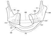
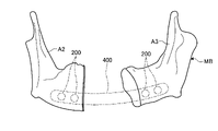
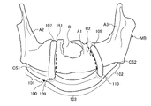
図8~図11は、実施形態にかかる骨再建手術について説明するための図である。図8には、下顎骨に対して外科手術用デバイスを固定する場合を例示する。図9には、下顎骨の切除予定領域を切除する場合を例示する。図10には、分断した下顎骨に対してプレートを固定する場合を例示する。図11には、プレートが固定された後、外科手術用デバイスを取り外す場合を例示する。 8 to 11 are diagrams for explaining the bone reconstructive surgery according to the embodiment. FIG. 8 illustrates the fixation of the surgical device to the mandible. FIG. 9 illustrates a case of resecting a planned resection region of the mandible. FIG. 10 illustrates the case of fixing the plate to the divided mandible. FIG. 11 illustrates removal of the surgical device after the plate has been secured.
まず、医師は、被検体の顎の表皮および筋肉を切開し、少なくとも下顎骨MBを露出させる。次に、医師は、図9に示すように、下顎骨MBに外科手術用デバイス100を押し当てる。このとき、下顎骨MBの下側表面CS1,CS2には、外科手術用デバイス100の接触領域101,102の接触面101a,102aがそれぞれ接触する。次に、医師は、デバイス用固定具150を各貫通孔104,105に挿入し、デバイス用固定具150を下顎骨MBに固定する。これにより、外科手術用デバイス100が下顎骨MBの残存領域A2,A3にそれぞれ固定される。次に、医師は、壊死部位Dに応じて、切除予定領域A1を区画するためにラインCL1,CL2を形成する。ここで、ラインCL1,CL2は、塗料であってもよいし、下顎骨MB自体を切削してもよい。
First, the doctor makes an incision in the epidermis and muscle of the subject's jaw to expose at least the mandible MB. The physician then presses the
次に、医師は、図10に示すように、外科手術用デバイス100と下顎骨MBとの間に金属ヘラ300を挿入する。ここでは、切除予定領域A1と非接触領域103との間に形成された隙間Sが形成されているため、ラインCL1,CL2にそれぞれ対向するように2つの金属ヘラ300を挿入することができる。ここで、金属ヘラ300は、医師がボーンソー等を用いて下顎骨MBを切削する際に、ボーンソーが外科手術用デバイス100と接触することを抑制するためのものである。このとき、外科手術用デバイス100は、外表面が曲面であり、金属ヘラ300が引っ掛かりにくいため、金属ヘラ300の挿入時に周辺組織を損傷することを抑制することができる。
The physician then inserts a
次に、医師は、図示しないボーンソーにより、ラインCL1,CL2に沿って、下顎骨MBを切断する。これにより、壊死部位Dを含む切除予定領域A1が下顎骨MBから切除され、下顎骨MBが残存領域A2,A3に分断される。ここで、下顎骨MBが残存領域A2,A3に分断された状態では、すでに外科手術用デバイス100が残存領域A2,A3にそれぞれ固定されている。従って、残存領域A2,A3は、切除予定領域A1が下顎骨MBから切除される前の位置を維持することができる。また、切除予定領域A1と非接触領域103との間に形成された隙間Sが形成されているため、仮に、金属ヘラ300が挿入されていなくても、ボーンソーが外科手術用デバイス100と接触することを抑制することができるので、外科手術用デバイス100をボーンソーが切削することにより、外科手術用デバイス100から切り屑が発生することを抑制することができる。
Next, the doctor cuts the mandible MB along lines CL1 and CL2 using a bone saw (not shown). As a result, the planned resection region A1 including the necrotic site D is resected from the mandible MB, and the mandible MB is divided into remaining regions A2 and A3. Here, in a state where the mandible MB is divided into the remaining areas A2 and A3, the
次に、医師は、例えば、プレート400を分断された下顎骨MBに押し当てる。ここでは、プレート400の両端部を外科手術用デバイス100が固定された残存領域A2,A3にそれぞれ対向させて押し当てる。このとき、切除予定領域A1と非接触領域103との間に形成された隙間Sが形成されているため、押し当てられたプレート400が外科手術用デバイス100と干渉することを抑制することができる。次に、プレート400の両端部に形成される図示しない穴にプレート用固定具200を挿入し、プレート用固定具200を残存領域A2,A3にそれぞれ固定する。これにより、プレート400が下顎骨MBの残存領域A2,A3にそれぞれ固定され。このとき、デバイス用固定具150は、プレート用固定具200と同一形状であるため、下顎骨MBに対して外科手術用デバイス100を固定しているデバイス用固定具150を取りはずし、プレート用固定具200として再利用することができるので、手術に必要な物を少なくすることができ、費用を抑制することができる。
Next, the doctor presses the
次に、医師は、図11に示すように、プレート400が分断された下顎骨MBに固定された状態で、外科手術用デバイス100を下顎骨MBから取り外す。次に、医師は、被検体の顎の表皮および筋肉を修復し、骨再建手術を完了する。
The physician then removes
このように、医師は、外科手術用デバイス100を用いて、プレート400を骨に固定する。ここで、外科手術用デバイス100は、骨を切除する前に、骨に固定されるため、骨が切除されても、切除されずに残った骨を骨が切除される前の位置を維持することができる。
Thus, the physician uses
以上説明した実施形態によれば、骨再建手術において、切除後の骨を切除前の位置に精度良く位置合わせすることができる外科手術用デバイス、情報処理装置、システム、情報処理方法、およびプログラムを提供することができる。 According to the embodiments described above, a surgical device, an information processing apparatus, a system, an information processing method, and a program capable of precisely aligning a post-resection bone to a pre-resection position in bone reconstructive surgery are provided. can provide.
本発明に係る実施形態について説明したが、本発明は、上述の実施形態そのままに限定されるものではなく、実施段階ではその要旨を逸脱しない範囲で構成要素を変形して具体化できる。また、上述の実施形態に開示されている複数の構成要素の適宜な組み合わせにより、種々の発明を形成できる。例えば、実施形態に示される全構成要素から幾つかの構成要素を削除しても良い。 Although the embodiments according to the present invention have been described, the present invention is not limited to the above-described embodiments as they are, and the constituent elements can be modified and embodied without departing from the gist of the present invention. Also, various inventions can be formed by appropriate combinations of the plurality of constituent elements disclosed in the above-described embodiments. For example, some components may be deleted from all the components shown in the embodiments.
〔変形例1〕
本実施形態における外科手術用デバイス100は、切除案内部を有していてもよい。図12は、外科手術用デバイスの変形例を示す図である。外科手術用デバイス100は、切除予定領域A1の境界B1,B2と対向する切除案内部107,108を有している。切除案内部107,108は、外科手術用デバイス100に対して着脱自在に構成されている。本実施形態における外科手術用デバイス100は、切除案内部107,108にそれぞれ対応する挿入穴109,110が形成されている。切除案内部107,108は、挿入穴109,110に挿入されることで、外科手術用デバイス100に固定される。なお、切除案内部107,108および挿入穴109,110は、切除案内部107,108が挿入穴109,110に挿入された状態で、外科手術用デバイス100に対して切除案内部107,108の回転が規制される回転規制構造を有することが好ましい。
[Modification 1]
この場合、生成部204は、骨に応じた外形データおよび切除予定領域データに基づいて、外科手術用デバイス100に対応するモデルデータの挿入穴109,110に対応する挿入穴データを決定する。また、生成部204は、骨に応じた外形データおよび切除予定領域データに基づいて、切除案内部107,108にそれぞれ対応するモデルデータを生成する。生成部204は、挿入穴データおよび切除案内部107,108にそれぞれ対応するモデルデータを、切除案内部107,108が切除予定領域A1の境界B1,B2と対向するように決定する。
In this case, the
次に、骨再建手術においては、医師は、外科手術用デバイス100の挿入穴109,110に切除案内部107,108をそれぞれ挿入した状態で、外科手術用デバイス100を下顎骨MBに固定する。このとき、切除案内部107,108は、切除予定領域A1の境界B1,B2に対向する。次に、医師は、切除案内部107,108に沿って、ラインCL1,CL2を形成し、切除案内部107,108を外科手術用デバイス100から取り外し、ボーンソーにより、ラインCL1,CL2に沿って、下顎骨MBを切断する。また、医師は、切除案内部107,108に沿って、ボーンソーにより、ラインCL1,CL2に沿って、下顎骨MBを直接切断してもよい。この場合、切除案内部107,108は、ボーンソーによる切り屑の発生を抑制するために金属製であることが好ましい。
Next, in the bone reconstructive surgery, the doctor inserts the resection guides 107 and 108 into the insertion holes 109 and 110 of the
外科手術用デバイス100が、切除予定領域A1の境界B1,B2と対向する切除案内部107,108を有することで、医師は容易にラインCL1,CL2を形成することができる。または、医師は、ラインCL1,CL2を形成せずに、切除予定領域A1を切除することができる。
〔変形例2〕
本実施形態における外科手術用デバイス100は、着脱可能に分割されていてもよい。図14は、外科手術用デバイスの変形例を示す図である。外科手術用デバイス100は、接触領域101および第一非接触領域103aからなる第一外科手術用デバイスと、接触領域102および第二非接触領域103bからなる第二外科手術用デバイスとから構成されている。第一外科手術用デバイスおよび第二外科手術用デバイスは、例えば、ネジ等の固定具により第一非接触領域103aおよび第二非接触領域103bを固定することで、1つの非接触領域103とすることで、一体化される。一方、ネジ等の固定具を取り外して、第一非接触領域103aおよび第二非接触領域103bを分離することで、分離することができる。
[Modification 2]
The
この場合、生成部204は、骨に応じた外形データおよび切除予定領域データに基づいて、第一外科手術用デバイスおよび第二外科手術用デバイスにそれぞれ対応するモデルデータを生成する。生成部204は、第一外科手術用デバイスおよび第二外科手術用デバイスにそれぞれ対応するモデルデータを、第一非接触領域103aおよび第二非接触領域103bが一体化することができるように決定する。
In this case, the
次に、骨再建手術においては、医師は、図示しないボーンソーにより、ラインCL1,CL2に沿って、下顎骨MBを切断した後、ネジ等の固定具を取り外して、外科手術用デバイス100を第一外科手術用デバイスおよび第二外科手術用デバイスに分離する。次に、医師は、下顎骨MBの裏側に位置する組織に対する処理を行う。次に、医師は、ネジ等の固定具により、第一外科手術用デバイスおよび第二外科手術用デバイスを一体化する。次に、医師は、下顎骨MBに対してプレート400を固定し、下顎骨MBに対して外科手術用デバイス100を取り外す。
Next, in the bone reconstructive surgery, the doctor cuts the mandibular bone MB along the lines CL1 and CL2 with a bone saw (not shown), removes fasteners such as screws, and places the
外科手術用デバイス100が、着脱可能に分割されていることで、医師は下顎骨MBの裏側の状態を容易に視認することができ、裏側に位置する組織を容易に処置することができる。
Since the
上述の実施形態は、以上の変形例と任意に組み合わせることができるし、以上の変形例同士を任意に組み合わせても良い。 The above-described embodiment can be arbitrarily combined with the above modifications, and the above modifications may be arbitrarily combined.
また、上述した実施形態の情報処理装置20で実行されるプログラムは、インストール可能な形式または実行可能な形式のファイルでCD-ROM、フレキシブルディスク(FD)、CD-R、DVD、USB(Universal Serial Bus)等のコンピュータで読み取り可能な記録媒体に記録して提供するように構成しても良いし、インターネット等のネットワーク経由で提供または配布するように構成しても良い。また、各種プログラムを、例えばROM等の不揮発性の記憶媒体に予め組み込んで提供するように構成しても良い。 In addition, the program executed by the information processing apparatus 20 of the above-described embodiment is a file in an installable format or an executable format, and can be stored on a CD-ROM, a flexible disk (FD), a CD-R, a DVD, a USB (Universal Serial Bus) or other computer-readable recording medium, or may be provided or distributed via a network such as the Internet. In addition, various programs may be configured to be pre-installed in a non-volatile storage medium such as a ROM and provided.
また、本実施形態における外科手術用デバイス100は、下顎骨MBにおける壊死部位Dが複数有り、切除予定領域A1が複数ある場合、各切除予定領域A1に対応する非接触領域103が形成され、各非接触領域103を挟んで接触領域101,102が形成される。
Further, in the
また、本実施形態における外科手術用デバイス100は、接触面101a,102aが下顎骨MBの下側表面CS1,CS2にそれぞれ対応するものであるが、下顎骨MBの上側表面にそれぞれ対応するものであってもよい。つまり、外科手術用デバイス100は、下顎骨MBの下側に固定されるものであっても、上側に固定されるものであってもよい。
In the
また、本実施形態における外科手術用デバイス100は、各貫通孔104,105も同時に造形装置30により造形されるが、造形後に各貫通孔104,105を形成してもよい。
In the
1 システム
10 医用画像診断装置
20 情報処理装置
21 CPU
22 ROM
23 RAM
24 補助記憶装置
25 入力装置
26 表示装置
27 外部I/F
30 造形装置
31 造形部
201 記憶部
202 ユーザインタフェース部
203 取得部
204 生成部
205 出力部
100 外科手術用デバイス
101,102 接触領域
103 非接触領域
104,105 貫通孔
150 デバイス用固定具
107,108 切除案内部
109,110 挿入孔
200 プレート用固定具
300 金属ヘラ
400 プレート
1 System 10 Medical Image Diagnostic Apparatus 20
22 ROMs
23 RAM
24
30 molding apparatus 31
Claims (16)
前記骨に対して前記外科手術用デバイスが固定された状態において、被検体の前記骨に接触し、かつ前記骨に応じた部位を有する接触領域を複数有し、
前記接触領域は、前記骨に固定するための固定部を有し、
隣り合う前記接触領域の間は、前記骨に対して前記外科手術用デバイスが固定された状態において、前記骨のうち、少なくとも切除予定領域に接触しない非接触領域を有する
外科手術用デバイス。 A surgical device for use in fixing a plate to bone in bone reconstruction surgery, comprising:
having a plurality of contact areas that are in contact with the bone of the subject in a state in which the surgical device is fixed to the bone and have a site corresponding to the bone;
the contact area has a fixation portion for fixation to the bone;
Between the adjacent contact regions, there is a non-contact region that does not contact at least the region to be resected of the bone when the surgical device is fixed to the bone.
surgical device.
請求項1に記載の外科手術用デバイス。The surgical device of Claim 1.
請求項1に記載の外科手術用デバイス。 The non-contact area is divided into a plurality of divided areas that are detachable from each other .
The surgical device of Claim 1 .
請求項1から3のいずれか1項に記載の外科手術用デバイス。 4. The surgical device according to any one of claims 1 to 3, further comprising a resection guide arranged along a boundary between the planned resection area and a remaining unresected area of the bone .
前記貫通孔は、デバイス用固定具を前記骨に固定するために用いられる、
請求項1から4のいずれか1項に記載の外科手術用デバイス。 The fixing part is a through hole formed in the contact area and penetrating to a contact surface where the contact area contacts the bone,
The through-hole is used to fix the device fixture to the bone,
A surgical device according to any one of claims 1-4.
請求項5に記載の外科手術用デバイス。 The device fixture has the same shape as the plate fixture that fixes the plate to the bone,
A surgical device according to claim 5.
請求項1から6のいずれか1項に記載の外科手術用デバイス。 The surgical device of any one of claims 1-6, wherein the bone is a jawbone.
請求項7に記載の外科手術用デバイス。 the jawbone is the mandible
A surgical device according to claim 7.
請求項8に記載の外科手術用デバイス。The surgical device of Claim 8.
被検体の骨を含む領域が撮像された画像データに基づいて、前記骨の外形データを含む骨形状情報を取得する取得部と、
前記骨に対して前記外科手術用デバイスが固定された状態において、前記被検体の前記骨に接触し、かつ前記骨に応じた部位を有する接触領域を複数有する外科手術用デバイスのモデルデータを、前記骨形状情報に基づいて生成する生成部と、
を備え、
前記接触領域は、前記骨に固定するための固定部を有し、
隣り合う前記接触領域の間は、前記骨に対して前記外科手術用デバイスが固定された状態において、前記骨のうち、少なくとも切除予定領域に接触しない非接触領域を有する
情報処理装置。 An information processing device for generating model data of a surgical device used when fixing a plate to a bone in bone reconstructive surgery,
an acquisition unit that acquires bone shape information including outer shape data of the bone based on image data obtained by imaging a region including the bone of the subject;
Model data of a surgical device having a plurality of contact areas that are in contact with the bone of the subject and have portions corresponding to the bones in a state in which the surgical device is fixed to the bone, a generator that generates based on the bone shape information;
with
the contact area has a fixation portion for fixation to the bone;
Between the adjacent contact regions, there is a non-contact region that does not contact at least the region to be resected of the bone when the surgical device is fixed to the bone.
Information processing equipment.
前記生成部は、隣り合う前記接触領域の間は、前記骨のうち、少なくとも切除予定領域と非接触の非接触領域を有する外科手術用デバイスのモデルデータを前記骨形状情報に基づいて生成する
請求項10に記載の情報処理装置。 The acquisition unit acquires the bone shape information including the planned resection region data corresponding to the planned resection region of the bone,
The generation unit generates model data of a surgical device having at least a non-contact region that is not in contact with a region to be resected among the bones, based on the bone shape information, between the adjacent contact regions. Item 11. The information processing device according to item 10 .
をさらに備える、
請求項10または11に記載の情報処理装置。 an output unit that outputs the model data generated by the generation unit to a modeling device;
The information processing apparatus according to claim 10 or 11 .
前記表示部に表示された前記モデルデータおよび前記骨形状情報を参照するユーザーから、前記モデルデータを修正する操作を受け付ける受付部と、
をさらに備え、
前記生成部は、前記受付部が受け付けた前記操作に応じて修正を前記モデルデータに行う、
請求項10から12のいずれか1項に記載の情報処理装置。 a display unit that simultaneously displays the model data and the bone shape information generated by the generation unit;
a reception unit that receives an operation for correcting the model data from a user who refers to the model data and the bone shape information displayed on the display unit;
further comprising
wherein the generation unit modifies the model data according to the operation received by the reception unit;
The information processing apparatus according to any one of claims 10 to 12 .
被検体の骨を含む領域が撮像された画像データに基づいて、前記骨の外形データを含む骨形状情報を取得する取得部と、
前記骨に対して前記外科手術用デバイスが固定された状態において、前記被検体の前記骨に接触し、かつ前記骨に応じた部位を有する接触領域を複数有する外科手術用デバイスのモデルデータを、前記骨形状情報に基づいて生成する生成部と、
前記モデルデータに基づいて、前記外科手術用デバイスを造形する造形装置と、
を備え、
前記接触領域は、前記骨に固定するための固定部を有し、
隣り合う前記接触領域の間は、前記骨に対して前記外科手術用デバイスが固定された状態において、前記骨のうち、少なくとも切除予定領域に接触しない非接触領域を有する
システム。 A system for modeling a surgical device that includes at least an information processing device and a modeling device and is used for fixing a plate to a bone in bone reconstructive surgery,
an acquisition unit that acquires bone shape information including outer shape data of the bone based on image data obtained by imaging a region including the bone of the subject;
Model data of a surgical device having a plurality of contact areas that are in contact with the bone of the subject and have portions corresponding to the bones in a state in which the surgical device is fixed to the bone, a generator that generates based on the bone shape information;
a modeling apparatus that models the surgical device based on the model data;
with
the contact area has a fixation portion for fixation to the bone;
Between the adjacent contact regions, there is a non-contact region that does not contact at least the region to be resected of the bone when the surgical device is fixed to the bone.
system .
被検体の骨を含む領域が撮像された画像データに基づいて、前記骨の外形データを含む骨形状情報を取得する取得ステップと、
前記骨に対して前記外科手術用デバイスが固定された状態において、前記被検体の前記骨に接触し、かつ前記骨に応じた部位を有する接触領域を複数有する外科手術用デバイスのモデルデータを、前記骨形状情報に基づいて生成する生成ステップと、
を含み、
前記接触領域は、前記骨に固定するための固定部を有し、
隣り合う前記接触領域の間は、前記骨に対して前記外科手術用デバイスが固定された状態において、前記骨のうち、少なくとも切除予定領域に接触しない非接触領域を有する
情報処理方法。 An information processing method for generating model data of a surgical device used to fix a plate to a bone in bone reconstructive surgery, comprising:
an acquiring step of acquiring bone shape information including outer shape data of the bone based on image data obtained by imaging a region including the bone of the subject;
Model data of a surgical device having a plurality of contact areas that are in contact with the bone of the subject and have portions corresponding to the bones in a state in which the surgical device is fixed to the bone, a generation step of generating based on the bone shape information;
including
the contact area has a fixation portion for fixation to the bone;
Between the adjacent contact regions, there is a non-contact region that does not contact at least the region to be resected of the bone when the surgical device is fixed to the bone.
Information processing methods.
コンピュータに、
被検体の骨を含む領域が撮像された画像データに基づいて、前記骨の外形データを含む骨形状情報を取得する取得処理と、
前記骨に対して前記外科手術用デバイスが固定された状態において、前記被検体の前記骨に接触し、かつ前記骨に応じた部位を有する接触領域を複数有する外科手術用デバイスのモデルデータを、前記骨形状情報に基づいて生成する生成処理と、
を実行させるためのプログラムであって、
前記接触領域は、前記骨に固定するための固定部を有し、
隣り合う前記接触領域の間は、前記骨に対して前記外科手術用デバイスが固定された状態において、前記骨のうち、少なくとも切除予定領域に接触しない非接触領域を有する
プログラム。 A program for generating model data of a surgical device used to fix a plate to a bone in bone reconstructive surgery, comprising:
to the computer,
Acquisition processing for acquiring bone shape information including external shape data of the bone based on image data obtained by imaging a region including the bone of the subject;
Model data of a surgical device having a plurality of contact areas that are in contact with the bone of the subject and have portions corresponding to the bones in a state in which the surgical device is fixed to the bone, a generation process for generating based on the bone shape information;
A program for executing
the contact area has a fixation portion for fixation to the bone;
Between the adjacent contact regions, there is a non-contact region that does not contact at least the region to be resected of the bone when the surgical device is fixed to the bone.
program.
Priority Applications (1)
| Application Number | Priority Date | Filing Date | Title |
|---|---|---|---|
| JP2018228341A JP7201166B2 (en) | 2018-12-05 | 2018-12-05 | Surgical device, information processing apparatus, system, information processing method, and program |
Applications Claiming Priority (1)
| Application Number | Priority Date | Filing Date | Title |
|---|---|---|---|
| JP2018228341A JP7201166B2 (en) | 2018-12-05 | 2018-12-05 | Surgical device, information processing apparatus, system, information processing method, and program |
Publications (2)
| Publication Number | Publication Date |
|---|---|
| JP2020089550A JP2020089550A (en) | 2020-06-11 |
| JP7201166B2 true JP7201166B2 (en) | 2023-01-10 |
Family
ID=71013379
Family Applications (1)
| Application Number | Title | Priority Date | Filing Date |
|---|---|---|---|
| JP2018228341A Active JP7201166B2 (en) | 2018-12-05 | 2018-12-05 | Surgical device, information processing apparatus, system, information processing method, and program |
Country Status (1)
| Country | Link |
|---|---|
| JP (1) | JP7201166B2 (en) |
Families Citing this family (2)
| Publication number | Priority date | Publication date | Assignee | Title |
|---|---|---|---|---|
| CN113180776B (en) * | 2021-04-21 | 2023-01-10 | 四川大学 | Bone cutting guide plate for zygomatic bone and zygomatic arch plastic surgery and internal pushing guide plate generation method |
| KR102677510B1 (en) * | 2021-09-14 | 2024-06-21 | 주식회사 잇다헬스케어 | Device for manufacturing surgical guide and mehtod thereof |
Citations (4)
| Publication number | Priority date | Publication date | Assignee | Title |
|---|---|---|---|---|
| WO2013087082A1 (en) | 2011-12-14 | 2013-06-20 | Stryker Leibinger Gmbh & Co. Kg | Technique for generating a bone plate design |
| WO2013165558A1 (en) | 2012-05-03 | 2013-11-07 | DePuy Synthes Products, LLC | Surgical guides from scanned implant data |
| WO2014158740A1 (en) | 2013-03-14 | 2014-10-02 | DePuy Synthes Products, LLC | Mandibular bone plate |
| JP2017153831A (en) | 2016-03-04 | 2017-09-07 | パナソニック株式会社 | Osteosynthesis parts |
Family Cites Families (1)
| Publication number | Priority date | Publication date | Assignee | Title |
|---|---|---|---|---|
| US5975904A (en) * | 1997-12-05 | 1999-11-02 | Spiegel; Jeffrey H. | Articulated bone reconstruction bar |
-
2018
- 2018-12-05 JP JP2018228341A patent/JP7201166B2/en active Active
Patent Citations (7)
| Publication number | Priority date | Publication date | Assignee | Title |
|---|---|---|---|---|
| WO2013087082A1 (en) | 2011-12-14 | 2013-06-20 | Stryker Leibinger Gmbh & Co. Kg | Technique for generating a bone plate design |
| JP2015503943A (en) | 2011-12-14 | 2015-02-05 | シュトリュケル ライビンゲル ゲーエムベーハー ウント カンパニ カーゲー | Techniques for generating bone plate designs |
| WO2013165558A1 (en) | 2012-05-03 | 2013-11-07 | DePuy Synthes Products, LLC | Surgical guides from scanned implant data |
| JP2018140219A (en) | 2012-05-03 | 2018-09-13 | シンセス・ゲーエムベーハーSynthes GmbH | Surgical guide based on implant scan data |
| WO2014158740A1 (en) | 2013-03-14 | 2014-10-02 | DePuy Synthes Products, LLC | Mandibular bone plate |
| JP2016511061A (en) | 2013-03-14 | 2016-04-14 | デピュイ・シンセス・プロダクツ・インコーポレイテッド | Mandible plate |
| JP2017153831A (en) | 2016-03-04 | 2017-09-07 | パナソニック株式会社 | Osteosynthesis parts |
Also Published As
| Publication number | Publication date |
|---|---|
| JP2020089550A (en) | 2020-06-11 |
Similar Documents
| Publication | Publication Date | Title |
|---|---|---|
| Kamburoğlu | Use of dentomaxillofacial cone beam computed tomography in dentistry | |
| Lin et al. | Three-dimensional computer-assisted orthognathic surgery: experience of 37 patients | |
| EP2004071B1 (en) | Targeting device, computer readable medium and program element | |
| US12268403B2 (en) | Surgical guides with removable inserts | |
| CN120419981A (en) | Apparatus and method for use with bone surgery | |
| US11478207B2 (en) | Method for visualizing a bone | |
| Findik et al. | Three-dimensional anatomic analysis of the lingula and mandibular foramen: a cone beam computed tomography study | |
| WO2017195797A1 (en) | Medical image diagnostic device | |
| US20210059691A1 (en) | Surgical cutting guides designed for anatomical landmarks | |
| Frongia et al. | Cone-beam computed tomography: accuracy of three-dimensional cephalometry analysis and influence of patient scanning position | |
| JP2009061035A (en) | Medical diagnostic imaging equipment | |
| Gosal et al. | Simulation of surgery for supratentorial gliomas in virtual reality using a 3D volume rendering technique: a poor man's neuronavigation | |
| Valdec et al. | Guided biopsy of osseous pathologies in the jaw bone using a 3D-printed, tooth-supported drilling template | |
| JP7201166B2 (en) | Surgical device, information processing apparatus, system, information processing method, and program | |
| KR20200028658A (en) | A method for manufacturing surgical guide using 3d image | |
| CN101044993A (en) | System and method for improved ablation of tumors | |
| Kim et al. | Accuracy and validity of stitching sectional cone beam computed tomographic images | |
| JP6797555B2 (en) | Medical information processing device | |
| Ha et al. | Reduction malarplasty using customized surgical stent based on 3D virtual surgery, CAD/CAM, and 3D printing technology: case series | |
| JP2007175323A (en) | Method of accumulating radiation information and display system of radiation information | |
| Seitel et al. | Ultrasound-guided spine anesthesia: feasibility study of a guidance system | |
| Dayoub et al. | The relationship between the zygomatic arch and the floor of the middle cranial fossa: a radiographic study | |
| Frongia et al. | Three-dimensional cephalometry: A method for the identification and for the orientation of the skull after cone-bean computed tomographic scan | |
| CN213075888U (en) | Minimally Invasive Stabilization System Guide for Posterior Ring of Pelvic Fractures | |
| WO2020122063A1 (en) | Device for surgery, information processing device, system, information processing method, and program |
Legal Events
| Date | Code | Title | Description |
|---|---|---|---|
| A521 | Request for written amendment filed |
Free format text: JAPANESE INTERMEDIATE CODE: A523 Effective date: 20210910 |
|
| A621 | Written request for application examination |
Free format text: JAPANESE INTERMEDIATE CODE: A621 Effective date: 20210910 |
|
| A977 | Report on retrieval |
Free format text: JAPANESE INTERMEDIATE CODE: A971007 Effective date: 20220622 |
|
| A131 | Notification of reasons for refusal |
Free format text: JAPANESE INTERMEDIATE CODE: A131 Effective date: 20220628 |
|
| A521 | Request for written amendment filed |
Free format text: JAPANESE INTERMEDIATE CODE: A523 Effective date: 20220825 |
|
| TRDD | Decision of grant or rejection written | ||
| A01 | Written decision to grant a patent or to grant a registration (utility model) |
Free format text: JAPANESE INTERMEDIATE CODE: A01 Effective date: 20221206 |
|
| A61 | First payment of annual fees (during grant procedure) |
Free format text: JAPANESE INTERMEDIATE CODE: A61 Effective date: 20221214 |
|
| R150 | Certificate of patent or registration of utility model |
Ref document number: 7201166 Country of ref document: JP Free format text: JAPANESE INTERMEDIATE CODE: R150 |
|
| S111 | Request for change of ownership or part of ownership |
Free format text: JAPANESE INTERMEDIATE CODE: R313115 |
|
| R350 | Written notification of registration of transfer |
Free format text: JAPANESE INTERMEDIATE CODE: R350 |
|
| R250 | Receipt of annual fees |
Free format text: JAPANESE INTERMEDIATE CODE: R250 |