JP7200112B2 - Discharge container, customized discharge system having the discharge container, and discharge control method for the discharge container - Google Patents
Discharge container, customized discharge system having the discharge container, and discharge control method for the discharge container Download PDFInfo
- Publication number
- JP7200112B2 JP7200112B2 JP2019535144A JP2019535144A JP7200112B2 JP 7200112 B2 JP7200112 B2 JP 7200112B2 JP 2019535144 A JP2019535144 A JP 2019535144A JP 2019535144 A JP2019535144 A JP 2019535144A JP 7200112 B2 JP7200112 B2 JP 7200112B2
- Authority
- JP
- Japan
- Prior art keywords
- discharge
- piston
- contents
- discharge space
- container
- Prior art date
- Legal status (The legal status is an assumption and is not a legal conclusion. Google has not performed a legal analysis and makes no representation as to the accuracy of the status listed.)
- Active
Links
Images


Classifications
-
- B—PERFORMING OPERATIONS; TRANSPORTING
- B65—CONVEYING; PACKING; STORING; HANDLING THIN OR FILAMENTARY MATERIAL
- B65D—CONTAINERS FOR STORAGE OR TRANSPORT OF ARTICLES OR MATERIALS, e.g. BAGS, BARRELS, BOTTLES, BOXES, CANS, CARTONS, CRATES, DRUMS, JARS, TANKS, HOPPERS, FORWARDING CONTAINERS; ACCESSORIES, CLOSURES, OR FITTINGS THEREFOR; PACKAGING ELEMENTS; PACKAGES
- B65D83/00—Containers or packages with special means for dispensing contents
- B65D83/14—Containers or packages with special means for dispensing contents for delivery of liquid or semi-liquid contents by internal gaseous pressure, i.e. aerosol containers comprising propellant for a product delivered by a propellant
- B65D83/60—Contents and propellant separated
- B65D83/64—Contents and propellant separated by piston
-
- A—HUMAN NECESSITIES
- A45—HAND OR TRAVELLING ARTICLES
- A45D—HAIRDRESSING OR SHAVING EQUIPMENT; EQUIPMENT FOR COSMETICS OR COSMETIC TREATMENTS, e.g. FOR MANICURING OR PEDICURING
- A45D34/00—Containers or accessories specially adapted for handling liquid toiletry or cosmetic substances, e.g. perfumes
- A45D34/04—Appliances specially adapted for applying liquid, e.g. using roller or ball
-
- B—PERFORMING OPERATIONS; TRANSPORTING
- B05—SPRAYING OR ATOMISING IN GENERAL; APPLYING FLUENT MATERIALS TO SURFACES, IN GENERAL
- B05B—SPRAYING APPARATUS; ATOMISING APPARATUS; NOZZLES
- B05B12/00—Arrangements for controlling delivery; Arrangements for controlling the spray area
- B05B12/14—Arrangements for controlling delivery; Arrangements for controlling the spray area for supplying a selected one of a plurality of liquids or other fluent materials or several in selected proportions to a spray apparatus, e.g. to a single spray outlet
- B05B12/1409—Arrangements for controlling delivery; Arrangements for controlling the spray area for supplying a selected one of a plurality of liquids or other fluent materials or several in selected proportions to a spray apparatus, e.g. to a single spray outlet the selection means being part of the discharge apparatus, e.g. part of the spray gun
-
- A—HUMAN NECESSITIES
- A45—HAND OR TRAVELLING ARTICLES
- A45D—HAIRDRESSING OR SHAVING EQUIPMENT; EQUIPMENT FOR COSMETICS OR COSMETIC TREATMENTS, e.g. FOR MANICURING OR PEDICURING
- A45D34/00—Containers or accessories specially adapted for handling liquid toiletry or cosmetic substances, e.g. perfumes
- A45D34/06—Containers or accessories specially adapted for handling liquid toiletry or cosmetic substances, e.g. perfumes in combination with other toiletry or cosmetic articles
-
- B—PERFORMING OPERATIONS; TRANSPORTING
- B01—PHYSICAL OR CHEMICAL PROCESSES OR APPARATUS IN GENERAL
- B01F—MIXING, e.g. DISSOLVING, EMULSIFYING OR DISPERSING
- B01F33/00—Other mixers; Mixing plants; Combinations of mixers
- B01F33/50—Movable or transportable mixing devices or plants
- B01F33/501—Movable mixing devices, i.e. readily shifted or displaced from one place to another, e.g. portable during use
- B01F33/5011—Movable mixing devices, i.e. readily shifted or displaced from one place to another, e.g. portable during use portable during use, e.g. hand-held
-
- B—PERFORMING OPERATIONS; TRANSPORTING
- B01—PHYSICAL OR CHEMICAL PROCESSES OR APPARATUS IN GENERAL
- B01F—MIXING, e.g. DISSOLVING, EMULSIFYING OR DISPERSING
- B01F33/00—Other mixers; Mixing plants; Combinations of mixers
- B01F33/80—Mixing plants; Combinations of mixers
- B01F33/84—Mixing plants with mixing receptacles receiving material dispensed from several component receptacles, e.g. paint tins
-
- B—PERFORMING OPERATIONS; TRANSPORTING
- B01—PHYSICAL OR CHEMICAL PROCESSES OR APPARATUS IN GENERAL
- B01F—MIXING, e.g. DISSOLVING, EMULSIFYING OR DISPERSING
- B01F35/00—Accessories for mixers; Auxiliary operations or auxiliary devices; Parts or details of general application
- B01F35/75—Discharge mechanisms
- B01F35/754—Discharge mechanisms characterised by the means for discharging the components from the mixer
- B01F35/75425—Discharge mechanisms characterised by the means for discharging the components from the mixer using pistons or plungers
-
- B—PERFORMING OPERATIONS; TRANSPORTING
- B05—SPRAYING OR ATOMISING IN GENERAL; APPLYING FLUENT MATERIALS TO SURFACES, IN GENERAL
- B05B—SPRAYING APPARATUS; ATOMISING APPARATUS; NOZZLES
- B05B11/00—Single-unit hand-held apparatus in which flow of contents is produced by the muscular force of the operator at the moment of use
- B05B11/01—Single-unit hand-held apparatus in which flow of contents is produced by the muscular force of the operator at the moment of use characterised by the means producing the flow
- B05B11/10—Pump arrangements for transferring the contents from the container to a pump chamber by a sucking effect and forcing the contents out through the dispensing nozzle
- B05B11/1081—Arrangements for pumping several liquids or other fluent materials from several containers, e.g. for mixing them at the moment of pumping
- B05B11/1083—Arrangements for pumping several liquids or other fluent materials from several containers, e.g. for mixing them at the moment of pumping in adjustable proportion
-
- B—PERFORMING OPERATIONS; TRANSPORTING
- B05—SPRAYING OR ATOMISING IN GENERAL; APPLYING FLUENT MATERIALS TO SURFACES, IN GENERAL
- B05B—SPRAYING APPARATUS; ATOMISING APPARATUS; NOZZLES
- B05B12/00—Arrangements for controlling delivery; Arrangements for controlling the spray area
- B05B12/14—Arrangements for controlling delivery; Arrangements for controlling the spray area for supplying a selected one of a plurality of liquids or other fluent materials or several in selected proportions to a spray apparatus, e.g. to a single spray outlet
- B05B12/1472—Arrangements for controlling delivery; Arrangements for controlling the spray area for supplying a selected one of a plurality of liquids or other fluent materials or several in selected proportions to a spray apparatus, e.g. to a single spray outlet separate supply lines supplying different materials to separate outlets of the spraying apparatus
-
- B—PERFORMING OPERATIONS; TRANSPORTING
- B05—SPRAYING OR ATOMISING IN GENERAL; APPLYING FLUENT MATERIALS TO SURFACES, IN GENERAL
- B05C—APPARATUS FOR APPLYING FLUENT MATERIALS TO SURFACES, IN GENERAL
- B05C17/00—Hand tools or apparatus using hand held tools, for applying liquids or other fluent materials to, for spreading applied liquids or other fluent materials on, or for partially removing applied liquids or other fluent materials from, surfaces
- B05C17/005—Hand tools or apparatus using hand held tools, for applying liquids or other fluent materials to, for spreading applied liquids or other fluent materials on, or for partially removing applied liquids or other fluent materials from, surfaces for discharging material from a reservoir or container located in or on the hand tool through an outlet orifice by pressure without using surface contacting members like pads or brushes
- B05C17/00553—Hand tools or apparatus using hand held tools, for applying liquids or other fluent materials to, for spreading applied liquids or other fluent materials on, or for partially removing applied liquids or other fluent materials from, surfaces for discharging material from a reservoir or container located in or on the hand tool through an outlet orifice by pressure without using surface contacting members like pads or brushes with means allowing the stock of material to consist of at least two different components
- B05C17/00556—Hand tools or apparatus using hand held tools, for applying liquids or other fluent materials to, for spreading applied liquids or other fluent materials on, or for partially removing applied liquids or other fluent materials from, surfaces for discharging material from a reservoir or container located in or on the hand tool through an outlet orifice by pressure without using surface contacting members like pads or brushes with means allowing the stock of material to consist of at least two different components with means for adjusting the proportions of the components
-
- B—PERFORMING OPERATIONS; TRANSPORTING
- B05—SPRAYING OR ATOMISING IN GENERAL; APPLYING FLUENT MATERIALS TO SURFACES, IN GENERAL
- B05C—APPARATUS FOR APPLYING FLUENT MATERIALS TO SURFACES, IN GENERAL
- B05C17/00—Hand tools or apparatus using hand held tools, for applying liquids or other fluent materials to, for spreading applied liquids or other fluent materials on, or for partially removing applied liquids or other fluent materials from, surfaces
- B05C17/005—Hand tools or apparatus using hand held tools, for applying liquids or other fluent materials to, for spreading applied liquids or other fluent materials on, or for partially removing applied liquids or other fluent materials from, surfaces for discharging material from a reservoir or container located in or on the hand tool through an outlet orifice by pressure without using surface contacting members like pads or brushes
- B05C17/00569—Hand tools or apparatus using hand held tools, for applying liquids or other fluent materials to, for spreading applied liquids or other fluent materials on, or for partially removing applied liquids or other fluent materials from, surfaces for discharging material from a reservoir or container located in or on the hand tool through an outlet orifice by pressure without using surface contacting members like pads or brushes with a pump in the hand tool
-
- B—PERFORMING OPERATIONS; TRANSPORTING
- B65—CONVEYING; PACKING; STORING; HANDLING THIN OR FILAMENTARY MATERIAL
- B65D—CONTAINERS FOR STORAGE OR TRANSPORT OF ARTICLES OR MATERIALS, e.g. BAGS, BARRELS, BOTTLES, BOXES, CANS, CARTONS, CRATES, DRUMS, JARS, TANKS, HOPPERS, FORWARDING CONTAINERS; ACCESSORIES, CLOSURES, OR FITTINGS THEREFOR; PACKAGING ELEMENTS; PACKAGES
- B65D81/00—Containers, packaging elements, or packages, for contents presenting particular transport or storage problems, or adapted to be used for non-packaging purposes after removal of contents
- B65D81/32—Containers, packaging elements, or packages, for contents presenting particular transport or storage problems, or adapted to be used for non-packaging purposes after removal of contents for packaging two or more different materials which must be maintained separate prior to use in admixture
- B65D81/3216—Rigid containers disposed one within the other
- B65D81/3227—Rigid containers disposed one within the other arranged parallel or concentrically and permitting simultaneous dispensing of the two materials without prior mixing
-
- B—PERFORMING OPERATIONS; TRANSPORTING
- B65—CONVEYING; PACKING; STORING; HANDLING THIN OR FILAMENTARY MATERIAL
- B65D—CONTAINERS FOR STORAGE OR TRANSPORT OF ARTICLES OR MATERIALS, e.g. BAGS, BARRELS, BOTTLES, BOXES, CANS, CARTONS, CRATES, DRUMS, JARS, TANKS, HOPPERS, FORWARDING CONTAINERS; ACCESSORIES, CLOSURES, OR FITTINGS THEREFOR; PACKAGING ELEMENTS; PACKAGES
- B65D81/00—Containers, packaging elements, or packages, for contents presenting particular transport or storage problems, or adapted to be used for non-packaging purposes after removal of contents
- B65D81/32—Containers, packaging elements, or packages, for contents presenting particular transport or storage problems, or adapted to be used for non-packaging purposes after removal of contents for packaging two or more different materials which must be maintained separate prior to use in admixture
- B65D81/3283—Cylindrical or polygonal containers, e.g. bottles, with two or more substantially axially offset, side-by-side compartments for simultaneous dispensing
- B65D81/3288—Cylindrical or polygonal containers, e.g. bottles, with two or more substantially axially offset, side-by-side compartments for simultaneous dispensing composed of two or more separate containers joined to each other
-
- B—PERFORMING OPERATIONS; TRANSPORTING
- B65—CONVEYING; PACKING; STORING; HANDLING THIN OR FILAMENTARY MATERIAL
- B65D—CONTAINERS FOR STORAGE OR TRANSPORT OF ARTICLES OR MATERIALS, e.g. BAGS, BARRELS, BOTTLES, BOXES, CANS, CARTONS, CRATES, DRUMS, JARS, TANKS, HOPPERS, FORWARDING CONTAINERS; ACCESSORIES, CLOSURES, OR FITTINGS THEREFOR; PACKAGING ELEMENTS; PACKAGES
- B65D83/00—Containers or packages with special means for dispensing contents
- B65D83/14—Containers or packages with special means for dispensing contents for delivery of liquid or semi-liquid contents by internal gaseous pressure, i.e. aerosol containers comprising propellant for a product delivered by a propellant
- B65D83/16—Containers or packages with special means for dispensing contents for delivery of liquid or semi-liquid contents by internal gaseous pressure, i.e. aerosol containers comprising propellant for a product delivered by a propellant characterised by the actuating means
- B65D83/20—Containers or packages with special means for dispensing contents for delivery of liquid or semi-liquid contents by internal gaseous pressure, i.e. aerosol containers comprising propellant for a product delivered by a propellant characterised by the actuating means operated by manual action, e.g. button-type actuator or actuator caps
-
- B—PERFORMING OPERATIONS; TRANSPORTING
- B65—CONVEYING; PACKING; STORING; HANDLING THIN OR FILAMENTARY MATERIAL
- B65D—CONTAINERS FOR STORAGE OR TRANSPORT OF ARTICLES OR MATERIALS, e.g. BAGS, BARRELS, BOTTLES, BOXES, CANS, CARTONS, CRATES, DRUMS, JARS, TANKS, HOPPERS, FORWARDING CONTAINERS; ACCESSORIES, CLOSURES, OR FITTINGS THEREFOR; PACKAGING ELEMENTS; PACKAGES
- B65D83/00—Containers or packages with special means for dispensing contents
- B65D83/14—Containers or packages with special means for dispensing contents for delivery of liquid or semi-liquid contents by internal gaseous pressure, i.e. aerosol containers comprising propellant for a product delivered by a propellant
- B65D83/68—Dispensing two or more contents, e.g. sequential dispensing or simultaneous dispensing of two or more products without mixing them
- B65D83/682—Dispensing two or more contents, e.g. sequential dispensing or simultaneous dispensing of two or more products without mixing them the products being first separated, but finally mixed, e.g. in a dispensing head
-
- A—HUMAN NECESSITIES
- A45—HAND OR TRAVELLING ARTICLES
- A45D—HAIRDRESSING OR SHAVING EQUIPMENT; EQUIPMENT FOR COSMETICS OR COSMETIC TREATMENTS, e.g. FOR MANICURING OR PEDICURING
- A45D34/00—Containers or accessories specially adapted for handling liquid toiletry or cosmetic substances, e.g. perfumes
- A45D2034/002—Accessories
-
- A—HUMAN NECESSITIES
- A45—HAND OR TRAVELLING ARTICLES
- A45D—HAIRDRESSING OR SHAVING EQUIPMENT; EQUIPMENT FOR COSMETICS OR COSMETIC TREATMENTS, e.g. FOR MANICURING OR PEDICURING
- A45D44/00—Other cosmetic or toiletry articles, e.g. for hairdressers' rooms
- A45D2044/007—Devices for determining the condition of hair or skin or for selecting the appropriate cosmetic or hair treatment
-
- A—HUMAN NECESSITIES
- A45—HAND OR TRAVELLING ARTICLES
- A45D—HAIRDRESSING OR SHAVING EQUIPMENT; EQUIPMENT FOR COSMETICS OR COSMETIC TREATMENTS, e.g. FOR MANICURING OR PEDICURING
- A45D2200/00—Details not otherwise provided for in A45D
- A45D2200/05—Details of containers
- A45D2200/054—Means for supplying liquid to the outlet of the container
- A45D2200/055—Piston or plunger for supplying the liquid to the applicator
-
- A—HUMAN NECESSITIES
- A45—HAND OR TRAVELLING ARTICLES
- A45D—HAIRDRESSING OR SHAVING EQUIPMENT; EQUIPMENT FOR COSMETICS OR COSMETIC TREATMENTS, e.g. FOR MANICURING OR PEDICURING
- A45D2200/00—Details not otherwise provided for in A45D
- A45D2200/05—Details of containers
- A45D2200/058—Means for mixing different substances prior to application
-
- B—PERFORMING OPERATIONS; TRANSPORTING
- B05—SPRAYING OR ATOMISING IN GENERAL; APPLYING FLUENT MATERIALS TO SURFACES, IN GENERAL
- B05B—SPRAYING APPARATUS; ATOMISING APPARATUS; NOZZLES
- B05B1/00—Nozzles, spray heads or other outlets, with or without auxiliary devices such as valves, heating means
- B05B1/30—Nozzles, spray heads or other outlets, with or without auxiliary devices such as valves, heating means designed to control volume of flow, e.g. with adjustable passages
- B05B1/32—Nozzles, spray heads or other outlets, with or without auxiliary devices such as valves, heating means designed to control volume of flow, e.g. with adjustable passages in which a valve member forms part of the outlet opening
- B05B1/326—Nozzles, spray heads or other outlets, with or without auxiliary devices such as valves, heating means designed to control volume of flow, e.g. with adjustable passages in which a valve member forms part of the outlet opening the valve being a gate valve, a sliding valve or a cock
-
- B—PERFORMING OPERATIONS; TRANSPORTING
- B05—SPRAYING OR ATOMISING IN GENERAL; APPLYING FLUENT MATERIALS TO SURFACES, IN GENERAL
- B05B—SPRAYING APPARATUS; ATOMISING APPARATUS; NOZZLES
- B05B12/00—Arrangements for controlling delivery; Arrangements for controlling the spray area
- B05B12/14—Arrangements for controlling delivery; Arrangements for controlling the spray area for supplying a selected one of a plurality of liquids or other fluent materials or several in selected proportions to a spray apparatus, e.g. to a single spray outlet
- B05B12/1418—Arrangements for controlling delivery; Arrangements for controlling the spray area for supplying a selected one of a plurality of liquids or other fluent materials or several in selected proportions to a spray apparatus, e.g. to a single spray outlet for supplying several liquids or other fluent materials in selected proportions to a single spray outlet
-
- B—PERFORMING OPERATIONS; TRANSPORTING
- B05—SPRAYING OR ATOMISING IN GENERAL; APPLYING FLUENT MATERIALS TO SURFACES, IN GENERAL
- B05B—SPRAYING APPARATUS; ATOMISING APPARATUS; NOZZLES
- B05B15/00—Details of spraying plant or spraying apparatus not otherwise provided for; Accessories
- B05B15/50—Arrangements for cleaning; Arrangements for preventing deposits, drying-out or blockage; Arrangements for detecting improper discharge caused by the presence of foreign matter
- B05B15/52—Arrangements for cleaning; Arrangements for preventing deposits, drying-out or blockage; Arrangements for detecting improper discharge caused by the presence of foreign matter for removal of clogging particles
-
- B—PERFORMING OPERATIONS; TRANSPORTING
- B05—SPRAYING OR ATOMISING IN GENERAL; APPLYING FLUENT MATERIALS TO SURFACES, IN GENERAL
- B05B—SPRAYING APPARATUS; ATOMISING APPARATUS; NOZZLES
- B05B9/00—Spraying apparatus for discharge of liquids or other fluent material, without essentially mixing with gas or vapour
- B05B9/03—Spraying apparatus for discharge of liquids or other fluent material, without essentially mixing with gas or vapour characterised by means for supplying liquid or other fluent material
- B05B9/04—Spraying apparatus for discharge of liquids or other fluent material, without essentially mixing with gas or vapour characterised by means for supplying liquid or other fluent material with pressurised or compressible container; with pump
- B05B9/08—Apparatus to be carried on or by a person, e.g. of knapsack type
- B05B9/0805—Apparatus to be carried on or by a person, e.g. of knapsack type comprising a pressurised or compressible container for liquid or other fluent material
- B05B9/0838—Apparatus to be carried on or by a person, e.g. of knapsack type comprising a pressurised or compressible container for liquid or other fluent material supply being effected by follower in container, e.g. membrane or floating piston, or by deformation of container
-
- B—PERFORMING OPERATIONS; TRANSPORTING
- B05—SPRAYING OR ATOMISING IN GENERAL; APPLYING FLUENT MATERIALS TO SURFACES, IN GENERAL
- B05B—SPRAYING APPARATUS; ATOMISING APPARATUS; NOZZLES
- B05B9/00—Spraying apparatus for discharge of liquids or other fluent material, without essentially mixing with gas or vapour
- B05B9/03—Spraying apparatus for discharge of liquids or other fluent material, without essentially mixing with gas or vapour characterised by means for supplying liquid or other fluent material
- B05B9/04—Spraying apparatus for discharge of liquids or other fluent material, without essentially mixing with gas or vapour characterised by means for supplying liquid or other fluent material with pressurised or compressible container; with pump
- B05B9/08—Apparatus to be carried on or by a person, e.g. of knapsack type
- B05B9/085—Apparatus to be carried on or by a person, e.g. of knapsack type with a liquid pump
- B05B9/0855—Apparatus to be carried on or by a person, e.g. of knapsack type with a liquid pump the pump being motor-driven
- B05B9/0861—Apparatus to be carried on or by a person, e.g. of knapsack type with a liquid pump the pump being motor-driven the motor being electric
Description
本発明は、複数の収容部を備える吐出容器、該吐出容器を有するカスタマイズ吐出システム、及び該吐出容器における吐出制御方法に関する。 TECHNICAL FIELD The present invention relates to a dispensing container having a plurality of housings, a customized dispensing system having the dispensing container, and a dispensing control method for the dispensing container.
複数の収容部を備え、複数の内容物を同時に吐出する容器の技術として、複数の種類の調味料を吐出する食品用小型包装容器であるディスペンパック(登録商標)が広く知られている。 Dispen packs (registered trademark), which are small packaging containers for food that dispense a plurality of types of seasonings, are widely known as a technology for a container that has a plurality of storage portions and dispenses a plurality of contents at the same time.
また、化学反応を起こす2種類の液剤を別々に保管して、櫛の上で混合させる染毛剤容器も知られている(例えば、特許文献1参照)。 Also known is a hair dye container in which two types of liquid agents that cause chemical reactions are separately stored and mixed on a comb (see, for example, Patent Document 1).
さらに、特許文献2において、2種類の薬物を2つのカートリッジに保管して、薬物をカートリッジから押し出してアセンブリ内部に一時押し込み、その2種類の薬物が送出針から同時に外に射出される注射器アセンブリが提案されている。
Furthermore, in
しかし、上記ディスペンパックは、1回に使用する分のみ収容されている使い捨て容器であり、複数回の吐出の使用は想定されていない。 However, the above-mentioned dispense pack is a disposable container containing only the amount to be used once, and is not assumed to be used for multiple discharges.
同様に、上記特許文献2に係る注射器アセンブリは、衛生面を考慮して、使い捨て、あるいは、使用後の清掃と使用前の滅菌が必要であった。
Similarly, the syringe assembly according to
また、上記特許文献1に係る染毛剤容器では、櫛の上で2種類の液剤を混合させるため、吐出動作後に、櫛の部分に混合した液剤が残留する。そのため、吐出動作後に、外部操作により櫛の部分の内部を清掃する必要があり、手間がかかった。また、2種類の液剤が、保管中に、混合部である櫛の部分を介して揮散するおそれがあった。
In addition, in the hair dye container according to
そこで、本発明は上記事情に鑑み、吐出動作後の容器内部の清掃が不要になり、吐出動作時以外に内容物の揮散を防止する、複数の収容部を備える吐出容器の提供を目的とする。 SUMMARY OF THE INVENTION In view of the above circumstances, an object of the present invention is to provide a discharge container having a plurality of storage units, which eliminates the need to clean the inside of the container after a discharge operation and prevents volatilization of the contents except during the discharge operation. .
上記課題を解決するため、本発明の一態様の吐出容器は、
吐出孔が形成された吐出面を有する容器本体と、
前記容器本体の内部において前記吐出孔と連通する吐出空間を有するシリンダー部と、
前記吐出空間内で、第1の位置と、該第1の位置よりも前記吐出面から離間した第2の位置との間で、前記吐出空間の内壁に密接して移動可能なピストンと、
内容物を収容する複数の収容部と、を備え、
前記吐出空間の前記内壁には、前記複数の収容部と夫々対応づけられた複数の流入孔が形成されており、
前記ピストンが前記第2の位置にあるとき、前記ピストンの頂面と前記吐出面との間の前記吐出空間に前記複数の流入孔が連通し、前記複数の流入孔から前記内容物が前記吐出空間に流入可能な状態となり、
前記ピストンが前記第1の位置にあるとき、前記複数の流入孔が前記ピストンの側面によって閉鎖される。
In order to solve the above problems, a discharge container according to one aspect of the present invention includes:
a container body having a discharge surface in which a discharge hole is formed;
a cylinder portion having a discharge space communicating with the discharge hole inside the container body;
a piston movable within the discharge space between a first position and a second position spaced further from the discharge surface than the first position , in close contact with an inner wall of the discharge space ;
a plurality of storage units for storing contents,
The inner wall of the discharge space is formed with a plurality of inflow holes respectively associated with the plurality of storage portions,
When the piston is at the second position, the plurality of inflow holes communicate with the discharge space between the top surface of the piston and the discharge surface, and the contents are discharged from the plurality of inflow holes. It becomes possible to flow into the space,
When the piston is in the first position, the plurality of inlet holes are closed by sides of the piston.
一態様によれば、複数の収容部を有する吐出容器において、吐出動作後の容器内部の清掃を不要にすることができ、吐出動作時以外に内容物の揮散を防止することができる。 According to one aspect, in a discharge container having a plurality of storage portions, it is possible to eliminate the need to clean the inside of the container after the discharge operation, and prevent volatilization of the contents except during the discharge operation.
以下、図面を参照して本発明を実施するための形態について説明する。下記、各図面において、同一構成部分には同一符号を付し、重複した説明を省略する場合がある。 EMBODIMENT OF THE INVENTION Hereinafter, the form for implementing this invention is demonstrated with reference to drawings. In each drawing below, the same components are denoted by the same reference numerals, and redundant description may be omitted.
<第1実施形態>
図1は、本発明の第1実施形態の吐出容器の全体図である。本発明の吐出容器には、内容物として、例えば、化粧料(基礎化粧料、ベースメイク用化粧料、ポイントメイク用化粧料)や練り香水、調味料等が収容される。<First Embodiment>
FIG. 1 is an overall view of a discharge container according to a first embodiment of the invention. The contents of the discharge container of the present invention include, for example, cosmetics (basic cosmetics, base makeup cosmetics, point makeup cosmetics), kneaded perfumes, seasonings, and the like.
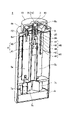
図1に示すように、本実施形態の吐出容器1は、吐出孔15が形成された吐出面13を有する容器本体(カバー、ケース)10によって囲われている。
As shown in FIG. 1, the
図1に示す例では、容器本体10は、径が異なる円筒を段状に組み合わせた形状である。詳しくは、容器本体10は、吐出側筒体11と、収容側筒体12とで構成されている。本例では、吐出側筒体11と、収容側筒体12は、円筒形状の例を示すが、角筒形状であってもよい。
In the example shown in FIG. 1, the
また、本実施形態では、収容側筒体12の外側(外側表面)の一例として、収容側筒体12の外周縁に近い上側表面に、操作部(操作スイッチ)101、発光部102、電源スイッチ103が設けられている。
In addition, in the present embodiment, as an example of the outside (outer surface) of the
操作部101は、吐出する収容物の吐出量(混合比率)を調整する。発光部102は、操作部101で選択された吐出量の選択量を示すように点灯する。図1の例では、複数種類の内容物について、3段階に吐出量を選択可能な表示例を示している。なお、図1では操作部101と発光部102のセットを2つ図示しているが、吐出容器1に含まれる内容物の種類は3種類以上であってもよい。
The
3段階に吐出量を選択する構成では、例えば、発光部102が何れも点灯していない場合はその内容物の「吐出無し」、1つの点灯場合は「吐出量:少」、2つ点灯の場合は「吐出量:中」、3つ点灯の場合は「吐出量:多」を示す。
In the configuration in which the ejection amount is selected in three stages, for example, when none of the
なお、操作部101の数は、吐出容器1内部の内容物の種類の数によって増減してもよい。また、操作部101の形状は、図1では三角で示しているが、内容物の吐出量を操作できるものであれば他の形状であってもよい。
The number of
電源スイッチ103は、吐出容器1の電源91(図7参照)をON/OFFする。
The
本例では、容器本体10の上面が吐出面13であり、吐出面13には、吐出孔15の周囲の部分はすり鉢状(受け皿状)に内側に凹んだ凹部16が形成されている。
In this example, the upper surface of the
また、吐出孔15の内側の吐出空間2(図2A参照)には、ピストン3が設けられている。図1の例では、吐出孔15と連通する吐出空間2内に設けられるピストン3の周囲と、吐出孔15が同じ大きさである例を示す。
A
電源をOFFにしたとき、又は電源ONにおいて吐出後及び待機位置にあるときは、ピストン3が第1の位置にある。本実施形態では、第1の位置は、ピストン3の頂面31は、吐出孔15の開口表面14(図2A参照)と略同一の位置にある。
The
[吐出容器内部断面]
図2A,図2Bは、図1の吐出容器1の断面図の一例である。[Internal cross section of discharge container]
2A and 2B are examples of cross-sectional views of the
図2A,図2Bに示すように、容器本体10の内側には、吐出空間2を有するシリンダー部25が設けられ、その吐出空間2にはピストン3が設置されている。シリンダー部25の内部空間では、容器本体10の内部において吐出孔15と連通し(開口し)、内壁21に囲まれている吐出空間2が形成されている。
As shown in FIGS. 2A and 2B, a
ピストン3は、吐出空間2の内壁21の内側に嵌り込み、図2Aに示す第1の位置と、その第1の位置よりも吐出孔15から離間した、図2Bに示す第2の位置との間で移動可能である。図2A,図2Bに示すピストン3の頭部は、側面32が吐出空間2の内側の側面(内壁21)に密着可能な、円柱又は楕円柱形である。
The
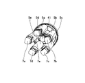
さらに、容器本体10の内部には、異なる種類の複数の収容物をそれぞれ収容する複数の収容部5a~5eが備えられている。
Further, inside the container
なお、図2A,図2Bは縦方向の断面図であるため、図面上では2つの手前側の収容部5a,5cが視認可能であるが、本例において、複数の収容部は図中手前や奥側にも設けられているため、5つの収容部5a,5b,5c,5d,5eが吐出容器1内に設けられているものとする。
Since FIGS. 2A and 2B are vertical cross-sectional views, the two
吐出空間2の内壁21には、収容部5a~5eに夫々対応付けられた流入孔22a~22eが形成されている。
ピストン3が図2Bに示す第2の位置にあるとき、ピストン3の頂面31と吐出面13との間の吐出空間2に、流入孔22a~22eが連通し(開放され)、流入孔22a~22eから内容物が夫々吐出空間2へ流入可能な状態になる。
When the
ピストン3が図2Aに示す第1の位置にあるとき、吐出空間2において複数の流入孔22a~22eがピストン3によって閉鎖される。
A plurality of
ピストン3の外周面(側面)32において、ピストン3が第1の位置にあるときに流入孔22a~22eと当接する部分には、流入孔封止のために密閉性をより高めるシール部33が設けられている。
On the outer peripheral surface (side surface) 32 of the
例えば、図2A,図2Bに示す例では、ピストン3のシール部33以外の部分は、HDPE(High Density Polyethylene:硬質ポリエチレン)又はPP(polypropylene:ポリプロピレン)で構成され、ピストン3におけるシール部33はNBR(nitrile rubber)、シリコンゴム、熱可塑性エラストマー(オレフィン系、スチレン系)などの軟材質によって構成されている。
For example, in the example shown in FIGS. 2A and 2B, the portion of the
また、吐出容器1の内部には、複数の収容部の各収容部5a~5eと、複数の流入孔の各流入孔22a~22eとの間を夫々接続し、複数の内容物の各収容物が夫々通る複数の供給路6a~6eとを備えている。
Further, inside the
さらに、図2A,図2Bに示す吐出容器1には、収容部5a~5eの下側に、押出部7a~7eが設けられている。
Further, the
ここで、ピストン3の駆動について説明する。ピストン3は、ピストン3の下部に設けられたピストン駆動部4によって移動駆動させられる。
Here, driving of the
なお、本例では、吐出孔15が形成された吐出面13が容器本体10の上面である例を示しているため、ピストン3は、図2Aに示す上方にある第1の位置と、図2Bに示す下方にある第2の位置との間を上下に昇降可能である。
In this example, since the
ピストン3は、吐出空間2を構成するシリンダー部(円筒部)25の内部を昇降する。本構成例では、ピストン3が最も下側の第2の位置にあるときにピストン3の位置を規制するストッパー26が、ピストン3とピストン駆動部4との間に設けられている。ストッパー26は、略円筒形状であって、外周面がシリンダー部25の内壁21の一部に挿嵌されるように設置され、ストッパー26の上面が吐出空間2の底部として機能する。
The
図2A,図2Bの例では、ピストン駆動部4は、回転力を発生する回転モータ(位置決めギアモータ)であるピストン用モータ41と、該ピストン用モータ41及びピストン3との間に介在する連結ネジ(回転ネジ)である回転伝達体45とを含んでいる。
In the example of FIGS. 2A and 2B, the
詳しくは、本構成例では、ピストン3の吐出孔15から離れた下側には、下に開口し、内周面に螺旋溝を有する雌ネジ形状のピストンロッド35が形成されている。ピストンロッド35はストッパー26の中空部を貫通するように形成されている。
Specifically, in this configuration example, a female screw-shaped
そして、回転伝達体45は雄ネジ付きベアリング形状であって、ピストン3と嵌合する上側には、上に突出したネジ部である雄ネジ47が形成されている。また、回転伝達体45の下側のネジ頭部46には、ピストン用モータ41においてモータ部42によって回転駆動される回転軸43と嵌合する軸受穴48が形成されている。
The
このように、回転伝達体45とピストン3とがネジ状に嵌合することで、ピストン駆動部4において、回転伝達体45はピストン用モータ41の回転力をピストン3の移動力として伝達する。
In this manner, the
なお、ピストンロッド35の外周面には、上下方向に延伸する複数の突起又は溝が非円対称に設けられており、その突起又は溝がストッパー26の内側面に設けられた上下方向に延伸する溝又は突起と係合する。この構成により、回転伝達体45が回転した際に、ピストン3が連れ回ることを制限して、ピストン用モータ41による回転力をピストン3の進退方向の移動力として伝達する。
A plurality of projections or grooves extending in the vertical direction are asymmetrically provided on the outer peripheral surface of the
また、図2A,図2Bの例では、ピストン駆動部4を、ピストン用モータ(回転モータ)41と、回転ネジで構成される回転伝達体45で構成する例を説明したが、回転ネジの代わりに巻きバネを用いてもよいし、回転モータの代わりに他の駆動モータを用いてもよい。
In addition, in the example of FIGS. 2A and 2B, an example in which the
次に、本実施形態における収容部5a~5eから流入孔22a~22eへの供給の駆動について説明する。
Next, a description will be given of driving the supply from the
本実施形態において、複数の押出部7a~7eは、各収容部から吐出空間2への各内容物の供給量(流入量)を調整して、各収容部5a~5eから、各内容物を押し出して各供給路6a~6eを介して各流入孔22a~22eへ移送する。複数の押出部7a~7eは、例えば、ギアモータで構成され、複数の押出式の移送手段として機能する。押出部の詳細については、図5A~図6とともに説明する。
In the present embodiment, the plurality of
押出部(押し上げ部)7a~7eが下部に設けられた収容部5a~5eは、例えば、ディスペンサー構造であって、1プッシュとして収容部5a~5eを持ち上げることで、収容部5a~5eから所定量、流入孔22a~22e側へ内容物が移送される。ここで、押出部7a~7eが1プッシュ動作で所定高さ分、収容部5a~5eを押し上げることにより、収容部5a~5eから押し出される1プッシュあたりの吐出量を規定し、調整された吐出量に応じて、1吐出動作におけるプッシュ回数を増減することができる。
The
あるいは、押出部7a~7eは、繰り出し式として、上記のピストン駆動部4と同様に収容部5a~5eの内部で移動する各色ピストン54(図6参照)とその各色ピストン54を駆動させる繰り出し駆動部として構成してもよい。この場合は、調整された吐出量に応じて、押出部7a~7e(モータ71の回転軸72)の回転量を調整することで、繰り出し量を調整することができる。
Alternatively, the extruding
なお、押出部7a~7eによる供給量は制御部9によって制御される。供給量の制御については、図7とともに詳述する。
The
また、本実施形態では、図2Aに示すように、ピストン3の周囲と、吐出孔15が同じ大きさであり、ピストン3が第1の位置にあるときは、吐出面13の凹部16の最も低い部分の表面(開口表面14)とピストン3の頂面(本例では上面)31が略同一の高さになる。
Further, in this embodiment, as shown in FIG. 2A, the periphery of the
そのため、流入孔22a~22eから吐出空間2に吐出された複数種類の内容物は、ピストン3に押し出されることにより、残らず、全て吐出容器1の外に押し出すことができる。
Therefore, the plurality of types of contents discharged into the
詳しくは、内容物は、吐出空間2において、ピストン3の底面34に接触することなく、ピストンの上面のみに接触して、ピストン3の頂面31に乗り、ピストン3の上昇に伴って容器本体10の吐出面13の位置に運ばれる。
Specifically, in the
したがって、吐出動作において、内容物が接触するのは、吐出空間2の内壁21と、ピストン3の頂面31のみとなる。ここで、吐出空間2の内壁21と、ピストン3の側面32は密接しているため、吐出空間2への流入時に内壁21に内容物が付着したとしても、ピストン3の第2の位置から第1の位置への移動に伴い、付着した内容物もピストン3の頂面31上に集められ、吐出面13の位置へ外まで押し出される。
Therefore, only the
そのため、吐出動作後には、吐出空間2内部には、いずれの内容物の残らないことになるため、吐出動作後の吐出容器1内部の清掃が不要となる。
Therefore, since none of the contents remain in the
また、吐出動作後、ピストン3が図2Aに示す第1の位置に留まることで、複数の流入孔22a~22eがピストン3によって閉鎖されて複数の供給路6a~6eと吐出空間2とを遮断状態にして、複数の内容物の吐出空間2への流入を阻止した状態が維持される。
Further, after the discharge operation, the
したがって、本発明の吐出容器は、容器内部の清掃をしなくても、吐出空間2内部には、いずれの内容物も残らず、ゴミ等も堆積しないため、次の使用の際に混合比を変えて使用する際、前回の内容物の混合比率状況を考慮することなく、掃除不要で、吐出動作を実行させることができる。また、吐出動作時以外は、複数の孔を有効に封鎖するため内容物の揮散を防止することができる。
Therefore, in the discharge container of the present invention, even if the inside of the container is not cleaned, neither the content remains nor dust accumulates in the
さらに、本実施形態では、吐出孔15の径が吐出空間を構成するシリンダー部25の内径と連続して、略同じ大きさに構成されている。即ち、吐出孔15は、ピストン3の周囲径に密着可能な寸法で構成されているため、ピストン3の頂面31に乗った内容物は、側方からの圧力を受けずに、頂面31の上で流入時と同じ面積を維持したまま外に押し出される。
Furthermore, in the present embodiment, the diameter of the
この構成により、使用者は、吐出空間2内に流入孔22a~22eから流入してくる内容物の動きや、ピストン3の動きを全て視認可能であるため、吐出容器1の吐出動作を見て楽しむことができる。
With this configuration, the user can see all the movement of the contents flowing into the
なお、図2A,図2Bの示す例ではピストン3の下側に雌ネジ形状のピストンロッド35が設けられ、回転伝達体45が雄ネジ付きベアリングであったが、ネジ状に係合すれば、ネジの雌雄は逆であってもよい。すなわち、ピストン3の下側に雄ネジが設けられ、回転伝達体が雌ネジ付きベアリングである構成でもよい。
In the example shown in FIGS. 2A and 2B, a female-threaded
[分解断面斜視図(変形例)]
図3に、回転伝達体45Aが雌ネジ付きベアリングで構成される吐出容器1Aの筐体を外した内部構成の分解断面斜視図を示す。図3では、ピストン3Aが第1の位置に位置した状態で分解した例を示しており、図面の重なりを防ぐため、収容部5Aについては収容部やその周辺は1つのみを図示している。図3を用いて、図2A,図2Bにおいて隠れていた構成要素を中心に説明する。[Exploded cross-sectional perspective view (modification)]
FIG. 3 shows an exploded cross-sectional perspective view of the internal configuration of the discharge container 1A, in which the rotation transmitting body 45A is formed of a bearing with a female thread, with the housing removed. FIG. 3 shows an example disassembled with the
図3において、+Z側の集合体は、上側固定支持部17(図5A参照)の内部を示し、上側固定支持部17の上板17Uの下側に、シリンダー部25と、複数の筐体側ホルダ61a~61eと、シリンダー部25と筐体側ホルダ61a~61eを夫々接続する供給路6a~6eとが形成されている。
In FIG. 3, the assembly on the +Z side shows the inside of the upper fixed support portion 17 (see FIG. 5A). 61a to 61e, and
なお、図3は断面図のため、筐体側ホルダ61a~61e等、内容物の種類と同数設けられるものは、全ては示さず、角度等により適宜視認できる個数のみ示すものとする。また図3では、シリンダー部25として、シリンダー部25の内壁21Aを示している。
Since FIG. 3 is a cross-sectional view, not all of the housing-
また、―Z側の集合体は、下側固定支持部18の内部を示し、下側固定支持部18の上板18Uの上側に、軸受ゴム182が取り付けられた回転体軸受ホルダ181が設けられている。
The -Z side assembly shows the inside of the lower fixed
また下側固定支持部18の上板18Uの下側には、モータホルダ75a~75e(75a~75dを図示)が設けられている。モータホルダ75a~75eの内部空間βには、押出部であるモータ7a(図6参照)が設置されるものとする。
なお、図示はしないが、モータホルダ75a~75eに囲まれた中央の空間αには、ピストン用モータ41(図2A、図5B参照)が設置され、ピストン用モータ41は回転体軸受ホルダ181に保持される軸受を介して、回転伝達体45Aの軸受穴48と連結する。
Although not shown, the piston motor 41 (see FIGS. 2A and 5B) is installed in the central space α surrounded by the
本構成では、ピストン3Aの吐出孔側端面(図3中、+Z側の面)の中央には、凸部311が形成されている例を示す。本構成においては、ピストン3Aは、頂面部31Aと、筒部32Aとを有している。
This configuration shows an example in which a
頂面部31Aは、内容物に接触する部分として、凸部311と、凸部311の周囲の先端側面部(平面部)312とを有する。また、図3に示す例では、頂面部31Aの凸部311以外の部分の側面である先端側側面部313で流入孔22を塞ぐ。そのため、頂面部31Aは、図2Bのシール部33と同様にNBR、シリコンゴム、熱可塑性エラストマーなどの軟材質によって構成されている。また、ピストン3Aの筒部32Aは、例えばHDPE又はPPで構成されている。
31 A of top surface parts have the
また、図3に示す例では、ピストン3Aの筒部32Aにおいて、円筒部36の先端には、頂面部31Aと係合するための係合突起38が設けられている。
Further, in the example shown in FIG. 3, an engaging
図3の+Z側の、シリンダー部25の内壁21Aには、ピストン3Aの進退方向である上下方向に沿って延伸する、複数の延伸溝27が形成されている。これに対応して、ピストン3Aの円筒部36の上部の外周面には、延伸溝27に係合する複数の延伸突起37が設けられている。
A plurality of
また、図3に示す回転伝達体45AはH型の雌ネジ付きベアリング形状であり、ピストン3A側の先端部は雌ネジ構成であって、内壁部には、回転溝49が形成されている。これに対応して、ピストン3Aの円筒部36の外周の下部には、伝達部として、螺旋突起39が形成されている。また、回転伝達体45Aにおいて、回転溝49が形成された雌ネジ部分の端面はストッパー面46Asとして機能する。
The rotation transmitting body 45A shown in FIG. 3 is in the shape of an H-shaped female-threaded bearing. Correspondingly, a
このような構成により、ピストン3Aは、螺旋係合によりH型の回転伝達体45Aからの回転力が伝達されて、シリンダー部25の内壁21A内で、ピストン3Aの延伸突起37が延伸溝27に沿って移動することで、ピストン3A自体が回転することなく、位置が規制されながら所望の進退方向に移動する。
With such a configuration, the
また、収容部5Aの本体筒51は固定突起58を有する収容部ホルダ57によって保持されている。一方、収容部5Aの操作筒52の内側に形成された嵌合突起52Gに軸受56が嵌りこみ、軸受56には、押出部(繰り出し駆動部)7Aの回転軸72(図6参照)が挿嵌される。
Further, the
本体筒51を保持する収容部ホルダ57に固定突起58が形成されている。これに対応して、本体側ホルダ61(61a~61e)には、上下方向に延伸する溝62が夫々形成されている。
A fixing
収容部ホルダ57の固定突起58が筐体側ホルダ61の溝62に係合することで、操作筒52が回転しても、本体筒51は固定されているため、操作筒52の本体筒51に対する相対的な回転により、内容物が供給路6a~6eを介して流入孔22a~22eへ押し出される。
Since the fixing
<動作手順>
次に、本発明の吐出容器1における動作手順について説明する。<Operation procedure>
Next, the operating procedure of the
図4は、本発明の吐出容器を使用する際の動作フローチャートである。このフローの手順は、制御部9に記憶されたプログラムによって予め設定されているものとする。
FIG. 4 is an operation flow chart when using the dispensing container of the present invention. It is assumed that the procedure of this flow is set in advance by a program stored in the
図4のステップS1で、使用者は、内容物の混合比を設定し、指示部により入力する。本実施形態では、指示部は操作部101であるが、後述するように、ネットワークによって接続された情報処理端末によって、使用者が情報を入力してもよい。
At step S1 in FIG. 4, the user sets the mixing ratio of the contents and inputs it through the instruction section. In this embodiment, the instruction unit is the
ステップS2で、制御部9は、設定された混合比に基づいて、複数種類の内容物の夫々の使用量(吐出量)を決定する。
In step S2, the
ステップS3で、吐出空間2において、ピストン3を第1の位置から第2の位置へ移動させる。即ち、ピストン3が、吐出空間2において、シリンダー部25の内壁21の流入孔22a~22eを塞ぐ位置から、吐出面13から内側に離れ、下面部がストッパー26(又はストッパー面46As)と接触して、流入孔22a~22eを開放する位置に移動する。
In step S3, in the
S3の後に、ステップS4で、内容物を移送することで、吐出空間2内に、複数の流入孔22a~22eから、複数種類の内容物が流入する。
After S3, by transferring the contents in step S4, a plurality of types of contents flow into the
ステップS4において、図2A,図2Bの例のように、ディスペンサータイプの押し出し式の場合は、押出部7a~7eは、下から上に収容部5a~5eを押し込むことで、収容部5a~5eから内容物を流入孔22a~22eに向かって押し出す。または、図3や図6の例のように、繰り出しタイプの押し出し式の場合は、押出部(繰り出し駆動部)7Aは、収容部5A内の内容物を、回転により上昇する各色ピストン54によって押し込むことで、収容部5Aから内容物を流入孔22a~22eに向かって押し出す。あるいは、後述する第2実施形態のように、吸引式の場合は、その内容物を、収容部50a~50e(図9A,図9B参照)から供給路60a~60e内をポンプ8a~8eによって流入孔22a~22eへ移動させてもよい。
In step S4, as in the example of FIGS. 2A and 2B, in the case of a dispenser-type push-out type, the push-out
例えば、内容物の粘度が高い場合は押し出し式を用い、粘度が低い場合はポンプ式を用いて移動させる。 For example, when the viscosity of the contents is high, an extrusion system is used, and when the viscosity is low, a pump system is used to move the contents.
なお、使用開始直後以降はすでに前の使用時に送り込んだ内容物がすでに、流入孔22a~22eまで、あるいは流入孔22a~22e付近まで到達している状態である。そのため、使用開始直後以外では、S3でピストン3の移動によりシリンダー部25の内壁の流入孔22a~22eが開放され、移送手段により移送されることにより、複数種類の内容物が、複数の流入孔22a~22eから吐出空間2内に、すぐに流入する。
Immediately after the start of use, the contents sent during the previous use have already reached the
この際、複数の流入孔22a~22eから吐出空間2への流入は、複数の内容物間で同時であってもよいし、順番に1又は複数の内容物ずつ夫々のタイミングで流入してきてもよい。
At this time, the plurality of contents may flow into the
そして、吐出空間2に、複数種類の内容物が、設定された所定量流入すると(ステップS5)、ステップS6で、吐出空間2において、ピストン3を第2の位置から第1の位置へ移動させる。
Then, when a plurality of types of contents flow into the
ステップS6のピストン3の移動に伴い、吐出空間2内の複数の内容物は、ピストン3の頂面31に乗って、容器本体10の吐出面13と同一の高さまで押し出される(ステップS7)。
As the
そして、使用者は、吐出面13上で複数種類の内容物を混合した後(ステップS8)、混合物を使用する(ステップS9)。 Then, the user mixes a plurality of types of contents on the ejection surface 13 (step S8), and then uses the mixture (step S9).
図1~図2Bに示す本実施形態では、複数種類の内容物は、混合されずに且つ吐出空間2内で圧力をほとんど受けずに、ピストン3の頂面31に乗って容器本体10の吐出面13と同一位置まで到達するため、使用者は、内容物を自分で混ぜる楽しみがある。この際、第1実施形態では、容器本体10の上面である吐出面13には、吐出孔15の周囲の部分に凹部16が形成されているため、使用者は、凹部16を受け皿として、押し出された複数の内容物を凹部16の縁部よりも内側で混合すると、効率的である。
In the present embodiment shown in FIGS. 1 to 2B, the multiple types of contents are discharged from the
また、上記フローの後、吐出容器1の外部である吐出面13上に混合物が付着していた場合は、適宜、使用者は、ティッシュ等でその付着物を拭き取るとより好適である。
After the flow described above, if the mixture adheres to the
[容器内部押出部]
図5A,図5Bは、吐出容器1の収容側筒体12を取り外した、複数の押出し式収容部の構成図である。詳しくは、図5Aは吐出容器1の収容側筒体12を取り外した、複数の押出し式収容部の側面図であって、図5Bは、図5Aから固定支持部17,18を取り外して、別の角度から見た図である。[Container inner extrusion part]
5A and 5B are configuration diagrams of a plurality of push-out type storage portions from which the storage-
上述のように、本例においては、吐出容器1には、収容部5a~5e、押出部7a~7e、供給路6a~6eは5つずつ設けられている。
As described above, in the present example, the
また、収容側筒体12の内側には、チューブ状の供給路6a~6eの上下方向及び周方向の位置を固定するための上側の固定支持部17と、筒状の収容部5a~5eの一部分の位置、及び押出部7a~7eの位置を固定するための下側の固定支持部18とが設けられている。
In addition, inside the storage side
図5Aでは、筒状の収容部5a~5eの上側であって、固定支持部17の内側には、プッシュによって上方に吐出させる、上吐出タイプのディスペンサー部Dが設けられている。なお、図5Aでは、収容部5aに取り付けられているディスペンサー部Dのみを示しているが、他の収容部5b~5fの上部にも、同様にディスペンサー部が設けられているとする。
In FIG. 5A, a top discharge type dispenser D is provided inside the fixed
ここで、押し上げ部である押出部7a~7eは、それぞれの筒状の収容部5a~5eの下側に一直線上に設けられており、下から上に、筒状の収容部5a~5eを押し上げることで、固定支持部17の内側に固定されたディスペンサーDのポンプ機能を作動させる。
Here, the push-up
収容部5a~5eに収容される内容物は、押出部7a~7eによる1プッシュにつき所定量、ディスペンサーDによって吸い上げられ、上方の吐出側筒体11に形成された供給路6a~6eへ押し上げられる。
The contents stored in the
図5Bに示すように、吐出容器1内に、収容部5a~5e、押出部7a~7e、供給路6a~6eは一体化して設けられているため、中身がなくなった場合は、カートリッジ「収容部+押出部+供給路」を一単位として、交換する。
As shown in FIG. 5B, the containing
[繰り出し移動機構]
図6に、図5とは異なる構成の、繰り出しタイプの押し出し式の収容部5Aと、押出部(繰り出し駆動部)7Aからなる繰り出し移動機構の1つを抜き出した図を示す。[Delivery movement mechanism]
FIG. 6 shows a drawing of one of the drawing-out movement mechanisms consisting of a draw-out type push-out
収容部5Aは、収容ケースとしての本体筒51と、本体筒51に連結している操作筒52を備えている。本体筒51及び操作筒52内には移動体53が挿通して収容されている。
The
本体筒51は、内容物Cが充填される充填領域を内部に備える。操作筒52は、本体筒51の後端部に相対回転自在に設けられる。
The
操作筒52が本体筒51に対して相対回転されると、本体筒51及び操作筒52内に収容されている移動体53が前進し(図6では左方向に移動し)、この移動体53の先端に設けられている各色ピストン54が前進することで内容物Cが先端側に押し出される。これにより、内容物Cは、本体筒51の先端にある径小部55を通って、径小部55に装着されている供給路6(6a~6e)(図2A,図3参照)へ押し出される。
When the
なお、本構成では、軸状の移動体53はピストン54を貫通せずに、ピストン54の下側(後端側、図6の右側)のみに存在する。したがって、ピストン54の上側(先端側(図6の左側)には、移動体53は存在しないため、ピストン54の上側の内容物Cは、移動体53に付着することなく、押し出すことができる。
In this configuration, the shaft-shaped moving
また、本体筒51の上側には移動体53は存在しないため、本体筒51の上側の径小部55周辺をシンプルな構成にすることができる。そのため、容器本体10の上部にある、吐出側筒体11側には、動力源や動力伝達部材は必要なく、径小部55に適した大きさの吐出側筒体11の下面に形成された開口部を入口とする供給路6a~6eに対して、径小部55を差し込めば、下側から動力が伝達されたピストン54によって、内容物Cが押し出される。
Further, since the moving
図3で示したように、本体筒51は、収容部ホルダ57及び筐体側ホルダ61によって、収容側筒体12に対して、周方向の回転が規制されて、固定されている。
As shown in FIG. 3 , the
一方、操作筒52の下端側であって内径が小さくなる尾栓部には、軸受56が設けられている。軸受56には、押出部7Aを構成するモータ71の回転軸(出力軸)72が連結されている。
On the other hand, a
本構成例では、繰り上げタイプの押出部であるモータ71が、収容部5Aの下側に一直線上に設けられているため、図3で示したようにセットされて、図1に示すように起立して設置された状態では、収容部5Aにおいて操作筒52に対して、モータ71から下から上に直接動力が伝達される。即ち、配線73から電力が供給されて、押出部7Aのモータ71が回転軸72を回転駆動させると、その回転力が軸受56を介して操作筒52に伝達され、操作筒52が固定された本体筒51に対して相対的に回転することで、各色ピストン54が上昇し、上側の径小部55から、内容物Cを供給路6へ押し出す。
In this configuration example, the
なお、図6の繰り出し式の押し出し構成では、図5Aのディスペンサー式の押し出し構成で使用される内容物よりも粘度が高いものを押し出すことができる。 It should be noted that the dispensing configuration of FIG. 6 can extrude a more viscous content than the contents used in the dispensing configuration of FIG. 5A.
[制御部]
図7は、吐出容器1の制御ブロック図の一例である。[Control section]
FIG. 7 is an example of a control block diagram of the
ここでは、複数の内容物が、色の異なる5色の化粧料である構成について説明する。本例では、5色の化粧料が、例えばポイント化粧料等で用いる、シアン、マゼンダ、イエロー、ブラック、ホワイトの化粧料である例を説明する。 Here, a configuration will be described in which the plurality of contents are cosmetics of five different colors. In this example, five colors of cosmetics are cyan, magenta, yellow, black, and white cosmetics used as point cosmetics, for example.
ピストン駆動部4の一部として、ピストン3の駆動のためのピストン用モータ41が設けられている。また、各収容部5a~5eから内容物を押し出すための押出部(押し上げ部)であるシアンモータ7a、マゼンタモータ7b、イエローモータ7c、ブラックモータ7d、ホワイトモータ7eと、これらのモータによるプッシュにより内容物を押し出すディスペンサー部Dが、押出式の移送手段として設けられている。あるいは、図6に示す、繰り出しタイプの場合は、押出部(繰り出し駆動部)7Aを構成するモータ71によって駆動回転され、上昇して内容物を押し出す各色ピストン54が、押出式の移送手段として設けられている。
A
制御部9を構成する制御基板90には、電源91と、主制御部92と、ピストン制御部93と、供給制御部94とを備える。
A
電源91は吐出容器1全体の電力供給源であって、電源スイッチ103によって制御される。
A
ピストン制御部93は、ピストン用のモータ41を駆動する。
The
供給制御部94は、複数の収容部から複数の供給路及び複数の流入孔を介して吐出空間2に流入させる複数の内容物の夫々の供給量を設定する。供給制御部94は、配合・吐出量設定部95と、パラメータ変換部96とを有する。
The
配合・吐出量設定部95は、配合に関する情報の指示に基づいて、複数の内容物の配合割合を設定し、複数の内容物の夫々の供給量を設定する。
The mixing/dispensing
パラメータ変換部96は、設定された複数の内容物の夫々の供給量をパラメータに変換する。例えば、パラメータとして、移送手段である各色モータ(押出部)7a~7eの動作プッシュ回数や動作時間を制御することで、複数の内容物の供給量(押出移送量)を調整する。そして、設定されたパラメータに基づいて、押出移送手段である各色モータ7a~7eに電力を供給する。
The
主制御部92は、供給制御部94及びピストン制御部93を動作させるタイミングを調整する。
The
ピストン制御部93は、操作部101から指示を受けた後、速やかに、ピストン用モータ41に電力を供給し、ピストン3を第1の位置から第2の位置に移動させる。
Immediately after receiving the instruction from the
供給制御部94は、ピストン3が第2の位置へ移動した後のタイミングで、押出部(モータ7a~7e)を駆動させて、設定された複数の内容物を吐出空間2内に供給させる。
The
ピストン制御部93は、設定された複数の内容物がすべて吐出空間2内に供給された後のタイミングで、ピストン用モータ41に電力を供給し、ピストン3を第2の位置から第1の位置に移動させる。
The
操作部101は、本実施形態における指示受付部であって、複数の内容物の配合に関する情報の指示を受け付ける。発光部102は、電源スイッチ103及び操作部101によって操作された現在の状況を示すように発光する。電源スイッチ103は、電源91をON/OFFする。
The
<第2実施形態>
図8は、本発明の第2実施形態の吐出容器1Bの全体図である。<Second embodiment>
FIG. 8 is an overall view of a
本実施形態では、吐出孔19の径が、ピストン3B(図9A参照)の周囲径よりも小さい。そして、図3の構成例と同様にピストン3Bの吐出孔側端面である頂面31Bの中央には、凸部311が形成されている(図9A参照)。
In this embodiment, the diameter of the
本実施形態のピストン3Bが第1の位置にあるときは、ピストン3Bの凸部311の頂面は、吐出孔19の開口表面14B(図9A参照)と略同一の又は開口表面14Bよりも高い高さにある。
When the
[内部模式図]
図9A,図9Bは、図8の吐出容器1Bの内部概略図であって、図9Aはピストン3Bが第2の位置の状態、図9Bはピストン3Bが第2の位置から第1の位置に向かっている状態を示している。[Internal schematic diagram]
9A and 9B are schematic internal views of the
図9Aに示すように、本実施形態の吐出容器1Bの内部には、吐出空間2Bと、ピストン3Bと、複数の収容部50a,50bと、供給路60a,60bと、ポンプ8a,8bと、が設けられている。吐出空間2Bは、吐出面13Bに形成された吐出孔19と連通する。
As shown in FIG. 9A, inside the
図9Bを参照して、ピストン3Bが第1の位置にあるとき、ピストン3Bの凸部311の頂面は、吐出孔19の開口表面14Bと略同一の位置にあり、ピストン3Bの凸部以外の先端側面部312が、吐出面13B又は凹部16の内側面(下側表面)16Iに当接する高さとなる。なお、ピストン3Bの先端側面部312は、吐出面13Bの内面形状に合わせた形状となっており、図9Bに示すように平面であってもよいし、図3に示したように中央部の凸部311に向けて高くなるように傾斜していてもよいし、凸部311に向けて低くなるように傾斜していてもよい。
9B, when the
このように本実施形態では、吐出孔19の径が小さいことで、吐出される複数の種類の内容物は圧力を受けてから、吐出面13B上に運ばれることになる。よって、本実施形態の吐出容器1Bでは、内容物は、若干混合されながら、押し出される。したがって、使用者は、若干混ざり合った吐出物が徐々に注出する様子を楽しむことが可能となるとともに、吐出孔から押し出された内容物を吐出面13B上で混合に要する時間を減らすことができる。
Thus, in this embodiment, since the diameter of the
また、図9A,図9Bの例では収容部50a,50bから吐出空間2Bへの内容物Ca,Cbの供給方法として、ポンプ8a,8bを用いる例を示している。ポンプ8a,8bは、複数の供給経路の各供給経路に夫々設けられている。
9A and 9B show an
なお、本例では、収容部50a,50bと、対応するポンプ8a,8b、供給路60a,60bが2つの例であるが、収容容器の設置数は複数であれば数はいくつであってもよい。
In this example, there are two
ポンプ8a,8bは、吸引式の移送手段であって、各収容部50a,50bから吐出空間2Bへ流入させる各内容物Ca,Cbの供給量を調整して、各供給路60a,60bにおいて各収容部50a,50bから各内容物Ca,Cbを吸引して各流入孔22a,22bへ移送する。
The
また、ポンプ8a,8bは、上述の供給制御部94によって、夫々の収容部50a,50bからの夫々の内容物Ca,Cbの供給量を調整することで、吐出孔19から吐出される際の複数の内容物の配合割合が調整される。そして、供給制御部94において、設定された複数の内容物の夫々の供給量をパラメータに変換する。例えば、パラメータとして、吸引式の移送手段であるポンプ8a,8bの吸引量を制御することで、複数の内容物Ca,Cbの供給量(吸引移送量)を調整する。
In addition, the
本実施形態における吐出動作では、ピストン3Bを第2の位置に移動させることで、複数の流入孔22a,22bを開放させた後、複数の供給路60a,60bと吐出空間2Bとを連通状態にした後、ポンプ8a,8bによって、複数の内容物Ca,Cbを供給路60a,60bから吐出空間2Bに流入させる。
In the discharge operation in the present embodiment, the
その後、ピストン3Bを第1の位置に移動させることで、吐出空間2B内に流入した複数の内容物を吐出孔19から吐出容器1Bの外に押し出す。
Thereafter, by moving the
なお、本実施形態では、吐出孔として、吐出空間2Bの径よりも小さい径の吐出孔19を用い、複数の内容物の移送方式として、ポンプ8a,8bを用いた吸引式の移送駆動方式を用いた構成について説明したが、吐出孔と供給方式の組み合わせはこれに限られない。
In this embodiment, a
例えば、吐出孔として、図8に示すような吐出空間2Bの径よりも小さい径の吐出孔19を用い、図5A又は図6に示すように、内容物の移送方式として押出部7a~7e、7A(ディスペンサータイプ又は繰り出しタイプの押し出し式の移送駆動)を用いた構成であってもよい。あるいは、吐出孔として、図1に示すように、吐出空間2の径と略同一な径の吐出孔15を用い、図9A,図9Bの中央部に示すように内容物の移送形式として、ポンプ8a,8b(吸引式の移送駆動)を用いた構成であってもよい。
For example, as a discharge hole, a
<使用形態例(第3の実施形態)>
図10は、本発明の吐出容器の他の使用状態を示す図である。<Usage example (third embodiment)>
FIG. 10 is a diagram showing another usage state of the discharge container of the present invention.
上述の実施形態では、吐出容器1,1A,1Bにおいて上方に吐出するように配置する例を示していたが、本発明の吐出容器において、吐出の方向は上方に限られず、図10のように下方に吐出する構成であってもよい。
In the above-described embodiments, the
図10のように、吐出容器1Cにおいて下方に吐出させるように配置する場合は、備え付けのハンドウォッシュのように、使用者の手に吐出させて、手のひら上で混ぜ合わせてもよい。
As shown in FIG. 10, when disposing downward in the
なお、下方に吐出させる場合は、使用者が視認可能なように、図10に示すように、操作部101や発光部102は、側面等、適宜見やすい位置に設けられると好適である。
In the case of downward ejection, it is preferable that the
本実施形態では、吐出孔19Cが形成された吐出面13Cが容器本体10Cの下面である例を示しているため、内部のピストンは下方にある第1の位置と、上方にある第2の位置との間を上下に昇降可能である。本構成では、電源をOFFにしたとき、又は電源ONにおいて吐出後及び待機位置にあるときは、ピストンが下方の第1の位置にあり、吐出面(下面)13Cの表面とピストンの下面が略同一の高さになる。
In this embodiment, since the
ここで、吐出容器1Cにおいて下向きで吐出させる場合は重力を考慮して、内容物は粘度が高いものであると好ましい。また、重力を考慮して、本使用形態では上記図8で示したように、吐出孔19Cが連通する吐出空間の径よりも小さい構成であると好ましい。
Here, when the content is discharged downward from the
さらに、図10で示すように下向きで吐出させる場合、吐出孔19Cの周囲は、第1、第2の実施形態のようにすり鉢状に凹んでいる構成ではなく、吐出面13Cから山状に突出した凸部16Cであると好適である。
Furthermore, when discharging downward as shown in FIG. 10, the periphery of the
図10では、下方に吐出する構成を示しているが、吐出の方向は、上下に限られず、側方であってもよい。 Although FIG. 10 shows a configuration in which ink is discharged downward, the direction of discharge is not limited to the vertical direction, and may be lateral.
<変形例>
さらに、上述の実施形態の吐出容器では、ピストンが自動で昇降する例を示したが、ピストンが手動で昇降してもよい。<Modification>
Furthermore, in the discharge container of the above-described embodiment, an example in which the piston is automatically moved up and down has been shown, but the piston may be moved up and down manually.
例えば、ピストンが手動式の吐出容器では、1回の吐出に用いる使用量に相当する所定の、プッシュ回数や操作筒回転量や吸引量の分の内容物を移送手段が移送して、複数の内容物の吐出空間への所定量の流入が完了すると、音や光でその旨通知する。そして、ユーザーがボタンを押したり、ピストンと接続している突起を引き上げたり押し下げたりすることにより、ピストンを移動させて、複数の内容物を外に吐出させる。 For example, in a discharge container with a manual piston, the transfer means transfers the contents corresponding to the predetermined number of times of pushing, the amount of rotation of the operation cylinder, and the amount of suction, which correspond to the amount used for one discharge. When a predetermined amount of content has been introduced into the discharge space, the effect is notified by sound or light. When the user presses a button or pulls up or down a projection connected to the piston, the piston is moved and the contents are ejected to the outside.
<カスタマイズ吐出システム>
図11は、本発明の第4実施形態の吐出容器を含むカスタマイズ吐出システムの概略図である。<Customized dispensing system>
FIG. 11 is a schematic diagram of a customized dispensing system including a dispensing container according to a fourth embodiment of the present invention;
上記の実施形態では、容器本体10に設けられた操作部101によって、使用者が、吐出量(混合割合)を指示していた。
In the above-described embodiment, the user instructs the discharge amount (mixing ratio) using the
しかし、本発明の第4実施形態の吐出容器1Dでは、吐出容器1Dにネットワークを介して通信可能な外部機器である情報処理端末から、複数の内容物の配合に関する情報の指示を受けることも可能である。
However, in the
本実施形態では、吐出容器1Dの制御基板90Dの一部には、通信部97(図12参照)が設けられており、その通信部97は、情報処理端末であるコンピュータ200又はスマートフォン300と通信可能である。
In this embodiment, a part of the
情報処理端末200,300では、例えば、予めアプリをダウンロードする等によって、吐出容器1Dの複数の内容物の配合に関する情報の指示を受け付ける指示受付機能を有する。したがって、使用者は、情報処理端末200,300に、吐出容器の吐出量(配合)に関する情報を入力する。
The
本実施形態において、吐出容器1Dと情報処理端末200,300とを合わせて、カスタマイズ吐出システム1000とする。
In this embodiment, the
図11では吐出容器1Dの外観のみを示しているが、本実施形態においても、上記の第1~第3実施形態のいずれかと同様に、吐出容器1Dは、例えば、容器本体と、吐出空間内で移動可能なピストンと、複数の収容部と、複数の供給路と、プッシュタイプ若しくは繰り出しタイプの押し出し式、または吸引式の移送手段と、制御部等を備えている。吐出空間の内壁には、複数の収容部と夫々対応づけられた複数の流入孔が形成されている。
Although FIG. 11 shows only the appearance of the
そして、吐出容器1Dは、情報処理端末200,300に入力された配合に関する情報の指示に基づいて、複数の収容部から複数の供給路及び複数の流入孔を介して吐出空間に流入させる複数の内容物の夫々の供給量を設定する。
The
なお、図11では、通信可能な吐出容器1Dには操作部が設けられない例を示しているが、吐出容器において、情報処理端末200,300からの指示に加えて、さらに手元でも操作できるように、通信可能な吐出容器に操作部がさらに設けられていてもよい。
FIG. 11 shows an example in which the
[カスタマイズ吐出システムの制御ブロック]
図12は、図11のカスタマイズ吐出システム1000の機能制御ブロック図である。[Control block of customized dispensing system]
FIG. 12 is a functional control block diagram of the customized
カスタマイズ吐出システム1000に含まれる吐出容器1Dは、ネットワークを介して通信可能な外部機器(情報処理端末200,300)によって送信された情報を受信する指示受付部として通信部97が設けられている。
A
また、情報処理端末200は、演算部201と、容器内内容物情報記憶部202と、表示部203と、指示情報記憶部204と、通信部205と、を実行可能に有している。
The
使用者が、情報処理端末200,300を用いて、吐出容器1Dの吐出量を設定する場合、操作部101と同様に、吐出容器1D側で内容物の比率や吐出量を直接設定してもよい。あるいは、情報処理端末200,300に記憶されたアプリ(容器内内容物情報)によって、適宜場合分けされた情報の中から、完成後の情報を基に、情報処理端末200,300側の操作部207によって選択してもよい。
When the user sets the discharge amount of the
完成後の情報を基に選択する場合は、情報処理端末200,300において、予め、各内容物の吐出量の比率(配合)と、混合後の完成した色味や肌感触を、容器内内容物情報記憶部202に予め記憶しておく。そして、その所定の比率で混合した後の色味や肌感触の情報を表示部203に表示させ、使用者に、混合した後の色味や肌感触の情報を基に、情報を選択させる。このように選択可能にすることで、使用者が内容物の混合の比率を検討する負荷を軽減することができる。
When the selection is made based on the information after completion, the
例えば、上記のように、吐出容器1Dの内容物として色の異なる内容物(化粧料)についてベースメイク用化粧料を作成する場合、情報処理端末200では、例えば、混合後のオークル、ベージュ、アイボリー肌の色等の複数のモデル色を、表示部203で段階的に表示させる。そして、使用者がその画面上の色を選択することで、演算部201が選択された画像表示色に合わせて、吐出の配合を演算する。その演算された情報を通信部205が吐出容器1Dへと送信し、吐出容器1Dが、その情報を基にした、所定の混合比率で複数の異なる色の内容物を同時に吐出させ、使用者が混ぜ合わせることで所定の完成色となる。
For example, as described above, when preparing base makeup cosmetics for contents (cosmetics) of different colors as the contents of the
また、内容物として、色の異なる内容物(化粧料)について、部分メイク用化粧料を作成する場合、例えば、ルーセント(透明)、ホワイト、ピンク、レッド、パープル、ブルー、グリーン、ブラウン等の色等を夫々の色について段階的に選択することができる。この場合も、情報処理端末200で、色味のモデル色を、表示部203で表示させ、その画面上の色を選択することで、演算部201が選択された画像表示色に合わせて、吐出の配合を演算する。
In addition, when preparing partial make-up cosmetics for contents (cosmetics) of different colors as contents, for example, colors such as lucent (transparent), white, pink, red, purple, blue, green, brown, etc. etc. can be selected step by step for each color. In this case as well, in the
上記の部分メイク用化粧料を混合して作成する場合、吐出する色を変えることで、1つの吐出容器で複数の色味を楽しむことができるとともに、色の設定を変更することで、1本で複数の用途(例えば、アイグロスとリップグロス、ハイライトとシャドーとチーク)として使用することが可能になる。 When mixing and creating the above-mentioned partial make-up cosmetics, by changing the color to be discharged, it is possible to enjoy a plurality of colors in one discharge container, and by changing the color setting, one container can be used. , it can be used for multiple purposes (e.g. eye and lip gloss, highlight and shadow and cheek).
なお、このように完成後の情報から選択可能な場合であっても、使用者が比率を検討し、直接比率を入力する方式も残しておいてもよい。 Even in the case where it is possible to select from the information after completion in this way, a method in which the user examines the ratio and directly inputs the ratio may be left.
上記では、内容物として、色の異なる内容物(化粧料)について説明したが、内容物は、例えば、触感が異なる内容物等を用いてもよい。 In the above description, contents (cosmetics) having different colors are described as the contents, but contents having different tactile sensations, for example, may be used.
例えば、触感が異なる内容物等を用いて基礎化粧料を吐出する場合、肌の状態、外気の気温や湿度、使用者の気分に合わせて、情報処理端末200上で「さっぱり」、「しっとり」、「普通」、「敏感」、「美白」、「にきび対策」、「パック用」等の情報を選択することで、その選択に適した肌感触になりうる内容物の混合比を演算する。触感が異なる内容物は、粘度に影響する成分組成であり、触感が異なる内容物として、例えば、基礎成分、トロミ成分(潤い成分)、収斂成分、美白成分(ビタミンC等)、にきび対策成分等、異なる機能に特化した内容物を予め収容しておく。
For example, when the basic cosmetics are ejected using contents having different tactile sensations, the
そして、その演算された情報を吐出容器1Dへと送信し、吐出容器1Dが、その情報を基にした、所定の混合比率で複数の異なる粘度(肌上の触感)の内容物を同時に吐出させる。吐出された内容物を、混ぜ合わせることで、所定の効果を奏する基礎化粧料となる。
Then, the calculated information is transmitted to the
また、光の反射率が異なる内容物等を用いてベースメイク用の化粧料を吐出する場合、肌の状態、外気の気温や湿度、使用者の気分に合わせて、「ナチュラル」、「ツヤ(キラキラ)」、「マット」等を選択することで、同じ色であっても内容物の混合比を調整することで、肌に対する光の反射率が異なる化粧料を吐出させるように、適宜、選択可能にしてもよい。 In addition, when dispensing base makeup cosmetics using contents with different light reflectances, it is possible to select “natural”, “glossy”, according to the skin condition, the temperature and humidity of the outside air, and the mood of the user. By selecting "Glitter", "Matte", etc., even if the color is the same, by adjusting the mixing ratio of the contents, it is possible to eject cosmetics with different light reflectances to the skin. It may be possible.
上記の本発明における吐出容器では、吐出空間に到達する前までは、内容物は別々に保管され、移送されるため、放置すると分離したり、劣化したりする性質の複数の内容物を、使用直前で混ぜ合わせることで、劣化や分離をせずに使用することが可能となる。上記例として、例えば、ビタミンC含有化粧料や、整髪剤等が想定しうる。 In the above-described discharge container of the present invention, the contents are stored and transferred separately until they reach the discharge space, so a plurality of contents that tend to separate or deteriorate if left unattended cannot be used. By mixing just before, it becomes possible to use without deterioration or separation. As the above examples, vitamin C-containing cosmetics, hair styling agents, and the like can be assumed.
上記では、使用者が直接又は完成した情報から混合比を選択する例を説明したが、カメラでの肌の撮影結果に応じて、自動的に演算部201で最適な色の配合を設定してもよい。例えば、図11に示すスマートフォン300に撮像部(カメラ)206を内蔵させ、あるいは、コンピュータ200にカメラを取付け、撮像部206で肌を撮影し、撮影した写真画像内の肌の色に合わせて、完成した色を設定可能にしてもよい。
In the above example, the user selects the mixing ratio directly or based on the completed information. good too. For example, an imaging unit (camera) 206 is built into the
例えば、ベースメイクの場合、スマートフォン300の演算部201において自動的に、肌色に合わせて色を選択し混合比を演算して設定し、吐出容器1Dから所定の割合により混合によりその色を吐出させるようにしてもよい。あるいは、部分用メイクの場合、スマートフォン300の演算部201において自動的に、肌色に適したメイク色の色味を選択して、おすすめとして表示部203に表示させ、選択可能にしてもよい。
For example, in the case of base makeup, the
上記説明では、本発明の吐出容器を、家庭において、使用者が適宜選択して使用することを想定して説明してきたが、上記吐出容器は、販売店におけるカウンターで使用しても好適である。カウンターにおいて、混合比を調整することで、来店する客の夫々の顔色や好みに応じた混合比率の内容物を都度設定することが可能になる。 In the above description, it is assumed that the user appropriately selects and uses the discharge container of the present invention at home. . By adjusting the mixing ratio at the counter, it is possible to set the contents of the mixing ratio according to the complexion and taste of each customer who visits the store.
また、上記では内容物として、視覚的に変化を与える化粧品を例として説明したが、内容物として、液体または粘性のある香りを有するもの(香水や、練り香水としてのボディクリームやハンドクリーム等)を収容してもよい。香水又は練り香水を内容物とすることで、使用者は香りをカスタマイズすることができる。 In the above description, cosmetics that visually change the contents are described as examples, but the contents include liquids or viscous scented items (perfume, body cream, hand cream, etc. as perfume paste). may be accommodated. By using perfume or kneaded perfume as the content, the user can customize the scent.
さらに、上記では内容物として、化粧品を例として説明したが、内容物として、液体または粘性のある調味料を収容してもよい。調味料を収容することで、使用者は、味をカスタマイズしたり、料理に使用する調味料の分量を、測量具を用いずに予め準備しておくこと等が可能になる。 Furthermore, although cosmetics have been described as examples of contents in the above, liquid or viscous seasonings may be accommodated as contents. By storing the seasoning, the user can customize the taste or prepare the amount of the seasoning to be used for cooking in advance without using a measuring instrument.
以上、本発明の好ましい実施形態について詳述したが、本発明は係る特定の実施形態に限定されるものではなく、特許請求の範囲に記載された本発明の実施形態の要旨の範囲内において、種々の変形、変更が可能である。 Although the preferred embodiments of the present invention have been described in detail above, the present invention is not limited to such specific embodiments, and within the scope of the embodiments of the present invention described in the claims, Various modifications and changes are possible.
本出願は、2017年8月9日に日本国特許庁に出願された特願2017-154523号に基づく優先権を主張するものであり、特願2017-154523号の全内容を本出願に援用する。 This application claims priority based on Japanese Patent Application No. 2017-154523 filed with the Japan Patent Office on August 9, 2017, and the entire contents of Japanese Patent Application No. 2017-154523 are incorporated into this application. do.
1,1A,1B,1C,1D 吐出容器
10 容器本体
11 吐出側筒体
12 収容側筒体
13,13B,13C 吐出面
14 吐出孔の開口表面
15 吐出孔
16,16B 凹部
16I 凹部内側表面
16C 凸部
17,18 固定支持部
19 吐出孔
2,2B 吐出空間
21,21A 内壁
22 流入孔
25 シリンダー部
26 ストッパー
3,3A,3B ピストン
31,31B 頂面
311 凸部
312 先端側面部(平面部)
31A 頂面部
32 ピストン側面
32A 筒部
33 シール部(側面封止部)
34 ピストン底面
35 ピストンロッド
4 ピストン駆動部
41 ピストン用モータ(回転モータ、ギアモータ)
45,45A 回転伝達体(回転ネジ)
5a,5b,5c,5d,5e 収容部(繰り出し式)
50a,50b,50c,50d,50e 収容部(吸引式)
51 本体筒
52 操作筒
54 各色ピストン
6a,6b,6c,6d,6e 供給路
7a,7b,7c,7d,7e 押出部(押出式の移送手段、ディスペンサータイプの押出部)
7A 押出部(押出式の移送手段、繰り出しタイプの押出部)
8a,8b,8c,8d,8e ポンプ(吸引式の移送手段)
9 制御部
90,90D 制御基板
91 電源
92 主制御部
93 ピストン制御部
94 供給制御部
95 配合・吐出量設定部
96 パラメータ変換部
97 通信部(指示受付部)
101 操作部(指示受付部)
102 発光部
103 電源スイッチ
200 ノートパソコン(情報処理端末)
201 演算部
202 容器内内容物情報記憶部
203 表示部
204 指示情報記憶部
205 通信部
206 撮像部
300 スマートフォン(情報処理端末)
1000 カスタマイズ吐出システム
31A
34
45, 45A Rotation transmission body (rotation screw)
5a, 5b, 5c, 5d, 5e Storage section (extension type)
50a, 50b, 50c, 50d, 50e storage section (suction type)
51
7A Extrusion part (extrusion type transfer means, delivery type extrusion part)
8a, 8b, 8c, 8d, 8e pump (suction transfer means)
9
101 operation unit (instruction reception unit)
102
201
1000 customized dispensing system
Claims (14)
前記容器本体の内部において前記吐出孔と連通する吐出空間を有するシリンダー部と、
前記吐出空間内で、第1の位置と、該第1の位置よりも前記吐出面から離間した第2の位置との間で、前記吐出空間の内壁に密接して移動可能なピストンと、
内容物を収容する複数の収容部と、を備え、
前記吐出空間の前記内壁には、前記複数の収容部と夫々対応づけられた複数の流入孔が形成されており、
前記ピストンが前記第2の位置にあるとき、前記ピストンの頂面と前記吐出面との間の前記吐出空間に前記複数の流入孔が連通し、前記複数の流入孔から前記内容物が前記吐出空間に流入可能な状態となり、
前記ピストンが前記第1の位置にあるとき、前記複数の流入孔が前記ピストンの側面によって閉鎖される、
吐出容器。 a container body having a discharge surface in which a discharge hole is formed;
a cylinder portion having a discharge space communicating with the discharge hole inside the container body;
a piston movable within the discharge space between a first position and a second position spaced further from the discharge surface than the first position, in close contact with an inner wall of the discharge space;
a plurality of storage units for storing contents,
The inner wall of the discharge space is formed with a plurality of inflow holes respectively associated with the plurality of storage portions,
When the piston is at the second position, the plurality of inflow holes communicate with the discharge space between the top surface of the piston and the discharge surface, and the contents are discharged from the plurality of inflow holes. It becomes possible to flow into the space,
the plurality of inlet holes are closed by side surfaces of the piston when the piston is in the first position;
discharge container.
前記ピストンを前記第1の位置から前記第2の位置に移動させて、前記複数の流入孔を介して前記複数の供給路と前記吐出空間とを連通状態にして、前記内容物を前記吐出空間に流入させた後、
前記ピストンを前記第2の位置から前記第1の位置に移動させることで、前記吐出空間内に流入した前記内容物を前記吐出孔から前記吐出容器の外に押し出す、
請求項1に記載の吐出容器。 A plurality of supply paths connecting the plurality of storage portions and the plurality of inflow holes, respectively, through which the contents from the plurality of storage portions pass,
By moving the piston from the first position to the second position, the plurality of supply passages and the discharge space are brought into communication with each other through the plurality of inlet holes, and the content is transferred to the discharge space. After flowing into
By moving the piston from the second position to the first position, the content that has flowed into the discharge space is pushed out of the discharge container through the discharge hole.
A dispensing container according to claim 1.
前記複数の内容物の配合に関する情報の指示を受け付ける指示受付部と、
前記配合に関する情報の指示に基づいて、前記複数の収容部から前記複数の供給路及び前記複数の流入孔を介して前記吐出空間に流入させる前記複数の内容物の夫々の供給量を設定する供給制御部と、を備える、
請求項2に記載の吐出容器。 When a plurality of contents of different types are accommodated in the plurality of accommodating portions,
an instruction receiving unit that receives an instruction for information regarding the combination of the plurality of contents;
supply for setting the supply amount of each of the plurality of contents to be flown into the discharge space from the plurality of storage units through the plurality of supply channels and the plurality of inlet holes based on the instruction of the information on the composition; a controller;
3. Dispensing container according to claim 2.
前記供給制御部は、
前記配合に関する情報の指示に基づいて、前記複数の内容物の配合割合を設定し、前記複数の内容物の夫々の供給量を設定し、設定された各供給量をパラメータに夫々変換し、
設定された各パラメータに基づいて、各移送手段を駆動させる、
請求項3に記載の吐出容器。 A plurality of transfer means for transferring the plurality of contents from the plurality of storage units to the plurality of inflow holes at the adjusted supply amounts of the plurality of contents,
The supply control unit
setting the mixing ratio of the plurality of contents, setting the supply amount of each of the plurality of contents, and converting each set supply amount into a parameter, based on the instruction of the information on the mixture;
driving each transfer means based on each set parameter;
4. Dispensing container according to claim 3.
請求項1に記載の吐出容器。 A sealing portion is formed in a portion of the outer peripheral surface of the piston that contacts the inflow hole when the piston is in the first position,
A dispensing container according to claim 1.
前記第1の位置は、前記ピストンの前記頂面は、前記吐出孔の開口表面と同一の位置にある、
請求項1に記載の吐出容器。 The diameter of the discharge hole is the same as the inner diameter of the cylinder portion,
In the first position, the top surface of the piston is at the same position as the opening surface of the discharge hole.
A dispensing container according to claim 1.
前記容器本体の内部において前記吐出孔と連通する吐出空間を有するシリンダー部と、
前記吐出空間内で、第1の位置と、該第1の位置よりも前記吐出面から離間した第2の位置との間で移動可能なピストンと、
内容物を収容する複数の収容部と、を備え、
前記吐出空間の内壁には、前記複数の収容部と夫々対応づけられた複数の流入孔が形成されており、
前記ピストンが前記第2の位置にあるとき、前記ピストンの頂面と前記吐出面との間の前記吐出空間に前記複数の流入孔が連通し、前記複数の流入孔から前記内容物が前記吐出空間に流入可能な状態となり、
前記ピストンが前記第1の位置にあるとき、前記複数の流入孔が前記ピストンによって閉鎖され、
前記吐出孔の径が前記シリンダー部の内径よりも小さく、
前記ピストンの前記頂面の中央には凸部が設けられ、
前記第1の位置では、前記ピストンの凸部の頂面は、前記吐出孔の開口表面と同一の位置にあり、前記ピストンの前記凸部以外の平面部が、前記吐出面の内側面に当接する、
吐出容器。 a container body having a discharge surface in which a discharge hole is formed;
a cylinder portion having a discharge space communicating with the discharge hole inside the container body;
a piston movable within the discharge space between a first position and a second position further from the discharge surface than the first position;
a plurality of storage units for storing contents,
an inner wall of the discharge space is formed with a plurality of inflow holes respectively associated with the plurality of accommodating portions;
When the piston is at the second position, the plurality of inflow holes communicate with the discharge space between the top surface of the piston and the discharge surface, and the contents are discharged from the plurality of inflow holes. It becomes possible to flow into the space,
the plurality of inlet holes are closed by the piston when the piston is in the first position;
the diameter of the discharge hole is smaller than the inner diameter of the cylinder,
A protrusion is provided at the center of the top surface of the piston,
At the first position, the top surface of the convex portion of the piston is at the same position as the opening surface of the discharge hole, and the flat portion of the piston other than the convex portion is on the inner side surface of the discharge surface. abut,
discharge container.
請求項1に記載の吐出容器。 In the ejection surface, a portion around the ejection hole is recessed inward in a mortar shape,
A dispensing container according to claim 1.
請求項1に記載の吐出容器。 The content is cosmetics,
A dispensing container according to claim 1.
請求項3に記載の吐出容器。 The instruction receiving unit is an operation unit installed on the outer surface of the container body,
4. Dispensing container according to claim 3.
請求項3に記載の吐出容器。 The instruction receiving unit is a communication unit that receives information transmitted by an external device that can communicate via a network.
4. Dispensing container according to claim 3.
前記吐出容器にネットワークを介して通信可能な情報処理端末と、を有するカスタマイズ吐出システムであって、
前記情報処理端末では、複数の内容物の配合に関する情報の指示を受け付ける指示受付機能を有する、
カスタマイズ吐出システム。 a dispensing container according to claim 11;
A customized dispensing system comprising an information processing terminal capable of communicating with the dispensing container via a network,
The information processing terminal has an instruction reception function that receives an instruction for information regarding the combination of a plurality of contents,
Customized dispensing system.
前記吐出容器は、吐出孔と連通する吐出空間を有するシリンダー部と、前記吐出空間内で、第1の位置と該第1の位置よりも容器本体の吐出面から離間した第2の位置との間で、前記吐出空間の内壁に密接して移動可能なピストンと、内容物を収容する複数の収容部と、を備えており、
前記ピストンを前記第1の位置から前記第2の位置に移動させて、前記吐出空間の前記内壁に設けられた複数の流入孔を介して、前記複数の流入孔と前記複数の収容部とを接続する複数の供給路と前記吐出空間とを連通状態にするステップと、
前記連通状態で、前記内容物を前記複数の流入孔から前記吐出空間に流入させるステップと、
前記ピストンを第2の位置から前記第1の位置に移動させることで、前記吐出空間内に流入した前記内容物を前記吐出孔から前記吐出容器の外に押し出し、前記複数の流入孔を前記ピストンの側面によって閉鎖するステップと、を有する、
吐出制御方法。 A discharge control method for a discharge container, comprising:
The discharge container has a cylinder portion having a discharge space communicating with the discharge hole, and a first position and a second position in the discharge space spaced further apart from the discharge surface of the container body than the first position. A piston that can move in close contact with the inner wall of the discharge space between them, and a plurality of storage units that store contents,
By moving the piston from the first position to the second position, the plurality of inflow holes and the plurality of accommodating portions are moved through the plurality of inflow holes provided in the inner wall of the discharge space. bringing a plurality of connected supply paths and the discharge space into communication;
a step of allowing the contents to flow into the discharge space from the plurality of inflow holes in the communicating state;
By moving the piston from the second position to the first position, the contents that have flowed into the discharge space are pushed out of the discharge container through the discharge holes, and the plurality of inflow holes are moved to the first position. closing by the side of
Discharge control method.
前記複数の内容物の配合に関する情報の指示を受け付けるステップと、
前記複数の流入孔から前記吐出空間に供給する前記複数の内容物の夫々の流入量を設定するステップと、を有する、
請求項13に記載の吐出制御方法。 When a plurality of contents of different types are accommodated in the plurality of accommodating portions,
receiving an indication of information regarding the composition of the plurality of contents;
setting an inflow amount of each of the plurality of contents to be supplied from the plurality of inflow holes to the discharge space;
The discharge control method according to claim 13.
Applications Claiming Priority (3)
| Application Number | Priority Date | Filing Date | Title |
|---|---|---|---|
| JP2017154523 | 2017-08-09 | ||
| JP2017154523 | 2017-08-09 | ||
| PCT/JP2018/028893 WO2019031358A1 (en) | 2017-08-09 | 2018-08-01 | Discharge container, customized discharge system including discharge container, and discharge control method for discharge container |
Publications (2)
| Publication Number | Publication Date |
|---|---|
| JPWO2019031358A1 JPWO2019031358A1 (en) | 2020-08-13 |
| JP7200112B2 true JP7200112B2 (en) | 2023-01-06 |
Family
ID=65271510
Family Applications (1)
| Application Number | Title | Priority Date | Filing Date |
|---|---|---|---|
| JP2019535144A Active JP7200112B2 (en) | 2017-08-09 | 2018-08-01 | Discharge container, customized discharge system having the discharge container, and discharge control method for the discharge container |
Country Status (7)
| Country | Link |
|---|---|
| US (1) | US11203483B2 (en) |
| EP (1) | EP3666687B1 (en) |
| JP (1) | JP7200112B2 (en) |
| KR (1) | KR20200039668A (en) |
| CN (1) | CN110997519B (en) |
| TW (1) | TW201910231A (en) |
| WO (1) | WO2019031358A1 (en) |
Families Citing this family (5)
| Publication number | Priority date | Publication date | Assignee | Title |
|---|---|---|---|---|
| WO2020054435A1 (en) * | 2018-09-10 | 2020-03-19 | 株式会社資生堂 | Feeding container, discharge device, and customized discharge system |
| CN113710371B (en) * | 2019-04-26 | 2023-11-03 | 株式会社资生堂 | Liquid discharge device and container |
| KR102222745B1 (en) * | 2020-07-10 | 2021-03-04 | 주식회사 통인에이치앤씨 | APPARATUS OF SPRAYING LIQUID BASED ON IoT |
| JPWO2022114071A1 (en) * | 2020-11-30 | 2022-06-02 | ||
| WO2022124269A1 (en) * | 2020-12-07 | 2022-06-16 | 株式会社資生堂 | Discharge system |
Citations (6)
| Publication number | Priority date | Publication date | Assignee | Title |
|---|---|---|---|---|
| JP2000313487A (en) | 1999-04-02 | 2000-11-14 | L'oreal Sa | Portable dispenser for packaging and dispensing color cosmetic |
| JP2007297059A (en) | 2006-04-27 | 2007-11-15 | Yoshino Kogyosho Co Ltd | Delivery instrument for two liquid |
| US20140158717A1 (en) | 2011-10-17 | 2014-06-12 | Sulzer Mixpac Ag | Cartridge and multicomponent cartridge |
| JP2014168781A (en) | 2009-01-19 | 2014-09-18 | Access Business Group International Llc | Method and apparatus for dispensing fluid composition |
| WO2016087470A2 (en) | 2014-12-02 | 2016-06-09 | L'oreal | System for dispensing a makeup product |
| WO2018077598A1 (en) | 2016-10-24 | 2018-05-03 | Beiersdorf Ag | Multi-component applicator |
Family Cites Families (22)
| Publication number | Priority date | Publication date | Assignee | Title |
|---|---|---|---|---|
| FR2299578A1 (en) * | 1975-01-28 | 1976-08-27 | Secmer Sa | HEAD FOR MIXING AND SPILLING UNDER PRESSURE OF AT LEAST TWO PRODUCTS |
| DE3013237A1 (en) * | 1980-04-03 | 1981-10-08 | Bayer Ag, 5090 Leverkusen | METHOD AND DEVICE FOR PRODUCING A MIXTURE CONTAINING SOLID OR FOAM MADE FROM AT LEAST TWO FLOWABLE REACTION COMPONENTS AND FILLERS |
| US4473531A (en) * | 1981-04-28 | 1984-09-25 | Regents Of The University Of Minnesota | Rim mixhead with high pressure recycle |
| DE3633343A1 (en) * | 1986-09-10 | 1988-03-17 | Bayer Ag | METHOD AND DEVICE FOR PRODUCING A PLASTIC, IN PARTICULAR FOAM-MAKING, FLOWABLE REACTION MIXTURE FROM AT LEAST TWO FLOWABLE REACTION COMPONENTS IN A CONTINUOUS PROCESS |
| US5445781A (en) * | 1991-08-28 | 1995-08-29 | Centro Sviluppo Settori Impiego S.R.L. | Process for the injection molding of non-precatalyzed polymerizable resins at high-pressure and flow |
| US5270013A (en) * | 1992-05-06 | 1993-12-14 | Decker Herman W | Reactive fluid mixing head |
| IT1271538B (en) * | 1993-10-15 | 1997-05-30 | Sviluppo Settori Impiego Srl | DEVICE FOR THE MOLDING OF ITEMS OF COMPOSITE MATERIAL AND PROCEDURE USING SUCH DEVICE |
| US6047861A (en) * | 1998-04-15 | 2000-04-11 | Vir Engineering, Inc. | Two component fluid dispenser |
| WO1999059670A1 (en) * | 1998-05-21 | 1999-11-25 | Baxter International Inc. | Sealant applicator and method employing impulse clearing |
| JP2004345738A (en) * | 2003-04-28 | 2004-12-09 | Shiseido Co Ltd | Constant quantity delivery container |
| JP4341516B2 (en) * | 2003-10-03 | 2009-10-07 | 花王株式会社 | Discharge device |
| US7445372B1 (en) * | 2004-10-01 | 2008-11-04 | Access Business Group International Llc | Custom cosmetic mixer |
| JP5113409B2 (en) | 2007-03-28 | 2013-01-09 | ホーユー株式会社 | Applicator and dispensing container with applicator |
| EP2508217B1 (en) | 2011-04-05 | 2019-09-04 | Kpr U.S., Llc | Anesthetic syringe |
| US9239428B2 (en) * | 2011-09-28 | 2016-01-19 | Ksaria Corporation | Epoxy dispensing system and dispensing tip used therewith |
| KR101488340B1 (en) | 2013-04-10 | 2015-02-02 | (주)연우 | Cosmetic vessel having mixed two-type materials |
| GB201308810D0 (en) * | 2013-05-16 | 2013-07-03 | Mcgill Tech Ltd | Container with outlet |
| EP3117909A4 (en) * | 2014-03-10 | 2017-10-25 | Musashi Engineering, Inc. | Application device and application method |
| US10076175B2 (en) * | 2015-03-19 | 2018-09-18 | Jonathan Eng Jin Wee | Device for storing, mixing, and applying cosmetic, skincare, food, or pharmaceutical products |
| US20170144187A1 (en) * | 2015-11-25 | 2017-05-25 | Nordson Corporation | Integrated multicomponent dispensing system and associated methods |
| JP6485387B2 (en) | 2016-02-29 | 2019-03-20 | トヨタ自動車株式会社 | Control device for hybrid vehicle |
| CN205738644U (en) * | 2016-05-11 | 2016-11-30 | 上海嘉亨日用化学品有限公司 | A kind of drawing mechanism of bottle for cosmetics |
-
2018
- 2018-08-01 KR KR1020207003152A patent/KR20200039668A/en unknown
- 2018-08-01 EP EP18845014.2A patent/EP3666687B1/en active Active
- 2018-08-01 JP JP2019535144A patent/JP7200112B2/en active Active
- 2018-08-01 US US16/633,705 patent/US11203483B2/en active Active
- 2018-08-01 CN CN201880051115.XA patent/CN110997519B/en active Active
- 2018-08-01 WO PCT/JP2018/028893 patent/WO2019031358A1/en active Application Filing
- 2018-08-06 TW TW107127326A patent/TW201910231A/en unknown
Patent Citations (6)
| Publication number | Priority date | Publication date | Assignee | Title |
|---|---|---|---|---|
| JP2000313487A (en) | 1999-04-02 | 2000-11-14 | L'oreal Sa | Portable dispenser for packaging and dispensing color cosmetic |
| JP2007297059A (en) | 2006-04-27 | 2007-11-15 | Yoshino Kogyosho Co Ltd | Delivery instrument for two liquid |
| JP2014168781A (en) | 2009-01-19 | 2014-09-18 | Access Business Group International Llc | Method and apparatus for dispensing fluid composition |
| US20140158717A1 (en) | 2011-10-17 | 2014-06-12 | Sulzer Mixpac Ag | Cartridge and multicomponent cartridge |
| WO2016087470A2 (en) | 2014-12-02 | 2016-06-09 | L'oreal | System for dispensing a makeup product |
| WO2018077598A1 (en) | 2016-10-24 | 2018-05-03 | Beiersdorf Ag | Multi-component applicator |
Also Published As
| Publication number | Publication date |
|---|---|
| KR20200039668A (en) | 2020-04-16 |
| CN110997519A (en) | 2020-04-10 |
| CN110997519B (en) | 2022-08-02 |
| TW201910231A (en) | 2019-03-16 |
| EP3666687B1 (en) | 2024-01-17 |
| US20200207538A1 (en) | 2020-07-02 |
| JPWO2019031358A1 (en) | 2020-08-13 |
| EP3666687A1 (en) | 2020-06-17 |
| US11203483B2 (en) | 2021-12-21 |
| EP3666687A4 (en) | 2021-05-12 |
| WO2019031358A1 (en) | 2019-02-14 |
Similar Documents
| Publication | Publication Date | Title |
|---|---|---|
| JP7200112B2 (en) | Discharge container, customized discharge system having the discharge container, and discharge control method for the discharge container | |
| TWI461172B (en) | Dispensing apparatus | |
| KR102118247B1 (en) | Dispensing system for delivering a mixture of variable colour | |
| CN106998884B (en) | System for dispensing at least one cosmetic product and method for dispensing and evaluating a cosmetic product | |
| CN106998885B (en) | System for dispensing cosmetic products | |
| CN106998876B (en) | Dispensing system with at least two outlet interfaces | |
| CN106998875B (en) | Assembly comprising a spray gun | |
| US11845050B2 (en) | System and method for producing a mixture of liquids | |
| JP7208252B2 (en) | Delivery drive mechanism, ejection device having delivery drive mechanism, customized ejection system having ejection device, and delivery drive method in delivery drive mechanism | |
| JP7345486B2 (en) | Dispensing equipment and customized dispensing system | |
| CN214630594U (en) | Full-automatic one-comb dyeing double-tube electric push rod type hair dyeing comb |
Legal Events
| Date | Code | Title | Description |
|---|---|---|---|
| A621 | Written request for application examination |
Free format text: JAPANESE INTERMEDIATE CODE: A621 Effective date: 20210701 |
|
| A131 | Notification of reasons for refusal |
Free format text: JAPANESE INTERMEDIATE CODE: A131 Effective date: 20220621 |
|
| A521 | Request for written amendment filed |
Free format text: JAPANESE INTERMEDIATE CODE: A523 Effective date: 20220729 |
|
| A131 | Notification of reasons for refusal |
Free format text: JAPANESE INTERMEDIATE CODE: A131 Effective date: 20221011 |
|
| A521 | Request for written amendment filed |
Free format text: JAPANESE INTERMEDIATE CODE: A523 Effective date: 20221017 |
|
| TRDD | Decision of grant or rejection written | ||
| A01 | Written decision to grant a patent or to grant a registration (utility model) |
Free format text: JAPANESE INTERMEDIATE CODE: A01 Effective date: 20221220 |
|
| A61 | First payment of annual fees (during grant procedure) |
Free format text: JAPANESE INTERMEDIATE CODE: A61 Effective date: 20221221 |
|
| R150 | Certificate of patent or registration of utility model |
Ref document number: 7200112 Country of ref document: JP Free format text: JAPANESE INTERMEDIATE CODE: R150 |