EP2508217B1 - Anesthetic syringe - Google Patents
Anesthetic syringe Download PDFInfo
- Publication number
- EP2508217B1 EP2508217B1 EP12162966.1A EP12162966A EP2508217B1 EP 2508217 B1 EP2508217 B1 EP 2508217B1 EP 12162966 A EP12162966 A EP 12162966A EP 2508217 B1 EP2508217 B1 EP 2508217B1
- Authority
- EP
- European Patent Office
- Prior art keywords
- cartridge
- needle
- syringe assembly
- set forth
- barrel
- Prior art date
- Legal status (The legal status is an assumption and is not a legal conclusion. Google has not performed a legal analysis and makes no representation as to the accuracy of the status listed.)
- Active
Links
Images


Classifications
-
- A—HUMAN NECESSITIES
- A61—MEDICAL OR VETERINARY SCIENCE; HYGIENE
- A61M—DEVICES FOR INTRODUCING MEDIA INTO, OR ONTO, THE BODY; DEVICES FOR TRANSDUCING BODY MEDIA OR FOR TAKING MEDIA FROM THE BODY; DEVICES FOR PRODUCING OR ENDING SLEEP OR STUPOR
- A61M5/00—Devices for bringing media into the body in a subcutaneous, intra-vascular or intramuscular way; Accessories therefor, e.g. filling or cleaning devices, arm-rests
- A61M5/178—Syringes
- A61M5/31—Details
- A61M5/315—Pistons; Piston-rods; Guiding, blocking or restricting the movement of the rod or piston; Appliances on the rod for facilitating dosing ; Dosing mechanisms
- A61M5/31565—Administration mechanisms, i.e. constructional features, modes of administering a dose
- A61M5/3159—Dose expelling manners
-
- A—HUMAN NECESSITIES
- A61—MEDICAL OR VETERINARY SCIENCE; HYGIENE
- A61C—DENTISTRY; APPARATUS OR METHODS FOR ORAL OR DENTAL HYGIENE
- A61C5/00—Filling or capping teeth
- A61C5/60—Devices specially adapted for pressing or mixing capping or filling materials, e.g. amalgam presses
- A61C5/62—Applicators, e.g. syringes or guns
-
- A—HUMAN NECESSITIES
- A61—MEDICAL OR VETERINARY SCIENCE; HYGIENE
- A61M—DEVICES FOR INTRODUCING MEDIA INTO, OR ONTO, THE BODY; DEVICES FOR TRANSDUCING BODY MEDIA OR FOR TAKING MEDIA FROM THE BODY; DEVICES FOR PRODUCING OR ENDING SLEEP OR STUPOR
- A61M5/00—Devices for bringing media into the body in a subcutaneous, intra-vascular or intramuscular way; Accessories therefor, e.g. filling or cleaning devices, arm-rests
- A61M5/178—Syringes
- A61M5/19—Syringes having more than one chamber, e.g. including a manifold coupling two parallelly aligned syringes through separate channels to a common discharge assembly
-
- A—HUMAN NECESSITIES
- A61—MEDICAL OR VETERINARY SCIENCE; HYGIENE
- A61M—DEVICES FOR INTRODUCING MEDIA INTO, OR ONTO, THE BODY; DEVICES FOR TRANSDUCING BODY MEDIA OR FOR TAKING MEDIA FROM THE BODY; DEVICES FOR PRODUCING OR ENDING SLEEP OR STUPOR
- A61M5/00—Devices for bringing media into the body in a subcutaneous, intra-vascular or intramuscular way; Accessories therefor, e.g. filling or cleaning devices, arm-rests
- A61M5/178—Syringes
- A61M5/24—Ampoule syringes, i.e. syringes with needle for use in combination with replaceable ampoules or carpules, e.g. automatic
-
- A—HUMAN NECESSITIES
- A61—MEDICAL OR VETERINARY SCIENCE; HYGIENE
- A61M—DEVICES FOR INTRODUCING MEDIA INTO, OR ONTO, THE BODY; DEVICES FOR TRANSDUCING BODY MEDIA OR FOR TAKING MEDIA FROM THE BODY; DEVICES FOR PRODUCING OR ENDING SLEEP OR STUPOR
- A61M5/00—Devices for bringing media into the body in a subcutaneous, intra-vascular or intramuscular way; Accessories therefor, e.g. filling or cleaning devices, arm-rests
- A61M5/178—Syringes
- A61M5/31—Details
- A61M5/3129—Syringe barrels
- A61M5/3137—Specially designed finger grip means, e.g. for easy manipulation of the syringe rod
-
- A—HUMAN NECESSITIES
- A61—MEDICAL OR VETERINARY SCIENCE; HYGIENE
- A61M—DEVICES FOR INTRODUCING MEDIA INTO, OR ONTO, THE BODY; DEVICES FOR TRANSDUCING BODY MEDIA OR FOR TAKING MEDIA FROM THE BODY; DEVICES FOR PRODUCING OR ENDING SLEEP OR STUPOR
- A61M5/00—Devices for bringing media into the body in a subcutaneous, intra-vascular or intramuscular way; Accessories therefor, e.g. filling or cleaning devices, arm-rests
- A61M5/178—Syringes
- A61M5/24—Ampoule syringes, i.e. syringes with needle for use in combination with replaceable ampoules or carpules, e.g. automatic
- A61M5/2455—Ampoule syringes, i.e. syringes with needle for use in combination with replaceable ampoules or carpules, e.g. automatic with sealing means to be broken or opened
- A61M5/2466—Ampoule syringes, i.e. syringes with needle for use in combination with replaceable ampoules or carpules, e.g. automatic with sealing means to be broken or opened by piercing without internal pressure increase
- A61M2005/247—Ampoule syringes, i.e. syringes with needle for use in combination with replaceable ampoules or carpules, e.g. automatic with sealing means to be broken or opened by piercing without internal pressure increase with fixed or steady piercing means, e.g. piercing under movement of ampoule
-
- A—HUMAN NECESSITIES
- A61—MEDICAL OR VETERINARY SCIENCE; HYGIENE
- A61M—DEVICES FOR INTRODUCING MEDIA INTO, OR ONTO, THE BODY; DEVICES FOR TRANSDUCING BODY MEDIA OR FOR TAKING MEDIA FROM THE BODY; DEVICES FOR PRODUCING OR ENDING SLEEP OR STUPOR
- A61M5/00—Devices for bringing media into the body in a subcutaneous, intra-vascular or intramuscular way; Accessories therefor, e.g. filling or cleaning devices, arm-rests
- A61M5/178—Syringes
- A61M5/31—Details
- A61M5/3129—Syringe barrels
- A61M5/3137—Specially designed finger grip means, e.g. for easy manipulation of the syringe rod
- A61M2005/3139—Finger grips not integrally formed with the syringe barrel, e.g. using adapter with finger grips
-
- A—HUMAN NECESSITIES
- A61—MEDICAL OR VETERINARY SCIENCE; HYGIENE
- A61M—DEVICES FOR INTRODUCING MEDIA INTO, OR ONTO, THE BODY; DEVICES FOR TRANSDUCING BODY MEDIA OR FOR TAKING MEDIA FROM THE BODY; DEVICES FOR PRODUCING OR ENDING SLEEP OR STUPOR
- A61M5/00—Devices for bringing media into the body in a subcutaneous, intra-vascular or intramuscular way; Accessories therefor, e.g. filling or cleaning devices, arm-rests
- A61M5/178—Syringes
- A61M5/31—Details
- A61M5/315—Pistons; Piston-rods; Guiding, blocking or restricting the movement of the rod or piston; Appliances on the rod for facilitating dosing ; Dosing mechanisms
- A61M5/31596—Pistons; Piston-rods; Guiding, blocking or restricting the movement of the rod or piston; Appliances on the rod for facilitating dosing ; Dosing mechanisms comprising means for injection of two or more media, e.g. by mixing
- A61M2005/31598—Pistons; Piston-rods; Guiding, blocking or restricting the movement of the rod or piston; Appliances on the rod for facilitating dosing ; Dosing mechanisms comprising means for injection of two or more media, e.g. by mixing having multiple telescopically sliding coaxial pistons encompassing volumes for components to be mixed
-
- A—HUMAN NECESSITIES
- A61—MEDICAL OR VETERINARY SCIENCE; HYGIENE
- A61M—DEVICES FOR INTRODUCING MEDIA INTO, OR ONTO, THE BODY; DEVICES FOR TRANSDUCING BODY MEDIA OR FOR TAKING MEDIA FROM THE BODY; DEVICES FOR PRODUCING OR ENDING SLEEP OR STUPOR
- A61M5/00—Devices for bringing media into the body in a subcutaneous, intra-vascular or intramuscular way; Accessories therefor, e.g. filling or cleaning devices, arm-rests
- A61M5/178—Syringes
- A61M5/31—Details
- A61M5/32—Needles; Details of needles pertaining to their connection with syringe or hub; Accessories for bringing the needle into, or holding the needle on, the body; Devices for protection of needles
- A61M5/3205—Apparatus for removing or disposing of used needles or syringes, e.g. containers; Means for protection against accidental injuries from used needles
- A61M5/321—Means for protection against accidental injuries by used needles
- A61M5/3243—Means for protection against accidental injuries by used needles being axially-extensible, e.g. protective sleeves coaxially slidable on the syringe barrel
- A61M5/326—Fully automatic sleeve extension, i.e. in which triggering of the sleeve does not require a deliberate action by the user
- A61M2005/3267—Biased sleeves where the needle is uncovered by insertion of the needle into a patient's body
-
- A—HUMAN NECESSITIES
- A61—MEDICAL OR VETERINARY SCIENCE; HYGIENE
- A61M—DEVICES FOR INTRODUCING MEDIA INTO, OR ONTO, THE BODY; DEVICES FOR TRANSDUCING BODY MEDIA OR FOR TAKING MEDIA FROM THE BODY; DEVICES FOR PRODUCING OR ENDING SLEEP OR STUPOR
- A61M5/00—Devices for bringing media into the body in a subcutaneous, intra-vascular or intramuscular way; Accessories therefor, e.g. filling or cleaning devices, arm-rests
- A61M5/178—Syringes
- A61M5/31—Details
- A61M5/32—Needles; Details of needles pertaining to their connection with syringe or hub; Accessories for bringing the needle into, or holding the needle on, the body; Devices for protection of needles
- A61M5/34—Constructions for connecting the needle, e.g. to syringe nozzle or needle hub
- A61M2005/341—Constructions for connecting the needle, e.g. to syringe nozzle or needle hub angularly adjustable or angled away from the axis of the injector
-
- A—HUMAN NECESSITIES
- A61—MEDICAL OR VETERINARY SCIENCE; HYGIENE
- A61M—DEVICES FOR INTRODUCING MEDIA INTO, OR ONTO, THE BODY; DEVICES FOR TRANSDUCING BODY MEDIA OR FOR TAKING MEDIA FROM THE BODY; DEVICES FOR PRODUCING OR ENDING SLEEP OR STUPOR
- A61M2202/00—Special media to be introduced, removed or treated
- A61M2202/04—Liquids
- A61M2202/0468—Liquids non-physiological
- A61M2202/048—Anaesthetics
-
- A—HUMAN NECESSITIES
- A61—MEDICAL OR VETERINARY SCIENCE; HYGIENE
- A61M—DEVICES FOR INTRODUCING MEDIA INTO, OR ONTO, THE BODY; DEVICES FOR TRANSDUCING BODY MEDIA OR FOR TAKING MEDIA FROM THE BODY; DEVICES FOR PRODUCING OR ENDING SLEEP OR STUPOR
- A61M2205/00—General characteristics of the apparatus
- A61M2205/58—Means for facilitating use, e.g. by people with impaired vision
- A61M2205/583—Means for facilitating use, e.g. by people with impaired vision by visual feedback
- A61M2205/585—Means for facilitating use, e.g. by people with impaired vision by visual feedback having magnification means, e.g. magnifying glasses
-
- A—HUMAN NECESSITIES
- A61—MEDICAL OR VETERINARY SCIENCE; HYGIENE
- A61M—DEVICES FOR INTRODUCING MEDIA INTO, OR ONTO, THE BODY; DEVICES FOR TRANSDUCING BODY MEDIA OR FOR TAKING MEDIA FROM THE BODY; DEVICES FOR PRODUCING OR ENDING SLEEP OR STUPOR
- A61M2205/00—General characteristics of the apparatus
- A61M2205/58—Means for facilitating use, e.g. by people with impaired vision
- A61M2205/586—Ergonomic details therefor, e.g. specific ergonomics for left or right-handed users
-
- A—HUMAN NECESSITIES
- A61—MEDICAL OR VETERINARY SCIENCE; HYGIENE
- A61M—DEVICES FOR INTRODUCING MEDIA INTO, OR ONTO, THE BODY; DEVICES FOR TRANSDUCING BODY MEDIA OR FOR TAKING MEDIA FROM THE BODY; DEVICES FOR PRODUCING OR ENDING SLEEP OR STUPOR
- A61M2205/00—General characteristics of the apparatus
- A61M2205/58—Means for facilitating use, e.g. by people with impaired vision
- A61M2205/587—Lighting arrangements
-
- A—HUMAN NECESSITIES
- A61—MEDICAL OR VETERINARY SCIENCE; HYGIENE
- A61M—DEVICES FOR INTRODUCING MEDIA INTO, OR ONTO, THE BODY; DEVICES FOR TRANSDUCING BODY MEDIA OR FOR TAKING MEDIA FROM THE BODY; DEVICES FOR PRODUCING OR ENDING SLEEP OR STUPOR
- A61M2205/00—General characteristics of the apparatus
- A61M2205/59—Aesthetic features, e.g. distraction means to prevent fears of child patients
-
- A—HUMAN NECESSITIES
- A61—MEDICAL OR VETERINARY SCIENCE; HYGIENE
- A61M—DEVICES FOR INTRODUCING MEDIA INTO, OR ONTO, THE BODY; DEVICES FOR TRANSDUCING BODY MEDIA OR FOR TAKING MEDIA FROM THE BODY; DEVICES FOR PRODUCING OR ENDING SLEEP OR STUPOR
- A61M5/00—Devices for bringing media into the body in a subcutaneous, intra-vascular or intramuscular way; Accessories therefor, e.g. filling or cleaning devices, arm-rests
- A61M5/178—Syringes
- A61M5/31—Details
- A61M5/3129—Syringe barrels
- A61M5/3134—Syringe barrels characterised by constructional features of the distal end, i.e. end closest to the tip of the needle cannula
-
- A—HUMAN NECESSITIES
- A61—MEDICAL OR VETERINARY SCIENCE; HYGIENE
- A61M—DEVICES FOR INTRODUCING MEDIA INTO, OR ONTO, THE BODY; DEVICES FOR TRANSDUCING BODY MEDIA OR FOR TAKING MEDIA FROM THE BODY; DEVICES FOR PRODUCING OR ENDING SLEEP OR STUPOR
- A61M5/00—Devices for bringing media into the body in a subcutaneous, intra-vascular or intramuscular way; Accessories therefor, e.g. filling or cleaning devices, arm-rests
- A61M5/178—Syringes
- A61M5/31—Details
- A61M5/3148—Means for causing or aiding aspiration or plunger retraction
-
- A—HUMAN NECESSITIES
- A61—MEDICAL OR VETERINARY SCIENCE; HYGIENE
- A61M—DEVICES FOR INTRODUCING MEDIA INTO, OR ONTO, THE BODY; DEVICES FOR TRANSDUCING BODY MEDIA OR FOR TAKING MEDIA FROM THE BODY; DEVICES FOR PRODUCING OR ENDING SLEEP OR STUPOR
- A61M5/00—Devices for bringing media into the body in a subcutaneous, intra-vascular or intramuscular way; Accessories therefor, e.g. filling or cleaning devices, arm-rests
- A61M5/178—Syringes
- A61M5/31—Details
- A61M5/315—Pistons; Piston-rods; Guiding, blocking or restricting the movement of the rod or piston; Appliances on the rod for facilitating dosing ; Dosing mechanisms
- A61M5/31511—Piston or piston-rod constructions, e.g. connection of piston with piston-rod
-
- A—HUMAN NECESSITIES
- A61—MEDICAL OR VETERINARY SCIENCE; HYGIENE
- A61M—DEVICES FOR INTRODUCING MEDIA INTO, OR ONTO, THE BODY; DEVICES FOR TRANSDUCING BODY MEDIA OR FOR TAKING MEDIA FROM THE BODY; DEVICES FOR PRODUCING OR ENDING SLEEP OR STUPOR
- A61M5/00—Devices for bringing media into the body in a subcutaneous, intra-vascular or intramuscular way; Accessories therefor, e.g. filling or cleaning devices, arm-rests
- A61M5/178—Syringes
- A61M5/31—Details
- A61M5/315—Pistons; Piston-rods; Guiding, blocking or restricting the movement of the rod or piston; Appliances on the rod for facilitating dosing ; Dosing mechanisms
- A61M5/31565—Administration mechanisms, i.e. constructional features, modes of administering a dose
- A61M5/3159—Dose expelling manners
- A61M5/31591—Single dose, i.e. individually set dose administered only once from the same medicament reservoir, e.g. including single stroke limiting means
-
- A—HUMAN NECESSITIES
- A61—MEDICAL OR VETERINARY SCIENCE; HYGIENE
- A61M—DEVICES FOR INTRODUCING MEDIA INTO, OR ONTO, THE BODY; DEVICES FOR TRANSDUCING BODY MEDIA OR FOR TAKING MEDIA FROM THE BODY; DEVICES FOR PRODUCING OR ENDING SLEEP OR STUPOR
- A61M5/00—Devices for bringing media into the body in a subcutaneous, intra-vascular or intramuscular way; Accessories therefor, e.g. filling or cleaning devices, arm-rests
- A61M5/178—Syringes
- A61M5/31—Details
- A61M5/32—Needles; Details of needles pertaining to their connection with syringe or hub; Accessories for bringing the needle into, or holding the needle on, the body; Devices for protection of needles
- A61M5/3205—Apparatus for removing or disposing of used needles or syringes, e.g. containers; Means for protection against accidental injuries from used needles
- A61M5/321—Means for protection against accidental injuries by used needles
- A61M5/3216—Caps placed transversally onto the needle, e.g. pivotally attached to the needle base
-
- A—HUMAN NECESSITIES
- A61—MEDICAL OR VETERINARY SCIENCE; HYGIENE
- A61M—DEVICES FOR INTRODUCING MEDIA INTO, OR ONTO, THE BODY; DEVICES FOR TRANSDUCING BODY MEDIA OR FOR TAKING MEDIA FROM THE BODY; DEVICES FOR PRODUCING OR ENDING SLEEP OR STUPOR
- A61M5/00—Devices for bringing media into the body in a subcutaneous, intra-vascular or intramuscular way; Accessories therefor, e.g. filling or cleaning devices, arm-rests
- A61M5/178—Syringes
- A61M5/31—Details
- A61M5/32—Needles; Details of needles pertaining to their connection with syringe or hub; Accessories for bringing the needle into, or holding the needle on, the body; Devices for protection of needles
- A61M5/3205—Apparatus for removing or disposing of used needles or syringes, e.g. containers; Means for protection against accidental injuries from used needles
- A61M5/321—Means for protection against accidental injuries by used needles
- A61M5/3243—Means for protection against accidental injuries by used needles being axially-extensible, e.g. protective sleeves coaxially slidable on the syringe barrel
-
- A—HUMAN NECESSITIES
- A61—MEDICAL OR VETERINARY SCIENCE; HYGIENE
- A61M—DEVICES FOR INTRODUCING MEDIA INTO, OR ONTO, THE BODY; DEVICES FOR TRANSDUCING BODY MEDIA OR FOR TAKING MEDIA FROM THE BODY; DEVICES FOR PRODUCING OR ENDING SLEEP OR STUPOR
- A61M5/00—Devices for bringing media into the body in a subcutaneous, intra-vascular or intramuscular way; Accessories therefor, e.g. filling or cleaning devices, arm-rests
- A61M5/178—Syringes
- A61M5/31—Details
- A61M5/32—Needles; Details of needles pertaining to their connection with syringe or hub; Accessories for bringing the needle into, or holding the needle on, the body; Devices for protection of needles
- A61M5/3286—Needle tip design, e.g. for improved penetration
-
- A—HUMAN NECESSITIES
- A61—MEDICAL OR VETERINARY SCIENCE; HYGIENE
- A61M—DEVICES FOR INTRODUCING MEDIA INTO, OR ONTO, THE BODY; DEVICES FOR TRANSDUCING BODY MEDIA OR FOR TAKING MEDIA FROM THE BODY; DEVICES FOR PRODUCING OR ENDING SLEEP OR STUPOR
- A61M5/00—Devices for bringing media into the body in a subcutaneous, intra-vascular or intramuscular way; Accessories therefor, e.g. filling or cleaning devices, arm-rests
- A61M5/178—Syringes
- A61M5/31—Details
- A61M5/32—Needles; Details of needles pertaining to their connection with syringe or hub; Accessories for bringing the needle into, or holding the needle on, the body; Devices for protection of needles
- A61M5/329—Needles; Details of needles pertaining to their connection with syringe or hub; Accessories for bringing the needle into, or holding the needle on, the body; Devices for protection of needles characterised by features of the needle shaft
- A61M5/3291—Shafts with additional lateral openings
-
- A—HUMAN NECESSITIES
- A61—MEDICAL OR VETERINARY SCIENCE; HYGIENE
- A61M—DEVICES FOR INTRODUCING MEDIA INTO, OR ONTO, THE BODY; DEVICES FOR TRANSDUCING BODY MEDIA OR FOR TAKING MEDIA FROM THE BODY; DEVICES FOR PRODUCING OR ENDING SLEEP OR STUPOR
- A61M5/00—Devices for bringing media into the body in a subcutaneous, intra-vascular or intramuscular way; Accessories therefor, e.g. filling or cleaning devices, arm-rests
- A61M5/178—Syringes
- A61M5/31—Details
- A61M5/32—Needles; Details of needles pertaining to their connection with syringe or hub; Accessories for bringing the needle into, or holding the needle on, the body; Devices for protection of needles
- A61M5/3295—Multiple needle devices, e.g. a plurality of needles arranged coaxially or in parallel
- A61M5/3298—Needles arranged in parallel
-
- A—HUMAN NECESSITIES
- A61—MEDICAL OR VETERINARY SCIENCE; HYGIENE
- A61M—DEVICES FOR INTRODUCING MEDIA INTO, OR ONTO, THE BODY; DEVICES FOR TRANSDUCING BODY MEDIA OR FOR TAKING MEDIA FROM THE BODY; DEVICES FOR PRODUCING OR ENDING SLEEP OR STUPOR
- A61M5/00—Devices for bringing media into the body in a subcutaneous, intra-vascular or intramuscular way; Accessories therefor, e.g. filling or cleaning devices, arm-rests
- A61M5/178—Syringes
- A61M5/31—Details
- A61M5/32—Needles; Details of needles pertaining to their connection with syringe or hub; Accessories for bringing the needle into, or holding the needle on, the body; Devices for protection of needles
- A61M5/34—Constructions for connecting the needle, e.g. to syringe nozzle or needle hub
- A61M5/344—Constructions for connecting the needle, e.g. to syringe nozzle or needle hub using additional parts, e.g. clamping rings or collets
-
- A—HUMAN NECESSITIES
- A61—MEDICAL OR VETERINARY SCIENCE; HYGIENE
- A61M—DEVICES FOR INTRODUCING MEDIA INTO, OR ONTO, THE BODY; DEVICES FOR TRANSDUCING BODY MEDIA OR FOR TAKING MEDIA FROM THE BODY; DEVICES FOR PRODUCING OR ENDING SLEEP OR STUPOR
- A61M5/00—Devices for bringing media into the body in a subcutaneous, intra-vascular or intramuscular way; Accessories therefor, e.g. filling or cleaning devices, arm-rests
- A61M5/48—Devices for bringing media into the body in a subcutaneous, intra-vascular or intramuscular way; Accessories therefor, e.g. filling or cleaning devices, arm-rests having means for varying, regulating, indicating or limiting injection pressure
- A61M5/484—Regulating injection pressure
-
- A—HUMAN NECESSITIES
- A61—MEDICAL OR VETERINARY SCIENCE; HYGIENE
- A61M—DEVICES FOR INTRODUCING MEDIA INTO, OR ONTO, THE BODY; DEVICES FOR TRANSDUCING BODY MEDIA OR FOR TAKING MEDIA FROM THE BODY; DEVICES FOR PRODUCING OR ENDING SLEEP OR STUPOR
- A61M5/00—Devices for bringing media into the body in a subcutaneous, intra-vascular or intramuscular way; Accessories therefor, e.g. filling or cleaning devices, arm-rests
- A61M5/48—Devices for bringing media into the body in a subcutaneous, intra-vascular or intramuscular way; Accessories therefor, e.g. filling or cleaning devices, arm-rests having means for varying, regulating, indicating or limiting injection pressure
- A61M5/488—Limiting injection pressure
Definitions
- the present invention generally relates to devices for injecting liquid medications from prefilled cartridges and more particularly to single use disposable syringe assemblies for injecting local anesthetics.
- a re-usable breech-loading, metallic, cartridge-type syringe assembly is used to inject the anesthetic.
- the dental syringe assembly includes a syringe, a cartridge, and a needle.
- the syringe may be constructed of chrome-plated brass and stainless steel and may include a needle adapter, a syringe barrel, a plunger rod, a finger grip, and a thumb ring.
- the syringe must be sterilized before each use.
- the cartridge or carpule is a vial containing a local anesthetic among other ingredients.
- the cartridge may include a glass cylinder, a piston, and a rubber diaphragm held in position by an aluminum band. The cartridge is usually wiped with alcohol prior to being loaded into the syringe.
- the needle of the dental syringe permits local anesthetic to travel from the dental cartridge into tissue surrounding the needle tip. Needles may be pre-sterilized and disposable.
- the needle may consist of a single piece of metal tubing surrounded by a plastic or a metal needle hub attached to the needle adapter of the syringe.
- Assembly of a dental syringe often requires removing a sterilized syringe from its container and placing an alcohol wiped cartridge into the syringe with the plunger rod of the syringe fully retracted.
- the rubber diaphragm on a distal end of the cartridge is inserted into the syringe first and the plunger rod engages the piston positioned at a proximal end of the cartridge.
- the syringe includes an access needle for puncturing the cartridge.
- the needle assembly including a needle and protective cap may be secured to the syringe. The protective cap is removed from the needle and the syringe is ready for use.
- the needle assembly After the assembled dental syringe is used, the needle assembly must be recapped, disconnected from the syringe and disposed in a sharps container, and the cartridge must be removed and disposed in a biohazard bag or sharps container. Thereafter, the syringe may be sterilized for its next use.
- the present invention includes a syringe assembly for dispensing medicine from a cartridge having a diaphragm and a piston opposite the diaphragm.
- the assembly comprises a barrel having a hollow interior, an open proximal end extending into the hollow interior, a closed distal end opposite the proximal end, and an outlet adapted for fluid communication with a delivery needle for delivering medicine to tissue of a subject.
- the assembly also includes a cartridge receiver slidably receivable in the hollow interior of the barrel.
- the cartridge receiver includes an interior space sized and shaped for receiving the cartridge, an access needle extending into the interior space of the cartridge receiver for puncturing the diaphragm of the cartridge received in the interior space to access medicine.
- the access needle directs fluid to the barrel outlet when the cartridge receiver is received in the hollow interior of the barrel.
- the cartridge receiver further comprises a plunger rod movable into the interior space of the cartridge receiver for engaging the piston of the cartridge received in the receiver to selectively force medicine in the cartridge through the access needle.
- the cartridge receiver includes a cartridge receiver thumb ring for manipulating the assembly when dispensing medicine from the cartridge.
- the plunger rod includes a plunger rod thumb ring for manipulating the assembly when dispensing medicine from the cartridge, said cartridge receiver thumb ring and said plunger rod diaphragm is pierced by the access handle.
- the cartridge receiver further comprises a plunger rod movable thumb ring being concentrically aligned when the cartridge is in the interior space of the cartridge receiver, the access needle is fully inserted in the diaphragm of the cartridge, and the plunger rod is engaging the piston of the cartridge.
- a syringe assembly of a first embodiment is designated in its entirety by the reference number 30.
- the syringe assembly 30 includes a barrel 32 having an inner wall 34 defining a hollow interior 36 having a closed distal end 38 and an open proximal end (not shown) opposite the closed end.
- An outlet 42 is provided in the closed end 38 of the barrel 32.
- a conventional deliver needle may be attached to the outlet 42.
- the syringe assembly 30 includes a cartridge receiver, generally designated by 50, slidably received in the barrel 32.
- the cartridge receiver 50 includes an interior wall 52 defining a interior space 54 sized and shaped for receiving a conventional cartridge C containing medicine (e.g., anesthetic).
- the cartridge receiver 50 includes a removable distal cap or cover 56 having an access needle 58.
- the access needle 58 includes a distal delivery point 60 and a sharp proximal access point 62 adapted to penetrate a diaphragm D of the cartridge C.
- An elastomeric seal 64 surrounds the cap 56 for sealingly engaging the inner wall 34 of the barrel 32.
- An outer surface 70 of the cartridge receiver 50 includes spaced ribs 72 for guiding the receiver as it reciprocates in the barrel 32.
- a proximal end of the receiver 50 includes scalloped sides 74 for receiving fingers of the user. Further, the proximal end of the receiver 50 includes an outer thumb ring 76 that is used when the syringe assembly 30 is readied for injection as will be explained in detail below.
- a plunger rod 80 extends inside the cartridge receiver and engages a piston P on the cartridge C.
- a proximal end of the plunger rod 80 includes a thumb ring 82.
- the plunger rod 80 extends through an opening 84 in the thumb ring 76 of the cartridge receiver 50.
- a user prepares the cartridge C for use by pushing the plunger rod 80 distally to engage the access tip 60 of the access needle 58 with the diaphragm D of the cartridge C. Once in this position, the cartridge receiver 50 may be drawn proximally relative to the plunger rod 80 until the thumb rings 82, 76 of the plunger rod 80 and cartridge receiver 50, respectively, overlap as shown in Fig 1c .
- FIG. 2 A second embodiment of a syringe assembly 30' of the present invention is shown in Fig. 2 .
- the cartridge receiver 50 has a unitary cap and seal 64.
- an access adapter 90 having an access needle 58 is positioned on the cartridge C.
- the barrel 32 is provided with a finger flange 92 and a luer lock tip 94. Because other physical characteristics of this embodiment are similar to those previously described, they will not be described in further detail.
- the cartridge receiver 50 is adapted for receiving two cartridges C simultaneously. Further, the third embodiment has two rods 80. Other features of the third embodiment are similar to those of the first embodiment described above and will not be described in further detail.
- a schematic cross section of the syringe assembly of the third embodiment is shown in Fig. 4a .
- the cartridge receiver 50 may be adapted to receive three cartridges C as shown in a schematic cross section of the syringe assembly of a fourth embodiment shown in Fig. 4b .
- This embodiment includes three access needles (not shown) extending through the cap of the receiver and three plunger rods (not shown) adapted to engage the respective seals of the cartridges C.
- Those skilled in the art will appreciate that still other embodiments adapted for receiving still more cartridges are also within the scope of the present invention.
- a syringe assembly 30" includes a polished or convex annular ring 100 surrounding an exterior wall of the barrel 32". This convex ring 100 magnifies the contents of the barrel 32". Thus, a user can more readily identify aspirate or flashback flowing backward through the delivery needle 102 and into the syringe assembly 30''. As other aspects of this embodiment are generally similar to those described above, they will not be described.
- Fig. 6 illustrates a sixth embodiment of a syringe assembly 30"' of the present invention.
- patients become anxious upon seeing a needle of the syringe.
- an elastomeric sleeve 110 is fastened over the delivery needle of the syringe assembly 30"'.
- the plunger rod 80' forces the delivery needle 102 through the elastomeric sheath 110, exposing the needle for use.
- Other aspects of this embodiment are similar to those described above and will not be described.
- a seventh embodiment of a syringe assembly includes a quick release coupling 122 that holds the needle 102 in place.
- the coupling 122 is disconnected so the needle 102 can be discarded.
- releasing the coupling 122 can operate to eject the entire sub-assembly. It is envisioned that an element could be included on a sharps container for disconnecting the coupling 122.
- a barrel 132 separates so the needle 102 and cartridge C can be discarded.
- a plunger rod 142 separates to release the needle and cartridge C.
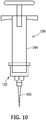
- a sub-assembly generally designated by 152, comprising the needle and a cartridge (not shown) separates from the barrel 154 so the needle 102 and cartridge C can be discarded.
- the sub-assembly 152 may be fastened to the barrel 154 in any conventional way, such as by a press fit connection as shown in Fig. 10 .
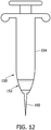
- the subassembly 152 may be fastened to the barrel 154 by a pin 156 that can be removed as shown in Figs. 11a-d .
- the sub-assembly 152 is threadably connected to the barrel 154 of the syringe assembly 150.
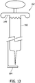
- the disposable portion need not only include a distal portion of a barrel, but may also include a longer portion of the barrel 160 as in a syringe assembly, generally designated by 162 in Fig. 13 .
- a distal end of the barrel may include flexible leaves (similar to the leaves described below with respect to Fig. 18 ) so the sub-assembly can be ejected through the barrel by pushing the plunger rod. It is envisioned that a spring could be incorporated in the syringe assembly to aid ejection of the sub-assembly.
- the syringe assembly designated by 162 in Fig. 13 also includes other features of interest.
- the syringe assembly 162 includes a needle guard 164 extending from the barrel 160 to a position beyond the needle 102. It is envisioned that this guard 164 can be folded so its distal end lies adjacent a finger flange 166 when the assembly is ready to use. When injection is complete, the guard 164 could be released permitting it to return to the unfolded configuration in which it could provide protection against inadvertent needle sticks. Further, the guard 164 may be made in a contrasting color so that flashback or aspirate is more apparent. The contrasting colors may include phosphorescent coloring. Alternatively, the barrel may be light transmitting or include back lighting or front lighting to further improve visibility of aspirate or flashback.
- Figs. 14a-c illustrate an alternate embodiment of a syringe assembly, generally designated by 170, having a needle guard 172.
- the guard 172 is pulled proximally onto the syringe body 174.
- the guard is pushed distally over the needle 102 as shown in Fig. 14c .
- needle guards aid in preventing inadvertent needle stabs.
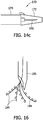
- FIG. 15 illustrates an embodiment of a delivery needle 180 having multiple openings 182 along its length for spreading the anesthetic over a broader area of tissue.
- Fig. 16 illustrates yet another embodiment, in which thin fibers 184 are extended from the needle 186. The fibers 184 fan out and cause multiple punctures in the patient's tissue that may be flooded with anesthetic so the tissue receives anesthetic over a broad area.
- the fibers 184 may be made more flexible than the delivery needle but have sufficient rigidity to allow them to penetrate the tissue as they extend out of the needle 186.
- the fibers are solid rather than hollow, leaving puncture holes that can be flooded with anesthetic. It is believed that multiple injection sites could reduce discomfort by reducing forces applied to each site.
- the syringe assembly may be colored to blend with the user's gloves, thereby camouflaging the syringe assembly.
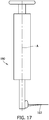
- the delivery needle 102 may be configured to extend perpendicular to a primary axis A of the syringe assembly, generally designated by 190, as illustrated in Fig 17 . This form factor may mimic other dental tools, such as water syringes, to reduce a likelihood recognition by the patient.
- Fig. 18 illustrates an automatically sizing thumb ring 200 that may be incorporated in any of the embodiments described above.
- the thumb ring 200 includes an elastomeric panel 202 extending across its central opening 204.
- the panel 202 includes spaced radially extending slots 206, forming leaves 208 in the panel that are separately deformed when the user's thumb is inserted in the ring 200.
- the leaves 208 of the panel 202 are biased toward the thumb, providing an appropriate fit.
- the thumb ring may be comprised of two halves ratcheted together. In one embodiment, ratchet teeth on one half operatively engage ratchet teeth on the other half of the thumb ring.
- the two halves may be compressed toward one another and locked via the ratchets to reduce the internal size of the thumb ring. Similarly, the two halves may be expanded and locked via ratchets to increase the internal size of the thumb ring.
- This automatically sizing thumb ring permits users having smaller and weaker hands to use the syringe.
- the ratchet locking mechanism of the thumb ring allows the user to both advance and retract the plunger rod without repositioning the hand.
- An alternate embodiment of a syringe assembly designated generally by 210 in Fig. 19 , includes a plunger rod 212 having an elastomeric foam ball 214 in place of the conventional thumb ring.
- Elastomeric ball 214 may have any size and shape to conform to a user's hand, such as round or oval. It is believed such a configuration would provide a less intimidating form factor and provide a more universal fit for users.
- the elastomeric foam ball and plunger rod are replaced with an elastomeric hollow bulb that is squeezed to pressurize the anesthetic so that it is ejected from the delivery needle 102. It is believed this alternate embodiment would provide a smooth and continuous flow of anesthetic to the patient because the bulb would dampen pressure changes, as well as provide a less intimidating form factor and a more universal fit for users.
- Fig. 20 shows an accumulator element, generally designated by 220, that could be incorporated in different locations of a syringe assembly.
- the element 220 is used along a hollow passage to minimize pressure changes.
- a hole 222 is provided along the passage and an elastomeric balloon or bulb 224 is positioned around the area of the passage having the hole.
- the balloon or bulb 224 provides an elastomeric fluid accumulator.
- the accumulator expands and contracts to absorb and release fluid as pressure varies in the passage.
- anesthetic may be delivered at a more constant pressure, thereby potentially reducing discomfort of the patient.
- a damper could be formed along the plunger rod to accomplish a similar result.
- a hole 222 is provided along the passage and an elastomeric balloon or bulb 224 is positioned around the area of the passage having the hole.
- the balloon or bulb 224 provides an elastomeric fluid accumulator.
- anesthetic is delivered through the passage, the accumulator expands and contracts to absorb and release fluid as pressure varies in the passage.
- anesthetic may be delivered at a more constant pressure, thereby potentially reducing discomfort of the patient.
- a damper could be formed along the plunger rod to accomplish a similar result.
Description
- This application claims priority to
U.S. Patent Application 61/471,903 filed April 5, 2011 - The present invention generally relates to devices for injecting liquid medications from prefilled cartridges and more particularly to single use disposable syringe assemblies for injecting local anesthetics.
- Many dental procedures use anesthetic to numb an area of a patient's mouth to reduce pain and discomfort a patient may feel. Conventionally, a re-usable breech-loading, metallic, cartridge-type syringe assembly is used to inject the anesthetic. The dental syringe assembly includes a syringe, a cartridge, and a needle. The syringe may be constructed of chrome-plated brass and stainless steel and may include a needle adapter, a syringe barrel, a plunger rod, a finger grip, and a thumb ring. Typically, the syringe must be sterilized before each use.
- Generally, the cartridge or carpule is a vial containing a local anesthetic among other ingredients. The cartridge may include a glass cylinder, a piston, and a rubber diaphragm held in position by an aluminum band. The cartridge is usually wiped with alcohol prior to being loaded into the syringe.
- The needle of the dental syringe permits local anesthetic to travel from the dental cartridge into tissue surrounding the needle tip. Needles may be pre-sterilized and disposable. The needle may consist of a single piece of metal tubing surrounded by a plastic or a metal needle hub attached to the needle adapter of the syringe.
- Assembly of a dental syringe often requires removing a sterilized syringe from its container and placing an alcohol wiped cartridge into the syringe with the plunger rod of the syringe fully retracted. The rubber diaphragm on a distal end of the cartridge is inserted into the syringe first and the plunger rod engages the piston positioned at a proximal end of the cartridge. The syringe includes an access needle for puncturing the cartridge. As the plunger rod advances, anesthetic is forced out of the cartridge toward a need assembly. The needle assembly including a needle and protective cap may be secured to the syringe. The protective cap is removed from the needle and the syringe is ready for use.
- After the assembled dental syringe is used, the needle assembly must be recapped, disconnected from the syringe and disposed in a sharps container, and the cartridge must be removed and disposed in a biohazard bag or sharps container. Thereafter, the syringe may be sterilized for its next use.
- Examples of known syringes are described in
US2002147430 ,US2007060897 ,US4820275 ,EP2058020 ,US5542934 andJPH067746U - The present invention includes a syringe assembly for dispensing medicine from a cartridge having a diaphragm and a piston opposite the diaphragm. The assembly comprises a barrel having a hollow interior, an open proximal end extending into the hollow interior, a closed distal end opposite the proximal end, and an outlet adapted for fluid communication with a delivery needle for delivering medicine to tissue of a subject. The assembly also includes a cartridge receiver slidably receivable in the hollow interior of the barrel. The cartridge receiver includes an interior space sized and shaped for receiving the cartridge, an access needle extending into the interior space of the cartridge receiver for puncturing the diaphragm of the cartridge received in the interior space to access medicine. The access needle directs fluid to the barrel outlet when the cartridge receiver is received in the hollow interior of the barrel. The cartridge receiver further comprises a plunger rod movable into the interior space of the cartridge receiver for engaging the piston of the cartridge received in the receiver to selectively force medicine in the cartridge through the access needle. The cartridge receiver includes a cartridge receiver thumb ring for manipulating the assembly when dispensing medicine from the cartridge. The plunger rod includes a plunger rod thumb ring for manipulating the assembly when dispensing medicine from the cartridge, said cartridge receiver thumb ring and said plunger rod diaphragm is pierced by the access handle. The cartridge receiver further comprises a plunger rod movable thumb ring being concentrically aligned when the cartridge is in the interior space of the cartridge receiver, the access needle is fully inserted in the diaphragm of the cartridge, and the plunger rod is engaging the piston of the cartridge.
- Other aspects of the present invention will be apparent in view of the following description and claims.
-
-
Fig. 1a is a side elevation in partial section of a syringe assembly of a first embodiment of the present invention shown in a first position; -
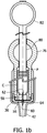
Fig. 1b is a side elevation in partial section of the syringe assembly ofFig. 1a shown in a second position; -
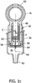
Fig. 1c is a side elevation in partial section of the syringe assembly ofFig. 1a shown in a third position; -
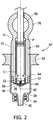
Fig. 2 is a side elevation in partial section of the syringe assembly of a second embodiment; -
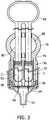
Fig. 3 is a side elevation in partial section of the syringe assembly of a third and fourth embodiment; -
Figs. 4a and 4b are schematic cross sections of the assemblies of the third and fourth embodiments; -
Fig. 5 is a side elevation a syringe assembly of a fifth embodiment of the present invention; -
Fig. 6 is a side elevation of a syringe assembly of a sixth embodiment of the present invention; -
Figs. 7-10 ,11a-d ,12 , and13 are side elevations of various alternative embodiments of the present invention; -
Fig. 14a-c are perspectives of a syringe assembly having a needle guard; -
Fig. 15 is a side elevation of a needle of one embodiment of the present invention; -
Fig. 16 is a side elevation of a needle of an alternate embodiment of the present invention; -
Fig. 17 is a side elevation of a syringe assembly of another embodiment of the present invention; -
Fig. 18 is a side elevation of a thumb ring of a syringe assembly of another embodiment of the present invention; -
Fig. 19 is a side elevation of a syringe
assembly of yet another embodiment of the present invention; and -
Fig. 20 is a schematic elevation of a portion of a syringe assembly of the present invention. - Corresponding reference characters indicate corresponding parts throughout the drawings.
- Referring to
Fig. 1a , a syringe assembly of a first embodiment is designated in its entirety by thereference number 30. Thesyringe assembly 30 includes abarrel 32 having aninner wall 34 defining ahollow interior 36 having a closeddistal end 38 and an open proximal end (not shown) opposite the closed end. Anoutlet 42 is provided in theclosed end 38 of thebarrel 32. A conventional deliver needle may be attached to theoutlet 42. - In addition, the
syringe assembly 30 includes a cartridge receiver, generally designated by 50, slidably received in thebarrel 32. Thecartridge receiver 50 includes aninterior wall 52 defining ainterior space 54 sized and shaped for receiving a conventional cartridge C containing medicine (e.g., anesthetic). Thecartridge receiver 50 includes a removable distal cap or cover 56 having anaccess needle 58. Theaccess needle 58 includes adistal delivery point 60 and a sharpproximal access point 62 adapted to penetrate a diaphragm D of the cartridge C. Anelastomeric seal 64 surrounds thecap 56 for sealingly engaging theinner wall 34 of thebarrel 32. Anouter surface 70 of thecartridge receiver 50 includes spacedribs 72 for guiding the receiver as it reciprocates in thebarrel 32. A proximal end of thereceiver 50 includes scallopedsides 74 for receiving fingers of the user. Further, the proximal end of thereceiver 50 includes anouter thumb ring 76 that is used when thesyringe assembly 30 is readied for injection as will be explained in detail below. - A
plunger rod 80 extends inside the cartridge receiver and engages a piston P on the cartridge C. A proximal end of theplunger rod 80 includes athumb ring 82. Theplunger rod 80 extends through anopening 84 in thethumb ring 76 of thecartridge receiver 50. As shown inFig. 1b , a user prepares the cartridge C for use by pushing theplunger rod 80 distally to engage theaccess tip 60 of theaccess needle 58 with the diaphragm D of the cartridge C. Once in this position, thecartridge receiver 50 may be drawn proximally relative to theplunger rod 80 until the thumb rings 82, 76 of theplunger rod 80 andcartridge receiver 50, respectively, overlap as shown inFig 1c . This action drives the piston P distally in the cartridge C, forcing medicine through theaccess needle 58 and into thehollow interior 36 of thebarrel 32. Once in this position, thecartridge receiver 50 andplunger rod 80 are moved together in a distal direction to eject the medicine from thebarrel 32 through theoutlet 42 and into a delivery needle (not shown). - A second embodiment of a syringe assembly 30' of the present invention is shown in
Fig. 2 . Rather than having aseparate cap 56, thecartridge receiver 50 has a unitary cap andseal 64. Further, anaccess adapter 90 having anaccess needle 58 is positioned on the cartridge C. Thebarrel 32 is provided with afinger flange 92 and aluer lock tip 94. Because other physical characteristics of this embodiment are similar to those previously described, they will not be described in further detail. - In a third embodiment of the present invention shown in
Fig. 3 , thecartridge receiver 50 is adapted for receiving two cartridges C simultaneously. Further, the third embodiment has tworods 80. Other features of the third embodiment are similar to those of the first embodiment described above and will not be described in further detail. A schematic cross section of the syringe assembly of the third embodiment is shown inFig. 4a . As will be appreciated by those skilled in the art, thecartridge receiver 50 may be adapted to receive three cartridges C as shown in a schematic cross section of the syringe assembly of a fourth embodiment shown inFig. 4b . This embodiment includes three access needles (not shown) extending through the cap of the receiver and three plunger rods (not shown) adapted to engage the respective seals of the cartridges C. Those skilled in the art will appreciate that still other embodiments adapted for receiving still more cartridges are also within the scope of the present invention. - In a fifth embodiment illustrated in
Fig. 5 , asyringe assembly 30" includes a polished or convexannular ring 100 surrounding an exterior wall of thebarrel 32". Thisconvex ring 100 magnifies the contents of thebarrel 32". Thus, a user can more readily identify aspirate or flashback flowing backward through thedelivery needle 102 and into the syringe assembly 30''. As other aspects of this embodiment are generally similar to those described above, they will not be described. -
Fig. 6 illustrates a sixth embodiment of asyringe assembly 30"' of the present invention. In some instances patients become anxious upon seeing a needle of the syringe. To prevent the patient from seeing theneedle 102, anelastomeric sleeve 110 is fastened over the delivery needle of thesyringe assembly 30"'. When the syringe assembly 30'" is armed, the plunger rod 80'" forces thedelivery needle 102 through theelastomeric sheath 110, exposing the needle for use. Other aspects of this embodiment are similar to those described above and will not be described. - Various portions of the syringe assembly may be made reusable to minimize waste. By selectively choosing the portions of the syringe assembly that are disposable, the need for sterilization may be minimized or eliminated. For example, in one embodiment illustrated in
Fig. 7 , a seventh embodiment of a syringe assembly, generally designated by 120, includes aquick release coupling 122 that holds theneedle 102 in place. When a user is finished using thesyringe assembly 120, thecoupling 122 is disconnected so theneedle 102 can be discarded. In some alternate embodiments having the needle and cartridge joined as a sub-assembly, releasing thecoupling 122 can operate to eject the entire sub-assembly. It is envisioned that an element could be included on a sharps container for disconnecting thecoupling 122. - In another embodiment of a syringe assembly, generally designated by 130 in
Fig. 8 , abarrel 132 separates so theneedle 102 and cartridge C can be discarded. Likewise, in another embodiment of a syringe assembly, generally designated by 140 inFig. 9 , aplunger rod 142 separates to release the needle and cartridge C. In an embodiment of a syringe assembly, generally designated by 150 inFig. 10 , a sub-assembly, generally designated by 152, comprising the needle and a cartridge (not shown) separates from thebarrel 154 so theneedle 102 and cartridge C can be discarded. The sub-assembly 152 may be fastened to thebarrel 154 in any conventional way, such as by a press fit connection as shown inFig. 10 . Alternatively, thesubassembly 152 may be fastened to thebarrel 154 by apin 156 that can be removed as shown inFigs. 11a-d . In still another embodiment shown inFig. 12 , thesub-assembly 152 is threadably connected to thebarrel 154 of thesyringe assembly 150. As will be appreciated by those skilled in the art, the disposable portion need not only include a distal portion of a barrel, but may also include a longer portion of thebarrel 160 as in a syringe assembly, generally designated by 162 inFig. 13 . In another embodiment (not shown), a distal end of the barrel may include flexible leaves (similar to the leaves described below with respect toFig. 18 ) so the sub-assembly can be ejected through the barrel by pushing the plunger rod. It is envisioned that a spring could be incorporated in the syringe assembly to aid ejection of the sub-assembly. - The syringe assembly designated by 162 in
Fig. 13 also includes other features of interest. In particular, thesyringe assembly 162 includes aneedle guard 164 extending from thebarrel 160 to a position beyond theneedle 102. It is envisioned that thisguard 164 can be folded so its distal end lies adjacent afinger flange 166 when the assembly is ready to use. When injection is complete, theguard 164 could be released permitting it to return to the unfolded configuration in which it could provide protection against inadvertent needle sticks. Further, theguard 164 may be made in a contrasting color so that flashback or aspirate is more apparent. The contrasting colors may include phosphorescent coloring. Alternatively, the barrel may be light transmitting or include back lighting or front lighting to further improve visibility of aspirate or flashback. -
Figs. 14a-c illustrate an alternate embodiment of a syringe assembly, generally designated by 170, having aneedle guard 172. Before use, theguard 172 is pulled proximally onto thesyringe body 174. After use, the guard is pushed distally over theneedle 102 as shown inFig. 14c . As will be appreciated by those skilled in the art, needle guards aid in preventing inadvertent needle stabs. - In some dental operations, anesthetic is desired over a broad area of tissue. Pulling a needle out of tissue and repositioning it to inject anesthetic in a different area can be painful for the patient. Thus, there is a need for a dental syringe that is capable of spreading anesthetic from a single injection site.
Fig. 15 illustrates an embodiment of adelivery needle 180 havingmultiple openings 182 along its length for spreading the anesthetic over a broader area of tissue.Fig. 16 illustrates yet another embodiment, in whichthin fibers 184 are extended from theneedle 186. Thefibers 184 fan out and cause multiple punctures in the patient's tissue that may be flooded with anesthetic so the tissue receives anesthetic over a broad area. It is envisioned that thefibers 184 may be made more flexible than the delivery needle but have sufficient rigidity to allow them to penetrate the tissue as they extend out of theneedle 186. In one embodiment, the fibers are solid rather than hollow, leaving puncture holes that can be flooded with anesthetic. It is believed that multiple injection sites could reduce discomfort by reducing forces applied to each site. - As previously mentioned, some patients become agitated or anxious at the sight of a conventional aspirating syringe. In order to provide less intimidating form factors for syringe assemblies, various modifications can be made to their configurations and appearance. For example, the syringe assembly may be colored to blend with the user's gloves, thereby camouflaging the syringe assembly. Alternately, the
delivery needle 102 may be configured to extend perpendicular to a primary axis A of the syringe assembly, generally designated by 190, as illustrated inFig 17 . This form factor may mimic other dental tools, such as water syringes, to reduce a likelihood recognition by the patient. -
Fig. 18 illustrates an automatically sizingthumb ring 200 that may be incorporated in any of the embodiments described above. Thethumb ring 200 includes anelastomeric panel 202 extending across itscentral opening 204. Thepanel 202 includes spaced radially extendingslots 206, formingleaves 208 in the panel that are separately deformed when the user's thumb is inserted in thering 200. As will be appreciated by those skilled in the art, theleaves 208 of thepanel 202 are biased toward the thumb, providing an appropriate fit. Alternatively, the thumb ring may be comprised of two halves ratcheted together. In one embodiment, ratchet teeth on one half operatively engage ratchet teeth on the other half of the thumb ring. The two halves may be compressed toward one another and locked via the ratchets to reduce the internal size of the thumb ring. Similarly, the two halves may be expanded and locked via ratchets to increase the internal size of the thumb ring. This automatically sizing thumb ring permits users having smaller and weaker hands to use the syringe. The ratchet locking mechanism of the thumb ring allows the user to both advance and retract the plunger rod without repositioning the hand. - An alternate embodiment of a syringe assembly, designated generally by 210 in
Fig. 19 , includes aplunger rod 212 having anelastomeric foam ball 214 in place of the conventional thumb ring.Elastomeric ball 214 may have any size and shape to conform to a user's hand, such as round or oval. It is believed such a configuration would provide a less intimidating form factor and provide a more universal fit for users. In an alternate embodiment, the elastomeric foam ball and plunger rod are replaced with an elastomeric hollow bulb that is squeezed to pressurize the anesthetic so that it is ejected from thedelivery needle 102. It is believed this alternate embodiment would provide a smooth and continuous flow of anesthetic to the patient because the bulb would dampen pressure changes, as well as provide a less intimidating form factor and a more universal fit for users. -
Fig. 20 shows an accumulator element, generally designated by 220, that could be incorporated in different locations of a syringe assembly. Theelement 220 is used along a hollow passage to minimize pressure changes. Ahole 222 is provided along the passage and an elastomeric balloon orbulb 224 is positioned around the area of the passage having the hole. The balloon orbulb 224 provides an elastomeric fluid accumulator. As anesthetic is delivered through the passage, the accumulator expands and contracts to absorb and release fluid as pressure varies in the passage. Thus, anesthetic may be delivered at a more constant pressure, thereby potentially reducing discomfort of the patient. It is envisioned that a damper could be formed along the plunger rod to accomplish a similar result. - Having described the invention in detail, it will be apparent that modifications and variations are possible without departing from the scope of the invention defined in the appended claims.
- When introducing elements of the present invention or the preferred embodiment(s) thereof, the articles "a", "an", "the", and "said" are intended to mean that there are one or more of the elements. The terms "comprising", "including", and "having" are intended to be inclusive and mean that there may be additional elements other than the listed elements.
- As various changes could be made in the above constructions, products, and methods without departing from the scope of the invention, it is intended that all matter contained in the above description and shown in the accompanying drawings shall be interpreted as illustrative and not in a limiting sense. along a hollow passage to minimize pressure changes. A
hole 222 is provided along the passage and an elastomeric balloon orbulb 224 is positioned around the area of the passage having the hole. The balloon orbulb 224 provides an elastomeric fluid accumulator. As anesthetic is delivered through the passage, the accumulator expands and contracts to absorb and release fluid as pressure varies in the passage. Thus, anesthetic may be delivered at a more constant pressure, thereby potentially reducing discomfort of the patient. It is envisioned that a damper could be formed along the plunger rod to accomplish a similar result. - Having described the invention in detail, it will be apparent that modifications and variations are possible without departing from the scope of the invention defined in the appended claims.
- When introducing elements of the present invention or the preferred embodiment(s) thereof, the articles "a", "an", "the", and "said" are intended to mean that there are one or more of the elements. The terms "comprising", "including", and "having" are intended to be inclusive and mean that there may be additional elements other than the listed elements.
- As various changes could be made in the above constructions, products, and methods without departing from the scope of the invention, it is intended that all matter contained in the above description and shown in the accompanying drawings shall be interpreted as illustrative and not in a limiting sense.
Claims (17)
- A syringe assembly for dispensing medicine from a cartridge (C) having a diaphragm (D) and a piston (P) opposite the diaphragm (D), said assembly comprising:a barrel (32) having a hollow interior (36), an open proximal end extending into the hollow interior (36), a closed distal end (38) opposite the proximal end, and an outlet (42) adapted for fluid communication with a delivery needle (102) for delivering medicine to tissue of a subject; anda cartridge receiver (50) slidably receivable in the hollow interior (36) of the barrel (32), the cartridge receiver (50) including an interior space (54) sized and shaped for receiving the cartridge (C), an access needle (58) extending into the interior space (54) of the cartridge receiver (50) for puncturing the diaphragm (D) of the cartridge (C) received in the interior space (54) to access medicine therein, the access needle (58) directing fluid to the barrel outlet (42) when the diaphragm (D) is pierced by the access needle (58), anda plunger rod (80) movable into the interior space (54) of the cartridge receiver (50) for engaging the piston of the cartridge (C) received in the receiver to selectively force medicine in the cartridge (C) through the access needle (58),characterised in thatthe cartridge receiver (50) includes a cartridge receiver thumb ring (76) for manipulating the assembly when dispensing medicine from the cartridge (C), and in thatthe plunger rod (80) includes a plunger rod thumb ring (82) for manipulating the assembly when dispensing medicine from the cartridge (C), said cartridge receiver thumb ring (76) and said plunger rod thumb ring (82) being concentrically aligned when the cartridge (C) is in the interior space (54) of the cartridge receiver (50), the access needle (58) is fully inserted in the diaphragm (D) of the cartridge (C), and the plunger rod (80) is engaging the piston (P) of the cartridge (C).
- A syringe assembly (30) as set forth in claim 1, wherein the cartridge receiver (50) includes an opening for loading the cartridge (C) into the interior space (54) of the cartridge receiver (50) and a cover (56) for selectively covering the opening to retain the cartridge (C) in the interior space (54).
- A syringe assembly (30) as set forth in claim 2, wherein the cover (56) includes the access needle (58).
- A syringe assembly (30) as set forth in claim 3, wherein the cartridge receiver (50) further includes a seal (64) for engaging the barrel (32) to seal (64) an interface between the cartridge receiver (50) and the barrel (32).
- A syringe assembly (30) as set forth in claim 1, wherein a plurality of leaves (208) extend into the thumb ring (76) to engage a thumb inserted in the ring (76).
- A syringe assembly (30) as set forth in claim 1, wherein the cartridge receiver (50) interior space (54) is sized and shaped for receiving a plurality of cartridges (C), the cartridge receiver (50) has a plurality of access needles (58) corresponding to the plurality of cartridges (C) so each of the access needle (58) punctures one of the cartridge (C) diaphragms (D), and the cartridge receiver (50) has a plurality of plunger rods (80) corresponding to the plurality of cartridges (C) so each of the plunger rods (80) engages one of the cartridge (C) pistons (P) to selectively force medicine from each of the plurality of cartridges through the corresponding access needle (58).
- A syringe assembly (30) as set forth in claim 6, wherein the plunger rods (80) are joined by a common thumb ring (82) so the plunger rods (80) move simultaneously.
- A syringe assembly (30) as set forth in claim 1, wherein the barrel (32) is separable, allowing the barrel (32) to be discarded separately from the cartridge (C) and needle.
- A syringe assembly (30) as set forth in claim 1, further comprising a delivery needle (102) downstream from the access needle (58) for delivering medicine to tissue of a subject.
- A syringe assembly (30) as set forth in claim 9, further comprising a retractable needle guard (164) selectively retractable from an extended position in which the guard (164) limits access to the delivery needle (102) to prevent inadvertent sticks to a retracted position in which the guard (164) permits access to the delivery needle (102) to permit insertion of the delivery needle (102) into tissue of the subject.
- A syringe assembly (30) as set forth in claim 9, wherein the needle (102) extends perpendicular to the barrel (32) .
- A syringe assembly (30) as set forth in claim 9, wherein the delivery needle (102) includes a plurality of openings (182) for delivering medicine to tissue of a subject.
- A syringe assembly (30) as set forth in claim 1, wherein the cartridge receiver (50) includes an elastomeric body (202) positioned on a proximal end of the plunger rod (80) for manipulating the plunger rod (80) when dispensing medicine from the cartridge (C).
- A syringe assembly (30) as set forth in claim 1, wherein the barrel (32) includes an annular lens (100) surrounding the barrel (32) to magnify contents of the barrel (32).
- A syringe assembly (30) as set forth in claim 1, further comprising an elastomeric fluid accumulator (220) downstream from the cartridge (C) absorbing and releasing fluid as pressure varies in the accumulator (220) to provide the medicine at an invariant pressure.
- The syringe assembly (30) as set forth in claim 1, further comprising an elastomeric sleeve (110) positioned over the delivery needle.
- The syringe assembly (30) as set forth in claim 1, further comprising an elastomeric foam ball (214) attached to an end of the plunger rod (80).
Applications Claiming Priority (1)
| Application Number | Priority Date | Filing Date | Title |
|---|---|---|---|
| US201161471903P | 2011-04-05 | 2011-04-05 |
Publications (3)
| Publication Number | Publication Date |
|---|---|
| EP2508217A2 EP2508217A2 (en) | 2012-10-10 |
| EP2508217A3 EP2508217A3 (en) | 2014-10-01 |
| EP2508217B1 true EP2508217B1 (en) | 2019-09-04 |
Family
ID=46000785
Family Applications (1)
| Application Number | Title | Priority Date | Filing Date |
|---|---|---|---|
| EP12162966.1A Active EP2508217B1 (en) | 2011-04-05 | 2012-04-03 | Anesthetic syringe |
Country Status (5)
| Country | Link |
|---|---|
| US (2) | US9289272B2 (en) |
| EP (1) | EP2508217B1 (en) |
| JP (3) | JP5559831B2 (en) |
| AU (1) | AU2012201968B2 (en) |
| CA (1) | CA2773271C (en) |
Families Citing this family (7)
| Publication number | Priority date | Publication date | Assignee | Title |
|---|---|---|---|---|
| US20150056718A1 (en) * | 2013-08-23 | 2015-02-26 | Sylvia Maria Cuttino | Dual syringe |
| KR101462438B1 (en) * | 2013-11-07 | 2014-11-17 | 주식회사 메가젠임플란트 | Apparatus for injecting medicine |
| AU2016277481B2 (en) | 2015-06-12 | 2020-06-11 | Becton Dickinson France | Adaptor for a drug delivery device and drug delivery device |
| KR101726196B1 (en) * | 2016-09-05 | 2017-04-26 | 박창순 | A syringe for reducing pain |
| WO2018148434A1 (en) | 2017-02-08 | 2018-08-16 | Veran Medical Technologies, Inc. | Localization needle |
| KR20200039668A (en) | 2017-08-09 | 2020-04-16 | 가부시키가이샤 시세이도 | Discharge container, customized discharge system having discharge container, and discharge control method in discharge container |
| CN109395228B (en) * | 2018-11-23 | 2020-12-15 | 王敏 | Portable field exploration wound local anesthesia ware |
Citations (1)
| Publication number | Priority date | Publication date | Assignee | Title |
|---|---|---|---|---|
| JPH067746U (en) * | 1992-06-30 | 1994-02-01 | テルモ株式会社 | Syringe |
Family Cites Families (37)
| Publication number | Priority date | Publication date | Assignee | Title |
|---|---|---|---|---|
| US1234582A (en) * | 1916-12-14 | 1917-07-24 | Barclay T Trueblood | Hypodermic syringe. |
| US1798117A (en) * | 1930-05-02 | 1931-03-24 | Macgregor Instr Company | Syringe |
| US2939459A (en) * | 1957-01-11 | 1960-06-07 | Jorge A Lazarte | Tandem syringe |
| US3074541A (en) * | 1959-10-13 | 1963-01-22 | Brunswick Corp | Medicinal vial and needle assembly |
| US3110309A (en) * | 1960-08-15 | 1963-11-12 | Brunswick Corp | Plastic cartridge needle assembly |
| US3316909A (en) * | 1963-12-30 | 1967-05-02 | Pharmaseal Lab | Hypodermic syringe operable by one hand |
| US3380450A (en) * | 1965-05-10 | 1968-04-30 | William H. Adelberger | Sterile disposable plastic prefilled syringe |
| US3785379A (en) * | 1971-08-12 | 1974-01-15 | M Cohen | Syringe for injection of freshly mixed liquid-powder |
| US3811441A (en) * | 1972-02-10 | 1974-05-21 | Survival Technology | Cartridge syringe |
| US3939833A (en) * | 1975-01-15 | 1976-02-24 | Astra Pharmaceutical Products Inc. | Piston construction for syringes |
| US4109653A (en) * | 1977-02-22 | 1978-08-29 | George Kozam | Successive delivery multiple barrel syringe |
| US4171698A (en) | 1977-08-15 | 1979-10-23 | Abbott Laboratories | Prefilled two-compartment syringe |
| JPS5519660U (en) * | 1978-07-27 | 1980-02-07 | ||
| JPH0336360Y2 (en) * | 1980-04-08 | 1991-08-01 | ||
| EP0139872A1 (en) | 1983-08-18 | 1985-05-08 | Abbott Laboratories | Flashback indicating system |
| US4861335A (en) * | 1985-07-26 | 1989-08-29 | Duoject Medical Systems Inc. | Syringe |
| US4820275A (en) * | 1987-12-21 | 1989-04-11 | Habley Medical Technology Corporation | Retractable needle syringe with integral spring |
| IT218502Z2 (en) * | 1989-01-16 | 1992-05-27 | Guerci Sergio | SYRINGE FOR THE WASHING OF THE ROOT CANALS OF THE TEETH |
| US5281198A (en) * | 1992-05-04 | 1994-01-25 | Habley Medical Technology Corporation | Pharmaceutical component-mixing delivery assembly |
| US5476449A (en) * | 1992-12-28 | 1995-12-19 | Richmond; Frank M. | Needleless multi-liquid medicament delivery system with membranes |
| GB9323447D0 (en) | 1993-11-13 | 1994-01-05 | Seldoren Ltd | Syringes |
| EP0727187B1 (en) | 1995-02-15 | 2003-08-06 | Joseph Eldor | Multiple hole spinal needle |
| US5785682A (en) * | 1995-03-22 | 1998-07-28 | Abbott Laboratories | Pre-filled syringe drug delivery system |
| US5542934A (en) * | 1995-06-02 | 1996-08-06 | Silver; Richard M. | Multiple carpule hypodermic syringe |
| US6117144A (en) * | 1995-08-24 | 2000-09-12 | Sutura, Inc. | Suturing device and method for sealing an opening in a blood vessel or other biological structure |
| US5833668A (en) * | 1996-11-21 | 1998-11-10 | Aguilar; David G. | Hypodermic syringe |
| FR2764193B1 (en) * | 1997-06-09 | 1999-10-08 | Sofic | IMPROVED INJECTION SYRINGE COMPRISING SUCTION MEANS |
| US6086569A (en) * | 1999-05-04 | 2000-07-11 | Schweizer; Kenneth M. | Hypodermic syringe |
| AU5774500A (en) | 1999-06-30 | 2001-01-31 | Baxter International Inc. | Syringe for transfer of medication from a prefilled medication container |
| US6719736B2 (en) * | 2001-04-06 | 2004-04-13 | Margie M. Collins | Dental syringe with disposable needle assembly and reusable plunger assembly |
| TW475449U (en) | 2001-05-22 | 2002-02-01 | Chiou Jiu Chuen | Rotation sleeve control type pull-back safe injector |
| US7291131B2 (en) * | 2003-05-05 | 2007-11-06 | Physicians Industries, Inc. | Infusion syringe |
| JP2007526023A (en) * | 2003-10-24 | 2007-09-13 | エム ディー シー インベストメント ホールディングス インコーポレイテッド | Dual chamber mixing syringe and method of using the same |
| EP1843812A4 (en) * | 2005-02-01 | 2008-12-03 | Intelliject Llc | Devices, systems, and methods for medicament delivery |
| US8529517B2 (en) * | 2005-05-02 | 2013-09-10 | Shi Zi Technology, Ltd. | Autoflush syringe |
| US20070060897A1 (en) * | 2005-09-02 | 2007-03-15 | Wang Hsien T | Disposable safety syringe for dispensing anesthetic |
| CN101130120A (en) | 2006-08-24 | 2008-02-27 | 郑万章 | Portion abandoning type tube needle bed of agent |
-
2012
- 2012-04-03 EP EP12162966.1A patent/EP2508217B1/en active Active
- 2012-04-03 CA CA2773271A patent/CA2773271C/en not_active Expired - Fee Related
- 2012-04-04 JP JP2012085741A patent/JP5559831B2/en not_active Expired - Fee Related
- 2012-04-04 US US13/438,853 patent/US9289272B2/en not_active Expired - Fee Related
- 2012-04-04 AU AU2012201968A patent/AU2012201968B2/en not_active Ceased
-
2014
- 2014-06-06 JP JP2014117405A patent/JP5990221B2/en not_active Expired - Fee Related
- 2014-08-28 JP JP2014173783A patent/JP2014217788A/en active Pending
-
2016
- 2016-03-21 US US15/075,277 patent/US20160271328A1/en not_active Abandoned
Patent Citations (1)
| Publication number | Priority date | Publication date | Assignee | Title |
|---|---|---|---|---|
| JPH067746U (en) * | 1992-06-30 | 1994-02-01 | テルモ株式会社 | Syringe |
Also Published As
| Publication number | Publication date |
|---|---|
| US20120258421A1 (en) | 2012-10-11 |
| EP2508217A2 (en) | 2012-10-10 |
| JP2014193397A (en) | 2014-10-09 |
| CA2773271A1 (en) | 2012-10-05 |
| US20160271328A1 (en) | 2016-09-22 |
| EP2508217A3 (en) | 2014-10-01 |
| AU2012201968B2 (en) | 2013-06-20 |
| JP5559831B2 (en) | 2014-07-23 |
| AU2012201968A1 (en) | 2012-10-25 |
| JP2012217850A (en) | 2012-11-12 |
| JP2014217788A (en) | 2014-11-20 |
| CA2773271C (en) | 2016-10-11 |
| JP5990221B2 (en) | 2016-09-07 |
| US9289272B2 (en) | 2016-03-22 |
Similar Documents
| Publication | Publication Date | Title |
|---|---|---|
| US20160271328A1 (en) | Anesthetic Syringe | |
| CA2468213C (en) | Cannula retractable medical collection device | |
| CA2806589C (en) | Single use device for delivery of cartridge drugs | |
| CN103930141B (en) | Automatic injection device | |
| US6416323B1 (en) | Aspirating dental syringe with needle shield | |
| CN103079611B (en) | For the needle housings of safety device, safety device and injection device | |
| US5330440A (en) | Reverse thread carpule dental safety syringe | |
| AU2017375774B2 (en) | Safety needle device | |
| US20150283329A1 (en) | Medical Device with Selectively Retractable Needle Cap | |
| CA3030746A1 (en) | Self sheathing anesthetic needle with a dedicated syringe | |
| US20040243067A1 (en) | Multidiameter syringe families | |
| EP2508216B1 (en) | Medicine delivery system | |
| US20190224423A1 (en) | Syringe with adjustable needle shield | |
| WO2023194097A1 (en) | Multiple injection syringe with retractable needle and assisted needle actuation for injection and return | |
| AU2014200639B2 (en) | Single use device for delivery of cartridge drugs | |
| WO2016070265A1 (en) | Medical and dental safety syringe |
Legal Events
| Date | Code | Title | Description |
|---|---|---|---|
| PUAI | Public reference made under article 153(3) epc to a published international application that has entered the european phase |
Free format text: ORIGINAL CODE: 0009012 |
|
| 17P | Request for examination filed |
Effective date: 20120403 |
|
| AK | Designated contracting states |
Kind code of ref document: A2 Designated state(s): AL AT BE BG CH CY CZ DE DK EE ES FI FR GB GR HR HU IE IS IT LI LT LU LV MC MK MT NL NO PL PT RO RS SE SI SK SM TR |
|
| AX | Request for extension of the european patent |
Extension state: BA ME |
|
| RAP1 | Party data changed (applicant data changed or rights of an application transferred) |
Owner name: COVIDIEN LP |
|
| PUAL | Search report despatched |
Free format text: ORIGINAL CODE: 0009013 |
|
| AK | Designated contracting states |
Kind code of ref document: A3 Designated state(s): AL AT BE BG CH CY CZ DE DK EE ES FI FR GB GR HR HU IE IS IT LI LT LU LV MC MK MT NL NO PL PT RO RS SE SI SK SM TR |
|
| AX | Request for extension of the european patent |
Extension state: BA ME |
|
| RIC1 | Information provided on ipc code assigned before grant |
Ipc: A61M 5/19 20060101ALI20140822BHEP Ipc: A61M 5/315 20060101ALI20140822BHEP Ipc: A61M 5/48 20060101ALI20140822BHEP Ipc: A61M 5/31 20060101ALI20140822BHEP Ipc: A61M 5/24 20060101AFI20140822BHEP Ipc: A61M 5/34 20060101ALI20140822BHEP Ipc: A61M 5/32 20060101ALI20140822BHEP |
|
| RAP1 | Party data changed (applicant data changed or rights of an application transferred) |
Owner name: KPR U.S., LLC |
|
| STAA | Information on the status of an ep patent application or granted ep patent |
Free format text: STATUS: EXAMINATION IS IN PROGRESS |
|
| 17Q | First examination report despatched |
Effective date: 20180223 |
|
| GRAP | Despatch of communication of intention to grant a patent |
Free format text: ORIGINAL CODE: EPIDOSNIGR1 |
|
| STAA | Information on the status of an ep patent application or granted ep patent |
Free format text: STATUS: GRANT OF PATENT IS INTENDED |
|
| INTG | Intention to grant announced |
Effective date: 20190313 |
|
| GRAS | Grant fee paid |
Free format text: ORIGINAL CODE: EPIDOSNIGR3 |
|
| GRAA | (expected) grant |
Free format text: ORIGINAL CODE: 0009210 |
|
| STAA | Information on the status of an ep patent application or granted ep patent |
Free format text: STATUS: THE PATENT HAS BEEN GRANTED |
|
| AK | Designated contracting states |
Kind code of ref document: B1 Designated state(s): AL AT BE BG CH CY CZ DE DK EE ES FI FR GB GR HR HU IE IS IT LI LT LU LV MC MK MT NL NO PL PT RO RS SE SI SK SM TR |
|
| REG | Reference to a national code |
Ref country code: GB Ref legal event code: FG4D |
|
| REG | Reference to a national code |
Ref country code: CH Ref legal event code: EP |
|
| REG | Reference to a national code |
Ref country code: AT Ref legal event code: REF Ref document number: 1174469 Country of ref document: AT Kind code of ref document: T Effective date: 20190915 |
|
| REG | Reference to a national code |
Ref country code: DE Ref legal event code: R096 Ref document number: 602012063546 Country of ref document: DE |
|
| REG | Reference to a national code |
Ref country code: IE Ref legal event code: FG4D |
|
| REG | Reference to a national code |
Ref country code: NL Ref legal event code: MP Effective date: 20190904 |
|
| REG | Reference to a national code |
Ref country code: LT Ref legal event code: MG4D |
|
| PG25 | Lapsed in a contracting state [announced via postgrant information from national office to epo] |
Ref country code: FI Free format text: LAPSE BECAUSE OF FAILURE TO SUBMIT A TRANSLATION OF THE DESCRIPTION OR TO PAY THE FEE WITHIN THE PRESCRIBED TIME-LIMIT Effective date: 20190904 Ref country code: LT Free format text: LAPSE BECAUSE OF FAILURE TO SUBMIT A TRANSLATION OF THE DESCRIPTION OR TO PAY THE FEE WITHIN THE PRESCRIBED TIME-LIMIT Effective date: 20190904 Ref country code: HR Free format text: LAPSE BECAUSE OF FAILURE TO SUBMIT A TRANSLATION OF THE DESCRIPTION OR TO PAY THE FEE WITHIN THE PRESCRIBED TIME-LIMIT Effective date: 20190904 Ref country code: BG Free format text: LAPSE BECAUSE OF FAILURE TO SUBMIT A TRANSLATION OF THE DESCRIPTION OR TO PAY THE FEE WITHIN THE PRESCRIBED TIME-LIMIT Effective date: 20191204 Ref country code: SE Free format text: LAPSE BECAUSE OF FAILURE TO SUBMIT A TRANSLATION OF THE DESCRIPTION OR TO PAY THE FEE WITHIN THE PRESCRIBED TIME-LIMIT Effective date: 20190904 Ref country code: NO Free format text: LAPSE BECAUSE OF FAILURE TO SUBMIT A TRANSLATION OF THE DESCRIPTION OR TO PAY THE FEE WITHIN THE PRESCRIBED TIME-LIMIT Effective date: 20191204 |
|
| PG25 | Lapsed in a contracting state [announced via postgrant information from national office to epo] |
Ref country code: AL Free format text: LAPSE BECAUSE OF FAILURE TO SUBMIT A TRANSLATION OF THE DESCRIPTION OR TO PAY THE FEE WITHIN THE PRESCRIBED TIME-LIMIT Effective date: 20190904 Ref country code: ES Free format text: LAPSE BECAUSE OF FAILURE TO SUBMIT A TRANSLATION OF THE DESCRIPTION OR TO PAY THE FEE WITHIN THE PRESCRIBED TIME-LIMIT Effective date: 20190904 Ref country code: GR Free format text: LAPSE BECAUSE OF FAILURE TO SUBMIT A TRANSLATION OF THE DESCRIPTION OR TO PAY THE FEE WITHIN THE PRESCRIBED TIME-LIMIT Effective date: 20191205 Ref country code: LV Free format text: LAPSE BECAUSE OF FAILURE TO SUBMIT A TRANSLATION OF THE DESCRIPTION OR TO PAY THE FEE WITHIN THE PRESCRIBED TIME-LIMIT Effective date: 20190904 Ref country code: RS Free format text: LAPSE BECAUSE OF FAILURE TO SUBMIT A TRANSLATION OF THE DESCRIPTION OR TO PAY THE FEE WITHIN THE PRESCRIBED TIME-LIMIT Effective date: 20190904 |
|
| REG | Reference to a national code |
Ref country code: AT Ref legal event code: MK05 Ref document number: 1174469 Country of ref document: AT Kind code of ref document: T Effective date: 20190904 |
|
| PG25 | Lapsed in a contracting state [announced via postgrant information from national office to epo] |
Ref country code: EE Free format text: LAPSE BECAUSE OF FAILURE TO SUBMIT A TRANSLATION OF THE DESCRIPTION OR TO PAY THE FEE WITHIN THE PRESCRIBED TIME-LIMIT Effective date: 20190904 Ref country code: PL Free format text: LAPSE BECAUSE OF FAILURE TO SUBMIT A TRANSLATION OF THE DESCRIPTION OR TO PAY THE FEE WITHIN THE PRESCRIBED TIME-LIMIT Effective date: 20190904 Ref country code: IT Free format text: LAPSE BECAUSE OF FAILURE TO SUBMIT A TRANSLATION OF THE DESCRIPTION OR TO PAY THE FEE WITHIN THE PRESCRIBED TIME-LIMIT Effective date: 20190904 Ref country code: RO Free format text: LAPSE BECAUSE OF FAILURE TO SUBMIT A TRANSLATION OF THE DESCRIPTION OR TO PAY THE FEE WITHIN THE PRESCRIBED TIME-LIMIT Effective date: 20190904 Ref country code: NL Free format text: LAPSE BECAUSE OF FAILURE TO SUBMIT A TRANSLATION OF THE DESCRIPTION OR TO PAY THE FEE WITHIN THE PRESCRIBED TIME-LIMIT Effective date: 20190904 Ref country code: AT Free format text: LAPSE BECAUSE OF FAILURE TO SUBMIT A TRANSLATION OF THE DESCRIPTION OR TO PAY THE FEE WITHIN THE PRESCRIBED TIME-LIMIT Effective date: 20190904 Ref country code: PT Free format text: LAPSE BECAUSE OF FAILURE TO SUBMIT A TRANSLATION OF THE DESCRIPTION OR TO PAY THE FEE WITHIN THE PRESCRIBED TIME-LIMIT Effective date: 20200106 |
|
| PG25 | Lapsed in a contracting state [announced via postgrant information from national office to epo] |
Ref country code: SK Free format text: LAPSE BECAUSE OF FAILURE TO SUBMIT A TRANSLATION OF THE DESCRIPTION OR TO PAY THE FEE WITHIN THE PRESCRIBED TIME-LIMIT Effective date: 20190904 Ref country code: SM Free format text: LAPSE BECAUSE OF FAILURE TO SUBMIT A TRANSLATION OF THE DESCRIPTION OR TO PAY THE FEE WITHIN THE PRESCRIBED TIME-LIMIT Effective date: 20190904 Ref country code: IS Free format text: LAPSE BECAUSE OF FAILURE TO SUBMIT A TRANSLATION OF THE DESCRIPTION OR TO PAY THE FEE WITHIN THE PRESCRIBED TIME-LIMIT Effective date: 20200224 Ref country code: CZ Free format text: LAPSE BECAUSE OF FAILURE TO SUBMIT A TRANSLATION OF THE DESCRIPTION OR TO PAY THE FEE WITHIN THE PRESCRIBED TIME-LIMIT Effective date: 20190904 |
|
| REG | Reference to a national code |
Ref country code: DE Ref legal event code: R097 Ref document number: 602012063546 Country of ref document: DE |
|
| PLBE | No opposition filed within time limit |
Free format text: ORIGINAL CODE: 0009261 |
|
| STAA | Information on the status of an ep patent application or granted ep patent |
Free format text: STATUS: NO OPPOSITION FILED WITHIN TIME LIMIT |
|
| PG2D | Information on lapse in contracting state deleted |
Ref country code: IS |
|
| PG25 | Lapsed in a contracting state [announced via postgrant information from national office to epo] |
Ref country code: DK Free format text: LAPSE BECAUSE OF FAILURE TO SUBMIT A TRANSLATION OF THE DESCRIPTION OR TO PAY THE FEE WITHIN THE PRESCRIBED TIME-LIMIT Effective date: 20190904 Ref country code: IS Free format text: LAPSE BECAUSE OF FAILURE TO SUBMIT A TRANSLATION OF THE DESCRIPTION OR TO PAY THE FEE WITHIN THE PRESCRIBED TIME-LIMIT Effective date: 20200105 |
|
| PGFP | Annual fee paid to national office [announced via postgrant information from national office to epo] |
Ref country code: DE Payment date: 20200429 Year of fee payment: 9 Ref country code: FR Payment date: 20200427 Year of fee payment: 9 |
|
| 26N | No opposition filed |
Effective date: 20200605 |
|
| PG25 | Lapsed in a contracting state [announced via postgrant information from national office to epo] |
Ref country code: SI Free format text: LAPSE BECAUSE OF FAILURE TO SUBMIT A TRANSLATION OF THE DESCRIPTION OR TO PAY THE FEE WITHIN THE PRESCRIBED TIME-LIMIT Effective date: 20190904 |
|
| PGFP | Annual fee paid to national office [announced via postgrant information from national office to epo] |
Ref country code: GB Payment date: 20200427 Year of fee payment: 9 |
|
| PG25 | Lapsed in a contracting state [announced via postgrant information from national office to epo] |
Ref country code: MC Free format text: LAPSE BECAUSE OF FAILURE TO SUBMIT A TRANSLATION OF THE DESCRIPTION OR TO PAY THE FEE WITHIN THE PRESCRIBED TIME-LIMIT Effective date: 20190904 |
|
| REG | Reference to a national code |
Ref country code: CH Ref legal event code: PL |
|
| PG25 | Lapsed in a contracting state [announced via postgrant information from national office to epo] |
Ref country code: CH Free format text: LAPSE BECAUSE OF NON-PAYMENT OF DUE FEES Effective date: 20200430 Ref country code: LU Free format text: LAPSE BECAUSE OF NON-PAYMENT OF DUE FEES Effective date: 20200403 Ref country code: LI Free format text: LAPSE BECAUSE OF NON-PAYMENT OF DUE FEES Effective date: 20200430 |
|
| REG | Reference to a national code |
Ref country code: BE Ref legal event code: MM Effective date: 20200430 |
|
| PG25 | Lapsed in a contracting state [announced via postgrant information from national office to epo] |
Ref country code: BE Free format text: LAPSE BECAUSE OF NON-PAYMENT OF DUE FEES Effective date: 20200430 |
|
| PG25 | Lapsed in a contracting state [announced via postgrant information from national office to epo] |
Ref country code: IE Free format text: LAPSE BECAUSE OF NON-PAYMENT OF DUE FEES Effective date: 20200403 |
|
| REG | Reference to a national code |
Ref country code: DE Ref legal event code: R119 Ref document number: 602012063546 Country of ref document: DE |
|
| GBPC | Gb: european patent ceased through non-payment of renewal fee |
Effective date: 20210403 |
|
| PG25 | Lapsed in a contracting state [announced via postgrant information from national office to epo] |
Ref country code: GB Free format text: LAPSE BECAUSE OF NON-PAYMENT OF DUE FEES Effective date: 20210403 Ref country code: FR Free format text: LAPSE BECAUSE OF NON-PAYMENT OF DUE FEES Effective date: 20210430 Ref country code: DE Free format text: LAPSE BECAUSE OF NON-PAYMENT OF DUE FEES Effective date: 20211103 |
|
| PG25 | Lapsed in a contracting state [announced via postgrant information from national office to epo] |
Ref country code: TR Free format text: LAPSE BECAUSE OF FAILURE TO SUBMIT A TRANSLATION OF THE DESCRIPTION OR TO PAY THE FEE WITHIN THE PRESCRIBED TIME-LIMIT Effective date: 20190904 Ref country code: MT Free format text: LAPSE BECAUSE OF FAILURE TO SUBMIT A TRANSLATION OF THE DESCRIPTION OR TO PAY THE FEE WITHIN THE PRESCRIBED TIME-LIMIT Effective date: 20190904 Ref country code: CY Free format text: LAPSE BECAUSE OF FAILURE TO SUBMIT A TRANSLATION OF THE DESCRIPTION OR TO PAY THE FEE WITHIN THE PRESCRIBED TIME-LIMIT Effective date: 20190904 |
|
| PG25 | Lapsed in a contracting state [announced via postgrant information from national office to epo] |
Ref country code: MK Free format text: LAPSE BECAUSE OF FAILURE TO SUBMIT A TRANSLATION OF THE DESCRIPTION OR TO PAY THE FEE WITHIN THE PRESCRIBED TIME-LIMIT Effective date: 20190904 |