JP7192186B1 - Cutting tools - Google Patents
Cutting tools Download PDFInfo
- Publication number
- JP7192186B1 JP7192186B1 JP2022538304A JP2022538304A JP7192186B1 JP 7192186 B1 JP7192186 B1 JP 7192186B1 JP 2022538304 A JP2022538304 A JP 2022538304A JP 2022538304 A JP2022538304 A JP 2022538304A JP 7192186 B1 JP7192186 B1 JP 7192186B1
- Authority
- JP
- Japan
- Prior art keywords
- piece
- blade
- axial direction
- mounting screw
- screw
- Prior art date
- Legal status (The legal status is an assumption and is not a legal conclusion. Google has not performed a legal analysis and makes no representation as to the accuracy of the status listed.)
- Active
Links
Images


Classifications
-
- B—PERFORMING OPERATIONS; TRANSPORTING
- B23—MACHINE TOOLS; METAL-WORKING NOT OTHERWISE PROVIDED FOR
- B23B—TURNING; BORING
- B23B29/00—Holders for non-rotary cutting tools; Boring bars or boring heads; Accessories for tool holders
- B23B29/03—Boring heads
- B23B29/034—Boring heads with tools moving radially, e.g. for making chamfers or undercuttings
-
- B—PERFORMING OPERATIONS; TRANSPORTING
- B23—MACHINE TOOLS; METAL-WORKING NOT OTHERWISE PROVIDED FOR
- B23B—TURNING; BORING
- B23B39/00—General-purpose boring or drilling machines or devices; Sets of boring and/or drilling machines
-
- B—PERFORMING OPERATIONS; TRANSPORTING
- B23—MACHINE TOOLS; METAL-WORKING NOT OTHERWISE PROVIDED FOR
- B23C—MILLING
- B23C5/00—Milling-cutters
- B23C5/16—Milling-cutters characterised by physical features other than shape
- B23C5/20—Milling-cutters characterised by physical features other than shape with removable cutter bits or teeth or cutting inserts
- B23C5/22—Securing arrangements for bits or teeth or cutting inserts
- B23C5/24—Securing arrangements for bits or teeth or cutting inserts adjustable
Abstract
切削工具は、中心軸回りに回転され、かつ中心軸に沿う軸方向において先端を有する。切削工具は、ボディと、ブレードと、第1取り付けねじと、調整駒と、第2取り付けねじとを備える。ボディは、外周面を有する。先端側の端部にある外周面には、ポケットが形成されている。ブレードは、ポケット内において、第1取り付けねじをボディに螺合させることによりボディに取り付けられている。ブレードは、軸方向に直交し、かつ中心軸を通る径方向において内側を向いているブレード側面を有する。ポケットの内壁面は、ブレード側面と径方向において間隔を空けて対向している接触面を有する。ブレード側面と接触面との間の間隔は、軸方向において先端から離れるにつれて小さくなる。調整駒は、ブレード側面と接触面との間に配置されている。第2取り付けねじは、ボディに螺合されており、かつ軸方向に沿って進退されることにより調整駒を軸方向に沿って移動させる。The cutting tool is rotated about a central axis and has a tip in an axial direction along the central axis. The cutting tool includes a body, a blade, a first mounting screw, an adjusting piece, and a second mounting screw. The body has an outer peripheral surface. A pocket is formed on the outer peripheral surface at the end on the tip side. The blade is attached to the body within the pocket by threading the first attachment screw into the body. The blades have blade sides facing inward in a radial direction perpendicular to the axial direction and passing through the central axis. The inner wall surface of the pocket has a contact surface that is diametrically opposed to the side surface of the blade. The spacing between the blade side and the contact surface decreases axially away from the tip. The adjustment piece is arranged between the blade side surface and the contact surface. The second mounting screw is screwed into the body, and moves the adjustment piece along the axial direction by advancing and retreating along the axial direction.
Description
本開示は、切削工具に関する。 The present disclosure relates to cutting tools.
特開2013-176827号公報(特許文献1)には、切削工具が記載されている。特許文献1に記載の切削工具は、工具本体と、カートリッジと、切削インサートと、振れ調整機構とを有している。カートリッジには、切削インサートが取り付けられている。カートリッジは、工具本体に取り付けられている。振れ調整機構により、径方向における切削インサートの切れ刃の突出量が調整される。 Japanese Patent Laying-Open No. 2013-176827 (Patent Document 1) describes a cutting tool. The cutting tool described in Patent Document 1 has a tool body, a cartridge, a cutting insert, and a deflection adjustment mechanism. A cutting insert is attached to the cartridge. The cartridge is attached to the tool body. The runout adjustment mechanism adjusts the amount of protrusion of the cutting edge of the cutting insert in the radial direction.
本開示の切削工具は、中心軸回りに回転され、かつ中心軸に沿う軸方向において先端を有する。切削工具は、ボディと、ブレードと、第1取り付けねじと、調整駒と、第2取り付けねじとを備えている。ボディは、外周面を有する。先端側の端部にある外周面には、ポケットが形成されている。ブレードは、ポケット内において、第1取り付けねじをボディに螺合させることによりボディに取り付けられている。ブレードは、軸方向に直交し、かつ中心軸を通る径方向において内側を向いているブレード側面を有する。ポケットの内壁面は、ブレード側面と径方向において間隔を空けて対向している接触面を有する。ブレード側面と接触面との間の間隔は、軸方向において先端から離れるにつれて小さくなっている。調整駒は、ブレード側面と接触面との間に配置されている。第2取り付けねじは、ボディに螺合されており、かつ軸方向に沿って進退されることにより調整駒を軸方向に沿って移動させる。 The cutting tool of the present disclosure is rotated about a central axis and has a tip in an axial direction along the central axis. The cutting tool has a body, a blade, a first mounting screw, an adjusting piece, and a second mounting screw. The body has an outer peripheral surface. A pocket is formed on the outer peripheral surface at the end on the tip side. The blade is attached to the body within the pocket by threading the first attachment screw into the body. The blades have blade sides facing inward in a radial direction perpendicular to the axial direction and passing through the central axis. The inner wall surface of the pocket has a contact surface that is diametrically opposed to the side surface of the blade. The spacing between the blade side and the contact surface decreases axially away from the tip. The adjustment piece is arranged between the blade side surface and the contact surface. The second mounting screw is screwed into the body, and moves the adjustment piece along the axial direction by advancing and retreating along the axial direction.
[本開示が解決しようとする課題]
特許文献1に記載の切削工具では、切れ刃の位置調整の精度に改善の余地がある。本開示は、このような従来技術の問題点に鑑みてなされたものである。より具体的には、本開示は、切れ刃の位置調整の精度を改善可能な切削工具を提供するものである。[Problems to be Solved by the Present Disclosure]
The cutting tool described in Patent Literature 1 has room for improvement in the accuracy of position adjustment of the cutting edge. The present disclosure has been made in view of such problems of the prior art. More specifically, the present disclosure provides a cutting tool capable of improving the accuracy of cutting edge alignment.
[本開示の効果]
本開示の切削工具によると、切れ刃の位置調整の精度を改善可能である。[Effect of the present disclosure]
The cutting tool of the present disclosure can improve the accuracy of cutting edge alignment.
[実施形態の概要]
まず、本開示の実施形態を列記して説明する。[Overview of embodiment]
First, embodiments of the present disclosure will be listed and described.
(1)実施形態に係る切削工具は、中心軸回りに回転され、かつ中心軸に沿う軸方向において先端を有する。切削工具は、ボディと、ブレードと、第1取り付けねじと、調整駒と、第2取り付けねじとを備えている。ボディは、外周面を有する。先端側の端部にある外周面には、ポケットが形成されている。ブレードは、ポケット内において、第1取り付けねじをボディに螺合させることによりボディに取り付けられている。ブレードは、軸方向に直交し、かつ中心軸を通る径方向において内側を向いているブレード側面を有する。ポケットの内壁面は、ブレード側面と径方向において間隔を空けて対向している接触面を有する。ブレード側面と接触面との間の間隔は、軸方向において先端から離れるにつれて小さくなっている。調整駒は、ブレード側面と接触面との間に配置されている。第2取り付けねじは、ボディに螺合されており、かつ軸方向に沿って進退されることにより調整駒を軸方向に沿って移動させる。上記(1)の切削工具によると、切れ刃の位置調整の精度を改善可能である。 (1) A cutting tool according to an embodiment is rotated around a central axis and has a tip in an axial direction along the central axis. The cutting tool has a body, a blade, a first mounting screw, an adjusting piece, and a second mounting screw. The body has an outer peripheral surface. A pocket is formed on the outer peripheral surface at the end on the tip side. The blade is attached to the body within the pocket by threading the first attachment screw into the body. The blades have blade sides facing inward in a radial direction perpendicular to the axial direction and passing through the central axis. The inner wall surface of the pocket has a contact surface that is diametrically opposed to the side surface of the blade. The spacing between the blade side and the contact surface decreases axially away from the tip. The adjustment piece is arranged between the blade side surface and the contact surface. The second mounting screw is screwed into the body, and moves the adjustment piece along the axial direction by advancing and retreating along the axial direction. According to the cutting tool of (1) above, it is possible to improve the accuracy of position adjustment of the cutting edge.
(2)上記(1)の切削工具では、調整駒が、ブレード側面に接触している第1駒側面と、径方向における第1駒側面の反対面であり、かつ接触面に接触している第2駒側面とを有していてもよい。第2駒側面は、接触面に平行になっていてもよい。上記(2)の切削工具によると、切れ刃の位置調整の精度をさらに改善可能である。 (2) In the cutting tool of (1) above, the adjustment piece is the side surface of the first piece in contact with the side surface of the blade, and the surface opposite to the side surface of the first piece in the radial direction, and is in contact with the contact surface. It may have a second piece side surface. The second piece side surface may be parallel to the contact surface. According to the cutting tool of (2) above, it is possible to further improve the accuracy of position adjustment of the cutting edge.
(3)上記(1)又は(2)の切削工具では、第2取り付けねじが、頭部と、頭部に接続され、かつ、ボディに螺合されている軸部とを有していてもよい。頭部は、径方向における軸部の中央と径方向における調整駒の中央との間の径方向における距離が1.5mm以下となるように調整駒に接触していてもよい。上記(3)の切削工具によると、第2取り付けねじの軸力が調整駒に伝達されやすくなり、調整駒の移動を安定化することが可能である。 (3) In the cutting tool of (1) or (2) above, even if the second mounting screw has a head and a shaft connected to the head and screwed to the body, good. The head may be in contact with the adjusting piece such that the radial distance between the center of the shaft in the radial direction and the center of the adjusting piece in the radial direction is 1.5 mm or less. According to the cutting tool of (3) above, the axial force of the second mounting screw is easily transmitted to the adjusting piece, and the movement of the adjusting piece can be stabilized.
(4)上記(1)の切削工具では、調整駒が、ブレード側面に接触している第1駒側面と、径方向における第1駒側面の反対面であり、かつ、接触面に接触している第2駒側面とを有していてもよい。第2駒側面は、接触面に平行になっていてもよい。第2取り付けねじは、頭部と、頭部に接続され、かつボディに螺合されている軸部とを有していてもよい。頭部は、径方向における軸部の中央と径方向における調整駒の中央との間の径方向における距離が1.5mm以下となるように調整駒に接触していてもよい。 (4) In the cutting tool of (1) above, the adjusting piece is the side surface of the first piece that is in contact with the side surface of the blade, and the surface opposite to the side surface of the first piece in the radial direction, and is in contact with the contact surface. It may have a second piece side surface that is in contact with. The second piece side surface may be parallel to the contact surface. The second mounting screw may have a head and a shank connected to the head and screwed to the body. The head may be in contact with the adjusting piece such that the radial distance between the center of the shaft in the radial direction and the center of the adjusting piece in the radial direction is 1.5 mm or less.
[実施形態の詳細]
次に、本開示の実施形態の詳細を、図面を参照しながら説明する。以下の図面では、同一又は相当する部分に同一の参照符号を付し、重複する説明は繰り返さないものとする。実施形態に係る切削工具を、切削工具100とする。[Details of embodiment]
Next, details of embodiments of the present disclosure will be described with reference to the drawings. In the drawings below, the same or corresponding parts are denoted by the same reference numerals, and redundant description will not be repeated. Let the cutting tool according to the embodiment be a
(切削工具100の構成)
以下に、切削工具100の構成を説明する。
図1は、切削工具100の斜視図である。図2は、切削工具100の正面図である。図3は、図2中のIII-IIIにおける断面図である。図4は、ブレード20の斜視図である。図5は、調整駒40の正面図である。図6Aは、図5中のVIA-VIAにおける断面図である。図6Bは、図5中のVIB-VIBにおける断面図である。図6Cは、調整駒40の第1斜視図である。図6Dは、調整駒40の第2斜視図である。図6Dには、図6Cとは異なる方向から見た調整駒40の斜視図が示されている。図1から図6Dに示されるように、切削工具100は、ボーリングクイルである。但し、切削工具100は、これに限られるものではない。(Configuration of cutting tool 100)
The configuration of the
FIG. 1 is a perspective view of a
切削工具100の中心軸を、中心軸Aとする。中心軸Aに沿う方向を、軸方向とする。軸方向に直交し、かつ中心軸Aを通る方向を、径方向とする。軸方向に沿って見た際に中心軸Aを中心とする円周に沿う方向を、周方向とする。
Let the central axis of the
切削工具100は、先端100aと、基端100bとを有している。先端100a及び基端100bは、それぞれ、軸方向における切削工具100の両端である。基端100bは、先端100aの反対側の端である。切削工具100は、基端100b側において、工作機械の主軸に取り付けられる。工作機械は、中心軸A回りに切削工具100を回転させる。切削工具100は、ボディ10と、ブレード20と、第1取り付けねじ30と、調整駒40と、第2取り付けねじ50と、調整ねじ60とを有している。
The
<ボディ10>
ボディ10は、例えば鋼により形成されている。ボディ10は、外周面10aを有している。ボディ10の先端100a側の端部にある外周面10aには、複数のポケット10bが形成されている。複数のポケット10bは、例えば周方向において等間隔に形成されている。ポケット10bは、座面10baと、接触面10bbとを有している。座面10baは、後述する底面22bと接触するポケット10bの内壁面の部分である。接触面10bbは、ブレード20がボディ10に取り付けられた状態で、後述する第1ブレード側面22cと径方向において間隔を空けて対向しているポケット10bの部分である。図示されていないが、座面10baには、ねじ穴が形成されている。<
The
<ブレード20>
ブレード20は、切れ刃21を有している。中心軸A回りの切削工具100の回転に伴って切れ刃21が被削材に接触することにより、被削材に対する切削加工が行われる。<
切れ刃21は、第1切れ刃21aと、第2切れ刃21bと、コーナ切れ刃21cとを有している。第1切れ刃21a及び第2切れ刃21bは、コーナ切れ刃21cにより、互いに接続されている。第1切れ刃21aは、ボディ10に取り付けられた状態で軸方向に沿って延びている。第2切れ刃21bは、ボディ10に取り付けられた状態で径方向に沿って延びている。ブレード20は、基体22と、刃先チップ23とを有している。但し、ブレード20は、基体22のみで構成されていてもよい。
The
基体22は、例えば、超硬合金により形成されている。基体22は、上面22aと、底面22bと、第1ブレード側面22cと、第2ブレード側面22dと、第3ブレード側面22eと、第4ブレード側面22fとを有している。上面22a及び底面22bは、基体22の厚さ方向における端面である。底面22bは、上面22aの反対面である。
The
第1ブレード側面22c、第2ブレード側面22d、第3ブレード側面22e及び第4ブレード側面22fは、上端において上面22aに連なっており、下端において底面22bに連なっている。第1ブレード側面22cは、ボディ10に取り付けられた状態で、径方向内側を向いている。第2ブレード側面22dは、第1ブレード側面22cの反対面である。第3ブレード側面22eは、ボディ10に取り付けられた状態で、先端100a側を向いている。第4ブレード側面22fは、第3ブレード側面22eの反対面である。
The first
上面22aは、取り付け面22aaを有している。取り付け面22aaは、上面22aの第3ブレード側面22e側の端部にある。取り付け面22aaにおける底面22bとの間の距離は、取り付け面22aa以外の上面22aの部分における底面22bとの間の距離よりも小さくなっている。その結果、取り付け面22aaと取り付け面22aa以外の上面22aの部分との間には、段差が形成されている。
The
基体22には、貫通穴22gが形成されている。貫通穴22gは、基体22を厚さ方向に沿って貫通している。このことを別の観点から言えば、貫通穴22gは、上面22a及び底面22bにおいて開口している。上記のとおり、第1ブレード側面22cは、径方向において、接触面10bbと間隔を空けて対向している。第1ブレード側面22cと接触面10bbとの間の間隔は、先端100aから離れるにつれて小さくなっている。
A through
刃先チップ23は、例えば、立方晶窒化硼素粒子の焼結体により形成されている。刃先チップ23は、ダイヤモンド粒子の焼結体により形成されていてもよい。但し、刃先チップ23の構成材料は、これに限られるものではない。刃先チップ23は、基体22に取り付けられている。より具体的には、刃先チップ23は、例えばろう付けにより、取り付け面22aaに取り付けられている。刃先チップ23には、切れ刃21が形成されている。なお、ブレード20が刃先チップ23を有しない場合には、切れ刃21は、基体22に形成される。
The
<第1取り付けねじ30>
第1取り付けねじ30は、ブレード20をボディ10に取り付けるために用いられる。より具体的には、ブレード20は、底面22bが座面10baに接触した状態で第1取り付けねじ30が貫通穴22gに通されるとともに座面10baに形成されているねじ穴に螺合されることにより、ポケット10b内においてボディ10に取り付けられる。<
A first mounting
<調整駒40>
調整駒40は、ブレード20(切れ刃21)の径方向における位置を調整するために用いられる。調整駒40は、第1ブレード側面22cと接触面10bbとの間に配置されており、第1ブレード側面22c及び接触面10bbに接触している。<
The
調整駒40は、第1駒側面40aと、第2駒側面40bとを有している。第1駒側面40a及び第2駒側面40bは、径方向における調整駒40の端面である。第1駒側面40aは、第1ブレード側面22cに接触している。第2駒側面40bは、第1駒側面40aの反対面であり、かつ接触面10bbに接触している。第2駒側面40bは、接触面10bbと平行になっていることが好ましい。上記のとおり、第1ブレード側面22cと接触面10bbとの間の間隔は先端100aから離れるにつれて小さくなっているため、調整駒40が軸方向に沿って先端100aから離れるように移動することにより、ブレード20は径方向外側に移動し、第1切れ刃21aの径方向における位置は外側に移動する。
The
調整駒40は、第3駒側面40cと、第4駒側面40dとを有している。第3駒側面40c及び第4駒側面40dは、軸方向における調整駒40の端面である。第3駒側面40cは、先端100a側を向いている。第4駒側面40dは、第3駒側面40cの反対面である。調整駒40は、第1駒側壁41と、第2駒側壁42とを有している。第1駒側壁41及び第2駒側壁42は、それぞれ、第3駒側面40c及び第4駒側面40dを構成している調整駒40の側壁である。第1駒側壁41及び第2駒側壁42は、軸方向において、間隔を空けて対向している。
The
第1駒側壁41には、第1貫通穴41aが形成されている。第1貫通穴41aは、第1駒側壁41を厚さ方向(軸方向)に沿って貫通している。第1貫通穴41aの一方端は第3駒側面40cにおいて開口しており、第1貫通穴41aの他方端は調整駒40の内部において開口している。第2駒側壁42には、第2貫通穴42aが形成されている。第2貫通穴42aは、第2駒側壁42を厚さ方向(軸方向)に沿って貫通している。第2貫通穴42aの一方端は第4駒側面40dにおいて開口しており、第2貫通穴42aの他方端は調整駒40の内部において開口している。
A first through
径方向における調整駒40の中央を、第1位置P1とする。第1位置P1は、第1駒側面40aの第3駒側面40c側の端と第2駒側面40bの第3駒側面40c側の端との間の中点である。径方向における軸部52(後述)の中央を、第2位置P2とする。径方向における第1位置P1と第2位置P2との間の距離を、距離DISとする。第2位置P2は、第1位置P1よりも第1駒側面40aの近くにあってもよく、第1位置P1よりも第2駒側面40bの近くにあってもよい。
The center of the
<第2取り付けねじ50>
第2取り付けねじ50は、調整駒40を軸方向に沿って進退させるために用いられる。第2取り付けねじ50は、頭部51と、軸部52とを有している。頭部51は、調整駒40の内部に配置されている。頭部51は、距離DISが1.5mm以下となるように、第2駒側壁42の内壁面に接触していることが好ましい。距離DISは、0mmである(第1位置P1と第2位置P2とが一致している)ことがさらに好ましい。<
The second mounting
軸部52は、頭部51に接続されている。軸部52は、軸方向に沿って延びている。軸部52は、第2貫通穴42aに通されるとともにねじ穴10cに螺合されている。なお、ねじ穴10cは、ボディ10に形成されており、軸方向に沿って延びている。第1貫通穴41aから工具を挿入して頭部51を第2取り付けねじ50の中心軸回りに回転させることにより、第2取り付けねじ50は、軸方向に沿って進退する。上記のとおり、頭部51が第2駒側壁42の内壁面に接触しているため、第2取り付けねじ50の軸方向に沿った進退に伴い、調整駒40も軸方向に沿って進退する。
The
<調整ねじ60>
調整ねじ60は、ブレード20(切れ刃21)の軸方向における位置を調整するために用いられる。調整ねじ60は、頭部61と、軸部62とを有している。頭部61は、第4ブレード側面22fと接触している。軸部62は、頭部61に接続されている。軸部62は、軸方向に沿って延びている。軸部62は、ねじ穴10dに螺合されている。なお、ねじ穴10dは、ボディ10に形成されており、軸方向に沿って延びている。頭部61が第4ブレード側面22fに接触しているため、頭部61を調整ねじ60の中心軸回りに回転させて調整ねじ60を軸方向に沿って進退させることにより、ブレード20の軸方向における位置が調整されることになる。<
The adjusting
(切削工具100におけるブレード20の位置調整方法)
以下に、切削工具100におけるブレード20の位置調整方法を説明する。
切削工具100においてブレード20の位置調整が行われる際、第1に、第1取り付けねじ30を用いて、ブレード20がボディ10に仮締めされる。第1取り付けねじ30によりブレード20がボディ10に仮締めされている状態は、第1取り付けねじ30の締め付けトルクが締付推奨トルクの30パーセント程度になっている状態である。この締付推奨トルクは、第1取り付けねじ30のねじサイズにより定まる。(Position adjustment method of
A method for adjusting the position of the
When adjusting the position of the
第2に、調整ねじ60を回転させることにより、ブレード20の軸方向における位置が調整される。第3に、第2取り付けねじ50を回転させることにより、ブレード20の径方向における位置が調整される。第4に、第1取り付けねじ30をさらに回転させることにより、ブレード20がボディ10に本締めされる。第1取り付けねじ30によりブレード20がボディ10に本締めされている状態は、第1取り付けねじ30の締め付けトルクが締付推奨トルク以上になっている状態である。このようにして、切削工具100では、径方向及び軸方向におけるブレード20の位置が調整されることになる。
Second, the axial position of the
(切削工具100の効果)
以下に、切削工具100の効果を、比較例に係る切削工具と対比しながら説明する。比較例に係る切削工具を、切削工具200とする。(Effect of cutting tool 100)
Below, the effect of the
図7は、切削工具200の部分的な平面図である。図8は、切削工具200の部分的な第1側面図である。図9は、切削工具200の部分的な第2側面図である。図7から図9中では、ボディ10の図示が省略されている。図7から図9に示されるように、切削工具200では、ブレード20、第1取り付けねじ30、調整駒40、第2取り付けねじ50及び調整ねじ60に代えて、カートリッジ70、径方向調整ねじ80及び軸方向調整ねじ90が用いられている。カートリッジ70は、カートリッジ本体71と、切削インサート72と、取り付けねじ73と、取り付けねじ74とを有している。
FIG. 7 is a partial plan view of the
カートリッジ本体71(カートリッジ70)は、軸方向に沿って延びている。カートリッジ本体71の軸方向における両端を、それぞれ第1端71a及び第2端71bとする。第1端71aは、切削工具200の先端側の端である。第2端71bは、第1端71aの反対側の端である。
The cartridge main body 71 (cartridge 70) extends along the axial direction. Both ends of the cartridge
カートリッジ本体71には、貫通穴71c及びねじ穴71dが形成されている。貫通穴71cは、軸方向におけるカートリッジ本体71の中央よりも、第2端71bの近くにある。ねじ穴71dは、軸方向におけるカートリッジ本体71の中央よりも、第1端71aの近くにある。カートリッジ本体71は、取り付けねじ73が貫通穴71cに通されるとともにボディ10に形成さているねじ穴(図示せず)に螺合されることにより、ボディ10に取り付けられる。
The
切削インサート72には、貫通穴72aが形成されている。切削インサート72は、取り付けねじ74が貫通穴72aに通されるとともにカートリッジ本体71に形成されているねじ穴(図示せず)に螺合されることにより、カートリッジ本体71に取り付けられている。切削インサート72は、カートリッジ本体71の第1端71a側の端部に取り付けられている。
A through
切削インサート72は、切れ刃72bを有している。切れ刃72bは、複数の直線切れ刃72baと、複数のコーナ切れ刃72bbとを有している。カートリッジ70は、カートリッジ本体71がボディ10に取り付けられた状態で、複数の直線切れ刃72baのうちの1つの延びている方向が径方向に沿うように、ボディ10に取り付けられている。
The cutting
径方向調整ねじ80は、ねじ穴71dに螺合されている。径方向調整ねじ80は、中心軸回りに回転された際に軸部の先端がカートリッジ本体71から突出し、ボディ10に接触する。これにより、切削インサート72の切れ刃の径方向における位置が調整される。軸方向調整ねじ90の軸部は、カートリッジ本体71の第2端71b側の端面に形成されているねじ穴(図示せず)に螺合されている。軸方向調整ねじ90の頭部は、ボディ10に接触している。そのため、軸方向調整ねじ90を中心軸回りに回転することにより、切削インサート72の切れ刃の軸方向における位置が調整される。
The
切削工具200において切削インサート72の位置調整が行われる際には、第1に、取り付けねじ73を用いて、カートリッジ本体71がボディ10に仮締めされる。取り付けねじ73によりカートリッジ本体71がボディ10に仮締めされている状態は、取り付けねじ73の締め付けトルクが締付推奨トルクの30パーセント程度になっている状態である。この締付推奨トルクは、取り付けねじ73のねじサイズにより定まる。第2に、軸方向調整ねじ90を軸方向に沿って進退させることにより、切削インサート72の軸方向における位置が調整される。第3に、径方向調整ねじ80を回転させてカートリッジ本体71からの突出量を変化させることにより、切削インサート72の径方向における位置が調整される。
When adjusting the position of the cutting
第4に、取り付けねじ73をさらに回転させることにより、カートリッジ本体71がボディ10に本締めされる。取り付けねじ73によりカートリッジ本体71がボディ10に本締めされている状態は、取り付けねじ73の締め付けトルクが締付推奨トルク以上になっている状態である。このようにして、切削工具200では、径方向及び軸方向における切削インサート72(切れ刃72b)の位置が調整されることになる。
Fourthly, by further rotating the mounting
切削工具200では、径方向における切削インサート72の位置の調整が、径方向調整ねじ80の軸部の先端をカートリッジ本体71から突出させるとともに当該先端をボディ10に接触させることにより行われる。また、軸方向における径方向調整ねじ80の位置は、軸方向における取り付けねじ73の軸方向における位置から大きく離れている。
In the
そのため、径方向における切削インサート72の位置の調整に伴い、カートリッジ本体71が取り付けねじ73の近傍を支点として撓んでしまう。この撓みにより、切れ刃72bの延びる方向が径方向に対して傾斜してしまう。カートリッジ本体71の撓みは、取り付けねじ73を本締めした際にも生じる。これにより、径方向における切削インサート72の位置の調整を行っても、取り付けねじ73の本締めの際に、径方向における切削インサート72の位置がずれてしまう。このように、切削工具200では、切削インサート72(切れ刃72b)の位置調整の精度が低くなってしまう。
As a result, the cartridge
他方で、切削工具100では、接触面10bbと第1ブレード側面22cとの間にある調整駒40を軸方向に沿って進退させることにより、ブレード20の径方向における位置が調整される。また、軸方向における調整駒40の位置は、軸方向における第1取り付けねじ30の位置と近接している。
On the other hand, in the
その結果、切削工具100では、第1取り付けねじ30を支点とするブレード20の撓みは生じがたいため、径方向におけるブレード20の位置の調整に伴って径方向に対する第2切れ刃21bの傾斜が生じにくく、第1取り付けねじ30の本締めの際に径方向におけるブレード20の位置がずれにくい。このように、切削工具100によると、ブレード20(切れ刃21)の位置調整の精度を改善することができる。
As a result, in the
接触面10bbと第2駒側面40bとが平行になっている場合、調整駒40からブレード20に加わる力が径方向に平行に近くなりやすい。そのため、この場合には、径方向におけるブレード20の位置の調整に伴って径方向に対する第2切れ刃21bの傾斜がさらに生じにくく、第1取り付けねじ30の本締めが行われる際の径方向における位置ずれがさらに生じにくくなる。
When the contact surface 10bb and the second
距離DISが1.5mm以下となるように頭部51が調整駒40に接触している場合、第2取り付けねじ50の軸力が調整駒40に伝達されやすくなるため、調整駒40の移動を安定化することが可能である。
When the
(切れ刃の位置調整精度の評価)
切削工具100における切れ刃21の位置調整精度及び切削工具200における切れ刃72bの位置調整精度を評価するため、第1試験及び第2試験が行われた。(Evaluation of cutting edge position adjustment accuracy)
A first test and a second test were conducted to evaluate the positional adjustment accuracy of the
<第1試験>
第1試験では、径方向外側にブレード20の位置を移動させる前後における径方向に対する第2切れ刃21bの傾斜角の変動量(角度変動量X1)及び径方向外側に切削インサート72の位置を移動させる前後における径方向に対する直線切れ刃72baの傾斜角の変動量(角度変動量X2)が評価された。径方向外側にブレード20の位置を移動させる前の径方向に対する第2切れ刃21bの傾斜角及び径方向外側に切削インサート72の位置を移動させる前の径方向に対する直線切れ刃72baの傾斜角は、0°とされた。<First test>
In the first test, the amount of variation in the inclination angle of the
図10Aは、角度変動量X1の測定方法を説明する模式図である。図10Aに示されるように、角度変動量X1の測定では、第1に、第2取り付けねじ50により、ブレード20の位置が径方向外側に0.05mm移動される。第2に、Zoller社製のventurion450(以下「刃先測定器」とする)を用いて、切れ刃21の形状が測定される。この際、刃先測定器に用いられる測定プログラムはLasso機能/No.21とされ、刃先測定器の測定モードは測定NNとされ、刃先測定器の測定精度は0.001mmとされる。第3に、上記のようにして得られた切れ刃21の形状に基づいて、第2切れ刃21bと径方向とがなす角度が算出される。この角度が、角度変動量X1となる。
FIG. 10A is a schematic diagram illustrating a method for measuring the angular variation amount X1. As shown in FIG. 10A, in the measurement of the angular variation amount X1, first, the position of the
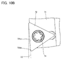
図10Bは、角度変動量X2の測定方法を説明する模式図である。図10Bに示されるように、角度変動量X2の測定では、第1に、径方向調整ねじ80により、切削インサート72の位置が径方向外側に0.05mm移動される。第2に、刃先測定器を用いて、切れ刃72bの形状が測定される。この際の測定条件は、上記と同様である。第3に、上記のようにして得られた切れ刃72bの形状に基づいて、直線切れ刃72baと径方向とがなす角度が算出される。この角度が、角度変動量X2となる。
FIG. 10B is a schematic diagram illustrating a method for measuring the angular variation amount X2. As shown in FIG. 10B, in the measurement of the angular variation amount X2, first, the
切削工具200では、角度変動量X2が0.19°になっていた。他方で、切削工具100では、角度変動量X1が0.03°になっていた。すなわち、切削工具100では、切削工具200と比較して、径方向外側への移動の前後における切れ刃角度の変動量が84パーセント減少していた。
In the
<第2試験>
第2試験では、第1取り付けねじ30の本締め前後におけるブレード20の径方向における位置変動量(位置変動量Y1)及び取り付けねじ73の本締め前後における切削インサート72の径方向における位置変動量(位置変動量Y2)が評価された。<Second test>
In the second test, the radial positional fluctuation amount of the
図11Aは、第1取り付けねじ30の本締め前後における位置変動量Y1の測定方法を説明する模式図である。図11Aに示されるように、第1取り付けねじ30の本締め前後におけるブレード20の径方向における位置変動の測定では、第1に、第1取り付けねじ30の本締め前の(すなわち、第1取り付けねじ30が仮締めされている状態での)切れ刃21の形状が測定される。第2に、第1取り付けねじ30が本締めされる。第3に、第1取り付けねじ30の本締め後の切れ刃21の形状が測定される。
FIG. 11A is a schematic diagram illustrating a method of measuring the positional variation Y1 before and after the first mounting
第4に、第1取り付けねじ30の本締め前において最も径方向外側にある切れ刃21上の位置と第1取り付けねじ30の本締め後において最も径方向外側にある切れ刃21上の位置とを比較することにより、位置変動量Y1が得られる。なお、切れ刃21の形状の測定方法は、第1試験と同様である。
Fourth, the position on the radially
図11Bは、取り付けねじ73の本締め前後における位置変動量Y2の測定方法を説明する模式図である。図11Bに示されるように、取り付けねじ73の本締め前後における切削インサート72の径方向における位置変動の測定では、第1に、取り付けねじ73の本締め前の(すなわち、取り付けねじ73が仮締めされている状態での)切れ刃72bの形状が測定される。第2に、取り付けねじ73が本締めされる。第3に、取り付けねじ73の本締め後の切れ刃72bの形状が測定される。
FIG. 11B is a schematic diagram illustrating a method of measuring the positional variation Y2 before and after the mounting
第4に、取り付けねじ73の本締め前において最も径方向外側にある切れ刃72b上の位置と取り付けねじ73の本締め後において最も径方向外側にある切れ刃72b上の位置とを比較することにより、位置変動量Y2が得られる。なお、切れ刃72bの形状の測定方法は、第1試験と同様である。
Fourth, the position on the radially
切削工具200では、位置変動量Y2が0.009mmであった。他方で、切削工具100では、位置変動量Y1が0.001mmであった。すなわち、切削工具100では、取り付けねじの本締めの前後での径方向における切れ刃の位置変動が、切削工具200と比較して、89パーセント減少していた。
In the
今回開示された実施形態は全ての点で例示であって、制限的なものではないと考えられるべきである。本発明の範囲は上記の実施形態ではなく請求の範囲によって示され、請求の範囲と均等の意味及び範囲内での全ての変更が含まれることが意図される。 The embodiments disclosed this time are illustrative in all respects and should be considered not restrictive. The scope of the present invention is indicated by the scope of claims rather than the above-described embodiments, and is intended to include all modifications within the meaning and scope equivalent to the scope of the claims.
100,200 切削工具、100a 先端、100b 基端、A 中心軸、10 ボディ、10a 外周面、10b ポケット、10ba 座面、10bb 接触面、10c ねじ穴、10d ねじ穴、20 ブレード、21 切れ刃、21a 第1切れ刃、21b 第2切れ刃、21c コーナ切れ刃、22 基体、22a 上面、22aa 取り付け面、22b 底面、22c 第1ブレード側面、22d 第2ブレード側面、22e 第3ブレード側面、22f 第4ブレード側面、22g 貫通穴、23 刃先チップ、30 第1取り付けねじ、40 調整駒、40a 第1駒側面、40b 第2駒側面、40c 第3駒側面、40d 第4駒側面、41 第1駒側壁、41a 第1貫通穴、42 第2駒側壁、42a 第2貫通穴、50 第2取り付けねじ、51 頭部、52 軸部、60 調整ねじ、61 頭部、62 軸部、70 カートリッジ、71 カートリッジ本体、71a 第1端、71b 第2端、71c 貫通穴、71d ねじ穴、72 切削インサート、72a 貫通穴、72b 切れ刃、72ba 直線切れ刃、72bb コーナ切れ刃、73 取り付けねじ、74 取り付けねじ、80 径方向調整ねじ、90 軸方向調整ねじ、DIS 距離、P1 第1位置、P2 第2位置、X1 角度変動量、X2 角度変動量、Y1 位置変動量、Y2 位置変動量。 Reference Signs List 100, 200 cutting tool, 100a tip, 100b base end, A central axis, 10 body, 10a outer peripheral surface, 10b pocket, 10ba bearing surface, 10bb contact surface, 10c screw hole, 10d screw hole, 20 blade, 21 cutting edge, 21a first cutting edge, 21b second cutting edge, 21c corner cutting edge, 22 base, 22a top surface, 22aa attachment surface, 22b bottom surface, 22c first blade side surface, 22d second blade side surface, 22e third blade side surface, 22f second 4 blade side surface 22g through hole 23 blade tip 30 first mounting screw 40 adjustment piece 40a first piece side surface 40b second piece side surface 40c third piece side surface 40d fourth piece side surface 41 first piece Side wall 41a First through hole 42 Second piece side wall 42a Second through hole 50 Second mounting screw 51 Head 52 Shaft 60 Adjusting screw 61 Head 62 Shaft 70 Cartridge 71 Cartridge body 71a first end 71b second end 71c through hole 71d threaded hole 72 cutting insert 72a through hole 72b cutting edge 72ba straight cutting edge 72bb corner cutting edge 73 mounting screw 74 mounting screw , 80 radial adjustment screw, 90 axial adjustment screw, DIS distance, P1 first position, P2 second position, X1 angle variation amount, X2 angle variation amount, Y1 position variation amount, Y2 position variation amount.
Claims (2)
ボディと、
ブレードと、
第1取り付けねじと、
調整駒と、
第2取り付けねじと、
調整ねじとを備え、
前記ボディは、外周面を有し、
前記先端側の端部にある前記外周面には、ポケットが形成されており、
前記ブレードは、前記ポケット内において、前記第1取り付けねじを前記ボディに螺合させることにより前記ボディに取り付けられており、
前記ブレードは、前記軸方向に直交し、かつ前記中心軸を通る径方向において内側を向いている第1ブレード側面と、前記軸方向において前記先端の反対側の端である基端側を向いている第4ブレード側面とを有し、
前記ポケットの内壁面は、前記第1ブレード側面と前記径方向において間隔を空けて対向している接触面を有し、
前記第1ブレード側面と前記接触面との間の間隔は、前記軸方向において前記先端から離れるにつれて小さくなっており、
前記調整駒は、前記第1ブレード側面と前記接触面との間に配置されており、
前記調整駒は、前記第1ブレード側面に接触している第1駒側面と、前記径方向における前記第1駒側面の反対面であり、かつ前記接触面に接触している第2駒側面と、第1駒側壁と、第2駒側壁とを有し、
前記第1駒側壁及び前記第2駒側壁は、前記軸方向において、間隔を空けて対向しており、
前記第1駒側壁は、前記調整駒の前記先端側を向いている第3駒側面を構成し、
前記第2駒側壁は、前記軸方向における前記第3駒側面の反対面である第4駒側面を構成し、
前記第2取り付けねじは、前記ボディに螺合されており、かつ前記軸方向に沿って進退されることにより前記調整駒を前記軸方向に沿って移動させ、
前記第2取り付けねじは、第1頭部と、前記第1頭部に接続され、かつ前記ボディに螺合されている第1軸部とを有し、
前記第1頭部は、前記第2駒側壁の内壁面に接触しており、
前記径方向における前記調整駒の中央を前記第1駒側面の前記第3駒側面側の端と前記第2駒側面の前記第3駒側面側の端との間の中点とするとき、前記第1頭部は、前記径方向における前記第1軸部の中央と前記径方向における前記調整駒の前記中央との間の前記径方向における距離が1.5mm以下となるように前記調整駒に接触しており、
前記調整ねじは、前記ボディに螺合されており、
前記調整ねじが前記軸方向に沿って進退されることにより、前記ブレードの前記軸方向における位置が調整され、
前記調整ねじは、第2頭部と、前記第2頭部に接続され、かつ前記ボディに螺合されている第2軸部とを有し、
前記第2頭部は、前記第4ブレード側面に接触している、切削工具。 A cutting tool rotated about a central axis and having a tip in an axial direction along the central axis,
body and
a blade;
a first mounting screw;
an adjustment piece;
a second mounting screw ;
with an adjustment screw ,
The body has an outer peripheral surface,
A pocket is formed in the outer peripheral surface at the end on the tip side,
the blade is attached to the body by screwing the first attachment screw into the body in the pocket,
The blade has a first blade side surface facing inward in a radial direction perpendicular to the axial direction and passing through the central axis, and a proximal end that is the end opposite to the tip in the axial direction. and a fourth blade side surface that is in the
The inner wall surface of the pocket has a contact surface facing the first blade side surface with a gap in the radial direction,
the distance between the first blade side surface and the contact surface becomes smaller as it moves away from the tip in the axial direction;
The adjustment piece is arranged between the first blade side surface and the contact surface,
The adjustment piece has a first piece side surface in contact with the first blade side surface and a second piece side surface opposite to the first piece side surface in the radial direction and in contact with the contact surface. , a first piece side wall and a second piece side wall,
The first piece side wall and the second piece side wall are opposed to each other with a space therebetween in the axial direction,
The first piece side wall constitutes a third piece side surface facing the tip side of the adjustment piece,
The second piece side wall constitutes a fourth piece side surface opposite to the third piece side surface in the axial direction,
the second mounting screw is screwed into the body and moved back and forth along the axial direction to move the adjustment piece along the axial direction;
the second mounting screw has a first head and a first shaft connected to the first head and screwed to the body;
The first head is in contact with the inner wall surface of the second piece side wall,
When the center of the adjustment piece in the radial direction is set as the middle point between the end of the side surface of the first piece on the side surface of the third piece and the end of the side surface of the second piece on the side surface of the third piece, the One head contacts the adjusting piece so that the distance in the radial direction between the center of the first shaft portion in the radial direction and the center of the adjusting piece in the radial direction is 1.5 mm or less. and
The adjusting screw is screwed into the body,
The position of the blade in the axial direction is adjusted by advancing and retracting the adjusting screw along the axial direction,
The adjusting screw has a second head and a second shaft connected to the second head and screwed to the body,
The cutting tool , wherein the second head is in contact with the fourth blade side surface.
Applications Claiming Priority (1)
| Application Number | Priority Date | Filing Date | Title |
|---|---|---|---|
| PCT/JP2022/002921 WO2023144937A1 (en) | 2022-01-26 | 2022-01-26 | Cutting tool |
Publications (3)
| Publication Number | Publication Date |
|---|---|
| JP7192186B1 true JP7192186B1 (en) | 2022-12-20 |
| JPWO2023144937A1 JPWO2023144937A1 (en) | 2023-08-03 |
| JPWO2023144937A5 JPWO2023144937A5 (en) | 2023-12-26 |
Family
ID=84534609
Family Applications (1)
| Application Number | Title | Priority Date | Filing Date |
|---|---|---|---|
| JP2022538304A Active JP7192186B1 (en) | 2022-01-26 | 2022-01-26 | Cutting tools |
Country Status (2)
| Country | Link |
|---|---|
| JP (1) | JP7192186B1 (en) |
| WO (1) | WO2023144937A1 (en) |
Citations (9)
| Publication number | Priority date | Publication date | Assignee | Title |
|---|---|---|---|---|
| US3363299A (en) * | 1966-05-12 | 1968-01-16 | Gen Electric | Cutting tool assembly |
| DE2140004A1 (en) * | 1971-08-10 | 1973-02-22 | Walter Kieninger | COUNTERING AND MILLING TOOL |
| JPS6426116U (en) * | 1987-08-04 | 1989-02-14 | ||
| US7037050B1 (en) * | 1998-01-08 | 2006-05-02 | Hartmetallwerkzeugfabrik Andreas Maier Gmbh | Milling head with one to three-dimensional adjustable cutting insert and with a positive fitting cutting insert |
| DE102004058962A1 (en) * | 2004-12-08 | 2006-06-14 | MAPAL Fabrik für Präzisionswerkzeuge Dr. Kress KG | Tool for machining of optical plastic lenses, comprising adjustable cutting blades and rotary blades |
| JP2009125828A (en) * | 2007-11-20 | 2009-06-11 | Akio Takewa | Outer diameter minutely adjustable boring bar |
| JP2020508225A (en) * | 2017-02-21 | 2020-03-19 | イスカル リミテッド | Drilling tool and guide pad adjustment mechanism therefor |
| WO2020217846A1 (en) * | 2019-04-26 | 2020-10-29 | 株式会社牧野フライス製作所 | Rotary tool |
| JP2020199572A (en) * | 2019-06-07 | 2020-12-17 | 株式会社牧野フライス製作所 | Milling cuter |
-
2022
- 2022-01-26 WO PCT/JP2022/002921 patent/WO2023144937A1/en active Application Filing
- 2022-01-26 JP JP2022538304A patent/JP7192186B1/en active Active
Patent Citations (9)
| Publication number | Priority date | Publication date | Assignee | Title |
|---|---|---|---|---|
| US3363299A (en) * | 1966-05-12 | 1968-01-16 | Gen Electric | Cutting tool assembly |
| DE2140004A1 (en) * | 1971-08-10 | 1973-02-22 | Walter Kieninger | COUNTERING AND MILLING TOOL |
| JPS6426116U (en) * | 1987-08-04 | 1989-02-14 | ||
| US7037050B1 (en) * | 1998-01-08 | 2006-05-02 | Hartmetallwerkzeugfabrik Andreas Maier Gmbh | Milling head with one to three-dimensional adjustable cutting insert and with a positive fitting cutting insert |
| DE102004058962A1 (en) * | 2004-12-08 | 2006-06-14 | MAPAL Fabrik für Präzisionswerkzeuge Dr. Kress KG | Tool for machining of optical plastic lenses, comprising adjustable cutting blades and rotary blades |
| JP2009125828A (en) * | 2007-11-20 | 2009-06-11 | Akio Takewa | Outer diameter minutely adjustable boring bar |
| JP2020508225A (en) * | 2017-02-21 | 2020-03-19 | イスカル リミテッド | Drilling tool and guide pad adjustment mechanism therefor |
| WO2020217846A1 (en) * | 2019-04-26 | 2020-10-29 | 株式会社牧野フライス製作所 | Rotary tool |
| JP2020199572A (en) * | 2019-06-07 | 2020-12-17 | 株式会社牧野フライス製作所 | Milling cuter |
Also Published As
| Publication number | Publication date |
|---|---|
| JPWO2023144937A1 (en) | 2023-08-03 |
| WO2023144937A1 (en) | 2023-08-03 |
Similar Documents
| Publication | Publication Date | Title |
|---|---|---|
| CN102271848B (en) | Cutting tool having an adjustment mechanism | |
| EP2570212A1 (en) | Tool cartridge with precision adjustment | |
| JP6627174B2 (en) | Cutting edge position adjustment mechanism and cutting edge replaceable cutting tool | |
| US9352405B2 (en) | Metal-cutting tool, in particular reaming tool | |
| JP4816496B2 (en) | Drilling tool | |
| JP7192186B1 (en) | Cutting tools | |
| JP2018140482A (en) | Polygon processing tool | |
| CN107614173A (en) | Indexable insert blade type cutting element | |
| JP2009061587A (en) | Insert | |
| JP4765807B2 (en) | Drilling tools and inserts | |
| JP4872534B2 (en) | Cutting tools | |
| JP5272693B2 (en) | Insert detachable cutter | |
| JP4380365B2 (en) | Reamer | |
| JP4946229B2 (en) | Drilling tool | |
| JP5780179B2 (en) | Drilling tool | |
| JP4770254B2 (en) | Cutting tools | |
| JP2007130739A (en) | Boring tool | |
| JP2008296326A (en) | Cutting holder and cutware | |
| JP4967863B2 (en) | Drilling tool | |
| JP2006247775A (en) | Cutting tool and insert | |
| JP2008000829A (en) | Insert detachable type spherical cutter | |
| JP5817230B2 (en) | Replaceable cutting tool | |
| JP2005125431A (en) | Adjustable diameter boring tool | |
| JP4910514B2 (en) | Cutting edge position measuring method and cutting edge position measuring jig of insert detachable spherical cutter | |
| JP2005103706A (en) | Cutting tool |
Legal Events
| Date | Code | Title | Description |
|---|---|---|---|
| A521 | Request for written amendment filed |
Free format text: JAPANESE INTERMEDIATE CODE: A523 Effective date: 20220620 |
|
| A621 | Written request for application examination |
Free format text: JAPANESE INTERMEDIATE CODE: A621 Effective date: 20220620 |
|
| A871 | Explanation of circumstances concerning accelerated examination |
Free format text: JAPANESE INTERMEDIATE CODE: A871 Effective date: 20220620 |
|
| A131 | Notification of reasons for refusal |
Free format text: JAPANESE INTERMEDIATE CODE: A131 Effective date: 20220712 |
|
| A521 | Request for written amendment filed |
Free format text: JAPANESE INTERMEDIATE CODE: A523 Effective date: 20220805 |
|
| A131 | Notification of reasons for refusal |
Free format text: JAPANESE INTERMEDIATE CODE: A131 Effective date: 20220913 |
|
| A521 | Request for written amendment filed |
Free format text: JAPANESE INTERMEDIATE CODE: A523 Effective date: 20221007 |
|
| TRDD | Decision of grant or rejection written | ||
| A01 | Written decision to grant a patent or to grant a registration (utility model) |
Free format text: JAPANESE INTERMEDIATE CODE: A01 Effective date: 20221108 |
|
| A61 | First payment of annual fees (during grant procedure) |
Free format text: JAPANESE INTERMEDIATE CODE: A61 Effective date: 20221115 |
|
| R150 | Certificate of patent or registration of utility model |
Ref document number: 7192186 Country of ref document: JP Free format text: JAPANESE INTERMEDIATE CODE: R150 |