JP7190863B2 - Collet chuck device - Google Patents
Collet chuck device Download PDFInfo
- Publication number
- JP7190863B2 JP7190863B2 JP2018195158A JP2018195158A JP7190863B2 JP 7190863 B2 JP7190863 B2 JP 7190863B2 JP 2018195158 A JP2018195158 A JP 2018195158A JP 2018195158 A JP2018195158 A JP 2018195158A JP 7190863 B2 JP7190863 B2 JP 7190863B2
- Authority
- JP
- Japan
- Prior art keywords
- chuck
- cylindrical body
- main body
- collet chuck
- insertion recess
- Prior art date
- Legal status (The legal status is an assumption and is not a legal conclusion. Google has not performed a legal analysis and makes no representation as to the accuracy of the status listed.)
- Active
Links
Images


Description
本発明は、コレットチャック装置に関する技術分野に属する。 The present invention belongs to the technical field related to collet chuck devices.
一般に、コレットチャック装置は、駆動手段により中心軸周りに回転駆動されるチャック本体部と、該チャック本体部に対して着脱可能に取り付けられたコレットチャックとを備えている。コレットチャックは、ワークの外周面を把持する、周方向に並ぶ複数の爪部を有し、該爪部は、チャック本体部に設けられた作動装置により、拡径及び縮径される。コレットチャックは、通常、締結用ボルトによってチャック本体部に締結固定される。 Generally, a collet chuck device includes a chuck main body that is rotationally driven around a central axis by a driving means, and a collet chuck that is detachably attached to the chuck main body. The collet chuck has a plurality of claws arranged in the circumferential direction for gripping the outer peripheral surface of the work, and the diameters of the claws are expanded and contracted by an actuator provided on the chuck main body. The collet chuck is usually fastened and fixed to the chuck main body with fastening bolts.
コレットチャックは、ワークの、爪部により把持される部分の外径に対応して交換される(所謂段替えが行われる)。そのコレットチャックの交換時(段替え時)には、コレットチャックの周囲に配置されている部品の脱着も必要になり、交換作業が面倒であるという問題がある。 The collet chuck is replaced according to the outer diameter of the portion of the workpiece gripped by the claws (so-called step change is performed). When exchanging the collet chuck (at the time of changeover), it is necessary to attach and detach parts arranged around the collet chuck, and the exchange work is troublesome.
そこで、例えば特許文献1では、コレットチャックの交換作業を容易にするために、コレットチャックの爪部のすり割り部に、締結用ボルトを挿入可能な切欠き部を設け、このすり割り部に設けた切欠き部から締結用ボルト及び締付工具を挿入して、締結用ボルトを締め付けたり弛めたりできるようにしている。 Therefore, for example, in Patent Document 1, in order to facilitate the exchange work of the collet chuck, a notch portion into which a fastening bolt can be inserted is provided in the slit portion of the claw portion of the collet chuck. A tightening bolt and a tightening tool can be inserted through the notch to tighten or loosen the tightening bolt.
しかしながら、特許文献1の構成を採用したとしても、すり割り部に設けた径の小さい切欠き部から締結用ボルト及び締付工具を挿入して締結用ボルトを締め付けたり弛めたりする作業は煩わしくて面倒であり、しかも、締結用ボルトが複数有るため、上記切欠き部を通しての複数の締結用ボルトの締付け及び弛め作業は、時間を要するという問題がある。 However, even if the configuration of Patent Document 1 is adopted, it is troublesome to insert a fastening bolt and a fastening tool through a small-diameter notch provided in the slot to tighten or loosen the fastening bolt. Moreover, since there are a plurality of fastening bolts, it takes time to tighten and loosen the plurality of fastening bolts through the notches.
本発明は、斯かる点に鑑みてなされたものであり、その目的とするところは、コレットチャックの交換作業を容易にかつ短時間で行えるコレットチャック装置を提供することにある。 SUMMARY OF THE INVENTION The present invention has been made in view of the above problems, and an object of the present invention is to provide a collet chuck device in which exchange work of the collet chuck can be easily performed in a short period of time.
上記の目的を達成するために、本発明では、駆動手段により中心軸周りに回転駆動されるチャック本体部と、ワークの外周面を把持する、該ワークの周方向に並ぶ複数の爪部を有するとともに、該チャック本体部に対して着脱可能に取り付けられたコレットチャックとを備えたコレットチャック装置を対象として、上記チャック本体部は、上記コレットチャックの爪部を拡径及び縮径させる作動装置と、該チャック本体部の中心軸上に位置し、上記ワークをセンタリングする軸心センター部材とを有し、上記軸心センター部材の周囲において上記チャック本体部と同軸に配置され、上記コレットチャックが固定された筒体を更に備え、上記チャック本体部の中心軸方向の一側の端面には、上記コレットチャックと共に上記筒体が挿入される挿入凹部が設けられており、上記挿入凹部に挿入された上記筒体を、上記チャック本体部に保持する保持装置を更に備え、上記筒体及び上記チャック本体部には、該筒体の軸心方向に互いに係合可能な第1係合部及び第2係合部がそれぞれ設けられており、上記筒体の第1係合部は、該筒体の外周面の周方向の一部から径方向外側に突出する外側突出部で構成され、上記チャック本体部の第2係合部は、上記挿入凹部の内周面の周方向の一部に設けられた溝部の側壁部で構成され、上記第1係合部を構成する上記外側突出部は、該外側突出部が上記挿入凹部の上記側壁部よりも奥側に位置するように上記筒体が該挿入凹部に挿入された後に、該筒体が該筒体の軸心周りに回動されたときに、上記溝部に挿入されることで、上記第2係合部を構成する上記側壁部と係合可能な状態になるように構成され、上記保持装置は、上記軸心センター部材の周囲において上記筒体に対して上記挿入凹部の開口側とは反対側で上記チャック本体部と同軸に配置された筒状加圧部材と、該筒状加圧部材を上記チャック本体部の中心軸方向に駆動する油圧シリンダとを有し、上記筒状加圧部材は、上記油圧シリンダにより上記中心軸方向における上記挿入凹部の開口側に駆動されたときに、上記筒体を該筒体の軸心方向の上記開口側に加圧して、該筒体の第1係合部を上記チャック本体部の第2係合部に押圧して係合させることで、該筒体を該チャック本体部に保持するように構成されている、という構成とした。 In order to achieve the above object, the present invention has a chuck main body that is driven to rotate about a central axis by a drive means, and a plurality of claws that grip the outer peripheral surface of the work and are arranged in the circumferential direction of the work. and a collet chuck detachably attached to the chuck main body, wherein the chuck main body includes an operating device for expanding and contracting the diameter of the claw portion of the collet chuck. and an axial center member positioned on the central axis of the chuck main body for centering the workpiece, and arranged coaxially with the chuck main body around the axial center member, and the collet chuck is fixed. An insertion recess into which the cylindrical body is inserted together with the collet chuck is provided on one end face of the chuck main body in the central axis direction, and is inserted into the insertion recess. A holding device for holding the tubular body to the chuck main body is further provided, and the tubular body and the chuck main body are provided with a first engaging portion and a first engaging portion that can be engaged with each other in the axial direction of the tubular body. The first engaging portion of the cylindrical body is composed of an outer protruding portion that protrudes radially outward from a portion of the outer peripheral surface of the cylindrical body in the circumferential direction, and the chuck The second engaging portion of the main body portion is composed of a side wall portion of a groove portion provided in a part of the inner peripheral surface of the insertion recess in the circumferential direction, and the outer protruding portion constituting the first engaging portion comprises: After the cylindrical body is inserted into the insertion recess so that the outer protruding portion is positioned deeper than the side wall portion of the insertion recess, the cylindrical body is rotated about the axis of the cylindrical body. When inserted into the groove, the holding device is configured to be engaged with the side wall portion that constitutes the second engaging portion, and the holding device is arranged around the axial center member. a cylindrical pressurizing member arranged coaxially with the chuck main body on the side opposite to the opening side of the insertion recess with respect to the cylindrical body; and a hydraulic cylinder that drives the cylindrical pressure member, and when driven by the hydraulic cylinder to the opening side of the insertion recess in the central axis direction, the cylindrical pressure member moves the cylindrical body in the axial direction of the cylindrical body. By pressurizing the opening side of the cylinder to press and engage the first engaging portion of the cylinder with the second engaging portion of the chuck body, the cylinder is held in the chuck body It is configured as follows.
上記の構成により、コレットチャックを交換する際には、保持装置による筒体の保持を解除して、コレットチャック及び筒体のセットを挿入凹部から引き出し、その後、その引き出されたセットのコレットチャックを筒体から取り外して、該筒体に別のコレットチャックを固定し、こうして作製した新たなセットを挿入凹部に挿入する。或いは、筒体にコレットチャックを固定した別のセットを予め用意しておき、コレットチャック及び筒体のセットを挿入凹部から引き出した後、その別のセットを挿入凹部に挿入する。続いて、保持装置により、挿入凹部に挿入された筒体をチャック本体部に保持する。コレットチャックが別のものに代わっても、筒体は同じもの又は略同じ形状のものを用いれば、チャック本体部を変更する必要はない。したがって、コレットチャックの交換作業を容易にかつ短時間で行うことができる。 With the above configuration, when exchanging the collet chuck, the retention of the cylindrical body by the retaining device is released, the set of the collet chuck and the cylindrical body is pulled out from the insertion recess, and then the pulled-out set of collet chuck is removed. It is removed from the barrel, another collet chuck is fixed to the barrel, and the new set thus produced is inserted into the insertion recess. Alternatively, another set in which the collet chuck is fixed to the cylindrical body is prepared in advance, and after the set of the collet chuck and the cylindrical body is pulled out from the insertion recess, the other set is inserted into the insertion recess. Subsequently, the cylindrical body inserted into the insertion recess is held in the chuck main body by the holding device. Even if the collet chuck is replaced with another one, the chuck main body does not need to be changed as long as the same or substantially the same shape of the cylindrical body is used. Therefore, the exchange work of the collet chuck can be easily performed in a short time.
また、作業者は、筒体(及びコレットチャック)を挿入凹部に挿入した後に、保持装置を作動させれば、該筒体がチャック本体部に保持される。したがって、コレットチャックの交換作業を容易にかつ短時間で行うことができる。Further, when the operator operates the holding device after inserting the cylindrical body (and collet chuck) into the insertion recess, the cylindrical body is held by the chuck main body. Therefore, the exchange work of the collet chuck can be easily performed in a short time.
さらに、筒体の第1係合部及びチャック本体部の第2係合部を簡単に構成することができる。また、作業者は、筒体(及びコレットチャック)を挿入凹部に挿入した後に該筒体をその軸心周りに回動させれば、第1係合部(外側突出部)と第2係合部(側壁部)とが係合可能な状態になり、この状態で保持装置を作動させれば、第1係合部と第2係合部とを容易に係合させることができる。Furthermore, the first engaging portion of the cylindrical body and the second engaging portion of the chuck main body can be easily constructed. Further, if the operator rotates the cylindrical body (and the collet chuck) around its axis after inserting the cylindrical body (and collet chuck) into the insertion recess, the first engaging portion (outer protruding portion) and the second engaging portion can be engaged. When the holding device is operated in this state, the first engaging portion and the second engaging portion can be easily engaged.
また、保持装置をチャック本体部に容易にかつコンパクトに配置することができるとともに、油圧シリンダにより第1係合部と第2係合部との係合(つまり筒体のチャック本体部に対する保持)を確実なものとすることができる。In addition, the holding device can be easily and compactly arranged on the chuck main body, and the engagement between the first engaging portion and the second engaging portion by the hydraulic cylinder (that is, the holding of the cylindrical body on the chuck main body) can be achieved. can be ensured.
上記コレットチャック装置において、上記挿入凹部の周側壁における開口側の部分が、上記作動装置の一部を構成しかつ上記爪部を縮径させる際に上記コレットチャックに対して当接して径方向内側に押圧する略筒状の当接部材で構成され、上記当接部材の外周面には、上記挿入凹部の開口側に向かって径が小さくなるテーパ面が形成され、上記当接部材及び上記コレットチャックにおける互いの当接部は、該当接部材の軸心方向に関して径が変化しない面とされている、ことが好ましい。 In the above collet chuck device, the opening side portion of the peripheral wall of the insertion recess constitutes a part of the operating device, and contacts the collet chuck when the diameter of the claw portion is reduced, and is radially inward. The outer peripheral surface of the contact member is formed with a tapered surface whose diameter decreases toward the opening side of the insertion recess, and the contact member and the collet It is preferable that the mutually contacting portions of the chucks are surfaces whose diameters do not change in the axial direction of the contacting member.
このことにより、当接部材及びコレットチャックにおける互いの当接部が、当接部材の軸心方向に関して径が変化しない面とされているので、当接部材が、コレットチャック及び筒体の挿入凹部に対する引き出し及び挿入の邪魔にならない。すなわち、従来のコレットチャック装置では、当接部材及びコレットチャックの当接部に、テーパ面が形成されているが、特に挿入凹部の開口側に向かって径が小さくなるテーパ面が形成されている場合、当接部材が、コレットチャック及び筒体の挿入凹部に対する引き出し及び挿入の邪魔になるので、コレットチャックの交換時に少なくとも当接部材をチャック本体部から取り外す必要がある。これに対し、当接部材及びコレットチャックの当接部の径が変化しない構成では、コレットチャックの交換時に当接部材やその他の部材をチャック本体部から取り外す必要がなくなる。よって、コレットチャックの交換作業をより一層容易にかつ短時間で行うことができる。 As a result, the abutting portions of the abutting member and the collet chuck have surfaces that do not change in diameter with respect to the axial direction of the abutting member. do not interfere with the withdrawal and insertion of That is, in the conventional collet chuck device, the abutting member and the abutting portion of the collet chuck are formed with tapered surfaces. In this case, since the abutting member interferes with drawing out and inserting into the insertion recess of the collet chuck and the cylindrical body, it is necessary to remove at least the abutting member from the chuck main body when exchanging the collet chuck. On the other hand, in a structure in which the diameters of the abutment member and the abutment portion of the collet chuck do not change, it is not necessary to remove the abutment member and other members from the chuck main body when replacing the collet chuck. Therefore, the exchange work of the collet chuck can be performed more easily and in a short time.
上記のように上記保持装置が筒状加圧部材と油圧シリンダとを有する場合、上記筒体は、上記ワークの該筒体に対する回転位相決めを行う回転位相決めピンを有し、上記筒状加圧部材は、上記チャック本体部の中心軸周りに該チャック本体部と一体的に回転するように構成されているとともに、上記油圧シリンダにより上記中心軸方向の上記開口側に駆動されたときに、上記筒体に設けられた嵌合凹部に嵌合する楔状突部を有している、ことが好ましい。 When the holding device has a tubular pressure member and a hydraulic cylinder as described above , the tubular body has a rotational phase determining pin for determining the rotational phase of the workpiece with respect to the tubular body. The pressurizing member is configured to rotate integrally with the chuck body about the central axis of the chuck body, and when driven by the hydraulic cylinder toward the opening in the central axis direction. Preferably, it has a wedge-shaped protrusion that fits into a fitting recess provided in the cylindrical body.
このことで、ワークの周方向の位置によって形状が変化する場合であっても、そのワークの回転位相がチャック本体部の回転位相と対応するようになり、チャック本体部の回転位相に対応して切削工具のワークに対する位置を変更して、ワークの切削や研削等の加工を適切に行うことができるようになる。また、筒体が筒状加圧部材により加圧されながら楔状突部が嵌合凹部に嵌合することで、筒体が筒状加圧部材と一体的に回転可能に結合されて、ワークの回転位相とチャック本体部の回転位相との対応を確実なものとすることができるとともに、筒体を強く加圧することができて、第1係合部と第2係合部との係合(筒体のチャック本体部に対する保持)をより一層確実なものとすることができる。 As a result, even if the shape of the workpiece changes depending on the position of the workpiece in the circumferential direction, the rotation phase of the workpiece corresponds to the rotation phase of the chuck body. By changing the position of the cutting tool with respect to the work, it is possible to appropriately perform processing such as cutting and grinding of the work. In addition, the wedge-shaped protrusion is fitted into the fitting recess while the cylindrical body is pressed by the cylindrical pressure member, so that the cylindrical body and the cylindrical pressure member are integrally rotatably connected to each other, thereby removing the workpiece. Correspondence between the rotation phase and the rotation phase of the chuck main body can be ensured, and the cylindrical body can be strongly pressurized, so that the engagement between the first engaging portion and the second engaging portion ( (holding of the cylindrical body to the chuck main body) can be further ensured.
本発明の別の態様では、駆動手段により中心軸周りに回転駆動されるチャック本体部と、ワークの外周面を把持する、該ワークの周方向に並ぶ複数の爪部を有するとともに、該チャック本体部に対して着脱可能に取り付けられたコレットチャックとを備えたコレットチャック装置を対象として、上記チャック本体部は、上記コレットチャックの爪部を拡径及び縮径させる作動装置と、該チャック本体部の中心軸上に位置し、上記ワークをセンタリングする軸心センター部材とを有し、上記軸心センター部材の周囲において上記チャック本体部と同軸に配置され、上記コレットチャックが固定された筒体を更に備え、上記チャック本体部の中心軸方向の一側の端面には、上記コレットチャックと共に上記筒体が挿入される挿入凹部が設けられており、上記挿入凹部に挿入された上記筒体を、上記チャック本体部に保持する保持装置を更に備え、上記筒体の外周面の周方向の一部に、係合凹部が設けられ、上記保持装置は、上記チャック本体部に設けられかつ上記係合凹部に嵌合して係合することで上記筒体を該チャック本体部に保持する係合部材を有していて、該係合部材を、上記係合凹部に対して係合又は非係合となるように、上記チャック本体部において上記筒体の軸心方向と交差する方向に移動させるよう構成されており、上記保持装置の係合部材は、油圧シリンダの油圧室に供給される油圧によって上記筒体の軸心方向と交差する方向に移動するように構成されている、という構成とした。 In another aspect of the present invention, the chuck body has a chuck body portion that is rotationally driven around a central axis by a drive means, and a plurality of claw portions that grip the outer peripheral surface of the work and are arranged in the circumferential direction of the work. A collet chuck device having a collet chuck detachably attached to a part, wherein the chuck main body comprises an operating device for increasing and decreasing the diameter of the claws of the collet chuck, and the chuck main body. and an axial center member for centering the work, and arranged coaxially with the chuck main body around the axial center member, to which the collet chuck is fixed. Further, an insertion recess into which the cylindrical body is inserted together with the collet chuck is provided on one end face of the chuck main body in the central axis direction, and the cylindrical body inserted into the insertion recess is A holding device for holding the chuck main body is further provided, and an engaging recess is provided in a part of the outer peripheral surface of the cylindrical body in the circumferential direction, and the holding device is provided on the chuck main body and engages the It has an engaging member that holds the cylindrical body in the chuck main body by fitting into and engaging with the recess, and the engaging member is engaged or disengaged with the engaging recess. The engaging member of the holding device is moved by hydraulic pressure supplied to the hydraulic chamber of the hydraulic cylinder. It is configured such that it is configured to move in a direction intersecting with the axial direction of the cylinder.
これにより、作業者は、筒体(及びコレットチャック)を挿入凹部に挿入し、該筒体の周方向の位置を、係合部材が係合凹部に係合する位置に合わせた後、保持装置を作動させれば、該筒体がチャック本体部に保持される。したがって、コレットチャックの交換作業を容易にかつ短時間で行うことができる。 Accordingly, the operator inserts the cylindrical body (and the collet chuck) into the insertion recess, adjusts the position of the cylindrical body in the circumferential direction to the position where the engaging member engages with the engaging recess, and then removes the holding device. is operated, the cylindrical body is held by the chuck main body. Therefore, the exchange work of the collet chuck can be easily performed in a short time.
また、係合部材を筒体の軸心方向と交差する方向に移動させることが容易にできるとともに、係合部材が係合凹部に係合したときに、筒体のチャック本体部に対する保持が確実なものとなる。 In addition, the engaging member can be easily moved in a direction crossing the axial direction of the cylindrical body, and when the engaging member is engaged with the engaging recess, the cylindrical body can be securely held on the chuck main body. become something.
上記別の態様のコレットチャック装置において、上記挿入凹部の周側壁における開口側の部分が、上記作動装置の一部を構成しかつ上記爪部を縮径させる際に上記コレットチャックに対して当接して径方向内側に押圧する略筒状の当接部材で構成され、上記当接部材の外周面には、上記挿入凹部の開口側に向かって径が小さくなるテーパ面が形成され、上記当接部材及び上記コレットチャックにおける互いの当接部は、該当接部材の軸心方向に関して径が変化しない面とされている、という構成でもよい。In the collet chuck device according to another aspect of the invention, the opening side portion of the peripheral wall of the insertion recess constitutes a part of the operating device and abuts against the collet chuck when the claw portion is contracted in diameter. The outer peripheral surface of the contact member is formed with a tapered surface whose diameter decreases toward the opening side of the insertion recess. A contact portion between the member and the collet chuck may be a surface whose diameter does not change with respect to the axial direction of the contact member.
上記別の態様のコレットチャック装置において、上記筒体は、上記ワークの該筒体に対する回転位相決めを行う回転位相決めピンを有する、という構成でもよい。In the collet chuck device according to another aspect of the invention, the cylindrical body may have a rotational phase determining pin for determining the rotational phase of the workpiece with respect to the cylindrical body.
以上説明したように、本発明のコレットチャック装置によると、コレットチャックの交換作業を容易にかつ短時間で行うことができる。 As described above, according to the collet chuck device of the present invention, the collet chuck can be easily replaced in a short period of time.
以下、本発明の実施形態を図面に基づいて詳細に説明する。 BEST MODE FOR CARRYING OUT THE INVENTION Hereinafter, embodiments of the present invention will be described in detail based on the drawings.
(実施形態1)
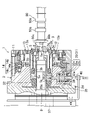
図1は、本発明の実施形態1に係るコレットチャック装置1を示す。このコレットチャック装置1は、駆動手段により中心軸周りに回転駆動されるチャック本体部2と、該チャック本体部2の中心軸方向の一側(図1の右側)の端部に配置され、ワーク90(特に軸状のワーク)を把持するコレットチャック3とを備えている。尚、チャック本体部2は、複数の部材で構成される。
(Embodiment 1)
FIG. 1 shows a collet chuck device 1 according to Embodiment 1 of the present invention. The collet chuck device 1 includes a chuck
コレットチャック3は、後述の軸心センター部材8によりセンタリングされたワーク90の周囲において周方向に並びかつワーク90の外周面を把持する複数の爪部3a(図2参照)を有するとともに、チャック本体部2に対して着脱可能に取り付けられる。この着脱可能な構成は、後に詳細に説明する。
The
上記駆動手段は、図示は省略するが、本実施形態では、自身の回転位相が分かるサーボモータである。このサーボモータは、チャック本体部2の中心軸方向の他側(図1の左側)の端部に連結される。サーボモータの駆動及び停止は、作業者のスイッチ操作により行う。
Although not shown, the drive means is a servomotor whose own rotational phase is known in this embodiment. This servomotor is connected to the end of the chuck
以下、チャック本体部2について、中心軸方向の上記一側を前側といい、中心軸方向の上記他側を後側という。
Hereinafter, with respect to the chuck
図1に例示するワーク90は、エンジンのカムシャフトである。ワーク90は、不図示の工具(砥石)により研削加工が行われる加工部90a(カムシャフトのカム面)を有する。ワーク90は、該ワーク90の一端部で、コレットチャック3(詳細には、爪部3a)により把持される。ワーク90の他端部は、不図示の支持部材により回転可能に支持される。そして、チャック本体部2の回転により、後述の如くコレットチャック3が回転し、このコレットチャック3の回転によりワーク90が回転する。このワーク90の回転時に、工具(砥石)により加工部90aの研削加工が行われる。この工具は、サーボモータの回転位相に対応して、加工部90aに対する位置が自動で変化するように構成されている。後述の如く、ワーク90の回転位相がサーボモータの回転位相(つまりチャック本体部2の回転位相)と対応するようになされているので、上記工具によって、ワーク90の周方向の位置によって径が変化するカム面のような加工部90aの研削加工が適切に行われる。尚、ワーク90の加工は、研削加工には限られず、例えば切削加工であってもよい。
A
チャック本体部2は、チャック本体部2の中心軸上に位置しかつワーク90をセンタリングする軸心センター部材8を有する。すなわち、軸心センター部材8の前側の端部が、先細りのテーパ状に形成され、ワーク90の端面の中心部には、係合穴90bが形成されており、この係合穴90bの開口周縁部が、軸心センター部材8の前側の端部に対応してテーパ状に形成されている。そして、軸心センター部材8の前側の端部が、係合穴90bの開口周縁部に係合することで、ワーク90がセンタリングされる。
The chuck
チャック本体部2の前側の端面には、コレットチャック3と共に筒体5が挿入される挿入凹部2aが後側に凹むように設けられている。筒体5はコレットチャック3に固定されてセット状態にされており、このセット状態で挿入凹部2aに挿入されたり引き出されたりする。
An
コレットチャック3は、略筒状に形成されていて、軸心センター部材8の周囲においてチャック本体部2と同軸に配置されている。コレットチャック3は、リング状のベース部3bと、このベース部3bから挿入凹部2aの開口側(前側)に向かって延びる略筒状の爪支持部3cとを有する。爪支持部3cの周方向の複数箇所(本実施形態では、6箇所)には、爪支持部3cの先端(前側端)からベース部3b側(後側)に延びるすり割り3d(図2参照)が形成されて、爪支持部3cが周方向において複数(6つ)に分割されている。これら複数の分割部分の先端部における内周面に、爪部3aがそれぞれ設けられている。爪支持部3cにおける先端部を除く部分の厚みは、先端部よりも薄くされており、これにより、後述の当接部材12によりコレットチャック3(爪支持部3c)が径方向内側に押圧されたときに、爪支持部3cが弾性変形により撓んで爪部3aが縮径されることになる。こうして縮径された爪部3aにより、ワーク90が把持されることになる。
The
チャック本体部2は、コレットチャック3の爪部3aを拡径及び縮径させる作動装置11を更に有する。この作動装置11は、爪部を縮径させる際にコレットチャック3(爪支持部3c)に対して当接して径方向内側に押圧する略筒状の当接部材12と、この当接部材12の径方向外側に配置された筒状押圧部材13と、この筒状押圧部材13と連結されたピストン14aを含む油圧シリンダ14とを有する。
The chuck
当接部材12及び筒状押圧部材13は、コレットチャック3と同軸に配置されている。また、当接部材12は、コレットチャック3の爪支持部3cのすり割り3dに対応する周方向の位置に、すり割り3dと同様のすり割り(図示省略)が形成されて、当接部材12が周方向において複数(6つ)に分割されている。
The
油圧シリンダ14は、チャック本体部2におけるピストン14aの前側及び後側にそれぞれ設けられた縮径用油圧室14bと拡径用油圧室14cとを有し、縮径用油圧室14bに油圧が供給されたときには、ピストン14aと共に筒状押圧部材13が、チャック本体部2の後側に移動する一方、拡径用油圧室14cに油圧が供給されたときには、ピストン14a及び筒状押圧部材13が、チャック本体部2の前側に移動するようになっている。尚、縮径用油圧室14b及び拡径用油圧室14cへの油圧供給の切換えは、作業者のスイッチ操作により行う。
The
当接部材12の外周面の先端部には、挿入凹部2aの開口側(前側)に向かって径が小さくなるテーパ面12aが形成されている。また、筒状押圧部材13の内周面におけるテーパ面12aに対応する部分にも、挿入凹部2aの開口側に向かって径が小さくなるテーパ面13aが形成されている。油圧シリンダ14により筒状押圧部材13がチャック本体部2の後側に移動したときには、筒状押圧部材13によって両テーパ面12a,13aを介して当接部材12が径方向内側に押圧される。一方、油圧シリンダ14により筒状押圧部材13がチャック本体部2の前側に移動したときには、筒状押圧部材13による当接部材12の押圧が解除される。
A
当接部材12は、挿入凹部2aの周側壁における開口側(前側)の部分を構成していて、チャック本体部2により構成された、挿入凹部2aの周側壁における奥側(後側)の部分に繋がる。当接部材12は、挿入凹部2aの周側壁において当接部材12により構成された部分とチャック本体部2により構成された部分との境界部分で、ボルト16によりチャック本体部2に固定されるリング状のベース部12bを有し、このベース部12bから挿入凹部2aの開口端まで延びている。当接部材12の内周面は、該当接部材12の軸心方向に関して径が変化しない面とされている。当接部材12の内周面における先端部(前側の端部)が、爪部3aを縮径させる際にコレットチャック3(爪支持部3c)の外周面における先端部に当接する。コレットチャック3(爪支持部3c)の外周面における当接部材12が当接する部分も、コレットチャックの軸心方向に関して径が変化しない面とされている。したがって、当接部材12及びコレットチャック3における互いの当接部は、該当接部材12の軸心方向に関して径が変化しない面とされている。
The
ここで、当接部材12及びコレットチャック3における互いの当接部が、テーパ面12a,13aのように挿入凹部2aの開口側に向かって径が小さくなっていた場合、コレットチャック3の交換時に少なくとも当接部材12をチャック本体部2から取り外す必要がある。しかし、本実施形態では、当接部材12が、コレットチャック3及び筒体5のセットの、挿入凹部2aに対する引き出し及び挿入の邪魔にならず、コレットチャック3の交換時に、当接部材12やその他の部材をチャック本体部2から取り外す必要がない。尚、コレットチャック3の交換方法については、後に詳細に説明する。
Here, if the abutment portions of the
当接部材12におけるベース部12b及び先端部を除く部分の厚みは、コレットチャック3の爪支持部3cと同様に、先端部よりも薄くされており、これにより、当接部材12は、筒状押圧部材13によって径方向内側に押圧されたときには、弾性変形により撓んで、コレットチャック3を径方向内側に押圧して爪部3aを縮径させる。一方、筒状押圧部材13による当接部材12の押圧が解除されたときには、当接部材12及び爪支持部3cが元の状態に戻って爪部3aが拡径されることになる。
The thickness of the portion of the
筒体5は、コレットチャック3よりも挿入凹部2aの奥側(後側)に位置しかつコレットチャック3のベース部3bと不図示のボルトにより固定される大径部5aと、大径部5aの前側の面からコレットチャック3の内側を通って挿入凹部2aの開口側(前側)に延びる、大径部5aよりも小径の小径部5bとを有する。筒体5も、軸心センター部材8の周囲においてチャック本体部2と同軸に配置されている。
The
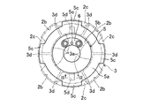
図2に示すように、筒体5の大径部5aにおける外周面の周方向の一部(本実施形態では、周方向に等間隔をあけた4箇所)には、径方向外側に突出する外側突出部5cが設けられている。一方、チャック本体部2において挿入凹部2aの最も奥側の内周面の周方向の一部(本実施形態では、周方向に等間隔をあけた4箇所)には、4つの外側突出部5cが挿入される4つの溝部2bが形成されている。各溝部2bは、挿入凹部2aの内周面における各溝部2bに対応する部分から径方向内側に突出した内側突出部2cと、挿入凹部の底部における内側突出部2cに対応(対向)する部分と、挿入凹部2aの底部と各内側突出部2cとの間における挿入凹部2aの内周面とで形成されている。各溝部2bを構成する内側突出部2c及び底部が、当該溝部2b両側の側壁部を構成し、挿入凹部2aの底部と各内側突出部2cとの間における挿入凹部2aの内周面が、溝部2bの底部を構成することになる。
As shown in FIG. 2, a portion of the outer peripheral surface of the large-
筒体5(コレットチャック3及び筒体5のセット)は、該筒体5の外側突出部5cが、相隣接する内側突出部2cの間を通るように、挿入凹部2aの底部まで挿入される。つまり、筒体5は、外側突出部5cが挿入凹部2aの内側突出部2cよりも奥側に位置するように挿入凹部2aに挿入される。この挿入後に筒体5が該筒体5の軸心周りに回動されたときに、外側突出部5cが溝部2bに挿入される。これにより、外側突出部5cと内側突出部2cとが係合可能な状態になる。
The cylindrical body 5 (a set of the
筒体5の外側突出部5cは、筒体5が後述の筒状加圧部材22により挿入凹部2aの開口側(前側)に加圧されたときに、内側突出部2cに押圧されて該内側突出部2cと係合する。すなわち、外側突出部5c及び内側突出部2cは、筒体5の軸心方向に互いに係合可能な第1係合部及び第2係合部をそれぞれ構成することになる。外側突出部5c(第1係合部)と内側突出部2c(第2係合部)との係合によって、筒体5がチャック本体部2に保持されることになる。
The outer protruding
チャック本体部2には、このように筒体5をチャック本体部2に保持する保持装置21が設けられている。すなわち、保持装置21は、筒体5を該筒体5の軸心方向に加圧して該筒体5の外側突出部5cを内側突出部2cに押圧して係合させることで、筒体5をチャック本体部2に保持するように構成されている。
The chuck
具体的に、保持装置21は、軸心センター部材8の周囲において筒体5に対して挿入凹部2aの開口側とは反対側でチャック本体部2と同軸に配置された筒状加圧部材22と、該筒状加圧部材22をチャック本体部2の中心軸方向に駆動する油圧シリンダ23とを有する。
Specifically, the holding
油圧シリンダ23は、筒状加圧部材22の外周面から径方向外側に突出するように固定されたピストン23aと、チャック本体部2におけるピストン23aの前側及び後側にそれぞれ形成された前側油圧室23b及び後側油圧室23cとを有する。後側油圧室23cに油圧が供給されたときには、筒状加圧部材22が前側に駆動され、前側油圧室23bに油圧が供給されたときには、筒状加圧部材22が後側に駆動される。尚、前側油圧室23b及び後側油圧室23cへの油圧供給の切換えは、作業者のスイッチ操作により行う。
The
ピストン23aには、ピストン23a及び筒状加圧部材22がチャック本体部2の中心軸方向に移動するようにガイドするガイド部材24が設けられている。ガイド部材24は、ピストン23a及び筒状加圧部材22をチャック本体部2の中心軸周りに該チャック本体部2と一体的に回転させる役割も有する。
The
筒状加圧部材22は、油圧シリンダ23により前側に駆動されたときに、筒体5を前側に加圧して、外側突出部5cを内側突出部2cに押圧して係合させる。
When the
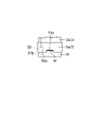
図2及び図3に示すように、筒状加圧部材22の前側の面(径方向に対応する2箇所)には、油圧シリンダ23により筒状加圧部材22が前側に駆動されたときに、筒体5の後側の面(大径部5aの後側の面)に設けられた嵌合凹部5dに嵌合する楔状突部22aが設けられている。楔状突部22aは、筒状加圧部材22の周方向の幅が前側に向かって小さくされ、嵌合凹部5dにおける筒体5の周方向の幅も、楔状突部5dと同様の形状に形成されている。筒体5は、筒状加圧部材22により加圧されながら嵌合凹部5dに楔状突部22aが嵌合したときに、筒状加圧部材22に対してチャック本体部2の中心軸周りに一体的に回転可能に結合されることになる。また、嵌合凹部5dに楔状突部22aが嵌合した状態で筒体5が筒状加圧部材22により加圧されることで、筒体5が前側に確実に加圧されて、外側突出部5cと内側突出部2cとの係合が確実なものとなる。
As shown in FIGS. 2 and 3 , on the front side surface (two points corresponding to the radial direction) of the
筒体5の小径部5bにおける前側の端面には、ワーク90の該筒体5に対する回転位相決めを行う回転位相決めピン5eが設けられている。本実施形態では、回転位相決めピン5eは、不図示のボルトを介して筒体5に固定された、筒体5とは別の部材6に設けられているが、筒体5に直に設けることも可能である。回転位相決めピン5eが、ワーク90の端面に設けられた回転位相決め穴90cに嵌合することで、ワーク90の回転位相が、上記サーボモータの回転位相(つまりチャック本体部2の回転位相)と対応することになる。
A rotational
ワーク90の加工部90aの研削加工が終了して爪部3aを拡径した後、別のワーク90の加工部90aの研削加工を行う際、該別のワーク90の端部の径が、研削加工が終了した直後のワーク90の端部の径と異なる場合には、コレットチャック3をその別のワーク90に対応したものに交換する。
After the grinding of the processed
すなわち、作業者は、先ず、保持装置21の油圧シリンダ23により筒状加圧部材22を後側に移動させて、外側突出部5cと内側突出部2cとの係合を解除する。続いて、コレットチャック3及び筒体5のセットを挿入凹部2aから引き出す。尚、その引き出す前に、筒体5を、筒体5の軸心周りに、後述の挿入後の回動とは逆向きに回動させる必要がある。
That is, the operator first moves the
その後、作業者は、その引き出したセットのコレットチャック3を筒体5から取り外して、該筒体5に別のコレットチャック3を固定し、こうして作製した新たなセットを挿入凹部2aに挿入する。
After that, the worker removes the
或いは、筒体5にコレットチャック3を固定した別のセットを予め用意しておき、コレットチャック3及び筒体5のセットを挿入凹部2aから引き出した後、その別のセットを挿入凹部2aに挿入してもよい。上記別のセットの筒体5は、挿入凹部2aから引き出した直後のセットの筒体5と同様のものである。
Alternatively, another set in which the
上記作製した新たなセット、又は、予め用意してあった上記別のセットを挿入凹部2aに挿入する際、回転位相決めピン5eの位置を、筒体5の周方向の予め決められた位置に合わせた状態で、挿入する。これにより、筒体5の外側突出部5cが、相隣接する内側突出部2cの間を通るようになる。そして、筒体5の後側の端面が挿入凹部2aの底部に当接したとき、筒体5(及びコレットチャック3)を、筒体5の軸心周りに回動させて、外側突出部5cを溝部2bに挿入する。この回動は、外側突出部5cが不図示のストッパに当接するまで行う。これにより、回転位相決めピン5eの位置が、筒体5の周方向の特定の位置(ワーク90の回転位相を上記サーボモータの回転位相と対応させることが可能な位置)となる。
When inserting the new set prepared above or another set prepared in advance into the
続いて、保持装置21の油圧シリンダ23により筒状加圧部材22を前側に移動させて、筒状加圧部材22により筒体5を前側に加圧する。このとき、筒状加圧部材22の楔状突部22aが筒体5の嵌合凹部5dに嵌合する。筒状加圧部材22による筒体5の前側への加圧により、外側突出部5cと内側突出部2cとが係合して、筒体5がチャック本体部2に保持される。また、筒体5及びコレットチャック3が、筒状加圧部材22、延いては、チャック本体部2と一体的に回転可能に結合される。
Subsequently, the
次いで、ワーク90を軸心センター部材8によりセンタリングしかつ回転位相決めピン5eを回転位相決め穴90cに嵌合させた状態で、作動装置11により爪部3aを縮径して、ワーク90を爪部3aにより把持する。
Next, in a state in which the
その後、上記サーボモータを駆動すれば、ワーク90が回転しながら加工部90aの研削加工が自動で行われる。
Thereafter, by driving the servomotor, the
したがって、本実施形態では、コレットチャック3の交換作業を容易にかつ短時間で行うことができる。
Therefore, in the present embodiment, the
(実施形態2)
図4は、本発明の実施形態2を示し(尚、図1と同じ部分については同じ符号を付して、その詳細な説明は省略する)、上記実施形態1の保持装置21に代えて、別の構成の保持装置31を設けたものである。
(Embodiment 2)
FIG. 4 shows
すなわち、本実施形態では、挿入凹部2aの底部に、筒体5と連結されるリング状の連結部材51が、チャック本体部2と同軸に固定されている。連結部材51の前側の面には、図5にも示すように、連結用突出部51a(上記実施形態1における楔状突部22aのような楔状とはなっていない)が設けられており、連結用突出部51aが、挿入凹部2aに挿入された筒体5の後側の面に設けられた嵌合凹部5fに嵌合する。この嵌合により、筒体5(及びコレットチャック3)がチャック本体部2と該チャック本体部2の中心軸周りに一体的に回転可能に連結される。尚、本実施形態では、チャック本体部2に、上記実施形態1における溝部2b及び内側突出部2cは設けられていない。
That is, in the present embodiment, a ring-shaped connecting
筒体5は、コレットチャック3のベース部3bにボルト52(図5参照)により固定されてセット状態にされている。このボルト52の頭部52aが、連結部材51の前側の面に設けられた凹部51bに嵌合するようになっている。筒体5における大径部5aの外周面の周方向の一部には、係合凹部5gが設けられている。ボルト52の頭部が連結部材51の凹部51bに嵌合した状態では、係合凹部5gが後述の係合部材32と対向する位置に位置するとともに、回転位相決めピン5eの位置が、筒体5の周方向の上記特定の位置となる。
The
保持装置31は、チャック本体部2に設けられた軸状の係合部材32を有している。この係合部材32は、係合凹部5g側の端部が係合凹部5gに嵌合して係合することで、筒体5をチャック本体部2に保持する。
The holding
また、保持装置31は、係合部材32を、係合凹部5gに対して係合又は非係合となるように、チャック本体部2において、筒体5の軸心方向と交差する方向(本実施形態では、筒体5の軸心方向と直交する方向)に移動させる油圧シリンダ33を更に有する。
Further, the holding
油圧シリンダ33は、係合部材32と一体形成されたピストン33aと、チャック本体部2におけるピストン33aの反係合凹部5g側及び係合凹部5g側にそれぞれ設けられた係合用油圧室33b及び非係合用油圧室33cとを有する。
The
チャック本体部2における挿入凹部2の後側部分には、非係合用油路35(図4参照)と係合用油路36(図6参照)とが形成された油路形成部2dが設けられている。非係合用油路35は、チャック本体部2における油路形成部2dの後側部分において軸心センター部材8の周囲に設けられた共通油路37に接続される接続端部35aから非係合用油圧室33cまで延びている。一方、係合用油路36は、共通油路37に接続される接続端部36aから、チャック本体部2において非係合用油路35とは別の箇所を通って、係合用油圧室33bまで延びている。非係合用油路35の接続端部35a及び係合用油路36の接続端部36aは、チャック本体部2の中心軸の近傍において該中心軸を挟んで互いに対向する位置に位置する。
An oil
非係合用油路35を介して非係合用油圧室33cに油圧が供給されたときには、係合部材32が係合凹部5gから離れる向きに移動して、該係合凹部5gに対して非係合となる。一方、係合用油路36を介して係合用油圧室33bに油圧が供給されたときには、係合部材32が係合凹部5gに近付く向きに移動して、該係合凹部5gと係合する。尚、係合用油圧室33b及び非係合用油圧室33cへの油圧供給の切換えは、作業者のスイッチ操作により行う。
When hydraulic pressure is supplied to the non-engaging
係合用油圧室33b内には、ピストン33aを非係合用油圧室33c側へ付勢する圧縮コイルスプリング39が設けられている。これにより、非係合用油圧室33cの油圧がドレンされれば、係合用油圧室33bに油圧が供給されなくても、係合部材32が係合凹部5gに近付く向きに移動して、該係合凹部5gと係合することが可能である。
A
係合部材32は、ピストン33aから係合凹部5gとは反対側に延びる被検出部32aが設けられている。この被検出部32aに対向するように、近接センサ40が設けられている。近接センサ40は、被検出部32aが近接センサ40に対して所定値以下の距離に近付いたときには、被検出部32aを検出する一方、被検出部32aが近接センサ40に対して上記所定値よりも大きい距離離れているときには、被検出部32aを検出しない。すなわち、係合部材32が係合凹部5gに係合していないときには、近接センサ40により被検出部32aが検出される一方、係合部材32が係合凹部5gに係合したときには、被検出部32aが検出されない。
The engaging
近接センサ40による被検出部32aの検出及び非検出の情報は、不図示の表示装置に表示されるようになっている。この表示装置が例えばランプの場合、近接センサ40により被検出部32aが検出されているときには、ランプが点灯する一方、被検出部32aが検出されないときには、ランプが消灯する。このように、作業者は、表示装置によって、係合部材32が係合凹部5gに係合しているか否かが分かるようになっている。
Information on detection and non-detection of the detected
作業者は、コレットチャック3及び筒体5のセットを挿入凹部2aから引き出す際、非係合用油圧室33cに油圧を供給して、係合部材32と筒体5の係合凹部5gとの係合を解除し、この解除後に、上記セットを挿入凹部2aから引き出す。本実施形態においても、コレットチャック3の交換時に当接部材12やその他の部材をチャック本体部2から取り外す必要がない。
When the operator pulls out the set of the
続いて、上記実施形態1と同様に、挿入凹部2aから引き出したセットの筒体5を利用して作製した新たなセット、又は、予め用意してあった別のセットを挿入凹部2aに挿入する。その際、回転位相決めピン5eの位置を特定の位置に合わせた状態で、セットを挿入する。この挿入により筒体5を連結部材51と連結させる(ボルト52の頭部を凹部51bに嵌合させるとともに、連結用突出部51aを嵌合凹部5fに嵌合させる)。尚、本実施形態では、筒体5(及びコレットチャック3)を、筒体5の軸心周りに回動させる必要はない。
Subsequently, in the same manner as in the first embodiment, a new set made by using the
次いで、非係合用油圧室33cの油圧をドレンする。これにより、圧縮コイルスプリング39によって係合部材32が係合凹部5gに近付く向きに移動する。ボルト52の頭部が凹部51bに嵌合していれば、通常は、係合部材32が係合凹部5gに嵌合し、近接センサ40による被検出部32aの検出がなされなくなる。非係合用油圧室33cの油圧をドレンしても、近接センサ40により被検出部32aが検出されていれば、作業者は、挿入凹部2aに挿入したセットの位置の微調整を行って、係合部材32を係合凹部5gに嵌合させて、近接センサ40による被検出部32aの検出がなされなくなるようにする。
Next, the hydraulic pressure in the non-engagement
作業者は、上記表示装置によって、係合部材32が係合凹部5gに係合していることを確認した後、係合用油圧室33bに油圧を供給することで、保持装置31による筒体5のチャック本体部2への保持を確実なものとする。
After confirming that the engaging
したがって、本実施形態においても、上記実施形態1と同様に、コレットチャック3の交換作業を容易にかつ短時間で行うことができる。
Therefore, in this embodiment, similarly to the first embodiment, the
尚、上述の各実施形態では、コレットチャック3及び筒体5のセットの交換作業(挿入凹部2aに対する引き出し及び挿入)を作業者が行うようになっていたが、これに代えて、ロボットハンドでコレットチャック3及び筒体5のセットを把持して、自動的に交換作業を行うようにすることも可能である。
In each of the above-described embodiments, an operator replaces the set of the
本発明は、上記実施形態に限られるものではなく、請求の範囲の主旨を逸脱しない範囲で代用が可能である。 The present invention is not limited to the above embodiments, and substitutions are possible without departing from the scope of the claims.
上述の実施形態は単なる例示に過ぎず、本発明の範囲を限定的に解釈してはならない。本発明の範囲は請求の範囲によって定義され、請求の範囲の均等範囲に属する変形や変更は、全て本発明の範囲内のものである。 The above-described embodiments are merely examples, and should not be construed as limiting the scope of the present invention. The scope of the present invention is defined by the scope of claims, and all variations and modifications within the equivalent scope of the claims are within the scope of the invention.
本発明は、駆動手段により中心軸周りに回転駆動されるチャック本体部と、ワークの周囲において周方向に並びかつ該ワークの外周面を把持する複数の爪部を有するとともに、該チャック本体部に対して着脱可能に取り付けられたコレットチャックとを備えたコレットチャック装置に有用である。 The present invention has a chuck body that is driven to rotate about a central axis by a drive means, and a plurality of claws that are arranged circumferentially around a work and grip the outer peripheral surface of the work. It is useful for a collet chuck device having a collet chuck detachably attached to a collet chuck.
1 コレットチャック装置
2 チャック本体部
2a 挿入凹部
2b 溝部
2c 内側突出部(溝部の側壁部)
3 コレットチャック
3a 爪部
5 筒体
5c 外側突出部
5g 係合凹部
11 作動装置
12 当接部材
21 保持装置
22 筒状加圧部材
22a 楔状突部
23 油圧シリンダ
31 保持装置
32 係合部材
33 油圧シリンダ
REFERENCE SIGNS LIST 1
3
Claims (6)
上記チャック本体部は、上記コレットチャックの爪部を拡径及び縮径させる作動装置と、該チャック本体部の中心軸上に位置し、上記ワークをセンタリングする軸心センター部材とを有し、
上記軸心センター部材の周囲において上記チャック本体部と同軸に配置され、上記コレットチャックが固定された筒体を更に備え、
上記チャック本体部の中心軸方向の一側の端面には、上記コレットチャックと共に上記筒体が挿入される挿入凹部が設けられており、
上記挿入凹部に挿入された上記筒体を、上記チャック本体部に保持する保持装置を更に備え、
上記筒体及び上記チャック本体部には、該筒体の軸心方向に互いに係合可能な第1係合部及び第2係合部がそれぞれ設けられており、
上記筒体の第1係合部は、該筒体の外周面の周方向の一部から径方向外側に突出する外側突出部で構成され、
上記チャック本体部の第2係合部は、上記挿入凹部の内周面の周方向の一部に設けられた溝部の側壁部で構成され、
上記第1係合部を構成する上記外側突出部は、該外側突出部が上記挿入凹部の上記側壁部よりも奥側に位置するように上記筒体が該挿入凹部に挿入された後に、該筒体が該筒体の軸心周りに回動されたときに、上記溝部に挿入されることで、上記第2係合部を構成する上記側壁部と係合可能な状態になるように構成され、
上記保持装置は、上記軸心センター部材の周囲において上記筒体に対して上記挿入凹部の開口側とは反対側で上記チャック本体部と同軸に配置された筒状加圧部材と、該筒状加圧部材を上記チャック本体部の中心軸方向に駆動する油圧シリンダとを有し、
上記筒状加圧部材は、上記油圧シリンダにより上記中心軸方向における上記挿入凹部の開口側に駆動されたときに、上記筒体を該筒体の軸心方向の上記開口側に加圧して、該筒体の第1係合部を上記チャック本体部の第2係合部に押圧して係合させることで、該筒体を該チャック本体部に保持するように構成されていることを特徴とするコレットチャック装置。 It has a chuck main body that is driven to rotate about a central axis by a driving means, and a plurality of claws that grip the outer peripheral surface of the work and are arranged in the circumferential direction of the work, and is detachably attached to the chuck main body. A collet chuck device comprising:
The chuck main body has an operating device for expanding and contracting the diameter of the claw portion of the collet chuck, and an axial center member positioned on the central axis of the chuck main body for centering the work,
further comprising a cylindrical body arranged coaxially with the chuck main body around the axial center member and to which the collet chuck is fixed;
An insertion recess into which the cylindrical body is inserted together with the collet chuck is provided on one end face of the chuck main body in the central axis direction,
further comprising a holding device for holding the cylindrical body inserted into the insertion recess in the chuck main body ,
The cylindrical body and the chuck main body are provided with a first engaging portion and a second engaging portion, respectively, which are engageable with each other in the axial direction of the cylindrical body,
The first engaging portion of the cylindrical body is composed of an outer protruding portion that protrudes radially outward from a portion of the outer peripheral surface of the cylindrical body in the circumferential direction,
The second engaging portion of the chuck main body is formed of a side wall portion of a groove portion provided in a part of the inner peripheral surface of the insertion recess in the circumferential direction,
The outer protruding portion that constitutes the first engaging portion is arranged so that the outer protruding portion is positioned on the inner side of the side wall portion of the insertion recess after the cylindrical body is inserted into the insertion recess. When the cylindrical body is rotated about the axis of the cylindrical body, the cylindrical body is inserted into the groove so as to be engageable with the side wall portion that constitutes the second engaging portion. is,
The holding device includes a cylindrical pressurizing member arranged coaxially with the chuck main body on the side opposite to the opening side of the insertion recess with respect to the cylindrical body around the axial center member; a hydraulic cylinder for driving the pressurizing member in the direction of the center axis of the chuck body,
The cylindrical pressure member presses the cylindrical body toward the opening side in the axial direction of the cylindrical body when driven toward the opening side of the insertion recess in the central axis direction by the hydraulic cylinder, The cylindrical body is held by the chuck body by pressing the first engaging portion of the cylindrical body to engage with the second engaging portion of the chuck body. and collet chuck device.
上記挿入凹部の周側壁における開口側の部分が、上記作動装置の一部を構成しかつ上記爪部を縮径させる際に上記コレットチャックに対して当接して径方向内側に押圧する略筒状の当接部材で構成され、
上記当接部材の外周面には、上記挿入凹部の開口側に向かって径が小さくなるテーパ面が形成され、
上記当接部材及び上記コレットチャックにおける互いの当接部は、該当接部材の軸心方向に関して径が変化しない面とされていることを特徴とするコレットチャック装置。 In the collet chuck device according to claim 1,
A portion of the peripheral wall of the insertion recess on the opening side constitutes a part of the operating device and has a substantially cylindrical shape that abuts against the collet chuck and presses it radially inward when the claw portion is contracted in diameter. is composed of a contact member of
The outer peripheral surface of the contact member is formed with a tapered surface whose diameter decreases toward the opening side of the insertion recess,
A collet chuck device according to claim 1, wherein the abutment portions of the abutment member and the collet chuck are surfaces having a diameter that does not change with respect to the axial direction of the abutment member.
上記筒体は、上記ワークの該筒体に対する回転位相決めを行う回転位相決めピンを有し、
上記筒状加圧部材は、上記チャック本体部の中心軸周りに該チャック本体部と一体的に回転するように構成されているとともに、上記油圧シリンダにより上記中心軸方向の上記開口側に駆動されたときに、上記筒体に設けられた嵌合凹部に嵌合する楔状突部を有していることを特徴とするコレットチャック装置。 In the collet chuck device according to claim 1 ,
The cylinder has a rotational phase determining pin for determining the rotational phase of the workpiece with respect to the cylinder,
The cylindrical pressure member is configured to rotate integrally with the chuck body about the central axis of the chuck body, and is driven by the hydraulic cylinder to the opening side in the central axis direction. A collet chuck device, characterized in that it has a wedge-shaped protrusion that fits into a fitting recess provided in the cylindrical body when the collet chuck device is closed.
上記チャック本体部は、上記コレットチャックの爪部を拡径及び縮径させる作動装置と、該チャック本体部の中心軸上に位置し、上記ワークをセンタリングする軸心センター部材とを有し、
上記軸心センター部材の周囲において上記チャック本体部と同軸に配置され、上記コレットチャックが固定された筒体を更に備え、
上記チャック本体部の中心軸方向の一側の端面には、上記コレットチャックと共に上記筒体が挿入される挿入凹部が設けられており、
上記挿入凹部に挿入された上記筒体を、上記チャック本体部に保持する保持装置を更に備え、
上記筒体の外周面の周方向の一部に、係合凹部が設けられ、
上記保持装置は、上記チャック本体部に設けられかつ上記係合凹部に嵌合して係合することで上記筒体を該チャック本体部に保持する係合部材を有していて、該係合部材を、上記係合凹部に対して係合又は非係合となるように、上記チャック本体部において上記筒体の軸心方向と交差する方向に移動させるよう構成されており、
上記保持装置の係合部材は、油圧シリンダの油圧室に供給される油圧によって上記筒体の軸心方向と交差する方向に移動するように構成されていることを特徴とするコレットチャック装置。 It has a chuck main body that is driven to rotate about a central axis by a driving means, and a plurality of claws that grip the outer peripheral surface of the work and are arranged in the circumferential direction of the work, and is detachably attached to the chuck main body. A collet chuck device comprising:
The chuck main body has an operating device for expanding and contracting the diameter of the claw portion of the collet chuck, and an axial center member positioned on the central axis of the chuck main body for centering the work,
further comprising a cylindrical body arranged coaxially with the chuck main body around the axial center member and to which the collet chuck is fixed;
An insertion recess into which the cylindrical body is inserted together with the collet chuck is provided on one end face of the chuck main body in the central axis direction,
further comprising a holding device for holding the cylindrical body inserted into the insertion recess in the chuck main body,
An engaging recess is provided in a part of the outer peripheral surface of the cylindrical body in the circumferential direction,
The holding device has an engaging member that is provided in the chuck main body and engages with the engaging concave portion to hold the tubular body in the chuck main body. The member is configured to be moved in a direction crossing the axial direction of the cylindrical body in the chuck main body so as to be engaged or disengaged with the engaging recess ,
The collet chuck device, wherein the engaging member of the holding device is configured to move in a direction crossing the axial direction of the cylindrical body by hydraulic pressure supplied to a hydraulic chamber of a hydraulic cylinder .
上記挿入凹部の周側壁における開口側の部分が、上記作動装置の一部を構成しかつ上記爪部を縮径させる際に上記コレットチャックに対して当接して径方向内側に押圧する略筒状の当接部材で構成され、A portion of the peripheral wall of the insertion recess on the opening side constitutes a part of the operating device and has a substantially cylindrical shape that abuts against the collet chuck and presses it radially inward when the claw portion is contracted in diameter. is composed of a contact member of
上記当接部材の外周面には、上記挿入凹部の開口側に向かって径が小さくなるテーパ面が形成され、The outer peripheral surface of the contact member is formed with a tapered surface whose diameter decreases toward the opening side of the insertion recess,
上記当接部材及び上記コレットチャックにおける互いの当接部は、該当接部材の軸心方向に関して径が変化しない面とされていることを特徴とするコレットチャック装置。A collet chuck device according to claim 1, wherein the abutment portions of the abutment member and the collet chuck are surfaces having a diameter that does not change with respect to the axial direction of the abutment member.
上記筒体は、上記ワークの該筒体に対する回転位相決めを行う回転位相決めピンを有することを特徴とするコレットチャック装置。A collet chuck device, wherein the cylindrical body has a rotational phase determining pin for determining the rotational phase of the workpiece with respect to the cylindrical body.
Priority Applications (1)
| Application Number | Priority Date | Filing Date | Title |
|---|---|---|---|
| JP2018195158A JP7190863B2 (en) | 2018-10-16 | 2018-10-16 | Collet chuck device |
Applications Claiming Priority (1)
| Application Number | Priority Date | Filing Date | Title |
|---|---|---|---|
| JP2018195158A JP7190863B2 (en) | 2018-10-16 | 2018-10-16 | Collet chuck device |
Publications (2)
| Publication Number | Publication Date |
|---|---|
| JP2020062708A JP2020062708A (en) | 2020-04-23 |
| JP7190863B2 true JP7190863B2 (en) | 2022-12-16 |
Family
ID=70386529
Family Applications (1)
| Application Number | Title | Priority Date | Filing Date |
|---|---|---|---|
| JP2018195158A Active JP7190863B2 (en) | 2018-10-16 | 2018-10-16 | Collet chuck device |
Country Status (1)
| Country | Link |
|---|---|
| JP (1) | JP7190863B2 (en) |
Citations (5)
| Publication number | Priority date | Publication date | Assignee | Title |
|---|---|---|---|---|
| JP2005319580A (en) | 2004-05-04 | 2005-11-17 | Erowa Ag | Fastening device for fixing collet to chuck |
| JP2007125668A (en) | 2005-11-07 | 2007-05-24 | Nissan Motor Co Ltd | Collet chuck device |
| JP2007130715A (en) | 2005-11-09 | 2007-05-31 | Jtekt Corp | Collet chuck device |
| WO2014027466A1 (en) | 2012-08-17 | 2014-02-20 | 長野オートメーション株式会社 | Processing device provided with collet chuck |
| JP6312306B2 (en) | 2014-02-03 | 2018-04-18 | ライオン株式会社 | Cleaning method for mixing equipment |
Family Cites Families (2)
| Publication number | Priority date | Publication date | Assignee | Title |
|---|---|---|---|---|
| JPH0746405Y2 (en) * | 1989-02-10 | 1995-10-25 | 日立精機株式会社 | Collet chuck device |
| JPH06312306A (en) * | 1993-04-28 | 1994-11-08 | Toyoda Mach Works Ltd | Collet chuck device |
-
2018
- 2018-10-16 JP JP2018195158A patent/JP7190863B2/en active Active
Patent Citations (5)
| Publication number | Priority date | Publication date | Assignee | Title |
|---|---|---|---|---|
| JP2005319580A (en) | 2004-05-04 | 2005-11-17 | Erowa Ag | Fastening device for fixing collet to chuck |
| JP2007125668A (en) | 2005-11-07 | 2007-05-24 | Nissan Motor Co Ltd | Collet chuck device |
| JP2007130715A (en) | 2005-11-09 | 2007-05-31 | Jtekt Corp | Collet chuck device |
| WO2014027466A1 (en) | 2012-08-17 | 2014-02-20 | 長野オートメーション株式会社 | Processing device provided with collet chuck |
| JP6312306B2 (en) | 2014-02-03 | 2018-04-18 | ライオン株式会社 | Cleaning method for mixing equipment |
Also Published As
| Publication number | Publication date |
|---|---|
| JP2020062708A (en) | 2020-04-23 |
Similar Documents
| Publication | Publication Date | Title |
|---|---|---|
| US4856797A (en) | Chuck for gripping a workpiece | |
| US20080160130A1 (en) | Expansion tool device for pliers or machine for producing sockets at the ends of pipes made out of plastic or composite material | |
| JPS59500462A (en) | Machine Tools | |
| JP7190863B2 (en) | Collet chuck device | |
| US7526940B2 (en) | Die element changing devices | |
| US4208061A (en) | Chuck with retractable stop | |
| JP3837373B2 (en) | Wheel processing chuck | |
| JPH07299614A (en) | Tool | |
| JP2022535952A (en) | Clamping device for tool holders | |
| US2842839A (en) | Method of making expanding mandrels | |
| KR101966196B1 (en) | A Chucking System For Bearing Race Working | |
| JP5347782B2 (en) | Coupling device | |
| JP4895688B2 (en) | Chuck device | |
| TWI768768B (en) | Tool-holder holding device | |
| JP7253836B2 (en) | Tool holder holding device in tool magazine | |
| JP5446958B2 (en) | Chuck | |
| JP5278738B2 (en) | 4-jaw chuck | |
| JPH1058210A (en) | Tool holding device of machine tool | |
| JP4436290B2 (en) | Screw connection specification quick connection female joint member | |
| US20230090540A1 (en) | Clamping device for a tool or workpiece, draw-in collet and coupling element for the clamping device, and method for preparing the clamping device | |
| JP2003019608A (en) | Work holding tool for lathe | |
| US2776839A (en) | Expanding mandrel and method of making same | |
| JP4119536B2 (en) | Method for integrating the outer surface of the insertion member of the tool body with the inner surface of the spindle of the machine tool in a high-speed rotation state | |
| JPH0129643B2 (en) | ||
| JP2017177249A (en) | Workpiece gripping device |
Legal Events
| Date | Code | Title | Description |
|---|---|---|---|
| RD01 | Notification of change of attorney |
Free format text: JAPANESE INTERMEDIATE CODE: A7426 Effective date: 20181106 |
|
| A521 | Request for written amendment filed |
Free format text: JAPANESE INTERMEDIATE CODE: A821 Effective date: 20181106 |
|
| A621 | Written request for application examination |
Free format text: JAPANESE INTERMEDIATE CODE: A621 Effective date: 20210827 |
|
| A977 | Report on retrieval |
Free format text: JAPANESE INTERMEDIATE CODE: A971007 Effective date: 20220426 |
|
| A131 | Notification of reasons for refusal |
Free format text: JAPANESE INTERMEDIATE CODE: A131 Effective date: 20220531 |
|
| A521 | Request for written amendment filed |
Free format text: JAPANESE INTERMEDIATE CODE: A523 Effective date: 20220712 |
|
| TRDD | Decision of grant or rejection written | ||
| A01 | Written decision to grant a patent or to grant a registration (utility model) |
Free format text: JAPANESE INTERMEDIATE CODE: A01 Effective date: 20221122 |
|
| A61 | First payment of annual fees (during grant procedure) |
Free format text: JAPANESE INTERMEDIATE CODE: A61 Effective date: 20221206 |
|
| R150 | Certificate of patent or registration of utility model |
Ref document number: 7190863 Country of ref document: JP Free format text: JAPANESE INTERMEDIATE CODE: R150 |