JP7189415B2 - pachinko machine - Google Patents
pachinko machine Download PDFInfo
- Publication number
- JP7189415B2 JP7189415B2 JP2018104723A JP2018104723A JP7189415B2 JP 7189415 B2 JP7189415 B2 JP 7189415B2 JP 2018104723 A JP2018104723 A JP 2018104723A JP 2018104723 A JP2018104723 A JP 2018104723A JP 7189415 B2 JP7189415 B2 JP 7189415B2
- Authority
- JP
- Japan
- Prior art keywords
- game
- main
- ball
- control board
- main game
- Prior art date
- Legal status (The legal status is an assumption and is not a legal conclusion. Google has not performed a legal analysis and makes no representation as to the accuracy of the status listed.)
- Active
Links
Images


Description
ぱちんこ遊技機に関する。 It relates to a pachinko game machine.
近年のぱちんこ遊技機としては、遊技盤面(遊技領域)上の始動口に遊技球が入球したことを契機として所定確率の大当り抽選がなされ、当該大当り抽選に当選した場合には大当り(特別遊技)状態へと移行し、遊技盤面に備えられた大入賞口が開放して大量の賞球を獲得できるぱちんこ遊技機が主流である。このように構成されたぱちんこ遊技機の内には、当該大当り抽選における当選確率を上昇させる確率変動遊技状態や当該大当り抽選における抽選結果を報知するための図柄変動の効率を上昇させる時間短縮遊技状態等を備え、これら遊技状態によって遊技者にとって有利な遊技進行状態を創り出すことで遊技の興趣性を高める遊技機も存在している。 As a recent pachinko game machine, a jackpot lottery with a predetermined probability is triggered when a game ball enters the starting hole on the game board (game area), and if you win the jackpot lottery, you win a big hit (special game ) state, and a large winning opening provided on the game board can be opened to win a large number of prize balls. Among the pachinko gaming machines constructed in this way, there are a probability variable game state for increasing the probability of winning in the big win lottery and a time shortening game state for increasing the efficiency of pattern variation for notifying the lottery result in the big win lottery. There is also a gaming machine that enhances the interest of the game by creating a game progress state that is advantageous to the player by these game states.
しかしながら、このような遊技機は従来から多く存在しているため、更なる斬新な遊技性が実現されるような機種の開発が望まれているという課題が存在する。 However, since many such gaming machines have existed in the past, there is a problem that the development of a machine capable of realizing even more novel game characteristics is desired.
本態様に係るぱちんこ遊技機は、
第一状態、第二状態に変更可能な設定手段と、
遊技情報を記憶可能な記憶手段と、
初期化操作手段の操作に基づき記憶手段の遊技情報を初期化可能な初期化手段と
を備え、
遊技者が獲得した賞球を付与する付与手段を有し、
設定手段が第一状態であり初期化操作手段が操作された状況下で電源が投入されると、設定値を設定可能な設定値設定状態に設定し、
設定手段が第二状態であり初期化操作手段が操作された状況下で電源が投入されると、記憶手段の遊技情報を初期化し、
設定手段が第一状態であり初期化操作手段が操作されていない状況下で電源が投入されると、設定値を新たに設定できないものの、設定値を所定の表示手段に表示可能な設定表示状態に設定し、
記憶手段には、少なくともデータを退避する際に使用される退避領域と、退避領域よりも上位のアドレスの所定領域とを含み、
所定領域と退避領域との間には遊技に使用されない領域を有し、
所定領域に設定値を示す設定値データが記憶され、
初期化が行われる場合には、設定値データよりも下位に位置する所定アドレスから、遊技に使用されない領域を含め、退避領域までをクリア範囲に指定してクリアし、
前記付与手段により賞球が付与されている途中で設定表示状態になった場合、賞球の付与を中断する一方、前記付与手段により賞球が付与されている途中で設定値設定状態になった場合、付与されていない賞球データをクリアし、
所定のエラーが発生している状況下では、設定表示状態にならないよう構成されていることを特徴とするぱちんこ遊技機である。
<付記>
尚、本態様とは異なる別態様について以下に列記しておくが、これらには何ら限定されることなく実施することが可能である。
本別態様に係るぱちんこ遊技機は、
遊技球が入球可能な第一始動口(例えば、第1主遊技始動口A10)と、
遊技球が入球可能な第二始動口(例えば、第2主遊技始動口B30)と、
第一識別情報を表示可能な第一識別情報表示部(例えば、第1主遊技図柄表示部A21g)と、
第二識別情報を表示可能な第二識別情報表示部(例えば、第2主遊技図柄表示部B21g)と、
第二始動口に取り付けられた、開放状態及び閉鎖状態に変位可能な可変部材(例えば、第2主遊技始動口電動役物B11d)であって、開放状態に変位したときには第二始動口に遊技球が入球可能又は閉鎖状態と比較して入球容易であり、閉鎖状態に変位したときには第二始動口に遊技球が入球不能又は開放状態と比較して入球困難に構成されている可変部材と、
閉状態と開状態とを採り得る大入賞口(例えば、第2大入賞口C20)と、
遊技の進行を制御する主遊技部(例えば、主制御基板M)と
を備え、
主遊技部は、
第一始動口への入球に基づき第一乱数を取得する第一乱数取得手段と、
第一乱数取得手段により第一乱数が取得された場合、第一識別情報の変動表示開始条件を充足するまで当該取得された第一乱数を一時記憶して第一保留が生起するよう制御する第一乱数一時記憶手段と、
ある第一保留に関する第一識別情報の変動表示開始条件を充足した場合において、当該ある第一保留を消化して、当該ある第一保留に係る第一乱数に基づく当否判定結果に従い、第一識別情報表示部にて第一識別情報を変動表示させた後に第一識別情報の停止識別情報を停止表示するよう制御する第一識別情報表示制御手段と、
第二始動口への入球に基づき第二乱数を取得する第二乱数取得手段と、
第二乱数取得手段により第二乱数が取得された場合、第二識別情報の変動表示開始条件を充足するまで当該取得された第二乱数を一時記憶して第二保留が生起するよう制御する第二乱数一時記憶手段と、
ある第二保留に関する第二識別情報の変動表示開始条件を充足した場合において、当該ある第二保留を消化して、当該ある第二保留に係る第二乱数に基づく当否判定結果に従い、第二識別情報表示部にて第二識別情報を変動表示させた後に第二識別情報の停止識別情報を停止表示するよう制御する第二識別情報表示制御手段と
を有し、
第二保留が存在する場合には、第一識別情報の変動表示開始条件が充足されない一方、第一保留が存在するか否かに拘わらず、第二識別情報の変動表示開始条件が充足され得るよう構成されており、
第一識別情報表示部に停止表示された第一識別情報の停止識別情報が所定態様であった場合又は第二識別情報表示部に停止表示された第二識別情報の停止識別情報が所定態様であった場合、条件装置を作動可能な特別遊技と、
条件装置が作動する場合に作動可能で、大入賞口を連続して作動させることができる役物連続作動装置と、
第一乱数に基づく当否判定の結果又は第二乱数に基づく当否判定の結果が当選となる確率が所定確率となる低確率抽選状態と、第一乱数に基づく当否判定の結果又は第二乱数に基づく当否判定の結果が当選となる確率が当該所定確率よりも高確率となる高確率抽選状態と、
可変部材の開放容易性に関する遊技状態として、通常遊技状態と通常遊技状態よりも可変部材が開放状態となり易い特定遊技状態と
を備え、
大入賞口の少なくとも一つは、内部に特定領域を有する特殊大入賞口であり、
前記停止識別情報の所定態様として、特殊態様を有しており、
前記停止識別情報が特殊態様であった場合に実行された特別遊技中は、特殊大入賞口の特定領域へ遊技球が入球容易となるよう構成され、
特別遊技中に特殊大入賞口の特定領域に遊技球が入球した場合、当該特別遊技終了後に高確率抽選状態となることを決定するよう構成されており、
特別遊技中における役物連続作動装置の作動が終了した以降の所定タイミングにて条件装置の作動を終了させるよう構成されており、
役物連続作動装置の作動が終了してから条件装置の作動が終了するまでの期間は、特定遊技状態となり得る
ことを特徴とするぱちんこ遊技機である。
The pachinko game machine according to this aspect is
setting means capable of changing between a first state and a second state;
a storage means capable of storing game information;
initialization means capable of initializing the game information in the storage means based on the operation of the initialization operation means;
Having a granting means for granting prize balls won by the player,
When the power is turned on under the condition that the setting means is in the first state and the initialization operation means is operated, the setting value is set to a setting value setting state in which the setting value can be set,
When the power is turned on under the condition that the setting means is in the second state and the initialization operation means is operated, game information in the storage means is initialized,
When the power is turned on under the condition that the setting means is in the first state and the initialization operation means is not operated, a setting display state in which the setting values can be displayed on the predetermined display means although the setting values cannot be newly set. set to
The storage means includes at least a save area used when saving data and a predetermined area of higher addresses than the save area,
An area not used for games is provided between the predetermined area and the retreat area,
setting value data indicating a setting value is stored in a predetermined area;
When the initialization is performed, the area from a predetermined address located lower than the set value data to the save area, including the area not used for the game, is designated as a clear range and cleared,
When the setting display state is entered while the awarding means is imparting the prize balls, the awarding of the prize balls is interrupted, and the set value setting state is entered while the awarding means is imparting the prize balls. In the case, clear the prize ball data that has not been granted,
The pachinko game machine is characterized in that it is configured so as not to enter a setting display state under a situation where a predetermined error occurs.
<Appendix>
Other aspects different from this aspect will be listed below, but the present invention can be implemented without being limited to these.
The pachinko machine according to this alternative aspect is
A first start opening into which a game ball can enter (for example, a first main game start opening A10);
A second starting port (for example, a second main game starting port B30) into which a game ball can enter;
a first identification information display portion (for example, a first main game symbol display portion A21g) capable of displaying the first identification information;
a second identification information display portion (for example, a second main game symbol display portion B21g) capable of displaying the second identification information;
A variable member (for example, a second main game starter electric accessory B11d) attached to the second starter that can be displaced to an open state and a closed state, and when displaced to the open state, the game is opened to the second starter. A ball can be entered or is easier to enter than in the closed state, and when displaced to the closed state, a game ball cannot be entered into the second starting port or is difficult to enter compared to the open state. a variable member;
a large winning opening (for example, a second large winning opening C20) that can take a closed state and an open state;
A main game unit (for example, a main control board M) that controls the progress of the game,
The main game department
a first random number acquiring means for acquiring a first random number based on the ball entering the first starting port;
When the first random number is acquired by the first random number acquisition means, the acquired first random number is temporarily stored until the condition for starting the variable display of the first identification information is satisfied, and the first hold is controlled to occur. one random number temporary storage means;
When the conditions for starting the variable display of the first identification information related to a certain first hold are satisfied, the first hold is digested, and the first identification is performed according to the result of the judgment based on the first random number related to the first hold. first identification information display control means for controlling to stop display of the stop identification information of the first identification information after variably displaying the first identification information on the information display unit;
a second random number acquiring means for acquiring a second random number based on the ball entering the second starting port;
when the second random number is obtained by the second random number obtaining means, the obtained second random number is temporarily stored until the condition for starting the variable display of the second identification information is satisfied; two random number temporary storage means;
When the conditions for starting the variable display of the second identification information related to a certain second reservation are satisfied, the second identification is digested and the second identification is performed according to the result of the judgment based on the second random number related to the second reservation. a second identification information display control means for controlling to stop and display the stop identification information of the second identification information after the second identification information is variably displayed on the information display unit;
If the second hold exists, the condition for starting variable display of the first identification information is not satisfied, but regardless of whether the first hold exists, the condition for starting variable display of the second identification information can be satisfied. is configured as
When the stop identification information of the first identification information stop-displayed in the first identification information display portion is in a predetermined form, or when the stop identification information of the second identification information stop-displayed in the second identification information display portion is in a predetermined form If there is, a special game that can operate the condition device,
a role item continuous operating device that is operable when the condition device is operated and that can continuously operate the large winning opening;
Low-probability lottery state in which the probability of winning the result of win-fail judgment based on the first random number or the result of the win-fail judgment based on the second random number is a predetermined probability, and the result of the win-fail judgment based on the first random number or based on the second random number A high-probability lottery state in which the probability that the result of the success/failure determination is a winning is higher than the predetermined probability;
As game states related to the ease of opening the variable member, a normal game state and a specific game state in which the variable member is more likely to be opened than in the normal game state are provided,
At least one of the big winning holes is a special big winning hole having a specific area inside,
As a predetermined aspect of the stop identification information, it has a special aspect,
During the special game executed when the stop identification information is in a special mode, the game ball is configured to easily enter the specific area of the special large winning opening,
When a game ball enters a specific area of a special big prize opening during a special game, it is configured to determine a high probability lottery state after the special game ends,
It is configured to end the operation of the condition device at a predetermined timing after the operation of the accessory continuous operation device during the special game is completed,
The pachinko game machine is characterized in that a specific game state can be established during a period from the end of the operation of the accessory continuous actuating device to the end of the operation of the condition device.
本態様に係るぱちんこ遊技機によれば、遊技者にとって有利な遊技進行状態を創り出すという概念を採用した遊技機において、更なる斬新な遊技性を実現することができる。 According to the pachinko gaming machine according to this aspect, it is possible to realize a further innovative gaming property in the gaming machine that employs the concept of creating a game progress state that is advantageous to the player.
はじめに、本明細書における各用語の意義について説明する。「入球」とは、賞球が払い出される入賞のみならず、賞球払い出しの無い「スルーチャッカー」への通過も含む。「識別情報」とは、五感(視覚、聴覚、触覚等)を通じて情報の種類を識別可能であればどのような形態でもよいが、好適には、視覚的なもの、例えば、数字、文字、図柄等の形状のあるものを挙げることができる。また、本明細書においては「識別情報」を、主遊技図柄・特別図柄(特図)や装飾図柄(装図)と呼ぶことがあるが、「特別図柄(特図)」は、主制御基板側にて表示制御される識別情報であり、「装飾図柄(装図)」は、副制御基板側にて表示される演出としての識別情報である。「識別情報を表示可能」とは、表示方法には何ら限定されず、例えば、発光手段(例えば液晶、LED、7セグ)の発光(発光の有無だけでなく、色の違いも含む)、物理的な表示(例えば、リール帯に描かれた図柄を所定位置に停止表示する)等、を挙げることができる。「演出」とは、遊技の興趣性を高める表示内容を指し、例えば、識別情報変動・停止や予告等をはじめ、アニメーションや実写等の動画像や絵、写真、文字等の静止画像又はこれらの組み合わせを挙げることができる。「開状態、開放状態」及び「閉状態、閉鎖状態」とは、例えば、一般的な大入賞口(いわゆる、アタッカー)の構成においては、開状態=入賞容易状態であり、閉状態=入賞非容易状態となる。また、例えば、遊技盤(遊技者側)から突き出した状態(以下、進出状態と呼ぶことがある)と遊技盤内(遊技者側と反対側)に引っ込んだ状態(以下、退避状態と呼ぶことがある)とを採り得る構成(いわゆる、ベロ型アタッカー)においては、進出状態=入賞容易状態であり、退避状態=入賞非容易状態となる。「乱数」とは、ぱちんこ遊技機において何らかの遊技内容を決定するための抽選(電子計算機によるくじ)に使用される乱数であり、狭義の乱数の他に擬似乱数も含む(例えば、乱数としてはハード乱数、擬似乱数としてはソフト乱数)。例えば、遊技の結果に影響を与えるいわゆる「基本乱数」、具体的には、特別遊技の移行と関連した「当選乱数(当否抽選用乱数)」、識別図柄の変動態様(又は変動時間)を決定するための「変動態様決定乱数」、停止図柄を決定する「図柄決定乱数」、特別遊技後に特定遊技(例えば確率変動遊技)に移行するか否かを決定する「当り図柄決定乱数」等を挙げることができる。尚、変動態様の内容や確定識別情報の内容等を決定する際、これらすべての乱数を使用する必要はなく、互いに同一又は相違する、少なくとも一つの乱数を使用すればよい。また、本明細書では、乱数の数とか複数個の乱数、といった形で乱数を個数表示していることがあるが、乱数取得の契機となる入球口(例えば始動入球口)の一回の入球により取得された乱数を一個と称している(即ち、前記の例だと、当選乱数+変動態様決定乱数+図柄決定乱数・・・という乱数の束を一個の乱数と称している)。また、例えば、一種の乱数(例えば当選乱数)が、別種の乱数(例えば図柄決定乱数)を兼ねていてもよい。「遊技状態」とは、例えば、大入賞口が開放状態となり得る特別遊技状態、特別遊技状態への移行抽選確率が予め定められた値である非確率変動遊技状態よりも特別遊技状態への移行抽選確率が高い確率変動遊技状態、特別遊技への移行抽選契機となる始動口への入賞に対する補助が有る補助遊技状態(いわゆる、普通図柄時短状態、例えば、始動口に可変部材が取り付けられている場合では、可変部材の開放期間が長い、可変部材の開放当選確率が高い、可変部材の開放抽選の結果報知の時間が短い)、等の任意の一又は複数の組合せである。「単位時間あたりにおける易入球遊技の期待平均実行時間」とは、補助遊技図柄の図柄変動が絶え間なく行われる状況(例えば、補助遊技図柄に係る保留が常に存在している状況)を仮定した場合において、始動口に取り付けられた可変部材の単位時間(例えば、5分間)あたりにおける開放期間が占める割合を意味しているが、内部処理的には、前述した遊技状態に基づき換言すると、例えば、始動口に可変部材が取り付けられている場合では、可変部材の開放期間の長短(いわゆる開放延長機能作動状態・非作動状態)、可変部材の開放契機となる普通図柄(補助遊技図柄)の当選確率の高低(いわゆる普図高確率状態・低確率状態)、可変部材の開放契機となる普通図柄(補助遊技図柄)の変動時間の長短(いわゆる普図変動短縮機能非作動状態・作動状態)、等の任意の一又は複数の組合せによって実現されるものである。 First, the meaning of each term used in this specification will be explained. "Entering ball" includes not only prize winning in which a prize ball is paid out, but also passing through a "through chucker" in which prize balls are not paid out. "Identification information" may be in any form as long as the type of information can be identified through the five senses (visual, auditory, tactile, etc.), but is preferably visual, such as numbers, letters, and patterns. and the like. In addition, in this specification, "identification information" may be referred to as main game design/special design (special design) or decoration design (design), but "special design (special design)" is the main control board The "decorative design (design)" is identification information as an effect displayed on the sub-control board side. The term “identification information can be displayed” is not limited to any display method, and includes, for example, light emission from light emitting means (for example, liquid crystal, LED, 7-segment) (including not only the presence or absence of light emission but also the difference in color), physical typical display (for example, a pattern drawn on the reel band is stopped and displayed at a predetermined position). “Production” refers to display content that enhances the interest of the game, such as identification information change / stop, notice, etc., moving images such as animation and live action, still images such as pictures, photographs, characters, etc. Combinations can be mentioned. "Open state, open state" and "closed state, closed state" are, for example, in the configuration of a general large winning opening (so-called attacker), open state = easy winning state, closed state = non-winning state. Easy state. Also, for example, a state of protruding from the game board (player side) (hereinafter sometimes referred to as an advanced state) and a state of being retracted into the game board (on the side opposite to the player side) (hereinafter referred to as a retracted state) ) (so-called tongue-type attacker), advance state=easy-win state, retreat state=non-easy-win state. “Random numbers” are random numbers used in lotteries (computer-based lotteries) to determine game content in pachinko machines, and include pseudo-random numbers in addition to strictly-defined random numbers (for example, random numbers are hard soft random numbers as random numbers, pseudo-random numbers). For example, the so-called "basic random number" that affects the result of the game, specifically, the "random number (random number for lottery)" related to the transition to the special game, and the variation mode (or variation time) of the identification pattern are determined. ``variation mode determination random number'' for determining the stop pattern, ``symbol determination random number'' for determining the stop pattern, and ``hit pattern determination random number'' for determining whether to shift to a specific game (for example, probability variation game) after a special game. be able to. It is not necessary to use all these random numbers when determining the content of the variation mode, the content of the definite identification information, etc., but at least one random number that is the same or different from each other may be used. In this specification, the number of random numbers may be expressed in the form of the number of random numbers or a plurality of random numbers. The random number obtained by entering the ball is called one (that is, in the above example, a bunch of random numbers such as winning random number + variation mode determination random number + symbol determination random number ... is called one random number) . Also, for example, one type of random number (for example, winning random number) may serve as another type of random number (for example, symbol determination random number). "Game state" means, for example, a special game state in which a large winning hole can be opened, a transition to a special game state rather than a non-probability variable game state in which the lottery probability of transition to the special game state is a predetermined value. A probability variable game state with a high lottery probability, a transition to a special game Auxiliary game state with assistance for winning a prize to the starting port that triggers the lottery (so-called normal pattern time saving state, for example, a variable member is attached to the starting port In some cases, it is an arbitrary combination of one or more of the following: long open period of variable members, high winning probability of open variable members, short notification time of lottery results for open variable members, and the like. "Expected average execution time of easy-to-enter game per unit time" is assumed to be a situation where the auxiliary game patterns are constantly changing (for example, a situation where there is always a hold related to the auxiliary game patterns) In the case, it means the ratio of the open period per unit time (for example, 5 minutes) of the variable member attached to the start port. , If the variable member is attached to the starting port, the length of the opening period of the variable member (so-called open extension function operating state / non-operating state), the normal pattern (auxiliary game pattern) that triggers the opening of the variable member Probability high and low (so-called normal pattern high probability state / low probability state), length of fluctuation time of normal pattern (auxiliary game pattern) that triggers the opening of variable members (so-called normal pattern fluctuation reduction function non-operating state / operating state), etc. is realized by any one or a plurality of combinations.
以下の実施形態は、従来の第1種ぱちんこ遊技機を二つ混在させたような機種(第1種第1種複合機)である。但し、これには何ら限定されず、他の遊技機(例えば、従来の第1種、第2種、第3種、一般電役等のぱちんこ遊技機)に応用された場合も範囲内である。尚、本実施形態は、あくまで一例であり、各手段が存在する場所や機能等、各種処理に関しての各ステップの順序、フラグのオン・オフのタイミング、各ステップの処理を担う手段名等に関し、以下の態様に限定されるものではない。また、上記した実施形態や変更例は、特定のものに対して適用されると限定的に解すべきでなく、どのような組み合わせであってもよい。例えば、ある実施形態についての変更例は、別の実施形態の変更例であると理解すべきであり、また、ある変更例と別の変更例が独立して記載されていたとしても、当該ある変更例と当該別の変更例を組み合わせたものも記載されていると理解すべきである。また、本実施形態では、各種テーブルに関し、抽選テーブルと参照テーブルとが存在するが、これらも限定的ではなく、抽選テーブルを参照テーブルとしたり或いはこの逆としてもよい。更に、以下の実施形態や変更例において示す具体的一例としての数値{例えば、抽選実行時における当選確率、特別遊技時における最大ラウンド数、図柄変動時間、各遊技状態における継続回数、等}は、あくまで一例であり、特に、異なる条件下(例えば、第1主遊技側と第2主遊技側との条件別、確率変動遊技時と非確率変動遊技時との条件別、時間短縮遊技時と非時間短縮遊技時との条件別、等)において示した数値の大小関係や組み合わせは、以下の実施形態や変更例の趣旨を大きく逸脱しない限りにおいては、適宜変更してもよいものであると理解すべきである。例えば、第1主遊技側と第2主遊技側とで、抽選実行時における当選確率や特別遊技時における最大ラウンド数の期待値における大小関係が、第1主遊技側=第2主遊技側となるよう例示されていたとしても、当該大小関係を第1主遊技側<第2主遊技側とする、或いは、第1主遊技側>第2主遊技側とするといったように適宜変更してもよい(その他の数値、条件下についても同様)。また、例えば、確率変動遊技状態の継続回数として、次回大当りが発生するまで継続するとの趣旨に基づき構成するに際し、継続回数として「65535」をセットするのか(実質的に継続するよう構成する)、或いは、継続回数をセットせずに次回大当りが発生するまで確率変動遊技状態を維持する、といった同一趣旨に基づく実現方法の選択肢においても、以下の実施形態や変更例の趣旨を大きく逸脱しない限りにおいては、適宜変更してもよいものであると理解すべきである。
The following embodiment is a model (first class first class compound machine) in which two conventional first class pachinko game machines are mixed. However, it is not limited to this in any way, and it is within the scope even if it is applied to other game machines (for example,
ここで、各構成要素について説明する前に、本実施形態に係るぱちんこ遊技機の特徴(概略)を説明する。以下、図面を参照しながら、各要素について詳述する。 Here, before describing each component, the features (outline) of the pachinko gaming machine according to the present embodiment will be described. Each element will be described in detail below with reference to the drawings.
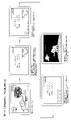
まず、図1及び図2を参照しながら、本実施形態に係るぱちんこ遊技機の前面側の基本構造を説明する。ぱちんこ遊技機は、大別すると遊技機枠Dと遊技盤Daとに分けられ、遊技機枠D及び遊技盤Daは、夫々複数のユニットを組み付けて形成されている。以下、遊技機枠D及び遊技盤Daを構成する各ユニットについて順に説明する。 First, the basic structure of the front side of the pachinko game machine according to the present embodiment will be described with reference to FIGS. 1 and 2. FIG. A pachinko game machine is roughly divided into a game machine frame D and a game board Da, and the game machine frame D and the game board Da are each formed by assembling a plurality of units. Each unit constituting the game machine frame D and the game board Da will be described in order below.
はじめに、ぱちんこ遊技機の遊技機枠Dは、外枠ユニットD12、前枠ユニットD14、透明板ユニット(又はガラスユニットともいう)D16、扉ユニット(又はガラス扉、ともいう)D18、球皿ユニットD17(上球皿D20、下球皿D22及び発射ハンドルD44を含む)を主体として構成される。 First, the game machine frame D of the pachinko game machine includes an outer frame unit D12, a front frame unit D14, a transparent plate unit (also called glass unit) D16, a door unit (also called glass door) D18, and a ball tray unit D17. (including the upper ball plate D20, the lower ball plate D22 and the shooting handle D44).
外枠ユニットD12は、ぱちんこ遊技機を設置すべき位置に固定するための枠体であり、上下左右の枠杆(上枠杆D12d、下枠杆D12e、左枠杆D12a、右枠杆D12b)及び幕板D12cを、額縁状に適宜組み付けてユニット化されている。ここで、左枠杆D12aには、前枠ユニットD14を組み付けるための上下1組の前枠用ヒンジD12a-1が固着され、右枠杆D12bには、前枠ユニットD14を施錠するための外枠側の施錠金具(不図示)が固着されている。また、本実施形態では、幕板D12cに遊技状態に応じた音声を出力可能なスピーカD24が配設されており、左右の枠杆(左枠杆D12a、右枠杆D12b)が金属により、上下の枠杆(上枠杆D12d、下枠杆D12e)が木材により、幕板D12cが樹脂により夫々形成されている。 The outer frame unit D12 is a frame body for fixing the pachinko game machine to a position to be installed, and includes upper, lower, left, and right frame rods (upper frame rod D12d, lower frame rod D12e, left frame rod D12a, right frame rod D12b). and the curtain plate D12c are appropriately assembled in a frame shape to form a unit. Here, a set of upper and lower front frame hinges D12a-1 for assembling the front frame unit D14 is fixed to the left frame rod D12a, and an outer frame for locking the front frame unit D14 is attached to the right frame rod D12b. A locking metal fitting (not shown) on the frame side is fixed. In addition, in this embodiment, the curtain plate D12c is provided with a speaker D24 capable of outputting a sound according to the game state, and the left and right frame rods (left frame rod D12a, right frame rod D12b) are made of metal. The frame rods (upper frame rod D12d, lower frame rod D12e) are made of wood, and the curtain plate D12c is made of resin.
前枠ユニットD14は、外形サイズが、外枠ユニットD12の開口部分に整合する枠体であり、外枠ユニットD12に設けられた前枠用ヒンジD12a-1及び施錠金具(不図示)と、前枠ユニットD14の適宜位置に設けられた(これらに対応した)ヒンジ機構D14a-1並びに施錠装置(不図示)により、外枠ユニットD12に対して横開き開閉可能、且つ施錠可能に取り付けられる。 The front frame unit D14 is a frame whose outer size matches the opening of the outer frame unit D12. A hinge mechanism D14a-1 (corresponding to these) provided at an appropriate position of the frame unit D14 and a locking device (not shown) are attached to the outer frame unit D12 so as to be laterally openable, openable, and lockable.
前枠ユニットD14には、遊技球を発射する発射機構、遊技盤Daを着脱可能に収容させるための遊技盤収容機構、賞球を付与するための賞球払出機構や、遊技済み球を誘導又は回収するための遊技済み球排出機構等が設けられている。本実施形態では、基体を成し遊技盤収容機構が形成されると共に発射機構の取り付けられた前枠本体D14aと、前枠本体D14aに着脱可能に取り付けられ、賞球払出機構、遊技済み球排出機構が形成された裏機構ユニットD14bと、から前枠ユニットD14が形成されている。また、前枠本体D14aの左側部には、後述する扉ユニットD18を組み付けるための上下1組のガラス枠用ヒンジD14a-2が設けられており、前枠本体D14aの右側部に扉ユニットD18を施錠するためのガラス枠用施錠装置(不図示)が設けられている。更に前枠本体D14aの下部には、後述する球皿ユニットD17を組み付けるための球皿ユニット支持機構(球皿用ヒンジD14a-3を含む)が設けられている。 The front frame unit D14 includes a shooting mechanism for shooting game balls, a game board housing mechanism for detachably housing the game board Da, a prize ball payout mechanism for awarding prize balls, and a mechanism for guiding or guiding played balls. A played ball ejection mechanism or the like is provided for collecting the played balls. In this embodiment, a front frame main body D14a forming a base and forming a game board accommodating mechanism and having a shooting mechanism attached thereto, and detachably attached to the front frame main body D14a, a prize ball payout mechanism, and a game ball discharging mechanism are provided. A back mechanism unit D14b in which a mechanism is formed and a front frame unit D14 are formed. A set of upper and lower glass frame hinges D14a-2 for assembling a door unit D18, which will be described later, is provided on the left side of the front frame main body D14a, and the door unit D18 is attached to the right side of the front frame main body D14a. A glass frame locking device (not shown) is provided for locking. Further, a sphere unit support mechanism (including a sphere hinge D14a-3) for assembling a sphere unit D17, which will be described later, is provided at the lower portion of the front frame main body D14a.
透明板ユニットD16は、複数枚(例えば2枚)のガラスやアクリル板などの透明板D16aを所定の間隔(20mm程度)をあけて平行に保持するためのものであり、コの字状の第一部材D16bに形成されたガラス保持部(不図示)にガラスを挿入した後に、挿入部分を遮蔽する第二部材D16cをはめ込み接着して一体化されて形成される。尚、透明板ユニットD16(特に、透明板D16a)は、後述する扉ユニットD18の開口面を介して、遊技盤Daの遊技領域D30を透視可能で且つ、当該開口面から異物が進入しない(当該開口面から遊技盤Da及び遊技領域D30へアクセス困難となる)ように取り付けられる。 The transparent plate unit D16 is for holding a plurality of (for example, two) transparent plates D16a such as glass or acrylic plates in parallel with a predetermined interval (about 20 mm). After glass is inserted into a glass holding portion (not shown) formed in one member D16b, a second member D16c that shields the inserted portion is fitted and bonded to be integrated. The transparent plate unit D16 (particularly, the transparent plate D16a) allows the game area D30 of the game board Da to be seen through the opening surface of the door unit D18, which will be described later. Access to the game board Da and the game area D30 from the opening surface is difficult).
扉ユニット(ガラス扉)D18は、前枠ユニットD14に設けられたガラス枠用ヒンジD14a-2及びガラス枠用施錠装置(不図示)と、扉ユニットD18の適宜位置に設けられた(これらに対応した)ヒンジ機構並びに施錠金具(不図示)により、前枠ユニットD14に対して横開き開閉可能、且つ施錠可能に取り付けられる。尚、扉ユニットD18は、外形サイズが、遊技盤Daの外形に略整合する大きさで構成されており、中央に透明板ユニットD16よりも小さい面積にて開口部D18aが設けられ、透明板ユニットD16を介して後述する遊技盤Da及び遊技領域D30が、視認可能となっている。 The door unit (glass door) D18 includes a glass frame hinge D14a-2 and a glass frame locking device (not shown) provided in the front frame unit D14, and provided at an appropriate position of the door unit D18 (corresponding to these ), it is attached to the front frame unit D14 so that it can be laterally opened and closed and can be locked by a hinge mechanism and a locking metal fitting (not shown). The door unit D18 has an outer size that substantially matches the outer shape of the game board Da. A game board Da and a game area D30, which will be described later, can be visually recognized through D16.
扉ユニットD18には、その背面側に、透明板ユニットD16を保持する透明板ユニット保持部D18b、開口部D18aの周囲に電飾効果や視覚的効果が得られるような装飾が施された装飾部D18c等も形成されている。尚、本実施形態では、扉ユニットD18の右上部に枠装飾ランプD18-Lと、扉ユニットD18の中央上部に、所定の演出(例えば、大当り時等)の実行時に開状態(点線にて図示)となって点灯する演出用開閉役物D18-Y(即ち、初期位置としては閉状態にあって非点灯となっており、所定の演出の実行開始条件を充足した場合には、開状態となって点灯し、所定の演出の実行終了条件を充足した場合には、再び閉状態となって非点灯となる部材であり、後述する副制御基板Sによってその動作が制御される部材)と、が配設されている。扉ユニットD18の部品構成等についての詳細は後述する。 The door unit D18 has a transparent plate unit holding portion D18b for holding the transparent plate unit D16 on its back side, and a decorative portion around the opening D18a which is decorated so as to provide an illumination effect and a visual effect. D18c etc. are also formed. In the present embodiment, a frame decorative lamp D18-L is placed in the upper right part of the door unit D18, and a lamp in an open state (illustrated by a dotted line) is placed in the upper central part of the door unit D18 when a predetermined effect (for example, when a big hit is performed) is executed. ) to light up the effect opening/closing accessory D18-Y. (a member whose operation is controlled by a sub-control board S, which will be described later); are arranged. The details of the component configuration of the door unit D18 will be described later.
球皿ユニットD17は、前枠ユニットD14に設けられた球皿ユニット支持機構(球皿用ヒンジD14a-3を含む)と、球皿ユニットD17の適宜位置に設けられた係合部材(例えば、係合部材D17a-1)とにより、前枠ユニットD14に対して着脱可能に取り付けられる。尚、球皿ユニットD17は、扉ユニットD18を開閉した状態でのみ前枠ユニットD14から着脱可能とすることで、当該遊技機専用の鍵を設けずとも、遊技に供されている状態では取り外しが困難な構造(例えば、扉ユニットD18の一部と球皿ユニットD17の一部がラップする構造)を採用している。 The spherical disk unit D17 includes a spherical disk unit support mechanism (including a spherical disk hinge D14a-3) provided on the front frame unit D14, and an engaging member (for example, an engaging member) provided at an appropriate position on the spherical disk unit D17. It is detachably attached to the front frame unit D14 by the joining member D17a-1). The ball tray unit D17 can be removed from the front frame unit D14 only when the door unit D18 is opened and closed. A difficult structure (for example, a structure in which a part of the door unit D18 and a part of the spherical dish unit D17 overlap) is adopted.
球皿ユニットD17は、外形サイズが、方形状に形成され、上部にて発射装置に遊技球を供給する上球皿D20、下部にて多数の賞球が払い出されたことにより、上球皿D20に過剰な遊技球が供給された場合に当該過剰分の遊技球を貯留可能な下球皿D22が形成され、下球皿D22の右側に、遊技者の操作により発射装置の発射強度(遊技球の打球位置)を調整する発射ハンドルD44が設けられている。また、球皿ユニットD17の一部表面(本例では、上球皿D20の上面)には、遊技者が演出時に操作するサブ入力ボタンSB、遊技球の貸し出し要求を行うための貸出操作部(不図示)が配設されている。また、上球皿D20と下球皿D22との間には、スピーカD24が設けられている。尚、球皿ユニットD17の部品構成等についての詳細は後述する。 The ball tray unit D17 has a rectangular outer shape, an upper ball tray D20 for supplying game balls to the launching device at the top, and an upper ball tray D20 for supplying a large number of prize balls at the bottom. A lower ball tray D22 capable of storing the excess game balls when excessive game balls are supplied to D20 is formed. A shooting handle D44 is provided for adjusting the hitting position of the ball. A part of the surface of the ball tray unit D17 (in this example, the upper surface of the upper ball tray D20) is provided with a sub-input button SB operated by the player during production, and a lending operation unit ( (not shown) are provided. A speaker D24 is provided between the upper spherical dish D20 and the lower spherical dish D22. The details of the component configuration of the spherical dish unit D17 will be described later.
本実施形態における遊技機枠Dの概略構成は以上の通りであるが、前述したように、遊技機枠Dは複数のユニットから構成されており、より具体的には、外枠ユニットD12の前方に前枠ユニットD14(遊技盤Daを内包)、前枠ユニットD14の前方に透明板ユニットD16、扉ユニットD18及び球皿ユニットD17が、それぞれ着脱可能(又は開閉可能)に構成されている。このため、それぞれのユニットの整合部分には、開閉操作や着脱操作を容易にするための微少な間隙を有することとなる。よって、本実施形態においては、図示は省略するが、各ユニットの整合部分には、異物の混入を抑止するために、間隙が直線的にならないように整合部分にラビリンス構造(断面視で凹凸形状となるような構造)を採用していることが望ましい(但し、これには限定されない)。 The schematic configuration of the gaming machine frame D in this embodiment is as described above. As described above, the gaming machine frame D is composed of a plurality of units. A front frame unit D14 (including a game board Da), a transparent plate unit D16, a door unit D18 and a ball tray unit D17 in front of the front frame unit D14 are detachable (or openable/closable). For this reason, the aligned portions of the respective units have minute gaps for facilitating opening/closing operations and attachment/detachment operations. Therefore, in the present embodiment, although illustration is omitted, in order to prevent foreign matter from entering the alignment portion of each unit, the alignment portion is provided with a labyrinth structure (an uneven shape in a cross-sectional view) so that the gap is not straight. (However, it is not limited to this).
尚、本実施形態では、扉ユニットD18と球皿ユニットD17とが別体の構造を採用しているが、双方を一体構造を採用しても良い。また、本実施形態においては、遊技結果に応じて物理的な遊技媒体を払い出す構造を採用しているが、電子式な媒体管理を行うよう構成してもよい。その場合には、下球皿D22や賞球払出機構等は不要となり、遊技済み球を上球皿D20に戻して電子的な管理を行う遊技機形態(いわゆる封入循環形態)が採用され、球皿ユニットD17或いは扉ユニットD18等に電子媒体による精算・貸出用の操作部が配設されることになることを補足しておく。 In this embodiment, the door unit D18 and the spherical dish unit D17 employ separate structures, but both may employ an integrated structure. Further, in the present embodiment, a structure is adopted in which physical game media are paid out according to game results, but it may be configured to perform electronic media management. In that case, the lower ball tray D22, prize ball payout mechanism, etc. are not required, and a game machine form (so-called enclosed circulation form) is adopted in which the played balls are returned to the upper ball tray D20 and electronically managed. It is supplemented that an operation unit for checkout/rental by an electronic medium is arranged in the plate unit D17 or the door unit D18 or the like.
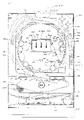
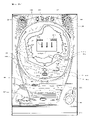
次に、遊技盤Daには、外レールD32と内レールD34とにより区画された遊技領域D30が形成されている。そして、当該遊技領域D30には、図示しない複数の遊技釘及び風車等の機構や各種一般入賞口の他、第1主遊技始動口A10、第2主遊技始動口B10、補助遊技始動口H10、第1大入賞口C10、第2大入賞口C20(又は振分入賞口C20と呼ぶことがある)、第1主遊技図柄表示装置A20、第2主遊技図柄表示装置B20、演出表示装置SG、補助遊技図柄表示装置H20、センター飾りD38及びアウト口C80が設置されている。以下、各要素を順番に詳述する。 Next, a game area D30 defined by an outer rail D32 and an inner rail D34 is formed on the game board Da. In addition, in the game area D30, in addition to a plurality of mechanisms such as game nails and windmills (not shown) and various general winning openings, a first main game start opening A10, a second main game start opening B10, an auxiliary game start opening H10, 1st big winning slot C10, 2nd big winning slot C20 (or sometimes called distribution winning slot C20), 1st main game symbol display device A20, 2nd main game symbol display device B20, effect display device SG, An auxiliary game symbol display device H20, a center decoration D38 and an out port C80 are installed. Each element will be described in detail below.
次に、第1主遊技始動口A10は、第1主遊技に対応する始動入賞口として設置されている。具体的構成としては、第1主遊技始動口A10は、第1主遊技始動口入球検出装置A11sを備える。ここで、第1主遊技始動口入球検出装置A11sは、第1主遊技始動口A10への遊技球の入球を検出するセンサであり、入球時にその入球を示す第1主遊技始動口入球情報を生成する。 Next, the first main game starting port A10 is installed as a starting prize winning port corresponding to the first main game. As a specific configuration, the first main game start opening A10 includes a first main game start opening ball detection device A11s. Here, the first main game start opening detection device A11s is a sensor that detects the entry of a game ball to the first main game start opening A10, and the first main game start that indicates the entry at the time of entry. Generate entry ball information.
次に、第2主遊技始動口B10は、第2主遊技に対応する始動入賞口として設置されている。具体的構成としては、第2主遊技始動口B10は、第2主遊技始動口入球検出装置B11sと、第2主遊技始動口電動役物B11dと、を備える。ここで、第2主遊技始動口入球検出装置B11sは、第2主遊技始動口B10への遊技球の入球を検出するセンサであり、入球時にその入球を示す第2主遊技始動口入球情報を生成する。次に、第2主遊技始動口電動役物B11dは、第2主遊技始動口B10に遊技球が入賞し難い閉鎖状態と当該通常状態よりも遊技球が入賞し易い開放状態に可変する。 Next, the second main game starting port B10 is installed as a starting prize winning port corresponding to the second main game. Specifically, the second main game start opening B10 includes a second main game start opening ball detection device B11s and a second main game start electric accessory B11d. Here, the second main game start opening ball detection device B11s is a sensor that detects the entry of a game ball to the second main game start opening B10, and the second main game start indicating the entry at the time of entry. Generate entry ball information. Next, the second main game starter electric accessory B11d changes between a closed state in which game balls are less likely to enter the second main game starter B10 and an open state in which game balls are easier to enter than in the normal state.
ここで、本実施形態においては、第1主遊技始動口A10と第2主遊技始動口B10とが離隔して設けられており、遊技領域D30の左側(遊技領域中央を基準)を流下する遊技球が、第1主遊技始動口A10に誘導され易い一方、第2主遊技始動口B10に誘導され難いよう構成されている。他方、遊技領域D30の右側(遊技領域中央を基準)を流下する遊技球は、第1主遊技始動口A10に誘導され難い一方、第2主遊技始動口B10に誘導され易いよう構成されている。尚、「誘導され易い」及び「誘導され難い」は、例えば、遊技球を右側及び左側にそれぞれ10000球発射した際の、入球数の大小で決定するものとする。 Here, in this embodiment, the first main game start port A10 and the second main game start port B10 are provided separately, and the game flowing down the left side of the game area D30 (based on the center of the game area) The ball is structured so as to be easily guided to the first main game start port A10, but difficult to be guided to the second main game start port B10. On the other hand, a game ball flowing down the right side of the game area D30 (with reference to the center of the game area) is configured to be easily guided to the second main game start opening B10 while it is difficult to be guided to the first main game start opening A10. . It should be noted that "easily guided" and "difficult to be guided" are determined, for example, by the number of incoming balls when 10,000 game balls are shot to the right and left respectively.
尚、本実施形態では、第2主遊技始動口B10側に電動役物を設けるよう構成したが、これには限定されず、第1主遊技始動口A10側に電動役物を設けるよう構成してもよい。更には、本実施形態では、第1主遊技始動口A10と第2主遊技始動口B10とが離隔して配置されているが、これにも限定されず、第1主遊技始動口A10と第2主遊技始動口B10とを重ねるように配置してもよく、その場合には、第1主遊技始動口A10の存在により、第2主遊技始動口B10の上部が塞がれているよう構成してもよい。 In this embodiment, the electric accessory is provided on the side of the second main game start port B10, but it is not limited to this, and the electric accessory is provided on the side of the first main game start port A10. may Furthermore, in the present embodiment, the first main game starter A10 and the second main game starter B10 are arranged apart from each other, but it is not limited to this, and the first main game starter A10 and the second main game starter A10 are arranged separately. It may be arranged so as to overlap the second main game starter B10, and in that case, the upper part of the second main game starter B10 is blocked by the existence of the first main game starter A10. You may
次に、補助遊技始動口H10は、補助遊技始動口入球検出装置H11sを備える。ここで、補助遊技始動口入球検出装置H11sは、補助遊技始動口H10への遊技球の入球を検出するセンサであり、入球時にその入球を示す補助遊技始動口入球情報を生成する。尚、補助遊技始動口H10への遊技球の入球は、第2主遊技始動口B10の第2主遊技始動口電動役物B11dを拡開させるための抽選の契機となる。 Next, the auxiliary game starting port H10 is provided with an auxiliary game starting port entering ball detection device H11s. Here, the auxiliary game start entrance ball detection device H11s is a sensor that detects the entrance of the game ball to the auxiliary game start hole H10, and generates auxiliary game start entrance ball information indicating the entrance ball at the time of entrance. do. The entry of the game ball into the auxiliary game starter H10 triggers a lottery for expanding the second main game starter electric accessory B11d of the second main game starter B10.
ここで、本実施形態においては、遊技領域D30の左側(遊技領域中央を基準)を流下する遊技球が、補助遊技始動口H10に誘導され難い一方、遊技領域D30の右側(遊技領域中央を基準)を流下する遊技球は、補助遊技始動口H10に誘導され易いよう構成されている{但し、これには限定されず、遊技領域D30の左側(遊技領域中央を基準)を流下する遊技球をも、補助遊技始動口H10に誘導され易いよう構成してもよい}。 Here, in the present embodiment, the game ball flowing down the left side of the game area D30 (based on the center of the game area) is difficult to be guided to the auxiliary game start opening H10, while the right side of the game area D30 (based on the center of the game area) ) is configured to be easily guided to the auxiliary game starting port H10 {However, it is not limited to this, and the game ball flowing down the left side of the game area D30 (based on the center of the game area) may also be configured to be easily guided to the auxiliary game starting port H10}.
次に、アウト口C80の上方(特に、遊技領域D30の右側)には、第1大入賞口C10と第2大入賞口C20とが設けられており、遊技領域D30の右側(遊技領域中央を基準)を流下する遊技球は、アウト口C80に到達する前に、第1大入賞口C10及び第2大入賞口C20が配置されている領域を通過し易いよう構成されている。 Next, above the out port C80 (particularly, on the right side of the game area D30), there are provided a first big winning hole C10 and a second big winning hole C20. The game ball flowing down the standard) is configured to easily pass through the area where the first big winning hole C10 and the second big winning hole C20 are arranged before reaching the out hole C80.
次に、第1大入賞口C10は、第1主遊技図柄(特別図柄)又は第2主遊技図柄(特別図柄)が大当り図柄停止した場合に開状態となる、横長方形状を成しアウト口C80の上方(特に、遊技領域D30の右側)に位置した、主遊技に対応した入賞口である。具体的構成としては、第1大入賞口C10は、遊技球の入球を検出するための第1大入賞口入賞検出装置C11sと、第1大入賞口電動役物C11d(及び第1大入賞口ソレノイドC13)と、を備える。ここで、第1大入賞口入賞検出装置C11sは、第1大入賞口C10への遊技球の入球を検出するセンサであり、入球時にその入球を示す第1大入賞口入球情報を生成する。第1大入賞口電動役物C11dは、第1大入賞口C10に遊技球が入賞不能又は入賞困難な通常状態と遊技球が入賞し易い開放状態に第1大入賞口C10を可変させる(第1大入賞口ソレノイドC13を励磁して可変させる)。尚、本実施形態では、大入賞口の態様を、横長方形状を成し遊技球が入賞不能又は入賞困難な通常状態と遊技球が入賞し易い開放状態とに可変させる態様としているが、これには限定されない。その場合には、例えば、大入賞口に設けられた棒状部材が遊技者側に突き出した状態である進出状態と遊技者側に対して引っ込んだ状態である退避状態とを採り得る態様(いわゆる、スライド式アタッカーであり、遊技領域D30から突出し遊技領域D30を流下する遊技球を受入れ可能な箱状の部材を大入賞口自体が有しており、進出状態にある場合には当該箱状の部材への遊技球の受け入れが阻害されることで大入賞口が閉状態となり、退避状態にある場合には当該箱状の部材への遊技球の受け入れが許容されることで大入賞口が開状態となる構成)としてもよく、大入賞口への入球数を所定数(例えば、10個)とすることを担保したい場合において好適である。 Next, the first big winning hole C10 is a horizontally rectangular out hole that opens when the first main game pattern (special pattern) or the second main game pattern (special pattern) stops as a jackpot pattern. This is a prize winning opening corresponding to the main game located above C80 (especially on the right side of the game area D30). As a specific configuration, the first large winning opening C10 includes a first large winning opening winning detection device C11s for detecting the entry of a game ball, a first large winning opening electric accessory C11d (and a first large winning opening and a solenoid C13). Here, the first big winning hole winning detection device C11s is a sensor that detects the entry of a game ball into the first big winning hole C10, and the first big winning hole entering ball information indicating the ball entering the first big winning hole C10. to generate The first big winning opening electric accessory C11d changes the first big winning opening C10 between a normal state in which the game ball cannot or is difficult to win in the first big winning opening C10 and an open state in which the game ball easily wins (the first 1. Excite the big winning opening solenoid C13 to make it variable). In the present embodiment, the mode of the big winning opening is changed between a normal state in which a game ball cannot or is difficult to win a horizontal rectangular shape and an open state in which a game ball can easily win a prize. is not limited to In that case, for example, a state in which the rod-shaped member provided in the big winning opening protrudes toward the player side and a retracted state in which the bar member is retracted toward the player side (so-called The big prize opening itself has a box-shaped member which is a slide type attacker and can accept game balls that protrude from the game area D30 and flow down the game area D30, and the box-shaped member is in the advancing state. The large winning opening is closed by obstructing the acceptance of the game ball into the box-shaped member, and when it is in the retracted state, the big winning opening is opened by allowing the reception of the game ball into the box-shaped member. ), which is suitable when it is desired to ensure that the number of balls entering the big winning hole is a predetermined number (for example, 10).
次に、第2大入賞口C20は、第1主遊技図柄(特別図柄)又は第2主遊技図柄(特別図柄)が大当り図柄で停止した場合に開状態となる、横長方形状を成しアウト口C80の上方(特に、遊技領域D30の右側)に位置した、主遊技に対応した入賞口である。具体的構成としては、第2大入賞口C20は、遊技球の入球を検出するための第2大入賞口入賞検出装置C21sと、第2大入賞口電動役物C21d(及び第2大入賞口ソレノイドC23)と、を備える。ここで、第2大入賞口入賞検出装置C21sは、第2大入賞口C20への遊技球の入球を検出するセンサであり、入球時にその入球を示す第2大入賞口入球情報を生成する。そして、第2大入賞口C20内に入球した遊技球は、第2大入賞口入賞検出装置C21sによって検出されるよう構成されている。次に、第2大入賞口電動役物C21dは、第2大入賞口C20に遊技球が入賞不能又は入賞困難な通常状態と遊技球が入賞し易い開放状態とに第2大入賞口C20を可変させる(第2大入賞口ソレノイドC23を励磁して可変させる)。尚、本実施形態では、大入賞口の態様を、横長方形状を成し遊技球が入賞不能又は入賞困難な通常状態と遊技球が入賞し易い開放状態とに可変させる態様としているが、これには限定されない。その場合には、例えば、大入賞口に設けられた棒状部材が遊技者側に突き出した状態である進出状態と遊技者側に対して引っ込んだ状態である退避状態とを採り得る態様(いわゆる、スライド式アタッカーであり、遊技領域D30から突出し遊技領域D30を流下する遊技球を受入れ可能な箱状の部材を大入賞口自体が有しており、進出状態にある場合には当該箱状の部材への遊技球の受け入れが阻害されることで大入賞口が閉状態となり、退避状態にある場合には当該箱状の部材への遊技球の受け入れが許容されることで大入賞口が開状態となる構成)としてもよく、大入賞口への入球数を所定数(例えば、10個)とすることを担保したい場合において好適である。 Next, the second big winning hole C20 is a horizontal rectangular shape that is opened when the first main game pattern (special pattern) or the second main game pattern (special pattern) stops with a big win pattern, and is out. This is a prize winning opening corresponding to the main game located above the opening C80 (particularly on the right side of the game area D30). As a specific configuration, the second large winning opening C20 includes a second large winning opening winning detection device C21s for detecting the entry of a game ball, a second large winning opening electric accessory C21d (and a second large winning opening and a solenoid C23). Here, the second large winning opening detection device C21s is a sensor that detects the entry of a game ball into the second large winning opening C20, and the second large winning opening entry ball information indicating the entry of the ball at the time of entry. to generate A game ball entered into the second big winning hole C20 is configured to be detected by the second big winning hole winning detection device C21s. Next, the second big winning hole electric accessory C21d changes the second big winning hole C20 into a normal state in which the game ball cannot or is difficult to win in the second big winning hole C20 and an open state in which the game ball easily wins. Make it variable (make it variable by energizing the second big winning opening solenoid C23). In the present embodiment, the mode of the big winning opening is changed between a normal state in which a game ball cannot or is difficult to win a horizontal rectangular shape and an open state in which a game ball can easily win a prize. is not limited to In that case, for example, a state in which the rod-shaped member provided in the big winning opening protrudes toward the player side and a retracted state in which the bar member is retracted toward the player side (so-called The big prize opening itself has a box-shaped member which is a slide type attacker and can accept game balls that protrude from the game area D30 and flow down the game area D30, and the box-shaped member is in the advancing state. The large winning opening is closed by obstructing the acceptance of the game ball into the box-shaped member, and when it is in the retracted state, the big winning opening is opened by allowing the reception of the game ball into the box-shaped member. ), which is suitable when it is desired to ensure that the number of balls entering the big winning hole is a predetermined number (for example, 10).
次に、第1主遊技図柄表示装置A20(第2主遊技図柄表示装置B20)は、第1主遊技(第2主遊技)に対応する第1主遊技図柄(第2主遊技図柄)に関連した表示等を実行する装置である。具体的構成としては、第1主遊技図柄表示装置A20(第2主遊技図柄表示装置B20)は、第1主遊技図柄表示部A21g(第2主遊技図柄表示部B21g)と、第1主遊技図柄保留表示部A21h(第2主遊技図柄保留表示部B21h)とを備える。ここで、第1主遊技図柄保留表示部A21h(第2主遊技図柄保留表示部B21h)は、4個のランプから構成され、当該ランプの点灯個数が、第1主遊技(第2主遊技)に係る乱数の保留数(実行されていない主遊技図柄の変動数)に相当する。尚、第1主遊技図柄表示部A21g(第2主遊技図柄表示部B21g)は、例えば7セグメントLEDで構成され、第1主遊技図柄(第2主遊技図柄)は、「0」~「9」の10種類の数字及びハズレの「-」で表示される{但し、これには限定されず、いずれの主遊技図柄が表示されたのかを遊技者が認識困難となるよう、7セグメントLEDを用いて記号等によって表示することが好適である。また、保留数表示においても、4個のランプから構成されていることには限定されず、最大4個分の保留数を表示可能に構成(例えば、1個のランプから構成されており、保留数1:点灯、保留数2:低速点滅、保留数3:中速点滅、保留数4:高速点滅、するよう構成)されていればよい}。 Next, the first main game symbol display device A20 (second main game symbol display device B20) is associated with the first main game symbol (second main game symbol) corresponding to the first main game (second main game). It is a device that executes display, etc. As a specific configuration, the first main game symbol display device A20 (second main game symbol display device B20) includes a first main game symbol display portion A21g (second main game symbol display portion B21g) and a first main game symbol display portion A21g (second main game symbol display portion B21g). A symbol reservation display portion A21h (second main game symbol reservation display portion B21h) is provided. Here, the first main game symbol reservation display portion A21h (second main game symbol reservation display portion B21h) is composed of four lamps, and the number of lighting of the lamps is equal to the first main game (second main game). It corresponds to the number of pending random numbers (the number of fluctuations in the main game symbols that have not been executed). The first main game symbol display portion A21g (second main game symbol display portion B21g) is composed of, for example, a 7-segment LED, and the first main game symbol (second main game symbol) is "0" to "9". ” and ``-'' for failure {However, it is not limited to this, and the 7-segment LED is displayed so that it is difficult for the player to recognize which main game pattern is displayed. It is preferable to display by a symbol or the like using In addition, the display of the number of holds is not limited to being composed of four lamps, and is configured to be able to display the number of holds for up to four (for example, it is composed of one lamp, number 1: lighting, number of holds 2: flashing at low speed, number of holds 3: flashing at medium speed, number of holds 4: flashing at high speed}.
尚、第1主遊技図柄(第2主遊技図柄)は必ずしも演出的な役割を持つ必要が無いため、本実施形態では、第1主遊技図柄表示装置A20(第2主遊技図柄表示装置B20)の大きさは、目立たない程度に設定されている。しかしながら、第1主遊技図柄(第2主遊技図柄)自体に演出的な役割を持たせて第1装飾図柄(第2装飾図柄)を表示させないような手法を採用する場合には、後述する演出表示装置SGのような液晶ディスプレーに、第1主遊技図柄(第2主遊技図柄)を表示させるように構成してもよい。 It should be noted that the first main game symbol (second main game symbol) does not necessarily have to play a role in production, so in this embodiment, the first main game symbol display device A20 (second main game symbol display device B20) is used. is set to an inconspicuous size. However, in the case of adopting a technique in which the first main game pattern (second main game pattern) itself has a role in production and the first decorative pattern (second decorative pattern) is not displayed, the production described later The first main game symbols (second main game symbols) may be displayed on a liquid crystal display such as the display device SG.
次に、演出表示装置SGは、第1主遊技図柄・第2主遊技図柄と連動して変動・停止する装飾図柄を含む演出画像の表示等を実行する装置である。ここで、具体的構成としては、演出表示装置SGは、装飾図柄の変動表示等を含めて演出が実行される表示領域SG10を備える。ここで、表示領域SG10は、主遊技保留情報を表示する第1保留表示部SG12(及び第2保留表示部SG13)と、例えば、スロットマシンのゲームを模した複数列の装飾図柄変動の動画像を表示する装飾図柄表示領域SG11と、を有している。尚、演出表示装置SGは、本実施形態では液晶ディスプレーで構成されているが、機械式のドラムやLED等の他の表示手段で構成されていてもよい。次に、第1保留表示部SG12(及び第2保留表示部SG13)は、4個のランプから構成され、当該ランプは、主遊技図柄の保留ランプと連動している。 Next, the effect display device SG is a device that executes display of effect images including decorative symbols that fluctuate and stop interlocking with the first main game symbols and the second main game symbols. Here, as a specific configuration, the effect display device SG includes a display area SG10 in which effects including variable display of decorative symbols are executed. Here, the display area SG10 consists of a first pending display portion SG12 (and a second pending display portion SG13) for displaying main game pending information, and a moving image of a plurality of columns of decoration symbol variations imitating a slot machine game, for example. and a decorative design display area SG11 for displaying . In this embodiment, the effect display device SG is composed of a liquid crystal display, but may be composed of other display means such as mechanical drums or LEDs. Next, the first suspension display portion SG12 (and the second suspension display portion SG13) is composed of four lamps, and the lamps are interlocked with the suspension lamps of the main game symbols.
次に、補助遊技図柄表示装置H20は、補助遊技図柄に関する表示等を実行する装置である。具体的構成としては、補助遊技図柄表示装置H20は、補助遊技図柄表示部H21gと、補助遊技図柄保留表示部H21hとを備える。ここで、補助遊技図柄保留表示部H21hは、4個のランプから構成され、当該ランプの点灯個数が、補助遊技図柄変動の保留数(実行されていない補助遊技図柄変動の数)に相当する。 Next, the auxiliary game symbol display device H20 is a device that executes display and the like regarding auxiliary game symbols. Specifically, the auxiliary game symbol display device H20 includes an auxiliary game symbol display portion H21g and an auxiliary game symbol reserve display portion H21h. Here, the auxiliary game symbol reservation display portion H21h is composed of four lamps, and the number of lights of the lamps corresponds to the number of auxiliary game symbol fluctuation reservations (the number of auxiliary game symbol fluctuations that have not been executed).
次に、センター飾りD38は、演出表示装置SGの周囲に設置され、遊技球の流路、演出表示装置SGの保護、装飾等の機能を有する。また、遊技効果ランプD26は、遊技領域D30又は遊技領域D30以外の領域に設けられ、点滅等することで演出の役割を果たす。 Next, the center decoration D38 is installed around the performance display device SG, and has functions such as the passage of game balls, the protection of the performance display device SG, decoration, and the like. Also, the game effect lamp D26 is provided in the game area D30 or an area other than the game area D30, and plays a role of effect by blinking or the like.
次に、図3を参照しながら、ぱちんこ遊技機の背面側における基本構造を説明する。ぱちんこ遊技機は、ぱちんこ遊技機の全体動作を制御し、特に第1主遊技始動口A10(第2主遊技始動口B10)へ入球したときの抽選等、遊技動作全般の制御(即ち、遊技者の利益と直接関係する制御)を行う主制御基板Mと、遊技内容に興趣性を付与する演出表示装置SG上での各種演出に係る表示制御等を行う演出制御手段(サブメイン制御部)SMと、主に演出表示を実行するサブサブ制御部SSと、所定のエラー発生時に点灯してエラー発生を報知するエラーランプSS3と、賞球タンクKT、賞球レールKR及び各入賞口への入賞に応じて賞球タンクKTから供給される遊技球を上球皿D20へ払い出す賞球払出ユニットKE10等を備える賞球払出装置(セット基盤)KEと、賞球払出ユニットKE10による払出動作を制御する賞球払出制御基板KHと、払出に係るエラーの発生状況を表示(例えば、7セグ表示)するエラー表示器KH3と、所定のエラーを解除するためのエラー解除スイッチKH3aと、上球皿D20の遊技球(貯留球)を遊技領域D30へ1球ずつ発射する発射装置D42と、発射装置D42の発射動作を制御する発射制御基板D40と、ぱちんこ遊技機の各部へ電力を供給する電源供給ユニットEと、ぱちんこ遊技機の電源をオン・オフするスイッチである電源スイッチEa等が、前枠ユニットD14裏面(遊技側と反対側)に設けられている。 Next, the basic structure on the back side of the pachinko game machine will be described with reference to FIG. The pachinko game machine controls the overall operation of the pachinko game machine, and controls the overall game operation (i.e., the game a main control board M that performs control directly related to the interests of players), and an effect control means (sub-main control unit) that performs display control related to various effects on the effect display device SG that adds interest to the game content. SM, a sub-sub control unit SS that mainly executes performance display, an error lamp SS3 that lights up when a predetermined error occurs to notify the occurrence of an error, a prize ball tank KT, a prize ball rail KR, and prizes for each prize opening A prize ball payout device (set base) KE equipped with a prize ball payout unit KE10, etc. that pays out game balls supplied from the prize ball tank KT to the upper ball tray D20 in accordance with the above, and the payout operation by the prize ball payout unit KE10 is controlled. a prize ball payout control board KH, an error indicator KH3 that displays the occurrence status of an error related to payout (for example, a 7-segment display), an error release switch KH3a for canceling a predetermined error, and an upper ball tray D20. A launching device D42 that shoots game balls (stored balls) into the game area D30 one by one, a launch control board D40 that controls the shooting operation of the launching device D42, and a power supply unit that supplies power to each part of the pachinko game machine. E and a power switch Ea, which is a switch for turning on/off the power of the pachinko game machine, are provided on the rear surface of the front frame unit D14 (opposite side to the game side).
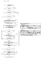
次に、図4及び図5を参照しながら、本実施形態に係るぱちんこ遊技機の賞球払出ユニットKE10の構造と遊技球の払出を行う動作原理を説明することとする。まず、図4上段に示されるように、賞球払出ユニットKE10は、払出の際に駆動される払出モータ(ステッピングモータ)KE10mを有している。そして、図4下段に示されるように、賞球払出ユニットKE10は、ステッピングモータKE10mと連結したスプロケットKE10pを有している。このような構造の賞球払出ユニットKE10は、下記の原理に従い動作する。まず、遊技領域内の入賞口に遊技球が入球すると、入賞信号が主制御基板Mに送られ主制御基板Mは払出個数を決定し、賞球払出制御基板KHへ賞球の信号を送信する。或いは、カードユニットR等の遊技球貸出装置から賞球払出制御基板KHへ球貸しの要求がなされる。これを受けて賞球払出制御基板KHは賞球払出ユニットKE10を作動させ、賞球払出ユニットKE10内のステッピングモータKE10mが遊技球の払出を実行する。図5に示されるように、ステッピングモータKE10mが回転することにより、スプロケットKE10p(第1スプロケットKE10p1、第2スプロケットKE10p2及び回転確認用部材KE10p3が一体となっている部材)が回転し、遊技球が1球ずつ払い出される。また、払い出された遊技球は、賞球払出ユニットKE10の下流に連続して設けられた払出カウントセンサKE10sにより検知される。尚、断面C-Cについては、図示されるように、遊技球の流路に沿った(流路が見えやすい)断面を図示していることを補足しておく。 Next, referring to FIGS. 4 and 5, the structure of the prize ball payout unit KE10 of the pachinko game machine according to the present embodiment and the principle of operation for paying out game balls will be described. First, as shown in the upper part of FIG. 4, the prize ball payout unit KE10 has a payout motor (stepping motor) KE10m driven at the time of payout. As shown in the lower part of FIG. 4, the prize ball payout unit KE10 has a sprocket KE10p connected to the stepping motor KE10m. The prize ball payout unit KE10 having such a structure operates according to the following principle. First, when a game ball enters a winning hole in the game area, a winning signal is sent to the main control board M, the main control board M determines the number of payouts, and a prize ball signal is sent to the prize ball payout control board KH. do. Alternatively, a request for ball lending is made from the game ball lending device such as the card unit R to the prize ball payout control board KH. In response to this, the prize ball payout control board KH operates the prize ball payout unit KE10, and the stepping motor KE10m in the prize ball payout unit KE10 executes game ball payout. As shown in FIG. 5, the rotation of the stepping motor KE10m rotates the sprocket KE10p (a member in which the first sprocket KE10p1, the second sprocket KE10p2, and the rotation confirmation member KE10p3 are integrated), and the game ball rotates. One ball is paid out. In addition, the paid out game balls are detected by a payout count sensor KE10s continuously provided downstream of the prize ball payout unit KE10. It should be noted that the cross section CC is a cross section along the flow path of the game ball (the flow path is easy to see).
また、図4下段は、ロータ位置確認センサ(払出モータ位置センサ)KE10msと回転体(スプロケット)KE10pとを模式的に示した図である(一例)。ロータ位置確認センサKE10msは、一対の測定部を有しており、測定部間の物体を光の投受光により検出するフォトセンサである。ここで、一対の測定部は、光を投光する投光部と、投光部からの光を受光する受光部であり、回転確認用部材KE10p3を挟んで配置されている。ここで、回転確認用部材KE10p3は、円周に沿って6個の凹部が形成されており、回転確認用部材KE10p3がこれら投光部と受光部との間に介在しているときにはオフとなり、回転確認用部材KE10p3がこれら投光部と受光部との間に介在していないときにはオン(図4下段の状態)となる。 Further, the lower part of FIG. 4 is a diagram schematically showing a rotor position confirmation sensor (dispensing motor position sensor) KE10ms and a rotating body (sprocket) KE10p (an example). The rotor position confirmation sensor KE10ms is a photosensor that has a pair of measurement units and detects an object between the measurement units by light projection and reception. Here, the pair of measurement units are a light projecting unit that projects light and a light receiving unit that receives light from the light projecting unit, and are arranged with the rotation confirmation member KE10p3 interposed therebetween. Here, the rotation confirmation member KE10p3 has six concave portions formed along the circumference, and is turned off when the rotation confirmation member KE10p3 is interposed between the light projecting portion and the light receiving portion. When the rotation confirmation member KE10p3 is not interposed between the light projecting portion and the light receiving portion, it is turned on (state shown in the lower part of FIG. 4).
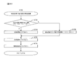
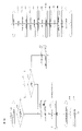
次に、図6のブロック図を参照しながら、本実施形態に係るぱちんこ遊技機の電気的な概略構成を説明する。はじめに、本実施形態に係るぱちんこ遊技機は、前述したように、遊技の進行を制御する主制御基板Mと、主制御基板Mからの情報(信号、コマンド等)に基づいて遊技球の払出を制御する賞球払出制御基板KHと、主制御基板Mからの情報(信号、コマンド等)に基づいて装飾図柄の変動・停止等の演出表示装置SG上での各種演出、スピーカD24からの音響、遊技効果ランプD26の点灯、エラー報知等の実行を制御する副制御基板S(本例では、サブメイン制御部SMとサブサブ制御部SSとが一つの基板上に配置されている)と、これらの制御基板を含む遊技機全体に電源を供給する電源供給ユニットEと、を主体として構成されている。ここで、副制御基板Sは、装飾図柄の変動・停止等の演出表示装置SG上での各種演出、スピーカD24からの音響、遊技効果ランプD26の点灯、エラー報知を制御するサブメイン制御部SMと、演出表示装置SG上での装飾図柄の変動表示・停止表示及び保留表示や予告表示等の表示処理を実行するサブサブ制御部SSの2つの制御部とを備えている。尚、主制御基板M、賞球払出制御基板KH、サブメイン制御部SM及びサブサブ制御部SSには、様々な演算処理を行うCPU、CPUの演算処理を規定したプログラムを予め記憶するROM、CPUが取り扱うデータ(遊技中に発生する各種データやROMから読み出されたコンピュータプログラム等)を一時的に記憶するRAM、電断時に情報を保持するためのバックアップ領域(及びバックアップ用電源)が搭載されている。 Next, a schematic electrical configuration of the pachinko gaming machine according to the present embodiment will be described with reference to the block diagram of FIG. First, the pachinko game machine according to the present embodiment, as described above, has a main control board M that controls the progress of the game, and pays out game balls based on information (signals, commands, etc.) from the main control board M. Based on information (signals, commands, etc.) from the prize ball payout control board KH to control and the main control board M, various effects on the effect display device SG such as fluctuation / stop of the decorative pattern, sound from the speaker D24, A sub-control board S (in this example, a sub-main control section SM and a sub-sub-control section SS are arranged on one board) for controlling lighting of the game effect lamp D26, execution of error notification, etc.; A power supply unit E for supplying power to the entire game machine including the control board is the main component. Here, the sub-control board S is a sub-main control unit SM that controls various effects on the effect display device SG such as variation and stoppage of decorative patterns, sound from the speaker D24, lighting of the game effect lamp D26, and error notification. and a sub-sub control unit SS for executing display processing such as variable display/stop display of decorative symbols on the effect display device SG, pending display, and advance notice display. In addition, the main control board M, prize ball payout control board KH, sub-main control unit SM and sub-sub control unit SS include a CPU for performing various arithmetic processing, a ROM for pre-storing a program defining the arithmetic processing of the CPU, and a CPU. Equipped with a RAM that temporarily stores data handled by (various data generated during games, computer programs read from ROM, etc.), and a backup area (and backup power supply) to retain information in the event of a power failure. ing.
以下、各基板の概略構成及び各基板・装置間の電気的な接続態様について概説する。まず、主制御基板Mは、入賞口センサNs{前述した第1主遊技始動口入球検出装置A11s、第2主遊技始動口入球検出装置B11s、補助遊技始動口入球検出装置H11s、第1大入賞口入賞検出装置C11s、第2大入賞口入賞検出装置C21s、一般入賞検出装置(不図示であるが、一般入球口とは、特別遊技の実行有無に拘わらず常時開口しており且つ賞球はあるが図柄抽選等を行わない入球口である)}、図示略する駆動ソレノイド(前述した、第1大入賞口ソレノイドC13、第2大入賞口ソレノイドC23等)、情報表示LED(不図示)等、遊技の進行に必須となる入出力装置である遊技周辺機器(図中の、第1主遊技周辺機器A、第2主遊技周辺機器B、第1・第2主遊技共用周辺機器C、補助遊技周辺機器H)と電気的に接続され、各入力装置からの入力信号に基づいて遊技の進行を制御している。更に、主制御基板Mは、賞球払出制御基板KHと、副制御基板S(サブメイン制御部SM・サブサブ制御部SS)とも電気的に接続されており、遊技進行に基づいて、賞球払出等に関する情報(コマンド)を賞球払出制御基板KHに、演出・遊技の進行状態等に関する情報(コマンド)を副制御基板Sにそれぞれ送信可能に構成されている。尚、主制御基板Mは、外部接続端子(不図示)を介してホールコンピュータHC等と接続可能となっており、外部接続端子を介してホールコンピュータHCと配線接続することで、主制御基板Mから外部の装置に対して遊技関連情報を出力できるよう構成されている。 Schematic configurations of the substrates and electrical connections between the substrates and devices will be described below. First, the main control board M has a winning opening sensor Ns {the first main game starting entrance entrance detection device A11s, the second main game start entrance entrance detection device B11s, the auxiliary game start entrance entrance detection device H11s, the second 1 large winning opening winning detection device C11s, 2nd large winning opening winning detection device C21s, general winning detection device (although not shown, the general winning opening is always open regardless of whether a special game is executed or not. Also, there is a prize ball, but a symbol lottery is not performed)}, a driving solenoid (not shown) (first big winning solenoid C13, second big winning solenoid C23, etc.), information display LED (not shown), etc., which are input/output devices essential for the progress of the game (first main game peripheral A, second main game peripheral B, first and second main game shared in the figure) It is electrically connected to the peripheral device C and the auxiliary game peripheral device H), and controls the progress of the game based on the input signal from each input device. Furthermore, the main control board M is electrically connected to the prize ball payout control board KH and the sub-control board S (sub-main control section SM, sub-sub control section SS), and prize ball payout is performed based on the game progress. etc. to the prize ball payout control board KH, and information (commands) to the sub control board S about the performance/game progress and the like. The main control board M can be connected to the hall computer HC or the like via an external connection terminal (not shown). It is configured to be able to output game-related information from to an external device.
また、本実施形態では、図6の矢印表記の通り、主制御基板Mと賞球払出制御基板KHとは、双方向通信が可能となるよう構成されている一方、主制御基板Mとサブメイン制御部SMとは、主制御基板Mからサブメイン制御部SMへの一方向通信が可能となるよう構成されている(通信方法は、シリアル通信、パラレル通信のいずれを用いてもよい)。尚、制御基板間(制御装置間)の通信については一方向通信でも双方向通信でもよい。また、主制御基板M及び賞球払出制御基板KHは、外部中継端子板Gを介して、遊技関連情報や払出関連情報を、外部出力情報としてホールコンピュータHCに出力(ホールコンピュータHC側に出力する一方向通信)可能に構成されている(詳細については後述する)。 In addition, in this embodiment, as indicated by arrows in FIG. The control section SM is configured to enable one-way communication from the main control board M to the sub-main control section SM (either serial communication or parallel communication may be used for the communication method). Communication between control boards (between control devices) may be one-way communication or two-way communication. In addition, the main control board M and the prize ball payout control board KH output game-related information and payout-related information to the hall computer HC via the external relay terminal board G as external output information (output to the hall computer HC side). One-way communication) is possible (details will be described later).
次に、賞球払出制御基板KHは、遊技球の払出を実行する賞球払出装置KEと、遊技者によって操作可能な装置であって遊技球の貸出要求を受付けて賞球払出制御基板KHに伝達する遊技球貸出装置R(カードユニットR)とに接続されている。また、図示略するが、本実施形態では、賞球払出制御基板KH内に、発射装置の制御回路部(発射制御基板D40)が併設されており、賞球払出制御基板KHと発射装置D42(発射ハンドル・発射モータ・球送り装置等)とも接続されている。尚、本実施形態では、遊技球貸出装置Rを別体として遊技機に隣接する形態を採用しているが、遊技機と一体としてもよく、その場合には、賞球払出制御基板KHにより貸出制御及び電子マネー等貸出用の記録媒体の管理制御等を統括して行ってもよい。 Next, the prize ball payout control board KH includes a prize ball payout device KE for executing game ball payout, and a device operable by the player that accepts a game ball lending request and sends the prize ball payout control board KH. It is connected to a game ball lending device R (card unit R) for transmission. Further, although not shown, in the present embodiment, a control circuit unit (firing control board D40) of the launching device is provided in the prize ball payout control board KH, and the prize ball payout control board KH and the launching device D42 ( It is also connected to the launch handle, launch motor, ball feeder, etc.). In this embodiment, the game ball lending device R is a separate unit adjacent to the gaming machine, but it may be integrated with the gaming machine. Control and management control of recording media for lending electronic money or the like may be performed in an integrated manner.
次に、副制御基板Sは、前述したように装飾図柄等を表示する演出表示装置SGと、スピーカD24と、遊技効果ランプD26と、その他演出用の駆動装置(不図示であるが、いわゆる演出用の可動体役物のモータ・ソレノイド等)と接続されている。本実施形態では、前述の通り、副制御基板S内にサブメイン制御部SMとサブサブ制御部SSとを有しており、サブメイン制御部SMによりスピーカD24から出力させる音声の制御、遊技効果(電飾)ランプD26の点灯制御並びに、演出表示装置SG上で表示する表示内容の決定制御が行われ、サブサブ制御部SSにより、演出表示装置SG上の表示制御(実体的な表示制御)が行われるように構成されている。尚、本実施形態では、サブメイン制御部SMとサブサブ制御部SSとを、副制御基板Sにて一体化されるよう構成されているが、これに限定されるわけではない(別基板として構成してもよいが、一体化するよう構成することでスペースメリットや配線等にノイズが混入してしまう事態を低減できるといったメリットが生ずる)。また、両制御部での作業分担についても、例えばサブサブ制御部SSにより音声制御を実行させる(VDPに音声制御回路が一体化されたものを採用する場合に好適)等、適宜変更できる。また、賞球として物理的な賞球を付与せずに電子的な価値を付与してもよい。 Next, the sub-control board S includes, as described above, the performance display device SG for displaying decorative patterns and the like, the speaker D24, the game effect lamp D26, and other driving devices for performance (not shown, but a so-called performance It is connected to a motor, solenoid, etc. of a movable body accessory for use. In this embodiment, as described above, the sub-control board S has the sub-main control unit SM and the sub-sub-control unit SS. Lighting control of the illumination lamp D26 and determination control of display contents to be displayed on the effect display device SG are performed, and display control (substantial display control) on the effect display device SG is performed by the sub-sub control unit SS. It is configured to be In this embodiment, the sub-main control section SM and the sub-sub-control section SS are configured to be integrated on the sub-control board S, but the present invention is not limited to this (configured as separate boards). (Although it may be possible to do so, there are merits such as a space merit and a reduction in the situation where noise is mixed in the wiring etc.). Also, the division of work between the two controllers can be appropriately changed, for example, the sub-sub-controller SS executes voice control (preferable when adopting a VDP integrated with a voice control circuit). Also, instead of giving physical prize balls as prize balls, electronic values may be given.
次に、同図下段の、遊技球の流路イメージ図を参照し、遊技に供される遊技球の流路について説明する。本実施形態における遊技機においては、遊技領域D30内に発射された遊技球は、各入球口{第1主遊技始動口A10、第2主遊技始動口B10、第1大入賞口C10、第2大入賞口C20、一般入賞口(不図示)、アウト口C80}のいずれかに入球し、各入球口に対応する入球センサを通過して遊技機内(遊技機枠D内)に誘導される。ここで、第1主遊技始動口A10に入球した遊技球については、不正検出の為に設けられた第1主遊技始動口確認センサA11s2を通過する。その後、遊技機内に誘導されたすべての遊技球は、総排出確認センサC90sを通過して遊技機外に排出されることとなるのである。尚、本例では特に図示していないが、入球確認用のスイッチ{各入球口(例えば、第1主遊技始動口A10、第2主遊技始動口B10、第1大入賞口C10、第2大入賞口C20、一般入賞口)に入球した遊技球が通過するスイッチであって、各入球口への入球を検出するためのスイッチとは異なる一又は複数のスイッチ}を有しているものとする。 Next, the flow path of the game ball to be played will be described with reference to the image diagram of the flow path of the game ball shown in the lower part of the figure. In the gaming machine according to the present embodiment, the game balls launched into the game area D30 enter the respective ball entrances {first main game start opening A10, second main game start opening B10, first big winning opening C10, first The ball enters one of the two major winning openings C20, the general winning opening (not shown), and the out-opening C80}, passes through the ball entry sensor corresponding to each ball entry opening, and enters the gaming machine (inside the gaming machine frame D). Induced. Here, the game ball entered into the first main game start opening A10 passes through the first main game start opening confirmation sensor A11s2 provided for fraud detection. After that, all game balls guided into the game machine pass through the total discharge confirmation sensor C90s and are discharged out of the game machine. It should be noted that, although not particularly shown in this example, a switch for confirming the entry of a ball {each entry opening (for example, the first main game start opening A10, the second main game start opening B10, the first big winning opening C10, the second 2 major winning opening C20, general winning opening) passes through a game ball, which is different from the switch for detecting the entry into each ball entry opening or a plurality of switches}. shall be
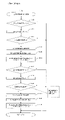
次に、図7のブロック図を参照しながら、本実施形態に係るぱちんこ遊技機の各種機能について説明する。はじめに、主制御基板Mは、遊技に係る遊技周辺機器(第1主遊技周辺機器A、第2主遊技周辺機器B、第1・第2主遊技共用周辺機器C、補助遊技周辺機器H)、演出に係るサブメイン制御部SM(副遊技制御手段SM)、主制御基板Mからの払出指示に基づき所定数の賞球の払出制御を行う賞球払出制御基板KHと、情報伝達可能に接続されている。また、サブメイン制御部SM(副遊技制御手段SM)は、画像演出を実行するサブサブ制御部SS(演出表示手段SS)、各種遊技効果ランプD26(例えばサイドランプ)や枠装飾ランプD18-L、スピーカD24等とも電気的に接続されている。更に、賞球払出制御基板KHは、ステッピングモータやスプロケット等を備えた賞球払出装置KEと電気的に接続されている。尚、主制御基板M、サブメイン制御部SM(副遊技制御手段SM)、サブサブ制御部SS(演出表示手段SS)、賞球払出制御基板KH等は、ハードウエア的にはデ-タやプログラムを格納するROMやRAM、演算処理に用いるCPU等の素子等から構成される。尚、以下で主制御基板Mに含まれるとする各手段を周辺機器(例えば、遊技周辺機器)に搭載される形で構成してもよい。例えば、周辺機器(例えば、遊技周辺機器)に含まれるとする各手段を主制御基板Mに搭載される形で構成してもよい。以下、上記各手段(装置)の詳細を説明する。 Next, various functions of the pachinko gaming machine according to the present embodiment will be described with reference to the block diagram of FIG. First, the main control board M includes game peripherals related to games (first main game peripheral A, second main game peripheral B, first and second main game shared peripheral C, auxiliary game peripheral H), A sub-main control unit SM (sub-game control means SM) related to the production, and a prize ball payout control board KH that controls the payout of a predetermined number of prize balls based on payout instructions from the main control board M, and are connected so that information can be transmitted. ing. In addition, the sub-main control unit SM (sub-game control means SM) includes a sub-sub control unit SS (effect display means SS) that executes image effects, various game effect lamps D26 (for example, side lamps) and frame decoration lamps D18-L, It is also electrically connected to the speaker D24 and the like. Further, the prize ball payout control board KH is electrically connected to a prize ball payout device KE having a stepping motor, a sprocket, and the like. In addition, the main control board M, sub-main control section SM (sub-game control means SM), sub-sub control section SS (effect display means SS), prize ball payout control board KH, etc. are data and programs in terms of hardware. , and elements such as a CPU used for arithmetic processing. Incidentally, each means included in the main control board M below may be configured to be mounted on a peripheral device (for example, a game peripheral device). For example, each means included in a peripheral device (for example, a game peripheral device) may be configured to be mounted on the main control board M. FIG. The details of each means (apparatus) will be described below.
まず、主制御基板Mは、遊技用の情報の取得を制御する遊技用情報制御手段MJと、遊技の内容を決定するための遊技内容決定手段MNと、特別遊技や特定遊技等の遊技の進行を司る遊技進行手段MPと、遊技状態等に係る情報を一時記憶するための遊技状態一時記憶手段MBと、遊技機が検知したエラーや不正行為に関する処理を司る不正検知情報管理手段ME(及び、エラー検知や不正検知に係る情報を一時記憶するための不正関連情報一時記憶手段MEb)と、遊技周辺機器側(特に、サブメイン制御部SM側)に各種遊技情報{例えば、停止図柄情報、停止図柄の属性情報{例えば、16R大当り、8R大当り、4R大当り、ハズレ}、変動態様に関する情報(例えば、変動時間)、特別遊技の開始信号・状態情報・終了信号、保留情報等}を送信するための情報送信制御手段MT(及び未送信コマンドを蓄積するコマンド送信用バッファMT10)と、遊技に係る情報を、外部中継端子板Gを介してホールコンピュータHCに出力する外部信号出力制御手段MGと、各種入賞口への遊技球の入賞に基づき所定の賞球の払出を行うように賞球払出制御基板KHを制御する賞球払出決定手段MHと、を有している。 First, the main control board M comprises game information control means MJ for controlling acquisition of game information, game content determination means MN for determining the content of the game, and progress of the game such as a special game or a specific game. game progress means MP that controls the game state temporary storage means MB for temporarily storing information related to the game state etc. fraud detection information management means ME that controls processing related to errors and fraud detected by the gaming machine (and Fraud-related information temporary storage means MEb) for temporarily storing information related to error detection and fraud detection, and various game information {for example, stop pattern information, stop To transmit pattern attribute information {e.g., 16R jackpot, 8R jackpot, 4R jackpot, loss}, information on fluctuation mode (for example, fluctuation time), special game start signal, status information, end signal, hold information, etc.} information transmission control means MT (and command transmission buffer MT10 for accumulating unsent commands); external signal output control means MG for outputting game-related information to hall computer HC via external relay terminal board G; It has prize ball payout determination means MH for controlling a prize ball payout control board KH so as to pay out predetermined prize balls based on the winning of game balls into various prize winning openings.
ここで、遊技用情報制御手段MJは、各入球口(始動口等)への遊技球の流入を判定するための入球判定手段MJ10と、各乱数の取得可否を判定し、当該判定結果に基づき当該各乱数を取得するための乱数取得判定実行手段MJ20と、変動表示中における各始動口への入球を保留球として上限個数以内で一時記憶するための保留制御手段MJ30と、を有している。以下、各手段について詳述する。 Here, the game information control means MJ includes a ball entry determination means MJ10 for determining the inflow of a game ball into each ball entrance (starting opening, etc.), and determines whether or not each random number can be obtained. and a holding control means MJ30 for temporarily storing, as holding balls within the upper limit number, balls entered into each starting opening during variable display. is doing. Each means will be described in detail below.
まず、入球判定手段MJ10は、第1主遊技始動口A10(及び、第1主遊技始動口確認センサA11s2)に遊技球が入球したか否かを判定する第1主遊技始動口入球判定手段MJ11-Aと、第2主遊技始動口B10に遊技球が入球したか否かを判定する第2主遊技始動口入球判定手段MJ11-Bと、補助遊技始動口H10に遊技球が流入したか否かを判定する補助遊技始動口入球判定手段MJ11-Hと、第1大入賞口C10に遊技球が入球したか否かを判定する、第1大入賞口入球判定手段MJ11-C10と、第2大入賞口C20に遊技球が入球したか否かを判定する、第2大入賞口入球判定手段MJ11-C20と、一般入賞口(不図示)に遊技球が入球したか否かを判定する、一般入賞口入球判定手段(不図示)と、アウト口C80に遊技球が入球したか否かを判定する、アウト口入球判定手段MJ11-C80と、総排出確認センサC90sに遊技球が入球(排出を検出)したか否かを判定する、総排出確認手段MJ11-C90(及び、当該入球数を計数する、総排出確認数カウンタMJ11c-C90)と、入球口への入球に係る情報を一時記憶するための入球関連情報一時記憶手段MJ10bと、各入球口への入球総数を計数する入球数カウンタMJ10c{本例では、当該カウンタ値は電断に基づくRAMクリアによってのみ、クリアされるよう構成されているものとするが、所定時間(例えば、遊技場の営業休止時間に相当する8時間、等)の経過によって自動的に値がクリアされるよう構成してもよい}と、第1主遊技始動口A10に入球した遊技球数を計数する第1主遊技始動口入球数カウンタMJ10c-Aと、第1主遊技始動口確認センサA11s2にて検出した遊技球数を計数する第1主遊技始動口確認カウンタMJ10c2-Aと、を有している。 First, the ball entry determination means MJ10 determines whether or not the game ball has entered the first main game start hole A10 (and the first main game start hole confirmation sensor A11s2). Determination means MJ11-A, second main game start entrance ball determination means MJ11-B for determining whether or not a game ball has entered the second main game start opening B10, and a game ball in the auxiliary game start opening H10 Auxiliary game start opening ball entry determination means MJ11-H for determining whether or not has flowed in, and 1st large winning opening ball determination for determining whether a game ball has entered the first large winning opening C10 A means MJ11-C10, a second big winning hole entrance ball determination means MJ11-C20 for determining whether or not a game ball has entered the second big winning hole C20, and a game ball in a general winning hole (not shown) general winning entrance ball entry determination means (not shown) for determining whether or not a ball has entered, and out entrance ball entry determination means MJ11-C80 for determining whether or not a game ball has entered the out exit C80 Then, the total discharge confirmation means MJ11-C90 (and the total discharge confirmation number counter MJ11c that counts the number of balls entered) determines whether or not the game ball has entered (detected discharge) to the total discharge confirmation sensor C90s -C90), a ball entry-related information temporary storage means MJ10b for temporarily storing information related to the ball entry into the entrance, and a ball entry counter MJ10c for counting the total number of balls entered into each entrance. In the example, it is assumed that the counter value is cleared only by clearing the RAM based on a power outage. may be configured so that the value is automatically cleared by], a first main game start opening ball entry counter MJ10c-A that counts the number of game balls entered into the first main game start opening A10, It has a first main game start opening confirmation counter MJ10c2-A that counts the number of game balls detected by the first main game start opening confirmation sensor A11s2.
次に、乱数取得判定実行手段MJ20は、第1主遊技始動口A10への遊技球の入球に基づき第1主遊技側乱数を取得するか否かを判定すると共に、判定結果に応じて当該乱数(例えば、第1当選乱数、第1変動態様決定乱数、第1主遊技図柄決定乱数等)を取得する第1主遊技乱数取得判定実行手段MJ21-Aと、第2主遊技始動口B10への遊技球の入球に基づき第2主遊技側乱数を取得するか否かを判定すると共に、判定結果に応じて当該乱数(例えば、第2当選乱数、第2変動態様決定乱数、第2主遊技図柄決定乱数等)を取得する第2主遊技乱数取得判定実行手段MJ21-Bと、補助遊技側乱数の取得の可否を判定し、当該判定結果に基づき当該乱数を取得するための補助遊技乱数取得判定実行手段MJ21-Hと、を有している。 Next, the random number acquisition determination execution means MJ20 determines whether or not to acquire the first main game side random number based on the entry of the game ball into the first main game start port A10, and according to the determination result, 1st main game random number acquisition determination execution means MJ21-A for acquiring random numbers (for example, 1st winning random number, 1st variation mode determination random number, 1st main game pattern determination random number, etc.) and to the 2nd main game start port B10 It is determined whether or not to acquire the second main game side random number based on the entry of the game ball, and the random number according to the determination result (for example, the second winning random number, the second variation mode determination random number, the second main A second main game random number acquisition determination execution means MJ21-B that acquires a game symbol determination random number, etc.), and an auxiliary game random number for determining whether or not to acquire an auxiliary game side random number and acquiring the random number based on the determination result. and acquisition determination execution means MJ21-H.
ここで、上記を含め本特許請求の範囲及び本明細書における「乱数」は、例えば、乱数の種類(例えば、当選乱数や変動態様決定乱数)により割り振られた「0」~「65535」や「0」~「255」といった所定範囲からランダムに選択された値である。また、乱数としては、数学的に発生させる乱数でなくともよく、ハードウエア乱数やソフトウエア乱数等により発生させる擬似乱数でもよい。例えば、乱数にある夫々の値の発現方式が、乱数の数列に沿って順々に値を発現させる方式(プラスワン方式)、乱数の数列の最終値が発現したときの次の値(初期値)を偶然性のある値によって定める方式(初期値更新方式)、これらの組み合わせ等を挙げることができる。 Here, the "random number" in the claims and this specification including the above is, for example, "0" to "65535" or " It is a value randomly selected from a predetermined range of 0 to 255. Moreover, the random numbers may not be mathematically generated random numbers, but may be pseudo-random numbers generated by hardware random numbers, software random numbers, or the like. For example, the expression method of each value in the random number is a method of expressing the value in order along the sequence of random numbers (plus one method), the next value when the final value of the sequence of random numbers is expressed (initial value ) is determined by a random value (initial value update method), a combination of these methods, and the like.
次に、保留制御手段MJ30は、保留消化及び変動開始に係る処理を制御する保留消化制御手段MJ31と、第1主遊技図柄の変動許可が下りていない状況で取得した当該第1主遊技側乱数を一時記憶するか否かを判定し、当該判定結果に基づき前記乱数を第1主遊技図柄の変動許可が下りるまで第1主遊技図柄保留情報一時記憶手段MJ32b-Aに保留するための第1主遊技図柄保留手段MJ32-Aと、第2主遊技図柄の変動許可が下りていない状況で取得した当該第2主遊技側乱数を一時記憶するか否かを判定し、当該判定結果に基づき前記乱数を第2主遊技図柄の変動許可が下りるまで第2主遊技図柄保留情報一時記憶手段MJ32b-Bに保留するための第2主遊技図柄保留手段MJ32-Bと、補助遊技図柄の変動許可が下りていない状況で取得した補助遊技側乱数を一時記憶するか否かを判定し、当該判定結果に基づき当該乱数を補助遊技図柄の変動許可が下りるまで補助遊技図柄保留情報一時記憶手段MJ32b-Hに保留するための補助遊技図柄保留手段MJ32-Hと、を有している。 Next, the reservation control means MJ30 includes a reservation digestion control means MJ31 that controls processing related to the holding digestion and the start of fluctuation, and the first main game side random number acquired in the situation where the permission for fluctuation of the first main game symbols is not granted. is temporarily stored, and based on the determination result, the random number is retained in the first main game symbol retention information temporary storage means MJ32b-A until the permission to change the first main game symbol is obtained. The main game symbol holding means MJ32-A determines whether or not to temporarily store the second main game side random number obtained in a situation where the second main game symbol variation permission is not granted, and based on the determination result, Second main game symbol holding means MJ32-B for holding random numbers in the second main game pattern holding information temporary storage means MJ32b-B until the second main game pattern fluctuation permission is granted, and auxiliary game pattern fluctuation permission. It is determined whether or not to temporarily store the auxiliary game side random number acquired in the situation where it is not down, and based on the determination result, the random number is stored in the auxiliary game design reservation information temporary storage means MJ32b-H until the permission to change the auxiliary game design is granted. and an auxiliary game symbol holding means MJ32-H for holding.
ここで、保留消化制御手段MJ31は、変動を開始する条件を充足したか否かを判定する変動開始条件充足判定手段MJ31jを有している。 Here, the pending digestion control means MJ31 has a variation start condition satisfaction determination means MJ31j for determining whether or not the conditions for starting the variation are satisfied.
次に、第1主遊技図柄保留手段MJ32-A、第2主遊技図柄保留手段MJ32-B及び補助遊技図柄保留手段MJ32-Hは、最大4個まで記憶可能な、前記乱数を保留順序と結合した形で一時記憶するための、第1主遊技図柄保留情報一時記憶手段MJ32b-A、第2主遊技図柄保留情報一時記憶手段MJ32b-B及び補助遊技図柄保留情報一時記憶手段MJ32b-Hを夫々有している。 Next, the first main game symbol reservation means MJ32-A, the second main game symbol reservation means MJ32-B and the auxiliary game symbol reservation means MJ32-H combine the random numbers, which can store up to four, with the reservation order. 1st main game symbol reservation information temporary storage means MJ32b-A, 2nd main game symbol reservation information temporary storage means MJ32b-B and auxiliary game symbol reservation information temporary storage means MJ32b-H for temporarily storing in the form of have.
次に、遊技内容決定手段MNは、特別遊技への移行可否及び第2主遊技始動口電動役物B11dの開放可否を抽選する当否抽選手段MN10と、各乱数に基づき、各図柄の停止図柄を決定するための図柄内容決定手段MN40と、各乱数に基づき、各図柄の変動態様(変動時間等)を決定するための変動態様決定手段MN50とを、有している。ここで、当否抽選手段MN10は、第1主遊技図柄に関しての当否抽選を行う第1主遊技当否抽選手段MN11-Aと、第2主遊技図柄に関しての当否抽選を行う第2主遊技当否抽選手段MN11-Bと、補助遊技図柄に関しての当否抽選を行う補助遊技当否抽選手段MN11-Hとを、有している。ここで、第1主遊技当否抽選手段MN11-A、第2主遊技当否抽選手段MN11-B及び補助遊技当否抽選手段MN11-Hは、第1主遊技図柄に関しての当否抽選を行う際に参照される第1主遊技用当否抽選テーブルMN11ta-Aと、第2主遊技図柄に関しての当否抽選を行う際に参照される第2主遊技用当否抽選テーブルMN11ta-Bと、補助遊技図柄に関しての当否抽選を行う際に参照される補助遊技用当否抽選テーブルMN11ta-Hを夫々有している。尚、詳細なテーブル構成の一例については後述する。 Next, the game content determination means MN selects the stop symbols of each symbol based on the success/failure lottery means MN10 for determining whether or not to move to the special game and whether or not to open the second main game starter electric accessory B11d, and each random number. It has symbol content determination means MN40 for determining, and variation mode determination means MN50 for determining the variation mode (variation time, etc.) of each symbol based on each random number. Here, the success/failure lottery means MN10 consist of a first main game success/failure lottery means MN11-A that performs a success/failure lottery with respect to the first main game symbols, and a second main game success/failure lottery means that performs a success/failure lottery with respect to the second main game symbols. It has MN11-B and an auxiliary game success/failure lottery means MN11-H for performing a success/failure lottery for the auxiliary game symbols. Here, the first main game success/failure lottery means MN11-A, the second main game success/failure lottery means MN11-B and the auxiliary game success/failure lottery means MN11-H are referred to when performing a success/failure lottery for the first main game symbols. a first main game win/fail lottery table MN11ta-A, a second main game win/fail lottery table MN11ta-B referred to when performing a win/fail lottery for the second main game symbols, and a win/fail lottery for the auxiliary game symbols. Each has an auxiliary game success or failure lottery table MN11ta-H that is referred to when performing. An example of detailed table configuration will be described later.
次に、図柄内容決定手段MN40は、取得した遊技内容決定乱数(第1主遊技乱数)に基づき、第1主遊技図柄の停止図柄を決定する第1主遊技図柄決定手段MN41-Aと、取得した遊技内容決定乱数(第2主遊技乱数)に基づき、第2主遊技図柄の停止図柄を決定する第2主遊技図柄決定手段MN41-Bと、取得した補助遊技図柄当選乱数に基づき補助遊技図柄の停止図柄を決定する補助遊技図柄決定手段MN41-Hと、を有している。 Next, the symbol content determination means MN40 includes a first main game symbol determination means MN41-A for determining a stop symbol of the first main game symbol based on the acquired game content determination random number (first main game random number), A second main game symbol determination means MN41-B for determining a stop symbol of the second main game symbol based on the game content determination random number (second main game random number) obtained, and an auxiliary game symbol based on the acquired auxiliary game symbol winning random number. and an auxiliary game symbol determination means MN41-H for determining the stop symbol of the game.
ここで、第1主遊技図柄決定手段MN41-Aは、第1主遊技図柄に係る停止図柄を決定する際に参照される第1主遊技図柄決定用抽選テーブルMN41ta-Aを有しており、当該第1主遊技図柄決定用抽選テーブルMN41ta-Aは、当否結果に応じて異なる各種抽選テーブルを備えている。また、第2主遊技図柄決定手段MN41-Bは、第2主遊技図柄に係る停止図柄を決定する際に参照される第2主遊技図柄決定用抽選テーブルMN41ta-Bを有しており、当該第2主遊技図柄決定用抽選テーブルMN41ta-Bは、当否結果に応じて異なる各種抽選テーブルを備えている。更に、補助遊技図柄決定手段MN41-Hは、補助遊技図柄に係る停止図柄を決定する際に参照される補助遊技図柄決定用抽選テーブルMN41ta-Hを有しており、当該補助遊技図柄決定用抽選テーブルMN41ta-Hは、遊技状態に応じて異なる各種当選テーブルを備えている。尚、詳細なテーブル構成の一例については後述する。 Here, the first main game symbol determination means MN41-A has a first main game symbol determination lottery table MN41ta-A referred to when determining stop symbols related to the first main game symbols, The lottery table MN41ta-A for determining the first main game symbols includes various lottery tables that differ according to the winning/losing results. In addition, the second main game symbol determination means MN41-B has a second main game symbol determination lottery table MN41ta-B referred to when determining stop symbols related to the second main game symbols. The lottery table MN41ta-B for determining the second main game symbols includes various lottery tables that differ according to the winning/losing results. Further, the auxiliary game symbol determination means MN41-H has an auxiliary game symbol determination lottery table MN41ta-H referred to when determining the stop symbols related to the auxiliary game symbols, and the auxiliary game symbol determination lottery. The table MN41ta-H includes various winning tables that differ according to the gaming state. An example of detailed table configuration will be described later.
次に、変動態様決定手段MN50は、取得した遊技内容決定乱数(第1主遊技乱数)に基づき、第1主遊技図柄の変動態様(変動時間等)を決定する第1主遊技変動態様決定手段MN51-Aと、取得した遊技内容決定乱数(第2主遊技乱数)に基づき、第2主遊技図柄の変動態様(変動時間等)を決定する第2主遊技変動態様決定手段MN51-Bと、取得した補助遊技図柄当選乱数に基づき補助遊技図柄の変動態様(変動時間等)を決定する補助遊技変動態様決定手段MN51-Hと、を有している。 Next, the variation mode determination means MN50 is the first main game variation mode determination means for determining the variation mode (variation time, etc.) of the first main game symbols based on the acquired game content determination random number (first main game random number). MN51-A, a second main game variation mode determination means MN51-B that determines the variation mode (variation time, etc.) of the second main game pattern based on the acquired game content determination random number (second main game random number), Auxiliary game variation mode determination means MN51-H for determining the variation mode (variation time, etc.) of the auxiliary game symbols based on the acquired auxiliary game symbol winning random numbers.
ここで、第1主遊技変動態様決定手段MN51-Aは、第1主遊技図柄に係る変動態様を決定する際に参照される第1主遊技変動態様決定用抽選テーブルMN51ta-Aを有しており、当該第1主遊技変動態様決定用抽選テーブルMN51ta-Aは、当否結果・遊技状態に応じて異なる各種抽選テーブルを備えている。また、第2主遊技変動態様決定手段MN51-Bは、第2主遊技図柄に係る変動態様を決定する際に参照される第2主遊技変動態様決定用抽選テーブルMN51ta-Bを有しており、当該第2主遊技変動態様決定用抽選テーブルMN51ta-Bは、当否結果・遊技状態に応じて異なる各種抽選テーブルを備えている。尚、詳細なテーブル構成の一例については後述する。更に、補助遊技変動態様決定手段MN51-Hは、補助遊技図柄に係る変動態様を決定する際に参照される補助遊技変動態様決定用抽選テーブルMN51ta-Hを有しており、当該補助遊技変動態様決定用抽選テーブルMN51ta-Hは、遊技状態に応じて異なる各種当選テーブルを備えている(例えば、通常遊技→補助遊技通常用抽選テーブル、確率変動遊技及び時間短縮遊技→補助遊技時間短縮用抽選テーブル)。 Here, the first main game variation mode determination means MN51-A has a first main game variation mode determination lottery table MN51ta-A referred to when determining the variation mode related to the first main game symbols. The lottery table MN51ta-A for determining the first main game variation mode includes various lottery tables that differ according to win/fail results and game states. In addition, the second main game variation mode determination means MN51-B has a second main game variation mode determination lottery table MN51ta-B referred to when determining the variation mode related to the second main game symbols. , The lottery table MN51ta-B for determining the second main game variation mode includes various lottery tables that differ according to win/fail results and game states. An example of detailed table configuration will be described later. Furthermore, the auxiliary game variation mode determination means MN51-H has an auxiliary game variation mode determination lottery table MN51ta-H referred to when determining the variation mode related to the auxiliary game pattern, and the auxiliary game variation mode The determination lottery table MN51ta-H has various winning tables that differ according to the game state (for example, normal game → auxiliary game normal lottery table, probability variable game and time reduction game → lottery table for auxiliary game time reduction ).
次に、表示制御手段MP10は、第1主遊技図柄表示装置A20の第1主遊技図柄表示部A21g上及び第2主遊技図柄表示装置B20の第2主遊技図柄表示部B21g上で、所定時間第1主遊技図柄を変動させた後に停止表示する制御を行う第1・第2主遊技図柄制御手段MP11-Cと、補助遊技図柄表示装置H20の補助遊技図柄表示部H21g上で、所定時間補助遊技図柄を変動させた後に停止表示する制御を行う補助遊技図柄制御手段MP11-Hとを有している。 Next, the display control means MP10 displays the first main game symbol display portion A21g of the first main game symbol display device A20 and the second main game symbol display portion B21g of the second main game symbol display device B20 for a predetermined time. 1st and 2nd main game symbol control means MP11-C for controlling the stop display after changing the 1st main game symbol, and on the auxiliary game symbol display part H21g of the auxiliary game symbol display device H20, the auxiliary game symbol for a predetermined time. It has an auxiliary game symbol control means MP11-H that performs control to stop and display after varying the game symbols.
ここで、第1・第2主遊技図柄制御手段MP11-Cは、ゼロクリア可能な第1・第2主遊技図柄変動管理用タイマMP11t-C(例えば、所定間隔毎に減算されるデクリメントカウンタであり、以下、タイマに類するものは同様のカウンタにて実装可能)を有している。更に、補助遊技図柄制御手段MP11-Hは、時間を計測可能な補助遊技図柄変動管理用タイマMP11t-Hを更に備えている。 Here, the first and second main game symbol control means MP11-C is a timer MP11t-C for controlling first and second main game symbol fluctuations that can be cleared to zero (for example, a decrement counter that is subtracted at predetermined intervals. , hereinafter, those similar to timers can be implemented with similar counters). Further, the auxiliary game symbol control means MP11-H is further provided with an auxiliary game symbol variation management timer MP11t-H capable of measuring time.
次に、第2主遊技始動口電動役物開閉制御手段MP20-Bは、第2主遊技始動口電動役物B11dを開閉する処理を行うための条件を充足しているか否かを判定するための第2主遊技始動口電動役物開閉条件判定手段MP21-Bと、第2主遊技始動口電動役物B11dの駆動(開放)時間を計測する第2主遊技始動口電動役物開放タイマMP22t-Bと、第2主遊技始動口電動役物B11dの閉鎖後に第2主遊技始動口電動役物B11d内に残存している遊技球が第2主遊技始動口入球検出装置B11sに検出されるまで待機する時間を計時する、第2主遊技始動口入球待機タイマMP22t2と、を有している。 Next, the second main game starter electric accessory opening/closing control means MP20-B is used to determine whether or not the conditions for opening and closing the second main game starter electric accessory B11d are satisfied. The second main game starter electric accessory opening/closing condition determination means MP21-B and the second main game starter electric accessory opening timer MP22t that measures the driving (opening) time of the second main game starter electric accessory B11d. -B, the game ball remaining in the second main game starter electric accessory B11d after the closing of the second main game starter electric accessory B11d is detected by the second main game starter entrance ball detection device B11s. It has a second main game starting port entry ball waiting timer MP22t2 that counts the waiting time.
次に、特別遊技制御手段MP30は、特別遊技に移行するための条件を充足しているか否かを判定する条件判定手段MP31と、特別遊技移行条件を充足している場合、当該特別遊技の内容(具体的には、開状態となる大入賞口、ラウンド数、ラウンド間時間等)を決定し、特別遊技関連情報一時記憶手段MB20b内にセットする特別遊技内容決定手段MP32と、第1大入賞口C10又は第2大入賞口C20を所定条件で開状態にする特別遊技(大当り)を実行するための特別遊技実行手段MP33と、特別遊技に関する各種処理の時間管理(例えば、第1大入賞口C10及び第2大入賞口C20の開閉時間)を行うための特別遊技時間管理手段MP34と、振分遊技を実行するための振分遊技実行制御手段MP36と、を有している。ここで、特別遊技実行手段MP33は、第1大入賞口電動役物C11dと第2大入賞口電動役物C21dを開閉させる第1・第2大入賞口電動役物開閉制御手段MP33-Cと、第1大入賞口C10と第2大入賞口C20への入賞球を計測する入賞球カウンタMP33cを有している。特別遊技時間管理手段MP34は、ラウンド時間を管理する特別遊技用タイマMP34tと、大入賞口の開放時間を計時する開放タイマMP34t2と、第1大入賞口C10(又は第2大入賞口C20)の閉鎖後に第1大入賞口C10(又は第2大入賞口C20)内に残存している遊技球が第1大入賞口入賞検出装置C11s(又は第2大入賞口入賞検出装置C21s)に検出されるまで待機する時間を計時する、大入賞口入球待機タイマMP34t3と、を更に有している。また、特別遊技内容決定手段MP32は、特別遊技関連情報一時記憶手段MB20bにセットされるべき前記特別遊技の内容を特定する際に参照される特別遊技内容参照テーブルMP32taを更に有している(テーブルの詳細については不図示であるが、開状態となる大入賞口、最大ラウンド数、1ラウンドの実行内容等が定められたテーブルである。また、特別遊技が開始されてから初回のラウンドが実行されるまでの待機時間である開始デモ時間、最終回のラウンドが終了してから特別遊技を終了するまでの待機時間である終了デモ時間、等も本テーブルにて予め定められている)。 Next, the special game control means MP30 includes a condition determination means MP31 for determining whether or not the conditions for shifting to the special game are satisfied, and the content of the special game when the special game transition conditions are satisfied. (Specifically, a special game content determination means MP32 that determines the big winning opening to be opened, the number of rounds, the time between rounds, etc.) and sets it in the special game related information temporary storage means MB20b, and the first big winning Special game execution means MP33 for executing a special game (big hit) that opens the opening C10 or the second big winning opening C20 under a predetermined condition, and time management of various processes related to the special game (for example, the first big winning opening C10 and the opening and closing time of the second big winning opening C20), special game time management means MP34, and distribution game execution control means MP36 for executing a distribution game. Here, the special game executing means MP33 includes the first and second big winning opening electric access control means MP33-C for opening and closing the first big winning opening electric role C11d and the second big winning opening electric role C21d. , and a winning ball counter MP33c for counting winning balls to the first big winning hole C10 and the second big winning hole C20. The special game time management means MP34 includes a special game timer MP34t that manages the round time, an opening timer MP34t2 that measures the opening time of the big winning opening, and the first big winning opening C10 (or the second big winning opening C20). The game balls remaining in the first big winning opening C10 (or the second big winning opening C20) after closing are detected by the first big winning opening winning detection device C11s (or the second big winning opening winning detection device C21s). It further has a big winning hole entrance ball waiting timer MP34t3 for measuring the waiting time. In addition, the special game content determination means MP32 further has a special game content reference table MP32ta referred to when specifying the content of the special game to be set in the special game related information temporary storage means MB20b (table Although the details are not shown, it is a table that defines the big winning mouth to be opened, the maximum number of rounds, the execution contents of one round, etc. Also, the first round is executed after the special game is started. The start demo time, which is the waiting time until the game is played, and the end demo time, which is the waiting time from the end of the final round to the end of the special game, are also predetermined in this table).
次に、特定遊技制御手段MP50は、確率変動遊技状態の終了条件を充足しているか否かを判定する確変終了条件判定手段MP51と、時間短縮遊技状態の終了条件を充足しているか否かを判定する時短遊技終了条件判定手段MP52を有している。時短回数をカウント可能な時短回数カウンタMP52c、を夫々有している。ここで、確率変動遊技状態とは、第1主遊技図柄及び第2主遊技図柄の当否抽選時における当選確率が非確率変動遊技状態よりも高確率となる遊技状態を意味し、時間短縮遊技状態とは、第1主遊技図柄や第2主遊技図柄の変動時間の平均値が非時間短縮遊技状態よりも短時間となる、及び/又は、単位時間あたりにおける第2主遊技始動口電動役物B11dの開放容易性が向上する遊技状態を意味する。 Next, the specific game control means MP50 determines whether the probability variable end condition determination means MP51 for determining whether or not the end condition of the probability variable game state is satisfied, and whether the end condition of the time reduction game state is satisfied. It has time saving game end condition determination means MP52 for determination. It has time saving frequency counter MP52c which can count time saving frequency, respectively. Here, the probability variable gaming state means a gaming state in which the winning probability at the time of the lottery of the first main game pattern and the second main game pattern is higher than the non-probability variable gaming state, and the time shortening gaming state. means that the average value of the fluctuation time of the first main game pattern and the second main game pattern is shorter than the non-time reduction game state, and/or the second main game starter electric accessory per unit time This means a game state in which the ease of opening B11d is improved.
ここで、本実施形態においては、時間短縮遊技中には、非時間短縮遊技中と比較して、第1主遊技図柄及び第2主遊技図柄の変動時間が相対的に短縮される(時間短縮機能)。更に、補助遊技図柄が高確率で当り図柄となり且つ補助遊技図柄の変動時間も相対的に短縮されると共に、第2主遊技始動口電動役物B11dの開放延長時間が相対的に延長される(開放時間延長機能)。また、本実施形態における時間短縮遊技は、第1主遊技図柄の変動回数と第2主遊技図柄の変動回数の合計値が所定回数を超えた場合に終了する(時短回数制限無しの確率変動遊技を除く)。即ち、時短回数は、第1主遊技図柄及び第2主遊技図柄の変動(停止)毎に減算されるよう構成されている。尚、上記の確変終了条件判定手段MP51及び時短遊技終了条件判定手段MP52は、例えば、図柄変動の度に所定確率で特定遊技(例えば確率変動遊技や時間短縮遊技)から通常遊技への移行抽選を行う機能を有していてもよい(いわゆる、転落抽選機能を有するぱちんこ遊技機の場合)。 Here, in this embodiment, during the time reduction game, the fluctuation time of the first main game symbols and the second main game symbols is relatively shortened (time reduction function). Furthermore, the auxiliary game symbols become winning symbols with a high probability, the variation time of the auxiliary game symbols is relatively shortened, and the opening extension time of the second main game start opening electric accessory B11d is relatively extended ( open time extension function). In addition, the time reduction game in this embodiment ends when the total value of the number of fluctuations of the first main game pattern and the number of fluctuations of the second main game pattern exceeds a predetermined number (a probability fluctuation game without time reduction number limit except for). That is, the number of times of time saving is configured to be subtracted each time the first main game pattern and the second main game pattern change (stop). In addition, the probability variation end condition determination means MP51 and the time reduction game end condition determination means MP52 are, for example, a specific game (for example, a probability variation game or a time reduction game) with a predetermined probability every time the pattern changes. (In the case of a pachinko game machine having a so-called falling lottery function).
次に、遊技状態一時記憶手段MBは、第1主遊技(第1主遊技図柄の変動から停止に至るまでの遊技)及び第2主遊技(第2主遊技図柄の変動から停止に至るまでの遊技)における現在の遊技状態を一時記憶するための第1・第2主遊技状態一時記憶手段MB10-Cと、補助遊技における現在の遊技状態を一時記憶するための補助遊技状態一時記憶手段MB10-Hと、特別遊技における現在の遊技状態(例えば、ラウンド数、任意のラウンドにおける遊技球の入賞個数、特別遊技に関する各種フラグのオン・オフ等)を一時記憶するための特別遊技関連情報一時記憶手段MB20bと、特定遊技における現在の遊技状態(例えば、時短の残り回数、特定遊技に関する各種フラグのオン・オフ等)を一時記憶するための特定遊技関連情報一時記憶手段MB30bと、を有している。 Next, the game state temporary storage means MB stores the first main game (the game from the fluctuation of the first main game symbols to the stop) and the second main game (the game from the fluctuation of the second main game symbols to the stop). first and second main game state temporary storage means MB10-C for temporarily storing the current game state in the game), and auxiliary game state temporary storage means MB10- for temporarily storing the current game state in the auxiliary game H and special game-related information temporary storage means for temporarily storing the current game state in the special game (for example, the number of rounds, the number of winning game balls in an arbitrary round, ON/OFF of various flags related to special games, etc.) MB20b, and a specific game-related information temporary storage means MB30b for temporarily storing the current game state in the specific game (for example, the remaining number of time reductions, the ON/OFF of various flags related to the specific game, etc.) .
ここで、第1・第2主遊技状態一時記憶手段MB10-Cは、現在変動中の第1又は第2主遊技図柄(変動開始条件が成立した第1又は第2主遊技図柄)に係る停止図柄及び変動態様情報を一時記憶するための第1・第2主遊技図柄情報一時記憶手段MB11b-Cを有している。 Here, the first and second main game state temporary storage means MB10-C stops the currently varying first or second main game symbol (the first or second main game symbol for which the variation start condition is satisfied). It has first and second main game symbol information temporary storage means MB11b-C for temporarily storing symbols and variation mode information.
また、補助遊技状態一時記憶手段MB10-Hは、現在変動中の補助遊技図柄(変動開始条件が成立した補助遊技図柄)に係る停止図柄等の情報を一時記憶するための補助遊技図柄情報一時記憶手段MB11b-Hを有している。 In addition, the auxiliary game state temporary storage means MB10-H temporarily stores auxiliary game pattern information for temporarily storing information such as stop patterns related to the currently fluctuating auxiliary game pattern (auxiliary game pattern in which the fluctuation start condition is satisfied). means MB11b-H.
次に、賞球払出決定手段MHは、賞球払出制御基板KH側との間で賞球の払出(及びエラー検知や不正検知)に係る情報を送受信するための払出情報送受信手段MHsj(及び送受信した情報を一時記憶する払出コマンド一時記憶手段MHsjb)と、遊技球の入球に基づく賞球総数を計数するための賞球数カウンタMHcと、賞球の払出が完了していない(賞球払出制御基板KH側から払出完了に係る情報を受信していない)未払出賞球に係る情報を一時記憶するための未払出賞球情報一時記憶手段MHbと、を有している。 Next, the prize ball payout determination means MH communicates with the prize ball payout control board KH side payout information transmission/reception means MHsj (and transmission/reception a payout command temporary storage means MHsjb) for temporarily storing the information received, a prize ball counter MHc for counting the total number of prize balls based on the number of game balls entered, and a prize ball payout not completed (prize ball payout and a non-discharged prize ball information temporary storage means MHb for temporarily storing information regarding non-discharged prize balls for which information regarding the completion of disbursement has not been received from the control board KH side.
次に、遊技周辺機器について説明する。尚、一部の周辺機器については既に詳細構成を述べたので、残る構成について簡潔に説明する。まず、遊技周辺機器は、第1主遊技側の周辺機器である第1主遊技周辺機器Aと、第2主遊技側の周辺機器である第2主遊技周辺機器Bと、第1主遊技側と第2主遊技側の共用周辺機器である第1・第2主遊技共用周辺機器Cと、補助遊技に関する補助遊技周辺機器Hと、副遊技制御手段(サブメイン制御部)SM、サブサブ制御部SS(及び演出表示装置SG)等、を有している。ここで、サブメイン制御部SMにより制御される演出は、第1主遊技図柄及び第2主遊技図柄の変動と時間的に同期の取れた形での装飾図柄の変動を含め、遊技の結果に影響を与えない情報のみの表示に係るものである。以下、これらの周辺機器を順番に説明する。 Next, game peripherals will be described. Since the detailed configuration of some peripheral devices has already been described, the remaining configuration will be briefly described. First, the game peripheral devices are the first main game peripheral device A, which is the peripheral device on the first main game side, the second main game peripheral device B, which is the peripheral device on the second main game side, and the first main game side. And the first and second main game shared peripheral device C which is a shared peripheral device on the second main game side, auxiliary game peripheral device H related to the auxiliary game, sub game control means (sub main control unit) SM, sub sub control unit SS (and effect display device SG) and the like. Here, the effects controlled by the sub-main control section SM are based on the results of the game, including the variation of the decorative symbols in time synchronization with the variation of the first main game symbols and the second main game symbols. It concerns the display of only non-influential information. These peripheral devices will be described in order below.
まず、第1主遊技周辺機器Aは、特別遊技移行の契機となる第1主遊技始動口A10と、第1主遊技図柄の停止表示及び変動表示が可能な第1主遊技図柄表示装置A20と、を有している。尚、第1主遊技始動口A10に関しては、第1主遊技始動口A10への入球を検出するための第1主遊技始動口入球検出装置A11sと、当該入球が正常な入球であるかを確認するための第1主遊技始動口確認センサA11s2とを有しており、いずれかの入球口でのみ(特に、第1主遊技始動口入球検出装置A11sでのみ)入球が検出された場合には、不正行為又はエラー発生に係る処理を実行するよう構成されている(詳細は後述)。尚、このように2つのセンサを用いて入球を二重にチェックする場合、検出の仕組みが異なるセンサ(例えば、非接触型のフォトセンサと、接触型の物理スイッチ)を組み合わせて利用することが、不正行為を検出するためには好適である。 First, the first main game peripheral device A consists of a first main game starting port A10 that triggers the shift to a special game, and a first main game symbol display device A20 that is capable of displaying the first main game symbols in a stationary and variable manner. ,have. In addition, regarding the first main game start opening A10, the first main game start opening detection device A11s for detecting the ball entering the first main game start opening A10 It has a first main game start opening confirmation sensor A11s2 for confirming whether there is a ball entered only at one of the entrances (especially, only at the first main game start entrance entrance detection device A11s) is detected, processing related to fraud or error occurrence is executed (details will be described later). If two sensors are used to double-check incoming balls, sensors with different detection mechanisms (for example, a non-contact photosensor and a contact-type physical switch) must be used in combination. is suitable for detecting fraud.
次に、第2主遊技周辺機器Bは、特別遊技移行の契機となる第2主遊技始動口B10と、第2主遊技図柄の停止表示及び変動表示が可能な第2主遊技図柄表示装置B20と、を有している。 Next, the second main game peripheral device B includes a second main game starting port B10 that triggers the transition to a special game, and a second main game symbol display device B20 that is capable of displaying stationary and variable second main game symbols. and have
次に、第1・第2主遊技共用周辺機器Cは、通常遊技の際には閉状態にあり、特別遊技(大当り)の際には所定条件下で開状態となる第1大入賞口C10及び第2大入賞口C20と、遊技領域D30に発射された遊技球の内始動口や入賞口に入球しなかった遊技球を遊技機内に取り込むためのアウト口C80と、始動口や入球口及びアウト口C80から遊技機内に取り込まれた遊技球を遊技機外に排出する経路上に設けられ、遊技機から排出する遊技球を検出するための総排出確認センサC90sと、を有している。 Next, the shared peripheral device C for the first and second main games is closed during the normal game, and is opened under predetermined conditions during the special game (big win). And a second big winning opening C20, an out opening C80 for taking in the game ball that did not enter the starting opening of the game ball launched into the game area D30 or the winning opening into the game machine, and a starting opening and a winning opening. and a total discharge confirmation sensor C90s provided on a path for discharging game balls taken into the game machine from the outlet and the out port C80 to the outside of the game machine and for detecting game balls discharged from the game machine. there is
次に、補助遊技周辺機器Hは、第2主遊技始動口B10の第2主遊技始動口電動役物B11dの開放の契機となる補助遊技始動口H10と、補助遊技図柄の停止表示及び変動表示が可能な補助遊技図柄表示装置H20とを有している。 Next, the auxiliary game peripheral device H is the auxiliary game start opening H10 that triggers the opening of the second main game start electric accessory B11d of the second main game start opening B10, and the stop display and change display of the auxiliary game symbols. It has an auxiliary game symbol display device H20 capable of.
次に、演出表示制御手段(サブメイン制御部)SMは、主制御基板M側からの各種情報を受信するための表示情報受信手段SM10と、演出表示に係る演出内容の決定処理及び表示制御処理を司る演出表示制御手段SM20と、エラー発生時のエラー報知を制御するエラー報知制御手段SM30と、サブサブ制御部SS側との情報送受信を制御する情報送受信制御手段SM40と、を有している。以下、上記各手段を詳述する。 Next, the effect display control means (sub-main control unit) SM includes display information receiving means SM10 for receiving various information from the main control board M side, determination processing of effect contents related to the effect display, and display control processing. , error notification control means SM30 for controlling error notification when an error occurs, and information transmission/reception control means SM40 for controlling information transmission/reception with the sub-sub control unit SS. Each of the above means will be described in detail below.
まず、表示情報受信手段SM10は、主制御基板M側からの第1主遊技及び第2主遊技に関する図柄情報や表示指示情報を一時記憶するためのメイン側情報一時記憶手段SM11bを有している。 First, the display information receiving means SM10 has a main side information temporary storage means SM11b for temporarily storing pattern information and display instruction information relating to the first main game and the second main game from the main control board M side. .
次に、演出表示制御手段SM20は、装飾図柄の変動態様や停止図柄の決定処理及び表示制御処理を司る装飾図柄表示制御手段SM21と、装飾図柄の保留個数管理や保留表示処理を司る装図保留情報表示制御手段SM22と、背景画像の決定処理及び表示制御処理を司る背景演出表示制御手段SM23と、予告演出内容の決定処理及び表示制御処理を司る予告演出表示制御手段SM24と、リーチ演出内容の決定処理及び表示制御処理を司るリーチ演出表示制御手段SM25と、を有している。 Next, the effect display control means SM20 includes a decorative pattern display control means SM21 that controls the display control process and the determination process of the variation mode of the decorative patterns and the stopped patterns, and a decorative pattern display control means SM21 that controls the reserved number management of the decorative patterns and the reserved display process. information display control means SM22; background effect display control means SM23 that controls background image determination processing and display control processing; notice effect display control means SM24 that controls notice effect content determination processing and display control processing; It has reach effect display control means SM25 that manages determination processing and display control processing.
次に、エラー報知制御手段SM30は、エラー発生の有無を判定するためのエラー発生判定手段SM31を有している。 Next, the error notification control means SM30 has an error occurrence determination means SM31 for determining whether or not an error has occurred.
ここで、装飾図柄表示制御手段SM21は、主制御基板M側からの情報に基づいて、装飾図柄の停止図柄及び変動態様を決定する装図表示内容決定手段SM21nと、装飾図柄の図柄変動に係る各種情報(変動態様情報、停止図柄情報、各種フラグ等)を一時記憶するための装図表示関連情報一時記憶手段SM21bと、装飾図柄の変動時間を計時するための装図変動時間管理タイマSM21tと、を有している。ここで、装図表示内容決定手段SM21nは、装飾図柄の停止図柄及び変動態様を決定する際に参照される装図変動内容決定用抽選(参照)テーブルSM21taを更に有している(テーブルの詳細については不図示)。 Here, based on information from the main control board M side, the decorative pattern display control means SM21 includes a decorative pattern display content determining means SM21n for determining the stop pattern and the variation mode of the decorative patterns, and a decorative pattern display content determining means SM21n for determining the pattern fluctuation of the decorative patterns. Design display related information temporary storage means SM21b for temporarily storing various information (variation mode information, stop pattern information, various flags, etc.), and design variation time management timer SM21t for measuring the variation time of the decorative design ,have. Here, the design display content determining means SM21n further includes a lottery (reference) table SM21ta for determining the content of design variation referred to when determining the stop design and variation mode of the decorative design (details of the table). are not shown).
次に、装図保留情報表示制御手段SM22は、装飾図柄に係る保留に関する情報を一時記憶するための装図保留情報一時記憶手段SM22bと、保留先読み演出を実行するための保留先読み演出実行制御手段SM26と、を有している。ここで、保留先読み演出実行制御手段SM26は、保留先読み演出の実行可否(例えば、保留内に大当りとなる予定の保留が存在するか否か)を判定する保留先読み演出実行可否判定手段SM26kを更に有している。 Next, the drawing reservation information display control means SM22 includes the drawing reservation information temporary storage means SM22b for temporarily storing information about the reservation related to the decorative design, and the reservation look-ahead effect execution control means for executing the reservation look-ahead effect. and SM26. Here, the pending prefetch effect execution control means SM26 further includes a pending prefetch effect execution feasibility determination means SM26k which determines whether or not the pending prefetch effect can be executed (for example, whether or not there is a pending scheduled to be a big hit in the pending). have.
次に、背景演出表示制御手段SM23は、主制御基板M側からの情報に基づいて、背景演出(本例では、装飾図柄の背面にて表示され、保留に関する情報に基づき特別遊技の実行可能性を示唆・報知する演出)の表示内容を決定する背景演出表示内容決定手段SM23nと、背景演出表示に係る情報を一時記憶するための背景演出関連情報一時記憶手段SM23bと、を有している。 Next, the background effect display control means SM23, based on the information from the main control board M side, the background effect (in this example, it is displayed on the back of the decorative pattern, background effect display content determining means SM23n for determining the display contents of the effect suggesting/notifying the background effect display) and background effect related information temporary storage means SM23b for temporarily storing information related to the background effect display.
次に、予告演出表示制御手段SM24は、主制御基板M側からの情報に基づいて、予告演出(本例では、装飾図柄の変動表示中において表示され、当該変動における特別遊技への移行期待度や、保留に関する情報に基づき特別遊技の実行可能性を示唆・報知する演出)の表示内容や表示タイミング等を決定する予告演出表示内容決定手段SM24nと、予告演出表示に係る情報を一時記憶するための予告演出関連情報一時記憶手段SM24bと、を有している。 Next, based on the information from the main control board M side, the advance notice effect display control means SM24, based on the information from the main control board M side, the notice effect (in this example, it is displayed during the variable display of decorative symbols, and a presentation effect display content determining means SM24n for determining the display content and display timing of the performance suggesting and notifying the possibility of execution of the special game based on the information on the hold, and for temporarily storing information related to the announcement effect display. and a temporary storage means SM24b for information related to advance notice effect.
次に、リーチ演出表示制御手段SM25は、主制御基板M側からの情報に基づいて、リーチ演出(主に、装飾図柄の変動表示中において表示され、停止表示された装飾図柄の組み合わせによってリーチ状態となったことが報知された後に実行される演出であるが、リーチ状態とならなくとも装飾図柄の変動表示と連動して実行される演出をも含んでいる)の表示内容や表示タイミング等を決定するリーチ演出表示内容決定手段SM25nと、リーチ演出表示に係る情報を一時記憶するためのリーチ演出関連情報一時記憶手段SM25bと、を有している。 Next, the ready-to-win effect display control means SM25, based on the information from the main control board M side, the ready-to-win effect (mainly displayed during the variable display of the decorative symbols, the ready-to-win state depending on the combination of the decorative symbols displayed stopped) It is a production that is executed after being notified that it has become, but it also includes production that is executed in conjunction with the variable display of the decorative pattern even if it is not in the reach state) Display content, display timing, etc. It has a ready-to-win effect display content determination means SM25n to be determined and a ready-to-win effect related information temporary storage means SM25b for temporarily storing information relating to the ready-to-win effect display.
次に、演出表示手段(サブサブ制御部)SSは、サブメイン制御部SM側との情報送受信を制御する副情報送受信制御手段SS10と、演出表示装置SG上の表示領域SG10へ画像を表示する画像表示制御手段SS20と、を有している。ここで、画像表示制御手段SS20は、サブメイン制御部SM側から受信したコマンドや各種画像表示に係る情報を一時記憶するための画像表示関連情報一時記憶手段SS21bを更に有している。 Next, the effect display means (sub-sub control unit) SS includes sub-information transmission/reception control means SS10 for controlling information transmission/reception with the sub-main control unit SM, and an image for displaying an image in the display area SG10 on the effect display device SG. and display control means SS20. Here, the image display control means SS20 further has an image display related information temporary storage means SS21b for temporarily storing commands received from the sub-main control section SM side and information relating to various image displays.
また、演出表示手段(サブサブ制御部)SSは、演出表示手段(サブサブ制御部)SSからの情報に基づいて演出に係る画像を表示する演出表示装置SGと電気的に接続されている。ここで、演出表示装置SGは、画像を表示する表示領域SG10を有している。 The performance display means (sub-sub control section) SS is electrically connected to a performance display device SG that displays an image related to the performance based on information from the performance display means (sub-sub control section) SS. Here, the effect display device SG has a display area SG10 for displaying an image.
ここで、表示領域SG10は、装飾図柄を変動表示するための装飾図柄表示領域SG11と、主遊技保留情報を表示する第1保留表示部SG12(及び第2保留表示部SG13)と、を有している。 Here, the display area SG10 has a decorative pattern display area SG11 for displaying decorative patterns in a variable manner, and a first pending display portion SG12 (and a second pending display portion SG13) for displaying main game pending information. ing.
尚、第1主遊技図柄表示装置A20、第2主遊技図柄表示装置B20及び補助遊技図柄表示装置H20が、主制御基板Mと情報伝達可能に接続されており、残る演出表示手段(サブサブ制御部)SSが、副遊技制御手段(サブメイン制御部)SMと情報伝達可能に接続されている。即ち、第1主遊技図柄表示装置A20、第2主遊技図柄表示装置B20及び補助遊技図柄表示装置H20は、主制御基板Mにより制御され、演出表示手段(サブサブ制御部)SSは、副遊技制御手段(サブメイン制御部)SMにより制御されることを意味する。尚、主制御基板Mと片方向通信(一方向通信)により制御される他の周辺機器を介して、別の周辺機器を制御するように構成してもよい。 In addition, the first main game symbol display device A20, the second main game symbol display device B20 and the auxiliary game symbol display device H20 are connected to the main control board M so as to be able to transmit information, and the remaining effect display means (sub-sub control unit ) SS is connected to the sub-game control means (sub-main control unit) SM so that information can be transmitted. That is, the first main game symbol display device A20, the second main game symbol display device B20 and the auxiliary game symbol display device H20 are controlled by the main control board M, and the effect display means (sub-sub control unit) SS is the sub-game control. means controlled by means (sub-main control unit) SM. It should be noted that another peripheral device may be controlled via another peripheral device controlled by the main control board M and one-way communication (one-way communication).
次に、図8は、主制御基板Mが行う一般的な処理の流れを示したメインフローチャートである。遊技機の電源投入後、同図(a)の処理が実行される。即ち、遊技機の電源投入後、初期設定を行った後(不図示であるが、レジスタの初期化や入出力ポートの設定等を行う)、ステップ1002で、主制御基板Mは、RAMクリアボタンの入力ポートを確認し、電源供給ユニットEのリセットボタン(RAMクリアボタン)が操作されたか否か、即ち、遊技場の管理者等によって意図的にRAMの内容をクリアさせる操作が行われたか否かを判定する。ステップ1002でYesの場合、ステップ1004で、主制御基板Mは、主制御基板M側のRAM内容(例えば、遊技状態一時記憶手段MB内の情報等)を全てクリアする。次に、ステップ1006で、情報送信制御手段MTは、主制御基板MのRAMをクリアしたことを示すラムクリア情報(コマンド)をサブメイン制御部SM側に送信し(当該タイミングにて送信してもよいし、当該タイミングではコマンドをセットしておき後述する制御コマンド送信処理にて送信するよう構成してもよい)、ステップ1016の処理に移行する。他方、ステップ1002でNoの場合は、ステップ1008で、主制御基板Mは、主制御基板MにおけるRAM領域の内容をチェックする(例えば、電断時に記録されたチェックサムとRAM領域に保存されている情報量との比較を行う)。次に、ステップ1010で、主制御基板Mは、当該チェック結果に基づきRAMの内容が正常でないか否か(正確に電断時の情報がRAMにバックアップされていないか否か)を判定する。ステップ1010でYes、即ちRAMにバックアップされていたデータが異常な場合には、ステップ1004の処理(前述したRAMクリア処理)に移行する。他方、ステップ1010でNo、即ちRAMにバックアップされていたデータが正常な場合、ステップ1012で、主制御基板Mは、主制御基板MにおけるRAM内に記憶(バックアップ)されている電断時の各種情報コマンドを取得し、ステップ1014で、取得した各種情報コマンドをサブメイン制御部SM側に送信し(当該タイミングにて送信してもよいし、当該タイミングではコマンドをセットしておき後述する制御コマンド送信処理にて送信するよう構成してもよい)、ステップ1016の処理に移行する。次に、ステップ1016で、主制御基板Mは、同図(b)によって示される主制御基板M側のメイン処理に係る実行定時割り込み(例えば、約1.5ms毎のハードウエア割り込みを契機とするが、本例では、当該割り込み周期をTとする)を許可し{その結果、当該実行定時割り込みタイミング到達時には、同図(b)が実行されることとなる}、ステップ1018の処理に移行する。尚、ステップ1018後は、次の定時割り込みタイミングに到達するまで、主制御基板Mは、各種乱数更新処理(例えば、乱数カウンタのインクリメント処理)を繰り返し実行することとなる。
Next, FIG. 8 is a main flow chart showing the flow of general processing performed by the main control board M. As shown in FIG. After the game machine is powered on, the process of FIG. 1(a) is executed. That is, after turning on the power of the game machine and performing initial settings (although not shown, register initialization, input/output port settings, etc. are performed), in
次に、タイマ割り込み処理について説明する。主制御基板Mは、定時割り込みタイミングに到達した場合に発生する割り込み要求に基づいて、同図(b)の処理を実行する。即ち、定時割り込み周期Tの到達時(例えば、約1.5ms毎のハードウエア割り込み)を契機として、ステップ2000で、主制御基板Mは、後述の入球検出処理を実行する。ステップ1100で、主制御基板Mは、後述の補助遊技内容決定乱数取得処理を実行する。次に、ステップ1200で、主制御基板Mは、後述の電動役物駆動判定処理を実行する。次に、ステップ1300で、主制御基板Mは、後述の主遊技内容決定乱数取得処理を実行する。次に、ステップ1400で、主制御基板Mは、後述の主遊技図柄表示処理を実行する。次に、ステップ1500で、主制御基板Mは、後述の特別遊技作動条件判定処理を実行する。次に、ステップ1600で、主制御基板Mは、後述の特別遊技制御処理を実行する。次に、ステップ1900で、主制御基板Mは、不正検知情報管理処理を実行する。次に、ステップ1950で、主制御基板Mは、後述のエラー管理処理を実行する。次に、ステップ3000で、主制御基板Mは、後述の賞球払出コマンド送信制御処理を実行する。次に、ステップ3500で、主制御基板Mは、後述の外部信号出力処理(外部端子板、ホールコンピュータHC等への情報出力)を実行する。次に、ステップ1990で、主制御基板Mは、制御コマンド送信処理(前述の各処理でセットされたコマンドをサブメイン制御部側に送信する)を実行し、本割り込み処理の実行直前に実行されていた処理に復帰する。
Next, timer interrupt processing will be described. The main control board M executes the processing shown in FIG. That is, at
次に、NMI割り込み処理について説明する。前述の通り、主制御基板Mは、リセットICからの電断信号がCPUのNMI端子に入力されるように構成されており、遊技機における電源断時において、同図(c)の処理が実行される。即ち、遊技機の電源断時(本例では、NMI割り込み時)において、ステップ1020で、主制御基板Mは、RAM領域の情報に基づき電断時情報(例えば、チェックサム)をセットする。次に、ステップ1022で、主制御基板Mは、RAM領域への書き込みを禁止すると共に、タイマ割り込み処理を禁止し、電源断待ちループ処理に移行する。
Next, NMI interrupt processing will be described. As described above, the main control board M is configured so that the power interruption signal from the reset IC is input to the NMI terminal of the CPU, and when the game machine is powered off, the process of FIG. be done. That is, at
次に、図9は、図8におけるステップ2000のサブルーチンに係る、入球検出処理のフローチャートである。まず、ステップ2100で、入球判定手段は、後述する補助遊技始動口入球検出処理を実行する。次に、ステップ2200で、入球判定手段は、後述する主遊技始動口入球検出処理を実行する。次に、ステップ2300で、入球判定手段は、後述する第1(第2)大入賞口入球検出処理を実行する。次に、ステップ2400で、入球判定手段は、後述する一般入賞口入球検出処理を実行する。次に、ステップ2500で、入球判定手段は、後述する排出球検出処理を実行する。次に、ステップ2600で、入球判定手段は、後述するアウト口入球検出処理を実行する。次に、ステップ2700で、入球判定手段は、後述する賞球決定処理を実行し、次の処理(ステップ1100の処理)に移行する。
Next, FIG. 9 is a flow chart of the entering ball detection process according to the subroutine of
次に、図10は、図9におけるステップ2100のサブルーチンに係る、補助遊技始動口入球検出処理のフローチャートである。まず、ステップ2102で、補助遊技始動口入球判定手段MJ11-Hは、入球関連情報一時記憶手段MJ10bのフラグエリアを参照し、補助遊技始動口検出継続フラグがオフであるか否かを判定する。ステップ2102でYesの場合、ステップ2104で、補助遊技始動口入球判定手段MJ11-Hは、補助遊技始動口入球検出装置H11sからの入力が入球検出時間(当該時間以上、補助遊技始動口入球検出装置H11sが入力を検知すると補助遊技始動口H10に入球があったとみなす時間)以上ONであるか否かを判定する。ステップ2104でYesの場合、ステップ2106で、補助遊技始動口入球判定手段MJ11-Hは、入球関連情報一時記憶手段MJ10bのフラグエリア内にある、補助遊技始動フラグをオンにする。次に、ステップ2108で、補助遊技始動口入球判定手段MJ11-Hは、入球関連情報一時記憶手段MJ10bのフラグエリア内にある、補助遊技始動口検出継続フラグをオンにし、次の処理(ステップ2200の処理)に移行する。 Next, FIG. 10 is a flow chart of auxiliary game start entrance ball detection processing according to the subroutine of step 2100 in FIG. First, in step 2102, the auxiliary game start opening entrance determination means MJ11-H refers to the flag area of the entrance related information temporary storage means MJ10b, and determines whether or not the auxiliary game start entrance detection continuation flag is off. do. In the case of Yes in step 2102, in step 2104, the auxiliary game start entrance ball determination means MJ11-H determines that the input from the auxiliary game start entrance ball detection device H11s is the entrance detection time (more than the time, the auxiliary game start entrance When the entering ball detection device H11s detects an input, it is determined whether or not it is ON for the time when it is assumed that a ball has entered the auxiliary game start port H10. In the case of Yes in step 2104, in step 2106, the auxiliary game start entrance determination means MJ11-H turns on the auxiliary game start flag in the flag area of the entrance related information temporary storage means MJ10b. Next, in step 2108, the auxiliary game start entrance determination means MJ11-H turns on the auxiliary game start entrance detection continuation flag in the flag area of the entrance related information temporary storage means MJ10b, and the next process ( processing of step 2200).
他方、ステップ2102でNoの場合、ステップ2110で、補助遊技始動口入球判定手段MJ11-Hは、補助遊技始動口入球検出装置H11sからの入力が検出終了時間(当該時間以上、補助遊技始動口入球検出装置H11sが入力を検知していない場合、遊技球が補助遊技始動口入球検出装置H11sを通過完了したとみなす時間)以上OFFであるか否かを判定する。ステップ2110でYesの場合、ステップ2112で、補助遊技始動口入球判定手段MJ11-Hは、入球関連情報一時記憶手段MJ10bのフラグエリア内にある、補助遊技始動口検出継続フラグをオフにし、次の処理(ステップ2200の処理)に移行する。尚、ステップ2104又はステップ2110でNoの場合にも、次の処理(ステップ2200の処理)に移行する。 On the other hand, in the case of No in step 2102, in step 2110, the auxiliary game start entrance ball determination means MJ11-H determines that the input from the auxiliary game start entrance ball detection device H11s is the detection end time (more than the time, auxiliary game start If the entrance ball detection device H11s does not detect an input, it is determined whether or not the game ball is OFF for the time considered to have passed through the auxiliary game start entrance ball detection device H11s. In the case of Yes in step 2110, in step 2112, the auxiliary game start opening detection means MJ11-H turns off the auxiliary game start opening detection continuation flag in the flag area of the entry related information temporary storage means MJ10b, The process proceeds to the next process (process of step 2200). Note that even if No in step 2104 or step 2110, the process proceeds to the next process (process of step 2200).
次に、図11は、図9におけるステップ2200のサブルーチンに係る、主遊技始動口入球検出処理のフローチャートである。まず、ステップ2202で、第1主遊技始動口入球判定手段MJ11-Aは、入球関連情報一時記憶手段MJ10bを参照し、第1主遊技始動口検出継続フラグがオフであるか否かを判定する。ステップ2202でYesの場合、ステップ2204で、第1主遊技始動口入球判定手段MJ11-Aは、第1主遊技始動口入球検出装置A11sからの入力は入球検出時間(当該時間以上、第1主遊技始動口入球検出装置A11sが入力を検知すると第1主遊技始動口A10に入球があったとみなす時間)以上ONであるか否かを判定する。ステップ2204でYesの場合、ステップ2206で、第1主遊技始動口入球判定手段MJ11-Aは、入球関連情報一時記憶手段MJ10bのフラグエリア内にある、第1主遊技始動フラグをオンにする。次に、ステップ2208で、第1主遊技始動口入球判定手段MJ11-Aは、入球数カウンタMJ10cのカウンタ値に1を加算(インクリメント)する。次に、ステップ2210で、第1主遊技始動口入球判定手段MJ11-Aは、入球関連情報一時記憶手段MJ10bのフラグエリア内にある、第1主遊技始動口検出継続フラグをオンにする。次に、ステップ2211で、第1主遊技始動口入球判定手段MJ11-Aは、第1主遊技始動口入球数カウンタMJ10c-Aの値に1を加算(インクリメント)し、ステップ2216に移行する。
Next, FIG. 11 is a flow chart of the main game start entrance ball detection process according to the subroutine of
他方、ステップ2202でNoの場合、ステップ2212で、入球数カウンタMJ10cからの入力が検出時間(当該時間以上、第1主遊技始動口入球検出装置A11sが入力を検知していない場合、遊技球が第1主遊技始動口入球検出装置A11sを通過完了したとみなす時間)以上OFFであるか否かを判定する。次に、ステップ2214で、第1主遊技始動口入球判定手段MJ11-Aは、入球関連情報一時記憶手段MJ10bのフラグエリア内にある。第1主遊技始動口検出継続フラグをオフにする。次に、ステップ2215で、第1主遊技始動口入球判定手段MJ11-Aは、入球関連情報一時記憶手段MJ10bのフラグエリア内にある、第1主遊技始動口長時間検出フラグをオフにし、ステップ2216に移行する。尚、ステップ2204又はステップ2212でNoの場合にも、ステップ2216に移行する。 On the other hand, in the case of No in step 2202, in step 2212, the input from the entering ball number counter MJ10c is within the detection time (if the input is not detected by the first main game start entrance detecting device A11s for the time or more, the game It is determined whether or not the ball is OFF for the time considered to have passed through the first main game start entrance ball detection device A11s. Next, in step 2214, the first main game start entrance ball determination means MJ11-A is in the flag area of the ball entry related information temporary storage means MJ10b. Turn off the first main game start opening detection continuation flag. Next, in step 2215, the first main game start opening determination means MJ11-A turns off the first main game start opening long time detection flag in the flag area of the entry related information temporary storage means MJ10b. , go to step 2216 . It should be noted that even if No in step 2204 or step 2212 , the process proceeds to step 2216 .
次に、ステップ2216で、第1主遊技始動口入球判定手段MJ11-Aは、第1主遊技始動口確認センサA11s2が遊技球を検出したか否かを判定する。ステップ2216でYesの場合、ステップ2218で、第1主遊技始動口入球判定手段MJ11-Aは、第1主遊技始動口確認カウンタMJ10c2-Aのカウンタ値に1を加算(インクリメント)し、ステップ2222に移行する。他方、ステップ2216でNoの場合にも、ステップ2222に移行する。
Next, in step 2216, the first main game start entrance ball determination means MJ11-A determines whether or not the first main game start entrance confirmation sensor A11s2 has detected a game ball. In the case of Yes in step 2216, in step 2218, the first main game start entrance ball determination means MJ11-A adds (increments) 1 to the counter value of the first main game start entrance confirmation counter MJ10c2-A, and
次に、ステップ2222で、第2主遊技始動口入球判定手段MJ11-Bは、入球関連情報一時記憶手段MJ10bを参照し、第2主遊技始動口検出継続フラグがオンであるか否かを判定する。ステップ2222でYesの場合、ステップ2224で、第2主遊技始動口入球判定手段MJ11-Bは、第2主遊技始動口入球検出装置B11sからの入力は入球検出時間(当該時間以上、第2主遊技始動口入球検出装置B11sが入力を検知すると第2主遊技始動口B10に入球があったとみなす時間)以上ONであるか否かを判定する。ステップ2224でYesの場合、ステップ2225で、第2主遊技始動口入球判定手段MJ11-Bは、入球関連情報一時記憶手段MJ10bを参照し、第2主遊技始動口有効期間中フラグがオンであるか否かを判定する。ステップ2225でYesの場合、ステップ2226で、第2主遊技始動口入球判定手段MJ11-Bは、入球関連情報一時記憶手段MJ10bのフラグエリア内にある第2主遊技始動フラグをオンにする。次に、ステップ2228で、第2主遊技始動口入球判定手段MJ11-Bは、入球数カウンタMJ10cのカウンタ値に1を加算(インクリメント)する。次に、ステップ2230で、第2主遊技始動口入球判定手段MJ11-Bは、入球関連情報一時記憶手段MJ10bのフラグエリア内にある、第2主遊技始動口検出継続フラグをオンにし、ステップ2240に移行する。
Next, in
他方、ステップ2225でNoの場合(第2主遊技始動口B10への入球が有効でない期間中に遊技球の入球を検出した場合)、ステップ2231で、第2主遊技始動口入球判定手段MJ11-Bは、第2主遊技始動口B10に不正な入球があったと判定し、第2主遊技始動口不正入球コマンド(サブ側へのコマンド)をセットし、ステップ2240に移行する。尚、ステップ2224でNoの場合にも、ステップ2240に移行する。 On the other hand, in the case of No in step 2225 (when the entry of a game ball is detected during the period in which the entry into the second main game start opening B10 is not valid), in step 2231, the second main game start entry ball determination The means MJ11-B determines that there is an illegal ball entry to the second main game start hole B10, sets the second main game start hole illegal ball entry command (command to the sub side), and proceeds to step 2240. . It should be noted that even if No in step 2224 , the process proceeds to step 2240 .
他方、ステップ2222でNoの場合、ステップ2232で、第2主遊技始動口入球判定手段MJ11-Bは、第2主遊技始動口入球検出装置B11sからの入力が検出時間(当該時間以上、第2主遊技始動口入球検出装置B11sが入力を検知していない場合、遊技球が第2主遊技始動口入球検出装置B11sを通過完了したとみなす時間)以上OFFであるか否かを判定する。ステップ2232でYesの場合、ステップ2234で、第2主遊技始動口入球判定手段MJ11-Bは、入球関連情報一時記憶手段MJ10bのフラグエリア内にある、第2主遊技始動口検出継続フラグをオフにする。次に、ステップ2238で、第2主遊技始動口入球判定手段MJ11-Bは、入球関連情報一時記憶手段MJ10bのフラグエリア内にある、第2主遊技始動口長時間検出フラグをオフにし、ステップ2240に移行する。
On the other hand, in the case of No in
次に、ステップ2240で、第1主遊技始動口入球判定手段MJ11-A(第2主遊技始動口入球判定手段MJ11-B)は、第1主遊技始動口入球検出装置A11s(第2主遊技始動口入球検出装置B11s)が不正検出時間(通常の入球として検出される時間を超えた時間であり、不正が行われていると判定する時間)以上ONとなっているか否かを判定する。ステップ2240でYesの場合、ステップ2242で、第1主遊技始動口入球判定手段MJ11-A(第2主遊技始動口入球判定手段MJ11-B)は、入球関連情報一時記憶手段MJ10bのフラグエリア内にある、第1(第2)主遊技始動口長時間検出フラグをオンにし、次の処理(ステップ2300の処理)に移行する。他方、ステップ2240でNoの場合にも、次の処理(ステップ2300の処理)に移行する。 Next, in step 2240, the first main game start entrance ball determination means MJ11-A (second main game start entrance ball determination means MJ11-B) detects the first main game start entrance ball detection device A11s (second 2 Main game start entrance ball detection device B11s) is ON for fraud detection time (time exceeding the time detected as normal ball entry and determining that fraud is being performed) or more determine whether In the case of Yes in step 2240, in step 2242, the first main game start entrance determination means MJ11-A (second main game start entrance determination means MJ11-B) enters the entrance related information temporary storage means MJ10b. Turn on the first (second) main game start opening long time detection flag in the flag area, and proceed to the next process (process of step 2300). On the other hand, also in the case of No in step 2240, the process proceeds to the next process (process of step 2300).
次に、図12は、図9におけるステップ2300のサブルーチンに係る、第1(第2)大入賞口入球検出処理のフローチャートである。まず、ステップ2302で、第1大入賞口入球判定手段MJ11-C10(第2大入賞口入球判定手段MJ11-C20)は、入球関連情報一時記憶手段MJ10bのフラグエリアを参照し、第1(第2)大入賞口検出継続フラグがオフであるか否かを判定する。ステップ2302でYesの場合、ステップ2304で、第1大入賞口入球判定手段MJ11-C10(第2大入賞口入球判定手段MJ11-C20)は、第1大入賞口入賞検出装置C11s(第2大入賞口入賞検出装置C21s)からの入力が入球検出時間(当該時間以上、入球検出装置が入力を検知すると、当該入球口に入球があったとみなす時間)以上ONであるか否かを判定する。ステップ2304でYesの場合、ステップ2305で、第1大入賞口入球判定手段MJ11-C10(第2大入賞口入球判定手段MJ11-C20)は、入球関連情報一時記憶手段MJ10bを参照し、第1(第2)大入賞口有効期間中フラグがオンであるか否かを判定する。ステップ2305でYesの場合、ステップ2306で、第1大入賞口入球判定手段MJ11-C10(第2大入賞口入球判定手段MJ11-C20)は、入球関連情報一時記憶手段MJ10bのフラグエリア内にある、第1(第2)大入賞口入球フラグをオンにする。次に、ステップ2308で、第1大入賞口入球判定手段MJ11-C10(第2大入賞口入球判定手段MJ11-C20)は、入球数カウンタMJ10cのカウンタ値に1を加算(インクリメント)する。次に、ステップ2310で、第1大入賞口入球判定手段MJ11-C10(第2大入賞口入球判定手段MJ11-C20)は、入球関連情報一時記憶手段MJ10bのフラグエリア内にある、第1(第2)大入賞口検出継続フラグをオンにし、ステップ2320に移行する。
Next, FIG. 12 is a flow chart of the first (second) big winning hole entrance ball detection process according to the subroutine of
他方、ステップ2305でNoの場合(大入賞口への入球が有効でない期間中に遊技球の入球を検出した場合)、ステップ2311で、第1大入賞口入球判定手段MJ11-C10(第2大入賞口入球判定手段MJ11-C20)は、大入賞口に不正な入球があったと判定し、第1(第2)大入賞口不正入球コマンド(サブ側へのコマンド)をセットし、ステップ2320に移行する。尚、ステップ2304でNoの場合にも、ステップ2320に移行する。 On the other hand, if No in step 2305 (when the entry of a game ball is detected during a period in which the entry of a ball into the large winning opening is not valid), in step 2311, the first large winning opening ball determination means MJ11-C10 ( The second big winning hole entrance ball determination means MJ11-C20) determines that there is an illegal ball entering the big winning hole, and issues the first (second) big winning hole illegal ball entry command (command to the sub side). set and go to step 2320 . It should be noted that even if No in step 2304 , the process proceeds to step 2320 .
他方、ステップ2302でNoの場合、ステップ2312で、第1大入賞口入球判定手段MJ11-C10(第2大入賞口入球判定手段MJ11-C20)は、第1大入賞口入賞検出装置C11s(第2大入賞口入賞検出装置C21s)からの入力が検出時間{当該時間以上、第1大入賞口入賞検出装置C11s(第2大入賞口入賞検出装置C21s)が入力を検知していない場合、遊技球が第1大入賞口入賞検出装置C11s(第2大入賞口入賞検出装置C21s)を通過完了したとみなす時間}以上OFFであるか否かを判定する。ステップ2312でYesの場合、ステップ2314で、第1大入賞口入球判定手段MJ11-C10(第2大入賞口入球判定手段MJ11-C20)は、入球関連情報一時記憶手段MJ10bのフラグエリア内にある、第1(第2)大入賞口検出継続フラグをオフにする。次に、ステップ2318で、第1大入賞口入球判定手段MJ11-C10(第2大入賞口入球判定手段MJ11-C20)は、入球関連情報一時記憶手段MJ10bのフラグエリア内にある第1(第2)大入賞口長時間検出フラグをオフにし、ステップ2320に移行する。 On the other hand, in the case of No at step 2302, at step 2312, the first big winning opening ball determination means MJ11-C10 (second big winning opening ball determination means MJ11-C20) detects the first big winning opening winning detection device C11s. Input from (2nd large winning opening winning detection device C21s) is detection time {when the first large winning opening winning detection device C11s (second large winning opening winning detection device C21s) does not detect the input for the time or more , It is determined whether or not the game ball is OFF for the time considered to have completed passing the first large winning opening winning detection device C11s (second large winning opening winning detection device C21s). In the case of Yes in step 2312, in step 2314, the first big winning entrance ball determination means MJ11-C10 (second big winning entrance ball determination means MJ11-C20) stores the flag area of the ball entrance related information temporary storage means MJ10b. The first (second) big winning opening detection continuation flag inside is turned off. Next, in step 2318, the first big winning entrance ball determination means MJ11-C10 (second big winning entrance ball determination means MJ11-C20) determines the flag area of the ball entrance related information temporary storage means MJ10b. 1 (Second) Turns off the large winning opening long time detection flag, and proceeds to step 2320 .
次に、ステップ2320で、第1大入賞口入球判定手段MJ11-C10(第2大入賞口入球判定手段MJ11-C20)は、第1大入賞口入賞検出装置C11s(第2大入賞口入賞検出装置C21s)からの入力が不正検出時間{当該時間以上、第1大入賞口入賞検出装置C11s(第2大入賞口入賞検出装置C21s)が入力を検知した場合、第1大入賞口C10(第2大入賞口C20)への不正な入球が検知されたとみなす時間}以上ONであるか否かを判定する。ステップ2320でYesの場合、ステップ2322で、第1大入賞口入球判定手段MJ11-C10(第2大入賞口入球判定手段MJ11-C20)は、入球関連情報一時記憶手段MJ10bのフラグエリア内にある第1(第2)大入賞口長時間検出フラグをオンにし、次の処理(ステップ2400の処理)に移行する。他方、ステップ2320でNoの場合にも、次の処理(ステップ2400の処理)に移行する。 Next, in step 2320, the first big winning opening ball determination means MJ11-C10 (second big winning opening ball determination means MJ11-C20) detects the first big winning opening winning detection device C11s (second big winning opening). If the input from the winning detection device C21s) is the fraud detection time {this time or more, the first big winning opening winning detection device C11s (second big winning opening winning detection device C21s) detects the input, the first big winning opening C10 It is determined whether or not it has been ON for at least (the time during which it is assumed that an illegal entry into the second big winning hole C20 has been detected). In the case of Yes in step 2320, in step 2322, the first big winning entrance ball determination means MJ11-C10 (second big winning entrance ball determination means MJ11-C20) stores the flag area of the ball entrance related information temporary storage means MJ10b. The first (second) big winning opening long time detection flag inside is turned on, and the process proceeds to the next process (process of step 2400). On the other hand, also in the case of No in step 2320, the process proceeds to the next process (process of step 2400).
次に、図13は、図9におけるステップ2400のサブルーチンに係る、一般入賞口入球検出処理のフローチャートである。尚、一般入賞口とは、特に図示していないが、遊技球が入球することで、賞球を払い出すが、遊技の進行には影響しない入球口であり、遊技球の入球を検出するセンサである、一般入賞口入球検出装置(不図示)を備えている。また、入球判定手段MJ10は、一般入賞口への入球有無を判定するための、一般入賞口入球判定手段(不図示)を有している。 Next, FIG. 13 is a flow chart of the general winning hole entrance ball detection process according to the subroutine of step 2400 in FIG. Incidentally, although not shown in particular, the general winning hole is a ball entry hole that pays out prize balls when a game ball enters, but does not affect the progress of the game. It is equipped with a general winning entrance ball detection device (not shown), which is a sensor for detection. In addition, the ball entry determination means MJ10 has a general winning hole entry determination means (not shown) for determining whether or not a ball has entered the general winning hole.
まず、ステップ2402で、一般入賞口入球判定手段は、入球関連情報一時記憶手段MJ10bを参照し、一般入賞口検出継続フラグがオフであるか否かを判定する。ステップ2402でYesの場合、一般入賞口入球判定手段は、一般入賞口入球検出装置からの入力が入球検出時間(当該時間以上、一般入賞口入球検出装置が入力を検知すると一般入賞口に入球があったとみなす時間)以上ONであるか否かを判定する。ステップ2404でYesの場合、ステップ2406で、一般入賞口入球判定手段は、入球関連情報一時記憶手段MJ10bのフラグエリア内にある、一般入賞口入球フラグをオンにする。次に、ステップ2408で、一般入賞口入球判定手段は、入球数カウンタMJ10cのカウンタ値に1を加算(インクリメント)する。次に、ステップ2410で、一般入賞口入球判定手段は、入球関連情報一時記憶手段MJ10bのフラグエリア内にある、一般入賞口検出継続フラグをオンにし、ステップ2420に移行する。他方、ステップ2402でNoの場合、ステップ2412で、一般入賞口入球判定手段は、一般入賞口入球検出装置からの入力が入球検出時間(当該時間以上、一般入賞口入球検出装置が入力を検知しなかった場合、遊技球が一般入賞口入球検出装置を通過完了したとみなす時間)以上OFFであるか否かを判定する。ステップ2412でYesの場合、ステップ2414で、一般入賞口入球判定手段は、入球関連情報一時記憶手段MJ10bのフラグエリア内にある一般入賞口検出継続フラグをオフにする。次に、ステップ2418で、一般入賞口入球判定手段は、入球関連情報一時記憶手段MJ10bのフラグエリア内にある、一般入賞口長時間検出フラグをオフにし、ステップ2420に移行する。尚、ステップ2404又は、ステップ2412でNoの場合にも、ステップ2420に移行する。 First, at step 2402, the general winning hole entry determination means refers to the entry related information temporary storage means MJ10b and determines whether or not the general winning hole detection continuation flag is off. In the case of Yes in step 2402, the general winning entrance ball determination means determines that the input from the general winning entrance ball detection device is within the ball entrance detection time (if the general winning entrance ball detection device detects the input, the general winning It is determined whether or not the ball is ON for a period of time during which it is assumed that the ball has hit the ball in the mouth. If Yes at step 2404, at step 2406, the general winning entrance ball determination means turns on the general winning entrance ball flag in the flag area of the temporary storage means MJ10b. Next, at step 2408, the general winning hole entry ball determination means adds 1 to the counter value of the entry ball number counter MJ10c (increments). Next, at step 2410, the general winning hole entry determination means turns on the general winning hole detection continuation flag in the flag area of the entry related information temporary storage means MJ10b, and proceeds to step 2420. On the other hand, in the case of No in step 2402, in step 2412, the general winning entrance entrance ball determination means determines that the input from the general winning entrance entrance ball detection device is within the ball entrance detection time (this time or more, the general winning entrance entrance ball detection device If the input is not detected, it is determined whether or not the game ball is OFF for the time considered to have passed through the general winning entrance ball detection device. In the case of Yes at step 2412, at step 2414, the general winning hole entrance determination means turns off the general winning hole detection continuation flag in the flag area of the temporary storage means MJ10b for entering ball related information. Next, at step 2418, the general winning opening ball determination means turns off the general winning opening long time detection flag in the flag area of the ball entry related information temporary storage means MJ10b, and proceeds to step 2420. It should be noted that if the result of step 2404 or step 2412 is No, the process proceeds to step 2420 as well.
次に、ステップ2420で、一般入賞口入球判定手段は、一般入賞口入球検出装置からの入力が不正検出時間{当該時間以上、一般入賞口入球検出装置が入力を検知した場合、一般入賞口への不正な入球が検知されたとみなす時間}以上ONであるか否かを判定する。ステップ2420でYesの場合、ステップ2422で、一般入賞口入球判定手段は、入球関連情報一時記憶手段MJ10bのフラグエリア内にある、一般入賞口長時間検出フラグをオンにし、次の処理(ステップ2500の処理)に移行する。尚、ステップ2420でNoの場合にも、次の処理(ステップ2500の処理)に移行する。 Next, in step 2420, the general winning entrance ball determination means determines that the input from the general winning entrance ball detection device is the fraud detection time {if the general winning entrance ball detection device detects the input for this time or more, the general A determination is made as to whether or not the switch is ON for a period of time for which it is assumed that an illegal entry into the winning hole has been detected. In the case of Yes in step 2420, in step 2422, the general winning entrance ball determination means turns on the general winning entrance long time detection flag in the flag area of the temporary storage means MJ10b for entrance related information, and the next process ( processing of step 2500). Note that even if No in step 2420, the process proceeds to the next process (process of step 2500).
次に、図14は、図9におけるステップ2500のサブルーチンに係る、排出球検出処理のフローチャートである。まず、ステップ2502で、総排出球確認手段は、入球関連情報一時記憶手段MJ10bのフラグエリアを参照し、排出確認検出継続フラグがオフであるか否かを判定する。ステップ2502でYesの場合、ステップ2504で、総排出球確認手段は、総排出確認センサC90sからの入力が入球検出時間(当該時間以上、総排出確認センサC90sが入力を検知すると総排出確認センサC90sに入球があったとみなす時間)以上ONであるか否かを判定する。ステップ2504でYesの場合、ステップ2506で、総排出球確認手段は、入球関連情報一時記憶手段MJ10bのフラグエリア内にある、排出確認検出継続フラグをオンにする。次に、ステップ2508で、総排出球確認手段は、総排出確認数カウンタMJ11c-C90に1を加算(インクリメント)し、ステップ2520に移行する。
Next, FIG. 14 is a flow chart of the discharged ball detection process according to the subroutine of
他方、ステップ2502でNoの場合、ステップ2510で、総排出球確認手段は、総排出確認センサC90sからの入力が検出終了時間(当該時間以上、総排出確認センサC90sが入力を検知しなかった場合、遊技球が総排出確認センサC90sを通過完了したとみなす時間)以上OFFであるか否かを判定する。ステップ2510でYesの場合、ステップ2512で、総排出球確認手段は、入球関連情報一時記憶手段MJ10bのフラグエリア内にある、排出確認検出継続フラグをオフにする。次に、ステップ2514で、総排出球確認手段は、入球関連情報一時記憶手段MJ10bのフラグエリア内にある、排出確認長時間検出フラグをオフにし、ステップ2520に移行する。尚、ステップ2504又はステップ2510でNoの場合にも、ステップ2520に移行する。 On the other hand, if No in step 2502, in step 2510, the total discharge confirmation means detects the input from the total discharge confirmation sensor C90s until the detection end time (when the total discharge confirmation sensor C90s does not detect the input for this time , the time when it is considered that the game ball has completely passed through the total discharge confirmation sensor C90s) or more. In the case of Yes at step 2510, at step 2512, the total discharged balls confirmation means turns off the discharge confirmation detection continuation flag in the flag area of the entry related information temporary storage means MJ10b. Next, in step 2514, the total discharged ball confirmation means turns off the discharge confirmation long time detection flag in the flag area of the entered ball related information temporary storage means MJ10b, and proceeds to step 2520. It should be noted that even if No in step 2504 or step 2510 , the process proceeds to step 2520 .
次に、ステップ2520で、総排出球確認手段は、総排出確認センサC90sからの入力が不正検出時間(当該時間以上、総排出確認センサC90sが入力を検知している場合に、総排出確認センサC90sへの不正な入球が行われているとみなす時間)以上ONであるか否かを判定する。ステップ2520でYesの場合、ステップ2522で、総排出球確認手段は、入球関連情報一時記憶手段MJ10bのフラグエリア内にある、排出確認長時間検出フラグをオンにし、次の処理(ステップ2600の処理)に移行する。他方、ステップ2520でNoの場合にも、次の処理(ステップ2600の処理)に移行する。 Next, in step 2520, the total discharge confirmation sensor C90s detects the input from the total discharge confirmation sensor C90s for the fraudulent detection time (if the total discharge confirmation sensor C90s has detected the input for this time or longer, the total discharge confirmation sensor It is determined whether or not it is ON for a period of time during which it is assumed that an illegal ball is being entered into C90s. If Yes at step 2520, at step 2522, the total ejected ball confirmation means turns on the ejection confirmation long time detection flag in the flag area of the entered ball related information temporary storage means MJ10b, and proceeds to the next process (step 2600). process). On the other hand, also in the case of No in step 2520, the process proceeds to the next process (process of step 2600).
次に、図15は、図9におけるステップ2600のサブルーチンに係る、アウト口入球検出処理のフローチャートである。まず、ステップ2602で、アウト口入球判定手段MJ11-C80は、入球関連情報一時記憶手段MJ10bを参照し、アウト口検出継続フラグがオフであるか否かを判定する。ステップ2602でYesの場合、ステップ2604で、アウト口入球判定手段MJ11-C80は、アウト口入球検出装置C80sからの入力が入球検出時間(当該時間以上、アウト口入球検出装置C80sが入力を検知するとアウト口C80に入球があったとみなす時間)以上ONであるか否かを判定する。ステップ2604でYesの場合、ステップ2606で、アウト口入球判定手段MJ11-C80は、入球関連情報一時記憶手段MJ10bのフラグエリア内にある、アウト口検出継続フラグをオンにする。次に、ステップ2608で、アウト口入球判定手段MJ11-C80は、入球数カウンタMJ10cに1を加算し、次の処理(ステップ2700の処理)に移行する。
Next, FIG. 15 is a flow chart of the out-going ball detection process according to the subroutine of
他方、ステップ2602でNoの場合、ステップ2610で、アウト口入球判定手段MJ11-C80は、アウト口入球検出装置C80sからの入力が検出終了時間(当該時間以上、アウト口入球検出装置C80sが入力を検知していない場合、遊技球がアウト口入球検出装置C80sを通過完了したとみなす時間)以上OFFであるか否かを判定する。ステップ2610でYesの場合、ステップ2612で、アウト口入球判定手段MJ11-C80は、入球関連情報一時記憶手段MJ10bのフラグエリア内にある、アウト口検出継続フラグをオフにする。次に、ステップ2615で、アウト口入球判定手段MJ11-C80は、入球関連情報一時記憶手段MJ10bのフラグエリア内にある、アウト口長時間検出フラグをオフにし、ステップ2620に移行する。他方、ステップ2604又はステップ2610でNoの場合にも、ステップ2620に移行する。 On the other hand, in the case of No in step 2602, in step 2610, the out-port entrance ball determination means MJ11-C80 determines that the input from the out-port entrance ball detection device C80s exceeds the detection end time (this time or longer, the out-port entrance ball detection device C80s If the input is not detected, it is determined whether or not the game ball is OFF for a period of time deemed to have completed passing through the out entrance ball detection device C80s. If Yes at step 2610, at step 2612, the out-going ball determination means MJ11-C80 turns off the out-going detection continuation flag in the flag area of the entry-related information temporary storage means MJ10b. Next, at step 2615, the out-going ball entry determination means MJ11-C80 turns off the out-going long time detection flag in the flag area of the entry related information temporary storage means MJ10b, and proceeds to step 2620. FIG. On the other hand, if step 2604 or step 2610 is No, the process proceeds to step 2620 as well.
次に、ステップ2620で、アウト口入球判定手段MJ11-C80は、アウト口入球検出装置C80sからの入力が不正検出時間(当該時間以上、アウト口入球検出装置C80sが入力を検知している場合に、アウト口C80への不正な入球が行われているとみなす時間)以上ONであるか否かを判定する。ステップ2620でYesの場合、ステップ2622で、アウト口入球判定手段MJ11-C80は、入球関連情報一時記憶手段MJ10bのフラグエリア内にある、アウト口長時間検出フラグをオンにし、次の処理(ステップ2700の処理)に移行する。他方、ステップ2620でNoの場合にも、次の処理(ステップ2700の処理)に移行する。 Next, in step 2620, the out-going ball determination means MJ11-C80 determines that the input from the out-going ball detection device C80s has not detected the fraudulent detection time (this time or more, the out-going ball detection device C80s has not detected the input). If it is, it is determined whether or not it is ON for a period of time during which it is considered that an illegal ball is entered into the out port C80. If Yes at step 2620, at step 2622, the out-going ball entry determination means MJ11-C80 turns on the out-going long time detection flag in the flag area of the entry-related information temporary storage means MJ10b, and proceeds to the next process. (Processing of step 2700). On the other hand, also in the case of No in step 2620, the process proceeds to the next process (process of step 2700).
次に、図16は、図9におけるステップ2700のサブルーチンに係る、賞球数決定処理のフローチャートである。まず、ステップ2702で、賞球払出決定手段MHは、入球関連情報一時記憶手段MJ10bのフラグエリアを参照し、第1主遊技始動フラグがオンであるか否かを判定する。ステップ2702でYesの場合、ステップ2704で、賞球払出決定手段MHは、賞球数カウンタMHcのカウンタ値に、第1主遊技始動口A10に係る賞球数(本例では、3)を加算する。次に、ステップ2708で、賞球払出決定手段MHは、未払出賞球情報一時記憶手段MHbに、第1主遊技始動口A10に係る賞球を払い出す旨の情報(例えば、賞球数に係る情報)を一時記憶し、ステップ2712に移行する。他方、ステップ2702でNoの場合もステップ2712に移行する。 Next, FIG. 16 is a flow chart of the number-of-prizing-balls determination process according to the subroutine of step 2700 in FIG. First, at step 2702, the prize ball payout determination means MH refers to the flag area of the entry-related information temporary storage means MJ10b to determine whether or not the first main game start flag is ON. If Yes at step 2702, at step 2704, the prize ball payout determination means MH adds the number of prize balls related to the first main game start port A10 (3 in this example) to the counter value of the prize ball counter MHc. do. Next, in step 2708, the prize ball payout determination means MH stores information (for example, the number of prize balls related information) is temporarily stored, and the process proceeds to step 2712 . On the other hand, if No in step 2702, the process proceeds to step 2712 as well.
次に、ステップ2712で、賞球払出決定手段MHは、入球関連情報一時記憶手段MJ10bのフラグエリアを参照し、第2主遊技始動フラグがオンであるか否かを判定する。ステップ2712でYesの場合、ステップ2714で、賞球払出決定手段MHは、賞球数カウンタMHcのカウンタ値に、第2主遊技始動口B10に係る賞球数(本例では、3)を加算する。次に、ステップ2718で、賞球払出決定手段MHは、未払出賞球情報一時記憶手段MHbに、第2主遊技始動口B10に係る賞球を払い出す旨の情報(例えば、賞球数に係る情報)を一時記憶し、ステップ2722に移行する。他方、ステップ2712でNoの場合もステップ2722に移行する。 Next, at step 2712, the prize ball payout determination means MH refers to the flag area of the entry related information temporary storage means MJ10b and determines whether or not the second main game start flag is ON. If Yes at step 2712, at step 2714, the prize ball payout determining means MH adds the number of prize balls (3 in this example) to the counter value of the prize ball counter MHc. do. Next, at step 2718, the prize ball payout determination means MH stores information (for example, the number of prize balls related information) is temporarily stored, and the process proceeds to step 2722 . On the other hand, if No in step 2712, the process proceeds to step 2722 as well.
次に、ステップ2722で、賞球払出決定手段MHは、入球関連情報一時記憶手段MJ10bのフラグエリアを参照し、第1(第2)大入賞口入球フラグがオンであるか否かを判定する。ステップ2722でYesの場合、ステップ2723で、賞球払出決定手段MHは、入球関連情報一時記憶手段MJ10bのフラグエリア内にある、第1(第2)大入賞口入球フラグをオフにする。次に、ステップ2724で、賞球払出決定手段MHは、賞球数カウンタMHcのカウンタ値に第1大入賞口C10(第2大入賞口C20)に係る賞球数(本例では、13)を加算する。次に、ステップ2728で、賞球払出決定手段MHは、未払出賞球情報一時記憶手段MHbに、第1大入賞口C10(第2大入賞口C20)に係る賞球を払い出す旨の情報(例えば、賞球数に係る情報)を一時記憶し、ステップ2732に移行する。他方、ステップ2722でNoの場合もステップ2732に移行する。 Next, at step 2722, the prize ball payout determination means MH refers to the flag area of the ball entry related information temporary storage means MJ10b to determine whether or not the first (second) big prize entry ball flag is on. judge. In the case of Yes in step 2722, in step 2723, prize ball payout determining means MH turns off the first (second) big winning hole entry flag in the flag area of entry related information temporary storage means MJ10b. . Next, at step 2724, the prize ball payout determination means MH sets the counter value of the prize ball number counter MHc to the number of prize balls (13 in this example) related to the first big winning hole C10 (second big winning hole C20). is added. Next, at step 2728, the prize ball payout determining means MH stores information indicating that the prize balls related to the first big winning hole C10 (second big winning hole C20) are to be paid out to the unpaid prize ball information temporary storage means MHb. (For example, information relating to the number of winning balls) is temporarily stored, and the process proceeds to step 2732 . On the other hand, in the case of No in step 2722 as well, the process proceeds to step 2732 .
次に、ステップ2732で、賞球払出決定手段MHは、入球関連情報一時記憶手段MJ10bのフラグエリアを参照し、一般入賞口入球フラグがオンであるか否かを判定する。ステップ2732でYesの場合、ステップ2733で、賞球払出決定手段MHは、入球関連情報一時記憶手段MJ10bのフラグエリア内にある、一般入賞口入球フラグをオフにする。次に、ステップ2734で、賞球払出決定手段MHは、賞球数カウンタMHcのカウンタ値に、一般入賞口に係る賞球数(本例では、10)を加算する。次に、ステップ2738で、賞球払出決定手段MHは、未払出賞球情報一時記憶手段MHbに、一般入賞口に係る賞球を払い出す旨の情報(例えば、賞球数に係る情報)を一時記憶し、次の処理(ステップ1100の処理)に移行する。他方、ステップ2732でNoの場合にも、次の処理(ステップ1100の処理)に移行する。 Next, at step 2732, the prize ball payout determining means MH refers to the flag area of the ball entry related information temporary storage means MJ10b to determine whether or not the general winning hole entry flag is on. In the case of Yes at step 2732, at step 2733, prize ball payout determination means MH turns off the general prize winning opening ball flag in the flag area of ball entry related information temporary storage means MJ10b. Next, at step 2734, the prize ball payout determining means MH adds the number of prize balls (10 in this example) to the counter value of the prize ball counter MHc. Next, in step 2738, the prize ball payout determination means MH stores information (for example, information on the number of prize balls) to the effect that prize balls related to the general winning opening are to be paid out to the undischarged prize ball information temporary storage means MHb. It is temporarily stored and proceeds to the next process (process of step 1100). On the other hand, also in the case of No in step 2732, the process proceeds to the next process (process of step 1100).
次に、図17は、図8におけるステップ1100のサブルーチンに係る、補助遊技内容決定乱数取得処理のフローチャートである。まず、ステップ1102で、補助遊技始動口入球判定手段MJ11-Hは、入球関連情報一時記憶手段MJ10bのフラグエリア内を参照し、補助遊技始動フラグがオンであるか否かを判定する。ステップ1102でYesの場合、ステップ1103で、補助遊技始動口入球判定手段MJ11-Hは、入球関連情報一時記憶手段MJ10bのフラグエリア内にある、補助遊技始動フラグをオフにする。次に、ステップ1104で、補助遊技乱数取得判定実行手段MJ21-Hは、補助遊技図柄保留情報一時記憶手段MJ32b-Hを参照し、保留球が上限(例えば4個)でないか否かを判定する。ステップ1104でYesの場合、ステップ1106で、補助遊技乱数取得判定実行手段MJ21-Hは、補助遊技内容決定乱数(例えば、補助遊技図柄当選乱数)を取得する。次に、ステップ1108で、補助遊技図柄保留手段MJ32-Hは、何個目の保留であるかという情報と共に、当該乱数を補助遊技図柄保留情報一時記憶手段MJ32b-Hにセットする形で保留球を1加算し、次の処理(ステップ1200の処理)に移行する。尚、ステップ1102及びステップ1104でNoの場合も、次の処理(ステップ1200の処理)に移行する。
Next, FIG. 17 is a flow chart of the auxiliary game content determination random number acquisition process according to the subroutine of
次に、図18は、図8におけるステップ1200のサブルーチンに係る、電動役物駆動判定処理のフローチャートである。まず、ステップ1202で、第2主遊技始動口電動役物開閉条件判定手段MP21-Bは、補助遊技状態一時記憶手段MB10-Hのフラグエリアを参照して、電動役物開放中フラグがオフであるか否かを判定する。ステップ1202でYesの場合、ステップ1204で、第2主遊技始動口電動役物開閉条件判定手段MP21-Bは、補助遊技状態一時記憶手段MB10-Hを参照して、補助遊技図柄変動中フラグがオフであるか否かを判定する。ステップ1204でYesの場合、ステップ1206で、第2主遊技始動口電動役物開閉条件判定手段MP21-Bは、補助遊技図柄保留情報一時記憶手段MJ32b-Hにアクセスし、補助遊技図柄に関する保留球があるか否かを判定する。ステップ1206でYesの場合、ステップ1216で、補助遊技図柄決定手段MN41-Hは、補助遊技状態一時記憶手段MB10-Hを参照して補助遊技側の遊技状態(補助遊技時短フラグのフラグ状態)を取得すると共に、補助遊技図柄決定用抽選テーブルMN41ta-Hを参照し、当該取得した補助遊技側の遊技状態及び当該保留球に基づく補助遊技図柄乱数に基づき停止図柄を決定(例えば、補助遊技時短フラグがオンである場合には、オフである場合と比して高確率で当選図柄を選択)して補助遊技図柄情報一時記憶手段MB11b-Hに一時記憶する。
Next, FIG. 18 is a flowchart of the electric accessary product drive determination process according to the subroutine of
ここで、同図右は、補助遊技停止図柄決定用抽選テーブルの一例である。同テーブルに示されるように、本例においては、停止図柄は「D0、D1、D2」が存在し、当り図柄となる停止図柄は「D1、D2」であり、夫々が停止したことに起因して開放することとなる電動役物の開放態様は、非時間短縮遊技時においては、停止した図柄が「D1」である場合、開放態様は(0.2秒間開放→閉鎖)であり、停止した図柄が「D1、D2」である場合、開放態様は(0.2秒間開放→閉鎖)である。また、時間短縮遊技時においては、停止した図柄が「D1」である場合、開放態様は(1秒間開放→1秒間閉鎖→1秒間開放→1秒間閉鎖→1秒間開放→閉鎖)であり、停止した図柄が「D2」である場合、開放態様は(0.2秒間開放→0.8秒間閉鎖→4.0秒間開放→閉鎖)であるよう構成されている。尚、非時間短縮遊技時には停止図柄はハズレ図柄「D0」となり易く、時間短縮遊技時には停止図柄は当り図柄「D1」となり易いよう構成されている。 Here, the right side of the same figure is an example of the lottery table for determining the auxiliary game stop symbol. As shown in the table, in this example, there are "D0, D1, D2" as the stop symbols, and "D1, D2" as the winning symbols. The opening mode of the electric accessary to be opened at the time of the non-time reduction game is (open for 0.2 seconds → closed) when the stopped symbol is "D1". When the pattern is "D1, D2", the opening mode is (open for 0.2 seconds→closed). Further, in the time shortening game, when the stopped symbol is "D1", the opening mode is (open for 1 second→close for 1 second→open for 1 second→close for 1 second→open for 1 second→close), and stop. When the drawn pattern is "D2", the opening mode is configured to be (open for 0.2 seconds→close for 0.8 seconds→open for 4.0 seconds→close). The stop pattern is likely to be a losing symbol "D0" during a non-time shortening game, and the stop symbol is likely to be a winning symbol "D1" during a time shortening game.
次に、ステップ1218で、補助遊技変動態様決定手段MN51-Hは、補助遊技側の遊技状態(補助遊技時短フラグのフラグ状態)に基づき、補助遊技図柄変動管理用タイマMP11t-Hに補助遊技図柄の変動時間に係る所定時間(例えば、補助遊技時短フラグがオンの場合には1秒、補助遊技時短フラグがオフの場合には10秒)をセットする。そして、ステップ1220で、補助遊技図柄制御手段MP11-Hは、補助遊技状態一時記憶手段MB10-Hのフラグエリア内にある、補助遊技図柄変動中フラグをオンにする。次に、ステップ1222で、補助遊技図柄保留手段MJ32-Hは、補助遊技図柄に関する当該保留球を1減算した上で補助遊技図柄保留情報一時記憶手段MJ32b-Hに記録されている保留情報を更新すると共に、補助遊技図柄制御手段MP11-Hは、補助遊技図柄変動管理用タイマMP11t-Hをスタートした後、補助遊技図柄表示部H21g上で補助遊技図柄の変動表示を開始する。 Next, in step 1218, the auxiliary game variation mode determination means MN51-H sets the auxiliary game symbol variation management timer MP11t-H based on the auxiliary game side game state (flag state of the auxiliary game time reduction flag). A predetermined time (for example, 1 second when the auxiliary game time saving flag is on and 10 seconds when the auxiliary game time saving flag is off) is set. Then, in step 1220, the auxiliary game symbol control means MP11-H turns on the auxiliary game symbol fluctuating flag in the flag area of the auxiliary game state temporary storage means MB10-H. Next, in step 1222, the auxiliary game symbol reservation means MJ32-H updates the reservation information recorded in the auxiliary game symbol reservation information temporary storage means MJ32b-H after subtracting 1 from the relevant reservation ball related to the auxiliary game symbols. At the same time, the auxiliary game symbol control means MP11-H starts the auxiliary game symbol variation management timer MP11t-H, and then starts the variable display of the auxiliary game symbols on the auxiliary game symbol display section H21g.
次に、ステップ1224で、補助遊技図柄制御手段MP11-Hは、補助遊技図柄変動管理用タイマMP11t-Hを参照して、補助遊技図柄の変動時間に係る所定時間に到達したか否かを判定する。ステップ1224でYesの場合、ステップ1226で、補助遊技図柄制御手段MP11-Hは、補助遊技図柄情報一時記憶手段MB11b-Hを参照して補助遊技図柄の停止図柄を取得すると共に、当該取得した補助遊技図柄の停止図柄を補助遊技図柄表示部H21g上で確定表示する。そして、ステップ1228で、補助遊技図柄制御手段MP11-Hは、補助遊技状態一時記憶手段MB10-Hのフラグエリア内にある、補助遊技図柄変動中フラグをオフにする。
Next, in step 1224, the auxiliary game symbol control means MP11-H refers to the auxiliary game symbol variation management timer MP11t-H, and determines whether or not the predetermined time related to the variation time of the auxiliary game symbols has been reached. do. In the case of Yes in step 1224, in step 1226, the auxiliary game symbol control means MP11-H refers to the auxiliary game symbol information temporary storage means MB11b-H to acquire the stop symbol of the auxiliary game symbol, and the acquired auxiliary game symbol. The stop symbols of the game symbols are fixedly displayed on the auxiliary game symbol display portion H21g. Then, in
次に、ステップ1230で、第2主遊技始動口電動役物開閉条件判定手段MP21-Bは、当該補助遊技図柄の停止図柄が「当り」(本例では、D1・D2)であるか否かを判定する。ステップ1230でYesの場合、ステップ1232で、第2主遊技始動口電動役物開閉制御手段MP20-Bは、補助遊技側の当り図柄及び遊技状態に基づき、開放態様(例えば、時間短縮遊技時における、当り図柄「D1」の場合には、1秒間開放→1秒間閉鎖→1秒間開放→1秒間閉鎖→1秒間開放→閉鎖となる開放態様、当り図柄「D2」の場合には、0.2秒開放、0.8秒閉鎖、5秒開放となる開放態様)を決定し、第2主遊技始動口電動役物開放タイマMP22t-Bに電動役物の開放時間(開閉時間)に係る所定時間をセットする。次に、ステップ1234で、第2主遊技始動口電動役物開閉制御手段MP20-Bは、補助遊技状態一時記憶手段MB10-Hのフラグエリア内にある、電動役物開放中フラグをオンにする。そして、ステップ1236で、第2主遊技始動口電動役物開閉制御手段MP20-Bは、第2主遊技始動口電動役物開放タイマMP22t-Bをスタートした後、第2主遊技始動口電動役物B11dを開放する。次に、ステップ1238で、第2主遊技始動口電動役物開閉条件判定手段MP21-Bは、入球関連情報一時記憶手段MJ10bのフラグエリア内にある、第2主遊技始動口有効期間中フラグをオンにし、ステップ1242に移行する。
Next, at step 1230, the second main game start opening electric accessory opening/closing condition determination means MP21-B determines whether the stop symbol of the auxiliary game symbol is "hit" (in this example, D1 and D2). judge. In the case of Yes in step 1230, in step 1232, the second main game start opening electric accessory opening/closing control means MP20-B is based on the winning pattern and game state on the auxiliary game side, the opening mode (for example, during the time shortening game , In the case of the winning pattern "D1", the opening mode of 1 second open → 1 second closed → 1 second open → 1 second closed → 1 second open → closed, and in the case of the winning pattern "D2", 0.2 Seconds open, 0.8 seconds closed, 5 seconds open) is determined, and a predetermined time related to the opening time (opening/closing time) of the electric accessory is set to the second main game start opening electric accessory opening timer MP22t-B. to set. Next, in step 1234, the second main game start opening electric accessary product opening/closing control means MP20-B turns on the electric accessary product open flag in the flag area of the auxiliary game state temporary storage means MB10-H. . Then, in
次に、ステップ1242で、第2主遊技始動口電動役物開閉制御手段MP20-Bは、第2主遊技始動口電動役物開放タイマMP22t-Bを参照して、電動役物の開放時間に係る所定時間に到達したか否かを判定する。ステップ1242でYesの場合、ステップ1244及びステップ1246で、第2主遊技始動口電動役物開閉制御手段MP20-Bは、第2主遊技始動口電動役物B11dを閉鎖すると共に、補助遊技状態一時記憶手段MB10-Hのフラグエリア内にある、電動役物開放中フラグをオフにする。次に、ステップ1248で、第2主遊技始動口電動役物開閉条件判定手段MP21-Bは、第2主遊技始動口入球待機タイマMP22t2に電動役物入球待機時間(本例では、3秒)をセットしてスタートする。次に、ステップ1250で、第2主遊技始動口電動役物開閉条件判定手段MP21-Bは、第2主遊技始動口入球待機タイマMP22t2を参照し、当該タイマ値が0であるか否かを判定する。ステップ1250でYesの場合、ステップ1252で、第2主遊技始動口電動役物開閉条件判定手段MP21-Bは、入球関連情報一時記憶手段MJ10bのフラグエリア内にある、第2主遊技始動口有効期間中フラグをオフにし、次の処理(ステップ1300の処理)に移行する。このように、本例においては、第2主遊技始動口の有効期間(第2主遊技始動口有効期間中フラグがオンである期間)は、第2主遊技始動口電動役物B11dの開放タイミングから、第2主遊技始動口電動役物B11dの閉鎖後に電動役物入球待機時間(本例では、3秒)が経過するまでであり、第2主遊技始動口電動役物B11dが閉鎖しても電動役物入球待機時間の分だけ遊技球の入球を待機し得るよう構成されている。
Next, in step 1242, the second main game starter electric accessory opening/closing control means MP20-B refers to the second main game starter electric accessory opening timer MP22t-B, and at the opening time of the electric accessory It is determined whether or not the predetermined time has been reached. In the case of Yes in step 1242, in
尚、ステップ1202でNoの場合にはステップ1242に移行し、ステップ1204でNoの場合にはステップ1224に移行し、ステップ1206、ステップ1224、ステップ1230、ステップ1240又はステップ1250でNoの場合には次の処理(ステップ1300の処理)に移行する。 If No in step 1202, the process proceeds to step 1242; if No in step 1204, the process proceeds to step 1224; The process proceeds to the next process (process of step 1300).
また、本フローチャートでは、便宜上、ステップ1226での停止図柄表示後、すぐに次のステップに移行しているが、これには限定されない。その場合には、500ms程度の停止表示固定時間を経てから次の処理に移行するよう構成してもよい(例えば、停止表示固定中フラグ及びタイマを利用して分岐処理を行うことによりこの処理を達成可能である)。 Further, in this flowchart, for the sake of convenience, the process proceeds to the next step immediately after displaying the stop symbol in step 1226, but the present invention is not limited to this. In that case, it may be configured to move to the next process after a stop display fixing time of about 500 ms (for example, this process may be performed by branching using the stop display fixing flag and timer. achievable).
次に、図19は、図8におけるステップ1300のサブルーチンに係る、主遊技内容決定乱数取得処理のフローチャートである。まず、ステップ1302で、第1主遊技始動口入球判定手段MJ11-Aは、入球関連情報一時記憶手段MJ10bのフラグエリアを参照し、第1主遊技始動フラグがオンであるか否かを判定する。ステップ1302でYesの場合、ステップ1304で、第1主遊技始動口入球判定手段MJ11-Aは、入球関連情報一時記憶手段MJ10bのフラグエリア内にある、第1主遊技始動フラグをオフにする。次に、ステップ1306で、第1主遊技乱数取得判定実行手段MJ21-Aは、第1主遊技図柄保留情報一時記憶手段MJ32b-Aを参照し、主遊技(特に第1主遊技側)に関する保留球が上限(例えば4個)でないか否かを判定する。ステップ1306でYesの場合、ステップ1308で、第1主遊技乱数取得判定実行手段MJ21-Aは、第1主遊技内容決定乱数を取得する。なお、本実施例では、第1主遊技内容決定乱数として、当否を決定するための当否抽選乱数、当り時の図柄を決定するための図柄抽選乱数、特別図柄の変動パターン(変動時間)を決定するための変動態様抽選乱数の3つの乱数を取得している。ちなみに、これら3つの乱数は夫々更新周期・乱数範囲の異なる乱数生成手段から生成され、本タイミングで一連的に取得するようになっている。次に、ステップ1310で、第1主遊技図柄保留手段MJ32-Aは、当該取得した第1主遊技内容決定乱数を第1主遊技図柄保留情報一時記憶手段MJ32b-Aに一時記憶(保留)する。次に、ステップ1312で、保留制御手段MJ30は、取得した第1主遊技乱数に係る情報(保留発生コマンド)を、サブメイン制御部SMへ送信するためのコマンド送信用バッファMT10にセット(ステップ1990の制御コマンド送信処理によってサブメイン制御部SM側に送信される)し、ステップ1322に移行する。他方、ステップ1302又はステップ1306でNoの場合にもステップ1322に移行する。
Next, FIG. 19 is a flow chart of main game content determination random number acquisition processing according to the subroutine of step 1300 in FIG. First, in step 1302, the first main game start entrance determination means MJ11-A refers to the flag area of the entry related information temporary storage means MJ10b, and determines whether or not the first main game start flag is on. judge. In the case of Yes in step 1302, in step 1304, the first main game start entrance determination means MJ11-A turns off the first main game start flag in the flag area of the entry related information temporary storage means MJ10b. do. Next, in
次に、ステップ1322で、第2主遊技始動口入球判定手段MJ11-Bは、入球関連情報一時記憶手段MJ10bのフラグエリアを参照し、第2主遊技始動フラグがオンであるか否かを判定する。ステップ1322でYesの場合、ステップ1324で、第2主遊技始動口入球判定手段MJ11-Bは、入球関連情報一時記憶手段MJ10bのフラグエリア内にある、第2主遊技始動フラグをオフにする。次に、ステップ1326で、第2主遊技乱数取得判定実行手段MJ21-Bは、第2主遊技図柄保留情報一時記憶手段MJ32b-Bを参照し、主遊技(特に第2主遊技側)に関する保留球が上限(例えば4個)でないか否かを判定する。ステップ1326でYesの場合、ステップ1328で、第2主遊技乱数取得判定実行手段MJ21-Bは、第2主遊技内容決定乱数を取得する。なお、本実施例では、第2主遊技内容決定乱数として、第1主遊技内容決定乱数と同様に当否抽選乱数、図柄抽選乱数、変動態様抽選乱数の3つの乱数を取得している。ちなみに、第1主遊技内容決定乱数の各乱数の取得範囲と第2主遊技内容決定乱数の各乱数の取得範囲(例えば第1主遊技用の当否抽選乱数と第2主遊技用の当否抽選乱数の取得範囲)を同じに設定している。次に、ステップ1330で、第2主遊技図柄保留手段MJ32-Bは、当該取得した第2主遊技内容決定乱数を第2主遊技図柄保留情報一時記憶手段MJ32b-Bに一時記憶(保留)する。次に、ステップ1332で、保留制御手段MJ30は、取得した第2主遊技乱数に係る情報(保留発生コマンド)を、サブメイン制御部SMへ送信するためのコマンド送信用バッファMT10にセット(ステップ1990の制御コマンド送信処理によってサブメイン制御部SM側に送信される)し、次の処理(ステップ1400の処理)に移行する。尚、ステップ1322又はステップ1326でNoの場合にも次の処理(ステップ1400の処理)に移行する。 Next, in step 1322, the second main game start entrance determination means MJ11-B refers to the flag area of the entry related information temporary storage means MJ10b, and determines whether the second main game start flag is on. judge. In the case of Yes in step 1322, in step 1324, the second main game start entrance determination means MJ11-B turns off the second main game start flag in the flag area of the entry related information temporary storage means MJ10b. do. Next, in step 1326, the second main game random number acquisition determination execution means MJ21-B refers to the second main game symbol hold information temporary storage means MJ32b-B, and holds the main game (especially the second main game side). It is determined whether or not the number of spheres is not the upper limit (for example, 4). In the case of Yes at step 1326, at step 1328, the second main game random number acquisition determination executing means MJ21-B acquires the second main game content determination random number. In this embodiment, three random numbers are obtained as the second main game content determination random number, the win/fail lottery random number, the symbol lottery random number, and the variation mode lottery random number, similarly to the first main game content determination random number. Incidentally, the acquisition range of each random number for the first main game content determination random number and the acquisition range for each random number of the second main game content determination random number (for example, the winning lottery random number for the first main game and the winning lottery random number for the second main game acquisition range) are set to the same. Next, at step 1330, the second main game symbol holding means MJ32-B temporarily stores (holds) the obtained second main game content determination random number in the second main game symbol holding information temporary storage means MJ32b-B. . Next, at step 1332, the suspension control means MJ30 sets the acquired information (suspension generation command) related to the second main game random number to the command transmission buffer MT10 for transmitting to the sub-main control unit SM (step 1990). (transmitted to the sub-main control unit SM side by the control command transmission process of step 1400), and the process proceeds to the next process (process of step 1400). It should be noted that even if No in step 1322 or step 1326, the process proceeds to the next process (process of step 1400).
次に、図20は、図8におけるステップ1400のサブルーチンに係る、主遊技図柄表示処理のフローチャートである。まず、ステップ1401で、保留消化制御手段MJ31は、第2主遊技図柄保留情報一時記憶手段MJ32b-Bを参照し、第2主遊技図柄の保留が存在していないか否かを確認する。ステップ1401でYesの場合、ステップ1400(1)で、遊技内容決定手段MNは、後述の第1主遊技図柄表示処理を実行し、次の処理(ステップ1500の処理)に移行する。他方、ステップ1401でNoの場合、ステップ1400(2)で、遊技内容決定手段MNは、後述の第2主遊技図柄表示処理を実行し、次の処理(ステップ1500の処理)に移行する。
Next, FIG. 20 is a flow chart of the main game symbol display process according to the subroutine of
このように、本実施形態においては、第2主遊技図柄の保留球が存在する場合には、第1主遊技図柄の保留球の存在に係らず(たとえ入賞順序が第1主遊技図柄の保留の方が先でも)、第2主遊技図柄の保留消化を優先して実行するよう構成されているが、これには限定されない(入賞順序に基づく保留消化や、双方の主遊技図柄を同時並行的に抽選する並列抽選を実行するよう構成してもよい)。 Thus, in this embodiment, when there is a reserved ball of the second main game pattern, regardless of the presence of a reserved ball of the first main game pattern (even if the winning order is the reserved ball of the first main game pattern) Although it is configured to preferentially execute the pending digestion of the second main game symbol, it is not limited to this (pending digestion based on the winning order, and simultaneous parallel execution of both main game symbols It may be configured to execute a parallel lottery that randomly draws lots).
次に、図21は、図20におけるステップ1400(1){ステップ1400(2)}のサブルーチンに係る、第1主遊技図柄表示処理(第2主遊技図柄表示処理)のフローチャートである。尚、本処理は、第1主遊技図柄側と第2主遊技図柄とで略同一の処理となるため、第1主遊技図柄側について主に説明し、第2主遊技図柄側の処理については括弧書きとする。まず、ステップ1403で、保留消化制御手段MJ31は、変動開始条件が成立しているか否かを判定する。ここで、当該変動開始条件は、特別遊技中(又は条件装置作動中)でない、且つ、主遊技図柄変動中でない、且つ、主遊技図柄の保留が存在することが条件となる。尚、本例では図示していないが、変動固定時間(主遊技図柄の確定表示後、当該確定表示図柄を停止表示する時間)を設ける場合、変動固定時間中には、次変動の変動開始条件を満たさないよう構成してもよい。
Next, FIG. 21 is a flow chart of the first main game symbol display process (second main game symbol display process) relating to the subroutine of step 1400 (1) {step 1400 (2)} in FIG. Since this process is substantially the same for the first main game symbol side and the second main game symbol side, the first main game symbol side will be mainly described, and the second main game symbol side will be described. Use parentheses. First, at
ステップ1403でYesの場合、ステップ1405及びステップ1406で、保留消化制御手段MJ31は、第1主遊技図柄保留情報一時記憶手段MJ32b-A(第2主遊技図柄保留情報一時記憶手段MJ32b-B)に一時記憶されている、今回の図柄変動に係る第1主遊技内容決定乱数(第2主遊技内容決定乱数)を読み出すと共に、第1主遊技図柄保留情報一時記憶手段MJ32b-A(第2主遊技図柄保留情報一時記憶手段MJ32b-B)から削除し、当該一時記憶されている残りの情報をシフトする(保留消化処理)。次に、ステップ1410-1で、当否抽選手段MN10は、各遊技状態に対応する第1主遊技用当否抽選テーブルMN11ta-A(第2主遊技用当否抽選テーブルMN11ta-B)を参照し、第1主遊技内容決定乱数(第2主遊技内容決定乱数)(特に、当選抽選乱数)に基づき、主遊技図柄当否抽選を実行する。
If Yes at
ここで、図22(主遊技テーブル1)は、第1主遊技用当否抽選テーブルMN11ta-A(第2主遊技用当否抽選テーブルMN11ta-B)の一例である。本例に示されるように、本実施形態においては、確率変動遊技状態時における大当り当選確率は、非確率変動遊技状態時における大当り当選確率よりも高確率となるよう構成されている。尚、当選確率はあくまでも一例であり、これには何ら限定されない。また、本実施形態においては、遊技状態を移行させ得ない当り(いわゆる小当り)については例示していないが、小当りが発生(小当りに当選)するよう構成してもよい。 Here, FIG. 22 (main game table 1) is an example of the first main game success/failure lottery table MN11ta-A (second main game success/failure lottery table MN11ta-B). As shown in this example, in the present embodiment, the probability of winning a jackpot in the probability variation gaming state is higher than the probability of winning a jackpot in the non-probability variation gaming state. It should be noted that the winning probability is merely an example, and is not limited to this at all. Further, in the present embodiment, a hit (so-called small win) that cannot shift the game state is not exemplified, but it may be configured so that a small win occurs (a small win is won).
次に、ステップ1410-2で、第1主遊技図柄決定手段MN41-A(第2主遊技図柄決定手段MN41-B)は、第1主遊技図柄決定用抽選テーブルMN41ta-A(第2主遊技図柄決定用抽選テーブルMN41ta-B)を参照し、主遊技図柄当否抽選結果及び第1主遊技内容決定乱数(第2主遊技内容決定乱数)(特に、図柄抽選乱数)に基づいて主遊技図柄に関する停止図柄を決定し、これらを第1・第2主遊技図柄情報一時記憶手段MB11b-Cに一時記憶する。 Next, at step 1410-2, the first main game symbol determination means MN41-A (second main game symbol determination means MN41-B) draws the first main game symbol determination lottery table MN41ta-A (second main game With reference to the symbol determination lottery table MN41ta-B), the main game symbols are related based on the main game symbol lottery result and the first main game content determination random number (second main game content determination random number) (especially, the symbol lottery random number). Stop symbols are determined and temporarily stored in the first and second main game symbol information temporary storage means MB11b-C.
ここで、図22(主遊技テーブル2)は、第1主遊技図柄決定用抽選テーブルMN41ta-A(第2主遊技図柄決定用抽選テーブルMN41ta-B)の一例である。本例に示されるように、本実施形態においては、大当りに当選した場合、複数の主遊技図柄候補(本例では、「4A・5A・7A」及び「4B・5B・7B」)の内から一つの主遊技図柄が大当り図柄として決定されるよう構成されている。尚、乱数値や停止図柄の種類についても、あくまで一例であり、これには限定されない{例えば、ハズレ図柄は一種類の図柄であることには限定されず、複数種類の図柄を設けるよう構成してもよく、特定の図柄が停止表示された場合には当該特定の図柄が停止表示される前とは、主遊技図柄の変動態様の種類及び/又は選択率が異なる状態(限定頻度状態)へ移行するよう構成してもよい}。 Here, FIG. 22 (main game table 2) is an example of the first main game symbol determination lottery table MN41ta-A (second main game symbol determination lottery table MN41ta-B). As shown in this example, in this embodiment, when a big hit is won, a plurality of main game symbol candidates ("4A, 5A, 7A" and "4B, 5B, 7B" in this example) are selected. It is configured such that one main game symbol is determined as a jackpot symbol. In addition, the types of random numbers and stop symbols are only examples and are not limited to these {for example, the lost symbols are not limited to one type of symbol, and may be configured to provide multiple types of symbols. Alternatively, when a specific symbol is stopped and displayed, the type of variation and/or selection rate of the main game pattern is different from before the specific symbol is stopped and displayed (limited frequency state). may be configured to migrate}.
次に、ステップ1410-3で、第1主遊技変動態様決定手段MN51-A(第2主遊技変動態様決定手段MN51-B)は、各遊技状態に対応する第1主遊技変動態様決定用抽選テーブルMN51ta-A(第2主遊技変動態様決定用抽選テーブルMN51ta-B)を参照し、主遊技図柄当否抽選結果及び第1主遊技内容決定乱数(第2主遊技内容決定乱数)(特に、変動態様抽選乱数)に基づいて主遊技図柄の変動態様を決定し、これらを第1・第2主遊技図柄情報一時記憶手段MB11b-Cに一時記憶して、ステップ1415に移行する。 Next, in step 1410-3, the first main game variation mode determination means MN51-A (second main game variation mode determination means MN51-B) draws a lottery for determining the first main game variation mode corresponding to each game state. With reference to the table MN51ta-A (lottery table MN51ta-B for determining the second main game variation mode), the result of the main game pattern win-or-fail lottery and the first main game content determination random number (second main game content determination random number) (especially the variation The variation mode of the main game symbols is determined based on the mode lottery random number), these are temporarily stored in the first and second main game symbol information temporary storage means MB11b-C, and the process proceeds to step 1415.
ここで、図22(主遊技テーブル3)は、第1主遊技変動態様決定用抽選テーブルMN51ta-A(第2主遊技変動態様決定用抽選テーブルMN51ta-B)の一例である。本例に示されるように、本実施形態においては、主遊技図柄の当否抽選結果及び主遊技時短フラグ状態に基づき、主遊技図柄の変動態様(変動時間)が決定されるよう構成されている。即ち、主遊技図柄の当否抽選結果が当りの場合には相対的に変動時間が長時間となる変動態様が決定され易く、主遊技時短フラグがオンである場合(時短遊技状態)には相対的に変動時間が短時間となる変動態様が決定され易いよう構成されている。尚、本例はあくまでも一例であり、停止図柄の種類や選択率等には何ら限定されない。また、本実施形態では、説明の便宜上、保留球数に応じて異なるテーブルを有するよう構成しなかったが、保留球数に応じて異なるテーブルを有するように構成してもよいことはいうまでもない。更には、時間短縮遊技状態(主遊技時短フラグがオンの場合)における第1主遊技側の図柄変動時間が相対的に長時間となるよう構成してもよい{第2主遊技側での図柄変動が実行されることが遊技者にとって有利となるよう構成されていた際、第1主遊技側の図柄変動効率を低下させることで第2主遊技側の保留が生起し易い(遊技者にとって有利となる)状況を構築することを趣旨とするため、第1主遊技側の始動口と第2主遊技側の始動口とを打ち分けできない場合において特に効果を発揮する}。 Here, FIG. 22 (main game table 3) is an example of the first main game variation mode determination lottery table MN51ta-A (second main game variation mode determination lottery table MN51ta-B). As shown in this example, in the present embodiment, the variation mode (variation time) of the main game symbols is determined based on the lottery result of the main game symbols and the state of the main game time saving flag. That is, when the winning lottery result of the main game pattern is a win, it is easy to determine a variation mode in which the variation time is relatively long, and when the main game time saving flag is on (time saving game state) It is configured such that the variation mode in which the variation time is short is easily determined. It should be noted that this example is merely an example, and the types of stop symbols, the selection rate, and the like are not limited at all. Further, in this embodiment, for convenience of explanation, different tables are not provided according to the number of reserved balls, but it goes without saying that different tables may be provided according to the number of reserved balls. do not have. Furthermore, it may be configured so that the pattern fluctuation time on the first main game side in the time shortening game state (when the main game time saving flag is ON) is relatively long {symbols on the second main game side When it is configured so that the execution of the variation is advantageous to the player, it is easy for the second main game to hold the second main game by reducing the symbol variation efficiency of the first main game (advantageous to the player). ), it is particularly effective when the first main game side start opening and the second main game side start opening cannot be separated}.
次に、ステップ1415で、遊技内容決定手段MNは、第1・第2主遊技図柄情報一時記憶手段MB11b-Cに一時記憶された主遊技図柄に係るコマンド(停止図柄情報、停止図柄の属性情報、変動態様情報等)及び現在の遊技状態に係るコマンド(図柄変動表示開始指示コマンド)を、サブメイン制御部SM側に送信するためのコマンド送信用バッファMT10にセット(ステップ1990の制御コマンド送信処理によってサブメイン制御部SM側に送信される)する。次に、ステップ1416で、第1・第2主遊技図柄制御手段MP11-Cが、主遊技図柄の変動時間に係る所定時間を第1・第2主遊技図柄変動管理用タイマMP11t-Cにセットする。次に、ステップ1417で、第1・第2主遊技図柄制御手段MP11-Cは、第1主遊技図柄表示装置A20(第2主遊技図柄表示装置B20)の第1主遊技図柄表示部A21g(第2主遊技図柄表示部B21g)上で、第1・第2主遊技図柄情報一時記憶手段MB11b-Cに記憶された変動態様に従い、主遊技図柄の変動表示を開始する。次に、ステップ1418で、第1・第2主遊技図柄制御手段MP11-Cは、第1・第2主遊技状態一時記憶手段MB10-Cのフラグエリア内にある、変動中フラグをオンにし、ステップ1420に移行する。
Next, at
他方、ステップ1403でNoの場合、ステップ1419で、第1・第2主遊技図柄制御手段MP11-Cは、第1・第2主遊技状態一時記憶手段MB10-Cのフラグエリアを参照し、変動中フラグがオンであるか否かを判定する。ステップ1419でYesの場合にはステップ1420に移行し、ステップ1419でNoの場合には次の処理(ステップ1500の処理)に移行する。
On the other hand, if No at
次に、ステップ1420で、第1・第2主遊技図柄制御手段MP11-Cは、主遊技図柄の変動時間に係る所定時間に到達したか否かを判定する。ステップ1420でYesの場合、ステップ1422で、第1・第2主遊技図柄制御手段MP11-Cは、図柄変動が終了する旨の情報(図柄確定表示指示コマンド)を、サブメイン制御部SM側に送信するためのコマンド送信用バッファMT10にセット(ステップ1990の制御コマンド送信処理によってサブメイン制御部SM側に送信される)する。次に、ステップ1423で、第1・第2主遊技図柄制御手段MP11-Cは、第1主遊技図柄表示装置A20(第2主遊技図柄表示装置B20)の第1主遊技図柄表示部A21g(第2主遊技図柄表示部B21g)上での主遊技図柄の変動表示を停止し、第1・第2主遊技図柄情報一時記憶手段MB11b-Cに記憶されている停止図柄を確定停止図柄として表示制御する。次に、ステップ1424で、第1・第2主遊技図柄制御手段MP11-Cは、第1・第2主遊技状態一時記憶手段MB10-Cのフラグエリア内にある、変動中フラグをオフにする。
Next, at step 1420, the first and second main game symbol control means MP11-C determines whether or not a predetermined time relating to the main game symbol variation time has been reached. In the case of Yes at step 1420, at step 1422, the first and second main game symbol control means MP11-C sends information (symbol confirmation display instruction command) to the effect that the symbol variation will end to the sub-main control unit SM side. It is set in the command transmission buffer MT10 for transmission (transmitted to the sub-main control unit SM side by the control command transmission processing in step 1990). Next, at step 1423, the first/second main game symbol control means MP11-C controls the first main game symbol display unit A21g ( The variable display of the main game symbols on the second main game symbol display section B21g) is stopped, and the stop symbols stored in the first and second main game symbol information temporary storage means MB11b-C are displayed as fixed stop symbols. Control. Next, at
次に、ステップ1430で、遊技内容決定手段MNは、第1・第2主遊技図柄情報一時記憶手段MB11b-Cを参照し、当該主遊技図柄の停止図柄が大当り図柄であるか否かを判定する。ステップ1430でYesの場合、ステップ1432で、遊技内容決定手段MNは、特別遊技関連情報一時記憶手段MB20bのフラグエリア内にある、条件装置作動フラグをオンにする。他方、ステップ1430でNoの場合には、ステップ1432をスキップする。
Next, at
次に、ステップ1450で、特定遊技制御手段MP50は、後述の特定遊技終了判定処理を実行し、次の処理(ステップ1500の処理)に移行する。尚、ステップ1420でNoの場合にも、次の処理(ステップ1500の処理)に移行する。
Next, at
次に、図23は、図21におけるステップ1450のサブルーチンに係る、特定遊技終了判定処理のフローチャートである。まず、ステップ1452で、特定遊技制御手段MP50は、特定遊技関連情報一時記憶手段MB30bのフラグエリアを参照し、主遊技確変フラグがオフであるか否かを判定する。ステップ1452でYesの場合、ステップ1454で、特定遊技制御手段MP50は、時短回数カウンタMP52cの値を参照し、当該カウンタ値が0よりも大きいか否かを判定する。ステップ1454でYesの場合、ステップ1456で、特定遊技制御手段MP50は、時短回数カウンタMP52cのカウンタ値を1減算(デクリメント)する。次に、ステップ1458で、特定遊技制御手段MP50は、時短回数カウンタMP52cの値を参照し、当該カウンタ値(残り時短回数)が0であるか否かを判定する。ステップ1458でYesの場合、ステップ1460及びステップ1462で、特定遊技制御手段MP50は、特定遊技関連情報一時記憶手段MB30bのフラグエリア内にある、主遊技時短フラグ及び補助遊技時短フラグをオフにし、次の処理(ステップ1500の処理)に移行する。尚、ステップ1452、ステップ1454又はステップ1458でNoの場合にも、次の処理(ステップ1500の処理)に移行する。
Next, FIG. 23 is a flow chart of specific game end determination processing according to the subroutine of
次に、図24は、図8におけるステップ1500のサブルーチンに係る、特別遊技作動条件判定処理のフローチャートである。まず、ステップ1502で、特別遊技制御手段MP30は、特別遊技関連情報一時記憶手段MB20bのフラグエリアを参照し、役物連続作動装置作動フラグがオフであるか否かを判定する。ステップ1502でYesの場合、ステップ1503で、条件判定手段MP31は、特別遊技関連情報一時記憶手段MB20bのフラグエリアを参照し、条件装置作動フラグがオンであるか否かを判定する。ステップ1503でYesの場合、ステップ1504で、特別遊技制御手段MP30は、特定遊技関連情報一時記憶手段MB30bのフラグエリア内にある、特定遊技フラグ(主遊技確変フラグ・主遊技時短フラグ・補助遊技時短フラグ)をオフにする。次に、ステップ1508で、特定遊技制御手段MP50は、時短回数カウンタMP52cの値をクリアして、次の処理(ステップ1600の処理)に移行する。尚、ステップ1502又はステップ1503でNoの場合にも、次の処理(ステップ1600の処理)に移行する。
Next, FIG. 24 is a flowchart of the special game operating condition determination process according to the subroutine of
次に、図25は、図8におけるステップ1600のサブルーチンに係る、特別遊技制御処理のフローチャートである。まず、ステップ1602で、条件判定手段MP31は、特別遊技関連情報一時記憶手段MB20bのフラグエリアを参照し、条件装置作動フラグがオンであるか否かを判定する。ステップ1602でYesの場合、ステップ1604で、特別遊技制御手段MP30は、特別遊技関連情報一時記憶手段MB20bのフラグエリアを参照し、役物連続作動装置作動フラグがオフであるか否かを判定する。ステップ1604でYesの場合、ステップ1606で、特別遊技制御手段MP30は、特別遊技関連情報一時記憶手段MB20bのフラグエリア内にある、役物連続作動装置作動フラグをオンにする。次に、ステップ1608で、特別遊技実行手段MP33は、特別遊技関連情報一時記憶手段MB20b内のラウンド数カウンタ(不図示)に初期値(本例では、1)をセットする。次に、ステップ1610で、特別遊技実行手段MP33は、特別遊技を開始する旨の情報(特別遊技開始表示指示コマンド)を、サブメイン制御部側に送信するためのコマンド送信用バッファMT10にセット(ステップ1990の制御コマンド送信処理にて、サブメイン制御部SM側に送信される)し、ステップ1614に移行する。
Next, FIG. 25 is a flow chart of special game control processing according to the subroutine of
次に、ステップ1614で、特別遊技実行手段MP33は、特別遊技関連情報一時記憶手段MB20bのフラグエリアを参照し、ラウンド継続フラグがオフであるか否か、換言すれば、各ラウンドの開始直前であるか否かを判定する。ステップ1614でYesの場合、即ち、各ラウンドの開始直前である場合、まず、ステップ1616で、特別遊技実行手段MP33は、特別遊技関連情報一時記憶手段MB20bにセットした開放パターン(例えば、開放し続ける開放パターン、開閉を行うパターン)をセットする。次に、ステップ1618で、特別遊技実行手段MP33は、入賞球カウンタMP33cのカウンタ値をゼロクリアする。次に、ステップ1620で、特別遊技実行手段MP33は、特別遊技関連情報一時記憶手段MB20bのフラグエリア内にある、ラウンド継続フラグをオンにする。次に、ステップ1622で、特別遊技実行手段MP33は、第1大入賞口電動役物C11d(又は第2大入賞口電動役物C21d)を駆動して第1大入賞口C10(又は第2大入賞口C20)を開放し、特別遊技用タイマMP34t(特に開放時間タイマ)に所定時間(例えば30秒)をセットしてスタートする。次に、ステップ1623で、特別遊技実行手段MP33は、入球関連情報一時記憶手段MJ10bのフラグエリア内にある、第1(第2)大入賞口有効期間中フラグをオンにし、ステップ1624に移行する。他方、ステップ1614でNoの場合、即ち、大入賞口が開放中である場合、ステップ1616~1623の処理を行うことなく、ステップ1624に移行する。
Next, at
次に、ステップ1624で、特別遊技実行手段MP33は、現在の特別遊技中に係る遊技状態コマンド(例えば、現在のラウンド数や遊技球の入賞個数等)を、サブメイン制御部SM側に送信するためのコマンド送信用バッファMT10にセット(ステップ1990の制御コマンド送信処理にて、サブメイン制御部SM側に送信される)する。次に、ステップ1625で、特別遊技実行手段MP33は、特別遊技関連情報一時記憶手段MB20bのフラグエリアを参照し、入球待機中フラグがオフであるか否かを判定する。ステップ1625でYesの場合、ステップ1626で、特別遊技実行手段MP33は、入賞球カウンタMP33cのカウンタ値を参照し、当該ラウンドで第1大入賞口C10(又は第2大入賞口C20)に所定個数(例えば10球)の入賞球があったか否かを判定する。ステップ1626でYesの場合には、ステップ1628に移行する。他方、ステップ1626でNoの場合、ステップ1627で、特別遊技実行手段MP33は、特別遊技用タイマMP34t(特に開放時間タイマ)を参照して大入賞口開放に係る所定時間(例えば、30秒)が経過したか否かを判定する。ステップ1627でYesの場合にも、ステップ1628に移行する。尚、ステップ1627でNoの場合には、本サブルーチンの呼び出し元に復帰する。
Next, at step 1624, the special game executing means MP33 transmits a game state command (for example, the current number of rounds, the number of winning game balls, etc.) related to the current special game to the side of the sub-main control unit SM. (transmitted to the sub-main control unit SM side in the control command transmission process of step 1990). Next, at
次に、ステップ1628で、特別遊技実行手段MP33は、第1大入賞口C10の第1大入賞口電動役物C11d(又は第2大入賞口C20の第2大入賞口電動役物C21d)の駆動を停止して第1大入賞口C10(又は第2大入賞口C20)を閉鎖する(当該処理にて閉鎖に係る処理を実行しているが、実際にデバイスへの制御コマンドを送信する処理は、ステップ1990の制御コマンド送信処理にて実行されることとなる)。次に、ステップ1629で、特別遊技実行手段MP33は、大入賞口入球待機タイマMP34t3に大入賞口入球待機時間(本例では、3秒)をセットしてスタートする。次に、ステップ1630で、特別遊技実行手段MP33は、特別遊技関連情報一時記憶手段MB20bのフラグエリア内にある、入球待機中フラグをオンにし、ステップ1631に移行する。尚、ステップ1625でNoの場合にもステップ1631に移行する。
Next, in
次に、ステップ1631で、特別遊技実行手段MP33は、大入賞口入球待機タイマを参照し、当該タイマ値が0であるか否かを判定する。ステップ1631でYesの場合、ステップ1632で、特別遊技実行手段MP33は、特別遊技関連情報一時記憶手段MB20bのフラグエリア内にある、入球待機中フラグをオフにする。次に、ステップ1633で、特別遊技実行手段MP33は、入球関連情報一時記憶手段MJ10bのフラグエリア内にある、第1(第2)大入賞口有効期間中フラグをオフにする。次に、ステップ1634で、特別遊技実行手段MP33は、開放タイマMP34t2をリセットする。次に、ステップ1635で、特別遊技実行手段MP33は、特別遊技関連情報一時記憶手段MB20bのフラグエリア内にある、ラウンド継続フラグをオフにする。次に、ステップ1636で、特別遊技実行手段MP33は、特別遊技関連情報一時記憶手段MB20b内のラウンド数カウンタ(不図示)のカウンタ値に1を加算する。次に、ステップ1638で、特別遊技実行手段MP33は、特別遊技関連情報一時記憶手段MB20bを参照し、最終ラウンドが終了したか否か(例えば、特別遊技関連情報一時記憶手段MB20b内のラウンド数カウンタ(不図示)のカウンタ値が最大ラウンド数を超過したか否か)を判定する。ステップ1638でYesの場合、ステップ1640で、特別遊技実行手段MP33は、特別遊技関連情報一時記憶手段MB20bのフラグエリア内にある、役物連続作動装置作動フラグをオフにする。次に、ステップ1642で、特別遊技実行手段MP33は、特別遊技関連情報一時記憶手段MB20bのフラグエリア内にある、条件装置作動フラグをオフにする。次に、ステップ1644で、特別遊技実行手段MP33は、特別遊技を終了する旨の情報(特別遊技終了表示指示コマンド)を、サブメイン制御部SM側に送信するためのコマンド送信用バッファMT10にセット(ステップ1990の制御コマンド送信処理にて、サブメイン制御部SM側に送信される)する。そして、ステップ1700で、特定遊技制御手段MP50は、後述の特別遊技終了後の遊技状態決定処理を実行し、次の処理(ステップ1900の処理)に移行する。尚、ステップ1602、ステップ1631又はステップ1638でNoの場合にも、次の処理(ステップ1900の処理)に移行する。
Next, at step 1631, the special game executing means MP33 refers to the big winning entrance ball standby timer, and determines whether or not the timer value is zero. In the case of Yes at step 1631, at
次に、図26は、図25におけるステップ1700のサブルーチンに係る、特別遊技終了後の遊技状態決定処理のフローチャートである。まず、ステップ1702で、特定遊技制御手段MP50は、停止中の大当り図柄が確変大当り図柄(特別遊技終了後に確率変動遊技状態となる主遊技図柄であり、本例では、5A・5B・7A・7B)であるか否かを判定する。ステップ1702でYesの場合、ステップ1704で、特定遊技制御手段MP50は、特定遊技関連情報一時記憶手段MB30bのフラグエリア内にある、主遊技確変フラグをオンにし、ステップ1708に移行する。他方、ステップ1702でNoの場合、ステップ1706で、特定遊技制御手段MP50は、時短回数カウンタMP52cのカウンタ値に所定回数(本例では、100)をセットし、ステップ1708に移行する。次に、ステップ1708及びステップ1710で、特定遊技制御手段MP50は、特定遊技関連情報一時記憶手段MB30bのフラグエリア内にある、主遊技時短フラグ及び補助遊技時短フラグをオンにし、次の処理(ステップ1900の処理)に移行する。
Next, FIG. 26 is a flow chart of the game state determination process after the special game ends, according to the subroutine of
次に、図27は、図8におけるステップ1900のサブルーチンに係る、不正検知情報管理処理のフローチャートである。まず、ステップ1902で、不正検知情報管理手段MEは、不正電波センサを参照し、不正電波センサからの入力が所定回数連続でONであるか否かを判定する(例えば、当該処理はタイマ割り込み処理にて実行される処理であり、所定回数の割り込みにおいて連続でONとなっているか否かを判定することで、ノイズの影響を除去する趣旨である、尚、以下、同図におけるの処理にて「所定回数連続で」という場合には、同様の趣旨である)。ステップ1902でYesの場合、ステップ1904で、不正検知情報管理手段MEは、不正電波が検出されたと判定し、不正関連情報一時記憶手段MEbのフラグエリア内にある、不正電波検出フラグをオンにし、ステップ1912に移行する。他方、ステップ1902でNoの場合、ステップ1906で、不正検知情報管理手段MEは、不正電波センサを参照し、不正電波センサからの入力が所定回数連続でOFFであるか否かを判定する。ステップ1906でYesの場合、ステップ1908で、不正検知情報管理手段MEは、不正電波の検出が終了したと判定し、不正関連情報一時記憶手段MEbのフラグエリア内にある、不正電波検出フラグをオフにし、ステップ1912に移行する。尚、ステップ1906でNoの場合にも、ステップ1912に移行する。
Next, FIG. 27 is a flow chart of fraud detection information management processing related to the subroutine of
次に、ステップ1912で、不正検知情報管理手段MEは、不正磁気センサを参照し、不正磁気センサからの入力が所定回数連続でONであるか否かを判定する。ステップ1912でYesの場合、ステップ1914で、不正検知情報管理手段MEは、不正磁気が検出されたと判定し、不正関連情報一時記憶手段MEbのフラグエリア内にある、不正磁気検出フラグをオンにし、ステップ1922に移行する。他方、ステップ1912でNoの場合、ステップ1916で、不正検知情報管理手段MEは、不正磁気センサを参照し、不正磁気センサからの入力が所定回数連続でOFFであるか否かを判定する。ステップ1916でYesの場合、ステップ1918で、不正検知情報管理手段MEは、不正磁気の検出が終了したと判定し、不正関連情報一時記憶手段MEbのフラグエリア内にある、不正磁気検出フラグをオフにし、ステップ1922に移行する。尚、ステップ1916でNoの場合にも、ステップ1922に移行する。 Next, in step 1912, the fraud detection information management means ME refers to the fraudulent magnetic sensor and determines whether or not the input from the fraudulent magnetic sensor is ON for a predetermined number of times in succession. If Yes in step 1912, in step 1914, the fraud detection information management means ME determines that fraudulent magnetism has been detected, turns on the fraudulent magnetism detection flag in the flag area of the fraud-related information temporary storage means MEb, Go to step 1922 . On the other hand, if No at step 1912, at step 1916, the fraud detection information management means ME refers to the fraudulent magnetic sensor and determines whether or not the input from the fraudulent magnetic sensor is OFF for a predetermined number of times in succession. If Yes at step 1916, at step 1918, the fraud detection information management means ME determines that detection of fraudulent magnetism has ended, and turns off the fraudulent magnetism detection flag in the flag area of the fraud-related information temporary storage means MEb. and go to step 1922 . It should be noted that even if No in step 1916 , the process proceeds to step 1922 .
次に、ステップ1922で、不正検知情報管理手段MEは、扉開放センサを参照し、扉開放センサからの入力が所定回数連続でONであるか否かを判定する。ステップ1922でYesの場合、ステップ1924で、不正検知情報管理手段MEは、扉ユニットD18が開放されたと判定し、不正関連情報一時記憶手段MEbのフラグエリア内にある、扉開放中フラグをオンにし、ステップ1932に移行する。他方、ステップ1922でNoの場合、ステップ1926で、不正検知情報管理手段MEは、扉開放センサを参照し、扉開放センサからの入力が所定回数連続でOFFであるか否かを判定する。ステップ1926でYesの場合、ステップ1928で、不正検知情報管理手段MEは、扉ユニットD18が開放されたと判定し、不正関連情報一時記憶手段MEbのフラグエリア内にある、扉開放中フラグをオフにし、ステップ1932に移行する。尚、ステップ1926でNoの場合にも、ステップ1932に移行する。 Next, at step 1922, the fraud detection information management means ME refers to the door open sensor and determines whether or not the input from the door open sensor is ON for a predetermined number of times in succession. If Yes at step 1922, at step 1924, the fraud detection information management means ME determines that the door unit D18 has been opened, and turns on the door open flag in the flag area of the fraud-related information temporary storage means MEb. , go to step 1932 . On the other hand, if No at step 1922, at step 1926, the fraud detection information management means ME refers to the door open sensor and determines whether or not the input from the door open sensor is OFF for a predetermined number of times in succession. If Yes at step 1926, at step 1928, the fraud detection information management means ME determines that the door unit D18 has been opened, and turns off the door open flag in the flag area of the fraud-related information temporary storage means MEb. , go to step 1932 . It should be noted that even if No in step 1926 , the process proceeds to step 1932 .
次に、ステップ1932で、不正検知情報管理手段MEは、枠開放センサを参照し、枠開放センサからの入力が所定回数連続でONであるか否かを判定する。ステップ1932でYesの場合、ステップ1934で、不正検知情報管理手段MEは、遊技機枠Dが開放されたと判定し、不正関連情報一時記憶手段MEbのフラグエリア内にある、枠開放中フラグをオンにし、ステップ1934に移行する。他方、ステップ1932でNoの場合、ステップ1936で、不正検知情報管理手段MEは、枠開放センサを参照し、枠開放センサからの入力が所定回数連続でOFFであるか否かを判定する。ステップ1936でYesの場合、ステップ1938で、不正検知情報管理手段MEは、遊技機枠Dが開放されたと判定し、不正関連情報一時記憶手段MEbのフラグエリア内にある、枠開放中フラグをオフにし、次の処理(ステップ1950の処理)に移行する。尚、ステップ1936でNoの場合にも、次の処理(ステップ1950の処理)に移行する。 Next, at step 1932, the fraud detection information management means ME refers to the frame open sensor and determines whether or not the input from the frame open sensor is ON for a predetermined number of times in succession. In the case of Yes at step 1932, at step 1934, the fraud detection information management means ME determines that the gaming machine frame D has been released, and turns on the frame open flag in the flag area of the fraud-related information temporary storage means MEb. and go to step 1934 . On the other hand, if No at step 1932, at step 1936, the fraud detection information management means ME refers to the frame open sensor and determines whether or not the input from the frame open sensor is OFF for a predetermined number of times in succession. In the case of Yes at step 1936, at step 1938, the fraud detection information management means ME determines that the gaming machine frame D has been released, and turns off the frame open flag in the flag area of the fraud-related information temporary storage means MEb. , and proceeds to the next process (process of step 1950). Note that even if No in step 1936, the process proceeds to the next process (process of step 1950).
次に、図28は、図8におけるステップ1950のサブルーチンに係る、エラー管理処理のフローチャートである。まず、ステップ1952で、エラー管理手段は、エラー発生条件が充足されたか否かを判定する(尚、発生し得るエラー及びエラー発生時の制御については、図73及び図74を参照)。ステップ1952でYesの場合、ステップ1954で、エラー管理手段は、エラーが発生した旨及びエラー種別情報に係るコマンド(サブ側へのコマンド)を送信する(ステップ1990の制御コマンド送信処理によってサブメイン制御部SM側に送信される)。次に、ステップ1956で、エラー管理手段は、エラー解除条件が充足されたか否かを判定する(エラーの解除条件及びエラー解除時の制御についても、図73及び図74を参照)。ステップ1956でYesの場合、ステップ1958で、エラー管理手段は、エラーが解除された旨の情報に係るコマンド(サブ側へのコマンド)を送信(ステップ1990の制御コマンド送信処理によってサブメイン制御部SM側に送信される)し、次の処理(ステップ3000の処理)に移行する。尚、ステップ1952又はステップ1956でNoの場合にも次の処理(ステップ3000の処理)に移行する。
Next, FIG. 28 is a flow chart of error management processing related to the subroutine of
次に、図29は、図8におけるステップ3000のサブルーチンに係る、賞球払出コマンド送信制御処理のフローチャートである。まず、ステップ3100で、主制御基板Mは、後述する対払出制御基板送信制御処理を実行する。次に、ステップ3200で、主制御基板Mは、後述する対払出制御基板受信制御処理を実行し、次の処理(ステップ3500の処理)に移行する。
Next, FIG. 29 is a flow chart of prize ball payout command transmission control processing according to the subroutine of
次に、図30は、図29のステップ3100のサブルーチンに係る、対払出制御基板送信制御処理のフローチャートを示したものである。まず、ステップ3105で、払出情報送受信手段MHsjは、第二回線(賞球払出中か否かに係るON・OFF信号を送信する線)の入力ポートを参照し、払出信号がOFFであるか否か、即ち、現在払出が実行されていないか否かを判定する。ステップ3105でYesの場合、ステップ3110で、払出情報送受信手段MHsjは、未払出賞球情報一時記憶手段MHbを参照し、未払出賞球(まだ賞球払出コマンドを賞球払出制御基板KH側に送信していない賞球)が存在するか否かを判定する。ステップ3110でYesの場合、ステップ3115で、払出情報送受信手段MHsjは、不正関連情報一時記憶手段MEbのフラグエリアを参照し、賞球払出を行うことが不適なエラーである賞球払出関連エラー(例えば、払出モータの故障に関するエラー、上皿満タン、球切れエラー等)が発生していないか否かを判定する。ステップ3115でYesの場合、ステップ3120で、払出情報送受信手段MHsjは、未払出賞球情報一時記憶手段MHbに一時記憶されている、今回払出処理が実行される順番の未払出賞球情報に対応した賞球数分の賞球払出コマンド(図31参照)を、払出コマンド一時記憶手段MHsjbにセットする。そして、ステップ3125で、払出情報送受信手段MHsjは、今回セットした賞球払出コマンドに対応する未払出賞球情報を、未払出賞球情報一時記憶手段MHbから消去し、以後の情報をシフトさせる処理を実行する。次に、ステップ3130で、払出情報送受信手段MHsjは、払出コマンド一時記憶手段MHsjbにセットした賞球払出コマンドを賞球払出制御基板KH側に送信し、次の処理(ステップ3200の対払出制御基板受信制御処理)に移行する。尚、ステップ3105、ステップ3110及びステップ3115でNoの場合にも、次の処理(ステップ3200の対払出制御基板受信制御処理)に移行する。
Next, FIG. 30 shows a flowchart of the payout control board transmission control process according to the subroutine of
《主制御基板/払出制御基板間で送受信されるコマンド・情報の内容》
ここで、図31を参照しながら、主制御基板M及び賞球払出制御基板KH間で送受信されるコマンド及び情報の内容を説明する。ここで、本実施形態に係る主制御基板Mから賞球払出制御基板KHへのコマンドは、賞球払出コマンドであることの特定情報及び賞球個数の情報からなる。具体的には、ビット7~4は、1001固定である(当該コマンドが賞球払出コマンドであることの識別情報)。次に、ビット3~0は、賞球個数に関するものであり、例えば、0(0000B)は賞球0個であることを意味し、15(1111A)は賞球15個であることを意味する。
<<Details of commands and information sent and received between the main control board and the payout control board>>
Here, with reference to FIG. 31, the contents of commands and information transmitted and received between the main control board M and the prize ball payout control board KH will be described. Here, the command from the main control board M according to this embodiment to the prize ball payout control board KH consists of specific information indicating that it is a prize ball payout command and information on the number of prize balls. Specifically,
次に、賞球払出制御基板KHから主制御基板M側に送信される払出関連情報を説明することとする。ここで、一例として、払出関連情報(賞球払出関連情報又は払出異常関連情報)は、固定値(スタートビット)、払出モータ動作エラー情報、過剰払出エラー情報、球経路エラー情報、払出モータエラー情報、賞球装置エラー情報、受け皿満タンエラー及び賞球払出完了情報からなる。ここで、夫々のエラー内容の詳細については後述するが、夫々のエラーに対応したビットは、「0」であれば当該エラーが発生していないことを意味し、「1」であれば当該エラーが発生していることを意味する。尚、ビット0は、賞球払出完了に関するものであり、「0」は賞球払出完了であることを意味し、「1」は賞球払出未完了であることを意味する。
Next, the payout-related information transmitted from the prize ball payout control board KH to the main control board M side will be described. Here, as an example, the payout related information (prize ball payout related information or payout abnormality related information) includes a fixed value (start bit), payout motor operation error information, excessive payout error information, ball path error information, and payout motor error information. , prize ball device error information, tray full error, and prize ball payout completion information. Here, the details of each error will be described later. If the bit corresponding to each error is "0", it means that the error has not occurred. is occurring.
次に、図32は、図29のステップ3200のサブルーチンに係る、対払出制御基板受信制御処理のフローチャートを示したものである。まず、ステップ3205で、払出情報送受信手段MHsjは、払出コマンド一時記憶手段MHsjbを参照し、払出関連情報を受信したか否かを判定する。ここで、ステップ3205でYesの場合、ステップ3210で、不正検知情報管理手段MEは、受信した払出関連情報中にエラー情報(球切れエラー、上皿満タンエラー、他の払出関連エラー)が存在するか否かを判定する。ステップ3210でYesの場合、ステップ3215で、不正検知情報管理手段MEは、不正関連情報一時記憶手段MEbのフラグエリアにアクセスし、該当するエラーに係るエラーフラグをオンにすることで、賞球払出制御基板KH側でのエラー情報を主制御基板M側でも管理(一元管理)する。他方、ステップ3210でNoの場合、ステップ3220で、不正検知情報管理手段MEは、不正関連情報一時記憶手段MEbのフラグエリアにアクセスし、賞球払出制御基板KH側でのエラーに係るエラーフラグをオフにする。そして、ステップ3225で、払出情報送受信手段MHsjは、受信した払出関連情報中に賞球払出完了情報が存在するか否かを判定する。ステップ3225でYesの場合、ステップ3230で、払出情報送受信手段MHsjは、払出コマンド一時記憶手段MHsjbにセットされている賞球払出コマンド(今回の払出完了に係る賞球払出コマンド)をクリアし、次の処理(ステップ3500の処理)に移行する。尚、ステップ3205及びステップ3225でNoの場合にも、次の処理(ステップ3500の処理)に移行する。 Next, FIG. 32 shows a flowchart of the payout control board reception control process according to the subroutine of step 3200 of FIG. First, at step 3205, the payout information transmitting/receiving means MHsj refers to the payout command temporary storage means MHsjb and determines whether or not the payout related information has been received. Here, in the case of Yes in step 3205, in step 3210, the fraud detection information management means ME determines that error information (out-of-ball error, upper tray full error, other payout-related error) exists in the received payout-related information. Determine whether or not In the case of Yes in step 3210, in step 3215, the fraud detection information management means ME accesses the flag area of the fraud-related information temporary storage means MEb, turns on the error flag associated with the error, and pays out prize balls. The error information on the control board KH side is also managed (unifiedly managed) on the main control board M side. On the other hand, if No at step 3210, at step 3220, the fraud detection information management means ME accesses the flag area of the fraud related information temporary storage means MEb, and sets an error flag related to the error on the prize ball payout control board KH side. Turn off. Then, in step 3225, the payout information transmitting/receiving means MHsj determines whether or not the prize ball payout completion information exists in the received payout related information. In the case of Yes at step 3225, at step 3230, the payout information transmitting/receiving means MHsj clears the prize ball payout command set in the payout command temporary storage means MHsjb (the prize ball payout command associated with the completion of the current payout), and then (process of step 3500). Note that even if No in steps 3205 and 3225, the process proceeds to the next process (process of step 3500).
次に、図33は、図8におけるステップ3500のサブルーチンに係る、外部信号出力処理のフローチャートである。まず、ステップ3502で、外部信号出力制御手段MGは、遊技状態一時記憶手段MBを参照し、遊技機の状態を確認する。次に、ステップ3504で、外部信号出力制御手段MGは、外部端子送信内容決定テーブル1を参照して、当該確認した遊技機の状態に基づき、外部中継端子板Gを介して、ホールコンピュータHCに遊技機の状態を示す信号を出力し、次の処理(ステップ1990の処理)に移行する。
Next, FIG. 33 is a flow chart of external signal output processing according to the subroutine of
(外部中継端子板)
ここで、同図下段(信号出力のイメージ図)を参照しながら、本実施形態に係る外部中継端子板Gを介しての信号出力について説明する。外部中継端子板Gには、各種ケーブルコネクタが接続される出力端子部としての複数の外部接続端子{例えば、賞球払出に関する情報、入賞や図柄停止に関する情報、現在の遊技状態(通常遊技状態、特定遊技状態、特別遊技状態等)に関する情報を出力するための遊技状態情報出力用の端子、扉が開放している際に開放検知センサ等によって検出される各種エラー情報を出力するためのエラー情報出力用の端子等}が設けられている。そして、後述するように、当該複数の出力端子は、ケーブルハーネスによってホールコンピュータHCと結線されることで、当該複数の出力端子からホールコンピュータHCへ情報出力可能に構成されている。ここで、本実施形態においては、賞球払出制御基板KHから出力される情報であって複数種類の情報である払出関連情報の出力用端子として、一の出力端子が割り当てられている。尚、当該一の出力端子以外の出力端子は主制御基板Mから出力される信号の出力用端子であり、例えば、大当り時に大当りの間信号を出力する大当り出力用端子(大当りの種類によって複数あり)、ガラス扉D18が開放している間信号を出力する扉開放出力用端子、始動口に入賞した際に信号を出力する始動口入賞時出力用端子、賞球タンクKTに球が不足している間信号を出力する球切れ時出力用端子、特別図柄確定停止時に信号を出力する特別図柄確定回数用出力用端子等のように、遊技場運営者側にとって重要な情報である遊技関連情報の出力用端子である。即ち、当該払出関連情報の出力用端子を一の出力端子とすることで、これら重要な遊技関連情報の出力用端子が枯渇してしまうことを回避できるよう構成されているのである。
(External relay terminal board)
Here, the signal output via the external relay terminal strip G according to this embodiment will be described with reference to the lower part of the figure (image diagram of signal output). The external relay terminal plate G has a plurality of external connection terminals as output terminals to which various cable connectors are connected {for example, information on prize ball payout, information on winning and symbol stop, current game state (normal game state, game state information output terminal for outputting information related to specific game state, special game state, etc.), error information for outputting various error information detected by an open detection sensor etc. when the door is open terminals for output, etc.} are provided. As will be described later, the plurality of output terminals are connected to the hall computer HC by cable harnesses so that information can be output from the plurality of output terminals to the hall computer HC. Here, in the present embodiment, one output terminal is assigned as a terminal for outputting payout-related information, which is information output from the prize ball payout control board KH and is a plurality of types of information. The output terminals other than the one output terminal are output terminals for signals output from the main control board M. For example, a jackpot output terminal for outputting a signal during a jackpot (there are a plurality of terminals depending on the type of jackpot). ), a door opening output terminal that outputs a signal while the glass door D18 is open, a start opening winning output terminal that outputs a signal when the start opening wins, and a ball shortage in the prize ball tank KT. Game-related information that is important for the game hall operator, such as output terminal for out-of-ball output that outputs a signal while it is in use, output terminal for the number of times of special design confirmation that outputs a signal when the special design is fixed, etc. This is an output terminal. That is, by using the output terminal for the payout-related information as one output terminal, it is possible to avoid exhaustion of the terminals for output of these important game-related information.
また、本実施形態においては、主制御基板M及び賞球払出制御基板KHは、外部中継端子板Gに対して遊技関連情報及び払出関連情報を一方向シリアル送信の形で送信するよう構成されている。即ち、外部中継端子板Gから主制御基板M及び賞球払出制御基板KHへは送信線が設けられていないのである(外部中継端子板GからホールコンピュータHCへの情報送信も同様)。 Further, in this embodiment, the main control board M and the prize ball payout control board KH are configured to transmit game-related information and payout-related information to the external relay terminal board G in the form of one-way serial transmission. there is That is, no transmission line is provided from the external relay terminal board G to the main control board M and the prize ball payout control board KH (the same applies to information transmission from the external relay terminal board G to the hall computer HC).
ここで、本実施形態に係るぱちんこ遊技機の情報伝達方式についての概略を説明すると、まず、主制御基板M及び賞球払出制御基板KHと外部中継端子板Gとの間、並びに外部中継端子板GとホールコンピュータHCとの間はケーブルハーネスによって結線されている。他方、本例に示すように、外部中継端子板Gは通信用継電器(所謂、リレー)によって構成されているため、主制御基板M及び賞球払出制御基板KHとホールコンピュータHCとは常時導通している訳ではない。即ち、主制御基板M及び賞球払出制御基板KHから外部中継端子板Gの入力端子に入力された電気的な信号(電圧がHiレベル/Lowレベルである2値論理の信号)が、当該リレー部によって一旦物理的な信号(スイッチ状態がオン/オフである2値論理の信号)に置き換えられた上で、外部中継端子板Gの出力端子からホールコンピュータHCへと出力されるのである。より具体的には、外部中継端子板Gは、夫々の入出力端子と対応した複数のリレーコイルG1及び接点部G2を有している。そして、入力端子に入力されたパルス信号に基づきリレーコイルG1を励磁すると磁力が発生し、当該発生した磁力によって接点部G2が閉状態となることで、出力端子とホールコンピュータHCが導通する。また、リレーコイルG1を消磁した場合には、接点部G2が開状態に復帰することで、出力端子とホールコンピュータHCが導通しなくなる。よって、ホールコンピュータHC側では、当該導通した期間を検出することで、外部中継端子板Gの入力端子に入力されたパルス信号と略同一のパルス信号を得ることができるのである。このような構成となっているため、主制御基板M及び賞球払出制御基板KHからホールコンピュータHCへの一方向通信を物理的に担保することができ、ホールコンピュータHC側から主制御基板M及び賞球払出制御基板KHを不正に操作するゴト行為(所謂、遠隔操作ゴト)を防止しているのである。尚、本例では、リレーコイルを用いた機構によって、ゴト行為を防止しつつ、ホールコンピュータHCへの一方向通信を可能に構成したが、これには限定されず、例えば、一対の発光部と受光部を持つフォトセンサによっても、一方向通信を可能に構成する(例えば、主制御基板M及び賞球払出制御基板KHに接続された発光部からの光を、ホールコンピュータHCに接続された受光部で読み取ることで、信号を受信する)ことができることを補足しておく。 Here, an outline of the information transmission system of the pachinko game machine according to the present embodiment will be described. A cable harness connects between G and the hall computer HC. On the other hand, as shown in this example, since the external relay terminal board G is composed of a communication relay (so-called relay), the main control board M, the prize ball payout control board KH and the hall computer HC are always connected. It doesn't mean that That is, an electrical signal (a signal of binary logic whose voltage is Hi level/Low level) input from the main control board M and the prize ball payout control board KH to the input terminal of the external relay terminal board G is After being replaced by a physical signal (a signal of binary logic whose switch state is ON/OFF) by the unit, it is output from the output terminal of the external relay terminal board G to the hall computer HC. More specifically, the external relay terminal board G has a plurality of relay coils G1 and contact portions G2 corresponding to respective input/output terminals. Then, when the relay coil G1 is excited based on the pulse signal input to the input terminal, a magnetic force is generated, and the generated magnetic force closes the contact portion G2, thereby connecting the output terminal and the hall computer HC. Further, when the relay coil G1 is demagnetized, the contact portion G2 returns to the open state, thereby disconnecting the output terminal from the hall computer HC. Therefore, on the hall computer HC side, a pulse signal substantially identical to the pulse signal input to the input terminal of the external relay terminal board G can be obtained by detecting the conduction period. With such a configuration, one-way communication from the main control board M and the prize ball payout control board KH to the hall computer HC can be physically secured, and the main control board M and This prevents illegal manipulation of the prize ball payout control board KH (so-called remote control goto). In this example, the mechanism using the relay coil is configured to prevent slanderous behavior and enable one-way communication to the hall computer HC. A photosensor having a light-receiving part is also configured to enable one-way communication (for example, light from a light-emitting part connected to the main control board M and prize ball payout control board KH is received by a light-receiving part connected to the hall computer HC). It should be supplemented that the signal can be received by reading it with the unit.
しかしながら、一旦物理的な信号(スイッチ状態がオン/オフ)に置き換えられる構成となるため、主制御基板M及び賞球払出制御基板KHからホールコンピュータHCに対して、外部中継端子板Gにおける一の入出力端子を用いて複雑な情報を送信することは困難であり、当該一の入出力端子を用いて一の種類の情報を送信する(例えば、特別図柄確定回数用出力用端子であれば、「特別図柄の1変動が終了」した旨の情報のみを送信可能とする)よう構成することが通例となっている。 However, since it is configured to be temporarily replaced with a physical signal (switch state is on/off), the main control board M and the prize ball payout control board KH to the hall computer HC, one signal on the external relay terminal board G It is difficult to transmit complicated information using the input/output terminal, and one type of information is transmitted using the one input/output terminal (for example, if it is an output terminal for the number of special symbol determination, It is customary to configure so that only information indicating that "one variation of special symbols has ended" can be transmitted).
次に、図34を参照しながら、本実施形態における外部中継端子板への送信信号について説明する。尚、本例にて示す信号の具体的な内容(数値、報知態様、重複時の処置等)はあくまで一例であり、本例の概念を大きく逸脱しない限りは、変更可能であることを補足しておく。 Next, referring to FIG. 34, the transmission signal to the external relay terminal board in this embodiment will be described. It should be noted that the specific contents of the signal shown in this example (numerical value, notification mode, action at the time of duplication, etc.) are only examples, and can be changed as long as they do not deviate greatly from the concept of this example. Keep
まず、その他の信号である;常にオフであることを出力する予備的な信号は;電源投入{例えば、図8の(a)主制御基板側メイン処理の実行開始}後の任意のタイミングから;常時、オフ信号を出力する信号である。尚、当該信号は、開発機種(遊技性の複雑さ)毎に応じて使用有無が異なる信号である。 First, there are the other signals; the preliminary signals that output that they are always off; This is a signal that always outputs an off signal. It should be noted that this signal is a signal that is used or not depending on the development model (game complexity).
次に、IN/OUT係の信号である;遊技領域D30上に配置された全ての入球口(アウト口を含む)へ入球した遊技球個数(≒遊技領域D30に打ち込まれた遊技球個数)を出力する信号は;総排出確認センサC90sにて検出された遊技球数(例えば、総排出確認数カウンタMJ11c-C90の値であるが、入球数カウンタMJ10cの値であってもよい)が所定数(10)の倍数に達する毎に;0.2秒間に亘ってオン信号を出力した後、0.2秒間に亘ってオフ信号を出力する信号である。尚、出力期間が重複した場合には、今回出力している1信号の出力期間が満了するまで、次回の出力を待機するよう構成されている。 Next, there is a signal for the IN/OUT section; ) is the number of game balls detected by the total ejection confirmation sensor C90s (for example, the value of the total ejection confirmation number counter MJ11c-C90, but it may be the value of the entry ball number counter MJ10c). is a signal that outputs an ON signal for 0.2 seconds and then an OFF signal for 0.2 seconds each time reaches a multiple of a predetermined number (10). In addition, when the output periods overlap, the next output is waited until the output period of the one signal being output this time expires.
次に、IN/OUT係の信号である;遊技機が払い出した遊技球個数を出力する信号は;払出カウントセンサKE10sにて検出された遊技球数が所定数(10)の倍数に達する毎に;0.2秒間に亘ってオン信号を出力した後、0.2秒間に亘ってオフ信号を出力する信号である。尚、出力期間が重複した場合には、今回出力している1信号の出力期間が満了するまで、次回の出力を待機するよう構成されている。また、前記出力タイミングを初めて満たす場合には、所定期間の経過後(1割り込み分=0.004秒)から出力開始するよう構成してもよく、且つ、次回の出力を待機している場合には、今回の出力期間が満了した直後に(前記した所定期間が経過せずとも)出力開始するよう構成してもよい。 Next, there is a signal for the IN/OUT section; a signal for outputting the number of game balls put out by the gaming machine; A signal that outputs an ON signal for 0.2 seconds and then outputs an OFF signal for 0.2 seconds. In addition, when the output periods overlap, the next output is waited until the output period of the one signal being output this time expires. In addition, when the output timing is met for the first time, the output may be started after a predetermined period of time (1 interrupt = 0.004 seconds). may be configured to start outputting immediately after the current output period expires (even if the above-described predetermined period does not elapse).
次に、ユニット監視系の信号である;遊技機のガラス扉(透明板が着装された枠体であり、例えば、ガラス扉D18)が開放中であることを出力する信号は;扉ユニット開放検知センサD18sが、オフ→オンに変化した場合(例えば、ステップ1924で、扉開放中フラグをオンとした場合){※但し、オフ→オンに変化した後、所定期間(0.1秒間)オンが連続したことを出力タイミングとしてもよい};当該検知センサがオンである期間中(例えば、扉開放中フラグがオンである期間中)は、常時オン信号を出力する信号である{※但し、オン→オフに変化した後、所定期間(0.1秒間)が経過するまではオン信号を出力し続けてもよい}。 Next, the signal of the unit monitoring system; the signal outputting that the glass door of the game machine (a frame with a transparent plate attached, for example, the glass door D18) is being opened; door unit open detection When the sensor D18s changes from off to on (for example, when the door open flag is turned on at step 1924) {*However, after the change from off to on, it is turned on for a predetermined period (0.1 seconds). The output timing may be continuation}; During the period when the detection sensor is on (for example, during the period when the door open flag is on), it is a signal that always outputs an on signal. → After changing to OFF, the ON signal may continue to be output until a predetermined period (0.1 seconds) elapses}.
次に、ユニット監視系の信号である;遊技機の前枠(遊技盤が着装された枠体であり、例えば、前枠ユニットD14)が開放中であることを出力する信号は;前枠ユニット開放検知センサD14sが、オフ→オンに変化した場合(例えば、ステップ1934で枠開放中フラグをオンとした場合){※但し、オフ→オンに変化した後、所定期間(0.1秒間)オンが連続したことを出力タイミングとしてもよい};当該検知センサがオンである期間中(例えば、枠開放中フラグがオンである期間中)は、常時オン信号を出力する信号である{※但し、オン→オフに変化した後、所定期間(0.1秒間)が経過するまではオン信号を出力し続けてもよい}。 Next, the signal of the unit monitoring system; the signal outputting that the front frame of the game machine (the frame on which the game board is mounted, for example, the front frame unit D14) is being opened; the front frame unit When the open detection sensor D14s changes from off to on (for example, when the frame open flag is turned on at step 1934) {* However, after the change from off to on, it is turned on for a predetermined period (0.1 seconds). The output timing may be that the is continuous}; During the period when the detection sensor is on (for example, during the period when the frame open flag is on), it is a signal that always outputs an on signal {* However, After changing from on to off, the on signal may continue to be output until a predetermined period (0.1 seconds) elapses}.
次に、ユニット監視系の信号である;遊技機の受け皿枠(球受け皿が着装された枠体であり球皿ユニットD17)が開放中であることを出力する信号は;球皿ユニット開放検知センサD20sが、オフ→オンに変化した場合{※但し、オフ→オンに変化した後、所定期間(0.1秒間)オンが連続したことを出力タイミングとしてもよい};当該検知センサがオンである期間中は、常時オン信号を出力する信号である{※但し、オン→オフに変化した後、所定期間(0.1秒間)が経過するまではオン信号を出力し続けてもよい}。 Next, there is a signal from the unit monitoring system; a signal that outputs that the tray frame of the game machine (the frame on which the ball tray is attached, which is the ball tray unit D17) is being opened; the ball tray unit open detection sensor When D20s changes from off to on {*however, after the change from off to on, the output timing may be that the on continues for a predetermined period (0.1 seconds)}; the detection sensor is on. During the period, it is a signal that always outputs an ON signal {*however, after the ON→OFF change, the ON signal may continue to be output until a predetermined period (0.1 second) elapses}.
ここで、上記3種類のユニット監視系の信号は、各ユニット間の構成に応じて、同一の出力信号としてもよい。その場合には、いずれかの開放検知センサがオンである期間中は、オン信号を出力し続ければよい。また、各ユニットの開放検知センサは、主制御基板Mに接続していてもよいし、賞球払出制御基板KH側に接続されていてもよい(主制御基板Mと賞球払出制御基板KHとは、双方向通信可能であるため)。 Here, the above three types of unit monitoring system signals may be the same output signal depending on the configuration between the units. In that case, it is sufficient to keep outputting the ON signal while any of the open detection sensors is ON. In addition, the opening detection sensor of each unit may be connected to the main control board M, or may be connected to the prize ball payout control board KH side (the main control board M and the prize ball payout control board KH is bi-directional).
次に、図柄変動系の信号である;大入賞口(アタッカー)を開放させる契機となる図柄変動の全てを対象とし、その図柄変動回数を出力する信号は;第1主遊技図柄又は第2主遊技図柄の変動表示が終了した場合(例えば、ステップ1424で変動中フラグをオン→オフとした場合){※尚、変動表示が終了した後、図柄を固定表示している期間が終了した場合(又は開始した場合、期間中である場合)を出力タイミングとしてもよい};0.5秒間に亘ってオン信号を出力する信号である。尚、出力期間は、第1主遊技図柄及び第2主遊技図柄の変動表示期間が採り得る最短期間よりも短くなるよう構成しておくことが好適となる。また、主遊技図柄の変動固定時間中である期間、当該信号を出力するよう構成してもよい。 Next, the signal of the symbol variation system; targeting all symbol variations that trigger the opening of the big winning slot (attacker), and the signal for outputting the number of symbol variations is; the first main game symbol or the second main game symbol. When the variable display of the game pattern ends (for example, when the variable flag is turned from ON to OFF in step 1424) {*In addition, after the variable display ends, when the period of fixed display of the pattern ends ( or when it is started or during the period)}; This is a signal that outputs an ON signal for 0.5 seconds. It should be noted that the output period is preferably configured to be shorter than the shortest possible period of the variable display period of the first main game symbols and the second main game symbols. In addition, the signal may be output for a certain period during the fluctuation fixed time of the main game symbols.
次に、図柄変動系の信号である;大入賞口(アタッカー)を開放させる契機となる図柄変動の一部(例えば、第2主遊技側の図柄変動)を対象とし、その図柄変動回数を出力する信号は;第2主遊技図柄の変動表示が終了した場合(例えば、第2主遊技図柄表示処理における、ステップ1424にて、変動中フラグをオン→オフとした場合){※尚、変動表示が終了した後、図柄を固定表示している期間が終了した場合(又は開始した場合、期間中である場合)を出力タイミングとしてもよい};0.5秒間に亘ってオン信号を出力する信号である。尚、出力期間は、第2主遊技図柄の変動表示期間が採り得る最短期間よりも短くなるよう構成しておくことが好適となる。
Next, it is a signal of the symbol variation system; part of the symbol variation (for example, symbol variation on the second main game side) that triggers the opening of the big winning slot (attacker) is targeted, and the number of symbol variations is output. When the variable display of the second main game symbols is completed (for example, when the variable flag is turned from ON to OFF in
次に、大当り系の信号である;大入賞口(アタッカー)を開放させ得る期間中(役物連続作動装置作動中)であることを出力する信号は;特別遊技が開始された場合(例えば、ステップ1606で、役物連続作動装置作動フラグをオフ→オンとした場合であるが、ステップ1432で条件装置作動フラグをオフ→オンとした場合でもよい){※尚、開始デモ期間の開始前、期間中、終了後を出力タイミングとしてもよい};特別遊技が実行中である期間中(例えば、役物連続作動装置作動フラグ又は条件装置作動フラグがオンである期間中)は、常時オン信号を出力する信号である。
Next, it is a big hit system signal; a signal that outputs that it is during a period (a character continuous operation device is operating) that can open a big winning opening (attacker); When a special game is started (for example, In
次に、大当り系の信号である;大入賞口(アタッカー)を開放させ得る期間中(役物連続作動装置作動中)である、及び、大入賞口(アタッカー)を開放させる契機となる図柄変動の時間短縮遊技中(変動時間短縮機能作動中)であることを出力する信号は;特別遊技が開始された場合(例えば、ステップ1606で、役物連続作動装置作動フラグをオフ→オンとした場合、又はステップ1432で条件装置作動フラグをオフ→オンとした場合)、及び、時間短縮遊技が開始された場合(例えば、ステップ1708で主遊技時短フラグをオフ→オンとした場合、及び/又は、ステップ1710で、補助遊技時短フラグをオフ→オンとした場合);特別遊技が実行中である期間中(例えば、役物連続作動装置作動フラグ及び/又は条件装置作動フラグがオンである期間中)、及び、時間短縮遊技が実行されている期間中(例えば、主遊技時短フラグ及び/又は補助遊技時短フラグがオンである期間中)は、常時オン信号を出力する信号である。
Next, there is a signal of the jackpot system; it is during the period when the jackpot (attacker) can be opened (during the operation of the continuous actuating device), and the symbol variation that triggers the opening of the jackpot (attacker). The signal outputting that the time shortening game is in progress (the variable time shortening function is in operation) is: When a special game is started (for example, in
次に、その他の信号である;遊技機を一意に識別するための情報を出力する{※遊技機製造業者の識別コード(2バイト)、遊技機型式名識別コード(64バイト)、メイン基板CPUの固有情報(チップコードレジスタ値=4バイト)を順に出力する}信号は;電源投入{例えば、図8の(a)主制御基板側メイン処理の実行開始}後の任意のタイミング(例えば、電源投入後から約10秒後);当該固有情報を1フレーム(スタートビット1ビット+データビット8ビット+パリティビット1ビット+ストップビット1ビット)毎に分割したものを、シリアル伝送方式(調歩同期、200bps)にてすべて出力するまでの期間、出力する信号である。尚、他の信号種別とは、信号形式(定格電圧、定格電流)を異ならせておくことが好適である。 Next, there are other signals; information for uniquely identifying the gaming machine is output {* game machine manufacturer identification code (2 bytes), game machine model name identification code (64 bytes), main board CPU specific information (chip code register value = 4 bytes)} signal; arbitrary timing after power-on {for example, start of execution of main control board side main processing (a) in FIG. 8 } (for example, power Approximately 10 seconds after input); The specific information is divided into each frame (1 bit of start bit + 8 bits of data bit + 1 bit of parity bit + 1 bit of stop bit) and serially transmitted (start-stop synchronization, 200 bps) until all signals are output. It is preferable to set the signal format (rated voltage, rated current) different from other signal types.
次に、IN/OUT系の信号である;遊技機からの払い出し予定である遊技球個数を出力する信号は;賞球払出し対象となる各入賞口の入球センサにて遊技球の入球を検出した際に、払出すべき賞球数を合計し、当該合計した賞球数(例えば、賞球数カウンタMHcの値)が所定数(10)の倍数に達する毎に;0.1秒間に亘ってオン信号を出力した後、0.1秒間に亘ってオフ信号を出力する信号である。尚、出力期間が重複した場合には、今回出力している1信号の出力期間が満了するまで、次回の出力を待機するよう構成されている。また、前記出力タイミングを初めて満たす場合には、所定期間の経過後(1割り込み分=0.004秒)から出力開始するよう構成してもよく、且つ、次回の出力を待機している場合には、今回の出力期間が満了した直後に(前記した所定期間が経過せずとも)出力開始するよう構成してもよい。 Next, the IN/OUT system signal; the signal for outputting the number of game balls to be paid out from the gaming machine; When it is detected, the number of prize balls to be paid out is totaled, and each time the total number of prize balls (for example, the value of the number of prize ball counter MHc) reaches a multiple of a predetermined number (10); This is a signal that outputs an off signal for 0.1 seconds after outputting an on signal for a period of 0.1 seconds. In addition, when the output periods overlap, the next output is on standby until the output period of the one signal being output this time expires. In addition, when the output timing is met for the first time, the output may be started after a predetermined period of time (1 interrupt = 0.004 seconds). may be configured to start output immediately after the current output period expires (even if the above-described predetermined period does not elapse).
次に、セキュリティ系の信号である;遊技機にてRAM初期化操作が行われたことを出力する信号は;RAM初期化操作を伴う、電源投入(例えば、ステップ1002でYesと判定した場合)後の任意のタイミング{電源投入後から所定期間(1割り込み分=0.004秒)の経過後}から;0.2秒間に亘ってオン信号を出力する信号である。尚、IN/OUT系や入賞検知系における出力期間と同一の出力期間となるよう構成してもよい。 Next, there is a security system signal; a signal outputting that a RAM initialization operation has been performed in a gaming machine; a power-on accompanied by a RAM initialization operation (for example, when it is determined as Yes in step 1002) It is a signal that outputs an ON signal for 0.2 seconds from an arbitrary later timing {after a predetermined period (one interrupt = 0.004 seconds) has elapsed after the power is turned on}. It should be noted that the output period may be the same as the output period in the IN/OUT system or the winning detection system.
次に、セキュリティ系の信号である;大入賞口(アタッカー)を開放させ得る期間中(特別電動役物の作動から作動終了後における所定期間経過まで)以外の期間{例えば、第1(第2)大入賞口有効期間中フラグがオフである期間}において、大入賞口(アタッカーであり、例えば、第1大入賞口C10又は第2大入賞口C20)への入球を検出したことを出力する信号は;特別遊技中における各ラウンドの実行期間(排出待ち期間やラウンド間期間を含む)以外{例えば、第1(第2)大入賞口有効期間中フラグがオフである期間}において、大入賞口の入球センサにて遊技球の入球を検出した場合(例えば、ステップ2305でNoと判定した場合);0.2秒間に亘ってオン信号を出力した後、0.2秒間に亘ってオフ信号を出力する信号である。尚、出力期間が重複した場合には、今回出力している1信号の出力期間が満了するまで、次回の出力を待機するよう構成されている。 Next, there is a security system signal; a period other than the period during which the large winning opening (attacker) can be opened (from the operation of the special electric role until the elapse of a predetermined period after the operation ends) {for example, the first (second ) during the period in which the flag during the special winning opening valid period is off}, it is output that a ball entering the big winning opening (attacker, for example, the first big winning opening C10 or the second big winning opening C20) is detected. The signal to be played is; except for the execution period of each round during the special game (including the discharge waiting period and the inter-round period) {for example, the period during which the first (second) large winning opening valid period flag is off}, When the entry sensor of the winning opening detects the entry of the game ball (for example, when it is determined as No in step 2305); This is a signal for outputting an off signal. In addition, when the output periods overlap, the next output is on standby until the output period of the one signal being output this time expires.
次に、セキュリティ系の信号である;磁石センサエラー(磁石の接近を感知するセンサが異常な磁気を検出)があったことを出力する信号は;磁石センサからの信号がオンとなった場合(例えば、ステップ1914で不正磁気検出中フラグをオフ→オンとした場合){※但し、当該オンとなった後から所定期間(1秒)以内に、再度オンとなった場合には出力タイミングを満たさない};0.2秒間に亘ってオン信号を出力する信号である。尚、出力タイミングと、出力期間との関係性から、出力期間は重複し得ないよう構成されている。 Next is the security system signal; the signal outputting that there was a magnet sensor error (the sensor that detects the approach of a magnet detects abnormal magnetism); when the signal from the magnet sensor is turned on ( For example, in step 1914, if the fraudulent magnetism detection flag is turned from off to on) {*However, if it turns on again within a predetermined period (1 second) after turning on, the output timing is satisfied. None}; This is a signal that outputs an ON signal for 0.2 seconds. Note that the output periods are configured so as not to overlap due to the relationship between the output timing and the output period.
次に、セキュリティ系の信号である;電波センサエラー(電波を感受するセンサが異常な電波を検出)があったことを出力する信号は;電波センサからの信号がオンとなった場合(例えば、ステップ1904で不正電波検出中フラグをオフ→オンとした場合){※但し、当該オンとなった後から所定期間(1秒)以内に、再度オンとなった場合には出力タイミングを満たさない};0.2秒間に亘ってオン信号を出力する信号である。尚、出力タイミングと、出力期間との関係性から、出力期間は重複し得ないよう構成されている。 Next, it is a security system signal; a signal that outputs that there was a radio wave sensor error (a sensor that senses radio waves has detected an abnormal radio wave); If the illegal radio wave detection flag is changed from off to on in step 1904) {*However, if it turns on again within a predetermined period (1 second) after turning on, the output timing is not satisfied} A signal that outputs an ON signal for 0.2 seconds. Note that the output periods are configured so as not to overlap due to the relationship between the output timing and the output period.
次に、セキュリティ系の信号である;払出制御基板側(例えば、賞球払出制御基板KH)にて電波センサエラー(電波を感受するセンサが異常な電波を検出)があったことを出力する信号は;払出制御基板側に入力される電波センサからの信号がオンとなった場合(例えば、ステップ3215で、賞球払出制御基板KHからの電波検知エラーに係る情報を確認した場合){※但し、当該オンとなった後から所定期間(1秒)以内に、再度オンとなった場合には出力タイミングを満たさない};0.2秒間に亘ってオン信号を出力する信号である。尚、出力タイミングと、出力期間との関係性から、出力期間は重複し得ない。また、払出制御基板(例えば、賞球払出制御基板KH)側から主制御基板(例えば、主制御基板M)側に対して、電波センサからの信号がオンとなった旨のコマンドを送信し、当該コマンドを受信した主制御基板が信号を出力するよう構成してもよい。 Next, it is a security system signal; a signal that outputs that there is a radio wave sensor error (a sensor that senses radio waves detects an abnormal radio wave) on the payout control board side (for example, prize ball payout control board KH) When the signal from the radio wave sensor input to the payout control board side is turned on (for example, in step 3215, when the information related to the radio wave detection error from the prize ball payout control board KH is confirmed) {*However, , the output timing is not met if the switch is turned on again within a predetermined period (1 second) after it is turned on}; This is a signal that outputs an on signal for 0.2 seconds. Note that the output periods cannot overlap due to the relationship between the output timing and the output period. In addition, a command is transmitted from the payout control board (eg, prize ball payout control board KH) to the main control board (eg, main control board M) to indicate that the signal from the radio wave sensor has been turned on, The main control board that receives the command may be configured to output the signal.
次に、セキュリティ系の信号である;賞球払い出しの対象となる各入賞口への不正な入球(例えば、所定時間内における所定回数以上の入球、入球検出センサが所定時間以上ON継続、特別遊技中における大入賞口への入球数が、特別遊技の実行態様毎に定められた所定個数以上、ある入球有効期間中における設計値を超える数の入球、等)があったことを出力する信号は;1.各入賞口への入球を検出するためのスイッチで一の入球を検出した後、各入賞口毎に定められた期間内に再度、一の入球を検出した事象が、合計して所定回数以上発生した場合、及び2.各入賞口への入球を検出するためのスイッチで、所定期間に亘って入球を検出し続けた場合、及び3.ある特別遊技(例えば、16ラウンド大当り)の実行中において、大入賞口への入球センサにて検出された入球数が、当該期間中を通して規定数(例えば、160)を超えた場合、の1~3のいずれかを満たした場合;0.2秒間に亘ってオン信号を出力した後、0.2秒間に亘ってオフ信号を出力する信号である。尚、出力期間が重複した場合には、今回出力している1信号の出力期間が満了するまで、次回の出力を待機するよう構成されている。また、前記3の場合には、特別遊技の実行内容に応じて、規定数を異ならせておくことが好適である(例1:最大ラウンド数が10ラウンドの場合には、規定数=100。例2:大入賞口が短開放のみを行う場合には、前記3を適用しない)。 Next, there is a security system signal; illegal ball entry into each winning hole to be paid out (e.g., ball entry more than a prescribed number of times within a prescribed period of time, ball entry detection sensor continues to be ON for a prescribed period of time or longer) , the number of balls entering the big winning slot during the special game is equal to or greater than a predetermined number determined for each execution mode of the special game, the number of balls entering exceeds the design value during a certain valid period of ball entry, etc.) The signals that output:1. After one ball is detected by the switch for detecting the entry of a ball into each winning hole, the number of events in which one ball is detected again within the period specified for each winning hole is totaled and specified. 2. if it occurs more than the number of times; 3. When the switch for detecting the ball entering each winning hole continues to detect the ball entering for a predetermined period; During execution of a certain special game (for example, a 16-round jackpot), if the number of balls entered into the big prize hole detected by the ball sensor exceeds a specified number (for example, 160) throughout the period. When any one of 1 to 3 is satisfied: A signal that outputs an ON signal for 0.2 seconds and then outputs an OFF signal for 0.2 seconds. In addition, when the output periods overlap, the next output is on standby until the output period of the one signal being output this time expires. Also, in the case of 3 above, it is preferable to change the specified number according to the execution contents of the special game (Example 1: When the maximum number of rounds is 10, the specified number=100. Example 2: When the big winning opening is only opened for a short time, the above 3 is not applied).
次に、セキュリティ系の信号である;遊技機にてRAM初期化操作が行われたこと、及び、遊技機にて検出可能な不正行為{例えば、不正入賞・・・大入賞口(アタッカー)を開放させ得る期間中(特別電動役物の作動時)以外の期間において、大入賞口(アタッカー)への入球を所定個数(5個)以上検出した、又は普通電動役物が開放し得ない期間中において、普通電動役物への入球を所定個数(5個)以上検出した。電波センサエラー・・・電波を感受するセンサが異常な電波を検出、又は、当該センサが未接続。盤面スイッチエラー・・・遊技盤面に設けられた、近接センサによって物体の接近を検出。磁石センサエラー・・・磁石の接近を感知するセンサが異常な磁気を検出、又は、当該センサが未接続、等}が行われていることを出力する信号は;1.RAM初期化操作が行われた(例えば、ステップ1002でYesと判定した場合)後の任意のタイミング、及び2.前記不正行為(不正入賞1、電波センサエラー)の検出時、及び3.前記不正行為(盤面スイッチエラー、磁石センサエラー)の検出時、の1~3のいずれかを満たした場合;前記1の場合には、第一期間(30秒間)に亘ってオン信号を出力し、前記2の場合には、第二期間(30秒間)に亘ってオン信号を出力し、前記3の場合には、第三期間(各不正行為の検出中)に亘ってオン信号を出力する信号である。尚、出力期間が重複した場合には、すべての出力期間を重複させ、すべての出力期間が満了するまで、オン信号の出力を維持するよう構成されている。また、前記1の場合と、前記2の場合とでは、出力期間を異ならせておいてもよい
Next is a security system signal; the RAM initialization operation has been performed in the game machine, and fraudulent acts that can be detected by the game machine {for example, fraudulent winning ... large winning opening (attacker) During the period other than the period during which the special electric accessory can be opened (at the time of operation of the special electric accessory), a predetermined number (5) or more of balls entering the big winning opening (attacker) are detected, or the normal electric accessory cannot be opened. During the period, a predetermined number (5) or more of balls entered into the normal electric accessories were detected. Radio wave sensor error: The sensor that senses radio waves has detected abnormal radio waves, or the sensor is not connected. Board switch error: A proximity sensor on the game board detects the approach of an object. Magnet sensor error: A signal outputting that a sensor that senses the approach of a magnet detects abnormal magnetism, or that the sensor is not connected, etc.; 2. Any time after a RAM initialization operation has taken place (eg, if
次に、セキュリティ系の信号である;遊技機にてRAM初期化操作が行われたこと、及び、遊技機にて検出可能な不正行為{例えば、異常入賞エラー・・・大入賞口(アタッカー)を開放させ得る期間中(特別電動役物の作動時)以外の期間において、大入賞口(アタッカー)への入球を検出した、普通電動役物が開放し得ない期間中(閉鎖直後の所定期間を除く)において、普通電動役物への入球を検出した、等。磁石センサエラー・・・磁石の接近を感知するセンサが異常な磁気を検出、等。排出エラー・・・賞球払い出し対象となる各入球口への入球を検出するためのスイッチで検出された入球数と、当該スイッチよりも下流にある入球確認用のスイッチ(特に図示していないが、各入球口に入球した遊技球が通過するスイッチであって、各入球口への入球を検出するためのスイッチとは異なる一又は複数のスイッチ)にて検出された入球数との差が所定数(100)を超えた、等}が行われていることを出力する信号は;1.RAM初期化操作が行われた(例えば、ステップ1002でYesと判定した場合)後の任意のタイミング、及び2.前記不正行為(異常入賞エラー、磁石センサエラー)の検出時、及び3.前記不正行為(排出エラー)の検出時;前記1、2の場合には、0.2秒間に亘ってオン信号を出力した後、0.2秒間に亘ってオフ信号を出力し、前記3の場合には、次回の前記1を満たすまでオン信号を出力する信号である。尚、出力期間が重複(前記3以外)した場合には、今回出力している1信号の出力期間が満了するまで、次回の出力を待機するよう構成されている。また、前記1、2に係る出力期間であっても、前記3に係る出力タイミングとなった時点でオン信号の出力を維持し、前記3に係る出力期間中において、前記1、2に係る出力タイミングとなった場合であっても、オン信号の出力を維持するよう構成されている。
Next is a security system signal; the RAM initialization operation has been performed in the game machine, and fraudulent behavior that can be detected by the game machine {for example, abnormal winning error ... large winning opening (attacker) During the period other than the period when the special electric role can be opened (when the special electric role is activated), the entry into the big winning opening (attacker) is detected, during the period when the normal electric role cannot be opened (predetermined immediately after closing except for the period), such as detecting a ball entering a normal electric accessory. Magnet sensor error: The sensor that senses the approach of magnets detects abnormal magnetism, etc. Ejection error: The number of balls detected by the switch for detecting the ball entering each ball entrance to be paid out, and the ball confirmation switch downstream of the switch (especially the figure Although not shown, it is a switch through which a game ball that has entered each ball entrance passes, and is detected by one or more switches that are different from the switch for detecting the ball entering each ball entrance. The difference between the number of hits and the number of hits exceeds a predetermined number (100), etc.} is performed. 2. Any time after a RAM initialization operation has taken place (eg, if
次に、入賞検知系の信号である;大入賞口(アタッカー)を開放させる契機となる図柄変動に係る始動口の全てを対象とし、各始動口への入球回数を出力する信号は;第1主遊技始動口への入球を検出するためのスイッチで一の入球を検出した場合、及び、第2主遊技始動口(電動役物が搭載されているものが1つ、電動役物が搭載されていないものが一つ)への入球を検出するためのスイッチで一の入球を検出した場合(例えば、ステップ2206で、第1主遊技始動フラグをオフ→オンとした場合、又はステップ2226で、第2主遊技始動フラグをオフ→オンとした場合);0.1秒間に亘ってオン信号を出力した後、0.1秒間に亘ってオフ信号を出力する信号である。尚、出力期間が重複した場合には、今回出力している1信号の出力期間が満了するまで、次回の出力を待機するよう構成されている。また、第2主遊技始動口(電動役物が搭載されているもの)への不正な入球を検出した場合には、当該入球を契機として出力タイミングを満たさないよう構成してもよい。 Next, it is a signal of the winning detection system; targeting all the starting openings related to the pattern change that triggers the opening of the big winning opening (attacker), and the signal that outputs the number of times a ball enters each starting opening is; When one ball is detected by the switch for detecting the ball entering the 1 main game start port, and the 2nd main game start port (one equipped with an electric accessory, an electric accessory If one ball is detected by the switch for detecting ball entry (one that is not equipped with ) (for example, in step 2206, if the first main game start flag is turned from off to on, Or in step 2226, when the second main game start flag is turned from OFF to ON); After outputting an ON signal for 0.1 seconds, it is a signal for outputting an OFF signal for 0.1 seconds. In addition, when the output periods overlap, the next output is on standby until the output period of the one signal being output this time expires. In addition, when an illegal ball entry into the second main game starter (equipped with an electric accessory) is detected, the output timing may not be satisfied with the ball entry as a trigger.
次に、図35~図46のフローチャートを参照しながら、賞球払出制御基板KH側での処理を詳述することとする。 Next, the processing on the prize ball payout control board KH will be described in detail with reference to the flow charts of FIGS. 35-46.
まず、図35は、賞球払出制御基板KH側で実行されるメインルーチン4000のフローチャートである。はじめに、ステップ4100で、払出制御基板(払出制御手段)KHは、後述する異常検出時エラー制御処理を実行する。次に、ステップ4200で、払出制御基板(払出制御手段)KHは、主制御基板Mとの間での、後述する賞球払出関連情報送受信処理を実行する。次に、ステップ4300で、払出制御基板(払出制御手段)KHは、後述する賞球払出制御処理(賞球払出開始・モータ駆動開始時)を実行する。次に、ステップ4400で、払出制御基板(払出制御手段)KHは、後述する賞球払出制御処理(モータ駆動終了時・賞球払出終了時)を実行する。次に、ステップ4500で、払出制御基板(払出制御手段)KHは、後述する賞球払出制御処理(モータ駆動実行時)を実行する。そして、ステップ4600で、払出制御基板(払出制御手段)KHは、後述するモータエラー時処理を実行し、ステップ4100に移行する。 First, FIG. 35 is a flow chart of a main routine 4000 executed on the prize ball payout control board KH side. First, at step 4100, the payout control board (payout control means) KH executes an error control process at the time of abnormality detection, which will be described later. Next, at step 4200, the payout control board (payout control means) KH executes prize ball payout related information transmission/reception processing with the main control board M, which will be described later. Next, at step 4300, the payout control board (payout control means) KH executes a prize ball payout control process (at the start of prize ball payout/motor drive start), which will be described later. Next, at step 4400, the payout control board (payout control means) KH executes prize ball payout control processing (at the end of motor driving/at the end of prize ball payout), which will be described later. Next, at step 4500, the payout control board (payout control means) KH executes prize ball payout control processing (during execution of motor drive), which will be described later. Then, at step 4600, the payout control board (payout control means) KH executes a motor error processing, which will be described later, and proceeds to step 4100.
ここで、同図右のブロック図を参照しながら、本実施形態における遊技機の、賞球払出制御基板KHは、主制御基板M側やカードユニットR側等とのコマンド・情報の送受信の制御を司る送受信制御手段3100と、賞球払出制御基板KH側での払出等に関連したエラーの制御を実行するエラー制御手段3200と、賞球払出コマンドや貸球コマンドを受けて所定数の遊技球の払出処理を実行する払出制御手段3300と、を有している。以下、各手段について詳述する。 Here, referring to the block diagram on the right side of FIG. , an error control means 3200 for controlling errors related to payout on the prize ball payout control board KH side, and a predetermined number of game balls in response to a prize ball payout command or a ball rental command. and a payout control means 3300 for executing payout processing. Each means will be described in detail below.
まず、送受信制御手段3100は、主制御基板MやカードユニットRからの情報(例えば、コマンドや信号)の受信制御を司る受信制御手段3110と、主制御基板MやカードユニットRへの情報の送信制御を司る送信制御手段3120と、を有している。 First, the transmission/reception control means 3100 includes reception control means 3110 for controlling reception of information (for example, commands and signals) from the main control board M and the card unit R, and transmission of information to the main control board M and the card unit R. and transmission control means 3120 for controlling.
ここで、受信制御手段3110は、主制御基板Mからの情報(例えば、コマンド)の受信制御を司るメイン側受信制御手段3111を更に有している。そして、メイン側受信制御手段3111は、主制御基板M側から送信されてきた情報が一時記憶されるメイン側受信情報一時記憶手段3111aを更に有している。また、送信制御手段3120は、主制御基板M側に送信するための払出動作に係るエラー情報が一時記憶される払出関連エラー情報一時記憶手段3121を更に有している。 Here, the reception control means 3110 further has main side reception control means 3111 for controlling reception of information (for example, commands) from the main control board M. FIG. The main side reception control means 3111 further has a main side reception information temporary storage means 3111a for temporarily storing information transmitted from the main control board M side. In addition, the transmission control means 3120 further has a payout-related error information temporary storage means 3121 for temporarily storing error information related to the payout operation for transmission to the main control board M side.
次に、エラー制御手段3200は、賞球払出制御基板KH側での払出等のエラーフラグのオン・オフ状態を一時記憶するためのエラーフラグ一時記憶手段3221と、払出モータ動作異常が検出された際のエラー制御を司る払出モータ動作異常検出時エラー制御手段3230と、払出異常が検出された際のエラー制御を司る払出異常検出時エラー制御手段3240と、球経路異常が検出された際のエラー制御を司る球経路異常検出時エラー制御手段3250と、払出モータ異常が検出された際のエラー制御を司る払出モータ異常検出時エラー制御手段3260と、賞球払出動作に係る致命的な異常が検出された際のエラー制御を司る要払出停止異常検出時エラー制御手段3270と、賞球払出ユニットKE10の玉噛みエラーが発生した場合に当該エラー報知の期間を管理する玉噛みエラー発生タイマ3200tと、払出カウントセンサKE10sの未通過エラーが発生した場合に当該エラー報知の期間を管理する未通過エラー発生タイマ3200t2と、を更に有している。ここで、払出モータ動作異常検出時エラー制御手段3230は、払出モータ動作異常が検出された回数を累積してカウントするための不正払出累積カウンタ3231を更に有している。また、払出異常検出時エラー制御手段3240は、過剰な賞球の払出個数を累積してカウントするための過剰払出累積カウンタ3241を更に有している。また、球経路異常検出時エラー制御手段3250は、賞球払出に係る払出間隔の時間延長処理を実行する払出間隔延長制御手段3251を更に有している。また、払出モータ異常検出時エラー制御手段3260は、払出モータKE10mの異常動作解消を図るための再試行動作(リトライ動作)を実行するリトライ動作制御手段3261を更に有している。
Next, the error control means 3200 includes an error flag temporary storage means 3221 for temporarily storing the on/off state of an error flag such as payout on the prize ball payout control board KH side, An error control means 3230 for error control when detecting an abnormality in the operation of the ball, an error control means 3240 for error control when an abnormality is detected when an abnormality is detected, and an error control means 3240 when an error is detected when an abnormality in the path of the ball is detected. Ball path abnormality detection error control means 3250 that governs control, payout motor abnormality detection error control means 3260 that governs error control when a payout motor abnormality is detected, and a fatal abnormality related to the prize ball payout operation is detected. a ball bite
次に、払出制御手段3300は、払出処理の際に必要な情報を一時記憶するための払出処理関連情報一時記憶手段3310を有している。ここで、払出処理関連情報一時記憶手段3310は、払出に関連した状態(例えば、払出中か否か・払出異常が発生しているか否か)を一時記憶するための払出状態フラグ一時記憶手段3311と、払出処理時に、払い出されるべき遊技球数がセットされる払出カウンタ3312と、払出モータKE10mの駆動されるべきステップ数を一時記憶するためのステップカウンタ一時記憶手段3313と、払出モータKE10mが駆動されている際、励磁されているステータの位置情報を一時記憶するための励磁ステータ位置特定カウンタ値一時記憶手段3314と、1回の連続払出動作(単位払出動作)後における所定時間(球通過待ち時間・モータ休止時間)を計時するための球通過待ちタイマ3315と、単位払出動作によって払出されるべき遊技球数がセットされる単位払出カウンタ3317と、を更に有している。ここで、本実施形態においては、球通過待ちタイマ3315はデクリメント方式のタイマであり、タイマ値が0となった時点で停止するよう構成されているが、これには限定されず、インクリメント方式のタイマを用いて構成することも可能である。以下、各サブルーチンを詳述することとする。 Next, the payout control means 3300 has a payout process related information temporary storage means 3310 for temporarily storing information necessary for the payout process. Here, the payout processing related information temporary storage means 3310 is payout status flag temporary storage means 3311 for temporarily storing the status related to payout (for example, whether or not payout is in progress, whether or not payout abnormality has occurred). At the time of the payout process, a payout counter 3312 for setting the number of game balls to be paid out, a step counter temporary storage means 3313 for temporarily storing the number of steps to be driven by the payout motor KE10m, and the payout motor KE10m are driven. An excitation stator position identification counter value temporary storage means 3314 for temporarily storing the position information of the stator being excited when the excitation is being performed, and a predetermined time (ball passage waiting time) after one continuous payout operation (unit payout operation). It further has a ball passage waiting timer 3315 for timing time (motor pause time) and a unit payout counter 3317 in which the number of game balls to be paid out by the unit payout operation is set. Here, in the present embodiment, the ball passage waiting timer 3315 is a decrement timer, and is configured to stop when the timer value reaches 0, but is not limited to this, and is an increment timer. A configuration using a timer is also possible. Each subroutine will be described in detail below.
次に、図36は、図35のステップ4100のサブルーチンに係る、異常検出時エラー制御処理のフローチャートである。はじめに、ステップ4110で、エラー制御手段3200は、後述する払出モータ動作異常検出時エラー制御処理を実行する。次に、ステップ4120で、エラー制御手段3200は、後述する払出異常検出時エラー制御処理を実行する。次に、ステップ4140で、エラー制御手段3200は、後述する球経路異常検出時エラー制御処理を実行する。次に、ステップ4170で、エラー制御手段3200は、後述する払出モータ異常検出時エラー制御処理を実行する。次に、ステップ4190で、エラー制御手段3200は、後述する要払出停止異常検出時エラー制御処理を実行し、次の処理(ステップ4200の賞球払出関連情報送受信処理)へ移行する。 Next, FIG. 36 is a flow chart of error control processing at the time of abnormality detection according to the subroutine of step 4100 of FIG. First, at step 4110, the error control means 3200 executes an error control process at the time of abnormal operation of the payout motor, which will be described later. Next, at step 4120, the error control means 3200 executes an error control process at the time of abnormal payout detection, which will be described later. Next, at step 4140, the error control means 3200 executes an error control process at the time of ball path abnormality detection, which will be described later. Next, at step 4170, the error control means 3200 executes an error control process at the time of abnormal payout motor detection, which will be described later. Next, in step 4190, the error control means 3200 executes an error control process when a payout stop abnormality is detected, which will be described later, and proceeds to the next process (prize ball payout related information transmission/reception process in step 4200).
次に、図37は、図36のステップ4110のサブルーチンに係る、払出モータ動作異常検出時エラー制御処理のフローチャートである。はじめに、本処理の目的は、後述する払出モータ動作異常を検出した場合には、当該異常発生回数をカウントすることと、当該異常発生回数が閾値以上となった場合には、エラー発生を示すフラグをオンにすることである。まず、ステップ4111で、払出モータ動作異常検出時エラー制御手段3230は、払出状態フラグ一時記憶手段3311を参照し、払出モータ動作異常検出フラグがオンであるか否かを判定する。ここで、後述するように、払出モータ動作異常検出フラグは、賞球払出制御基板KH側での賞球払出処理を実行していない状況下で、払出カウントセンサKE10sにて遊技球の通過を検出した場合(払出モータ動作異常)にオンとなるフラグである。ステップ4111でYesの場合、ステップ4112で、払出モータ動作異常検出時エラー制御手段3230は、払出状態フラグ一時記憶手段3311にアクセスし、払出モータ動作異常検出フラグをオフにする。次に、ステップ4113で、払出モータ動作異常検出時エラー制御手段3230は、不正払出累積カウンタ3231のカウンタ値を1加算(インクリメント)する。次に、ステップ4114で、払出モータ動作異常検出時エラー制御手段3230は、不正払出累積カウンタ3231のカウンタ値を参照し、当該カウント値が所定数(例えば、25)以上であるか否かを判定する。ステップ4114でYesの場合、ステップ4115で、払出モータ動作異常検出時エラー制御手段3230は、エラーフラグ一時記憶手段3221内の払出モータ動作エラーフラグをオンにし、ステップ4116へ移行する。尚、ステップ4111又はステップ4114でNoの場合にも、ステップ4116へ移行する。 Next, FIG. 37 is a flow chart of error control processing at the time of detection of abnormal operation of the payout motor, according to the subroutine of step 4110 of FIG. First, the purpose of this processing is to count the number of occurrences of the abnormality when a payout motor operation abnormality described later is detected, and to set a flag indicating the occurrence of an error when the number of occurrences of the abnormality exceeds a threshold value. is to turn on. First, in step 4111, the payout motor operation abnormality detection error control means 3230 refers to the payout state flag temporary storage means 3311 and determines whether or not the payout motor operation abnormality detection flag is on. Here, as will be described later, the payout motor operation abnormality detection flag detects the passing of the game ball by the payout count sensor KE10s under the condition that the prize ball payout process is not executed on the prize ball payout control board KH side. It is a flag that is turned on when (withdrawal motor operation abnormality). In the case of Yes in step 4111, in step 4112, the payout motor operation abnormality detection error control means 3230 accesses the payout state flag temporary storage means 3311 and turns off the payout motor operation abnormality detection flag. Next, at step 4113, the payout motor operation abnormality detection error control means 3230 adds 1 to the counter value of the fraudulent payout cumulative counter 3231 (increments). Next, in step 4114, the payout motor operation abnormality detection error control means 3230 refers to the counter value of the fraudulent payout cumulative counter 3231, and determines whether or not the count value is equal to or greater than a predetermined number (for example, 25). do. In the case of Yes at step 4114 , at step 4115 , the payout motor operation error detection error control means 3230 turns on the payout motor operation error flag in the error flag temporary storage means 3221 , and proceeds to step 4116 . It should be noted that even if No in step 4111 or step 4114 , the process proceeds to step 4116 .
次に、ステップ4116で、払出モータ動作異常検出時エラー制御手段3230は、エラーフラグ一時記憶手段3221を参照し、払出モータ動作エラーフラグがオンであるか否かを判定する。ステップ4116でYesの場合、ステップ4119で、払出モータ動作異常検出時エラー制御手段3230は、払出関連エラー情報として払出モータ動作エラーを、払出関連エラー情報一時記憶手段3121にセットし、次の処理(ステップ4120の払出異常検出時エラー制御処理)へ移行する。尚、ステップ4116でNoの場合にも、次の処理(ステップ4120の払出異常検出時エラー制御処理)へ移行する。 Next, in step 4116, the payout motor operation error detection error control means 3230 refers to the error flag temporary storage means 3221 and determines whether or not the payout motor operation error flag is on. In the case of Yes in step 4116, in step 4119, the payout motor operation error detection error control means 3230 sets the payout motor operation error as payout related error information in the payout related error information temporary storage means 3121, and the next process ( It shifts to step 4120 (error control processing when payout abnormality is detected). Also in the case of No in step 4116, the process proceeds to the next process (error control process at step 4120 when abnormal payout is detected).
次に、図38は、図36のステップ4120のサブルーチンに係る、払出異常検出時エラー制御処理のフローチャートである。はじめに、本処理の目的は、後述する払出異常を検出した場合には、当該異常に起因した過剰な遊技球の払出数をカウントすることと、当該カウント数が閾値以上となった場合には、エラー発生を示すフラグをオンにすることである。まず、ステップ4121で、払出異常検出時エラー制御手段3240は、払出状態フラグ一時記憶手段3311を参照し、払出異常検出フラグがオンであるか否かを判定する。ここで、後述するように、払出異常検出フラグは、主制御基板M側から送信されたコマンドに基づく所定の賞球払出数を超過して、過剰な遊技球の払出が検出された場合(払出異常)にオンとなるフラグである。ステップ4121でYesの場合、ステップ4122で、払出異常検出時エラー制御手段3240は、払出状態フラグ一時記憶手段3311にアクセスし、払出異常検出フラグをオフにする。次に、ステップ4123で、払出異常検出時エラー制御手段3240は、払出処理関連情報一時記憶手段3310に一時記憶されている過剰払出数を取得すると共に、当該過剰払出数を過剰払出累積カウンタ3241に加算する。次に、ステップ4124で、払出異常検出時エラー制御手段3240は、過剰払出累積カウンタ3241のカウンタ値を参照し、当該カウント値が所定数(例えば、25)以上であるか否かを判定する。ステップ4124でYesの場合、ステップ4125で、払出異常検出時エラー制御手段3240は、エラーフラグ一時記憶手段3221内の過剰払出エラーフラグをオンにし、ステップ4126へ移行する。尚、ステップ4121又はステップ4124でNoの場合にも、ステップ4126へ移行する。尚、当該過剰払出エラー(過剰払出エラーフラグがオンである状態)は、電源の再投入によってのみ、解消されるよう構成されているが、本例はあくまで一例であり、これには限定されず、例えば、エラー解除スイッチの押下や、所定時間経過、等によって当該エラーが解消されるよう構成してもよい。 Next, FIG. 38 is a flow chart of error control processing at the time of payout abnormality detection, relating to the subroutine of step 4120 of FIG. First, the purpose of this process is to count the number of excessive game ball payouts caused by the abnormality when a payout abnormality, which will be described later, is detected, and when the count number exceeds the threshold, It is to turn on a flag indicating the occurrence of an error. First, in step 4121, the payout abnormality detection error control means 3240 refers to the payout state flag temporary storage means 3311 and determines whether or not the payout abnormality detection flag is on. Here, as will be described later, the payout abnormality detection flag is set when a predetermined number of prize ball payouts based on a command transmitted from the main control board M side is exceeded and an excessive payout of game balls is detected (payout This is a flag that is turned on when there is an abnormality. In the case of Yes in step 4121, in step 4122, the payout abnormality detection error control means 3240 accesses the payout state flag temporary storage means 3311 and turns off the payout abnormality detection flag. Next, in step 4123, the payout abnormality detection error control means 3240 acquires the excess payout number temporarily stored in the payout process related information temporary storage means 3310, and sets the excess payout number to the excess payout accumulation counter 3241. to add. Next, in step 4124, the payout abnormality detection error control means 3240 refers to the counter value of the excessive payout accumulation counter 3241, and determines whether or not the count value is equal to or greater than a predetermined number (for example, 25). In the case of Yes at step 4124 , at step 4125 , the payout abnormality detection error control means 3240 turns on the overpayment error flag in the error flag temporary storage means 3221 , and proceeds to step 4126 . It should be noted that even if No in step 4121 or step 4124 , the process proceeds to step 4126 . In addition, the overpayment error (state in which the overpayment error flag is on) is configured to be resolved only by turning on the power again, but this example is only an example and is not limited to this. For example, the error may be canceled by pressing an error canceling switch or by elapse of a predetermined period of time.
次に、ステップ4126で、払出異常検出時エラー制御手段3240は、エラーフラグ一時記憶手段3221を参照し、過剰払出エラーフラグがオンであるか否かを判定する。ステップ4126でYesの場合、ステップ4129で、払出異常検出時エラー制御手段3240は、払出関連エラー情報として過剰払出エラーを、払出関連エラー情報一時記憶手段3121にセットし、次の処理(ステップ4140の球経路異常検出時エラー制御処理)へ移行する。尚、ステップ4126でNoの場合にも、次の処理(ステップ4140の球経路異常検出時エラー制御処理)へ移行する。 Next, in step 4126, the payout abnormality detection error control means 3240 refers to the error flag temporary storage means 3221 and determines whether or not the excessive payout error flag is on. In the case of Yes in step 4126, in step 4129, the payout abnormality detection error control means 3240 sets an excessive payout error as payout related error information in the payout related error information temporary storage means 3121, and the next process (step 4140 error control processing when ball path abnormality is detected). If No in step 4126, the process proceeds to the next process (error control process at step 4140 when ball path abnormality is detected).
次に、図39は、図36のステップ4140のサブルーチンに係る、球経路異常検出時エラー制御処理のフローチャートである。はじめに、本処理の目的は、後述する球経路異常を検出した場合には、(1)賞球タンクKT又は賞球払出ユニットKE10内に遊技球が存在していない(球切れ)異常が発生したか、又は賞球払出ユニットKE10内に存在する遊技球が少量である(球不足)異常が発生したかを調査すると共に、当該球切れ異常又は球不足異常に相当する異常を検出した場合には、エラー発生を示すフラグをオンにすることである。また、(2)球切れ異常又は球不足異常に相当する異常を検出した場合には、賞球払出の払出間隔を延長することで、球切れ異常又は球不足異常が解消されるまでの待ち時間を作り出すことである。まず、ステップ4141で、球経路異常検出時エラー制御手段3250は、払出状態フラグ一時記憶手段3311を参照し、球経路異常検出フラグがオンであるか否かを判定する。ここで、後述するように、球経路異常検出フラグは、賞球払出制御基板KH側で予定されている所定個数の払出動作(単位払出動作)実行終了時であって、モータ駆動が正常に動作していると判断されている状況下において、当該払出が予定されている所定個数に満たない状況が検出された場合にオンとなるフラグである。ステップ4141でYesの場合、ステップ4142で、球経路異常検出時エラー制御手段3250は、払出状態フラグ一時記憶手段3311にアクセスし、球経路異常検出フラグをオフにする。次に、ステップ4143で、球経路異常検出時エラー制御手段3250は、球切れ異常又は球不足異常の発生条件を充足しているか否かを判定する。ここで、球切れ異常又は球不足異常の発生条件には特に限定されないが、例えば、賞球タンクKT又は賞球払出ユニットKE10内の所定の位置に遊技球の検出センサを設け、当該検出センサで遊技球の存在を検出できない場合に球切れ異常が発生している条件とする例や、賞球払出ユニットKE10内のスプロケットKE10pの直上における球流路(本例では、2条の球流路が存在)の夫々に遊技球の検出センサを設け、当該検出センサの何れかで遊技球の存在を検出できない場合に球不足異常が発生している条件とする例を挙げることができる。ステップ4143でYesの場合、ステップ4144で、球経路異常検出時エラー制御手段3250は、エラーフラグ一時記憶手段3221内の球経路エラーフラグをオンにする。そして、ステップ4146で、球経路異常検出時エラー制御手段3250は、払出関連エラー情報として球経路エラーを、払出関連エラー情報一時記憶手段3121にセットし、ステップ4151へ移行する。尚、ステップ4141又はステップ4143でNoの場合にも、ステップ4151へ移行する。 Next, FIG. 39 is a flow chart of the error control process when ball path abnormality is detected, according to the subroutine of step 4140 of FIG. First, the purpose of this process is to detect an abnormality in the ball path, which will be described later. Or, when an abnormality corresponding to the ball running out abnormality or the ball shortage abnormality is detected, along with investigating whether there is a small amount of game balls (ball shortage) abnormality in the prize ball payout unit KE10 , to turn on a flag indicating that an error has occurred. In addition, (2) when an abnormality equivalent to a ball running out abnormality or a ball shortage abnormality is detected, by extending the payout interval of the prize ball payout, the waiting time until the ball running out abnormality or ball shortage abnormality is resolved. is to create First, in step 4141, the ball path abnormality detection error control means 3250 refers to the payout state flag temporary storage means 3311 and determines whether or not the ball path abnormality detection flag is ON. Here, as will be described later, the ball path abnormality detection flag is set at the end of execution of a predetermined number of payout operations (unit payout operations) scheduled on the prize ball payout control board KH side, and the motor drive operates normally. This flag is turned on when it is detected that the predetermined number of coins to be paid out is not reached under the condition that it is determined that the number of coins to be paid out is not enough. In the case of Yes in step 4141, in step 4142, the ball path abnormality detection error control means 3250 accesses the payout state flag temporary storage means 3311 and turns off the ball path abnormality detection flag. Next, in step 4143, the ball path abnormality detection error control means 3250 determines whether or not the conditions for occurrence of the ball running out abnormality or the ball shortage abnormality are satisfied. Here, the conditions for occurrence of the ball-out abnormality or the ball-insufficient abnormality are not particularly limited. An example of the condition that the ball running out abnormality occurs when the presence of the game ball cannot be detected, and the ball flow path directly above the sprocket KE10p in the prize ball payout unit KE10 (in this example, two ball flow paths Existence) is provided with a game ball detection sensor, and when the existence of a game ball cannot be detected by any of the detection sensors, it is assumed that the ball shortage abnormality is occurring. In the case of Yes in step 4143 , in step 4144 , ball path abnormality detection error control means 3250 turns on the ball path error flag in error flag temporary storage means 3221 . Then, in step 4146 , the ball path abnormality detection error control means 3250 sets the ball path error as the payout-related error information in the payout-related error information temporary storage means 3121 , and proceeds to step 4151 . It should be noted that even if No in step 4141 or step 4143 , the process proceeds to step 4151 .
次に、ステップ4151で、球経路異常検出時エラー制御手段3250は、エラーフラグ一時記憶手段3221を参照し、球経路エラーフラグがオンであるか否かを判定する。ステップ4151でYesの場合、ステップ4152で、球経路異常検出時エラー制御手段3250は、球切れ異常又は球不足異常の解消条件を充足しているか否かを判定する。ここで、球切れ異常又は球不足異常の解消条件には特に限定されず、前述の球切れ異常又は球不足異常の発生条件が未充足となった場合に当該異常が解消された条件とする例を挙げることができる。ステップ4152でYesの場合、ステップ4153で、球経路異常検出時エラー制御手段3250は、エラーフラグ一時記憶手段3221内の球経路エラーフラグをオフにする。そして、ステップ4155で、払出間隔延長制御手段3251は、通常動作時における励磁タイミング(例えば、3ms×8ステップ=24msに1個の速度で所定個数の払出動作を行うよう連続して励磁)や球通過待ち時間(例えば、500ms)を設定し、次の処理(ステップ4170の払出モータ異常検出時エラー制御処理)へ移行する。他方、ステップ4152でNoの場合、ステップ4156で、払出間隔延長制御手段3251は、通常動作時と比較して相対的に球1個の払出速度が低速となるよう励磁タイミングや球通過待ち時間を変更し、次の処理(ステップ4170の払出モータ異常検出時エラー制御処理)へ移行する。尚、ステップ4151でNoの場合にも、次の処理(ステップ4170の払出モータ異常検出時エラー制御処理)へ移行する。ここで、当該変更する励磁タイミングには特に限定されないが、例えば、3ms×8ステップ=24msに1個の速度で球1個分の払出動作を実行した後、所定時間(例えば5秒)の待ち時間を設け、当該待ち時間経過後に、再度3ms×8ステップ=24msに1個の速度で払出動作を実行するよう励磁タイミングを変更する例を挙げることができる。また、当該変更する球通過待ち時間にも特に限定されない(例えば、500msから30秒へ変更)。 Next, in step 4151, the ball path abnormality detection error control means 3250 refers to the error flag temporary storage means 3221 and determines whether or not the ball path error flag is ON. In the case of Yes in step 4151, in step 4152, the ball path abnormality detection error control means 3250 determines whether or not the conditions for resolving the ball run-out abnormality or ball shortage abnormality are satisfied. Here, there is no particular limitation on the conditions for resolving the out-of-balls abnormality or insufficient balls-abnormality, and in the case where the above-mentioned conditions for occurrence of out-of-balls abnormality or insufficient balls-abnormality are unsatisfied, an example in which the abnormality is resolved can be mentioned. In the case of Yes in step 4152 , in step 4153 , ball path abnormality detection error control means 3250 turns off the ball path error flag in error flag temporary storage means 3221 . Then, in step 4155, the payout interval extension control means 3251 determines the excitation timing (for example, 3ms×8 steps=continuous excitation to perform a predetermined number of payout operations at a speed of 1 at 24ms) during normal operation, and the ball A passage waiting time (for example, 500 ms) is set, and the process proceeds to the next process (error control process at step 4170 when an abnormality in the payout motor is detected). On the other hand, if No at step 4152, at step 4156, the payout interval extension control means 3251 adjusts the excitation timing and the ball passage waiting time so that the payout speed of one ball is relatively lower than that during normal operation. Then, the process proceeds to the next process (error control process at step 4170 when abnormality of payout motor is detected). Incidentally, even in the case of No in step 4151, the process proceeds to the next process (error control process at step 4170 when abnormality of payout motor is detected). Here, the excitation timing to be changed is not particularly limited, but for example, after performing a payout operation for one ball at a speed of 3 ms×8 steps=24 ms, wait for a predetermined time (for example, 5 seconds). An example can be given of changing the excitation timing so that a time is provided, and after the waiting time has elapsed, the payout operation is performed again at a speed of 1 payout every 3 ms×8 steps=24 ms. Also, the changed ball passage waiting time is not particularly limited (for example, changed from 500 ms to 30 seconds).
次に、図40は、図36のステップ4170のサブルーチンに係る、払出モータ異常検出時エラー制御処理のフローチャートである。はじめに、本処理の目的は、後述する払出モータ異常を検出した場合には、エラー発生を示すフラグをオンにすると共に、払出モータ(賞球払出ユニットKE10内のステッピングモータKE10m)のリトライ動作への切替制御処理を実行することである。まず、ステップ4171で、払出モータ異常検出時エラー制御手段3260は、払出状態フラグ一時記憶手段3311を参照し、払出モータ異常検出フラグがオンであるか否かを判定する。ここで、後述するように、払出モータ異常検出フラグは、球噛み等の外的要因により、モータ駆動が正常に動作していないと判断された場合にオンとなるフラグである。ステップ4171でYesの場合、ステップ4172で、払出モータ異常検出時エラー制御手段3260は、払出状態フラグ一時記憶手段3311内の払出モータ異常検出フラグをオフにする。次に、ステップ4173で、払出モータ異常検出時エラー制御手段3260は、エラーフラグ一時記憶手段3221内の払出モータエラーフラグをオンにする。次に、ステップ4175で、払出モータ異常検出時エラー制御手段3260は、払出関連エラー情報として払出モータエラーを、払出関連エラー情報一時記憶手段3121にセットする。そして、ステップ4176で、払出モータ異常検出時エラー制御手段3260は、払出状態フラグ一時記憶手段3311内のリトライ動作実行待機フラグをオンにして、ステップ4177へ移行する。尚、ステップ4171でNoの場合にも、ステップ4177へ移行する。ここで、リトライ動作実行待機フラグとは、後述するモータエラーが発生した後の所定時間はリトライ動作を待機状態とし、当該所定時間内でのモータエラーの解消待ち時間を設けるためのフラグである。 Next, FIG. 40 is a flow chart of the error control process at the time of abnormal detection of the payout motor, according to the subroutine of step 4170 of FIG. First, the purpose of this process is to turn on a flag indicating the occurrence of an error when an abnormality in the payout motor, which will be described later, is detected, and to retry the payout motor (the stepping motor KE10m in the prize ball payout unit KE10). It is to execute a switching control process. First, in step 4171, the payout motor abnormality detection error control means 3260 refers to the payout state flag temporary storage means 3311 and determines whether or not the payout motor abnormality detection flag is on. Here, as will be described later, the payout motor abnormality detection flag is a flag that is turned on when it is determined that the motor drive is not operating normally due to external factors such as ball engagement. In the case of Yes in step 4171 , in step 4172 , the payout motor abnormality detection error control means 3260 turns off the payout motor abnormality detection flag in the payout state flag temporary storage means 3311 . Next, at step 4173 , the payout motor abnormality detection error control means 3260 turns on the payout motor error flag in the error flag temporary storage means 3221 . Next, at step 4175, the payout motor abnormality detection error control means 3260 sets the payout motor error in the payout related error information temporary storage means 3121 as payout related error information. Then, at step 4176 , the payout motor abnormality detection error control means 3260 turns on the retry operation execution standby flag in the payout state flag temporary storage means 3311 , and proceeds to step 4177 . It should be noted that even if No in step 4171 , the process proceeds to step 4177 . Here, the retry operation execution standby flag is a flag for setting the retry operation to a standby state for a predetermined time after the occurrence of a motor error, which will be described later, and providing a wait time for the motor error to be eliminated within the predetermined time.
次に、ステップ4177で、払出モータ異常検出時エラー制御手段3260は、エラーフラグ一時記憶手段3221を参照し、払出モータエラーフラグがオンであるか否かを判定する。ステップ4177でYesの場合、ステップ4178で、リトライ動作制御手段3261は、払出状態フラグ一時記憶手段3311を参照し、リトライ動作実行許可フラグがオンであるか否かを判定する。ステップ4178でYesの場合、ステップ4179で、リトライ動作制御手段3261は、払出状態フラグ一時記憶手段3311内のリトライ動作実行許可フラグをオフにする。次に、ステップ4180で、リトライ動作制御手段3261は、リトライ動作時における所定のステップ数を、ステップカウンタ一時記憶手段3313内のステップカウンタ値(n)としてセットする。ここで、リトライ動作時における所定のステップ数には特に限定されないが、後述するリトライ動作時におけるロータ位置確認センサKE10msの確認タイミングと同数としておく例を挙げることができる。次に、ステップ4181で、リトライ動作制御手段3261は、励磁ステータ位置特定カウンタ値一時記憶手段3314内の励磁ステータ位置特定カウンタ値(j)として0をセットする。次に、ステップ4182で、リトライ動作制御手段3261は、ステッピングモータ動作に係るリトライ動作用の励磁方式(例えば、周知の1-2相励磁方式)とリトライ動作用の1ステップの切替速度(例えば、6ms)を設定する。次に、ステップ4183で、リトライ動作制御手段3261は、ステッピングモータ動作に係る球通過待ち時間・モータ休止時間として所定値(例えば、500ms)を、球通過待ちタイマ3315にセットする。次に、ステップ4184で、リトライ動作制御手段3261は、払出状態フラグ一時記憶手段3311内のリトライ動作実行中フラグをオンにする。そして、ステップ4185で、リトライ動作制御手段3261は、払出状態フラグ一時記憶手段3311内のモータ駆動中フラグをオンにして、次の処理(ステップ4190の要払出停止異常検出時エラー制御処理)に移行する。尚、ステップ4177又はステップ4178でNoの場合にも、次の処理(ステップ4190の要払出停止異常検出時エラー制御処理)に移行する。
Next, in step 4177, the payout motor abnormality detection error control means 3260 refers to the error flag temporary storage means 3221 and determines whether or not the payout motor error flag is on. In the case of Yes at step 4177, at step 4178, the retry operation control means 3261 refers to the payout state flag temporary storage means 3311 and determines whether or not the retry operation execution permission flag is ON. In the case of Yes at step 4178 , at step 4179 , the retry operation control means 3261 turns off the retry operation execution permission flag in the payout state flag temporary storage means 3311 . Next, at step 4180 , the retry operation control means 3261 sets a predetermined number of steps during the retry operation as the step counter value (n) in the step counter temporary storage means 3313 . Here, the predetermined number of steps during the retry operation is not particularly limited, but an example of setting it to the same number as the confirmation timing of the rotor position confirmation sensor KE10ms during the retry operation, which will be described later, can be given. Next, at step 4181 , the retry operation control means 3261
次に、図41は、図36のステップ4190のサブルーチンに係る、要払出停止異常検出時エラー制御処理のフローチャートである。はじめに、本処理の目的は、賞球払出処理の続行に係る致命的な異常を検出した場合には、エラー発生を示すフラグをオンにすると共に、当該賞球払出処理の続行に係る致命的な異常が解消されるまで賞球払出処理の続行を不能とすることである。ここで、賞球払出処理の続行に係る致命的な異常とは、主制御基板Mと賞球払出制御基板KH間の通信異常、カードユニットRと賞球払出制御基板KH間の通信異常、払出カウントセンサKE10sのセンサ異常、受け皿(上皿)満タン異常等が挙げられる。まず、ステップ4191-1で、要払出停止異常検出時エラー制御手段3270は、エラーフラグ一時記憶手段3221を参照し、払出モータエラーフラグがオフからオンに切り替わったか否かを判定する。ステップ4191-1でYesの場合、ステップ4191-2で、要払出停止異常検出時エラー制御手段3270は、玉噛みエラー発生タイマ3200tにエラー継続時間(例えば、120秒)をセットしてスタートさせ、ステップ4192-1に移行する。他方、ステップ4191-1でNoの場合、ステップ4191-3で、要払出停止異常検出時エラー制御手段3270は、玉噛みエラー発生タイマ3200tを参照し、当該タイマ値が0であるか否かを判定する。ステップ4191-3でYesの場合、ステップ4191-4で、要払出停止異常検出時エラー制御手段3270は、エラーフラグ一時記憶手段3221内にある、払出モータエラーフラグをオフにし、ステップ4192-1に移行する。他方、ステップ4191-3でNoの場合にも、ステップ4192-1に移行する。
Next, FIG. 41 is a flow chart of the error control process at the time of the payout stop abnormality detection, according to the subroutine of step 4190 of FIG. First, the purpose of this process is to turn on a flag indicating the occurrence of an error when a fatal abnormality related to the continuation of the prize ball payout process is detected, and to detect a fatal error related to the continuation of the prize ball payout process. To disable the continuation of prize ball payout processing until the abnormality is eliminated. Here, the fatal anomaly related to the continuation of the prize ball payout process includes a communication error between the main control board M and the prize ball payout control board KH, a communication error between the card unit R and the prize ball payout control board KH, and payout. The sensor abnormality of the count sensor KE10s, the tray (upper tray) full tank abnormality, and the like can be mentioned. First, in step 4191-1, the payout stop abnormality detection error control means 3270 refers to the error flag temporary storage means 3221 and determines whether or not the payout motor error flag has been switched from off to on. In the case of Yes in step 4191-1, in step 4191-2, the payout stop abnormality detection error control means 3270 sets and starts the error duration time (for example, 120 seconds) in the ball engagement
次に、ステップ4192-1で、要払出停止異常検出時エラー制御手段3270は、エラーフラグ一時記憶手段3221を参照し、スイッチ未通過エラー検出フラグがオフからオンに切り替わったか否かを判定する。ステップ4192-1でYesの場合、ステップ4192-2で、要払出停止異常検出時エラー制御手段3270は、未通過エラー発生タイマ3200t2にエラー継続時間(例えば、120秒)をセットしてスタートさせ、ステップ4193-1に移行する。他方、ステップ4192-1でNoの場合、ステップ4192-3で、要払出停止異常検出時エラー制御手段3270は、未通過エラー発生タイマ3200t2を参照し、当該タイマ値が0であるか否かを判定する。ステップ4192-3でYesの場合、ステップ4192-4で、要払出停止異常検出時エラー制御手段3270は、エラーフラグ一時記憶手段3221内にある、スイッチ未通過エラーフラグをオフにし、ステップ4193-1に移行する。他方、ステップ4192-3でNoの場合にも、ステップ4193-1に移行する。 Next, in step 4192-1, the payout stop abnormality detection error control means 3270 refers to the error flag temporary storage means 3221 and determines whether or not the switch non-passage error detection flag has been switched from off to on. In the case of Yes in step 4192-1, in step 4192-2, the payout stop abnormality detection error control means 3270 sets and starts the non-passage error occurrence timer 3200t2 with an error duration time (for example, 120 seconds), Go to step 4193-1. On the other hand, in the case of No in step 4192-1, in step 4192-3, the payout stop abnormality detection error control means 3270 refers to the non-passage error generation timer 3200t2, and determines whether the timer value is 0. judge. In the case of Yes in step 4192-3, in step 4192-4, the payout stop abnormality detection error control means 3270 turns off the switch non-passage error flag in the error flag temporary storage means 3221, and step 4193-1. transition to On the other hand, if No in step 4192-3, the process proceeds to step 4193-1.
次に、ステップ4193-1で、要払出停止異常検出時エラー制御手段3270は、エラー解除スイッチKH3aが押下されたか否かを判定する。ステップ4193-1でYesの場合、ステップ4193-2~ステップ4193-5で、要払出停止異常検出時エラー制御手段3270は、当該エラー解除スイッチKH3aの押下をエラー解除条件に含むエラーに係るフラグ(例えば、払出モータ動作エラーフラグ、払出動作未完了時遊技球検出フラグ、払出モータエラーフラグ、スイッチ未通過エラー検出フラグ)をオフにし、ステップ4194-1に移行する。他方、ステップ4193-1でNoの場合にも、ステップ4194-1に移行する。 Next, in step 4193-1, the payout stop abnormality detection error control means 3270 determines whether or not the error release switch KH3a has been pressed. If Yes in step 4193-1, in steps 4193-2 to 4193-5, the payout stop abnormality detection error control means 3270 generates a flag ( For example, payout motor operation error flag, payout operation incomplete game ball detection flag, payout motor error flag, switch non-passing error detection flag) is turned off, and the process proceeds to step 4194-1. On the other hand, if No in step 4193-1, the process proceeds to step 4194-1.
次に、ステップ4194-1で、要払出停止異常検出時エラー制御手段3270は、主制御基板Mと賞球払出制御基板KH間の通信異常が検出されたか否かを判定する。ステップ4194-1でYesの場合、ステップ4194-2で、要払出停止異常検出時エラー制御手段3270は、エラーフラグ一時記憶手段3221内の通信エラーフラグをオンにして、ステップ4195-1へ移行する。他方、ステップ4194-1でNoの場合、ステップ4194-3で、要払出停止異常検出時エラー制御手段3270は、エラーフラグ一時記憶手段3221内の通信エラーフラグをオフにして、ステップ4195-1へ移行する。 Next, in step 4194-1, the payout stop required error detection error control means 3270 determines whether or not a communication error between the main control board M and the prize ball payout control board KH is detected. If Yes in step 4194-1, in step 4194-2, the payout stop abnormality detection error control means 3270 turns on the communication error flag in the error flag temporary storage means 3221, and proceeds to step 4195-1. . On the other hand, if No in step 4194-1, in step 4194-3, the payout stop abnormality detection error control means 3270 turns off the communication error flag in the error flag temporary storage means 3221, and proceeds to step 4195-1. Transition.
次に、ステップ4195-1で、要払出停止異常検出時エラー制御手段3270は、払出カウントセンサKE10sのセンサ異常(例えば、カウントセンサからの入力が無い、又は、所定時間以上、入力値が一定である、等)が検出されたか否かを判定する。ステップ4195-1でYesの場合、ステップ4195-2で、要払出停止異常検出時エラー制御手段3270は、エラーフラグ一時記憶手段3221内の賞球装置エラーフラグをオンにして、ステップ4196-1へ移行する。他方、ステップ4195-1でNoの場合、ステップ4195-3で、要払出停止異常検出時エラー制御手段3270は、エラーフラグ一時記憶手段3221内の賞球装置エラーフラグをオフにして、ステップ4196-1へ移行する。 Next, in step 4195-1, the error control means 3270 when detecting a payout stop abnormality detection detects a sensor abnormality of the payout count sensor KE10s (for example, there is no input from the count sensor, or the input value is constant for a predetermined time or longer). etc.) is detected. In the case of Yes in step 4195-1, in step 4195-2, the payout stop abnormality detection time error control means 3270 turns on the prize ball device error flag in the error flag temporary storage means 3221, and proceeds to step 4196-1. Transition. On the other hand, if No in step 4195-1, in step 4195-3, the payout stop abnormality detection time error control means 3270 turns off the prize ball device error flag in the error flag temporary storage means 3221, and step 4196- Go to 1.
次に、ステップ4196-1で、要払出停止異常検出時エラー制御手段3270は、受け皿(上皿)満タン異常が検出されたか否かを判定する。ステップ4196-1でYesの場合、ステップ4196-2で、要払出停止異常検出時エラー制御手段3270は、エラーフラグ一時記憶手段3221内の受け皿満タンエラーフラグをオンにして、ステップ4197-1へ移行する。他方、ステップ4196-1でNoの場合、ステップ4196-3で、要払出停止異常検出時エラー制御手段3270は、エラーフラグ一時記憶手段3221内の受け皿満タンエラーフラグをオフにして、ステップ4197-1へ移行する。 Next, in step 4196-1, the payout stop required error detection error control means 3270 determines whether or not the saucer (upper tray) full-up error has been detected. In the case of Yes in step 4196-1, in step 4196-2, the payout stop abnormality detection error control means 3270 turns on the tray full error flag in the error flag temporary storage means 3221, and proceeds to step 4197-1. Transition. On the other hand, if No in step 4196-1, in step 4196-3, the payout stop abnormality detection error control means 3270 turns off the tray full error flag in the error flag temporary storage means 3221, and step 4197- Go to 1.
次に、ステップ4197-1で、要払出停止異常検出時エラー制御手段3270は、カードユニットRの接続異常が検出されたか否かを判定する。ステップ4197-1でYesの場合、ステップ4197-2で、要払出停止異常検出時エラー制御手段3270は、エラーフラグ一時記憶手段3221内のCRユニット未接続エラーフラグをオンにして、ステップ4198-1へ移行する。他方、ステップ4197-1でNoの場合、ステップ4197-3で、要払出停止異常検出時エラー制御手段3270は、エラーフラグ一時記憶手段3221内のCRユニット未接続エラーフラグをオフにして、ステップ4198-1へ移行する。 Next, in step 4197-1, the payout stop required error detection error control means 3270 determines whether or not a connection error of the card unit R is detected. If Yes at step 4197-1, at step 4197-2, the payout stop abnormality detection error control means 3270 turns on the CR unit disconnection error flag in the error flag temporary storage means 3221, and at step 4198-1 Move to On the other hand, if No in step 4197-1, in step 4197-3, the payout stop abnormality detection error control means 3270 turns off the CR unit disconnection error flag in the error flag temporary storage means 3221, and step 4198 -1.
次に、ステップ4198-1で、要払出停止異常検出時エラー制御手段3270は、エラーフラグ一時記憶手段3221を参照し、払出動作停止に係るエラーの一部(例えば、過剰払出エラー、賞球装置エラー、払出モータ動作エラー、払出動作未完了時遊技球検出、払出モータエラー、スイッチ未通過エラー)に関するすべてのフラグがオフであるか否かを判定する。 Next, in step 4198-1, the payout stop abnormality detection error control means 3270 refers to the error flag temporary storage means 3221, and part of the error related to the payout operation stop (eg, excessive payout error, prize ball device Error, payout motor operation error, game ball detection when payout operation is not completed, payout motor error, switch non-passage error) is determined whether or not all flags are off.
ステップ4198-1でYesの場合、ステップ4198-2で、要払出停止異常検出時エラー制御手段3270は、エラーフラグ一時記憶手段3221を参照し、通信エラーフラグ、賞球装置エラーフラグ、受け皿満タンエラーフラグ、CRユニット未接続エラーフラグの全てのエラーフラグがオフであるか否かを判定する。ステップ4198-2でYesの場合、ステップ4198-3で、要払出停止異常検出時エラー制御手段3270は、払出制御手段3300における通常の払出動作を実行(即ち、後述するステップ4198-4で払出動作を一時停止している場合において、当該払出動作を再開)し、次の処理(ステップ4200の処理)に移行する。他方、ステップ4198-1又はステップ4198-2でNoの場合、ステップ4198-4で、要払出停止異常検出時エラー制御手段3270は、払出制御手段3300における払出動作を強制的に一時停止し、次の処理(ステップ4200の処理)に移行する。 In the case of Yes in step 4198-1, in step 4198-2, payout stop abnormality detection time error control means 3270 refers to error flag temporary storage means 3221, communication error flag, prize ball device error flag, saucer full It is determined whether or not all the error flags of the error flag and the CR unit unconnected error flag are off. In the case of Yes in step 4198-2, in step 4198-3, the payout stop abnormality detection error control means 3270 executes the normal payout operation in the payout control means 3300 (that is, payout operation in step 4198-4 to be described later). is paused, the payout operation is resumed), and the process proceeds to the next process (process of step 4200). On the other hand, if No in step 4198-1 or step 4198-2, in step 4198-4, the payout stop required error detection error control means 3270 forcibly suspends the payout operation in the payout control means 3300, and then (process of step 4200).
次に、図42は、図35のステップ4200のサブルーチンに係る、賞球払出関連情報受信処理(対主制御基板)のフローチャートである。ここで、当該フローの前半が主制御基板Mからの情報受信処理(及びこれに伴う賞球払出数のセット処理)であり、当該フローの後半が主制御基板Mへの情報送信処理である。そこで、前半の主制御基板Mからの情報受信処理(及びこれに伴う賞球払出数のセット処理)から説明すると、まず、ステップ4205で、メイン側受信制御手段3111は、払出状態フラグ一時記憶手段3311を参照し、賞球払出中フラグがオフであるか否かを判定する。ここで、「賞球払出中フラグ」とは、払出制御側での賞球払出処理が実行中の場合(払出装置の払出モータが駆動動作中である場合や、球通過待ち時間・モータ休止時間中である場合)にオンになるフラグである。ステップ4205でYesの場合、ステップ4210で、メイン側受信制御手段3111は、メイン側受信情報一時記憶手段3111aを参照し、賞球払出コマンドを受信したか否かを判定する。ステップ4210でYesの場合、ステップ4215で、払出制御手段3300は、払出状態フラグ一時記憶手段3311のフラグ領域にアクセスし、賞球払出開始許可フラグをオンにする。次に、ステップ4220で、払出制御手段3300は、メイン側受信情報一時記憶手段3111aに一時記憶されている賞球払出コマンド情報に基づき、今回払い出されるべき賞球数を導き、当該賞球数情報を払出カウンタ3312にセットし、次の処理(ステップ4225)に移行する。以上で、通常の賞球払出処理が実行される際の、賞球払出数のセット処理を終了する。尚、ステップ4205及びステップ4210でNoの場合にも次の処理(ステップ4225)に移行する。 Next, FIG. 42 is a flowchart of prize ball payout related information reception processing (for the main control board) according to the subroutine of step 4200 of FIG. Here, the first half of the flow is information reception processing from the main control board M (and accompanying processing of setting the number of prize balls to be paid out), and the second half of the flow is information transmission processing to the main control board M. Therefore, the first half of the process of receiving information from the main control board M (and the associated process of setting the number of prize balls to be paid out) will be described. With reference to 3311, it is determined whether or not the prize ball payout flag is off. Here, the "prize ball payout flag" is when the prize ball payout process is being executed on the payout control side (when the payout motor of the payout device is in driving operation, when the ball passage waiting time/motor pause time It is a flag that is turned on when the If Yes at step 4205, at step 4210, the main reception control means 3111 refers to the main reception information temporary storage means 3111a and determines whether or not a prize ball payout command has been received. If Yes at step 4210, at step 4215, the payout control means 3300 accesses the flag area of the payout state flag temporary storage means 3311 and turns on the prize ball payout start permission flag. Next, in step 4220, the payout control means 3300 derives the number of prize balls to be paid out based on the prize ball payout command information temporarily stored in the main side reception information temporary storage means 3111a, and determines the number of prize balls to be paid out. is set in the payout counter 3312, and the process proceeds to the next process (step 4225). This completes the set processing of the number of prize balls to be paid out when the normal prize ball payout processing is executed. It should be noted that even if No in steps 4205 and 4210, the process proceeds to the next process (step 4225).
次に、主制御基板Mへの情報送信処理を説明すると、まず、ステップ4225で、送信制御手段3120は、エラーフラグ一時記憶手段3221を参照し、払出関連エラー送信フラグがオンであるか否かを判定する。ここで、「払出関連エラー送信フラグ」とは、前述のような払出関連エラー{払出モータ動作エラー、過剰払出エラー、球切れエラー、球不足エラー、払出モータエラー、払出停止エラー}が発生した際にオンとなり、当該エラー報知が主制御基板側になされた後にオフとなるフラグである。ステップ4225でYesの場合、ステップ4230で、エラー制御手段3200は、エラーフラグ一時記憶手段3221内の払出関連エラー送信フラグをオフにする。そして、ステップ4235で、送信制御手段3120は、払出関連エラー情報一時記憶手段3121にセットされた払出関連エラー情報を主制御基板M側に送信し、次の処理(ステップ4240)に移行する。尚、ステップ4225でNoの場合にも次の処理(ステップ4240)に移行する。 Next, the information transmission processing to the main control board M will be described. First, in step 4225, the transmission control means 3120 refers to the error flag temporary storage means 3221 and determines whether or not the payout-related error transmission flag is on. judge. Here, the "payout-related error transmission flag" is when the payout-related error {payout motor operation error, excessive payout error, ball out error, ball shortage error, payout motor error, payout stop error} occurs. This flag is turned on immediately after the error is notified to the main control board side and then turned off. If Yes at step 4225 , at step 4230 the error control means 3200 turns off the payout-related error transmission flag in the error flag temporary storage means 3221 . Then, at step 4235, the transmission control means 3120 transmits the payout-related error information set in the payout-related error information temporary storage means 3121 to the main control board M side, and proceeds to the next process (step 4240). Also in the case of No in step 4225, the process proceeds to the next process (step 4240).
次に、ステップ4240で、送信制御手段3120は、払出状態フラグ一時記憶手段3311を参照し、賞球払出完了フラグがオンであるか否かを判定する。ここで、「賞球払出完了フラグ」とは、払出制御手段3300により賞球払出が完了したと判定された場合にオンとなるフラグである。ステップ4240でYesの場合、ステップ4245で、送信制御手段3120は、払出状態フラグ一時記憶手段3311のフラグ領域にアクセスし、賞球払出完了フラグをオフにする。そして、ステップ4250で、送信制御手段3120は、主制御基板M側に対して賞球払出が完了した旨の情報を送信し、次の処理{ステップ4300の賞球払出制御処理(賞球払出開始・モータ駆動開始時)}に移行する。尚、ステップ4240でNoの場合にも、次の処理{ステップ4300の賞球払出制御処理(賞球払出開始・モータ駆動開始時)}に移行する。以上で、賞球払出完了情報送信処理を終了する。 Next, at step 4240, the transmission control means 3120 refers to the payout state flag temporary storage means 3311 and determines whether or not the prize ball payout completion flag is on. Here, the "prize ball payout completion flag" is a flag that is turned on when the payout control means 3300 determines that the prize ball payout is completed. If Yes at step 4240, at step 4245, the transmission control means 3120 accesses the flag area of the payout state flag temporary storage means 3311 and turns off the prize ball payout completion flag. Then, in step 4250, the transmission control means 3120 transmits the information indicating that the prize ball payout has been completed to the main control board M side, and the next processing {prize ball payout control process in step 4300 (prize ball payout start・Motor drive start)}. Incidentally, even in the case of No at step 4240, the next process {prize ball payout control process at step 4300 (at the start of prize ball payout/motor drive start)} is shifted to. With this, the prize ball payout completion information transmission process is terminated.
次に、図43は、図35のステップ4300のサブルーチンに係る、賞球払出制御処理(賞球払出開始・モータ駆動開始時)のフローチャートである。ここで、当該処理は、次のステップ4400のモータ駆動処理を実行する前段階の処理であり、主制御基板側からの賞球払出コマンドを受信したことを受けてモータ駆動のステップ数等をセットする処理である。まず、ステップ4305で、払出制御手段3300は、払出状態フラグ一時記憶手段3311を参照し、賞球払出開始許可フラグ(図42のステップ4215参照)がオンであるか否かを判定する。ステップ4305でYesの場合、ステップ4310及びステップ4315で、払出制御手段3300は、払出状態フラグ一時記憶手段3311にアクセスし、賞球払出中フラグをオンにすると共に賞球払出開始許可フラグをオフにする。 Next, FIG. 43 is a flow chart of the prize ball payout control process (at the start of prize ball payout/motor drive start) relating to the subroutine of step 4300 of FIG. Here, this process is the process before executing the motor drive process of the next step 4400, and sets the number of motor drive steps, etc. in response to receiving the prize ball payout command from the main control board side. It is a process to First, at step 4305, the payout control means 3300 refers to the payout state flag temporary storage means 3311 and determines whether or not the prize ball payout start permission flag (see step 4215 in FIG. 42) is on. In the case of Yes in step 4305, in steps 4310 and 4315, the payout control means 3300 accesses the payout state flag temporary storage means 3311, turns on the prize ball payout flag, and turns off the prize ball payout start permission flag. do.
次に、ステップ4320で、払出制御手段3300は、払出カウンタ3312にセットされている賞球払出個数が所定個数(例えば3個)以上であるか否かを判定する。ステップ4320でYesの場合、ステップ4325で、払出制御手段3300は、所定個数分払い出されるよう、ステップカウンタ一時記憶手段3313にカウンタ値(n)を一時記憶し、ステップ4332に移行する。ここで一時記憶されるカウンタ値(n)は、ステッピングモータのステップ数である。他方、ステップ4320でNoの場合、払出制御手段3300は、払出カウンタ3312にセットされている賞球払出個数が払い出されるよう、ステップカウンタ一時記憶手段3313にカウンタ値(n)を一時記憶し、ステップ4332に移行する。 Next, at step 4320, the payout control means 3300 determines whether or not the number of paid out prize balls set in the payout counter 3312 is equal to or greater than a predetermined number (for example, 3). If Yes at step 4320 , at step 4325 , the payout control means 3300 temporarily stores the counter value (n) in the step counter temporary storage means 3313 so that the predetermined number of coins are paid out, and proceeds to step 4332 . The counter value (n) temporarily stored here is the number of steps of the stepping motor. On the other hand, in the case of No in step 4320, the payout control means 3300 temporarily stores the counter value (n) in the step counter temporary storage means 3313 so that the number of prize ball payouts set in the payout counter 3312 is paid out. 4332.
次に、ステップ4332で、払出制御手段3300は、今回の単位払出動作における払出予定個数(即ち、ステップ4325又はステップ4330で予定している払出個数)を、単位払出カウンタ3317にセットする。次に、ステップ4335で、払出制御手段3300は、励磁ステータ位置特定カウンタ値(j)として0をセットする。ここで、励磁ステータ位置特定カウンタは、ステータに対するロータの相対位置を示したものであり、「0」が払出待機(停止)時におけるデフォルト位置に相当する。次に、ステップ4337で、払出制御手段3300は、ステッピングモータ動作に係る通常動作用の励磁方式(例えば、周知の2-2相励磁方式)と通常動作用の1ステップの切替速度(例えば、3ms)を設定する。次に、ステップ4338で、払出制御手段3300は、ステッピングモータ動作に係る球通過待ち時間・モータ休止時間として所定値(例えば、500ms)を、球通過待ちタイマ3315にセットする。次に、ステップ4339で、払出制御手段3300は、払出状態フラグ一時記憶手段3311にアクセスし、リトライ動作実行中フラグをオフにする。ここで、リトライ動作実行中フラグとは、前述のようにステッピングモータ動作に係るリトライ動作を実行中においてオンとなるフラグである。そして、ステップ4340で、払出制御手段3300は、払出状態フラグ一時記憶手段3311にアクセスし、モータ駆動中フラグをオンにし、次の処理{ステップ4400の賞球払出制御処理(モータ駆動終了時・賞球払出終了時)}に移行する。
Next, at step 4332 , the payout control means 3300 sets the planned payout number in the current unit payout operation (that is, the payout number scheduled at step 4325 or step 4330 ) to the unit payout counter 3317 . Next, at step 4335, the payout control means 3300
他方、ステップ4305でNoの場合、ステップ4345で、払出制御手段3300は、払出状態フラグ一時記憶手段3311を参照し、モータ駆動中フラグがオンであるか否かを判定する。ステップ4345でYesの場合には、既にモータが駆動されているので、次の処理{ステップ4400の賞球払出制御処理(モータ駆動終了時・賞球払出終了時)}に移行する。
On the other hand, if No at step 4305, at
他方、ステップ4345でNoの場合には、ステップ4350で、払出制御手段3300は、払出状態フラグ一時記憶手段3311にアクセスし、賞球払出継続フラグがオフであるか否かを判定する。ここで、賞球払出継続フラグとは、単位払出動作における所定ステップ数分のステッピングモータ動作後であって、球通過待ち時間・モータ休止時間経過時において、賞球払出動作を継続すべき場合(詳細な条件については後述する)にオンとなるフラグである。ステップ4350でYesの場合には、次の処理{ステップ4400の賞球払出制御処理(モータ駆動終了時・賞球払出終了時)}に移行する。
On the other hand, if No at
他方、ステップ4350でNoの場合には、ステップ4352で、払出制御手段3300は、払出状態フラグ一時記憶手段3311にアクセスし、賞球払出継続フラグをオフにする。そして、ステップ4354で、払出制御手段3300は、単位払出カウンタ3317を参照し、当該カウンタ値が0超過であるか否か(即ち、今回の単位払出動作による払出予定個数分が全て払出されなかったか否か)を判定する。ステップ4354でYesの場合、ステップ4356で、払出制御手段3300は、払出状態フラグ一時記憶手段3311にアクセスし、球経路異常検出フラグをオンにして、ステップ4320へ移行する。他方、ステップ4354でNoの場合には、ステップ4356を実行することなくステップ4320へ移行する。即ち、賞球払出継続フラグがオンである場合には、主制御基板側からの賞球払出コマンドの受信を契機とすることなく、再度モータ駆動のステップ数等をセットする処理を実行すると共に、今回の単位払出動作による払出予定個数分が全て払出されなかったと判定された場合には、球切れエラー又は球不足エラーの要因となる異常発生が検出されることとなる。 On the other hand, if No at step 4350, at step 4352, the payout control means 3300 accesses the payout state flag temporary storage means 3311 and turns off the prize ball payout continuation flag. Then, in step 4354, the payout control means 3300 refers to the unit payout counter 3317 to determine whether or not the counter value exceeds 0 (that is, whether or not all of the planned payout quantity by the current unit payout operation has been paid out). or not). If Yes at step 4354 , at step 4356 , the payout control means 3300 accesses the payout state flag temporary storage means 3311 , turns on the ball path abnormality detection flag, and proceeds to step 4320 . On the other hand, if step 4354 is No, the process proceeds to step 4320 without executing step 4356 . That is, when the prize ball payout continuation flag is ON, the process of setting the motor drive step number and the like is executed again without receiving the prize ball payout command from the main control board side, If it is determined that the number of balls scheduled to be paid out by the unit payout operation this time has not been paid out, an abnormality that causes a ball-out error or a ball-shortage error is detected.
次に、図44は、図35のステップ4400のサブルーチンに係る、賞球払出制御処理(モータ駆動終了時・賞球払出終了時)のフローチャートである。ここで、当該処理は、前の処理(ステップ4300)で予定されているすべてのモータの駆動終了を実行し、或いは、予定されているすべての賞球払出が実行された際の終了処理である。ここで、ステップ4402~ステップ4419にかけてモータ駆動終了処理を実行し、ステップ4420~ステップ4425にかけて遊技球検知処理を実行し、ステップ4430~ステップ4462にかけて賞球払出終了処理を実行する。
Next, FIG. 44 is a flow chart of prize ball payout control processing (at the end of motor driving/at the end of prize ball payout) relating to the subroutine of step 4400 in FIG. Here, this process is the termination process when all the motors scheduled in the previous process (step 4300) are finished to be driven, or when all the scheduled prize balls are paid out. . Here, step 4402 to step 4419 executes motor drive end processing, step 4420 to step 4425 execute game ball detection processing, and
はじめに、モータ駆動終了処理から説明すると、まず、ステップ4402で、払出制御手段3300は、払出状態フラグ一時記憶手段3311のフラグ領域を参照し、賞球払出中フラグがオンであるか否かを判定する。ステップ4402でYesの場合、ステップ4405で、払出制御手段3300は、払出状態フラグ一時記憶手段3311のフラグ領域を参照し、モータ駆動中フラグがオンであるか否かを判定する。ステップ4405でYesの場合、ステップ4410で、払出制御手段3300は、ステップカウンタ一時記憶手段3313内のカウンタ値(n)を参照し、カウンタ値が0であるか否か、即ち、図43のステップ4325又はステップ4330でセットした今回の単位払出動作におけるステップ数がすべて実行されたか否かを判定する。ステップ4410でYesの場合、ステップ4415で、払出制御手段3300は、払出状態フラグ一時記憶手段3311のフラグ領域にアクセスし、モータ駆動中フラグをオフにする。次に、ステップ4416で、払出制御手段3300は、払出状態フラグ一時記憶手段3311のフラグ領域を参照し、リトライ動作実行中フラグがオンであるか否かを判定する。ステップ4416でYesの場合、ステップ4417で、払出制御手段3300は、払出状態フラグ一時記憶手段3311のフラグ領域にアクセスし、リトライ動作実行中フラグをオフにして、ステップ4418へ移行する。他方、ステップ4416でNoの場合には、ステップ4418へ移行する。次に、ステップ4418で、払出制御手段3300は、ステッピングモータの休止状態を維持(本例では、励磁出力を下げた上で、現在の励磁ステータ位置特定カウンタ値(j)に継続励磁)する。次に、ステップ4419で、払出制御手段3300は、球通過待ちタイマ3315をスタートさせ、ステップ4420に移行する。尚、ステップ4405又はステップ4410でNoの場合にもステップ4420に移行する。以上で、モータ駆動終了処理を終了する。
First, the motor drive end processing will be described. First, in step 4402, the payout control means 3300 refers to the flag area of the payout state flag temporary storage means 3311, and determines whether or not the prize ball payout flag is on. do. In the case of Yes at step 4402, at
次に、遊技球検出処理を説明すると、まず、ステップ4420で、払出制御手段3300は、払出カウントセンサKE10sから遊技球検出信号を受信したか否かを判定する。ステップ4420でYesの場合、ステップ4422で、払出制御手段3300は、単位払出カウンタ3317に一時記憶されているカウンタ値を1減算する。次に、ステップ4425で、払出制御手段3300は、払出カウンタ3312に一時記憶されているカウンタ値を1減算し、ステップ4430に移行する。尚、ステップ4420でNoの場合にもステップ4430に移行する。ここで、本例では、払出カウンタ3312の値を、入球を検知する毎に1減算(デクリメント)するよう構成しているが、これには限定されず、複数の遊技球の入球を検出している場合には、当該入球数分の値を減算し得るよう構成してもよい。以上で、遊技球検出時処理を終了する。 Next, the game ball detection process will be described. First, at step 4420, the payout control means 3300 determines whether or not a game ball detection signal has been received from the payout count sensor KE10s. In the case of Yes at step 4420 , at step 4422 , the payout control means 3300 subtracts 1 from the counter value temporarily stored in the unit payout counter 3317 . Next, at step 4425 , the payout control means 3300 subtracts 1 from the counter value temporarily stored in the payout counter 3312 , and proceeds to step 4430 . It should be noted that the process proceeds to step 4430 also in the case of No in step 4420 . Here, in this example, the value of the payout counter 3312 is configured to be decremented by 1 each time an entering ball is detected, but is not limited to this, and multiple entering balls are detected. If so, it may be configured so that the value corresponding to the number of hits can be subtracted. With this, the game ball detection processing is terminated.
次に、賞球払出終了処理を説明すると、まず、ステップ4430で、払出制御手段3300は、払出カウンタ3312を参照し、カウント値が0以下であるか否かを判定する。ステップ4430でYesの場合、ステップ4431で、払出制御手段3300は、払出状態フラグ一時記憶手段3311のフラグエリアを参照し、モータ駆動中フラグがオンであるか否かを判定する。ステップ4431でYesの場合(即ち、当該払出に係るモータの駆動が終了していないにも拘わらず、当該払出に係る遊技球数分の遊技球がセンサに検知された場合)、ステップ4432で、払出制御手段3300は、エラーフラグ一時記憶手段3221内にある、払出未完了時遊技球検出フラグをオンにし、ステップ4435に移行する。他方、ステップ4431でNoの場合にも、ステップ4435に移行する。
Next, the prize ball payout end processing will be described. First, at
次に、ステップ4435及びステップ4440で、払出制御手段3300は、払出状態フラグ一時記憶手段3311にアクセスし、賞球払出中フラグをオフにすると共に賞球払出完了フラグをオンにする。次に、ステップ4441で、払出制御手段3300は、払出カウンタ3312を参照し、カウント値が0未満であるか否かを判定する。ステップ4441でYesの場合、ステップ4442で、払出制御手段3300は、払出状態フラグ一時記憶手段3311内の払出異常検出フラグをオンにする。次に、ステップ4443で、払出制御手段3300は、払出カウンタ3312を参照し、当該カウント値に基づき過剰払出数(例えば、カウンタ値が-3であれば、過剰払出数は3)を払出処理関連情報一時記憶手段3310に一時記憶し、次の処理{ステップ4500の賞球払出制御処理(モータ駆動実行時)}に移行する。尚、ステップ4441でNoの場合(即ち、払出カウンタ3312のカウント値が0であり、所定の払出個数分が正常に払出された場合)にも、次の処理{ステップ4500の賞球払出制御処理(モータ駆動実行時)}に移行する。尚、本例では、払出カウンタ3312の値が0以下となった時点で、過剰払出の検出を行っているが、これには限定されず、例えば、払出に係るモータの駆動が終了してから所定時間(例えば、当該駆動によって払い出された遊技球が払出カウントセンサKE10sによって検出されるまでに十分な検出待機時間)が経過した時点で、過剰払出の検出(払出カウンタ3312の値が0未満であるか否かの判定)を実行し得るよう構成してもよい(即ち、過剰払出とは、払出予定である遊技球数を超過した個数分の遊技球が払出されたという不測の事態が発生したことを意味し、設計上は極めて発生し難いこの不測の事態が発生したということは、払出機構のいずれかにて不具合が生じているか、払出動作を行っている最中に不正行為が行われた可能性が高いことを意味している)。 Next, in steps 4435 and 4440, the payout control means 3300 accesses the payout state flag temporary storage means 3311, turns off the prize ball payout flag, and turns on the prize ball payout completion flag. Next, at step 4441, the payout control means 3300 refers to the payout counter 3312 and determines whether or not the count value is less than zero. In the case of Yes at step 4441 , at step 4442 , the payout control means 3300 turns on the payout abnormality detection flag in the payout state flag temporary storage means 3311 . Next, at step 4443, the payout control means 3300 refers to the payout counter 3312, and based on the count value, determines the number of excess payouts (for example, if the counter value is -3, the number of excess payouts is 3). The information is temporarily stored in the information temporary storage means 3310, and the process proceeds to the next process {prize ball payout control process at step 4500 (during execution of motor drive)}. In addition, in the case of No in step 4441 (that is, when the count value of the payout counter 3312 is 0 and the predetermined number of payouts are normally paid out), the following processing {prize ball payout control processing of step 4500 (during execution of motor drive)}. In this example, when the value of the payout counter 3312 becomes 0 or less, overpayment is detected. When a predetermined time (for example, sufficient detection standby time until the game ball paid out by the drive is detected by the payout count sensor KE10s) has passed, detection of excessive payout (payout counter 3312 value less than 0 determination of whether or not) can be executed (that is, excessive payout is an unexpected situation in which the number of game balls that exceeds the number of game balls scheduled to be paid out has been paid out). The occurrence of this unforeseen event, which is extremely difficult to occur by design, means that there is a malfunction in one of the dispensing mechanisms, or that fraudulent acts have occurred during the dispensing operation. (meaning that it is likely that
他方、ステップ4430でNoの場合、ステップ4445で、払出制御手段3300は、球通過待ちタイマ3315のタイマ値を参照し、当該タイマ値が0であるか否かを判定する。ステップ4445でYesの場合、ステップ4446で、払出制御手段3300は、エラーフラグ一時記憶手段3221内にある、スイッチ未通過エラー検出フラグをオンにする(尚、本例では、払出動作終了後、所定時間の球通過待ち時間を経過しても、当該払出動作に係る遊技球数分の遊技球が検出されなかった場合、即座にスイッチ未通過エラーが発生したと判定しているが、これには限定されず、当該事象が複数回発生した場合に、スイッチ未通過エラーが発生したと判定するよう構成してもよい)。
On the other hand, if No at
次に、ステップ4447で、払出制御手段3300は、払出状態フラグ一時記憶手段3311にアクセスし、リトライ動作実行待機フラグがオフであるか否かを判定する。ここで、リトライ動作実行待機フラグとは、前述のようにモータ駆動中においてモータエラーが発生した場合にオンとなるフラグである。ステップ4447でYesの場合、ステップ4450で、払出制御手段3300は、払出状態フラグ一時記憶手段3311にアクセスし、賞球払出継続フラグをオンにし、次の処理{ステップ4500の賞球払出制御処理(モータ駆動実行時)}へ移行する。他方、ステップ4447でNoの場合、ステップ4460及びステップ4462で、払出制御手段3300は、払出状態フラグ一時記憶手段3311にアクセスし、リトライ動作実行待機フラグをオフにすると共に、リトライ動作実行許可フラグをオンにし、次の処理{ステップ4500の賞球払出制御処理(モータ駆動実行時)}へ移行する。尚、ステップ4445でNoの場合にも、次の処理{ステップ2400の賞球払出制御処理(モータ駆動実行時)}へ移行する。
Next, at step 4447, the payout control means 3300 accesses the payout state flag temporary storage means 3311 and determines whether or not the retry action execution waiting flag is off. Here, the retry operation execution standby flag is a flag that is turned on when a motor error occurs during motor driving as described above. In the case of Yes at step 4447, at step 4450, the payout control means 3300 accesses the payout state flag temporary storage means 3311, turns on the prize ball payout continuation flag, and performs the following processing {prize ball payout control process at step 4500 ( (during execution of motor drive)}. On the other hand, in the case of No in step 4447, in
ここで、ステップ4402でNoの場合(即ち、賞球払出処理が実行中でない場合)には、ステップ4470で、払出制御手段3300は、払出カウントセンサKE10sから遊技球検出信号を受信したか否かを判定する。ステップ4470でYesの場合、ステップ4472で、払出制御手段3300は、払出状態フラグ一時記憶手段3311内の払出モータ動作異常検出フラグをオンにして、次の処理{ステップ4500の賞球払出制御処理(モータ駆動実行時)}へ移行する。尚、ステップ4470でNoの場合にも、次の処理{ステップ4500の賞球払出制御処理(モータ駆動実行時)}へ移行する。 Here, if No in step 4402 (that is, if the prize ball payout process is not being executed), in step 4470, the payout control means 3300 determines whether or not a game ball detection signal has been received from the payout count sensor KE10s. judge. In the case of Yes at step 4470, at step 4472, the payout control means 3300 turns on the payout motor operation abnormality detection flag in the payout state flag temporary storage means 3311, and performs the following processing {prize ball payout control process at step 4500 ( (during execution of motor drive)}. Incidentally, even in the case of No at step 4470, the next process {prize ball payout control process at step 4500 (during execution of motor drive)} is shifted to.
次に、図45は、図35のステップ4500のサブルーチンに係る、賞球払出制御処理(モータ駆動実行時)のフローチャートである。ここで、当該処理は、前の処理(ステップ4400)でセットされたステップ数に基づき、実際にモータ駆動を実行する処理である。まず、ステップ4505で、払出制御手段3300は、払出状態フラグ一時記憶手段3311のフラグ領域を参照し、モータ駆動中フラグがオンであるか否かを判定する。尚、モータ駆動中フラグは、ステップカウンタ一時記憶手段3313に所定のステップカウンタ数がセットされた際にオンとなるフラグであり(図43のステップ4340参照)、当該所定のステップカウンタ数と対応した励磁がすべて実行された際にオフとなるフラグである。ここで、ステップ4505でYesの場合、ステップ4510で、払出制御手段3300は、ステップカウンタ一時記憶手段3313のステップカウンタ値(n)を1減算する。次に、ステップ4520で、払出制御手段3300は、励磁ステータ位置特定カウンタ値一時記憶手段3314における励磁ステータ位置特定カウンタ値(j)を更新(1インクリメント)する。次に、ステップ4525で、払出制御手段3300は、所定の励磁方式と切替速度に基づき、励磁ステータ位置特定カウンタ値一時記憶手段3314における励磁ステータ位置特定カウンタ値(j)に対応したステータを励磁する。 Next, FIG. 45 is a flow chart of prize ball payout control processing (during execution of motor drive) relating to the subroutine of step 4500 of FIG. Here, this process is a process of actually driving the motor based on the number of steps set in the previous process (step 4400). First, at step 4505, the payout control means 3300 refers to the flag area of the payout state flag temporary storage means 3311 and determines whether or not the motor driving flag is ON. The motor driving flag is a flag that turns on when a predetermined step counter number is set in the step counter temporary storage means 3313 (see step 4340 in FIG. 43). This is a flag that turns off when all the excitation is executed. Here, if Yes at step 4505 , at step 4510 , the payout control means 3300 subtracts 1 from the step counter value (n) of the step counter temporary storage means 3313 . Next, at step 4520 , the payout control means 3300 updates (increments by 1) the exciting stator position identification counter value (j) in the excitation stator position identification counter value temporary storage means 3314 . Next, at step 4525, the payout control means 3300 excites the stator corresponding to the excitation stator position identification counter value (j) in the excitation stator position identification counter value temporary storage means 3314 based on the predetermined excitation method and switching speed. .
次に、ステップ4530で、払出制御手段3300は、励磁ステータ位置特定カウンタ値一時記憶手段3314内のカウンタ値(j)が、ロータ位置確認センサKE10msの確認タイミングであるか否かを判定する。ここで、ロータ位置確認センサKE10msの確認とは、モータ動作に係る異常動作(球噛み等による脱調現象)が発生しているか否かを確認する目的で行われるものである。ステップ4530でYesの場合、ステップ4550で、払出制御手段3300は、ロータ位置確認センサKE10msからの検知信号の有無を参照する。そして、ステップ4555で、エラー制御手段3200は、ステップ4550での検知信号の有無に基づき、ロータが正しく回転していないか否か、即ち、モータエラーが発生しているか否かを判定する。ステップ4555でYesの場合、ステップ4560で、エラー制御手段3200は、払出状態フラグ一時記憶手段3311におけるモータ位置異常フラグをオンにし、次の処理(ステップ4600のモータエラー時処理)に移行する。尚、ステップ4530でNoの場合にも、次の処理(ステップ4600のモータエラー時処理)に移行し、ステップ4555でNoの場合には、ステップ4565で、エラー制御手段3200は、エラーフラグ一時記憶手段3221におけるモータエラーフラグをオフにし、次の処理(ステップ4600のモータエラー時処理)に移行する。 Next, at step 4530, the payout control means 3300 determines whether or not the counter value (j) in the excitation stator position identification counter value temporary storage means 3314 is the confirmation timing of the rotor position confirmation sensor KE10ms. Here, the confirmation of the rotor position confirmation sensor KE10 ms is performed for the purpose of confirming whether or not an abnormal operation (out-of-step phenomenon due to ball engagement, etc.) related to motor operation has occurred. In the case of Yes at step 4530, at step 4550, the payout control means 3300 refers to the presence or absence of the detection signal from the rotor position confirmation sensor KE10ms. Then, at step 4555, error control means 3200 determines whether or not the rotor is rotating correctly, that is, whether or not a motor error has occurred, based on the presence or absence of the detection signal at step 4550. If Yes at step 4555, at step 4560, the error control means 3200 turns on the motor position abnormality flag in the payout status flag temporary storage means 3311, and proceeds to the next process (motor error processing at step 4600). If No at step 4530, the process proceeds to the next process (motor error processing at step 4600). The motor error flag in means 3221 is turned off, and the process proceeds to the next process (step 4600 for motor error processing).
次に、図46は、図35のステップ4600のサブルーチンに係る、モータエラー時処理のフローチャートである。はじめに、本処理の目的は、モータエラーを検出した際には、モータ駆動を休止状態へと強制的に移行することである。まず、ステップ4605で、払出制御手段3300は、払出状態フラグ一時記憶手段3311を参照し、モータ位置異常フラグがオンであるか否かを判定する。ここで、図45のステップ4560に示すように、所定の検知タイミングにてモータが所定の回転位置に存在するか否かを検知した上、当該所定の回転位置に存在しない場合には脱調等をしたと判定し、このモータ位置異常フラグはオンとなる。ステップ4605でYesの場合、ステップ4610で、払出制御手段3300は、払出状態フラグ一時記憶手段3311にアクセスし、モータ位置異常フラグをオフにする。次に、ステップ4615で、払出制御手段3300は、払出状態フラグ一時記憶手段3311を内の払出モータ異常検出フラグをオンにする。そして、ステップ4620で、エラー制御手段3200は、ステップカウンタ一時記憶手段3313におけるステップカウンタ値(n)をクリアして、次の処理(ステップ4100の異常検出時エラー制御処理)に移行する。これは、モータエラー発生により、今回セットしたステップ数を実行しなくなったためであり、当該カウント値のクリア実行後は、モータ駆動が休止状態へと移行することとなる(図44のステップ4410及びステップ4415参照)。尚、ステップ4605でNoの場合にも、次の処理(ステップ4100の異常検出時エラー制御処理)に移行する。 Next, FIG. 46 is a flow chart of motor error processing according to the subroutine of step 4600 of FIG. First, the purpose of this processing is to forcibly shift the motor drive to a rest state when a motor error is detected. First, at step 4605, the payout control means 3300 refers to the payout state flag temporary storage means 3311 and determines whether or not the motor position abnormality flag is on. Here, as shown in step 4560 in FIG. 45, it is detected at a predetermined detection timing whether or not the motor is at a predetermined rotational position. and the motor position abnormality flag is turned on. In the case of Yes at step 4605, at step 4610, the payout control means 3300 accesses the payout state flag temporary storage means 3311 and turns off the motor position abnormality flag. Next, at step 4615 , the payout control means 3300 turns on the payout motor abnormality detection flag in the payout state flag temporary storage means 3311 . Then, at step 4620, the error control means 3200 clears the step counter value (n) in the step counter temporary storage means 3313, and proceeds to the next process (error detection process at step 4100). This is because the number of steps set this time was not executed due to the occurrence of a motor error. 4415). Note that even if No in step 4605, the process proceeds to the next process (error control process at the time of abnormality detection in step 4100).
次に、図47~図52を参照して、サブメイン制御部SM側で実行される制御処理を説明する。まず、図47は、本実施形態に係るぱちんこ遊技機における、副制御基板S側(特に、サブメイン制御部SM側)のメインフローチャートである。ここで、同図(d)の処理は、遊技機への電源投入時等のリセット後に実行されるサブメイン制御部SM側での処理である。即ち、遊技機への電源投入時において、ステップ5002で、サブメイン制御部SMは、メイン側から受信した情報に基づき、初期処理(例えば、メイン側からRAMクリア情報を受信した場合には、サブ側のRAMを初期化、メイン側から各種情報コマンドを受信した場合には、電断時の演出関連情報をセットして復元、等)を実行する。その後、サブメイン制御部SMの繰り返し処理ルーチンである(e)を繰り返し実行するループ処理に移行する。 Next, referring to FIGS. 47 to 52, the control processing executed by the sub-main control section SM will be described. First, FIG. 47 is a main flowchart of the sub-control board S side (especially sub-main control unit SM side) in the pachinko game machine according to the present embodiment. Here, the process of FIG. 14(d) is a process on the side of the sub-main control unit SM that is executed after reset such as when power is turned on to the gaming machine. That is, when the game machine is powered on, in step 5002, the sub-main control section SM performs initial processing based on information received from the main side (for example, when RAM clear information is received from the main side, the sub-main control section SM Initialize the RAM on the side, and when various information commands are received from the main side, set and restore performance-related information at the time of power failure, etc.). After that, the process shifts to a loop process for repeatedly executing (e), which is the repetitive process routine of the sub-main control unit SM.
ここで、(e)が実行された場合、同図(e)の処理に示されるように、まず、ステップ5100で、副遊技制御手段(サブメイン制御部)SMは、後述する保留情報管理処理を実行する。次に、ステップ5400で、副遊技制御手段(サブメイン制御部)SMは、後述する装飾図柄表示内容決定処理を実行する。次に、ステップ5500で、副遊技制御手段(サブメイン制御部)SMは、後述する装飾図柄表示制御処理を実行する。次に、ステップ5600で、副遊技制御手段(サブメイン制御部)SMは、後述する特別遊技関連表示制御処理を実行する。次に、ステップ5700で、副遊技制御手段(サブメイン制御部)SMは、後述するエラー報知実行処理を実行する。次に、ステップ5020で、副遊技制御手段(サブメイン制御部)SMは、表示コマンド送信制御処理(これら一連のサブルーチンでセットされたコマンドをサブサブ制御部SS側に送信する)を実行し、本繰り返し処理ルーチンを終了する。
Here, when (e) is executed, as shown in the process of FIG. to run. Next, at step 5400, the sub-game control means (sub-main control section) SM executes a decorative symbol display content determination process, which will be described later. Next, at
以上のように、サブメイン制御部SMは、リセット後、サブメイン側ルーチン(ステップ5100~ステップ5700及びステップ5020)をループ処理する形態を採用している。
As described above, the sub-main control section SM adopts a mode of loop processing the sub-main side routine (
また、同図(f)の処理は、サブメイン制御部SMの割り込み処理であり、前述した主制御基板MにおけるSTB信号線からの信号がサブメイン制御部SMのCPUの一端子(本例では、NMI端子)に接続されていた場合における処理フロー(f)である。即ち、サブメイン制御部SMのCPUにおいてNMI割り込みが発生した場合(STB信号線からの信号状態がオンとなった場合)、ステップ5004で、サブメイン制御部SMは、主制御基板M側からのコマンド入力ポート(前述したデータ信号線の入力ポート)を確認する。そして、ステップ5006で、サブメイン制御部SMは、当該確認結果に基づき、サブメイン制御部SM側のRAM(例えば、メイン側情報一時記憶手段SM11b)に、主制御基板M側から送信されたコマンドを一時記憶し、本割り込み処理直前に実行されていた処理へ復帰する。 Further, the processing of FIG. 4(f) is the interrupt processing of the sub-main control unit SM, and the signal from the STB signal line in the main control board M is transmitted to one terminal of the CPU of the sub-main control unit SM (in this example, , NMI terminal). That is, when an NMI interrupt occurs in the CPU of the sub-main control unit SM (when the signal state from the STB signal line is turned on), in step 5004, the sub-main control unit SM receives a signal from the main control board M side. Check the command input port (input port of the data signal line described above). Then, in step 5006, the sub-main control unit SM stores the command sent from the main control board M side in the RAM (for example, main-side information temporary storage means SM11b) of the sub-main control unit SM based on the confirmation result. is temporarily stored, and the process executed immediately before this interrupt process is resumed.
次に、同図(g)の処理は、例えば、電源供給ユニットEや主制御基板M等からの電断信号受信時における、電断時処理のフローチャートである。即ち、電断信号を受信した場合、ステップ5014で、サブメイン制御部SMは、RAMに記憶されている遊技関連情報を退避領域に記憶する。次に、ステップ5016で、サブメイン制御部SMは、退避領域に予備電力を供給開始する。次に、ステップ5018で、サブメイン制御部SMは、割り込み処理の実行を禁止し、電断待ちループに移行する。尚、これには限定されず、RAMに電断後も自動的に予備電力が供給される領域を設け(又は、自動的に予備電力が供給されるRAMを設け)、遊技関連情報を当該領域に記憶するよう構成してもよい。 Next, the process of FIG. 10G is a flow chart of the power failure process when receiving a power failure signal from the power supply unit E, the main control board M, or the like, for example. That is, when the power interruption signal is received, at step 5014, the sub-main control section SM stores the game-related information stored in the RAM in the save area. Next, at step 5016, the sub-main control unit SM starts supplying reserve power to the save area. Next, at step 5018, the sub-main control unit SM prohibits execution of interrupt processing, and shifts to a power failure waiting loop. In addition, it is not limited to this, and an area to which reserve power is automatically supplied even after power failure is provided in RAM (or a RAM is provided to which reserve power is automatically supplied), and game-related information is stored in the area. may be configured to be stored in
次に、図48は、図47におけるステップ5100のサブルーチンに係る、保留情報管理処理のフローチャートである。まず、ステップ5102で、装図保留情報表示制御手段SM22は、メイン側情報一時記憶手段SM11bを参照し、主制御基板M側から新たな保留発生コマンド(第1主遊技図柄又は第2主遊技図柄に係る保留情報)を受信したか否かを判定する。ステップ5102でYesの場合、ステップ5104で、装図保留情報表示制御手段SM22は、装図保留情報一時記憶手段SM22b内の装図保留カウンタ(本例では、第1主遊技用が最大4個、第2主遊技用が最大4個)に「1」を加算する。次に、ステップ5106で、装図保留情報表示制御手段SM22は、主制御基板M側から送信された保留発生コマンドに基づき、保留情報(特に、主遊技図柄抽選に係る乱数値)を、装図保留情報一時記憶手段SM22bに一時記憶し、ステップ5116に移行する。
Next, FIG. 48 is a flowchart of the pending information management process related to the subroutine of
他方、ステップ5102でNoの場合、ステップ5108で、装図保留情報表示制御手段SM22は、メイン側情報一時記憶手段SM11bを参照し、主制御基板M側から図柄変動表示開始指示コマンドを受信したか否かを判定する。ステップ5108でYesの場合、ステップ5110で、装図保留情報表示制御手段SM22は、装図保留情報一時記憶手段SM22b内の装図保留カウンタから「1」を減算する。次に、ステップ5112で、装図保留情報表示制御手段SM22は、当該図柄変動に係る保留情報を、装図保留情報一時記憶手段SM22bから削除すると共に、残りの保留情報をシフトする。次に、ステップ5114で、副遊技制御手段(サブメイン制御部)SMは、装図表示関連情報一時記憶手段SM21bのフラグ領域にアクセスし、図柄内容決定許可フラグをオンにし、ステップ5116に移行する。次に、ステップ5116で、装図保留情報表示制御手段SM22は、演出表示手段SSを駆使して演出表示装置SG上(特に、第1保留表示部SG12、第2保留表示部SG13)に、装図保留情報一時記憶手段SM22b内の装図保留カウンタ値と同数の保留表示ランプを点灯表示し、次の処理(ステップ5400の処理)に移行する。尚、ステップ5108でNoの場合には、ステップ5116に移行する。 On the other hand, in the case of No in step 5102, in step 5108, the design reservation information display control means SM22 refers to the main side information temporary storage means SM11b, and determines whether a pattern variation display start instruction command has been received from the main control board M side. determine whether or not In the case of Yes at step 5108, at step 5110, the drawing reservation information display control means SM22 subtracts "1" from the drawing reservation counter in the drawing reservation information temporary storage means SM22b. Next, at step 5112, the design reservation information display control means SM22 deletes the design reservation information display control means SM22 from the design reservation information temporary storage means SM22b and shifts the remaining reservation information. Next, in step 5114, the sub-game control means (sub-main control unit) SM accesses the flag area of the design display related information temporary storage means SM21b, turns on the design content determination permission flag, and proceeds to step 5116. . Next, in step 5116, the design reservation information display control means SM22 makes full use of the effect display means SS to display the display on the effect display device SG (in particular, the first reservation display section SG12 and the second reservation display section SG13). The same number of pending display lamps as the value of the pending pending counter in the temporary storage means SM22b for pending information is displayed, and the process proceeds to the next process (process of step 5400). If No in step 5108 , the process proceeds to step 5116 .
次に、図49は、図47におけるステップ5400のサブルーチンに係る、装飾図柄表示内容決定処理のフローチャートである。まず、ステップ5402で、装図表示内容決定手段SM21nは、装図表示関連情報一時記憶手段SM21bのフラグエリアを参照し、図柄内容決定許可フラグがオンであるか否かを判定する。ステップ5402でYesの場合、ステップ5404で、装図表示内容決定手段SM21nは、装図表示関連情報一時記憶手段SM21bのフラグエリア内にある、図柄内容決定許可フラグをオフにする。次に、ステップ5406で、装図表示内容決定手段SM21n(及び予告演出表示内容決定手段SM24n、リーチ演出表示内容決定手段SM25n)は、メイン側情報一時記憶手段SM11b内に一時記憶された図柄情報(主遊技図柄に係る停止図柄・変動態様)と、装図変動内容決定用抽選テーブルSM21taとを参照して、装飾図柄の停止図柄{例えば、主遊技図柄に係る停止図柄が大当り図柄である場合には、「7・7・7」等のゾロ目、ハズレ図柄である場合には、「1・3・5」等のバラケ目}及び変動態様{例えば、主遊技図柄に係る変動態様が短時間変動である場合には、非リーチ、長時間変動である場合には、ノーマルリーチやスーパーリーチ等}を決定し装図表示関連情報一時記憶手段SM21b(及び予告演出関連情報一時記憶手段SM24b、リーチ演出関連情報一時記憶手段SM25b)に一時記憶する。 Next, FIG. 49 is a flow chart of the decorative symbol display content determination process according to the subroutine of step 5400 in FIG. First, at step 5402, the design display content determination means SM21n refers to the flag area of the design display related information temporary storage means SM21b to determine whether or not the design content determination permission flag is ON. If Yes at step 5402, at step 5404, the design display content determination means SM21n turns off the design content determination permission flag in the flag area of the design display related information temporary storage means SM21b. Next, at step 5406, the design display content determination means SM21n (and the advance notice effect display content determination means SM24n, the ready-to-win effect display content determination means SM25n) determine the pattern information ( With reference to the stopped symbols/variation modes related to the main game symbols) and the lottery table SM21ta for determining the content of the design variation, the stopped symbols of the decorative symbols {for example, when the stopped symbols related to the main game symbols are the jackpot symbols, , if it is a double pattern such as "7, 7, 7", or if it is a losing pattern, a loose pattern such as "1, 3, 5"} and a variation mode {for example, a variation mode related to the main game pattern is for a short time In the case of fluctuation, non-reach, and in the case of long-term fluctuation, normal reach, super reach, etc.} are determined, and the design display related information temporary storage means SM21b (and notice performance related information temporary storage means SM24b, reach performance) Temporarily stored in related information temporary storage means SM25b).
次に、ステップ5408で、装図表示内容決定手段SM21nは、装図表示関連情報一時記憶手段SM21bのフラグエリア内にある、図柄内容決定フラグをオンにし、次の処理(ステップ5500の処理)に移行する。尚、ステップ5402でNoの場合にも、次の処理(ステップ5500の処理)に移行する。 Next, at step 5408, the design display content determination means SM21n turns on the design content determination flag in the flag area of the design display related information temporary storage means SM21b, and proceeds to the next process (step 5500). Transition. Note that even if No in step 5402, the process proceeds to the next process (process of step 5500).
次に、図50は、図47におけるステップ5500のサブルーチンに係る、装飾図柄表示制御処理のフローチャートである。まず、ステップ5502で、装飾図柄表示制御手段SM21は、装図表示関連情報一時記憶手段SM21bのフラグエリアを参照し、図柄内容決定フラグがオンであるか否かを判定する。ステップ5502でYesの場合、ステップ5504で、装飾図柄表示制御手段SM21は、装図表示関連情報一時記憶手段SM21bのフラグエリア内にある、図柄内容決定フラグをオフにする。次に、ステップ5506で、装飾図柄表示制御手段SM21は、装図表示関連情報一時記憶手段SM21bのフラグエリア内にある、図柄変動中フラグをオンにする。次に、ステップ5508で、装飾図柄表示制御手段SM21は、装図変動時間管理タイマSM21tをスタートし、ステップ5510に移行する。尚、ステップ5502でNoの場合にも、ステップ5510に移行する。
Next, FIG. 50 is a flow chart of the decorative design display control process related to the subroutine of
次に、ステップ5510で、装飾図柄表示制御手段SM21は、装図表示関連情報一時記憶手段SM21bのフラグエリアを参照し、図柄変動中フラグがオンであるか否かを判定する。ステップ5510でYesの場合、ステップ5511で、装飾図柄表示制御手段SM21は、装図変動時間管理タイマSM21tのタイマ値を確認する。次に、ステップ5512で、装飾図柄表示制御手段SM21は、装図変動時間管理タイマSM21tと装図表示関連情報一時記憶手段SM21bに一時記憶された変動態様とに基づき、装飾図柄の変動開始タイミングに到達したか否かを判定する。ステップ5512でYesの場合、ステップ5514で、装飾図柄表示制御手段SM21は、装飾図柄の変動表示コマンドをセット(ステップ5020の表示コマンド送信制御処理にて、サブサブ制御部SS側に送信される)し、ステップ5530に移行する。
Next, at step 5510, the decorative design display control means SM21 refers to the flag area of the design display related information temporary storage means SM21b, and determines whether or not the design changing flag is ON. In the case of Yes at step 5510, at step 5511, the decorative design display control means SM21 confirms the timer value of the design variation time management timer SM21t. Next, at step 5512, the decorative design display control means SM21, based on the design fluctuation time management timer SM21t and the fluctuation mode temporarily stored in the design display related information temporary storage means SM21b, at the timing of starting the fluctuation of the decorative design. Determine whether or not it has reached. In the case of Yes in step 5512, in
他方、ステップ5512でNoの場合、ステップ5516で、装飾図柄表示制御手段SM21は、装図変動時間管理タイマSM21tと装図表示関連情報一時記憶手段SM21bに一時記憶された変動態様とに基づき、装飾図柄の停止表示タイミング(仮停止表示タイミング)に到達したか否かを判定する。ステップ5516でYesの場合、ステップ5518で、装飾図柄表示制御手段SM21は、装飾図柄の停止表示コマンド(仮停止表示コマンド)をセット(ステップ5020の表示コマンド送信制御処理にて、サブサブ制御部SS側に送信される)し、ステップ5530に移行する。
On the other hand, in the case of No in step 5512, in step 5516, the decorative design display control means SM21 performs decoration based on the design variation time management timer SM21t and the variation mode temporarily stored in the design display related information temporary storage means SM21b. It is determined whether or not the symbol stop display timing (temporary stop display timing) has been reached. In the case of Yes at step 5516, at
他方、ステップ5516でNoの場合、ステップ5520で、予告演出表示制御手段SM24(及びリーチ演出表示制御手段SM25)は、装図変動時間管理タイマSM21tと予告演出関連情報一時記憶手段SM24b(及びリーチ演出関連情報一時記憶手段SM25b)に一時記憶された変動態様とに基づき、予告画像やリーチ画像の表示タイミングに到達したか否かを判定する。ステップ5520でYesの場合、ステップ5522で、予告演出表示制御手段SM24(及びリーチ演出表示制御手段SM25)は、当該予告画像やリーチ画像に係る画像表示コマンドをセット(ステップ5020の表示コマンド送信制御処理にて、サブサブ制御部SS側に送信される)し、ステップ5530に移行する。尚、ステップ5520でNoの場合にも、ステップ5530に移行する。 On the other hand, in the case of No in step 5516, in step 5520, the notice effect display control means SM24 (and the ready-to-win effect display control means SM25) store the design fluctuation time management timer SM21t and the notice effect related information temporary storage means SM24b (and the ready-to-win effect display control means SM24). Based on the variation mode temporarily stored in the related information temporary storage means SM25b), it is determined whether or not the display timing of the preview image and the ready-to-win image has been reached. In the case of Yes in step 5520, in step 5522, the notice effect display control means SM24 (and the ready-to-win effect display control means SM25) sets an image display command related to the notice image and the reach image (display command transmission control process in step 5020). , the data is transmitted to the sub-sub-controller SS side), and the process proceeds to step 5530 . It should be noted that even if No in step 5520 , the process proceeds to step 5530 .
次に、ステップ5530で、装飾図柄表示制御手段SM21は、主遊技図柄が停止表示されたか否かを判定する(例えば、メイン側情報一時記憶手段SM11bを参照し、主制御基板M側から主遊技図柄が停止表示される旨の情報を受信したか否かを判定する)。ステップ5530でYesの場合、ステップ5532で、装飾図柄表示制御手段SM21は、装飾図柄の停止表示コマンド(確定表示コマンド)をセット(ステップ5020の表示コマンド送信制御処理にてサブサブ制御部SS側に送信される)する。次に、ステップ5534で、装飾図柄表示制御手段SM21は、装図変動時間管理タイマSM21tを停止すると共にリセット(ゼロクリア)する。次に、ステップ5536で、装飾図柄表示制御手段SM21は、装図表示関連情報一時記憶手段SM21bのフラグエリア内にある、図柄変動中フラグをオフにし、次の処理(ステップ5600の処理)に移行する。尚、ステップ5510又はステップ5530でNoの場合にも、次の処理(ステップ5600の処理)に移行する。 Next, at step 5530, the decorative symbol display control means SM21 determines whether or not the main game symbol is stopped and displayed (for example, referring to the main side information temporary storage means SM11b, the main game symbol is displayed from the main control board M side). determines whether or not information indicating that the symbol is to be stopped is received). In the case of Yes in step 5530, in step 5532, the decorative design display control means SM21 sets the decorative design stop display command (determined display command) (transmitted to the sub-sub control unit SS side in the display command transmission control process of step 5020). be done). Next, at step 5534, the decorative design display control means SM21 stops and resets (clears to zero) the design variation time management timer SM21t. Next, at step 5536, the decorative design display control means SM21 turns off the design changing flag in the flag area of the design display related information temporary storage means SM21b, and proceeds to the next process (process of step 5600). do. Note that even if No in step 5510 or step 5530, the process proceeds to the next process (step 5600).
次に、図51は、図47におけるステップ5600のサブルーチンに係る、特別遊技関連表示制御処理のフローチャートである。まず、ステップ5602で、背景演出表示制御手段SM23は、背景演出関連情報一時記憶手段SM23bのフラグエリアを参照し、特別遊技中フラグがオフであるか否かを判定する。ステップ5602でYesの場合、ステップ5604で、背景演出表示制御手段SM23は、メイン側情報一時記憶手段SM11bを参照し、メイン側から特別遊技開始表示指示コマンドを受信したか否かを判定する。ステップ5604でYesの場合、ステップ5606で、背景演出表示制御手段SM23は、メイン側情報一時記憶手段SM11bを参照し、当該大当りが初当り(非確率変動・非時間短縮遊技状態中における大当り)でないか否かを判定する。ステップ5606でYesの場合、ステップ5610に移行する。他方、ステップ5606でNoの場合(初当りである場合)、ステップ5608で、背景演出表示制御手段SM23は、連荘回数カウンタSM23c2の値をリセット(ゼロクリア)し、ステップ5610に移行する。
Next, FIG. 51 is a flowchart of the special game-related display control process according to the subroutine of step 5600 in FIG. First, at step 5602, the background effect display control means SM23 refers to the flag area of the background effect related information temporary storage means SM23b, and determines whether or not the special game flag is off. If Yes at step 5602, at step 5604, background effect display control means SM23 refers to main side information temporary storage means SM11b and determines whether or not a special game start display instruction command has been received from the main side. In the case of Yes in step 5604, in step 5606, the background effect display control means SM23 refers to the main side information temporary storage means SM11b, and the relevant jackpot is not the first hit (jackpot in non-probability variation/non-time reduction game state). Determine whether or not If Yes in step 5606 , go to step 5610 . On the other hand, in the case of No in step 5606 (in the case of the first hit), in
次に、ステップ5610で、背景演出表示制御手段SM23は、連荘回数カウンタSM23c2の値に1加算(インクリメント)する。次に、ステップ5612及びステップ5614で、背景演出表示制御手段SM23は、背景演出関連情報一時記憶手段SM23bのフラグエリア内にある、特別遊技中フラグをオンにすると共に、演出表示装置SG上で大当り開始表示を行い(大当りの種類に基づき適宜表示を行う)、ステップ5616に移行する。尚、ステップ5602でNoの場合にも、ステップ5616に移行する。 Next, at step 5610, the background effect display control means SM23 adds 1 to (increments) the value of the consecutive villa number counter SM23c2. Next, in steps 5612 and 5614, the background effect display control means SM23 turns on the special game flag in the flag area of the background effect related information temporary storage means SM23b, and the big hit is achieved on the effect display device SG. Start display is performed (appropriate display is performed based on the type of jackpot), and the process proceeds to step 5616 . Note that if step 5602 is No, the process proceeds to step 5616 as well.
次に、ステップ5616で、背景演出表示制御手段SM23は、メイン側から逐次送信されている遊技情報に基づき、演出表示装置SG上にてラウンド数と入賞個数を逐次表示する(遊技性や大当りの種類等に基づき、必要に応じて適宜実行すればよい)。次に、ステップ5618で、背景演出表示制御手段SM23は、連荘回数カウンタSM23c2を参照し、当該カウンタ値が所定値(例えば、10)以上であるか否かを判定する。ステップ5618でYesの場合、ステップ5620で、背景演出表示制御手段SM23は、装図表示関連情報一時記憶手段SM21bを参照し、当該実行中の大当りが最大ラウンド大当り(例えば、16R大当りであり、7A・7B図柄に係る大当り)であるか否かを判定する。ステップ5620でYesの場合、ステップ5622で、背景演出表示制御手段SM23は、エンディング演出{所定条件(例えば、特定遊技中における、連荘回数、連荘時における総獲得出玉数、複数種類の特定演出がすべて発生、等の一又は複数の組み合わせとなる条件)を満たした場合にのみ表示される特別遊技中又は特定遊技中の演出}の表示に係るコマンドをセットし、ステップ5626に移行する。他方、ステップ5618、ステップ5620のいずれかでNoの場合、ステップ5624で、背景演出表示制御手段SM23は、大当り進行中表示に係るコマンドをセットし、ステップ5626に移行する。
Next, at step 5616, the background effect display control means SM23 sequentially displays the number of rounds and the number of winning prizes on the effect display device SG based on the game information sequentially transmitted from the main side. It may be executed appropriately as necessary based on the type, etc.). Next, at step 5618, the background effect display control means SM23 refers to the number of consecutive villas counter SM23c2 and determines whether or not the counter value is equal to or greater than a predetermined value (for example, 10). In the case of Yes in step 5618, in
このように構成することで、大当りの連荘回数(初当りはカウントしない)に基づいて、大当り実行中に表示する演出を特殊な演出にすることが可能であると共に、第2主遊技始動口電動役物B11dの最長開放中における入球によって発生した保留で大当りとなった場合には、当該大当りが初当りであっても、連荘回数としてカウントするため、第2主遊技始動口電動役物B11dの最長開放中に発生した保留に係る変動時に、遊技者の興味を惹きつけることができるのである。尚、本例はあくまで一例であり、これには限定されず、例えば、エンディング演出の発生条件として複数の条件が存在する場合、当該複数の条件の内少なくとも一の条件(例えば、特定演出で大当り、等)を満たしたものとみなすよう構成してもよい。 By constructing in this way, it is possible to make special effects displayed during the execution of the big win based on the number of consecutive games of the big win (the first win is not counted), and the second main game start port. In the case of a big hit due to a hold caused by a ball entering during the longest opening of the electric role object B11d, even if the big hit is the first hit, it is counted as the number of consecutive games, so the second main game start gate electric role It is possible to attract the interest of the player at the time of the change related to the holding that occurs while the object B11d is open for the longest time. It should be noted that this example is only an example and is not limited to this. , etc.) may be considered to be satisfied.
次に、ステップ5626で、背景演出表示制御手段SM23は、メイン側情報一時記憶手段SM11bを参照し、メイン側から特別遊技終了表示指示コマンドを受信したか否かを判定する。ステップ5426でYesの場合、ステップ5428で、背景演出表示制御手段SM23は、演出表示装置SG上で、大当り終了表示を行う(大当りの種類に基づき適宜表示を行う)。次に、ステップ5430で、背景演出表示制御手段SM23は、背景演出関連情報一時記憶手段SM23bのフラグエリア内にある、特別遊技中フラグをオフにし、次の処理(ステップ5700の処理)に移行する。尚、ステップ5404又はステップ5426でNoの場合にも、次の処理(ステップ5700の処理)に移行する。 Next, at step 5626, the background effect display control means SM23 refers to the main side information temporary storage means SM11b and determines whether or not a special game end display instruction command has been received from the main side. In the case of Yes at step 5426, at step 5428, the background effect display control means SM23 displays the end of the big win on the effect display device SG (performs appropriate display based on the type of the big win). Next, at step 5430, the background effect display control means SM23 turns off the special game flag in the flag area of the background effect related information temporary storage means SM23b, and proceeds to the next process (process of step 5700). . Note that even if No in step 5404 or step 5426, the process proceeds to the next process (process of step 5700).
次に、図52は、図47におけるステップ5700のサブルーチンに係る、エラー報知実行処理のフローチャートである。まず、ステップ5702で、エラー報知制御手段SM30は、メイン側情報一時記憶手段SM11bを参照し、メイン側からエラー発生コマンドを受信しているか否かを判定する。ステップ5702でYesの場合、ステップ5704で、エラー報知制御手段SM30は、当該受信したエラー発生コマンドに対応するエラー種別に基づき、エラー報知態様及びエラー報知終了条件を決定し、エラー報知を実行する。尚、本実施形態において発生し得るエラー、及びエラー発生時の制御については、(図73)及び(図74)にて詳細に図示している。 Next, FIG. 52 is a flow chart of error notification execution processing related to the subroutine of step 5700 in FIG. First, at step 5702, the error notification control means SM30 refers to the main side information temporary storage means SM11b to determine whether or not an error occurrence command has been received from the main side. If Yes at step 5702, at step 5704, the error notification control means SM30 determines the error notification mode and error notification termination conditions based on the error type corresponding to the received error occurrence command, and executes error notification. Note that errors that can occur in this embodiment and control when an error occurs are shown in detail in (FIGS. 73) and (74).
次に、ステップ5706で、エラー報知制御手段SM30は、前述の処理で決定したエラー報知終了条件を充足したか否かを判定する。ステップ5706でYesの場合、当該エラー報知終了条件を充足したエラーに係るエラー報知を終了し、次の処理(ステップ5020の処理)に移行する。尚、ステップ5702又はステップ5706でNoの場合にも、次の処理(ステップ5020の処理)に移行する。 Next, at step 5706, the error notification control means SM30 determines whether or not the error notification end condition determined in the above process is satisfied. If Yes in step 5706, the error notification related to the error that satisfies the error notification end condition is terminated, and the process proceeds to the next process (process of step 5020). Note that even if No in step 5702 or step 5706, the process proceeds to the next process (process of step 5020).
以上のように構成することで、本実施形態に係る遊技機によれば、遊技進行状況やエラー発生情報に関する情報を、外部出力(例えば、ホールコンピュータHCに対して出力)するに際し、信号の出力態様のバリエーションが豊富であるため、遊技機の特性に合わせた適切な情報を外部出力することができることとなる。 With the configuration as described above, according to the gaming machine according to the present embodiment, when information about the game progress and error occurrence information is output to the outside (for example, output to the hall computer HC), a signal is output. Since there are many variations of modes, it is possible to externally output appropriate information that matches the characteristics of the gaming machine.
(第2実施形態)
尚、本実施形態にて示した遊技機の特性とは異なる特性を有する遊技機においては、ホールコンピュータHCに対して出力すべき情報が異なる場合がある。そこで、そのような場合における構成を、第2実施形態とし、以下、本実施形態との相違点についてのみ、詳述する。
(Second embodiment)
Incidentally, in a gaming machine having characteristics different from those of the gaming machine shown in the present embodiment, information to be output to the hall computer HC may be different. Therefore, the configuration in such a case is referred to as the second embodiment, and only the differences from the present embodiment will be described in detail below.
ここで、第2実施形態においては、第2大入賞口C20内に、遊技球が入球可能な特定領域C22(及び、特定領域入球検出装置C22s)を有している。また、特別遊技制御手段MP30は、後述する振分遊技の実行を司る振分遊技実行制御手段MP36を有している。また、確変終了条件判定手段MP51は、確率変動遊技状態を終了させるまでの残り変動回数を計数するための確変回数カウンタMP51cを有している。 Here, in the second embodiment, the second big winning hole C20 has a specific area C22 (and a specific area entering ball detection device C22s) into which a game ball can enter. Also, the special game control means MP30 has a distribution game execution control means MP36 that controls execution of a distribution game to be described later. Further, the variable probability end condition determination means MP51 has a variable probability number counter MP51c for counting the number of remaining fluctuations until the probability variable gaming state is ended.
次に、図53は、第2実施形態における図21にて参照される、主遊技テーブルの構成イメージ図である。はじめに、本実施形態との相違点は、大当り時に実行される特別遊技の実行態様(特に、大入賞口の開放態様)として、開放時間が短時間であり、賞球の獲得が期待できない「短開放」を有していることである(相対的に、開放時間が長時間であり、賞球の獲得が期待できる開放態様を「長開放」としている)。即ち、大当り図柄「4A」に係る大当りでは、8R短開放となる特別遊技が実行される。また、大当り図柄「4B」に係る大当りでは、16R短開放となる特別遊技が実行される。また、大当り図柄「5A」「5B」に係る大当りでは、8R長開放となる特別遊技が実行される。また、大当り図柄「7A」「7B」に係る大当りでは、16R長開放となる特別遊技が実行されることとなる。尚、本例では特に図示していないが、後述する振分遊技を実行するラウンドについてのみ、短開放の開放態様にて大入賞口を開放するよう構成してもよい(大入賞口の開放態様を短開放とするのは、特定領域C22への入球予定を設定し得るよう構成することが趣旨であるため)。 Next, FIG. 53 is a configuration image diagram of the main game table referred to in FIG. 21 in the second embodiment. First, the difference from the present embodiment is that the execution mode of the special game executed at the time of the big win (especially, the opening mode of the big winning opening) has a short opening time and a "short game" in which winning of prize balls cannot be expected. (An open mode in which the open time is relatively long and the winning of prize balls can be expected is referred to as a "long open"). In other words, a special game with 8R short opening is executed in the big win related to the big win symbol "4A". In addition, a special game with 16R short opening is executed in the big hit related to the big hit symbol "4B". Also, in the big hits related to the big hit symbols "5A" and "5B", a special game with 8R length open is executed. Also, in the big hits related to the big hit symbols "7A" and "7B", a special game with 16R length open is executed. Although not particularly shown in this example, only for the rounds in which the distribution game described later is executed, the large winning opening may be opened in the short opening mode (opening mode of the big winning mouth). is set to be short open because it is intended to be configured so as to set a schedule for entering the specific area C22).
次に、図54は、第2実施形態における図21での、ステップ1450のサブルーチンに係る、特定遊技終了判定処理のフローチャートである。はじめに、本実施形態との相違点は、ステップ1472(第2)~ステップ1478(第2)についてであり、その目的は、特別遊技終了後に所定回数の図柄変動が停止したことを契機として、確率変動遊技状態が終了し得るよう構成することである。即ち、ステップ1472(第2)で、特定遊技制御手段MP50は、確変回数カウンタMP51cを参照し、当該カウンタ値が0より大きいか否かを判定する。ステップ1472(第2)でYesの場合、ステップ1474(第2)で、特定遊技制御手段MP50は、確変回数カウンタMP51cの値を1減算(デクリメント)する。次に、ステップ1476(第2)で、特定遊技制御手段MP50は、確変回数カウンタMP51cを参照し、当該カウンタ値が0であるか否かを判定する。ステップ1476(第2)でYesの場合、ステップ1478(第2)で、特定遊技制御手段MP50は、特定遊技関連情報一時記憶手段MB30bのフラグエリア内にある、主遊技確変フラグをオフにし、ステップ1454以降の処理(時間短縮遊技状態の終了判定に係る処理)に移行する。他方、ステップ1472(第2)又はステップ1476(第2)でNoの場合にも、ステップ1454の処理に移行する。
Next, FIG. 54 is a flow chart of specific game end determination processing relating to the subroutine of
次に、図55は、第2実施形態における図8での、ステップ1500のサブルーチンに係る、特別遊技作動条件判定処理のフローチャートである。はじめに、本実施形態との相違点は、ステップ1510(第2)についてであり、その目的は、大当りとなった場合、確率変動遊技状態が終了するまでの残り変動回数を計数するカウンタの値をリセットすることである。即ち、ステップ1410(第2)で、特別遊技制御手段MP30は、確変回数カウンタMP51cの値をクリア(ゼロクリア)し、次の処理(ステップ1600の処理)に移行する。
Next, FIG. 55 is a flow chart of the special game operating condition determination process according to the subroutine of
次に、図56は、第2実施形態における図8での、ステップ1600のサブルーチンに係る、特別遊技作動条件判定処理のフローチャートである。はじめに、本実施形態との相違点は、ステップ1612(第2)及びステップ1650(第2)についてであり、その目的は、特別遊技終了後に確率変動遊技状態へと移行するか否かに係る、後述する振分遊技実行処理を実行することである。即ち、ステップ1612(第2)で、特別遊技制御手段MP30は、特別遊技関連情報一時記憶手段MB20b(特に、ラウンド数カウンタ)を参照し、当該ラウンドが振分遊技を実行するラウンド(第2ラウンド又は第4ラウンド)であるか否かを判定する。ステップ1612(第2)でYesの場合、ステップ1650(第2)で、振分遊技実行制御手段MP36は、後述する振分遊技実行処理を実行し、ステップ1638に移行する。他方、ステップ1612(第2)でNoの場合、ステップ1614に移行し、本実施形態で述べた特別遊技中の処理を実行する。
Next, FIG. 56 is a flow chart of the special game operation condition determination process according to the subroutine of
次に、図57は、第2実施形態における、図57でのステップ1650(第2)のサブルーチンに係る、振分遊技実行処理のフローチャートである。まず、ステップ1652で、振分遊技実行制御手段MP36は、特別遊技関連情報一時記憶手段MB20bのフラグエリアを参照し、振分遊技実行中フラグがオンであるか否かを判定する。ステップ1652でYesの場合、ステップ1666に移行する。 Next, FIG. 57 is a flowchart of distribution game execution processing according to the subroutine of step 1650 (second) in FIG. 57 in the second embodiment. First, in step 1652, the distribution game execution control means MP36 refers to the flag area of the special game related information temporary storage means MB20b, and determines whether or not the distribution game execution flag is ON. If Yes in step 1652 , go to step 1666 .
他方、ステップ1652でNoの場合、ステップ1654で、振分遊技実行制御手段MP36は、特別遊技関連情報一時記憶手段MB20bを参照し、当該実行中の特別遊技に係る大当り図柄が長開放大当りとなる図柄(例えば、5A、7A、又は5B、7B)であるか否かを判定する。ステップ1654でYesの場合、ステップ1655で、振分遊技実行制御手段MP36は、特定領域C22を有する第2大入賞口C20の開放パタ-ンとして、長開放パタ-ン(例えば、15秒間の開放であって、特定領域C22への入球が容易となるよう設計された開放パターン)をセットし、ステップ1658に移行する。他方、ステップ1614でNoの場合、即ち、当該特別遊技に係る大当り図柄が短開放大当りとなる図柄(例えば、4A、4B)である場合、ステップ1656で、振分遊技実行制御手段MP36は、特定領域C22を有する第2大入賞口C20の開放パタ-ンとして、短開放パタ-ン(例えば、0.1秒間の開放であって、特定領域C22への入球が困難となるよう設計された開放パタ-ン)をセットし、ステップ1658に移行する。
On the other hand, in the case of No in step 1652, in step 1654, the distribution game execution control means MP36 refers to the special game related information temporary storage means MB20b, and the jackpot design related to the special game being executed becomes the long open jackpot. It is determined whether it is a pattern (for example, 5A, 7A or 5B, 7B). In the case of Yes in step 1654, in
次にステップ1658で、振分遊技実行制御手段MP36は、入賞球カウンタMP33cのカウンタ値をクリアする。次に、ステップ1660で、振分遊技実行制御手段MP36は、特別遊技関連情報一時記憶手段MB20bのフラグエリア内にある、振分遊技実行中フラグをオンにする。次に、ステップ1662で、振分遊技実行制御手段MP36は、セットされた開放パターンにて第2大入賞口C20を開放すし、開放タイマMP34t2をスタートさせる。次に、ステップ1664で、振分遊技実行制御手段MP36は、特別遊技関連情報一時記憶手段MB20bのフラグエリア内にある、第2大入賞口有効期間中フラグをオンにし、ステップ1666に移行する。
Next, at step 1658, the distribution game execution control means MP36 clears the counter value of the winning ball counter MP33c. Next, at step 1660, the distribution game execution control means MP36 turns on the distribution game execution flag in the flag area of the special game related information temporary storage means MB20b. Next, at step 1662, the distribution game execution control means MP36 opens the second big winning hole C20 according to the set opening pattern, and starts the opening timer MP34t2. Next, at
次に、ステップ1666で、振分遊技実行制御手段MP36は、特別遊技中に係る遊技状態情報コマンド(サブ側へのコマンド)をセットする。次に、ステップ1668で、振分遊技実行制御手段MP36は、特別遊技関連情報一時記憶手段MB20bのフラグエリアを参照し、入球待機中フラグがオフであるか否かを判定する。ステップ1668でYesの場合、ステップ1670で、振分遊技実行制御手段MP36は、入賞球カウンタMP33cのカウンタ値を確認し、第2大入賞口C20に遊技球が所定個数(10個)入賞したか否かを判定する。ステップ1670でYesの場合、ステップ1672に移行する。他方、ステップ1670でNoの場合、ステップ1671で、振分遊技実行制御手段MP36は、第2大入賞口C20の開放期間(セットされた開放パターン)が終了したか否かを判定する。ステップ1671でYesの場合、ステップ1672に移行する。
Next, at step 1666, the distribution game execution control means MP36 sets the game state information command (command to the sub side) relating to the special game. Next, at
次に、ステップ1672で、振分遊技実行制御手段MP36は、第2大入賞口C20を閉鎖する。次に、ステップ1674で、振分遊技実行制御手段MP36は、大入賞口入球待機タイマMP34t3に大入賞口入球待機時間(本例では、3秒)をセットしてスタートする。次に、ステップ1676で、振分遊技実行制御手段MP36は、特別遊技関連情報一時記憶手段MB20bのフラグエリア内にある、入球待機中フラグをオンにし、ステップ1678に移行する。尚、ステップ1668でNoの場合にもステップ1678に移行する。
Next, at
次に、ステップ1678で、振分遊技実行制御手段MP36は、大入賞口入球待機タイマMP34t3を参照し、当該タイマ値が0であるか否かを判定する。ステップ1678でYesの場合、ステップ1680及びステップ1682で、振分遊技実行制御手段MP36は、特別遊技関連情報一時記憶手段MB20bのフラグエリア内にある、入球待機中フラグ及び第2大入賞口有効期間中フラグをオフにする。次に、ステップ1684で、振分遊技実行制御手段MP36は、開放タイマMP34t2の値をリセット(ゼロクリア)して停止させる。次に、ステップ1686で、振分遊技実行制御手段MP36は、特別遊技関連情報一時記憶手段MB20bのフラグエリア内にある、振分遊技実行中フラグをオフにする。
Next, at step 1678, the distribution game execution control means MP36 refers to the big winning opening ball waiting timer MP34t3, and determines whether or not the timer value is zero. In the case of Yes in step 1678, in steps 1680 and 1682, the distribution game execution control means MP36 sets the ball entry standby flag and the second big winning opening valid in the flag area of the special game related information temporary storage means MB20b. Turn off the flag during the period. Next, at step 1684, the distribution game execution control means MP36 resets (clears to zero) the value of the open timer MP34t2 and stops it. Next, at
次に、ステップ1688で、振分遊技実行制御手段MP36は、当該振分遊技の実行ラウンドにおいて特定領域C22への遊技球の入球があったか否かを判定する。ステップ1688でYesの場合、ステップ1690で、振分遊技実行制御手段MP36は、特別遊技関連情報一時記憶手段MB20bを参照し、当該実行中の特別遊技に係る大当り図柄が短開放大当りとなる図柄(例えば、4A、4B)であるか否かを判定する。ステップ1690でYesの場合、換言すれば、特定領域C22への入球が困難である(予定されていない)はずの特別遊技中にて、特定領域C22への入球が検出された場合、ステップ1692で、振分遊技実行制御手段MP36は、特定領域C22不正入球コマンド{サブ側へのコマンドであり、特に図示しないが、当該コマンドをサブ側で受信した場合、不正入球に係る報知(例えば、「不正な入球を検知しました」と表示)を実行する}をセットし、ステップ1694に移行する。他方、ステップ1690でNoの場合(特定領域C22への入球が正常である場合)にも、ステップ1694に移行する。次に、ステップ1694で、振分遊技実行制御手段MP36は、振分遊技実行制御手段MP36は、特別遊技関連情報一時記憶手段MB20bのフラグエリア内にある、主遊技確変移行予約フラグをオンにし、ステップ1696に移行する。他方、ステップ1688でNoの場合にもステップ1696に移行する。次に、ステップ1696で、振分遊技実行制御手段MP36は、ラウンド数カウンタに1加算し(振分遊技の実行ラウンドを終了し)、次の処理(ステップ1638の処理)に移行する。尚、ステップ1671又はステップ1678でNoの場合も、次の処理(ステップ1638の処理)に移行する。
Next, at
次に、図58は、第2実施形態における、図56でのステップ1700のサブルーチンに係る、特別遊技終了後の遊技状態決定処理のフローチャートである。はじめに、本実施形態との相違点は、特別遊技中(特に、振分遊技中)における、特定領域C22への入球があったか否かによって、当該特別遊技終了後に確率変動遊技状態へと移行するか否かを決定すること、及び確率変動遊技状態が継続する、特別遊技終了後における主遊技図柄の変動上限回数を設定し得るよう構成することである。即ち、ステップ1720(第2)で、特定遊技制御手段MP50は、特別遊技関連情報一時記憶手段MB20bのフラグエリアを参照し、確変移行予約フラグがオンであるか否かを判定する。ステップ1720(第2)でYesの場合、ステップ1722(第2)で、特定遊技制御手段MP50は、特別遊技関連情報一時記憶手段MB20bのフラグエリア内にある、確変移行予約フラグをオフにする。次に、ステップ1724(第2)及びステップ1726(第2)で、特定遊技制御手段MP50は、確変回数カウンタMP51c及び時短回数カウンタMP52cに所定回数(例えば、150)をセットし、ステップ1704~ステップ1710の処理(主遊技確変フラグ、主遊技時短フラグ、補助遊技時短フラグをオンにする処理)を実行する。他方、ステップ1720(第2)でNoの場合、ステップ1706で時短回数カウンタMP52cに所定回数(例えば、確率変動遊技状態となる場合よりも少ない値であり、例えば、100)をセットし、ステップ1708及びステップ1710の処理(主遊技時短フラグ、補助遊技時短フラグをオンにする処理)を実行する。
Next, FIG. 58 is a flowchart of the game state determination processing after the end of the special game, according to the subroutine of
次に、図59は、第2実施形態における、図8でのステップ3500のサブルーチンに係る、外部信号出力処理のフローチャートである。はじめに、本実施形態との相違点は、ステップ3504-2(第2)についてであり、その目的は、第2実施形態に係る遊技機の特性に合わせた信号を出力し得るよう、参照するテーブルを追加することである。即ち、ステップ3502で遊技機の状態を確認した後、ステップ3504-2(第2)で、外部信号出力制御手段MGは、外部端子送信内容決定テーブル1及び2を参照して、当該確認した遊技機の状態に基づき、外部中継端子板Gを介して、ホールコンピュータHCに遊技機の状態を示す信号を出力し、次の処理(ステップ1990の処理)に移行する。
Next, FIG. 59 is a flow chart of external signal output processing according to the subroutine of
次に、図60を参照しながら、第2実施形態における外部中継端子板への送信信号について説明する。尚、本例にて示す信号の具体的な内容(数値、報知態様、重複時の処置等)はあくまで一例であり、本例の概念を大きく逸脱しない限りは、変更可能であることを補足しておく。 Next, referring to FIG. 60, the transmission signal to the external relay terminal board in the second embodiment will be described. It should be noted that the specific contents of the signal shown in this example (numerical value, notification mode, action at the time of duplication, etc.) are only examples, and can be changed as long as they do not deviate greatly from the concept of this example. Keep
まず、図柄変動系の信号である;大入賞口(アタッカー)を開放させる契機となる図柄変動(例えば、第1主遊技側の図柄変動)の一部を対象とし、その図柄変動回数を出力する信号は;第1主遊技図柄の変動表示が終了した場合(例えば、第1主遊技図柄表示処理における、ステップ1424にて、変動中フラグをオン→オフとした場合){※尚、変動表示が終了した後、図柄を固定表示している期間が終了した場合(又は開始した場合、期間中である場合)を出力タイミングとしてもよい};0.5秒間に亘ってオン信号を出力する信号である。尚、出力期間は、第1主遊技図柄の変動表示期間が採り得る最短期間よりも短くなるよう構成しておくことが好適となる。
First, it is a signal of the symbol variation system; part of the symbol variation (for example, symbol variation on the first main game side) that triggers the opening of the big winning slot (attacker) is targeted, and the number of symbol variations is output. The signal is; when the fluctuation display of the first main game pattern is completed (for example, in
次に、大当り系の信号である;確率変動遊技状態への移行可否を決定するための入球領域(本例では、特定領域C22)を備えた大入賞口(アタッカーであり、例えば、第2大入賞口C20)が短開放する(例えば、最大開放時間が0.01秒である)ラウンド実行中(特別電動役物作動中)であって、且つ、当該入球領域への入球検出が有効となっている状態であるときに、遊技球が当該入球領域へ入球したことを出力する信号は;第2大入賞口を短開放するラウンド実行中であって、且つ、特定領域への入球検出が有効となっている状態であるときに、遊技球が特定領域へ入球した場合(例えば、ステップ1690でYesと判定した場合);1秒間に亘ってオン信号を出力する信号である。尚、1回の特別遊技の実行時において、前記出力タイミングを満たす1個目以外の場合は、出力しないよう構成しておくことが好適となる。 Next, a signal of the jackpot system; The large winning opening C20) is open for a short period of time (for example, the maximum opening time is 0.01 seconds), and the round is being executed (special electric accessory is in operation), and the entry into the area is detected. When the state is valid, the signal that outputs that the game ball has entered the ball entry area; When the game ball enters the specific area when the ball entry detection is enabled (for example, when it is determined as Yes in step 1690); A signal that outputs an ON signal for 1 second is. It should be noted that it is preferable to configure so as not to output anything other than the first one that satisfies the output timing when one special game is executed.
次に、セキュリティ系の信号である;遊技機に電源投入されたこと、及び、遊技機にて検出可能な不正行為{例えば、異常入賞・・・開放制御を行っている大入賞口とは異なる大入賞口への入球。磁石センサエラー・・・磁石の接近を感知するセンサが異常な磁気を検出。電波センサエラー・・・電波を感受するセンサが異常な電波を検出。振動センサエラー・・・振動を感受するセンサが、所定条件下=大当り時における各ラウンドの実行中以外で、異常な振動を検出。スイッチ異常エラー・・・各入賞口への入球を検出するためのスイッチで入球検出された一方、当該スイッチよりも下流にある入球確認用のスイッチにて入球検出されない。大入賞口異常排出エラー・・・大入賞口への入球を検出するためのスイッチで検出された入球数と比較して、当該スイッチよりも下流にある排出確認用のスイッチにて検出された入球数の方が多い。大入賞口入出球不一致エラー・・・大入賞口への入球を検出するためのスイッチで検出された入球数と比較して、当該スイッチよりも下流にある排出確認用のスイッチにて検出された入球数の方が少ない、等}が行われていることを出力する信号は;1.電源投入{例えば、図8の(a)主制御基板側メイン処理の実行開始}後の任意のタイミング{電源投入後から所定期間(1割り込み分=0.004秒)の経過後}及び2.前記不正行為の検出時{※検出時から所定期間(1割り込み分=0.004秒)の経過後であってもよい};前記1の場合には、第一期間(30秒間)に亘ってオン信号を出力、前記2の場合には、第二期間(18秒間)に亘ってオン信号を出力する信号である。尚、出力期間が重複した場合には、今回出力している1信号の出力期間を破棄した上で、新たに、次回の出力を開始するよう構成されている{※次回の出力タイミングを満たした場合、所定期間(1割り込み分=0.004秒)の経過後において、今回出力している1信号の出力期間を破棄した上で、新たに、次回の出力を開始するよう構成してもよい}。また、同一の出力信号であっても、前記1の場合と、前記2の場合とでは、出力期間を異ならせておくことが好適である。
Next, there is a security system signal; the fact that the gaming machine is turned on, and fraudulent behavior that can be detected by the gaming machine {for example, abnormal winnings... different from the big winnings opening that is controlled to open Entering the big prize mouth. Magnet sensor error: The sensor that senses the approach of magnets detects abnormal magnetism. Radio wave sensor error: The sensor that senses radio waves detects abnormal radio waves. Vibration sensor error: A sensor that senses vibration detects abnormal vibrations under predetermined conditions, except during the execution of each round at the time of a big hit. Abnormal switch error: A ball is detected by a switch for detecting a ball entering each winning hole, but a ball is not detected by a switch for confirming the entry of a ball located downstream of the switch. Large winning hole abnormal discharge error: Compared with the number of balls detected by the switch for detecting balls entering the big winning hole, it is detected by the discharge confirmation switch downstream of the switch. The number of balls entered is higher. Large winning slot entry/exit ball discrepancy error: compared with the number of balls detected by the switch for detecting balls entering the big winning slot, detected by the discharge confirmation switch located downstream of the switch. The number of hits made is smaller, etc.} is performed;1. 2. Arbitrary timing after power-on {for example, start of execution of main control board side main processing in (a) of FIG. When the fraudulent act is detected {* it may be after a predetermined period (1 interrupt = 0.004 seconds) has elapsed from the time of detection}; in the case of 1 above, over the first period (30 seconds) It is a signal that outputs an ON signal, and in the case of 2, outputs an ON signal over a second period (18 seconds). When the output period overlaps, the output period of one signal that is being output this time is discarded, and then the next output is newly started. In this case, after a predetermined period (1 interrupt = 0.004 seconds) has passed, the output period of one signal that is being output this time may be discarded, and the next output may be newly started. }. Further, it is preferable to set the output period to be different between the
次に、入賞検知系の信号である;大入賞口(アタッカー)を開放させる契機となる図柄変動に係る始動口の一部(例えば、第1主遊技始動口A10)を対象とし、各始動口への入球回数を出力する信号は;第1主遊技始動口への入球を検出するためのスイッチで一の入球を検出した場合(例えば、ステップ2206で第1主遊技始動フラグをオフ→オンにした場合);0.1秒間に亘ってオン信号を出力した後、0.1秒間に亘ってオフ信号を出力する信号である。尚、出力期間が重複した場合には、今回出力している1信号の出力期間が満了するまで、次回の出力を待機するよう構成されている。 Next, it is a signal of the winning detection system; targeting a part of the starting port (for example, the first main game starting port A10) related to the symbol change that triggers the opening of the big winning port (attacker), each starting port The signal that outputs the number of times a ball is entered to; When one ball is detected by the switch for detecting a ball entered into the first main game start port (for example, the first main game start flag is turned off in step 2206 → When turned on): This is a signal that outputs an on signal for 0.1 seconds and then outputs an off signal for 0.1 seconds. In addition, when the output periods overlap, the next output is waited until the output period of the one signal being output this time expires.
次に、入賞検知系の信号である;大入賞口(アタッカー)を開放させる契機となる図柄変動に係る始動口の一部(例えば、第2主遊技始動口B10)を対象とし、各始動口への入球回数を出力する信号は;第2主遊技始動口(電動役物が搭載されているもの)への入球を検出するためのスイッチで一の入球を検出した場合(例えば、ステップ2226で第2主遊技始動フラグをオフ→オンにした場合);0.1秒間に亘ってオン信号を出力した後、0.1秒間に亘ってオフ信号を出力する信号である。尚、出力期間が重複した場合には、今回出力している1信号の出力期間が満了するまで、次回の出力を待機するよう構成されている。また、第2主遊技始動口(電動役物が搭載されているもの)への不正な入球を検出した場合には、当該入球を契機として出力タイミングを満たさないよう構成してもよい。 Next, it is a signal of the winning detection system; targeting a part of the starting port (for example, the second main game starting port B10) related to the symbol change that triggers the opening of the big winning port (attacker), each starting port The signal that outputs the number of ball entries to; When one ball is detected by the switch for detecting the ball entry to the second main game start port (equipped with an electric accessory) (for example, When the second main game start flag is turned from OFF to ON in step 2226): After outputting an ON signal for 0.1 seconds, it is a signal for outputting an OFF signal for 0.1 seconds. In addition, when the output periods overlap, the next output is waited until the output period of the one signal being output this time expires. In addition, when an illegal ball entry into the second main game starter (equipped with an electric accessory) is detected, the output timing may not be satisfied with the ball entry as a trigger.
次に、入賞検知系の信号である;普通電動役物(電チューであり、例えば、第2主遊技始動口電動役物B11d)を開放させる契機となる図柄変動に係る始動口(例えば、補助遊技始動口H10)の全てを対象とし、各始動口への入球回数を出力する信号は;補助遊技始動口(通過ゲート)への入球を検出するためのスイッチで一の入球を検出した場合(例えば、ステップ2106で補助遊技始動フラグをオフ→オンにした場合);0.1秒間に亘ってオン信号を出力した後、0.1秒間に亘ってオフ信号を出力する信号である。尚、出力期間が重複した場合には、今回出力している1信号の出力期間が満了するまで、次回の出力を待機するよう構成されている。 Next, there is the signal of the winning detection system; Targeting all game start ports H10), the signal that outputs the number of times a ball has entered each start port is: A switch for detecting a ball entered into an auxiliary game start port (passage gate) detects one ball entry. When (for example, when the auxiliary game start flag is turned off → on in step 2106); After outputting an on signal over 0.1 seconds, it is a signal that outputs an off signal over 0.1 seconds . In addition, when the output periods overlap, the next output is on standby until the output period of the one signal being output this time expires.
以上のように構成することで、第2実施形態に係る、特別遊技中の所定のラウンド(本例では、第2、第4ラウンド)にて特定領域C22に遊技球が入球することで当該特別遊技終了後に確率変動遊技状態へと移行することが決定されるよう構成された遊技機においても、遊技進行状況やエラー発生情報に関する情報を外部出力(例えば、ホールコンピュータHCに対して出力)するに際し、遊技機の特性に合わせた適切な情報を外部出力することができることとなる。 By configuring as described above, according to the second embodiment, when the game ball enters the specific area C22 in a predetermined round (second and fourth rounds in this example) during the special game, Even in a gaming machine configured so that it is decided to shift to the probability variable gaming state after the end of the special game, information relating to the game progress and error occurrence information is output to the outside (for example, output to the hall computer HC). In this case, it is possible to externally output appropriate information that matches the characteristics of the gaming machine.
(第3実施形態)
尚、本実施形態及び第2実施形態にて示した遊技機の特性とは異なる特性を有する遊技機においては、ホールコンピュータHCに対して出力すべき情報が異なる場合がある。そこで、そのような場合における構成を、第3実施形態とし、以下、本実施形態との相違点についてのみ、詳述する。
(Third embodiment)
Incidentally, in a gaming machine having characteristics different from those of the gaming machines shown in the present embodiment and the second embodiment, the information to be output to the hall computer HC may be different. Therefore, the configuration in such a case will be referred to as the third embodiment, and only the differences from the present embodiment will be described in detail below.
ここで、第3実施形態においては、補助遊技始動口H10及び補助遊技始動口入球検出装置H11sは、後述する特定入球口及び特定入球口入球検出装置としての機能をも兼ね備えている(第3実施形態に係る説明では、特定入球口H10及び特定入球口入球検出装置H11sと呼ぶことがある)。 Here, in the third embodiment, the auxiliary game start hole H10 and the auxiliary game start hole entrance detection device H11s also function as a specific ball entrance and a specific ball entrance detection device, which will be described later. (In the description of the third embodiment, they may be referred to as the specific ball entrance H10 and the specific ball entrance detection device H11s).
次に、図61は、第3実施形態における、図8でのステップ1600のサブルーチンに係る、特別遊技制御処理のフローチャートである。はじめに、本実施形態との相違点は、ステップ1605(第3)及びステップ1607(第3)についてであり、その目的は、大当り図柄の停止表示後、特定入球口H10への遊技球の入球が検出されるまで、特別遊技を開始しないよう構成することである。即ち、ステップ1604でYesの場合(大当り図柄停止後であって、特別遊技に係る大入賞口の開放前である場合)、ステップ1605(第3)で、特別遊技制御手段MP30は、特定入球口H10への入球が検出されたか否かを判定する。ステップ1605(第3)でYesの場合、ステップ1606に移行し、特別遊技の実行に係る通常の処理を実行する。他方、ステップ1605(第3)でNoの場合、ステップ1607(第3)で、特別遊技制御手段MP30は、特定入球口入球操作表示開始指示コマンド(サブ側へのコマンド)をセット(後述するように、サブ側では特定入球口への入球を促す画像が表示される)し、次の処理(ステップ1900の処理)に移行する。尚、本例では特定入球口H10への入球がなされるまで、特定入球口入球操作表示開始指示コマンドをサブ側に送信するよう構成しているが、これには限定されず、例えば、大当り図柄の停止表示後に、サブ側での表示を開始するためのコマンドを一度だけ送信するよう構成してもよいし、大当り図柄の停止表示後において特定入球口H10への入球による特別遊技の開始が有効になるまでの準備期間を待ってから、サブ側での表示を開始するためのコマンドを送信し得るよう構成してもよい。このように構成することで大当り図柄の停止表示後、特定入球口H10への入球が検出されるまで、特定入球口H10への入球を促す画像を表示することとなる。
Next, FIG. 61 is a flow chart of special game control processing according to the subroutine of
次に、図62は、第3実施形態における、図47でのステップ5600のサブルーチンに係る、特別遊技関連表示制御処理のフローチャートである。はじめに、本実施形態との相違点は、ステップ5640(第3)及びステップ5642(第3)についてであり、その目的は、メイン側からのコマンドに合わせて、特定入球口H10への入球を促す画像を表示することである。即ち、ステップ5602でYesの場合(特別遊技実行前である場合)、ステップ5640(第3)で、演出表示制御手段SM20は、メイン側情報一時記憶手段SM11bを参照し、メイン側から特定入球口入球操作表示開始指示コマンドを受信したか否かを判定する。ステップ5640(第3)でYesの場合、ステップ5642(第3)で、演出表示制御手段SM20は、遊技球を特定入球口H10へ入球させることを促す画像を表示(例えば、「特定入球口に入球すると特別遊技が開始されます」と表示)するコマンドをセットし、ステップ5604に移行する。他方、ステップ5640(第3)でNoの場合もステップ5604に移行する。 Next, FIG. 62 is a flowchart of special game-related display control processing related to the subroutine of step 5600 in FIG. 47 in the third embodiment. First, steps 5640 (third) and steps 5642 (third) are different from the present embodiment, and their purpose is to prevent the ball from entering the specific ball entrance H10 in accordance with a command from the main side. is to display an image prompting That is, if Yes in step 5602 (before the special game is executed), in step 5640 (third), the effect display control means SM20 refers to the main side information temporary storage means SM11b, and the specified ball is entered from the main side. It is determined whether or not an instruction command to start the entry operation display is received. In the case of Yes in step 5640 (third), in step 5642 (third), the effect display control means SM20 displays an image prompting the game ball to enter the specific ball entrance H10 (for example, "specific A special game will start when the ball enters the ball mouth" is set, and the process proceeds to step 5604. On the other hand, if No in step 5640 (third), the process proceeds to step 5604 as well.
次に、図63は、第3実施形態における、図8でのステップ3500のサブルーチンに係る、外部信号出力処理のフローチャートである。はじめに、本実施形態との相違点は、ステップ3504-3(第3)についてであり、その目的は、第3実施形態に係る遊技機の特性に合わせた信号を出力し得るよう、参照するテーブルを追加することである。即ち、ステップ3502で遊技機の状態を確認した後、ステップ3504-3(第3)で、外部信号出力制御手段MGは、外部端子送信内容決定テーブル1及び3を参照して、当該確認した遊技機の状態に基づき、外部中継端子板Gを介して、ホールコンピュータHCに遊技機の状態を示す信号を出力し、次の処理(ステップ1990の処理)に移行する。
Next, FIG. 63 is a flow chart of external signal output processing according to the subroutine of
次に、図64を参照しながら、第3実施形態における外部中継端子板への送信信号について説明する。尚、本例にて示す信号の具体的な内容(数値、報知態様、重複時の処置等)はあくまで一例であり、本例の概念を大きく逸脱しない限りは、変更可能であることを補足しておく。また、本例においては特に図示していないが、大入賞口を所定の条件(例えば、所定数の入球又は所定時間の経過)を満たすまで開放する単位遊技を1回だけ実行する小当り(単位遊技を複数回実行する場合を大当りと呼ぶ)を実行し得るよう構成されていてもよく、同図では小当りを実行し得るよう構成されているものとして記載している。 Next, referring to FIG. 64, a transmission signal to the external relay terminal board in the third embodiment will be described. It should be noted that the specific contents of the signal shown in this example (numerical value, notification mode, action in case of duplication, etc.) are only examples, and can be changed as long as they do not deviate greatly from the concept of this example. Keep Also, although not particularly shown in the present example, a small winning opening (for example, a small hit that executes a unit game that opens until a predetermined condition (e.g., a predetermined number of balls entered or a predetermined period of time has elapsed) is satisfied) A case where a unit game is executed a plurality of times is called a big win), and in the same figure, it is described as being configured to be able to execute a small win.
まず、大当り系の信号である;大入賞口(アタッカー)を開放させ得る条件を充足したこと(役物連続作動装置に係る条件装置を作動させることとなる図柄の組み合わせが表示されたこと)、及び、大入賞口(アタッカー)を開放させ得る期間中(役物連続作動装置作動中)であることを出力する信号は;大当り図柄に係る図柄の変動表示が終了した(例えば、ステップ1432で条件装置作動フラグをオフ→オンとした)後から、所定期間(例えば、0.5秒であるが、次回の割り込み処理にて信号を出力する場合には、割り込み処理の周期を加算した、0.504秒)が経過した場合{※尚、変動表示が終了した後、図柄を固定表示している期間が終了した場合(又は開始した場合、期間中である場合)を出力タイミングとしてもよい};前記出力タイミング後となる期間中、及び、特別遊技が実行中である期間中(例えば、条件装置作動フラグがオンである期間中)は、常時オン信号を出力する信号である。尚、大当り図柄に係る図柄の変動表示が終了した後、特定の入球口(例えば、特定入球口H10)への遊技球の入球がなければ特別遊技が実行されないため、前記の出力期間が可変する場合がある。 First, it is a signal of the jackpot system; that the conditions for opening the jackpot (attacker) are satisfied (that the combination of symbols that will activate the conditional device related to the continuous actuating device for the character is displayed); And, the signal outputting that it is in the period during which the big winning opening (attacker) can be opened (the continuous actuating device is in operation) is; After the device operation flag is changed from off to on), a predetermined period (for example, 0.5 seconds, but when a signal is to be output in the next interrupt process, the period of the interrupt process is added, which is 0.5 sec.). 504 seconds) has passed {*In addition, after the end of the variable display, the output timing may be when the period of fixed display of the pattern ends (or when it starts, during the period)}; During the period after the output timing and during the period during which the special game is being executed (for example, during the period during which the condition device operation flag is ON), it is a signal that always outputs an ON signal. In addition, since the special game is not executed unless the game ball is entered into a specific ball entrance (for example, a specific ball entrance H10) after completion of the variable display of the symbols related to the jackpot symbols, the output period is described above. may vary.
次に、大当り系の信号である;大入賞口(アタッカー)を開放させ得る第一条件を充足したこと(役物連続作動装置に係る条件装置を作動させることとなる図柄の組み合わせが表示されたこと)、及び、大入賞口(アタッカー)を開放させ得る期間中(役物連続作動装置作動中)であることを出力する、加えて、大入賞口(アタッカー)を開放させ得る第二条件を充足したこと(特別電動役物が作動することとなる図柄の組み合わせが表示されたこと)、及び、大入賞口(アタッカー)を開放させ得る期間中(特別電動役物作動中)であることを出力する信号は;大当り図柄に係る図柄の変動表示が終了した(例えば、ステップ1432で条件装置作動フラグをオフ→オンとした)後から、所定期間(例えば、0.5秒であるが、次回の割り込み処理にて信号を出力する場合には、割り込み処理の周期を加算した、0.504秒)が経過した場合、及び、小当り図柄に係る図柄の変動表示が終了した{例えば、後述する第4実施形態における構成を例に挙げて説明すると、ステップ1436(第4)で小当りフラグをオフ→オンとした}後から、所定期間(例えば、0.5秒であるが、次回の割り込み処理にて信号を出力する場合には、割り込み処理の周期を加算した、0.504秒)が経過した場合{※尚、変動表示が終了した後、図柄を固定表示している期間が終了した場合(又は開始した場合、期間中である場合)を出力タイミングとしてもよい};前記出力タイミング後となる期間中、及び、特別遊技(大当りに係るもの、小当りに係るもの)が実行中である期間中(例えば、条件装置作動フラグがオンである期間中、及び、後述する第4実施形態における構成を例に挙げて説明すると、小当りフラグ及び/又は小当り実行フラグがオンである期間中)は、常時オン信号を出力{※尚、小当りに係る特別遊技の場合には、開始デモ時間や終了デモ時間を含めてもよく、小当りに係る特別遊技の開始前の遊技状態に応じて、更に出力期間を付加する(時間短縮遊技状態であれば1.0秒、非時間短縮遊技状態であれば10.0秒を付加する)ことが好適となる、この場合、大入賞口の閉鎖からの出力期間は最大で9.0秒の差が生じる一方、大当りに係る特別遊技においては、大入賞口の閉鎖からの出力期間は一定である、又は小当りに係る特別遊技における出力期間の付加期間の差よりも短い期間の差しか生じないよう構成してもよい。また、時間短縮遊技状態中における小当りの終了デモ時間は、時間短縮遊技状態中及び非時間短縮遊技状態中における大当りの終了デモ時間としてとり得る時間よりも短い(最短となる)よう構成することで、出玉を獲得困難な大入賞口の開放(小当り)においては、小当りの発生自体を遊技者に認識させないよう構成することが可能である(その場合、当該信号の出力期間は、大当りの終了デモ時間又は小当りの終了デモ時間に基づいた期間となる)}する信号である。尚、大当り図柄に係る図柄の変動表示が終了した後、特定の入球口(例えば、特定入球口H10)への遊技球の入球がなければ特別遊技が実行されないため、前記の出力期間が可変する場合がある。 Next, it is a signal of the jackpot system; that the first condition that can open the jackpot (attacker) has been satisfied (a combination of symbols that will activate the conditional device related to the continuous actuating device of the character is displayed) ), and output that it is during the period when the large winning opening (attacker) can be opened (the continuous actuating device is in operation), and in addition, the second condition that can open the big winning opening (attacker) That it is satisfied (the combination of symbols that will activate the special electric accessory is displayed), and that it is during the period (special electric accessory is in operation) that can open the big winning opening (attacker) The signal to be output is; After the fluctuation display of the symbols related to the jackpot symbols is completed (for example, the condition device operation flag is turned off → on in step 1432), a predetermined period (for example, 0.5 seconds, but the next time In the case of outputting a signal in the interrupt process, when 0.504 seconds, which is the cycle of the interrupt process, has elapsed, and the fluctuation display of the symbol related to the small winning symbol has ended {for example, described later If the configuration in the fourth embodiment is described as an example, step 1436 (fourth) turns the small hit flag off → on} after a predetermined period (for example, 0.5 seconds, but the next interrupt When outputting a signal in processing, when 0.504 seconds, which is the cycle of interrupt processing, has elapsed The output timing may be the case (or the case when it starts, or the case when it is during the period)}; During a certain period (for example, during the period when the condition device operation flag is on, and when the configuration in the fourth embodiment described later is taken as an example, the period during which the small hit flag and / or the small hit execution flag is on middle) outputs a constant-on signal {* In the case of a special game related to a small win, the start demo time and end demo time may be included, and the game state before the start of the special game related to a small win Accordingly, it is preferable to add an output period (1.0 seconds if the time shortened game state, and 10.0 seconds if the non-time shortened game state is added). In this case, the large winning opening While there is a maximum difference of 9.0 seconds in the output period from the closing of the big win, in the special game related to the big win, the output period from the closing of the big winning mouth is constant, or the output in the special game related to the small win Addition of duration causes a difference in duration that is less than the difference in duration may be configured as follows. In addition, the end demonstration time of the small win during the time shortening game state is configured to be shorter (minimum) than the time that can be taken as the end demonstration time of the big win during the time shortening game state and the non-time shortening game state. In the case of opening a big winning slot (minor win) where it is difficult to obtain a ball, it is possible to configure the player not to recognize the occurrence of the small win itself (in that case, the output period of the signal is It is a signal that has a period based on the end demonstration time of the big win or the end demonstration time of the small win)}. In addition, since the special game is not executed unless the game ball is entered into a specific ball entrance (for example, a specific ball entrance H10) after completion of the variable display of the symbols related to the jackpot symbols, the output period is described above. may vary.
次に、大当り系の信号である;大入賞口(アタッカー)を開放させ得る条件を充足したこと(役物連続作動装置に係る条件装置を作動させることとなる図柄の組み合わせが表示されたこと)、大入賞口(アタッカー)を開放させ得る期間中(役物連続作動装置作動中)であること、及び、大入賞口(アタッカー)を開放させる契機となる図柄変動の時間短縮遊技中(変動時間短縮機能作動中)であることを出力する信号は;大当り図柄に係る図柄の変動表示が終了した(例えば、ステップ1432で条件装置作動フラグをオフ→オンとした)後から、所定期間(例えば、0.5秒であるが、次回の割り込み処理にて信号を出力する場合には、割り込み処理の周期を加算した、0.504秒)が経過した場合、及び、時間短縮遊技が開始された場合(例えば、ステップ1708で主遊技時短フラグをオフ→オンとした場合、及び/又は、ステップ1710で、補助遊技時短フラグをオフ→オンとした場合);前記出力タイミング後となる期間中(例えば、ステップ1432で条件装置作動フラグをオフ→オンとしてから所定時間が経過した後であって、条件装置作動フラグをオン→オフとするまでの期間中)、特別遊技が実行中である期間中(例えば、役物連続作動装置作動フラグ及び/又は条件装置作動フラグがオンである期間中)、及び、時間短縮遊技が実行されている期間中(例えば、主遊技時短フラグ及び/又は補助遊技時短フラグがオンである期間中)は、常時オン信号を出力する信号である。尚、大当り図柄に係る図柄の変動表示が終了した後、特定の入球口(特定入球口H10)への遊技球の入球がなければ特別遊技が実行されないため、前記の出力期間が可変する場合がある。
Next, the signal of the jackpot system; that the conditions for opening the jackpot (attacker) are satisfied (the combination of symbols that activates the conditional device related to the character continuous actuating device is displayed). , During the period in which the large winning opening (attacker) can be opened (during the operation of the continuous actuating device), and during the time reduction game of the pattern fluctuation that triggers the opening of the large winning opening (attacker) (variable time The signal outputting that the shortening function is in operation) is a predetermined period (for example, Although it is 0.5 seconds, when a signal is output in the next interrupt process, when 0.504 seconds, which is the cycle of the interrupt process, has elapsed, and when the time reduction game is started. (For example, when the main game time reduction flag is turned off->on in step 1708, and/or when the auxiliary game time reduction flag is turned off->on in step 1710); During the period after the output timing (for example, After a predetermined time has passed since the conditional device operation flag was turned off→on in
次に、セキュリティ系の信号である;遊技機にてRAM初期化操作が行われたこと、及び、遊技機にて検出可能な不正行為{例えば、磁石センサエラー・・・磁石の接近を感知するセンサが異常な磁気を検出。大入賞口入賞異常エラー・・・大入賞口の最長開放期間内(又は、複数回のラウンドを実行する場合には、その合計期間)において設計上入球可能な入球数と比較して、大入賞口への入球を検出するためのスイッチで検出された入球数の方が多い。始動口入賞異常エラー1・・・ある始動口への入球を検出するためのスイッチで検出された入球数と比較して、当該スイッチよりも下流にある不正防止用のスイッチにて検出された入球数の方が少ない。始動口入賞異常エラー2・・・普通電動役物の最長開放期間内(閉鎖後のインターバルを含む)において設計上入球可能な入球数と比較して、普通電動役物への入球を検出するためのスイッチで検出された入球数の方が多い、或いは、普通電動役物が開放し得ない期間中において、普通電動役物への入球を検出するためのスイッチで入球が検出された、等}が行われていることを出力する信号は;1.RAM初期化操作が行われた(例えば、ステップ1004で、RAMクリアを実行)後の任意のタイミング及び2.前記不正行為の検出時;前記1の場合には、第一期間(30秒間)に亘ってオン信号を出力し、前記2の場合には、第二期間(30秒間)に亘ってオン信号を出力する信号である。尚、出力期間が重複した場合には、今回出力している1信号の出力期間を破棄した上で、新たに、次回の出力を開始するよう構成されている。また、前記1の場合と、前記2の場合とでは、出力期間を異ならせておいてもよい。
Next is a security system signal; RAM initialization operation has been performed in the game machine, and fraudulent behavior that can be detected by the game machine {for example, magnet sensor error ... Detecting the approach of a magnet Sensor detects abnormal magnetism. Special prize opening abnormal error: Compared to the number of balls that can be entered during the maximum opening period of the special prize opening (or the total period if multiple rounds are performed), The number of balls detected by the switch for detecting the balls entering the big winning opening is larger. Starting opening winning error 1: Compared with the number of balls detected by a switch for detecting entering a starting opening, it is detected by a fraud prevention switch downstream of the switch. The number of balls entered is less. Starting entrance winning abnormal error 2: Compared to the number of balls that can be entered by design within the maximum opening period of the normal electric accessory (including the interval after closing), the number of balls that can be entered into the normal electric accessory The number of balls detected by the switch for detection is larger, or the number of balls entered by the switch for detecting the ball into the normal electric accessory is greater during the period when the normal electric accessory cannot be opened. detected, etc.} is taking place;1. 2. Any time after a RAM initialization operation has been performed (eg, a RAM clear is performed in step 1004); When the fraudulent act is detected; in the case of 1, output the ON signal for the first period (30 seconds), and in the case of 2, output the ON signal for the second period (30 seconds). This is the output signal. In addition, when the output periods overlap, the output period of one signal that is being output this time is discarded, and then the next output is newly started. Also, the output period may be different between the
以上のように構成することで、第3実施形態に係る、大当り図柄の停止表示後、特定入球口H10に遊技球を入球するまで、特別遊技の実行(大入賞口の開放)を待機し得るよう構成された遊技機においても、遊技進行状況やエラー発生情報に関する情報を外部出力(例えば、ホールコンピュータHCに対して出力)するに際し、遊技機の特性に合わせた適切な情報を外部出力することができることとなる。尚、本例では特に図示していないが、特定入球口H10(補助遊技始動口H10)及び第2主遊技始動口電動役物B11dに遊技球が入球し易いよう構成してもよく、また、第2主遊技始動口B10への入球に係る賞球数が、第1主遊技始動口A10への入球に係る賞球数よりも少なくなるよう構成してもよい。 With the configuration as described above, according to the third embodiment, after the jackpot symbol is stopped and displayed, the execution of the special game (opening of the big winning opening) is on standby until the game ball is entered into the specific ball entrance H10. Also in a gaming machine configured to be able to do so, when information relating to the progress of the game and error occurrence information is output to the outside (for example, output to the hall computer HC), appropriate information that matches the characteristics of the gaming machine is output to the outside. It can be done. Although not particularly shown in this example, it may be configured such that game balls can easily enter the specific ball entrance H10 (auxiliary game start opening H10) and the second main game start electric accessory B11d. Also, the number of prize balls entering the second main game start opening B10 may be less than the number of prize balls entering the first main game start opening A10.
(第4実施形態)
尚、本実施形態、第2実施形態、第3実施形態にて示した遊技機の特性とは異なる特性を有する遊技機においては、ホールコンピュータHCに対して出力すべき情報が異なる場合がある。そこで、そのような場合における構成を、第4実施形態とし、以下、本実施形態との相違点についてのみ、詳述する。
(Fourth embodiment)
It should be noted that in gaming machines having characteristics different from the characteristics of the gaming machines shown in the present embodiment, the second embodiment, and the third embodiment, the information to be output to the hall computer HC may differ. Therefore, the configuration in such a case is referred to as the fourth embodiment, and only the differences from the present embodiment will be described in detail below.
ここで、第4実施形態においては、遊技進行手段MPは、小当り遊技に係る処理を司る小当り遊技制御手段MP40を有している。 Here, in the fourth embodiment, the game progress means MP has a small-hit game control means MP40 which controls the processing relating to the small-hit game.
まず、図65は、第4実施形態における、主制御側メイン処理及びタイマ割り込み時処理のフローチャートである。はじめに、本実施形態との相違点は、ステップ1800(第4)についてであり、その目的は、後述する小当り遊技制御処理を実行し得るよう構成することである。即ち、ステップ1800(第4)で、小当り遊技制御手段MP40は、後述する小当り遊技制御処理を実行し、次の処理(ステップ1900の処理)に移行する。 First, FIG. 65 is a flow chart of main control side main processing and timer interrupt processing in the fourth embodiment. First, the difference from the present embodiment is about step 1800 (fourth), and its purpose is to configure so as to be able to execute a small winning game control process to be described later. That is, at step 1800 (fourth), the small-hit game control means MP40 executes a small-hit game control process, which will be described later, and proceeds to the next process (process of step 1900).
次に、図66は、第4実施形態における、図20でのステップ1400(1)及びステップ1400(2)のサブルーチンに係る、第1(第2)主遊技図柄表示処理のフローチャートである。はじめに、本実施形態との相違点は、ステップ1434(第4)及びステップ1436(第4)についてであり、その目的は、主遊技図柄の停止図柄が小当り図柄であった場合には、小当り遊技を実行する契機となるフラグ(小当りフラグ)をオンとすることである。即ち、ステップ1430でNoの場合(停止図柄が大当り図柄でない場合)、ステップ1434(第4)で、遊技進行手段MPは、第1・第2主遊技図柄情報一時記憶手段MB11b-Cを参照し、停止表示されている主遊技図柄が小当り図柄であるか否かを判定する。 Next, FIG. 66 is a flow chart of the first (second) main game symbol display process according to the subroutines of steps 1400(1) and 1400(2) in FIG. 20 in the fourth embodiment. First, the difference from this embodiment is about step 1434 (fourth) and step 1436 (fourth). It is to turn on a flag (minor hit flag) that serves as an opportunity to execute a winning game. That is, if No in step 1430 (if the stopped symbol is not a big hit symbol), in step 1434 (fourth), the game progress means MP refers to the first and second main game symbol information temporary storage means MB11b-C. , It is determined whether or not the main game symbol that is stopped and displayed is a small winning symbol.
ここで、図67は、主遊技内容を決定する際に参照される主遊技テーブルのイメージ図である。同図に示されるように、第4実施形態においては、小当りに当選し得るよう構成されている(小当りに係る図柄は「K」)。また、大当り図柄「3A」に係る大当りは、大入賞口の開放態様が短開放となるよう構成されている。 Here, FIG. 67 is an image diagram of the main game table referred to when determining the content of the main game. As shown in the figure, in the fourth embodiment, it is configured so that a small win can be won (the symbol for the small win is "K"). In addition, the big win associated with the big win symbol “3A” is configured such that the opening mode of the big winning opening is short opening.
フローチャートの説明に戻ると、ステップ1434(第4)でYesの場合、ステップ1436(第4)で、遊技進行手段MPは、特別遊技関連情報一時記憶手段MB20bのフラグエリア内にある、小当りフラグをオンにし、ステップ1450に移行する。他方、ステップ1434(第4)でNoの場合にも、ステップ1450に移行する。 Returning to the description of the flow chart, in the case of Yes in step 1434 (fourth), in step 1436 (fourth), the game progress means MP displays a small hit flag in the flag area of the special game related information temporary storage means MB20b. is turned on and the process proceeds to step 1450 . On the other hand, if No in step 1434 (fourth), the process proceeds to step 1450 as well.
次に、図68は、第4実施形態における図65でのステップ1600のサブルーチンに係る、特別遊技制御処理のフローチャートである。はじめに、本実施形態との相違点は、ステップ1605-1(第4)、ステップ1605-2(第4)、ステップ1617(第4)についてであり、その目的は、時間短縮遊技状態中の大当りに係る特別遊技である場合、当該特別遊技終了後に時間短縮遊技状態に移行するよう構成する、及び、大入賞口の開放態様として長開放と短開放とを設定(特に、短開放においては、後述する小当りによる大入賞口の開放パターンと類似した開放パターンとなるよう設定)し得るよう構成することである。即ち、ステップ1604でYesの場合(大当り図柄停止直後における当該処理の実行時)、ステップ1605-1(第4)で、特別遊技制御手段MP30は、特別遊技関連情報一時記憶手段MB20bを参照し、当該特別遊技が時間短縮遊技状態中の大当りに係る特別遊技であるか否かを判定する。ステップ1605-1(第4)でYesの場合、ステップ1605-2(第4)で、特別遊技制御手段MP30は、特定遊技関連情報一時記憶手段MB30bのフラグエリア内にある、時短移行予約フラグをオンにし、ステップ1606に移行し、特別遊技の開始処理を実行する。尚、ステップ1605-1(第4)でNoの場合にも、ステップ1606に移行する。
Next, FIG. 68 is a flow chart of special game control processing according to the subroutine of
また、ステップ1614でYesの場合(特別遊技中におけるあるラウンドの開始タイミングである場合)、ステップ1617(第4)で、特別遊技制御手段MP30は、当該ラウンドにおける大入賞口の開放パターンをセット{例えば、長開放大当りである場合には、30秒間の開放→閉鎖となる開放パターン、短開放大当りである場合には、0.2秒間の開放→閉鎖となる開放パターン(入球待機時間を含めると、当該特別遊技に係る5R分の大入賞口の開放には13.0秒間を要する)をセット}し、ステップ1618に移行する。 Also, in the case of Yes in step 1614 (when it is the start timing of a certain round during the special game), in step 1617 (fourth), the special game control means MP30 sets the opening pattern of the big winning opening in the round { For example, in the case of a long open jackpot, the opening pattern is 30 seconds open → closed, and in the case of a short open jackpot, the open pattern is open → closed for 0.2 seconds (including ball waiting time) , and it takes 13.0 seconds to open the 5R worth of big winning slots related to the special game), and the process proceeds to step 1618 .
次に、図69は、第4実施形態における図68でのステップ1700のサブルーチンに係る、特別遊技終了後の遊技状態決定処理のフローチャートである。まず、ステップ1740で、特定遊技制御手段MP50は、第1・第2主遊技図柄情報一時記憶手段MB11b-Cを参照し、当該特別遊技に係る大当り図柄が確変大当り図柄(例えば、3A、5A、5B、7A、7B)であるか否かを判定する。ステップ1740でYesの場合、ステップ1742で、特定遊技制御手段MP50は、特定遊技関連情報一時記憶手段MB30bのフラグエリア内にある、主遊技確変フラグをオンにする。
Next, FIG. 69 is a flowchart of the game state determination processing after the end of the special game, according to the subroutine of
次に、ステップ1744で、特定遊技制御手段MP50は、当該特別遊技の契機となった大当り図柄が、時短なし大当り図柄(例えば、大当り図柄「3A」)であるか否かを判定する。ステップ1744でYesの場合、ステップ1746で、特定遊技制御手段MP50は、特定遊技関連情報一時記憶手段MB30bのフラグエリアを参照し、時短移行予約フラグがオンであるか否かを判定する。ステップ1746でYesの場合、ステップ1748に移行する。他方、ステップ1746でNoの場合、即ち、当該特別遊技が非時間短縮遊技状態中における時短なし大当り図柄(例えば、「3A」)に係る特別遊技である場合、時間短縮遊技へと移行することなく、次の処理(ステップ1800の処理)に移行する。 Next, at step 1744, the specific game control means MP50 determines whether or not the big hit pattern that triggered the special game is a time-saving no big hit pattern (for example, big hit pattern "3A"). In the case of Yes at step 1744, at step 1746, the specific game control means MP50 refers to the flag area of the specific game related information temporary storage means MB30b and determines whether or not the time saving transition reservation flag is ON. If Yes at step 1746 , go to step 1748 . On the other hand, in the case of No in step 1746, that is, if the special game is a special game related to the big hit pattern (for example, "3A") without time reduction in the non-time reduction game state, without shifting to the time reduction game. , the process proceeds to the next process (process of step 1800).
他方、ステップ1744でNoの場合{当該特別遊技が時短なし大当り図柄(例えば、「3A」)に係る大当りでない場合}も、ステップ1748に移行する。 On the other hand, in the case of No in step 1744 {when the special game is not a jackpot related to a jackpot symbol (for example, “3A”) without time saving”}, the process also proceeds to step 1748 .
次に、ステップ1748で、特定遊技制御手段MP50は、特定遊技関連情報一時記憶手段MB30bのフラグエリア内にある、時短移行予約フラグをオフにする。次に、ステップ1750及びステップ1752で、特定遊技制御手段MP50は、特定遊技関連情報一時記憶手段MB30bのフラグエリア内にある、主遊技時短フラグ及び補助遊技時短フラグをオンにし、次の処理(ステップ1800の処理)に移行する。
Next, at step 1748, the specific game control means MP50 turns off the time saving transition reservation flag in the flag area of the specific game related information temporary storage means MB30b. Next, in
他方、ステップ1740でNoの場合(当該特別遊技が非確変大当り図柄に係る特別遊技である場合)、ステップ1754で、特定遊技制御手段MP50は、時短回数カウンタMP52cの値として、所定回数(時間短縮遊技状態が継続する変動上限回数であり、例えば、50)をセットし、ステップ1748に移行する。このように構成することで、非時間短縮遊技状態中における、大当り図柄「3A」に係る特別遊技(出玉の獲得が期待できない特別遊技)終了後には、確率変動・非時間短縮遊技状態へと移行することとなるのである。 On the other hand, in the case of No in step 1740 (when the special game is a special game related to non-probability variable jackpot symbols), in step 1754, the specific game control means MP50 sets the value of the time reduction counter MP52c to a predetermined number of times (time reduction It is the upper limit number of fluctuations for which the gaming state continues. By configuring in this way, after the special game related to the jackpot symbol "3A" (special game in which it is not possible to expect to obtain a ball) in the non-time-reduced game state, the probability fluctuation/non-time-reduced game state is entered. It will be a transition.
次に、図70は、第4実施形態における図65でのステップ1800のサブルーチンに係る、小当り遊技制御処理のフローチャートである。まず、ステップ1652で、小当り遊技制御手段MP40は、遊技状態一時記憶手段MBのフラグエリアを参照し、小当りフラグがオンであるか否かを判定する。ステップ1802でYesの場合、ステップ1804で、小当り遊技制御手段MP40は、遊技状態一時記憶手段MBのフラグエリア内にある、小当りフラグをオフにする。次に、ステップ1806で、小当り遊技制御手段MP40は、当該ラウンド(当該小当り遊技)に係る開放パターン{短開放大当り時の大入賞口の開放パターンと類似するような開放パターンが好ましく、例えば、「0.2秒間の開放→3秒間の閉鎖」を5回繰り返す(繰り返しの最後については、次回の開放までの閉鎖となる)開放パターン、等}をセットする。次に、ステップ1808で、小当り遊技制御手段MP40は、特別遊技関連情報一時記憶手段MB20bのフラグエリア内にある、小当り実行フラグをオンにする。次に、ステップ1812で、小当り遊技制御手段MP40は、第1大入賞口C10(又は第2大入賞口C20)を開放し、開放タイマMP34t2をスタートさせる。次に、ステップ1814で、小当り遊技制御手段MP40は、入球関連情報一時記憶手段MJ10bのフラグエリア内にある、第1(第2)大入賞口有効期間中フラグをオンにし、ステップ1818に移行する。 Next, FIG. 70 is a flow chart of small-hit game control processing according to the subroutine of step 1800 in FIG. 65 in the fourth embodiment. First, in step 1652, the small-hit game control means MP40 refers to the flag area of the game state temporary storage means MB, and determines whether or not the small-hit flag is ON. In the case of Yes at step 1802, at step 1804, the small hit game control means MP40 turns off the small hit flag in the flag area of the game state temporary storage means MB. Next, in step 1806, the small winning game control means MP40 is preferably an opening pattern related to the round (the small winning game) {an opening pattern similar to the opening pattern of the big winning opening at the time of the short open big win, for example , "open for 0.2 seconds→close for 3 seconds" is repeated five times (at the end of the repetition, it is closed until the next opening), etc.}. Next, in step 1808, the small-hit game control means MP40 turns on the small-hit execution flag in the flag area of the special game-related information temporary storage means MB20b. Next, at step 1812, the small winning game control means MP40 opens the first big winning opening C10 (or the second big winning opening C20) and starts the opening timer MP34t2. Next, in step 1814, the small winning game control means MP40 turns on the flag during the first (second) big winning opening valid period in the flag area of the entry-related information temporary storage means MJ10b, and proceeds to step 1818. Transition.
他方、ステップ1802でNoの場合、ステップ1816で、小当り遊技制御手段MP40は、入球関連情報一時記憶手段MJ10bのフラグエリアを参照し、小当り実行フラグがオンであるか否かを判定する。ステップ1816でYesの場合、ステップ1818に移行する。
On the other hand, in the case of No in step 1802, in
次に、ステップ1818で、小当り遊技制御手段MP40は、特別遊技関連情報一時記憶手段MB20bのフラグエリアを参照し、小当り入球待機中フラグがオフであるか否かを判定する。ステップ1818でYesの場合、ステップ1820で、小当り遊技制御手段MP40は、入賞球カウンタMP33cを参照し、第1大入賞口C10(又は第2大入賞口C20)に所定個数(例えば、10個)の入球があったか否かを判定する。ステップ1820でYesの場合には、ステップ1824に移行する。他方、ステップ1820でNoの場合、ステップ1822で、小当り遊技制御手段MP40は、開放タイマMP34t2を参照して大入賞口開放に係る所定時間{例えば、「0.2秒間の開放→3秒間の閉鎖」を5回繰り返す(繰り返しの最後については、次回の開放までの閉鎖となる)開放パターンを実行するのに必要な時間である、13.0秒間}が経過したか否かを判定する。ステップ1822でYesの場合、ステップ1824に移行する。
Next, in
次に、ステップ1824で、小当り遊技制御手段MP40は、第1大入賞口電動役物C11d又は第2大入賞口電動役物C21dの駆動を停止して第1大入賞口C10又は第2大入賞口C20を閉鎖する。次に、ステップ1826で、小当り遊技制御手段MP40は、大入賞口入球待機タイマMP34t3に大入賞口入球待機時間(例えば、3秒)をセットしてスタートさせる。次に、ステップ1828で、小当り遊技制御手段MP40は、特別遊技関連情報一時記憶手段MB20bのフラグエリア内にある、小当り入球待機中フラグをオンにし、ステップ1830に移行する。他方、ステップ1818でNoの場合にも、ステップ1830に移行する。
Next, in
次に、ステップ1830で、小当り遊技制御手段MP40は、大入賞口入球待機タイマMP34t3を参照し、当該タイマ値が0であるか否かを判定する。ステップ1830でYesの場合、ステップ1832で、小当り遊技制御手段MP40は、特別遊技関連情報一時記憶手段MB20bのフラグエリア内にある、小当り入球待機中フラグをオフにする。次に、ステップ1834で、小当り遊技制御手段MP40は、入球関連情報一時記憶手段MJ10bのフラグエリア内にある、第1(第2)大入賞口有効期間中フラグをオフにする。次に、ステップ1836で、小当り遊技制御手段MP40は、開放タイマMP34t2を停止してリセットする。次に、ステップ1838で、小当り遊技制御手段MP40は、特別遊技関連情報一時記憶手段MB20bのフラグエリア内にある、小当り実行フラグをオフにし、次の処理(ステップ1900の処理)に移行する。尚、ステップ1816又はステップ1822でNoの場合にも、次の処理(ステップ1900の処理)に移行する。
Next, at step 1830, the small-hit game control means MP40 refers to the big winning opening ball waiting timer MP34t3, and determines whether or not the timer value is zero. In the case of Yes in step 1830, in step 1832, the small-hit game control means MP40 turns off the small-hit entry ball standby flag in the flag area of the special game related information temporary storage means MB20b. Next, at step 1834, the small winning game control means MP40 turns off the flag during the first (second) big winning opening valid period, which is in the flag area of the entrance-related information temporary storage means MJ10b. Next, at step 1836, the small hit game control means MP40 stops and resets the open timer MP34t2. Next, in
このように構成することで、大入賞口が短開放の開放態様{例えば、短開放大当りである場合には、0.2秒間の開放→閉鎖となる開放パターン(5R分実行する場合、入球待機時間を含めると、「0.2秒間の開放→3秒間の閉鎖」を5回繰り返す(繰り返しの最後については、次回の開放までの閉鎖となる)}で開放される短開放大当りと、当該短開放大当りと類似した開放態様{例えば、「0.2秒間の開放→3秒間の閉鎖」を5回繰り返す(繰り返しの最後については、次回の開放までの閉鎖となる)開放パターン}にて大入賞口を開放させる小当りとが実行され得るため、現在の遊技状態が判別困難となり、遊技の興趣性を向上させることができるのである。尚、特に図示していないが、当該短開放大当りと小当りとでは、サブ側で実行される演出が同一(又は略同一)となるよう構成されていることが好適である。 By configuring in this way, the opening mode of the big winning opening is a short opening {for example, when it is a short opening jackpot, an opening pattern of opening for 0.2 seconds → closing (when executing for 5R, entering a ball Including the waiting time, "0.2 seconds open → 3 seconds closed" is repeated 5 times (at the end of the repetition, it will be closed until the next opening)} and the short open jackpot An opening pattern similar to the short-open jackpot {for example, "open for 0.2 seconds → close for 3 seconds" is repeated 5 times (at the end of the repetition, it will be closed until the next opening). Since it is possible to execute a small win to open the winning slot, it becomes difficult to determine the current game state, and the interest in the game can be improved. It is preferable that the effect executed on the sub-side is the same (or substantially the same) as the small hit.
次に、図71は、第4実施形態における、図65でのステップ3500のサブルーチンに係る、外部信号出力処理のフローチャートである。はじめに、本実施形態との相違点は、ステップ3504-4(第4)についてであり、その目的は、第4実施形態に係る遊技機の特性に合わせた信号を出力し得るよう、参照するテーブルを追加することである。即ち、ステップ3502で遊技機の状態を確認した後、ステップ3504-4(第4)で、外部信号出力制御手段MGは、外部端子送信内容決定テーブル1及び4を参照して、当該確認した遊技機の状態に基づき、外部中継端子板Gを介して、ホールコンピュータHCに遊技機の状態を示す信号を出力し、次の処理(ステップ1990の処理)に移行する。
Next, FIG. 71 is a flow chart of external signal output processing according to the subroutine of
次に、図72を参照しながら、第4実施形態における外部中継端子板への送信信号について説明する。尚、本例にて示す信号の具体的な内容(数値、報知態様、重複時の処置等)はあくまで一例であり、本例の概念を大きく逸脱しない限りは、変更可能であることを補足しておく。 Next, referring to FIG. 72, a transmission signal to the external relay terminal board in the fourth embodiment will be described. It should be noted that the specific contents of the signal shown in this example (numerical value, notification mode, action at the time of duplication, etc.) are only examples, and can be changed as long as they do not deviate greatly from the concept of this example. Keep
まず、大当り系の信号である;大入賞口(アタッカー)を開放させる契機となる図柄変動の時間短縮遊技(変動時間短縮機能作動)が予定されていることを条件とする大入賞口(アタッカー)を開放させ得る期間中(役物連続作動装置作動中)である、及び、大入賞口(アタッカー)を開放させる契機となる図柄変動の時間短縮遊技中(変動時間短縮機能作動中)であることを出力する信号は;時間短縮遊技への移行が予定されている条件下で特別遊技が開始された場合(例えば、時短移行予約フラグをオフ→オンとした場合、又は、大当り図柄「3A」以外の大当り図柄に係る特別遊技における条件装置作動フラグ及び/又は役連装置作動フラグをオフ→オンとした場合)、及び、時間短縮遊技が開始された場合(例えば、ステップ1750で主遊技時短フラグをオフ→オンとした場合、及び/又は、ステップ1752で、補助遊技時短フラグをオフ→オンとした場合);時間短縮遊技への移行が予定されている条件下での特別遊技が実行中である期間中(例えば、時短移行予約フラグがオンである期間中、又は大当り図柄「3A」以外の大当り図柄に係る特別遊技における条件装置作動フラグ及び/又は役連装置作動フラグがオンである期間中)、及び、時間短縮遊技が実行されている期間中(例えば、主遊技時短フラグ及び/又は補助遊技時短フラグがオンである期間中)は、常時オン信号を出力する信号である。尚、当該信号は、小当りが発生した場合には、時間短縮遊技に係る情報(例えば、主遊技時短フラグ及び/又は補助遊技時短フラグのオン・オフ)に基づいて出力される一方、大当りが発生した場合には、時間短縮遊技に係る情報(例えば、主遊技時短フラグ及び/又は補助遊技時短フラグのオン・オフ)だけでなく、特別遊技に係る情報(例えば、時短移行予約フラグ、条件装置作動フラグ及び/又は役連装置作動フラグ)に基づいて出力されることとなることを補足しておく。
First of all, it is a signal of the jackpot system; a jackpot (attacker) on the condition that a pattern variation time reduction game (fluctuation time reduction function operation) is scheduled as an opportunity to open the jackpot (attacker). is in the period during which the game can be opened (the continuous activation device is in operation), and the symbol variation time reduction game that triggers the opening of the large winning opening (attacker) is in progress (the variation time reduction function is in operation). When the special game is started under the condition that the transition to the time reduction game is scheduled (for example, when the time reduction transition reservation flag is turned off → on, or the jackpot pattern "3A" other than When the condition device operation flag and/or the combination device operation flag in the special game related to the jackpot pattern are turned off → on), and when the time reduction game is started (for example, the main game time reduction flag is set in
次に、大当り系の信号である;複数回のラウンドに亘って大入賞口(アタッカー)を開放させ得る期間中(役物連続作動装置作動中)であることを出力する、加えて、大入賞口(アタッカー)を開放させる契機となる図柄変動の時間短縮遊技中(変動時間短縮機能作動中)でないことを条件とする、1回のラウンドにおいてのみ大入賞口(アタッカー)を開放させ得る期間中(特別電動役物作動中)であることを出力する信号は;大当り図柄に係る特別遊技が開始された場合(例えば、ステップ1606で、役物連続作動装置作動フラグをオフ→オンとした場合、又はステップ1432で条件装置作動フラグをオフ→オンとした場合)、及び、非時間短縮遊技である条件下で小当り図柄に係る特別遊技が開始された場合(例えば、主遊技時短フラグ及び/又は補助遊技時短フラグがオフである状況下、小当りフラグ又は小当り実行フラグをオフ→オンとした場合);前記出力タイミング後において、特別遊技(大当りに係るもの、小当りに係るもの)が実行中である期間中(例えば、役物連続作動装置作動フラグ及び/又は条件装置作動フラグがオンである期間中、及び、小当りフラグ及び/又は小当り実行フラグがオンである期間中)は、常時オン信号を出力する{※尚、小当りに係る特別遊技の場合には、開始デモ時間や終了デモ時間を含めてもよい}信号である。
Next, there is a signal of the jackpot system; outputting that it is during the period during which the jackpot (attacker) can be opened over a plurality of rounds (the continuous actuator for the character is in operation), in addition to the jackpot. During the period in which the big winning mouth (attacker) can be opened only in one round, provided that the symbol variation time reduction game that triggers the opening of the mouth (attacker) is not in progress (variation time reduction function is in operation). The signal that outputs that (special electric role product is in operation) is; when a special game related to a big hit pattern is started (for example, in
次に、大当り系の信号である;大入賞口(アタッカー)を開放させる契機となる図柄変動の時間短縮遊技中(変動時間短縮機能作動中)であること、前記した時間短縮遊技中である場合に、大入賞口(アタッカー)を開放させ得る条件を充足し(役物連続作動装置に係る条件装置を作動させることとなる図柄の組み合わせが表示され)複数回のラウンドに亘って大入賞口(アタッカー)を開放させ得る期間中(役物連続作動装置作動中)であること、及び、前記した時間短縮遊技中でない場合に、所定の図柄の組み合わせ(出玉が略獲得できない予定となるもの)以外によって大入賞口(アタッカー)を開放させ得る条件を充足し(役物連続作動装置に係る条件装置を作動させることとなる図柄の組み合わせが表示され)複数回のラウンドに亘って大入賞口(アタッカー)を開放させ得る期間中(役物連続作動装置作動中)であることを出力する信号は;時間短縮遊技が開始された場合(例えば、ステップ1750で主遊技時短フラグをオフ→オンとした場合、及び/又は、ステップ1752で、補助遊技時短フラグをオフ→オンとした場合)、時間短縮遊技である条件下で大当り図柄に係る特別遊技が開始された場合(例えば、時短移行予約フラグをオフ→オンとした場合)、及び、非時間短縮遊技である条件下で所定の大当り図柄以外に係る特別遊技が開始された場合(例えば、主遊技時短フラグ及び補助遊技時短フラグがオフであり、大当り図柄「3A」以外の大当り図柄が停止表示されている状況下、役物連続作動装置作動フラグ及び/又は条件装置作動フラグをオフ→オンとした場合);時間短縮遊技が実行されている期間中(例えば、主遊技時短フラグ及び/又は補助遊技時短フラグがオンである期間中)、及び、前記出力タイミング後において、特別遊技が実行中である期間中(例えば、役物連続作動装置作動フラグ及び/又は条件装置作動フラグがオンである期間中)は、常時オン信号を出力する信号である。 Next, it is a signal of the jackpot system; during the time shortening game of pattern variation (during the variation time shortening function) which is the opportunity to open the jackpot (attacker), and when the above time shortening game is in progress. 2, the conditions for opening the large winning slot (attacker) are satisfied (the combination of symbols that will activate the conditional device related to the continuous actuating device is displayed) and the large winning slot (attacker) is displayed over multiple rounds Attacker) is in a period during which the player can be released (during the operation of the character continuous operation device), and when the above-mentioned time reduction game is not in progress, a predetermined combination of symbols (those in which it is expected that the ball will not be obtained) Other than satisfying the conditions that can open the big winning mouth (attacker) (the combination of symbols that will activate the conditional device related to the continuous actuating device is displayed) over multiple rounds, the big winning mouth ( Attacker) can be released during the period (accessory continuous actuating device is in operation). and/or in step 1752, if the auxiliary game time saving flag is turned off→on), if a special game related to the jackpot pattern is started under the conditions of a time saving game (for example, the time saving transition reservation flag When off → on), and when a special game related to other than a predetermined jackpot pattern is started under the condition that it is a non-time reduction game (for example, the main game time reduction flag and the auxiliary game time reduction flag are off, In the situation where the jackpot symbols other than the jackpot symbol "3A" are stopped and displayed, the accessory continuous operation device operation flag and/or the condition device operation flag are turned from off to on); During (for example, during the period when the main game time saving flag and/or the auxiliary game time saving flag is on), and after the output timing, during the period during which the special game is being executed (for example, the accessory continuous operating device operation flag and/or while the condition device activation flag is on) is a signal that outputs an always-on signal.
次に、セキュリティ系の信号である;遊技機にてRAM初期化操作又はエラー解除操作(賞球の払い出し動作が行われにも拘わらず、払い出し不足となった事象が所定期間内に所定回数発生した場合のエラーを解除する操作)が行われたこと、及び、遊技機にて検出可能な不正行為{例えば、不正入賞1・・・大入賞口(アタッカー)を開放させ得る期間中(特別電動役物の作動時)以外の期間において、大入賞口(アタッカー)への入球を検出した。不正入賞2・・・普通電動役物が開放し得ない期間中(閉鎖直後の所定期間を除く)において、普通電動役物への入球を検出するためのスイッチで入球が検出された。磁石センサエラー・・・磁石の接近を感知するセンサが異常な磁気を検出(0.1秒以上に亘って検出)。電波センサエラー・・・電波を感受するセンサが異常な電波を検出(0.01秒以上に亘って検出)。入賞口スイッチエラー・・・各入賞口への入球を検出するためのスイッチで、所定期間以上(0.2秒以上)に亘って入球を検出し続けた、等}が行われていることを出力する信号は;1.RAM初期化操作(例えば、ステップ1004で、RAMクリアを実行)又はエラー解除操作が行われた後の任意のタイミング、及び2.前記不正行為(不正入賞1、不正入賞2)の検出時、及び3.前記不正行為(磁石センサエラー、電波センサエラー、入賞口スイッチエラー)の検出時;前記1の場合には、第一期間(30秒間)に亘ってオン信号を出力し、前記2の場合には、第二期間(30秒間)に亘ってオン信号を出力し、前記3の場合には、第三期間(各不正行為の検出中及び各不正行為が未検出となった後の30秒間)に亘ってオン信号を出力する信号である。尚、出力期間が重複した場合には、今回出力している1信号の出力期間を破棄した上で、新たに、次回の出力を開始するよう構成されている。また、前記1の場合と、前記2の場合とでは、出力期間を異ならせておいてもよい。
Next, there is a security system signal; RAM initialization operation or error cancellation operation in the gaming machine (in spite of the payout operation of the prize balls, the event of insufficient payout occurs a predetermined number of times within a predetermined period). operation to release the error in the event of an error) has been performed, and fraudulent acts that can be detected by the game machine {for example, fraudulent winning 1 ... during the period during which the large winning opening (attacker) can be opened (special electric During the period other than when the role is activated), the ball entering the big prize opening (attacker) was detected. Illicit Winning 2: During a period when the normal electric accessory cannot be opened (except for a predetermined period immediately after closing), a ball is detected by a switch for detecting a ball entering the normal electric accessory. Magnet sensor error: The sensor that senses the approach of a magnet detects abnormal magnetism (detected over 0.1 seconds). Radio wave sensor error: A sensor that senses radio waves detects abnormal radio waves (detected over 0.01 second). Winning hole switch error: The switch for detecting a ball entering each winning hole continues to detect a ball for a predetermined period of time (0.2 seconds or longer), etc.) The signals that output:1. 2. Any time after a RAM initialization operation (eg, perform RAM clear in step 1004) or an error clearing operation; 3. upon detection of the fraudulent act (illegal winning 1, fraudulent winning 2); When the fraudulent act (magnet sensor error, radio wave sensor error, winning slot switch error) is detected; in the case of 1 above, an ON signal is output for the first period (30 seconds), and in the case of 2 above. , outputs an ON signal for the second period (30 seconds), and in the case of 3, during the third period (30 seconds during detection of each fraudulent act and 30 seconds after each fraudulent act is not detected) It is a signal that outputs an ON signal over the entire period. In addition, when the output periods overlap, the output period of one signal that is being output this time is discarded, and then the next output is newly started. Also, the output period may be different between the
次に、セキュリティ系の信号である;遊技機にてRAM初期化操作が行われたこと、及び、遊技機にて検出可能な不正行為{例えば、大入賞口不正入賞エラー・・・大入賞口(アタッカー)を開放させ得る期間中(特別電動役物の作動時)以外の期間において、大入賞口(アタッカー)への入球を所定個数(5個)以上検出した、但し、1回のラウンドにおいてのみ大入賞口(アタッカー)を開放させ得る期間中(特別電動役物作動中)は除く。所定始動口不正入賞エラー・・・普通電動役物が開放し得ない期間中において、普通電動役物への入球を検出した。磁石センサエラー・・・磁石の接近を感知するセンサが異常な磁気を検出。誘導磁界検知エラー・・・電波を感受するセンサが異常な電波を検出、等}が行われていることを出力する信号は;1.RAM初期化操作が行われた(例えば、ステップ1004で、RAMクリアを実行)後の任意のタイミング及び2.前記不正行為の検出時;0.05秒間に亘ってオン信号を出力した後、0.05秒間に亘ってオフ信号を出力する信号である。尚、出力期間が重複した場合には、今回出力している1信号の出力期間が満了するまで、次回の出力を待機するよう構成されている。また、IN/OUT系、図柄変動系、入賞検知系における出力期間と同一の出力期間となるよう構成してもよい。 Next, there is a security system signal; RAM initialization operation has been performed in the gaming machine, and fraudulent behavior that can be detected by the gaming machine {for example, large winning opening fraudulent winning error ... large winning opening During the period other than the period during which the (attacker) can be opened (during the operation of the special electric accessory), a predetermined number (5) or more of the balls entering the big winning opening (attacker) were detected, but only once in one round. Excludes the period (while special electric accessories are in operation) that can open the big winning mouth (attacker) only in Predetermined start opening fraudulent winning error: A ball entered into a normal electric accessory was detected during a period when the normal electric accessory could not be opened. Magnet sensor error: The sensor that senses the approach of magnets detects abnormal magnetism. Inductive magnetic field detection error: A sensor that senses radio waves detects an abnormal radio wave, etc.}. 2. Any time after a RAM initialization operation has been performed (eg, a RAM clear is performed in step 1004); When the fraudulent act is detected: a signal that outputs an ON signal for 0.05 seconds and then outputs an OFF signal for 0.05 seconds. In addition, when the output periods overlap, the next output is on standby until the output period of the one signal being output this time expires. Also, the output period may be the same as the output period in the IN/OUT system, the symbol variation system, and the winning detection system.
以上のように構成することで、第4実施形態に係る、大入賞口が短開放の開放態様{例えば、短開放大当りである場合には、0.2秒間の開放→閉鎖となる開放パターン(5R分実行する場合、入球待機時間を含めると、「0.2秒間の開放→3秒間の閉鎖」を5回繰り返す(繰り返しの最後については、次回の開放までの閉鎖となる)}で開放される短開放大当りと、当該短開放大当りと類似した開放態様{例えば、「0.2秒間の開放→3秒間の閉鎖」を5回繰り返す(繰り返しの最後については、次回の開放までの閉鎖となる)開放パターン}にて大入賞口を開放させる小当りとを実行し得ることで、現在の遊技状態を判別困難にし、遊技の興趣性を向上させるよう構成された遊技機においても、遊技進行状況やエラー発生情報に関する情報を外部出力(例えば、ホールコンピュータHCに対して出力)するに際し、遊技機の特性に合わせた適切な情報を外部出力することができることとなる。 With the above configuration, according to the fourth embodiment, the opening mode of the big winning opening is short opening {for example, in the case of a short opening jackpot, an opening pattern of opening for 0.2 seconds → closing ( When executing for 5R minutes, including the waiting time for entering the ball, "open for 0.2 seconds → close for 3 seconds" is repeated 5 times (at the end of the repetition, it will be closed until the next opening)} and an opening mode similar to the short-open jackpot {for example, "open for 0.2 seconds → close for 3 seconds" is repeated 5 times (at the end of the repetition, the closing until the next opening The game progresses even in a gaming machine configured to make it difficult to determine the current game state and improve the amusement of the game by executing a small win that opens the big winning hole in the "opening pattern". When externally outputting information about the situation and error occurrence information (for example, outputting to the hall computer HC), it is possible to externally output appropriate information that matches the characteristics of the gaming machine.
(エラー制御)
次に、図73及び図74は、本例に係る遊技機における、エラー発生時の処理について纏めた表である。同図を参照しながら、エラー発生時の処理について説明する。
(error control)
Next, FIGS. 73 and 74 are tables summarizing processing when an error occurs in the gaming machine according to this example. Processing when an error occurs will be described with reference to FIG.
まず、図73について説明する。遊技球排出に係るエラーとして;払出制御基板(例えば、賞球払出制御基板KH)は;自身が有するカウンタ(過剰払出カウンタであり、例えば、過剰払出累積カウンタ3241)を参照し;前記カウンタが所定数に到達(過剰な払出し分の累積数が許容数を超えた)した場合(例えば、ステップ4124でYesと判定した場合);払出動作の停止、及びエラー表示器(7セグ表示器へのエラー番号(1)の表示を実行する。また、電源断後からの復帰により;払出動作の解除、及び前記エラー番号を非表示とする。尚、他の遊技球払出に係るエラーと重複した場合には、払出動作の停止を維持、及び報知制御に関しては、優先度の高いものを優先表示するよう構成されている。また、演出表示装置SGにてエラー表示、枠装飾LED点滅、エラー報知音声再生にてエラー報知を実行してもよい。 First, FIG. 73 will be described. As an error related to the discharge of game balls; the payout control board (for example, the prize ball payout control board KH); refers to its own counter (excessive payout counter, for example, the excess payout cumulative counter 3241); When the number is reached (the cumulative number of excessive payouts exceeds the allowable number) (for example, when it is determined as Yes in step 4124); Execute the display of number (1).In addition, when the power is restored after the power is turned off, the payout operation is canceled and the error number is hidden.In addition, when an error related to another game ball payout overlaps, maintains the suspension of the payout operation, and regarding notification control, it is configured to preferentially display the one with a higher priority.In addition, the effect display device SG displays an error, blinks the frame decoration LED, and reproduces the error notification sound. You may execute an error notification in .
次に、遊技球払出に係るエラーとして;払出制御基板(例えば、賞球払出制御基板KH)は;カウントセンサ(例えば、払出カウントセンサKE10s)を参照し;前記センサからの異常な信号を検出した場合(例えば、ステップ4195-2で、賞球装置エラーフラグをオフ→オンとした場合);払出動作の停止、及びエラー表示器(7セグ表示器)へのエラー番号(3)の表示を実行する。また、電源断後からの復帰により;払出動作の再開、及び前記エラー表示を非表示とする。尚、他の遊技球払出に係るエラーと重複した場合には、払出動作の停止を維持、及び報知制御に関しては、優先度の高いものを優先表示するよう構成されている。また、エラー表示器(7セグ表示器)へ表示されるエラー番号は、あくまで一例であり、各項目毎にエラー番号を異ならせてもよい。 Next, as an error related to the game ball payout; the payout control board (for example, the prize ball payout control board KH); refers to the count sensor (for example, payout count sensor KE10s); detects an abnormal signal from the sensor If (for example, in step 4195-2, if the ball device error flag is turned off → on); Stop the payout operation, and display the error number (3) on the error indicator (7 segment indicator) do. Also, when the power is restored after the power is turned off, the payout operation is resumed and the error display is hidden. In addition, when an error related to another game ball payout occurs, the payout operation is kept stopped, and the notification control is configured to preferentially display the one with a higher priority. Also, the error number displayed on the error indicator (7-segment indicator) is merely an example, and the error number may be different for each item.
次に、遊技球払出に係るエラーとして;払出制御基板(例えば、賞球払出制御基板KH)は;カウントセンサ(例えば、払出カウントセンサKE10s)を参照し;払出制御の非実行時において前記センサからの入球信号を検出した場合(例えば、ステップ2372で、払出モータ動作異常検出フラグをオフ→オンとした場合、又はステップ4115で、払出モータ動作エラーフラグをオフ→オンとした場合);払出動作の停止、及びエラー表示器(7セグ表示器)へのエラー番号(5)の表示を実行する。また、エラー解除スイッチの操作(例えば、エラー解除スイッチKH3aの押下)により;払出動作の再開、及び前記エラー表示を非表示とする。尚、他の遊技球払出に係るエラーと重複した場合には、払出動作の停止を維持、及び報知制御に関しては、優先度の高いものを優先表示するよう構成されている。また、エラー表示器(7セグ表示器)へ表示されるエラー番号は、あくまで一例であり、各項目毎にエラー番号を異ならせてもよい。 Next, as an error related to game ball payout; the payout control board (for example, prize ball payout control board KH); refers to the count sensor (for example, payout count sensor KE10s); from the sensor when payout control is not executed is detected (for example, in step 2372, the payout motor operation abnormality detection flag is turned off→on, or in step 4115, the payout motor operation error flag is turned off→on); payout operation and display the error number (5) on the error indicator (7-segment indicator). Also, by operating the error release switch (for example, pressing the error release switch KH3a); the payout operation is resumed and the error display is hidden. When an error related to another game ball payout is duplicated, the payout operation is kept stopped, and the notification control is configured to preferentially display the one with a higher priority. Also, the error number displayed on the error indicator (7-segment indicator) is merely an example, and the error number may be different for each item.
次に、遊技球払出に係るエラーとして;払出制御基板(例えば、賞球払出制御基板KH)は;カウントセンサ(例えば、払出カウントセンサKE10s)を参照し;所定数分の払出制御の実行完了前において前記センサから当該所定数分を超える入球信号を検出した場合(例えば、ステップ4432で、払出動作未完了時遊技球検出フラグをオフ→オンとした場合);払出動作の停止、及びエラー表示器(7セグ表示器)へのエラー番号(5)の表示を実行する。また、エラー解除スイッチの操作(例えば、エラー解除スイッチKH3aの押下)により;払出動作の再開、及び前記エラー表示を非表示とする。尚、他の遊技球払出に係るエラーと重複した場合には、払出動作の停止を維持、及び報知制御に関しては、優先度の高いものを優先表示するよう構成されている。また、エラー表示器(7セグ表示器)へ表示されるエラー番号は、あくまで一例であり、各項目毎にエラー番号を異ならせてもよい。
Next, as an error related to the game ball payout; the payout control board (for example, the prize ball payout control board KH); refers to the count sensor (for example, the payout count sensor KE10s); (For example, in
次に、遊技球払出に係るエラーとして;払出制御基板(例えば、賞球払出制御基板KH)は;払出モータセンサ(例えば、ロータ位置確認センサKE10ms)を参照し;遊技球1個分の払出モータ駆動完了時において、スプロケット(例えば、スプロケットKE10p)が所定角度分の回転変位をしていない場合(例えば、ステップ4560で、モータ位置異常フラグをオフ→オンとした場合、又は、ステップ4173で、払出モータエラーフラグをオフ→オンとした場合);払出動作の停止(又はリトライ動作の実行)、及びエラー表示器(7セグ表示器)へのエラー番号(7)の表示を実行する。また、また、エラー解除スイッチの操作(例えば、エラー解除スイッチKH3aの押下)、又はエラー発生後から所定期間(例えば、2分)の経過(例えば、ステップ4191-3で、Yesと判定)により;払出動作の再開、及び前記エラー表示を非表示とする。尚、他の遊技球払出に係るエラーと重複した場合には、払出動作の停止を維持、及び報知制御に関しては、優先度の高いものを優先表示するよう構成されている。また、エラー表示器(7セグ表示器)へ表示されるエラー番号は、あくまで一例であり、各項目毎にエラー番号を異ならせてもよい。 Next, as an error related to the game ball payout; the payout control board (for example, the prize ball payout control board KH); refers to the payout motor sensor (for example, the rotor position confirmation sensor KE10ms); payout motor for one game ball When the sprocket (for example, sprocket KE10p) has not rotated by a predetermined angle at the time of completion of driving (for example, when the motor position abnormality flag is changed from off to on in step 4560, or when the payout When the motor error flag is changed from off to on); stop the payout operation (or execute the retry operation), and display the error number (7) on the error indicator (7 segment indicator). Also, by operating an error release switch (for example, pressing the error release switch KH3a), or by elapse of a predetermined period of time (for example, 2 minutes) after the occurrence of an error (for example, determination of Yes in step 4191-3); Resume the payout operation and hide the error display. When an error related to another game ball payout is duplicated, the payout operation is kept stopped, and the notification control is configured to preferentially display the one with a higher priority. Also, the error number displayed on the error indicator (7-segment indicator) is merely an example, and the error number may be different for each item.
次に、遊技球払出に係るエラーとして;払出制御基板(例えば、賞球払出制御基板KH)は;カウントセンサ(例えば、払出カウントセンサKE10s)を参照し;所定数分の払出制御の実行完了時(又は完了後の所定期間経過時)において前記センサから当該所定数分未満の入球信号を検出した場合(例えば、ステップ4446で、スイッチ未通過エラー検出フラグをオフ→オンとした場合);払出動作の停止(又は低速な払出動作の実行)、及びエラー表示器(7セグ表示器)へのエラー番号(7)の表示を実行する。また、また、エラー解除スイッチの操作(例えば、エラー解除スイッチKH3aの押下)、又はエラー発生後から所定期間(例えば、2分)の経過(例えば、ステップ4192-3で、Yesと判定)により;払出動作の再開、及び前記エラー表示を非表示とする。尚、他の遊技球払出に係るエラーと重複した場合には、払出動作の停止を維持、及び報知制御に関しては、優先度の高いものを優先表示するよう構成されている。また、エラー表示器(7セグ表示器)へ表示されるエラー番号は、あくまで一例であり、各項目毎にエラー番号を異ならせてもよい。 Next, as an error related to the game ball payout; the payout control board (for example, the prize ball payout control board KH); refers to the count sensor (for example, the payout count sensor KE10s); (or when a predetermined period of time has elapsed after completion), when the sensor detects a ball-entering signal for less than the predetermined number of minutes (for example, in step 4446, when the switch non-passing error detection flag is turned from off to on); Stop the operation (or execute a low-speed payout operation) and display the error number (7) on the error indicator (7-segment indicator). Also, by operating an error release switch (for example, pressing the error release switch KH3a), or by elapse of a predetermined period of time (for example, 2 minutes) after the occurrence of an error (for example, determination of Yes in step 4192-3); Resume the payout operation and hide the error display. When an error related to another game ball payout is duplicated, the payout operation is kept stopped, and the notification control is configured to preferentially display the one with a higher priority. Also, the error number displayed on the error indicator (7-segment indicator) is merely an example, and the error number may be different for each item.
次に、異常入賞に係るエラーとして;主制御基板(例えば、主制御基板M)は;第1(第2)大入賞口センサ(例えば、第1大入賞口C10入球検出装置又は第2大入賞口C20入球検出装置)を参照し;第1(第2)大入賞口有効期間外における、第1(第2)大入賞口への遊技球入球を検出した場合(例えば、ステップ2305でNoと判定した場合)(※但し、特別遊技実行中においては、1回の特別遊技実行中に所定回数、当該入球を検出した場合としてもよい);枠装飾LED(例えば、枠装飾ランプD18-L)の点灯、演出表示装置SGにてエラー表示、及びエラー報知音再生を実行する。また、RAMクリアボタンを押下した状態で電源再投入(例えば、ステップ1002でYesと判定した場合)、又はエラー発生から所定時間(30秒間)経過により;前記エラー報知を終了する。 Next, as an error related to abnormal winning; the main control board (for example, main control board M); Winning hole C20 ball entering detection device); When detecting a game ball entering the first (second) big winning hole outside the first (second) big winning hole valid period (for example, step 2305 (* However, during execution of the special game, it may be the case that the ball is detected a predetermined number of times during execution of one special game); Frame decoration LED (for example, frame decoration lamp D18-L) is lit, an error is displayed on the performance display device SG, and an error notification sound is reproduced. Also, when the power is turned on again while the RAM clear button is pressed (for example, when it is determined as Yes in step 1002), or when a predetermined time (30 seconds) elapses after the occurrence of the error, the error notification ends.
次に、扉開放に係るエラーとして;払出制御基板(例えば、賞球払出制御基板KH)は;扉開放センサ(例えば、扉ユニット開放検知センサD18s)を参照し;扉開放センサが、オフからオンに変化した場合(例えば、ステップ1924で、扉開放中フラグをオフ→オンとした場合);払出動作の停止、球貸出の禁止、及び枠装飾LED(例えば、枠装飾ランプD18-L)の点滅、演出表示装置SGにてエラー表示、エラー報知音再生、第1(第2)主遊技始動口又は補助遊技始動口への入球を検出した場合には専用の入球効果音の再生、を実行する。また、扉開放センサがオンからオフに変化することにより(例えば、ステップ1928で、扉開放中フラグをオン→オフとした場合);払出動作を再開、球貸出を許可、及び前記エラー表示、エラー報知音再生、入球効果音の再生を終了する(エラー解除後も、所定時間経過まで枠装飾LEDの点滅は継続)。尚、他の大入賞口異常検知に係るエラーと重複した場合には、払出動作の停止及び球貸出の禁止を維持、及び報知制御に関しては、大入賞口異常検知を優先するよう構成されている。また、検出主体は主制御基板でもよいし、優先度の高いエラー(例えば、大入賞口異常検知)発生時には、当該優先度の高いエラーに係る処置を優先して実行してもよい。また、エラー解除からエラー報知音再生を終了するまでの時間は、主遊技図柄の最短変動時間以内となり得る一方
エラー解除から枠装飾LEDの点滅を終了までの時間は、主遊技図柄の最短変動時間を超過するよう構成されていることを補足しておく。
Next, as an error related to door opening; the payout control board (eg, prize ball payout control board KH); refers to the door open sensor (eg, door unit open detection sensor D18s); the door open sensor turns from off to on (for example, in step 1924, when the door open flag is turned from off to on); stop dispensing operation, prohibit ball lending, and blink the frame decoration LED (for example, frame decoration lamp D18-L) , error display on the performance display device SG, reproduction of error notification sound, and reproduction of dedicated ball entry effect sound when detecting entry into the first (second) main game start opening or auxiliary game start opening. Run. Also, when the door open sensor changes from ON to OFF (for example, when the door open flag is changed from ON to OFF in step 1928); Terminate the reproduction of the notification sound and the effect sound of entering the ball (even after the error is cleared, the frame decoration LED continues to flash until a predetermined time has elapsed). It should be noted that, in the event that an error related to the detection of an abnormality in another large winning opening overlaps, the stop of the payout operation and the prohibition of lending the ball are maintained, and regarding the notification control, the abnormality detection of the large winning opening is prioritized. . In addition, the main control board may be the main control board, and when an error with a high priority (for example, detection of an abnormality in a large winning opening) occurs, the treatment for the error with a high priority may be preferentially executed. Also, the time from error cancellation to the end of error notification sound reproduction can be within the shortest variation time of the main game pattern, while the time from error cancellation to the end of flashing of the frame decoration LED is the shortest variation time of the main game pattern. It should be noted that it is configured to exceed
次に、枠に係るエラーとして;払出制御基板(例えば、賞球払出制御基板KH)は;枠開放センサ(前枠ユニット開放検知センサD14s)を参照し;枠開放センサが、オフからオンに変化した場合(例えば、ステップ1934で、枠開放中フラグをオフ→オンとした場合);払出動作の停止、球貸出の禁止、及び枠装飾LED(例えば、枠装飾ランプD18-L)の点滅、演出表示装置SGにてエラー表示、エラー報知音再生、を実行する。また、前枠ユニットの開放検知センサがオンからオフに変化することにより(例えば、ステップ1938で、枠開放中フラグをオン→オフとした場合);前記エラー表示、エラー報知音の再生を終了する(エラー解除後も、所定時間経過まで枠装飾LEDの点滅は継続)。尚、検出主体は主制御基板でもよい。 Next, as an error related to the frame; the payout control board (for example, the prize ball payout control board KH); refers to the frame open sensor (front frame unit open detection sensor D14s); the frame open sensor changes from off to on. (for example, in step 1934, when the frame open flag is turned from off to on); the payout operation is stopped, ball lending is prohibited, and the frame decoration LED (for example, the frame decoration lamp D18-L) blinks and produces Error display and error notification sound reproduction are performed on the display device SG. Also, when the open detection sensor of the front frame unit changes from ON to OFF (for example, when the frame open flag is changed from ON to OFF in step 1938), the error display and reproduction of the error notification sound are terminated. (Even after the error is canceled, the blinking of the frame decoration LED continues until the predetermined time elapses). Incidentally, the main control board may be used as the main body of detection.
次に、大入賞口異常検知に係るエラーとして;主制御基板(例えば、主制御基板M)は;第1(第2)大入賞口センサ(例えば、第1大入賞口C10入球検出装置又は第2大入賞口C20入球検出装置)を参照し;第1(第2)大入賞口有効期間外における、第1(第2)大入賞口への遊技球の入球を検出した場合(例えば、ステップ2305でNoと判定した場合);当該エラー発生に係る入球を無効とする、及び枠装飾LED(例えば、枠装飾ランプD18-L)・盤面装飾LED(例えば、電飾ランプD26)・モニターLED(例えば、エラーランプSS3)の点灯、演出表示装置SGにてエラー表示、エラー報知音再生、を実行する。また、電源再投入{例えば、図8の(a)主制御基板側メイン処理の実行開始}、又は前枠ユニットの開放検知センサがオンからオフに変化することより(例えば、ステップ1938で、枠開放中フラグをオン→オフとした場合);前記エラー報知を終了する。尚、枠装飾LED(及び盤面装飾LED)は点滅ではなく点灯である。また、枠開放におけるエラー解除条件と同一だが、枠装飾LEDの消灯条件が異なる。 Next, as an error related to the large winning hole abnormality detection; the main control board (for example, the main control board M); 2nd big winning hole C20 entrance ball detection device); When detecting a game ball entering the first (second) big winning hole outside the first (second) big winning hole valid period ( For example, if it is determined as No in step 2305); Invalidate the entry ball related to the occurrence of the error, and frame decoration LED (eg, frame decoration lamp D18-L) / board surface decoration LED (eg, illumination lamp D26) - The monitor LED (for example, the error lamp SS3) lights up, the effect display device SG displays an error, and the error notification sound is reproduced. In addition, when the power is turned on again {for example, (a) of FIG. 8, the execution of the main control board side main processing starts}, or when the open detection sensor of the front frame unit changes from on to off (for example, in step 1938, the frame When the open flag is changed from ON to OFF); End the error notification. Note that the frame decoration LED (and the board surface decoration LED) are lit rather than blinking. Also, although the error cancellation conditions are the same as those for opening the frame, the extinguishing conditions for the frame decoration LED are different.
次に、入賞口異常検知に係るエラーとして;主制御基板(例えば、主制御基板M)は;電波センサ、全入球口の入球センサ(例えば、第1主遊技始動口入球検出装置A11s、第2主遊技始動口入球検出装置B11s、第1大入賞口C10入球検出装置、第2大入賞口C20入球検出装置、一般入賞口入球検出装置、アウト口入球検出装置C80s)、第1(第2)大入賞口センサを参照し;異常電波検知(例えば、ステップ1912で、不正電波検出中フラグをオフ→オンとした場合)や、入賞センサ又はアウトスイッチで一定時間ONが継続したことを検出(例えば、ステップ2242、ステップ2322、ステップ2422、ステップ2622で、各入球口に対応する長時間検出フラグをオフ→オンとした場合)、特別遊技中において大入賞口への所定数以上の遊技球の入球を検出した場合;当該エラー発生に係る入球を無効とする、及び枠装飾LED(例えば、枠装飾ランプD18-L)・盤面装飾LED(例えば、電飾ランプD26)・モニターLED(例えば、エラーランプSS3)の点灯、演出表示装置SGにてエラー表示、エラー報知音再生、を実行する。また、電源再投入{例えば、図8の(a)主制御基板側メイン処理の実行開始}、又は前枠ユニットの開放検知センサがオンからオフに変化することより(例えば、ステップ1938で、枠開放中フラグをオン→オフとした場合);前記エラー報知を終了する。尚、全入球口とは、第1(第2)主遊技始動口、一般入賞口、第1(第2)大入賞口、アウト口(例えば、第1主遊技始動口A10、第2主遊技始動口B10、一般入賞口、第1大入賞口C10、第2大入賞口C20、アウト口C80)のことである。 Next, as an error related to the winning hole abnormality detection; the main control board (for example, the main control board M); , 2nd main game start entrance ball detection device B11s, 1st big winning entrance C10 ball entrance detection device, 2nd big prize entrance C20 ball entrance detection device, general winning entrance ball entrance detection device, out entrance ball entrance detection device C80s ), refer to the first (second) prize winning opening sensor; abnormal radio wave detection (for example, in step 1912, when the fraudulent radio wave detection flag is turned off → on), and the winning sensor or out switch turns on for a certain time continues (for example, in steps 2242, 2322, 2422, and 2622, when the long-time detection flag corresponding to each ball entrance is turned off → on), to the big winning opening during the special game When a predetermined number or more of game balls are detected; Lamp D26)-Lighting of a monitor LED (for example, error lamp SS3), error display on effect display device SG, and reproduction of error notification sound are executed. In addition, when the power is turned on again {for example, (a) of FIG. 8, the execution of the main control board side main processing starts}, or when the open detection sensor of the front frame unit changes from on to off (for example, in step 1938, the frame When the open flag is changed from ON to OFF); End the error notification. In addition, all ball entrances include the first (second) main game start opening, general winning opening, first (second) big winning opening, out opening (for example, first main game starting opening A10, second main opening, etc.). It means a game start opening B10, a general winning opening, a first big winning opening C10, a second big winning opening C20, and an out opening C80).
次に、普通電動役物入賞異常に係るエラーとして;主制御基板(例えば、主制御基板M)は;第2主遊技始動口センサ(例えば、第2主遊技始動口入球検出装置B11s)を参照し;第2主遊技始動口有効期間中フラグオフ→オン→オフの期間(第2主遊技始動口有効期間中フラグがオンである期間)に第2主遊技始動口に所定数A(15球)以上の遊技球が入球した場合、又は第2主遊技始動口有効期間中フラグオフの状態で第2主遊技始動口に所定数B(10球)以上の遊技球が入球した場合、又は普通電動役物入賞異常発生中(例えば、当該エラー発生中)に第2主遊技始動口に遊技球が所定数C(1球)以上入球した場合;サブ入力ボタン(例えば、サブ入力ボタンSB)、サブ入力ボタン装飾LED(不図示)、その他の各種LEDが点滅又は点灯、及び演出表示装置SGにてエラー表示{※エラー解除しない場合には、所定時間A(300秒)後に終了}、エラー報知音再生{※エラー解除しない場合には、所定時間B(90秒)後に終了}を実行する。また、電源再投入{例えば、図8の(a)主制御基板側メイン処理の実行開始}により;前記エラー報知を終了する。尚、エラーの発生は遊技の進行に影響しない所定数A>所定数B>所定数Cとなっている。また、サブ入力ボタン系LEDの表示態様が演出に依存しない一方、演出表示装置SGの表示態様は演出に依存しつつエラー表示も実行されるよう構成されている。 Next, as an error related to the normal electric accessory winning abnormality; the main control board (for example, the main control board M); Refer to; A predetermined number A (15 balls) at the second main game start opening during the flag OFF→ON→OFF period during the valid period of the second main game start opening (the period when the flag is ON during the valid period of the second main game start opening) ) or more game balls enter, or when a predetermined number B (10 balls) or more of game balls enter the second main game start port with the flag off during the valid period of the second main game start port, or When a predetermined number C (1 ball) or more of game balls enter the second main game start port during normal electric accessory winning abnormality (for example, during the error); sub-input button (for example, sub-input button SB ), sub-input button decoration LED (not shown), other various LEDs blinking or lighting, and error display on the effect display device SG {* If the error is not canceled, it ends after a predetermined time A (300 seconds)}, Playback of error notification sound {*End after predetermined time B (90 seconds) if error is not canceled} is executed. Also, by turning on the power again {for example, start of main processing on the main control board side in (a) of FIG. 8}, the error notification is terminated. Incidentally, the number of errors that do not affect the progress of the game satisfies a predetermined number A>predetermined number B>predetermined number C. In addition, while the display mode of the sub-input button system LED does not depend on the effect, the display mode of the effect display device SG is configured to be dependent on the effect and the error display is also executed.
次に、図74について説明する。大入賞口入賞異常に係るエラーとして;主制御基板(例えば、主制御基板M)は;第1(第2)大入賞口センサ(例えば、第1大入賞口C10入球検出装置又は第2大入賞口C20入球検出装置)を参照し;小当り実行中において小当り実行フラグオンから小当り入球待機中フラグオン→オフの期間{例えば、小当り遊技中における、第1(第2)大入賞口有効期間中フラグがオンである期間}に大入賞口に所定数A(11球)の遊技球が入球した場合、特別遊技の実行中に大入賞口に停止中の主遊技図柄に基づいた所定数Nの遊技球が入球した場合、小当り実行フラグオフ且つ条件装置作動フラグオフ時{第1(第2)大入賞口有効期間中フラグがオフである期間中}に大入賞口に所定数B(3球)の遊技球が入球した場合、大入賞口入賞異常中発生中(例えば、当該エラー発生中)に大入賞口に遊技球が所定数C(1球)入球した場合;サブ入力ボタンセンサ(例えば、サブ入力ボタンSB)、サブ入力ボタン装飾LED(不図示)、その他の各種LEDが点滅又は点灯、演出表示装置SGにてエラー表示{※エラー解除しない場合には、所定時間A(300秒)後に終了}、エラー報知音再生{※エラー解除しない場合には、所定時間B(90秒)後に終了}を実行する。また、電源再投入{例えば、図8の(a)主制御基板側メイン処理の実行開始}により;前記エラー報知を終了する。尚、エラーの発生は遊技の進行に影響しない。また、所定数Nは停止中の主遊技図柄によって決定され、同一ラウンド数で構成されている特別遊技であっても所定数Nは相違し得る。また、所定数A>所定数B>所定数Cとなるよう構成されている。また、同一の大入賞口を開放する場合において、所定数Nの最小値は、所定数Aの値と同値となることを補足しておく。 Next, FIG. 74 will be described. As an error related to the big winning opening winning abnormality; the main control board (for example, the main control board M); Winning mouth C20 ball detection device); period from small hit execution flag on to small hit ball waiting flag on → off during small hit {for example, the first (second) big win during the small win game When a predetermined number A (11 balls) of game balls enter the big winning hole during the period in which the flag is ON during the effective period}, based on the main game symbols stopped in the big winning hole during execution of the special game. When a predetermined number N of game balls enter the ball, when the small hit execution flag is off and the condition device operation flag is off {during the period when the first (second) big winning opening valid period flag is off} When a number B (3 balls) of game balls enter the game ball, or when a predetermined number C (1 ball) of game balls enter the big prize hole while an abnormality is occurring in the big prize hole (for example, during the occurrence of the error) ; Sub-input button sensor (for example, sub-input button SB), sub-input button decoration LED (not shown), and other various LEDs blink or light up, error display on effect display device SG {* If error is not canceled, end after a predetermined time A (300 seconds)}, and play back an error notification sound {*end after a predetermined time B (90 seconds) if the error is not canceled}. Also, by turning on the power again {for example, start of main processing on the main control board side in (a) of FIG. 8}, the error notification is terminated. Note that the occurrence of an error does not affect the progress of the game. Also, the predetermined number N is determined by the main game symbols that are stopped, and the predetermined number N may be different even if the special game consists of the same number of rounds. Further, it is configured such that the predetermined number A>predetermined number B>predetermined number C. In addition, it should be supplemented that the minimum value of the predetermined number N is the same as the value of the predetermined number A when the same big winning opening is opened.
次に、始動口入賞異常に係るエラーとして;主制御基板(例えば、主制御基板M)は;第1主遊技始動口センサ及び第1主遊技始動口確認センサ(例えば、第1主遊技始動口入球検出装置A11s及び第1主遊技始動口確認センサA11s2)を参照し;第1主遊技始動口入球数カウンタ値(例えば、第1主遊技始動口入球数カウンタMJ10c-Aの値)が第1主遊技始動口確認カウンタ値(第1主遊技始動口確認カウンタMJ10c2-Aの値)よりも所定数(100球)以上多い場合;ジョグセンサ(例えば、サブ入力ボタンSB)、ジョグ装飾LED(不図示)、その他の各種LEDが点滅又は点灯、演出表示装置SGにてエラー表示{※エラー解除しない場合には、所定時間A(300秒)後に終了}、エラー報知音再生{※エラー解除しない場合には、所定時間B(90秒)後に終了}を実行する。また、電源再投入{例えば、図8の(a)主制御基板側メイン処理の実行開始}により;前記エラー報知を終了する。尚、エラーの発生は遊技の進行に影響しない。また、第1主遊技始動口センサは非接触センサであり第1主遊技始動口確認センサは接触センサであるよう構成することが好適である。また、第1主遊技始動口センサを接触センサに、第1主遊技始動口確認センサを非接触センサにしてもよい。 Next, as an error related to the starting opening winning anomaly; the main control board (for example, the main control board M); the first main game starting opening sensor and the first main game starting opening confirmation sensor (for example, the first main game starting opening Refer to the entrance detection device A11s and the first main game start opening confirmation sensor A11s2); the first main game start entrance number counter value (for example, the value of the first main game start entrance number counter MJ10c-A) is larger than the first main game starting point confirmation counter value (the value of the first main game starting point confirmation counter MJ10c2-A) by a predetermined number (100 balls) or more; jog sensor (eg, sub-input button SB), jog decoration LED (not shown), other various LEDs blink or light, error display on effect display device SG {* If error is not canceled, end after predetermined time A (300 seconds)}, error notification sound played {* error If it is not canceled, end after a predetermined time B (90 seconds)} is executed. Also, by turning on the power again {for example, start of main processing on the main control board side in (a) of FIG. 8}, the error notification is terminated. Note that the occurrence of an error does not affect the progress of the game. Further, it is preferable that the first main game start sensor is a non-contact sensor and the first main game start confirmation sensor is a contact sensor. Also, the first main game starting opening sensor may be a contact sensor, and the first main game starting opening confirmation sensor may be a non-contact sensor.
次に、皿満タンエラーに係るエラーとして;払出制御基板(例えば、賞球払出制御基板KH)は;下球皿満タンセンサ(不図示)を参照し;賞球払出装置KE又は遊技球貸出装置Rの作動によって受け皿満タンエラーフラグがオフ→オンとなった場合(例えば、ステップ4196-2で、受け皿満タンエラーフラグをオフ→オンとした場合);払出動作の停止、及び演出表示装置SGにてエラー表示、エラー報知音再生を実行する。また、受け皿満タンエラーフラグがオン→オフとなった場合(例えば、ステップ4196-4で、受け皿満タンエラーフラグをオン→オフとした場合);払出動作の再開、及び前記エラー報知を終了する。尚、エラー報知音は所定の主遊技図柄(大当り図柄)停止時且つ条件装置作動フラグオン時(特に、同一ラウンド数で構成されている特別遊技であっても、賞球の獲得が容易である、長開放大当りに係る特別遊技時)にのみ再生されるよう構成されている。また、検出主体は主制御基板でもよい。 Next, as an error related to the plate full error; the payout control board (for example, the prize ball payout control board KH); refers to the lower ball plate full sensor (not shown); the prize ball payout device KE or the game ball lending device R (for example, in step 4196-2, when the saucer full error flag is turned from off to on); to display an error and play an error notification sound. Also, when the tray full error flag is turned from ON to OFF (for example, when the tray full error flag is turned from ON to OFF in step 4196-4); resuming the dispensing operation and ending the error notification. . The error notification sound is emitted when a predetermined main game pattern (jackpot pattern) is stopped and when the conditional device activation flag is turned on (especially, even in special games consisting of the same number of rounds, it is easy to win prize balls. It is configured to be reproduced only during a special game related to a long open jackpot. Also, the main control board may be the main control board.
次に、扉開放エラーに係るエラーとして;払出制御基板(例えば、賞球払出制御基板KH)は;扉開放センサ(例えば、扉ユニット開放検知センサD18s)及び枠開放センサ(例えば、前枠ユニット開放検知センサD14s)を参照し;枠開放センサが、オフ→オンに変化した場合(例えば、ステップ1934で、枠開放中フラグをオフ→オンとした場合);払出動作の停止、サブ制御の演出用役物(他のエラー報知の視認性を阻害しないような役物であり、例えば、演出用開閉役物D18-Y)を初期位置に移動、及び枠装飾LED(例えば、枠装飾ランプD18-L)の点灯、演出表示装置SGにてエラー表示、エラー報知音再生{※エラー発生から所定時間(300秒)後に再生終了}を実行する。また、扉開放センサが、オン→オフに変化した場合(例えば、ステップ1928で、扉開放中フラグをオン→オフとした場合)、又は枠開放センサが、オン→オフに変化した場合(例えば、ステップ1938で、枠開放中フラグをオン→オフとした場合);払出動作の再開、及びエラー解除後所定時間A(30秒)後に枠装飾LEDを消灯、前記エラー表示を終了、エラー解除後所定時間B(5秒)後にエラー報知音の再生を終了する。尚、サブ制御の演出用役物がエラー表示を視認し難くなり得るよう構成している場合には、エラー発生時には初期位置に移動することで、他のエラー表示を視認し易くするよう構成してもよい。また、検出主体は主制御基板でもよい。 Next, as an error related to the door opening error; payout control board (for example, prize ball payout control board KH); door open sensor (for example, door unit open detection sensor D18s) and frame open sensor (for example, front frame unit open detection sensor D14s); when the frame open sensor changes from OFF to ON (for example, in step 1934, when the frame open flag is turned from OFF to ON); Move the accessory (a accessory that does not hinder the visibility of other error notifications, for example, the opening and closing accessory for production D18-Y) to the initial position, and the frame decoration LED (for example, the frame decoration lamp D18-L ) is lit, an error is displayed on the performance display device SG, and an error notification sound is played (*playback ends after a predetermined time (300 seconds) from the occurrence of the error). Further, when the door open sensor changes from ON to OFF (for example, when the door open flag is changed from ON to OFF in step 1928), or when the frame open sensor changes from ON to OFF (for example, In step 1938, when the frame open flag is turned from ON to OFF); the frame decoration LED is turned off after a predetermined time A (30 seconds) after the payout operation is resumed and the error is cleared, the error display is terminated, and the error is cleared. After time B (5 seconds), the reproduction of the error notification sound is terminated. In addition, if the sub-control production accessory is configured to make it difficult to see the error display, it is configured to make other error displays easier to see by moving to the initial position when an error occurs. may Also, the main control board may be the main control board.
次に、異常入賞に係るエラーとして;主制御基板(例えば、主制御基板M)は;第2主遊技始動口センサ(第2主遊技始動口入球検出装置B11s)及び第1(第2)大入賞口センサ(例えば、第1大入賞口C10入球検出装置又は第2大入賞口C20入球検出装置)を参照し;第2主遊技始動口有効期間中フラグオフ時に第2主遊技始動口に遊技球が所定数A(10球)以上入球した場合、又は第1(第2)大入賞口有効期間中フラグオフ時に第1(第2)大入賞口に遊技球が所定数A(10球)以上入球した場合;枠装飾LED(例えば、枠装飾ランプD18-L)の点灯{※エラー発生から所定時間A(1秒)後に消灯}を実行する。;また、第2主遊技始動口有効期間中フラグオフ時に第2主遊技始動口に遊技球が所定数B(30球)以上入球した場合、又は第1(第2)大入賞口有効期間中フラグオフ時に第1(第2)大入賞口に遊技球が所定数B(30球)以上入球した場合;枠装飾LED(例えば、枠装飾ランプD18-L)の点灯{※エラー発生から所定時間B(30秒)後に消灯}を実行する。尚、エラーの発生は遊技の進行に影響しない。また、2つのエラー報知態様に付随して、夫々のエラー発生条件が異なる且つエラー報知の終了契機が2つ以上存在することが特徴である。 Next, as an error related to abnormal winning; the main control board (for example, main control board M); Refer to the large winning opening sensor (for example, the first large winning opening C10 ball entry detection device or the second large winning opening C20 ball detection device); game balls enter a predetermined number A (10 balls) or more, or when the flag is turned off during the validity period of the first (second) big winning opening, a predetermined number A (10 When the ball hits more than the ball), the frame decoration LED (for example, the frame decoration lamp D18-L) is turned on {*turned off after a predetermined time A (1 second) from the occurrence of the error}. ; Also, when the flag is turned off during the validity period of the second main game start opening, a predetermined number B (30 balls) or more of game balls enter the second main game start opening, or during the validity period of the first (second) big winning opening When a predetermined number B (30 balls) or more of game balls enter the first (second) big winning hole when the flag is off; the frame decoration LED (for example, frame decoration lamp D18-L) lights up {* a predetermined time after the error occurs Turn off after B (30 seconds)} is executed. Note that the occurrence of an error does not affect the progress of the game. In addition, the two error notification modes are accompanied by two or more error notification completion timings and different error occurrence conditions.
次に、排出エラーに係るエラーとして;主制御基板(例えば、主制御基板M)は;全入球口の入球センサ(例えば、第1主遊技始動口入球検出装置A11s、第2主遊技始動口入球検出装置B11s、第1大入賞口C10入球検出装置、第2大入賞口C20入球検出装置、一般入賞口入球検出装置)及び入球確認用のスイッチ(特に図示していないが、各入球口に入球した遊技球が通過するスイッチであって、各入球口への入球を検出するためのスイッチとは異なる一又は複数のスイッチ)を参照し;入球数カウンタ値(例えば、全入球口の入球センサによって検出された遊技球数)と入球確認用のスイッチが検出した遊技球数との差が所定数(100)を超えた場合;演出表示装置SGにてエラー表示{※エラー発生から所定時間(30秒)後にエラー報知終了}、エラー報知音再生{※エラー発生から所定時間(30秒)後にエラー報知終了}、枠装飾LED(例えば、枠装飾ランプD18-L)点灯{※エラー発生から所定時間(30秒)後にエラー報知終了}を実行する。尚、エラーの発生は遊技の進行に影響しない。また、異常入賞エラーよりもエラー報知態様が多く、エラー報知終了条件が少ない。 Next, as an error related to the discharge error; the main control board (for example, the main control board M); Starting entrance ball detection device B11s, first big prize mouth C10 ball detection device, second big prize mouth C20 ball detection device, general prize mouth ball detection device) and switch for entering ball confirmation (not shown in particular) However, one or more switches that are different from the switch for detecting the entry of a ball into each ball entrance) through which the game ball that enters each ball entrance passes; When the difference between the numerical counter value (for example, the number of game balls detected by the ball entry sensors of all ball entry holes) and the number of game balls detected by the entry confirmation switch exceeds a predetermined number (100); Error display on the display device SG {* error notification ends after a predetermined time (30 seconds) from the occurrence of the error}, error notification sound playback {* error notification ends after a predetermined time (30 seconds) from the error occurrence}, frame decoration LED (for example , frame decoration lamp D18-L) lights up {*error notification ends after a predetermined time (30 seconds) from the occurrence of the error}. Note that the occurrence of an error does not affect the progress of the game. In addition, there are more error notification modes than abnormal winning errors, and there are fewer error notification end conditions.
次に、図75は、図34、図60(第2)、図64(第3)、図72(第4)のテーブルにて示した信号の同一性について纏めた信号出力パターン対応表である。同図に図示しているパターン1~パターン7までの出力パターンにおいて、同一の記号(丸囲み付き数値となっている記号が同一)となるものは、オン信号の出力期間(出力態様)を同一としてもよい。尚、「―」として示している項目は、出力期間中において常時信号を出力し続けるため、同一性については除外することとする。尚、各出力パターンにおいて、記号の数値(丸囲み付き数値)の大小関係は、出力期間の長短関係と対応していることを補足しておく。また、出力開始のタイミングについては、ある契機から出力開始する信号は、当該ある契機から所定時間(例えば、タイマ割り込みの周期である4ms等)経過後から出力開始するよう構成してもよいし、逆にある契機から所定時間経過後に出力開始する信号を、ある契機から出力開始するよう構成してもよい。
Next, FIG. 75 is a signal output pattern correspondence table summarizing the identity of the signals shown in the tables of FIGS. 34, 60 (second), 64 (third), and 72 (fourth). . In the output patterns from
(第5実施形態)
尚、本実施形態~第4実施形態にて示した遊技機の特性とは異なる特性を有する遊技機においては、ホールコンピュータHCに対して出力すべき情報が異なる場合がある。そこで、そのような場合における構成を、第5実施形態とし、以下、本実施形態との相違点についてのみ、詳述する。
(Fifth embodiment)
Incidentally, in a game machine having characteristics different from those shown in the present embodiment to the fourth embodiment, the information to be output to the hall computer HC may be different. Therefore, the configuration in such a case is referred to as a fifth embodiment, and only the differences from this embodiment will be described in detail below.
ここで、第5実施形態においては、小当り遊技に係る処理を司る小当り遊技制御手段MP40と、主遊技図柄の変動停止タイミングから次の主遊技図柄の変動開始が可能となるまでの時間である変動固定時間に係る処理を司る変動固定制御手段MN30と、変動固定時間に係る情報を一時記憶する変動固定関連情報一時記憶手段MN30bと、変動固定時間を計測可能な変動固定時間タイマMN30tと、V入賞口C22の有効期間等を管理するV入賞口制御手段MN70と、V入賞口C26への入球の有無を判定するV入賞口入球判定手段MJ11‐Vと、を有している。 Here, in the fifth embodiment, the small winning game control means MP40 that controls the processing related to the small winning game, and the time from the timing when the fluctuation of the main game pattern is stopped until the fluctuation of the next main game pattern can be started. a variable fixed control means MN30 that controls processing related to a certain variable fixed time; a variable fixed related information temporary storage means MN30b that temporarily stores information related to the variable fixed time; a variable fixed time timer MN30t that can measure the variable fixed time; It has a V winning opening control means MN70 that manages the valid period of the V winning opening C22, etc., and a V winning opening ball determination means MJ11-V that determines whether or not a ball has entered the V winning opening C26.
はじめに、図76は、第5実施形態におけるぱちんこ遊技機の正面図である。本実施形態との相違点は、第2大入賞口C20内部の構成である。第2大入賞口C20は小当り遊技時に開放し得るよう構成されており、小当り遊技時且つV入賞口入球検出装置C26sが有効である状況にて、V入賞口C26(V入賞口入球検出装置C26s)に遊技球が入球したことを契機に大当りが開始されるよう構成されている。尚、大当り時に開放し得る大入賞口は第1大入賞口C10となっている。V入賞口C26については後述することとする。また、大当り時及び小当り時には右打ち(遊技者から見て遊技盤面右方向に遊技球を発射し続ける遊技方法)にて遊技を進行させる遊技性となっている。 First, FIG. 76 is a front view of a pachinko game machine in the fifth embodiment. The difference from this embodiment is the internal configuration of the second big winning hole C20. The second big winning opening C20 is configured to be open during a small winning game, and when a small winning game is played and the V winning opening ball detection device C26s is effective, the V winning opening C26 A big hit is started when a game ball enters the ball detection device C26s). Incidentally, the big winning opening that can be opened at the time of the big win is the first big winning opening C10. The V winning opening C26 will be described later. In addition, when a big hit or a small hit is made, the game progresses with right hitting (a game method in which the game ball is continuously shot in the right direction of the game board as seen from the player).
次に、図77は、第2大入賞口C20に係る作用図であり、より具体的には、第2大入賞口内C20内に設けられた上遮蔽部材C24及び下遮蔽部材C25の開放態様及び閉鎖態様に基づくV入賞口C26への遊技球の入球可否に係る作用図である。尚、第5実施形態においては、小当り遊技実行中に遊技球を第2大入賞口C20に向けて発射し続けていれば(右打ちし続けていれば)、第2大入賞口C20に遊技球が複数球入球するよう構成されている{例えば、第2大入賞口C20(第2大入賞口電動役物C21d)の開放態様は「0.2秒開放→0.8秒閉鎖→1秒開放→1秒閉鎖→1秒開放→閉鎖」である}ため、V入賞口C26への遊技球の入球可否は、第2大入賞口C20内の遊技球が、上遮蔽部材C24と下遮蔽部材C25との開放タイミングとうまく合致するか否かによって決定される。以下、小当り遊技中にて、第2大入賞口C20に入球した遊技球の作用について詳述する。 Next, FIG. 77 is a working diagram relating to the second big prize winning port C20. It is an operation diagram related to whether or not a game ball can enter the V winning opening C26 based on the closed mode. In addition, in the fifth embodiment, if the game ball continues to be shot toward the second big winning hole C20 during execution of the small winning game (if it continues to hit to the right), the second big winning hole C20 A game ball is configured to enter a plurality of balls {for example, the opening mode of the second big winning mouth C20 (second big winning mouth electric accessory C21d) is "open for 0.2 seconds → close for 0.8 seconds → open for 1 second→closed for 1 second→open for 1 second→closed.} Therefore, whether or not a game ball can enter the V winning opening C26 is determined by whether or not a game ball enters the second big winning opening C20 and the upper shielding member C24. It is determined by whether or not the opening timing of the lower shielding member C25 matches well. Hereinafter, the action of the game ball entering the second big winning hole C20 during the small winning game will be described in detail.
まず、図77(a)に示されるように、第2大入賞口C20は、その内部に(第2大入賞口C20内部における遊技球の流路として)、第2大入賞口C20への入球を検出する第2大入賞口入賞検出装置C21sと、V入賞口C26と、V入賞口C26への入球を検出するV入賞口入球検出装置C26sと、V入賞口C26へ入球されなかった遊技球の排出流路である第2大入賞口排出口C27と、第2大入賞口排出口C27への入球を検出する第2大入賞口排出検出装置C27sと、を備え、更に、V入賞口C26の上方に設けられた下遮蔽部材C25と、下遮蔽部材C25の上方に設けられた上遮蔽部材C24と、を備え、上遮蔽部材C24及び下遮蔽部材C25は、遊技盤から(遊技者から見て手前側に)突き出した状態(進出状態)となることで遊技球の落下を阻害可能又は阻害容易となる閉鎖状態と、遊技盤内(遊技者から見て奥側)に引っ込んだ状態(退避状態)となることで遊技球の落下を阻害不可能又は阻害困難(遊技球が落下可能)となる開放状態と、を採り得るよう構成されている(いわゆる、ベロ型アタッカーのような構成である)。より詳細には、第5実施形態においては、上遮蔽部材C24が閉鎖状態の場合には、遊技球は下遮蔽部材C25まで到達不可能又は到達困難であり、上遮蔽部材C24が開放状態の場合には、遊技球は下遮蔽部材C25まで到達可能又は到達容易であり、下遮蔽部材C25が閉鎖状態の場合には、遊技球はV入賞口C26まで到達不可能又は到達困難であり、下遮蔽部材C25が開放状態の場合には、遊技球はV入賞口C26まで到達可能又は到達容易となるように構成されている。次に、小当り遊技実行中に第2大入賞口C20に入球した遊技球の具体的な流路に関して説明する。 First, as shown in FIG. 77(a), the second big winning hole C20 has an inside thereof (as a flow path of the game ball inside the second big winning hole C20) to enter the second big winning hole C20. A second big winning opening winning detection device C21s for detecting a ball, a V winning opening C26, a V winning opening ball detecting device C26s for detecting a ball entering the V winning opening C26, and a ball entering the V winning opening C26. A second big winning hole discharge port C27 which is a discharge channel of the game ball that was not there, and a second big winning hole discharge detection device C27s for detecting the ball entering the second big winning hole discharge port C27, and further , a lower shielding member C25 provided above the V winning opening C26, and an upper shielding member C24 provided above the lower shielding member C25. The protruding state (advancing state) (toward the player's side) can or can easily prevent the game ball from falling, and the inside of the game board (toward the player's side). It is configured to be able to adopt an open state in which it is impossible or difficult to prevent the game ball from falling (a game ball can fall) by entering a retracted state (retracted state) (a so-called tongue type attacker). configuration). More specifically, in the fifth embodiment, when the upper shielding member C24 is in the closed state, the game ball cannot or hardly reaches the lower shielding member C25, and when the upper shielding member C24 is in the open state. , the game ball can or easily reach the lower shielding member C25, and when the lower shielding member C25 is closed, the game ball cannot or cannot reach the V winning opening C26, and the lower shielding When the member C25 is in the open state, the game ball is configured to reach or easily reach the V winning opening C26. Next, a specific flow path of a game ball entering the second big winning hole C20 during execution of a small winning game will be described.
図77(a)に示すように、小当り遊技実行中に第2大入賞口C20に入球した遊技球は、第2大入賞口入賞検出装置C21sを通過した後、閉鎖状態である上遮蔽部材C24まで誘導され、上遮蔽部材C24及び第2大入賞口C20の内壁面等で形成される領域(停留領域とする。)にて停留する(上遮蔽部材C24上に載置される)。第5実施形態では、当該停留領域は遊技球が一つのみ載置可能なように構成されているため、図77(a)に示されるように、或る遊技球が当該停留領域に載置されている場合には、当該或る遊技球の載置タイミング以降に第2大入賞口C20内部に誘導された遊技球は、上遮蔽部材C24上に載置された当該或る遊技球と衝突して、上遮蔽部材C24を通過せずに第2大入賞口排出検出装置C27s及び第2大入賞口排出口C27へ到達する流路(V入賞口C26への入球が不可能又は困難となる流路)へと誘導されるよう構成されている(尚、当該停留領域は、当該別の遊技球が衝突した際の衝撃によっては、当該或る遊技球が当該停留領域から抜出されないよう構成されている)。ここで、図77(a)右部は、図77(a)におけるX-X断面を模式的に示した断面図である。当該断面図に示されるように、図77(a)では、上遮蔽部材C24及び下遮蔽部材C25が共に閉鎖状態{遊技盤から(遊技者から見て手前側に)突き出した状態(当該断面図において左側に突出している状態)}となっており、この場合、上遮蔽部材C24上に遊技球が載置可能となっていることが理解される。 As shown in FIG. 77(a), a game ball entered into the second large winning opening C20 during execution of a small winning game passes through the second large winning opening winning detection device C21s, and then is closed. It is guided to the member C24, and stops (is placed on the upper shielding member C24) in an area (a staying area) formed by the upper shielding member C24 and the inner wall surface of the second big prize winning opening C20. In the fifth embodiment, since the stationary area is configured so that only one game ball can be placed, a certain game ball can be placed in the stationary area as shown in FIG. 77(a). If so, the game ball guided into the second big winning hole C20 after the timing of placing the certain game ball collides with the certain game ball placed on the upper shielding member C24. Then, without passing through the upper shielding member C24, the flow path that reaches the second large winning opening discharge detection device C27s and the second large winning opening discharging opening C27 (V It is impossible or difficult to enter the winning opening C26 (In addition, the stationary area is configured to prevent the certain game ball from being extracted from the stationary area by the impact when the other game ball collides. It is configured). Here, the right part of FIG. 77(a) is a sectional view schematically showing the XX section in FIG. 77(a). As shown in the cross-sectional view, in FIG. 77(a), both the upper shielding member C24 and the lower shielding member C25 are in a closed state {protruding from the game board (toward the player as viewed from the player) (this cross-sectional view )}, and in this case, it is understood that the game ball can be placed on the upper shielding member C24.
次に、図77(a)にて、上遮蔽部材C24が閉鎖状態から開放状態へ遷移した場合(本例においては、小当り遊技開始から5秒後に上遮蔽部材C24が閉鎖状態から開放状態へ遷移する。)の遊技球の流路(上遮蔽部材C24が開放状態となることで上遮蔽部材C24に載置されていた遊技球が上遮蔽部材C24の下方に落下した場合の遊技球の流路)を、図77(b)及び図77(c)を参照しながら説明する。 Next, in FIG. 77(a), when the upper shielding member C24 transitions from the closed state to the open state (in this example, the upper shielding member C24 changes from the closed state to the open state after 5 seconds from the start of the small hit game). transition.) of the game ball (when the game ball placed on the upper shielding member C24 falls below the upper shielding member C24 due to the upper shielding member C24 being in an open state, the flow of the game ball 77(b) and 77(c).
次に、図77(b)は、上遮蔽部材C24が開放状態となり(遊技球が上遮蔽部材C24の位置から落下し)、遮蔽部材C25の位置まで到達したタイミングにおいて、下遮蔽部材C25が開放状態であった場合の遊技球の流路を示す図である。この場合、下遮蔽部材C25の位置まで到達した遊技球は、下遮蔽部材C25によって落下を阻害されることなく、下遮蔽部材C25の下流に設けられたV入賞口入球検出装置C26s及びV入賞口C26まで到達し得る。ここで、図77(b)下部は、図77(b)におけるY-Y断面を模式的に示した断面図である。当該断面図に示されるように、図77(b)においては、上遮蔽部材C24及び下遮蔽部材C25が共に開放状態{遊技盤内(遊技者から見て奥側)に引っ込んだ状態(当該断面図において右側の壁面内に収容されている状態}となっており、上遮蔽部材C24の位置から落下した遊技球は、下遮蔽部材C25に阻害されることなく下遮蔽部材C25の位置よりも下方に落下可能となっていることが理解される。 Next, in FIG. 77(b), the upper shielding member C24 is opened (the game ball falls from the position of the upper shielding member C24), and at the timing when it reaches the position of the shielding member C25, the lower shielding member C25 is opened. It is a diagram showing the flow path of the game ball when it is in the state. In this case, the game ball that has reached the position of the lower shielding member C25 is not prevented from falling by the lower shielding member C25, and the V winning hole entrance ball detection device C26s provided downstream of the lower shielding member C25 and the V prize It can reach up to the port C26. Here, the lower part of FIG. 77(b) is a cross-sectional view schematically showing the YY cross section in FIG. 77(b). As shown in the cross-sectional view, in FIG. 77(b), both the upper shielding member C24 and the lower shielding member C25 are in an open state {within the game board (back side as viewed from the player) (the cross-section The game ball dropped from the position of the upper shielding member C24 is below the position of the lower shielding member C25 without being hindered by the lower shielding member C25. It is understood that it is possible to fall to
尚、上記態様{図77(b)に係る態様}をより詳細に説明すると、遊技球が上遮蔽部材C24の位置から下遮蔽部材C25の位置まで流下するまでには略一定の時間(本例では、0.2秒)が必要となり、上遮蔽部材C24の位置から落下し、下遮蔽部材C25の位置に達した遊技球がV入賞口C26に入球可能か否か(遊技球の落下が下遮蔽部材C25に阻害されないか否か)は、当該一定の時間(本例では、0.2秒)経過後に下遮蔽部材C25が開放状態であるか閉鎖状態であるかによって決定され得る。従って、第5実施形態においては、上遮蔽部材C24が開放状態となるタイミングと下遮蔽部材C25が開放状態となるタイミングとが略同時である場合にV入賞口C26へ遊技球を入球することが可能となり得る(上遮蔽部材C24及び下遮蔽部材C25が共に1秒間開放状態となるため)と共に、下遮蔽部材C25が開放状態となるタイミングよりも、当該ある略一定の時間(本例では、0.2秒)だけ早く上遮蔽部材C24が開放状態となる場合も、V入賞口C26へ遊技球を入球することが可能となり得る。更には、下遮蔽部材C25が開放状態となるタイミングよりも、下遮蔽部材C25の開放時間(本例では、1秒)から当該略一定の時間(本例では、0.2秒)を減じた時間(本例では、0.8秒)分だけ遅く上遮蔽部材C24が開放状態となる場合にも、V入賞口C26へ遊技球を入球することが可能となり得る。 In addition, to explain the above aspect {aspect related to FIG. 77(b)} in more detail, it takes a substantially constant time (this example Then, 0.2 seconds) is required, and whether or not the game ball that has fallen from the position of the upper shielding member C24 and reached the position of the lower shielding member C25 can enter the V winning opening C26 (the falling of the game ball is Whether or not it is blocked by the lower shielding member C25) can be determined by whether the lower shielding member C25 is in an open state or a closed state after the predetermined time (in this example, 0.2 seconds) has elapsed. Therefore, in the fifth embodiment, when the timing at which the upper shielding member C24 is opened and the timing at which the lower shielding member C25 is opened are substantially the same, the game ball is entered into the V winning opening C26. (because both the upper shielding member C24 and the lower shielding member C25 are in the open state for 1 second), and the timing at which the lower shielding member C25 is in the open state is shortened for a certain period of time (in this example, 0.2 seconds), the game ball can enter the V winning opening C26 even when the upper shielding member C24 is opened as early as possible. Furthermore, the substantially constant time (0.2 seconds in this example) is subtracted from the opening time of the lower shielding member C25 (1 second in this example) than the timing at which the lower shielding member C25 opens. Even when the upper shielding member C24 is opened after a delay of time (in this example, 0.8 seconds), it may be possible to enter the game ball into the V winning opening C26.
尚、上述のように、上記停留領域は遊技球が1個のみ停留可能な構造となっている。ここで、本例において、上遮蔽部材C24が開放状態となるタイミング(上遮蔽部材C24の位置から遊技球が落下し、停留領域を抜けだすタイミング)は、小当り遊技実行後に一定時間(本例では、5秒)経過した後である。停留領域に或る遊技球が載置している場合には、上述のように、当該或る遊技球の載置タイミング以降に第2大入賞口C20に入球した遊技球は、当該ある遊技球と衝突して第2大入賞口排出検出装置C27s及び第2大入賞口排出口C27側へと誘導される。従って、小当り遊技開始後、一定時間(本例では、5秒)が経過するまでは、停留領域に存在し得る遊技球(上遮蔽部材C24の位置まで到達し得る遊技球)は1個のみとなる。更に、本例においては、第2大入賞口C20に入球した遊技球が上遮蔽部材C24の位置まで到達するために要する時間は1秒未満となるよう構成されており、且つ、第2大入賞口C20(第2大入賞口電動役物C21d)の開放態様は「0.2秒開放→0.8秒閉鎖→1秒開放→1秒閉鎖→1秒開放→閉鎖」であり、最後の3回目の開放(1秒開放)中に遊技球が第2大入賞口C20に入球したと仮定した場合でも、当該遊技球が上遮蔽部材C24の位置まで到達するのは、小当り遊技開始から5秒未満となる。即ち、上遮蔽部材C24が開放状態となる期間(本例においては、小当り開始後5秒後~6秒後の1秒間)において、新たな遊技球は上遮蔽部材C24の位置まで到達不可能又は到達困難となる。以上説明したように、本例においては、或る小当り遊技が実行された際、上遮蔽部材C24の位置から下遮蔽部材C25の位置まで落下し得る(V入賞口C26に入球し得る)遊技球は1球のみ(1回の小当り遊技につき1球のみ)となるように構成されている。 In addition, as described above, the parking area has a structure in which only one game ball can be parked. Here, in this example, the timing at which the upper shielding member C24 opens (the timing at which the game ball falls from the position of the upper shielding member C24 and exits the stationary area) is a certain time (this example Then, after 5 seconds have passed. When a certain game ball is placed in the stationary area, as described above, the game ball entering the second big winning hole C20 after the placement timing of the certain game ball is It collides with the ball and is guided to the side of the second big winning hole discharge detection device C27s and the second big winning hole discharge hole C27. Therefore, only one game ball (a game ball that can reach the position of the upper shielding member C24) can exist in the stationary area until a certain period of time (in this example, 5 seconds) elapses after the start of the small winning game. becomes. Furthermore, in this example, the time required for the game ball that enters the second large winning hole C20 to reach the position of the upper shielding member C24 is less than 1 second, and the second large winning hole C20 The opening mode of the winning opening C20 (second big winning opening electric accessory C21d) is "open for 0.2 seconds→close for 0.8 seconds→open for 1 second→close for 1 second→open for 1 second→close". Even if it is assumed that the game ball enters the second big winning hole C20 during the third opening (opening for 1 second), the game ball reaches the position of the upper shielding member C24 before the start of the small winning game. to less than 5 seconds. That is, during the period in which the upper shielding member C24 is open (in this example, 1 second after 5 seconds to 6 seconds after the start of the small hit), a new game ball cannot reach the position of the upper shielding member C24. Or it becomes difficult to reach. As described above, in this example, when a certain small winning game is executed, it can fall from the position of the upper shielding member C24 to the position of the lower shielding member C25 (the ball can enter the V winning opening C26). The game ball is configured to be only one ball (only one ball per small winning game).
次に、図77(c)は、上遮蔽部材C24が開放状態となり(遊技球が上遮蔽部材C24の位置から落下し)、下遮蔽部材C25の位置まで到達したタイミングにおいて、下遮蔽部材C25が閉鎖状態であった場合の遊技球の流路を示す図である。このような場合、下遮蔽部材C25の位置まで到達した遊技球は、遊技盤から(遊技者から見て手前側に)突き出した状態(閉鎖状態)である下遮蔽部材C25と衝突し、落下を阻害される(下遮蔽部材C25の下流に設けられたV入賞口C26への入球を阻害される)。その後、遊技球は下遮蔽部材C25上を転動し、第2大入賞口排出検出装置C27s及び第2大入賞口排出口C27へと誘導される。ここで、図77(c)下部は、図77(c)におけるZ-Z断面を模式的に示した断面図である。当該断面図に示されるように、図77(c)においては、上遮蔽部材C24が開放状態{遊技盤内(遊技者から見て奥側)に引っ込んだ状態(当該断面図において右側の壁面内に収容されている状態}であり、下遮蔽部材C25が閉鎖状態{遊技盤から(遊技者から見て手前側に)突き出した状態(当該断面図において左側に突出している状態)}であるため、上遮蔽部材C24の位置から落下した遊技球は、下遮蔽部材C25に落下を阻害され、下遮蔽部材C25の位置よりも下流には流下不可能又は流下困難となっていることが理解される。 Next, in FIG. 77(c), the upper shielding member C24 is in an open state (the game ball falls from the position of the upper shielding member C24), and at the timing when it reaches the position of the lower shielding member C25, the lower shielding member C25 is opened. It is a figure which shows the flow path of a game ball at the time of being a closed state. In such a case, the game ball that reaches the position of the lower shielding member C25 collides with the lower shielding member C25 that is in a state (closed state) protruding from the game board (toward the player's side), and falls. It is blocked (the ball is blocked from entering the V winning port C26 provided downstream of the lower shielding member C25). After that, the game ball rolls on the lower shielding member C25 and is guided to the second big winning hole discharge detection device C27s and the second big winning hole discharge hole C27. Here, the lower part of FIG. 77(c) is a cross-sectional view schematically showing the ZZ cross section in FIG. 77(c). As shown in the cross-sectional view, in FIG. 77(c), the upper shielding member C24 is in an open state {inside the game board (the back side as seen from the player) (inside the wall surface on the right side in the cross-sectional view). }, and the lower shielding member C25 is in a closed state {protruding from the game board (toward the player's side) (protruding leftward in the sectional view)}. , the game ball falling from the position of the upper shielding member C24 is inhibited from falling by the lower shielding member C25, and it is understood that it is impossible or difficult to flow downstream from the position of the lower shielding member C25. .
以上説明したように、第5実施形態においては、上遮蔽部材C24は小当り遊技開始から一定時間後(本例では、小当り遊技開始から5秒後)に開放されるように設定されており、下遮蔽部材C25は電源投入時から一定周期(本例では、4秒周期)で閉鎖状態と開放状態との遷移を繰り返すよう構成されている(下遮蔽部材C25の開放タイミングは周期的なものとなる)状況下、V入賞口C26への入球の可否は、上遮蔽部材C24が開放状態となるタイミング(換言すれば、小当り遊技開始のタイミング)によって主に決定されるのである(下遮蔽部材C25が開放状態となるタイミングと上遮蔽部材C24が開放状態となるタイミングとが略一致する予定である小当り遊技が開始される場合に、V入賞口C26へ遊技球が入球し得る)。 As described above, in the fifth embodiment, the upper shielding member C24 is set to be opened after a certain period of time from the start of the small winning game (in this example, 5 seconds after the starting of the small winning game). , The lower shielding member C25 is configured to repeat transitions between the closed state and the open state at a constant cycle (in this example, a 4-second cycle) after the power is turned on (the opening timing of the lower shielding member C25 is periodic. ), whether or not the ball can enter the V winning opening C26 is mainly determined by the timing when the upper shielding member C24 is opened (in other words, the timing when the small winning game starts). When a small winning game is started in which the timing when the shielding member C25 is opened and the timing when the upper shielding member C24 is opened are approximately the same, the game ball can enter the V winning opening C26. ).
尚、第5実施形態はあくまで一例であり、上遮蔽部材C24及び下遮蔽部材C25は、遊技球の落下を阻害不能又は阻害困難な状態と、遊技球の落下を阻害可能又は阻害容易な状態と、を遷移可能であればどのような構造であってもよいし、その他の構成に関しても何ら限定されるものではない。 The fifth embodiment is merely an example, and the upper shielding member C24 and the lower shielding member C25 can be in a state in which it is impossible or difficult to impede the fall of the game ball, and a state in which it is possible or easy to impede the fall of the game ball. , and the other configurations are not limited at all.
尚、前述したように小当り遊技中且つV入賞口入球検出装置C26sが有効である状況にて、遊技球が第2大入賞口C20に入球しV入賞口C26に入球することにより、大当りの移行権利を獲得することとなり、当該実行中の小当り遊技終了後に大当りが開始されることとなる。 As described above, when the game ball enters the second big winning opening C20 and enters the V winning opening C26 in a situation where the V winning opening detection device C26s is active during the small winning game, , the right to shift to the big win is acquired, and the big win is started after the small win game being executed is finished.
次に、図78は、第5実施形態における主制御基板側でのメインフローチャートである。本実施形態との相違点は、ステップ6200(第5)であり、即ち、ステップ1800(第4)で、主制御基板Mは、小当り遊技制御処理を実行した後、ステップ6200(第5)で、主制御基板Mは、後述する、V入賞口入球判定処理を実行し、ステップ1900に移行する。尚、ステップ1800(第4)の小当り遊技制御処理は第4実施形態と同様の処理となっている。 Next, FIG. 78 is a main flow chart on the main control board side in the fifth embodiment. The difference from the present embodiment is step 6200 (fifth), that is, in step 1800 (fourth), the main control board M executes the small hit game control process, then step 6200 (fifth) Then, the main control board M executes V winning hole entry ball determination processing, which will be described later, and proceeds to step 1900 . In addition, the small hit game control process of step 1800 (4th) is the same process as 4th Embodiment.
次に、図79は、第5実施形態における、図78でのステップ1300のサブルーチンに係る、主遊技内容決定乱数取得処理のフローチャートである。本実施形態との相違点は、ステップ1326‐1(第5)であり、ステップ1324で第2主遊技フラグをオフとした後、ステップ1326‐1(第5)で、第2主遊技乱数取得判定実行手段MJ21‐Bは、入球関連情報一時記憶手段MJ10bを参照し、第2主遊技図柄は変動中ではないか否かを判定する。1326‐1(第5)でYesの場合には、ステップ1328に移行して第2主遊技内容決定乱数を取得し、Noの場合には次の処理(ステップ1400の処理)に移行する。このように、第5実施形態においては、第2主遊技側では、保留が生起不可能(保留が生起可能な個数が0個)となるよう構成されている(主遊技図柄が変動していない場合に遊技球が第2主遊技始動口B10に入球した場合には、当該入球に係る乱数を取得して一旦保留した後当該保留を消化する。また、主遊技図柄が変動している場合に遊技球が第2主遊技始動口B10に入球した場合には、当該入球に係る乱数は取得せず、保留もしないこととなる)。尚、不図示であるが、第2主遊技図柄が変動固定時間中である場合に第2主遊技始動口B10に遊技球が入球した場合にも、第2主遊技内容決定乱数は取得されない(変動中の場合と同様の扱いとなる)よう構成されている。 Next, FIG. 79 is a flow chart of main game content determination random number acquisition processing relating to the subroutine of step 1300 in FIG. 78 in the fifth embodiment. The difference from the present embodiment is step 1326-1 (fifth), after turning off the second main game flag in step 1324, step 1326-1 (fifth) obtains the second main game random number. The determination executing means MJ21-B refers to the entry-related information temporary storage means MJ10b, and determines whether or not the second main game symbols are fluctuating. If Yes in 1326-1 (fifth), the process proceeds to step 1328 to acquire the second main game content determination random number, and if No, the process proceeds to the next process (process of step 1400). Thus, in the fifth embodiment, on the second main game side, it is configured so that the suspension cannot occur (the number of suspensions that can occur is 0) (the main game symbols do not change). When the game ball enters the second main game start port B10 in the case, the random number related to the entering ball is acquired and temporarily suspended, and then the suspension is digested. In this case, when the game ball enters the second main game start port B10, the random number related to the entering ball is neither obtained nor reserved). Although not shown, when the second main game symbol is in the variable fixed time and the game ball enters the second main game start port B10, the second main game content determination random number is not acquired. (It is treated in the same way as when it is fluctuating).
ここで、第5実施形態のような構成を採用している場合、主遊技側の遊技進行と補助遊技側の遊技進行との連動性を高めておくことが好適となるのであるが、双方の遊技進行は夫々独立して制御される(一方の遊技進行を行う際に、他方の遊技進行を待つような連動制御が行われない)ため、時間設定に工夫を凝らすことで連動性を高めるよう構成しておくことが好適となる。より具体的には、例えば、(X)「時間短縮遊技時における補助遊技図柄に係る変動時間の平均時間値(又は変動時間が複数種類ある場合の最小時間値)」+(Y)「第2主遊技始動口電動役物B11dの開放総時間(時間短縮遊技時における補助遊技図柄1回の当選で第2主遊技始動口電動役物B11dが開閉する際に開放状態を維持しているトータル期間であるが、このトータル期間が複数種類ある場合には最小時間値でもよい)」≧(Z)「時間短縮遊技時における(特に第2主遊技図柄の)小当り時での変動時間の平均時間(又は変動時間が複数種類ある場合の最大時間値)」+(W)「時間短縮遊技時における小当り遊技の実行開始までの待機期間=いわゆる開始デモ期間(小当り図柄の固定表示期間を含めてもよい)」+(V)「小当り遊技時に開放される第2大入賞口C20の開放総時間」+(T)「第2大入賞口C20内に入球した遊技球の排出待ち時間」との関係性が成立するよう各時間設定を行うことを例示できる。このように構成した場合、補助遊技側の遊技進行が(X)→(Y)として行われた際に(第2主遊技始動口電動役物B11dで遊技球が拾われ)、主遊技側の遊技進行が(Z)→(W)→(V)→(T)と行われた場合、この(T)が完了した時点で、新たな補助遊技側の遊技進行が行われていたとしても(X)又は(Y)が未だ継続中となり、第2主遊技始動口電動役物B11dで遊技球が拾われるチャンスが残存することとなる。よって、このように構成した場合には、第2主遊技図柄の変動開始条件を充足できない状況下{(Z)→(W)→(V)→(T)が未だ継続中である状況下}では、第2主遊技始動口電動役物B11dの開放タイミングに到達せず{新たな補助遊技側の遊技進行が行われていたとしても(X)が未だ継続中となり}、第2主遊技図柄の変動開始条件を充足できる状況下{(Z)→(W)→(V)→(T)が完了した後の状況下}では、第2主遊技始動口電動役物B11dの開放タイミングに到達し得る{新たな補助遊技側の遊技進行が行われていた際の(X)が完了し得る}ため、主遊技側の遊技進行と補助遊技側の遊技進行との連動性が高まることとなる(いわゆる被り入賞球が発生し難くなる)。 Here, when adopting the configuration like the fifth embodiment, it is preferable to enhance the interlocking between the game progress on the main game side and the game progress on the auxiliary game side. Since the game progress is controlled independently (when one game progresses, interlocking control such as waiting for the other game progress is not performed), the interlocking is enhanced by devising the time setting. It is preferable to configure More specifically, for example, (X) "average time value of fluctuation time (or minimum time value when there are multiple types of fluctuation time)" + (Y) "second The total opening time of the main game starter electric accessory B11d (the total period during which the second main game starter electric accessory B11d is opened and closed when the auxiliary game symbol is won once during the time reduction game However, if there are multiple types of this total period, the minimum time value may be used)” ≧ (Z) “Average time of fluctuation time at the time of the small win (especially the second main game symbol) during the time shortening game (or the maximum time value when there are multiple types of variable times)" + (W) "waiting period until the execution of the small winning game during the time shortening game = so-called start demonstration period (including the fixed display period of the small winning pattern )” + (V) “Total opening time of the second big winning port C20 opened during small winning game” + (T) “Waiting time for discharge of game balls entered in the second big winning port C20 ” can be exemplified by setting each time so that the relationship between ” is established. When configured in this way, when the game progress on the auxiliary game side is performed as (X) → (Y) (the game ball is picked up at the second main game start opening electric accessory B11d), the main game side When the game progresses in the order of (Z) → (W) → (V) → (T), when this (T) is completed, even if the game progresses on the new auxiliary game side ( X) or (Y) is still ongoing, and there remains a chance that the game ball will be picked up at the second main game starter electric accessory B11d. Therefore, in the case of such a configuration, under a situation where the second main game symbol fluctuation start condition cannot be satisfied {under a situation where (Z) → (W) → (V) → (T) is still continuing}. Then, the opening timing of the second main game starter electric accessory B11d is not reached {even if the new auxiliary game side game progresses, (X) is still ongoing}, and the second main game symbol. (Z) → (W) → (V) → (T) is completed}, the opening timing of the second main game start electric accessory B11d is reached. Since (X) can be completed when the game progress on the new auxiliary game side is being performed}, the interlocking between the game progress on the main game side and the game progress on the auxiliary game side will be enhanced. (It becomes difficult to generate a so-called covered winning ball).
次に、図80は、第5実施形態における、図20でのステップ1400(1)、(2)のサブルーチンに係る、主遊技内容決定乱数取得処理のフローチャートである。本実施形態との相違点は、ステップ6100(第5)及びステップ1435‐1(第5)~ステップ1435‐5(第5)であり、即ち、ステップ1410‐3で主遊技図柄に関する変動態様を決定した後、ステップ6100(第5)で、変動固定制御手段MN30は、後述する、変動固定時間決定処理を実行し、ステップ1415に移行する。 Next, FIG. 80 is a flow chart of main game content determination random number acquisition processing related to the subroutines of steps 1400 (1) and (2) in FIG. 20 in the fifth embodiment. The difference from this embodiment is step 6100 (fifth) and steps 1435-1 (fifth) to step 1435-5 (fifth), that is, in step 1410-3, the variation mode regarding the main game pattern is After the determination, at step 6100 (fifth), the variable fixation control means MN30 executes a variable fixation time determination process, which will be described later, and proceeds to step 1415 .
また、ステップ1424で変動中フラグをオフにした後、ステップ1435‐1(第5)で、変動固定制御手段MN30は、決定された変動固定時間を変動固定時間タイマMN30t(デクリメントタイマ)にセットしてスタートさせる。次に、ステップ1435‐2(第5)で、変動固定制御手段MN30は、変動固定関連情報一時記憶手段MN30bのフラグエリア内にある変動固定フラグをオンにし、ステップ1435‐4(第5)に移行する。
Further, after turning off the fluctuating flag at
また、ステップ1426で変動中フラグがオフであった場合、ステップ1435‐3(第5)で、変動固定制御手段MN30は、変動固定関連情報一時記憶手段MN30bのフラグエリアを参照し、変動固定中フラグがオンであるか否かを判定する。ステップ1435‐3(第5)でYesの場合にはステップ1435‐4(第5)に移行し、Noの場合には次の処理(ステップ1500の処理)に移行する。 Further, if the fluctuation flag is off at step 1426, at step 1435-3 (fifth), the fluctuation fixation control means MN30 refers to the flag area of the fluctuation fixation related information temporary storage means MN30b. Determine whether the flag is on. If Yes in step 1435-3 (fifth), the process proceeds to step 1435-4 (fifth), and if No, the process proceeds to the next process (process of step 1500).
次に、ステップ1435‐4(第5)で、変動固定制御手段MN30は、変動固定時間タイマMN30tを参照し、当該タイマ値は0であるか否かを判定する。ステップ1435‐4(第5)でYesの場合、ステップ1435‐5(第5)で、変動固定制御手段MN30は、変動固定関連情報一時記憶手段MN30bのフラグエリア内にある変動固定中フラグをオフにしてステップ1430に移行する。他方、ステップ1435‐4(第5)でNoの場合には、次の処理(ステップ1500の処理)に移行する。尚、同図の処理においては、第4形態と同様に小当り図柄に係る処理が実行されるよう構成されている。また、ステップ1403の変動開始条件として、小当り遊技中でないこと及び変動固定時間中ではないことが追加されている。
Next, at step 1435-4 (fifth), the variable fixed control means MN30 refers to the variable fixed time timer MN30t and determines whether or not the timer value is zero. If Yes at step 1435-4 (fifth), at step 1435-5 (fifth), the fluctuation fixation control means MN30 turns off the fluctuation fixation flag in the flag area of the fluctuation fixation related information temporary storage means MN30b. and go to
次に、図81は、第5実施形態における、図80でのステップ6100(第5)のサブルーチンに係る、変動固定時間決定処理のフローチャートである。まず、ステップ6102で、変動固定制御手段MN30は、特定遊技関連情報一時記憶手段MB30bを参照し、遊技状態は時間短縮遊技状態であるか否かを判定する。ステップ6102でYesの場合、ステップ6104で、変動固定制御手段MN30は、第1・第2主遊技図柄情報一時記憶手段MB11b‐Cを参照し、当該図柄変動は小当りに係る変動であるか否かを判定する。ステップ6104でYesの場合、ステップ6106で、変動固定制御手段MN30は、当該図柄変動の変動固定時間を短時間(本例では、0.2秒)に決定し、次の処理(ステップ1415の処理)に移行する。他方、ステップ6104でNoの場合、ステップ6106で、変動固定制御手段MN30は、当該図柄変動の変動固定時間を長時間(本例では、0.8秒)に決定し、次の処理(ステップ1415の処理)に移行する。このように、第5実施形態においては、時間短縮遊技状態の小当り図柄に係る変動固定時間が短時間(非時間短縮遊技状態の小当り図柄や、すべての大当り図柄、すべてのハズレ図柄よりも短時間)となるよう構成されている。尚、変動固定時間が相違する要素は本例には限定されず、非時間短縮遊技状態における小当り図柄に係る変動固定時間を短時間としてもよいし、大当り図柄又はハズレ図柄に係る変動固定時間を短時間としてもよい。また、第5実施形態においては、時間短縮遊技状態且つ停止図柄が小当り図柄の場合の変動固定時間が短時間となるよう構成したが、これには限定されず、遊技状態に拘らず、停止図柄が小当り図柄の場合には変動固定時間を短時間としてもよいし、遊技状態に拘らず第1主遊技図柄の変動固定時間は長時間(又は、短時間)、第2主遊技図柄の変動固定時間は短時間(又は、長時間)としてもよい。また、そのように構成した場合にも、後述する図柄変動回数を出力する信号の出力期間を、変動固定時間が長時間の場合には出力期間も長時間、変動固定時間が短時間の場合には出力期間も短時間となるよう構成してもよい。 Next, FIG. 81 is a flowchart of variable fixed time determination processing according to the subroutine of step 6100 (fifth) in FIG. 80 in the fifth embodiment. First, at step 6102, the fluctuation fixing control means MN30 refers to the specific game related information temporary storage means MB30b, and determines whether or not the game state is the time reduction game state. In the case of Yes in step 6102, in step 6104, the variation fixation control means MN30 refers to the first and second main game symbol information temporary storage means MB11b-C, and determines whether or not the symbol variation is a variation related to a small hit. determine whether In the case of Yes in step 6104, in step 6106, the fluctuation fixation control means MN30 determines the fluctuation fixation time of the symbol fluctuation to be a short time (in this example, 0.2 seconds), and the next process (the process of step 1415). ). On the other hand, in the case of No in step 6104, in step 6106, the variation fixation control means MN30 determines the variation fixation time of the symbol variation to be long (0.8 seconds in this example), and proceeds to the next process (step 1415). processing). Thus, in the fifth embodiment, the variable fixed time related to the small winning pattern in the time shortening game state is shorter than the small winning pattern in the non-time shortening game state, all the big winning patterns, and all the losing patterns short time). It should be noted that the element for which the variable fixed time is different is not limited to this example, and the variable fixed time related to the small winning pattern in the non-reduced time gaming state may be set to a short time, or the variable fixed time related to the big winning pattern or the losing pattern. may be short. In addition, in the fifth embodiment, in the case of the time shortening game state and the stop pattern is a small winning pattern, the variable fixing time is set to be short, but this is not the only option. If the pattern is a small winning pattern, the variable fixed time may be short, and regardless of the game state, the variable fixed time of the first main game pattern is long (or short), and the second main game pattern is fixed. The variable fixed time may be short (or long). Also, in such a configuration, the output period of the signal for outputting the number of symbol fluctuations, which will be described later, is set to be long if the fixed variable time is long, and if the fixed variable time is short, the output period is set to be long. may be configured so that the output period is also short.
次に、図82は、第5実施形態における、主遊技テーブルの一例である。本実施形態との相違点は、小当りを設け、第1主遊技側の小当り図柄を1種類(7AK)、第2主遊技側の小当り図柄を2種類(2BK・7BK)設けたことである。尚、第5実施形態においては、確率変動遊技状態は存在しておらず、主遊技に係る遊技状態は時間短縮遊技状態と非時間短縮遊技状態との2つとなっている。尚、第1主遊技側にも小当り図柄を複数種類(例えば、2AK・7AKの2種類)設けてもよい。そのような場合には、「2AK」と「7AK」との当選比率の差は「2BK」と「7BK」との当選比率の差よりも少なくしてもよい(例えば、「2AK」が「0~450」の乱数値、「7AK」が「451~1023」の乱数値)。また、そのように構成した場合には更に、当選時に非時間短縮遊技状態の場合には、「2AK」を契機とした特別遊技終了後には非時間短縮遊技状態に移行し、「7AK」を契機とした特別遊技終了後には時間短縮遊技状態に移行する一方、当選時に時間短縮遊技状態の場合には、「2AK」を契機とした特別遊技終了後には時間短縮遊技状態に移行(必ず移行しても一部移行してもよい)し、「7AK」を契機とした特別遊技終了後にも時間短縮遊技状態に移行するよう構成してもよい。 Next, FIG. 82 is an example of the main game table in the fifth embodiment. The difference from this embodiment is that small hits are provided, and one type of small hit symbol (7AK) is provided on the first main game side, and two types of small hit symbols (2BK/7BK) are provided on the second main game side. is. Incidentally, in the fifth embodiment, there is no probability variable game state, and there are two game states related to the main game: a time shortening game state and a non-time shortening game state. In addition, a plurality of types of small winning symbols (for example, two types of 2AK and 7AK) may be provided on the first main game side. In such a case, the difference in winning percentage between “2AK” and “7AK” may be smaller than the difference in winning percentage between “2BK” and “7BK” (for example, “2AK” may be “0”). ~ 450”, and “7AK” is a random value of “451 to 1023”). Further, in the case of such a configuration, in the case of the non-time-reduced game state at the time of winning, after the special game triggered by ``2AK'', the state is shifted to the non-time-reduced game state, and ``7AK'' is triggered. On the other hand, if the time-reduction game state is entered at the time of winning, the time-reduction game state is entered after the special game triggered by "2AK" (always shift to the time-reduction game state). may also be partially shifted), and it may be configured to shift to the time reduction game state even after the special game triggered by "7AK".
また、本例における構成として、大当り又は小当り(V入賞口への入球)を契機とした大当りに当選した際の遊技状態に応じて、時間短縮遊技状態移行率が異なる(同一の大当り図柄、同一の小当り図柄であっても、遊技状態に応じて時間短縮遊技状態に移行する否かが異なる)、更に言えば、時間短縮遊技状態である場合における、大当りや小当り(V入賞口への入球)を契機とした大当りについては時間短縮遊技状態に移行し易いよう構成してもよい。 In addition, as a configuration in this example, the time reduction game state transition rate differs (same big winning pattern , Even if it is the same small winning pattern, it differs depending on the game state whether it shifts to the time shortening game state), furthermore, in the case of the time shortening game state, the big hit or small win (V winning opening It may be configured so that the big hit triggered by the ball entering the game can be easily shifted to the time shortening game state.
次に、図83は、第5実施形態における、図78でのステップ1500のサブルーチンに係る、特別遊技作動条件判定処理のフローチャートである。本実施形態との相違点は、ステップ1504‐1(第5)であり、即ち、ステップ1503で条件装置作動フラグがオンであった場合に、ステップ1504‐1(第5)で、特定遊技制御手段MP50は、特定遊技関連情報一時記憶手段MB30bのフラグエリア内にある特定遊技フラグ(主遊技時短フラグ、補助遊技時短フラグ)をオフにし、ステップ1508に移行する。このように、第5実施形態においては、主遊技確変フラグが存在しないため、本処理でオフにする処理が削除されている。
Next, FIG. 83 is a flow chart of special game operation condition determination processing according to the subroutine of
次に、図84は、第5実施形態における、図25でのステップ1700のサブルーチンに係る、特別遊技終了後の遊技状態決定処理のフローチャートである。まず、ステップ1738で、特定遊技制御手段MP50は、第1・第2主遊技図柄情報一時記憶手段MB11b‐Cを参照し、V入賞口C26への入球を契機とした特別遊技終了後ではないか否かを判定する(第5実施形態においては、小当り遊技中にV入賞口C26へ遊技球が入球することを契機として、特別遊技が実行されるよう構成されている)。ステップ1738でYesの場合、ステップ1739で、特定遊技制御手段MP50は、第1・第2主遊技図柄情報一時記憶手段MB11b‐Cを参照し、停止図柄が時短大当り図柄(特別遊技の実行終了後に時間短縮遊技状態に移行する大当り図柄であり、本例では、4B・5A・5B・7A・7B)であるか否かを判定する。ステップ1739でYesの場合、ステップ1741に移行する。他方、ステップ1738でNoの場合、ステップ1740で、特定遊技制御手段MP50は、第1・第2主遊技図柄情報一時記憶手段MB11b‐Cを参照し、時短小当り図柄(当特別遊技の実行終了後に時間短縮遊技状態に移行することとなる、当該特別遊技への移行契機となる小当り図柄であり、本例では、7AK・7BK)を契機とした特別遊技終了後であるか否かを判定する。ステップ1740でYesの場合にはステップ1741に移行する。
Next, FIG. 84 is a flowchart of the game state determination process after the end of the special game, according to the subroutine of
次に、ステップ1741で、特定遊技制御手段MP50は、時短回数カウンタMP52cのカウンタ値に所定回数(本例では、100回)をセットする。次に、ステップ1742及びステップ1742で、特定遊技制御手段MP50は、特定遊技関連情報一時記憶手段MB30bのフラグエリア内にある、主遊技時短フラグ及び補助遊技時短フラグをオンにし、次の処理{ステップ1800(第4)の処理}に移行する。尚、ステップ1739又はステップ1740でNoの場合にも次の処理{ステップ1800(第4)の処理}に移行する。このように、第5実施形態においては、小当り遊技を契機として(小当り遊技中にV入賞口C26に遊技球が入球したことを契機として)特別遊技が実行された場合には、当該契機となった小当り図柄によって、特別遊技終了後に時間短縮遊技状態に移行するか否かが相違し得るよう構成されている。 Next, at step 1741, the specific game control means MP50 sets a predetermined number of times (100 times in this example) to the counter value of the time saving number counter MP52c. Next, in step 1742 and step 1742, the specific game control means MP50 turns on the main game time saving flag and auxiliary game time saving flag in the flag area of the specific game related information temporary storage means MB30b, and the following processing {step 1800 (fourth) processing}. Note that even if No in step 1739 or step 1740, the next process {step 1800 (fourth) process} is performed. Thus, in the fifth embodiment, when a special game is executed with a small winning game as a trigger (a game ball entering the V winning opening C26 during a small winning game) is executed, It is configured so that whether or not to shift to the time shortening game state after the end of the special game can be different depending on the small winning pattern that triggered it.
次に、図85は、図78におけるステップ6200(第5)のサブルーチンに係る、V入賞口入球判定処理のフローチャートである。まず、ステップ6202で、V入賞口制御手段MN70は、特別遊技関連情報一時記憶手段MB20bのフラグエリアを参照し、条件装置作動予約フラグ(後述するステップ6210でオンとなるフラグであり、即ち、排出待機時間中においてV入賞口C26に遊技球が入球した場合にオンとなるフラグ)がオフであるか否かを判定する。ステップ6202でYesの場合、ステップ6204で、V入賞口制御手段MN70は、V入賞口入球判定手段MJ11‐Vを参照し、V入賞口C26への遊技球の入球があったか否かを判定する。ステップ6204でYesの場合、ステップ6206で、V入賞口制御手段MN70は、V入賞口有効期間(小当り遊技の開始タイミングから、当該小当り遊技に係る排出待機時間終了タイミングまでの期間)内であるか否かを判定する。ステップ6206でYesの場合、ステップ6208で、V入賞口制御手段MN70は、V入賞検出コマンド(不図示であるが、V入賞口C26に遊技球が入球した旨を報知するV入賞検出演出を実行するためのコマンド)を、サブメイン制御部SM側に送信するためのコマンド送信用バッファMT10にセット(ステップ1990の制御コマンド送信処理によってサブメイン制御部SM側に送信される)する。次に、ステップ6210で、V入賞口制御手段MN70は、特別遊技関連情報一時記憶手段MB20bのフラグエリア内にある、条件装置作動予約フラグをオンにし、次の処理(ステップ1900の処理)に移行する。 Next, FIG. 85 is a flow chart of the V winning hole entry ball determination process according to the subroutine of step 6200 (fifth) in FIG. First, in step 6202, the V winning mouth control means MN70 refers to the flag area of the special game related information temporary storage means MB20b, and the condition device operation reservation flag (a flag that is turned on in step 6210 described later, that is, discharge It is determined whether or not a flag that is turned on when a game ball enters the V winning opening C26 during the standby time is off. In the case of Yes in step 6202, in step 6204, the V winning opening control means MN70 refers to the V winning opening ball determination means MJ11-V and determines whether or not a game ball has entered the V winning opening C26. do. In the case of Yes in step 6204, in step 6206, the V winning opening control means MN70 operates within the V winning opening valid period (the period from the start timing of the small winning game to the end timing of the discharge standby time related to the small winning game). Determine whether or not there is In the case of Yes at step 6206, at step 6208, the V winning opening control means MN70 issues a V winning detection command (not shown, but a V winning detection effect for notifying that a game ball has entered the V winning opening C26). execution command) is set in the command transmission buffer MT10 for transmission to the sub-main control unit SM (transmitted to the sub-main control unit SM by the control command transmission processing in step 1990). Next, at step 6210, the V winning opening control means MN70 turns on the condition device operation reservation flag in the flag area of the special game related information temporary storage means MB20b, and proceeds to the next process (process of step 1900). do.
他方、ステップ6202でNoの場合、ステップ6212で、V入賞口制御手段MN70は、V入賞口有効期間(小当り遊技の開始タイミングから、当該小当り遊技に係る排出待機時間終了タイミングまでの期間)が終了したか否かを判定する。ステップ6212でYesの場合、ステップ6214で、V入賞口制御手段MN70は、特別遊技関連情報一時記憶手段MB20bのフラグエリア内にある、条件装置作動フラグをオンにし、次の処理(ステップ1900の処理)に移行する。尚、ステップ6204、ステップ6206又はステップ6212でNoの場合にも、次の処理(ステップ1900の処理)に移行する。また、ステップ6206でNoの場合、換言すれば、小当り遊技が実行されていないにも拘わらずV入賞口C26に遊技球が入球する等の不正入球の危険性が高まる場合においては、適宜エラー処理を実行するよう構成しておくことが好適である。尚、V入賞口C26への入球に係る特別遊技のラウンド数は「15R」となっており、「小当り遊技→V入賞口C26への入球に係る特別遊技」の一連の流れを合計すると、小当り遊技に係るラウンド数の「1R」と特別遊技に係るラウンド数の「15R」とで、「16R」となっている。 On the other hand, in the case of No in step 6202, in step 6212, the V winning opening control means MN70 determines the V winning opening valid period (period from the start timing of the small winning game to the end timing of the discharge standby time related to the small winning game). is completed. In the case of Yes in step 6212, in step 6214, the V winning opening control means MN70 turns on the condition device operation flag in the flag area of the special game related information temporary storage means MB20b, and the next process (the process of step 1900 ). Note that even if No in step 6204, step 6206, or step 6212, the process proceeds to the next process (process of step 1900). Further, in the case of No in step 6206, in other words, when the risk of illegal ball entry such as game ball entering the V winning opening C26 is increased even though the small winning game is not being executed, It is preferable to be configured to execute error processing as appropriate. In addition, the number of rounds of the special game related to the entry of the ball into the V winning opening C26 is "15R", and the series flow of "small winning game → special game related to the entry of the ball into the V winning opening C26" is totaled. Then, the number of rounds "1R" for the small winning game and the number of rounds for the special game "15R" are "16R".
次に、図86は、第5実施形態における、図78でのステップ3500のサブルーチンに係る、外部信号出力処理のフローチャートである。はじめに、本実施形態との相違点は、ステップ3504‐5(第5)についてであり、その目的は、第5実施形態に係る遊技機の特性に合わせた信号を出力し得るよう、参照するテーブルを追加することである。即ち、ステップ3502で遊技機の状態を確認した後、ステップ3505‐5(第5)で、外部信号出力制御手段MGは、外部端子送信内容決定テーブル1及び5を参照して、当該確認した遊技機の状態に基づき、外部中継端子板Gを介して、ホールコンピュータHCに遊技機の状態を示す信号を出力し、次の処理(ステップ1990の処理)に移行する。
Next, FIG. 86 is a flow chart of external signal output processing according to the subroutine of
次に、図87を参照しながら、第5実施形態における外部中継端子板への送信信号について説明する。尚、本例にて示す信号の具体的な内容(数値、報知態様、重複時の処置等)はあくまで一例であり、本例の概念を大きく逸脱しない限りは、変更可能であることを補足しておく。 Next, referring to FIG. 87, the transmission signal to the external relay terminal board in the fifth embodiment will be described. It should be noted that the specific contents of the signal shown in this example (numerical value, notification mode, action at the time of duplication, etc.) are only examples, and can be changed as long as they do not deviate greatly from the concept of this example. Keep
まず、図柄変動回数の信号である;第1主遊技図柄及び第2主遊技図柄の変動停止回数(確定停止回数)を出力する信号は;第1主遊技図柄及び第2主遊技図柄の変動停止タイミング(例えば、ステップ1420でYesとなった場合);時間短縮遊技状態における小当り図柄の変動停止タイミングでは0.200秒間オン信号を出力した後にオフとなり、その他の場合(非時間短縮遊技状態中における小当り図柄の変動停止タイミング、大当り図柄の変動停止タイミング及びハズレ図柄の変動停止タイミング)では0.800秒間オン信号を出力した後にオフとなる。また、図柄変動回数の信号である;第1主遊技図柄(確定停止回数)を出力する信号は;第1主遊技図柄の変動停止タイミング(例えば、ステップ1420でYesとなった場合);時間短縮遊技状態における小当り図柄の変動停止タイミングでは0.200秒間オン信号を出力した後にオフとなり、その他の場合(非時間短縮遊技状態中における小当り図柄の変動停止タイミング、大当り図柄の変動停止タイミング及びハズレ図柄の変動停止タイミング)では0.800秒間オン信号を出力した後にオフとなる。 First, the signal for the number of symbol fluctuations; the signal for outputting the number of times the first and second main game symbols have stopped fluctuating (the number of fixed stops) is; Timing (for example, when it becomes Yes in step 1420); at the timing of stopping the fluctuation of the small winning pattern in the time shortened game state, it turns off after outputting the ON signal for 0.200 seconds, and in other cases (during the non-time shortened game state 2), it turns off after outputting an ON signal for 0.800 seconds at the fluctuation stop timing of the small winning pattern, the fluctuation stopping timing of the big winning pattern, and the fluctuation stopping timing of the losing pattern. In addition, it is a signal of the number of symbol fluctuations; a signal that outputs the first main game symbol (the number of fixed stoppages); the timing of stopping the fluctuation of the first main game symbol (for example, if it is Yes in step 1420); At the timing of stopping the fluctuation of the small winning symbols in the game state, it turns off after outputting the ON signal for 0.200 seconds. At the fluctuation stop timing of the losing pattern), it turns off after outputting the on signal for 0.800 seconds.
以上のように構成することで、第5実施形態に係る、小当り遊技中に第2大入賞口C20内のV入賞口C26に遊技球が入球することにより、大当りの移行権利を獲得可能となるよう構成した遊技機において、時間短縮遊技状態における小当り図柄の変動停止タイミングに出力される外部信号の出力期間をその他のタイミングに出力される外部信号の出力期間よりも短時間とすることで、小当り遊技当選に係る外部信号と小当り遊技中にV入賞口C26に入球したことを契機として実行される大当りに係る外部信号とを重複させずに適切に信号出力を実行することができることとなる。尚、詳細は後述することとなるが、小当り遊技中にV入賞口C26に入球したことを契機として実行される大当りに係る外部信号の出力期間は、V入賞口C26への入球を検出したタイミングから大当りが終了するタイミングまでとなっている。尚、非時間短縮遊技状態においては、正常な遊技の進行時にはV入賞口C26に入球不能(あるいは、し難い)よう構成されているため、時間短縮遊技状態における小当り図柄の変動停止タイミングにおいてのみ短時間の信号出力となる。尚、時間短縮遊技状態において、小当り図柄の変動時間は大当り図柄の変動時間よりも相対的に短時間であることが好適であり、少なくとも小当り図柄の変動時間の最短時間は大当り図柄の変動時間の最短時間よりも短時間であることが好適である。また、大当り図柄の停止を契機とした大当りの特別遊技開始デモ時間は小当り図柄変動に係る変動固定時間(及び変動固定時間に係る図柄確定信号出力期間)よりも長時間であることが好適である。また、時間短縮遊技中においてハズレ図柄変動は小当り図柄変動よりも相対的に長時間としてもよい。 With the configuration as described above, according to the fifth embodiment, by entering the game ball into the V winning opening C26 in the second big winning opening C20 during the small winning game, it is possible to acquire the right to shift to the big winning. To make the output period of the external signal output at the fluctuation stop timing of the small winning pattern in the time shortening game state shorter than the output period of the external signal output at the other timing. To appropriately output a signal without overlapping an external signal related to winning of a small winning game and an external signal related to a big winning executed when a ball enters a V winning hole C26 during a small winning game. can be done. Although the details will be described later, the output period of the external signal related to the big hit executed when the ball enters the V winning opening C26 during the small winning game is the time when the ball enters the V winning opening C26. It is from the timing of detection to the timing of the end of the big hit. In the non-time-reduced gaming state, it is configured such that it is impossible (or difficult) to enter the ball into the V winning opening C26 during normal game progress. Only short-time signal output. In the time reduction game state, it is preferable that the fluctuation time of the small winning patterns is relatively shorter than the fluctuation time of the big winning patterns, and at least the shortest time of the fluctuation time of the small winning patterns is the fluctuation of the big winning patterns. Shorter times than the shortest time period are preferred. Also, it is preferable that the jackpot special game start demonstration time triggered by the stoppage of the jackpot pattern is longer than the variable fixed time (and the pattern confirmation signal output period related to the variable fixed time) related to the small win symbol variation. be. Further, during the time shortening game, the losing pattern variation may be relatively longer than the small winning pattern variation.
(第5実施形態からの変更例1)
尚、本実施形態~第5実施形態にて示した遊技機の特性とは異なる特性を有する遊技機においては、ホールコンピュータHCに対して出力すべき情報が異なる場合がある。そこで、そのような場合における構成を、第5実施形態からの変更例1とし、以下、第5実施形態との変更点についてのみ、詳述する。
(
Incidentally, in a game machine having characteristics different from those shown in the present embodiment to the fifth embodiment, the information to be output to the hall computer HC may be different. Therefore, the configuration in such a case is referred to as modification example 1 from the fifth embodiment, and only the modifications from the fifth embodiment will be described in detail below.
はじめに、図88は、第5実施形態からの変更例1におけるぱちんこ遊技機の正面図である。第5実施形態からの変更点は、V大入賞口V30(不図示であるが、ハネ役物V11dからV入賞口C26までの大入賞口全体を総称している)が設けられていることである。まず、第5実施形態における遊技球がV入賞口C26に入球するまでの遊技の流れを以下に詳述する。
First, FIG. 88 is a front view of a pachinko game machine in
まず、振分装置V16は、V大入賞口V30に遊技球が入球することによって開状態となり得る、小当り遊技に対応する入賞口(振分装置として機能)である。具体的構成としては、振分装置V16は、振分装置V16(V大入賞口V30)の内部に設けられているV入賞口C26及び通常領域V13と、遊技球をV入賞口C26及び通常領域V13のいずれかへ誘導する誘導装置V15と、V入賞口C26への遊技球の入球を検出するためのV入賞口入球検出装置C26sと、通常領域V13への遊技球の入球を検出するための通常領域入球検出装置V14sと、ハネ役物V11dと、振分装置V16への遊技球の入球を検出する振分装置入球検出装置V11sとを備える。上述した振分装置V16(V大入賞口V30)の内部に設置された各構成部分には、ハネ役物V11dが開状態(図中の点線で示される位置)の際に入賞した遊技球のみが到達可能であり、ハネ役物V11dが閉状態(図中の実線で示される位置)の際には到達不能に構成されている。ここで、振分装置V16は、一つの弁部材を有する誘導装置V15を備えており、ハネ役物V11dが閉状態であるときには、誘導装置V15における弁部材は下降状態(図中の実線で示される位置)にある。他方、ハネ役物V11dが開状態となったことを契機として、誘導装置V15における弁部材は上昇状態(図中の破線で示される位置)へ変位し、当該ハネ役物V11dの開状態からの所定期間(例えば、1秒)経過後には再び下降状態へ変位する。ここで、誘導装置V15における弁部材が上昇状態にあるときには、流下してきた遊技球がV入賞口C26へ誘導される一方、下降状態にあるときには、流下してきた遊技球は通常領域V13へ誘導される。即ち、ハネ役物V11dが開状態となった直後に振分装置V16内に進入した遊技球のみにV入賞口C26へ入球する機会が与えられるよう構成されていることとなる(当該誘導装置V15の動作が正常でない場合に後述する誘導装置異常エラーが発生することとなる)。尚、第5実施形態からの変更例1では、変位[本例では、軸を基準として回転変位する態様であるが、上下方向に変位する態様、左右方向に変位する態様、前後方向に変位する態様(例えばベロのように板状の部材が遊技領域D30から出たり引っ込んだりするような変位)、回転変位する態様{例えば、穴が設けられた円形部材を公転変位(例えば反時計回り)させ、穴が所定位置(例えば2時)のときに遊技球を受け入れて下流に誘導するような態様}、これらの二以上の任意の組み合わせ]可能な誘導装置を設けているが、誘導部材が存在しないような構成であってもよい(例えば、遊技球の転動態様によって複数穴のうちいずれかに振り分けられる所謂「クルーン」のような態様)。更には、本例では、V入賞口C26はその位置が固定されている状態であるが、可動式であってもよい{例えば、電源立ち上げから回転動作をする回転部材の外周の一部に特定領域が設けられており、所定位置(例えば12時の位置)のときに遊技球が流下してきた場合にV入賞口C26に入球するように構成されている態様}。 First, the sorting device V16 is a prize winning opening (functioning as a sorting device) corresponding to a small winning game, which can be opened when a game ball enters the V big prize winning opening V30. As a specific configuration, the sorting device V16 includes a V winning mouth C26 and a normal area V13 provided inside the sorting device V16 (V big winning mouth V30), and a V winning mouth C26 and a normal area for game balls. A guiding device V15 for guiding to any one of V13, a V winning opening ball detection device C26s for detecting the entry of a game ball into the V winning opening C26, and the entry of a game ball into the normal area V13 is detected. A normal area ball entry detection device V14s, a splash role V11d, and a distribution device ball entry detection device V11s for detecting the game ball entry to the distribution device V16 are provided. Only the game balls that won when the splash accessory V11d was in the open state (the position indicated by the dotted line in the figure) is reachable, and is configured to be unreachable when the splash accessory V11d is in the closed state (the position indicated by the solid line in the figure). Here, the sorting device V16 is provided with a guiding device V15 having one valve member, and when the splash object V11d is in a closed state, the valve member in the guiding device V15 is in a lowered state (indicated by a solid line in the figure). position). On the other hand, when the splash accessory V11d is opened, the valve member in the guide device V15 is displaced to the raised state (the position indicated by the dashed line in the figure), and the splash accessory V11d is released from the open state. After a predetermined period of time (for example, 1 second) has elapsed, it is again displaced to the descending state. Here, when the valve member in the guide device V15 is in the rising state, the game balls that have flowed down are guided to the V winning opening C26, while in the down state, the game balls that have flowed down are guided to the normal area V13. be. That is, it is configured so that only game balls that have entered the sorting device V16 immediately after the splash role V11d is opened are given an opportunity to enter the V winning opening C26 (the guidance device If the operation of V15 is not normal, a guidance device abnormality error, which will be described later, will occur). In addition, in modification example 1 from the fifth embodiment, displacement [in this example, there is a mode of rotational displacement with respect to an axis, a mode of vertical displacement, a mode of lateral displacement, and a mode of longitudinal displacement. A mode (for example, a plate-like member such as a tongue moves out and back from the game area D30); , a mode in which a game ball is received and guided downstream when the hole is at a predetermined position (for example, 2 o'clock), any combination of two or more of these] is provided, but the guide member is present. It may be a configuration that does not (for example, a mode like a so-called "clone" that is distributed to one of a plurality of holes depending on the rolling mode of the game ball). Furthermore, in this example, the position of the V-winning opening C26 is fixed, but it may be movable {for example, a part of the outer circumference of the rotating member that rotates after power-on A mode in which a specific area is provided, and when a game ball flows down at a predetermined position (for example, 12 o'clock position), the ball enters the V winning opening C26}.
次に、左第1主遊技始動口A10-1及び右第1主遊技始動口A10-2は、主遊技に対応する始動入賞口として設置されている。具体的構成としては、左第1主遊技始動口A10-1は、左第1主遊技始動口入球検出装置A11s-1を備え、右第1主遊技始動口A10-2は、右第1主遊技始動口入球検出装置A11s-2を備える。ここで、左第1主遊技始動口入球検出装置A11s-1は左第1主遊技始動口A10-1への遊技球の入球を検出するセンサであり、右第1主遊技始動口入球検出装置A11s-2は右第1主遊技始動口A10-2への遊技球の入球を検出するセンサであり、どちらも入球時にその入球を示す主遊技始動口入球情報を生成する。 Next, the left first main game start port A10-1 and the right first main game start port A10-2 are installed as start winning ports corresponding to the main game. As a specific configuration, the left first main game start gate A10-1 is equipped with a left first main game start gate entry detection device A11s-1, and the right first main game start gate A10-2 is equipped with a right first main game start gate A11s-1. Equipped with a main game start entrance ball detection device A11s-2. Here, the left first main game start entrance ball detection device A11s-1 is a sensor that detects the entry of a game ball into the left first main game start entrance A10-1, and the right first main game start entrance The ball detection device A11s-2 is a sensor that detects the entry of a game ball into the right first main game start opening A10-2, and both generate main game start entry ball information indicating the entry at the time of entry. do.
ここで、本例においては、遊技領域D30の右側(遊技領域中央を基準)を流下する遊技球が、補助遊技始動口H10に誘導され易い一方、遊技領域D30の左側(遊技領域中央を基準)を流下する遊技球は、補助遊技始動口H10に誘導され難いよう構成されている{但し、これには限定されず、遊技領域D30の左側(遊技領域中央を基準)を流下する遊技球をも、補助遊技始動口H10に誘導され易いよう構成してもよい}。 Here, in this example, while the game ball flowing down the right side of the game area D30 (based on the center of the game area) is likely to be guided to the auxiliary game start opening H10, the left side of the game area D30 (based on the center of the game area) The game ball flowing down is configured to be difficult to be guided to the auxiliary game start port H10 {However, it is not limited to this, and the game ball flowing down the left side of the game area D30 (based on the center of the game area) , It may be configured to be easily guided to the auxiliary game start port H10}.
ここで、本例においては、遊技領域D30の左側(遊技領域中央を基準)を流下する遊技球は左第1主遊技始動口A10-1に誘導され易く、右第1主遊技始動口A10-2に誘導され難くなっており、他方、遊技領域D30の右側(遊技領域中央を基準)を流下する遊技球は右第1主遊技始動口A10-2に誘導され易く、左第1主遊技始動口A10-1に誘導され難くなっている。そして、前述したように、左第1主遊技始動口A10-1と右第1主遊技始動口A10-2とは、機能的な役割が同一となる入球口である(主遊技始動口入球情報の生成契機となる入球口である)ため、遊技領域D30の左側(遊技領域中央を基準)を流下する遊技球及び遊技領域D30の右側(遊技領域中央を基準)を流下する遊技球のどちらもが、主遊技始動口入球情報の生成契機となる入球口{以降、左第1主遊技始動口A10-1と右第1主遊技始動口A10-2とを総称して主遊技始動口と呼ぶことがある}に誘導され易いよう構成されていることとなる。但し、遊技領域D30の左側(遊技領域中央を基準)を流下する遊技球が左第1主遊技始動口A10-1へ入球する割合(入球確率)は、遊技領域D30の右側(遊技領域中央を基準)を流下する遊技球が右第1主遊技始動口A10-2に入球する割合(入球確率)よりも高くなるよう構成しておくことが、第5実施形態における遊技性を実現するためには好適であり、その場合には、右第1主遊技始動口A10-2に入球する割合を低めるためのゲージ構成(遊技領域D30に配置されている遊技釘や風車の配置変更)を採用してもよいし、右第1主遊技始動口A10-2への入球を振り分けるための更なる構成{例えば、右第1主遊技始動口A10-2へ入球する穴と、右第1主遊技始動口A10-2へ入球することなく遊技領域D30上に戻すための穴と、を有する所謂クルーン}を遊技領域D30上に設けてもよい。尚、「誘導され易い」及び「誘導され難い」は、例えば、遊技球を右側及び左側にそれぞれ10000球発射した際の、入球数の大小で決定するものとする。また、これには限定されず、主遊技始動口を1つのみ設けて、遊技領域D30の左側(遊技領域中央を基準)を流下する遊技球と右側(遊技領域中央を基準)を流下する遊技球とのどちらもが主遊技始動口に誘導され易いよう構成してもよい。 Here, in this example, the game ball flowing down the left side of the game area D30 (based on the center of the game area) is easily guided to the left first main game start opening A10-1, and the right first main game start opening A10- 2. On the other hand, the game ball flowing down the right side of the game area D30 (based on the center of the game area) is easily guided to the right first main game start port A10-2, and the left first main game start. It has become difficult to be led to mouth A10-1. And, as described above, the left first main game starter A10-1 and the right first main game starter A10-2 are entrances with the same functional role (main game starter entrance A game ball that flows down the left side of the game area D30 (based on the center of the game area) and a game ball that flows down on the right side of the game area D30 (based on the center of the game area). Both are entrances that trigger the generation of main game start entrance information {Hereafter, left first main game start A10-1 and right first main game start A10-2 are collectively referred to as main It may be called a game starting port}. However, the rate of the game ball flowing down the left side of the game area D30 (based on the center of the game area) entering the left first main game start opening A10-1 (entering probability) is the right side of the game area D30 (the game area The playability in the fifth embodiment is improved by configuring the ratio (ball entry probability) of the game balls flowing down the right first main game start opening A10-2 to be higher than that. In that case, a gauge configuration (arrangement of game nails and windmills placed in the game area D30) for reducing the percentage of balls entering the right first main game start opening A10-2 change) may be adopted, or a further configuration for distributing the ball entering the right first main game start port A10-2 {for example, a hole that enters the right first main game start port A10-2 and , and a hole for returning the ball to the game area D30 without entering the right first main game start port A10-2. It should be noted that "easily guided" and "difficult to be guided" are determined, for example, by the number of incoming balls when 10,000 game balls are shot to the right and left respectively. In addition, it is not limited to this, and only one main game start opening is provided, and a game ball that flows down the left side of the game area D30 (based on the center of the game area) and a game that flows down on the right side (based on the center of the game area) It may be configured such that both the ball and the ball are easily guided to the main game start port.
次に、図89は、第5実施形態からの変更例1における、図78でのステップ3500のサブルーチンに係る、外部信号出力処理のフローチャートである。はじめに、第5実施形態からの変更点は、ステップ3504‐5(第5変1)についてであり、その目的は、第5実施形態からの変更例1に係る遊技機の特性に合わせた信号を出力し得るよう、参照するテーブルを追加することである。即ち、ステップ3502で遊技機の状態を確認した後、ステップ3505‐5(第5変1)で、外部信号出力制御手段MGは、外部端子送信内容決定テーブル1及び5‐1を参照して、当該確認した遊技機の状態に基づき、外部中継端子板Gを介して、ホールコンピュータHCに遊技機の状態を示す信号を出力し、次の処理(ステップ1990の処理)に移行する。
Next, FIG. 89 is a flowchart of the external signal output processing according to the subroutine of
次に、図90を参照しながら、第5実施形態からの変更例1における外部中継端子板への送信信号について説明する。尚、本例にて示す信号の具体的な内容(数値、報知態様、重複時の処置等)はあくまで一例であり、本例の概念を大きく逸脱しない限りは、変更可能であることを補足しておく。具体的な変更可能な例としては、図柄変動系の信号を第1主遊技の図柄変動回数のみ出力してもよいし、第2主遊技の図柄変動回数のみ出力してもよいし、第1主遊技の図柄変動と第2主遊技の図柄変動とを共通した図柄変動回数に係る信号を出力してもよくこれら信号のいずれか1つ以上を有する構成であれば問題ない。また、第1主遊技に係る信号の出力時間と第2主遊技に係る信号の出力時間とを相違させてもよい。
Next, referring to FIG. 90, the transmission signal to the external relay terminal board in
まず、図柄変動回数の信号である;第1主遊技図柄及び第2主遊技図柄の変動停止回数(確定停止回数)を出力する信号は;第1主遊技図柄及び第2主遊技図柄の変動停止タイミング(例えば、ステップ1420でYesとなった場合);時間短縮遊技状態におけるすべての図柄の変動停止タイミングでは0.6秒間オン信号を出力した後にオフとなり、非時間短縮遊技状態におけるすべての図柄の変動停止タイミング(例えば、ステップ1420でYesとなった場合)では1秒間オン信号を出力した後にオフとなる。また、大当り系の信号である;大当り中であること(例えば、条件装置作動フラグがオンであること)を出力する信号は;小当りを契機としたV入賞口C26への入球に基づく大当りの場合にはV入賞口C26への入球を検出したタイミング、大当り図柄の停止を契機とした大当りの場合には条件装置作動フラグオフ→オンのタイミング(大当り開始のタイミング)であり;大当りが終了するまで(条件装置作動フラグオン→オフまで)オン信号を出力した後にオフとなる。また、;大当り中(例えば、条件装置作動フラグがオン)又は時間短縮遊技状態(例えば、主遊技時短フラグがオン)であることを出力する信号は;小当りを契機としたV入賞口C26への入球に基づく大当りの場合にはV入賞口C26への入球を検出したタイミング、大当り図柄の停止を契機とした大当りの場合には条件装置作動フラグオフ→オンのタイミング(大当り開始のタイミング)であり;大当りが終了したタイミング(例えば、条件装置作動フラグオン→オフのタイミング)で主遊技時短フラグがオフとなっているタイミング又は時間短縮遊技状態から非時間短縮遊技状態に移行するタイミング(例えば、主遊技時短フラグオン→オフ)にて、条件作動装置フラグがオフとなっているタイミングまでオン信号を出力した後にオフとなる。 First, the signal for the number of symbol fluctuations; the signal for outputting the number of times the first and second main game symbols have stopped fluctuating (the number of fixed stops) is; Timing (for example, if Yes at step 1420): At the timing of stopping fluctuation of all symbols in the time-reduced game state, the on signal is output for 0.6 seconds and then turned off, and all symbols in the non-time-reduced game state are turned off. At the fluctuation stop timing (for example, when it becomes Yes in step 1420), it turns off after outputting an on signal for one second. In addition, it is a signal of the jackpot system; a signal that outputs that the jackpot is in progress (for example, the condition device operation flag is ON); In the case of , it is the timing of detecting the ball entering the V winning opening C26, and in the case of a big hit triggered by the stop of the big win pattern, the condition device operation flag OFF→ON timing (timing of the start of the big win); (Condition device operation flag ON→OFF) After outputting the ON signal, it turns OFF. In addition, a signal that outputs that the jackpot is in progress (eg, the condition device operation flag is on) or a time-reduction gaming state (eg, the main game time-reduction flag is on); In the case of a big hit based on the ball entering, the timing of detecting the ball entering the V winning opening C26, and in the case of a big hit triggered by the stop of the big winning pattern, the timing of the condition device operation flag OFF → ON (timing of the start of the big win) At the timing when the big hit ends (for example, the timing when the conditional device operation flag is turned on → off), the timing when the main game time reduction flag is turned off, or the timing when the time reduction game state transitions to the non-time reduction game state (for example, In the main game time saving flag ON→OFF), it turns OFF after outputting an ON signal until the timing when the conditional operating device flag is OFF.
また、追加外部端子系の信号である;非時間短縮遊技状態における小当り遊技中にV入賞口C26に遊技球が入球したことを出力する信号は;非時間短縮遊技状態における小当り遊技中にてV入賞口有効期間(V入賞口C26に遊技球が入球することにより大当りの移行権利を獲得できる期間)内にV入賞口C26に遊技球が入球したタイミング;0.200秒オンとなった後0.200秒オフとなる。また、小当り遊技中であることを出力する信号は;小当り遊技に係る第2大入賞口C20の開放開始タイミング{例えば、ステップ1436(第4)で小当りフラグがオンとなったタイミング};小当り遊技に係る第2大入賞口C20の開放時間終了タイミングまでオンとなる。また、第2大入賞口入球センサ(第2大入賞口入賞検出装置C21s)が遊技球を検出したことを出力する信号は;第2大入賞口入球センサオフ→オン(例えば、第2大入賞口入賞検出装置C21sが遊技球の入球を検出した)場合;0.200秒オンとなった後0.200秒オフとなる。尚、他の信号と出力期間が重複した場合には、先に出力していた信号の0.200秒オン→0.200秒オフの出力期間の、0.200秒オフが終了するまで待機した後にオンとなる(実行中の出力が終了するまで待機)。 In addition, it is a signal of an additional external terminal system; a signal that outputs that a game ball has entered the V winning opening C26 during a small winning game in a non-time shortening gaming state; During a small winning game in a non-time shortening gaming state Timing when the game ball enters the V winning opening C26 within the V winning opening valid period (the period during which the right to transition to the big hit can be acquired by entering the game ball into the V winning opening C26); 0.200 seconds on After that, it becomes off for 0.200 seconds. In addition, the signal that outputs that it is in the middle of the small-hit game is the opening start timing of the second big winning opening C20 related to the small-hit game {for example, the timing when the small-hit flag is turned on in step 1436 (fourth)}. ; It is turned on until the opening time end timing of the second big winning hole C20 related to the small winning game. In addition, the signal outputting that the second large winning opening ball sensor (second large winning opening winning detection device C21s) has detected a game ball is; When the winning opening winning detection device C21s detects the entry of the game ball; it is turned on for 0.200 seconds and then turned off for 0.200 seconds. In addition, when the output period overlapped with another signal, it waited until 0.200 seconds OFF of the output period of 0.200 seconds ON → 0.200 seconds OFF of the previously output signal was completed. Turns on later (waits for output in progress to finish).
また、セキュリティ系の信号である;誘導装置異常エラー又は排出エラーを検出したことを出力する信号は;誘導装置異常エラーの場合には、大入賞口内に設けられている、ハネ型の形状である誘導装置V15が開閉するべきタイミングで開閉していない(開放態様通りに開放していない)場合、又は、排出エラーの場合には、大入賞口への入球を検出するためのスイッチ(例えば、第2大入賞口入賞検出装置C21s)で検出された入球数と比較して、当該スイッチよりも下流にある排出確認用のスイッチ(例えば、排出口の入球検出装置)にて検出された入球数の方が多い場合;誘導装置異常エラーと判断したタイミング又は排出エラーと判断したタイミング;0.200秒オンとなった後0.200秒オフとなる。尚、他の信号と出力期間が重複した場合には、先に出力していた信号の0.200秒オン→0.200秒オフの出力期間の、0.200秒オフが終了するまで待機した後にオンとなる(実行中の出力が終了するまで待機)。尚、誘導装置異常エラーとは、誘導装置V15に設けられた位置センサにより、現在の誘導装置V15の状態が開放状態か閉鎖状態かを認識可能とし、その開放/閉鎖状態が、現在の遊技状態(誘導装置V15が開放状態とすべき状態又はしてもよい状態か、そうでない状態か)に応じた適切なものであるかを判断し、不適切である場合に発生するエラーである。具体的には、小当り遊技開始から小当り遊技終了後の所定期間経過までは開放状態であってもエラーとはしないが、それ以外の期間であるとエラーとする等であり、この場合、大当り中に検知された場合はエラーと見做さなくてもよい。 In addition, it is a security system signal; the signal that outputs that a guidance device abnormality error or ejection error has been detected; If the guidance device V15 does not open and close at the timing it should open and close (does not open according to the opening mode), or in the case of an ejection error, a switch (for example, Compared with the number of entering balls detected by the second big winning hole winning detection device C21s), it is detected by a discharge confirmation switch (for example, a ball entering detection device at the discharge port) downstream of the switch. When the number of incoming balls is larger; the timing at which it is determined that there is an error in the guidance device or the timing at which it is determined that there is an ejection error; it is turned on for 0.200 seconds and then turned off for 0.200 seconds. In addition, when the output period overlapped with another signal, it waited until 0.200 seconds OFF of the output period of 0.200 seconds ON → 0.200 seconds OFF of the previously output signal was completed. Turns on later (waits for output in progress to finish). It should be noted that the guidance device abnormal error, by the position sensor provided in the guidance device V15, it is possible to recognize whether the current state of the guidance device V15 is open state or closed state, the open / closed state is the current game state This is an error that occurs when it is determined whether it is appropriate according to (whether the guidance device V15 should be opened or allowed to be opened, or not). Specifically, even if it is in the open state from the start of the small win game to the elapse of a predetermined period after the end of the small win game, it will not be an error, but if it is in a period other than that, it will be an error, etc. In this case, If it is detected during a big hit, it may not be regarded as an error.
以上のように構成することで、第5実施形態からの変更例1に係る、小当り遊技中に第2大入賞口C20内のV入賞口C26に遊技球が入球することにより、大当りの移行権利を獲得可能となるよう構成した遊技機において、大当りが大当り図柄の停止を契機としたか、小当り遊技中におけるV入賞口C26への入球を契機としたかによって、当該大当りに係る信号の出力開始タイミングが相違するよう構成されており、第5実施形態の構成に対して適切な信号の出力態様とすることができる。 With the configuration as described above, a game ball enters the V winning opening C26 in the second big winning opening C20 during the small winning game according to the modification example 1 from the fifth embodiment. In a gaming machine constructed so as to be able to acquire the transfer right, whether the big win is triggered by the stoppage of the big win pattern or by the ball entering the V winning hole C26 during the small win game, the big win is related to the The signal output start timings are configured to be different, and an appropriate signal output mode can be obtained for the configuration of the fifth embodiment.
尚、第5実施形態からの変更例1のように、時間短縮遊技状態と非時間短縮遊技状態とで主遊技図柄の停止後に出力される信号の出力時間を相違される場合には、変動固定時間も当該信号の出力時間と同様に、時間短縮遊技状態の場合には短時間、非時間短縮遊技状態の場合には長時間とすることにより、非時間短縮遊技状態の場合に保留を生起することができない場合にも、毎変動の間隔を長めにすることにより、遊技者に対して遊技が進行していないことによる倦怠感を抱かせる恐れを軽減することができる。
In addition, as in the
(第5実施形態からの変更例2)
尚、本実施形態~第5実施形態からの変更例1にて示した遊技機の特性とは異なる特性を有する遊技機においては、ホールコンピュータHCに対して出力すべき情報が異なる場合がある。そこで、そのような場合における構成を、第5実施形態からの変更例2とし、以下、第5実施形態との変更点についてのみ、詳述する。
(
Incidentally, in a gaming machine having characteristics different from the characteristics of the gaming machine shown in Modified Example 1 from the present embodiment to the fifth embodiment, the information to be output to the hall computer HC may be different. Therefore, the configuration in such a case is referred to as modification example 2 from the fifth embodiment, and only the modifications from the fifth embodiment will be described in detail below.
はじめに、図91は、第5実施形態からの変更例2におけるぱちんこ遊技機の正面図である。同図を用いて第5実施形態からの変更例2の遊技性の特徴を詳述する。
First, FIG. 91 is a front view of a pachinko game machine in
まず、第2大入賞口C20は、第1主遊技図柄(特別図柄)又は第2主遊技図柄(特別図柄)が小当り図柄(図柄の種類については後述する)にて停止した場合に開状態となる、アウト口D36の右上方、且つ、第1大入賞口C10の上方に位置した、主遊技に対応した入賞口である。具体的構成としては、第2大入賞口C20は、遊技球の入球を検出するための第2大入賞口入賞検出装置C21sと、第2大入賞口電動役物C21d(及び第2大入賞口ソレノイドC24)と、その内部に、後述する特別遊技(本例においては、第1大入賞口C10を開放状態とする遊技)の実行契機となるV入賞口C26と、V入賞口C26への遊技球の入球を検出するセンサであるV入賞口入球検出装置C26sと、第2大入賞口C20へ入球した遊技球を第2大入賞口C20外へ直接排出させるかV入賞口C26へ一旦誘導させるかを振り分けるための振分役物C23と、を備える。ここで、第2大入賞口入賞検出装置C21sは、第2大入賞口C20への遊技球の入球を検出するセンサであり、入球時にその入球を示す第2大入賞口入球情報を生成する。そして、第2大入賞口C20内に入球した遊技球は、第2大入賞口入賞検出装置C21sよって検出されるよう構成されている。次に、第2大入賞口電動役物C21dは、第2大入賞口C20に遊技球が入賞不能又は入賞困難な通常状態と遊技球が入賞し易い開放状態とに第2大入賞口C20を可変させる(第2大入賞口ソレノイドC24を励磁して可変させる)。尚、本例では、第2大入賞口電動役物C21dは、第1大入賞口電動役物C11dと同様に平板状の部材ではあるが、第1大入賞口電動役物C11dの可変態様とは異なり、遊技盤(遊技領域D30)に対して垂直方向に可変する態様を採る。即ち、第2大入賞口電動役物C21dは、遊技盤(遊技領域D30)内に略完全に埋没する状態(以下、退避状態と呼ぶことがある)と、遊技盤(遊技領域D30)から透明板D16と近接するまで、遊技者側に向かって突き出た状態(以下、進出状態)とを採る。そして、第2大入賞口電動役物C21dは、遊技盤(遊技領域D30)から突き出し遊技領域D30を流下する遊技球を受入れ可能な箱状部材C20-1(この箱状部材に入球した遊技球が第2大入賞口C20内へ進入する)の蓋となる役割を果たし、即ち、第2大入賞口電動役物C21dが退避状態を採る場合には、箱状部材C20-1(延いては第2大入賞口C20内)へ遊技球が進入可能となる一方で、第2大入賞口電動役物C21dが進出状態を採る場合には、箱状部材C20-1(延いては第2大入賞口C20内)へ遊技球が進入不能となる(この箱状部材が略密閉された状態となる)よう構成されている。そして、第2大入賞口C20内へ進入した遊技球が、振分役物C23によって、第2大入賞口C20外へ直接排出されるか、或いは、V入賞口C26へ一旦誘導されるかが振り分けられるよう構成されている。 First, the second big winning hole C20 is opened when the first main game symbol (special symbol) or the second main game symbol (special symbol) stops with a small winning symbol (types of symbols will be described later). This is a winning hole corresponding to the main game, which is positioned above the upper right of the out hole D36 and above the first big winning hole C10. As a specific configuration, the second large winning opening C20 includes a second large winning opening winning detection device C21s for detecting the entry of a game ball, a second large winning opening electric accessory C21d (and a second large winning opening Solenoid C24), and inside thereof, a V winning opening C26 that triggers the execution of a special game (in this example, a game in which the first big winning opening C10 is opened), and a connection to the V winning opening C26. A V winning hole entrance ball detection device C26s, which is a sensor for detecting the entry of a game ball, and a V winning hole C26 to directly discharge the game ball that has entered the second big winning hole C20 to the outside of the second big winning hole C20. and a distribution function C23 for distributing whether the user is once guided to the destination. Here, the second large winning opening detection device C21s is a sensor that detects the entry of a game ball into the second large winning opening C20, and the second large winning opening entry ball information indicating the entry of the ball at the time of entry. to generate A game ball entered into the second large winning opening C20 is configured to be detected by the second large winning opening winning detection device C21s. Next, the second big winning hole electric accessory C21d changes the second big winning hole C20 into a normal state in which the game ball cannot or is difficult to win in the second big winning hole C20 and an open state in which the game ball easily wins. Make it variable (make it variable by energizing the second big winning opening solenoid C24). Incidentally, in this example, the second big prize mouth electric accessory C21d is a plate-like member like the first big prize mouth electric role thing C11d, but it has a variable aspect of the first big prize mouth electric role thing C11d. , it adopts a mode that varies in the vertical direction with respect to the game board (game area D30). That is, the second big winning mouth electric accessory C21d is in a state of being almost completely buried in the game board (game area D30) (hereinafter sometimes referred to as a retracted state) and transparent from the game board (game area D30). It adopts a state of protruding toward the player side (hereinafter referred to as advanced state) until it approaches the board D16. Then, the second big winning mouth electric accessory C21d is a box-shaped member C20-1 (a game ball entered into this box-shaped member) capable of receiving a game ball protruding from the game board (game area D30) and flowing down the game area D30. The ball enters the second big prize opening C20), that is, when the second big prize opening electric accessory C21d takes the retracted state, the box-shaped member C20-1 (extended While the game ball can enter the second large winning opening C20), when the second large winning opening electric accessory C21d adopts the advanced state, the box-shaped member C20-1 (and by extension the second It is configured so that game balls cannot enter (into the big winning opening C20) (this box-shaped member is substantially sealed). Then, it is determined whether the game ball that has entered the second big winning hole C20 is discharged directly out of the second big winning hole C20 or once guided to the V winning hole C26 by the sorting accessory C23. configured to be distributed.
次に、VランプV10は、V入賞口C26の周囲に設置され、点灯等することで演出(V入賞口C26に遊技球が入球した旨を遊技者に報知する演出)の役割を果たす。 Next, the V lamp V10 is installed around the V winning hole C26, and plays a role of an effect (an effect of informing the player that a game ball has entered the V winning hole C26) by lighting or the like.
以上が、第5実施形態からの変更例2のぱちんこ遊技機における前面側の基本構造であるが、第5実施形態からの変更例2の特徴部分の説明に先立ち、この遊技盤上で展開される遊技内容について概説しておく。まず、遊技領域D30へ向けて発射された遊技球は、遊技領域D30の左側(遊技領域中央を基準)に形成された流下ルート(以下、左打ちルートと呼ぶことがある)を流下するか、遊技領域D30の右側(遊技領域中央を基準)に形成された流下ルート(以下、右打ちルートと呼ぶことがある)を流下するか、に大きく2分される。ここで、左打ちルート上を流下した遊技球は、第1主遊技始動口A10又は第1大入賞口C10に入球する機会を得られる一方で、右打ちルートを流下した遊技球は、補助遊技始動口H10、第2大入賞口C20、第2主遊技始動口B10、第1大入賞口C10に入球する機会を得られる。また、本実施形態においては、右打ちルートを流下した遊技球は、左打ちルート上を流下した遊技球よりも第1大入賞口C10に入球し易いよう構成されている(「入球し易い」及び「入球し難い」は、例えば、遊技球を右打ちルート及び左打ちルートにそれぞれ10000球発射した際の、入球数の大小で決定するものとする。)。
The above is the basic structure of the front side of the pachinko game machine of
また、左打ちルート上には(不図示ではあるが)、多数の遊技釘及び風車によって、第1主遊技始動口A10へ向かって遊技球が誘導されたり誘導されなかったり、といったように遊技球が様々な流下態様を採る一方で、右打ちルート上には(不図示ではあるが)、左打ちルートと比較して遊技釘及び風車の数が少なく、遊技球が略一様な流下態様を採る。 In addition, on the left-handed route (although not shown), the game ball may or may not be guided toward the first main game start port A10 by a large number of game nails and windmills. On the other hand, on the right-handed route (although not shown), compared to the left-handed route, there are fewer game nails and windmills, and the game balls flow in a substantially uniform manner. take.
右打ちルートに関してより具体的には、まず、遊技領域D30の右側を狙って発射された遊技球(例えば、発射装置による遊技球の発射強度が最大である場合であり、右打ちとも呼ばれる)は、外レールD32に沿って遊技領域D30内を飛び、遊技領域D30の右上端(遊技領域中央を基準)に設けられたストッパ部材(ゴム等で形成された部材)に衝突することで自重による落下を始める。次に、当該落下した遊技球は、その直下にある補助遊技始動口H10へ高確率で入球した後、流路幅が遊技球1個分を超え且つ遊技球2個分未満となる整流通路D50へ集球される(補助遊技始動口H10へ入球したか否かに拘わらず集球される)。次に、整流通路D50に沿って流下した遊技球は、整流通路D50の出口から放出された後、水平方向に対してやや左傾斜であり且つ3段構えとなっている第1段通路D51-1、第2段通路D51-2、第3段通路D51-3、の各通路上を転動した後、アウト口D36へ向かって放出される。 More specifically with respect to the right-handed route, first, a game ball shot aiming at the right side of the game area D30 (for example, when the shooting intensity of the game ball by the shooting device is the maximum, also called right-handed shot) is , Fly along the outer rail D32 within the game area D30, and collide with a stopper member (a member made of rubber or the like) provided at the upper right end of the game area D30 (the center of the game area as a reference) to fall due to its own weight. start. Next, the dropped game ball enters the auxiliary game start opening H10 directly under it with a high probability, and then the flow path width exceeds one game ball and is less than two game balls. Balls are collected to D50 (balls are collected regardless of whether or not the ball entered the auxiliary game start hole H10). Next, the game ball that has flowed down along the rectifying passage D50 is released from the exit of the rectifying passage D50, and then the first stage passage D51- that is inclined slightly to the left with respect to the horizontal direction and has three stages. 1, after rolling on the second stage passage D51-2 and the third stage passage D51-3, it is discharged toward the outlet D36.
ここで、第1段通路D51-1に関しては、進出状態にある第2大入賞口電動役物C21dによって形成される一方で、第2段通路D51-2及び第3段通路D51-3に関しては、合成樹脂等によって形成された遊技球通路が遊技盤に対して予め固着されることで形成されている。即ち、第2大入賞口電動役物C21dが通常状態(進出状態)にあり、且つ、第1大入賞口電動役物C11dが通常状態(閉鎖状態)にある場合には、整流通路D50の出口から放出された遊技球が、第1段通路D51-1上を転動する→第1段通路D51-1から放出された遊技球が、第2段通路D51-2上を転動する→第2段通路D51-2から放出された遊技球が、第3段通路D51-3上を転動する→第3段通路D51-3から放出された遊技球がアウト口D36へ向かって放出される、との略一様な流下態様を採るよう構成されていることとなる。 Here, the first stage passage D51-1 is formed by the second big winning mouth electric accessory C21d in the advanced state, while the second stage passage D51-2 and the third stage passage D51-3 are formed. A game ball passage made of synthetic resin or the like is fixed in advance to the game board. In other words, when the second big winning mouth electric accessory C21d is in the normal state (advancing state) and the first big winning mouth electric accessory C11d is in the normal state (closed state), the exit of the rectifying passage D50 A game ball released from rolls on the first stage passage D51-1 → A game ball released from the first stage passage D51-1 rolls on the second stage passage D51-2 → The game ball released from the second-stage passage D51-2 rolls on the third-stage passage D51-3→The game ball released from the third-stage passage D51-3 is released toward the out port D36. , and is configured to adopt a substantially uniform flow-down mode.
このように、右打ちルートを流下した遊技球が略一様な流下態様を採るため、右打ちルートへ向けて遊技球を連続発射(約0.6秒間隔で1個発射)した場合、補助遊技始動口H10へ安定して入球し、第2大入賞口電動役物C21dが開放状態(退避状態)となった場合には、箱状部材C20-1(延いては第2大入賞口C20内)へ安定して入球し、第1大入賞口電動役物C11dが開放状態となった場合には、第1大入賞口C10へ安定して入球するよう構成することができる。尚、第2段通路D51-2から放出された遊技球が、第3段通路D51-3に到達するまでの空間には、退避状態と進出状態とを採り得る第2主遊技始動口電動役物B11dが設けられており、第2主遊技始動口電動役物B11dが進出状態となった場合には、第2主遊技始動口B10へ向かって遊技球を誘導可能に構成されている。 In this way, since the game ball flowing down the right-handed route takes a substantially uniform flow pattern, when game balls are continuously shot toward the right-handed route (one ball is shot at an interval of about 0.6 seconds), an auxiliary When the ball is stably entered into the game start opening H10 and the second large winning opening electric accessory C21d is in an open state (retracted state), the box-shaped member C20-1 (extends to the second large winning opening C20), and when the first big winning slot electric accessory C11d is in an open state, the ball can stably enter the first big winning slot C10. In addition, in the space until the game ball released from the second stage passage D51-2 reaches the third stage passage D51-3, there is a second main game start opening motorized role that can take a retracted state and an advanced state. An object B11d is provided, and when the second main game starter electric accessory B11d is advanced, the game ball can be guided toward the second main game starter B10.
尚、このような構成とした場合、整流通路D50の出口から放出された遊技球が、第1段通路D51-1、即ち、進出状態にある第2大入賞口電動役物C21dと強く衝突してしまうと、第2大入賞口電動役物C21dが破損してしまう恐れがある。そこで、少なくとも整流通路D50の出口においては、整流通路D50内を流下(略落下)してきた遊技球の勢いを削ぐための構成が肝要となる。第5実施形態からの変更例2においては、整流通路D50の出口付近において図示するように、整流通路D50の通路壁面が整流通路D50内に向かって突起する形状となっており、この形状により整流通路D50内を遊技球がジグザグに落下することで、遊技球の勢いを削ぐよう構成されているのである。尚、本例においては、同様の理屈で、第1段通路D51-1上を転動する遊技球の勢い(転動速度)を削ぐための構成をも備えている。
In this configuration, the game ball released from the outlet of the rectifying passage D50 strongly collides with the first passage D51-1, that is, the second big winning opening electric accessory C21d in the advanced state. Otherwise, there is a risk that the second big prize mouth electric accessory C21d will be damaged. Therefore, at least at the exit of the rectifying passage D50, a configuration for reducing the momentum of the game ball flowing down (substantially falling) in the rectifying passage D50 is essential. In the
また、第5実施形態からの変更例2においては、第2主遊技側の小当り当選確率は1/5程度(第2主遊技保留が最大数の場合に、いずれかの第2主遊技保留で当選容易な保留数)となっている。また、遊技の進行の流れとして、「第1主遊技側の大当りに当選(大当り図柄の停止又は小当り中のV入賞口C26への入球)→時間短縮遊技状態に移行→第2主遊技小当り図柄に当選し、当該小当りを契機とした大当りに当選→非時間短縮遊技状態に移行→第2主遊技側の残存保留4個にて第2主遊技小当り図柄に当選」のような流れを繰り返して遊技球を獲得してゆく遊技性となっている。
In addition, in the
次に、図92は、第5実施形態からの変更例2における、図78でのステップ1300のサブルーチンに係る、主遊技内容決定乱数取得処理のフローチャートである。第5実施形態からの変更点は、第2主遊技側にも保留が4つまで生起し得るよう構成されていることであり、当該構成は本実施形態の処理と同一の処理となっているため説明は省略する。
Next, FIG. 92 is a flow chart of main game content determination random number acquisition processing relating to the subroutine of step 1300 in FIG. 78 in
次に、図93は、第5実施形態からの変更例2における、図78でのステップ3500のサブルーチンに係る、外部信号出力処理のフローチャートである。はじめに、第5実施形態からの変更点は、ステップ3504‐5(第5変2)についてであり、その目的は、第5実施形態からの変更例2に係る遊技機の特性に合わせた信号を出力し得るよう、参照するテーブルを追加することである。即ち、ステップ3502で遊技機の状態を確認した後、ステップ3505‐5(第5変2)で、外部信号出力制御手段MGは、外部端子送信内容決定テーブル1及び5‐2を参照して、当該確認した遊技機の状態に基づき、外部中継端子板Gを介して、ホールコンピュータHCに遊技機の状態を示す信号を出力し、次の処理(ステップ1990の処理)に移行する。
Next, FIG. 93 is a flowchart of the external signal output processing according to the subroutine of
次に、図94を参照しながら、第5実施形態からの変更例2における外部中継端子板への送信信号について説明する。尚、本例にて示す信号の具体的な内容(数値、報知態様、重複時の処置等)はあくまで一例であり、本例の概念を大きく逸脱しない限りは、変更可能であることを補足しておく。
Next, referring to FIG. 94, the transmission signal to the external relay terminal board in
まず、大当り系の信号である;大当り中、小当り中及び時間短縮遊技状態中である旨、即ち、遊技者にとって有利な状態である旨を出力;大当り開始(例えば、条件装置作動フラグオフ→オン)から0.504秒後のタイミング;条件装置作動フラグオン→オフ時に主遊技時短フラグがオフとなっているタイミング、又は、主遊技時短フラグオン→オフ時に条件装置作動フラグオフとなっているタイミングまでオン信号を出力。尚、出力終了し得るタイミングである、条件装置作動フラグオン→オフ時に主遊技時短フラグがオフとなっているタイミングとなった場合にも、第2主遊技側に係る保留に係る図柄変動がすべて終了するまでオンとなる。 First, it is a signal of the big hit system; output that it is in the middle of the big hit, the middle of the small hit, and the time reduction game state, that is, the state that is advantageous for the player; ), the timing after 0.504 seconds; the timing when the main game short time flag is off when the conditional device operation flag is turned on → off, or the timing when the conditional device operation flag is turned off when the main game short time flag is turned on → off. output. It should be noted that, even when the main game time reduction flag is turned off when the conditional device operation flag is turned on and turned off, which is the timing at which the output can be ended, all pattern variations related to the hold related to the second main game end. remains on until
以上のように構成することで、第5実施形態からの変更例2に係る、小当り遊技中に第2大入賞口C20内のV入賞口C26に遊技球が入球することにより、大当りの移行権利を獲得可能となるよう構成した遊技機において、遊技者にとって有利な状態である旨の信号を出力する際に、大当り終了且つ非時間短縮遊技状態に移行した場合にも、第2主遊技保留が存在しなくなるまで、当該信号の出力を継続するよう構成することにより、当該第2主遊技保留が大当りとなった場合(小当りとなって、当該小当りを契機として大当りに当選した場合)に、前記遊技者にとって有利な状態(連荘状態)が継続することとなり、第5実施形態からの変更例2に適し連荘の区切り態様及び第5実施形態のからの変更例2の構成に対して適切な信号の出力態様とすることができる。
With the configuration as described above, a game ball enters the V winning opening C26 in the second big winning opening C20 during the small winning game according to the modification example 2 from the fifth embodiment. In a gaming machine constructed so as to be able to acquire a transition right, when a signal to the effect that it is in an advantageous state for a player is output, even if the game ends in a big win and transitions to a non-time-reduction gaming state, the second main game By configuring the output of the signal to continue until the suspension no longer exists, when the second main game suspension becomes a big hit (when it becomes a small win and a big win is won with the small win as a trigger) ), the state that is advantageous to the player (continuous villa state) continues, and is suitable for
また、第5実施形態からの変更例2においては、小当り遊技中にV入賞口C26に入球することにより大当りの移行権利を獲得し得る遊技機であるため、大当り中の超過入賞(累積)を判断する閾値N(大当り図柄により可変)が、小当りにおける排出を考慮して、排出整合が合ってからの2R以降を対象とするよう構成されている。 In addition, in the modification example 2 from the fifth embodiment, since it is a gaming machine that can acquire the right to transition to the big hit by entering the V winning opening C26 during the small winning game, excess winning (cumulative winning) during the big winning ) for determining (variable depending on the jackpot pattern) is configured to target the 2R and later after matching the discharge in consideration of the discharge in the small win.
また、第1主遊技始動口A10、第2主遊技始動口B10、特定領域C22の順に、不正行為確認用スイッチとの差異数に基づくエラー報知条件が厳しくなる。但し、それ以外のエラー報知態様や遊技状態、終了条件は同一であるよう構成してもよい。また、第1主遊技側に小当りを設け、当該第1主遊技側の小当りを第2主遊技側の小当りとは異なる大入賞口の開放態様とすることでV入賞口C26へ入球しない(又はし難い)遊技者を煽るための小当りとした場合、当該第1主遊技側の小当りでV入賞口C26へ入球することはほぼありえないため(あるとしたら、不正行為を行った場合なので)、このような小当りでの、V入賞口C26への入球においてはセキュリティ外端信号を出力し、それ以外では出力しないよう構成してもよい。また、不正行為確認用スイッチとは、各入球口(第1主遊技始動口、第2主遊技始動口、特定領域、等)の入球検知センサを通過した後に、当該通過した遊技球が遊技機外に排出されたことを確認するために、当該各入球口よりも下流に設置されたスイッチであり、当該各入球口への遊技球検知数(入球検知数)と、不正行為確認用スイッチの遊技球検知数との差異数に基づいてエラー報知を行う。この差異数がA、B、Cであり大小関係がA>B>Cとすると、各入球口に対応するエラー報知条件の差異数は、第1主遊技始動口がA、第2主遊技始動口がB、特定領域がCとなる{遊技の結果への影響が大きい程差異数が小さくなる(エラーになり易くなる)}。 In addition, the error notification condition based on the number of differences from the cheating confirmation switch becomes stricter in the order of the first main game starter A10, the second main game starter B10, and the specific area C22. However, other than that, the error notification mode, game state, and termination conditions may be configured to be the same. In addition, a small win is provided on the first main game side, and the small win on the first main game side has a different opening mode of the big winning opening from the small winning on the second main game side, thereby entering the V winning opening C26. If a small hit is used to arouse a player who does not (or is difficult to) play, it is almost impossible for the small hit on the first main game side to enter the V winning opening C26 (if there is, it is considered cheating. ), the security outer end signal may be output when the ball enters the V winning opening C26 in such a small hit, and may not be output otherwise. In addition, the cheating confirmation switch means that after passing the ball entry detection sensor of each ball entrance (first main game start opening, second main game start opening, specific area, etc.), the passing game ball It is a switch installed downstream from each ball entrance in order to confirm that it has been discharged out of the game machine. Error notification is performed based on the number of differences from the number of game balls detected by the action confirmation switch. If the difference numbers are A, B, and C, and the magnitude relationship is A>B>C, the difference number of the error notification conditions corresponding to each ball entrance is A for the first main game start opening, and A for the second main game. The starting port is B and the specific area is C {the number of differences becomes smaller as the effect on the result of the game is greater (errors are more likely to occur)}.
(第6実施形態)
尚、本実施形態~第5実施形態からの変更例2にて示した遊技機の特性とは異なる特性を有する遊技機においては、ホールコンピュータHCに対して出力すべき情報が異なる場合がある。そこで、そのような場合における構成を、第6実施形態とし、以下、本実施形態との変更点についてのみ、詳述する。
(Sixth embodiment)
Incidentally, in a gaming machine having characteristics different from the characteristics of the gaming machine shown in Modified Example 2 from the present embodiment to the fifth embodiment, the information to be output to the hall computer HC may be different. Therefore, the configuration in such a case is referred to as a sixth embodiment, and only the differences from this embodiment will be described in detail below.
ここで、第6実施形態においては、特別遊技における最初のラウンドの実行前に設けられた特別遊技終了デモ時間開始時間を計測し得る開始デモ時間タイマMP30t4を有している。 Here, in the sixth embodiment, there is provided a start demonstration time timer MP30t4 capable of measuring the special game end demonstration time start time provided before execution of the first round in the special game.
はじめに、図95は、第6実施形態における、主遊技テーブルの一例である。本実施形態との相違点は、小当りを設け、第1主遊技側の小当り当選率が第2主遊技側の小当り当選率よりも高くなるよう構成したことである。また、第6実施形態の大当り図柄は様々な種類が設けられており、具体的には、潜伏ループ大当り図柄(大当り終了後に確率変動遊技状態に移行することとなり、時間短縮遊技状態に移行するか否かは大当り時の遊技状態に依存することとなる大当り図柄であり詳細は後述する)、初回潜伏大当り図柄(大当り終了後に確率変動遊技状態に移行することとなり、時間短縮遊技状態に移行するか否かは大当り時の遊技状態に依存することとなる大当り図柄であり詳細は後述する)、非確変大当り図柄(大当り終了後に非確率変動遊技状態に移行することとなる大当り図柄である)、確変大当り図柄(大当り終了後に確率変動遊技状態に移行することとなる大当り図柄である)、が設けられている。 First, FIG. 95 is an example of a main game table in the sixth embodiment. The difference from the present embodiment is that a small win is provided, and the small win winning rate on the first main game side is higher than the small winning winning rate on the second main game side. In addition, various types of jackpot patterns in the sixth embodiment are provided. Whether or not is a big hit pattern that depends on the game state at the time of the big hit, and details will be described later), the first latent big win pattern (after the big win, it will shift to the probability variable game state, and whether it will shift to the time reduction game state) Whether or not is a big hit pattern that depends on the game state at the time of the big hit (details will be described later), non-probability variable big win pattern (a jackpot pattern that will shift to a non-probability variable game state after the end of the big win), probability variable A jackpot pattern (a jackpot pattern that shifts to the probability variation game state after the jackpot is completed) is provided.
次に、図96は、第6実施形態における、図8でのステップ1600のサブルーチンに係る、特別遊技制御処理のフローチャートである。本実施形態との相違点は、ステップ1646‐1(第6)~ステップ1646‐4(第6)であり、即ち、ステップ1604で、役物連続作動装置フラグがオフであった場合に、ステップ1646‐1(第6)で、特別遊技制御手段MP30は、特別遊技関連情報一時記憶手段MB20bのフラグエリアを参照し、特別遊技開始デモフラグ(特別遊技における最初のラウンドの実行前に設けられた特別遊技開始デモ時間開始時にオンとなるフラグ)がオフであるか否かを判定する。ステップ1646‐1(第6)でYesの場合、ステップ1646‐2(第6)で、特別遊技制御手段MP30は、特別遊技関連情報一時記憶手段MB20bのフラグエリア内にある特別遊技開始デモフラグをオンにする。次に、ステップ1646‐3(第6)で、特別遊技制御手段MP30は、開始デモ時間タイマMP30t4(デクリメントタイマ)に開始デモ時間(例えば、5秒間であり、大当りである旨を遊技者に報知する演出等が実行される)をセットしてスタートし、ステップ1646‐4(第6)に移行する。他方、ステップ1646‐1(第6)でNoの場合にもステップ1646‐4(第6)に移行する。次に、ステップ1646‐4(第6)で、特別遊技制御手段MP30は、開始デモ時間タイマMP30t4を参照し、当該タイマ値が0であるか否かを判定する。ステップ1646‐4(第6)でYesの場合にはステップ1606に移行し、Noの場合には次の処理(ステップ1900の処理)に移行する。
Next, FIG. 96 is a flow chart of special game control processing according to the subroutine of
次に、図97は、第6実施形態における、図96でのステップ1700のサブルーチンに係る、特別遊技終了後の遊技状態決定処理である。本実施形態との相違点は、ステップ1745‐1(第6)~ステップ1745‐4(第6)であり、即ち、ステップ1745‐1(第6)で、特定遊技制御手段MP50は、特別遊技関連情報一時記憶手段MB20bを参照し、停止中の大当り図柄は確変大当り図柄(大当り終了後に確率変動遊技状態に移行することとなる大当り図柄であり、本例では、3A・5A・5B・7A・7B)であるか否を判定する。ステップ1745‐1(第6)でYesの場合にはステップ1704に移行し、Noの場合にはステップ1706に移行する。また、ステップ1704で主遊技確変フラグがオンとなった後、又は、ステップ1706で時短回数カウンタMP52cに所定回数(本例では、100回)をセットした後、ステップ1745‐2(第6)で、特定遊技制御手段MP50は、特別遊技関連情報一時記憶手段MB20bを参照し、停止中の大当り図柄は潜伏確変大当り図柄{大当り終了後に確率変動遊技状態且つ非時間短縮遊技状態に移行し得ることとなる大当り図柄(大当り当選時の遊技状態によって大当り終了後の遊技状態が相違し得る)であり、本例では、1A・3A}であるか否を判定する。ステップ1745‐2(第6)Yesの場合はステップ1708に移行し、Noの場合には、ステップ1745‐3(第6)で、特定遊技制御手段MP50は、停止中の大当り図柄の大当り当選時の遊技状態は時間短縮遊技状態ではないか否かを判定する。ステップ1745‐3(第6)でYesの場合、ステップ1745‐4(第6)で、特定遊技制御手段MP50は、特別遊技関連情報一時記憶手段MB20bを参照し、停止中の大当り図柄は初回潜伏確変大当り図柄(大当り終了後の遊技状態として、非確率変動遊技状態且つ非時間短縮遊技状態にて大当りした場合には確率変動遊技状態且つ非時間短縮遊技状態に移行し、その他の遊技状態にて大当りした場合には確率変動遊技状態且つ時間短縮遊技状態に移行することとなる大当り図柄であり、本例では、3A)であるか否を判定する。尚、「1A」は潜伏ループ大当り図柄であり、大当り終了後の遊技状態として、非時間短縮遊技状態にて大当りした場合には確率変動遊技状態且つ非時間短縮遊技状態に移行し、時間短縮遊技状態にて大当りした場合には確率変動遊技状態且つ時間短縮遊技状態に移行することとなる大当り図柄である。ステップ1745‐4(第6)でYesの場合、ステップ1745‐5(第6)で、特定遊技制御手段MP50は、停止中の大当り図柄の大当り当選時の遊技状態は確率変動遊技状態ではないか否かを判定する。ステップ1745‐5(第6)でYesの場合には次の処理{ステップ1800(第4)}の処理に移行し、Noの場合には、ステップ1708に移行する。
Next, FIG. 97 shows the game state determination process after the end of the special game, according to the subroutine of
次に、図98は、第6実施形態における、図8でのステップ3500のサブルーチンに係る、外部信号出力処理のフローチャートである。はじめに、本実施形態との相違点は、ステップ3504‐6(第6)についてであり、その目的は、第6実施形態に係る遊技機の特性に合わせた信号を出力し得るよう、参照するテーブルを追加することである。即ち、ステップ3502で遊技機の状態を確認した後、ステップ3505‐6(第6)で、外部信号出力制御手段MGは、外部端子送信内容決定テーブル1及び6を参照して、当該確認した遊技機の状態に基づき、外部中継端子板Gを介して、ホールコンピュータHCに遊技機の状態を示す信号を出力し、次の処理(ステップ1990の処理)に移行する。
Next, FIG. 98 is a flowchart of external signal output processing according to the subroutine of
次に、図99を参照しながら、第6実施形態における外部中継端子板への送信信号について説明する。尚、本例にて示す信号の具体的な内容(数値、報知態様、重複時の処置等)はあくまで一例であり、本例の概念を大きく逸脱しない限りは、変更可能であることを補足しておく。 Next, referring to FIG. 99, the transmission signal to the external relay terminal board in the sixth embodiment will be described. It should be noted that the specific contents of the signal shown in this example (numerical value, notification mode, action at the time of duplication, etc.) are only examples, and can be changed as long as they do not deviate greatly from the concept of this example. Keep
まず、大当り系の信号である;大当り中及び時間短縮遊技状態中である旨、即ち、遊技者にとって有利な状態である旨を出力;大当り開始(例えば、条件装置作動フラグオフ→オン);条件装置作動フラグオン→オフ時に主遊技時短フラグがオフとなっているタイミングまで。尚、大当り図柄の停止から、当該大当り図柄停止による非時間短縮遊技状態への移行期間もオンのままとなる。 First, it is a signal of the jackpot system; outputting the fact that the game is in the middle of the jackpot and the time reduction game state, that is, it is in an advantageous state for the player; the start of the jackpot (for example, the condition device operation flag OFF → ON); the condition device Until the timing when the main game time reduction flag is off when the operation flag is on → off. It should be noted that the transition period from the stop of the big-hit design to the non-time-reduction gaming state due to the stop of the big-hit design remains on.
次に、図柄変動系の信号である;第1主遊技図柄及び第2主遊技図柄の変動停止回数(確定停止回数)を出力する信号は;第1主遊技図柄及び第2主遊技図柄の変動停止タイミング(例えば、ステップ1420でYesとなった場合);時間短縮遊技状態における小当り図柄の変動停止タイミングでは0.200秒間オン信号を出力した後にオフとなり、その他の場合(非時間短縮遊技状態中における小当り図柄の変動停止タイミング、大当り図柄の変動停止タイミング及びハズレ図柄の変動停止タイミング)では0.800秒間オン信号を出力した後にオフとなる。 Next, the signal of the symbol variation system; the signal for outputting the number of times of stoppage of variation of the first and second main game symbols (the number of times of fixed stoppage) is; the variation of the first and second main game symbols. Stop timing (for example, when it becomes Yes in step 1420); at the fluctuation stop timing of the small winning pattern in the time shortening game state, it turns off after outputting the ON signal for 0.200 seconds, and in other cases (non-time shortening game state In the variation stop timing of the small winning symbol, the variation stop timing of the big winning symbol, and the variation stop timing of the losing symbol), it is turned off after outputting the ON signal for 0.800 seconds.
また、IN/OUT系の信号である;入賞口への賞球数を出力する信号は;払出数検出スイッチが遊技球を10球検出する毎に出力;払出数検出スイッチが遊技球を10球検出する毎に出力され;0.128秒間オン→0.064秒間オフ、また、重複した場合には0.064秒オフが終了するまで待機した後にオンとなる(実行中の出力が終了するまで待機)。また、1回の信号の出力時間としてオンとなる時間値よりもオフとなる時間の方が短時間となっている。 In addition, it is an IN/OUT system signal; the signal for outputting the number of prize balls to the winning opening is output every time the payout number detection switch detects 10 game balls; the payout number detection switch detects 10 game balls. 0.128 seconds on → 0.064 seconds off, and if overlapped, it will turn on after waiting until the 0.064 seconds off ends (until the output being executed ends) stand-by). In addition, the OFF time is shorter than the ON time as the output time of one signal.
また、大当り系の信号である;大当りが実行された旨及び時間短縮遊技状態が終了した旨を出力;大当り図柄停止から0.504秒後;大当り終了(条件装置作動フラグオン→オフ)、又は、主遊技時短フラグオン→オフまで出力する。尚、これには限定されず、出力開始タイミングを大当り開始時(条件装置作動フラグオフ→オン)や特別遊技開始デモ時間開始時としてもよい。尚、第6実施形態においては、時間短縮遊技状態が終了した旨(時間短縮遊技状態である旨)を出力する信号が、大当り終了後に継続して出力されるか否かは大当り図柄の種類及び/又は大当り図柄停止時の遊技状態に依存して決定される。具体的には、初回潜伏確変図柄(本例では、3A)については、非確率変動遊技状態且つ非時間短縮遊技状態にて停止した場合には当該信号は継続して出力されずに大当り終了時に出力終了する一方、その他の遊技状態にて停止した場合には当該信号は継続して出力されることとなる。また、潜伏ループ大当り図柄(潜伏確変大当り図柄のうち初回潜伏確変大当り図柄ではない大当り図柄で、時間短縮遊技状態にて停止した場合には大当り終了後に時間短縮遊技状態に移行するが非時間短縮遊技状態にて停止した場合には大当り終了後に時間短縮遊技状態に移行しない大当り図柄であり、本例では、1A)については、非時間短縮遊技状態(確率変動遊技状態と非確率変動遊技状態のどちらも含む)にて停止した場合には当該信号は継続して出力されずに大当り終了時に出力終了する一方、時間短縮遊技状態(確率変動遊技状態と非確率変動遊技状態のどちらも含む)にて停止した場合には当該信号は継続して出力されることとなる。また、当該大当り終了後の信号の継続有無だけには限定されず、特別遊技開始デモ時間、特別遊技終了デモ時間、特別遊技開始デモ時間に係る信号出力期間、特別遊技終了デモ時間に係る信号出力期間等も大当り図柄の種類及び/又は大当り図柄停止時の遊技状態に依存して相違させてよく、例えば、前記初回潜伏大当り図柄が非確率変動遊技状態且つ非時間短縮遊技状態にて停止した場合の特別遊技終了デモ時間及び特別遊技終了デモ時間に係る信号出力期間よりも、前記初回潜伏大当り図柄が非確率変動遊技状態且つ非時間短縮遊技状態以外の遊技状態にて停止した場合の特別遊技終了デモ時間及び特別遊技終了デモ時間に係る信号出力期間の方が長時間となるよう構成してもよい。 In addition, it is a signal of the jackpot system; output that the jackpot has been executed and that the time reduction game state has ended; 0.504 seconds after the jackpot pattern stops; Main game time saving flag is output from ON to OFF. In addition, it is not limited to this, and the output start timing may be set at the start of the jackpot (conditional device operation flag OFF→ON) or at the start of the special game start demonstration time. In addition, in the sixth embodiment, whether or not the signal outputting that the time shortening game state has ended (that the time shortening game state has been reached) is continuously output after the jackpot ends depends on the type of the jackpot symbol and the / Or determined depending on the game state when the jackpot symbol is stopped. Specifically, regarding the initial latency probability variable pattern (3A in this example), when stopped in a non-probability variable gaming state and a non-time reduction gaming state, the signal is not continuously output and at the end of the jackpot. While the output ends, if the game stops in another gaming state, the signal is continuously output. In addition, the latent loop jackpot pattern (out of the latent probability variable jackpot patterns, it is a jackpot pattern that is not the first latent probability variable jackpot pattern, and if it stops in the time-reduced game state, it will shift to the time-reduced game state after the jackpot ends, but the non-time-reduced game If it stops in the state, it is a jackpot pattern that does not shift to the time shortening game state after the jackpot is completed. ), the signal is not output continuously and output ends at the end of the jackpot, while the time shortening game state (including both the probability fluctuation game state and the non-probability fluctuation game state) When stopped, the signal is continuously output. In addition, it is not limited only to whether or not the signal continues after the end of the big hit, but the special game start demonstration time, the special game end demonstration time, the signal output period related to the special game start demonstration time, and the signal output related to the special game end demonstration time. The period, etc. may also differ depending on the type of the jackpot pattern and/or the game state when the jackpot pattern is stopped. Special game end when the first latent jackpot pattern stops in a game state other than the non-probability variable game state and the non-time reduction game state than the signal output period related to the special game end demo time and the special game end demo time The signal output period related to the demonstration time and the special game end demonstration time may be configured to be longer.
以上のように構成することで、第6実施形態に係る、確変大当り図柄、非確変大当り図柄、初回潜伏図柄、潜伏ループ図柄が存在している遊技機においては、大当り系の外部信号も当選した大当り図柄がいずれであるか、及び/又は大当り当選時の遊技状態がいずれであったかによって相違することとなる。このような場合においても、第6実施形態の構成とすることにより適切な信号の出力態様とすることができる。 By configuring as described above, in the gaming machine according to the sixth embodiment, in which the probability variable jackpot pattern, the non-probability variable jackpot pattern, the initial latent pattern, and the latent loop pattern exist, the external signal of the jackpot system is also won. It differs depending on which of the jackpot symbols is and/or which game state was when the jackpot was won. Even in such a case, an appropriate signal output mode can be obtained by adopting the configuration of the sixth embodiment.
また、第6実施形態においては、大当り中における大入賞口内の入賞数と排出数との差Aが100球以上である場合のエラー、大当り中における第1主遊技始動口A10と不正行為確認用スイッチの検知回数誤差Bが100以上である場合のエラーとを比較すると、大当り終了タイミングにおいて、Aについては累積値がクリアされ、Bについては累積値がクリアされない、大入賞口のエラーの場合、Aの値によってエラー態様を複数有している、且つ大当り中でなくとも当該エラーは発生し得る、また、エラー報知態様及びエラー(表示)終了条件は、共に同一であるよう構成してもよい。 In addition, in the sixth embodiment, errors when the difference A between the number of winning prizes and the number of discharges in the big winning opening during the big winning is 100 balls or more, and the first main game start opening A10 and fraud confirmation during the big winning When compared with the error when the switch detection count error B is 100 or more, at the end of the jackpot, the cumulative value of A is cleared, and the cumulative value of B is not cleared. It may be configured such that it has multiple error modes depending on the value of A, and that the error can occur even when the jackpot is not in progress, and that the error notification mode and the error (display) termination conditions are both the same. .
(第7実施形態)
尚、本実施形態~第6実施形態にて示した遊技機の特性とは異なる特性を有する遊技機においては、ホールコンピュータHCに対して出力すべき情報が異なる場合がある。そこで、そのような場合における構成を、第7実施形態とし、以下、本実施形態との変更点についてのみ、詳述する。
(Seventh embodiment)
Incidentally, in a game machine having characteristics different from those shown in the present embodiment to the sixth embodiment, the information to be output to the hall computer HC may be different. Therefore, the configuration in such a case is referred to as the seventh embodiment, and only the differences from the present embodiment will be described in detail below.
はじめに、図100は、第7実施形態における、主遊技テーブルの一例である。本実施形態との相違点は、小当りを設け、第1主遊技側の小当り当選率が第2主遊技側の小当り当選率よりも高くなるよう構成したことである。また、第7実施形態の大当り図柄は様々な種類が設けられており、実行され得るラウンド数も2R、12R、16Rと様々な種類が設けられている(大当り時の実行ラウンド数によって、当該大当り中の演出が相違し得ることとなる)。また、第7実施形態においては、特別遊技にて実行されるラウンドは、遊技者にとって相対的に不利な短開放ラウンド(遊技球が入球し難いラウンド)と遊技者にとって相対的に有利な長開放ラウンド(遊技球が入球し易いラウンドであり、当該長開放ラウンドが実行されるラウンド数を実質ラウンド数と称する)とから構成されており、当該短開放ラウンドと長開放ラウンドとを1つの特別遊技に混在させることにより、当該特別遊技の実行されるラウンド数(実行ラウンド数)と実質的に賞球を獲得容易となる実質ラウンド数(長開放ラウンド数)とを相違させることができるよう構成されている(例えば、「3A」の場合には、「短開放ラウンド数=8R、長開放ラウンド数=4R、実質ラウンド数=4R」となっている)。尚、「2A」、「3A」、「3B」、「5A」、「5B」はすべて12Rの大当りとなっているが、実質ラウンド数が相違しており、このように構成することにより、後述するラウンド報知演出表示(遊技者に大当りの実質ラウンド数及び大当り後の遊技状態を煽る演出)を効果的に実行できることとなる。 First, FIG. 100 is an example of a main game table in the seventh embodiment. The difference from the present embodiment is that a small win is provided, and the small win winning rate on the first main game side is higher than the small winning winning rate on the second main game side. In addition, various types of jackpot symbols are provided in the seventh embodiment, and the number of rounds that can be executed is also provided with various types such as 2R, 12R, and 16R. The production inside may be different). In addition, in the seventh embodiment, the rounds executed in the special game are short open rounds (rounds in which game balls are difficult to enter) that are relatively disadvantageous to the player, and long open rounds that are relatively advantageous to the player. It consists of open rounds (rounds in which game balls are easy to enter, and the number of rounds in which the long open rounds are executed is called the actual number of rounds), and the short open rounds and long open rounds are combined into one. By being mixed in the special game, the number of rounds in which the special game is executed (number of executed rounds) and the actual number of rounds (number of long open rounds) that makes it easier to obtain prize balls can be made different. (For example, in the case of "3A", "the number of short open rounds = 8R, the number of long open rounds = 4R, and the actual number of rounds = 4R"). "2A", "3A", "3B", "5A", and "5B" are all 12R big hits, but the actual number of rounds is different. It is possible to effectively execute the round notification effect display (the effect of inciting the actual number of rounds of the big win to the player and the game state after the big win).
次に、図101は、第7実施形態における、図47でのステップ5600のサブルーチンに係る、特別遊技関連表示制御処理のフローチャートである。はじめに、本実施形態との相違点は、ステップ5640‐1(第7)~ステップ5640‐6(第7)であり、即ち、ステップ5614で大当り開始表示に係るコマンドをセットした後、または、ステップ5602で特別遊技中フラグがオンであった場合に、ステップ5640‐1(第7)で、背景演出表示制御手段SM23は、メイン側から逐次送信されている遊技情報に基づき、演出表示装置SG上にてラウンド数(第7実施形態においては、実質ラウンド数を表示する)と入賞個数を逐次表示する(遊技性や大当りの種類等に基づき、必要に応じて適宜実行すればよい)。次に、ステップ5640‐2(第7)で、背景演出表示制御手段SM23は、メイン側情報一時記憶手段SM11bを参照し、当該大当りは第1主遊技図柄に係る大当りであるか否かを判定する。ステップ5640‐2(第7)でYesの場合、ステップ5640‐3(第7)で、背景演出表示制御手段SM23は、メイン側情報一時記憶手段SM11bを参照し、当該実行中の大当りは、最大ラウンド大当り(本例では、実行されるラウンド数と実質ラウンド数とがいずれも16Rの大当りであり、7A)ではないか否かを判定する。ステップ5640‐3(第7)でYesの場合、ステップ5640‐4(第7)で、背景演出表示制御手段SM23は、ラウンド報知演出表示(当該大当り中の実質ラウンド数が何ラウンドであるか及び/又は大当り終了後の遊技状態を遊技者に対して煽った後、最終的に当該実質ラウンド数及び/又は遊技状態を報知する演出)に係るコマンドをセットし、ステップ5626に移行する。このように第7実施形態においては、第1主遊技図柄に係る大当り且つ実質ラウンド数が最大ラウンド数(本例では、16R)でない大当りの場合には、当該大当り中にてラウンド報知演出表示が実行されることとなる。尚、第7実施形態においては、潜伏確変大当り図柄(非確率変動遊技状態且つ非時間短縮遊技状態にて当選した場合、大当り終了後に確率変動遊技状態且つ非時間短縮遊技状態に移行することとなる大当り図柄)且つ「実質0R」である大当り図柄(1Aとする)を設けてもよく、そのように構成した場合には、「実質4R」且つ大当り終了後に確率変動遊技状態且つ時間短縮遊技状態に移行することとなる「3A」に係る特別遊技中の演出と同一の演出(例えば、ラウンド報知演出表示)を「1A」に係る特別遊技中及び或る小当り図柄に係る小当り遊技中においても実行し、遊技者にとって高利益な大当りであるか低利益な大当りであるか小当りであるかを、大当り又は小当り開始時には判別困難なように構成してもよい。尚、当該判別困難にするために好適な構成として、「1A」及び「3A」に係る大当り系信号を出力する際には、大当り開始時から所定時間経過後に出力開始するよう構成することにより、大当りに当選したのか小当りに当選したのかがすぐには判別されず、遊技の興趣性を損なわない構成とすることができる。また、「1A」及び「3A」に係る大当り系信号を出力開始するタイミングを同一タイミングとし、且つ、前記実行ラウンド数を同一のラウンド数(例えば、12R)として且つ実質ラウンド数を相違させることにより、ラウンドランプ(大当りの実行ラウンド数を報知するランプであり、大当り開始時に必ず点灯する)が示すラウンド数、同一大当り系信号の出力によるデータ表示機(遊技の結果に係る情報等を遊技者に報知するための表示装置)のランプ点灯態様及び大当り中の演出が同一であるため、いずれの大当りに当選したのかを遊技者に判別されることを防止でき、遊技の興趣性を損なわない構成とすることができる。 Next, FIG. 101 is a flowchart of special game-related display control processing according to the subroutine of step 5600 in FIG. 47 in the seventh embodiment. First, the difference from the present embodiment is step 5640-1 (seventh) to step 5640-6 (seventh), that is, after setting a command related to the jackpot start display in step 5614, or step If the special game flag is ON at 5602, at step 5640-1 (seventh), the background effect display control means SM23 displays the effect display device SG based on the game information sequentially transmitted from the main side. The number of rounds (in the seventh embodiment, the actual number of rounds is displayed) and the number of prizes won are sequentially displayed (which may be executed as necessary based on the game characteristics, the type of jackpot, etc.). Next, at step 5640-2 (seventh), the background effect display control means SM23 refers to the main side information temporary storage means SM11b, and determines whether or not the big win is related to the first main game symbol. do. If Yes at step 5640-2 (seventh), at step 5640-3 (seventh), the background effect display control means SM23 refers to the main side information temporary storage means SM11b, and It is determined whether or not there is a round jackpot (in this example, the number of rounds to be executed and the actual number of rounds are both 16R jackpots and 7A). In the case of Yes in step 5640-3 (seventh), in step 5640-4 (seventh), the background effect display control means SM23 displays the round notification effect (how many rounds are / Or after arousing the game state after the end of the big hit to the player, finally set a command related to the effect of notifying the actual number of rounds and/or the game state, and move to step 5626 . As described above, in the seventh embodiment, in the case of a jackpot related to the first main game pattern and a jackpot where the actual number of rounds is not the maximum number of rounds (16R in this example), the round notification effect display is performed during the jackpot. will be executed. In addition, in the seventh embodiment, if the latent probability variable jackpot pattern (non-probability variable game state and non-time reduction game state) is won, after the jackpot is completed, the probability change game state and non-time reduction game state will be shifted. A jackpot pattern) and a "substantially 0R" jackpot pattern (assumed to be 1A) may be provided, and in the case of such a configuration, after the jackpot is completed, the probability variable game state and the time reduction game state are entered. The same effect (for example, round notification effect display) as the effect during the special game related to "3A" to be shifted is displayed during the special game related to "1A" and during the small winning game related to a certain small winning symbol. It may be configured so that it is difficult for the player to determine whether it is a high-profit big win, a low-profit big win, or a small win at the start of the big win or the small win. In addition, as a suitable configuration for making the discrimination difficult, when outputting the jackpot system signal related to "1A" and "3A", by configuring to start output after a predetermined time has elapsed from the start of the jackpot, It is not immediately discriminated whether a big win or a small win is won, so that it is possible to have a configuration that does not impair the amusement of the game. In addition, by setting the timing to start outputting the jackpot signals related to "1A" and "3A" to be the same timing, setting the number of execution rounds to be the same number of rounds (for example, 12R), and making the actual number of rounds different. , the number of rounds indicated by the round lamp (a lamp that notifies the number of execution rounds of the jackpot and always lights up when the jackpot starts), and a data display device that outputs the same jackpot signal (information related to game results, etc. to players) Since the lighting mode of the lamps of the display device for notifying the players and the performance during the big win are the same, it is possible to prevent the player from discriminating which jackpot has been won, and to keep the interest of the game. can do.
また、ステップ5640‐2(第7)でNoの場合、ステップ5640‐5(第7)で、背景演出表示制御手段SM23は、メイン側情報一時記憶手段SM11bを参照し、当該実行中の大当りは、最低ラウンド大当り(本例では、2Rの大当りであり、2B)ではないか否かを判定する。ステップ5640‐5(第7)でYes又はステップ5640‐3(第7)でNoの場合、ステップ5624に移行することとなる。他方、ステップ5640‐5(第7)でNoの場合、ステップ5640‐6(第7)で、背景演出表示制御手段SM23は、最低ラウンド専用演出表示(大当り中に獲得し得る遊技球数がほとんど獲得できない、且つ、大当り終了後の遊技状態が非確率変動遊技状態となるため、遊技者に低利益であることを報知する演出を表示)に係るコマンドをセットし、ステップ5626に移行する。 Further, if No at step 5640-2 (seventh), at step 5640-5 (seventh), the background effect display control means SM23 refers to the main side information temporary storage means SM11b, and , it is determined whether or not it is the lowest round jackpot (in this example, the jackpot is 2R and 2B). If Yes in step 5640-5 (seventh) or No in step 5640-3 (seventh), step 5624 is entered. On the other hand, if No at step 5640-5 (seventh), at step 5640-6 (seventh), the background effect display control means SM23 displays the effect display dedicated to the lowest round (the number of game balls that can be acquired during the big win is Since the game state cannot be obtained and the game state after the end of the jackpot becomes a non-probability variable game state, a command for displaying an effect to inform the player that the profit is low is set, and the process proceeds to step 5626.例文帳に追加
次に、図102は、第7実施形態における、図8でのステップ3500のサブルーチンに係る、外部信号出力処理のフローチャートである。はじめに、本実施形態との相違点は、ステップ3504‐6(第6)についてであり、その目的は、第7実施形態に係る遊技機の特性に合わせた信号を出力し得るよう、参照するテーブルを追加することである。即ち、ステップ3502で遊技機の状態を確認した後、ステップ3505‐6(第6)で、外部信号出力制御手段MGは、外部端子送信内容決定テーブル1及び7を参照して、当該確認した遊技機の状態に基づき、外部中継端子板Gを介して、ホールコンピュータHCに遊技機の状態を示す信号を出力し、次の処理(ステップ1990の処理)に移行する。
Next, FIG. 102 is a flow chart of external signal output processing according to the subroutine of
次に、図103を参照しながら、第7実施形態における外部中継端子板への送信信号について説明する。尚、本例にて示す信号の具体的な内容(数値、報知態様、重複時の処置等)はあくまで一例であり、本例の概念を大きく逸脱しない限りは、変更可能であることを補足しておく。 Next, referring to FIG. 103, transmission signals to the external relay terminal board in the seventh embodiment will be described. It should be noted that the specific contents of the signal shown in this example (numerical value, notification mode, action at the time of duplication, etc.) are only examples, and can be changed as long as they do not deviate greatly from the concept of this example. Keep
まず、大当り系の信号である;時間短縮遊技状態に移行することとなる大当り実行中である旨を出力する信号は;実行終了後に時間短縮遊技状態に移行することとなる大当り図柄に係る条件装置作動フラグオフ→オンとなったタイミングから5秒後;条件装置作動フラグオン→オフまで出力。また、非時間短縮遊技状態にて大当りに当選し、且つ、実行終了後に時間短縮遊技状態に移行することとなる大当り実行中である、又は、時間短縮遊技状態中である旨を出力;大当り終了後に時間短縮遊技状態に移行することとなる大当り図柄に係る条件装置作動フラグオフ→オンから所定時間(5秒)経過後;条件装置作動フラグオフ且つ非時間短縮遊技状態に移行するまで出力。また、大当り中である旨を出力;条件装置作動フラグオフ→オン;条件装置作動フラグオン→オフまで出力。また、大当り中である旨及び小当り中である旨を出力;条件装置作動フラグオフ→オン又は小当りフラグオフ→オン;条件装置作動フラグオン→オフ又は小当りフラグオン→オフとなるまで出力。尚、当該記載した条件装置作動フラグオフ→オンのタイミングから5秒後に出力する大当り系の信号は、遊技者に実行される大当りの種類(実行される遊技球を獲得可能なラウンド数、大当り終了後の遊技状態、等)を認識されないようにするために出力開始タイミングを大当り開始から5秒遅延させている(8R大当りに係る信号は大当り開始タイミングに出力開始し、2R大当りは大当り開始から5秒後に出力開始すると遊技者に認識されてしまう)ので、最大ラウンド数(16R)の大当りを実行する場合には前述したラウンド報知演出表示が実行されないために、条件装置作動フラグオフ→オンのタイミングから5秒後に出力する大当り系の信号は出力されないよう構成されている(条件装置作動フラグオフ→オンのタイミングから出力される信号が出力される)。
First, it is a signal of the jackpot system; a signal outputting that a jackpot is being executed that will shift to the time-reduced gaming state; 5 seconds after the timing when the operation flag is turned off → on; output until the conditional device operation flag is turned on → off. In addition, a jackpot is won in a non-time-reduced game state, and a jackpot is being executed by shifting to a time-reduced game state after the end of the execution, or output to the effect that the time-reduced game state is in progress; jackpot end; After a predetermined time (5 seconds) has passed since the conditional device operation flag OFF→ON for the jackpot symbol that will later shift to the time-reduced game state; output until the conditional device operation flag is turned off and transitioned to the non-time-reduced game state. In addition, the fact that the jackpot is in progress is output; conditional device operation flag OFF→ON; conditional device operation flag ON→OFF. In addition, the fact that the big hit and the fact that the small hit are in progress are output; condition device operation flag OFF → ON or small hit flag OFF → ON; output until condition device operation flag ON → OFF or small hit flag ON → OFF. In addition, the jackpot
また、IN/OUT系の信号である;入賞口への賞球数を出力する信号は;払出数検出スイッチが遊技球を10球検出する毎に出力;払出数検出スイッチが遊技球を10球検出してから0.004秒後に出力され;0.1秒間オン→0.1秒間オフ。また、重複した場合には0.1秒オフが終了するまで待機した後にオンとなる(実行中の出力が終了するまで待機)。また、1回の信号の出力時間としてオンとなる時間値よりもオフとなる時間の方が短時間となっている。10球以上20球未満の賞球の場合、入賞口スイッチ信号が1回オンとなることに対して、賞球予定個数情報は2回オン(オン→オフ→オン→オフ)となる。また、前記入賞口スイッチ信号がオンとなった場合に、カウントした10球分の遊技球数をリセットする(又は、カウントしている値から10減算する)よう構成してもよい。 In addition, it is an IN/OUT system signal; the signal for outputting the number of prize balls to the winning opening is output every time the payout number detection switch detects 10 game balls; the payout number detection switch detects 10 game balls. Output 0.004 seconds after detection; ON for 0.1 seconds→OFF for 0.1 seconds. In the case of duplication, it is turned on after waiting until the 0.1 second off is completed (waiting until the output being executed is completed). In addition, the off time is shorter than the on time value as the output time of one signal. In the case of prize balls of 10 or more and less than 20 balls, the winning hole switch signal is turned on once, and the expected number of prize balls information is turned on twice (on→off→on→off). Further, when the winning hole switch signal is turned on, the number of game balls counted for 10 balls may be reset (or 10 is subtracted from the counted value).
以上のように構成することで、第7実施形態に係る、様々な種類の大当りを設けた構成となっている遊技機においては、大当りの種類によって、大当り系の外部信号の出力タイミングが相違するよう構成することにより、遊技者が遊技球を獲得できる大当りであるか、遊技者が遊技球を獲得できない大当りであるか、小当りであるか、大当りにて実行されるラウンド数は何ラウンドであるか等を遊技者に事前に知られることなく、遊技者の利益に関わる演出を適切に実行することができることとなる。 With the configuration as described above, in the gaming machine according to the seventh embodiment, which is configured to provide various types of jackpots, the output timing of the jackpot-related external signal differs depending on the type of jackpot. By configuring as above, it is possible to determine whether the player can win a game ball, whether the player can win a game ball, or whether the player cannot win a game ball, or whether the jackpot is a small win, and how many rounds are executed in the big win. Without letting the player know in advance whether or not there is any, it is possible to appropriately execute an effect related to the profit of the player.
(第7実施形態からの変更例1)
尚、第7実施形態にて示した遊技機の特性とは異なる特性を有する遊技機においても、第7実施形態と同様の情報をホールコンピュータHCに対して出力するよう構成可能となっている。そこで、そのような場合における構成を、第7実施形態からの変更例1とし、以下、第7実施形態からの変更点についてのみ、詳述する。
(
A game machine having characteristics different from those of the game machine shown in the seventh embodiment can be configured to output the same information as in the seventh embodiment to the hall computer HC. Therefore, the configuration in such a case is referred to as modification example 1 from the seventh embodiment, and only the modifications from the seventh embodiment will be described in detail below.
ここで、第7実施形態からの変更例1においては、特別遊技におけるすべてのラウンドの実行が終了した後に設けられた特別遊技終了デモ時間を計測し得る終了デモ時間タイマMP34t5を有している。
Here, in the
はじめに、図104は、第7実施形態からの変更例1における、図8でのステップ1600のサブルーチンに係る、特別遊技制御処理のフローチャートである。はじめに、第7実施形態からの変更点は、ステップ1648‐1(第7変1)~ステップ1648‐8(第7変1)についてであり、即ち、ステップ1602で条件装置作動フラグがオンであった場合に、ステップ1648‐1(第7変1)で、特別遊技制御手段MP30は、特別遊技関連情報一時記憶手段MB20bのフラグエリアを参照し、特別遊技終了デモフラグ(特別遊技におけるすべてのラウンドの実行が終了した後にオンとなるフラグ)がオフであるか否かを判定する。ステップ1648‐1(第7変1)でYesの場合にはステップ1604に移行し、Noの場合にはステップ1648‐7(第7変1)に移行する。
First, FIG. 104 is a flowchart of special game control processing according to the subroutine of
また、ステップ1644で特別遊技終了表示指示コマンドをセットした後、ステップ1648‐2(第7変1)で、特別遊技制御手段MP30は、特別遊技関連情報一時記憶手段MB20bのフラグエリア内にある特別遊技終了デモフラグをオンにする。ステップ1648‐2(第7変1)でYesの場合、ステップ1648‐3(第7変1)で、特別遊技制御手段MP30は、特別遊技関連情報一時記憶手段MB20bを参照し、実行中の特別遊技は通常遊技状態(非確率変動遊技状態且つ非時間短縮遊技状態)にて当選した特別遊技であるか否かを判定する。ステップ1648‐3(第7変1)でYesの場合、ステップ1648‐4(第7変1)で、特別遊技制御手段MP30は、特別遊技関連情報一時記憶手段MB20bを参照し、停止中の大当り図柄は確変大当り図柄(本例では、3A・3B・5A・5B・7A・7B)であるか否かを判定するステップ1648‐5(第7変1)ででYesの場合、ステップ1648‐5(第7変1)で、特別遊技制御手段MP30は、終了デモ時間タイマMP34t5(デクリメントタイマ)に終了デモ時間として長時間(本例では、5秒であり、後述する短時間の終了デモ時間よりも長時間であればよい)をセットしてスタートし、ステップ1648‐7(第7変1)に移行する。尚、確変大当り図柄に係る特別遊技終了後には確率変動遊技状態且つ時間短縮遊技状態に移行することとなる。
Also, after setting the special game end display instruction command in
他方、ステップ1648‐3(第7変1)又はステップ1648‐4(第7変1)でNoの場合、ステップ1648‐6(第7変1)で、特別遊技制御手段MP30は、終了デモ時間タイマMP34t5(デクリメントタイマ)に終了デモ時間として短時間(本例では、3秒であり、前述した長時間の終了デモ時間よりも短時間であればよい)をセットしてスタートし、ステップ1648‐7(第7変1)に移行する。 On the other hand, if No in step 1648-3 (seventh variation 1) or step 1648-4 (seventh variation 1), in step 1648-6 (seventh variation 1), the special game control means MP30 sets the end demo time A timer MP34t5 (decrement timer) is set to a short time (in this example, it is 3 seconds, which is shorter than the long-term end demonstration time described above) as the end demonstration time, and is started, step 1648- 7 (7th variation 1).
次に、ステップ1648‐7(第7変1)で、特別遊技制御手段MP30は、終了デモ時間タイマMP34t4を参照し、当該タイマ値が0であるか否かを判定する。ステップ1648‐7(第7変1)でYesの場合、ステップ1648‐8(第7変1)で、特別遊技制御手段MP30は、特別遊技関連情報一時記憶手段MB20bのフラグエリア内にある特別遊技終了デモフラグをオフにし、ステップ1642に移行する。他方、ステップ1648‐7(第7変1)でNoの場合には次の処理(ステップ1900の処理)に移行する。このように、第7実施形態からの変更例1においては、大当りに当選した遊技状態及び大当り図柄によって、大当り中における終了デモ時間(特別遊技終了デモ時間)が相違し得るよう構成されており、具体的には、通常遊技状態にて確変大当り図柄に当選した場合(初当りに当選した場合)に、当該確変大当り図柄に係る特別遊技終了デモ時間が長時間となるよう構成されている。尚、特別遊技終了デモ時間が長時間である場合には、当該終了デモ時間中に実行される演出実行時間及び終了デモ時間中に出力される外部信号の出力時間も長時間となる。また、特別遊技開始デモ時間についても同様に、特別遊技開始デモ時間が長時間である場合には、当該開始デモ時間中に実行される演出実行時間及び開始デモ時間中に出力される外部信号の出力時間も長時間となる。また、特別遊技開始デモ時間と特別遊技終了デモ時間とを比較すると、特別遊技開始デモ時間の最長時間と最短時間との差分(又は、最長時間値に対する最短時間値の割合)と特別遊技終了デモ時間の最長時間と最短時間との差分(又は、最長時間値に対する最短時間値の割合)とでは、特別遊技終了デモ時間の差分の方が大きい(又は、前記割合が小さい)ことが好適である。但し、遊技機の設計上、どのような状況下で大当りしても、その特別遊技終了デモ時間でいずれかの演出を実行する必要がある場合、上記差分(又は、割合)に係る関係が逆転し、特別遊技開始デモ時間の方が差分が大きい(又は、割合が小さい)よう構成してもよい。尚、第7実施形態からの変更例1においては、非確率変動遊技状態且つ非時間短縮遊技状態から確率変動遊技状態且つ時間短縮遊技状態に移行する際の特別遊技終了デモ時間に係る信号出力期間や非確率変動遊技状態且つ時間短縮遊技状態から確率変動遊技状態且つ時間短縮遊技状態に移行する際の特別遊技終了デモ時間に係る信号出力期間は、非確率変動遊技状態且つ非時間短縮遊技状態からの非確率変動遊技状態且つ時間短縮遊技状態に移行する際の特別遊技終了デモ時間に係る信号出力期間や非確率変動遊技状態且つ時間短縮遊技状態から非確率変動遊技状態且つ時間短縮遊技状態に移行する際の特区別遊技終了デモ時間に係る信号出力期間よりも長時間であることが好適である。また、非確率変動遊技状態且つ非時間短縮遊技状態から確率変動遊技状態且つ時間短縮遊技状態に移行する際の特別遊技終了デモ時間に係る信号出力期間や非確率変動遊技状態且つ時間短縮遊技状態から確率変動遊技状態且つ時間短縮遊技状態に移行する際の特別遊技終了デモ時間に係る信号出力期間以外にも、非確率変動遊技状態且つ非時間短縮遊技状態からの非確率変動遊技状態且つ時間短縮遊技状態に移行する際の特別遊技終了デモ時間に係る信号出力期間や非確率変動遊技状態且つ時間短縮遊技状態から非確率変動遊技状態且つ時間短縮遊技状態に移行する際の特別遊技終了デモ時間に係る信号出力期間についても、確率変動遊技状態且つ時間短縮遊技状態から確率変動遊技状態且つ時間短縮遊技状態に移行する際の特別遊技終了デモ時間に係る信号出力期間よりは長時間であることが好適である。
Next, at step 1648-7 (seventh variation 1), the special game control means MP30 refers to the end demonstration time timer MP34t4 and determines whether or not the timer value is zero. In the case of Yes in step 1648-7 (seventh variation 1), in step 1648-8 (seventh variation 1), the special game control means MP30 selects the special game in the flag area of the special game related information temporary storage means MB20b. Turns off the end demo flag and proceeds to step 1642 . On the other hand, if No in step 1648-7 (seventh variation 1), the process proceeds to the next process (step 1900 process). As described above, in the
次に、図105は、第7実施形態からの変更例1における、図8でのステップ3500のサブルーチンに係る、外部信号出力処理のフローチャートである。はじめに、本実施形態との相違点は、ステップ3504‐7(第7)についてであり、その目的は、第7実施形態からの変更例1に係る遊技機の特性に合わせた信号を出力し得るよう、参照するテーブルを追加することである。即ち、ステップ3502で遊技機の状態を確認した後、ステップ3505‐7(第7)で、外部信号出力制御手段MGは、外部端子送信内容決定テーブル1及び7‐1を参照して、当該確認した遊技機の状態に基づき、外部中継端子板Gを介して、ホールコンピュータHCに遊技機の状態を示す信号を出力し、次の処理(ステップ1990の処理)に移行する。
Next, FIG. 105 is a flow chart of external signal output processing according to the subroutine of
次に、図106を参照しながら、第7実施形態からの変更例1における外部中継端子板への送信信号について説明する。尚、本例にて示す信号の具体的な内容(数値、報知態様、重複時の処置等)はあくまで一例であり、本例の概念を大きく逸脱しない限りは、変更可能であることを補足しておく。
Next, referring to FIG. 106, the transmission signal to the external relay terminal board in
まず、大当り系の信号である;大当り実行中である旨又は非時間短縮遊技状態中に当選した小当り遊技中である旨を出力する信号は;大当り開始タイミング(条件装置作動フラグオフ→オン)、又は、非時間短縮遊技状態における小当り図柄に係る図柄変動の演出実行開始時;大当り終了タイミング(条件装置作動フラグオン→オフ)、又は、小当り終了(小当り実行フラグオン→オフ)→大入賞口閉鎖→最終演出時間終了タイミングまで出力する。尚、当該信号は時間短縮遊技状態における小当り遊技当選時には出力しない。また、小当り遊技中である旨を出力する信号は、非時間短縮遊技状態における小当り図柄に係る図柄変動の演出実行開始時;小当り終了(小当り実行フラグオン→オフ)→大入賞口閉鎖→最終演出時間終了タイミングまで出力。尚、前述の信号とは異なり、当該信号はすべての小当り当選時に出力する。尚、不図示であるが、小当りについても大当りと同様に、小当り開始デモ時間及び小当り終了デモ時間が設けられており、当該小当り開始デモ時間及び小当り終了デモ時間を小当り図柄停止時の遊技状態に応じて相違させてもよい。また、小当りに係る大入賞口の開放時間は大当りに係る大入賞口の開放時間と比較して相対的に短時間であるため、開始デモ時間が短いと、小当り図柄が停止してから遊技球を打ち出しても大入賞口への入球可能性が低くなってしまうため、小当り開始デモ時間と小当り終了デモ時間とを比較すると、小当り開始デモ時間の最長時間と最短時間との差分(又は、最長時間値に対する最短時間値の割合)と小当り終了デモ時間の最長時間と最短時間との差分(又は、最長時間値に対する最短時間値の割合)とでは、小当り終了デモ時間の方が大きい(又は、前記割合が小さい)ことが好適であり、前述した大当りの場合よりも更に当該差分の値が小当り終了デモ時間の方が大きい(又は、前記割合が小さい)(又は、終了デモ時間のみ差分が存在する)ことが好適である。尚、小当りに係る信号の出力期間は、小当り開始時から小当り終了デモ時間の終了までとなっている。 First, it is a signal of the jackpot system; the signal that outputs the fact that the jackpot is being executed or that the jackpot is being won during the non-time-reduced game state is the jackpot start timing (condition device operation flag off → on), Or, at the start of the performance execution of the pattern variation related to the small winning pattern in the non-time shortening game state; jackpot end timing (condition device operation flag ON → OFF), or small winning end (small winning execution flag ON → OFF) → big winning opening Closed → output until the end of the final performance time. In addition, the signal is not output at the time of winning the small winning game in the time shortening game state. In addition, the signal to output that the small winning game is in progress is the time when the performance execution of the pattern variation related to the small winning pattern in the non-time shortening game state starts; → Output until the end of the final performance time. In addition, unlike the above-mentioned signal, the signal concerned is output at the time of winning all small hits. In addition, although not shown, the small winning start demonstration time and the small winning ending demonstration time are provided for the small winning as well as the big winning. You may make it differ according to the game state at the time of a stop. In addition, since the opening time of the big winning opening related to the small winning is relatively short compared to the opening time of the big winning winning opening related to the big winning, if the start demonstration time is short, the small winning symbols are stopped. Even if a game ball is launched, the probability of the ball entering the big winning slot is low. difference (or the ratio of the shortest time value to the longest time value) and the difference between the longest time and the shortest time of the small hit end demo time (or the ratio of the shortest time value to the longest time value) It is preferable that the time is larger (or the ratio is smaller), and the value of the difference is larger (or the ratio is smaller) in the small winning end demo time than in the case of the above-mentioned big win ( Alternatively, it is preferable that the difference exists only in the end demo time). In addition, the output period of the signal related to the small win is from the start of the small win to the end of the small win end demonstration time.
以上のように構成することで、第7実施形態からの変更例1に係る、小当り遊技実行中に係る信号を2つの情報端子に分けて出力するよう構成した遊技機において、2つの情報端子を情報端子A、情報端子Bとした場合に、情報端子Aにおいては非時間短縮遊技状態における小当り当選時に出力することに対し、情報端子Bにおいてはすべての小当り当選時に出力するよう構成することにより、第7実施形態からの変更例1の構成における外部信号出力を適切に実行することができることとなる。
With the configuration as described above, in the gaming machine configured to output the signal related to the execution of the small winning game by dividing it into two information terminals according to Modification Example 1 from the seventh embodiment, two information terminals are provided. are the information terminal A and the information terminal B, the information terminal A is configured to output when a small win is won in a non-time-reduced game state, while the information terminal B is configured to output when all the small wins are won. As a result, the external signal output in the configuration of
(第7実施形態からの変更例2)
尚、第7実施形態にて示した遊技機の特性とは異なる特性を有する遊技機においても、第7実施形態と同様の情報をホールコンピュータHCに対して出力するよう構成可能となっている。そこで、そのような場合における構成を、第7実施形態からの変更例2とし、以下、第7実施形態からの変更点についてのみ、詳述する。
(
A game machine having characteristics different from those of the game machine shown in the seventh embodiment can be configured to output the same information as in the seventh embodiment to the hall computer HC. Therefore, the configuration in such a case is referred to as modification example 2 from the seventh embodiment, and only the modifications from the seventh embodiment will be described in detail below.
はじめに、図107は、第7実施形態からの変更例2における、図8でのステップ1600のサブルーチンに係る、特別遊技制御処理のフローチャートである。はじめに、第7実施形態からの変更点は、ステップ1649‐1(第7変2)~ステップ1649‐2(第7変2)及びステップ1650(第2)であり、即ち、ステップ1610で特別遊技開始表示指示コマンドをセットした後、又は、ステップ1604で役物連続作動装置作動フラグがオンであった場合に、ステップ1649‐1(第7変2)で、特別遊技制御手段MP30は、特別遊技関連情報一時記憶手段MB20bを参照し、現在のラウンドは振分遊技実行ラウンド(特定領域C22を有する第2大入賞口が開放することとなるラウンドであり、本例では、2R・4R)であるか否かを判定する。次に、ステップ1650(第2)で、特別遊技制御手段MP30は、前述した第2実施形態における振分遊技実行処理を実行し、ステップ1638に移行する。
First, FIG. 107 is a flowchart of a special game control process according to the subroutine of
また、ステップ1648‐2(第7変1)で特別遊技終了デモフラグをオンにした後、ステップ1649‐2(第7変2)で、特別遊技制御手段MP30は、特別遊技関連情報一時記憶手段MB20bを参照し、実行中の特別遊技は時間短縮遊技状態にて当選した特別遊技であるか否かを判定する。ステップ1649‐2(第7変2)でYesの場合には、ステップ1648‐5(第7変1)に移行して長時間の終了デモ時間をセットし、ステップ1649‐2(第7変2)でNoの場合には、ステップ1648‐6(第7変1)に移行して短時間の終了デモ時間をセットすることとなる。このように、第7実施形態からの変更例2においては、特別遊技実行中に第2大入賞口C20内の特定領域C22に遊技球が入球することにより特別遊技実行終了後に確率変動遊技状態に移行するよう構成されている。また、特別遊技終了デモ時間は、時間短縮遊技状態にて当選した特別遊技が長時間の終了デモ時間となるよう構成されている。
Also, after turning on the special game end demo flag at step 1648-2 (seventh variation 1), at step 1649-2 (seventh variation 2), the special game control means MP30 moves the special game related information temporary storage means MB20b. , it is determined whether or not the special game being executed is a special game won in the time-reduced game state. If Yes at step 1649-2 (7th Variant 2), then proceed to step 1648-5 (7th Variant 1) to set a long end demo time, step 1649-2 (7th Variant 2). ), the process proceeds to step 1648-6 (seventh variation 1) to set a short ending demo time. Thus, in the
以上のように構成することで、第7実施形態からの変更例2に係る遊技機においては、大入賞口内に特定領域を設け、当該特定領域に遊技球が入球することにより、当別遊技終了後に確率変動遊技状態に移行し得る、且つ、時間短縮遊技状態にて当選した大当りの場合に特別遊技終了デモ時間を長時間とするような構成としても、第7実施形態又は第7実施形態からの変更例1と同様の外部信号出力態様の構成とすることができることとなる。
With the configuration as described above, in the gaming machine according to Modification Example 2 from the seventh embodiment, a specific area is provided in the big winning opening, and when the game ball enters the specific area, the game ends. In the case of a jackpot won in the time-reduced gaming state, the seventh embodiment or the seventh embodiment can be configured such that the special game ending demonstration time is set to a long time. The configuration of the external signal output mode similar to that of
(第7実施形態からの変更例3)
尚、第7実施形態にて示した遊技機の特性とは異なる特性を有する遊技機においても、第7実施形態~第7実施形態からの変更例2と同様の情報をホールコンピュータHCに対して出力するよう構成可能となっている。そこで、そのような場合における構成を、第7実施形態からの変更例3とし、以下、第7実施形態からの変更点についてのみ、詳述する。
(
It should be noted that even in a gaming machine having characteristics different from those of the gaming machine shown in the seventh embodiment, the same information as in
はじめに、図108は、第7実施形態からの変更例3における、図8でのステップ1600のサブルーチンに係る、特別遊技制御処理のフローチャートである。はじめに、第7実施形態からの変更点は、ステップ1649‐3(第7変3)及びステップ1649‐4(第7変3)であり、即ち、ステップ1649‐3(第7変3)で特別遊技終了デモフラグをオフにした後、で、は通常遊技状態(非確率変動遊技状態且つ非時間短縮遊技状態)にて当選した特別遊技であるか否かを判定する。ステップ1649‐3(第7変3)でYesの場合、ステップ1649‐4(第7変3)で、特別遊技制御手段MP30は、特別遊技関連情報一時記憶手段MB20bを参照し、実行中の特別遊技において特定領域C22に遊技球が入球したか否かを判定する。ステップ1649‐4(第7変3)でYesの場合には、ステップ1648‐5(第7変1)に移行して長時間の終了デモ時間をセットし、ステップ1649‐4(第7変3)でNoの場合には、ステップ1648‐6(第7変1)に移行して短時間の終了デモ時間をセットすることとなる。このように、第7実施形態からの変更例3においては、特別遊技終了デモ時間は、通常遊技状態にて当選した特別遊技実行中においてすべてのラウンドが実行されるまでに特定領域C22に遊技球が入球した場合に長時間の終了デモ時間となるよう構成されている。
First, FIG. 108 is a flowchart of a special game control process according to the subroutine of
以上のように構成することで、第7実施形態からの変更例3に係る遊技機においては、大入賞口内に特定領域を設け、当該特定領域に遊技球が入球することにより、当別遊技終了後に確率変動遊技状態に移行し得る、且つ、通常遊技状態にて大当りに当選して、大当り終了後に確率変動遊技状態に移行することとなる場合(当該特別遊技が初当りの場合)に特別遊技終了デモ時間を長時間とするような構成としても、第7実施形態、第7実施形態からの変更例1又は第7実施形態からの変更例2と同様の外部信号出力態様の構成とすることができることとなる。 With the configuration as described above, in the gaming machine according to Modification Example 3 from the seventh embodiment, a specific area is provided in the big winning opening, and when the game ball enters the specific area, the game ends. A special game that can shift to a probability variable game state later, and when a jackpot is won in a normal game state and shifts to a probability variable game state after the jackpot ends (when the special game is the first hit). Even if the end demonstration time is set to a long time, the same external signal output configuration as in the seventh embodiment, modified example 1 from the seventh embodiment, or modified example 2 from the seventh embodiment. can be done.
また、第7実施形態からの変更例2及び3においては、同一の大当り図柄であっても、特定領域C22への遊技球の入球有無によって、特別遊技終了デモ時間が異なるよう構成されている。また、当該構成は、特定領域C22への入球が容易な大当りであっても、困難な大当りであっても適用される。但し、特定領域C22への入球に係るラウンドより先のタイミングとなっている特別遊技開始デモ時間に係る信号の出力期間については、特定領域C22への遊技球の入球有無によって可変しないため(特定領域C22への遊技球の入球有無が決定されていないため)、大当り図柄の種類及び/又は大当り時の遊技状態にのみ依存することとなる。 Further, in modification examples 2 and 3 from the seventh embodiment, even with the same jackpot pattern, the special game end demonstration time is configured to differ depending on whether or not the game ball enters the specific area C22. . In addition, this configuration is applied to both a big hit in which it is easy to enter the specific area C22 and a big hit in which it is difficult to enter the specific area C22. However, the output period of the signal related to the special game start demonstration time, which is the timing prior to the round related to the entry of the ball into the specific area C22, is not variable depending on whether or not the game ball enters the specific area C22 ( Since it is not determined whether or not the game ball enters the specific area C22), it depends only on the type of the jackpot symbol and/or the game state at the time of the jackpot.
また、前述したように、実行中の大当りが初当りの場合に、特別遊技終了デモ時間が長時間となるよう構成すると共に、当該終了デモ時間中に実行される演出実行時間及び終了デモ時間中に出力される外部信号の出力時間も長時間となるよう構成することで、初当り時の終了デモ時間中にICカードの取り忘れの防止を遊技者に促す演出を実行することができ、よりユーザーフレンドリーな遊技機とすることができることとなる。尚、ICカードとは、遊技場にて遊技球の貸出を行うためのカードであり、遊技球を貸し出すための遊技価値が記憶されているため、健全な遊技場の経営としてICカードを取り忘れてしまうことによる紛失・盗難の防止は重要なこととなっている。尚、初当り(通常遊技状態から確率変動遊技状態且つ時間短縮遊技状態に移行することとなる大当り)以外の遊技状態にてICカードの取り忘れの防止を遊技者に促す演出を実行する場合、通常遊技状態から通常遊技状態に移行することとなる大当りの場合には、遊技者が有利な遊技状態に移行できず気分がさえない時に実行するべきではないと判断でき、確率変動遊技状態且つ時間短縮遊技状態から確率変動遊技状態且つ時間短縮遊技状態に移行することとなる大当りの場合には、毎回当該演出を実行していたら連荘中の遊技のテンポが悪くなってしまうと判断でき、確率変動遊技状態且つ時間短縮遊技状態から通常遊技状態に移行することとなる大当りの場合には、連荘が終わって遊技者が満足している時に、遊技を終了することを示唆する演出を実行してしまうと遊技者が遊技を終了してしまう恐れがあるため、以上の理由により第7実施形態からの変更例3の構成とすることが望ましいと判断できる。また、大当りすることにより確率変動遊技状態且つ時間短縮遊技状態以外の状態から確率変動遊技状態且つ時間短縮遊技状態へ移行する場合に、特別遊技終了デモにおける時間値確保を行い、ICカードの取り忘れの防止を遊技者に促す演出を実行するよう構成することが好適である。
In addition, as described above, when the jackpot during execution is the first hit, the special game ending demonstration time is set to be long, and the special game end demonstration time is executed during the end demonstration time and during the end demonstration time. By configuring the output time of the external signal to be output to be long, it is possible to execute an effect that prompts the player to prevent forgetting to take out the IC card during the end demonstration time at the time of the first win. A user-friendly game machine can be created. An IC card is a card for lending game balls at amusement arcades, and since the game value for lending game balls is stored in memory, it is necessary to forget to remove the IC card for sound management of the amusement arcade. It is important to prevent loss or theft due to mishandling. In addition, when executing an effect to prompt the player to prevent forgetting to take out the IC card in a game state other than the first hit (a jackpot that shifts from the normal game state to the probability variable game state and the time reduction game state), In the case of a big hit that shifts from the normal game state to the normal game state, it can be determined that it should not be executed when the player cannot shift to an advantageous game state and does not feel well, and the probability variable game state and time. In the case of a big hit that shifts from the shortened game state to the probability variable game state and the time shortened game state, it can be determined that the tempo of the game during the continuous game will deteriorate if the performance is executed every time, and the probability is increased. In the case of a big win that shifts from the variable game state and the time-reduced game state to the normal game state, when the player is satisfied with the end of the continuous game, an effect suggesting the end of the game is executed. Since there is a risk that the player will end the game if the game is over, it can be determined that the configuration of
本例においては、通常遊技状態=非確率変動遊技状態且つ非時間短縮遊技状態、特定遊技状態=確率変動遊技状態且つ時間短縮遊技状態として例示しているが、これには限定されず、遊技状態の関係を以下のように構成してもよい。
(1)通常遊技状態=非確率変動遊技状態、特定遊技状態=確率変動遊技状態
(2)通常遊技状態=非時間短縮遊技状態、特定遊技状態=時間短縮遊技状態
(3)通常遊技状態=非確率変動遊技状態且つ非時間短縮遊技状態、特定遊技状態=確率変動遊技状態且つ時間短縮遊技状態
(4)通常遊技状態=非確率変動遊技状態且つ時間短縮遊技状態、特定遊技状態=確率変動遊技状態且つ時間短縮遊技状態
(5)通常遊技状態=確率変動遊技状態且つ非時間短縮遊技状態、特定遊技状態=確率変動遊技状態且つ時間短縮遊技状態
(6)通常遊技状態=非確率変動遊技状態且つ非時間短縮遊技状態、特定遊技状態=確率変動遊技状態且つ非時間短縮遊技状態
(7)通常遊技状態=非確率変動遊技状態且つ非時間短縮遊技状態、特定遊技状態=非確率変動遊技状態且つ時間短縮遊技状態
尚、時間短縮遊技状態は主遊技時短フラグオフ且つ補助遊技時短フラグオン(いわゆる開放容易状態)としてもよい。
In this example, the normal game state = non-probability fluctuation game state and non-time reduction game state, specific game state = probability fluctuation game state and time reduction game state, but not limited to this, the game state may be constructed as follows:
(1) normal game state = non-probability variable game state, specific game state = probability variable game state (2) normal game state = non-time-reduced game state, specific game state = time-reduced game state (3) normal game state = non Probability variation gaming state and non-time shortening gaming state, specific gaming state = probability variation gaming state and time shortening gaming state (4) Normal gaming state = non-probability variation gaming state and time shortening gaming state, specific gaming state = probability variation gaming state And time reduction gaming state (5) normal gaming state = probability fluctuation gaming state and non-time reduction gaming state, specific gaming state = probability fluctuation gaming state and time reduction gaming state (6) normal gaming state = non-probability fluctuation gaming state and non- Time reduction game state, specific game state = probability variation game state and non-time reduction game state (7) normal game state = non-probability variation game state and non-time reduction game state, specific game state = non-probability variation game state and time reduction Game state In addition, the time reduction game state may be the main game time reduction flag OFF and the auxiliary game time reduction flag ON (so-called easy-to-open state).
また、以下の構成を本例にて例示した信号に適用してもよい。尚、以下の構成は主遊技図柄の停止図柄のグループとして所定グループ(例えば、大当り図柄)と特定グループ(例えば、小当り図柄)とを設けた場合を例示している。
(1)大当り系の信号の出力期間として、所定グループに係る信号の出力は特別遊技開始デモ時間に出力するが、特定グループに係る信号の出力は特別遊技開始デモ時間に出力しない。
(2)所定グループの信号であっても、大当り当選時の遊技状態によって、出力タイミングが相違し得る(例えば、非時間短縮遊技状態において、所定グループに係る信号の出力タイミングは第1タイミング、特定グループに係る信号の出力タイミングは第2タイミングとした場合、時間短縮遊技状態における所定グループに係る信号の出力タイミングは第3タイミングとなる)。
(3)第1主遊技図柄が所定グループに属する割合は、第2主遊技図柄が所定グループに属する割合よりも高い。
(3)所定グループに係る信号の出力タイミングは第1タイミング、特定グループに係る信号の出力タイミングは第2タイミングとした場合、第1タイミングの方が第2タイミングよりも早いタイミングとなっている。
Also, the following configuration may be applied to the signals exemplified in this example. In the following configuration, a predetermined group (for example, big win symbols) and a specific group (for example, small win symbols) are provided as groups of stop symbols of the main game symbols.
(1) As for the output period of the signal of the jackpot system, the output of the signal related to the predetermined group is output during the special game start demo time, but the output of the signal related to the specific group is not output during the special game start demo time.
(2) Even if it is a signal of a predetermined group, the output timing may differ depending on the game state at the time of winning the jackpot (for example, in a non-reduced time gaming state, the output timing of the signal related to the predetermined group is the first timing, the specific When the output timing of the signal related to the group is the second timing, the output timing of the signal related to the predetermined group in the time-reduced game state becomes the third timing).
(3) The percentage of the first main game symbols belonging to the predetermined group is higher than the percentage of the second main game symbols belonging to the predetermined group.
(3) When the output timing of the signal associated with the predetermined group is the first timing and the output timing of the signal associated with the specific group is the second timing, the first timing is earlier than the second timing.
また、以下の構成を本例にて例示した信号に適用してもよい。尚、以下の構成は主遊技図柄の停止図柄のグループとして所定グループ(例えば、大当り図柄)と特定グループ(例えば、小当り図柄)とを設けた場合を例示している。
(1)所定グループのうち第一所定グループに属する主遊技図柄に係る特別遊技について、非確率変動遊技状態(通常遊技状態)且つ非時間短縮遊技状態時(入球非容易状態時)に主遊技図柄が停止表示した場合の特別遊技後に移行する遊技状態は確率変動遊技状態(特定遊技状態)且つ非時間短縮遊技状態(入球非容易状態)である。
(2)確率変動遊技状態(特定遊技状態)且つ非時間短縮遊技状態(入球非容易状態)に主遊技図柄が停止表示した場合の特別遊技後に移行する遊技状態は確率変動遊技状態(特定遊技状態)且つ時間短縮遊技状態(入球容易状態)である。
(3)(1)の場合の特別遊技終了デモ時間中の信号出力期間と、(2)の場合の特別遊技終了デモ時間中の信号出力期間とでは、(2)の出力期間の方が長い。
このように構成することにより、同一の大当り図柄であっても、遊技状態の遷移がそのときの遊技状態に応じて相違することを可能にすると共に、特別遊技前後の遊技状態の遷移態様に応じた特別遊技終了デモ時間とすることで、ホール側に大当り時の状態を判別可能とするとともに、遊技者に対しても適切な遊技性を担保できる(確率変動遊技状態且つ非時間短縮遊技状態では長々と演出を実行しない、プリペイドカードの抜きとり忘れの注意喚起の表示をしない)こととなる。
Also, the following configuration may be applied to the signals exemplified in this example. In the following configuration, a predetermined group (for example, big win symbols) and a specific group (for example, small win symbols) are provided as groups of stop symbols of the main game symbols.
(1) Regarding the special game related to the main game pattern belonging to the first predetermined group among the predetermined groups, the main game is in the non-probability variable game state (normal game state) and the non-time reduction game state (non-easy entry state). The game state to be shifted after the special game when the symbol is stopped and displayed is the probability variable game state (specified game state) and the non-time reduction game state (entering non-easy state).
(2) The game state to be shifted after the special game when the main game pattern is stopped and displayed in the probability variable game state (specific game state) and the non-time shortened game state (non-easy entry state) is the probability variable game state (specific game state) and time-reduced game state (easy ball entry state).
(3) Between the signal output period during the special game end demonstration time in the case of (1) and the signal output period during the special game end demonstration time in the case of (2), the output period of (2) is longer. .
By configuring in this way, even with the same jackpot pattern, the transition of the game state can be different according to the game state at that time, and according to the transition mode of the game state before and after the special game. By setting the special game end demo time, it is possible to determine the state of the big hit on the hall side, and to ensure appropriate game performance for the player (in the probability variable game state and non-time shortened game state, The effect is not executed for a long time, and the warning for forgetting to remove the prepaid card is not displayed).
(エラー制御)
次に、図109は、本例に係る遊技機における、エラー発生時の処理について纏めた表である。同図を参照しながら、エラー発生時の処理について説明する。
(error control)
Next, FIG. 109 is a table summarizing processing when an error occurs in the gaming machine according to this example. Processing when an error occurs will be described with reference to FIG.
まず、大入賞口排出異常に係るエラーとして;主制御基板(例えば、主制御基板M)は;第1(第2)大入賞口入球センサ(例えば、第1大入賞口C10入球検出装置又は第2大入賞口C20入球検出装置)を参照し;大当り中に大入賞口入球センサが検出した遊技球よりも大入賞口排出センサ(例えば、第2大入賞口排出検出装置C27s)又は特定領域入球検出装置(例えば、特定領域入球検出装置C22s)が検出した遊技球が多かった場合;枠装飾LED(例えば、枠装飾ランプD18-L)の点灯、演出表示装置SGにてエラー表示、及びエラー報知音再生を実行する。また、電源再投入(例えば、ステップ1002でYesと判定した場合)、又はエラー発生から所定時間(300秒間)経過により;前記エラー報知を終了する。尚、当該エラーが実行され得る遊技機の構成として、特定領域を有している、大入賞口から排出される遊技球は排出センサ又は特定領域入球検出装置を必ず通過するよう構成されている。 First, as an error related to the large winning hole discharge abnormality; the main control board (for example, the main control board M); Or refer to the second large winning opening C20 entrance ball detection device); the large winning opening discharge sensor than the game ball detected by the large winning opening ball sensor during the big hit (for example, the second large winning opening discharge detection device C27s) Or when there are many gaming balls detected by the specific area entrance ball detection device (eg, specific area entrance ball detection device C22s); lighting of the frame decoration LED (eg, frame decoration lamp D18-L), at the effect display device SG Executes error display and error notification sound reproduction. Also, when the power is turned on again (for example, when it is determined as Yes in step 1002), or when a predetermined time (300 seconds) elapses after the occurrence of the error, the error notification is terminated. In addition, as a configuration of the gaming machine in which the error can be executed, a game ball ejected from a special winning opening having a specific area is configured to always pass through the ejection sensor or the specific area ball detection device. .
次に、大入賞口入出球不一致に係るエラーとして;主制御基板(例えば、主制御基板M)は;第1(第2)大入賞口入球センサ(例えば、第1大入賞口C10入球検出装置又は第2大入賞口C20入球検出装置)を参照し;大当り中に大入賞口入球センサが検出した遊技球よりも大入賞口排出センサ(例えば、第2大入賞口排出検出装置C27s)又は特定領域入球検出装置(例えば、特定領域入球検出装置C22s)が検出した遊技球が多かった場合;主遊技図柄の変動及び大入賞口の作動を停止;枠装飾LED(例えば、枠装飾ランプD18-L)の点灯、演出表示装置SGにてエラー表示、及びエラー報知音再生を実行する。また、電源再投入(例えば、ステップ1002でYesと判定した場合)又は異常発生後300秒経過時に前記エラー報知を終了する。尚、当該エラーが実行され得る遊技機の構成として、特定領域を有している、大入賞口から排出される遊技球は排出センサ又は特定領域入球検出装置を必ず通過するよう構成されている。 Next, as an error related to the mismatch of the ball entering and leaving the big winning hole; the main control board (for example, the main control board M); detection device or second big winning hole C20 ball entering detection device); C27s) or when there are many game balls detected by the specific area entrance ball detection device (for example, specific area entrance ball detection device C22s); Lighting of the frame decoration lamp D18-L), error display on the effect display device SG, and error notification sound reproduction are executed. Also, the error notification is terminated when the power is turned on again (for example, when it is determined as Yes in step 1002) or when 300 seconds have elapsed after the occurrence of the abnormality. In addition, as a configuration of the gaming machine in which the error can be executed, a game ball ejected from a special winning opening having a specific area always passes through an ejection sensor or a ball entering detection device in the specific area. .
次に、大入賞口異常入賞に係るエラーとして;主制御基板(例えば、主制御基板M)は;第1(第2)大入賞口入球センサ(例えば、第1大入賞口C10入球検出装置又は第2大入賞口C20入球検出装置)を参照し;大入賞口入球センサが著しく長い時間(例えば、300秒)遊技球を検出し続けた場合;枠装飾LED(例えば、枠装飾ランプD18-L)の点灯、エラー報知音再生を実行する。また、異常発生後1秒後にエラー報知を終了するが、エラーの原因となる検出が合計10個以上となった場合に報知、効果音はエラーの原因となる検出が合計30個以上となった場合には異常発生後30秒後に終了する。 Next, as an error related to the abnormal winning of the large winning opening; the main control board (for example, the main control board M); device or second large winning opening C20 ball entering detection device); If the large winning opening entering ball sensor continues to detect the game ball for a significantly long time (eg, 300 seconds); Frame decoration LED (eg, frame decoration The lamp D18-L) is turned on and an error notification sound is reproduced. In addition, the error notification ends 1 second after the occurrence of an abnormality, but when the total number of detections that cause errors is 10 or more, the notification is made, and the sound effect is 30 or more in total. In that case, it ends 30 seconds after the occurrence of the abnormality.
次に、誘導装置異常エラーとして;主制御基板(例えば、主制御基板M)は;誘導装置V15の誘導装置ソレノイドによって大入賞口内部の誘導装置V15の正常な動作との相違を検出したため;エラーの原因となる検出が合計5回以上となった場合;演出表示装置SGにてエラー表示、枠装飾LED(例えば、枠装飾ランプD18-L)の点灯を実行;異常発生後5分後にエラー報知を終了する。
Next, as an induction device abnormality error; the main control board (for example, the main control board M); the induction device solenoid of the induction device V15 detects a difference from the normal operation of the induction device V15 inside the large winning opening; error When the total number of detections that cause is 5 or more; error display on the effect display device SG, frame decoration LED (for example, frame decoration lamp D18-L) is lit;
次に、第1主遊技始動口エラーとして;主制御基板(例えば、主制御基板M)は;電源投入時からの第1主遊技始動口入球センサ(第1主遊技始動口入球検出装置A11s)が検出した遊技球数と不正行為確認用センサが検出した遊技球数との差が所定数以上となった場合;演出表示装置SGにてエラー表示、枠装飾LED(例えば、枠装飾ランプD18-L)の点灯を実行;電源再投入、電源再投入しない場合にはエラー発生後300秒経過でエラー表示を終了し、エラー発生後90秒経過で効果音の出力を終了する。 Next, as the first main game starter error; the main control board (for example, the main control board M); the first main game starter entrance sensor (first main game starter entrance ball detection device If the difference between the number of game balls detected by A11s) and the number of game balls detected by the cheating confirmation sensor exceeds a predetermined number; D18-L) is turned on; the power is turned on again. If the power is not turned on again, the error display ends 300 seconds after the error occurs, and the sound effect output ends 90 seconds after the error occurs.
次に、第2主遊技始動口エラーとして;非時間短縮遊技状態であり、且つ、大当り及び小当り中である場合に、第2主遊技始動口に入球した場合を参照し;枠装飾LED(例えば、枠装飾ランプD18-L)の点灯、エラー報知音再生を実行する。また、電源再投入(例えば、ステップ1002でYesと判定した場合)又は異常発生後300秒経過時に前記エラー報知を終了する。尚、当該構成は、第2主遊技側に保留機能がない遊技機に適用される。当該エラーが検出されてから、第1主遊技図柄が5回変動終了するまでに再度のエラー検出、又は、第1主遊技図柄が変動する前にV入賞口C26に入球、又は、待機デモ画面が表示される前にV入賞口C26に入球した場合にエラー報知を実行する。 Next, as the second main game starting hole error; refer to the case where the ball enters the second main game starting hole when the game is in a non-time-reduced gaming state and during the jackpot and minor win; frame decoration LED (For example, the frame decoration lamp D18-L) is turned on and an error notification sound is reproduced. Also, the error notification is terminated when the power is turned on again (for example, when it is determined as Yes in step 1002) or when 300 seconds have elapsed after the occurrence of the abnormality. It should be noted that this configuration is applied to gaming machines that do not have a hold function on the second main game side. After the error is detected, the error is detected again before the first main game pattern fluctuates 5 times, or before the first main game pattern fluctuates, a ball is entered into the V winning opening C26, or a standby demo. Error notification is executed when the ball enters the V winning hole C26 before the screen is displayed.
次に、電動役物異常入賞エラーとして、非時間短縮遊技状態・・・第2主遊技始動口に遊技球が1球入球した場合;各種LEDが点灯し;電源再投入又は異常発生後300秒経過で終了する。また、電動役物異常入賞エラーとして、時間短縮遊技状態且つ電動役物有効期間内・・・第2主遊技始動口に遊技球が6球入球した場合、時間短縮遊技状態且つ電動役物有効期間外・・・第2主遊技始動口に遊技球が5球入球した場合、時間短縮遊技状態且つ当該異常発生後・・・第2主遊技始動口に遊技球が1球入球した場合;主遊技図柄の変動及び大入賞口の作動を中断し;演出表示装置SGにてエラー表示、枠装飾LED(例えば、枠装飾ランプD18-L)の点灯、エラー報知音再生を実行;扉を開放させながら電源再投入することによりエラーから解除される。 Next, as an electric accessory abnormal winning error, non-time shortened game state ... When one game ball enters the second main game start port; various LEDs light up; Ends in seconds. In addition, as an electric accessory abnormal winning error, the time shortened game state and the electric accessory valid period ... If 6 game balls enter the second main game start port, the time shortened game state and the electric accessory valid Outside the period: If 5 game balls enter the 2nd main game start port, after the time shortened game state and the relevant abnormality occurs: If 1 game ball enters the 2nd main game start port Interrupt the main game pattern fluctuation and the operation of the big winning opening; Display an error on the effect display device SG, turn on the frame decoration LED (for example, the frame decoration lamp D18-L), and play the error notification sound; The error is canceled by turning on the power supply again while opening.
尚、本例における外部信号の出力態様やエラー実行態様を以下の遊技機に適用してもよい。
(1)第1主遊技と第2主遊技とがあり、第2主遊技側の図柄変動が第1主遊技側の図柄変動よりも優先して実行される(本実施形態と同様)。
(2)特定領域を有している(第7実施形態からの変更例2と同様)。
(3)第1主遊技側については、賞球獲得期待値で最大利益となる大当りの割合が第2主遊技側よりも高い。
(4)第2主遊技側については、特定領域C22に入球容易な大当りとなる大当りの割合が第1主遊技側よりも高い。
(5)第1主遊技側の大当りと第2主遊技側の大当りとで実行される平均ラウンド数が同一である。
Incidentally, the external signal output mode and the error execution mode in this example may be applied to the following game machines.
(1) There is a first main game and a second main game, and the symbol variation of the second main game is executed with priority over the symbol variation of the first main game (similar to this embodiment).
(2) It has a specific area (similar to
(3) As for the first main game side, the ratio of the jackpots with the maximum profit in terms of the expected value of winning prize balls is higher than that of the second main game side.
(4) As for the second main game side, the percentage of big hits that are easy to enter the specific area C22 is higher than that of the first main game side.
(5) The average number of rounds executed for the jackpot on the first main game side and the jackpot on the second main game side are the same.
(まとめ)
尚、以上の実施例において示した構成に基づき、以下のような概念を抽出(列記)することができる。但し、以下に列記する概念はあくまで一例であり、これら列記した概念の結合や分離(上位概念化)は勿論のこと、以上の実施例において示した更なる構成に基づく概念を、これら概念に付加してもよい。
(summary)
The following concepts can be extracted (listed) based on the configurations shown in the above embodiments. However, the concepts listed below are only examples, and not only can these listed concepts be combined or separated (generalized concepts), but also concepts based on the further configurations shown in the above examples can be added to these concepts. may
本概念(1)に係るぱちんこ遊技機は、
主遊技を実行する主遊技部(例えば、主制御基板M)と、
主遊技をサポートする補助遊技部(例えば、主制御基板M)と、
遊技球が入球可能な第一始動口(例えば、第1主遊技始動口A10)と、
遊技球が入球可能な第二始動口(例えば、第2主遊技始動口B10)と、
第二始動口(例えば、第2主遊技始動口B10)に取り付けられた、開放状態と閉鎖状態を採り得る部材であって、開放状態の際は第二始動口(例えば、第2主遊技始動口B10)に遊技球が入球可能又は閉鎖状態と比較して入球容易であり、閉鎖状態の際は第二始動口(例えば、第2主遊技始動口B10)に遊技球が入球不能又は開放状態と比較して入球困難に構成されている可変部材(例えば、第2主遊技始動口電動役物B11d)と、
遊技球が入球可能な補助遊技始動口(例えば、補助遊技始動口H10)と、
開状態と閉状態とに変位可能な可変入賞口(例えば、第1大入賞口C10、第2大入賞口C20)と、
可変入賞口(例えば、第1大入賞口C10、第2大入賞口C20)に入球した遊技球が入球し得る特定領域(例えば、特定領域C22)と、
第一識別情報を表示可能な第一識別情報表示部(例えば、第1主遊技図柄表示部A21g)と、
第二識別情報を表示可能な第二識別情報表示部(例えば、第2主遊技図柄表示部B21g)と、
補助遊技識別情報を表示可能な補助遊技識別情報表示部(例えば、補助遊技図柄表示部H21g)と
を備え、
主遊技部(例えば、主制御基板M)は、
第一始動口(例えば、第1主遊技始動口A10)への遊技球の入球を契機として、第一乱数を取得する第一乱数取得手段(例えば、第1主遊技乱数取得判定実行手段MJ21-A)と、
第一乱数取得手段(例えば、第1主遊技乱数取得判定実行手段MJ21-A)が取得した第一乱数に基づき、当否判定を実行する第一当否判定手段(例えば、第1主遊技当否抽選手段MN11-A)と、
第一当否判定手段(例えば、第1主遊技当否抽選手段MN11-A)による当否判定結果に基づき、第一識別情報の停止表示態様である停止第一識別情報を決定する第一識別情報表示内容決定手段(例えば、第1主遊技図柄決定手段MN41-A)と、
第一識別情報表示内容決定手段(例えば、第1主遊技図柄決定手段MN41-A)による決定に基づき、第一識別情報表示部(例えば、第1主遊技図柄表示部A21g)にて第一識別情報を変動表示させた後、停止第一識別情報を停止表示するよう制御する第一識別情報表示制御手段(例えば、第1・第2主遊技図柄制御手段MP11-C)と、
第一乱数取得手段(例えば、第1主遊技乱数取得判定実行手段MJ21-A)により第一乱数が取得された場合、第一当否判定手段(例えば、第1主遊技当否抽選手段MN11-A)による当否判定が許可されるまで第一乱数を保留として一時記憶する第一乱数一時記憶手段(例えば、第1主遊技図柄保留手段MJ32-A)と、
第二始動口(例えば、第2主遊技始動口B10)への遊技球の入球を契機として、第二乱数を取得する第二乱数取得手段(例えば、第2主遊技乱数取得判定実行手段MJ21-B)と、
第二乱数取得手段(例えば、第2主遊技乱数取得判定実行手段MJ21-B)が取得した第二乱数に基づき、当否判定を実行する第二当否判定手段(例えば、第2主遊技当否抽選手段MN11-B)と、
第二当否判定手段(例えば、第2主遊技当否抽選手段MN11-B)による当否判定結果に基づき、第二識別情報の停止表示態様である停止第二識別情報を決定する第二識別情報表示内容決定手段(例えば、第2主遊技図柄決定手段MN41-B)と、
第二識別情報表示内容決定手段(例えば、第2主遊技図柄決定手段MN41-B)による決定に基づき、第二識別情報表示部(例えば、第2主遊技図柄表示部B21g)にて第二識別情報を変動表示させた後、停止第二識別情報を停止表示するよう制御する第二識別情報表示制御手段(例えば、第1・第2主遊技図柄制御手段MP11-C)と、
第二乱数取得手段(例えば、第2主遊技乱数取得判定実行手段MJ21-B)により第二乱数が取得された場合、第二当否判定手段(例えば、第2主遊技当否抽選手段MN11-B)による当否判定が許可されるまで第二乱数を保留として一時記憶する第二乱数一時記憶手段(例えば、第2主遊技図柄保留手段MJ32-B)と、
第一当否判定手段(例えば、第1主遊技当否抽選手段MN11-A)による当否判定結果が当選であった場合において停止第一識別情報が停止表示された後、又は、第二当否判定手段(例えば、第2主遊技当否抽選手段MN11-B)による当否判定結果が当選であった場合において停止第二識別情報が停止表示された後、可変入賞口(例えば、第1大入賞口C10、第2大入賞口C20)を遊技者にとって有利な状態とする特別遊技を実行する手段であって、特別遊技の実行内容として、第一特別遊技と、第一特別遊技よりも特定領域(例えば、特定領域C22)へ入球容易となる第二特別遊技とを有し、第一特別遊技及び第二特別遊技のいずれかの実行内容にて特別遊技を実行する特別遊技制御手段(例えば、特別遊技制御手段MP30)と、
前記当否判定の結果が所定確率で当選となる低確率抽選状態と、前記当否判定の結果が当該所定確率よりも高確率で当選となる高確率抽選状態とを有し、特別遊技の実行時において特定領域(例えば、特定領域C22)への入球があった場合には当該特別遊技の実行終了後において高確率抽選状態とし得るよう制御する抽選状態制御手段(例えば、特定遊技制御手段MP50)と、
第一識別情報の変動表示期間が採り得る最短期間又は第二識別情報の変動表示期間が採り得る最短期間が所定期間となる長期間変動状態と、第一識別情報の変動表示期間が採り得る最短期間又は第二識別情報の変動表示期間が採り得る最短期間が当該所定期間よりも短期間となる短期間変動状態とを有し、特別遊技の実行終了後において短期間変動状態とし得るよう制御する変動状態制御手段(例えば、特定遊技制御手段MP50)と
を備え、第二乱数一時記憶手段(例えば、第2主遊技図柄保留手段MJ32-B)に保留が存在する場合には、第一当否判定手段(例えば、第1主遊技当否抽選手段MN11-A)による当否判定が許可されない一方、第一乱数一時記憶手段(例えば、第1主遊技図柄保留手段MJ32-A)に保留が存在するか否かに拘わらず、第二当否判定手段(例えば、第2主遊技当否抽選手段MN11-B)による当否判定が許可され得るよう構成されており、且つ、第二当否判定手段(例えば、第2主遊技当否抽選手段MN11-B)による当否判定結果が当選であった場合の方が、第一当否判定手段(例えば、第1主遊技当否抽選手段MN11-A)による当否判定結果が当選であった場合よりも、第二特別遊技にて特別遊技が実行され易いよう構成されており、
補助遊技部(例えば、主制御基板M)は、
補助遊技始動口(例えば、補助遊技始動口H10)への遊技球の入球に基づき、可変部材(例えば、第2主遊技始動口電動役物B11d)の開放状態駆動に係る補助遊技乱数を取得する補助遊技乱数取得手段(例えば、補助遊技乱数取得判定実行手段MJ21-H)と、
補助遊技乱数取得手段(例えば、補助遊技乱数取得判定実行手段MJ21-H)が取得した補助遊技乱数に基づき、補助遊技識別情報の停止識別情報を決定する補助遊技識別情報表示内容決定手段(例えば、補助遊技当否抽選手段MN11-H、補助遊技図柄決定手段MN41-H)と、
補助遊技識別情報表示内容決定手段(例えば、補助遊技当否抽選手段MN11-H、補助遊技図柄決定手段MN41-H)による決定に基づき、補助遊技識別情報表示部(例えば、補助遊技図柄表示部H21g)にて補助遊技識別情報を変動表示した後、補助遊技識別情報の停止識別情報を停止表示するよう制御する補助遊技識別情報表示制御手段(例えば、補助遊技図柄制御手段MP11-H)と、
補助遊技識別情報の停止識別情報が特定態様にて停止表示された後、可変部材(例えば、第2主遊技始動口電動役物B11d)を開放状態に駆動制御する易入球遊技を実行可能な可変部材開放制御手段(例えば、第2主遊技始動口電動役物開閉制御手段MP20-B)と、
補助遊技通常遊技状態と、補助遊技通常遊技状態よりも易入球遊技が実行され易い補助遊技特定遊技状態とを有し、特別遊技の実行終了後において補助遊技特定遊技状態とし得るよう制御する補助遊技状態制御手段(例えば、特定遊技制御手段MP50)と
を備え、短期間変動状態にある場合には、補助遊技特定遊技状態となるよう構成されており、
ぱちんこ遊技機から外部へ出力するための外部出力情報として、第一情報と第二情報と、を別個に出力可能に構成されており、
前記第一情報は、特別遊技の実行中である旨の情報及び短期間変動状態である旨の情報となり、前記第二情報は、第一特別遊技に係る特別遊技の実行時において特定領域(例えば、特定領域C22)への入球があった旨の情報となるよう構成されている
ことを特徴とするぱちんこ遊技機である。
The pachinko machine related to this concept (1) is
A main game section (for example, a main control board M) that executes the main game;
Auxiliary game section (for example, main control board M) that supports the main game,
A first start opening into which a game ball can enter (for example, a first main game start opening A10);
A second start port (for example, a second main game start port B10) into which a game ball can enter;
A member that can take an open state and a closed state attached to the second start port (for example, the second main game start port B10), and in the open state, the second start port (for example, the second main game start A game ball can enter the port B10) or is easier to enter than in the closed state, and a game ball cannot enter the second start port (for example, the second main game start port B10) in the closed state. Or a variable member (for example, the second main game starter electric accessory B11d) configured to make ball entry more difficult than in the open state,
Auxiliary game start opening (for example, auxiliary game start opening H10) where game balls can enter,
a variable winning opening (for example, a first big winning opening C10, a second big winning opening C20) that can be displaced between an open state and a closed state;
A specific area (for example, a specific area C22) in which a game ball that has entered a variable winning opening (for example, the first big winning opening C10, the second big winning opening C20) can enter;
a first identification information display portion (for example, a first main game symbol display portion A21g) capable of displaying the first identification information;
a second identification information display portion (for example, a second main game symbol display portion B21g) capable of displaying the second identification information;
Auxiliary game identification information display unit (for example, auxiliary game symbol display unit H21g) capable of displaying auxiliary game identification information,
The main game part (for example, the main control board M)
First random number acquisition means (for example, first main game random number acquisition determination execution means MJ21 for acquiring a first random number with the entry of a game ball into a first start opening (for example, first main game start opening A10) as a trigger -A) and
Based on the first random number acquired by the first random number acquisition means (eg, the first main game random number acquisition determination execution means MJ21-A), the first success determination means (eg, the first main game success or failure lottery means MN11-A) and
First identification information display content for determining the stop first identification information, which is the stop display mode of the first identification information, based on the win/fail judgment result by the first win/fail determination means (for example, the first main game win/fail lottery means MN11-A) Determination means (for example, first main game symbol determination means MN41-A);
First identification in the first identification information display section (eg, first main game symbol display section A21g) based on determination by the first identification information display content determination means (eg, first main game symbol determination means MN41-A) First identification information display control means (for example, first and second main game symbol control means MP11-C) for controlling to stop display the stop first identification information after the information is variably displayed;
When the first random number is acquired by the first random number acquisition means (eg, first main game random number acquisition determination execution means MJ21-A), the first success determination means (eg, first main game success or failure lottery means MN11-A) A first random number temporary storage means (for example, first main game symbol reservation means MJ32-A) that temporarily stores the first random number as a reservation until the success judgment is permitted,
Second random number acquisition means (for example, second main game random number acquisition determination execution means MJ21 for acquiring a second random number with the entry of a game ball into a second start opening (for example, second main game start opening B10) as a trigger -B) and
Based on the second random number acquired by the second random number acquisition means (for example, the second main game random number acquisition determination execution means MJ21-B), the second success determination means (for example, the second main game success or failure lottery means MN11-B) and
Second identification information display content for determining the stop second identification information, which is the stop display mode of the second identification information, based on the win/fail judgment result by the second win/fail determination means (for example, the second main game win/fail lottery means MN11-B) Determination means (for example, second main game symbol determination means MN41-B);
Second identification by second identification information display section (for example, second main game symbol display section B21g) based on determination by second identification information display content determination means (for example, second main game symbol determination section MN41-B) Second identification information display control means (for example, first and second main game symbol control means MP11-C) that controls to stop display the stop second identification information after the information is variably displayed;
When the second random number is obtained by the second random number obtaining means (for example, the second main game random number obtaining determination execution means MJ21-B), the second win/fail determination means (for example, the second main game win/fail lottery means MN11-B) Second random number temporary storage means (for example, second main game symbol holding means MJ32-B) that temporarily stores the second random number as pending until the success/failure determination is permitted,
Stop after the first identification information is stopped and displayed when the result of the success/failure determination by the first success/failure determination means (for example, the first main game success/failure lottery means MN11-A) is won, or the second success/failure determination means ( For example, when the result of the winning/losing determination by the second main game winning lottery means MN11-B) is winning, after the stop second identification information is stopped and displayed, the variable winning opening (for example, the first big winning opening C10, the second A means for executing a special game in which the second prize winning opening C20) is in an advantageous state for the player. Special game control means (for example, special game control means MP30);
A low-probability lottery state in which the result of the success/failure determination results in winning with a predetermined probability, and a high-probability lottery state in which the result of the success/failure determination results in winning with a higher probability than the predetermined probability, and when a special game is executed. Lottery state control means (e.g., specific game control means MP50) for controlling so that a high-probability lottery state can be established after execution of the special game when there is a ball entering a specific area (e.g., specific area C22); ,
A long-term change state in which the shortest possible period of the variable display period of the first identification information or the shortest possible period of the variable display period of the second identification information is a predetermined period, and the shortest possible period of the variable display period of the first identification information. It has a short-term fluctuation state in which the shortest period that the period or the fluctuation display period of the second identification information can take is shorter than the predetermined period, and is controlled to be in the short-term fluctuation state after the execution of the special game is finished. Fluctuation state control means (for example, specific game control means MP50) and second random number temporary storage means (for example, second main game pattern reservation means MJ32-B) If there is a hold, the first propriety judgment Whether or not a hold exists in the first random number temporary storage means (for example, the first main game pattern holding means MJ32-A) while the win/fail judgment by the means (for example, the first main game win/fail lottery means MN11-A) is not permitted Regardless of whether or not, it is configured so that the success/failure determination by the second success/failure determination means (eg, the second main game success/failure lottery means MN11-B) can be permitted, and the second success/failure determination means (eg, the second main The result of winning/failure determination by the game winning/failing lottery means MN11-B) was winning, the winning/failing determination result by the first winning/failing determining means (for example, the first main game winning/failing lottery means MN11-A) was winning. It is configured so that the special game is more likely to be executed in the second special game than in the case of
Auxiliary game unit (for example, main control board M)
Acquire an auxiliary game random number related to the open state drive of the variable member (for example, the second main game starter electric accessory B11d) based on the entry of the game ball into the auxiliary game starter (for example, the auxiliary game starter H10). Auxiliary game random number acquisition means (for example, auxiliary game random number acquisition determination execution means MJ21-H),
Auxiliary game identification information display content determination means (for example, Auxiliary game success or failure lottery means MN11-H, auxiliary game pattern determination means MN41-H),
Based on the determination by the auxiliary game identification information display content determination means (eg, auxiliary game success or failure lottery means MN11-H, auxiliary game pattern determination means MN41-H), auxiliary game identification information display section (eg, auxiliary game design display section H21g) After variably displaying the auxiliary game identification information at, auxiliary game identification information display control means (for example, auxiliary game symbol control means MP11-H) that controls to stop and display the stop identification information of the auxiliary game identification information,
After the stop identification information of the auxiliary game identification information is stopped and displayed in a specific mode, an easy-to-enter ball game that drives and controls the variable member (for example, the second main game start opening electric accessory B11d) to the open state can be executed. Variable member opening control means (for example, second main game start opening electric accessory opening and closing control means MP20-B),
It has an auxiliary game normal game state and an auxiliary game specific game state in which an easy-to-enter ball game is more likely to be executed than the auxiliary game normal game state, and an auxiliary to control to be in the auxiliary game specific game state after execution of the special game. A game state control means (for example, specific game control means MP50) is provided, and when it is in a short-term fluctuation state, it is configured to be in an auxiliary game specific game state,
As external output information for outputting from the pachinko game machine to the outside, the first information and the second information are configured to be output separately,
The first information is the information that the special game is being executed and the information that it is in a short-term fluctuation state, and the second information is the specific area (for example, , a pachinko game machine characterized in that it is configured to provide information indicating that a ball has entered the specific area C22).
本概念(2)に係るぱちんこ遊技機は、
遊技球が入球可能な第一始動口(例えば、第1主遊技始動口A10)と、
遊技球が入球可能な第二始動口(例えば、第2主遊技始動口B10)と、
第一始動口(例えば、第1主遊技始動口A10)への遊技球の入球を契機として、当否判定を実行する第一当否判定手段(例えば、第1主遊技当否抽選手段MN11-A)と、
第二始動口(例えば、第2主遊技始動口B10)への遊技球の入球を契機として、当否判定を実行する第二当否判定手段(例えば、第2主遊技当否抽選手段MN11-B)と、
第一当否判定手段(例えば、第1主遊技当否抽選手段MN11-A)による当否判定結果が当選であった場合、又は、第二当否判定手段(例えば、第2主遊技当否抽選手段MN11-B)による当否判定結果が当選であった場合、遊技者にとって有利な特別遊技を実行する特別遊技制御手段(例えば、特別遊技制御手段MP30)と
を備え、
ぱちんこ遊技機から外部へ出力するための外部出力情報として、第一情報と第二情報と第三情報と、を別個に出力可能に構成されており、
前記第一情報は、第一始動口(例えば、第1主遊技始動口A10)への一の入球があった旨の情報となり、前記第二情報は、第二始動口(例えば、第2主遊技始動口B10)への一の入球があった旨の情報となり、前記第三情報は、第一始動口(例えば、第1主遊技始動口A10)及び/又は第二始動口(例えば、第2主遊技始動口B10)への入球に基づく払い出すべき賞球数が所定数に到達した旨の情報となるよう構成されており、
前記第一情報は、第一始動口(例えば、第1主遊技始動口A10)への一の入球があったことを契機として一の情報が出力され、前記第二情報は、第二始動口(例えば、第2主遊技始動口B10)への一の入球があったことを契機として一の情報が出力され、前記第三情報は、第一始動口(例えば、第1主遊技始動口A10)及び/又は第二始動口(例えば、第2主遊技始動口B10)への入球に基づく払い出すべき賞球数が所定数に到達したことを契機として一の情報が出力され、
前記一の情報を出力するに際しては、予め定められた期間に亘って所定の信号を出力することで、前記一の情報の出力期間が形成されており、或る種類の外部出力情報(前記した第一情報~第三情報のいずれかであり、例えば、第一情報)における一の情報を出力する場合において、当該或る種類の外部出力情報(前記した第一情報~第三情報のいずれかであり、例えば、第一情報)における先に出力した一の情報の出力期間中である場合には、当該或る種類の外部出力情報(前記した第一情報~第三情報のいずれかであり、例えば、第一情報)における先に出力した一の情報の出力期間後に、当該或る種類の外部出力情報(前記した第一情報~第三情報のいずれかであり、例えば、第一情報)における一の情報を出力するよう構成されており、且つ、或る種類の外部出力情報(前記した第一情報~第三情報のいずれかであり、例えば、第一情報)における一の情報を出力する場合においては、当該或る種類の外部出力情報とは異なる種類の外部出力情報(前記した第一情報~第三情報のいずれかであり、例えば、第二情報)における一の情報の出力期間中であっても、当該或る種類の外部出力情報(前記した第一情報~第三情報のいずれかであり、例えば、第一情報)における一の情報を出力するよう構成されている
ことを特徴とするぱちんこ遊技機である。
The pachinko machine related to this concept (2) is
A first start opening into which a game ball can enter (for example, a first main game start opening A10);
A second start port (for example, a second main game start port B10) into which a game ball can enter;
Triggered by the entry of the game ball into the first start port (eg, the first main game start port A10), the first success determination means (eg, first main game success/failure lottery means MN11-A) for executing the success/failure determination. When,
Triggered by the entry of the game ball into the second start port (for example, the second main game start port B10), the second right/failure determination means (for example, the second main game success/failure lottery means MN11-B) for executing the win/fail determination. When,
If the result of the winning/failure determination by the first win/fail determination means (eg, first main game win/fail lottery means MN11-A) is winning, or if the second win/fail determination means (eg, second main game win/fail lottery means MN11-B ) has a special game control means (e.g., special game control means MP30) for executing a special game advantageous to the player when the success/failure determination result is winning,
The first information, the second information, and the third information are configured to be output separately as external output information for outputting from the pachinko game machine to the outside,
The first information is the information that there was one entry to the first start port (for example, the first main game start port A10), and the second information is the second start port (for example, the second It becomes information that there was one entry to the main game start opening B10), and the third information is the first start opening (for example, the first main game start opening A10) and / or the second start opening (for example , the number of prize balls to be paid out based on the ball entering the second main game start port B10) has reached a predetermined number,
In the first information, one information is output triggered by the fact that there is one entry to the first start port (for example, the first main game start port A10), and the second information is the second start One piece of information is output when one ball is entered into the opening (for example, the second main game start opening B10), and the third information is the first opening opening (for example, the first main game start A piece of information is output when the number of prize balls to be paid out based on the entry into the port A10) and/or the second start port (for example, the second main game start port B10) reaches a predetermined number,
When outputting the one information, by outputting a predetermined signal over a predetermined period, the output period of the one information is formed, and a certain type of external output information (the Any of the first information to the third information, for example, in the case of outputting one information in the first information), the certain type of external output information (any of the above-mentioned first information to third information For example, if it is during the output period of the previously output information in the first information), the certain type of external output information (any of the above-mentioned first information to third information) , for example, first information), after the output period of the previously output one piece of information, the certain type of external output information (any of the above-mentioned first information to third information, for example, first information) and output one information in a certain type of external output information (any of the above-mentioned first information to third information, for example, first information) In that case, the output period of one piece of information in a different type of external output information (one of the above-mentioned first information to third information, for example, second information) from the certain type of external output information Among them, it is configured to output one piece of information in the certain type of external output information (one of the above-mentioned first information to third information, for example, the first information) It is a pachinko machine that features.
本概念(2)に係るぱちんこ遊技機は、
遊技球が入球可能な第一始動口(例えば、第1主遊技始動口A10)と、
遊技球が入球可能な第二始動口(例えば、第2主遊技始動口B10)と、
第一識別情報を表示可能な第一識別情報表示部(例えば、第1主遊技図柄表示部A21g)と、
第二識別情報を表示可能な第二識別情報表示部(例えば、第2主遊技図柄表示部B21g)と、
第一始動口(例えば、第1主遊技始動口A10)への遊技球の入球を契機として、当否判定を実行する第一当否判定手段(例えば、第1主遊技当否抽選手段MN11-A)と、
第一当否判定手段(例えば、第1主遊技当否抽選手段MN11-A)による当否判定結果に基づき、第一識別情報の停止表示態様である停止第一識別情報を決定する第一識別情報表示内容決定手段(例えば、第1主遊技図柄決定手段MN41-A)と、
第一識別情報表示内容決定手段(例えば、第1主遊技図柄決定手段MN41-A)による決定に基づき、第一識別情報表示部(例えば、第1主遊技図柄表示部A21g)にて第一識別情報を変動表示させた後、停止第一識別情報を停止表示するよう制御する第一識別情報表示制御手段(例えば、第1・第2主遊技図柄制御手段MP11-C)と、
第二始動口(例えば、第2主遊技始動口B10)への遊技球の入球を契機として、当否判定を実行する第二当否判定手段(例えば、第2主遊技当否抽選手段MN11-B)と、
第二当否判定手段(例えば、第2主遊技当否抽選手段MN11-B)による当否判定結果に基づき、第二識別情報の停止表示態様である停止第二識別情報を決定する第二識別情報表示内容決定手段(例えば、第2主遊技図柄決定手段MN41-B)と、
第二識別情報表示内容決定手段(例えば、第2主遊技図柄決定手段MN41-B)による決定に基づき、第二識別情報表示部(例えば、第2主遊技図柄表示部B21g)にて第二識別情報を変動表示させた後、停止第二識別情報を停止表示するよう制御する第二識別情報表示制御手段(例えば、第1・第2主遊技図柄制御手段MP11-C)と、
第一当否判定手段(例えば、第1主遊技当否抽選手段MN11-A)による当否判定結果が当選であった場合において停止第一識別情報が停止表示された後、又は、第二当否判定手段(例えば、第2主遊技当否抽選手段MN11-B)による当否判定結果が当選であった場合において停止第二識別情報が停止表示された後、遊技者にとって有利な特別遊技を実行する特別遊技制御手段(例えば、特別遊技制御手段MP30)と
を備え、
ぱちんこ遊技機から外部へ出力するための外部出力情報として、第一情報と第二情報と第三情報と第四情報と第五情報と、を別個に出力可能に構成されており、
前記第一情報は、第一始動口(例えば、第1主遊技始動口A10)への一の入球があった旨の情報となり、前記第二情報は、第二始動口(例えば、第2主遊技始動口B10)への一の入球があった旨の情報となり、前記第三情報は、第一始動口(例えば、第1主遊技始動口A10)及び/又は第二始動口(例えば、第2主遊技始動口B10)への入球に基づく払い出すべき賞球数が所定数に到達した旨の情報となり、前記第四情報は、第一始動口(例えば、第1主遊技始動口A10)又は第二始動口(例えば、第2主遊技始動口B10)への一の入球があった旨の情報となり、前記第五情報は、第一識別情報が変動表示された後に停止表示された旨の情報となるよう構成されており、
前記第一情報は、第一始動口(例えば、第1主遊技始動口A10)への一の入球があったことを契機として一の情報が出力され、前記第二情報は、第二始動口(例えば、第2主遊技始動口B10)への一の入球があったことを契機として一の情報が出力され、前記第三情報は、第一始動口(例えば、第1主遊技始動口A10)及び/又は第二始動口(例えば、第2主遊技始動口B10)への入球に基づく払い出すべき賞球数が所定数に到達したことを契機として一の情報が出力され、前記第四情報は、第一始動口(例えば、第1主遊技始動口A10)又は第二始動口(例えば、第2主遊技始動口B10)への一の入球があったことを契機として一の情報が出力され、
前記一の情報を出力するに際しては、予め定められた期間に亘って所定の信号を出力することで、前記一の情報の出力期間が形成されており、或る種類の外部出力情報(前記した第一情報~第四情報のいずれかであり、例えば、第一情報)における一の情報を出力する場合において、当該或る種類の外部出力情報(前記した第一情報~第四情報のいずれかであり、例えば、第一情報)における先に出力した一の情報の出力期間中である場合には、当該或る種類の外部出力情報(前記した第一情報~第四情報のいずれかであり、例えば、第一情報)における先に出力した一の情報の出力期間後に、当該或る種類の外部出力情報(前記した第一情報~第四情報のいずれかであり、例えば、第一情報)における一の情報を出力するよう構成されており、且つ、或る種類の外部出力情報(前記した第一情報~第四情報のいずれかであり、例えば、第一情報)における一の情報を出力する場合においては、当該或る種類の外部出力情報とは異なる種類の外部出力情報(前記した第一情報~第四情報のいずれかであり、例えば、第二情報)における一の情報の出力期間中であっても、当該或る種類の外部出力情報(前記した第一情報~第四情報のいずれかであり、例えば、第一情報)における一の情報を出力するよう構成されており、
第一識別情報が変動表示中である場合には、新たに第一識別情報の変動表示を開始させないよう構成されており、前記第五情報を出力するに際しては、第一識別情報が変動表示された後に停止表示されたことを契機として、所定期間に亘って所定の信号を出力するよう構成されており、且つ、第一識別情報の変動表示期間における最短期間は、当該所定期間よりも長くなるよう構成されている
ことを特徴とするぱちんこ遊技機である。
The pachinko machine related to this concept (2) is
A first start opening into which a game ball can enter (for example, a first main game start opening A10);
A second start port (for example, a second main game start port B10) into which a game ball can enter;
a first identification information display portion (for example, a first main game symbol display portion A21g) capable of displaying the first identification information;
a second identification information display portion (for example, a second main game symbol display portion B21g) capable of displaying the second identification information;
Triggered by the entry of the game ball into the first start port (eg, the first main game start port A10), the first success determination means (eg, first main game success/failure lottery means MN11-A) for executing the success/failure determination. When,
First identification information display content for determining the stop first identification information, which is the stop display mode of the first identification information, based on the win/fail judgment result by the first win/fail determination means (for example, the first main game win/fail lottery means MN11-A) Determination means (for example, first main game symbol determination means MN41-A);
First identification in the first identification information display section (eg, first main game symbol display section A21g) based on determination by the first identification information display content determination means (eg, first main game symbol determination means MN41-A) First identification information display control means (for example, first and second main game symbol control means MP11-C) for controlling to stop display the stop first identification information after the information is variably displayed;
Triggered by the entry of the game ball into the second start port (for example, the second main game start port B10), the second right/failure determination means (for example, the second main game success/failure lottery means MN11-B) for executing the win/fail determination. When,
Second identification information display content for determining the stop second identification information, which is the stop display mode of the second identification information, based on the win/fail judgment result by the second win/fail determination means (for example, the second main game win/fail lottery means MN11-B) Determination means (for example, second main game symbol determination means MN41-B);
Second identification by second identification information display section (for example, second main game symbol display section B21g) based on determination by second identification information display content determination means (for example, second main game symbol determination section MN41-B) Second identification information display control means (for example, first and second main game symbol control means MP11-C) that controls to stop display the stop second identification information after the information is variably displayed;
Stop after the first identification information is stopped and displayed when the result of the success/failure determination by the first success/failure determination means (for example, the first main game success/failure lottery means MN11-A) is won, or the second success/failure determination means ( For example, special game control means for executing a special game advantageous to the player after the stop second identification information is stop-displayed when the win-or-fail determination result by the second main game win-or-fail lottery means MN11-B) is winning. (For example, special game control means MP30) and
First information, second information, third information, fourth information, and fifth information are configured to be output separately as external output information for output from the pachinko game machine,
The first information is the information that there was one entry to the first start port (for example, the first main game start port A10), and the second information is the second start port (for example, the second It becomes information that there was one entry to the main game start opening B10), and the third information is the first start opening (for example, the first main game start opening A10) and / or the second start opening (for example , the number of prize balls to be paid out based on the ball entering the second main game start port B10) has reached a predetermined number, and the fourth information is the first start port (for example, the first main game start It becomes information that one ball has been entered into the port A10) or the second start port (for example, the second main game start port B10), and the fifth information stops after the first identification information is variably displayed. It is configured to be the information displayed,
In the first information, one information is output triggered by the fact that there is one entry to the first start port (for example, the first main game start port A10), and the second information is the second start One piece of information is output when one ball is entered into the opening (for example, the second main game start opening B10), and the third information is the first opening opening (for example, the first main game start A piece of information is output when the number of prize balls to be paid out based on the entry into the port A10) and/or the second start port (for example, the second main game start port B10) reaches a predetermined number, Said fourth information is triggered by the fact that there was one entry to the first start port (eg, first main game start port A10) or second start port (eg, second main game start port B10) One piece of information is output,
When outputting the one information, by outputting a predetermined signal over a predetermined period, the output period of the one information is formed, and a certain type of external output information (the Any of the first information to the fourth information, for example, when outputting one information in the first information), the certain type of external output information (any of the above-mentioned first information to fourth information For example, in the case of the output period of the previously output one information in the first information), the certain type of external output information (any of the above-mentioned first information to fourth information) , for example, first information), after the output period of the previously output one information, the certain type of external output information (any of the above-mentioned first information to fourth information, for example, first information) and output one information in a certain type of external output information (any of the first to fourth information, for example, the first information) In that case, the output period of one piece of information in a different type of external output information (one of the above-mentioned first information to fourth information, for example, second information) from the certain type of external output information Among them, it is configured to output one piece of information in the certain type of external output information (one of the above-mentioned first information to fourth information, for example, the first information),
When the first identification information is being variably displayed, it is configured not to newly start variably displaying the first identification information, and when the fifth information is output, the first identification information is variably displayed. It is configured to output a predetermined signal for a predetermined period when it is stopped and displayed after that, and the shortest period in the variable display period of the first identification information is longer than the predetermined period It is a pachinko game machine characterized by being configured as follows.
本概念(3)に係るぱちんこ遊技機は、
遊技球が入球可能な第一始動口(例えば、第1主遊技始動口A10)と、
遊技球が入球可能な第二始動口(例えば、第2主遊技始動口B10)と、
第一識別情報を表示可能な第一識別情報表示部(例えば、第1主遊技図柄表示部A21g)と、
第二識別情報を表示可能な第二識別情報表示部(例えば、第2主遊技図柄表示部B21g)と、
第一始動口(例えば、第1主遊技始動口A10)への遊技球の入球を契機として、当否判定を実行する第一当否判定手段(例えば、第1主遊技当否抽選手段MN11-A)と、
第一当否判定手段(例えば、第1主遊技当否抽選手段MN11-A)による当否判定結果に基づき、第一識別情報の停止表示態様である停止第一識別情報を決定する第一識別情報表示内容決定手段(例えば、第1主遊技図柄決定手段MN41-A)と、
第一識別情報表示内容決定手段(例えば、第1主遊技図柄決定手段MN41-A)による決定に基づき、第一識別情報表示部(例えば、第1主遊技図柄表示部A21g)にて第一識別情報を変動表示させた後、停止第一識別情報を停止表示するよう制御する第一識別情報表示制御手段(例えば、第1・第2主遊技図柄制御手段MP11-C)と、
第二始動口(例えば、第2主遊技始動口B10)への遊技球の入球を契機として、当否判定を実行する第二当否判定手段(例えば、第2主遊技当否抽選手段MN11-B)と、
第二当否判定手段(例えば、第2主遊技当否抽選手段MN11-B)による当否判定結果に基づき、第二識別情報の停止表示態様である停止第二識別情報を決定する第二識別情報表示内容決定手段(例えば、第2主遊技図柄決定手段MN41-B)と、
第二識別情報表示内容決定手段(例えば、第2主遊技図柄決定手段MN41-B)による決定に基づき、第二識別情報表示部(例えば、第2主遊技図柄表示部B21g)にて第二識別情報を変動表示させた後、停止第二識別情報を停止表示するよう制御する第二識別情報表示制御手段(例えば、第1・第2主遊技図柄制御手段MP11-C)と、
第一当否判定手段(例えば、第1主遊技当否抽選手段MN11-A)による当否判定結果が当選であった場合において停止第一識別情報が停止表示された後、又は、第二当否判定手段(例えば、第2主遊技当否抽選手段MN11-B)による当否判定結果が当選であった場合において停止第二識別情報が停止表示された後、遊技者にとって有利な特別遊技を実行する特別遊技制御手段(例えば、特別遊技制御手段MP30)と
を備え、
ぱちんこ遊技機から外部へ出力するための外部出力情報として、第一情報と第二情報と第三情報と第四情報と第五情報と、を別個に出力可能に構成されており、
前記第一情報は、第一始動口(例えば、第1主遊技始動口A10)への一の入球があった旨の情報となり、前記第二情報は、第二始動口(例えば、第2主遊技始動口B10)への一の入球があった旨の情報となり、前記第三情報は、第一始動口(例えば、第1主遊技始動口A10)及び/又は第二始動口(例えば、第2主遊技始動口B10)への入球に基づく払い出すべき賞球数が所定数に到達した旨の情報となり、前記第四情報は、第一始動口(例えば、第1主遊技始動口A10)又は第二始動口(例えば、第2主遊技始動口B10)への一の入球があった旨の情報となり、前記第五情報は、第一識別情報が変動表示された後に停止表示された旨の情報となるよう構成されており、
前記第一情報は、第一始動口(例えば、第1主遊技始動口A10)への一の入球があったことを契機として一の情報が出力され、前記第二情報は、第二始動口(例えば、第2主遊技始動口B10)への一の入球があったことを契機として一の情報が出力され、前記第三情報は、第一始動口(例えば、第1主遊技始動口A10)及び/又は第二始動口(例えば、第2主遊技始動口B10)への入球に基づく払い出すべき賞球数が所定数に到達したことを契機として一の情報が出力され、前記第四情報は、第一始動口(例えば、第1主遊技始動口A10)又は第二始動口(例えば、第2主遊技始動口B10)への一の入球があったことを契機として一の情報が出力され、
前記一の情報を出力するに際しては、予め定められた期間に亘って所定の信号を出力することで、前記一の情報の出力期間が形成されており、或る種類の外部出力情報(前記した第一情報~第四情報のいずれかであり、例えば、第一情報)における一の情報を出力する場合において、当該或る種類の外部出力情報(前記した第一情報~第四情報のいずれかであり、例えば、第一情報)における先に出力した一の情報の出力期間中である場合には、当該或る種類の外部出力情報(前記した第一情報~第四情報のいずれかであり、例えば、第一情報)における先に出力した一の情報の出力期間後に、当該或る種類の外部出力情報(前記した第一情報~第四情報のいずれかであり、例えば、第一情報)における一の情報を出力するよう構成されており、且つ、或る種類の外部出力情報(前記した第一情報~第四情報のいずれかであり、例えば、第一情報)における一の情報を出力する場合においては、当該或る種類の外部出力情報とは異なる種類の外部出力情報(前記した第一情報~第四情報のいずれかであり、例えば、第二情報)における一の情報の出力期間中であっても、当該或る種類の外部出力情報(前記した第一情報~第四情報のいずれかであり、例えば、第一情報)における一の情報を出力するよう構成されており、
第一識別情報が変動表示中である場合には、新たに第一識別情報の変動表示を開始させないよう構成されており、前記第五情報を出力するに際しては、第一識別情報が変動表示された後に停止表示されたことを契機として、所定期間に亘って所定の信号を出力するよう構成されており、且つ、第一識別情報の変動表示期間における最短期間は、当該所定期間よりも長くなるよう構成されている
ことを特徴とするぱちんこ遊技機である。
The pachinko machine related to this concept (3) is
A first start opening into which a game ball can enter (for example, a first main game start opening A10);
A second start port (for example, a second main game start port B10) into which a game ball can enter;
a first identification information display portion (for example, a first main game symbol display portion A21g) capable of displaying the first identification information;
a second identification information display portion (for example, a second main game symbol display portion B21g) capable of displaying the second identification information;
Triggered by the entry of the game ball into the first start port (eg, the first main game start port A10), the first success determination means (eg, first main game success/failure lottery means MN11-A) for executing the success/failure determination. When,
First identification information display content for determining the stop first identification information, which is the stop display mode of the first identification information, based on the win/fail judgment result by the first win/fail determination means (for example, the first main game win/fail lottery means MN11-A) Determination means (for example, first main game symbol determination means MN41-A);
First identification in the first identification information display section (eg, first main game symbol display section A21g) based on determination by the first identification information display content determination means (eg, first main game symbol determination means MN41-A) First identification information display control means (for example, first and second main game symbol control means MP11-C) for controlling to stop display the stop first identification information after the information is variably displayed;
Triggered by the entry of the game ball into the second start port (for example, the second main game start port B10), the second right/failure determination means (for example, the second main game success/failure lottery means MN11-B) for executing the win/fail determination. When,
Second identification information display content for determining the stop second identification information, which is the stop display mode of the second identification information, based on the win/fail judgment result by the second win/fail determination means (for example, the second main game win/fail lottery means MN11-B) Determination means (for example, second main game symbol determination means MN41-B);
Second identification by second identification information display section (for example, second main game symbol display section B21g) based on determination by second identification information display content determination means (for example, second main game symbol determination section MN41-B) Second identification information display control means (for example, first and second main game symbol control means MP11-C) that controls to stop display the stop second identification information after the information is variably displayed;
Stop after the first identification information is stopped and displayed when the result of the success/failure determination by the first success/failure determination means (for example, the first main game success/failure lottery means MN11-A) is won, or the second success/failure determination means ( For example, special game control means for executing a special game advantageous to the player after the stop second identification information is stop-displayed when the win-or-fail determination result by the second main game win-or-fail lottery means MN11-B) is winning. (For example, special game control means MP30) and
First information, second information, third information, fourth information, and fifth information are configured to be output separately as external output information for output from the pachinko game machine,
The first information is the information that there was one entry to the first start port (for example, the first main game start port A10), and the second information is the second start port (for example, the second It becomes information that there was one entry to the main game start opening B10), and the third information is the first start opening (for example, the first main game start opening A10) and / or the second start opening (for example , the number of prize balls to be paid out based on the ball entering the second main game start port B10) has reached a predetermined number, and the fourth information is the first start port (for example, the first main game start It becomes information that one ball has been entered into the port A10) or the second start port (for example, the second main game start port B10), and the fifth information stops after the first identification information is variably displayed. It is configured to be the information displayed,
In the first information, one information is output triggered by the fact that there is one entry to the first start port (for example, the first main game start port A10), and the second information is the second start One piece of information is output when one ball is entered into the opening (for example, the second main game start opening B10), and the third information is the first opening opening (for example, the first main game start A piece of information is output when the number of prize balls to be paid out based on the entry into the port A10) and/or the second start port (for example, the second main game start port B10) reaches a predetermined number, Said fourth information is triggered by the fact that there was one entry to the first start port (eg, first main game start port A10) or second start port (eg, second main game start port B10) One piece of information is output,
When outputting the one information, by outputting a predetermined signal over a predetermined period, the output period of the one information is formed, and a certain type of external output information (the Any of the first information to the fourth information, for example, when outputting one information in the first information), the certain type of external output information (any of the above-mentioned first information to fourth information For example, in the case of the output period of the previously output one information in the first information), the certain type of external output information (any of the above-mentioned first information to fourth information) , for example, first information), after the output period of the previously output one information, the certain type of external output information (any of the above-mentioned first information to fourth information, for example, first information) and output one information in a certain type of external output information (any of the first to fourth information, for example, the first information) In that case, the output period of one piece of information in a different type of external output information (one of the above-mentioned first information to fourth information, for example, second information) from the certain type of external output information Among them, it is configured to output one piece of information in the certain type of external output information (one of the above-mentioned first information to fourth information, for example, the first information),
When the first identification information is being variably displayed, it is configured not to newly start variably displaying the first identification information, and when the fifth information is output, the first identification information is variably displayed. It is configured to output a predetermined signal for a predetermined period when it is stopped and displayed after that, and the shortest period in the variable display period of the first identification information is longer than the predetermined period It is a pachinko game machine characterized by being configured as follows.
本概念(4)に係るぱちんこ遊技機は、
遊技球が入球可能な第一始動口(例えば、第1主遊技始動口A10)と、
遊技球が入球可能な第二始動口(例えば、第2主遊技始動口B10)と、
開状態と閉状態とに変位可能な可変入賞口(例えば、第1大入賞口C10、第2大入賞口C20)と、
可変入賞口(例えば、第1大入賞口C10、第2大入賞口C20)に入球した遊技球が入球し得る特定領域(例えば、特定領域C22)と、
第一識別情報を表示可能な第一識別情報表示部(例えば、第1主遊技図柄表示部A21g)と、
第二識別情報を表示可能な第二識別情報表示部(例えば、第2主遊技図柄表示部B21g)と、
第一始動口(例えば、第1主遊技始動口A10)への遊技球の入球を契機として、第一乱数を取得する第一乱数取得手段(例えば、第1主遊技乱数取得判定実行手段MJ21-A)と、
第一乱数取得手段(例えば、第1主遊技乱数取得判定実行手段MJ21-A)が取得した第一乱数に基づき、当否判定を実行する第一当否判定手段(例えば、第1主遊技当否抽選手段MN11-A)と、
第一当否判定手段(例えば、第1主遊技当否抽選手段MN11-A)による当否判定結果に基づき、第一識別情報の停止表示態様である停止第一識別情報を決定する第一識別情報表示内容決定手段(例えば、第1主遊技図柄決定手段MN41-A)と、
第一識別情報表示内容決定手段(例えば、第1主遊技図柄決定手段MN41-A)による決定に基づき、第一識別情報表示部(例えば、第1主遊技図柄表示部A21g)にて第一識別情報を変動表示させた後、停止第一識別情報を停止表示するよう制御する第一識別情報表示制御手段(例えば、第1・第2主遊技図柄制御手段MP11-C)と、
第二始動口(例えば、第2主遊技始動口B10)への遊技球の入球を契機として、第二乱数を取得する第二乱数取得手段(例えば、第2主遊技乱数取得判定実行手段MJ21-B)と、
第二乱数取得手段(例えば、第2主遊技乱数取得判定実行手段MJ21-B)が取得した第二乱数に基づき、当否判定を実行する第二当否判定手段(例えば、第2主遊技当否抽選手段MN11-B)と、
第二当否判定手段(例えば、第2主遊技当否抽選手段MN11-B)による当否判定結果に基づき、第二識別情報の停止表示態様である停止第二識別情報を決定する第二識別情報表示内容決定手段(例えば、第2主遊技図柄決定手段MN41-B)と、
第二識別情報表示内容決定手段(例えば、第2主遊技図柄決定手段MN41-B)による決定に基づき、第二識別情報表示部(例えば、第2主遊技図柄表示部B21g)にて第二識別情報を変動表示させた後、停止第二識別情報を停止表示するよう制御する第二識別情報表示制御手段(例えば、第1・第2主遊技図柄制御手段MP11-C)と、
第一当否判定手段(例えば、第1主遊技当否抽選手段MN11-A)による当否判定結果が当選であった場合において停止第一識別情報が停止表示された後、又は、第二当否判定手段(例えば、第2主遊技当否抽選手段MN11-B)による当否判定結果が当選であった場合において停止第二識別情報が停止表示された後、可変入賞口(例えば、第1大入賞口C10、第2大入賞口C20)を遊技者にとって有利な状態とする特別遊技を実行する手段であって、特別遊技の実行内容として、第一特別遊技と、第一特別遊技よりも特定領域(例えば、特定領域C22)へ入球容易となる第二特別遊技とを有し、第一特別遊技及び第二特別遊技のいずれかの実行内容にて特別遊技を実行する特別遊技制御手段(例えば、特別遊技制御手段MP30)と、
前記当否判定の結果が所定確率で当選となる低確率抽選状態と、前記当否判定の結果が当該所定確率よりも高確率で当選となる高確率抽選状態とを有し、特別遊技の実行時において特定領域(例えば、特定領域C22)への入球があった場合には当該特別遊技の実行終了後において高確率抽選状態とし得るよう制御する抽選状態制御手段(例えば、特定遊技制御手段MP50)と
を備え、
ぱちんこ遊技機から外部へ出力するための外部出力情報として、第一情報と第二情報と、を別個に出力可能に構成されており、
前記第一情報は、第一特別遊技に係る特別遊技の実行時において特定領域(例えば、特定領域C22)への入球があった旨の情報となり、前記第二情報は、特別遊技の実行時において可変入賞口(例えば、第1大入賞口C10、第2大入賞口C20)への不正な入球があった旨の情報となるよう構成されており、
前記第一情報は、第一特別遊技に係る特別遊技の実行時において特定領域(例えば、特定領域C22)への入球があったことを契機として出力され(但し、第二特別遊技において、可変入賞口を一旦短期間開放した後で、可変入賞口を長期間開放させることで、特定領域へ入球容易とする場合には、当該一旦短期間開放した際に特定領域へ入球したことを契機として出力させてもよい)、前記第二情報は、第一特別遊技及び第二特別遊技のいずれであるかに拘わらず、特別遊技の実行時において可変入賞口(例えば、第1大入賞口C10、第2大入賞口C20)への不正な入球があったことを契機として出力されるよう構成されている
ことを特徴とするぱちんこ遊技機である。
The pachinko machine related to this concept (4) is
A first start opening into which a game ball can enter (for example, a first main game start opening A10);
A second start port (for example, a second main game start port B10) into which a game ball can enter;
a variable winning opening (for example, a first big winning opening C10, a second big winning opening C20) that can be displaced between an open state and a closed state;
A specific area (for example, a specific area C22) in which a game ball that has entered a variable winning opening (for example, the first big winning opening C10, the second big winning opening C20) can enter;
a first identification information display portion (for example, a first main game symbol display portion A21g) capable of displaying the first identification information;
a second identification information display portion (for example, a second main game symbol display portion B21g) capable of displaying the second identification information;
First random number acquisition means (for example, first main game random number acquisition determination execution means MJ21 for acquiring a first random number with the entry of a game ball into a first start opening (for example, first main game start opening A10) as a trigger -A) and
Based on the first random number acquired by the first random number acquisition means (eg, the first main game random number acquisition determination execution means MJ21-A), the first success determination means (eg, the first main game success or failure lottery means MN11-A) and
First identification information display content for determining the stop first identification information, which is the stop display mode of the first identification information, based on the win/fail judgment result by the first win/fail determination means (for example, the first main game win/fail lottery means MN11-A) Determination means (for example, first main game symbol determination means MN41-A);
First identification in the first identification information display section (eg, first main game symbol display section A21g) based on determination by the first identification information display content determination means (eg, first main game symbol determination means MN41-A) First identification information display control means (for example, first and second main game symbol control means MP11-C) for controlling to stop display the stop first identification information after the information is variably displayed;
Second random number acquisition means (for example, second main game random number acquisition determination execution means MJ21 for acquiring a second random number with the entry of a game ball into a second start opening (for example, second main game start opening B10) as a trigger -B) and
Based on the second random number acquired by the second random number acquisition means (for example, the second main game random number acquisition determination execution means MJ21-B), the second success determination means (for example, the second main game success or failure lottery means MN11-B) and
Second identification information display content for determining the stop second identification information, which is the stop display mode of the second identification information, based on the win/fail judgment result by the second win/fail determination means (for example, the second main game win/fail lottery means MN11-B) Determination means (for example, second main game symbol determination means MN41-B);
Second identification by second identification information display section (for example, second main game symbol display section B21g) based on determination by second identification information display content determination means (for example, second main game symbol determination section MN41-B) Second identification information display control means (for example, first and second main game symbol control means MP11-C) that controls to stop display the stop second identification information after the information is variably displayed;
Stop after the first identification information is stopped and displayed when the result of the success/failure determination by the first success/failure determination means (for example, the first main game success/failure lottery means MN11-A) is won, or the second success/failure determination means ( For example, when the result of the winning/losing determination by the second main game winning lottery means MN11-B) is winning, after the stop second identification information is stopped and displayed, the variable winning opening (for example, the first big winning opening C10, the second A means for executing a special game in which the second prize winning opening C20) is in an advantageous state for the player. Special game control means (for example, special game control means MP30);
A low-probability lottery state in which the result of the success/failure determination results in winning with a predetermined probability, and a high-probability lottery state in which the result of the success/failure determination results in winning with a higher probability than the predetermined probability, and when a special game is executed. Lottery state control means (e.g., specific game control means MP50) for controlling so that a high-probability lottery state can be established after execution of the special game when there is a ball entering a specific area (e.g., specific area C22); with
As external output information for outputting from the pachinko game machine to the outside, the first information and the second information are configured to be output separately,
The first information is information indicating that a ball entered a specific area (for example, the specific area C22) during the execution of the special game related to the first special game, and the second information is the information that the special game is executed. is configured to provide information indicating that a ball has been illegally entered into a variable winning opening (e.g., first big winning opening C10, second big winning opening C20),
The first information is output when a ball enters a specific area (for example, specific area C22) during execution of a special game related to the first special game (however, in the second special game, variable In the case of making it easier for a ball to enter a specific area by opening the variable winning opening for a long period of time after opening the winning opening for a short period of time, it is possible to indicate that the ball has entered the specific area when the winning opening is opened for a short period of time. may be output as a trigger), the second information, regardless of whether it is the first special game or the second special game, when the special game is executed variable winning opening (for example, the first big winning opening C10, the pachinko game machine is characterized in that it is configured to be output when a ball is illegally entered into the second big winning hole C20).
本概念(5)に係るぱちんこ遊技機は、
遊技領域(例えば、遊技領域D30)上に設けられた、遊技球が入球可能な第一始動口(例えば、第1主遊技始動口A10)と、
遊技領域(例えば、遊技領域D30)上に設けられた、遊技球が入球可能な第二始動口(例えば、第2主遊技始動口B10)と、
遊技領域(例えば、遊技領域D30)上に打ち込まれた遊技球を回収するための回収路(例えば、総排出確認センサC90sが取り付けられた流路)と、
第一始動口(例えば、第1主遊技始動口A10)への遊技球の入球を契機として、当否判定を実行する第一当否判定手段(例えば、第1主遊技当否抽選手段MN11-A)と、
第二始動口(例えば、第2主遊技始動口B10)への遊技球の入球を契機として、当否判定を実行する第二当否判定手段(例えば、第2主遊技当否抽選手段MN11-B)と、
第一当否判定手段(例えば、第1主遊技当否抽選手段MN11-A)による当否判定結果が当選であった場合、又は、第二当否判定手段(例えば、第2主遊技当否抽選手段MN11-B)による当否判定結果が当選であった場合、遊技者にとって有利な特別遊技を実行する特別遊技制御手段(例えば、特別遊技制御手段MP30)と
を備え、
ぱちんこ遊技機から外部へ出力するための外部出力情報として、第一情報と第二情報と第三情報と、を別個に出力可能に構成されており、
前記第一情報は、第一始動口(例えば、第1主遊技始動口A10)への一の入球があった旨の情報となり、前記第二情報は、第二始動口(例えば、第2主遊技始動口B10)への一の入球があった旨の情報となり、前記第三情報は、前記回収路(例えば、総排出確認センサC90sが取り付けられた流路)を通過した遊技球数が所定数に到達した旨の情報となるよう構成されており、
前記第一情報は、第一始動口(例えば、第1主遊技始動口A10)への一の入球があったことを契機として出力され、前記第二情報は、第二始動口(例えば、第2主遊技始動口B10)への一の入球があったことを契機として出力され、前記第三情報は、前記回収路(例えば、総排出確認センサC90sが取り付けられた流路)を通過した遊技球数が、一を超える個数である所定数に到達したこと及び当該所定数に到達した後でその到達点を起点として更に当該所定数に到達したことを契機として出力される(例えば、所定数=10個と設定した場合、10個に到達した時点で出力、その後更に10個に到達した時点で出力、となる)よう構成されている
ことを特徴とするぱちんこ遊技機である。
The pachinko machine related to this concept (5) is
A first start opening (for example, a first main game start opening A10) provided on a game area (for example, a game area D30) into which a game ball can enter;
A second start opening (for example, second main game start opening B10) provided on the game area (for example, game area D30) into which a game ball can enter;
a recovery path (for example, a channel to which a total discharge confirmation sensor C90s is attached) for recovering game balls hit onto the game area (for example, the game area D30);
Triggered by the entry of the game ball into the first start port (eg, the first main game start port A10), the first success determination means (eg, first main game success/failure lottery means MN11-A) for executing the success/failure determination. When,
Triggered by the entry of the game ball into the second start port (for example, the second main game start port B10), the second right/failure determination means (for example, the second main game success/failure lottery means MN11-B) for executing the win/fail determination. When,
If the result of the winning/failure determination by the first win/fail determination means (eg, first main game win/fail lottery means MN11-A) is winning, or if the second win/fail determination means (eg, second main game win/fail lottery means MN11-B ) has a special game control means (e.g., special game control means MP30) for executing a special game advantageous to the player when the success/failure determination result is winning,
The first information, the second information, and the third information are configured to be output separately as external output information for outputting from the pachinko game machine to the outside,
The first information is the information that there was one entry to the first start port (for example, the first main game start port A10), and the second information is the second start port (for example, the second The third information is the number of game balls that have passed through the collection path (for example, the path to which the total discharge confirmation sensor C90s is attached). has reached a predetermined number,
The first information is output when there is one entry to the first starting port (for example, the first main game starting port A10), and the second information is the second starting port (for example, Triggered by the fact that there is one entry into the second main game start port B10), the third information passes through the recovery path (for example, the path to which the total discharge confirmation sensor C90s is attached). Output is triggered when the number of game balls played reaches a predetermined number, which is a number exceeding one, and after reaching the predetermined number, the reaching point is used as a starting point to further reach the predetermined number (for example, When the predetermined number is set to 10, the pachinko game machine is configured to output when reaching 10, and then output when reaching 10 more.
本概念(6)に係るぱちんこ遊技機は、
遊技領域(例えば、遊技領域D30)上に設けられた、遊技球が入球可能な第一始動口(例えば、第1主遊技始動口A10)と、
遊技領域(例えば、遊技領域D30)上に設けられた、遊技球が入球可能な第二始動口(例えば、第2主遊技始動口B10)と、
遊技領域(例えば、遊技領域D30)上に打ち込まれた遊技球を回収するための回収路(例えば、総排出確認センサC90sが取り付けられた流路)と、
第一識別情報を表示可能な第一識別情報表示部(例えば、第1主遊技図柄表示部A21g)と、
第二識別情報を表示可能な第二識別情報表示部(例えば、第2主遊技図柄表示部B21g)と、
第一始動口(例えば、第1主遊技始動口A10)への遊技球の入球を契機として、第一乱数を取得する第一乱数取得手段(例えば、第1主遊技乱数取得判定実行手段MJ21-A)と、
第一乱数取得手段(例えば、第1主遊技乱数取得判定実行手段MJ21-A)が取得した第一乱数に基づき、当否判定を実行する第一当否判定手段(例えば、第1主遊技当否抽選手段MN11-A)と、
第一当否判定手段(例えば、第1主遊技当否抽選手段MN11-A)による当否判定結果に基づき、第一識別情報の停止表示態様である停止第一識別情報を決定する第一識別情報表示内容決定手段(例えば、第1主遊技図柄決定手段MN41-A)と、
第一識別情報表示内容決定手段(例えば、第1主遊技図柄決定手段MN41-A)による決定に基づき、第一識別情報表示部(例えば、第1主遊技図柄表示部A21g)にて第一識別情報を変動表示させた後、停止第一識別情報を停止表示するよう制御する第一識別情報表示制御手段(例えば、第1・第2主遊技図柄制御手段MP11-C)と、
第一乱数取得手段(例えば、第1主遊技乱数取得判定実行手段MJ21-A)により第一乱数が取得された場合、第一当否判定手段(例えば、第1主遊技当否抽選手段MN11-A)による当否判定が許可されるまで第一乱数を保留として一時記憶する第一乱数一時記憶手段(例えば、第1主遊技図柄保留手段MJ32-A)と、
第二始動口(例えば、第2主遊技始動口B10)への遊技球の入球を契機として、第二乱数を取得する第二乱数取得手段(例えば、第2主遊技乱数取得判定実行手段MJ21-B)と、
第二乱数取得手段(例えば、第2主遊技乱数取得判定実行手段MJ21-B)が取得した第二乱数に基づき、当否判定を実行する第二当否判定手段(例えば、第2主遊技当否抽選手段MN11-B)と、
第二当否判定手段(例えば、第2主遊技当否抽選手段MN11-B)による当否判定結果に基づき、第二識別情報の停止表示態様である停止第二識別情報を決定する第二識別情報表示内容決定手段(例えば、第2主遊技図柄決定手段MN41-B)と、
第二識別情報表示内容決定手段(例えば、第2主遊技図柄決定手段MN41-B)による決定に基づき、第二識別情報表示部(例えば、第2主遊技図柄表示部B21g)にて第二識別情報を変動表示させた後、停止第二識別情報を停止表示するよう制御する第二識別情報表示制御手段(例えば、第1・第2主遊技図柄制御手段MP11-C)と、
第二乱数取得手段(例えば、第2主遊技乱数取得判定実行手段MJ21-B)により第二乱数が取得された場合、第二当否判定手段(例えば、第2主遊技当否抽選手段MN11-B)による当否判定が許可されるまで第二乱数を保留として一時記憶する第二乱数一時記憶手段(例えば、第2主遊技図柄保留手段MJ32-B)と、
第一当否判定手段(例えば、第1主遊技当否抽選手段MN11-A)による当否判定結果が当選であった場合において停止第一識別情報が停止表示された後、又は、第二当否判定手段(例えば、第2主遊技当否抽選手段MN11-B)による当否判定結果が当選であった場合において停止第二識別情報が停止表示された後、遊技者にとって有利な特別遊技を実行する特別遊技制御手段(例えば、特別遊技制御手段MP30)と
を備え、第二乱数一時記憶手段(例えば、第2主遊技図柄保留手段MJ32-B)に保留が存在する場合には、第一当否判定手段(例えば、第1主遊技当否抽選手段MN11-A)による当否判定が許可されない一方、第一乱数一時記憶手段(例えば、第1主遊技図柄保留手段MJ32-A)に保留が存在するか否かに拘わらず、第二当否判定手段(例えば、第2主遊技当否抽選手段MN11-B)による当否判定が許可され得るよう構成されており、且つ、第二始動口(例えば、第2主遊技始動口B10)への入球に基づく払い出すべき賞球数は、第一始動口(例えば、第1主遊技始動口A10)への入球に基づく払い出すべき賞球数よりも少なくなるよう構成されており、
ぱちんこ遊技機から外部へ出力するための外部出力情報として、第一情報と第二情報と第三情報と第四情報と、を別個に出力可能に構成されており、
前記第一情報は、第一始動口(例えば、第1主遊技始動口A10)への一の入球があった旨の情報となり、前記第二情報は、第二始動口(例えば、第2主遊技始動口B10)への一の入球があった旨の情報となり、前記第三情報は、前記回収路(例えば、総排出確認センサC90sが取り付けられた流路)を通過した遊技球数が所定数に到達した旨の情報となり、前記第四情報は、第一識別情報又は第二識別情報が変動表示された後に停止表示された旨の情報となるよう構成されており、
前記第一情報は、第一始動口(例えば、第1主遊技始動口A10)への一の入球があったことを契機として一の情報が出力され、前記第二情報は、第二始動口(例えば、第2主遊技始動口B10)への一の入球があったことを契機として一の情報が出力され、前記第三情報は、前記回収路(例えば、総排出確認センサC90sが取り付けられた流路)を通過した遊技球数が、一を超える個数である所定数に到達したこと及び当該所定数に到達した後でその到達点を起点として更に当該所定数に到達したことを契機として出力され(例えば、所定数=10個と設定した場合、10個に到達した時点で出力、その後更に10個に到達した時点で出力、となる)、
前記一の情報を出力するに際しては、予め定められた期間に亘って所定の信号を出力することで、前記一の情報の出力期間が形成されており、或る種類の外部出力情報(前記した第一情報~第三情報のいずれかであり、例えば、第一情報)における一の情報を出力する場合において、当該或る種類の外部出力情報(前記した第一情報~第三情報のいずれかであり、例えば、第一情報)における先に出力した一の情報の出力期間中である場合には、当該或る種類の外部出力情報(前記した第一情報~第三情報のいずれかであり、例えば、第一情報)における先に出力した一の情報の出力期間後に、当該或る種類の外部出力情報(前記した第一情報~第三情報のいずれかであり、例えば、第一情報)における一の情報を出力するよう構成されており、且つ、或る種類の外部出力情報(前記した第一情報~第三情報のいずれかであり、例えば、第一情報)における一の情報を出力する場合においては、当該或る種類の外部出力情報とは異なる種類の外部出力情報(前記した第一情報~第三情報のいずれかであり、例えば、第二情報)における一の情報の出力期間中であっても、当該或る種類の外部出力情報(前記した第一情報~第三情報のいずれかであり、例えば、第一情報)における一の情報を出力するよう構成されており、
前記第四情報を出力するに際しては、第一識別情報又は第二識別情報が変動表示された後に停止表示されたことを契機として、所定期間に亘って所定の信号を出力するよう構成されている
ことを特徴とするぱちんこ遊技機である。
The pachinko machine related to this concept (6) is
A first start opening (for example, a first main game start opening A10) provided on a game area (for example, a game area D30) into which a game ball can enter;
A second start opening (for example, second main game start opening B10) provided on the game area (for example, game area D30) into which a game ball can enter;
a recovery path (for example, a channel to which a total discharge confirmation sensor C90s is attached) for recovering game balls hit onto the game area (for example, the game area D30);
a first identification information display portion (for example, a first main game symbol display portion A21g) capable of displaying the first identification information;
a second identification information display portion (for example, a second main game symbol display portion B21g) capable of displaying the second identification information;
First random number acquisition means (for example, first main game random number acquisition determination execution means MJ21 for acquiring a first random number with the entry of a game ball into a first start opening (for example, first main game start opening A10) as a trigger -A) and
Based on the first random number acquired by the first random number acquisition means (eg, the first main game random number acquisition determination execution means MJ21-A), the first success determination means (eg, the first main game success or failure lottery means MN11-A) and
First identification information display content for determining the stop first identification information, which is the stop display mode of the first identification information, based on the win/fail judgment result by the first win/fail determination means (for example, the first main game win/fail lottery means MN11-A) Determination means (for example, first main game symbol determination means MN41-A);
First identification in the first identification information display section (eg, first main game symbol display section A21g) based on determination by the first identification information display content determination means (eg, first main game symbol determination means MN41-A) First identification information display control means (for example, first and second main game symbol control means MP11-C) for controlling to stop display the stop first identification information after the information is variably displayed;
When the first random number is acquired by the first random number acquisition means (eg, first main game random number acquisition determination execution means MJ21-A), the first success determination means (eg, first main game success or failure lottery means MN11-A) A first random number temporary storage means (for example, first main game symbol reservation means MJ32-A) that temporarily stores the first random number as a reservation until the success judgment is permitted,
Second random number acquisition means (for example, second main game random number acquisition determination execution means MJ21 for acquiring a second random number with the entry of a game ball into a second start opening (for example, second main game start opening B10) as a trigger -B) and
Based on the second random number acquired by the second random number acquisition means (for example, the second main game random number acquisition determination execution means MJ21-B), the second success determination means (for example, the second main game success or failure lottery means MN11-B) and
Second identification information display content for determining the stop second identification information, which is the stop display mode of the second identification information, based on the win/fail judgment result by the second win/fail determination means (for example, the second main game win/fail lottery means MN11-B) Determination means (for example, second main game symbol determination means MN41-B);
Second identification by second identification information display section (for example, second main game symbol display section B21g) based on determination by second identification information display content determination means (for example, second main game symbol determination section MN41-B) Second identification information display control means (for example, first and second main game symbol control means MP11-C) that controls to stop display the stop second identification information after the information is variably displayed;
When the second random number is obtained by the second random number obtaining means (for example, the second main game random number obtaining determination execution means MJ21-B), the second win/fail determination means (for example, the second main game win/fail lottery means MN11-B) Second random number temporary storage means (for example, second main game symbol holding means MJ32-B) that temporarily stores the second random number as pending until the success/failure determination is permitted,
Stop after the first identification information is stopped and displayed when the result of the success/failure determination by the first success/failure determination means (for example, the first main game success/failure lottery means MN11-A) is won, or the second success/failure determination means ( For example, special game control means for executing a special game advantageous to the player after the stop second identification information is stop-displayed when the win-or-fail determination result by the second main game win-or-fail lottery means MN11-B) is winning. (For example, special game control means MP30), and if there is a hold in the second random number temporary storage means (for example, second main game pattern holding means MJ32-B), the first propriety determination means (for example, Regardless of whether or not there is a hold in the first random number temporary storage means (eg, first main game symbol holding means MJ32-A) while the win/fail determination by the first main game win/fail lottery means MN11-A) is not permitted , It is configured so that the success determination by the second success determination means (eg, the second main game success or failure lottery means MN11-B) can be permitted, and the second start port (eg, the second main game start port B10) The number of prize balls to be paid out based on the entry into the first opening (for example, the first main game start opening A10) is configured to be smaller than the number of prize balls to be paid out based on the entry into the first main game start opening A10. ,
As external output information for outputting from the pachinko game machine to the outside, the first information, the second information, the third information, and the fourth information are configured to be output separately,
The first information is the information that there was one entry to the first start port (for example, the first main game start port A10), and the second information is the second start port (for example, the second The third information is the number of game balls that have passed through the collection path (for example, the path to which the total discharge confirmation sensor C90s is attached). has reached a predetermined number, and the fourth information is configured to be information indicating that the first identification information or the second identification information has been variably displayed and then stopped, and
In the first information, one information is output triggered by the fact that there is one entry to the first start port (for example, the first main game start port A10), and the second information is the second start One piece of information is output triggered by one ball entering the opening (for example, the second main game start opening B10), and the third information is the recovery path (for example, the total discharge confirmation sensor C90s The number of game balls that have passed through the attached flow path has reached a predetermined number exceeding one, and after reaching the predetermined number, the number of balls has reached the predetermined number starting from the point of arrival. It is output as a trigger (for example, if the predetermined number is set to 10, it will be output when it reaches 10, and then when it reaches 10),
When outputting the one information, by outputting a predetermined signal over a predetermined period, the output period of the one information is formed, and a certain type of external output information (the Any of the first information to the third information, for example, in the case of outputting one information in the first information), the certain type of external output information (any of the above-mentioned first information to third information For example, if it is during the output period of the previously output information in the first information), the certain type of external output information (any of the above-mentioned first information to third information) , for example, first information), after the output period of the previously output one piece of information, the certain type of external output information (any of the above-mentioned first information to third information, for example, first information) and output one information in a certain type of external output information (any of the above-mentioned first information to third information, for example, first information) In that case, the output period of one piece of information in a different type of external output information (one of the above-mentioned first information to third information, for example, second information) from the certain type of external output information Among them, it is configured to output one piece of information in the certain type of external output information (one of the above-mentioned first information to third information, for example, the first information),
When outputting the fourth information, it is configured to output a predetermined signal for a predetermined period, triggered by the stop display of the first identification information or the second identification information after being variably displayed. It is a pachinko game machine characterized by
本概念(7)に係るぱちんこ遊技機は、
遊技球が入球可能な複数の入賞口(例えば、第1主遊技始動口A10、第2主遊技始動口B10、一般入賞口)と、
前記複数の入賞口(例えば、第1主遊技始動口A10、第2主遊技始動口B10、一般入賞口)における各入賞口への遊技球の入球を検出する入賞口入球検出部(例えば、第1主遊技始動口入球検出装置A11s、第2主遊技始動口入球検出装置B11s、一般入賞口入球検出装置)と、
開状態と閉状態とに変位可能な可変入賞口(例えば、第1大入賞口C10、第2大入賞口C20)と、
可変入賞口(例えば、第1大入賞口C10、第2大入賞口C20)への遊技球の入球を検出する可変入賞口入球検出部(例えば、第1大入賞口入賞検出装置C11s、第2大入賞口入賞検出装置C21s)と、
前記複数の入賞口(例えば、第1主遊技始動口A10、第2主遊技始動口B10、一般入賞口)の内の予め定められた入賞口(例えば、第1主遊技始動口A10、第2主遊技始動口B10)への遊技球の入球を契機として、当否判定を実行する当否判定手段(例えば、第1主遊技当否抽選手段MN11-A、第2主遊技当否抽選手段MN11-B)と、
当否判定手段(例えば、第1主遊技当否抽選手段MN11-A、第2主遊技当否抽選手段MN11-B)による当否判定結果が当選であった場合、可変入賞口(例えば、第1大入賞口C10、第2大入賞口C20)を遊技者にとって有利な状態とする特別遊技を実行する特別遊技制御手段(例えば、特別遊技制御手段MP30)と
を備え、
ぱちんこ遊技機から外部へ出力するための外部出力情報として、少なくとも第一情報を、出力可能に構成されており、
前記第一情報は、前記複数の入賞口(例えば、第1主遊技始動口A10、第2主遊技始動口B10、一般入賞口)のいずれかへの不正な入球があった旨の情報及び可変入賞口(例えば、第1大入賞口C10、第2大入賞口C20)への不正な入球があった旨の情報のいずれかを示す情報となるよう構成されており、且つ、当該不正な入球があったと判定するための第一条件、第二条件及び第三条件の少なくともいずれかを充足したことを契機として同一の信号として出力されるよう構成されており、
前記第一条件は、或る入賞口への或る遊技球の入球が検出された後から当該或る入賞口への更なる遊技球の入球が検出されるまでの期間が、予め定められた期間内であることを充足した回数が所定回数に達したことで充足され、前記第二条件は、或る入賞口において予め定められた期間に亘って遊技球の入球を検出し続けたことで充足され、前記第三条件は、特別遊技の実行中における可変入賞口(例えば、第1大入賞口C10、第2大入賞口C20)への遊技球の入球が検出された数が予め定められた数を超えたことで充足されるよう構成されている
ことを特徴とするぱちんこ遊技機である。
The pachinko machine related to this concept (7) is
A plurality of winning openings into which game balls can enter (for example, first main game starting opening A10, second main game starting opening B10, general winning opening),
Winning hole entrance ball detection unit (for example, , first main game start entrance ball detection device A11s, second main game start entrance ball detection device B11s, general winning entrance entrance ball detection device),
a variable winning opening (for example, a first big winning opening C10, a second big winning opening C20) that can be displaced between an open state and a closed state;
A variable winning hole entrance detection unit (for example, a first big winning hole winning detection device C11s, which detects the entry of a game ball into a variable winning hole (for example, a first big winning hole C10, a second big winning hole C20), Second big winning opening winning detection device C21s),
A predetermined winning port (for example, the first main game starting port A10, the second Triggered by the entry of a game ball into the main game starting port B10), the success/failure determination means (eg, first main game success/failure lottery means MN11-A, second main game success/failure lottery means MN11-B) When,
If the result of winning/failure determination by the win/fail determination means (eg, first main game win/fail lottery means MN11-A, second main game win/fail lottery means MN11-B) is winning, a variable winning opening (eg, first big winning opening C10, a second big winning hole C20) for executing a special game that is advantageous to the player (for example, a special game control means MP30),
As external output information for outputting from the pachinko game machine to the outside, at least the first information is configured to be output,
The first information is information indicating that a ball has been illegally entered into one of the plurality of winning openings (for example, first main game starting opening A10, second main game starting opening B10, general winning opening); It is configured to be information indicating any of the information indicating that a ball has been illegally entered into a variable winning hole (for example, the first big winning hole C10, the second big winning hole C20), and The same signal is output when at least one of the first, second, and third conditions for determining that a ball has been entered is satisfied,
The first condition is that the period from when a game ball is detected to enter a winning hole until another game ball is detected to enter the winning hole is predetermined. The second condition is satisfied when the number of times that the condition is within the predetermined period reaches a predetermined number of times, and the second condition continues to detect the entry of a game ball in a certain winning hole over a predetermined period. The third condition is the number of game balls detected entering a variable winning opening (for example, the first big winning opening C10, the second big winning opening C20) during execution of the special game. The pachinko game machine is characterized in that it is configured to be satisfied by exceeding a predetermined number.
本概念(8)に係るぱちんこ遊技機は、
遊技球が入球可能な始動口(例えば、第1主遊技始動口A10、第2主遊技始動口B10)と、
遊技球が入球可能な特定入球口(例えば、特定入球口H10)と、
開状態と閉状態とに変位可能な可変入賞口(例えば、第1大入賞口C10、第2大入賞口C20)と、
識別情報を表示可能な識別情報表示部(例えば、第1主遊技図柄表示部A21g、第2主遊技図柄表示部B21g)と、
始動口(例えば、第1主遊技始動口A10、第2主遊技始動口B10)への遊技球の入球を契機として、乱数を取得する乱数取得手段(例えば、第1主遊技乱数取得判定実行手段MJ21-A、第2主遊技乱数取得判定実行手段MJ21-B)と、
乱数取得手段(例えば、第1主遊技乱数取得判定実行手段MJ21-A、第2主遊技乱数取得判定実行手段MJ21-B)が取得した乱数に基づき、当否判定を実行する当否判定手段(例えば、第1主遊技当否抽選手段MN11-A、第2主遊技当否抽選手段MN11-B)と、
当否判定手段(例えば、第1主遊技当否抽選手段MN11-A、第2主遊技当否抽選手段MN11-B)による当否判定結果に基づき、識別情報の停止表示態様である停止識別情報を決定する識別情報表示内容決定手段(例えば、第1主遊技図柄決定手段MN41-A、第2主遊技図柄決定手段MN41-B)と、
識別情報表示内容決定手段(例えば、第1主遊技図柄決定手段MN41-A、第2主遊技図柄決定手段MN41-B)による決定に基づき、識別情報表示部(例えば、第1主遊技図柄表示部A21g、第2主遊技図柄表示部B21g)にて識別情報を変動表示させた後、停止識別情報を停止表示するよう制御する識別情報表示制御手段(例えば、第1・第2主遊技図柄制御手段MP11-C)と、
当否判定手段(例えば、第1主遊技当否抽選手段MN11-A、第2主遊技当否抽選手段MN11-B)による当否判定結果が当選であった場合において停止識別情報が停止表示された後、遊技者にとって有利となる特別遊技状態への移行権利を付与する特別遊技状態移行権利付与手段(例えば、特別遊技制御手段MP30)と、
特別遊技状態への移行権利が付与された後で当該付与された移行権利が未だ行使されていない未行使状態である状況下、遊技球が特定入球口(例えば、特定入球口H10)に入球した場合には、当該未行使状態である特別遊技状態への移行権利を行使して特別遊技状態へ移行させる特別遊技状態移行権利行使制御手段(例えば、特別遊技制御手段MP30)と、
特別遊技状態へ移行した場合、可変入賞口(例えば、第1大入賞口C10、第2大入賞口C20)を遊技者にとって有利な状態とする特別遊技を実行する特別遊技制御手段(例えば、特別遊技制御手段MP30)と、
識別情報の変動表示期間が採り得る最短期間が所定期間となる長期間変動状態と、識別情報の変動表示期間が採り得る最短期間が当該所定期間よりも短期間となる短期間変動状態とを有し、特別遊技の実行終了後において短期間変動状態とし得るよう制御する変動状態制御手段(例えば、特定遊技制御手段MP50)と
を備え、特別遊技状態への移行権利が未行使状態である状況下、遊技球が特定入球口(例えば、特定入球口H10)に入球するまで特別遊技状態への移行権利が未行使状態となるよう構成されており、
ぱちんこ遊技機から外部へ出力するための外部出力情報として、第一情報と第二情報と、を別個に出力可能に構成されており、
前記第一情報は、特別遊技状態への移行権利が未行使状態である旨の情報及び当該未行使状態である特別遊技状態への移行権利を行使した際の特別遊技の実行中である旨の情報のいずれかを示す情報となり、前記第二情報は、特別遊技状態への移行権利が未行使状態である旨の情報、当該未行使状態である特別遊技状態への移行権利を行使した際の特別遊技の実行中である旨の情報、及び、短期間変動状態である旨の情報のいずれかを示す情報となるよう構成されている
ことを特徴とするぱちんこ遊技機である。
尚、本概念(8)に係るぱちんこ遊技機は、以下のような構成を備えていてもよい。
前記第一情報及び前記第二情報は、特別遊技状態への移行権利が付与されることとなる停止識別情報の停止表示後から所定期間が経過したことを契機として出力されるよう構成されており、特別遊技の実行終了後において短期間変動状態となるか否かを特別遊技状態への移行権利が付与されることとなる停止識別情報の種類に応じて決定可能であり、前記第二情報は、当該停止識別情報の種類に応じて出力継続期間が異なるよう構成されている。
The pachinko machine related to this concept (8) is
A starting port into which a game ball can enter (for example, a first main game starting port A10, a second main game starting port B10),
A specific ball entrance into which gaming balls can enter (for example, a specific ball entrance H10);
a variable winning opening (for example, a first big winning opening C10, a second big winning opening C20) that can be displaced between an open state and a closed state;
an identification information display portion capable of displaying identification information (for example, a first main game symbol display portion A21g, a second main game symbol display portion B21g);
Random number acquisition means for acquiring random numbers (for example, first main game random number acquisition determination execution, triggered by the entry of a game ball into a start opening (for example, first main game start opening A10, second main game start opening B10) means MJ21-A, second main game random number acquisition determination execution means MJ21-B);
Based on the random number acquired by the random number acquisition means (for example, the first main game random number acquisition determination execution means MJ21-A, the second main game random number acquisition determination execution means MJ21-B), the success judgment means for executing the success judgment (for example, first main game success/failure lottery means MN11-A, second main game success/failure lottery means MN11-B),
Identification that determines the stop identification information, which is the stop display mode of the identification information, based on the win-or-fail judgment result by the win-or-fail determination means (for example, the first main game win-fail lottery means MN11-A, the second main game win-fail lottery means MN11-B) Information display content determination means (for example, first main game symbol determination means MN41-A, second main game symbol determination means MN41-B);
Based on the determination by the identification information display content determination means (eg, first main game symbol determination means MN41-A, second main game symbol determination means MN41-B), the identification information display section (eg, first main game symbol display section A21g, second main game symbol display portion B21g), after the identification information is displayed in a variable manner, identification information display control means (for example, first and second main game symbol control means) for controlling to stop and display the stop identification information MP11-C) and
After the stop identification information is stop-displayed in the case where the win-or-fail judgment result by the win-or-fail determination means (for example, the first main game win-fail lottery means MN11-A, the second main game win-fail lottery means MN11-B) is winning, the game Special game state transition right granting means (for example, special game control means MP30) that grants the right to transition to a special game state that is advantageous to the player;
After the right to transition to a special game state has been granted, under a situation where the granted transition right has not been exercised yet, the game ball enters a specific ball entrance (e.g., specific ball entrance H10) Special game state transition right exercise control means (for example, special game control means MP30) for exercising the transition right to the special game state, which is the unexercised state, and shifting to the special game state when the ball is entered;
When shifting to the special game state, special game control means (for example, special game control means MP30);
There is a long-term fluctuation state in which the shortest possible period of the variable display period of the identification information is a predetermined period, and a short-term fluctuation state in which the shortest period of the variable display period of the identification information is shorter than the predetermined period. However, after the execution of the special game, it is provided with a variable state control means (for example, a specific game control means MP50) that controls to be in a short-term variable state, and in a situation where the transition right to the special game state is not exercised. , The right to shift to the special game state is not exercised until the game ball enters a specific ball entrance (for example, a specific ball entrance H10),
As external output information for outputting from the pachinko game machine to the outside, the first information and the second information are configured to be output separately,
The first information includes information to the effect that the right to transition to the special game state is in an unexercised state, and information to the effect that a special game is being executed when the right to transition to the special game state, which is in the unexercised state, is exercised. Information that indicates any of the information, the second information is the information that the right to transition to the special game state is in an unexercised state, when exercising the right to transition to the special game state that is in said unexercised state The pachinko gaming machine is characterized in that it is configured to be information indicating either information indicating that a special game is being executed or information indicating that it is in a short-term fluctuation state.
Incidentally, the pachinko gaming machine according to the present concept (8) may have the following configuration.
The first information and the second information are configured to be output when a predetermined period of time has elapsed after the stop identification information indicating that the right to shift to the special game state is granted. , It is possible to determine whether the short-term fluctuation state will occur after the execution of the special game, according to the type of stop identification information that will be granted the right to shift to the special game state, and the second information is , the output continuation period is configured to differ according to the type of the stop identification information.
本概念(9)に係るぱちんこ遊技機は、
遊技球が入球可能な始動口(例えば、第1主遊技始動口A10、第2主遊技始動口B10)と、
遊技球が入球可能な特定入球口(例えば、特定入球口H10)と、
開状態と閉状態とに変位可能な可変入賞口(例えば、第1大入賞口C10、第2大入賞口C20)と、
識別情報を表示可能な識別情報表示部(例えば、第1主遊技図柄表示部A21g、第2主遊技図柄表示部B21g)と、
始動口(例えば、第1主遊技始動口A10、第2主遊技始動口B10)への遊技球の入球を契機として、乱数を取得する乱数取得手段(例えば、第1主遊技乱数取得判定実行手段MJ21-A、第2主遊技乱数取得判定実行手段MJ21-B)と、
乱数取得手段(例えば、第1主遊技乱数取得判定実行手段MJ21-A、第2主遊技乱数取得判定実行手段MJ21-B)が取得した乱数に基づき、当否判定を実行する当否判定手段(例えば、第1主遊技当否抽選手段MN11-A、第2主遊技当否抽選手段MN11-B)と、
当否判定手段(例えば、第1主遊技当否抽選手段MN11-A、第2主遊技当否抽選手段MN11-B)による当否判定結果に基づき、識別情報の停止表示態様である停止識別情報を決定する識別情報表示内容決定手段(例えば、第1主遊技図柄決定手段MN41-A、第2主遊技図柄決定手段MN41-B)と、
識別情報表示内容決定手段(例えば、第1主遊技図柄決定手段MN41-A、第2主遊技図柄決定手段MN41-B)による決定に基づき、識別情報表示部(例えば、第1主遊技図柄表示部A21g、第2主遊技図柄表示部B21g)にて識別情報を変動表示させた後、停止識別情報を停止表示するよう制御する識別情報表示制御手段(例えば、第1・第2主遊技図柄制御手段MP11-C)と、
当否判定手段(例えば、第1主遊技当否抽選手段MN11-A、第2主遊技当否抽選手段MN11-B)による当否判定結果が当選であった場合において停止識別情報が第一停止識別情報又は第二停止識別情報にて停止表示された後、遊技者にとって有利となる特別遊技状態への移行権利を付与する特別遊技状態移行権利付与手段(例えば、特別遊技制御手段MP30)と、
特別遊技状態への移行権利が付与された後で当該付与された移行権利が未だ行使されていない未行使状態である状況下、遊技球が特定入球口(例えば、特定入球口H10)に入球した場合には、当該未行使状態である特別遊技状態への移行権利を行使して特別遊技状態へ移行させる特別遊技状態移行権利行使制御手段(例えば、特別遊技制御手段MP30)と、
停止識別情報が第三停止識別情報にて停止表示された後、遊技球が特定入球口(例えば、特定入球口H10)に入球せずとも特別遊技状態へ移行させる特別遊技自動移行制御手段(例えば、小当り遊技制御手段MP40)と、
第一停止識別情報又は第二停止識別情報が停止表示されたことに起因して特別遊技状態へ移行された場合には、可変入賞口(例えば、第1大入賞口C10、第2大入賞口C20)への所定個数の入球があるか又は所定期間が経過するまで可変入賞口(例えば、第1大入賞口C10、第2大入賞口C20)を遊技者にとって有利な状態とする単位遊技を複数回実行する特別遊技を実行可能であって、第三停止識別情報が停止表示されたことに起因して特別遊技状態へ移行された場合には、可変入賞口(例えば、第1大入賞口C10、第2大入賞口C20)への所定個数の入球があるか又は所定期間が経過するまで可変入賞口(例えば、第1大入賞口C10、第2大入賞口C20)を遊技者にとって有利な状態とする単位遊技を一回実行する特別遊技を実行可能な特別遊技制御手段(例えば、特別遊技制御手段MP30、小当り遊技制御手段MP40)と、
前記当否判定の結果が所定確率で当選となる低確率抽選状態と、前記当否判定の結果が当該所定確率よりも高確率で当選となる高確率抽選状態とを有し、当該特別遊技の実行終了後において高確率抽選状態とし得るよう制御する抽選状態制御手段(例えば、特定遊技制御手段MP50)と、
識別情報の変動表示期間が採り得る最短期間が所定期間となる長期間変動状態と、識別情報の変動表示期間が採り得る最短期間が当該所定期間よりも短期間となる短期間変動状態とを有し、特別遊技の実行終了後において短期間変動状態とし得るよう制御する変動状態制御手段(例えば、特定遊技制御手段MP50)と
を備え、特別遊技状態への移行権利が未行使状態である状況下、遊技球が特定入球口(例えば、特定入球口H10)に入球するまで特別遊技状態への移行権利が未行使状態となるよう構成されており、第一停止識別情報が停止表示されたことに起因する特別遊技の実行終了後においては、高確率抽選状態且つ長期間変動状態となり、第二停止識別情報が停止表示されたことに起因する特別遊技の実行終了後においては、高確率抽選状態且つ短期間変動状態となり、第三停止識別情報が停止表示されたことに起因する特別遊技の実行前後においては、高確率抽選状態及び低確率抽選状態に係る遊技状態と長期間変動状態及び短期間変動状態に係る遊技状態とが変化しないよう構成されており、
ぱちんこ遊技機から外部へ出力するための外部出力情報として、第一情報と第二情報と、を別個に出力可能に構成されており、
前記第一情報は、特別遊技状態への移行権利が未行使状態である旨の情報及び当該未行使状態である特別遊技状態への移行権利を行使した際の特別遊技の実行中である旨の情報のいずれかを示す情報となり、前記第二情報は、特別遊技状態への移行権利が未行使状態である旨の情報、当該未行使状態である特別遊技状態への移行権利を行使した際の特別遊技の実行中である旨の情報、第三停止識別情報が停止表示されたことに起因した少なくとも特別遊技の実行中である旨の情報、及び、第三停止識別情報が停止表示されたことに起因する特別遊技の実行終了後において識別情報の変動表示が可能となるまでの期間(例えば、この期間は、前記した可変入賞口を開放させることはないものの演出用の期間として設けられている期間であり、いわゆる小当り後のデモ期間となることを挙げることができる)を示す情報のいずれかを示す情報となるよう構成されており、
前記第二情報における、第三停止識別情報が停止表示されたことに起因する特別遊技の実行終了後において識別情報の変動表示が可能となるまでの期間を示す情報は、当該特別遊技の実行開始時にて長期間変動状態であった場合には第一の期間に亘って出力され、当該特別遊技の実行開始時にて短期間変動状態であった場合には第二の期間に亘って出力されるよう構成されており、当該第二の期間は当該第一の期間よりも短くなるよう構成されている
ことを特徴とするぱちんこ遊技機である。
The pachinko machine related to this concept (9) is
A starting port into which a game ball can enter (for example, a first main game starting port A10, a second main game starting port B10),
A specific ball entrance into which gaming balls can enter (for example, a specific ball entrance H10);
a variable winning opening (for example, a first big winning opening C10, a second big winning opening C20) that can be displaced between an open state and a closed state;
an identification information display portion capable of displaying identification information (for example, a first main game symbol display portion A21g, a second main game symbol display portion B21g);
Random number acquisition means for acquiring random numbers (for example, first main game random number acquisition determination execution, triggered by the entry of a game ball into a start opening (for example, first main game start opening A10, second main game start opening B10) means MJ21-A, second main game random number acquisition determination execution means MJ21-B);
Based on the random number acquired by the random number acquisition means (for example, the first main game random number acquisition determination execution means MJ21-A, the second main game random number acquisition determination execution means MJ21-B), the success judgment means for executing the success judgment (for example, first main game success/failure lottery means MN11-A, second main game success/failure lottery means MN11-B),
Identification that determines the stop identification information, which is the stop display mode of the identification information, based on the win-or-fail judgment result by the win-or-fail determination means (for example, the first main game win-fail lottery means MN11-A, the second main game win-fail lottery means MN11-B) Information display content determination means (for example, first main game symbol determination means MN41-A, second main game symbol determination means MN41-B);
Based on the determination by the identification information display content determination means (eg, first main game symbol determination means MN41-A, second main game symbol determination means MN41-B), the identification information display section (eg, first main game symbol display section A21g, second main game symbol display portion B21g), after the identification information is displayed in a variable manner, identification information display control means (for example, first and second main game symbol control means) for controlling to stop and display the stop identification information MP11-C) and
In the case where the success/failure determination result by the success determination means (for example, the first main game success/failure lottery means MN11-A, the second main game success/failure lottery means MN11-B) is winning, the stop identification information is the first stop identification information or the second Special game state transition right granting means (for example, special game control means MP30) that grants the right to shift to a special game state that is advantageous to the player after being stopped and displayed with the two-stop identification information;
After the right to transition to a special game state has been granted, under a situation where the granted transition right has not been exercised yet, the game ball enters a specific ball entrance (e.g., specific ball entrance H10) Special game state transition right exercise control means (for example, special game control means MP30) for exercising the transition right to the special game state, which is the unexercised state, and shifting to the special game state when the ball is entered;
After the stop identification information is stop-displayed by the third stop identification information, special game automatic transition control for shifting to a special game state even if the game ball does not enter a specific ball entrance (e.g., a specific ball entrance H10). Means (for example, small hit game control means MP40),
When the transition to the special game state is made due to the stop display of the first stop identification information or the second stop identification information, the variable winning opening (for example, the first big winning opening C10, the second big winning opening C20) until a predetermined number of balls are entered or a predetermined period of time elapses, the variable winning opening (for example, the first big winning opening C10, the second big winning opening C20) is in an advantageous state for the player. can be executed a plurality of times, and when the state is shifted to the special game state due to the stop display of the third stop identification information, a variable winning opening (for example, the first big winning The player opens the variable winning opening (for example, the first large winning opening C10, the second large winning opening C20) until a predetermined number of balls enter the opening (C10, second large winning opening C20) or a predetermined period of time elapses. Special game control means (for example, special game control means MP30, small winning game control means MP40) capable of executing a special game that executes a unit game that is advantageous for
A low-probability lottery state in which the result of the success/failure determination results in winning with a predetermined probability, and a high-probability lottery state in which the result of the success/failure determination results in winning with a higher probability than the predetermined probability, and execution of the special game ends. A lottery state control means (for example, specific game control means MP50) that controls to be able to make a high probability lottery state later,
There is a long-term fluctuation state in which the shortest possible period of the variable display period of the identification information is a predetermined period, and a short-term fluctuation state in which the shortest period of the variable display period of the identification information is shorter than the predetermined period. However, after the execution of the special game, it is provided with a variable state control means (for example, a specific game control means MP50) that controls to be in a short-term variable state, and in a situation where the transition right to the special game state is not exercised. , the right to shift to the special game state is not exercised until the game ball enters a specific ball entrance (for example, a specific ball entrance H10), and the first stop identification information is stopped and displayed. After the execution of the special game is ended due to this, the high probability lottery state and the long-term fluctuation state occur, and after the execution of the special game is ended due to the stop display of the second stop identification information, the probability is high. A lottery state and a short-term variable state occur, and before and after execution of a special game caused by stopping display of the third stop identification information, the game state related to the high-probability lottery state and the low-probability lottery state, the long-term variable state, and the It is configured so that the game state related to the short-term fluctuation state does not change,
As external output information for outputting from the pachinko game machine to the outside, the first information and the second information are configured to be output separately,
The first information includes information to the effect that the right to transition to the special game state is in an unexercised state, and information to the effect that a special game is being executed when the right to transition to the special game state, which is in the unexercised state, is exercised. Information that indicates any of the information, the second information is the information that the right to transition to the special game state is in an unexercised state, when exercising the right to transition to the special game state that is in said unexercised state Information to the effect that the special game is being executed, information to the effect that at least the special game is being executed due to the stop display of the third stop identification information, and the stop display of the third stop identification information The period until the variable display of the identification information becomes possible after the execution of the special game caused by the above (for example, this period is provided as a period for production although the variable winning opening is not opened. It is configured to be information indicating any of the information indicating the period, which can be a demo period after the so-called small hit),
The information indicating the period until the variable display of the identification information becomes possible after the execution of the special game due to the stop display of the third stop identification information in the second information is the start of execution of the special game When it is in a long-term fluctuation state at the time, it is output over a first period, and when it is in a short-term fluctuation state at the start of execution of the special game, it is output over a second period. and the second period is shorter than the first period.
本概念(10)に係るぱちんこ遊技機は、
遊技球が入球可能な始動口(例えば、第1主遊技始動口A10、第2主遊技始動口B10)と、
開状態と閉状態とに変位可能な可変入賞口(例えば、第1大入賞口C10、第2大入賞口C20)と、
識別情報を表示可能な識別情報表示部(例えば、第1主遊技図柄表示部A21g、第2主遊技図柄表示部B21g)と、
始動口(例えば、第1主遊技始動口A10、第2主遊技始動口B10)への遊技球の入球を契機として、乱数を取得する乱数取得手段(例えば、第1主遊技乱数取得判定実行手段MJ21-A、第2主遊技乱数取得判定実行手段MJ21-B)と、
乱数取得手段(例えば、第1主遊技乱数取得判定実行手段MJ21-A、第2主遊技乱数取得判定実行手段MJ21-B)が取得した乱数に基づき、当否判定を実行する当否判定手段(例えば、第1主遊技当否抽選手段MN11-A、第2主遊技当否抽選手段MN11-B)と、
当否判定手段(例えば、第1主遊技当否抽選手段MN11-A、第2主遊技当否抽選手段MN11-B)による当否判定結果に基づき、識別情報の停止表示態様である停止識別情報を決定する識別情報表示内容決定手段(例えば、第1主遊技図柄決定手段MN41-A、第2主遊技図柄決定手段MN41-B)と、
識別情報表示内容決定手段(例えば、第1主遊技図柄決定手段MN41-A、第2主遊技図柄決定手段MN41-B)による決定に基づき、識別情報表示部(例えば、第1主遊技図柄表示部A21g、第2主遊技図柄表示部B21g)にて識別情報を変動表示させた後、停止識別情報を停止表示するよう制御する識別情報表示制御手段(例えば、第1・第2主遊技図柄制御手段MP11-C)と、
当否判定手段(例えば、第1主遊技当否抽選手段MN11-A、第2主遊技当否抽選手段MN11-B)による当否判定結果が当選であった場合において停止識別情報が第一停止識別情報又は第二停止識別情報にて停止表示された場合には、可変入賞口(例えば、第1大入賞口C10、第2大入賞口C20)への所定個数の入球があるか又は所定期間が経過するまで可変入賞口(例えば、第1大入賞口C10、第2大入賞口C20)を遊技者にとって有利な状態とする単位遊技を複数回実行する特別遊技を実行可能であって、停止識別情報が第三停止識別情報にて停止表示された場合には、可変入賞口(例えば、第1大入賞口C10、第2大入賞口C20)への所定個数の入球があるか又は所定期間が経過するまで可変入賞口(例えば、第1大入賞口C10、第2大入賞口C20)を遊技者にとって有利な状態とする単位遊技を一回実行する特別遊技を実行可能な特別遊技制御手段(例えば、特別遊技制御手段MP30、小当り遊技制御手段MP40)と、
前記当否判定の結果が所定確率で当選となる低確率抽選状態と、前記当否判定の結果が当該所定確率よりも高確率で当選となる高確率抽選状態とを有し、当該特別遊技の実行終了後において高確率抽選状態とし得るよう制御する抽選状態制御手段(例えば、特定遊技制御手段MP50)と、
識別情報の変動表示期間が採り得る最短期間が所定期間となる長期間変動状態と、識別情報の変動表示期間が採り得る最短期間が当該所定期間よりも短期間となる短期間変動状態とを有し、特別遊技の実行終了後において短期間変動状態とし得るよう制御する変動状態制御手段(例えば、特定遊技制御手段MP50)と
を備え、第一停止識別情報が停止表示されたことに起因する特別遊技の実行終了後においては、高確率抽選状態且つ長期間変動状態となり、第二停止識別情報が停止表示されたことに起因する特別遊技の実行終了後においては、高確率抽選状態且つ短期間変動状態となり、第三停止識別情報が停止表示されたことに起因する特別遊技の実行前後においては、高確率抽選状態及び低確率抽選状態に係る遊技状態と長期間変動状態及び短期間変動状態に係る遊技状態とが変化しないよう構成されており、
ぱちんこ遊技機から外部へ出力するための外部出力情報として、第一情報と第二情報と、を別個に出力可能に構成されており、
前記第一情報は、第一停止識別情報又は第二停止識別情報が停止表示されたことに起因した特別遊技の実行中である旨の情報となり、前記第二情報は、第一停止識別情報又は第二停止識別情報が停止表示されたことに起因した特別遊技の実行中である旨の情報及び長期間変動状態である場合において第三停止識別情報が停止表示されたことに起因した特別遊技の実行中である旨の情報のいずれかを示す情報となるよう構成されており、
前記第二情報における、長期間変動状態である場合において第三停止識別情報が停止表示されたことに起因した特別遊技の実行中である旨の情報は、当該特別遊技における単位遊技実行前の初回演出時間から当該単位遊技の実行中の状態を経て、当該単位遊技実行終了後の可変入賞口閉鎖期間と最終演出時間までの一連の期間(例えば、この期間は、前記した可変入賞口を開放させることはないものの演出用の期間として設けられている期間を含み、いわゆる小当り実行前のデモ期間+小当り実行中+いわゆる小当り実行後のデモ期間となる一連の期間を挙げることができる)に亘って継続して出力されるよう構成されている
ことを特徴とするぱちんこ遊技機である。
The pachinko machine according to this concept (10) is
A starting port into which a game ball can enter (for example, a first main game starting port A10, a second main game starting port B10),
a variable winning opening (for example, a first big winning opening C10, a second big winning opening C20) that can be displaced between an open state and a closed state;
an identification information display portion capable of displaying identification information (for example, a first main game symbol display portion A21g, a second main game symbol display portion B21g);
Random number acquisition means for acquiring random numbers (for example, first main game random number acquisition determination execution, triggered by the entry of a game ball into a start opening (for example, first main game start opening A10, second main game start opening B10) means MJ21-A, second main game random number acquisition determination execution means MJ21-B);
Based on the random number acquired by the random number acquisition means (for example, the first main game random number acquisition determination execution means MJ21-A, the second main game random number acquisition determination execution means MJ21-B), the success judgment means for executing the success judgment (for example, first main game success/failure lottery means MN11-A, second main game success/failure lottery means MN11-B),
Identification that determines the stop identification information, which is the stop display mode of the identification information, based on the win-or-fail judgment result by the win-or-fail determination means (for example, the first main game win-fail lottery means MN11-A, the second main game win-fail lottery means MN11-B) Information display content determination means (for example, first main game symbol determination means MN41-A, second main game symbol determination means MN41-B);
Based on the determination by the identification information display content determination means (eg, first main game symbol determination means MN41-A, second main game symbol determination means MN41-B), the identification information display section (eg, first main game symbol display section A21g, second main game symbol display portion B21g), after the identification information is displayed in a variable manner, identification information display control means (for example, first and second main game symbol control means) for controlling to stop and display the stop identification information MP11-C) and
In the case where the success/failure determination result by the success determination means (for example, the first main game success/failure lottery means MN11-A, the second main game success/failure lottery means MN11-B) is winning, the stop identification information is the first stop identification information or the second When stopped by the two-stop identification information, there is a predetermined number of balls entering the variable winning opening (eg, the first big winning opening C10, the second big winning opening C20), or a predetermined period of time has passed. It is possible to execute a special game in which a unit game is executed a plurality of times in which the variable winning opening (for example, the first big winning opening C10, the second big winning opening C20) is in an advantageous state for the player, and the stop identification information is When the third stop identification information is stopped and displayed, there is a predetermined number of balls entering the variable winning opening (eg, the first big winning opening C10, the second big winning opening C20) or a predetermined period of time has passed. A special game control means (for example, , special game control means MP30, small winning game control means MP40),
A low-probability lottery state in which the result of the success/failure determination results in winning with a predetermined probability, and a high-probability lottery state in which the result of the success/failure determination results in winning with a higher probability than the predetermined probability, and execution of the special game ends. A lottery state control means (for example, specific game control means MP50) that controls to be able to make a high probability lottery state later,
There is a long-term fluctuation state in which the shortest possible period of the variable display period of the identification information is a predetermined period, and a short-term fluctuation state in which the shortest period of the variable display period of the identification information is shorter than the predetermined period. Then, after the execution of the special game, it is provided with a variable state control means (for example, a specific game control means MP50) that controls to be in a short-term variable state, and a special caused by the stop display of the first stop identification information After the execution of the game, the high-probability lottery state and the long-term fluctuation state occur, and after the execution of the special game caused by the stop display of the second stop identification information, the high-probability lottery state and the short-term fluctuation state occur. state, and before and after the execution of the special game caused by the stop display of the third stop identification information, the game state related to the high-probability lottery state and the low-probability lottery state, the long-term fluctuation state, and the short-term fluctuation state It is configured so that the game state does not change,
As external output information for outputting from the pachinko game machine to the outside, the first information and the second information are configured to be output separately,
The first information is information to the effect that the special game is being executed due to the stop display of the first stop identification information or the second stop identification information, and the second information is the first stop identification information or Information to the effect that a special game is being executed due to the stop display of the second stop identification information, and information that the special game is being executed due to the stop display of the third stop identification information in the case of a long-term fluctuation state It is configured to be information indicating any of the information indicating that it is being executed,
In the second information, the information that the special game is being executed due to the third stop identification information being stopped and displayed in the case of a long-term fluctuation state is the first time before the unit game is executed in the special game A series of periods from the performance time to the execution state of the unit game, the variable winning port closing period after the completion of the unit game execution, and the final performance time (for example, during this period, the variable winning port is opened) Although there is no such thing as a period provided as a period for production, a series of periods of a demo period before the execution of the so-called small win + during the execution of the small win + the demonstration period after the execution of the so-called small win can be mentioned) The pachinko game machine is characterized in that it is configured to continuously output over a period of time.
本概念(11)に係るぱちんこ遊技機は、
遊技球が入球可能な複数の入賞口(例えば、第1主遊技始動口A10、第2主遊技始動口B10、一般入賞口)と、
前記複数の入賞口(例えば、第1主遊技始動口A10、第2主遊技始動口B10、一般入賞口)の内の予め定められた入賞口(例えば、第1主遊技始動口A10、第2主遊技始動口B10)への遊技球の入球を契機として、当否判定を実行する当否判定手段(例えば、第1主遊技当否抽選手段MN11-A、第2主遊技当否抽選手段MN11-B)と、
当否判定手段(例えば、第1主遊技当否抽選手段MN11-A、第2主遊技当否抽選手段MN11-B)による当否判定結果が当選であった場合、遊技者にとって有利な特別遊技を実行する特別遊技制御手段(例えば、特別遊技制御手段MP30)と
を備え、
ぱちんこ遊技機から外部へ出力するための外部出力情報として、第一情報と第二情報と第三情報と、を別個に出力可能に構成されており、
前記第一情報は、前記予め定められた入賞口(例えば、第1主遊技始動口A10、第2主遊技始動口B10)のいずれかへの一の入球があった旨の情報となり、前記第二情報は、前記複数の入賞口(例えば、第1主遊技始動口A10、第2主遊技始動口B10、一般入賞口)への入球に基づく払い出すべき賞球数が所定数に到達した旨の情報となり、前記第三情報は、前記複数の入賞口(例えば、第1主遊技始動口A10、第2主遊技始動口B10、一般入賞口)のいずれかへの不正な入球があった旨を少なくとも含む情報となるよう構成されており、
前記第一情報は、前記予め定められた入賞口(例えば、第1主遊技始動口A10、第2主遊技始動口B10)への一の入球があったことを契機として一の情報が出力され、前記第二情報は、前記複数の入賞口(例えば、第1主遊技始動口A10、第2主遊技始動口B10、一般入賞口)への入球に基づく払い出すべき賞球数が所定数に到達したことを契機として一の情報が出力され、
前記一の情報を出力するに際しては、予め定められた期間に亘って所定の信号を出力することで、前記一の情報の出力期間が形成されており、或る種類の外部出力情報(前記した第一情報~第二情報のいずれかであり、例えば、第一情報)における一の情報を出力する場合において、当該或る種類の外部出力情報(前記した第一情報~第二情報のいずれかであり、例えば、第一情報)における先に出力した一の情報の出力期間中である場合には、当該或る種類の外部出力情報(前記した第一情報~第二情報のいずれかであり、例えば、第一情報)における先に出力した一の情報の出力期間後に、当該或る種類の外部出力情報(前記した第一情報~第二情報のいずれかであり、例えば、第一情報)における一の情報を出力するよう構成されており、且つ、或る種類の外部出力情報(前記した第一情報~第二情報のいずれかであり、例えば、第一情報)における一の情報を出力する場合においては、当該或る種類の外部出力情報とは異なる種類の外部出力情報(前記した第一情報~第二情報のいずれかであり、例えば、第二情報)における一の情報の出力期間中であっても、当該或る種類の外部出力情報(前記した第一情報~第二情報のいずれかであり、例えば、第一情報)における一の情報を出力するよう構成されており、
前記第三情報を出力するに際しては、前記複数の入賞口(例えば、第1主遊技始動口A10、第2主遊技始動口B10、一般入賞口)のいずれかへの不正な入球があったことを契機として所定期間に亘って継続して出力するよう構成されており、
前記第一情報及び前記第二情報を出力する際における前記一の情報の出力期間は同一の期間となる一方で、前記第一情報及び前記第二情報を出力する際における前記一の情報の出力期間と、前記第三情報を出力する際における前記所定期間とは異なる期間となり、且つ、前記第一情報及び前記第二情報を出力する際における前記一の情報の出力期間よりも前記第三情報を出力する際における前記所定期間の方が長くなるよう構成されており、
前記第三情報を前記所定期間に亘って継続して出力している期間中に、前記第三情報を再度出力すべき条件を充足した場合においては、当該条件を充足した時点から起算して、前記所定期間に亘って前記第三情報を継続して出力するよう構成されている
ことを特徴とするぱちんこ遊技機である。
The pachinko machine according to this concept (11) is
A plurality of winning openings into which game balls can enter (for example, first main game starting opening A10, second main game starting opening B10, general winning opening),
A predetermined winning port (for example, the first main game starting port A10, the second Triggered by the entry of a game ball into the main game starting port B10), the success/failure determination means (eg, first main game success/failure lottery means MN11-A, second main game success/failure lottery means MN11-B) When,
If the result of winning/failure determination by the win/fail determination means (for example, first main game win/fail lottery means MN11-A, second main game win/fail lottery means MN11-B) is a win, a special game that is advantageous to the player is executed. With game control means (for example, special game control means MP30),
The first information, the second information, and the third information are configured to be output separately as external output information for outputting from the pachinko game machine to the outside,
The first information is information to the effect that one ball has entered one of the predetermined winning openings (for example, the first main game starting opening A10, the second main game starting opening B10). The second information is that the number of prize balls to be paid out has reached a predetermined number based on the balls entering the plurality of prize winning openings (eg, first main game starting opening A10, second main game starting opening B10, general winning opening). The third information is the illegal entry into any of the plurality of winning openings (eg, first main game starting opening A10, second main game starting opening B10, general winning opening). It is configured to be information that includes at least the fact that there was
As for the first information, one piece of information is output when one ball is entered into the predetermined prize winning opening (eg, first main game starting opening A10, second main game starting opening B10). and the second information includes a predetermined number of prize balls to be paid out based on the balls entered into the plurality of prize winning openings (eg, first main game starting opening A10, second main game starting opening B10, general winning opening). A piece of information is output when the number is reached,
When outputting the one information, by outputting a predetermined signal over a predetermined period, the output period of the one information is formed, and a certain type of external output information (the Any of the first information to the second information, for example, when outputting one information in the first information), the certain type of external output information (any of the above-mentioned first information to second information , for example, during the output period of the previously output information in the first information), the certain type of external output information (any of the above-mentioned first information to second information) , for example, first information), after the output period of the previously output one information, the certain type of external output information (any of the above-mentioned first information to second information, for example, first information) and output one information in a certain type of external output information (any of the above-mentioned first information to second information, for example, first information) In that case, the output period of one piece of information in a different type of external output information (one of the above-mentioned first information to second information, for example, second information) from the certain type of external output information Among them, it is configured to output one piece of information in the certain type of external output information (one of the first information to the second information, for example, the first information),
When outputting the third information, there was an illegal ball entry into any of the plurality of winning openings (e.g., first main game starting opening A10, second main game starting opening B10, general winning opening) Triggered by this, it is configured to continuously output for a predetermined period of time,
While the output period of the one information when outputting the first information and the second information is the same period, the output of the one information when outputting the first information and the second information the period is different from the predetermined period when outputting the third information, and the third information is longer than the output period of the first information when outputting the first information and the second information is configured to be longer than the predetermined period when outputting
When the condition for outputting the third information again is satisfied during the period in which the third information is continuously output for the predetermined period, counting from the time when the condition is satisfied, The pachinko game machine is characterized in that it is configured to continuously output the third information over the predetermined period.
本概念(12)に係るぱちんこ遊技機は、
遊技球が入球可能な始動口(例えば、第1主遊技始動口A10、第2主遊技始動口B10)と、
始動口(例えば、第1主遊技始動口A10、第2主遊技始動口B10)への遊技球の入球を契機として、当否判定を実行する当否判定手段(例えば、第1主遊技当否抽選手段MN11-A、第2主遊技当否抽選手段MN11-B)と、
当否判定手段(例えば、第1主遊技当否抽選手段MN11-A、第2主遊技当否抽選手段MN11-B)による当否判定結果が当選であった場合、遊技者にとって有利な特別遊技を実行する特別遊技制御手段(例えば、特別遊技制御手段MP30)と
を備え、
ぱちんこ遊技機から外部へ出力するための外部出力情報として、第一情報と第二情報と第三情報と、を別個に出力可能に構成されており、
前記第一情報は、始動口(例えば、第1主遊技始動口A10、第2主遊技始動口B10)への入球に基づく払い出すべき賞球数が所定数に到達した旨の情報となり、前記第二情報は、当該払い出すべき賞球数の内の払い出しが完了した遊技球の個数が所定数に到達した旨の情報となり、前記第三情報は、ぱちんこ遊技機の種別を識別するための情報となるよう構成されており、
前記第一情報は、始動口(例えば、第1主遊技始動口A10、第2主遊技始動口B10)への入球に基づく払い出すべき賞球数が所定数に到達したことを契機として一の情報が出力され、前記第二情報は、当該払い出すべき賞球数の内の払い出しが完了した遊技球の個数が所定数に到達したことを契機として一の情報が出力され、
前記一の情報を出力するに際しては、予め定められた期間に亘って所定の信号を出力することで、前記一の情報の出力期間が形成されており、或る種類の外部出力情報(前記した第一情報~第二情報のいずれかであり、例えば、第一情報)における一の情報を出力する場合において、当該或る種類の外部出力情報(前記した第一情報~第二情報のいずれかであり、例えば、第一情報)における先に出力した一の情報の出力期間中である場合には、当該或る種類の外部出力情報(前記した第一情報~第二情報のいずれかであり、例えば、第一情報)における先に出力した一の情報の出力期間後に、当該或る種類の外部出力情報(前記した第一情報~第二情報のいずれかであり、例えば、第一情報)における一の情報を出力するよう構成されており、且つ、或る種類の外部出力情報(前記した第一情報~第二情報のいずれかであり、例えば、第一情報)における一の情報を出力する場合においては、当該或る種類の外部出力情報とは異なる種類の外部出力情報(前記した第一情報~第二情報のいずれかであり、例えば、第二情報)における一の情報の出力期間中であっても、当該或る種類の外部出力情報(前記した第一情報~第二情報のいずれかであり、例えば、第一情報)における一の情報を出力するよう構成されており、
前記第三情報を出力するに際しては、前記ぱちんこ遊技機の種別を識別するための情報を、第一バイト数となる第一識別信号、第二バイト数となる第二識別信号、第三バイト数となる第三識別信号の順に出力可能であって、前記一の情報を出力するに際しての信号形式とは異なる信号形式にて出力するよう構成されている
ことを特徴とするぱちんこ遊技機である。
The pachinko machine according to this concept (12) is
A starting port into which a game ball can enter (for example, a first main game starting port A10, a second main game starting port B10),
Triggered by the entry of the game ball into the starting port (for example, the first main game starting port A10, the second main game starting port B10), a win-or-fail judgment means (for example, the first main game win-or-fail lottery means) MN11-A, second main game success/fail lottery means MN11-B),
If the result of winning/failure determination by the win/fail determination means (for example, first main game win/fail lottery means MN11-A, second main game win/fail lottery means MN11-B) is a win, a special game that is advantageous to the player is executed. Game control means (for example, special game control means MP30) and
The first information, the second information, and the third information are configured to be output separately as external output information for outputting from the pachinko game machine to the outside,
The first information is information to the effect that the number of prize balls to be paid out based on the ball entering the start port (for example, the first main game start port A10, the second main game start port B10) has reached a predetermined number, The second information is information to the effect that the number of game balls that have been paid out within the number of prize balls to be paid out has reached a predetermined number, and the third information is for identifying the type of pachinko gaming machine. It is configured to be the information of
The first information is triggered by the number of prize balls to be paid out based on the entry into the starting port (for example, the first main game starting port A10, the second main game starting port B10) has reached a predetermined number. is output, and the second information is triggered by the fact that the number of game balls that have been paid out within the number of prize balls to be paid out reaches a predetermined number, and one information is output;
When outputting the one information, by outputting a predetermined signal over a predetermined period, the output period of the one information is formed, and a certain type of external output information (the Any of the first information to the second information, for example, when outputting one information in the first information), the certain type of external output information (any of the above-mentioned first information to second information , for example, during the output period of the previously output information in the first information), the certain type of external output information (any of the above-mentioned first information to second information) , for example, first information), after the output period of the previously output one information, the certain type of external output information (any of the above-mentioned first information to second information, for example, first information) and output one information in a certain type of external output information (any of the above-mentioned first information to second information, for example, first information) In that case, the output period of one piece of information in a different type of external output information (one of the above-mentioned first information to second information, for example, second information) from the certain type of external output information Among them, it is configured to output one piece of information in the certain type of external output information (one of the first information to the second information, for example, the first information),
When outputting the third information, the information for identifying the type of the pachinko game machine is a first identification signal that is the first byte number, a second identification signal that is the second byte number, and a third byte number. The pachinko game machine is characterized in that it is capable of outputting in the order of the third identification signal, and is configured to output in a signal format different from the signal format in outputting the first information.
本概念(13)に係るぱちんこ遊技機は、
遊技球が入球可能な複数の入賞口(例えば、第1主遊技始動口A10、第2主遊技始動口B10、一般入賞口)と、
前記複数の入賞口(例えば、第1主遊技始動口A10、第2主遊技始動口B10、一般入賞口)における各入賞口への遊技球の入球を検出する入賞口入球検出部(例えば、第1主遊技始動口入球検出装置A11s、第2主遊技始動口入球検出装置B11s、一般入賞口入球検出装置)と、
前記複数の入賞口(例えば、第1主遊技始動口A10、第2主遊技始動口B10、一般入賞口)における各入賞口へ入球した遊技球の排出を検出する入賞口排出検出部(例えば、総排出確認センサC90s)と、
所定の一時記憶手段にて一時記憶されている情報を初期化するための情報初期化手段(例えば、主制御基板M)と
を備え、
ぱちんこ遊技機から外部へ出力するための外部出力情報として、少なくとも第一情報を、出力可能に構成されており、
前記第一情報は、不正な入球があった旨の情報、前記所定の一時記憶手段にて一時記憶されている情報が初期化された旨の情報、及び、前記複数の入賞口(例えば、第1主遊技始動口A10、第2主遊技始動口B10、一般入賞口)のいずれかへ入球した遊技球の排出異常があった旨の情報のいずれかを示す情報となるよう構成されており、
前記第一情報を出力するに際しては、前記複数の入賞口(例えば、第1主遊技始動口A10、第2主遊技始動口B10、一般入賞口)のいずれかへの不正な入球が検出されたことを契機として一の情報が出力されるか、或いは、前記所定の一時記憶手段にて一時記憶されている情報が初期化されたことを契機として一の情報が出力され、当該一の情報を出力するに際しては、予め定められた期間に亘って所定の信号を出力するよう構成されており、
前記第一情報を出力するに際して、前記複数の入賞口(例えば、第1主遊技始動口A10、第2主遊技始動口B10、一般入賞口)のいずれかへ入球した遊技球の排出異常が検出された場合には、前記一の情報として前記予め定められた期間に亘った所定の信号が出力されている期間中であっても、当該排出異常が検出された時点から、新たに前記所定の一時記憶手段にて一時記憶されている情報が初期化されるまでは、前記第一情報を継続して出力するよう構成されており、且つ、当該排出異常が検出されたことを契機として前記第一情報を継続して出力している場合には、当該継続して出力している期間中において、新たに前記一の情報を出力すべきであっても前記第一情報を継続して出力するよう構成されており、
前記外部出力情報として、第一情報と第一情報とは異なる第二情報(例えば、前記した始動口への一の入球を契機として出力する情報、払出予定又は払出済みの賞球数が所定数に達したことを契機として出力する情報、等)と、を別個に出力可能に構成されており、当該第二情報を出力するに際しての一の情報を出力する出力期間と、前記第一情報を出力するに際しての一の情報を出力する出力期間とが、同一の期間となるよう構成されている
ことを特徴とするぱちんこ遊技機である。
The pachinko machine according to this concept (13) is
A plurality of winning openings into which game balls can enter (for example, first main game starting opening A10, second main game starting opening B10, general winning opening),
Winning hole entrance ball detection unit (for example, , first main game start entrance ball detection device A11s, second main game start entrance ball detection device B11s, general winning entrance entrance ball detection device),
Winning hole discharge detection unit (for example, , total discharge confirmation sensor C90s);
Information initialization means (for example, main control board M) for initializing information temporarily stored in a predetermined temporary storage means,
As external output information for outputting from the pachinko game machine to the outside, at least the first information is configured to be output,
The first information includes information to the effect that an illegal ball has been entered, information to the effect that the information temporarily stored in the predetermined temporary storage means has been initialized, and the plurality of winning holes (for example, 1st main game start port A10, 2nd main game start port B10, general winning port). cage,
When outputting the first information, illegal entry into any of the plurality of winning openings (eg, first main game starting opening A10, second main game starting opening B10, general winning opening) is detected. Triggered by this, one piece of information is output, or one piece of information is outputted Triggered by initialization of the information temporarily stored in the predetermined temporary storage means, and the piece of information When outputting, it is configured to output a predetermined signal over a predetermined period,
When outputting the first information, there is an abnormality in the ejection of a game ball that has entered one of the plurality of winning openings (for example, the first main game starting opening A10, the second main game starting opening B10, the general winning opening). When the discharge abnormality is detected, even during a period in which a predetermined signal over the predetermined period is output as the one information, the predetermined discharge abnormality is newly detected from the time when the discharge abnormality is detected. The first information is continuously output until the information temporarily stored in the temporary storage means is initialized, and when the discharge abnormality is detected, the When the first information is continuously output, the first information is continuously output during the continuous output period even if the first information should be newly output. is configured to
As the external output information, the first information and the second information different from the first information (for example, information to be output when one ball enters the starting port, the number of prize balls to be paid out or paid out is specified) information to be output when the number is reached, etc.) can be separately output, and an output period for outputting one piece of information when outputting the second information, and the first information The pachinko game machine is characterized in that an output period for outputting one piece of information when outputting is configured to be the same period.
本概念(14)に係るぱちんこ遊技機は、
払出動作をすることで遊技球を払出可能な払出手段(例えば、賞球払出ユニットKE10)と、
払出手段(例えば、賞球払出ユニットKE10)による遊技球の払出動作を制御する払出制御手段(例えば、賞球払出制御基板KH)と、
操作者によって操作可能なスイッチ部材(例えば、エラー解除スイッチKH3a)と
を備えるぱちんこ遊技機であって、
払出制御手段(例えば、賞球払出制御基板KH)は、
遊技球の払出動作に係るエラーが発生したか否かを判定するためのエラー判定手段(例えば、エラー制御手段3200)と、
エラー判定手段(例えば、エラー制御手段3200)によりエラーが発生したと判定されたエラー状態である場合において、所定の解除条件を充足した場合には、当該エラー状態を解除するエラー解除手段(例えば、エラー制御手段3200)と
を備え、
前記エラーの種類として、第一種エラーと第二種エラーと第三種エラーとを少なくとも有し、第一種エラーと第二種エラーと第三種エラーとでは、エラー判定手段(例えば、エラー制御手段3200)によってエラーが発生したと判定されるための条件が異なり、
第一種エラー、第二種エラー、及び、第三種エラーのいずれかに係るエラー状態である場合には、払出手段(例えば、賞球払出ユニットKE10)による払出動作を停止させるよう構成されており、
第一種エラーに係るエラー状態である場合には、前記スイッチ部材(例えば、エラー解除スイッチKH3a)が操作されたことを契機として、当該第一種エラーに係るエラー状態が解除され得るよう構成されており、
第二種エラーに係るエラー状態である場合には、前記スイッチ部材(例えば、エラー解除スイッチKH3a)が操作されたことを契機とせずとも当該第二種エラーに係るエラー状態である期間が所定期間に到達したことを契機として、当該第二種エラーに係るエラー状態が解除され得るよう構成されており、
第三種エラーに係るエラー状態である場合には、前記スイッチ部材(例えば、エラー解除スイッチKH3a)が操作されたとしても当該第三種エラーに係るエラー状態が解除され得ず、且つ、当該第三種エラーに係るエラー状態である期間によっても当該第三種エラーに係るエラー状態が解除され得ないよう構成されている
ことを特徴とするぱちんこ遊技機である。
The pachinko machine related to this concept (14) is
a payout means (for example, a prize ball payout unit KE10) capable of paying out game balls by performing a payout operation;
payout control means (for example, prize ball payout control board KH) for controlling the game ball payout operation by the payout means (for example, prize ball payout unit KE10);
A pachinko game machine comprising a switch member (for example, an error release switch KH3a) that can be operated by an operator,
Payout control means (for example, prize ball payout control board KH)
error determination means (for example, error control means 3200) for determining whether or not an error related to the game ball payout operation has occurred;
In the case of an error state in which it is determined that an error has occurred by the error determination means (for example, the error control means 3200), if a predetermined cancellation condition is satisfied, the error cancellation means for canceling the error state (for example, Error control means 3200),
As the types of errors, there are at least first-class errors, second-class errors, and third-class errors. The conditions for determining that an error has occurred by the control means 3200) are different,
In the case of an error state related to any one of the first type error, the second type error, and the third type error, it is configured to stop the payout operation by the payout means (for example, the prize ball payout unit KE10) cage,
When the error state is related to the first type error, the error state related to the first type error can be canceled by operating the switch member (for example, the error canceling switch KH3a). and
In the case of the error state related to the
When the error state is related to the third type error, the error state related to the third type error cannot be cleared even if the switch member (for example, the error cancellation switch KH3a) is operated, and the error state related to the third type error cannot be cleared. The pachinko game machine is characterized in that it is configured so that the error state related to the third type error cannot be canceled even during the period of the error state related to the third type error.
本概念(15)に係るぱちんこ遊技機は、
所定の設置場所にて固定するための枠体である外枠体(例えば、外枠ユニットD12)と、
外枠体(例えば、外枠ユニットD12)の開口部に整合する枠体であって、外枠体(例えば、外枠ユニットD12)に対して開閉可能に取り付けられた内枠体(例えば、前枠ユニットD14)と、
透明板(例えば、透明板ユニットD16)を含む枠体であって、内枠体(例えば、前枠ユニットD14)に対して開閉可能に取り付けられた透明板付枠体(例えば、扉ユニットD18)と、
透明板付枠体(例えば、扉ユニットD18)が内枠体(例えば、前枠ユニットD14)に対して開放状態であるか否かを検出するための透明板付枠体開放検出部(例えば、扉ユニットD18に取り付けられた扉開放センサ)と
を備え、
遊技球が入球可能な始動口(例えば、第1主遊技始動口A10、第2主遊技始動口B10)と、
識別情報を表示可能な識別情報表示部(例えば、第1主遊技図柄表示部A21g、第2主遊技図柄表示部B21g)と、
サウンドを出力可能なサウンド出力部(例えば、スピーカD24)と、
少なくとも透明板付枠体(例えば、扉ユニットD18)に設けられた複数の光源を有する装飾ランプ部(例えば、枠装飾ランプD18-L)と、
遊技の進行を制御する主制御部(例えば、主制御基板M)と、
サウンド出力部(例えば、スピーカD24)へのサウンド出力及び装飾ランプ部(例えば、枠装飾ランプD18-L)における発光を制御する副制御部(例えば、副制御基板S)と
を更に備え、
主制御部(例えば、主制御基板M)は、
始動口(例えば、第1主遊技始動口A10、第2主遊技始動口B10)への遊技球の入球に基づき、識別情報表示部(例えば、第1主遊技図柄表示部A21g、第2主遊技図柄表示部B21g)にて識別情報を変動表示させた後、識別情報を停止表示するよう制御する識別情報表示制御手段(例えば、第1・第2主遊技図柄制御手段MP11‐C)と、
識別情報表示部(例えば、第1主遊技図柄表示部A21g、第2主遊技図柄表示部B21g)にて停止表示された識別情報が所定態様であった場合、遊技者にとって有利な特別遊技を実行する特別遊技制御手段(例えば、特別遊技制御手段MP30)と、
透明板付枠体開放検出部(例えば、扉ユニットD18に取り付けられた扉開放センサ)での検出状態に基づき、前記開放状態であるか否かを判定するエラー判定手段(例えば、不正検知情報管理手段ME)と
を備え、エラー判定手段(例えば、不正検知情報管理手段ME)により前記開放状態であると判定されたエラー状態であるか、エラー判定手段(例えば、不正検知情報管理手段ME)により前記開放状態でないと判定された非エラー状態であるかに拘わらず、識別情報の変動表示及び停止表示を実行可能に構成されており、
副制御部(例えば、副制御基板S)は、
前記エラー状態である期間中においては、所定のサウンドをサウンド出力部(例えば、スピーカD24)から出力させ且つ所定の発光態様に基づき装飾ランプ部(例えば、枠装飾ランプD18-L)を発光させるよう構成されており、前記エラー状態が前記非エラー状態となった場合には、当該所定のサウンドの出力を終了させた後で、当該所定の発光態様に基づく発光を終了させるよう構成されており、
前記エラー状態が前記非エラー状態となってから前記所定のサウンドの出力が終了するまでの期間は、識別情報の変動表示期間が採り得る最短期間以内となり得る一方、前記エラー状態が前記非エラー状態となってから前記所定の発光態様に基づく発光が終了するまでの期間は、識別情報の変動表示期間が採り得る最短期間超過となるよう構成されている
ことを特徴とするぱちんこ遊技機である。
The pachinko machine according to this concept (15) is
an outer frame body (for example, outer frame unit D12) that is a frame body for fixing at a predetermined installation location;
A frame matching the opening of the outer frame (for example, the outer frame unit D12) and attached to the outer frame (for example, the outer frame unit D12) so as to be openable and closable (for example, the front frame unit D14);
a frame body including a transparent plate (eg, transparent plate unit D16) and attached to an inner frame body (eg, front frame unit D14) so as to be openable and closable (eg, door unit D18); and ,
A frame with transparent plate (for example, door unit D18) is in an open state with respect to the inner frame (for example, front frame unit D14). door open sensor attached to D18),
A starting port into which a game ball can enter (for example, a first main game starting port A10, a second main game starting port B10),
an identification information display portion capable of displaying identification information (for example, a first main game symbol display portion A21g, a second main game symbol display portion B21g);
a sound output unit capable of outputting sound (for example, a speaker D24);
A decorative lamp section (eg, frame decorative lamp D18-L) having a plurality of light sources provided at least on a frame with a transparent plate (eg, door unit D18);
A main control unit (for example, a main control board M) that controls the progress of the game;
A sub control unit (eg, sub control board S) that controls sound output to the sound output unit (eg, speaker D24) and light emission in the decoration lamp unit (eg, frame decoration lamp D18-L),
The main control unit (for example, the main control board M)
Based on the entry of the game ball into the starting port (for example, the first main game starting port A10, the second main game starting port B10), the identification information display portion (for example, the first main game pattern display portion A21g, the second main Identification information display control means (for example, first and second main game symbol control means MP11-C) for controlling to stop display the identification information after the identification information is variably displayed in the game symbol display section B21g);
When the identification information stopped and displayed in the identification information display section (for example, the first main game symbol display section A21g, the second main game symbol display section B21g) is in a predetermined mode, a special game advantageous to the player is executed. Special game control means (for example, special game control means MP30),
Error judgment means (for example, fraud detection information management means) for judging whether or not the open state is detected based on the detection state of the transparent plate-equipped frame body open detection section (for example, the door open sensor attached to the door unit D18). ME), and whether it is an error state determined to be the open state by the error determination means (eg, fraud detection information management means ME), or the error determination means (eg, fraud detection information management means ME) is in the error state Regardless of whether it is in a non-error state determined not to be in an open state, it is configured to be able to perform variable display and stop display of identification information,
The sub control unit (for example, sub control board S)
During the error state period, a predetermined sound is output from the sound output unit (eg, the speaker D24) and the decoration lamp unit (eg, the frame decoration lamp D18-L) is caused to emit light based on a predetermined light emission mode. is configured to terminate light emission based on the predetermined light emission mode after outputting the predetermined sound is terminated when the error state becomes the non-error state,
The period from when the error state changes to the non-error state to when the output of the predetermined sound ends can be within the shortest period that the identification information variable display period can take, while the error state changes to the non-error state. The pachinko game machine is characterized in that the period from when the light emission is completed until the light emission based on the predetermined light emission mode is completed exceeds the shortest possible period of the variable display period of the identification information.
本概念(16)に係るぱちんこ遊技機は、
遊技球が入球可能な主遊技用始動口(例えば、第1主遊技始動口A10、第2主遊技始動口B10)と、
遊技球が入球可能な補助遊技用始動口(例えば、補助遊技始動口H10)と、
主遊技用始動口(例えば、第2主遊技始動口B10)に取り付けられた、開放状態と閉鎖状態とに変位する部材であって、開放状態に変位した際は主遊技用始動口(例えば、第2主遊技始動口B10)に遊技球が入球可能又は閉鎖状態と比較して入球容易であり、閉鎖状態に変位した際は主遊技用始動口(例えば、第2主遊技始動口B10)に遊技球が入球不能又は開放状態と比較して入球困難に構成されている可変部材(例えば、第2主遊技始動口電動役物B11d)と、
サウンドを出力可能なサウンド出力部(例えば、スピーカD24)と、
遊技者にとって視認可能な位置に設けられた複数の光源を有する装飾ランプ部(例えば、サブ入力ボタンSBの装飾LED)と、
映像を表示可能な映像表示部(例えば、演出表示装置SG)と、
遊技の進行を制御する主制御部(例えば、主制御基板M)と、
サウンド出力部(例えば、スピーカD24)へのサウンド出力、装飾ランプ部(例えば、サブ入力ボタンSBの装飾LED)における発光、及び、映像表示部(例えば、演出表示装置SG)への映像表示を制御する副制御部(例えば、副制御基板S)と
を備え、
主制御部(例えば、主制御基板M)は、
主遊技用始動口(例えば、第1主遊技始動口A10、第2主遊技始動口B10)への遊技球の入球に基づき主遊技を進行させ、当該主遊技を進行させた結果が所定結果となった場合、遊技者にとって有利な特別遊技を実行するよう制御する主遊技制御手段(例えば、遊技進行手段MP)と、
補助遊技用始動口(例えば、補助遊技始動口H10)への遊技球の入球に基づき補助遊技を進行させ、当該補助遊技を進行させた結果が特定結果となった場合、可変部材(例えば、第2主遊技始動口電動役物B11d)を開放状態とし得るよう制御する補助遊技制御手段(例えば、遊技進行手段MP)と、
可変部材(例えば、第2主遊技始動口電動役物B11d)の変位状態と主遊技用始動口(例えば、第1主遊技始動口A10、第2主遊技始動口B10)への入球状況とに基づく複数種類のエラー判定条件のいずれかを充足した場合には、エラーが発生したと判定するエラー判定手段(例えば、不正検知情報管理手段ME)と、
エラー判定手段(例えば、不正検知情報管理手段ME)によってエラーが発生したと判定されたエラー状態である場合において、所定のエラー解除条件を充足した場合には、当該エラー状態を解除するエラー解除手段(例えば、不正検知情報管理手段ME)と
を備え、前記エラー状態であるか否かに拘わらず、前記主遊技の進行及び前記補助遊技の進行が可能に構成されており、
副制御部(例えば、副制御基板S)は、
前記主遊技の進行に応じて、映像表示部(例えば、演出表示装置SG)にて演出映像を表示し得るよう制御する演出映像表示制御手段(例えば、演出表示制御手段SM20)と、
演出映像の表示内容と対応した所定の発光態様に基づき装飾ランプ部(例えば、サブ入力ボタンSBの装飾LED)を発光させるよう制御する演出用ランプ発光制御手段(例えば、演出表示制御手段SM20)と
を備え、
前記エラー状態である期間中においては、所定のサウンドをサウンド出力部(例えば、スピーカD24)から出力させ且つ前記所定の発光態様とは異なる特定の発光態様に基づき装飾ランプ部(例えば、サブ入力ボタンSBの装飾LED)を発光させるよう構成されており、
前記所定のエラー解除条件が充足されない場合であっても、所定期間に亘って前記所定のサウンドを出力させた後には当該出力を終了させ、前記所定のエラー解除条件が充足されない場合であっても、当該所定期間よりも長期間に亘って前記特定の発光態様に基づき装飾ランプ部(例えば、サブ入力ボタンSBの装飾LED)を発光させた後には当該発光を終了させるよう構成されている
ことを特徴とするぱちんこ遊技機である。
The pachinko machine related to this concept (16) is
A main game start opening into which a game ball can enter (for example, a first main game start opening A10, a second main game start opening B10),
Auxiliary game start opening (for example, auxiliary game start opening H10) in which game balls can enter,
A member attached to the main game start port (for example, the second main game start port B10) that displaces between an open state and a closed state, and when displaced to the open state, the main game start port (for example, A game ball can enter the second main game start port B10) or is easier to enter than in the closed state, and when displaced to the closed state, the main game start port (for example, the second main game start port B10 ), a variable member (for example, the second main game start opening electric accessory B11d) configured to make it difficult for a game ball to enter or difficult to enter compared to the open state;
a sound output unit capable of outputting sound (for example, a speaker D24);
a decorative lamp unit (for example, a decorative LED of the sub-input button SB) having a plurality of light sources provided at positions visible to the player;
a video display unit (for example, effect display device SG) capable of displaying video;
A main control unit (for example, a main control board M) that controls the progress of the game;
Sound output to the sound output section (for example, the speaker D24), light emission in the decoration lamp section (for example, the decoration LED of the sub input button SB), and image display on the image display section (for example, the effect display device SG) are controlled. A sub control unit (for example, a sub control board S) is provided,
The main control unit (for example, the main control board M)
The main game is progressed based on the entry of the game ball into the main game start port (for example, the first main game start port A10, the second main game start port B10), and the result of the progress of the main game is the predetermined result. When it becomes, main game control means (for example, game progress means MP) that controls to execute a special game that is advantageous to the player;
Auxiliary game starting port (for example, auxiliary game starting port H10) to advance the auxiliary game based on the entry ball of the game ball, when the result of the progress of the auxiliary game is a specific result, a variable member (for example, Auxiliary game control means (for example, game progress means MP) that controls to open the second main game starter electric accessory B11d),
The displacement state of the variable member (for example, the second main game starter electric accessory B11d) and the ball entry state to the main game starter (for example, the first main game starter A10, the second main game starter B10) error determination means (for example, fraud detection information management means ME) that determines that an error has occurred when any one of a plurality of types of error determination conditions based on is satisfied;
Error canceling means for canceling the error state when a predetermined error canceling condition is satisfied in an error state determined by the error determining means (for example, fraud detection information managing means ME) (for example, fraud detection information management means ME), and is configured to enable the progress of the main game and the progress of the auxiliary game regardless of whether or not the error state exists,
The sub control unit (for example, sub control board S)
Effect image display control means (for example, effect display control means SM20) for controlling the effect image to be displayed on the image display unit (for example, effect display device SG) according to the progress of the main game;
production lamp light emission control means (for example, production display control means SM20) that controls lighting of the decoration lamp section (for example, the decoration LED of the sub-input button SB) based on a predetermined light emission mode corresponding to the display content of the production image; with
During the period of the error state, a predetermined sound is output from the sound output unit (for example, the speaker D24) and based on a specific light emission mode different from the predetermined light emission mode Decoration lamp section (for example, sub input button SB decoration LED) is configured to emit light,
Even if the predetermined error cancellation condition is not satisfied, the output is terminated after the predetermined sound is output for a predetermined period, and even if the predetermined error cancellation condition is not satisfied. and, after the decoration lamp section (for example, the decoration LED of the sub-input button SB) emits light based on the specific light emission mode for a long period of time longer than the predetermined period, the light emission is terminated. It is a pachinko machine that features.
本概念(17)に係るぱちんこ遊技機は、
遊技球が入球可能な始動口(例えば、第1主遊技始動口A10、第2主遊技始動口B10)と、
開状態と閉状態とに変位可能であって、遊技領域(例えば、遊技領域D30)上の異なる位置に配置された少なくとも二つの可変入賞口(例えば、第1大入賞口C10、第2大入賞口C20)と、
サウンドを出力可能なサウンド出力部(例えば、スピーカD24)と、
遊技者にとって視認可能な位置に設けられた複数の光源を有する装飾ランプ部(例えば、枠装飾ランプD18-L)と、
遊技の進行を制御する主制御部(例えば、主制御基板M)と、
サウンド出力部(例えば、スピーカD24)へのサウンド出力及び装飾ランプ部(例えば、枠装飾ランプD18-L)における発光を制御する副制御部(例えば、副制御基板S)と
を備え、
主制御部(例えば、主制御基板M)は、
始動口(例えば、第1主遊技始動口A10、第2主遊技始動口B10)への遊技球の入球に基づき遊技を進行させ、当該遊技を進行させた結果が所定結果となった場合、前記二つの可変入賞口(例えば、第1大入賞口C10、第2大入賞口C20)のいずれかを遊技者にとって有利な状態とする特別遊技を進行させる(例えば、第1大入賞口C10及び第2大入賞口C20を、最大開放期間=30秒、最大カウント数=10個、賞球数=15個という同一の条件で開放する)よう制御する遊技制御手段(例えば、遊技進行手段MP)と、
前記二つの可変入賞口(例えば、第1大入賞口C10、第2大入賞口C20)の変位状態と前記二つの可変入賞口(例えば、第1大入賞口C10、第2大入賞口C20)への入球状況とに基づく複数種類のエラー判定条件のいずれかを充足した場合には、エラーが発生したと判定するエラー判定手段(例えば、不正検知情報管理手段ME)と、
エラー判定手段(例えば、不正検知情報管理手段ME)によってエラーが発生したと判定されたエラー状態である場合において、所定のエラー解除条件を充足した場合には、当該エラー状態を解除するエラー解除手段(例えば、不正検知情報管理手段ME)と
を備え、前記エラー状態であるか否かに拘わらず、前記特別遊技の進行が可能に構成されており、且つ、特別遊技を進行させるに際しては、前記二つの可変入賞口(例えば、第1大入賞口C10、第2大入賞口C20)のいずれかへの所定個数の入球又は所定期間の経過となるまで前記二つの可変入賞口(例えば、第1大入賞口C10、第2大入賞口C20)のいずれかを遊技者にとって有利な状態とする単位遊技を複数回実行可能であり、単位遊技を所定回数実行する特別遊技である第一特別遊技及び単位遊技を当該所定回数実行する特別遊技であって第一特別遊技とは前記二つの可変入賞口(例えば、第1大入賞口C10、第2大入賞口C20)の開放態様(例えば、最大開放期間=30秒と同一であるものの、開放し続けるパターンや開閉を繰り返すパターン)又は開放対象とする前記二つの可変入賞口(例えば、第1大入賞口C10、第2大入賞口C20)の種類の少なくともいずれかが異なる第二特別遊技のいずれかを実行可能に構成されており、或る種類のエラー判定条件における特別遊技中の入球数に係る閾値(例えば、前記した単位遊技ごとではなく、前記した特別遊技の実行期間中全体に亘っての総入球数が上限値に達したか否かをエラー判定条件とする場合には、当該上限値が閾値となる)は、第一特別遊技と第二特別遊技とで異なるよう構成されており、
副制御部(例えば、副制御基板S)は、
前記エラー状態である期間中においては、所定のサウンドをサウンド出力部(例えば、スピーカD24)から出力させ且つ所定の発光態様に基づき装飾ランプ部(例えば、枠装飾ランプD18-L)を発光させるよう構成されており、
前記所定のエラー解除条件が充足されない場合であっても、所定期間に亘って前記所定のサウンドを出力させた後には当該出力を終了させ、前記所定のエラー解除条件が充足されない場合であっても、当該所定期間よりも長期間に亘って前記所定の発光態様に基づき装飾ランプ部(例えば、枠装飾ランプD18-L)を発光させた後には当該発光を終了させるよう構成されている
ことを特徴とするぱちんこ遊技機である。
The pachinko machine according to this concept (17) is
A starting port into which a game ball can enter (for example, a first main game starting port A10, a second main game starting port B10),
At least two variable winning openings (e.g., first big winning opening C10, second big winning opening C10, second big winning opening C10, etc.) that can be displaced between an open state and a closed state and are arranged at different positions on the game area (e.g., game area D30) Mouth C20) and
a sound output unit capable of outputting sound (for example, a speaker D24);
a decoration lamp unit (for example, a frame decoration lamp D18-L) having a plurality of light sources provided at positions visible to the player;
A main control unit (for example, a main control board M) that controls the progress of the game;
A sub control unit (eg, sub control board S) that controls sound output to the sound output unit (eg, speaker D24) and light emission in the decoration lamp unit (eg, frame decoration lamp D18-L),
The main control unit (for example, the main control board M)
When the game progresses based on the entry of the game ball into the starting port (for example, the first main game starting port A10, the second main game starting port B10), and the result of progressing the game becomes a predetermined result, A special game in which one of the two variable winning openings (for example, the first large winning opening C10 and the second large winning opening C20) is in an advantageous state for the player is advanced (for example, the first large winning opening C10 and the second large winning opening C20). A game control means (for example, a game progress means MP) that controls the second big winning hole C20 to be opened under the same conditions of maximum opening period = 30 seconds, maximum count = 10, and number of prize balls = 15. When,
Displacement state of the two variable winning openings (eg, first big winning opening C10, second big winning opening C20) and two variable winning openings (eg, first big winning opening C10, second big winning opening C20) error determination means (for example, fraud detection information management means ME) that determines that an error has occurred when any one of a plurality of types of error determination conditions based on the ball entering state is satisfied;
Error canceling means for canceling the error state when a predetermined error canceling condition is satisfied in an error state determined by the error determining means (for example, fraud detection information managing means ME) (for example, fraud detection information management means ME), and regardless of whether or not the error state is present, the special game can be progressed, and when the special game is progressed, the Two variable winning openings (for example, the first big winning opening C10, the second big winning opening C20) until a predetermined number of balls enter or a predetermined period of time passes The two variable winning openings (for example, the second A first special game which is a special game in which a unit game can be executed a plurality of times to make either one of the first big winning opening C10 and the second big winning opening C20) advantageous to the player, and the unit game is executed a predetermined number of times. And a special game in which the unit game is executed the predetermined number of times, and the first special game is the opening mode (for example, the maximum Open period = 30 seconds, but a pattern that continues to open or a pattern that repeats opening and closing) or the two variable winning openings to be opened (for example, the first big winning opening C10, the second big winning opening C20) It is configured to be able to execute one of the second special games of which at least one of the types is different, and a threshold value related to the number of balls entered during a special game under a certain type of error determination condition (for example, for each unit game However, if the error determination condition is whether or not the total number of balls entered during the execution period of the special game has reached the upper limit value, the upper limit value becomes the threshold value) is the first The special game and the second special game are configured differently,
The sub control unit (for example, sub control board S)
During the error state period, a predetermined sound is output from the sound output unit (eg, speaker D24) and the decoration lamp unit (eg, frame decoration lamp D18-L) is caused to emit light based on a predetermined light emission mode. is composed of
Even if the predetermined error cancellation condition is not satisfied, the output is terminated after the predetermined sound is output for a predetermined period, and even if the predetermined error cancellation condition is not satisfied. , the light emission is terminated after the decoration lamp section (for example, the frame decoration lamp D18-L) emits light based on the predetermined light emission mode for a long period of time longer than the predetermined period. It is a pachinko machine.
本概念(18)に係るぱちんこ遊技機は、
所定の設置場所にて固定するための枠体である外枠体(例えば、外枠ユニットD12)と、
外枠体(例えば、外枠ユニットD12)の開口部に整合する枠体であって、外枠体(例えば、外枠ユニットD12)に対して開閉可能に取り付けられた内枠体(例えば、前枠ユニットD14)と、
透明板(例えば、透明板ユニットD16)を含む枠体であって、内枠体(例えば、前枠ユニットD14)に対して開閉可能に取り付けられた透明板付枠体(例えば、扉ユニットD18)と、
透明板付枠体(例えば、扉ユニットD18)が内枠体(例えば、前枠ユニットD14)に対して開放状態であるか否かを検出するための透明板付枠体開放検出部(例えば、扉ユニットD18に取り付けられた扉開放センサ)と
を備え、
遊技球が入球可能な始動口(例えば、第1主遊技始動口A10、第2主遊技始動口B10)と、
サウンドを出力可能なサウンド出力部(例えば、スピーカD24)と、
少なくとも透明板付枠体(例えば、扉ユニットD18)に設けられた複数の光源を有する装飾ランプ部(例えば、枠装飾ランプD18-L)と、
透明板付枠体(例えば、扉ユニットD18)に設けられており、所定の初期位置から変位可能な第一演出用変位部材(例えば、演出用開閉役物D18-Y)と、
内枠体(例えば、前枠ユニットD14)に取り付けられた遊技盤上に設けられており、特定の初期位置から変位可能な第二演出用変位部材(例えば、演出表示装置SGの表示領域を遮蔽する位置と遮蔽しない位置とに変位可能な部材であって、いわゆる演出用の可動部材が相当する)と、
遊技の進行を制御する主制御部(例えば、主制御基板M)と、
サウンド出力部(例えば、スピーカD24)へのサウンド出力、装飾ランプ部(例えば、枠装飾ランプD18-L)における発光、及び、第一演出用変位部材(例えば、演出用開閉役物D18-Y)と第二演出用変位部材(例えば、演出表示装置SGの表示領域を遮蔽する位置と遮蔽しない位置とに変位可能な部材であって、いわゆる演出用の可動部材が相当する)との変位駆動を制御する副制御部(例えば、副制御基板S)と
を更に備え、
主制御部(例えば、主制御基板M)は、
始動口(例えば、第1主遊技始動口A10、第2主遊技始動口B10)への遊技球の入球に基づき、遊技を進行させる遊技制御手段(例えば、遊技進行手段MP)と、
透明板付枠体開放検出部(例えば、扉ユニットD18に取り付けられた扉開放センサ)での検出状態に基づき、前記開放状態であるか否かを判定するエラー判定手段(例えば、不正検知情報管理手段ME)と
を備え、エラー判定手段(例えば、不正検知情報管理手段ME)により前記開放状態であると判定されたエラー状態であるか、エラー判定手段(例えば、不正検知情報管理手段ME)により前記開放状態でないと判定された非エラー状態であるかに拘わらず、遊技を進行可能に構成されており、
前記エラー状態である期間中においては、所定のサウンドをサウンド出力部(例えば、スピーカD24)から出力させ且つ所定の発光態様に基づき装飾ランプ部(例えば、枠装飾ランプD18-L)を発光させるよう構成されており、前記エラー状態が前記非エラー状態となった場合には、当該所定のサウンドの出力を終了させた後で、当該所定の発光態様に基づく発光を終了させるよう構成されており、且つ、前記エラー状態が前記非エラー状態とならずとも、所定期間に亘って当該所定のサウンドを出力させた後には当該出力を終了させるよう構成されており、
前記非エラー状態が前記エラー状態となった場合において、第一演出用変位部材(例えば、演出用開閉役物D18-Y)が前記所定の初期位置に存在していない場合には、第一演出用変位部材(例えば、演出用開閉役物D18-Y)を前記所定の初期位置に変位させる一方で、前記非エラー状態が前記エラー状態となった場合において、第二演出用変位部材(例えば、演出表示装置SGの表示領域を遮蔽する位置と遮蔽しない位置とに変位可能な部材であって、いわゆる演出用の可動部材が相当する)が前記特定の初期位置に存在していない場合であっても、第二演出用変位部材(例えば、演出表示装置SGの表示領域を遮蔽する位置と遮蔽しない位置とに変位可能な部材であって、いわゆる演出用の可動部材が相当する)を前記特定の初期位置に変位させないよう構成されている
ことを特徴とするぱちんこ遊技機である。
The pachinko machine according to this concept (18) is
an outer frame body (for example, outer frame unit D12) that is a frame body for fixing at a predetermined installation location;
A frame matching the opening of the outer frame (for example, the outer frame unit D12) and attached to the outer frame (for example, the outer frame unit D12) so as to be openable and closable (for example, the front frame unit D14);
a frame body including a transparent plate (eg, transparent plate unit D16) and attached to an inner frame body (eg, front frame unit D14) so as to be openable and closable (eg, door unit D18); and ,
A frame with transparent plate (for example, door unit D18) is in an open state with respect to the inner frame (for example, front frame unit D14). door open sensor attached to D18),
A starting port into which a game ball can enter (for example, a first main game starting port A10, a second main game starting port B10),
a sound output unit capable of outputting sound (for example, a speaker D24);
A decorative lamp section (eg, frame decorative lamp D18-L) having a plurality of light sources provided at least on a frame with a transparent plate (eg, door unit D18);
A first production displacement member (for example, opening and closing accessory D18-Y for production) provided in a frame with a transparent plate (for example, door unit D18) and displaceable from a predetermined initial position;
It is provided on the game board attached to the inner frame (for example, the front frame unit D14) and is capable of being displaced from a specific initial position. A member that can be displaced between a position to shield and a position to not shield, and corresponds to a so-called movable member for performance);
A main control unit (for example, a main control board M) that controls the progress of the game;
Sound output to the sound output unit (eg, speaker D24), light emission in the decorative lamp unit (eg, frame decorative lamp D18-L), and first production displacement member (eg, production opening and closing accessory D18-Y) and a second displacement member for effect (for example, a member that can be displaced between a position that shields the display area of the effect display device SG and a position that does not shield it, and corresponds to a so-called movable member for effect). Further comprising a sub control unit (for example, sub control board S) to control,
The main control unit (for example, the main control board M)
game control means (e.g., game progress means MP) for progressing the game based on the entry of the game ball into the start port (e.g., first main game start port A10, second main game start port B10);
Error judgment means (for example, fraud detection information management means) for judging whether or not the open state is detected based on the detection state of the transparent plate-equipped frame body open detection section (for example, the door open sensor attached to the door unit D18). ME), and whether it is an error state determined to be the open state by the error determination means (eg, fraud detection information management means ME), or the error determination means (eg, fraud detection information management means ME) is in the error state regardless of whether it is in a non-error state determined not to be in an open state, the game is configured to proceed,
During the error state period, a predetermined sound is output from the sound output unit (eg, the speaker D24) and the decoration lamp unit (eg, the frame decoration lamp D18-L) is caused to emit light based on a predetermined light emission mode. is configured to terminate light emission based on the predetermined light emission mode after outputting the predetermined sound is terminated when the error state becomes the non-error state, Further, even if the error state does not change to the non-error state, the output is terminated after outputting the predetermined sound for a predetermined period of time,
When the non-error state becomes the error state, if the first effect displacement member (for example, the effect opening/closing accessory D18-Y) does not exist at the predetermined initial position, the first effect When the non-error state becomes the error state while displacing the displacement member for presentation (for example, opening and closing accessory D18-Y) to the predetermined initial position, the second displacement member for presentation (for example, A member that can be displaced between a position that shields and a position that does not shield the display area of the effect display device SG (corresponding to a so-called movable member for effect) does not exist at the specific initial position. Also, the second effect displacement member (for example, a member that can be displaced between a position that shields the display area of the effect display device SG and a position that does not shield it, and corresponds to a so-called movable member for effect) is the specific The pachinko game machine is characterized in that it is configured not to be displaced to the initial position.
本概念(19)に係るぱちんこ遊技機は、
遊技球が入球可能な始動口(例えば、第1主遊技始動口A10、第2主遊技始動口B10)と、
開状態と閉状態とに変位可能な可変入賞口(例えば、第1大入賞口C10、第2大入賞口C20)と、
サウンドを出力可能なサウンド出力部(例えば、スピーカD24)と、
遊技者にとって視認可能な位置に設けられた複数の光源を有する装飾ランプ部(例えば、枠装飾ランプD18-L)と、
遊技の進行を制御する主制御部(例えば、主制御基板M)と、
サウンド出力部(例えば、スピーカD24)へのサウンド出力及び装飾ランプ部(例えば、枠装飾ランプD18-L)における発光を制御する副制御部(例えば、副制御基板S)と
を備え、
主制御部(例えば、主制御基板M)は、
始動口(例えば、第1主遊技始動口A10、第2主遊技始動口B10)への遊技球の入球に基づき遊技を進行させ、当該遊技を進行させた結果が所定結果となった場合、可変入賞口(例えば、第1大入賞口C10、第2大入賞口C20)を遊技者にとって有利な状態とする特別遊技を進行させるよう制御する遊技制御手段(例えば、遊技進行手段MP)と、
可変入賞口(例えば、第1大入賞口C10、第2大入賞口C20)の変位状態と可変入賞口(例えば、第1大入賞口C10、第2大入賞口C20)への入球状況とに基づくエラー判定条件を充足した場合には、エラーが発生したと判定するエラー判定手段(例えば、不正検知情報管理手段ME)と、
エラー判定手段(例えば、不正検知情報管理手段ME)によってエラーが発生したと判定されたエラー状態である場合において、所定のエラー解除条件を充足した場合には、当該エラー状態を解除するエラー解除手段(例えば、不正検知情報管理手段ME)と
を備え、
副制御部(例えば、副制御基板S)は、
所定のサウンドをサウンド出力部(例えば、スピーカD24)から出力させ且つ所定の発光態様に基づき装飾ランプ部(例えば、枠装飾ランプD18-L)を発光させることでエラー報知を行う第一エラー報知態様と、当該所定のサウンドをサウンド出力部(例えば、スピーカD24)から出力させない一方で当該所定の発光態様に基づき装飾ランプ部(例えば、枠装飾ランプD18-L)を発光させることでエラー報知を行う第二エラー報知態様と、を有し、前記エラー状態にある期間中においては、第一エラー報知態様及び第二エラー報知態様のいずれかを実行可能であり、
第一エラー報知態様を実行する場合において充足されるエラー判定条件である第一種エラー判定条件と第二エラー報知態様を実行する場合において充足されるエラー判定条件である第二種エラー判定条件とが異なるよう構成されており、且つ、第一エラー報知態様を実行した場合には、所定期間に亘ってエラー報知を行った後には当該エラー報知を終了させる一方で、第二エラー報知態様を実行した場合には、当該所定期間とは異なる特定期間に亘ってエラー報知を行った後には当該エラー報知を終了させるよう構成されており、
第二種エラー判定条件が充足された後であって第一種エラー判定条件が充足されるまでは第二エラー報知態様を実行し、当該第二エラー報知態様の実行中において第一種エラー判定条件が充足された場合には、新たに第一エラー報知態様を実行するよう構成されている
ことを特徴とするぱちんこ遊技機である。
The pachinko machine related to this concept (19) is
A starting port into which a game ball can enter (for example, a first main game starting port A10, a second main game starting port B10),
a variable winning opening (for example, a first big winning opening C10, a second big winning opening C20) that can be displaced between an open state and a closed state;
a sound output unit capable of outputting sound (for example, a speaker D24);
a decoration lamp unit (for example, a frame decoration lamp D18-L) having a plurality of light sources provided at positions visible to the player;
A main control unit (for example, a main control board M) that controls the progress of the game;
A sub control unit (eg, sub control board S) that controls sound output to the sound output unit (eg, speaker D24) and light emission in the decoration lamp unit (eg, frame decoration lamp D18-L),
The main control unit (for example, the main control board M)
When the game progresses based on the entry of the game ball into the starting port (for example, the first main game starting port A10, the second main game starting port B10), and the result of progressing the game becomes a predetermined result, A game control means (for example, game progress means MP) that controls to progress a special game in which the variable winning opening (for example, the first big winning opening C10, the second big winning opening C20) is in an advantageous state for the player;
The displacement state of the variable winning opening (for example, the first big winning opening C10, the second big winning opening C20) and the state of the ball entering the variable winning opening (for example, the first big winning opening C10, the second big winning opening C20), and error determination means (for example, fraud detection information management means ME) that determines that an error has occurred when an error determination condition based on
Error canceling means for canceling the error state when a predetermined error canceling condition is satisfied in an error state determined by the error determining means (for example, fraud detection information managing means ME) (For example, fraud detection information management means ME),
The sub control unit (for example, sub control board S)
A first error notification mode in which a predetermined sound is output from the sound output section (eg, speaker D24) and an error is reported by emitting light from the decorative lamp section (eg, frame decoration lamp D18-L) based on a predetermined light emission mode. Then, the predetermined sound is not output from the sound output unit (for example, the speaker D24), while the decoration lamp unit (for example, the frame decoration lamp D18-L) is caused to emit light based on the predetermined light emission mode, thereby reporting the error. and a second error notification mode, wherein either the first error notification mode or the second error notification mode can be executed during the period in the error state,
A first error determination condition that is an error determination condition that is satisfied when the first error notification mode is executed and a second error determination condition that is an error determination condition that is satisfied when the second error notification mode is executed; is configured to be different, and when the first error notification mode is executed, the error notification is terminated after the error notification is performed for a predetermined period, while the second error notification mode is executed. In this case, the error notification is terminated after the error notification is performed for a specific period different from the predetermined period,
After the second type error determination condition is satisfied and until the first type error determination condition is satisfied, the second error notification mode is executed, and the first error determination is performed during the execution of the second error notification mode. The pachinko game machine is characterized in that it is configured to newly execute a first error notification mode when a condition is satisfied.
本概念(5-1)に係るぱちんこ遊技機は、
遊技球が入球可能な第一始動口と、
遊技球が入球可能な第二始動口と、
閉状態と開状態とを採り得る可変入賞口と、
第一識別情報を表示可能な第一識別情報表示部と、
第二識別情報を表示可能な第二識別情報表示部と
を備え、
第一始動口への入球に基づき、第一乱数を取得する第一乱数取得手段と、
第一乱数取得手段により第一乱数が取得された場合、第一当否判定許可条件を充足するまで当該取得された第一乱数を第一保留として一時記憶する第一乱数一時記憶手段と、
第一当否判定許可条件を充足した場合、第一乱数に基づき当否判定を実行する第一当否判定手段と、
第一当否判定手段による当否判定の結果に基づき、第一識別情報の停止識別情報を決定する第一識別情報表示内容決定手段と、
第一識別情報表示内容決定手段による決定に基づき、第一識別情報表示部にて第一識別情報を変動表示した後、第一識別情報の停止識別情報を停止表示するよう制御する第一識別情報表示制御手段と、
第二始動口への入球に基づき、第二乱数を取得する第二乱数取得手段と、
第二乱数取得手段により第二乱数が取得された場合、第二当否判定許可条件を充足するまで当該取得された第二乱数を第二保留として一時記憶する第二乱数一時記憶手段と、
第二当否判定許可条件を充足した場合、第二乱数に基づき当否判定を実行する第二当否判定手段と、
第二当否判定手段による当否判定の結果に基づき、第二識別情報の停止識別情報を決定する第二識別情報表示内容決定手段と、
第二識別情報表示内容決定手段による決定に基づき、第二識別情報表示部にて第二識別情報を変動表示した後、第二識別情報の停止識別情報を停止表示するよう制御する第二識別情報表示制御手段と、
第一当否判定手段による当否判定の結果が当選であって第一識別情報表示部に停止表示された第一識別情報の停止識別情報が特定停止識別情報であった場合、又は、第二当否判定手段による当否判定の結果が当選であって第二識別情報表示部に停止表示された第二識別情報の停止識別情報が特定停止識別情報であった場合、可変入賞口への所定個数の入球があるか又は所定期間が経過するまで可変入賞口を遊技者にとって有利な状態とする単位遊技を複数回実行する特別遊技を実行可能な特別遊技制御手段と、
通常遊技状態と通常遊技状態よりも第二始動口へ入球容易となる特定遊技状態とを有し、特別遊技の実行終了後において特定遊技状態とするよう制御し得る遊技状態移行制御手段と
を備え、第二保留が存在する場合には、第一当否判定許可条件が充足されない一方、第一保留が存在するか否かに拘わらず、第二当否判定許可条件が充足され得るよう構成されており、且つ、第二当否判定手段による当否判定の結果が当選であった場合の方が、第一当否判定手段による当否判定の結果が当選であった場合よりも、遊技者に付される利益率が相対的に高くなるよう構成されており、
ぱちんこ遊技機から外部へ出力するための外部出力情報として、第一情報を出力可能に構成されており、
前記第一情報は、特別遊技の実行を契機として出力される情報であり、当該特別遊技が終了するまで出力される情報となるよう構成されており、
前記第一情報は、通常遊技状態にて特別遊技が実行される場合には第一の期間に亘って出力され、特定遊技状態にて特別遊技が実行される場合には第二の期間に亘って出力されるよう構成されており、当該第二の期間は当該第一の期間よりも短くなるよう構成されている
ことを特徴とするぱちんこ遊技機である。
The pachinko machine related to this concept (5-1) is
A first starting port into which a game ball can enter;
a second starting port into which a game ball can enter;
a variable winning opening that can take a closed state and an open state;
a first identification information display section capable of displaying the first identification information;
A second identification information display unit capable of displaying the second identification information,
a first random number acquiring means for acquiring a first random number based on the ball entering the first starting port;
a first random number temporary storage means for temporarily storing, when a first random number is obtained by the first random number obtaining means, the obtained first random number as a first hold until a first right/wrong judgment permission condition is satisfied;
a first right/wrong determination means for executing a right/wrong determination based on a first random number when a first right/wrong determination permission condition is satisfied;
first identification information display content determination means for determining stop identification information of the first identification information based on the result of the validity determination by the first validity determination means;
After the first identification information is variably displayed on the first identification information display unit based on the determination by the first identification information display content determination means, the first identification information is controlled to stop and display the stop identification information of the first identification information. display control means;
a second random number acquiring means for acquiring a second random number based on the ball entering the second starting port;
a second random number temporary storage means for temporarily storing, when a second random number is obtained by the second random number obtaining means, the obtained second random number as a second hold until a second right/wrong judgment permission condition is satisfied;
a second right/wrong determination means for executing a right/wrong determination based on a second random number when a second right/wrong determination permission condition is satisfied;
second identification information display content determination means for determining stop identification information of the second identification information based on the result of the validity determination by the second validity determination means;
Second identification information for controlling so that the stop identification information of the second identification information is stopped and displayed after the second identification information is variably displayed by the second identification information display unit based on the determination by the second identification information display content determination means display control means;
If the result of the success/failure determination by the first success/failure determination means is winning and the stop identification information of the first identification information stopped and displayed on the first identification information display unit is the specific stop identification information, or the second success/failure determination If the result of the success/failure determination by the means is winning and the stop identification information of the second identification information stopped and displayed on the second identification information display portion is the specific stop identification information, a predetermined number of balls enter the variable winning hole. special game control means capable of executing a special game for executing a unit game a plurality of times in which the variable winning opening is in an advantageous state for the player until a predetermined period elapses;
A game state transition control means having a normal game state and a specific game state in which a ball is easier to enter into a second starting port than the normal game state, and capable of controlling the game state to be in the specific game state after execution of the special game is finished. In addition, when the second suspension exists, the first validity determination permission condition is not satisfied, but regardless of whether the first suspension exists, the second validity determination permission condition is configured to be satisfied. In addition, if the result of the win-or-fail judgment by the second win-or-fail judging means is a win, the profit given to the player is greater than if the win-or-fail judgment result by the first win-or-fail judging means is a win. It is structured so that the rate is relatively high,
As external output information for outputting from the pachinko game machine to the outside, the first information is configured to be output,
The first information is information that is output when a special game is executed, and is configured to be information that is output until the special game ends,
The first information is output over the first period when the special game is executed in the normal game state, and over the second period when the special game is executed in the specific game state and the second period is shorter than the first period.
本概念(5-2)に係るぱちんこ遊技機は、
遊技球が入球可能な第一始動口と、
遊技球が入球可能な第二始動口と、
閉状態と開状態とを採り得る可変入賞口と、
第一識別情報を表示可能な第一識別情報表示部と、
第二識別情報を表示可能な第二識別情報表示部と
を備え、
第一始動口への入球に基づき、第一乱数を取得する第一乱数取得手段と、
第一乱数取得手段により第一乱数が取得された場合、第一当否判定許可条件を充足するまで当該取得された第一乱数を第一保留として一時記憶する第一乱数一時記憶手段と、
第一当否判定許可条件を充足した場合、第一乱数に基づき当否判定を実行する第一当否判定手段と、
第一当否判定手段による当否判定の結果に基づき、第一識別情報の停止識別情報を決定する第一識別情報表示内容決定手段と、
第一識別情報表示内容決定手段による決定に基づき、第一識別情報表示部にて第一識別情報を変動表示した後、第一識別情報の停止識別情報を停止表示するよう制御する第一識別情報表示制御手段と、
第二始動口への入球に基づき、第二乱数を取得する第二乱数取得手段と、
第二乱数取得手段により第二乱数が取得された場合、第二当否判定許可条件を充足するまで当該取得された第二乱数を第二保留として一時記憶する第二乱数一時記憶手段と、
第二当否判定許可条件を充足した場合、第二乱数に基づき当否判定を実行する第二当否判定手段と、
第二当否判定手段による当否判定の結果に基づき、第二識別情報の停止識別情報を決定する第二識別情報表示内容決定手段と、
第二識別情報表示内容決定手段による決定に基づき、第二識別情報表示部にて第二識別情報を変動表示した後、第二識別情報の停止識別情報を停止表示するよう制御する第二識別情報表示制御手段と、
第一当否判定手段による当否判定の結果が当選であって第一識別情報表示部に停止表示された第一識別情報の停止識別情報が特定停止識別情報であった場合、又は、第二当否判定手段による当否判定の結果が当選であって第二識別情報表示部に停止表示された第二識別情報の停止識別情報が特定停止識別情報であった場合、可変入賞口への所定個数の入球があるか又は所定期間が経過するまで可変入賞口を遊技者にとって有利な状態とする単位遊技を複数回実行する特別遊技を実行可能な特別遊技制御手段と、
通常遊技状態と通常遊技状態よりも第二始動口へ入球容易となる特定遊技状態とを有し、特別遊技の実行終了後において特定遊技状態とするよう制御し得る遊技状態移行制御手段と
を備え、第二保留が存在する場合には、第一当否判定許可条件が充足されない一方、第一保留が存在するか否かに拘わらず、第二当否判定許可条件が充足され得るよう構成されており、且つ、第二当否判定手段による当否判定の結果が当選であった場合の方が、第一当否判定手段による当否判定の結果が当選であった場合よりも、遊技者に付される利益率が相対的に高くなるよう構成されており、
ぱちんこ遊技機から外部へ出力するための外部出力情報として、第一情報を出力可能に構成されており、
前記第一情報は、特別遊技の実行を契機として出力される情報であり、当該特別遊技が終了するまで出力される情報となるよう構成されており、
特別遊技の実行期間は、特別遊技の実行開始から初回となる単位遊技の実行開始までの待機期間である開始デモ期間と、初回となる単位遊技の実行開始から最終回となる単位遊技の実行終了までの単位遊技実行期間と、最終回となる単位遊技の実行終了から特別遊技の実行終了までの待機期間である終了デモ期間と、を含み、
前記第一情報は、開始デモ期間と単位遊技実行期間と終了デモ期間とに亘って継続して出力され、
通常遊技状態にて特別遊技が実行される場合、終了デモ期間中において前記第一情報が出力されている期間は第一の期間となるよう構成されており、
特定遊技状態にて特別遊技が実行される場合、終了デモ期間中において前記第一情報が出力されている期間は第二の期間となるよう構成されており、
前記第二の期間は前記第一の期間よりも短くなるよう構成されている
ことを特徴とするぱちんこ遊技機である。
The pachinko machine related to this concept (5-2) is
A first starting port into which a game ball can enter;
a second starting port into which a game ball can enter;
a variable winning opening that can take a closed state and an open state;
a first identification information display section capable of displaying the first identification information;
A second identification information display unit capable of displaying the second identification information,
a first random number acquiring means for acquiring a first random number based on the ball entering the first starting port;
a first random number temporary storage means for temporarily storing, when a first random number is obtained by the first random number obtaining means, the obtained first random number as a first hold until a first right/wrong judgment permission condition is satisfied;
a first right/wrong determination means for executing a right/wrong determination based on a first random number when a first right/wrong determination permission condition is satisfied;
first identification information display content determination means for determining stop identification information of the first identification information based on the result of the validity determination by the first validity determination means;
After the first identification information is variably displayed on the first identification information display unit based on the determination by the first identification information display content determination means, the first identification information is controlled to stop and display the stop identification information of the first identification information. display control means;
a second random number acquiring means for acquiring a second random number based on the ball entering the second starting port;
a second random number temporary storage means for temporarily storing, when a second random number is obtained by the second random number obtaining means, the obtained second random number as a second hold until a second right/wrong judgment permission condition is satisfied;
a second right/wrong determination means for executing a right/wrong determination based on a second random number when a second right/wrong determination permission condition is satisfied;
second identification information display content determination means for determining stop identification information of the second identification information based on the result of the validity determination by the second validity determination means;
Second identification information for controlling so that the stop identification information of the second identification information is stopped and displayed after the second identification information is variably displayed by the second identification information display unit based on the determination by the second identification information display content determination means display control means;
If the result of the success/failure determination by the first success/failure determination means is winning and the stop identification information of the first identification information stopped and displayed on the first identification information display unit is the specific stop identification information, or the second success/failure determination If the result of the success/failure determination by the means is winning and the stop identification information of the second identification information stopped and displayed on the second identification information display portion is the specific stop identification information, a predetermined number of balls enter the variable winning hole. special game control means capable of executing a special game for executing a unit game a plurality of times in which the variable winning opening is in an advantageous state for the player until a predetermined period elapses;
A game state transition control means having a normal game state and a specific game state in which a ball is easier to enter into a second starting port than the normal game state, and capable of controlling the game state to be in the specific game state after execution of the special game is finished. In addition, when the second suspension exists, the first validity determination permission condition is not satisfied, but regardless of whether the first suspension exists, the second validity determination permission condition is configured to be satisfied. In addition, if the result of the win-or-fail judgment by the second win-or-fail judging means is a win, the profit given to the player is greater than if the win-or-fail judgment result by the first win-or-fail judging means is a win. It is structured so that the rate is relatively high,
As external output information for outputting from the pachinko game machine to the outside, the first information is configured to be output,
The first information is information that is output when a special game is executed, and is configured to be information that is output until the special game ends,
The execution period of the special game is the start demo period, which is the waiting period from the start of execution of the special game to the start of execution of the first unit game, and the end of execution of the final unit game from the start of execution of the first unit game. A unit game execution period up to and an end demo period which is a waiting period from the end of execution of the final unit game to the end of execution of the special game,
The first information is continuously output over the start demonstration period, the unit game execution period, and the end demonstration period,
When the special game is executed in the normal game state, the period during which the first information is output during the end demonstration period is configured to be the first period,
When the special game is executed in the specific game state, the period during which the first information is output during the end demonstration period is configured to be the second period,
The pachinko game machine is characterized in that the second period is configured to be shorter than the first period.
本概念(8-1)に係るぱちんこ遊技機は、
遊技球が入球可能な始動口と、
閉状態と開状態とを採り得る可変入賞口と、
識別情報を表示可能な識別情報表示部と、
始動口への入球に基づき、乱数を取得する乱数取得手段と、
乱数取得手段が取得した乱数に基づき、当否判定を実行する当否判定手段と、
当否判定手段による当否判定の結果に基づき、識別情報の停止識別情報を決定する識別情報表示内容決定手段と、
識別情報表示内容決定手段による決定に基づき、識別情報表示部にて識別情報を変動表示した後、識別情報の停止識別情報を停止表示するよう制御する識別情報表示制御手段と、
当否判定手段による当否判定の結果が当選であって識別情報表示部に停止表示された識別情報の停止識別情報が特定停止識別情報であった場合、可変入賞口への所定個数の入球があるか又は所定期間が経過するまで可変入賞口を遊技者にとって有利な状態とする単位遊技を複数回実行する特別遊技を実行可能な特別遊技制御手段と、
通常遊技状態と通常遊技状態よりも始動口へ入球容易となる特定遊技状態とを有し、特別遊技の実行終了後において特定遊技状態とするよう制御し得る遊技状態移行制御手段と
を備え、
ぱちんこ遊技機から外部へ出力するための外部出力情報として、第一情報と第二情報と、を別個に出力可能に構成されており、
前記第一情報は、特別遊技の実行を契機として出力される情報であり、当該特別遊技が終了するまで出力される情報となるよう構成されており、
前記第一情報は、通常遊技状態にて特別遊技が実行される場合には第一の期間に亘って出力され、特定遊技状態にて特別遊技が実行される場合には第二の期間に亘って出力されるよう構成されており、当該第二の期間は当該第一の期間よりも短くなるよう構成されており、
前記第二情報は、特定遊技状態にて特別遊技が実行され且つ当該特別遊技の実行終了後において再び特定遊技状態となる場合、当該特別遊技実行前の特定遊技状態と当該特別遊技実行中と当該特別遊技実行終了後の特定遊技状態とに亘って継続して出力されるよう構成されている
ことを特徴とするぱちんこ遊技機である。
The pachinko machine related to this concept (8-1) is
A starting port into which a game ball can enter;
a variable winning opening that can take a closed state and an open state;
an identification information display unit capable of displaying identification information;
random number acquiring means for acquiring a random number based on the ball entering the starting port;
a success/failure determination means for executing a success/failure determination based on the random number obtained by the random number obtaining means;
Identification information display content determination means for determining stop identification information of identification information based on the result of validity determination by the validity determination means;
identification information display control means for controlling to stop and display the stop identification information of the identification information after the identification information is variably displayed by the identification information display section based on the determination by the identification information display content determination means;
When the result of the success/failure determination by the success/failure determination means is winning and the stop identification information of the identification information stopped and displayed on the identification information display unit is the specific stop identification information, there is a predetermined number of balls entering the variable winning hole. Alternatively, special game control means capable of executing a special game for executing a unit game a plurality of times in which the variable winning opening is in an advantageous state for the player until a predetermined period elapses;
A game state transition control means which has a normal game state and a specific game state in which it is easier to enter a ball into a starting hole than the normal game state, and which can be controlled to enter the specific game state after execution of the special game is completed,
As external output information for outputting from the pachinko game machine to the outside, the first information and the second information are configured to be output separately,
The first information is information that is output when a special game is executed, and is configured to be information that is output until the special game ends,
The first information is output over the first period when the special game is executed in the normal game state, and over the second period when the special game is executed in the specific game state and the second period is configured to be shorter than the first period,
Said second information is, when a special game is executed in a specific game state and the specific game state is again after the execution of the special game is completed, the specific game state before the special game is executed, the special game is being executed, and the special game is being executed. The pachinko game machine is characterized in that it is configured to continue outputting over a specific game state after execution of a special game is finished.
本概念(8-2)に係るぱちんこ遊技機は、
遊技球が入球可能な始動口と、
閉状態と開状態とを採り得る可変入賞口と、
識別情報を表示可能な識別情報表示部と、
始動口への入球に基づき、乱数を取得する乱数取得手段と、
乱数取得手段が取得した乱数に基づき、当否判定を実行する当否判定手段と、
当否判定手段による当否判定の結果に基づき、識別情報の停止識別情報を決定する識別情報表示内容決定手段と、
識別情報表示内容決定手段による決定に基づき、識別情報表示部にて識別情報を変動表示した後、識別情報の停止識別情報を停止表示するよう制御する識別情報表示制御手段と、
当否判定手段による当否判定の結果が当選であって識別情報表示部に停止表示された識別情報の停止識別情報が特定停止識別情報であった場合、可変入賞口への所定個数の入球があるか又は所定期間が経過するまで可変入賞口を遊技者にとって有利な状態とする単位遊技を複数回実行する特別遊技を実行可能な特別遊技制御手段と、
通常遊技状態と通常遊技状態よりも始動口へ入球容易となる特定遊技状態とを有し、特別遊技の実行終了後において特定遊技状態とするよう制御し得る遊技状態移行制御手段と
を備え、
ぱちんこ遊技機から外部へ出力するための外部出力情報として、第一情報と第二情報と、を別個に出力可能に構成されており、
前記第一情報は、特別遊技の実行を契機として出力される情報であり、当該特別遊技が終了するまで出力される情報となるよう構成されており、
特別遊技の実行期間は、特別遊技の実行開始から初回となる単位遊技の実行開始までの待機期間である開始デモ期間と、初回となる単位遊技の実行開始から最終回となる単位遊技の実行終了までの単位遊技実行期間と、最終回となる単位遊技の実行終了から特別遊技の実行終了までの待機期間である終了デモ期間と、を含み、
前記第一情報は、開始デモ期間と単位遊技実行期間と終了デモ期間とに亘って継続して出力され、
通常遊技状態にて特別遊技が実行される場合、終了デモ期間中において前記第一情報が出力されている期間は第一の期間となるよう構成されており、
特定遊技状態にて特別遊技が実行される場合、終了デモ期間中において前記第一情報が出力されている期間は第二の期間となるよう構成されており、
前記第二の期間は前記第一の期間よりも短くなるよう構成されており、
前記第二情報は、特定遊技状態にて特別遊技が実行され且つ当該特別遊技の実行終了後において再び特定遊技状態となる場合、当該特別遊技実行前の特定遊技状態と当該特別遊技実行中と当該特別遊技実行終了後の特定遊技状態とに亘って継続して出力されるよう構成されている
ことを特徴とするぱちんこ遊技機である。
The pachinko machine related to this concept (8-2) is
a starting port into which a game ball can enter;
a variable winning opening that can take a closed state and an open state;
an identification information display unit capable of displaying identification information;
random number acquiring means for acquiring a random number based on the ball entering the starting port;
a success/failure determination means for executing a success/failure determination based on the random number obtained by the random number obtaining means;
Identification information display content determination means for determining stop identification information of identification information based on the result of validity determination by the validity determination means;
identification information display control means for controlling to stop and display the stop identification information of the identification information after the identification information is variably displayed by the identification information display section based on the determination by the identification information display content determination means;
When the result of the success/failure determination by the success/failure determination means is winning and the stop identification information of the identification information stopped and displayed on the identification information display unit is the specific stop identification information, there is a predetermined number of balls entering the variable winning hole. Alternatively, special game control means capable of executing a special game for executing a unit game a plurality of times in which the variable winning opening is in an advantageous state for the player until a predetermined period elapses;
A game state transition control means which has a normal game state and a specific game state in which it is easier to enter a ball into a starting hole than the normal game state, and which can be controlled to enter the specific game state after execution of the special game is completed,
As external output information for outputting from the pachinko game machine to the outside, the first information and the second information are configured to be output separately,
The first information is information that is output when a special game is executed, and is configured to be information that is output until the special game ends,
The execution period of the special game is the start demo period, which is the waiting period from the start of execution of the special game to the start of execution of the first unit game, and the end of execution of the final unit game from the start of execution of the first unit game. A unit game execution period up to and an end demo period which is a waiting period from the end of execution of the final unit game to the end of execution of the special game,
The first information is continuously output over the start demonstration period, the unit game execution period, and the end demonstration period,
When the special game is executed in the normal game state, the period during which the first information is output during the end demonstration period is configured to be the first period,
When the special game is executed in the specific game state, the period during which the first information is output during the end demo period is configured to be the second period,
the second period is configured to be shorter than the first period;
The second information is, when a special game is executed in a specific game state and the specific game state is again after the execution of the special game is finished, the specific game state before the special game is executed, and the special game is being executed. This pachinko game machine is characterized in that it is configured to continue outputting over a specific game state after execution of a special game is finished.
本概念(9-1)に係るぱちんこ遊技機は、
遊技球が入球可能な始動口と、
開状態と閉状態とに変位可能な可変入賞口と、
識別情報を表示可能な識別情報表示部と、
始動口への遊技球の入球を契機として、乱数を取得する乱数取得手段と、
乱数取得手段が取得した乱数に基づき、当否判定を実行する当否判定手段と、
当否判定手段による当否判定結果に基づき、識別情報の停止表示態様である停止識別情報を決定する識別情報表示内容決定手段と、
識別情報表示内容決定手段による決定に基づき、識別情報表示部にて識別情報を変動表示させた後、停止識別情報を停止表示するよう制御する識別情報表示制御手段と、
停止識別情報が特定停止識別情報又は特殊停止識別情報にて停止表示された後、可変入賞口を遊技者にとって有利な状態とし得る特別遊技状態へ移行させる特別遊技状態移行制御手段と、
特定停止識別情報が停止表示されたことに起因して特別遊技状態へ移行された場合には、可変入賞口への所定個数の入球があるか又は所定期間が経過するまで可変入賞口を遊技者にとって有利な状態とする単位遊技を複数回実行する特別遊技を実行可能であって、特殊停止識別情報が停止表示されたことに起因して特別遊技状態へ移行された場合には、可変入賞口への所定個数の入球があるか又は所定期間が経過するまで可変入賞口を遊技者にとって有利な状態とする単位遊技を一回実行する特別遊技を実行可能な特別遊技制御手段と、
前記当否判定の結果が所定確率で当選となる低確率抽選状態と、前記当否判定の結果が当該所定確率よりも高確率で当選となる高確率抽選状態とを有し、特別遊技の実行終了後において高確率抽選状態とし得るよう制御する抽選状態制御手段と、
識別情報の変動表示期間に関する遊技状態として、通常変動状態と、通常変動状態よりも識別情報の変動表示期間が相対的に短縮される時短変動状態とを有し、特別遊技の実行終了後において時短変動状態とし得るよう制御する変動状態制御手段と
を備え、特定停止識別情報が停止表示されたことに起因する特別遊技の実行前後においては、高確率抽選状態及び低確率抽選状態に係る遊技状態と通常変動状態及び時短変動状態に係る遊技状態との少なくとも何れかが変化し得る一方で、特殊停止識別情報が停止表示されたことに起因する特別遊技の実行前後においては、高確率抽選状態及び低確率抽選状態に係る遊技状態と通常変動状態及び時短変動状態に係る遊技状態とが変化しないよう構成されており、
ぱちんこ遊技機から外部へ出力するための外部出力情報として、第一情報を出力可能に構成されており、
前記第一情報は、特殊停止識別情報が停止表示されたことに起因する特別遊技の実行終了後において識別情報の変動表示が可能となるまでの期間を示す情報となるよう構成されており、
前記第一情報は、特殊停止識別情報が停止表示されたことに起因する特別遊技の実行開始時にて通常変動状態であった場合には第一の期間に亘って出力され、特殊停止識別情報が停止表示されたことに起因する特別遊技の実行開始時にて時短変動状態であった場合には第二の期間に亘って出力されるよう構成されており、当該第二の期間は当該第一の期間よりも短くなるよう構成されている
ことを特徴とするぱちんこ遊技機である。
The pachinko machine related to this concept (9-1) is
A starting port into which a game ball can enter;
a variable winning opening that can be displaced between an open state and a closed state;
an identification information display unit capable of displaying identification information;
Random number acquisition means for acquiring a random number when a game ball enters a starting hole;
a success/failure determination means for executing a success/failure determination based on the random number obtained by the random number obtaining means;
Identification information display content determination means for determining stop identification information, which is a stop display mode of identification information, based on the result of the validity determination by the validity determination means;
identification information display control means for controlling the stop identification information to be stopped after the identification information is variably displayed by the identification information display unit based on the determination by the identification information display content determination means;
a special game state transition control means for shifting the variable winning port to a special game state in which the variable winning port can be in an advantageous state for the player after the stop identification information is stopped and displayed by the specific stop identification information or the special stop identification information;
If the transition to the special game state is caused by the stop display of the specific stop identification information, the variable winning opening is played until a predetermined number of balls enter the variable winning opening or a predetermined period of time elapses. It is possible to execute a special game in which a unit game is executed a plurality of times in a state advantageous to the player, and when the state is shifted to the special game state due to the stop display of the special stop identification information, variable winning is possible. a special game control means capable of executing a special game for executing a unit game once in which the variable winning opening is put in an advantageous state for the player until a predetermined number of balls are entered into the opening or a predetermined period elapses;
A low-probability lottery state in which the result of the success/failure determination results in winning with a predetermined probability, and a high-probability lottery state in which the result of the success/failure determination results in winning with a higher probability than the predetermined probability, and after execution of the special game is completed. A lottery state control means for controlling the high probability lottery state in
As game states related to the variable display period of the identification information, there are a normal variable state and a time-saving variable state in which the variable display period of the identification information is relatively shortened compared to the normal variable state, and the time-saving after the execution of the special game is completed. A variable state control means for controlling a variable state, and before and after the execution of the special game caused by the stop display of the specific stop identification information, the game state according to the high-probability lottery state and the low-probability lottery state. While at least one of the game state related to the normal fluctuation state and the time reduction fluctuation state can change, before and after the execution of the special game caused by the stop display of the special stop identification information, the high probability lottery state and the low probability lottery state It is configured so that the game state related to the probability lottery state and the game state related to the normal variation state and the time reduction variation state do not change,
As external output information for outputting from the pachinko game machine to the outside, the first information is configured to be output,
The first information is configured to be information indicating a period until variable display of the identification information becomes possible after execution of the special game caused by the stop display of the special stop identification information,
The first information is output over the first period when the normal fluctuation state occurs at the start of execution of the special game due to the stop display of the special stop identification information, and the special stop identification information is output over the first period. It is configured to be output over a second period in the case of a time-saving fluctuation state at the start of execution of the special game due to the stop display, and the second period is the first period. The pachinko game machine is characterized by being configured to be shorter than the period.
本概念(9-2)に係るぱちんこ遊技機は、
遊技球が入球可能な第一始動口と、
遊技球が入球可能な第二始動口と、
第二始動口に取り付けられた、開放状態及び閉鎖状態に変位可能な可変部材であって、開放状態に変位したときには第二始動口に遊技球が入球可能又は閉鎖状態と比較して入球容易であり、閉鎖状態に変位したときには第二始動口に遊技球が入球不能又は開放状態と比較して入球困難に構成されている可変部材と、
開状態と閉状態とに変位可能な可変入賞口と、
第一識別情報を表示可能な第一識別情報表示部と、
第二識別情報を表示可能な第二識別情報表示部と、
第一始動口への遊技球の入球を契機として、第一乱数を取得する第一乱数取得手段と、
第一乱数取得手段が取得した第一乱数に基づき、当否判定を実行する第一当否判定手段と、
第一当否判定手段による当否判定結果に基づき、第一識別情報の停止表示態様である第一停止識別情報を決定する第一識別情報表示内容決定手段と、
第一識別情報表示内容決定手段による決定に基づき、第一識別情報表示部にて第一識別情報を変動表示させた後、第一停止識別情報を停止表示するよう制御する第一識別情報表示制御手段と、
第二始動口への遊技球の入球を契機として、第二乱数を取得する第二乱数取得手段と、
第二乱数取得手段が取得した第二乱数に基づき、当否判定を実行する第二当否判定手段と、
第二当否判定手段による当否判定結果に基づき、第二識別情報の停止表示態様である第二停止識別情報を決定する第二識別情報表示内容決定手段と、
第二識別情報表示内容決定手段による決定に基づき、第二識別情報表示部にて第二識別情報を変動表示させた後、第二停止識別情報を停止表示するよう制御する第二識別情報表示制御手段と、
第一停止識別情報又は第二停止識別情報が、所定の停止表示態様にて停止表示された後、可変入賞口を遊技者にとって有利な状態とし得る特別遊技状態へ移行させる特別遊技状態移行制御手段と、
前記所定の停止表示態様として特定停止識別情報が停止表示されたことに起因して特別遊技状態へ移行された場合には、可変入賞口への所定個数の入球があるか又は第1期間が経過するまで可変入賞口を遊技者にとって有利な状態とする第1単位遊技を複数回実行する特別遊技を実行可能であって、前記所定の停止表示態様として特殊停止識別情報が停止表示されたことに起因して特別遊技状態へ移行された場合には、可変入賞口への所定個数の入球があるか又は第1期間よりも短い第2期間が経過するまで可変入賞口を遊技者にとって有利な状態とする第2単位遊技を一回実行する特別遊技を実行可能な特別遊技制御手段と、
第一識別情報又は第二識別情報の変動表示期間に関する遊技状態として、通常変動状態と、通常変動状態よりも第一識別情報又は第二識別情報の変動表示期間が相対的に短縮される時短変動状態とを有し、特別遊技の実行終了後において時短変動状態とし得るよう制御する変動状態制御手段と
を備え、特定停止識別情報が停止表示されたことに起因する特別遊技の実行前後においては、通常変動状態及び時短変動状態に係る遊技状態が変化し得る一方で、特殊停止識別情報が停止表示されたことに起因する特別遊技の実行前後においては、通常変動状態及び時短変動状態に係る遊技状態が変化しないよう構成されており、
ぱちんこ遊技機から外部へ出力するための外部出力情報として、第一情報を出力可能に構成されており、
前記第一情報は、特殊停止識別情報が停止表示されたことを契機として出力される情報であり、当該特殊停止識別情報が停止表示されたことに起因する特別遊技の実行終了タイミングよりも後のタイミングである所定タイミングまで出力される情報となるよう構成されており、
前記第一情報は、特殊停止識別情報が停止表示されたことに起因する特別遊技の実行開始時にて通常変動状態であった場合には第一の期間に亘って出力され、特殊停止識別情報が停止表示されたことに起因する特別遊技の実行開始時にて時短変動状態であった場合には第二の期間に亘って出力されるよう構成されており、当該第二の期間は当該第一の期間よりも短くなるよう構成されており、
第二停止識別情報として特定停止識別情報が停止表示された場合の方が、第一停止識別情報として特定停止識別情報が停止表示された場合よりも遊技者に付される利益率が相対的に高くなるよう構成されている
ことを特徴とするぱちんこ遊技機である。
The pachinko machine related to this concept (9-2) is
A first starting port into which a game ball can enter;
a second starting port into which a game ball can enter;
A variable member attached to the second starting port that can be displaced to an open state and a closed state, and when displaced to the open state, a game ball can be entered into the second starting port or compared to the closed state. A variable member that is easy to enter and is configured to make it difficult for game balls to enter the second start opening when displaced to the closed state or difficult to enter compared to the open state;
a variable winning opening that can be displaced between an open state and a closed state;
a first identification information display section capable of displaying the first identification information;
a second identification information display unit capable of displaying the second identification information;
a first random number acquiring means for acquiring a first random number with the entry of a game ball into the first starting port as a trigger;
a first right/wrong determination means for executing right/wrong determination based on the first random number acquired by the first random number acquisition means;
first identification information display content determination means for determining the first stop identification information, which is the stop display mode of the first identification information, based on the result of the validity determination by the first validity determination means;
first identification information display control for controlling the first identification information to be stopped and displayed after the first identification information is variably displayed by the first identification information display unit based on the determination by the first identification information display content determining means; means and
a second random number acquiring means for acquiring a second random number triggered by the entry of a game ball into the second starting port;
a second right/wrong determination means for executing right/wrong determination based on the second random number acquired by the second random number acquisition means;
Second identification information display content determination means for determining second stop identification information, which is a stop display mode of the second identification information, based on the result of right or wrong determination by the second right or wrong determination means;
Second identification information display control for controlling the second identification information to be stopped and displayed after the second identification information is variably displayed by the second identification information display unit based on the determination by the second identification information display content determination means. means and
After the first stop identification information or the second stop identification information is stopped and displayed in a predetermined stop display mode, a special game state transition control means for shifting to a special game state in which the variable winning opening can be in an advantageous state for the player. When,
When the transition to the special game state is caused by the stop display of the specific stop identification information as the predetermined stop display mode, a predetermined number of balls have been entered into the variable winning opening, or the first period has expired. It is possible to execute a special game in which the first unit game is executed a plurality of times in which the variable winning opening is placed in an advantageous state for the player until the time elapses, and the special stop identification information is stopped and displayed as the predetermined stop display mode. When the transition to the special game state is caused by the above, the variable winning opening is advantageous for the player until a predetermined number of balls enter the variable winning opening or a second period shorter than the first period elapses. a special game control means capable of executing a special game that executes the second unit game once in a state;
As a game state related to the variable display period of the first identification information or the second identification information, the normal variation state and the time-saving variation in which the variation display period of the first identification information or the second identification information is relatively shortened compared to the normal variation state and a variable state control means for controlling the time-saving variable state after the execution of the special game is completed, and before and after the execution of the special game caused by the stop display of the specific stop identification information, While the game state related to the normal variation state and the time reduction variation state can change, before and after the execution of the special game caused by the stop display of the special stop identification information, the game state related to the normal variation state and the time reduction variation state is configured so that it does not change, and
As external output information for outputting from the pachinko game machine to the outside, the first information is configured to be output,
The first information is information that is output when the special stop identification information is stopped and displayed, and is after the special game execution end timing caused by the stop display of the special stop identification information. It is configured to be information that is output until a predetermined timing, which is the timing,
The first information is output over the first period when the normal fluctuation state occurs at the start of execution of the special game due to the stop display of the special stop identification information, and the special stop identification information is output over the first period. It is configured to be output over a second period in the case of a time-saving fluctuation state at the start of execution of the special game due to the stop display, and the second period is the first period. It is configured to be shorter than the period,
When the specific stop identification information is statically displayed as the second stop identification information, the profit rate given to the player is relatively higher than when the specific stop identification information is statically displayed as the first stop identification information. This pachinko game machine is characterized in that it is constructed to be high.
本概念(16-1)に係るぱちんこ遊技機は、
遊技球が入球可能な主遊技用始動口と、
遊技球が入球可能な補助遊技用始動口と、
主遊技用始動口に取り付けられた、開放状態と閉鎖状態とに変位する部材であって、開放状態に変位した際は主遊技用始動口に遊技球が入球可能又は閉鎖状態と比較して入球容易であり、閉鎖状態に変位した際は主遊技用始動口に遊技球が入球不能又は開放状態と比較して入球困難に構成されている可変部材と、
サウンドを出力可能なサウンド出力部と、
遊技者にとって視認可能な位置に設けられた複数の光源を有する装飾ランプ部と、
映像を表示可能な映像表示部と、
遊技の進行を制御する主制御部と、
サウンド出力部へのサウンド出力、装飾ランプ部における発光、及び、映像表示部への映像表示を制御する副制御部と
を備え、
主制御部は、
主遊技用始動口への遊技球の入球に基づき主遊技用識別情報を変動表示させて主遊技を進行させ、主遊技用識別情報が所定態様にて停止表示された場合、遊技者にとって有利な特別遊技を実行するよう制御する主遊技制御手段と、
補助遊技用始動口への遊技球の入球に基づき補助遊技用識別情報を変動表示させて補助遊技を進行させ、補助遊技用識別情報が特定態様にて停止表示された場合、可変部材を開放状態とし得るよう制御する補助遊技制御手段と、
可変部材の変位状態と主遊技用始動口への入球状況とに基づく複数種類のエラー判定条件のいずれかを充足した場合には、エラーが発生したと判定するエラー判定手段と、
エラー判定手段によってエラーが発生したと判定されたエラー状態である場合において、所定のエラー解除条件を充足した場合には、当該エラー状態を解除するエラー解除手段と
を備え、前記エラー状態であるか否かに拘わらず、前記主遊技の進行及び前記補助遊技の進行が可能に構成されており、
前記補助遊技用識別情報が特定態様にて停止表示された場合、可変部材を開放状態とし得る開放駆動期間内において、可変部材を閉鎖状態から開放状態とした後で閉鎖状態とする動作を一又は複数回実行可能な易入球遊技を実行するよう構成されており、
前記複数種類のエラー判定条件として、第一条件と第二条件とを少なくとも有し、
前記第一条件は、易入球遊技が一回実行された際における主遊技用始動口への入球を正常と見做す期間である入球有効期間の期間内において、主遊技用始動口への入球が第一の個数以上になることで充足し、
前記第二条件は、前記入球有効期間の期間外において、主遊技用始動口への入球が第二の個数以上になることで充足するよう構成されており、
前記第一条件を充足してエラー状態となった場合であっても、前記第二条件を充足してエラー状態となった場合であっても、当該エラー状態となった後において、主遊技用始動口への入球が第三の個数以上になることで再びエラー状態となるよう構成されており、
前記第一の個数は前記第二の個数よりも多く且つ前記第二の個数は前記第三の個数よりも多くなるよう構成されており、
副制御部は、
前記主遊技の進行に応じて、映像表示部にて演出映像を表示し得るよう制御する演出映像表示制御手段と、
演出映像の表示内容と対応した所定の発光態様に基づき装飾ランプ部を発光させるよう制御する演出用ランプ発光制御手段と
を備え、
前記エラー状態である期間中においては、所定のサウンドをサウンド出力部から出力させ且つ前記所定の発光態様とは異なる特定の発光態様に基づき装飾ランプ部を発光させるよう構成されており、
前記所定のエラー解除条件が充足されない場合であっても、所定期間に亘って前記所定のサウンドを出力させた後には当該出力を終了させ、前記所定のエラー解除条件が充足されない場合であっても、当該所定期間よりも長期間に亘って前記特定の発光態様に基づき装飾ランプ部を発光させた後には当該発光を終了させるよう構成されている
ことを特徴とするぱちんこ遊技機である。
The pachinko machine related to this concept (16-1) is
a main game start opening into which a game ball can enter;
An auxiliary game starting port into which a game ball can enter;
A member that is attached to the main game starting port and that can be displaced between an open state and a closed state, and when displaced to the open state, a game ball can enter the main game starting port or compared to the closed state. a variable member that is easy to enter and that is configured to make entry of a game ball into the main game starting opening impossible or more difficult than in the open state when the game ball is displaced to the closed state;
a sound output unit capable of outputting sound;
a decorative lamp unit having a plurality of light sources provided at positions visible to the player;
a video display unit capable of displaying video;
a main control unit that controls the progress of the game;
A sub control unit that controls sound output to the sound output unit, light emission in the decorative lamp unit, and image display on the image display unit,
The main control unit
When the main game identification information is variably displayed based on the entry of the game ball into the main game starting hole to progress the main game, and the main game identification information is stopped and displayed in a predetermined manner, it is advantageous for the player. a main game control means for controlling to execute a special game;
The auxiliary game identification information is variably displayed based on the entry of the game ball into the auxiliary game starting port to progress the auxiliary game, and when the auxiliary game identification information is stopped and displayed in a specific mode, the variable member is released. Auxiliary game control means for controlling to be in a state,
error determination means for determining that an error has occurred when any one of a plurality of types of error determination conditions based on the displacement state of the variable member and the state of entry into the main game start hole is satisfied;
an error canceling means for canceling the error state when predetermined error canceling conditions are satisfied in the case where the error judging means determines that an error has occurred; Regardless of whether or not, the main game and the auxiliary game are configured to be able to progress,
When the auxiliary game identification information is stopped and displayed in a specific mode, within the open drive period in which the variable member can be opened, the variable member is opened from the closed state and then closed. It is configured to execute an easy-to-enter ball game that can be executed multiple times,
Having at least a first condition and a second condition as the plurality of types of error determination conditions,
The first condition is that during the ball entry valid period, which is the period during which the ball entering the main game starting hole is considered normal when the easy-to-enter game is executed once, the main game starting hole It is satisfied that the number of balls entering the ball is equal to or greater than the first number,
The second condition is configured to be satisfied by a second number or more of balls entering the main game starting hole outside the effective period of ball entry,
Even if the first condition is satisfied and an error state occurs, even if the second condition is satisfied and an error state occurs, after the error state occurs, the main game It is configured to return to the error state when the number of balls entering the starting port reaches the third number or more,
The first number is greater than the second number and the second number is greater than the third number,
The sub control unit
effect image display control means for controlling the effect image to be displayed on the image display unit according to the progress of the main game;
an effect lamp light emission control means for controlling the decorative lamp part to emit light based on a predetermined light emission mode corresponding to the display content of the effect image,
During the error state period, a predetermined sound is output from the sound output unit and the decorative lamp unit is configured to emit light based on a specific light emission mode different from the predetermined light emission mode,
Even if the predetermined error cancellation condition is not satisfied, the output is terminated after the predetermined sound is output for a predetermined period, and even if the predetermined error cancellation condition is not satisfied. The pachinko game machine is characterized in that the light emission is terminated after the decorative lamp section is caused to emit light based on the specific light emission mode for a long period of time longer than the predetermined period.
本概念(16-2)に係るぱちんこ遊技機は、
遊技球が入球可能な主遊技用始動口と、
遊技球が入球可能な補助遊技用始動口と、
主遊技用識別情報を表示可能な主遊技用識別情報表示部と、
補助遊技用識別情報を表示可能な補助遊技用識別情報表示部と、
主遊技用始動口に取り付けられた、開放状態と閉鎖状態とに変位する部材であって、開放状態に変位した際は主遊技用始動口に遊技球が入球可能又は閉鎖状態と比較して入球容易であり、閉鎖状態に変位した際は主遊技用始動口に遊技球が入球不能又は開放状態と比較して入球困難に構成されている可変部材と
を備え、
主遊技用始動口への遊技球の入球に基づき主遊技用識別情報を変動表示させて主遊技を進行させ、主遊技用識別情報が所定態様にて停止表示された場合、遊技者にとって有利な特別遊技を実行するよう制御する主遊技制御手段と、
補助遊技用始動口への遊技球の入球に基づき補助遊技用識別情報を変動表示させて補助遊技を進行させ、補助遊技用識別情報が特定態様にて停止表示された場合、可変部材を開放状態とし得るよう制御する補助遊技制御手段と、
可変部材の変位状態と主遊技用始動口への入球状況とに基づく複数種類のエラー判定条件のいずれかを充足した場合には、エラーが発生したと判定するエラー判定手段と
を備え、
前記補助遊技用識別情報が特定態様にて停止表示された場合、可変部材を開放状態とし得る開放駆動期間内において、可変部材を閉鎖状態から開放状態とした後で閉鎖状態とする動作を一又は複数回実行可能な易入球遊技を実行するよう構成されており、
前記複数種類のエラー判定条件として、第一条件と第二条件とを少なくとも有し、
前記第一条件は、易入球遊技が一回実行された際における主遊技用始動口への入球を正常と見做す期間である入球有効期間の期間内において、主遊技用始動口への入球が第一の個数になることで充足し、
前記第二条件は、前記入球有効期間の期間外において、主遊技用始動口への入球が第二の個数になることで充足するよう構成されており、
前記第一条件を充足することでエラーが発生したと判定した場合であっても、前記第二条件を充足することでエラーが発生したと判定した場合であっても、エラーが発生したと判定した後においては、主遊技用始動口への入球が第三の個数になることで再びエラーが発生したと判定するよう構成されており、
前記第一の個数は前記第二の個数よりも多く且つ前記第二の個数は前記第三の個数よりも多くなるよう構成されている
ことを特徴とするぱちんこ遊技機である。
The pachinko machine related to this concept (16-2) is
a main game start opening into which a game ball can enter;
An auxiliary game starting port into which a game ball can enter;
a main game identification information display unit capable of displaying main game identification information;
Auxiliary game identification information display unit capable of displaying auxiliary game identification information;
A member that is attached to the main game starting port and that can be displaced between an open state and a closed state, and when displaced to the open state, a game ball can enter the main game starting port or compared to the closed state. A variable member that is easy to enter and is configured to make entry of a game ball into the main game start opening impossible or more difficult than in the open state when displaced to the closed state,
When the main game identification information is variably displayed based on the entry of the game ball into the main game starting hole to progress the main game, and the main game identification information is stopped and displayed in a predetermined manner, it is advantageous for the player. a main game control means for controlling to execute a special game;
The auxiliary game identification information is variably displayed based on the entry of the game ball into the auxiliary game starting port to progress the auxiliary game, and when the auxiliary game identification information is stopped and displayed in a specific mode, the variable member is released. Auxiliary game control means for controlling to be in a state,
error determination means for determining that an error has occurred when any one of a plurality of types of error determination conditions based on the displacement state of the variable member and the ball entry state into the main game start hole is satisfied,
When the auxiliary game identification information is stopped and displayed in a specific mode, within the open drive period in which the variable member can be opened, the variable member is opened from the closed state and then closed. It is configured to execute an easy-to-enter ball game that can be executed multiple times,
Having at least a first condition and a second condition as the plurality of types of error determination conditions,
The first condition is that during the ball entry valid period, which is the period during which the ball entering the main game starting hole is considered normal when the easy-to-enter game is executed once, the main game starting hole It is satisfied that the number of balls entered into is the first number,
The second condition is configured to be satisfied by the second number of balls entering the main game starting hole outside the effective period of ball entry,
Even if it is determined that an error has occurred by satisfying the first condition, and even if it is determined that an error has occurred by satisfying the second condition, it is determined that an error has occurred. After that, it is determined that an error has occurred again when the number of balls entering the main game start hole reaches the third number,
The pachinko game machine is characterized in that the first number is greater than the second number and the second number is greater than the third number.
本概念(17-1)に係るぱちんこ遊技機は、
遊技球が入球可能な始動口と、
識別情報を表示可能な識別情報表示部と、
開状態と閉状態とに変位可能な可変入賞口と、
サウンドを出力可能なサウンド出力部と、
遊技者にとって視認可能な位置に設けられた複数の光源を有する装飾ランプ部と、
遊技の進行を制御する主制御部と、
サウンド出力部へのサウンド出力及び装飾ランプ部における発光を制御する副制御部と
を備え、
主制御部は、
始動口への遊技球の入球に基づき識別情報を変動表示させて遊技を進行させ、識別情報が所定態様にて停止表示された場合、可変入賞口を遊技者にとって有利な状態とする特別遊技を進行させるよう制御する遊技制御手段と、
可変入賞口への入球状況に基づく複数種類のエラー判定条件のいずれかを充足した場合には、エラーが発生したと判定するエラー判定手段と、
エラー判定手段によってエラーが発生したと判定されたエラー状態である場合において、所定のエラー解除条件を充足した場合には、当該エラー状態を解除するエラー解除手段と
を備え、前記エラー状態であるか否かに拘わらず、前記特別遊技の進行が可能に構成されており、且つ、特別遊技を進行させるに際しては、可変入賞口を遊技者にとって有利な状態とする単位遊技を複数回実行可能であり、単位遊技を所定回数実行する特別遊技である第一特別遊技及び単位遊技を当該所定回数実行する特別遊技であって第一特別遊技とは可変入賞口の開放態様が異なる第二特別遊技のいずれかを実行可能に構成されており、
前記所定態様の種類として、第一特別遊技が実行されることに対応する第一所定態様と、第二特別遊技が実行されることに対応する第二所定態様とを少なくとも有しており、
前記複数種類のエラー判定条件として、第一条件と第二条件とを少なくとも有し、
前記第一条件は、特別遊技が一回実行された際における可変入賞口への入球を正常と見做す期間である入球有効期間の期間内において、可変入賞口への入球が第一の個数以上になることで充足し、
前記第二条件は、前記入球有効期間の期間外において、可変入賞口への入球が第二の個数以上になることで充足するよう構成されており、
前記第一条件を充足してエラー状態となった場合であっても、前記第二条件を充足してエラー状態となった場合であっても、当該エラー状態となった後において、可変入賞口への入球が第三の個数以上になることで再びエラー状態となるよう構成されており、
前記第一の個数は前記第二の個数よりも多く且つ前記第二の個数は前記第三の個数よりも多くなるよう構成されており、
前記第一の個数は、前記第一所定態様が停止表示されて第一特別遊技が実行される場合と前記第二所定態様が停止表示されて第二特別遊技が実行される場合とで、前記第一条件として設定される値が異なるよう構成されており、
副制御部は、
前記エラー状態である期間中においては、所定のサウンドをサウンド出力部から出力させ且つ所定の発光態様に基づき装飾ランプ部を発光させるよう構成されており、
前記所定のエラー解除条件が充足されない場合であっても、所定期間に亘って前記所定のサウンドを出力させた後には当該出力を終了させ、前記所定のエラー解除条件が充足されない場合であっても、当該所定期間よりも長期間に亘って前記所定の発光態様に基づき装飾ランプ部を発光させた後には当該発光を終了させるよう構成されている
ことを特徴とするぱちんこ遊技機である。
The pachinko machine related to this concept (17-1) is
A starting port into which a game ball can enter;
an identification information display unit capable of displaying identification information;
a variable winning opening that can be displaced between an open state and a closed state;
a sound output unit capable of outputting sound;
a decorative lamp unit having a plurality of light sources provided at positions visible to the player;
a main control unit that controls the progress of the game;
A sub control unit that controls sound output to the sound output unit and light emission in the decorative lamp unit,
The main control unit
A special game in which a game is progressed by variably displaying identification information based on the entry of a game ball into a starting opening, and the variable winning opening is placed in an advantageous state for the player when the identification information is stopped and displayed in a predetermined manner. A game control means for controlling the progress of
error determination means for determining that an error has occurred when any one of a plurality of types of error determination conditions based on the state of entry of a ball into a variable winning opening is satisfied;
an error canceling means for canceling the error state when predetermined error canceling conditions are satisfied in the case where the error judging means determines that an error has occurred; Regardless of whether or not, the special game can be progressed, and when the special game is progressed, the unit game can be executed a plurality of times in which the variable winning opening is in an advantageous state for the player. , a first special game that is a special game in which the unit game is executed a predetermined number of times, and a second special game that is a special game in which the unit game is executed a predetermined number of times and has a variable winning opening that is different from the first special game. is configured to be able to run
As the type of the predetermined mode, it has at least a first predetermined mode corresponding to the execution of the first special game and a second predetermined mode corresponding to the execution of the second special game,
Having at least a first condition and a second condition as the plurality of types of error determination conditions,
The first condition is that the ball entering the variable winning hole is the first during the ball entering valid period, which is the period during which the ball entering the variable winning hole is considered normal when the special game is executed once. It is satisfied by being equal to or greater than the number of one,
The second condition is configured to be satisfied when the number of balls entering the variable winning slot is equal to or greater than a second number outside the valid period of ball entry,
Even if the first condition is satisfied and an error state occurs, even if the second condition is satisfied and an error state occurs, after the error state, the variable winning opening It is configured to return to an error state when the number of balls entering the ball reaches the third number or more,
The first number is greater than the second number and the second number is greater than the third number,
The first number is determined when the first predetermined mode is stop-displayed and the first special game is executed and when the second predetermined mode is stop-displayed and the second special game is executed. The value set as the first condition is configured to be different,
The sub control unit
During the error state period, the sound output unit is configured to output a predetermined sound and the decorative lamp unit is caused to emit light based on a predetermined light emission mode,
Even if the predetermined error cancellation condition is not satisfied, the output is terminated after the predetermined sound is output for a predetermined period, and even if the predetermined error cancellation condition is not satisfied. The pachinko game machine is characterized in that the light emission is terminated after the decorative lamp section is caused to emit light based on the predetermined light emission mode for a longer period than the predetermined period.
本概念(17-2)に係るぱちんこ遊技機は、
遊技球が入球可能な始動口と、
識別情報を表示可能な識別情報表示部と、
開状態と閉状態とに変位可能な可変入賞口と
を備え、
始動口への遊技球の入球に基づき識別情報を変動表示させて遊技を進行させ、識別情報が所定態様にて停止表示された場合、可変入賞口を遊技者にとって有利な状態とする特別遊技を進行させるよう制御する遊技制御手段と、
可変入賞口への入球状況に基づく複数種類のエラー判定条件のいずれかを充足した場合には、エラーが発生したと判定するエラー判定手段と
を備え、特別遊技を進行させるに際しては、可変入賞口を遊技者にとって有利な状態とする単位遊技を複数回実行可能であり、単位遊技を所定回数実行する特別遊技である第一特別遊技及び単位遊技を当該所定回数実行する特別遊技であって第一特別遊技とは可変入賞口の開放態様が異なる第二特別遊技のいずれかを実行可能に構成されており、
前記所定態様の種類として、第一特別遊技が実行されることに対応する第一所定態様と、第二特別遊技が実行されることに対応する第二所定態様とを少なくとも有しており、
前記複数種類のエラー判定条件として、第一条件と第二条件とを少なくとも有し、
前記第一条件は、特別遊技が一回実行された際における可変入賞口への入球を正常と見做す期間である入球有効期間の期間内において、可変入賞口への入球が第一の個数になることで充足し、
前記第二条件は、前記入球有効期間の期間外において、可変入賞口への入球が第二の個数になることで充足するよう構成されており、
前記第一条件を充足することでエラーが発生したと判定した場合であっても、前記第二条件を充足することでエラーが発生したと判定した場合であっても、エラーが発生したと判定した後においては、可変入賞口への入球が第三の個数になることで再びエラーが発生したと判定するよう構成されており、
前記第一の個数は前記第二の個数よりも多く且つ前記第二の個数は前記第三の個数よりも多くなるよう構成されており、
前記第一の個数は、前記第一所定態様が停止表示されて第一特別遊技が実行される場合と前記第二所定態様が停止表示されて第二特別遊技が実行される場合とで、前記第一条件として設定される値が異なるよう構成されている
ことを特徴とするぱちんこ遊技機である。
The pachinko machine related to this concept (17-2) is
A starting port into which a game ball can enter;
an identification information display unit capable of displaying identification information;
Equipped with a variable winning opening that can be displaced between an open state and a closed state,
A special game in which a game is progressed by variably displaying identification information based on the entry of a game ball into a starting opening, and the variable winning opening is placed in an advantageous state for the player when the identification information is stopped and displayed in a predetermined manner. A game control means for controlling the progress of
error determination means for determining that an error has occurred when any one of a plurality of types of error determination conditions based on the state of the ball entering the variable winning slot is satisfied, and when proceeding with the special game, variable winning is performed. A first special game which is a special game in which a unit game in which the mouth is in an advantageous state for the player can be executed a plurality of times, and a special game in which the unit game is executed a predetermined number of times, and a special game in which the unit game is executed a predetermined number of times. It is configured to be able to execute one of the second special games in which the opening mode of the variable winning opening is different from the one special game,
As the type of the predetermined mode, it has at least a first predetermined mode corresponding to the execution of the first special game and a second predetermined mode corresponding to the execution of the second special game,
Having at least a first condition and a second condition as the plurality of types of error determination conditions,
The first condition is that the ball entering the variable winning hole is the first during the ball entering valid period, which is the period during which the ball entering the variable winning hole is considered normal when the special game is executed once. It is satisfied by becoming the number of one,
The second condition is configured to be satisfied by the second number of balls entering the variable winning slot outside the valid period of ball entry,
Even if it is determined that an error has occurred by satisfying the first condition, and even if it is determined that an error has occurred by satisfying the second condition, it is determined that an error has occurred. After that, it is determined that an error has occurred again when the number of balls entering the variable winning opening reaches the third number,
The first number is greater than the second number and the second number is greater than the third number,
The first number is determined when the first predetermined mode is stop-displayed and the first special game is executed and when the second predetermined mode is stop-displayed and the second special game is executed. The pachinko game machine is characterized in that the values set as the first conditions are configured to be different.
本概念(18-1)に係るぱちんこ遊技機は、
所定の設置場所にて固定するための枠体である外枠体と、
外枠体の開口部に整合する枠体であって、外枠体に対して開閉可能に取り付けられた内枠体と、
透明板を含む枠体であって、内枠体に対して開閉可能に取り付けられた透明板付枠体と、
透明板付枠体が内枠体に対して開放状態であるか否かを検出するための透明板付枠体開放検出部と
を備え、
遊技球が入球可能な始動口と、
サウンドを出力可能なサウンド出力部と、
少なくとも透明板付枠体に設けられた複数の光源を有する装飾ランプ部と、
透明板付枠体に設けられており、所定の初期位置から変位可能な第一演出用変位部材と、
内枠体に取り付けられた遊技盤上に設けられており、特定の初期位置から変位可能な第二演出用変位部材と、
遊技の進行を制御する主制御部と、
サウンド出力部へのサウンド出力、装飾ランプ部における発光、及び、第一演出用変位部材と第二演出用変位部材との変位駆動を制御する副制御部と
を更に備え、
主制御部は、
始動口への遊技球の入球に基づき、遊技を進行させる遊技制御手段と、
透明板付枠体開放検出部での検出状態に基づき、前記開放状態であるか否かを判定するエラー判定手段と
を備え、エラー判定手段により前記開放状態であると判定されたエラー状態であるか、エラー判定手段により前記開放状態でないと判定された非エラー状態であるかに拘わらず、遊技を進行可能に構成されており、
前記エラー状態である期間中においては、所定のサウンドをサウンド出力部から出力させ且つ所定の発光態様に基づき装飾ランプ部を発光させるよう構成されており、前記エラー状態が前記非エラー状態となった場合には、当該所定のサウンドの出力を終了させた後で、当該所定の発光態様に基づく発光を終了させるよう構成されており、且つ、前記エラー状態が前記非エラー状態とならずとも、所定期間に亘って当該所定のサウンドを出力させた後には当該出力を終了させるよう構成されており、
前記非エラー状態が前記エラー状態となった場合において、第一演出用変位部材が前記所定の初期位置に存在していない場合には、第一演出用変位部材を前記所定の初期位置に変位させる一方で、前記非エラー状態が前記エラー状態となった場合において、第二演出用変位部材が前記特定の初期位置に存在していない場合であっても、第二演出用変位部材を前記特定の初期位置に変位させないよう構成されており、
装飾ランプ部と第一演出用変位部材とは隣接して配置されており、
第一演出用変位部材は、前記所定の初期位置に存在していない場合には特定の発光態様にて発光する一方、第一演出用変位部材は、前記非エラー状態が前記エラー状態となったことにより前記所定の初期位置に存在していない状況から前記所定の初期位置に存在している状況となった場合には当該特定の発光態様にて発光しないよう構成されており、
前記非エラー状態が前記エラー状態となった場合においては、第一演出用変位部材を前記所定の初期位置に変位させるとともに、装飾ランプ部を前記所定の発光態様に基づき発光させるよう構成されている
ことを特徴とするぱちんこ遊技機である。
The pachinko machine related to this concept (18-1) is
an outer frame body that is a frame body for fixing at a predetermined installation location;
an inner frame body that is aligned with the opening of the outer frame body and that is attached to the outer frame body so as to be openable and closable;
a frame body including a transparent plate attached to the inner frame body so as to be openable and closable;
a transparent plate-attached frame body open detection unit for detecting whether or not the transparent plate-attached frame body is in an open state with respect to the inner frame body,
a starting port into which a game ball can enter;
a sound output unit capable of outputting sound;
a decorative lamp section having a plurality of light sources provided at least on a frame with a transparent plate;
a first effect displacement member provided on the transparent plate attached frame and capable of being displaced from a predetermined initial position;
A second effect displacement member provided on the game board attached to the inner frame and capable of being displaced from a specific initial position;
a main control unit that controls the progress of the game;
A sub-controller that controls sound output to the sound output unit, light emission in the decorative lamp unit, and displacement driving of the first displacement member for presentation and the second displacement member for presentation,
The main control unit
a game control means for progressing the game based on the entry of the game ball into the starting port;
error determination means for determining whether or not the frame body with the transparent plate is in the open state based on the detection state by the open detection section, and whether the error state determined by the error determination means to be the open state is present. , regardless of whether it is in a non-error state determined by the error determining means that it is not in the open state, the game can proceed,
During the error state period, a predetermined sound is output from the sound output unit and the decoration lamp unit is caused to emit light based on a predetermined light emission mode, and the error state becomes the non-error state. In this case, after the output of the predetermined sound is terminated, the light emission based on the predetermined light emission mode is terminated, and even if the error state does not become the non-error state, the predetermined After outputting the predetermined sound for a period of time, the output is terminated,
When the non-error state becomes the error state and the first displacement member for effect is not present at the predetermined initial position, the first displacement member for effect is displaced to the predetermined initial position. On the other hand, when the non-error state becomes the error state, even if the second displacement member for effect does not exist at the specific initial position, the second displacement member for effect is positioned at the specific initial position. It is configured not to be displaced to the initial position,
The decorative lamp part and the first production displacement member are arranged adjacent to each other,
The first displacement member for effect emits light in a specific light emission mode when not existing at the predetermined initial position, while the first displacement member for effect changes from the non-error state to the error state. By doing so, when the state of not existing at the predetermined initial position changes to the state of existing at the predetermined initial position, it is configured not to emit light in the specific light emission mode,
When the non-error state becomes the error state, the first effect displacement member is displaced to the predetermined initial position, and the decoration lamp portion is configured to emit light based on the predetermined light emission mode. It is a pachinko game machine characterized by
本概念(18-2)に係るぱちんこ遊技機は、
遊技球が入球可能な主遊技用始動口と、
遊技球が入球可能な補助遊技用始動口と、
主遊技用識別情報を表示可能な主遊技用識別情報表示部と、
補助遊技用識別情報を表示可能な補助遊技用識別情報表示部と、
主遊技用始動口に取り付けられた、開放状態と閉鎖状態とに変位する部材であって、開放状態に変位した際は主遊技用始動口に遊技球が入球可能又は閉鎖状態と比較して入球容易であり、閉鎖状態に変位した際は主遊技用始動口に遊技球が入球不能又は開放状態と比較して入球困難に構成されている可変部材と
を備え、
主遊技用始動口への遊技球の入球に基づき主遊技用識別情報を変動表示させて主遊技を進行させ、主遊技用識別情報が所定態様にて停止表示された場合、遊技者にとって有利な特別遊技を実行するよう制御する主遊技制御手段と、
補助遊技用始動口への遊技球の入球に基づき補助遊技用識別情報を変動表示させて補助遊技を進行させ、補助遊技用識別情報が特定態様にて停止表示された場合、可変部材を開放状態とし得るよう制御する補助遊技制御手段と、
可変部材の変位状態と主遊技用始動口への入球状況とに基づく複数種類のエラー判定条件のいずれかを充足した場合には、エラーが発生したと判定するエラー判定手段と
を備え、
前記補助遊技用識別情報が特定態様にて停止表示された場合、可変部材を開放状態とし得る開放駆動期間内において、可変部材を閉鎖状態から開放状態とした後で閉鎖状態とする動作を一又は複数回実行可能な易入球遊技を実行するよう構成されており、
前記複数種類のエラー判定条件として、第一条件と第二条件とを少なくとも有し、
前記第一条件は、易入球遊技が一回実行された際における主遊技用始動口への入球を正常と見做す期間である入球有効期間の期間外において、主遊技用始動口への入球が第一の個数になることで充足し、
前記第二条件は、前記入球有効期間の期間外において、主遊技用始動口への入球が第二の個数になることで充足するよう構成されており、
前記第一条件を充足することでエラーが発生したと判定した場合には所定のエラー報知部にて所定期間に亘ってエラー報知を行う一方で、前記第二条件を充足することでエラーが発生したと判定した場合には所定のエラー報知部にて当該所定期間とは異なる特定期間に亘ってエラー報知を行うよう構成されており、
前記第一の個数は前記第二の個数よりも多くなるよう構成されており、且つ、前記所定期間は前記特定期間よりも長くなるよう構成されている
ことを特徴とするぱちんこ遊技機である。
The pachinko machine related to this concept (18-2) is
a main game start opening into which a game ball can enter;
An auxiliary game starting port into which a game ball can enter;
a main game identification information display unit capable of displaying main game identification information;
Auxiliary game identification information display unit capable of displaying auxiliary game identification information;
A member that is attached to the main game starting port and that can be displaced between an open state and a closed state, and when displaced to the open state, a game ball can enter the main game starting port or compared to the closed state. A variable member that is easy to enter and is configured to make entry of a game ball into the main game start opening impossible or more difficult than in the open state when displaced to the closed state,
When the main game identification information is variably displayed based on the entry of the game ball into the main game starting hole to progress the main game, and the main game identification information is stopped and displayed in a predetermined manner, it is advantageous for the player. a main game control means for controlling to execute a special game;
The auxiliary game identification information is variably displayed based on the entry of the game ball into the auxiliary game starting port to progress the auxiliary game, and when the auxiliary game identification information is stopped and displayed in a specific mode, the variable member is released. Auxiliary game control means for controlling to be in a state,
error determination means for determining that an error has occurred when any one of a plurality of types of error determination conditions based on the displacement state of the variable member and the ball entry state into the main game start hole is satisfied,
When the auxiliary game identification information is stopped and displayed in a specific mode, within the open drive period in which the variable member can be opened, the variable member is opened from the closed state and then closed. It is configured to execute an easy-to-enter ball game that can be executed multiple times,
Having at least a first condition and a second condition as the plurality of types of error determination conditions,
The first condition is that the ball entering the main game starting hole is considered to be normal when the easy-to-enter game is executed once, outside the effective period of the ball entering the main game starting hole. It is satisfied that the number of balls entered into is the first number,
The second condition is configured to be satisfied by the second number of balls entering the main game starting hole outside the effective period of ball entry,
When it is determined that an error has occurred by satisfying the first condition, error notification is performed for a predetermined period by a predetermined error notification unit, while an error occurs by satisfying the second condition. If it is determined that the
The pachinko game machine is characterized in that the first number is configured to be greater than the second number, and the predetermined period is configured to be longer than the specific period.
本概念(19-1)に係るぱちんこ遊技機は、
遊技球が入球可能な主遊技用始動口と、
遊技球が入球可能な補助遊技用始動口と、
主遊技用識別情報を表示可能な主遊技用識別情報表示部と、
補助遊技用識別情報を表示可能な補助遊技用識別情報表示部と、
主遊技用始動口に取り付けられた、開放状態と閉鎖状態とに変位する部材であって、開放状態に変位した際は主遊技用始動口に遊技球が入球可能又は閉鎖状態と比較して入球容易であり、閉鎖状態に変位した際は主遊技用始動口に遊技球が入球不能又は開放状態と比較して入球困難に構成されている可変部材と、
サウンドを出力可能なサウンド出力部と、
遊技者にとって視認可能な位置に設けられた複数の光源を有する装飾ランプ部と、
遊技の進行を制御する主制御部と、
サウンド出力部へのサウンド出力及び装飾ランプ部における発光を制御する副制御部と
を備え、
主制御部は、
主遊技用始動口への遊技球の入球に基づき主遊技用識別情報を変動表示させて主遊技を進行させ、主遊技用識別情報が所定態様にて停止表示された場合、遊技者にとって有利な特別遊技を実行するよう制御する主遊技制御手段と、
補助遊技用始動口への遊技球の入球に基づき補助遊技用識別情報を変動表示させて補助遊技を進行させ、補助遊技用識別情報が特定態様にて停止表示された場合、可変部材を開放状態とし得るよう制御する補助遊技制御手段と、
可変部材の変位状態と主遊技用始動口への入球状況とに基づく複数種類のエラー判定条件のいずれかを充足した場合には、エラーが発生したと判定するエラー判定手段と、
エラー判定手段によってエラーが発生したと判定されたエラー状態である場合において、所定のエラー解除条件を充足した場合には、当該エラー状態を解除するエラー解除手段と
を備え、
前記補助遊技用識別情報が特定態様にて停止表示された場合、可変部材を開放状態とし得る開放駆動期間内において、可変部材を閉鎖状態から開放状態とした後で閉鎖状態とする動作を一又は複数回実行可能な易入球遊技を実行するよう構成されており、
前記複数種類のエラー判定条件として、第一条件と第二条件とを少なくとも有し、
前記第一条件は、易入球遊技が一回実行された際における主遊技用始動口への入球を正常と見做す期間である入球有効期間の期間外において、主遊技用始動口への入球が第一の個数以上になることで充足し、
前記第二条件は、前記入球有効期間の期間外において、主遊技用始動口への入球が第二の個数以上になることで充足するよう構成されており、
副制御部は、
所定のサウンドをサウンド出力部から出力させ且つ所定の発光態様に基づき装飾ランプ部を発光させることでエラー報知を行う第一エラー報知態様と、当該所定のサウンドをサウンド出力部から出力させない一方で当該所定の発光態様に基づき装飾ランプ部を発光させることでエラー報知を行う第二エラー報知態様と、を有し、前記エラー状態にある期間中においては、第一エラー報知態様及び第二エラー報知態様のいずれかを実行可能であり、
前記第一条件を充足してエラー状態となった場合には第一エラー報知態様を実行する一方で、前記第二条件を充足してエラー状態となった場合には第二エラー報知態様を実行するよう構成されており、且つ、第一エラー報知態様を実行した場合には、所定期間に亘ってエラー報知を行った後には当該エラー報知を終了させる一方で、第二エラー報知態様を実行した場合には、当該所定期間とは異なる特定期間に亘ってエラー報知を行った後には当該エラー報知を終了させるよう構成されており、
前記第一の個数は前記第二の個数よりも多くなるよう構成されており、且つ、前記所定期間は前記特定期間よりも長くなるよう構成されている
ことを特徴とするぱちんこ遊技機である。
The pachinko machine related to this concept (19-1) is
a main game start opening into which a game ball can enter;
An auxiliary game starting port into which a game ball can enter;
a main game identification information display unit capable of displaying main game identification information;
Auxiliary game identification information display unit capable of displaying auxiliary game identification information;
A member that is attached to the main game starting port and that can be displaced between an open state and a closed state, and when displaced to the open state, a game ball can enter the main game starting port or compared to the closed state. a variable member that is easy to enter and that is configured to make entry of a game ball into the main game starting opening impossible or more difficult than in the open state when the game ball is displaced to the closed state;
a sound output unit capable of outputting sound;
a decorative lamp unit having a plurality of light sources provided at positions visible to the player;
a main control unit that controls the progress of the game;
A sub control unit that controls sound output to the sound output unit and light emission in the decorative lamp unit,
The main control unit
When the main game identification information is variably displayed based on the entry of the game ball into the main game starting hole to progress the main game, and the main game identification information is stopped and displayed in a predetermined manner, it is advantageous for the player. a main game control means for controlling to execute a special game;
The auxiliary game identification information is variably displayed based on the entry of the game ball into the auxiliary game starting port to progress the auxiliary game, and when the auxiliary game identification information is stopped and displayed in a specific mode, the variable member is released. Auxiliary game control means for controlling to be in a state,
error determination means for determining that an error has occurred when any one of a plurality of types of error determination conditions based on the displacement state of the variable member and the state of entry into the main game start hole is satisfied;
error canceling means for canceling the error state when a predetermined error canceling condition is satisfied in the case where the error judging means determines that an error has occurred,
When the auxiliary game identification information is stopped and displayed in a specific mode, within the open drive period in which the variable member can be opened, the variable member is opened from the closed state and then closed. It is configured to execute an easy-to-enter ball game that can be executed multiple times,
Having at least a first condition and a second condition as the plurality of types of error determination conditions,
The first condition is that the ball entering the main game starting hole is considered to be normal when the easy-to-enter game is executed once, outside the effective period of the ball entering the main game starting hole. It is satisfied that the number of balls entering the ball is equal to or greater than the first number,
The second condition is configured to be satisfied by a second number or more of balls entering the main game starting hole outside the effective period of ball entry,
The sub control unit
A first error notification mode in which an error is notified by outputting a predetermined sound from the sound output unit and emitting light from the decorative lamp unit based on a predetermined light emission mode; a second error notification mode in which error notification is performed by causing the decorative lamp portion to emit light based on a predetermined light emission mode, and during the period in which the error state exists, the first error notification mode and the second error notification mode can be either
When the first condition is satisfied and an error state occurs, a first error notification mode is executed, while when the second condition is satisfied and an error state occurs, a second error notification mode is executed. and when the first error notification mode is executed, the error notification is terminated after the error notification is performed for a predetermined period, while the second error notification mode is executed. In this case, the error notification is terminated after the error notification is performed for a specific period different from the predetermined period,
The pachinko game machine is characterized in that the first number is configured to be greater than the second number, and the predetermined period is configured to be longer than the specific period.
本概念(19-2)に係るぱちんこ遊技機は、
遊技球が入球可能な主遊技用始動口と、
遊技球が入球可能な補助遊技用始動口と、
主遊技用識別情報を表示可能な主遊技用識別情報表示部と、
補助遊技用識別情報を表示可能な補助遊技用識別情報表示部と、
主遊技用始動口に取り付けられた、開放状態と閉鎖状態とに変位する部材であって、開放状態に変位した際は主遊技用始動口に遊技球が入球可能又は閉鎖状態と比較して入球容易であり、閉鎖状態に変位した際は主遊技用始動口に遊技球が入球不能又は開放状態と比較して入球困難に構成されている可変部材と
を備え、
主遊技用始動口への遊技球の入球に基づき主遊技用識別情報を変動表示させて主遊技を進行させ、主遊技用識別情報が所定態様にて停止表示された場合、遊技者にとって有利な特別遊技を実行するよう制御する主遊技制御手段と、
補助遊技用始動口への遊技球の入球に基づき補助遊技用識別情報を変動表示させて補助遊技を進行させ、補助遊技用識別情報が特定態様にて停止表示された場合、可変部材を開放状態とし得るよう制御する補助遊技制御手段と、
可変部材の変位状態と主遊技用始動口への入球状況とに基づく複数種類のエラー判定条件のいずれかを充足した場合には、エラーが発生したと判定するエラー判定手段と
を備え、
前記補助遊技用識別情報が特定態様にて停止表示された場合、可変部材を開放状態とし得る開放駆動期間内において、可変部材を閉鎖状態から開放状態とした後で閉鎖状態とする動作を一又は複数回実行可能な易入球遊技を実行するよう構成されており、
前記複数種類のエラー判定条件として、第一条件と第二条件とを少なくとも有し、
前記第一条件は、易入球遊技が一回実行された際における主遊技用始動口への入球を正常と見做す期間である入球有効期間の期間外において、主遊技用始動口への入球が第一の個数になることで充足し、
前記第二条件は、前記入球有効期間の期間外において、主遊技用始動口への入球が第二の個数になることで充足するよう構成されており、
前記第一条件を充足することでエラーが発生したと判定した場合には所定のサウンドによるエラー報知を行う一方で、前記第二条件を充足することでエラーが発生したと判定した場合には当該所定のサウンドによるエラー報知を行わないよう構成されており、
前記第一の個数は前記第二の個数よりも多くなるよう構成されている
ことを特徴とするぱちんこ遊技機である。
The pachinko machine related to this concept (19-2) is
a main game start opening into which a game ball can enter;
An auxiliary game starting port into which a game ball can enter;
a main game identification information display unit capable of displaying main game identification information;
Auxiliary game identification information display unit capable of displaying auxiliary game identification information;
A member that is attached to the main game starting port and that can be displaced between an open state and a closed state, and when displaced to the open state, a game ball can enter the main game starting port or compared to the closed state. A variable member that is easy to enter and is configured to make entry of a game ball into the main game start opening impossible or more difficult than in the open state when displaced to the closed state,
When the main game identification information is variably displayed based on the entry of the game ball into the main game starting hole to progress the main game, and the main game identification information is stopped and displayed in a predetermined manner, it is advantageous for the player. a main game control means for controlling to execute a special game;
The auxiliary game identification information is variably displayed based on the entry of the game ball into the auxiliary game starting port to progress the auxiliary game, and when the auxiliary game identification information is stopped and displayed in a specific mode, the variable member is released. Auxiliary game control means for controlling to be in a state,
error determination means for determining that an error has occurred when any one of a plurality of types of error determination conditions based on the displacement state of the variable member and the ball entry state into the main game start hole is satisfied,
When the auxiliary game identification information is stopped and displayed in a specific mode, within the open drive period in which the variable member can be opened, the variable member is opened from the closed state and then closed. It is configured to execute an easy-to-enter ball game that can be executed multiple times,
Having at least a first condition and a second condition as the plurality of types of error determination conditions,
The first condition is that the ball entering the main game starting hole is considered to be normal when the easy-to-enter game is executed once, outside the effective period of the ball entering the main game starting hole. It is satisfied that the number of balls entered into is the first number,
The second condition is configured to be satisfied by the second number of balls entering the main game starting hole outside the effective period of ball entry,
When it is determined that an error has occurred by satisfying the first condition, an error notification is performed with a predetermined sound, and when it is determined that an error has occurred by satisfying the second condition, the It is configured not to perform error notification by predetermined sound,
The pachinko game machine is characterized in that the first number is configured to be greater than the second number.
本概念(A1)に係るぱちんこ遊技機は、
遊技球が入球可能な始動口(例えば、第1主遊技始動口A10、第2主遊技始動口B10)と、
閉状態と開状態とを採り得る可変入賞口(例えば、第1大入賞口C10、第2大入賞口C20)と、
識別情報を表示可能な識別情報表示部(例えば、第1主遊技図柄表示部A21g、第2主遊技図柄表示部B21g)と
を備え、
始動口(例えば、第1主遊技始動口A10、第2主遊技始動口B10)への入球に基づき、乱数を取得する乱数取得手段(例えば、第1主遊技乱数取得判定実行手段MJ21-A、第2主遊技乱数取得判定実行手段MJ21-B)と、
乱数取得手段(例えば、第1主遊技乱数取得判定実行手段MJ21-A、第2主遊技乱数取得判定実行手段MJ21-B)が取得した乱数に基づき、識別情報表示部(例えば、第1主遊技図柄表示部A21g、第2主遊技図柄表示部B21g)にて識別情報を変動表示させた後で停止表示するよう制御する識別情報表示制御手段(例えば、第1・第2主遊技図柄制御手段MP11-C)と、
識別情報が所定グループに属する停止表示態様にて停止表示された後、可変入賞口(例えば、第1大入賞口C10、第2大入賞口C20)を遊技者にとって有利な状態とし得る特別遊技を実行可能な特別遊技制御手段(例えば、特別遊技制御手段MP30)と、
通常遊技状態と通常遊技状態よりも始動口へ入球容易となる特定遊技状態とを有し、所定条件を充足した場合には通常遊技状態から特定遊技状態とするよう制御する遊技状態制御手段(例えば、特定遊技制御手段MP50)と
を備え、
ぱちんこ遊技機から外部へ出力するための外部出力情報として、第一情報を出力可能に構成されており、
前記第一情報は、識別情報が変動表示された後に停止表示されたことを契機として出力されるよう構成されており、
通常遊技状態において識別情報が変動表示された後に停止表示された場合には、前記第一情報が出力されている期間は第一の期間となるよう構成されており、
特定遊技状態において識別情報が変動表示された後に停止表示された場合には、前記第一情報が出力されている期間は第二の期間となるよう構成されており、
前記第二の期間は、前記第一の期間よりも相対的に短くなるよう構成されている
ことを特徴とするぱちんこ遊技機である。
The pachinko machine related to this concept (A1) is
A starting port into which a game ball can enter (for example, a first main game starting port A10, a second main game starting port B10),
a variable winning opening (for example, first big winning opening C10, second big winning opening C20) that can take a closed state and an open state;
An identification information display section capable of displaying identification information (for example, a first main game symbol display section A21g, a second main game symbol display section B21g),
Random number acquisition means for acquiring random numbers (for example, first main game random number acquisition determination execution means MJ21-A, based on the ball entering the start opening (for example, first main game start opening A10, second main game start opening B10) , second main game random number acquisition determination execution means MJ21-B),
Based on the random number acquired by the random number acquisition means (eg, first main game random number acquisition determination execution means MJ21-A, second main game random number acquisition determination execution means MJ21-B), the identification information display unit (eg, first main game Identification information display control means (for example, first and second main game symbol control means MP11) for controlling to stop display after the identification information is variably displayed in the symbol display portion A21g, second main game symbol display portion B21g) -C) and
After identification information is stopped and displayed in a stop display mode belonging to a predetermined group, a special game is provided in which a variable winning port (for example, a first big winning port C10, a second big winning port C20) can be brought into an advantageous state for the player. Executable special game control means (for example, special game control means MP30),
A game state control means ( For example, with a specific game control means MP50),
As external output information for outputting from the pachinko game machine to the outside, the first information is configured to be output,
The first information is configured to be output when the identification information is stopped after being variably displayed, and
The period during which the first information is output is the first period when the identification information is variably displayed and then displayed stationary in the normal game state,
When the identification information is variably displayed in the specific game state and then stopped and displayed, the period during which the first information is output is configured to be the second period,
The pachinko game machine is characterized in that the second period is configured to be relatively shorter than the first period.
本概念(A2)に係るぱちんこ遊技機は、
遊技球が入球可能な第一始動口(例えば、第1主遊技始動口A10)と、
遊技球が入球可能な第二始動口(例えば、第2主遊技始動口B10)と、
閉状態と開状態とを採り得る可変入賞口(例えば、いわゆるアタッカー)と、
可変入賞口(例えば、いわゆるアタッカー)に入球した遊技球が入球し得る特定領域(例えば、いわゆるVゾーン)と、
第一識別情報を表示可能な第一識別情報表示部(例えば、第1主遊技図柄表示部A21g)と、
第二識別情報を表示可能な第二識別情報表示部(例えば、第2主遊技図柄表示部B21g)と
を備え、
第一始動口(例えば、第1主遊技始動口A10)への入球に基づき、第一乱数を取得する第一乱数取得手段(例えば、第1主遊技乱数取得判定実行手段MJ21-A)と、
第一乱数取得手段(例えば、第1主遊技乱数取得判定実行手段MJ21-A)が取得した第一乱数に基づき、第一識別情報表示部(例えば、第1主遊技図柄表示部A21g)にて第一識別情報を変動表示させた後で停止表示するよう制御する第一識別情報表示制御手段(例えば、第1・第2主遊技図柄制御手段MP11-C)と、
第一識別情報が所定グループに属する停止表示態様にて停止表示された後、遊技者にとって有利となり得る第一特別遊技を実行可能な第一特別遊技制御手段(例えば、特別遊技制御手段MP30)と、
第二始動口(例えば、第2主遊技始動口B10)への入球に基づき、第二乱数を取得する第二乱数取得手段(例えば、第2主遊技乱数取得判定実行手段MJ21-B)と、
第二乱数取得手段(例えば、第2主遊技乱数取得判定実行手段MJ21-B)が取得した第二乱数に基づき、第二識別情報表示部(例えば、第2主遊技図柄表示部B21g)にて第二識別情報を変動表示させた後で停止表示するよう制御する第二識別情報表示制御手段(例えば、第1・第2主遊技図柄制御手段MP11-C)と、
第二識別情報が特定グループに属する停止表示態様にて停止表示された後、可変入賞口(例えば、いわゆるアタッカー)を閉状態から開状態とし得る可変入賞口開放遊技を実行する可変入賞口開放遊技制御手段(例えば、いわゆる小当り遊技を実行する制御手段)と、
可変入賞口開放遊技が実行され且つ前記特定領域への入球があった場合には、遊技者にとって有利となる第二特別遊技を実行する第二特別遊技制御手段(例えば、小当り遊技時におけるVゾーンへの入球を契機として、いわゆる大当り遊技を実行する制御手段)と、
通常遊技状態と通常遊技状態よりも第二始動口(例えば、第2主遊技始動口B10)へ入球容易となる特定遊技状態とを有し、所定条件を充足した場合には通常遊技状態から特定遊技状態とするよう制御する遊技状態制御手段(例えば、特定遊技制御手段MP50)と
を備え、
ぱちんこ遊技機から外部へ出力するための外部出力情報として、第一情報を出力可能に構成されており、
前記第一情報は、第一識別情報又は第二識別情報が変動表示された後に停止表示されたことを契機として出力されるよう構成されており、
前記第一情報の出力期間の長さを複数種類備え、特定遊技状態において第二識別情報が変動表示された後に特定グループに属する停止表示態様にて停止表示されたことを契機として出力される前記第一情報の出力期間が最短の出力期間となるよう構成されている
ことを特徴とするぱちんこ遊技機である。
The pachinko machine related to this concept (A2) is
A first start opening into which a game ball can enter (for example, a first main game start opening A10);
A second start port (for example, a second main game start port B10) into which a game ball can enter;
A variable prize winning opening (for example, a so-called attacker) that can take a closed state and an open state;
A specific area (for example, so-called V zone) where a game ball entering a variable winning hole (for example, so-called attacker) can enter;
a first identification information display portion (for example, a first main game symbol display portion A21g) capable of displaying the first identification information;
A second identification information display portion (for example, a second main game symbol display portion B21g) capable of displaying the second identification information,
First random number acquisition means (for example, first main game random number acquisition determination execution means MJ21-A) for acquiring a first random number based on the ball entering the first start opening (for example, first main game start opening A10); ,
Based on the first random number acquired by the first random number acquisition means (eg, first main game random number acquisition determination execution means MJ21-A), at the first identification information display section (eg, first main game symbol display section A21g) First identification information display control means (for example, first and second main game symbol control means MP11-C) that controls to stop display after the first identification information is variably displayed;
After the first identification information is stopped and displayed in a stop display mode belonging to a predetermined group, first special game control means (for example, special game control means MP30) capable of executing a first special game that can be advantageous to the player; ,
Second random number acquisition means (for example, second main game random number acquisition determination execution means MJ21-B) for acquiring a second random number based on the ball entering the second start opening (for example, second main game start opening B10); ,
Based on the second random number acquired by the second random number acquisition means (eg, second main game random number acquisition determination execution means MJ21-B), on the second identification information display section (eg, second main game symbol display section B21g) Second identification information display control means (for example, first and second main game symbol control means MP11-C) that controls to stop display after the second identification information is variably displayed;
A variable winning opening opening game for executing a variable winning opening opening game capable of opening a variable winning opening (for example, a so-called attacker) from a closed state after the second identification information is stopped and displayed in a stop display mode belonging to a specific group. Control means (for example, control means for executing a so-called small winning game),
Second special game control means for executing a second special game that is advantageous to the player when a variable winning opening opening game is executed and a ball enters the specific area (for example, during a small winning game Control means for executing a so-called jackpot game triggered by the entry of a ball into the V zone);
It has a normal game state and a specific game state that makes it easier to enter the second start port (for example, the second main game start port B10) than the normal game state, and when a predetermined condition is satisfied, the normal game state is changed. A game state control means (for example, specific game control means MP50) that controls to be in a specific game state,
As external output information for outputting from the pachinko game machine to the outside, the first information is configured to be output,
The first information is configured to be output when the first identification information or the second identification information is stopped after being variably displayed,
A plurality of types of the length of the output period of the first information are provided, and the output is triggered by the stop display in the stop display mode belonging to the specific group after the second identification information is variably displayed in the specific game state. The pachinko game machine is characterized in that the output period of the first information is configured to be the shortest output period.
本概念(A3)に係るぱちんこ遊技機は、
遊技球が入球可能な始動口(例えば、第1主遊技始動口A10、第2主遊技始動口B10)と、
閉状態と開状態とを採り得る可変入賞口(例えば、第1大入賞口C10、第2大入賞口C20)と、
識別情報を表示可能な識別情報表示部(例えば、第1主遊技図柄表示部A21g、第2主遊技図柄表示部B21g)と
を備え、
始動口(例えば、第1主遊技始動口A10、第2主遊技始動口B10)への入球に基づき、乱数を取得する乱数取得手段(例えば、第1主遊技乱数取得判定実行手段MJ21-A、第2主遊技乱数取得判定実行手段MJ21-B)と、
乱数取得手段(例えば、第1主遊技乱数取得判定実行手段MJ21-A、第2主遊技乱数取得判定実行手段MJ21-B)が取得した乱数に基づき、識別情報表示部(例えば、第1主遊技図柄表示部A21g、第2主遊技図柄表示部B21g)にて識別情報を変動表示させた後で停止表示するよう制御する識別情報表示制御手段(例えば、第1・第2主遊技図柄制御手段MP11-C)と、
識別情報が所定グループに属する停止表示態様にて停止表示された後、又は、識別情報が特定グループに属する停止表示態様にて停止表示された後、可変入賞口(例えば、第1大入賞口C10、第2大入賞口C20)を遊技者にとって有利な状態とし得る特別遊技を実行可能な特別遊技制御手段(例えば、特別遊技制御手段MP30)と
を備え、
ぱちんこ遊技機から外部へ出力するための外部出力情報として、第一情報を出力可能に構成されており、
前記第一情報は、特別遊技の実行を契機として出力される情報であり、当該特別遊技が終了するまで出力される情報となるよう構成されており、
識別情報が所定グループに属する停止表示態様にて停止表示されたことに起因する特別遊技の実行時においては、識別情報が停止表示された後から第一のタイミングに到達したことを契機として前記第一情報の出力が開始されるよう構成されており、
識別情報が特定グループに属する停止表示態様にて停止表示されたことに起因する特別遊技の実行時においては、識別情報が停止表示された後から第二のタイミングに到達したことを契機として前記第一情報の出力が開始されるよう構成されており、
前記第一のタイミングと前記第二のタイミングとが異なるよう構成されている
ことを特徴とするぱちんこ遊技機である。
The pachinko machine related to this concept (A3) is
A starting port into which a game ball can enter (for example, a first main game starting port A10, a second main game starting port B10),
a variable winning opening (for example, a first big winning opening C10, a second big winning opening C20) that can take a closed state and an open state;
An identification information display section capable of displaying identification information (for example, a first main game symbol display section A21g, a second main game symbol display section B21g),
Random number acquisition means for acquiring random numbers (for example, first main game random number acquisition determination execution means MJ21-A, based on the ball entering the start opening (for example, first main game start opening A10, second main game start opening B10) , second main game random number acquisition determination execution means MJ21-B),
Based on the random number acquired by the random number acquisition means (eg, first main game random number acquisition determination execution means MJ21-A, second main game random number acquisition determination execution means MJ21-B), the identification information display unit (eg, first main game Identification information display control means (for example, first and second main game symbol control means MP11) for controlling to stop display after the identification information is variably displayed in the symbol display portion A21g, second main game symbol display portion B21g) -C) and
After the identification information is stop-displayed in a stop display mode belonging to a predetermined group, or after the identification information is stop-displayed in a stop display mode belonging to a specific group, a variable winning opening (for example, the first big winning opening C10 , a second big winning hole C20) capable of executing a special game (for example, a special game control means MP30) capable of making the state advantageous to the player,
As external output information for outputting from the pachinko game machine to the outside, the first information is configured to be output,
The first information is information that is output when a special game is executed, and is configured to be information that is output until the special game ends,
During the execution of the special game caused by the stop display of the identification information in the stop display mode belonging to the predetermined group, the second timing is triggered by the arrival of the first timing after the stop display of the identification information. It is configured to start outputting one information,
During the execution of the special game caused by the stop display of the identification information in the stop display mode belonging to the specific group, the second timing is triggered after the stop display of the identification information. It is configured to start outputting one information,
The pachinko game machine is characterized in that the first timing and the second timing are configured to be different.
本概念(A4)に係るぱちんこ遊技機は、
遊技球が入球可能な第一始動口(例えば、第1主遊技始動口A10)と、
遊技球が入球可能な第二始動口(例えば、第2主遊技始動口B10)と、
閉状態と開状態とを採り得る可変入賞口(例えば、第1大入賞口C10、第2大入賞口C20)と、
第一識別情報を表示可能な第一識別情報表示部(例えば、第1主遊技図柄表示部A21g)と、
第二識別情報を表示可能な第二識別情報表示部(例えば、第2主遊技図柄表示部B21g)と
を備え、
第一始動口(例えば、第1主遊技始動口A10)への入球に基づき、第一乱数を取得する第一乱数取得手段(例えば、第1主遊技乱数取得判定実行手段MJ21-A)と、
第一乱数取得手段(例えば、第1主遊技乱数取得判定実行手段MJ21-A)が取得した第一乱数に基づき、第一識別情報表示部(例えば、第1主遊技図柄表示部A21g)にて第一識別情報を変動表示させた後で停止表示するよう制御する第一識別情報表示制御手段(例えば、第1・第2主遊技図柄制御手段MP11-C)と、
第二始動口(例えば、第2主遊技始動口B10)への入球に基づき、第二乱数を取得する第二乱数取得手段(例えば、第2主遊技乱数取得判定実行手段MJ21-B)と、
第二乱数取得手段(例えば、第2主遊技乱数取得判定実行手段MJ21-B)が取得した第二乱数に基づき、第二識別情報表示部(例えば、第2主遊技図柄表示部B21g)にて第二識別情報を変動表示させた後で停止表示するよう制御する第二識別情報表示制御手段(例えば、第1・第2主遊技図柄制御手段MP11-C)と、
第一識別情報又は第二識別情報が所定グループに属する停止表示態様にて停止表示された後、可変入賞口(例えば、第1大入賞口C10、第2大入賞口C20)への所定個数の入球があるか又は所定期間が経過するまで可変入賞口(例えば、第1大入賞口C10、第2大入賞口C20)を遊技者にとって有利な状態とし得る単位遊技を複数回実行する第一特別遊技を実行可能であり、第一識別情報又は第二識別情報が特定グループに属する停止表示態様にて停止表示された後、可変入賞口(例えば、第1大入賞口C10、第2大入賞口C20)への所定個数の入球があるか又は特定期間が経過するまで可変入賞口(例えば、第1大入賞口C10、第2大入賞口C20)を遊技者にとって有利な状態とし得る単位遊技を一回実行する第二特別遊技を実行可能な特別遊技制御手段(例えば、いわゆる大当り遊技を実行する制御手段、いわゆる小当り遊技を実行する制御手段)と、
通常遊技状態と通常遊技状態よりも第二始動口(例えば、第2主遊技始動口B10)へ入球容易となる特定遊技状態とを有し、所定条件を充足した場合には通常遊技状態から特定遊技状態とするよう制御する遊技状態制御手段(例えば、特定遊技制御手段MP50)と
を備え、
第一識別情報が特定グループに属する停止表示態様にて停止表示される確率は、第二識別情報が特定グループに属する停止表示態様にて停止表示される確率よりも高くなるよう構成されている、又は、第一識別情報は特定グループに属する停止表示態様にて停止表示され得る一方で第二識別情報は特定グループに属する停止表示態様にて停止表示されないよう構成されており、
ぱちんこ遊技機から外部へ出力するための外部出力情報として、第一情報を出力可能に構成されており、
前記第一情報は、第二特別遊技の実行を契機として出力される情報であり、当該第二特別遊技が終了するまで出力される情報となるよう構成されており、
第二特別遊技の実行期間は、第二特別遊技の実行開始から単位遊技の実行開始までの待機期間である開始デモ期間と、単位遊技の実行開始から単位遊技の実行終了までの単位遊技実行期間と、単位遊技の実行終了から第二特別遊技の実行終了までの待機期間である終了デモ期間と、を含み、
前記第一情報は、開始デモ期間と単位遊技実行期間と終了デモ期間とに亘って継続して出力され、
通常遊技状態にて第一識別情報又は第二識別情報が特定グループに属する停止表示態様にて停止表示されて第二特別遊技が実行される場合、当該第二特別遊技での単位遊技において可変入賞口(例えば、第1大入賞口C10、第2大入賞口C20)への入球がないまま前記特定期間が経過したことにより当該単位遊技が終了した際には、当該第二特別遊技での終了デモ期間中において前記第一情報が出力されている期間は第一の期間となるよう構成されており、
特定遊技状態にて第一識別情報又は第二識別情報が特定グループに属する停止表示態様にて停止表示されて第二特別遊技が実行される場合、当該第二特別遊技での単位遊技において可変入賞口(例えば、第1大入賞口C10、第2大入賞口C20)への入球がないまま前記特定期間が経過したことにより当該単位遊技が終了した際には、当該第二特別遊技での終了デモ期間中において前記第一情報が出力されている期間は第二の期間となるよう構成されており、
前記第二の期間は、前記第一の期間よりも短くなるよう構成されている
ことを特徴とするぱちんこ遊技機である。
The pachinko machine related to this concept (A4) is
A first start opening into which a game ball can enter (for example, a first main game start opening A10);
A second start port (for example, a second main game start port B10) into which a game ball can enter;
a variable winning opening (for example, a first big winning opening C10, a second big winning opening C20) that can take a closed state and an open state;
a first identification information display portion (for example, a first main game symbol display portion A21g) capable of displaying the first identification information;
A second identification information display portion (for example, a second main game symbol display portion B21g) capable of displaying the second identification information,
First random number acquisition means (for example, first main game random number acquisition determination execution means MJ21-A) for acquiring a first random number based on the ball entering the first start opening (for example, first main game start opening A10); ,
Based on the first random number acquired by the first random number acquisition means (eg, first main game random number acquisition determination execution means MJ21-A), at the first identification information display section (eg, first main game symbol display section A21g) First identification information display control means (for example, first and second main game symbol control means MP11-C) that controls to stop display after the first identification information is variably displayed;
Second random number acquisition means (for example, second main game random number acquisition determination execution means MJ21-B) for acquiring a second random number based on the ball entering the second start opening (for example, second main game start opening B10); ,
Based on the second random number acquired by the second random number acquisition means (eg, second main game random number acquisition determination execution means MJ21-B), on the second identification information display section (eg, second main game symbol display section B21g) Second identification information display control means (for example, first and second main game symbol control means MP11-C) that controls to stop display after the second identification information is variably displayed;
After the first identification information or the second identification information is stopped and displayed in the stop display mode belonging to the predetermined group, a predetermined number of the variable winning openings (for example, the first big winning opening C10, the second big winning opening C20) A unit game is executed a plurality of times in which a variable winning hole (for example, the first big winning hole C10, the second big winning hole C20) can be put in an advantageous state for the player until a ball is entered or a predetermined period elapses. A special game can be executed, and after the first identification information or the second identification information is stopped and displayed in a stop display mode belonging to a specific group, a variable winning opening (for example, the first big winning opening C10, the second big winning opening A unit that can put a variable winning hole (for example, the first big winning hole C10, the second big winning hole C20) in an advantageous state for the player until a predetermined number of balls enter the hole C20) or a specific period elapses. A special game control means capable of executing a second special game that executes a game once (for example, a control means that executes a so-called jackpot game, a control means that executes a so-called small-hit game),
It has a normal game state and a specific game state that makes it easier to enter the second start port (for example, the second main game start port B10) than the normal game state, and when a predetermined condition is satisfied, the normal game state is changed. A game state control means (for example, specific game control means MP50) that controls to be in a specific game state,
The probability that the first identification information is statically displayed in the static display mode belonging to the specific group is higher than the probability that the second identification information is statically displayed in the static display mode belonging to the specific group. Alternatively, the first identification information can be stop-displayed in the stop display mode belonging to the specific group, while the second identification information is configured not to be stop-display in the stop display mode belonging to the specific group,
As external output information for outputting from the pachinko game machine to the outside, the first information is configured to be output,
The first information is information that is output when the second special game is executed, and is configured to be information that is output until the second special game ends,
The execution period of the second special game is the start demo period, which is the waiting period from the start of execution of the second special game to the start of execution of the unit game, and the unit game execution period from the start of execution of the unit game to the end of execution of the unit game. and an end demo period, which is a waiting period from the end of execution of the unit game to the end of execution of the second special game,
The first information is continuously output over the start demonstration period, the unit game execution period, and the end demonstration period,
When the first identification information or the second identification information is stopped and displayed in a stop display mode belonging to a specific group in the normal game state and the second special game is executed, variable winning in the unit game in the second special game When the unit game ends due to the passage of the specific period without a ball entering the opening (for example, the first big winning opening C10, the second big winning opening C20), the second special game The period during which the first information is output during the end demonstration period is configured to be the first period,
When the first identification information or the second identification information is stop-displayed in the stop display mode belonging to the specific group in the specific game state and the second special game is executed, variable winning in the unit game in the second special game When the unit game ends due to the passage of the specific period without a ball entering the opening (for example, the first big winning opening C10, the second big winning opening C20), the second special game The period during which the first information is output during the end demonstration period is configured to be the second period,
The pachinko game machine is characterized in that the second period is configured to be shorter than the first period.
本概念(A5)に係るぱちんこ遊技機は、
遊技球が入球可能な始動口(例えば、第1主遊技始動口A10、第2主遊技始動口B10)と、
閉状態と開状態とを採り得る可変入賞口(例えば、第1大入賞口C10、第2大入賞口C20)と、
可変入賞口(例えば、第1大入賞口C10、第2大入賞口C20)に入球した遊技球が入球し得る特定領域(例えば、特定領域C22)と、
識別情報を表示可能な識別情報表示部(例えば、第1主遊技図柄表示部A21g、第2主遊技図柄表示部B21g)と
を備え、
始動口(例えば、第1主遊技始動口A10、第2主遊技始動口B10)への入球に基づき、乱数を取得する乱数取得手段(例えば、第1主遊技乱数取得判定実行手段MJ21-A、第2主遊技乱数取得判定実行手段MJ21-B)と、
乱数取得手段(例えば、第1主遊技乱数取得判定実行手段MJ21-A、第2主遊技乱数取得判定実行手段MJ21-B)が取得した乱数に基づき、識別情報表示部(例えば、第1主遊技図柄表示部A21g、第2主遊技図柄表示部B21g)にて識別情報を変動表示させた後で停止表示するよう制御する識別情報表示制御手段(例えば、第1・第2主遊技図柄制御手段MP11-C)と、
識別情報が所定グループに属する停止表示態様にて停止表示された後、可変入賞口(例えば、第1大入賞口C10、第2大入賞口C20)への所定個数の入球があるか又は所定期間が経過するまで可変入賞口(例えば、第1大入賞口C10、第2大入賞口C20)を遊技者にとって有利な状態とし得る単位遊技を複数回実行する特別遊技を実行可能な特別遊技制御手段(例えば、特別遊技制御手段MP30)と、
特別遊技の非実行時における遊技状態として、通常遊技状態と通常遊技状態よりも遊技者にとって有利な特定遊技状態とを有し、特別遊技が実行され且つ前記特定領域(例えば、特定領域C22)への入球があった場合には、当該特別遊技の実行終了後において特定遊技状態とし得るよう制御する遊技状態制御手段(例えば、特定遊技制御手段MP50)と
を備え、
ぱちんこ遊技機から外部へ出力するための外部出力情報として、第一情報を出力可能に構成されており、
前記第一情報は、特別遊技の実行を契機として出力される情報であり、当該特別遊技が終了するまで出力される情報となるよう構成されており、
特別遊技の実行期間は、特別遊技の実行開始から初回となる単位遊技の実行開始までの待機期間である開始デモ期間と、初回となる単位遊技の実行開始から最終回となる単位遊技の実行終了までの単位遊技実行期間と、最終回となる単位遊技の実行終了から特別遊技の実行終了までの待機期間である終了デモ期間と、を含み、
前記第一情報は、開始デモ期間と単位遊技実行期間と終了デモ期間とに亘って継続して出力され、
特別遊技の実行開始前における前記遊技状態と特別遊技の実行終了後における前記遊技状態とが相違する場合には、当該特別遊技での終了デモ期間中において前記第一情報が出力されている期間は第一の期間となるよう構成されており、
特別遊技の実行開始前における前記遊技状態と特別遊技の実行終了後における前記遊技状態とが相違しない場合には、当該特別遊技での終了デモ期間中において前記第一情報が出力されている期間は第二の期間となるよう構成されており、
前記第二の期間と前記第一の期間とが異なるよう構成されている
ことを特徴とするぱちんこ遊技機である。
The pachinko machine related to this concept (A5) is
A starting port into which a game ball can enter (for example, a first main game starting port A10, a second main game starting port B10),
a variable winning opening (for example, a first big winning opening C10, a second big winning opening C20) that can take a closed state and an open state;
A specific area (for example, a specific area C22) in which a game ball that has entered a variable winning opening (for example, the first big winning opening C10, the second big winning opening C20) can enter;
An identification information display section capable of displaying identification information (for example, a first main game symbol display section A21g, a second main game symbol display section B21g),
Random number acquisition means for acquiring random numbers (for example, first main game random number acquisition determination execution means MJ21-A, based on the ball entering the start opening (for example, first main game start opening A10, second main game start opening B10) , second main game random number acquisition determination execution means MJ21-B),
Based on the random number acquired by the random number acquisition means (eg, first main game random number acquisition determination execution means MJ21-A, second main game random number acquisition determination execution means MJ21-B), the identification information display unit (eg, first main game Identification information display control means (for example, first and second main game symbol control means MP11) for controlling to stop display after the identification information is variably displayed in the symbol display portion A21g, second main game symbol display portion B21g) -C) and
After the identification information is stopped and displayed in a stop display mode belonging to a predetermined group, there is a predetermined number of balls entering the variable winning opening (for example, the first big winning opening C10, the second big winning opening C20), or a predetermined A special game control capable of executing a special game in which a unit game is executed a plurality of times so that a variable winning hole (for example, a first big winning hole C10, a second big winning hole C20) can be put in an advantageous state for a player until a period elapses. Means (for example, special game control means MP30),
As a game state when the special game is not executed, there is a normal game state and a specific game state that is more advantageous for the player than the normal game state, and the special game is executed and the specific area (for example, the specific area C22) is entered. When there is a ball entry, a game state control means (for example, specific game control means MP50) that controls so as to be in a specific game state after the execution of the special game is completed,
As external output information for outputting from the pachinko game machine to the outside, the first information is configured to be output,
The first information is information that is output when a special game is executed, and is configured to be information that is output until the special game ends,
The execution period of the special game is the start demo period, which is the waiting period from the start of execution of the special game to the start of execution of the first unit game, and the end of execution of the final unit game from the start of execution of the first unit game. A unit game execution period up to and an end demo period which is a waiting period from the end of execution of the final unit game to the end of execution of the special game,
The first information is continuously output over the start demonstration period, the unit game execution period, and the end demonstration period,
When the game state before the execution of the special game is started and the game state after the execution of the special game is different, the period during which the first information is output during the end demonstration period of the special game is It is structured to be the first period,
If the game state before the execution of the special game is started and the game state after the execution of the special game is not different, the period during which the first information is output during the end demonstration period of the special game is configured to be a second period,
The pachinko game machine is characterized in that the second period and the first period are configured to be different.
本概念(A6)に係るぱちんこ遊技機は、
遊技球が入球可能な始動口(例えば、第1主遊技始動口A10、第2主遊技始動口B10)と、
閉状態と開状態とを採り得る可変入賞口(例えば、第1大入賞口C10、第2大入賞口C20)と、
識別情報を表示可能な識別情報表示部(例えば、第1主遊技図柄表示部A21g、第2主遊技図柄表示部B21g)と
を備え、
始動口(例えば、第1主遊技始動口A10、第2主遊技始動口B10)への入球に基づき、乱数を取得する乱数取得手段(例えば、第1主遊技乱数取得判定実行手段MJ21-A、第2主遊技乱数取得判定実行手段MJ21-B)と、
乱数取得手段(例えば、第1主遊技乱数取得判定実行手段MJ21-A、第2主遊技乱数取得判定実行手段MJ21-B)が取得した乱数に基づき、識別情報表示部(例えば、第1主遊技図柄表示部A21g、第2主遊技図柄表示部B21g)にて識別情報を変動表示させた後で停止表示するよう制御する識別情報表示制御手段(例えば、第1・第2主遊技図柄制御手段MP11-C)と、
識別情報が所定グループに属する停止表示態様にて停止表示された後、可変入賞口(例えば、第1大入賞口C10、第2大入賞口C20)への所定個数の入球があるか又は所定期間が経過するまで可変入賞口(例えば、第1大入賞口C10、第2大入賞口C20)を遊技者にとって有利な状態とし得る単位遊技を複数回実行する特別遊技を実行可能な特別遊技制御手段(例えば、特別遊技制御手段MP30)と、
特別遊技の非実行時における遊技状態として、通常遊技状態と通常遊技状態よりも遊技者にとって有利な特定遊技状態とを有し、特別遊技の実行終了後において特定遊技状態とし得るよう制御する遊技状態制御手段(例えば、特定遊技制御手段MP50)と
を備え、
ぱちんこ遊技機から外部へ出力するための外部出力情報として、第一情報を出力可能に構成されており、
前記第一情報は、特別遊技の実行を契機として出力される情報であり、当該特別遊技が終了するまで出力される情報となるよう構成されており、
特別遊技の実行期間は、特別遊技の実行開始から初回となる単位遊技の実行開始までの待機期間である開始デモ期間と、初回となる単位遊技の実行開始から最終回となる単位遊技の実行終了までの単位遊技実行期間と、最終回となる単位遊技の実行終了から特別遊技の実行終了までの待機期間である終了デモ期間と、を含み、
前記第一情報は、開始デモ期間と単位遊技実行期間と終了デモ期間とに亘って継続して出力され、
特別遊技の実行開始前における前記遊技状態が通常遊技状態であり且つ特別遊技の実行終了後における前記遊技状態が特定遊技状態である場合には、当該特別遊技での終了デモ期間中において前記第一情報が出力されている期間は第一の期間となるよう構成されており、
特別遊技の実行開始前における前記遊技状態が通常遊技状態であり且つ特別遊技の実行終了後における前記遊技状態が通常遊技状態である場合には、当該特別遊技での終了デモ期間中において前記第一情報が出力されている期間は第二の期間となるよう構成されており、
前記第二の期間は、前記第一の期間よりも短くなるよう構成されている
ことを特徴とするぱちんこ遊技機である。
The pachinko machine related to this concept (A6) is
A starting port into which a game ball can enter (for example, a first main game starting port A10, a second main game starting port B10),
a variable winning opening (for example, a first big winning opening C10, a second big winning opening C20) that can take a closed state and an open state;
An identification information display section capable of displaying identification information (for example, a first main game symbol display section A21g, a second main game symbol display section B21g),
Random number acquisition means for acquiring random numbers (for example, first main game random number acquisition determination execution means MJ21-A, based on the ball entering the start opening (for example, first main game start opening A10, second main game start opening B10) , second main game random number acquisition determination execution means MJ21-B),
Based on the random number acquired by the random number acquisition means (eg, first main game random number acquisition determination execution means MJ21-A, second main game random number acquisition determination execution means MJ21-B), the identification information display unit (eg, first main game Identification information display control means (for example, first and second main game symbol control means MP11) for controlling to stop display after the identification information is variably displayed in the symbol display portion A21g, second main game symbol display portion B21g) -C) and
After the identification information is stopped and displayed in a stop display mode belonging to a predetermined group, there is a predetermined number of balls entering the variable winning opening (for example, the first big winning opening C10, the second big winning opening C20), or a predetermined A special game control capable of executing a special game in which a unit game is executed a plurality of times so that a variable winning hole (for example, a first big winning hole C10, a second big winning hole C20) can be put in an advantageous state for a player until a period elapses. Means (for example, special game control means MP30),
As a game state when the special game is not executed, a normal game state and a specific game state more advantageous for the player than the normal game state are provided, and the game state is controlled so as to be in the specific game state after execution of the special game is finished. Control means (for example, specific game control means MP50) and
As external output information for outputting from the pachinko game machine to the outside, the first information is configured to be output,
The first information is information that is output when a special game is executed, and is configured to be information that is output until the special game ends,
The execution period of the special game is the start demo period, which is the waiting period from the start of execution of the special game to the start of execution of the first unit game, and the end of execution of the final unit game from the start of execution of the first unit game. A unit game execution period up to and an end demo period which is a waiting period from the end of execution of the final unit game to the end of execution of the special game,
The first information is continuously output over the start demonstration period, the unit game execution period, and the end demonstration period,
When the game state before the start of execution of the special game is the normal game state and the game state after the execution of the special game is the specific game state, during the end demonstration period of the special game, the first The period during which information is output is configured to be the first period,
When the game state before the start of execution of the special game is the normal game state and the game state after the execution of the special game is the normal game state, during the end demonstration period of the special game, the first The period during which the information is output is configured to be the second period,
The pachinko game machine is characterized in that the second period is configured to be shorter than the first period.
本概念(A7)に係るぱちんこ遊技機は、
遊技球が入球可能な始動口(例えば、第1主遊技始動口A10、第2主遊技始動口B10)と、
閉状態と開状態とを採り得る可変入賞口(例えば、第1大入賞口C10、第2大入賞口C20)と、
識別情報を表示可能な識別情報表示部(例えば、第1主遊技図柄表示部A21g、第2主遊技図柄表示部B21g)と
を備え、
始動口(例えば、第1主遊技始動口A10、第2主遊技始動口B10)への入球に基づき、乱数を取得する乱数取得手段(例えば、第1主遊技乱数取得判定実行手段MJ21-A、第2主遊技乱数取得判定実行手段MJ21-B)と、
乱数取得手段(例えば、第1主遊技乱数取得判定実行手段MJ21-A、第2主遊技乱数取得判定実行手段MJ21-B)が取得した乱数に基づき、識別情報表示部(例えば、第1主遊技図柄表示部A21g、第2主遊技図柄表示部B21g)にて識別情報を変動表示させた後で停止表示するよう制御する識別情報表示制御手段(例えば、第1・第2主遊技図柄制御手段MP11-C)と、
識別情報が所定グループに属する停止表示態様にて停止表示された後、可変入賞口(例えば、第1大入賞口C10、第2大入賞口C20)への所定個数の入球があるか又は所定期間が経過するまで可変入賞口(例えば、第1大入賞口C10、第2大入賞口C20)を遊技者にとって有利な状態とし得る単位遊技を複数回実行する特別遊技を実行可能な特別遊技制御手段(例えば、特別遊技制御手段MP30)と、
特別遊技の非実行時における遊技状態として、通常遊技状態と通常遊技状態よりも遊技者にとって有利な特定遊技状態とを有し、特別遊技の実行終了後において特定遊技状態とし得るよう制御する遊技状態制御手段(例えば、特定遊技制御手段MP50)と
を備え、
ぱちんこ遊技機から外部へ出力するための外部出力情報として、第一情報を出力可能に構成されており、
前記第一情報は、特別遊技の実行を契機として出力される情報であり、当該特別遊技が終了するまで出力される情報となるよう構成されており、
特別遊技の実行期間は、特別遊技の実行開始から初回となる単位遊技の実行開始までの待機期間である開始デモ期間と、初回となる単位遊技の実行開始から最終回となる単位遊技の実行終了までの単位遊技実行期間と、最終回となる単位遊技の実行終了から特別遊技の実行終了までの待機期間である終了デモ期間と、を含み、
前記第一情報は、開始デモ期間と単位遊技実行期間と終了デモ期間とに亘って継続して出力され、
特別遊技の実行開始前における前記遊技状態が通常遊技状態であり且つ特別遊技の実行終了後における前記遊技状態が特定遊技状態である場合には、当該特別遊技での終了デモ期間中において前記第一情報が出力されている期間は第一の期間となるよう構成されており、
特別遊技の実行開始前における前記遊技状態が特定遊技状態であり且つ特別遊技の実行終了後における前記遊技状態が特定遊技状態である場合には、当該特別遊技での終了デモ期間中において前記第一情報が出力されている期間は第二の期間となるよう構成されており、
前記第二の期間は、前記第一の期間よりも短くなるよう構成されている
ことを特徴とするぱちんこ遊技機である。
The pachinko machine related to this concept (A7) is
A starting port into which a game ball can enter (for example, a first main game starting port A10, a second main game starting port B10),
a variable winning opening (for example, a first big winning opening C10, a second big winning opening C20) that can take a closed state and an open state;
An identification information display section capable of displaying identification information (for example, a first main game symbol display section A21g, a second main game symbol display section B21g),
Random number acquisition means for acquiring random numbers (for example, first main game random number acquisition determination execution means MJ21-A, based on the ball entering the start opening (for example, first main game start opening A10, second main game start opening B10) , second main game random number acquisition determination execution means MJ21-B),
Based on the random number acquired by the random number acquisition means (eg, first main game random number acquisition determination execution means MJ21-A, second main game random number acquisition determination execution means MJ21-B), the identification information display unit (eg, first main game Identification information display control means (for example, first and second main game symbol control means MP11) for controlling to stop display after the identification information is variably displayed in the symbol display portion A21g, second main game symbol display portion B21g) -C) and
After the identification information is stopped and displayed in a stop display mode belonging to a predetermined group, there is a predetermined number of balls entering the variable winning opening (for example, the first big winning opening C10, the second big winning opening C20), or a predetermined A special game control capable of executing a special game in which a unit game is executed a plurality of times so that a variable winning hole (for example, a first big winning hole C10, a second big winning hole C20) can be put in an advantageous state for a player until a period elapses. Means (for example, special game control means MP30),
As a game state when the special game is not executed, a normal game state and a specific game state more advantageous for the player than the normal game state are provided, and the game state is controlled so as to be in the specific game state after execution of the special game is finished. Control means (for example, specific game control means MP50) and
As external output information for outputting from the pachinko game machine to the outside, the first information is configured to be output,
The first information is information that is output when a special game is executed, and is configured to be information that is output until the special game ends,
The execution period of the special game is the start demo period, which is the waiting period from the start of execution of the special game to the start of execution of the first unit game, and the end of execution of the final unit game from the start of execution of the first unit game. A unit game execution period up to and an end demo period which is a waiting period from the end of execution of the final unit game to the end of execution of the special game,
The first information is continuously output over the start demonstration period, the unit game execution period, and the end demonstration period,
When the game state before the start of execution of the special game is the normal game state and the game state after the execution of the special game is the specific game state, during the end demonstration period of the special game, the first The period during which information is output is configured to be the first period,
If the game state before the start of execution of the special game is the specific game state and the game state after the execution of the special game is the specific game state, the first The period during which the information is output is configured to be the second period,
The pachinko game machine is characterized in that the second period is configured to be shorter than the first period.
本概念(A8)に係るぱちんこ遊技機は、
本態様に係るぱちんこ遊技機は、
遊技球が入球可能な始動口(例えば、第1主遊技始動口A10、第2主遊技始動口B10)と、
閉状態と開状態とを採り得る可変入賞口(例えば、第1大入賞口C10、第2大入賞口C20)と、
識別情報を表示可能な識別情報表示部(例えば、第1主遊技図柄表示部A21g、第2主遊技図柄表示部B21g)と
を備え、
始動口(例えば、第1主遊技始動口A10、第2主遊技始動口B10)への入球に基づき、乱数を取得する乱数取得手段(例えば、第1主遊技乱数取得判定実行手段MJ21-A、第2主遊技乱数取得判定実行手段MJ21-B)と、
乱数取得手段(例えば、第1主遊技乱数取得判定実行手段MJ21-A、第2主遊技乱数取得判定実行手段MJ21-B)が取得した乱数に基づき当否判定を実行し、当該当否判定の結果に基づき識別情報表示部(例えば、第1主遊技図柄表示部A21g、第2主遊技図柄表示部B21g)にて識別情報を変動表示させた後で停止表示するよう制御する識別情報表示制御手段(例えば、第1・第2主遊技図柄制御手段MP11-C)と、
識別情報が所定グループに属する停止表示態様にて停止表示された後、可変入賞口(例えば、第1大入賞口C10、第2大入賞口C20)への所定個数の入球があるか又は所定期間が経過するまで可変入賞口(例えば、第1大入賞口C10、第2大入賞口C20)を遊技者にとって有利な状態とし得る単位遊技を複数回実行する特別遊技を実行可能な特別遊技制御手段(例えば、特別遊技制御手段MP30)と、
前記当否判定の結果が所定確率で当選となる低確率抽選状態と、前記当否判定の結果が当該所定確率よりも高確率で当選となる高確率抽選状態とを有し、特別遊技の実行終了後において高確率抽選状態とするよう制御し得る抽選状態制御手段(例えば、特定遊技制御手段MP50)と、
非入球容易状態と非入球容易状態よりも始動口(例えば、第1主遊技始動口A10、第2主遊技始動口B10)へ入球容易となる入球容易状態とを有し、特別遊技の実行終了後において入球容易状態とするよう制御し得る遊技状態移行制御手段(例えば、特定遊技制御手段MP50)と
を備え、
低確率抽選状態且つ非入球容易状態にて識別情報が所定グループの中の第一所定グループに属する停止表示態様にて停止表示された場合、特別遊技の実行終了後において高確率抽選状態且つ非入球容易状態となり、
高確率抽選状態且つ非入球容易状態にて識別情報が所定グループの中の第一所定グループに属する停止表示態様にて停止表示された場合、特別遊技の実行終了後において高確率抽選状態且つ入球容易状態となり、
ぱちんこ遊技機から外部へ出力するための外部出力情報として、第一情報を出力可能に構成されており、
前記第一情報は、特別遊技の実行を契機として出力される情報であり、当該特別遊技が終了するまで出力される情報となるよう構成されており、
特別遊技の実行期間は、特別遊技の実行開始から初回となる単位遊技の実行開始までの待機期間である開始デモ期間と、初回となる単位遊技の実行開始から最終回となる単位遊技の実行終了までの単位遊技実行期間と、最終回となる単位遊技の実行終了から特別遊技の実行終了までの待機期間である終了デモ期間と、を含み、
前記第一情報は、開始デモ期間と単位遊技実行期間と終了デモ期間とに亘って継続して出力され、
低確率抽選状態且つ非入球容易状態にて識別情報が所定グループの中の第一所定グループに属する停止表示態様にて停止表示されて特別遊技が実行され、当該特別遊技の実行終了後において高確率抽選状態且つ非入球容易状態となる場合には、当該特別遊技での終了デモ期間中において前記第一情報が出力されている期間は第一の期間となるよう構成されており、
高確率抽選状態且つ非入球容易状態にて識別情報が所定グループの中の第一所定グループに属する停止表示態様にて停止表示されて特別遊技が実行され、当該特別遊技の実行終了後において高確率抽選状態且つ入球容易状態となる場合には、当該特別遊技での終了デモ期間中において前記第一情報が出力されている期間は第二の期間となるよう構成されており、
前記第二の期間は、前記第一の期間よりも長くなるよう構成されている
ことを特徴とするぱちんこ遊技機である。
The pachinko machine related to this concept (A8) is
The pachinko game machine according to this aspect is
A starting port into which a game ball can enter (for example, a first main game starting port A10, a second main game starting port B10),
a variable winning opening (for example, a first big winning opening C10, a second big winning opening C20) that can take a closed state and an open state;
An identification information display section capable of displaying identification information (for example, a first main game symbol display section A21g, a second main game symbol display section B21g),
Random number acquisition means for acquiring random numbers (for example, first main game random number acquisition determination execution means MJ21-A, based on the ball entering the start opening (for example, first main game start opening A10, second main game start opening B10) , second main game random number acquisition determination execution means MJ21-B),
Random number acquisition means (for example, first main game random number acquisition judgment execution means MJ21-A, second main game random number acquisition judgment execution means MJ21-B) executes a success judgment based on the acquired random number, and the result of the success judgment Identification information display control means (for example, , first and second main game symbol control means MP11-C),
After the identification information is stopped and displayed in a stop display mode belonging to a predetermined group, there is a predetermined number of balls entering the variable winning opening (for example, the first big winning opening C10, the second big winning opening C20), or a predetermined A special game control capable of executing a special game in which a unit game is executed a plurality of times so that a variable winning hole (for example, a first big winning hole C10, a second big winning hole C20) can be put in an advantageous state for a player until a period elapses. Means (for example, special game control means MP30),
A low-probability lottery state in which the result of the success/failure determination results in winning with a predetermined probability, and a high-probability lottery state in which the result of the success/failure determination results in winning with a higher probability than the predetermined probability, and after execution of the special game is completed. A lottery state control means (for example, specific game control means MP50) that can be controlled to be in a high probability lottery state in
It has an easy-to-enter state and an easy-to-enter state in which it is easier to enter a starting port (for example, the first main game starting port A10, the second main game starting port B10) than the non-easy-to-enter state. A game state transition control means (for example, specific game control means MP50) that can be controlled to make it easy to enter after the execution of the game is completed,
When the identification information is stopped and displayed in a stop display mode belonging to the first predetermined group in the predetermined group in the low probability lottery state and non-easy ball entry state, after the execution of the special game is finished, the high probability lottery state and non-ball It becomes easy to enter the ball,
When the identification information is stopped and displayed in the stop display mode belonging to the first predetermined group among the predetermined groups in the high-probability lottery state and the non-easy-to-enter state, the high-probability lottery state and the entry state are displayed after the execution of the special game. The ball becomes easy,
As external output information for outputting from the pachinko game machine to the outside, the first information is configured to be output,
The first information is information that is output when a special game is executed, and is configured to be information that is output until the special game ends,
The execution period of the special game is the start demo period, which is the waiting period from the start of execution of the special game to the start of execution of the first unit game, and the end of execution of the final unit game from the start of execution of the first unit game. A unit game execution period up to and an end demo period which is a waiting period from the end of execution of the final unit game to the end of execution of the special game,
The first information is continuously output over the start demonstration period, the unit game execution period, and the end demonstration period,
In a low-probability lottery state and a non-easy-to-enter state, the identification information is stopped and displayed in a stop display mode belonging to the first predetermined group among the predetermined groups, the special game is executed, and after the execution of the special game is finished, the identification information is stopped and displayed. In the case of the probability lottery state and non-easy ball entry state, the period during which the first information is output during the end demonstration period of the special game is configured to be the first period,
In a high probability lottery state and a non-entering easy state, the identification information is stopped and displayed in a stop display mode belonging to the first predetermined group among the predetermined groups, the special game is executed, and after the execution of the special game, the high probability In the case of the probability lottery state and the easy-to-enter state, the period during which the first information is output during the end demonstration period of the special game is configured to be the second period,
The pachinko game machine is characterized in that the second period is longer than the first period.
本概念(AA1)に係るぱちんこ遊技機は、
遊技球が入球可能な始動口(例えば、第1主遊技始動口A10、第2主遊技始動口B10)と、
開状態と閉状態とに変位可能な可変入賞口(例えば、第1大入賞口C10、第2大入賞口C20)と、
可変入賞口(例えば、第1大入賞口C10、第2大入賞口C20)に入球した遊技球が入球し得る特定領域(例えば、特定領域C22)と、
識別情報を表示可能な識別情報表示部(例えば、第1主遊技図柄表示部A21g、第2主遊技図柄表示部B21g)と、
始動口(例えば、第1主遊技始動口A10、第2主遊技始動口B10)への遊技球の入球を契機として、乱数を取得する乱数取得手段(例えば、第1主遊技乱数取得判定実行手段MJ21-A、第2主遊技乱数取得判定実行手段MJ21-B)と、
乱数取得手段(例えば、第1主遊技乱数取得判定実行手段MJ21-A、第2主遊技乱数取得判定実行手段MJ21-B)が取得した乱数に基づき、当否判定を実行する当否判定手段(例えば、第1主遊技当否抽選手段MN11-A、第2主遊技当否抽選手段MN11-B)と、
当否判定手段(例えば、第1主遊技当否抽選手段MN11-A、第2主遊技当否抽選手段MN11-B)による当否判定結果に基づき、識別情報の停止表示態様である停止識別情報を決定する識別情報表示内容決定手段(例えば、第1主遊技図柄決定手段MN41-A、第2主遊技図柄決定手段MN41-B)と、
識別情報表示内容決定手段(例えば、第1主遊技図柄決定手段MN41-A、第2主遊技図柄決定手段MN41-B)による決定に基づき、識別情報表示部(例えば、第1主遊技図柄表示部A21g、第2主遊技図柄表示部B21g)にて識別情報を変動表示させた後、停止識別情報を停止表示するよう制御する識別情報表示制御手段(例えば、第1・第2主遊技図柄制御手段MP11-C)と、
当否判定手段(例えば、第1主遊技当否抽選手段MN11-A、第2主遊技当否抽選手段MN11-B)による当否判定結果が当選であった場合において停止識別情報が停止表示された後、可変入賞口(例えば、第1大入賞口C10、第2大入賞口C20)を遊技者にとって有利な状態とする特別遊技を実行する特別遊技制御手段(例えば、特別遊技制御手段MP30)と、
前記当否判定の結果が所定確率で当選となる低確率抽選状態と、前記当否判定の結果が当該所定確率よりも高確率で当選となる高確率抽選状態とを有し、特別遊技の実行時において特定領域(例えば、特定領域C22)への入球があった場合には当該特別遊技の実行終了後において高確率抽選状態とし得るよう制御する抽選状態制御手段(例えば、特定遊技制御手段MP50)と、
可変入賞口(例えば、第1大入賞口C10、第2大入賞口C20)への入球状況に基づく複数種類のエラー判定条件のいずれかを充足した場合には、エラーが発生したと判定するエラー判定手段(例えば、不正検知情報管理手段ME)と
を備え、
前記複数種類のエラー判定条件として、第一条件と第二条件とを少なくとも有し、
前記第一条件は、可変入賞口(例えば、第1大入賞口C10、第2大入賞口C20)へ入球した遊技球よりも多くの遊技球が、可変入賞口(例えば、第1大入賞口C10、第2大入賞口C20)からの排出口又は特定領域(例えば、特定領域C22)を通過することで充足し(即ち、可変入賞口への入球総数<可変入賞口からの排出総数、となる場合であり、可変入賞口への入球を有効とする期間の経過後において、当該関係性が成立したか否かを判定してもよいし、当該期間の経過前において判定してもよい)、
前記第二条件は、可変入賞口(例えば、第1大入賞口C10、第2大入賞口C20)へ入球した遊技球が、可変入賞口(例えば、第1大入賞口C10、第2大入賞口C20)からの排出口又は特定領域(例えば、特定領域C22)を通過しなかったことで充足し(即ち、可変入賞口への入球総数>可変入賞口からの排出総数、となる場合であり、可変入賞口への入球を有効とする期間の経過後において、当該関係性が成立したか否かを判定してもよいし、当該期間の経過前において判定してもよい)、
前記第一条件を充足してエラーが発生したと判定された場合、特別遊技の実行中である際には、当該特別遊技の実行を継続させ、所定のエラー報知(例えば、演出表示装置SGの表示領域でエラーメッセージを表示、枠装飾ランプD18-Lを点灯、但しスピーカD24へのエラーサウンド出力を行わない)を実行するよう構成されており、
前記第二条件を充足してエラーが発生したと判定された場合、特別遊技の実行中である際には、当該特別遊技の実行を停止させ(この際、識別情報の変動表示中である際には当該変動表示を中止させてもよく、識別情報の停止表示中=いわゆる大当り図柄を継続表示中である際には、当該継続表示を中止させて特別遊技の実行を強制終了=大当り遊技を終わらせて通常遊技に戻してもよい)、特定のエラー報知(例えば、演出表示装置SGの表示領域でエラーメッセージを表示、枠装飾ランプD18-Lを点灯、スピーカD24へのエラーサウンド出力を行う)を実行するよう構成されており、
前記第一条件を充足してエラーが発生したと判定された場合、その後、所定の操作(例えば、人為的に操作可能なエラー解除用スイッチを操作した状態で電源を再投入する)が行われることで、エラー状態が解除されて前記所定のエラー報知が終了する一方で、当該所定の操作が行われなくとも、所定期間が経過した際には少なくとも前記所定のエラー報知が終了する(但し、エラー状態は解除しなくともよい)よう構成されており、
前記第二条件を充足してエラーが発生したと判定された場合、その後、特定の操作(例えば、可変入賞口内の球詰まりを解除し、人為的に操作可能なエラー解除用スイッチを操作した状態で電源を再投入する)が行われることで、エラー状態が解除されて前記特定のエラー報知が終了する一方で、当該特定の操作が行われない場合には、前記所定期間が経過したとしても前記特定のエラー報知が終了しない(勿論、エラー状態も解除しない)よう構成されている
ことを特徴とするぱちんこ遊技機である。
尚、上記の可変入賞口として複数の可変入賞口(例えば、第1大入賞口C10、第2大入賞口C20)を備え、その内部に特定領域(例えば、特定領域C22)を備えない可変入賞口(例えば、第1大入賞口C10)と、その内部に特定領域(例えば、特定領域C22)を備える可変入賞口(例えば、第2大入賞口C20)とを別個に設置する場合には、その内部に特定領域(例えば、特定領域C22)を備える可変入賞口(例えば、第2大入賞口C20)を開放する場合においてのみ、上記のエラー判定条件を適用してもよい。
また、その内部に特定領域(例えば、特定領域C22)を備える可変入賞口(例えば、第2大入賞口C20)を開放する際に、特定領域(例えば、特定領域C22)へ入球容易となるよう可変入賞口(例えば、第2大入賞口C20)を開放する場合(即ち、当該ラウンドの実行時において特定領域へ入球容易となる場合)と、特定領域(例えば、特定領域C22)へ入球困難となるよう可変入賞口(例えば、第2大入賞口C20)を開放する場合(即ち、当該ラウンドの実行時において特定領域へ入球困難となる場合)とのいずれかを実行可能に構成されているのであれば、特定領域(例えば、特定領域C22)へ入球容易となるよう可変入賞口(例えば、第2大入賞口C20)を開放する場合(即ち、当該ラウンドの実行時において特定領域へ入球容易となる場合)においてのみ、上記のエラー判定条件を適用してもよい。
The pachinko machine related to this concept (AA1) is
A starting port into which a game ball can enter (for example, a first main game starting port A10, a second main game starting port B10),
a variable winning opening (for example, a first big winning opening C10, a second big winning opening C20) that can be displaced between an open state and a closed state;
A specific area (for example, a specific area C22) in which a game ball that has entered a variable winning opening (for example, the first big winning opening C10, the second big winning opening C20) can enter;
an identification information display portion capable of displaying identification information (for example, a first main game symbol display portion A21g, a second main game symbol display portion B21g);
Random number acquisition means for acquiring random numbers (for example, first main game random number acquisition determination execution, triggered by the entry of a game ball into a start opening (for example, first main game start opening A10, second main game start opening B10) means MJ21-A, second main game random number acquisition determination execution means MJ21-B);
Based on the random number acquired by the random number acquisition means (for example, the first main game random number acquisition determination execution means MJ21-A, the second main game random number acquisition determination execution means MJ21-B), the success judgment means for executing the success judgment (for example, first main game success/failure lottery means MN11-A, second main game success/failure lottery means MN11-B),
Identification that determines the stop identification information, which is the stop display mode of the identification information, based on the win-or-fail judgment result by the win-or-fail determination means (for example, the first main game win-fail lottery means MN11-A, the second main game win-fail lottery means MN11-B) Information display content determination means (for example, first main game symbol determination means MN41-A, second main game symbol determination means MN41-B);
Based on the determination by the identification information display content determination means (eg, first main game symbol determination means MN41-A, second main game symbol determination means MN41-B), the identification information display section (eg, first main game symbol display section A21g, second main game symbol display portion B21g), after the identification information is displayed in a variable manner, identification information display control means (for example, first and second main game symbol control means) for controlling to stop and display the stop identification information MP11-C) and
After the stop identification information is stopped and displayed when the result of the win/fail determination by the win/fail determination means (for example, the first main game win/fail lottery means MN11-A and the second main game win/fail lottery means MN11-B) is winning, the variable a special game control means (for example, special game control means MP30) for executing a special game in which the winning opening (for example, the first big winning opening C10, the second big winning opening C20) is in an advantageous state for the player;
A low-probability lottery state in which the result of the success/failure determination results in winning with a predetermined probability, and a high-probability lottery state in which the result of the success/failure determination results in winning with a higher probability than the predetermined probability, and when a special game is executed. Lottery state control means (e.g., specific game control means MP50) for controlling so that a high-probability lottery state can be established after execution of the special game when there is a ball entering a specific area (e.g., specific area C22); ,
If any one of a plurality of error determination conditions based on the state of the ball entering the variable winning opening (eg, first big winning opening C10, second big winning opening C20) is satisfied, it is determined that an error has occurred. An error determination means (for example, fraud detection information management means ME),
Having at least a first condition and a second condition as the plurality of types of error determination conditions,
The first condition is that more game balls than the game balls entering the variable winning opening (for example, the first big winning opening C10, the second big winning opening C20) Exit C10, second big winning opening C20) or passing through a specific area (for example, specific area C22) is satisfied (that is, the total number of balls entering the variable winning opening < the total number of discharge from the variable winning opening , and it may be determined whether or not the relationship has been established after the period during which the ball entering the variable winning slot is valid, or it may be determined before the period has elapsed. can also be used),
The second condition is that the game ball entering the variable winning opening (for example, the first large winning opening C10, the second large winning opening C20) is a variable winning opening (eg, the first large winning opening C10, the second large If the total number of balls entering the variable winning hole > the total number of balls discharged from the variable winning hole It may be determined whether or not the relationship has been established after the period during which the ball entering the variable winning slot is valid, or it may be determined before the period has elapsed),
If it is determined that the first condition is satisfied and an error has occurred, when the special game is being executed, the execution of the special game is continued, and a predetermined error notification (for example, the effect display device SG Display an error message in the display area, turn on the frame decoration lamp D18-L, but do not output an error sound to the speaker D24),
If it is determined that the second condition is satisfied and an error has occurred, when the special game is being executed, the execution of the special game is stopped (at this time, when the identification information is being displayed During the stop display of the identification information = during the continuous display of the so-called jackpot pattern, the continuous display is stopped and the execution of the special game is forcibly terminated = the jackpot game You may end it and return to the normal game), specific error notification (for example, display an error message in the display area of the effect display device SG, turn on the frame decoration lamp D18-L, output an error sound to the speaker D24 ) and is configured to run
If it is determined that the first condition is satisfied and an error has occurred, then a predetermined operation (for example, turning on the power again while the manually operable error canceling switch is operated) is performed. Thus, while the error state is canceled and the predetermined error notification ends, at least the predetermined error notification ends when the predetermined period elapses even if the predetermined operation is not performed (however, It is configured so that the error state does not need to be canceled),
If it is determined that the second condition is satisfied and an error has occurred, then a specific operation (for example, releasing the clogged balls in the variable winning port and operating the error release switch that can be operated artificially) ) is performed, the error state is canceled and the specific error notification ends. The pachinko game machine is characterized in that it is configured so that the specific error notification is not terminated (and, of course, the error state is not cleared).
It should be noted that a plurality of variable winning openings (for example, first big winning opening C10, second big winning opening C20) are provided as the above-mentioned variable winning openings, and variable winning openings without specific areas (for example, specific area C22) are provided therein. When the opening (for example, the first big winning opening C10) and the variable winning opening (for example, the second big winning opening C20) having a specific area (for example, the specific area C22) are installed separately, The above error determination condition may be applied only when a variable winning opening (for example, second big winning opening C20) having a specific area (for example, specific area C22) is opened.
In addition, when opening a variable winning opening (for example, the second big winning opening C20) having a specific area (for example, the specific area C22) inside thereof, it becomes easy to enter the specific area (for example, the specific area C22). When opening a variable winning opening (for example, the second big winning opening C20) (that is, when it becomes easy to enter a specific area during the execution of the round) and entering a specific area (for example, a specific area C22) When the variable winning opening (for example, the second big winning opening C20) is opened so that the ball becomes difficult (that is, when it becomes difficult to enter the specific area during the execution of the round). If so, when opening the variable winning opening (for example, the second big winning opening C20) so that it is easy to enter the specific area (for example, the specific area C22) (i.e., when executing the round) The above error determination condition may be applied only when the ball can easily enter the area.
本概念(AA2)に係るぱちんこ遊技機は、
遊技球が入球可能な始動口(例えば、第1主遊技始動口A10、第2主遊技始動口B10)と、
開状態と閉状態とに変位可能な可変入賞口(例えば、第1大入賞口C10、第2大入賞口C20)と、
識別情報を表示可能な識別情報表示部(例えば、第1主遊技図柄表示部A21g、第2主遊技図柄表示部B21g)と、
始動口(例えば、第1主遊技始動口A10、第2主遊技始動口B10)への遊技球の入球を契機として、乱数を取得する乱数取得手段(例えば、第1主遊技乱数取得判定実行手段MJ21-A、第2主遊技乱数取得判定実行手段MJ21-B)と、
乱数取得手段(例えば、第1主遊技乱数取得判定実行手段MJ21-A、第2主遊技乱数取得判定実行手段MJ21-B)が取得した乱数に基づき、当否判定を実行する当否判定手段(例えば、第1主遊技当否抽選手段MN11-A、第2主遊技当否抽選手段MN11-B)と、
当否判定手段(例えば、第1主遊技当否抽選手段MN11-A、第2主遊技当否抽選手段MN11-B)による当否判定結果に基づき、識別情報の停止表示態様である停止識別情報を決定する識別情報表示内容決定手段(例えば、第1主遊技図柄決定手段MN41-A、第2主遊技図柄決定手段MN41-B)と、
識別情報表示内容決定手段(例えば、第1主遊技図柄決定手段MN41-A、第2主遊技図柄決定手段MN41-B)による決定に基づき、識別情報表示部(例えば、第1主遊技図柄表示部A21g、第2主遊技図柄表示部B21g)にて識別情報を変動表示させた後、停止識別情報を停止表示するよう制御する識別情報表示制御手段(例えば、第1・第2主遊技図柄制御手段MP11-C)と、
当否判定手段(例えば、第1主遊技当否抽選手段MN11-A、第2主遊技当否抽選手段MN11-B)による当否判定結果が当選であった場合において停止識別情報が停止表示された後、可変入賞口(例えば、第1大入賞口C10、第2大入賞口C20)を遊技者にとって有利な状態とする特別遊技を実行する特別遊技制御手段(例えば、特別遊技制御手段MP30)と、
始動口(例えば、第1主遊技始動口A10、第2主遊技始動口B10)又は可変入賞口(例えば、第1大入賞口C10、第2大入賞口C20)への入球状況に基づく複数種類のエラー判定条件のいずれかを充足した場合には、エラーが発生したと判定するエラー判定手段(例えば、不正検知情報管理手段ME)と
を備え、
前記複数種類のエラー判定条件として、第一条件と第二条件とを少なくとも有し、
前記第一条件は、特別遊技(複数回のラウンド実行を行う大当り遊技の他、1回のラウンド実行を行う小当り遊技を対象としてもよい)が一回実行された際における可変入賞口(例えば、第1大入賞口C10、第2大入賞口C20)への入球を正常と見做す期間である入球有効期間の期間内(特別遊技=当り遊技の一連区間を意味しているが、いわゆる開始デモ期間、ラウンド間のインターバル、終了デモ期間中に関しては、その一部又はすべてを入球有効期間から除外してもよい)において、可変入賞口(例えば、第1大入賞口C10、第2大入賞口C20)への入球が第一所定個数以上になることで充足し{この第一所定個数に関しては、当り遊技の一連区間で獲得できる期待賞球数に応じて異ならせても良く(例えば、期待賞球数=1000の場合には100個、期待賞球数=100の場合には10個等であるが、大当り遊技での期待賞球数が少数となるものが存在している場合、この第一所定個数に関して、大当り遊技と小当り遊技とで同一としてもよい)、この期待賞球数の違いは、最大ラウンド数を異ならせることで実現してもよいし、最大ラウンド数は同一であっても可変入賞口の開放態様や1ラウンドにおける継続期間の上限及び/又は1ラウンドにおける許容入賞個数の上限を異ならせることで実現してもよい}、もしくは、当該入球有効期間の期間外において可変入賞口(例えば、第1大入賞口C10、第2大入賞口C20)への入球が第二所定個数以上になることで充足し(この第二所定個数に関しては、第一所定個数よりも少なくしておくことが好適であり、例えば、3個とすることを例示できる)、もしくは、これら条件を充足した後でエラー状態が解除されないまま可変入賞口(例えば、第1大入賞口C10、第2大入賞口C20)への入球が第三所定個数以上になることで充足し(この第三所定個数に関しては、第二所定個数よりも少なくしておくことが好適であり、例えば、1個とすることを例示できる)、
前記第一条件を充足してエラーが発生したと判定された場合、遊技の進行は継続して行う一方で、所定のエラー報知(例えば、演出表示装置SGの表示領域でエラーメッセージを表示、枠装飾ランプD18-Lを点灯、スピーカD24へのエラーサウンド出力を行う)を実行するよう構成されており、
前記第一条件を充足してエラーが発生したと判定された場合、その後、所定の操作(例えば、電源を再投入する)が行われることで、エラー状態が解除されて前記所定のエラー報知が終了する一方で、当該所定の操作が行われなくとも、所定期間が経過した際には少なくとも前記所定のエラー報知の一部が終了する{但し、エラー状態は解除しなくともよく、また、例えば、エラー発生から第一時間(例えば、90秒)が経過すると当該エラー報知の一部(例えば、スピーカD24へのエラーサウンド出力を行う)を終了させ、エラー発生から第二時間(例えば、300秒)が経過すると当該エラー報知の更に一部(例えば、演出表示装置SGの表示領域でエラーメッセージを表示)を終了させ、エラー発生から上記の所定の操作が行われるまでは、時間経過があったとしても、当該エラー報知の残り(例えば、枠装飾ランプD18-Lを点灯)は終了させないよう構成してもよい}よう構成されており、
前記第二条件は、始動口(例えば、第1主遊技始動口A10、第2主遊技始動口B10)への入球を検出する検出部である第一入球検出部(例えば、図6で示された「第1主遊技始動口A10の入球センサ」)で検出された遊技球総数の方が、始動口(例えば、第1主遊技始動口A10、第2主遊技始動口B10)への入球を検出する検出部であって第一入球検出部よりも下流に設けられた第二入球検出部(例えば、図6で示された「第1主遊技始動口確認センサ」)で検出された遊技球総数よりも、特定個数以上多くなることで充足し(この特定個数に関しては特に限定されないが、上記した第一所定個数と同数としてもよいし、上記した第二所定個数よりも多数としてもよいし、上記した第三所定個数よりも多数としてもよい)、
前記第二条件を充足してエラーが発生したと判定された場合、遊技の進行は継続して行う一方で、特定のエラー報知(例えば、演出表示装置SGの表示領域でエラーメッセージを表示、枠装飾ランプD18-Lを点灯、スピーカD24へのエラーサウンド出力を行う)を実行するよう構成されており、
前記第二条件を充足してエラーが発生したと判定された場合、その後、特定の操作(例えば、電源を再投入する)が行われることで、エラー状態が解除されて前記特定のエラー報知が終了する一方で、当該特定の操作が行われなくとも、特定期間が経過した際には少なくとも前記特定のエラー報知の一部が終了する{但し、エラー状態は解除しなくともよく、また、例えば、エラー発生から第一時間(例えば、90秒)が経過すると当該エラー報知の一部(例えば、スピーカD24へのエラーサウンド出力を行う)を終了させ、エラー発生から第二時間(例えば、300秒)が経過すると当該エラー報知の更に一部(例えば、演出表示装置SGの表示領域でエラーメッセージを表示)を終了させ、エラー発生から上記の特定の操作が行われるまでは、時間経過があったとしても、当該エラー報知の残り(例えば、枠装飾ランプD18-Lを点灯)は終了させないよう構成してもよい}よう構成されており、
前記第一条件を充足してエラーが発生したと判定された場合と、前記第二条件を充足してエラーが発生したと判定された場合とを比較すると、遊技の進行は継続して行う点が共通し、エラー状態を解除するための前記所定の操作と前記特定の操作とが共通の操作態様となり(例えば、電源を再投入すること)、エラー報知態様(例えば、演出表示装置SGの表示領域でエラーメッセージを表示、枠装飾ランプD18-Lを点灯、スピーカD24へのエラーサウンド出力を行うこと)及びエラー報知の終了条件{例えば、エラー発生から第一時間(例えば、90秒)が経過すると当該エラー報知の一部(例えば、スピーカD24へのエラーサウンド出力を行う)を終了させ、エラー発生から第二時間(例えば、300秒)が経過すると当該エラー報知の更に一部(例えば、演出表示装置SGの表示領域でエラーメッセージを表示)を終了させ、エラー発生から上記のエラー解除操作が行われるまでは、時間経過があったとしても、当該エラー報知の残り(例えば、枠装飾ランプD18-Lを点灯)は終了させないよう構成してもよいこと}も共通となり得るよう構成されており、
前記第一条件に関する前記第一所定個数に関しては、所定の初期値(例えば、0)から累積してカウントしたカウント値が、特別遊技の実行終了を契機としてクリアされる一方で、前記第二条件に関する前記特定個数に関しては、所定の初期値(例えば、0)から特別遊技の実行中であるか否かに拘わらず累積してカウントしたカウント値が、特別遊技の実行終了を契機としてクリアされない(特別遊技の実行中や入球有効期間にてカウントされたものであっても、そのカウント分がクリアされることがない)よう構成されている(即ち、今回実行された特別遊技における入球有効期間の期間内における可変入賞口への入球数と、次回実行された特別遊技における入球有効期間の期間内における可変入賞口への入球数との合計数によってはじめて前記第一所定個数以上となる場合には前記第一条件が充足されないが、今回実行された特別遊技における入球有効期間の期間内で発生した第一入球検出部及び第二入球検出部間での検出差異数と、次回実行された特別遊技における入球有効期間の期間内で発生した第一入球検出部及び第二入球検出部間での検出差異数との合計数によってはじめて前記特定個数以上となる場合には前記第二条件が充足されることとなる)
ことを特徴とするぱちんこ遊技機である。
The pachinko machine related to this concept (AA2) is
A starting port into which a game ball can enter (for example, a first main game starting port A10, a second main game starting port B10),
a variable winning opening (for example, a first big winning opening C10, a second big winning opening C20) that can be displaced between an open state and a closed state;
an identification information display portion capable of displaying identification information (for example, a first main game symbol display portion A21g, a second main game symbol display portion B21g);
Random number acquisition means for acquiring random numbers (for example, first main game random number acquisition determination execution, triggered by the entry of a game ball into a start opening (for example, first main game start opening A10, second main game start opening B10) means MJ21-A, second main game random number acquisition determination execution means MJ21-B);
Based on the random number acquired by the random number acquisition means (for example, the first main game random number acquisition determination execution means MJ21-A, the second main game random number acquisition determination execution means MJ21-B), the success judgment means for executing the success judgment (for example, first main game success/failure lottery means MN11-A, second main game success/failure lottery means MN11-B),
Identification that determines the stop identification information, which is the stop display mode of the identification information, based on the win-or-fail judgment result by the win-or-fail determination means (for example, the first main game win-fail lottery means MN11-A, the second main game win-fail lottery means MN11-B) Information display content determination means (for example, first main game symbol determination means MN41-A, second main game symbol determination means MN41-B);
Based on the determination by the identification information display content determination means (eg, first main game symbol determination means MN41-A, second main game symbol determination means MN41-B), the identification information display section (eg, first main game symbol display section A21g, second main game symbol display portion B21g), after the identification information is displayed in a variable manner, identification information display control means (for example, first and second main game symbol control means) for controlling to stop and display the stop identification information MP11-C) and
After the stop identification information is stopped and displayed when the result of the win/fail determination by the win/fail determination means (for example, the first main game win/fail lottery means MN11-A and the second main game win/fail lottery means MN11-B) is winning, the variable a special game control means (for example, special game control means MP30) for executing a special game in which the winning opening (for example, the first big winning opening C10, the second big winning opening C20) is in an advantageous state for the player;
Multiple based on the state of entry into the starting port (eg, 1st main game starting port A10, 2nd main game starting port B10) or variable winning port (eg, 1st big winning port C10, 2nd big winning port C20) An error determination means (for example, fraud detection information management means ME) that determines that an error has occurred when any one of the error determination conditions of the type is satisfied,
Having at least a first condition and a second condition as the plurality of types of error determination conditions,
The first condition is a variable winning opening (for example, , 1st big prize-winning hole C10, 2nd big prize-winning hole C20) within the period during which the ball entering the ball is considered to be normal (special game = a series of winning games) , during the so-called start demonstration period, the interval between rounds, and the end demonstration period, some or all of them may be excluded from the ball entry valid period), in the variable winning opening (for example, the first big winning opening C10, It is satisfied when the number of balls entering the second big winning hole C20) reaches the first predetermined number or more {This first predetermined number is varied according to the expected number of prize balls that can be obtained in a series of sections of the winning game. (For example, if the expected number of prize balls = 1000, the number is 100, and if the expected number of prize balls = 100, the number is 10, etc.) If so, the first predetermined number may be the same for the big win game and the small win game), the difference in the expected number of prize balls may be realized by making the maximum number of rounds different, Even if the maximum number of rounds is the same, it may be realized by changing the opening mode of the variable winning mouth, the upper limit of the duration in one round and / or the upper limit of the allowable winning number in one round}, or It is satisfied when the number of balls entering the variable winning opening (for example, the first big winning opening C10, the second big winning opening C20) becomes a second predetermined number or more outside the ball valid period (regarding this second predetermined number is preferably set to be less than the first predetermined number, for example, 3 can be exemplified), or a variable winning opening without releasing the error state after satisfying these conditions (for example, , first big prize opening C10, second big prize opening C20) is satisfied by a third predetermined number or more (this third predetermined number is set to be smaller than the second predetermined number). is preferable, for example, one can be exemplified),
When it is determined that the first condition is satisfied and an error has occurred, while the game continues to progress, a predetermined error notification (for example, an error message is displayed in the display area of the effect display device SG, a frame lighting the decorative lamp D18-L and outputting an error sound to the speaker D24),
If it is determined that the first condition is satisfied and an error has occurred, then a predetermined operation (for example, turning on the power again) is performed, thereby canceling the error state and notifying the predetermined error. On the other hand, even if the predetermined operation is not performed, at least a part of the predetermined error notification is terminated when the predetermined period elapses {however, the error state may not be canceled, and for example, , When the first time (for example, 90 seconds) has elapsed since the error occurred, part of the error notification (for example, error sound output to the speaker D24) is terminated, and the second time (for example, 300 seconds) has passed since the error occurred. ) has passed, a part of the error notification (for example, an error message is displayed in the display area of the effect display device SG) is terminated, and a period of time elapses from the occurrence of the error until the above-described predetermined operation is performed. However, the rest of the error notification (for example, lighting the frame decoration lamp D18-L) may be configured not to end},
The second condition is the first entrance detection unit (for example, in FIG. 6 The total number of game balls detected by the indicated "entering ball sensor of the first main game starter A10") goes to the starter (for example, the first main game starter A10, the second main game starter B10) A second ball detection unit that is a detection unit that detects the ball entry and is provided downstream from the first ball entry detection unit (for example, the "first main game start opening confirmation sensor" shown in FIG. 6) (This specific number is not particularly limited, but it may be the same number as the first predetermined number described above, or it may be greater than the second predetermined number described above.) may be a large number, or may be a larger number than the third predetermined number described above),
If it is determined that the second condition is satisfied and an error has occurred, while the game continues to progress, a specific error notification (for example, an error message is displayed in the display area of the effect display device SG, a frame lighting the decorative lamp D18-L and outputting an error sound to the speaker D24),
If it is determined that the second condition is satisfied and an error has occurred, then a specific operation (for example, turning on the power again) is performed to cancel the error state and issue the specific error notification. On the other hand, even if the specific operation is not performed, at least a part of the specific error notification ends when the specific period elapses {however, the error state may not be canceled, and for example, , When the first time (for example, 90 seconds) has elapsed since the error occurred, part of the error notification (for example, error sound output to the speaker D24) is terminated, and the second time (for example, 300 seconds) has passed since the error occurred. ) has passed, a part of the error notification (for example, an error message is displayed in the display area of the effect display device SG) is ended, and a certain amount of time has passed since the occurrence of the error until the above-mentioned specific operation is performed. However, the rest of the error notification (for example, lighting the frame decoration lamp D18-L) may be configured not to end},
Comparing the case where it is determined that an error has occurred by satisfying the first condition and the case where it is determined that an error has occurred by satisfying the second condition, the progress of the game continues. is common, the predetermined operation and the specific operation for canceling the error state are common operation modes (for example, turning on the power again), and the error notification mode (for example, display of the effect display device SG Display an error message in the area, turn on the frame decoration lamp D18-L, output an error sound to the speaker D24) and end conditions for error notification {for example, the first time (for example, 90 seconds) has elapsed since the error occurred Then, a part of the error notification (for example, outputting an error sound to the speaker D24) is terminated, and when a second time (for example, 300 seconds) elapses from the occurrence of the error, a further part of the error notification (for example, production display of the error message in the display area of the display device SG) is terminated, and even if some time elapses from the occurrence of the error until the above-described error cancellation operation is performed, the remaining error notification (for example, the frame decoration lamp D18 -Lighting L) may be configured not to end} is also configured to be common,
Regarding the first predetermined number related to the first condition, the count value accumulated and counted from a predetermined initial value (for example, 0) is cleared upon completion of execution of the special game, while the second condition With respect to the specific number of items, the count value accumulated from a predetermined initial value (for example, 0) regardless of whether the special game is being executed is not cleared when the execution of the special game is finished ( Even if it is counted during the execution of the special game or during the effective period of entry, the count is not cleared (that is, the entry valid period in the special game executed this time) The number of balls entering the variable winning hole within the period of time and the number of balls entering the variable winning hole during the period of the ball entry valid period in the next executed special game must be equal to or greater than the first predetermined number. In this case, the first condition is not satisfied, but the number of detection differences between the first entrance detection unit and the second entrance detection unit that occurred within the period of the entrance valid period in the special game executed this time and the number of detection differences between the first ball entry detection unit and the second ball entry detection unit that occurred within the period of the ball entry valid period in the next executed special game. In that case, the second condition is satisfied)
It is a pachinko game machine characterized by
本概念(AA3)に係るぱちんこ遊技機は、
遊技球が入球可能な主遊技用始動口(例えば、第2主遊技始動口B10)と、
遊技球が入球可能な補助遊技用始動口(例えば、補助遊技始動口H10)と、
主遊技用識別情報を表示可能な主遊技用識別情報表示部(例えば、第2主遊技図柄表示部B21g)と、
補助遊技用識別情報を表示可能な補助遊技用識別情報表示部(例えば、補助遊技図柄表示部H21g)と、
主遊技用始動口(例えば、第2主遊技始動口B10)に取り付けられた、開放状態と閉鎖状態とに変位する部材であって、開放状態に変位した際は主遊技用始動口(例えば、第2主遊技始動口B10)に遊技球が入球可能又は閉鎖状態と比較して入球容易であり、閉鎖状態に変位した際は主遊技用始動口(例えば、第2主遊技始動口B10)に遊技球が入球不能又は開放状態と比較して入球困難に構成されている可変部材(例えば、第2主遊技始動口電動役物B11d)と
を備え、
主遊技用始動口(例えば、第2主遊技始動口B10)への遊技球の入球に基づき主遊技用識別情報を変動表示させて主遊技を進行させ、主遊技用識別情報が所定態様にて停止表示された場合、遊技者にとって有利な特別遊技を実行するよう制御する主遊技制御手段(例えば、遊技進行手段MPであるが、特に主遊技=いわゆる特別図柄やいわゆる大当り遊技に関する制御が相当する)と、
補助遊技用始動口(例えば、補助遊技始動口H10)への遊技球の入球に基づき補助遊技用識別情報を変動表示させて補助遊技を進行させ、補助遊技用識別情報が特定態様にて停止表示された場合、可変部材(例えば、第2主遊技始動口電動役物B11d)を開放状態とし得るよう制御する補助遊技制御手段(例えば、遊技進行手段MPであるが、特に補助遊技=いわゆる普通図柄やいわゆる電チューサポートに関する制御が相当する)と、
可変部材(例えば、第2主遊技始動口電動役物B11d)の変位状態と主遊技用始動口(例えば、第2主遊技始動口B10)への入球状況とに基づく複数種類のエラー判定条件のいずれかを充足した場合には、エラーが発生したと判定するエラー判定手段(例えば、不正検知情報管理手段ME)と
を備え、
前記補助遊技用識別情報が特定態様にて停止表示された場合、可変部材(例えば、第2主遊技始動口電動役物B11d)を開放状態とし得る開放駆動期間内において、可変部材(例えば、第2主遊技始動口電動役物B11d)を閉鎖状態から開放状態とした後で閉鎖状態とする動作を一又は複数回実行可能な易入球遊技を実行するよう構成されており、
前記複数種類のエラー判定条件として、第一条件と第二条件とを少なくとも有し、
前記第一条件は、易入球遊技が一回実行された際における主遊技用始動口(例えば、第2主遊技始動口B10)への入球を正常と見做す期間である入球有効期間の期間外において、主遊技用始動口(例えば、第2主遊技始動口B10)への入球が第一の個数になることで充足し、
前記第二条件は、前記入球有効期間の期間外において、主遊技用始動口(例えば、第2主遊技始動口B10)への入球が第二の個数になることで充足するよう構成されており、
前記第一条件を充足することでエラーが発生したと判定した場合には所定のサウンドによるエラー報知を行う一方で、前記第二条件を充足することでエラーが発生したと判定した場合には当該所定のサウンドによるエラー報知を行わないよう構成されており、
前記第一の個数は前記第二の個数よりも多くなるよう構成されており、
前記複数種類のエラー判定条件として、第一条件とも第二条件とも異なる第三条件を更に有しており、
前記第三条件は、主遊技用始動口(例えば、第2主遊技始動口B10)への入球検出部(例えば、第2主遊技始動口入球検出装置B11s)において、所定期間{例えば、数秒程度であるが、少なくとも、正常な入球と見做せる検出期間(遊技球がセンサを通過し始めてから通過し終わるまでに要する期間であり、数十ms程度が想定される)よりも長い期間}に亘って遊技球が検出され続けたことで充足し、
前記第三条件を充足することでエラーが発生したと判定した場合には、前記第一条件を充足していない状況下であっても、前記所定のサウンドによるエラー報知を行うよう構成されている
ことを特徴とするぱちんこ遊技機である。
The pachinko machine related to this concept (AA3) is
A main game start opening (for example, a second main game start opening B10) into which a game ball can enter;
Auxiliary game start opening (for example, auxiliary game start opening H10) in which game balls can enter,
a main game identification information display portion (for example, a second main game symbol display portion B21g) capable of displaying main game identification information;
Auxiliary game identification information display unit (for example, auxiliary game symbol display unit H21g) capable of displaying auxiliary game identification information;
A member attached to the main game start port (for example, the second main game start port B10) that displaces between an open state and a closed state, and when displaced to the open state, the main game start port (for example, A game ball can enter the second main game start port B10) or is easier to enter than in the closed state, and when displaced to the closed state, the main game start port (for example, the second main game start port B10 ) is equipped with a variable member (for example, the second main game start opening electric accessory B11d) that is configured to make it difficult for the game ball to enter or difficult to enter compared to the open state,
The main game identification information is variably displayed based on the entry of the game ball into the main game start port (for example, the second main game start port B10) to progress the main game, and the main game identification information is in a predetermined mode. Main game control means (for example, game progress means MP) that controls to execute a special game advantageous to the player when the main game is stopped and displayed. ) and
The auxiliary game identification information is variably displayed based on the entry of the game ball into the auxiliary game start opening (for example, the auxiliary game start opening H10) to progress the auxiliary game, and the auxiliary game identification information is stopped in a specific mode. When displayed, the auxiliary game control means (for example, the game progress means MP) that controls the variable member (for example, the second main game starter electric accessory B11d) to be in the open state, especially the auxiliary game = so-called normal Controls related to patterns and so-called electric chew supports) and
Multiple types of error determination conditions based on the displacement state of the variable member (eg, second main game starter electric accessory B11d) and the state of entry into the main game starter (eg, second main game starter B10) An error determination means (for example, fraud detection information management means ME) that determines that an error has occurred when any of the above is satisfied,
When the auxiliary game identification information is stopped and displayed in a specific mode, the variable member (for example, the second It is configured to execute an easy-to-enter ball game that can execute the operation of closing the 2 main game starter electric accessory B11d) from the closed state to the open state and then to the closed state one or more times,
Having at least a first condition and a second condition as the plurality of types of error determination conditions,
The first condition is a period during which the entry into the main game start port (for example, the second main game start port B10) is regarded as normal when the easy-to-enter game is executed once. Outside the period, it is satisfied that the number of balls entering the main game start port (for example, the second main game start port B10) becomes the first number,
The second condition is configured to be satisfied when the number of balls entered into the main game start port (for example, the second main game start port B10) becomes the second number outside the valid period of ball entry. and
When it is determined that an error has occurred by satisfying the first condition, an error notification is performed with a predetermined sound, and when it is determined that an error has occurred by satisfying the second condition, the It is configured not to perform error notification by predetermined sound,
The first number is configured to be greater than the second number,
The plurality of types of error determination conditions further include a third condition different from the first condition and the second condition,
The third condition is that a ball entering the main game starting hole (for example, the second main game starting hole B10) is detected by a ball entering detection unit (for example, the second main game starting hole entering ball detecting device B11s) for a predetermined period of time {for example, It is about several seconds, but at least longer than the detection period that can be regarded as a normal ball entry (the period required for the game ball to pass through the sensor from the time it starts to the time it passes through the sensor, and is assumed to be about several tens of milliseconds). It is satisfied that the game ball has been detected over the period},
When it is determined that an error has occurred by satisfying the third condition, the error notification is performed by the predetermined sound even if the first condition is not satisfied. It is a pachinko game machine characterized by
本概念(AA4)に係るぱちんこ遊技機は、
遊技球が入球可能な主遊技用始動口(例えば、第2主遊技始動口B10)と、
遊技球が入球可能な補助遊技用始動口(例えば、補助遊技始動口H10)と、
主遊技用識別情報を表示可能な主遊技用識別情報表示部(例えば、第2主遊技図柄表示部B21g)と、
補助遊技用識別情報を表示可能な補助遊技用識別情報表示部(例えば、補助遊技図柄表示部H21g)と、
主遊技用始動口(例えば、第2主遊技始動口B10)に取り付けられた、開放状態と閉鎖状態とに変位する部材であって、開放状態に変位した際は主遊技用始動口(例えば、第2主遊技始動口B10)に遊技球が入球可能又は閉鎖状態と比較して入球容易であり、閉鎖状態に変位した際は主遊技用始動口(例えば、第2主遊技始動口B10)に遊技球が入球不能又は開放状態と比較して入球困難に構成されている可変部材(例えば、第2主遊技始動口電動役物B11d)と
を備え、
主遊技用始動口(例えば、第2主遊技始動口B10)への遊技球の入球に基づき主遊技用識別情報を変動表示させて主遊技を進行させ、主遊技用識別情報が所定態様にて停止表示された場合、遊技者にとって有利な特別遊技を実行するよう制御する主遊技制御手段(例えば、遊技進行手段MPであるが、特に主遊技=いわゆる特別図柄やいわゆる大当り遊技に関する制御が相当する)と、
補助遊技用始動口(例えば、補助遊技始動口H10)への遊技球の入球に基づき補助遊技用識別情報を変動表示させて補助遊技を進行させ、補助遊技用識別情報が特定態様にて停止表示された場合、可変部材(例えば、第2主遊技始動口電動役物B11d)を開放状態とし得るよう制御する補助遊技制御手段(例えば、遊技進行手段MPであるが、特に補助遊技=いわゆる普通図柄やいわゆる電チューサポートに関する制御が相当する)と、
可変部材(例えば、第2主遊技始動口電動役物B11d)の変位状態と主遊技用始動口(例えば、第2主遊技始動口B10)への入球状況とに基づく複数種類のエラー判定条件のいずれかを充足した場合には、エラーが発生したと判定するエラー判定手段(例えば、不正検知情報管理手段ME)と
を備え、
前記補助遊技用識別情報が特定態様にて停止表示された場合、可変部材(例えば、第2主遊技始動口電動役物B11d)を開放状態とし得る開放駆動期間内において、可変部材(例えば、第2主遊技始動口電動役物B11d)を閉鎖状態から開放状態とした後で閉鎖状態とする動作を一又は複数回実行可能な易入球遊技を実行するよう構成されており、
補助遊技側の遊技状態として、通常遊技状態と通常遊技状態よりも易入球遊技が実行され易い特定遊技状態とを有しており、所定条件を充足した場合には、補助遊技側の遊技状態を変化させるよう構成されており、
前記複数種類のエラー判定条件として、第一条件と第二条件とを少なくとも有し、
前記第一条件は、特定遊技状態において易入球遊技が一回実行された際における主遊技用始動口(例えば、第2主遊技始動口B10)への入球を正常と見做す期間である入球有効期間の期間内において、主遊技用始動口(例えば、第2主遊技始動口B10)への入球が第一所定個数以上になることで充足し(この第一所定個数に関しては、特定遊技状態での易入球遊技の一回の実行時における主遊技用始動口への入球数として設計上では起こり得ない値としておくことが好ましく、例えば、易入球遊技の実行終了条件として主遊技用始動口への入球数が1個以上となること、と設定されている場合において、第一所定個数=6個と設定することを例示することができる)、もしくは、特定遊技状態が継続している状況下における当該入球有効期間の期間外において主遊技用始動口(例えば、第2主遊技始動口B10)への入球が第二所定個数以上になることで充足し(この第二所定個数に関しては、第一所定個数よりも少なくしておくことが好適であり、例えば、5個とすることを例示できる)、もしくは、これら条件を充足した後でエラー状態が解除されないまま主遊技用始動口(例えば、第2主遊技始動口B10)への入球が第三所定個数以上になることで充足し(この第三所定個数に関しては、第二所定個数よりも少なくしておくことが好適であり、例えば、1個とすることを例示できる)、
前記第一条件を充足してエラーが発生したと判定された場合、遊技の進行を強制的に中断し(この際、特別遊技の実行中である際には、当該特別遊技の実行を中断させ、主遊技用識別情報の変動表示中である際には当該変動表示を中止させてもよく、主遊技用識別情報の停止表示中=いわゆる大当り図柄を継続表示中である際には、当該継続表示を中止させて特別遊技の実行を強制終了=大当り遊技を終わらせて通常遊技に戻してもよい)、所定のエラー報知(例えば、演出表示装置SGの表示領域でエラーメッセージを表示、枠装飾ランプD18-Lを点灯、スピーカD24へのエラーサウンド出力を行う)を実行するよう構成されており、
前記第一条件を充足してエラーが発生したと判定された場合、その後、所定の操作(例えば、扉ユニットD18を開放させ且つ電源スイッチEaで電源を再投入する)が行われることで、エラー状態が解除されて前記所定のエラー報知が終了する(即ち、扉ユニットD18を開放させず電源スイッチEaで電源を再投入するという不正行為が想定される操作である場合には、エラー状態が解除されない)よう構成されており(エラー発生から上記の所定の操作が行われるまでは、時間経過があったとしても、当該エラー報知は終了させないよう構成してもよい)、
前記第二条件は、通常遊技状態において易入球遊技が一回実行された際における主遊技用始動口(例えば、第2主遊技始動口B10)への入球を正常と見做す期間である入球有効期間の期間内において、主遊技用始動口(例えば、第2主遊技始動口B10)への入球が特定個数以上になることで充足し(この特定個数に関しては、通常遊技状態での易入球遊技の一回の実行時における主遊技用始動口への入球数として設計上では起こり難い値としておくことが好ましく、例えば、可変部材の開放時間が著しく短く且つ当該短期間の開放時間では、第2主遊技始動口B10への入球誘導が設計上極めて困難となるよう構成されている場合において、特定個数=1個と設定することを例示することができる)、
前記第二条件を充足してエラーが発生したと判定された場合、遊技の進行を中断せずに続行する一方で、特定のエラー報知(例えば、枠装飾ランプD18-Lを点灯するが、演出表示装置SGの表示領域でエラーメッセージを表示せず、スピーカD24へのエラーサウンド出力も行わない)を実行するよう構成されており、
前記第二条件を充足してエラーが発生したと判定された場合、その後、特定の操作(例えば、電源スイッチEaで電源を再投入する)が行われることで、エラー状態が解除されて前記特定のエラー報知が終了する(即ち、扉ユニットD18を開放させず電源スイッチEaで電源を再投入するという不正行為が想定される操作であっても、エラー状態が解除される)一方で、当該特定の操作が行われなくとも、特定期間が経過した際には前記特定のエラー報知が終了するよう構成されている
ことを特徴とするぱちんこ遊技機である。
The pachinko machine related to this concept (AA4) is
A main game start opening (for example, a second main game start opening B10) into which a game ball can enter;
Auxiliary game start opening (for example, auxiliary game start opening H10) in which game balls can enter,
a main game identification information display portion (for example, a second main game symbol display portion B21g) capable of displaying main game identification information;
Auxiliary game identification information display unit (for example, auxiliary game symbol display unit H21g) capable of displaying auxiliary game identification information;
A member attached to the main game start port (for example, the second main game start port B10) that displaces between an open state and a closed state, and when displaced to the open state, the main game start port (for example, A game ball can enter the second main game start port B10) or is easier to enter than in the closed state, and when displaced to the closed state, the main game start port (for example, the second main game start port B10 ) is equipped with a variable member (for example, the second main game start opening electric accessory B11d) that is configured to make it difficult for the game ball to enter or difficult to enter compared to the open state,
The main game identification information is variably displayed based on the entry of the game ball into the main game start port (for example, the second main game start port B10) to progress the main game, and the main game identification information is in a predetermined mode. Main game control means (for example, game progress means MP) that controls to execute a special game advantageous to the player when the main game is stopped and displayed. ) and
The auxiliary game identification information is variably displayed based on the entry of the game ball into the auxiliary game start opening (for example, the auxiliary game start opening H10) to progress the auxiliary game, and the auxiliary game identification information is stopped in a specific mode. When displayed, the auxiliary game control means (for example, the game progress means MP) that controls the variable member (for example, the second main game starter electric accessory B11d) to be in the open state, especially the auxiliary game = so-called normal Controls related to patterns and so-called electric chew supports) and
Multiple types of error determination conditions based on the displacement state of the variable member (eg, second main game starter electric accessory B11d) and the state of entry into the main game starter (eg, second main game starter B10) An error determination means (for example, fraud detection information management means ME) that determines that an error has occurred when any of the above is satisfied,
When the auxiliary game identification information is stopped and displayed in a specific mode, the variable member (for example, the second It is configured to execute an easy-to-enter ball game that can execute the operation of closing the 2 main game starter electric accessory B11d) from the closed state to the open state and then to the closed state one or more times,
As the game state of the auxiliary game side, it has a normal game state and a specific game state in which the easy ball game is more likely to be executed than the normal game state, and when a predetermined condition is satisfied, the game state of the auxiliary game side. is configured to change the
Having at least a first condition and a second condition as the plurality of types of error determination conditions,
The first condition is a period during which the entry into the main game start port (for example, the second main game start port B10) is considered normal when the easy-to-enter ball game is executed once in the specific game state. It is satisfied that the number of balls entered into the main game start port (for example, the second main game start port B10) is equal to or greater than the first predetermined number within the period of a certain ball entry valid period (regarding this first predetermined number , It is preferable to set the number of balls entering the main game start hole during one execution of the easy-entry game in the specific game state to a value that cannot occur in terms of design, for example, the end of the easy-entry game In the case where the condition is that the number of balls entering the main game starting hole is set to be 1 or more, the first predetermined number can be set to 6), or a specific Sufficient when the number of balls entered into the main game start port (for example, the second main game start port B10) is equal to or greater than the second predetermined number outside the valid period of ball entry under the condition that the game state continues. (the second predetermined number is preferably set to be less than the first predetermined number, for example, 5), or an error state occurs after these conditions are satisfied. It is satisfied that the number of balls entered into the main game start port (for example, the second main game start port B10) is the third predetermined number or more without being released (the third predetermined number is more than the second predetermined number It is preferable to keep it small, for example, one can be exemplified),
If it is determined that the first condition is satisfied and an error has occurred, the progress of the game is forcibly interrupted (at this time, if the special game is being executed, the execution of the special game is interrupted) , When the main game identification information is being displayed in a variable manner, the variable display may be stopped. Stop the display and forcibly terminate the execution of the special game = the jackpot game may be ended and the normal game may be returned), a predetermined error notification (for example, an error message is displayed in the display area of the effect display device SG, frame decoration lighting the lamp D18-L and outputting an error sound to the speaker D24),
If it is determined that the first condition is satisfied and an error has occurred, then a predetermined operation (for example, opening the door unit D18 and turning on the power again with the power switch Ea) is performed to prevent the error. The state is canceled and the predetermined error notification ends (that is, if the operation is assumed to be a fraudulent act of turning on the power again with the power switch Ea without opening the door unit D18, the error state is canceled). (Even if some time elapses from the occurrence of an error until the above-described predetermined operation is performed, the error notification may be configured not to end),
The second condition is a period during which a ball entering the main game start port (for example, the second main game start port B10) is considered normal when the easy-to-enter ball game is executed once in the normal game state. It is satisfied that the number of balls entered into the main game start port (for example, the second main game start port B10) becomes a specific number or more within a certain ball entry valid period (regarding this specific number, the normal game state It is preferable to set the number of balls entering the main game starting hole during one execution of the easy-to-enter ball game at a value that is unlikely to occur in terms of design. For example, the opening time of the variable member is extremely short and the short period In the opening time of , if the design makes it extremely difficult to induce a ball to enter the second main game start gate B10, setting the specific number = 1 can be exemplified),
If it is determined that the second condition is satisfied and an error has occurred, the game continues without interruption, while a specific error notification (for example, the frame decoration lamp D18-L is lit, but the effect No error message is displayed in the display area of the display device SG and no error sound is output to the speaker D24).
If it is determined that the second condition is satisfied and an error has occurred, then a specific operation (for example, turning on the power again with the power switch Ea) is performed to cancel the error state and cause the specific error to occur. (that is, even if the operation is assumed to be a fraudulent act of turning on the power again with the power switch Ea without opening the door unit D18, the error state is canceled), the specified The pachinko game machine is characterized in that the specific error notification is terminated when the specific period elapses even if the operation of (1) is not performed.
(第8実施形態)
次に、第8実施形態として、本実施形態から第7実施形態、第7実施形態からの変更例1、第7実施形態からの変更例2に適用可能な、役物連続作動装置作動フラグがオフになるタイミングと条件装置作動フラグがオフになるタイミングが異なる構成について説明する。
(Eighth embodiment)
Next, as an eighth embodiment, a role product continuous actuating device operation flag that can be applied to the seventh embodiment from the present embodiment, the first modification from the seventh embodiment, and the second modification from the seventh embodiment is A configuration in which the timing of turning off and the timing of turning off the conditional device operation flag are different will be described.
図110は、第8実施形態における、図8でのステップ1600のサブルーチンに係る、特別遊技制御処理のフローチャートである。本実施形態を説明した図25との相違点は、ステップ1603、ステップ1641‐1、ステップ1641‐2、ステップ1641‐3が備えられている点、ステップ1700の処理タイミングが異なる点であり、相違点を中心に以下に説明する。第8実施形態では、ステップ1602でYesの場合、ステップ1603で、特別遊技制御手段MP30は、特別遊技終了デモフラグがオフであるか否かを判定する。ステップ1603でYesの場合、ステップ1604の処理へ移行する。尚、ステップ1603でNoの場合、後述するステップ1641‐2の処理へ移行する。
FIG. 110 is a flowchart of special game control processing according to the subroutine of
次に、ステップ1638で、特別遊技実行手段MP33は、特別遊技関連情報一時記憶手段MB20bを参照し、最終ラウンドが終了したか否か(例えば、特別遊技関連情報一時記憶手段MB20b内のラウンド数カウンタ(不図示)のカウンタ値が最大ラウンド数を超過したか否か)を判定する。ステップ1638でYesの場合、ステップ1639で、特別遊技実行手段MP33は、第1大入賞口C10(又は第2大入賞口C20)が閉鎖した後(又は、閉鎖するための駆動を開始した後)、一定期間(例えば、1秒)の間は入球を有効とするための入球有効期間が経過したか否かを判定する。このように構成することにより、例えば、ラウンドが終了することとなる所定個数を10球とした場合に、特別遊技における最終ラウンドにて、当該最終ラウンド中における10球目の遊技球と11球目の遊技球とが連続して(略同時に)第1大入賞口C10(又は第2大入賞口C20)に入球した場合にも、11球目の入球に対応する賞球を払い出すこととなり、遊技者は第1大入賞口C10(又は第2大入賞口C20)への遊技球の入球状況に注目することとなり、特別遊技中における遊技の興趣性を向上させることができる。なお、本例においては、入球有効期間を最終ラウンドのみに設けたが、これには限定されず、すべてのラウンドの終了後に一定期間(例えば、1秒)の入球有効期間を設けるよう構成してもよい。
Next, at
フローチャートの説明に戻ると、ステップ1639でYesの場合、ステップ1640で、特別遊技実行手段MP33は、特別遊技関連情報一時記憶手段MB20bのフラグエリア内にある、役物連続作動装置作動フラグをオフにする。次に、ステップ1700で、特定遊技制御手段MP50は、後述の特別遊技終了後の遊技状態決定処理を実行する。ステップ1700の処理の次に、ステップ1641‐1で、特別遊技実行手段MP33は、特別遊技関連情報一時記憶手段MB20bのフラグエリア内にある、特別遊技終了デモフラグをオンにする。次に、ステップ1641‐2で、特別遊技実行手段MP33は、特別遊技終了デモ時間が経過したか否か(所定タイミングに到達したか否か)を判定する。ステップ1641‐2でYesの場合、ステップ1641‐3で、特別遊技実行手段MP33は、特別遊技関連情報一時記憶手段MB20bのフラグエリア内にある、特別遊技終了デモフラグをオフにする。次に、ステップ1642で、特別遊技実行手段MP33は、特別遊技関連情報一時記憶手段MB20bのフラグエリア内にある、条件装置作動フラグをオフにする。次に、ステップ1644で、特別遊技実行手段MP33は、特別遊技を終了する旨の情報(特別遊技終了表示指示コマンド)を、サブメイン制御部SM側に送信するためのコマンド送信用バッファMT10にセット(ステップ1990の制御コマンド送信処理にて、サブメイン制御部SM側に送信される)する。尚、ステップ1602、ステップ1631、ステップ1638、ステップ1639、ステップ1641‐2でNoの場合にも、次の処理(ステップ1900の処理)に移行する。
Returning to the explanation of the flow chart, in the case of Yes in
なお、条件装置作動フラグがオンになることを条件装置が作動すると称することがあり、条件装置作動フラグがオフになることを条件装置の作動が終了すると称することがあり、役物連続作動装置作動フラグがオンになることを役物連続作動装置が作動すると称することがあり、役物連続作動装置作動フラグがオフになることを役物連続作動装置の作動が終了すると称することがある。 In addition, when the conditional device operation flag is turned on, it may be said that the conditional device is activated, and when the conditional device operation flag is turned off, it may be said that the operation of the conditional device is finished. Turning on the flag is sometimes referred to as activation of the continuous activation device, and turning off the activation flag is sometimes referred to as termination of the operation of the continuous activation device.
次に、図111は、第8実施形態におけるぱちんこ機における、大当りに関するタイミングチャートである。ここでは、時間軸に沿って説明する。なお、図110では不図示であるが、第8実施形態においては、ステップ1602でYesと判定された後に所定時間の特別遊技開始デモ時間を設けて、当該特別遊技開始デモ時間が経過した後に、ステップ1604の処理を実行するよう構成されている。また、特別遊技開始デモ時間を特別遊技開始デモと称することがあり、特別遊技終了デモ時間を特別遊技終了デモと称することがある。
Next, FIG. 111 is a timing chart regarding a big hit in the pachinko machine in the eighth embodiment. Here, the explanation will be given along the time axis. Although not shown in FIG. 110, in the eighth embodiment, a special game start demonstration time of a predetermined time is provided after the determination of Yes in
まず、(1)のタイミングでは、第1(又は第2)主遊技図柄の変動が停止し、大当り図柄が停止表示されたことを契機として、条件装置作動フラグ及び役物連続作動装置作動フラグがオンとなり、特別遊技開始デモが開始される。次に、(2)のタイミングは、特別遊技開始デモの終了且つ大当りラウンドの開始タイミング(1ラウンド目の開始タイミング)であり、特別電動役物がオンとなり、第1大入賞口C10(又は第2大入賞口C20)が開放される。次に、(3)のタイミングは、1ラウンド目の終了タイミングであり、特別電動役物がオフとなり、第1大入賞口C10(又は第2大入賞口C20)が閉鎖され、第1大入賞口C10(又は第2大入賞口C20)の閉鎖時間が開始される。次に、(4)のタイミングは、第1大入賞口C10(又は第2大入賞口C20)の閉鎖時間の経過タイミング且つ2ラウンド目の開始タイミングであり、特別電動役物がオンとなり、第1大入賞口C10(又は第2大入賞口C20)が開放される。次に、(5)のタイミングは、最終ラウンドの開始タイミングであり、特別電動役物がオンとなり、第1大入賞口C10(又は第2大入賞口C20)が開放される。次に、(6)のタイミングは、最終ラウンドの終了タイミングであり、特別電動役物がオフとなり、第1大入賞口C10(又は第2大入賞口C20)が閉鎖され、第1大入賞口C10(又は第2大入賞口C20)の閉鎖時間が開始され、特別遊技終了デモが開始される。次に、(7)のタイミングは、第1大入賞口C10(又は第2大入賞口C20)の閉鎖後の一定期間(例えば、1秒)は入球が有効となるよう設けられている入球有効期間の終了タイミングであり、入球有効期間が終了すると役物連続作動装置作動フラグがオフになる。このように、最終ラウンドの第1大入賞口C10(又は第2大入賞口C20)の閉鎖を契機として役物連続作動装置作動フラグがオフとなるよう構成されており、より詳細には、最終ラウンドの第1大入賞口C10(又は第2大入賞口C20)の閉鎖を契機とする入球有効期間の終了後に役物連続作動装置作動フラグがオフになるよう構成されている。次に、(8)のタイミングは、特別遊技終了デモ終了タイミング(所定タイミング)であり、特別遊技終了デモの終了を契機として条件装置作動フラグがオフになる。 First, at the timing of (1), the fluctuation of the first (or second) main game symbol is stopped, and when the jackpot symbol is stopped and displayed, the condition device operation flag and the accessory continuous operation device operation flag are set. It is turned on, and a special game start demonstration is started. Next, the timing of (2) is the end of the special game start demo and the start timing of the jackpot round (start timing of the first round), the special electric accessory is turned on, and the first big prize opening C10 (or the first The second prize winning opening C20) is opened. Next, the timing of (3) is the end timing of the first round, the special electric accessory is turned off, the first big prize opening C10 (or the second big prize opening C20) is closed, and the first big prize The closing time of the opening C10 (or the second big winning opening C20) is started. Next, the timing of (4) is the closing time of the first big prize opening C10 (or the second big prize opening C20) and the start timing of the second round. The 1st prize winning opening C10 (or the 2nd prize winning opening C20) is opened. Next, the timing of (5) is the start timing of the final round, the special electric accessory is turned on, and the first big prize winning opening C10 (or the second big winning opening C20) is opened. Next, the timing of (6) is the end timing of the final round, the special electric accessory is turned off, the first big prize opening C10 (or the second big prize opening C20) is closed, and the first big prize opening Closing time of C10 (or second big winning port C20) is started, and special game end demonstration is started. Next, the timing of (7) is provided so that ball entry is valid for a certain period of time (for example, 1 second) after the closing of the first large prize winning port C10 (or the second large prize winning port C20). It is the end timing of the ball effective period, and when the incoming ball effective period ends, the accessory continuous operation device operation flag is turned off. In this way, the closure of the first big prize winning port C10 (or the second big winning prize port C20) in the final round is configured to turn off the accessory continuous operating device operation flag. It is configured such that the accessory continuous operating device operation flag is turned off after the ball-entering effective period ends when the first big winning hole C10 (or the second big winning hole C20) of the round is closed. Next, the timing of (8) is the special game end demonstration end timing (predetermined timing), and the condition device operation flag is turned off with the end of the special game end demonstration as a trigger.
このように、条件装置作動フラグ及び役物連続作動装置作動フラグがオンになるタイミングは、主遊技図柄の変動が停止し、大当り図柄が停止表示した際であり、同じタイミングでオンになるよう構成されているが、条件装置作動フラグ及び役物連続作動装置作動フラグがオフになるタイミングは、入球有効期間が終了したタイミングで役物連続作動装置作動フラグがオフになり、役物連続作動装置作動フラグがオフになってから所定期間(例えば、特別遊技終了デモ時間の終了タイミングまでの期間)経過後に条件装置作動フラグがオフになるため、異なるタイミングでオフになるよう構成されている。 In this way, the timing at which the conditional device activation flag and the accessory continuous activation device activation flag are turned on is when the fluctuation of the main game symbols stops and the jackpot symbols are stopped and displayed, and they are configured to turn on at the same timing. However, the timing at which the conditional device operation flag and the accessory continuous operation device operation flag are turned off is that the accessory continuous operation device operation flag is turned off at the timing when the effective period of ball entry ends, and the accessory continuous operation device is turned off. Since the condition device operation flag is turned off after a predetermined period (for example, the period until the end timing of the special game end demo time) has elapsed after the operation flag is turned off, it is configured to be turned off at different timings.
なお、大当りの契機となる大当り図柄の種類によって、特別遊技終了デモ時間を相違させてもよいし、役物連続作動装置作動フラグをオフにしてから条件装置作動フラグをオフにするまでの期間を相違させてもよい。具体例としては、大当り終了後に時間短縮遊技状態に移行することとなる、第1主遊技側の大当り図柄Aを契機とした大当りにおいては、特別遊技終了デモ時間を20秒とし、大当り終了後に非時間短縮遊技状態に移行することとなる、第1主遊技側の大当り図柄Bを契機とした大当りにおいては、特別遊技終了デモ時間を3秒としてもよい。また、所定の大当り図柄を契機とした大当りでは、役物連続作動装置作動フラグをオフにするタイミングと条件装置作動フラグをオフにするタイミングとを略同時(例えば、間に他の処理をはさまない)としてもよい。 In addition, depending on the type of the jackpot pattern that triggers the jackpot, the special game end demonstration time may be changed, or the period from when the accessory continuous operation device operation flag is turned off until the condition device operation flag is turned off. They may be different. As a specific example, in the big hit triggered by the big hit pattern A on the first main game side, which will shift to the time reduction game state after the big win, the special game end demonstration time is set to 20 seconds, and after the big win In the big win triggered by the big win symbol B on the first main game side, which shifts to the time shortening game state, the special game ending demonstration time may be set to 3 seconds. In addition, in a big hit triggered by a predetermined big hit pattern, the timing to turn off the accessory continuous operation device operation flag and the timing to turn off the conditional device operation flag are substantially simultaneous (for example, other processing is interposed). not).
また、最終ラウンドにおける第1大入賞口C10(又は第2大入賞口C20)が閉鎖した後の入球有効期間が終了したことを契機として役物連続作動装置作動フラグがオフになり、特別遊技終了デモが終了したことを契機として条件装置作動フラグがオフになる実施形態を説明したが、最終ラウンドにおける第1大入賞口C10(又は第2大入賞口C20)が閉鎖したことを契機として(つまり、入球有効期間が終了したことを契機としない)役物連続作動装置作動フラグがオフになり、特別遊技終了デモが終了したことを契機として条件装置作動フラグがオフになるよう構成してもよい。 In addition, when the ball-entering validity period after the closing of the first big prize-winning hole C10 (or the second big prize-winning hole C20) in the final round ends, the accessory continuous operation device operation flag is turned off, and the special game An embodiment has been described in which the conditional device activation flag is turned off when the end demo ends, but when the first big prize opening C10 (or the second big prize opening C20) in the final round is closed ( In other words, the accessory continuous operation device operation flag is turned off, and the condition device operation flag is turned off at the end of the special game end demonstration. good too.
次に、図112を用いて、第8実施形態におけるぱちんこ機における、補助遊技図柄の変動及び普通電動役物の開放について説明する。なお、同図における、(6)、(7)及び(8)のタイミングは、図111における(6)、(7)及び(8)のタイミングと同一のタイミングとなっている。 Next, with reference to FIG. 112, the variation of the auxiliary game symbols and the opening of the normal electric accessories in the pachinko machine in the eighth embodiment will be described. The timings of (6), (7) and (8) in the figure are the same as the timings of (6), (7) and (8) in FIG.
まず、役物連続作動装置作動フラグがオンである際は、遊技状態は通常遊技状態(非確率変動遊技状態且つ非時間短縮遊技状態)であるため、補助遊技図柄の当選確率は低確率、補助遊技図柄の変動時間は長時間、普通電動役物(電チュー)の開放パターンは短開放パターンである。現在((6)より前のタイミング)、役物連続作動装置作動フラグがオンであり、大当りの最終ラウンドが行われている。第1大入賞口C10(又は第2大入賞口C20)開放中に補助遊技図柄の変動が停止し、補助遊技図柄が当りであったため、普通電動役物(電チュー)が開放されるが、通常遊技状態であるため、短開放パターンで開放される。次に、補助遊技図柄の保留が残っていたため、普通電動役物(電チュー)が閉鎖された後すぐに補助遊技図柄の変動が開始されている。ここでは、まだ最終ラウンド中であるため、補助遊技図柄の当選確率は低確率であり且つ補助遊技図柄の変動時間は長時間であり、(7)~(8)のタイミングで停止しているが、補助遊技図柄の当否抽選でハズレとなっているため、普通電動役物(電チュー)がオフのままである。 First, when the accessory continuous operating device operation flag is on, the game state is a normal game state (non-probability fluctuation game state and non-time reduction game state), so the winning probability of the auxiliary game pattern is low probability, auxiliary The variation time of the game pattern is long, and the opening pattern of the normal electric accessory (electric chew) is a short opening pattern. At present (timing before (6)), the accessory continuous actuating device operation flag is on, and the final round of big wins is being performed. The variation of the auxiliary game pattern is stopped while the first big prize hole C10 (or the second big prize hole C20) is open, and since the auxiliary game pattern is a hit, the normal electric accessory (electric chew) is opened, Since it is in the normal game state, it is opened with a short opening pattern. Next, since the reserve of the auxiliary game pattern remains, the fluctuation of the auxiliary game pattern is started immediately after the normal electric accessory (electric chew) is closed. Here, since the final round is still in progress, the winning probability of the auxiliary game symbols is low and the fluctuation time of the auxiliary game symbols is long, and the timing is stopped at (7) to (8). , Since the winning lottery of the auxiliary game pattern is lost, the normal electric accessory (electric chew) remains off.
次に、(7)~(8)のタイミングで再度、補助遊技図柄の変動が開始されている。尚、(7)のタイミングで入球有効期間が終了しているため、役物連続作動装置作動フラグがオフになっている。役物連続作動装置作動フラグがオフになったとき、主遊技図柄の確率変動機能、主遊技図柄の時間短縮機能、補助遊技図柄の確率変動機能、補助遊技図柄の時間短縮機能、普通電動役物(電チュー)の開放延長機能、が作動可能(オンになる)であり、大当り図柄に応じて確率変動遊技状態及び/又は時間短縮遊技状態になり得るよう構成されている。ここでは、時間短縮遊技状態(少なくとも、主遊技図柄の時間短縮機能(但し、主遊技図柄は未だ変動不可)、補助遊技図柄の確率変動機能、補助遊技図柄の時間短縮機能、普通電動役物(電チュー)の開放延長機能、が作動した状態)となっており、補助遊技図柄の変動が(7)~(8)の間で開始しているため、時間短縮遊技状態(特に、補助遊技図柄の確率変動機能、補助遊技図柄の時間短縮機能、普通電動役物(電チュー)の開放延長機能が作動した状態)による補助遊技の当否抽選が行われ、補助遊技図柄の変動が短時間で終了し、当否抽選で当りであったため、普通電動役物(電チュー)の開放パターンが長開放パターンとなっている。次に、(8)のタイミングで条件装置作動フラグがオフになり、大当り遊技が終了し、主遊技図柄の変動が可能となっている。尚、(8)のタイミング以降は、ここでは時間短縮遊技状態であるため、補助遊技図柄の当選確率は高確率、補助遊技図柄の変動は短時間、普通電動役物(電チュー)の開放パターンは長開放パターンである。尚、通常遊技状態における補助遊技図柄の変動時間のうち最長の変動時間は、役物連続作動装置作動フラグがオフになってから条件装置作動フラグがオフになるまでの期間よりも短くなっているのが好ましい。このように構成することで、役物連続作動装置作動フラグがオフになってから条件装置がオフになるまでの期間において、少なくとも1回は普通電動役物(電チュー)が開放する可能性が高くなるよう構成することができる。 Next, at the timing of (7) to (8), the variation of the auxiliary game symbols is started again. It should be noted that since the effective period of ball entry has ended at the timing of (7), the accessory continuous operation device operation flag is turned off. When the accessory continuous operation device operation flag is turned off, the probability variation function of the main game pattern, the time reduction function of the main game pattern, the probability variation function of the auxiliary game pattern, the time reduction function of the auxiliary game pattern, the normal electric accessory (Electric chew) open extension function, is operable (turned on), and is configured to be able to enter the probability variable game state and/or the time reduction game state according to the jackpot pattern. Here, the time reduction game state (at least, the time reduction function of the main game pattern (however, the main game pattern cannot be changed yet), the probability variation function of the auxiliary game pattern, the time reduction function of the auxiliary game pattern, the normal electric accessory ( Electric chew) open extension function, is activated), and since the variation of the auxiliary game pattern has started between (7) and (8), the time shortening game state (especially the auxiliary game pattern 's probability variation function, auxiliary game pattern time shortening function, normal electric accessory (electric chew) open extension function is activated) A lottery for the auxiliary game is performed, and the fluctuation of the auxiliary game pattern ends in a short time. However, since it was a hit in the lottery, the opening pattern of the normal electric accessory (electric chew) is a long opening pattern. Next, at the timing of (8), the conditional device operation flag is turned off, the jackpot game ends, and the main game symbols can be varied. It should be noted that after the timing of (8), here is the time shortened game state, so the winning probability of the auxiliary game pattern is high probability, the fluctuation of the auxiliary game pattern is short, and the opening pattern of the normal electric accessory (electric chew) is the long open pattern. In addition, the longest variation time of the variation time of the auxiliary game symbols in the normal game state is shorter than the period from when the accessory continuous operation device operation flag is turned off until the condition device operation flag is turned off. is preferred. By configuring in this way, there is a possibility that the normal electric accessory (electric chew) will be opened at least once during the period from when the accessory continuous operation device operation flag is turned off until the condition device is turned off. It can be configured to be higher.
このように、入球有効期間が終了した際にまず役物連続作動装置作動フラグをオフにし、その後に条件装置作動フラグをオフにする構成とすることで、役物連続作動装置作動フラグをオフにした際に、時間短縮遊技状態(特に、補助遊技図柄の確率変動機能、補助遊技図柄の時間短縮機能、普通電動役物の開放延長機能が作動した状態)とすることが可能であり、普通電動役物(電チュー)が備えられた第2主遊技始動口B10への入球が容易とすることができ、第2主遊技側の変動が第1主遊技側の変動より優先して行われるため、この期間に第2主遊技始動口B10へ入球させることで、条件装置作動フラグがオフとなり大当り遊技が終了した後すぐに第2主遊技側の変動を開始させることができる。つまり、第1主遊技側と第2主遊技側とで、大当りラウンドの振り分け割合が異なる仕様(例えば、第2主遊技側の方が第1主遊技側よりも16R当りの割合が高い)、時間短縮遊技状態の付与回数の振り分け割合が異なる仕様(例えば、第2主遊技側の方が第1主遊技側よりも時間短縮遊技状態が100回付与される割合が高い)、等である場合には、大当り終了時に第1主遊技側の保留があっても、大当り遊技終了後の1回転目を遊技者にとって不利な第1主遊技側で変動させる可能性を低くでき、第2主遊技側で変動させる可能性を高くすることができる。 In this way, when the ball entry valid period ends, the accessory continuous operating device operation flag is first turned off, and then the conditional device operation flag is turned off, so that the accessory continuous operating device operation flag is turned off. When it is, it is possible to set the time shortening game state (in particular, the probability variation function of the auxiliary game pattern, the time shortening function of the auxiliary game pattern, and the state in which the opening extension function of the normal electric accessory is activated), and it is normal It is possible to make it easy to enter a ball into the second main game start port B10 equipped with an electric accessory (electric chew), and the fluctuation on the second main game side takes precedence over the fluctuation on the first main game side. Therefore, by entering the ball into the second main game start port B10 during this period, the condition device operation flag is turned off and the variation on the second main game side can be started immediately after the big win game ends. In other words, the specification that the distribution ratio of the jackpot round is different between the first main game side and the second main game side (for example, the second main game side has a higher ratio of 16R hits than the first main game side), If the ratio of allocation of the number of time-reduced game states granted is different (for example, the second main game side has a higher rate of being granted 100 time-reduced game states than the first main game side), etc. Even if there is a hold on the first main game side at the end of the big win, the possibility of changing the first rotation after the end of the big win game on the first main game side, which is disadvantageous to the player, can be reduced, and the second main game. It is possible to increase the possibility of variation on the side.
次に、前述した説明では省略した部分を補足する。 Next, the parts omitted in the above description will be supplemented.
まず、特別遊技開始デモ及び特別遊技終了デモは、大当り前の遊技状態及び大当り図柄に応じて時間が設定されるよう構成されている。例えば、非時間短縮遊技状態では、第1主遊技側の大当り図柄Aでは、特別遊技開始デモ時間が5秒、特別遊技終了デモ時間が15秒、第1主遊技側の大当り図柄Bでは、特別遊技開始デモ時間が5秒、特別遊技終了デモ時間が10秒、等のように、特別遊技開始デモ時間及び特別遊技終了デモ時間が、時短短縮遊技状態よりも相対的に長くなるよう構成されている。時間短縮遊技状態では、第1主遊技側の大当り図柄A、第1主遊技側の大当り図柄Bともに、特別遊技開始デモ時間が3秒、特別遊技終了デモ時間が2秒、等のように、特別遊技開始デモ時間及び特別遊技終了デモ時間が、非時間短縮遊技状態よりも相対的に短くなるよう構成されている。尚、非時間短縮遊技状態において、第1主遊技側の大当り図柄A、第1主遊技側の大当り図柄Bのいずれも特別遊技開始デモ時間が5秒、特別遊技終了デモ時間が10秒としてもよく、時間短縮遊技状態において、第1主遊技側の大当り図柄Aと第1主遊技側の大当り図柄Bで、特別遊技開始デモ時間、特別遊技終了デモ時間を異ならせてもよい。尚、時短遊技遊技状態においては、第2主遊技側で遊技を行う割合が高いため、時間短縮遊技状態における第2主遊技側の大当り図柄(例えば、大当り図柄C、D)では、特別遊技開始デモ時間が3秒、特別遊技終了デモ時間が2秒のように、短い時間となるよう構成するのが好適である。 First, the special game start demonstration and the special game end demonstration are configured so that the time is set according to the game state before the big win and the big win symbols. For example, in the non-time-reduced game state, the jackpot pattern A on the first main game side has a special game start demo time of 5 seconds, the special game end demo time of 15 seconds, and the jackpot pattern B on the first main game side has a special The special game start demo time and the special game end demo time are configured to be relatively longer than the time-saving shortened game state, such as a game start demo time of 5 seconds and a special game end demo time of 10 seconds. there is In the time reduction game state, both the jackpot symbol A on the first main game side and the jackpot symbol B on the first main game side have a special game start demo time of 3 seconds, a special game end demo time of 2 seconds, and so on. The special game start demonstration time and the special game end demonstration time are configured to be relatively shorter than the non-time reduction game state. In the non-time-reduced game state, even if the special game start demo time is 5 seconds and the special game end demo time is 10 seconds for both the jackpot symbol A on the first main game side and the jackpot symbol B on the first main game side. Well, in the time shortening game state, the special game start demo time and the special game end demo time may be differentiated between the jackpot symbol A on the first main game side and the jackpot symbol B on the first main game side. In addition, in the time-reduction game state, the ratio of playing games on the second main game side is high, so in the time-reduction game state, the special game starts with the jackpot symbols on the second main game side (for example, jackpot patterns C, D). It is preferable to set the demo time to be 3 seconds and the special game end demo time to be 2 seconds.
つまり、初当り時(例えば、非確率変動遊技状態且つ非時間短縮遊技状態での第1主遊技側の大当り図柄A)は、特別遊技終了デモ時間が長く(例えば、10秒)、連荘中(例えば、時間短縮遊技状態での第1主遊技側の大当り図柄A、時間短縮遊技状態での第2主遊技側の大当り図柄C)は、特別遊技終了デモ時間が短く(例えば、2秒)なるよう構成されているため、初当り時における大当り中は、連荘中における大当り中よりも、役物連続作動装置作動フラグがオフになってから条件装置作動フラグがオフになるまでの期間が長くなるよう構成されている。このように構成することで、第2主遊技側の保留が貯留されていない初当り後には、第1主遊技側に貯留されている残り保留により大当りに当選してしまうことを防止することができ、さらに、第2主遊技側の保留が貯留されている可能性が高い連荘中には、第1主遊技側に貯留されている可能性が低く、また、第1主遊技側の貯留があったとしても第2主遊技側の変動が優先して行われるため、第1主遊技側で大当りに当選することで遊技者が不利益を被る可能性が低いため、特別遊技終了デモ時間を短く(役物連続作動装置作動フラグがオフになってから条件装置作動フラグがオフになるまでの期間を短く)設定することで、遊技をスムーズに進行させることができる。 That is, at the time of the first hit (for example, the jackpot symbol A on the first main game side in the non-probability variable game state and the non-time reduction game state), the special game end demo time is long (for example, 10 seconds), (For example, the jackpot pattern A on the first main game side in the time shortening game state, the jackpot pattern C on the second main game side in the time shortening game state) has a short special game end demonstration time (for example, 2 seconds). Therefore, during the big hit at the time of the first hit, the period from when the accessory continuous operation device operation flag is turned off to when the condition device operation flag is turned off is longer than during the big hit during the consecutive games. designed to be long. By configuring in this way, it is possible to prevent a big win from being won due to the remaining hold reserved on the first main game side after the first hit in which the reserve on the second main game side is not reserved. In addition, during a series of games in which there is a high possibility that reserves on the second main game side are reserved, there is a low possibility that reserves are reserved on the first main game side, and reserves on the first main game side are also reserved. Even if there is, the change on the second main game side is given priority, so the possibility that the player will suffer a disadvantage by winning the jackpot on the first main game side is low, so the special game end demo time is set short (the period from when the accessory continuous operation device operation flag is turned off until the conditional device operation flag is turned off) is set to make the game progress smoothly.
(第8実施形態からの変更例1)
尚、今回の大当りが初当り(非確率変動遊技状態且つ非時間短縮遊技状態にて大当りに当選)であれば、入球有効期間が終了したタイミングで役物連続作動装置作動フラグをオフにし、特別遊技終了デモ時間が終了したタイミングにおいて条件装置作動フラグをオフにするが、今回の大当りが連荘(確率変動遊技状態又は時間短縮遊技状態にて大当りに当選し、且つ当該大当り終了後に確率変動遊技状態又は時間短縮遊技状態に移行することとなる)であれば、入球有効期間が終了したタイミングにおいて役物連続作動装置作動フラグ及び条件装置作動フラグをオフにする構成とすることにより、役物連続作動装置作動フラグがオフになるタイミングと条件装置作動フラグがオフになるタイミングとの間隔が短くなるよう構成しても良い。言い換えると、初当り時は、連荘時よりも、役物連続作動装置作動フラグがオフになってから条件装置作動フラグがオフになるまでの期間が長くなるよう構成してもよい。
(
If the current jackpot is the first hit (a jackpot is won in a non-probability variable game state and a non-time reduction game state), the accessory continuous operation device operation flag is turned off at the timing when the valid period of ball entry ends, At the timing when the special game end demo time ends, the conditional device operation flag is turned off, but this time the jackpot is a continuous game (probability fluctuation game state or time reduction game state). game state or time-reduced game state), the role continuous operation device operation flag and the condition device operation flag are turned off at the timing when the effective period of ball entry ends. It may be configured so that the interval between the timing at which the object continuous operating device operation flag is turned off and the timing at which the conditional device operation flag is turned off is shortened. In other words, at the time of the first hit, the period from when the accessory continuous operation device operation flag is turned off to when the condition device operation flag is turned off may be longer than at the time of consecutive games.
具体的には、図113のフローチャートにて示す通り、ステップ1638で、特別遊技実行手段MP33は、特別遊技関連情報一時記憶手段MB20bを参照し、最終ラウンドが終了したか否か(例えば、特別遊技関連情報一時記憶手段MB20b内のラウンド数カウンタ(不図示)のカウンタ値が最大ラウンド数を超過したか否か)を判定する。ステップ1638でYesの場合、ステップ1639で、特別遊技実行手段MP33は、第1大入賞口C10(又は第2大入賞口C20)が閉鎖した後、一定期間(例えば、1秒)の間は入球を有効とするための入球有効期間が経過したか否かを判定する。ステップ1639でYesの場合、ステップ1640で、特別遊技実行手段MP33は、特別遊技関連情報一時記憶手段MB20bのフラグエリア内にある、役物連続作動装置作動フラグをオフにする。次に、ステップ1700で、特定遊技制御手段MP50は、特別遊技終了後の遊技状態決定処理を実行する。ステップ1700の処理の次に、ステップ1641‐1で、特別遊技実行手段MP33は、特別遊技関連情報一時記憶手段MB20bのフラグエリア内にある、特別遊技終了デモフラグをオンにする。次に、ステップ1641‐1‐1で、特別遊技実行手段MP33は、今回の大当りが初当りであるか否かを判定する。言い換えると、非確率変動遊技状態且つ非時間短縮遊技状態において大当りとなったか否かを判定する。ステップ1641‐1‐1でYesの場合、ステップ1641‐2で、特別遊技実行手段MP33は、特別遊技終了デモ時間が経過したか否か(所定タイミングに到達したか否か)を判定する。ステップ1641‐2でYesの場合、ステップ1641‐3で、特別遊技実行手段MP33は、特別遊技関連情報一時記憶手段MB20bのフラグエリア内にある、特別遊技終了デモフラグをオフにする。次に、ステップ1642で、特別遊技実行手段MP33は、特別遊技関連情報一時記憶手段MB20bのフラグエリア内にある、条件装置作動フラグをオフにする。尚、ステップ1641‐1‐1でNoの場合(=連荘である場合)、ステップ1641‐2の処理をスキップし、ステップ1641‐3で、特別遊技実行手段MP33は、特別遊技関連情報一時記憶手段MB20bのフラグエリア内にある、特別遊技終了デモフラグをオフにし、ステップ1642で、特別遊技実行手段MP33は、特別遊技関連情報一時記憶手段MB20bのフラグエリア内にある、条件装置作動フラグをオフにする。
Specifically, as shown in the flowchart of FIG. 113, at
尚、ステップ1641‐1‐1で、特別遊技実行手段MP33は、今回の大当りが初当りであるか否かを判定するのだけではなく、確率変動遊技状態且つ非時間短縮遊技状態において大当りとなったか否かも判定するよう構成してもよい。 In addition, in step 1641-1-1, the special game execution means MP33 not only determines whether or not the current big win is the first win, but also makes a big win in the probability variable game state and the non-time reduction game state. It may also be configured to determine whether or not
このように、初当り時は、連荘中よりも、特別遊技終了デモ時間の開始(最終ラウンド終了)から条件装置作動フラグがオフになるまでの期間が長くなる構成となっているため、例えば、初当り時には、特別遊技終了デモ時間において、大当り終了演出(例えば、今回の大当り中に獲得した出玉数を表示する等)、時間短縮遊技状態への導入演出(例えば、時間短縮遊技状態でのステージを選択する等)、時間短縮遊技状態の演出表示(例えば、時間短縮遊技状態でのステージを表示する等)等を実行するが、連荘中には、特別遊技終了デモ時間で大当り終了演出、時間短縮遊技状態への導入演出、時間短縮遊技状態の演出表示等を表示しないよう構成することができる。尚、連荘中には、大当り遊技が終了した後に、連荘数、今回の大当り中に獲得した出玉数、連荘中に獲得したトータル出玉数を、演出表示装置SGに小さな表示領域で表示(ワイプ表示)してもよい。このように構成することで、連荘中には大当り中の時間を短縮することが可能となる。尚、連荘が終了となる変動(STの最終変動、時間短縮遊技状態の最終変動)で、トータル獲得出玉数や連荘数等を表示するよう構成してもよい。また、初当り時には、特別遊技終了デモ時間を利用してICカードの取り忘れ防止を遊技者に促す演出を実行可能であるが、連荘中には、特別遊技終了デモ時間でICカードの取り忘れ防止を遊技者に促す演出を実行しないよう構成することもでき、ICカードの取り忘れ防止を遊技者に促す演出は、演出表示装置SGの画面全体に表示したり、演出表示装置SGに小さな表示領域で表示(ワイプ表示)したり、演出表示装置SGの上端部に「ICカードの取り忘れにご注意ください」の文字を表示する等としても良い。尚、ICカードの取り忘れ防止を遊技者に促す演出を、連荘が終了となる変動(STの最終変動、時間短縮遊技状態の最終変動)で実行するよう構成してもよい。さらに、ICカードの取り忘れ防止を遊技者に促す演出と同様に、初当り時には、特別遊技終了デモ時間を利用してメーカーのロゴ表示を実行可能であるが、連荘中には、特別遊技終了デモ時間でメーカーのロゴ表示を実行しないよう構成することもできる。メーカーのロゴ表示は、演出表示装置SGの画面全体に表示したり、演出表示装置SGに小さな表示領域で表示(ワイプ表示)する等の構成としても良い。尚、メーカーのロゴ表示を、連荘が終了となる変動(STの最終変動、時間短縮遊技状態の最終変動)で実行するよう構成してもよい。その他に、長時間遊技に対する注意喚起(のめり込み防止の注意喚起、例えば、「パチンコは、適度に楽しむ遊びです」等)、役物出現に伴う注意喚起(例えば、「指を挟まないように注意してください」、「ボタン押した後は役物が収納されます」等)を、同様に表示可能な構成としてもよい。 In this way, at the time of the first hit, since the period from the start of the special game end demonstration time (end of the final round) to the condition device operation flag being turned off is longer than during the consecutive games, for example , At the time of the first hit, during the special game end demonstration time, the jackpot end production (for example, displaying the number of balls obtained during the current jackpot), the introduction production to the time-reduced game state (for example, in the time-reduced game state (e.g. select the stage of the game), display of the time-reduced game state (for example, display the stage in the time-reduced game state, etc.) It is possible to configure so as not to display the effect, the introduction effect to the time shortening game state, the effect display of the time shortening game state, and the like. In addition, after the jackpot game is over, the number of consecutive games, the number of balls won during the current jackpot, and the total number of balls won during the consecutive games are displayed in a small display area on the effect display device SG. may be displayed (wipe display). By constructing in this way, it is possible to shorten the time during the big hit during the consecutive villas. It should be noted that the total number of balls obtained, the number of consecutive games, and the like may be displayed at the time when the consecutive game ends (final change in ST, final change in the time-reduced game state). In addition, at the first hit, it is possible to execute an effect to urge the player to prevent the player from forgetting to remove the IC card during the special game end demonstration time. It is also possible to configure so that the effect urging the player not to forget to take out the IC card is not executed. It may be displayed in the display area (wipe display), or may be displayed with characters such as "Be careful not to forget to remove the IC card" at the upper end of the effect display device SG. It should be noted that the effect of prompting the player to prevent the IC card from being forgotten may be executed at the change (final change of ST, final change of the time-reduced game state) at which the continuous game ends. Furthermore, in the same manner as the effect of urging the player to prevent the player from forgetting to take out the IC card, the logo of the manufacturer can be displayed during the special game ending demonstration time at the time of the first hit. It can also be configured not to run the manufacturer's logo display during the end demo time. The manufacturer's logo may be displayed on the entire screen of the effect display device SG, or may be displayed in a small display area (wipe display) on the effect display device SG. It should be noted that the maker's logo may be displayed at the end of the series of games (last change of ST, final change of time-reduced gaming state). In addition, call attention to long-time games (call attention to prevent addiction, e.g., "Pachinko is a game that can be enjoyed moderately"), call attention to the appearance of characters (e.g., "Be careful not to pinch your fingers please”, “the accessory will be stored after pressing the button”, etc.) can be similarly displayed.
ここで、図114を用いて、特別遊技終了デモの演出表示の流れの例を示す。まず、初当り時の大当り中の演出について説明する。大当り開始デモ時間が終了すると、楽曲選択画面とキャラクタ選択画面が表示される。楽曲選択の有効期間は7秒で、十字キー(上下ボタン、左右ボタン)が操作されると7秒が再セットされる。有効期間の残り5秒からカウントダウン表示が行われる。サブ入力ボタンSBが操作されると、選択されているキャラクタと楽曲に決定され、有効期間の7秒が経過しても、その時点で選択されているキャラクタと楽曲に決定される。次に、設定された楽曲とキャラクタにより、大当り遊技が行われる。第1大入賞口C10(又は第2大入賞口C20)に入球するごとに演出表示装置SGに表示された「〇」が1つずつ消去され、獲得数表示が加算される。次に、最終ラウンドが終了すると、特別遊技終了デモ時間となり、当該大当り終了後に開始される時間短縮遊技状態(例えば、確率変動遊技状態且つ時間短縮遊技状態、非確率変動遊技状態且つ時間短縮遊技状態)のステージで表示するキャラクタを選択するキャラクタ選択画面や、連荘数、今回の大当り中に獲得した出玉数等が、演出表示装置SGに小さな表示領域で表示(ワイプ表示)される。次に、特別遊技終了デモ時間が終了すると、大当り遊技終了後の時間短縮遊技状態(例えば、確率変動遊技状態且つ時間短縮遊技状態、非確率変動遊技状態且つ時間短縮遊技状態)のステージが表示され、時間短縮遊技状態(例えば、確率変動遊技状態且つ時間短縮遊技状態、非確率変動遊技状態且つ時間短縮遊技状態)による遊技が開始される。 Here, with reference to FIG. 114, an example of the flow of effect display of the special game end demonstration will be shown. First, the production during the big hit at the time of the first hit will be described. When the jackpot start demo time ends, a music selection screen and a character selection screen are displayed. The effective period of music selection is 7 seconds, and 7 seconds is reset when the cross key (up/down button, left/right button) is operated. A countdown display starts from the remaining 5 seconds of the validity period. When the sub-input button SB is operated, the selected character and music are determined, and even if the validity period of 7 seconds elapses, the character and music selected at that time are determined. Next, a jackpot game is played with the set music and characters. Each time the ball enters the first big prize hole C10 (or the second big prize hole C20), the "o" displayed on the effect display device SG is erased one by one, and the winning number display is added. Next, when the final round ends, it becomes the special game end demo time, and the time shortening game state (for example, the probability fluctuation game state and time shortening game state, the non-probability fluctuation game state and time shortening game state) started after the end of the big hit ), a character selection screen for selecting a character to be displayed on the stage, the number of consecutive games, the number of balls won during the current jackpot, and the like are displayed (wiped display) in a small display area on the performance display device SG. Next, when the special game end demo time ends, the stage of the time-reduced game state after the end of the jackpot game (for example, probability variable game state and time-reduced game state, non-probability variable game state and time-reduced game state) is displayed. , a game in a time-reduced gaming state (for example, a probability-variable game state and a time-reduced game state, a non-probability-variable game state and a time-reduced game state) is started.
次に、図115を用いて、連荘中の大当り中の演出について説明する。連荘中も初当り時と同様に大当り中の演出表示が行われる。尚、連荘中には、連荘中に獲得したトータル出玉数が表示されてもよいし、今回の大当り中に獲得した出玉数と連荘中に獲得したトータル出玉数の双方が表示されてもよい。最終ラウンドが終了すると、特別遊技終了デモを経由することなく、大当り遊技終了後に時間短縮遊技状態(例えば、確率変動遊技状態且つ時間短縮遊技状態、非確率変動遊技状態且つ時間短縮遊技状態)のステージが表示され、連荘数、今回の大当り中に獲得した出玉数、連荘中に獲得したトータル出玉数が演出表示装置SGに小さな表示領域で表示(ワイプ表示)される。 Next, with reference to FIG. 115, the effect during the jackpot during consecutive games will be described. During Renso, the production display during the big hit is performed in the same way as the first hit. In addition, the total number of balls played during the consecutive game may be displayed, and both the number of balls played during the current jackpot and the total number of balls obtained during the consecutive game may be displayed. may be displayed. When the final round ends, the stage of the time-reduced game state (for example, probability variable game state and time-reduced game state, non-probability variable game state and time-reduced game state) after the end of the jackpot game without going through the special game end demonstration. is displayed, and the number of consecutive games, the number of balls obtained during the current jackpot, and the total number of balls obtained during the consecutive games are displayed (wiped display) in a small display area on the performance display device SG.
(第8実施形態からの変更例2)
大当り終了後に確率変動遊技状態へ移行する大当り(大当り図柄)である場合には、入球有効期間の終了タイミングにおいて役物連続作動装置作動フラグをオフにした後、所定期間(例えば、特別遊技終了デモ時間の終了タイミングまでの期間)経過後に条件装置作動フラグをオフにするが、大当り終了後に非確率変動遊技状態へ移行する大当り(大当り図柄)である場合には、入球有効期間が終了したタイミングにおいて役物連続作動装置作動フラグ及び条件装置作動フラグをオフにする構成とすることにより、役物連続作動装置作動フラグがオフになるタイミングと条件装置作動フラグがオフになるタイミングとの間隔が短くなるよう構成しても良い。言い換えると、大当り終了後に確率変動遊技状態へ移行する大当り(大当り図柄)である場合は、大当り終了後に非確率変動遊技状態へ移行する大当り(大当り図柄)である場合よりも、役物連続作動装置作動フラグがオフになってから条件装置作動フラグがオフになるまでの時間が長くなるよう構成してもよい。
(
In the case of a jackpot (jackpot pattern) that shifts to the probability fluctuation game state after the jackpot ends, after turning off the accessory continuous operation device operation flag at the end timing of the ball entry valid period, a predetermined period (for example, special game end After the period until the end timing of the demo time), the conditional device operation flag is turned off, but in the case of a big hit (jackpot pattern) that shifts to a non-probability variable game state after the jackpot ends, the entry valid period has ended. By configuring to turn off the accessory continuous operation device operation flag and the conditional device operation flag at the timing, the interval between the timing when the accessory continuous operation device operation flag is turned off and the timing when the conditional device operation flag is turned off It may be configured to be shorter. In other words, in the case of a jackpot (jackpot pattern) that shifts to the probability variable gaming state after the jackpot ends, the jackpot (jackpot pattern) that shifts to the non-probability variable gaming state after the jackpot ends is more likely than the jackpot (jackpot pattern) to transition to the non-probability variable gaming state after the jackpot ends. It may be configured such that the time from when the operation flag is turned off to when the conditional device operation flag is turned off is longer.
具体的には、図116のフローチャートにて示す通り、ステップ1638で、特別遊技実行手段MP33は、特別遊技関連情報一時記憶手段MB20bを参照し、最終ラウンドが終了したか否か(例えば、特別遊技関連情報一時記憶手段MB20b内のラウンド数カウンタ(不図示)のカウンタ値が最大ラウンド数を超過したか否か)を判定する。ステップ1638でYesの場合、ステップ1639で、特別遊技実行手段MP33は、第1大入賞口C10(又は第2大入賞口C20)が閉鎖した後、一定期間(例えば、1秒)の間は入球を有効とするための入球有効期間が経過したか否かを判定する。ステップ1639でYesの場合、ステップ1640で、特別遊技実行手段MP33は、特別遊技関連情報一時記憶手段MB20bのフラグエリア内にある、役物連続作動装置作動フラグをオフにする。次に、ステップ1700で、特定遊技制御手段MP50は、特別遊技終了後の遊技状態決定処理を実行する。ステップ1700の処理の次に、ステップ1641‐1で、特別遊技実行手段MP33は、特別遊技関連情報一時記憶手段MB20bのフラグエリア内にある、特別遊技終了デモフラグをオンにする。次に、ステップ1641‐1‐2で、特別遊技実行手段MP33は、大当り図柄が確変大当り図柄であるか否かを判定する。ステップ1641‐1‐2でYesの場合、ステップ1641‐2で、特別遊技実行手段MP33は、特別遊技終了デモ時間が経過したか否か(所定タイミングに到達したか否か)を判定する。ステップ1641‐2でYesの場合、ステップ1641‐3で、特別遊技実行手段MP33は、特別遊技関連情報一時記憶手段MB20bのフラグエリア内にある、特別遊技終了デモフラグをオフにする。次に、ステップ1642で、特別遊技実行手段MP33は、特別遊技関連情報一時記憶手段MB20bのフラグエリア内にある、条件装置作動フラグをオフにする。尚、ステップ1641‐1‐2でNoの場合(=大当り図柄が非確変大当り図柄である場合)、ステップ1641‐2の処理をスキップし、ステップ1641‐3で、特別遊技実行手段MP33は、特別遊技関連情報一時記憶手段MB20bのフラグエリア内にある、特別遊技終了デモフラグをオフにし、ステップ1642で、特別遊技実行手段MP33は、特別遊技関連情報一時記憶手段MB20bのフラグエリア内にある、条件装置作動フラグをオフにする。
Specifically, as shown in the flowchart of FIG. 116, at
確率変動遊技状態となった際には、第1主遊技側と第2主遊技側の双方とも大当りに当選する確率が高くなっているため、意図しない第1主遊技側によって大当りに当選してしまう可能性も高くなっている。従って、大当り遊技終了後に確率変動遊技状態となる際には、役物連続作動装置作動フラグがオフになってから条件装置作動フラグがオフになるまでの期間を長くし、この期間に有利な第2主遊技側の保留を貯めることで、不利な第1主遊技側で大当りに当選してしまう可能性を低くすることができる。尚、非確率変動遊技状態では、第1主遊技側と第2主遊技側の双方とも大当りに当選する確率が低いため、意図しない第1主遊技側によって大当りに当選してしまう可能性が低い。そのため、大当り遊技終了後に非確率遊技状態となる際には、役物連続作動装置作動フラグがオフになってから条件装置作動フラグがオフになるまでの期間を短くすることで、第1主遊技側で遊技が行われてしまった場合であっても遊技者が被る不利益が少ない。従って、確率変動遊技状態となる際にのみ役物連続作動装置作動フラグがオフになってから条件装置作動フラグがオフになるまでの期間を長くしておくことで、遊技者が不利益を被る可能性を下げるよう構成するのが好適である。 When the probability variable game state is reached, both the first main game side and the second main game side have a high probability of winning the big win, so that the unintended first main game side wins the big win. It is also more likely to get lost. Therefore, when the probability fluctuation game state is reached after the end of the jackpot game, the period from when the accessory continuous operation device operation flag is turned off until the condition device operation flag is turned off is lengthened, and the second advantageous in this period By accumulating the reserves on the second main game side, the possibility of winning a big win on the disadvantageous first main game side can be reduced. In addition, in the non-variable probability game state, the probability of winning a big win by both the first main game side and the second main game side is low, so the possibility of winning a big win by an unintended first main game side is low. . Therefore, when the non-probability game state is reached after the end of the big hit game, the first main game by shortening the period from when the accessory continuous operation device operation flag is turned off until the condition device operation flag is turned off. Even if the game is played on the side, the player suffers little disadvantage. Therefore, the player suffers a disadvantage by lengthening the period from when the accessory continuous operation device operation flag is turned off until the conditional device operation flag is turned off only when the probability variation game state is entered. It is preferable to configure to reduce the probability.
尚、反対に、大当り終了後に非確率変動遊技状態へ移行する大当り(大当り図柄)である場合には、入球有効期間の終了タイミングにおいて役物連続作動装置作動フラグをオフにした後、所定期間(例えば、特別遊技終了デモ時間の終了タイミングまでの期間)経過後に条件装置作動フラグをオフにするが、大当り終了後に確率変動遊技状態へ移行する大当り(大当り図柄)である場合には、入球有効期間が終了したタイミングにおいて役物連続作動装置作動フラグ及び条件装置作動フラグをオフにする構成とすることにより、役物連続作動装置作動フラグがオフになるタイミングと条件装置作動フラグがオフになるタイミングとの間隔が短くなるよう構成しても良い。言い換えると、大当り終了後に非確率変動遊技状態へ移行する大当り(大当り図柄)である場合は、大当り終了後に確率変動遊技状態へ移行する大当り(大当り図柄)である場合よりも、役物連続作動装置作動フラグがオフになってから条件装置作動フラグがオフになるまでの時間が長くなるよう構成してもよい。 On the contrary, in the case of a jackpot (jackpot pattern) that shifts to a non-probability variation game state after the jackpot ends, after turning off the accessory continuous operation device operation flag at the end timing of the ball entry valid period, for a predetermined period (For example, the period until the end timing of the special game end demo time) turns off the condition device operation flag after the elapse, but if it is a big win (jackpot pattern) that shifts to the probability variable game state after the big win ends, the ball is entered. By configuring to turn off the accessory continuous operation device operation flag and the conditional device operation flag at the timing when the valid period ends, the timing when the accessory continuous operation device operation flag is turned off and the conditional device operation flag are turned off It may be configured so that the interval with the timing is shortened. In other words, in the case of a jackpot (jackpot pattern) that shifts to the non-probability variable gaming state after the jackpot is completed, the jackpot (jackpot pattern) that shifts to the probability variable gaming state after the jackpot is completed is more likely than the jackpot (jackpot pattern) to shift to the probability variable gaming state after the jackpot is completed. It may be configured such that the time from when the operation flag is turned off to when the conditional device operation flag is turned off is longer.
次に、第8実施形態、第8実施形態からの変更例1、第8実施形態からの変更例2、から変更可能又は付加可能な構成について説明する。
Next, configurations that can be changed or added to the eighth embodiment,
(役物連続作動装置作動フラグがオフになってから条件装置作動フラグがオフになるまでの期間)
特別遊技終了デモ時間は、大当り前の遊技状態及び大当り図柄に応じて複数種類備えられているが、役物連続作動装置作動フラグがオフになってから条件装置作動フラグがオフになるまでの期間は大当り図柄に拘らず一定となるよう構成することも可能である。ここで、図117を用いて具体的に説明する。なお、同図における、(6)、(8)は、図111における(6)、(8)と同一の意味を持つタイミングとなっている。まず、ここでは、特別遊技終了デモの終了の10秒前に役物連続作動装置作動フラグをオフにするよう構成されている。大当り図柄X(例えば、長開放当り)では、特別遊技終了デモ時間が20秒に設定されており、(6)のタイミングで特別遊技終了デモが開始され、ICカード取り忘れ防止等の注意喚起の表示が行われる。ICカード取り忘れ防止等の注意喚起の表示は、特別遊技終了デモの終了10秒前のタイミングで終了するよう構成されているため、ここでは10秒間表示される構成となっている。次に、特別遊技終了デモの終了10秒前のタイミングとなると、役物連続作動装置作動フラグがオフになり、役物連続作動装置作動フラグがオフ且つ条件装置作動フラグがオンとなり、時間短縮遊技状態(電サポ)となる。時間短縮遊技状態となると、時間短縮遊技状態(電サポ)が開始されたことを示す表示が行われる。尚、時間短縮遊技状態となると、普通電動役物(電チュー)が開放することを示す表示、普通電動役物(電チュー)が開放中であることを示す表示を行う構成でもよい。そして、(8)のタイミングになると、特別遊技終了デモが終了し、条件装置作動フラグがオフになり、大当り遊技が終了となる。尚、条件装置作動フラグがオフになるまでは大当り中であるため、新たな主遊技図柄の変動が開始されることはない。
(Period from when the accessory continuous operation device operation flag is turned off until the conditional device operation flag is turned off)
A plurality of types of special game end demo time are provided according to the game state before the big win and the big win pattern, but the period from when the accessory continuous operation device operation flag is turned off until the conditional device operation flag is turned off is constant regardless of the jackpot pattern. Here, a specific description will be given with reference to FIG. 117 . Note that (6) and (8) in FIG. 111 are timings having the same meaning as (6) and (8) in FIG. First, here, 10 seconds before the end of the special game end demonstration, the accessory continuous operation device operation flag is turned off. The special game end demonstration time is set to 20 seconds for the jackpot pattern X (for example, long open win), and the special game end demonstration is started at the timing of (6) to call attention to prevent forgetting to take out the IC card. display is performed. Since the display of the warning such as the prevention of forgetting to remove the IC card is configured to end 10 seconds before the end of the special game end demonstration, it is configured to be displayed for 10 seconds here. Next, at the
次に、大当り図柄Y(例えば、短開放当り)では、特別遊技終了デモ時間が10秒に設定されており、(6)のタイミングで特別遊技終了デモが開始されたと略同時に特別遊技終了デモの終了10秒前のタイミングとなり、役物連続作動装置作動フラグがオフになり、役物連続作動装置作動フラグがオフ且つ条件装置作動フラグがオンとなり、時間短縮遊技状態(電サポ)となる。大当り図柄Y(例えば、短開放当り)では、遊技者に大当り遊技であったことを報知しないよう構成するのが好適であり、例えば、役物連続作動装置作動フラグがオフ且つ条件装置作動フラグがオンである時間短縮遊技状態中に、高期待演出を紹介するムービー等を表示したり、後述する設定値を備える構成における設定示唆演出等を表示する構成としてもよい。尚、時間短縮遊技状態が開始されたことを示す表示も行わないよう構成する方がよい。そして、(8)のタイミングになると、特別遊技終了デモが終了し、条件装置作動フラグがオフになり、大当り遊技が終了となる。
Next, the special game end demonstration time is set to 10 seconds for the jackpot symbol Y (for example, short open win), and the special game end demonstration starts almost at the same time as the special game end demonstration starts at the timing of (6). At the
このように、大当り図柄によって、特別遊技終了デモ時間の長さは異なる(ここでは、大当り図柄X:20秒、大当り図柄Y:10秒)が、役物連続作動装置作動フラグがオフになってから条件装置作動フラグがオフになるまでの期間は同一となる(ここでは、10秒)よう構成することができる。尚、大当り図柄に応じて予め役物連続作動装置作動フラグがオフになるタイミングを定める構成とすることもできる。 Thus, depending on the jackpot pattern, the length of the special game end demonstration time differs (here, jackpot pattern X: 20 seconds, jackpot pattern Y: 10 seconds), but the accessory continuous actuating device operation flag is turned off. The period from when the conditional device operation flag is turned off can be configured to be the same (here, 10 seconds). In addition, it is also possible to set the timing at which the accessory continuous operation device operation flag is turned off in advance according to the big hit pattern.
(先読み演出の実行タイミング)
役物連続作動装置作動フラグがオフになってから条件装置作動フラグがオフになるまで(条件装置作動フラグがオン)の間で、先読み演出を実行可能とする。例えば、役物連続作動装置作動フラグがオフになると、そのとき存在する保留に対して先読み演出を実行可能としたり、当該期間(役物連続作動装置作動フラグがオフ且つ条件装置作動フラグがオンの期間)に新たに第1主遊技始動口A10又は第2主遊技始動口B10へ入球したときに先読み演出を実行可能に構成してもよい。尚、先読み演出は、第2主遊技側の保留が優先して消化される仕様であれば、第2主遊技側の保留に対して実行可能としてもよいし、第2主遊技側の保留が優先して消化されない仕様であれば、第1主遊技側の保留及び第2主遊技側の保留のいずれの保留に対しても実行可能としてもよい。
(Execution timing of look-ahead effect)
A look-ahead effect can be executed from when the accessory continuous operating device operation flag is turned off until the conditional device operation flag is turned off (the conditional device operation flag is on). For example, when the accessory continuous operation device operation flag is turned off, it is possible to execute a look-ahead effect for the hold that exists at that time, or during the period (when the accessory continuous operation device operation flag is off and the condition device operation flag is on) Period), when a ball is newly entered into the first main game start port A10 or the second main game start port B10, the anticipation effect may be executed. It should be noted that the look-ahead effect may be executable for the second main game's hold if the specification is such that the second main game's hold is given priority. If it is a specification that is not consumed with priority, it may be possible to execute both the first main game side hold and the second main game side hold.
ここで、図118を用いて、特別遊技終了デモの演出表示の流れの例を示す。最終ラウンドが終了すると、特別遊技終了デモとなり、時間短縮遊技状態(役物連続作動装置作動フラグがオフ且つ条件装置作動フラグがオン)となったため、第2主遊技始動口B10(電チュー)へ遊技球を入球させることが可能であることを示す、「ストックチャンス!」「右打ちして電チューに球を入れろ!」の文字表示が演出表示装置SGの画面略中央に行われ、演出表示装置SGの右下に普通電動役物(電チュー)が開放していることを示す画像表示と「右打ちしてね!」の文字表示がワイプ表示で行われる。次に、第2主遊技始動口B10へ遊技球が入球し、第2主遊技側の保留表示が行われている。尚、新たに第2主遊技始動口B10へ入球したときに先読み演出を実行可能であるが、ここでは、先読み演出の実行抽選に非当選であったため、先読み演出が実行されていない。次に、4つ目の保留が入球した際に先読み演出の実行抽選に当選しており、4thの保留表示が、大当り期待度が高いことを示す赤色にて表示されている。次に、第2主遊技側の4つ目の保留が貯まると、演出表示装置SGに「ストック完了!」の文字表示が行われ、特別遊技終了デモが終了するまで待機する。 Here, with reference to FIG. 118, an example of the flow of effect display of the special game end demonstration will be shown. When the final round ends, it becomes a special game end demo, and the time shortened game state (the accessory continuous operation device operation flag is OFF and the condition device operation flag is ON), so to the second main game start port B10 (electric chew) A character display indicating that the game ball can be entered, "stock chance!" At the lower right of the display device SG, an image display indicating that the normal electric accessory (electric chew) is open and a character display of "Right shot!" are displayed by wiping. Next, a game ball enters the second main game start port B10, and a hold display on the second main game side is performed. It should be noted that although the prefetching performance can be executed when a ball is newly entered into the second main game start opening B10, the prefetching performance is not executed here because the execution lottery for the prefetching performance was not won. Next, when the 4th reservation hits the ball, the execution lottery for the look-ahead effect is won, and the 4th reservation display is displayed in red indicating that the degree of expectation for the big hit is high. Next, when the fourth reserve on the second main game side is accumulated, the effect display device SG displays the characters "stock completed!"
(役物連続作動装置作動フラグがオフ且つ条件装置作動フラグがオンである期間における普通電動役物(電チュー)開放示唆)
役物連続作動装置作動フラグがオフになってから条件装置作動フラグがオフになるまで(条件装置作動フラグがオン)の間で、普通電動役物(電チュー)が開放するか否かを示唆する、普通電動役物(電チュー)が開放するタイミングであることを示唆する、電チューが開放中であることを示唆する、特定遊技状態(時間短縮遊技状態)であることを示唆する、等のように構成してもよい。具体的には、役物連続作動装置作動フラグがオフになり、時間短縮遊技状態が開始された後に補助遊技図柄の変動が開始された際には、演出表示装置SGで〇と×が交互に表示される演出が行われ、〇が停止すると普通電動役物(電チュー)が開放されることを示し、〇が停止した後に普通電動役物(電チュー)が開放されるよう構成される、又は、役物連続作動装置作動フラグがオフになり、時間短縮遊技状態が開始された後に補助遊技図柄の変動が開始され、補助遊技図柄の当否抽選で当りであった場合には、補助遊技図柄の変動が終了する前に普通電動役物(電チュー)に備えられたLEDを発光させることで普通電動役物(電チュー)が開放することを示唆する、又は、役物連続作動装置作動フラグがオフになり、時間短縮遊技状態が開始された後に補助遊技図柄の変動が開始され、補助遊技図柄の当否抽選で当選であった場合に、補助遊技図柄の変動が停止した後に普通電動役物(電チュー)が開放し、このとき、普通電動役物(電チュー)が開放していることを示すために普通電動役物(電チュー)に備えられたLEDを発光させる等のように構成してもよい。尚、これらの普通電動役物(電チュー)開放示唆は、大当り中又は時間短縮遊技状態中に表示される右打ち示唆表示(例えば、「→右打ち→」の文字表示)とは異なる示唆態様であるのが好ましい。
(Suggestion of normal electric accessory (electric chew) opening during the period when accessory continuous operation device operation flag is off and condition device operation flag is on)
Suggests whether or not the normal electric accessory (electric chew) opens between the time when the accessory continuous operation device operation flag is turned off and the conditional device operation flag is turned off (the conditional device operation flag is on) , suggesting that it is time for the normal electric accessory (electric chew) to open, suggesting that the electric chew is being opened, suggesting that it is in a specific game state (time shortened game state), etc. It may be configured as Specifically, when the accessory continuous operation device operation flag is turned off and the variation of the auxiliary game pattern is started after the time shortening game state is started, 〇 and × are alternately displayed on the effect display device SG The displayed effect is performed, and when 〇 stops, it indicates that the normal electric accessory (electric chew) will be opened, and after 〇 stops, the normal electric accessory (electric chew) will be opened, Or, when the accessory continuous operating device operation flag is turned off, the auxiliary game pattern starts to change after the time shortening game state is started, and the auxiliary game pattern wins in the lottery of the auxiliary game pattern, the auxiliary game pattern Suggests that the normal electric accessory (electric chew) is opened by lighting the LED provided in the ordinary electric accessory (electric chew) before the fluctuation of the is completed, or the accessory continuous operation device operation flag is turned off, the variation of the auxiliary game pattern is started after the time shortening game state is started, and if it is won in the lottery of the auxiliary game pattern, the normal electric accessory after the variation of the auxiliary game pattern stops (Electric chew) is opened, and at this time, an LED provided in the ordinary electric accessory (Electric chew) is illuminated to indicate that the ordinary electric accessory (Electric chew) is open. You may It should be noted that these suggestions for opening the normal electric accessory (electric chew) are different from the right-handed suggestion display (for example, the character display of "→ right-handed →") displayed during the jackpot or during the time-reduction game state. is preferred.
ここで、図119を用いて、特別遊技終了デモの演出表示の流れの例を示す。最終ラウンドが終了すると、特別遊技終了デモとなり、演出表示装置SGに連荘数(「BONUS×5」)、今回の大当り中に獲得した出玉数(「GET 1500」)、連荘中に獲得したトータル出玉数(「TOTAL 7055」)が表示され、さらに、時間短縮遊技状態(役物連続作動装置作動フラグがオフ且つ条件装置作動フラグがオン)となったため、普通電動役物(電チュー)が開放中である場合には、演出表示装置SGの右下に普通電動役物(電チュー)が開放していることを示す画像表示と「電チュー開放中!」の文字表示がワイプ表示で行われる。尚、時間短縮遊技状態となると、普通電動役物(電チュー)が開放することを示す表示、時間短縮遊技状態であることを示す表示を行う構成でもよい。次に、第2主遊技始動口B10へ遊技球が入球し、第2主遊技側の保留表示が行われている。次に、第2主遊技側の保留上限数である4つ目の保留が貯まると、特別遊技終了デモが終了するまで待機する。次に、特別遊技終了デモが終了すると、大当り遊技終了後の時間短縮遊技状態(確率変動遊技状態且つ時間短縮遊技状態、非確率変動遊技状態且つ時間短縮遊技状態)のステージが表示され、時間短縮遊技状態(確率変動遊技状態且つ時間短縮遊技状態、非確率変動遊技状態且つ時間短縮遊技状態)による遊技が開始される。
Here, with reference to FIG. 119, an example of the flow of effect display of the special game end demonstration will be shown. When the final round ends, it becomes a special game end demonstration, and the number of consecutive games ("BONUS x 5"), the number of balls obtained during this big hit ("GET 1500"), and the number of balls obtained during the consecutive games are displayed on the effect display device SG. The total number of balls released (“
反対に、役物連続作動装置作動フラグがオフになってから条件装置作動フラグがオフになるまで(条件装置作動フラグがオン)の間で、普通電動役物(電チュー)が開放するか否かを示唆しないよう構成することも可能である。このように構成することで、遊技者からすると、第2主遊技側の保留がいつの間にか貯まっており、大当り遊技終了後に1回転目から第2主遊技側にて遊技ができるため、安心して遊技することができる構成とすることができる。つまり、役物連続作動装置作動フラグがオフになってから条件装置作動フラグがオフになるまで(条件装置作動フラグがオン)の間で、「右打ちして電チューに球を入れろ!」や「電チュー開放中!」等の特別な示唆を行うことはないが、この間も大当り遊技における打ち分け示唆(「→右打ち→」)を継続することで、自然に普通電動役物(電チュー)へ入球させることを促すことができる。 On the other hand, whether or not the normal electric accessory (electric chew) opens from the time when the accessory continuous operation device operation flag is turned off until the conditional device operation flag is turned off (the conditional device operation flag is on) It is also possible to configure so as not to suggest whether or not. With this configuration, from the player's point of view, the reserve of the second main game side is accumulated without realizing it, and after the jackpot game ends, the game can be played on the second main game side from the first rotation, so the player can play the game with peace of mind. can be configured. In other words, between the time the accessory continuous operation device operation flag is turned off and the conditional device operation flag is turned off (the conditional device operation flag is on), "Right hit and put the ball in the electric chew!" There is no special suggestion such as “Electric chew open!” ) can be encouraged to enter the ball.
(特別遊技終了デモ演出)
特別遊技終了デモ時間は、大当り前の遊技状態及び大当り図柄に応じて複数種類備えられており、特別遊技終了デモ時間中である、役物連続作動装置作動フラグがオフになってから条件装置作動フラグがオフになるまでの間に、特別遊技終了デモ演出を行う。特別遊技終了デモ演出は、例えば、保留を貯めさせる演出を行ってもよい。具体的には、特定遊技状態(時間短縮遊技状態)であることを示唆するように、「右打ちして電チューに球を入れろ!」のような文字表示、音声出力を行う等である。このように、構成することで、特別遊技終了デモ時間が3秒であれば、保留が平均して1個貯まり、特別遊技終了デモ時間が6秒であれば、保留が平均して2個貯まり、特別遊技終了デモ時間が10秒であれば、平均して4個貯まるよう構成することができる。
(Special game ending demo effect)
A plurality of types of special game end demo time are provided according to the game state before the big win and the big win pattern. A special game end demonstration performance is performed until the flag is turned off. The special game end demonstration effect may perform, for example, an effect of accumulating a hold. Specifically, to suggest that it is in a specific game state (time-reduced game state), it is possible to display characters such as "Rip to the right and put the ball in the electric chew!" By configuring in this way, if the special game end demonstration time is 3 seconds, 1 hold is accumulated on average, and if the special game end demonstration time is 6 seconds, 2 holds are accumulated on average. , if the special game ending demonstration time is 10 seconds, it can be constructed so that 4 pieces are accumulated on average.
より具体的には、第5実施形態からの変更例2の遊技機に適用し、特別遊技終了デモ期間(役物連続作動装置作動フラグがオフ且つ条件装置作動フラグがオンの期間)にのみ特定遊技状態(時間短縮遊技状態)となり、条件装置作動フラグがオフになると、特定遊技状態(時間短縮遊技状態)が終了する構成とすることで、特定遊技状態(時間短縮遊技状態)中に貯めた第2主遊技側の保留数がそのまま連荘期待度となり(例えば、第2主遊技側の小当り確率が約1/6.5であり、小当りに当選するとほぼ100%でV入賞口C26に入球して大当りとなる場合の連荘期待度は、保留1個:約15.3%、保留2個:約30.7%、保留3個:約46.1%、保留4個:約61.5%)、特別遊技終了デモの長さに応じて連荘期待度を変えることができる新しい遊技性を実現することが可能となる。 More specifically, it is applied to the gaming machine of Modified Example 2 from the fifth embodiment, and specified only during the special game end demonstration period (the period during which the accessory continuous operation device operation flag is OFF and the condition device operation flag is ON) When the game state (time reduction game state) is entered and the conditional device operation flag is turned off, the specific game state (time reduction game state) is terminated, so that the specific game state (time reduction game state) is saved. The number of reserves on the 2nd main game side becomes the expectation level as it is (for example, the probability of a small hit on the 2nd main game side is about 1/6.5, and if you win a small hit, it is almost 100%. Expectations for consecutive houses when entering the ball and hitting the jackpot are: 1 reserved: about 15.3%, 2 reserved: about 30.7%, 3 reserved: about 46.1%, 4 reserved: about 61.5%), and it is possible to realize a new game feature that can change the degree of expectation for a series of games according to the length of the special game end demonstration.
ここで、図120を用いて、特別遊技終了デモの演出表示の流れの例を示す。最終ラウンドが終了すると、特別遊技終了デモとなり、時間短縮遊技状態(役物連続作動装置作動フラグがオフ且つ条件装置作動フラグがオン)となったため、第2主遊技始動口B10(電チュー)へ遊技球を入球させることが可能であることを示す、「ストックチャンス」の文字表示が演出表示装置SGの画面略中央に行われると共に、ストックチャンス(=特別遊技終了デモ)の時間を示す「00:10:00」(=10秒)の表示が行われ、さらに、演出表示装置SGの右下に右打ちして普通電動役物(電チュー)へ入球させることを示唆する表示(「右打ちしてね!」)がワイプ表示で行われる。次に、ストックチャンスの残り秒数の更新表示を行うと共に、第2主遊技始動口B10へ遊技球が入球すると、第2主遊技側の保留表示を行う。次に、第2主遊技側の4つ目の保留が貯まると、演出表示装置SGに「ストック完了!」の文字表示が行われ、特別遊技終了デモが終了するまで待機する。次に、特別遊技終了デモが終了すると、通常遊技状態(非確率変動遊技状態且つ非時間短縮遊技状態)となり、演出表示装置SGに「ストック放出開始」の文字表示が行われ、第2主遊技側の保留によって小当りに当選するか否かを示す演出が行われる。 Here, with reference to FIG. 120, an example of the flow of effect display of the special game end demonstration will be shown. When the final round ends, it becomes a special game end demo, and the time shortened game state (the accessory continuous operation device operation flag is OFF and the condition device operation flag is ON), so to the second main game start port B10 (electric chew) A character display of "stock chance" indicating that the game ball can be entered is displayed in the approximate center of the screen of the effect display device SG, and "stock chance (= special game end demonstration) time" is displayed. 00:10:00" (=10 seconds) is displayed, and a display (" Hit right!") is performed in the wipe display. Next, the remaining seconds of the stock chance are updated and displayed, and when the game ball enters the second main game start port B10, the second main game side hold display is performed. Next, when the fourth reserve on the second main game side is accumulated, the effect display device SG displays the characters "stock completed!" Next, when the special game end demonstration ends, the normal game state (non-probability variable game state and non-time reduction game state) is entered, characters of "stock release start" are displayed on the effect display device SG, and the second main game is played. An effect indicating whether or not a small hit is won is performed by holding on the side.
尚、特別遊技終了デモ演出の開始前から(例えば、大当りの最終ラウンドにおいて)、役物連続作動装置作動フラグがオフになってから条件装置作動フラグがオフになるまでの間が特定遊技状態(時間短縮遊技状態)となることを示唆する(例えば、「電チュー開放準備中」の文字表示等)よう構成しても良い。 In addition, from before the start of the special game end demonstration effect (for example, in the final round of the big hit), the specific game state ( It may be configured to suggest (for example, character display such as "preparing to open electric chew") that it will be in a time shortened game state.
(外部端子出力)
役物連続作動装置作動フラグがオンになると大当り中であることを示す大当り中信号の出力を開始し、役物連続作動装置作動フラグがオフになると大当り中信号の出力を終了する。つまり、役物連続作動装置作動フラグがオフ且つ条件装置作動フラグがオンであるときには、条件装置作動フラグがオンであるため実際には大当り遊技中であるが、外部端子出力された情報に基づいて表示制御されるデータ表示器(遊技機とは異なる表示装置であり、変動回数、大当り回数、連荘回数、大当り中、時間短縮遊技状態中、等が認識可能に表示される装置)では、大当り遊技中の表示が行われず、時間短縮遊技状態中の表示が行われる。また、大当り中信号以外にも外部端子出力が行われており、大当りに関するものとしては、大当り中と時短中に継続して出力される連荘中信号が出力される。尚、連荘中信号と大当り中信号により時間短縮遊技状態中であることを認識可能である(連荘中信号がオン且つ大当り中信号がオフ)が、時間短縮遊技状態中を示す時短中信号を出力するよう構成してもよい。また、このような構成は、上述した、「初当り時は、連荘中よりも、特別遊技終了デモ時間の開始(最終ラウンド終了)から条件装置作動フラグがオフになるまでの期間が長くなる構成」等に適用することで、より効果的に作用する。
(external terminal output)
When the role product continuous operating device operation flag is turned on, the output of the big winning signal indicating that the big win is in progress is started, and when the role product continuous operating device operation flag is turned off, the output of the big winning signal is terminated. That is, when the accessory continuous operating device operating flag is off and the conditional device operating flag is on, the conditional device operating flag is on, so the jackpot game is actually in progress, but based on the information output from the external terminal. A display-controlled data display device (a display device different from a game machine that displays the number of fluctuations, the number of big wins, the number of consecutive games, during the big win, during the time reduction game state, etc. in a recognizable manner) The display during the game is not performed, and the display during the time reduction game state is performed. In addition, an external terminal output is performed in addition to the signal during the big win, and as a signal related to the big win, a signal during continuous play that is continuously output during the big win and the time saving is output. It should be noted that it is possible to recognize that it is in the time reduction game state by the signal during the continuous game and the signal during the big hit (the signal during the continuous game is on and the signal during the big hit is off), but the time reduction medium signal indicating the time reduction game state is in progress. may be configured to output In addition, in such a configuration, as described above, "at the time of the first hit, the period from the start of the special game end demonstration time (end of the final round) to the turning off of the conditional device operation flag is longer than during consecutive games. By applying it to "configuration" etc., it works more effectively.
また、役物連続作動装置作動フラグがオフ且つ条件装置作動フラグがオンのときにのみ出力される特殊時短中信号を出力する構成としてもよい。 Moreover, it is good also as a structure which outputs the signal during special time saving which is output only when the accessory continuous operation|movement device operation flag is OFF and a condition device operation flag is ON.
尚、外部端子出力のオン/オフを、役物連続作動装置作動フラグ又は条件装置作動フラグのオン/オフに関連付けてもよく、例えば、
(1)条件装置作動フラグがオンになると外部端子出力がオンになり、条件装置作動フラグがオフになると外部端子出力がオフになる
(2)条件装置作動フラグがオンになると外部端子出力がオンになり、役物連続作動装置作動フラグがオフになると外部端子出力がオフになる
(3)役物連続作動装置作動フラグがオンになると外部端子出力がオンになり、条件装置作動フラグがオフになると外部端子出力がオフになる
(4)役物連続作動装置作動フラグがオンになると外部端子出力がオンになり、役物連続作動装置作動フラグがオフになると外部端子出力がオフになる
のように構成することができ、第3実施形態のように、特定入球口に遊技球が入球する(又は通過する)ことによって役物連続作動装置作動フラグがオンになる機種の場合、(4)の構成を適用することで、見た目上の大当り遊技の開始(見た目上は特定入球口に遊技球が入球すると大当り遊技が開始となる)と外部端子出力の開始とを一致させることができる。さらに、外部端子出力を役物連続作動装置作動フラグのオン/オフのみで管理することができるため、外部端子出力を役物連続作動装置作動フラグのオン/オフと条件装置作動フラグのオン/オフで管理するときと比較するとプログラム容量を削減することができるため好適である。
The on/off of the external terminal output may be associated with the on/off of the accessory continuous operation device operation flag or the conditional device operation flag.
(1) When the conditional device operation flag is turned on, the external terminal output is turned on, and when the conditional device operation flag is turned off, the external terminal output is turned off. (2) When the conditional device operation flag is turned on, the external terminal output is turned on. , and when the accessory continuous operation device operation flag turns off, the external terminal output is turned off. (3) When the accessory continuous operation device operation flag is turned on, the external terminal output is turned on, and the conditional device operation flag is turned off. (4) When the accessory continuous operation device operation flag is turned on, the external terminal output is turned on, and when the accessory continuous operation device operation flag is turned off, the external terminal output is turned off. As in the third embodiment, when the game ball enters (or passes through) a specific ball hole, the accessory continuous operation device operation flag is turned on, (4 ), the apparent start of the jackpot game (apparently, the jackpot game starts when the game ball enters the specific ball entrance) can be matched with the start of the external terminal output. can. Furthermore, since the external terminal output can be managed only by turning on/off the accessory continuous operating device operation flag, the external terminal output can be controlled by turning on/off the accessory continuous operating device operating flag and turning on/off the conditional device operating flag. This is preferable because the program capacity can be reduced compared to when managing with .
(主遊技確変フラグ、補助遊技確変フラグをオンにするタイミング)
役物連続作動装置作動フラグがオフになったときに主遊技確変フラグ及び補助遊技確変フラグをオンにすることが可能に構成されている。換言すると、大当り中において役物連続作動装置作動がオフとなった時点で遊技状態を移行させることが可能となっている。このように構成することで、役物連続作動装置作動フラグがオフ且つ条件装置作動フラグがオンの状態において、主制御基板MのCPUMCは、確率変動遊技状態における先読み処理を実行することが可能となり、副制御基板SのCPUSCは、確率変動遊技状態における演出頻度テーブルを用いて先読み演出の実行抽選及び演出抽選を実行することが可能となる。
(Timing to turn on the main game probability variation flag and auxiliary game probability variation flag)
It is configured to be able to turn on the main game probability variable flag and the auxiliary game probability variable flag when the accessory continuous operating device operation flag is turned off. In other words, it is possible to shift the game state when the accessory continuous operation device operation is turned off during the big win. With this configuration, the CPUMC of the main control board M can execute the look-ahead process in the probability variation game state when the accessory continuous operation device operation flag is off and the conditional device operation flag is on. , the CPUSC of the sub-control board S can execute the execution lottery and the effect lottery of the look-ahead effect using the effect frequency table in the probability variable game state.
(実施形態の組み合わせ例)
本実施形態と第8実施形態とを組み合わせた場合、第2主遊技側の変動が第1主遊技側よりも優先して変動し、役物連続作動装置作動フラグがオフになった後に所定タイミングに到達すると(所定期間経過後)条件装置作動フラグがオフになり、役物連続作動装置作動フラグがオフ且つ条件装置作動フラグがオンのときに時間短縮遊技状態(電サポ)となる遊技機を提供することができる。このように構成することで、大当り終了後に補助遊技始動口に入球させて第2主遊技始動口へ入球させるまでに要する遊技球の数を減らすことができる。つまり、遊技者からすると、大当り終了後に有利な第2主遊技側で遊技を開始するまでにかかる遊技球の数を節約することができる。また、非確率変動遊技状態且つ非時間短縮遊技状態における先読み演出により、第1主遊技側の保留内に大当りとなる保留があることを把握している場合、大当り終了後にすぐに第2主遊技側で変動させることができるため、第1主遊技側の大当りとなる保留を保持したまま第2主遊技側で遊技することが可能となる。
(Example of combination of embodiments)
When the present embodiment and the eighth embodiment are combined, the variation on the second main game side is preferentially varied over the first main game side, and a predetermined timing after the accessory continuous operation device operation flag is turned off (After a predetermined period of time has elapsed), the conditional device operation flag is turned off, and when the accessory continuous operation device operation flag is off and the conditional device operation flag is on, the game machine enters a time-reduced game state (electric support). can provide. By configuring in this way, it is possible to reduce the number of game balls required to enter the auxiliary game start opening after the end of the big win and enter the second main game start opening. In other words, the player can save the number of game balls required to start the game on the advantageous second main game side after the end of the big win. In addition, if it is known that there is a hold that will result in a big hit in the hold on the first main game side due to the look-ahead effect in the non-variable probability game state and the non-time reduction game state, the second main game will be played immediately after the end of the big win. Since it can be changed on the side, it is possible to play the game on the second main game side while holding the big win on the first main game side.
本実施形態と第8実施形態とを組み合わせた場合にはさらに、第2主遊技側の変動が第1主遊技側よりも優先して変動し、第2主遊技側の方が第1主遊技側よりも遊技者に有利な大当り(例えば、出玉が多い大当り、時間短縮遊技状態の回数が多い大当り等)になり易く、役物連続作動装置作動フラグがオフになった後に所定タイミングに到達すると(所定期間経過後)条件装置作動フラグがオフになり、役物連続作動装置作動フラグがオフ且つ条件装置作動フラグがオンのときに時間短縮遊技状態(電サポ)となる遊技機を提供することができる。このように構成することで、大当り中に第2主遊技始動口B10へ入球させることが可能となるため、遊技者は大当り終了後の1回転目を不利(例えば、出玉が多い大当りになり難い、時間短縮遊技状態の回数が多い大当りになり難い等)な第1主遊技側で変動させることなく、有利(例えば、出玉が多い大当りになり易い、時間短縮遊技状態の回数が多い大当りになり易い等)な第2主遊技側で変動させることが可能となる。 When this embodiment and the eighth embodiment are combined, furthermore, the second main game side fluctuates with priority over the first main game side, and the second main game side fluctuates more than the first main game side. A jackpot that is more advantageous to the player (for example, a jackpot with many balls, a jackpot with a large number of time-reduced game states, etc.) is more likely to occur than the side, and a predetermined timing is reached after the accessory continuous operation device operation flag is turned off. To provide a game machine in which a condition device operation flag is turned off (after a predetermined period of time has elapsed), and a time shortening game state (electric support) is entered when the accessory continuous operation device operation flag is off and the condition device operation flag is on. be able to. By configuring in this way, it is possible to enter the ball into the second main game start port B10 during the big win, so the player is disadvantaged in the first rotation after the end of the big win (for example, in a big win with many balls) Advantageous (for example, easy to get a big win with many balls, many times of the time-reduced game state, etc.) without changing on the first main game side It is possible to make a change on the second main game side, such as the possibility of a big hit.
第2実施形態と第8実施形態とを組み合わせた場合、大当り中に遊技球が特定領域(V)を通過することにより確率変動遊技状態を付与可能(確率変動遊技状態へ移行可能)であり、第2主遊技側で大当りとなった場合の方が第1主遊技側で大当りとなった場合よりも、大当り中に遊技球が特定領域を通過し易く、役物連続作動装置作動フラグがオフになった後に所定タイミングに到達すると(所定期間経過後)条件装置作動フラグがオフになり、役物連続作動装置作動フラグがオフ且つ条件装置作動フラグがオンのときに時間短縮遊技状態(電サポ)となる遊技機を提供することができる。このように構成することで、大当り中に第2主遊技始動口B10へ入球させることが可能となるため、遊技者は大当り終了後の1回転目を不利(確率変動遊技状態へ移行し難い)な第1主遊技側で変動させることなく、有利(確率変動遊技状態へ移行し易い)な第2主遊技側で変動させることが可能となる。 When the second embodiment and the eighth embodiment are combined, the game ball passes through the specific area (V) during the big hit, so that the probability variable gaming state can be imparted (shift to the probability variable gaming state is possible), When the big win is achieved on the second main game side, it is easier for the game ball to pass through the specific area during the big win than when the big win is achieved on the first main game side, and the accessory continuous operating device operation flag is turned off. After reaching a predetermined timing (after a predetermined period of time has elapsed), the conditional device operation flag is turned off, and when the accessory continuous operation device operation flag is off and the conditional device operation flag is on, the time shortening game state (electric support ) can be provided. By configuring in this way, it is possible to enter the ball into the second main game start port B10 during the big win, so the player is disadvantaged in the first rotation after the big win (it is difficult to shift to the probability variable game state). ), it is possible to change the second main game side, which is advantageous (easily shifts to the probability variable game state), without changing it on the first main game side.
第5実施形態と第8実施形態とを組み合わせた場合、小当りにより大入賞口(例えば、第2大入賞口C20)を開放可能であり、小当りによる大入賞口(例えば、第2大入賞口C20)の開放中に遊技球が大入賞口(例えば、第2大入賞口C20)に入球し、遊技球が大入賞口(例えば、第2大入賞口C20)内の特定領域(V)を通過することにより大当りとなり、第2主遊技側の方が第1主遊技側よりも遊技者に有利な大当り(例えば、出玉が多い大当り、時間短縮遊技状態の回数が多い等)になり易く、役物連続作動装置作動フラグがオフになった後に所定タイミングに到達すると(所定期間経過後)条件装置作動フラグがオフになり、役物連続作動装置作動フラグがオフ且つ条件装置作動フラグがオンのときに時間短縮遊技状態(電サポ)となる遊技機を提供することができる。このように構成することで、大当り中に第2主遊技始動口B10へ入球させることが可能となるため、遊技者は大当り終了後の1回転目を不利(例えば、出玉が多い大当りになり難い、時間短縮遊技状態の回数が多い大当りになり難い等)な第1主遊技側で変動させることなく、有利(例えば、出玉が多い大当りになり易い、時間短縮遊技状態の回数が多い大当りになり易い等)な第2主遊技側で変動させることが可能となる。つまり、時間短縮遊技状態の回数が限られているにも関わらず、そのうちの1回を不利な第1主遊技側で遊技してしまうことを抑制することができる。 When the fifth embodiment and the eighth embodiment are combined, it is possible to open the big winning opening (for example, the second big winning opening C20) by the small winning, and the big winning opening by the small winning (for example, the second big winning opening While the opening C20) is open, the game ball enters the large winning opening (for example, the second large winning opening C20), and the game ball enters the special winning opening (for example, the second large winning opening C20) in a specific area (V ), the second main game side is more advantageous to the player than the first main game side (for example, a big win with more balls, more times in the time-reduced game state, etc.). When a predetermined timing is reached after the accessory continuous operation device operation flag is turned off (after a predetermined period of time has elapsed), the conditional device operation flag is turned off, and the accessory continuous operation device operation flag is off and the conditional device operation flag It is possible to provide a game machine that enters a time shortening game state (power support) when is on. By configuring in this way, it is possible to enter the ball into the second main game start port B10 during the big win, so the player is disadvantaged in the first rotation after the end of the big win (for example, in a big win with many balls) Advantageous (for example, easy to get a big win with many balls, many times of the time-reduced game state, etc.) without changing on the first main game side It is possible to make a change on the second main game side, such as the possibility of a big hit. In other words, although the number of times of the time shortening game state is limited, it is possible to prevent one of them from being played on the disadvantageous first main game side.
第5実施形態からの変更例2と第8実施形態とを組み合わせた場合、小当りにより大入賞口(例えば、第2大入賞口C20)を開放可能であり、小当りによる大入賞口(例えば、第2大入賞口C20)の開放中に遊技球が大入賞口(例えば、第2大入賞口C20)に入球し、遊技球が大入賞口(例えば、第2大入賞口C20)内の特定領域(V)を通過することにより大当りとなり、非時間短縮遊技状態から大当りとなった場合には時間短縮遊技状態へ移行し得るが、時間短縮遊技状態から大当りとなった場合には再度時間短縮遊技状態に移行することがなく、役物連続作動装置作動フラグがオフになった後に所定タイミングに到達すると(所定期間経過後)条件装置作動フラグがオフになり、役物連続作動装置作動フラグがオフ且つ条件装置作動フラグがオンのときに時間短縮遊技状態(電サポ)となる遊技機を提供することができる。このように構成することで、時間短縮遊技状態中に第2主遊技側の保留を貯めることができずに小当り→特定領域通過→大当りとなった場合であっても、大当り中の役物連続作動装置作動フラグがオフ且つ条件装置作動フラグがオンのとき(特別遊技終了デモ期間中)に第2主遊技側の保留を貯めることができため、大当り終了後に第2主遊技側の保留が少なく、連荘確率が下がってしまうことを抑制することができる。尚、大入賞口へ向かって遊技球を発射していれば補助遊技始動口H10を遊技球が通過する構成とするのが好適である。 When the modified example 2 from the fifth embodiment and the eighth embodiment are combined, it is possible to open the big winning opening (for example, the second big winning opening C20) by the small winning, and the big winning opening by the small winning (for example, , The game ball enters the big winning opening (for example, the second big winning opening C20) while the second big winning opening C20) is open, and the game ball enters the big winning opening (for example, the second big winning opening C20) A big win is achieved by passing through the specific area (V) of (1), and when the big win is achieved from the non-time-reduced game state, the state can be shifted to the time-reduced game state, but when the big win is made from the time-reduced game state, it is again possible. When a predetermined timing is reached after the accessory continuous operation device operation flag is turned off without transitioning to the time shortening game state (after a predetermined period of time has elapsed) the conditional device operation flag is turned off and the accessory continuous operation device is operated. It is possible to provide a gaming machine in which the time-reducing gaming state (electrical support) occurs when the flag is off and the condition device operation flag is on. By constructing in this way, even if the holding of the second main game side cannot be accumulated during the time shortening game state and the small win→the specific area passage→the big win, the accessory is in the middle of the big win. When the continuous operation device operation flag is off and the conditional device operation flag is on (during the special game end demonstration period), the second main game side can be saved, so the second main game side can be held after the big win. Therefore, it is possible to suppress a decrease in the probability of consecutive residences. In addition, if the game ball is launched toward the big winning opening, it is preferable that the game ball passes through the auxiliary game starting opening H10.
(第9実施形態)
はじめに、本明細書における各用語の意義について説明する。「入球」とは、賞球が払い出される入賞のみならず、賞球払い出しの無い「スルーチャッカー」への通過も含む。「識別情報」とは、五感(視覚、聴覚、触覚等)を通じて情報の種類を識別可能であればどのような形態でもよいが、好適には、視覚的なもの、例えば、数字、文字、図柄等の形状のあるものを挙げることができる。また、本明細書においては「識別情報」を、主遊技図柄・特別図柄(特図)や装飾図柄(装図)と呼ぶことがあるが、「特別図柄(特図)」は、主制御基板側にて表示制御される識別情報であり、「装飾図柄(装図)」は、副制御基板側にて表示される演出としての識別情報である。「識別情報を表示可能」とは、表示方法には何ら限定されず、例えば、発光手段(例えば液晶、LED、7セグ)の発光(発光の有無だけでなく、色の違いも含む)、物理的な表示(例えば、リール帯に描かれた図柄を所定位置に停止表示する)等、を挙げることができる。「演出」とは、遊技の興趣性を高める表示内容を指し、例えば、識別情報変動・停止や予告等をはじめ、アニメーションや実写等の動画像や絵、写真、文字等の静止画像又はこれらの組み合わせを挙げることができる。「開状態、開放状態」及び「閉状態、閉鎖状態」とは、例えば、一般的な大入賞口(いわゆる、アタッカー)の構成においては、開状態=入賞容易状態であり、閉状態=入賞非容易状態となる。また、例えば、遊技盤(遊技者側)から突き出した状態(以下、進出状態と呼ぶことがある)と遊技盤内(遊技者側と反対側)に引っ込んだ状態(以下、退避状態と呼ぶことがある)とを採り得る構成(いわゆる、ベロ型アタッカー)においては、進出状態=入賞容易状態であり、退避状態=入賞非容易状態となる。「乱数」とは、ぱちんこ遊技機において何らかの遊技内容を決定するための抽選(電子計算機によるくじ)に使用される乱数であり、狭義の乱数の他に擬似乱数も含む(例えば、乱数としてはハード乱数、擬似乱数としてはソフト乱数)。例えば、遊技の結果に影響を与えるいわゆる「基本乱数」、具体的には、特別遊技の移行と関連した「当選乱数(当否抽選用乱数)」、識別図柄の変動態様(又は変動時間)を決定するための「変動態様決定乱数」、停止図柄を決定する「図柄決定乱数」、特別遊技後に特定遊技(例えば確率変動遊技)に移行するか否かを決定する「当り図柄決定乱数」等を挙げることができる。尚、変動態様の内容や確定識別情報の内容等を決定する際、これらすべての乱数を使用する必要はなく、互いに同一又は相違する、少なくとも一つの乱数を使用すればよい。また、本明細書では、乱数の数とか複数個の乱数、といった形で乱数を個数表示していることがあるが、乱数取得の契機となる入球口(例えば始動入球口)の一回の入球により取得された乱数を一個と称している(即ち、前記の例だと、当選乱数+変動態様決定乱数+図柄決定乱数・・・という乱数の束を一個の乱数と称している)。また、例えば、一種の乱数(例えば当選乱数)が、別種の乱数(例えば図柄決定乱数)を兼ねていてもよい。「遊技状態」とは、ぱちんこ遊技機の場合、例えば、大入賞口が開放状態となり得る特別遊技状態、特別遊技状態への移行抽選確率が予め定められた値である非確率変動遊技状態よりも特別遊技状態への移行抽選確率が高い確率変動遊技状態、特別遊技への移行抽選契機となる始動口への入賞に対する補助が有る補助遊技状態(いわゆる、普通図柄時短状態、例えば、始動口に可変部材が取り付けられている場合では、可変部材の開放期間が長い、可変部材の開放当選確率が高い、可変部材の開放抽選の結果報知の時間が短い)、等の任意の一又は複数の組合せである。「遊技領域」とは、遊技球が転動可能な領域であり、遊技盤D35の手前(遊技者から見て)のみに限られず、例えば、遊技盤D35の奥側(遊技者から見て)と遊技盤D35の手前側(遊技者から見て)との双方を含む遊技球が転動可能な領域であってもよい。「左打ち」とは、後述する、遊技領域D30の左側(左打ちルート)を遊技球が流下するよう、遊技球の発射強度を調節して遊技球を打ち出すことである。「右打ち」とは、後述する、遊技領域D30の右側(右打ちルート)を遊技球が流下するよう、遊技球の発射強度を調節して遊技球を打ち出すことである。また、「左打ち領域」とは、遊技領域中央を基準とした場合に遊技領域D30の左側の領域のことである。「右打ち領域」とは、遊技領域中央を基準とした場合に遊技領域D30の右側の領域のことである。「単位時間あたりにおける易入球遊技の期待平均実行時間」とは、補助遊技図柄の図柄変動が絶え間なく行われる状況(例えば、補助遊技図柄に係る保留が常に存在している状況)を仮定した場合において、始動口に取り付けられた可変部材の単位時間(例えば、5分間)あたりにおける開放期間が占める割合を意味しているが、内部処理的には、前述した遊技状態に基づき換言すると、例えば、始動口に可変部材が取り付けられている場合では、可変部材の開放期間の長短(いわゆる開放延長機能作動状態・非作動状態)、可変部材の開放契機となる普通図柄(補助遊技図柄)の当選確率の高低(いわゆる普図高確率抽選状態・低確率抽選状態)、可変部材の開放契機となる普通図柄(補助遊技図柄)の変動時間の長短(いわゆる普図変動短縮機能非作動状態・作動状態)、等の任意の一又は複数の組合せによって実現されるものである。「識別情報の変動表示期間の平均値」とは、識別情報の変動表示毎に変動表示期間を実測し、当該実測値に基づく平均値を採るという意味に限定されるものではない。より具体的には、識別情報の変動表示毎に、その変動表示期間を決定するよう構成されている場合であって、決定(選択)されるべき変動表示期間の候補が複数種類ある場合には、当該複数種類の変動表示期間に基づく期待値(「選択確率×変動表示期間」の総和)となるが、当該選択されるべき変動表示期間の候補が一種類である場合には、その一種類の変動表示期間そのものとなる(即ち、双方の概念を含むものである)。更には、ハズレ時における識別情報の変動表示期間の平均値のみに限定した概念又は当り時における識別情報の変動表示期間の平均値のみに限定した概念、或いは、最も選択確率の高い変動表示期間のみに限定した概念としてもよく、即ち、この文言の趣旨は、遊技者が体感できる遊技の進行スピードを指し示す指標として用いることにあることを補足しておく(よって、「識別情報の変動表示期間の平均値」を異ならせる実現方法としては、変動表示期間の候補及び/又は選択確率を異ならせる、或いは、変動表示期間の候補及び/又は選択確率が同一であっても更なる変動表示期間を付加する際の期間値を異ならせる、等の様々な手法はあるが、いずれかの手法に限定されるものではない)。「識別情報の変動表示期間の平均値が第一の期間となる第一変動期間状態と、識別情報の変動表示期間の平均値が当該第一の期間とは異なる第二の期間となる第二変動期間状態とを少なくとも有し、」とは、当該二つの状態のみならず、三つ以上の状態を有していてもよい(或いは、三つ以上の状態を有する場合におけるいずれか二つの状態を対象とする)という意味であり、例えば、識別情報の変動表示回数に応じて、「第一変動期間状態」→「第二変動期間状態」→「第三変動期間状態」との状態遷移を採り得るものも含む。この場合においては、夫々の状態における識別情報の変動表示期間の平均値が、「第一変動期間状態」<「第二変動期間状態」<「第三変動期間状態」となるよう構成した場合、高速な遊技進行状態→中速な遊技進行状態→低速な遊技進行状態、との状態遷移を構築することができる{勿論、この逆となる状態遷移(遊技進行状態)を構築してもよく、その場合、次回の大当りまで継続する確率変動遊技状態+電チュー特定遊技状態と併用する際において好適となる(次回の大当り発生が確定的である状況にも拘わらず、次回の大当りが得られない状況が続くほど、遊技の進行スピードが向上するため、いわゆるハマリ時における倦怠感を払拭できる)場合がある}。更には、各状態の特徴として、「第一変動期間状態」においては、ハズレ時における識別情報の変動表示期間の平均値と当り時における識別情報の変動表示期間の平均値との差が、「第二変動期間状態」におけるその差よりも小さい、「第三変動期間状態」においては、ハズレ時における識別情報の変動表示期間の平均値と当り時における識別情報の変動表示期間の平均値との差が、「第二変動期間状態」におけるその差よりも小さいことに加え、「第一変動期間状態」と比べて、特にハズレ時における識別情報の変動表示期間が相対的に長時間となり易い(即ち、当りやリーチを示唆する変動又はリーチ変動となり易い)、「第二変動期間状態」においては、他の状態と比べて、特に当り時における識別情報の変動表示期間が相対的に長時間となり易い{即ち、ハズレが確定的となる短変動ハズレの変動表示期間や当りを示唆する中変動ハズレの変動表示期間が選択されない(又は選択され難い)が、リーチ変動(長変動当り)の変動表示期間のみ選択される(又は選択され易い)}、といった特徴を有することを例示することができる。「特別遊技の実行終了後での高確率抽選状態における特定期間」とは、当該特別遊技の実行終了直後から所定回数分の図柄変動がなされるまでの期間であってもよいし、当該特別遊技の実行終了後における一又は複数回の図柄変動がなされた後から所定回数分の図柄変動がなされるまでの期間であってもよい(即ち、特別遊技の実行終了後にて高確率抽選状態が維持されている範囲内であれば、その範囲内における任意の期間であることを意味するが故、前述の「第一変動期間状態」→「第二変動期間状態」→「第三変動期間状態」との状態遷移を採り得る場合には、当該特定期間が「第一変動期間状態」及び/又は「第二変動期間状態」の滞在期間を意味するものとなり得る)。「保留に関する情報において所定条件を充足した際」とは、例えば、その保留消化時において特別遊技(いわゆる大当り遊技)が生起する可能性が高いことを意味するが、特別遊技が生起する可能性の判断基準には特に限定されない。より具体的には、「当選乱数(当否抽選用乱数)」、識別図柄の変動態様(又は変動時間)を決定するための「変動態様決定乱数」、停止図柄を決定する「図柄決定乱数」、特別遊技後に特定遊技(例えば確率変動遊技)に移行するか否かを決定する「当り図柄決定乱数」等の乱数値を判断基準としてもよいし、これら乱数値から導き出される事象内容(当否判定結果、変動時間の長さ、停止図柄の種類、特定遊技への移行可否等)を判断基準としてもよい。「保留の存在を示唆又は報知する」とは、示唆する場合には、例えば、当該保留に到るまでの保留消化時における演出(装飾図柄の図柄変動態様や、それと連動して行われている背景演出等)の実行態様を変化させる、等を挙げることができ、報知する場合には、例えば、当該保留生起時において保留表示灯(液晶表示装置上の画像であってもよい)の表示態様を変化させる(その場合には、表示色を変化させる、表示形状を変化させる、等)、当該保留生起時において保留発生音やBGM等の音響を変化させる、当該保留生起時において演出用の発光体(枠発光体等)の点灯態様を変化させる、或いは、当該保留生起時において実行されている他の演出(装飾図柄の図柄変動態様や、それと連動して行われている背景演出等)の実行態様を変化させる、等を挙げることができる。
(Ninth embodiment)
First, the meaning of each term used in this specification will be explained. "Entering ball" includes not only prize winning in which a prize ball is paid out, but also passing through a "through chucker" in which prize balls are not paid out. "Identification information" may be in any form as long as the type of information can be identified through the five senses (visual, auditory, tactile, etc.), but is preferably visual, such as numbers, letters, and patterns. and the like. In addition, in this specification, "identification information" may be referred to as main game design/special design (special design) or decoration design (design), but "special design (special design)" is the main control board The "decorative design (design)" is identification information as an effect displayed on the sub-control board side. The term “identification information can be displayed” is not limited to any display method, and includes, for example, light emission from light emitting means (for example, liquid crystal, LED, 7-segment) (including not only the presence or absence of light emission but also the difference in color), physical typical display (for example, a pattern drawn on the reel band is stopped and displayed at a predetermined position). “Production” refers to display content that enhances the interest of the game, such as identification information change / stop, notice, etc., moving images such as animation and live action, still images such as pictures, photographs, characters, etc. Combinations can be mentioned. "Open state, open state" and "closed state, closed state" are, for example, in the configuration of a general large winning opening (so-called attacker), open state = easy winning state, closed state = non-winning state. Easy state. Also, for example, a state of protruding from the game board (player side) (hereinafter sometimes referred to as an advanced state) and a state of being retracted into the game board (on the side opposite to the player side) (hereinafter referred to as a retracted state) ) (so-called tongue-type attacker), advance state=easy-win state, retreat state=non-easy-win state. “Random numbers” are random numbers used in lotteries (computer-based lotteries) to determine game content in pachinko machines, and include pseudo-random numbers in addition to strictly-defined random numbers (for example, random numbers are hard soft random numbers as random numbers, pseudo-random numbers). For example, the so-called "basic random number" that affects the result of the game, specifically, the "random number (random number for lottery)" related to the transition to the special game, and the variation mode (or variation time) of the identification pattern are determined. ``variation mode determination random number'' for determining the stop pattern, ``symbol determination random number'' for determining the stop pattern, and ``hit pattern determination random number'' for determining whether to shift to a specific game (for example, probability variation game) after a special game. be able to. It is not necessary to use all these random numbers when determining the content of the variation mode, the content of the definite identification information, etc., but at least one random number that is the same or different from each other may be used. In this specification, the number of random numbers may be expressed in the form of the number of random numbers or a plurality of random numbers. The random number obtained by entering the ball is called one (that is, in the above example, a bunch of random numbers such as winning random number + variation mode determination random number + symbol determination random number ... is called one random number) . Also, for example, one type of random number (for example, winning random number) may serve as another type of random number (for example, symbol determination random number). "Game state" means, in the case of a pachinko game machine, for example, a special game state in which the large winning opening can be open, and a non-probability variable game state in which the lottery probability of transition to the special game state is a predetermined value. Transition to special game state Probability fluctuation game state with high lottery probability, transition to special game Auxiliary game state with assistance for winning a prize to the starting port that triggers the lottery (so-called normal pattern time saving state, for example, variable to the starting port In the case where the member is attached, any one or a combination of the following: long open period of the variable member, high probability of winning the open variable member, short time to announce the result of the open lottery of the variable member), etc. be. The "game area" is an area in which a game ball can roll, and is not limited to the area in front of the game board D35 (as viewed from the player), but may be, for example, the area behind the game board D35 (as seen from the player). and the front side of the game board D35 (as seen from the player), in which the game ball can roll. “Left-handed hitting” means to hit a game ball by adjusting the shooting intensity of the game ball so that the game ball flows down the left side (left-handed hitting route) of the game area D30, which will be described later. "Right-handed" means to hit a game ball by adjusting the shooting intensity of the game ball so that the game ball flows down the right side (right-handed route) of the game area D30, which will be described later. Also, the "left-handed area" is the area on the left side of the game area D30 when the center of the game area is used as a reference. "Right-handed area" is an area on the right side of the game area D30 when the center of the game area is used as a reference. "Expected average execution time of easy-to-enter game per unit time" is assumed to be a situation where auxiliary game patterns are constantly changing (for example, a situation where there is always a hold related to auxiliary game patterns) In the case, it means the ratio of the open period per unit time (for example, 5 minutes) of the variable member attached to the start port. , If the variable member is attached to the starting port, the length of the opening period of the variable member (so-called open extension function operating state / non-operating state), the normal pattern (auxiliary game pattern) that triggers the opening of the variable member Probability high and low (so-called normal pattern high probability lottery state / low probability lottery state), length of fluctuation time of normal pattern (auxiliary game pattern) that triggers the opening of variable members (so-called normal pattern fluctuation reduction function non-operating state / operating state ), etc., are realized by any one or multiple combinations. The "average value of the variable display period of the identification information" is not limited to the fact that the variable display period is actually measured for each variable display of the identification information and the average value based on the measured value is taken. More specifically, when the variable display period is determined for each variable display of the identification information, and there are multiple types of candidates for the variable display period to be determined (selected). , the expected value based on the multiple types of variable display periods (the sum of "selection probability x variable display period"), but if there is only one type of candidate for the variable display period to be selected, that one type (that is, it includes both concepts). Furthermore, a concept limited to only the average value of the variable display period of the identification information at the time of losing, a concept limited to only the average value of the variable display period of the identification information at the time of winning, or only the variable display period with the highest selection probability In other words, it should be added that the purpose of this phrase is to use it as an index that indicates the progress speed of the game that the player can experience (therefore, "the variable display period of the identification information As a method of making the "average value" different, the candidates and/or selection probabilities of the variable display period are made different, or even if the candidates and/or selection probabilities of the variable display period are the same, an additional variable display period is added. There are various methods such as differentiating the period value when performing the calculation, but the method is not limited to any of them). "a first variable period state in which the average value of the variable display period of identification information is the first period, and a second period in which the average value of the variable display period of identification information is a second period different from the first period "has at least a variable period state," may have not only the two states, but also three or more states (or any two states in the case of having three or more states For example, depending on the number of times the identification information is displayed, the state transition from "first fluctuation period state" → "second fluctuation period state" → "third fluctuation period state" Including what you can get. In this case, if the average value of the variable display period of the identification information in each state is configured to be "first variable period state"<"second variable period state"<"third variable period state", A state transition of high-speed game progress→medium-speed game progress→slow game progress can be constructed {of course, the opposite state transition (game progress) may be constructed, In that case, it is suitable when used together with the probability fluctuation game state that continues until the next big hit + the electric chew specific game state (despite the situation where the next big hit is certain, the next big hit As the situation continues, the progress speed of the game improves, so that it may be possible to dispel the feeling of fatigue during the so-called addiction)}. Furthermore, as a feature of each state, in the "first variable period state", the difference between the average value of the variable display period of identification information at the time of losing and the average value of the variable display period of identification information at the time of winning is " In the "third fluctuation period state", which is smaller than the difference in the "second fluctuation period state", the average value of the identification information fluctuation display period at the time of losing and the average value of the identification information fluctuation display period at the time of winning In addition to the fact that the difference is smaller than the difference in the "second fluctuation period state", compared to the "first fluctuation period state", the fluctuation display period of the identification information, especially at the time of losing, tends to be relatively long ( In other words, fluctuations or reach fluctuations that suggest hits and reach are likely to occur), in the "second fluctuation period state", the period of fluctuation display of identification information, especially at the time of winning, is relatively long compared to other states. {That is, the fluctuation display period of the short fluctuation loss that makes the loss deterministic and the fluctuation display period of the medium fluctuation loss that suggests a hit are not selected (or are difficult to select), but the reach fluctuation (per long fluctuation) fluctuation display only the period is selected (or is likely to be selected)}. "Specific period in the high probability lottery state after the execution of the special game" may be a period from immediately after the execution of the special game to a predetermined number of symbol changes, or the special game. It may be a period from after one or more symbol variations are made after the execution of the above to the symbol variations for a predetermined number of times (that is, after the execution of the special game, the high probability lottery state is maintained If it is within the range, it means that it is an arbitrary period within that range. If the state transition can be taken, the specific period can mean the stay period of "first fluctuation period state" and / or "second fluctuation period state"). "When a predetermined condition is satisfied in the information on hold" means, for example, that there is a high possibility that a special game (so-called jackpot game) will occur when the hold is digested, but the possibility that a special game will occur The judgment criteria are not particularly limited. More specifically, "winning random number (random number for success or failure lottery)", "variation mode determination random number" for determining the variation mode (or variation time) of the identification pattern, "symbol determination random number" for determining the stop design, A random number value such as "hit pattern determination random number" that determines whether or not to shift to a specific game (for example, probability variation game) after a special game may be used as a judgment criterion, and event contents derived from these random numbers (whether judgment result , the length of the fluctuation time, the type of stop pattern, whether or not to shift to a specific game, etc.) may be used as the judgment criteria. ``Suggesting or notifying the existence of a hold'' means, when suggesting, for example, the production at the time of digestion of the hold until the hold (the pattern variation of the decorative pattern, and the background effect, etc.) can be changed. (In that case, change the display color, change the display shape, etc.), change the sound such as on-hold sound and BGM when the on-hold occurs, light emission for production when the on-hold occurs Change the lighting mode of the body (frame luminous body, etc.), or change other effects that are being executed at the time of the suspension occurrence (decorative pattern pattern variation mode, background effect that is performed in conjunction with it, etc.) changing the execution mode, and the like.
尚、第9実施形態は、あくまで一例であり、各手段が存在する場所や機能等、各種処理に関しての各ステップの順序、フラグのオン・オフのタイミング、各ステップの処理を担う手段名等に関し、以下の態様に限定されるものではない。また、上記した実施形態や変更例は、特定のものに対して適用されると限定的に解すべきでなく、どのような組み合わせであってもよい。例えば、ある実施形態についての変更例は、別の実施形態の変更例であると理解すべきであり、また、ある変更例と別の変更例が独立して記載されていたとしても、当該ある変更例と当該別の変更例を組み合わせたものも記載されていると理解すべきである。 Note that the ninth embodiment is only an example, and regarding the locations and functions of each means, the order of each step regarding various processes, the on/off timing of flags, the names of means responsible for the processing of each step, etc. , is not limited to the following aspects. Also, the above-described embodiments and modifications should not be construed as being limited to being applied to a specific one, and may be combined in any way. For example, a modification of one embodiment should be understood as a modification of another embodiment, and even if one modification is described independently of another, the It should be understood that combinations of modifications and other such modifications are also described.
尚、以下の実施形態におけるステップ番号、符号、手段名等は、他の実施形態におけるステップ番号、符号、手段名等と同一である場合があるが、これらはそれぞれ単独の実施形態におけるステップ番号、符号、手段名等であることを示している(例えば、第9実施形態におけるステップ2102と第10実施形態におけるステップ2102とが存在する場合、別の実施形態におけるステップ2102であるため、それぞれ単独で機能する処理である)。 Note that the step numbers, symbols, means names, etc. in the following embodiments may be the same as the step numbers, symbols, means names, etc. in other embodiments, but these are the step numbers, (For example, if step 2102 in the ninth embodiment and step 2102 in the tenth embodiment exist, it is step 2102 in another embodiment, so each alone process that works).
以下の実施形態は、従来の第1種ぱちんこ遊技機を二つ混在させたような機種(第1種第1種複合機)である。但し、これには何ら限定されず、他の遊技機(例えば、従来の第1種、第2種、第3種、一般電役等のぱちんこ遊技機)に応用された場合も範囲内である。尚、第9実施形態は、あくまで一例であり、各手段が存在する場所や機能等、各種処理に関しての各ステップの順序、フラグのオン・オフのタイミング、各ステップの処理を担う手段名等に関し、以下の態様に限定されるものではない。また、上記した実施形態や変更例は、特定のものに対して適用されると限定的に解すべきでなく、どのような組み合わせであってもよい。例えば、ある実施形態についての変更例は、別の実施形態の変更例であると理解すべきであり、また、ある変更例と別の変更例が独立して記載されていたとしても、当該ある変更例と当該別の変更例を組み合わせたものも記載されていると理解すべきである。また、第9実施形態では、各種テーブルに関し、抽選テーブルと参照テーブルとが存在するが、これらも限定的ではなく、抽選テーブルを参照テーブルとしたり或いはこの逆としてもよい。また、本例において「テーブル」という場合には、その形式に限定されるものではなく、一又は複数の情報に基づき、複数の選択候補の中から一又は複数の選択候補が選択されるように対応付けられている態様であると理解すべきである。更に、以下の実施形態や変更例において示す具体的一例としての数値{例えば、抽選実行時における当選確率、特別遊技時における最大ラウンド数、図柄変動時間、各遊技状態における継続回数、等}は、あくまで一例であり、特に、異なる条件下(例えば、第1主遊技側と第2主遊技側との条件別、確率変動遊技時と非確率変動遊技時との条件別、時間短縮遊技時と非時間短縮遊技時との条件別、等)において示した数値の大小関係や組み合わせは、以下の実施形態や変更例の趣旨を大きく逸脱しない限りにおいては、適宜変更してもよいものであると理解すべきである。例えば、第1主遊技側と第2主遊技側とで、抽選実行時における当選確率や特別遊技時における最大ラウンド数の期待値における大小関係が、第1主遊技側=第2主遊技側となるよう例示されていたとしても、当該大小関係を第1主遊技側<第2主遊技側とする、或いは、第1主遊技側>第2主遊技側とするといったように適宜変更してもよい(その他の数値、条件下についても同様)。また、例えば、確率変動遊技状態の継続回数として、次回大当りが発生するまで継続するとの趣旨に基づき構成するに際し、継続回数として「65535」をセットするのか(実質的に継続するよう構成する)、或いは、継続回数をセットせずに次回大当りが発生するまで確率変動遊技状態を維持する、といった同一趣旨に基づく実現方法の選択肢においても、以下の実施形態や変更例の趣旨を大きく逸脱しない限りにおいては、適宜変更してもよいものであると理解すべきである。
The following embodiment is a model (first class first class compound machine) in which two conventional first class pachinko game machines are mixed. However, it is not limited to this in any way, and it is within the scope even if it is applied to other game machines (for example,
(第9実施形態)
はじめに、図121は、第9実施形態における、遊技機の前面側の基本構造を示す図面である。ぱちんこ遊技機は、主に遊技機枠と遊技盤D35で構成される。以下、これらを順に説明する。
(Ninth embodiment)
First, FIG. 121 is a drawing showing the basic structure of the front side of the gaming machine in the ninth embodiment. The pachinko game machine is mainly composed of a game machine frame and a game board D35. These will be described in order below.
はじめに、ぱちんこ遊技機の遊技機枠は、外枠D12、前枠D14、透明板D16、扉D18、上球皿D20、下球皿D22及び発射ハンドルD44を含む。まず、外枠D12は、ぱちんこ遊技機を設置すべき位置に固定するための枠体である。前枠D14は、外枠D12の開口部分に整合する枠体であり、図示しないヒンジ機構を介して外枠D12に開閉可能に取り付けられる。前枠D14は、遊技球を発射する機構、遊技盤D35を着脱可能に収容させるための機構、遊技球を誘導又は回収するための機構、サブ入力ボタンSB等を含む。透明板D16は、ガラス等により形成され、扉D18(ガラス扉D18と称することがある)により支持される。扉D18は、図示しないヒンジ機構を介して前枠D14に開閉可能に取り付けられる。上球皿D20は、遊技球の貯留、発射レ-ルへの遊技球の送り出し、下球皿D22への遊技球の抜き取り等の機構を有する。下球皿D22は、遊技球の貯留、抜き取り等の機構を有する。また、遊技盤D35の右上方と左上方とにはスピーカD24が設けられており、遊技状態等に応じた効果音が出力される。 First, the game machine frame of the pachinko game machine includes an outer frame D12, a front frame D14, a transparent plate D16, a door D18, an upper ball tray D20, a lower ball tray D22 and a firing handle D44. First, the outer frame D12 is a frame for fixing the pachinko game machine to a position to be installed. The front frame D14 is a frame that matches the opening of the outer frame D12, and is attached to the outer frame D12 via a hinge mechanism (not shown) so that it can be opened and closed. The front frame D14 includes a mechanism for shooting game balls, a mechanism for detachably housing the game board D35, a mechanism for guiding or collecting game balls, a sub-input button SB, and the like. The transparent plate D16 is made of glass or the like and supported by a door D18 (sometimes referred to as a glass door D18). The door D18 is attached to the front frame D14 via a hinge mechanism (not shown) so that it can be opened and closed. The upper ball tray D20 has a mechanism for storing game balls, delivering game balls to the launch rail, extracting game balls to the lower ball tray D22, and the like. The lower ball tray D22 has a mechanism for storing and extracting game balls. Speakers D24 are provided on the upper right and upper left sides of the game board D35 to output sound effects according to the game state and the like.
遊技盤D35と遊技機の前面の透明板D16(例えば、ガラス板)とは、13mmを超え25mmを超えない距離(本例では、19mm)の距離を保ち並行になるように遊技機枠に取り付けられている。ここで、遊技盤D35は、容易に動揺しないように固定機構によってしっかりと固定されている。 The game board D35 and the transparent plate D16 (for example, a glass plate) on the front of the game machine are attached to the game machine frame so as to be parallel to each other while maintaining a distance of more than 13 mm and not more than 25 mm (19 mm in this example). It is Here, the game board D35 is firmly fixed by a fixing mechanism so as not to be easily shaken.
また、透明板D16(例えば、ガラス板)は、遊技盤の全体の構造の見通しを妨げず、遊技盤上の遊技球の位置を確認できるように遊技領域全体が無色透明で凹凸がないように形成されている。 In addition, the transparent plate D16 (for example, a glass plate) is designed so that the entire game area is colorless and transparent and has no unevenness so that the position of the game ball on the game board can be confirmed without obstructing the view of the entire structure of the game board. formed.
球皿(例えば、上球皿D20、下球皿D22)は、球皿上の遊技球が遊技者にとって可視的(遊技球の数を概ね確認可能)であり、遊技者が受け皿に受けた遊技球の取り出しを阻害しないような形状(遊技球を自由に取り出せるような形状)になっている。 The ball tray (for example, the upper ball tray D20, the lower ball tray D22) is such that the game balls on the ball tray are visible to the player (the number of game balls can be generally confirmed), and the player receives the game ball on the tray. It has a shape that does not hinder the taking out of the ball (a shape that allows the game ball to be taken out freely).
次に、サブ入力ボタンSBは、副制御基板Sと電気的に接続された、操作(押下)することによって当該操作に基づく演出が実行されることとなる操作部材である。尚、サブ入力ボタンSBの操作態様として、単発押し(短時間の1回のみサブ入力ボタンSBを押下する操作態様)と、連打(複数回サブ入力ボタンSBを押下する操作態様)と、長押し(所定期間サブ入力ボタンSBを押し続ける操作態様)と、を有するよう構成してもよい。また、副制御基板Sと電気的に接続された、操作(押下)することによって当該操作に基づく演出が実行されることとなる操作部材はサブ入力ボタンSBのみには限定されず、上、下、左、右の4つの操作部を有しており、当該操作部を操作することにより、実行する演出(予告演出等)を選択可能に構成される十字キー、手前に引くことにより演出(可動体役物が作動する、等)が実行されるレバー、等を有するよう構成してもよい。 Next, the sub-input button SB is an operation member electrically connected to the sub-control board S, which is operated (depressed) to execute an effect based on the operation. The modes of operation of the sub-input button SB include a single press (an operation mode in which the sub-input button SB is pressed only once for a short period of time), a continuous press (an operation mode in which the sub-input button SB is pressed multiple times), and a long press. (an operation mode in which the sub-input button SB is kept pressed for a predetermined period of time). Further, the operation member that is electrically connected to the sub control board S and that is operated (depressed) to execute an effect based on the operation is not limited to the sub input button SB. , left, and right. By operating the operation part, the cross key is configured to be able to select the effect to be executed (notice effect, etc.). , etc.) may be configured to have a lever, etc., on which a physical object is actuated, etc.).
次に、遊技盤D35は、外レールD32と内レールD34とにより区画された遊技領域D30が形成されており、透明板D16を介して遊技盤D35上(遊技領域D30上)を流下する遊技球の位置を確認できるようになっている。遊技領域D30は、左打ち領域と右打ち領域とに大別される。そして、当該遊技領域D30には、図示しない複数の遊技釘及び風車等の機構や各種一般入賞口(左一般入賞口、右一般入賞口)、左打ちルート、右打ちルートの他、第1主遊技始動口A10、第2主遊技始動口B10、補助遊技始動口H10、第1大入賞口C10、第2大入賞口C20、が設置され、当該遊技盤D35には、主制御表示装置D53(ラウンド表示灯R10、第1主遊技図柄表示装置A20、第2主遊技図柄表示装置B20、補助遊技図柄表示装置H20等)、演出表示装置SG、センター飾りD38、アウト口D36が設置されている。尚、第9実施形態においては、左打ちルートを第1流下ルートと称することがあり、右打ちルートを第2流下ルートと称することがある。以下、各要素を順番に詳述する。 Next, the game board D35 has a game area D30 defined by an outer rail D32 and an inner rail D34. position can be confirmed. The game area D30 is roughly divided into a left-handed area and a right-handed area. In addition, in the game area D30, there are a plurality of mechanisms such as game nails and windmills (not shown), various general winning openings (left general winning opening, right general winning opening), left-handed route, right-handed route, and the first main A game start opening A10, a second main game start opening B10, an auxiliary game start opening H10, a first big winning opening C10, and a second big winning opening C20 are installed, and a main control display device D53 ( Round indicator lamp R10, first main game symbol display device A20, second main game symbol display device B20, auxiliary game symbol display device H20, etc.), production display device SG, center decoration D38, and out port D36 are installed. In the ninth embodiment, the left-handed route may be referred to as the first downstream route, and the right-handed route may be referred to as the second downstream route. Each element will be described in detail below.
次に、第1主遊技始動口A10は、第1主遊技に対応する始動入賞口として設置されている。具体的構成としては、第1主遊技始動口A10は、第1主遊技始動口入球検出装置A11sを備える。ここで、第1主遊技始動口入球検出装置A11sは、第1主遊技始動口A10への遊技球の入球を検出するセンサであり、入球時にその入球を示す第1主遊技始動口入球情報を生成する。 Next, the first main game starting port A10 is installed as a starting prize winning port corresponding to the first main game. As a specific configuration, the first main game start opening A10 includes a first main game start opening ball detection device A11s. Here, the first main game start opening ball detection device A11s is a sensor that detects the entry of a game ball to the first main game start opening A10, and the first main game start indicating the entry at the time of entry. Generate entry ball information.
次に、第2主遊技始動口B10は、第2主遊技に対応する始動入賞口として設置されている。具体的構成としては、第2主遊技始動口B10は、第2主遊技始動口入球検出装置B11sと、第2主遊技始動口電動役物B11dと、を備える。ここで、第2主遊技始動口入球検出装置B11sは、第2主遊技始動口B10への遊技球の入球を検出するセンサであり、入球時にその入球を示す第2主遊技始動口入球情報を生成する。次に、第2主遊技始動口電動役物B11dは、第2主遊技始動口B10に遊技球が入賞し難い閉鎖状態と当該閉鎖状態よりも遊技球が入賞し易い開放状態に可変する。 Next, the second main game starting port B10 is installed as a starting prize winning port corresponding to the second main game. Specifically, the second main game start opening B10 includes a second main game start opening ball detection device B11s and a second main game start electric accessory B11d. Here, the second main game start opening ball detection device B11s is a sensor that detects the entry of a game ball to the second main game start opening B10, and the second main game start indicating the entry at the time of entry. Generate entry ball information. Next, the second main game starter electric accessory B11d changes between a closed state in which game balls are less likely to enter the second main game starter B10 and an open state in which game balls are easier to enter than in the closed state.
ここで、第9実施形態においては、第1主遊技始動口A10と第2主遊技始動口B10とが設けられており、遊技領域D30の左側(左打ち領域)を流下する遊技球とが第1主遊技始動口A10に誘導され易い一方、遊技領域D30の右側(右打ち領域)を流下する遊技球は第1主遊技始動口A10に誘導され難いよう構成されている。また、遊技領域D30の左側を流下する遊技球と遊技領域D30の右側を流下する遊技球とのいずれも第2主遊技始動口B10に誘導され得るよう構成されている。 Here, in the ninth embodiment, the first main game start port A10 and the second main game start port B10 are provided, and the game balls flowing down the left side (left-handed region) of the game region D30 While easily guided to the first main game start port A10, the game ball flowing down the right side (right-handed region) of the game area D30 is configured to be less likely to be guided to the first main game start port A10. In addition, both the game balls flowing down the left side of the game area D30 and the game balls flowing down the right side of the game area D30 are configured to be guided to the second main game start port B10.
尚、第9実施形態では、第2主遊技始動口B10側に電動役物を設けるよう構成したが、これには限定されず、第1主遊技始動口A10側に電動役物を設けるよう構成してもよい。更には、第9実施形態では、第1主遊技始動口A10と第2主遊技始動口B10とが重ねるように配置されているが、これにも限定されず、第1主遊技始動口A10と第2主遊技始動口B10とを離隔して配置してもよい。 In the ninth embodiment, the electric accessory is provided on the side of the second main game start port B10, but it is not limited to this, and the electric accessory is provided on the side of the first main game start port A10. You may Furthermore, in the ninth embodiment, the first main game starter A10 and the second main game starter B10 are arranged so as to overlap, but this is not a limitation, and the first main game starter A10 and It may be arranged apart from the second main game start port B10.
また、遊技領域D30の左側(遊技領域中央を基準)を流下する遊技球が、第1主遊技始動口A10に誘導され易い一方、第2主遊技始動口B10に誘導され難く、遊技領域D30の右側(遊技領域中央を基準)を流下する遊技球が、第1主遊技始動口A10に誘導され難い一方、第2主遊技始動口B10に誘導され易いように夫々の始動口を配置してもよい。尚、「誘導され易い」及び「誘導され難い」は、例えば、遊技球を右側及び左側にそれぞれ10000球発射した際の、入球数の大小で決定するものとする。 In addition, while the game ball flowing down the left side of the game area D30 (based on the center of the game area) is easily guided to the first main game start port A10, it is difficult to be guided to the second main game start port B10. Even if the respective start ports are arranged so that the game ball flowing down on the right side (based on the center of the game area) is less likely to be guided to the first main game start port A10, but more likely to be guided to the second main game start port B10. good. It should be noted that "easily guided" and "difficult to be guided" are determined, for example, by the number of incoming balls when 10,000 game balls are shot to the right and left respectively.
次に、補助遊技始動口H10は、補助遊技始動口入球検出装置H11sを備える。ここで、補助遊技始動口入球検出装置H11sは、補助遊技始動口H10への遊技球の入球を検出するセンサであり、入球時にその入球を示す補助遊技始動口入球情報を生成する。尚、補助遊技始動口H10への遊技球の入球は、第2主遊技始動口B10の第2主遊技始動口電動役物B11dを拡開させるための抽選の契機となる。 Next, the auxiliary game starting port H10 is provided with an auxiliary game starting port entering ball detection device H11s. Here, the auxiliary game start entrance ball detection device H11s is a sensor that detects the entrance of the game ball to the auxiliary game start hole H10, and generates auxiliary game start entrance ball information indicating the entrance ball at the time of entrance. do. The entry of the game ball into the auxiliary game starter H10 triggers a lottery for expanding the second main game starter electric accessory B11d of the second main game starter B10.
ここで、第9実施形態においては、補助遊技始動口H10は、遊技領域D30の右側(遊技領域中央を基準)を流下する遊技球が、誘導され易く、遊技領域D30の左側を流下する遊技球が誘導され難いよう構成されている{但し、これには限定されず、遊技領域D30の左側(遊技領域中央を基準)を流下する遊技球が、補助遊技始動口H10に誘導され易いよう構成してもよい(例えば、遊技領域D30左側と右側に夫々、補助遊技始動口H10を設けてもよい)}。 Here, in the ninth embodiment, the auxiliary game start opening H10 is such that a game ball flowing down the right side of the game area D30 (based on the center of the game area) is easily guided, and a game ball flowing down the left side of the game area D30 is easily guided. {However, it is not limited to this, and the game ball flowing down the left side of the game area D30 (based on the center of the game area) is configured to be easily guided to the auxiliary game start opening H10. (For example, an auxiliary game starting port H10 may be provided on the left side and right side of the game area D30)}.
次に、アウト口D36の右上方には、第1大入賞口C10と第2大入賞口C20とが配置されており、遊技領域D30の右側(遊技領域中央を基準)を流下する遊技球は、アウト口D36に到達する前に、第1大入賞口C10及び第2大入賞口C20が配置されている領域を通過し易いよう構成されている。 Next, on the upper right side of the out hole D36, a first big winning hole C10 and a second big winning hole C20 are arranged. , before reaching the out port D36, it is configured to easily pass through the area where the first big prize winning port C10 and the second big prize winning port C20 are arranged.
次に、第1大入賞口C10は、第1主遊技図柄(特別図柄)又は第2主遊技図柄(特別図柄)が大当り図柄停止した場合に開状態となる、横長方形状を成しアウト口D36の右上方に位置した、主遊技に対応した入賞口である。具体的構成としては、第1大入賞口C10は、遊技球の入球を検出するための第1大入賞口入賞検出装置C11sと、第1大入賞口電動役物C11d{及び第1大入賞口電動役物ソレノイドC13}と、を備える。ここで、第1大入賞口入賞検出装置C11sは、第1大入賞口C10への遊技球の入球を検出するセンサであり、入球時にその入球を示す第1大入賞口入球情報を生成する。第1大入賞口電動役物C11dは、第1大入賞口C10に遊技球が入賞不能又は入賞困難な通常状態と遊技球が入賞し易い開放状態に第1大入賞口C10を可変させる(第1大入賞口電動役物ソレノイドC13を励磁して可変させる)。尚、第9実施形態では、大入賞口の態様を、横長方形状を成し遊技球が入賞不能又は入賞困難な通常状態と遊技球が入賞し易い開放状態とに可変させる態様としているが、これには限定されない。その場合には、例えば、大入賞口内に設けられた棒状部材が遊技者側に突き出した状態である進出状態と遊技者側に対して引っ込んだ状態である退避状態とを採り得る態様(いわゆる、ベロ型アタッカ-)や、遊技球が転動可能な通路上の開口部を大入賞口とし、当該開口部を閉鎖する状態と開放する状態とを採り得る態様(いわゆる、スライド式アタッカー)としてもよく、大入賞口への入球数を所定数(例えば、10個)とすることを担保したい場合において好適である。 Next, the first big winning hole C10 is a horizontally rectangular out hole that opens when the first main game pattern (special pattern) or the second main game pattern (special pattern) stops as a jackpot pattern. This is a prize winning opening corresponding to the main game located on the upper right side of D36. As a specific configuration, the first large winning opening C10 includes a first large winning opening winning detection device C11s for detecting the entry of a game ball, a first large winning opening electric accessory C11d {and a first big winning Mouth electric accessory solenoid C13}. Here, the first big winning hole winning detection device C11s is a sensor that detects the entry of a game ball into the first big winning hole C10, and the first big winning hole entering ball information indicating the ball entering the first big winning hole C10. to generate The first big winning opening electric accessory C11d changes the first big winning opening C10 between a normal state in which the game ball cannot or is difficult to win in the first big winning opening C10 and an open state in which the game ball easily wins (the first 1 big prize opening electric accessory solenoid C13 is excited and varied). In the ninth embodiment, the mode of the big winning opening is changed between a normal state in which the game ball is in a horizontal rectangular shape and it is impossible or difficult for the game ball to win a prize, and an open state in which the game ball can easily win a prize. It is not limited to this. In that case, for example, a state in which the rod-shaped member provided in the big prize opening protrudes toward the player side and a retracted state in which the bar member is retracted toward the player side (so-called Tongue type attacker-), and an opening on the passage where the game ball can roll is used as a large winning opening, and the opening can be closed and opened (so-called slide attacker). This is suitable when it is desired to ensure that the number of balls entering the big winning hole is a predetermined number (eg, 10).
次に、第2大入賞口C20は、第1主遊技図柄(特別図柄)又は第2主遊技図柄(特別図柄)が大当り図柄で停止した場合に開状態となる、横長方形状を成しアウト口D36の右上方、且つ、第1大入賞口C10の右上方に位置した、主遊技に対応した入賞口である。具体的構成としては、第2大入賞口C20は、遊技球の入球を検出するための第2大入賞口入賞検出装置C21sと、第2大入賞口電動役物C21d(及び第2大入賞口ソレノイドC26)と、小当り遊技開始時に駆動を開始し、遊技球の下遮蔽部材C25への流下を阻害し得る上遮蔽部材C24と、遊技機の電源投入時に駆動を開始し、遊技球のV入賞口C22への流下を阻害し得る下遮蔽部材C25と、小当り遊技時に入球することにより特別遊技に移行する契機となる入賞口であるV入賞口C22と、V入賞口C22への遊技球の入球を検出するためのV入賞口入球検出装置C22sと、第2大入賞口C20に入球した遊技球を排出するための第2大入賞口排出口C23と、第2大入賞口排出口C23への遊技球の入球を検出するための第2大入賞口排出検出装置C23sと、を備える。ここで、第2大入賞口入賞検出装置C21sは、第2大入賞口C20への遊技球の入球を検出するセンサであり、入球時にその入球を示す第2大入賞口入球情報を生成する。そして、第2大入賞口C20内に入球した遊技球は、第2大入賞口入賞検出装置C21sよって検出されるよう構成されている。次に、第2大入賞口電動役物C21dは、第2大入賞口C20に遊技球が入賞不能又は入賞困難な通常状態と遊技球が入賞し易い開放状態とに第2大入賞口C20を可変させる。尚、大入賞口の態様を、横長方形状を成し遊技球が入賞不能又は入賞困難な通常状態と遊技球が入賞し易い開放状態とに可変させる態様としているが、これには限定されない。その場合には、例えば、大入賞口内に設けられた棒状部材が遊技者側に突き出した状態である進出状態と遊技者側に対して引っ込んだ状態である退避状態とを採り得る態様(いわゆる、ベロ型アタッカー)としてもよく、大入賞口への入球数を所定数(例えば、10個)とすることを担保したい場合において好適である。尚、第2大入賞口C20の内部の構造については、後述することとする。 Next, the second big winning hole C20 is a horizontal rectangular shape that is opened when the first main game pattern (special pattern) or the second main game pattern (special pattern) stops with a big win pattern, and is out. This is a winning opening corresponding to the main game, located above the opening D36 and above the first big winning opening C10. As a specific configuration, the second large winning opening C20 includes a second large winning opening winning detection device C21s for detecting the entry of a game ball, a second large winning opening electric accessory C21d (and a second large winning opening an upper solenoid C26), an upper shielding member C24 that starts to drive when a small winning game starts and can block the flow of the game ball to the lower shielding member C25, and a drive that starts when the game machine is powered on to release the game ball. A lower shielding member C25 that can hinder the flow down to the V winning opening C22, a V winning opening C22 that is a winning opening that triggers a shift to a special game by entering a ball during a small winning game, and a V winning opening C22 A V winning opening ball detection device C22s for detecting the entry of a game ball, a second big winning opening discharge opening C23 for discharging a gaming ball that has entered the second big winning opening C20, and a second big winning opening A second big winning opening discharge detection device C23s for detecting the entry of a game ball into the winning opening discharge opening C23 is provided. Here, the second large winning opening detection device C21s is a sensor that detects the entry of a game ball into the second large winning opening C20, and the second large winning opening entry ball information indicating the entry of the ball at the time of entry. to generate A game ball entered into the second large winning opening C20 is configured to be detected by the second large winning opening winning detection device C21s. Next, the second big winning hole electric accessory C21d changes the second big winning hole C20 into a normal state in which the game ball cannot or is difficult to win in the second big winning hole C20 and an open state in which the game ball easily wins. variable. The form of the big winning opening is changed between a normal state in which a game ball cannot or is difficult to win a horizontal rectangular shape and an open state in which a game ball can easily win a prize, but it is not limited to this. In that case, for example, a state in which the rod-shaped member provided in the big prize opening protrudes toward the player side and a retracted state in which the bar member is retracted toward the player side (so-called It may be a tongue type attacker), which is suitable when it is desired to ensure that the number of balls entering the big winning hole is a predetermined number (for example, 10). The internal structure of the second big winning hole C20 will be described later.
尚、非時間短縮遊技状態における左打ちの実行時には(非時間短縮遊技状態においては左打ちにて遊技を進行する)、補助遊技始動口H10(及び右一般入賞口)に遊技球が入球し難いため第2主遊技始動口電動役物B11dが開放し難く、主遊技側の始動口として主に第1主遊技始動口A10への入球によって遊技を進行していくこととなり、一方、時間短縮遊技状態における右打ちの実行時には(時間短縮遊技状態においては右打ちにて遊技を進行する)、補助遊技始動口H10(及び右一般入賞口)に遊技球が入球し易いため第2主遊技始動口電動役物B11dが開放し易く、主遊技側の始動口として主に第2主遊技始動口B10への入球によって遊技を進行していくこととなる。また、非時間短縮遊技状態において左打ちにて遊技球を発射し続けた場合の第1主遊技始動口A10への入球容易性よりも、時間短縮遊技状態において右打ちにて遊技球を発射し続けた場合の第2主遊技始動口B10への入球容易性の方が高い、換言すると、非時間短縮遊技状態において左打ちにて遊技球を発射し続けた場合の第1主遊技始動口A10又は第2主遊技始動口B10への入球容易性よりも、時間短縮遊技状態において右打ちにて遊技球を発射し続けた場合の第1主遊技始動口A10又は第2主遊技始動口B10への入球容易性の方が高くなる。 In addition, when executing left-handed hitting in the non-time-reduced gaming state (the game proceeds with left-handed hitting in the non-time-reduced gaming state), the game ball enters the auxiliary game start opening H10 (and the right general winning opening). Since it is difficult to open the second main game starter electric accessory B11d, the game progresses mainly by entering the first main game starter A10 as the starter on the main game side. When executing right hitting in the shortened game state (the game progresses with right hitting in the time shortened game state), the second main because the game ball easily enters the auxiliary game start opening H10 (and the right general winning opening) The game starter electric accessory B11d is easy to open, and the game proceeds mainly by entering the second main game starter B10 as the starter on the main game side. In addition, the ease of entering the first main game start opening A10 in the case of continuing to shoot left-handed game balls in a non-time-reduced gaming state is more pronounced than the ease with which a game ball can be shot right-handed in a time-reduced gaming state. The easiness of entering the ball into the second main game start port B10 is higher in the case of continuing to do so, in other words, the first main game start when the game ball continues to be shot left-handed in the non-shortening game state. 1st main game start A10 or 2nd main game start when game balls continue to be shot by hitting to the right in the time shortening game state rather than the ease of entering the ball into the hole A10 or 2nd main game start B10 The ease of entering the ball into the mouth B10 is higher.
尚、本明細書においては、非確率変動遊技状態を、通常状態、通常遊技状態、通常時、低確率、低確率状態、低確率遊技状態、低確率時、非確変、低確率抽選状態等と称することがある。また、確率変動遊技状態を、高確率、高確率状態、高確率遊技状態、高確率時、確変、高確率抽選状態等と称することがある。また、時間短縮遊技状態を、時短状態、時短中、時短、等と称することがある。また、非時間短縮遊技状態を、非時短状態、非時短中、非時短等と称することがある。また、非確率変動遊技状態且つ非時間短縮遊技状態を、通常状態、通常遊技状態、通常時、等と称することがある。 In this specification, the non-probability variable gaming state is normal state, normal gaming state, normal time, low probability, low probability state, low probability gaming state, low probability time, non-probability variation, low probability lottery state, etc. sometimes referred to as Also, the probability variable gaming state may be referred to as high probability, high probability state, high probability gaming state, high probability time, probability variation, high probability lottery state, and the like. Also, the time reduction game state may be referred to as a time saving state, a time saving medium, a time saving, or the like. Also, the non-time-reduction gaming state may be referred to as non-time-saving state, non-time-saving, non-time-saving, and the like. Also, the non-probability variable gaming state and non-time reduction gaming state may be referred to as normal state, normal game state, normal time, and the like.
ここで、図122及び図123を用いて主制御表示装置D53について詳細に説明する。主制御表示装置D53は、主制御基板MのCPUMCにより制御され、複数の情報表示装置(表示部)が集約的に設けられた表示装置であり、第1主遊技図柄表示装置A20、第2主遊技図柄表示装置B20、補助遊技図柄表示装置H20、ラウンド表示灯R10、その他各種の表示灯を備えている。第1主遊技図柄表示装置A20(第2主遊技図柄表示装置B20)は、第1主遊技(第2主遊技)に対応する第1主遊技図柄(第2主遊技図柄)に関連した表示等を実行する装置である。具体的構成としては、第1主遊技図柄表示装置A20(第2主遊技図柄表示装置B20)は、第1主遊技図柄表示部A21g(第2主遊技図柄表示部B21g)と、第1主遊技図柄保留表示部A21h(第2主遊技図柄保留表示部B21h)とを備える。ここで、第1主遊技図柄保留表示部A21h(第2主遊技図柄保留表示部B21h)は、2個の発光体から構成され、当該発光体の消灯・点灯・点滅の組み合わせにより保留個数が示され、この個数が、第1主遊技(第2主遊技)に係る乱数の保留数(実行されていない主遊技図柄の変動数)に相当する。第1主遊技図柄表示部A21g(第2主遊技図柄表示部B21g)は、例えば、発光体として8個の赤色の単色LEDで構成され、第1主遊技図柄(第2主遊技図柄)は、「a」~「h」(「k」~「r」)の8個のLEDの点灯パターンで表示される。なお、発光体として複数個のLEDで構成するものには限定されず、7セグメントLEDを用いて記号等によって表示することも可能である。この場合にはいずれの主遊技図柄が表示されたのかを遊技者が認識困難となるように停止図柄のセグメントを割付るようにすることが望ましい。また、第9実施形態では、第1主遊技図柄(第2主遊技図柄)の変動中には、第1主遊技図柄表示部A21g(第2主遊技図柄表示部B21g)の右2つの発光体(「g」「h」、「q」「r」)を点滅させる(「g」「h」の点灯、「q」「r」の点灯は、ハズレを示す図柄である)よう構成されているが、これに限定されず、所定の当り図柄を点滅させるよう構成してもよいし、変動中であることを示す変動中図柄を点滅させるよう構成してもよいし、「a」~「h」を順に点灯させていく(「a」→「b」→「c」・・・と点灯させていくが、「b」が点灯する際には直前に点灯させた「a」は消灯となる)よう構成してもよい。さらに、保留数表示においても、2個の発光体から構成されていることには限定されず、最大4個分の保留数を表示可能に構成(例えば、1個の発光体から構成されており、保留数1:点灯、保留数2:低速点滅、保留数3:中速点滅、保留数4:高速点滅、するよう構成)されていればよい。 Here, the main control display device D53 will be described in detail with reference to FIGS. 122 and 123. FIG. The main control display device D53 is a display device controlled by the CPUMC of the main control board M, and is a display device in which a plurality of information display devices (display units) are collectively provided. A game pattern display device B20, an auxiliary game pattern display device H20, a round indicator lamp R10, and other various indicator lamps are provided. The first main game symbol display device A20 (second main game symbol display device B20) provides display etc. related to the first main game symbol (second main game symbol) corresponding to the first main game (second main game). It is a device that executes As a specific configuration, the first main game symbol display device A20 (second main game symbol display device B20) includes a first main game symbol display portion A21g (second main game symbol display portion B21g) and a first main game symbol display portion A21g (second main game symbol display portion B21g). A symbol reservation display portion A21h (second main game symbol reservation display portion B21h) is provided. Here, the first main game symbol reservation display portion A21h (second main game symbol reservation display portion B21h) is composed of two light emitters, and the number of reservations is indicated by a combination of extinguishing, lighting, and blinking of the light emitters. This number corresponds to the number of reserved random numbers (variation number of main game symbols that have not been executed) related to the first main game (second main game). The first main game symbol display portion A21g (second main game symbol display portion B21g) is composed of, for example, eight red monochromatic LEDs as light emitters, and the first main game symbol (second main game symbol) is Eight LED lighting patterns of "a" to "h" ("k" to "r") are displayed. In addition, the luminous body is not limited to the one composed of a plurality of LEDs, and it is also possible to display by a symbol or the like using a 7-segment LED. In this case, it is desirable to allocate the segment of the stop symbol so that it is difficult for the player to recognize which main game symbol is displayed. Further, in the ninth embodiment, during the fluctuation of the first main game symbol (second main game symbol), the right two light emitters of the first main game symbol display portion A21g (second main game symbol display portion B21g) ("g", "h", "q", "r") are flashed (lighting of "g", "h" and lighting of "q", "r" are symbols indicating failure). However, it is not limited to this. ” are lit in order (“a” → “b” → “c” …). ) may be configured as follows. Furthermore, the display of the number of reservations is not limited to being composed of two light emitters, and can be configured to display up to four numbers of reservations (for example, it is composed of one light emitter. , hold number 1: lighting, hold number 2: low speed flashing, hold number 3: medium speed flash, hold number 4: high speed flash).
尚、主遊技図柄は必ずしも演出的な役割を持つ必要が無いため、第9実施形態では、第1主遊技図柄表示装置A20の大きさは、目立たない程度に設定されている。しかしながら、主遊技図柄自体に演出的な役割を持たせて装飾図柄を表示させないような手法を採用する場合には、後述する演出表示装置SGのような液晶ディスプレーに、主遊技図柄を表示させるように構成してもよい。 It should be noted that the main game symbols do not necessarily have a role in performance, so in the ninth embodiment, the size of the first main game symbol display device A20 is set to an inconspicuous level. However, in the case of adopting a method in which the main game symbols themselves have an effect role and the decorative symbols are not displayed, it is possible to display the main game symbols on a liquid crystal display such as the effect display device SG, which will be described later. can be configured to
次に、補助遊技図柄表示装置H20は、補助遊技図柄に関する表示等を実行する装置である。具体的構成としては、補助遊技図柄表示装置H20は、補助遊技図柄表示部H21gと、補助遊技図柄保留表示部H21hとを備える。ここで、補助遊技図柄保留表示部H21hは、2個の発光体から構成され、当該発光体の消灯・点灯・点滅の組み合わせにより保留個数が示され、この個数が、補助遊技図柄変動の保留数(実行されていない補助遊技図柄変動の数)に相当する。 Next, the auxiliary game symbol display device H20 is a device that executes display and the like regarding auxiliary game symbols. Specifically, the auxiliary game symbol display device H20 includes an auxiliary game symbol display portion H21g and an auxiliary game symbol reserve display portion H21h. Here, the auxiliary game symbol reservation display part H21h is composed of two light emitters, and the number of reservations is indicated by a combination of extinguishing, lighting, and blinking of the light emitters, and this number is the number of reservations of the auxiliary game symbol variation. It corresponds to (the number of auxiliary game symbol variations that have not been executed).
次に、ラウンド表示灯R10は、4つの発光体から構成され、当該発光体の点灯パターンにより、当りとなった際にラウンド数を示す。図3を参照すると、例えば、8R当りでは「A」が点灯し、10R当りでは「A」「C」「D」が点灯するよう構成されている。尚、ラウンド表示灯R10は、RAMクリア時には3秒間全点灯するよう構成されている。 Next, the round indicator lamp R10 is composed of four light emitters, and indicates the number of rounds when a win is achieved by the lighting pattern of the light emitters. Referring to FIG. 3, for example, "A" lights up at 8R hits, and "A", "C" and "D" light up at 10R hits. The round indicator lamp R10 is designed to be fully lit for 3 seconds when the RAM is cleared.
主制御表示装置D53に設けられている発光体は他にもあり、発光体「5」は、主制御エラー表示灯であり、RAMクリア時に30秒間点灯するよう構成されている。次に、発光体「6」は主遊技図柄が確率変動状態であることを示す主遊技図柄の確変表示灯であり、主遊技図柄が非確率変動状態であれば消灯し、電源投入時に主遊技図柄が確率変動状態であれば点灯するよう構成されている。尚、電源投入後、主遊技図柄による変動が開始すると主遊技図柄の確変表示灯は消灯する。次に、発光体「7」は補助遊技図柄が確率変動状態であることを示す補助遊技図柄の確変表示灯であり、補助遊技図柄が非確率変動状態であれば消灯し、補助遊技図柄が確率変動状態であれば点灯するよう構成されている。次に、発光体「8」は遊技状態が時短中(右打ちすべき遊技状態)であることを示す右打ち表示灯であり、通常中(左打ちすべき遊技状態)であれば消灯し、時短中(右打ちすべき遊技状態)であれば点灯するよう構成されている。 There are other light emitters provided in the main control display device D53, and the light emitter "5" is a main control error indicator lamp, which is configured to light up for 30 seconds when the RAM is cleared. Next, the luminous body "6" is a main game pattern probability variation indicator lamp that indicates that the main game pattern is in the probability variation state, and is extinguished if the main game pattern is in the non-probability variation state, and the main game is activated when the power is turned on. It is configured to light up if the pattern is in the probability variation state. In addition, after the power is turned on, when the fluctuation by the main game pattern starts, the probability variation indicator lamp of the main game pattern is extinguished. Next, the light emitting body "7" is an auxiliary game pattern probability variation indicator lamp that indicates that the auxiliary game pattern is in the probability fluctuation state, and if the auxiliary game pattern is in the non-probability fluctuation state, it is extinguished, and the auxiliary game pattern is in the probability fluctuation state. It is configured to light up if it is in a fluctuating state. Next, the light emitting body "8" is a right-handed indicator lamp that indicates that the game state is during time saving (game state that should be played to the right). It is configured to light up if it is during time saving (game state that should be hit to the right).
次に、演出表示装置SGは、主遊技図柄と連動して変動・停止する装飾図柄を含む演出画像の表示等を実行する装置である。ここで、具体的構成としては、演出表示装置SGは、装飾図柄の変動表示等を含めて演出が実行される表示領域SG10を備える。ここで、表示領域SG10は、例えば、スロットマシンのゲームを模した複数列の装飾図柄変動の動画像を表示する装飾図柄表示領域SG11と、主遊技保留情報を表示する第1保留表示部SG12及び第2保留表示部SG13と、変動中の演出用保留表示として擬似的な保留表示を示す当該変動擬似保留表示部SG14と、第1主遊技図柄による変動が行われているか第2主遊技図柄による変動が行われているかを示す信号機SG15(第1主遊技図柄による変動の場合には「〇」が点滅し、第2主遊技図柄による変動の場合には「△」が点滅する)と、装飾図柄と共に変動中であることや当りであるかハズレかを示す第4図柄SG16(変動中であれば「☆」が点滅、当りであれば「☆」が色付きで停止、ハズレであれば「☆」が色無しで停止)と、を有している。尚、演出表示装置SGは、第9実施形態では液晶ディスプレーで構成されているが、機械式のドラムやLED等の他の表示手段で構成されていてもよい。次に、第1保留表示部SG12及び第2保留表示部SG13は夫々4個の発光体から構成され、当該発光体は、主遊技図柄の保留発光体と連動している。 Next, the effect display device SG is a device for executing the display of effect images including decorative symbols that fluctuate and stop interlocking with the main game symbols. Here, as a specific configuration, the effect display device SG includes a display area SG10 in which effects including variable display of decorative symbols are executed. Here, the display area SG10 includes, for example, a decorative symbol display area SG11 that displays moving images of a plurality of rows of decorative symbol variations imitating a slot machine game, a first pending display area SG12 that displays main game pending information, and A second pending display portion SG13, a variation pseudo pending display portion SG14 showing a pseudo pending display as a pending display for effect during fluctuation, and whether or not the variation is performed according to the first main game symbols is based on the second main game symbols. A traffic light SG15 indicating whether or not a change is being made (“○” flashes in the case of a change in the first main game pattern, and “△” flashes in the case of a change in the second main game pattern), and decorations. 4th pattern SG16 indicating that it is fluctuating with the pattern and whether it is a hit or a loss (“☆” blinks if it is fluctuating, “☆” stops with color if it is a hit, and “☆” if it is a loss) ' stops at no color) and has . In the ninth embodiment, the performance display device SG is composed of a liquid crystal display, but it may be composed of other display means such as mechanical drums or LEDs. Next, the first suspension display portion SG12 and the second suspension display portion SG13 are each composed of four light emitters, and the light emitters are interlocked with the suspension light emitters of the main game symbols.
次に、センター飾りD38は、演出表示装置SGの周囲に設置され、遊技球の流路、演出表示装置SGの保護、装飾等の機能を有する。また、遊技効果発光体D26は、遊技領域D30及び/又は遊技領域D30以外の領域に設けられ、点滅等することで演出の役割を果たす。 Next, the center decoration D38 is installed around the performance display device SG, and has functions such as the passage of game balls, the protection of the performance display device SG, decoration, and the like. In addition, the game effect light emitters D26 are provided in the game area D30 and/or areas other than the game area D30, and play a role of effect by blinking or the like.
次に、アウト口D36は、遊技領域D30の下方に設けられた入球口であり、遊技領域D30に設けられたいずれの入賞口にも入球せずに流下した遊技球が入球する入球口であり、アウト口D36に遊技球が入球した場合には、乱数に基づく各種抽選や入球に基づく賞球等は実行されず、当該遊技球は遊技機外に排出されることとなる。なお、本実施例では、が遊技盤上の最下部にのみ、入賞口に入賞しなかった遊技球が入るアウト口D36が設けられているが、遊技盤の上部の所定箇所にアウト口を設けることも可能である。その場合には、当該入口が入賞口でないことを明らかにするため、シールを用いて、「OUT」を表示する等、入賞口と混同しないようにすることが望ましい。 Next, the out port D36 is a ball entrance provided below the game area D30, and a game ball that has flowed down without entering any of the winning openings provided in the game area D30 enters. When a game ball enters the out hole D36, various lotteries based on random numbers and prize balls based on the entered ball are not executed, and the game ball is discharged out of the gaming machine. Become. In this embodiment, only the lowest part of the game board is provided with an out hole D36 for receiving game balls that did not win a prize. is also possible. In that case, in order to make it clear that the entrance is not a prize winning opening, it is desirable to use a sticker to display "OUT" or the like so as not to confuse it with a prize winning opening.
次に、図124を参照しながら、ぱちんこ遊技機の背面側における基本構造を説明する。ぱちんこ遊技機は、ぱちんこ遊技機の全体動作を制御し、特に第1主遊技始動口A10(第2主遊技始動口B10)へ入球したときの抽選等、遊技動作全般の制御(即ち、遊技者の利益と直接関係する制御)を行う主制御基板Mと、遊技内容に興趣性を付与する演出表示装置SG上での各種演出に係る表示制御等を行うサブメイン制御部SMと、主に演出表示を実行するサブサブ制御部SSと、所定のエラー発生時に点灯してエラー発生を報知するエラー発光体SS3と、賞球タンクKT、賞球レールKR及び各入賞口への入賞に応じて賞球タンクKTから供給される遊技球を上球皿D20へ払い出す払出ユニットKE10等を備える賞球払出装置(セット基盤)KEと、所定のエラーを解除するためのエラー解除スイッチKH3aと、賞球払出ユニットKE10による払出動作を制御する賞球払出制御基板KHと、払出に係るエラーの発生状況を表示(例えば、7セグ表示)するエラー表示器KH3と、払出ユニットKE10による払出動作を制御する賞球払出制御基板KHと、上球皿D20の遊技球(貯留球)を遊技領域D30へ1球ずつ発射する発射装置D42と、発射装置D42の発射動作を制御する発射制御基板D40と、ぱちんこ遊技機の各部へ電力を供給する電源供給ユニットEと、ぱちんこ遊技機の電源をオン・オフするスイッチである電源スイッチEa等が、前枠D14裏面(遊技側と反対側)に設けられている。 Next, with reference to FIG. 124, the basic structure on the back side of the pachinko game machine will be described. The pachinko game machine controls the overall operation of the pachinko game machine, and controls the overall game operation (i.e., the game A main control board M that performs control directly related to the interests of players), and a sub-main control unit SM that performs display control etc. related to various effects on the effect display device SG that adds interest to the game content. A sub-sub control unit SS that executes a performance display, an error light emitter SS3 that lights up when a predetermined error occurs to notify the occurrence of an error, a prize ball tank KT, a prize ball rail KR, and a prize according to the winning of each prize opening. A prize ball payout device (set base) KE including a payout unit KE10 for paying out game balls supplied from the ball tank KT to the upper ball tray D20, an error release switch KH3a for canceling a predetermined error, and prize balls. A prize ball payout control board KH for controlling the payout operation by the payout unit KE10, an error indicator KH3 for displaying the status of an error related to payout (for example, 7-segment display), and a prize for controlling the payout operation by the payout unit KE10. A ball payout control board KH, a launcher D42 for launching the game balls (stored balls) in the upper ball tray D20 one by one into the game area D30, a launch control board D40 for controlling the launching operation of the launcher D42, and a pachinko game. A power supply unit E for supplying electric power to each part of the machine and a power switch Ea for turning on/off the power of the pachinko game machine are provided on the rear surface of the front frame D14 (opposite side to the game side).
また、主制御基板M上には、第1主遊技始動口A10、第2主遊技始動口B10、左一般入賞口、右一般入賞口、第1大入賞口C10、第2大入賞口C20、等の入賞口への遊技球の入球状況を表示し得る入球状態表示装置J10が設けられており、4桁の8セグメント表示器が横一列に整列されて取り付けられている。尚、同図における入球状態表示装置J10は、主制御基板Mの遊技機の裏側方向の面に設けられており、遊技場側が所持している鍵で扉ユニットD18を解錠して扉ユニットD18を開放し、扉ユニットD18(遊技盤)の裏面に取り付けられた基板類を確認する必要があるので、遊技者は確認することができないよう構成されている。尚、入球状態表示装置J10に表示する入球状況の一例としては、総アウト個数による区間情報やベース比率(『(低確払出個数÷低確アウト個数)×100』で算出される値)等が挙げられる。尚、後述するステップ1550‐10の処理を実行するROM・RAM領域と、後述するステップ1000‐1~ステップ3500の処理を実行するROM・RAM領域とを異なる(互いにアドレスが重複していない)領域となるよう構成してもよい。 In addition, on the main control board M, there are a first main game start-up port A10, a second main game start-up port B10, a left general prize-winning port, a right general prize-winning port, a first big prize-winning port C10, a second big prize-winning port C20, A ball entry state display device J10 capable of displaying the state of entry of a game ball into a winning hole is provided, and 4-digit 8-segment displays are arranged in a horizontal row and attached. The ball-entering state display device J10 in FIG. 1 is provided on the surface of the main control board M facing the back side of the game machine. Since it is necessary to open the D18 and check the boards attached to the rear surface of the door unit D18 (game board), the player cannot check it. An example of the ball entry status displayed on the ball entry status display device J10 includes section information based on the total number of outs and a base ratio (a value calculated by "(number of low-probability payouts/number of low-probability outs) x 100"). etc. Note that the ROM/RAM area for executing the process of step 1550-10 described later and the ROM/RAM area for executing the process of steps 1000-1 to 3500 described later are different areas (addresses do not overlap each other). It may be configured to be
次に、図125のブロック図を参照しながら、第9実施形態に係るぱちんこ遊技機の電気的な概略構成を説明する。はじめに、第9実施形態に係るぱちんこ遊技機は、前述したように、遊技の進行を制御する主制御基板Mと、主制御基板Mからの情報(信号、コマンド等)に基づいて遊技球の払出を制御する賞球払出制御基板KHと、主制御基板Mからの情報(信号、コマンド等)に基づいて装飾図柄の変動・停止等の演出表示装置SG上での各種演出、スピーカD24からの音響、遊技効果発光体D26の点灯、エラー報知等の実行を制御する副制御基板S(本例では、サブメイン制御部SMとサブサブ制御部SSとが一つの基板上に配置されている)と、これらの制御基板を含む遊技機全体に電源を供給する電源供給ユニットEと、を主体として構成されている。ここで、副制御基板Sは、装飾図柄の変動・停止等の演出表示装置SG上での各種演出、スピーカD24からの音響、遊技効果発光体D26の点灯、エラー報知を制御するサブメイン制御部SMと、演出表示装置SG上での装飾図柄の変動表示・停止表示及び保留表示や予告表示等の表示処理を実行するサブサブ制御部SSの2つの制御部とを備えている。尚、主制御基板M、賞球払出制御基板KH、サブメイン制御部SM及びサブサブ制御部SSには、様々な演算処理を行うCPU、CPUの演算処理を規定したプログラムを予め記憶するROM、CPUが取り扱うデータ(遊技中に発生する各種データやROMから読み出されたコンピュータプログラム等)を一時的に記憶するRAM、電断時に情報を保持するためのバックアップ領域(及びバックアップ用電源)が搭載されている。 Next, the schematic electrical configuration of the pachinko game machine according to the ninth embodiment will be described with reference to the block diagram of FIG. First, the pachinko game machine according to the ninth embodiment, as described above, the main control board M for controlling the progress of the game, and the payout of game balls based on the information (signal, command, etc.) from the main control board M and the information (signal, command, etc.) from the main control board M, various effects on the effect display device SG such as fluctuation / stop of the decorative pattern, sound from the speaker D24 , a sub-control board S (in this example, the sub-main control section SM and the sub-sub-control section SS are arranged on one board) for controlling the lighting of the game effect light-emitting body D26, execution of error notification, etc.; It is mainly composed of a power supply unit E that supplies power to the entire game machine including these control boards. Here, the sub-control board S is a sub-main control unit that controls various effects on the effect display device SG such as fluctuation and stoppage of decorative patterns, sound from the speaker D24, lighting of the game effect light emitter D26, and error notification. It has two control units, namely, SM and a sub-sub control unit SS for executing display processing such as variable display/stop display of decorative symbols on the effect display device SG, pending display, and advance notice display. In addition, the main control board M, prize ball payout control board KH, sub-main control unit SM and sub-sub control unit SS include a CPU for performing various arithmetic processing, a ROM for pre-storing a program defining the arithmetic processing of the CPU, and a CPU. Equipped with a RAM that temporarily stores data handled by (various data generated during games, computer programs read from ROM, etc.), and a backup area (and backup power supply) to retain information in the event of a power failure. ing.
以下、各基板の概略構成及び各基板・装置間の電気的な接続態様について概説する。まず、主制御基板Mは、入賞口センサ{前述した第1主遊技始動口入球検出装置A11s、第2主遊技始動口入球検出装置B11s、補助遊技始動口入球検出装置H11s、第1大入賞口入賞検出装置C11s、第2大入賞口入賞検出装置C21s、一般入賞口入球検出装置}、図示略する駆動ソレノイド(前述した、第1大入賞口ソレノイドC13、第2大入賞口ソレノイドC23等)、情報表示LED(不図示)等、遊技の進行に必須となる入出力装置である遊技周辺機器(図中の、第1主遊技周辺機器A、第2主遊技周辺機器B、第1・第2主遊技共用周辺機器C、補助遊技周辺機器H)と電気的に接続され、各入力装置からの入力信号に基づいて遊技の進行を制御している。更に、主制御基板Mは、賞球払出制御基板KHと、副制御基板S(サブメイン制御部SM・サブサブ制御部SS)とも電気的に接続されており、遊技進行に基づいて、賞球払出等に関する情報(コマンド)を賞球払出制御基板KHに、演出・遊技の進行状態等に関する情報(コマンドであり、表示指示関連情報とも称する)や賞球払出等の表示に関する情報(コマンドであり、払出動作関連情報とも称する)を副制御基板Sにそれぞれ送信可能に構成されている。 Schematic configurations of the substrates and electrical connections between the substrates and devices will be described below. First, the main control board M has a winning opening sensor {first main game starting entrance entrance detection device A11s, second main game start entrance entrance detection device B11s, auxiliary game start entrance entrance detection device H11s, first Large winning opening winning detection device C11s, second large winning opening winning detecting device C21s, general winning opening winning ball detecting device}, drive solenoids not shown (first large winning opening solenoid C13, second large winning opening solenoid C23, etc.), information display LEDs (not shown), etc., which are input/output devices essential for the progress of the game (first main game peripheral A, second main game peripheral B, second It is electrically connected to 1 and 2 main game shared peripherals C and auxiliary game peripherals H), and controls the progress of the game based on the input signal from each input device. Further, the main control board M is electrically connected to the prize ball payout control board KH and the sub control board S (sub-main control section SM, sub-sub control section SS), and prize ball payout is performed based on the progress of the game. Information (commands) on prize ball payout control board KH, information on performance/game progress (commands, also referred to as display instruction related information) and information on display of prize ball payouts (commands, (also referred to as payout operation related information) can be transmitted to the sub control board S, respectively.
また、第9実施形態では、図125の矢印表記の通り、主制御基板Mと賞球払出制御基板KHとは、双方向通信が可能となるよう構成されている一方、主制御基板Mとサブメイン制御部SMとは、主制御基板Mからサブメイン制御部SMへの一方向通信が可能となるよう構成されている(通信方法は、シリアル通信、パラレル通信のいずれを用いてもよい)。尚、制御基板間(制御装置間)の通信については一方向通信でも双方向通信でもよい。また、主制御基板M及び賞球払出制御基板KHは、外部中継端子板Gを介して、遊技関連情報や払出関連情報を、外部出力情報としてホールコンピュータHCに出力(ホールコンピュータHC側に出力する一方向通信)可能に構成されている。 In addition, in the ninth embodiment, as indicated by arrows in FIG. The main control unit SM is configured to enable one-way communication from the main control board M to the sub-main control unit SM (either serial communication or parallel communication may be used for the communication method). Communication between control boards (between control devices) may be one-way communication or two-way communication. In addition, the main control board M and the prize ball payout control board KH output game-related information and payout-related information to the hall computer HC via the external relay terminal board G as external output information (output to the hall computer HC side). one-way communication).
次に、賞球払出制御基板KHは、遊技球の払出を実行する賞球払出装置KEと、遊技者によって操作可能な装置であって遊技球の貸出要求を受付けて賞球払出制御基板KHに伝達する遊技球貸出装置R(カードユニットRと称することがある)とに接続されている。また、図示略するが、第9実施形態では、賞球払出制御基板KH内に、発射装置の制御回路部(発射制御基板D40)が併設されており、賞球払出制御基板KHと発射装置D42(発射ハンドル・発射モータ・球送り装置等)とも接続されている。尚、第9実施形態では、遊技球貸出装置Rを別体として遊技機に隣接する形態を採用しているが、遊技機と一体としてもよく、その場合には、賞球払出制御基板KHにより貸出制御及び電子マネー等貸出用の記録媒体の管理制御等を統括して行ってもよい。 Next, the prize ball payout control board KH includes a prize ball payout device KE for executing game ball payout, and a device that can be operated by a player and receives a game ball lending request and sends the prize ball payout control board KH. It is connected to a game ball lending device R (sometimes referred to as a card unit R) for transmission. Further, although not shown, in the ninth embodiment, a control circuit unit (firing control board D40) of the shooting device is provided in the prize ball payout control board KH. (Firing handle, firing motor, ball feeding device, etc.) are also connected. In the ninth embodiment, the game ball lending device R is separated and adjacent to the gaming machine. However, it may be integrated with the gaming machine. Lending control and management control of recording media for lending electronic money or the like may be performed in an integrated manner.
ここで、発射装置D42は、遊技者が発射ハンドルD44を直接操作したことが検出(タッチ検出)された場合に発射ハンドルの操作量に基づいて発射強度(発射位置)を決定し、遊技領域D30の任意の位置に向けて遊技球を1球ずつ発射できるように構成されており、連続して遊技球を発射する場合でも遊技球が1分間に100個を超えて発射できないようにカウンタやタイマ等により一定間隔(例えば599.9ms/1個)で遊技球が発射されるように構成されている。換言すると、確率変動遊技状態等の遊技状態や特別遊技の実行有無等の遊技の状態に関係することなく、常時一定間隔で遊技球の発射が行われる(発射速度が相違しない)ように構成されており、これにより、遊技の状態にかかわらず遊技者の発射技量が適切に反映されるようになっている。詳述すると、遊技者が右打ちを所望する場合には、右打ちを実行可能な発射強度に対応する位置に発射ハンドルD44を操作することにより右打ちを実行可能であり、遊技者が左打ちを所望する場合には、左打ちを実行可能な発射強度に対応する位置に発射ハンドルD44を操作することにより左打ちを実行可能となっており、特別遊技の実行中であるか否かなど遊技の状態に拘わらず、常時発射ハンドルD44の操作に基づく発射強度にて遊技球を発射可能に構成されているのである。 Here, when it is detected (touch detection) that the player has directly operated the firing handle D44, the firing device D42 determines the firing strength (firing position) based on the operation amount of the firing handle, and It is configured to shoot game balls one by one toward an arbitrary position, and even if game balls are shot continuously, counters and timers are used so that game balls cannot be shot in excess of 100 in one minute. It is configured such that game balls are shot at regular intervals (for example, 599.9 ms/1 ball). In other words, regardless of the game state such as the probability variable game state or the game state such as whether or not the special game is executed, the game balls are always shot at regular intervals (the shooting speed is the same). As a result, the player's shooting skill is appropriately reflected regardless of the game state. More specifically, when the player desires to hit to the right, the player can hit to the right by manipulating the firing handle D44 to a position corresponding to the firing intensity at which the player can hit to the left. is desired, left-hand hitting can be performed by operating the shooting handle D44 to a position corresponding to the firing intensity at which left-hand hitting can be performed. Regardless of the state of (1), the game ball can always be shot with the shooting intensity based on the operation of the shooting handle D44.
なお、発射ハンドルD44には、発射停止スイッチ(不図示)が設けられており、遊技者が任意のタイミングで遊技球の発射を停止することができる(1球単位で発射できる)ように構成されている。具体的には、遊技者が発射ハンドルD44を操作している(発射ハンドルD44を直接操作したことが検出(タッチ検出)されている)場合においても、発射停止スイッチを操作することにより遊技球の発射を停止することが可能となっている。ここで、「直接操作」とは、遊技者の身体の一部を使用し、遊技機に接触して遊技を行うことを意味する。また、本例においては射幸性の観点から、発射装置D42の性能が所定期間に亘って、或いは外来ノイズ等で変化しないよう、また耐久性が担保されるように発射モータ、発射ハンドル(強度調整機能)、発射装置の制御回路が夫々設計されている。また、発射ハンドルD44には、遊技者による発射位置の調整を阻害することがないように、発射ハンドルD44が振動する機能等を搭載しないことが望ましい。 The shooting handle D44 is provided with a shooting stop switch (not shown), and is configured so that the player can stop shooting game balls at an arbitrary timing (can shoot one ball at a time). ing. Specifically, even when the player is operating the shooting handle D44 (direct operation of the shooting handle D44 is detected (touch detection)), the game ball can be released by operating the shooting stop switch. It is possible to stop firing. Here, "direct operation" means using a part of the player's body to touch the gaming machine and play a game. In this example, from the viewpoint of gambling, the performance of the launching device D42 is not changed over a predetermined period of time or due to external noise, etc., and the launching motor and launching handle (strength adjustment) are arranged so that durability is ensured. function), the control circuit of the launcher is designed respectively. In addition, it is desirable that the shooting handle D44 does not have a function of vibrating the shooting handle D44 so as not to hinder the adjustment of the shooting position by the player.
また、遊技球の発射に係る装置総体である発射装置D42における遊技球に運動エネルギーを与える部分は、1の発射モータにより構成されている。また、発射ハンドルD44は、遊技者が直接操作していないときにその発射強度が0に戻るよう(ばね等により基準位置方向に付勢され発射ハンドルD44から手を離すと基準位置に戻るよう)になっており、遊技者の強度調整技能が遊技結果に反映可能となっている。 In addition, the part that gives kinetic energy to the game ball in the launching device D42, which is the entire device related to shooting the game ball, is composed of one shooting motor. Also, the shooting handle D44 is set so that the shooting intensity returns to 0 when the player does not directly operate it (it is urged by a spring or the like toward the reference position and returns to the reference position when the hand is released from the shooting handle D44). , and the strength adjustment skill of the player can be reflected in the game result.
尚、本例において、使用する遊技球は、直径11mm、質量が5.4g以上5.7g以下の玉が用いられる。 In this example, the game balls to be used are balls having a diameter of 11 mm and a mass of 5.4 g or more and 5.7 g or less.
次に、副制御基板Sは、前述したように装飾図柄等を表示する演出表示装置SGと、スピーカD24と、遊技効果発光体D26と、その他演出用の駆動装置(不図示であるが、いわゆる演出用の可動体役物のモータ・ソレノイド等)と接続されている。また、所定の操作(長押しや押下)を実行することにより、ベース値の計測の開始又は終了、所定の演出の実行、又は、メンテナンスモードの表示開始、等が実行可能となるサブ入力ボタンSBも副制御基板Sを接続されている。また、サブ入力ボタン検出装置が検出することにより、サブ入力ボタンSBが操作されたと判定し得る。第9実施形態では、前述の通り、副制御基板S内にサブメイン制御部SMとサブサブ制御部SSとを有しており、サブメイン制御部SMによりスピーカD24から出力させる音声の制御、遊技効果(電飾)発光体D26の点灯制御並びに、演出表示装置SG上で表示する表示内容の決定制御が行われ、サブサブ制御部SSにより、演出表示装置SG上の表示制御(実体的な表示制御)が行われるように構成されている。尚、第9実施形態では、サブメイン制御部SMとサブサブ制御部SSとを、副制御基板Sにて一体化されるよう構成されているが、これに限定されるわけではない(別基板として構成してもよいが、一体化するよう構成することでスペースメリットや配線等にノイズが混入してしまう事態を低減できるといったメリットが生ずる)。また、両制御部での作業分担についても、例えばサブサブ制御部SSにより音声制御を実行させる(VDPに音声制御回路が一体化されたものを採用する場合に好適)等、適宜変更できる。また、賞球として物理的な賞球を付与せずに電子的な価値を付与してもよい。 Next, the sub-control board S includes, as described above, the performance display device SG for displaying decorative patterns and the like, the speaker D24, the game effect light emitter D26, and other driving devices for performance (not shown, but the so-called It is connected to the motor, solenoid, etc. of the movable body accessory for production. Also, by executing a predetermined operation (long press or depression), the sub-input button SB can start or end the measurement of the base value, execute a predetermined effect, or start displaying the maintenance mode. is connected to the sub control board S. Further, it can be determined that the sub-input button SB has been operated based on detection by the sub-input button detection device. In the ninth embodiment, as described above, the sub-main control unit SM and the sub-sub-control unit SS are provided in the sub-control board S, and the sub-main control unit SM controls the sound output from the speaker D24 and the game effects. (Electrical decoration) Lighting control of the light emitter D26 and determination control of the display contents to be displayed on the effect display device SG are performed, and display control (substantial display control) on the effect display device SG is performed by the sub-sub control unit SS. is configured to take place. In the ninth embodiment, the sub-main control section SM and the sub-sub-control section SS are configured to be integrated on the sub-control board S, but this is not the only option. (Although it may be configured, the integrated configuration brings about merits such as space advantage and reduction of noise intrusion into wiring, etc.). Also, the division of work between the two controllers can be appropriately changed, for example, the sub-sub-controller SS executes voice control (preferable when adopting a VDP integrated with a voice control circuit). Also, instead of giving physical prize balls as prize balls, electronic values may be given.
次に、同図下段の、遊技球の流路イメージ図を参照し、遊技に供される遊技球の流路について説明する。第9実施形態における遊技機においては、遊技領域D30内に発射された遊技球は、各入球口{第1主遊技始動口A10、第2主遊技始動口B10、第1大入賞口C10、第2大入賞口C20、一般入賞口、アウト口D36}のいずれかに入球し、各入球口に対応する入球センサを通過して遊技機内(遊技機枠D内)に誘導される。ここで、第1主遊技始動口A10に入球した遊技球については、不正検出の為に設けられた第1主遊技始動口確認センサを通過する。その後、遊技機内に誘導されたすべての遊技球は、総排出確認センサを通過して遊技機外に排出されることとなるのである。尚、本例では特に図示していないが、入球確認用のスイッチ{各入球口(例えば、第1主遊技始動口A10、第2主遊技始動口B10、第1大入賞口C10、第2大入賞口C20、一般入賞口)に入球した遊技球が通過するスイッチであって、各入球口への入球を検出するためのスイッチとは異なる一又は複数のスイッチ}を有しているものとする。 Next, the flow paths of game balls to be played will be described with reference to the image diagram of flow paths of game balls shown in the lower part of the figure. In the gaming machine according to the ninth embodiment, game balls launched into the game area D30 are entered into respective ball entrances {first main game start opening A10, second main game start opening B10, first big winning opening C10, A ball enters one of the second big winning hole C20, the general winning hole, and the out hole D36}, passes through the ball entering sensor corresponding to each ball entering hole, and is guided into the gaming machine (inside the gaming machine frame D). . Here, the game ball entered into the first main game start opening A10 passes through the first main game start opening confirmation sensor provided for fraud detection. After that, all game balls guided into the game machine pass through the total discharge confirmation sensor and are discharged out of the game machine. Although not particularly shown in this example, a switch for confirming the entry of a ball {each entry opening (for example, the first main game start opening A10, the second main game start opening B10, the first big winning opening C10, the (2 major winning openings C20, general winning openings) pass through a game ball, which is different from the switch for detecting the entry of a ball into each ball entry opening or a plurality of switches]. shall be
次に、図126は、第9実施形態における、第2大入賞口C20に係る作用図であり、より具体的には、第2大入賞口内C20内に設けられた上遮蔽部材C24及び下遮蔽部材C25の開放態様及び閉鎖態様に基づくV入賞口C22への遊技球の入球可否に係る作用図である。尚、第9実施形態においては、小当り遊技実行中に遊技球を第2大入賞口C20に向けて発射し続けていれば(右打ちし続けていれば)、第2大入賞口C20に遊技球が複数球入球するよう構成されている{例えば、第2大入賞口C20(第2大入賞口電動役物C21d)の開放態様は「0.2秒開放→0.8秒閉鎖→1秒開放→1秒閉鎖→1秒開放→閉鎖」である}ため、V入賞口C22への遊技球の入球可否は、第2大入賞口C20内の遊技球が、上遮蔽部材C24と下遮蔽部材C25との開放タイミングとうまく合致するか否かによって決定される。以下、小当り遊技中にて、第2大入賞口C20に入球した遊技球の作用について詳述する。 Next, FIG. 126 is a working diagram relating to the second big prize winning port C20 in the ninth embodiment. It is an operation diagram relating to whether or not a game ball can enter the V winning opening C22 based on the open mode and the closed mode of the member C25. In addition, in the ninth embodiment, if the game ball continues to be shot toward the second big winning hole C20 during execution of the small winning game (if it continues to hit to the right), A game ball is configured to enter a plurality of balls {for example, the opening mode of the second big winning mouth C20 (second big winning mouth electric accessory C21d) is "open for 0.2 seconds → close for 0.8 seconds → open for 1 second→closed for 1 second→open for 1 second→closed.} Therefore, whether or not a game ball can enter the V winning opening C22 is determined if the game ball inside the second big winning opening C20 is the upper shielding member C24. It is determined by whether or not the opening timing of the lower shielding member C25 matches well. Hereinafter, the action of the game ball entering the second big winning hole C20 during the small winning game will be described in detail.
まず、図126(a)に示されるように、第2大入賞口C20は、その内部に(第2大入賞口C20内部における遊技球の流路として)、第2大入賞口C20への入球を検出する第2大入賞口入賞検出装置C21sと、V入賞口C22と、V入賞口C22への入球を検出するV入賞口入賞検出装置C22sと、V入賞口C22へ入球されなかった遊技球の排出流路である第2大入賞口排出口C23と、第2大入賞口排出口C23への入球を検出する第2大入賞口排出検出装置C23sと、を備え、更に、V入賞口C22の上方に設けられた下遮蔽部材C25と、下遮蔽部材C25の上方に設けられた上遮蔽部材C24と、を備え、上遮蔽部材C24及び下遮蔽部材C25は、遊技盤から(遊技者から見て手前側に)突き出した状態(進出状態)となることで遊技球の落下を阻害可能又は阻害容易となる閉鎖状態と、遊技盤内(遊技者から見て奥側)に引っ込んだ状態(退避状態)となることで遊技球の落下を阻害不可能又は阻害困難(遊技球が落下可能)となる開放状態と、を採り得るよう構成されている(いわゆる、ベロ型アタッカーのような構成である)。より詳細には、上遮蔽部材C24が閉鎖状態の場合には、遊技球は下遮蔽部材C25まで到達不可能又は到達困難であり、上遮蔽部材C24が開放状態の場合には、遊技球は下遮蔽部材C25まで到達可能又は到達容易であり、下遮蔽部材C25が閉鎖状態の場合には、遊技球はV入賞口C22まで到達不可能又は到達困難であり、下遮蔽部材C25が開放状態の場合には、遊技球はV入賞口C22まで到達可能又は到達容易となるように構成されている。次に、小当り遊技実行中に第2大入賞口C20に入球した遊技球の具体的な流路に関して説明する。 First, as shown in FIG. 126(a), the second big winning hole C20 has an inside thereof (as a flow path of the game ball inside the second big winning hole C20), and the entry into the second big winning hole C20. A second big winning opening winning detection device C21s for detecting a ball, a V winning opening C22, a V winning opening winning detection device C22s for detecting a ball entering the V winning opening C22, and a ball not entering the V winning opening C22. a second big winning hole outlet C23 which is a discharge channel for the game ball, and a second big winning hole discharge detection device C23s for detecting the ball entering the second big winning hole outlet C23; A lower shielding member C25 provided above the V winning opening C22 and an upper shielding member C24 provided above the lower shielding member C25 are provided. A closed state in which the game ball can or easily be prevented from falling by protruding (advanced state), and a closed state in which the game ball is retracted into the game board (back side as viewed from the player). It is configured to be able to take an open state (a so-called tongue type attacker) in which it is impossible or difficult to prevent the game ball from falling (a game ball can fall) by being in a state (retracted state). configuration). More specifically, when the upper shielding member C24 is in the closed state, the game ball cannot or hardly reaches the lower shielding member C25, and when the upper shielding member C24 is in the open state, the game ball is below. When the shielding member C25 is reachable or easily reached, and the lower shielding member C25 is closed, the game ball cannot or is difficult to reach the V winning opening C22, and when the lower shielding member C25 is open. , the game ball is configured to reach or easily reach the V winning opening C22. Next, a specific flow path of a game ball entering the second big winning hole C20 during execution of a small winning game will be described.
図126(a)に示すように、小当り遊技実行中に第2大入賞口C20に入球した遊技球は、第2大入賞口入賞検出装置C21sを通過した後、閉鎖状態である上遮蔽部材C24まで誘導され、上遮蔽部材C24及び第2大入賞口C20の内壁面等で形成される領域(停留領域とする。)にて停留する(上遮蔽部材C24上に載置される)。第9実施形態では、当該停留領域は遊技球が一つのみ載置可能なように構成されているため、図126(a)に示されるように、或る遊技球が当該停留領域に載置されている場合には、当該或る遊技球の載置タイミング以降に第2大入賞口C20内部に誘導された遊技球は、上遮蔽部材C24上に載置された当該或る遊技球と衝突して、上遮蔽部材C24を通過せずに第2大入賞口排出検出装置C23s及び第2大入賞口排出口C23へ到達する流路(V入賞口C22への入球が不可能又は困難となる流路)へと誘導されるよう構成されている(尚、当該停留領域は、当該別の遊技球が衝突した際の衝撃によっては、当該或る遊技球が当該停留領域から抜出されないよう構成されている)。ここで、図126(a)右部は、図126(a)におけるX-X断面を模式的に示した断面図である。当該断面図に示されるように、図126(a)では、上遮蔽部材C24及び下遮蔽部材C25が共に閉鎖状態{遊技盤から(遊技者から見て手前側に)突き出した状態(当該断面図において左側に突出している状態)}となっており、この場合、上遮蔽部材C24上に遊技球が載置可能となっていることが理解される。 As shown in FIG. 126(a), the game ball entered into the second large winning opening C20 during execution of the small winning game passes through the second large winning opening winning detection device C21s, and then the upper shielding which is in the closed state. It is guided to the member C24, and stops (is placed on the upper shielding member C24) in an area (a staying area) formed by the upper shielding member C24 and the inner wall surface of the second big prize winning opening C20. In the ninth embodiment, the stationary area is configured so that only one game ball can be placed, so that a certain game ball can be placed in the stationary area as shown in FIG. If so, the game ball guided into the second big winning hole C20 after the timing of placing the certain game ball collides with the certain game ball placed on the upper shielding member C24. Then, without passing through the upper shielding member C24, the flow path reaching the second large winning opening discharge detection device C23s and the second large winning opening discharging opening C23 (V It is impossible or difficult to enter the ball into the winning opening C22 (In addition, the stationary area is configured to prevent the certain game ball from being extracted from the stationary area by the impact when the other game ball collides. It is configured). Here, the right part of FIG. 126(a) is a cross-sectional view schematically showing the XX cross section in FIG. 126(a). As shown in the cross-sectional view, in FIG. 126(a), both the upper shielding member C24 and the lower shielding member C25 are in a closed state {protruding from the game board (toward the player as viewed from the player) (this cross-sectional view )}, and in this case, it is understood that the game ball can be placed on the upper shielding member C24.
尚、第9実施形態においては、上遮蔽部材C24は小当り遊技開始から一定時間後(本例では、小当り遊技開始から5秒後)に開放されるように設定されており、下遮蔽部材C25は電源投入時から一定周期(本例では、4秒周期)で閉鎖状態と開放状態との遷移を繰り返すよう構成されている(下遮蔽部材C25の開放タイミングは周期的なものとなる)状況下、V入賞口C22への入球の可否は、上遮蔽部材C24が開放状態となるタイミング(換言すれば、小当り遊技開始のタイミング)によって主に決定されるのである(下遮蔽部材C25が開放状態となるタイミングと上遮蔽部材C24が開放状態となるタイミングとが略一致する予定である小当り遊技が開始される場合に、V入賞口C22へ遊技球が入球し得る)。 In the ninth embodiment, the upper shielding member C24 is set to be opened after a certain period of time from the start of the small winning game (in this example, 5 seconds after the start of the small winning game). C25 is configured to repeat transitions between the closed state and the open state at a constant cycle (4-second cycle in this example) from the time the power is turned on (the opening timing of the lower shielding member C25 is periodic). Whether or not a ball can enter the lower V winning opening C22 is mainly determined by the timing when the upper shielding member C24 opens (in other words, the timing when the small winning game starts). A game ball can enter the V winning opening C22 when a small hit game is started in which the timing of opening and the timing of opening the upper shielding member C24 are scheduled to substantially match).
尚、第9実施形態はあくまで一例であり、上遮蔽部材C24及び下遮蔽部材C25は、遊技球の落下を阻害不能又は阻害困難な状態と、遊技球の落下を阻害可能又は阻害容易な状態と、を遷移可能であればどのような構造であってもよいし、その他の構成に関しても何ら限定されるものではない。 The ninth embodiment is merely an example, and the upper shielding member C24 and the lower shielding member C25 can be in a state in which it is impossible or difficult to impede the fall of the game ball, and a state in which it is possible or easy to impede the fall of the game ball. , and the other configurations are not limited at all.
また、第9実施形態においては、V入賞口C22への遊技球の入球を阻害する遮蔽部材を上遮蔽部材C24と下遮蔽部材C25の2つ設けたがこれには限定されず、1つの遮蔽部材にてV入賞口C22への遊技球の入球を阻害するよう構成してもよい。更に、特別遊技中にて特定領域C22に遊技球が入球することにより、当該特別遊技終了後に確率変動遊技状態に移行することとなる遊技機においても、特定領域C22への遊技球の入球を阻害する遮蔽部材を設けるよう構成してもよい。そのように構成した場合には、遮蔽部材の開放態様は大当りの契機となった大当り図柄によって相違するよう構成してもよく、そのように構成した場合、(1)振分遊技実行ラウンドにおける遮蔽部材の開放態様として、大当り図柄に拘らず振分遊技実行ラウンド開始タイミングから50ms後又は振分遊技実行ラウンド開始タイミングにて遮蔽部材が閉状態から開状態となる、(2)振分遊技実行ラウンドの終了タイミングから200ms後のタイミングで遮蔽部材が開状態から閉状態となる(大当り図柄によって、200ms後の場合や3000ms後の場合がある)、よう構成してもよく、そのように構成することにより、大当り図柄に拘らず遮蔽部材が開放するタイミングが存在する、振分遊技実行ラウンドが開始されてから遮蔽部材が最初に開放を開始するまでの期間よりも、振分遊技実行ラウンドが終了してから遮蔽部材が最後に閉鎖するまでの期間の方が長時間となるよう構成することができる。 In addition, in the ninth embodiment, two shielding members, the upper shielding member C24 and the lower shielding member C25, are provided to prevent the game ball from entering the V winning hole C22. A shielding member may be configured to block entry of game balls into the V winning opening C22. Furthermore, even in a gaming machine that shifts to the probability variable gaming state after the special game is completed by the game ball entering the specific area C22 during the special game, the game ball entering the specific area C22 may be configured to provide a shielding member that obstructs the In such a configuration, the opening mode of the shielding member may be configured to differ depending on the jackpot symbol that triggered the jackpot. As the opening mode of the member, regardless of the jackpot pattern, the shielding member changes from the closed state to the open state after 50 ms from the distribution game execution round start timing or at the distribution game execution round start timing, (2) Distribution game execution round 200 ms after the end timing of the shielding member is changed from the open state to the closed state. Therefore, there is a timing at which the shielding member is opened regardless of the jackpot pattern, and the distribution game execution round is completed before the period from the start of the distribution game execution round to the first opening of the shielding member. It can be configured such that the time period from the time of closing until the final closure of the shielding member is longer.
次に、第9実施形態においては、遊技機の主遊技図柄の当否当選確率等に対応する設定値を複数設けて構成されている。そこでこのように設定値を複数設ける遊技機の構成について詳述する。 Next, in the ninth embodiment, a plurality of setting values are provided corresponding to the winning probability of the main game symbol of the gaming machine. Therefore, the configuration of the gaming machine in which a plurality of setting values are provided in this manner will be described in detail.
はじめに、第9実施形態に係るぱちんこ遊技機は、主遊技図柄の当否当選確率を異ならせるための設定値を複数備えるため、設定変更手段として、設定変更用の設定キー(設定キースイッチとも称することがある)を設けている。以下、本例における設定変更用の装置として、設定変更用の設定キーを用いて説明するが、これに限らず、ディップスイッチ等の一般的な入力装置を採用してもよい。また、特定の管理者のみが設定変更を行うことを可能にする観点より、設定変更用の設定キーを用いるのが好適だが、その他にも、パスワードの入力、生体認証、等のセキュリティ性能の高い認証システムを利用して設定変更を可能とするように構成してもよい。尚、設定変更とは、設定値を変更するだけではなく、再度同じ設定値とすることも含む。 First, the pachinko gaming machine according to the ninth embodiment has a plurality of setting values for differentiating the winning probability of the main game pattern. is provided). Hereinafter, as the device for changing settings in this example, setting keys for changing settings will be used for explanation, but the present invention is not limited to this, and a general input device such as a DIP switch may be employed. In addition, from the viewpoint of enabling only a specific administrator to change settings, it is preferable to use a setting key for changing settings, but in addition, password input, biometric authentication, etc. The configuration may be such that the setting can be changed using an authentication system. It should be noted that the setting change includes not only changing the setting value but also setting the same setting value again.
ここで、本例においては、
(1)設定キーがオン、且つ、RAMクリアボタンがオンの状態で電源が投入されると、設定変更が可能となるよう構成されている
(2)設定キーがオン、且つ、RAMクリアボタンがオフの状態で電源が投入されると、設定確認が可能となるよう構成されている
(3)設定キーがオフ、且つ、RAMクリアボタンがオンの状態で電源が投入されると、RAMクリアが実行されて復電するよう構成されている
(4)設定キーがオフ、且つ、RAMクリアボタンがオフの状態で電源が投入されると、RAMクリアが実行されずに復電するよう構成されている
なお、設定値を変更する際には、RAMクリアボタンの操作により設定値を変更するよう構成してもよいし、RAMクリアボタンや設定キーとは異なる設定値を変更するためのボタン(設定変更ボタン)等を用いて変更するよう構成してもよく、また、主制御基板Mにて管理される他の入力手段によって変更するよう構成してもよい。
Here, in this example,
(1) When the power is turned on while the setting key is on and the RAM clear button is on, the setting can be changed. (2) The setting key is on and the RAM clear button is on. (3) When the power is turned on with the setting key turned off and the RAM clear button turned on, the RAM is cleared. (4) When power is turned on while the setting key is off and the RAM clear button is off, the power is restored without executing the RAM clear. When changing the setting value, the setting value may be changed by operating the RAM clear button. A change button) or the like may be used, or other input means managed by the main control board M may be used for the change.
以下では、電源投入時における、設定変更に係る処理について、図127を用いて説明する。 Processing related to setting change when the power is turned on will be described below with reference to FIG. 127 .
まず、図127は、第9実施形態に係る、主制御基板Mが行う一般的な処理の流れを示したメインフローチャートである。遊技機の電源投入後、ステップ1001で、主制御基板MのCPUMCは、設定キーが操作されていないか否かを判定する。ステップ1001でYesの場合、ステップ1002の処理に移行する。ステップ1001で設定キーがオンであると判定した場合(ステップ1001でNoの場合)、ステップ1030で、主制御基板MのCPUMCは、RAMクリアボタンはオンであるか否かを判定する。ステップ1030でYesの場合、ステップ1003に移行し、設定変更処理を実行する。他方、ステップ1030でNoの場合、ステップ3850で、主制御基板MのCPUMCは、後述する設定確認処理を実行し、ステップ1007に移行する。
First, FIG. 127 is a main flow chart showing the flow of general processing performed by the main control board M according to the ninth embodiment. After the game machine is powered on, at
次に、ステップ1002で、主制御基板Mは、RAMクリアボタンの入力ポートを確認し、電源供給ユニットEのリセットボタン(RAMクリアボタン)が操作されたか否か、即ち、遊技場の管理者等によって意図的にRAMの内容をクリアさせる操作が行われたか否かを判定する。ステップ1002でYesの場合、ステップ1004で、主制御基板MのCPUMCは、主制御基板M側のRAM内容を全てクリアする。次に、ステップ1006で、主制御基板MのCPUMCは、主制御基板MのRAMをクリアしたことを示すRAMクリア情報(コマンド)をサブメイン制御部SM側に送信し(当該タイミングにて送信してもよいし、当該タイミングではコマンドをセットしておき後述する制御コマンド送信処理にて送信するよう構成してもよい)、ステップ1015の処理に移行する。他方、ステップ1002でNoの場合は、ステップ1007で、主制御基板MのCPUMCは、正常に電源断が行われたことを示す情報がRAMに保存されているか否かを判定する。ステップ1007でYesの場合、ステップ1008で、主制御基板MのCPUMCは、主制御基板MにおけるRAM領域の内容をチェックする(例えば、電断時に記録されたチェックサムとRAM領域に保存されている情報量との比較を行う)。次に、ステップ1010で、主制御基板MのCPUMCは、当該チェック結果に基づきRAMの内容が正常でないか否か(正確に電断時の情報がRAMにバックアップされていないか否か)を判定する。ステップ1010でYes、即ちRAMにバックアップされていたデータが異常な場合には、ステップ1004の処理(前述したRAMクリア処理)に移行する。他方、ステップ1007でNo、即ちRAMに正常に電源断したことを示す情報が保存されていない場合、ステップ1004の処理に移行する。ステップ1010でNo、即ちRAMにバックアップされていたデータが正常な場合、ステップ1012で、主制御基板MのCPUMCは、主制御基板MにおけるRAM内に記憶(バックアップ)されている電断時の各種情報コマンドを取得し、ステップ1014で、取得した各種情報コマンドをサブメイン制御部SM側に送信し(当該タイミングにて送信してもよいし、当該タイミングではコマンドをセットしておき後述する制御コマンド送信処理にて送信するよう構成してもよい)、ステップ1014‐1で、主制御基板MのCPUMCは、ソレノイドの復帰設定{第2主遊技始動口B10の第2主遊技始動口電動役物B11d、大入賞口(例えば、第1大入賞口C10、第2大入賞口C20)及び後述する可動片(例えば、図126の上遮蔽部材C24、下遮蔽部材C25等)の開放又は閉鎖状態を電源断前の状態に復帰させるため、第2主遊技始動口電動役物B11d、大入賞口、可動片の順に、ソレノイド作動ビットがオンか否かを判断し、オンの場合には、(電源断前に第2主遊技始動口/大入賞口/可動片が開放中と判断して、改めて開放させるために)ソレノイド作動フラグを対応するアドレスに格納する}を行い、ステップ1015の処理に移行する。ステップ1015で、主制御基板MのCPUMCは、正常に電源が投入されたことを示す情報をRAMに保存し、ステップ1016の処理に移行する。次に、ステップ1016で、主制御基板MのCPUMCは、同図(b)によって示される主制御基板M側のメイン処理に係る実行定時割り込み(例えば、約1.5ms毎のハードウエア割り込みを契機とするが、本例では、当該割り込み周期をTとする)を許可し{その結果、当該実行定時割り込みタイミング到達時には、同図(b)が実行されることとなる}、ステップ1018の処理に移行する。尚、ステップ1018後は、次の定時割り込みタイミングに到達するまで、主制御基板MのCPUMCは、各種乱数更新処理(例えば、乱数カウンタのインクリメント処理)を繰り返し実行することとなる。
Next, in
このように、第9実施形態においては、設定キーが操作された状態で電源が投入された場合、RAMクリアボタンがオンである場合には設定変更モードに移行し、RAMクリアボタンがオフである場合には設定表示モード(設定確認モード)に移行するよう構成されている。管理者の操作としては、設定キーが操作されている且つRAMクリアボタンを押下したまま電源スイッチをオンにすると設定変更モードに移行し、設定キーをオン且つRAMクリアボタンを押下せずに電源スイッチをオンにすると設定表示モードに移行するよう構成されている。また、設定変更モード中においては、設定変更ボタンを押下する毎に、表示されている設定値表示装置に表示されている設定値の表示が「1→2→3・・」のように切り替わっていき、設定キーを所定位置(設定キーの挿抜可能位置)に戻すと設定値表示装置に表示されている設定値となるように、設定値が確定するよう構成されている。また、設定確認モード中から設定キーを所定位置(設定キーの挿抜可能位置)に戻すと、設定確認モードを終了するよう構成してもよい。尚、RAMクリアボタンをオンにした状態で電源を投入して設定変更モードに移行した場合には、スピーカから「設定変更モードに移行しました」との音声を出力し、その後設定キーが所定位置に戻されて設定変更モードが終了した場合に、スピーカから「設定変更モードを終了しました」との音声を出力するよう構成してもよい。また、RAMクリアボタンをオフにした状態で電源を投入して設定確認モードに移行した場合には、スピーカから「設定確認モードに移行しました」との音声を出力し、その後設定キーが所定位置に戻されて設定確認モードが終了した場合に、スピーカから「設定確認モードを終了しました」との音声を出力するよう構成してもよい。そのように構成した場合には、音声のみではなく、枠発光体等の各種発光体や演出表示装置においても、設定変更モード中であるか設定確認モードであるかを判別可能するために、枠発光体等の各種発光体や演出表示装置における表示態様を相違させたり、設定変更モードの開始又は終了、設定確認モードの開始又は終了を判別できるように、枠発光体等の各種発光体や演出表示装置にて報知するよう構成してもよい。 As described above, in the ninth embodiment, when the power is turned on while the setting key is operated, if the RAM clear button is on, the setting change mode is entered, and if the RAM clear button is off. In this case, it is configured to shift to the setting display mode (setting confirmation mode). As an operation of the administrator, if the setting key is operated and the power switch is turned on while the RAM clear button is pressed, the setting change mode is entered. is configured to switch to the setting display mode when is turned on. Further, in the setting change mode, each time the setting change button is pressed, the display of the setting value displayed on the displayed setting value display device is switched like "1→2→3...". Then, when the setting key is returned to a predetermined position (the position where the setting key can be inserted and removed), the setting value is determined so that the setting value displayed on the setting value display device is obtained. Further, the setting confirmation mode may be terminated when the setting key is returned to a predetermined position (position where the setting key can be inserted/extracted) from the setting confirmation mode. In addition, when the power is turned on with the RAM clear button turned on and the setting change mode is entered, a voice saying "The setting change mode has been entered" is output from the speaker, and then the setting key is moved to the specified position. , and the setting change mode ends, the speaker may be configured to output a voice saying "the setting change mode has ended." In addition, when the power is turned on with the RAM clear button turned off and the setting confirmation mode is entered, a voice saying "The setting confirmation mode has been entered" is output from the speaker, and then the setting key is moved to the specified position. , and the setting confirmation mode is terminated, the speaker may be configured to output a voice saying "setting confirmation mode is terminated." In such a configuration, not only the sound but also various light emitters such as frame light emitters and effect display devices can be used to determine whether they are in the setting change mode or the setting confirmation mode. Various luminous bodies such as luminous bodies and various luminous bodies such as frame luminous bodies and production It may be configured so as to be notified by a display device.
尚、第9実施形態のように、設定キーがオンの場合にRAMクリアボタンのオン・オフによって、電源投入に設定変更モードに移行するか設定確認モードに移行するかが切り替わるよう構成した場合には、副制御基板S側で制御している、スピーカD24から出力される音声や演出用の発光体(遊技効果発光体)による点灯態様や演出表示装置SGによる表示等によって、設定変更モードに移行した旨と設定確認モードに移行した旨等を報知するよう構成してもよい。一例としては、設定変更モードに移行した際には、「設定変更モード中です」との音声を出力し、設定表示モードに移行した際には、「設定確認モード中です」との音声を出力、設定変更モードが終了した際には、「設定を変更しました」との音声を出力し、設定表示モードが終了した際には、「設定確認モードを終了します」との音声を出力するよう構成してもよい。 As in the ninth embodiment, when the RAM clear button is turned on and off when the setting key is turned on, switching between the setting change mode and the setting confirmation mode is performed when the power is turned on. , which is controlled by the sub control board S side, shifts to the setting change mode according to the lighting mode of the sound output from the speaker D24, the lighting mode of the light emitting body for effect (game effect light emitting body), the display by the effect display device SG, etc. It may be configured to notify that the operation has been completed and that the mode has been changed to the setting confirmation mode. For example, when shifting to the setting change mode, it outputs the voice "in the setting change mode", and when it shifts to the setting display mode, it outputs the voice "in the setting confirmation mode". , When the setting change mode ends, output a voice saying "The setting has been changed", and when the setting display mode ends, output a voice saying "Setting confirmation mode is finished". may be configured as follows.
尚、ステップ1004で、RAMクリアされることにより、作動確率(大当り確率)は低確率となるよう構成されており、設定が変更された後は必ず低確率となる。なお、普通図柄の当り確率も同様に、設定が変更された後はRAMクリアされるため必ず低確率となる。
It should be noted that the RAM is cleared in
次に、図128は、第9実施形態に係る、設定変更処理の流れを示したフローチャートである。設定変更処理が開始されると、ステップ1003-1で、設定変更処理が開始したことを示すコマンドをセットし、副制御基板Sに対して送信する。これにより、副制御基板Sは、演出表示装置において「設定変更モード中」等の表示を行うことができる(図185)。また、同時に、外端信号(セキュリティ信号)として外部端子板への出力を行う。ステップ1003-2で、設定値(設定値データ)が正常な範囲(「1」~「6」)にあるか否かを確認し、YESの場合、ステップ1003-4の処理に移行する。ステップ1003-2でNOの場合、すなわち、設定値(設定値データ)が「1」~「6」以外の異常な値と判断された場合には、ステップ1003-3で最低出玉率の設定値(設定値データ)である「1」をセットし、ステップ1003-4の処理に移行する。ステップ1003-4では、設定変更中であることを示す表示態様(例えば、全点灯)で特別図柄表示装置(第1主遊技図柄表示装置A20又は第2主遊技図柄表示装置B20と称することがある)のLEDを点灯させ、同時に、設定値表示装置に現在の設定値を表示する。次に、ステップ1003-5で、RAMクリアボタンの押下による入力信号があるか否かを確認し、NOの場合、ステップ1003-11の処理に移行する。ステップ1003-5でYESの場合、ステップ1003-6で設定キーによって切り替えられた設定値データを取得し、ステップ1003-7の処理に移行する。ステップ1003-7では、現在の設定値(設定値データ)が最大値でないか否かを確認し、YESの場合、ステップ1003-9の処理に移行し、設定値(設定値データ)に1を加算する。ステップ1003-7でNOの場合、すなわち、設定値(設定値データ)が最大の「6」であると判断された場合には、ステップ1003-8で最低出玉率である「1」をセットするとともに、ステップ1003-9の処理に移行し、設定値(設定値データ)に1を加算する。続いて、ステップ1003-10で設定値データの更新を行い、ステップ1003-11で設定キー信号の立下りがあるかどうかを確認する。ステップ1003-11では、設定キー信号の立下りがない場合、ステップ1003-5の処理に移行し、設定キー信号の立下りが確認されるまでステップ1003-5の処理からステップ1003-11の処理を繰り返す。ステップ1003-11でYESの場合、すなわち設定キースイッチが設定変更を行う前の状態に戻ったと判断された場合、ステップ1003-12で特別図柄表示装置のLEDを全消灯することで、設定変更中であることを示す表示態様をクリアした後、ステップ1003-13で、設定変更処理が終了したことを示すコマンドをセットし、副制御基板Sに対して送信する。これにより、副制御基板Sは、演出表示装置において表示中の「設定変更モード中」を非表示にするとともに、外部端子板への出力を停止する。ステップ1003-13の処理が終了した後は、本処理のステップ1004の処理に移行し、RAMクリアを実行する。また、第9実施形態の処理フローにおいては、設定キーによって切り替えられた設定値が設定キー信号の立下りによって確定される処理となっているが(ステップ1003-11)、これに限らず、いずれかのメイン操作(図示しない、玉貸しボタンや、ハンドルのセンサ、等)を行うことで設定値を確定させるようにしてもよい。さらにいうと、遊技盤面に設けられた各種スイッチの入力情報(各種ゲート、始動口、アタッカー、等)によって設定値を確定させるようにしてもよく、この場合には、遊技者が各種スイッチに触れることができないことにより、不正な設定変更を防止することができるとともに、このように設定変更において複雑な手順を採用することで、不正な設定変更を予防する役目もある。また、全体の処理を通して、RAMで管理する設定値データとして「1」~「6」を用いて説明したが、それぞれ、設定値データ「0」~「5」に置き換えて処理を行ってもよい。このようにすることで、RAM異常によりRAMクリアが発生した際、設定値データを管理するRAMの値に「0」がセットされることによる異常判定(ステップ1003-2でNO)を回避することができる。設定値データを「0」~「5」で管理すると、「0」は設定値データとして扱われているため、異常と判断されることがない。さらに、設定値データを利用して何らかの抽選を行う場合(例えば、先読みテーブル等において設定値毎に異なるデータを選択する場合)、テーブル選択におけるオフセット処理が行いやすい利点もある。具体的に、設定値データを「1」~「6」で管理する場合、テーブル選択のオフセットデータとしてそのまま使用する際には、開始アドレスを-1する等の処理を行う必要があるが、設定値データを「0」~「5」で管理する場合、そのままの値をオフセットデータとして使用することができる。実際に、設定値データを設定値表示装置に表示する際には、設定値データに1加算することで「1」~「6」として表示する。 Next, FIG. 128 is a flowchart showing the flow of setting change processing according to the ninth embodiment. When the setting change process is started, a command indicating the start of the setting change process is set and transmitted to the sub control board S in step 1003-1. As a result, the sub-control board S can display "in setting change mode" or the like on the effect display device (FIG. 185). At the same time, it is output to the external terminal board as an outer end signal (security signal). At step 1003-2, it is checked whether the set value (set value data) is within the normal range ("1" to "6"), and if YES, the process proceeds to step 1003-4. If NO in step 1003-2, that is, if the set value (set value data) is determined to be an abnormal value other than "1" to "6", the minimum payout rate is set in step 1003-3. A value (set value data) of "1" is set, and the process proceeds to step 1003-4. In step 1003-4, a special symbol display device (first main game symbol display device A20 or second main game symbol display device B20 may be called in a display mode (for example, full lighting) indicating that the setting is being changed. ) is turned on, and at the same time, the current set value is displayed on the set value display device. Next, in step 1003-5, it is checked whether or not there is an input signal by pressing the RAM clear button, and if NO, the process proceeds to step 1003-11. If YES in step 1003-5, the setting value data switched by the setting key is obtained in step 1003-6, and the process proceeds to step 1003-7. At step 1003-7, it is checked whether the current set value (set value data) is not the maximum value. to add. If NO at step 1003-7, that is, if it is determined that the set value (set value data) is the maximum "6", the lowest ball payout rate "1" is set at step 1003-8. At the same time, the process proceeds to step 1003-9, and 1 is added to the set value (set value data). Subsequently, in step 1003-10, the set value data is updated, and in step 1003-11, it is checked whether or not there is a fall of the set key signal. At step 1003-11, if there is no fall of the setting key signal, the processing proceeds to step 1003-5, and the processing from step 1003-5 to step 1003-11 continues until the fall of the setting key signal is confirmed. repeat. In the case of YES in step 1003-11, that is, when it is determined that the setting key switch has returned to the state before the setting change, all the LEDs of the special symbol display device are turned off in step 1003-12, and the setting is being changed. After clearing the display mode indicating that the setting change process is completed, a command is set and transmitted to the sub-control board S in step 1003-13. As a result, the sub-control board S hides the message "setting change mode in progress" being displayed on the effect display device, and stops the output to the external terminal board. After the processing of step 1003-13 is completed, the processing shifts to step 1004 of this processing, and RAM clear is executed. In addition, in the processing flow of the ninth embodiment, the setting value switched by the setting key is confirmed by the fall of the setting key signal (step 1003-11), but this is not the only option. The set value may be determined by performing one of the main operations (ball lending button, steering wheel sensor, etc., not shown). Furthermore, the input information of various switches (various gates, starting ports, attackers, etc.) provided on the game board may determine the set values. In this case, the player touches the various switches. Unauthorized change of settings can be prevented by not being able to change settings, and adopting such a complicated procedure for changing settings also serves to prevent unauthorized change of settings. Also, throughout the entire process, the setting value data managed by the RAM has been described using "1" to "6", but the setting value data "0" to "5" may be substituted for the processing. . By doing so, when the RAM is cleared due to a RAM abnormality, the abnormality determination (NO in step 1003-2) due to setting "0" to the value of the RAM that manages the set value data can be avoided. can be done. If the set value data is managed as "0" to "5", "0" is treated as set value data and is not judged to be abnormal. Furthermore, when some kind of lottery is performed using set value data (for example, when different data is selected for each set value in a look-ahead table or the like), there is an advantage that offset processing in table selection is easy to perform. Specifically, when setting value data is managed with "1" to "6", when using it as it is as offset data for table selection, it is necessary to perform processing such as subtracting 1 from the start address. When the value data is managed with "0" to "5", the value can be used as it is as the offset data. When actually displaying the set value data on the set value display device, the set value data is displayed as "1" to "6" by adding 1 to the set value data.
第9実施形態では、設定値(設定値データ)が「1」~「6」以外の異常な値であった場合には、エラーとするよう構成している。この場合、再度、設定変更を行い(設定キーオン・RAMクリアボタンオンで電源投入)、設定値を適切に設定し直すこととなる。このように、設定値が「1」~「6」以外の異常な値のままでは遊技不可能となるよう構成している。また、設定値データが範囲外である「0」の場合に限り設定変更が可能な状態に移行できるように構成されているため、エラーとなった場合には、エラーの復帰処理として設定値データの記憶領域を含むRAMクリアを行うことで、設定値データには範囲外である「0」がセットされることとなる。尚、設定値データを「0」~「5」で管理する場合においてRAMクリア等により設定値データとして「0」が設定されるよう構成すれば、RAMクリアされた場合でも設定値データは範囲内であるためエラーとならない構成となる。 In the ninth embodiment, an error is generated when the set value (set value data) is an abnormal value other than "1" to "6". In this case, the setting is changed again (the power is turned on by turning on the setting key and the RAM clear button), and the set value is set again appropriately. In this manner, the game is configured so that the game cannot be played if the set value remains an abnormal value other than "1" to "6". In addition, since it is configured so that it is possible to shift to a state in which the setting can be changed only when the set value data is "0", which is out of range, when an error occurs, the set value data By clearing the RAM including the storage area of , "0", which is out of range, is set to the set value data. When setting value data is managed as "0" to "5", if the configuration is such that "0" is set as the setting value data by RAM clearing, etc., the setting value data will remain within the range even if the RAM is cleared. Therefore, the configuration is such that an error does not occur.
本例においては、ステップ1003-2にて設定値(設定値データ)が正常な範囲にあるか否かを判定する、換言すると、設定値(設定値データ)の確認処理を実行するよう構成したが、当該確認処理の実行タイミングとしては、
(1)電源投入直後のタイミング
(2)所定の入球口への入球タイミング
(3)主遊技始動口への入球タイミング
(4)補助遊技始動口への入球タイミング
(5)大入賞口への入球タイミング
(6)主遊技図柄変動開始タイミング
(7)遊技状態が切り替わった直後のタイミング
(8)大当り開始直後のタイミング
(9)大当り終了直後のタイミング
上記のタイミングにて実行してもよい。尚、上記9つのタイミングのいずれか1つのタイミングのみで設定値(設定値データ)の確認処理を実行してもよいし、上記9つのタイミングの複数のタイミングにて設定値(設定値データ)の確認処理を実行してもよい。例えば、電源投入時にはチェックサム処理を実行するよう構成されているため、わざわざ設定値(設定値データ)のみを確認する処理を設ける必要がないという観点から、電源投入直後のタイミングにて設定値(設定値データ)の確認処理を実行しないよう構成してもよい。
In this example, in step 1003-2, it is determined whether or not the set value (set value data) is within a normal range, in other words, the set value (set value data) is confirmed. However, as the execution timing of the confirmation process,
(1) Timing immediately after turning on the power (2) Timing of entering a ball into a predetermined opening (3) Timing of entering a ball into a main game starting opening (4) Timing of entering a ball into an auxiliary game starting opening (5) Big win Timing of entering the ball into the mouth (6) Main game pattern fluctuation start timing (7) Timing immediately after the game state is switched (8) Timing immediately after the start of the big win (9) Timing immediately after the end of the big win Execute at the above timing. good too. Note that the setting value (setting value data) confirmation process may be executed only at one of the above nine timings, or the setting value (setting value data) confirmation process may be executed at a plurality of the above nine timings. A confirmation process may be performed. For example, since it is configured to execute checksum processing when the power is turned on, it is not necessary to provide a process to check only the set values (set value data). The setting value data) may be configured not to execute confirmation processing.
次に、図129は、第9実施形態における、図127のステップ3850のサブルーチンに係る設定確認処理のフローチャートである。まず、ステップ3852で、主制御基板MのCPUMCは、現在の設定値情報に応じた設定値を設定値表示装置に表示する。次に、ステップ3854で、主制御基板MのCPUMCは、主制御基板MのCPUMCは、設定確認が完了した(設定キースイッチ信号が立下り)か否かを判定する。尚、設定確認が完了したと判定する条件としては、前述した設定表示モードの終了条件のいずれとしてもよく、例えば、設定キースイッチがオフとなることによりYesと判定するよう構成してもよい。ステップ3854でNoの場合には、ステップ3852及びステップ3854の処理を繰り返し実行することとなる。他方、ステップ3854でYesの場合、ステップ3856で、主制御基板MのCPUMCは、設定値表示装置に表示している設定値の表示を消去し、次の処理(ステップ1007の処理)に移行する。尚、同図における設定確認処理を実行開始した直後(例えば、ステップ3852の処理を実行する直前)及び前述した設定変更処理を実行開始した直後(例えば、ステップ1003‐14の処理を実行する直前)にてステップ1016の処理と同様にタイマ割り込みを許可する処理を実行してもよい。
Next, FIG. 129 is a flow chart of setting confirmation processing related to the subroutine of step 3850 of FIG. 127 in the ninth embodiment. First, in step 3852, the CPUMC of the main control board M displays the set values corresponding to the current set value information on the set value display device. Next, in step 3854, the CPUMC of the main control board M determines whether or not the setting confirmation has been completed (the setting key switch signal has fallen). Any of the conditions for ending the setting display mode described above may be used as the condition for determining that the setting confirmation has been completed. If No in step 3854, the processes of steps 3852 and 3854 are repeatedly executed. On the other hand, in the case of Yes in step 3854, in step 3856, the CPUMC of the main control board M erases the display of the set values displayed on the set value display device, and proceeds to the next process (process of step 1007). . It should be noted that immediately after starting execution of the setting confirmation process in the same figure (for example, immediately before executing the process of step 3852) and immediately after starting execution of the above-described setting change process (for example, immediately before executing the process of step 1003-14) , the process of permitting the timer interrupt may be executed in the same manner as the process of
次に、図130は、主制御基板Mが行うタイマ割り込み処理の流れを示したフローチャートである。主制御基板MのCPUMCは、定時割り込みタイミングに到達した場合に発生する割り込み要求に基づいて、同図(b)の処理を実行する。即ち、定時割り込み周期Tの到達時(例えば、約1.5ms毎のハードウエア割り込み)を契機として、まず、ステップ1000‐Sで、主制御基板MのCPUMCは、後述の設定キー操作判定処理を実行する。次に、ステップ1000‐1で、主制御基板MのCPUMCは、後述の入力処理を実行する。次に、ステップ1000‐2で、主制御基板MのCPUMCは、後述の各種乱数更新処理を実行する。次に、ステップ1000‐3で、主制御基板MのCPUMCは、後述の初期値更新型乱数更新処理を実行する。次に、ステップ1000‐4で、主制御基板MのCPUMCは、後述の初期値乱数更新処理を実行する。次に、ステップ1000‐5で、主制御基板MのCPUMCは、後述のタイマ減算処理を実行する。次に、ステップ1000‐6で、主制御基板MのCPUMCは、後述の始動口2有効期間設定処理(第2主遊技始動口B10の有効期間を設定する処理)を実行する。次に、ステップ1000‐7で、主制御基板MのCPUMCは、後述の入賞監視処理を実行する。次に、ステップ3000で、主制御基板MのCPUMCは、後述の賞球払出コマンド送信制御処理を実行する。尚、各入賞口に遊技球が入賞した場合の賞球払出数は、第1主遊技始動口A10が4球、第2主遊技始動口B10が1球、第1大入賞口C10及び第2大入賞口C20が13球、左一般入賞口(一般入賞口とも称することがある)が3球、右一般入賞口が2球となっている。尚、これらの賞球払出数は一例であり、第1主遊技始動口A10に入球した場合と、第2主遊技始動口B10に入球した場合との賞球払出数が異なるように構成してもよいし、第1大入賞口C10に入球した場合と、第2大入賞口C20に入球した場合との賞球払出数を異なるようにしてもよい。尚、左一般入賞口に遊技球が入球した場合には、当否抽選等の抽選は実行されず、所定の賞球払出数(本例では、3球)が遊技者に付与されるよう構成されている。また、右一般入賞口に遊技球が入球した場合には、補助遊技側の乱数を取得すると共に、所定の賞球払出数(本例では、2球)が遊技者に付与されるよう構成されている。但し、本例に係るぱちんこ遊技機に設けられている全ての入賞口の賞球個数は、1の入賞(入球)に対して15個を超えず、且つ、遊技状態に関わらず一定(異常状況下やエラー発生中等により無効化されている場合を除く)となるように構成され、また、入賞以外で賞球払出が行われないように構成されており、様々な遊技状態を実現しつつ、直接的な遊技の結果が「発射した遊技球が所定の入賞口に入賞するか否か」に集約されるようになっている。
Next, FIG. 130 is a flow chart showing the flow of timer interrupt processing performed by the main control board M. As shown in FIG. The CPUMC of the main control board M executes the processing shown in FIG. That is, with the arrival of the scheduled interrupt period T (for example, a hardware interrupt at approximately 1.5 ms intervals) as a trigger, first, in step 1000-S, the CPUMC of the main control board M performs the setting key operation determination processing described later. Run. Next, at step 1000-1, the CPUMC of the main control board M executes input processing, which will be described later. Next, at step 1000-2, the CPUMC of the main control board M executes various random number updating processes, which will be described later. Next, at step 1000-3, the CPUMC of the main control board M executes an initial value update type random number update process, which will be described later. Next, at step 1000-4, the CPUMC of the main control board M executes an initial value random number update process, which will be described later. Next, at step 1000-5, the CPUMC of the main control board M executes timer subtraction processing, which will be described later. Next, at step 1000-6, the CPUMC of the main control board M executes the starting
なお、本例では、具体的な賞球払出制御処理が主制御基板Mではなく賞球払出制御基板KHで行われるため、主制御基板Mでは、その払出制御の途中経過をリアルタイムで管理することが難しく、1個の遊技球の入賞に対する払出中に停電等の突発事項により障害があったときには、正確な個数の賞球が行えない場合がある。このため、本例では、改めて当該入賞に対する遊技球の払出しを行う異常時リトライ機能(例えば、第1主遊技始動口A10に遊技球が入賞して、1球の遊技球が払い出された時点で電源断が発生し、その後、電源復帰後に残りの3球の遊技球の払出を実行する機能)を有している。無論、賞球払出制御基板KHにバックアップ機能を付与することでこのような異常が発生した場合にも正確な個数の賞球払出を実現することも可能であり、この場合には、異常時リトライ機能を設けなくてもよい。 In this example, since the specific prize ball payout control process is performed by the prize ball payout control board KH instead of the main control board M, the main control board M manages the progress of the payout control in real time. However, if there is an accident such as a power failure during payout of one game ball, the correct number of prize balls may not be delivered. For this reason, in this example, a retry function in the event of an abnormality that again pays out game balls for the winning prize (for example, when a game ball enters the first main game start port A10 and one game ball is paid out , and after that, after the power is restored, the remaining 3 game balls are paid out). Of course, by providing a backup function to the prize ball payout control board KH, it is possible to realize the correct number of prize ball payouts even when such an abnormality occurs. No function is required.
次に、ステップ2000で、主制御基板MのCPUMCは、後述の入球検出処理を実行する。次に、ステップ1100で、主制御基板MのCPUMCは、後述の補助遊技内容決定乱数取得処理を実行する。次に、ステップ1200で、主制御基板MのCPUMCは、後述の電動役物駆動判定処理を実行する。次に、ステップ1300で、主制御基板MのCPUMCは、後述の主遊技内容決定乱数取得処理を実行する。次に、ステップ1400で、主制御基板MのCPUMCは、後述の主遊技図柄表示処理を実行する。次に、ステップ1700で、主制御基板MのCPUMCは、後述の小当り遊技制御処理を実行する。次に、ステップ1750で、主制御基板MのCPUMCは、後述の上遮蔽部材駆動制御処理を実行する。次に、ステップ3450で、主制御基板MのCPUMCは、後述の下遮蔽部材駆動制御処理を実行する。次に、ステップ1950で、主制御基板MのCPUMCは、後述のV入賞口入球判定処理を実行する。次に、ステップ1600で、主制御基板MのCPUMCは、後述の特別遊技制御処理を実行する。次に、ステップ1600‐1で、主制御基板MのCPUMCは、大入賞口有効期間設定処理を実行する。次に、ステップ1550で、主制御基板MのCPUMCは、後述の特別遊技作動条件判定処理を実行する。次に、ステップ1550‐1で、主制御基板MのCPUMCは、異常検知処理を実行する。次に、ステップ1550‐2で、主制御基板MのCPUMCは、入球通過時間異常検出処理を実行する。次に、ステップ1550‐3で、主制御基板MのCPUMCは、遊技状態表示処理を実行する。次に、ステップ1550‐4で、主制御基板MのCPUMCは、ハンドル状態信号検査処理を実行する。次に、ステップ1550‐5で、主制御基板MのCPUMCは、アウト口監視処理を実行する。次に、ステップ1550‐6で、主制御基板MのCPUMCは、LED出力処理を実行する。次に、ステップ1900で、主制御基板MのCPUMCは、後述の不正検知情報管理処理を実行する。次に、ステップ1950-1で、主制御基板MのCPUMCは、後述のエラー管理処理を実行する。次に、ステップ1550‐7で、主制御基板MのCPUMCは、後述の発射制御信号出力処理を実行する。次に、ステップ1550‐8で、主制御基板MのCPUMCは、試験信号出力処理を実行する。次に、ステップ1550‐9で、主制御基板MのCPUMCは、ソレノイド出力処理を実行する。次に、ステップ1999で、主制御基板MのCPUMCは、制御コマンド送信処理(前述の各処理でセットされたコマンドをサブメイン制御部側に送信する)を実行する。次に、ステップ3500で、主制御基板MのCPUMCは、後述の外部信号出力処理を実行する。次に、ステップ1550‐10で、主制御基板MのCPUMCは、入球状態制御処理を実行する。次に、ステップ1550‐11で、主制御基板MのCPUMCは、タイマ割り込みの発生を許可するよう設定し、本割り込み処理の実行直前に実行されていた処理に復帰する。
Next, at
次に、前述した主制御基板MのCPUMCが行うタイマ割り込み処理において行われる各種処理について順に説明する。 Next, various processes performed in the timer interrupt process performed by the CPUMC of the main control board M will be described in order.
設定キー操作判定処理とは、設定キースイッチの操作の有無を判定する(設定キーが設定キー差込口に入力されているか否か、及び、設定変更用のキースイッチがON状態となっているか否か、等を判定する)処理である。タイマ割り込み時処理における設定キー操作判定処理において、設定キースイッチの操作が有りと判定された場合(即ち、設定キー差込口に設定キーが挿入され、設定キーが所定の方向に回転されることで設定変更用のキースイッチがON状態となっている場合)、遊技中の不正な設定キーの操作や、ドア解放を伴わない設定キーの操作であると判定し、エラーとして処理することができる。なお、電源投入後の最初のタイマ割り込み処理でのみ設定キーの入力を判定するようにしてもよい。 The setting key operation determination process determines whether or not the setting key switch has been operated (whether the setting key is input to the setting key insertion port, and whether the key switch for changing the setting is in the ON state). or not, etc.). When it is determined that the setting key switch has been operated in the setting key operation determination processing in the timer interrupt processing (i.e., the setting key is inserted into the setting key insertion port and the setting key is rotated in a predetermined direction). If the key switch for changing the setting is ON), it can be determined that it is an illegal operation of the setting key during the game or an operation of the setting key that does not involve opening the door, and can be processed as an error. . It should be noted that the input of the setting key may be determined only in the first timer interrupt process after the power is turned on.
入力処理とは、センサ等の入力装置から主制御基板Mに入力される信号を判定し、当該信号に対応するフラグ等を設定する処理であり、本例においては、遊技盤面に取り付けられているスイッチ(例えば、第1主遊技始動口入球検出装置A11s、第2主遊技始動口入球検出装置B11s、補助遊技始動口入球検出装置H11s、第1大入賞口入賞検出装置C11s、第2大入賞口入賞検出装置C21s、一般入賞検出装置等)、アウト口D36への入球を検出するアウト球カウントスイッチ、断線短絡電源異常検知信号、開放信号(例えば、前枠D14、扉D18等)、磁気検知信号1(磁気検出センサ1による検出信号)、電波検知信号、衝撃検知信号、タッチ状態信号及び磁気検知信号2(磁気検出センサ2による検出信号)の入力を監視する処理である。尚、本例においては、RAMクリアスイッチ等の特殊な入力については、当該入力処理とは別の処理により入力判定等が行われている。 The input process is a process of determining a signal input to the main control board M from an input device such as a sensor and setting a flag or the like corresponding to the signal. Switch (for example, first main game start entrance detection device A11s, second main game start entrance detection device B11s, auxiliary game start entrance detection device H11s, first big winning entrance winning detection device C11s, second Large winning entrance winning detection device C21s, general winning detection device, etc.), out ball count switch for detecting the ball entering the out mouth D36, disconnection short circuit power supply abnormality detection signal, open signal (for example, front frame D14, door D18, etc.) , magnetic detection signal 1 (detection signal by magnetic detection sensor 1), radio wave detection signal, impact detection signal, touch state signal, and magnetic detection signal 2 (detection signal by magnetic detection sensor 2) are monitored. In this example, for a special input such as a RAM clear switch, input determination and the like are performed by a process different from the input process.
各種乱数更新処理とは、出玉への影響が極めて低い抽選に用いられる乱数を比較的単純に更新(例えば、定数を加算)する処理であり、本例においては、普通図柄変動パターン乱数(例えば、補助遊技図柄変動態様乱数)及び変動パターン乱数(例えば、変動態様抽選乱数)を更新する処理である。 Various random number update processing is a process of relatively simply updating (for example, adding a constant) the random number used for lottery that has an extremely low impact on the ball output. , Auxiliary game symbol variation mode random numbers) and variation pattern random numbers (for example, variation mode lottery random numbers) are updated.
初期値更新型乱数更新処理とは、出玉への影響が一定程度生じる抽選に用いられる乱数を更新する処理(前述した、各種乱数更新処理とは異なる処理)であり、本例においては、普通図柄当り乱数(例えば、補助遊技図柄当選乱数)、普通図柄図柄乱数(例えば、補助遊技図柄停止図柄乱数)、特別図柄図柄乱数(例えば、図柄抽選乱数)、後述の特別図柄当りソフト乱数等を更新するための処理である。 The initial value update type random number update process is a process of updating the random numbers used in the lottery that affects the payout to a certain extent (a process different from the various random number update processes described above). Random numbers per symbol (for example, random numbers for winning auxiliary game symbols), random numbers for normal symbols (for example, random numbers for stopping symbols for auxiliary game symbols), random numbers for special symbols (for example, random numbers for lottery symbols), soft random numbers for special symbols, etc., which will be described later, are updated. It is a process for
初期値乱数更新処理とは、前述した出玉への影響が一定程度生じる抽選に用いられる初期値更新型乱数更新処理で更新される乱数の初期値決定用の乱数を更新する処理であり、本例における、更新する乱数の一例としては、普通図柄当り初期値乱数、普通図柄図柄初期値乱数、特別図柄図柄初期値乱数及び特別図柄当りソフト初期値乱数等が例示できる。尚、普通図柄当り初期値乱数及び普通図柄図柄初期値乱数は、補助遊技内容決定乱数を複数有するよう構成した場合に初期値乱数更新処理にて更新される乱数となっている。 The initial value random number update process is a process of updating the random number for determining the initial value of the random number updated by the initial value update type random number update process used in the lottery that has a certain amount of influence on the ball output. In the example, as an example of the random number to be updated, an initial value random number per normal design, a normal design design initial value random number, a special design design initial value random number and a special design per soft initial value random number can be exemplified. Incidentally, the normal per symbol initial value random number and the normal symbol symbol initial value random number are random numbers that are updated by the initial value random number update process when the configuration is such that a plurality of auxiliary game content determination random numbers are provided.
タイマ減算処理とは、1バイトタイマや2バイトタイマ(例えば、第1・第2主遊技図柄変動管理用タイマ、第2主遊技始動口電動役物開放タイマ、特別遊技用タイマ、開放時間タイマ等)等の更新を行う処理である。 The timer subtraction process is a 1-byte timer or a 2-byte timer (for example, a timer for managing the fluctuation of the first and second main game symbols, a timer for opening the second main game starter electric accessory, a timer for a special game, an opening time timer, etc.). ) and so on.
始動口2有効期間設定処理とは、普通電動役物(例えば、第2主遊技始動口電動役物B11d)の作動状態により、普通電動役物が作動することにより入賞容易となる入賞口(例えば、第2主遊技始動口B10)の有効期間を設定する処理である。
The
入賞監視処理とは、スイッチの通過カウンタの更新、外部端子板へ出力するセキュリティの出力要求の作成及び演出制御基板に送信するコマンドの送信要求を行う処理である。 The prize-winning monitoring process is a process of updating the passing counter of the switch, creating a security output request to be output to the external terminal board, and requesting transmission of a command to be transmitted to the effect control board.
大入賞口有効期間設定処理とは、大入賞口(例えば、第1大入賞口C10、第2大入賞口C20)の有効期間判定の結果を保存する処理である。尚、後述するように、大入賞口内に特定領域C22を有するよう構成した場合には、大入賞口有効期間設定処理によって特定領域C22の有効期間判定の結果を保存するよう構成してもよい。 The large winning opening valid period setting process is a process of saving the result of valid period determination of the large winning opening (eg, the first large winning opening C10, the second large winning opening C20). As will be described later, when the special winning opening has a specific area C22, the result of valid period determination of the specific area C22 may be saved by the special winning opening valid period setting process.
異常検知処理とは、磁気の監視、断線・短絡の監視・電源の監視、電波の監視、ガラス枠セット・遊技盤D35の枠の開閉状態の監視及び衝撃の監視等を行う処理である。 The abnormality detection process is a process of monitoring magnetism, disconnection/short circuit, power source monitoring, radio wave monitoring, opening/closing state of glass frame set/game board D35, impact monitoring, and the like.
入球通過時間異常検出処理とは、各種入球口(例えば、第1主遊技始動口A10)に遊技球が入球する際の入球通過時間異常の検出を行うため、各スイッチレベルの連続オン時間(入球センサの連続オン時間)の監視を行う処理である。 The ball passing time abnormality detection process is to detect the ball passing time abnormality when a game ball enters various ball entrances (for example, the first main game start opening A10), so that each switch level is continuously detected. This is the process of monitoring the ON time (continuous ON time of the entering ball sensor).
遊技状態表示処理とは、特別電動役物が連続して作動する回数(大当りにおける実行ラウンド数)、エラー状態、普通図柄表示装置の作動保留球数(補助遊技図柄表示装置H20に表示される現在の補助遊技保留球数)及び特別図柄表示装置の作動保留球数(第1主遊技図柄表示装置A20又は第2主遊技図柄表示装置B20に表示される現在の主遊技保留球数)の表示要求を行う処理である。 The game state display process includes the number of times the special electric accessory operates continuously (the number of rounds executed in the big hit), the error state, the number of balls that are suspended in operation of the normal symbol display device (currently displayed on the auxiliary game symbol display device H20 Display request for the number of auxiliary game pending balls) and the number of active pending balls of the special symbol display device (current number of main game pending balls displayed on the first main game symbol display device A20 or the second main game symbol display device B20) This is the process of performing
ハンドル状態信号検査処理とは、発射ハンドル(例えば、発射ハンドルD44)のタッチ状態の監視を行う処理である。 The handle state signal inspection process is a process of monitoring the touch state of the firing handle (for example, the firing handle D44).
アウト口監視処理とは、セキュリティの出力要求の作成を行うため、アウト口(例えば、アウト口D36)の監視を行う処理である。 The out-port monitoring process is a process of monitoring the out-port (for example, the out-port D36) in order to create a security output request.
LED出力処理とは、特別図柄表示装置における表示(例えば、第1主遊技図柄表示装置A20における第1主遊技図柄の表示、第2主遊技図柄表示装置B20における第2主遊技図柄の表示、第1主遊技図柄表示装置A20における第1主遊技側の作動保留球数の表示、第2主遊技図柄表示装置B20における第2主遊技側の作動保留球数の表示)、普通図柄表示装置における表示(補助遊技図柄表示装置H20における補助図柄の表示、補助遊技図柄表示装置H20における補助遊技側の作動保留球数の表示)、エラー状態の表示、遊技状態の表示、打ち分けの表示(例えば、右打ちするべき状況、左打ちをするべき状況である旨を表示する)及び特別電動役物が連続して作動する回数の表示(大当りにおけるラウンド数の表示)を行うため、表示の初期化、表示データの出力等の主制御基板M側にて制御するLED出力の制御を順次行う処理である。 The LED output process means display on the special symbol display device (for example, display of the first main game symbol on the first main game symbol display device A20, display of the second main game symbol on the second main game symbol display device B20, display of the second main game symbol on the second main game symbol display device B20, 1. Display of the number of operation pending balls on the first main game side on the main game symbol display device A20, display of the number of operation pending balls on the second main game side on the second main game symbol display device B20), display on the normal symbol display device (Display of auxiliary symbols in the auxiliary game symbol display device H20, display of the number of operation pending balls on the auxiliary game side in the auxiliary game symbol display device H20), display of error state, display of game state, display of hitting (for example, right In order to display the situation that you should hit and the situation that you should hit left) and the number of times the special electric accessory operates continuously (display the number of rounds in the big hit), initialization and display of the display This is the process of sequentially controlling the LED output controlled on the main control board M side, such as data output.
発射制御信号出力処理とは、遊技球の発射の禁止又は許可の信号を出力する処理であり、詳細については後述する。 The shooting control signal output process is a process of outputting a signal for prohibiting or permitting shooting of game balls, and the details thereof will be described later.
試験信号出力処理とは、遊技機外部の試験装置に出力する信号を作成し、対応した出力ポートに出力する処理である。 The test signal output process is a process of creating a signal to be output to a test device outside the game machine and outputting it to the corresponding output port.
ソレノイド出力処理とは、普通電動役物(例えば、第2主遊技始動口電動役物B11d)ソレノイド及び大入賞口(例えば、第1大入賞口C10、第2大入賞口C20)ソレノイドの出力データの出力を行う処理である。尚、後述するように大入賞口内に遮蔽部材(上遮蔽部材C24、下遮蔽部材C25)を有するよう構成した場合には、ソレノイド出力処理にて可動片ソレノイドの出力データの出力を実行する。 Solenoid output processing refers to the output data of the normal electric accessory (for example, the second main game starter electric accessory B11d) solenoid and the large winning opening (eg, the first large winning opening C10, the second large winning opening C20) solenoid This is the process of outputting the As will be described later, when shielding members (upper shielding member C24, lower shielding member C25) are provided in the big winning opening, the output data of the movable piece solenoid is output in solenoid output processing.
入球状態制御処理では、入球状態表示装置J10に表示するためのベース値の演算、当該演算結果の記憶、演算結果の表示制御等を実行する。このとき、後述する設定変更手段を設けた場合においては、設定値ごとに通常時賞球数カウンタ値、通常時アウト個数カウンタ値、総アウト個数カウンタ値、直前区間の最終ベース値等を記憶し、入球状態表示装置にて表示するよう構成することも可能である。より具体的には、電源投入時に、現在の設定に対応する遊技機の性能(例えば、大当り当選確率や各入賞口の賞球数)を読み出し、さらに、現在の設定に対応する記憶領域(例えば、通常時賞球数カウンタ値、通常時アウト個数カウンタ値、総アウト個数カウンタ値、直前区間の最終ベース値等を記憶する記憶領域)をセットする。そして、それぞれの記憶領域に記憶された値をもとに入状状態情報の生成及び表示を行う。このように構成することで、設定毎の入球状態情報(例えば、ベース値)を適切に生成及び表示することが可能となる。また、入球状態表示装置に表示する入球状態情報について、専用の入球状態表示切替ボタンを操作することにより、又は、設定変更ボタン(設定値を変更するために操作する装置)を操作することにより表示内容が切り替わるよう構成する(例えば、現在の設定が1の場合、入球状態表示切替ボタンが1回操作されると、設定2の入球状態情報が表示され、さらにもう1回操作されると、設定3の入球状態情報が表示される)ことで、設定毎の最新情報を確認可能としてもよい。ここで、設定変更ボタンを用いる場合、設定変更ボタンを操作することで設定が変更されてしまうことがないように、上述した設定キーを用いる構成(例えば、電源オン且つ設定キースイッチを左に回している状態で、設定変更ボタンを操作することで、表示内容が切り替わる構成)が好ましい。尚、入球状態表示切替ボタンや設定変更ボタンにより、入球状態情報の表示を切り替えた場合、所定時間経過すると現在の設定の表示に戻すよう構成してもよい。 In the ball-entering state control process, calculation of a base value to be displayed on the ball-entering state display device J10, storage of the calculation result, display control of the calculation result, and the like are executed. At this time, if a setting change means to be described later is provided, the normal prize ball count counter value, normal out count counter value, total out count counter value, final base value of the immediately preceding section, etc. are stored for each set value. It is also possible to configure the display to be displayed on the ball entry state display device. More specifically, when the power is turned on, the performance of the gaming machine corresponding to the current settings (for example, the probability of winning a jackpot or the number of winning balls in each winning hole) is read, and a storage area corresponding to the current settings (for example, , a storage area for storing the normal prize ball count counter value, the normal out count counter value, the total out count counter value, the final base value of the immediately preceding section, etc.). Then, based on the values stored in the respective storage areas, the entry state information is generated and displayed. By configuring in this way, it is possible to appropriately generate and display ball entry state information (for example, base value) for each setting. In addition, regarding the ball entry status information displayed on the ball entry status display device, by operating a dedicated ball entry status display switching button, or by operating a setting change button (a device operated to change the set value) (For example, if the current setting is 1, when the ball entry state display switching button is operated once, the ball entry state information of setting 2 is displayed, and another operation is performed. Then, the ball entry state information of setting 3 is displayed), so that the latest information for each setting can be confirmed. Here, when using the setting change button, in order to prevent the setting from being changed by operating the setting change button, the configuration using the setting key described above (for example, the power is turned on and the setting key switch is turned to the left) A configuration in which the display content is switched by operating the setting change button while the display is on) is preferable. In addition, when the display of the entering state information is switched by the entering state display switching button or the setting change button, the display may be returned to the current setting after a predetermined time elapses.
次に、図131は、主制御基板Mが行うNMI割り込み処理(電断時)の流れを示したメインフローチャートである。まず、NMI割り込み処理について説明する。前述の通り、主制御基板MのCPUMCは、リセットICからの電断信号がCPUのNMI端子に入力されるように構成されており、遊技機における電源断時において、同図(c)の処理が実行される。即ち、遊技機の電源断時(本例では、NMI割り込み時)において、ステップ1019‐1で、主制御基板MのCPUMCは、タイマ割り込み中ではないか否かを判定する。ステップ1019‐1でYesの場合、ステップ1019‐2で、主制御基板MのCPUMCは、正常に電源投入されたことを示す情報がRAMに保存されていないか否かを判定する。他方、ステップ1019‐1でNoの場合、再度ステップ1019‐1の処理を行う。ステップ1019‐2でYesの場合、ステップ1019‐3で、主制御基板MのCPUMCは、異常な電源断であることを示す情報をRAMに保存し、次のステップ1022に移行する。他方、ステップ1019‐2でNoの場合、ステップ1019‐4で、主制御基板MのCPUMCは、正常な電源断であることを示す情報をRAMに保存し、ステップ1020で、主制御基板MのCPUMCは、RAM領域の情報に基づき電断時情報(例えば、チェックサム)をセットする。次に、ステップ1022で、主制御基板MのCPUMCは、RAM領域への書き込みを禁止すると共に、タイマ割り込み処理を禁止し、電源断待ちループ処理に移行する。尚、電断信号がCPUのNMI端子に入力されることで電断処理(図131)を実行する例を説明したが、これに限らず、電断信号を特定の入力ポートに入力するように設定し、主制御基板側メイン処理(図127)やタイマ割り込み時処理(図130)にて特定の入力ポートを監視することで電断を判断して電断処理を行うようにしてもよい。
Next, FIG. 131 is a main flow chart showing the flow of NMI interrupt processing (at the time of power failure) performed by the main control board M. As shown in FIG. First, NMI interrupt processing will be described. As described above, the CPUMC of the main control board M is configured so that the power interruption signal from the reset IC is input to the NMI terminal of the CPU, and when the power supply to the gaming machine is interrupted, the process of FIG. is executed. That is, when the gaming machine is powered off (in this example, when an NMI interrupt occurs), at step 1019-1, the CPUMC of the main control board M determines whether or not a timer interrupt is in progress. If Yes at step 1019-1, at step 1019-2, the CPUMC of the main control board M determines whether or not information indicating that the power has been turned on normally is stored in the RAM. On the other hand, if No in step 1019-1, the process of step 1019-1 is performed again. If Yes at step 1019-2, at step 1019-3, the CPUMC of the main control board M saves information indicating an abnormal power failure in the RAM, and proceeds to the
次に、図132は、図130におけるステップ3000のサブルーチンに係る、賞球払出コマンド送信制御処理のフローチャートである。まず、ステップ3100で、主制御基板Mは、後述する対払出制御基板送信制御処理を実行する。次に、ステップ3200で、主制御基板Mは、後述する対払出制御基板受信制御処理を実行し、次の処理(ステップ2000の処理)に移行する。
Next, FIG. 132 is a flow chart of prize ball payout command transmission control processing relating to the subroutine of
次に、図133は、図132のステップ3100のサブルーチンに係る、対払出制御基板送信制御処理のフローチャートを示したものである。まず、ステップ3105で、主制御基板MのCPUMCは、し、払出信号がOFFであるか否か、即ち、現在払出が実行されていないか否かを判定する。ステップ3105でYesの場合、ステップ3110で、主制御基板MのCPUMCは、未払出賞球(まだ賞球払出コマンドを賞球払出制御基板KH側に送信していない賞球)が存在するか否かを判定する。ステップ3110でYesの場合、ステップ3115で、主制御基板MのCPUMCは、賞球払出を行うことが不適なエラーである賞球払出関連エラー(例えば、払出モータの故障に関するエラー、上皿満タン、球切れエラー等)が発生していないか否かを判定する。ステップ3115でYesの場合、ステップ3120で、主制御基板MのCPUMCは、今回払出処理が実行される順番の未払出賞球情報に対応した賞球払出数分の賞球払出コマンド(図134参照)をセットする。そして、ステップ3125で、主制御基板MのCPUMCは、今回セットした賞球払出コマンドに対応する未払出賞球情報を消去し、以後の情報をシフトさせる処理を実行する。次に、ステップ3130で、主制御基板MのCPUMCは、セットした賞球払出コマンドを賞球払出制御基板KH側に送信し、次の処理(ステップ3200の対払出制御基板受信制御処理)に移行する。尚、ステップ3105、ステップ3110及びステップ3115でNoの場合にも、次の処理(ステップ3200の処理)に移行する。
Next, FIG. 133 shows a flowchart of the payout control board transmission control process according to the subroutine of
《主制御基板/払出制御基板間で送受信されるコマンド・情報の内容》
ここで、図134を参照しながら、主制御基板M及び賞球払出制御基板KH間で送受信されるコマンド及び情報の内容を説明する。ここで、第9実施形態に係る主制御基板Mから賞球払出制御基板KHへのコマンドは、賞球払出コマンドであることの特定情報及び賞球個数の情報からなる。具体的には、ビット7~4は、1001固定である(当該コマンドが賞球払出コマンドであることの識別情報)。次に、ビット3~0は、賞球個数に関するものであり、例えば、0(0000B)は賞球0個であることを意味し、15(1111A)は賞球15個であることを意味する。
<<Details of commands and information sent and received between the main control board and the payout control board>>
Here, with reference to FIG. 134, the contents of commands and information transmitted and received between the main control board M and the prize ball payout control board KH will be described. Here, the command from the main control board M according to the ninth embodiment to the prize ball payout control board KH consists of specific information indicating that it is a prize ball payout command and information on the number of prize balls. Specifically,
次に、賞球払出制御基板KHから主制御基板M側に送信される払出関連情報を説明することとする。ここで、一例として、払出関連情報(賞球払出関連情報又は払出異常関連情報)は、固定値(スタートビット)、払出モータ動作エラー情報、過剰払出エラー情報、球経路エラー情報、払出モータエラー情報、賞球装置エラー情報、受け皿満タンエラー及び賞球払出完了情報からなる。ここで、夫々のエラー内容の詳細については後述するが、夫々のエラーに対応したビットは、「0」であれば当該エラーが発生していないことを意味し、「1」であれば当該エラーが発生していることを意味する。尚、ビット0は、賞球払出完了に関するものであり、「0」は賞球払出完了であることを意味し、「1」は賞球払出未完了であることを意味する。
Next, the payout-related information transmitted from the prize ball payout control board KH to the main control board M side will be described. Here, as an example, the payout related information (prize ball payout related information or payout abnormality related information) includes a fixed value (start bit), payout motor operation error information, excessive payout error information, ball path error information, and payout motor error information. , prize ball device error information, tray full error, and prize ball payout completion information. Here, the details of each error will be described later. If the bit corresponding to each error is "0", it means that the error has not occurred. is occurring.
次に、図135は、図132のステップ3200のサブルーチンに係る、対払出制御基板受信制御処理のフローチャートを示したものである。まず、ステップ3205で、主制御基板MのCPUMCは、払出関連情報を受信したか否かを判定する。ここで、ステップ3205でYesの場合、ステップ3210で、主制御基板MのCPUMCは、受信した払出関連情報中にエラー情報(球切れエラー、上皿満タンエラー、他の払出関連エラー)が存在するか否かを判定する。ステップ3210でYesの場合、ステップ3215で、主制御基板MのCPUMCは、該当するエラーに係るエラーフラグをオンにすることで、賞球払出制御基板KH側でのエラー情報を主制御基板M側でも管理(一元管理)する。尚、このとき、払出制御基板KH側のエラー情報を主制御基板Mから副制御基板S側に送信するよう構成してもよい。他方、ステップ3210でNoの場合、ステップ3220で、主制御基板MのCPUMCは、賞球払出制御基板KH側でのエラーに係るエラーフラグをオフにする。そして、ステップ3225で、主制御基板MのCPUMCは、受信した払出関連情報中に賞球払出完了情報が存在するか否かを判定する。ステップ3225でYesの場合、ステップ3230で、主制御基板MのCPUMCは、セットされている賞球払出コマンド(今回の払出完了に係る賞球払出コマンド)をクリアし、次の処理(ステップ2000の処理)に移行する。尚、ステップ3205及びステップ3225でNoの場合にも、次の処理(ステップ2000の処理)に移行する。 Next, FIG. 135 shows a flow chart of the payout control board reception control process according to the subroutine of step 3200 of FIG. First, at step 3205, the CPUMC of the main control board M determines whether or not the payout-related information has been received. Here, in the case of Yes in step 3205, in step 3210, the CPUMC of the main control board M detects that error information (out-of-ball error, upper tray full error, other payout-related error) exists in the received payout-related information. Determine whether or not In the case of Yes in step 3210, in step 3215, the CPUMC of the main control board M turns on the error flag related to the error, and the error information on the prize ball payout control board KH side is transmitted to the main control board M side. But manage (unified management). At this time, the error information on the payout control board KH side may be configured to be transmitted from the main control board M to the sub control board S side. On the other hand, if No at step 3210, at step 3220, the CPUMC of the main control board M turns off the error flag associated with the error on the prize ball payout control board KH side. Then, in step 3225, the CPUMC of the main control board M determines whether or not the received payout-related information includes prize ball payout completion information. If Yes at step 3225, at step 3230, the CPUMC of the main control board M clears the set prize ball payout command (the prize ball payout command associated with the completion of this payout), and proceeds to the next process (step 2000). process). Note that even if No in steps 3205 and 3225, the process proceeds to the next process (process of step 2000).
次に、図136は、図130におけるステップ2000のサブルーチンに係る、入球検出処理のフローチャートである。まず、ステップ2100で、主制御基板MのCPUMCは、後述する補助遊技始動口入球検出処理を実行する。次に、ステップ2200で、主制御基板MのCPUMCは、後述する主遊技始動口入球検出処理を実行する。次に、ステップ2300で、入球判定手段は、後述する第1(第2)大入賞口入球検出処理を実行する。次に、ステップ2400で、主制御基板MのCPUMCは、後述する一般入賞口入球検出処理を実行する。次に、ステップ2500で、主制御基板MのCPUMCは、後述する排出球検出処理を実行する。次に、ステップ2600で、主制御基板MのCPUMCは、後述するアウト口入球検出処理を実行する。次に、ステップ2700で、主制御基板MのCPUMCは、後述する賞球決定処理を実行し、次の処理(ステップ1100の処理)に移行する。
Next, FIG. 136 is a flow chart of the entering ball detection process according to the subroutine of
次に、図137は、図136におけるステップ2100のサブルーチンに係る、補助遊技始動口入球検出処理のフローチャートである。まず、ステップ2102で、主制御基板MのCPUMCは、補助遊技始動口検出継続フラグがオフであるか否かを判定する。ステップ2102でYesの場合、ステップ2104で、主制御基板MのCPUMCは、補助遊技始動口入球検出装置H11sからの入力が入球検出時間(当該時間以上、補助遊技始動口入球検出装置H11sが入力を検知すると補助遊技始動口H10に入球があったとみなす時間)以上ONであるか否かを判定する。ステップ2104でYesの場合、ステップ2106で、主制御基板MのCPUMCは、補助遊技始動フラグをオンにする。次に、ステップ2108で、主制御基板MのCPUMCは、補助遊技始動口検出継続フラグをオンにし、次の処理(ステップ2200の処理)に移行する。 Next, FIG. 137 is a flow chart of auxiliary game starting entrance ball detection processing according to the subroutine of step 2100 in FIG. First, in step 2102, the CPUMC of the main control board M determines whether or not the auxiliary game start opening detection continuation flag is off. In the case of Yes in step 2102, in step 2104, the CPUMC of the main control board M determines that the input from the auxiliary game start entrance detection device H11s is the entrance detection time (this time or more, the auxiliary game start entrance detection device H11s When detects the input, it determines whether or not it is ON for the time when it is considered that there is a ball entering the auxiliary game start port H10. If Yes in step 2104, in step 2106, the CPUMC of the main control board M turns on the auxiliary game start flag. Next, in step 2108, the CPUMC of the main control board M turns on the auxiliary game start opening detection continuation flag, and proceeds to the next process (process of step 2200).
他方、ステップ2102でNoの場合、ステップ2110で、主制御基板MのCPUMCは、補助遊技始動口入球検出装置H11sからの入力が検出終了時間(当該時間以上、補助遊技始動口入球検出装置H11sが入力を検知していない場合、遊技球が補助遊技始動口入球検出装置H11sを通過完了したとみなす時間)以上OFFであるか否かを判定する。ステップ2110でYesの場合、ステップ2112で、主制御基板MのCPUMCは、補助遊技始動口検出継続フラグをオフにし、次の処理(ステップ2200の処理)に移行する。尚、ステップ2104又はステップ2110でNoの場合にも、次の処理(ステップ2200の処理)に移行する。 On the other hand, in the case of No in step 2102, in step 2110, the CPUMC of the main control board M detects that the input from the auxiliary game start entrance detection device H11s is detected over the detection end time (this time or more, the auxiliary game start entrance detection device If H11s does not detect the input, it is determined whether or not the game ball is OFF for the time considered to have passed through the auxiliary game start entrance entrance ball detection device H11s. In the case of Yes in step 2110, in step 2112, the CPUMC of the main control board M turns off the auxiliary game start opening detection continuation flag, and proceeds to the next process (process of step 2200). Note that even if No in step 2104 or step 2110, the process proceeds to the next process (process of step 2200).
次に、図138は、図136におけるステップ2200のサブルーチンに係る、主遊技始動口入球検出処理のフローチャートである。まず、ステップ2202で、主制御基板MのCPUMCは、第1主遊技始動口検出継続フラグがオフであるか否かを判定する。ステップ2202でYesの場合、ステップ2204で、主制御基板MのCPUMCは、第1主遊技始動口入球検出装置A11sからの入力は入球検出時間(当該時間以上、第1主遊技始動口入球検出装置A11sが入力を検知すると第1主遊技始動口A10に入球があったとみなす時間)以上ONであるか否かを判定する。ステップ2204でYesの場合、ステップ2206で、主制御基板MのCPUMCは、第1主遊技始動フラグをオンにする。次に、ステップ2210で、主制御基板MのCPUMCは、第1主遊技始動口検出継続フラグをオンにする。
Next, FIG. 138 is a flow chart of the main game start entrance ball detection process according to the subroutine of
次に、ステップ2211で、主制御基板MのCPUMCは、現第1主遊技始動口入球数カウンタ値に1を加算(インクリメント)し、ステップ2216に移行する。尚、ステップ2204でNoの場合にも、ステップ2216に移行する。 Next, in step 2211, the CPUMC of the main control board M adds (increments) 1 to the current first main game starting port entry ball count counter value, and proceeds to step 2216. It should be noted that even if No in step 2204 , the process proceeds to step 2216 .
他方、ステップ2202でNoの場合、ステップ2212で、主制御基板MのCPUMCは、入球数カウンタMJ10cからの入力が検出時間(当該時間以上、第1主遊技始動口入球検出装置A11sが入力を検知していない場合、遊技球が第1主遊技始動口入球検出装置A11sを通過完了したとみなす時間)以上OFFであるか否かを判定する。次に、ステップ2214で、主制御基板MのCPUMCは、第1主遊技始動口検出継続フラグをオフにする。次に、ステップ2215で、主制御基板MのCPUMCは、第1主遊技始動口長時間検出フラグをオフにし、ステップ2216に移行する。尚、ステップ2212でNoの場合にも、ステップ2216に移行する。 On the other hand, if No in step 2202, in step 2212, the CPUMC of the main control board M detects that the input from the number-of-entered-balls counter MJ10c is longer than the detection time (this time or more, the first main game start entrance-entered ball detection device A11s is not detected, it is determined whether or not the game ball is OFF for more than the time considered to have passed through the first main game start entrance ball detection device A11s. Next, at step 2214, the CPUMC of the main control board M turns off the first main game start opening detection continuation flag. Next, at step 2215, the CPUMC of the main control board M turns off the first main game start opening long time detection flag, and proceeds to step 2216. It should be noted that even if No in step 2212 , the process proceeds to step 2216 .
次に、ステップ2216で、主制御基板MのCPUMCは、第1主遊技始動口確認センサが遊技球を検出したか否かを判定する。ステップ2216でYesの場合、ステップ2218で、主制御基板MのCPUMCは、第1主遊技始動口確認カウンタ値に1を加算(インクリメントし、ステップ2222に移行する。尚、ステップ2216でNoの場合にも、ステップ2222に移行する。 Next, at step 2216, the CPUMC of the main control board M determines whether or not the first main game start opening confirmation sensor has detected a game ball. In the case of Yes in step 2216, in step 2218, the CPUMC of the main control board M adds (increments) 1 to the first main game start opening confirmation counter value, and proceeds to step 2222. In the case of No in step 2216, Also, the process moves to step 2222 .
次に、ステップ2222で、主制御基板MのCPUMCは、第2主遊技始動口検出継続フラグがオフであるか否かを判定する。ステップ2222でYesの場合、ステップ2224で、第2主遊技始動口入球判定手段は、第2主遊技始動口入球検出装置B11sからの入力は入球検出時間(当該時間以上、第2主遊技始動口入球検出装置B11sが入力を検知すると第2主遊技始動口B10に入球があったとみなす時間)以上ONであるか否かを判定する。ステップ2224でYesの場合、ステップ2225で、主制御基板MのCPUMCは、第2主遊技始動口有効期間中フラグがオンであるか否かを判定する。ステップ2225でYesの場合、ステップ2226で、主制御基板MのCPUMCは、第2主遊技始動フラグをオンにする。次に、ステップ2230で、主制御基板MのCPUMCは、第2主遊技始動口検出継続フラグをオンにする。
Next, at
他方、ステップ2222でNoの場合、ステップ2232で、主制御基板MのCPUMCは、第2主遊技始動口入球検出装置B11sからの入力が検出時間(当該時間以上、第2主遊技始動口入球検出装置B11sが入力を検知していない場合、遊技球が第2主遊技始動口入球検出装置B11sを通過完了したとみなす時間)以上OFFであるか否かを判定する。ステップ2232でYesの場合、ステップ2234で、主制御基板MのCPUMCは、第2主遊技始動口検出継続フラグをオフにする。次に、ステップ2238で、主制御基板MのCPUMCは、第2主遊技始動口長時間検出フラグをオフにし、ステップ2240に移行する。尚、ステップ2224、ステップ2232でNoの場合にも、ステップ2240に移行する。また、ステップ2225でNoの場合、ステップ2231で、主制御基板MのCPUMCは、第2主遊技始動口不正入球コマンド(サブ側へのコマンド)をセットし、ステップ2240に移行する。
On the other hand, if No in
次に、ステップ2240で、主制御基板MのCPUMCは、第1主遊技始動口入球検出装置A11s(第2主遊技始動口入球検出装置B11s)が不正検出時間(通常の入球として検出される時間を超えた時間であり、不正が行われていると判定する時間)以上ONとなっているか否かを判定する。ステップ2240でYesの場合、ステップ2242で、主制御基板MのCPUMCは、第1(第2)主遊技始動口長時間検出フラグをオンにし、次の処理(ステップ2300の処理)に移行する。他方、ステップ2240でNoの場合にも、次の処理(ステップ2300の処理)に移行する。 Next, in step 2240, the CPUMC of the main control board M detects that the first main game start entrance detection device A11s (the second main game start entrance detection device B11s) is detected as a normal entrance during the fraud detection time. It is determined whether or not it has been ON for a period of time exceeding the period of time for which fraudulent activity is determined to have occurred. In the case of Yes in step 2240, in step 2242, the CPUMC of the main control board M turns on the first (second) main game start opening long time detection flag, and proceeds to the next process (process of step 2300). On the other hand, also in the case of No in step 2240, the process proceeds to the next process (process of step 2300).
次に、図139は、図136におけるステップ2300のサブルーチンに係る、第1(第2)大入賞口入球検出処理のフローチャートである。まず、ステップ2302で、主制御基板MのCPUMCは、第1(第2)大入賞口検出継続フラグがオフであるか否かを判定する。ステップ2302でYesの場合、ステップ2304で、主制御基板MのCPUMCは、第1大入賞口入賞検出装置C11s(第2大入賞口入賞検出装置C21s)からの入力が入球検出時間(当該時間以上、入球検出装置が入力を検知すると、当該入球口に入球があったとみなす時間)以上ONであるか否かを判定する。ステップ2304でYesの場合、ステップ2305で、主制御基板MのCPUMCは、第1(第2)大入賞口有効期間中フラグがオンであるか否かを判定する。ステップ2305でYesの場合、ステップ2306で、主制御基板MのCPUMCは、第1(第2)大入賞口入球フラグをオンにする。次に、ステップ2308で、主制御基板MのCPUMCは、入球数カウンタ値に1を加算する。次に、ステップ2310で、主制御基板MのCPUMCは、第1(第2)大入賞口検出継続フラグをオンにし、ステップ2320に移行する。
Next, FIG. 139 is a flow chart of the first (second) big winning hole entrance ball detection process according to the subroutine of
他方、ステップ2305でNoの場合(大入賞口への入球が有効でない期間中に遊技球の入球を検出した場合)、ステップ2311で、主制御基板MのCPUMCは、大入賞口に不正な入球があったと判定し、第1(第2)大入賞口不正入球コマンド(副制御基板S側へのコマンド)をセットし、ステップ2320に移行する。尚、ステップ2304でNoの場合にも、ステップ2320に移行する。 On the other hand, in the case of No in step 2305 (when the entry of the game ball into the big winning opening is detected during the period when the entering of the game ball is not valid), in step 2311, the CPUMC of the main control board M detects that the big winning opening is illegal. Then, the first (second) big winning hole illegal ball entry command (command to the sub control board S side) is set, and the process proceeds to step 2320 . It should be noted that even if No in step 2304 , the process proceeds to step 2320 .
他方、ステップ2302でNoの場合、ステップ2312で、主制御基板MのCPUMCは、第1大入賞口入賞検出装置C11s(第2大入賞口入賞検出装置C21s)からの入力が検出時間{当該時間以上、第1大入賞口入賞検出装置C11s(第2大入賞口入賞検出装置C21s)が入力を検知していない場合、遊技球が第1大入賞口入賞検出装置C11s(第2大入賞口入賞検出装置C21s)を通過完了したとみなす時間}以上OFFであるか否かを判定する。ステップ2312でYesの場合、ステップ2314で、主制御基板MのCPUMCは、第1(第2)大入賞口検出継続フラグをオフにする。次に、ステップ2318で、主制御基板MのCPUMCは、第1(第2)大入賞口長時間検出フラグをオフにし、ステップ2320に移行する。 On the other hand, in the case of No in step 2302, in step 2312, the CPUMC of the main control board M detects the input from the first large winning opening winning detection device C11s (the second large winning opening winning detection device C21s) for the detection time {this time As described above, when the first large winning opening winning detection device C11s (second large winning opening winning detection device C21s) does not detect the input, the game ball detects the first large winning opening winning detection device C11s (second large winning opening winning detection device C11s). It is determined whether or not it has been OFF for the time considered to have completed passing through the detection device C21s). In the case of Yes at step 2312, at step 2314, the CPUMC of the main control board M turns off the first (second) big winning opening detection continuation flag. Next, in step 2318, the CPUMC of the main control board M turns off the first (second) big winning opening long time detection flag, and proceeds to step 2320.
次に、ステップ2320で、主制御基板MのCPUMCは、第1大入賞口入賞検出装置C11s(第2大入賞口入賞検出装置C21s)からの入力が不正検出時間{当該時間以上、第1大入賞口入賞検出装置C11s(第2大入賞口入賞検出装置C21s)が入力を検知した場合、第1大入賞口C10(第2大入賞口C20)への不正な入球が検知されたとみなす時間}以上ONであるか否かを判定する。ステップ2320でYesの場合、ステップ2322で、主制御基板MのCPUMCは、第1(第2)大入賞口長時間検出フラグをオンにし、次の処理(ステップ2400の処理)に移行する。他方、ステップ2320でNoの場合にも、次の処理(ステップ2400の処理)に移行する。 Next, in step 2320, the CPUMC of the main control board M determines that the input from the first large winning opening winning detection device C11s (the second large winning opening winning detection device C21s) When the winning opening detection device C11s (the second big winning opening detection device C21s) detects an input, the time when it is assumed that the illegal entry into the first big winning opening C10 (the second big winning opening C20) is detected. } It is determined whether or not it is ON. In the case of Yes in step 2320, in step 2322, the CPUMC of the main control board M turns on the first (second) big winning opening long time detection flag, and proceeds to the next process (process of step 2400). On the other hand, also in the case of No in step 2320, the process proceeds to the next process (process of step 2400).
次に、図140は、図136におけるステップ2400のサブルーチンに係る、一般入賞口入球検出処理のフローチャートである。尚、一般入賞口(左一般入賞口と右一般入賞口とを総称して一般入賞口を称することがある)は、遊技球が入球することで、賞球を払い出すが、遊技の進行には影響しない(遊技の進行に影響する抽選を実行しない)入球口であり、遊技球の入球を検出するセンサである一般入賞口入球検出装置(第9実施形態においては、左一般入賞口への遊技球の入球を検出するセンサである一般入賞口入球検出装置と右一般入賞口への遊技球の入球を検出するセンサである一般入賞口入球検出装置との2つの一般入賞口入球検出装置を有している)を備えている。 Next, FIG. 140 is a flow chart of the general winning hole entrance ball detection process according to the subroutine of step 2400 in FIG. In addition, the general winning opening (the left general winning opening and the right general winning opening may be collectively referred to as the general winning opening) pays out prize balls when the game ball enters, but the game progresses. A general winning entrance ball detection device (in the ninth embodiment, left general 2: a general winning hole ball detection device which is a sensor for detecting the entry of a game ball into the winning hole and a general winning hole ball detection device which is a sensor for detecting the entry of a game ball into the right general winning hole. It has two general winning entrance ball detection devices).
まず、ステップ2402で、主制御基板MのCPUMCは、一般入賞口検出継続フラグがオフであるか否かを判定する。ステップ2402でYesの場合、ステップ2404で、主制御基板MのCPUMCは、一般入賞口入球検出装置からの入力が入球検出時間(当該時間以上、一般入賞口入球検出装置が入力を検知すると一般入賞口に入球があったとみなす時間)以上ONであるか否かを判定する。ステップ2404でYesの場合、ステップ2406で、主制御基板MのCPUMCは、一般入賞口入球フラグをオンにする。次に、ステップ2410で、主制御基板MのCPUMCは、一般入賞口検出継続フラグをオンにする。他方、ステップ2402でNoの場合、ステップ2412で、主制御基板MのCPUMCは、一般入賞口入球検出装置からの入力が入球検出時間(当該時間以上、一般入賞口入球検出装置が入力を検知しなかった場合、遊技球が一般入賞口入球検出装置を通過完了したとみなす時間)以上OFFであるか否かを判定する。ステップ2412でYesの場合、ステップ2414で、主制御基板MのCPUMCは、一般入賞口検出継続フラグをオフにする。次に、ステップ2418で、主制御基板MのCPUMCは、一般入賞口長時間検出フラグをオフにし、ステップ2420に移行する。尚、ステップ2404、ステップ2412でNoの場合にも、ステップ2420に移行する。 First, at step 2402, the CPUMC of the main control board M determines whether or not the general winning opening detection continuation flag is off. In the case of Yes in step 2402, in step 2404, the CPUMC of the main control board M detects that the input from the general winning entrance ball detection device is within the ball entrance detection time (this time or more, the general winning entrance ball detection device detects the input). Then, it is determined whether or not the switch is ON for a period of time during which it is assumed that a ball has entered the general winning hole. In the case of Yes in step 2404, in step 2406, the CPUMC of the main control board M turns on the general winning hole entry ball flag. Next, at step 2410, the CPUMC of the main control board M turns on the general winning hole detection continuation flag. On the other hand, in the case of No in step 2402, in step 2412, the CPUMC of the main control board M determines that the input from the general prize winning entrance detection device is the detection time of the ball (this time or longer, the general winning entrance detection device inputs is not detected, it is determined whether or not the game ball is OFF for the time considered to have passed through the general winning entrance ball detection device. If Yes at step 2412, at step 2414, the CPUMC of the main control board M turns off the general winning hole detection continuation flag. Next, at step 2418, the CPUMC of the main control board M turns off the general winning opening long time detection flag, and proceeds to step 2420. It should be noted that even if No in steps 2404 and 2412 , the process proceeds to step 2420 .
次に、ステップ2420で、主制御基板MのCPUMCは、一般入賞口入球検出装置からの入力が不正検出時間{当該時間以上、一般入賞口入球検出装置が入力を検知した場合、一般入賞口への不正な入球が検知されたとみなす時間}以上ONであるか否かを判定する。ステップ2420でYesの場合、ステップ2422で、主制御基板MのCPUMCは、一般入賞口長時間検出フラグをオンにし、次の処理(ステップ2500の処理)に移行する。尚、ステップ2420でNoの場合にも、次の処理(ステップ2500の処理)に移行する。 Next, in step 2420, the CPUMC of the main control board M determines that the input from the general winning entrance ball detection device is the fraud detection time {if the general winning entrance ball detection device detects the input for this time or more, the general winning A determination is made as to whether or not the switch is ON for a period of time over which an illegal ball into the mouth is deemed to have been detected. In the case of Yes at step 2420, at step 2422, the CPUMC of the main control board M turns on the general winning opening long time detection flag, and proceeds to the next process (process at step 2500). Note that even if No in step 2420, the process proceeds to the next process (process of step 2500).
次に、図141は、図136におけるステップ2500のサブルーチンに係る、排出球検出処理のフローチャートである。まず、ステップ2502で、主制御基板MのCPUMCは、排出確認検出継続フラグがオフであるか否かを判定する。ステップ2502でYesの場合、ステップ2504で、主制御基板MのCPUMCは、総排出確認センサからの入力が入球検出時間(当該時間以上、総排出確認センサが入力を検知すると総排出確認センサに入球があったとみなす時間)以上ONであるか否かを判定する。ステップ2504でYesの場合、ステップ2506で、主制御基板MのCPUMCは、排出確認検出継続フラグをオンにする。次に、ステップ2508で、主制御基板MのCPUMCは、総排出確認数カウンタに1を加算(インクリメント)し、次の処理(ステップ2600の処理)に移行する。
Next, FIG. 141 is a flow chart of the discharged ball detection process according to the subroutine of
他方、ステップ2502でNoの場合、ステップ2510で、主制御基板MのCPUMCは、総排出確認センサからの入力が検出終了時間(当該時間以上、総排出確認センサが入力を検知しなかった場合、遊技球が総排出確認センサを通過完了したとみなす時間)以上OFFであるか否かを判定する。ステップ2510でYesの場合、ステップ2512で、主制御基板MのCPUMCは、排出確認検出継続フラグをオフにする。次に、ステップ2514で、主制御基板MのCPUMCは、排出確認長時間検出フラグをオフにし、次の処理(ステップ2600の処理)に移行する。尚、ステップ2504又はステップ2510でNoの場合にも、次の処理(ステップ2600の処理)に移行する。 On the other hand, if No in step 2502, in step 2510, the CPUMC of the main control board M detects the input from the total discharge confirmation sensor for the detection end time (if the total discharge confirmation sensor does not detect the input for this time or longer, It is determined whether or not the game ball is OFF for the time considered to have passed the total discharge confirmation sensor. If Yes at step 2510, at step 2512, the CPUMC of the main control board M turns off the discharge confirmation detection continuation flag. Next, in step 2514, the CPUMC of the main control board M turns off the discharge confirmation long time detection flag, and proceeds to the next process (process of step 2600). Note that even if No in step 2504 or step 2510, the process proceeds to the next process (process of step 2600).
次に、図142は、図136におけるステップ2600のサブルーチンに係る、アウト口入球検出処理のフローチャートである。まず、ステップ2602で、主制御基板MのCPUMCは、アウト口検出継続フラグがオフであるか否かを判定する。ステップ2602でYesの場合、ステップ2604で、主制御基板MのCPUMCは、アウト口入球検出装置からの入力が入球検出時間(当該時間以上、アウト口入球検出装置が入力を検知するとアウト口D36に入球があったとみなす時間)以上ONであるか否かを判定する。ステップ2604でYesの場合、ステップ2606で、主制御基板MのCPUMCは、アウト口検出継続フラグをオンにし、ステップ2608で、入球数カウンタ値に1を加算(インクリメント)し、ステップ2620の処理に移行する。
Next, FIG. 142 is a flow chart of the out-hole ball detection process according to the subroutine of
他方、ステップ2602でNoの場合、ステップ2610で、主制御基板MのCPUMCは、アウト口入球検出装置からの入力が検出終了時間(当該時間以上、アウト口入球検出装置が入力を検知していない場合、遊技球がアウト口入球検出装置を通過完了したとみなす時間)以上OFFであるか否かを判定する。ステップ2610でYesの場合、ステップ2612で、主制御基板MのCPUMCは、アウト口検出継続フラグをオフにする。次に、ステップ2615で、主制御基板MのCPUMCは、アウト口長時間検出フラグをオフにし、ステップ2620に移行する。他方、ステップ2604又はステップ2610でNoの場合にも、ステップ2620に移行する。 On the other hand, in the case of No in step 2602, in step 2610, the CPUMC of the main control board M determines that the input from the out entrance ball detection device has not detected the input for the detection end time (this time or more). If not, it is determined whether or not the game ball is OFF for the time considered to have passed through the out entrance ball detection device. If Yes at step 2610, at step 2612, the CPUMC of the main control board M turns off the outlet detection continuation flag. Next, at step 2615, the CPUMC of the main control board M turns off the outlet long time detection flag, and proceeds to step 2620. FIG. On the other hand, if step 2604 or step 2610 is No, the process proceeds to step 2620 as well.
次に、ステップ2620で、主制御基板MのCPUMCは、アウト口入球検出装置からの入力が不正検出時間(当該時間以上、アウト口入球検出装置が入力を検知している場合に、アウト口D36への不正な入球が行われているとみなす時間)以上ONであるか否かを判定する。ステップ2620でYesの場合、ステップ2622で、主制御基板MのCPUMCは、アウト口長時間検出フラグをオンにし、次の処理(ステップ2700の処理)に移行する。他方、ステップ2620でNoの場合にも、次の処理(ステップ2700の処理)に移行する。 Next, in step 2620, the CPUMC of the main control board M determines that the input from the out-door entrance ball detection device is the illegal detection time (if the out-door entrance ball detection device detects It is determined whether or not it is ON for a period of time during which it is considered that an illegal ball is being entered into the mouth D36. In the case of Yes at step 2620, at step 2622, the CPUMC of the main control board M turns on the outlet long time detection flag, and proceeds to the next process (process at step 2700). On the other hand, also in the case of No in step 2620, the process proceeds to the next process (process of step 2700).
次に、図143は、図136におけるステップ2700のサブルーチンに係る、賞球数決定処理のフローチャートである。まず、ステップ2702で、主制御基板MのCPUMCは、第1主遊技始動フラグがオンであるか否かを判定する。ステップ2702でYesの場合、ステップ2704で、主制御基板MのCPUMCは、賞球数カウンタのカウンタ値に、第1主遊技始動口A10に係る賞球払出数(本例では、3)を加算する。次に、ステップ2708で、主制御基板MのCPUMCは、第1主遊技始動口A10に係る賞球を払い出す旨の情報(例えば、賞球払出数に係る情報)を一時記憶し、ステップ2712に移行する。他方、ステップ2702でNoの場合もステップ2712に移行する。 Next, FIG. 143 is a flow chart of the number-of-prizing-balls determination process according to the subroutine of step 2700 in FIG. First, at step 2702, the CPUMC of the main control board M determines whether or not the first main game start flag is ON. If Yes at step 2702, at step 2704, the CPUMC of the main control board M adds the number of prize balls paid out related to the first main game start port A10 (3 in this example) to the counter value of the number of prize balls counter. do. Next, in step 2708, the CPUMC of the main control board M temporarily stores information (for example, information on the number of prize balls to be paid out) to the effect that prize balls are to be paid out from the first main game start port A10, and step 2712. transition to On the other hand, if No in step 2702, the process proceeds to step 2712 as well.
次に、ステップ2712で、主制御基板MのCPUMCは、第2主遊技始動フラグがオンであるか否かを判定する。ステップ2712でYesの場合、ステップ2714で、主制御基板MのCPUMCは、賞球数カウンタのカウンタ値に、第2主遊技始動口B10に係る賞球払出数(本例では、3)を加算する。次に、ステップ2718で、主制御基板MのCPUMCは、第2主遊技始動口B10に係る賞球を払い出す旨の情報(例えば、賞球払出数に係る情報)を一時記憶し、ステップ2722に移行する。他方、ステップ2712でNoの場合もステップ2722に移行する。 Next, at step 2712, the CPUMC of the main control board M determines whether or not the second main game start flag is ON. If Yes at step 2712, at step 2714, the CPUMC of the main control board M adds the number of prize balls paid out (3 in this example) to the counter value of the number of prize balls counter. do. Next, in step 2718, the CPUMC of the main control board M temporarily stores information (for example, information on the number of prize balls to be paid out) to the effect that prize balls are to be paid out from the second main game start port B10, and step 2722. transition to On the other hand, if No in step 2712, the process proceeds to step 2722 as well.
次に、ステップ2722で、主制御基板MのCPUMCは、第1(第2)大入賞口入球フラグがオンであるか否かを判定する。ステップ2722でYesの場合、ステップ2723で、主制御基板MのCPUMCは、第1(第2)大入賞口入球フラグをオフにする。次に、ステップ2724で、主制御基板MのCPUMCは、賞球数カウンタのカウンタ値に第1大入賞口C10(第2大入賞口C20)に係る賞球払出数(本例では、13)を加算する。次に、ステップ2728で、主制御基板MのCPUMCは、第1大入賞口C10(第2大入賞口C20)に係る賞球を払い出す旨の情報(例えば、賞球払出数に係る情報)を一時記憶し、ステップ2732に移行する。他方、ステップ2722でNoの場合もステップ2732に移行する。 Next, at step 2722, the CPUMC of the main control board M determines whether or not the first (second) big winning hole entry flag is ON. In the case of Yes at step 2722, at step 2723, the CPUMC of the main control board M turns off the first (second) big winning hole entry flag. Next, in step 2724, the CPUMC of the main control board M sets the counter value of the prize ball number counter to the number of prize balls paid out (13 in this example) associated with the first big prize hole C10 (second big prize hole C20). is added. Next, in step 2728, the CPUMC of the main control board M provides information to the effect that the prize balls related to the first big winning hole C10 (second big winning hole C20) will be paid out (for example, information related to the number of paid out prize balls). is temporarily stored, and the process proceeds to step 2732 . On the other hand, in the case of No in step 2722 as well, the process proceeds to step 2732 .
次に、ステップ2732で、主制御基板MのCPUMCは、一般入賞口入球フラグがオンであるか否かを判定する。ステップ2732でYesの場合、ステップ2733で、主制御基板MのCPUMCは、一般入賞口入球フラグをオフにする。次に、ステップ2734で、主制御基板MのCPUMCは、賞球数カウンタのカウンタ値に、一般入賞口に係る賞球払出数(本例では、10)を加算する。次に、ステップ2738で、主制御基板MのCPUMCは、一般入賞口に係る賞球を払い出す旨の情報(例えば、賞球払出数に係る情報)を一時記憶し、次の処理(ステップ1100の処理)に移行する。他方、ステップ2732でNoの場合にも、次の処理(ステップ1100の処理)に移行する。 Next, at step 2732, the CPUMC of the main control board M determines whether or not the general winning hole entry flag is ON. In the case of Yes at step 2732, at step 2733, the CPUMC of the main control board M turns off the general winning hole entry ball flag. Next, at step 2734, the CPUMC of the main control board M adds the number of prize balls paid out (10 in this example) to the counter value of the number of prize balls counter. Next, in step 2738, the CPUMC of the main control board M temporarily stores information (for example, information on the number of prize balls to be paid out) to the effect that prize balls are to be paid out for the general winning hole, and the next process (step 1100) is performed. processing). On the other hand, also in the case of No in step 2732, the process proceeds to the next process (process of step 1100).
次に、図144は、図130におけるステップ1100のサブルーチンに係る、補助遊技内容決定乱数取得処理のフローチャートである。まず、ステップ1102で、主制御基板MのCPUMCは、補助遊技始動口H10に遊技球が入球(流入、ゲートの場合は通過)したか否かを判定する。ステップ1102でYesの場合、ステップ1103で、主制御基板MのCPUMCは、補助遊技始動口H10に入球した旨に関するコマンドである補助遊技始動口入球コマンドをサブメイン制御部SMへ送信するためのコマンド送信用バッファにセット(ステップ1999の制御コマンド送信処理によってサブメイン制御部SM側に送信される)し、ステップ1110の処理に移行する。他方、ステップ1102でNoの場合、ステップ1104で、主制御基板MのCPUMCは、右一般入賞口に入球したか否かを判定する。ステップ1104でYesの場合、ステップ1106で、主制御基板MのCPUMCは、特別遊技実行フラグがオンであるか否かを判定する。ステップ1106でYesの場合、ステップ1108で、主制御基板MのCPUMCは、右一般入賞口に入球した旨に関するコマンドである右一般入賞口入球コマンドをサブメイン制御部SMへ送信するためのコマンド送信用バッファにセット(ステップ1999の制御コマンド送信処理によってサブメイン制御部SM側に送信される)し、ステップ1110の処理に移行する。尚、ステップ1106でNoの場合にも、ステップ1110の処理に移行する。次に、ステップ1110で、主制御基板MのCPUMCは、保留球が上限(例えば、4個)でないか否かを判定する。ステップ1110でYesの場合、ステップ1112で、主制御基板MのCPUMCは、補助遊技内容決定乱数(例えば、補助遊技図柄当選乱数)を取得する。次に、ステップ1114で、主制御基板MのCPUMCは、何個目の保留であるかという情報と共に、主制御基板MのRAM領域にセットする形で保留球を1加算し、次の処理(ステップ1200の処理)に移行する。尚、ステップ1104及びステップ1110でNoの場合も、次の処理(ステップ1200の処理)に移行する。ここで、第9実施形態においては、補助遊技始動口H10又は右一般入賞口に入球した場合に補助遊技側の乱数を取得し得るよう構成されている。また、補助遊技始動口H10はゲートの形状をしているため、補助遊技始動口H10に入球(補助遊技始動口H10を通過)した遊技球は、遊技盤面を引き続き流下することとなり補助遊技始動口H10よりも下流の入球口(右一般入賞口等)に入球し得る一方、右一般入賞口に入球した遊技球は、遊技盤面の奥に流下していき、以降他の入球口には入球しないよう構成されている。尚、詳細は後述することとなるが、補助遊技始動口H10に遊技球が入球(補助遊技始動口H10を遊技球が通過)しても賞球の払出はないが、右一般入賞口に遊技球が入球した場合には賞球の払出が発生するよう構成されている。
Next, FIG. 144 is a flow chart of auxiliary game content determination random number acquisition processing according to the subroutine of
次に、図145は、図130におけるステップ1200のサブルーチンに係る、電動役物駆動判定処理のフローチャートである。まず、ステップ1202で、主制御基板MのCPUMCは、電動役物開放中フラグがオフであるか否かを判定する。ステップ1202でYesの場合、ステップ1204で、主制御基板MのCPUMCは、補助遊技図柄変動中フラグがオフであるか否かを判定する。ステップ1204でYesの場合、ステップ1206で、主制御基板MのCPUMCは、補助遊技図柄に関する保留球があるか否かを判定する。ステップ1206でYesの場合、ステップ1216で、主制御基板MのCPUMCは、補助遊技側の遊技状態(補助遊技時短フラグのフラグ状態)を取得すると共に、補助遊技図柄決定用抽選テーブルを参照し、当該取得した補助遊技側の遊技状態及び当該保留球に基づく補助遊技図柄当選乱数に基づき停止図柄を決定(例えば、補助遊技時短フラグがオンである場合には、オフである場合と比して高確率で当選図柄を選択)して主制御基板MのCPUMCのRAM領域に一時記憶する。
Next, FIG. 145 is a flow chart of the electric accessary product drive determination process according to the subroutine of
ここで、同図右は、補助遊技停止図柄決定用抽選テーブルの一例である。同テーブルに示されるように、本例においては、停止図柄は「D0、D1、D2」が存在し、当り図柄となる停止図柄は「D1、D2」であり、夫々が停止したことに起因して開放することとなる電動役物の開放態様は、非時間短縮遊技時においては、停止した図柄が「D1」である場合、開放態様は(0.2秒間開放→閉鎖)であり、停止した図柄が「D2」である場合、開放態様は(0.2秒間開放→0.8秒間閉鎖→2.0秒間開放、閉鎖)である(最長開放)。また、時間短縮遊技時においては、停止した図柄が「D1」である場合、開放態様は(1秒間開放→1秒間閉鎖→1秒間開放→1秒間閉鎖→1秒間開放→閉鎖)であり、停止した図柄が「D2」である場合、開放態様は(0.2秒間開放→0.8秒間閉鎖→4.0秒間開放→閉鎖)であるよう構成されている。尚、非時間短縮遊技時には停止図柄はハズレ図柄「D0」となり易く、時間短縮遊技時には停止図柄は当り図柄「D1」となり易いよう構成されている。 Here, the right side of the figure is an example of the lottery table for determining the auxiliary game stop symbol. As shown in the table, in this example, there are "D0, D1, D2" as the stopped symbols, and "D1, D2" as the winning symbols. The opening mode of the electric accessary to be opened at the time of the non-time reduction game is (open for 0.2 seconds→closed) when the stopped symbol is "D1". When the pattern is "D2", the opening mode is (open for 0.2 seconds→close for 0.8 seconds→open, close for 2.0 seconds) (maximum open). Further, in the time shortening game, when the stopped symbol is "D1", the opening mode is (open for 1 second→close for 1 second→open for 1 second→close for 1 second→open for 1 second→close), and stop. When the drawn pattern is "D2", the opening mode is configured to be (open for 0.2 seconds→close for 0.8 seconds→open for 4.0 seconds→close). Incidentally, the stop pattern is likely to be a losing symbol "D0" during the non-time shortening game, and the stop symbol is likely to be a winning symbol "D1" during the time shortening game.
次に、ステップ1218で、主制御基板MのCPUMCは、補助遊技側の遊技状態(補助遊技時短フラグのフラグ状態)に基づき、補助遊技図柄変動管理用タイマに補助遊技図柄の変動時間に係る所定時間(例えば、補助遊技時短フラグがオンの場合には1秒、補助遊技時短フラグがオフの場合には10秒)をセットする。そして、ステップ1220で、主制御基板MのCPUMCは、補助遊技図柄変動中フラグをオンにする。次に、ステップ1222で、主制御基板MのCPUMCは、補助遊技図柄に関する当該保留球を1減算した上で主制御基板MのCPUMCのRAM領域に記録されている保留情報を更新すると共に、補助遊技図柄変動管理用タイマをスタートした後、補助遊技図柄表示部H21g上で補助遊技図柄の変動表示を開始する。 Next, in step 1218, the CPUMC of the main control board M sets the timer for auxiliary game design variation management based on the game state of the auxiliary game side (the flag state of the auxiliary game time reduction flag) to the predetermined time related to the auxiliary game design fluctuation time. Time (for example, 1 second when the auxiliary game time saving flag is on, 10 seconds when the auxiliary game time saving flag is off) is set. Then, at step 1220, the CPUMC of the main control board M turns on the auxiliary game symbol fluctuating flag. Next, in step 1222, the CPUMC of the main control board M updates the holding information recorded in the RAM area of the CPUMC of the main control board M after subtracting 1 from the holding ball related to the auxiliary game pattern, After starting the game symbol variation management timer, the auxiliary game symbol variation display is started on the auxiliary game symbol display section H21g.
次に、ステップ1224で、主制御基板MのCPUMCは、補助遊技図柄変動管理用タイマを参照して、補助遊技図柄の変動時間に係る所定時間に到達したか否かを判定する。ステップ1224でYesの場合、ステップ1226で、主制御基板MのCPUMCは、補助遊技図柄の停止図柄を取得すると共に、当該取得した補助遊技図柄の停止図柄を補助遊技図柄表示部H21g上で確定表示する。そして、ステップ1228で、主制御基板MのCPUMCは、補助遊技図柄変動中フラグをオフにする。次に、ステップ1230で、主制御基板MのCPUMCは、当該補助遊技図柄の停止図柄が「当り」(本例では、D1・D2)であるか否かを判定する。ステップ1230でYesの場合、ステップ1232で、主制御基板MのCPUMCは、補助遊技側の当り図柄に基づき、開放態様(例えば、当り図柄「D1」の場合には、1秒間開放→1秒間閉鎖→1秒間開放→1秒間閉鎖→1秒間開放→閉鎖となる開放態様、当り図柄「D2」の場合には、0.2秒間開放、0.8秒間閉鎖、5秒間開放となる開放態様、)を決定し、第2主遊技始動口電動役物開放タイマに電動役物の開放時間(開閉時間)に係る所定時間をセットする。次に、ステップ1234で、主制御基板MのCPUMCは、電動役物開放中フラグをオンにする。そして、ステップ1236で、主制御基板MのCPUMCは、第2主遊技始動口B10の第2主遊技始動口電動役物B11dを開放し、ステップ1242に移行する。尚、ステップ1202でNoの場合にも、ステップ1242に移行する。尚、第9実施形態においては、主遊技時短フラグオフ且つ補助遊技停止図柄が所定の当り図柄(D2)である場合に第2主遊技始動口電動役物B11dを開放し続ける時間が最長となるよう構成されている。
Next, at step 1224, the CPUMC of the main control board M refers to the auxiliary game symbol variation management timer to determine whether or not the predetermined time related to the auxiliary game symbol variation time has been reached. In the case of Yes in step 1224, in step 1226, the CPUMC of the main control board M acquires the stop symbols of the auxiliary game symbols and confirms and displays the acquired stop symbols of the auxiliary game symbols on the auxiliary game symbol display section H21g. do. Then, at
次に、ステップ1242で、主制御基板MのCPUMCは、第2主遊技始動口電動役物開放タイマを参照して、電動役物の開放時間に係る所定時間に到達したか否かを判定する。ステップ1242でYesの場合、ステップ1244及びステップ1246で、主制御基板MのCPUMCは、第2主遊技始動口電動役物B11dを閉鎖すると共に、電動役物開放中フラグをオフにし、次の処理(ステップ1300の処理)に移行する。
Next, in step 1242, the CPUMC of the main control board M refers to the second main game start opening electric accessory opening timer, and determines whether or not the predetermined time related to the opening time of the electric accessory has reached. . In the case of Yes in step 1242, in
尚、ステップ1204でNoの場合にはステップ1224に移行し、ステップ1206、ステップ1224、ステップ1230及びステップ1242でNoの場合には次の処理(ステップ1300の処理)に移行する。 If No at step 1204, the process proceeds to step 1224. If No at steps 1206, 1224, 1230, and 1242, the process proceeds to the next process (process of step 1300).
また、本フローチャートでは、便宜上、ステップ1226での停止図柄表示後、すぐに次のステップに移行しているが、これには限定されない。その場合には、500ms程度の停止表示固定時間を経てから次の処理に移行するよう構成してもよい(例えば、停止表示固定中フラグ及びタイマを利用して分岐処理を行うことによりこの処理を達成可能である)。また、補助遊技内容決定乱数は複数あってもよく、補助遊技の当否を決定するための補助遊技図柄当選乱数、補助遊技図柄の停止図柄を決定するための補助遊技図柄停止図柄乱数、補助遊技図柄の変動時間を決定するための補助遊技図柄変動態様乱数等を備えていてもよい。 Further, in this flowchart, for the sake of convenience, the process proceeds to the next step immediately after displaying the stop symbol in step 1226, but the present invention is not limited to this. In that case, it may be configured to move to the next process after a stop display fixing time of about 500 ms (for example, this process may be performed by branching using the stop display fixing flag and timer. achievable). In addition, there may be a plurality of auxiliary game content determination random numbers, auxiliary game symbol winning random number for determining the success or failure of the auxiliary game, auxiliary game symbol stop symbol random number for determining the stop symbol of the auxiliary game pattern, auxiliary game symbol Auxiliary game symbol variation mode random numbers or the like for determining the variation time may be provided.
尚、不図示であるが、第2主遊技始動口電動役物B11dの1回の開放動作(1回の補助遊技当り図柄の停止に基づく開放動作)において、第2主遊技始動口B10に遊技球が所定数(例えば、10球)入球した場合にも、第2主遊技始動口電動役物B11dの開放動作を終了するよう構成されている、即ち、時間短縮遊技状態(補助遊技時短フラグオン)の場合に補助遊技停止図柄「D2」に基づく第2主遊技始動口電動役物B11dの開放(最長開放)が実行された場合には、「0.2秒間開放→0.8秒間閉鎖→4秒間開放→閉鎖」の開放時間が終了する、或いは当該第2主遊技始動口電動役物B11dの開放期間中に前記所定数(例えば、10球)の遊技球が第2主遊技始動口B10に入球した場合のいずれか早い方の達成により、第2主遊技始動口電動役物B11dの開放(開放期間)が終了するよう構成されている。また、非時間短縮遊技状態(補助遊技時短フラグオフ)の場合に補助遊技停止図柄「D2」に基づく第2主遊技始動口電動役物B11dの開放(最長開放)が実行された場合には、「0.2秒間開放→0.8秒間閉鎖→2.0秒間開放→閉鎖」の開放時間が終了する、或いは当該第2主遊技始動口電動役物B11dの開放期間中に前記所定数(例えば、10球)の遊技球が第2主遊技始動口B10に入球した場合のいずれか早い方の達成により、第2主遊技始動口電動役物B11dの開放(開放期間)が終了するよう構成されている。また、時間短縮遊技状態(補助遊技時短フラグオン)における最長開放時(補助遊技停止図柄が「D2」の場合)の普通電動役物が開放している時間の合計は4.2秒であり、非時間短縮遊技状態(補助遊技時短フラグオフ)における最長開放時(補助遊技停止図柄が「D2」の場合)の普通電動役物が開放している時間の合計は2.2秒であり、いずれの遊技状態においても、一回の最大開放時間が通じて6秒を超えないよう構成されていると共に、作動中の最大入賞数が概ね10個を超えないように遊技状態毎(時間短縮遊技状態であるか非時間短縮遊技状態であるか)に予め定められている。 In addition, although not shown, in one opening operation of the second main game start opening electric accessory B11d (opening operation based on the stop of the symbol per auxiliary game once), the game is opened at the second main game start opening B10. Even when a predetermined number of balls (for example, 10 balls) are entered, the opening operation of the second main game starter electric accessory B11d is ended, that is, the time reduction game state (auxiliary game time reduction flag ON ), when the opening (longest opening) of the second main game starter electric accessory B11d based on the auxiliary game stop symbol “D2” is executed, “open for 0.2 seconds → close for 0.8 seconds → When the opening time of "open for 4 seconds → closed" ends, or the predetermined number of game balls (for example, 10 balls) are released from the second main game start opening B10 during the opening period of the second main game start opening electric accessory B11d. The opening (opening period) of the second main game starter electric accessory B11d is completed by the achievement of whichever is earlier when the ball is entered. Also, in the case of the non-time reduction game state (auxiliary game time reduction flag off), when the opening (longest opening) of the second main game start opening electric accessory B11d based on the auxiliary game stop symbol "D2" is executed, " Open for 0.2 seconds → Close for 0.8 seconds → Open for 2.0 seconds → Closed", or the predetermined number (for example, 10) game balls enter the second main game starter B10, whichever comes first, the opening (opening period) of the second main game starter electric accessory B11d ends. ing. In addition, the total time during which the normal electric accessories are open at the maximum opening time (when the auxiliary game stop symbol is "D2") in the time shortening game state (auxiliary game time reduction flag on) is 4.2 seconds, non- The total time that the normal electric accessories are open at the maximum open time (when the auxiliary game stop pattern is "D2") in the time shortening game state (auxiliary game time reduction flag off) is 2.2 seconds, any game Even in the state, it is configured not to exceed 6 seconds throughout the maximum opening time of one time, and in each game state (time shortening game state) so that the maximum number of winnings during operation does not exceed about 10 or non-time reduction game state).
また、本例では、普通電動役物(第2主遊技始動口電動役物B11d)の作動契機となっている普通図柄(補助遊技図柄)が当り態様で確定表示されると、ただちに(例えば、遊技機における最短の図柄変動時間より短い500ms以内)作動するように構成されており、普通電動役物がどの契機に基づいて作動しているのかが明確に対応づけられるようになっている。尚、普通電動役物(第2主遊技始動口電動役物B11d)の閉鎖動作中(開放→閉鎖となる動作の途中)に多数の遊技球が入賞することを抑止するために、普通電動役物(第2主遊技始動口電動役物B11d)が短時間で未作動中の状態に戻るように駆動源(ソレノイド)が選定されており、必要以上に遊技球が入賞してしまって出玉設計と大きく異なることがないようになっている。 In addition, in this example, when the normal symbol (auxiliary game symbol) which is the trigger for the operation of the normal electric accessory (second main game starter electric accessory B11d) is confirmed and displayed in the winning mode, immediately (for example, (within 500 ms, which is shorter than the shortest pattern variation time in the game machine), and it is clearly associated with which trigger the normal electric accessory is operating. In addition, in order to prevent a large number of game balls from winning during the closing operation (during the operation of opening → closing) of the normal electric role (second main game start opening electric role B11d), the normal electric role The drive source (solenoid) is selected so that the object (second main game starter electric accessory B11d) returns to the non-operating state in a short time, and more game balls than necessary are won and the ball is released. It is designed so that it does not differ greatly from the design.
次に、図146は、図130におけるステップ1300のサブルーチンに係る、主遊技内容決定乱数取得処理のフローチャートである。まず、ステップ1302で、主制御基板MのCPUMCは、第1主遊技始動口A10の第1主遊技始動口入球検出装置A11sから第1主遊技始動口入球情報を受信したか否かを判定する。ステップ1302でYesの場合、ステップ1303で、主制御基板MのCPUMCは、第1主遊技始動口A10に入球した旨に関するコマンドである第1主遊技始動口入球コマンドをサブメイン制御部SMへ送信するためのコマンド送信用バッファにセット(ステップ1999の制御コマンド送信処理によってサブメイン制御部SM側に送信される)し、ステップ1304の処理に移行する。次に、ステップ1304で、主制御基板MのCPUMCは、主遊技(特に第1主遊技側)に関する保留球が上限(例えば4個)内であるか否かを判定する。ステップ1304でYesの場合、ステップ1306で、主制御基板MのCPUMCは、第1主遊技内容決定乱数を取得する。なお、本実施例では、第1主遊技内容決定乱数として、当否を決定するための当否抽選乱数、当り時の図柄を決定するための図柄抽選乱数、特別図柄の変動パターン(変動時間)を決定するための変動態様抽選乱数の3つの乱数を取得している。ちなみに、これら3つの乱数は夫々更新周期・乱数範囲の異なる乱数生成手段から生成され、本タイミングで一連的に取得するようになっている。次に、ステップ1308で、主制御基板MのCPUMCは、当該取得した乱数を主制御基板MのRAM領域に一時記憶(保留)する。次に、ステップ1310で、主制御基板MのCPUMCは、第1主遊技乱数が取得された旨の情報(保留発生コマンド)を、サブメイン制御部SMへ送信するためのコマンド送信用バッファにセット(ステップ1999の制御コマンド送信処理によってサブメイン制御部SM側に送信される)する。
Next, FIG. 146 is a flow chart of main game content determination random number acquisition processing according to the subroutine of step 1300 in FIG. First, in step 1302, the CPUMC of the main control board M determines whether or not the first main game start entrance ball information has been received from the first main game start entrance ball detection device A11s of the first main game start entrance A10. judge. In the case of Yes in step 1302, in step 1303, the CPUMC of the main control board M sends the first main game starting port entry command, which is a command related to entering the first main game starting port A10, to the sub-main control unit SM. (transmitted to the sub-main control unit SM side by the control command transmission processing in step 1999), and the process proceeds to step 1304. Next, in step 1304, the CPUMC of the main control board M determines whether or not the number of reserved balls related to the main game (especially the first main game side) is within the upper limit (for example, 4). In the case of Yes at step 1304, at
尚、当否抽選乱数は、1つの乱数により構成されるものでもよいし、2つ以上の乱数により生成される乱数でもよい。2つ以上の乱数により生成される乱数として、CPUのクロックや外部クロックに基づいて更新されるCPU内蔵乱数とタイマ割り込み処理により更新される特別図柄(主遊技図柄)当りソフト乱数とを備え、双方を演算(例えば加算)した結果を用いる等していてもよい。 The lottery random number may be composed of one random number, or may be a random number generated from two or more random numbers. As random numbers generated from two or more random numbers, a CPU built-in random number updated based on a CPU clock or an external clock and a soft random number per special symbol (main game symbol) updated by timer interrupt processing are provided. may be used.
次に、ステップ1312で、主制御基板MのCPUMCは、第2主遊技始動口B10の第2主遊技始動口入球検出装置B11sから第2主遊技始動口入球情報を受信したか否かを判定する。ステップ1312でYesの場合、ステップ1314で、主制御基板MのCPUMCは、主遊技(特に第2主遊技側)に関する保留球が上限(例えば4個)内であるか否かを判定する。ステップ1314でYesの場合、ステップ1316で、主制御基板MのCPUMCは、第2主遊技内容決定乱数を取得する。なお、第9実施形態では、第2主遊技内容決定乱数として、第1主遊技側と同様に当否抽選乱数、図柄抽選乱数、変動態様抽選乱数の3つの乱数を取得している。ちなみに、第1主遊技側の各乱数の取得範囲と第2主遊技側の各乱数の取得範囲(例えば第1主遊技用の当否抽選乱数と第2主遊技用の当否抽選乱数の取得範囲)を同じに設定している。次に、ステップ1318で、主制御基板MのCPUMCは、当該取得した乱数をRAM領域に一時記憶(保留)する。次に、ステップ1320で、主制御基板MのCPUMCは、第2主遊技乱数が取得された旨の情報(保留発生コマンド)を、サブメイン制御部SMへ送信するためのコマンド送信用バッファにセット(ステップ1999の制御コマンド送信処理によってサブメイン制御部SM側に送信される)し、次の処理(ステップ1400の処理)に移行する。尚、ステップ1302及びステップ1304でNoの場合にはステップ1312に移行し、ステップ1312及びステップ1314でNoの場合には次の処理(ステップ1400の処理)に移行する。 Next, in step 1312, the CPUMC of the main control board M has received the second main game start entrance ball information from the second main game start entrance ball detection device B11s of the second main game start entrance B10. judge. In the case of Yes in step 1312, in step 1314, the CPUMC of the main control board M determines whether or not the number of reserved balls related to the main game (especially the second main game side) is within the upper limit (eg 4). In the case of Yes at step 1314, at step 1316, the CPUMC of the main control board M acquires the second main game content determination random number. In the ninth embodiment, as with the first main game side, three random numbers are acquired as the second main game content determination random numbers: win/fail lottery random numbers, symbol lottery random numbers, and variation mode lottery random numbers. Incidentally, the acquisition range of each random number on the first main game side and the acquisition range of each random number on the second main game side (for example, the acquisition range of the winning lottery random number for the first main game and the winning lottery random number for the second main game) are set to the same. Next, at step 1318, the CPUMC of the main control board M temporarily stores (holds) the acquired random number in the RAM area. Next, at step 1320, the CPUMC of the main control board M sets the information indicating that the second main game random number has been obtained (hold generation command) in the command transmission buffer for transmitting to the sub-main control unit SM. (Sent to the sub-main control unit SM side by the control command transmission process of step 1999), and the process proceeds to the next process (process of step 1400). If No in steps 1302 and 1304, the process proceeds to step 1312. If No in steps 1312 and 1314, the next process (process of step 1400) is performed.
次に、図147は、図130におけるステップ1400のサブルーチンに係る、主遊技図柄表示処理のフローチャートである。まず、ステップ1401で、主制御基板MのCPUMCは、主制御基板MのRAM領域を参照し、第2主遊技図柄の保留が存在していないか否かを確認する。ステップ1401でYesの場合、ステップ1400(1)で、主制御基板MのCPUMCは、後述の第1主遊技図柄表示処理を実行し、次の処理{ステップ1400(1)、(2)の処理}に移行する。他方、ステップ1401でNoの場合、ステップ1400(2)で、主制御基板MのCPUMCは、後述の第2主遊技図柄表示処理を実行し、次の処理{ステップ1400(1)、(2)の処理}に移行する。
Next, FIG. 147 is a flow chart of main game symbol display processing relating to the subroutine of
このように、第9実施形態においては、第2主遊技図柄の保留球が存在する場合には、第1主遊技図柄の保留球の存在に係らず(たとえ入賞順序が第1主遊技図柄の保留の方が先でも)、第2主遊技図柄の保留消化を優先して実行するよう構成されているが、これには限定されない(入賞順序に基づく保留消化や、双方の主遊技図柄を同時並行的に抽選する並列抽選を実行するよう構成してもよい)。 Thus, in the ninth embodiment, when there is a reserved ball of the second main game pattern, regardless of the presence of a reserved ball of the first main game pattern (even if the winning order is that of the first main game pattern). (Even if the hold is first), the hold digestion of the second main game pattern is preferentially executed, but it is not limited to this (the hold digestion based on the winning order, or the simultaneous execution of both main game symbols). It may be configured to execute a parallel lottery that draws lots in parallel).
次に、図148は、図147におけるステップ1400(1){ステップ1400(2)}のサブルーチンに係る、第1主遊技図柄表示処理(第2主遊技図柄表示処理)のフローチャートである。尚、本処理は、第1主遊技図柄側と第2主遊技図柄とで略同一の処理となるため、第1主遊技図柄側について主に説明し、第2主遊技図柄側の処理については括弧書きとする。まず、ステップ1403で、主制御基板MのCPUMCは、変動開始条件が充足しているか否かを判定する。ここで、当該変動開始条件は、特別遊技中(又は条件装置作動中)でない、且つ、主遊技図柄変動中でない、且つ、主遊技図柄の保留が存在する、且つ、小当り遊技中ではないことが条件となる。尚、本例では図示していないが、変動固定時間(主遊技図柄の確定表示後、当該確定表示図柄を停止表示する時間)を設ける場合、変動固定時間中には、次変動の変動開始条件を満たさないよう構成してもよい。
Next, FIG. 148 is a flow chart of the first main game symbol display process (second main game symbol display process) relating to the subroutine of step 1400 (1) {step 1400 (2)} in FIG. Since this process is substantially the same for the first main game symbol side and the second main game symbol side, the first main game symbol side will be mainly described, and the second main game symbol side will be described. Use parentheses. First, at
ステップ1403でYesの場合、ステップ1405及びステップ1406で、主制御基板MのCPUMCは、主制御基板MのRAM領域に一時記憶されている、今回の図柄変動に係る第1主遊技内容決定乱数(第2主遊技内容決定乱数)を読み出すと共に、主制御基板MのRAM領域から削除し、当該一時記憶されている残りの保留情報をシフトする(保留消化処理)。次に、ステップ1410-1で、主制御基板MのCPUMCは、各遊技状態に対応する主遊技テーブル1を参照し、第1主遊技内容決定乱数(第2主遊技内容決定乱数)(特に、当選抽選乱数)に基づき、主遊技図柄当否抽選を実行する。
If Yes at
ここで、図149(主遊技テーブル1)は、第1主遊技用当否抽選テーブル(第2主遊技用当否抽選テーブル)の一例である。 Here, FIG. 149 (main game table 1) is an example of the first main game winning/failure lottery table (second main game winning/failure lottery table).
次に、ステップ1410-2で、主制御基板MのCPUMCは、第1主遊技図柄決定用抽選テーブル(第2主遊技図柄決定用抽選テーブル)を参照し、主遊技図柄当否抽選結果及び第1主遊技内容決定乱数(第2主遊技内容決定乱数)(特に、図柄抽選乱数)に基づいて主遊技図柄に関する停止図柄を決定し、これらをRAM領域に一時記憶する。 Next, at step 1410-2, the CPUMC of the main control board M refers to the first main game symbol determination lottery table (the second main game symbol determination lottery table), the main game symbol win/fail lottery result and the first Based on the main game content determination random number (second main game content determination random number) (particularly, the symbol lottery random number), the stop symbols relating to the main game symbols are determined and temporarily stored in the RAM area.
ここで、図149(主遊技テーブル2)は、第1主遊技図柄決定用抽選テーブル(第2主遊技図柄決定用抽選テーブル)の一例である。本例に示されるように、第9実施形態においては、大当りに当選した場合、複数の主遊技図柄候補(本例では、「4A(例えば、abcdが点灯)・5A(例えば、abcdeが点灯)・7A(例えば、abcdefgが点灯)」及び「4B(例えば、klmnが点灯)・5B(例えば、klmnoが点灯)・7B(例えば、klmnopqが点灯)」)の内から一つの主遊技図柄が大当り図柄として決定されるよう構成されている。尚、当該主遊技図柄を参照して決定される特別遊技のラウンド数は、4A、4B、5A、5Bが8R、7A、7Bが10Rとなっている。尚、乱数値や停止図柄の種類についても、あくまで一例であり、これには限定されない{例えば、ハズレ図柄は一種類の図柄であることには限定されず、複数種類の図柄を設けるよう構成してもよい}。 Here, FIG. 149 (main game table 2) is an example of a first main game symbol determination lottery table (second main game symbol determination lottery table). As shown in this example, in the ninth embodiment, when a big hit is won, a plurality of main game symbol candidates (in this example, "4A (for example, abcd is lit)/5A (for example, abcde is lit) One main game pattern from 7A (for example, abcdefg is lit) and 4B (for example, klmn is lit), 5B (for example, klmno is lit), and 7B (for example, klmnopq is lit) is a big hit. It is configured to be determined as a design. The number of rounds of the special game determined with reference to the main game symbols is 8R for 4A, 4B, 5A and 5B, and 10R for 7A and 7B. In addition, the types of random numbers and stop symbols are only examples and are not limited to these {for example, the lost symbols are not limited to one type of symbol, and may be configured to provide multiple types of symbols. may}.
次に、ステップ1410‐2で主遊技図柄に関する停止図柄を決定した後、ステップ1410‐3で、主制御基板MのCPUMCは、主遊技側乱数、当否抽選結果、遊技状態に基づき、主遊技図柄に関する変動態様(又は変動時間)を決定し、ステップ1414に移行する。 Next, in step 1410-2, after determining the stop symbols related to the main game symbols, in step 1410-3, the CPUMC of the main control board M determines the main game symbols based on the main game side random number, the win/loss lottery result, and the game state. is determined (or variation time), and the process proceeds to step 1414 .
ここで、図149に示す主遊技テーブル3は、第1主遊技変動態様決定用抽選テーブル(第2主遊技変動態様決定用抽選テーブル)の一例である。本図に示されるように、第9実施形態においては、主遊技図柄の当否抽選結果、主遊技時短フラグ状態に基づき、ある乱数値に対する主遊技図柄の変動態様(変動時間)が決定され得るよう構成されている。例えば、ある乱数値に関して、主遊技図柄の当否抽選結果が当りの場合には、相対的に変動時間が長時間となる変動態様が決定され易く、主遊技時短フラグがオンである場合(時間短縮遊技状態である場合)には、相対的に変動時間が短時間となる変動態様が決定され易いよう構成されている。尚、本例はあくまでも一例であり、変動態様(変動時間)の種類や選択率等には何ら限定されない。また、時間短縮遊技状態(主遊技時短フラグがオンの場合)における第1主遊技側の図柄変動時間が相対的に長時間となるよう構成してもよい{第2主遊技側での図柄変動が実行されることが遊技者にとって有利となるよう構成されていた際、第1主遊技側の図柄変動効率を低下させることで第2主遊技側の保留が生起し易い(遊技者にとって有利となる)状況を構築することを趣旨とするため、第1主遊技側の始動口と第2主遊技側の始動口とを打ち分けできない場合において特に効果を発揮する}。 Here, the main game table 3 shown in FIG. 149 is an example of a lottery table for determining the first main game variation mode (lottery table for determining the second main game variation mode). As shown in this figure, in the ninth embodiment, the variation mode (variation time) of the main game symbols with respect to a certain random value can be determined based on the result of the lottery of the main game symbols and the state of the main game time saving flag. It is configured. For example, with respect to a certain random number, if the result of the lottery of the main game pattern is a hit, it is easy to determine a variation mode in which the variation time is relatively long, and if the main game time reduction flag is on (time reduction In the case of a game state), it is configured such that a variation mode in which the variation time is relatively short is easily determined. This example is merely an example, and the type of variation mode (variation time), selectivity, and the like are not limited in any way. Also, it may be configured so that the symbol variation time on the first main game side in the time shortening game state (when the main game time shortening flag is ON) is relatively long {symbol variation on the second main game side is configured to be advantageous to the player, the pattern fluctuation efficiency of the first main game side is reduced, and the second main game side is likely to be suspended (which is advantageous to the player). (because it is intended to construct a situation, it is particularly effective when the first main game side start opening and the second main game side start opening cannot be separated).
次に、ステップ1414で、主制御基板MのCPUMCは、主制御基板MのRAM領域に一時記憶された主遊技図柄に係るコマンド(停止図柄情報、停止図柄の属性情報、変動態様情報等)及び現在の遊技状態に係るコマンド(図柄変動表示開始指示コマンド)を、サブメイン制御部SM側に送信するためのコマンド送信用バッファにセット(ステップ1999の制御コマンド送信処理によってサブメイン制御部SM側に送信される)する。次に、ステップ1415で、主制御基板MのCPUMCが、主遊技図柄の変動時間に係る所定時間を第1・第2主遊技図柄変動管理用タイマにセットする。次に、ステップ1416で、主制御基板MのCPUMCは、第1主遊技図柄表示装置A20(第2主遊技図柄表示装置B20)の第1主遊技図柄表示部A21g(第2主遊技図柄表示部B21g)上で、主制御基板MのRAM領域に記憶された変動態様に従い、主遊技図柄の変動表示を開始する。次に、ステップ1418で、主制御基板MのCPUMCは、変動中フラグをオンにし、ステップ1420に移行する。
Next, in step 1414, the CPUMC of the main control board M issues a command (stop symbol information, attribute information of the stop symbol, variation mode information, etc.) related to the main game symbol temporarily stored in the RAM area of the main control board M, and A command related to the current gaming state (symbol variation display start instruction command) is set in the command transmission buffer for transmission to the sub-main control unit SM side (by the control command transmission processing in
他方、ステップ1403でNoの場合、ステップ1419で、主制御基板MのCPUMCは、変動中フラグがオンであるか否かを判定する。ステップ1419でYesの場合にはステップ1420に移行し、ステップ1419でNoの場合には次の処理(ステップ1700の処理)に移行する。
On the other hand, if No at
次に、ステップ1420で、主制御基板MのCPUMCは、主遊技図柄の変動時間に係る所定時間に到達したか否かを判定する。ステップ1420でYesの場合、ステップ1422で、主制御基板MのCPUMCは、図柄変動が終了する旨の情報(図柄確定表示指示コマンド)を、サブメイン制御部SM側に送信するためのコマンド送信用バッファにセット(ステップ1999の制御コマンド送信処理によってサブメイン制御部SM側に送信される)する。次に、ステップ1423で、主制御基板MのCPUMCは、第1主遊技図柄表示装置A20(第2主遊技図柄表示装置B20)の第1主遊技図柄表示部A21g(第2主遊技図柄表示部B21g)上での主遊技図柄の変動表示を停止し、主制御基板MのRAM領域に記憶されている停止図柄を確定停止図柄として表示制御する。次に、ステップ1424で、主制御基板MのCPUMCは、変動中フラグをオフにする。
Next, at step 1420, the CPUMC of the main control board M determines whether or not a predetermined time relating to the variation time of the main game symbols has been reached. In the case of Yes at step 1420, at step 1422, the CPUMC of the main control board M sends information to the effect that the pattern variation will end (symbol confirmation display instruction command) for command transmission to the sub-main control unit SM side. It is set in the buffer (transmitted to the sub-main control unit SM side by the control command transmission processing in step 1999). Next, at step 1423, the CPUMC of the main control board M displays the first main game symbol display portion A21g (second main game symbol display portion) of the first main game symbol display device A20 (second main game symbol display device B20). B21g) Stops the variable display of the main game symbols on the screen, and controls the display of the stop symbols stored in the RAM area of the main control board M as fixed stop symbols. Next, at
次に、ステップ1430で、主制御基板MのCPUMCは、主制御基板MのRAM領域を参照し、当該主遊技図柄の停止図柄が大当り図柄であるか否かを判定する。ステップ1430でYesの場合、ステップ1432で、主制御基板MのCPUMCは、条件装置作動フラグをオンにし、ステップ1500に移行する。他方、ステップ1430で停止図柄が大当り図柄でなかった場合、ステップ1434で、主制御基板MのCPUMCは、停止図柄が小当り図柄であるか否かを判定する。ステップ1434でYesの場合、ステップ1436で、主制御基板MのCPUMCは、小当りフラグをオンにし、ステップ1500に移行する。他方、ステップ1434でNoの場合にも、ステップ1500に移行する。
Next, at
次に、ステップ1500で、主制御基板MのCPUMCは、後述の特定遊技終了判定処理を実行し、次の処理(ステップ1700の処理)に移行する。尚、ステップ1420でNoの場合にも、次の処理(ステップ1700の処理)に移行する。
Next, at
次に、図149(主遊技テーブル1及び主遊技テーブル2)は、第9実施形態における、第1主遊技用当否抽選テーブル(第2主遊技用当否抽選テーブル)の一例である。第9実施形態においては、遊技状態に拘らず、第1主遊技側に係る図柄変動であるか第2主遊技側に係る図柄変動であるかによってのみ参照するテーブル内容が相違するよう構成されている。また、第1主遊技側と第2主遊技側と共に小当りに当選し得るよう構成されており、第2主遊技側における当否抽選結果はほぼ小当りとなる。尚、当選確率はあくまでも一例であり、これには何ら限定されない。また、小当りに当選した場合、第1主遊技側は1種類、第2主遊技側は2種類の主遊技図柄候補のうちから一つの主遊技図柄が小当り図柄として決定されるよう構成されている。尚、乱数値や停止図柄の種類についても、あくまで一例であり、これには限定されない{例えば、ハズレ図柄は一種類の図柄であることには限定されず、複数種類の図柄を設けるよう構成してもよく、特定の図柄が停止表示された場合には当該特定の図柄が停止表示される前とは、主遊技図柄の変動態様の種類及び/又は選択率が異なる状態(限定頻度状態)へ移行するよう構成してもよい}。 Next, FIG. 149 (main game table 1 and main game table 2) is an example of the first main game win/fail lottery table (second main game win/fail lottery table) in the ninth embodiment. In the ninth embodiment, regardless of the game state, the contents of the table to be referred to differ only depending on whether the symbol variation is related to the first main game side or the symbol variation related to the second main game side. there is In addition, it is configured so that a small win can be won on both the first main game side and the second main game side, and the win/loss lottery result on the second main game side is almost a small win. It should be noted that the winning probability is merely an example, and is not limited to this at all. Further, when a small win is won, one main game symbol is determined as a small winning symbol from among one type of main game symbol candidates for the first main game side and two types of main game symbol candidates for the second main game side. ing. In addition, the types of random numbers and stop symbols are only examples and are not limited to these {for example, the lost symbols are not limited to one type of symbol, and may be configured to provide multiple types of symbols. Alternatively, when a specific symbol is stopped and displayed, the type of variation and/or selection rate of the main game pattern is different from before the specific symbol is stopped and displayed (limited frequency state). may be configured to migrate}.
次に、図150は、第9実施形態における、図130におけるステップ1700のサブルーチンに係る、小当り遊技制御処理のフローチャートである。まず、ステップ1701で、主制御基板MのCPUMCは、排出待機中フラグ{後述するステップ1722でオンとなるフラグであり、即ち、予定されていた小当り遊技(特に、予定されていた第2大入賞口C20の開放パターン)の実行終了後において、第2大入賞口C20内に残存している遊技球の排出待ち期間(排出待機時間)中においてオンとなるフラグ}がオフであるか否かを判定する。ステップ1701でYesの場合、ステップ1702で、主制御基板MのCPUMCは、小当りフラグがオンであるか否かを判定する。ステップ1702でYesの場合、ステップ1704で、主制御基板MのCPUMCは、小当りフラグをオフにする。次に、ステップ1705で、主制御基板MのCPUMCは、当該ラウンドの第2大入賞口C20の開放パターン(本例では、例えば、すべての小当り図柄において、「0.2秒開放→0.8秒閉鎖→1秒開放→1秒閉鎖→1秒開放→閉鎖」であり、遊技球を第2大入賞口C20に向けて発射し続けていれば、第2大入賞口C20に遊技球が複数球入球するよう構成されている)をセットする。尚、小当り実行時における大入賞口(第2大入賞口C20)の開放態様は任意に設定可能であり、例えば、小当り1回の実行時における第2大入賞口C20の合計の開放時間を所定時間以下(例えば、1.8秒以下)となるよう構成してもよい(例えば、「0.2秒開放→0.8秒閉鎖→1秒開放→閉鎖」(合計の開放時間=1.2秒))。次に、ステップ1706で、主制御基板MのCPUMCは、小当り実行フラグをオンにする。次に、ステップ1707で、主制御基板MのCPUMCは、小当り実行開始コマンド(小当り遊技が開始された旨のコマンドであり、遊技者に第2大入賞口C20へ向けた遊技球の発射を促すためのコマンドである)を、サブメイン制御部SMへ送信するためのコマンド送信用バッファにセット(ステップ1999の制御コマンド送信処理によってサブメイン制御部SM側に送信される)する。次に、ステップ1708で、主制御基板MのCPUMCは、第2大入賞口C20を開放すると共に、小当り遊技用タイマをスタートする(タイマ値がカウントダウンされる)。次に、ステップ1709で、主制御基板MのCPUMCは、排出待機タイマ(インクリメントタイマ)をスタートし、ステップ1712に移行する。尚、ここでは、当該排出待機タイマが小当り遊技開始時からの経過時間を計測することにより、当該小当り開始から所定時間(本例では、10秒)経過後に排出待機時間が終了するよう構成されている{勿論、排出待機時間の計測方法はこれには限定されず、例えば、予定されていた小当り遊技(特に、予定されていた第2大入賞口C20の開放パターン)の実行終了後から計測開始してもよい}。
Next, FIG. 150 is a flow chart of small-hit game control processing according to the subroutine of
他方、ステップ1702でNoの場合、ステップ1710で、主制御基板MのCPUMCは、小当り実行フラグがオンであるか否かを判定する。ステップ1710でYesの場合、ステップ1712に移行する。 On the other hand, in the case of No in step 1702, in step 1710, the CPUMC of the main control board M determines whether or not the small hit execution flag is ON. If Yes in step 1710 , go to step 1712 .
次に、ステップ1712で、主制御基板MのCPUMCは、第2大入賞口C20に遊技球の入賞(入球)があったか否かを判定する。ステップ1712でYesの場合、ステップ1714で、主制御基板MのCPUMCは、第2大入賞口C20に所定個数(例えば、10個)の入賞球があったか否かを判定する。ステップ1714でYesの場合には、ステップ1718に移行する。他方、ステップ1712又はステップ1714でNoの場合、ステップ1716で、主制御基板MのCPUMCは、小当り遊技用タイマを参照して大入賞口開放に係る所定時間(例えば、4秒)が経過したか否かを判定する。ステップ1716でYesの場合、ステップ1718に移行する。 Next, at step 1712, the CPUMC of the main control board M determines whether or not a game ball has won a prize (entered a ball) in the second big prize winning opening C20. In the case of Yes at step 1712, at step 1714, the CPUMC of the main control board M determines whether or not there are a predetermined number (for example, 10) of winning balls in the second big winning hole C20. If Yes in step 1714 , go to step 1718 . On the other hand, in the case of No in step 1712 or step 1714, in step 1716, the CPUMC of the main control board M refers to the small winning game timer, and a predetermined time (for example, 4 seconds) relating to the opening of the big winning opening has passed. Determine whether or not If Yes at step 1716 , go to step 1718 .
次に、ステップ1718で、主制御基板MのCPUMCは、第2大入賞口電動役物C21dの駆動を停止して第2大入賞口C20を閉鎖する。次に、ステップ1722で、主制御基板MのCPUMCは、排出待機中フラグをオンにし(本処理実行タイミングから排出待機時間が開始されることとなる)、ステップ1724に移行する。尚、ステップ1701でNoの場合にも、ステップ1724に移行する。 Next, at step 1718, the CPUMC of the main control board M stops the driving of the second big winning opening electric accessory C21d to close the second big winning opening C20. Next, at step 1722 , the CPUMC of the main control board M turns on the ejection standby flag (ie, the ejection standby time starts from the execution timing of this process), and the process proceeds to step 1724 . It should be noted that even if No in step 1701 , the process proceeds to step 1724 .
次に、ステップ1724で、主制御基板MのCPUMCは、当該タイマ値が排出待機時間終了値(本例では、10秒)となったか否かを判定する。ステップ1724でYesの場合、ステップ1725で、主制御基板MのCPUMCは、排出待機タイマをゼロクリアする。次に、ステップ1726で、主制御基板MのCPUMCは、排出待機中フラグをオフにする。次に、ステップ1728で、主制御基板MのCPUMCは、小当り遊技用タイマを停止してリセットする。次に、ステップ1730で、主制御基板MのCPUMCは、小当り実行フラグをオフにし、次の処理{ステップ1750の処理}に移行する。尚、ステップ1710、ステップ1716又はステップ1724でNoの場合にも次の処理{ステップ1750の処理}に移行する。 Next, at step 1724, the CPUMC of the main control board M determines whether or not the timer value has reached the discharge waiting time end value (10 seconds in this example). If Yes at step 1724, at step 1725, the CPUMC of the main control board M clears the discharge standby timer to zero. Next, at step 1726, the CPUMC of the main control board M turns off the discharge standby flag. Next, at step 1728, the CPUMC of the main control board M stops and resets the timer for the small hit game. Next, at step 1730, the CPUMC of the main control board M turns off the small hit execution flag, and proceeds to the next process {process of step 1750}. Incidentally, even if No in step 1710, step 1716 or step 1724, the process proceeds to the next process {process of step 1750}.
ここで、本例においては、1の小当りにおいてプログラム上として設定された最大入賞数は10個、1回の小当りにおける大入賞口の最大開放時間は通じて1.8秒以下である1.2秒(より具体的には、小当りを1回実行する際の大入賞口の開放態様として、「0.2秒開放→0.8秒閉鎖→1秒開放→閉鎖」する一連の開閉動作)に設定されており、いずれかの閉鎖条件が達成した場合に大入賞口を閉鎖するように制御される。ここで、過剰入賞を抑止して出玉設計値との乖離を最小化するために、閉鎖条件の達成後は直ちに閉鎖するように制御することが望ましい。一方、そのように処理した場合でも閉鎖条件達成直後に大入賞口に入球したり、カウントセンサの手前に入賞済み球が滞留している(閉鎖条件の達成後に入賞済み球をカウントセンサが検出する)ことも考えられる。そこで、最大開放時間の経過後、最大入賞数を超えた後のいずれの場合であっても、所定条件下(閉鎖後の所定期間内)に限り、当該入賞を有効な入賞として処理するよう構成することが望ましい。 Here, in this example, the maximum number of winning prizes set as a program for one small win is 10, and the maximum opening time of the big winning hole for one small win is 1.8 seconds or less. .2 seconds (more specifically, a series of opening and closing of "0.2 seconds open → 0.8 seconds closed → 1 second open → closed" as the opening mode of the big winning opening when executing one small win operation), and is controlled to close the big winning opening when any of the closing conditions is achieved. Here, in order to suppress excessive prize winning and minimize the divergence from the design value of paid balls, it is desirable to perform control so as to close immediately after the closing conditions are met. On the other hand, even if such processing is performed, the ball enters the big prize hole immediately after the closing condition is met, or the winning ball stays in front of the count sensor (the winning ball is detected by the count sensor after the closing condition is met). to do) is also considered. Therefore, in either case after the maximum opening time has passed or after the maximum number of winnings has been exceeded, the winning is processed as a valid winning only under predetermined conditions (within a predetermined period after closing). It is desirable to
次に、図151は、第9実施形態における、図130におけるステップ1750のサブルーチンに係る、上遮蔽部材駆動制御処理のフローチャートである。まず、ステップ1752で、主制御基板MのCPUMCは、小当り実行フラグがオンであるか否かを判定する。ステップ1752でYesの場合、ステップ1754で、主制御基板MのCPUMCは、所定の駆動パターン(本例では、「5秒閉鎖→1秒開放→24秒閉鎖」を繰り返すパターン)にて上遮蔽部材C24の駆動を開始し、次の処理(ステップの1800の処理)に移行する。尚、上遮蔽部材C24の駆動パターンは変更しても問題ないが、本例では、上遮蔽部材C24の開放タイミングと下遮蔽部材C25の開放タイミングとが一致した場合にのみ、遊技球がV入賞口C22に入球可能となるよう構成されているため、開放時間を3秒等の長時間としたり、駆動開始から10秒以上開放しなかったりとして、V入賞口C22に入球不可能には構成しないことが望ましい。他方、ステップ1752でNoの場合、ステップ1756で、主制御基板MのCPUMCは、上遮蔽部材C24を閉鎖状態(初期位置)にして駆動を終了し、次の処理{ステップの3450の処理}に移行する。このように、第10実施形態においては、上遮蔽部材C24は小当り遊技の開始(小当りに係る第2大入賞口C20の開放開始)を契機として駆動を開始し、小当り遊技の終了を契機として駆動を終了するよう構成されており、前記上遮蔽部材C24の開放パターンにて1回駆動するよりも前に小当り遊技が終了し、上遮蔽部材C24の駆動は終了するよう構成されている。尚、小当り遊技には排出待機時間が設けられているため、小当り遊技に係る第2大入賞口C20の開放が終了した以降も、当該排出待機時間が終了するまで小当り遊技は終了しないこととなる。
Next, FIG. 151 is a flowchart of the upper shielding member drive control process related to the subroutine of
次に、図152は、第9実施形態における、図130におけるステップ3450のサブルーチンに係る、下遮蔽部材駆動制御処理のフローチャートである。まず、ステップ3452で、主制御基板MのCPUMCは、電源投入後から常時一定の駆動パターン(本例では、「3秒閉鎖→1秒開放」を繰り返すパターン)にて下遮蔽部材C25を駆動し、次の処理{ステップ1950の処理}に移行する。このように、上遮蔽部材C24が小当り遊技の開始を契機として駆動を開始することに対して、下遮蔽部材C25は遊技機の電源投入を契機として駆動を開始するよう構成されている。 Next, FIG. 152 is a flow chart of the lower shielding member drive control process relating to the subroutine of step 3450 in FIG. 130 in the ninth embodiment. First, in step 3452, the CPUMC of the main control board M drives the lower shielding member C25 in a constant driving pattern (in this example, a pattern that repeats "closed for 3 seconds → open for 1 second") after the power is turned on. , the process proceeds to the next process {process of step 1950}. Thus, the upper shielding member C24 is configured to start driving when the small winning game is started, while the lower shielding member C25 is configured to start driving when the gaming machine is turned on.
次に、図153は、第9実施形態における、図130におけるステップ1950のサブルーチンに係る、V入賞口入球判定処理のフローチャートである。まず、ステップ1952で、主制御基板MのCPUMCは、条件装置作動予約フラグ(後述するステップ1960でオンとなるフラグであり、即ち、排出待機時間中においてV入賞口C22に遊技球が入球した場合にオンとなるフラグ)がオフであるか否かを判定する。ステップ1952でYesの場合、ステップ1954で、主制御基板MのCPUMCは、V入賞口C22への遊技球の入球があったか否かを判定する。ステップ1954でYesの場合、ステップ1956で、主制御基板MのCPUMCは、V入賞口有効期間(小当り遊技の開始タイミングから、当該小当り遊技に係る排出待機時間終了タイミングまでの期間)内であるか否かを判定する。ステップ1956でYesの場合、ステップ1958で、主制御基板MのCPUMCは、V入賞検出コマンド(後述する、V入賞検出演出を実行するためのコマンド)を、サブメイン制御部SM側に送信するためのコマンド送信用バッファにセット(ステップ1999の制御コマンド送信処理によってサブメイン制御部SM側に送信される)する。次に、ステップ1960で、主制御基板MのCPUMCは、条件装置作動予約フラグをオンにし、次の処理(ステップ1700の処理)に移行する。
Next, FIG. 153 is a flow chart of the V winning hole entrance ball determination process according to the subroutine of
他方、ステップ1952でNoの場合、ステップ1962で、主制御基板MのCPUMCは、V入賞口有効期間(小当り遊技の開始タイミングから、当該小当り遊技に係る排出待機時間終了タイミングまでの期間)が終了したか否かを判定する。ステップ1962でYesの場合、ステップ1964で、主制御基板MのCPUMCは、条件装置作動フラグをオンにし、次の処理(ステップ1700の処理)に移行する。尚、ステップ1954、ステップ1956又はステップ1962でNoの場合にも、次の処理(ステップ1700の処理)に移行する。また、ステップ1956でNoの場合、換言すれば、小当り遊技が実行されていないにも拘わらずV入賞口C22に遊技球が入球する等の不正入球の危険性が高まる場合においては、適宜エラー処理を実行するよう構成しておくことが好適である。尚、V入賞口C22への入球に係る特別遊技のラウンド数は「9R」となっており、「小当り遊技→V入賞口C22への入球に係る特別遊技」の一連の流れを合計すると、小当り遊技に係るラウンド数の「1R」と特別遊技に係るラウンド数の「9R」とで、「10R」となっている。なお、本例では、V入賞口C22(特定領域)へ入球させるラウンドを1Rとして設定していた(つまり、出玉が獲得できるラウンドは、2~10ラウンドの9ラウンド分である)が、V入賞口C22へ入球した後から1Rとして設計してもよい(つまり、1~10ラウンドの10ラウンド分の出玉が獲得できる)。 On the other hand, in the case of No in step 1952, in step 1962, the CPUMC of the main control board M determines the V winning opening valid period (from the start timing of the small winning game to the end timing of the discharge waiting time related to the small winning game) is finished. In the case of Yes at step 1962, at step 1964, the CPUMC of the main control board M turns on the condition device operation flag, and proceeds to the next process (process of step 1700). Incidentally, even if No in step 1954, step 1956 or step 1962, the process proceeds to the next process (process of step 1700). Further, in the case of No in step 1956, in other words, when there is an increased risk of illegal ball entry, such as game balls entering the V winning opening C22 even though the small winning game is not being executed, It is preferable to be configured to execute error processing as appropriate. In addition, the number of rounds of the special game related to the entry of the ball into the V winning opening C22 is "9R", and the series flow of "small winning game → special game related to the entry of the ball into the V winning opening C22" is totaled. Then, the number of rounds "1R" related to the small winning game and the number of rounds "9R" related to the special game are "10R". In this example, the round for entering the ball into the V winning slot C22 (specific area) was set as 1R (that is, the number of rounds in which balls can be obtained is 9 rounds from 2 to 10 rounds), It may be designed as 1R after entering the V winning hole C22 (that is, 10 rounds worth of balls from 1 to 10 can be obtained).
次に、図154は、図130におけるステップ1600のサブルーチンに係る、特別遊技制御処理のフローチャートである。まず、ステップ1602で、主制御基板MのCPUMCは、特別遊技移行許可フラグがオンであるか否かを判定する。ステップ1602でYesの場合、ステップ1604及びステップ1606で、主制御基板MのCPUMCは、特別遊技移行許可フラグをオフにすると共に特別遊技実行フラグをオンにする。次に、ステップ1607で、主制御基板MのCPUMCは、ラウンド数カウンタ(不図示)に初期値(本例では、1)をセットする。次に、ステップ1608で、主制御基板MのCPUMCは、特別遊技を開始する旨の情報(特別遊技開始表示指示コマンド)を、サブメイン制御部側に送信するためのコマンド送信用バッファにセット(ステップ1999の制御コマンド送信処理にて、サブメイン制御部SM側に送信される)し、ステップ1612に移行する。
Next, FIG. 154 is a flow chart of special game control processing according to the subroutine of
他方、ステップ1602でNoの場合、ステップ1610で、主制御基板MのCPUMCは、特別遊技実行フラグがオンであるか否かを判定する。そして、ステップ1610でYesの場合には、ステップ1612に移行する。尚、ステップ1610でNoの場合には、主制御基板MのCPUMCは、特別遊技の許可が下りていないと判定し、次の処理(ステップ1601の処理)に移行する。
On the other hand, if No at
次に、ステップ1612で、主制御基板MのCPUMCは、ラウンド継続フラグがオフであるか否か、換言すれば、各ラウンドの開始直前であるか否かを判定する。ステップ1612でYesの場合、即ち、各ラウンドの開始直前である場合、まず、ステップ1614で、セットした開放パターン(例えば、開放し続ける開放パターン、開放と閉鎖を複数回行うパターン)をセットする。次に、ステップ1616で、主制御基板MのCPUMCは、入賞球カウンタのカウンタ値をゼロクリアする。次に、ステップ1618で、主制御基板MのCPUMCは、ラウンド継続フラグをオンにする。次に、ステップ1620で、主制御基板MのCPUMCは、第1大入賞口C10の第1大入賞口電動役物C11d(又は第2大入賞口電動役物C21d)を駆動して第1大入賞口C10(又は第2大入賞口C20)を開放し、特別遊技用タイマ(特に開放時間タイマ)に所定時間(例えば30秒)をセットしてスタートし、ステップ1622に移行する。他方、ステップ1612でNoの場合、即ち、大入賞口が開放中である場合、ステップ1614~1620の処理を行うことなく、ステップ1622に移行する。
Next, at step 1612, the CPUMC of the main control board M determines whether or not the round continuation flag is off, in other words, whether or not each round is about to start. If Yes in step 1612, that is, if it is just before the start of each round, first, in
次に、ステップ1622で、主制御基板MのCPUMCは、現在の特別遊技中に係る遊技状態コマンド(例えば、現在のラウンド数や遊技球の入賞個数等)を、サブメイン制御部SM側に送信するためのコマンド送信用バッファにセット(ステップ1999の制御コマンド送信処理にて、サブメイン制御部SM側に送信される)する。次に、ステップ1624で、主制御基板MのCPUMCは、入賞球カウンタのカウンタ値を参照し、当該ラウンドで第1大入賞口C10(又は第2大入賞口C20)に所定個数(例えば、10球)の入賞球があったか否かを判定する。ステップ1624でYesの場合には、ステップ1628に移行する。他方、ステップ1624でNoの場合、ステップ1626で、主制御基板MのCPUMCは、特別遊技用タイマ(特に開放時間タイマ)を参照して大入賞口の開放に係る所定時間(例えば、30秒)が経過したか否かを判定する。ステップ1626でYesの場合にも、ステップ1628に移行する。尚、ステップ1626でNoの場合には、次の処理(ステップ1601の処理)に移行する。
Next, at
次に、ステップ1628で、主制御基板MのCPUMCは、第1大入賞口C10の第1大入賞口電動役物C11d(又は第2大入賞口C20の第2大入賞口電動役物C21d)の駆動を停止して第1大入賞口C10(又は第2大入賞口C20)を閉鎖する。次に、ステップ1630で、主制御基板MのCPUMCは、特別遊技用タイマ(特に開放時間タイマ)をリセットする。次に、ステップ1632で、主制御基板MのCPUMCは、ラウンド継続フラグをオフにする。次に、ステップ1633で、主制御基板MのCPUMCは、ラウンド数カウンタ(不図示)のカウンタ値に1を加算する。次に、ステップ1634で、最終ラウンドが終了したか否か(例えば、ラウンド数カウンタ(不図示)のカウンタ値が最大ラウンド数を超過したか否か)を判定する。ステップ1634でYesの場合、ステップ1636で、主制御基板MのCPUMCは、特別遊技実行フラグをオフにする。次に、ステップ1638で、主制御基板MのCPUMCは、特別遊技を終了する旨の情報(特別遊技終了表示指示コマンド)を、サブメイン制御部SM側に送信するためのコマンド送信用バッファにセット(ステップ1999の制御コマンド送信処理にて、サブメイン制御部SM側に送信される)する。そして、ステップ1650で、後述の特別遊技終了後の遊技状態決定処理を実行し、次の処理(ステップ1601の処理)に移行する。尚、ステップ1634でNoの場合にも、次の処理(ステップ1601の処理)に移行する。
Next, in
尚、本例では、1の単位遊技(1回のラウンドの実行)においてプログラム上として設定された遊技球の最大入賞数は、10個として設定されており、当該最大入賞数に達した場合には、大入賞口(例えば、第1大入賞口C10、第2大入賞口C20)を直ちに閉鎖するように制御し、最大入賞数を超える遊技球の入賞を阻止する一方、球がみ(大入賞口の閉鎖動作中に遊技球が扉と遊技盤との間で一時的に停留する)等の不測の事態によって最大入賞数を超えた場合でも、所定条件下(閉鎖後の所定期間内)に限り、当該最大入賞数を超えた入賞を有効な入賞として処理するようになっている。 In this example, the maximum winning number of game balls set as a program in one unit game (execution of one round) is set as 10, and when the maximum winning number is reached, controls to immediately close the big winning openings (for example, the first big winning opening C10, the second big winning opening C20), and prevents the winning of game balls exceeding the maximum winning number. Even if the maximum number of prizes is exceeded due to unforeseen circumstances such as game balls temporarily stopping between the door and the game board during the closing operation of the prize opening, it is subject to certain conditions (within a predetermined period after closing). Only in this case, winnings exceeding the maximum number of winnings are treated as valid winnings.
より具体的には、大当りにおける第1ラウンドで第1大入賞口C10が開放する場合、第1ラウンドにおいて第1大入賞口C10に所定個数(例えば、10球)の入賞があった場合に第1ラウンドが終了することとなるが、第1ラウンドにおいて第1大入賞口C10に9球の遊技球が入球した状況にて、第1大入賞口C10への10球目の入球と11球目の入球とが略同時に発生することによって、第1ラウンドが終了することとなる所定個数(例えば、10球)を超過した遊技球が第1大入賞口C10に入球した場合でも、入賞を有効として賞球払出を行うように構成されている。一方、大入賞口の駆動機構(ソレノイドや駆動伝達機構)や開閉部(扉等)は、過剰入賞(最大入賞数を超える入賞)を抑止するように、閉鎖処理の実行とリアルタイムに大入賞口が閉鎖し、閉鎖動作直前に複数の遊技球が開閉部材やその近傍に滞留しないよう構造設計、電気設計がなされている。これにより、出玉設計値と乖離した遊技性能となることを抑止しつつ、遊技者に不利となるようなことがないように構成されている。 More specifically, when the first big winning hole C10 is opened in the first round of the jackpot, when a predetermined number (for example, 10 balls) of prizes are won in the first big winning hole C10 in the first round, the One round will end, but in the first round, in the situation where 9 game balls enter the first big prize hole C10, the tenth ball enters the first big prize hole C10 and the 11th ball enters the first big prize hole C10. Even if a predetermined number of game balls (for example, 10 balls) that will end the first round enter the first big prize hole C10 by entering the ball at the same time, It is configured to pay out prize balls with winning as effective. On the other hand, the drive mechanism (solenoid and drive transmission mechanism) and the opening/closing part (door, etc.) of the big prize opening execute closing processing and real-time is closed, and structural design and electrical design are made so that a plurality of game balls do not stay in the opening and closing member or its vicinity immediately before the closing operation. As a result, the game performance is prevented from deviating from the ball output design value, and the player is not disadvantaged.
また、1の単位遊技(1回のラウンドの実行)においてプログラム上として設定された最大開放時間は、1の単位遊技を通じて30秒以下となるように設定されており、最大開放時間経過前に大入賞口への遊技球の入賞数が最大入賞数に達した場合には、大入賞口を直ちに閉鎖するように制御し、最大開放時間経過後には、遊技球の入賞を阻止する一方、球がみ(大入賞口の閉鎖動作中に遊技球が扉と遊技盤との間で一時的に停留する)等の不測の事態によって最大開放時間経過後に入賞した場合でも、所定条件下(閉鎖後の所定期間内)に限り、当該入賞を有効な入賞として処理するようになっている。 In addition, the maximum open time set as a program in one unit game (execution of one round) is set to be 30 seconds or less throughout one unit game, When the number of winning game balls into the winning opening reaches the maximum winning number, control is performed so that the big winning opening is immediately closed, and after the maximum opening time elapses, the winning of game balls is prevented, while the balls are (The game ball temporarily stays between the door and the game board during the closing operation of the big winning opening.) Even if you win after the maximum opening time has passed, Only within a predetermined period), the winning is processed as a valid winning.
より具体的には、大当りにおける1回のラウンドを実行する際の大入賞口の開放態様として、大当りの種類や単位遊技の回数(実行ラウンド数)に応じて「15秒開放→2秒閉鎖→14.5秒開放→閉鎖」、「29.5秒開放→閉鎖」等、複数の作動パターンのいずれかが設定されるようになっているが、いずれの作動パターンであっても大入賞口が開放している時間の合計が30秒以下となるよう構成され、1回のラウンドにおいて大入賞口の最大開放時間(29.5秒)が経過して、大入賞口の閉鎖処理中に遊技球が入球した場合であっても、有効期間(大入賞口の閉鎖処理終了後から1000ms程度)内であれば入賞を有効として賞球払出を行うように構成されている。一方、大入賞口の駆動機構(ソレノイドや駆動伝達機構)や開閉部(扉等)は、最大開放時間の経過後の入賞を抑止するように、閉鎖処理の実行とリアルタイムに大入賞口が閉鎖し、閉鎖動作直前に複数の遊技球が開閉部材やその近傍に滞留しないよう構造設計、電気設計がなされている。これにより、出玉設計値と乖離した遊技性能となることを抑止しつつ、遊技者に不利となるようなことがないように構成されている。 More specifically, according to the type of jackpot and the number of unit games played (number of rounds executed), the opening mode of the jackpot when executing one round in the jackpot is "open for 15 seconds → closed for 2 seconds → 14.5 seconds open→closed", "29.5 seconds open→closed", etc., one of a plurality of operation patterns can be set, but the big prize opening will be opened in any operation pattern. The total opening time is set to 30 seconds or less, and when the maximum opening time (29.5 seconds) of the large winning opening elapses in one round, the game ball is closed during the closing process of the large winning opening. Even if a ball is entered, the prize ball is paid out as long as it is within the effective period (about 1000 ms after the end of closing processing of the big prize opening). On the other hand, the drive mechanism (solenoid and drive transmission mechanism) and the opening/closing part (door, etc.) of the big prize gate will close the big prize gate in real time with the execution of the closing process so as to prevent winning after the maximum opening time has passed. However, structural design and electrical design are made so that a plurality of game balls do not stay in the opening and closing member or its vicinity immediately before the closing operation. As a result, the game performance is prevented from deviating from the ball output design value, and the player is not disadvantaged.
次に、図155は、図154におけるステップ1650のサブルーチンに係る、特別遊技終了後の遊技状態決定処理のフローチャートである。まず、ステップ1681‐1で、主制御基板MのCPUMCは、V入賞口C22への入球を契機とした特別遊技終了後ではないか否かを判定する(第9実施形態においては、小当り遊技中にV入賞口C22へ遊技球が入球することを契機として、特別遊技が実行されるよう構成されている)。ステップ1681‐1でYesの場合、ステップ1681‐2で、主制御基板MのCPUMCは、停止図柄が時短大当り図柄(特別遊技の実行終了後に時間短縮遊技状態に移行する大当り図柄であり、本例では、4B・5A・5B・7A・7B)であるか否かを判定する。ステップ1681‐2でYesの場合、ステップ1681‐5に移行する。他方、ステップ1681‐1でNoの場合、ステップ1681‐4で、主制御基板MのCPUMCは、時短小当り図柄(特別遊技の実行終了後に時間短縮遊技状態に移行することとなる、当該特別遊技への移行契機となる小当り図柄であり、本例では、7AK(例えば、fghが点灯)・7BK(例えば、pqrが点灯))を契機とした特別遊技終了後であるか否かを判定する。ステップ1681‐4でYesの場合にはステップ1681‐5に移行する。
Next, FIG. 155 is a flow chart of the game state determination process after the special game ends, according to the subroutine of
次に、ステップ1681‐5で、主制御基板MのCPUMCは、時短回数カウンタのカウンタ値に所定回数(本例では、100回)をセットする。次に、ステップ1681‐6及びステップ1681‐7で、主制御基板MのCPUMCは、主遊技時短フラグ及び補助遊技時短フラグをオンにし、次の処理(ステップ1601の処理)に移行する。尚、ステップ1681‐2でNoの場合、換言すると、停止図柄が時短大当り図柄である4Aの場合、又は、ステップ1681‐4でNoの場合、換言すると、時短小当り図柄である2BK(例えば、oqrが点灯)を契機とした特別遊技終了後である場合にも、次の処理(ステップ1601の処理)に移行する。 Next, in step 1681-5, the CPUMC of the main control board M sets a predetermined number of times (100 times in this example) to the counter value of the time saving number counter. Next, in steps 1681-6 and 1681-7, the CPUMC of the main control board M turns on the main game time saving flag and the auxiliary game time saving flag, and proceeds to the next process (step 1601 process). In the case of No in step 1681-2, in other words, if the stop pattern is 4A, which is a time-saving jackpot pattern, or in the case of No in step 1681-4, in other words, 2BK, which is a time-saving small hit pattern (for example, oqr lights up), the process proceeds to the next process (process of step 1601) even if the special game has ended.
また、本例においては、大当りの終了に基づいてのみ電サポ遊技状態(普通電動役物に係る入賞口の開放等の時間、開放等までの時間、開放等の回数及び普通電動役物が作動することとなる図柄の組合せが表示される確率を入賞が容易となるように変動させる状態であり、時間短縮遊技状態、補助遊技時間短縮遊技状態とも称することがある)に新たに移行し、当該状態は、予め定められた所定回(例えば、100回)の主遊技図柄の変動が行われるまで(所定回目の主遊技図柄の変動が終了するまで)の間に限られている。更に、他の入賞口への入賞と合わせて獲得される遊技球数が、発射された遊技球数と略同じ(出玉率が1を超えない)か、それ以下となるように電サポ遊技状態中の出玉設計(各入賞口の配置や普通電動役物の作動内容、補助遊技図柄の当り確率等が設計)されており、電サポ遊技状態の出玉性能が、大当り遊技の出玉性能よりも高くならないようになっている。このように構成することで、主遊技図柄に関する遊技と補助遊技図柄に関する遊技とが遊技上の主従関係となり、遊技が必要以上に複雑化しない。 In addition, in this example, only based on the end of the big hit, the electric sapo game state (time for opening the winning opening related to normal electric accessories, time until opening, etc., number of openings, etc., and operation of normal electric accessories) It is a state in which the probability of displaying the combination of symbols to be played is changed so as to facilitate winning, and may be referred to as a time shortened game state or an auxiliary game time shortened game state). The state is limited until the main game symbols are changed a predetermined number of times (for example, 100 times) (until the main game symbols are changed for a predetermined number of times). Furthermore, the electric support game is set so that the number of game balls acquired together with the winning of other winning holes is substantially the same as the number of game balls fired (the ball output rate does not exceed 1) or less. The ball is designed during the state (the placement of each winning port, the operation of normal electric accessories, the probability of hitting the auxiliary game pattern, etc.), and the ball output performance in the electric sapo game state is the same as the jackpot game. It is designed not to be higher than performance. By configuring in this way, the game related to the main game pattern and the game related to the auxiliary game pattern become master-slave relationship in the game, and the game does not become unnecessarily complicated.
次に、図156は、図130におけるステップ1550のサブルーチンに係る、特別遊技作動条件判定処理のフローチャートである。まず、ステップ1552で、主制御基板MのCPUMCは、条件装置作動フラグがオンであるか否かを判定する。ステップ1552でYesの場合、ステップ1554で、主制御基板MのCPUMCは、特定遊技フラグ(主遊技時短フラグ・補助遊技時短フラグ)をオフにする。次に、ステップ1558で、主制御基板MのCPUMCは、時短回数カウンタの値をクリアする。次に、ステップ1560で、主制御基板MのCPUMCは、特別遊技移行許可フラグをオンにする。次に、ステップ1562で、主制御基板MのCPUMCは、条件装置作動フラグをオフにし、次の処理(ステップ1550‐1の処理)に移行する。尚、ステップ1552でNoの場合も、次の処理(ステップ1550‐1の処理)に移行する。 Next, FIG. 156 is a flowchart of the special game operating condition determination process according to the subroutine of step 1550 in FIG. First, at step 1552, the CPUMC of the main control board M determines whether or not the condition device operation flag is ON. In the case of Yes in step 1552, in step 1554, the CPUMC of the main control board M turns off the specific game flag (main game time reduction flag/auxiliary game time reduction flag). Next, at step 1558, the CPUMC of the main control board M clears the value of the time saving counter. Next, at step 1560, the CPUMC of the main control board M turns on the special game transition permission flag. Next, at step 1562, the CPUMC of the main control board M turns off the condition device operation flag, and proceeds to the next process (process of step 1550-1). Incidentally, even if No in step 1552, the process proceeds to the next process (process of step 1550-1).
次に、図157は、図130におけるステップ1900のサブルーチンに係る、不正検知情報管理処理のフローチャートである。まず、ステップ1902で、主制御基板MのCPUMCは、不正電波センサを参照し、不正電波センサからの入力が所定回数連続でONであるか否かを判定する(例えば、当該処理はタイマ割り込み処理にて実行される処理であり、所定回数の割り込みにおいて連続でONとなっているか否かを判定することで、ノイズの影響を除去する趣旨である、尚、以下、同図におけるの処理にて「所定回数連続で」という場合には、同様の趣旨である)。ステップ1902でYesの場合、ステップ1904で、主制御基板MのCPUMCは、不正電波が検出されたと判定し、不正電波検出フラグをオンにし、ステップ1912に移行する。他方、ステップ1902でNoの場合、ステップ1906で、主制御基板MのCPUMCは、不正電波センサを参照し、不正電波センサからの入力が所定回数連続でOFFであるか否かを判定する。ステップ1906でYesの場合、ステップ1908で、主制御基板MのCPUMCは、不正電波の検出が終了したと判定し、不正電波検出フラグをオフにし、ステップ1912に移行する。尚、ステップ1906でNoの場合にも、ステップ1912に移行する。
Next, FIG. 157 is a flow chart of fraud detection information management processing related to the subroutine of
次に、ステップ1912で、主制御基板MのCPUMCは、不正磁気センサを参照し、不正磁気センサからの入力が所定回数連続でONであるか否かを判定する。ステップ1912でYesの場合、ステップ1914で、主制御基板MのCPUMCは、不正磁気が検出されたと判定し、不正磁気検出フラグをオンにし、ステップ1922に移行する。他方、ステップ1912でNoの場合、ステップ1916で、主制御基板MのCPUMCは、不正磁気センサを参照し、不正磁気センサからの入力が所定回数連続でOFFであるか否かを判定する。ステップ1916でYesの場合、ステップ1918で、主制御基板MのCPUMCは、不正磁気の検出が終了したと判定し、不正磁気検出フラグをオフにし、ステップ1922に移行する。尚、ステップ1916でNoの場合にも、ステップ1922に移行する。 Next, in step 1912, the CPUMC of the main control board M refers to the fraudulent magnetic sensor and determines whether or not the input from the fraudulent magnetic sensor is ON for a predetermined number of times in succession. If Yes at step 1912 , at step 1914 , the CPUMC of the main control board M determines that fraudulent magnetism has been detected, turns on the fraudulent magnetism detection flag, and proceeds to step 1922 . On the other hand, if No at step 1912, at step 1916, the CPUMC of the main control board M refers to the fraudulent magnetic sensor and determines whether or not the input from the fraudulent magnetic sensor is OFF for a predetermined number of times in succession. If Yes at step 1916 , at step 1918 , the CPUMC of the main control board M determines that detection of fraudulent magnetism has ended, turns off the fraudulent magnetism detection flag, and proceeds to step 1922 . It should be noted that even if No in step 1916 , the process proceeds to step 1922 .
次に、ステップ1922で、主制御基板MのCPUMCは、扉開放センサを参照し、扉開放センサからの入力が所定回数連続でONであるか否かを判定する。ステップ1922でYesの場合、ステップ1924で、主制御基板MのCPUMCは、扉ユニットD18が開放されたと判定し、扉開放中フラグをオンにし、ステップ1932に移行する。他方、ステップ1922でNoの場合、ステップ1926で、主制御基板MのCPUMCは、扉開放センサを参照し、扉開放センサからの入力が所定回数連続でOFFであるか否かを判定する。ステップ1926でYesの場合、ステップ1928で、主制御基板MのCPUMCは、扉ユニットD18が開放されたと判定し、扉開放中フラグをオフにし、ステップ1932に移行する。尚、ステップ1926でNoの場合にも、ステップ1932に移行する。 Next, at step 1922, the CPUMC of the main control board M refers to the door open sensor and determines whether or not the input from the door open sensor is ON for a predetermined number of times in succession. If Yes at step 1922 , at step 1924 , the CPUMC of the main control board M determines that the door unit D 18 has been opened, turns on the door open flag, and proceeds to step 1932 . On the other hand, if No at step 1922, at step 1926, the CPUMC of the main control board M refers to the door open sensor and determines whether or not the input from the door open sensor is OFF for a predetermined number of times in succession. If Yes at step 1926 , at step 1928 , the CPUMC of the main control board M determines that the door unit D 18 has been opened, turns off the door open flag, and proceeds to step 1932 . It should be noted that even if No in step 1926 , the process proceeds to step 1932 .
次に、ステップ1932で、主制御基板MのCPUMCは、枠開放センサを参照し、枠開放センサからの入力が所定回数連続でONであるか否かを判定する。ステップ1932でYesの場合、ステップ1934で、主制御基板MのCPUMCは、遊技機枠Dが開放されたと判定し、枠開放中フラグをオンにし、次の処理(ステップ1950‐1の処理)に移行する。他方、ステップ1932でNoの場合、ステップ1936で、主制御基板MのCPUMCは、枠開放センサを参照し、枠開放センサからの入力が所定回数連続でOFFであるか否かを判定する。ステップ1936でYesの場合、ステップ1938で、主制御基板MのCPUMCは、遊技機枠Dが開放されたと判定し、枠開放中フラグをオフにし、次の処理(ステップ1950‐1の処理)に移行する。尚、ステップ1936でNoの場合にも、次の処理(ステップ1950‐1の処理)に移行する。 Next, at step 1932, the CPUMC of the main control board M refers to the frame open sensor and determines whether or not the input from the frame open sensor is ON for a predetermined number of times in succession. In the case of Yes in step 1932, in step 1934, the CPUMC of the main control board M determines that the game machine frame D has been opened, turns on the frame open flag, and proceeds to the next process (step 1950-1). Transition. On the other hand, if No at step 1932, at step 1936, the CPUMC of the main control board M refers to the frame open sensor and determines whether or not the input from the frame open sensor is OFF for a predetermined number of times in succession. In the case of Yes in step 1936, in step 1938, the CPUMC of the main control board M determines that the game machine frame D has been opened, turns off the frame open flag, and proceeds to the next process (step 1950-1). Transition. Note that even if No in step 1936, the process proceeds to the next process (step 1950-1).
次に、図158は、図130におけるステップ1950‐1のサブルーチンに係る、エラー管理処理のフローチャートである。まず、ステップ1952‐1で、主制御基板MのCPUMCは、エラー発生条件が充足されたか否かを判定する。ステップ1952‐1でYesの場合、ステップ1954‐1で、主制御基板MのCPUMCは、エラーが発生した旨及びエラー種別情報に係るコマンド(副制御基板S側へのコマンド)を送信する(ステップ1999の制御コマンド送信処理によってサブメイン制御部SM側に送信される)。次に、ステップ1956‐1で、主制御基板MのCPUMCは、エラー解除条件が充足されたか否かを判定する。ステップ1956‐1でYesの場合、ステップ1958‐1で、主制御基板MのCPUMCは、エラーが解除された旨の情報に係るコマンド(副制御基板S側へのコマンド)を送信(ステップ1999の制御コマンド送信処理によってサブメイン制御部SM側に送信される)し、次の処理(ステップ1550‐7の処理)に移行する。尚、ステップ1952‐1又はステップ1956‐1でNoの場合にも次の処理(ステップ1550‐7の処理)に移行する。
Next, FIG. 158 is a flow chart of error management processing related to the subroutine of step 1950-1 in FIG. First, at step 1952-1, the CPUMC of the main control board M determines whether or not the error occurrence condition is satisfied. If Yes in step 1952-1, in step 1954-1, the CPUMC of the main control board M transmits a command indicating that an error has occurred and the error type information (command to the sub control board S side) (step transmitted to the sub-main control unit SM by the control command transmission process of 1999). Next, at step 1956-1, the CPUMC of the main control board M determines whether or not the error cancellation condition is satisfied. In the case of Yes in step 1956-1, in step 1958-1, the CPUMC of the main control board M transmits a command (command to the sub control board S side) related to information indicating that the error has been canceled (in
次に、図159は、図130におけるステップ1550‐7のサブルーチンに係る、発射制御信号出力処理のフローチャートである。まず、ステップ1550‐7‐1で、主制御基板MのCPUMCは、払出制御基板(賞球払出制御基板KHと称することがある)と通信状態(BIT0)及び断線短絡電源異常(BIT1)を示すエラーフラグを取得する。通信状態を示すBIT0は、「00000000B」であれば正常を示し、「00000001B」であれば異常を示す。断線短絡電源異常を示すBIT1では、「00000000B」であれば正常を示し、「00000010B」であれば異常を示す。次に、ステップ1550‐7‐2で、主制御基板MのCPUMCは、ステップ1550‐7‐1で取得したエラーフラグと、判定データ(「00000011B」)の論理積を算出する。次に、ステップ1550‐7‐3で、主制御基板MのCPUMCは、発射許可信号ビットデータをセットする。例えば、出力ポートのBIT5が発射許可信号を示しており、「00000000B」であればエラー(異常)を示し、「00100000B」であれば正常を示す。次に、ステップ1550‐7‐4で、主制御基板MのCPUMCは、出力ポートへ出力し、次の処理(ステップ1550‐8の処理)に移行する。ここで出力ポートは、例えば、BIT0がデジット1ビットデータ、BIT1がデジット2ビットデータ、BIT2がデジット3ビットデータ、BIT3がデジット4ビットデータ、BIT4がデジット5ビットデータ、BIT5が発射許可信号ビットデータ、BIT6が演出ストローブビットデータ、BIT7がセキュリティビットのように構成されている。 Next, FIG. 159 is a flow chart of firing control signal output processing according to the subroutine of step 1550-7 in FIG. First, in step 1550-7-1, the CPUMC of the main control board M indicates the payout control board (sometimes referred to as the prize ball payout control board KH) and the communication state (BIT0) and disconnection short circuit power supply abnormality (BIT1). Get the error flag. BIT0, which indicates the communication state, indicates normal if "00000000B" and indicates abnormal if "00000001B". In BIT1 indicating disconnection and short-circuit power source abnormality, "00000000B" indicates normality, and "00000010B" indicates abnormality. Next, at step 1550-7-2, the CPUMC of the main control board M calculates the AND of the error flag acquired at step 1550-7-1 and the determination data ("00000011B"). Next, at step 1550-7-3, the CPUMC of the main control board M sets the firing enable signal bit data. For example, BIT5 of the output port indicates the emission enable signal, and "00000000B" indicates an error (abnormality), and "00100000B" indicates normality. Next, at step 1550-7-4, the CPUMC of the main control board M outputs to the output port and proceeds to the next process (process of step 1550-8). BIT0 is digit 1-bit data, BIT1 is digit 2-bit data, BIT2 is digit 3-bit data, BIT3 is digit 4-bit data, BIT4 is digit 5-bit data, and BIT5 is firing enable signal bit data. , BIT6 is effect strobe bit data, and BIT7 is a security bit.
次に、図160は、図130におけるステップ3500のサブルーチンに係る、外部信号出力処理のフローチャートである。まず、ステップ3502で、主制御基板MのCPUMCは、遊技状態一時記憶手段MBを参照し、遊技機の状態を確認する。次に、ステップ3504で、主制御基板MのCPUMCは、外部端子送信内容決定テーブル1を参照して、当該確認した遊技機の状態に基づき、外部中継端子板Gを介して、ホールコンピュータHCに遊技機の状態を示す信号を出力し、次の処理(ステップ1550‐10の処理)に移行する。
Next, FIG. 160 is a flow chart of external signal output processing according to the subroutine of
(外部中継端子板)
ここで、同図下段(信号出力のイメージ図)を参照しながら、第9実施形態に係る外部中継端子板Gを介しての信号出力について説明する。外部中継端子板Gには、各種ケーブルコネクタが接続される出力端子部としての複数の外部接続端子{例えば、賞球払出に関する情報、入賞や図柄停止に関する情報、現在の遊技状態(通常遊技状態、特定遊技状態、特別遊技状態等)に関する情報を出力するための遊技状態情報出力用の端子、扉が開放している際に開放検知センサ等によって検出される各種エラー情報を出力するためのエラー情報出力用の端子等}が設けられている。そして、後述するように、当該複数の出力端子は、ケーブルハーネスによってホールコンピュータHCと結線されることで、当該複数の出力端子からホールコンピュータHCへ情報出力可能に構成されている。ここで、第9実施形態においては、賞球払出制御基板KHから出力される情報であって複数種類の情報である払出関連情報の出力用端子として、一の出力端子が割り当てられている。尚、当該一の出力端子以外の出力端子は主制御基板Mから出力される信号の出力用端子であり、例えば、大当り時に大当りの間信号を出力する大当り出力用端子(大当りの種類によって複数あり)、ガラス扉D18が開放している間信号を出力する扉開放出力用端子、始動口に入賞した際に信号を出力する始動口入賞時出力用端子、賞球タンクKTに球が不足している間信号を出力する球切れ時出力用端子、特別図柄確定停止時に信号を出力する特別図柄確定回数用出力用端子等のように、遊技場運営者側にとって重要な情報である遊技関連情報の出力用端子である。即ち、当該払出関連情報の出力用端子を一の出力端子とすることで、これら重要な遊技関連情報の出力用端子が枯渇してしまうことを回避できるよう構成されているのである。
(External relay terminal board)
Here, the signal output via the external relay terminal strip G according to the ninth embodiment will be described with reference to the lower part of the figure (image diagram of signal output). The external relay terminal plate G has a plurality of external connection terminals as output terminals to which various cable connectors are connected {for example, information on prize ball payout, information on winning and symbol stop, current game state (normal game state, game state information output terminal for outputting information related to specific game state, special game state, etc.), error information for outputting various error information detected by an open detection sensor etc. when the door is open terminals for output, etc.} are provided. As will be described later, the plurality of output terminals are connected to the hall computer HC by cable harnesses so that information can be output from the plurality of output terminals to the hall computer HC. Here, in the ninth embodiment, one output terminal is assigned as a terminal for outputting payout-related information, which is information output from the prize ball payout control board KH and is a plurality of types of information. The output terminals other than the one output terminal are output terminals for signals output from the main control board M. For example, a jackpot output terminal for outputting a signal during a jackpot (there are a plurality of terminals depending on the type of jackpot). ), a door opening output terminal that outputs a signal while the glass door D18 is open, a start opening winning output terminal that outputs a signal when the start opening wins, and a ball shortage in the prize ball tank KT. Game-related information that is important for the game hall operator, such as output terminal for out-of-ball output that outputs a signal while it is in use, output terminal for the number of times of special design confirmation that outputs a signal when the special design is fixed, etc. This is an output terminal. That is, by using the output terminal for the payout-related information as one output terminal, it is possible to avoid exhaustion of the terminals for output of these important game-related information.
また、第9実施形態においては、主制御基板M及び賞球払出制御基板KHは、外部中継端子板Gに対して遊技関連情報及び払出関連情報を一方向シリアル送信の形で送信するよう構成されている。即ち、外部中継端子板Gから主制御基板M及び賞球払出制御基板KHへは送信線が設けられていないのである(外部中継端子板GからホールコンピュータHCへの情報送信も同様)。 In the ninth embodiment, the main control board M and the prize ball payout control board KH are configured to transmit game-related information and payout-related information to the external relay terminal board G in the form of one-way serial transmission. ing. That is, no transmission line is provided from the external relay terminal board G to the main control board M and the prize ball payout control board KH (the same applies to information transmission from the external relay terminal board G to the hall computer HC).
ここで、第9実施形態に係るぱちんこ遊技機の情報伝達方式についての概略を説明すると、まず、主制御基板M及び賞球払出制御基板KHと外部中継端子板Gとの間、並びに外部中継端子板GとホールコンピュータHCとの間はケーブルハーネスによって結線されている。他方、本例に示すように、外部中継端子板Gは通信用継電器(所謂、リレー)によって構成されているため、主制御基板M及び賞球払出制御基板KHとホールコンピュータHCとは常時導通している訳ではない。即ち、主制御基板M及び賞球払出制御基板KHから外部中継端子板Gの入力端子に入力された電気的な信号(電圧がHiレベル/Lowレベルである2値論理の信号)が、当該リレー部によって一旦物理的な信号(スイッチ状態がオン/オフである2値論理の信号)に置き換えられた上で、外部中継端子板Gの出力端子からホールコンピュータHCへと出力されるのである。より具体的には、外部中継端子板Gは、夫々の入出力端子と対応した複数のリレーコイルG1及び接点部G2を有している。そして、入力端子に入力されたパルス信号に基づきリレーコイルG1を励磁すると磁力が発生し、当該発生した磁力によって接点部G2が閉状態となることで、出力端子とホールコンピュータHCが導通する。また、リレーコイルG1を消磁した場合には、接点部G2が開状態に復帰することで、出力端子とホールコンピュータHCが導通しなくなる。よって、ホールコンピュータHC側では、当該導通した期間を検出することで、外部中継端子板Gの入力端子に入力されたパルス信号と略同一のパルス信号を得ることができるのである。このような構成となっているため、主制御基板M及び賞球払出制御基板KHからホールコンピュータHCへの一方向通信を物理的に担保することができ、ホールコンピュータHC側から主制御基板M及び賞球払出制御基板KHを不正に操作するゴト行為(所謂、遠隔操作ゴト)を防止しているのである。尚、本例では、リレーコイルを用いた機構によって、ゴト行為を防止しつつ、ホールコンピュータHCへの一方向通信を可能に構成したが、これには限定されず、例えば、一対の発光部と受光部を持つフォトセンサによっても、一方向通信を可能に構成する(例えば、主制御基板M及び賞球払出制御基板KHに接続された発光部からの光を、ホールコンピュータHCに接続された受光部で読み取ることで、信号を受信する)ことができることを補足しておく。 Here, an outline of the information transmission system of the pachinko game machine according to the ninth embodiment will be described. A cable harness connects between the board G and the hall computer HC. On the other hand, as shown in this example, since the external relay terminal board G is composed of a communication relay (so-called relay), the main control board M, the prize ball payout control board KH and the hall computer HC are always connected. It doesn't mean that That is, an electrical signal (a signal of binary logic whose voltage is Hi level/Low level) input from the main control board M and the prize ball payout control board KH to the input terminal of the external relay terminal board G is After being replaced by a physical signal (a signal of binary logic whose switch state is ON/OFF) by the unit, it is output from the output terminal of the external relay terminal board G to the hall computer HC. More specifically, the external relay terminal board G has a plurality of relay coils G1 and contact portions G2 corresponding to respective input/output terminals. Then, when the relay coil G1 is excited based on the pulse signal input to the input terminal, a magnetic force is generated, and the generated magnetic force closes the contact portion G2, thereby connecting the output terminal and the hall computer HC. Further, when the relay coil G1 is demagnetized, the contact portion G2 returns to the open state, thereby disconnecting the output terminal from the hall computer HC. Therefore, on the hall computer HC side, a pulse signal substantially identical to the pulse signal input to the input terminal of the external relay terminal board G can be obtained by detecting the conduction period. With such a configuration, one-way communication from the main control board M and the prize ball payout control board KH to the hall computer HC can be physically secured, and the main control board M and This prevents illegal manipulation of the prize ball payout control board KH (so-called remote control goto). In this example, the mechanism using the relay coil is configured to prevent slanderous behavior and enable one-way communication to the hall computer HC. A photosensor having a light-receiving part is also configured to enable one-way communication (for example, light from a light-emitting part connected to the main control board M and prize ball payout control board KH is received by a light-receiving part connected to the hall computer HC). It should be supplemented that the signal can be received by reading it with the unit.
しかしながら、一旦物理的な信号(スイッチ状態がオン/オフ)に置き換えられる構成となるため、主制御基板M及び賞球払出制御基板KHからホールコンピュータHCに対して、外部中継端子板Gにおける一の入出力端子を用いて複雑な情報を送信することは困難であり、当該一の入出力端子を用いて一の種類の情報を送信する(例えば、特別図柄確定回数用出力用端子であれば、「特別図柄の1変動が終了」した旨の情報のみを送信可能とする)よう構成することが通例となっている。 However, since it is configured to be temporarily replaced with a physical signal (switch state is ON/OFF), the main control board M and the prize ball payout control board KH to the hall computer HC, one signal on the external relay terminal board G It is difficult to transmit complicated information using the input/output terminal, and one type of information is transmitted using the one input/output terminal (for example, if it is an output terminal for the number of times of special design determination, It is customary to configure so that only information indicating that "one variation of special symbols has ended" can be transmitted).
次に、図161~図172のフローチャートを参照しながら、賞球払出制御基板KH側での処理を詳述することとする。 Next, the processing on the prize ball payout control board KH side will be described in detail with reference to the flow charts of FIGS. 161-172.
まず、図161は、賞球払出制御基板KH側で実行されるメインルーチン4000のフローチャートである。はじめに、ステップ4100で、払出制御基板(払出制御手段)KHは、後述する異常検出時エラー制御処理を実行する。次に、ステップ4200で、払出制御基板(払出制御手段)KHは、主制御基板Mとの間での、後述する賞球払出関連情報送受信処理を実行する。次に、ステップ4300で、払出制御基板(払出制御手段)KHは、後述する賞球払出制御処理(賞球払出開始・モータ駆動開始時)を実行する。次に、ステップ4400で、払出制御基板(払出制御手段)KHは、後述する賞球払出制御処理(モータ駆動終了時・賞球払出終了時)を実行する。次に、ステップ4500で、払出制御基板(払出制御手段)KHは、後述する賞球払出制御処理(モータ駆動実行時)を実行する。そして、ステップ4600で、払出制御基板(払出制御手段)KHは、後述するモータエラー時処理を実行し、ステップ4100に移行する。 First, FIG. 161 is a flowchart of a main routine 4000 executed on the prize ball payout control board KH side. First, at step 4100, the payout control board (payout control means) KH executes error control processing at the time of abnormality detection, which will be described later. Next, at step 4200, the payout control board (payout control means) KH executes prize ball payout related information transmission/reception processing with the main control board M, which will be described later. Next, at step 4300, the payout control board (payout control means) KH executes prize ball payout control processing (at the start of prize ball payout/motor drive start), which will be described later. Next, at step 4400, the payout control board (payout control means) KH executes prize ball payout control processing (at the end of motor driving/at the end of prize ball payout), which will be described later. Next, at step 4500, the payout control board (payout control means) KH executes prize ball payout control processing (during execution of motor driving), which will be described later. Then, in step 4600, the payout control board (payout control means) KH executes a motor error processing, which will be described later, and proceeds to step 4100.
ここで、同図右のブロック図を参照しながら、第9実施形態における遊技機の、賞球払出制御基板KHは、主制御基板M側やカードユニットR側等とのコマンド・情報の送受信の制御を司る送受信制御手段3100と、賞球払出制御基板KH側での払出等に関連したエラーの制御を実行するエラー制御手段3200と、賞球払出コマンドや貸球コマンドを受けて所定数の遊技球の払出処理を実行する払出制御手段3300と、を有している。以下、各手段について詳述する。 Here, referring to the block diagram on the right side of FIG. Transmission/reception control means 3100 for control, error control means 3200 for controlling errors related to payout on the prize ball payout control board KH side, and a predetermined number of games in response to a prize ball payout command or a ball rental command. and a payout control means 3300 for executing ball payout processing. Each means will be described in detail below.
まず、送受信制御手段3100は、主制御基板MやカードユニットRからの情報(例えば、コマンドや信号)の受信制御を司る受信制御手段3110と、主制御基板MやカードユニットRへの情報の送信制御を司る送信制御手段3120と、を有している。 First, the transmission/reception control means 3100 includes reception control means 3110 for controlling reception of information (for example, commands and signals) from the main control board M and the card unit R, and transmission of information to the main control board M and the card unit R. and transmission control means 3120 for controlling.
ここで、受信制御手段3110は、主制御基板Mからの情報(例えば、コマンド)の受信制御を司るメイン側受信制御手段3111を更に有している。そして、メイン側受信制御手段3111は、主制御基板M側から送信されてきた情報が一時記憶されるメイン側受信情報一時記憶手段3111aを更に有している。また、送信制御手段3120は、主制御基板M側に送信するための払出動作に係るエラー情報が一時記憶される払出関連エラー情報一時記憶手段3121を更に有している。 Here, the reception control means 3110 further has main side reception control means 3111 for controlling reception of information (for example, commands) from the main control board M. FIG. The main side reception control means 3111 further has a main side reception information temporary storage means 3111a for temporarily storing information transmitted from the main control board M side. In addition, the transmission control means 3120 further has a payout-related error information temporary storage means 3121 for temporarily storing error information related to the payout operation for transmission to the main control board M side.
次に、エラー制御手段3200は、賞球払出制御基板KH側での払出等のエラーフラグのオン・オフ状態を一時記憶するためのエラーフラグ一時記憶手段3221と、払出モータ動作異常が検出された際のエラー制御を司る払出モータ動作異常検出時エラー制御手段3230と、払出異常が検出された際のエラー制御を司る払出異常検出時エラー制御手段3240と、球経路異常が検出された際のエラー制御を司る球経路異常検出時エラー制御手段3250と、払出モータ異常が検出された際のエラー制御を司る払出モータ異常検出時エラー制御手段3260と、賞球払出動作に係る致命的な異常が検出された際のエラー制御を司る要払出停止異常検出時エラー制御手段3270と、賞球払出ユニットKE10の玉噛みエラーが発生した場合に当該エラー報知の期間を管理する玉噛みエラー発生タイマ3200tと、払出カウントセンサKE10sの未通過エラーが発生した場合に当該エラー報知の期間を管理する未通過エラー発生タイマ3200t2と、を更に有している。ここで、払出モータ動作異常検出時エラー制御手段3230は、払出モータ動作異常が検出された回数を累積してカウントするための不正払出累積カウンタ3231を更に有している。また、払出異常検出時エラー制御手段3240は、過剰な賞球の払出個数を累積してカウントするための過剰払出累積カウンタ3241を更に有している。また、球経路異常検出時エラー制御手段3250は、賞球払出に係る払出間隔の時間延長処理を実行する払出間隔延長制御手段3251を更に有している。また、払出モータ異常検出時エラー制御手段3260は、払出モータKE10mの異常動作解消を図るための再試行動作(リトライ動作)を実行するリトライ動作制御手段3261を更に有している。
Next, the error control means 3200 includes an error flag temporary storage means 3221 for temporarily storing the on/off state of an error flag such as payout on the prize ball payout control board KH side, An error control means 3230 for error control when detecting an abnormality in the operation of the ball, an error control means 3240 for error control when an abnormality is detected when an abnormality is detected, and an error control means 3240 when an error is detected when an abnormality in the path of the ball is detected. Ball path abnormality detection error control means 3250 that governs control, payout motor abnormality detection error control means 3260 that governs error control when a payout motor abnormality is detected, and a fatal abnormality related to the prize ball payout operation is detected. a ball bite
次に、払出制御手段3300は、払出処理の際に必要な情報を一時記憶するための払出処理関連情報一時記憶手段3310を有している。ここで、払出処理関連情報一時記憶手段3310は、払出に関連した状態(例えば、払出中か否か・払出異常が発生しているか否か)を一時記憶するための払出状態フラグ一時記憶手段3311と、払出処理時に、払い出されるべき遊技球数がセットされる払出カウンタと、払出モータKE10mの駆動されるべきステップ数を一時記憶するためのステップカウンタ一時記憶手段と、払出モータKE10mが駆動されている際、励磁されているステータの位置情報を一時記憶するための励磁ステータ位置特定カウンタ値一時記憶手段3314と、1回の連続払出動作(単位払出動作)後における所定時間(球通過待ち時間・モータ休止時間)を計時するための球通過待ちタイマ3315と、単位払出動作によって払出されるべき遊技球数がセットされる単位払出カウンタ3317と、を更に有している。ここで、第9実施形態においては、球通過待ちタイマ3315はデクリメント方式のタイマであり、タイマ値が0となった時点で停止するよう構成されているが、これには限定されず、インクリメント方式のタイマを用いて構成することも可能である。以下、各サブルーチンを詳述することとする。 Next, the payout control means 3300 has a payout process related information temporary storage means 3310 for temporarily storing information necessary for the payout process. Here, the payout process related information temporary storage means 3310 is payout status flag temporary storage means 3311 for temporarily storing the status related to payout (for example, whether or not payout is in progress, whether or not payout abnormality has occurred). During the payout process, a payout counter for setting the number of game balls to be paid out, step counter temporary storage means for temporarily storing the number of steps to be driven by the payout motor KE10m, and the payout motor KE10m are driven. a temporary storage means 3314 for temporarily storing the position information of the excited stator, and a predetermined time after one continuous payout operation (unit payout operation). It further has a ball passage waiting timer 3315 for timing the motor pause time) and a unit payout counter 3317 in which the number of game balls to be paid out by the unit payout operation is set. Here, in the ninth embodiment, the ball passage waiting timer 3315 is a decrement type timer, and is configured to stop when the timer value reaches 0, but is not limited to this, and is an increment type timer. It is also possible to configure using a timer of Each subroutine will be described in detail below.
次に、図162は、図161のステップ4100のサブルーチンに係る、異常検出時エラー制御処理のフローチャートである。はじめに、ステップ4110で、エラー制御手段3200は、後述する払出モータ動作異常検出時エラー制御処理を実行する。次に、ステップ4120で、エラー制御手段3200は、後述する払出異常検出時エラー制御処理を実行する。次に、ステップ4140で、エラー制御手段3200は、後述する球経路異常検出時エラー制御処理を実行する。次に、ステップ4170で、エラー制御手段3200は、後述する払出モータ異常検出時エラー制御処理を実行する。次に、ステップ4190で、エラー制御手段3200は、後述する要払出停止異常検出時エラー制御処理を実行し、次の処理(ステップ4200の賞球払出関連情報送受信処理)へ移行する。 Next, FIG. 162 is a flow chart of error control processing at the time of abnormality detection according to the subroutine of step 4100 of FIG. First, at step 4110, the error control means 3200 executes an error control process at the time of abnormal operation of the payout motor, which will be described later. Next, at step 4120, the error control means 3200 executes an error control process at the time of abnormal payout detection, which will be described later. Next, at step 4140, the error control means 3200 executes an error control process at the time of ball path abnormality detection, which will be described later. Next, at step 4170, the error control means 3200 executes an error control process at the time of abnormal payout motor detection, which will be described later. Next, in step 4190, the error control means 3200 executes an error control process when a payout stop abnormality is detected, which will be described later, and proceeds to the next process (prize ball payout related information transmission/reception process in step 4200).
次に、図163は、図162のステップ4110のサブルーチンに係る、払出モータ動作異常検出時エラー制御処理のフローチャートである。はじめに、本処理の目的は、後述する払出モータ動作異常を検出した場合には、当該異常発生回数をカウントすることと、当該異常発生回数が閾値以上となった場合には、エラー発生を示すフラグをオンにすることである。まず、ステップ4111で、払出モータ動作異常検出時エラー制御手段3230は、払出状態フラグ一時記憶手段3311を参照し、払出モータ動作異常検出フラグがオンであるか否かを判定する。ここで、後述するように、払出モータ動作異常検出フラグは、賞球払出制御基板KH側での賞球払出処理を実行していない状況下で、払出カウントセンサKE10sにて遊技球の通過を検出した場合(払出モータ動作異常)にオンとなるフラグである。ステップ4111でYesの場合、ステップ4112で、払出モータ動作異常検出時エラー制御手段3230は、払出状態フラグ一時記憶手段3311にアクセスし、払出モータ動作異常検出フラグをオフにする。次に、ステップ4113で、払出モータ動作異常検出時エラー制御手段3230は、不正払出累積カウンタ3231のカウンタ値を1加算(インクリメント)する。次に、ステップ4114で、払出モータ動作異常検出時エラー制御手段3230は、不正払出累積カウンタ3231のカウンタ値を参照し、当該カウント値が所定数(例えば、25)以上であるか否かを判定する。ステップ4114でYesの場合、ステップ4115で、払出モータ動作異常検出時エラー制御手段3230は、エラーフラグ一時記憶手段3221内の払出モータ動作エラーフラグをオンにし、ステップ4116へ移行する。尚、ステップ4111又はステップ4114でNoの場合にも、ステップ4116へ移行する。 Next, FIG. 163 is a flow chart of error control processing at the time of detection of abnormal operation of the payout motor, according to the subroutine of step 4110 of FIG. 162 . First, the purpose of this process is to count the number of occurrences of the abnormality when a payout motor operation abnormality described later is detected, and to set a flag indicating the occurrence of an error when the number of occurrences of the abnormality exceeds a threshold value. is to turn on. First, in step 4111, the payout motor operation abnormality detection error control means 3230 refers to the payout state flag temporary storage means 3311 and determines whether or not the payout motor operation abnormality detection flag is on. Here, as will be described later, the payout motor operation abnormality detection flag detects the passing of the game ball by the payout count sensor KE10s under the condition that the prize ball payout process is not executed on the prize ball payout control board KH side. It is a flag that is turned on when (withdrawal motor operation abnormality). In the case of Yes in step 4111, in step 4112, the payout motor operation abnormality detection error control means 3230 accesses the payout state flag temporary storage means 3311 and turns off the payout motor operation abnormality detection flag. Next, in step 4113, the payout motor operation abnormality detection error control means 3230 adds 1 to the counter value of the fraudulent payout cumulative counter 3231 (increments). Next, in step 4114, the payout motor operation abnormality detection error control means 3230 refers to the counter value of the fraudulent payout cumulative counter 3231, and determines whether or not the count value is equal to or greater than a predetermined number (for example, 25). do. In the case of Yes in step 4114 , in step 4115 , the payout motor operation error detection error control means 3230 turns on the payout motor operation error flag in the error flag temporary storage means 3221 , and proceeds to step 4116 . It should be noted that even if No in step 4111 or step 4114 , the process proceeds to step 4116 .
次に、ステップ4116で、払出モータ動作異常検出時エラー制御手段3230は、エラーフラグ一時記憶手段3221を参照し、払出モータ動作エラーフラグがオンであるか否かを判定する。ステップ4116でYesの場合、ステップ4119で、払出モータ動作異常検出時エラー制御手段3230は、払出関連エラー情報として払出モータ動作エラーを、払出関連エラー情報一時記憶手段3121にセットし、次の処理(ステップ4120の払出異常検出時エラー制御処理)へ移行する。尚、ステップ4116でNoの場合にも、次の処理(ステップ4120の払出異常検出時エラー制御処理)へ移行する。 Next, in step 4116, the payout motor operation error detection error control means 3230 refers to the error flag temporary storage means 3221 and determines whether or not the payout motor operation error flag is on. In the case of Yes in step 4116, in step 4119, the payout motor operation error detection error control means 3230 sets the payout motor operation error as payout related error information in the payout related error information temporary storage means 3121, and the next process ( It shifts to step 4120 (error control processing when abnormal payout is detected). Also in the case of No in step 4116, the process proceeds to the next process (error control process at step 4120 when abnormal payout is detected).
次に、図164は、図162のステップ4120のサブルーチンに係る、払出異常検出時エラー制御処理のフローチャートである。はじめに、本処理の目的は、後述する払出異常を検出した場合には、当該異常に起因した過剰な遊技球の払出数をカウントすることと、当該カウント数が閾値以上となった場合には、エラー発生を示すフラグをオンにすることである。まず、ステップ4121で、払出異常検出時エラー制御手段3240は、払出状態フラグ一時記憶手段3311を参照し、払出異常検出フラグがオンであるか否かを判定する。ここで、後述するように、払出異常検出フラグは、主制御基板M側から送信されたコマンドに基づく所定の賞球払出数を超過して、過剰な遊技球の払出が検出された場合(払出異常)にオンとなるフラグである。ステップ4121でYesの場合、ステップ4122で、払出異常検出時エラー制御手段3240は、払出状態フラグ一時記憶手段3311にアクセスし、払出異常検出フラグをオフにする。次に、ステップ4123で、払出異常検出時エラー制御手段3240は、払出処理関連情報一時記憶手段3310に一時記憶されている過剰払出数を取得すると共に、当該過剰払出数を過剰払出累積カウンタ3241に加算する。次に、ステップ4124で、払出異常検出時エラー制御手段3240は、過剰払出累積カウンタ3241のカウンタ値を参照し、当該カウント値が所定数(例えば、25)以上であるか否かを判定する。ステップ4124でYesの場合、ステップ4125で、払出異常検出時エラー制御手段3240は、エラーフラグ一時記憶手段3221内の過剰払出エラーフラグをオンにし、ステップ4126へ移行する。尚、ステップ4121又はステップ4124でNoの場合にも、ステップ4126へ移行する。尚、当該過剰払出エラー(過剰払出エラーフラグがオンである状態)は、電源の再投入によってのみ、解消されるよう構成されているが、本例はあくまで一例であり、これには限定されず、例えば、エラー解除スイッチの押下や、所定時間経過、等によって当該エラーが解消されるよう構成してもよい。 Next, FIG. 164 is a flow chart of error control processing at the time of payout abnormality detection, relating to the subroutine of step 4120 of FIG. First, the purpose of this process is to count the number of excessive game ball payouts caused by the abnormality when a payout abnormality, which will be described later, is detected, and when the count number exceeds the threshold, It is to turn on a flag indicating the occurrence of an error. First, in step 4121, the payout abnormality detection error control means 3240 refers to the payout state flag temporary storage means 3311 and determines whether or not the payout abnormality detection flag is on. Here, as will be described later, the payout abnormality detection flag is set when a predetermined number of prize ball payouts based on a command transmitted from the main control board M side is exceeded and an excessive payout of game balls is detected (payout This is a flag that is turned on when there is an abnormality. In the case of Yes in step 4121, in step 4122, the payout abnormality detection error control means 3240 accesses the payout state flag temporary storage means 3311 and turns off the payout abnormality detection flag. Next, in step 4123, the payout abnormality detection error control means 3240 acquires the excess payout number temporarily stored in the payout process related information temporary storage means 3310, and sets the excess payout number to the excess payout accumulation counter 3241. to add. Next, in step 4124, the payout abnormality detection error control means 3240 refers to the counter value of the excessive payout accumulation counter 3241, and determines whether or not the count value is equal to or greater than a predetermined number (for example, 25). In the case of Yes at step 4124 , at step 4125 , the payout abnormality detection error control means 3240 turns on the overpayment error flag in the error flag temporary storage means 3221 , and proceeds to step 4126 . It should be noted that even if No in step 4121 or step 4124 , the process proceeds to step 4126 . In addition, the overpayment error (state in which the overpayment error flag is on) is configured to be resolved only by turning on the power again, but this example is only an example and is not limited to this. For example, the error may be canceled by pressing an error canceling switch or by elapse of a predetermined period of time.
次に、ステップ4126で、払出異常検出時エラー制御手段3240は、エラーフラグ一時記憶手段3221を参照し、過剰払出エラーフラグがオンであるか否かを判定する。ステップ4126でYesの場合、ステップ4129で、払出異常検出時エラー制御手段3240は、払出関連エラー情報として過剰払出エラーを、払出関連エラー情報一時記憶手段3121にセットし、次の処理(ステップ4140の球経路異常検出時エラー制御処理)へ移行する。尚、ステップ4126でNoの場合にも、次の処理(ステップ4140の球経路異常検出時エラー制御処理)へ移行する。 Next, in step 4126, the payout abnormality detection error control means 3240 refers to the error flag temporary storage means 3221 and determines whether or not the excessive payout error flag is on. In the case of Yes in step 4126, in step 4129, the payout abnormality detection error control means 3240 sets an excessive payout error as payout related error information in the payout related error information temporary storage means 3121, and the next process (step 4140 error control processing when ball path abnormality is detected). If No in step 4126, the process proceeds to the next process (error control process at step 4140 when ball path abnormality is detected).
次に、図165は、図162のステップ4140のサブルーチンに係る、球経路異常検出時エラー制御処理のフローチャートである。はじめに、本処理の目的は、後述する球経路異常を検出した場合には、(1)賞球タンクKT又は賞球払出ユニットKE10内に遊技球が存在していない(球切れ)異常が発生したか、又は賞球払出ユニットKE10内に存在する遊技球が少量である(球不足)異常が発生したかを調査すると共に、当該球切れ異常又は球不足異常に相当する異常を検出した場合には、エラー発生を示すフラグをオンにすることである。また、(2)球切れ異常又は球不足異常に相当する異常を検出した場合には、賞球払出の払出間隔を延長することで、球切れ異常又は球不足異常が解消されるまでの待ち時間を作り出すことである。まず、ステップ4141で、球経路異常検出時エラー制御手段3250は、払出状態フラグ一時記憶手段3311を参照し、球経路異常検出フラグがオンであるか否かを判定する。ここで、後述するように、球経路異常検出フラグは、賞球払出制御基板KH側で予定されている所定個数の払出動作(単位払出動作)実行終了時であって、モータ駆動が正常に動作していると判断されている状況下において、当該払出が予定されている所定個数に満たない状況が検出された場合にオンとなるフラグである。ステップ4141でYesの場合、ステップ4142で、球経路異常検出時エラー制御手段3250は、払出状態フラグ一時記憶手段3311にアクセスし、球経路異常検出フラグをオフにする。次に、ステップ4143で、球経路異常検出時エラー制御手段3250は、球切れ異常又は球不足異常の発生条件を充足しているか否かを判定する。ここで、球切れ異常又は球不足異常の発生条件には特に限定されないが、例えば、賞球タンクKT又は賞球払出ユニットKE10内の所定の位置に遊技球の検出センサを設け、当該検出センサで遊技球の存在を検出できない場合に球切れ異常が発生している条件とする例や、賞球払出ユニットKE10内のスプロケットの直上における球流路(本例では、2条の球流路が存在)の夫々に遊技球の検出センサを設け、当該検出センサの何れかで遊技球の存在を検出できない場合に球不足異常が発生している条件とする例を挙げることができる。ステップ4143でYesの場合、ステップ4144で、球経路異常検出時エラー制御手段3250は、エラーフラグ一時記憶手段3221内の球経路エラーフラグをオンにする。そして、ステップ4146で、球経路異常検出時エラー制御手段3250は、払出関連エラー情報として球経路エラーを、払出関連エラー情報一時記憶手段3121にセットし、ステップ4151へ移行する。尚、ステップ4141又はステップ4143でNoの場合にも、ステップ4151へ移行する。 Next, FIG. 165 is a flow chart of the error control process when ball path abnormality is detected, according to the subroutine of step 4140 in FIG. First, the purpose of this process is to detect an abnormality in the ball path, which will be described later. Or, when an abnormality corresponding to the ball running out abnormality or the ball shortage abnormality is detected, along with investigating whether there is a small amount of game balls (ball shortage) abnormality in the prize ball payout unit KE10 , to turn on a flag indicating that an error has occurred. In addition, (2) when an abnormality equivalent to a ball running out abnormality or a ball shortage abnormality is detected, by extending the payout interval of the prize ball payout, the waiting time until the ball running out abnormality or ball shortage abnormality is resolved. is to create First, in step 4141, the ball path abnormality detection error control means 3250 refers to the payout state flag temporary storage means 3311 and determines whether or not the ball path abnormality detection flag is ON. Here, as will be described later, the ball path abnormality detection flag is set at the end of execution of a predetermined number of payout operations (unit payout operations) scheduled on the prize ball payout control board KH side, and the motor drive operates normally. This flag is turned on when it is detected that the predetermined number of coins to be paid out is not reached under the condition that it is determined that the number of coins to be paid out is not enough. In the case of Yes in step 4141, in step 4142, the ball path abnormality detection error control means 3250 accesses the payout state flag temporary storage means 3311 and turns off the ball path abnormality detection flag. Next, in step 4143, the ball path abnormality detection error control means 3250 determines whether or not the conditions for occurrence of the ball running out abnormality or the ball shortage abnormality are satisfied. Here, the conditions for occurrence of the ball-out abnormality or the ball-insufficient abnormality are not particularly limited. An example where it is assumed that a ball running out abnormality has occurred when the presence of a game ball cannot be detected, and a ball flow path directly above the sprocket in the prize ball payout unit KE10 (in this example, there are two ball flow paths ) is provided with a game ball detection sensor, and when the presence of game balls cannot be detected by any of the detection sensors, it is assumed that the ball shortage abnormality occurs. In the case of Yes in step 4143 , in step 4144 , ball path abnormality detection error control means 3250 turns on the ball path error flag in error flag temporary storage means 3221 . Then, in step 4146 , the ball path abnormality detection error control means 3250 sets the ball path error as the payout-related error information in the payout-related error information temporary storage means 3121 , and proceeds to step 4151 . It should be noted that even if No in step 4141 or step 4143 , the process proceeds to step 4151 .
次に、ステップ4151で、球経路異常検出時エラー制御手段3250は、エラーフラグ一時記憶手段3221を参照し、球経路エラーフラグがオンであるか否かを判定する。ステップ4151でYesの場合、ステップ4152で、球経路異常検出時エラー制御手段3250は、球切れ異常又は球不足異常の解消条件を充足しているか否かを判定する。ここで、球切れ異常又は球不足異常の解消条件には特に限定されず、前述の球切れ異常又は球不足異常の発生条件が未充足となった場合に当該異常が解消された条件とする例を挙げることができる。ステップ4152でYesの場合、ステップ4153で、球経路異常検出時エラー制御手段3250は、エラーフラグ一時記憶手段3221内の球経路エラーフラグをオフにする。そして、ステップ4155で、払出間隔延長制御手段3251は、通常動作時における励磁タイミング(例えば、3ms×8ステップ=24msに1個の速度で所定個数の払出動作を行うよう連続して励磁)や球通過待ち時間(例えば、500ms)を設定し、次の処理(ステップ4170の払出モータ異常検出時エラー制御処理)へ移行する。他方、ステップ4152でNoの場合、ステップ4156で、払出間隔延長制御手段3251は、通常動作時と比較して相対的に球1個の払出速度が低速となるよう励磁タイミングや球通過待ち時間を変更し、次の処理(ステップ4170の払出モータ異常検出時エラー制御処理)へ移行する。尚、ステップ4151でNoの場合にも、次の処理(ステップ4170の払出モータ異常検出時エラー制御処理)へ移行する。ここで、当該変更する励磁タイミングには特に限定されないが、例えば、3ms×8ステップ=24msに1個の速度で球1個分の払出動作を実行した後、所定時間(例えば5秒)の待ち時間を設け、当該待ち時間経過後に、再度3ms×8ステップ=24msに1個の速度で払出動作を実行するよう励磁タイミングを変更する例を挙げることができる。また、当該変更する球通過待ち時間にも特に限定されない(例えば、500msから30秒へ変更)。 Next, in step 4151, the ball path abnormality detection error control means 3250 refers to the error flag temporary storage means 3221 and determines whether or not the ball path error flag is ON. In the case of Yes in step 4151, in step 4152, the ball path abnormality detection error control means 3250 determines whether or not the conditions for resolving the ball run-out abnormality or ball shortage abnormality are satisfied. Here, there is no particular limitation on the conditions for resolving the out-of-balls abnormality or insufficient balls-abnormality, and in the case where the above-mentioned conditions for occurrence of out-of-balls abnormality or insufficient balls-abnormality are unsatisfied, an example in which the abnormality is resolved can be mentioned. In the case of Yes in step 4152 , in step 4153 , ball path abnormality detection error control means 3250 turns off the ball path error flag in error flag temporary storage means 3221 . Then, in step 4155, the payout interval extension control means 3251 determines the excitation timing (for example, 3ms×8 steps=continuous excitation to perform a predetermined number of payout operations at a speed of 1 at 24ms) during normal operation, and the ball A passage waiting time (for example, 500 ms) is set, and the process proceeds to the next process (error control process at step 4170 when an abnormality in the payout motor is detected). On the other hand, if No at step 4152, at step 4156, the payout interval extension control means 3251 adjusts the excitation timing and the ball passage waiting time so that the payout speed of one ball is relatively lower than that during normal operation. Then, the process proceeds to the next process (error control process at step 4170 when abnormality of payout motor is detected). Also in the case of No in step 4151, the process proceeds to the next process (error control process at step 4170 when abnormality is detected in the payout motor). Here, the excitation timing to be changed is not particularly limited, but for example, after performing a payout operation for one ball at a speed of 3 ms×8 steps=24 ms, wait for a predetermined time (for example, 5 seconds). An example can be given of changing the excitation timing so that a time is provided, and after the waiting time has elapsed, the payout operation is performed again at a rate of 1 payout every 3 ms×8 steps=24 ms. Also, the changed ball passage waiting time is not particularly limited (for example, changed from 500 ms to 30 seconds).
次に、図166は、図162のステップ4170のサブルーチンに係る、払出モータ異常検出時エラー制御処理のフローチャートである。はじめに、本処理の目的は、後述する払出モータ異常を検出した場合には、エラー発生を示すフラグをオンにすると共に、払出モータ(賞球払出ユニットKE10内のステッピングモータKE10m)のリトライ動作への切替制御処理を実行することである。まず、ステップ4171で、払出モータ異常検出時エラー制御手段3260は、払出状態フラグ一時記憶手段3311を参照し、払出モータ異常検出フラグがオンであるか否かを判定する。ここで、後述するように、払出モータ異常検出フラグは、球がみ等の外的要因により、モータ駆動が正常に動作していないと判断された場合にオンとなるフラグである。ステップ4171でYesの場合、ステップ4172で、払出モータ異常検出時エラー制御手段3260は、払出状態フラグ一時記憶手段3311内の払出モータ異常検出フラグをオフにする。次に、ステップ4173で、払出モータ異常検出時エラー制御手段3260は、エラーフラグ一時記憶手段3221内の払出モータエラーフラグをオンにする。次に、ステップ4175で、払出モータ異常検出時エラー制御手段3260は、払出関連エラー情報として払出モータエラーを、払出関連エラー情報一時記憶手段3121にセットする。そして、ステップ4176で、払出モータ異常検出時エラー制御手段3260は、払出状態フラグ一時記憶手段3311内のリトライ動作実行待機フラグをオンにして、ステップ4177へ移行する。尚、ステップ4171でNoの場合にも、ステップ4177へ移行する。ここで、リトライ動作実行待機フラグとは、後述するモータエラーが発生した後の所定時間はリトライ動作を待機状態とし、当該所定時間内でのモータエラーの解消待ち時間を設けるためのフラグである。 Next, FIG. 166 is a flow chart of the error control process at the time of abnormal payout motor detection according to the subroutine of step 4170 of FIG. First, the purpose of this process is to turn on a flag indicating the occurrence of an error when an abnormality in the payout motor, which will be described later, is detected, and to retry the payout motor (the stepping motor KE10m in the prize ball payout unit KE10). It is to execute a switching control process. First, in step 4171, the payout motor abnormality detection error control means 3260 refers to the payout state flag temporary storage means 3311 and determines whether or not the payout motor abnormality detection flag is on. Here, as will be described later, the payout motor abnormality detection flag is a flag that is turned on when it is determined that the motor drive is not operating normally due to external factors such as ball jam. In the case of Yes in step 4171 , in step 4172 , the payout motor abnormality detection error control means 3260 turns off the payout motor abnormality detection flag in the payout state flag temporary storage means 3311 . Next, at step 4173 , the payout motor abnormality detection error control means 3260 turns on the payout motor error flag in the error flag temporary storage means 3221 . Next, at step 4175, the payout motor abnormality detection error control means 3260 sets the payout motor error in the payout related error information temporary storage means 3121 as payout related error information. Then, at step 4176 , the payout motor abnormality detection error control means 3260 turns on the retry operation execution standby flag in the payout state flag temporary storage means 3311 , and proceeds to step 4177 . It should be noted that even if No in step 4171 , the process proceeds to step 4177 . Here, the retry operation execution standby flag is a flag for setting the retry operation to a standby state for a predetermined time after the occurrence of a motor error, which will be described later, and providing a wait time for the motor error to be eliminated within the predetermined time.
次に、ステップ4177で、払出モータ異常検出時エラー制御手段3260は、エラーフラグ一時記憶手段3221を参照し、払出モータエラーフラグがオンであるか否かを判定する。ステップ4177でYesの場合、ステップ4178で、リトライ動作制御手段3261は、払出状態フラグ一時記憶手段3311を参照し、リトライ動作実行許可フラグがオンであるか否かを判定する。ステップ4178でYesの場合、ステップ4179で、リトライ動作制御手段3261は、払出状態フラグ一時記憶手段3311内のリトライ動作実行許可フラグをオフにする。次に、ステップ4180で、リトライ動作制御手段3261は、リトライ動作時における所定のステップ数を、ステップカウンタ一時記憶手段内のステップカウンタ値(n)としてセットする。ここで、リトライ動作時における所定のステップ数には特に限定されないが、後述するリトライ動作時におけるロータ位置確認センサKE10msの確認タイミングと同数としておく例を挙げることができる。次に、ステップ4181で、リトライ動作制御手段3261は、励磁ステータ位置特定カウンタ値一時記憶手段3314内の励磁ステータ位置特定カウンタ値(j)として0をセットする。次に、ステップ4182で、リトライ動作制御手段3261は、ステッピングモータ動作に係るリトライ動作用の励磁方式(例えば、周知の1‐2相励磁方式)とリトライ動作用の1ステップの切替速度(例えば、6ms)を設定する。次に、ステップ4183で、リトライ動作制御手段3261は、ステッピングモータ動作に係る球通過待ち時間・モータ休止時間として所定値(例えば、500ms)を、球通過待ちタイマ3315にセットする。次に、ステップ4184で、リトライ動作制御手段3261は、払出状態フラグ一時記憶手段3311内のリトライ動作実行中フラグをオンにする。そして、ステップ4185で、リトライ動作制御手段3261は、払出状態フラグ一時記憶手段3311内のモータ駆動中フラグをオンにして、次の処理(ステップ4190の要払出停止異常検出時エラー制御処理)に移行する。尚、ステップ4177又はステップ4178でNoの場合にも、次の処理(ステップ4190の要払出停止異常検出時エラー制御処理)に移行する。
Next, in step 4177, the payout motor abnormality detection error control means 3260 refers to the error flag temporary storage means 3221 and determines whether or not the payout motor error flag is on. In the case of Yes at step 4177, at step 4178, the retry operation control means 3261 refers to the payout state flag temporary storage means 3311 and determines whether or not the retry operation execution permission flag is on. In the case of Yes at step 4178 , at step 4179 , the retry operation control means 3261 turns off the retry operation execution permission flag in the payout state flag temporary storage means 3311 . Next, at step 4180, the retry operation control means 3261 sets a predetermined number of steps during the retry operation as the step counter value (n) in the step counter temporary storage means. Here, the predetermined number of steps during the retry operation is not particularly limited, but an example of setting it to the same number as the confirmation timing of the rotor position confirmation sensor KE10ms during the retry operation, which will be described later, can be given. Next, at step 4181 , the retry operation control means 3261
次に、図167は、図162のステップ4190のサブルーチンに係る、要払出停止異常検出時エラー制御処理のフローチャートである。はじめに、本処理の目的は、賞球払出処理の続行に係る致命的な異常を検出した場合には、エラー発生を示すフラグをオンにすると共に、当該賞球払出処理の続行に係る致命的な異常が解消されるまで賞球払出処理の続行を不能とすることである。ここで、賞球払出処理の続行に係る致命的な異常とは、主制御基板Mと賞球払出制御基板KH間の通信異常、カードユニットRと賞球払出制御基板KH間の通信異常、払出カウントセンサKE10sのセンサ異常、受け皿(上皿)満タン異常等が挙げられる。まず、ステップ4191‐1で、要払出停止異常検出時エラー制御手段3270は、エラーフラグ一時記憶手段3221を参照し、払出モータエラーフラグがオフからオンに切り替わったか否かを判定する。ステップ4191‐1でYesの場合、ステップ4191‐2で、要払出停止異常検出時エラー制御手段3270は、玉噛みエラー発生タイマ3200tにエラー継続時間(例えば、120秒)をセットしてスタートさせ、ステップ4192‐1に移行する。他方、ステップ4191‐1でNoの場合、ステップ4191‐3で、要払出停止異常検出時エラー制御手段3270は、玉噛みエラー発生タイマ3200tを参照し、当該タイマ値が0であるか否かを判定する。ステップ4191‐3でYesの場合、ステップ4191‐4で、要払出停止異常検出時エラー制御手段3270は、エラーフラグ一時記憶手段3221内にある、払出モータエラーフラグをオフにし、ステップ4192‐1に移行する。他方、ステップ4191‐3でNoの場合にも、ステップ4192‐1に移行する。
Next, FIG. 167 is a flow chart of error control processing at the time of payout stop abnormality detection, relating to the subroutine of step 4190 of FIG. 162 . First, the purpose of this process is to turn on a flag indicating the occurrence of an error when a fatal abnormality related to the continuation of the prize ball payout process is detected, and to detect a fatal error related to the continuation of the prize ball payout process. To disable the continuation of prize ball payout processing until the abnormality is eliminated. Here, the fatal anomaly related to the continuation of the prize ball payout process includes a communication error between the main control board M and the prize ball payout control board KH, a communication error between the card unit R and the prize ball payout control board KH, and payout. The sensor abnormality of the count sensor KE10s, the tray (upper tray) full tank abnormality, and the like can be mentioned. First, in step 4191-1, the payout stop abnormality detection error control means 3270 refers to the error flag temporary storage means 3221 and determines whether or not the payout motor error flag has been switched from off to on. In the case of Yes in step 4191-1, in step 4191-2, the payout stop abnormality detection error control means 3270 sets and starts the error duration time (for example, 120 seconds) in the ball biting
次に、ステップ4192‐1で、要払出停止異常検出時エラー制御手段3270は、エラーフラグ一時記憶手段3221を参照し、スイッチ未通過エラー検出フラグがオフからオンに切り替わったか否かを判定する。ステップ4192‐1でYesの場合、ステップ4192‐2で、要払出停止異常検出時エラー制御手段3270は、未通過エラー発生タイマ3200t2にエラー継続時間(例えば、120秒)をセットしてスタートさせ、ステップ4193‐1に移行する。他方、ステップ4192‐1でNoの場合、ステップ4192‐3で、要払出停止異常検出時エラー制御手段3270は、未通過エラー発生タイマ3200t2を参照し、当該タイマ値が0であるか否かを判定する。ステップ4192‐3でYesの場合、ステップ4192‐4で、要払出停止異常検出時エラー制御手段3270は、エラーフラグ一時記憶手段3221内にある、スイッチ未通過エラーフラグをオフにし、ステップ4193‐1に移行する。他方、ステップ4192‐3でNoの場合にも、ステップ4193‐1に移行する。 Next, in step 4192-1, the payout stop abnormality detection error control means 3270 refers to the error flag temporary storage means 3221 and determines whether or not the switch non-passage error detection flag has been switched from off to on. In the case of Yes in step 4192-1, in step 4192-2, the payout stop abnormality detection time error control means 3270 sets the error duration (for example, 120 seconds) to the non-passage error occurrence timer 3200t2 and starts it, Go to step 4193-1. On the other hand, in the case of No in step 4192-1, in step 4192-3, the payout stop abnormality detection time error control means 3270 refers to the non-passage error generation timer 3200t2, and determines whether the timer value is 0. judge. In the case of Yes in step 4192-3, in step 4192-4, the payout stop abnormality detection error control means 3270 turns off the switch non-passage error flag in the error flag temporary storage means 3221, and step 4193-1. transition to On the other hand, also in the case of No in step 4192-3, the process proceeds to step 4193-1.
次に、ステップ4193‐1で、要払出停止異常検出時エラー制御手段3270は、エラー解除スイッチKH3aが押下されたか否かを判定する。ステップ4193‐1でYesの場合、ステップ4193‐2~ステップ4193‐5で、要払出停止異常検出時エラー制御手段3270は、当該エラー解除スイッチKH3aの押下をエラー解除条件に含むエラーに係るフラグ(例えば、払出モータ動作エラーフラグ、払出動作未完了時遊技球検出フラグ、払出モータエラーフラグ、スイッチ未通過エラー検出フラグ)をオフにし、ステップ4194‐1に移行する。他方、ステップ4193‐1でNoの場合にも、ステップ4194‐1に移行する。 Next, in step 4193-1, the payout stop abnormality detection error control means 3270 determines whether or not the error release switch KH3a has been pressed. If Yes in step 4193-1, in steps 4193-2 to 4193-5, the payout stop abnormality detection error control means 3270 generates a flag ( For example, the payout motor operation error flag, payout operation incomplete game ball detection flag, payout motor error flag, switch non-passing error detection flag) are turned off, and the process proceeds to step 4194-1. On the other hand, if No in step 4193-1, the process also proceeds to step 4194-1.
次に、ステップ4194‐1で、要払出停止異常検出時エラー制御手段3270は、主制御基板Mと賞球払出制御基板KH間の通信異常が検出されたか否かを判定する。ステップ4194‐1でYesの場合、ステップ4194‐2で、要払出停止異常検出時エラー制御手段3270は、エラーフラグ一時記憶手段3221内の通信エラーフラグをオンにして、ステップ4195‐1へ移行する。他方、ステップ4194‐1でNoの場合、ステップ4194‐3で、要払出停止異常検出時エラー制御手段3270は、エラーフラグ一時記憶手段3221内の通信エラーフラグをオフにして、ステップ4195‐1へ移行する。 Next, in step 4194-1, the error control means 3270 upon detecting an abnormality requiring stoppage of payout determines whether or not an abnormality in communication between the main control board M and the ball payout control board KH is detected. In the case of Yes in step 4194-1, in step 4194-2, the payout stop abnormality detection error control means 3270 turns on the communication error flag in the error flag temporary storage means 3221, and proceeds to step 4195-1. . On the other hand, if No in step 4194-1, in step 4194-3, the payout stop abnormality detection error control means 3270 turns off the communication error flag in the error flag temporary storage means 3221, and proceeds to step 4195-1. Transition.
次に、ステップ4195‐1で、要払出停止異常検出時エラー制御手段3270は、払出カウントセンサKE10sのセンサ異常(例えば、カウントセンサからの入力が無い、又は、所定時間以上、入力値が一定である、等)が検出されたか否かを判定する。ステップ4195‐1でYesの場合、ステップ4195‐2で、要払出停止異常検出時エラー制御手段3270は、エラーフラグ一時記憶手段3221内の賞球装置エラーフラグをオンにして、ステップ4196‐1へ移行する。他方、ステップ4195‐1でNoの場合、ステップ4195‐3で、要払出停止異常検出時エラー制御手段3270は、エラーフラグ一時記憶手段3221内の賞球装置エラーフラグをオフにして、ステップ4196‐1へ移行する。 Next, in step 4195-1, the error control means 3270 when the payout stop abnormality is detected detects a sensor abnormality of the payout count sensor KE10s (for example, there is no input from the count sensor, or the input value is constant for a predetermined time or longer). , etc.) is detected. In the case of Yes in step 4195-1, in step 4195-2, the payout stop abnormality detection time error control means 3270 turns on the prize ball device error flag in the error flag temporary storage means 3221, and proceeds to step 4196-1. Transition. On the other hand, in the case of No in step 4195-1, in step 4195-3, the payout stop abnormality detection time error control means 3270 turns off the prize ball device error flag in the error flag temporary storage means 3221, and step 4196- Go to 1.
次に、ステップ4196‐1で、要払出停止異常検出時エラー制御手段3270は、受け皿(上皿)満タン異常が検出されたか否かを判定する。ステップ4196‐1でYesの場合、ステップ4196‐2で、要払出停止異常検出時エラー制御手段3270は、エラーフラグ一時記憶手段3221内の受け皿満タンエラーフラグをオンにする。次に、ステップ4196‐3で、要払出停止異常検出時エラー制御手段3270は、副制御基板S側への、受け皿満タンコマンドを送信して、ステップ4197‐1へ移行する。他方、ステップ4196‐1でNoの場合、ステップ4196‐4で、要払出停止異常検出時エラー制御手段3270は、エラーフラグ一時記憶手段3221内の受け皿満タンエラーフラグをオフにする。次に、ステップ4196‐5で、要払出停止異常検出時エラー制御手段3270は、副制御基板S側への、受け皿満タン解除コマンドを送信して、ステップ4197‐1へ移行する。 Next, in step 4196-1, the error control means 3270 upon detection of abnormality requiring stoppage of dispensing determines whether or not the tray (upper tray) full tank abnormality has been detected. In the case of Yes in step 4196-1, the payout stop required abnormality detection error control means 3270 turns on the saucer full error flag in the error flag temporary storage means 3221 in step 4196-2. Next, in step 4196-3, the payout stop abnormality detection time error control means 3270 transmits a saucer full tank command to the sub-control board S side, and proceeds to step 4197-1. On the other hand, if No in step 4196-1, the payout stop required error detection error control means 3270 turns off the tray full error flag in the error flag temporary storage means 3221 in step 4196-4. Next, in step 4196-5, the payout stop abnormality detection time error control means 3270 transmits a tray full tank release command to the sub-control board S side, and proceeds to step 4197-1.
次に、ステップ4197‐1で、要払出停止異常検出時エラー制御手段3270は、カードユニットRの接続異常が検出されたか否かを判定する。ステップ4197‐1でYesの場合、ステップ4197‐2で、要払出停止異常検出時エラー制御手段3270は、エラーフラグ一時記憶手段3221内のCRユニット未接続エラーフラグをオンにして、ステップ4198‐1へ移行する。他方、ステップ4197‐1でNoの場合、ステップ4197‐3で、要払出停止異常検出時エラー制御手段3270は、エラーフラグ一時記憶手段3221内のCRユニット未接続エラーフラグをオフにして、ステップ4198‐1へ移行する。 Next, in step 4197-1, the payout stop required error detection error control means 3270 determines whether or not a connection error of the card unit R is detected. In the case of Yes in step 4197-1, in step 4197-2, the payout stop abnormality detection error control means 3270 turns on the CR unit disconnection error flag in the error flag temporary storage means 3221, and step 4198-1. to On the other hand, if No in step 4197-1, the payout stop abnormality detection error control means 3270 turns off the CR unit disconnection error flag in the error flag temporary storage means 3221 in step 4197-3, and -1.
次に、ステップ4198‐1で、要払出停止異常検出時エラー制御手段3270は、エラーフラグ一時記憶手段3221を参照し、払出動作停止に係るエラーの一部(例えば、過剰払出エラー、賞球装置エラー、払出モータ動作エラー、払出動作未完了時遊技球検出、払出モータエラー、スイッチ未通過エラー)に関するすべてのフラグがオフであるか否かを判定する。 Next, in step 4198-1, the payout stop abnormality detection error control means 3270 refers to the error flag temporary storage means 3221, and part of the error related to the payout operation stop (for example, excessive payout error, prize ball device Error, payout motor operation error, game ball detection when payout operation is not completed, payout motor error, switch non-passage error) is determined whether or not all flags are off.
ステップ4198‐1でYesの場合、ステップ4198‐2で、要払出停止異常検出時エラー制御手段3270は、エラーフラグ一時記憶手段3221を参照し、通信エラーフラグ、賞球装置エラーフラグ、受け皿満タンエラーフラグ、CRユニット未接続エラーフラグの全てのエラーフラグがオフであるか否かを判定する。ステップ4198‐2でYesの場合、ステップ4198‐3で、要払出停止異常検出時エラー制御手段3270は、払出制御手段3300における通常の払出動作を実行(即ち、後述するステップ4198‐4で払出動作を一時停止している場合において、当該払出動作を再開)し、次の処理(ステップ4200の処理)に移行する。他方、ステップ4198‐1又はステップ4198‐2でNoの場合、ステップ4198‐4で、要払出停止異常検出時エラー制御手段3270は、払出制御手段3300における払出動作を強制的に一時停止し、次の処理(ステップ4200の処理)に移行する。 In the case of Yes in step 4198-1, in step 4198-2, the payout stop abnormality detection time error control means 3270 refers to the error flag temporary storage means 3221, the communication error flag, the prize ball device error flag, the tray full It is determined whether or not all the error flags of the error flag and the CR unit unconnected error flag are off. In the case of Yes in step 4198-2, in step 4198-3, the payout stop required abnormality detection error control means 3270 executes the normal payout operation in the payout control means 3300 (that is, payout operation in step 4198-4 described later). is paused, the payout operation is resumed), and the process proceeds to the next process (process of step 4200). On the other hand, if No in step 4198-1 or step 4198-2, in step 4198-4, the payout stop required error detection error control means 3270 forcibly suspends the payout operation in the payout control means 3300, and then (process of step 4200).
次に、図168は、図161のステップ4200のサブルーチンに係る、賞球払出関連情報受信処理(対主制御基板)のフローチャートである。ここで、当該フローの前半が主制御基板Mからの情報受信処理(及びこれに伴う賞球払出数のセット処理)であり、当該フローの後半が主制御基板Mへの情報送信処理である。そこで、前半の主制御基板Mからの情報受信処理(及びこれに伴う賞球払出数のセット処理)から説明すると、まず、ステップ4205で、メイン側受信制御手段3111は、払出状態フラグ一時記憶手段3311を参照し、賞球払出中フラグがオフであるか否かを判定する。ここで、「賞球払出中フラグ」とは、払出制御側での賞球払出処理が実行中の場合(払出装置の払出モータが駆動動作中である場合や、球通過待ち時間・モータ休止時間中である場合)にオンになるフラグである。ステップ4205でYesの場合、ステップ4210で、メイン側受信制御手段3111は、メイン側受信情報一時記憶手段3111aを参照し、賞球払出コマンドを受信したか否かを判定する。ステップ4210でYesの場合、ステップ4215で、払出制御手段3300は、払出状態フラグ一時記憶手段3311のフラグ領域にアクセスし、賞球払出開始許可フラグをオンにする。次に、ステップ4220で、払出制御手段3300は、メイン側受信情報一時記憶手段3111aに一時記憶されている賞球払出コマンド情報に基づき、今回払い出されるべき賞球払出数を導き、当該賞球払出数情報を払出カウンタにセットし、次の処理(ステップ4225)に移行する。以上で、通常の賞球払出処理が実行される際の、賞球払出数のセット処理を終了する。尚、ステップ4205及びステップ4210でNoの場合にも次の処理(ステップ4225)に移行する。 Next, FIG. 168 is a flow chart of prize ball payout related information reception processing (for the main control board) relating to the subroutine of step 4200 of FIG. Here, the first half of the flow is information reception processing from the main control board M (and accompanying processing of setting the number of prize balls to be paid out), and the second half of the flow is information transmission processing to the main control board M. Therefore, the first half of the process of receiving information from the main control board M (and the associated process of setting the number of prize balls to be paid out) will be described. With reference to 3311, it is determined whether or not the prize ball payout flag is off. Here, the "prize ball payout flag" is when the prize ball payout process is being executed on the payout control side (when the payout motor of the payout device is in driving operation, when the ball passage waiting time/motor pause time It is a flag that is turned on when the If Yes at step 4205, at step 4210, the main reception control means 3111 refers to the main reception information temporary storage means 3111a and determines whether or not a prize ball payout command has been received. If Yes at step 4210, at step 4215, the payout control means 3300 accesses the flag area of the payout state flag temporary storage means 3311 and turns on the prize ball payout start permission flag. Next, in step 4220, the payout control means 3300 derives the number of prize balls to be paid out based on the prize ball payout command information temporarily stored in the main-side reception information temporary storage means 3111a, and determines the prize ball payout. The number information is set in the payout counter, and the process proceeds to the next process (step 4225). This completes the process of setting the number of prize balls to be paid out when the normal prize ball payout process is executed. It should be noted that even if No in steps 4205 and 4210, the process proceeds to the next process (step 4225).
次に、主制御基板Mへの情報送信処理を説明すると、まず、ステップ4225で、送信制御手段3120は、エラーフラグ一時記憶手段3221を参照し、払出関連エラー送信フラグがオンであるか否かを判定する。ここで、「払出関連エラー送信フラグ」とは、前述のような払出関連エラー{払出モータ動作エラー、過剰払出エラー、球切れエラー、球不足エラー、払出モータエラー、払出停止エラー}が発生した際にオンとなり、当該エラー報知が主制御基板M側になされた後にオフとなるフラグである。ステップ4225でYesの場合、ステップ4230で、エラー制御手段3200は、エラーフラグ一時記憶手段3221内の払出関連エラー送信フラグをオフにする。そして、ステップ4235で、送信制御手段3120は、払出関連エラー情報一時記憶手段3121にセットされた払出関連エラー情報を主制御基板M側に送信し、次の処理(ステップ4240)に移行する。尚、ステップ4225でNoの場合にも次の処理(ステップ4240)に移行する。 Next, the information transmission processing to the main control board M will be described. First, in step 4225, the transmission control means 3120 refers to the error flag temporary storage means 3221 and determines whether or not the payout-related error transmission flag is on. judge. Here, the "payout-related error transmission flag" is when the payout-related error {payout motor operation error, excessive payout error, ball out error, ball shortage error, payout motor error, payout stop error} occurs. The flag is turned on immediately after the error is notified to the main control board M side and then turned off. If Yes at step 4225 , at step 4230 the error control means 3200 turns off the payout-related error transmission flag in the error flag temporary storage means 3221 . Then, at step 4235, the transmission control means 3120 transmits the payout-related error information set in the payout-related error information temporary storage means 3121 to the main control board M side, and proceeds to the next process (step 4240). Also in the case of No in step 4225, the process proceeds to the next process (step 4240).
次に、ステップ4240で、送信制御手段3120は、払出状態フラグ一時記憶手段3311を参照し、賞球払出完了フラグがオンであるか否かを判定する。ここで、「賞球払出完了フラグ」とは、払出制御手段3300により賞球払出が完了したと判定された場合にオンとなるフラグである。ステップ4240でYesの場合、ステップ4245で、送信制御手段3120は、払出状態フラグ一時記憶手段3311のフラグ領域にアクセスし、賞球払出完了フラグをオフにする。そして、ステップ4250で、送信制御手段3120は、主制御基板M側に対して賞球払出が完了した旨の情報を送信し、次の処理{ステップ4300の賞球払出制御処理(賞球払出開始・モータ駆動開始時)}に移行する。尚、ステップ4240でNoの場合にも、次の処理{ステップ4300の賞球払出制御処理(賞球払出開始・モータ駆動開始時)}に移行する。以上で、賞球払出完了情報送信処理を終了する。 Next, at step 4240, the transmission control means 3120 refers to the payout state flag temporary storage means 3311 and determines whether or not the prize ball payout completion flag is on. Here, the "prize ball payout completion flag" is a flag that is turned on when the payout control means 3300 determines that the prize ball payout is completed. If Yes at step 4240, at step 4245, the transmission control means 3120 accesses the flag area of the payout status flag temporary storage means 3311 and turns off the prize ball payout completion flag. Then, in step 4250, the transmission control means 3120 transmits information indicating that the prize ball payout has been completed to the main control board M side, and the next process {prize ball payout control process in step 4300 (prize ball payout start・Motor drive start)}. Incidentally, even in the case of No at step 4240, the next process {prize ball payout control process at step 4300 (at the start of prize ball payout/motor drive start)} is shifted to. With this, the prize ball payout completion information transmission process is terminated.
次に、図169は、図161のステップ4300のサブルーチンに係る、賞球払出制御処理(賞球払出開始・モータ駆動開始時)のフローチャートである。ここで、当該処理は、次のステップ4400のモータ駆動処理を実行する前段階の処理であり、主制御基板M側からの賞球払出コマンドを受信したことを受けてモータ駆動のステップ数等をセットする処理である。まず、ステップ4305で、払出制御手段3300は、払出状態フラグ一時記憶手段3311を参照し、賞球払出開始許可フラグ(図168のステップ4215参照)がオンであるか否かを判定する。ステップ4305でYesの場合、ステップ4310及びステップ4315で、払出制御手段3300は、払出状態フラグ一時記憶手段3311にアクセスし、賞球払出中フラグをオンにすると共に賞球払出開始許可フラグをオフにする。 Next, FIG. 169 is a flow chart of prize ball payout control processing (at the start of prize ball payout/motor drive start) relating to the subroutine of step 4300 of FIG. Here, this process is the process before executing the motor drive process of the next step 4400, and in response to receiving the prize ball payout command from the main control board M side, the number of motor drive steps, etc. This is the process of setting. First, at step 4305, the payout control means 3300 refers to the payout state flag temporary storage means 3311 and determines whether or not the prize ball payout start permission flag (see step 4215 in FIG. 168) is on. In the case of Yes in step 4305, in steps 4310 and 4315, the payout control means 3300 accesses the payout state flag temporary storage means 3311, turns on the prize ball payout flag, and turns off the prize ball payout start permission flag. do.
次に、ステップ4320で、払出制御手段3300は、払出カウンタにセットされている賞球払出個数が所定個数(例えば3個)以上であるか否かを判定する。ステップ4320でYesの場合、ステップ4325で、払出制御手段3300は、所定個数分払い出されるよう、ステップカウンタ一時記憶手段にカウンタ値(n)を一時記憶し、ステップ4332に移行する。ここで一時記憶されるカウンタ値(n)は、ステッピングモータのステップ数である。他方、ステップ4320でNoの場合、払出制御手段3300は、払出カウンタにセットされている賞球払出個数が払い出されるよう、ステップカウンタ一時記憶手段にカウンタ値(n)を一時記憶し、ステップ4332に移行する。 Next, at step 4320, the payout control means 3300 determines whether or not the number of prize balls to be paid out set in the payout counter is equal to or greater than a predetermined number (for example, 3). If Yes at step 4320 , at step 4325 , the payout control means 3300 temporarily stores the counter value (n) in the step counter temporary storage means so that the predetermined number of coins are paid out, and proceeds to step 4332 . The counter value (n) temporarily stored here is the number of steps of the stepping motor. On the other hand, if No in step 4320, the payout control means 3300 temporarily stores the counter value (n) in the step counter temporary storage means so that the number of prize balls to be paid out set in the payout counter is paid out, and proceeds to step 4332. Transition.
次に、ステップ4332で、払出制御手段3300は、今回の単位払出動作における払出予定個数(即ち、ステップ4325又はステップ4330で予定している払出個数)を、単位払出カウンタ3317にセットする。次に、ステップ4335で、払出制御手段3300は、励磁ステータ位置特定カウンタ値(j)として0をセットする。ここで、励磁ステータ位置特定カウンタは、ステータに対するロータの相対位置を示したものであり、「0」が払出待機(停止)時におけるデフォルト位置に相当する。次に、ステップ4337で、払出制御手段3300は、ステッピングモータ動作に係る通常動作用の励磁方式(例えば、周知の2‐2相励磁方式)と通常動作用の1ステップの切替速度(例えば、3ms)を設定する。次に、ステップ4338で、払出制御手段3300は、ステッピングモータ動作に係る球通過待ち時間・モータ休止時間として所定値(例えば、500ms)を、球通過待ちタイマ3315にセットする。次に、ステップ4339で、払出制御手段3300は、払出状態フラグ一時記憶手段3311にアクセスし、リトライ動作実行中フラグをオフにする。ここで、リトライ動作実行中フラグとは、前述のようにステッピングモータ動作に係るリトライ動作を実行中においてオンとなるフラグである。そして、ステップ4340で、払出制御手段3300は、払出状態フラグ一時記憶手段3311にアクセスし、モータ駆動中フラグをオンにし、次の処理{ステップ4400の賞球払出制御処理(モータ駆動終了時・賞球払出終了時)}に移行する。
Next, at step 4332 , the payout control means 3300 sets the planned payout number in the current unit payout operation (that is, the payout number scheduled at step 4325 or step 4330 ) to the unit payout counter 3317 . Next, at step 4335, the payout control means 3300
他方、ステップ4305でNoの場合、ステップ4345で、払出制御手段3300は、払出状態フラグ一時記憶手段3311を参照し、モータ駆動中フラグがオンであるか否かを判定する。ステップ4345でYesの場合には、既にモータが駆動されているので、次の処理{ステップ4400の賞球払出制御処理(モータ駆動終了時・賞球払出終了時)}に移行する。
On the other hand, if No at step 4305, at
他方、ステップ4345でNoの場合には、ステップ4350で、払出制御手段3300は、払出状態フラグ一時記憶手段3311にアクセスし、賞球払出継続フラグがオフであるか否かを判定する。ここで、賞球払出継続フラグとは、単位払出動作における所定ステップ数分のステッピングモータ動作後であって、球通過待ち時間・モータ休止時間経過時において、賞球払出動作を継続すべき場合(詳細な条件については後述する)にオンとなるフラグである。ステップ4350でYesの場合には、次の処理{ステップ4400の賞球払出制御処理(モータ駆動終了時・賞球払出終了時)}に移行する。
On the other hand, if No at
他方、ステップ4350でNoの場合には、ステップ4352で、払出制御手段3300は、払出状態フラグ一時記憶手段3311にアクセスし、賞球払出継続フラグをオフにする。そして、ステップ4354で、払出制御手段3300は、単位払出カウンタ3317を参照し、当該カウンタ値が0超過であるか否か(即ち、今回の単位払出動作による払出予定個数分が全て払出されなかったか否か)を判定する。ステップ4354でYesの場合、ステップ4356で、払出制御手段3300は、払出状態フラグ一時記憶手段3311にアクセスし、球経路異常検出フラグをオンにして、ステップ4320へ移行する。他方、ステップ4354でNoの場合には、ステップ4356を実行することなくステップ4320へ移行する。即ち、賞球払出継続フラグがオンである場合には、主制御基板M側からの賞球払出コマンドの受信を契機とすることなく、再度モータ駆動のステップ数等をセットする処理を実行すると共に、今回の単位払出動作による払出予定個数分が全て払出されなかったと判定された場合には、球切れエラー又は球不足エラーの要因となる異常発生が検出されることとなる。 On the other hand, if No at step 4350, at step 4352, the payout control means 3300 accesses the payout state flag temporary storage means 3311 and turns off the prize ball payout continuation flag. Then, in step 4354, the payout control means 3300 refers to the unit payout counter 3317 to determine whether or not the counter value exceeds 0 (that is, whether or not all of the planned payout quantity in the current unit payout operation has been paid out). or not). If Yes at step 4354 , at step 4356 , the payout control means 3300 accesses the payout state flag temporary storage means 3311 , turns on the ball path abnormality detection flag, and proceeds to step 4320 . On the other hand, if step 4354 is No, the process proceeds to step 4320 without executing step 4356 . That is, when the prize ball payout continuation flag is ON, the process of setting the motor driving step number and the like is executed again without being triggered by the reception of the prize ball payout command from the main control board M side. If it is determined that the number of balls scheduled to be paid out by the current unit payout operation has not been completely paid out, an abnormality that causes a ball-out error or ball shortage error is detected.
次に、図170は、図161のステップ4400のサブルーチンに係る、賞球払出制御処理(モータ駆動終了時・賞球払出終了時)のフローチャートである。ここで、当該処理は、前の処理(ステップ4300)で予定されているすべてのモータの駆動終了を実行し、或いは、予定されているすべての賞球払出が実行された際の終了処理である。ここで、ステップ4402~ステップ4419にかけてモータ駆動終了処理を実行し、ステップ4420~ステップ4425にかけて遊技球検知処理を実行し、ステップ4430~ステップ4462にかけて賞球払出終了処理を実行する。
Next, FIG. 170 is a flow chart of prize ball payout control processing (at the end of motor driving/at the end of prize ball payout) relating to the subroutine of step 4400 in FIG. Here, this process is the termination process when all the motors scheduled in the previous process (step 4300) are finished to be driven, or when all the scheduled prize balls are paid out. . Here, step 4402 to step 4419 executes motor drive end processing, step 4420 to step 4425 execute game ball detection processing, and
はじめに、モータ駆動終了処理から説明すると、まず、ステップ4402で、払出制御手段3300は、払出状態フラグ一時記憶手段3311のフラグ領域を参照し、賞球払出中フラグがオンであるか否かを判定する。ステップ4402でYesの場合、ステップ4405で、払出制御手段3300は、払出状態フラグ一時記憶手段3311のフラグ領域を参照し、モータ駆動中フラグがオンであるか否かを判定する。ステップ4405でYesの場合、ステップ4410で、払出制御手段3300は、ステップカウンタ一時記憶手段内のカウンタ値(n)を参照し、カウンタ値が0であるか否か、即ち、図169のステップ4325又はステップ4330でセットした今回の単位払出動作におけるステップ数がすべて実行されたか否かを判定する。ステップ4410でYesの場合、ステップ4415で、払出制御手段3300は、払出状態フラグ一時記憶手段3311のフラグ領域にアクセスし、モータ駆動中フラグをオフにする。次に、ステップ4416で、払出制御手段3300は、払出状態フラグ一時記憶手段3311のフラグ領域を参照し、リトライ動作実行中フラグがオンであるか否かを判定する。ステップ4416でYesの場合、ステップ4417で、払出制御手段3300は、払出状態フラグ一時記憶手段3311のフラグ領域にアクセスし、リトライ動作実行中フラグをオフにして、ステップ4418へ移行する。他方、ステップ4416でNoの場合には、ステップ4418へ移行する。次に、ステップ4418で、払出制御手段3300は、ステッピングモータの休止状態を維持(本例では、励磁出力を下げた上で、現在の励磁ステータ位置特定カウンタ値(j)に継続励磁)する。次に、ステップ4419で、払出制御手段3300は、球通過待ちタイマ3315をスタートさせ、ステップ4420に移行する。尚、ステップ4405又はステップ4410でNoの場合にもステップ4420に移行する。以上で、モータ駆動終了処理を終了する。
First, the motor drive end processing will be described. First, in step 4402, the payout control means 3300 refers to the flag area of the payout state flag temporary storage means 3311, and determines whether or not the prize ball payout flag is on. do. In the case of Yes at step 4402, at
次に、遊技球検出処理を説明すると、まず、ステップ4420で、払出制御手段3300は、払出カウントセンサKE10sから遊技球検出信号を受信したか否かを判定する。ステップ4420でYesの場合、ステップ4422で、払出制御手段3300は、単位払出カウンタ3317に一時記憶されているカウンタ値を1減算する。次に、ステップ4425で、払出制御手段3300は、払出カウンタに一時記憶されているカウンタ値を1減算し、ステップ4430に移行する。尚、ステップ4420でNoの場合にもステップ4430に移行する。ここで、本例では、払出カウンタの値を、入球を検知する毎に1減算(デクリメント)するよう構成しているが、これには限定されず、複数の遊技球の入球を検出している場合には、当該入球数分の値を減算し得るよう構成してもよい。以上で、遊技球検出時処理を終了する。 Next, the game ball detection process will be described. First, at step 4420, the payout control means 3300 determines whether or not a game ball detection signal has been received from the payout count sensor KE10s. In the case of Yes at step 4420 , at step 4422 , the payout control means 3300 subtracts 1 from the counter value temporarily stored in the unit payout counter 3317 . Next, at step 4425 , the payout control means 3300 subtracts 1 from the counter value temporarily stored in the payout counter, and proceeds to step 4430 . It should be noted that the process proceeds to step 4430 also in the case of No in step 4420 . Here, in this example, the value of the payout counter is decremented by 1 each time an entering ball is detected. If so, it may be configured so that the value corresponding to the number of hits can be subtracted. With this, the game ball detection processing is terminated.
次に、賞球払出終了処理を説明すると、まず、ステップ4430で、払出制御手段3300は、払出カウンタを参照し、カウント値が0以下であるか否かを判定する。ステップ4430でYesの場合、ステップ4431で、払出制御手段3300は、払出状態フラグ一時記憶手段3311のフラグエリアを参照し、モータ駆動中フラグがオンであるか否かを判定する。ステップ4431でYesの場合(即ち、当該払出に係るモータの駆動が終了していないにも拘わらず、当該払出に係る遊技球数分の遊技球がセンサに検知された場合)、ステップ4432で、払出制御手段3300は、エラーフラグ一時記憶手段3221内にある、払出未完了時遊技球検出フラグをオンにし、ステップ4435に移行する。他方、ステップ4431でNoの場合にも、ステップ4435に移行する。
Next, the prize ball payout end process will be described. First, at
次に、ステップ4435及びステップ4440で、払出制御手段3300は、払出状態フラグ一時記憶手段3311にアクセスし、賞球払出中フラグをオフにすると共に賞球払出完了フラグをオンにする。次に、ステップ4441で、払出制御手段3300は、払出カウンタを参照し、カウント値が0未満であるか否かを判定する。ステップ4441でYesの場合、ステップ4442で、払出制御手段3300は、払出状態フラグ一時記憶手段3311内の払出異常検出フラグをオンにする。次に、ステップ4443で、払出制御手段3300は、払出カウンタを参照し、当該カウント値に基づき過剰払出数(例えば、カウンタ値が「-3」であれば、過剰払出数は「3」)を払出処理関連情報一時記憶手段3310に一時記憶し、次の処理{ステップ4500の賞球払出制御処理(モータ駆動実行時)}に移行する。尚、ステップ4441でNoの場合(即ち、払出カウンタのカウント値が0であり、所定の払出個数分が正常に払出された場合)にも、次の処理{ステップ4500の賞球払出制御処理(モータ駆動実行時)}に移行する。尚、本例では、払出カウンタの値が0以下となった時点で、過剰払出の検出を行っているが、これには限定されず、例えば、払出に係るモータの駆動が終了してから所定時間(例えば、当該駆動によって払い出された遊技球が払出カウントセンサKE10sによって検出されるまでに十分な検出待機時間)が経過した時点で、過剰払出の検出(払出カウンタの値が0未満であるか否かの判定)を実行し得るよう構成してもよい(即ち、過剰払出とは、払出予定である遊技球数を超過した個数分の遊技球が払出されたという不測の事態が発生したことを意味し、設計上は極めて発生し難いこの不測の事態が発生したということは、払出機構のいずれかにて不具合が生じているか、払出動作を行っている最中に不正行為が行われた可能性が高いことを意味している)。 Next, in steps 4435 and 4440, the payout control means 3300 accesses the payout state flag temporary storage means 3311, turns off the prize ball payout flag, and turns on the prize ball payout completion flag. Next, at step 4441, the payout control means 3300 refers to the payout counter and determines whether or not the count value is less than zero. In the case of Yes at step 4441 , at step 4442 , the payout control means 3300 turns on the payout abnormality detection flag in the payout state flag temporary storage means 3311 . Next, at step 4443, the payout control means 3300 refers to the payout counter, and based on the count value, the number of excess payouts (for example, if the counter value is "-3", the number of excess payouts is "3"). The information is temporarily stored in the payout process-related information temporary storage means 3310, and the process proceeds to the next process {prize ball payout control process at step 4500 (during execution of motor drive)}. In addition, if No in step 4441 (that is, if the count value of the payout counter is 0 and the predetermined number of payouts are normally paid out), the following processing {prize ball payout control processing in step 4500 ( (during execution of motor drive)}. In this example, the excess payout is detected when the value of the payout counter becomes 0 or less, but the present invention is not limited to this. When the time (for example, sufficient detection standby time until the game balls paid out by the drive are detected by the payout count sensor KE10s) has passed, detection of excessive payout (payout counter value is less than 0 determination of whether or not) can be executed (that is, excessive payout is an unexpected situation in which game balls exceeding the number of game balls scheduled to be paid out have been paid out) In other words, the occurrence of this unforeseen event, which is extremely difficult to occur due to design, means that a malfunction has occurred in one of the dispensing mechanisms, or that a fraudulent act has occurred during the dispensing operation. (meaning that it is likely that
他方、ステップ4430でNoの場合、ステップ4445で、払出制御手段3300は、球通過待ちタイマ3315のタイマ値を参照し、当該タイマ値が0であるか否かを判定する。ステップ4445でYesの場合、ステップ4446で、払出制御手段3300は、エラーフラグ一時記憶手段3221内にある、スイッチ未通過エラー検出フラグをオンにする(尚、本例では、払出動作終了後、所定時間の球通過待ち時間を経過しても、当該払出動作に係る遊技球数分の遊技球が検出されなかった場合、即座にスイッチ未通過エラーが発生したと判定しているが、これには限定されず、当該事象が複数回発生した場合に、スイッチ未通過エラーが発生したと判定するよう構成してもよい)。
On the other hand, if No at
次に、ステップ4447で、払出制御手段3300は、払出状態フラグ一時記憶手段3311にアクセスし、リトライ動作実行待機フラグがオフであるか否かを判定する。ここで、リトライ動作実行待機フラグとは、前述のようにモータ駆動中においてモータエラーが発生した場合にオンとなるフラグである。ステップ4447でYesの場合、ステップ4450で、払出制御手段3300は、払出状態フラグ一時記憶手段3311にアクセスし、賞球払出継続フラグをオンにし、次の処理{ステップ4500の賞球払出制御処理(モータ駆動実行時)}へ移行する。他方、ステップ4447でNoの場合、ステップ4460及びステップ4462で、払出制御手段3300は、払出状態フラグ一時記憶手段3311にアクセスし、リトライ動作実行待機フラグをオフにすると共に、リトライ動作実行許可フラグをオンにし、次の処理{ステップ4500の賞球払出制御処理(モータ駆動実行時)}へ移行する。尚、ステップ4445でNoの場合にも、次の処理{ステップ4500の賞球払出制御処理(モータ駆動実行時)}へ移行する。
Next, at step 4447, the payout control means 3300 accesses the payout state flag temporary storage means 3311 and determines whether or not the retry action execution waiting flag is off. Here, the retry operation execution standby flag is a flag that is turned on when a motor error occurs during motor driving as described above. In the case of Yes at step 4447, at step 4450, the payout control means 3300 accesses the payout state flag temporary storage means 3311, turns on the prize ball payout continuation flag, and performs the following processing {prize ball payout control process at step 4500 ( (during execution of motor drive)}. On the other hand, in the case of No in step 4447, in
ここで、ステップ4402でNoの場合(即ち、賞球払出処理が実行中でない場合)には、ステップ4470で、払出制御手段3300は、払出カウントセンサKE10sから遊技球検出信号を受信したか否かを判定する。ステップ4470でYesの場合、ステップ4472で、払出制御手段3300は、払出状態フラグ一時記憶手段3311内の払出モータ動作異常検出フラグをオンにして、次の処理{ステップ4500の賞球払出制御処理(モータ駆動実行時)}へ移行する。尚、ステップ4470でNoの場合にも、次の処理{ステップ4500の賞球払出制御処理(モータ駆動実行時)}へ移行する。 Here, if No in step 4402 (that is, if the prize ball payout process is not being executed), in step 4470, the payout control means 3300 determines whether or not a game ball detection signal has been received from the payout count sensor KE10s. judge. In the case of Yes at step 4470, at step 4472, the payout control means 3300 turns on the payout motor operation abnormality detection flag in the payout state flag temporary storage means 3311, and performs the following processing {prize ball payout control process at step 4500 ( (during execution of motor drive)}. Incidentally, even in the case of No at step 4470, the next process {prize ball payout control process at step 4500 (during execution of motor drive)} is shifted to.
次に、図171は、図161のステップ4500のサブルーチンに係る、賞球払出制御処理(モータ駆動実行時)のフローチャートである。ここで、当該処理は、前の処理(ステップ4400)でセットされたステップ数に基づき、実際にモータ駆動を実行する処理である。まず、ステップ4505で、払出制御手段3300は、払出状態フラグ一時記憶手段3311のフラグ領域を参照し、モータ駆動中フラグがオンであるか否かを判定する。尚、モータ駆動中フラグは、ステップカウンタ一時記憶手段に所定のステップカウンタ数がセットされた際にオンとなるフラグであり(図169のステップ4340参照)、当該所定のステップカウンタ数と対応した励磁がすべて実行された際にオフとなるフラグである。ここで、ステップ4505でYesの場合、ステップ4510で、払出制御手段3300は、ステップカウンタ一時記憶手段のステップカウンタ値(n)を1減算する。次に、ステップ4520で、払出制御手段3300は、励磁ステータ位置特定カウンタ値一時記憶手段3314における励磁ステータ位置特定カウンタ値(j)を更新(1インクリメント)する。次に、ステップ4525で、払出制御手段3300は、所定の励磁方式と切替速度に基づき、励磁ステータ位置特定カウンタ値一時記憶手段3314における励磁ステータ位置特定カウンタ値(j)に対応したステータを励磁する。 Next, FIG. 171 is a flow chart of prize ball payout control processing (during execution of motor driving) relating to the subroutine of step 4500 of FIG. Here, this process is a process of actually driving the motor based on the number of steps set in the previous process (step 4400). First, at step 4505, the payout control means 3300 refers to the flag area of the payout state flag temporary storage means 3311 and determines whether or not the motor driving flag is ON. The motor driving flag is a flag that turns on when a predetermined step counter number is set in the step counter temporary storage means (see step 4340 in FIG. 169). is a flag that is turned off when all are executed. Here, if Yes at step 4505, at step 4510, the payout control means 3300 subtracts 1 from the step counter value (n) of the step counter temporary storage means. Next, at step 4520 , the payout control means 3300 updates (increments by one) the exciting stator position identification counter value (j) in the excitation stator position identification counter value temporary storage means 3314 . Next, at step 4525, the payout control means 3300 excites the stator corresponding to the excitation stator position identification counter value (j) in the excitation stator position identification counter value temporary storage means 3314 based on the predetermined excitation method and switching speed. .
次に、ステップ4530で、払出制御手段3300は、励磁ステータ位置特定カウンタ値一時記憶手段3314内のカウンタ値(j)が、ロータ位置確認センサKE10msの確認タイミングであるか否かを判定する。ここで、ロータ位置確認センサKE10msの確認とは、モータ動作に係る異常動作(球がみ等による脱調現象)が発生しているか否かを確認する目的で行われるものである。ステップ4530でYesの場合、ステップ4550で、払出制御手段3300は、ロータ位置確認センサKE10msからの検知信号の有無を参照する。そして、ステップ4555で、エラー制御手段3200は、ステップ4550での検知信号の有無に基づき、ロータが正しく回転していないか否か、即ち、モータエラーが発生しているか否かを判定する。ステップ4555でYesの場合、ステップ4560で、エラー制御手段3200は、払出状態フラグ一時記憶手段3311におけるモータ位置異常フラグをオンにし、次の処理(ステップ4600のモータエラー時処理)に移行する。尚、ステップ4530でNoの場合にも、次の処理(ステップ4600のモータエラー時処理)に移行し、ステップ4555でNoの場合には、ステップ4565で、エラー制御手段3200は、エラーフラグ一時記憶手段3221におけるモータエラーフラグをオフにし、次の処理(ステップ4600のモータエラー時処理)に移行する。 Next, at step 4530, the payout control means 3300 determines whether or not the counter value (j) in the excitation stator position identification counter value temporary storage means 3314 is the confirmation timing of the rotor position confirmation sensor KE10ms. Here, the confirmation of the rotor position confirmation sensor KE10 ms is performed for the purpose of confirming whether or not an abnormal operation related to the motor operation (out-of-step phenomenon due to ball jamming, etc.) has occurred. In the case of Yes at step 4530, at step 4550, the payout control means 3300 refers to the presence or absence of the detection signal from the rotor position confirmation sensor KE10ms. Then, at step 4555, error control means 3200 determines whether or not the rotor is rotating correctly, that is, whether or not a motor error has occurred, based on the presence or absence of the detection signal at step 4550. If Yes at step 4555, at step 4560, the error control means 3200 turns on the motor position abnormality flag in the payout status flag temporary storage means 3311, and proceeds to the next process (motor error processing at step 4600). If No at step 4530, the process proceeds to the next process (motor error processing at step 4600). The motor error flag in means 3221 is turned off, and the process proceeds to the next process (step 4600 for motor error processing).
次に、図172は、図161のステップ4600のサブルーチンに係る、モータエラー時処理のフローチャートである。はじめに、本処理の目的は、モータエラーを検出した際には、モータ駆動を休止状態へと強制的に移行することである。まず、ステップ4605で、払出制御手段3300は、払出状態フラグ一時記憶手段3311を参照し、モータ位置異常フラグがオンであるか否かを判定する。ここで、図171のステップ4560に示すように、所定の検知タイミングにてモータが所定の回転位置に存在するか否かを検知した上、当該所定の回転位置に存在しない場合には脱調等をしたと判定し、このモータ位置異常フラグはオンとなる。ステップ4605でYesの場合、ステップ4610で、払出制御手段3300は、払出状態フラグ一時記憶手段3311にアクセスし、モータ位置異常フラグをオフにする。次に、ステップ4615で、払出制御手段3300は、払出状態フラグ一時記憶手段3311を内の払出モータ異常検出フラグをオンにする。そして、ステップ4620で、エラー制御手段3200は、ステップカウンタ一時記憶手段におけるステップカウンタ値(n)をクリアして、次の処理(ステップ4100の異常検出時エラー制御処理)に移行する。これは、モータエラー発生により、今回セットしたステップ数を実行しなくなったためであり、当該カウント値のクリア実行後は、モータ駆動が休止状態へと移行することとなる(図170のステップ4410及びステップ4415参照)。尚、ステップ4605でNoの場合にも、次の処理(ステップ4100の異常検出時エラー制御処理)に移行する。 Next, FIG. 172 is a flow chart of motor error processing according to the subroutine of step 4600 of FIG. First, the purpose of this processing is to forcibly shift the motor drive to a rest state when a motor error is detected. First, at step 4605, the payout control means 3300 refers to the payout state flag temporary storage means 3311 and determines whether or not the motor position abnormality flag is on. Here, as shown in step 4560 in FIG. 171, it is detected at a predetermined detection timing whether or not the motor is at a predetermined rotational position. and the motor position abnormality flag is turned on. In the case of Yes at step 4605, at step 4610, the payout control means 3300 accesses the payout state flag temporary storage means 3311 and turns off the motor position abnormality flag. Next, at step 4615 , the payout control means 3300 turns on the payout motor abnormality detection flag in the payout state flag temporary storage means 3311 . At step 4620, the error control means 3200 clears the step counter value (n) in the step counter temporary storage means, and proceeds to the next process (error control process at the time of abnormality detection at step 4100). This is because the number of steps set this time was not executed due to the occurrence of a motor error. 4415). Note that even if No in step 4605, the process proceeds to the next process (error control process at the time of abnormality detection in step 4100).
次に、図173を参照して、第9実施形態に係るサブメイン制御部SM側で実行される制御処理を説明する。まず、図173は、副制御基板S側(特に、サブメイン制御部SM側)のメインフローチャートである。ここで、同図(a)の処理は、遊技機への電源投入時等のリセット後に実行されるサブメイン制御部SM側での処理である。即ち、遊技機への電源投入時において、ステップ2001で、副制御基板SのCPUSCは、電源投入タイマをリセットしてスタートする。尚、電源投入タイマは、下遮蔽部材C25の開放タイミングを把握するために設けられている。次に、ステップ2002で、副制御基板SのCPUSCは、メイン側(主制御基板M側)から受信した情報に基づき、初期処理を実行する(例えば、RAMクリア情報を受信した場合→サブ側のRAMを初期化、各種情報コマンドを受信した場合→電断時の演出関連情報をサブ側のRAMに再セット)。次に、ステップ2003で、副制御基板SのCPUSCは、メイン側(主制御基板M側)から受信した情報に基づき、保留数(例えば、装図保留カウンタ値)を復元する。尚、実行中の演出、特殊図柄に係る情報等は復元されず、次変動の開始時までは「準備中」画面を表示する。その後、副制御基板SのCPUSCの繰り返し処理ルーチンである(b)を繰り返し実行するループ処理に移行する。ここで、(b)が実行された場合、同図(b)の処理に示されるように、まず、ステップ2400‐1で、副制御基板SのCPUSCは、後述する保留情報管理処理を実行する。次に、ステップ2700‐1で、副制御基板SのCPUSCは、後述する装飾図柄表示内容決定処理を実行する。次に、ステップ2800で、副制御基板SのCPUSCは、後述する装飾図柄表示制御処理を実行する。次に、ステップ2500‐1で、副制御基板SのCPUSCは、後述するV入賞検出演出表示制御処理を実行する。次に、ステップ2900で、副制御基板SのCPUSCは、後述する特別遊技関連表示制御処理を実行する。次に、ステップ2550で、副制御基板SのCPUSCは、後述する小当り遊技関連表示制御処理を実行する。次に、ステップ2999で、副制御基板SのCPUSCは、表示コマンド送信制御処理(これら一連のサブルーチンでセットされたコマンドをサブサブ制御部SS側に送信する)を実行し、本繰り返し処理ルーチンを終了する。 Next, with reference to FIG. 173, control processing executed by the sub-main control unit SM according to the ninth embodiment will be described. First, FIG. 173 is a main flowchart on the sub-control board S side (especially on the sub-main control unit SM side). Here, the process of FIG. 1(a) is the process on the side of the sub-main control unit SM that is executed after reset such as when power is turned on to the gaming machine. That is, when the game machine is powered on, in step 2001, the CPUSC of the sub-control board S resets and starts the power-on timer. The power-on timer is provided for grasping the opening timing of the lower shielding member C25. Next, in step 2002, the CPUSC of the sub-control board S executes initial processing based on the information received from the main side (main control board M side) (for example, when RAM clear information is received → sub-side When the RAM is initialized and various information commands are received → the performance-related information at the time of power failure is reset in the sub-side RAM). Next, in step 2003, the CPUSC of the sub-control board S restores the number of reservations (for example, the value of the binding reservation counter) based on the information received from the main side (main control board M side). In addition, the effect being executed, the information related to the special pattern, etc. are not restored, and the "preparing" screen is displayed until the start of the next variation. After that, the CPUSC of the sub-control board S shifts to loop processing for repeatedly executing (b), which is a repetitive processing routine. Here, when (b) is executed, first, in step 2400-1, the CPUSC of the sub control board S executes the pending information management process, which will be described later, as shown in the process of FIG. . Next, at step 2700-1, the CPUSC of the sub-control board S executes a decorative symbol display content determination process, which will be described later. Next, at step 2800, the CPUSC of the sub-control board S executes decorative symbol display control processing, which will be described later. Next, at step 2500-1, the CPUSC of the sub-control board S executes V winning detection effect display control processing, which will be described later. Next, at step 2900, the CPUSC of the sub-control board S executes a special game-related display control process, which will be described later. Next, at step 2550, the CPUSC of the sub-control board S executes a small-hit game-related display control process, which will be described later. Next, at step 2999, the CPUSC of the sub-control board S executes the display command transmission control process (transmits the commands set by these series of subroutines to the sub-subcontroller SS side), and terminates this repeat processing routine. do.
以上のように、サブメイン制御部SMのCPUSCは、リセット後、サブメイン側ルーチン(S2400‐1~S2999)をループ処理する形態を採用している。また、同図(c)の処理は、サブメイン制御部SMの割り込み時の処理であり、前述した主制御基板MにおけるSTB信号線からの信号がサブメイン制御部SMのCPUの一端子(本例では、NMI端子)に接続されていた場合における処理フロー(c)である。即ち、サブメイン制御部SMにおいてNMI割り込みが発生した場合(STB信号線がオンとなった場合)、ステップ2004で、副制御基板SのCPUSCは、主制御基板M側からのコマンド入力ポート(前述したデータ信号線の入力ポート)を確認する。そして、ステップ2006で、副制御基板SのCPUSCは、当該確認結果に基づき、サブメイン制御部SM側のRAM領域に、主制御基板M側から送信されたコマンドを一時記憶し、本割り込み処理直前に実行されていた処理へ復帰する。 As described above, the CPUSC of the sub-main control unit SM adopts a mode of loop processing the sub-main side routine (S2400-1 to S2999) after resetting. Further, the process of FIG. 4(c) is the process at the time of interrupt of the sub-main control unit SM, and the signal from the STB signal line of the main control board M is transmitted to one terminal of the CPU of the sub-main control unit SM (this terminal). In the example, it is the processing flow (c) in the case of being connected to the NMI terminal). That is, when an NMI interrupt occurs in the sub-main control unit SM (when the STB signal line is turned on), in step 2004, the CPUSC of the sub-control board S receives the command input port from the main control board M side (described above). Check the input port of the data signal line that has been connected). Then, in step 2006, the CPUSC of the sub control board S temporarily stores the command transmitted from the main control board M side in the RAM area of the sub main control unit SM side based on the confirmation result, and immediately before this interrupt processing. return to the process that was being executed.
尚、本例では、副制御基板SのCPUSCの繰り返し処理ルーチンである(b)を繰り返し実行するループ処理として構成したが、これに限られず、(b)の処理を所定時間毎に実行されるタイマ割り込み処理で構成することも可能である。 In this example, it is configured as a loop process for repeatedly executing the repetitive process routine (b) of the CPUSC of the sub control board S, but the process is not limited to this, and the process (b) is executed every predetermined time. It is also possible to configure with timer interrupt processing.
次に、図174は、図173におけるステップ2400‐1のサブルーチンに係る、保留情報管理処理のフローチャートである。まず、ステップ2402‐1で、副制御基板SのCPUSCは、主制御基板M側から新たな保留発生に係るコマンド(第1主遊技図柄又は第2主遊技図柄に係る保留情報)を受信したか否かを判定する。ステップ2402‐1でYesの場合、ステップ2404‐1で、副制御基板SのCPUSCは、装図保留カウンタ値(本例では、第1主遊技用が最大4個、第2主遊技用が最大4個)に「1」を加算する。次に、ステップ2406‐1で、副制御基板SのCPUSCは、主制御基板M側から送信された保留情報(乱数値等)を、副制御基板SのRAM領域に一時記憶し、ステップ2418‐1に移行する。 Next, FIG. 174 is a flowchart of pending information management processing according to the subroutine of step 2400-1 in FIG. First, in step 2402-1, the CPUSC of the sub control board S receives a command (holding information relating to the first main game symbol or the second main game symbol) related to the occurrence of a new hold from the main control board M side. determine whether or not In the case of Yes in step 2402-1, in step 2404-1, the CPUSC of the sub-control board S sets the binding hold counter value (in this example, a maximum of 4 for the first main game and a maximum for the second main game 4) is added to "1". Next, in step 2406-1, the CPUSC of the sub-control board S temporarily stores the hold information (random value, etc.) transmitted from the main control board M side in the RAM area of the sub-control board S, and step 2418- 1.
他方、ステップ2402‐1でNoの場合、ステップ2410‐1で、副制御基板SのCPUSCは、主制御基板M側から図柄変動表示開始指示コマンドを受信したか否かを判定する。ステップ2410‐1でYesの場合、ステップ2412‐1で、副制御基板SのCPUSCは、装図保留カウンタ値から「1」を減算する。次に、ステップ2414‐1で、副制御基板SのCPUSCは、当該図柄変動に関わる保留情報(乱数値等)を、副制御基板SのRAM領域から削除すると共に、残りの保留情報をシフトする。次に、ステップ2416‐1で、副制御基板SのCPUSCは、図柄内容決定許可フラグをオンにし、ステップ2418‐1に移行する。尚、ステップ2410‐1でNoの場合にもステップ2418‐1に移行する。 On the other hand, if No in step 2402-1, the CPUSC of the sub-control board S determines whether or not a symbol variation display start instruction command has been received from the main control board M side in step 2410-1. If Yes at step 2410-1, at step 2412-1, the CPUSC of the sub control board S subtracts "1" from the drawing pending counter value. Next, in step 2414-1, the CPUSC of the sub-control board S deletes the pending information (random number etc.) related to the symbol variation from the RAM area of the sub-control board S and shifts the remaining pending information. . Next, at step 2416-1, the CPUSC of the sub-control board S turns on the design content determination permission flag, and proceeds to step 2418-1. It should be noted that even if No in step 2410-1, the process proceeds to step 2418-1.
次に、ステップ2418‐1で、主制御基板MのCPUMCは、演出表示装置SG上にて、装図保留カウンタ値と同数の保留表示画像を点灯表示し、次の処理(ステップ2700‐1の処理)に移行する。 Next, at step 2418-1, the CPUMC of the main control board M lights and displays the same number of pending display images as the setting pending counter value on the effect display device SG, and the next process (step 2700-1 process).
次に、図174は、図173におけるステップ2700‐1のサブルーチンに係る、装飾図柄表示内容決定処理のフローチャートである。まず、ステップ2702‐1で、副制御基板SのCPUSCは、図柄内容決定許可フラグがオンであるか否かを判定する。ステップ2702‐1でYesの場合、ステップ2704‐1で、副制御基板SのCPUSCは、図柄内容決定許可フラグをオフにする。次に、ステップ2706‐1で、副制御基板SのCPUSCは、一時記憶された図柄情報(主遊技図柄に係る停止図柄・変動態様)と、装図変動内容決定用抽選テーブルとを参照して、装飾図柄の停止図柄{例えば、主遊技図柄に係る停止図柄が大当り図柄である場合には、「7・7・7」等のゾロ目、ハズレ図柄である場合には、「1・3・5」等のバラケ目}及び変動態様を決定し副制御基板SのRAM領域に一時記憶する。 Next, FIG. 174 is a flow chart of the decorative design display content determination process according to the subroutine of step 2700-1 in FIG. First, at step 2702-1, the CPUSC of the sub control board S determines whether or not the design content determination permission flag is ON. In the case of Yes at step 2702-1, at step 2704-1, the CPUSC of the sub control board S turns off the design content determination permission flag. Next, at step 2706-1, the CPUSC of the sub-control board S refers to the temporarily stored symbol information (stop symbol/variation mode related to the main game symbol) and the lottery table for determining the details of the variation of the design. , Stop symbols of decorative symbols {For example, when the stop symbols related to the main game symbols are jackpot symbols, doubles such as "7, 7, 7", and when they are losing symbols, "1, 3, 5" and the like} and the mode of variation are determined and temporarily stored in the RAM area of the sub-control board S.
次に、ステップ2712‐1で、副制御基板SのCPUSCは、図柄内容決定フラグをオンにし、次の処理(ステップ2800の処理)に移行する。尚、ステップ2702‐1でNoの場合にも、次の処理(ステップ2800の処理)に移行する。 Next, at step 2712-1, the CPUSC of the sub control board S turns on the design content determination flag, and proceeds to the next process (process of step 2800). Note that even if No in step 2702-1, the process proceeds to the next process (process of step 2800).
次に、図176は、図173におけるステップ2800のサブルーチンに係る、装飾図柄表示制御処理のフローチャートである。まず、ステップ2802で、副制御基板SのCPUSCは、図柄内容決定フラグがオンであるか否かを判定する。ステップ2802でYesの場合、ステップ2804で、副制御基板SのCPUSCは、図柄内容決定フラグをオフにする。次に、ステップ2806で、副制御基板SのCPUSCは、図柄変動中フラグをオンにする。次に、ステップ2809で、副制御基板SのCPUSCは、装図変動時間管理タイマをスタートし、ステップ2810に移行する。尚、ステップ2802でNoの場合にも、ステップ2810に移行する。 Next, FIG. 176 is a flow chart of decorative design display control processing relating to the subroutine of step 2800 in FIG. First, at step 2802, the CPUSC of the sub control board S determines whether or not the design content determination flag is ON. In the case of Yes in step 2802, in step 2804, the CPUSC of the sub control board S turns off the design content determination flag. Next, at step 2806, the CPUSC of the sub-control board S turns on the symbol-fluctuation flag. Next, at step 2809, the CPUSC of the sub-control board S starts the design variation time management timer, and proceeds to step 2810. It should be noted that even if No in step 2802 , the process proceeds to step 2810 .
次に、ステップ2810で、副制御基板SのCPUSCは、図柄変動中フラグがオンであるか否かを判定する。ステップ2810でYesの場合、ステップ2811で、副制御基板SのCPUSCは、装図変動時間管理タイマのタイマ値を確認する。次に、ステップ2812で、副制御基板SのCPUSCは、装図変動時間管理タイマと副制御基板SのRAM領域に一時記憶された変動態様とに基づき、装飾図柄の変動開始タイミングに到達したか否かを判定する。ステップ2812でYesの場合、ステップ2814で、副制御基板SのCPUSCは、演出表示装置SG上にて装飾図柄の変動を表示するコマンドをセット(ステップ2999の表示コマンド送信制御処理にて、サブサブ制御部SS側に送信される)し、ステップ2832に移行する。 Next, at step 2810, the CPUSC of the sub-control board S determines whether or not the symbol-fluctuation flag is ON. In the case of Yes in step 2810, in step 2811, the CPUSC of the sub control board S confirms the timer value of the design variation time management timer. Next, in step 2812, the CPUSC of the sub-control board S determines whether or not the decorative pattern variation start timing has been reached based on the design variation time management timer and the variation mode temporarily stored in the RAM area of the sub-control board S. determine whether or not In the case of Yes in step 2812, in step 2814, the CPUSC of the sub control board S sets a command to display the variation of the decorative pattern on the effect display device SG (in the display command transmission control process of step 2999, sub-sub control (transmitted to the SS side), and the process proceeds to step 2832.
他方、ステップ2812でNoの場合、ステップ2816で、副制御基板SのCPUSCは、装図変動時間管理タイマと副制御基板SのRAM領域に一時記憶された変動態様とに基づき、装飾図柄の停止表示タイミング(仮停止表示タイミング)に到達したか否かを判定する。ステップ2816でYesの場合、ステップ2818で、副制御基板SのCPUSCは、演出表示装置SG上にて装飾図柄の停止表示(仮停止表示)を表示するコマンドをセット(ステップ2999の表示コマンド送信制御処理にて、サブサブ制御部SS側に送信される)し、ステップ2832に移行する。 On the other hand, in the case of No in step 2812, in step 2816, the CPUSC of the sub control board S stops the decorative design based on the design variation time management timer and the variation mode temporarily stored in the RAM area of the sub control board S. It is determined whether or not the display timing (temporary stop display timing) has been reached. In the case of Yes at step 2816, at step 2818, the CPUSC of the sub control board S sets a command to display the stop display (temporary stop display) of the decorative pattern on the effect display device SG (display command transmission control at step 2999). in processing, it is transmitted to the sub-sub control unit SS side), and the process proceeds to step 2832 .
他方、ステップ2816でNoの場合、ステップ2824で、副制御基板SのCPUSCは、装図変動時間管理タイマと副制御基板SのRAM領域に一時記憶された変動態様とに基づき、予告画像やリーチ画像の表示タイミングに到達したか否かを判定する。ステップ2824でYesの場合、ステップ2826で、副制御基板SのCPUSCは、当該予告画像やリーチ画像に係る画像表示を演出表示装置SGに表示するコマンドをセット(ステップ2999の表示コマンド送信制御処理にて、サブサブ制御部SS側に送信される)し、ステップ2832に移行する。尚、ステップ2824でNoの場合にも、ステップ2832に移行する。 On the other hand, in the case of No in step 2816, in step 2824, the CPUSC of the sub-control board S displays the preview image and reach based on the design variation time management timer and the variation mode temporarily stored in the RAM area of the sub-control board S. It is determined whether or not the image display timing has been reached. In the case of Yes in step 2824, in step 2826, the CPUSC of the sub control board S sets a command to display the image display related to the preview image and reach image on the effect display device SG (in the display command transmission control process of step 2999). and transmitted to the sub-sub-controller SS side), and the process proceeds to step 2832 . It should be noted that even if No in step 2824 , the process proceeds to step 2832 .
次に、ステップ2832で、副制御基板SのCPUSCは、主遊技図柄が停止表示されたか否かを判定する(例えば、主制御基板M側から主遊技図柄が停止表示される旨の情報を受信したか否かを判定する)。ステップ2832でYesの場合、ステップ2834で、副制御基板SのCPUSCは、演出表示装置SGにて装飾図柄の停止表示コマンド(確定表示コマンド)をセット(ステップ2999の表示コマンド送信制御処理にてサブサブ制御部SS側に送信される)する。次に、ステップ2836で、副制御基板SのCPUSCは、装図変動時間管理タイマを停止すると共にリセット(ゼロクリア)する。次に、ステップ2838で、副制御基板SのCPUSCは、図柄変動中フラグをオフにし、次の処理(ステップ2500‐1の処理)に移行する。尚、ステップ2810又はステップ2832でNoの場合にも、次の処理(ステップ2500‐1の処理)に移行する。 Next, at step 2832, the CPUSC of the sub control board S determines whether or not the main game symbols are stopped and displayed (for example, the information indicating that the main game symbols are stopped and displayed is received from the main control board M side). (determine whether or not the In the case of Yes in step 2832, in step 2834, the CPUSC of the sub control board S sets a decorative pattern stop display command (fixed display command) in the effect display device SG (sub sub in the display command transmission control process of step 2999). transmitted to the control unit SS side). Next, at step 2836, the CPUSC of the sub-control board S stops and resets (clears to zero) the design variation time management timer. Next, at step 2838, the CPUSC of the sub-control board S turns off the symbol-fluctuation flag, and proceeds to the next process (step 2500-1). Note that even if No in step 2810 or step 2832, the process proceeds to the next process (step 2500-1).
次に、図178は、図173におけるステップ2500‐1のサブルーチンに係る、V入賞検出演出表示制御処理のフローチャートである。まず、ステップ2502‐1で、副制御基板SのCPUSCは、メイン側から小当り実行開始コマンド(小当り遊技が開始された旨に係るコマンド)を受信したか否かを判定する。ステップ2502‐1でYesの場合、ステップ2504‐1で、副制御基板SのCPUSCは、右打ち指示演出{小当り遊技中に第2大入賞口C20に向けた遊技球の発射(右打ちの実行)を促す演出}に係るコマンドをセット(ステップ2999の表示コマンド送信制御処理にてサブサブ制御部SS側に送信される)し、ステップ2506‐1に移行する。他方、ステップ2502‐1でNoの場合にも、ステップ2506‐1に移行する。次に、ステップ2506‐1で、副制御基板SのCPUSCは、副制御基板SのCPUSCは、メイン側からV入賞検出コマンド(V入賞口C22に遊技球が入球した旨を遊技者に報知するための演出である、V入賞検出演出を実行するためのコマンド)を受信したか否かを判定する。ステップ2506‐1でYesの場合、ステップ2508‐1で、副制御基板SのCPUSCは、V入賞検出演出に係るコマンドをセット(ステップ2999の表示コマンド送信制御処理にてサブサブ制御部SS側に送信される)し、次の処理に移行する。他方、ステップ2506‐1でNoの場合にも、次の処理に移行する。尚、V入賞検出演出は、V入賞口C22に遊技球が入球し、その後特別遊技が実行されることを遊技者に報知する演出であるため、演出内容としては、遊技者を祝福する演出内容や遊技者にとって高利益である旨を報知する演出内容等が望ましく、例えば、演出表示装置SG上に「V」を表示領域SG10一杯に表示する演出となる。 Next, FIG. 178 is a flow chart of the V prize detection effect display control process according to the subroutine of step 2500-1 in FIG. First, in step 2502-1, the CPUSC of the sub-control board S determines whether or not it has received a small hit execution start command (a command indicating that a small prize game has started) from the main side. In the case of Yes in step 2502-1, in step 2504-1, the CPUSC of the sub control board S issues a right-handed instruction effect {shooting a game ball toward the second big winning hole C20 during a small winning game (right-handed execution)} is set (transmitted to the sub-sub control unit SS side in the display command transmission control process of step 2999), and the process proceeds to step 2506-1. On the other hand, if the answer to step 2502-1 is No, the process also proceeds to step 2506-1. Next, in step 2506-1, the CPUSC of the sub control board S issues a V winning detection command from the main side (notifies the player that a game ball has entered the V winning hole C22). It is determined whether or not a command for executing a V prize detection effect, which is an effect for making a game, has been received. In the case of Yes in step 2506-1, in step 2508-1, the CPUSC of the sub control board S sets a command related to the V prize detection effect (transmitted to the sub-sub control unit SS side in the display command transmission control process of step 2999). be executed) and move to the next process. On the other hand, also in the case of No in step 2506-1, the process proceeds to the next process. In addition, since the V winning detection effect is an effect for notifying the player that a game ball enters the V winning hole C22 and then a special game is executed, the effect content is to congratulate the player. It is desirable that the content or the content of the presentation notifies the player of the fact that the player is highly profitable.
次に、図178は、図173におけるステップ2900のサブルーチンに係る、特別遊技関連表示制御処理のフローチャートである。まず、ステップ2902で、副制御基板SのCPUSCは、特別遊技中フラグがオフであるか否かを判定する。ステップ2902でYesの場合、ステップ2904で、副制御基板SのCPUSCは、主制御基板M側から特別遊技開始表示指示コマンドを受信したか否かを判定する。ステップ2904でYesの場合、ステップ2912で、副制御基板SのCPUSCは、特別遊技中フラグをオンにする。次に、ステップ2914で、副制御基板SのCPUSCは、演出表示装置SG上で大当り開始表示を行い(大当りの種類に基づき適宜表示を行う)、ステップ2920に移行する。尚、ステップ2902でNoの場合にも、ステップ2920に移行する。 Next, FIG. 178 is a flowchart of special game-related display control processing according to the subroutine of step 2900 in FIG. First, at step 2902, the CPUSC of the sub control board S determines whether or not the special game flag is off. In the case of Yes at step 2902, at step 2904, the CPUSC of the sub control board S determines whether or not a special game start display instruction command has been received from the main control board M side. In the case of Yes at step 2904, at step 2912, the CPUSC of the sub control board S turns on the special game flag. Next, at step 2914, the CPUSC of the sub-control board S displays the big win start display on the effect display device SG (appropriate display based on the type of big win), and proceeds to step 2920. It should be noted that even if No in step 2902 , the process proceeds to step 2920 .
次に、ステップ2920で、副制御基板SのCPUSCは、主制御基板M側から逐次送信されている遊技情報に基づき、演出表示装置SG上にてラウンド数と入賞個数と賞球数を逐次表示する(遊技性や大当りの種類等に基づき、必要に応じて適宜実行すればよい)コマンドをセットする。次に、ステップ2926で、副制御基板SのCPUSCは、主制御基板M側から特別遊技終了表示指示コマンドを受信したか否かを判定する。ステップ2926でYesの場合、ステップ2928で、副制御基板SのCPUSCは、演出表示装置SG上で、大当り終了表示をするコマンドをセットする(大当りの種類に基づき適宜表示を行う)。次に、ステップ2929で、副制御基板SのCPUSCは、入球数カウンタ(特別遊技中における右一般入賞口への入球数を計測するカウンタ)をゼロクリアする。次に、ステップ2930で、副制御基板SのCPUSCは、特別遊技中フラグをオフにし、次の処理(ステップ2550の処理)に移行する。尚、ステップ2904又はステップ2926でNoの場合にも、次の処理(ステップ2550の処理)に移行する。 Next, at step 2920, the CPUSC of the sub control board S sequentially displays the number of rounds, the number of prizes won, and the number of prize balls on the effect display device SG based on the game information sequentially transmitted from the main control board M side. Set a command to execute (which may be appropriately executed as necessary based on game characteristics, types of jackpots, etc.). Next, at step 2926, the CPUSC of the sub control board S determines whether or not a special game end display instruction command has been received from the main control board M side. In the case of Yes at step 2926, at step 2928, the CPUSC of the sub control board S sets a command to display the end of the big win on the performance display device SG (performs appropriate display based on the type of big win). Next, at step 2929, the CPUSC of the sub-control board S zeroes the number-of-balls-entering counter (counter for measuring the number of balls entering the right general winning hole during the special game). Next, at step 2930, the CPUSC of the sub control board S turns off the special game flag, and proceeds to the next process (step 2550 process). Note that even if No in step 2904 or step 2926, the process proceeds to the next process (process of step 2550).
次に、図179は、図173におけるステップ2550のサブルーチンに係る、小当り遊技関連表示制御処理のフローチャートである。まず、ステップ2552で、副制御基板SのCPUSCは、小当り中フラグがオフであるか否かを判定する。ステップ2552でYesの場合、ステップ2554で、副制御基板SのCPUSCは、メイン側から小当り開始コマンドを受信したか否かを判定する。ステップ2554でYesの場合、ステップ2558で、副制御基板SのCPUSCは、小当り開始表示に係るコマンドをセット(ステップ2999の表示コマンド送信制御処理にてサブサブ制御部SS側に送信される)する。 Next, FIG. 179 is a flow chart of small-hit-game-related display control processing according to the subroutine of step 2550 in FIG. First, in step 2552, the CPUSC of the sub-control board S determines whether or not the flag during the small hit is off. In the case of Yes in step 2552, in step 2554, the CPUSC of the sub control board S determines whether or not it has received a small hit start command from the main side. In the case of Yes in step 2554, in step 2558, the CPUSC of the sub-control board S sets a command related to the small hit start display (transmitted to the sub-sub control unit SS side in the display command transmission control process of step 2999). .
次に、ステップ2562で、副制御基板SのCPUSCは、小当り中フラグをオンにし、ステップ2564に移行する。尚、ステップ2552でNoの場合にも、ステップ2564に移行する。次に、ステップ2564で、副制御基板SのCPUSCは、メイン側から小当り終了コマンドを受信したか否かを判定する。ステップ2564でYesの場合、ステップ2566で、副制御基板SのCPUSCは、小当り終了表示に係るコマンドをセット(ステップ2999の表示コマンド送信制御処理にてサブサブ制御部SS側に送信される)する。次に、ステップ2568で、副制御基板SのCPUSCは、小当り中フラグをオフにし、次の処理(ステップ2999の処理)に移行する。尚、ステップ2554又はステップ2564でNoの場合にも、次の処理(ステップ2999の処理)に移行する。 Next, at step 2562, the CPUSC of the sub-control board S turns on the small hit medium flag, and proceeds to step 2564. It should be noted that even if No in step 2552 , the process proceeds to step 2564 . Next, at step 2564, the CPUSC of the sub control board S determines whether or not it has received a small hit end command from the main side. In the case of Yes in step 2564, in step 2566, the CPUSC of the sub-control board S sets a command related to the small hit end display (transmitted to the sub-sub control unit SS side in the display command transmission control process of step 2999). . Next, in step 2568, the CPUSC of the sub-control board S turns off the flag during a small hit, and proceeds to the next process (process of step 2999). Note that even if No in step 2554 or step 2564, the process proceeds to the next process (process of step 2999).
(作用)
次に、図180を参照しながら、第9実施形態における、V入賞口C22への入賞に係る作用について説明する。はじめに、同図は、小当りに係る保留が生起した場合に、変動時間決定時の保留数に基づき算出されることとなる、小当りに係る保留が生起してから上遮蔽部材C24の開放が開始されるまでの時間(以降、単に「上遮蔽部材開放到達時間」と表記する場合がある。)と、V入賞口C22への入球容易性と、の関係性を例示した作用図である。尚、本例においては、ハズレに係る保留が2個存在している或る図柄変動中に小当りに係る保留が生起した場合を例示している。尚、本例においては、保留の消化順は、「第1保留→第2保留→第3保留」の順とする(第3保留が小当りに係る保留である)。尚、以下においては、第3保留(=小当りに係る保留)が生起してから変動中の図柄変動が終了するまでの時間は同一(2秒)であり、第1保留の図柄変動開始のタイミング及び第1保留~第3保留の変動態様決定乱数の乱数値が同一であるとする。
(action)
Next, with reference to FIG. 180, the operation related to winning to the V winning opening C22 in the ninth embodiment will be described. First, in the figure, when a hold related to a small hit occurs, the opening of the upper shielding member C24 is calculated based on the number of holds at the time of determining the fluctuation time, and the opening of the upper shielding member C24 after the hold related to the small win occurs. FIG. 10 is a working diagram illustrating the relationship between the time until the game starts (hereinafter sometimes simply referred to as "upper shielding member opening arrival time") and the ease with which a ball can enter the V winning opening C22. . Incidentally, in this example, a case is exemplified in which a hold related to a small hit occurs during a certain symbol variation in which there are two holds related to a loss. In this example, the order of consuming the reserves is "first reserve->second reserve->third reserve" (the third reserve is a reserve related to a small prize). In the following, the time from the occurrence of the third suspension (=reservation related to the small hit) to the end of the pattern variation during variation is the same (2 seconds), and the start of the pattern variation of the first suspension It is assumed that the timing and the random values of the variation mode determination random numbers for the first to third suspensions are the same.
まず、ハズレに係る保留が2個存在している図柄変動中に小当りに係る保留が生起した場合、上遮蔽部材開放到達時間は、第3保留(=小当りに係る保留)が生起してから変動中の図柄変動が終了するまでの時間と;第1保留の変動時間と;第2保留の変動時間と;第3保留(=小当りに係る保留)の変動時間と;小当り遊技開始から上遮蔽部材C24の開放が開始されるまでの時間と;の合計の時間として算出される。 First, when a hold related to a small hit occurs during a pattern variation in which there are two holds related to a loss, the third hold (= hold related to a small win) occurs in the upper shielding member opening arrival time. The time from to the end of the pattern fluctuation during fluctuation; the fluctuation time of the first reservation; the fluctuation time of the second reservation; the fluctuation time of the third reservation (=holding related to the small hit); to the time when the upper shielding member C24 starts to open, and ;
次に、同図上部の表を参照しながら、ハズレに係る保留が2個存在(第1保留及び第2保留)している図柄変動中に、第3保留(=小当りに係る保留)が生起した状況下、パターンAとして、第3保留(=小当りに係る保留)生起以降に遊技球の発射を停止した場合{特には、第3保留(=小当りに係る保留)が生起した以降は新たな保留が生起しない場合}の上遮蔽部材開放到達時間と、パターンBとして、第3保留(=小当りに係る保留)生起以降に遊技球の発射を継続した場合{特には、第3保留(=小当りに係る保留)が生起した以降に新たな保留が生起する場合}の上遮蔽部材開放到達時間と、を例示する。 Next, while referring to the table in the upper part of the same figure, during the pattern variation in which there are two retentions related to losing (first retention and second retention), the third retention (=retention related to the small hit) is Under the situation that occurred, as pattern A, when the shooting of the game ball is stopped after the occurrence of the third suspension (= suspension related to the small hit) {especially after the third suspension (= suspension related to the small hit) is when a new hold does not occur} and the shielding member opening arrival time, and as pattern B, when the game ball is continued to be launched after the occurrence of the third hold (= hold related to the small hit) {especially, the third When a new hold occurs after a hold (=hold related to a small hit) occurs} and the upper shielding member opening arrival time are exemplified.
パターンAにおいては、第3保留(=小当りに係る保留)が生起した以降は新たな保留が生起せず、第1保留に係る変動時間決定時には、保留数が2個{第2保留及び第3保留(=小当りに係る保留)}であり、第2保留に係る変動時間決定時には、保留数が1個{第3保留(=小当りに係る保留)}であり、第3保留(=小当りに係る保留)に係る変動時間決定時には、保留数が0個となる。この場合、図149の第1主遊技変動態様決定用抽選テーブルを参照し、第3保留(=小当りに係る保留)が生起してから変動中の図柄変動が終了するまでの時間が2秒であり;第1保留の変動時間が5秒であり;第2保留の変動時間が10秒であり;第3保留(=小当りに係る保留)の変動時間が60秒であり;小当り遊技開始から上遮蔽部材C24の開放が開始されるまでの時間が5秒である;ことから、上遮蔽部材開放到達時間は82秒となる。 In pattern A, no new suspension occurs after the third suspension (= suspension related to the small hit) occurs, and when the fluctuation time related to the first suspension is determined, the number of suspensions is 2 {second suspension and second 3 hold (= hold for small hit)}, and when the variable time for the second hold is determined, the number of holds is 1 {3rd hold (= hold for small hit)}, and the third hold (= At the time of determining the variable time related to the small hit), the number of reservations is 0. In this case, referring to the lottery table for determining the first main game variation mode in FIG. 149, the time from the occurrence of the third suspension (=retention related to the small win) to the end of the symbol variation during variation is 2 seconds. The variation time of the first suspension is 5 seconds; The variation time of the second suspension is 10 seconds; The variation time of the third suspension (= suspension related to the small hit) is 60 seconds; The time from the start to the opening of the upper shielding member C24 is 5 seconds; therefore, the time to reach the opening of the upper shielding member is 82 seconds.
次に、パターンBは、第3保留(=小当りに係る保留)が生起した以降、第1保留の図柄変動開始後から第2保留の図柄変動開始前に新たに2個の保留が生起する場合であり、第1保留に係る変動時間決定時には、保留数が2個{第2保留及び第3保留(=小当りに係る保留)}であり、第2保留に係る変動時間決定時には保留数が3個{第3保留(=小当りに係る保留)及び新たに生起した2個の保留}であり、第3保留(=小当りに係る保留)に係る変動時間決定時には、保留数が2個(前記新たに生起した保留2個)となる。この場合、図149の第1主遊技変動態様決定用抽選テーブルを参照し、パターンBにおいては、第3保留(=小当りに係る保留)が生起してから変動中の図柄変動が終了するまでの時間が2秒であり;第1保留の変動時間が5秒であり;第2保留の変動時間が5秒であり;第3保留(=小当りに係る保留)の変動時間が60秒であり;小当り遊技開始から上遮蔽部材C24の開放が開始されるまでの時間が5秒である;ことから、上遮蔽部材開放到達時間は77秒となる。 Next, in pattern B, after the occurrence of the third suspension (=reservation related to the small win), two new suspensions occur after the start of the symbol variation of the first suspension and before the start of the symbol variation of the second suspension. In the case, when the variable time related to the first hold is determined, the number of holds is 2 {second hold and third hold (= hold related to the small hit)}, and the number of holds when the variable time is determined for the second hold There are 3 {third hold (= hold related to small hit) and two new holds}, and when the variable time related to the 3rd hold (= hold related to small win) is determined, the number of holds is 2 (the newly occurring two pending). In this case, referring to the lottery table for determining the first main game variation mode in FIG. 149, in pattern B, from the occurrence of the third suspension (=retention related to the small win) to the end of the symbol variation during variation. The time of the first suspension is 2 seconds; The variation time of the first suspension is 5 seconds; The variation time of the second suspension is 5 seconds; The variation time of the third suspension (= suspension related to the small hit) is 60 seconds Yes; the time from the start of the small winning game to the start of opening the upper shielding member C24 is 5 seconds;
ここで、前述のように、V入賞口C22への入球容易性(V入賞口C22への遊技球の入球可否)は、上遮蔽部材C24の開放タイミングと下遮蔽部材C25の開放タイミングとがうまく合致するか否かによって決定される。即ち、上遮蔽部材開放到達時間と下遮蔽部材C25の開放タイミングを参照することにより、上記パターンA及びパターンBに係る小当り遊技時において、V入賞口C22への入球が容易であるか否かを事前に判定することが可能となる。 Here, as described above, the ease with which a ball can enter the V winning opening C22 (whether or not a game ball can enter the V winning opening C22) depends on the opening timing of the upper shielding member C24 and the opening timing of the lower shielding member C25. is a good match or not. That is, by referring to the opening arrival time of the upper shielding member and the opening timing of the lower shielding member C25, it is possible to determine whether it is easy for the ball to enter the V winning opening C22 during the small winning game according to the patterns A and B. It is possible to determine in advance whether
次に、同図下部は、上記パターンA及び上記パターンBの各々における上遮蔽部材C24の開放態様(閉鎖態様)と、下遮蔽部材C25の開放態様(閉鎖態様)(下遮蔽部材C25は、電源投入時から周期的に開放と閉鎖とを繰り返している。)と、を示すタイミングチャートである。本タイミングチャートにおいては、第3保留(=小当りに係る保留)生起タイミングを基準として、第3保留(=小当りに係る保留)生起タイミングからの経過時間を図示している。また、下遮蔽部材C25の開放態様(閉鎖態様)としては、第3保留(=小当りに係る保留)生起タイミングからの経過時間が、「4n+1(秒)」~「4n+2(秒)」(nは整数)となる期間において開放状態となるものとしている。 Next, the lower part of the figure shows the open mode (closed mode) of the upper shielding member C24 and the open mode (closed mode) of the lower shielding member C25 in each of the pattern A and the pattern B (the lower shielding member C25 is a power source). It repeats opening and closing periodically from the time of turning on.) is a timing chart showing . In this timing chart, the elapsed time from the third suspension (=retention associated with the small hit) occurrence timing is illustrated with reference to the third suspension (=retention associated with the small hit) occurrence timing. In addition, as the opening mode (closing mode) of the lower shielding member C25, the elapsed time from the timing of occurrence of the third suspension (= suspension related to the small hit) is "4n+1 (seconds)" to "4n+2 (seconds)" (n is an integer).
本タイミングチャートに示されるように、パターンAにおいては、上遮蔽部材C24の開放が開始されるタイミングが、第3保留(=小当りに係る保留)生起タイミングから82秒が経過したタイミングであり、遊技球が上遮蔽部材C24の位置から下遮蔽部材C25に到達するまでの時間(本例では0.2秒)を加味すると82.2秒となり、当該82.2秒は、「4n+1(秒)」~「4n+2(秒)」(nは整数)の範囲外である。従って、上遮蔽部材C24の開放タイミングと、下遮蔽部材C25の開放タイミングとが合致せず、上遮蔽部材C24が開放されることで上遮蔽部材C24上に載置されていた遊技球が落下し、下遮蔽部材C25まで到達した時点において、下遮蔽部材C25が開放されていないため、下遮蔽部材C25の下流に位置するV入賞口C22への入球が困難となる(下遮蔽部材C25によってV入賞口C22への入球が阻害され易い)。他方、パターンBにおいては、上遮蔽部材C24の開放が開始されるタイミングが、第3保留(=小当りに係る保留)生起タイミングから77秒が経過したタイミングであり、遊技球が上遮蔽部材C24の位置から下遮蔽部材C25に到達するまでの時間(本例では0.2秒)を加味すると77.2秒となり、当該77.2秒は、「4n+1(秒)」~「4n+2(秒)」(nは整数)の範囲内である(n=19)。従って、上遮蔽部材C24の開放タイミングと、下遮蔽部材C25の開放タイミングとが合致し、上遮蔽部材C24が開放されることで上遮蔽部材C24上に載置されていた遊技球が落下し下遮蔽部材C25まで到達した時点で、下遮蔽部材C25が開放されているため、下遮蔽部材C25の下流に位置するV入賞口C22への入球が容易となる(下遮蔽部材C25によっては遊技球のV入賞口C22への入球が阻害され難い)。尚、当該パターンA及び当該パターンBの場合には、前述した、発射継続指示演出が実行されることとなる。 As shown in this timing chart, in pattern A, the timing at which the opening of the upper shielding member C24 is started is the timing when 82 seconds have elapsed from the timing of the occurrence of the third suspension (= suspension related to the small hit), Taking into account the time (0.2 seconds in this example) required for the game ball to reach the lower shielding member C25 from the position of the upper shielding member C24, the result is 82.2 seconds. " to "4n+2 (seconds)" (n is an integer). Therefore, the opening timing of the upper shielding member C24 and the opening timing of the lower shielding member C25 do not match, and the game ball placed on the upper shielding member C24 falls due to the opening of the upper shielding member C24. , When reaching the lower shielding member C25, the lower shielding member C25 is not opened, so it becomes difficult for the ball to enter the V winning opening C22 located downstream of the lower shielding member C25 (V Entry of the ball into the prize winning opening C22 is likely to be hindered). On the other hand, in pattern B, the timing at which the opening of the upper shielding member C24 is started is the timing when 77 seconds have passed since the timing of occurrence of the third hold (=holding related to the small hit), and the game ball is placed on the upper shielding member C24. When the time (0.2 seconds in this example) to reach the lower shielding member C25 from the position of is added, it becomes 77.2 seconds. " (n is an integer) (n=19). Therefore, the opening timing of the upper shielding member C24 and the opening timing of the lower shielding member C25 match, and the game balls placed on the upper shielding member C24 fall down when the upper shielding member C24 is opened. Since the lower shielding member C25 is opened when the lower shielding member C25 is reached, it becomes easier for the ball to enter the V winning opening C22 located downstream of the lower shielding member C25 (the game ball may Entry of the ball into the V winning opening C22 is difficult to be inhibited). Incidentally, in the case of the pattern A and the pattern B, the above-described shooting continuation instruction effect is executed.
以上のように、第9実施形態においては、パターンAとして、小当りに係る保留が生起してから小当りに係る図柄変動が開始されるまでに新たな保留が生起しない(保留数が2個以上である状態にて図柄変動が開始され難い=小当りに係る保留が生起してから上遮蔽部材C24の開放が開始されるまでの時間が長くなり易い)場合と、パターンBとして、小当りに係る保留が生起してから小当りに係る図柄変動が開始されるまでに新たな保留が生起する(保留数が2個以上である状態が常に維持されたまま図柄変動が開始され易い=小当りに係る保留が生起してから上遮蔽部材C24の開放が開始されるまでの時間が短くなり易い)場合と、において、上遮蔽部材C24の開放タイミングが変化し得る。更には、このような上遮蔽部材C24の開放タイミングの変化により、上遮蔽部材C24の開放タイミングと下遮蔽部材C25の開放タイミングとがうまく合致するか否かが変化し得る構成となっているため、小当りに当選した場合に、V入賞口C22に入球するか否かに注目するような興趣性の高い遊技機とすることができる。 As described above, in the ninth embodiment, as pattern A, a new hold does not occur from the occurrence of the hold related to the small hit to the start of the symbol variation related to the small win (the number of holds is 2 Pattern variation is difficult to start in the above state (the time from the occurrence of a hold related to a small win to the start of opening of the upper shielding member C24 tends to be long), and as pattern B, a small win A new hold occurs after the hold related to the occurrence of the small hit before the start of the pattern change related to the small hit (the number of holds is always maintained at 2 or more, and the pattern change is easily started = small The opening timing of the upper shielding member C24 may change in the case where the time from the occurrence of a hold relating to a win to the start of opening the upper shielding member C24 tends to be short. Furthermore, it is possible to change whether or not the opening timing of the upper shielding member C24 matches the opening timing of the lower shielding member C25 according to such a change in the opening timing of the upper shielding member C24. It is possible to provide a game machine with high interest such that attention is paid to whether or not the ball enters the V winning hole C22 when winning a small prize.
尚、第9実施形態においては、小当りに係る保留が生起した時点で存在している保留の変動態様決定乱数に基づいて、保留消化時の保留数に対応した実行され得る変動時間をすべて確認し、その結果に基づいて予め小当りに係る保留が生起してから上遮蔽部材C24の開放が開始されるまでの時間を算出し、当該算出された結果と、下遮蔽部材C25の開放タイミングと、を参照する(更には、遊技球が上遮蔽部材C24の位置から下遮蔽部材C25に到達するまでの時間を加味する)ことにより、小当り遊技において、V入賞口C22への入球を容易とする(上遮蔽部材C24の開放タイミングと下遮蔽部材C25の開放タイミングとを合致させる)ための望ましい保留数の変化(どのタイミングでどの程度の保留が存在することが望ましいか)を予想することが可能となる。このように構成し、且つ、小当りとなる保留の生起時に当該保留に係る小当り遊技実行中におけるV入賞口C22への入球が可能である場合、当該入球可能となる変動時間の組み合わせとなり易い遊技球の発射態様(又は、望ましい保留数の変化)を演出として遊技者に報知し得るよう構成してもよく、そのように構成することにより、小当り遊技においてV入賞口C22へ遊技球が入球するか否かが遊技者の技術介入により決定し得るという斬新な遊技性を創出することができることとなる。 In addition, in the ninth embodiment, based on the pending variation mode determination random number existing at the time of occurrence of the pending related to the small hit, all the variable times that can be executed corresponding to the pending number at the time of the pending digestion are confirmed. Then, based on the result, the time from the occurrence of the hold related to the small win to the start of the opening of the upper shielding member C24 is calculated in advance, and the calculated result and the opening timing of the lower shielding member C25 are calculated. , (Furthermore, the time required for the game ball to reach the lower shielding member C25 from the position of the upper shielding member C24 is taken into consideration), in the small hit game, the ball can be easily entered into the V winning opening C22. (matching the opening timing of the upper shielding member C24 with the opening timing of the lower shielding member C25). becomes possible. In this way, when a ball can be entered into the V winning opening C22 during execution of the small winning game related to the reservation when the reservation to be a small win occurs, the combination of the variable time that allows the ball to enter. It may be configured so that the player can be notified of the shooting mode of the game ball that is likely to become (or a change in the desired number of reservations) as an effect, and by configuring in this way, the game to the V winning opening C22 in the small winning game It is possible to create novel playability that whether or not the ball will enter the ball can be determined by the player's technical intervention.
尚、第9実施形態においては、主遊技図柄の変動時間を決定する際の保留数によって、当該決定される変動時間が相違し得るよう構成することによって、小当りとなる保留が生起してから下遮蔽部材C25が開放するまでの時間を変化し得るよう構成し、遊技者の技術介入を可能としたが、小当りとなる保留が生起してから下遮蔽部材C25が開放するまでの時間を、遊技者の技術介入によって相違し得るようにする構成はこれには限定されず、例えば、(1)遊技者が押下することにより主遊技図柄の変動が強制停止して、停止図柄が表示されることとなる変動短縮ボタンを設けて、当該ボタンを押下するタイミングにより、前記時間を相違させる、(2)第1主遊技図柄と第2主遊技図柄との双方の主遊技図柄を同時並行的に抽選可能(及び変動可能)である並列抽選を実行し得るよう構成し、且つ、第2主遊技図柄に係る停止図柄が小当り図柄となった場合には、当該小当り図柄に係る小当り遊技実行中の期間は第1主遊技図柄の変動時間(変動時間の経過)を一時停止するよう構成して、前記時間を相違させる、よう構成してもよい。 In addition, in the ninth embodiment, depending on the number of holdings when determining the fluctuation time of the main game symbols, the determined fluctuation time can be different, so that after the holding to become a small win occurs. The time until the opening of the lower shielding member C25 can be changed, and the player's technical intervention is made possible, but the time until the opening of the lower shielding member C25 after the holding of the small win occurs. However, the configuration that can be changed by the player's technical intervention is not limited to this. (2) Both the first main game symbols and the second main game symbols are executed simultaneously in parallel. A parallel lottery that can be drawn (and can be changed) can be executed at any time, and when the stop pattern related to the second main game pattern becomes a small winning pattern, a small winning related to the small winning pattern During the period during which the game is being executed, the variation time (elapse of variation time) of the first main game symbols may be temporarily stopped, and the time may be varied.
尚、第9実施形態においては、所定の条件(例えば、特定の小当り図柄が停止中、等)を充足した場合に、当該小当り遊技実行中にV入賞口C22に遊技球が入球し得るような遊技球の発射タイミングを遊技者に報知する演出(例えば、演出表示装置SG上にて、「今特定入球口に入球すればV入賞口に入球する大チャンス!!」等と表示する)を実行し得るよう構成してもよい。 In the ninth embodiment, when a predetermined condition (for example, a specific small winning symbol is stopped, etc.) is satisfied, the game ball enters the V winning opening C22 during the execution of the small winning game. An effect that notifies the player of the timing of launching a game ball that can be obtained (for example, on the effect display device SG, ``If you enter a specific ball hole now, you have a great chance to enter the V winning hole!'', etc.) ) can be executed.
また、特定遊技状態として、非確率変動遊技状態と比較して当否抽選結果が遊技者にとって有利となる確率変動遊技状態を有し、且つ、特別遊技中における第2大入賞口C20が開放するラウンドである振分遊技実行ラウンドを有するよう構成し、当該振分遊技実行ラウンド中にV入賞口C22に入球することによって、当該特別遊技終了後に確率変動遊技状態に移行するよう構成してもよい。また、そのように構成した場合には、振分遊技実行ラウンド以前のラウンドにて、振分遊技実行ラウンドにてV入賞口C22に遊技球が入球し得るような遊技球の発射タイミングを遊技者に報知する演出(例えば、演出表示装置SG上にて、「今第2大入賞口に入球すれば確変の大チャンス!!」等と表示する)を実行し得るよう構成することが望ましい。 In addition, as a specific game state, there is a probability variable game state in which the result of the winning lottery is advantageous to the player compared to the non-probability variable game state, and a round in which the second big winning opening C20 is opened during the special game. It may be configured to have a distribution game execution round, and by entering a ball in the V winning opening C22 during the distribution game execution round, it may be configured to shift to the probability variation game state after the special game ends. . In addition, in the case of such a configuration, in the round before the distribution game execution round, the game ball launch timing is set so that the game ball can enter the V winning opening C22 in the distribution game execution round. It is desirable to be configured so as to be able to execute an effect to notify the player (for example, display on the effect display device SG, "If you enter the second big prize hole now, you will have a big chance to change the probability!" etc.). .
(メモリマップの構成)
次に、図181を参照して、本例に係るぱちんこ遊技機に適用可能な主制御基板MのRAMにおけるメモリマップの一部の構成について詳述する。同図に示す領域には、上位アドレスから、
(1)「設定値データ」:設定値に関する情報(設定値を管理するための番号のデータ等)を格納するための領域
(2)「外部信号系データ」:外部信号出力に関係する情報を格納するための領域
(3)「RAMチェックサムデータ」:電源投入時に実行するチェックサム算出処理にて使用するデータであって、電源断時にRAMに記憶されているデータから算出されたデータを記憶し、電源投入時に実行するチェックサム算出処理にて特定の値(例えば「0」)を算出させる為の情報を格納するための領域
(4)「制御コマンドバッファ」:副制御基板側に送信するためのコマンド情報を格納するための領域
(5)「スタックポインタ一時保存バッファ」:電源断復帰時に使用する情報であって、電源断時に現在のスタックポインタに記憶されているデータを記憶し、電源断復帰時にスタックポインタに記憶する情報を格納するための領域
(6)「未使用領域」:遊技に使用されない領域を格納するための領域
(7)「退避データ1~退避データ8」:CALL命令、PUSH命令などにより、退避されるデータが設計上最大に書き込まれる可能性があるRAM
の順に領域が使用されている。このように構成した場合において、設計上スタックポインタが示す最上位アドレスは「7FF8H」となっているが、想定しない不具合(予期しない電断など)が発生した場合には、「7FF8H」よりも上位のアドレスをスタックポインタが示してしまう事態が生じる可能性がある。その場合、予め退避されるデータの領域として確保していた「退避データ1~退避データ8」の領域を超えて、退避データが記憶されてしまう可能性がある。そのような事態を考慮して、前記想定しない不具合が発生した場合にスタックポインタが示してしまう恐れのあるアドレス(「7FF8H」に近いアドレス)には遊技の進行に影響がないデータ(影響が少ないデータ)を格納するよう構成することが好適である。具体的には、予め退避されるデータの領域として確保していた「退避データ1~退避データ8」から少なくとも1アドレス空けたアドレスに、「設定値データ」を記憶するアドレスを設けることにより、遊技者だけでなく遊技場に対しても不利益を与えない遊技機を提供することができる。尚、同図においては、(5)「スタックポインタ一時保存バッファ」は、電源断復帰後に遊技が進行している状況においては使用することのないデータであり、(4)「制御コマンドバッファ」においては、副制御基板S側にコマンドを送信できなくなっても遊技の進行には影響が生じにくく、(3)「RAMチェックサムデータ」は、電源断復帰後に遊技が進行している状況においては使用することのないデータであり、(2)「外部信号系データ」は、ホールコンピュータに送信するためのデータであるため、遊技の進行には影響の少ないデータである。一方、(1)「設定値データ」は遊技の結果に影響のある設定値に関する情報であり、例えば、ゼロクリアされてしまった場合には当否抽選が正常に実行されない等の遊技者に著しい不利益が生じてしまう。以上の通り、(1)「設定値データ」は、遊技の正常な進行にとって重要なデータとなっている。このような理由から、同図における(1)~(7)では、(1)「設定値データ」が最も上位のデータ(上位アドレスに記憶されるデータ)となっている。換言すると、(1)「設定値データ」と(7)「退避データ1~退避データ8」との間のアドレスには、(2)「外部信号系データ」、(3)「RAMチェックサムデータ」、(4)「制御コマンドバッファ」、(5)「スタックポインタ一時保存バッファ」、(6)「未使用領域」、が格納されている。尚、(2)「外部信号系データ」、(3)「RAMチェックサムデータ」、(4)「制御コマンドバッファ」、(5)「スタックポインタ一時保存バッファ」、(6)「未使用領域」の5つのデータを格納するアドレスの順序は変更しても問題なく、例えば、上位アドレスから「(3)→(2)→(4)→(5)→(6)」の順に格納してもよいし、上位アドレスから「(6)→(5)→(3)→(2)→(4)」の順に格納してもよい。また、(6)「未使用領域」を設けないよう構成してもよい。
(Configuration of memory map)
Next, with reference to FIG. 181, the configuration of part of the memory map in the RAM of the main control board M applicable to the pachinko game machine according to this example will be described in detail. In the area shown in the figure, from the upper address,
(1) "Set value data": Area for storing information related to set values (number data for managing set values, etc.) (2) "External signal system data": Information related to external signal output Area for storage (3) "RAM checksum data": data used in the checksum calculation process executed when the power is turned on, which is calculated from the data stored in the RAM when the power is turned off. and an area (4) "control command buffer" for storing information for calculating a specific value (for example, "0") in the checksum calculation process executed when the power is turned on: transmitted to the sub control board side (5) "stack pointer temporary storage buffer": Information used when power is restored. Area for storing information to be stored in the stack pointer when returning from interruption (6) "Unused area": Area for storing areas not used for games (7) "Save
area is used in the order of In this configuration, the highest address indicated by the stack pointer is designed to be "7FF8H". There is a possibility that the stack pointer points to the address of In that case, there is a possibility that the saved data will be stored beyond the area of "saved
尚、前述した「設定値データ」を格納するための領域(図181に示す(1)の領域)には、バックアップ用電源によって電断時においても給電されることで設定値データが保持される。この「設定値データ」を保持するためのバックアップ用電源は、電源供給ユニットEや、電源供給ユニットEと主制御基板Mとの間に設けられた中継基板に設けることができる。「設定値データ」を保持するためのバックアップ用電源は、主制御基板Mや副制御基板S(サブメイン制御部SMとサブサブ制御部SS)や賞球払出制御基板KHなどのCPUを有する基板には搭載されていない。このように構成することで、設定値データが格納された制御基板を交換した際に必ず設定値データがクリアされることになり、制御基板の不正な交換を抑止することができる。無論、設定データを格納している領域のみを当該バックアップ用電源によりバックアップすることもできる。 In addition, in the area for storing the aforementioned "set value data" (area (1) shown in FIG. 181), the set value data is held by supplying power from the backup power supply even when the power is cut off. . A backup power supply for holding this "set value data" can be provided in the power supply unit E or a relay board provided between the power supply unit E and the main control board M. The backup power source for holding the "set value data" is a board having a CPU such as the main control board M, sub-control board S (sub-main control part SM and sub-sub control part SS), prize ball payout control board KH, etc. is not installed. With this configuration, the set value data is always cleared when the control board in which the set value data is stored is replaced, and unauthorized replacement of the control board can be suppressed. Of course, only the area storing the setting data can be backed up by the backup power supply.
ここで、設定値データを格納している領域と他の領域、或いは、設定値データを格納しているRAMと他のRAMのそれぞれを別々のバックアップ用電源によりバックアップすることも好適である。このように構成することで、重要な設定値データの記憶信頼度を向上させることができる。 Here, it is also preferable to back up the area storing the set value data and another area, or the RAM storing the set value data and the other RAM, respectively, with separate backup power sources. With this configuration, it is possible to improve the storage reliability of important set value data.
(設定変更方法の説明)
次に、設定変更方法について説明する。まず、各装置について説明し、次に、設定変更の対象となる機能について説明し、最後に、具体的な設定変更の手順について説明する。
(Description of how to change settings)
Next, a setting change method will be described. First, each device will be described, then the functions to be changed in settings will be described, and finally, a specific procedure for changing settings will be described.
≪設定値表示装置≫
まず、設定値表示装置について説明する。本例に係る遊技機は設定変更する際に、設定しようとする設定値を表示するための設定値表示装置を主制御基板Mに備えている。設定値表示装置は、7セグメント表示器であり、「1」~「6」の表示により、設定1~6の6段階を判別可能となっている。尚、本例では、設定値表示装置を、入球状態表示装置J10、RAMクリアボタン等とは別個に備える例を説明したが、これに限らず、入球状態表示装置J10を利用して設定値の表示を行うようにしてもよい。この場合、入球状態表示装置J10には、設定値とベース値との両方が表示されることになるが、設定変更モードや設定確認状態では設定値を表示するようにし、それ以外の場合には、ベース値を表示するよう構成してもよい。また、設定変更モードの間もベース値を表示し続けるようにすることも可能であり、その際は、設定値とベース値の表示を、時間、または、いずれかの入力装置の操作によって切り替えることが考えられる。さらに、入球状態表示装置J10の表示態様を変更することで、4桁の7セグにて、設定値とベース値の両方を同時に表示してもよい。例えば、4桁の7セグのうち、最上位桁に現在の設定値を表示し、残りの3桁にベース値を表示するよう構成してもよい。
≪Set value display device≫
First, the setting value display device will be described. The gaming machine according to this example includes a set value display device on the main control board M for displaying set values to be set when changing settings. The setting value display device is a 7-segment display device, and the display of "1" to "6" makes it possible to determine six levels of setting 1 to 6. In this example, an example in which the set value display device is provided separately from the ball entry state display device J10, the RAM clear button, etc. has been described, but the present invention is not limited to this, and the setting value display device is set using the ball entry state display device J10. A value may be displayed. In this case, both the setting value and the base value are displayed on the ball entry state display device J10. may be configured to display the base value. It is also possible to keep the base value displayed during the setting change mode. can be considered. Furthermore, by changing the display mode of the entering state display device J10, both the set value and the base value may be displayed simultaneously in 4-digit 7-segment. For example, of the 4-digit 7-seg, the most significant digit may display the current set value, and the remaining 3 digits may display the base value.
≪変更対象≫
本例においては、1の遊技状態における主遊技図柄の当否抽選の当選確率を変更可能に構成されている。第9実施形態とは異なるが、例えば、設定1~6の6段階が設けられており、設定1から設定6の順で確率変動遊技状態及び非確率変動遊技状態夫々の大当りの当選確率が徐々に高くなるように(遊技者に有利となるように)構成されており、また、設定毎の確率変動遊技状態の当選確率は非確率変動遊技状態の当選確率の2倍となるよう構成となっている。具体的には、非確率変動遊技状態の当選確率は、設定1:1/320(205/65536)、設定2:1/318(206/65536)、設定3:1/317(207/65536)、設定4:1/315(208/65536)、設定5:1/314(209/65536)、設定6:13312(210/65536)のように設けられ、確率変動遊技状態の当選確率は、設定1:1/160(410/65536)、設定2:1/159(412/65536)、設定3:1/158(414/65536)、設定4:1/158(416/65536)、設定5:1/157(418/65536)、設定6:1/156(420/65536)となるように設けることができる。尚、主遊技図柄の当否抽選の当選確率には、小当りの当選確率も含まれ、小当りの当選確率は、設定値及び遊技状態(確率変動遊技状態、非確率変動遊技状態)に関わらず一定(例えば、1/99)となっている。なお、確率変動遊技状態の当選確率は、非確率変動遊技状態の10倍以内になるように、即ち、設定1:1/30.7、設定2:1/30.3、設定3:1/29.9、設定4:1/29.5、設定5:1/28.0、設定6:1/27.0となるように設けていてもよい。
≪Change target≫
In this example, it is possible to change the winning probability of the winning lottery of the main game symbols in one game state. Although different from the ninth embodiment, for example, six stages of setting 1 to 6 are provided, and the probability of winning the jackpot in each of the probability fluctuation gaming state and the non-probability fluctuation gaming state gradually increases in the order of setting 1 to setting 6 (to be advantageous to the player), and the winning probability of the probability variable gaming state for each setting is double the winning probability of the non-probability variable gaming state. ing. Specifically, the winning probability of the non-probability variation gaming state is set 1: 1/320 (205/65536), set 2: 1/318 (206/65536), set 3: 1/317 (207/65536) , Setting 4: 1/315 (208/65536), Setting 5: 1/314 (209/65536), Setting 6: 13312 (210/65536). 1: 1/160 (410/65536), setting 2: 1/159 (412/65536), setting 3: 1/158 (414/65536), setting 4: 1/158 (416/65536), setting 5: 1/157 (418/65536), setting 6:1/156 (420/65536). In addition, the winning probability of the winning lottery of the main game pattern includes the winning probability of the small win, and the winning probability of the small win is regardless of the set value and the game state (probability variable game state, non-probability variable game state). It is constant (for example, 1/99). It should be noted that the winning probability of the probability variable gaming state is within 10 times the non-probability variable gaming state, that is, setting 1: 1/30.7, setting 2: 1/30.3, setting 3: 1/ 29.9, setting 4: 1/29.5, setting 5: 1/28.0, setting 6: 1/27.0.
第9実施形態におけるRAM領域は、設定値の記憶領域(特定の領域)とその他の遊技データ記憶領域(例えば、主遊技側乱数、ラウンド数等)とを有しており、設定値の記憶領域は、RAM領域の上位アドレスに記憶するよう構成されている。尚、設定キースイッチによる設定変更を実行し、且つRAM領域に異常があった場合には、設定値の記憶領域を含め、全てのRAM領域がクリア(初期化)されるが、RAMクリアボタンの操作によるRAMクリアでは、設定値の記憶領域はクリアされず、その他の遊技データ記憶領域のデータのみがクリア(初期化)される。また、RAMクリア時のクリア範囲を指定し易くすることを目的として設定値をRAM領域の先頭アドレスに記憶する例を説明したが、RAM領域のいずれのアドレスに記憶しても問題ない。また、設定変更を実行し、且つRAM領域に異常があった場合にも、クリアされない記憶領域を設けてもよく、例えば、設定変更を実行し、且つRAM領域に異常があった場合にも、入球状態表示装置J10への表示に関する情報はクリアしないよう構成してもよい。 The RAM area in the ninth embodiment has a setting value storage area (specific area) and other game data storage areas (for example, main game side random numbers, round numbers, etc.). are configured to be stored at higher addresses in the RAM area. If a setting is changed by the setting key switch and there is an error in the RAM area, the entire RAM area, including the setting value storage area, is cleared (initialized). When the RAM is cleared by operation, the memory area for setting values is not cleared, and only the data in other game data memory areas are cleared (initialized). Also, an example has been described in which the set value is stored at the start address of the RAM area for the purpose of facilitating designation of the clear range when clearing the RAM, but there is no problem in storing the setting value at any address in the RAM area. Also, a storage area may be provided that is not cleared even when a setting change is executed and there is an abnormality in the RAM area. The information related to the display on the entering state display device J10 may be configured not to be cleared.
≪設定値データの確認タイミング≫
次に、当否抽選時における設定値の確認処理について説明する。当否抽選時における設定値の確認処理は、タイマ割り込み時処理におけるステップ1400の主遊技図柄表示処理中のステップ1410-1の前に行われ、現在設定されている設定値を確認し、設定されている設定値に対応する主遊技テーブル1(つまり、上述した設定に対応する大当りの当選確率)を設定する処理である。当否抽選時において設定値の確認処理を行った後、ステップ1410-1で、主制御基板MのCPUMCは、各遊技状態に対応する主遊技テーブル1を参照し、第1主遊技内容決定乱数(第2主遊技内容決定乱数)(特に、当選抽選乱数)に基づき、主遊技図柄当否抽選を実行する。尚、現在設定されている設定値を確認したときに、設定値が範囲外(例えば、設定1~設定6の6段階設定を使用する場合には、設定値が0以下の場合と7以上の場合に範囲外となる)であると判定した場合には、(1)設定変更時のRAMクリア処理を実行しないと復帰できない復帰不可能エラー(当該エラーが発生する直前の状況には復帰不可能なエラー)として遊技の進行を停止する、(2)設定値を最も遊技者にとって不利な設定1として判定する、のように構成してもよい。
≪Timing of confirmation of set value data≫
Next, confirmation processing of set values at the time of lottery will be described. Confirmation processing of the set value at the time of the lottery is performed before step 1410-1 during the main game symbol display processing of
尚、特別図柄の抽選処理毎で設定値を確認する構成を説明したが、所定のタイミングでのみ実行することも可能である。具体的には、設定変更時及び電源投入時に情報を一度だけ確認してもよいし、大当り等の遊技状態の変更タイミング毎に確認してもよい。また、入球状態表示装置J10を搭載した遊技機の場合には、その表示タイミングや演算タイミングに合わせて確認してもよい。これにより、設定値を確認するタイミングを少なくでき、他の処理への負担を低減することができる。 In addition, although the structure which confirms a setting value for every special symbol lottery process was demonstrated, it is also possible to perform only at a predetermined timing. Specifically, the information may be checked only once when the settings are changed and when the power is turned on, or may be checked at each change timing of the game state such as a big win. Also, in the case of a game machine equipped with the ball entry state display device J10, confirmation may be made in accordance with the display timing or calculation timing. As a result, the timing of checking the setting value can be reduced, and the load on other processes can be reduced.
≪設定変更中の処理≫
次に、設定変更中の処理について説明する。
<<Processing while changing settings>>
Next, processing during setting change will be described.
<主制御側の処理>
まず、主制御基板MのCPUMCは、設定変更中であることを特別図柄表示装置(第1主遊技図柄表示装置A20、第2主遊技図柄表示装置B20)にて表示可能に構成されている。具体的には、設定変更中は、特別図柄表示装置のLEDが全点灯するよう構成されている。なお、特別図柄表示装置のLEDの全点灯は、遊技者の遊技中に表示されることがない態様であることが望ましい。また、設定変更中であることを示すことが可能であれば、必ずしも、特別図柄表示装置を使用する必要はなく、例えば、遊技盤面に設けられた各種LEDを利用してもよい。ただし、この際、通常の電断復帰時に行われる各種機能に関する報知(電断復帰報知やRAMクリア報知、等)と同一の点灯パターンで報知を行ってしまうと、報知態様が混同して設定変更中であることを明確に判断できない懸念が生じるため、設定変更中でのみ実行される点灯パターンにて報知を行うのが望ましい。この場合、設定変更が終了した後に各種機能に関する報知に切り替えて報知することで、設定変更中から通常の電断復帰状態に移行したことを視覚的に分かりやすくすることができる。また、専用のLEDを設け、設定変更中にのみ表示するように処理することで、その他の遊技情報を表示する各種LED{特別図柄表示装置や普通図柄表示装置(補助遊技図柄表示装置H20)}を兼用するよりも、処理負担を軽くすることができる。
<Processing on the main control side>
First, the CPUMC of the main control board M is configured to be able to display that the setting is being changed on the special symbol display device (first main game symbol display device A20, second main game symbol display device B20). Specifically, during the setting change, all the LEDs of the special symbol display device are configured to light up. It should be noted that it is desirable that all the LEDs of the special symbol display device are lit up in such a manner that they are not displayed during the game of the player. Also, if it is possible to indicate that the setting is being changed, it is not always necessary to use a special symbol display device, and for example, various LEDs provided on the game board surface may be used. However, at this time, if the same lighting pattern as the notification related to various functions normally performed at the time of power failure recovery (power failure recovery notification, RAM clear notification, etc.) is performed, the notification mode will be confused and the setting will be changed. Since there is a concern that it may not be possible to clearly determine that the setting is being changed, it is desirable to notify the user with a lighting pattern that is executed only during the setting change. In this case, by switching to the notification regarding various functions after the setting change is completed, it is possible to make it visually easy to understand that the setting change has been changed to the normal power failure recovery state. Also, by providing a dedicated LED and processing it to display only during setting change, various LEDs {special symbol display device and normal symbol display device (auxiliary game symbol display device H20)} that display other game information , the processing load can be reduced compared to using .
<副制御側の処理>
次に、副制御基板SのCPUSCは、設定変更中であることを演出表示装置SG、スピーカD24等にて示唆可能に構成されている。具体的には、演出表示装置SGにて、「設定変更中」の画像を表示するよう構成され、スピーカD24にて「設定変更中です」の音声を出力するよう構成されている。また、設定変更中には、主遊技に関係しない(主制御基板MのCPUMCにて制御されない)遊技データを変更可能に構成されている。例えば、音量変更の設定(可能又は不可能)、RTC(リアルタイムクロック)の設定、省エネモードの設定{遊技待機中(所定期間遊技が実行されていないと判定した場合に遊技待機中となり、例えば、発射ハンドルが5分間操作されていない場合に遊技待機中になるよう構成されており、遊技待機中においては、演出表示装置にて待機デモ画面が表示される)には通常遊技中と比べて光量が低くなる}等の変更が可能となっており、サブ入力ボタンSBや十字キーを操作することでこれらの変更が可能に構成されている。また、これに限らず、タッチパネル等の入力装置を代用してもよい。この場合、演出表示装置としてメインの遊技に使用する液晶ディスプレーの他に、サブ入力のみを行う別の液晶ディスプレーを設け、タッチパネルとして利用するのが望ましい。尚、RTC(リアルタイムクロック)とは、サブメイン制御部の基板上に設けられた、計時を行う機構である。RTC(リアルタイムクロック)は、基板から独立した内蔵電源(バッテリー)を有しており、遊技機に対する電力の供給が行われていない間も計時を継続するため、工場出荷時等に設定された日付・時刻に基づき、現在の日付・時刻を供給することが可能である。
<Processing on the sub-control side>
Next, the CPUSC of the sub-control board S is configured to be able to suggest that the settings are being changed by means of the effect display device SG, the speaker D24, and the like. Specifically, the effect display device SG is configured to display an image of "Settings are being changed", and the speaker D24 is configured to output a voice of "Settings are being changed". Also, during the setting change, the game data unrelated to the main game (not controlled by the CPUMC of the main control board M) can be changed. For example, setting of volume change (possible or impossible), setting of RTC (real time clock), setting of energy saving mode {playing standby (playing standby when it is determined that the game has not been executed for a predetermined period of time, for example, When the shooting handle is not operated for 5 minutes, it is in game standby, and during game standby, the standby demonstration screen is displayed on the effect display device). is lowered}, and these changes can be made by operating the sub-input button SB or the cross key. Moreover, you may substitute input devices, such as not only this but a touch panel. In this case, in addition to the liquid crystal display used for the main game as the effect display device, it is desirable to provide another liquid crystal display for performing only sub-inputs and use it as a touch panel. The RTC (real time clock) is a mechanism for measuring time provided on the substrate of the sub-main control unit. The RTC (real-time clock) has a built-in power source (battery) that is independent of the board, and keeps time even when power is not supplied to the game machine. - Based on the time, it is possible to supply the current date and time.
<入力制限>
次に、設定変更中の入力制限について説明する。具体的には、ステップ1003の処理(設定変更処理)では、始動口(第1主遊技始動口A10、第2主遊技始動口B10)への入球を検出しないよう構成されている。例えば、第1主遊技始動口入球検出装置(A11s)又は第2主遊技始動口入球検出装置(B11s)が入力を検出したことにより、入力信号が入力ポートに入力されていたとしても、主制御基板MのCPUMCは、タイマ割り込み時処理を許可していないため、入力ポートを確認することがない。しかし、扉開放検出や磁石検出等のエラー検出を可能に構成されている。従って、主制御基板側メイン処理(設定変更処理)にて扉開放検出や磁石検出等のエラー検出を可能とすることで、設定変更中状態にてゴト行為が行われることを防止することが可能である。
<Input restrictions>
Next, input restrictions during setting change will be described. Specifically, in the process of step 1003 (setting change process), it is configured not to detect the ball entering the starting port (first main game starting port A10, second main game starting port B10). For example, even if the input signal is input to the input port by detecting the input by the first main game start entrance detection device (A11s) or the second main game start entrance detection device (B11s), Since the CPUMC of the main control board M does not permit timer interrupt processing, it does not check the input port. However, it is configured to enable error detection such as door open detection and magnet detection. Therefore, by making it possible to detect errors such as door open detection and magnet detection in the main processing (setting change processing) on the main control board side, it is possible to prevent cheating during the setting change state. is.
<外部出力>
次に、主制御基板MのCPUMCが外部へ出力する情報について説明する。主制御基板MのCPUMCが外部へ出力する情報として、1.設定値、2.設定変更中を示す信号、を出力することが可能である。本実施例においては、1.設定値の外部出力、2.設定変更中を示す情報、の双方とも主制御基板Mからホールコンピュータに出力するよう構成している。なお、設定変更中を示す信号は、設定変更中は継続して出力されており、設定変更終了時から所定時間(例えば、1000ms)が経過するまで継続して出力されるよう構成されている。さらに、主制御基板MのCPUMCは、副制御基板SのCPUSC及び賞球払出制御基板のCPUに、設定値コマンド、設定変更開始コマンド、設定変更終了コマンドを送信するよう構成されている。
<External output>
Next, the information that the CPUMC of the main control board M outputs to the outside will be described. As the information that the CPUMC of the main control board M outputs to the outside, 1. setting value;2. It is possible to output a signal indicating that the setting is being changed. In this embodiment, 1. external output of set values;2. Information indicating that the setting is being changed is configured to be output from the main control board M to the hall computer. The signal indicating that the setting is being changed is continuously output during the setting change, and is configured to continue to be output until a predetermined time (for example, 1000 ms) elapses after the setting change is completed. Further, the CPUMC of the main control board M is configured to transmit a setting value command, a setting change start command, and a setting change end command to the CPUSC of the sub control board S and the CPU of the prize ball payout control board.
<払出処理>
次に、払出処理中に電源断が発生し、その後、設定変更となった際の処理について説明する。具体的には、賞球払出ユニットKE10にて賞球の払い出しが行われている状況において電源断が発生した場合には、残賞球数がRAM領域にバックアップされた状態で電源がオフになる。そして、電源復帰時に、通常の電源復帰(つまり、RAMクリアではない)では、残賞球数が記憶されたままであるため、電源復帰後に残賞球数が払い出されるが、設定キースイッチが操作されている(オンとなっている)状況にて電源復帰した場合には、設定値の記憶領域を含む全てのRAM領域がクリアされるため、バックアップされていた残賞球数もクリアされ、賞球払い出し中に電源断となったとしても電源復帰時に残賞球数が払い出されることがないよう構成されている。なお、不図示であるが、設定変更モードに移行した際には、主遊技基板MのCPUMCは、賞球払出制御基板KH(賞球払出制御基板のCPU)に設定変更モードに移行した旨のコマンド(設定変更開始コマンドと称することがある)を送信し、設定変更モード終了時には、設定変更モードが終了した旨のコマンド(設定変更終了コマンドと称することがある)を送信するよう構成されている。なお、設定変更が有効に行われた後に、残賞球数をクリアするように構成してもよい。
<Payment processing>
Next, a description will be given of the process when the power is cut off during the payout process and then the setting is changed. Specifically, when power is cut off while prize balls are being paid out in the prize ball payout unit KE10, the power is turned off while the number of remaining prize balls is backed up in the RAM area. . When the power is restored, the number of remaining prize balls is still stored in normal power restoration (that is, RAM is not cleared). If the power is restored when the power is turned on, the entire RAM area, including the storage area for the set values, will be cleared, so the number of remaining prize balls that was backed up will also be cleared. Even if the power is cut off during the putting out, the number of remaining prize balls will not be put out when the power is restored. Although not shown, when the setting change mode is entered, the CPUMC of the main game board M notifies the prize ball payout control board KH (the CPU of the prize ball payout control board) that the setting change mode has been entered. A command (sometimes referred to as a setting change start command) is transmitted, and when the setting change mode ends, a command indicating that the setting change mode has ended (sometimes referred to as a setting change end command) is transmitted. . It should be noted that the number of remaining prize balls may be cleared after the setting change is effective.
<乱数更新処理>
第9実施形態において、設定変更中に乱数更新処理が行われないよう構成されている。つまり、乱数の更新は、主制御基板側メイン処理のステップ1018の乱数更新又はタイマ割り込み時処理のステップ1000‐2(各種乱数更新処理)、ステップ1000‐3(初期値更新型乱数更新処理)、ステップ1000‐4(初期値乱数更新処理)において行われるのみであり、設定変更処理内では、乱数の更新を行う処理が設けられていない。
<Random number update process>
In the ninth embodiment, the random number update process is not performed during setting change. In other words, the random number is updated by updating the random number in
≪設定確認中の表示≫
次に、設定確認中(設定確認状態、設定表示中と称することがある)の表示について説明する。
≪Display during setting confirmation≫
Next, display during setting confirmation (sometimes referred to as setting confirmation state or setting display) will be described.
<主制御側の表示>
まず、主制御側では、上述した通り、特別図柄表示装置(第1主遊技図柄表示装置A20、第2主遊技図柄表示装置B20)のLEDにて設定変更中であることを表示可能に構成されているが、設定確認中においても特別図柄表示装置(第1主遊技図柄表示装置A20、第2主遊技図柄表示装置B20)のLEDにて設定確認中であることを表示可能に構成されており、設定確認中には特別図柄表示装置の全てのLEDが点滅表示するよう構成されている。尚、特別図柄表示装置の全てのLEDが点滅表示する態様は、遊技者の遊技中に表示されることがない態様であることが望ましい(遊技者の遊技中に表示される態様は、例えば、あるLEDと別のLEDとが交互に点滅表示される態様である)。また、特別図柄の変動中に設定確認中となった際には、特別図柄表示装置(第1主遊技図柄表示装置A20、第2主遊技図柄表示装置B20)における主遊技図柄の変動表示は、設定値の表示より優先して表示されるよう構成されている。
<Display on the main control side>
First, on the main control side, as described above, the LEDs of the special symbol display devices (first main game symbol display device A20, second main game symbol display device B20) are configured to be able to display that the settings are being changed. However, even during setting confirmation, the LEDs of the special symbol display devices (first main game symbol display device A20, second main game symbol display device B20) can display that the setting is being confirmed. , All the LEDs of the special symbol display device are configured to blink during setting confirmation. In addition, it is desirable that the mode in which all the LEDs of the special symbol display device flash and display is a mode that is not displayed during the game of the player (the mode that is displayed during the game of the player is, for example, A certain LED and another LED blink alternately). In addition, when the setting is being confirmed during the fluctuation of the special symbols, the fluctuation display of the main game symbols on the special symbol display device (first main game symbol display device A20, second main game symbol display device B20) is It is configured to be displayed with priority over the display of setting values.
<副制御側の表示>
次に、設定確認中において、副制御基板S側では、演出表示装置SGにて「設定確認中」の画像表示、スピーカD24にて「設定確認中です」の音声出力が行われる。なお、設定変更中(設定変更モード、設定変更モード中と称することがある)には、主遊技に関係しない(主制御基板MのCPUMCにて制御されない、遊技の結果に影響しない)遊技データを変更可能に構成されている(メンテナンスモード)が、設定確認中には、主遊技に関係しない(主制御基板MのCPUMCにて制御されない、遊技の結果に影響しない)遊技データであっても変更不可能なように構成されており、設定可能な状態とならないよう構成されている。なお、出力時間を延長する他のエラーとの重要度に合わせて出力時間を設定することが望ましい(例えば、設定変更の報知の重要度が初期化時の報知より重要度が高く、初期化時の出力延長時間が5000msであれば、設定変更時にはそれより長い6000msにする等が挙げられる)。
<Display on the sub-control side>
Next, during setting confirmation, on the side of the sub-control board S, the effect display device SG displays an image of "setting confirmation in progress", and the speaker D24 outputs a voice "setting confirmation in progress". It should be noted that during the setting change (sometimes referred to as a setting change mode or during the setting change mode), game data unrelated to the main game (not controlled by the CPUMC of the main control board M and not affecting the game result) is changed. Although it is configured to be changeable (maintenance mode), even game data that is not related to the main game (not controlled by the CPUMC of the main control board M and does not affect the game results) can be changed during the setting confirmation. It is configured so that it is not possible and is configured not to be in a configurable state. In addition, it is desirable to set the output time according to the importance of other errors that extend the output time (for example, the importance of setting change notification is higher than that of initialization notification, and the is 5000 ms, the setting may be changed to a longer time of 6000 ms).
<入力情報の制限>
次に、入力情報の制限について説明する。設定変更中には、上述のように、入力情報の制限が設けられていたが、設定確認中には、入力情報の制限が設けられていないよう構成されている。具体的には、設定変更中には入力が制限されていた始動口(第1主遊技始動口A10、第2主遊技始動口B10)への入球検出が行われる等、主制御側(主制御基板MのCPUMCによる制御)、副制御側(副制御基板SのCPUSCによる制御)に関わらず、遊技に関する全ての情報を検出し、処理するように構成されている。
<Restrictions on input information>
Next, restrictions on input information will be described. As described above, input information is restricted during setting change, but input information is not restricted during setting confirmation. Specifically, the main control side (main Regardless of the control by the CPUMC of the control board M) or the sub-control side (control by the CPUSC of the sub-control board S), all information related to the game is detected and processed.
<外部出力>
次に、設定確認中の外部出力について説明する。まず、設定変更中に外部出力を行う設定値について、設定確認中では、外部出力を行わないよう構成されている。次に、設定確認中は、設定確認中であることを示す信号を継続して出力するよう構成されている。また、設定確認終了後、特定時間(例えば、500ms)まで継続して出力するよう構成されており、設定変更中の所定時間(例えば、1000ms)よりも短い時間出力されるよう構成されている。
<External output>
Next, external output during setting confirmation will be described. First, it is configured not to perform external output during setting confirmation for setting values that are to be externally output during setting change. Next, while the settings are being checked, a signal indicating that the settings are being checked is continuously output. Further, it is configured to continuously output until a specific time (for example, 500 ms) after setting confirmation is completed, and is configured to output for a time shorter than the predetermined time (for example, 1000 ms) during setting change.
<払出処理>
次に、設定確認中の賞球払出制御について説明する。まず、賞球払出装置KEにて賞球の払い出しが行われている際に、設定確認中となった場合には、賞球の払い出し制御を一旦中断するよう構成されている。設定の確認は、遊技店員等が遊技機枠を開放し、遊技機背面側から設定キースイッチにより確認可能となる。つまり、遊技機枠を開放することにより、店側の球供給装置から遊技機への球供給が正常に行われないようになる可能性がある。したがって、賞球の払い出しを一旦中断する構成が好ましい。なお、不図示であるが、賞球の払い出しを一旦中断する際には、主遊技基板MのCPUMCは、賞球払出制御基板KH(賞球払出制御基板のCPU)に設定確認状態に移行した旨のコマンド(設定確認開始コマンドと称することがある)を送信し、設定確認状態の終了時には、設定確認状態が終了した旨のコマンド(設定確認終了コマンドと称することがある)を送信するよう構成されている。
<Payment processing>
Next, prize ball payout control during setting confirmation will be described. First, when the setting is being checked while the prize balls are being paid out by the prize ball payout device KE, the prize ball payout control is temporarily interrupted. The setting can be confirmed by a game clerk or the like by opening the game machine frame and using the setting key switch from the back side of the game machine. In other words, by opening the game machine frame, there is a possibility that the ball supply device on the parlor side will not normally supply balls to the game machine. Therefore, it is preferable to temporarily suspend the payout of prize balls. Although not shown, when the payout of prize balls is temporarily interrupted, the CPUMC of the main game board M shifts to the setting confirmation state of the prize ball payout control board KH (the CPU of the prize ball payout control board). A command to that effect (sometimes referred to as a setting confirmation start command) is transmitted, and when the setting confirmation state ends, a command to the effect that the setting confirmation state has ended (sometimes referred to as a setting confirmation end command) is transmitted. It is
<乱数更新処理等の内部処理>
次に、設定確認中の乱数更新処理等の内部処理について説明する。設定変更中には、乱数の更新処理が行われないよう構成されているが、設定確認中では、遊技中と同様に乱数更新処理等が行われるよう構成されている。
<Internal processing such as random number update processing>
Next, internal processing such as random number update processing during setting confirmation will be described. The random number update process is not performed during the setting change, but the random number update process and the like are performed during the setting confirmation process in the same manner as during the game.
≪電源復帰時における処理≫
次に、電源断復帰時の処理について説明する。
<<Processing when the power is restored>>
Next, the processing at the time of power failure recovery will be described.
<通常電源断復帰>
まず、電源復帰時に設定変更及びRAMクリアが行われなかった場合には、設定値を含め、電源断前の遊技状態に復帰させ、遊技が開始されるよう構成されている。
<Normal power failure recovery>
First, if the settings are not changed and the RAM is not cleared when the power is restored, the game state including the set values is restored to the state before the power was turned off, and the game is started.
<設定変更時の処理>
次に、設定変更時の処理について説明する。設定変更時は、設定値を含め全てのRAM領域のデータがクリアされ、その後、設定された設定値が記憶される。なお、設定値以外のRAM領域のデータのクリアを行う際に、例えば主遊技図柄又は補助遊技図柄の状態等、電断時の遊技状態に応じてRAMクリアを行う範囲を異ならせるように構成することも可能である。具体的には、主遊技図柄が確率変動状態でRAMクリアを行う場合、設定値データと主遊技図柄の状態データ(確率変動、非確率変動等)の双方がクリアされ、主遊技図柄が非確率変動状態でRAMクリアを行う場合、設定値データがクリアされ、主遊技図柄の状態データはクリアされないようにすることが挙げられる。また、補助遊技図柄についても主遊技図柄と同様に構成してもよく、さらに、主遊技図柄の状態と補助遊技図柄の状態との組み合わせにより、RAMクリアを行う範囲を異ならせるよう構成してもよい。このように構成することにより、RAMクリア時の処理負担を軽減させることが可能である。
<Processing when changing settings>
Next, processing when changing settings will be described. When the setting is changed, all data in the RAM area including the set value are cleared, and then the set set value is stored. In addition, when clearing the data in the RAM area other than the set values, the range for clearing the RAM is changed according to the game state at the time of power failure, such as the state of the main game pattern or the auxiliary game pattern. is also possible. Specifically, when the RAM is cleared while the main game symbols are in the probability variation state, both the set value data and the state data of the main game symbols (probability variation, non-probability variation, etc.) are cleared, and the main game symbols are non-probability. When the RAM is cleared in the variable state, the set value data is cleared and the state data of the main game symbols are not cleared. Further, the auxiliary game symbols may be configured in the same manner as the main game symbols, and furthermore, it may be configured so that the RAM clearing range is varied depending on the combination of the state of the main game symbols and the state of the auxiliary game symbols. good. By configuring in this way, it is possible to reduce the processing load when clearing the RAM.
<RAMクリア時の処理>
次に、RAMクリア時の処理について説明する。RAMクリアボタン操作時のRAMクリアでは、設定値を除き、その他の遊技データがクリアされる。また、RAM領域内に異常があった場合のRAMクリアでは、設定値を含め、全てのRAM領域のデータがクリアされるよう構成されている。
<Processing when clearing RAM>
Next, the processing when clearing the RAM will be described. When the RAM clear button is operated, game data other than the set values are cleared. In addition, in RAM clearing when there is an abnormality in the RAM area, all the data in the RAM area including the set values are cleared.
≪コマンド送信タイミング≫
次に、第9実施形態では、タイマ割り込み時処理におけるステップ1999における制御コマンド送信処理においてコマンドが送信されるよう構成されているが、設定変更モードが開始された際又は設定変更モードが終了した際には、主遊技基板MのCPUMCは、賞球払出制御基板KH(賞球払出制御基板のCPU)に、設定変更モードの開始後、即座に、設定変更モード開始に係るコマンド(設定変更開始コマンド)を送信し、設定変更の終了後、即座に、設定変更終了に係るコマンド(設定変更終了コマンド)を送信するよう構成するのが好適である。また、遊技の開始時(例えば、変動開始コマンドの送信タイミング)、遊技の終了時(例えば、変動停止コマンドの停止タイミング)、保留生起時(例えば、後述する、先読み用当否コマンドや先読み用変動態様コマンドの停止タイミング)等のタイミングにて、主制御基板Mから副制御基板Sに対して設定値に関するコマンドを送信するようにしてもよい。このとき、副制御基板Sは、受信した設定値を記憶するとともに、次遊技で受信した設定値との比較を行い、相違する場合には報知を行うようにすることで、遊技途中における不正な設定変更の発見を助長することもできる。
<<Command transmission timing>>
Next, in the ninth embodiment, the command is transmitted in the control command transmission process in
≪設定変更に係る処理のまとめ≫
以上のように、設定変更に係る処理を説明したが、概要をまとめると以下の通りとなる。まず、設定変更中の状況にあっては、主制御手段(例えば、主制御基板MのCPUMC)は、演出制御手段(例えば、副制御基板SのCPUSC)と払出制御手段(例えば、賞球払出制御基板KHのCPU)に対して主制御手段において設定変更中の処理が実行される旨を示すコマンド(設定変更開始コマンド)を送信するとともに、当否に関連する乱数の更新処理、始動口センサ等の遊技関連入力、例えば球皿満タン(上球皿D20に過剰に遊技球が貯留されることにより、満タンを検知するセンサが遊技球を検知するエラー)等の優先度の低い異常報知が行われないようにする。また、主制御手段は、外部端子から設定変更中である旨の信号を出力する。なお、優先度の高い異常報知{例えば、不正に直結する異常(磁気検知、電波検知等)}については設定変更中においても報知が行われる。一方、演出制御手段においては、設定変更中である旨の報知を行うとともに、メンテナンスモードに移行し、演出制御手段におけるテスト出力や、各種の演出設定、遊技者操作の有効範囲の設定等が実行できるように構成される。また、払出制御手段にあっては、払出処理及び発射処理のいずれも禁止されるように構成される。
≪Summary of processing related to setting change≫
As described above, the processing related to the setting change has been described, and the summary is as follows. First, in a situation where the setting is being changed, the main control means (for example, the CPUMC of the main control board M), the effect control means (for example, the CPUSC of the sub-control board S) and the payout control means (for example, the prize ball payout A command (setting change start command) indicating that the process during setting change in the main control means is to be executed is transmitted to the CPU of the control board KH), and the random number update process related to the success or failure, the starting opening sensor, etc. game-related input, for example, low-priority abnormality notification such as ball tray full (error that the sensor that detects the full tank detects game balls due to excessive game balls being stored in the upper ball tray D20) prevent it from happening. Further, the main control means outputs a signal indicating that the setting is being changed from the external terminal. It should be noted that high-priority anomaly notifications {for example, anomalies directly linked to fraud (magnetic detection, radio wave detection, etc.)} are also notified during setting changes. On the other hand, the production control means notifies that the settings are being changed, shifts to maintenance mode, and executes test output in the production control means, various production settings, setting of the effective range of player operation, etc. configured to allow Also, the payout control means is configured to prohibit both the payout process and the shooting process.
尚、上記優先度の低いエラーまたは優先度の高いエラーの発生中(検出中)に電源をオフにし、電源がオフの状況にて設定キースイッチをオンにして電源を投入した場合には、設定変更モードになり、当該設定変更モードにて設定値を変更した場合(設定値を確定した場合)、発生していた優先度の低いエラーまたは優先度の高いエラーの検出及びエラー報知を終了するよう構成してもよい。また、そのように構成した場合にも、設定値の変更後に再度異常を検出した場合には、エラーの検出及びエラー報知を実行するよう構成してもよい。また、設定変更モード中に優先度の低い異常を検出した場合には、エラーであると判定せずにエラー報知を実行しないよう構成してもよいし、設定確認状態中に優先度の低い異常を検出した場合には、エラーであると判定せずにエラー報知を実行しないよう構成してもよい。 If the power is turned off while an error with a low priority or an error with a high priority is occurring (during detection), and the power is turned off, the setting key switch is turned on to turn on the power. When the change mode is entered and the setting value is changed in the setting change mode (when the setting value is confirmed), the detection and error notification of the low-priority error or high-priority error that has occurred will be terminated. may be configured. Further, even in such a configuration, if an abnormality is detected again after changing the setting value, the error detection and error notification may be performed. In addition, when an abnormality with a low priority is detected during the setting change mode, it may not be judged as an error and error notification may not be executed. is detected, the error notification may not be executed without judging that there is an error.
設定値表示装置にて設定値を表示中の状況にあっては、主制御手段は、演出制御手段と払出制御手段に対して主制御手段において設定値表示中の処理が実行される旨を示すコマンド(設定表示中コマンド)を送信する一方で、当否に関連する乱数の更新処理、始動口センサ等の遊技関連入力、異常報知等、通常と同様の処理が行われるようになっている。但し、外部端子からは設定値表示中である旨の信号を出力する。同様に、演出制御手段においても、設定値を表示中である旨の報知を行うものの、メンテナンスモードに移行することはない。そして、払出制御手段にあっては、払出処理を一旦中断するものの、発射処理の動作は禁止しないように構成される。 In a situation where the set value is being displayed on the set value display device, the main control means indicates to the performance control means and the payout control means that the main control means will execute the process during which the set value is being displayed. While sending a command (setting display command), the same processing as usual, such as update processing of random numbers related to win/fail, game-related input such as a start opening sensor, and abnormality notification, is performed. However, a signal indicating that the set value is being displayed is output from the external terminal. Similarly, the effect control means also notifies that the setting value is being displayed, but does not shift to the maintenance mode. In the payout control means, the payout process is temporarily interrupted, but the operation of the shooting process is not prohibited.
以上の通り構成されているため、第9実施形態においては、設定変更という管理者のみが行う操作に基づく点を考慮して、演出制御手段(例えば、副制御基板SのCPUSC)においても管理者が行う操作モードに移行させ、また、主制御手段(例えば、主制御基板MのCPUMC)や払出制御手段(例えば、賞球払出制御基板KHのCPU)においては、遊技機能を停止する。すなわち、他の制御手段においても設定変更の処理に合わせて管理者のみが実行可能な操作が実行された場合専用の処理が実行され、通常の遊技進行にて実行する処理が実行されない。このため、設定変更という1の操作を起点として、複数の制御手段が夫々に対応した管理処理を実行することができる。一方、設定表示という確認作業の際(設定確認状態)においては、通常の遊技処理を極力維持するように構成することで、必要以上に制御の制約を与えることがなく、適正な処理を実現することができる。 Since it is configured as described above, in the ninth embodiment, in consideration of the point based on the operation that only the administrator performs such as setting change, the administrator Also, the main control means (for example, CPUMC of main control board M) and payout control means (for example, CPU of prize ball payout control board KH) stop the game function. That is, when an operation that can be executed only by the administrator is executed in the other control means as well, a dedicated process is executed, and the process executed in normal game progress is not executed. Therefore, starting from one operation of changing the setting, a plurality of control means can execute corresponding management processes. On the other hand, during the confirmation work of setting display (setting confirmation state), by configuring so as to maintain normal game processing as much as possible, proper processing is realized without imposing unnecessary restrictions on control. be able to.
(設定変更方法)
次に、図182及び図183は、設定キースイッチ及びRAMクリアボタンを用いた設定変更方法を示す遷移図である。当該設定変更方法は以下の手順により行われる。
(1)遊技店員等が前枠D14を外枠D12から開放する。
(2)遊技店員等が前枠D14を開放した際、遊技機の電源スイッチEaがオフ且つ設定キースイッチがオフ且つRAMクリアボタンがオフであれば、次の手順に進む。尚、遊技機の電源スイッチEaがオン又は設定キースイッチがオンであれば、オフにして次の手順に進む。
(3)遊技店員等が設定キースイッチを右方向に回転させてオンにする、RAMクリアボタンをオンにする。
(4)遊技店員等が電源スイッチEaをオンにすると、遊技機は設定変更モードに移行し、設定値表示装置に設定値が表示される。このとき、設定値表示装置にはデフォルト設定値(例えば、大当り確率が最も低い設定1)が表示されるよう構成してもよいし、現在設定されている設定値が表示されるよう構成してもよい。また、設定変更モードであることを把握可能にするため、「設定変更中です」の音声が出力されるよう構成してもよい。
(5)RAMクリアボタンを一旦オフにする
(6)遊技店員等がRAMクリアボタンを押下する毎(オフからオンになる毎)に、設定値(設定値データ、設定値候補と称することがある)が次の設定値(設定値データ)に変更されると共に、設定値表示装置に設定値(設定値データ)が表示される。同図においては、設定値1に+1され、設定値2に変更されているが、設定が飛び番(例えば、設定1→設定3→設定5、設定2→設定4→設定6、等)で構成されている場合であっても、次の設定値(例えば、設定値1から設定値3に変更される)となるよう構成することが好適である。また、遊技店員等が設定変更ボタンを1回押下すると、設定が-1される構成であってもよい。この場合、設定6は大当り確率が最も低い設定であることが望ましく、デフォルト設定値を6としておくことが望ましい。さらに、設定として、7セグメント表示機の設定値表示装置で表示可能である文字や記号が用いられてもよく、例えば、L(LOW)やH(HIGH)とすることも可能である。尚、ここでは設定値の表示や設定値の選択候補が変更可能であって、設定が確定するのは確定条件を満たした際となるよう構成されている。即ち、設定値表示装置の表示は、設定変更モードに移行した時点で「1」が表示され、設定変更ボタンを操作する毎に、「1→2→3→1→2」と表示が切り替わっていき、設定値表示装置の表示が「2」であるときに確定条件を満たすと、設定値が2に設定(確定)されるよう構成されている。
(7)遊技店員等が設定キースイッチを左方向に回転させてオフにすることで設定が確定され(設定変更モード終了)、遊技機の設定値表示装置に表示されていた設定値の表示が消去される。尚、設定確定後、所定時間(例えば、5秒)が経過するまでは設定値が表示されるよう構成してもよい。
(8)前枠D14を閉鎖する。尚、設定が確定されたことにより、遊技が実行可能となるよう構成してもよいし、前枠D14が閉鎖されたことにより、遊技が実行可能となるよう構成してもよい。
(How to change settings)
Next, FIGS. 182 and 183 are transition diagrams showing a setting change method using the setting key switch and the RAM clear button. The setting change method is performed according to the following procedure.
(1) A game clerk or the like releases the front frame D14 from the outer frame D12.
(2) When the game clerk opens the front frame D14, if the power switch Ea of the gaming machine is off, the setting key switch is off, and the RAM clear button is off, the next procedure is performed. If the power switch Ea of the gaming machine is on or the setting key switch is on, it is turned off to proceed to the next procedure.
(3) The game clerk or the like turns the setting key switch to the right to turn it on, turning on the RAM clear button.
(4) When the game clerk or the like turns on the power switch Ea, the game machine shifts to the setting change mode, and the set value is displayed on the set value display device. At this time, the setting value display device may be configured to display a default setting value (for example, setting 1 with the lowest jackpot probability), or may be configured to display the currently set setting value. good too. Also, in order to make it possible to grasp that the mode is the setting change mode, a configuration may be adopted in which a voice saying "setting is being changed" is output.
(5) Once the RAM clear button is turned off (6) Each time the game clerk presses the RAM clear button (every time it is turned on from off), the set value (set value data, sometimes referred to as set value candidate) ) is changed to the next set value (set value data), and the set value (set value data) is displayed on the set value display device. In the same figure, the setting
(7) The game clerk turns the setting key switch to the left to turn it off, thereby confirming the setting (ending the setting change mode), and the setting value displayed on the setting value display device of the game machine disappears. erased. It should be noted that the setting value may be displayed until a predetermined time (for example, 5 seconds) has elapsed after the setting is confirmed.
(8) Close the front frame D14. It should be noted that the configuration may be such that the game can be executed when the setting is confirmed, or the game can be executed when the front frame D14 is closed.
(設定確認方法)
次に、図184は、設定キースイッチ及びRAMクリアボタンを用いた設定確認方法を示す遷移図である。当該設定確認方法は以下の手順により行われる。
(1)遊技店員等が前枠D14を外枠D12から開放する。
(2)遊技機の電源スイッチEaがオフ且つ設定キースイッチがオフ且つRAMクリアボタンがオフとなっている。
(3)(4)遊技店員等が設定キースイッチを右方向に回転させてオンにし、電源スイッチEaをオンにすると、遊技機は設定確認モード(設定表示モードと称することもある)へ移行し、設定値表示装置に現在の設定値が表示される。このとき、設定確認モードであることを把握可能にするため、「設定確認中です」の音声が出力されるよう構成してもよく、遊技進行中であるが、遊技音(BGM、SE等)は出力されず(遊技音の出力が停止して)、「設定確認中です」の音声のみが出力されるよう構成してもよく、また、遊技音と「設定確認中です」が同時に出力される構成としてもよい。
(5)遊技店員等が設定キースイッチをオフにすると、遊技機は設定確認モードを終了し、設定値表示装置に表示されていた設定値の表示が消去される。この際、「設定確認を終了します」の音声が出力されるよう構成してもよい。
(6)遊技店員等が前枠D14を閉鎖する。設定確認モードでは、遊技の進行(特別図柄の変動等)が一時停止することなく継続されているため、特別図柄の変動中に前枠が閉鎖された場合であっても、演出表示装置SGでは装飾図柄の変動や演出表示が継続されたままである。尚、設定確認モードにおいて、遊技の進行を一時停止する構成としてもよく、この場合には、設定キースイッチがオンになると設定確認モードに移行して遊技の進行が一時停止され、設定キースイッチがオフになると設定確認モードが終了して一時停止が解除され、引き続き遊技が進行することとなる。ここで、設定確認モードに移行した場合には、設定変更モードに移行した場合とは異なり、確率状態は設定確認モードに移行する直前の状態に維持されている。
(Setting confirmation method)
Next, FIG. 184 is a transition diagram showing a setting confirmation method using the setting key switch and the RAM clear button. The setting confirmation method is performed according to the following procedure.
(1) A game clerk or the like releases the front frame D14 from the outer frame D12.
(2) The power switch Ea of the gaming machine is off, the setting key switch is off, and the RAM clear button is off.
(3) (4) When a game clerk turns the setting key switch to the right to turn it on and turns on the power switch Ea, the gaming machine shifts to a setting confirmation mode (also called a setting display mode). , the current set value is displayed on the set value display device. At this time, in order to make it possible to grasp that it is in the setting confirmation mode, it may be configured to output a sound "Confirming settings". is not output (the output of the game sound is stopped), and only the sound "Checking settings" is output, or the game sound and "Checking settings" are output at the same time. It may be configured to be
(5) When the game clerk or the like turns off the setting key switch, the game machine terminates the setting confirmation mode, and the display of the setting value displayed on the setting value display device is erased. At this time, the configuration may be such that a voice saying "The setting confirmation is finished" is output.
(6) The game clerk or the like closes the front frame D14. In the setting confirmation mode, since the progress of the game (variation of special symbols, etc.) is continued without being paused, even if the front frame is closed during the variation of the special symbols, the effect display device SG Variation of decorative patterns and effect display are continued. In the setting confirmation mode, the progress of the game may be temporarily stopped. In this case, when the setting key switch is turned on, the setting confirmation mode is entered, the progress of the game is temporarily stopped, and the setting key switch is turned on. When turned off, the setting confirmation mode is terminated, the temporary stop is released, and the game continues to progress. Here, when shifting to the setting confirmation mode, unlike the case of shifting to the setting change mode, the probability state is maintained in the state immediately before shifting to the setting confirmation mode.
次に、図185は、設定変更中、及び設定確認中における、演出表示装置SGでの表示態様の例を示した図である。 Next, FIG. 185 is a diagram showing an example of a display mode on the effect display device SG during setting change and setting confirmation.
次に、同図上段は、設定変更処理の期間において、副制御基板Sで実行されるメンテナンスモード中に設定可能な項目の一覧を示すイメージ図である。本例においては、主制御基板M側から設定変更モードに移行したことを示すコマンドを送信することにより、主制御基板M側で設定変更中において、その旨を示すとともに、副制御基板S側でメンテナンスモード(店舗での設定や製造確認用のモード)を実行可能なように構成されている。また、本例においては、メンテナンスモード中、演出表示装置SGに、現在の設定値を案内する設定表示画像SGSHG(本例においては、現在の設定値である「4」を示す画像)の表示を行うよう構成されている。また、同図に示されるように、設定変更モードである場合には、演出表示装置SGにて、設定変更モード情報表示画像SGHMH(現在設定変更中である旨の報知を行う画像であり、本例においては、「設定変更モード中」との表示を行う画像)を表示可能なように構成されている。 Next, the upper part of the figure is an image diagram showing a list of items that can be set during the maintenance mode executed by the sub control board S during the setting change process. In this example, by transmitting a command indicating that the setting change mode has been entered from the main control board M side, it is indicated that the setting is being changed on the main control board M side, and the sub control board S side It is configured so that a maintenance mode (a mode for store settings and manufacturing confirmation) can be executed. In this example, during the maintenance mode, the effect display device SG displays a setting display image SGSHG (in this example, an image showing the current setting value "4") that guides the current setting value. configured to do so. Further, as shown in the figure, in the case of the setting change mode, the effect display device SG displays a setting change mode information display image SGHMH (an image for notifying that the setting is currently being changed). In the example, it is configured to be able to display an image displaying "in setting change mode").
尚、同図に示されるように、本例においては、メンテナンスモード中、情報出力に関する各種設定として、複数の項目を選択可能に構成されている。より具体的には、本例においては、メンテナンスモード中、出荷時テストモード(例えば、発光体・音声・液晶表示装置・入力確認等のテストを実行するモード)の実行(尚、出荷時テストモードは、一連の動作が終了する、又は、例えばサブ入力ボタンを長押しすることにより本画面に戻る、等としてもよい)、広告内容の設定{即ち、デモ画面を始めとした特定のタイミングにて広告を表示するか否かの設定であり、また広告を表示する場合の具体的な広告内容(例えば、店名等)の設定である}、節電モードの有効又は無効(即ち、遊技待機中等に、省エネモードに自動で移行するか否かの設定である)、RTC演出(所定の時刻に到達すると実行される演出)の有効又は無効の選択(RTC演出を行うか否かの設定であり、全てのRTC演出を一律に設定可能としてもよいし、複数のRTC演出を個別に設定可能としてもよい)、設定確認状態において設定値表示を行うか否かの選択{即ち、遊技機の現在の設定値を演出表示装置SGに表示可能とするモードである設定表示モード(表示設定)と、遊技機の現在の設定値を演出表示装置SGには表示しないモードである設定表示モード(非表示設定)とのいずれを選択するかの設定である}、遊技者音量設定の有効又は無効の選択及び遊技者光量設定の有効又は無効の選択(メンテナンスモード以外での通常状態において、遊技者がサブ入力ボタンや十字キー等を用いて音量設定や光量設定を行うことを可能とするか否かの設定である)、を行うことが可能な構成としている。また、メンテナンスモードの終了が選択された場合、または、設定変更終了時に(例えば、主制御基板M側から設定変更モードからの復帰(設定変更モードの終了)を示すコマンドを受信したことに基づいて)メンテナンスモードを終了し、デモ画面、通常画面、専用画面等の所定の画面が表示される。 As shown in the figure, in this example, a plurality of items can be selected as various settings related to information output during the maintenance mode. More specifically, in this example, during the maintenance mode, a shipping test mode (for example, a mode for executing a test of the light emitter, sound, liquid crystal display device, input confirmation, etc.) is executed (the shipping test mode , a series of actions may be completed, or, for example, by pressing and holding the sub-input button to return to the main screen, etc.), advertisement content setting {that is, at a specific timing such as the demo screen It is a setting of whether or not to display an advertisement, and a setting of specific advertisement content (for example, store name, etc.) in the case of displaying an advertisement], enabling or disabling the power saving mode (that is, during game standby, etc.) It is a setting whether to automatically shift to the energy saving mode or not), selection of valid or invalid of the RTC effect (a effect that is executed when a predetermined time is reached) (a setting of whether to perform the RTC effect, all may be set uniformly, or a plurality of RTC effects may be set individually), selection of whether or not to display the set value in the setting confirmation state {that is, the current setting of the game machine A setting display mode (display setting), which is a mode in which values can be displayed on the effect display device SG, and a setting display mode (non-display setting), which is a mode in which the current setting values of the gaming machine are not displayed on the effect display device SG. }, selection of enabling or disabling the player's volume setting, and selection of enabling or disabling the player's light intensity setting (in a normal state other than the maintenance mode, the player presses the sub-input button , a cross key, etc., to set whether or not it is possible to set the volume and the amount of light). Also, when the end of the maintenance mode is selected, or when the setting change is finished (for example, based on the reception of a command indicating return from the setting change mode (end of the setting change mode) from the main control board M side) ) The maintenance mode is ended, and a predetermined screen such as a demo screen, normal screen, or dedicated screen is displayed.
本例においては、十字キーの操作によって項目を選択し、サブ入力ボタンを押下することで変更内容を決定するよう構成されている。また、演出表示装置SGにて、ボタン操作情報画像SGHMB(メンテナンスモードにおけるボタン操作の説明を行う画像)を表示可能なように構成されている。また、設定変更表示領域(例えば、演出表示装置SG)の下部には、メンテナンスモードの終了条件を示唆・案内する字幕SGHMJ(本例では、「メンテナンスモードは設定変更終了時に強制終了します。…」という字幕)がスクロール表示される。尚、字幕SGHMJは、十字キーで「メンテナンスモードの終了」を選択した場合に表示されてもよいし、メンテナンスモード中において常に表示されてもよい。また、このような字幕SGHMJに限らず、所定の文字情報や音声情報等によりメンテナンスモードの終了条件等を示唆・案内してもよいし、このような案内・示唆を行わなくともよい。また、サブ入力ボタン又は十字キーが所定時間操作されていないことに基づいて自動でメンテナンスモードを終了するよう構成してもよく、この場合、字幕SGHMJとして、サブ入力ボタン又は十字キーの操作が特定時間(所定時間未満の時間)されていない旨と共に、自動でメンテナンスモードを終了するまでの残り時間等を告知するよう構成してもよい。 In this example, an item is selected by operating the cross key, and the content to be changed is determined by pressing the sub-input button. Further, the effect display device SG is configured to be able to display a button operation information image SGHMB (an image for explaining button operation in the maintenance mode). In addition, at the bottom of the setting change display area (for example, the effect display device SG), there is a caption SGHMJ that suggests and guides the end condition of the maintenance mode (in this example, "Maintenance mode will be forcibly terminated when the setting change is completed. ” subtitle) is scrolled. The caption SGHMJ may be displayed when "end of maintenance mode" is selected with the cross key, or may be displayed all the time during the maintenance mode. In addition, not only subtitles SGHMJ, but also predetermined text information, voice information, etc. may be used to suggest/guidance of conditions for ending the maintenance mode, etc., or such guidance/suggestion may not be performed. Alternatively, the maintenance mode may be automatically terminated based on the fact that the sub-input button or cross key has not been operated for a predetermined period of time. It may be configured to notify that the time (less than the predetermined time) has not been reached and the remaining time until the maintenance mode is automatically terminated.
次に、設定確認中の表示画面例について説明する。同図中段は、副制御基板S側が遊技待機状態(図柄変動が実行されておらず、また、保留も存在しない状態)であり、前述したメンテナンスモードにおいて設定表示モードが、設定表示モード(表示設定)となっており、且つ、主制御基板M側が設定確認中において表示されるイメージ図である。本例においては、主制御基板M側から設定確認中モードに移行したことを示すコマンドを送信することにより、主制御基板M側が設定確認中の状態において、副制御基板S側でその旨を示す表示を実行可能なように構成されている。 Next, an example of a display screen during setting confirmation will be described. In the middle of the figure, the sub-control board S side is in a game standby state (a state in which no pattern variation is being executed and there is no hold), and the setting display mode in the above-described maintenance mode is changed to the setting display mode (display setting). ), and is an image diagram displayed when the main control board M side is confirming the settings. In this example, by transmitting a command indicating that the main control board M side has shifted to the setting confirmation mode, the sub control board S side indicates that while the main control board M side is confirming the settings. It is configured so that display can be executed.
また、本例では、設定表示画像SGSHGは、遊技待機状態に表示されるデモ画面に係る画像の手前に存在する(即ち、設定表示画像SGSHGの方が、デモ画面に係る画像よりも表示の優先度が高く、デモ画面の画像によっては、設定表示画像SGSHGの表示の視認性が妨げられない)よう構成されている。また、本例においては、デモ画面表示領域(例えば、演出表示装置SG)の下部には、設定表示モード(表示設定)の終了条件を示唆・案内する字幕SGSMJ(本例では、「設定表示モード(表示設定)中です。設定キーを抜くと通常モードに戻ります」という字幕)がスクロール表示される。 Further, in this example, the setting display image SGSHG exists in front of the image related to the demo screen displayed in the game standby state (that is, the setting display image SGSHG has priority over the image related to the demo screen). The visibility of the display of the setting display image SGSHG is not hindered depending on the image of the demonstration screen). Further, in this example, at the bottom of the demonstration screen display area (for example, effect display device SG), subtitles SGSMJ (in this example, "set display mode (Display setting is in progress. Remove the setting key to return to normal mode.") is scrolled.
尚、設定変更中又は設定表示中(設定確認中)であることを報知する装置は、演出表示装置SGに限られず、また、設定変更中又は設定表示中(設定確認中)であることを報知する装置において、設定変更中又は設定表示中であることを報知するか否かを遊技店側が選択可能となるよう構成してもよい。例えば、遊技店側は、店員によって設定情報が流出する可能性を防止するなら報知しないようにし、店員によって設定が変更されることを防止するなら報知するように選択するができる。また、設定変更中又は設定表示中(設定確認中)であることを報知するか否かを時間帯により変化させるように構成することも可能である。具体的には、副制御基板SにRTCを搭載して、遊技店側が管理者メニュー画面(RTCの設定、音量設定、省電力モードの設定等が可能)等から報知を実行しない時間帯(或いは報知を実行する時間帯)を設定できるように構成し、RTCの時刻データが設定時間の範囲にある場合には副制御基板SのCPUSCで管理される設定変更中や設定表示中(設定確認中)の報知を行わない(或いは報知を行う)ように制御する。このように構成することにより、設定確認や設定変更を行うことがない営業時間中においては、当該報知を行うように設定し、閉店した後は、当該報知を行わないように設定することができ、これにより、営業時間中の不正については報知することで不正を防止するという目的と、営業時間後において清掃員やアルバイト等に対して設定変更作業を行ったことの示唆の抑止という目的を同時に果たすことができる。尚、上記設定について、音声による報知等の目立つ報知についてのみ設定可能としてもよく、また、報知する(報知しない)装置を選択可能としてもよい。 Note that the device that notifies that the setting is being changed or is being displayed (setting is being confirmed) is not limited to the effect display device SG, and that it is being changed or is being displayed (setting is being confirmed) The apparatus may be configured so that the game parlor side can select whether or not to notify that the setting is being changed or the setting is being displayed. For example, the amusement arcade side can choose not to report if it is to prevent the possibility of the setting information being leaked by the clerk, and to make it to be reported if it is to prevent the clerk from changing the setting. It is also possible to configure whether or not to notify that the setting is being changed or the setting is being displayed (setting confirmation) is changed depending on the time zone. Specifically, the RTC is mounted on the sub-control board S, and the time zone (or When the time data of the RTC is within the set time range, the setting managed by the CPUSC of the sub-control board S is being changed or the setting is being displayed (setting is being checked). ) is not notified (or is notified). By configuring in this way, it is possible to set the notification to be performed during business hours when the setting confirmation and setting change are not performed, and to set the notification not to be performed after the store is closed. By doing this, the purpose of preventing fraud by notifying fraud during business hours and the purpose of suppressing suggestions that cleaning staff and part-time workers have changed settings after business hours are at the same time. can be fulfilled. Note that the above setting may be configured so that only conspicuous notification such as notification by voice can be set, or a device that performs notification (not notification) can be selected.
具体的には、設定変更中又は設定確認中にであることを常に報知したい場合は、「目立つ報知を24時間行う」(つまり、目立たない報知を行う時間はない)よう設定する。これにより、いずれの時間においても設定変更又は設定確認が行われていることを察知することができる。また、営業時間外に遊技店の責任者が設定変更又は設定確認していることを、他の遊技店員に察知されないようにしたい場合(すなわち、内部からの情報流出を防止したい場合)には、「目立つ報知を9:00~23:00で行う」(目立たない報知を23:00~9:00で行う)よう設定する。これにより、営業時間外に行われる設定変更又は設定確認に対しては目立たない報知を行うことで、遊技店の責任者が秘密裏に設定変更又は設定確認を行うことができる。さらに、営業時間前に遊技店の責任者が設定変更又は設定確認を行うことが遊技店のオペレーションとして確立されている場合、例えば、「目立つ報知を9:00~5:00で行う」(目立たない報知を5:00~9:00で行う)よう設定することで、より限定的に正規の設定変更又は設定確認のタイミングが規定されるため、限られた時間以外での不正な設定変更又は設定確認を厳密に抑制することができる。逆に、営業時間後に遊技店の責任者が設定変更又は設定確認することが遊技店のオペレーションとして確立されている場合、例えば、「目立つ報知を5:00~23:00で行う」(目立たない報知を23:00~5:00で行う)よう設定することで同様の効果を得ることができる。言うまでもなく、遊技店毎に営業時間が異なるため、例示した時間に限らず、遊技店毎の営業時間とオペレーションに応じて適宜時間の設定を行うのが望ましい。 Specifically, if it is desired to always notify that the setting is being changed or is being checked, the setting is set so as to "perform conspicuous notification for 24 hours" (that is, there is no time for inconspicuous notification). Thereby, it is possible to perceive that setting change or setting confirmation is being performed at any time. Also, if you want to prevent other game clerks from detecting that the person in charge of the game store is changing or checking settings outside business hours (that is, if you want to prevent information leakage from the inside), It is set to "perform conspicuous notification from 9:00 to 23:00" (perform inconspicuous notification from 23:00 to 9:00). As a result, the person in charge of the game parlor can secretly change or confirm the setting by inconspicuously informing the setting change or setting confirmation performed outside business hours. Furthermore, if it is established as an operation of the game store that the person in charge of the game store changes or confirms the settings before business hours, 5:00 to 9:00), the timing of regular setting change or setting confirmation is stipulated more limitedly, so unauthorized setting change or setting confirmation outside the limited time Configuration checks can be strictly suppressed. On the other hand, if it is established as an operation of the amusement arcade that the person in charge of the amusement arcade changes or confirms the setting after business hours, for example, "notice conspicuously from 5:00 to 23:00" (inconspicuous A similar effect can be obtained by setting the notification to be performed from 23:00 to 5:00. Needless to say, since the business hours are different for each amusement arcade, it is desirable to appropriately set the hours according to the business hours and operations of each amusement arcade, not limited to the exemplified hours.
(設定変更方法の変更例)
尚、本例においては、遊技機は複数の設定値(本例では3つの設定値)を備えるが、設定キーの操作態様と、遊技機の設定値の変移との対応は、適宜自由に設計可能である。例えば、本例における設定値の数が6(設定値が「1」~「6」のいずれかとなる)であり、且つ、電源投入時の設定値が「6」の場合、設定キーを1回操作すると、設定値が「5」となり、設定キーを3回操作すると、設定値が「3」となる、といったように、設定キーの操作回数に応じて、設定値を「6」→「1」に繰り下げていく構成であってもよい(同様に、設定キーの操作回数に応じて、設定値を「1」→「6」に順次繰り上げていく構成であってもよい)。また、この場合、設定値が「1」の状態で、設定キーを1回操作すると、設定値が「6」となる、といったように、設定値が下限値である状態にて、設定キーが操作された場合には、設定値が上限値に変移するように構成してもよい。同様に、設定キーの操作回数に応じて、設定値を繰り上げていく構成とし、設定値が上限値(本例では、「6」)の状態にて設定キーが操作された場合には、設定値が下限値(本例では、「1」)に変移するように構成してもよい。また、操作ボタンを長押しすることで、設定値が順次変更されるように構成してもよい。
(Example of how to change settings)
In this example, the game machine has a plurality of set values (three set values in this example), but the correspondence between the operation mode of the setting keys and the change in the set values of the game machine can be freely designed as appropriate. It is possible. For example, if the number of setting values in this example is 6 (the setting value is one of "1" to "6") and the setting value at power-on is "6", press the setting key once. When the setting key is operated, the setting value becomes "5", and when the setting key is operated three times, the setting value becomes "3". (Similarly, the setting value may be moved up sequentially from "1" to "6" according to the number of times the setting key is operated). Also, in this case, when the setting value is "1" and the setting key is operated once, the setting value becomes "6". The set value may be configured to shift to the upper limit value when operated. Similarly, according to the number of times the setting key is operated, the setting value is incremented. The value may be configured to transition to the lower limit (“1” in this example). Alternatively, the setting values may be changed sequentially by pressing the operation button for a long time.
なお、設定値の数は、例えば、2つ、3つ、4つ、5つ、6つ等、適宜自由に設計可能である。設定値の数が少ないほど(例えば、設定値の数が2つや3つの場合)、複数の設定値を有することに基づく遊技の興趣性を向上させつつも遊技機の構成を簡易なものとすることが可能となり、設定値の数が多いほど(例えば、設定値の数が5つや6つの場合)、より遊技の興趣性を高めることが可能となる。 The number of setting values can be freely designed as appropriate, for example, two, three, four, five, six, or the like. The smaller the number of set values (for example, when the number of set values is two or three), the more interesting the game based on having a plurality of set values is and the simpler the configuration of the game machine is. The greater the number of setting values (for example, when the number of setting values is 5 or 6), the more interesting the game can be.
(設定変更に関する変更例)
次に、設定変更に関する変更例について以下に列挙する。
≪設定変更を必要としない遊技機≫
第9実施形態では、特別図柄の当否確率について設定値毎に異ならせる例を説明したが、普通機など、電気的に出玉率の設定を行いにくい遊技機においては、実質的に設定変更を行う機能(設定変更手段)を設けることにあまり意味をなさない場合がある。しかし、遊技機開発を行ううえで、設定変更手段を設けた遊技機と設定変更手段を設けない遊技機とを別々に設計するのは、ハード的・ソフト的な観点からも好ましいものではなく、可能な限り、同じソフト構成・ハード構成を利用して多種多様なスペックの遊技機を開発することが、開発コストを抑制するためにも必要である。そこで、以下は、設定変更を必要としない遊技機における、設定変更手段の取り扱いについての一例を列挙する。このように構成することで、設定変更手段を必要としない遊技機においても、設定変更手段を行う遊技機と同様のソフト構成・ハード構成で遊技機開発を行うことが可能となる。また、設定変更手段を必要としない遊技機と、設定変更手段を行う遊技機とで、必ずしもハード構成・ソフト構成が同一である必要はなく、同様の効果を発揮するものであれば、多少の設計変更があっても問題ない。
<1段階設定>
設定変更手段によって変更し得る設定値を1種類に設定する。これにより、設定値を切り替える処理は同じまま(例えば、設定変更モードには移行するが、設定変更スイッチを操作しても設定値は「1」から変更されないように処理を行うことで)、従来と同様に、設定変更を必要としない遊技機と同様の仕様を実現することができる。この場合、設定値として採り得る数値は1種類のため、設定値データとしての「1」を設定値表示装置に表示することで、設定を表示する処理が行われていることを認識させるようにしてもよいし、表示しなくても、どちらでもよい。また、副制御基板に設定値に関する情報を表示する処理が搭載されている場合には、デフォルトの値(例えば「設定1」)を送信するようにしてもよいし、事実上の設定値が存在しない旨のコマンドを送信してもよい。なお、設定値が存在しない旨のコマンドを送信する場合、副制御基板には、当該コマンドの受信により設定値が存在しないことを表示する処理が行われるようにしておくことが望ましい。
<共通設定値>
設定変更手段によって変更し得る設定値を全て同一の設定値として設定する。具体的に、6段階設定(設定1~設定6)を使用する場合、例えば、全ての設定値を「1」として取り扱うことで、いずれの設定値を選択した場合でも同じ設定値として機能させることができる。これにより、設定値を切り替える処理は変更することなく、1段階設定と同様の仕様を実現可能にする。また、設定値データの読み出しに際しては、設定1~設定6のそれぞれに対応するROMのアドレスに設定値「1」のデータを記憶し、選択された設定値に応じたアドレスから設定値「1」のデータを読み出してもよいし、設定1~設定6に共通するアドレスに設定値「1」のデータを記憶するようにしてもよい。このとき、設定値表示装置には、設定キーの操作に応じて、設定値「1」~「6」を表示することも考えられるが、いずれの操作が行われた場合でも設定値「1」を表示するのが設定変更を必要としない機械においては好適であり、これにより、設定値を確認する際の誤認を避けることができる。
<設定値を参照しないソフト処理>
RAMに保存した設定値(設定変更手段によって選択された設定値)を処理的に参照しないようにする。具体的には、設定値を採用する遊技機の場合、特別図柄の当否を抽選する際、当否確率テーブルを参照するにあたっては、選択された設定値としてRAMに保存された設定値を参照して設定値に対応する当否確率テーブルを選択する。このとき、設定値をRAMから参照する処理を省略し、予め定めた1つの当否確率テーブルを決定することで、設定変更を必要としない遊技機と同様の仕様を実現することができる。
<設定値を参照するソフト処理>
設定変更を必要としない遊技機として、上記にて設定値を参照しないソフト処理について説明したが、選択可能な設定値の数に係わらず遊技状態に応じて1つの当否確率テーブルのみを備える場合、この限りでない。選択された設定値がいずれの設定値データであったとしても、同一の当否確率テーブルを決定することになるため、結果として、設定値による設定差が生じることがなくなる。
<識別フラグ>
設定変更を行う遊技機と、設定変更を必要としない遊技機とを識別するフラグを設け、遊技開始タイミング等の所定契機にてフラグを判断することで、設定変更を行う遊技機における処理と、設定変更を必要としない遊技機における処理とを変更する。電源投入時の処理において、ステップ1001の処理を行う前に主制御基板MのROMに格納されたフラグ参照し、設定変更を必要としない遊技機であることを示す値のときは、ステップ1001の処理を行わずにステップ1002の処理に移行することが考えられる。この場合、ソフト的な変更は生じ得るが、少なくとも、ハード的な変更は生じ得ない。
<設定数の設定>
設定変更に使用する設定数を選択する。例えば、1段階設定、3段階設定、6段階設定の3種類を、遊技スペックに応じて適宜選択可能に設計する。具体的には、設定変更を行う際に使用する設定キースイッチの回転位置に応じて設定する方法や、ディップスイッチ等の入力スイッチを使用して選択する方法が考えられる。また、別の手段として、上記の識別フラグを利用した例と同様に、主制御基板MのROMに格納された選択可能な設定数(1段階設定、3段階設定、6段階設定)を示すフラグを、ステップ1001の処理の前や、ステップ1003-1の処理の前に参照することで設定数を選択可能にしてもよい。このような方法を用いることにより、現在の遊技機の仕様として、1段階設定に対応する遊技機、3段階設定に対応する遊技機、6段階設定に対応する遊技機、の3種類に区分けすることが可能となるため、設定数に応じた処理を容易に選択することができる。また、これにより、1段階設定を選択使用する場合には設定変更を必要としない遊技機として機能させることができるとともに、3段階設定、6段階設定を選択使用する場合には選択した設定段階による設定変更が可能な遊技機として機能させることができる。また、上記の1段階設定を利用した例と同様に、副制御基板に設定情報を表示する処理が搭載されている場合には、選択された設定数を示す値(例えば「3段階設定」)を送信するようにしてもよい。これにより、副制御基板Sは、主制御基板Mから受信した値に応じて、「現在、選択されている設定は、3段階設定です」等の報知を、演出表示装置SGやスピーカD24にて行うことができる。また、設定変更に使用する設定数を選択可能な構成でなくともよく、予め設定値の個数に応じて使用する設定値を定めておき、以下のように構成することも可能である。例えば、設定値の数が1個の際は、設定6(又は設定1)を優先して使用するよう構成してもよいし、そうでなくともよい。
(1)1個
設定6を使用する。尚、設定1を使用してもよい。
(2)2個
設定1と設定6を使用する。
(3)3個
(3-1)設定1、設定4、設定6を使用する。
(3-2)設定1、設定3、設定6を使用する。
(3-3)設定1、設定2、設定3を使用する。
(3-4)設定4、設定5、設定6を使用する。
(3-5)設定1、設定2、設定6を使用する。
(3-6)設定1、設定5、設定6を使用する。
(4)4個
(4-1)設定1、設定3、設定4、設定6を使用する。
(4-2)設定1、設定2、設定5、設定6を使用する。
(4-3)設定1、設定2、設定3、設定4を使用する。
(4-4)設定3、設定4、設定5、設定6を使用する。
(4-5)設定1、設定2、設定3、設定6を使用する。
(4-6)設定1、設定4、設定5、設定6を使用する。
(5)5個
(5-1)設定1、設定3、設定4、設定5、設定6を使用する。
(5-2)設定1、設定2、設定4、設定5、設定6を使用する。
(5-3)設定1、設定2、設定3、設定5、設定6を使用する。
(5-4)設定1、設定2、設定3、設定4、設定6を使用する。
(5-5)設定1、設定2、設定3、設定4、設定5を使用する。
(5-6)設定2、設定3、設定4、設定5、設定6を使用する。
<その他>
設定変更に関する機能(設定キー、等)を、主制御基板ではなく、副基板(電源基板、等)に設け、設定変更を必要としない遊技機の場合には、主制御基板への信号入力を行わないようにしてもよい。具体的には、設定変更に関する機能を設けた副基板と、主制御基板との間のハーネス接続を行わない方法や、副基板から主制御基板に対して設定変更に係るコマンドを送信しないようにする方法、等が考えられる。
(Example of change related to setting change)
Next, examples of changes related to setting changes are listed below.
≪Amusement machines that do not require setting changes≫
In the ninth embodiment, an example in which the probability of success or failure of special symbols is changed for each set value has been described. In some cases, it does not make much sense to provide a function (setting changing means) to perform the setting. However, when developing a game machine, it is not desirable from both a hardware and software standpoint to separately design a game machine equipped with a setting change means and a game machine without a setting change means. In order to reduce development costs, it is necessary to develop game machines with a wide variety of specifications using the same software and hardware configurations as much as possible. Therefore, an example of how to handle the setting change means in a gaming machine that does not require setting changes will be listed below. By configuring in this way, it is possible to develop a game machine with the same software and hardware configuration as a game machine that does not require the setting change means, even if the game machine does not require the setting change means. In addition, it is not necessary that the hardware and software configurations be the same between the game machine that does not require the setting change means and the game machine that does use the setting change means. There is no problem even if there is a design change.
<1 step setting>
A set value that can be changed by the setting change means is set to one type. As a result, the process of switching the setting value remains the same (for example, even though the setting change mode is entered, the setting value is not changed from "1" even if the setting change switch is operated). Similarly, it is possible to realize specifications similar to those of gaming machines that do not require setting changes. In this case, since there is only one type of numerical value that can be used as the setting value, by displaying "1" as the setting value data on the setting value display device, it is made to recognize that the processing for displaying the setting is being performed. It does not matter if it is displayed or not. Also, if the sub-control board is equipped with a process for displaying information about the set values, the default value (for example, "setting 1") may be sent, or the actual set values exist. You can send a command not to. When a command indicating that the setting value does not exist is transmitted, it is desirable that the sub-control board receives the command and displays that the setting value does not exist.
<Common setting value>
All setting values that can be changed by the setting changing means are set as the same setting value. Specifically, when using 6-level settings (
<Software processing that does not refer to set values>
The setting values stored in the RAM (the setting values selected by the setting changing means) are not referred to in processing. Specifically, in the case of a gaming machine that adopts set values, when referring to the win-or-fail probability table when drawing lots for special symbols, the set values stored in the RAM as the selected set values are referred to. Select the success/failure probability table corresponding to the set value. At this time, by omitting the process of referring to the set values from the RAM and determining one predetermined win-or-fail probability table, it is possible to realize specifications similar to those of gaming machines that do not require setting changes.
<Software processing that refers to set values>
The software processing that does not refer to set values has been described above as a game machine that does not require setting changes. This is not the case. Regardless of which set value data the selected set value is, the same right/wrong probability table is determined. As a result, there is no setting difference due to the set value.
<Identification flag>
A flag is provided to distinguish between a gaming machine that requires a setting change and a gaming machine that does not require a setting change, and the flag is determined at a predetermined trigger such as a game start timing to perform processing in the gaming machine that changes the setting; To change processing in a game machine that does not require setting change. In the process when the power is turned on, the flag stored in the ROM of the main control board M is referred to before the process of
<Set number of settings>
Select the number of settings to use for setting changes. For example, three types of setting, 1-step setting, 3-step setting, and 6-step setting, are designed so that they can be appropriately selected according to game specifications. Specifically, a method of setting according to the rotational position of a setting key switch used when changing settings, and a method of selecting using an input switch such as a DIP switch are conceivable. As another means, as in the example using the identification flag, a flag indicating the number of selectable settings (1-step setting, 3-step setting, 6-step setting) stored in the ROM of the main control board M may be referred to before the process of
(1) 1
(2) 2 Use setting 1 and setting 6.
(3) Three (3-1)
(3-2) Use setting 1, setting 3, and setting 6.
(3-3) Use setting 1, setting 2, and setting 3.
(3-4)
(3-5) Use setting 1, setting 2, and setting 6.
(3-6) Use setting 1, setting 5, and setting 6.
(4) 4 (4-1) Use setting 1, setting 3, setting 4, and setting 6.
(4-2)
(4-3) Use setting 1, setting 2, setting 3, and setting 4.
(4-4)
(4-5) Use setting 1, setting 2, setting 3, and setting 6.
(4-6)
(5) Five (5-1)
(5-2)
(5-3) Use setting 1, setting 2, setting 3, setting 5, and setting 6.
(5-4)
(5-5)
(5-6) Use setting 2, setting 3, setting 4, setting 5, and setting 6.
<Others>
Functions related to setting changes (setting keys, etc.) are provided on the sub-board (power supply board, etc.) instead of the main control board, and in the case of game machines that do not require setting changes, signal input to the main control board You can choose not to do it. Specifically, there is a method that does not connect the harness between the sub-board that has the function related to setting change and the main control board, and a method that does not send commands related to setting change from the sub-board to the main control board. method, etc. can be considered.
<<設定確認中の構成>>
本例に係る遊技機に適用可能な設定確認中の構成について以下に列挙する。尚、以下に列挙する構成については、上述したすべての実施形態に適用可能であり、1又は複数を適宜組み合わせて問題ないことを補足しておく(設定値を複数設けた場合に限る)。
<<Configuration being checked>>
Configurations during setting confirmation applicable to the gaming machine according to this example are listed below. It should be noted that the configurations listed below are applicable to all of the above-described embodiments, and it is supplemented that there is no problem in appropriately combining one or a plurality of configurations (only when a plurality of setting values are provided).
<設定確認中の作用>
設定確認中(設定確認状態)においては、以下のように構成してもよい。
(1)第1主遊技始動口A10、第2主遊技始動口B10、補助遊技始動口H10、一般入賞口、第1大入賞口C10、第2大入賞口C20、への入球が無効となる(一部の入球口のみ入球が無効となり、その他の入球口への入球は有効としてもよい
(2)第1主遊技始動口A10、第2主遊技始動口B10、補助遊技始動口H10、一般入賞口、第1大入賞口C10、第2大入賞口C20、への入球が有効のままとなる
(3)発射ハンドルD44の操作が無効となる(遊技球が発射不能となる)
(4)発射ハンドルD44の操作が有効のままとなる(遊技球が発射不能とならない)
(5)エラーの検出は実行可能であるがエラー報知を演出表示装置SGにて表示しない
(6)エラーの検出は実行可能であり、演出表示装置SGにおける設定確認中に係る表示よりも前面レイヤーにてエラー報知を表示する
(7)デモ画面を表示しない(遊技待機状態に移行しない)
(8)主遊技図柄(第1主遊技図柄、第2主遊技図柄)が変動開始しない
(9)補助遊技図柄が変動開始しない
<Action during setting confirmation>
During setting confirmation (setting confirmation state), the configuration may be as follows.
(1) Entry into the first main game start gate A10, second main game start gate B10, auxiliary game start gate H10, general winning gate, first big winning gate C10, second big winning gate C20 is invalid. Become (Only some ball entrances are invalid, and ball entrances to other ball entrances may be valid (2) 1st main game start port A10, 2nd main game start port B10, auxiliary game Entry of the ball into the starting hole H10, the general winning hole, the first big winning hole C10, and the second big winning hole C20 remains valid. (3) Operation of the shooting handle D44 becomes invalid (the game ball cannot be shot becomes)
(4) The operation of the shooting handle D44 remains valid (the game ball is not disabled to be shot).
(5) Error detection is executable, but error notification is not displayed on effect display device SG. Display an error notification at (7) Do not display the demo screen (do not shift to game standby state)
(8) Main game symbols (first main game symbol, second main game symbol) do not start changing (9) Auxiliary game symbols do not start changing
<設定確認不可能な期間>
本例においては、遊技機の起動中に設定キースイッチをオンにすることで設定確認状態に移行し得るよう構成したが、以下の期間においては設定キースイッチをオンにしても設定確認できない(設定確認状態に移行しない)よう構成してもよい。
(1)特別遊技開始デモ時間
(2)特別遊技終了デモ時間
(3)特別遊技実行中
(4)主遊技図柄(第1主遊技図柄、第2主遊技図柄)の変動中
(5)補助遊技図柄の変動中
(6)普通電動役物(例えば、第2主遊技始動口電動役物)の作動中
(7)特定演出中(RTCに係る演出の実行中等)
(8)時間短縮遊技状態中
(9)確率変動遊技状態中
(10)特定のエラー(扉開放検出や磁石検出等)発生中
<Period during which settings cannot be confirmed>
In this example, it is configured so that turning on the setting key switch while the game machine is running allows the transition to the setting confirmation state. It may be configured so as not to shift to the confirmation state).
(1) Special game start demo time (2) Special game end demo time (3) Special game in progress (4) Main game symbols (first main game symbol, second main game symbol) fluctuating (5) Auxiliary game While the pattern is changing (6) During the operation of the normal electric accessory (for example, the second main game starter electric accessory) (7) During the specific effect (executing the effect related to RTC, etc.)
(8) During time reduction game state (9) During probability variation game state (10) During specific error (door open detection, magnet detection, etc.)
<設定確認中から復帰した場合>
本例においては、設定確認状態にて設定キースイッチをオンからオフにすることで設定確認状態から復帰し得るよう構成したが、設定確認中(設定確認状態)から復帰した場合(設定キーをオフにした場合)の作用について以下のように構成してもよい。
(1)音量設定が初期設定に設定される
(2)光量設定が初期設定に設定される
(3)デモ画面が表示される(遊技待機状態に移行する)
<When returning from checking settings>
In this example, it is configured to be able to return from the setting confirmation state by turning the setting key switch from ON to OFF in the setting confirmation state. ) may be configured as follows.
(1) The volume setting is set to the initial setting (2) The light intensity setting is set to the initial setting (3) A demo screen is displayed (shifts to the game standby state)
<<設定変更モードの構成>>
本例に係る遊技機に適用可能な設定変更モードの構成について以下に列挙する。尚、以下に列挙する構成については、上述したすべての実施形態に適用可能であり、1又は複数を適宜組み合わせて問題ないことを補足しておく(設定値を複数設けた場合に限る)。
<<Configuration of setting change mode>>
Configurations of setting change modes applicable to the gaming machine according to this example are listed below. It should be noted that the configurations enumerated below are applicable to all the above-described embodiments, and it should be supplemented that there is no problem by appropriately combining one or a plurality of configurations (only when a plurality of setting values are provided).
<設定変更モード中に電源断が発生した場合>
設定変更モード中に電源断が発生し、その後電源断から復帰した場合(設定キースイッチはオンのままである場合)、
(1)設定変更モードが再開される
(2)設定変更モードが終了する(その後設定キースイッチをオフ→オンとした場合には設定確認中となる)
(3)設定確認中に移行する
尚、上記(1)のように構成することにより、電源復帰時に設定キースイッチのオン・オフ状況を確認することで、設定変更モードに移行するか否かを判断することができ、簡便な処理にて設定変更モードへの移行有無を判定することができる。
<When power failure occurs during setting change mode>
If the power is interrupted while in the setting change mode and then recovered from the power interruption (if the setting key switch remains on),
(1) The setting change mode is restarted (2) The setting change mode ends (when the setting key switch is turned from off to on after that, the setting is being checked)
(3) Transition during setting confirmation By configuring as in (1) above, whether or not to transition to the setting change mode can be determined by checking the ON/OFF status of the setting key switch when the power is restored. It is possible to determine whether or not to switch to the setting change mode by a simple process.
<設定変更モード中の作用>
(1)第1主遊技始動口A10、第2主遊技始動口B10、補助遊技始動口H10、一般入賞口、第1大入賞口C10、第2大入賞口C20、への入球が無効となる(一部の入球口のみ入球が無効となり、その他の入球口への入球は有効としてもよい
(2)第1主遊技始動口A10、第2主遊技始動口B10、補助遊技始動口H10、一般入賞口、第1大入賞口C10、第2大入賞口C20、への入球が有効のままとなる
(3)発射ハンドルD44の操作が無効となる(遊技球が発射不能となる)
(4)発射ハンドルD44の操作が有効のままとなる(遊技球が発射不能とならない)
(5)エラーの検出は実行可能であるがエラー報知を演出表示装置SGにて表示しない
(6)エラーの検出は実行可能であり、演出表示装置SGにおける設定確認中に係る表示よりも前面レイヤーにてエラー報知を表示する
(7)デモ画面を表示しない(遊技待機状態に移行しない)
(8)主遊技図柄(第1主遊技図柄、第2主遊技図柄)が変動開始しない
(9)補助遊技図柄が変動開始しない
<Action during setting change mode>
(1) Entry into the first main game start gate A10, second main game start gate B10, auxiliary game start gate H10, general winning gate, first big winning gate C10, second big winning gate C20 is invalid. (Only some entrances may be invalid, and other entrances may be valid (2) 1st main game start A10, 2nd main game start B10, auxiliary game Entry into the starting hole H10, the general winning hole, the first big winning hole C10, and the second big winning hole C20 remains valid. (3) The operation of the shooting handle D44 becomes invalid (the game ball cannot becomes)
(4) The operation of the shooting handle D44 remains valid (the game ball is not disabled to be shot).
(5) Error detection is executable, but error notification is not displayed on effect display device SG. Display an error notification at (7) Do not display the demo screen (do not shift to game standby state)
(8) Main game symbols (first main game symbol, second main game symbol) do not start changing (9) Auxiliary game symbols do not start changing
<設定変更モード中から復帰した場合>
設定変更モード中から復帰した場合の作用について以下のように構成してもよい。
(1)音量設定が初期設定に設定される
(2)光量設定が初期設定に設定される
(3)デモ画面が表示される(遊技待機状態に移行する)
<When returning from the setting change mode>
The action when returning from the setting change mode may be configured as follows.
(1) The volume setting is set to the initial setting (2) The light intensity setting is set to the initial setting (3) The demo screen is displayed (shifts to the game standby state)
<設定確認状態に関する作用1>
「保留が0個の状況にて遊技球を発射した→遊技領域を遊技球が流下している状況にて扉ユニットD18を開放→設定キースイッチを操作して設定確認状態にする→遊技球が第1主遊技始動口A10に入球→第1主遊技図柄が変動開始→第1主遊技図柄が大当り図柄にて停止表示」となった場合において、
(1)設定値が表示されたまま大当りが開始される
(2)設定値が表示されたままであり、大当りが開始しない。その後、設定キースイッチを操作して設定確認状態が終了すると、設定値の表示が非表示になると共に大当りが開始される
(3)エラーとなり遊技の進行が停止される
のように構成してもよいし、設定確認状態にて遊技球が第1主遊技始動口A10(または、第2主遊技始動口B10)に入球しても、当該入球は無効となるよう構成してもよいし、当該入球に基づく保留が生起するが、設定確認状態が終了するまで保留が消化されず、図柄変動が開始されないように構成してもよい。尚、設定確認状態に移行しても、遊技の結果には影響がないため、上記(1)のように構成することにより、スムーズに遊技進行が行えることとなる。
<
"A game ball was launched when the number of pending balls was 0 → The door unit D18 was opened while the game ball was flowing down the game area → The setting key switch was operated to enter the setting confirmation state → A game ball was released. 1st main game starting gate A10 -> 1st main game symbols start to fluctuate -> 1st main game symbols are jackpot symbols and stop display.
(1) The big win starts while the set value is displayed. (2) The set value remains displayed and the big win does not start. After that, when the setting key switch is operated and the setting confirmation state ends, the display of the set value disappears and the jackpot starts (3) An error occurs and the progress of the game is stopped. Alternatively, even if a game ball enters the first main game start port A10 (or the second main game start port B10) in the setting confirmation state, the entry may be invalidated. , A suspension based on the ball entry occurs, but the suspension may not be digested until the setting confirmation state is completed, and the symbol variation may not be started. It should be noted that even if the state is shifted to the setting confirmation state, the result of the game is not affected.
<設定確認状態に関する作用2>
「保留が0個の状況にて遊技球を発射した→遊技領域を遊技球が流下している状況にて扉ユニットD18を開放→設定キースイッチを操作して設定確認状態にする→遊技球が第1主遊技始動口A10に入球→第1主遊技図柄が変動開始→第1主遊技図柄が小当り図柄にて停止表示」となった場合において、
(1)設定値が表示されたまま小当りが開始される
(2)設定値が表示されたままであり、小当りが開始しない。その後、設定キースイッチを操作して設定確認状態が終了すると、設定値の表示が非表示になると共に小当りが開始される
(3)エラーとなり遊技の進行が停止される
のように構成してもよい。尚、設定確認状態に移行しても、遊技の結果には影響がないため、上記(1)のように構成することにより、スムーズに遊技進行が行えることとなる。
<
"A game ball is fired when there are no pending items → The door unit D18 is opened while the game ball is flowing down the game area → The setting key switch is operated to enter the setting confirmation state → A game ball is released. 1st main game starting gate A10 ball entry → 1st main game symbols start to fluctuate → 1st main game symbols are small winning symbols and stop display.
(1) A small win starts while the set value is displayed. (2) A small win does not start because the set value remains displayed. After that, when the setting key switch is operated to end the setting confirmation state, the display of the set value is hidden and a small win is started (3) An error occurs and the progress of the game is stopped. good too. It should be noted that even if the state is shifted to the setting confirmation state, the result of the game is not affected.
<設定確認状態に関する作用3>
「遊技球を発射した→遊技領域を遊技球が流下している状況にて扉ユニットD18を開放→設定キースイッチを操作して設定確認状態にする→遊技球が補助遊技始動口H10に入球→補助遊技図柄が変動開始→補助遊技図柄が当り図柄にて停止表示」となった場合において、
(1)設定値が表示されたまま第2主遊技始動口電動役物B11d(普通電動役物)が開放開始する
(2)設定値が表示されたままであり、第2主遊技始動口電動役物B11d(普通電動役物)が開放開始しない。その後、設定キースイッチを操作して設定確認状態が終了すると、設定値の表示が非表示になると共に第2主遊技始動口電動役物B11d(普通電動役物)の開放が開始される
尚、設定確認状態に移行しても、遊技の結果には影響がないため、上記(1)のように構成することにより、スムーズに遊技進行が行えることとなる。
<
"The game ball is launched → The door unit D18 is opened while the game ball is flowing down the game area → The setting key switch is operated to enter the setting confirmation state → The game ball enters the auxiliary game start opening H10 → Auxiliary game symbols start to fluctuate → Auxiliary game symbols win and stop displaying at the symbols”,
(1) The second main game starter electric accessory B11d (normal electric accessory) starts to open while the set value is displayed (2) The set value remains displayed and the second main game starter electric role is displayed Object B11d (normal electric accessories) does not start opening. After that, when the setting key switch is operated to end the setting confirmation state, the display of the set value disappears and the opening of the second main game start opening electric accessory B11d (normal electric accessory) is started. Since the game result is not affected even if the state is changed to the setting confirmation state, the game can be smoothly progressed by configuring as in (1) above.
<設定確認状態に関する作用4>
「設定キースイッチを操作して設定確認状態にする→電源断が発生する→設定キースイッチがオンである状況を維持したまま電源復帰する」となった場合において、
(1)電源断時のバックアップ情報に基づき設定確認状態に復帰する
(2)設定変更モードに移行する
(3)設定確認状態にも設定変更モードにも移行しない(その後設定キースイッチをオフ→オンとした場合には設定確認中となる)
尚、電源復帰時に設定値キースイッチがオンであるかを判定し、オンであった場合には設定変更モードに移行するよう構成することで、簡便な処理にて設定変更モードへの移行有無を判定することができるため、上記(2)の構成が最も好適である。
<
In the case of "operating the setting key switch to check the settings → power failure occurs → power is restored while the setting key switch is on",
(1) Returns to the setting confirmation state based on the backup information at the time of power failure (2) Shifts to the setting change mode (3) Neither shifts to the setting confirmation state nor the setting change mode (then turns the setting key switch from off to on) If it is, the setting is being confirmed)
When the power is restored, it is determined whether the set value key switch is on, and if it is on, the setting change mode is entered. The configuration of (2) above is the most suitable because it can be determined.
<設定確認状態に関する作用5>
「設定キースイッチを操作して設定確認状態にする→電源断が発生する→設定キースイッチをオフにする→設定キースイッチを再度オンにした状況にて電源復帰する」となった場合において、
(1)電源断時のバックアップ情報に基づき設定確認状態に復帰する
(2)設定変更モードに移行する
(3)設定確認状態にも設定変更モードにも移行しない(その後設定キースイッチをオフ→オンとした場合には設定確認中となる)
尚、電源復帰時に設定値キースイッチがオンであるかを判定し、オンであった場合には設定変更モードに移行するよう構成することで、簡便な処理にて設定変更モードへの移行有無を判定することができるため、上記(2)の構成が最も好適である。
<
In the case of "operate the setting key switch to confirm the settings → power failure occurs → turn off the setting key switch → turn on the setting key switch again to restore power",
(1) Returns to the setting confirmation state based on the backup information when the power is turned off. (2) Shifts to the setting change mode. If it is, the setting is being confirmed)
When the power is restored, it is determined whether the set value key switch is on, and if it is on, it is configured to shift to the setting change mode. The configuration of (2) above is the most suitable because it can be determined.
<設定確認状態に関する作用6>
「設定キースイッチを操作して設定確認状態にする→電源断が発生する→設定キースイッチをオフにする→設定キースイッチがオフである状況を維持したまま電源復帰する」となった場合において、
(1)設定確認状態にも設定変更モードにも移行しない
<
In the case of "operate the setting key switch to check the settings → power failure occurs → turn off the setting key switch → restore the power while maintaining the state where the setting key switch is off",
(1) Neither transition to setting confirmation state nor setting change mode
(設定変更処理のタイミングの変更例)
第9実施形態では、ステップ1001で、設定キースイッチがオフであるか否か確認した後、Noの場合に、ステップ1030でRAMクリアボタンがオンであれば、ステップ1003で設定変更処理を実行するよう構成したが、ステップ1001の前に初期設定処理を設け、初期設定処理において設定キースイッチの確認や設定変更処理を行うよう構成してもよい。具体的には、初期設定処理では、まず、各ポートやレジスタの設定処理を行い、その後、設定キースイッチの操作がオンであれば設定変更処理を行うよう構成する。
(Example of changing the timing of setting change processing)
In the ninth embodiment, after confirming whether or not the setting key switch is off in
(設定変更に係る乱数範囲の変更例)
第9実施形態では、乱数値の分子の数により大当り確率が変更されるよう構成したが、乱数値の分母の数を変更することにより大当り確率が変更するよう構成することも可能である。
(Example of random number range change related to setting change)
In the ninth embodiment, the jackpot probability is changed according to the number of numerators of the random number, but it is also possible to change the jackpot probability by changing the number of denominators of the random number.
例えば、まず、非確率変動遊技時は、設定1では、非確率変動遊技時において、当選抽選乱数の乱数上限値が65535となっている。乱数値は、乱数値0~204(置数205)が大当り、乱数値205~65535がハズレに設定されている。次に、設定2では、非確率変動遊技時において、当選抽選乱数の乱数上限値が65501となっている。乱数値は、乱数値0~204(置数205)が大当り、乱数値205~65501がハズレに設定されている。次に、設定3では、非確率変動遊技時において、当選抽選乱数の乱数上限値が65301となっている。乱数値は、乱数値0~204(置数205)が大当り、乱数値205~65301がハズレに設定されている。
For example, first, at the time of the non-probability variation game, in the
次に、確率変動遊技状態時は、設定1では、確率変動遊技時において、当選抽選乱数の乱数上限値は、非確率変動遊技時の設定1と同様に65535となっている。乱数値は、乱数値0~409(置数410)が大当り、乱数値410~65535がハズレに設定されている。次に、設定2では、確率変動遊技時において、当選抽選乱数の乱数上限値は、非確率変動遊技時の設定2と同様に65501となっている。乱数値は、乱数値0~409(置数410)が大当り、乱数値410~65501がハズレに設定されている。次に設定3では、確率変動遊技時において、当選抽選乱数の乱数上限値は、非確率変動遊技状態時の設定3と同様に65301となっている。乱数値は、乱数値0~409(置数410)が大当り、乱数値410~65301がハズレに設定されている。
Next, in the probability variation gaming state, in setting 1, the random number upper limit of the winning lottery random number is 65535 at the time of probability variation gaming, as in setting 1 at the time of non-probability variation gaming. As for the random numbers,
このように構成することにより、設定値を変更することによる当選確率の違いは、同一遊技状態下(例えば、非確率変動遊技時、確率変動時)においては、乱数上限値の違いにより生じることとなる。このため、当選確率を設定毎に変更しつつ、当否抽選用の判定テーブルを共通にすることができ、先読み処理や当否抽選において設定値毎に個別の処理を実行する必要を低減することができる。 By configuring in this way, the difference in the winning probability due to the change in the set value is caused by the difference in the random number upper limit value under the same game state (for example, during non-probability fluctuation game, during probability fluctuation). Become. Therefore, while changing the winning probability for each setting, it is possible to share the determination table for the winning/failing lottery, and reduce the necessity of executing individual processing for each set value in the look-ahead process and the winning/failure lottery. .
(2段階当否抽選の実施例)
次に、設定値に応じて主遊技図柄の当選確率を変更する場合の実施例を説明する。本実施例においては、高確率状態(確率変動遊技状態)における当選確率をベースとして2段階抽選を実施する点が特徴である。
(Embodiment of two-stage lottery)
Next, an embodiment in which the winning probability of the main game symbol is changed according to the set value will be described. This embodiment is characterized in that a two-stage lottery is performed based on the winning probability in the high-probability state (variable-probability gaming state).
例えば、第1当否抽選乱数のテーブルは、設定1では2050/65536(1/31.969)、設定2では2100/65536(1/31.208)、設定3では2150/65536(1/30.482)となっており、第2当否抽選乱数のテーブルは、全設定共通で1/2.5とする。つまり、本実施例において、通常遊技状態(非確率変動遊技状態)における当り(大当り)確率は、設定1で1/79.92(2050/65536×1/2.5)、設定2で1/78.02(2100/65536×1/2.5)、設定3で1/76.20(2150/65536×1/2.5)となり、高確率遊技状態(確率変動遊技状態)における当り(大当り)確率は、第1当否抽選乱数のテーブルにおける当選確率であり、設定1で1/31.969、設定2で1/31.208、設定3で1/30.482となる。したがって、本実施例においては、通常遊技状態と高確率遊技状態との確率変更比率は、全設定値において、共通の2.5倍となる。 For example, the first lottery random number table is 2050/65536 (1/31.969) for setting 1, 2100/65536 (1/31.208) for setting 2, and 2150/65536 (1/30.208) for setting 3. 482), and the second lottery random number table is 1/2.5 in common for all settings. That is, in this embodiment, the probability of winning (jackpot) in the normal gaming state (non-probability variable gaming state) is 1/79.92 (2050/65536×1/2.5) at setting 1, and 1/1 at setting 2. 78.02 (2100/65536×1/2.5), 1/76.20 (2150/65536×1/2.5) at setting 3, hit (jackpot) in high probability game state (probability variable game state) ) probability is the winning probability in the table of the first lottery random numbers, and is 1/31.969 for setting 1, 1/31.208 for setting 2, and 1/30.482 for setting 3. Therefore, in this embodiment, the probability change ratio between the normal game state and the high probability game state is 2.5 times in common for all set values.
以上のように、本実施例のように2つの当否抽選乱数を採用することにより、所定範囲の乱数値を用いて当否の決定を行う前提で通常時(非確率変動遊技状態時)の当り確率を細かく設定した場合であっても、高確率時(確率変動遊技状態時)との当選比率を各設定で完全に同一とすることができるという効果を得ることができる。 As described above, by adopting two winning lottery random numbers as in the present embodiment, the winning probability during normal time (during non-probability variable gaming state) is determined on the premise that winning or losing is determined using random numbers within a predetermined range. is finely set, it is possible to obtain the effect that the winning ratio at the time of high probability (at the time of probability variable gaming state) can be completely the same for each setting.
(2段階当否抽選の別実施例)
上記にて、高確率状態(確率変動遊技状態)における当選確率をベースとして2段階抽選を実施するよう構成を説明したが、2段階目の抽選(第2当否抽選乱数の判定処理)については、遊技状態毎に1つずつの判定テーブル(1の低確率用の当否抽選テーブルと1の高確率用の当否抽選テーブル)を備えておき、1段目の抽選(第1当否抽選乱数の判定処理)について、設定値毎に異なる判定テーブルを用いて抽選を行うことも可能である。
(Another example of a two-step win-fail lottery)
In the above, the configuration has been described so as to implement a two-stage lottery based on the winning probability in the high probability state (probability variable gaming state). One determination table (one win-fail lottery table for low probability and one win-fail lottery table for high probability) is prepared for each game state, and the lottery of the first stage (decision processing of first win-fail lottery random number) is provided. ), it is also possible to perform a lottery using a different determination table for each set value.
具体的には、第1当否抽選乱数のテーブルは、設定1では98/100、設定2では99/100、設定3では100/100となっており、第2当否抽選乱数の当否抽選乱数判定テーブルのうち、低確率状態用のテーブルは全設定共通で210/65536(1/318.4)、高確率状態用のテーブルは全設定共通で1001/65536(1/65.5)、とする。つまり、通常遊技状態(非確率変動遊技状態)における当り(大当り)確率は、設定1では1/318.4(98/100×210/65536)、設定2で1/315.2(99/100×210/65536)、設定3で1/312.0(100/100×210/65536)となり、高確率遊技状態における当り(大当り)確率は、設定1で1/66.8(98/100×1001/65536)、設定2で1/66.1(99/100×1001/65536)、設定3で1/65.5(100/100×1001/65536)となる。したがって、通常遊技状態(低確率状態)と高確率遊技状態との確率変更比率は、全設定値において、共通の1001/210倍(4.766・・・倍)となる。すなわち、通常遊技状態(低確率状態)と高確率状態との当選確率の比率は低確率用の第2当否抽選乱数判定テーブルと高確率用の第2当否抽選乱数判定テーブルの比となる。このため、その比率を一様に設定することが極めて容易であり、高確率時の当否抽選テーブルの当り乱数の個数を素(本実施例においては、1001個)とした場合でも、設定毎の確率比率を同一とすることができる。 Specifically, the table for the first lottery random numbers is 98/100 for setting 1, 99/100 for setting 2, and 100/100 for setting 3. Of these, the table for the low-probability state is 210/65536 (1/318.4) common to all settings, and the table for the high-probability state is 1001/65536 (1/65.5) common to all settings. That is, the hit (jackpot) probability in the normal game state (non-probability variable game state) is 1/318.4 (98/100×210/65536) in setting 1, and 1/315.2 (99/100 in setting 2). × 210/65536), setting 3 is 1/312.0 (100/100 × 210/65536), and the hit (jackpot) probability in the high probability gaming state is 1/66.8 (98/100 × 1001/65536), setting 2 is 1/66.1 (99/100×1001/65536), and setting 3 is 1/65.5 (100/100×1001/65536). Therefore, the probability change ratio between the normal game state (low probability state) and the high probability game state is a common 1001/210 times (4.766... times) in all set values. That is, the ratio of the winning probability between the normal game state (low probability state) and the high probability state is the ratio between the low probability second lottery random number determination table and the high probability second lottery random number determination table. Therefore, it is extremely easy to set the ratio uniformly. The probability ratios can be the same.
なお、最終的に大当りとなるか否かは第2当否抽選乱数のパラメータに大きく依存するため、本パラメータに関する情報のみに基づいて先読み演出の実行を判定することも好適である。詳述すると、実当選確率(最終的に大当りとなる確率)は、第1当否抽選乱数の当選確率と、第2当否抽選乱数の当選確率との合算により算出されるものの、第1当否抽選乱数の当選確率が非常に高く(設定1でも98/100)設定されているため、第2当否抽選乱数の当否結果に大きく依存することになる。したがって、大当りの期待度を示すための情報を生成する先読み判定処理においては、第2当否抽選乱数のパラメータが重要となる。 It should be noted that, since whether or not a big hit is finally achieved depends largely on the parameter of the second lottery random number, it is also preferable to determine execution of the look-ahead effect based only on information regarding this parameter. More specifically, the actual winning probability (probability of finally winning the jackpot) is calculated by adding the winning probability of the first winning lottery random number and the winning probability of the second winning lottery random number. is set to be very high (98/100 even at setting 1), it depends greatly on the result of the second lottery random number. Therefore, in the look-ahead determination process for generating information indicating the degree of expectation of a big hit, the parameter of the second lottery random number is important.
このようなことから、実際の先読み演出の実行判定(例えば第9実施形態における副制御基板の先読み処理等)では、その演出の実行可否や内容決定のプロセスにおいて、第2当否抽選乱数の当否結果に基づいて生成される情報の依存度を高く設定することが好ましい。 For this reason, in the execution determination of the actual look-ahead effect (for example, the look-ahead processing of the sub-control board in the ninth embodiment), in the process of determining whether the effect can be executed or not, the result of the second winning lottery random number It is preferable to set a high degree of dependence of the information generated based on.
具体的には、複数の乱数を用いて段階的に当否判定を行う場合には、先読み演出の決定(先読み演出の実行可否や先読み判定処理等を含む)に際して当選確率の低い方の情報の依存度を高くすることが好ましく、これにより適切に先読演出による当り示唆の機能を果たせることとなる。 Specifically, when making step-by-step judgments using multiple random numbers, dependence on the information with the lower winning probability when deciding on the look-ahead effect (including whether to execute the look-ahead effect and the look-ahead determination process, etc.) It is preferable to increase the degree, so that the function of suggesting a hit by the pre-reading effect can be appropriately fulfilled.
(設定値により低確率時の大当り確率が異なり、高確率の大当り確率は設定値に関わらず共通である実施例)
主遊技図柄の変動回数によって確率変動遊技状態が終了する遊技機(所謂ST機)においては、高確率時の大当り確率が異なることにより、確率変動状態の継続確率が一定ではなくなってしまう。そのため、高確率時の大当り確率は、設定値に関わらず共通としておく方が好適である。
(Embodiment in which the jackpot probability at low probability differs depending on the setting value, and the high probability jackpot probability is common regardless of the setting value)
In a game machine (so-called ST machine) in which the probability variable game state ends depending on the number of times the main game pattern changes, the probability of continuation of the probability variable state is not constant due to the difference in the jackpot probability at the time of high probability. Therefore, it is preferable to use the same jackpot probability at the time of high probability regardless of the setting value.
例えば、第1主遊技用当否抽選テーブル(第2主遊技用当否抽選テーブル)における非確率変動遊技状態にて参照するテーブルでは、遊技者に付与される利益率が低いものから順に、設定1、設定2、設定3の順番とする。より具体的には、非確率変動遊技状態での設定1の当り(大当り)当選確率が、約1/320に設定されており、非確率変動遊技状態での設定2の当り(大当り)当選確率が、約1/318に設定されており、非確率変動遊技状態での設定3の当り(大当り)当選確率が、約1/317に設定されている。一方、第1主遊技用当否抽選テーブル(第2主遊技用当否抽選テーブル)における確率変動遊技状態にて参照するテーブルでは、いずれの設定値においても当り(大当り)当選確率が同一となるよう構成されている。より具体的には、設定1、設定2及び設定3のすべての設定値において、当り(大当り)当選確率が、約1/159(412/65536)に設定されている。 For example, in the first main game winning lottery table (second main game winning lottery table), which is referenced in the non-probability variable gaming state, setting 1, The order of setting 2 and setting 3 is set. More specifically, the setting 1 winning (jackpot) winning probability in the non-probability variable gaming state is set to approximately 1/320, and the setting 2 winning (jackpot) winning probability in the non-probability variable gaming state. is set to approximately 1/318, and the winning probability of setting 3 in the non-probability variable gaming state is set to approximately 1/317. On the other hand, the first main game win/loss lottery table (second main game win/loss lottery table) is configured so that the winning (jackpot) winning probability is the same for any set value in the table referred to in the probability variable gaming state. It is More specifically, in all setting values of setting 1, setting 2 and setting 3, the winning (jackpot) winning probability is set to approximately 1/159 (412/65536).
尚、大当り終了後には、当該大当りに係る大当り図柄に拘わらず確率変動遊技状態に移行するよう構成されており、確変回数カウンタに80回がセットされる、換言すると、確変回数は80回となっている。また、確率変動遊技状態における大当り確率は412/65536であるため、確変回数である80回の主遊技図柄の変動のいずれかで大当りに当選できる確率(連荘確率とも称することがある)は、
{1-(1-412/65536)80}×100≒39.62(%)
であり、設定値が相違しても同一の連荘確率となる。
It should be noted that, after the end of the big win, it is configured to shift to the probability variable game state regardless of the big win pattern related to the big win, and 80 times is set in the probability change number counter, in other words, the probability change number becomes 80 times. ing. In addition, since the jackpot probability in the probability variable gaming state is 412/65536, the probability of winning a jackpot in any of the 80 variations of the main game pattern, which is the probability variable number of times (sometimes referred to as the consecutive game probability), is
{1−(1−412/65536) 80 }×100≈39.62(%)
, and even if the set values are different, the probability of consecutive residences is the same.
以上のように構成することにより、設定値として設定1、設定2、設定3の3つの設定値を有しており、非確率変動遊技状態においては、設定値が相違することにより大当り確率が相違し得るよう構成することにより、遊技者に現在の設定値はどの程度有利な設定値であるかを推測しながら遊技を進行するという斬新な興趣性を提供できると共に、確率変動遊技状態における大当り確率を設定値が相違しても同一の大当り確率となるよう設定することにより、特別遊技の終了後に確率変動遊技状態に移行した場合に主遊技図柄の変動回数によって確率変動遊技状態が終了するよう構成された遊技機において、確率変動遊技状態における連荘確率が設定値によって相違してしまう事態を防止することができ、遊技者にとって有利な状態である確率変動遊技状態にて提供する利益率が遊技する遊技機によって相違することがない、ユーザーフレンドリーな遊技機を創出することができる。 With the configuration as described above, there are three setting values, setting 1, setting 2, and setting 3, as setting values, and in a non-probability variable gaming state, the different setting values result in different jackpot probabilities. By constructing the system so as to allow the player to play the game while guessing how advantageous the current set value is, it is possible to provide the player with novel amusement, and the probability of a big win in the probability variable game state. is set so that the same jackpot probability is obtained even if the set values are different, so that the probability variable game state is terminated by the number of times the main game pattern changes when the state shifts to the probability variable game state after the end of the special game. In a game machine with a variable probability, it is possible to prevent a situation in which the consecutive game probability in the probability variable game state differs depending on the set value, and the profit rate provided in the probability variable game state, which is an advantageous state for the player, is improved. It is possible to create a user-friendly gaming machine that does not differ depending on the gaming machine used.
(試験端子の概要)
ここで、試験端子および、試験端子から出力する情報について、補足的に説明する。市場(遊技店)に供給する遊技機には搭載しないものの、様々な出玉試験等を容易に行うために、試験時に限り、コネクタ及び、試験端子の出力専用のバッファICやラッチIC等を搭載する(専用ICがない場合には、コネクタのみを搭載する)ことで、遊技機の各種情報を出力可能に構成されている。具体的には、主制御基板Mに試験端子の搭載領域が形成され、試験時に、当該領域の対応したランド(制御回路と電気的に接続されている回路パターン)に対応するように、1又は複数のバッファICやラッチIC(例えば74HC244や74HC541)及び接続コネクタを搭載(半田付)することにより、試験端子から所定の遊技情報が出力可能となる。
(Overview of test terminals)
Here, the test terminals and the information output from the test terminals will be supplementarily explained. Although it is not installed in gaming machines supplied to the market (game halls), it is equipped with connectors, buffer ICs, latch ICs, etc. dedicated to the output of test terminals only during testing, in order to facilitate various ball payout tests. (if there is no dedicated IC, only the connector is mounted), various information of the gaming machine can be output. Specifically, a test terminal mounting area is formed on the main control board M, and at the time of testing, 1 or By mounting (soldering) a plurality of buffer ICs and latch ICs (for example, 74HC244 and 74HC541) and connectors, predetermined game information can be output from the test terminals.
<試験端子出力情報>
次に、上述した試験端子から出力される情報について簡単に説明する。前述したとおり試験端子は出玉試験等を容易に行うことを目的としているため、出玉の獲得状況や遊技の進行状況を把握するための情報をなるべくリアルタイムに出力できるように構成されている。本実施例においては、遊技に関して主制御基板Mに入力される信号である「アウト球カウント」「タッチ状態」「普通図柄作動ゲート」「第1主遊技始動口」「第2主遊技始動口」「普通入賞口」「第1大入賞口入賞」「第2大入賞口入賞」が出力され、異常に関する信号として「断線短絡電源異常検知信号」「扉開放信号」「磁気検知信号」「電波検知信号」「衝撃検知信号」が出力され、また、遊技機の状態に関する信号として「条件装置作動中」「役物連続作動装置作動中」「第1主遊技図柄当り」「第1主遊技図柄変動中」「第2主遊技図柄当り」「第2主遊技図柄変動中」「第1主遊技高確率状態」「第1主遊技変動時間短縮状態」「第2主遊技高確率状態」「第2主遊技変動時間短縮状態」「補助遊技図柄高確率状態」「補助遊技図柄変動時間短縮状態」「補助遊技開放延長状態」「特別電動役物作動中」「第1大入賞口ソレノイド駆動中」「第2大入賞口ソレノイド駆動中」「補助遊技図柄当り」「補助遊技図柄変動中」「普通電動役物作動中」「遊技機エラー状態」が出力され、その他図柄に関する情報して「主遊技図柄の図柄データ」「補助遊技図柄の図柄データ」が出力される。また、設定装置(設定キースイッチ、設定値の表示及び設定変更に関する装置)を搭載している場合には、設定装置の作動状態(例えば、設定変更モード中であるか、設定表示モード中であるか)及び、設定値の情報も出力され、入球状態表示装置J10を搭載している場合には、当該表示装置に表示される情報についても出力されている。
<Test terminal output information>
Next, the information output from the test terminals described above will be briefly described. As described above, the test terminal is intended to facilitate ball-out tests, etc., and is configured so as to be able to output information in real time as much as possible for grasping the status of winning balls and the progress of the game. In this embodiment, "out ball count", "touch state", "normal symbol operation gate", "first main game start port", and "second main game start port", which are signals input to the main control board M regarding games. "Normal winning mouth", "1st big winning mouth winning", "2nd big winning mouth winning" are output, and as signals related to abnormalities, "disconnection short circuit power supply abnormality detection signal", "door open signal", "magnetism detection signal", "radio wave detection"Signal" and "Impact detection signal" are output, and as signals related to the state of the gaming machine, "Condition device is in operation", "Accessory continuous operation device is in operation", "First main game symbol hit", "First main game symbol variation" is output. Medium""2nd main game symbol hit""2nd main game symbol fluctuating""1st main game high probability state""1st main game fluctuation time reduction state""2nd main game high probability state""2nd Main game fluctuation time shortened state "Auxiliary game symbol high probability state""Auxiliary game symbol fluctuation time shortened state""Auxiliary game open extended state""Special electric accessory in operation""1st large winning opening solenoid driven"" The 2nd big prize opening solenoid is being driven,” “assisting game symbol hit”, “auxiliary game symbol is changing”, “ordinary electric accessories are in operation”, “game machine error state” is output, and information about other symbols is “main game symbol”. 'symbol data' and 'symbol data of auxiliary game patterns' are output. Also, if a setting device (setting key switch, device related to setting value display and setting change) is installed, the operating state of the setting device (for example, in setting change mode or in setting display mode) (or) and set value information are also output, and when the ball entry state display device J10 is installed, information to be displayed on the display device is also output.
(ECO遊技機)
第9実施形態では、遊技者が球皿(上球皿D20、下球皿D22)等から遊技球に触れることが可能であるが、遊技機内部で遊技球が循環する構成とすることで、遊技者が遊技球に触れることが不可能なように構成し、所持している球数データや賞球データを遊技機側(賞球払出制御基板KH)で管理する構成としてもよい。簡易的ではあるが、図186及び図187を参照し、ぱちんこ遊技機の前面側の基本構造を説明する。
(ECO game machine)
In the ninth embodiment, a player can touch a game ball from a ball tray (upper ball tray D20, lower ball tray D22) or the like. The configuration may be such that the player cannot touch the game balls, and the game machine side (prize ball payout control board KH) manages the number of balls data and prize ball data possessed. Although simple, the basic structure of the front side of the pachinko game machine will be described with reference to FIGS. 186 and 187. FIG.
第9実施形態との大きな相違点は、ECOユニットEU及び操作部装置50の構成である。具体的には、ぱちんこ遊技機の外部に設置されたECOユニットEUが設けられており、ぱちんこ遊技機とECOユニットEUとの間で様々な遊技情報を通信可能に構成されている。また、操作部装置50には、持ち球数表示装置MU、ECOユニット操作パネルESが設けられている。以下、図187を用いて持ち球数表示装置MU、ECOユニット操作パネルESについて詳述する。
A major difference from the ninth embodiment is the configuration of the ECO unit EU and the
次に、図187は、図186における操作部装置50の詳細を示す図である。まず、持ち球数表示装置MUについて説明する。持ち球数表示装置MUには、持ち球数表示部501、精算数設定表示部502、情報表示部503、全精算ボタン504、一部精算ボタン505、精算単位数設定ボタン506が設けられ、ECOユニット操作パネルESには、精算済み表示部601、再遊技ボタン602、カード残高表示部603、貸出ボタン604、カード返却ボタン605、状態表示部606が設けられている。
Next, FIG. 187 is a diagram showing details of the
持ち球数表示部501は、例えば、6桁の7セグメントLEDにより構成されており、遊技機側で記憶(保持)している持ち球数を「999,999」個まで表示可能となっている。精算数設定表示部502は、例えば、4桁の7セグメントLEDにより構成されており、持ち球数の一部を精算する際の単位遊技球数を「9,999」個まで表示可能となっており、各桁に対応して配置された精算単位数設定ボタン506の上ボタン又は下ボタンを操作することにより、単位精算数を桁ごとに設定することが可能である。情報表示部503は、英字表示可能なLED等により構成されており(図示省略)、エラー等が発生した際にエラー情報の表示や精算確認の表示等(「精算してもよろしいでしょうか?」の表示や音声出力)が可能となっている。具体的には、賞球払出制御基板KHと持ち球数表示部501との間における通信異常であれば「E1」、賞球払出制御基板KHとECOユニットEUとの間における通信異常であれば「E2」のようにエラーに対応するコード情報が表示される。尚、持ち球数表示部501では、持ち球数以外の情報(例えばエラー情報等)が表示されることがないよう構成することが好適である。尚、上記桁数はあくまで一例であり、変更しても問題ない。
The number-of-
全精算ボタン504は、メカスイッチ等により構成され、遊技機側で記憶(保持)している遊技球(持ち球)を精算する際に操作するためのボタンであり、操作面が持ち球数表示装置MUの中で最も大きくなるように構成されている。なお、誤操作を防止するために、複数回の操作により全精算処理が行われるよう構成するのが好適である。一部精算ボタン505は、メカスイッチ等により構成され、遊技機側で記憶(保持)している遊技球(持ち球)のうちの一部を精算する際に操作するためのボタンであり、前述した全精算ボタン504よりも操作面が小さくなるように構成されている。なお、全精算処理と同様に誤操作を防止するために、複数回の操作により一部精算の処理が行われるよう構成するのが好適である。
The all
次に、ECOユニット操作パネルESについて説明する。精算済み表示部601は、例えば、持ち球数表示部501と同様に、6桁の7セグメントLEDにより構成されており、ECOユニット側で管理されている遊技者の持ち球数を「999,999」個まで表示可能となっている。カード残高表示部603は、例えば、3桁の7セグメントLEDにより構成されており、ICカードに記録された残高(度数)を表示可能である。貸出ボタン604は、例えば、メカスイッチ等により構成され、ICカードに記録された残高(度数)の範囲内で遊技球を貸し出す際に操作するためのボタンである。カード返却ボタン605は、例えば、メカスイッチ等により構成され、遊技者がICカードを抜去する際に操作するボタンである。再遊技ボタン602は、例えば、メカスイッチ等により構成され、遊技者が操作すると精算済み表示部601に表示される精算済み遊技球を利用可能とするためのボタンである。なお、ECOユニット操作パネルESに設けられた各種のボタン入力に応じた制御や表示制御等はECOユニット側の制御部により行われることとなる。状態表示部606は、例えば、LEDにより構成されており、ECOユニットEUとECOユニット操作パネルESとの間で通信異常が発生した場合に点灯や点滅によりエラーが発生したことを報知する。
Next, the ECO unit operation panel ES will be explained. For example, similarly to the number-of-
次に、図188、図189を参照して、主制御基板及び払出制御基板(賞球払出制御基板)に係る機能ブロック図について例示する。尚、点線は、電源断時のコンデンサからの給電ルート(電源断時に主制御基板のRAM、払出制御基板のRAMのデータを維持するため)を示している。 Next, with reference to FIGS. 188 and 189, functional block diagrams relating to the main control board and payout control board (prize ball payout control board) will be illustrated. Incidentally, the dotted line indicates the power supply route from the capacitor at the time of power failure (to maintain the data of the RAM of the main control board and the RAM of the payout control board at the time of power failure).
<構成1>
構成1においては、電源基板と払出制御基板とがハーネス1で接続されており、電源基板から払出制御基板(遊技メダル、遊技球、得点等の遊技価値を付与するための制御を実行する基板)に電力が供給されるよう構成されている。また、主制御基板の基板上及び払出制御基板の基板上にはCPUが設けられている。尚、同図においては、CPU内にROM及びRAMが内蔵されているが、これには限定されず、CPUとROMとRAMとを別々にして払出制御基板の基板上や主制御基板の基板上に設けてもよい。また、払出制御基板と主制御基板とがハーネス2で接続されており、払出制御基板から主制御基板に電力を供給可能に構成されている。また、払出制御基板の基板上にはコンデンサが設けられている。尚、コンデンサは、電力を蓄えることができ、電源基板から払出制御基板への電力の供給が停止したとしてもコンデンサに蓄えられている電力によって、一定時間払出制御基板から主制御基板に電力が供給されることとなる(ハーネス2が接続されている場合)。従って、払出制御基板上のCPUに内蔵されたRAMに記憶されているデータ及び主制御基板上のCPUに内蔵されたRAMに記憶されているデータは、電源基板から払出制御基板への電力の供給が停止したとしてもコンデンサから供給される電力によって維持される。
<
In
<構成2>
構成2においては、電源基板と払出制御基板とがハーネス3で接続されており、電源基板から払出制御基板(遊技メダル、遊技球、得点等の遊技価値を付与するための制御を実行する基板)に電力が供給されるよう構成されている。また、主制御基板の基板上及び払出制御基板の基板上にはCPUが設けられている。尚、同図においては、CPU内にROM及びRAMが内蔵されているが、これには限定されず、CPUとROMとRAMとを別々にして払出制御基板の基板上や主制御基板の基板上に設けてもよい。また、払出制御基板と主制御基板とがハーネス4で接続されており、払出制御基板から主制御基板に電力を供給可能に構成されている。また、払出制御基板ケース内にて、払出制御基板の基板とコンデンサが設けられた副基板とがフローティングコネクタ等によって接続されている。コンデンサは、電力を蓄えることができ、電源基板から払出制御基板を介して電力を蓄えることができるよう構成されている。尚、電源基板から払出制御基板への電力の供給が停止したとしてもコンデンサに蓄えられている電力によって、一定時間副基板→払出制御基板→主制御基板と電力が供給されることとなる(ハーネス4が接続されている場合)。従って、払出制御基板上のCPUに内蔵されたRAMに記憶されているデータ及び主制御基板上のCPUに内蔵されたRAMに記憶されているデータは、電源基板から払出制御基板への電力の供給が停止したとしても副基板のコンデンサから供給される電力によって維持される。
<
In
<構成3>
構成3においては、電源基板と払出制御基板とがハーネス5で接続されており、電源基板から払出制御基板(遊技メダル、遊技球、得点等の遊技価値を付与するための制御を実行する基板)に電力が供給されるよう構成されている。また、主制御基板の基板上及び払出制御基板の基板上にはCPUが設けられている。尚、同図においては、CPU内にROM及びRAMが内蔵されているが、これには限定されず、CPUとROMとRAMとを別々にして払出制御基板の基板上や主制御基板の基板上に設けてもよい。また、払出制御基板と主制御基板とがハーネス6で接続されており、払出制御基板から主制御基板に電力を供給可能に構成されている。また、払出制御基板ケース内にて、払出制御基板の基板とコンデンサが設けられた副基板とがフローティングコネクタ等によって接続されている。コンデンサは、電力を蓄えることができ、電源基板から払出制御基板を介して電力を蓄えることができるよう構成されている。尚、電源基板から払出制御基板への電力の供給が停止したとしてもコンデンサに蓄えられている電力によって、一定時間副基板→払出制御基板、副基板→主制御基板へと電力が供給されることとなる(ハーネス6、ハーネス7が接続されている場合)。従って、払出制御基板上のCPUに内蔵されたRAMに記憶されているデータ及び主制御基板上のCPUに内蔵されたRAMに記憶されているデータは、電源基板から払出制御基板への電力の供給が停止したとしても副基板のコンデンサから供給される電力によって維持される。
<
In
<構成4>
構成4においては、主制御基板と電源基板とがハーネス8で接続されており、電源基板から主制御基板に電力が供給されるよう構成されている。また、主制御基板の基板上にはCPUが設けられている。また、払出制御基板(遊技メダル、遊技球、得点等の遊技価値を付与するための制御を実行する基板)と電源基板とがハーネス9で接続されており、電源基板から払出制御基板に電力が供給されるよう構成されている。また、払出制御基板の基板上にはCPUが設けられている。また、払出制御基板と副基板(払出制御基板のRAMに記憶されている情報をバックアップするための基板)とがハーネス10で接続されており、副基板から払出制御基板に電力を供給可能に構成されている。尚、主制御基板と払出制御基板とはハーネス11で接続されており、双方向にコマンドを送受信可能に構成されている。また、副基板の基板上にはコンデンサが設けられている。コンデンサは、電力を蓄えることができ、電源基板から払出制御基板を介して電力を蓄えることができるよう構成されている。尚、電源基板から払出制御基板への電力の供給が停止した場合には、副基板の基板上に設けられたコンデンサに蓄えている電力によって、一定時間払出制御基板に電力が供給されるよう構成されている(ハーネス10が接続されている場合)。また、電源基板から主制御基板と払出制御基板への電力の供給が停止した場合にも、副基板の基板上に設けられたコンデンサに蓄えている電力によって、一定時間副基板→払出制御基板→主制御基板へと電力が供給されるよう構成されている(ハーネス10、ハーネス11が接続されている場合)。尚、同図においては、電源基板から払出制御基板に直接電力を供給可能に構成したが、これには限定されず、電源基板と副基板2(同段落で記載した副基板と同一でも問題無い)とをハーネスによって接続し、「電源基板→副基板2→払出制御基板」のように電力を供給可能に構成してもよい。尚、構成4において、主制御基板とハーネスで接続される副基板Bを設けてもよく、そのように構成した場合には、副基板Bの基板上にはコンデンサを設けるよう構成してもよい。
<
In
<構成5>
構成5においては、主制御基板と電源基板とがハーネス13で接続されており、電源基板から主制御基板に電力が供給されるよう構成されている。また、主制御基板の基板上にはCPUが設けられている。また、主制御基板と副基板(主制御基板のRAMに記憶されている情報をバックアップするための基板)とがハーネス12で接続されており、副基板から主制御基板に電力を供給可能に構成されている。また、副基板の基板上にはコンデンサが設けられている。尚、コンデンサは、電力を蓄えることができ、電源基板から主制御基板への電力の供給が停止したとしてもコンデンサに蓄えている電力によって、一定時間副基板から主制御基板に電力が供給されることとなる(ハーネス12が接続されている場合)。また、払出制御基板(遊技メダル、遊技球、得点等の遊技価値を付与するための制御を実行する基板)と電源基板とがハーネス14で接続されており、電源基板から払出制御基板に電力が供給されるよう構成されている。また、払出制御基板の基板上にはCPUとコンデンサとが設けられている。尚、主制御基板と払出制御基板とはハーネス15で接続されており、双方向にコマンドを送受信可能に構成されている。尚、コンデンサは、電力を蓄えることができ、コンデンサを有する払出制御基板は、電源基板から払出制御基板への電力の供給が停止したとしてもコンデンサに蓄えている電力によって、一定時間払出制御基板に電力が供給される。尚、同図においては、電源基板から主制御基板や払出制御基板に直接電力を供給可能に構成したが、これには限定されない。例えば、電源基板と副基板2(同段落で記載した副基板と同一でも問題無い)とをハーネスによって接続し、「電源基板→副基板2→主制御基板」のように電力を供給可能に構成してもよい。同様に、電源基板と副基板3(同段落で記載した副基板と同一でも問題無い)とをハーネスによって接続し、「電源基板→副基板3→払出制御基板」のように電力を供給可能に構成してもよい。尚、構成5は、封入式の回胴式遊技機や封入式のぱちんこ遊技機に適用してもよい。
<
In
<構成6>
構成6においては、主制御基板と電源基板とがハーネス16で接続されており、電源基板から主制御基板に電力が供給されるよう構成されている。また、主制御基板の基板上にはCPUが設けられている。また、払出制御基板(遊技メダル、遊技球、得点等の遊技価値を付与するための制御を実行する基板)と電源基板とがハーネス17で接続されており、電源基板から払出制御基板に電力が供給されるよう構成されている。また、払出制御基板の基板上にはCPUが設けられている。尚、主制御基板と払出制御基板とはハーネス19で接続されており、双方向にコマンドを送受信可能に構成されている。また、払出制御基板ケース内にて、払出制御基板の基板とコンデンサが設けられた副基板(払出制御基板のRAMに記憶されている情報をバックアップするための基板)とがフローティングコネクタ等によって接続され、副基板から払出制御基板に電力を供給可能に構成されている。
コンデンサは、電力を蓄えることができ、電源基板から払出制御基板を介して電力を蓄えることができるよう構成されている。尚、電源基板から払出制御基板への電力の供給が停止した場合には、副基板の基板上に設けられたコンデンサに蓄えている電力によって、一定時間払出制御基板に電力が供給されるよう構成されている(フローティングコネクタが接続されている場合)。また、電源基板から主制御基板と払出制御基板への電力の供給が停止した場合にも、副基板の基板上に設けられたコンデンサに蓄えている電力によって、一定時間副基板→払出制御基板→主制御基板へと電力が供給されるよう構成されている(フローティングコネクタ、ハーネス19が接続されている場合)。尚、同図においては、電源基板から払出制御基板に直接電力を供給可能に構成したが、これには限定されず、電源基板と副基板2(同段落で記載した副基板と同一でも問題無い)とをハーネスによって接続し、「電源基板→副基板2→払出制御基板」のように電力を供給可能に構成してもよい。尚、構成6において、主制御基板とハーネスで接続される副基板Bを設けてもよく、そのように構成した場合には、副基板Bの基板上にはコンデンサを設けるよう構成してもよい。
<
In
The capacitor can store power and is configured to store power from the power supply board via the payout control board. In addition, when the power supply from the power board to the payout control board is stopped, the power stored in the capacitor provided on the board of the sub board is configured to supply power to the payout control board for a certain period of time. connected (if the floating connector is connected). In addition, even if the power supply from the power supply board to the main control board and the payout control board is stopped, the power stored in the capacitor provided on the board of the subboard will cause the sub board → payout control board → for a certain period of time. Power is supplied to the main control board (when the floating connector and harness 19 are connected). In the figure, the power supply board is configured to be able to directly supply power to the payout control board, but the present invention is not limited to this, and the power supply board and the sub-board 2 (the same as the sub-board described in the same paragraph can be used without any problem). ) may be connected by a harness so that electric power can be supplied in the order of "power board→
(第10実施形態)
はじめに、第10実施形態に係る遊技機は、第2大入賞口C20の内部に、遊技球が入球可能な特定領域C22を有しており、特別遊技実行中に特定領域C22に遊技球が入球することにより、当該特別遊技終了後に確率変動遊技状態に移行するような構成(いわゆる、玉確機、VST機)となっている。尚、確率変動遊技状態では、時間短縮遊技状態となっており、また、主遊技図柄の変動回数によって確率変動遊技状態が終了するよう構成されている。尚、第10実施形態では、第9実施形態と同様に第2主遊技図柄の保留球が存在する場合には、第1主遊技図柄の保留球の存在に係らず(たとえ入賞順序が第1主遊技図柄の保留の方が先でも)、第2主遊技図柄の保留消化を優先して実行するよう構成するのが好適であるが、これに限定されることはない(入賞順序に基づく保留消化や、双方の主遊技図柄を同時並行的に抽選する並列抽選を実行するよう構成してもよい)。また、第10実施形態では、第9実施形態にて記載した構成(例えば、設定値を備える構成等)を適宜適用してもよいことを補足しておく。
(Tenth embodiment)
First, the gaming machine according to the tenth embodiment has a specific area C22 in which a game ball can enter inside the second big winning hole C20. By entering a ball, it is configured to shift to a probability variable game state after the end of the special game (so-called ball winning machine, VST machine). In addition, the probability variation gaming state is a time shortening gaming state, and the probability variation gaming state is terminated by the number of variations of the main game symbols. In addition, in the tenth embodiment, as in the ninth embodiment, when there is a reserved ball of the second main game pattern, regardless of the existence of the reserved ball of the first main game pattern (even if the winning order is the first It is preferable to preferentially execute the holding of the second main game symbol (even if the main game symbol is held first), but it is not limited to this (holding based on the winning order). It may be configured to execute a parallel lottery that simultaneously draws a lottery for both main game patterns). Also, in the tenth embodiment, it is supplemented that the configuration described in the ninth embodiment (for example, a configuration including a set value, etc.) may be applied as appropriate.
まず、図190は、第10実施形態における、図148のステップ1400(1){ステップ1400(2)}のサブルーチンに係る、第1(第2)主遊技図柄表示処理のフローチャートである。はじめに、第9実施形態との相違点は、ステップ1408(第10)、ステップ1411(第10)、ステップ1412‐1(第10)、ステップ1412‐2(第10)、ステップ1450(第10)、ステップ1413(第10)である。即ち、ステップ1410‐2で主遊技図柄の停止図柄を決定した後、ステップ1408(第10)で、主制御基板MのCPUMCは、主遊技時短フラグがオフであるか否かを判定する。ステップ1408(第10)でYesの場合、ステップ1412‐1(第10)で、主制御基板MのCPUMCは、主遊技側乱数・当否抽選結果に基づき、主遊技図柄の変動態様を決定する。他方、ステップ1408(第10)でNoの場合、ステップ1411(第10)に移行し、主制御基板MのCPUMCは、限定頻度カウンタ値が0であるか否かを判定する。ステップ1411でYesの場合、即ち、限定頻度カウンタ値が0である場合、ステップ1412‐2(第10)で、主制御基板MのCPUMCは、主遊技側乱数・当否抽選結果に基づき、主遊技図柄の変動態様を決定する。他方、ステップ1411(第10)でNoの場合、ステップ1450(第10)で、限定頻度変動態様決定処理を実行し、ステップ1413(第10)で、限定頻度カウンタ値を1減算する処理を実行する。 First, FIG. 190 is a flow chart of the first (second) main game symbol display process according to the subroutine of step 1400 (1) {step 1400 (2)} of FIG. 148 in the tenth embodiment. First, the differences from the ninth embodiment are step 1408 (tenth), step 1411 (tenth), step 1412-1 (tenth), step 1412-2 (tenth), and step 1450 (tenth). , step 1413 (tenth). That is, after determining the stop symbol of the main game symbol in step 1410-2, in step 1408 (10th), the CPUMC of the main control board M determines whether or not the main game time saving flag is off. If Yes at step 1408 (10th), at step 1412-1 (10th), the CPUMC of the main control board M determines the variation mode of the main game symbols based on the main game side random numbers and winning/losing lottery results. On the other hand, if No in step 1408 (10th), the process proceeds to step 1411 (10th), and the CPUMC of the main control board M determines whether or not the limited frequency counter value is zero. If Yes in step 1411, that is, if the limited frequency counter value is 0, in step 1412-2 (10th), the CPUMC of the main control board M, based on the main game side random numbers and winning/losing lottery results, the main game Determines the pattern variation mode. On the other hand, if No in step 1411 (10th), in step 1450 (10th), limited frequency variation mode determination processing is executed, and in step 1413 (10th), processing for subtracting 1 from the limited frequency counter value is executed. do.
ここで、図191は、第10実施形態における、主制御基板側での第1(第2)主遊技図柄表示処理にて用いられる主遊技テーブル構成図である。大当りとなる主遊技図柄のうち、特定領域に遊技球が入球容易となる特別遊技が実行されることとなる主遊技図柄は「5A・7A・3B・5B・7B」であり、特定領域に遊技球が入球困難となる特別遊技が実行されることとなる主遊技図柄は「2A」となっている。 Here, FIG. 191 is a configuration diagram of the main game table used in the first (second) main game symbol display process on the main control board side in the tenth embodiment. Of the main game symbols that become a big hit, the main game symbols for executing a special game that makes it easier for the game ball to enter the specific area are "5A, 7A, 3B, 5B, 7B". The main game symbol for executing a special game in which a game ball is difficult to enter is "2A".
次に、図192は、図190におけるステップ1450(第10)のサブルーチンに係る、限定頻度変動態様決定処理のフローチャートである。まず、ステップ1452で、主制御基板MのCPUMCは、限定頻度カウンタを参照し、当該カウンタ値Gが第1段階範囲内の値(80≧G>50)であるか否かを判定する。ステップ1452でYesの場合、ステップ1454で、主制御基板MのCPUMCは、主遊技側乱数、当否抽選結果に基づき、主遊技図柄に係る変動態様(変動時間)を決定し、次の処理(ステップ1413の処理)に移行する。
Next, FIG. 192 is a flow chart of the limited frequency variation mode determination process according to the subroutine of step 1450 (tenth) in FIG. First, in step 1452, the CPUMC of the main control board M refers to the limited frequency counter and determines whether the counter value G is within the first stage range (80≧G>50). In the case of Yes in step 1452, in
ここで、図193(限定頻度テーブル1)は、限定頻度変動態様決定用抽選テーブルの一例である。本例に示されるように、第10実施形態においては、限定頻度カウンタ値Gが所定の範囲内の値(80≧G>50)である場合に限定頻度テーブル1が参照される。尚、第1主遊技側と第2主遊技側とで参照するテーブルは同一の内容である。また、当り時の変動時間はハズレ時の変動時間と比較して相対的に長くなっている。尚、限定頻度テーブル2及び限定頻度テーブル3と比較すると、限定頻度テーブル1が最も平均の変動時間が短くなるよう構成されている。また、限定頻度テーブル1においては保留球数に拘らず同様のテーブルを参照するよう構成されている。 Here, FIG. 193 (limited frequency table 1) is an example of a lottery table for determining the limited frequency variation mode. As shown in this example, in the tenth embodiment, the limited frequency table 1 is referred to when the limited frequency counter value G is within a predetermined range (80≧G>50). The tables referred to by the first main game side and the second main game side have the same contents. Also, the variation time at the time of winning is relatively longer than the variation time at the time of loss. When compared with the limited frequency table 2 and the limited frequency table 3, the limited frequency table 1 is configured to have the shortest average fluctuation time. Further, the limited frequency table 1 is configured to refer to a similar table regardless of the number of held balls.
他方、ステップ1452でNoの場合、ステップ1456で、主制御基板MのCPUMCは、限定頻度カウンタを参照し、当該カウンタ値Gが第2段階範囲内(50≧G>10)の値であるか否かを判定する。ステップ1456でYesの場合、ステップ1458で、主制御基板MのCPUMCは、主遊技側乱数、当否抽選結果、第2主遊技側の保留球数に基づき、主遊技図柄に係る変動態様(変動時間)を決定し、次の処理(ステップ1413の処理)に移行する。 On the other hand, if No in step 1452, in step 1456, the CPUMC of the main control board M refers to the limited frequency counter to determine whether the counter value G is within the second stage range (50≧G>10). determine whether or not In the case of Yes in step 1456, in step 1458, the CPUMC of the main control board M determines the variation mode (variation time ) is determined, and the process proceeds to the next process (process of step 1413).
ここで、図193(限定頻度テーブル2)は、限定頻度変動態様決定用抽選テーブルの一例である。本例に示されるように、第10実施形態においては、限定頻度カウンタ値Gが所定の範囲内(50≧G>10)の値である場合に限定頻度テーブル2が参照される。尚、第1主遊技側と第2主遊技側とで参照するテーブルは同一の内容となっている。また、当り時の変動時間はハズレ時の変動時間と比較して相対的に長くなっている。尚、限定頻度テーブル2及び限定頻度テーブル3と比較すると、限定頻度テーブル2が最も平均の変動時間が長くなるよう構成されている。また、限定頻度テーブル2においては保留球が0個または1個存在する場合に比べて2個又は3個存在する場合の方が平均の変動時間が短くなるよう構成されている。 Here, FIG. 193 (limited frequency table 2) is an example of a lottery table for determining the limited frequency variation mode. As shown in this example, in the tenth embodiment, the limited frequency table 2 is referred to when the limited frequency counter value G is within a predetermined range (50≧G>10). The tables referred to by the first main game side and the second main game side have the same contents. Also, the variation time at the time of winning is relatively longer than the variation time at the time of loss. When compared with the limited frequency table 2 and the limited frequency table 3, the limited frequency table 2 is configured to have the longest average fluctuation time. Also, the limited frequency table 2 is configured so that the average variation time is shorter when there are two or three pending balls than when there are zero or one.
他方、ステップ1456でNoの場合、換言すると、限定頻度カウンタ値Gが第3段階範囲内(10≧G)の値である場合、ステップ1460で、主制御基板MのCPUMCは、主遊技側乱数、当否抽選結果に基づき、主遊技図柄に係る変動態様(変動時間)を決定し、次の処理(ステップ1413の処理)に移行する。 On the other hand, if No at step 1456, in other words, if the limited frequency counter value G is within the range of the third stage (10≧G), at step 1460, the CPUMC of the main control board M generates a main game side random number. , Based on the lottery result, the variation mode (variation time) related to the main game symbol is determined, and the process proceeds to the next process (process of step 1413).
ここで、図193(限定頻度テーブル3)は、限定頻度変動態様決定用抽選テーブルの一例である。本例に示されるように、第10実施形態においては、限定頻度カウンタ値Gが所定の範囲(10≧G)である場合に限定頻度テーブル3が参照される。尚、第1主遊技側と第2主遊技側とで参照するテーブルは同一の内容となっている。また、限定頻度テーブル3にて選択され得る変動時間は1種類のみとなっており、当否抽選結果、保留球数に拘らず一定となっている。 Here, FIG. 193 (limited frequency table 3) is an example of a lottery table for determining the limited frequency variation mode. As shown in this example, in the tenth embodiment, the limited frequency table 3 is referred to when the limited frequency counter value G is within a predetermined range (10≧G). The tables referred to by the first main game side and the second main game side have the same contents. In addition, only one type of variable time can be selected in the limited frequency table 3, and is constant regardless of the lottery results and the number of pending balls.
尚、限定頻度テーブルの内容はこれには限定されず、所定の段階(例えば、第1段階)においてのみ、第1主遊技側と第2主遊技側とで、参照する限定頻度テーブルの内容が同一となるよう構成してもよい。また、所定の段階(例えば、第3段階)においては、(第1主遊技側、第2主遊技側の双方において)保留数に拘らず変動態様が決定されるように構成してもよい。そのように構成しない場合には、第1主遊技側では保留数に拘らず同一のテーブルから変動態様を選択し、第2主遊技側では、保留数が所定個数以上の場合には、保留数が所定個数以下の場合より相対的に短い変動時間となるよう構成することが望ましい。 The content of the limited frequency table is not limited to this, and only in a predetermined stage (for example, the first stage), the contents of the limited frequency table to be referred to by the first main game side and the second main game side are They may be configured to be identical. Also, in a predetermined stage (for example, the third stage), the variation mode may be determined (on both the first main game side and the second main game side) regardless of the number of reservations. If not configured as such, the first main game side selects a variation mode from the same table regardless of the number of reservations, and the second main game side selects the number of reservations when the number of reservations is equal to or greater than a predetermined number. is less than a predetermined number.
尚、第10実施形態においては、限定頻度テーブルは3種類とし、限定頻度テーブル1→限定頻度テーブル2→限定頻度テーブル3の順に3段階に切り替えるよう構成(いわゆる3段階ST)したがこれには限定されず、限定頻度テーブルの種類を何種類としても、参照するテーブルの順序を変更しても何ら問題ない。更には、限定頻度テーブル1と限定頻度テーブル2との2つのテーブルを有し、参照するテーブルを、限定頻度テーブル1→限定頻度テーブル2→限定頻度テーブル1の順に切り替えて3段階STの態様としてもよい。 In the tenth embodiment, there are three types of limited frequency tables, which are switched in three stages in the order of limited frequency table 1→limited frequency table 2→limited frequency table 3 (so-called 3-step ST). There is no problem even if the number of types of the limited frequency table is changed and the order of the tables to be referred to is changed. Furthermore, two tables, a limited frequency table 1 and a limited frequency table 2, are provided, and the tables to be referred to are switched in the order of the limited frequency table 1→limited frequency table 2→limited frequency table 1 to form a 3-step ST mode. good too.
次に、図194は、第10実施形態における、図130のステップ1600のサブルーチンに係る、特別遊技制御処理のフローチャートである。はじめに、第9実施形態との相違点は、ステップ1611(第10)及びステップ1850(第10)であり、その目的は、振分遊技(特定領域を有する第2大入賞口C20を開放する単位遊技)を実行し得るよう構成することである。即ち、ステップ1608でサブ側への特別遊技開始表示指示コマンドをセットした後、又は、特別遊技実行フラグがオンであった場合、ステップ1611(第10)で、主制御基板MのCPUMCは、現在実行するラウンドが振分遊技実行ラウンド(本例では第2R、4R)であるか否かを判定する。ステップ1611(第10)でYesの場合、ステップ1850(第10)で、主制御基板MのCPUMCは、後述する振分遊技実行処理を実行し、ステップ1634に移行する。他方、ステップ1611(第10)でNoの場合には、ステップ1612に移行し、第9実施形態と同様の処理を実行する。
Next, FIG. 194 is a flowchart of special game control processing according to the subroutine of
次に、図195は、第10実施形態における、図194のステップ1850(第10)のサブルーチンに係る、振分遊技実行処理のフローチャートである。まず、ステップ1852で、主制御基板MのCPUMCは、振分遊技実行中フラグがオンであるか否かを判定する。ステップ1852でYesの場合、ステップ1866に移行する。他方、ステップ1852でNoの場合、ステップ1854で、主制御基板MのCPUMCは、停止している主遊技図柄は長開放図柄(振分遊技実行ラウンドにおいて第2大入賞口C20が相対的に長時間開放する大当り図柄であり、本例では、3B・5A・5B・7A・7B)であるか否かを判定する。ステップ1854でYesの場合、ステップ1856で、主制御基板MのCPUMCは、特定領域C22を有する第2大入賞口C20の開放パターンとして、長開放パターン(例えば、15秒間の開放であって、特定領域C22への入球が確定的となるよう設計された開放パターン)をセットし、ステップ1860に移行する。ステップ1854でNoの場合、換言すると、停止図柄が2Aの場合、ステップ1858で、主制御基板MのCPUMCは、特定領域C22を有する第2大入賞口C20の開放パタ‐ンとして、短開放パタ‐ン(例えば、0.1秒間の開放であって、特定領域C22への非入球が確定的となるよう設計された開放パターン)をセットし、ステップ1860に移行する。尚、第1主遊技側の長開放図柄は「5A・7A」となっており、大当り時に選択される割合は「524/1024」となっており、第2主遊技側の長開放図柄は「3B・5B・7B」となっており、大当り時に選択される割合は「1024/1024」となっているため、第1主遊技側の大当りよりも第2主遊技側の大当りの方が振分遊技実行ラウンドにおいて第2大入賞口C20が長開放となる割合が高い、即ち、大当り時に特定領域C22に遊技球が入球し易いよう構成されている。
Next, FIG. 195 is a flow chart of distribution game execution processing according to the subroutine of step 1850 (tenth) of FIG. 194 in the tenth embodiment. First, at step 1852, the CPUMC of the main control board M determines whether or not the distribution game execution flag is ON. If Yes in step 1852 , go to
次に、ステップ1860で、主制御基板MのCPUMCは、入賞球カウンタのカウンタ値をクリアする。次に、ステップ1862で、主制御基板MのCPUMCは、振分遊技継続フラグをオンにする。次に、ステップ1864で、主制御基板MのCPUMCは、セットされた開放パターンにて第2大入賞口C20を開放し、ステップ1866に移行する。
Next, at step 1860, the CPUMC of the main control board M clears the counter value of the winning ball counter. Next, at step 1862, the CPUMC of the main control board M turns on the distribution game continuation flag. Next, at
次に、ステップ1866で、主制御基板MのCPUMCは、入賞球カウンタのカウンタ値を確認し、第2大入賞口C20に遊技球が所定個数(10個)入賞したか否かを判定する。ステップ1866でYesの場合、ステップ1870に移行する。他方、ステップ1866でNoの場合には、ステップ1868で、主制御基板MのCPUMCは、第2大入賞口C20の開放期間(セットされた開放パターン)が終了したか否かを判定する。ステップ1868でYesの場合、ステップ1870に移行する。次に、ステップ1870で、主制御基板MのCPUMCは、第2大入賞口C20を閉鎖する。次に、ステップ1872で、主制御基板MのCPUMCは、振分遊技実行中フラグをオフにする。次に、ステップ1874で、主制御基板MのCPUMCは、当該振分遊技の実行ラウンドにおいて特定領域C22への遊技球の入球があったか否かを判定する。ステップ1874でYesの場合、ステップ1876で、主制御基板MのCPUMCは、主遊技確変移行予約フラグをオンにし、ステップ1878に移行する。尚、ステップ1874でNoの場合も、ステップ1878に移行する。次に、ステップ1878で、主制御基板MのCPUMCは、ラウンド数カウンタに1を加算し(振分遊技の実行ラウンドを終了し)、次の処理に移行する。尚、ステップ1868でNoの場合にも、次の処理に移行する。
Next, at
次に、図196は、第10実施形態における、図194のステップ1650のサブルーチンに係る特別遊技終了後の遊技状態決定処理のフローチャートである。第10実施形態では、振分遊技において、特定領域C22への入球があったか否かによって、確率変動遊技状態への移行可否及び時間短縮遊技状態における変動回数の上限値を異ならせるよう構成されている。即ち、本サブルーチンの実行時、ステップ1680(第10)で、主制御基板MのCPUMCは、主遊技確変移行予約フラグがオンであるか否かを判定する。ステップ1680(第10)でYesの場合、ステップ1682(第10)で、主制御基板MのCPUMCは、主遊技確変移行予約フラグをオフにする。次に、ステップ1652及びステップ1654で、主制御基板MのCPUMCは、確変回数カウンタに所定回数(本例では、80回)をセットすると共に、主遊技確変フラグをオンにする。次に、ステップ1684(第10)で、主制御基板MのCPUMCは、限定頻度カウンタに所定回数A(本例では、80回)をセットする。次に、ステップ1656で、主制御基板MのCPUMCは、時短回数カウンタに所定回数A(本例では、80回)をセットしてステップ1658に移行し、以降、ステップ1658及びステップ1660にて、主遊技時短フラグをオン、補助遊技時短フラグをオンにする処理を実行する。
Next, FIG. 196 is a flow chart of the game state determination process after the special game ends according to the subroutine of
他方、ステップ1680(第10)でNoの場合、ステップ1686(第10)で、主制御基板MのCPUMCは、時短回数カウンタに所定回数B(本例では、50回であるが、これには限定されない。尚、所定回数A以下の値が好適である。)をセットし、ステップ1658に移行する。 On the other hand, if No in step 1680 (10th), in step 1686 (10th), the CPUMC of the main control board M sets the time saving counter to a predetermined number of times B (in this example, 50 times, but this However, a value equal to or less than the predetermined number of times A is preferable.) is set, and step 1658 is performed.
ここで、第10実施形態においては、特別遊技中における特定領域C22への入球有無に拘らず、特別遊技終了後には時間短縮遊技状態に移行するよう構成されている。また、特別遊技中に特定領域C22への遊技球の入球があった場合には当該特別遊技後にて時間短縮遊技状態となる変動回数が、確率変動遊技状態となる変動回数と同じ所定回数A(本例では80回)となり、特別遊技中に特定領域への遊技球の入球がなかった場合には当該特別遊技後にて時間短縮遊技状態となる変動回数が所定回数Aとは異なる(少ない)回数である所定回数B(本例では50回)となるように構成されている。これにより、万一、特定領域C22への入球が容易となる特別遊技中に特定領域C22を通過しなかった場合でも、一定程度の有利期間を提供でき、特定領域C22を通過しなかった場合の興趣低下の抑止が期待できる。また、時間短縮遊技状態時の主遊技図柄の変動態様は、所定回数Aの時間短縮遊技状態時においては3段階の限定頻度テーブル(限定頻度テーブル1、限定頻度テーブル2及び限定頻度テーブル3)が参照され、所定回数Bの時間短縮遊技状態時においては主遊技テーブル3‐2が参照され、また、演出内容も異なるテーブルを参照するよう構成されている。尚、当該構成は特別遊技の実行契機となった大当り図柄が同一の場合にも相違する場合にも適用される(例えば、同一の大当り図柄を契機とした特別遊技であっても、特別遊技実行中に特定領域C22に入球するか否かによって時短回数が相違する、等)。尚、本例はあくまで一例であり、これには限定されず、例えば、時間短縮遊技の変動上限回数が、大当り時の図柄に基づいて決定されるよう構成してもよい(例えば、特別遊技中に特定領域C22への入球がなされなかった場合、大当り図柄によって時間短縮遊技の変動上限回数が決定される、等)。 Here, in the tenth embodiment, regardless of whether or not a ball is entered into the specific area C22 during the special game, the state is shifted to the time shortening game state after the special game ends. Further, when there is a game ball entering the specific area C22 during the special game, the number of fluctuations in the time shortening game state after the special game is the same predetermined number of times A as the number of fluctuations in the probability fluctuation game state. (80 times in this example), and if the game ball does not enter the specific area during the special game, the number of fluctuations in the time-reduced game state after the special game is different from the predetermined number A (smaller ), which is a predetermined number of times B (50 times in this example). As a result, even in the unlikely event that the specific area C22 is not passed during the special game in which it is easy for the ball to enter the specific area C22, a certain advantageous period can be provided, and the case where the specific area C22 is not passed can be provided. It can be expected to prevent the decline in interest in In addition, the variation mode of the main game symbols in the time-reduced game state is that, in the time-reduced game state of the predetermined number of times A, there are three stages of limited frequency tables (limited frequency table 1, limited frequency table 2, and limited frequency table 3). The main game table 3-2 is referred to during the time-reduced game state for a predetermined number of times B, and a table with different effect contents is referred to. In addition, the configuration is applied to both cases in which the jackpot symbols that triggered the execution of the special game are the same or different (for example, even if the special game is triggered by the same jackpot pattern, the special game execution The number of times of time saving differs depending on whether or not the ball enters the specific area C22, etc.). It should be noted that this example is merely an example, and is not limited to this. If the ball is not entered into the specific area C22 at the beginning of the game, the upper limit number of fluctuations in the time reduction game is determined by the jackpot pattern, etc.).
次に、図197は、第10実施形態における、演出内容決定テーブルの一例である。第10実施形態では、特別遊技中に特定領域C22に遊技球が入球しなかった場合、特別遊技後の遊技状態は確率変動遊技状態とならず、非確率変動・時間短縮遊技状態(50変動)となる。そうなった場合、当該テーブルを参照し、演出内容を決定することとなる。尚、本例はあくまで一例であり、変動回数、演出内容、変動態様、テーブルの構成等、これには限定されない。 Next, FIG. 197 is an example of an effect content determination table in the tenth embodiment. In the tenth embodiment, when the game ball does not enter the specific area C22 during the special game, the game state after the special game does not become the probability fluctuation game state, but the non-probability fluctuation/time reduction game state (50 fluctuation ). In that case, the table is referenced to determine the contents of the effect. It should be noted that this example is merely an example, and the number of times of variation, the content of presentation, the mode of variation, the structure of the table, etc., are not limited to these.
以上のように、第10実施形態に係る、特別遊技中の特定領域への遊技球の入球有無によって、当該特別遊技実行後に確率変動遊技状態へと移行するか否かを決定する(特定領域に入球ありで確率変動遊技状態に移行し、入球なしで確率変動遊技状態に移行しない)遊技機(いわゆる、玉確、VSTタイプの遊技機)において、確率変動遊技状態とならなかった場合の非確率変動遊技状態且つ時間短縮遊技状態中の変動態様(及び演出)を確率変動遊技状態中の変動態様(及び演出)と異ならせることで、遊技者の利益態様に応じた、適切な演出を実行することができるのである。尚、本例では特に図示していないが、振分遊技を実行する際には、専用の演出(第2大入賞口C20が長開放となるか否かを煽る演出、特定領域C22への入球がなされるか否かを煽る演出、特定領域C22への入球がなされた旨を報知する演出、等)が実行されるよう構成してもよい{実行態様には特に限定されないが、例えば、特定領域C22への入球がなされた旨を報知する演出である場合には、当該入球がなされたタイミング(直後であることが望ましい)にて、演出表示装置SGや演出表示装置SGの前面に設けられた演出装置(例えば、いわゆる演出用の可動体役物や導光板等)にて、当該報知を実行するよう構成することを例示することができる(例えば、演出表示装置SG上に「V」と描かれた画像を表示する、或いは、演出用の可動体役物を初期位置から演出可能な位置へ変位させる、或いは、導光板に光を照射することで導光板上に像を浮かび上がらせる、等)}。尚、特定領域C22への入球がなされた旨を報知する演出を実行するに際しては、特定の遊技状態(例えば、確率変動遊技状態)で特別遊技に当選したときや特定の特別図柄(大当り図柄)が当選したとき等の、特定領域C22への入球が略確定的となるよう設計された開放パターンが実行される特別遊技においては、「V」と描かれた画像を控えめに表示(例えば、小さく表示)するなど、特定領域C22への入球が略確定的となるよう設計された開放パターンが実行されない特別遊技が行われる可能性がある状況において(特別遊技における特定領域C22への入球容易性が不明である状況において)、その後、特定領域C22への入球が略確定的となるよう設計された開放パターンが実行された場合には、特定領域C22への入球がなされた旨を報知する演出と異なる演出を実行することも好適であり、これにより、必要に応じた優先度で演出を実行することができる。 As described above, according to the tenth embodiment, depending on whether or not the game ball enters the specific area during the special game, it is determined whether or not to shift to the probability fluctuation game state after executing the special game (specific area When a game machine (so-called ball-certain, VST type game machine) that shifts to the probability variable gaming state with a ball entering and does not shift to the probability variable gaming state without a ball entering, does not enter the probability variable gaming state Appropriate performance according to the player's profit mode by making the variation mode (and performance) during the non-probability variable game state and time shortening game state different from the variation mode (and performance) during the probability variable game state can be executed. Although not particularly shown in this example, when executing a sorting game, special effects (effects to incite whether the second big winning opening C20 will be long open, entry to the specific area C22 Effect of inciting whether or not the ball will be played, effect of notifying that the ball has been entered into the specific area C22, etc.) may be configured to be executed (the execution mode is not particularly limited, but for example , In the case of an effect to notify that the ball has entered the specific area C22, the effect display device SG or the effect display device SG is displayed at the timing (preferably immediately after) when the ball is entered. It can be exemplified that the effect device (for example, a so-called movable body accessory for performance, a light guide plate, etc.) provided on the front side is configured to execute the notification (for example, on the effect display device SG An image is displayed on the light guide plate by displaying an image drawn with "V", by displacing the movable body accessory for production from the initial position to a position where production is possible, or by irradiating the light guide plate with light. float, etc.)}. It should be noted that when executing the effect to notify that the ball has been entered into the specific area C22, when a special game is won in a specific game state (for example, probability variable game state) or a specific special pattern (jackpot pattern) ) is won, in a special game in which an open pattern designed to make it almost certain that the ball enters the specific area C22 is executed, an image drawn with "V" is displayed sparingly (for example, , small display), etc., in a situation where there is a possibility that a special game will not be performed that is designed to make the ball entering the specific area C22 almost certain (e.g., entering the specific area C22 in the special game In a situation where the ball easiness is unknown), after that, when an open pattern designed to make the ball entering the specific area C22 almost certain is executed, the ball was entered into the specific area C22 It is also preferable to execute an effect different from the effect of notifying that effect, and thereby the effect can be executed with a priority according to need.
また、第10実施形態においては、第2大入賞口C20が開状態となる単位遊技(ラウンド)における開放態様が、複数存在する(例えば、2種類)。具体的には、特に図示していないが、第一の時間(好適には、遊技球の1発射間隔未満又は以下)開放し得る第一単位遊技と、前記第一の時間開放した後、所定時間の閉鎖を経て、前記第一の時間よりも長い第二の時間再び開放(又は開閉)し得る第二単位遊技と、を有する。このように、第一の単位遊技及び第二の単位遊技を実行可能と構成することにより、確率変動移行への期待度が低い第一の時間の開放動作が終了した後であっても、確率変動移行への期待度が高い第二の時間の開放動作が実行される可能性を持たせることができる。その結果、特別遊技中における遊技の興趣性を高めることが可能となる。尚、前記第二の時間は、特定領域への入球を担保すべく、遊技球の1発射間隔以上又は超であることが好適であり、(当該ラウンドの上限入賞個数の半分)×(遊技球の1発射間隔)以上又は超であることがより好適であり、(当該ラウンドの上限入賞個数)×(遊技球の1発射間隔)以上又は超であることが特に好適である。 Further, in the tenth embodiment, there are a plurality of opening modes (for example, two types) in the unit game (round) in which the second big winning hole C20 is open. Specifically, although not shown, a first unit game that can be opened for a first time (preferably less than or less than one shooting interval of the game ball), and a predetermined time after opening the first time and a second unit game that can be closed (or opened and closed) again for a second period of time longer than the first period of time after being closed for a period of time. Thus, by configuring the first unit game and the second unit game to be executable, the probability It is possible to have the possibility of executing the opening operation at the second time when the expectation for the fluctuation transition is high. As a result, it is possible to enhance the interest of the game during the special game. In addition, the second time is preferably more than or equal to one firing interval of the game ball in order to ensure that the ball enters the specific area. It is more preferable to be at least or more than (1 firing interval of the ball), and it is particularly preferable to be at least (upper limit winning number of the round) x (1 firing interval of the game ball) or more.
尚、第10実施形態のような特別遊技の実行中に特定領域C22に入球することにより、特別遊技終了後に確率変動遊技状態に移行し得る遊技機(いわゆる、玉確機、VST機)においては、(1)大入賞口を1つのみ設けて、当該1つの大入賞口にて通常ラウンド(特定領域C22への入球が無効となるラウンド)と振分遊技実行ラウンド(特定領域C22への入球が有効となるラウンド)とを実行する、(2)大入賞口Aと、特定領域C22を有する大入賞口Bとを設けて、大入賞口Aにて通常ラウンドを実行し、大入賞口Bにて振分遊技実行ラウンドを実行する、(3)大入賞口Aと、特定領域C22を有する大入賞口Bと上下に重なるような配置(大入賞口Bが上となっている)にて設け、大入賞口Aにて通常ラウンドを実行し、大入賞口Bにて振分遊技実行ラウンドを実行し、振分遊技実行ラウンドの実行中のみ特定領域C22がへの入球が有効となり得る、(4)大入賞口Aと、特定領域C22を有する大入賞口Bと上下に重なるような配置(大入賞口Bが上となっている)にて設け、大入賞口Aにて通常ラウンドを実行し、大入賞口Bにて振分遊技実行ラウンドを実行し、振分遊技実行ラウンドの実行中のみ特定領域C22に遊技球が入球し得る(遮蔽部材が設けられており、当該遮蔽部材が開放状態であると特定領域C22への入球が容易となり、当該遮蔽部材が閉鎖状態であると特定領域C22への入球が困難となる)、のように構成してもよい。 In addition, in a gaming machine (so-called winning machine, VST machine) that can shift to a probability variable gaming state after the special game ends by entering the specific area C22 during execution of the special game as in the tenth embodiment (1) Only one big winning hole is provided, and the normal round (round in which the ball entering the specific area C22 is invalid) and the distribution game execution round (to the specific area C22) (2) A large winning hole A and a large winning hole B having a specific area C22 are provided, and a normal round is executed in the big winning hole A, Execute the distribution game execution round at the winning opening B. (3) Arrangement such that the large winning opening A and the large winning opening B having the specific area C22 overlap vertically (large winning opening B is on top ), the normal round is executed at the big winning opening A, the distribution game execution round is executed at the big winning opening B, and only during the execution of the distribution game execution round, the ball can be entered into the specific area C22. (4) A large winning opening A and a large winning opening B having a specific area C22 are arranged so as to overlap each other (large winning opening B is on top). , the normal round is executed, the distribution game execution round is executed at the big winning opening B, and the game ball can enter the specific area C22 only during the execution of the distribution game execution round (a shielding member is provided , when the shielding member is in the open state, it becomes easy to enter the specific area C22, and when the shielding member is in the closed state, it becomes difficult to enter the specific area C22). good.
(第10実施形態からの変更例1)
尚、第10実施形態においては、特別遊技実行中に特定領域C22に入球することによって当該特別遊技終了後に確率変動遊技状態に移行する遊技機の構成を例示したが、このような構成は第10実施形態に構成には限定されない。そこで、第10実施形態とは異なる特定領域C22を有する構成を第10実施形態からの変更例1とし、以下、第10実施形態からの変更点についてのみ詳述する。
(
In addition, in the tenth embodiment, the configuration of the gaming machine that shifts to the probability variable gaming state after the special game is completed by entering the specific area C22 during execution of the special game was exemplified. The configuration is not limited to the ten embodiments. Therefore, the configuration having the specific area C22 different from that of the tenth embodiment is defined as
はじめに、図198は、第10実施形態からの変更例1における、主制御基板MのCPUMCが行う一般的な処理の流れを示したメインフローチャートである。第9実施形態との相違点は、入賞口に対応する賞球数であり、即ち、第1主遊技始動口A10の賞球数は3球であり、第2主遊技始動口B10の賞球数は1球であり、第1大入賞口C10の賞球数は15球であり、第2大入賞口C20の賞球数は13球であり、一般入賞口(左一般入賞口、右一般入賞口)の賞球数は10球である。このように、第10実施形態からの変更例1においては、第1大入賞口C10の賞球数よりも、第2大入賞口C20の賞球数の方が少なくなっている。
First, FIG. 198 is a main flow chart showing the flow of general processing performed by the CPUMC of the main control board M in
次に、図199は、第10実施形態からの変更例1における、図147のステップ1400(1){ステップ1400(2)}のサブルーチンに係る、第1(第2)主遊技図柄表示処理のフローチャートである。はじめに、第10実施形態からの変更点は、ステップ1450(第10変1)、ステップ1431‐1(第10変1)及びステップ1431‐2(第10変1)であり、即ち、ステップ1411で限定頻度カウンタ値が0ではない場合、ステップ1450(第10変1)で、主制御基板MのCPUMCは、後述する限定頻度変動態様決定処理を実行し、ステップ1413に移行する。
Next, FIG. 199 shows the first (second) main game symbol display process according to the subroutine of step 1400 (1) {step 1400 (2)} of FIG. 147 in
また、ステップ1440で、条件装置作動フラグをオンにした後、ステップ1431‐1(第10変1)で、主制御基板MのCPUMCは、停止図柄が限度頻度大当り図柄(大当り終了後の時間短縮遊技状態が終了した後に限定頻度状態となる大当り図柄であり、本例では、7B)であるか否かを判定する。ステップ1431‐1(第10変1)でYesの場合、ステップ1431‐2(第10変1)で、主制御基板MのCPUMCは、限度頻度カウンタに所定回数(本例では、100回)をセットし、ステップ1500に移行する。
In step 1440, after turning on the conditional device operation flag, in step 1431-1 (tenth variation 1), the CPUMC of the main control board M determines that the stop pattern is a limit frequency jackpot pattern (shortening the time after the jackpot ends). It is determined whether or not it is a jackpot pattern that becomes a limited frequency state after the game state is finished, and in this example, 7B). If Yes in step 1431-1 (tenth variation 1), in step 1431-2 (tenth variation 1), the CPUMC of the main control board M stores a predetermined number of times (100 times in this example) in the limit frequency counter. set and go to
次に、図200は、第10実施形態からの変更例1における、図199のステップ1450(第10変1)のサブルーチンに係る、限定頻度変動態様決定処理のフローチャートである。まず、ステップ1451‐1で、主制御基板MのCPUMCは、限定頻度カウンタ値Gが第1段階範囲内の値(100≧G>21)であるか否かを判定する。ステップ1451‐1でYesの場合、ステップ1451‐2で、主制御基板MのCPUMCは、主遊技テーブル3を参照して主遊技側乱数、当否抽選結果に基づき、主遊技図柄に係る変動態様(変動時間)を決定し、次の処理(ステップ1413の処理)に移行する。他方、ステップ1451‐1でNoの場合、ステップ1451‐3で、主制御基板MのCPUMCは、限定頻度カウンタ値Gが第2段階範囲内の値(G=21)であるか否かを判定する。尚、限定頻度カウンタ値が21の場合には、時間短縮遊技状態における最終変動となっている。ステップ1451‐3でYesの場合、ステップ1451‐4で、主制御基板MのCPUMCは、現在の遊技状態が確率変動遊技状態であるか否かを判定する。ステップ1451‐4でYesの場合、ステップ1451‐5で、主制御基板MのCPUMCは、限定頻度テーブル1を参照して、主遊技側乱数、当否抽選結果に基づき、主遊技図柄に係る変動態様(変動時間)を決定し、次の処理(ステップ1413の処理)に移行する。尚、ステップ1451‐4でNoの場合にはステップ1451‐2に移行し、主遊技テーブル3を参照して主遊技図柄に係る変動態様(変動時間)を決定する。このように、第10実施形態からの変更例1においては、時間短縮遊技状態の最終変動において、確率変動遊技状態である場合と非確率変動遊技状態である場合とで、変動態様を決定する際に参照するテーブルが相違する。換言すると、限度頻度大当り図柄である「7B」に係る大当りの実行中に特定領域C22に遊技球した場合と入球しなかった場合とで、当該大当り終了後の時間短縮遊技状態の最終図柄変動にて変動態様を決定する際に参照するテーブルが相違するよう構成されている。尚、ステップ1451‐3でNoの場合、ステップ1451‐6で、主制御基板MのCPUMCは、限定頻度テーブル2を参照して、主遊技側乱数、当否抽選結果に基づき、主遊技図柄に係る変動態様(変動時間)を決定し、次の処理(ステップ1413の処理)に移行する。また、第10実施形態からの変更例1においては、前述した、限度頻度大当り図柄である「7B」に係る大当りが終了した場合には、限定頻度カウンタに100回がセットされ、時短回数カウンタに80回がセットされる。このように構成しているため、限定頻度カウンタ値が第1段階範囲内でない、即ち、限定頻度カウンタ値が20以下の値である場合には、非時間短縮遊技状態且つ限定頻度カウンタ値が0より大きい状況となる。このような状態の場合に限定頻度テーブルを参照して主遊技図柄の変動態様を決定するよう構成することにより、限度頻度大当り図柄である「7B」に係る大当りが終了した場合には、「図柄変動80回分の時間短縮遊技状態→図柄変動20回分の限定頻度状態(非時間短縮遊技状態)」のように遷移していくこととなる。尚、このような構成には限定されず、時間短縮遊技状態においては80回の図柄変動の期間にて限定頻度状態A(参照する限定頻度テーブルが「限定頻度テーブルA1→限定頻度テーブルA2→限定頻度テーブルA3」と遷移する)となり、時間短縮遊技状態が終了し非時間短縮遊技状態に移行してから20回の図柄変動の期間にて限定頻度状態B(参照する限定頻度テーブルは「限定頻度テーブルB1」のみとなる)となる、即ち、限定頻度状態は、異なる遊技状態を跨がないよう構成してもよい。尚、限度頻度大当り図柄である「7B」が当選した場合には当該「7B」に係る特別遊技実行中に特定領域C22に入球するか否かに拘らず時短回数カウンタに80回がセットされ、限定頻度カウンタに100回がセットされる、即ち、時間短縮遊技状態の終了後に限定頻度状態に移行するよう構成されている。尚、限定頻度カウンタ値が0ではない状態にて大当りした場合には連荘中の大当りと見做し、前述した連荘回数カウンタ値を加算するよう構成してもよい(時間短縮遊技状態が終了していても、限定頻度状態にて大当りに当選したならば連荘の大当りと見做してよい)。尚、これには限定されず、限度頻度大当り図柄である「7B」が当選した場合において、当該「7B」に係る特別遊技実行中に特定領域C22に入球した場合には時短回数カウンタに80回がセットされ、限定頻度カウンタに100回がセットされる一方、特定領域C22に入球しなかった場合には時短回数カウンタに50回がセットされ、限定頻度カウンタに70回がセットされるように構成してもよい。また、限度頻度大当り図柄である「7B」が当選した場合において、当該「7B」に係る特別遊技実行中に特定領域C22に入球しなかった場合の、特別遊技終了後の時間短縮遊技状態における最終変動においては、当該最終変動のみにて参照される限定頻度テーブル(例えば、限定頻度テーブル3)を参照して主遊技図柄の変動態様を決定するよう構成してもよい。尚、限定頻度テーブル3の内容は、保留数に依存せず、当りの場合もハズレの場合も7秒の均一の変動時間が決定されるよう構成してもよい。また、限度頻度大当り図柄である「7B」が当選した場合において、当該「7B」に係る特別遊技実行中に特定領域C22に入球しなかった場合の、特別遊技終了後の時間短縮遊技状態における最終変動にて参照する限定頻度テーブルを、当該「7B」に係る特別遊技実行中に特定領域C22に入球した場合の、特別遊技終了後の時間短縮遊技状態における最終変動にて参照する限定頻度テーブルを同一とするよう構成してもよく、そのように構成した場合には、時間短縮遊技状態における最終変動における演出内容及び演出傾向を同一としてもよい。
Next, FIG. 200 is a flow chart of the limited frequency variation mode determination process according to the subroutine of step 1450 (tenth variation 1) of FIG. 199 in modification example 1 from the tenth embodiment. First, in step 1451-1, the CPUMC of the main control board M determines whether or not the limited frequency counter value G is within the first stage range (100≧G>21). In the case of Yes in step 1451-1, in step 1451-2, the CPUMC of the main control board M refers to the main game table 3, and based on the main game side random number and the lottery result, the variation mode related to the main game symbol ( fluctuation time) is determined, and the process proceeds to the next process (process of step 1413). On the other hand, if No at step 1451-1, at step 1451-3, the CPUMC of the main control board M determines whether or not the limited frequency counter value G is within the second stage range (G=21). do. Incidentally, when the limited frequency counter value is 21, it is the final variation in the time shortening game state. In the case of Yes at step 1451-3, at step 1451-4, the CPUMC of the main control board M determines whether or not the current gaming state is the probability variation gaming state. In the case of Yes at step 1451-4, at step 1451-5, the CPUMC of the main control board M refers to the limited frequency table 1, and based on the main game side random number and the winning/failing lottery result, the variation mode related to the main game symbol. (Variation time) is determined, and the process proceeds to the next process (process of step 1413). If No in step 1451-4, the process proceeds to step 1451-2, and the main game table 3 is referenced to determine the variation mode (variation time) related to the main game symbol. Thus, in the
ここで、図201は、第10実施形態からの変更例1における、主制御基板側での第1(第2)主遊技図柄表示処理にて用いられる主遊技テーブル構成図である。第10実施形態からの変更点は、大当りとなる主遊技図柄の組み合わせが異なる点と、限定頻度テーブルの構成である。尚、大当りとなる主遊技図柄のうち、特定領域に遊技球が入球容易となる特別遊技が実行されることとなる主遊技図柄は「5A・7A・3B・5B・7B」であり、特定領域に遊技球が入球困難となる特別遊技が実行されることとなる主遊技図柄は「4A」となっている。また、前述した、限度頻度大当り図柄である「7B」に係る大当りが終了した場合には、80回の図柄変動の時間短縮遊技状態に移行し(主遊技テーブル3を参照して変動時間が決定される)、当該80回の図柄変動が終了すると、その後20回の図柄変動の限定頻度状態に移行する(限定頻度テーブル2を参照して変動時間が決定される)よう構成されている。尚、限定頻度テーブル2を参照する限定頻度状態の場合には、主遊技図柄の変動時間は、当否抽選結果に拘らず10秒を超過するような長時間が選択されないよう構成されている。また、限度頻度大当り図柄である「7B」に係る大当りが終了した場合に移行する時間短縮遊技状態の最終変動(大当り終了後から80変動目)においては、当該「7B」の実行中にて特定領域C22への入球があった場合には限定頻度テーブル1を参照して変動態様を決定する一方、当該「7B」の実行中にて特定領域C22への入球がなかった場合には主遊技テーブル3を参照して変動態様を決定するよう構成されている(主遊技テーブル3のハズレにおける最短変動時間よりも限定頻度テーブル1のハズレにおける最短変動時間の方が長時間となっている)。尚、時間短縮遊技状態における最終変動では限定頻度テーブル1又は主遊技テーブル3が参照され得るよう構成されているが、時間短縮遊技状態における最終変動が確率変動遊技状態である場合と非確率変動遊技状態である場合とで当該最終変動における演出内容を相違させる、即ち、特別遊技中に特定領域C22に遊技球が入球するか否かで当該最終変動における演出内容を相違させるよう構成してもよい。例えば、相対的に長時間の図柄変動となる限定頻度テーブル1を参照した場合には、当該図柄変動にて確率変動遊技状態且つ時間短縮遊技状態が終了するかもしくは大当りとなるかを煽るような演出を実行してもよい。
Here, FIG. 201 is a configuration diagram of the main game table used in the first (second) main game symbol display process on the main control board side in
次に、図202は、第10実施形態からの変更例1における、図130のステップ1600のサブルーチンに係る、特別遊技制御処理のフローチャートである。はじめに、第10実施形態からの変更点は、ステップ1635‐1(第10変1)及びステップ1635‐2(第10変1)、ステップ1800(第10変1)であり、即ち、ステップ1634で特別遊技における最終ラウンドであった場合、ステップ1635‐1(第10変1)で、主制御基板MのCPUMCは、終了デモ実行許可フラグ(オンとなることにより特別遊技終了デモ時間が開始されることとなるフラグ)をオンにし、ステップ1635‐2(第10変1)に移行する。尚、ステップ1634でNoの場合にもステップ1635‐2(第10変1)に移行する。次に、ステップ1635‐2(第10変1)で、主制御基板MのCPUMCは、終了デモ実行許可フラグがオンであるか否かを判定する。ステップ1635‐2(第10変1)でYesの場合、ステップ1800(第10変1)に移行し、Noの場合には次の処理に移行する。
Next, FIG. 202 is a flow chart of special game control processing according to the subroutine of
次に、図203は、第10実施形態からの変更例1における、図202のステップ1800(第10変1)のサブルーチンに係る、終了デモ時間制御処理のフローチャートである。まず、ステップ1802で、主制御基板MのCPUMCは、終了デモ実行中フラグがオフであるか否かを判定する。ステップ1802でYesの場合、ステップ1803(第10変1)で、主制御基板MのCPUMCは、当該特別遊技にて特定領域C22への入球があったか否かを判定する。ステップ1803(第10変1)でYesの場合にはステップ1806に移行し、Noの場合にはステップ1808に移行する。ステップ1806で、主制御基板MのCPUMCは、終了デモ時間タイマ(特別遊技の終了デモ時間を計測するためのメイン側のタイマ)に長時間(例えば、10秒)をセットしてスタートし、ステップ1810に移行する。他方、ステップ1804でNoの場合、換言すると、停止図柄が短デモ時間大当り図柄(3A・3B・5A・5B)である場合、ステップ1808で、主制御基板MのCPUMCは、終了デモ時間タイマに短時間(例えば、3秒)をセットしてスタートし、ステップ1810に移行する。次に、ステップ1810で、主制御基板MのCPUMCは、サブ側への特別遊技終了表示指示コマンド及び決定した終了デモ時間情報に係るコマンドをセット(ステップ1999の制御コマンド送信処理によってサブメイン制御部SM側に送信される)する。次に、ステップ1812で、主制御基板MのCPUMCは、終了デモ実行中フラグをオンにし、ステップ1814に移行する。尚、ステップ1802でNoの場合にも、ステップ1814に移行する。
Next, FIG. 203 is a flowchart of end demonstration time control processing according to the subroutine of step 1800 (tenth variation 1) of FIG. 202 in
次に、ステップ1814で、主制御基板MのCPUMCは、当該タイマ値が0であるか否かを判定する。ステップ1814でYesの場合、ステップ1816で、主制御基板MのCPUMCは、終了デモ実行中フラグをオフにする。次に、ステップ1818で、主制御基板MのCPUMCは、終了デモ実行許可フラグをオフにする。次に、ステップ1820で、主制御基板MのCPUMCは、特別遊技実行フラグをオフにする。次に、ステップ1650で、主制御基板MのCPUMCは、前述した特別遊技終了後の遊技状態決定処理を実行し、次の処理に移行する。尚、ステップ1814でNoの場合にも、次の処理に移行する。
Next, at step 1814, the CPUMC of the main control board M determines whether or not the timer value is zero. If Yes at step 1814, at
このように、第10実施形態からの変更例1においては、特別遊技の最終ラウンド終了後の期間である特別遊技終了デモ時間は、当該特別遊技の実行中に特定領域C22への遊技球の入球があったか否かによって時間値が相違するよう構成されている。尚、特別遊技終了デモ時間が相違する条件はこれには限定されず、例えば、大当りとなった時点での遊技状態によって相違させてもよい。具体的には、(1)確率変動遊技状態であるか非確率変動遊技状態であるかによって相違する、(2)時間短縮遊技状態であるか非時間短縮遊技状態であるかによって相違する、(3)確率変動遊技状態且つ時間短縮遊技状態と、確率変動遊技状態且つ非時間短縮遊技状態と、非確率変動遊技状態且つ時間短縮遊技状態と、非確率変動遊技状態且つ非時間短縮遊技状態と、の夫々が相違する、(4)確率変動遊技状態且つ時間短縮遊技状態と、確率変動遊技状態且つ非時間短縮遊技状態と、非確率変動遊技状態且つ時間短縮遊技状態と、非確率変動遊技状態且つ非時間短縮遊技状態と、の一部の組み合わせで相違する、よう構成してもよい。 Thus, in the modification example 1 from the tenth embodiment, the special game end demo time, which is the period after the final round of the special game ends, is the time when the game ball enters the specific area C22 during execution of the special game. It is configured so that the time value differs depending on whether or not there was a ball. Incidentally, the condition for the special game end demonstration time to be different is not limited to this, and for example, the difference may be made according to the game state at the time of the big win. Specifically, (1) It differs depending on whether it is a probability variation gaming state or a non-probability variation gaming state, (2) It differs depending on whether it is a time shortening gaming state or a non-time shortening gaming state, ( 3) probability variation gaming state and time shortened gaming state, probability variation gaming state and non-time shortening gaming state, non-probability variation gaming state and time shortening gaming state, non-probability variation gaming state and non-time shortening gaming state, (4) probability variation gaming state and time shortening gaming state, probability variation gaming state and non-time shortening gaming state, non-probability variation gaming state and time shortening gaming state, non-probability variation gaming state and It may be configured such that it is different in some combination of the non-time reduction game state.
また、本例においては、或る大当り図柄に係る特別遊技について、(1)非時間短縮遊技状態にて特別遊技に当選し、特別遊技中に特定領域C22への入球があった場合の特別遊技終了デモ時間は第一期間(10秒)、(2)非時間短縮遊技状態にて特別遊技に当選し、特別遊技中に特定領域C22への入球がなかった場合の特別遊技終了デモ時間は第二期間(3秒)、(3)時間短縮遊技状態にて特別遊技に当選し、特別遊技中に特定領域C22への入球があった場合の特別遊技終了デモ時間は第二期間(1秒)、(4)時間短縮遊技状態にて特別遊技に当選し、特別遊技中に特定領域C22への入球がなかった場合の特別遊技終了デモ時間は第三期間(3秒)、のように、「第二期間<第三期間<第一期間」となるよう構成してもよい。尚、このような構成は、非確率変動遊技状態且つ非時間短縮遊技状態又は確率変動遊技状態且つ時間短縮遊技状態にて当選した特別遊技に適用することが好適である。尚、特別遊技終了デモ時間にて実行される演出の具体例としては、第一期間においては、確率変動遊技状態に移行する旨を報知する演出、遊技球の貸出に使用するICカードの取り忘れの注意喚起に関する演出、のめりこみ防止を図る標語の表示演出、遊技機メーカーのロゴを表示する演出を実行し、第三期間においては、非確率変動遊技状態且つ時間短縮遊技状態に移行する旨を報知する演出、ICカードの取り忘れの注意喚起に関する演出を実行し、第二期間においては、確率変動遊技状態(連荘状態)が継続する旨を報知する演出を実行する。このように、特別遊技終了デモ時間の長さによって実行される演出が相違するよう構成してもよい。また、状況別の特別遊技終了デモ時間の長短を比較すると、特別遊技開始前が非確率変動遊技状態であり特別遊技終了後が確率変動遊技状態となる場合(初当り)の特別遊技終了デモ時間が10秒、特別遊技終了後が非確率変動遊技状態且つ時間短縮遊技状態となる場合の特別遊技終了デモ時間が3秒、特別遊技開始前が確率変動遊技状態であり特別遊技終了後が確率変動遊技状態となる場合(連荘継続)の特別遊技終了デモ時間が1秒、といった時間値の関係となるよう構成してもよい。 In addition, in this example, regarding a special game related to a certain jackpot pattern, (1) special game is won in a non-time-reduced game state, and there is a ball entering the specific area C22 during the special game. The game end demo time is the first period (10 seconds), (2) the special game end demo time when the special game is won in the non-time-reduced game state and no ball is entered into the specific area C22 during the special game. is the second period (3 seconds), (3) If the special game is won in the time-reduced game state and there is a ball entering the specific area C22 during the special game, the special game end demonstration time is the second period ( 1 second), (4) If the special game is won in the time-reduced game state and no ball is entered into the specific area C22 during the special game, the special game end demonstration time is the third period (3 seconds). Thus, it may be configured such that "second period<third period<first period". It should be noted that such a configuration is preferably applied to a special game won in the non-probability varying gaming state and non-time shortening gaming state or the probability varying gaming state and time shortening gaming state. In addition, as a specific example of the effect executed during the special game end demo time, in the first period, the effect of notifying the transition to the probability variable game state, forgetting to take out the IC card used for lending the game ball , a slogan display effect to prevent addiction, and an effect to display the logo of the game machine manufacturer. An effect for notifying, an effect for calling attention to forgetting to take the IC card is executed, and an effect for notifying that the probability variable game state (continuous game state) will continue is executed in the second period. In this way, it may be configured such that the effect to be executed differs depending on the length of the special game end demonstration time. In addition, comparing the length of the special game end demo time by situation, the special game end demo time when the non-probability variable game state is before the special game starts and the probability variable game state is after the special game (first hit) is 10 seconds, the special game end demo time is 3 seconds when the special game is in a non-probability variable game state and a time shortened game state, the probability variable game state is before the special game starts, and the probability variable state is after the special game ends. It may be configured such that the special game ending demonstration time in the case of entering the game state (continuous game continuation) is 1 second.
次に、図204は、第10実施形態からの変更例1における、図173のステップ2900のサブルーチンに係る、特別遊技関連表示制御処理のフローチャートである。第9実施形態との相違点は、ステップ2980(第10変1)~ステップ2984(第10変1)である。即ち、ステップ2930で特別遊技中をオフにした後、ステップ2980(第10変1)で、副制御基板SのCPUSCは、特別遊技終了コマンドは長開放コマンド(ステップ1810にてセットされる終了デモ時間情報に係るコマンドであり、終了デモ時間が長時間である10秒である旨に係るコマンド)であるか否かを判定する。ステップ2980(第10変1)でYesの場合、ステップ2982(第10変1)で、副制御基板SのCPUSCは、連荘継続画像(特別遊技終了後に確率変動遊技状態に移行する旨を報知する演出であり、例えば、「おめでとう!まだまだ継続!」と表示する)を長時間(本例では、10秒)表示するコマンドをセットし、次の処理に移行する。他方、ステップ2980(第10変1)でNoの場合、即ち、特別遊技終了コマンドが短開放コマンドであった場合、ステップ2984(第10変1)で、連荘終了画像(特別遊技終了後に確率変動遊技状態に移行しない旨を報知する演出であり、例えば、「またね!」と表示する)を短時間(本例では、3秒)表示するコマンドをセットし、次の処理に移行する。尚、特別遊技終了デモ時間が長時間(10秒)である場合と短時間(3秒)である場合とで、特別遊技終了デモ時間にて実行する演出態様が相違するよう構成したが、特別遊技終了デモ時間が長時間(10秒)である場合の特別遊技終了後の時間短縮遊技状態における演出態様(演出傾向)と、特別遊技終了デモ時間が短時間(3秒)である場合の特別遊技終了後の時間短縮遊技状態における演出態様(演出傾向)とは同一となるよう構成されている。
Next, FIG. 204 is a flowchart of special game-related display control processing according to the subroutine of step 2900 of FIG. 173 in
以上のように構成することにより、第10実施形態からの変更例1に係る遊技機においては、特別遊技における最終ラウンドが終了した後に特別遊技終了デモ時間を設け、実行中の特別遊技にて特定領域C22へ遊技球が入球したか否かによって、特別遊技終了デモ時間の期間が相違するよう構成することにより、特定領域C22に入球した場合には遊技者にとって高利益であることから長時間の遊技者を祝福するような演出を実行する一方、特定領域C22に入球しなかった場合には遊技者にとって高利益でないことから短時間の演出を実行した後通常遊技に戻るような、より抑揚のある遊技機とすることができる。 By configuring as described above, in the gaming machine according to Modification Example 1 from the tenth embodiment, after the final round of the special game is over, a special game end demonstration time is provided, and the special game is specified by the special game being executed. By configuring the period of the special game end demonstration time to be different depending on whether or not the game ball enters the area C22, it is possible to increase the profit for the player when the game ball enters the specific area C22. On the other hand, if the player does not enter the specified area C22, it is not profitable for the player. The game machine can have more intonation.
尚、第10実施形態からの変更例1においては、特別遊技開始デモ時間を設けてもよい。尚、特別遊技開始デモ時間においては、当該特別遊技にて特定領域C22に遊技球が入球するか否かが決定していないため、特定領域C22への入球有無によっては特別遊技開始デモ時間の期間は相違しないこととなる。但し、特別遊技に当選した際の遊技状態に応じて特別遊技開始デモ時間を相違させてもよく、例えば、非時間短縮遊技状態にて特別遊技に当選した場合には10秒(遊技者に右打ちの実行を促す演出を実行するため相対的に長時間)、非時間短縮遊技状態にて特別遊技に当選した場合には3秒(遊技者に右打ちの実行を促す演出を実行しないため相対的に短時間)となるよう構成してもよい。また、特定領域C22への入球が略確定的となるよう設計された開放パターンが実行される特別遊技が行われる際には、特別遊技開始デモ時間において「SUPERラッキー!」のように、実質的に特別遊技終了後に確率変動遊技状態となることを示唆するような演出を実行して抑揚を高めてもよい。
Incidentally, in
(第10実施形態からの変更例2)
尚、第10実施形態及び第10実施形態からの変更例1においては、特別遊技実行中に特定領域C22に入球することによって当該特別遊技終了後に確率変動遊技状態に移行する遊技機の構成を例示したが、このような構成としては第10実施形態及び第10実施形態からの変更例1の構成のみには限定されない。そこで、第10実施形態及び第10実施形態からの変更例1とは異なる特定領域C22を有する構成を第10実施形態からの変更例2とし、以下、第10実施形態からの変更点についてのみ詳述する。
(
In addition, in the tenth embodiment and modification example 1 from the tenth embodiment, the configuration of the gaming machine is changed to the probability variable game state after the special game is completed by entering the specific area C22 during the execution of the special game. Although exemplified, such a configuration is not limited to only the tenth embodiment and the configuration of
はじめに、図205は、第10実施形態からの変更例2における、図130のステップ1600のサブルーチンに係る、特別遊技制御処理のフローチャートである。まず、第10実施形態との相違点は、ステップ1609‐1(第10変2)及びステップ3100‐1(第10変2)であり、即ち、ステップ1608でサブ側への特別遊技開始表示指示コマンドをセットした後、ステップ1609‐1(第10変2)で、主制御基板MのCPUMCは、開始デモ実行許可フラグをオンにし、ステップ3100‐1(第10変2)に移行する。他方、ステップ1610でYesの場合にも、ステップ3100‐1(第10変2)に移行する。次に、ステップ3100‐1(第10変2)で、主制御基板MのCPUMCは、後述する開始デモ時間制御処理を実行し、ステップ1610‐1に移行する。
First, FIG. 205 is a flowchart of special game control processing according to the subroutine of
次に、図206は、第10実施形態からの変更例2における、図205のステップ1850(第10)のサブルーチンに係る、振分遊技実行処理のフローチャートである。はじめに、第10実施形態との相違点は、ステップ1851‐1(第10変2)、ステップ1899‐1(第10変2)~ステップ1899‐7(第10変2)であり、即ち、ステップ1851‐1(第10変2)で、主制御基板MのCPUMCは、振分デモ時間中フラグがオフであるか否かを判定する。ステップ1851‐1(第10変2)でYesの場合、ステップ1852に移行し、Noの場合にはステップ1854に移行する。また、ステップ1856で長開放パターンをセットした後、又は、ステップ1858で、短開放パターンをセットした後、ステップ1899‐1(第10変2)で、主制御基板MのCPUMCは、停止図柄は第1主遊技図柄(第1主遊技大当り図柄)であるか否かを判定する。ステップ1899‐1(第10変2)でYesの場合、ステップ1899‐2(第10変2)で、主制御基板MのCPUMCは、振分開始デモタイマに長時間{ステップ1899‐3(第10変2)でセットする時間値よりも長時間となる時間値であり、本例では、10秒}をセットしてスタートし、ステップ1899‐4(第10変2)に移行する。他方、ステップ1899‐1(第10変2)でNoの場合、換言すると、停止図柄が第2主遊技図柄(第2主遊技大当り図柄)であった場合、ステップ1899‐3(第10変2)で、主制御基板MのCPUMCは、振分開始デモタイマに短時間{ステップ1899‐2(第10変2)でセットする時間値よりも短時間となる時間値であり、本例では、3秒}をセットしてスタートし、ステップ1899‐4(第10変2)に移行する。次に、ステップ1899‐4(第10変2)で、主制御基板MのCPUMCは、決定した振分開始デモ時間情報に係るコマンド(サブ側へのコマンドであり、実行中の特別遊技の振分デモ時間の時間値に係るコマンド)をセットする。次に、ステップ1899‐5(第10変2)で、主制御基板MのCPUMCは、振分デモ時間中フラグ(オンとなることにより振分デモ時間が開始されるフラグ)をオンにし、ステップ1899‐6(第10変2)に移行する。尚、ステップ1851‐1(第10変2)でNoの場合にも、ステップ1899‐6(第10変2)に移行する。次に、ステップ1899‐6(第10変2)で、主制御基板MのCPUMCは、振分開始デモタイマの値が0であるか否かを判定する。ステップ1899‐6(第10変2)でYesの場合、ステップ1899‐7(第10変2)で、主制御基板MのCPUMCは、振分デモ時間中フラグをオフにし、ステップ1860に移行する。尚、ステップ1899‐6(第10変2)でNoの場合には、次の処理に移行する。このように、第10実施形態からの変更例2においては、振分遊技実行ラウンドの開始デモ時間である、振分開始デモ時間は、第1主遊技側の大当りである場合の方が第2主遊技側の大当りである場合よりも長時間となっている。
Next, FIG. 206 is a flow chart of distribution game execution processing according to the subroutine of step 1850 (tenth) of FIG. 205 in
次に、図207は、大入賞口の開放パターンの一例の構成図である。第10実施形態における大当り図柄は、第1主遊技大当り図柄が「4A・5A・7A」の3種類、第2主遊技大当り図柄が「4B・5B・7B」の3種類の合計6種類の大当り図柄を有しており、1回のラウンドにおける開放パターンは、「短開放=500ms開放→閉鎖」、「長開放=30000ms開放→閉鎖」の2種類のみとなっている。尚、大入賞口(第1大入賞口C10又は第2大入賞口C20)の開放パターンはこれには限定されず、種類を増やしてもよいし、1回のラウンドにおいて複数回開放するような開放パターン(例えば、「10000ms開放→10000ms閉鎖→10000ms開放→閉鎖」)としてもよい。ここでは、第2主遊技長開放大当りである「5B・7B」のみすべてのラウンド(10R)において大入賞口の開放パターンが長開放となっている。また、第2大入賞口C20が開放することとなる振分遊技実行ラウンドは第4ラウンドとなっており、その他のラウンドは第1大入賞口が開放することとなる。また、すべての大当りにおいて、実行されるラウンド数は4ラウンド以上となっており、振分遊技実行ラウンドが必ず実行されるよう構成されている。このように、第1主遊技長開放大当りである「5A・7A」には短開放となるラウンドが存在する(第2R)一方、第2主遊技長開放大当りである「5B・7B」には短開放となるラウンドが存在しない、即ち、短開放となるラウンド数は、第2主遊技長開放大当りよりも第1主遊技長開放大当りの方が多いよう構成されている。 Next, FIG. 207 is a configuration diagram of an example of the opening pattern of the big winning opening. The jackpot patterns in the tenth embodiment are three types of first main game jackpot patterns "4A, 5A, and 7A" and three types of second main game jackpot patterns "4B, 5B, and 7B," for a total of six jackpot patterns. There are only two types of opening patterns in one round: "Short opening = 500 ms open -> close" and "Long opening = 30000 ms open -> close". In addition, the opening pattern of the big winning opening (the first big winning opening C10 or the second big winning opening C20) is not limited to this. An open pattern (for example, "open for 10000 ms→close for 10000 ms→open for 10000 ms→close") may be used. Here, only the second main game length opening jackpot "5B/7B" has a long opening pattern in all rounds (10R). Also, the distribution game execution round to be opened by the second big winning hole C20 is the fourth round, and the other rounds are to be opened by the first big winning hole. In addition, in all big hits, the number of rounds to be executed is 4 rounds or more, and a distribution game execution round is always executed. In this way, the first main game length opening jackpot "5A/7A" has a short opening round (second R), while the second main game length opening jackpot "5B/7B" has a short opening round. There is no short open round, that is, the number of short open rounds is configured so that the first main game length open jackpot is larger than the second main game length open jackpot.
次に、図208は、第10実施形態からの変更例2における、図205のステップ3100‐1(第10変2)のサブルーチンに係る開始デモ時間制御処理のフローチャートである。まず、ステップ3102で、主制御基板MのCPUMCは、開始デモ実行中フラグがオフであるか否かを判定する。ステップ3102でYesの場合、ステップ3104で、主制御基板MのCPUMCは、開始デモ時間タイマに開始デモ時間(本例では、3秒)をセットしてスタートする。次に、ステップ3106で、主制御基板MのCPUMCは、停止中の大当り図柄が第2主遊技大当り図柄(本例では、3B、5B及び7B)か否かを判定する。ステップ3106でYesの場合、ステップ3108で、主制御基板MのCPUMCは、サブ側への特別遊技開始表示指示コマンドとして、第2長開放コマンド(第2主遊技大当り図柄に係る特別遊技が開始された旨に係るコマンド)をセットし、ステップ3116に移行する。他方、ステップ3106でNoの場合、ステップ3110で、主制御基板MのCPUMCは、停止中の大当り図柄が第1主遊技長開放大当り図柄(本例では、5A及び7A)である否かを判定する。ステップ3110でYesの場合、ステップ3112で、主制御基板MのCPUMCは、サブ側への特別遊技開始表示指示コマンドとして、第1長開放コマンド(第1主遊技大当り図柄のうち第2大入賞口C20が長開放となる特別遊技が開始された旨に係るコマンド)をセットし、ステップ3116に移行する。他方、ステップ3110でNoの場合、換言すると、停止中の大当り図柄が第1主遊技長開放大当り図柄ではないの場合、即ち、第1主遊技短開放図柄(本例では、2A)である場合、ステップ3114で、主制御基板MのCPUMCは、サブ側への特別遊技開始表示指示コマンドとして、第1短開放コマンド(第1主遊技大当り図柄のうち第2大入賞口C20が短開放となる特別遊技が開始された旨に係るコマンド)をセットし、ステップ3116に移行する。
Next, FIG. 208 is a flow chart of start demonstration time control processing according to the subroutine of step 3100-1 (tenth modification 2) of FIG. 205 in
次に、ステップ3116で、主制御基板MのCPUMCは、サブ側への決定した開始デモ時間情報に係るコマンドをセットする。次に、ステップ3118で、主制御基板MのCPUMCは、開始デモ実行中フラグをオンにし、ステップ3120に移行する。尚、ステップ3102でNoの場合にも、ステップ3120に移行する。次に、ステップ3120で、主制御基板MのCPUMCは、開始デモ時間タイマのタイマ値が0であるか否かを判定する。ステップ3120でYesの場合、ステップ3122で、主制御基板MのCPUMCは、開始デモ実行中フラグをオフにする。次に、ステップ3124で、主制御基板MのCPUMCは、開始デモ実行許可フラグをオフにする。次に、ステップ3124で、主制御基板MのCPUMCは、特別遊技実行フラグをオンにし、次の処理に移行する。他方、ステップ3120でNoの場合にも、次の処理に移行する。 Next, at step 3116, the CPUMC of the main control board M sets a command related to the determined start demonstration time information to the sub side. Next, at step 3118, the CPUMC of the main control board M turns on the start demonstration execution flag, and proceeds to step 3120. FIG. It should be noted that even if No in step 3102 , the process proceeds to step 3120 . Next, at step 3120, the CPUMC of the main control board M determines whether or not the timer value of the start demonstration time timer is zero. If Yes at step 3120, at step 3122, the CPUMC of the main control board M turns off the start demonstration running flag. Next, at step 3124, the CPUMC of the main control board M turns off the start demonstration execution permission flag. Next, at step 3124, the CPUMC of the main control board M turns on the special game execution flag, and proceeds to the next process. On the other hand, also in the case of No in step 3120, the process proceeds to the next process.
次に、図209は、第10実施形態からの変更例2における、図173のステップ2900のサブルーチンに係る、特別遊技関連表示制御処理のフローチャートである。第10実施形態からの変更点は、ステップ2903‐1(第10変2)~ステップ2903‐11(第10変2)及びステップ2350(第10変2)であり、即ち、ステップ2902で特別遊技中フラグをオフにした後、ステップ2903‐1(第10変2)で、副制御基板SのCPUSCは、開始デモ中フラグ(オンとなることにより特別遊技開始デモ時間が開始されることとなるフラグ)がオフである否かを判定する。ステップ2903‐1(第10変2)でYesの場合、ステップ2904に移行する。次に、ステップ2904でYesの場合、ステップ2903‐2(第10変2)で、副制御基板SのCPUSCは、開始デモ表示タイマに所定時間(例えば、3秒)をセットして当該タイマをスタートする。次に、ステップ2903‐3(第10変2)で、副制御基板SのCPUSCは、開始デモ中フラグをオンにする。次に、ステップ2350(第10変2)で、副制御基板SのCPUSCは、後述する開始デモ演出実行処理を実行し、ステップ2903‐4(第10変2)に移行する。尚、ステップ2903‐1(第10変2)でNoの場合にもステップ2903‐4(第10変2)に移行する。
Next, FIG. 209 is a flowchart of special game-related display control processing according to the subroutine of step 2900 of FIG. 173 in
次に、ステップ2903‐4(第10変2)で、副制御基板SのCPUSCは、開始デモ時間タイマのタイマ値が0であるか否かを判定する。ステップ2903‐4(第10変2)でYesの場合、ステップ2903‐5(第10変2)で、副制御基板SのCPUSCは、開始デモ中フラグをオフにし、ステップ2912に移行する。他方、ステップ2903‐4(第10変2)でNoの場合、次の処理に移行する。 Next, in step 2903-4 (tenth variation 2), the CPUSC of the sub control board S determines whether or not the timer value of the start demonstration time timer is zero. If Yes in step 2903-4 (tenth variation 2), in step 2903-5 (tenth variation 2), the CPUSC of the sub control board S turns off the start demonstration flag and proceeds to step 2912. On the other hand, if No in step 2903-4 (tenth variation 2), the next process is performed.
また、ステップ2914で大当り開始表示に係るコマンドをセットした後、ステップ2903‐6(第10変2)で、副制御基板SのCPUSCは、メイン側から振分開始デモ時間情報に係るコマンドを受信したか否かを判定する。ステップ2903‐6(第10変2)でYesの場合、ステップ2903‐7(第10変2)で、副制御基板SのCPUSCは、振分開始デモ時間は長時間(本例では、10秒)であるかを判定する。尚、ここでは、振分開始デモ時間、即ち、振分遊技実行ラウンドの開始デモ時間の時間値は、長時間と短時間の2種類存在している。ステップ2903‐7(第10変2)でYesの場合、ステップ2903‐8(第10変2)で、副制御基板SのCPUSCは、長時間となる振分開始デモ時間にて入球容易未報知演出(振分遊技実行ラウンドにて第2大入賞口C20が長開放となるか否かを遊技者に確定的に報知しない演出)を実行し、ステップ2903‐10(第10変2)に移行する。他方、ステップ2903‐7(第10変2)でNoの場合、ステップ2903‐9(第10変2)で、副制御基板SのCPUSCは、短時間となる振分開始デモ時間にて入球容易報知演出(振分遊技実行ラウンドにて第2大入賞口C20が長開放となることを遊技者に確定的に報知する演出)を実行し、ステップ2903‐10(第10変2)に移行する。尚、ステップ2903‐6(第10変2)でNoの場合にも、ステップ2903‐10(第10変2)に移行する。このように、第1主遊技図柄に係る振分遊技実行ラウンドにおいては入球容易未報知演出を実行し、第2主遊技図柄に係る振分遊技実行ラウンドにおいては入球容易報知演出を実行するよう構成されている。尚、これには限定されず、遊技状態によっても入球容易未報知演出と入球容易報知演出とのいずれの演出を実行するかを相違させてもよい。例えば、非時間短縮遊技状態且つ非確率変動遊技状態にて当選した第1主遊技側の長開放大当り(5A・7A)に係る振分遊技実行ラウンドにおいては入球容易未報知演出を実行し、時間短縮遊技状態且つ確率変動遊技状態にて当選した第2主遊技側の長開放大当り(3B・5B・7B)に係る振分遊技実行ラウンドにおいては入球容易報知演出を実行するよう構成してもよい。また、エンディング演出を実行し得るよう構成してもよく、そのように構成した場合には、エンディング演出を実行する特別遊技実行中においては、入球容易未報知演出及び入球容易報知演出は遊技者にとって目立たないよう表示するよう構成することが好適である。そのように構成することによって、達成難易度が高いエンディング演出に対してより注目させることができることとなる。同様に、特別遊技に実行中において存在する保留の中に大当りとなる保留が存在している旨を遊技者に報知する保留内連荘演出を実行可能に構成し、当該保留内連荘演出が実行された場合においても入球容易未報知演出及び入球容易報知演出を遊技者にとって目立たないよう表示するよう構成してもよい。 In addition, after setting the command related to the jackpot start display in step 2914, in step 2903-6 (10th variation 2), the CPUSC of the sub control board S receives the command related to the distribution start demonstration time information from the main side. determine whether or not If Yes in step 2903-6 (tenth variation 2), in step 2903-7 (tenth variation 2), the CPUSC of the sub control board S sets the distribution start demonstration time to a long time (10 seconds in this example). ). Here, there are two types of time values of the distribution start demonstration time, that is, the start demonstration time of the distribution game execution round, long time and short time. If Yes in step 2903-7 (Tenth Variation 2), in Step 2903-8 (Tenth Variation 2), the CPUSC of the sub-control board S determines whether it is easy to enter or not during the long distribution start demonstration time. A notification effect (a effect that does not definitely notify the player whether or not the second big winning port C20 will be long open in the distribution game execution round) is executed, and to step 2903-10 (tenth variation 2) Transition. On the other hand, if No in step 2903-7 (Tenth Variation 2), in Step 2903-9 (Tenth Variation 2), the CPUSC of the sub-control board S enters the ball at the distribution start demonstration time, which is a short time. Easy notification effect (effect for definitely notifying the player that the second big winning port C20 will be long open in the distribution game execution round) is executed, and the process proceeds to step 2903-10 (tenth variation 2). do. If No in step 2903-6 (tenth variation 2), the process proceeds to step 2903-10 (tenth variation 2). In this way, in the distribution game execution round related to the first main game pattern, the easy-to-enter non-notification effect is executed, and in the distribution game execution round related to the second main game pattern, the easy-to-enter ball notification effect is executed. is configured as follows. It should be noted that the present invention is not limited to this, and it is also possible to make a difference as to which of the easy-to-ball-enter non-reporting effect and the easy-to-ball-notifying effect is to be executed depending on the game state. For example, in the distribution game execution round related to the long open jackpot (5A/7A) on the first main game side won in the non-time reduction game state and non-probability variation game state, an easy-to-enter ball unnotified effect is executed, In the distribution game execution round related to the long-open jackpot (3B, 5B, 7B) on the second main game side won in the time reduction game state and the probability variation game state, an easy-ball entry notification performance is executed. good too. In addition, it may be configured so that the ending effect can be executed, and in the case of such a configuration, during the execution of the special game that executes the ending effect, the easy-to-enter non-notification effect and the easy-to-enter ball notification effect are the game. It is preferable to configure the display so as to be inconspicuous to the user. With such a configuration, it is possible to make the player pay more attention to the ending effects that are difficult to achieve. Similarly, it is configured to be able to execute a reservation internal rendezvous effect for informing the player that there is a big hit reserving in the reservations that exist during the execution of the special game, and Even when executed, the easy-to-ball-enter non-notification effect and the easy-to-ball-entering notification effect may be displayed inconspicuously for the player.
次に、ステップ2903‐10(第10変2)で、副制御基板SのCPUSCは、実行中の特別遊技は第2主遊技長開放大当り図柄に係る特別遊技であるか否かを判定する(第2主遊技長開放大当り図柄は、3B、5B及び7Bとなっている)。ステップ2903‐10(第10変2)でYesの場合にはステップ2916に移行する。他方、ステップ2903‐10(第10変2)でNoの場合、ステップ2903‐11(第10変2)で、副制御基板SのCPUSCは、入賞個数を遂次表示するコマンドをセット(短開放となるラウンドが存在する大当りでは、ラウンド数を報知しない)し、ステップ2926に移行する。このように、第10実施形態からの変更例2においては、すべてのラウンドにおいて第1大入賞口C10又は第2大入賞口C20が長開放となる大当り図柄である第2主遊技長開放大当り図柄に係る大当りにおいては、各ラウンドの実行時に実行中のラウンドを報知する(現在第何ラウンドを実行しているかを報知する)一方、いずれかのラウンドにおいて第1大入賞口C10又は第2大入賞口C20が短開放となる大当りにおいては(もしくは、第1大入賞口C10が短開放となるラウンドを有する大当りにおいては)、各ラウンドの実行時に実行中のラウンドを報知しないよう構成されている。また、実行中のラウンドを報知しない場合には、ラウンドを報知する表示の代わりにラウンド数(実質ラウンド数)に対応するオブジェクト画像(例えば、宝箱、等)を第1大入賞口C10又は第2大入賞口C20が長開放となるラウンドが実行される毎に追加して表示していくよう構成してもよい。また、特別遊技開始時(又は、特別遊技開始直後)にてオブジェクト画像を複数個表示しておき、当該オブジェクト画像の個数分のラウンド数が長開放となることを保障する演出を実行するよう構成してもよい。尚、すべてのラウンドが長開放となる特別遊技実行時には当該演出を実行しなくてもよいし、実行してもよいが、実行しない場合には現在実行しているラウンド数を表示するよう構成することが望ましい。尚、いずれかのラウンドにおいて第1大入賞口C10又は第2大入賞口C20が短開放となる大当りにおいては(もしくは、第1大入賞口C10が短開放となるラウンドを有する大当りにおいては)、第1大入賞口C10又は第2大入賞口C20が長開放となるラウンド数のみを報知するよう構成してもよい(例えば、「第1R=長開放、第2R=短開放、第3R=長開放」となる場合には、第3Rにて2ラウンド目であることを報知する、等)。尚、特別遊技の実行中に実行する演出はこれには限定されず、例えば、特別遊技実行中の振分遊技実行ラウンド以降の所定のラウンド(もしくは振分遊技実行ラウンド)にて保留内に大当りとなる保留が存在する場合には、大当りとなることが確定的である旨を報知する保留内連荘演出を実行し得るよう構成してもよい。尚、このように構成した場合には、振分遊技実行ラウンド以前のラウンドにて保留内連荘演出を実行した場合には、特別遊技終了後の遊技状態が決定していない(特定領域C22への入球有無が決定していない)ため、大当りとなることを報知したにも拘らず、当該報知対象となった保留に係る図柄変動がハズレとなってしまう可能性が生じるため、保留内連荘演出の実行タイミングは、振分遊技実行ラウンドにて特定領域C22に入球した後、もしくは、振分遊技実行ラウンドが終了した後とすることが好適である。また、振分遊技実行ラウンドはどのラウンドとしてもよく、例えば、第1ラウンドを振分遊技実行ラウンドとするよう構成してもよい(大入賞口が1つである場合にも適用可能である)が、打球すべき遊技球が存在しない場合(例えば、当りとなる図柄変動中に全ての遊技球を打ち切ってしまった場合)でも追加の遊技球の貸出が行える時間を十分とれるように第2ラウンド以降とすることが望ましい。
Next, at step 2903-10 (10th variation 2), the CPUSC of the sub control board S determines whether or not the special game being executed is a special game related to the second main game length opening jackpot symbol ( The second main game length open jackpot symbols are 3B, 5B and 7B). If Yes in step 2903-10 (tenth variation 2),
次に、図210は、第10実施形態からの変更例2における、図209のステップ2350(第10変2)のサブルーチンに係る、開始デモ演出実行処理のフローチャートである。まず、ステップ2352で、副制御基板SのCPUSCは、メイン側から第2長開放コマンドを受信するか否かを判定する。ステップ2352でYesの場合、ステップ2360に移行する。他方、ステップ2352でNoの場合、ステップ2354で、副制御基板SのCPUSCは、メイン側から第1長開放コマンドを受信するか否かを判定する。ステップ2354でYesの場合、ステップ2356で、副制御基板SのCPUSCは、1/5で当選する確定演出実行抽選(実行中の特別遊技において第2大入賞口C20が長開放する旨を報知するか否かの抽選)を実行する。次に、ステップ2358で、副制御基板SのCPUSCは、当該確定演出実行抽選に当選したか否かを判定する。ステップ2358でYesの場合、ステップ2360に移行する。次に、ステップ2360で、副制御基板SのCPUSCは、開始デモ演出として、長開放確定報知演出(実行中の特別遊技において第2大入賞口C20が長開放する旨を報知する演出)を実行し、次の処理{ステップ2903‐4(第10変2)の処理}に移行する。尚、ステップ2354でNoの場合(メイン側から第1短開放コマンドを受信した場合)又はステップ2358でNoの場合、ステップ2362で、副制御基板SのCPUSCは、開始デモ演出として長開放有無非報知演出(実行中の特別遊技において第2大入賞口C20が長開放するのか短開放するのかを報知しない演出)を実行し、次の処理{ステップ2903‐4(第10変2)の処理}に移行する。尚、開始デモ演出が実行されることとなる特別遊技開始デモ時間においても、振分開始デモ時間と同様に、第1主遊技側の大当り(のうち高い割合)では10秒、第2主遊技側の大当り(のうち高い割合)では3秒となるように構成してもよい。
Next, FIG. 210 is a flow chart of start demonstration effect execution processing according to the subroutine of step 2350 (tenth modification 2) of FIG. 209 in
以上のように構成することにより、第10実施形態からの変更例2においては、第2主遊技側に係る特別遊技においては、すべての特別遊技で振分遊技実行ラウンドにて第2大入賞口C20が長開放し、第1主遊技側に係る特別遊技においては、振分遊技実行ラウンドにて第2大入賞口C20が長開放する特別遊技と短開放する特別遊技とを設けるよう構成し、第2主遊技側の特別遊技においては、特別遊技の開始デモ時間にて第2大入賞口C20が長開放する旨を報知する一方、第1主遊技側の特別遊技においては、第2大入賞口C20が長開放する特別遊技であっても特別遊技の開始デモ時間にて第2大入賞口C20が長開放する旨を報知する場合と報知しない場合とを有するよう構成し、特別遊技中に特定領域C22に入球することが確定的な第2主遊技側の特別遊技では遊技者に第2大入賞口C20が長開放する旨を報知する一方、特別遊技中に特定領域C22に入球することが確定的ではない第1主遊技側の特別遊技では遊技者に第2大入賞口C20が長開放するか否かを煽る演出を基本的には実行するが確定的に報知する場合もあるよう構成することにより、特定領域C22への入球容易性に対応した演出を実行可能な興趣性の高い遊技機とすることができる。 By configuring as described above, in the second modification example from the tenth embodiment, in the special game related to the second main game side, the second big winning opening in the distribution game execution round in all special games C20 is long open, and in the special game related to the first main game side, a special game in which the second big winning opening C20 is long open and a special game in which the second big winning opening C20 is short open are provided in the distribution game execution round, In the special game on the second main game side, it is announced that the second big winning port C20 will be open for a long time at the start demonstration time of the special game, while in the special game on the first main game side, the second big winning prize. Even if it is a special game in which the opening C20 is long open, it is constituted so that there are cases where it is notified that the second big winning opening C20 is long open at the start demonstration time of the special game and there are cases where it is not notified, and during the special game. In the special game on the side of the second main game in which it is certain that the ball will enter the specific area C22, the player is notified that the second big winning hole C20 will be opened for a long time, while the player enters the specific area C22 during the special game. In the special game on the side of the first main game where it is not definite to do so, an effect is basically executed to prompt the player whether or not the second big prize opening C20 will be opened for a long time, but there are cases where it is definitely notified. With such a configuration, it is possible to provide a highly entertaining gaming machine capable of executing an effect corresponding to the ease with which a ball can be entered into the specific area C22.
尚、第10実施形態からの変更例2においては、入球容易報知演出及び入球容易未報知演出を振分開始デモ時間にて実行するよう構成したが、振分遊技実行ラウンドよりも前に実行されるラウンドの実行中(複数ラウンドに亘って実行してもよい)にて実行してもよいし、振分遊技実行ラウンドの実行中にて実行してもよい。
In the
(確変変動遊技状態の終了条件)
以上、第10実施形態及び、これらの変更例では、確率変動遊技状態の終了条件として、大当りの当選によって終了する場合と、大当り終了後の主遊技図柄の変動回数によって終了する場合と、確変転落抽選によって終了する場合とが挙げられる。ここでは図211を参照し、確率転落抽選によって終了する場合について説明する。
(Conditions for ending the probability variable gaming state)
As described above, in the tenth embodiment and these modified examples, the conditions for ending the probability variable gaming state are the case of ending with the winning of a big win, the case of ending with the number of fluctuations of the main game pattern after the end of the big win, and the probability variable fall. For example, the process may be terminated by a lottery. Here, with reference to FIG. 211, the case of ending by the probability drop lottery will be described.
図211における本例の特徴は、ステップ1448‐1(第10変3)~ステップ1448‐4(第10変3)であり、即ち、ステップ1406で保留消化を実行した後、ステップ1448‐1(第10変3)で、主制御基板MのCPUMCは、主遊技確変フラグがオンであるか否かを判定する。ステップ1448‐1(第10変3)でYesの場合、ステップ1448‐2(第10変3)で、主制御基板MのCPUMCは、所定確率(例えば、1/50)で当選する確変転落抽選(確率変動遊技状態が終了するか否かの抽選)を実行する。次に、ステップ1448‐3(第10変3)で、主制御基板MのCPUMCは、確変転落抽選に当選したか否かを判定する。ステップ1448‐3(第10変3)でYesの場合、ステップ1448‐4(変1)で、主制御基板MのCPUMCは、主遊技確変フラグをオフにし、ステップ1410‐1に移行する。尚、ステップ1448‐1(第10変3)又はステップ1448‐3(第10変3)でNoの場合にも、ステップ1410‐1に移行する。 A feature of the present example in FIG. In the tenth variation 3), the CPUMC of the main control board M determines whether or not the main game probability variation flag is on. If Yes in step 1448-1 (tenth variation 3), in step 1448-2 (tenth variation 3), the CPUMC of the main control board M wins with a predetermined probability (for example, 1/50). (lottery to determine whether or not the probability variation gaming state will end) is executed. Next, at step 1448-3 (tenth variation 3), the CPUMC of the main control board M determines whether or not the variable probability drop lottery is won. In the case of Yes in step 1448-3 (tenth variation 3), in step 1448-4 (variation 1), the CPUMC of the main control board M turns off the main game probability variation flag, and proceeds to step 1410-1. If No in step 1448-1 (tenth variation 3) or step 1448-3 (tenth variation 3), the process proceeds to step 1410-1.
以上のように構成することにより、大当り終了後に確率変動遊技状態に移行した場合には、主遊技図柄の変動回数によって当該確率変動遊技状態が終了しないよう構成されている状況下、確率変動遊技状態にて実行される主遊技図柄の変動毎(当否抽選実行直前のタイミング)に確変転落抽選を実行し、当該確変転落抽選に当選した場合には、確率変動遊技状態が終了する(確率変動遊技状態から非確率変動遊技状態に移行する)よう構成することによって、遊技者はいつ確率変動遊技状態が終了するのかに注目し、確率変動遊技状態における主遊技図柄の図柄変動の興趣性を向上させることができる。 By constructing as described above, in the case of shifting to the probability variable gaming state after the end of the big hit, the probability variable gaming state is set so that the probability variable gaming state does not end due to the number of fluctuations of the main game symbols. A probability variable drop lottery is executed for each change in the main game pattern executed in (timing immediately before the winning lottery execution), and if the probability variable drop lottery is won, the probability variable game state ends (probability variable game state to a non-probability-fluctuation game state), so that the player pays attention to when the probability-fluctuation game state ends, and the interest of the pattern variation of the main game pattern in the probability-fluctuation game state is improved. can be done.
また、確変転落抽選の当選確率、確変回数、等を設定値毎に調整することによって、遊技者にとって有利な確率変動遊技状態の期待値が設定毎に相違し難い遊技機の構成を例示したが、上述した要素を組み合わせて調整することによって、遊技者にとって有利な確率変動遊技状態の期待値が設定毎に相違し難い遊技機を構成してもよい。具体的には、確率変動遊技状態における大当り当選確率と確変転落抽選の当選確率と大当り終了後に付与される確変回数とを適宜調整することによって、遊技者にとって有利な確率変動遊技状態の期待値が設定毎に相違し難い遊技機を構成してもよい。 In addition, by adjusting the winning probability of the probability variable fall lottery, the probability variable number of times, etc. for each set value, the configuration of the gaming machine in which the expected value of the probability variable game state that is advantageous to the player is unlikely to differ for each setting is illustrated. By combining and adjusting the above-described elements, a gaming machine may be configured in which the expected value of the probability variable gaming state that is advantageous to the player is unlikely to differ from one setting to another. Specifically, by appropriately adjusting the probability of winning a jackpot in the variable probability gaming state, the probability of winning a variable drop lottery, and the variable number of times given after the jackpot ends, the expected value of the probability variable gaming state that is advantageous to the player is increased. A gaming machine may be configured in which the settings are unlikely to differ for each setting.
(小当りによって出玉を増やす性能)
また、第9実施形態、第10実施形態やその変更例では、第2大入賞口C20の内部にV入賞口C22を備えた遊技機を前提として説明したが、第2大入賞口C20の内部にV入賞口C22を設けていない一般的な確率変動機能付きの遊技機(図柄により確率変動遊技に移行するか否が定まる確率変動機能付きの遊技機)の第1主遊技図柄表示装置A20と第2主遊技図柄表示装置B20に小当りを備え、第2主遊技図柄表示装置B20では小当りが発生しやすい構成の遊技機に適用することもできる。以下では、当該遊技機の遊技性について簡単に説明する。
(Performance to increase the number of balls with a small hit)
Further, in the ninth embodiment, the tenth embodiment, and modifications thereof, the explanation was given on the premise that the gaming machine has the V winning opening C22 inside the second big winning opening C20. A first main game pattern display device A20 of a general game machine with a probability variation function (a game machine with a probability variation function that determines whether or not to shift to a probability variation game depending on the pattern) that does not have a V winning opening C22 in the The second main game symbol display device B20 is provided with a small win, and the second main game symbol display device B20 can be applied to a game machine having a configuration in which a small win is likely to occur. Below, the playability of the gaming machine will be briefly described.
まず、第1主遊技図柄表示装置A20で大当りとなり、時短状態へ移行することによって第2主遊技始動口電動役物B11dが開放し易くなるため、第2主遊技図柄表示装置B20による遊技が主となる。第2主遊技図柄表示装置B20では小当りが多く発生する(例えば、図29のような構成)よう構成した場合、時短状態では、第2主遊技図柄表示装置B20による小当りにより第1大入賞口C10(又は第2大入賞口C20)が開放され、出玉を獲得することが可能となる。 First, the first main game symbol display device A20 becomes a big hit, and the transition to the time saving state makes it easier to open the second main game starter electric accessory B11d, so the main game is played by the second main game symbol display device B20. becomes. When the second main game symbol display device B20 is configured so that many small wins occur (for example, the configuration shown in FIG. 29), in the time saving state, the second main game symbol display device B20 wins the first big prize due to the small win. The opening C10 (or the second big winning opening C20) is opened, and it becomes possible to win the ball.
このような遊技機は、時短状態の終了条件を満たすまで、第2主遊技図柄表示装置B20による遊技を主とするゲーム性が継続されるため、大当りによる出玉獲得に加え、小当りにより出玉獲得させることが可能な遊技機となっている。 In such a gaming machine, the game feature mainly based on the game by the second main game symbol display device B20 is continued until the end condition of the time-saving state is satisfied. It is a gaming machine capable of acquiring balls.
(先読み演出の実行に関する実施例)
第10実施形態では、設定値を備えていない構成を説明したが、上述した通り、第10実施形態において複数の設定値を備える構成としてもよく、複数の設定値を備えた場合の先読み演出の実行に関する実施例を第10実施形態からの変更例4として以下に説明する。
(Example regarding execution of look-ahead effect)
In the tenth embodiment, a configuration without setting values has been described. An example of execution will be described below as Modified Example 4 from the tenth embodiment.
図212は、設定値に応じて主遊技図柄の当選確率を変更する場合の第1主遊技用当否抽選テーブル(第2主遊技用当否抽選テーブル)の一例である。本例では、設定1、設定2、設定3の順に遊技者に付与される利益率が高くなるよう構成されている。より具体的には、非確率変動遊技時の設定1の当り(大当り)当選確率が、約1/320に設定されており、非確率変動遊技時の設定2の当り(大当り)当選確率が、約1/318に設定されており、非確率変動遊技時の設定3の当り(大当り)当選確率が、約1/317に設定されている。また、確率変動遊技時の設定1の当り(大当り)当選確率が、約1/160に設定されており、確率変動遊技時の設定2の当り(大当り)当選確率が、約1/159に設定されており、確率変動遊技時の設定3の当り(大当り)当選確率が、約1/158に設定されている。よって、確率変動遊技時の当り(大当り)当選確率が、非確率変動遊技時の当り(大当り)当選確率の約2倍になっており、その比率が全設定で共通になるよう構成されている。この点は、第1主遊技側、第2主遊技側も同様となっている。
FIG. 212 is an example of the first main game win/loss lottery table (second main game win/loss lottery table) in the case of changing the winning probability of the main game symbols according to the set value. In this example, the setting 1, the setting 2, and the setting 3 are configured so that the profit rate given to the player increases in that order. More specifically, the setting 1 win (jackpot) winning probability during the non-probability variation game is set to about 1/320, and the
また、同図に示されるように、非確率変動遊技時の設定1において当り(大当り)と判定される乱数値範囲にも、非確率変動遊技時の設定2において当り(大当り)と判定される乱数値範囲にも、非確率変動遊技時の設定3において当り(大当り)と判定される乱数値範囲にも、「0~204」が共通の範囲として含まれている。よって、例えば、「0~204」のいずれかを乱数値とする保留が非確率変動遊技時において生起した場合において、当該保留が消化され当否抽選が行われるよりも前に、当該保留が当り(大当り)となる予定である旨を事前報知した場合(且つ、「0~204」の範囲外となる当り(大当り)と判定される乱数値の場合には、事前報知しないこととすると)、その事前報知(先読み演出)が実行されることなく当該保留が消化され当否抽選が行われる(結果、大当りが発生する)ことの頻度が高まるほど、設定3である可能性が高くなる(設定値の示唆が可能となる)よう構成することもできる(設定1、設定2、設定3の順で、「0~204」の範囲外となる当り(大当り)と判定される乱数値が多くなるためである)。尚、この点については、確率変動遊技時にも同様に適用可能であり、第1主遊技側でも第2主遊技側でも同様に適用可能である。また、ある設定値において当り(小当り)と判定される乱数値範囲は、他の設定値において当り(大当り)と判定される乱数値範囲と重複していないため、設定値がいずれであるかに拘わらず、当り(小当り)と判定される乱数値範囲に属する乱数値とする保留が生起した場合において、当該保留が消化され当否抽選が行われるよりも前に、当該保留が当り(小当り)となる予定である旨を事前報知すると、設定値がいずれであっても当り(小当り)の事前報知とできる(先読み演出に係る事前判定処理を共通化できる)。 In addition, as shown in the figure, it is determined to be a hit (big hit) in the setting 2 of the non-probability variation game even in the random value range determined to be a hit (big hit) in the setting 1 at the time of the non-probability variation game. Both the random number range and the random number range determined as winning (jackpot) in the setting 3 at the time of non-probability variation game include "0 to 204" as a common range. Therefore, for example, when a hold with a random value of one of "0 to 204" occurs during a non-probability variation game, the hold is won ( (and if the random number determined to be a hit (jackpot) outside the range of "0 to 204" is not notified in advance), that The higher the frequency that the hold is digested and the winning lottery is performed (resulting in a big hit) without the advance notification (prefetching effect) being executed, the higher the possibility of setting 3 (the set value It can also be configured so that suggestions can be made) (In the order of setting 1, setting 2, and setting 3, the number of random numbers determined as hits (big hits) outside the range of “0 to 204” increases. be). This point can be similarly applied to the probability variation game, and can be applied to both the first main game side and the second main game side. Also, since the random number range determined to be a hit (small hit) for a certain set value does not overlap with the random number range determined to be a hit (big hit) for other set values, which set value is Regardless of whether or not a hit (minor hit) is determined to be a random number that belongs to the range of random values, if a hold occurs, the hold will be a hit (small hit) before the hold is digested and the lottery If you pre-notify that you are going to be a hit), you can pre-notify a win (minor win) regardless of the set value (pre-determination processing related to the look-ahead effect can be shared).
他方、先読み演出によって設定値の示唆が行われないよう構成することも可能であり、以下、その一例を示す。下表の先読み判定テーブルは、主制御基板Mが有している事前判定用のテーブルである。主制御基板Mは、保留が生起すると当該保留に係る乱数値に基づき先読み判定テーブルを参照して先読みコードを導出し、副制御基板Sへ送信する。副制御基板Sは、予め主制御基板Mから送信された設定値に係る情報に基づき、例えば、主制御基板M側が設定3であれば、先読みコードA、B、Cのいずれかの場合に当り(大当り)である旨の事前報知を行い、主制御基板M側が設定2であれば、先読みコードA、Bのいずれかの場合のみに当り(大当り)である旨の事前報知を行い、主制御基板M側が設定1であれば、先読みコードAの場合のみに当り(大当り)である旨の事前報知を行う。このように構成することで、先読み演出の実行傾向からは主制御基板M側の設定を推測することが困難となるのである。

上述したように、先読み演出を行うためには、遊技状態(例えば、非確率変動遊技時)と設定値(例えば、設定1)とを踏まえて、保留として保持されている乱数値が、当り(大当り)と判定される乱数値範囲(例えば、「0~204」)に属するか否かを事前判定しなければ不正確なものとなり得る。その際、先読み演出の実行可否を副制御基板S側で決定するよう構成する場合、例えば、保留として保持されている乱数値が、当り(大当り)と判定される乱数値範囲に属するか否かを副制御基板S側で事前判定する必要性があり、その際には副制御基板S側にて設定値に関する情報が必要となる。ところが、主制御基板Mが保持している設定値に関する情報を副制御基板Sへ送信してしまうことはセキュリティ上或いは遊技の公正性を担保する上では好ましくない{副制御基板S側へ送信する際に設定値に関する情報が傍受され悪用される恐れもあるし、副制御基板S側にて設定値に関する情報を外部へ明確に報知した(例えば、遊技場運営者がメンテナンスの用途で表示した)ものが遊技行為者に盗み見られる恐れもある}。そこで、主制御基板Mが保持している設定値に関する情報を副制御基板Sへ送信せずとも先読み演出を正確に行うための手法を、以下に詳述する。 As described above, in order to perform the look-ahead effect, based on the game state (for example, non-probability variation game) and the setting value (for example, setting 1), the random number held as pending is the hit ( It can be inaccurate unless it is determined in advance whether it belongs to the random value range (eg, "0 to 204") that is determined to be a big hit. At that time, if the sub control board S side decides whether or not to execute the look-ahead effect, for example, whether or not the random number value held as reserved belongs to the random number range determined to be a hit (big hit). is required to be determined in advance on the sub-control board S side, and in that case, the sub-control board S side needs information about the set values. However, sending the information about the set values held by the main control board M to the sub control board S is not preferable in terms of security or ensuring the fairness of the game. There is a risk that the information about the setting value may be intercepted and misused at the time, and the information about the setting value is clearly notified to the outside on the sub control board S side (for example, the game hall operator displays it for maintenance purposes). There is also a risk that things can be snooped on by game players}. Therefore, a method for accurately performing the look-ahead effect without transmitting the information on the set values held by the main control board M to the sub-control board S will be described in detail below.
まず、本例においては、新たな保留が生起した際に、当該新たな保留が大当りとなる保留であるか否かによって、先読み演出抽選の実行又は非実行となる確率が相違するように(即ち、先読み演出抽選の際には、当該新たな保留に係る「当否抽選乱数」に関する情報を参照するように)構成されている。 First, in this example, when a new hold occurs, the probability of execution or non-execution of the look-ahead effect lottery is different depending on whether or not the new hold is a hold that will result in a big hit (i.e. , At the time of the look-ahead effect lottery, it is configured to refer to the information on the "win-win lottery random number" related to the new reservation).
この場合、新たな保留に係る当否抽選乱数が同じであっても、設定毎にその当否抽選結果(大当りであるか否か)が異なり得る、という状況が生じ、更には、当否抽選結果が相違する結果、同じ変動態様抽選乱数が取得されたとしても、選択される変動態様(例えば、変動時間)が異なる、という状況が生じ得る。一例として、『「当否抽選乱数」が「206」であり、変動態様抽選乱数が「900」』という保留が生起した場合に、設定値3においては「大当り」となり且つ「変動時間が60秒」であることが決定され、設定値1においては「ハズレ」となり且つ「変動時間が30秒」であることが決定される、といった状況が生じ得る。この場合、設定3においては、(当該新たな保留に係る大当り期待度が高いことを報知するために)先読み演出抽選が実行され易いように(先読み演出抽選確率が高くなるように)構成することが望ましい一方で、設定1においては、先読み演出抽選が実行され難いように(先読み演出抽選確率が低くなるように)構成することが望ましい、といった場合がある。しかしながら、副制御基板S側が現在の設定値に係る情報を有していない(副制御基板S側が現在の設定値を保持していない)場合、副制御基板Sは、当否抽選乱数「206」が、「大当り」と判定されるのか「ハズレ」と判定されるのかが判断できない結果、正確な先読み演出が実行困難となる事態が想定される。
In this case, even if the winning/failing lottery random number related to the new reservation is the same, the winning/failing lottery result (whether it is a big hit or not) may differ for each setting. As a result, even if the same variation mode lottery random number is obtained, a situation may arise in which the selected variation mode (for example, variation time) is different. As an example, if a hold occurs where "the ``win-fail random number'' is ``206'' and the variation mode random number is ``900'', the setting
そこで、設定値を有する遊技機においては、先読み演出抽選の実行又は非実行を決定する(抽選する)際に、「当否抽選乱数」に関する情報を参照することなく、「変動態様抽選乱数」及び/又は「図柄抽選乱数」に関する情報のみを参照する構成としてもよい。一例として、新たに生起した保留に係る変動時間が長時間(例えば、60秒)であることが確定している{そのような乱数値範囲に属する「変動態様抽選乱数」であった場合であり、例えば、図212の主遊技テーブル3においては、「1000~1023」の何れかであった場合には、大当りであるか否かに拘わらず長時間(例えば、60秒)の変動態様が選択される}場合には、特定確率(例えば、1/3)で当選となる先読み演出抽選を実行する一方で、変動時間が短時間(例えば、3秒又は5秒又は10秒)であることが確定している{そのような乱数値範囲に属する「変動態様抽選乱数」であった場合であり、例えば、図212の主遊技テーブル3においては、「0~2」の何れかであった場合には、大当りであるか否かに拘わらず短時間(例えば、3秒又は5秒又は10秒)の変動態様が選択される}場合には、上記特定確率よりも低い確率である所定確率(例えば、1/50)で当選となる先読み演出抽選を実行する、等である。このように構成することで、先読み演出として「新たに生起した保留に係る変動時間が長時間となる予定であることを示唆する」ことに関して、先読み演出を正確に行うことは可能となる。 Therefore, in a gaming machine having a set value, when determining whether to execute a look-ahead effect lottery (drawing a lottery), without referring to information about the "win-win lottery random number", the "fluctuation mode lottery random number" and/or Alternatively, the configuration may be such that only the information on the "symbol lottery random number" is referred to. As an example, it is confirmed that the fluctuation time related to the newly occurring hold is long (for example, 60 seconds) {If it was a "fluctuation mode lottery random number" belonging to such a random number range For example, in the main game table 3 of FIG. 212, when the value is any of "1000 to 1023", a long-time (for example, 60 seconds) variation mode is selected regardless of whether it is a big hit or not. }, while executing a prefetch effect lottery that wins with a specific probability (for example, 1/3), the fluctuation time is short (for example, 3 seconds, 5 seconds, or 10 seconds). This is the case where it is a ``fluctuation mode lottery random number'' belonging to such a fixed random number range, for example, when it is ``0 to 2'' in the main game table 3 of FIG. , a short-time (for example, 3 seconds, 5 seconds, or 10 seconds) variation mode is selected regardless of whether it is a big hit}, a predetermined probability that is lower than the specific probability ( For example, a pre-reading effect lottery that wins at 1/50) is executed. By configuring in this way, it is possible to accurately carry out the look-ahead effect with respect to "suggesting that the variable time related to the newly occurring suspension is scheduled to be long" as the look-ahead effect.
同様に、「図柄抽選乱数」のみを参照して先読み演出抽選を実行する場合、「新たな保留が生起した際に、図柄抽選乱数のみに基づき先読み演出抽選を行い、当該新たに生起した保留に係る停止図柄がいずれであるかを示唆する演出」(当該新たな保留が仮に大当りであった場合の図柄種別(確率変動大当り図柄であるか否か)を示唆する演出)、と読み替えることもできる。 Similarly, when executing a pre-reading effect lottery by referring only to the "symbol lottery random number", "when a new hold occurs, perform a pre-reading effect lottery based only on the symbol lottery random number, It can also be read as "a production that suggests which of the relevant stopped symbols" .
次に、主制御基板Mが保持している設定値に関する情報を副制御基板Sへ送信せずとも先読み演出を正確に行うための別の手法(主制御側で設定値に応じて当否判定を行う手法)を第10実施形態からの変更例5として以下に説明する。 Next, another method for accurately performing the look-ahead effect without transmitting information about the setting values held by the main control board M to the sub-control board S method) will be described below as a fifth modification from the tenth embodiment.
図213は、本例における、主遊技内容決定乱数取得処理のフローチャートである。第9実施形態である図146との相違点は、ステップ1316‐1(第10変5)にて、主制御基板MのCPUMCは、先読み用判定処理を行うことである。 FIG. 213 is a flowchart of main game content determination random number acquisition processing in this example. The difference from FIG. 146, which is the ninth embodiment, is that the CPUMC of the main control board M performs pre-reading determination processing in step 1316-1 (tenth variation 5).
次に、図214は、本例における、先読み用判定処理のサブルーチンに係るフローチャートである。まず、ステップ1316‐1‐2で、主制御基板MのCPUMCは、現在の設定値が3(=設定3)であるか否かを判定する。ステップ1316‐1‐2でYesの場合、ステップ1316‐1‐3で、主制御基板MのCPUMCは、設定3における当否判定テーブル(当該当否判定テーブルは、当否抽選テーブルと同様の内容であるが、参照タイミングが異なるため、別のテーブルとして備えられている)を参照し、取得した第2主遊技内容決定乱数が当り(大当り)であるか否かを判定する。ステップ1316‐1‐3でYesの場合、ステップ1316‐1‐4で、主制御基板MのCPUMCは、限定頻度カウンタ値、保留情報(当該取得した乱数値を含める保留数、変動態様乱数)に基づき、対応する当り時の判定用限定頻度テーブル(当該判定用限定テーブルは、限定頻度テーブルと同様の内容であるが、参照タイミングが異なるため、別のテーブルとして備えられている)を参照して、変動態様を判定する。他方、ステップ1316‐1‐3でNoの場合、主制御基板MのCPUMCは、限定頻度カウンタ値、保留情報(当該取得した乱数値を含める保留数、変動態様乱数)に基づき、対応するハズレ時の限定頻度テーブルを参照して、変動態様を判定する。次に、ステップ1316‐1‐2でNoの場合、ステップ1316‐1‐6で、主制御基板MのCPUMCは、現在の設定値が2(=設定2)であるか否かを判定する。ステップ1316‐1‐6でYesの場合、ステップ1316‐1‐7で、主制御基板MのCPUMCは、設定2における当否判定テーブル(当該判定テーブルは、当否抽選テーブルと同様の内容であるが、参照タイミングが異なるため、別のテーブルとして備えられている)を参照し、取得した第2主遊技内容決定乱数が当り(大当り)であるか否かを判定する。ステップ1316‐1‐7でYesの場合、ステップ1316‐1‐8で、主制御基板MのCPUMCは、限定頻度カウンタ値、保留情報(当該取得した乱数値を含める保留数、変動態様乱数)に基づき、対応する当り時の判定用限定頻度テーブル(当該判定用限定テーブルは、限定頻度テーブルと同様の内容であるが、参照タイミングが異なるため、別のテーブルとして備えられている)を参照して、変動態様を判定する。他方、ステップ1316‐1‐7でNoの場合、ステップ1316‐1‐9で、主制御基板MのCPUMCは、限定頻度カウンタ値、保留情報(当該取得した乱数値を含める保留数、変動態様乱数)に基づき、対応するハズレ時の限定頻度テーブルを参照して、変動態様を判定する。次に、ステップ1316‐1‐6でNoの場合、ステップ1316‐1‐10で、主制御基板MのCPUMCは、現在の設定値が1(=設定1)であるか否かを判定する。ステップ1316‐1‐10でYesの場合、ステップ1316‐1‐11で、主制御基板MのCPUMCは、設定1における当否判定テーブル(当該判定テーブルは、当否抽選テーブルと同様の内容であるが、参照タイミングが異なるため、別のテーブルとして備えられている)を参照し、取得した第2主遊技内容決定乱数が当り(大当り)であるか否かを判定する。ステップ1316‐1‐11でYesの場合、ステップ1316‐1‐12で、主制御基板MのCPUMCは、限定頻度カウンタ値、保留情報(当該取得した乱数値を含める保留数、変動態様乱数)に基づき、対応する当り時の判定用限定頻度テーブル(当該判定用限定テーブルは、限定頻度テーブルと同様の内容であるが、参照タイミングが異なるため、別のテーブルとして備えられている)を参照して、変動態様を判定する。他方、ステップ1316‐1‐11でNoの場合、主制御基板MのCPUMCは、限定頻度カウンタ値、保留情報(当該取得した乱数値を含める保留数、変動態様乱数)に基づき、対応するハズレ時の限定頻度テーブルを参照して、変動態様を判定する。ステップ1316‐1‐4、ステップ1316‐1‐5、ステップ1316‐1‐8、ステップ1316‐1‐9、ステップ1316‐1‐12、ステップ1316‐1‐13の処理が終了すると、ステップ1316‐1‐14で、主制御基板MのCPUMCは、当否判定結果及び変動態様の判定結果に基づいて、先読み用当否コマンド及び先読み用変動態様コマンドをセットし、次の処理(ステップ1318)の処理に移行する。なお、ステップ1316‐1‐10でNoの場合も次の処理(ステップ1318)の処理に移行する。 Next, FIG. 214 is a flowchart relating to a subroutine of prefetching determination processing in this example. First, in step 1316-1-2, the CPUMC of the main control board M determines whether or not the current setting value is 3 (=setting 3). In the case of Yes in step 1316-1-2, in step 1316-1-3, the CPUMC of the main control board M displays the success/failure determination table in setting 3 (this success/failure determination table has the same contents as the success/failure lottery table). , which is provided as a separate table because the reference timing is different), and determines whether or not the acquired second main game content determination random number is a win (jackpot). In the case of Yes in step 1316-1-3, in step 1316-1-4, the CPUMC of the main control board M changes the limited frequency counter value, pending information (holding number including the acquired random value, variable mode random number) Based on this, refer to the corresponding limited frequency table for judgment at the time of winning (this limited table for judgment has the same contents as the limited frequency table, but is provided as a separate table because the reference timing is different). , determine the variation mode. On the other hand, in the case of No in step 1316-1-3, the CPUMC of the main control board M, based on the limited frequency counter value and the hold information (the number of holds including the obtained random number, the variable random number), The variation mode is determined by referring to the limited frequency table of . Next, if No at step 1316-1-2, at step 1316-1-6, the CPUMC of the main control board M determines whether or not the current setting value is 2 (=setting 2). In the case of Yes in step 1316-1-6, in step 1316-1-7, the CPUMC of the main control board M displays the success/failure determination table in setting 2 (this determination table has the same content as the success/failure lottery table, Since the reference timing is different, it is provided as a separate table), and it is determined whether or not the acquired second main game content determination random number is a win (jackpot). In the case of Yes in step 1316-1-7, in step 1316-1-8, the CPUMC of the main control board M sets the limited frequency counter value, pending information (holding number including the acquired random value, variable mode random number) Based on this, refer to the corresponding limited frequency table for judgment at the time of winning (this limited table for judgment has the same contents as the limited frequency table, but is provided as a separate table because the reference timing is different). , determine the variation mode. On the other hand, in the case of No in step 1316-1-7, in step 1316-1-9, the CPUMC of the main control board M outputs the limited frequency counter value, pending information (a pending number including the obtained random value, a variation mode random number ), the variation mode is determined by referring to the corresponding limited frequency table at the time of loss. Next, if No at step 1316-1-6, at step 1316-1-10, the CPUMC of the main control board M determines whether or not the current setting value is 1 (=setting 1). In the case of Yes in step 1316-1-10, in step 1316-1-11, the CPUMC of the main control board M displays the success/failure determination table in setting 1 (this determination table has the same content as the success/failure lottery table, Since the reference timing is different, it is provided as a separate table), and it is determined whether or not the acquired second main game content determination random number is a win (jackpot). In the case of Yes in step 1316-1-11, in step 1316-1-12, the CPUMC of the main control board M changes the limited frequency counter value, pending information (holding number including the acquired random value, variable mode random number) Based on this, refer to the corresponding limited frequency table for judgment at the time of winning (this limited table for judgment has the same contents as the limited frequency table, but is provided as a separate table because the reference timing is different). , determine the variation mode. On the other hand, in the case of No in step 1316-1-11, the CPUMC of the main control board M, based on the limited frequency counter value and the hold information (the hold number including the obtained random number, the fluctuation mode random number), The variation mode is determined by referring to the limited frequency table of . After the processing of steps 1316-1-4, 1316-1-5, 1316-1-8, 1316-1-9, 1316-1-12, and 1316-1-13, step 1316- At 1-14, the CPUMC of the main control board M sets a read-ahead pass/fail command and a read-ahead variation mode command based on the pass/fail determination result and the variation mode determination result, and proceeds to the next process (step 1318). Transition. Note that even if No in step 1316-1-10, the process proceeds to the next process (step 1318).
このように、主制御基板MのCPUMCは、乱数値(例えば、主遊技用乱数値、変動態様乱数値)を取得した際に、設定値に応じた当否判定を行ったうえで、変動態様判定を行い、当否判定結果(先読み用当否コマンド)及び変動態様結果(先読み用変動態様コマンド)を副制御基板SのCPUSCに送信することで、副制御基板SのCPUSCは、主制御側の設定値による影響を受けることなく、当否結果と変動態様に応じた先読み演出の実行判定を行うことが可能となる。 In this way, when the CPUMC of the main control board M acquires a random number value (for example, a random number value for the main game, a variation mode random number value), it performs a win-or-fail decision according to the set value, and then determines a variation mode. , and by transmitting the pass/fail determination result (read-ahead pass/fail command) and the variation mode result (pre-read variation mode command) to the CPUSC of the sub-control board S, the CPUSC of the sub-control board S changes the set value on the main control side It is possible to determine the execution of the prefetch effect according to the success or failure result and the variation mode without being affected by the result.
なお、本例では、取得した乱数値を保留する前に先読み用判定処理を行う(つまり、取得したレジスタにおいて取得している乱数値を直接判定する)よう構成したが、これに限られず、取得した乱数値をRAMに一度記憶した後、記憶した乱数値を読み出して先読み判定処理を行うよう構成することも可能である。 In this example, the configuration is such that the read-ahead judgment processing is performed before the acquired random number is reserved (that is, the random number acquired in the acquired register is directly judged). It is also possible to configure such that after once storing the random number value in the RAM, the stored random number value is read out and the read-ahead determination process is performed.
次に、図215は、本例における、先読み演出実行判定処理のフローチャートである。本例では、第9実施形態の保留情報管理処理において、ステップ2418‐1の処理を実行する前に当該先読み演出実行判定処理(ステップ2150(第10変5))を実行する構成となっている。 Next, FIG. 215 is a flow chart of the look-ahead effect execution determination process in this example. In this example, in the pending information management process of the ninth embodiment, the prefetch effect execution determination process (step 2150 (tenth variation 5)) is executed before the process of step 2418-1 is executed. .
先読み演出実行判定処理では、まず、ステップ2152で、副制御基板SのCPUSCは、先読み演出実行カウンタ値が0であるか否かを判定する。ステップ2152でYesの場合、ステップ2155で、副制御基板SのCPUSCが、保留内に当り保留がないか否か判定しYesの場合、ステップ2156の処理に移行する。他方、ステップ2155でNoの場合、次の処理に移行する。次に、ステップ2156で、副制御基板SのCPUSCは、現在セット(一時記憶)されている滞在ステージが「長演出ステージ」であるか否かを判定する。 In the look-ahead effect execution determination process, first, in step 2152, the CPUSC of the sub-control board S determines whether or not the look-ahead effect execution counter value is zero. If Yes at step 2152 , at step 2155 , the CPUSC of the sub control board S determines whether or not there is a hit hold in the hold. On the other hand, if No in step 2155, the process proceeds to the next step. Next, at step 2156, the CPUSC of the sub control board S determines whether or not the currently set (temporarily stored) stay stage is the "long effect stage".
ステップ2156でYesの場合、ステップ2158では、副制御基板SのCPUSCは、主制御基板MのCPUMCから送信された先読み用変動態様コマンドに基づいて、変動時間を事前判定する。次に、ステップ2160で、副制御基板SのCPUSCは、当該新たな保留の変動時間が所定時間(例えば、10秒)以上となることが確定しているか否かを判定する。ここで、変動時間を事前判定するに際して、例えば、当該新たな保留の変動態様乱数値が900~1023である場合、当該新たな保留消化時の保留数に関係なく、変動時間は10秒以上となることが判定できる。 In the case of Yes in step 2156, in step 2158, the CPUSC of the sub control board S prejudges the variation time based on the look-ahead variation mode command transmitted from the CPUMC of the main control board M. FIG. Next, at step 2160, the CPUSC of the sub-control board S determines whether or not it is confirmed that the new suspension fluctuation time will be a predetermined time (for example, 10 seconds) or longer. Here, when determining the fluctuation time in advance, for example, if the new hold fluctuation mode random value is 900 to 1023, regardless of the number of holds at the time of digestion of the new hold, the fluctuation time is 10 seconds or more. It can be determined that
ステップ2160でYesの場合、ステップ2162で、副制御基板SのCPUSCは、当該新たな保留が大当りとなる保留であるか否かを判定する(例えば、当否抽選乱数に基づいて判定する)。ステップ2162でYesの場合、ステップ2164で、副制御基板SのCPUSCは、所定確率(例えば、1/3)で当選となる先読み演出抽選を実行し、ステップ2176に移行する。他方、ステップ2162でNoの場合、ステップ2166で、副制御基板SのCPUSCは、所定確率(例えば、1/5であるが、ステップ2164での当選確率より低確率であればよい)で当選となる先読み演出抽選を実行し、ステップ2176に移行する。 In the case of Yes at step 2160, at step 2162, the CPUSC of the sub control board S determines whether or not the new hold is a hold that will result in a big hit (for example, the determination is made based on a winning lottery random number). In the case of Yes in step 2162 , in step 2164 , the CPUSC of the sub control board S executes a pre-reading effect lottery to win with a predetermined probability (for example, 1/3), and proceeds to step 2176 . On the other hand, in the case of No in step 2162, in step 2166, the CPUSC of the sub-control board S determines that the winner is selected with a predetermined probability (for example, 1/5, but the probability is lower than the winning probability in step 2164). A look-ahead effect lottery is executed, and the process proceeds to step 2176.例文帳に追加
他方、ステップ2156でNoの場合、ステップ2168で、副制御基板SのCPUSCは、現在セット(RAM領域に一時記憶)されている滞在ステージが「固定演出ステージ」であるか否かを判定する。ステップ2168でYesの場合、ステップ2170で、副制御基板SのCPUSCは、当該新たな保留が大当りとなる保留であるか否かを判定する(例えば、当否抽選乱数に基づいて判定する)。ステップ2170でYesの場合、ステップ2172で、副制御基板SのCPUSCは、所定確率(例えば、1/4)で当選となる先読み演出抽選を実行し、ステップ2176に移行する。他方、ステップ2170でNoの場合、ステップ2174で、副制御基板SのCPUSCは、所定確率(例えば、1/6であるが、ステップ2172での当選確率より低確率であればよい)で当選となる先読み演出抽選を実行し、ステップ2176に移行する。 On the other hand, if No at step 2156, at step 2168, the CPUSC of the sub control board S determines whether or not the stay stage currently set (temporarily stored in the RAM area) is the "fixed effect stage". In the case of Yes at step 2168, at step 2170, the CPUSC of the sub control board S determines whether or not the new hold is a hold that will result in a big hit (for example, the determination is made based on a winning lottery random number). In the case of Yes in step 2170 , in step 2172 , the CPUSC of the sub control board S executes a pre-reading effect lottery to win with a predetermined probability (for example, 1/4), and proceeds to step 2176 . On the other hand, if No at step 2170, at step 2174, the CPUSC of the sub-control board S determines that the winner is selected with a predetermined probability (for example, 1/6, but the probability is lower than the winning probability at step 2172). A look-ahead effect lottery is executed, and the process proceeds to step 2176.例文帳に追加
次に、ステップ2176で、副制御基板SのCPUSCは、先読み演出抽選(ステップ2164、ステップ2166、ステップ2172、ステップ2174いずれかの抽選)に当選したか否かを判定する。ステップ2176でYesの場合、ステップ2178で、副制御基板SのCPUSCは、副制御基板SのRAM領域に一時記憶された保留数を参照し、前記抽選に当選した保留(トリガ保留)が消化されるまでの主遊技図柄の変動停止回数Ha(0~4回)を導出する。次に、ステップ2180で、副制御基板SのCPUSCは、滞在ステージ管理カウンタを参照し、当該カウンタ値に基づき、現在の滞在ステージが終了するまでの主遊技図柄の変動停止回数Hbを導出する。
Next, at step 2176, the CPUSC of the sub-control board S determines whether or not the prefetch effect lottery (lottery of step 2164, step 2166, step 2172, or step 2174) has been won. In the case of Yes at step 2176, at
ここで、変動停止回数Hbは、現時点で変動表示中の図柄の変動停止回数をも含む。また、先読み演出の実行可否は、後述するように、変動開始時に決定するため、図柄変動中である場合には、当該変動中の図柄が停止した次の変動から、先読み演出が実行され得るのである。 Here, the fluctuation stop count Hb also includes the fluctuation stop count of the symbols that are currently being variably displayed. In addition, as will be described later, whether or not the look-ahead effect can be executed is determined at the start of the fluctuation, so if the pattern is in the process of changing, the look-ahead effect can be executed from the next change after the design in the change stops. be.
次に、ステップ2182で、副制御基板SのCPUSCは、先読み演出を実行する回数(本例では、Ha)が、最低先読み演出回数(有効な先読み演出を実行するための最低回数であり、例えば、2回)以上であるか否かを判定する。ステップ2182でYesの場合、ステップ2184で、副制御基板SのCPUSCは、当該導出したHa及びHbが、Ha≦Hbの関係を充足している(先読み演出が現在の滞在ステージ中に終了する)か否かを判定する。ステップ2184でYesの場合、ステップ2186で、副制御基板SのCPUSCは、先読み演出実行カウンタにHaをセットし、次の処理に移行する。尚、ステップ2152、ステップ2154、ステップ2160、ステップ2168、ステップ2176、ステップ2182、ステップ2184のいずれかでNoの場合にも、次の処理に移行する。 Next, in step 2182, the CPUSC of the sub control board S determines that the number of times of executing the look-ahead effect (Ha in this example) is the minimum number of times of look-ahead effect (the minimum number of times for executing an effective look-ahead effect, for example , twice). In the case of Yes in step 2182, in step 2184, the CPUSC of the sub control board S determines that the derived Ha and Hb satisfy the relationship Ha≦Hb (the look-ahead effect ends during the current stay stage). Determine whether or not In the case of Yes at step 2184, at step 2186, the CPUSC of the sub control board S sets Ha to the look-ahead effect execution counter, and proceeds to the next process. If No in any of steps 2152, 2154, 2160, 2168, 2176, 2182, and 2184, the process proceeds to the next step.
このように、複数変動に亘る先読み演出が、現在の滞在ステージ中に終了しない場合には先読み演出を実行しないよう構成することで(特に、ステップ2184)、テーブルの切り替わりと先読み演出とが同時に実行されないこととなり、遊技者を混乱させてしまう事態を回避することが可能となるのである。尚、先読み演出抽選を実行した後、滞在ステージを跨ぐかの判断に応じて先読み演出の実行可否判断を行うよう構成しても良いし、先読み演出に係る処理の順序は適宜変更してもよく、例えば滞在ステージを跨ぐことが判定された後に先読み演出抽選を実行するよう構成してもよい(即ち、滞在ステージを跨ぐことが予定されている場合には、そもそも先読み演出抽選自体を実行しない構成をも含むとの意)。 In this way, if the look-ahead effect over multiple variations does not end during the current stay stage, the look-ahead effect is not executed (especially step 2184), so that the table switching and the look-ahead effect are executed at the same time. Therefore, it is possible to avoid a situation in which the player is confused. After executing the prefetch effect lottery, it may be configured to determine whether or not the prefetch effect can be executed depending on whether the stay stage is crossed, or the order of processing related to the prefetch effect may be changed as appropriate. For example, it may be configured such that the prefetching effect lottery is executed after it is determined that the stay stage is straddled (that is, if the stay stage is scheduled to be straddled, the prefetching effect lottery itself is not executed in the first place. ).
尚、本例における先読み演出はトリガ保留に係る変動でも発生する演出、つまり、複数変動に亘る先読み演出における当該複数変動には当該トリガ保留に係る変動を含んでもよい。例えば、同一の態様の演出もしくは同系統の演出が、トリガ保留に係る変動より以前の変動から当該トリガ保留に係る変動まで発生する演出でもよい。 Note that the look-ahead effect in this example may also include a change related to the trigger hold, that is, the multiple changes in the look-ahead effect over multiple changes may include the change related to the trigger hold. For example, an effect of the same mode or an effect of the same system may occur from a change before a change related to trigger suspension to a change related to the trigger suspension.
尚、本例はあくまで一例であり、これには限定されず、例えば、複数変動に亘る先読み演出の終了が現在の滞在ステージ終了(又は切り替わり)後となる場合にも先読み演出を実行可能とし、複数変動に亘る先読み演出が滞在ステージ終了(又は切り替わり)を跨いだ場合には、当該先読み演出に係るいずれかの変動において大当りとなる期待度が、滞在ステージ終了(又は切り替わり)を跨がない先読み演出を実行している場合よりも相対的に高いよう構成してもよい。そのように構成した場合には、滞在ステージ(及び演出)の終了(又は切り替わり)を跨いで先読み演出が発生するか否か、という点に遊技者の注目を集めることが可能となり、遊技の興趣性を高めることができることとなる。 Note that this example is only an example, and is not limited to this. For example, even if the end of the look-ahead effect over multiple fluctuations is after the end of the current stay stage (or switching), the look-ahead effect can be executed, If the look-ahead effect that spans multiple fluctuations straddles the end (or switching) of the stay stage, the expectation of a big hit in any of the fluctuations related to the look-ahead effect is a look-ahead that does not straddle the end (or switching) of the stay stage It may be configured to be relatively higher than when the production is being performed. In such a configuration, it is possible to attract the player's attention to whether or not the look-ahead effect will occur across the end (or switching) of the stay stage (and effect), and the interest of the game. It is possible to improve the quality.
また、複数変動に亘る先読み演出が、現在の滞在ステージの終了(又は切り替わり)後となる場合にも先読み演出を実行可能とした場合、当該先読み演出は、現在の滞在ステージが終了する最終変動までで終了(中断)するよう構成してもよい。また、先読み演出を中断した場合、当該中断した先読み演出とは異なる先読み演出(例えば、切り替わった後の滞在ステージでの演出に即した先読み演出又はその他の演出)を代わりに実行し得るよう構成してもよい。更には、複数変動に亘る先読み演出が終了するまで、現在の滞在ステージを少なくとも見た目上、終了(又は切り替わり)させないように構成することも可能である。 In addition, if the pre-reading effect over multiple fluctuations can be executed even after the current stay stage ends (or switches), the pre-reading effect will continue until the final change when the current stay stage ends. It may be configured to end (interrupt) with In addition, when the look-ahead effect is interrupted, a look-ahead effect different from the interrupted look-ahead effect (for example, a look-ahead effect that is in line with the effect at the stay stage after switching or other effects) can be executed instead. may Furthermore, it is also possible to configure so that the current stay stage is not finished (or switched), at least visually, until the look-ahead effect over multiple variations is finished.
また、或る滞在ステージにおいて、以後の変動において高期待度演出もしくは変動時間が長い変動態様が選択される旨を報知する先読み演出が発生し、且つ当該或る滞在ステージで当該高期待度演出もしくは変動時間が長い変動態様が選択されなかった場合には、次の滞在ステージにて当該高期待度演出もしくは変動時間が長い変動態様が選択されるよう構成してもよい。また、そのように構成した場合には、次の滞在ステージにおける先読み演出は当該次の滞在ステージに即した演出にすることが望ましい。 In addition, in a certain stay stage, a foreseeing effect informing that a high-expectation-level effect or a variation mode with a long variation time will be selected in subsequent fluctuations occurs, and at the certain stay-stage, the high-expectation-level effect or If a variation mode with a long variation time is not selected, the high expectation performance or a variation mode with a long variation time may be selected in the next stay stage. In addition, in such a configuration, it is desirable that the look-ahead effect in the next stay stage should be the effect in line with the next stay stage.
(先読み演出の実行に関する別の実施例)
また、主制御基板Mにて保留として保持されている乱数値に関する情報は、副制御基板Sへ送信可能であり、当該保留の消化時において当り(大当り)と判定されたか否かは、主制御基板Mから特別遊技の発生有無に関する情報を副制御基板Sへ送信することで副制御基板S側にて把握可能である。このような前提構成に着目すると、副制御基板S側にて設定値に関する情報を保持せずとも先読み演出を正確に行うための別の手法を挙げることができる。
(Another example of execution of look-ahead effect)
Further, the information about the random number held as pending in the main control board M can be transmitted to the sub-control board S, and whether or not it is determined to be a hit (jackpot) at the end of the hold can be determined by the main control. By transmitting information on whether or not a special game has occurred from the board M to the sub control board S, the sub control board S side can grasp it. Focusing on such a premise configuration, another technique for accurately performing the look-ahead effect without holding the information on the set value on the sub-control board S side can be mentioned.
より具体的には、非確率変動遊技状態である状況下、主制御基板Mにて或る保留として保持されている乱数値に関する情報が「204」として副制御基板Sへ送信され、当該或る保留の消化時において主制御基板Mから特別遊技発生有りの旨の情報が副制御基板Sへ送信された場合、その特別遊技の実行後であって非確率変動遊技状態である状況下、主制御基板Mにて別の保留として保持されている乱数値に関する情報が「204」として副制御基板Sへ送信された際には、副制御基板S側は、当該別の保留が消化されるよりも前に、特別遊技が発生予定であることを推測できるため、この推測に基づき副制御基板Sは、当該別の保留が消化されるよりも前に当り(大当り)に関する先読み演出(事前報知)が実行可能となる。 More specifically, under the non-probability variation gaming state, the information about the random number held as a certain reservation in the main control board M is transmitted to the sub control board S as "204", and the certain When information to the effect that there is a special game occurrence is transmitted from the main control board M to the sub control board S at the end of the hold, the main control is performed after the special game is executed and in the non-probability variable game state. When the information about the random value held as another hold in the board M is transmitted to the sub-control board S as "204", the sub-control board S side will Since it can be presumed that the special game is scheduled to occur before, based on this presumption, the sub-control board S will perform the pre-reading effect (advance notification) regarding the hit (jackpot) before the other hold is completed. become executable.
即ち、副制御基板S側において、保留として保持されている乱数値に関する情報と、その保留が消化された際に発生した事象とを遊技履歴として蓄積していく(副制御基板S側が学習していく)ことで、当該遊技履歴に基づく先読み演出は、当り(大当り)に関する事前報知として正確なものとなり得る。 That is, on the sub control board S side, the information about the retained random number value and the event that occurred when the retention was completed are accumulated as a game history (the sub control board S side learns and By doing so, the look-ahead effect based on the game history can be accurate as advance notification of a hit (big hit).
但し、このように、保留として保持されている乱数値に関する情報と、その保留が消化された際に発生した事象とを遊技履歴として蓄積していく(副制御基板S側が学習していく)ことで、当該遊技履歴に基づく先読み演出の精度を向上させる手法は、主制御基板M側の設定が或る設定値にて維持(固定)されていることが前提条件として必要であるため、主制御基板M側の設定値が変更されたことが副制御基板S側で推測・把握された場合(例えば、電源断があった場合、主制御基板M側から設定値が変更された旨のコマンドが送信された場合)には、それまでに蓄積された情報はクリアして再蓄積していくことが望ましい。 However, in this way, the information about the random number held as a hold and the event that occurred when the hold was completed are accumulated as a game history (the sub control board S side learns). In the method of improving the accuracy of the look-ahead effect based on the game history, it is necessary as a precondition that the setting on the main control board M side is maintained (fixed) at a certain set value, so the main control When the sub-control board S side guesses and grasps that the setting value on the board M side has been changed (for example, when there is a power failure, a command to the effect that the setting value has been changed is issued from the main control board M side. is sent), it is desirable to clear the information accumulated up to that point and re-accumulate it.
加えて、主制御基板Mが有する第1主遊技用当否抽選テーブル(第2主遊技用当否抽選テーブル)が図212に示されるような乱数値範囲で設定されていた場合、非確率変動遊技状態である状況下、主制御基板Mにて或る保留として保持されている乱数値に関する情報が「206」として副制御基板Sへ送信され、当該或る保留の消化時において主制御基板Mから特別遊技発生有りの旨の情報が副制御基板Sへ送信された場合、{乱数値「206」が当り(大当り)と判定されるのは設定3のみであるが故}、主制御基板Mが保持している設定値に関する情報を副制御基板Sへ送信せずとも(換言すれば、副制御基板S側にて設定値に関する情報を保持せずとも)、副制御基板S側は主制御基板M側が設定3であることを把握可能となる(その場合、副制御基板S側は、乱数値「206」が当り(大当り)と判定されること=設定3であることの対応関係は予め保持しておく必要性がある)。 In addition, when the first main game success/failure lottery table (second main game success/failure lottery table) possessed by the main control board M is set in a random number range as shown in FIG. In this situation, the information about the random value held as a certain hold in the main control board M is transmitted to the sub control board S as "206", and when the certain hold is completed, the main control board M sends a special When information indicating that a game has occurred is sent to the sub control board S, {because only setting 3 is determined to be a hit (jackpot) with the random value "206"}, the main control board M holds it. Even if the information about the set values that are currently set is not transmitted to the sub control board S (in other words, even if the information about the set values is not held on the sub control board S side), the sub control board S side (In that case, the sub-control board S side holds in advance the correspondence relationship that the random number "206" is determined to be a hit (jackpot) = setting 3. must be kept).
更には、主制御基板Mが有する第1主遊技用当否抽選テーブル(第2主遊技用当否抽選テーブル)が図216(第10実施形態からの変更例6)に示されるような乱数値範囲で設定されており、副制御基板S側でも同様のテーブルを有していた場合、即ち、ある設定値において当り(大当り)と判定される乱数値範囲が、他の設定値において当り(大当り)と判定される乱数値範囲と重複しない場合(本例では、非確率変動遊技状態且つ設定1:0~204、非確率変動遊技状態且つ設定2:205~410、非確率変動遊技状態且つ設定3:411~617)、非確率変動遊技状態である状況下、主制御基板Mにて或る保留として保持されている乱数値に関する情報が「411~617」の何れかとして副制御基板Sへ送信され、当該或る保留の消化時において主制御基板Mから特別遊技発生有りの旨の情報が副制御基板Sへ送信された場合、主制御基板Mが保持している設定値に関する情報を副制御基板Sへ送信せずとも(換言すれば、副制御基板S側にて設定値に関する情報を保持せずとも)、副制御基板S側は主制御基板M側が設定3であることを把握可能となる。よって、このように構成した場合には、副制御基板S側は主制御基板M側の設定値が何れであるかを迅速に把握可能となる。 Furthermore, the first main game success/failure lottery table (second main game success/failure lottery table) of the main control board M has a random value range as shown in FIG. If it is set and the sub control board S side has a similar table, that is, the random value range determined to be a hit (big hit) at a certain set value is determined to be a hit (big hit) at another set value. If it does not overlap with the random value range to be determined (in this example, non-probability fluctuation gaming state and setting 1: 0 to 204, non-probability fluctuation gaming state and setting 2: 205 to 410, non-probability fluctuation gaming state and setting 3: 411 to 617), under the non-probability variation gaming state, the information about the random number held as a certain hold in the main control board M is sent to the sub control board S as any of "411 to 617". , when information indicating that a special game has occurred is transmitted from the main control board M to the sub control board S at the end of the certain hold, the information on the set values held by the main control board M is sent to the sub control board S (in other words, even if the sub control board S side does not hold information about the set value), the sub control board S side can grasp that the main control board M side is setting 3. . Therefore, when configured in this way, the sub control board S side can quickly grasp which setting value is set on the main control board M side.
尚、同様に、非確率変動遊技状態である状況下、主制御基板Mにて或る保留として保持されている乱数値に関する情報が「0~204」の何れかとして副制御基板Sへ送信され、当該或る保留の消化時において主制御基板Mから特別遊技発生有りの旨の情報が副制御基板Sへ送信されなかった場合(「ハズレ」であった場合)、副制御基板S側は主制御基板M側が設定2又は3であることを把握可能となるので、このような観点からも副制御基板S側は主制御基板M側の設定値が何れであるか(何れである可能性があるか)を迅速に把握可能となるといえる。 Similarly, under the non-probability variation gaming state, the information on the random number held as a certain reservation in the main control board M is transmitted to the sub control board S as any one of "0 to 204". , when the main control board M does not send the information indicating that there is a special game to the sub control board S at the end of the certain hold (in the case of "losing"), the sub control board S side is the main control board. Since it is possible to grasp that the control board M side is set to 2 or 3, from this point of view, the sub control board S side can determine which setting value is set on the main control board M side. It can be said that it is possible to quickly grasp whether there is
以上、説明した各実施例(特に、設定値を複数有する実施形態)においては、主制御基板Mが設定値情報を把握し、把握された設定値情報に基づいて主遊技図柄の当否抽選テーブルを選択する等の処理をおこなっていたが、副制御基板Sのみならず、主制御基板Mの制御プログラムにおいても設定情報を把握できないように構成することで、不正等に対する強化を図ることが期待できる。そこで、変更例として、主制御基板M(CPU)の制御プログラムと独立して設定に応じた当選値等のパラメータを設定可能な形態を第10実施形態からの変更例7として例示する。 In each embodiment described above (particularly, an embodiment having a plurality of set values), the main control board M grasps the set value information, and based on the grasped set value information, draws a lottery table for the main game symbols. Although processing such as selection has been performed, by configuring not only the sub control board S but also the control program of the main control board M so that the setting information cannot be grasped, it can be expected to strengthen against fraud etc. . Therefore, as a modified example, a mode in which parameters such as winning values can be set independently of the control program of the main control board M (CPU) will be exemplified as modified example 7 from the tenth embodiment.
具体的には、本変更例においては、設定値(本変更例においては設定1~3の3段階)に応じた当選確率テーブルを通常の記憶領域と別の領域である当選値データ記憶装置Q20に設け、当選値データ記憶装置Q20に記憶された当選値等のデータのうち、設定変更手段Q10により設定された設定値に応じた当選値等のデータを主制御基板MのCPUMCが読み出すことができるように構成されている。図217の本変更例におけるハードウエアの概略ブロック図を用いて詳述すると、主制御基板MのCPUMCと当選値データ記憶装置Q20との間が8ビットのデータバスで接続されるとともに、当選値データ記憶装置(ROM)Q20の下位アドレス(例えば、下位2ビットである「A0・A1」アドレス信号線)及び読取要求信号(例えばリード信号)を送信可能に電気的に接続されている。また、当選値データ記憶装置(ROM)Q20の上位アドレス(例えば「A14・A15」のアドレス)に対応した端子が設定変更手段Q10と接続されており、設定変更手段Q10から出力される設定値に対応した信号が当選値データ記憶装置Q20の上位アドレス(例えば「A14・A15」のアドレス)の指定データとなるようになっている。
Specifically, in this modified example, a winning probability table corresponding to set values (three levels of
次に、当該概略ブロック図における設定変更手段Q10の構成について詳述する。本変更例における設定変更手段Q10は、ロータリースイッチに近似した設定キースイッチと、設定キースイッチにより操作した1~3の設定値を報知する3つの設定値表示LEDとを備えている。本変更例における設定キースイッチは、設定キーを挿入してから右方向に2段階回転するように構成され、且つ、1段階目~2段階目の間は1段階目の位置に付勢されている。このような設定キースイッチに、設定キーを挿入し、右方向に1段階回転させると現在選択されている設定値に対応した設定値表示LEDが点灯するように構成され、この状態から2段階目の回転可能な位置まで右方向に回転させると1回毎に設定値が1ずつインクリメントするように構成されている。なお、設定値の最大値である3が設定されている状態で更に1回、回転させると設定値が最小値である1に戻るように構成されている。そして、設定キースイッチにより設定された設定値は設定変更手段Q10により保持され、2ビットの信号(設定1であれば「01」、設定2であれば「10」、設定3であれば「11」)として出力され、出力されたデータは、前述の通り当選値データ記憶装置(ROM)Q20の上位ビット端子に入力されるように電気的に接続されている。
Next, the configuration of the setting change means Q10 in the schematic block diagram will be described in detail. The setting change means Q10 in this modified example includes a setting key switch similar to a rotary switch, and three setting value display LEDs for informing
次に、当該概略ブロック図における当選値データ記憶装置(ROM)Q20の構成について詳述する。本変更例における当選値データ記憶装置(ROM)Q20は、0000h~FFFFhまでの16ビットのアドレスに対応した8ビットのデータ格納領域を備えた記憶装置を例示しており、図217のテーブルに示すように上位アドレス「01」「10」「11」(即ち、「40h」「80h」「C0h」)に対応させて設定値毎の当り値が非確率変動遊技状態(低確率)・確率変動遊技状態(高確率)毎に記憶されている。また、当選値データ記憶装置(ROM)Q20のリード端子(読出を要求する端子)及び、下位2ビットのアドレス並びに、データバスは主制御基板MのCPUMCと接続されている。なお、概要ブロック図では図示を省略しているが、「A3」~「A13」までのアドレスバスについてはGNDと接続されており、図217のテーブルに示すアドレスに対応した記憶領域以外へのアクセスが不可能となっている。 Next, the configuration of the winning value data storage device (ROM) Q20 in the schematic block diagram will be described in detail. The winning value data storage device (ROM) Q20 in this modified example exemplifies a storage device having 8-bit data storage areas corresponding to 16-bit addresses from 0000h to FFFFh, as shown in the table in FIG. As shown, the hit value for each set value is a non-probability fluctuation game state (low probability)/probability fluctuation game It is stored for each state (high probability). The read terminal (terminal requesting readout) of the winning value data storage device (ROM) Q20, the address of the lower 2 bits, and the data bus are connected to the CPUMC of the main control board M. FIG. Although illustration is omitted in the schematic block diagram, the address buses from "A3" to "A13" are connected to GND, and access to areas other than the storage areas corresponding to the addresses shown in the table of FIG. has become impossible.
(作用)
次に、本変更例においての各設定値に対応する当選値の読み込みの流れについて、設定変更手段Q10により設定値「1」が設定され、遊技状態が通常遊技状態(非確率変動遊技状態)である場合を例示して説明する。主制御基板MのCPUMCは、当選値を参照すべき所定の処理を実行する際(例えば、当否抽選を行う際)に、通常遊技状態(非確率変動遊技状態)に対応したアドレスのうち、当選値の下位の値に該当するデータアドレス(00h)を指定して当該指定アドレスのデータをリードする。すると、当選値データ記憶装置(ROM)Q20の上位アドレスは、設定変更手段Q10からの出力データにより設定値「1」に対応した「4000h」に固定されているため、「4000h」のデータである「11001100」がデータバスから出力される。そして、主制御基板MのCPUMCは、データバスに出力された「11001100」の値を一旦レジスタ等に取り込み、続けて、通常遊技状態(非確率変動遊技状態)に対応したアドレスのうち、当選値の上位の値に該当するデータ(01h)を指定して当該指定アドレスのデータをリードする。すると、当選値データ記憶装置(ROM)Q20の上位アドレスは設定変更手段Q10からの出力データにより設定値「1」に対応した「4000h」に固定されているため、「4001h」のデータである「00000000」がデータバスから出力される。そして、主制御基板MのCPUMCは、データバスに出力された「00000000」の値を一旦レジスタ等に取り込み、先に取り込んだ下位アドレスのデータ「11001100」と合わせて16ビットの値である「0000000011001100(10進数で205)」を得る。そして、主制御基板MのCPUMCは、当否判定用の乱数値「N」と、前述のように取得した当選値とを比較し、乱数値が「N」が当選値以下(N≦当選値)かを判定し、当選値以下であれば当りと判定する。
(action)
Next, regarding the flow of reading the winning value corresponding to each set value in this modified example, the set value "1" is set by the setting change means Q10, and the game state is the normal game state (non-probability variable game state). A certain case will be exemplified and explained. When the CPUMC of the main control board M executes a predetermined process to refer to the winning value (for example, when performing a winning lottery), among the addresses corresponding to the normal gaming state (non-probability variable gaming state), A data address (00h) corresponding to the lower value of the value is specified, and the data of the specified address is read. Then, since the upper address of the winning value data storage device (ROM) Q20 is fixed to "4000h" corresponding to the set value "1" by the output data from the setting change means Q10, it is the data of "4000h". "11001100" is output from the data bus. Then, the CPUMC of the main control board M takes in the value "11001100" output to the data bus once into a register or the like, and then selects the winning value from the addresses corresponding to the normal game state (non-probability variation game state). The data (01h) corresponding to the upper value of is specified, and the data of the specified address is read. Then, since the upper address of the winning value data storage device (ROM) Q20 is fixed to "4000h" corresponding to the set value "1" by the output data from the setting change means Q10, the data of "4001h" is changed to " 00000000” is output from the data bus. Then, the CPUMC of the main control board M takes the value "00000000" output to the data bus into a register or the like, and combines it with the data "11001100" of the lower address previously taken in to obtain a 16-bit value "0000000011001100". (205 in decimal)” is obtained. Then, the CPUMC of the main control board M compares the random number "N" for winning/failure judgment with the winning value obtained as described above, and the random number "N" is equal to or less than the winning value (N≦winning value). If the winning value is equal to or less than the winning value, it is determined as winning.
以上のように構成することにより、主制御基板MのCPUMCは、そもそも設定値が何れであるかを把握していないものの、設定値に応じた抽選を実現することができ、不正対策に適した遊技機を提供することができる。 With the configuration as described above, although the CPUMC of the main control board M does not know what the set value is in the first place, it is possible to realize a lottery according to the set value, which is suitable for fraud countermeasures. Amusement machines can be provided.
なお、本変更例においては、通常のプログラムを記憶した記憶装置(ROM)と別の記憶装置(ROM)を用いたが、共通の記憶装置(ROM)を用いて一部のエリアを当選値データ記憶領域に割当て、該当する領域について、上述のように読み込み対象のアドレスを外部から操作するように構成することも可能である。また、本変更例ではハードウエアにより設定値に対応した記憶領域をリードするように構成したが、ソフトウエアにより一定の制限を行って不正防止を担保することも可能である。 In this modified example, a storage device (ROM) storing a normal program and another storage device (ROM) are used, but a common storage device (ROM) is used to store part of the winning value data. It is also possible to allocate data to a storage area and operate the read target address from the outside as described above for the corresponding area. In addition, in this modified example, hardware is configured to read the storage area corresponding to the set value, but it is also possible to secure fraud prevention by imposing certain restrictions on software.
具体的には、各実施例における主制御基板Mにおけるメインルーチンに移行する前の処理(電源投入後の初期化処理)において、設定変更手段Q10からの出力情報(設定値)を読み取り、読み取った出力情報に応じた当選値の格納領域を特定させる(当否抽選時にリードすべき記憶領域を特定させる)。そして、初期化処理以外、即ち、初期化処理完了後に移行するメインルーチン処理や割り込み処理においては、設定変更手段Q10からの出力情報(設定値)を読み込む処理を設けることなく、特定された格納領域の当選値を使用するように構成する。このように構成することにより、電源投入後等の特定の時期以外(初期化処理以外)においては設定値情報を読み取ることができないプログラムを構成することができ、不正防止に寄与することが期待できる。 Specifically, in the process (initialization process after power-on) before shifting to the main routine in the main control board M in each embodiment, the output information (set value) from the setting change means Q10 is read and read. To specify a storage area for a winning value corresponding to output information (to specify a storage area to be read at the time of winning/failure lottery). In other than the initialization process, that is, in the main routine process and the interrupt process that shift after the completion of the initialization process, there is no need to provide the process of reading the output information (set value) from the setting change means Q10. configured to use the winning value of By configuring in this way, it is possible to configure a program in which setting value information cannot be read except at a specific time (other than initialization processing) such as after power-on, which can be expected to contribute to fraud prevention. .
以上のように、各実施形態においては、ハードウエア及びソフトウエアにより所定条件下(所定の制限のもと)で設定値に応じた当選値テーブルの格納エリアを指定することにより、設定値に応じた確率で抽選等を行いつつ、主制御基板Mでの通常の処理ルーチンにおいて設定値情報を確認できないように構成されているため、主制御基板Mのみならず副制御基板Sにおいても設定値情報を認識することができず、設定値情報を盗み取るような不正を効果的に抑止することが期待できる。 As described above, in each embodiment, by specifying the storage area of the winning value table according to the set value under predetermined conditions (under predetermined restrictions) by hardware and software, While the lottery etc. are performed with a high probability, the set value information cannot be confirmed in the normal processing routine in the main control board M, so the set value information can be obtained not only in the main control board M but also in the sub control board S. can be expected to effectively deter fraud such as stealing setting value information.
前述した先読み用判定処理において、設定されている設定値を参照して先読み演出の実行有無を判定し得るよう構成したが、これには限定されず、設定値を参照せずに先読み演出を実行するよう構成してもよい。具体的には、前述した先読み判定テーブルにおける先読みコードA(設定値に関わらず大当りとなる乱数範囲)と先読みコードD(設定値に関わらず小当りとなる乱数範囲)、先読みコードE(設定値に関わらずハズレとなる乱数範囲)に決定された場合には、先読み抽選を実行し得る一方、先読みコードB及びC(設定値によって大当りとなる場合とハズレとなる場合がある乱数)に決定された場合には、先読み抽選を実行しないよう構成してもよい。 In the pre-reading determination process described above, it is configured to determine whether or not to execute the pre-reading effect by referring to the set value, but the present invention is not limited to this, and the pre-reading effect is executed without referring to the set value. may be configured to Specifically, the look-ahead code A (random number range that will be a big hit regardless of the set value) and look-ahead code D (random number range that will be a small hit regardless of the set value), look-ahead code E (set value If it is determined to be a random number range that will result in a loss regardless of the value), the prefetch lottery can be executed, while the prefetch code B and C (random numbers that may result in a big hit or a loss depending on the set value) are determined. In this case, the prefetch lottery may be configured not to be executed.
以上のように構成することで、設定値に関わらず共通の処理を用いて副制御基板が先読み演出を実行可能に構成することができる。 By configuring as described above, the sub-control board can be configured to be able to execute the look-ahead effect using common processing regardless of the set value.
尚、主制御基板M側から副制御基板S側に設定値に関する情報を送信し得るよう構成することによって、副制御基板S側が現在設定されている設定値を把握可能に構成してもよく、そのように構成した場合には、特定の予告演出を実行可能に構成し、設定値によって当該特定の予告演出の発生確率が相違するよう構成してもよいし、特定の設定値(例えば、設定6)の場合にのみ特定の予告演出が実行され得るよう構成してもよい。また、設定値毎に所定の演出に対する選択上限回数(例えば、RAMクリアによって選択上限回数はリセットされる)を設けて、設定1~設定5では選択上限回数が特定回数未満となっており、設定6では選択上限回数が特定回数以上となるよう構成することで、所定の演出が特定回数以実行された場合に設定値が設定6であることを遊技者が認識できるよう構成してもよい。そのように構成することによって、遊技者は前記特定の演出の実行有無又は実行頻度に注目することによって、現在設定されている設定値を推測しながら遊技を実行していくことができ、興趣性の高い遊技機を提供することができる。 It should be noted that the setting values may be grasped by the sub-control board S side by configuring so that the information about the setting values can be transmitted from the main control board M side to the sub-control board S side. In such a configuration, a specific advance notice effect may be configured to be executable, and the probability of occurrence of the specific notice effect may differ depending on the setting value, or a specific setting value (for example, setting It may be configured so that a specific advance notice effect can be executed only in the case of 6). In addition, an upper limit number of selections for a predetermined effect is provided for each set value (for example, the upper limit number of selections is reset by clearing the RAM), and in setting 1 to setting 5, the upper limit number of selections is less than the specific number of times. In 6, the upper limit number of selections may be configured to be a specific number of times or more, so that the player can recognize that the set value is the setting 6 when a predetermined effect is executed more than the specific number of times. With such a configuration, the player can play the game while estimating the set value currently set by paying attention to whether or not the specific effect is executed or the execution frequency of the specific effect. It is possible to provide a game machine with a high
(主制御基板MのCPUMCから副制御基板SのCPUSCへ設定変更の操作に関するコマンドを送信する構成)
上述したように、主制御基板MのCPUMCから副制御基板SのCPUSCへ設定値を送信しない遊技機において、設定値とは異なる情報を送信するよう構成することによって、副制御基板SのCPUSCが現在設定されている設定値を把握可能に構成することが可能であるが、主制御基板MのCPUMCから副制御基板SのCPUSCへ設定変更を行うためのスイッチ(例えば、RAMクリアボタン、設定変更ボタン)の押下コマンドを送信し、この情報に基づいて設定値を推測することも好適である。具体的には、RAMクリアボタンの押下により設定値を変更する構成である場合、RAMクリアボタンの押下時(RAMクリア時、設定変更操作時)にRAMクリアボタンの押下を示すコマンドを主制御基板MのCPUMCから副制御基板SのCPUSCへ送信するよう構成することで、副制御基板SのCPUSCは、電源投入後、当該コマンドを受信した回数を所定の条件(例えば、電源投入後の1回目のコマンドは設定変更を実行するためのRAMクリアボタンの操作であるため無視する)で記憶することで設定値を推測する。例えば、副制御基板SのCPUSCは、設定キースイッチがONとなった後から設定キースイッチがOFFになるまでの間(すなわち、設定変更の開始を示すコマンドを受信したときから設定変更の終了を示すコマンドを受信するまでの間)において、RAMクリアボタン(又は設定変更ボタン)の入力コマンドの受信回数をカウントする。例えば、「1」~「6」の6段階設定でRAMクリアボタン(又は設定変更ボタン)の入力コマンドの受信回数をカウントするカウンタの初期値が「1」(設定1)にセットされる仕様の場合、設定変更中に8回のRAMクリアボタンの入力コマンドを受信した場合、RAMクリアボタンが1回押下されるとRAMクリアボタンの入力コマンドの受信回数をカウントするカウンタの値が「2」となり「設定2」に変更され、RAMクリアボタンが2回押下されるとRAMクリアボタンの入力コマンドの受信回数をカウントするカウンタの値が「3」となり「設定3」に変更され、RAMクリアボタンが3回押下されるとRAMクリアボタンの入力コマンドの受信回数をカウントするカウンタの値が「4」となり「設定4」に変更され、RAMクリアボタンが4回押下されるとRAMクリアボタンの入力コマンドの受信回数をカウントするカウンタの値が「5」となり「設定5」に変更され、RAMクリアボタンが5回押下されるとRAMクリアボタンの入力コマンドの受信回数をカウントするカウンタの値が「6」となり「設定6」に変更され、RAMクリアボタンが6回押下されるとRAMクリアボタンの入力コマンドの受信回数をカウントするカウンタの値が「1」となり「設定1」に変更され、RAMクリアボタンが7回押下されるとRAMクリアボタンの入力コマンドの受信回数をカウントするカウンタの値が「2」となり「設定2」に変更され、RAMクリアボタンが8回押下されるとRAMクリアボタンの入力コマンドの受信回数をカウントするカウンタの値が「3」となり「設定3」に変更されるため、副制御基板SのCPUSCは現在の設定値が「設定3」に設定されていると推測することができる。そして、RAMクリアボタンの入力コマンドの受信回数をカウントするカウンタの値は、バックアップ電源等により、電源断によってクリアされないよう構成されているため、次回の設定変更時には、RAMクリアボタンの入力コマンドの受信回数をカウントするカウンタの値が「3」から開始され、RAMクリアボタンが1回押下されるとRAMクリアボタンの入力コマンドの受信回数をカウントするカウンタの値が「4」となり「設定4」に変更される。このように、副制御基板SのCPUSCは、推測した設定値の情報を電断時もクリアされないように記憶しておくことで、次回の電断復帰時であっても設定変更中におけるRAMクリアボタンの入力コマンドの受信回数のカウントを継続することが可能であるが、副制御基板SのCPUSCは、主制御基板MのCPUMCから設定変更に伴い送信されるRAMクリア情報を受信すると、副制御基板S側で持つRAMクリアボタンの入力コマンドの受信回数をカウントするカウンタをクリアする構成とすることで、主制御側の設定値と副制御側の設定値が同一となることを補足しておく。このとき、副制御基板SのCPUSCは、設定値を推測するためのカウンタは、最大設定値の数(=N)で1周するカウンタ(本例においてはN=「6」のため、6カウントで1周するカウンタである)を用いるのが最適であるが、設定変更中の全てのRAMクリアボタンの入力コマンドの受信回数を累積カウントするカウンタを設け、N-1の数(本例における5)で除算することで算出することもできる。例えば、カウンタが211の場合、5で除算すると42余り1となり、余りの「1」が設定値を表すこととなる。ここで、副制御基板Sにおける主制御基板Mから受信したRAMクリアボタンの入力コマンドの受信回数をカウントするカウンタの値として「1」~「6」を用いて説明したが、前述のとおり、それぞれ、設定値データ「0」~「5」に置き換えて処理を行ってもよい。
(Structure for transmitting a command related to a setting change operation from the CPUMC of the main control board M to the CPUSC of the sub control board S)
As described above, in a game machine that does not transmit setting values from the CPUMC of the main control board M to the CPUSC of the sub-control board S, by configuring to transmit information different from the setting values, the CPUSC of the sub-control board S It is possible to comprehend the setting value currently set, but a switch (for example, RAM clear button, setting change button, etc.) for changing settings from CPUMC of main control board M to CPUSC of sub control board S It is also preferable to send a command to press a button) and infer the setting value based on this information. Specifically, in the case of a configuration in which the setting value is changed by pressing the RAM clear button, when the RAM clear button is pressed (during RAM clearing, setting change operation), a command indicating pressing of the RAM clear button is sent to the main control board By configuring to transmit from the CPUMC of M to the CPUSC of the sub-control board S, the CPUSC of the sub-control board S can check the number of times the command is received after power-on under a predetermined condition (for example, the first time after power-on). command is ignored because it is the operation of the RAM clear button for executing the setting change). For example, the CPUSC of the sub-control board S controls the end of the setting change after the setting key switch is turned ON until the setting key switch is turned OFF (that is, when the command indicating the start of the setting change is received). counts the number of times the RAM clear button (or setting change button) input command is received. For example, the initial value of the counter that counts the number of times the input command of the RAM clear button (or setting change button) is received is set to "1" (setting 1) in 6 steps from "1" to "6". In this case, if eight RAM clear button input commands are received while the settings are being changed, when the RAM clear button is pressed once, the value of the counter that counts the number of times the RAM clear button input command is received becomes "2". When the RAM clear button is pressed twice, the value of the counter that counts the number of times the input command of the RAM clear button is received becomes "3", and the RAM clear button is changed to "setting 3". When the RAM clear button is pressed three times, the value of the counter that counts the number of times the input command of the RAM clear button is received becomes "4" and is changed to "setting 4", and when the RAM clear button is pressed four times, the input command of the RAM clear button If the RAM clear button is pressed five times, the value of the counter that counts the number of times the input command of the RAM clear button is received changes to "5" and changes to "setting 5". is changed to "setting 6", and when the RAM clear button is pressed six times, the value of the counter that counts the number of times the input command of the RAM clear button is received becomes "1" and changed to "setting 1", and the RAM is cleared. When the button is pressed 7 times, the value of the counter that counts the number of times the input command of the RAM clear button is received becomes "2" and changes to "setting 2", and when the RAM clear button is pressed 8 times, the RAM clear button Since the value of the counter that counts the number of times the input command is received becomes "3" and is changed to "setting 3", the CPUSC of the sub-control board S presumes that the current setting value is set to "setting 3". be able to. The value of the counter that counts the number of times the RAM clear button input command is received is configured so that it is not cleared by a power failure due to a backup power source or the like. The value of the counter that counts the number of times starts from "3", and when the RAM clear button is pressed once, the value of the counter that counts the number of times the input command of the RAM clear button is received changes to "4" and becomes "setting 4". Be changed. In this way, the CPUSC of the sub-control board S stores the information of the estimated setting value so that it will not be cleared even when the power is cut off. It is possible to continue counting the number of times the button input command is received. It is supplemented that the set value on the main control side and the set value on the sub control side become the same by configuring to clear the counter that counts the number of times the input command of the RAM clear button on the board S side is received. . At this time, the CPUSC of the sub-control board S determines that the counter for estimating the setting value is a counter that makes one round with the number of maximum setting values (=N) (in this example, N=“6”, so 6 counts). However, a counter for cumulatively counting the number of receptions of all RAM clear button input commands during setting change is provided, and the number of N-1 (5 in this example) is provided. ) can also be calculated. For example, when the counter is 211, division by 5 gives a remainder of 42, and the remainder "1" represents the set value. Here, the counter values "1" to "6" for counting the number of receptions of the RAM clear button input command received from the main control board M in the sub control board S have been described. , may be replaced with set value data "0" to "5" for processing.
尚、設定値の変更操作としてRAMクリアボタンが押下される毎に、主制御基板MのCPUMCから副制御基板SのCPUSCへRAMクリアボタンの入力コマンドを送信する構成としたが、これに限られず、主制御基板MのCPUMCは、設定変更中にRAMクリアボタンが押下された回数をカウントしておき、設定変更終了時に計数したカウントに基づくコマンドを副制御基板SのCPUSCへ送信するよう構成してもよいし、主制御基板MのCPUMCは、前回の設定値と今回の設定値の差分に基づくコマンドを副制御基板SのCPUSCへ送信するよう構成してもよい。 It should be noted that the input command of the RAM clear button is transmitted from the CPUMC of the main control board M to the CPUSC of the sub control board S every time the RAM clear button is pressed as the setting value change operation, but the present invention is not limited to this. The CPUMC of the main control board M counts the number of times the RAM clear button is pressed during the setting change, and transmits a command based on the counted count to the CPUSC of the sub control board S when the setting change is completed. Alternatively, the CPUMC of the main control board M may be configured to transmit to the CPUSC of the sub control board S a command based on the difference between the previous set value and the current set value.
次に、設定変更が行われた否かを遊技者が判別することが困難である構成又は設定変更が行われたか否かを遊技者が判別(推測)可能な構成を示す。 Next, a configuration in which it is difficult for the player to determine whether the setting has been changed or a configuration in which the player can determine (guess) whether the setting has been changed will be described.
(第11実施形態)
上記の実施形態では、設定変更を行った際にはRAMクリアが行われるよう構成されており、RAMクリアにより主遊技図柄表示部(第1主遊技図柄表示部A21g、第2主遊技図柄表示部B21g)、補助遊技図柄表示部H21gに表示されていた図柄がクリアされてしまい、設定変更が行われた可能性があることを遊技者が容易に判別できてしまうといった懸念がある。より詳細には、電源スイッチEaのオンのみによる電断復帰では、RAMクリアが行われず、設定変更があったか否かに拘わらず、RAMクリアが行われた場合と、RAMクリアが行われなかった場合とで、主遊技図柄表示部及び補助遊技図柄表示部H21gに表示される図柄が異なることとなる(RAMクリア時:図柄データがクリア、電源スイッチEaのオンのみによる電断復帰時:図柄データがクリアされない)。このことは、図柄データがクリアされている場合には、少なくとも、RAMクリアボタンの操作によるRAMクリア又は設定変更によるRAMクリアが行われたことを表し、反対に、図柄データがクリアされていない場合には、設定変更がされていないことを表す。すなわち、遊技者は、遊技店の開店後、最初に選択した遊技機の主遊技図柄表示部又は補助遊技図柄表示部H21gの図柄がクリアされているか否かを確認することで、設定変更が行われたか否かを正確に把握することはできないが、少なくとも、「設定変更が行われた可能性がある台」と「設定変更が行われなかった台」を判別することができてしまう。そこで、第11実施形態として、設定変更が行われたか否かを判別し難い遊技機の構成について説明する。第11実施形態は、前述した第9実施形態に対して設定変更が行われたか否かを判別し難い構成を追加的に搭載しているため、第9実施形態と同一の処理については説明を省略或いは簡略化し、相違点を中心に図面を用いて説明する。
(Eleventh embodiment)
In the above embodiment, the RAM is cleared when the settings are changed. B21g), there is a concern that the symbols displayed in the auxiliary game symbol display portion H21g will be cleared, and the player will be able to easily determine that there is a possibility that the settings have been changed. More specifically, when the power is restored only by turning on the power switch Ea, the RAM is not cleared, and regardless of whether or not the setting has been changed, the RAM is cleared, and the RAM is not cleared. , the symbols displayed in the main game symbol display portion and the auxiliary game symbol display portion H21g are different (When the RAM is cleared: the symbol data is cleared. When power is restored only by turning on the power switch Ea: the symbol data is not cleared). This means that if the design data has been cleared, at least the RAM has been cleared by operating the RAM clear button or by changing the settings. Conversely, if the design data has not been cleared. indicates that the setting has not been changed. That is, after the opening of the gaming parlor, the player confirms whether or not the symbols in the main game symbol display portion or the auxiliary game symbol display portion H21g of the first selected gaming machine are cleared, thereby changing the setting. Although it is not possible to accurately grasp whether or not the setting has been changed, at least it is possible to distinguish between "tables on which settings may have been changed" and "tables on which settings have not been changed." Therefore, as an eleventh embodiment, a configuration of a gaming machine in which it is difficult to determine whether or not the setting has been changed will be described. The eleventh embodiment additionally includes a configuration that makes it difficult to determine whether or not a setting change has been made in the ninth embodiment. Descriptions will be omitted or simplified, and the differences will be mainly described with reference to the drawings.
図218は、第11実施形態における、主制御基板MのCPUMCが行う主制御基板側メイン処理のフローチャートである。第9実施形態との相違点は、ステップ1005(第11)、ステップ1011‐1(第11)、ステップ1011‐2(第11)、ステップ1011‐3(第11)である。尚、第9実施形態では、図示していない(図7)が、RAMクリアが行われた場合には、第1主遊技図柄表示部A21g、第2主遊技図柄表示部B21g、補助遊技図柄表示部H21gへの表示データとして、RAMクリア時のデータ(消灯データ)をセットし、RAMクリアが行われない場合には、電断時のデータをセットするよう構成されている。 FIG. 218 is a flowchart of the main control board side main processing performed by the CPUMC of the main control board M in the eleventh embodiment. Differences from the ninth embodiment are step 1005 (eleventh), step 1011-1 (eleventh), step 1011-2 (eleventh), and step 1011-3 (eleventh). In the ninth embodiment, although not shown (FIG. 7), when the RAM is cleared, the first main game symbol display portion A21g, the second main game symbol display portion B21g, and the auxiliary game symbol display are displayed. Data at the time of RAM clear (light-off data) is set as display data to the portion H21g, and data at the time of power failure is set when the RAM is not cleared.
即ち、ステップ1003の設定変更処理が行われた後、又は、ステップ1002でRAMクリアボタンが操作されたと判定された後、ステップ1004でRAMクリアが行われ、次に、ステップ1005(第11)で、第1主遊技図柄表示部A21g、第2主遊技図柄表示部B21g、補助遊技図柄表示部H21gに表示する予め定められた初期データをセットするよう構成されている。次に、ステップ1010でNoの場合、ステップ1011‐1(第11)で、遊技待機中ではないか否かを判定する。ステップ1011‐1(第11)でYesの場合{つまり、変動中、図柄確定中(ハズレ時の図柄固定時間中、当り時の開始デモ中等)、大当り中、小当り中、等の遊技待機中ではない場合}、ステップ1011‐2(第11)で、第1主遊技図柄表示部A21g、第2主遊技図柄表示部B21g、補助遊技図柄表示部H21gに表示する電断時のデータをセットする。尚、ステップ1011‐1(第11)でNoの場合(つまり、遊技待機中の場合)、ステップ1011‐3(第11)で、第1主遊技図柄表示部A21g、第2主遊技図柄表示部B21g、補助遊技図柄表示部H21gに表示する初期データをセットする。ステップ1011‐2(第11)、ステップ1011‐3(第11)の処理が終了すると、ステップ1012へ移行する。ステップ1005(第11)、ステップ1011‐2(第11)、ステップ1011‐3(第11)でセットされたデータに基づいて、タイマ割り込みの許可後、タイマ割込み処理のLED出力処理(図10のステップ1550‐6)によって図柄が表示される。補足であるが、遊技待機中とは、主遊技図柄の変動を開始させることが可能な状況であり、図柄確定中とは、主遊技図柄の表示時間中であり、且つ、変動を開始させることが不可能な状況である。例えば、ハズレ図柄の図柄固定時間中(例えば、500ms)は、保留がある状況であっても変動を開始させることはできないため、「ハズレ図柄の図柄確定中」と言え、ハズレ図柄の図柄固定時間を経過すると、変動を開始させることが可能となるため、「遊技待機中」と言える。
That is, after the setting change processing in step 1003 is performed, or after it is determined that the RAM clear button has been operated in
RAMクリアを行うと初期データの図柄が表示され、前日の停止図柄の態様であるか初期データの図柄であるかを確認することで設定変更が行われた可能性があることを判別することが可能であるが、このように、設定変更時、RAMクリア時、遊技中ではない場合(=遊技待機中)の電断復帰時には、第1主遊技図柄表示部A21g、第2主遊技図柄表示部B21g、補助遊技図柄表示部H21gに予め定められた初期データを表示するよう構成することで、RAMクリアがされた状態であるのか、それとも、RAMクリアがされずに電断復帰した状態であるのかの判別が困難になる。 When the RAM is cleared, the design of the initial data is displayed, and it is possible to determine that there is a possibility that the setting has been changed by confirming whether it is the mode of the stop design of the previous day or the design of the initial data. However, in this way, when changing settings, when clearing the RAM, when power is restored when the game is not in progress (=during game standby), the first main game symbol display portion A21g and the second main game symbol display portion A21g are displayed. By configuring B21g and the auxiliary game symbol display part H21g to display predetermined initial data, is it a state in which the RAM has been cleared, or a state in which the power failure has been restored without clearing the RAM? becomes difficult to determine.
(第11実施形態の変更例1)
次に、図219は、第11実施形態の変更例1における、主制御基板MのCPUMCが行う主制御基板側メイン処理のフローチャートである。第11実施形態との相違点は、ステップ1005‐1(第11変1)、ステップ1011‐2‐1(第11変1)である。
(
Next, FIG. 219 is a flow chart of the main control board side main processing performed by the CPUMC of the main control board M in
即ち、ステップ1003の設定変更処理が行われた後、又は、ステップ1002でRAMクリアボタンが操作されたと判定された後、ステップ1004でRAMクリアが行われ、次に、ステップ1005‐1(第11変1)で、第1主遊技図柄表示部A21g、第2主遊技図柄表示部B21g、補助遊技図柄表示部H21gに表示するハズレ図柄を選択し、選択したハズレ図柄を初期データとしてセットするよう構成されている。次に、ステップ1007、ステップ1010でNoの場合、ステップ1011‐2‐1(第11変1)で、第1主遊技図柄表示部A21g、第2主遊技図柄表示部B21g、補助遊技図柄表示部H21gに表示する電断時のデータをセットし、ステップ1012へ移行する。ステップ1005‐1(第11変1)、ステップ1011‐2‐1(第11変1)でセットされたデータに基づいて、タイマ割り込みの許可後、タイマ割込み処理のLED出力処理(図10のステップ1550‐6)によって図柄が表示される。
That is, after the setting change process in step 1003 is performed, or after it is determined that the RAM clear button has been operated in
第11実施形態との相違点は、RAMクリア後にセットする図柄のデータが異なる点と、RAMクリアを行わない電断復帰時にセットする図柄のデータが異なる点であり、第11実施形態の変更例1では、RAMクリア後にハズレ図柄のデータをセットし、RAMクリアを行わない電断復帰時には、遊技待機中であるか否かに関わらず、電断時のデータをセットする。尚、第9実施形態から変更する際には、第11実施形態と第11実施形態の変更例1のいずれを採用してもよい。
The difference from the eleventh embodiment is that the pattern data to be set after the RAM is cleared and the pattern data to be set when power is restored without clearing the RAM. In 1, the data of the lost pattern is set after the RAM is cleared, and the data at the time of the power failure is set regardless of whether the game is on standby or not at the time of power failure recovery without clearing the RAM. When changing from the ninth embodiment, either the eleventh embodiment or
このように、設定変更時、RAMクリア時には、第1主遊技図柄表示部A21g、第2主遊技図柄表示部B21g、補助遊技図柄表示部H21gに、選択したハズレ図柄を表示する構成することで、RAMクリアがされた状態であるのか、それとも、ハズレとなった後に停止している状態であるのかの判別が困難になる。 In this way, when the settings are changed and the RAM is cleared, the selected losing symbols are displayed in the first main game symbol display portion A21g, the second main game symbol display portion B21g, and the auxiliary game symbol display portion H21g. It becomes difficult to determine whether the RAM has been cleared or whether the game has stopped after a failure.
(第11実施形態の変更例2)
次に、図220は、第11実施形態の変更例2における、主制御基板MのCPUMCが行う主制御基板側メイン処理のフローチャートである。第11実施形態との相違点は、ステップ1005‐2(第11変2)、ステップ1011‐2‐2(第11変2)である。
(
Next, FIG. 220 is a flowchart of the main control board side main processing performed by the CPUMC of the main control board M in
即ち、ステップ1003の設定変更処理が行われた後、又は、ステップ1002でRAMクリアボタンが操作されたと判定された後、ステップ1004でRAMクリアが行われ、次に、ステップ1005‐2(第11変2)で、第1主遊技図柄表示部A21g、第2主遊技図柄表示部B21g、補助遊技図柄表示部H21gに表示する図柄を、全ての図柄(当り図柄、ハズレ図柄を含む全ての図柄)からランダムに選択し、選択した図柄を初期データとしてセットするよう構成されている。次に、ステップ1007、ステップ1010でNoの場合、ステップ1011‐2‐2(第11変2)で、第1主遊技図柄表示部A21g、第2主遊技図柄表示部B21g、補助遊技図柄表示部H21gに表示する電断時のデータをセットし、ステップ1012へ移行する。ステップ1005‐2(第11変2)、ステップ1011‐2‐2(第11変2)でセットされたデータに基づいて、タイマ割り込みの許可後、タイマ割込み処理のLED出力処理(図10のステップ1550‐6)によって図柄が表示される。
That is, after the setting change process in step 1003 is performed, or after it is determined that the RAM clear button has been operated in
このように、設定変更時、RAMクリア時には、第1主遊技図柄表示部A21g、第2主遊技図柄表示部B21g、補助遊技図柄表示部H21gに、全ての図柄からランダムに選択した図柄を表示する構成することで、設定変更あり且つRAMクリア状態であるのか、それとも、設定変更なし且つRAMクリア状態であるのかの判別が困難になる。 In this way, at the time of changing the settings and clearing the RAM, the symbols randomly selected from all symbols are displayed in the first main game symbol display portion A21g, the second main game symbol display portion B21g, and the auxiliary game symbol display portion H21g. This configuration makes it difficult to determine whether the setting has been changed and the RAM is cleared, or whether the setting has not been changed and the RAM is cleared.
尚、RAMクリアを行わない電断復帰の際{ステップ1011‐2‐2(第11変2)}にも、RAMクリア時と同様に、表示する図柄をランダムに選択してデータをセットする構成としてもよい。このように構成することで、前日から停止図柄の態様が変更されているか否かを確認することにより、RAMクリアがされた可能性があることを判別することが不可能となる。特に、ハズレ図柄を複数備える遊技機であった場合には、前日のハズレ図柄と翌日のハズレ図柄を比較することで、RAMクリアがされた可能性があることを判別することが容易となってしまう可能性があるが、このように構成することで、RAMクリアがされた可能性があることを判別することが不可能となる。 In the case of recovery from power failure {step 1011-2-2 (eleventh variation 2)} without clearing the RAM, the pattern to be displayed is randomly selected and data is set as in the case of clearing the RAM. may be With such a configuration, it is impossible to determine the possibility that the RAM has been cleared by confirming whether or not the mode of the stop symbols has been changed since the previous day. In particular, in the case of a gaming machine having a plurality of lost symbols, by comparing the lost symbols of the previous day and the next day, it becomes easy to determine the possibility that the RAM has been cleared. However, this configuration makes it impossible to determine that the RAM may have been cleared.
(第11実施形態の変更例3)
次に、図221は、第11実施形態の変更例3における、主制御基板MのCPUMCが行う主制御基板側メイン処理のフローチャートである。第11実施形態との相違点は、ステップ1004(第11変3)、ステップ1050(第11変3)、ステップ1005‐3(第11変3)、ステップ1052(第11変3)、ステップ1011‐2‐3(第11変3)である。
(
Next, FIG. 221 is a flow chart of the main control board side main processing performed by the CPUMC of the main control board M in
即ち、ステップ1003の設定変更処理が行われた後、又は、ステップ1002でRAMクリアボタンが操作されたと判定された後、ステップ1004(第11変3)でRAMクリアが行われる。ただし、第11実施形態の変更例3におけるステップ1004(第11変3)のRAMクリアでは、第1主遊技図柄、第2主遊技図柄、補助遊技図柄のデータはクリアされないよう構成されている。次に、ステップ1050(第11変3)で、RAMに第1主遊技図柄、第2主遊技図柄、補助遊技図柄のデータが正しく記憶されているか否かを判定する。ステップ1050(第11変3)でYesの場合、ステップ1005‐3(第11変3)で、第1主遊技図柄表示部A21g、第2主遊技図柄表示部B21g、補助遊技図柄表示部H21gに表示する電断時のデータをセットするよう構成されている。尚、ステップ1050(第11変3)でNoの場合、ステップ1052(第11変3)で、第1主遊技図柄表示部A21g、第2主遊技図柄表示部B21g、補助遊技図柄表示部H21gに表示する予め定められた初期データをセットするよう構成されている。次に、ステップ1007、ステップ1010でNoの場合、ステップ1011‐2‐3(第11変3)で、第1主遊技図柄表示部A21g、第2主遊技図柄表示部B21g、補助遊技図柄表示部H21gに表示する電断時のデータをセットし、ステップ1012へ移行する。ステップ1005‐3(第11変3)、ステップ1052(第11変3)、ステップ1011‐2‐3(第11変3)でセットされたデータに基づいて、タイマ割り込みの許可後、タイマ割込み処理のLED出力処理(図10のステップ1550‐6)によって図柄が表示される。
That is, after the setting change processing of step 1003 is performed, or after it is determined that the RAM clear button has been operated in
このように、RAMクリア後にRAMに第1主遊技図柄、第2主遊技図柄、補助遊技図柄のデータが正しく記憶されている場合には、第1主遊技図柄表示部A21g、第2主遊技図柄表示部B21g、補助遊技図柄表示部H21gに予め定められた初期データを表示し、RAMクリア後にRAMに第1主遊技図柄、第2主遊技図柄、補助遊技図柄のデータが正しく記憶されていない場合やRAMクリアボタンの操作によるRAMクリア時、又は、RAMクリアボタンが操作されなかった場合の電断復帰時には、第1主遊技図柄表示部A21g、第2主遊技図柄表示部B21g、補助遊技図柄表示部H21gに、電断時のデータを表示するよう構成することで、RAMクリア後にRAMに第1主遊技図柄、第2主遊技図柄、補助遊技図柄のデータが正しく記憶されていない場合以外の電源投入時では、RAMクリアがされて電断復帰した状態であるのか、それとも、RAMクリアがされずに電断復帰した状態であるのかの判別が困難になる。 Thus, when the data of the first main game symbols, the second main game symbols and the auxiliary game symbols are correctly stored in the RAM after the RAM is cleared, the first main game symbol display area A21g and the second main game symbol display area A21g are displayed. When the predetermined initial data is displayed on the display portion B21g and the auxiliary game symbol display portion H21g, and the data of the first main game symbol, the second main game symbol, and the auxiliary game symbol are not correctly stored in the RAM after clearing the RAM. When the RAM is cleared by operating the RAM clear button, or when the power is restored when the RAM clear button is not operated, the first main game symbol display portion A21g, the second main game symbol display portion B21g, the auxiliary game symbol display By constructing the part H21g to display the data at the time of power failure, the power source except when the data of the first main game pattern, the second main game pattern, and the auxiliary game pattern are not correctly stored in the RAM after clearing the RAM. At the time of power-on, it is difficult to determine whether the RAM has been cleared and the power has been restored, or whether the RAM has not been cleared and the power has been restored.
(付加可能な構成又は変更可能な構成)
上述した実施例において、RAMクリアを行ったか否かを遊技者が判別し難い遊技機の基本構成について説明した。以下に、付加可能な構成又は変更可能な構成について列挙する。
<付加可能な構成1>
第11実施形態及び第11実施形態の変更例1~3では、電源投入時に表示する図柄でRAMクリアされたか否か判別し難くする構成について説明したが、遊技待機中に表示されている図柄を消去する構成を付加することが可能である。
(additionable configuration or changeable configuration)
In the above-described embodiment, the basic configuration of the gaming machine in which it is difficult for the player to determine whether or not the RAM has been cleared has been described. Configurations that can be added or changed are listed below.
<
In the eleventh embodiment and modification examples 1 to 3 of the eleventh embodiment, a configuration has been described in which it is difficult to determine whether or not the RAM has been cleared from the symbols displayed when the power is turned on. It is possible to add an erase configuration.
具体的には、主制御基板MのCPUMCにより主遊技図柄の変動が停止してからの期間を計測し、所定期間(例えば、242秒)に達すると、副制御基板SのCPUSCへ遊技待機デモ開始コマンドを送信するとともに、主制御基板MのCPUMCが制御する主制御表示装置D53の表示をクリア(消灯)する。また、副制御基板SのCPUSCは、主制御基板MのCPUMCから送信された遊技待機デモ開始コマンドを受信すると、当該コマンドの受信に基づいて遊技待機デモ画面(遊技待機デモムービー等)を表示させ、装飾図柄、背景画像、演出ステージ、音量、光量等の情報をクリアしたりリセットすることでデフォルト設定に戻すように処理する。このように構成することにより、電断前に表示されていた図柄と電源投入時に表示されている図柄とを比較することができなくなり、RAMクリアが行われたか否かを判別することが困難になる。 Specifically, the CPUMC of the main control board M measures the period after the fluctuation of the main game symbols has stopped, and when a predetermined period (for example, 242 seconds) is reached, the CPUSC of the sub control board S is sent to the CPUSC of the sub control board S to demonstrate the game standby. Along with transmitting the start command, the display of the main control display device D53 controlled by the CPUMC of the main control board M is cleared (turned off). Further, when the CPUSC of the sub control board S receives a game standby demonstration start command transmitted from the CPUMC of the main control board M, it displays a game standby demonstration screen (game standby demonstration movie, etc.) based on the reception of the command. , decorative pattern, background image, production stage, sound volume, amount of light, etc. are cleared or reset to return to default settings. With this configuration, it becomes impossible to compare the pattern displayed before the power is turned off with the pattern displayed when the power is turned on, making it difficult to determine whether or not the RAM has been cleared. Become.
<変更可能な構成1>
第11実施形態及び第11実施形態の変更例1~3では、電源投入時に表示する図柄でRAMクリアされたか否か判別し難くする構成として、設定変更時、RAMクリア時、遊技中ではない場合(=遊技待機中)の電断復帰時には、第1主遊技図柄表示部A21g、第2主遊技図柄表示部B21g、補助遊技図柄表示部H21gに予め定められた初期図柄(データ)、ランダムに選択した(外れ)図柄を表示したり、2回目以降の設定変更時には電断前の図柄を表示する形態について説明したが、電源投入回数に応じて、初期図柄を表示することで、RAMクリアされたか否か判別し難くする構成とすることも可能である。尚、初期図柄とは、ハズレ図柄、当り図柄、小当り図柄のいずれかであってもよいし、ハズレ図柄を複数種類持つ場合には、当該複数種類のハズレ図柄のうちいずれかであってもよいし、電断復帰時にのみ表示可能な図柄(当否抽選結果を示さない図柄)であってもよい。
<
In the eleventh embodiment and modification examples 1 to 3 of the eleventh embodiment, the symbols displayed when the power is turned on make it difficult to determine whether or not the RAM has been cleared. At the time of power failure recovery (=during game standby), initial symbols (data) predetermined in the first main game symbol display portion A21g, the second main game symbol display portion B21g, and the auxiliary game symbol display portion H21g are randomly selected. In the above description, the pattern that was set (out) is displayed, and the pattern before the power interruption is displayed when the setting is changed for the second time or later. It is also possible to adopt a configuration that makes it difficult to determine whether or not. In addition, the initial pattern may be any one of a losing pattern, a winning pattern, and a small winning pattern. Alternatively, it may be a pattern that can be displayed only when power is restored (a pattern that does not indicate the result of the lottery).
具体的には、設定変更の有無に関わらず電源投入(電断復帰)の回数に応じて第1主遊技図柄表示部A21g、第2主遊技図柄表示部B21g、補助遊技図柄表示部H21gに初期図柄を表示する。例えば、1回目の電源投入であれば、第9実施形態の第1主遊技図柄表示部A21gでは「a」を点灯させ、第2主遊技図柄表示部B21gでは「k」を点灯させ、補助遊技図柄表示部H21gでは「1」を点灯させ、2回目の電源投入であれば、第1主遊技図柄表示部A21gでは「b」を点灯させ、第2主遊技図柄表示部B21gでは「l」を点灯させ、補助遊技図柄表示部H21gでは「2」を点灯させる。このように、主遊技図柄表示部では、電源投入回数が1回増えると、前回点灯された発光体の右隣りの発光体が点灯するよう構成され、補助遊技図柄表示部H21gでは、「1」と「2」が交互に点灯するよう構成するのである。尚、本構成例では、第1主遊技図柄表示部A21gで「h」が点灯された後は、再び「a」が点灯され、第2主遊技図柄表示部B21gで「r」が点灯された後は、再び「k」が点灯されるよう構成しているが、「h」の次には「g」が点灯し徐々に「a」に向かって変化するように構成してもよい。また、初回に表示される初期図柄は、遊技機の遊技に関わる図柄として使用している当り図柄、ハズレ図柄、変動中図柄等であってもよいし、遊技機の遊技に関わる図柄として使用しておらず初期図柄でのみしか表示されない図柄であってもよい。このように構成することにより、第11実施形態及び第11実施形態の変更例1~3と同様にRAMクリアされたか否か判別し難くする構成とすることが可能である。 Specifically, the first main game symbol display portion A21g, the second main game symbol display portion B21g, and the auxiliary game symbol display portion H21g are initialized according to the number of times the power is turned on (power failure recovery) regardless of whether or not the setting has been changed. Display the pattern. For example, if the power is turned on for the first time, "a" is lit in the first main game symbol display portion A21g of the ninth embodiment, "k" is lit in the second main game symbol display portion B21g, and the auxiliary game is played. "1" is lighted in the symbol display portion H21g, and if the power is turned on for the second time, "b" is lighted in the first main game symbol display portion A21g, and "l" is lit in the second main game symbol display portion B21g. Lights up, and "2" lights up in the auxiliary game symbol display portion H21g. In this way, in the main game symbol display section, when the number of power-on increases by one, the light-emitting body to the right of the light-emitting body that was lit up last time is lit up, and in the auxiliary game symbol display section H21g, "1" is displayed. and "2" are lit alternately. In this configuration example, after "h" is lit up in the first main game symbol display portion A21g, "a" is lit up again, and "r" is lit up in the second main game symbol display portion B21g. After that, "k" is illuminated again, but it may be configured so that "g" is illuminated next to "h" and gradually changes toward "a". The initial symbols displayed for the first time may be winning symbols, losing symbols, fluctuating symbols, etc. used as symbols related to the game of the gaming machine, or may be used as symbols related to the game of the gaming machine. It may be a pattern that is not displayed and is displayed only in the initial pattern. With this configuration, it is possible to make it difficult to determine whether or not the RAM has been cleared, as in the eleventh embodiment and modification examples 1 to 3 of the eleventh embodiment.
<変更可能な構成2>
第11実施形態及び第11実施形態の変更例1~3では、電源投入時に表示する図柄でRAMクリアされたか否か判別し難くする構成として、設定変更時、RAMクリア時、遊技中ではない場合(=遊技待機中)の電断復帰時には、第1主遊技図柄表示部A21g、第2主遊技図柄表示部B21g、補助遊技図柄表示部H21gに予め定められた初期図柄(データ)、ランダムに選択した(外れ)図柄を表示したり、2回目以降の設定変更時には電断前の図柄を表示する形態について説明したが、設定変更によるRAMクリアでは、図柄データをクリアしない構成とすることで、設定変更によりRAMクリアされたか否か判別し難くすることが可能である。
<
In the eleventh embodiment and modification examples 1 to 3 of the eleventh embodiment, the symbols displayed when the power is turned on make it difficult to determine whether or not the RAM has been cleared. At the time of power failure recovery (=during game standby), initial symbols (data) predetermined in the first main game symbol display portion A21g, the second main game symbol display portion B21g, and the auxiliary game symbol display portion H21g are randomly selected. In the above description, the pattern data is displayed when the setting is changed for the second time or later. It is possible to make it difficult to determine whether or not the RAM has been cleared by the change.
具体的には、主制御基板MのCPUMCは、設定変更によるRAMクリアでは、設定値データ及び抽せんに関するデータをクリアし、他の部分はクリアしないように制御する。ここで、抽せんに関するデータとは、主遊技図柄が確率変動状態であるか否かを示すフラグ、補助遊技図柄が確率変動状態であるか否かを示すフラグ、停止表示中の図柄データ等であるが、少なくとも抽選に関するデータのうち図柄データに係る領域のクリアを行わないように制御する。一方、設定変更によらないRAMクリア(設定キーオフ、RAMクリアボタンオン、電源スイッチオンの場合)では、全てのRAM領域をクリアし、第1主遊技図柄表示部A21g、第2主遊技図柄表示部B21g、補助遊技図柄表示部H21gに表示する図柄は、設定変更によらないRAMクリア時の初期図柄となるように制御する。 Specifically, the CPUMC of the main control board M clears the set value data and the data related to the lottery when clearing the RAM due to the setting change, and controls the other parts not to be cleared. Here, the data relating to the lottery includes a flag indicating whether or not the main game symbols are in the probability fluctuation state, a flag indicating whether or not the auxiliary game symbols are in the probability fluctuation state, pattern data during stop display, and the like. However, it controls not to clear at least the area related to the pattern data among the data related to the lottery. On the other hand, in the case of RAM clearing (set key off, RAM clear button on, power switch on) not depending on setting change, all RAM areas are cleared and the first main game symbol display portion A21g and the second main game symbol display portion A21g are cleared. The symbols displayed in B21g and the auxiliary game symbol display portion H21g are controlled to be the initial symbols when the RAM is cleared without changing the setting.
このように構成することにより、設定変更によるRAMクリアであっても、電断前の図柄が継続して表示されることになるため、設定変更によりRAMクリアされたか否か判別し難くすることが可能である。尚、この際、設定変更によるRAMクリアによって抽せんに関するデータがクリアされることで、遊技状態が変更される一方、保記憶の情報等、一部のデータをクリアしない場合には、先読み演出等の演出表示に矛盾が生じる虞がある。そこで、先読み演出への対応策として、制御基板SのCPUSCは、設定変更によるRAMクリアの際には、電断前に実行されていた先読み演出を実行しないように構成することが可能である。 With this configuration, even if the RAM is cleared by changing the setting, the pattern before the power failure is continuously displayed, so that it is difficult to determine whether the RAM has been cleared by changing the setting. It is possible. At this time, by clearing the data related to the lottery by clearing the RAM due to the setting change, the game state is changed. There is a possibility that a contradiction may occur in the performance display. Therefore, as a countermeasure against the look-ahead effect, the CPUSC of the control board S can be configured not to execute the look-ahead effect that has been executed before the power interruption when the RAM is cleared due to the setting change.
具体的には、保留表示において先読み演出(保留変化演出)が実行されていた状況にて電断が発生し、設定変更によるRAMクリアにより電断復帰すると、保留表示における先読み演出(保留変化演出)は実行されず、デフォルトの保留表示が行われるように制御する方法が挙げられる。尚、先読み演出とは、図214の先読み用判定処理で主制御基板Mが決定した結果に基づいて送信される先読み用コマンドに基づいて副制御基板Sが実行する事前判定演出のことである。また、先読みステージが実行されていた場合には電断復帰するとRAMクリア時に表示される通常ステージとなり、変動停止時に同じ色の装飾図柄が表示されるチャンス目表示が実行されていた場合には電断復帰するとチャンス目表示は継続されないように制御する方法が挙げられる。このように構成することにより、電断前の図柄を継続して表示しつつ、設定変更によるRAMクリアによって抽せんに関するデータがクリアされることで、遊技状態が変更され、遊技状態が変更される前に決定した先読み演出等の演出表示に矛盾が生じることを防止することができる。 Specifically, when a power failure occurs in a situation where the prefetch effect (hold change effect) is being executed in the hold display, and the power is restored by clearing the RAM by changing the setting, the prefetch effect (hold change effect) is performed in the hold display. is not executed, and the default hold display is performed. The look-ahead effect is a pre-determination effect executed by the sub-control board S based on the look-ahead command transmitted based on the result determined by the main control board M in the look-ahead determination process of FIG. Also, if the look-ahead stage was being executed, when the power is restored, it will become the normal stage that is displayed when the RAM is cleared, and if the chance display that displays the decorative pattern of the same color when the fluctuation stops is being executed, the power will be displayed. There is a method of controlling so that the display of the chance eye is not continued when the recovery is interrupted. With this configuration, while the symbols before the power interruption are continuously displayed, the game state is changed by clearing the data related to the lottery by clearing the RAM by changing the setting, and before the game state is changed. It is possible to prevent a contradiction from occurring in the performance display such as the pre-reading performance determined in advance.
上記した具体例に加え、副制御基板SのCPUSCは、RAMクリアを行わない電断復帰の際に、主制御基板MのCPUMCから新たに受信したコマンド(遊技状態を示すコマンド等)に基づき、既存の保留に対して新たに先読み演出の実行抽選や先読み演出の演出パターン抽選を行うように制御することも好適である。このように構成することにより、RAMクリアを行わない電断復帰の際に、新たに先読み演出を実行し直すことができる。 In addition to the above-described specific examples, the CPUSC of the sub-control board S, based on commands newly received from the CPUMC of the main control board M (commands indicating game status, etc.) when recovering from a power failure without clearing the RAM, It is also preferable to perform control so as to newly perform a look-ahead effect execution lottery or a look-ahead effect effect pattern lottery for the existing hold. By constructing in this way, it is possible to re-execute the look-ahead effect anew when power is restored without clearing the RAM.
<変更可能な構成3>
第11実施形態では、RAMクリアを行わない電断復帰の際に、遊技待機中であった場合には、表示する図柄を電断前に表示されていた図柄とは異なる図柄とする構成を説明したが、RAMクリアを行わない電断復帰の際に、電断前にハズレ図柄が表示されていた場合にのみ、表示する図柄を変更する構成とすることが可能である。
<
In the eleventh embodiment, when power is restored without clearing the RAM and the game is on standby, the symbols to be displayed are different from the symbols displayed before the power failure. However, it is possible to change the pattern to be displayed only when the lost pattern is displayed before the power failure when the power is restored without clearing the RAM.
具体的には、RAMクリアを行わない電断復帰(電源投入)の際、電断前に所定の図柄が表示されていた場合には、特定の初期図柄に変更する。例えば、電断復帰時にRAMクリアが行われなかった際には、主制御基板MのCPUMCは、電断前に第1主遊技図柄表示部A21g、第2主遊技図柄表示部B21g、補助遊技図柄表示部H21gにハズレ図柄が表示されていた場合には、電断復帰時にのみ表示可能な図柄(ハズレ図柄でも当り図柄でもない図柄。すなわち、当否抽選結果を示さない図柄。以下同様)に変更する。尚、電断復帰時に設定変更に基づくRAMクリアが行われた際には、主制御基板MのCPUMCは、電断前に第1主遊技図柄表示部A21g、第2主遊技図柄表示部B21g、補助遊技図柄表示部H21gに当り図柄が表示されていた場合には、従来と同様に設定変更によらないRAMクリア時と同様の初期図柄を表示し、電断復帰時にRAMクリアが行われなかった際には、主制御基板MのCPUMCは、電断前に第1主遊技図柄表示部A21g、第2主遊技図柄表示部B21g、補助遊技図柄表示部H21gに当り図柄が表示されていた場合には、その当り図柄を再び表示する。このように構成することで、RAMクリアにより電断復帰時にのみ表示可能な図柄が表示されているのか、それとも、RAMクリアが行われず電断前にハズレ図柄が表示されていたことにより電断復帰時にのみ表示可能な図柄が表示されているのかの判別が困難となるよう構成することが可能である。 Specifically, when power is restored (turned on) without clearing the RAM, if a predetermined pattern was displayed before the power failure, it is changed to a specific initial pattern. For example, when the RAM is not cleared when the power is restored, the CPUMC of the main control board M displays the first main game symbol display portion A21g, the second main game symbol display portion B21g, and the auxiliary game symbols before the power failure. When a losing pattern is displayed on the display portion H21g, it is changed to a pattern that can be displayed only when the power is restored (a pattern that is neither a losing pattern nor a winning pattern. That is, a pattern that does not indicate the result of the lottery. The same applies hereinafter). . In addition, when the RAM is cleared based on the setting change at the time of power failure recovery, the CPUMC of the main control board M displays the first main game symbol display portion A21g, the second main game symbol display portion B21g, When a hit pattern is displayed in the auxiliary game pattern display part H21g, the same initial pattern as when the RAM is cleared without changing the setting is displayed as in the conventional case, and the RAM is not cleared when the power is restored. In this case, when the CPUMC of the main control board M hits the first main game symbol display portion A21g, the second main game symbol display portion B21g, and the auxiliary game symbol display portion H21g before the power is cut off, the symbols are displayed. , the winning pattern is displayed again. By configuring in this way, whether the pattern that can be displayed only at the time of power failure recovery is displayed by RAM clearing, or the power failure recovery is due to the fact that the RAM clear is not performed and the lost pattern was displayed before the power failure. It is possible to configure such that it is difficult to determine whether a pattern that can be displayed only when the display is displayed is displayed.
<変更可能な構成4>
第11実施形態では、RAMクリアを行わない電断復帰(電源投入)の際に、遊技待機中であった場合には、表示する図柄を電断前に表示されていた図柄とは異なる図柄とする構成を説明したが、RAMクリアを行わない電断復帰の際に、電断前にいずれの図柄が表示されていても、表示する図柄を変更する構成とすることが可能である。
<
In the eleventh embodiment, when power is restored (power is turned on) without clearing the RAM and the game is on standby, the symbols to be displayed are different from the symbols displayed before the power failure. However, it is possible to change the pattern to be displayed regardless of which pattern was displayed before the power failure when the power is restored without clearing the RAM.
具体的には、RAMクリアを行わない電断復帰(電源投入)の際、電断前に表示されていた図柄に関わらず、特定の初期図柄を表示する。例えば、電源投入(設定変更なしの電断復帰)の際、主制御基板MのCPUMCは、電断前に第1主遊技図柄表示部A21g、第2主遊技図柄表示部B21g、補助遊技図柄表示部H21gに表示されていた図柄が当り図柄又はハズレ図柄のいずれであっても、電断復帰時にのみ表示可能な図柄を表示する。このように構成することにより、RAMクリアが行われて電断復帰時にのみ表示可能な図柄が表示された場合でも電源を再投入することにより、RAMクリアが行われていない図柄を表示させることができるため、表示されている図柄から設定変更が行われたか否かの判別が困難となるよう構成することが可能である。なお、このように構成することにより、電源を再投入させなければ異なる初期図柄が表示されることになる。これにより遊技店が意図的にRAMクリア(設定変更)を行った痕跡を残したい場合には電源を再投入させないという選択ができ、遊技店側のニーズにあった初期図柄の表示を行うことができる。 Specifically, when the power is restored (turned on) without clearing the RAM, a specific initial pattern is displayed regardless of the pattern displayed before the power failure. For example, when the power is turned on (recovery from power failure without changing settings), the CPUMC of the main control board M displays the first main game symbol display portion A21g, the second main game symbol display portion B21g, and the auxiliary game symbol display before the power failure. Regardless of whether the pattern displayed in the part H21g is a winning pattern or a losing pattern, a pattern that can be displayed only when power is restored is displayed. With this configuration, even if the RAM is cleared and a pattern that can be displayed only when the power is restored is displayed, the pattern that has not been cleared by the RAM can be displayed by turning on the power again. Therefore, it is possible to make it difficult to determine from the displayed pattern whether or not the setting has been changed. With this configuration, a different initial pattern will be displayed unless the power is turned on again. As a result, if the amusement arcade wants to leave a trace of intentionally clearing the RAM (setting change), it is possible to select not to turn on the power again, and display the initial pattern that meets the needs of the amusement arcade. can.
<変更可能な構成5>
第11実施形態では、設定変更によるRAMクリア後の電断復帰の際及びRAMクリアを行わない電断復帰の際に遊技待機中であった場合には、表示する図柄を電断前に表示されていた図柄とは異なる図柄とする構成を説明したが、設定変更(RAMクリア)の際及びRAMクリアを行わない電断復帰の際に、電断前に表示されていた図柄に応じて表示する図柄を変更する構成とすることが可能である。
<
In the eleventh embodiment, when the power is restored after the RAM is cleared due to a setting change, or when the game is on standby when the power is restored without clearing the RAM, the symbols to be displayed are displayed before the power is cut off. Although the configuration has been described in which the pattern is different from the one previously displayed, the pattern that was displayed before the power failure is displayed when the setting is changed (RAM clear) and when the power is restored without clearing the RAM. It is possible to have a configuration in which the design is changed.
具体的には、設定変更やRAMクリアの有無に関わらず電断復帰(電源投入)の際、電断前に表示されていた図柄に応じた特定の初期図柄に変更する制御、設定変更やRAMクリアの有無に関わらず電断復帰の際、電断前に表示されていた図柄群に応じた特定の初期図柄に変更する制御を採用することが挙げられる。例えば、設定変更やRAMクリアの有無に関わらず電断復帰の際、主制御基板MのCPUMCは、電断前に第1主遊技図柄表示部A21g、第2主遊技図柄表示部B21g、補助遊技図柄表示部H21gに表示されていた図柄が、当り図柄であるか、ハズレ図柄であるかに応じて、電断復帰時にのみ表示可能な図柄に変更する。このように構成することにより、RAMクリアが行われて電断復帰時にのみ表示可能な当り図柄に対応する図柄やハズレ図柄に対応する図柄等が表示されているのか、それとも、RAMクリアが行われず電断復帰時にのみ表示可能な当り図柄に対応する図柄やハズレ図柄に対応する図柄が表示されているのかの判別が困難となるよう構成することが可能である。 Specifically, regardless of setting changes and RAM clearing, when power is restored (turned on), control to change to a specific initial pattern according to the pattern displayed before power failure, setting change, RAM Regardless of the presence or absence of clearing, at the time of power failure recovery, adopting control to change to a specific initial pattern according to the pattern group displayed before power failure is adopted. For example, regardless of setting changes or RAM clearing, at the time of power failure recovery, the CPUMC of the main control board M displays the first main game symbol display portion A21g, the second main game symbol display portion B21g, the auxiliary game symbol before the power failure. Depending on whether the pattern displayed in the pattern display part H21g is a winning pattern or a losing pattern, the pattern is changed to a pattern that can be displayed only when power is restored. With this configuration, whether the RAM is cleared and the patterns corresponding to the winning patterns or the patterns corresponding to the losing patterns, which can be displayed only when the power is restored, are displayed, or the RAM is not cleared. It is possible to configure such that it is difficult to determine whether a pattern corresponding to a winning pattern or a pattern corresponding to a losing pattern, which can be displayed only when power is restored, is displayed.
また、設定変更やRAMクリアの有無に関わらず電断復帰(電源投入)の際、主制御基板MのCPUMCは、電断前に第1主遊技図柄表示部A21g、第2主遊技図柄表示部B21g、補助遊技図柄表示部H21gに表示されていた図柄群{例えば、当り図柄1(10Rフル開放当り)、当り図柄2(10R当り:実質8R当り)、当り図柄3(8Rフル開放当り)、ハズレ図柄等}に応じた電断復帰時にのみ表示可能な図柄に変更する。このように構成することにより、RAMクリアが行われて電断復帰時にのみ表示可能な当り図柄群に対応する図柄やハズレ図柄群に対応する図柄等が表示されているのか、それとも、RAMクリアが行われず電断復帰時にのみ表示可能な当り図柄群に対応する図柄やハズレ図柄群に対応する図柄が表示されているのかの判別が困難となるよう構成することが可能である。 In addition, regardless of setting changes or RAM clearing, when power is restored (turned on), the CPUMC of the main control board M displays the first main game symbol display area A21g and the second main game symbol display area A21g before the power failure. B21g, the symbol group displayed in the auxiliary game symbol display portion H21g {for example, winning symbol 1 (per 10R full open), winning symbol 2 (per 10R: practically 8R per), winning symbol 3 (per 8R full open), The pattern is changed to a pattern that can be displayed only when power is restored according to the lost pattern, etc.). With this configuration, whether the RAM is cleared and the symbols corresponding to the winning symbol group or the symbols corresponding to the losing symbol group, which can be displayed only when the power is restored, are displayed, or the RAM is cleared. It is possible to make it difficult to determine whether symbols corresponding to a winning symbol group and symbols corresponding to a losing symbol group, which are not performed and can be displayed only when power is restored, are displayed.
なお、設定変更によりRAMクリアが行われる電断復帰(電源投入)の際は、主制御基板MのCPUMCは、電断前に主遊技図柄表示部(第1主遊技図柄表示部A21g、第2主遊技図柄表示部B21g)又は補助遊技図柄表示部H21gに表示されていた図柄(当り図柄、ハズレ図柄等)に応じた特定の初期図柄(電断復帰時にのみ表示可能な図柄)を決定するよう構成し、決定した特定の初期図柄が当り図柄に応じた図柄である場合には、ハズレ図柄に応じた初期図柄に変更すると、より好適である。このように構成することで、初期図柄と遊技状態、初期図柄と遊技状態の報知態様とが異なることがないようにすることができる。 In addition, at the time of power failure recovery (power on) in which the RAM is cleared by changing the setting, the CPUMC of the main control board M displays the main game symbol display part (first main game symbol display part A21g, second main game symbol display part A21g, second A specific initial pattern (symbols that can be displayed only when power is restored) corresponding to the symbols (hitting symbols, losing symbols, etc.) displayed in the main game symbol display portion B21g) or the auxiliary game symbol display portion H21g) is determined. If the configured and determined specific initial symbol is a symbol corresponding to a winning symbol, it is more preferable to change it to an initial symbol corresponding to a losing symbol. By configuring in this way, it is possible to prevent the notification mode between the initial symbols and the game state, and the initial symbols and the game state from being different.
この点を詳述すると、上述した「変更可能な構成5」の各例で設定変更によるRAMクリアが行われると、主遊技図柄表示部又は補助遊技図柄表示部H21gに表示される図柄は、電断前に表示されていた図柄群であるため、確変図柄群に対応する初期図柄が表示される可能性があるものの、RAMクリアが行われているため実際の遊技状態は非確変状態であり、確変図柄が停止表示されているにも関わらず非確変状態となっているという状況が想定される。しかも、電断復帰時に主遊技図柄の確変表示灯で確変であるか否かを示す場合には、主制御表示装置D53の確変表示灯が消灯するといった状況が発生し得るという問題が生じる。しかしながら、本構成を採用すれば、初期図柄と遊技状態、初期図柄と遊技状態の報知態様とを一致させることができるため、主遊技図柄表示部に表示される図柄と主制御表示装置D53の確変表示灯が示す遊技状態との矛盾が生じるといった状況を回避することが可能である。
<変更可能な構成6>
変更可能な構成5で、図柄(当り図柄、ハズレ図柄等)や図柄群(当り図柄群、ハズレ図柄群等)に応じた電断復帰時にのみ表示可能な図柄を表示する構成を説明したが、非確変図柄を持たない遊技機には適用できないため、非確変図柄を持たない遊技機に適用可能な構成とすることも可能である。但し、このような遊技機は、翌日の営業開始時に確率変動遊技から遊技が開始されないように設定変更に関わらずRAMクリアを行う点に着目すると、以下のように構成することで結果的に、図柄から設定変更が行われたか否かの判別を困難にすることができる。
To elaborate on this point, when the RAM is cleared by changing the settings in each example of the above-mentioned "
<
In the
具体的には、大当り終了後に必ず確率変動状態へ突入する非確変図柄を持たない遊技機(例えば、100%ST機等)においては、主制御基板MのCPUMCは、電断時に当り図柄が表示されていた場合には、当該図柄を設定変更によるRAMクリアが行われた場合と設定変更によらないRAMクリアが行われた場合とで、RAMクリア時にのみ表示可能な共通の図柄を表示する。このように構成することにより、非確変図柄を持たない遊技機については、設定変更によるRAMクリアが行われたのか、それとも、設定変更によらないRAMクリアが行われたのか判別することを困難にすることができ、非確変図柄を持たない遊技機に対しては実質的に設定変更が行われたか否の判別を困難にすることができる。
<変更可能な構成7>
第11実施形態及び第11実施形態の変更例1~3では、電源投入時に表示する図柄を変化させることでRAMクリアされたか否か判別し難くする構成について説明したが、表示する図柄の選択方法として、主制御基板MのCPUMCの個別IDに応じた初期図柄を表示することも可能であり、これにより、RAMクリアされたか否か判別し難くする構成とすることも可能である。
Specifically, in a game machine that does not have a non-probability variable pattern that always enters a probability variable state after a big hit (for example, a 100% ST machine, etc.), the CPUMC of the main control board M displays a winning pattern when the power is cut off. When the pattern has been cleared, a common pattern that can be displayed only when the RAM is cleared is displayed when the RAM is cleared by changing the setting of the pattern and when the RAM is cleared by not changing the setting. By constructing in this way, it becomes difficult to determine whether the RAM is cleared by changing the setting or the RAM is cleared by not changing the setting for the gaming machine having no non-probability variable symbols. It is possible to make it difficult to determine whether or not the setting has been substantially changed for a gaming machine that does not have non-probability variation symbols.
<
In the eleventh embodiment and modification examples 1 to 3 of the eleventh embodiment, the configuration in which it is difficult to determine whether or not the RAM is cleared by changing the pattern displayed when the power is turned on has been described, but the method of selecting the pattern to be displayed. , it is also possible to display an initial pattern corresponding to the individual ID of the CPUMC of the main control board M, thereby making it difficult to determine whether or not the RAM has been cleared.
具体的には、設定変更やRAMクリアの有無に関わらず電断復帰(電源投入)の際、主制御基板MのCPUMCは、識別情報(主制御基板MのCPUMCの個別ID)を参照し、参照結果に応じて、第1主遊技図柄表示部A21g、第2主遊技図柄表示部B21g、補助遊技図柄表示部H21gに表示する初期図柄を表示する。このように構成することにより、遊技機毎に固有の初期図柄が表示されることとなり、RAMクリアされたか否か判別し難くする構成とすることが可能である。なお、参照結果に対応して1対1の初期図柄を設定してもよく、この場合には初期表示される図柄により必ず固有の初期図柄が表示されることになるため、RAMクリアされたか否か判別し難くするだけでなく、夜間に主制御基板を不正に交換されたことを認識することができる。無論、他のパラメータと参照結果とにより複数の初期図柄をランダムに表示させることも可能である。
<変更可能な構成8>
第11実施形態及び第11実施形態の変更例1~3では、電源投入時に表示する図柄を変化させることでRAMクリアされたか否か判別し難くする構成について説明したが、表示する図柄の選択方法として、主制御基板MのCPUMCの処理結果に応じた初期図柄を表示することで、RAMクリアされたか否か判別し難くする構成とすることも可能である。
Specifically, at the time of power failure recovery (power on) regardless of setting changes or RAM clearing, the CPUMC of the main control board M refers to the identification information (individual ID of the CPUMC of the main control board M), Initial symbols to be displayed in the first main game symbol display portion A21g, the second main game symbol display portion B21g, and the auxiliary game symbol display portion H21g are displayed according to the reference result. By configuring in this way, an initial pattern unique to each game machine is displayed, and it is possible to make it difficult to determine whether or not the RAM has been cleared. It should be noted that one-to-one initial patterns may be set corresponding to the reference result. In addition to making it difficult to determine whether the main control board has been changed, it is possible to recognize that the main control board has been illegally replaced at night. Of course, it is also possible to randomly display a plurality of initial patterns based on other parameters and reference results.
<
In the eleventh embodiment and modification examples 1 to 3 of the eleventh embodiment, the configuration in which it is difficult to determine whether or not the RAM is cleared by changing the pattern displayed when the power is turned on has been described, but the method of selecting the pattern to be displayed. As such, by displaying an initial pattern according to the processing result of the CPUMC of the main control board M, it is possible to make it difficult to determine whether or not the RAM has been cleared.
具体的には、設定変更やRAMクリアの有無に関わらず電断復帰(電源投入)の際、主制御基板MのCPUMCは、誤り判定(チェックサム)を行うが、このときのチェックサムの値に応じて、第1主遊技図柄表示部A21g、第2主遊技図柄表示部B21g、補助遊技図柄表示部H21gに表示する初期図柄を表示する。このように構成することにより、電源復帰処理で必ず参照され、且つ、電源断時の処理状況(処理結果)により異なるチェックサムの値を用いることで、余計な乱数取得や乱数生成を行うことなくランダムな初期図柄を選択でき、且つ、RAMクリアされたか否か判別し難くする構成とすることが可能である。
<変更可能な構成9>
第11実施形態及び第11実施形態の変更例1~3では、電源投入時に表示する図柄を変化させることでRAMクリアされたか否か判別し難くする構成について説明したが、表示する図柄の選択方法として、主制御基板MのCPUMCの特定のアドレスデータに応じた初期図柄を表示することで、RAMクリアされたか否か判別し難くする構成とすることも可能である。
Specifically, at the time of power failure recovery (power on) regardless of setting changes or RAM clearing, the CPUMC of the main control board M performs error judgment (checksum). , the initial symbols to be displayed in the first main game symbol display portion A21g, the second main game symbol display portion B21g, and the auxiliary game symbol display portion H21g are displayed. With this configuration, the checksum value that is always referred to in the power restoration process and that differs depending on the processing status (processing result) at the time of power failure is used, thereby eliminating unnecessary random number acquisition and random number generation. A random initial pattern can be selected, and it is possible to make it difficult to determine whether or not the RAM has been cleared.
<
In the eleventh embodiment and modification examples 1 to 3 of the eleventh embodiment, the configuration in which it is difficult to determine whether or not the RAM is cleared by changing the pattern displayed when the power is turned on has been described, but the method of selecting the pattern to be displayed. Alternatively, by displaying an initial pattern corresponding to specific address data of the CPUMC of the main control board M, it is possible to make it difficult to determine whether or not the RAM has been cleared.
具体的には、設定変更やRAMクリアの有無に関わらず電断復帰(電源投入)の際、主制御基板MのCPUMCは、特定のアドレスデータ(例えば、図75の(2)、(4)、(7)で示されるいずれかのデータ)を参照し、参照結果に応じて、第1主遊技図柄表示部A21g、第2主遊技図柄表示部B21g、補助遊技図柄表示部H21gに表示する初期図柄を決定する。このように構成することにより、電源断時の処理状況(処理結果)によりある程度ランダム性が生じるアドレスのデータを用いることで、余計な乱数取得や乱数生成を行うことなくランダムな初期図柄を選択でき、且つ、RAMクリアされたか否か判別し難くする構成とすることが可能である。
<変更可能な構成10>
第11実施形態及び第11実施形態の変更例1~3では、電源投入時に表示する図柄を変化させることでRAMクリアされたか否か判別し難くする構成について説明したが、表示する図柄の選択方法として、主制御基板MのCPUMCは、型式名に応じた初期図柄を表示することで、RAMクリアされたか否か判別し難くする構成とすることも可能である。
Specifically, at the time of power failure recovery (power-on) regardless of setting changes or RAM clearing, the CPUMC of the main control board M stores specific address data (for example, (2) and (4) in FIG. 75). , any data shown in (7)), and according to the reference result, the initial stage to display in the first main game symbol display portion A21g, the second main game symbol display portion B21g, and the auxiliary game symbol display portion H21g Decide on the pattern. By configuring in this way, by using address data that has some degree of randomness depending on the processing status (processing result) at the time of power failure, a random initial pattern can be selected without unnecessary random number acquisition or random number generation. Moreover, it is possible to make it difficult to determine whether or not the RAM has been cleared.
<
In the eleventh embodiment and modification examples 1 to 3 of the eleventh embodiment, the configuration in which it is difficult to determine whether or not the RAM is cleared by changing the pattern displayed when the power is turned on has been described, but the method of selecting the pattern to be displayed. As such, the CPUMC of the main control board M can be configured to make it difficult to determine whether or not the RAM has been cleared by displaying an initial pattern corresponding to the model name.
具体的には、設定変更やRAMクリアの有無に関わらず電断復帰(電源投入)の際、主制御基板MのCPUMCは、型式名(プログラムに記憶されている遊技機の名称)に応じて、第1主遊技図柄表示部A21g、第2主遊技図柄表示部B21g、補助遊技図柄表示部H21gに表示する初期図柄を決定する。このように構成することにより、型式毎に固有の初期図柄が表示されることとなり、RAMクリアされたか否か判別し難くする構成とすることが可能である。なお、型式名に対応して1対1の初期図柄を設定してもよく、この場合には初期表示される図柄により必ず型式固有の初期図柄が表示されることになるため、RAMクリアされたか否か判別し難くするだけでなく、製造時等に型式に対応する主制御基板Mが搭載されているかを認識することができる。無論、他のパラメータと参照結果とにより複数の初期図柄をランダムに表示させることも可能である。
<変更可能な構成11>
第11実施形態及び第11実施形態の変更例1~3では、電源投入時に表示する図柄を変化させることでRAMクリアされたか否か判別し難くする構成について説明したが、表示する図柄の選択方法として、主制御基板MのCPUMCは、設定キーの回転速度に応じた初期図柄を表示することで、RAMクリアされたか否か判別し難くする構成とすることも可能である。
Specifically, regardless of setting changes or RAM clearing, at the time of power failure recovery (power on), the CPUMC of the main control board M will change according to the model name (the name of the gaming machine stored in the program). , the initial symbols to be displayed in the first main game symbol display portion A21g, the second main game symbol display portion B21g, and the auxiliary game symbol display portion H21g are determined. With this configuration, an initial pattern unique to each model is displayed, making it difficult to determine whether or not the RAM has been cleared. It should be noted that one-to-one initial patterns may be set in correspondence with the model name. In addition to making it difficult to determine whether or not it is installed, it is possible to recognize whether or not the main control board M corresponding to the model is mounted at the time of manufacture or the like. Of course, it is also possible to randomly display a plurality of initial patterns based on other parameters and reference results.
<
In the eleventh embodiment and modification examples 1 to 3 of the eleventh embodiment, the configuration in which it is difficult to determine whether or not the RAM is cleared by changing the pattern displayed when the power is turned on has been described, but the method of selecting the pattern to be displayed. As such, the CPUMC of the main control board M can be configured to make it difficult to determine whether or not the RAM has been cleared by displaying an initial pattern corresponding to the rotation speed of the setting key.
具体的には、設定変更やRAMクリアの有無に関わらず電断復帰(電源投入)の際、主制御基板MのCPUMCは、設定キーを回転させる速度に応じて、第1主遊技図柄表示部A21g、第2主遊技図柄表示部B21g、補助遊技図柄表示部H21gに表示する初期図柄を決定する。このように構成することにより、設定変更(RAMクリア)後に第1主遊技図柄表示部A21g、第2主遊技図柄表示部B21g、補助遊技図柄表示部H21gが消灯している状況が解消されるためRAMクリアが行われたか否かの判断が困難になる。また、遊技店員が設定キーをゆっくり回転させた際に表示される初期図柄が表示されている場合には、当該遊技店では設定変更が行われている可能性が高い等の遊技店独自の法則により、遊技者に設定変更が行われたことを示唆することも可能である。なお、設定キーを回転させなかったときと所定の速度で回転させたときとで同一の図柄が表示される場合があるように図柄を選択しておけば、設定キーを挿入しなかった場合でも設定キーを操作した場合に表示される図柄が選択され得ることになり、RAMクリアが行われたか否かの判別をより困難にすることができる。
<変更可能な構成12>
第11実施形態及び第11実施形態の変更例1~3では、電源投入時に表示する図柄を変化させることでRAMクリアされたか否か判別し難くする構成について説明したが、表示する図柄の選択方法として、主制御基板MのCPUMCは、設定キーの回転させたタイミングに応じた初期図柄を表示することで、RAMクリアされたか否か判別し難くする構成とすることも可能である。
Specifically, regardless of setting changes or RAM clearing, at the time of power failure recovery (power on), the CPUMC of the main control board M displays the first main game symbol display part according to the speed at which the setting key is rotated. The initial symbols to be displayed in A21g, the second main game symbol display portion B21g, and the auxiliary game symbol display portion H21g are determined. By configuring in this way, the situation in which the first main game symbol display portion A21g, the second main game symbol display portion B21g, and the auxiliary game symbol display portion H21g are turned off after the setting change (RAM clearing) is eliminated. It becomes difficult to determine whether or not the RAM has been cleared. Also, if the initial pattern displayed when the game clerk slowly rotates the setting key is displayed, there is a high possibility that the setting has been changed at the game store. , it is possible to suggest to the player that the setting has been changed. If the pattern is selected so that the same pattern may be displayed when the setting key is not rotated and when the setting key is rotated at a predetermined speed, even if the setting key is not inserted, the same pattern may be displayed. The pattern displayed when the setting key is operated can be selected, making it more difficult to determine whether or not the RAM has been cleared.
<
In the eleventh embodiment and modification examples 1 to 3 of the eleventh embodiment, the configuration in which it is difficult to determine whether or not the RAM is cleared by changing the pattern displayed when the power is turned on has been described, but the method of selecting the pattern to be displayed. As such, the CPUMC of the main control board M can be configured to make it difficult to determine whether or not the RAM has been cleared by displaying an initial pattern corresponding to the timing at which the setting key is rotated.
具体的には、設定変更やRAMクリアの有無に関わらず電断復帰(電源投入)の際、主制御基板MのCPUMCは、設定キーを回転させたタイミングに応じて、第1主遊技図柄表示部A21g、第2主遊技図柄表示部B21g、補助遊技図柄表示部H21gに表示する初期図柄を決定する。例えば、主制御基板MのCPUMCは、電源投入後からの経過期間を計測し、設定変更が行われた経過期間によって初期図柄を表示する。このように構成することにより、設定変更(RAMクリア)後に第1主遊技図柄表示部A21g、第2主遊技図柄表示部B21gや補助遊技図柄表示部H21gが消灯している状況が解消されるため設定変更が行われたか否かの判断が困難になる。また、遊技店員が設定変更を行うタイミング(電源投入からの経過期間)により初期図柄が異なるため、遊技店員が電源投入後から所定期間(例えば、300秒)経過後に設定変更を行った際に表示される初期図柄が表示されている場合には、当該遊技店では設定変更が行われている可能性が高い等の遊技店独自の法則により、遊技者に設定変更が行われたことを示唆することも可能である。なお、設定キーを回転させなかったときと所定のタイミングで回転させたときとで同一の図柄が表示される場合があるように図柄を選択しておけば、設定キーを挿入しなかった場合でも設定キーを操作した場合に表示される図柄が選択され得ることになり、RAMクリアが行われたか否かの判別をより困難にすることができる。
<変更可能な構成13>
第11実施形態及び第11実施形態の変更例1~3では、電源投入時に表示する図柄を変化させることでRAMクリアされたか否か判別し難くする構成について説明したが、表示する図柄の選択方法として、主制御基板MのCPUMCは、RAMクリアボタンが押下された期間に応じて初期図柄を表示することで、RAMクリアされたか否か判別し難くする構成とすることも可能である。
Specifically, regardless of setting changes or RAM clearing, when the power is restored (power is turned on), the CPUMC of the main control board M displays the first main game symbols according to the timing of rotating the setting key. Initial symbols to be displayed in the portion A21g, the second main game symbol display portion B21g, and the auxiliary game symbol display portion H21g are determined. For example, the CPUMC of the main control board M measures the elapsed time after the power is turned on, and displays the initial pattern according to the elapsed time during which the setting has been changed. By configuring in this way, the situation in which the first main game symbol display portion A21g, the second main game symbol display portion B21g and the auxiliary game symbol display portion H21g are turned off after the setting change (RAM clearing) is eliminated. It becomes difficult to determine whether or not the setting has been changed. In addition, since the initial pattern differs depending on the timing at which the game clerk changes the settings (elapsed period after turning on the power), it is displayed when the game clerk changes the settings after a predetermined period of time (for example, 300 seconds) has passed since the power was turned on. If the initial pattern is displayed, it suggests that the setting has been changed to the player according to the rules unique to the game store, such as the high possibility that the setting has been changed at the game store. is also possible. If the pattern is selected so that the same pattern may be displayed when the setting key is not rotated and when the setting key is rotated at a predetermined timing, even if the setting key is not inserted. The pattern displayed when the setting key is operated can be selected, making it more difficult to determine whether or not the RAM has been cleared.
<
In the eleventh embodiment and modification examples 1 to 3 of the eleventh embodiment, the configuration in which it is difficult to determine whether or not the RAM is cleared by changing the pattern displayed when the power is turned on has been described, but the method of selecting the pattern to be displayed. As such, the CPUMC of the main control board M can be configured to make it difficult to determine whether or not the RAM has been cleared by displaying the initial pattern according to the period during which the RAM clear button is pressed.
具体的には、設定変更やRAMクリアの有無に関わらず電断復帰(電源投入)の際、主制御基板MのCPUMCは、一定期間(例えば、電源投入時から3分)の間にRAMクリアボタンが押下された期間に応じて、第1主遊技図柄表示部A21g、第2主遊技図柄表示部B21g、補助遊技図柄表示部H21gに表示する初期図柄を決定する。このように構成することにより、設定変更がなされたか否かやRAMクリアが行われたか否かに関わらずRAMクリアスイッチの操作時間により初期図柄が選択されるため、設定変更やRAMクリア処理を行ったことにより選択された初期図柄なのか、単にRAMクリアスイッチを操作したことによる選択された初期図柄なのかがわからなくなり、RAMクリアや設定変更が行われたか否かの判断が困難になる。また、遊技店員がRAMクリアボタンを長く(例えば、5秒以上)押下した際に表示される初期図柄が表示されている場合には、当該遊技店では設定変更が行われている可能性が高い等の遊技店独自の法則により、遊技者に設定変更が行われたことを示唆することも可能である。
<変更可能な構成14>
第11実施形態及び第11実施形態の変更例1~3では、電源投入時に表示する図柄でRAMクリアされたか否か判別し難くする構成について説明したが、主制御基板MのCPUMCは、電源断から所定時間以上経過した場合には設定変更(RAMクリア)を行うことで遊技が可能となる構成とすることで、RAMクリアされたか否かの判別を不可能とすることも可能である。
Specifically, regardless of setting changes and RAM clearing, when power is restored (power is turned on), the CPUMC of the main control board M clears the RAM for a certain period of time (for example, 3 minutes after power is turned on). Initial symbols to be displayed in the first main game symbol display portion A21g, the second main game symbol display portion B21g, and the auxiliary game symbol display portion H21g are determined according to the period during which the button is pressed. With this configuration, the initial pattern is selected depending on the operation time of the RAM clear switch regardless of whether the setting has been changed or whether the RAM has been cleared. As a result, it becomes difficult to determine whether the initial pattern is selected or the initial pattern is simply selected by operating a RAM clear switch, and it becomes difficult to determine whether RAM clear or setting change is performed. Also, if the game clerk presses the RAM clear button for a long time (for example, 5 seconds or more) and the initial pattern displayed is displayed, there is a high possibility that the setting has been changed at the game parlor. It is also possible to suggest to the player that the setting has been changed according to rules unique to the game arcade.
<
In the eleventh embodiment and modification examples 1 to 3 of the eleventh embodiment, a configuration was described in which it is difficult to determine whether or not the RAM has been cleared by a pattern displayed when the power is turned on. It is also possible to make it impossible to determine whether or not the RAM has been cleared by changing the settings (RAM clearing) so that the game can be played when a predetermined time or more has elapsed since the RAM clearing.
具体的には、電源断から所定期間以上経過して電源投入された場合には、主制御基板MのCPUMCは、設定変更(RAMクリア)を行うことで遊技可能な状態とする。例えば、電源がオフとなってから6時間以上経過して電源がオンとなると、設定変更を行わなければ遊技が開始可能とならないよう構成する。尚、主制御基板M上にRTCを設け、主制御基板MのCPUMCは、RTCより電源がオフになった時間と電源がオンになった時間とを把握し、これらの時間に基づいて電源がオフとなっている期間を把握することが可能である。このように構成することにより、翌日なると設定変更(RAMクリア)されていない遊技機が存在しなくなり、電源投入後の遊技機の表示態様から設定変更(RAMクリア)がなされたことを判別できなくなる。
<変更可能な構成15>
第11実施形態及び第11実施形態の変更例1~3では、電源投入時に表示する図柄でRAMクリアされたか否か判別し難くする構成について説明したが、前日に特殊変動パターンを参照している遊技状態で遊技が終了した場合、翌日に特殊変動パターンの参照を継続しているか、それとも、特殊変動パターンの参照を行わない状況となっているかにより、設定変更の有無(RAMクリアの有無)が判別できてしまう可能性がある。そこで、主制御基板MのCPUMCは、電断前に参照していた特殊変動パターンテーブルを電断復帰後も継続して参照することで、設定変更(RAMクリア)されたか否かの判別を不可能とすることも可能である。
Specifically, when the power is turned on after a predetermined period of time or more has passed since the power was turned off, the CPUMC of the main control board M changes the setting (RAM clear) to enable the game. For example, when the power is turned on 6 hours or more after the power was turned off, the game cannot be started unless the setting is changed. An RTC is provided on the main control board M, and the CPUMC of the main control board M grasps the time when the power is turned off and the time when the power is turned on from the RTC, and the power is turned on based on these times. It is possible to grasp the period when it is off. With such a configuration, there will be no gaming machines whose settings have not been changed (RAM cleared) on the next day, and it will not be possible to determine that the settings have been changed (RAM cleared) from the display mode of the gaming machine after the power is turned on. .
<
In the eleventh embodiment and modification examples 1 to 3 of the eleventh embodiment, a configuration that makes it difficult to determine whether or not the RAM has been cleared by the pattern displayed when the power is turned on has been described, but the special variation pattern is referred to on the previous day. When the game ends in the game state, depending on whether the special variation pattern is being referred to the next day or whether the special variation pattern is not being referred to, the presence or absence of the setting change (whether or not the RAM is cleared) is determined. It is possible that it can be identified. Therefore, the CPUMC of the main control board M continues to refer to the special fluctuation pattern table that was referred to before the power failure even after the power failure, thereby making it impossible to determine whether or not the setting has been changed (RAM cleared). It is also possible to make it possible.
具体的には、設定変更によりRAMクリアが行われる電断復帰(電源投入)の際、主制御基板MのCPUMCは、電断前に主遊技図柄の当選確率が低確率であり且つ主遊技図柄の変動態様の種類及び/又は選択率が異なる特殊変動パターンテーブル(限定頻度テーブル)を参照していた場合であっても、特殊変動パターンテーブルの参照を予め定められた特殊変動パターンテーブルの参照回数に到達するまで継続する。このように構成することにより、設定変更によりRAMクリアが行われる電断復帰(電源投入)の際であっても、特殊変動パターンテーブルの参照を継続する構成とすることで、設定変更の有無(RAMクリアの有無)を判別不可能にすることができる。 Specifically, when power is restored (power is turned on) in which the RAM is cleared by changing settings, the CPUMC of the main control board M determines that the winning probability of the main game symbols is low and the main game symbols are selected before the power failure. Even if a special variation pattern table (limited frequency table) with a different variation mode type and / or selection rate is referenced, the special variation pattern table is referenced a predetermined number of times. continue until it reaches By configuring in this way, even when the RAM is cleared due to the setting change, even when the power is restored (turned on), the special fluctuation pattern table is continuously referred to. RAM clear) can be made indistinguishable.
(第12実施形態)
第11実施形態及び第11実施形態の変更例1~3では、設定変更処理等に応じて電源投入後に表示される図柄を変化させ、或いは統一化させることにより、表示されている図柄から設定変更が行われたか否かを判別し難いように構成したものを例示したが、第12実施形態では、初期図柄のような図柄を持つことなく、表示されている図柄から設定変更が行われたか否かを判別する態様について説明する。
(12th embodiment)
In the eleventh embodiment and modification examples 1 to 3 of the eleventh embodiment, the displayed pattern is changed by changing or unifying the pattern displayed after the power is turned on according to the setting change process or the like. However, in the twelfth embodiment, there is no pattern like the initial pattern, and whether or not the setting has been changed is determined from the displayed pattern. A mode for determining whether or not will be described.
まず、第9実施形態では、補助遊技図柄の停止図柄が「当り」となり、第2主遊技始動口B10の第2主遊技始動口電動役物B11dを開放した際に、第2主遊技始動口B10に遊技球が入球した場合にのみ、入球したことを検出するよう構成されている。このような構成では、設定変更によりRAMクリアが実行されると、第2主遊技図柄表示部B21gに表示されていた図柄データ(主遊技図柄のデータ)がクリアされ、初期データ等の予め定められたデータにて表示される(消灯も含む)こととなるため、設定変更が行われたか否かの判別が容易となってしまう虞がある。 First, in the ninth embodiment, when the stop symbol of the auxiliary game symbol becomes "hit" and the second main game start electric accessory B11d of the second main game start port B10 is opened, the second main game start port It is configured to detect that a game ball has entered B10 only when the game ball has entered. In such a configuration, when the RAM is cleared by changing the settings, the symbol data (main game symbol data) displayed in the second main game symbol display portion B21g is cleared, and the predetermined data such as the initial data is cleared. Therefore, it may be easy to determine whether the setting has been changed or not.
そこで、電源投入(又はRAMクリア)から所定期間(例えば、5秒間)内に、第2主遊技始動口B10に遊技球が入球した場合には、入球したことを検出するよう構成することで、遊技店員等が第2主遊技図柄表示部B21gに表示されている図柄を変更することを可能とする。例えば、第2主遊技図柄表示部B21gに表示される可能性のある図柄が「4B(4R当り)」「5B(5R当り)」「7B(7R当り)」、「F(ハズレ)」「2BK(小当り)」「7BK(小当り)」であり、設定変更時(RAMクリア時)に第2主遊技図柄表示部B21gに表示される図柄として、第2主遊技図柄表示部B21gの「k」「r」が点灯する場合、第2主遊技図柄表示部B21gの「k」「r」が点灯されていると、遊技者は設定変更が行われた可能性が高いと判断することが可能であるため、遊技店員等は遊技店の開店前に、電源投入時から所定時間(例えば、5秒間)内に第2主遊技始動口B10に遊技球を入球させ(手入れ等)、第2主遊技図柄表示部B21gに表示されている図柄を「k」「r」から変更することで、遊技者は設定変更が行われたか否かを判別しづらくなるようにする。「k」「r」から変更する図柄としては、当り図柄やハズレ図柄等が挙げられる。 Therefore, when a game ball enters the second main game start port B10 within a predetermined period (for example, 5 seconds) after turning on the power (or clearing the RAM), it is configured to detect that the ball has entered. , the game clerk or the like can change the symbols displayed in the second main game symbol display portion B21g. For example, the symbols that may be displayed in the second main game symbol display portion B21g are "4B (4R hit)", "5B (5R hit)", "7B (7R hit)", "F (losing)", and "2BK". (minor win)” and “7BK (minor win)”. ' and 'r' are lit, if 'k' and 'r' of the second main game symbol display portion B21g are lit, the player can determine that there is a high possibility that the setting has been changed. Therefore, before the opening of the amusement arcade, the game clerk or the like causes the game ball to enter the second main game start port B10 within a predetermined time (for example, 5 seconds) after the power is turned on (maintenance, etc.), and the second By changing the symbols displayed in the main game symbol display part B21g from "k" and "r", it becomes difficult for the player to determine whether or not the setting has been changed. Symbols to be changed from "k" and "r" include winning symbols and losing symbols.
ただし一般的には、RAMクリアや電源投入(RAMクリアなし)の際には、装飾図柄表示領域SG11に所定の図柄組み合わせ(例えば、RAMクリアでは「331」、電源投入では「246」等)が表示されるよう構成されていることが多く、上記のように第2主遊技始動口B10に遊技球を入球させてしまうと装飾図柄が変動してしまうため、装飾図柄表示領域SG11に表示されていた所定の図柄組み合わせが変更されてしまう虞がある。従って、電源投入時から所定時間(例えば、5秒間)内に第2主遊技始動口B10へ遊技球が入球した場合には、副制御基板SのCPUSCは、装飾図柄を変動させないよう構成するのが好ましい。 However, in general, when clearing the RAM or turning on the power (without clearing the RAM), a predetermined pattern combination (for example, "331" for clearing the RAM, "246" for turning on the power, etc.) is displayed in the decorative pattern display area SG11. In many cases, it is configured to be displayed, and if the game ball is entered into the second main game start port B10 as described above, the decorative pattern will change, so it is displayed in the decorative pattern display area SG11. There is a possibility that the predetermined symbol combination that has been used may be changed. Therefore, when a game ball enters the second main game start port B10 within a predetermined time (for example, 5 seconds) after the power is turned on, the CPUSC of the sub-control board S is configured so as not to change the decoration pattern. is preferred.
(第13実施形態)
第13実施形態では、第11実施形態、第11実施形態の変更例1~3、第12実施形態とは異なる構成による、設定変更が行われたか否かを判別し難い遊技機の構成について説明する。
(13th embodiment)
In the thirteenth embodiment, a configuration of a gaming machine that is different from the eleventh embodiment, modification examples 1 to 3 of the eleventh embodiment, and the twelfth embodiment and makes it difficult to determine whether or not a setting change has been made will be described. do.
第13実施形態では、電源投入(又はRAMクリア)から所定期間(例えば、10秒)内に、所定の操作(例えば、RAMクリアボタンの押下等)を行うことで、第2主遊技図柄表示部B21gに表示されている図柄を変更することが可能となるよう構成する。例えば、第2主遊技図柄表示部B21gに表示される可能性のある図柄が「4B(4R当り)」「5B(5R当り)」「7B(7R当り)」、「F(ハズレ)」「2BK(小当り)」「7BK(小当り)」であり、設定変更時(RAMクリア時)に第2主遊技図柄表示部B21gに表示される図柄として「k」「r」が点灯する場合、第2主遊技図柄表示部B21gに「k」「r」が点灯されていると、遊技者は設定変更が行われた可能性が高いと判断することが可能であるため、遊技店員等が遊技店の開店前に、電源投入から10秒以内にRAMクリアボタンの押下を行い、第2主遊技図柄表示部B21gに表示されている図柄を「k」「r」からランダムに変更又予め定められた図柄(例えば、ハズレ図柄「q」「r」の点灯)に変更することで、遊技者は設定変更が行われたか否かを判別することが困難となる。 In the thirteenth embodiment, by performing a predetermined operation (for example, pressing the RAM clear button, etc.) within a predetermined period (for example, 10 seconds) after turning on the power (or clearing the RAM), the second main game symbol display unit It is configured so that the design displayed in B21g can be changed. For example, the symbols that may be displayed in the second main game symbol display portion B21g are "4B (4R hit)", "5B (5R hit)", "7B (7R hit)", "F (losing)", and "2BK". (minor win)” and “7BK (minor win)”, and when “k” and “r” are lit as the symbols displayed in the second main game symbol display portion B21g when the setting is changed (when the RAM is cleared), the second If "k" and "r" are lit in the second main game symbol display portion B21g, the player can determine that there is a high possibility that the setting has been changed. , the RAM clear button is pressed within 10 seconds after the power is turned on, and the symbols displayed in the second main game symbol display area B21g are randomly changed from "k" and "r" or set in advance. By changing to symbols (for example, lighting of the losing symbols “q” and “r”), it becomes difficult for the player to determine whether or not the setting has been changed.
第9実施形態では、設定変更を行った際にはRAMクリアが行われるよう構成されており、RAMクリアに第1主遊技図柄表示部A21g、第2主遊技図柄表示部B21g、補助遊技図柄表示部H21gに表示されていた図柄がクリアされてしまい、設定変更が行われた可能性があることを遊技者が容易に判別できてしまう懸念がある。第14実施形態及び第14実施形態の1~3では、遊技店の店員等により、遊技者が設定変更を判別できるようにするか、又は、遊技者が設定変更を判別し難くするかを選択可能な遊技機の構成について説明する。 In the ninth embodiment, when the setting is changed, the RAM is cleared, and when the RAM is cleared, the first main game symbol display portion A21g, the second main game symbol display portion B21g, and the auxiliary game symbol display are displayed. There is a concern that the symbols displayed in the portion H21g will be cleared, and the player will easily be able to determine that there is a possibility that the settings have been changed. In the 14th embodiment and 1 to 3 of the 14th embodiment, the store clerk or the like selects whether to allow the player to distinguish the setting change or to make it difficult for the player to distinguish the setting change. A possible gaming machine configuration will be described.
(第14実施形態)
第14実施形態に係る遊技機では、以下の構成を備えている。
(1)『設定変更によるRAMクリア(設定変更の操作を行う)』では、RAMクリアを行うが、主遊技図柄の図柄データ及び補助遊技図柄の図柄データはクリアすることなく、保持し続ける
(2)『設定変更を行わないRAMクリア(設定変更の操作を行わず、RAMクリアの操作のみを行う)』では、主遊技図柄の図柄データ及び補助遊技図柄の図柄データを含み、RAMクリアを行う
このように構成することにより、遊技店側は、遊技者に設定変更したことを判別させたいのであれば、『設定変更によるRAMクリア』を行った後に『設定変更を行わないRAMクリア』を行うことで、設定変更と主遊技図柄の図柄データ及び補助遊技図柄の図柄データを含むRAMクリアをすればよく、他方、遊技者に設定変更したことを判別させたくないのであれば、『設定変更によるRAMクリア』を行うことで、設定変更と主遊技図柄の図柄データ及び補助遊技図柄の図柄データ以外のRAMクリアを行えばよい。
(14th embodiment)
The gaming machine according to the fourteenth embodiment has the following configuration.
(1) In "RAM clearing by setting change (perform setting change operation)", the RAM is cleared, but the pattern data of the main game pattern and the pattern data of the auxiliary game pattern are kept without being cleared (2 ) "RAM clear without setting change (only RAM clear operation without setting change operation)" includes the main game pattern pattern data and the auxiliary game pattern pattern data, and clears the RAM. By configuring as above, if the game parlor side wants the player to discriminate that the setting has been changed, after performing "RAM clearing by setting change", "RAM clearing without setting change" is performed. Then, it is sufficient to change the setting and clear the RAM containing the main game symbol data and the auxiliary game symbol data. By performing "Clear", setting change and RAM clearing other than the symbol data of the main game symbols and the symbol data of the auxiliary game symbols can be performed.
(第14実施形態の1)
第14実施形態の1に係る遊技機では、以下の構成を備えている。
(1)『設定変更の際に、現在の設定値から1周させずに設定値を確定する』と、RAMクリアを行うが、主遊技図柄の図柄データ及び補助遊技図柄の図柄データはクリアすることなく、保持し続ける
(2)『設定変更の際に、現在の設定値から1周以上させて設定値を確定する』と、主遊技図柄の図柄データ及び補助遊技図柄の図柄データを含み、RAMクリアを行う
具体的には、例えば、6段階の設定で、現在の設定値が2で設定値を3に変更する場合、次の2通りの方法がある。
1.設定値2→設定値3と変更し、設定値を確定させた場合には、主遊技図柄の図柄データ及び補助遊技図柄の図柄データはクリアすることなく、保持し続ける
2.設定値2→設定値3→設定値4→設定値5→設定値6→設定値1→設定値2→設定値3と変更し、設定値を確定させた場合には、主遊技図柄の図柄データ及び補助遊技図柄の図柄データを含み、RAMクリアを行う
このように構成することにより、遊技店側は、遊技者に設定変更したことを判別させたいのであれば、『設定変更の際に、現在の設定値から1周以上させて設定値を確定する』ことで、設定変更と主遊技図柄の図柄データ及び補助遊技図柄の図柄データを含むRAMクリアをすればよく、遊技者に設定変更したことを判別させたくないのであれば、『設定変更の際に、現在の設定値から1周させずに設定値を確定する』ことで、設定変更と主遊技図柄の図柄データ及び補助遊技図柄の図柄データ以外のRAMクリアを行えばよい。
(1 of the 14th embodiment)
The gaming machine according to 1 of the fourteenth embodiment has the following configuration.
(1) "When changing settings, fix the set value without making one cycle from the current set value", clears the RAM, but clears the design data of the main game design and the design data of the auxiliary game design. (2) ``When changing the setting, the setting value is fixed by making one or more cycles from the current setting value'', including the pattern data of the main game pattern and the pattern data of the auxiliary game pattern, Clearing the RAM Specifically, for example, when the current setting value is 2 and the setting value is to be changed to 3 in the 6-step setting, there are the following two methods.
1. When the set value is changed from the
(第14実施形態の2)
第14実施形態の2に係る遊技機では、以下の構成を備えている。
・設定変更完了時における所定の入力部の入力状況や設定変更の完了操作に応じた図柄の表示処理を行う
具体的には、設定値を確定させる際に、『RAMクリアボタンを押下せず、設定キーをオフにする』と、RAMクリアを行うが、主遊技図柄の図柄データ及び補助遊技図柄の図柄データはクリアすることなく、保持し続ける。設定値を確定させる際に、『RAMクリアボタンを押下しながら設定キーをオフにする』と、主遊技図柄の図柄データ及び補助遊技図柄の図柄データを含み、RAMクリアを行う。
このように構成することにより、遊技店側は、遊技者に設定変更したことを判別させたいのであれば、設定値を確定させる際に『RAMクリアボタンを押下しながら設定キーをオフにする』ことで、設定変更と主遊技図柄の図柄データ及び補助遊技図柄の図柄データを含むRAMクリアをすればよく、遊技者に設定変更したことを判別させたくないのであれば、設定値を確定させる際に『RAMクリアボタンを押下せず、設定キーをオフにする』ことで、設定変更と主遊技図柄の図柄データ及び補助遊技図柄の図柄データ以外のRAMクリアを行えばよい。
(2 of the 14th embodiment)
The gaming machine according to the
・Perform the display processing of the pattern according to the input status of the predetermined input unit when the setting change is completed and the completion operation of the setting change. When the setting key is turned off, the RAM is cleared, but the symbol data of the main game symbols and the symbol data of the auxiliary game symbols are kept without being cleared. When confirming the setting value, "turn off the setting key while pressing the RAM clear button", the pattern data of the main game pattern and the pattern data of the auxiliary game pattern are included, and the RAM is cleared.
With such a configuration, if the game parlor wants the player to recognize that the setting has been changed, the setting value can be confirmed by ``turning off the setting key while pressing the RAM clear button''. Therefore, it is sufficient to change the settings and clear the RAM containing the main game symbol data and the auxiliary game symbol data. By "turning off the setting key without pressing the RAM clear button", the setting change and the RAM clearing other than the main game pattern pattern data and the auxiliary game pattern pattern data may be performed.
(第14実施形態の3)
第14実施形態の3に係る遊技機では、以下の構成を備えている。
・主制御基板MのCPUMCで管理(制御)される操作手段(RAMクリアボタン、初期図柄を変更するための専用ボタン等)の入力回数に応じて、第1主遊技図柄表示部A21g、第2主遊技図柄表示部B21g、補助遊技図柄表示部H21gに表示する初期図柄を決定する
具体的には、主制御基板MのCPUMCは、RAMクリアボタン(又は初期図柄を変更するための専用ボタン)を押下した回数に応じて初期図柄を決定するよう構成される。例えば、第1主遊技図柄表示部A21gで「a」「h」が点灯されていた場合には、RAMクリアボタンが1回押下されたことを示し、主遊技図柄表示部A21gで「a」「g」が点灯されていた場合には、RAMクリアボタンが2回押下されたことを示し、主遊技図柄表示部A21gで「a」「f」が点灯されていた場合には、RAMクリアボタンが3回押下されたことを示すように、RAMクリアボタンの押下した回数に応じて、「a」といずれの発光体が点灯するかの組み合わせが異なるよう構成される。つまり、第1主遊技図柄表示部A21gで「a」「g」が点灯されていた場合、RAMクリアボタンが2回押下されたことを示し、遊技者は前日から設定値が2段階上がった(設定値が2から4に変更された)かもしれないと推測することが可能となる。一方、遊技店側は、遊技店の開店前であれば、設定値の変更が何度も可能であるため、例えば、前日の設定値が2で、1回目の設定変更で設定値を1に変更(RAMクリアボタンを5回操作し、第1主遊技図柄表示部A21gで「a」「d」が点灯)し、その後、2回目の設定変更で設定値を2に変更する(RAMクリアボタンを1回操作)と、第1主遊技図柄表示部A21gで「a」「h」が点灯されることとなり、設定値は前日から変更されていないにも関わらず、設定値が1段階上がったかもしれないことを示す表示を行うことも可能である。
(3 of the 14th embodiment)
The gaming machine according to 3 of the fourteenth embodiment has the following configuration.
・The first main game symbol display area A21g, the second main game symbol display area A21g, the second The initial symbols to be displayed in the main game symbol display portion B21g and the auxiliary game symbol display portion H21g are determined. The initial pattern is determined according to the number of times the button is pressed. For example, when "a" and "h" are lit in the first main game symbol display area A21g, it indicates that the RAM clear button has been pressed once, and "a" and "h" are lit in the main game symbol display area A21g. If "g" is illuminated, it means that the RAM clear button has been pressed twice, and if "a" and "f" are illuminated in the main game symbol display area A21g, the RAM clear button Depending on the number of times the RAM clear button has been pressed, the combination of "a" and which light emitter is turned on is different, so as to indicate that it has been pressed three times. In other words, if "a" and "g" are illuminated in the first main game symbol display area A21g, it indicates that the RAM clear button has been pressed twice, and the player has increased the set value by two steps from the previous day ( setting value changed from 2 to 4). On the other hand, on the amusement arcade side, the set value can be changed many times before the amusement arcade opens. Change (operate the RAM
第9実施形態では、設定変更を行った際にはRAMクリアが行われるよう構成されており、RAMクリアにより第1主遊技図柄表示部A21g、第2主遊技図柄表示部B21g、補助遊技図柄表示部H21gに表示されていた図柄がクリアされてしまい、設定変更が行われた可能性があることを遊技者が容易に判別できてしまう懸念がある。第15実施形態及び第15実施形態の1~5では、様々なタイミングにより第1主遊技図柄表示部A21g、第2主遊技図柄表示部B21g、補助遊技図柄表示部H21gに表示されていた図柄とは異なる表示態様に変更したり、変更された図柄の表示態様から所定のタイミングで復帰させたりすることで、設定変更が行われた可能性があることを遊技者が判別することが困難であるが、遊技中には適切な図柄表示を行うことができる遊技機の構成について説明する。 In the ninth embodiment, the RAM is cleared when the settings are changed, and the RAM is cleared to display the first main game symbol display portion A21g, the second main game symbol display portion B21g, and the auxiliary game symbol display. There is a concern that the symbols displayed in the portion H21g will be cleared, and the player will easily be able to determine that there is a possibility that the settings have been changed. In the fifteenth embodiment and 1 to 5 of the fifteenth embodiment, the symbols displayed in the first main game symbol display portion A21g, the second main game symbol display portion B21g, and the auxiliary game symbol display portion H21g are displayed at various timings. It is difficult for the player to determine that there is a possibility that the setting has been changed by changing to a different display mode or returning from the changed pattern display mode at a predetermined timing. However, a description will be given of the construction of a gaming machine capable of displaying appropriate symbols during a game.
(第15実施形態)
第15実施形態に係る遊技機では、変動停止時や電源投入時に図柄の表示が消去される構成を備えている。
(1)変動停止から一定時間経過後(例えば、60秒)に、主遊技図柄表示部(第1主遊技図柄表示部A21g、第2主遊技図柄表示部B21g)、補助遊技図柄表示部H21gに表示されている図柄を消灯させる(主遊技図柄の変動が停止した後は、主遊技図柄表示部を消灯し、補助遊技図柄の変動が停止した後は、補助遊技図柄表示部を消灯する)
(2)電源投入{設定変更(RAMクリア)/設定変更なしの電断復帰}の際は、第1主遊技図柄表示部A21g、第2主遊技図柄表示部B21g、補助遊技図柄表示部H21gでは、図柄を消灯させる
このように構成することにより、変動停止から一定時間経過している状況の遊技機が多い前日の閉店間際や電源投入後は、第1主遊技図柄表示部A21g、第2主遊技図柄表示部B21g、補助遊技図柄表示部H21gで図柄が消灯している状況となるため、遊技者が、前日の閉店間際に遊技することなく、第1主遊技図柄表示部A21g、第2主遊技図柄表示部B21g、補助遊技図柄表示部H21gで表示されている図柄を確認し、翌日に第1主遊技図柄表示部A21g、第2主遊技図柄表示部B21g、補助遊技図柄表示部H21gで図柄が消灯していると設定変更(RAMクリア)が行われたと判別することが困難になる。尚、設定変更なしの電断復帰の際は、まず、記憶している電源断前の図柄を表示し、一定時間(例えば、100ms)経過後に消灯するよう構成してもよい。
(15th embodiment)
The gaming machine according to the fifteenth embodiment has a configuration in which the display of symbols is erased when fluctuation stops or when the power is turned on.
(1) After a certain period of time (for example, 60 seconds) has passed since the fluctuation stopped, the main game symbol display portion (first main game symbol display portion A21g, second main game symbol display portion B21g) and auxiliary game symbol display portion H21g Turn off the displayed symbols (after the main game symbols stop changing, turn off the main game pattern display part, and after the auxiliary game patterns stop changing, turn off the auxiliary game pattern display part)
(2) When the power is turned on {setting change (RAM clear) / power failure recovery without setting change}, the first main game symbol display portion A21g, the second main game symbol display portion B21g, and the auxiliary game symbol display portion H21g With this configuration, the first main game symbol display area A21g and the second main game symbol display area A21g and the second main game symbol display area A21g and the second main game symbol display area A21g and the second main game symbol display area A21g and the second main game symbol display area A21g and the second main game symbol display area A21g and the second main game symbol display unit Since the symbols are turned off in the game symbol display portion B21g and the auxiliary game symbol display portion H21g, the player can display the first main game symbol display portion A21g and the second main game symbol display portion A21g without playing the game just before closing of the previous day. The symbols displayed in the game symbol display portion B21g and the auxiliary game symbol display portion H21g are confirmed, and on the next day, the symbols are displayed in the first main game symbol display portion A21g, the second main game symbol display portion B21g and the auxiliary game symbol display portion H21g. When is extinguished, it becomes difficult to determine that the setting has been changed (RAM clear). It should be noted that, when the power is restored without changing the settings, it may be configured such that the stored pattern before the power failure is first displayed, and then turned off after a certain period of time (for example, 100 ms) has elapsed.
(第15実施形態の1)
第15実施形態の1に係る遊技機では、図柄が表示されていない状況において、図柄を表示させることとなるタイミングについての構成を備えている。
・電源投入{設定変更(RAMクリア)/設定変更なしの電断復帰}の際は、第1主遊技図柄表示部A21g、第2主遊技図柄表示部B21g、補助遊技図柄表示部H21gでは、図柄が変動していない場合には、図柄を消灯させ、遊技が開始されると図柄を表示する
このように構成することにより、電源投入の際に、図柄が変動していない場合には、電源投入時には必ず第1主遊技図柄表示部A21g、第2主遊技図柄表示部B21g、補助遊技図柄表示部H21gで、図柄は消灯しているため、遊技者は設定変更が行われたのか否かの判断が困難となり、遊技が開始されると図柄が表示されるため、遊技者は遊技中であることを認識可能となっている。なお、電源投入の際に主遊技図柄又は補助遊技図柄が変動している場合には、そのまま変動させる。また、遊技が開始されるとは、例えば、始動口入賞(主遊技図柄始動口、補助遊技図柄始動口)、アウト口通過、発射ハンドルへの接触又は発射等である。尚、設定変更なしの電断復帰の際は、まず、記憶している電源断前の図柄を表示し、一定時間(例えば、100ms)経過後に消灯するよう構成してもよい。
(1 of the fifteenth embodiment)
The gaming machine according to 1 of the fifteenth embodiment is provided with a configuration regarding the timing at which symbols are displayed in a situation where no symbols are displayed.
・When the power is turned on {setting change (RAM clear) / power failure recovery without setting change}, the first main game symbol display portion A21g, the second main game symbol display portion B21g, and the auxiliary game symbol display portion H21g display If the pattern does not fluctuate, the pattern is turned off, and when the game is started, the pattern is displayed. Sometimes the first main game symbol display portion A21g, the second main game symbol display portion B21g, and the auxiliary game symbol display portion H21g are always turned off, so the player can determine whether or not the setting has been changed. becomes difficult, and since the symbols are displayed when the game is started, the player can recognize that the game is in progress. If the main game symbols or the auxiliary game symbols are changed when the power is turned on, they are changed as they are. Further, the start of the game means, for example, starting gate winning (main game symbol starting gate, auxiliary game symbol starting gate), passing through the out gate, contacting or firing the shooting handle, and the like. It should be noted that, when the power is restored without changing the settings, it may be configured such that the stored pattern before the power failure is first displayed, and then turned off after a certain period of time (for example, 100 ms) has elapsed.
尚、第15実施形態の1に係る遊技機に以下の構成を付加することも可能である。
・図柄が変動していない場合であってもエラーを表示する表示灯(例えば、主制御エラー表示灯)を消灯させない
・図柄が変動していない場合であっても遊技状態を表示する表示灯(例えば、確変表示灯)を消灯させない
このように構成を付加することにより、遊技店側が確認できなければならない情報(エラー情報等)については表示された上で、設定変更が行われた可能性があることを遊技者が判別することが困難なように、図柄については消灯させる構成とすることができる。
It is also possible to add the following configuration to the gaming machine according to 1 of the fifteenth embodiment.
・Even if the pattern does not change, the indicator light that displays the error (for example, the main control error indicator light) is not turned off ・Even if the pattern does not change, the indicator light that displays the game state ( For example, by adding a configuration like this, information (error information, etc.) that the amusement arcade must be able to confirm is displayed, and there is a possibility that the setting has been changed. The symbols may be turned off so that it is difficult for the player to discern that there is something there.
(第15実施形態の2)
第15実施形態の2に係る遊技機では、電断復帰時に図柄を消灯させ、所定条件を充足すると図柄の表示を復帰させる構成を備えている。
(1)電断復帰時{設定変更(RAMクリア)なしの電断復帰}には、電源断前の図柄情報を保持しているが、第1主遊技図柄表示部A21g、第2主遊技図柄表示部B21g、補助遊技図柄表示部H21gでは、図柄を消灯させる
(2)遊技開始後、所定条件(いずれかの始動口に入球)を充足すると、保持している図柄情報に基づいて図柄を表示させる
このように構成することにより、電源投入後は、第1主遊技図柄表示部A21g、第2主遊技図柄表示部B21g、補助遊技図柄表示部H21gで図柄が消灯している状況となるため、遊技者が遊技台を選別する状況においては設定変更(RAMクリア)が行われたか否かの判断を困難にさせることができる一方で、遊技が始まった場合(例えば、始動口への入球等)には電源断前から保持していた図柄を表示させることで、前回の停止図柄を明確に表示させることができる。
(2 of the fifteenth embodiment)
The gaming machine according to the second aspect of the fifteenth embodiment has a configuration in which the symbols are turned off when power is restored, and the display of the symbols is restored when a predetermined condition is satisfied.
(1) When recovering from power failure {recovery from power failure without changing settings (RAM clearing)}, the symbol information before the power failure is retained, but the first main game symbol display area A21g and the second main game symbol are retained. In the display portion B21g and the auxiliary game symbol display portion H21g, the symbols are turned off. By configuring in this way, after the power is turned on, the first main game symbol display portion A21g, the second main game symbol display portion B21g, and the auxiliary game symbol display portion H21g are turned off. In a situation where a player selects a gaming machine, it can be difficult to determine whether or not a setting change (RAM clear) has been made. etc.), it is possible to clearly display the last stop symbol by displaying the symbol held before the power is turned off.
(第15実施形態の3)
第15実施形態の3に係る遊技機では、図柄固定時間の経過後に図柄の表示を消去させる構成を備えている。
(1)変動が停止した後、図柄固定時間(主遊技図柄の変動が停止した際、停止した状態を維持する時間であり、例えば、500ms)の経過後に、第1主遊技図柄表示部A21g、第2主遊技図柄表示部B21g、補助遊技図柄表示部H21gに表示されている図柄を消灯させる(主遊技図柄の変動が停止した後は、主遊技図柄表示部を消灯し、補助遊技図柄の変動が停止した後は、補助遊技図柄表示部を消灯する)
(2)電源投入{設定変更(RAMクリア)/設定変更なしの電断復帰}の際は、第1主遊技図柄表示部A21g、第2主遊技図柄表示部B21g、補助遊技図柄表示部H21gでは、図柄を消灯させる
このように構成することにより、変動が停止している場合及び電源投入後は、第1主遊技図柄表示部A21g、第2主遊技図柄表示部B21g、補助遊技図柄表示部H21gで図柄が消灯している状況となるため、遊技者は設定変更(RAMクリア)が行われたか否かの判断が困難になる。尚、設定変更なしの電断復帰の際は、まず、記憶している電源断前の図柄を表示し、一定時間(例えば、100ms)経過後に消灯するよう構成してもよい。
(3 of the fifteenth embodiment)
The gaming machine according to 3 of the fifteenth embodiment is provided with a configuration for erasing the display of the symbols after the lapse of the symbol fixing time.
(1) After the fluctuation has stopped, the first main game pattern display area A21g after the elapse of the symbol fixing time (the time to maintain the stopped state when the fluctuation of the main game symbols stops, for example, 500 ms); The symbols displayed in the second main game symbol display portion B21g and the auxiliary game symbol display portion H21g are extinguished (after the main game symbol fluctuation is stopped, the main game symbol display portion is extinguished and the auxiliary game symbol fluctuation is After it stops, turn off the auxiliary game pattern display part)
(2) When the power is turned on {setting change (RAM clear) / power failure recovery without setting change}, the first main game symbol display portion A21g, the second main game symbol display portion B21g, and the auxiliary game symbol display portion H21g , The symbols are turned off. By configuring in this way, when the fluctuation is stopped and after the power is turned on, the first main game symbol display portion A21g, the second main game symbol display portion B21g, and the auxiliary game symbol display portion H21g are displayed. Since the symbol is turned off at , it becomes difficult for the player to determine whether or not the setting has been changed (RAM cleared). It should be noted that, when the power is restored without changing the settings, it may be configured such that the stored pattern before the power failure is first displayed, and then turned off after a certain period of time (for example, 100 ms) has elapsed.
(第15実施形態の4)
第15実施形態の4に係る遊技機では、電断復帰時に図柄を消灯させるのではなく、設定変更(RAMクリア)されたことが判別できないように点灯させる構成を備えている。
・電断復帰時{設定変更(RAMクリア)なしの電断復帰}は、第1主遊技図柄表示部A21g、第2主遊技図柄表示部B21g、補助遊技図柄表示部H21gのLEDを全点灯させる
このように構成することにより、電源投入後は、第1主遊技図柄表示部A21g、第2主遊技図柄表示部B21g、補助遊技図柄表示部H21gのLEDが全点灯している状況となるため、遊技者は設定変更(RAMクリア)が行われたか否かの判断が困難になる。さらに、電断復帰時(又はRAMクリア時)にのみ点灯するLEDを設けておき、電源投入(又はRAMクリア)後は、第1主遊技図柄表示部A21g、第2主遊技図柄表示部B21g、補助遊技図柄表示部H21gのLEDと電断復帰時にのみ点灯するLEDとを含め全点灯するよう構成することも可能である。尚、第1主遊技図柄表示部A21g、第2主遊技図柄表示部B21g、補助遊技図柄表示部H21gのLEDを全点灯させなくともよく、例えば、当り図柄や小当り図柄等とならないよう、第1主遊技図柄表示部A21g、第2主遊技図柄表示部B21gの8つのLEDのうち1つを消灯させる、8つのLEDのうち2つを消灯させる、構成としてもよい。
(4 of the fifteenth embodiment)
The gaming machine according to 4 of the fifteenth embodiment has a configuration in which the symbols are not turned off when the power is restored, but are turned on so that it cannot be determined that the setting has been changed (RAM cleared).
・At the time of power failure recovery {power failure recovery without setting change (RAM clearing)}, the LEDs of the first main game symbol display area A21g, the second main game symbol display area B21g, and the auxiliary game symbol display area H21g are all lit up. With this configuration, after the power is turned on, the LEDs of the first main game symbol display portion A21g, the second main game symbol display portion B21g, and the auxiliary game symbol display portion H21g are all lit up. It becomes difficult for the player to judge whether or not the setting has been changed (RAM cleared). Furthermore, an LED is provided that lights up only when the power is restored (or when the RAM is cleared). It is also possible to configure so that all LEDs, including the LEDs of the auxiliary game symbol display portion H21g and the LEDs that are lit only at the time of power failure recovery, are lit. It should be noted that the first main game symbol display portion A21g, the second main game symbol display portion B21g, and the auxiliary game symbol display portion H21g may not all be turned on. One of the eight LEDs of the first main game symbol display portion A21g and the second main game symbol display portion B21g may be extinguished, and two of the eight LEDs may be extinguished.
(第15実施形態の5)
第15実施形態の5に係る遊技機では、電断復帰後に図柄の表示を消去するが、電断復帰後であることを示す構成を備えている。
・電断復帰時{設定変更(RAMクリア)なしの電断復帰}には、第1主遊技図柄表示部A21g、第2主遊技図柄表示部B21g、補助遊技図柄表示部H21gでは、図柄を消灯させ、電断復帰後であることを示す電断復帰LEDを点灯させる
このように構成することにより、電源投入後は、第1主遊技図柄表示部A21g、第2主遊技図柄表示部B21g、補助遊技図柄表示部H21gで図柄が消灯している状況となるため、遊技者は設定変更(RAMクリア)が行われたか否かの判断が困難になる。また、主遊技図柄表示部と補助遊技図柄表示部のLEDが消灯(図柄が消灯)しているため、遊技店員や遊技者が遊技可能であるか否かを判断することが困難になってしまう虞があるが、電断復帰LEDを点灯させておくことで遊技が可能であると容易に判断することができる。
(5 of the fifteenth embodiment)
The gaming machine according to 5 of the fifteenth embodiment erases the display of the symbols after the power is restored, but has a configuration indicating that it is after the power is restored.
・When recovering from power failure {recovery from power failure without changing settings (RAM clearing)}, the first main game symbol display portion A21g, second main game symbol display portion B21g, and auxiliary game symbol display portion H21g turn off the symbols. and light up the power failure recovery LED indicating that the power failure recovery has been completed. Since the symbols are turned off in the game symbol display portion H21g, it becomes difficult for the player to determine whether or not the setting has been changed (RAM cleared). In addition, since the LEDs of the main game symbol display section and the auxiliary game symbol display section are turned off (the symbols are turned off), it becomes difficult for the game clerk and the player to determine whether the game is possible or not. Although there is a risk, it can be easily determined that a game can be played by turning on the power interruption recovery LED.
第9実施形態では、設定変更を行った際にはRAMクリアが行われるよう構成されており、RAMクリアにより第1主遊技図柄表示部A21g、第2主遊技図柄表示部B21g、補助遊技図柄表示部H21gに表示されていた図柄がクリアされてしまい、設定変更が行われた可能性があることを遊技者が容易に判別できてしまう懸念がある。しかし、このような懸念点を利用することによって、遊技者が、設定変更が行われたか否かや設定値を推測しながら遊技することが可能な遊技機も求められている。そこで、第16実施形態及び第16実施形態の1では、副制御基板SのCPUSCが、設定変更や設定値を示唆することにより、遊技者に設定変更や設定値を推測させることができる遊技機の構成について説明する。 In the ninth embodiment, the RAM is cleared when the settings are changed, and the RAM is cleared to display the first main game symbol display portion A21g, the second main game symbol display portion B21g, and the auxiliary game symbol display. There is a concern that the symbols displayed in the portion H21g will be cleared, and the player will easily be able to determine that there is a possibility that the settings have been changed. However, there is also a demand for a gaming machine that allows a player to play a game while guessing whether or not setting changes have been made and setting values by utilizing such concerns. Therefore, in the 16th embodiment and 1 of the 16th embodiment, the CPUSC of the sub-control board S suggests setting changes and setting values, thereby allowing the player to guess setting changes and setting values. will be described.
(第16実施形態)
第16実施形態の1に係る遊技機では、遊技店側が設定値に関わらず設定変更時に表示する装飾図柄を設定することができる構成を備えている。
・設定変更(RAMクリア)時に表示する装飾図柄(装飾図柄組み合わせ)又は/及び設定変更なしの電断復帰時に表示する装飾図柄(装飾図柄組み合わせ)を遊技店側(遊技店員等)が設定することを可能とする
例えば、遊技店員等が電源投入した後、所定期間(例えば、20秒)以内に特定の操作態様(例えば、サブ入力ボタンSBを長押し)を実行することで、設定変更(RAMクリア)時に表示する装飾図柄(装飾図柄組み合わせ)又は/及び設定変更なしの電断復帰時に表示する装飾図柄(装飾図柄組み合わせ)を設定することが可能な画面に移行するよう構成する。つまり、副制御基板SのCPUSCが制御する演出表示装置SG(装飾図柄の表示)、演出用発光体(遊技機枠LED、盤面LED等)、操作手段(サブ入力ボタンSB等)等により、設定変更や設定値を示唆することが可能となるよう構成している。表示する装飾図柄(装飾図柄組み合わせ)としては、例えば、設定変更を行った可能性が高い場合や設定値が良い場合には、良い設定値である「4」「5」「6」(「4」「5」「6」が良い設定値の場合)を表示する可能性が高く、設定変更を行った可能性が低い場合や設定値が悪い場合には、悪い設定値である「1」「2」「3」(「1」「2」「3」が悪い設定値の場合)を表示する可能性が高い等が挙げられ、他にも、設定変更を行った可能性が高い場合や設定値が良い場合には、語呂合わせ{例えば、114(いいよ)}や1つズレ(例えば、112)や連続する数字(例えば、123)を表示する可能性が高くなるよう設定することも可能である。操作手段では、操作手段が振動したり、演出用LEDでは、特定色(例えば、赤色)の割合が多い、等のように構成することも可能である。
このように構成することにより、設定変更したことや設定値を示唆したい遊技店では独自のルールに基づく装飾図柄(装飾図柄組み合わせ)等を表示させ、設定変更を行った可能性が高いことや設定値を示唆することが可能であり、遊技者に設定変更や設定値を推測させる興趣性の高い遊技機を提供することができる。
(16th embodiment)
The gaming machine according to 1 of the 16th embodiment has a configuration in which the gaming parlor side can set the decoration pattern to be displayed when the setting is changed regardless of the setting value.
・Amusement arcades (game clerks, etc.) set the decorative symbols (combination of decorative symbols) to be displayed when changing settings (clearing RAM) and/or the decorative symbols (combination of decorative symbols) to be displayed when power is restored without changing settings. For example, after the game clerk turns on the power, the setting can be changed (RAM Clear) and/or decorative patterns (combination of decorative patterns) to be displayed at the time of recovery from power failure without changing settings can be set. That is, setting is performed by the effect display device SG (display of decorative patterns) controlled by the CPUSC of the sub-control board S, the effect light emitter (game machine frame LED, board surface LED, etc.), the operation means (sub-input button SB, etc.), etc. It is configured so that it is possible to suggest changes and setting values. As for the decorative patterns (combination of decorative patterns) to be displayed, for example, if there is a high possibility that the settings have been changed or if the set values are good, the good set values "4", "5", "6"("4 , "5" and "6" are good setting values) is likely to be displayed, and if there is a low possibility that the setting has been changed or if the setting value is bad, the bad setting values "1" and "2" and "3" (if "1", "2", and "3" are bad setting values) are likely to be displayed. If the value is good, you can also set it to increase the likelihood of displaying puns {e.g. 114 (okay)}, one off (e.g. 112), or consecutive numbers (e.g. 123). be. It is also possible to configure the operation means such that the operation means vibrates, or that the performance LED has a high ratio of a specific color (for example, red).
By configuring in this way, it is highly likely that a game store that wants to indicate that a setting has been changed or a set value has changed the setting by displaying a decorative pattern (combination of decorative patterns) based on its own rules. It is possible to suggest a value, and it is possible to provide a highly entertaining gaming machine that allows the player to change the setting or guess the setting value.
(第16実施形態の1)
第16実施形態の1に係る遊技機では、副制御基板S側で設定変更を推測し、推測した結果に基づいた表示を行う構成を備えている。
(1)主制御基板MのCPUMCから副制御基板SのCPUSCへ設定値に関するコマンドを送信する
(2)副制御基板SのCPUSCは、受信した設定値に関するコマンドに基づいて、設定値に関する情報を記憶する(RAMクリア時であってもクリアされない)
(3)副制御基板SのCPUSCは、電源投入時(設定変更時)に、記憶している設定値に関する情報と電源投入時(設定変更時)に受信したコマンドが示す設定値に関する情報とを比較し、設定値が異なっていると判断した場合には、設定変更が行われた可能性が高いことを報知又は示唆する
例えば、設定変更が行われたことが高いことを報知又は示唆する手法としては、演出用LEDの色、演出表示装置SGへの表示(装飾図柄、背景画像、演出頻度)、音の違い等が挙げられる。
このように構成することにより、単なる設定の報知ではなく、あくまで設定変更の示唆を実現でき、さらに、主制御基板M側では、設定変更や設定値を示唆するためのプログラム容量を必要とせず、副制御基板S側で、設定変更や設定値を示唆するよう構成することが可能であり、遊技者に設定変更や設定値を推測させる興趣性の高い遊技機を提供することが可能である。
尚、設定値が異なっている場合であっても、設定変更が行われた可能性が低いことを報知又は示唆しても良いし、設定値が同じ場合に、設定変更が行われた可能性が低いことを報知又は示唆しても良いし、設定値が同じ場合であっても、設定変更が行われた可能性が高いことを報知又は示唆しても良い。
(1 of the 16th embodiment)
The gaming machine according to 1 of the sixteenth embodiment has a configuration in which setting changes are estimated on the sub-control board S side, and display is performed based on the estimated result.
(1) The CPUMC of the main control board M transmits a command related to the setting value to the CPUSC of the sub control board S. (2) The CPUSC of the sub control board S transmits information related to the setting value based on the received command related to the setting value. Stored (not cleared even when RAM is cleared)
(3) When the power is turned on (when the settings are changed), the CPUSC of the sub-control board S transfers information about the stored set values and information about the set values indicated by the commands received when the power is turned on (when the settings are changed). If it is determined that the setting values are different from each other, it is notified or suggested that there is a high possibility that the setting has been changed. Examples include the color of the performance LED, the display on the performance display device SG (decorative pattern, background image, frequency of performance), the difference in sound, and the like.
By constructing in this way, it is possible to realize suggestion of setting change rather than mere notification of setting. The sub-control board S side can be configured to suggest setting changes and setting values, and it is possible to provide a highly entertaining gaming machine that makes the player guess setting changes and setting values.
Even if the setting values are different, it may be notified or suggested that the possibility of the setting change is low, or if the setting values are the same, the possibility of the setting change may be indicated. is low, or even if the set values are the same, it may be notified or suggested that there is a high possibility that the setting has been changed.
第9実施形態では、設定変更を行った際にはRAMクリアが行われるよう構成されており、RAMクリアにより第1主遊技図柄表示部A21g、第2主遊技図柄表示部B21g、補助遊技図柄表示部H21gに表示されていた図柄がクリアされてしまい、設定変更が行われた可能性があることを遊技者が容易に判別できてしまう懸念がある。さらに、装飾図柄も設定変更時(RAMクリア時)と電断復帰時{設定変更(RAMクリア)なしの電断復帰}で異なっていることが多い(例えば、RAMクリア時:331、電断復帰時:246、等)。また、副制御基板SのCPUSCでは、主制御基板Mから送信されたコマンドに基づいて記憶する主遊技図柄の停止図柄情報や限定頻度テーブル情報、副制御基板S側でのみ記憶するステージ情報や内部カウンタ値、予告情報等のバックアップを行っている(電断時にデータが消去されない構成)場合に、RAMクリアが行われてしまうと、設定変更を行ったことを遊技者が判別できてしまう。そこで、第17実施形態及び第17実施形態の1、2では、副制御基板SのCPUSCが制御する情報(ステージ表示、内部カウンタ値、予告表示等)により、設定変更されたことを遊技者が判別することが困難な遊技機の構成について説明する。 In the ninth embodiment, the RAM is cleared when the settings are changed, and the RAM is cleared to display the first main game symbol display portion A21g, the second main game symbol display portion B21g, and the auxiliary game symbol display. There is a concern that the symbols displayed in the portion H21g will be cleared, and the player will easily be able to determine that there is a possibility that the settings have been changed. Furthermore, the decoration pattern is often different when changing the settings (when clearing the RAM) and when recovering from a power failure {recovering from a power failure without changing settings (RAM clearing)} (for example, when clearing the RAM: 331, after power failure hour: 246, etc.). In addition, the CPUSC of the sub control board S stores stop symbol information and limited frequency table information of the main game symbols based on commands transmitted from the main control board M, stage information stored only on the sub control board S side, and internal When the counter value, notice information, etc. are backed up (the data is not erased when the power is cut off), if the RAM is cleared, the player can determine that the setting has been changed. Therefore, in the 17th embodiment and 1 and 2 of the 17th embodiment, the information (stage display, internal counter value, advance notice display, etc.) controlled by the CPUSC of the sub-control board S allows the player to notify that the setting has been changed. The configuration of the gaming machine, which is difficult to distinguish, will be described.
(第17実施形態)
第17実施形態に係る遊技機では、副制御基板S側の制御のみで副制御基板S側で記憶するデータをクリアすることが可能となる構成を備えている。
(1)副制御基板SのCPUSCは、特定の操作態様(例えば、サブ入力ボタンSBを押下したまま電源投入)により副制御基板S側で記憶するバックアップデータ(例えば、主制御基板M側から送信されたコマンドに基づいて副制御基板S側で記憶する主遊技図柄情報(停止図柄情報)や限定頻度テーブル情報、副制御基板S側でのみ記憶するステージ情報、内部カウンタ値、予告情報等)のうち、少なくとも一部のクリアを行う
このように構成することにより、副制御基板S側のRAMは、RAMクリアボタンの操作による主制御基板M側のRAMクリアや設定変更による主制御基板M側のRAMクリアの有無に関わらず、副制御基板SのCPUSCの制御のみで副制御基板S側で記憶するバックアップデータをクリアすることが可能である。尚、副制御基板SのCPUSCの内部カウンタにより変動停止期間を計測して遊技待機デモ画面(変動停止期間が一定期間に達すると開始されるムービー)を表示する構成の場合、上記の副制御基板S側のRAMクリアにより、複数の遊技機間で遊技待機デモ画面の表示状況にズレが生じる虞があり、このズレにより設定変更が行われたことを遊技者が判別することが可能となってしまう。そこで、遊技待機デモ画面の開始及び進行管理は、副制御基板S側に設けられたRTC(リアルタイムクロック)により制御するよう構成することが好ましい。
(17th embodiment)
The gaming machine according to the seventeenth embodiment has a configuration that enables the data stored on the sub-control board S side to be cleared only by the control on the sub-control board S side.
(1) The CPUSC of the sub control board S stores backup data (e.g., transmitted from the main control board M side) stored on the sub control board S side in a specific operation mode (e.g., turning on the power while pressing the sub input button SB). Main game pattern information (stop pattern information) and limited frequency table information stored on the sub control board S side based on the command given, stage information stored only on the sub control board S side, internal counter value, notice information, etc.) At least part of them is cleared. With this configuration, the RAM on the sub control board S side is cleared by operating the RAM clear button to clear the RAM on the main control board M side, and by changing the settings, the RAM on the main control board M side is cleared. It is possible to clear the backup data stored on the sub-control board S side only by controlling the CPUSC of the sub-control board S regardless of whether or not the RAM is cleared. In addition, in the case of a configuration in which the internal counter of the CPUSC of the sub control board S measures the fluctuation stop period and displays the game standby demo screen (movie that starts when the fluctuation stop period reaches a certain period), the above sub control board Due to the RAM clearing on the S side, there is a risk that the display status of the game standby demo screen will be different between a plurality of gaming machines, and the player will be able to determine that the setting has been changed due to this deviation. put away. Therefore, it is preferable that the start and progress management of the game standby demo screen be controlled by an RTC (real time clock) provided on the sub control board S side.
また、以下のように構成することも可能である。
・副制御基板SのCPUSCは、特定の条件(例えば、RTCの日付が変更された後の電源投入である)を充足した場合に、副制御基板SのCPUSCが記憶するバックアップデータ(例えば、主制御基板M側から送信されたコマンドに基づいて副制御基板S側で記憶する主遊技図柄情報(停止図柄情報)や限定頻度テーブル情報、副制御基板S側でのみ記憶するステージ情報、内部カウンタ値、予告情報等)のうち、少なくとも一部のクリアを行う
このように構成することにより、副制御基板SのCPUSCは、営業中の電断復帰では、記憶しているバックアップデータをクリアせず、翌日である日付変更後の電断復帰では、記憶しているバックアップデータをクリアすることも可能である。
・遊技店員等は、所定の操作態様(例えば、電源投入した後、10秒以内にサブ入力ボタンSBを操作する)により、電源投入の度に副制御基板S側で記憶しているバックアップデータ(例えば、ステージ情報や内部カウンタ、予告情報等)のクリアを行うか否かを設定する
具体的には、遊技店員等が、電源投入した後、10秒以内にサブ入力ボタンSBを押下すると、管理者メニュー画面が表示され、ここで、「電源投入の度に副制御基板S側で記憶しているバックアップデータをクリアするか否か」を設定することが可能である。尚、「電源投入の度に副制御基板S側で記憶しているバックアップデータをクリアしない」設定とした場合には、上述した、「(1)副制御基板SのCPUSCは、特定の操作態様(例えば、サブ入力ボタンSBを押下したまま電源投入)により副制御基板S側で記憶するバックアップデータ(例えば、ステージ情報や内部カウンタ値、予告情報等)のクリアを行う」ようにしてもよい。このように構成することにより、副制御基板SのCPUSCで管理(制御)される情報をクリアするか否かを遊技店側の意思により管理することが可能となる。
It is also possible to configure as follows.
・The CPUSC of the sub control board S stores backup data stored by the CPUSC of the sub control board S (for example, main Main game pattern information (stop pattern information) and limited frequency table information stored on the sub control board S side based on commands sent from the control board M side, stage information stored only on the sub control board S side, internal counter value , advance notice information, etc.) are cleared. It is also possible to clear the stored backup data when power is restored on the following day after the date has been changed.
・A game clerk or the like can use a predetermined operation mode (for example, operate the sub-input button SB within 10 seconds after turning on the power) to store backup data ( For example, stage information, internal counters, advance notice information, etc.) are cleared or not. A user menu screen is displayed, and it is possible to set "whether or not to clear the backup data stored in the sub-control board S each time the power is turned on". In addition, if the setting "does not clear the backup data stored on the sub control board S side every time the power is turned on" is set, the above-mentioned "(1) The CPUSC of the sub control board S can (For example, by turning on the power while pressing the sub-input button SB), the backup data (eg, stage information, internal counter values, advance notice information, etc.) stored on the sub-control board S side may be cleared. By configuring in this way, it becomes possible to manage whether or not to clear the information managed (controlled) by the CPUSC of the sub-control board S according to the intention of the game parlor side.
(第17実施形態の1)
第17実施形態の1に係る遊技機では、副制御基板SのCPUSCで制御される表示にて設定変更されたか否かを判別することが困難な構成として、次のいずれかの構成を備えている。
・電源投入{設定変更(RAMクリア)/設定変更なしの電断復帰}の際に、副制御基板SのCPUSCで制御する表示を固定で表示する
・電源投入{設定変更(RAMクリア)/設定変更なしの電断復帰}の際に、副制御基板SのCPUSCで制御する表示をランダムに表示する
副制御基板SのCPUSCで制御される表示として、演出ステージ、装飾図柄(装飾図柄組み合わせ)、信号機SG15、第4図柄SG16等が挙げられる。また、電源投入の際は、装飾図柄、信号機SG15、第4図柄SG16等の表示を消去するよう構成してもよい。このように構成することにより、主制御基板MのCPUMCで制御される主遊技図柄表示装置によって遊技者が設定変更されたか否かを判別することが困難になるように構成(電源投入の際に、主遊技図柄表示装置に表示される図柄を固定にする又はランダムにする)した上で、副制御基板SのCPUSCで制御される演出表示装置SGによっても遊技者が設定変更されたか否かを判別することが困難となるよう構成することが可能である。
(1 of the 17th embodiment)
In the gaming machine according to 1 of the seventeenth embodiment, any one of the following configurations is provided as a configuration that makes it difficult to determine whether or not the setting has been changed by the display controlled by the CPUSC of the sub-control board S. there is
・At the time of power-on {setting change (RAM clear) / power failure recovery without setting change}, the display controlled by the CPUSC of the sub-control board S is fixedly displayed ・Power-on {setting change (RAM clear) / setting When the power is restored without change}, the display controlled by the CPUSC of the sub-control board S is displayed at random. Traffic light SG15, 4th pattern SG16, etc. are mentioned. Further, when the power is turned on, the display of the decorative pattern, the traffic light SG15, the fourth pattern SG16, etc. may be erased. With this configuration, it is difficult to determine whether or not the player has changed the settings by the main game symbol display device controlled by the CPUMC of the main control board M (when the power is turned on). , the symbols displayed on the main game symbol display device are fixed or randomized), and the performance display device SG controlled by the CPUSC of the sub-control board S also determines whether or not the player has changed the settings. It is possible to configure such that it is difficult to distinguish.
尚、遊技店側が設定変更したことを示唆したい場合も考えられるため、「電源投入の際、副制御基板SのCPUSCで制御される表示の一部については表示を固定にするのではなく、設定変更(RAMクリア)と設定変更なしの電断復帰とで異ならせ、その他の副制御基板SのCPUSCで制御される表示については固定で表示する」よう構成することで、設定変更を行ったことを意図的に示唆することも可能である。例えば、設定変更(RAMクリア)と設定変更なしの電断復帰とで、第4図柄のみを異ならせる等の構成としてもよい。また、副制御基板SのCPUSCで制御する設定変更を示唆するための表示部等を設け、電源投入の際にランダムで「設定変更?」等のように設定変更を示唆する表示をするよう構成する、又は、設定キーが操作されたことを契機として、「設定変更?」等の表示を行うか否かを抽選するよう構成してもよい。 In addition, since there may be a case where the amusement arcade wants to suggest that the setting has been changed, it is possible that "when the power is turned on, some of the displays controlled by the CPUSC of the sub-control board S are not fixed, but set. Change (RAM clear) and power failure recovery without setting change are differentiated, and other displays controlled by the CPUSC of the sub-control board S are fixed. can be intentionally suggested. For example, it may be configured such that only the fourth pattern is different between setting change (RAM clear) and power failure recovery without setting change. In addition, a display unit or the like for suggesting a setting change controlled by the CPUSC of the sub-control board S is provided, and when the power is turned on, a display suggesting the setting change such as "setting change?" Alternatively, a lottery may be made to determine whether or not to display "Change settings?"
「電源投入{設定変更(RAMクリア)/設定変更なしの電断復帰}の際に、副制御基板SのCPUSCで制御する表示をランダムに表示する」場合、予め定められた電源投入時専用の装飾図柄(装飾図柄組み合わせ)のうちから抽せんにより表示する装飾図柄を決定する構成としてもよい。尚、装飾図柄に限られず、電源投入時専用の演出ステージ、電源投入時専用の信号機SG15の表示、電源投入時専用の第4図柄SG16の表示等についても同様に構成することが可能である。 In the case of "randomly displaying the display controlled by the CPUSC of the sub-control board S when power is turned on {setting change (RAM clear) / power failure recovery without setting change}", a predetermined dedicated power-on A configuration may be adopted in which a decorative pattern to be displayed is determined by lottery from among the decorative patterns (decorative pattern combination). It should be noted that the display is not limited to the decorative pattern, and can be configured in the same manner as the effect stage dedicated to turning on the power, the display of the traffic light SG15 dedicated to turning on the power, the display of the fourth pattern SG16 dedicated to turning on the power, and the like.
(第17実施形態の2)
第17実施形態の2に係る遊技機では、主制御基板MのCPUMCで制御される図柄の表示にあわせて、副制御基板SのCPUSCで制御される表示を行う構成を備えている。
・電源投入{設定変更(RAMクリア)/設定変更なしの電断復帰}の際は、副制御基板SのCPUSCで制御する表示を、主制御基板MのCPUMCから送信されたコマンドに基づいて行う
具体的には、電源投入時に主制御基板MのCPUMCでは主遊技図柄表示部に表示する図柄をランダムに抽選で決定するよう構成した場合、主制御基板Mは、決定した主遊技図柄表示部に表示する図柄に関するコマンドを副制御基板SのCPUSCに送信し、副制御基板SのCPUSCでは、受信したコマンドに基づいて演出ステージ、装飾図柄(装飾図柄組み合わせ)、信号機SG15、第4図柄SG16等の表示内容を決定する。
例えば、電源投入時に主制御基板MのCPUMCでは主遊技図柄表示部に表示する図柄をランダムに抽選で決定するよう構成した場合に、電源投入時に主制御基板MのCPUMCで、第1主遊技図柄表示部A21gに表示する図柄としてハズレ図柄(「g」「h」の点灯)を決定し、第2主遊技図柄表示部B21gに表示する図柄としてハズレ図柄(「q」「r」の点灯)を決定し、補助遊技図柄表示部H21gに表示する図柄としてハズレ図柄(「1」「2」が消灯)を決定した場合には、主制御基板MのCPUMCは副制御基板SのCPUSCへ、第1主遊技図柄表示部A21gに表示する図柄がハズレ図柄(「g」「h」の点灯)であることを示すコマンド、第2主遊技図柄表示部B21gに表示する図柄がハズレ図柄(「q」「r」の点灯)であることを示すコマンド、補助遊技図柄表示部H21gに表示する図柄がハズレ図柄(「1」「2」の消灯)であることを示すコマンド、をそれぞれ送信する。副制御基板SのCPUSCでは、電源投入時の遊技状態が通常状態であれば、受信した第1主遊技図柄表示部A21gに表示する図柄がハズレ図柄(「g」「h」の点灯)であることを示すコマンドに基づいて、演出表示装置SGに表示する内容として、通常状態の演出ステージ、第1主遊技図柄がハズレ図柄であることを示す装飾図柄(例えば、253等のバラケ目)、第1主遊技図柄の変動が停止していることを示す信号機SG15の「〇」、第1主遊技図柄がハズレで停止していることを示す第4図柄SG16の「☆(色なし)」を表示する。
このように構成することにより、主制御基板MのCPUMCが表示する内容と副制御基板SのCPUSCが表示する内容とに齟齬が生じることがないため、遊技者は設定変更されたことを判別することが困難となる。
(2 of the 17th embodiment)
The gaming machine according to the second aspect of the seventeenth embodiment is provided with a configuration for performing display controlled by the CPUSC of the sub-control board S in accordance with the display of symbols controlled by the CPUMC of the main control board M. FIG.
・When power is turned on {setting change (RAM clear) / power failure recovery without setting change}, the display controlled by the CPUSC of the sub control board S is performed based on the command sent from the CPUMC of the main control board M. Specifically, when the CPUMC of the main control board M randomly determines the symbols to be displayed in the main game symbol display section when the power is turned on, the main control board M displays the determined main game symbol display section. A command related to the pattern to be displayed is transmitted to the CPUSC of the sub-control board S, and the CPUSC of the sub-control board S displays a production stage, a decorative pattern (decorative pattern combination), a traffic light SG15, a fourth pattern SG16, etc. based on the received command. Determines what is displayed.
For example, when the CPUMC of the main control board M randomly determines the symbols to be displayed in the main game symbol display section when the power is turned on, the CPUMC of the main control board M may select the first main game symbols when the power is turned on. Losing symbols (“g” and “h” lit up) are determined as symbols to be displayed on the display portion A21g, and losing symbols (“q” and “r” lit up) are determined as symbols to be displayed on the second main game symbol display portion B21g. When the design to be displayed in the auxiliary game design display portion H21g is determined to be a losing design (“1” and “2” are extinguished), the CPUMC of the main control board M sends the CPUSC of the sub control board S to the first A command indicating that the symbol displayed on the main game symbol display portion A21g is a lost symbol (lighting of "g" and "h"), and a symbol displayed on the second main game symbol display portion B21g is a lost symbol ("q", " A command indicating that the symbol to be displayed in the auxiliary game symbol display portion H21g is a losing symbol (lighting of "1" and "2"), respectively. In the CPUSC of the sub-control board S, if the game state when the power is turned on is the normal state, the symbols displayed in the received first main game symbol display area A21g are lost symbols (“g” and “h” lit up). Based on the command indicating that, the contents to be displayed on the effect display device SG include the effect stage in the normal state, decorative symbols (for example, 253 or the like) indicating that the first main game symbol is a losing symbol, and the second ``O'' of the traffic light SG15 indicating that the variation of the 1st main game pattern is stopped, and ``☆ (no color)'' of the 4th symbol SG16 indicating that the 1st main game pattern is stopped due to loss. do.
With this configuration, there is no discrepancy between the contents displayed by the CPUMC of the main control board M and the contents displayed by the CPUSC of the sub-control board S, so that the player can determine that the settings have been changed. becomes difficult.
第9実施形態にて説明した「小当りによって出玉を増やす性能」の遊技機では、第1主遊技図柄と第2主遊技図柄が同時に変動することが可能なように構成されている(並列抽せん機)。通常時(低ベース時)には第1主遊技図柄による遊技を行うため、第2主遊技図柄における変動時間は第1主遊技図柄の変動時間と比較すると相対的に長く(例えば、10分等)なるよう設計されており、反対に、時短中(高ベース時)には第2主遊技図柄による遊技を行うため、第1主遊技図柄における変動時間は第2主遊技図柄の変動時間と比較すると相対的に長く(例えば、10分等)なるよう設計されている。このような構成では、長い変動の途中に電断復帰となる可能性があり、設定変更を行ったことを遊技者が判別できてしまう。そこで、第18実施形態及び第18実施形態の1では、「小当りによって出玉を増やす性能」の遊技機において、設定変更されたことを遊技者が判別することが困難な構成について説明する。 In the gaming machine with the "ability to increase the number of balls released by a small hit" described in the ninth embodiment, the first main game symbols and the second main game symbols are configured to be able to fluctuate at the same time (parallel lottery machine). Since the game is played with the first main game symbols during normal times (when the base is low), the variation time of the second main game symbols is relatively long (for example, 10 minutes, etc.) compared to the variation time of the first main game symbols. ), and on the contrary, during time saving (at high base), the game is played with the second main game pattern, so the fluctuation time of the first main game pattern is compared with the fluctuation time of the second main game pattern. Then, it is designed to be relatively long (for example, 10 minutes, etc.). With such a configuration, there is a possibility that the power will be restored in the middle of a long fluctuation, and the player will be able to determine that the setting has been changed. Therefore, in the 18th embodiment and 1 of the 18th embodiment, a configuration in which it is difficult for the player to determine that the setting has been changed will be described in a gaming machine with "ability to increase the number of balls output by a small win".
(第18実施形態)
通常時において、第1主遊技図柄が停止状態かつ第2主遊技図柄が変動中において電断→電断復帰{設定変更(RAMクリア)なしの電断復帰}となった際、演出表示装置SG等では、第2主遊技図柄の変動を示す装飾図柄の表示が極めて小さく表示される等のように視認困難に構成されているため、遊技店員等は、第2主遊技図柄が変動していることを見落としてしまう虞がある。そこで、遊技店員が変動中であることを見落とすことがない遊技機が求められる。
(18th embodiment)
In the normal state, when the first main game symbols are in a stopped state and the second main game symbols are fluctuating, power failure → power failure recovery {power failure recovery without setting change (RAM clear)}, the effect display device SG. etc., the display of the decorative symbols that indicate the variation of the second main game symbols is displayed extremely small, making it difficult to see. There is a risk that you might miss something. Therefore, there is a demand for a gaming machine that does not overlook that the game clerk is changing.
そこで、本実施例では、図222を参照しながら、通常時において、第1主遊技図柄が停止状態かつ第2主遊技図柄が変動中において電断復帰した際において、電断復帰(設定変更(RAMクリア)なしの電断復帰)後に、変動中であることを見落とすことがない遊技機の構成について説明する。 Therefore, in the present embodiment, referring to FIG. 222, when the power failure is restored while the first main game symbol is in a stopped state and the second main game symbol is fluctuating, power failure recovery (setting change ( A description will be given of the configuration of a game machine that does not overlook that it is in the process of changing after a power failure recovery without RAM clearing.
電断復帰した後、第1主遊技図柄表示装置では、第1主遊技図柄は変動しておらず「g」「h」が点灯した状態で停止したままである。第2主遊技図柄表示装置では、第2主遊技図柄は変動中であり、ここでは「q」「r」が点滅表示されている。次に、演出表示装置では、第2主遊技図柄による変動であることを示す「△」が第2主遊技図柄と同様に点滅表示されている。遊技機枠LEDは、第1主遊技図柄と第2主遊技図柄が共に変動していない場合又は第1主遊技図柄が変動している場合とは異なる発光態様により、発光し続けている。尚、遊技機枠LEDではなく、盤面LEDや音声により認識可能となるよう構成してもよい。 After the power is restored, the first main game symbols do not fluctuate on the first main game symbol display device and remain stopped with "g" and "h" lit up. On the second main game symbol display device, the second main game symbols are changing, and "q" and "r" are blinking here. Next, on the performance display device, a "△" indicating that the variation is due to the second main game symbols is displayed blinking in the same manner as the second main game symbols. The game machine frame LED continues to emit light in a different light emission mode from when neither the first main game pattern nor the second main game pattern fluctuates or when the first main game pattern fluctuates. It should be noted that, instead of the gaming machine frame LEDs, it may be configured to be recognizable by board surface LEDs or voice.
このように、遊技機枠LED等により特殊な態様となっていれば、遊技店員等は設定変更していない状態且つ変動時間が長い状態であることを認識でき、設定変更(RAMクリア)を行うことで変動を停止状態にさせたり、変動が停止するのを待って開店を迎えることができるように注意を払うことができる。 In this way, if the game machine frame LED or the like is in a special mode, the game clerk can recognize that the setting has not been changed and the change time is long, and change the setting (RAM clear). By doing so, it is possible to pay attention so that the fluctuation can be stopped, or the store can be opened after waiting for the fluctuation to stop.
尚、通常時において、第1主遊技図柄が変動中かつ第2主遊技図柄が停止中において電断復帰した際には、遊技機枠LED等により特殊な態様で報知せず、演出表示装置SG等により第1主遊技図柄が変動中であることが示される(例えば、装飾図柄が変動する、メッセージを表示する)ことが好適である。 In normal times, when power is restored while the first main game symbols are fluctuating and the second main game symbols are stopped, the effect display device SG is not notified in a special manner by the gaming machine frame LED or the like. It is preferable to indicate that the first main game symbols are changing (for example, display a message that the decorative symbols change).
(第18実施形態の1)
第18実施形態の1に係る遊技機では、以下の構成を備えている。
・電源投入{設定変更(RAMクリア)}の際に、初期図柄{主遊技図柄表示部(第1主遊技図柄表示部A21g、第2主遊技図柄表示部B21g)、補助遊技図柄表示部H21gに表示する図柄}を決定するために擬似的に当否抽選、停止図柄の抽選、変動態様の抽選を行い、抽選結果に基づいて初期図柄を表示する
具体的には、電源投入{設定変更(RAMクリア)}の後、第1主遊技図柄表示部A21g、第2主遊技図柄表示部B21g、補助遊技図柄表示部H21gに表示する図柄を決定するために、電源投入{設定変更(RAMクリア)}後の遊技状態に基づいて、擬似的に当否抽選、停止図柄の抽選、変動態様(変動時間)の抽選を行う。つまり、第1主遊技図柄表示部A21gに表示する図柄を決定するために、擬似的に当否抽選、停止図柄の抽選、変動態様(変動時間)の抽選を行い、第2主遊技図柄表示部B21gに表示する図柄を決定するために、擬似的に当否抽選、停止図柄の抽選、変動態様(変動時間)の抽選を行い、補助遊技図柄表示部H21gに表示する図柄を決定するために、擬似的に当否抽選、停止図柄の抽選、変動態様(変動時間)の抽選を行う。尚、表示する図柄を決定するための擬似的な抽選であるため、決定された変動態様により図柄を変動表示させることはなく、また、変動態様の抽選を省略してもよい。
このように構成することにより、設定変更(RAMクリア)後に第1主遊技図柄表示部A21g、第2主遊技図柄表示部B21g、補助遊技図柄表示部H21gに表示する図柄を遊技機の遊技性(各図柄表示部における図柄の表示割合)に沿ったものとすることができる。
(1 of the 18th embodiment)
The gaming machine according to 1 of the eighteenth embodiment has the following configuration.
・When the power is turned on {setting change (RAM clear)}, initial symbols {main game symbol display area (first main game symbol display area A21g, second main game symbol display area B21g), auxiliary game symbol display area H21g In order to determine the symbols to be displayed}, a pseudo lottery, a stop pattern lottery, and a variation mode lottery are performed, and the initial pattern is displayed based on the lottery results. )}, in order to determine the symbols to be displayed in the first main game symbol display portion A21g, the second main game symbol display portion B21g, and the auxiliary game symbol display portion H21g, after the power is turned on {setting change (RAM clear)} Based on the game state of (1), a lottery for win/fail, a lottery for stop symbols, and a lottery for variation mode (fluctuation time) are performed in a pseudo manner. In other words, in order to determine the symbols to be displayed in the first main game symbol display portion A21g, pseudo-win/fail lottery, stop symbol lottery, and variation mode (variation time) lottery are performed, and the second main game symbol display portion B21g is performed. In order to determine the symbols to be displayed in the pseudo game symbol lottery, stop symbol lottery, variation mode (fluctuation time) lottery, and to determine the symbol to be displayed in the auxiliary game symbol display unit H21g, pseudo Then, a lottery for success or failure, a lottery for stop symbols, and a lottery for variation mode (variation time) are performed. Since this is a pseudo lottery for determining the symbols to be displayed, the symbols are not variably displayed according to the determined variation mode, and the variation mode lottery may be omitted.
By configuring in this way, the symbols displayed in the first main game symbol display portion A21g, the second main game symbol display portion B21g, and the auxiliary game symbol display portion H21g after the setting change (RAM clearing) can be display ratio of patterns in each pattern display portion).
(第19実施形態)
第19実施形態に係る遊技機では、以下の構成を備えている。
・主遊技図柄又は補助遊技図柄の状態に応じてRAMクリアを行う範囲を異ならせる
具体的には、主遊技図柄が確率変動状態でRAMクリアを行う場合、設定値データと主遊技図柄の状態データ(確率変動、非確率変動等)の双方がクリアされ、主遊技図柄が非確率変動状態でRAMクリアを行う場合、設定値データがクリアされ、主遊技図柄の状態データはクリアされない。また、補助遊技図柄についても主遊技図柄と同様に構成してもよく、さらに、主遊技図柄の状態と補助遊技図柄の状態との組み合わせにより、RAMクリアを行う範囲を異ならせるよう構成してもよい。
このように構成することにより、RAMクリア時の処理負担を軽減させることが可能である。
(19th embodiment)
The gaming machine according to the nineteenth embodiment has the following configuration.
・Different RAM clear range according to the state of main game symbols or auxiliary game symbols. (probability variation, non-probability variation, etc.) are both cleared, and when the main game pattern is in the non-probability variation state and the RAM is cleared, the set value data is cleared and the state data of the main game pattern is not cleared. Further, the auxiliary game symbols may be configured in the same manner as the main game symbols, and furthermore, it may be configured so that the RAM clearing range is varied depending on the combination of the state of the main game symbols and the state of the auxiliary game symbols. good.
By configuring in this way, it is possible to reduce the processing load when clearing the RAM.
(第20実施形態)
第20実施形態に係る遊技機では、リミッタ機と呼ばれる遊技機に関して、設定変更が行われたか否かを遊技者が判別可能である点に言及する。また、RAMクリアを判別可能か否かによって遊技店の開店直後の恩恵が変わるため、遊技者に大きな利益差が生じる可能性がある。
(Twentieth embodiment)
In the gaming machine according to the twentieth embodiment, it will be mentioned that a player can determine whether or not a setting change has been made with respect to a gaming machine called a limiter machine. In addition, since the benefit immediately after the opening of the amusement arcade changes depending on whether it is possible to determine RAM clearing, there is a possibility that a large profit difference will arise for the player.
まず、リミッタ機とは、大当りが予め定められた回数に達するまで確率変動が継続される遊技機である。例えば、リミッタ3回の遊技機であれば、初当り(大当り1回目)→確率変動突入→大当り(大当り2回目)→確率変動突入→大当り(大当り3回目)→非確率変動突入→・・・・→初当り(大当り1回目)→確率変動突入→大当り(大当り2回目)→確率変動突入→大当り(大当り3回目)→非確率変動突入→・・・、のように遊技状態が遷移する。尚、リミッタを大当りではなく、確率変動突入回数等で定めることも可能である。 First, the limiter machine is a game machine in which the probability variation is continued until the number of big wins reaches a predetermined number. For example, in the case of a gaming machine with a limiter of 3 times, the first hit (1st jackpot) → probability fluctuation entry → jackpot (2nd jackpot) → probability fluctuation entry → jackpot (3rd jackpot) → non-probability fluctuation entry → … The game state transitions in the following order: first win (first big win) → probability variable rush → big win (second big win) → probability variable rush → big win (third big win) → non-probability variable rush → . It should be noted that the limiter can be determined not by the big hit but by the number of probability fluctuation rushes or the like.
このようなリミッタ機においては、大当りとなった後に非確率変動となった際、遊技日の大当り回数を参照すると、設定変更(RAMクリア)が行われた否かの判別が可能である。具体的には、設定変更(RAMクリア)が行われていると、遊技日における初当り(大当り1回目)→確率変動突入→大当り(大当り2回目)→確率変動突入→大当り(大当り3回目)→非確率変動突入となるが、遊技日における初当り(1回目の大当り)→非確率変動突入、であれば、設定変更(RAMクリア)は行われておらず、前日に、初当り(大当り1回目)→確率変動→大当り(2回目大当り)→確率変動、の状態で遊技が終了していたこととなる。つまり、設定変更(RAMクリア)が行われていれば非確率変動状態から遊技を開始することになるし、設定変更(RAMクリア)が行われていなければ確率変動状態から遊技を開始することができる可能性がある。尚、リミッタ到達時や非確変図柄当りで、リミッタに到達して非確率変動状態となることを示す演出を行う遊技機では、遊技状態を判断するよりも明確にいつリミッタに到達したかを把握可能である。 In such a limiter machine, when a non-probability variation occurs after a big win, it is possible to determine whether or not the setting has been changed (RAM clear) by referring to the number of big wins in the game day. Specifically, when the setting change (RAM clearing) is performed, the first hit on the game day (first big win) → probability change rush → big win (second big win) → probability change rush → big win (third big win) → It will be a non-probability fluctuation entry, but if the first hit on the game day (first jackpot) → non-probability fluctuation entry, the setting change (RAM clear) has not been performed, and the first hit (jackpot) 1st time)→probability variation→big win (second big win)→probability variation, the game is finished. That is, if the setting change (RAM clear) is performed, the game is started from the non-probability change state, and if the setting change (RAM clear) is not performed, the game can be started from the probability change state. It is possible. In addition, in a game machine that performs an effect indicating that the limiter is reached and the non-probability fluctuation state is reached when the limiter is reached or the non-probability variation pattern is hit, it is possible to grasp when the limiter is reached more clearly than to judge the game state. It is possible.
このように、リミッタ機においては、大当りに当選することで遊技者が設定変更が行われたか否かを判別することが可能であるし、遊技店の開店直後の恩恵が変わることによって遊技者に大きな利益差が生じる可能性があるため、設定変更(RAMクリア)を行ったことを判別させたくない遊技店であれば、上述した設定変更(RAMクリア)の判別が困難となる構成を用いた遊技機で、電源投入時に設定変更(RAMクリア)を行う方が好ましいため、リミッタ機において、RAMクリアが行われたか否かの判別を困難にする手法を適用することは好適である。 Thus, in the limiter machine, it is possible for the player to determine whether or not the setting has been changed by winning the jackpot. Since there is a possibility that a large profit difference will occur, if it is a game store that does not want to distinguish that the setting change (RAM clear) has been performed, a configuration that makes it difficult to distinguish the above setting change (RAM clear) is used. Since it is preferable to change the settings (RAM clear) at the time of power-on in the game machine, it is preferable to apply a method that makes it difficult to determine whether the RAM has been cleared in the limiter machine.
(第21実施形態)
第9実施形態では、主制御基板MのCPUMCは、副制御基板SのCPUSCに対して設定値を送信しない構成としたが、主制御基板MのCPUMCは、副制御基板SのCPUSCに対して設定値を送信する構成とすることも可能である。この場合に、設定値を送信するタイミングとしては、以下の3のタイミングのいずれか1つ又は複数のタイミングで送信することが好適である。
(1)電断復帰{設定変更(RAMクリア)なしの電断復帰}後、遊技可能となるタイミングで、主制御基板MのCPUMCから副制御基板SのCPUSCへ設定値コマンドを送信する
(2)変動開始タイミング又は変動停止タイミングにて、主制御基板MのCPUMCから副制御基板SのCPUSCへ設定値コマンドを送信する
(3)始動口入球タイミングにて、主制御基板MのCPUMCから副制御基板SのCPUSCへ設定値コマンドを送信する
(21st embodiment)
In the ninth embodiment, the CPUMC of the main control board M is configured not to transmit the set value to the CPUSC of the sub control board S. It is also possible to adopt a configuration in which setting values are transmitted. In this case, it is preferable to transmit the set value at one or more of the following three timings.
(1) After recovery from power failure {recovery from power failure without changing settings (RAM clearing)}, at the timing at which the game becomes available, the CPUMC of the main control board M transmits a set value command to the CPUSC of the sub control board S (2 ) At the fluctuation start timing or fluctuation stop timing, the CPUMC of the main control board M transmits a set value command to the CPUSC of the sub control board S. (3) At the start entrance entrance timing, the sub Send a set value command to the CPUSC of the control board S
特に、変動開始タイミング又は変動停止タイミングにて、主制御基板MのCPUMCから副制御基板SのCPUSCへ設定値コマンドを送信することで、副制御基板SのCPUSCは、毎変動正しい設定値に基づいて演出抽選を行うことが可能となり、始動口入球タイミングにて、主制御基板MのCPUMCから副制御基板SのCPUSCへ設定値コマンドを送信することで、副制御基板SのCPUSCは、始動口入球タイミングで正しい設定値に基づいて先読み演出の演出抽選を行うことが可能となる。 In particular, by transmitting a setting value command from the CPUMC of the main control board M to the CPUSC of the sub control board S at the fluctuation start timing or the fluctuation stop timing, the CPUSC of the sub control board S can be set based on the correct setting value for each fluctuation. By transmitting a set value command from the CPUMC of the main control board M to the CPUSC of the sub control board S at the start entrance ball timing, the CPUSC of the sub control board S can start It is possible to perform a performance lottery for a look-ahead performance based on a correct set value at the timing of entering the ball.
(第22実施形態)
上記の実施形態では、遊技店が設定変更を行ったか否かを遊技者が判別困難となる遊技機の構成を主に説明したが、第22実施形態(1~3)として、遊技者に設定値を推測させる遊技機の構成について説明する。
(22nd embodiment)
In the above embodiment, the configuration of the gaming machine that makes it difficult for the player to determine whether the gaming arcade has changed the settings has been mainly described. A description will be given of the configuration of the gaming machine that allows the value to be guessed.
(第22実施形態の1)
第22実施形態の1に係る遊技機では、主制御基板MのCPUMCが設定値を示唆可能な構成を備えている。
・電源投入{設定変更(RAMクリア)}の際は、主制御基板MのCPUMCは、設定値に基づいて第1主遊技図柄表示部A21g、第2主遊技図柄表示部B21g、補助遊技図柄表示部H21gに表示する初期図柄の抽選を行う
例えば、設定値が良い場合に表示され易い初期図柄、設定値が悪い場合に表示され易い初期図柄を備え、設定値に基づく確率で初期図柄の抽選を行うよう構成する。尚、電断復帰{設定変更(RAMクリア)なしの電断復帰)}の際は、設定値に関わらずランダムに初期図柄の抽選を行う。
(1 of the 22nd embodiment)
The gaming machine according to 1 of the 22nd embodiment has a configuration in which the CPUMC of the main control board M can suggest the set value.
・When the power is turned on {setting change (RAM clearing)}, the CPUMC of the main control board M displays the first main game symbol display portion A21g, the second main game symbol display portion B21g, and the auxiliary game symbol display based on the set values. A lottery for initial symbols to be displayed in part H21g is performed. For example, an initial symbol that is likely to be displayed when the set value is good and an initial symbol that is likely to be displayed when the set value is bad are provided, and the initial symbol is drawn with a probability based on the set value. configured to do so. In the case of power failure recovery {recovery from power failure without setting change (RAM clearing)}, the initial pattern is randomly selected regardless of the set value.
(第22実施形態の2)
第22実施形態の2に係る遊技機では、装飾図柄により設定を示唆可能な構成を備えている。
・電源投入{設定変更(RAMクリア)/設定変更なしの電断復帰}の際に表示する装飾図柄(装飾図柄組み合わせ)又は/及び設定変更なしの電断復帰時に表示する装飾図柄(装飾図柄組み合わせ)を設定値に基づく抽選により決定する
例えば、設定値が良い場合には、良い設定値である「4」「5」「6」(「4」「5」「6」が良い設定値の場合)を表示する可能性が高く、設定値が悪い場合には、悪い設定値である「1」「2」「3」(「1」「2」「3」が悪い設定値の場合)を表示する可能性が高い等が挙げられ、他にも、設定変更を行った可能性が高い場合や設定値が良い場合には、語呂合わせ{例えば、114(いいよ)}や1つズレ(例えば、112)や連続する数字(例えば、123)を表示する可能性が高くなるよう構成することが可能である。
(2 of the 22nd embodiment)
The gaming machine according to 2 of the 22nd embodiment has a configuration capable of suggesting settings by decorative symbols.
・Decorative pattern (combination of decorative patterns) displayed when power is turned on {setting change (RAM clear) / power failure recovery without setting change} or/and decorative pattern displayed at power failure recovery without setting change (decorative pattern combination) ) is determined by lottery based on the set values. ) is likely to be displayed, and if the setting value is bad, the bad setting values ``1'', ``2'' and ``3'' (if ``1'', ``2'' and ``3'' are bad setting values) are displayed. In addition, if there is a high possibility that the setting has been changed or the setting value is good, a pun {for example, 114 (okay)} or a deviation by one (for example, 112) or consecutive numbers (eg, 123) are more likely to be displayed.
また、RTCを用いて特定時間における図柄変動のハズレ図柄の組合せ(装飾図柄)により示唆することも可能であるため、以下の構成としてもよい。
・特定期間における装飾図柄のハズレ図柄組合せを、設定値に基づく抽選により決定する
例えば、18:00~18:05の間の図柄変動でリーチなし外れとなった場合には設定を示唆する装飾図柄の組合せが表示される。
In addition, since it is possible to suggest a combination of lost symbols (decorative symbols) of symbol fluctuation at a specific time using RTC, the following configuration may be used.
・Determine the winning combination of decorative patterns in a specific period by lottery based on the set value. combination is displayed.
このように構成することにより、装飾図柄(装飾図柄の組み合わせ)により設定値を示唆することが可能であり、遊技者に設定値を推測させる興趣性の高い遊技機を提供することができる。 By configuring in this way, it is possible to suggest a set value by a decorative pattern (combination of decorative patterns), and it is possible to provide a highly entertaining gaming machine that makes a player guess the set value.
(第22実施形態の3)
第22実施形態の3に係る遊技機では、主制御基板MのCPUMCからのコマンドに基づいて副制御基板SのCPUSCは、設定値示唆を行うタイミングを決定する構成を備えている。
(1)主制御基板MのCPUMCは、設定値を示唆する設定示唆表示を行うための設定示唆コマンドを副制御基板SのCPUSCへ送信する
(2)副制御基板SのCPUSCは、主制御基板MのCPUMCから設定示唆コマンドを受信すると、設定値に基づいて設定示唆表示を行う
例えば、主遊技図柄(特別図柄)の図柄固定時間中にハンドルのタッチセンサによる検出がオフからオンになると、主制御基板MのCPUMCは設定示唆コマンドを副制御基板SのCPUSCへ送信する。副制御基板SのCPUSCは、設定示唆コマンドを受信すると、演出表示装置SG、スピーカD24、演出用の発光体(枠発光体等)等により現在の設定値を示唆する。その他に主制御基板MのCPUMCが設定示唆コマンドを送信するタイミングとしては、特定の状況下(保留4個時、保留変化時、大当り中等)で遊技球が入賞口に入賞した場合、所定条件(10連チャン達成等)を満たした場合、等でもよい。尚、設定示唆コマンドを送信する条件(タイミング)は、1つでもよいし、2つ以上の条件のうちいずれかを満たした場合でもよいし、2つ以上の条件を満たした場合でもよい。
(3 of the 22nd embodiment)
In the gaming machine according to the
(1) The CPUMC of the main control board M transmits a setting suggestion command for displaying a setting suggestion suggesting a setting value to the CPUSC of the sub control board S. (2) The CPUSC of the sub control board S is the main control board. When a setting suggestion command is received from the CPUMC of M, a setting suggestion display is performed based on the set value. The CPUMC of the control board M transmits a setting suggestion command to the CPUSC of the sub control board S. When the CPUSC of the sub-control board S receives the setting suggestion command, it suggests the current set value by means of the effect display device SG, the speaker D24, the effect light emitters (frame light emitters, etc.) and the like. In addition, as the timing at which the CPUMC of the main control board M transmits the setting suggestion command, when the game ball enters the winning hole under a specific situation (when 4 holds, when the hold changes, during a big hit, etc.), a predetermined condition ( 10 consecutive wins, etc.) may be satisfied. Note that the condition (timing) for transmitting the setting suggestion command may be one, a case where any one of two or more conditions is satisfied, or a case where two or more conditions are satisfied.
<<本例における課題・効果のまとめ>>
ここで、上述した各実施形態における課題及び効果を以下に詳述する。
<<Summary of problems and effects in this example>>
Here, the problems and effects of each embodiment described above will be described in detail below.
<第9実施形態における課題>
小当りを有する遊技機において、より興趣性の高い遊技性の創出が求められていた。
<Problems in the ninth embodiment>
In a game machine having a small hit, there is a demand for creation of a game with a higher level of interest.
<第9実施形態の効果>
パターンAとして、小当りに係る保留が生起してから小当りに係る図柄変動が開始されるまでに新たな保留が生起しない(保留数が2個以上である状態にて図柄変動が開始され難い=小当りに係る保留が生起してから上遮蔽部材C24の開放が開始されるまでの時間が長くなり易い)場合と、パターンBとして、小当りに係る保留が生起してから小当りに係る図柄変動が開始されるまでに新たな保留が生起する(保留数が2個以上である状態が常に維持されたまま図柄変動が開始され易い=小当りに係る保留が生起してから上遮蔽部材C24の開放が開始されるまでの時間が短くなり易い)場合と、において、上遮蔽部材C24の開放タイミングが変化し得る。更には、このような上遮蔽部材C24の開放タイミングの変化により、上遮蔽部材C24の開放タイミングと下遮蔽部材C25の開放タイミングとがうまく合致するか否かが変化し得る構成となっているため、小当りに当選した場合に、V入賞口C22に入球するか否かに注目するような興趣性の高い遊技機とすることができる。
<第10実施形態における課題>
大当り図柄によって確率変動遊技状態に移行するか否か、という点で遊技者の期待感を煽ることができる遊技機が求められていた。
<Effects of the ninth embodiment>
As pattern A, a new hold does not occur from the occurrence of the hold related to the small hit to the start of the pattern change related to the small win (when the number of holds is 2 or more, the pattern change is difficult to start = The time from when the suspension related to the small win occurs until the opening of the upper shielding member C24 is started tends to be long), and as Pattern B, the suspension related to the small win occurs after the suspension related to the small win A new hold occurs before the pattern fluctuation starts (the pattern fluctuation is likely to start while the number of holds is always maintained at 2 or more = the upper shielding member after the hold related to the small hit occurs The opening timing of the upper shielding member C24 may change in the case where the time until the opening of C24 is started tends to be shortened. Furthermore, it is possible to change whether or not the opening timing of the upper shielding member C24 matches the opening timing of the lower shielding member C25 according to such a change in the opening timing of the upper shielding member C24. It is possible to provide a game machine with high interest such that attention is paid to whether or not the ball enters the V winning hole C22 when winning a small prize.
<Problems in the tenth embodiment>
There has been a demand for a gaming machine capable of arousing a player's sense of expectation in terms of whether or not a transition to a probability variable gaming state is made according to the jackpot symbols.
<第10実施形態の効果>
特別遊技中の特定領域への遊技球の入球有無によって、当該特別遊技実行後に確率変動遊技状態へと移行するか否かを決定する(特定領域に入球ありで確率変動遊技状態に移行し、入球なしで確率変動遊技状態に移行しない)遊技機(いわゆる、玉確タイプの遊技機)において、確率変動遊技状態とならなかった場合の非確率変動遊技状態且つ時間短縮遊技状態中の変動態様(及び演出)を確率変動遊技状態中の変動態様(及び演出)と異ならせることで、遊技者の利益態様に応じた、適切な演出を実行することができるのである。尚、本例では特に図示していないが、振分遊技を実行する際には、専用の演出(第2大入賞口C20が長開放となるか否かを煽る演出、特定領域C22への入球がなされるか否かを煽る演出、特定領域C22への入球がなされた旨を報知する演出、等)が実行されるよう構成してもよい{実行態様には特に限定されないが、例えば、特定領域C22への入球がなされた旨を報知する演出である場合には、当該入球がなされたタイミング(直後であることが望ましい)にて、演出表示装置SGや演出表示装置SGの前面に設けられた演出装置(例えば、いわゆる演出用の可動体役物や導光板等)にて、当該報知を実行するよう構成することを例示することができる(例えば、演出表示装置SG上に「V」と描かれた画像を表示する、或いは、演出用の可動体役物を初期位置から演出可能な位置へ変位させる、或いは、導光板に光を照射することで導光板上に像を浮かび上がらせる、等)}。尚、特定領域C22への入球がなされた旨を報知する演出を実行するに際しては、特定の遊技状態(例えば、確率変動遊技状態)で特別遊技に当選したときや特定の特別図柄(大当り図柄)が当選したとき等の、特定領域C22への入球が略確定的となるよう設計された開放パターンが実行される特別遊技においては、「V」と描かれた画像を控えめに表示(例えば、小さく表示)するなど、特定領域C22への入球が略確定的となるよう設計された開放パターンが実行されない特別遊技が行われる可能性がある状況において(特別遊技における特定領域C22への入球容易性が不明である状況において)、その後、特定領域C22への入球が略確定的となるよう設計された開放パターンが実行された場合には、特定領域C22への入球がなされた旨を報知する演出と異なる演出を実行することも好適であり、これにより、必要に応じた優先度で演出を実行することができる。
<Effects of the tenth embodiment>
Depending on whether or not the game ball enters the specific area during the special game, it is determined whether or not to shift to the probability fluctuation game state after executing the special game (If there is a ball entered in the specific area, the probability fluctuation game state , does not shift to the probability variable gaming state without entering a ball) game machine (so-called ball probability type gaming machine), fluctuation during the non-probability variable gaming state and time reduction gaming state when the probability variable gaming state does not occur By making the mode (and effect) different from the variation mode (and effect) during the probability variable game state, it is possible to execute an appropriate effect according to the profit mode of the player. Although not particularly shown in this example, when executing a sorting game, special effects (effects to incite whether the second big winning opening C20 will be long open, entry to the specific area C22 Effect of inciting whether or not the ball will be played, effect of notifying that the ball has been entered into the specific area C22, etc.) may be configured to be executed (the execution mode is not particularly limited, but for example , In the case of an effect to notify that the ball has entered the specific area C22, the effect display device SG or the effect display device SG is displayed at the timing (preferably immediately after) when the ball is entered. It can be exemplified that the effect device (for example, a so-called movable body accessory for performance, a light guide plate, etc.) provided on the front side is configured to execute the notification (for example, on the effect display device SG An image is displayed on the light guide plate by displaying an image drawn with "V", by displacing the movable body accessory for production from the initial position to a position where production is possible, or by irradiating the light guide plate with light. float, etc.)}. It should be noted that when executing the effect to notify that the ball has been entered into the specific area C22, when a special game is won in a specific game state (for example, probability variable game state) or a specific special pattern (jackpot pattern) ) is won, in a special game in which an open pattern designed to make it almost certain that the ball enters the specific area C22 is executed, an image drawn with "V" is displayed sparingly (for example, , small display), etc., in a situation where there is a possibility that a special game will not be performed that is designed to make the ball entering the specific area C22 almost certain (e.g., entering the specific area C22 in the special game In a situation where the ball easiness is unknown), after that, when an open pattern designed to make the ball entering the specific area C22 almost certain is executed, the ball was entered into the specific area C22 It is also preferable to execute an effect different from the effect of notifying that effect, and thereby the effect can be executed with a priority according to need.
M 主制御基板、MJ 遊技用情報制御手段
MJ10 入球判定手段、MJ11-A 第1主遊技始動口入球判定手段
MJ11-B 第2主遊技始動口入球判定手段、MJ11-H 補助遊技始動口入球判定手段
MJ11-C10 第1大入賞口入球判定手段、MJ11-C20 第2大入賞口入球判定手段
MJ11-C80 アウト口入球判定手段、MJ11-C90 総排出球確認手段
MJ11c-90 総排出確認数カウンタ、MJ10b 入球関連情報一時記憶手段
MJ10c 入球数カウンタ、MJ10c-A 第1主遊技始動口入球数カウンタ
MJ10c2-A 第1主遊技始動口確認カウンタ、MJ20 乱数取得判定実行手段
MJ21-A 第1主遊技乱数取得判定実行手段、MJ21-B 第2主遊技乱数取得判定実行手段
MJ21-H 補助遊技乱数取得判定実行手段、MJ30 保留制御手段
MJ31 保留消化制御手段、MJ31j 変動開始条件充足判定手段
MJ32 図柄保留手段、MJ32-A 第1主遊技図柄保留手段
MJ32b-A 第1主遊技図柄保留情報一時記憶手段、MJ32-B 第2主遊技図柄保留手段
MJ32b-B 第2主遊技図柄保留情報一時記憶手段、MJ32-H 補助遊技図柄保留手段
MJ32b-H 補助遊技図柄保留情報一時記憶手段、MN 遊技内容決定手段
MN10 当否抽選手段、MN11-A 第1主遊技当否抽選手段
MN11ta-A 第1主遊技用当否抽選テーブル、MN11-B 第2主遊技当否抽選手段
MN11ta-B 第2主遊技用当否抽選テーブル、MN11-H 補助遊技当否抽選手段
MN11ta-H 補助遊技用当否抽選テーブル、MN40 図柄内容決定手段
MN41-A 第1主遊技図柄決定手段、MN41ta-A 第1主遊技図柄決定用抽選テーブル
MN41-B 第2主遊技図柄決定手段、MN41ta-B 第2主遊技図柄決定用抽選テーブル
MN41-H 補助遊技図柄決定手段、MN41ta-H 補助遊技図柄決定用抽選テーブル
MN50 変動態様決定手段、MN51-A 第1主遊技変動態様決定手段
MN51ta-A 第1主遊技変動態様決定用抽選テーブル、MN51-B 第2主遊技変動態様決定手段
MN51ta-B 第2主遊技変動態様決定用抽選テーブル、MN51-H 補助遊技変動態様決定手段
MN51ta-H 補助遊技変動態様決定用抽選テーブル、MP 遊技進行手段
MP10 表示制御手段、MP11-C 第1・第2主遊技図柄制御手段
MP11t-C 第1・第2主遊技図柄変動管理用タイマ、MP11-H 補助遊技図柄制御手段
MP11t-H 補助遊技図柄変動管理用タイマ、MP20-B 第2主遊技始動口電動役物開閉制御手段
MP21-B 第2主遊技始動口電動役物開閉条件判定手段、MP22t-B 第2主遊技始動口電動役物開放タイマ
MP22t2 第2主遊技始動口入球待機タイマ、MP30 特別遊技制御手段
MP31 条件判定手段、MP32 特別遊技内容決定手段
MP32ta 特別遊技内容参照テーブル、MP33 特別遊技実行手段
MP33-C 第1・第2大入賞口電動役物開閉制御手段、MP33c 入賞球カウンタ
MP34 特別遊技時間管理手段、MP34t 特別遊技用タイマ
MP34t2 開放タイマ、MP34t3 大入賞口入球待機タイマ
MP50 特定遊技制御手段、MP51 確変終了条件判定手段
MP52 時短終了条件判定手段、MP52c 時短回数カウンタ
MB 遊技状態一時記憶手段、MB10-C 第1・第2主遊技状態一時記憶手段
MB11b-C 第1・第2主遊技図柄情報一時記憶手段、MB10-H 補助遊技状態一時記憶手段
MB11b-H 補助遊技図柄情報一時記憶手段、MB20b 特別遊技関連情報一時記憶手段
MB30b 特定遊技関連情報一時記憶手段、ME 不正検知情報管理手段
MEb 不正関連情報一時記憶手段、MT 情報送信制御手段
MT10 コマンド送信用バッファ、MG 外部信号出力制御手段
MH 賞球払出決定手段、MHsj 払出情報送受信手段
MHsjb 払出コマンド一時記憶手段、MHc 賞球数カウンタ
MHb 未払出賞球情報一時記憶手段
A 第1主遊技周辺機器、A10 第1主遊技始動口
A11s 第1主遊技始動口入球検出装置、A11s2 第1主遊技始動口確認センサ
A20 第1主遊技図柄表示装置、A21g 第1主遊技図柄表示部
A21h 第1主遊技図柄保留表示部、B 第2主遊技周辺機器
B10 第2主遊技始動口、B11s 第2主遊技始動口入球検出装置
B11d 第2主遊技始動口電動役物、B20 第2主遊技図柄表示装置
B21g 第2主遊技図柄表示部、B21h 第2主遊技図柄保留表示部
C 第1・第2主遊技共用周辺機器、C10 第1大入賞口
C11s 第1大入賞口入賞検出装置、C11d 第1大入賞口電動役物
C20 第2大入賞口、C21s 第2大入賞口入賞検出装置
C21d 第2大入賞口電動役物、C80 アウト口
C80s アウト口入球検出装置、C90s 総排出確認センサ
H 補助遊技周辺機器、H10 補助遊技始動口
H11s 補助遊技始動口入球検出装置、H20 補助遊技図柄表示装置
H21g 補助遊技図柄表示部、H21h 補助遊技図柄保留表示部
S 副制御基板、SM 演出表示制御手段(サブメイン制御基板)
SM10 表示情報受信手段、SM11b メイン側情報一時記憶手段
SM20 演出表示制御手段、SM21 装飾図柄表示制御手段
SM21n 装図表示内容決定手段、SM21ta 装図変動内容決定用抽選テーブル
SM21b 装図関連情報一時記憶手段、SM21t 装図変動時間管理タイマ
SM22 装図保留情報表示制御手段、SM22b 装図保留情報一時記憶手段
SM23 背景演出表示制御手段、SM23n 背景演出表示内容決定手段
SM23b 背景演出関連情報一時記憶手段、SM24 予告演出表示制御手段
SM24n 予告演出表示内容決定手段、SM24b 予告演出関連情報一時記憶手段
SM25 リーチ演出表示制御手段、SM25n リーチ演出表示内容決定手段
SM25b リーチ演出関連情報一時記憶手段、SM30 エラー報知制御手段
SM31 エラー発生判定手段、SM40 情報送受信制御手段
SS 演出表示手段(サブサブ制御部)、SS10 副情報送受信制御手段
SS20 画像表示制御手段、SS21b 画像表示関連情報一時記憶手段
SG 演出表示装置、SG10 表示領域
SG11 装飾図柄表示領域、SG12 第1保留表示部
SG13 第2保留表示部
KH 賞球払出制御基板
KE 賞球払出装置
M Main control board, MJ Game information control means MJ10 Ball entry determination means, MJ11-A First main game start entrance ball determination means MJ11-B Second main game start entrance ball determination means, MJ11-H Auxiliary game start Entry ball determination means MJ11-C10 1st big prize entrance ball determination means MJ11-C20 2nd big prize entrance ball determination means MJ11-C80 Out entrance ball determination means MJ11-C90 Total discharged balls confirmation means MJ11c- 90 Total discharge confirmation number counter, MJ10b Entering ball related information temporary storage means MJ10c Entering ball number counter, MJ10c-A 1st main game start entrance enter ball number counter MJ10c2-A 1st main game start entrance confirmation counter, MJ20 Random number acquisition judgment Execution means MJ21-A First main game random number acquisition judgment execution means MJ21-B Second main game random number acquisition judgment execution means MJ21-H Auxiliary game random number acquisition judgment execution means MJ30 Retention control means MJ31 Retention digestion control means MJ31j Variation Start condition sufficiency determination means MJ32 Symbol reservation means MJ32-A First main game symbol reservation means MJ32b-A First main game symbol reservation information temporary storage means MJ32-B Second main game symbol reservation means MJ32b-B Second main game symbol reservation means MJ32b-A Game symbol reservation information temporary storage means MJ32-H Auxiliary game symbol reservation information temporary storage means MJ32b-H Auxiliary game symbol reservation information temporary storage means MN Game content determination means MN10 Win/fail lottery means MN11-A First main game win/fail lottery means MN11ta- A First main game success/failure lottery table MN11-B Second main game success/failure lottery means MN11ta-B Second main game success/failure lottery table MN11-H Auxiliary game success/failure lottery means MN11ta-H Auxiliary game success/failure lottery table MN40 Symbol content determination means MN41-A First main game symbol determination means MN41ta-A First main game symbol determination lottery table MN41-B Second main game symbol determination means MN41ta-B Second main game symbol determination lottery Table MN41-H Auxiliary game symbol determination means, MN41ta-H Auxiliary game symbol determination lottery table MN50 Variation mode determination means, MN51-A First main game variation mode determination means MN51ta-A First main game variation mode determination lottery table , MN51-B second main game variation mode determination means MN51ta-B second main game variation mode determination lottery table, MN51-H auxiliary game variation mode determination means MN51ta-H auxiliary game variation mode determination lottery table, MP game progress Means MP10 Display control means MP11-C First/second main game symbol control means MP11t-C First/second main game symbol variation management timer MP11-H Auxiliary game symbol control means MP11t-H Auxiliary game symbol variation management Timer, MP20-B 2nd main game starter electric accessory opening/closing control means MP21-B 2nd main game starter electric accessory opening/closing condition determination means, MP22t-B 2nd main game starter electric accessory opening timer MP22t2 2 main game start entrance ball waiting timer, MP30 special game control means MP31 condition determination means, MP32 special game content determination means MP32ta special game content reference table, MP33 special game execution means MP33-C 1st and 2nd big winning mouth electric Accessory opening/closing control means, MP33c Winning ball counter MP34 Special game time management means, MP34t Special game timer MP34t2 Opening timer, MP34t3 Large winning entrance ball waiting timer MP50 Specific game control means, MP51 Probability variable end condition determination means MP52 Time saving end condition Judgment means, MP52c Time saving number counter MB Game state temporary storage means, MB10-C First and second main game state temporary storage means MB11b-C First and second main game pattern information temporary storage means, MB10-H Auxiliary game state Temporary storage means MB11b-H Auxiliary game symbol information temporary storage means, MB20b Special game related information temporary storage means MB30b Specific game related information temporary storage means, ME Fraud detection information management means MEb Fraud related information temporary storage means, MT information transmission control means MT10 Command transmission buffer, MG External signal output control means MH Prize ball payout determination means, MHsj Payout information transmission/reception means MHsjb Payout command temporary storage means, MHc Prize ball number counter MHb Unpaid prize ball information temporary storage means A First main game Peripheral equipment, A10 1st main game start port A11s 1st main game start port entry detection device, A11s2 1st main game start port confirmation sensor A20 1st main game symbol display device, A21g 1st main game symbol display area A21h 1 Main game pattern holding display part, B 2nd main game peripheral device B10 2nd main game start opening, B11s 2nd main game start opening ball detection device B11d 2nd main game start electric accessory, B20 2nd main game Symbol display device B21g 2nd main game symbol display unit, B21h 2nd main game symbol reservation display unit C 1st and 2nd main game common peripheral device, C10 1st big winning gate C11s 1st big winning gate winning detection device, C11d 1st grand prize gate electric Accessory C20 2nd big prize mouth, C21s 2nd big prize mouth winning detection device C21d 2nd big prize mouth electric accessory, C80 Out mouth C80s Out mouth ball entry detection device, C90s Total discharge confirmation sensor H Auxiliary game peripheral equipment, H10 Auxiliary game start opening H11s Auxiliary game start opening ball detection device, H20 Auxiliary game design display device H21g Auxiliary game design display unit, H21h Auxiliary game design reservation display unit S Sub control board, SM Production display control means (sub main control board )
SM10 Display information receiving means, SM11b Main side information temporary storage means SM20 Effect display control means, SM21 Decorative design display control means SM21n Design display content determination means, SM21ta Design change content determination lottery table SM21b Design related information temporary storage means , SM21t Design change time management timer SM22 Design reservation information display control means SM22b Design reservation information temporary storage means SM23 Background effect display control means SM23n Background effect display content determination means SM23b Background effect related information temporary storage means SM24 Advance notice Effect display control means SM24n Notice effect display content determination means SM24b Notice effect related information temporary storage means SM25 Ready-to-win effect display control means SM25n Ready-to-win effect display content determination means SM25b Ready-to-win effect related information temporary storage means SM30 Error notification control means SM31 Error Occurrence determination means SM40 Information transmission/reception control means SS Effect display means (sub-sub control unit) SS10 Sub-information transmission/reception control means SS20 Image display control means SS21b Image display related information temporary storage means SG Effect display device SG10 Display area SG11 Decorative pattern Display area, SG12 First reservation display part SG13 Second reservation display part KH Prize ball payout control board KE Prize ball payout device
Claims (1)
遊技情報を記憶可能な記憶手段と、
初期化操作手段の操作に基づき記憶手段の遊技情報を初期化可能な初期化手段と
を備え、
遊技者が獲得した賞球を付与する付与手段を有し、
設定手段が第一状態であり初期化操作手段が操作された状況下で電源が投入されると、
設定値を設定可能な設定値設定状態に設定し、
設定手段が第二状態であり初期化操作手段が操作された状況下で電源が投入されると、記憶手段の遊技情報を初期化し、
設定手段が第一状態であり初期化操作手段が操作されていない状況下で電源が投入されると、設定値を新たに設定できないものの、設定値を所定の表示手段に表示可能な設定表示状態に設定し、
記憶手段には、少なくともデータを退避する際に使用される退避領域と、退避領域よりも上位のアドレスの所定領域とを含み、
所定領域と退避領域との間には遊技に使用されない領域を有し、
所定領域に設定値を示す設定値データが記憶され、
初期化が行われる場合には、設定値データよりも下位に位置する所定アドレスから、遊技に使用されない領域を含め、退避領域までをクリア範囲に指定してクリアし、
前記付与手段により賞球が付与されている途中で設定表示状態になった場合、賞球の付与を中断する一方、前記付与手段により賞球が付与されている途中で設定値設定状態になった場合、付与されていない賞球データをクリアし、
所定のエラーが発生している状況下では、設定表示状態にならないよう構成されている
ことを特徴とするぱちんこ遊技機。 setting means capable of changing between a first state and a second state;
a storage means capable of storing game information;
initialization means capable of initializing the game information in the storage means based on the operation of the initialization operation means;
Having a granting means for granting prize balls won by the player,
When the power is turned on under the condition that the setting means is in the first state and the initialization operation means is operated,
Set the setpoint to the settable setpoint state,
When the power is turned on under the condition that the setting means is in the second state and the initialization operation means is operated, game information in the storage means is initialized,
When the power is turned on under the condition that the setting means is in the first state and the initialization operation means is not operated, a setting display state in which the setting values can be displayed on the predetermined display means although the setting values cannot be newly set. set to
The storage means includes at least a save area used when saving data and a predetermined area of higher addresses than the save area,
An area not used for games is provided between the predetermined area and the retreat area,
setting value data indicating a setting value is stored in a predetermined area;
When the initialization is performed, the area from a predetermined address located lower than the set value data to the save area, including the area not used for the game, is designated as a clear range and cleared,
When the setting display state is entered while the awarding means is imparting the prize balls, the awarding of the prize balls is interrupted, and the set value setting state is entered while the awarding means is imparting the prize balls. In the case, clear the prize ball data that has not been granted,
A pachinko game machine characterized in that it is constructed so as not to be in a setting display state under a situation where a predetermined error occurs.
Priority Applications (1)
| Application Number | Priority Date | Filing Date | Title |
|---|---|---|---|
| JP2018104723A JP7189415B2 (en) | 2018-05-31 | 2018-05-31 | pachinko machine |
Applications Claiming Priority (1)
| Application Number | Priority Date | Filing Date | Title |
|---|---|---|---|
| JP2018104723A JP7189415B2 (en) | 2018-05-31 | 2018-05-31 | pachinko machine |
Publications (3)
| Publication Number | Publication Date |
|---|---|
| JP2019208599A JP2019208599A (en) | 2019-12-12 |
| JP2019208599A5 JP2019208599A5 (en) | 2021-07-26 |
| JP7189415B2 true JP7189415B2 (en) | 2022-12-14 |
Family
ID=68843810
Family Applications (1)
| Application Number | Title | Priority Date | Filing Date |
|---|---|---|---|
| JP2018104723A Active JP7189415B2 (en) | 2018-05-31 | 2018-05-31 | pachinko machine |
Country Status (1)
| Country | Link |
|---|---|
| JP (1) | JP7189415B2 (en) |
Families Citing this family (15)
| Publication number | Priority date | Publication date | Assignee | Title |
|---|---|---|---|---|
| JP7451312B2 (en) | 2020-06-12 | 2024-03-18 | 株式会社三共 | gaming machine |
| JP7283766B2 (en) * | 2020-07-09 | 2023-05-30 | 株式会社ニューギン | game machine |
| JP7370067B2 (en) * | 2020-07-09 | 2023-10-27 | 株式会社ニューギン | gaming machine |
| JP7262811B2 (en) * | 2020-12-15 | 2023-04-24 | 株式会社ニューギン | game machine |
| JP7262810B2 (en) * | 2020-12-15 | 2023-04-24 | 株式会社ニューギン | game machine |
| JP7262809B2 (en) * | 2020-12-15 | 2023-04-24 | 株式会社ニューギン | game machine |
| JP7160409B1 (en) | 2021-12-16 | 2022-10-25 | 株式会社大都技研 | playground |
| JP7160407B1 (en) | 2021-12-16 | 2022-10-25 | 株式会社大都技研 | playground |
| JP7126664B1 (en) * | 2021-12-16 | 2022-08-29 | 株式会社大都技研 | playground |
| JP7126289B1 (en) * | 2021-12-16 | 2022-08-26 | 株式会社大都技研 | playground |
| JP7126290B1 (en) * | 2021-12-16 | 2022-08-26 | 株式会社大都技研 | playground |
| JP7160408B1 (en) | 2021-12-16 | 2022-10-25 | 株式会社大都技研 | playground |
| JP7160406B1 (en) | 2021-12-16 | 2022-10-25 | 株式会社大都技研 | playground |
| JP7126291B1 (en) * | 2021-12-16 | 2022-08-26 | 株式会社大都技研 | playground |
| JP7126292B1 (en) * | 2021-12-16 | 2022-08-26 | 株式会社大都技研 | playground |
Citations (15)
| Publication number | Priority date | Publication date | Assignee | Title |
|---|---|---|---|---|
| JP2001340603A (en) | 2000-06-02 | 2001-12-11 | Daiichi Shokai Co Ltd | Game machine and information preserving method in interruption of electric energization |
| JP2002000878A (en) | 2000-06-21 | 2002-01-08 | Daiman:Kk | Game machine |
| JP2003144658A (en) | 2001-11-13 | 2003-05-20 | Fuji Shoji:Kk | Pachinko game machine |
| JP2007330350A (en) | 2006-06-12 | 2007-12-27 | Taiyo Elec Co Ltd | Pachinko game machine |
| JP2011182839A (en) | 2010-03-04 | 2011-09-22 | Sankyo Co Ltd | Game machine |
| JP2015029551A (en) | 2013-07-31 | 2015-02-16 | 株式会社大都技研 | Game machine |
| JP2017056108A (en) | 2015-09-18 | 2017-03-23 | 株式会社高尾 | Pinball game machine |
| JP2017176597A (en) | 2016-03-31 | 2017-10-05 | サミー株式会社 | Game machine |
| JP2017056082A5 (en) | 2015-09-18 | 2019-03-07 | ||
| JP2019058431A (en) | 2017-09-27 | 2019-04-18 | 株式会社藤商事 | Game machine |
| JP2019118382A (en) | 2017-12-28 | 2019-07-22 | 京楽産業.株式会社 | Game machine |
| JP2019136418A (en) | 2018-02-15 | 2019-08-22 | 株式会社三洋物産 | Game machine |
| JP2019180492A (en) | 2018-04-02 | 2019-10-24 | 株式会社ユニバーサルエンターテインメント | Game machine |
| JP7116298B2 (en) | 2018-05-31 | 2022-08-10 | サミー株式会社 | pachinko machine |
| JP7116299B2 (en) | 2018-05-31 | 2022-08-10 | サミー株式会社 | pachinko machine |
Family Cites Families (2)
| Publication number | Priority date | Publication date | Assignee | Title |
|---|---|---|---|---|
| CN105209508A (en) * | 2013-03-15 | 2015-12-30 | 路博润先进材料公司 | Itaconic acid polymers |
| JP2017056082A (en) | 2015-09-18 | 2017-03-23 | 株式会社三共 | Game machine |
-
2018
- 2018-05-31 JP JP2018104723A patent/JP7189415B2/en active Active
Patent Citations (15)
| Publication number | Priority date | Publication date | Assignee | Title |
|---|---|---|---|---|
| JP2001340603A (en) | 2000-06-02 | 2001-12-11 | Daiichi Shokai Co Ltd | Game machine and information preserving method in interruption of electric energization |
| JP2002000878A (en) | 2000-06-21 | 2002-01-08 | Daiman:Kk | Game machine |
| JP2003144658A (en) | 2001-11-13 | 2003-05-20 | Fuji Shoji:Kk | Pachinko game machine |
| JP2007330350A (en) | 2006-06-12 | 2007-12-27 | Taiyo Elec Co Ltd | Pachinko game machine |
| JP2011182839A (en) | 2010-03-04 | 2011-09-22 | Sankyo Co Ltd | Game machine |
| JP2015029551A (en) | 2013-07-31 | 2015-02-16 | 株式会社大都技研 | Game machine |
| JP2017056108A (en) | 2015-09-18 | 2017-03-23 | 株式会社高尾 | Pinball game machine |
| JP2017056082A5 (en) | 2015-09-18 | 2019-03-07 | ||
| JP2017176597A (en) | 2016-03-31 | 2017-10-05 | サミー株式会社 | Game machine |
| JP2019058431A (en) | 2017-09-27 | 2019-04-18 | 株式会社藤商事 | Game machine |
| JP2019118382A (en) | 2017-12-28 | 2019-07-22 | 京楽産業.株式会社 | Game machine |
| JP2019136418A (en) | 2018-02-15 | 2019-08-22 | 株式会社三洋物産 | Game machine |
| JP2019180492A (en) | 2018-04-02 | 2019-10-24 | 株式会社ユニバーサルエンターテインメント | Game machine |
| JP7116298B2 (en) | 2018-05-31 | 2022-08-10 | サミー株式会社 | pachinko machine |
| JP7116299B2 (en) | 2018-05-31 | 2022-08-10 | サミー株式会社 | pachinko machine |
Also Published As
| Publication number | Publication date |
|---|---|
| JP2019208599A (en) | 2019-12-12 |
Similar Documents
| Publication | Publication Date | Title |
|---|---|---|
| JP7189415B2 (en) | pachinko machine | |
| JP7126109B2 (en) | pachinko machine | |
| JP7125586B2 (en) | game machine | |
| JP6670436B2 (en) | Pachinko machine | |
| JP7109735B2 (en) | pachinko machine | |
| JP7111983B2 (en) | pachinko machine | |
| JP7111980B2 (en) | pachinko machine | |
| JP7111975B2 (en) | pachinko machine | |
| JP7141788B2 (en) | game machine | |
| JP7116299B2 (en) | pachinko machine | |
| JP7116298B2 (en) | pachinko machine | |
| JP7116297B2 (en) | pachinko machine | |
| JP2022117276A (en) | game machine | |
| JP7125587B2 (en) | game machine | |
| JP7111976B2 (en) | pachinko machine | |
| JP7189414B2 (en) | pachinko machine | |
| JP7181446B2 (en) | game machine | |
| JP7109733B2 (en) | pachinko machine | |
| JP7109732B2 (en) | pachinko machine | |
| JP7109734B2 (en) | pachinko machine | |
| JP7252475B2 (en) | pachinko machine | |
| JP7252476B2 (en) | pachinko machine | |
| JP7290837B2 (en) | pachinko machine | |
| JP7332905B2 (en) | pachinko machine | |
| JP7141789B2 (en) | game machine |
Legal Events
| Date | Code | Title | Description |
|---|---|---|---|
| A621 | Written request for application examination |
Free format text: JAPANESE INTERMEDIATE CODE: A621 Effective date: 20210305 |
|
| A521 | Request for written amendment filed |
Free format text: JAPANESE INTERMEDIATE CODE: A523 Effective date: 20210521 |
|
| A977 | Report on retrieval |
Free format text: JAPANESE INTERMEDIATE CODE: A971007 Effective date: 20220121 |
|
| A131 | Notification of reasons for refusal |
Free format text: JAPANESE INTERMEDIATE CODE: A131 Effective date: 20220201 |
|
| A521 | Request for written amendment filed |
Free format text: JAPANESE INTERMEDIATE CODE: A523 Effective date: 20220331 |
|
| A131 | Notification of reasons for refusal |
Free format text: JAPANESE INTERMEDIATE CODE: A131 Effective date: 20220628 |
|
| RD13 | Notification of appointment of power of sub attorney |
Free format text: JAPANESE INTERMEDIATE CODE: A7433 Effective date: 20220708 |
|
| A521 | Request for written amendment filed |
Free format text: JAPANESE INTERMEDIATE CODE: A523 Effective date: 20220715 |
|
| TRDD | Decision of grant or rejection written | ||
| A01 | Written decision to grant a patent or to grant a registration (utility model) |
Free format text: JAPANESE INTERMEDIATE CODE: A01 Effective date: 20221101 |
|
| A61 | First payment of annual fees (during grant procedure) |
Free format text: JAPANESE INTERMEDIATE CODE: A61 Effective date: 20221114 |
|
| R150 | Certificate of patent or registration of utility model |
Ref document number: 7189415 Country of ref document: JP Free format text: JAPANESE INTERMEDIATE CODE: R150 |