JP7188552B2 - Ultrasonic flaw detector - Google Patents
Ultrasonic flaw detector Download PDFInfo
- Publication number
- JP7188552B2 JP7188552B2 JP2021502654A JP2021502654A JP7188552B2 JP 7188552 B2 JP7188552 B2 JP 7188552B2 JP 2021502654 A JP2021502654 A JP 2021502654A JP 2021502654 A JP2021502654 A JP 2021502654A JP 7188552 B2 JP7188552 B2 JP 7188552B2
- Authority
- JP
- Japan
- Prior art keywords
- contact rate
- ultrasonic
- captured image
- flaw detector
- ultrasonic probe
- Prior art date
- Legal status (The legal status is an assumption and is not a legal conclusion. Google has not performed a legal analysis and makes no representation as to the accuracy of the status listed.)
- Active
Links
Images


Classifications
-
- G—PHYSICS
- G01—MEASURING; TESTING
- G01N—INVESTIGATING OR ANALYSING MATERIALS BY DETERMINING THEIR CHEMICAL OR PHYSICAL PROPERTIES
- G01N29/00—Investigating or analysing materials by the use of ultrasonic, sonic or infrasonic waves; Visualisation of the interior of objects by transmitting ultrasonic or sonic waves through the object
- G01N29/04—Analysing solids
- G01N29/043—Analysing solids in the interior, e.g. by shear waves
-
- G—PHYSICS
- G01—MEASURING; TESTING
- G01N—INVESTIGATING OR ANALYSING MATERIALS BY DETERMINING THEIR CHEMICAL OR PHYSICAL PROPERTIES
- G01N29/00—Investigating or analysing materials by the use of ultrasonic, sonic or infrasonic waves; Visualisation of the interior of objects by transmitting ultrasonic or sonic waves through the object
- G01N29/22—Details, e.g. general constructional or apparatus details
- G01N29/26—Arrangements for orientation or scanning by relative movement of the head and the sensor
-
- G—PHYSICS
- G01—MEASURING; TESTING
- G01N—INVESTIGATING OR ANALYSING MATERIALS BY DETERMINING THEIR CHEMICAL OR PHYSICAL PROPERTIES
- G01N29/00—Investigating or analysing materials by the use of ultrasonic, sonic or infrasonic waves; Visualisation of the interior of objects by transmitting ultrasonic or sonic waves through the object
- G01N29/04—Analysing solids
- G01N29/041—Analysing solids on the surface of the material, e.g. using Lamb, Rayleigh or shear waves
-
- G—PHYSICS
- G01—MEASURING; TESTING
- G01N—INVESTIGATING OR ANALYSING MATERIALS BY DETERMINING THEIR CHEMICAL OR PHYSICAL PROPERTIES
- G01N29/00—Investigating or analysing materials by the use of ultrasonic, sonic or infrasonic waves; Visualisation of the interior of objects by transmitting ultrasonic or sonic waves through the object
- G01N29/04—Analysing solids
- G01N29/06—Visualisation of the interior, e.g. acoustic microscopy
- G01N29/0609—Display arrangements, e.g. colour displays
-
- G—PHYSICS
- G01—MEASURING; TESTING
- G01N—INVESTIGATING OR ANALYSING MATERIALS BY DETERMINING THEIR CHEMICAL OR PHYSICAL PROPERTIES
- G01N29/00—Investigating or analysing materials by the use of ultrasonic, sonic or infrasonic waves; Visualisation of the interior of objects by transmitting ultrasonic or sonic waves through the object
- G01N29/04—Analysing solids
- G01N29/06—Visualisation of the interior, e.g. acoustic microscopy
- G01N29/0654—Imaging
- G01N29/069—Defect imaging, localisation and sizing using, e.g. time of flight diffraction [TOFD], synthetic aperture focusing technique [SAFT], Amplituden-Laufzeit-Ortskurven [ALOK] technique
-
- G—PHYSICS
- G01—MEASURING; TESTING
- G01N—INVESTIGATING OR ANALYSING MATERIALS BY DETERMINING THEIR CHEMICAL OR PHYSICAL PROPERTIES
- G01N29/00—Investigating or analysing materials by the use of ultrasonic, sonic or infrasonic waves; Visualisation of the interior of objects by transmitting ultrasonic or sonic waves through the object
- G01N29/22—Details, e.g. general constructional or apparatus details
- G01N29/24—Probes
-
- G—PHYSICS
- G01—MEASURING; TESTING
- G01N—INVESTIGATING OR ANALYSING MATERIALS BY DETERMINING THEIR CHEMICAL OR PHYSICAL PROPERTIES
- G01N29/00—Investigating or analysing materials by the use of ultrasonic, sonic or infrasonic waves; Visualisation of the interior of objects by transmitting ultrasonic or sonic waves through the object
- G01N29/22—Details, e.g. general constructional or apparatus details
- G01N29/26—Arrangements for orientation or scanning by relative movement of the head and the sensor
- G01N29/262—Arrangements for orientation or scanning by relative movement of the head and the sensor by electronic orientation or focusing, e.g. with phased arrays
-
- G—PHYSICS
- G01—MEASURING; TESTING
- G01N—INVESTIGATING OR ANALYSING MATERIALS BY DETERMINING THEIR CHEMICAL OR PHYSICAL PROPERTIES
- G01N29/00—Investigating or analysing materials by the use of ultrasonic, sonic or infrasonic waves; Visualisation of the interior of objects by transmitting ultrasonic or sonic waves through the object
- G01N29/22—Details, e.g. general constructional or apparatus details
- G01N29/26—Arrangements for orientation or scanning by relative movement of the head and the sensor
- G01N29/265—Arrangements for orientation or scanning by relative movement of the head and the sensor by moving the sensor relative to a stationary material
-
- G—PHYSICS
- G01—MEASURING; TESTING
- G01N—INVESTIGATING OR ANALYSING MATERIALS BY DETERMINING THEIR CHEMICAL OR PHYSICAL PROPERTIES
- G01N29/00—Investigating or analysing materials by the use of ultrasonic, sonic or infrasonic waves; Visualisation of the interior of objects by transmitting ultrasonic or sonic waves through the object
- G01N29/22—Details, e.g. general constructional or apparatus details
- G01N29/28—Details, e.g. general constructional or apparatus details providing acoustic coupling, e.g. water
-
- G—PHYSICS
- G01—MEASURING; TESTING
- G01N—INVESTIGATING OR ANALYSING MATERIALS BY DETERMINING THEIR CHEMICAL OR PHYSICAL PROPERTIES
- G01N29/00—Investigating or analysing materials by the use of ultrasonic, sonic or infrasonic waves; Visualisation of the interior of objects by transmitting ultrasonic or sonic waves through the object
- G01N29/22—Details, e.g. general constructional or apparatus details
- G01N29/32—Arrangements for suppressing undesired influences, e.g. temperature or pressure variations, compensating for signal noise
-
- G—PHYSICS
- G01—MEASURING; TESTING
- G01N—INVESTIGATING OR ANALYSING MATERIALS BY DETERMINING THEIR CHEMICAL OR PHYSICAL PROPERTIES
- G01N29/00—Investigating or analysing materials by the use of ultrasonic, sonic or infrasonic waves; Visualisation of the interior of objects by transmitting ultrasonic or sonic waves through the object
- G01N29/44—Processing the detected response signal, e.g. electronic circuits specially adapted therefor
-
- G—PHYSICS
- G06—COMPUTING OR CALCULATING; COUNTING
- G06T—IMAGE DATA PROCESSING OR GENERATION, IN GENERAL
- G06T7/00—Image analysis
- G06T7/0002—Inspection of images, e.g. flaw detection
-
- G—PHYSICS
- G01—MEASURING; TESTING
- G01N—INVESTIGATING OR ANALYSING MATERIALS BY DETERMINING THEIR CHEMICAL OR PHYSICAL PROPERTIES
- G01N2291/00—Indexing codes associated with group G01N29/00
- G01N2291/02—Indexing codes associated with the analysed material
- G01N2291/024—Mixtures
- G01N2291/02433—Gases in liquids, e.g. bubbles, foams
-
- G—PHYSICS
- G01—MEASURING; TESTING
- G01N—INVESTIGATING OR ANALYSING MATERIALS BY DETERMINING THEIR CHEMICAL OR PHYSICAL PROPERTIES
- G01N2291/00—Indexing codes associated with group G01N29/00
- G01N2291/02—Indexing codes associated with the analysed material
- G01N2291/028—Material parameters
- G01N2291/0289—Internal structure, e.g. defects, grain size, texture
-
- G—PHYSICS
- G01—MEASURING; TESTING
- G01N—INVESTIGATING OR ANALYSING MATERIALS BY DETERMINING THEIR CHEMICAL OR PHYSICAL PROPERTIES
- G01N2291/00—Indexing codes associated with group G01N29/00
- G01N2291/04—Wave modes and trajectories
- G01N2291/044—Internal reflections (echoes), e.g. on walls or defects
-
- G—PHYSICS
- G01—MEASURING; TESTING
- G01N—INVESTIGATING OR ANALYSING MATERIALS BY DETERMINING THEIR CHEMICAL OR PHYSICAL PROPERTIES
- G01N2291/00—Indexing codes associated with group G01N29/00
- G01N2291/26—Scanned objects
- G01N2291/263—Surfaces
- G01N2291/2634—Surfaces cylindrical from outside
-
- G—PHYSICS
- G01—MEASURING; TESTING
- G01N—INVESTIGATING OR ANALYSING MATERIALS BY DETERMINING THEIR CHEMICAL OR PHYSICAL PROPERTIES
- G01N2291/00—Indexing codes associated with group G01N29/00
- G01N2291/26—Scanned objects
- G01N2291/267—Welds
-
- G—PHYSICS
- G06—COMPUTING OR CALCULATING; COUNTING
- G06T—IMAGE DATA PROCESSING OR GENERATION, IN GENERAL
- G06T2207/00—Indexing scheme for image analysis or image enhancement
- G06T2207/10—Image acquisition modality
- G06T2207/10024—Color image
-
- G—PHYSICS
- G06—COMPUTING OR CALCULATING; COUNTING
- G06T—IMAGE DATA PROCESSING OR GENERATION, IN GENERAL
- G06T2207/00—Indexing scheme for image analysis or image enhancement
- G06T2207/10—Image acquisition modality
- G06T2207/10132—Ultrasound image
-
- G—PHYSICS
- G06—COMPUTING OR CALCULATING; COUNTING
- G06T—IMAGE DATA PROCESSING OR GENERATION, IN GENERAL
- G06T2207/00—Indexing scheme for image analysis or image enhancement
- G06T2207/20—Special algorithmic details
- G06T2207/20021—Dividing image into blocks, subimages or windows
-
- G—PHYSICS
- G06—COMPUTING OR CALCULATING; COUNTING
- G06T—IMAGE DATA PROCESSING OR GENERATION, IN GENERAL
- G06T2207/00—Indexing scheme for image analysis or image enhancement
- G06T2207/30—Subject of image; Context of image processing
- G06T2207/30108—Industrial image inspection
- G06T2207/30164—Workpiece; Machine component
-
- G—PHYSICS
- G06—COMPUTING OR CALCULATING; COUNTING
- G06T—IMAGE DATA PROCESSING OR GENERATION, IN GENERAL
- G06T2207/00—Indexing scheme for image analysis or image enhancement
- G06T2207/30—Subject of image; Context of image processing
- G06T2207/30168—Image quality inspection
Landscapes
- Physics & Mathematics (AREA)
- General Physics & Mathematics (AREA)
- Immunology (AREA)
- Pathology (AREA)
- Analytical Chemistry (AREA)
- Biochemistry (AREA)
- General Health & Medical Sciences (AREA)
- Life Sciences & Earth Sciences (AREA)
- Health & Medical Sciences (AREA)
- Chemical & Material Sciences (AREA)
- Engineering & Computer Science (AREA)
- Acoustics & Sound (AREA)
- Quality & Reliability (AREA)
- Computer Vision & Pattern Recognition (AREA)
- Theoretical Computer Science (AREA)
- Signal Processing (AREA)
- Investigating Or Analyzing Materials By The Use Of Ultrasonic Waves (AREA)
Description
本開示は、超音波探傷装置に関する。
本願は、2019年2月28日に日本に出願された特願2019-035946号に基づき優先権を主張し、その内容をここに援用する。The present disclosure relates to an ultrasonic flaw detector.
This application claims priority based on Japanese Patent Application No. 2019-035946 filed in Japan on February 28, 2019, the content of which is incorporated herein.
下記特許文献1には、超音波探触子を用いて検査対象を走査することで検査対象内の傷を検出する超音波探傷装置が開示されている。
ところで、超音波探傷装置は、超音波探触子と検査対象との間に気泡が存在すると、当該気泡により超音波の伝搬が妨げられるため、検査対象内の傷を正しく検出できず、超音波探傷検査の信頼性が低下してしまう可能性がある。
By the way, if there is an air bubble between the ultrasonic probe and the object to be inspected, the ultrasonic flaw detector cannot correctly detect flaws in the object to be inspected because the air bubbles interfere with the propagation of the ultrasonic wave. There is a possibility that the reliability of the flaw detection inspection will decrease.
そこで、検査員が目視で気泡の有無を確認して、気泡が存在する場合には超音波探触子の検出結果を上記超音波探傷検査に用いないことが考えられる。 Therefore, it is conceivable that an inspector visually confirms the presence or absence of air bubbles, and if air bubbles are present, the detection result of the ultrasonic probe is not used for the ultrasonic inspection.
ただし、検査対象のうねりなどの表面状態によっては完全に気泡を排除することは現実的に困難であり、気泡をある程度許容せざるを得ない事がある。 However, depending on the surface condition of the object to be inspected, such as undulations, it is practically difficult to completely eliminate air bubbles, and air bubbles must be allowed to some extent.
本開示は、このような事情に鑑みてなされ、その目的は、超音波探触子と検査対象との間に気泡が存在する場合であっても、超音波探傷検査の信頼性の低下を抑制することが可能な超音波探傷装置を提供することである。 The present disclosure is made in view of such circumstances, and its purpose is to suppress deterioration in the reliability of ultrasonic flaw detection even when bubbles exist between the ultrasonic probe and the test object. An object of the present invention is to provide an ultrasonic flaw detector capable of
(1)本開示の一態様は、検査対象に超音波を照射して反射波を検出する超音波探触子と、前記検査対象の表面に貼り付けられ、前記検査対象上に配列されると共に前記検査対象上の位置を示す二次元模様が描かれているシート材と、前記超音波探触子に取り付けられ、前記二次元模様を撮像する撮像装置と、前記撮像装置が撮像した撮像画像から前記検査対象上の位置を示す位置情報を読み取り、前記超音波探触子の検出結果と前記位置情報とを関連付ける処理部と、を備え、前記処理部は、前記撮像画像の所定の範囲において気泡が映っている領域である気泡領域に基づいて、前記検出結果の品質の度合いを示す指標を求める、超音波探傷装置である。 (1) One aspect of the present disclosure is an ultrasonic probe that detects reflected waves by irradiating an object to be inspected with ultrasonic waves, and is attached to the surface of the object to be inspected and arranged on the object to be inspected. From a sheet material on which a two-dimensional pattern indicating a position on the inspection object is drawn, an imaging device attached to the ultrasonic probe and imaging the two-dimensional pattern, and an image captured by the imaging device a processing unit that reads position information indicating a position on the inspection object and associates a detection result of the ultrasonic probe with the position information, wherein the processing unit reads air bubbles in a predetermined range of the captured image In the ultrasonic flaw detector, an index indicating the degree of quality of the detection result is obtained based on the bubble region, which is the region in which is reflected.
(2)上記(1)の超音波探傷装置であって、前記処理部は、前記撮像画像において、前記所定の範囲の総画素数に対する前記気泡領域の画素数の割合を求め、前記割合から前記検査対象に対する前記シート材の接触率を求めてもよい。 (2) In the ultrasonic flaw detection apparatus of (1) above, the processing unit obtains a ratio of the number of pixels in the bubble region to the total number of pixels in the predetermined range in the captured image, and from the ratio, the A contact rate of the sheet material with respect to the inspection object may be obtained.
(3)上記(2)の超音波探傷装置であって、前記処理部は、前記超音波探触子の前記検出結果と同時に得た前記撮像画像から前記接触率を求め、その求めた前記接触率と当該検出結果とを関連付けてもよい。 (3) In the ultrasonic flaw detection apparatus of (2) above, the processing unit obtains the contact rate from the captured image obtained simultaneously with the detection result of the ultrasonic probe, and the obtained contact You may associate a rate and the said detection result.
(4)上記(3)の超音波探傷装置であって、前記検査対象上における前記超音波探触子の走査範囲をメッシュ状の領域である複数の分割領域に分割して表示部に表示する表示制御部を備え、前記表示制御部は、前記接触率が閾値を超える場合には、前記複数の分割領域のうち当該接触率に関連付けられている位置情報を含む分割領域を第1の表示態様で表示し、前記接触率が閾値以下の場合には前記複数の分割領域のうち当該接触率に関連付けられている位置情報を含む分割領域を第1の表示態様とは異なる第2の表示態様で表示してもよい。 (4) In the ultrasonic flaw detector of (3) above, the scanning range of the ultrasonic probe on the inspection object is divided into a plurality of divided regions that are mesh-shaped regions and displayed on the display unit. a display control unit, wherein, when the contact rate exceeds a threshold, the display control unit displays a divided area including position information associated with the contact rate among the plurality of divided areas in a first display mode; , and when the contact rate is equal to or less than a threshold, a divided area including position information associated with the contact rate among the plurality of divided areas is displayed in a second display mode different from the first display mode. may be displayed.
(5)上記(4)の超音波探傷装置であって、操作部を備え、前記表示制御部は、前記操作部により前記複数の分割領域のうち任意の前記分割領域が選択された場合には、前記選択された前記分割領域に対応する前記検出結果と当該検出結果に関連付けられた前記接触率とを前記表示部に表示してもよい。 (5) The ultrasonic testing apparatus according to (4) above, further comprising an operation unit, and the display control unit, when an arbitrary divided area is selected from among the plurality of divided areas by the operation unit, and the detection result corresponding to the selected divided area and the contact rate associated with the detection result may be displayed on the display unit.
以上説明したように、本開示によれば、超音波探触子と検査対象との間に気泡が存在する場合であっても、超音波探傷走査の検査の信頼性の低下を抑制することができる。 As described above, according to the present disclosure, even when air bubbles exist between an ultrasonic probe and an object to be inspected, it is possible to suppress deterioration in the reliability of ultrasonic flaw detection scanning. can.
以下、本実施形態に係る超音波探傷装置を、図面を用いて説明する。 An ultrasonic flaw detector according to this embodiment will be described below with reference to the drawings.
本実施形態に係る超音波探傷装置Aは、対象物(検査対象)の超音波探傷検査に用いられ、検査対象の傷を検出する。本実施形態では、超音波探傷装置Aは、配管Pを検査対象として配管Pの溶接線に発生する亀裂等の傷を検出する。 The ultrasonic flaw detection apparatus A according to this embodiment is used for ultrasonic flaw detection inspection of an object (inspection target), and detects flaws in the inspection target. In the present embodiment, the ultrasonic flaw detector A detects flaws such as cracks occurring in the weld line of the pipe P with the pipe P as the inspection object.
図1は、本実施形態に係る超音波探傷装置の概略構成の一例を示す図である。図1に示すように、超音波探傷装置Aは、シート材1、超音波探触子2、撮像装置3、超音波探傷器4及び情報処理装置5を備える。
FIG. 1 is a diagram showing an example of a schematic configuration of an ultrasonic flaw detector according to this embodiment. As shown in FIG. 1 , the ultrasonic flaw detector A includes a
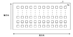
シート材1は、配管Pの表面に貼り付けられている。図2に示すように、シート材1は、表面に複数の二次元模様1aが描かれている。複数の二次元模様1aは、配管P上に配列されるとともに、配管P上の位置を示す。例えば、二次元模様1aは、シート材1において、配管Pの軸方向(中心軸方向)及び周方向に複数描かれている。二次元模様1aには、配管P上の位置(座標)を示す情報(以下、「位置情報」という。)が暗号化されている。例えば、二次元模様1aは、配管Pの軸方向及び周方向に10mm間隔で配置されている。例えば、二次元模様1aは、QR(登録商標)コードである。なお、シート材1は、配管Pの外周面において超音波探触子を走査する領域に設けられている。
The
シート材1は、配管Pの表面に直接ではなく、超音波を伝播させるための接触媒質が配管Pの表面に塗布された状態で、配管Pの表面に貼り付けられてもよい。このように、配管P上に塗布された接触媒質の上からシート材1を貼り付けることで、接触媒質の粘着性によりシート材1を配管Pに吸着させることができる。さらに、接触媒質によって、配管Pの表面に凹凸がある場合でも、シート材1を平らに(すなわち軸方向及び周方向に延びる周面に沿うように)貼り付けることができる。接触媒質は、減衰を抑制しつつ超音波を伝搬させる物質であればよく、例えば、グリセリン、水、油等である。
The
超音波探触子2は、同軸ケーブルを介して超音波探傷器4に接続されており、配管P上(配管Pの外周面上)を移動可能である。超音波探触子2は、先端から超音波を発生し、当該超音波の反射波を検出する。そして、超音波探触子2は、検出した反射波(エコー)の波形を検出信号(検出結果)Wとして超音波探傷器4に出力する。例えば、超音波探触子2は、検査員の手動によって配管P上の表面を移動しながら配管P上の所定の範囲(以下、「走査範囲」という。)S(図4参照)を超音波で走査して、配管Pの亀裂等を示すエコーを検出する。
The
撮像装置3は、超音波探触子2に取り付けられている。言い換えれば、撮像装置3は、超音波探触子2と連結されており、超音波探触子2の移動に連動して移動する。撮像装置3は、配管P上に貼り付けられたシート材1の二次元模様1aを撮像する、例えば光学式の撮像装置である。撮像装置3は、信号ケーブルを介して超音波探傷器4に接続されている。撮像装置3は、読み取った二次元模様1aの撮像画像Gを超音波探傷器4に出力する。例えば、撮像装置3は、LED(Light Emitting Diode)等の発光素子を備える発光部と、CCD(Charge Coupled Device)カメラ等の撮像部と備え、超音波探触子2の移動方向における後側に取り付けられている。なお、撮像装置3は、シート材1の二次元模様1aを撮像可能であれば、超音波探触子2のどの部分に取り付けられていてもよい。また、撮像装置3は、超音波探触子2と同じ筐体で一体化されていてもよいし、別体であってもよい。
例えば、超音波探触子2と撮像装置3とを検査プローブとして一体化されてもよい。なお、本実施形態の検査プローブの構成は、例えば、国際公開第2016/098224号に記載された検査プローブの構成を用いることができる。The imaging device 3 is attached to the
For example, the
超音波探傷器4は、超音波探触子2に接続されると共に情報処理装置5に接続されている。超音波探傷器4は、超音波探触子2及び撮像装置3に電力を供給する。超音波探傷器4は、超音波探触子2から入力される検出信号Wを、A/D変換して情報処理装置5に出力する。言い換えれば、超音波探傷器4は、A/Dコンバータを含む。なお、図1における矢印の向きは、検出信号Wの進む方向を表示しており、上述の電力供給の向きとは関係がない。
The
超音波探触子2には、超音波探傷器4から電力が供給され、撮像装置3には情報処理装置5から電力が供給されてもよい。なお、超音波探触子2及び撮像装置3の、超音波探傷器4や情報処理装置5に対する接続は、有線接続に限らず、無線接続であってもよい。
Power may be supplied to the
情報処理装置5は、超音波探傷器4に接続されている。例えば、情報処理装置5は、デスクトップ型またはノート型のコンピュータである。
The
以下に、本実施形態に係る情報処理装置5について説明する。図1に示すように、情報処理装置5は、表示部11、操作部12、通信I/F部13及び制御部14を備える。
The
表示部11は、制御部14からの情報を表示画面に表示する。例えば、表示部11は、CRT(Cathode Ray Tube)ディスプレイまたは液晶ディスプレイであり、制御部14の制御の下、各種情報を表示する。
The
操作部12は、ユーザの操作を受け付け、ユーザから受け付けた操作に応じた操作指示を制御部14に出力する。例えば、操作部12は、マウス等のポインティングデバイス及びキーボードその他の操作装置である。
The
通信I/F部13は、制御部14の制御の下、通信ケーブルを介して超音波探傷器4との間で各種信号の送受信を行う。通信I/F部13は、通信ケーブルを介して超音波探傷器4から受信した検出信号Wを制御部14に送信する。
通信I/F部13は、信号ケーブルを介して撮像装置3に接続されており、撮像装置3が撮像したた二次元模様1aの撮像画像Gを受信する。通信I/F部13は、受信した撮像画像Gの画像情報をA/D変換して制御部14に送信する。Under the control of the
The communication I/
例えば、制御部14は、CPU(Central Processing Unit)、ROM(Read Only Memory)及びRAM(Random Access Memory)等を備えている。
For example, the
以下に、本実施形態に係る制御部14の機能部について説明する。本実施形態に係る制御部14は、処理部21、表示制御部22及び格納部23を備える。なお、処理部21及び表示制御部22がそれぞれ、CPU、ROM及びRAM等を備えていてもよい。格納部23が、ROM及びRAM等の記憶装置を備えていてもよい。
The functional units of the
処理部21は、撮像画像Gから検査対象上の位置を示す位置情報を読み取る読取処理を実行する。すなわち、処理部21は、撮像画像Gを解析して、当該撮像画像Gに映っている二次元模様1aに暗号化されている位置情報を読み取る読取処理を実行する。そして、処理部21は、読取処理で読み取った位置情報と、当該読取処理で用いた撮像画像Gが得られたときに超音波探傷器4から受信した検出信号Wとを関連付ける。換言すれば、処理部21は、超音波探傷器4から受信した検出信号Wと、当該検出信号Wと同時に得た撮像画像Gから読み取った位置情報とを関連付ける。
The
処理部21は、撮像画像Gの画像情報に基づいて、撮像画像Gの所定の範囲H内に映っている気泡の領域(以下、「気泡領域」という。)HAを検出する気泡検出処理を実行する。例えば、処理部21は、通信I/F部13から得られた撮像画像Gの画像情報を用いて撮像画像Gに対して所定の画像処理を行うことで、気泡領域HAを検出する気泡検出処理を実行する。所定の画像処理とは、気泡領域HAを検出する処理であって、2値化処理等の公知の画像処理を用いてもよい。なお、気泡領域HAを検出するとは、例えば、気泡領域HAの画素数Naを求めることである。
なお、読取処理と気泡検出処理とのそれぞれで用いられる撮像画像Gは、同一の撮像画像Gである。Based on the image information of the captured image G, the
Note that the captured image G used in each of the reading process and the air bubble detection process is the same captured image G. As shown in FIG.
処理部21は、所定の範囲Hに対する気泡領域HAの割合を求め、その割合から接触率Rを求める演算処理を実行する。この接触率Rは、所定の範囲Hにおける配管Pの表面とシート材1との接触の割合を示す。例えば、処理部21は、演算処理として、撮像画像Gにおいて、所定の範囲Hの総画素数Nsに対する画素数Naの割合を求める。そして、処理部21は、下記に示す式(1)を用いて接触率Rを求める。
The
接触率R[%]=(1-Na/Ns)×100 …(1) Contact rate R [%] = (1-Na/Ns) x 100 (1)
図3A及び3Bは、本実施形態に係る処理部21の演算処理を説明する図である。図3Aは、気泡がない場合の撮像画像G1を示し、図Bは、気泡がある場合の撮像画像G2を示す。
3A and 3B are diagrams for explaining arithmetic processing of the
図3Aに示すように、撮像画像G1の所定範囲Hには、気泡が存在しない。したがって、処理部21は、撮像画像G1に対して気泡検出処理及び演算処理を行うことで撮像画像G2における所定範囲Hの接触率R1=100%を得る。一方、図Bに示すように、撮像画像G2の所定範囲Hには、気泡が存在する。したがって、処理部21は、撮像画像G2に対して気泡検出処理を行うことで気泡領域HAの画素数Naを求める。そして、処理部21は、式(1)を用いて演算処理を行うことで撮像画像G2における所定範囲Hの接触率R2を得る。ここで、総画素数Nsに対する画素数Naの割合が30%である場合には、処理部21は、式(1)を用いて演算処理を行うことで撮像画像G2における所定範囲Hの接触率R2=70%を得る。
As shown in FIG. 3A, no bubble exists in the predetermined range H of the captured image G1. Therefore, the
次に、処理部21は、演算処理で求めた接触率Rと、当該演算処理で用いた撮像画像Gが得られたときに超音波探傷器4から受信した検出信号Wとを関連付ける。換言すれば、処理部21は、超音波探傷器4から受信した検出信号Wと、当該検出信号Wと同時に得た撮像画像Gから求めた接触率Rとを関連付ける。
Next, the
表示制御部22は、配管P上における超音波探触子2の走査範囲Sをメッシュ状の領域である複数の分割領域100に分割して表示部11の表示画面に表示する。図4は、本実施形態に係る表示部11の表示画面の一例である。
The
表示制御部22は、処理部21が算出した接触率Rと予め設定された閾値Rthとを比較して、接触率Rが閾値Rthを超える場合には、複数の分割領域100のうち当該接触率Rに関連付けられている位置情報を含む分割領域100aを第1の表示態様で表示する。一方、表示制御部22は、処理部21が算出した接触率Rと予め設定された閾値Rthとを比較して、接触率Rが閾値Rth以下の場合には、複数の分割領域100のうち当該接触率Rに関連付けられている位置情報を含む分割領域100bを第1の表示態様とは異なる第2の表示態様で表示する。例えば、第1の表示態様とは分割領域100aを第1の色で塗りつぶすことであり、第2の表示態様とは、分割領域100bを第1の色とは異なる第2の色で塗りつぶすことであってもよい。また、第1の表示態様とは分割領域100aを第1の色で塗りつぶすことであり、第2の表示態様とは、分割領域100bを塗りつぶすさないことであってもよい。さらに、第1の表示態様とは、分割領域100aに第1のマークを記入することであり、第2の表示態様とは、分割領域100bに第1のマークとは異なる第2のマークを記入することであってもよい。
なお、閾値Rthは、検査対象の表面状態のうねり等の状態によって設定されてもよい。The
Note that the threshold value Rth may be set according to the surface state of the object to be inspected, such as undulations.
ここで、例えば、表示制御部22は、複数の分割領域100のうち、位置情報が含まれない分割領域に対しては塗りつぶしを行わない。すなわち、表示制御部22は、複数の分割領域100のうち、超音波探傷の走査が行われていない分割領域100に対しては塗りつぶしを行わない。また、例えば、表示制御部22は、接触率Rが閾値Rth以下の場合には、複数の分割領域100のうち当該接触率Rに関連付けられている位置情報を含む分割領域100bに対して塗りつぶしを行わない。したがって、ユーザは、表示部11の表示画面を確認して、塗りつぶしが行われていない分割領域100を再走査することで、検査漏れなく、且つ、高精度で検査対象を超音波探傷検査することができる。
Here, for example, the
格納部23には、検出信号W(エコーの波形)、位置情報及び接触率Rが関連付けられて格納されている。また、格納部23には検査プログラムが格納されてもよい。そして、制御部14は、格納部23(例えば、ROM)に格納されている検査プログラムに基づいて動作することで、読取処理、気泡検出処理、及び演算処理を実行してもよい。また、格納部23には表示プログラムが格納されてもよい。そして、制御部14は、格納部23(例えば、ROM)に格納されている表示プログラムに基づいて動作することで、接触率Rが閾値Rthを超える場合には、複数の分割領域100のうち当該接触率Rに関連付けられている位置情報を含む分割領域100aを第1の表示態様で表示し、接触率Rが閾値Rth以下の場合には複数の分割領域100のうち当該接触率Rに関連付けられている位置情報を含む分割領域100bを第1の表示態様とは異なる第2の表示態様で表示してもよい。
The
次に、本実施形態に係る超音波探傷装置Aの検査処理(読取処理、気泡検出処理及び演算処理)の動作について、図6を用いて説明する。図6は、本実施形態に係る超音波探傷装置Aのフロー図である。 Next, operation of inspection processing (reading processing, bubble detection processing, and arithmetic processing) of the ultrasonic flaw detector A according to this embodiment will be described with reference to FIG. FIG. 6 is a flowchart of the ultrasonic flaw detector A according to this embodiment.
検査員は、配管Pに発生する亀裂等の欠陥や減肉を検出するために、超音波探触子2を用いて配管P上の検査部位を走査する。例えば、検査員は、超音波探触子2を走査範囲Sにおいて、軸方向に沿って動かくことで当該軸方向の第1の端部から第2の端部まで走査する。次に、検査員は、超音波探触子2が第2の端部に到達すると、超音波探触子2を周方向にずらした位置から第1の端部に向けて軸方向に走査する。そして、検査員は、超音波探触子2に対する上記走査を繰り返すことで、配管P上の検査部位全体、すなわち走査範囲S全体を走査する。
The inspector scans the inspected portion on the pipe P using the
この際、超音波探触子2は、照射した超音波の反射波を検出してその反射波(エコー)の波形を検出信号(検出結果)Wとして超音波探傷器4を介して情報処理装置5に出力する(ステップS101)。また、撮像装置3は、撮像した二次元模様1aの撮像画像Gを情報処理装置5に出力する(ステップS102)。
At this time, the
情報処理装置5は、同時、又は同時と同視得る範囲において検出信号Wtと撮像画像Gtを受信した場合には、その撮像画像Gtに基づいて読取処理、気泡検出処理、及び演算処理を実行する。
When the
具体的には、処理部21は、読取処理を実行して、撮像画像Gtに含まれる二次元模様1a(例えば、QRコード(登録商標))に基づいて配管P上の位置情報(例えば、絶対座標)を取得する(ステップS103)。そして、処理部21は、超音波探触子2からの検出信号Wtと位置情報とを関連付けて格納部23に格納する(ステップS104)。すなわち、処理部21は、超音波探触子2からの検出信号Wtと撮像画像Gtから得られた位置情報とを関連付けて格納部23に格納する。
Specifically, the
また、処理部21は、気泡検出処理を実行して、読取処理で用いた撮像画像Gtの画像情報に基づいて、撮像画像Gtの所定の範囲H内に映っている気泡領域HAを検出する(ステップS104)。
In addition, the
そして、処理部21は、演算処理として、撮像画像Gtの所定の範囲Hに対する気泡領域HAの割合を求め、その割合から接触率Rtを求める演算処理を実行する。例えば、処理部21は、撮像画像Gtにおいて、総画素数Nsに対する気泡領域HAの画素数Naの割合を求め、上記式(1)を用いて接触率Rtを求める(ステップS105)。そして、処理部21は、接触率Rtと検出信号Wtとに関連付けて格納部23に格納する。したがって、格納部23には、接触率Rtと検出信号Wtと撮像画像Gtから得られた位置情報とが関連付けられてデータセットとして格納される(ステップS106)。
Then, as arithmetic processing, the
表示制御部22は、処理部21が算出した接触率Rtが予め設定された閾値Rthを超えるか否かを判定する(ステップS107)。表示制御部22は、接触率Rtが閾値Rthを超える場合には、複数の分割領域100のうち当該接触率Rtに関連付けられている位置情報を含む分割領域100aを第1の表示態様で表示する(ステップS108)。一方、表示制御部22は、接触率Rtが閾値Rth以下の場合には、複数の分割領域100のうち当該接触率Rに関連付けられている位置情報を含む分割領域100bを第1の表示態様とは異なる第2の表示態様で表示する(ステップS109)。例えば、表示制御部22は、分割領域100aを第1の表示態様として塗りつぶし、分割領域100bを第2の表示態様として塗りつぶしを行わない。さらに、処理部21は、分割領域100bの上記データセットを格納部23から削除してもよい。
The
処理部21は、すべての分割領域100が塗りつぶされたか否かを判定する(ステップS1110)。処理部21は、すべての分割領域100が塗りつぶされた場合には、検査処理を終了する(ステップS111)。すなわち、処理部21は、すべての分割領域100で上記データセットが得られた場合には、検査処理を終了する。一方、処理部21は、少なくとも一つの分割領域100が塗りつぶされていない場合には、検査処理を終了しない。すなわち、少なくとも一つの分割領域100に対応するデータセットがない場合や接触率RがRth以下での検出信号Wしかない分割領域100がある場合には、検査処理を終了しない。
The
これにより、検査員は、接触率Rの悪かった部分の再走査が必要になり接触率の悪化による検査の信頼性の低下を防止できる。
なお、処理部21は、同じ分割領域100で2つ以上のデータセットが得られた場合には、最新のデータセットのみを格納部23に格納してもよい。また、処理部21は、同じ分割領域100で2つ以上のデータセットが得られた場合には、接触率Rが高いデータセットのみを格納部23に格納してもよい。また、処理部21は、接触率Rが閾値Rthである場合に分割領域100に対応する上記データセットを格納部23に格納した場合には、その後の当該分割領域100に対するデータセットの取得を行わなくてもよい。すなわち、処理部21は、接触率Rが閾値Rthであるデータセットが存在する分割領域100に対して、検出信号Wや撮像画像Gが得られたとしても検査処理を実行しなくてもよい。As a result, the inspector is required to rescan the portion where the contact rate R is bad, and it is possible to prevent the reliability of the inspection from deteriorating due to the deterioration of the contact rate.
Note that, when two or more data sets are obtained from the same divided
ここで、処理部21は、上記データセットに基づいて探傷分布データを作成してもよい。そして、表示制御部22は、上記探傷分布データを表示してもよい。さらに、表示制御部22は、接触率Rを上記探傷分布データに対応させて表示してもよい。上記探傷分布データは、表示部11に表示された場合、探傷結果を示す各色(例えば、赤色、青色、黄色等)が配管P上の位置毎又は分割領域100毎にマッピングされた画像として表示される。
さらに、処理部21は、超音波探触子2による検出信号Wと配管P上の位置情報と時間とに関連付けて格納部23に格納してもよい。これにより、処理部21は、超音波探触子2の軌跡を取得することができる。この場合には、表示制御部22は、当該軌跡を表示部11に表示してもよい。なお、処理部21は、マッピングされた画像の表示形式として、超音波探触子2の位置だけでなく、超音波探触子2の傾き、及び被検体(例えば配管P)の形状を考慮したボリュームレンダリング処理を行ってもよい。Here, the
Furthermore, the
また、処理部21は、超音波探触子2を被検体の欠陥や減肉の周りを周回させるなど自在な超音波探触子2の操作を記録してもよい。
In addition, the
以上、この発明の実施形態について図面を参照して詳述してきたが、具体的な構成はこの実施形態に限定されず、この発明の範囲の設計変更等も含まれる。 Although the embodiments of the present invention have been described in detail above with reference to the drawings, the specific configuration is not limited to these embodiments, and design changes and the like are also included within the scope of the present invention.
(変形例1)上記実施形態の超音波探傷装置Aは、1つの撮像装置3を有しているが、撮像装置3の個数には限定されず、上記撮像装置3は複数備えてもよい。例えば、超音波探傷装置Aは、超音波探触子2を挟むように、超音波探触子2の前後に合計2個の撮像装置3を備えてもよい。
(Modification 1) The ultrasonic flaw detector A of the above embodiment has one imaging device 3, but the number of imaging devices 3 is not limited, and a plurality of imaging devices 3 may be provided. For example, the ultrasonic flaw detector A may include a total of two imaging devices 3 before and after the
(変形例2)上記実施形態の撮像装置3はLED等の発光素子を備える発光部ではなくレーザー発振器を備えてもよい。撮像装置3がレーザー発振器を用いる場合には、レーザー光により照射されたシート材1上の二次元模様1aが描かれている箇所と、二次元模様1aが描かれていない箇所とのコントラストを大きくすることができる。
(Modification 2) The imaging device 3 of the above-described embodiment may include a laser oscillator instead of the light emitting unit including a light emitting element such as an LED. When the imaging device 3 uses a laser oscillator, the contrast between a portion where the two-
(変形例3)上記実施形態の超音波探傷装置Aは、超音波探触子2を複数備えてもよい。また、超音波探触子2は、フェーズドアレイであってもよい。
(Modification 3) The ultrasonic flaw detector A of the above embodiment may include a plurality of
(変形例4)上記実施形態の表示制御部22は、操作部12により複数の分割領域100のうち、任意の分割領域が選択された場合には、その分割領域に対応したデータセットを表示部11に表示してもよい。例えば、表示制御部22は、操作部12により複数の分割領域100のうち、任意の分割領域が選択された場合には、選択された分割領域に対応する検出信号Wと、その検出信号Wに関連付けられた接触率Rを表示部11に表示してもよい。選択された分割領域に対応する検出信号Wとは、選択された分割領域に含まれる位置情報に関連付けられた検出信号である。
ここで、超音波探触子2と検査対象との間に気泡が存在する場合は、その反射の影響により、エコーにノイズが混入する場合がある。そのため、検査員は、そのエコーが欠陥からのエコーなのか、接触状態に起因するノイズなのか判断に迷う場合がある。変形例4では、制御部14は、接触率Rを求め、検出信号とともに表示部11に表示する。これにより、検査員は、接触の影響に起因したノイズなのか、もしくは試験体内からのエコーからなのかを判断することが可能となる。(Modification 4) When an arbitrary divided area is selected from the plurality of divided
Here, if an air bubble exists between the
(変形例5)上記実施形態の表示制御部22は、撮像画像Gを表示部11に表示してもよい。その際に、表示制御部22は、撮像画像Gとともに接触率Rを表示してもよい。接触率Rの表示態様としては、接触率Rの値を表示してもよいし、接触率Rの値を示す表示バーを表示してもよい。
(Modification 5) The
また、検査員は、カプラントの継ぎ足しや、再走査をする理由により、検査プローブを検査対象から離すことが多々ある。検査プローブが検査対象から離れる際に、ウォーターギャップが生じて検出信号Wにノイズが発生する。本実施形態の処理部21は、接触率Rが閾値Rth以下のデータセットを除外することで、上記ノイズが混入した検出信号Wを除去することができる。
Also, inspectors often move the test probe away from the test object for couplant replenishment or rescan reasons. When the inspection probe moves away from the inspection object, a water gap is generated and noise is generated in the detection signal W. The
以上、説明したように、本実施形態に係る超音波探傷装置Aは、撮像装置が撮像した二次元模様1aの撮像画像Gの所定の範囲Hにおいて気泡が映っている領域である気泡領域HAに基づいて検出信号Wの品質の度合いを示す指標を求める処理部21を備える。この品質の度合いを示す指標とは、所定の範囲Hに対する気泡領域HAの割合であってもよいし、接触率Rであってもよい。
As described above, the ultrasonic flaw detection apparatus A according to the present embodiment detects the air bubbles in the air bubble region HA in the predetermined range H of the captured image G of the two-
このような構成によれば、検査員が、所定の範囲Hに対する気泡領域HAの割合や接触率等の指標を確認して、割合が高い場合や接触率が低い場合には再走査を行うことで、超音波探触子と検査対象との間に気泡が存在する場合であっても、超音波探傷検査の信頼性の低下を抑制することができる。なお、上記割合を求めることは、接触率Rを求めることと同義である。 According to such a configuration, the inspector checks the index such as the ratio of the bubble area HA to the predetermined range H and the contact ratio, and rescans when the ratio is high or the contact ratio is low. Therefore, even if air bubbles exist between the ultrasonic probe and the inspection object, it is possible to suppress deterioration in the reliability of the ultrasonic inspection. It should be noted that obtaining the above ratio is synonymous with obtaining the contact rate R.
ここで、超音波探傷検査では、超音波探触子2と検査対象との間に気泡が存在すると、超音波の伝搬が妨げられ、傷を正しく検出できない可能性がある。そこで、気泡が存在する場合には超音波探触子の検出結果を超音波探傷検査に用いないようにする場合が考えられる。例えば、超音波探傷装置は、気泡を検出した場合にはすぐに検出信号Wのデータ採取を停止することが考えられる。ただし、このようにすると、データ採取に時間がかかり、十分なデータが得られない場合がある。また、検査対象のうねりなどの表面状態によっては完全に気泡を排除することは現実的に困難である。そのため、このような状況下では、気泡をある程度許容せざるを得ない。しかしながら、気泡をどのくらい許容するかは検査員によって異なるため、経験の少ない検査員が超音波探傷検査を行うと、検出信号Wの質の悪化が発生し、超音波探傷検査の信頼性が低下する。
Here, in the ultrasonic flaw detection, if there is an air bubble between the
本実施形態の超音波探傷装置Aは、気泡領域HAに基づいて、検出信号の品質の度合いを示す指標(例えば、上記割合や接触率R)を求める。そのため、検査員は、その指標を確認しながら超音波探傷検査を実施することが可能となり、超音波探傷検査の信頼性の低下を抑制することができる。 The ultrasonic flaw detector A of the present embodiment obtains an index (for example, the ratio or the contact ratio R) indicating the degree of quality of the detection signal based on the bubble area HA. Therefore, the inspector can perform the ultrasonic inspection while confirming the index, thereby suppressing deterioration in the reliability of the ultrasonic inspection.
なお、上述した情報処理装置5の全部または一部をコンピュータで実現するようにしてもよい。この場合、上記コンピュータは、CPU、GPUなどのプロセッサ及びコンピュータ読み取り可能な記録媒体を備えてもよい。そして、上記情報処理装置5の全部または一部の機能をコンピュータで実現するためのプログラムを上記コンピュータ読み取り可能な記録媒体に記録して、この記録媒体に記録されたプログラムを上記プロセッサに読み込ませ、実行することによって実現してもよい。ここで、「コンピュータ読み取り可能な記録媒体」とは、フレキシブルディスク、光磁気ディスク、ROM、CD-ROM等の可搬媒体、コンピュータシステムに内蔵されるハードディスク等の記憶装置のことをいう。さらに「コンピュータ読み取り可能な記録媒体」とは、インターネット等のネットワークや電話回線等の通信回線を介してプログラムを送信する場合の通信線のように、短時間の間、動的にプログラムを保持する媒体、その場合のサーバやクライアントとなるコンピュータシステム内部の揮発性メモリのように、一定時間プログラムを保持している媒体も含んでもよい。また上記プログラムは、前述した機能の一部を実現するためのプログラムであってもよく、さらに前述した機能をコンピュータシステムにすでに記録されているプログラムとの組み合わせで実現できるプログラムであってもよく、FPGA等のプログラマブルロジックデバイスを用いて実現されるプログラムであってもよい。
なお、「コンピュータ読み取り可能な記録媒体」は、非一時的コンピュータ読み取り可能な記録媒体であってもよい。All or part of the
The "computer-readable recording medium" may be a non-transitory computer-readable recording medium.
上記実施形態では、被検体が配管Pである構成について説明したが、これに限定されない。被検体は、金属製(例えば溶接可能な金属)の棒部材、管部材及び板部材等であってもよく、圧延材や鍛造材、さらにその溶接部であってもよい。さらに、炭素繊維強化プラスチック(CFRP)など、超音波探傷により検査することができる物質を被検体としてもよい。 In the above embodiment, the configuration in which the subject is the pipe P has been described, but the subject is not limited to this. The subject may be a metal (for example, weldable metal) bar member, tube member, plate member, or the like, or may be a rolled material, a forged material, or a welded portion thereof. Furthermore, a substance that can be inspected by ultrasonic flaw detection, such as carbon fiber reinforced plastic (CFRP), may be used as the subject.
本開示は、超音波探触子を用いて検査対象を走査することで検査対象内の傷や減肉を検出する超音波探傷装置に利用することができる。 INDUSTRIAL APPLICABILITY The present disclosure can be used for an ultrasonic flaw detector that detects flaws and thinning in an object to be inspected by scanning the object using an ultrasonic probe.
A 超音波探傷装置
1 シート材
2 超音波探触子
3 撮像装置
4 超音波探傷器
5 情報処理装置
11 表示部
12 操作部
13 通信I/F部
14 制御部
21 処理部
22 表示制御部A
Claims (4)
前記検査対象の表面に貼り付けられ、前記検査対象上に配列されると共に前記検査対象上の位置を示す二次元模様が描かれているシート材と、
前記超音波探触子に取り付けられ、前記二次元模様を撮像する撮像装置と、
前記撮像装置が撮像した撮像画像から前記検査対象上の位置を示す位置情報を読み取り、前記超音波探触子の検出結果と前記位置情報とを関連付ける処理部と、を備え、
前記処理部は、
前記撮像画像の所定の範囲において気泡が映っている領域である気泡領域に基づいて、前記検出結果の品質の度合いを示す指標を求め、
前記撮像画像において、前記所定の範囲の総画素数に対する前記気泡領域の画素数の割合を求め、前記割合から前記検査対象に対する前記シート材の接触率を求める、
超音波探傷装置。 an ultrasonic probe for irradiating an object to be inspected with ultrasonic waves and detecting reflected waves;
a sheet material attached to the surface of the inspection object, arranged on the inspection object and on which a two-dimensional pattern indicating a position on the inspection object is drawn;
an imaging device attached to the ultrasonic probe for imaging the two-dimensional pattern;
A processing unit that reads position information indicating a position on the inspection object from the captured image captured by the imaging device and associates the detection result of the ultrasonic probe with the position information,
The processing unit is
Obtaining an index indicating the degree of quality of the detection result based on a bubble region, which is a region in which bubbles appear in a predetermined range of the captured image ,
Obtaining a ratio of the number of pixels in the bubble region to the total number of pixels in the predetermined range in the captured image, and obtaining a contact rate of the sheet material with respect to the inspection object from the ratio ;
Ultrasonic flaw detector.
前記表示制御部は、前記接触率が閾値を超える場合には、前記複数の分割領域のうち当該接触率に関連付けられている位置情報を含む分割領域を第1の表示態様で表示し、前記接触率が閾値以下の場合には前記複数の分割領域のうち当該接触率に関連付けられている位置情報を含む分割領域を第1の表示態様とは異なる第2の表示態様で表示する、請求項2に記載の超音波探傷装置。 A display control unit that divides the scanning range of the ultrasonic probe on the inspection object into a plurality of divided regions that are mesh-shaped regions and displays them on a display unit,
When the contact rate exceeds a threshold value, the display control unit displays a divided area including position information associated with the contact rate among the plurality of divided areas in a first display mode, and displays the contact rate. 2. When the contact rate is equal to or less than a threshold, the divided area including the position information associated with the contact rate is displayed in a second display mode different from the first display mode, among the plurality of divided areas. The ultrasonic flaw detector according to .
前記表示制御部は、前記操作部により前記複数の分割領域のうち任意の前記分割領域が選択された場合には、前記選択された前記分割領域に対応する前記検出結果と当該検出結果に関連付けられた前記接触率とを前記表示部に表示する、請求項3に記載の超音波探傷装置。 Equipped with an operation unit,
When an arbitrary divided area is selected from among the plurality of divided areas by the operation unit, the display control unit associates the detection result corresponding to the selected divided area with the detection result. 4. The ultrasonic flaw detector according to claim 3, wherein said contact rate and said contact rate are displayed on said display unit .
Applications Claiming Priority (3)
| Application Number | Priority Date | Filing Date | Title |
|---|---|---|---|
| JP2019035946 | 2019-02-28 | ||
| JP2019035946 | 2019-02-28 | ||
| PCT/JP2020/008431 WO2020175687A1 (en) | 2019-02-28 | 2020-02-28 | Ultrasonic flaw detection device |
Publications (2)
| Publication Number | Publication Date |
|---|---|
| JPWO2020175687A1 JPWO2020175687A1 (en) | 2021-12-02 |
| JP7188552B2 true JP7188552B2 (en) | 2022-12-13 |
Family
ID=72239812
Family Applications (1)
| Application Number | Title | Priority Date | Filing Date |
|---|---|---|---|
| JP2021502654A Active JP7188552B2 (en) | 2019-02-28 | 2020-02-28 | Ultrasonic flaw detector |
Country Status (6)
| Country | Link |
|---|---|
| US (1) | US11875497B2 (en) |
| EP (1) | EP3933397A4 (en) |
| JP (1) | JP7188552B2 (en) |
| KR (1) | KR20210124461A (en) |
| TW (1) | TWI779268B (en) |
| WO (1) | WO2020175687A1 (en) |
Families Citing this family (6)
| Publication number | Priority date | Publication date | Assignee | Title |
|---|---|---|---|---|
| CN112198227B (en) * | 2020-09-30 | 2025-03-11 | 东莞市李群自动化技术有限公司 | Ultrasonic nondestructive testing defect location tracing method |
| EP4001735B1 (en) * | 2020-11-18 | 2024-04-10 | Georg Fischer Rohrleitungssysteme AG | Monitoring of pipe systems |
| JP2023136390A (en) * | 2022-03-17 | 2023-09-29 | 株式会社東芝 | Ultrasonic flaw detection system and ultrasonic flaw detection method |
| ES3049583T3 (en) * | 2022-08-10 | 2025-12-17 | Nexans | Method for inspecting surfaces and interfaces of high voltage cable components |
| CN117831659B (en) * | 2024-03-04 | 2024-05-03 | 山东钢铁股份有限公司 | Method and device for online detection of quality of wide and thick plates, electronic equipment and storage medium |
| WO2026078919A1 (en) * | 2024-10-07 | 2026-04-16 | 株式会社Ihi | Inspection method and inspection apparatus |
Citations (7)
| Publication number | Priority date | Publication date | Assignee | Title |
|---|---|---|---|---|
| JP2001349878A (en) | 2000-06-08 | 2001-12-21 | Japan Probe Kk | Ultrasonic probe, and system and method for ultrasonic flaw inspection |
| US20080307886A1 (en) | 2007-06-15 | 2008-12-18 | The Boeing Company | System and method for automated inspection of large-scale part |
| JP2013033028A (en) | 2011-06-30 | 2013-02-14 | Shibaura Mechatronics Corp | Bonded plate-like body inspection device and method |
| WO2015072188A1 (en) | 2013-11-15 | 2015-05-21 | 株式会社Ihi | Inspection system |
| WO2016098224A1 (en) | 2014-12-18 | 2016-06-23 | 株式会社Ihi | Inspection probe |
| JP2017163093A (en) | 2016-03-11 | 2017-09-14 | リンテック株式会社 | Sheet sticking device and sticking method |
| US20180165626A1 (en) | 2014-07-31 | 2018-06-14 | Cloverleaf Media, LLC | Merchandising communication and stock-out condition monitoring system |
Family Cites Families (3)
| Publication number | Priority date | Publication date | Assignee | Title |
|---|---|---|---|---|
| DE102011004584A1 (en) * | 2011-02-23 | 2012-08-23 | Krones Aktiengesellschaft | Method and apparatus for detecting bubbles and / or wrinkles on labeled containers |
| TWI559002B (en) * | 2014-12-18 | 2016-11-21 | Ihi股份有限公司 | Inspection probe |
| JP7207883B2 (en) | 2017-08-10 | 2023-01-18 | キヤノン株式会社 | Optical low-pass filter and imager |
-
2020
- 2020-02-27 TW TW109106503A patent/TWI779268B/en active
- 2020-02-28 WO PCT/JP2020/008431 patent/WO2020175687A1/en not_active Ceased
- 2020-02-28 JP JP2021502654A patent/JP7188552B2/en active Active
- 2020-02-28 KR KR1020217029327A patent/KR20210124461A/en not_active Ceased
- 2020-02-28 EP EP20763782.8A patent/EP3933397A4/en active Pending
-
2021
- 2021-08-26 US US17/412,619 patent/US11875497B2/en active Active
Patent Citations (7)
| Publication number | Priority date | Publication date | Assignee | Title |
|---|---|---|---|---|
| JP2001349878A (en) | 2000-06-08 | 2001-12-21 | Japan Probe Kk | Ultrasonic probe, and system and method for ultrasonic flaw inspection |
| US20080307886A1 (en) | 2007-06-15 | 2008-12-18 | The Boeing Company | System and method for automated inspection of large-scale part |
| JP2013033028A (en) | 2011-06-30 | 2013-02-14 | Shibaura Mechatronics Corp | Bonded plate-like body inspection device and method |
| WO2015072188A1 (en) | 2013-11-15 | 2015-05-21 | 株式会社Ihi | Inspection system |
| US20180165626A1 (en) | 2014-07-31 | 2018-06-14 | Cloverleaf Media, LLC | Merchandising communication and stock-out condition monitoring system |
| WO2016098224A1 (en) | 2014-12-18 | 2016-06-23 | 株式会社Ihi | Inspection probe |
| JP2017163093A (en) | 2016-03-11 | 2017-09-14 | リンテック株式会社 | Sheet sticking device and sticking method |
Also Published As
| Publication number | Publication date |
|---|---|
| US11875497B2 (en) | 2024-01-16 |
| US20210390680A1 (en) | 2021-12-16 |
| EP3933397A1 (en) | 2022-01-05 |
| JPWO2020175687A1 (en) | 2021-12-02 |
| TW202041201A (en) | 2020-11-16 |
| EP3933397A4 (en) | 2022-11-23 |
| WO2020175687A1 (en) | 2020-09-03 |
| TWI779268B (en) | 2022-10-01 |
| KR20210124461A (en) | 2021-10-14 |
Similar Documents
| Publication | Publication Date | Title |
|---|---|---|
| JP7188552B2 (en) | Ultrasonic flaw detector | |
| KR102121821B1 (en) | Linear-scan ultrasonic inspection apparatus and linear-scan ultrasonic inspection method | |
| US5952577A (en) | Ultrasonic imaging system | |
| JP7327464B2 (en) | Ultrasonic flaw detector | |
| KR101904687B1 (en) | Inspection system | |
| KR20220034889A (en) | Ultrasonic Inspection Systems and Ultrasonic Inspection Methods | |
| KR102910463B1 (en) | Ultrasonic inspection device and ultrasonic inspection method | |
| JP2015125008A (en) | Ultrasonic flaw detection system and control method of ultrasonic flaw detection system | |
| JP4866791B2 (en) | Ultrasonic flaw detection apparatus and method | |
| JP5890437B2 (en) | Ultrasonic flaw detection method and ultrasonic flaw detection apparatus | |
| JP4364031B2 (en) | Ultrasonic flaw detection image processing apparatus and processing method thereof | |
| CN114594157A (en) | Ultrasonic testing method and device for electrofusion joint of polyethylene steel skeleton pipe | |
| JP2007178186A (en) | Ultrasonic flaw detection method and ultrasonic flaw detection apparatus | |
| JP2001083123A (en) | Local water immersion type ultrasonic probe and ultrasonic inspection apparatus provided with the same | |
| JP2023049117A (en) | Ultrasonic flaw detection data processing program, ultrasonic flaw detection data processing device, and method for determining analyte | |
| JP6703832B2 (en) | Ultrasonic flaw detector, ultrasonic flaw detection method and program | |
| JP2006214996A (en) | Ultrasonic inspection method and ultrasonic inspection apparatus | |
| JPH11258214A (en) | Ultrasonic sensor | |
| JP2010085380A (en) | Ultrasonic inspection device, ultrasonic inspection method, and ultrasonic inspection program | |
| JP2019086477A (en) | Ultrasonic device and method for detecting surface wave |
Legal Events
| Date | Code | Title | Description |
|---|---|---|---|
| A621 | Written request for application examination |
Free format text: JAPANESE INTERMEDIATE CODE: A621 Effective date: 20210720 |
|
| A131 | Notification of reasons for refusal |
Free format text: JAPANESE INTERMEDIATE CODE: A131 Effective date: 20220816 |
|
| A521 | Request for written amendment filed |
Free format text: JAPANESE INTERMEDIATE CODE: A523 Effective date: 20221014 |
|
| TRDD | Decision of grant or rejection written | ||
| A01 | Written decision to grant a patent or to grant a registration (utility model) |
Free format text: JAPANESE INTERMEDIATE CODE: A01 Effective date: 20221101 |
|
| A61 | First payment of annual fees (during grant procedure) |
Free format text: JAPANESE INTERMEDIATE CODE: A61 Effective date: 20221114 |
|
| R151 | Written notification of patent or utility model registration |
Ref document number: 7188552 Country of ref document: JP Free format text: JAPANESE INTERMEDIATE CODE: R151 |