JP7186848B1 - Airtightness test device and airtightness test method - Google Patents
Airtightness test device and airtightness test method Download PDFInfo
- Publication number
- JP7186848B1 JP7186848B1 JP2021185107A JP2021185107A JP7186848B1 JP 7186848 B1 JP7186848 B1 JP 7186848B1 JP 2021185107 A JP2021185107 A JP 2021185107A JP 2021185107 A JP2021185107 A JP 2021185107A JP 7186848 B1 JP7186848 B1 JP 7186848B1
- Authority
- JP
- Japan
- Prior art keywords
- jig
- covering
- tube
- pipe
- pressing
- Prior art date
- Legal status (The legal status is an assumption and is not a legal conclusion. Google has not performed a legal analysis and makes no representation as to the accuracy of the status listed.)
- Active
Links
Images


Landscapes
- Examining Or Testing Airtightness (AREA)
Abstract
【課題】管に対する気密試験の精度を向上する。【解決手段】気密試験装置(1)は、管(T1)を所定の位置で固定する管固定部(10A,10B)と、管の端部を被覆する被覆治具(20A,20B)とを備え、被覆治具には、被覆治具の内部にエアーが注入されるエアー注入口(22a)が形成され、被覆治具は、少なくとも2つの部分被覆治具のそれぞれが管軸中心に向かって押圧されることで、端部を被覆する。【選択図】図1An object of the present invention is to improve the accuracy of an airtightness test for a pipe. An airtightness test device (1) includes a pipe fixing part (10A, 10B) for fixing a pipe (T1) at a predetermined position and a covering jig (20A, 20B) for covering the end of the pipe. The covering jig is formed with an air inlet (22a) through which air is injected into the inside of the covering jig. The edge is covered by being pressed. [Selection drawing] Fig. 1
Description
本発明は、管の気密性についての試験を行うための気密試験装置及び気密試験方法に関する。 TECHNICAL FIELD The present invention relates to an airtightness test apparatus and an airtightness test method for testing the airtightness of a pipe.
特許文献1には、管に対して気密試験を行うための気密試験装置が開示されている。当該気密試験装置は、管を包み込むフードと、フード内に支持される給気管と、給気管に形成される検知用ガスの吹き出しノズルと、管を回動させる回動手段と、を備える。上記気密試験装置は、管の挿し口及び受口の端面をパッキンで挟み込むことにより管内の気密性を保ち、吹き出しノズルから検知用ガスを管の外面に吹き付けることにより、管の全面を同一条件で検査する。
しかしながら、特許文献1に開示の気密試験装置では、気密試験の繰り返しによるパッキンのへたり等の影響により、検知用ガスが管の端部から管の内部に入り込む虞がある。これにより、当該気密試験装置では、管に対する気密試験の精度が低下するという問題がある。本発明の一態様は、管に対する気密試験の精度を向上することを目的とする。
However, in the airtightness test apparatus disclosed in
上記の課題を解決するために、本発明の一態様に係る気密試験装置は、管の両端に当接し、当該両端を前記管の軸方向に押圧することで、前記管を所定の位置で固定する管固定部と、前記管の端部を被覆する被覆治具とを備え、前記被覆治具には、当該被覆治具の内部にエアーが注入されるエアー注入口が形成され、前記被覆治具は、前記端部の周方向において互いに異なる範囲を被覆する、少なくとも2つの部分被覆治具を組み合わせることで構成され、当該部分被覆治具のそれぞれが、前記管の径方向において前記管の管軸中心に向かって押圧されることで、前記端部を被覆する。 In order to solve the above problems, an airtightness test device according to an aspect of the present invention abuts on both ends of a pipe and presses the both ends in the axial direction of the pipe, thereby fixing the pipe at a predetermined position. and a covering jig for covering the end of the pipe, wherein the covering jig is formed with an air inlet through which air is injected into the covering jig, and the covering jig The tool is configured by combining at least two partial covering jigs that cover different ranges in the circumferential direction of the end portion, and each of the partial covering jigs covers the pipe in the radial direction of the pipe. The end is covered by being pressed toward the center of the shaft.
上記の構成によれば、管の端部の近傍が被覆治具により被覆される。被覆治具が有するエアー注入口から被覆治具の内部にエアーが注入されることで、被覆治具の内部の圧力が上昇するため、気密試験に用いる検知用ガスが被覆治具の内部へ流入しにくくなる。これにより、管の端部の周辺に存在する検知用ガスが管の端部から内部へ流入しにくくなる。したがって、気密試験の精度が向上する。 According to the above configuration, the vicinities of the ends of the pipe are covered by the covering jig. When air is injected into the covering jig from the air injection port of the covering jig, the pressure inside the covering jig rises, so the detection gas used for the airtightness test flows into the covering jig. difficult to do. This makes it difficult for the detection gas existing around the end of the pipe to flow into the interior from the end of the pipe. Therefore, the accuracy of the airtightness test is improved.
また、本発明の一態様に係る気密試験装置において、前記部分被覆治具のそれぞれは、前記管の径方向において前記管の管軸中心に向かって前記部分被覆治具を押圧する押圧機構に接続される押圧治具と、前記管の口径に対応した形状を有し、前記管に当接する口径対応治具とを備え、前記口径対応治具は、前記押圧治具のそれぞれに着脱可能であることが好ましい。 Further, in the airtightness test apparatus according to one aspect of the present invention, each of the partial covering jigs is connected to a pressing mechanism that presses the partial covering jig toward the center of the pipe axis of the pipe in the radial direction of the pipe. and a caliber corresponding jig having a shape corresponding to the caliber of the pipe and abutting on the pipe, wherein the caliber corresponding jig is detachable from each of the pressing jigs. is preferred.
上記の構成によれば、管の口径に対応した口径対応治具を押圧治具に装着することで、互いに異なる複数種類の口径を有する管または管種に対応可能となる。 According to the above configuration, it is possible to deal with a plurality of different types of pipes or types of pipes by attaching a diameter corresponding jig corresponding to the diameter of the pipe to the pressing jig.
また、本発明の一態様に係る気密試験装置は、前記押圧治具に対して前記口径対応治具をクランプするクランプ状態と、前記押圧治具に対して前記口径対応治具をアンクランプするアンクランプ状態とを切替可能なクランプ機構をさらに備えることが好ましい。 Further, the airtightness test apparatus according to one aspect of the present invention includes a clamp state in which the jig corresponding to the diameter is clamped to the pressing jig, and an unclamping state in which the jig corresponding to the diameter is unclamped from the pressing jig. It is preferable to further include a clamping mechanism capable of switching between the clamping state and the clamping state.
上記の構成によれば、クランプ機構について、クランプ状態とアンクランプ状態とを切り替えることで、押圧治具に対して口径対応治具を容易に着脱できる。 According to the above configuration, by switching the clamping mechanism between the clamped state and the unclamped state, the aperture corresponding jig can be easily attached to and detached from the pressing jig.
また、本発明の一態様に係る気密試験装置において、前記被覆治具は、少なくとも3つの前記部分被覆治具を組み合わせることで構成されることが好ましい。 Moreover, in the airtightness test apparatus according to the aspect of the present invention, it is preferable that the covering jig is configured by combining at least three of the partial covering jigs.
上記の構成によれば、それぞれの部分被覆治具におけるいずれの位置においても、押圧機構からの押圧力が管軸中心に向かう成分を有する。このため、部分被覆治具の端部近傍における気密性を高めることができる。 According to the above configuration, the pressing force from the pressing mechanism has a component directed toward the center of the tube axis at any position on each partial covering jig. Therefore, the airtightness in the vicinity of the end of the partial covering jig can be improved.
また、本発明の一態様に係る気密試験装置において、前記被覆治具には、当該被覆治具の内部からエアーを排出するエアー排出口が形成されていることが好ましい。 Moreover, in the airtightness test apparatus according to the aspect of the present invention, it is preferable that the covering jig is formed with an air discharge port for discharging air from the inside of the covering jig.
上記の構成によれば、管の端部を被覆治具により被覆した時点で当該端部の周囲に滞留している検知用ガスを、エアー排出口からエアーとともに排出することで、当該検知用ガスが管の端部から内部へ流入することを防止できる。 According to the above configuration, when the end of the pipe is covered with the covering jig, the detection gas remaining around the end is discharged from the air discharge port together with the air. can be prevented from flowing into the interior from the end of the pipe.
また、本発明の一態様に係る気密試験方法は、管固定部を用いて、管の両端を前記管の軸方向に押圧することで、管を所定の位置で固定する管固定ステップと、前記管の端部の周方向において互いに異なる範囲を被覆する、少なくとも2つの部分被覆治具を組み合わせることで構成される被覆治具を用いて、当該部分被覆治具のそれぞれを、前記管の径方向において前記管の管軸中心に向かって押圧することで前記端部を被覆する被覆ステップと、前記被覆治具に形成されたエアー注入口から前記被覆治具の内部にエアーを注入するエアー注入ステップとを含む。 Further, an airtightness test method according to an aspect of the present invention includes a tube fixing step of fixing a tube at a predetermined position by pressing both ends of the tube in an axial direction of the tube using a tube fixing portion; Using a covering jig configured by combining at least two partial covering jigs for covering different ranges in the circumferential direction of the end of the pipe, each of the partial covering jigs is covered in the radial direction of the pipe. A covering step of covering the end portion by pressing toward the center of the tube axis of the pipe, and an air injection step of injecting air into the inside of the covering jig from an air injection port formed in the covering jig. including.
上記の構成によれば、上述した気密試験装置と同様の効果を奏する。 According to said structure, there exists an effect similar to the airtightness test apparatus mentioned above.
本発明の一態様によれば、管に対する気密試験の精度を向上することができる。 ADVANTAGE OF THE INVENTION According to one aspect of the present invention, it is possible to improve the accuracy of an airtightness test for a pipe.
〔実施形態1〕
以下、本発明の一実施形態について、詳細に説明する。
[Embodiment 1]
An embodiment of the present invention will be described in detail below.
図1は、実施形態1に係る気密試験装置1の全体構成を示す模式図である。図1において、ガス注入器50から管T1に向かう方向をZ軸方向、管T1の延伸方向をY軸方向、Y軸方向及びZ軸方向の両方に直交する方向をX軸方向とする。Z軸正方向は上方向であり、Z軸負方向は下方向である。ここで説明したX軸方向、Y軸方向及びZ軸方向の定義は、図1以外の他の図においても適用されるものとする。
FIG. 1 is a schematic diagram showing the overall configuration of an
気密試験装置1は、管T1の気密性を試験する気密試験を行うための装置である。管T1としては、例えばダクタイル鋳鉄管が挙げられる。また、管T1は必ずしもダクタイル鋳鉄管に限定されるものではなく、鋼管等の金属製の管であってもよい。図1に示すように、気密試験装置1は、管固定部10A,10Bと、真空ポンプ12と、検知部13と、バルブ14,15と、被覆治具20A,20Bと、フード40と、ガス注入器50と、を備える。
The
<管固定部10A,10Bの構成>
管固定部10A,10Bは、管T1を所定の位置で固定するためのものである。管固定部10Aは固定端11Aを有し、管固定部10Bは押圧端11Bを有する。固定端11Aは、気密試験装置1において一定の位置に固定されている。管T1の一端には、他の管T1の挿し口を挿入可能な受口が形成され、管T1の他端には、他の管T1の受口に挿入可能な挿し口が形成されている。固定端11Aには管T1の受口側の端部が当接する。なお、挿し口及び受口が形成された管T1は一例であり、管T1は、必ずしも挿し口及び受口が形成されているものに限定されない。
<Structure of
The
押圧端11Bは固定端11Aに対して移動する。押圧端11Bには管T1の挿し口側の端部が当接する。また、押圧端11Bは、管T1の両端部が固定端11A及び押圧端11Bのそれぞれに当接した状態で管T1に圧力を与える。また、固定端11Aは移動しないため、固定端11Aも管T1に圧力を与える。このように、管固定部10A,10Bは、押圧端11B及び固定端11Aにより管T1の両端を管T1の軸方向に押圧することで、管T1を所定の位置で固定する。
The pressing
固定端11Aは、パッキンP1を介して管T1の受口側の端部に当接し、押圧端11Bは、パッキンP2を介して管T1の挿し口側の端部に当接する。このため、管T1の気密性を試験する場合に用いる検知用ガスが、固定端11Aと管T1との間から管T1の内部に入り込むことを防ぐとともに、押圧端11Bと管T1との間から管T1の内部に入り込むことを防ぐことができる。
The fixed
また、固定端11Aには、管T1に対向する面から当該面の逆側の面まで貫通する貫通孔16が形成されている。固定端11Aに管T1が当接している場合、貫通孔16は管T1の内部と連通する。なお、固定端11Aに管T1の挿し口側の端部が当接するとともに、押圧端11Bに管T1の受口側の端部が当接してもよい。
Further, the fixed
<真空ポンプ12及び検知部13の構成>
真空ポンプ12は、管T1の内部を真空にするポンプである。真空ポンプ12には配管18が接続されており、配管18にはバルブ14が設けられている。配管18は、別の配管17に接続されている。配管17の一部は貫通孔16の内部に配置されている。バルブ14が開いている場合、真空ポンプ12は、配管17及び配管18を介して管T1の内部と連通する。
<Configuration of
The
検知部13は、管T1の内部において検知用ガスを検知するものである。検知部13としては、例えば、気体の成分を分析する分析器が挙げられる。検知部13には配管19が接続されており、配管19にはバルブ15が設けられている。配管19は配管17に接続されている。つまり、配管18及び配管19は、配管17に合流している。バルブ15が開いている場合、検知部13は、配管17及び配管19を介して管T1の内部と連通する。
The
<被覆治具20A,20Bの構成>
被覆治具20Aは、管T1の受口側の端部を被覆する。被覆治具20Bは、管T1の挿し口側の端部を被覆する。被覆治具20Aには、当該被覆治具20Aの内部にエアーが注入されるエアー注入口22aが形成されている。
<Structure of covering
The covering
実施形態1においては、被覆治具20Aは、管固定部10Aに当接した状態で管T1の挿し口側の端部を被覆する。被覆治具20Aと管固定部10Aとの間は、図示しない保持部材により気密状態となっている。保持部材は例えばゴムなどで形成される。被覆治具20Aの内部とは、被覆治具20A、管T1、及び管固定部10Aにより規定される空間である。ただし、被覆治具20Aは、必ずしも管固定部10Aに当接していなくてもよい。その場合には、被覆治具20Aの内部とは、被覆治具20A及び管T1により規定される空間である。
In the first embodiment, the covering
被覆治具20Bは、管T1の挿し口側の端部を被覆する点を除いて、被覆治具20Aと同様の構成等を有する。このため、以下の説明では、簡単のため、被覆治具20Aについてのみ説明し、被覆治具20Bについての説明を省略する。また、被覆治具20Aにより管T1の端部を被覆した状態における、管T1の周方向について、単に周方向と称する場合がある。また、被覆治具20Aにより管T1の端部を被覆した状態における、管T1の軸方向について、単に軸方向と称する場合がある。
The covering
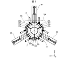
図2は、被覆治具20Aを軸方向から見た図である。被覆治具20Aは、管T1の端部を被覆するため、図2に示すように環状の形状を有する。本発明に係る被覆治具は、少なくとも2つの部分被覆治具21を組み合わせることで構成される。本発明に係る被覆治具は、少なくとも3つの部分被覆治具21を組み合わせることで構成されることが好ましい。実施形態1においては、被覆治具20Aは、図2に示すように、3つの部分被覆治具21を組み合わせることで構成される。部分被覆治具21は、周方向において互いに異なる範囲を被覆する。具体的には、それぞれの部分被覆治具21は、周方向における120°の範囲を被覆する。それぞれの部分被覆治具21が被覆する範囲は互いに接している。
FIG. 2 is an axial view of the covering
気密試験装置1は、部分被覆治具21の数に等しい数の押圧機構30をさらに備える。それぞれの部分被覆治具21は、押圧機構30に装着されている。押圧機構30は、管T1の径方向において管T1の管軸中心に向かって部分被覆治具21を押圧する。押圧機構30は、例えば油圧により駆動される。
The
上述したとおり、被覆治具20Aにはエアー注入口22aが形成されている。図2においては、エアー注入口22aは、それぞれの部分被覆治具21に2つずつ形成されている。また、それぞれの部分被覆治具21に、被覆治具20Aの内部からエアーを排出するエアー排出口22bがさらに形成されている。図2においては、エアー排出口22bは、それぞれの部分被覆治具21に2つずつ形成されている。ただし、エアー注入口22a及びエアー排出口22bの数はこれに限られない。また、エアー注入口22aの数とエアー排出口22bの数とが互いに異なっていてもよい。
As described above, the
図3は、管T1の端部を被覆する前の被覆治具20Aを軸方向から見た図である。被覆治具20Aが管T1の端部を被覆する前の状態では、3つの部分被覆治具21が互いに離隔している。管T1が管固定部10A,10Bにより固定された状態で、部分被覆治具21が押圧機構30により管T1の管軸中心に向かって押圧されることで、図2に示したように、部分被覆治具21が互いに当接し、かつ管T1に当接した状態となる。この状態において、被覆治具20Aは管T1の端部を被覆している。すなわち、被覆治具20Aは、部分被覆治具21のそれぞれが、管T1の径方向において管T1の管軸中心に向かって押圧されることで、管T1の端部を被覆する。
FIG. 3 is an axial view of the covering
<部分被覆治具21の構成>
図4は、部分被覆治具21の構成を示す図である。図4において、符号401は部分被覆治具21の正面図であり、符号402は符号401のA1-A1線矢視断面図である。図4に示すように、部分被覆治具21は、押圧治具22と口径対応治具23とを備える。押圧治具22は、押圧機構30に接続される治具である。口径対応治具23は、管T1の口径に対応した形状を有し、管T1に当接する。口径対応治具23は、押圧治具22のそれぞれに着脱可能である。
<Structure of Partially
FIG. 4 is a diagram showing the configuration of the
口径対応治具23は、気密試験装置1による試験の対象となる管T1の呼び径ごとに、予め複数種類用意されている。管T1の呼び径に応じた口径対応治具23を押圧治具22に装着することで、互いに異なる複数種類の呼び径の管T1に対応可能となる。
A plurality of
押圧治具22は、気密試験装置1による試験の対象となる管T1のうち、呼び径が最大であるものに当接する形状を有していてもよい。それにより、気密試験装置1による試験対象となる管T1のうち、呼び径が最大であるものについての試験を行う場合には、口径対応治具23を装着していない状態の押圧治具22を被覆治具20Aとして使用することができる。
The
気密試験装置1は、クランプ機構24をさらに備える。クランプ機構24は、押圧治具22に対して口径対応治具23をクランプするクランプ状態と、押圧治具22に対して口径対応治具23をアンクランプするアンクランプ状態とを切替可能な機構である。気密試験装置1がクランプ機構を備えることで、クランプ状態とアンクランプ状態とを切り替える操作を容易に行うことができ、口径対応治具23の交換作業を簡素化できる。図4においては、クランプ機構24は、1つの押圧治具22に対して2つ設けられている。ただし、クランプ機構24の数はこれに限られない。
The
具体的には、クランプ機構24は、柱状の軸部材24aと、軸部材24aに沿って変位可能な変位部材24bとを備える。押圧治具22は、軸部材24aの一端を固定することが可能な固定部22cを備える。固定部22cは、例えば押圧治具22に溶接されたナットである。この場合、軸部材24aの一端の側面には、固定部22cに螺合するネジ溝が形成されている。軸部材24aが固定部22cに固定された状態で、変位部材24bが軸部材24aに沿って変位することで、押圧治具22と変位部材24bとの距離が変化し、上記のクランプ状態とアンクランプ状態とが切り替わる。ただし、クランプ機構24の構成はこれに限らない。
Specifically, the
変位部材24bは、レバー操作により軸部材24aに沿って変位することが好ましい。これにより、変位部材24bが例えばネジにより軸部材24aに沿って変位する場合と比較して、クランプ状態とアンクランプ状態とを切り替える操作を、作業者がより容易に行うことができる。
The
図5は、口径対応治具23を押圧治具22へ装着する前の状態を示す図である。図5において、符号501は、口径対応治具23を押圧治具22へ装着する前の、口径対応治具23及び押圧治具22の正面図である。符号502は、符号501における領域A2の拡大図である。符号503は、符号501におけるA3-A3線矢視断面図である。簡単のため、符号501,502においてはクランプ機構24を省略している。
FIG. 5 is a diagram showing a state before mounting the
口径対応治具23は、クランプ機構24によりクランプされる被クランプ部23aを有する。被クランプ部23aは、口径対応治具23を押圧治具22へ装着した状態において軸部材24aに垂直である平板状の部材である。被クランプ部23aには、軸部材24aの径よりも幅が広い長穴状の切欠き23bが形成されている。被クランプ部23aは、クランプ機構24に対応して設けられる。このため、図5においては、被クランプ部23aは、押圧治具22に対するクランプ機構24と同様に、1つの口径対応治具23に対して2つ設けられている。クランプ機構24の数が変更される場合には、被クランプ部23aの数も同様に変更される。
The
口径対応治具23を押圧治具22へ装着する手順は以下のとおりである。まず、押圧治具22と変位部材24bとの距離が被クランプ部23aの厚さよりも長くなるように、変位部材24bを変位させる。次に、切欠き23bが軸部材24aに嵌入するように、被クランプ部23aを押圧治具22と変位部材24bとの間に挿入する。その状態で、押圧治具22と変位部材24bとが互いに当接するように、変位部材24bを軸部材24aに沿って変位させる。以上の手順により、押圧治具22と変位部材24bとの間で被クランプ部23aがクランプされる。すなわち、押圧治具22に対して口径対応治具23がクランプされる。
The procedure for attaching the
<フード40及びガス注入器50の構成>
図1に示すように、フード40は、管固定部10A,10Bに固定された管T1を覆うものである。フード40は、図示しない複数のチェーンによって吊り下げられている。ガス注入器50は、フード40が管T1を覆った状態で、フード40と管T1の外面との間の空間に検知用ガスを注入する。検知用ガスは、大気中における存在比率が極めて小さいガスである。検知用ガスの具体例として、He(ヘリウム)またはAr(アルゴン)が挙げられる。
<Configuration of
As shown in FIG. 1, the
ガス注入器50は、フード40と管T1の外面との間の空間に検知用ガスを注入するためのガス注入管51を有する。フード40が管T1を覆った状態で、ガス注入管51の開口端は、フード40の下端よりも高い位置に配置されているとともに、管T1の外面に接触しない位置に配置されている。
The
<気密試験装置1による気密試験方法>
気密試験装置1による気密試験方法としては、まず、管T1を昇降させる図示しない昇降装置に管T1を設置する。次に、当該昇降装置によって管T1を所定の高さまで持ち上げ、上記昇降装置によって持ち上げられた管T1を、管固定部10A,10Bにより所定の位置で固定する(管固定ステップ)。このとき、管固定部10Aの固定端11Aを、パッキンP1を介して管T1の受口側の端部に当接させるとともに、管固定部10Bの押圧端11Bを、パッキンP2を介して管T1の挿し口側の端部に当接させることにより、管T1の内部を密閉する。
<Airtightness test method by
As an airtightness test method using the
次に、被覆治具20Aを用いて、当該被覆治具20Aを構成する部分被覆治具21のそれぞれを、管T1の径方向において管T1の管軸中心に向かって押圧することで、管T1の受口側の端部を被覆する。(被覆ステップ)。さらに、エアー注入口22aから被覆治具20Aの内部にエアーを注入する(エアー注入ステップ)。管T1の挿し口側についても同様に、被覆治具20Bにより端部を被覆し、被覆治具20Bの内部にエアーを注入する。
Next, using the covering
次に、図示しないフード昇降機構によりフード40を管T1まで下ろし、管固定部10A,10Bにより固定された管T1をフード40により覆う。管T1をフード40により覆った後、真空ポンプ12により管T1の内部を真空にする。併せて、ガス注入器50によりフード40と管T1の外面との間の空間に検知用ガスを注入する。そして、管T1の内部の気体の成分を検知部13により分析し、当該気体に含まれる検知用ガスの量により管T1の気密性を評価する。
Next, the
以上のとおり、気密試験装置1においては、被覆治具20A,20Bの内部にエアーを注入することで、被覆治具20A,20Bの内部の圧力が上昇するため、検知用ガスが被覆治具20A,20Bの内部へ流入しにくくなる。これにより、管T1の端部の周辺に存在する検知用ガスが管T1の端部から内部へ流入しにくくなる。このため、検知用ガスが管T1の端部から内部へ流入することに起因して気密試験の精度が低下する可能性が低減される。したがって、気密試験の精度が向上する。
As described above, in the
特に、被覆治具20A,20Bが3以上の部分被覆治具21を組み合わせることで構成される場合、押圧機構30による押圧力は、周方向における部分被覆治具21の任意の点において、管T1の管軸中心へ向かう成分を含むこととなる。このため、周方向における部分被覆治具21の端部近傍において、部分被覆治具21と管T1との間の気密性が向上する。
In particular, when the covering
また、上述したとおり、被覆治具20Aには、エアー排出口22bが形成されている。エアー注入口22aからエアーを注入すると、被覆治具20Aの内部にもともと存在していた気体が、エアーとともにエアー排出口22bから排出される。
Further, as described above, the covering
複数の管T1について連続して試験を行っている場合などには、気密試験装置1の周囲に検知用ガスが滞留していることが考えられる。被覆治具20Aにより管T1の端部を、当該端部の近傍に滞留している検知用ガスとともに被覆すると、当該検知用ガスが管T1の端部から内部に流入し、気密試験の精度が低下する可能性がある。被覆治具20Aにエアー排出口22bを設けることで、滞留していた検知用ガスについてもエアー排出口22bから排出することができる。したがって、複数の管T1について連続して試験を行っている場合などにおいて、気密試験の精度を向上させることができる。
When a plurality of tubes T1 are continuously tested, it is conceivable that the gas for detection remains around the
ただし、被覆治具20Aには、必ずしもエアー排出口22bが形成されていなくてもよい。被覆治具20Aにエアー排出口22bが形成されていない場合には、押圧治具22と口径対応治具23との僅かな隙間などから、滞留していた検知用ガスがエアーとともに排出される。ただし、エアー排出口22bが形成されている場合と比較すると、滞留していた検知用ガスが排出される速度は遅くなる。
However, the covering
〔実施形態2〕
本発明の他の実施形態について、以下に説明する。なお、説明の便宜上、上記実施形態にて説明した部材と同じ機能を有する部材については、同じ符号を付記し、その説明を繰り返さない。
[Embodiment 2]
Other embodiments of the invention are described below. For convenience of description, members having the same functions as those of the members described in the above embodiments are denoted by the same reference numerals, and description thereof will not be repeated.
図6は、実施形態2に係る被覆治具20Cの外観を示す斜視図である。図6に示すように、被覆治具20Cは、2つの部分被覆治具21Cを組み合わせることで構成されている。部分被覆治具21Cは、周方向において被覆する範囲の違いを除いて、実施形態1で説明した部分被覆治具21と同じ構成を有する。具体的には、それぞれの部分被覆治具21Cは、周方向における180°の範囲を被覆する。それぞれの部分被覆治具21Cが被覆する範囲は互いに接している。
FIG. 6 is a perspective view showing the appearance of a covering
図6に示すように、被覆治具20Cは、2つの部分被覆治具21Cを組み合わせることで構成されていてもよい。このような被覆治具20Cを用いて管T1の端部を被覆した場合にも、管T1の端部を被覆しない場合と比較して、管T1の端部から内部へ検知用ガスが流入しにくくなる。したがって、気密試験の精度を向上させることができる。
As shown in FIG. 6, the covering
本発明は上述した各実施形態に限定されるものではなく、請求項に示した範囲で種々の変更が可能であり、異なる実施形態にそれぞれ開示された技術的手段を適宜組み合わせて得られる実施形態についても本発明の技術的範囲に含まれる。 The present invention is not limited to the above-described embodiments, but can be modified in various ways within the scope of the claims, and can be obtained by appropriately combining technical means disclosed in different embodiments. is also included in the technical scope of the present invention.
1 気密試験装置
20、20A、20B、20C 被覆治具
21、21C 部分被覆治具
22 押圧治具
22a エアー注入口
22b エアー排出口
23 口径対応治具
24 クランプ機構
Claims (6)
前記管の端部を被覆する被覆治具とを備え、
前記被覆治具には、当該被覆治具の内部にエアーが注入されるエアー注入口が形成され、
前記被覆治具は、前記端部の周方向において互いに異なる範囲を被覆する、少なくとも2つの部分被覆治具を組み合わせることで構成され、
当該部分被覆治具のそれぞれが、前記管の径方向において前記管の管軸中心に向かって押圧されることで、前記端部を被覆する、気密試験装置。 a pipe fixing part that abuts on both ends of the pipe and presses the both ends in the axial direction of the pipe to fix the pipe at a predetermined position;
and a covering jig for covering the end of the tube,
The covering jig is formed with an air inlet through which air is injected into the inside of the covering jig,
The covering jig is configured by combining at least two partial covering jigs that cover different ranges in the circumferential direction of the end,
The airtightness testing device, wherein each of the partial covering jigs covers the end portion by being pressed toward the tube axis center of the tube in the radial direction of the tube.
前記管の径方向において前記管の管軸中心に向かって前記部分被覆治具を押圧する押圧機構に接続される押圧治具と、
前記管の口径に対応した形状を有し、前記管に当接する口径対応治具とを備え、
前記口径対応治具は、前記押圧治具のそれぞれに着脱可能である請求項1に記載の気密試験装置。 Each of the partial covering jigs includes:
a pressing jig connected to a pressing mechanism that presses the partial covering jig toward the center of the tube axis of the tube in the radial direction of the tube;
a diameter corresponding jig having a shape corresponding to the diameter of the pipe and abutting on the pipe;
2. The airtightness testing apparatus according to claim 1, wherein said aperture-corresponding jig is attachable to and detachable from each of said pressing jigs.
前記管の端部の周方向において互いに異なる範囲を被覆する、少なくとも2つの部分被覆治具を組み合わせることで構成される被覆治具を用いて、当該部分被覆治具のそれぞれを、前記管の径方向において前記管の管軸中心に向かって押圧することで前記端部を被覆する被覆ステップと、
前記被覆治具に形成されたエアー注入口から前記被覆治具の内部にエアーを注入するエアー注入ステップとを含む、気密試験方法。 a tube fixing step of fixing the tube at a predetermined position by pressing both ends of the tube in the axial direction of the tube using the tube fixing part;
Using a covering jig configured by combining at least two partial covering jigs for covering different ranges in the circumferential direction of the end of the pipe, each of the partial covering jigs is set to the diameter of the pipe a coating step of coating the end by pressing in a direction toward the center of the tube axis of the tube;
and an air injection step of injecting air into the inside of the covering jig from an air injection port formed in the covering jig.
Priority Applications (2)
| Application Number | Priority Date | Filing Date | Title |
|---|---|---|---|
| JP2021185107A JP7186848B1 (en) | 2021-11-12 | 2021-11-12 | Airtightness test device and airtightness test method |
| JP2022183972A JP2023072694A (en) | 2021-11-12 | 2022-11-17 | Airtight test apparatus and airtight test method |
Applications Claiming Priority (1)
| Application Number | Priority Date | Filing Date | Title |
|---|---|---|---|
| JP2021185107A JP7186848B1 (en) | 2021-11-12 | 2021-11-12 | Airtightness test device and airtightness test method |
Related Child Applications (1)
| Application Number | Title | Priority Date | Filing Date |
|---|---|---|---|
| JP2022183972A Division JP2023072694A (en) | 2021-11-12 | 2022-11-17 | Airtight test apparatus and airtight test method |
Publications (2)
| Publication Number | Publication Date |
|---|---|
| JP7186848B1 true JP7186848B1 (en) | 2022-12-09 |
| JP2023072509A JP2023072509A (en) | 2023-05-24 |
Family
ID=84388149
Family Applications (2)
| Application Number | Title | Priority Date | Filing Date |
|---|---|---|---|
| JP2021185107A Active JP7186848B1 (en) | 2021-11-12 | 2021-11-12 | Airtightness test device and airtightness test method |
| JP2022183972A Pending JP2023072694A (en) | 2021-11-12 | 2022-11-17 | Airtight test apparatus and airtight test method |
Family Applications After (1)
| Application Number | Title | Priority Date | Filing Date |
|---|---|---|---|
| JP2022183972A Pending JP2023072694A (en) | 2021-11-12 | 2022-11-17 | Airtight test apparatus and airtight test method |
Country Status (1)
| Country | Link |
|---|---|
| JP (2) | JP7186848B1 (en) |
Citations (3)
| Publication number | Priority date | Publication date | Assignee | Title |
|---|---|---|---|---|
| JPS49141185U (en) * | 1973-03-31 | 1974-12-05 | ||
| JPS55119956U (en) * | 1979-02-17 | 1980-08-25 | ||
| JPS56105827U (en) * | 1979-12-11 | 1981-08-18 |
-
2021
- 2021-11-12 JP JP2021185107A patent/JP7186848B1/en active Active
-
2022
- 2022-11-17 JP JP2022183972A patent/JP2023072694A/en active Pending
Patent Citations (3)
| Publication number | Priority date | Publication date | Assignee | Title |
|---|---|---|---|---|
| JPS49141185U (en) * | 1973-03-31 | 1974-12-05 | ||
| JPS55119956U (en) * | 1979-02-17 | 1980-08-25 | ||
| JPS56105827U (en) * | 1979-12-11 | 1981-08-18 |
Also Published As
| Publication number | Publication date |
|---|---|
| JP2023072509A (en) | 2023-05-24 |
| JP2023072694A (en) | 2023-05-24 |
Similar Documents
| Publication | Publication Date | Title |
|---|---|---|
| KR101370591B1 (en) | Apparatus for testing valve | |
| CN112345170B (en) | Aeroengine supporting casing airtightness detection clamp and detection method | |
| CN110449615A (en) | A kind of rear pull type self-centering hydraulic pressure fixture of the airtight detection of band | |
| CN110553794A (en) | leak detection for heat exchanger plates | |
| JP7186848B1 (en) | Airtightness test device and airtightness test method | |
| JP2011117444A (en) | Fuel tank | |
| KR20120097026A (en) | method for testing leakage performance of cylinder head for automobile | |
| JP3849859B2 (en) | Piping pressure test closing device | |
| US20150330862A1 (en) | Apparatus and method for diesel engine check tool | |
| JP3407630B2 (en) | Leak inspection device | |
| JP7186849B1 (en) | Airtightness test device and airtightness test method | |
| JP2014070950A (en) | Method for inspecting leakage of hydraulic-piping connecting part, leakage inspection tool, and leakage inspection device | |
| JP7412623B1 (en) | Airtightness test equipment | |
| JP4103278B2 (en) | Leak inspection device | |
| KR101402336B1 (en) | Leak test apparatus of oil pump cover for vehicle | |
| CN114008432A (en) | Pressure resistance inspection device for valve | |
| JPH1137890A (en) | Pressure leakage inspector | |
| CN218444294U (en) | Air tightness test tool | |
| CN220398868U (en) | Detection jig | |
| CN219624817U (en) | Clamping tool for welding type valve flow test | |
| JP2009145130A (en) | Oiltightness inspection apparatus | |
| JP2010138843A (en) | Cylinder head structure, and leak inspection device and leak inspection method for cylinder head | |
| KR102516705B1 (en) | Pipe leak inspection device | |
| CN218566815U (en) | Air tightness detection device for iron casting | |
| KR100482067B1 (en) | a pipe end sealing up instrument for a pipe watertight test of vehicles |
Legal Events
| Date | Code | Title | Description |
|---|---|---|---|
| A621 | Written request for application examination |
Free format text: JAPANESE INTERMEDIATE CODE: A621 Effective date: 20220830 |
|
| A871 | Explanation of circumstances concerning accelerated examination |
Free format text: JAPANESE INTERMEDIATE CODE: A871 Effective date: 20220830 |
|
| TRDD | Decision of grant or rejection written | ||
| A01 | Written decision to grant a patent or to grant a registration (utility model) |
Free format text: JAPANESE INTERMEDIATE CODE: A01 Effective date: 20221018 |
|
| A601 | Written request for extension of time |
Free format text: JAPANESE INTERMEDIATE CODE: A601 Effective date: 20221024 |
|
| A61 | First payment of annual fees (during grant procedure) |
Free format text: JAPANESE INTERMEDIATE CODE: A61 Effective date: 20221129 |
|
| R150 | Certificate of patent or registration of utility model |
Ref document number: 7186848 Country of ref document: JP Free format text: JAPANESE INTERMEDIATE CODE: R150 |