[実施例1]
図面を参照しながら、画像形成装置の一例として電子写真方式のカラーレーザビームプリンタを説明する。ただし、この実施の形態に記載されている構成部品の寸法、材質、形状、その相対配置などは、特に特定的な記載がない限りはこの発明の範囲をそれらのみに限定する趣旨のものではない。また、本発明に係る画像形成装置はカラーレーザビームプリンタのみに限定するものではなく、複写機、ファクシミリ等、他の画像形成装置であってもよい。
[Example 1]
An electrophotographic color laser beam printer will be described as an example of an image forming apparatus with reference to the drawings. However, the dimensions, materials, shapes, relative arrangements, etc. of the components described in this embodiment are not intended to limit the scope of the present invention only to them, unless otherwise specified. . Also, the image forming apparatus according to the present invention is not limited to a color laser beam printer, and may be other image forming apparatuses such as a copying machine and a facsimile machine.
<画像形成装置>
図1に示された画像形成装置100は本体に対して着脱自在なプロセスカートリッジ5Y,5M,5C,5Kを備えている。なお、参照番号に付与されているY,M,C,Kの文字はイエロー、マゼンタ、シアン、ブラックのトナー色を示しており、各色に共通する事項が説明される際には省略される。プロセスカートリッジ5はトナー容器23、感光体ドラム1、帯電ローラ2、現像ローラ3、クリーニング部材4、廃トナー容器24を有している。また、プロセスカートリッジ5は露光器7と共に画像形成部101を形成している。
<Image forming apparatus>
The image forming apparatus 100 shown in FIG. 1 includes process cartridges 5Y, 5M, 5C, and 5K that are detachable from the main body. The letters Y, M, C, and K attached to the reference numbers indicate toner colors of yellow, magenta, cyan, and black, and are omitted when items common to each color are described. The process cartridge 5 has a toner container 23 , a photosensitive drum 1 , a charging roller 2 , a developing roller 3 , a cleaning member 4 and a waste toner container 24 . Further, the process cartridge 5 forms an image forming section 101 together with the exposing device 7 .
トナー容器23は現像剤(以降ではトナーと記述される)を収容している。感光体ドラム1は静電潜像やトナー画像を担持する像担持体である。帯電ローラ2は感光体ドラム1の表面を一様に帯電させる。露光器7は画像情報に応じてレーザ光を出力し、感光体ドラム1の表面に静電潜像を形成する。現像ローラ3は、トナー容器23から供給されたトナーを静電潜像に付着させて現像し、トナー画像を形成する。
The toner container 23 contains developer (hereinafter referred to as toner). The photosensitive drum 1 is an image carrier that carries an electrostatic latent image or a toner image. The charging roller 2 uniformly charges the surface of the photosensitive drum 1 . The exposure unit 7 outputs laser light according to image information to form an electrostatic latent image on the surface of the photosensitive drum 1 . The developing roller 3 adheres the toner supplied from the toner container 23 to the electrostatic latent image and develops the electrostatic latent image to form a toner image.
転写ユニットの一例である中間転写ユニット102は、中間転写ベルト8、駆動ローラ9、対向ローラ10、および、一次転写ローラ6を有している。一次転写ローラ6は感光体ドラム1に対向して配置されており、感光体ドラム1に担持されているトナー画像を中間転写ベルト8に一次転写する。中間転写ベルト8は駆動ローラ9と対向ローラ10とに張架されており、駆動ローラ9によって駆動されて回転する。中間転写ベルト8は矢印Aが示す方向に回転し、トナー画像を二次転写部へ搬送する。二次転写部は、中間転写ベルト8と二次転写ローラ11により形成されている。
An intermediate transfer unit 102 , which is an example of a transfer unit, has an intermediate transfer belt 8 , a drive roller 9 , an opposing roller 10 and a primary transfer roller 6 . A primary transfer roller 6 is arranged to face the photoreceptor drum 1 and primarily transfers the toner image carried on the photoreceptor drum 1 onto the intermediate transfer belt 8 . The intermediate transfer belt 8 is stretched between a drive roller 9 and an opposing roller 10, and is driven by the drive roller 9 to rotate. The intermediate transfer belt 8 rotates in the direction indicated by arrow A and conveys the toner image to the secondary transfer portion. A secondary transfer portion is formed by an intermediate transfer belt 8 and a secondary transfer roller 11 .
給紙カセット13は複数のシートPを収容している。シートPは、紙のように光を透過させずにその表面で光を反射したり、吸収したりする材質で構成された記録媒体(記録材)である。給紙ローラ14はシートPをピックアップして搬送路へ送り出す。搬送ローラ15は給紙ローラ14から受け渡されたシートPをさらに搬送方向の下流側へ搬送する。レジストローラ16は、シートPが二次転写部に到着するタイミングを、トナー画像を二次転写部に到着するタイミングに同期させる搬送ローラである。二次転写部においてトナー画像がシートPに二次転写される。ベルトクリーナ21は中間転写ベルト8上に残ったトナーを除去して廃トナー容器22へ回収する。
The paper feed cassette 13 accommodates a plurality of sheets P. As shown in FIG. The sheet P is a recording medium (recording material) made of a material that does not transmit light but reflects or absorbs light on its surface like paper. The paper feed roller 14 picks up the sheet P and sends it out to the conveying path. The transport roller 15 transports the sheet P transferred from the paper feed roller 14 further downstream in the transport direction. The registration roller 16 is a conveying roller that synchronizes the arrival timing of the sheet P at the secondary transfer portion with the arrival timing of the toner image at the secondary transfer portion. The toner image is secondarily transferred to the sheet P at the secondary transfer portion. A belt cleaner 21 removes the toner remaining on the intermediate transfer belt 8 and collects it in a waste toner container 22 .
トナー画像を転写されたシートPは定着装置17に搬送される。定着装置17はトナー画像とシートPに対して熱と圧力を加える加熱ローラ18および加圧ローラ19を有している。加熱ローラ18の内部にはヒータ30などの発熱ユニットが設けられている。また、ヒータ30には加熱ローラ18またはヒータ30の温度を計測する温度センサ12が設けられている。排出ローラ20はトナー画像が定着したシートPを画像形成装置100の外部に排出する。
The sheet P to which the toner image has been transferred is conveyed to the fixing device 17 . The fixing device 17 has a heating roller 18 and a pressure roller 19 that apply heat and pressure to the toner image and the sheet P. As shown in FIG. A heating unit such as a heater 30 is provided inside the heating roller 18 . Also, the heater 30 is provided with a temperature sensor 12 for measuring the temperature of the heating roller 18 or the heater 30 . The discharge roller 20 discharges the sheet P on which the toner image is fixed to the outside of the image forming apparatus 100 .
定着装置17の内部であって、加熱ローラ18および加圧ローラ19の下流にはシートセンサ31が設けられている。下流とはシートPの搬送方向における下流を指している。シートセンサ31は反射型の光学センサである。シートセンサ31は加熱ローラ18および加圧ローラ19により搬送されてきたシートPを検知する。
A sheet sensor 31 is provided inside the fixing device 17 and downstream of the heating roller 18 and the pressure roller 19 . Downstream refers to the downstream in the direction in which the sheet P is conveyed. The sheet sensor 31 is a reflective optical sensor. A sheet sensor 31 detects the sheet P conveyed by the heating roller 18 and the pressure roller 19 .
送風ユニット32は空気を吹き出すかまたは吸い出すファンと、ファンを駆動するモータとを有している。送風ユニット32は、定着装置17の外部に設けられている。送風ユニット32は、たとえば、定着装置17内の通風路を介して空気を送り込み、シートセンサ31を冷却する。
The blower unit 32 has a fan for blowing or sucking air and a motor for driving the fan. The blower unit 32 is provided outside the fixing device 17 . The blower unit 32 blows air through, for example, a ventilation passage in the fixing device 17 to cool the sheet sensor 31 .
制御基板25は画像形成装置100の各部を制御する電気回路を有している。たとえば、制御基板25には制御プログラムを実行することで画像形成装置100の各部を制御するCPU26が搭載されている。CPU26は、シートPの搬送に関する駆動源(不図示)やシートセンサ31に関する制御、送風ユニット32の制御、プロセスカートリッジ5の駆動源(不図示)の制御、画像形成に関する制御、更には故障検知に関する制御などを担当してもよい。スイッチング電源28は、外部電源に接続された電源ケーブル29から入力される交流電源電圧を直流電圧に変換し、制御基板25などに供給する。
The control board 25 has an electric circuit for controlling each part of the image forming apparatus 100 . For example, the control board 25 is equipped with a CPU 26 that controls each part of the image forming apparatus 100 by executing a control program. The CPU 26 controls a drive source (not shown) for conveying the sheet P and the sheet sensor 31, controls the blower unit 32, controls a drive source (not shown) for the process cartridge 5, controls for image formation, and further controls for failure detection. You may be in charge of control. The switching power supply 28 converts an AC power supply voltage input from a power cable 29 connected to an external power supply into a DC voltage, and supplies the DC voltage to the control board 25 and the like.
<シートセンサ>
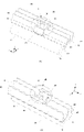
図2A、図2Bはシートセンサ31の斜視図である。図2Aと図2Bはシートセンサ31に対する視点が異なっている。なお、シートセンサ31の向きを理解しやすくするために方向を示す矢印x、y、zが付与されている。矢印zは画像形成装置100の高さ方向を示し、定着装置17におけるシートPの搬送方向と平行となっている。
<Seat sensor>
2A and 2B are perspective views of the sheet sensor 31. FIG. 2A and 2B have different viewpoints with respect to the seat sensor 31. FIG. Arrows x, y, and z are provided to indicate the direction of the seat sensor 31 for easy understanding. An arrow z indicates the height direction of the image forming apparatus 100 and is parallel to the conveying direction of the sheet P in the fixing device 17 .
第一ガイド36は、加圧ローラ19の上方に配置されており、シートPを誘導するガイド部材である。第一ガイド36のzx面と平行な断面は略U字形である。つまり、第一部材41の一方の端部は第二部材42の一方の端部と接合している。また、第二部材42の他方の端部は第三部材43の一方の端部と接合している。第一部材41はシートPをガイドするガイド面を有している。
The first guide 36 is arranged above the pressure roller 19 and is a guide member that guides the sheet P. As shown in FIG. A section parallel to the zx plane of the first guide 36 is substantially U-shaped. That is, one end of the first member 41 is joined to one end of the second member 42 . Also, the other end of the second member 42 is joined to one end of the third member 43 . The first member 41 has a guide surface that guides the sheet P. As shown in FIG.
第二ガイド37は、加熱ローラ18の上方で、かつ、第一ガイド36と対向して設けられ、シートPを誘導するガイド部材である。第二ガイド37のzx面と平行な断面は略L字形である。つまり、第四部材44の一方の端部は第五部材45の一方の端部と接合している。第四部材44はシートPをガイドするガイド面を有しており、第一部材41と平行である。
The second guide 37 is a guide member provided above the heating roller 18 and facing the first guide 36 to guide the sheet P. As shown in FIG. A section parallel to the zx plane of the second guide 37 is substantially L-shaped. That is, one end of the fourth member 44 is joined to one end of the fifth member 45 . The fourth member 44 has a guide surface that guides the sheet P and is parallel to the first member 41 .
第一ガイド36の第一部材41の中央には切欠きが設けられている。第二部材42から上方に向かって突出した基板保持部材46には基板35が固定されている。基板35には、発光部33と受光部34が実装されている。第二部材42から上方に向かって突出した遮光部材47は、発光部33と受光部34との間に設けられている。
A notch is provided in the center of the first member 41 of the first guide 36 . A substrate 35 is fixed to a substrate holding member 46 projecting upward from the second member 42 . A light-emitting portion 33 and a light-receiving portion 34 are mounted on the substrate 35 . A light blocking member 47 projecting upward from the second member 42 is provided between the light emitting section 33 and the light receiving section 34 .
第二ガイド37の第四部材44の中央にも切欠きが設けられている。第五部材45から上方に突出した反射部材保持部48には反射部材38が固定されている。この例では、反射部材保持部48と基板保持部材46とが平行となっている。また、発光部33から出力された光が反射部材38で正反射し、反射光が受光部34に入射するように、発光部33、反射部材38および受光部34が位置決めされている。なお、反射部材38は、光を反射する性質を有した部材や反射膜を有していればよい。たとえば、鏡、または、光沢のある金属もしくは樹脂などが、反射部材38として採用されうる。
A notch is also provided in the center of the fourth member 44 of the second guide 37 . A reflecting member 38 is fixed to a reflecting member holding portion 48 projecting upward from the fifth member 45 . In this example, the reflecting member holding portion 48 and the substrate holding member 46 are parallel. The light emitting portion 33 , the reflecting member 38 and the light receiving portion 34 are positioned so that the light emitted from the light emitting portion 33 is specularly reflected by the reflecting member 38 and the reflected light is incident on the light receiving portion 34 . In addition, the reflecting member 38 may have a member or a reflecting film having a property of reflecting light. For example, a mirror, lustrous metal, resin, or the like can be employed as the reflecting member 38 .
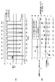
図3AはシートPが通過していないときのシートセンサ31の平面図である。図3BはシートPが通過しているときのシートセンサ31の平面図である。図3Aが示すように発光部33が照射した光は、搬送路49を跨いで第二ガイド37の反射部材38に届く。照射された光は反射部材38の表面で反射され、搬送路49を跨いで受光部34に届く。これによって、受光部34はシートPを検知していないことを示す検知信号(例:ローレベルの信号)を出力する。あるいは受光部34は、シートPを検知していることを示す検知信号(例:ハイレベルの信号)を出力しない。このようにシートセンサ31は搬送路49において発光部33を起源とした光が横切る位置にシートPがあるかどうかを検知する。
FIG. 3A is a plan view of the sheet sensor 31 when the sheet P has not passed. FIG. 3B is a plan view of the sheet sensor 31 when the sheet P is passing. As shown in FIG. 3A , the light emitted by the light emitting section 33 straddles the transport path 49 and reaches the reflecting member 38 of the second guide 37 . The irradiated light is reflected by the surface of the reflecting member 38 and reaches the light receiving section 34 across the transport path 49 . As a result, the light receiving unit 34 outputs a detection signal (for example, a low level signal) indicating that the sheet P is not detected. Alternatively, the light receiving unit 34 does not output a detection signal (eg, high-level signal) indicating that the sheet P is detected. In this manner, the sheet sensor 31 detects whether or not the sheet P exists at a position on the conveying path 49 crossed by the light originating from the light emitting section 33 .
図3Bが示すように、シートPが搬送路49を搬送されているときには、発光部33の光はシートPの表面まで届くものの、シートPの表面で光が遮光される。つまり、反射部材38まで光が届かず、受光部34も反射部材38からの反射光を受光できない。したがって、受光部34はシートPを検知していることを示す検知信号(例:ハイレベルの信号)を出力する。あるいは受光部34は、シートPを検知していないことを示す検知信号(例:ローレベルの信号)を出力しない。
As shown in FIG. 3B, when the sheet P is conveyed along the conveying path 49, the light from the light emitting unit 33 reaches the surface of the sheet P, but the surface of the sheet P blocks the light. In other words, the light does not reach the reflecting member 38 and the light receiving section 34 cannot receive the reflected light from the reflecting member 38 either. Therefore, the light receiving section 34 outputs a detection signal (eg, a high level signal) indicating that the sheet P is detected. Alternatively, the light receiving unit 34 does not output a detection signal (for example, a low level signal) indicating that the sheet P is not detected.
<送風ユニット>
図4はシートセンサ31の冷却機構の断面図である。図4において矢印は空気の流れを示している。排気ガイド39は送風ユニット32から吹き出された空気を第一ガイド36へ誘導する。排気ガイド39と第一ガイド36は通風路40を形成している。図4が示すように、基板35は通風路40内に配置されている。また、第一ガイド36の第一部材41と発光部33との間には排気ガイド39から侵入してきた空気が通過するための隙間が設けられている。この隙間を通過する空気によって発光部33が冷却される。さらに、この隙間を通過した空気は、断面形状が台形となる遮光部材47の一部を構成する壁によって反射部材38へ誘導される。反射部材38に空気が送風されることで、反射部材38の反射面に紙くずなどが付着しにくくなる。また、低湿な空気が送風されることで反射部材38近傍の水蒸気が拡散し、結露を減少させやすくなる。このように、定着装置17の外部に配置された送風ユニット32からの風を発光部33に導くことで発光部33を冷却するとともに、送風された空気によって反射部材38をクリーニングすることができる。
<Blower unit>
FIG. 4 is a sectional view of the cooling mechanism of the seat sensor 31. As shown in FIG. Arrows in FIG. 4 indicate the flow of air. The exhaust guide 39 guides the air blown out from the blower unit 32 to the first guide 36 . The exhaust guide 39 and the first guide 36 form a ventilation passage 40 . As shown in FIG. 4, the substrate 35 is positioned within the air passage 40 . A gap is provided between the first member 41 of the first guide 36 and the light-emitting portion 33 to allow the air entering from the exhaust guide 39 to pass therethrough. The air passing through this gap cools the light emitting part 33 . Furthermore, the air that has passed through this gap is guided to the reflecting member 38 by a wall forming part of the light shielding member 47 having a trapezoidal cross section. By blowing the air to the reflecting member 38, the reflecting surface of the reflecting member 38 is less susceptible to adhesion of waste paper and the like. In addition, by blowing low-humidity air, water vapor in the vicinity of the reflecting member 38 diffuses, making it easier to reduce dew condensation. In this manner, the air from the air blowing unit 32 arranged outside the fixing device 17 is directed to the light emitting portion 33, thereby cooling the light emitting portion 33 and cleaning the reflecting member 38 with the blown air.
なお、基板35は基板保持部材46と遮光部材47とによって挟持されてもよい。これにより基板35を安定的に位置決めできるようになる。また、遮光部材47を、空気の誘導部材として兼用できるだけなく、基板35を保持する部材としても兼用可能となる。
Note that the substrate 35 may be held between the substrate holding member 46 and the light shielding member 47 . As a result, the substrate 35 can be stably positioned. In addition, the light shielding member 47 can be used not only as an air guiding member, but also as a member for holding the substrate 35 .
<回路の説明>
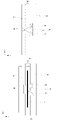
図5Aは送風ユニット32の駆動回路57を示している。駆動回路57は降圧コンバータである。CPU26は送風ユニット32を駆動するためにPWM信号を出力する。PWM信号は制限抵抗R1を介してトランジスタTr1のベースに入力される。PWM信号がHiレベルになるとトランジスタTr1はONする。トランジスタTr1がONすると、基準電圧Vccを抵抗R2、R3により分圧して生成された電圧がトランジスタTr2のベースに印加され、トランジスタTr2がONする。トランジスタTr2がONすると、基準電圧VccからトランジスタTr2およびコイルL1を介して電解コンデンサC1へチャージ電流が流れる。PWM信号がLowレベルになると、トランジスタTr1がオフとなり、それによってトランジスタTr2もオフする。これにより、コイルL1、電解コンデンサC1および回生ダイオードD1のルートで電流が流れる。PWM信号がON/OFFを繰り返すことでPWM信号のONデューティに応じた電圧が電解コンデンサC1の両端に生成される。この電圧は基準電圧Vccよりも低い電圧である。この電圧が送風ユニット32にモータに印加され、モータが回転する。モータに印加される電圧に応じてモータの回転数が決定される。
<Explanation of circuit>
FIG. 5A shows the drive circuit 57 of the blower unit 32. As shown in FIG. The drive circuit 57 is a step-down converter. CPU 26 outputs a PWM signal to drive blower unit 32 . A PWM signal is input to the base of the transistor Tr1 through the limiting resistor R1. When the PWM signal becomes Hi level, the transistor Tr1 is turned ON. When the transistor Tr1 is turned on, a voltage generated by dividing the reference voltage Vcc by the resistors R2 and R3 is applied to the base of the transistor Tr2, and the transistor Tr2 is turned on. When the transistor Tr2 is turned on, a charge current flows from the reference voltage Vcc to the electrolytic capacitor C1 through the transistor Tr2 and the coil L1. When the PWM signal becomes Low level, the transistor Tr1 is turned off, which also turns off the transistor Tr2. As a result, a current flows through the route of coil L1, electrolytic capacitor C1 and regeneration diode D1. By repeating ON/OFF of the PWM signal, a voltage corresponding to the ON duty of the PWM signal is generated across the electrolytic capacitor C1. This voltage is lower than the reference voltage Vcc. This voltage is applied to the motor in the blower unit 32, causing the motor to rotate. The number of rotations of the motor is determined according to the voltage applied to the motor.
CPU26は、PWM信号のONデューティを変更することで、送風ユニット32へ供給する電圧を変更する。たとえば、CPU26は、第一デューティのPWM信号を出力することで、送風ユニット32の風量を第一風量に設定する。また、CPU26は、第二デューティのPWM信号を出力することで、送風ユニット32の風量を第二風量に設定する。第二デューティが第一デューティよりも大きければ、第二風量は第一風量よりも多くなる。
The CPU 26 changes the voltage supplied to the blower unit 32 by changing the ON duty of the PWM signal. For example, the CPU 26 sets the air volume of the blower unit 32 to the first air volume by outputting the PWM signal with the first duty. Further, the CPU 26 sets the air volume of the blower unit 32 to the second air volume by outputting the PWM signal of the second duty. If the second duty is greater than the first duty, the second air volume will be greater than the first air volume.
図5Bは発光部33の駆動回路56を示している。CPU26は発光部33を駆動するための駆動信号を出力する。CPU26から出力される駆動信号は抵抗R4とコンデンサC2とによって構成された平滑回路により平滑されて、トランジスタTr3のベースに入力される。これによりトランジスタTr3がオンする。トランジスタTr3のコレクタと基準電圧Vccとの間には電流を制限する制限抵抗R5が設けられている。発光ダイオードD2は発光部33を構成している。CPU26は、駆動信号をON/OFFすることで、発光部33の発光/消灯を切り替える。
FIG. 5B shows the driving circuit 56 of the light emitting section 33. As shown in FIG. The CPU 26 outputs drive signals for driving the light emitting section 33 . A drive signal output from the CPU 26 is smoothed by a smoothing circuit composed of a resistor R4 and a capacitor C2 and input to the base of the transistor Tr3. This turns on the transistor Tr3. A current limiting resistor R5 is provided between the collector of the transistor Tr3 and the reference voltage Vcc. The light-emitting diode D2 constitutes the light-emitting portion 33. As shown in FIG. The CPU 26 switches the light emission/extinction of the light emitting unit 33 by turning on/off the drive signal.
図5Cは受光部34の検知回路を示している。発光部33から発せられた光を受光するフォトトランジスタTr4のコレクタ側は、プルアップ抵抗R6を介して基準電圧Vccに接続されているとともに、CPU26の入力ポートに接続されている。フォトトランジスタTr4は受光量に応じたレベルの検知信号(電圧)を出力する。そのため、CPU26の入力ポートに入力される電圧はほぼ0VからVccまでの間で変化する。ここでは、CPU26の入力ポートに印加された電圧が受光量と称される。入力ポートは、CPU26がアナログ値を受け取れるように、ADポートであってもよい。フォトトランジスタTr4がONすることができる十分な量の光を受光した場合、CPU26の入力ポートにはほぼ0Vの電圧が入力される。一方、フォトトランジスタTr4が反射部材38からの反射光を受光できない場合、入力ポートにはほぼ基準電圧Vccに等しい電圧が入力される。つまり、この検知回路では受光量が増えると入力電圧(検知電圧)が低下し、受光量が減ると入力電圧が増加する。この場合、シートPがあれば入力電圧が増加し、シートPがなければ入力電圧が減少する。あるいは、受光量が増えると入力電圧が増加し、受光量が減ると入力電圧が減少するような検知回路が採用されてもよい。この場合、シートPがあれば入力電圧が減少し、シートPがなければ入力電圧が増加する。
FIG. 5C shows a detection circuit of the light receiving section 34. As shown in FIG. The collector side of the phototransistor Tr4 which receives the light emitted from the light emitting section 33 is connected to the reference voltage Vcc through the pull-up resistor R6 and also to the input port of the CPU26. The phototransistor Tr4 outputs a detection signal (voltage) having a level corresponding to the amount of light received. Therefore, the voltage input to the input port of the CPU 26 varies between approximately 0V and Vcc. Here, the voltage applied to the input port of the CPU 26 is called the amount of received light. The input port may be an AD port so that CPU 26 can receive analog values. When the phototransistor Tr4 receives a sufficient amount of light to turn it on, the input port of the CPU 26 receives a voltage of approximately 0V. On the other hand, when the phototransistor Tr4 cannot receive the reflected light from the reflecting member 38, a voltage substantially equal to the reference voltage Vcc is input to the input port. That is, in this detection circuit, the input voltage (detection voltage) decreases as the amount of light received increases, and the input voltage increases as the amount of light received decreases. In this case, the input voltage increases if the sheet P is present, and decreases if the sheet P is absent. Alternatively, a detection circuit may be employed in which the input voltage increases as the amount of received light increases and decreases as the amount of received light decreases. In this case, the input voltage decreases if the sheet P is present, and increases if the sheet P is absent.
CPU26は入力ポートから入力された電圧に基づきシートPの有無を検知する。たとえば、CPU26は入力電圧がシート閾値以下であればシートなしと判定し、CPU26は入力電圧がシート閾値を超えていればシートありと判定してもよい。抵抗R7は、受光部34の受光ゲインの値を切り替えるために設けられた抵抗である。CPU26は、オン信号として0VをFET1のゲートに出力することで、FET1をオンする。これによりFET1が導通する。一方、CPU26は、オフ信号としてVccをFET1のゲートに出力することで、FET1をオフする。FET1がオンした場合、フォトトランジスタTr4のコレクタ側はプルアップ抵抗R6と抵抗R7の合成抵抗を介して基準電圧Vccに接続される。FET1がオフした場合、フォトトランジスタTr4のコレクタ側はプルアップ抵抗R6のみを介して基準電圧Vccに接続される。つまり、CPU26は、FET1のゲートにオン信号もしくはオフ信号を出力することで、受光部34の受光ゲインの値を切り替える。CPU26はオン信号を出力することで受光ゲインを第一ゲインに設定し、オフ信号を出力することで受光ゲインを第二ゲインに設定する。たとえば、プルアップ抵抗R6と抵抗R7として180kΩの抵抗が採用されてもよい。この場合、CPU26が受光ゲインを第一ゲインに設定するためにオン信号を出力すると、基準電圧Vccに接続される抵抗値は90kΩとなる。一方で、CPU26が受光ゲインを第二ゲインに設定するためにオフ信号を出力すると、抵抗値は180kΩとなる。つまり、第二ゲインは第一ゲインに対して2倍になる。CPU26がオフ信号を出力することで、基準電圧Vccに接続される抵抗値が増加する。つまり、第一ゲインと比較して第二ゲインは、より少ない受光量でCPU26への入力電圧を十分に低下させることができる。
The CPU 26 detects the presence or absence of the sheet P based on the voltage input from the input port. For example, the CPU 26 may determine that there is no sheet if the input voltage is equal to or less than the sheet threshold value, and the CPU 26 may determine that there is a sheet if the input voltage exceeds the sheet threshold value. A resistor R7 is a resistor provided for switching the value of the light receiving gain of the light receiving section 34 . The CPU 26 turns on the FET1 by outputting 0V to the gate of the FET1 as an ON signal. As a result, FET1 becomes conductive. On the other hand, the CPU 26 turns off the FET1 by outputting Vcc as an off signal to the gate of the FET1. When the FET1 is turned on, the collector side of the phototransistor Tr4 is connected to the reference voltage Vcc through the combined resistance of the pull-up resistor R6 and the resistor R7. When FET1 is turned off, the collector side of phototransistor Tr4 is connected to reference voltage Vcc only through pull-up resistor R6. That is, the CPU 26 switches the value of the light receiving gain of the light receiving section 34 by outputting an ON signal or an OFF signal to the gate of the FET1. The CPU 26 sets the light receiving gain to the first gain by outputting the ON signal, and sets the light receiving gain to the second gain by outputting the OFF signal. For example, a 180 kΩ resistor may be employed as pull-up resistor R6 and resistor R7. In this case, when the CPU 26 outputs an ON signal to set the light reception gain to the first gain, the resistance value connected to the reference voltage Vcc becomes 90 kΩ. On the other hand, when the CPU 26 outputs an off signal to set the light receiving gain to the second gain, the resistance value becomes 180 kΩ. That is, the second gain is double the first gain. As the CPU 26 outputs the OFF signal, the resistance value connected to the reference voltage Vcc increases. That is, compared with the first gain, the second gain can sufficiently reduce the input voltage to the CPU 26 with a smaller amount of received light.
<結露検知>
反射部材38が結露すると反射率が低下し、受光部34での受光量が減少し、シートPの検知精度が低下する。シートPが定着装置17を通過する際にシートPに吸着されていた水分が蒸発して水蒸気が発生する。この水蒸気が反射部材38に結露する可能性がある。そこで、送風ユニット32が空気を反射部材38に送ることで、反射部材38およびその周りに存在していた水蒸気を削減することが可能となる。本実施例では、シートPがシートセンサ31に無いときに、CPU26が受光部34の受光量を検知する。ここでは、受光部34が受光量と反比例(負の相関関係)する電圧を出力すると仮定されている。CPU26は、入力された電圧が予め定められた閾値を超えた場合、受光量が低下した(結露が発生した)と判定する。CPU26は、入力電圧が閾値を超えない場合、受光量が一定以上にあると判定する。つまり、CPU26は、反射部材38の結露が発生していないと判定したり、反射部材38の周りに水蒸気が発生していないと判定したりしてもよい。
<Condensation detection>
When the reflecting member 38 is dew-condensed, the reflectance decreases, the amount of light received by the light receiving unit 34 decreases, and the detection accuracy of the sheet P decreases. When the sheet P passes through the fixing device 17, water adsorbed on the sheet P evaporates to generate water vapor. This water vapor may condense on the reflecting member 38 . Therefore, by sending air to the reflecting member 38 by the blowing unit 32, it is possible to reduce the water vapor present in and around the reflecting member 38. FIG. In this embodiment, when the sheet sensor 31 does not have a sheet P, the CPU 26 detects the amount of light received by the light receiving section 34 . Here, it is assumed that the light receiving section 34 outputs a voltage that is inversely proportional (negative correlation) to the amount of light received. When the input voltage exceeds a predetermined threshold value, the CPU 26 determines that the amount of received light has decreased (condensation has occurred). When the input voltage does not exceed the threshold, the CPU 26 determines that the amount of received light is above a certain level. That is, the CPU 26 may determine that dew condensation has not occurred on the reflecting member 38 or that water vapor has not occurred around the reflecting member 38 .
<送風制御>
図6は画像形成装置100の状態と送風ユニット32の動作を示すタイミングチャートである。図6が示すように時刻t0で電源から電力が供給されて画像形成装置100が起動する。つまり、時刻t0で画像形成装置100は電源オフ状態からスタンバイ状態に遷移する。図7はCPU26が実行する制御を示すフローチャートである。
<Blow control>
FIG. 6 is a timing chart showing the state of the image forming apparatus 100 and the operation of the blower unit 32. As shown in FIG. As shown in FIG. 6, power is supplied from the power supply at time t0, and the image forming apparatus 100 is activated. That is, at time t0, the image forming apparatus 100 transitions from the power-off state to the standby state. FIG. 7 is a flow chart showing the control executed by the CPU 26. As shown in FIG.
S701でCPU26はプリント指示(画像形成指示)が操作部や外部のコンピュータから入力されたかを判定する。図7によれば時刻t1でプリント指示が入力されている。なお、画像形成装置100の状態は、時刻t0から時刻t1までプリント指示を待ち受けるスタンバイ状態である。画像形成装置100が起動した直後のスタンバイ状態では送風ユニット32は動作しない(風量=0)。なお、非常に少ない風量となるようにCPU26は送風ユニット32を駆動してもよい。時刻t1でプリント指示が入力されると、CPU26は画像形成を開始するためにS702に進む。
In S701, the CPU 26 determines whether a print instruction (image formation instruction) has been input from the operation unit or an external computer. According to FIG. 7, the print instruction is input at time t1. Note that the state of the image forming apparatus 100 is a standby state from time t0 to time t1 to wait for a print instruction. In the standby state immediately after the image forming apparatus 100 is activated, the fan unit 32 does not operate (air volume=0). Note that the CPU 26 may drive the blower unit 32 so that the amount of air is very small. When a print instruction is input at time t1, the CPU 26 advances to S702 to start image formation.
S702でCPU26は画像形成装置100を制御してプリントを開始する。さらに、CPU26は送風ユニット32を駆動して反射部材38への送風を開始する。これにより発光部33の冷却も開始され、発光部33の昇温に伴う発光量の低下が抑制される。CPU26は、送風ユニット32を駆動するためのPWM信号の出力を開始する。これにより、駆動回路57が送風ユニット32のモータに電力を供給し、モータがファンを回転させ、発光部33や反射部材38への送風が開始される。
In S702, the CPU 26 controls the image forming apparatus 100 to start printing. Further, the CPU 26 drives the blower unit 32 to start blowing air to the reflecting member 38 . As a result, cooling of the light emitting unit 33 is also started, and a decrease in the amount of light emitted due to an increase in the temperature of the light emitting unit 33 is suppressed. CPU 26 starts outputting a PWM signal for driving blower unit 32 . As a result, the drive circuit 57 supplies power to the motor of the blower unit 32 , the motor rotates the fan, and blowing of air to the light emitting section 33 and the reflecting member 38 is started.
S703でCPU26はプリントが終了したかどうかを判定する。CPU26は、操作部などによって指定されたプリントジョブがすべて完了したかどうかを判定する。時刻t3でプリントが終了すると、CPU26はS704に進む。
In S703, the CPU 26 determines whether printing has ended. The CPU 26 determines whether or not all print jobs designated by the operation unit or the like have been completed. When printing ends at time t3, the CPU 26 advances to S704.
S704でCPU26は、プリント終了(時刻t3)からの経過時間が所定時間Txになったかどうかを判定する。CPU26はタイマーやカウンタを用いてプリント終了からの経過時間を計測する。図6によれば時刻t4で経過時間が所定時間Txとなっている。所定時間Txは反射部材38の結露がほぼ解消するまでに必要となる時間であり、予め定められている。経過時間が所定時間Txになると、CPU26はS706に進む。経過時間が所定時間に達していない場合、S705に進む。
In S704, the CPU 26 determines whether the elapsed time from the end of printing (time t3) has reached a predetermined time Tx. The CPU 26 uses a timer or counter to measure the elapsed time from the end of printing. According to FIG. 6, the elapsed time is the predetermined time Tx at time t4. The predetermined time Tx is the time required until the dew condensation on the reflecting member 38 is almost eliminated, and is predetermined. When the elapsed time reaches the predetermined time Tx, the CPU 26 proceeds to S706. If the elapsed time has not reached the predetermined time, the process proceeds to S705.
S705でCPU26は受光部34における受光量が結露閾値を超えているかどうかを判定する。なお、受光部34が受光量と反比例する入力電圧を生成する場合、入力電圧が電圧閾値以下かどうか判定される。つまり、CPU26は受光部34における受光量に応じた電圧に基づき反射部材38の結露の有無や反射部材38の周囲の状態を判定してもよい。Th1は結露の有無を判定するために使用される結露閾値である。ThpはシートPの有無を判定するためのシート閾値である。ここで、Th1>ThPである。CPU26は受光量が結露閾値Th1を超えていれば、十分に水蒸気が低減されており、結露が生じていないと判定する。結露が生じていない場合、CPU26は、送風ユニット32を停止させるためにS706に進む。一方、CPU26は、受光量が結露閾値Th1を超えていなければ(入力電圧が電圧閾値以上であれば)、結露が発生している可能性があると判定する。この場合、CPU26は送風ユニット32の風量を維持したまま、S704に進む。なお、S705からS704に遷移する際に、CPU26は、所定の待機時間にわたり待機してもよい。これにより、CPU26の処理負荷が軽減される。
In S705, the CPU 26 determines whether or not the amount of light received by the light receiving unit 34 exceeds the dew condensation threshold. When the light receiving unit 34 generates an input voltage that is inversely proportional to the amount of light received, it is determined whether the input voltage is equal to or less than the voltage threshold. That is, the CPU 26 may determine the presence or absence of dew condensation on the reflecting member 38 and the state of the surroundings of the reflecting member 38 based on the voltage corresponding to the amount of light received by the light receiving section 34 . Th1 is a dew condensation threshold used to determine the presence or absence of dew condensation. Thp is a sheet threshold value for determining whether or not the sheet P is present. Here, Th1>ThP. If the amount of light received exceeds the dew condensation threshold Th1, the CPU 26 determines that water vapor is sufficiently reduced and no dew condensation has occurred. If no dew condensation has occurred, the CPU 26 proceeds to S706 to stop the blower unit 32 . On the other hand, if the received light amount does not exceed the dew condensation threshold Th1 (if the input voltage is equal to or greater than the voltage threshold), the CPU 26 determines that dew condensation may occur. In this case, the CPU 26 proceeds to S704 while maintaining the air volume of the blower unit 32 . Note that the CPU 26 may wait for a predetermined waiting time when transitioning from S705 to S704. This reduces the processing load on the CPU 26 .
S706でCPU26は送風ユニット32を停止させる。たとえば、送風ユニット32はPWM信号の出力を停止するか、または、PWM信号のデューティを減少させる。なお、送風ユニット32は完全に停止しなくてもよい。たとえば、送風ユニット32の風量が非常に少なくなるようにPWM信号のデューティを変更してもよい。
The CPU 26 stops the blower unit 32 in S706. For example, the blower unit 32 stops outputting the PWM signal or reduces the duty of the PWM signal. Note that the blower unit 32 does not have to be completely stopped. For example, the duty of the PWM signal may be changed so that the air volume of the blower unit 32 becomes very small.
本実施例によれば、CPU26は受光量を検知することで、反射部材38の結露状態およびその周囲の水蒸気の発生度合を取得することができる。たとえば、結露や水蒸気の発生度合が考慮されないケースでは、常に、一定時間にわたり強制的に送風ユニット32が駆動されてしまうだろう。一方で、本実施例では、結露や水蒸気の発生度合が低いと推定される場合、CPU26は、送風ユニット32を停止させる。これにより、送風ユニット32の稼働時間が削減され、消費電力も削減される。また、送風ユニット32の稼働時間が削減されるため、CPU26は、プリント状態から次の状態(スタンバイ状態など)にすぐに遷移できる。結露閾値Th1はシート閾値Thpよりも大きく設定されている。そのため、CPU26はシートPの無し状態を確実に検知できる。つまり、送風ユニット32の稼働時間の短縮と消費電力の低減を図りつつ、シート検知の精度が向上する。
According to this embodiment, the CPU 26 can acquire the dew condensation state of the reflecting member 38 and the degree of generation of water vapor around it by detecting the amount of received light. For example, if the degree of dew condensation or water vapor generation is not considered, the blower unit 32 will always be forcibly driven for a certain period of time. On the other hand, in this embodiment, the CPU 26 stops the blower unit 32 when it is estimated that the degree of condensation or water vapor generation is low. As a result, the operating time of the blower unit 32 is reduced, and the power consumption is also reduced. In addition, since the operating time of the blower unit 32 is reduced, the CPU 26 can immediately transition from the print state to the next state (standby state, etc.). The dew condensation threshold Th1 is set larger than the sheet threshold Thp. Therefore, the CPU 26 can reliably detect that the sheet P is absent. That is, the accuracy of sheet detection is improved while shortening the operation time of the blower unit 32 and reducing power consumption.
なお、本実施例では、受光量に応じてプリント後における送風ユニット32の稼働時間を変更するシーケンスの一例が示された。送風ユニット32の稼働時間を変更する代わり、CPU26は、受光量に応じて送風ユニット32の風量を変更してもよい。たとえば、CPU26は受光量に応じてPWM信号のデューティを変更してもよい。送風ユニット32は、時刻t0で画像形成装置100が起動すると、第一風量(ゼロであってもよい)となるよう駆動される。また、時刻t1で送風ユニット32は風量が第二風量となるように駆動される(第二風量>第一風量)。時刻t3から時刻t4まで、送風ユニット32は引き続き第二風量で送風を実行する。時刻t4で送風ユニット32の風量が第二風量から第一風量(ゼロであってもよい)に削減される。なお、CPU26は、時刻t0から時刻t1まで送風ユニット32の風量をゼロに制御し、時刻t1から時刻t2まで風量を第一風量(>0)に制御し、時刻t2以降で風量を第二風量(>第一風量)に制御してもよい。ここで、時刻t2は、図6において時刻t1と時刻t3との間にある時刻である。
In this embodiment, an example of the sequence for changing the operation time of the blower unit 32 after printing according to the amount of received light is shown. Instead of changing the operating time of the blower unit 32, the CPU 26 may change the air volume of the blower unit 32 according to the amount of received light. For example, the CPU 26 may change the duty of the PWM signal according to the amount of light received. When the image forming apparatus 100 is activated at time t0, the air blowing unit 32 is driven to have the first air volume (which may be zero). Further, at time t1, the blower unit 32 is driven so that the air volume becomes the second air volume (second air volume>first air volume). From time t3 to time t4, the blower unit 32 continues to blow air at the second air volume. At time t4, the air volume of the blower unit 32 is reduced from the second air volume to the first air volume (which may be zero). The CPU 26 controls the air volume of the blower unit 32 to zero from time t0 to time t1, controls the air volume to the first air volume (>0) from time t1 to time t2, and reduces the air volume to the second air volume after time t2. (> first air volume). Here, time t2 is a time between time t1 and time t3 in FIG.
本実施例では、画像形成装置100の構成として一つの条件で一つの送風ユニット32を制御する構成が示された。複数の条件で一つの送風ユニット32が制御されてもよい。たとえば、送風ユニット32の稼働時間は受光部34の受光量と、定着装置17内の温度とに応じて制御されてもよい。その際に、受光量に基づく制御が優先されてもよいし、定着装置17内の温度に基づく制御が優先されてもよい。定着装置17内の温度に基づく制御では、温度センサ12により検知された温度が使用される。たとえば、CPU26は、受光量が結露閾値Th1を超えていたとしても、定着装置17内の温度を一定値以下に低下していなければ、送風ユニット32の稼働を継続してもよい(温度優先制御)。また、CPU26は、定着装置17内の温度を一定値以下に低下していたとしても、受光量が結露閾値Th1を超えていなければ、送風ユニット32の稼働を継続してもよい(受光量優先制御)。本実施例によれば、送風ユニット32はシートセンサ31に送風しているが、定着装置17にも送風してもよい。このように、送風ユニット32は画像形成装置100が備える複数のユニットを冷却してもよい。
In this embodiment, as the configuration of the image forming apparatus 100, a configuration is shown in which one blower unit 32 is controlled under one condition. One blower unit 32 may be controlled under a plurality of conditions. For example, the operating time of the blower unit 32 may be controlled according to the amount of light received by the light receiving section 34 and the temperature inside the fixing device 17 . At that time, priority may be given to control based on the amount of received light, or priority may be given to control based on the temperature inside the fixing device 17 . The temperature detected by the temperature sensor 12 is used in the temperature-based control within the fixing device 17 . For example, even if the amount of light received exceeds the dew condensation threshold value Th1, the CPU 26 may continue the operation of the blower unit 32 as long as the temperature inside the fixing device 17 has not decreased below a certain value (temperature priority control ). Further, even if the temperature inside the fixing device 17 has fallen below a certain value, the CPU 26 may continue the operation of the blower unit 32 if the amount of received light does not exceed the dew condensation threshold value Th1 (the amount of received light is prioritized). control). According to this embodiment, the blower unit 32 blows air to the sheet sensor 31 , but it may also blow air to the fixing device 17 . In this manner, the blower unit 32 may cool multiple units included in the image forming apparatus 100 .
[実施例2]
実施例2は、実施例1を改良したものである。電源から電力の供給が開始されて画像形成装置100が起動したときや、プリント指示にしたがって画像形成装置100が省エネモードから通常モードに復帰したときに、CPU26は、反射部材38に結露が発生していないことを確認する。これにより、画像形成装置100は、反射部材38に結露が発生していない状態でプリントを開始できる。なお、通常モードとは、画像形成装置100が画像形成可能なモードであり、上述のプリント状態に相当する。省エネモードは画像形成装置100が画像形成可能でないモードであり、上述のスタンバイ状態に相当する。
[Example 2]
Example 2 is an improvement of Example 1. When the image forming apparatus 100 starts to supply electric power from the power source, or when the image forming apparatus 100 returns from the energy saving mode to the normal mode in accordance with a print instruction, the CPU 26 determines whether condensation occurs on the reflecting member 38. make sure it is not Accordingly, the image forming apparatus 100 can start printing in a state where dew condensation does not occur on the reflecting member 38 . Note that the normal mode is a mode in which the image forming apparatus 100 can form an image, and corresponds to the printing state described above. The energy saving mode is a mode in which the image forming apparatus 100 cannot form images, and corresponds to the standby state described above.
図8はCPU26が実行する方法を示すフローチャートである。
・S801でCPU26は画像形成装置100が電源オフ状態からスタンバイ状態(電源オン状態)に遷移したか、または、省エネモードから通常モードに復帰したかを判定する。このステップは、たとえば、図6の時刻t0から時刻t1までの間で実行されうる。画像形成装置100が電源オフ状態からスタンバイ状態に遷移したのであれば、CPU26はS802に進む。また、画像形成装置100が省エネモードから通常モードに復帰したのであれば、CPU26はS802に進む。
・S802でCPU26は駆動回路56を通じて発光部33を発光させる。発光部33から出力された光は反射部材38で反射し、受光部34で受光される。
・S803でCPU26は受光部34で取得された受光量を受け取り、受光量が結露閾値Thpを超えているかどうかを判定する。S803はS705と同じ処理である。受光量が結露閾値Thpを超えていれば、シートPを検知する上で問題となるような結露は生じていないため、CPU26は、S805に進む。一方で、受光量が結露閾値Thpを超えていなければ、シートPを検知する上で問題となるような結露が生じている可能性があるため、CPU26はS804に進む。
・S804でCPU26は駆動回路57を通じて送風ユニット32を駆動させる。これにより、発光部33の冷却が開始されるともとに、反射部材38への送風が開始される。たとえば、CPU26は、送風ユニット32を駆動するためのPWM信号の出力を開始する。これにより、送風ユニット32のモータに電力が供給され、モータがファンを回転させ、発光部33や反射部材38への送風が開始される。
・S805でCPU26は駆動回路57を通じて送風ユニット32を停止させる。たとえば、CPU26は送風ユニット32に対するPWM信号の出力を停止する。送風ユニット32は完全に停止しなくてもよい。たとえば、送風ユニット32の風量が非常に少なくなるように、CPU26は、PWM信号のデューティを減少させてもよい。
FIG. 8 is a flow chart showing the method performed by the CPU 26. As shown in FIG.
In S801, the CPU 26 determines whether the image forming apparatus 100 has transitioned from the power-off state to the standby state (power-on state), or whether the energy saving mode has returned to the normal mode. This step can be performed, for example, between time t0 and time t1 in FIG. If the image forming apparatus 100 has transitioned from the power-off state to the standby state, the CPU 26 advances to S802. Also, if the image forming apparatus 100 has returned from the energy saving mode to the normal mode, the CPU 26 advances to S802.
・In S802, the CPU 26 causes the light-emitting section 33 to emit light through the drive circuit 56 . The light emitted from the light emitting section 33 is reflected by the reflecting member 38 and received by the light receiving section 34 .
- In S803, the CPU 26 receives the amount of light received by the light receiving unit 34 and determines whether or not the amount of light exceeds the dew condensation threshold value Thp. S803 is the same processing as S705. If the amount of received light exceeds the dew condensation threshold value Thp, no dew condensation that poses a problem in detecting the sheet P has occurred, so the CPU 26 proceeds to S805. On the other hand, if the received light amount does not exceed the dew condensation threshold Thp, there is a possibility that dew condensation that poses a problem in detecting the sheet P occurs, so the CPU 26 proceeds to S804.
・At S804, the CPU 26 drives the blower unit 32 through the drive circuit 57 . As a result, the cooling of the light emitting section 33 is started, and the blowing of air to the reflecting member 38 is started. For example, CPU 26 starts outputting a PWM signal for driving blower unit 32 . As a result, power is supplied to the motor of the blower unit 32 , the motor rotates the fan, and blowing of air to the light emitting section 33 and the reflecting member 38 is started.
・At S805, the CPU 26 stops the blower unit 32 through the drive circuit 57 . For example, CPU 26 stops outputting the PWM signal to blower unit 32 . The blower unit 32 does not have to stop completely. For example, the CPU 26 may reduce the duty of the PWM signal so that the air volume of the blower unit 32 becomes very small.
S804からS803に遷移する際に、CPU26は、所定の待機時間(例:5秒など)だけ待ってもよい。送風ユニット32の風量は、送風ユニット32に設定可能な風量のうちの最大風量に設定されてもよい。この場合、最短時間で水蒸気が低減されよう。しかし、この風量設定は一例にすぎない。たとえば、CPU26は、受光量と結露閾値Th1との差分を算出し、差分に応じて風量を決定してもよい。また、CPU26は、画像形成装置100の消費電力マネージメントに応じて風量を決定してもよい。たとえば、CPU26は、画像形成装置100が第一消費電力で動作しているときには、送風ユニット32に第一風量を設定する。CPU26は、画像形成装置100が第二消費電力で動作しているときには、送風ユニット32に第二風量を設定する。ここで、第一消費電力は第二消費電力よりも多い。第一風量は第二風量よりも多い。
When transitioning from S804 to S803, the CPU 26 may wait for a predetermined waiting time (eg, 5 seconds, etc.). The air volume of the blower unit 32 may be set to the maximum air volume among air volumes that can be set for the blower unit 32 . In this case, water vapor will be reduced in the shortest possible time. However, this air volume setting is only an example. For example, the CPU 26 may calculate the difference between the amount of received light and the dew condensation threshold Th1, and determine the air volume according to the difference. Further, CPU 26 may determine the air volume according to power consumption management of image forming apparatus 100 . For example, CPU 26 sets the first air volume to blower unit 32 when image forming apparatus 100 is operating with the first power consumption. The CPU 26 sets the second air volume to the blower unit 32 when the image forming apparatus 100 is operating with the second power consumption. Here, the first power consumption is greater than the second power consumption. The first air volume is greater than the second air volume.
本実施例によれば、CPU26は、画像形成を実行する前に受光量を検知して受光量に基づき反射部材38の結露状態およびその周囲の水蒸気の発生度合を推定できる。また、結露が十分に解消するか、または、水蒸気が十分に減少すると、CPU26は、画像形成を開始する。これにより、CPU26はシートセンサ31を用いてシートPの有無を精度よく検知できるようになる。このようにプリントが開始されるまでに水蒸気や結露が十分に解消しているため、プリントを開始したときに送風ユニット32の風量を増加させる必要性が低くなる。これは、プリント状態における画像形成装置100のトータルでの消費電力を低減させることを可能とする。よって、実施例2によれば、シート検知の精度を向上させつつ、画像形成装置100のトータルでの消費電力が削減される。
According to this embodiment, the CPU 26 can detect the amount of received light before executing image formation, and can estimate the dew condensation state of the reflecting member 38 and the degree of generation of water vapor around it based on the amount of received light. Further, when the dew condensation is sufficiently eliminated or the water vapor is sufficiently reduced, the CPU 26 starts image formation. As a result, the CPU 26 can accurately detect the presence or absence of the sheet P using the sheet sensor 31 . Since water vapor and dew condensation are sufficiently eliminated by the time printing is started in this way, the need to increase the air volume of the blower unit 32 when printing is started is reduced. This makes it possible to reduce the total power consumption of the image forming apparatus 100 in the printing state. Therefore, according to the second embodiment, the total power consumption of the image forming apparatus 100 can be reduced while improving the accuracy of sheet detection.
[実施例3]
実施例2で、CPU26は受光量の減少した原因を結露であると推定している。受光量が減少する他の原因としては、発光部33や反射部材38の汚れと、発光部33の発光量の低下がある。このように結露以外の原因で光量低下が発生すると、シート検知の精度が低下したり、送風ユニット32の制御に無駄が生じたりする。そこで、実施例3では、CPU26が汚れや部品劣化による光量変化と結露による光量変化を区別する。これにより、結露の有無が精度よく検知される。
[Example 3]
In the second embodiment, the CPU 26 presumes that the cause of the decrease in the amount of received light is condensation. Other causes for the decrease in the amount of light received include contamination of the light emitting section 33 and the reflecting member 38 and a decrease in the amount of light emitted by the light emitting section 33 . If the amount of light decreases due to a cause other than dew condensation, the accuracy of sheet detection decreases, and the control of the blower unit 32 is wasteful. Therefore, in the third embodiment, the CPU 26 distinguishes between changes in the amount of light due to dirt and deterioration of parts and changes in the amount of light due to condensation. As a result, the presence or absence of dew condensation is detected with high accuracy.
CPU26は記憶装置87に記憶されている制御プログラムを実行することで様々な機能を実現する。記憶装置87はRAMやROMなどのメモリを有しており、制御プログラム、変換テーブルおよび閾値などを保持している。本実施例では、記憶装置87は、発光部33の発光量と、受光部34の受光量との関係を保持している。
The CPU 26 implements various functions by executing control programs stored in the storage device 87 . The storage device 87 has memories such as RAM and ROM, and holds control programs, conversion tables, threshold values, and the like. In this embodiment, the storage device 87 holds the relationship between the amount of light emitted by the light emitting section 33 and the amount of light received by the light receiving section 34 .
図9はCPU26が実行する方法を示すフローチャートである。
・S901でCPU26は画像形成装置100が電源オフ状態からスタンバイ状態(電源オン状態)に遷移したか、または、省エネモードから通常モードに復帰したかを判定する。このステップは、たとえば、図6の時刻t0から時刻t1までの間で実行されうる。画像形成装置100が電源オフ状態からスタンバイ状態に遷移したのであれば、CPU26はS902に進む。また、画像形成装置100が省エネモードから通常モードに復帰したのであれば、CPU26はS902に進む。
・S902でCPU26は駆動回路56を通じて発光部33を発光させる。発光部33から出力された光は反射部材38で反射し、受光部34で受光される。ここでは、CPU26は予め記憶装置87に記憶されている発光量を読み出し、読み出した発光量に応じた駆動信号を生成して出力する。記憶装置87に記憶されている発光量は、たとえば、製品出荷時に実行された出荷検査によって決定された値、または、結露の無い状態でかつ定期的に決定された値であってもよい。
・S903でCPU26は駆動回路57を通じて送風ユニット32を駆動させる。これにより、発光部33の冷却が開始されるともとに、反射部材38への送風が開始される。たとえば、CPU26は、送風ユニット32を駆動するためのPWM信号の出力を開始する。これにより、送風ユニット32のモータに電力が供給され、モータがファンを回転させ、発光部33や反射部材38への送風が開始される。なお、CPU26は送風ユニット32の稼働時間を計測するためにタイマーやカウンタをスタートさせてもよい。
・S904でCPU26は受光部34の受光量(入力電圧)を受け取り、受光量が所定範囲内かどうかを判定する。受光量は反射部材38の結露や反射部材38の周囲の状態を示すパラメータである。所定範囲は予め記憶装置87に記憶されている。たとえば、CPU26は受光量が、記憶装置87に記憶されている受光量範囲内かどうかを判定する。受光量範囲は下限値と上限値とにより定義されてもよい。この場合、CPU26は、検知された受光量が下限値以上でかつ、上限値以下であることを判定してもよい。あるいは所定範囲の中心となる基準受光量と、範囲パラメータである±Δに基づいて所定範囲が定義されてもよい。CPU26は、検知された受光量と基準受光量との差分が-Δ以上でかつ+Δ以下であることを判定してもよい。所定範囲を定義するパラメータは画像形成装置100の出荷時に決定されうる。たとえば、基準受光量は、製品出荷時に上記の発光量で発光した際に得られた受光量であってもよい。また、基準受光量は、結露の無い状態でかつ定期的に取得された受光量であってもよい。検知された受光量が所定範囲内にある場合、反射部材38、発光部33および受光部34の汚れは問題なく、また、反射部材38に問題となるような結露も発生していない。よって、CPU26はS905に進む。
・S905でCPU26は送風ユニット32を停止させる。
FIG. 9 is a flow chart showing the method performed by the CPU 26. As shown in FIG.
In S901, the CPU 26 determines whether the image forming apparatus 100 has transitioned from the power-off state to the standby state (power-on state), or whether the energy-saving mode has returned to the normal mode. This step can be performed, for example, between time t0 and time t1 in FIG. If the image forming apparatus 100 has transitioned from the power-off state to the standby state, the CPU 26 proceeds to S902. Also, if the image forming apparatus 100 has returned from the energy saving mode to the normal mode, the CPU 26 proceeds to S902.
· In S902, the CPU 26 causes the light emitting section 33 to emit light through the driving circuit 56. The light emitted from the light emitting section 33 is reflected by the reflecting member 38 and received by the light receiving section 34 . Here, the CPU 26 reads the amount of light emission stored in advance in the storage device 87, and generates and outputs a driving signal corresponding to the read amount of light emission. The light emission amount stored in storage device 87 may be, for example, a value determined by a shipping inspection performed at the time of product shipment, or a value determined periodically in a non-condensing state.
・At S903, the CPU 26 drives the blower unit 32 through the drive circuit 57 . As a result, the cooling of the light emitting section 33 is started, and the blowing of air to the reflecting member 38 is started. For example, CPU 26 starts outputting a PWM signal for driving blower unit 32 . As a result, power is supplied to the motor of the blower unit 32 , the motor rotates the fan, and blowing of air to the light emitting section 33 and the reflecting member 38 is started. Note that the CPU 26 may start a timer or counter to measure the operating time of the blower unit 32 .
· In S904, the CPU 26 receives the amount of received light (input voltage) of the light receiving section 34 and determines whether the amount of received light is within a predetermined range. The amount of received light is a parameter that indicates dew condensation on the reflecting member 38 and the state of the surroundings of the reflecting member 38 . The predetermined range is stored in the storage device 87 in advance. For example, the CPU 26 determines whether or not the received light amount is within the received light amount range stored in the storage device 87 . The received light amount range may be defined by a lower limit value and an upper limit value. In this case, the CPU 26 may determine that the detected amount of received light is greater than or equal to the lower limit value and less than or equal to the upper limit value. Alternatively, the predetermined range may be defined based on a reference amount of received light that is the center of the predetermined range and ±Δ that is a range parameter. The CPU 26 may determine that the difference between the detected amount of received light and the reference amount of received light is greater than or equal to -Δ and less than or equal to +Δ. A parameter defining the predetermined range can be determined when the image forming apparatus 100 is shipped. For example, the reference amount of received light may be the amount of received light obtained when the product is shipped with the above amount of light emitted. Also, the reference amount of received light may be an amount of received light that is periodically acquired in a non-condensing state. If the detected amount of received light is within the predetermined range, there is no problem with the contamination of the reflecting member 38, the light emitting section 33, and the light receiving section 34, and no problematic dew condensation has occurred on the reflecting member 38 either. Therefore, the CPU 26 proceeds to S905.
- CPU26 stops the ventilation unit 32 by S905.
一方、検知された受光量が所定範囲外にある場合、反射部材38、発光部33および受光部34に問題となる汚れが付着しているか、または、反射部材38に問題となるような結露が生じている可能性がある。よって、CPU26はS906に進む。ここでは、まず、S903で駆動された送風ユニット32で結露の削減が試行される。
・S906でCPU26は送風ユニット32の稼働時間が所定時間を越えたかどうかを判定する。所定時間は、反射部材38の結露を十分に低下させることができる時間であり、記憶装置87に記憶されている。稼働時間が所定時間を越えるまで、送風ユニット32は継続的に駆動される。これにより、結露の削減が試行される。稼働時間が所定時間を超えると、CPU26はS907に進む。稼働時間が所定時間を超えていなければ、CPU26はS904に進む。S904でCPU26は受光量を所定範囲と比較することで、結露が許容範囲まで減少したかどうかを判定する。結露が許容範囲まで減少していれば、CPU26はS905に進む。結露が許容範囲まで減少していなければ、CPU26はS906に進む。このように所定時間にわたって送風ユニット32を稼働させても受光量が所定範囲内になければ、結露以外の要因が受光量低下の原因となっている。
・S907およびS908でCPU26は、検知されている受光量が所定範囲内となるように発光部33の発光量を増大させたり、受光部34のゲインを増大させたりする。基本的に発光量の増大とゲインの増大はいずれか一方が採用される。S907で発光量を設定可能な最大光量まで増大させても、S908で受光量が所定範囲内にならないこともあろう。この場合、S907でCPU26はゲインの増大を開始してもよい。あるいは、S907でゲインを設定可能な最大ゲインまで増大させても、S908で受光量が所定範囲内にならないこともある。この場合、S907でCPU26は発光量の増大を開始してもよい。S908で受光量が所定範囲内になったと判定すると、CPU26はS909に進む。
・S909でCPU26は送風ユニット32を停止させる。その後、S910で、CPU26は、S908で判定条件が満たされたときの発光部33の発光量および受光部34のゲインを記憶装置87に記憶する。記憶された発光量やゲインは初期値として利用される。
On the other hand, if the detected amount of received light is outside the predetermined range, the reflective member 38, the light emitting section 33, and the light receiving section 34 may be contaminated, or the reflective member 38 may be dew condensed. may have occurred. Therefore, the CPU 26 proceeds to S906. Here, first, reduction of dew condensation is tried by the blower unit 32 driven in S903.
・At S906, the CPU 26 determines whether or not the operation time of the blower unit 32 has exceeded a predetermined time. The predetermined time is a time during which the dew condensation on the reflecting member 38 can be sufficiently reduced, and is stored in the storage device 87 . The blower unit 32 is continuously driven until the operating time exceeds a predetermined time. This attempts to reduce condensation. When the operating time exceeds the predetermined time, the CPU 26 proceeds to S907. If the operating time has not exceeded the predetermined time, the CPU 26 proceeds to S904. In S904, the CPU 26 compares the amount of received light with a predetermined range to determine whether the dew condensation has decreased to the allowable range. If the dew condensation has decreased to the permissible range, the CPU 26 proceeds to S905. If the condensation has not decreased to the permissible range, the CPU 26 proceeds to S906. If the amount of light received is not within the predetermined range even after the blower unit 32 is operated for a predetermined period of time in this way, factors other than condensation are the cause of the decrease in the amount of light received.
- In S907 and S908, the CPU 26 increases the light emission amount of the light emitting unit 33 or increases the gain of the light receiving unit 34 so that the detected light reception amount is within a predetermined range. Basically, either an increase in light emission amount or an increase in gain is adopted. Even if the amount of emitted light is increased to the settable maximum amount of light in S907, the amount of received light may not fall within the predetermined range in S908. In this case, the CPU 26 may start increasing the gain in S907. Alternatively, even if the gain is increased to the settable maximum gain in S907, the amount of received light may not fall within the predetermined range in S908. In this case, the CPU 26 may start increasing the light emission amount in S907. When it is determined in S908 that the amount of received light is within the predetermined range, the CPU 26 proceeds to S909.
- In S909, the CPU 26 stops the blower unit 32 . After that, in S910, the CPU 26 stores in the storage device 87 the light emission amount of the light emitting unit 33 and the gain of the light receiving unit 34 when the determination condition is satisfied in S908. The stored light emission amount and gain are used as initial values.
本実施例によれば、受光量に基づき画像形成装置100内の結露や汚れが検知され、送風ユニット32による結露の低減が試行される。送風ユニット32を稼働させても受光量の低下が解消しない場合、送風ユニット32の消費電力が削減され、さらに発光量やゲインが適切に調整される。そのため、シート検知の精度を維持しつつ、送風ユニット32の消費電力が削減される。
According to this embodiment, dew condensation and dirt inside the image forming apparatus 100 are detected based on the amount of received light, and reduction of the dew condensation by the blower unit 32 is attempted. When the decrease in the amount of received light is not resolved even when the blower unit 32 is operated, the power consumption of the blower unit 32 is reduced, and the light emission amount and gain are adjusted appropriately. Therefore, the power consumption of the blower unit 32 is reduced while maintaining the accuracy of sheet detection.
<実施例1~3のまとめ>
図10はCPU26が記憶装置87に記憶されている制御プログラムを実行することで実現する機能を示している。CPU26は制御手段として機能する。以下では図10を参照しながら上記の実施例から導かれる技術思想が説明される。なお、記憶装置87はRAMやROMなどのメモリを有しており、制御プログラム、変換式、変換テーブルおよび閾値などを保持している。
<Summary of Examples 1 to 3>
FIG. 10 shows functions realized by the CPU 26 executing the control program stored in the storage device 87 . The CPU 26 functions as control means. The technical idea derived from the above embodiment will be described below with reference to FIG. The storage device 87 has memories such as RAM and ROM, and holds control programs, conversion formulas, conversion tables, threshold values, and the like.
図3Aなどに示したように搬送路49はシートPを搬送する搬送路の一例である。発光部33は搬送路49を横切ることになる光を出力する発光手段の一例である。図10に示した光量制御部50は、発光部33の光量を制御する制御手段の一例である。光量制御部50は、図5Bに示した回路を有する駆動回路56を通じて発光部33の発光ダイオードD2を点灯させる。図2Bなどに示した反射部材38は発光部33に対向して設けられ、搬送路49を横切って入射してきた光を反射する反射部材の一例である。受光部34は、反射部材38からの反射光を受光し、受光量に応じたレベル検知信号を出力する受光手段の一例である。受光部34は、発光部33から受光部34に至るまでに一回以上にわたり搬送路49を横切ってきた光である反射光を受光する受光手段の一例である。ゲイン制御部61は、図5Cに示した検知回路における受光ゲインを制御することで、フォトトランジスタTr4により生成される電圧を変化させる。送風ユニット32は反射部材38の周辺の空気の対流を促すように反射部材38に対して空気を送るか、または空気を吸い出す送風手段の一例である。図10が示す風量制御部51は送風ユニット32の風量を制御する制御手段の一例である。風量制御部51は駆動回路57を通じて送風ユニット32の風量を制御する。シート検知部94は、受光部34により受光された反射光の光量に基づきシートPの有無を判定する判定手段の一例である。また、シート検知部94は、受光部34が受光量に応じて出力する検知信号に基づき搬送路49にシートPがあるかどうかを検知する検知手段の一例である。シート検知部94は、シートPの有無の判定結果に基づき、さらにシートPのジャムを検知してもよい。図7、図8および図9が示すように、結露検出部53は、搬送路49において光が横切る位置にシートPが無いときに受光部34が出力した検知信号に応じて送風ユニット32の風量と稼働時間とのうちの少なくとも一方を調整する。したがって、結露が生じうる環境下においても精度よくシートが検知可能となる。なお、結露検出部53は風量制御部51を通じて送風ユニット32を制御する。
As shown in FIG. 3A and the like, the transport path 49 is an example of a transport path for transporting the sheet P. FIG. The light emitting section 33 is an example of light emitting means for outputting light that crosses the conveying path 49 . A light amount control section 50 shown in FIG. 10 is an example of control means for controlling the light amount of the light emitting section 33 . The light amount control unit 50 lights the light emitting diode D2 of the light emitting unit 33 through the driving circuit 56 having the circuit shown in FIG. 5B. The reflective member 38 shown in FIG. 2B and the like is an example of a reflective member that is provided facing the light-emitting portion 33 and reflects the light incident across the transport path 49 . The light receiving unit 34 is an example of a light receiving unit that receives reflected light from the reflecting member 38 and outputs a level detection signal according to the amount of received light. The light receiving section 34 is an example of light receiving means for receiving reflected light, which is light that has crossed the conveying path 49 more than once from the light emitting section 33 to the light receiving section 34 . The gain control unit 61 changes the voltage generated by the phototransistor Tr4 by controlling the light reception gain in the detection circuit shown in FIG. 5C. The blowing unit 32 is an example of blowing means for blowing air to or sucking out air from the reflecting member 38 so as to promote air convection around the reflecting member 38 . An air volume control unit 51 shown in FIG. 10 is an example of control means for controlling the air volume of the blower unit 32 . The air volume control section 51 controls the air volume of the blower unit 32 through the drive circuit 57 . The sheet detection unit 94 is an example of determination means for determining whether or not the sheet P is present based on the amount of reflected light received by the light receiving unit 34 . Also, the sheet detection unit 94 is an example of a detection unit that detects whether or not there is a sheet P in the conveying path 49 based on a detection signal output by the light receiving unit 34 according to the amount of light received. The sheet detection unit 94 may further detect a jam of the sheet P based on the determination result of the presence or absence of the sheet P. As shown in FIGS. 7, 8, and 9, the dew condensation detection unit 53 detects the air volume of the blower unit 32 according to the detection signal output by the light receiving unit 34 when there is no sheet P at the position where the light crosses the conveying path 49. As shown in FIGS. and/or uptime. Therefore, it is possible to accurately detect the sheet even in an environment where dew condensation may occur. Note that the dew condensation detector 53 controls the blower unit 32 through the air volume controller 51 .
図7が示すように、結露検出部53は搬送路49にシートPが無いときに受光部34が出力した検知信号のレベル(受光量)が結露閾値Th1を超えているかどうかを判定する判定手段として機能する。つまり、結露検出部53は判定手段を有している。ここでは受光部34は受光量にほぼ比例したレベルの検知信号を出力するものと仮定されている。つまり、検知信号のレベルは受光量に対して正の相関関係を有していればよい。なお、CPU26は、受光部34からの入力電圧を受光量に変換してから結露閾値Th1と比較してもよい。つまり、入力電圧は受光量に反比例しているか、負の相関関係を有していてもよい。上述したように受光量に反比例した入力電圧が電圧閾値と比較されてもよい。この場合、各判定ステップにおける受光量と結露閾値Th1との大小関係と、入力電圧と電圧閾値との大小関係は逆となる。結露検出部53は、受光量が結露閾値Th1を超えていなければ送風ユニット32の風量を増加させるか、または、送風ユニット32による送風を継続する。これにより結露が低減される。一方、結露検出部53は、受光量が結露閾値Th1を超えていれば送風ユニット32の風量を減少させるか、または、送風ユニット32による送風を停止させる。これにより、送風ユニット32により消費される電力が削減される。また、本実施例は結露の除去用のヒータを省略できる利点も有している。
As shown in FIG. 7, the dew condensation detection unit 53 is determination means for determining whether the level (light reception amount) of the detection signal output by the light receiving unit 34 when there is no sheet P in the transport path 49 exceeds the dew condensation threshold value Th1. function as That is, the dew condensation detection unit 53 has determination means. Here, it is assumed that the light receiving section 34 outputs a detection signal whose level is approximately proportional to the amount of light received. That is, the level of the detection signal should have a positive correlation with the amount of received light. Note that the CPU 26 may convert the input voltage from the light receiving section 34 into the amount of received light and compare it with the dew condensation threshold Th1. That is, the input voltage may be inversely proportional to the amount of light received, or may have a negative correlation. An input voltage that is inversely proportional to the amount of light received as described above may be compared with the voltage threshold. In this case, the magnitude relationship between the amount of received light and the dew condensation threshold Th1 in each determination step is opposite to the magnitude relationship between the input voltage and the voltage threshold. If the received light amount does not exceed the condensation threshold Th1, the dew condensation detection unit 53 increases the air volume of the blower unit 32 or continues the blowing of air by the blower unit 32 . This reduces condensation. On the other hand, if the received light amount exceeds the condensation threshold Th1, the dew condensation detection unit 53 reduces the air volume of the blower unit 32 or stops blowing air from the blower unit 32 . This reduces the power consumed by the blower unit 32 . This embodiment also has the advantage that a heater for removing dew condensation can be omitted.
タイマー52は送風ユニット32の稼働時間を計測する計測手段の一例である。結露検出部53は、タイマー52により計測された稼働時間が所定時間以上となっても受光量が結露閾値Th1を超えていなければ送風ユニット32の風量を減少させるか、または、送風ユニット32による送風を停止させる。これにより、送風ユニット32により消費される電力が削減される。
The timer 52 is an example of measuring means for measuring the operating time of the blower unit 32 . If the amount of light received does not exceed the dew condensation threshold value Th1 even if the operation time measured by the timer 52 exceeds the predetermined time, the condensation detection unit 53 reduces the air volume of the blower unit 32 or causes the blower unit 32 to blow air. to stop This reduces the power consumed by the blower unit 32 .
図7が示すように結露検出部53は画像形成装置100がシートPに画像を形成している間は送風ユニット32を稼働させてもよい。結露検出部53は、画像形成装置100がシートPに対する画像の形成を終了すると、搬送路49にシートが無いときに受光部34が出力した検知信号に応じて、送風ユニット32の風量と稼働時間とのうちの少なくとも一方を調整してもよい。これによりプリントにより発生した水蒸気が拡散されるため、反射部材38の結露が発生しにくくなろう。
As shown in FIG. 7, the dew condensation detection unit 53 may operate the blower unit 32 while the image forming apparatus 100 is forming an image on the sheet P. FIG. When the image forming apparatus 100 finishes forming an image on the sheet P, the dew condensation detection unit 53 determines the air volume and operating time of the blower unit 32 according to the detection signal output by the light receiving unit 34 when there is no sheet on the transport path 49 . At least one of and may be adjusted. As a result, water vapor generated by printing is diffused, so that dew condensation on the reflective member 38 is less likely to occur.
図8が示すように結露検出部53は、電源から電力を供給されて画像形成装置100が起動したとき、または、画像形成装置100が画像形成を実行しない状態から画像形成を実行可能な状態に復帰したときに、発光部33に光を出力させてもよい。さらに、結露検出部53は受光部34が出力した検知信号に応じて送風ユニット32を駆動または停止させてもよい。このように電源から電力を供給されて画像形成装置100が起動したとき、または、画像形成装置100が画像形成を実行しない状態から画像形成を実行可能な状態に復帰したときに結露の低減が実行される。これによりプリントの開始時には結露が十分に低減していることが期待される。
As shown in FIG. 8, the dew condensation detection unit 53 is activated when the image forming apparatus 100 is powered by the power source, or when the image forming apparatus 100 changes from a non-executable state to an image forming state. You may make the light emission part 33 output light, when it returns. Furthermore, the condensation detector 53 may drive or stop the blower unit 32 according to the detection signal output by the light receiver 34 . When the image forming apparatus 100 starts up with power supplied from the power supply in this manner, or when the image forming apparatus 100 returns from a state in which image formation is not performed to a state in which image formation can be performed, the reduction of dew condensation is performed. be done. As a result, it is expected that dew condensation will be sufficiently reduced at the start of printing.
図8が示すように結露検出部53は、受光量が結露閾値Th1を超えていなければ送風ユニット32による送風を開始するか、または、送風ユニット32の風量を増加させてもよい。また、結露検出部53は、受光量が結露閾値Th1を超えていれば送風ユニット32の風量を減少させるか、または、送風ユニット32による送風を実行しない。これにより送風ユニット32が無駄に稼働しなくなるため、消費電力が削減される。
As shown in FIG. 8, the dew condensation detection unit 53 may start air blowing by the air blowing unit 32 or increase the air volume of the air blowing unit 32 if the received light amount does not exceed the dew condensation threshold Th1. Further, if the amount of received light exceeds the dew condensation threshold value Th1, the dew condensation detection unit 53 reduces the air volume of the blower unit 32 or does not blow air from the blower unit 32 . As a result, the blower unit 32 does not work wastefully, so power consumption is reduced.
図9が示すように、結露検出部53は、電源から電力を供給されて画像形成装置が起動したとき、または、画像形成装置が画像形成を実行しない状態から画像形成を実行可能な状態に復帰したときに、発光部33に光を出力させる。さらに、結露検出部53は、送風ユニット32の送風を開始させる。結露検出部53は、受光部34が出力した検知信号に応じて送風ユニット32を停止させるか、または、発光部33の発光量もしくは受光部34のゲインを調整する。したがって、結露が生じうる環境下においても精度よくシートが検知可能となる。
As shown in FIG. 9, the dew condensation detection unit 53 returns to a state in which image formation can be performed when the image forming apparatus is activated by being supplied with power from a power source, or when the image forming apparatus returns from a state in which image formation is not performed to a state in which image formation can be performed. Then, the light emitting section 33 is made to output light. Furthermore, the dew condensation detection unit 53 causes the blower unit 32 to start blowing air. The condensation detector 53 stops the blower unit 32 or adjusts the amount of light emitted by the light emitter 33 or the gain of the light receiver 34 according to the detection signal output by the light receiver 34 . Therefore, it is possible to accurately detect the sheet even in an environment where dew condensation may occur.
結露検出部53は、受光量が所定範囲の下限値以上でなければ送風ユニット32による送風を継続する。これにより結露の削減が試行される。一方で、結露検出部53は、受光量が所定範囲の下限値以上であれば送風ユニット32の風量を減少させるか、または、送風ユニット32による送風を停止させる。これにより消費電力が削減される。
The dew condensation detector 53 continues air blowing by the air blowing unit 32 unless the amount of received light is equal to or higher than the lower limit value of the predetermined range. This attempts to reduce condensation. On the other hand, if the amount of light received is equal to or higher than the lower limit of the predetermined range, the dew condensation detection unit 53 reduces the air volume of the blower unit 32 or stops blowing air from the blower unit 32 . This reduces power consumption.
S904、S906が示すように、結露検出部53は、タイマー52により計測された稼働時間が所定時間以上となっても受光量が所定範囲の下限値以上でなければ発光部33の発光量を増加させるかもしくは受光部34のゲインを増加させる。なお、結露検出部53は、光量制御部50を通じて発光量を制御する。結露検出部53は、ゲイン制御部61を通じて受光部34のゲインを制御する。これにより、結露以外の要因により受光量が低下しても、シートを精度よく検知可能となる。
As shown in S904 and S906, the dew condensation detection unit 53 increases the light emission amount of the light emitting unit 33 if the amount of light received is not the lower limit value of the predetermined range even if the operation time measured by the timer 52 exceeds the predetermined time. or increase the gain of the light receiving section 34 . Note that the dew condensation detection unit 53 controls the amount of light emitted through the light amount control unit 50 . The dew condensation detection section 53 controls the gain of the light receiving section 34 through the gain control section 61 . As a result, even if the amount of light received decreases due to factors other than condensation, the sheet can be detected with high accuracy.
結露検出部53は、発光部33の発光量と受光部34のゲインとの両方を増加させてもよいし、一方を増加させてもよい。結露検出部53は、発光部33の発光量を、発光部33に設定可能な最大値まで増加させても、受光量が所定範囲の下限値以上でなければ、受光部34のゲインを増加させてもよい。結露検出部53は、受光部34のゲインを、受光部34に設定可能な最大値まで増加させても、受光量が所定範囲の下限値以上でなければ、発光部33の発光量を増加させてもよい。なお、結露検出部53は、受光量が所定範囲の上限値を超えているときに、受光部34のゲインを減少させてもよい。同様に、結露検出部53は、受光量が所定範囲の上限値を超えているときに、発光部33の発光量を減少させてもよい。これにより消費電力が削減される。
The dew condensation detection unit 53 may increase both the light emission amount of the light emitting unit 33 and the gain of the light receiving unit 34, or may increase one of them. The dew condensation detection unit 53 increases the gain of the light receiving unit 34 if the amount of light emitted from the light emitting unit 33 is increased to the maximum value that can be set for the light emitting unit 33 but the amount of light received is not equal to or higher than the lower limit value of the predetermined range. may Even if the gain of the light receiving unit 34 is increased to the maximum value that can be set in the light receiving unit 34, the dew condensation detection unit 53 increases the light emission amount of the light emitting unit 33 if the amount of light received is not equal to or higher than the lower limit value of the predetermined range. may Note that the dew condensation detection unit 53 may decrease the gain of the light receiving unit 34 when the amount of light received exceeds the upper limit value of the predetermined range. Similarly, the dew condensation detection unit 53 may reduce the light emission amount of the light emission unit 33 when the light reception amount exceeds the upper limit value of the predetermined range. This reduces power consumption.
記憶装置87は受光量が所定範囲内となったときの発光部33の発光量を初期値として記憶する発光量記憶手段の一例である。結露検出部53は、発光部33の発光を開始するときに記憶装置87に記憶されている初期値を発光部33に設定する。これにより、適切な発光量を探索する時間が削減される。また、記憶装置87は受光量が所定範囲内となったときの受光部34のゲインを初期値として記憶するゲイン記憶手段の一例である。結露検出部53は、受光部34の受光を開始するときに記憶装置87に記憶されている初期値を受光部34に設定する。これにより、適切なゲインを探索する時間が削減される。
The storage device 87 is an example of light emission amount storage means for storing, as an initial value, the light emission amount of the light emitting section 33 when the light reception amount falls within a predetermined range. Dew condensation detection portion 53 sets the initial value stored in storage device 87 to light emission portion 33 when light emission of light emission portion 33 is started. This reduces the time required to search for an appropriate amount of light emission. The storage device 87 is an example of gain storage means for storing, as an initial value, the gain of the light receiving section 34 when the amount of light received falls within a predetermined range. The dew condensation detection unit 53 sets the initial value stored in the storage device 87 to the light receiving unit 34 when the light receiving unit 34 starts receiving light. This reduces the time spent searching for suitable gains.
なお、結露検出部53は反射部材38の結露を検出する検出手段として機能するか、これを含んでいてもよい。この場合、CPU26は結露検出部53により反射部材38の結露が検出されると送風ユニット32を稼働させて結露の低減を試行する。
Note that the dew condensation detection unit 53 may function as or include detection means for detecting dew condensation on the reflecting member 38 . In this case, when the dew condensation detector 53 detects dew condensation on the reflecting member 38, the CPU 26 operates the blower unit 32 to try to reduce the dew condensation.
図4を用いて説明したように送風ユニット32から吹き出されるか、または、送風ユニット32により吸引される空気が反射部材38に吹き当たるように反射部材38に空気を導く通風路40が設けられてもよい。このような通風路40を設けることで効率よく反射部材38をクリーニングし、また、シートPから発生した水蒸気を反射部材38の付近から追い出すことが可能となる。
As described with reference to FIG. 4, a ventilation passage 40 is provided to guide air to the reflecting member 38 so that the air blown from the blowing unit 32 or sucked by the blowing unit 32 hits the reflecting member 38. may By providing such a ventilation path 40 , it is possible to efficiently clean the reflecting member 38 and expel the water vapor generated from the sheet P from the vicinity of the reflecting member 38 .
図3Aなどが示すように、第一ガイド36と第二ガイド37は搬送路49において対向して設けられ、シートPをガイドする第一ガイド部材および第二ガイド部材の一例である。発光部33および受光部34は、第一ガイド36に固定されていてもよい。反射部材38は、第二ガイド37に固定されていてもよい。遮光部材47は発光部33と受光部34との間に設けられた遮光部材の一例である。遮光部材47は、発光部33から受光部34へ向かう直接光を遮光する。また、図3BにおいてシートPが搬送路49を搬送されているとき、発光部33からの光はほとんど反射部材38まで届かないが、シートPの表面には届いている。ゆえに、シートPの種類(表面状態)によっては、シートPの表面で光が反射し、その反射光が受光部34へと向かう可能性がある。このような反射光が受光部34により受光されると、シートPが搬送路49を搬送されているにも関わらず、受光部34はシートPを検知していないことを示す検知信号を出力してしまう可能性がある。そのため、遮光部材47は、このようなシートPの表面で反射して受光部34へ向かう反射光を少なくとも一部遮光するように構成されていてもよい。これにより、シートPの有無が精度よく検知されるようになろう。
As shown in FIG. 3A and the like, the first guide 36 and the second guide 37 are provided facing each other in the transport path 49 and are an example of a first guide member and a second guide member that guide the sheet P. As shown in FIG. The light emitting section 33 and the light receiving section 34 may be fixed to the first guide 36 . The reflecting member 38 may be fixed to the second guide 37 . The light shielding member 47 is an example of a light shielding member provided between the light emitting section 33 and the light receiving section 34 . The light blocking member 47 blocks direct light from the light emitting section 33 toward the light receiving section 34 . 3B, when the sheet P is being conveyed along the conveying path 49, the light from the light emitting unit 33 hardly reaches the reflecting member 38, but reaches the surface of the sheet P. As shown in FIG. Therefore, depending on the type (surface state) of the sheet P, there is a possibility that the surface of the sheet P reflects light and the reflected light travels toward the light receiving section 34 . When such reflected light is received by the light receiving unit 34, the light receiving unit 34 outputs a detection signal indicating that the sheet P is not detected even though the sheet P is being conveyed on the conveying path 49. There is a possibility that Therefore, the light blocking member 47 may be configured to block at least part of the light reflected by the surface of the sheet P and directed toward the light receiving section 34 . As a result, the presence or absence of the sheet P will be detected with high accuracy.
上述した図2Aなどによれば、発光部33から出力された光は搬送路49を横切って反射部材38に入射し、反射部材38からの反射光も搬送路49を横切って受光部34へ入射している。このように、発光部33から出力された光は二回にわたり搬送路49を横切っているが、搬送路49を光が横切る回数は一回以上であればよい。たとえば、発光部33から出力された光が搬送路49を横切ることなく反射部材38に入射し、反射部材38からの反射光も搬送路49を横切って受光部34へ入射してもよい。また、発光部33から出力された光は搬送路49を横切って反射部材38に入射し、反射部材38からの反射光が搬送路49を横切ることなく受光部34へ入射してもよい。搬送路49を光が横切る回数は一回であってもよい。発光部33から出力された光が搬送路49を横切って反射部材38に入射し、反射部材38からの反射光も搬送路49を横切って第二の反射部材に入射し、第二の反射部材からの反射光が受光部34へ入射してもよい。このように搬送路49を光が横切る回数は三回であってもよい。反射部材の数を増やすことで搬送路49を光が横切る回数を増加させることができる。このように搬送路49を横切る光とは、発光部33から出力されて受光部34に入射するまでに一回以上にわたり搬送路49を横切る光であればよい。また、発光部33から出力された光が搬送路49を横切るタイミングは、反射部材38に入射する前であってもよいし、後であってもよい。いずれの場合も発光部33は搬送路を横切ることになる光を出力する発光手段として機能している。また、発光部33と受光部34との間に設置される反射部材38の数は一個以上であればよい。光が搬送路49を横切る回数に応じて、発光部33と受光部34の配置が異なる。光が搬送路49を横切る回数が偶数であれば、図2Aが示すように、発光部33と受光部34とは搬送路49から見て同じ側に配置される。光が搬送路49を横切る回数が奇数であれば、発光部33と受光部34とは搬送路49を挟んで相互に反対側に配置される。
2A and the like described above, the light output from the light emitting unit 33 crosses the transport path 49 and enters the reflecting member 38, and the reflected light from the reflecting member 38 also crosses the transport path 49 and enters the light receiving part 34. is doing. In this way, the light emitted from the light emitting unit 33 crosses the transport path 49 twice, but the number of times the light crosses the transport path 49 should be one or more. For example, the light emitted from the light emitting section 33 may enter the reflecting member 38 without crossing the conveying path 49 , and the reflected light from the reflecting member 38 may also cross the conveying path 49 and enter the light receiving section 34 . Alternatively, the light emitted from the light emitting section 33 may cross the transport path 49 and enter the reflecting member 38 , and the reflected light from the reflecting member 38 may enter the light receiving part 34 without crossing the transport path 49 . The number of times the light traverses the transport path 49 may be one. The light emitted from the light emitting unit 33 crosses the transport path 49 and enters the reflecting member 38, and the reflected light from the reflecting member 38 also crosses the transport path 49 and enters the second reflecting member, and the second reflecting member may be incident on the light receiving section 34 . The number of times the light traverses the transport path 49 in this manner may be three. By increasing the number of reflecting members, the number of times the light crosses the transport path 49 can be increased. The light that traverses the transport path 49 in this manner may be light that traverses the transport path 49 one or more times from the light emitted from the light emitting unit 33 to the light receiving unit 34 . Moreover, the timing at which the light output from the light emitting unit 33 crosses the transport path 49 may be before or after the light is incident on the reflecting member 38 . In either case, the light emitting section 33 functions as light emitting means for outputting light that traverses the conveying path. Moreover, the number of reflecting members 38 installed between the light emitting unit 33 and the light receiving unit 34 should be one or more. The arrangement of the light emitting section 33 and the light receiving section 34 differs depending on the number of times the light crosses the transport path 49 . If the number of times the light traverses the transport path 49 is an even number, the light emitter 33 and the light receiver 34 are arranged on the same side as viewed from the transport path 49, as shown in FIG. 2A. If the number of times the light crosses the transport path 49 is an odd number, the light emitting part 33 and the light receiving part 34 are arranged on opposite sides of the transport path 49 .
[実施例4]
光学式のシートセンサは、発光素子と受光素子とを有し、シートによって光が遮られたかどうかに応じてシートを検知する。光学式のシートセンサは、メカフラグ式のシートセンサと比較して、応答性の点で有利であり、画像形成装置の生産性を向上させる。光学式のシートセンサは、メカフラグ式のシートセンサと比較して、製造コストを上昇させてしまう。そのため、光学式のシートセンサが、シート検知機能に加え、他の機能を有すれば、シートセンサのコスト対効果を向上させるだろう。よって、シートセンサのコスト対効果を向上させる必要があろう。
[Example 4]
An optical sheet sensor has a light-emitting element and a light-receiving element, and detects a sheet depending on whether light is blocked by the sheet. An optical sheet sensor is advantageous in terms of responsiveness compared to a mechanical flag type sheet sensor, and improves the productivity of the image forming apparatus. The optical seat sensor increases the manufacturing cost compared to the mechanical flag type seat sensor. Therefore, if the optical seat sensor had other functions in addition to the sheet sensing function, it would improve the cost effectiveness of the seat sensor. Therefore, there may be a need to improve the cost effectiveness of seat sensors.
<画像形成装置>
図11に示された画像形成装置100は、図1に示された画像形成装置100と比較して、両面印刷に関する機能が追加されている。
<Image forming apparatus>
Image forming apparatus 100 shown in FIG. 11 has a function related to double-sided printing added to image forming apparatus 100 shown in FIG.
片面印刷モードの場合、定着装置17から排出されたシートPは、排出ローラ20へ向けてフラッパ54によって搬送される。なお、フラッパ54から排出ローラ20までに存在する搬送路は排出路と呼ばれてもよい。排出ローラ20はシートPを画像形成装置100の外部に排出する。
In the single-sided printing mode, the sheet P discharged from the fixing device 17 is conveyed by the flapper 54 toward the discharge rollers 20 . The conveying path from the flapper 54 to the ejection roller 20 may be called an ejection path. The discharge roller 20 discharges the sheet P to the outside of the image forming apparatus 100 .
両面印刷モードの場合、シートPが反転ローラ27へ向けて搬送されるようにフラッパ54の姿勢が切り替わり、シートPが反転ローラ27に向けて搬送される。フラッパ54から反転ローラ27までの搬送路は引き込み路と呼ばれてもよい。反転ローラ27は正転することでシートPを引き込み、さらに逆転することでシートPを両面搬送路58へ送り込む。この際に、シートPの先端は両面搬送路58の開口部60から画像形成装置100の外部に露出するが、シートPの後端は露出しない。反転ローラ27の回転方向が切り替わることで、シートPの先端が後端に切り替わり、シートPの後端が先端に切り替わる。これにより、シートPの画像形成面が第一面から第二面に切り替わる。正転から反転に切り替わるタイミングはシートセンサ31によりシートPの後端が検知されたタイミングを基準として決定されてもよい。両面搬送路58のうち、反転ローラ27と送風ユニット32との間には搬送ガイド部材59が設けられている。両面搬送路58に設けられた複数の搬送ローラ55はシートPを両面搬送路58に沿って搬送し、レジストローラ16へ受け渡す。画像形成部101は、シートPの第二面に画像を形成し、フラッパ54および排出ローラ20によりシートPを排出する。
In the double-sided printing mode, the orientation of the flapper 54 is switched so that the sheet P is conveyed toward the reversing rollers 27 , and the sheet P is conveyed toward the reversing rollers 27 . A transport path from the flapper 54 to the reversing roller 27 may be called a pull-in path. The reversing roller 27 draws in the sheet P by rotating forward, and sends the sheet P to the double-sided conveying path 58 by rotating reversely. At this time, the leading edge of the sheet P is exposed to the outside of the image forming apparatus 100 through the opening 60 of the double-sided conveying path 58, but the trailing edge of the sheet P is not exposed. By switching the rotation direction of the reversing roller 27, the leading edge of the sheet P is switched to the trailing edge, and the trailing edge of the sheet P is switched to the leading edge. As a result, the image forming surface of the sheet P is switched from the first surface to the second surface. The timing of switching from normal rotation to reverse rotation may be determined based on the timing at which the trailing edge of the sheet P is detected by the sheet sensor 31 . A transport guide member 59 is provided between the reversing roller 27 and the blower unit 32 in the double-sided transport path 58 . A plurality of conveying rollers 55 provided in the double-sided conveying path 58 convey the sheet P along the double-sided conveying path 58 and deliver it to the registration rollers 16 . The image forming section 101 forms an image on the second surface of the sheet P and discharges the sheet P by the flapper 54 and the discharge roller 20 .
送風ユニット32は、たとえば、両面搬送路58へ向けて空気を送り込むように配置される。
The blower unit 32 is arranged, for example, to blow air toward the double-sided conveying path 58 .
<水蒸気検知アルゴリズム>
CPU26は、シートセンサ31における受光部34の受光量に基づき水蒸気の発生量(水蒸気量)を推定する。シートPが定着装置17を通過する際にシートPに吸着されていた水分が蒸発して水蒸気が発生する。搬送路49内に水蒸気が発生すると、搬送路49を横切る発光部33で照射された光が水蒸気により乱反射する。これにより、受光部34の受光量が減少する。つまり、受光量の減少は水蒸気量と相関している。そこで、CPU26は、シートPがシートセンサ31の検知位置に無いときに、発光部33に光を出力させて受光部34の受光量を取得する。検知位置とは光が搬送路49を横切る位置である。ここでは、受光部34が受光量と反比例(逆相関)する検知電圧を出力すると仮定されている。CPU26は、受光部34からの検知電圧が予め定められた閾値を超えた場合、受光量が低下した(発生した水蒸気量が多い)と推定する。CPU26は、検知電圧が閾値を超えない場合、受光量が一定以上にあると判定する。つまり、CPU26は、搬送路49内に発生した水蒸気量が少ないと推定する。
<Water vapor detection algorithm>
The CPU 26 estimates the amount of water vapor generated (water vapor amount) based on the amount of light received by the light receiving portion 34 of the sheet sensor 31 . When the sheet P passes through the fixing device 17, water adsorbed on the sheet P evaporates to generate water vapor. When water vapor is generated in the conveying path 49, the light irradiated by the light emitting section 33 crossing the conveying path 49 is irregularly reflected by the water vapor. As a result, the amount of light received by the light receiving section 34 is reduced. That is, the decrease in the amount of received light correlates with the amount of water vapor. Therefore, when the sheet P is not at the detection position of the sheet sensor 31 , the CPU 26 causes the light emitting section 33 to emit light and acquires the amount of light received by the light receiving section 34 . A detection position is a position at which light crosses the transport path 49 . Here, it is assumed that the light receiving section 34 outputs a detection voltage that is inversely proportional (inversely correlated) with the amount of light received. When the detected voltage from the light receiving unit 34 exceeds a predetermined threshold value, the CPU 26 estimates that the amount of received light has decreased (the amount of generated water vapor is large). When the detected voltage does not exceed the threshold, the CPU 26 determines that the amount of received light is above a certain level. In other words, the CPU 26 estimates that the amount of water vapor generated in the conveying path 49 is small.
ここで、シートPの吸湿状態でどのように受光部34の検知電圧が変化するかを実験的に検証した結果が示される。実験条件は一般的なオフィス環境が想定された。そのため、画像形成装置100は温度が25℃に設定され、相対湿度が50%に設定された環境に設置された。吸湿状態の異なる2種類のシートPが用意された。つまり、第一吸湿状態にある10枚のシートPと、第二吸湿状態にある10枚のシートPとが用意された。CPU26は、10枚のシートPを連続して定着装置17を通過させ、受光部34の検知電圧を監視した。シートPは一般的に流通している普通紙(坪量:80g/m2)である。第一吸湿状態のシートPに含まれる水分の割合は4.3%であった。第二吸湿状態にあるシートPに含まれる水分の割合は8.3%であった。第一吸湿状態にある10枚のシートPを定着装置17を通過させた直後における搬送路49の相対湿度を湿度センサで計測したところ、63%であった。第二吸湿状態にある10枚のシートPを定着装置17を通過させた直後における搬送路49の相対湿度を湿度センサで計測したところ、73%であった。このことから、水分の多いシートPを定着装置17に供給すると、搬送路49などに滞留している水蒸気量が多いことが分かる。
Here, the result of experimental verification of how the detection voltage of the light receiving unit 34 changes depending on the moisture absorption state of the sheet P is shown. A general office environment was assumed for the experimental conditions. Therefore, the image forming apparatus 100 was installed in an environment where the temperature was set to 25° C. and the relative humidity was set to 50%. Two types of sheets P having different moisture absorption states were prepared. That is, ten sheets P in the first moisture absorption state and ten sheets P in the second moisture absorption state were prepared. The CPU 26 continuously passed the ten sheets P through the fixing device 17 and monitored the detection voltage of the light receiving section 34 . The sheet P is plain paper (basis weight: 80 g/m 2 ) that is generally distributed. The percentage of moisture contained in the sheet P in the first moisture absorption state was 4.3%. The percentage of moisture contained in the sheet P in the second moisture absorption state was 8.3%. The humidity sensor measured the relative humidity of the transport path 49 immediately after the ten sheets P in the first moisture absorption state passed through the fixing device 17, and it was 63%. The humidity sensor measured the relative humidity of the conveying path 49 immediately after the ten sheets P in the second moisture absorption state passed through the fixing device 17, and it was 73%. From this, it can be seen that when the sheet P containing a lot of moisture is supplied to the fixing device 17, a large amount of water vapor remains in the conveying path 49 and the like.
図12Aは受光部34の電圧出力結果を示している。横軸は時間を示す。縦軸は受光部34の検知電圧を示す。検知電圧が低ければ低いほど、受光量は多い(シート無し)。検知電圧が高ければ高いほど、受光量は少ない(シート有り)。検知電圧が上下に変動している理由は、10枚のシートP1~P10を連続的に通紙するため、検知位置にはシートPが有る状態とシートPが無い状態とが繰り返されるからである。最初の凸波形は1枚目のシートが検知位置を通過していることを示している。実線は水分の多い第二吸湿状態のシートPについての検知電圧の波形を示している。破線は水分の少ない第一吸湿状態のシートPについての検知電圧の波形を示している。
FIG. 12A shows the voltage output result of the light receiving section 34. FIG. The horizontal axis indicates time. The vertical axis indicates the detection voltage of the light receiving section 34 . The lower the detection voltage, the greater the amount of light received (no sheet). The higher the detection voltage, the smaller the amount of light received (with sheet). The reason why the detection voltage fluctuates up and down is that since the 10 sheets P1 to P10 are continuously passed through, the state where the sheet P is present at the detection position and the state where the sheet P is absent are repeated. . The first convex waveform indicates that the first sheet has passed the detection position. A solid line indicates the waveform of the detection voltage for the sheet P in the second moisture absorption state with a large amount of moisture. A dashed line indicates the waveform of the detection voltage for the sheet P in the first moisture absorption state with less moisture.
第一吸湿状態の電圧波形と第二吸湿状態の電圧波形とを比較すると、1枚目のシートP1を検知する前(紙間t01)の初期電圧はどちらも0.16Vであることが分かる。なお、紙間tijとは先行するシートPiの後端と後続のシートPjの先端までの距離に相当する期間である(j=i+1)。1枚目のシートP1の先端が検知位置に到達すると、第一吸湿状態の電圧と第二吸湿状態の電圧とも3.1Vまで上昇している。ここではシートPの有無を判定するためのシート閾値が2.0Vに設定されている。そのため、CPU26は、どちらの吸湿状態でもシート有りを検知できている。シートP1の後端が検知位置に到達すると、第一吸湿状態の電圧と第二吸湿状態の電圧ともシート閾値以下まで低下している。シートP1とシートP2との間の紙間t12において、第二吸湿状態の電圧は0.24Vであり、第一吸湿状態の電圧は0.17Vであった。0Vから3.1Vまでの電位差を基準とした、初期電圧に対する各紙間における検知電圧の上昇率という概念が導入される。
上昇率ΔV=((検知電圧-初期電圧)/3.1)×100 [%]・・・(1)
紙間t12における第二吸湿状態についての上昇率ΔVは2.5%である。紙間t12における第一吸湿状態についての上昇率ΔVは0.3%である。よって、これらの差(上昇率差)は2.2%である。
Comparing the voltage waveform in the first moisture absorption state and the voltage waveform in the second moisture absorption state, it can be seen that the initial voltage before detection of the first sheet P1 (paper interval t01) is 0.16 V for both. Note that the sheet interval tij is a period corresponding to the distance between the trailing edge of the preceding sheet Pi and the leading edge of the succeeding sheet Pj (j=i+1). When the leading edge of the first sheet P1 reaches the detection position, both the voltage in the first moisture absorption state and the voltage in the second moisture absorption state have increased to 3.1V. Here, the sheet threshold for determining the presence or absence of the sheet P is set to 2.0V. Therefore, the CPU 26 can detect the presence of the sheet in either moisture absorption state. When the trailing edge of the sheet P1 reaches the detection position, both the voltage in the first moisture absorption state and the voltage in the second moisture absorption state are reduced below the sheet threshold value. At the paper interval t12 between the sheet P1 and the sheet P2, the voltage in the second moisture absorption state was 0.24V and the voltage in the first moisture absorption state was 0.17V. A concept is introduced of the rate of rise of the sensed voltage between each paper with respect to the initial voltage, based on the potential difference from 0V to 3.1V.
Rise rate ΔV=((detected voltage−initial voltage)/3.1)×100 [%] (1)
The increase rate ΔV for the second moisture absorption state at the paper interval t12 is 2.5%. The increase rate ΔV for the first moisture absorption state at the paper interval t12 is 0.3%. Therefore, the difference between them (increase rate difference) is 2.2%.
図12Bは各紙間における検知電圧と上昇率差を示している。図12Bにおいて左側の縦軸は各紙間における検知電圧[V]を示す。図12Bにおいて右側の縦軸は上昇率差[%]を示している。すべての紙間t01~t910で、水分の多いシートPについての検知電圧は、水分の少ないシートPについての検知電圧を上回っている。各紙間における上昇率差の平均値は14%程度であった。ここで、水蒸気量の大小を判定する水蒸気閾値が0.6Vに設定された場合、図12Bが示すように水分の多い2枚目以降のシートPについての検知電圧はいずれも水蒸気閾値を超える。よって、CPU26は、水分の多い2枚目以降のシートPをいずれも水分の多いシートであると推定できる。水分の多いシートPとは、シートPに含まれる水分の割合が8.0%以上であるシートPを指している。水蒸気閾値は任意に変更可能である。
FIG. 12B shows the detected voltage and the rate of rise difference between each sheet. In FIG. 12B, the vertical axis on the left indicates the detected voltage [V] between each sheet. In FIG. 12B, the vertical axis on the right side indicates the increase rate difference [%]. In all the paper intervals t01 to t910, the detection voltage for the sheet P with a lot of moisture exceeds the detection voltage for the sheet P with a little moisture. The average difference in rate of increase between sheets was about 14%. Here, when the water vapor threshold for judging the amount of water vapor is set to 0.6 V, the detected voltages for the second and subsequent sheets P with a large amount of water all exceed the water vapor threshold as shown in FIG. 12B. Therefore, the CPU 26 can estimate that the second and subsequent sheets P having a high moisture content are all moisture-rich sheets. A sheet P with a high moisture content refers to a sheet P having a percentage of moisture contained in the sheet P of 8.0% or more. The water vapor threshold can be changed arbitrarily.
上記の水蒸気量の推定アルゴリズムは一例にすぎない。たとえば、上昇率差に代えて上昇率に基づき水蒸気量が推定されてもよい。この推定方法を採用することで、部品の実装位置や製造ばらつきの影響が軽減される。ばらつきには、発光素子や受光素子の実装位置のばらつきや電気的特性のばらつき、基板35と反射部材38との相対的な位置関係のばらつきなどがある。これらのバラツキは検知電圧のばらつきをもたらす。そこで、これらのばらつきを考慮して閾値が設定されてもよい。一枚のシートPごとに水蒸気量が推定される必要は無く、n枚のシートPごとに水蒸気量が推定されてもよい。たとえば、CPU26は、n枚のシートのそれぞれについて取得されたn個の上昇率を累積的に加算し、この加算結果が閾値を超えたときに、給紙カセット13に収容されているシートPを、水分を多く含むシートPであると推定してもよい。このような推定方法を採用することで、シートPの吸湿状態(搬送路49における水蒸気量)の推定精度が向上する。
The water vapor content estimation algorithm described above is merely an example. For example, the amount of water vapor may be estimated based on the rate of rise instead of the rate of rise difference. By adopting this estimation method, the influence of component mounting positions and manufacturing variations is reduced. The variations include variations in the mounting positions of the light-emitting elements and the light-receiving elements, variations in electrical characteristics, and variations in the relative positional relationship between the substrate 35 and the reflecting member 38 . These variations lead to variations in sensed voltage. Therefore, the threshold may be set in consideration of these variations. It is not necessary to estimate the water vapor amount for each sheet P, and the water vapor amount may be estimated for each n sheets P. For example, the CPU 26 cumulatively adds the n number of rise rates acquired for each of the n sheets, and when the result of this addition exceeds the threshold value, the sheet P contained in the paper feed cassette 13 is , it may be estimated that the sheet P contains a large amount of moisture. Employing such an estimation method improves the accuracy of estimating the moisture absorption state of the sheet P (the amount of water vapor in the transport path 49).
<送風ユニット>
CPU26は水蒸気量の推定結果を用いて画像形成装置100を制御してもよい。ここでは水蒸気量を用いた送風ユニット32の制御が例示される。図13は両面搬送路58内に空気を送り込む送風ユニット32および送風ダクト80の断面図である。図13において矢印は空気の流れを示している。送風ダクト80は送風ユニット32から吹き出された空気を、両面搬送路58の一部を形成する搬送ガイド部材59へ誘導する。搬送ガイド部材59へ吹き出された空気は搬送ガイド部材59の搬送面に沿って両面搬送路58におけるシートPの搬送方向に対して逆方向に進む。この空気は反転ローラ27に設けられた開口部60から画像形成装置100の外部へ排出される。このような送風を行う理由は、シートPから発生し、両面搬送路58に侵入した水蒸気を画像形成装置100の外部へ排出すためである。これにより、水蒸気が水滴となって両面搬送路58に付着することが抑制される。両面搬送路58に付着した水滴も送風による乾燥効果によって除去されるだろう。両面搬送路58内に付着した水滴がシートPの第二面に付着すると、水滴によってトナーが転写されにくくなる。よって、水滴を削減することで、水滴に起因した画像不良が軽減される。
<Blower unit>
CPU 26 may control image forming apparatus 100 using the estimation result of the amount of water vapor. Control of the blower unit 32 using the water vapor amount is exemplified here. FIG. 13 is a cross-sectional view of the blower unit 32 and the blower duct 80 for blowing air into the double-sided conveying path 58. As shown in FIG. Arrows in FIG. 13 indicate the flow of air. The blower duct 80 guides the air blown out from the blower unit 32 to the conveying guide member 59 forming part of the double-sided conveying path 58 . The air blown to the transport guide member 59 travels along the transport surface of the transport guide member 59 in a direction opposite to the transport direction of the sheet P in the double-sided transport path 58 . This air is discharged to the outside of the image forming apparatus 100 through an opening 60 provided in the reversing roller 27 . The reason for such air blowing is to discharge the water vapor generated from the sheet P and entering the double-sided conveying path 58 to the outside of the image forming apparatus 100 . This prevents water vapor from becoming water droplets and adhering to the double-sided conveying path 58 . Water droplets adhering to the double-sided transport path 58 will also be removed by the drying effect of air blowing. When the water droplets that have adhered to the double-sided conveying path 58 adhere to the second surface of the sheet P, the water droplets make it difficult for the toner to be transferred. Therefore, by reducing water droplets, image defects caused by water droplets can be reduced.
<送風制御>
図6が示すように時刻t0で電源から電力が供給されて画像形成装置100が起動する。つまり、時刻t0で画像形成装置100は電源オフ状態からスタンバイ状態に遷移する。図14はCPU26が実行する制御を示すフローチャートである。
<Blow control>
As shown in FIG. 6, power is supplied from the power supply at time t0, and the image forming apparatus 100 is activated. That is, at time t0, the image forming apparatus 100 transitions from the power-off state to the standby state. FIG. 14 is a flow chart showing the control executed by the CPU 26. As shown in FIG.
S1401でCPU26はプリント指示(画像形成指示)が操作部や外部のコンピュータから入力されたかを判定する。図6によれば時刻t1でプリント指示が入力されている。なお、画像形成装置100の状態は、時刻t0から時刻t1までプリント指示を待ち受けるスタンバイ状態である。画像形成装置100が起動した直後のスタンバイ状態では送風ユニット32は動作しない(風量=0)。なお、非常に少ない風量となるようにCPU26は送風ユニット32を駆動してもよい。時刻t1でプリント指示が入力されると、CPU26は画像形成を開始するためにS1402に進む。
In S1401, the CPU 26 determines whether a print instruction (image formation instruction) has been input from the operation unit or an external computer. According to FIG. 6, the print instruction is input at time t1. Note that the state of the image forming apparatus 100 is a standby state from time t0 to time t1 to wait for a print instruction. In the standby state immediately after the image forming apparatus 100 is activated, the fan unit 32 does not operate (air volume=0). Note that the CPU 26 may drive the blower unit 32 so that the amount of air is very small. When a print instruction is input at time t1, the CPU 26 advances to S1402 to start image formation.
S1402でCPU26は画像形成装置100を制御してプリントを開始する。さらに、CPU26は送風ユニット32を駆動して搬送ガイド部材59への送風を開始する。たとえば、CPU26は、送風ユニット32を駆動するためのPWM信号の出力を開始する。これにより、駆動回路57が送風ユニット32のモータに電力を供給し、モータがファンを回転させ、搬送ガイド部材59への送風が開始される。これにより搬送ガイド部材59の搬送面に沿って空気の流れが形成され、水蒸気が開口部60から排出される。
In S1402, the CPU 26 controls the image forming apparatus 100 to start printing. Further, the CPU 26 drives the blower unit 32 to start blowing air to the transport guide member 59 . For example, CPU 26 starts outputting a PWM signal for driving blower unit 32 . As a result, the drive circuit 57 supplies power to the motor of the air blowing unit 32, the motor rotates the fan, and air blowing to the transport guide member 59 is started. As a result, an air flow is formed along the conveying surface of the conveying guide member 59 and water vapor is discharged from the opening 60 .
S1403でCPU26は紙間における受光量をシートセンサ31から取得し、受光量に基づき搬送路49における水蒸気量(水蒸気量)を推定する。なお、水蒸気の推定は、プリント中において少なくとも一回実行さればよい。複数回の推定が実行された場合、複数の推定結果の平均値が採用されてもよい。
In S1403, the CPU 26 acquires the amount of light received between sheets from the sheet sensor 31, and estimates the amount of water vapor (water vapor amount) in the conveying path 49 based on the amount of light received. Note that the water vapor estimation may be performed at least once during printing. If multiple estimations are performed, an average value of multiple estimation results may be employed.
S1404でCPU26はプリントが終了したかどうかを判定する。CPU26は、操作部などによって指定されたプリントジョブがすべて完了したかどうかを判定する。プリントジョブがn枚のシートに画像を形成するジョブであれば、n枚のシートへの画像の形成が完了したかどうかが判定される。時刻t3でプリントが終了すると、CPU26はS1405に進む。
In S1404, the CPU 26 determines whether printing has ended. The CPU 26 determines whether or not all print jobs designated by the operation unit or the like have been completed. If the print job is to form images on n sheets, it is determined whether or not the formation of images on n sheets has been completed. When printing ends at time t3, the CPU 26 advances to S1405.
S1405でCPU26は水蒸気量の推定結果に基づき所定時間Txを決定する。図6が示すように、所定時間Txはプリントが終了したタイミングから送風ユニット32を停止させるタイミングまでの稼働時間である。水蒸気量が多ければ所定時間Txは長くなる。水蒸気量が少なければ所定時間Txは短くなる。
In S1405, the CPU 26 determines the predetermined time Tx based on the estimation result of the water vapor amount. As shown in FIG. 6, the predetermined time Tx is the operating time from the timing when printing ends to the timing when the blower unit 32 is stopped. As the amount of water vapor increases, the predetermined time Tx increases. If the water vapor amount is small, the predetermined time Tx is shortened.
S1406でCPU26は、プリントが終了したタイミング(時刻t3)からの経過時間が所定時間Txになったかどうかを判定する。CPU26はタイマーやカウンタを用いてプリント終了からの経過時間を計測する。図6によれば時刻t4で経過時間が所定時間Txとなっている。所定時間Txは搬送ガイド部材59の搬送面への水滴付着がほぼ解消するまでに必要となる時間である。プリント中に搬送されたシートPの吸湿状態および搬送枚数などに依存して所定時間Txは変動する。経過時間が所定時間Txになると、CPU26はS1407に進む。
In S1406, the CPU 26 determines whether or not the elapsed time from the timing (time t3) at which printing ends has reached a predetermined time Tx. The CPU 26 uses a timer or counter to measure the elapsed time from the end of printing. According to FIG. 6, the elapsed time is the predetermined time Tx at time t4. Predetermined time Tx is the time required until the adhesion of water droplets to the conveying surface of the conveying guide member 59 is almost eliminated. The predetermined time Tx varies depending on the moisture absorption state of the sheet P conveyed during printing, the number of conveyed sheets, and the like. When the elapsed time reaches the predetermined time Tx, the CPU 26 proceeds to S1407.
S1407でCPU26は送風ユニット32を停止させる。たとえば、送風ユニット32はPWM信号の出力を停止するか、または、PWM信号のデューティ比を減少させる。なお、送風ユニット32は停止しなくてもよい。たとえば、送風ユニット32の風量が非常に少なくなるようにPWM信号のデューティ比を変更してもよい。
The CPU 26 stops the blower unit 32 in S1407. For example, the blower unit 32 stops outputting the PWM signal or reduces the duty ratio of the PWM signal. Note that the blower unit 32 does not have to be stopped. For example, the duty ratio of the PWM signal may be changed so that the air volume of the blower unit 32 becomes very small.
●所定時間Txの決定アルゴリズム
水蒸気の推定アルゴリズムによって、プリント中に搬送されたシートPの吸湿状態が推定される。CPU26は、推定結果と直前のプリントジョブにおけるシートPの搬送枚数とに基づき所定時間Txを決定する。
Algorithm for Determining the Predetermined Time Tx The moisture absorption state of the sheet P conveyed during printing is estimated by an algorithm for estimating water vapor. The CPU 26 determines the predetermined time Tx based on the estimation result and the number of sheets P to be conveyed in the previous print job.
図15は所定時間Txを決定する決定方法を説明するグラフである。横軸はプリント中に搬送されたシートの枚数を示している。縦軸が所定時間Txを示している。傾きの異なる2本の直線L1、L2は水蒸気量に応じて選択される直線である。直線L1は、水蒸気量が少ない場合に選択される直線である。直線L2は、水蒸気量が多い場合に選択される直線である。シート数nが10枚であり、かつ、水蒸気量が少ない場合、CPU26は直線L1を選択し、10枚に対応する所定時間Txを10秒と決定する。シート数nが10枚であり、かつ、水蒸気量が多い場合、CPU26は直線L2を選択し、10枚に対応する所定時間Txを30秒と決定する。直線L1の傾きa1は、水蒸気量が少ない場合に実行された実験により水滴の低減に要した時間に基づき決定される。同様に、直線L2の傾きa2は、水蒸気量が多い場合に実行された実験により水滴の低減に要した時間に基づき決定される。ここでは、シートの枚数nと傾きaとから所定時間Txを求める一次関数(直線の方程式)が採用されているが、より高次の関数が実験結果に基づき決定されてもよい。
FIG. 15 is a graph explaining a method of determining the predetermined time Tx. The horizontal axis indicates the number of sheets conveyed during printing. The vertical axis indicates the predetermined time Tx. The two straight lines L1 and L2 with different slopes are straight lines selected according to the amount of water vapor. A straight line L1 is a straight line that is selected when the amount of water vapor is small. A straight line L2 is a straight line that is selected when the amount of water vapor is large. When the number of sheets n is 10 and the amount of water vapor is small, the CPU 26 selects the straight line L1 and determines that the predetermined time Tx corresponding to 10 sheets is 10 seconds. When the number of sheets n is 10 and the amount of water vapor is large, the CPU 26 selects the straight line L2 and determines the predetermined time Tx corresponding to 10 sheets to be 30 seconds. The slope a1 of the straight line L1 is determined based on the time required for water droplets to be reduced by experiments conducted when the amount of water vapor is small. Similarly, the slope a2 of the straight line L2 is determined based on the time required for water droplets to be reduced by an experiment performed when the amount of water vapor is large. Here, a linear function (straight line equation) for obtaining the predetermined time Tx from the number of sheets n and the inclination a is employed, but a higher-order function may be determined based on experimental results.
実施例4によれば、CPU26は受光部34の受光量に応じて水蒸気量(シートの吸湿状態)を推定する。仮にシートPの吸湿状態を考慮せずに送風ユニット32の稼働時間(所定時間Tx)を設定してしまうと、稼働時間が過剰となったり、稼働時間が不足したりすることが考えられる。稼働時間が不足すれば、搬送ガイド部材59には水滴が残ってしまうだろう。一方で、稼働時間が過剰となれば、消費電力量が増加してしまう。したがって、水蒸気量(シートの吸湿状態)に応じて稼働時間を決定することで、水滴が十分に軽減され、かつ、消費電力量の増加が抑制されよう。また、水滴に起因した画像不良も発生しにくくなろう。水分の少ないシートPについては送風ユニット32の稼働時間が削減可能となり、必要以上の待ち時間は発生しなくなるだろう。
According to the fourth embodiment, the CPU 26 estimates the amount of water vapor (the moisture absorption state of the sheet) according to the amount of light received by the light receiving section 34 . If the operation time (predetermined time Tx) of the blower unit 32 is set without considering the moisture absorption state of the sheet P, the operation time may be excessive or insufficient. If the operating time is short, water droplets will remain on the transport guide member 59 . On the other hand, if the operating time is excessive, power consumption will increase. Therefore, by determining the operating time according to the amount of water vapor (hygroscopic state of the sheet), water droplets can be sufficiently reduced and an increase in power consumption can be suppressed. In addition, image defects caused by water droplets are less likely to occur. The operation time of the air blowing unit 32 can be reduced for the sheet P with less moisture, and unnecessary waiting time will not occur.
実施例4では、受光量に応じてプリントジョブの終了後における送風ユニット32の稼働時間が制御されるシーケンスが例示された。送風ユニット32の稼働時間を変更する代わりに、CPU26は、受光量に応じて送風ユニット32の風量を変更してもよい。たとえば、CPU26は受光量に応じてPWM信号のデューティ比を変更してもよい。送風ユニット32は、時刻t0で画像形成装置100が起動すると、第一風量(ゼロであってもよい)となるよう駆動される。また、時刻t1で送風ユニット32は風量が第二風量となるように駆動される(第二風量>第一風量)。時刻t3から時刻t4まで、送風ユニット32は引き続き第二風量で送風を実行する。時刻t4で送風ユニット32の風量が第二風量から第一風量(ゼロであってもよい)に削減される。なお、CPU26は、時刻t0から時刻t1まで送風ユニット32の風量をゼロに制御し、時刻t1から時刻t2まで風量を第一風量(>0)に制御し、時刻t2以降で風量を第二風量(>第一風量)に制御してもよい。ここで、時刻t2は、図6において時刻t1と時刻t3との間にある時刻である。とりわけ、CPU26は時刻t2で推定結果が確定すると、推定結果に基づき第二風量を決定してもよい。水蒸気量が多い場合、第二風量は相対的に多く設定される。水蒸気量が少ない場合、第二風量は相対的に少なく設定される。
In the fourth embodiment, a sequence was exemplified in which the operation time of the blower unit 32 after the end of the print job is controlled according to the amount of received light. Instead of changing the operating time of the blower unit 32, the CPU 26 may change the air volume of the blower unit 32 according to the amount of received light. For example, the CPU 26 may change the duty ratio of the PWM signal according to the amount of light received. When the image forming apparatus 100 is activated at time t0, the air blowing unit 32 is driven to have the first air volume (which may be zero). Further, at time t1, the blower unit 32 is driven so that the air volume becomes the second air volume (second air volume>first air volume). From time t3 to time t4, the blower unit 32 continues to blow air at the second air volume. At time t4, the air volume of the blower unit 32 is reduced from the second air volume to the first air volume (which may be zero). The CPU 26 controls the air volume of the blower unit 32 to zero from time t0 to time t1, controls the air volume to the first air volume (>0) from time t1 to time t2, and reduces the air volume to the second air volume after time t2. (> first air volume). Here, time t2 is a time between time t1 and time t3 in FIG. In particular, when the estimation result is determined at time t2, the CPU 26 may determine the second air volume based on the estimation result. When the amount of water vapor is large, the second air volume is set relatively large. When the amount of water vapor is small, the second air volume is set relatively low.
実施例4において、一つの紙間tijにおいて一つの推定結果が得られている。しかし、一つの紙間tijにおいて多くの推定結果を取得して、この推定結果が画像形成装置100の制御に対してフィードバックされてもよい。これにより、画像形成装置100の制御がよりきめ細かくなろう。画像形成装置100が周辺の温度や湿度といった環境情報をリアルタイムで取得できる環境センサを備えていることもある。CPU26は、環境センサから取得された環境データと、シートセンサ31により取得された受光量とに基づき、水蒸気量をより精度よく推定してもよい。たとえば、CPU26は、環境データを補正係数に変換し、補正係数を用いて推定結果を補正してもよい。
In Example 4, one estimation result is obtained for one paper interval tij. However, many estimation results may be obtained for one sheet interval tij, and these estimation results may be fed back to the control of the image forming apparatus 100 . As a result, the image forming apparatus 100 can be controlled more finely. The image forming apparatus 100 may also include an environment sensor capable of acquiring environmental information such as ambient temperature and humidity in real time. The CPU 26 may more accurately estimate the amount of water vapor based on the environmental data acquired from the environment sensor and the amount of light received by the sheet sensor 31 . For example, the CPU 26 may convert the environmental data into correction coefficients and correct the estimation result using the correction coefficients.
なお、実施例4において、送風ユニット32は両面搬送路58へ向けて空気を送り込んでいたが、これに加えて実施例1乃至3に記載したように、反射部材38へ向けて空気を送り込んでもよい。つまり、1つのファンからのびる通風路を2つに分け、一方が両面搬送路58へと向かい、他方が反射部材38へと向かうように構成してもよい。また、単純に両面搬送路58へ向けて空気を送り込むファンと、反射部材38へ向けて空気を送り込むファンを1つずつ配置してもよい。
In the fourth embodiment, the air blowing unit 32 blows air toward the double-sided conveying path 58. In addition, as described in the first to third embodiments, air may be blown toward the reflecting member 38. good. That is, the ventilation path extending from one fan may be divided into two, one of which may be directed to the double-sided conveying path 58 and the other to the reflecting member 38 . Alternatively, one fan for blowing air toward the double-sided conveying path 58 and one fan for blowing air toward the reflecting member 38 may be arranged.
<実施例5>
実施例5は、水蒸気量の推定結果をカール矯正機構にフィードバックするものである。定着装置17をシートPが通過することで、シートPにカールが発生することがある。シートPがカールすると、シートPが両面搬送路58などで詰まることがある。そのため、カール矯正機構は有用である。
<Example 5>
The fifth embodiment feeds back the estimation result of the water vapor amount to the curl straightening mechanism. As the sheet P passes through the fixing device 17, the sheet P may be curled. When the sheet P curls, the sheet P may be jammed in the double-sided conveying path 58 or the like. Therefore, the curl straightening mechanism is useful.
図16は実施例5における画像形成装置100の断面図である。実施例5において実施例4と異なる点は、定着装置17の下流にカール矯正機構が配置されている点である。カール矯正機構は、デカールローラ対90を有している。デカールローラ対90のニップ部をシートPが通過することで、シートPのカールが軽減される。
FIG. 16 is a cross-sectional view of the image forming apparatus 100 according to the fifth embodiment. The fifth embodiment differs from the fourth embodiment in that a curl correction mechanism is arranged downstream of the fixing device 17 . The curl straightening mechanism has a decurling roller pair 90 . As the sheet P passes through the nip portion of the decurling roller pair 90, curling of the sheet P is reduced.
<シートセンサ>
図17Aおよび図17Bが示すように、実施例5のシートセンサ31は透過型のシートセンサである。図17Aと図17Bとではシートセンサ31に対する視点が異なっている。すでに説明された部材には同一の参照符号が付与されている。発光部33を実装した発光基板70と、受光部34を実装した受光基板72が、それぞれ搬送路49を挟んで対向して配置されている。発光基板70は、第二部材42から上方に向かって突出した基板保持部材71に固定されている。発光部33は、第一部材41の中央に設けられた切欠きから搬送路49内の検知位置を光が横切るように光を照射する。受光基板72は、第五部材45から上方に突出した基板保持部材73に固定されている。発光部33から照射される光が、第四部材44の中央に設けられた切欠きを通過して受光部34に入射するように、発光基板70と受光基板72が位置決めされている。
<Seat sensor>
As shown in FIGS. 17A and 17B, the sheet sensor 31 of Example 5 is a transmissive sheet sensor. 17A and 17B have different viewpoints with respect to the seat sensor 31. FIG. Elements already described are provided with the same reference numerals. A light-emitting substrate 70 on which the light-emitting portion 33 is mounted and a light-receiving substrate 72 on which the light-receiving portion 34 is mounted are arranged facing each other with the transport path 49 interposed therebetween. The light emitting substrate 70 is fixed to a substrate holding member 71 projecting upward from the second member 42 . The light emitting unit 33 emits light from a notch provided in the center of the first member 41 so that the light traverses the detection position in the transport path 49 . The light receiving substrate 72 is fixed to a substrate holding member 73 projecting upward from the fifth member 45 . The light-emitting substrate 70 and the light-receiving substrate 72 are positioned so that the light emitted from the light-emitting portion 33 passes through the notch provided in the center of the fourth member 44 and enters the light-receiving portion 34 .
図18AはシートPが検知位置(搬送路49)を通過していないときのシートセンサ31を示す平面図である。図18BはシートPが検知位置を通過しているときのシートセンサ31を示す平面図である。図18Aが示すように発光部33が照射した光は、搬送路49を横切って受光部34に届く。これによって、受光部34はシートPを検知していないことを示す検知信号(例:ローレベルの信号)を出力する。あるいは受光部34は、シートPを検知していることを示す検知信号(例:ハイレベルの信号)を出力しない。
FIG. 18A is a plan view showing the sheet sensor 31 when the sheet P has not passed the detection position (conveyance path 49). FIG. 18B is a plan view showing the sheet sensor 31 when the sheet P is passing through the detection position. As shown in FIG. 18A , the light emitted by the light emitting section 33 crosses the transport path 49 and reaches the light receiving section 34 . As a result, the light receiving unit 34 outputs a detection signal (for example, a low level signal) indicating that the sheet P is not detected. Alternatively, the light receiving unit 34 does not output a detection signal (eg, high-level signal) indicating that the sheet P is detected.
図18Bが示すように、シートPが搬送路49を搬送されているときには、発光部33の光はシートPの表面まで届くものの、シートPの表面で光が遮光される。つまり、受光部34まで光が届かない。したがって、受光部34はシートPを検知していることを示す検知信号(例:ハイレベルの信号)を出力する。あるいは受光部34は、シートPを検知していないことを示す検知信号(例:ローレベルの信号)を出力しない。
As shown in FIG. 18B, while the sheet P is being conveyed along the conveying path 49, the light from the light emitting unit 33 reaches the surface of the sheet P, but the surface of the sheet P blocks the light. In other words, the light does not reach the light receiving section 34 . Therefore, the light receiving section 34 outputs a detection signal (eg, a high level signal) indicating that the sheet P is detected. Alternatively, the light receiving unit 34 does not output a detection signal (for example, a low level signal) indicating that the sheet P is not detected.
実施例5で採用されている透過型のシートセンサにおいても、シートPから発生した水蒸気によって発光部33から照射された光が乱反射し、受光部34での受光量が低下する。そのため、実施例4で説明された水蒸気量に関する推定アルゴリズムは実施例5にも適用可能である。
In the transmissive sheet sensor employed in Example 5 as well, the light emitted from the light emitting section 33 is diffusely reflected by water vapor generated from the sheet P, and the amount of light received by the light receiving section 34 is reduced. Therefore, the estimation algorithm for the amount of water vapor described in the fourth embodiment can also be applied to the fifth embodiment.
<カール矯正機構>
デカールローラ対90を構成する二つのローラは、金属製のハードローラに対してゴムを長手方向の全域に被覆させることで作成されたソフトローラである。デカールローラ対90のニップ部をシートPが通過する際に、シートPのカールが矯正されるように、デカールローラ対90がシートPに作用する。たとえば、デカールローラ対90を構成する二つのローラの回転速度の違いを利用してシートPのカールが矯正される。デカールローラ対90のニップ圧は、CPU26によって制御されるアクチュエータによって変更可能である。これによりカール矯正力が調整される。CPU26は、片面プリントか両面プリントかといったようなプリント条件に基づいてアクチュエータを制御することで、カール矯正力を補正する。
<Curl correction mechanism>
The two rollers that constitute the decurling roller pair 90 are soft rollers made by covering the entire lengthwise area of a metal hard roller with rubber. When the sheet P passes through the nip portion of the decurling roller pair 90, the decurling roller pair 90 acts on the sheet P so that the curl of the sheet P is corrected. For example, the curl of the sheet P is corrected using the difference in rotational speed between the two rollers forming the decurling roller pair 90 . The nip pressure of decurling roller pair 90 can be changed by an actuator controlled by CPU 26 . This adjusts the curl straightening force. The CPU 26 corrects the curl correction force by controlling the actuator based on printing conditions such as single-sided printing or double-sided printing.
<カール矯正機構制御>
図19はCPU26が実行する制御を示すフローチャートである。図19において図14と異なる点はS1403とS1404との間にS1901が追加されている点である。S1901でCPU26は、水蒸気量の推定結果に基づきカール矯正力を調整する。たとえば、CPU26は、水分の多いシートPが定着装置17に搬送されると、カール矯正力を基準値より増加させる。水分を多く含むシートPではカールが大きくなるからである。一方で、CPU26は、水分の少ないシートPが定着装置17に搬送されると、カール矯正力を基準値に維持する。水分の少ないシートPではカールが小さくなるからである。
<Curl correction mechanism control>
FIG. 19 is a flow chart showing control executed by the CPU 26. As shown in FIG. 19 differs from FIG. 14 in that S1901 is added between S1403 and S1404. In S1901, the CPU 26 adjusts the curl straightening force based on the estimation result of the water vapor amount. For example, the CPU 26 increases the curl correction force from the reference value when the sheet P with a lot of moisture is conveyed to the fixing device 17 . This is because the sheet P containing a large amount of moisture tends to curl more. On the other hand, the CPU 26 maintains the curl straightening force at the reference value when the sheet P with less moisture is conveyed to the fixing device 17 . This is because the sheet P with less moisture causes less curling.
実施例5によれば、CPU26は水蒸気量の推定結果(シートPの吸湿状態)に基づきカール矯正力を調整できるようになる。これにより、シートPのカールを適切に矯正することが可能となる。
According to the fifth embodiment, the CPU 26 can adjust the curl straightening force based on the estimation result of the water vapor amount (the moisture absorption state of the sheet P). As a result, the curl of the sheet P can be properly corrected.
<実施例4、5のまとめ>
画像形成部101および中間転写ユニット102は吸湿性のシートにトナー画像を形成する画像形成手段の一例である。定着装置17は画像形成手段によって形成されたトナー画像に熱を加えて、当該トナー画像をシートに定着させる定着手段の一例である。搬送路49や両面搬送路58は定着手段を通過してきたシートを搬送する搬送路の一例である。発光部33は搬送路を横切るように光を出力する発光手段の一例である。発光部33はLEDなどの発光素子である。受光部34は発光手段を光源とした光を受光する受光手段の一例である。受光部34はフォトトランジスタやフォトダイオードなどの受光素子である。
<Summary of Examples 4 and 5>
The image forming section 101 and the intermediate transfer unit 102 are examples of image forming means for forming a toner image on a hygroscopic sheet. The fixing device 17 is an example of fixing means for applying heat to the toner image formed by the image forming means to fix the toner image on the sheet. The conveying path 49 and the double-sided conveying path 58 are examples of conveying paths for conveying sheets that have passed through the fixing means. The light emitting unit 33 is an example of a light emitting unit that outputs light so as to traverse the conveying path. The light emitting part 33 is a light emitting element such as an LED. The light receiving unit 34 is an example of a light receiving unit that receives light using a light emitting unit as a light source. The light receiving section 34 is a light receiving element such as a phototransistor or a photodiode.
図20はCPU26の機能を示している。図21は推定部76の機能を示している。これらの機能のすべてまたは一部はCPU26が制御プログラムを実行することで実現されてもよいし、ASICやFPGAなどのハードウエアによって実現されてもよい。ASICは特定用途集積回路の略称である。FPGAはフィールドプログラマブルゲートアレイの略称である。制御プログラムは記憶装置87に記憶されていてもよい。
FIG. 20 shows the functions of the CPU 26. As shown in FIG. FIG. 21 shows the functions of the estimator 76. As shown in FIG. All or part of these functions may be implemented by the CPU 26 executing a control program, or may be implemented by hardware such as ASIC and FPGA. ASIC is an abbreviation for Application Specific Integrated Circuit. FPGA is an abbreviation for Field Programmable Gate Array. The control program may be stored in storage device 87 .
シート検知部94は受光手段の受光結果に基づき搬送路を光が横切る位置にシートがあるかどうかを検知するシート検知手段の一例である。たとえば、シート検知部94は検知回路93が出力する検知電圧に基づきシートの有無を検知する。推定部76はシート検知手段がシートを検知していないときに取得された受光手段の受光結果に基づき搬送路における水蒸気量を推定する推定手段の一例である。たとえば、推定部76は検知回路93が出力する検知電圧に基づき水蒸気量を推定する。
The sheet detection unit 94 is an example of a sheet detection unit that detects whether or not there is a sheet at a position where the light crosses the conveying path based on the light reception result of the light receiving unit. For example, the sheet detection unit 94 detects the presence or absence of the sheet based on the detection voltage output from the detection circuit 93 . The estimating unit 76 is an example of an estimating unit that estimates the amount of water vapor in the conveying path based on the light receiving result of the light receiving unit acquired when the sheet detecting unit does not detect the sheet. For example, the estimation unit 76 estimates the amount of water vapor based on the detection voltage output by the detection circuit 93 .
このように発光部33と受光部34とがシートを検知する機能(シートセンサ)と、水蒸気量を推定する機能(水蒸気量センサ)とで兼用される。よって、シートセンサのコスト対効果が向上する。なお、シート検知手段がシートを検知していないときとは、n枚目のシートの後端が検知位置を通過したときからn+1枚目のシートの先端が検知位置に到着するまので期間である。この期間は紙間と呼ばれてもよい。
In this way, the light-emitting portion 33 and the light-receiving portion 34 are used both for the function of detecting the sheet (sheet sensor) and the function of estimating the amount of water vapor (water vapor amount sensor). Therefore, the cost effectiveness of the seat sensor is improved. Note that the time when the sheet detection means does not detect the sheet is the period from when the trailing edge of the nth sheet passes the detection position until the leading edge of the (n+1)th sheet reaches the detection position. . This period may be referred to as a paper interval.
図12Bに関連して説明されたように、推定部76は、受光手段の受光結果である受光量に応じて水蒸気量が水蒸気閾値を超えているかどうかを推定してもよい。水蒸気量が増加すると受光量が減少し、水蒸気量が減少すると受光量が増加する。よって、受光量から水蒸気量を精度よく推定することが可能となる。水蒸気閾値は、たとえば、記憶装置87に記憶されている。
As described with reference to FIG. 12B, the estimation unit 76 may estimate whether or not the amount of water vapor exceeds the water vapor threshold according to the amount of light received by the light receiving means. When the amount of water vapor increases, the amount of light received decreases, and when the amount of water vapor decreases, the amount of light received increases. Therefore, it is possible to accurately estimate the amount of water vapor from the amount of light received. The water vapor threshold is stored in storage device 87, for example.
図12Aに関連して説明されたように、受光手段は受光量に逆相関した検知電圧を出力するように構成されている。推定部76は、検知電圧が電圧閾値を超えている場合に、水蒸気量が水蒸気閾値を超えていると推定してもよい。推定部76は、検知電圧が電圧閾値を超えていない場合に、水蒸気量が水蒸気閾値を超えていないと推定してもよい。このように、推定部76は、水蒸気量が多いか少ないかを推定してもよい。
As described in connection with FIG. 12A, the light receiving means is configured to output a detection voltage that is inversely correlated with the amount of light received. The estimation unit 76 may estimate that the amount of water vapor exceeds the water vapor threshold when the detected voltage exceeds the voltage threshold. The estimation unit 76 may estimate that the amount of water vapor does not exceed the water vapor threshold when the detected voltage does not exceed the voltage threshold. In this way, the estimation unit 76 may estimate whether the amount of water vapor is large or small.
推定部76は、複数のシートが連続して定着手段を通過する際に、二枚目以降のシートが定着手段を通過したときに取得された検知電圧を用いて水蒸気量を推定するように構成されていてもよい。図12Bが示すように、二枚目以降のシートが定着手段を通過したときに取得された検知電圧は、水蒸気量をより正確に示しているからである。このように、推定部76は一枚目のシートが定着手段を通過したときに取得された検知電圧を無視してもよい。
The estimating unit 76 is configured to estimate the amount of water vapor using the detection voltage obtained when the second and subsequent sheets pass through the fixing unit when a plurality of sheets pass through the fixing unit in succession. may have been This is because, as shown in FIG. 12B, the detected voltage obtained when the second and subsequent sheets pass through the fixing means more accurately indicates the amount of water vapor. Thus, the estimating section 76 may ignore the detected voltage obtained when the first sheet passes through the fixing means.
推定部76は、初期電圧に対する検知電圧の上昇率に基づき水蒸気量を推定するように構成されていてもよい。図21が示すように、上昇率演算部81が上昇率を演算してもよい。図12Bに関連して説明されたように、初期電圧は、定着手段にシートを通過させる前に受光手段により出力された検知電圧である。検知電圧は、シートが定着手段を通過した後に取得された検知電圧である。
The estimator 76 may be configured to estimate the amount of water vapor based on the rate of increase of the detected voltage with respect to the initial voltage. As shown in FIG. 21, the increase rate calculator 81 may calculate the increase rate. As described in connection with FIG. 12B, the initial voltage is the sensed voltage output by the light receiving means prior to passing the sheet through the fixing means. The detected voltage is the detected voltage obtained after the sheet passes through the fixing means.
上昇率演算部81は、n番目のシートが位置を通過した後からn+1番目のシートが位置を通過する前までの期間において取得された上昇率を演算する。上昇率演算部81は、n+1番目のシートが位置を通過した後からn+2番目のシートが位置を通過する前までの期間において取得された上昇率を演算する。加算部82は、これらの上昇率を加算する加算手段として機能する。判定部83は、加算手段の加算結果に基づき水蒸気量を推定してもよい。たとえば、判定部83は、検知電圧または上昇率と閾値とを比較することで、水蒸気量が多いか少ないかを判定してもよい。
The increase rate calculation unit 81 calculates the increase rate acquired during the period from after the n-th sheet passes the position to before the (n+1)-th sheet passes the position. The increase rate calculation unit 81 calculates the increase rate acquired during the period from after the n+1th sheet passes the position to before the n+2th sheet passes the position. The adding section 82 functions as adding means for adding these rates of increase. The determination unit 83 may estimate the amount of water vapor based on the addition result of the addition means. For example, the determination unit 83 may determine whether the amount of water vapor is large or small by comparing the detected voltage or rate of increase with a threshold.
シートカウンタ95は定着手段を連続的に通過してきたシートの枚数を計数する計数手段の一例である。推定部76は、シートの枚数が所定数になったときに、水蒸気量を推定するように構成されていてもよい。これは、シートの枚数が所定数になったときに水蒸気量の推定結果が安定するからである。
The sheet counter 95 is an example of counting means for counting the number of sheets that have continuously passed through the fixing means. The estimation unit 76 may be configured to estimate the water vapor amount when the number of sheets reaches a predetermined number. This is because the estimation result of the amount of water vapor stabilizes when the number of sheets reaches a predetermined number.
図17Aが示すように、発光手段と受光手段は、搬送路を挟んで対向するように配置されていてもよい。図3Aが示すように、発光手段により出力された光を反射する反射部材38をさらに設けられてもよい。受光手段は、反射部材38により反射した光を受光するように配置されていてもよい。
As shown in FIG. 17A, the light-emitting means and the light-receiving means may be arranged so as to face each other across the transport path. As shown in FIG. 3A, a reflective member 38 may be further provided for reflecting the light output by the light emitting means. The light receiving means may be arranged to receive the light reflected by the reflecting member 38 .
図20に示されたジャム検知部75はシート検知手段の検知結果に基づき定着手段におけるシートのジャムを検知するジャム検知手段の一例である。たとえば、ジャム検知部75は、シートの先端を検知したタイミングから所定時間を過ぎてもシートの後端を検知できない場合に、定着装置17においてシートのジャムが発生したと判定する。シート検知部94のシートの検知結果は、両面搬送路58におけるシートの搬送方向の切替タイミングを決定するために利用されてもよい。
A jam detection unit 75 shown in FIG. 20 is an example of jam detection means for detecting a sheet jam in the fixing means based on the detection result of the sheet detection means. For example, the jam detection unit 75 determines that a sheet jam has occurred in the fixing device 17 when the trailing edge of the sheet cannot be detected even after a predetermined time has passed since the timing at which the leading edge of the sheet was detected. The sheet detection result of the sheet detection unit 94 may be used to determine the switching timing of the sheet conveying direction in the double-sided conveying path 58 .
図13が示すように、送風ユニット32は、搬送路を形成する搬送ガイド部材に向けて空気を送る送風手段の一例である。図20に示されたファン制御部77は水蒸気量に応じて送風手段の稼働時間と風量とのうち少なくとも一方を制御する制御手段の一例である。稼働時間の決定方法はS1405や図15を用いて例示された通りである。
As shown in FIG. 13, the blower unit 32 is an example of a blower that blows air toward the conveying guide member that forms the conveying path. The fan control unit 77 shown in FIG. 20 is an example of control means for controlling at least one of the operation time of the air blowing means and the air volume according to the water vapor amount. The method of determining the operating time is as exemplified using S1405 and FIG.
搬送ガイド部材59は、第一面にトナー画像が形成されたシートの第二面にトナー画像を形成するために、当該シートの画像形成面を第一面から第二面に反転させる両面搬送路58の一部であってもよい。搬送ガイド部材59は、第一面にトナー画像が形成されたシートの第二面にトナー画像を形成するために、当該シートの画像形成面を第一面から第二面に反転させる反転搬送路であってもよい。反転ローラ27は反転搬送路に設けられた反転ローラの一例である。開口部60は反転搬送路に設けられ、画像形成装置の外部と連通した開口部の一例である。送風ユニット32は、送風手段により送付された空気が開口部から画像形成装置の外部に排出されるように、配置されている。これにより、画像形成装置100の内部で発生した水蒸気を外部に排出することが可能となる。
The conveying guide member 59 is a double-sided conveying path for inverting the image forming surface of the sheet from the first surface to the second surface in order to form the toner image on the second surface of the sheet having the toner image formed on the first surface. 58. The conveying guide member 59 is a reversing conveying path for reversing the image forming surface of the sheet from the first surface to the second surface in order to form the toner image on the second surface of the sheet having the toner image formed on the first surface. may be The reversing roller 27 is an example of a reversing roller provided on the reversing conveying path. The opening 60 is an example of an opening that is provided in the reverse conveying path and communicates with the outside of the image forming apparatus. The blower unit 32 is arranged so that the air sent by the blower is discharged from the opening to the outside of the image forming apparatus. As a result, water vapor generated inside the image forming apparatus 100 can be discharged to the outside.
ファン制御部77は、駆動回路57を介して送風ユニット32を制御する。ファン制御部77は、プリントジョブが終了したときにタイマー88をスタートさせてもよい。ファン制御部77は、経過時間が稼働時間Txになると、送風ユニット32を停止させる。また、ファン制御部77は、水蒸気量と定着手段を連続して通過してきたシートの枚数とに応じて送風手段の稼働時間と風量とのうち少なくとも一方を決定してもよい。係数選択部84は、水蒸気量に応じて傾きなどの係数を選択してもよい。図15が示すように、係数の選択は所定時間Txを決定するための直線の方程式の選択に相当しうる。稼働時間決定部85は、シートカウンタ95により取得されたシートの枚数nと、選択された係数とに基づき所定時間Txを決定してもよい。これにより、送風ユニット32の稼働時間が適切に制御されるようになろう。図6が示すように稼働時間Txは、複数のシートに対するプリントジョブが終了した後から送風手段を停止させるまでの時間であってもよい。プリントジョブの実行中は常にシートから水蒸気が発生するため、送風ユニット32が水蒸気を画像形成装置100の外部へ排出する。プリントジョブが終了した時点では、十分に水蒸気が排出されていないことがある。そのため、プリントジョブが終了した後も送風ユニット32が稼働してもよい。ただし、十分に水蒸気が排出された後も、送風ユニット32が稼働していると、無駄に電力が消費されてしまう。よって、発生した水蒸気量に応じて稼働時間Txが決定される。
The fan control section 77 controls the blower unit 32 via the drive circuit 57 . Fan controller 77 may start timer 88 when the print job is completed. The fan controller 77 stops the blower unit 32 when the elapsed time reaches the operating time Tx. Further, the fan control section 77 may determine at least one of the operation time and the air volume of the air blowing means according to the amount of water vapor and the number of sheets that have continuously passed through the fixing means. The coefficient selection unit 84 may select a coefficient such as a slope according to the amount of water vapor. As FIG. 15 shows, the selection of coefficients can correspond to the selection of a linear equation for determining the given time Tx. The operating time determination unit 85 may determine the predetermined time Tx based on the number n of sheets acquired by the sheet counter 95 and the selected coefficient. This will allow the operating time of the blower unit 32 to be appropriately controlled. As shown in FIG. 6, the operating time Tx may be the time from when the print job for a plurality of sheets is completed until the blower is stopped. Since water vapor is always generated from the sheet while the print job is being executed, the blower unit 32 discharges the water vapor to the outside of the image forming apparatus 100 . When the print job is finished, the water vapor may not be sufficiently exhausted. Therefore, the blower unit 32 may operate even after the print job is completed. However, if the blower unit 32 is in operation even after the water vapor is sufficiently discharged, power is wasted. Therefore, the operating time Tx is determined according to the generated water vapor amount.
デカールローラ対90は定着手段を通過することでシートに生じるカールを矯正するカール矯正手段の一例である。デカール制御部78は水蒸気量に応じてアクチュエータ79を制御することで、デカールローラ対90のカール矯正量Fxを調整してもよい。なお、矯正量決定部86は、水蒸気量に応じてカール矯正手段によるカールの矯正量を決定する。
The decurling roller pair 90 is an example of curl correcting means for correcting the curl of the sheet as it passes through the fixing means. The decurling control unit 78 may adjust the decurling amount Fx of the decurling roller pair 90 by controlling the actuator 79 according to the amount of water vapor. The correction amount determination unit 86 determines the amount of curl correction by the curl correction means according to the amount of water vapor.
なお、実施例4においては反射型のシートセンサが採用さているが、実施例5で説明された透過型のシートセンサが反射型のシートセンサに代えて採用されてもよい。また、実施例5においては透過型のシートセンサが採用されているが、実施例4で説明された反射型のシートセンサが透過型のシートセンサに代えて採用されてもよい。
Although the reflective sheet sensor is employed in the fourth embodiment, the transmissive sheet sensor described in the fifth embodiment may be employed instead of the reflective sheet sensor. Further, although the transmissive sheet sensor is employed in the fifth embodiment, the reflective sheet sensor described in the fourth embodiment may be employed instead of the transmissive sheet sensor.