JP7185632B2 - Method and ophthalmic mask device for treating eyes with broad-spectrum light source - Google Patents
Method and ophthalmic mask device for treating eyes with broad-spectrum light source Download PDFInfo
- Publication number
- JP7185632B2 JP7185632B2 JP2019544024A JP2019544024A JP7185632B2 JP 7185632 B2 JP7185632 B2 JP 7185632B2 JP 2019544024 A JP2019544024 A JP 2019544024A JP 2019544024 A JP2019544024 A JP 2019544024A JP 7185632 B2 JP7185632 B2 JP 7185632B2
- Authority
- JP
- Japan
- Prior art keywords
- light
- mask
- eye
- light source
- ophthalmic
- Prior art date
- Legal status (The legal status is an assumption and is not a legal conclusion. Google has not performed a legal analysis and makes no representation as to the accuracy of the status listed.)
- Active
Links
Images


Classifications
-
- A—HUMAN NECESSITIES
- A61—MEDICAL OR VETERINARY SCIENCE; HYGIENE
- A61N—ELECTROTHERAPY; MAGNETOTHERAPY; RADIATION THERAPY; ULTRASOUND THERAPY
- A61N5/00—Radiation therapy
- A61N5/06—Radiation therapy using light
- A61N5/0613—Apparatus adapted for a specific treatment
- A61N5/0625—Warming the body, e.g. hyperthermia treatment
-
- A—HUMAN NECESSITIES
- A61—MEDICAL OR VETERINARY SCIENCE; HYGIENE
- A61B—DIAGNOSIS; SURGERY; IDENTIFICATION
- A61B90/00—Instruments, implements or accessories specially adapted for surgery or diagnosis and not covered by any of the groups A61B1/00 - A61B50/00, e.g. for luxation treatment or for protecting wound edges
- A61B90/90—Identification means for patients or instruments, e.g. tags
- A61B90/94—Identification means for patients or instruments, e.g. tags coded with symbols, e.g. text
- A61B90/96—Identification means for patients or instruments, e.g. tags coded with symbols, e.g. text using barcodes
-
- A—HUMAN NECESSITIES
- A61—MEDICAL OR VETERINARY SCIENCE; HYGIENE
- A61B—DIAGNOSIS; SURGERY; IDENTIFICATION
- A61B90/00—Instruments, implements or accessories specially adapted for surgery or diagnosis and not covered by any of the groups A61B1/00 - A61B50/00, e.g. for luxation treatment or for protecting wound edges
- A61B90/90—Identification means for patients or instruments, e.g. tags
- A61B90/98—Identification means for patients or instruments, e.g. tags using electromagnetic means, e.g. transponders
-
- A—HUMAN NECESSITIES
- A61—MEDICAL OR VETERINARY SCIENCE; HYGIENE
- A61N—ELECTROTHERAPY; MAGNETOTHERAPY; RADIATION THERAPY; ULTRASOUND THERAPY
- A61N5/00—Radiation therapy
- A61N5/06—Radiation therapy using light
- A61N5/0613—Apparatus adapted for a specific treatment
-
- A—HUMAN NECESSITIES
- A61—MEDICAL OR VETERINARY SCIENCE; HYGIENE
- A61N—ELECTROTHERAPY; MAGNETOTHERAPY; RADIATION THERAPY; ULTRASOUND THERAPY
- A61N5/00—Radiation therapy
- A61N5/06—Radiation therapy using light
- A61N5/067—Radiation therapy using light using laser light
-
- A—HUMAN NECESSITIES
- A61—MEDICAL OR VETERINARY SCIENCE; HYGIENE
- A61F—FILTERS IMPLANTABLE INTO BLOOD VESSELS; PROSTHESES; DEVICES PROVIDING PATENCY TO, OR PREVENTING COLLAPSING OF, TUBULAR STRUCTURES OF THE BODY, e.g. STENTS; ORTHOPAEDIC, NURSING OR CONTRACEPTIVE DEVICES; FOMENTATION; TREATMENT OR PROTECTION OF EYES OR EARS; BANDAGES, DRESSINGS OR ABSORBENT PADS; FIRST-AID KITS
- A61F9/00—Methods or devices for treatment of the eyes; Devices for putting-in contact lenses; Devices to correct squinting; Apparatus to guide the blind; Protective devices for the eyes, carried on the body or in the hand
- A61F9/007—Methods or devices for eye surgery
- A61F9/008—Methods or devices for eye surgery using laser
- A61F2009/00885—Methods or devices for eye surgery using laser for treating a particular disease
- A61F2009/00891—Glaucoma
-
- A—HUMAN NECESSITIES
- A61—MEDICAL OR VETERINARY SCIENCE; HYGIENE
- A61N—ELECTROTHERAPY; MAGNETOTHERAPY; RADIATION THERAPY; ULTRASOUND THERAPY
- A61N5/00—Radiation therapy
- A61N5/06—Radiation therapy using light
- A61N2005/0626—Monitoring, verifying, controlling systems and methods
-
- A—HUMAN NECESSITIES
- A61—MEDICAL OR VETERINARY SCIENCE; HYGIENE
- A61N—ELECTROTHERAPY; MAGNETOTHERAPY; RADIATION THERAPY; ULTRASOUND THERAPY
- A61N5/00—Radiation therapy
- A61N5/06—Radiation therapy using light
- A61N2005/0635—Radiation therapy using light characterised by the body area to be irradiated
- A61N2005/0643—Applicators, probes irradiating specific body areas in close proximity
- A61N2005/0644—Handheld applicators
-
- A—HUMAN NECESSITIES
- A61—MEDICAL OR VETERINARY SCIENCE; HYGIENE
- A61N—ELECTROTHERAPY; MAGNETOTHERAPY; RADIATION THERAPY; ULTRASOUND THERAPY
- A61N5/00—Radiation therapy
- A61N5/06—Radiation therapy using light
- A61N2005/0635—Radiation therapy using light characterised by the body area to be irradiated
- A61N2005/0643—Applicators, probes irradiating specific body areas in close proximity
- A61N2005/0645—Applicators worn by the patient
- A61N2005/0647—Applicators worn by the patient the applicator adapted to be worn on the head
- A61N2005/0648—Applicators worn by the patient the applicator adapted to be worn on the head the light being directed to the eyes
-
- A—HUMAN NECESSITIES
- A61—MEDICAL OR VETERINARY SCIENCE; HYGIENE
- A61N—ELECTROTHERAPY; MAGNETOTHERAPY; RADIATION THERAPY; ULTRASOUND THERAPY
- A61N5/00—Radiation therapy
- A61N5/06—Radiation therapy using light
- A61N2005/065—Light sources therefor
- A61N2005/0651—Diodes
- A61N2005/0652—Arrays of diodes
-
- A—HUMAN NECESSITIES
- A61—MEDICAL OR VETERINARY SCIENCE; HYGIENE
- A61N—ELECTROTHERAPY; MAGNETOTHERAPY; RADIATION THERAPY; ULTRASOUND THERAPY
- A61N5/00—Radiation therapy
- A61N5/06—Radiation therapy using light
- A61N2005/0664—Details
- A61N2005/0665—Reflectors
- A61N2005/0666—Reflectors for redirecting light to the treatment area
Description
本出願は、2017年2月15日出願の米国仮特許出願第62/459,466号「Method and Eye Mask Apparatus for Treating an Eye Using a Broad Area Light Source(広域光源を用いて眼を治療するための方法及び眼用マスク装置)」、及び2017年6月7日出願の米国仮特許出願第62/516,478号「Method and Eye Mask Apparatus for Treating an Eye Using a Broad Area Light Source(広域光源を用いて眼を治療するための方法及び眼用マスク装置)」に対する優先権を主張する。上述の2つの米国仮特許出願の開示はその全体が、あらゆる目的のために、本出願中に完全に記載されているかのように、参照により本出願に援用される。本出願はまた、2017年2月15日出願の米国仮特許出願第62/459,487号「Method and Apparatus for Cyclo‐Scanner Using Surface Emitting Lasers or LEDs(面発光レーザ又はLEDを用いたサイクロスキャナ(Cyclo‐Scanner)のための方法及び装置)」、及びこれと同時に出願された、同一の譲受人に属する、代理人整理番号92081‐006310US‐1075643「Method and Apparatus for Cyclo‐Scanner Using Surface Emitting Lasers or LEDs(面発光レーザ又はLEDを用いたサイクロスキャナのための方法及び装置)」にも関連し、これらの内容はその全体が、あらゆる目的のために、参照により本出願に援用される。 This application is based on U.S. Provisional Patent Application No. 62/459,466, entitled "Method and Eye Mask Apparatus for Treating an Eye Using a Broad Area Light Source," filed February 15, 2017. and U.S. Provisional Patent Application No. 62/516,478, filed Jun. 7, 2017, entitled "Method and Eye Mask Apparatus for Treating an Eye Using a Broad Area Light Source." A method and ophthalmic mask device for treating the eye using the same patent. The entire disclosures of the two US provisional patent applications referenced above are hereby incorporated by reference into this application for all purposes, as if fully set forth in this application. This application is also related to U.S. Provisional Patent Application No. 62/459,487, filed Feb. 15, 2017 entitled "Method and Apparatus for Cyclo-Scanner Using Surface Emitting Lasers or LEDs." and Attorney Docket No. 92081-006310 US-1075643 "Method and Apparatus for Cyclo-Scanner Using Surface Emitting Lasers or LEDs (Methods and Apparatus for Cycloscanners Using Surface Emitting Lasers or LEDs)", the contents of which are hereby incorporated by reference in their entireties for all purposes.
本開示は主に、緑内障の眼を治療するための医療システム、デバイス及び方法に関する。緑内障は、失明の主要な原因である。緑内障は、視神経障害の特徴的なパターンでの、網膜神経節細胞の喪失を伴う。未治療の緑内障は、視神経の恒久的な損傷、及びその結果としての視野喪失につながる場合があり、これは失明へと進行する場合がある。緑内障による視野の喪失は、長期間にわたって徐々に発生することが多く、喪失が既に著しく進行したときにしか認識できない。このような損傷を被った視野は、一旦喪失すると回復は不可能である。 The present disclosure relates primarily to medical systems, devices and methods for treating glaucomatous eyes. Glaucoma is the leading cause of blindness. Glaucoma involves loss of retinal ganglion cells in a pattern characteristic of optic neuropathy. Untreated glaucoma can lead to permanent damage to the optic nerve and consequent visual field loss, which can progress to blindness. Vision loss due to glaucoma often occurs gradually over time and is only noticeable when the loss has already progressed significantly. Vision that has suffered such damage is irretrievable once lost.
眼圧(IOP)の上昇は、緑内障の発症に関する重大な危険因子である。IOPは、眼の毛様体による房水の産生、並びに線維柱帯網、及びぶどう膜強膜経路を含む全ての他の流出経路を通した上記房水の排出に左右される。房水は、電解質、有機溶質、及び眼の前房の非血管組織に栄養を供給する他のタンパク質の、複合混合物である。房水は毛様体から後房へと流れ、後房は、その後方の境界がレンズ及び毛様体小帯によって形成され、その前方の境界が虹彩によって形成される。続いて房水は、虹彩の瞳孔を通って前房へと流れ、前房は、その後方の境界が虹彩によって形成され、その前方の境界が角膜によって形成される。従来の房水流出経路では、線維柱帯網は房水を、前房からシュレム管を介して、強膜神経叢及び全体的な血液循環へと排出する。開放隅角緑内障では、線維柱帯網を通る流れが減少する。閉塞隅角緑内障では、虹彩が線維柱帯網に対して前方に押され、流体の流出を阻害する。 Elevated intraocular pressure (IOP) is a significant risk factor for developing glaucoma. IOP is dependent on the production of aqueous humor by the ciliary body of the eye and its drainage through the trabecular meshwork and all other outflow pathways, including the uveoscleral pathway. Aqueous humor is a complex mixture of electrolytes, organic solutes, and other proteins that nourish the non-vascular tissue of the anterior chamber of the eye. Aqueous humor flows from the ciliary body into the posterior chamber, which is bounded posteriorly by the lens and zonules and bounded anteriorly by the iris. Aqueous humor then flows through the pupil of the iris into the anterior chamber, which is bounded posteriorly by the iris and bounded anteriorly by the cornea. In the traditional aqueous outflow pathway, the trabecular meshwork drains aqueous humor from the anterior chamber through Schlemm's canal to the scleral plexus and the general blood circulation. In open-angle glaucoma, flow through the trabecular meshwork is reduced. In angle-closure glaucoma, the iris is pushed forward against the trabecular meshwork, impeding fluid outflow.
ぶどう膜強膜流出は、従来とは異なる経路であり、緑内障の管理において重要性を増している。ぶどう膜強膜流出では、房水は前房から毛様体筋に入り、毛様体上腔を通って、前部又は後部強膜を横断して出る。ぶどう膜強膜流出は、全房水流出に大きく寄与し得る。 Uveoscleral outflow is an unconventional pathway that is of increasing importance in the management of glaucoma. In uveoscleral outflow, aqueous humor enters the ciliary muscle from the anterior chamber, through the supraciliary space, and exits across the anterior or posterior sclera. Uveoscleral outflow can significantly contribute to total aqueous humor outflow.
現在、緑内障の療法は、房水の産生の制限、又は房水の流出の増大によって、IOPを低減することを目的としている。βブロッカー、炭酸脱水酵素阻害薬等といった薬物を、房水の産生を低減するための主要な治療として使用する。また、房水の流出を増大させるための主要な療法としても、薬物を使用してよい。縮瞳薬及びコリン作動薬は、線維柱帯流出を増大させ、その一方で例えばラタノプロスト及びビマトプロストといったプロスタグランジン薬は、ぶどう膜強膜流出を増大させる。しかしながら、これらの薬剤は高価であり、また望ましくない副作用を有し、これは時間の経過と共にコンプライアンスに依存した問題を引き起こす恐れがある。 Currently, glaucoma therapy aims to reduce IOP by limiting aqueous humor production or increasing outflow of aqueous humor. Drugs such as beta-blockers, carbonic anhydrase inhibitors, etc. are used as primary treatments to reduce aqueous humor production. Drugs may also be used as the primary therapy to increase outflow of aqueous humor. Miotics and cholinergics increase trabecular outflow, while prostaglandin drugs such as latanoprost and bimatoprost increase uveoscleral outflow. However, these agents are expensive and have undesirable side effects, which can lead to compliance-dependent problems over time.
房水の流出を増大させるため、又は房水の産生を低減するために、手術も使用できる。レーザ線維柱帯形成術は、線維柱帯の領域にレーザビームを適用することによって、流出を増大させるものである。毛様体冷凍凝固術及びレーザ毛様体光凝固術は、毛様体突起による房水の産生を低減するための外科的な試みである。これらは効果的ではあり得るものの、これらの破壊的な外科的介入は通常、眼球癆の重篤な合併症のリスクがあるため、緑内障の管理における最後のリソースとして使用される。毛様体を破壊する外科的手順の他の有害な副作用としては、低眼圧、及び前眼部の炎症が挙げられ、これは網膜黄斑合併症の発生の増加に関連し得る。更に他の有害な副作用としては、前房における一時的な出血及び滲出、ぶどう膜炎、視野喪失、並びに壊死性強膜炎が挙げられる。 Surgery can also be used to increase aqueous outflow or reduce aqueous production. Laser trabeculoplasty increases outflow by applying a laser beam to the area of the trabecular meshwork. Ciliary cryocoagulation and laser cyclophotocoagulation are surgical attempts to reduce the production of aqueous humor by the ciliary processes. Although they can be effective, these destructive surgical interventions are usually used as a resource of last resort in the management of glaucoma due to the risk of serious complications of pharyngitis. Other adverse side effects of surgical procedures that destroy the ciliary body include low intraocular pressure and inflammation of the anterior segment of the eye, which can be associated with an increased incidence of macular retina complications. Still other adverse side effects include transient bleeding and oozing in the anterior chamber, uveitis, visual field loss, and necrotizing scleritis.
レーザ経強膜毛様体光凝固術では、高強度の連続波(CW)赤外線レーザエネルギを、毛様体突起領域の選択された部分を通して、毛様体、強膜層の下の構造、及び上にある結膜に向かって配向する。毛様体の選択された部分及び関連する突起部は、恒久的に破壊され、これにより房水の全体的な産生が減少する。レーザエネルギは、空気を通して、特別な細隙灯の前に座った患者に向かって配向してよい。あるいはレーザエネルギは、患者の眼球に接触して配置された光ファイバハンドピースを用いて送達してよい。しかしながら、いずれのレーザエネルギ送達方法でも、レーザビームを、毛様体等といった表面下の視認できない標的に向かって正確に繰り返し配向するのは、外科医にとって困難であり得る。 In laser transscleral cyclophotocoagulation, high-intensity continuous-wave (CW) infrared laser energy is directed through selected portions of the ciliary process region into the ciliary body, structures beneath the scleral layer, and Orient towards the overlying conjunctiva. Selected portions of the ciliary body and associated projections are permanently destroyed, thereby reducing the overall production of aqueous humor. Laser energy may be directed through the air toward a patient seated in front of a special slit lamp. Alternatively, the laser energy may be delivered using a fiber optic handpiece placed in contact with the patient's eye. However, with any method of laser energy delivery, it can be difficult for the surgeon to precisely and repeatedly direct the laser beam toward a subsurface, non-visible target such as the ciliary body.
従来のレーザベースの手術システムは、縁部発光式ダイオードレーザ、ダイオード励起ソリッドステートレーザ、又はファイバレーザといった単一の光源を用いて、緑内障の状態を治療する。このような従来のシステムでは、レーザからの光は、光導波路(例えばマルチモードファイバプローブ)によって、眼内の治療部位へと搬送される。緑内障の治療に使用されるプローブは、典型的には眼の表面に接触し、レーザ源が標的又は治療スポットにおいてパルスエネルギを放出する。続いてプローブを、典型的には眼の縁部の周囲において時計回り又は反時計回りの回転で、異なる標的又は治療スポットへと移動させ、その後このプローブを再び使用して、新たな標的又は治療スポットにおいてパルスエネルギを放出させる。このプロセスは一般に、眼の治療のための「毛様体光凝固術」と呼ばれる。 Conventional laser-based surgical systems treat glaucoma conditions using a single light source, such as an edge-emitting diode laser, a diode-pumped solid-state laser, or a fiber laser. In such conventional systems, light from the laser is conveyed to the treatment site within the eye by an optical waveguide (eg, a multimode fiber probe). A probe used to treat glaucoma typically contacts the surface of the eye and a laser source emits pulses of energy at a target or treatment spot. The probe is then moved to a different target or treatment spot, typically in a clockwise or counterclockwise rotation around the edge of the eye, after which the probe can be used again for a new target or treatment. A pulse of energy is emitted at the spot. This process is commonly referred to as "ciliary photocoagulation" for eye treatment.
従来のシステム、方法及びデバイスは、技術の進歩をもたらしたものの、医師又はオペレータの位置への依存がより小さく、また高価な光源及び/又は複雑な光学系への依存がより少ない、改良されたシステムへの需要が存在する。 Although conventional systems, methods and devices have provided advances in technology, they have been improved to be less dependent on physician or operator position and less dependent on expensive light sources and/or complex optics. A demand exists for the system.
本開示の実施形態は一般に、眼科用レーザ治療システムに関する。いくつかの実施形態では、上記眼科用レーザ治療システムは、眼の上に位置決めされたレンズ又は眼用マスク(eye mask)と、治療光を上記眼用マスク及び眼に送達するよう構成された光源とを含んでよい。特定の実施形態では、上記眼科用レーザ治療システムを用いて、緑内障の治療のための患者の眼の毛様体光凝固術と同様の治療を提供できる。 Embodiments of the present disclosure generally relate to ophthalmic laser treatment systems. In some embodiments, the ophthalmic laser treatment system comprises a lens or eye mask positioned over the eye and a light source configured to deliver therapeutic light to the ocular mask and eye. and In certain embodiments, the ophthalmic laser treatment system can be used to provide a treatment similar to cyclophotocoagulation of a patient's eye for the treatment of glaucoma.
上記レンズ又は眼用マスクは、広域光源の使用(これにより、従来のレーザコンソール、従来の治療プローブ、及び/又は高価な光導波路、照準ビーム、レーザコリメーションデバイス等への依存が少なくなる)を含む、従来のシステムに勝る複数の利点を提供する。広域光源及びレンズ又は眼用マスクの使用は、製造コスト及び/又は治療コストを大幅に削減できる。更に、レンズ又は眼用マスクは、治療光線の正確な整列及び制御に関して医療専門家(health care professional:HCP)への依存が少ない、より一貫した、信頼性の高い、安全な治療アプリケーションを提供する。 The lenses or ophthalmic masks involve the use of broad-spectrum light sources, which reduce reliance on conventional laser consoles, conventional treatment probes, and/or expensive optical waveguides, aiming beams, laser collimation devices, etc. , offers several advantages over conventional systems. The use of broad-spectrum light sources and lenses or ophthalmic masks can significantly reduce manufacturing and/or treatment costs. Additionally, lenses or ophthalmic masks provide a more consistent, reliable and safe treatment application with less reliance on health care professionals (HCPs) for precise alignment and control of the therapeutic beam. .
一態様によると、患者の眼を治療するための光ベースのシステムは、患者の眼の上に位置決めされるよう構成された、コンタクトレンズ等の眼用マスクを含む。上記眼用マスクは、上記眼に相対して位置決めできる内面と、上記内面の反対側の外面とを有する。上記眼用マスクは、光学的に不透明かつ反射性であり、従って上記眼用マスクに当たった光は、上記眼用マスクの上記外面から離れるように反射される。上記眼用マスクは、光が上記眼用マスクを横断できるようにする少なくとも1つの透明開口を含む。上記透明開口は、上記眼用マスクを上記患者の上記眼の上に位置決めした場合に上記透明開口が上記眼の角膜輪部の径方向外側に位置決めされるように、上記眼用マスクの周りに位置決めされる。 According to one aspect, a light-based system for treating an eye of a patient includes an ophthalmic mask, such as a contact lens, configured to be positioned over the eye of the patient. The ophthalmic mask has an inner surface positionable relative to the eye and an outer surface opposite the inner surface. The ophthalmic mask is optically opaque and reflective so that light striking the ophthalmic mask is reflected away from the outer surface of the ophthalmic mask. The ophthalmic mask includes at least one transparent aperture that allows light to traverse the ophthalmic mask. The transparent aperture is positioned around the ophthalmic mask such that when the ophthalmic mask is positioned over the eye of the patient, the transparent aperture is positioned radially outward of the limbus of the eye. Positioned.
上記システムはまた、治療光を上記眼用マスクに向かって送達するよう構成された光源も含む。上記光源は、上記光源が上記眼用マスクの少なくとも一部分及び上記透明開口を照射することによって、上記治療光の一部分が上記透明開口を横断して上記眼内の標的組織に到達するように、上記眼用マスクに対して位置決めされる。一実施形態では、上記透明開口は複数の開口を含み、各上記開口は、上記眼の上記角膜輪部に対して径方向外側に位置決めされる。このような実施形態では、上記光源は典型的には、上記複数の開口を同時に照射する。上記眼用マスクは、1~100個の開口、より一般には5~40個の開口を含んでよく、各上記開口は、1ミクロン~1000ミクロン、10ミクロン~1000ミクロン、より一般には50ミクロン~600ミクロンの開口直径を有してよい。他の実施形態では、上記透明開口は、上記眼の上記角膜輪部に対して径方向外側に位置決めされた、細長又は環状スロットである。このような実施形態では、上記光源は典型的には、上記細長又は環状スロットの全領域を照射する。いくつかの実施形態では、上記透明開口は、集束光学素子(例えば小型ボールレンズ)若しくは発散光学素子(例えば小型凸レンズ)、及び/又は非ビーム成形材料を含む。 The system also includes a light source configured to deliver therapeutic light toward the ophthalmic mask. The light source is configured such that the light source illuminates at least a portion of the ophthalmic mask and the transparent aperture such that a portion of the therapeutic light traverses the transparent aperture to reach target tissue within the eye. Positioned relative to the ophthalmic mask. In one embodiment, the transparent aperture comprises a plurality of apertures, each aperture positioned radially outward relative to the limbus of the eye. In such embodiments, the light source typically illuminates the multiple apertures simultaneously. The ophthalmic mask may contain from 1 to 100 openings, more typically from 5 to 40 openings, each opening ranging from 1 micron to 1000 microns, from 10 microns to 1000 microns, more typically from 50 microns to It may have an aperture diameter of 600 microns. In another embodiment, the transparent aperture is an elongated or annular slot positioned radially outward relative to the limbus of the eye. In such embodiments, the light source typically illuminates the entire area of the elongated or annular slot. In some embodiments, the transparent aperture comprises a converging optical element (eg a small ball lens) or a diverging optical element (eg a small convex lens) and/or a non-beam shaping material.
上記システムは更に、上記眼用マスクと上記光源との間に位置決めされて上記眼用マスクを上記光源から隔てる、スペーサを含んでよい。上記スペーサは、近位端と、上記近位端の反対側の遠位端とを有する。上記近位端は、上記光源と連結可能であってよく、上記遠位端は、上記眼用マスクと整列してよく、又は上記眼用マスクの上に位置決めしてよい。上記スペーサは、上記眼用マスクを、上記光源から送達される上記治療光に曝露する、透明材料(例えばフリースペース)を含む。 The system may further include a spacer positioned between the ophthalmic mask and the light source to separate the ophthalmic mask from the light source. The spacer has a proximal end and a distal end opposite the proximal end. The proximal end may be connectable with the light source and the distal end may be aligned with or positioned over the ophthalmic mask. The spacer comprises a transparent material (eg, free space) that exposes the ophthalmic mask to the therapeutic light delivered from the light source.
上記眼用マスクは典型的には、反射材料を含み、これは、上記眼用マスクの上記外面上に位置決めされ、また光を、上記眼用マスクの上記外面から離れるように反射する。上記眼用マスクは透明材料製であってよく、上記眼用マスクの上記外面上に位置決めされた上記反射材料によって、不透明とすることができる。このような実施形態では、上記複数の開口は、上記反射材料にエッチングしてよく、又は他の方法で形成してよい。 The ophthalmic mask typically includes a reflective material that is positioned on the outer surface of the ophthalmic mask and reflects light away from the outer surface of the ophthalmic mask. The ophthalmic mask may be made of a transparent material and may be rendered opaque by the reflective material positioned on the outer surface of the ophthalmic mask. In such embodiments, the plurality of openings may be etched or otherwise formed in the reflective material.
上記システムは更に、上記眼の上記標的組織に対する治療光の送達を自動的に制御するために、上記光源に動作可能に連結される、制御ユニットを含む。上記制御ユニットは、上記光源を制御して、上記治療光の一連のパルスを上記標的組織に送達するよう構成してよく、ここで上記一連のパルスはそれぞれ、上記標的組織の従来の光凝固を生じさせることなく上記標的組織の治療的治癒を誘発するために十分なものである。「各パルスは、従来の光凝固を生じさせることなく治療的治癒を誘発するために十分なものである」という記述は、標的組織の白化等の視認可能な損傷が、上記標的組織上に全く存在しない、又は上記標的組織に全く関連しないことを意味している。他の実施形態では、上記制御ユニットは、上記光源を制御して、上記治療光の単一のパルス又は閃光を上記標的組織に送達するよう構成してよく、ここで上記単一のパルス又は閃光は、上記標的組織の治療的治癒を誘発するために十分なものである。上記光源は、眼の曲率に対応した湾曲構成を有してよく、これにより上記治療光は、上記眼の表面に対して垂直に近い角度で、上記眼に入る。例えば、上記治療光の入射角は、垂直±10°であってよい。上記光源は、VCSEL、LED等といった広域光源であってよい。 The system further includes a control unit operably coupled to the light source for automatically controlling delivery of therapeutic light to the target tissue of the eye. The control unit may be configured to control the light source to deliver a series of pulses of therapeutic light to the target tissue, wherein each of the series of pulses causes conventional photocoagulation of the target tissue. is sufficient to induce therapeutic healing of the target tissue without causing irreversible damage. The statement that "each pulse is sufficient to induce therapeutic healing without causing conventional photocoagulation" implies that no visible damage, such as whitening of the target tissue, occurs on the target tissue. Absent or not associated with the target tissue at all. In other embodiments, the control unit may be configured to control the light source to deliver a single pulse or flash of therapeutic light to the target tissue, wherein the single pulse or flash of light is sufficient to induce therapeutic healing of the target tissue. The light source may have a curved configuration corresponding to the curvature of the eye, such that the treatment light enters the eye at an angle near normal to the surface of the eye. For example, the incident angle of the therapeutic light may be ±10° perpendicular. The light source may be a broad area light source such as a VCSEL, LED, or the like.
上記眼用マスクの上記外面は、上記眼用マスクの上記外面に入射した上記治療光を電気エネルギに変換するために、光を電力に変換するよう構成された材料(例えば太陽電池材料)を含んでよい。光を電力に変換するよう構成された上記材料は、上記マスクの表面積の少なくとも50パーセントを被覆してよい。上記眼用マスクはまた、上記太陽電池材料が生成した電力によって給電される電子部品を含んでよい。上記電子部品は、センサ、MEMSミラー、無線信号トランシーバ、電力検出器、又は他のいずれの電子部品であってよい。上記マスクは更に、上記少なくとも1つの透明開口に埋め込まれる、パッシブ型又はアクティブ型光学部品を含んでよい。上記パッシブ型又はアクティブ型光学部品は、上記少なくとも1つの透明開口を通して伝達された上記治療光と相互作用できる。 The outer surface of the ophthalmic mask includes a material configured to convert light into electrical power (e.g., a solar cell material) to convert the therapeutic light incident on the outer surface of the ophthalmic mask into electrical energy. OK. The material configured to convert light into electrical power may cover at least 50 percent of the surface area of the mask. The ophthalmic mask may also include electronic components powered by power generated by the solar cell material. The electronic components may be sensors, MEMS mirrors, radio signal transceivers, power detectors, or any other electronic components. The mask may further include passive or active optics embedded in the at least one transparent aperture. The passive or active optics can interact with the therapeutic light transmitted through the at least one transparent aperture.
いくつかの実施形態では、上記少なくとも1つの開口を通って伝達された上記治療光を、上記眼用マスクの後方に位置決めされた組織の眼科的治療のための角度で反射するために、反射材料を、上記マスクの上記少なくとも1つの透明開口内に位置決めしてよい。上記反射材料は、上記少なくとも1つの透明開口の内面上に堆積させてよく、又は上記少なくとも1つの透明開口内に位置決めされたレンズ部品内に配置してよい。上記レンズ部品は、上記少なくとも1つの透明開口内の上記反射材料の相対位置が調整可能な、アクティブ型部品であってよい。この調整可能なアクティブ型部品により、反射した上記治療光の上記角度を、上記眼内の所望の組織を確実に標的とすることができるように、調整できる。いくつかの実施形態では、上記反射材料は、上記少なくとも1つの透明開口内に、事前に選択された角度で配置される。上記事前に選択された角度は、反射した上記治療光がシュレム管に入射するように選択してよい。反射した上記治療光の上記角度は、30°超であってよく、いくつかの実施形態では30~120°であってよい。 In some embodiments, a reflective material is used to reflect the therapeutic light transmitted through the at least one aperture at an angle for ophthalmic treatment of tissue positioned behind the ophthalmic mask. may be positioned within the at least one transparent opening of the mask. The reflective material may be deposited on the inner surface of the at least one transparent aperture or may be disposed within a lens component positioned within the at least one transparent aperture. The lens component may be an active component in which the relative position of the reflective material within the at least one transparent aperture is adjustable. The adjustable active component allows the angle of the reflected therapeutic light to be adjusted to ensure that desired tissue within the eye is targeted. In some embodiments, the reflective material is positioned within the at least one transparent opening at a preselected angle. The preselected angle may be selected such that the reflected treatment light is incident on Schlemm's canal. The angle of the reflected therapeutic light may be greater than 30°, and in some embodiments between 30 and 120°.
別の態様によると、患者の眼の緑内障を治療するための光ベースのシステムは、上記患者の上記眼の上に位置決めするために構成されたレンズを含む。上記レンズは、上記眼に相対して位置決めできる内面と、上記内面の反対側の外面とを有する。上記レンズは、上記レンズを通した光の伝達を防止するために、光学的に不透明である。上記レンズは、少なくとも1つの透明開口を含み、これにより、上記透明開口の後方に位置決めされた上記眼の標的組織への、上記レンズを通した光の伝達が可能となる。上記システムはまた、治療光を送達するよう構成された光源を含む。上記光源は、送達された上記治療光が上記レンズ及び上記透明開口の少なくとも一部分を照射することによって、上記治療光が上記透明開口を横断して上記透明開口の後方に位置決めされた上記標的組織に到達するように、上記レンズに対して位置決めされる。 According to another aspect, a light-based system for treating glaucoma in an eye of a patient includes a lens configured for positioning on the eye of the patient. The lens has an inner surface positionable relative to the eye and an outer surface opposite the inner surface. The lens is optically opaque to prevent transmission of light through the lens. The lens includes at least one transparent aperture that allows transmission of light through the lens to target tissue of the eye positioned behind the transparent aperture. The system also includes a light source configured to deliver therapeutic light. The light source directs the therapeutic light delivered to illuminate at least a portion of the lens and the transparent aperture such that the therapeutic light traverses the transparent aperture and onto the target tissue positioned behind the transparent aperture. positioned with respect to the lens so as to reach.
いくつかの実施形態では、上記透明開口は、上記治療光が上記レンズを横断できるようにする、複数の透明開口を含む。このような実施形態では、上記レンズを上記眼の上に位置決めすると、上記複数の透明開口の各開口は、上記眼の角膜輪部の径方向外側に位置決めされる。他の実施形態では、上記透明開口は、細長又は環状スロットである。このような実施形態では、上記レンズを上記眼の上に位置決めすると、上記細長又は環状スロットは、上記眼の角膜輪部の径方向外側に位置決めされる。 In some embodiments, the transparent apertures comprise a plurality of transparent apertures that allow the therapeutic light to traverse the lens. In such embodiments, when the lens is positioned on the eye, each aperture of the plurality of transparent apertures is positioned radially outward of the limbus of the eye. In other embodiments, the transparent apertures are elongated or annular slots. In such embodiments, when the lens is positioned on the eye, the elongated or annular slot is positioned radially outward of the limbus of the eye.
上記レンズの上記外面は典型的には反射性であり、従って上記レンズの光学的に不透明な上記外面に当たった上記治療光は、上記外面から離れるように反射される。上記システムはまた、上記レンズと上記光源との間に位置決めされて上記レンズを上記光源から隔てる、スペーサを含んでよい。上記スペーサは、近位端と、上記近位端の反対側の遠位端とを有する。上記近位端は、上記光源と連結可能であり、上記遠位端は、上記レンズの上に位置決めされる。 The outer surface of the lens is typically reflective so that the therapeutic light striking the optically opaque outer surface of the lens is reflected away from the outer surface. The system may also include a spacer positioned between the lens and the light source to separate the lens from the light source. The spacer has a proximal end and a distal end opposite the proximal end. The proximal end is connectable with the light source and the distal end is positioned over the lens.
上記システムは更に、上記眼の上記標的組織に対する治療光の送達を自動的に制御するために、上記光源に動作可能に連結される、制御ユニットを含んでよい。一実施形態では、上記制御ユニットは、上記光源を制御して、上記治療光の一連のパルスを上記標的組織に送達するよう構成してよく、ここで上記一連のパルスはそれぞれ、上記標的組織の従来の光凝固を生じさせることなく上記標的組織の治療的治癒を誘発するために十分なものである。別の実施形態では、上記制御ユニットは、上記光源を制御して、上記治療光の単一のパルス又は閃光を上記標的組織に送達するよう構成してよく、ここで上記単一のパルスは、上記標的組織の治療的治癒を誘発するために十分なものである。 The system may further include a control unit operably coupled to the light source for automatically controlling delivery of therapeutic light to the target tissue of the eye. In one embodiment, the control unit may be configured to control the light source to deliver a series of pulses of the therapeutic light to the target tissue, wherein each of the series of pulses is a pulse of the target tissue. sufficient to induce therapeutic healing of the target tissue without causing conventional photocoagulation. In another embodiment, the control unit may be configured to control the light source to deliver a single pulse or flash of therapeutic light to the target tissue, wherein the single pulse comprises: sufficient to induce therapeutic healing of the target tissue.
別の態様によると、光ベースのシステムを用いて患者の眼の緑内障を治療するための方法は:マスクを上記眼の上に位置決めするステップ;光源を上記マスクに対して整列させるステップ;及び治療光を上記光源から上記マスクへと送達するステップを含む。上記マスクは、内面と、上記内面の反対側の外面とを含む。上記マスクは、上記マスクを通した光の伝達を防止するために、光学的に不透明である。上記マスクはまた、少なくとも1つの透明開口を含み、これにより、上記透明開口の後方に位置決めされた上記眼の標的組織への、光学的に不透明な上記マスクを通る光の伝達が可能となる。上記治療光は、上記光源から上記マスクに向かって送達され、これにより、光学的に不透明な上記マスク及び上記透明開口の少なくとも一部分を照射することによって、上記治療光の少なくとも一部が上記透明開口を横断して、上記透明開口の後方に位置決めされた上記標的組織に到達する。 According to another aspect, a method for treating glaucoma in an eye of a patient using a light-based system includes: positioning a mask over said eye; aligning a light source with respect to said mask; and delivering light from the light source to the mask. The mask includes an inner surface and an outer surface opposite the inner surface. The mask is optically opaque to prevent transmission of light through the mask. The mask also includes at least one transparent aperture to permit transmission of light through the optically opaque mask to target tissue of the eye positioned behind the transparent aperture. The therapeutic light is delivered from the light source toward the mask such that at least a portion of the therapeutic light is directed to the transparent apertures by illuminating the optically opaque mask and at least a portion of the transparent apertures. to reach the target tissue positioned behind the transparent opening.
上記光源を上記マスクに対して整列させるステップは、スペーサを上記マスクと上記光源との間に位置決めすることによって、上記マスクを上記光源から隔てるステップを含んでよい。上記スペーサは、近位端と、上記近位端の反対側の遠位端とを有してよく、上記近位端は上記光源に連結可能であり、上記遠位端は、上記マスクの上に位置決めされる。上記方法は更に、制御ユニットを起動して、上記治療光を上記光源から自動的に送達するステップを含んでよい。一実施形態では、上記治療光を上記光源から自動的に送達する上記ステップは、上記治療光の一連のパルスを上記標的組織に送達するステップを含み、ここで上記一連のパルスはそれぞれ、上記標的組織の従来の光凝固を生じさせることなく上記標的組織の治療的治癒を誘発するために十分なものである。別の実施形態では、上記治療光を上記光源から自動的に送達する上記ステップは、上記治療光の単一のパルス又は閃光を上記標的組織に送達するステップを含み、ここで上記治療光の上記単一のパルス又は閃光は、上記標的組織の治療的治癒を誘発するために十分なものである。 Aligning the light source with respect to the mask may include spacing the mask from the light source by positioning spacers between the mask and the light source. The spacer may have a proximal end and a distal end opposite the proximal end, the proximal end being connectable to the light source and the distal end extending above the mask. is positioned at The method may further comprise activating a control unit to automatically deliver the therapeutic light from the light source. In one embodiment, said step of automatically delivering said therapeutic light from said light source comprises delivering a series of pulses of said therapeutic light to said target tissue, wherein said series of pulses each sufficient to induce therapeutic healing of the target tissue without causing conventional photocoagulation of the tissue. In another embodiment, said step of automatically delivering said therapeutic light from said light source comprises delivering a single pulse or flash of said therapeutic light to said target tissue, wherein said A single pulse or flash of light is sufficient to induce therapeutic healing of the target tissue.
いくつかの実施形態では、上記マスクは、上記マスクの上記外面上に位置決めされて、光を、上記マスクの上記外面から離れるように反射する、反射材料を含む。上記透明開口は複数の開口を含んでよく、上記治療光を上記光源から送達する上記ステップは、上記複数の開口の各開口を同時に照射するように実施できる。上記複数の開口の各開口を同時に照射することにより、毛様体光凝固術レーザ治療と同様の上記眼の治療を実施できる。他の実施形態では、上記透明開口は、細長又は環状スロットであってよく、上記治療光は、上記細長又は環状スロットの全領域を照射するように、上記光源から送達してよい。 In some embodiments, the mask includes a reflective material positioned on the outer surface of the mask to reflect light away from the outer surface of the mask. The transparent aperture may comprise a plurality of apertures, and the step of delivering the therapeutic light from the light source may be performed to simultaneously illuminate each aperture of the plurality of apertures. By irradiating each aperture of the plurality of apertures simultaneously, the eye treatment similar to ciliary photocoagulation laser treatment can be performed. In other embodiments, the transparent aperture may be an elongated or annular slot and the therapeutic light may be delivered from the light source so as to illuminate the entire area of the elongated or annular slot.
更に別の態様では、患者の眼を治療するためのマスク(例えばコンタクトレンズ)が提供される。上記マスクは、上記患者の上記眼の上に位置決めでき、上記眼に相対して位置決めできる内面と、上記内面の反対側の外面とを含む。上記マスクは、上記マスクを通した光の伝達を防止するために、光学的に不透明である。上記マスクはまた、少なくとも1つの透明開口を含み、これにより、上記少なくとも1つの透明開口の後方に位置決めされた上記眼の標的組織への、上記マスクを通る光の伝達が可能となる。上記マスクの上記外面は、上記マスクの上記外面に入射した光を電気エネルギに変換するために、光を電力に変換するよう構成された材料を含む。上記眼用マスクのサイズは典型的には、上記眼の胸膜の領域を被覆するために十分な大きさであり、従ってマスクは、一旦挿入されると、角膜に対して移動することはない。 In yet another aspect, a mask (eg, contact lens) for treating an eye of a patient is provided. The mask includes an inner surface positionable over and relative to the eye of the patient and an outer surface opposite the inner surface. The mask is optically opaque to prevent transmission of light through the mask. The mask also includes at least one transparent aperture to permit transmission of light through the mask to target tissue of the eye positioned behind the at least one transparent aperture. The outer surface of the mask includes a material configured to convert light into electrical power to convert light incident on the outer surface of the mask into electrical energy. The size of the ophthalmic mask is typically large enough to cover the pleural area of the eye, so that once inserted, the mask does not move relative to the cornea.
上記マスクは、治療光を送達するよう構成された光源も含むシステムの部品である。上記光源は、送達された上記治療光が上記マスク及び上記少なくとも1つの透明開口を照射することによって、上記治療光が上記少なくとも1つの透明開口を横断して、上記透明開口の後方に位置決めされた上記標的組織に到達するように、上記マスクに対して位置決めされる。上記光源は、VCSEL又はLED等の広域光源であってよい。上記システムはまた、上記マスクを上記光源から隔てるために上記マスクと上記光源との間に位置決めされるスペーサを含んでよい。上記スペーサは、近位端と、上記近位端の反対側の遠位端とを有してよい。上記近位端は上記光源に連結可能であってよく、また上記遠位端は、上記マスクと整列されていてよい。上記スペーサは、上記マスクの少なくとも一部分を、上記光源から送達される上記治療光に曝露する、透明材料(例えばフリースペース)を含んでよい。 The mask is part of a system that also includes a light source configured to deliver therapeutic light. The light source is positioned behind the transparent aperture such that the therapeutic light delivered illuminates the mask and the at least one transparent aperture such that the therapeutic light traverses the at least one transparent aperture. Positioned relative to the mask to reach the target tissue. The light source may be a broad area light source such as a VCSEL or an LED. The system may also include a spacer positioned between the mask and the light source to separate the mask from the light source. The spacer may have a proximal end and a distal end opposite the proximal end. The proximal end may be connectable to the light source and the distal end may be aligned with the mask. The spacer may comprise a transparent material (eg, free space) that exposes at least a portion of the mask to the therapeutic light delivered from the light source.
上記システムはまた、上記眼の上記標的組織に対する治療光の送達を自動的に制御するために、上記光源に動作可能に連結される、制御ユニットを含んでよい。上記制御ユニットは、上記光源を制御して、上記治療光の一連のパルスを上記標的組織に送達するよう構成してよく、ここで上記一連のパルスはそれぞれ、上記標的組織の従来の光凝固を生じさせることなく上記標的組織の治療的治癒を誘発するために十分なものである。他の実施形態では、上記制御ユニットは、上記光源を制御して、上記治療光の単一のパルス又は閃光を上記標的組織に送達するよう構成してよい。上記単一のパルス又は閃光は、上記標的組織の治療的治癒を誘発するために十分なものであってよい。 The system may also include a control unit operably coupled to the light source for automatically controlling delivery of therapeutic light to the target tissue of the eye. The control unit may be configured to control the light source to deliver a series of pulses of the therapeutic light to the target tissue, wherein each of the series of pulses causes conventional photocoagulation of the target tissue. is sufficient to induce therapeutic healing of the target tissue without causing irreversible damage. In other embodiments, the control unit may be configured to control the light source to deliver a single pulse or flash of therapeutic light to the target tissue. The single pulse or flash of light may be sufficient to induce therapeutic healing of the target tissue.
光を電力に変換するよう構成された上記材料は、太陽電池材料であってよい。上記マスクはまた、上記マスクが生成した電力によって給電される電子部品を含んでよい。上記電子部品は、センサ、MEMSミラー、無線信号トランシーバ、電力検出器等であってよい。上記マスクは更に、パッシブ型又はアクティブ型光学部品を含んでよく、これは、上記少なくとも1つの開口に埋め込まれることにより、上記少なくとも1つの開口を通って伝達された上記治療光と相互作用する。光を電力に変換するよう構成された上記材料は、上記マスクの表面積の少なくとも50パーセントを被覆する。 The material configured to convert light into electrical power may be a solar cell material. The mask may also include electronic components powered by power generated by the mask. The electronic components may be sensors, MEMS mirrors, radio signal transceivers, power detectors, and the like. The mask may further include passive or active optics that are embedded in the at least one aperture to interact with the therapeutic light transmitted through the at least one aperture. The material configured to convert light into electrical power covers at least 50 percent of the surface area of the mask.
いくつかの実施形態では、上記マスクは、複数の透明開口(例えば1~100個の開口、より一般には5~40個の開口)を含む。このような実施形態では、各上記開口は、上記眼の上記角膜輪部に対して径方向外側に位置決めでき、上記光源は各上記開口を同時に照射できる。各上記開口は、1~1000ミクロン、10~1000ミクロン、より一般には100~600ミクロンの開口直径を有してよい。他の実施形態では、上記透明開口は、上記眼の上記角膜輪部に対して外側に位置決めされた細長又は環状スロットであってよい。上記光源は、上記細長若しくは環状スロットの一部分、又はより一般には上記細長若しくは環状スロット全体を照射してよい。反射材料を、上記マスクの上記外面上に位置決めしてよく、上記反射材料は、光を上記マスクの上記外面から離れるように反射できる。上記マスクは透明材料製であってよく、上記マスクの上記外面上に位置決めされた上記反射材料によって、不透明とすることができる。このような実施形態では、上記複数の開口は、上記反射材料にエッチング又は形成してよい。 In some embodiments, the mask includes a plurality of transparent apertures (eg, 1-100 apertures, more typically 5-40 apertures). In such embodiments, each of the apertures can be positioned radially outward relative to the limbus of the eye, and the light sources can illuminate each of the apertures simultaneously. Each such aperture may have an aperture diameter of 1-1000 microns, 10-1000 microns, more typically 100-600 microns. In other embodiments, the transparent aperture may be an elongated or annular slot positioned externally to the limbus of the eye. The light source may illuminate a portion of the elongated or annular slot, or more generally the entire elongated or annular slot. A reflective material may be positioned on the outer surface of the mask, the reflective material capable of reflecting light away from the outer surface of the mask. The mask may be made of a transparent material and may be rendered opaque by the reflective material positioned on the outer surface of the mask. In such embodiments, the plurality of openings may be etched or formed in the reflective material.
別の態様によると、患者の眼を治療するためのレンズが提供される。上記レンズは、上記患者の上記眼の上に位置決めでき、上記眼に相対して位置決めできる内面と、上記内面の反対側の外面とを有する。上記レンズはまた、上記レンズの少なくとも一部分に入射した光を電気エネルギに変換するために、光を電力に変換するよう構成された材料を含む。光を電力に変換するよう構成された上記材料は、上記レンズの表面積の少なくとも50パーセントを被覆する。上記レンズの少なくとも一部分は、上記レンズを通した光の伝達を防止するために、光学的に不透明であってよく、また光を電力に変換するよう構成された上記材料は、上記レンズの、光学的に不透明な上記部分の上に位置決めしてよい。上記レンズは典型的には、少なくとも1つの透明開口も含み、これにより、光を、上記少なくとも1つの透明開口の後方に位置決めされた上記眼の標的組織へと、上記レンズを通して伝達できる。 According to another aspect, a lens for treating an eye of a patient is provided. The lens has an inner surface positionable over and relative to the eye of the patient and an outer surface opposite the inner surface. The lens also includes a material configured to convert light into electrical power to convert light incident on at least a portion of the lens into electrical energy. The material configured to convert light into electrical power covers at least 50 percent of the surface area of the lens. At least a portion of the lens may be optically opaque to prevent transmission of light through the lens, and the material configured to convert light into electrical power may be an optical element of the lens. may be positioned over the substantially opaque portion. The lens typically also includes at least one transparent aperture so that light can be transmitted through the lens to target tissue of the eye positioned behind the at least one transparent aperture.
上記レンズは更に、パッシブ型又はアクティブ型光学部品を含んでよく、これは、上記少なくとも1つの開口に埋め込まれることにより、上記少なくとも1つの開口を通して伝達された上記光と相互作用する。上記レンズは更に、上記マスクが生成した電力によって給電される電子部品を含んでよい。上記電子部品は、センサ、MEMSミラー、無線信号トランシーバ、電力検出器等であってよい。 The lens may further include passive or active optics that are embedded in the at least one aperture to interact with the light transmitted through the at least one aperture. The lens may further include electronic components powered by power generated by the mask. The electronic components may be sensors, MEMS mirrors, radio signal transceivers, power detectors, and the like.
別の態様によると、レンズを介して光エネルギを電力に変換する方法が提供される。上記方法は、眼の上に位置決めできるレンズを提供するステップを含み、上記レンズは、内面と、上記内面の反対側の外面と、上記レンズの少なくとも一部分に入射した光が電気エネルギに変換されるように、光を電力に変換するよう構成された材料とを含む。上記方法はまた、上記レンズを光で照射することにより、上記光の少なくとも一部分を、光を電力に変換するよう構成された上記材料によって、電気エネルギに変換するステップを含む。光を電力に変換するよう構成された上記材料は、上記レンズの表面積の少なくとも50パーセントを被覆する。 According to another aspect, a method of converting light energy into electrical power via a lens is provided. The method includes providing a lens positionable on the eye, the lens having an inner surface, an outer surface opposite the inner surface, and light incident on at least a portion of the lens being converted to electrical energy. and materials configured to convert light into electrical power. The method also includes converting at least a portion of the light into electrical energy by the material configured to convert light into electrical power by illuminating the lens with light. The material configured to convert light into electrical power covers at least 50 percent of the surface area of the lens.
上記レンズの少なくとも一部分は典型的には、上記レンズを通した光の伝達を防止するために、光学的に不透明であり、光を電力に変換するよう構成された上記材料は、上記レンズの光学的に不透明な上記部分の上に位置決めされる。上記レンズはまた、典型的には、少なくとも1つの透明開口を含み、これにより、光を、上記少なくとも1つの透明開口の後方に位置決めされた上記眼の標的組織へと、上記レンズを通して伝達できる。上記レンズは更に、パッシブ型又はアクティブ型光学部品を含んでよく、これは、上記少なくとも1つの開口に埋め込まれることにより、上記少なくとも1つの開口を通って伝達された上記光と相互作用する。上記レンズは更に、上記マスクが生成した電力によって給電される電子部品を含んでよい。上記電子部品は、センサ、MEMSミラー、無線信号トランシーバ、電力検出器等であってよい。 At least a portion of the lens is typically optically opaque to prevent transmission of light through the lens, and the material configured to convert light to electrical power is the optical element of the lens. positioned above the substantially opaque portion. The lens also typically includes at least one transparent aperture so that light can be transmitted through the lens to target tissue of the eye positioned behind the at least one transparent aperture. The lens may further include passive or active optics that are embedded in the at least one aperture to interact with the light transmitted through the at least one aperture. The lens may further include electronic components powered by power generated by the mask. The electronic components may be sensors, MEMS mirrors, radio signal transceivers, power detectors, and the like.
別の態様によると、患者の眼を治療するためのマスク(例えばコンタクトレンズ)が提供される。上記マスクは、上記患者の上記眼の上に位置決めでき、上記眼に相対して位置決めできる内面と、上記内面の反対側の外面とを有する。上記マスクは、上記マスクを通した光の伝達を防止するために、光学的に不透明であり、また上記マスクは少なくとも1つの透明開口を含み、これにより、光を、上記マスクの後方に位置決めされた上記眼の標的組織へと、上記マスクを通して伝達できる。上記マスクは、上記少なくとも1つの透明開口内に位置決めされて、上記開口を通って伝達された光を、上記マスクの後方に位置決めされた上記組織の眼科的治療のための角度で反射させる、反射材料も含む。上記反射材料によって反射される光は、VCSEL又はLED等の広域光源から送達されていてよい。 According to another aspect, a mask (eg, contact lens) for treating an eye of a patient is provided. The mask has an inner surface positionable over and relative to the eye of the patient and an outer surface opposite the inner surface. The mask is optically opaque to prevent transmission of light through the mask and includes at least one transparent aperture to allow light to be positioned behind the mask. and to target tissue in the eye through the mask. The mask is positioned within the at least one transparent aperture to reflect light transmitted through the aperture at an angle for ophthalmic treatment of the tissue positioned behind the mask. Including materials. Light reflected by the reflective material may be delivered from a broad area light source such as a VCSEL or LED.
上記反射材料は、上記少なくとも1つの透明開口の内面上に堆積させてよく、又は上記反射材料は、上記少なくとも1つの透明開口内に位置決めされたレンズ部品内に配置してよい。上記レンズ部品は、上記少なくとも1つの透明開口を通して伝達された、反射した上記光の上記角度を調整するために、上記少なくとも1つの透明開口内の上記反射材料の相対位置が調整可能となるような、アクティブ型部品であってよい。このプロセスは隅角レンズの反射と同様であってよい。上記反射材料は、上記少なくとも1つの透明開口内に、反射した上記光がシュレム管に入射するように事前に選択された角度で配置又は配向してよい。反射した上記光の上記角度は、30°超、例えば30~120°であってよい。 The reflective material may be deposited on the inner surface of the at least one transparent aperture, or the reflective material may be disposed within a lens component positioned within the at least one transparent aperture. The lens component is such that the relative position of the reflective material within the at least one transparent aperture is adjustable to adjust the angle of the reflected light transmitted through the at least one transparent aperture. , may be active components. This process may be similar to the reflection of a corneal lens. The reflective material may be positioned or oriented within the at least one transparent aperture at a preselected angle such that the reflected light is incident on Schlemm's canal. The angle of the reflected light may be greater than 30°, eg 30-120°.
いくつかの実施形態では、上記マスクは、上記マスクを上記光源から隔てるために上記マスクと光源との間に位置決めされるスペーサと共に使用されるよう、構成してよい。上記スペーサは、近位端と、上記近位端の反対側の遠位端とを有してよい。上記スペーサの上記近位端は、上記光源と連結可能であってよく、上記スペーサの上記遠位端は、上記マスクと整列されていてよい。上記スペーサは、上記マスクの少なくとも一部分を、上記光源から送達される上記治療光に曝露する、透明材料(例えばフリースペース)製であってよい。 In some embodiments, the mask may be configured for use with spacers positioned between the mask and the light source to separate the mask from the light source. The spacer may have a proximal end and a distal end opposite the proximal end. The proximal end of the spacer may be connectable with the light source and the distal end of the spacer may be aligned with the mask. The spacer may be made of a transparent material (eg, free space) that exposes at least a portion of the mask to the therapeutic light delivered from the light source.
上記マスク、上記スペーサ、及び上記光源は、光療法システムの部品であってよく、上記光療法システムは、上記眼の上記組織に対する治療光の送達を自動的に制御するために、上記光源に動作可能に連結される、制御ユニットも含んでよい。上記制御ユニットは、上記光源を制御して、上記治療光の一連のパルスを上記標的組織に送達するよう構成してよい。上記一連のパルスはそれぞれ、上記標的組織の従来の光凝固を生じさせることなく上記標的組織の治療的治癒を誘発するために十分なものであってよい。他の実施形態では、上記制御ユニットは、上記光源を制御して、上記光の単一のパルス又は閃光を上記標的組織に送達するよう構成してよい。上記単一のパルス又は閃光は、上記標的組織の治療的治癒を誘発するために十分なものであってよい。 The mask, the spacer, and the light source may be parts of a light therapy system, the light therapy system operating on the light source to automatically control delivery of therapeutic light to the tissue of the eye. A control unit, operably coupled, may also be included. The control unit may be configured to control the light source to deliver a series of pulses of therapeutic light to the target tissue. Each of the series of pulses may be sufficient to induce therapeutic healing of the target tissue without causing conventional photocoagulation of the target tissue. In other embodiments, the control unit may be configured to control the light source to deliver a single pulse or flash of light to the target tissue. The single pulse or flash of light may be sufficient to induce therapeutic healing of the target tissue.
いくつかの実施形態では、上記マスクは、複数の透明開口(例えば1~100個の開口、より一般には5~40個の透明開口)を含み、ここで各上記開口は、上記眼の上記角膜輪部に対して径方向外側に位置決めされる。このような実施形態では、反射材料は典型的には、各上記透明開口を通して伝達された光を、上記光の初期進行方向に対してある角度で反射するように、各上記透明開口内に位置決めされる。1つの光源を用いて、各上記透明開口を同時に照射できる。各上記透明開口は、1~1000ミクロン、10~1000ミクロン、より一般には100~600ミクロンの開口直径を有してよい。 In some embodiments, the mask includes a plurality of transparent apertures (eg, 1-100 apertures, more typically 5-40 transparent apertures), wherein each aperture corresponds to the cornea of the eye. It is positioned radially outwardly with respect to the annulus. In such embodiments, a reflective material is typically positioned within each transparent opening so as to reflect light transmitted through each transparent opening at an angle relative to the initial direction of travel of the light. be done. A single light source can be used to illuminate each of the transparent apertures simultaneously. Each said transparent aperture may have an aperture diameter of 1-1000 microns, 10-1000 microns, more typically 100-600 microns.
他の実施形態では、上記透明開口は、上記眼の上記角膜輪部に対して径方向外側に位置決めされた、細長又は環状スロットであってよい。上記反射材料は、上記細長若しくは環状スロットを通して伝達された光をある角度で反射させるために、上記細長若しくは環状スロットの少なくとも一部分に沿って位置決めしてよく、又は上記反射材料は、上記細長若しくは環状スロットの全長に沿って位置決めしてよい。上記マスクはまた、光を上記マスクの上記外面から離れるように反射させる、上記マスクの上記外面上に位置決めされた反射材料を含んでよい。上記マスクは、透明材料製であってよく、上記マスクの上記外面上に位置決めされた上記反射材料によって、光学的に不透明とすることができる。1つ以上の上記透明開口は、上記反射材料にエッチング又は形成してよい。 In other embodiments, the transparent aperture may be an elongated or annular slot positioned radially outward relative to the limbus of the eye. The reflective material may be positioned along at least a portion of the elongated or annular slot to reflect light transmitted through the elongated or annular slot at an angle; It may be positioned along the entire length of the slot. The mask may also include a reflective material positioned on the outer surface of the mask that reflects light away from the outer surface of the mask. The mask may be made of a transparent material and may be optically opaque with the reflective material positioned on the outer surface of the mask. One or more of the transparent apertures may be etched or formed in the reflective material.
別の態様によると、患者の眼を治療するためのレンズが提供される。上記レンズは、上記患者の上記眼の上に位置決めでき、上記眼に相対して位置決めできる内面と、上記内面の反対側の外面とを含む。反射材料が上記レンズ内に配置される。上記反射材料は、上記レンズを通して伝達された治療光を、上記治療光の軸から外れた、上記眼の組織の眼科的治療のための角度で、反射するように構成される。上記レンズは典型的には、上記レンズを通した上記治療光の伝達を防止するために、光学的に不透明であり、また上記レンズは典型的には、少なくとも1つの透明開口を含み、これにより、上記少なくとも1つの透明開口を通した上記治療光の伝達が可能となる。上記反射材料は、上記少なくとも1つの透明開口内に配置してよい。 According to another aspect, a lens for treating an eye of a patient is provided. The lens includes an inner surface positionable over and relative to the eye of the patient and an outer surface opposite the inner surface. A reflective material is disposed within the lens. The reflective material is configured to reflect therapeutic light transmitted through the lens at an angle off the axis of the therapeutic light for ophthalmic treatment of tissue of the eye. The lens is typically optically opaque to prevent transmission of the therapeutic light through the lens, and the lens typically includes at least one transparent aperture, thereby , allowing transmission of said therapeutic light through said at least one transparent aperture. The reflective material may be disposed within the at least one transparent aperture.
上記反射材料は、上記少なくとも1つの透明開口の内面上に配置してよく、又は上記反射材料は、上記少なくとも1つの透明開口内に位置決めされたレンズ部品内に配置してよい。上記レンズ部品はアクティブ型部品であってよく、これにより、上記少なくとも1つの透明開口を通して伝達された、反射した上記光の角度を調整するために、上記少なくとも1つの透明開口内の上記反射材料の相対位置が調整可能となる。上記反射材料は、上記レンズ内に、反射した上記治療光がシュレム管に入射するように事前に選択された角度で配置又は配向してよい。反射した上記治療光の上記角度は、30°超、例えば30~120°であってよい。 The reflective material may be disposed on the inner surface of the at least one transparent aperture, or the reflective material may be disposed within a lens component positioned within the at least one transparent aperture. The lens component may be an active component whereby a portion of the reflective material within the at least one transparent aperture adjusts the angle of the reflected light transmitted through the at least one transparent aperture. Relative position is adjustable. The reflective material may be positioned or oriented within the lens at a preselected angle such that the reflected therapeutic light is incident on Schlemm's canal. The angle of the reflected therapeutic light may be greater than 30°, eg 30-120°.
別の態様によると、光ベースのシステムを用いて患者の眼を治療するための方法が提供される。上記方法は、レンズを上記眼の表面上に位置決めするステップを含み、上記レンズは、内面と、上記内面の反対側の外面と、上記レンズ内に配置された反射材料とを含む。上記方法はまた:光源を上記レンズに対して整列させるステップ;及び治療光を上記光源から上記レンズに向かって送達することにより、送達された上記治療光の少なくとも一部分が上記反射材料を照射し、上記反射材料によって、上記光源から送達された上記治療光の軸から外れた、上記眼内の組織に向かうある角度で、反射されるステップを含む。ある具体的実施形態では、上記反射材料を照射する上記治療光は、上記眼のシュレム管の組織に向かって反射される。 According to another aspect, a method is provided for treating an eye of a patient with a light-based system. The method includes positioning a lens on the surface of the eye, the lens including an inner surface, an outer surface opposite the inner surface, and a reflective material disposed within the lens. The method also includes: aligning a light source with respect to the lens; and delivering therapeutic light from the light source toward the lens such that at least a portion of the delivered therapeutic light illuminates the reflective material; Reflecting by the reflective material at an angle off-axis of the therapeutic light delivered from the light source toward tissue within the eye. In a specific embodiment, the therapeutic light illuminating the reflective material is reflected toward tissue of Schlemm's canal of the eye.
反射した上記治療光の上記角度は、30°超、例えば30~120°であってよい。上記レンズは、上記レンズを通した上記治療光の伝達を防止するために、光学的に不透明であってよく、上記レンズは少なくとも1つの透明開口を含んでよく、これにより、上記少なくとも1つの透明開口を通した上記治療光の伝達が可能となる。上記反射材料は、上記少なくとも1つの透明開口内に配置してよい。上記反射材料は、上記少なくとも1つの透明開口の内面上に配置してよく、又は上記反射材料は、上記少なくとも1つの透明開口内に位置決めされたレンズ部品内に配置してよい。いくつかの実施形態では、上記レンズ部品は、アクティブ型部品であってよく、上記方法は、上記少なくとも1つの透明開口を通して伝達された上記光の上記角度を調整するために、上記少なくとも1つの透明開口内の上記反射材料の相対位置を調整するステップを含んでよい。 The angle of the reflected therapeutic light may be greater than 30°, eg 30-120°. The lens may be optically opaque to prevent transmission of the therapeutic light through the lens, and the lens may include at least one transparent aperture, thereby providing the at least one transparent aperture. Transmission of the therapeutic light through the aperture is enabled. The reflective material may be positioned within the at least one transparent aperture. The reflective material may be disposed on the inner surface of the at least one transparent aperture, or the reflective material may be disposed within a lens component positioned within the at least one transparent aperture. In some embodiments, the lens component may be an active component, and the method comprises adjusting the angle of the light transmitted through the at least one transparent aperture. Adjusting the relative position of the reflective material within the aperture may be included.
この特許が包含する本開示の実施形態は、この概要ではなく、以下の特許請求の範囲によって定義される。この概要は、本開示の様々な態様のハイレベルな概観であり、以下の「発明を実施するための形態」の節で更に説明される概念の一部を紹介するものである。この概要は、請求対象の主題の重要な又は必須の特徴を同定することを意図したものではなく、また請求対象の主題の範囲を決定するために単独で使用されることを意図したものでもない。主題は、この特許の明細書全体、いずれの又はあらゆる図面、及び各請求項の、複数の適切な部分を参照することによって理解されるものとする。 The embodiments of the disclosure covered by this patent are defined by the following claims rather than by this summary. This summary is a high-level overview of various aspects of this disclosure and is intended to introduce some concepts that are further described in the Detailed Description section below. This Summary is not intended to identify key or essential features of the claimed subject matter, nor is it intended to be used alone to determine the scope of the claimed subject matter. . The subject matter is to be understood by reference to the entire specification of this patent, any or all drawings, and appropriate portions of each claim.
本開示の更なる詳細、態様及び実施形態を、単なる例として、図面を参照して説明する。これらの図面においては、類似の、又は機能的に同等の要素を識別するために、同様の参照番号を使用する。図中の要素は、簡潔に分かりやすく図示されており、必ずしも正確な縮尺比で描画されていない。 Further details, aspects and embodiments of the disclosure will be described, by way of example only, with reference to the drawings. In the drawings, like reference numbers are used to identify similar or functionally equivalent elements. Elements in the figures are illustrated for simplicity and clarity and are not necessarily drawn to scale.
従来の眼科用レーザシステムは一般に、レーザコンソール及びレーザプローブを必要とし、上記レーザコンソールは、レーザ源、電源、及びコントローラを内包する。上記レーザプローブは一般に、光ファイバと、上記レーザコンソールへの取り付けのためのコネクタとを内包する。上記レーザコンソールは典型的には、患者の眼から数フィート離れた表面に配置されるAC給電システムであり、コンソールからのレーザ出力光は典型的には、光ファイバ(即ち導波路)によって患者の眼へと搬送され、ここで光凝固術ベースの治療を実施できる。このようなシステムは典型的には、外部AC電源と、細隙灯アダプタ、スキャナ又はハンドヘルド接触プローブによって実装できる末端アプリケータに光を送るための長いマルチモードファイバとを必要とする。 Conventional ophthalmic laser systems generally require a laser console and laser probe, the laser console containing the laser source, power supply, and controller. The laser probe generally contains an optical fiber and a connector for attachment to the laser console. The laser console is typically an AC powered system that is placed on the surface several feet from the patient's eye, and the laser output light from the console is typically delivered to the patient by an optical fiber (i.e. waveguide). It is delivered to the eye, where photocoagulation-based therapy can be performed. Such systems typically require an external AC power source and a long multimode fiber to deliver light to a distal applicator that can be implemented by a slit lamp adapter, scanner or handheld touch probe.
従来の眼科用レーザシステムはまた、縁部発光ダイオードレーザ、ダイオード励起ソリッドステートレーザ、又はファイバレーザといった単一の光源を採用する。レーザプローブの遠位端は典型的には眼の表面に触れ、レーザ源は、パルスエネルギを各スポットにおいて放出した後、眼の縁部の周囲において時計回り又は反時計回りの回転で、異なるスポットへと移動し、ここから、眼の治療のための「毛様体光凝固術(cyclophotocoagulation)」という用語が生まれる。眼の表面上でレーザプローブを移動させる手動プロセスは、眼の表面を擦ってしまう等の問題を引き起こし得る。更に、眼の周囲におけるプロープの配置及び位置決めを正確に制御するのは困難であり、従って眼へのレーザ光の送達を正確に制御するのは困難であり、これは治療のばらつきにつながり得る。 Conventional ophthalmic laser systems also employ a single light source, such as an edge-emitting diode laser, a diode-pumped solid-state laser, or a fiber laser. The distal end of the laser probe typically touches the surface of the eye, and the laser source emits pulsed energy at each spot, followed by rotating clockwise or counterclockwise around the edge of the eye to different spots. from which the term "cyclophotocoagulation" for the treatment of the eye arises. The manual process of moving the laser probe over the surface of the eye can cause problems such as scratching the surface of the eye. Furthermore, it is difficult to precisely control the placement and positioning of the probe around the eye, and thus the delivery of laser light to the eye is difficult to control, which can lead to treatment variability.
本明細書に記載の実施形態は、標準的な眼科用レーザシステムを上回る特定の利点及び改善を提供する。例えば本明細書に記載の眼科用レーザシステムは、従来のレーザコンソールの使用、従来の治療プロープの使用、又は高価な光導波路の使用を必要としない。そうではなく、本明細書のシステムは、光学的な眼用マスク又はレンズを採用し、これは眼の上に位置決めされ、光源と共に動作して治療処置を提供する。上記レンズ又は眼用マスクは、単回使用の使い捨て部品であり、上記レンズ又は眼用マスクを眼の上に配置したときに角膜又は角膜輪部の周囲に配置される開口又はスロットを含む。上記レンズ又は眼用マスクの使用により、眼の表面の擦れ及び治療光の送達のばらつきといった、従来のレーザプローブに関連する問題の多くが排除されるか、又は大幅に最小化される。本明細書に記載のシステムはまた、治療処置を提供するために、比較的安価で比較的複雑でない光源を使用できる。例えば、眼の個々のスポット又は地点ではなく、眼の全範囲を照射する、広域光源を使用してよい。本明細書中で使用される場合、用語「広域(broad area)」は、光源が、典型的にはレーザ波長のオーダーである極めて小さな近接場アパーチャを有するシングルモードレーザとは対照的に、大きな光学近接場アパーチャを有することを意味している。例えば広域光源は、レンズ若しくは眼用マスクの大半、又はレンズ若しくは眼用マスク全体を包含する光スポットを生成でき、これは、眼内に集束した小さな光のスポット(例えばシングル又はマルチモードレーザスポット)を生成する従来の治療手順とは対照的である。広域光源は典型的には、コストを削減し、また熱の管理が困難でなくなることにより、信頼性が高まる。広域光源は、従来のレーザ治療プローブが必要とするような、正確なビーム制御を必要としない。広域光源はまた、レーザ源である必要がなく、即ち非レーザ源を、本明細書に記載の光ベースのシステムに採用してよい。本明細書のシステムはまた、光源と眼との間にある距離を形成するための適切なスペーサを含んでよい。 Embodiments described herein provide certain advantages and improvements over standard ophthalmic laser systems. For example, the ophthalmic laser systems described herein do not require the use of conventional laser consoles, conventional therapeutic probes, or expensive optical waveguides. Rather, the system herein employs an optical ophthalmic mask or lens that is positioned over the eye and works with a light source to provide therapeutic treatment. The lens or ophthalmic mask is a single-use, disposable component that includes an opening or slot that is positioned around the cornea or limbus when the lens or ophthalmic mask is placed on the eye. The use of such lenses or ophthalmic masks eliminates or greatly minimizes many of the problems associated with conventional laser probes, such as eye surface abrasion and therapeutic light delivery variability. The systems described herein can also use relatively inexpensive and relatively uncomplicated light sources to provide therapeutic treatments. For example, a broad area light source may be used that illuminates the entire area of the eye rather than individual spots or spots on the eye. As used herein, the term "broad area" means that the light source has a large area, as opposed to a single-mode laser, which has a very small near-field aperture, typically on the order of the laser wavelength. It is meant to have an optical near-field aperture. For example, a broad-area light source can produce a light spot that encompasses most of the lens or ophthalmic mask, or the entire lens or ophthalmic mask, which is a small spot of light focused within the eye (e.g., a single or multimode laser spot). This is in contrast to conventional therapeutic procedures that produce . A broad area light source typically reduces cost and increases reliability by making heat management less difficult. A broad area light source does not require precise beam control, as conventional laser therapy probes require. The broad-area light source also need not be a laser source, ie, non-laser sources may be employed in the light-based systems described herein. Systems herein may also include suitable spacers to create a distance between the light source and the eye.
本明細書に記載のシステムは、デスクトップシステムとの使用に制限されず、従って農村地域若しくは人里離れた地域、又は個人宅等の、治療施設から離れた場所で使用できる。更に、提供される治療は、従来のシステムで達成されるものよりも正確で、予測可能性が高い。多くの実施形態は、特に経強膜毛様体光凝固術のために設計でき、ここでは、毛様体突起領域の選択された部分を通して、強膜層の下の構造、及び上にある結膜へとエネルギを配向することにより、緑内障の眼を治療する。実施形態の更なる特徴及び態様は、本明細書中において以下に記載される様々な図面を参照すると、より明らかになるだろう。 The systems described herein are not limited to use with desktop systems, and thus can be used in rural or remote areas, or in locations remote from treatment facilities, such as private residences. Moreover, the therapy provided is more accurate and predictable than that achieved with conventional systems. Many embodiments can be designed specifically for transscleral cyclophotocoagulation, where the structures below the scleral layer and the overlying conjunctiva are exposed through selected portions of the ciliary process area. A glaucomatous eye is treated by directing energy to the eye. Further features and aspects of the embodiments will become more apparent with reference to the various drawings described herein below.
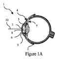
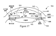
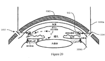
図1Aは、眼1の解剖学を示し、関連する部分には、解剖学的参照を提供するためにラベルが付与されている。強膜2は、角膜輪部4と呼ばれる円形接合部で角膜3に接する、眼の周囲の強靭な鞘である。角膜3の後ろには、虹彩5、レンズ6、並びに毛様体及び関連する突起部7が存在する。前房は、瞳孔8の直前の、眼1内の流体で満たされたコンパートメントである。側面図で見ると、前房は、その前方の境界がドーム型の角膜3によって形成され、その後方の境界が色付きの虹彩5によって形成される。角膜3及び虹彩5が収束する場所において、これらは、本明細書中で「前房の角度」と呼ばれる角度9を形成する。更に、眼1は視軸/光軸10を有してよい。
FIG. 1A shows the anatomy of
図1Bは、外科的な眼の解剖学の更なる詳細を示す。本明細書に記載の実施形態は、後部毛様体突起から毛様体扁平部にまで及ぶ眼内構造を標的としてよい。あるいは、毛様体扁平部を標的としてよく、毛様体突起、毛様体、及び他の毛様体の突起部は回避される。 FIG. 1B shows further details of the surgical eye anatomy. Embodiments described herein may target intraocular structures ranging from the posterior ciliary process to the pars plana. Alternatively, the pars plana may be targeted and the ciliary process, ciliary body, and other ciliary projections avoided.
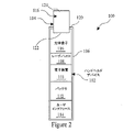
図2は、本明細書に記載のレンズ又は眼用マスク(以下「マスク」)のうちのいずれに治療光を送達するために使用できる、眼科用治療デバイス100を示す。具体的には、眼科用治療デバイス100は、毛様体及び/又は毛様体扁平部を標的とするために使用できる。図2の眼科用治療デバイス100は、レーザプローブ又はハンドヘルドデバイスとして図示されているが、他の実施形態では、上記デバイスは大きく異なっていてもよいことを理解されたい。例えばデバイス100は、デスクトップコンソール又はワークステーションに統合する等によって、手で把持及び操作されないように構成してもよい。構成にかかわらず、眼科用治療デバイス100は、治療光を、患者の眼の上に位置決めされたマスクへと送達する機能を果たす。
FIG. 2 illustrates an
図2では、眼科用治療デバイス100は、治療デバイス本体102と、治療デバイス本体102に着脱可能に連結された、交換式の単回使用又は複数回使用型先端部104とを備える。治療デバイス本体102は、ユーザが把持するためのハンドルを画定する外側表面を備えたハウジング106を含む。治療デバイス本体102は更に、眼の組織の治療のための治療光を提供するよう構成された、治療光源108を含む。光源108は典型的には、ハウジング106内に位置決めされるが、いくつかの実施形態では、ハウジング106の近位端を外部光源に連結してよく、又は光源をハウジング106の外部に位置決めしてよい。
In FIG. 2, an
光源108は広域光源であってよく、これは、レーザプローブ等の従来の治療システムで使用されるものよりも安価である。ある例示的実施形態では、光源108は、垂直キャビティ面発光レーザ(vertical cavity surface emitting laser:VCSEL)、面発光LED、又はこれらの組み合わせである。VCSELレーザは、本明細書に記載のマスクと容易に整列される、シングルモードビームを放出する。図10は、光源108において使用してよい面発光レーザダイオード240を示す。面発光レーザダイオード240は、円形ビームを放出する面発光レーザ242を含む。光源108は、1~10ワットの810nmレーザ光を送達するよう構成してよく、これは、従来のレーザ治療プローブで採用されるものよりも大幅に安価である。GaAs/AlGaAs化合物半導体材料で作製された典型的なVCSELは、アルミニウム含有量及び垂直キャビティの長さに応じて、780~860nmの発振波長を有し得る。
VCSEL又は面発光LEDの使用は、縁部発光レーザ等の、従来のシステムで使用される光源を上回る、複数の利点を提供する。例えばVCSELは、対称な円形ビームを放出し、これは典型的には、およそ15°の角度に内包される。このようなビームは、患者の眼の上に位置決めされたマスクに対して容易にコリメートできる。しかしながら、マスクを使用すると、縁部発光レーザを含む実質的にいずれの光源も使用できる。本出願の眼科用治療デバイス100は広域光源を採用できるため、眼科用治療デバイス100は、いずれの光ファイバの使用を必要とせず、従って上記システムは、光ファイバ及びこれに関連する部品を全く含まないものとすることができる。いくつかの実施形態では、光源108及び/又は眼科用治療デバイス100は、RFIDリーダ、カメラ、画像処理ユニット等と共に動作できる。RFIDリーダは、本明細書に記載の部品のうちの1つ以上、例えば先端部104、マスク等の単回使用を実現するために採用してよい。
The use of VCSELs or surface emitting LEDs offers several advantages over light sources used in conventional systems, such as edge emitting lasers. A VCSEL, for example, emits a symmetrical circular beam, which is typically contained within an angle of approximately 15°. Such a beam can be easily collimated with respect to a mask positioned over the patient's eye. However, with the mask, virtually any light source can be used, including edge-emitting lasers. Because the
光源108は、単一の発光デバイス、又はそれぞれが独立して治療光のビームを送達する複数のこのようなデバイスのアレイを含んでよい。組み合わされた発光デバイスのアレイは、眼科用治療デバイス100の遠位端から、眼の表面上に位置決めされたマスクに向かって放出される、光のビームを生成できる。いくつかの実施形態では、上記アレイの各発光デバイスは、所与の時点において、1つの発光デバイスのみ、又は複数の発光デバイスのうちの一部のみが治療光を送達するように、独立して制御できる。これにより、眼に送達される治療を、所望の様式で変更及び制御できる。
The
治療デバイス本体102はまた、1つ以上の追加の部品を含んでよい。例えば治療デバイス本体102は、レンズ光学系116を含んでよい。図2に示すように、レンズ光学系116は、ハウジング106内に位置決めしてよいが、他の実施形態では、レンズ光学系116は、単回使用又は複数回使用型先端部104(本明細書中ではスペーサ104とも呼ばれる)の一部であってもよい。更に他の実施形態では、レンズ光学系116は、ハウジング106と単回使用又は複数回使用型先端部104との間で分割されていてよい。いくつかの実施形態では、マスク及び広域光源の使用により、マスクが治療光を所望の様式で眼内において配向するため、レンズ光学系116を採用する必要が排除される。
治療デバイス本体102はまた、治療光の送達を自動的に制御する、制御ユニット又は電子装置110を含んでよい。治療デバイス本体102はまた、1つ以上のバッテリ112、AC/DC電源、及び/又はユーザインタフェース114を含んでよい。眼科用治療デバイス100を用いて、多様な異なる方法で、治療光を眼の標的組織に送達できる。ユーザインタフェース114は、1つ以上の機械式ダイヤル、ボタン、又はスイッチを備えてよく、これらは、タッチスクリーン又は専用の電子ディスプレイを備える又は備えない治療光源のパラメータを調整するために使用できる。更に、又はあるいは、治療パラメータを、無線周波数、例えばBluetooth(登録商標)を介して、プローブに通信してよい。
The
眼用マスク
図3は、眼1の簡単な正面図を示す。具体的には、図3は、眼1の瞳孔8、虹彩5、及び角膜輪部4を示す。図4A、5Aは、治療光を眼内の標的組織へと配向するために使用できるマスクの実施形態を示す。図4B、5Bは、図3の眼の上に重ねられたマスクを示す。図4A、5Aのマスクの使用により、治療デバイスが、眼の組織の治療に使用されるビームを画定する必要が排除される。例えば従来のデバイスでは、典型的にはレーザプローブである治療デバイスの遠位端を、患者の眼の表面上に適切に位置決めしなければならない。眼の表面上での治療デバイスの適切な位置決めには、典型的には、放出された光のビームが所望の角度で眼に当たるように、治療デバイスを眼に対して配向するステップが必要である。放出された光のビームもまた、適切に配向されていなければならず、これにはコリメータ、ダイオード、及び/又は導波路の使用が必要となることが多い。
Ophthalmic Mask FIG. 3 shows a simplified front view of the
図4A、5Aのマスクの使用により、個々のマスクが治療光を眼に対して画定し、また眼内に配向するため、上述のような治療デバイスの整列及び配向の必要が排除される。むしろ、眼用マスクの適切な位置決めには、典型的には、眼用マスクを角膜に対してセンタリングするステップしか必要でなくなる。従って、治療プロセスは、治療ビームの正確な制御及び送達に関して、光源及び/又は治療デバイスへの依存が大幅に少なくなり、これにより、コリメータ、ダイオード、導波路等のビーム整列用部品の必要が排除される。 Use of the masks of FIGS. 4A, 5A eliminates the need for alignment and orientation of treatment devices as described above, as individual masks define and direct treatment light to and into the eye. Rather, proper positioning of the ophthalmic mask typically requires only the step of centering the ophthalmic mask with respect to the cornea. Thus, the treatment process is much less dependent on the light source and/or treatment device for precise control and delivery of the treatment beam, thereby eliminating the need for beam alignment components such as collimators, diodes, waveguides, etc. be done.
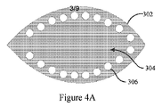
図4Aを具体的に参照すると、図示されているのは、本体304及び複数の開口又はアパーチャ306を含む、マスク302である。本体304は典型的には、使用中に眼に対して不快感又は刺激を引き起こさないよう、眼に対して生体適合性の薄型材料で作製される。例示的な材料としては、ポリメチルメタクリレート、酸素透過性ポリマー、柔軟な親水性プラスチック(例えばヒドロゲル)等が挙げられる。本体304は、眼の表面に相対して位置決めできる内面と、上記内面の反対側に位置決めされる外面とを含む。
Referring specifically to FIG. 4A, shown is
マスク302の本体304又はその一部分は、マスク302を通して光が伝達されるのを防止するために、光学的に不透明である。ある例示的実施形態では、マスク302の本体304全体が光学的に不透明であるが、全体が光学的に不透明な本体304が必要なわけではない。光学的に不透明な本体304は、治療光又は他の光が、マスク302を通って、このような光によって損傷を受け得る眼の敏感な組織(例えば網膜)まで伝達されるのを防止する。本体304はまた、典型的には反射性であり、従って本体304に入射した光はマスク302から離れるように反射される。本体304の反射機能により、本体304が入射光を吸収しない、又は最低限しか吸収しないことが保証され、これにより、治療光又は他のいずれの光に対する曝露によるマスク302の過熱が防止される。従ってマスク302は、比較的低温のままとすることができ、ユーザにとって快適なままとすることができる。
いくつかの実施形態では、マスク302は不透明材料製であってよい。他の実施形態では、マスク302は透明材料製であってよく、マスク302の内面及び/又は外面上に、不透明材料をコーティング又は形成してよい。反射特性は典型的には、反射材料をマスク302の外面上にコーティング、形成、又はその他の方法で位置決めすることによって達成される。例えば、金属材料をマスクの上にコーティング、形成、又は位置決めすることによって、反射特性を提供してよい。ある例示的実施形態では、マスクの上にコーティング、形成、又は位置決めされる反射材料は、マスク302を不透明にする材料と同一の材料である。反射材料は、必要に応じて、マスク302の外面全体の上、又はマスク302の外面の一部分のみの上に、コーティング、形成、又は位置決めしてよい。
In some embodiments,
マスク302は複数の透明開口306を含み、これにより、光がマスク302を横断する、マスク302を通して伝達される、又はマスク302を貫通するのを可能にする。各開口306は、マスク302の中心から径方向外側に位置決めされる。図4Bに示すように、開口306は、マスク302を眼1の上に位置決めした場合に、各開口306が、一般に強膜に沿って、眼1の角膜輪部4の径方向外側に位置決めされるように、マスク302の周囲に位置決めされる。眼1の虹彩5及び瞳孔8は、光学的に不透明な本体304によって全体的に被覆される。図4Bでは、開口306は眼1の全体を取り囲んでいるが、様々な他の開口の構成を必要に応じて使用してよい。開口306によって、光源108(例えばVCSEL、LED等)から送達された治療光が、本体304を通り、下にある眼1の標的組織まで、治療のために貫通できる。
開口306は、マスク302の外面及び/又は内面上にコーティング、形成、又は他の方法で位置決めされた材料内に形成される。例えば開口306を、マスク302の反射材料及び/又は不透明材料コーティングにエッチングしてよい。他の例では、反射材料及び/又は不透明材料をマスク302上にコーティング又は形成するにあたって、テンプレート又はパターンを使用してよい。テンプレート又はパターンは、マスク302の周囲における開口306の適切な配置を支援でき、並びに/又は反射材料及び/若しくは不透明材料が開口306をコーティング若しくは被覆するのを防止するのを支援できる。ある例示的実施形態では、開口は、直径100~600ミクロンであってよいが、他の様々な開口直径を採用してよい。マスク302は典型的には、1~100個の開口、5~40個の開口、より一般には10~25個の開口を含むが、他の構成も可能である。ある具体的実施形態では、マスク302はおよそ18個の開口を含み、これは、ある既存の治療プロトコルに対応する治療パターンを提供する。図4A及び4Bに図示されている開口の配置により、レーザ治療手順を、従来の毛様体光凝固術手順と同様に実施できる。
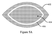
ここで図5Aを参照すると、治療光を眼1に送達する際に使用できる、別のマスク402が示されている。マスク402は本体404を含み、これもまた典型的には、上述のような薄型の生体適合性材料製である。本体404は光学的に不透明であり、典型的には、上述のような反射材料を含む。しかしながら、複数の開口の代わりに、マスク402は、本体404を通して治療光を貫通させる又は伝達することができる、透明スロット406を含む。透明スロット406は、エッチングによって、若しくは上述のようなテンプレート/パターンの使用によって形成してよく、又は他のいずれの方法で形成してよい。図5Bに示すように、透明スロット406は、マスク402を眼1の上に位置決めした場合に、透明スロット406が、一般に強膜に沿って又は強膜に隣接して、角膜輪部4の径方向外側に位置決めされるように、マスク402の周囲に位置決めされる。眼1の虹彩5及び瞳孔8は、光学的に不透明な本体404によって全体的に被覆されたままである。透明スロット406によって、光源108(例えばVCSEL、LED等)から送達された治療光が、本体404を通り、下にある眼1の標的組織まで、治療のために貫通できる。
Referring now to FIG. 5A, another
いくつかの実施形態では、透明スロット406は、50μm~600μmのスロット幅を有してよいが、他の様々なスロット幅を採用してもよい。更に、透明スロット406は、1つの連続したスロット又は特徴部分として図示されているが、他の実施形態では、透明スロット406は、単一のスロットのみを含んでも、又は複数の不連続なセクションを含んでもよい。他の実施形態では、透明スロット406は、虹彩8の上方又は下方等、眼1の片側のみに位置決めされていてもよい。透明スロット406は、眼の一部分に所望の治療を提供するよう構成及び配設してよい。
In some embodiments,
いくつかの実施形態では、図4A、5Aのマスク302、402は、RFID、メモリチップ、特別な機械的取り付け機構等を含んでよく、又はこれらと共に動作してよい。RFIDを使用することにより、眼科用治療デバイス100は、マスクが透明開口及び/若しくはスロットを含むかどうか、並びに/又はこれらの特徴部分のサイズ及び配置といった、マスクの構成を認識でき、また採用されているマスクの具体的構成に基づいて光源108のパラメータを調整できる。メモリチップはこの情報を記憶して、眼科用治療デバイス100に送達してよい。RFID及び/又はメモリチップは、マスクが1回しか使用されないことを保証するために使用することもできる。特別な機械的取り付け機構又は特徴部分は、マスクを、図11に図示されているもののようなスペーサの遠位端に着脱可能に連結又は取り付けできるようにすることができる。この特別な機械的取り付け機構は、スペーサ及びマスクの大まかな整列を支援できる。
In some embodiments, the
図4A、5Aのマスク302、402は例示を目的としたものであり、本明細書に記載のマスクの正確な構成を制限することを意図していないこと、及び他の様々な構成を採用してよいことを理解されたい。例えばマスクは、必要に応じて、透明スロットと開口との組み合わせを含んでよく、又は正方形、長方形、楕円形、多角形等といった他の幾何学的形状を含んでよい。
The
ここで図9を参照すると、マスク502を、治療光を患者の眼1に送達する光源510と組み合わせて使用する、システム500が図示されている。図9のマスク502は、図4Aのマスク302、図5Aのマスク402、又は治療プロセスで使用してよい他のいずれのマスクを表している。同様に、光源510は、眼科用治療デバイス100の光源108、又は治療プロセスで使用される他のいずれの光源であってよい。本明細書中で使用される場合、マスク502は、1つ以上の透明特徴部分506(例えば開口及び/又はスロット)が眼1の角膜輪部4の外側に位置決めされるように、眼の周囲に位置決めされる。
Referring now to FIG. 9, a
光源510は、マスク502に向かって治療光520を配向する。光源510は、光源510が、マスクの少なくとも一部分と、少なくとも1つ以上の透明特徴部分506とを同時に照射するように、マスク502に対して位置決めされる。図示されている実施形態では、光源510は、マスク502全体と、各透明特徴部分506とを、同時に照射する。本明細書中に記載されているように、光源510は、単一の発光デバイス、又は複数の発光デバイスのアレイを含んでよい。複数の発光デバイスのアレイを採用する場合、マスク502を同時に照射するように、又は必要に応じて変化させた様式でマスク502を照射するように、各発光デバイスからの治療光ビームの送達を制御してよい。光源510は典型的には、眼1の標的組織への治療光の送達を自動的に制御するようプログラムされた制御ユニットに、通信可能に連結される。
マスク502は、反射材料及び/又は不透明材料を含む。反射材料は、治療光520の一部を、マスク502から離れるように反射522させる。反射材料は、マスクの外面上に配置された反射性コーティング又は層であってよい。反射材料及び/又は不透明材料により、治療光520が眼1の所望の標的組織にしか送達されないことが保証される。透明特徴部分506により、治療光520の一部分524は、透明特徴部分506の直下又はすぐ後ろに位置決めされた標的組織に向かって、マスク502を横断する、マスク502を通って伝達される、又はマスク502を貫通することができる。光源510は、透明特徴部分506の一部又は各透明特徴部分506を同時に照射するため、光源510は、照射された透明特徴部分506に関連する標的組織を同時に治療する。
いくつかの実施形態では、透明特徴部分506は、治療光524が所望の角度で眼1に当たるように、治療光524を配向するよう構成してよく、これにより、眼の周囲における光源510及び/又は眼科用治療デバイス100の正確な整列の必要が排除又は最小化される。対照的に、治療プローブを使用する従来の治療システムでは、眼の治療の前に、ユーザが光源及び治療プローブを眼の周囲で整列させる必要がある。最善の努力にもかかわらず、ユーザが治療プローブを整列させると、眼の周囲におけるプローブの整列及び配向は比較的不正確になる。マスク502の使用は、所望の標的組織に対する治療光の送達において、はるかに良好な精度及び制御を提供できる。というのは、眼の周囲における透明特徴部分506の配置、配向、及び位置決めが、ユーザによる整列の対象ではないためである。そうではなく、眼1の周囲における透明特徴部分506の配置、配向、及び位置決めは、使用される適切なマスク502を選択すること、又は眼の固有の形状及び/若しくは他の特性に対してマスク502をカスタム製作することによって、制御される。マスク502が眼1の上の所定の位置に位置決めされて維持されるため、透明特徴部分506の配置、配向、及び位置決めは維持される。
In some embodiments, the
図9には図示されていないが、図11に示すスペーサ104のようなスペーサが、マスク502を光源510から隔てるために、典型的にはマスク502と光源510との間に位置決めされている。スペーサの近位端は、例えば上記近位端を眼科用治療デバイス100に連結することによって、光源510に連結してよく、またスペーサの遠位端は、マスク502の上に位置決めしてよい。いくつかの実施形態では、スペーサの遠位端は、マスク502に取り付けられるか、又は連結されていてよい。スペーサは典型的には、マスク502を光源510から送達された治療光に曝露する透明材料である。
Although not shown in FIG. 9, spacers, such as
いくつかの実施形態では、光源510は、治療光520の送達を支援するために、角度が付けられているか、又は湾曲していてよい。例えば、光源510又はスペーサの曲率は、眼1の曲率に一致していてよい。光源510及び/又はスペーサの外形の一致により、治療光524を、おおよそ垂直な角度で、眼1に当てて、眼1に入射させることができる(例えば治療光の入射角は、垂直の±10°以内であってよい)。従来のデバイスと比較すると、マスク502及び/又は光源510の使用は、眼1に入射する治療光の角度に対する、より良好な制御を提供する。というのは、従来のデバイス(例えばレーザプローブ)のユーザにとって、デバイスを、常に眼の周囲において適切に整列されたまま維持するのは困難であるためである。いくつかの実施形態では、眼科用治療デバイス100は、治療光520に角度を付けることによって眼1に対しておおよそ垂直とするために使用される、光学系116を含んでよい。
In some embodiments,
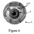
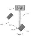
図6、7は、眼を治療するために採用してよい治療手順を示す。図6は、眼の角膜輪部4の周囲の、複数の離間して固定された場所117を示し、これらはそれぞれ治療光によって治療される。図6に示されている複数の離間して固定された場所117は、図4Aのマスク302の複数の開口306に対応する。離間して固定された場所117の治療については、米国公開特許第2010/0076419号に記載されており、上記文献は参照により本出願に援用される。米国公開特許第2010/0076419号に記載されている治療では、離間して固定された場所117それぞれを個別に治療するために、レーザプローブを眼の周りで移動させて再位置決めする。この手順とは対照的に、本明細書に記載の治療手順は、離間して固定された場所117の一部又は全てを同時に照射して治療する。ある例示的実施形態では、離間して固定された場所117それぞれを同時に照射して治療する。これにより、離間して固定された場所117それぞれを個別に治療するために必要な手間及び時間が削減される。また、治療ビームの整列が、眼の周囲における治療プローブのユーザによる整列に基づくものではないため、離間して固定された場所117それぞれの治療がより精密になる。治療の送達において、治療光を、離間して固定された場所117それぞれに対して1回送達してよく、又は以下に記載されるように、離間して固定された場所117それぞれに対して複数回送達してもよい。
Figures 6 and 7 illustrate treatment procedures that may be employed to treat the eye. FIG. 6 shows a plurality of spaced apart fixed
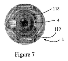
図7は、別の治療方法を示し、ここでは治療プローブを、光の送達と同時に、標的組織を横断するように摺動又はスイープ(sweep)させる。この治療方法は角膜輪部4の上方及び下方の、治療された組織の弓状の又は湾曲したパターン118、119をもたらす。この治療方法は、米国公開特許第2015/0374539号に記載されており、上記文献は参照により本出願に援用される。治療された組織の弓状の又は湾曲したパターン118、119は、図5Aのマスク402の透明スロット406の形状及び構成に対応する。米国公開特許第2015/0374539号の治療手順とは対照的に、本明細書に記載の治療手順は、弓状の/湾曲したパターン118、119の一部又は全体を同時に照射して治療する。ある例示的実施形態では、弓状の/湾曲したパターン118、119の全体を同時に照射して治療するが、光源を本明細書に記載されているように制御することにより、必要に応じて、弓状の/湾曲したパターン118、119の一部に沿って治療を変化させることもできる。本明細書に記載の治療手順により、眼の表面を横断するようにプローブを摺動又はスイープさせるために必要な手間及び時間が削減される。また、弓状の/湾曲したパターン118、119の治療は、ユーザがプローブを、眼の表面を横断するように摺動又はスイープさせることに依存しないため、より精密に画定され、またより精密に制御される。治療の送達において、治療光を、弓状の/湾曲したパターン118、119に対して1回送達してよく、又は以下に記載されるように、弓状の/湾曲したパターン118、119に対して複数回送達してもよい。
FIG. 7 shows another treatment method in which the treatment probe is slid or swept across the target tissue concurrently with light delivery. This method of treatment results in an arcuate or
上で簡潔に述べたように、光源108及び制御ユニット110は、パルス波又は連続波放出モードで光エネルギを送達するよう構成してよい。例えばいくつかの実施形態では、光源108及び制御ユニット110は:「オン」時間が約500μs、「オフ」時間が約1100μsという30%のデューティサイクル;「オン」時間が約300μs、「オフ」時間が約1700μsという約15%のデューティサイクル;又は「オン」時間が約200μs、「オフ」時間が約1800μsという約10%のデューティサイクルで動作するよう構成してよい。レーザエネルギパルスの「オン」及び「オフ」時間を注意深く選択すると、「オン」時間中に次のエネルギのパルスを送達する前に、レーザの「オフ」時間中に標的を冷却させることにより、標的に対する望ましくない熱損傷を回避できる。デューティサイクルは、「オフ」時間中の不十分な冷却によって発生する累積的な熱の蓄積を回避できるように、選択してよい。これにより、眼圧(IOP)の低減に必要な生物学的応答を引き起こすために十分な最小レベルまで、損傷を低減できる。図8は、本発明のいくつかの実施形態で使用できる、例示的なパルスモードを示す。図示されているモードは、100μsの「オン」時間及び1900μsの「オフ」時間を有してよく、周期は2000μsである。
As briefly mentioned above,
図11は、スペーサ104の一実施形態を示す。スペーサ104は、単回使用型部品又は複数回使用型部品であってよいが、ある例示的実施形態では、スペーサ104は単回使用型部品であり、これはハウジング106から取り外し可能であり、別のスペーサ104と交換できる。スペーサ104は、光源108、及び高温になり得る眼科用治療デバイス100の遠位端を、マスク(即ち302、402、502)及び眼1の表面から隔てることにより、眼1の表面が損傷を受けないことを保証する。ある例示的実施形態では、スペーサ104は、ガラスマスク、プラスチックマスク、又は光学系の形成に採用される他のいずれの材料から作製してよい。スペーサ104は、必要に応じて、材料の固形体の中空部分であってよく、典型的には、治療光の送達を妨げないよう、透明である。
FIG. 11 shows one embodiment of
スペーサ104は、近位端122と、近位端122の反対側の遠位アプリケータ端部124とを含む。スペーサ104は、いずれの光学系116が使用される場合、眼科用治療デバイス100の光学系116を格納してよく、又はこれを含んでよい。スペーサ104の近位端122は、1つ以上の係合用特徴部分を用いて、ハウジング106の遠位端120に機械的に連結されるよう、構成される。例えば図11は、ねじ山付き係合用特徴部分194を有するスペーサ104の近位端122を示しており、これにより、スペーサ104は、対応するねじ山付き係合用特徴部分を含んでよいハウジング106に対して、回転によって係合及び係合解除できる。あるいはスペーサ104は、ハウジング106の1つ以上の対応する係合用特徴部分にスナップ嵌合する1つ以上の突出部(図示せず)を含んでよく、又はハウジング106の対応するメス型若しくはオス型コネクタに係合する他のいずれのオス型若しくはメス型コネクタを含んでよい。
上で簡単に説明したように、いくつかの実施形態では、遠位端124の接触面196は、その外形が、眼の外形に一致するように成形されていてよい。例えば、接触面196は、強膜の曲率に一致するよう構成された曲率を有する凹面であってよい。接触面196の凹面構成により、上記接触面を、平均的な眼のジオメトリに対応する構成を有する、基本的にカップ状の形状とすることができる。接触面196の外形が成形された構成は、眼の表面に対して垂直な角度での治療光の送達を支援できる。スペーサ104の遠位端124は、マスク(例えば302、402、502)又は眼窩に取り付けられる又は連結されるように構成してもよい。
As briefly described above, in some embodiments, the
いくつかの実施形態では、スペーサ104は、コンピュータ可読媒体を含む。コンピュータ可読媒体は、光学バーコード(例えば2Dバーコード)、埋め込みチップ(例えばRFID、NFC、直接読み取りメモリチップ)等であってよい。コンピュータ可読媒体は、治療デバイス本体102に関連付けられた対応するセンサによって、読み取ることができる。いくつかの実施形態では、コンピュータ可読媒体は、治療デバイス本体102を、認証されていない交換用スペーサ104と共に使用されないよう保護する、セキュリティ用特徴部分であってよい。任意に、コンピュータ可読媒体は、スペーサ104及び/又はマスクに関連する治療パラメータ情報を保持してよい。例えば、スペーサ104を治療デバイス本体102に連結してよく、治療デバイス本体のセンサがコンピュータ可読媒体を読み取って、上記治療デバイス本体に取り付けられているスペーサ104のタイプ、及び/又は眼の周囲に位置決めされたマスクに、どの治療パラメータが関連するかを決定してよい。その後、治療デバイス本体102の制御ユニット110は、特定の治療のための光源108及び/又はマスクのパラメータを自動的に調整するように構成してよい。
In some embodiments,
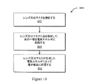
図12は、眼を治療するための方法600を示す。ブロック602では、レンズ又はマスクを眼の表面上に位置決めする。マスクは、内面と、内面の反対側に位置決めされた外面とを含む。マスクは、マスクを通した光の伝達を防止するために、光学的に不透明である。マスクはまた、透明開口又はスロットを含み、これにより、光学的に不透明なマスクを通した、上記透明開口又はスロットの後方に位置決めされた眼の標的組織への、光の伝達が可能となる。
FIG. 12 shows a
ブロック604では、光源をマスクに対して整列させる。ブロック606では、治療光を光源からマスクに向かって送達し、これにより、送達された治療光は、光学的に不透明なマスクの少なくとも一部分を照射し、また透明開口又はスロットを照射する。治療光の少なくとも一部は、透明開口又はスロットを横断して、透明開口又はスロットの後方に位置決めされた標的組織に到達する。ある例示的実施形態では、治療光は、光学的に不透明なマスクの大半又は全体を照射し、また各透明開口又はスロットを照射する。
At
上記方法はまた、典型的には、マスクを光源から隔てるために、マスクと光源との間にスペーサを位置決めするステップを含む。スペーサは、近位端と、近位端の反対側の遠位端とを有し、ここで近位端は光源に連結され、遠位端は、マスクの上に位置決めされる、及び/又はマスクに連結される。上記方法はまた、典型的には、光源から治療光を自動的に送達するために、制御ユニットを起動するステップを含む。いくつかの例では、光源から治療光を自動的に送達する上記ステップは、治療光の一連のパルスを標的組織に送達するステップを含み、ここで上記一連のパルスはそれぞれ、標的組織の従来の光凝固を生じさせることなく上記標的組織の治療的治癒を誘発するために十分なものである。「各パルスは、従来の光凝固を生じさせることなく治療的治癒を誘発するために十分なものである」という記述は、標的組織の白化等の視認可能な損傷が、上記標的組織上に全く存在しない、又は上記標的組織に全く関連しないことを意味している。他の例では、光源から治療光を自動的に送達する上記ステップは、治療光の単一のパルスを標的組織に送達するステップを含み、ここで上記単一のパルスは、標的組織の治療的治癒を誘発するために十分なものである。 The method also typically includes positioning a spacer between the mask and the light source to separate the mask from the light source. The spacer has a proximal end and a distal end opposite the proximal end, where the proximal end is coupled to the light source and the distal end is positioned over the mask; and/or Connected to the mask. The method also typically includes activating the control unit to automatically deliver therapeutic light from the light source. In some examples, the step of automatically delivering therapeutic light from the light source includes delivering a series of pulses of therapeutic light to the target tissue, wherein each of the series of pulses is a conventional pulse of the target tissue. sufficient to induce therapeutic healing of the target tissue without photocoagulation. The statement that "each pulse is sufficient to induce therapeutic healing without causing conventional photocoagulation" implies that no visible damage, such as whitening of the target tissue, occurs on the target tissue. It means absent or not associated with the target tissue at all. In another example, the step of automatically delivering therapeutic light from the light source includes delivering a single pulse of therapeutic light to the target tissue, wherein the single pulse is therapeutically effective in the target tissue. sufficient to induce healing.
光給電式眼用マスク
いくつかの実施形態では、眼用マスク又はレンズは、光を電気エネルギに変換するよう構成されていてよい。具体的には、マスクは、光を電気エネルギに変換するよう構成された材料を含んでよく、これにより、マスクの外面に入射した又は照射された光を用いて、1つ以上の電子部品に給電できる。光を電力に変換する材料は、太陽電池タイプの材料であってよく、これは、マスクの外面上に位置決めしてよく、又はマスク材料内に埋め込んでもよい。本明細書中での実施形態の説明を簡単にするために、光を電力に変換する材料を、これ以降、太陽電池又は太陽電池材料と呼ぶものとする。
Light-Powered Ophthalmic Masks In some embodiments, an ophthalmic mask or lens may be configured to convert light into electrical energy. Specifically, the mask may include a material configured to convert light into electrical energy such that light incident on or illuminated by the outer surface of the mask is used to affect one or more electronic components. Power can be supplied. The material that converts light to electrical power may be a solar cell type material, which may be positioned on the outer surface of the mask or embedded within the mask material. To simplify the description of the embodiments herein, materials that convert light into electrical power shall be referred to hereinafter as solar cells or solar cell materials.
本明細書中に記載されているように、マスクは、マスクを通した光の伝達を防止するために、光学的に不透明な材料で作製されていてよいが、他の実施形態では、マスク(又はその一部分)を透明材料で作製してよく、これにより、光を、レンズを通して眼まで伝達できる。太陽電池材料は、マスクの不透明部分上に位置決めしてよく、これにより、マスクのこの部分に入射した光が電力に変換される。太陽電池材料を用いてマスクの不透明領域を被覆することにより、眼科的治療に使用されない光を電力に変換でき、この電力を用いて、治療の提供に有用な電子部品に給電できる。太陽電池材料は、マスクの一部として作製してよく、治療される眼の全範囲を被覆してよく、及び/又は光ビームのサイズよりも範囲が大幅に大きくてよい。いくつかの実施形態では、太陽電池材料は、マスクの表面積の少なくとも30パーセントを被覆してよいが、太陽電池材料は典型的には、マスクの表面積の少なくとも40パーセント又は50パーセントを被覆する。いくつかの実施形態では、太陽電池材料は、マスクの表面積の60パーセント超又は70パーセント超を被覆してよい。ある具体的実施形態では、太陽電池材料は、マスクの表面積の90パーセント超を被覆してよい。例えば、図14に示す実施形態では、太陽電池材料は、開口706aが位置する箇所を除いて、マスク702aの全表面積を被覆してよく、これにより、マスク702aの表面積の90パーセント超を被覆する太陽電池材料が得られる。
As described herein, the mask may be made of an optically opaque material to prevent transmission of light through the mask, although in other embodiments the mask ( or part thereof) may be made of a transparent material, allowing light to be transmitted through the lens to the eye. A solar cell material may be positioned on the opaque portion of the mask such that light incident on this portion of the mask is converted to electrical power. By covering the opaque areas of the mask with a solar cell material, light not used for ophthalmic therapy can be converted into electrical power, which can be used to power electronic components useful in providing therapy. The solar cell material may be made as part of a mask, may cover the entire area of the eye to be treated, and/or may be significantly larger in area than the size of the light beam. In some embodiments, the solar cell material may cover at least 30 percent of the mask's surface area, although the solar cell material typically covers at least 40 percent or 50 percent of the mask's surface area. In some embodiments, the solar cell material may cover more than 60 percent or more than 70 percent of the surface area of the mask. In one specific embodiment, the solar cell material may cover more than 90 percent of the surface area of the mask. For example, in the embodiment shown in FIG. 14, the solar cell material may cover the entire surface area of
太陽電池材料が相当な表面積を占めることができることに加えて、本明細書に記載のマスクは、相当な量の電気エネルギを生成できる。例えばマスクの不透明領域における入射光のパワーのレベルは、従来の透明レンズより大幅に高くなり得る。というのは、マスクの不透明部分が、眼への光の伝達をブロックするためである。810nmでの治療のためのパワー密度は、典型的な操作において350W/cm2の治療閾値を有すると推定できる。このパワー密度は、表面積213mm2の眼用マスクに対する、およそ745W、即ち350W/cm2*2.13cm2の合計入射パワーを生じさせる。太陽電池材料がマスクのおよそ50パーセントを被覆すると仮定すると、太陽電池材料の合計入射パワーは、およそ372W、即ち745W/2となる。太陽電池材料が上記合計入射パワーを20%の率で変換すると、生成される電力はおよそ74Wとなり、これは、小さな太陽電池を有する従来のレンズに比べて、電力の有意な増大を表す。不透明領域で変換されて入手できる高い電力を、太陽電池に関連付けられた低電力センサ用途に加えて、いずれの眼科的用途に使用できる。 In addition to the ability of the solar cell material to occupy a substantial surface area, the masks described herein are capable of producing a substantial amount of electrical energy. For example, the power level of incident light in the opaque regions of the mask can be significantly higher than in conventional clear lenses. This is because the opaque portions of the mask block the transmission of light to the eye. The power density for therapy at 810 nm can be estimated to have a therapeutic threshold of 350 W/cm 2 in typical operation. This power density yields a total incident power of approximately 745 W or 350 W/cm 2 *2.13 cm 2 for an ophthalmic mask with a surface area of 213 mm 2 . Assuming that the solar cell material covers approximately 50 percent of the mask, the total incident power of the solar cell material is approximately 372 W or 745 W/2. If the solar cell material converts the total incident power at a rate of 20%, the power produced will be approximately 74 W, which represents a significant increase in power compared to conventional lenses with small solar cells. The high power available converted in opaque regions can be used for any ophthalmic application in addition to the low power sensor applications associated with solar cells.
図13は、光を電気エネルギに変換する太陽電池材料702を含むマスク700の、ある例示的実施形態を示す。マスク700は、マスク700が眼の虹彩全体を被覆するように、及びマスクの縁部が眼の強膜まで延在するように、眼の周囲に位置決めされる。マスク700は上述のように不透明であり、従って、光がマスク700を通って伝達されるのが防止される。ある例示的実施形態では、マスク700の不透明部分は、眼の虹彩全体を被覆し、強膜まで延在する。従って、マスク700を眼の周囲に配置すると、装用者は、マスク700を通した視認が不可能となる。マスク700全体が不透明であってよく、又はマスク700の一部分のみが不透明であってもよい。しかしながら、いずれの実施形態においても、マスク700の不透明部分は典型的には、眼を被覆するため、マスク700の装用者はマスク700を通した視認が不可能となる。
FIG. 13 shows an exemplary embodiment of a
太陽電池材料は、マスク700の光学的に不透明な部分の上に位置決めされる。マスク700の実質的に全体が光学的に不透明であるため、太陽電池材料が占有できる表面積は、眼への光の伝達を可能とする大きな透明領域を有する従来のコンタクトレンズの同様の面積よりも、大幅に大きくなる。従来のレンズでは、太陽電池材料は典型的には、瞳孔又は虹彩のすぐ前に位置決めされない。というのは、太陽電池材料をこのように位置決めすると、眼への光の伝達をブロックする、又は眼への光の伝達と干渉することによって、ユーザの視覚を大きく妨げるためである。従って従来のレンズでは、太陽電池材料及び/又は他のいずれの電子部品は、レンズの縁部付近にしか位置決めされず、従ってレンズの中央部分はこのような材料を含まないままである。この構成により、装用者の視覚が太陽電池によってマイナスの影響を受けないことが保証される。太陽電池材料はレンズの中央部分上には位置決めされないため、レンズのこの部分は、エネルギ変換に関してはデッドスペースであり、即ちこの部分はエネルギへの光の変換に寄与できない。
Solar cell material is positioned over the optically opaque portions of
対照的に、本明細書において考えられているマスクは、不透明なものとして構成され、従ってユーザはマスクを通した視認が不可能であるため、上述のような利点を被らない。マスクは不透明であるため、太陽電池材料及び/又は他の電子部品は、瞳孔及び虹彩のすぐ前の中央部分を含むマスクの基本的にいずれの部分を占有できる。本明細書に記載のマスクは、エネルギ変換を行うことができないデッドスペースを含まず、又はかなり小さなデッドスペースしか含まない。よって本明細書に記載のマスクは、従来のレンズよりも大幅に多量の電気エネルギを生成できる。 In contrast, the masks contemplated herein do not suffer from the advantages described above because they are configured as opaque and therefore the user cannot see through the mask. Because the mask is opaque, the solar cell material and/or other electronic components can occupy essentially any portion of the mask, including the central portion just in front of the pupil and iris. The masks described herein contain no dead space in which energy conversion cannot occur, or very little dead space. Thus, the masks described herein can generate significantly more electrical energy than conventional lenses.
図13に示すように、マスク700はまた、少なくとも1つの透明開口706を含み、これにより、マスク700を通した光704の伝達が可能となる。上で更に詳細に説明したように、開口706は、透明開口706の前方又は後方に位置決めされた眼の標的組織708に光704を照射できるようにするために構成される。開口706は、マスク700の中央から径方向外側に位置決めされ、典型的には、本明細書に記載されているように、一般に強膜に沿って、眼の角膜輪部の径方向外側に位置決めされる。光704は、眼の組織の治療のために、治療光源(例えば光源108)から供給される。本明細書に記載されているように、光源は、VCSEL、面発光LED又はこれらの組み合わせといった広域光源であってよい。
As shown in FIG. 13,
図14、15は、患者の眼の治療に使用できるマスク702a、702bの実施形態を示す。マスク702a、702bは、マスクに対して使用できる開口の異なる配置を示す。図14、15のマスク702a、702bは例示を目的としたものであり、開口の配置、個数及び/又は配向は、必要に応じて修正してよいことを理解されたい。図14は、マスク702aの中央部分の周囲に円形又は楕円形パターンで配設された複数の開口706aを示す。開口706aは、図4Aに示したマスクと同様の配置パターン、配向、及び/又は孔サイズを有してよい。図14に示されている開口の配置により、従来の毛様体光凝固術手順と同様にして、レーザ治療手順を実施できる。図15は、図5Aに示したマスクと同様の配置、配向及び/又は開口サイズを有する円形の比較的大型の開口706bを含む、マスク702bを示す。図15に示されている開口706bの配置により、図5A~Bに記載されているものと同様にして、レーザ治療手順を実施できる。
Figures 14 and 15 show embodiments of
図14、15はまた、各マスク702a、702bに照射される治療ビーム又はスポット712を示す。治療ビーム又はスポット712は、1つ以上の開口706a、706bの直径より大きな直径を有し、従って1つ以上の開口706a、706bが同時に照射される。いくつかの実施形態では、治療ビーム又はスポット712全体がマスク702a、702bの外周内に囲まれるよう、治療ビーム又はスポット712はマスク702a、702bより小さな直径を有してよいが、他の実施形態では、治療ビーム又はスポット712は、マスク702a、702bより大きくてよい。
Figures 14 and 15 also show a treatment beam or spot 712 that impinges on each
治療ビーム又はスポット712は、マスク702a、702bの中央部分を被覆し、本明細書に記載されているように虹彩及び/又は瞳孔のすぐ前のマスクの中央部分を含む、マスク702a、702bの不透明部分上に位置決めされた太陽電池材料を照射する。太陽電池材料は光を電気エネルギに変換し、この電気エネルギは、マスク702a、702b上に位置決めされた1つ以上の電子部品710に給電するために使用される。例示的な電子部品710について、以下で更に詳細に説明する。図14、15に示すように、電子部品は、マスク702a、702bの外縁部上に位置決めしてよいが、他の実施形態では、電子部品のうちの1つ以上を、マスクの中央部分又は中央部分付近に位置決めしてよい。マスク702a、702bの中央部分は不透明であるため、電子部品をマスクの中央部分又は中央部分付近に位置決めしても、マスクを通って移動するはずの光をブロックすることによって装用者の視覚を妨げる、又は不明瞭にすることはない。電子部品710を中央部分又は中央部分付近に位置決めすることにより、電子部品710を、実施される操作に応じて、より効率的に機能させることができる。
The treatment beam or spot 712 covers the central portion of the
いくつかの実施形態では、パッシブ型又はアクティブ型光学部品を、各マスク702a、702bの1つ以上の開口706a、706bのうちの1つ以上の中に埋め込む、又は位置決めしてよい。ある例示的実施形態では、開口706a、706bはそれぞれ、パッシブ型又はアクティブ型光学部品を有してよい。パッシブ型又はアクティブ型光学部品は、パッシブ型又はアクティブ型光学部品が中に位置決めされた各開口を通って伝達される光と相互作用できる。パッシブ型又はアクティブ型光学部品を使用することにより、マスク702a、702bの後方に位置決めされた標的組織への光の制御、性能、及び/又は送達を大幅に向上でき、これにより、マスクを用いて達成できる治療的便益を大幅に増大させることができる。
In some embodiments, passive or active optics may be embedded or positioned within one or more of the one or
上記マスクと共に使用してよい電子部品710としては、センサ、MEMSデバイス、無線信号トランシーバ、電力検出器、撮像デバイス、光パワー検出器等が挙げられる。センサは、眼圧センサ等の圧力センサ、グルコースセンサ等の化学センサ、生体材料センサ等であってよい。例えば圧力センサを用いて、眼圧(IOP)を測定してよい。圧力センサは、IOPを測定するために使用される1つ以上のひずみゲージを採用してよい。また、装用者の血糖値を測定できるグルコースセンサを使用してもよい。グルコースセンサは、グルコースレベルを測定できる光音響センサを採用してよい。
太陽電池が比較的大量の電力を生成できることにより、従来のセンサに比べて、追加のセンサ及び/又はより複雑なセンサを採用できる。換言すれば、センサの個数及び/又はセンサの動作は、本明細書に記載のマスクが生成できる電気エネルギが増加したことにより、従来のレンズで採用されるセンサのように制限されない。従って、患者の更なる又は改善された治療及び/又は治療データを、本明細書に記載のマスクによって測定できる。同様に、電気エネルギが更に生成されることにより、更なる治療選択肢を利用できる。 The ability of solar cells to generate relatively large amounts of power allows the employment of additional and/or more complex sensors than conventional sensors. In other words, the number of sensors and/or the operation of the sensors is not as limited as sensors employed in conventional lenses due to the increased electrical energy that the masks described herein can generate. Further or improved treatment and/or treatment data for a patient can thus be measured by the masks described herein. Likewise, additional treatment options are available as more electrical energy is generated.
いくつかの実施形態では、電子部品710は、処理用部品(即ちマイクロプロセッサ)を含んでよい。上記処理用部品は、1つ以上のセンサが測定したデータの分析に使用してよい。いくつかの実施形態では、データをリアルタイムで分析して、送達されている治療プロセスの1つ以上のパラメータを調整してよい。例えば、センサをマスクの上に位置決めしてよく、このセンサを用いて、マスクに当たる治療光の照射の量を測定してよい。処理用部品は、データを分析して、眼の標的組織に送達されている光エネルギを決定してよい。処理システムはこの情報を外部部品に伝達してよく、及び/又はこの情報を用いて、患者が受ける治療を最適化するために、治療光のパワーレベルを調整してよい。従って、センサ及び処理用部品を用いて、眼に送達される実際のパワー又はエネルギを、従来のシステムより大幅に正確に推定できる。このように、1つ以上のセンサ及びマイクロプロセッサの使用により、治療処置の送達において、閉ループフィードバックシステムを使用できる。従来の治療システムは、眼に入射する実際のパワーを推定できない。そうではなく、これらのシステムは、光が光源から出る際に光の照射を測定することが多く、これは、眼に入射する光の照射とは異なる場合がある。
In some embodiments,
マスクの開口内に配置されるアクティブ型又はパッシブ型光学部品を用いて、開口を通して伝達される治療光を成形又は調節してよい。アクティブ型又はパッシブ型光学部品は、ナノ又はマイクロ光学部品であってよい。パッシブ型又はアクティブ型部品としては、マイクロレンズ、微小電気機械システム(MEMS)ミラー又は部品、マイクロレンズとMEMSミラー/部品との組み合わせ等が挙げられる。太陽電池材料が生成するエネルギは、パッシブ型又はアクティブ型光学部品に給電できる。マイクロレンズを採用する場合、マイクロレンズは、緑内障の治療のために強膜下の場所に光を集束させる等の、ビーム成形のための光学的なタスクを実施できる。マイクロレンズは、眼内の所望のスポットに光を集束させるために、電気的に制御可能であってよい。マイクロレンズは、治療光の散乱を最小化でき、治療ビームを眼内の所望の領域に集中させることができる。図13は、マスク702の開口706内に配置されたマイクロレンズ707を示す。マイクロレンズ707は、入力光704を強膜表面の下方のスポット708に集束させるために使用される。マイクロレンズの使用により、眼内の標的組織への、より標的を絞った正確な治療光の送達が可能となる。また、マイクロレンズの使用により、眼に対する治療ビームのより精密かつ適切な配向も可能となる。いくつかの実施形態では、複数のマスクを採用してよく、各マスクは、わずかに異なる開口サイズ、及び/又は開口内に配置されたマイクロレンズによって達成される焦点距離を有する。複数のマスクの使用により、患者の個々の特徴及び/又は提供される具体的な治療に基づいて、ある特定のマスクを選択できる。
Active or passive optics placed within the apertures of the mask may be used to shape or modulate the therapeutic light transmitted through the apertures. Active or passive optics may be nano- or micro-optics. Passive or active components include microlenses, microelectromechanical system (MEMS) mirrors or components, combinations of microlenses and MEMS mirrors/components, and the like. The energy produced by the solar cell material can power passive or active optics. If microlenses are employed, they can perform optical tasks for beam shaping, such as focusing light to subscleral locations for the treatment of glaucoma. Microlenses may be electrically controllable to focus light to desired spots within the eye. Microlenses can minimize scattering of the treatment light and focus the treatment beam to desired regions within the eye. FIG. 13 shows a
MEMSミラー等のアクティブ型光学素子は、提供される治療処置を改善できる複数の機能を提供できる。例えばMEMSミラーは、開口706を通した治療光704の伝達を調節及び制御するための、開口706内のオン/オフ光スイッチとして機能できる。オン/オフスイッチ機能は、眼の繊細な領域への治療光の送達を制限するために使用してよく、図4A、4bに関連して説明した円形治療パターンを提供するために使用してよく、及び/又は従来の光凝固を生じさせることなく治療的治癒を誘発するために十分な、パルス幅が短い一連のパルスを提供するために使用してよい。これらの治療のうちのいずれ又は全てを提供するために、アクティブ型光学素子の一部をオフに切り替えている間に他のアクティブ型光学素子をオンに切り替えてよく、またその逆を行ってよい。アクティブ型又はパッシブ型光学素子をマスクと共に使用することにより、上記マスクによって達成できる治療を大幅に改善できる。
Active optical elements, such as MEMS mirrors, can provide multiple functions that can improve the therapeutic treatment provided. For example, a MEMS mirror can act as an on/off optical switch within
図16を参照すると、マスク又はレンズによって光エネルギを電気エネルギに変換する方法が提供されている。ブロック802では、眼の上に位置決めできるレンズ又はマスクが提供される。レンズ/マスクは、内面と、内面の反対側の外面と、光を電気エネルギに変換するよう構成された材料(例えば太陽電池材料)とを含む。太陽電池材料はレンズ/マスクの上に配設され、これにより、レンズ/マスクの少なくとも一部分に入射した光が電気エネルギに変換される。ブロック804では、レンズを光で照射することにより、上記光の少なくとも一部分が、太陽電池材料によって電気エネルギに変換される。いくつかの実施形態では、太陽電池材料は、レンズ/マスクの表面積の少なくとも50パーセントを被覆する。
Referring to FIG. 16, a method is provided for converting light energy into electrical energy by means of a mask or lens. At block 802, a lens or mask is provided that can be positioned over the eye. The lens/mask includes an inner surface, an outer surface opposite the inner surface, and a material configured to convert light into electrical energy (eg, solar cell material). A solar cell material is disposed over the lens/mask such that light impinging on at least a portion of the lens/mask is converted into electrical energy. At
いくつかの実施形態では、レンズ/マスクの少なくとも一部分は、レンズを通した光の伝達を防止するために、光学的に不透明である。このような実施形態では、太陽電池材料は、レンズの光学的に不透明な上記部分上に位置決めされる。レンズ/マスクは典型的には、少なくとも1つの透明開口を含み、これにより、上記少なくとも1つの透明開口の背後又は後方に位置決めされた眼の標的組織への、レンズ/マスクを通した光の伝達が可能となる。レンズ/マスクは、パッシブ型又はアクティブ型光学部品を含んでよく、これは少なくとも1つの開口内に埋め込まれて、上記少なくとも1つの開口を通って伝達された光と相互作用する。パッシブ型又はアクティブ型光学部品は、センサ、MEMSミラー、無線信号トランシーバ、電力検出器等であってよい。レンズ/マスクはまた、電子部品を含んでよい。ブロック806では、電子部品は、レンズ/マスクによって生成された電力によって給電される。
In some embodiments, at least a portion of the lens/mask is optically opaque to prevent transmission of light through the lens. In such embodiments, the solar cell material is positioned over the optically opaque portion of the lens. The lens/mask typically includes at least one transparent aperture for transmission of light through the lens/mask to target tissue of the eye positioned behind or behind said at least one transparent aperture. becomes possible. A lens/mask may include passive or active optics that are embedded within the at least one aperture to interact with light transmitted through the at least one aperture. Passive or active optics may be sensors, MEMS mirrors, radio signal transceivers, power detectors, and the like. The lens/mask may also contain electronic components. At
反射性眼用マスク
いくつかの実施形態では、マイクロミラー等の反射性光学部品を、眼の1つ以上の開口内に位置決めしてよい。反射性光学部品を用いて、上記開口を通して伝達される光ビームの方向又は角度を変化させることにより、従来の治療プローブ及びシステムでは照射又はアクセスが比較的困難な眼の組織を治療できる。例えば、反射性光学部品は、光が従来のシステムでは照射できない眼内の組織を照射できるように、光ビームをある角度で反射させることができる。光は、本明細書に記載されているような広域光源(例えばVCSEL、LED等)によって提供してよく、又は眼内の組織の治療に効果的な他のいずれの光源によって提供してもよい。
Reflective Ophthalmic Masks In some embodiments, reflective optics, such as micromirrors, may be positioned within one or more apertures of the eye. By using reflective optics to change the direction or angle of the light beam transmitted through the aperture, tissue of the eye that is relatively difficult to irradiate or access with conventional treatment probes and systems can be treated. For example, reflective optics can reflect a light beam at an angle so that the light can illuminate tissue within the eye that conventional systems cannot. Light may be provided by a wide area light source (e.g., VCSEL, LED, etc.) as described herein, or may be provided by any other light source that is effective in treating tissue within the eye. .
ある具体的実施形態では、反射性光学部品を用いて、線維柱帯網又は経路を介した眼内の房水レベルの調節を支援する眼内のリンパ様管であるシュレム管を治療してよい。シュレム管は小さな範囲の組織であり、前房から房水を放出させることができ、これによって眼内の眼圧(IOP)を低減できる。シュレム管の機能異常は、IOPの上昇、及び/又はこれに関連する、緑内障のリスクの上昇といった健康状態をもたらし得る。 In a specific embodiment, reflective optics may be used to treat Schlemm's canal, an intraocular lymphoid vessel that helps regulate aqueous humor levels in the eye via a trabecular meshwork or pathway. . Schlemm's canal is a small area of tissue that can release aqueous humor from the anterior chamber, thereby reducing intraocular pressure (IOP) within the eye. Dysfunction of Schlemm's canal can result in health conditions such as elevated IOP and/or associated increased risk of glaucoma.
シュレム管に治療光を照射することにより、シュレム管及び/又は線維柱帯網を刺激してよく、これにより、眼内から房水を放出すること、及び/又は眼内の流体の流れを調節することによって、シュレム管及び/又は線維柱帯網をより正常に機能させることができる。シュレム管の照射は、シュレム管及び/又は周囲の組織に対する他の有益な影響を有し得る。よって、緑内障のリスクの低減といった治療的便益を、シュレム管及び/又は線維柱帯網を治療光で治療することによって達成できる。 Irradiating Schlemm's canal with therapeutic light may stimulate Schlemm's canal and/or the trabecular meshwork, thereby releasing aqueous humor from within the eye and/or regulating fluid flow within the eye. By doing so, Schlemm's canal and/or trabecular meshwork can function more normally. Irradiation of Schlemm's canal may have other beneficial effects on Schlemm's canal and/or surrounding tissue. Thus, therapeutic benefits such as reduced risk of glaucoma can be achieved by treating Schlemm's canal and/or trabecular meshwork with therapeutic light.
図17は、眼900の概略図を示す。シュレム管902は、眼900の前房内において、虹彩906の上方に図示されている。図17は、後房と前房との間における、眼内での房水の流体の流れ904を示す。図示されているように、房水は、房水が産生される毛様体908から、房水が線維柱帯網又は経路を介して放出又は排水されるシュレム管902まで、流れる904。眼内のIOPの上昇は、毛様体908が、シュレム管902が放出又は排水できる量より多くの房水を産生することを原因とする場合があり、これは、緑内障及び/又は他の状態に関するリスクを上昇させ得る。IOPを調節するための従来の試みは、後房内での房水の産生を低減するための毛様体908の治療に焦点を当てたものであった。毛様体908の治療に加えて、又は上記治療に代えて、眼の前房内からの房水の放出又は排水を増大させるために、シュレム管902を治療することも、可能であり得る。
FIG. 17 shows a schematic diagram of an
シュレム管902は典型的には、極めて小さな(例えばおよそ50ミクロンの)幅を有するリング状である。また、シュレム管902は、従来の治療システムの治療光では照射又はアクセスが困難な領域内に位置決めされる。例えばシュレム管902は、従来の治療プローブの軸から外れており、これは即ち、シュレム管902を照射するためには、従来の治療プローブからの治療光を相当な量(例えば30°以上)曲げる、又は角度を付ける必要があることを意味している。従来の治療プローブ及びシステムは多くの場合、光ファイバを採用しており、これは、上述のような鋭角で治療光を曲げる、又は治療光に角度を付けることができない。というのは、光ファイバは典型的には破壊されてしまうか、又は光が上記光ファイバから漏れることになるためである。シュレム管902の位置を原因として、従来の治療システムでシュレム管902を治療するのは極めて困難である。
Schlemm's
図18は、シュレム管902等の、照射及び/又はアクセスが困難な眼900内の組織の治療に使用できる、マスク1000を示す。マスク1000は、単回使用のために設計された使い捨てレンズ又は材料であってよい。マスク1000は典型的には、上述のように、不透明材料1002又は外面と、少なくとも1つの開口1005とを含む。不透明材料1002は上述のように、マスク1000の加熱を最小化するために反射性であってよい。マスク1000の不透明部分1002及びマスク1000の1つ以上の開口1005の配置及び/又は配向は、図4A~4D、11及び/又は12に関連して説明したマスクの配置及び/又は配向と同様であってよい。同様に、ユーザの眼の周囲におけるマスク1000の配向及び/又は配置は、これらの図面に関連して説明した配置及び/又は配向と同様であってよい。例えば、マスク1000は典型的には、マスク1000の不透明部分1002が眼の虹彩及び瞳孔を完全に被覆するよう、並びに1つ以上の開口1005が、本明細書に記載されているように、眼の角膜輪部の径方向外側に位置決めされるよう、構成される。マスク1000はまた、典型的には、治療光ビームのスポットサイズより大きな面積を有する。
FIG. 18 shows a
反射性部品又は材料1004(以下、反射性部品1004)が、マスク1000の少なくとも1つの開口1005内に位置決めされる。反射性部品1004は、入力された治療ビームをある角度で反射し、これにより、治療ビームの、そうでなければアクセスできなかった組織に対するアクセス及び照射が可能となる。例えば図18は、反射性部品1004に当たる前の、治療ビームの第1の経路1006aと、反射性部品1004に当たった後の、治療ビームの第2の経路1006bとを示す。図示されているように、治療ビームの経路は、相当な量だけ、角度を付けられている、曲げられている、又は他の方法で変更されている。図示されている実施形態では、治療ビームは反射性部品1004によって、約90°だけ角度を付けられているが、他の実施形態では、反射性部品1004を用いて、15~120°、30~120°、又はより一般には30~90°若しくは30~60°だけ治療光に角度を付けてよい。
A reflective component or material 1004 (hereinafter reflective component 1004 ) is positioned within at least one opening 1005 of
マスク1000が、図4A、11に示した配置と同様の複数の開口1005を有する場合、反射性部品1004は所望に応じて、開口1005のうちのいくつかの中、又は各開口1005内に位置決めしてよい。ある例示的実施形態では、複数の開口1005のうちの各開口1005が反射性部品1004を含む。各反射性部品1004は、各開口1005内において、シュレム管等の標的組織を治療するために、治療光が眼の中心に向かって径方向内側に反射されるように配向できる。マスク1000が、図5A、12に示した配置と同様の単一の開口1005を有する場合、反射性部品1004は、単一の開口1005内に位置決めされた、連続リング状ミラー又は部品であってよい。この連続リング状ミラーは、シュレム管等の標的組織を治療するために、治療光を眼の中心に向かって径方向内側に反射するよう、配向及び構成できる。
If the
いくつかの実施形態では、反射性部品1004は、事前に選択された、事前に定義された、及び/又は調整不可能な角度で、治療光に角度を付けるよう設計された、パッシブ型又は静的部品であってよい。他の実施形態では、反射性部品1004は、治療光の角度を必要に応じて変更又は調整できる、アクティブ型又は動的部品であってよい。本明細書に記載されているように、反射性部品1004は、開口1005の内面又は縁部上に反射材料をめっきする又は堆積させることによって形成してよい。他の実施形態では、パッシブ型又はアクティブ型ミラーを開口1005内に位置決めしてよい。上記ミラーを、MEMSデバイス又は部品上に位置決め又は形成することにより、上記ミラーの配向を、マスク1000の開口1005内において調整できる。
In some embodiments, the
本明細書に記載されているように、マスク1000は、光を電気エネルギに変換するよう構成された材料(例えば太陽電池材料)を含んでよく、これにより、マスク1000の外面に入射した又は照射された光を電気エネルギに変換する。マスク1000は、眼内の標的組織への治療処置の送達に使用される1つ以上の電子部品(例えばセンサ等)を含んでもよい。従って、これまでの全ての実施形態において開示されている様々な特徴を、図18に示すマスク1000に適用及び/又は採用してよい。太陽電池材料によって生成された電気エネルギを用いて、反射性部品1004に給電してよく、これにより例えば、開口1005内の反射性部品1004の配向を調整し、これによって標的組織に送達されている治療光の角度を調整する。例えば、生成された電気エネルギを用いて、ミラー又は反射材料がその上に位置決め又は形成されたMEMSデバイス又は部品の配向を制御してよい。
As described herein,
図19は、マスク1000の開口1005の表面上に反射材料を形成するステップの、ある実施形態を示す。図示されているように、ミラー堆積源1102は、マスク1000の開口1005の内面1007に向かって配向される、反射材料1104(例えばアルミニウム)を提供してよい。反射材料1104を開口1005内に堆積させることにより、反射材料1104の層1108を内面1007上に形成してよい。反射材料1104の層1108は、本明細書に記載されているように治療光に角度を付ける機能を果たす、リフレクターを形成又は画定できる。いくつかの実施形態では、反射材料1104は、内面1007上に層1108を形成でき、開口1005の反対側の表面上に同様の層を形成することはない。他の実施形態では、マスク1000から隔てられた反射性部品(例えばミラー及び/又はMEMS部品)を、開口1005内に挿入してよい。
FIG. 19 illustrates one embodiment of forming a reflective material on the surface of
図20は、マスク1000の内面の概略図を示し、マスク1000の内面は眼の上に位置決めされている。図示されているように、マスク1000の不透明及び/又は反射性部分1002は、虹彩の全体を被覆し、これにより、治療光が、治療の標的でない眼の網膜又は他の繊細な組織に当たるのを略防止する。反射性部品1004は、治療光の軸から外れた、及び/又は治療光がアクセスできない若しくは治療光の照射が極めて困難な、眼内の標的組織を治療するために、第1の経路1006aから第2の経路1006bに向かって治療光を反射させて角度を付けるように、マスク1000の1つ以上の開口1005内において配向される。図示されている実施形態では、標的組織はシュレム管902及び/又は線維柱帯網であるが、標的組織は照射のために同定された他のいずれの組織であってよい。
FIG. 20 shows a schematic view of the inner surface of
反射性部品1004は、1つ以上の開口1005の内面に堆積された反射材料であってよく、又は反射性部品1004は、1つ以上の開口1005内に位置決めされたミラー若しくは反射性レンズであってよい。反射性部品1004は、反射した光が標的組織(例えばシュレム管)に向かって配向されてこれを照射するように、1つ以上の開口1005内において事前に選択された角度又は配向を有してよい。ある具体的実施形態では、反射性部品1004は、調整可能なアクティブ型部品であってよく、これにより、開口を通して伝達される反射した光の角度を調整するために、各開口1005内における反射性部品1004の相対位置又は配向が調整可能となる。反射した治療光の角度は、30°超、例えば30~120°であってよい。1つ以上の開口1005内の反射性部品1004を、眼球の表面において使用することにより、眼球の表面を、治療光に関する適切なビーム偏向角度を計算するための物理的基準として使用できる。
シュレム管の治療にあたって、シュレム管の位置を、眼の画像(例えば光干渉断層計(optical coherence tomography:OCT))によって検出できる。この情報を用いて、シュレム管を照射するために適切なマスク1000を選択してよい。例えば、治療光がシュレム管に向かって反射されてシュレム管に照射されることを保証するために、適切に配向されたリング状ミラーを有するマスク1000を選択してよい。リング状ミラーの使用により、シュレム管の実質的に全体を、同時に治療できる。別の実施形態では、アクティブ型反射性部品(例えばミラー又は反射性MEMS部品)の配向を、治療光がシュレム管に向かって反射されてシュレム管に照射されることを保証するように設定してよい。アクティブ型反射性部品の使用により、シュレム管が照射及び治療されていることを保証するために、1つ以上のリフレクターの配向をリアルタイムで調整できる。アクティブ型反射性部品は遠隔制御でき、またマスク1000の不透明領域1002上に位置決めされた太陽電池材料によって局所的に給電できる。他の実施形態では、局所的に生成された電気エネルギを用いて、例えばIOPの測定によってシュレム管の照射の効果の決定を支援する1つ以上のセンサに給電してよい。マスク1000は、治療光ビームをシュレム管に向かって効果的に案内又は配向でき、これは従来のレーザ治療プローブ又はシステムでは達成できないものである。
In treating Schlemm's canal, the location of Schlemm's canal can be detected by imaging of the eye (eg, optical coherence tomography (OCT)). Using this information, an
ここで図21を参照すると、反射光ベースのシステムを用いて患者の眼を治療するための方法1200が示されている。ブロック1202では、レンズ/マスクを眼の表面上に位置決めする。レンズ/マスクは、内面と、上記内面の反対側の外面と、レンズ/マスク内に配置された反射材料とを有する。ブロック1204では、光源をレンズ/マスクに対して整列させる。ブロック1206では、治療光を光源からレンズ/マスクに向かって送達することにより、送達された治療光の少なくとも一部分が反射材料に照射されて、反射材料によって、光源から送達される治療光の軸から外れた眼内の組織に向かって、ある角度で反射される。本明細書に記載されているように、治療光は、反射材料によって、眼のシュレム管の組織に向かって反射できる。反射される治療光の角度は、30°超、例えば30°~120°であってよい。
Referring now to FIG. 21, a
レンズ/マスクは典型的には、レンズ/マスクを通した治療光の伝達を防止するために、光学的に不透明である。このような例では、レンズ/マスクは少なくとも1つの透明開口を含み、これにより、上記少なくとも1つの透明開口を通した治療光の送達が可能となる。反射材料は、レンズ/マスクの少なくとも1つの透明開口内に配置される。いくつかの実施形態では、方法1200は、反射材料を少なくとも1つの透明開口の内面に堆積させるステップを含んでよい。他の実施形態では、反射材料を、少なくとも1つの透明開口内に位置決めされたレンズ部品内に配置してよい。このような実施形態では、レンズ部品はアクティブ型部品であってよく、上記方法は、少なくとも1つの透明開口を通して伝達される治療光の角度を調整するために、少なくとも1つの透明開口内における反射材料の相対位置を調整するステップを更に含んでよい。
The lens/mask is typically optically opaque to prevent transmission of therapeutic light through the lens/mask. In such instances, the lens/mask includes at least one transparent aperture, thereby enabling delivery of therapeutic light through said at least one transparent aperture. A reflective material is disposed within at least one transparent aperture of the lens/mask. In some embodiments,
コンピュータ可読形式のソフトウェア命令にアクセスすることによって、本明細書に記載の所望の機能性を提供するように、1つ以上の計算デバイスを適合させてよい。ソフトウェアを使用する場合、いずれの好適なプログラミング、スクリプト、又は他のタイプの言語若しくは言語の組み合わせを用いて、本明細書に内包されている教示を実装してよい。しかしながら、ソフトウェアを主に使用する必要はなく、又はソフトウェアを使用する必要は全くない。例えば本明細書に記載の方法及びシステムのいくつかの実施形態は、特定用途向け回路を含むがこれに限定されない、ハードワイヤードロジック又は他の回路構成によって実装することもできる。コンピュータ実行可能ソフトウェアとハードワイヤード論理又は他の回路構成との組み合わせも好適であり得る。 By accessing software instructions in computer readable form, one or more computing devices may be adapted to provide the desired functionality described herein. When using software, any suitable programming, scripting, or other type of language or combination of languages may be used to implement the teachings contained herein. However, it is not necessary to primarily use software, or to use software at all. For example, some embodiments of the methods and systems described herein may be implemented by hardwired logic or other circuitry, including but not limited to application specific circuitry. A combination of computer-executable software and hard-wired logic or other circuitry may also be suitable.
本明細書に記載の方法の実施形態は、1つ以上の好適な計算デバイスによって実行してよい。上述のような1つ以上のシステムは、本明細書で開示されている方法の1つ以上の実施形態を実施するよう適合された1つ以上の計算デバイスを備えてよい。上述のように、このようなデバイスは、コンピュータ可読命令を具体化する1つ以上のコンピュータ可読媒体にアクセスでき、上記コンピュータ可読命令は、少なくとも1つのコンピュータによって実行されると、上記少なくとも1つのコンピュータに、本発明の主題である方法の1つ以上の実施形態を実装させる。更に、又はあるいは、1つ以上の計算デバイスは、上記1つ以上のデバイスを、本発明の主題の方法のうちの1つ以上を実装するために動作可能とする、回路構成を備えてよい。 Embodiments of the methods described herein may be performed by one or more suitable computing devices. One or more systems as described above may comprise one or more computing devices adapted to perform one or more embodiments of the methods disclosed herein. As noted above, such devices have access to one or more computer readable media embodying computer readable instructions which, when executed by at least one computer, cause the at least one computer to: implement one or more embodiments of the method that is the subject of the present invention. Additionally or alternatively, one or more computing devices may comprise circuitry that enables said one or more devices to implement one or more of the methods of the present inventive subject matter.
ディスケット、ドライブ、及び他の磁気ベースの記憶媒体;ディスク(例えばCD‐ROM、DVD‐ROM、これらの変形等)、フラッシュ、RAM、ROM及び他の記憶デバイスを含む光学記憶媒体等を含むがこれらに限定されない、1つ以上のいずれの好適なコンピュータ可読媒体を用いて、本明細書で開示されている主題を実装又は実践してよい。 diskettes, drives, and other magnetic-based storage media; optical storage media, including disks (e.g., CD-ROM, DVD-ROM, variations thereof, etc.), flash, RAM, ROM, and other storage devices; Any one or more suitable computer-readable media may be used to implement or practice the subject matter disclosed herein, including but not limited to.
ここでは本発明の主題を具体的に説明しているが、請求対象である主題は、他の方法で具体化してもよく、異なる要素又はステップを含んでもよく、また他の既存の又は将来の技術と組み合わせて使用してもよい。 Although the inventive subject matter is particularly described herein, the claimed subject matter may be embodied in other ways, may include different elements or steps, and may include other existing or future modifications. May be used in combination with technology.
本記述は、個々のステップの順序又は要素の配置が明示的に記述されている場合を除いて、様々なステップ又は要素間のいずれの特定の順序又は配置を暗示するものとして解釈してはならない。図面に図示された又は上述された部品の異なる配置、並びに図示又は記載されていない部品及びステップが可能である。同様に、一部の特徴部分及び部分的組み合わせは有用であり、他の特徴部分及び部分的組み合わせを参照することなく採用できる。本発明の実施形態は、限定ではなく説明を目的として記載されており、本発明の読者には代替実施形態が明らかになるだろう。従って本発明は、上述された又は図面に図示された実施形態に限定されず、以下の特許請求の範囲から逸脱することなく、様々な実施形態及び修正形態を作成できる。 This description should not be construed as implying any particular order or arrangement between various steps or elements, except where the order of individual steps or arrangement of elements is explicitly stated. . Different arrangements of the parts shown in the drawings or described above, as well as parts and steps not shown or described, are possible. Likewise, some features and subcombinations are useful and can be employed without reference to other features and subcombinations. Embodiments of the invention have been described for purposes of illustration rather than limitation, and alternative embodiments will become apparent to the reader of the invention. The invention is therefore not limited to the embodiments described above or illustrated in the drawings, and various embodiments and modifications can be made without departing from the scope of the following claims.
Claims (19)
前記光ベースのシステムは:
患者の眼の上の所定の位置に置かれるよう構成された、眼用マスクであって、前記眼用マスクは、前記眼に相対する内面と、前記内面の反対側の外面とを有し、前記眼用マスクは、光学的に不透明かつ反射性であり、従って前記眼用マスクに当たった光は、前記眼用マスクの前記外面から離れるように反射され、前記眼用マスクは、光が前記眼用マスクを横断できるようにする少なくとも1つの透明開口を周縁部に備え、前記少なくとも1つの透明開口は、前記眼用マスクが前記所定の位置にある場合に前記眼の角膜輪部に対して径方向外側に配置され、
治療光を前記眼用マスクに向かって送達するよう構成された、光源であって、前記光源は、前記光源が前記眼用マスクの少なくとも一部分及び前記少なくとも1つの透明開口を照射することによって、前記治療光の一部分が前記少なくとも1つの透明開口を横断して前記眼内の標的組織に到達するように、前記眼用マスクに対して位置決めされる、光源
を備え、
前記光源が発する前記治療光が、前記眼用マスクが備える前記少なくとも1つの透明開口を通じて前記眼内の前記標的組織に配向されるように構成される光ベースのシステム。 A light-based system for treating an eye of a patient, comprising:
Said light-based system:
An ophthalmic mask configured to be placed in position over an eye of a patient, the ophthalmic mask having an inner surface facing the eye and an outer surface opposite the inner surface. the ophthalmic mask is optically opaque and reflective so that light striking the ophthalmic mask is reflected away from the outer surface of the ophthalmic mask; At least one transparent opening is provided in the peripheral edge to allow traversing of the ophthalmic mask, the at least one transparent opening traversing the annulus of the eye when the ophthalmic mask is in place. is arranged radially outward with respect to the
a light source configured to deliver therapeutic light toward the ophthalmic mask, the light source illuminating at least a portion of the ophthalmic mask and the at least one transparent aperture; a light source positioned relative to the ophthalmic mask such that a portion of the therapeutic light traverses the at least one transparent aperture to reach target tissue within the eye ;
A light-based system configured such that the therapeutic light emitted by the light source is directed to the target tissue within the eye through the at least one transparent aperture provided by the ophthalmic mask.
前記光源は、前記複数の開口を同時に照射する、請求項1または2に記載の光ベースのシステム。 said at least one transparent aperture comprising a plurality of apertures, each said aperture of said plurality of apertures being positioned radially outwardly relative to said limbus of said eye;
3. A light-based system according to claim 1 or 2 , wherein the light source illuminates the plurality of apertures simultaneously.
各前記開口は、10ミクロン~1000ミクロンの開口直径を有する、請求項3に記載の光ベースのシステム。 The ophthalmic mask comprises 1 to 100 openings,
4. The light-based system of claim 3, wherein each said aperture has an aperture diameter between 10 microns and 1000 microns.
前記光源は、前記細長又は環状スロットを照射する、請求項1~4のいずれか一項に記載の光ベースのシステム。 said at least one transparent aperture comprising an elongated or annular slot positioned radially outwardly with respect to said limbus of said eye;
A light-based system according to any preceding claim, wherein the light source illuminates the elongated or annular slot.
前記スペーサは、近位端と、前記近位端の反対側の遠位端とを有し、
前記近位端は、前記光源と連結可能であり、
前記遠位端は、前記眼用マスクと整列され、
前記スペーサは、前記眼用マスクの少なくとも一部分を、前記光源から送達される前記治療光に曝露する、透明材料を含む、請求項1~5のいずれか一項に記載の光ベースのシステム。 further comprising a spacer positioned between the ophthalmic mask and the light source to separate the ophthalmic mask from the light source;
the spacer has a proximal end and a distal end opposite the proximal end;
the proximal end is couplable with the light source;
the distal end is aligned with the ophthalmic mask;
The light-based system of any one of claims 1-5, wherein the spacer comprises a transparent material that exposes at least a portion of the ophthalmic mask to the therapeutic light delivered from the light source.
前記制御ユニットは、前記光源を制御して、前記治療光の単一のパルス又は閃光を前記標的組織に送達するよう構成され、前記単一のパルス又は閃光は、前記標的組織の治療的治癒を誘発するために十分なものである、請求項8に記載の光ベースのシステム。 The control unit is configured to control the light source to deliver a series of pulses of the therapeutic light to the target tissue, each pulse of the series of pulses corresponding to conventional photocoagulation of the target tissue. sufficient to induce therapeutic healing of said target tissue without causing
The control unit is configured to control the light source to deliver a single pulse or flash of therapeutic light to the target tissue, wherein the single pulse or flash of light causes therapeutic healing of the target tissue. 9. The light-based system of claim 8, sufficient to induce.
前記電子部品は、センサ、MEMSミラー、無線信号トランシーバ、又は電力検出器を含む、請求項13または14に記載の光ベースのシステム。 the ophthalmic mask further comprising an electronic component powered by power generated by the solar cell material;
15. A light-based system according to claim 13 or 14 , wherein the electronic components comprise sensors, MEMS mirrors, radio signal transceivers or power detectors.
Applications Claiming Priority (5)
| Application Number | Priority Date | Filing Date | Title |
|---|---|---|---|
| US201762459466P | 2017-02-15 | 2017-02-15 | |
| US62/459,466 | 2017-02-15 | ||
| US201762516478P | 2017-06-07 | 2017-06-07 | |
| US62/516,478 | 2017-06-07 | ||
| PCT/US2018/017561 WO2018152020A1 (en) | 2017-02-15 | 2018-02-09 | Method and eye mask apparatus for treating an eye using a broad area light source |
Publications (3)
| Publication Number | Publication Date |
|---|---|
| JP2020507416A JP2020507416A (en) | 2020-03-12 |
| JP2020507416A5 JP2020507416A5 (en) | 2021-03-11 |
| JP7185632B2 true JP7185632B2 (en) | 2022-12-07 |
Family
ID=63106624
Family Applications (1)
| Application Number | Title | Priority Date | Filing Date |
|---|---|---|---|
| JP2019544024A Active JP7185632B2 (en) | 2017-02-15 | 2018-02-09 | Method and ophthalmic mask device for treating eyes with broad-spectrum light source |
Country Status (5)
| Country | Link |
|---|---|
| US (2) | US11020612B2 (en) |
| EP (1) | EP3582729A4 (en) |
| JP (1) | JP7185632B2 (en) |
| CN (1) | CN110325153B (en) |
| WO (1) | WO2018152020A1 (en) |
Families Citing this family (6)
| Publication number | Priority date | Publication date | Assignee | Title |
|---|---|---|---|---|
| US11771596B2 (en) | 2010-05-10 | 2023-10-03 | Ramot At Tel-Aviv University Ltd. | System and method for treating an eye |
| US10401956B2 (en) * | 2017-05-11 | 2019-09-03 | Microsoft Technology Licensing, Llc | Infrared eye-tracking in high ambient light conditions |
| EP4349292A2 (en) * | 2019-09-12 | 2024-04-10 | Belkin Vision Ltd. | Selective laser stimulation of corneal stem cells |
| US20210379397A1 (en) * | 2020-06-05 | 2021-12-09 | Robert Epstein | UV-Mask for Crosslinking Treatment of Keratoconus |
| DE102021130135A1 (en) * | 2021-11-18 | 2023-05-25 | A.R.C. Laser Gmbh | Ophthalmic mask and ophthalmic device |
| CN114224602A (en) * | 2021-12-28 | 2022-03-25 | 浙江博也生物科技有限公司 | Cataract treatment device |
Citations (6)
| Publication number | Priority date | Publication date | Assignee | Title |
|---|---|---|---|---|
| US5108388A (en) | 1983-12-15 | 1992-04-28 | Visx, Incorporated | Laser surgery method |
| US20030109907A1 (en) | 1998-06-22 | 2003-06-12 | Shadduck John H. | Devices and techniques for light-mediated stimulation of trabecular meshwork in glaucoma therapy |
| JP2008518683A (en) | 2004-11-02 | 2008-06-05 | レンチキュラー リサーチ グループ、エルエルシー | Apparatus and method for preventing or delaying one or more symptoms of presbyopia |
| US20120283557A1 (en) | 2011-05-05 | 2012-11-08 | Berlin Michael S | Methods and Apparatuses for the Treatment of Glaucoma using visible and infrared ultrashort laser pulses |
| JP2013518672A (en) | 2010-02-01 | 2013-05-23 | モンテフィオーレ メディカル センター | Methods and devices for cross-linking of corneal collagen and for the treatment of ocular disorders |
| JP2016507321A (en) | 2013-02-26 | 2016-03-10 | ベルキン レーザー リミテッド | Glaucoma treatment system |
Family Cites Families (48)
| Publication number | Priority date | Publication date | Assignee | Title |
|---|---|---|---|---|
| US1075643A (en) | 1913-01-23 | 1913-10-14 | John K Gowen | Receptacle-closure. |
| US3034403A (en) | 1959-04-03 | 1962-05-15 | Neefe Hamilton Res Company | Contact lens of apparent variable light absorption |
| US4732148A (en) * | 1983-11-17 | 1988-03-22 | Lri L.P. | Method for performing ophthalmic laser surgery |
| US4576453A (en) | 1984-08-03 | 1986-03-18 | Richard Borowsky | Light-occluding contact lens |
| US4732715A (en) | 1985-09-20 | 1988-03-22 | Bausch & Lomb Incorporated | Manufacture of polymeric contact lenses |
| DE3535072A1 (en) * | 1985-09-27 | 1987-04-09 | Josef Prof Dr Wollensak | Contact lens as a mask for corneal surgery with laser light |
| US4856513A (en) * | 1987-03-09 | 1989-08-15 | Summit Technology, Inc. | Laser reprofiling systems and methods |
| US5135466A (en) | 1988-08-18 | 1992-08-04 | Fedorov Svjatoslav N | Method for treatment of diseases of the optic tract and a device for carrying said method into effect |
| US4966452A (en) | 1989-04-27 | 1990-10-30 | Ocular Instruments, Inc. | Contact lens for laser surgery |
| US5152759A (en) * | 1989-06-07 | 1992-10-06 | University Of Miami, School Of Medicine, Dept. Of Ophthalmology | Noncontact laser microsurgical apparatus |
| RU1799577C (en) | 1989-08-17 | 1993-03-07 | Межотраслевой научно-технический комплекс "Микрохирургия глаза" | Method for improving vision function affected by ophthalmic nerve and retina disease |
| US5434630A (en) | 1993-09-27 | 1995-07-18 | Bransome; Robert | Corrective contact lens system |
| US5376086A (en) | 1993-10-26 | 1994-12-27 | Khoobehi; Bahram | Laser surgical method of sculpting a patient's cornea and associated intermediate controlling mask |
| US5697923A (en) * | 1995-03-29 | 1997-12-16 | Poler; Stanley | Corneal drape for use in performing a photorefractory keratectomy procedure |
| US5719656A (en) | 1995-05-19 | 1998-02-17 | Bowling; Patricia J. | Contact lens utilizing stiles-crawford effect |
| US6520956B1 (en) * | 1995-11-06 | 2003-02-18 | David Huang | Apparatus and method for performing laser thermal keratoplasty with minimized regression |
| US6544193B2 (en) | 1996-09-04 | 2003-04-08 | Marcio Marc Abreu | Noninvasive measurement of chemical substances |
| US6200134B1 (en) | 1998-01-20 | 2001-03-13 | Kerr Corporation | Apparatus and method for curing materials with radiation |
| US6554424B1 (en) | 1999-03-01 | 2003-04-29 | Boston Innovative Optices, Inc. | System and method for increasing the depth of focus of the human eye |
| US7321795B2 (en) | 2003-03-24 | 2008-01-22 | Les Bogdanowicz | Compositions for electric stimulation of the eye |
| US7628810B2 (en) | 2003-05-28 | 2009-12-08 | Acufocus, Inc. | Mask configured to maintain nutrient transport without producing visible diffraction patterns |
| US20050046794A1 (en) * | 2003-06-17 | 2005-03-03 | Silvestrini Thomas A. | Method and apparatus for aligning a mask with the visual axis of an eye |
| JP4533013B2 (en) * | 2004-06-14 | 2010-08-25 | キヤノン株式会社 | Ophthalmic equipment |
| IL167559A (en) | 2005-03-21 | 2012-09-24 | A T I Advanced Medical Technologies Ltd | Device and method for pupil size modulation |
| US7976577B2 (en) | 2005-04-14 | 2011-07-12 | Acufocus, Inc. | Corneal optic formed of degradation resistant polymer |
| US7727138B2 (en) | 2005-07-07 | 2010-06-01 | Alfredo Alvarado | Magnetic apparatus for the treatment of cataracts and other eye conditions |
| KR100737240B1 (en) * | 2005-12-14 | 2007-07-09 | 오토스테크 주식회사 | Control method for preventing from dazzling with detecting welding light |
| US8696655B2 (en) | 2007-04-10 | 2014-04-15 | Intenzity Innovation Aps | Self-contained handpiece and method for optical tissue surface treatment |
| KR200440586Y1 (en) * | 2007-04-20 | 2008-06-19 | 김한규 | Drap for eye surgery |
| US8945103B2 (en) | 2007-10-30 | 2015-02-03 | Iridex Corporation | Contact probe for the delivery of laser energy |
| CA2735264C (en) * | 2008-08-25 | 2014-10-14 | Wavelight Ag | Coupling of an eye to a laser device |
| US8527055B2 (en) | 2009-07-23 | 2013-09-03 | Alcon Research, Ltd. | Application of an electrical field in the vicinity of the trabecular meshwork to treat glaucoma |
| NZ599267A (en) | 2009-10-20 | 2013-03-28 | Universal View Co Ltd | A soft contact lens with a light-shielding portion having a plurality of holes that maintains a scotopic vision and a night vision in use |
| WO2011067771A1 (en) * | 2009-12-06 | 2011-06-09 | Syneron Medical Ltd. | Eye protective article for personal cosmetic skin treatment |
| US8685038B2 (en) | 2009-12-07 | 2014-04-01 | Incube Labs, Llc | Iontophoretic apparatus and method for marking of the skin |
| WO2011151812A1 (en) * | 2010-05-10 | 2011-12-08 | Ramot At Tel-Aviv University Ltd. | System for treating glaucoma by directing electromagnetic energy to the limbal area of an eye |
| JP5993844B2 (en) * | 2010-05-14 | 2016-09-14 | コーニンクレッカ フィリップス エヌ ヴェKoninklijke Philips N.V. | Efficient circadian and interlinked regulation using sleep masks |
| US20160192988A1 (en) | 2012-05-14 | 2016-07-07 | K-Laser, Llc | Multiple Laser Source System for Portable Laser Therapy Apparatus |
| US9523865B2 (en) * | 2012-07-26 | 2016-12-20 | Verily Life Sciences Llc | Contact lenses with hybrid power sources |
| WO2014074475A1 (en) | 2012-11-07 | 2014-05-15 | Emmetrope Ophthalmics Llc | Magnetic eye shields and methods of treatment and diagnosis using the same |
| DE102013000429A1 (en) | 2013-01-10 | 2014-07-24 | Karlsruher Institut für Technologie | Sensor system for detecting the activation signals of a ciliary muscle |
| US10493274B2 (en) | 2013-12-09 | 2019-12-03 | Purdue Research Foundation | Optical pressure treatment through electrical stimulation |
| US9700461B2 (en) | 2014-06-27 | 2017-07-11 | Iridex Corporation | Convex contact probe for the delivery of laser energy |
| US11241334B2 (en) * | 2015-09-24 | 2022-02-08 | Visionage Therapies, Llc | Sonic and ultrasonic contact lens apparatus |
| WO2017161348A1 (en) * | 2016-03-18 | 2017-09-21 | Aleyegn Technologies, Llc | Effective ocular lens positioning methods and apparatus |
| CN105877974B (en) * | 2016-05-25 | 2019-07-12 | 刘东光 | A kind of multifunctional comprehensive glasses that myopia prevention-beauty-increasing is recalled-is massaged |
| JP7201441B2 (en) | 2016-06-30 | 2023-01-10 | イリデックス・コーポレーション | Handheld ophthalmic laser system with replaceable contact tip and procedure guide |
| EP3746178A4 (en) * | 2018-01-31 | 2022-03-09 | California Institute of Technology | Controllable ocular phototherapy |
-
2018
- 2018-02-09 EP EP18754450.7A patent/EP3582729A4/en active Pending
- 2018-02-09 WO PCT/US2018/017561 patent/WO2018152020A1/en unknown
- 2018-02-09 CN CN201880012048.0A patent/CN110325153B/en active Active
- 2018-02-09 US US15/892,893 patent/US11020612B2/en active Active
- 2018-02-09 JP JP2019544024A patent/JP7185632B2/en active Active
-
2021
- 2021-05-04 US US17/307,866 patent/US20210275829A1/en active Pending
Patent Citations (7)
| Publication number | Priority date | Publication date | Assignee | Title |
|---|---|---|---|---|
| US5108388A (en) | 1983-12-15 | 1992-04-28 | Visx, Incorporated | Laser surgery method |
| US5108388B1 (en) | 1983-12-15 | 2000-09-19 | Visx Inc | Laser surgery method |
| US20030109907A1 (en) | 1998-06-22 | 2003-06-12 | Shadduck John H. | Devices and techniques for light-mediated stimulation of trabecular meshwork in glaucoma therapy |
| JP2008518683A (en) | 2004-11-02 | 2008-06-05 | レンチキュラー リサーチ グループ、エルエルシー | Apparatus and method for preventing or delaying one or more symptoms of presbyopia |
| JP2013518672A (en) | 2010-02-01 | 2013-05-23 | モンテフィオーレ メディカル センター | Methods and devices for cross-linking of corneal collagen and for the treatment of ocular disorders |
| US20120283557A1 (en) | 2011-05-05 | 2012-11-08 | Berlin Michael S | Methods and Apparatuses for the Treatment of Glaucoma using visible and infrared ultrashort laser pulses |
| JP2016507321A (en) | 2013-02-26 | 2016-03-10 | ベルキン レーザー リミテッド | Glaucoma treatment system |
Also Published As
| Publication number | Publication date |
|---|---|
| US20180229051A1 (en) | 2018-08-16 |
| EP3582729A4 (en) | 2020-08-12 |
| JP2020507416A (en) | 2020-03-12 |
| EP3582729A1 (en) | 2019-12-25 |
| CN110325153A (en) | 2019-10-11 |
| WO2018152020A1 (en) | 2018-08-23 |
| US20210275829A1 (en) | 2021-09-09 |
| US11020612B2 (en) | 2021-06-01 |
| CN110325153B (en) | 2022-03-29 |
Similar Documents
| Publication | Publication Date | Title |
|---|---|---|
| JP7185632B2 (en) | Method and ophthalmic mask device for treating eyes with broad-spectrum light source | |
| US11576569B2 (en) | Handheld ophthalmic laser system with replaceable contact tips and treatment guide | |
| US20200323688A1 (en) | Illuminated Treatment Probe for Delivering Laser Energy | |
| JP6402116B2 (en) | Glaucoma treatment system | |
| EP4248925A2 (en) | Laser therapy for treatment and prevention of eye diseases | |
| US20210299466A1 (en) | Method and apparatus for cyclo-scanner using surface emitting lasers or leds | |
| JPH09506521A (en) | Irradiation system for reshaping of human body surface | |
| JP2020518317A (en) | Systems and processes for treatment of myopia | |
| US20230226372A1 (en) | Systems, methods, and apparatus for ocular laser therapy | |
| JP7116841B2 (en) | Probe with fiber taper and fluid collection channel for ophthalmic laser therapy |
Legal Events
| Date | Code | Title | Description |
|---|---|---|---|
| A521 | Request for written amendment filed |
Free format text: JAPANESE INTERMEDIATE CODE: A523 Effective date: 20210128 |
|
| A621 | Written request for application examination |
Free format text: JAPANESE INTERMEDIATE CODE: A621 Effective date: 20210128 |
|
| A977 | Report on retrieval |
Free format text: JAPANESE INTERMEDIATE CODE: A971007 Effective date: 20211228 |
|
| A131 | Notification of reasons for refusal |
Free format text: JAPANESE INTERMEDIATE CODE: A131 Effective date: 20220111 |
|
| A601 | Written request for extension of time |
Free format text: JAPANESE INTERMEDIATE CODE: A601 Effective date: 20220411 |
|
| A521 | Request for written amendment filed |
Free format text: JAPANESE INTERMEDIATE CODE: A523 Effective date: 20220711 |
|
| TRDD | Decision of grant or rejection written | ||
| A01 | Written decision to grant a patent or to grant a registration (utility model) |
Free format text: JAPANESE INTERMEDIATE CODE: A01 Effective date: 20221101 |
|
| A61 | First payment of annual fees (during grant procedure) |
Free format text: JAPANESE INTERMEDIATE CODE: A61 Effective date: 20221125 |
|
| R150 | Certificate of patent or registration of utility model |
Ref document number: 7185632 Country of ref document: JP Free format text: JAPANESE INTERMEDIATE CODE: R150 |