JP7183003B2 - Image display device, eyepiece optical system, and eyepiece optical system manufacturing method - Google Patents
Image display device, eyepiece optical system, and eyepiece optical system manufacturing method Download PDFInfo
- Publication number
- JP7183003B2 JP7183003B2 JP2018215326A JP2018215326A JP7183003B2 JP 7183003 B2 JP7183003 B2 JP 7183003B2 JP 2018215326 A JP2018215326 A JP 2018215326A JP 2018215326 A JP2018215326 A JP 2018215326A JP 7183003 B2 JP7183003 B2 JP 7183003B2
- Authority
- JP
- Japan
- Prior art keywords
- image display
- optical system
- lens
- eyepiece optical
- display device
- Prior art date
- Legal status (The legal status is an assumption and is not a legal conclusion. Google has not performed a legal analysis and makes no representation as to the accuracy of the status listed.)
- Active
Links
Images


Classifications
-
- G—PHYSICS
- G02—OPTICS
- G02B—OPTICAL ELEMENTS, SYSTEMS OR APPARATUS
- G02B6/00—Light guides; Structural details of arrangements comprising light guides and other optical elements, e.g. couplings
- G02B6/10—Light guides; Structural details of arrangements comprising light guides and other optical elements, e.g. couplings of the optical waveguide type
- G02B6/12—Light guides; Structural details of arrangements comprising light guides and other optical elements, e.g. couplings of the optical waveguide type of the integrated circuit kind
- G02B6/12007—Light guides; Structural details of arrangements comprising light guides and other optical elements, e.g. couplings of the optical waveguide type of the integrated circuit kind forming wavelength selective elements, e.g. multiplexer, demultiplexer
- G02B6/12009—Light guides; Structural details of arrangements comprising light guides and other optical elements, e.g. couplings of the optical waveguide type of the integrated circuit kind forming wavelength selective elements, e.g. multiplexer, demultiplexer comprising arrayed waveguide grating [AWG] devices, i.e. with a phased array of waveguides
- G02B6/12023—Light guides; Structural details of arrangements comprising light guides and other optical elements, e.g. couplings of the optical waveguide type of the integrated circuit kind forming wavelength selective elements, e.g. multiplexer, demultiplexer comprising arrayed waveguide grating [AWG] devices, i.e. with a phased array of waveguides characterised by means for reducing the polarisation dependence, e.g. reduced birefringence
-
- G—PHYSICS
- G02—OPTICS
- G02B—OPTICAL ELEMENTS, SYSTEMS OR APPARATUS
- G02B25/00—Eyepieces; Magnifying glasses
- G02B25/001—Eyepieces
-
- G—PHYSICS
- G02—OPTICS
- G02B—OPTICAL ELEMENTS, SYSTEMS OR APPARATUS
- G02B27/00—Optical systems or apparatus not provided for by any of the groups G02B1/00 - G02B26/00, G02B30/00
- G02B27/01—Head-up displays
- G02B27/017—Head mounted
- G02B27/0172—Head mounted characterised by optical features
-
- G—PHYSICS
- G02—OPTICS
- G02B—OPTICAL ELEMENTS, SYSTEMS OR APPARATUS
- G02B27/00—Optical systems or apparatus not provided for by any of the groups G02B1/00 - G02B26/00, G02B30/00
- G02B27/28—Optical systems or apparatus not provided for by any of the groups G02B1/00 - G02B26/00, G02B30/00 for polarising
- G02B27/283—Optical systems or apparatus not provided for by any of the groups G02B1/00 - G02B26/00, G02B30/00 for polarising used for beam splitting or combining
-
- G—PHYSICS
- G02—OPTICS
- G02B—OPTICAL ELEMENTS, SYSTEMS OR APPARATUS
- G02B5/00—Optical elements other than lenses
- G02B5/04—Prisms
-
- G—PHYSICS
- G02—OPTICS
- G02B—OPTICAL ELEMENTS, SYSTEMS OR APPARATUS
- G02B6/00—Light guides; Structural details of arrangements comprising light guides and other optical elements, e.g. couplings
- G02B6/0001—Light guides; Structural details of arrangements comprising light guides and other optical elements, e.g. couplings specially adapted for lighting devices or systems
- G02B6/0011—Light guides; Structural details of arrangements comprising light guides and other optical elements, e.g. couplings specially adapted for lighting devices or systems the light guides being planar or of plate-like form
- G02B6/0065—Manufacturing aspects; Material aspects
-
- G—PHYSICS
- G02—OPTICS
- G02B—OPTICAL ELEMENTS, SYSTEMS OR APPARATUS
- G02B6/00—Light guides; Structural details of arrangements comprising light guides and other optical elements, e.g. couplings
- G02B6/10—Light guides; Structural details of arrangements comprising light guides and other optical elements, e.g. couplings of the optical waveguide type
- G02B6/12—Light guides; Structural details of arrangements comprising light guides and other optical elements, e.g. couplings of the optical waveguide type of the integrated circuit kind
- G02B6/12007—Light guides; Structural details of arrangements comprising light guides and other optical elements, e.g. couplings of the optical waveguide type of the integrated circuit kind forming wavelength selective elements, e.g. multiplexer, demultiplexer
- G02B6/12009—Light guides; Structural details of arrangements comprising light guides and other optical elements, e.g. couplings of the optical waveguide type of the integrated circuit kind forming wavelength selective elements, e.g. multiplexer, demultiplexer comprising arrayed waveguide grating [AWG] devices, i.e. with a phased array of waveguides
- G02B6/12033—Light guides; Structural details of arrangements comprising light guides and other optical elements, e.g. couplings of the optical waveguide type of the integrated circuit kind forming wavelength selective elements, e.g. multiplexer, demultiplexer comprising arrayed waveguide grating [AWG] devices, i.e. with a phased array of waveguides characterised by means for configuring the device, e.g. moveable element for wavelength tuning
-
- G—PHYSICS
- G02—OPTICS
- G02B—OPTICAL ELEMENTS, SYSTEMS OR APPARATUS
- G02B6/00—Light guides; Structural details of arrangements comprising light guides and other optical elements, e.g. couplings
- G02B6/10—Light guides; Structural details of arrangements comprising light guides and other optical elements, e.g. couplings of the optical waveguide type
- G02B6/12—Light guides; Structural details of arrangements comprising light guides and other optical elements, e.g. couplings of the optical waveguide type of the integrated circuit kind
- G02B2006/12083—Constructional arrangements
- G02B2006/12116—Polariser; Birefringent
-
- G—PHYSICS
- G02—OPTICS
- G02B—OPTICAL ELEMENTS, SYSTEMS OR APPARATUS
- G02B27/00—Optical systems or apparatus not provided for by any of the groups G02B1/00 - G02B26/00, G02B30/00
- G02B27/01—Head-up displays
- G02B27/0101—Head-up displays characterised by optical features
- G02B2027/0132—Head-up displays characterised by optical features comprising binocular systems
- G02B2027/0134—Head-up displays characterised by optical features comprising binocular systems of stereoscopic type
Landscapes
- Physics & Mathematics (AREA)
- General Physics & Mathematics (AREA)
- Optics & Photonics (AREA)
- Engineering & Computer Science (AREA)
- Microelectronics & Electronic Packaging (AREA)
- Manufacturing & Machinery (AREA)
- Lenses (AREA)
- Polarising Elements (AREA)
Description
画像表示装置、接眼光学系、及び、接眼光学系の製造方法に関する。 The present invention relates to an image display device, an eyepiece optical system, and a manufacturing method of the eyepiece optical system.
バーチャルリアリティ(VR)用、あるいは、一人で大画面の観察像を楽しむことなどを目的として、ヘッドマウントディスプレイ(HMD)の開発が進められている。ヘッドマウントディスプレイ等に用いる画像表示装置としては、自然な観察をおこない、臨場感を増すために、広画角の画像提示が望まれている。また、頭部装着型の画像表示装置としては軽量であることが望ましい。 Development of a head-mounted display (HMD) is underway for the purpose of virtual reality (VR), or for the purpose of enjoying an observation image on a large screen by oneself. 2. Description of the Related Art As an image display device used for a head-mounted display or the like, an image presentation with a wide angle of view is desired in order to perform natural observation and increase a sense of realism. In addition, it is desirable that the image display device of the head-mounted type is lightweight.
広画角の画像提示を達成する技術として、偏光を利用して光路を折り畳む接眼光学系が提案されている。この偏光を利用した接眼光学系を軽量化するために、接眼光学系を構成するレンズを樹脂レンズにすることが考えられるが、樹脂レンズは成形時に複屈折等の光学歪み(以下簡単のために複屈折と略す)が発生してしまう。偏光を利用した接眼光学系で複屈折が発生すると、光量低下・光量ムラ・色ムラなどの悪影響が起きうる。特にレンズをモールド成形する際に形成される成形ゲート付近で発生する複屈折が大きいため、偏光を利用した接眼光学系では、成形ゲート付近での画質が低下する。 An eyepiece optical system that uses polarized light to fold an optical path has been proposed as a technique for presenting images with a wide angle of view. In order to reduce the weight of this eyepiece optical system that uses polarized light, it is conceivable to use resin lenses for the lenses that make up the eyepiece optical system. abbreviated as birefringence) occurs. If birefringence occurs in an eyepiece optical system that uses polarized light, adverse effects such as reduced light intensity, uneven light intensity, and uneven color may occur. In particular, the birefringence generated near the molding gate formed when the lens is molded is large, so that in an eyepiece optical system using polarized light, the image quality near the molding gate deteriorates.
樹脂レンズの成形ゲート付近での複屈折を低減する例として、特許文献1、2等が開示されている。特許文献1では、樹脂レンズの成形ゲート位置を光学有効領域から遠ざけることで成形ゲート付近の複屈折の影響を受けにくくしている。特許文献2では、光学有効領域と成形ゲート位置との間に非光学有効領域を設けることで、光学有効領域での複屈折を低減している。
しかしながら、特許文献1に記載の樹脂レンズでは成形ゲート位置が観察画像の最大画角の方向ではないため、成形ゲート位置が光学有効領域から遠いものの複屈折の影響を受けた画像を観察しやすい。特許文献2に記載の樹脂レンズでは成形ゲート位置と光学有効領域との間に非光学有効領域が設けられているが、特許文献1と同様に成形ゲート位置が最大画角の方向ではないため、複屈折の影響を受けた画像を観察しやすい。
However, in the resin lens described in
本発明は、例えば、偏光を利用した接眼光学系の光学素子において、複屈折による画質低下を低減する点で有利な画像表示装置を提供することを目的とする。 SUMMARY OF THE INVENTION It is an object of the present invention to provide an image display apparatus that is advantageous in reducing deterioration in image quality due to birefringence, for example, in an optical element of an eyepiece optical system using polarized light.
上記課題を解決するために、本発明は、画像表示素子と、該画像表示素子の矩形の画像表示領域からの光を観察者に導く接眼光学系とを有する画像表示装置であって、前記接眼光学系は、偏光素子と、外周の一部に成形ゲート跡が設けられた光学素子とを含み、
前記接眼光学系の光軸に垂直な断面における前記光学素子の外形は矩形であり、
前記画像表示素子及び前記光学素子を前記光軸方向から見たときの、前記成形ゲート跡に最も近い前記画像表示領域の頂点と前記光軸とを結ぶ直線と、前記成形ゲート跡の中心と前記光軸とを結ぶ直線とのなす角をθAとするとき、
|θA|≦20°
なる条件式を満足することを特徴とする。
In order to solve the above-mentioned problems, the present invention provides an image display device having an image display device and an eyepiece optical system for guiding light from a rectangular image display area of the image display device to an observer, wherein the eyepiece The optical system includes a polarizing element and an optical element having a molding gate trace on a part of the outer circumference,
The outer shape of the optical element in a cross section perpendicular to the optical axis of the eyepiece optical system is rectangular,
A straight line connecting the vertex of the image display region closest to the shaping gate trace and the optical axis when the image display device and the optical device are viewed from the optical axis direction , and the center of the shaping gate trace. When the angle formed by the straight line connecting the optical axis is θA,
|θA|≦ 20 °
It is characterized by satisfying the following conditional expression.
本発明によれば、例えば、偏光を利用した接眼光学系の光学素子において、複屈折による画質低下を低減することができる。 According to the present invention, for example, in an optical element of an eyepiece optical system using polarized light, it is possible to reduce deterioration in image quality due to birefringence.
以下、本発明の実施形態について図面を参照して詳細に説明する。各図において、同一の部材については、同一の参照番号を付し、重複する説明は省略する。 BEST MODE FOR CARRYING OUT THE INVENTION Hereinafter, embodiments of the present invention will be described in detail with reference to the drawings. In each figure, the same members are denoted by the same reference numerals, and overlapping descriptions are omitted.
(第1実施形態)
図1の画像表示装置の接眼光学系を参照して第1実施形態に係る画像表示装置の構成を説明する。図1は、第1実施形態に係る画像表示装置の概略図である。図中、101は画像表示装置としてのHMD、102は観察者の右眼、103は観察者の左眼である。レンズ104、レンズ105、レンズ106、レンズ107で右眼用接眼光学系を構成し、レンズ108、レンズ109、レンズ110、レンズ111で左眼用接眼光学系を構成している。112は右眼用画像表示素子、113は左眼用画像表示素子であり、有機ELディスプレイである。右眼用画像表示素子112および左眼用画像表示素子の画像を表示することが可能な領域(画像表示領域)は、それぞれ矩形である。
(First embodiment)
The configuration of the image display device according to the first embodiment will be described with reference to the eyepiece optical system of the image display device in FIG. FIG. 1 is a schematic diagram of an image display device according to the first embodiment. In the figure, 101 is an HMD as an image display device, 102 is the observer's right eye, and 103 is the observer's left eye.
右眼用接眼光学系は右眼用画像表示素子112に表示された原画像を拡大投影して観察者の右眼102に導き、左眼用接眼光学系は左眼用画像表示素子113に表示された原画像を拡大投影して観察者の左眼103に導く。右眼用接眼光学系と左眼用接眼光学系の水平表示画角は70°、垂直表示画角40°、対角表示画角76°であり、HMD101と観察者の眼球との距離(アイレリーフ)は20mmである。
The right-eye eyepiece optical system enlarges and projects the original image displayed on the right-eye
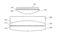
本実施形態の接眼光学系は偏光素子を含み、偏光を利用して光路を折り畳む光学系である。なお、本明細書において、偏光素子は、λ/4波長板、λ/2波長板等の波長板(位相差付与部材)や、反射型の偏光板、透過型の偏光板等の偏光板等を含む、光の偏光方向によって作用が替わる光学素子を指す。また、液晶表示素子のように偏光機能を内蔵したものも含む。本実施形態の接眼光学系の光路について右眼用接眼光学系で説明する。図2は、第1実施形態に係る接眼光学系の詳細を説明する図である。まず、図2のようにレンズ107の右眼用画像表示素子112側の平面に、右眼用画像表示素子112側から順に偏光板114とλ/4板115を形成し、レンズ105のレンズ106側の面にハーフミラー116を蒸着する。ハーフミラー116を蒸着する面が半透過反射面として作用し、接眼光学系の中で最も光学パワーが強い面としている。
The eyepiece optical system of this embodiment is an optical system that includes a polarizing element and uses polarized light to fold the optical path. In this specification, the polarizing element means a wavelength plate (retardation imparting member) such as a λ/4 wavelength plate and a λ/2 wavelength plate, a reflective polarizing plate, a polarizing plate such as a transmissive polarizing plate, and the like. Refers to an optical element whose action changes depending on the polarization direction of light, including It also includes a device with a built-in polarizing function such as a liquid crystal display device. The optical path of the eyepiece optical system of the present embodiment will be described with respect to the eyepiece optical system for the right eye. FIG. 2 is a diagram illustrating details of the eyepiece optical system according to the first embodiment. First, as shown in FIG. 2, a polarizing
また、レンズ105のレンズ104側の平面に右眼用画像表示素子112側から順にλ/4板117と反射偏光板のPBS(Polarizing Beam Splitter)118を形成する。このとき、λ/4板115の遅相軸と、λ/4板117の遅相軸とは直交する関係になっている。したがって、偏光板114が透過する偏光方向とλ/4板115の遅相軸が45°傾いているとき、偏光板114が透過する偏光方向とλ/4板117の遅相軸は-45°傾いている。また、偏光板114が透過する偏光方向とPBS118が透過する偏光方向は直交している。尚、ここで遅相軸が45°傾いている、或いは-45°傾いている、については、実質的に45°、或いは-45°傾いていれば良く、例えば、絶対値が40°以上50°以下、より好ましくは43°以上47°以下であれば構わない。また、傾きのプラスとマイナスは、プラスを時計回りの方向、マイナスを反時計回りの方向とする。また、後段に出てくる同様の45°の記載についても、同様の幅を持っていると解釈する。
Further, a λ/4
このような構成の場合に、右眼用画像表示素子112から出射した光は偏光板114を透過して直線偏光となり、λ/4板115を透過して円偏光となる。ハーフミラー116を透過してλ/4板117を透過して直線偏光になり、この直線偏光の偏光方向がPBS118で透過する偏光方向と直交しているため、PBS118で反射しλ/4板117を透過して円偏光となる。ハーフミラー116で反射してλ/4板117を透過して直線偏光になるが、この直線偏光の偏光方向は先ほどと異なり、PBS118で透過する偏光方向と一致するため、PBS118を透過して観察者の右眼102に導かれる。左眼用接眼光学系についても同様の光路である。
In such a configuration, the light emitted from the right-eye
本実施形態のように偏光を利用して光路を折り畳む光学系とすることで、薄型かつ接眼光学系の焦点距離を短くでき、広画角な画像観察を実現できる。 By adopting an optical system that uses polarized light to fold the optical path as in the present embodiment, it is possible to reduce the focal length of the eyepiece optical system and reduce the thickness of the eyepiece optical system, thereby realizing image observation with a wide angle of view.
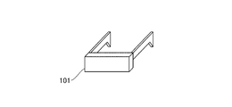
図3は、HMD101の外観図である。HMD101は頭部装着型の画像表示装置であるため、軽量であることが望ましい。そのため、接眼光学系を構成するレンズは硝子よりも比重の小さい樹脂で製作することが望ましく、本実施形態のレンズはすべて樹脂レンズとしている。
FIG. 3 is an external view of the HMD 101. FIG. Since the
しかし、樹脂レンズをモールド成形で製作した場合には、成形時の残留応力の影響で複屈折が生じる。本実施形態のように偏光を利用した光学系の場合には、レンズ内の複屈折により上記で説明した正規の光路の光利用効率が下がり、波長ごとの光利用効率の差も生じることから、観察画像の光量低下、光量ムラ、色ムラが発生してしまう。また、正規の光路においてPBS118で反射すべき光の中で、複屈折の影響によりPBS118を透過する光の割合が増えてしまい、図4のように表示素子からの光が直接観察者の眼に導かれるゴースト光が発生してしまう。そのため、接眼光学系を構成する樹脂レンズの複屈折は出来るだけ小さくする必要がある。
However, when a resin lens is manufactured by molding, birefringence occurs due to the influence of residual stress during molding. In the case of an optical system using polarized light as in this embodiment, the light utilization efficiency of the regular optical path described above decreases due to the birefringence in the lens, and a difference in light utilization efficiency occurs for each wavelength. A decrease in the amount of light in the observed image, unevenness in the amount of light, and unevenness in color occur. In addition, among the light that should be reflected by the
本実施形態では、樹脂レンズを成形する場合、成形ゲート付近には複屈折が大きくなる領域(歪み領域)が発生するため、成形ゲート付近の光路の見え方が悪化する。そこで、成形ゲートの位置を光学有効領域から遠ざけて、観察画像において目立ちにくい位置に配置することで、成形ゲート付近の複屈折による画質低下の影響を小さくする。なお、ここで、レンズの成形ゲートとは、モールド成形する際に、モールド(型)の内部に材料(樹脂や硝材)を流入させるためのゲート、或いはそのゲートが形成されたレンズの一部を指している。モールド成形している限りは全ての光学素子が持っているものであり、当業者が見れば、光学素子の成形ゲートがどこなのか(光学素子を成形する際のモールドのゲートがどこにあったのか)はすぐに分かる。具体的には、レンズの周辺部で他の部分よりも出っ張っている部分であったり、他の部分よりも粗さが大きい部分であったり、他の部分とは形状が違っていたり、色々なケースが考えられる。また、この成形ゲート(或いは成形ゲート跡)、或いはこの成形ゲート跡を切り落とした場合は成形ゲート跡から最も近い位置は、光学素子の中で最も複屈折量が多い位置(領域)である。従って、成形ゲート(跡)は、光学素子の中で最も複屈折量が多い部分(領域)と読み替えても構わない。 In this embodiment, when a resin lens is molded, a region (distorted region) in which birefringence increases occurs near the molding gate, so the appearance of the optical path near the molding gate deteriorates. Therefore, by moving the shaping gate away from the optically effective region and arranging it at a position that is not conspicuous in the observed image, the influence of the deterioration of the image quality due to the birefringence near the shaping gate is reduced. Here, the molding gate of the lens is a gate for allowing a material (resin or glass material) to flow into the interior of the mold during molding, or a part of the lens in which the gate is formed. pointing. As long as it is molded, all optical elements have it, and if a person skilled in the art sees it, where is the molding gate of the optical element (where was the gate of the mold when molding the optical element? ) is readily apparent. Specifically, there are parts that protrude from the periphery of the lens, parts that are rougher than other parts, parts that are different in shape from other parts, and so on. A case can be considered. In addition, the shaping gate (or the shaping gate trace), or if the shaping gate trace is cut off, the position closest to the shaping gate trace is the position (region) where the amount of birefringence is the largest in the optical element. Therefore, the shaping gate (mark) may be read as a portion (region) having the largest amount of birefringence in the optical element.
なお、レンズをモールド成形する際にゲート付近で発生する複屈折は、レンズの材料が樹脂である場合に特に顕著に大きくなるため、本実施形態では、樹脂レンズを例に説明するが、これに限られるものではない。ガラスレンズであっても複屈折が生じる場合があり、この課題は、レンズを含む全ての光学素子(モールド成形を行う光学素子)に共通であるため、本発明はモールド成形を行う光学素子に適用することが可能である。 Note that the birefringence that occurs near the gate when the lens is molded becomes particularly large when the lens is made of resin. It is not limited. Birefringence may occur even in glass lenses, and this problem is common to all optical elements including lenses (optical elements that are molded), so the present invention is applicable to optical elements that are molded. It is possible to
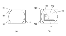
図5は、第1実施形態に係る右眼用接眼光学系のレンズ105の成形ゲート位置について説明する図である。図5(A)レンズ105の成形ゲート位置の一例を示す図である。成形ゲート121は、レンズ105の外周の一部に設けられ、光学有効領域(有効領域)119と成形ゲート121との間に非光学有効領域(非有効領域)120が設けられている。この非光学有効領域(非有効領域)120があることで、光学有効領域119と成形ゲート121の距離を離すことができ、成形ゲート121付近の複屈折が大きくても光学有効領域119に影響を与えにくくすることができる。
FIG. 5 is a diagram for explaining the shaping gate position of the
また、図5(B)に示すように、成形ゲート121は、光軸上の点に対して画像表示素子112の矩形の画像表示領域132の頂点の方向(以下、頂点方向と略す)に設けられる。つまり、右眼用接眼光学系に組み込まれる際に、レンズ105は、成形ゲート121またはその跡およびその近傍に生じた歪み領域が、光軸上の点に対して画像表示素子112の矩形の画像表示領域132の頂点方向に配置されるように組み込まれる。なお、ここで画像表示領域132の頂点とは、画像表示素子112が画像を表示することが可能であって、観察可能な領域の頂点のことである。本実施形態においては、光軸と垂直な断面において光軸上の点と成形ゲート121の中心とを結ぶ直線を直線130とする。光軸上の点と成形ゲート121に最も近い画像表示領域132の頂点とを結ぶ直線を直線131とする。直線130と直線131とがなす角度θ1は20°であり、成形ゲート121は観察画像の頂点方向に設けられている。
Further, as shown in FIG. 5B, the shaping
観察画像において頂点方向が最も画角が大きい方向であり、その方向で複屈折による画質低下が起こっても目立ちにくい。そのため、光軸と垂直な断面(平面)において光軸上の点と成形ゲート121の中心とを結ぶ直線130と、光軸上の点と成形ゲート121に最も近い画像表示領域132の頂点とを結ぶ直線131と、がほぼ同じ方向を向いていることが望ましい。具体的には、この直線130と直線131とがなす角度θ1(θA)の絶対値が30度以下、つまり|θA|≦30°を満足することが望ましい。更に望ましくは、|θA|≦7°を満足すると尚良い。ここで、角度θ1(θA)の絶対値が、30°を超えると成形ゲート付近の複屈折による画質低下が最大画角よりも内側の画角で発生して観察者が気付きやすくなってしまう。ここで、本実施例に記載したθ1の他に、角度θ2、θ3、θ4、θ6、θ7が、上述の角度θAに対応しており、上述の条件式を満足する。
In the observed image, the direction of the vertex is the direction with the largest angle of view, and even if deterioration of image quality due to birefringence occurs in that direction, it is not noticeable. Therefore, in a section (plane) perpendicular to the optical axis, a
成形ゲート付近の複屈折を小さくする方法として、成形ゲートの断面積を大きくすることが考えられる。レンズ105の成形ゲートの断面積Sは3mm×2mm=6mm2である。また、光学有効領域における成形ゲート付近の複屈折の影響を小さくするために、成形ゲート位置を光学有効領域から遠ざける方法が考えられる。光学有効領域119と成形ゲート121との最短距離Lは8mmである。そのため、レンズ105のL/S1/2は2.1となる。
As a method for reducing the birefringence near the shaping gate, it is conceivable to increase the cross-sectional area of the shaping gate. The cross-sectional area S of the shaping gate of the
本実施形態のように樹脂レンズのL/S1/2は1以上4以下であることが望ましい。この値が1よりも小さい場合には、成形ゲート位置と光学有効領域が近い、もしくは成形ゲートの断面積が大きく、前者の場合には成形ゲート付近の複屈折の影響が光学有効領域にも出てきてしまい画質が低下する。また後者の場合には、樹脂レンズが厚くなって接眼光学系が薄型化できずに重くなってしまったり、成形ゲートの幅が広くて複屈折の影響の範囲が広がってしまったりする。 As in this embodiment, L/S 1/2 of the resin lens is preferably 1 or more and 4 or less. If this value is smaller than 1, the shaping gate position and the optically effective region are close to each other, or the cross-sectional area of the shaping gate is large. The image quality deteriorates as a result. In the latter case, the resin lens is thick and the ocular optical system cannot be made thin and becomes heavy, and the wide width of the molding gate widens the range of influence of birefringence.
L/S1/2の値が4よりも大きい場合には、成形ゲート位置と光学有効領域が離れ過ぎ、もしくは成形ゲートの断面積が小さく、前者の場合には樹脂レンズの外形が大きくなり接眼光学系が大型化し重くなってしまう。また後者の場合には、成形ゲートの断面積が小さく成形ゲート付近の複屈折量が大きくなってしまう。 When the value of L/S 1/2 is larger than 4, the distance between the molding gate position and the optically effective area is too large, or the cross-sectional area of the molding gate is small. The optical system becomes large and heavy. In the latter case, the cross-sectional area of the shaping gate is small and the amount of birefringence in the vicinity of the shaping gate becomes large.
図5に示すようにレンズ105の成形ゲート121は観察者がHMD101を装着した状態で、観察者から見て左上に設けられている。上側にしている理由は、人間の視野は上側と下側を比較すると下側の方が広く下側を観察する機会が多いからである。そのため、複屈折による画質低下が発生する場合、下側よりも上側に発生した方が観察者は気付きにくい。そのため、成形ゲートは上側に設けることが望ましい。
As shown in FIG. 5, the
レンズ105以外の樹脂レンズについても、成形ゲートの位置をレンズ105と同様に配置することが望ましい。本実施形態のレンズ107、111のように比較的小さいレンズの場合には、ガラスレンズと樹脂レンズとの重量の差が小さいので、すべてを樹脂レンズとするのではなく、ガラスレンズと樹脂レンズを組み合わせても良い。その場合には、ガラスレンズの複屈折は非常に小さいため、高品位な画像観察が可能となる。
For resin lenses other than the
レンズ104、105、106やレンズ108、109、110は接合して一体のレンズとしても良い。接合レンズとすることで、レンズを保持する際に保持しやすくなる。本実施形態では偏光板114とλ/4板115の面積を小さくしてコスト低減するためにレンズ107にそれぞれ形成したが、偏光板とλ/4板への入射角を小さくして偏光特性を良好にするためにレンズ106の画像表示素子112側の平面に形成しても良い。また、不要なゴースト光を低減して観察画像のコントラストを高めるために、PBSと観察者の眼球との間に偏光板を配置しても良い。
The
PBS118はレンズ105の平面部に形成したが、曲面にしてレンズ104の眼側の面に形成しても良い。こうすることで、レンズ104とレンズ105を一体にすることができ、レンズ枚数を低減して薄型化、低コスト化が可能となる。また、偏光板114とλ/4板115はレンズ107に形成するのではなく、右眼用画像表示素子112との間に配置しても良い。
Although the
本実施形態では画像表示素子は有機ELとして無偏光の光が放射される画像表示素子としたが、液晶ディスプレイとして直線偏光の光が放射されるようにすることで、画像表示素子側の偏光板114が必要なくなり薄型化とコスト低減しても良い。 In this embodiment, the image display element is an organic EL image display element that emits non-polarized light. 114 may be eliminated and the thickness and cost may be reduced.
(第2実施形態)
図6の画像表示装置の接眼光学系を参照して第2実施形態に係る画像表示装置の構成を説明する。図6は、第2実施形態に係る画像表示装置の概略図である。図中、201はHMD、202は観察者の右眼、203は観察者の左眼である。レンズ204、レンズ205で右眼用接眼光学系を構成し、レンズ206、レンズ207で左眼用接眼光学系を構成している。208は右眼用画像表示素子、209は左眼用画像表示素子であり、有機ELディスプレイである。
(Second embodiment)
The configuration of the image display device according to the second embodiment will be described with reference to the eyepiece optical system of the image display device in FIG. FIG. 6 is a schematic diagram of an image display device according to the second embodiment. In the figure, 201 is the HMD, 202 is the observer's right eye, and 203 is the observer's left eye. The
右眼用接眼光学系は右眼用画像表示素子208に表示された原画像を拡大投影して観察者の右眼202に導き、左眼用接眼光学系は左眼用画像表示素子209に表示された原画像を拡大投影して観察者の左眼203に導く。右眼用接眼光学系と左眼用接眼光学系の水平表示画角は60°、垂直表示画角60°、対角表示画角78°であり、アイレリーフは18mmである。
The right-eye eyepiece optical system enlarges and projects the original image displayed on the right-eye
本実施形態の接眼光学系は第1実施形態と同様に偏光を利用して光路を折り畳む光学系であり、その光路について右眼用接眼光学系で説明する。まず、レンズ205と右眼用画像表示素子208との間に、右眼用画像表示素子208側から順に偏光板とλ/4板を形成し、レンズ204のレンズ205側の面にハーフミラーを蒸着する。ハーフミラーを蒸着する面が半透過反射面として作用し、接眼光学系の中で最も光学パワーが強い面としている。また、レンズ204の観察者の右眼202側の平面に右眼用画像表示素子208側から順にλ/4板と反射偏光板のPBSを形成する。このとき、レンズ205と右眼用画像表示素子208側のλ/4板の遅相軸と、観察者の右眼202側のλ/4板の遅相軸とは直交する関係になっている。したがって、レンズ205と右眼用画像表示素子208側との間の偏光板が透過する偏光方向とλ/4板の遅相軸が45°傾いているとき、レンズ204の観察者の右眼202側の平面のλ/4板の遅相軸は-45°傾いている。また、レンズ205と右眼用画像表示素子208側との間の偏光板が透過する偏光方向とPBSが透過する偏光方向は直交している。
The eyepiece optical system of this embodiment is an optical system that uses polarized light to fold the optical path, as in the first embodiment, and the optical path will be described in the eyepiece optical system for the right eye. First, between the
このような構成の場合に、右眼用画像表示素子208から出射した光は偏光板を透過して直線偏光となり、λ/4板を透過して円偏光となる。ハーフミラーを透過してλ/4板を透過して直線偏光になり、この直線偏光の偏光方向がPBSで透過する偏光方向と直交しているため、PBSで反射しλ/4板を透過して円偏光となる。ハーフミラーで反射してλ/4板を透過して直線偏光になるが、この直線偏光の偏光方向は先ほどと異なり、PBSで透過する偏光方向と一致するため、PBSを透過して観察者の右眼202に導かれる。左眼用接眼光学系についても同様の光路である。
In the case of such a configuration, the light emitted from the right-eye
本実施形態のように偏光を利用して光路を折り畳む光学系とすることで、薄型かつ接眼光学系の焦点距離を短くでき、広画角な画像観察を実現できる。HMD201は頭部装着型の画像表示装置であるため、軽量であることが望ましい。そのため、接眼光学系を構成するレンズは硝子よりも比重の小さい樹脂で製作することが望ましく、本実施形態のレンズはすべて樹脂レンズとしている。
By adopting an optical system that uses polarized light to fold the optical path as in the present embodiment, it is possible to reduce the focal length of the eyepiece optical system and reduce the thickness of the eyepiece optical system, thereby realizing image observation with a wide angle of view. Since the
図7は、第2実施形態に係る右眼用接眼光学系のレンズ204の成形ゲート位置について説明する図である。図7を参照して右眼用接眼光学系のレンズ204の成形ゲート位置について説明する。図7(A)は、レンズ204の成形ゲート位置の一例を示す図である。レンズ204の外周の一部に成形ゲート212が設けられており、光学有効領域210の周囲に非光学有効領域211があり、非光学有効領域211の外側に成形ゲート212が配置されている。非光学有効領域211があることで、光学有効領域210と成形ゲート212の距離を離すことができ、成形ゲート212付近の複屈折が大きくても光学有効領域210に影響を与えにくくすることができる。
FIG. 7 is a diagram for explaining the shaping gate position of the
また、図7(B)に示すように光軸と垂直な断面においてレンズ204の光軸上の点と成形ゲート212の中心とを結ぶ直線を直線220とする。レンズ204の光軸上の点と成形ゲート212に最も近い画像表示領域221の頂点とを結ぶ直線を直線222とする。直線220と直線222とがなす角度θ2の絶対値は5°であり、成形ゲート212は観察画像の頂点方向に設けられる。観察画像において頂点方向が最も画角が大きい方向であり、その方向で複屈折による画質低下が起こっても目立ちにくい。そのため、光軸と垂直な断面において光軸上の点から成形ゲート212の中心に向かう方向と、右眼用画像表示素子208の成形ゲート212に近い対角方向となす角の絶対値は30°以下であることが望ましい。更に望ましくは7°以下とするのが良い。
As shown in FIG. 7B, a
成形ゲート付近の複屈折を小さくする方法として、成形ゲートの断面積を大きくすることが考えられる。レンズ204の成形ゲートの断面積Sは5mm×1.6mm=8mm2である。また、光学有効領域における成形ゲート付近の複屈折の影響を小さくするために、成形ゲート位置を光学有効領域から遠ざける方法が考えられる。光学有効領域210と成形ゲート212との最短距離Lは3.5mmである。そのため、レンズ204のL/S1/2は1.2となる。
As a method for reducing the birefringence near the shaping gate, it is conceivable to increase the cross-sectional area of the shaping gate. The cross-sectional area S of the shaping gate of
次に、図8を参照して左眼用接眼光学系のレンズ206の成形ゲート位置について説明する。図8は、第2実施形態に係る左眼用接眼光学系のレンズ206の成形ゲート位置について説明する図である。図8(A)は、レンズ206の成形ゲート位置の一例を示す図である。レンズ206の外周の一部に成形ゲート215が設けられており、光学有効領域213の周囲に非光学有効領域214があり、非光学有効領域214の外側に成形ゲート215が配置されている。前述の通り、このようにすることで、成形ゲート215付近の複屈折は大きくても光学有効領域213に影響を与えにくくすることができる。
Next, the shaping gate position of the
また、図8(B)に示すように光軸と垂直な断面においてレンズ206の光軸上の点と成形ゲート215の中心とを結ぶ直線を直線223とする。レンズ206の光軸上の点と成形ゲート215に最も近い画像表示領域224の頂点とを結ぶ直線を直線225とする。直線223と直線225とがなす角度θ3の絶対値は5°であり、成形ゲート215は観察画像の頂点方向に設けられる。観察画像において頂点方向が最も画角が大きい方向であり、その方向で複屈折による画質低下が起こっても目立ちにくい。
As shown in FIG. 8B, a
レンズ206の成形ゲートの断面積Sは5mm×1.6mm=8mm2であり、光学有効領域213と成形ゲート215との最短距離Lは3.5mmである。そのため、レンズ206のL/S1/2は1.2となる。
The cross-sectional area S of the shaping gate of the
図7、図8に示すように本実施形態では左右のレンズの成形ゲート位置を左上として揃えている。これは、観察者がHMDを観察した際に左右で複屈折の影響が似た画像を観察した方が、両眼で融像した際に快適に観察できるからである。もしも、左右のレンズの成形ゲート位置が異なり、複屈折の影響による画質低下の発生する場所が左右で大きく異なる場合、両眼で融像した際に視野闘争が発生して快適に観察できない。また、左右それぞれの画質の悪い方の画像を認識してしまい、左上と右上の両方が画質低下したように観察される。 As shown in FIGS. 7 and 8, in this embodiment, the molding gate positions of the left and right lenses are aligned at the upper left. This is because when the observer observes the HMD, he/she can more comfortably observe images in which the effects of birefringence are similar between the left and right eyes when images are fused with both eyes. If the molding gate positions of the left and right lenses are different, and the locations where the image quality deteriorates due to the influence of birefringence are greatly different between the left and right lenses, binocular rivalry will occur when the images are fused, making it difficult to observe comfortably. In addition, the left and right images with lower image quality are recognized, and it is observed that both the upper left and upper right images have deteriorated image quality.
そのため、左右のレンズの成形ゲート位置は近い方が望ましい。本実施形態の光軸と垂直な断面においてレンズ204の光軸上の点と成形ゲート212の中心とを結ぶ直線220と、レンズ206の光軸上の点と成形ゲート215の中心とを結ぶ直線223と、の差の絶対値は10°である。換言すると、レンズ204の光軸上の点と、レンズ206の光軸上の点とを重ねた場合に、直線220と直線223とがなす角度φ1の絶対値は10°である。図8では、説明を簡単にするため、レンズ204の光軸上の点と成形ゲート212の中心とを結ぶ直線220を図示している。角度φ1はその絶対値が30°以下、つまり、|φ|≦30°を満足することが望ましく、更に好ましくは15°以下であると尚望ましい。このような条件を満足することで、左右のレンズの成形ゲート位置が近く、観察者がHMDを観察した際に左右で複屈折の影響が似た画像となり、両眼で融像した際に快適に観察できる。ここで、この実施例に記載した角度φ1と後述する角度φ2が、前述の角度φに対応しており、前述の条件式を満足する。
Therefore, it is desirable that the molding gate positions of the left and right lenses are close to each other. A
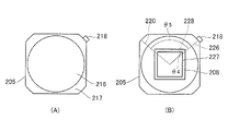
図9を参照して右眼用接眼光学系のレンズ205の成形ゲート位置について説明する。図6に示すように、レンズ205はレンズ204と同じ光が通るレンズ(両方とも右眼用)である。図9は、第2実施形態に係る右眼用接眼光学系のレンズ205の成形ゲート位置について説明する図である。図9(A)は、レンズ205の成形ゲート位置の一例を示す図である。レンズ205の外周の一部に成形ゲート218が設けられており、光学有効領域216の周囲に非光学有効領域217があり、非光学有効領域217の外側に成形ゲート218が配置されている。前述の通り、このようにすることで、成形ゲート218付近の複屈折は大きくても光学有効領域216に影響を与えにくくすることができる。
The shaping gate position of the
また、図9(B)に示すように光軸と垂直な断面においてレンズ205の光軸上の点と成形ゲート218の中心とを結ぶ直線を直線226とする。レンズ205の光軸上の点と成形ゲート218に最も近い画像表示領域227の頂点とを結ぶ直線を直線228とする。直線226と直線228とがなす角度θ4の絶対値は5°であり、成形ゲート218は観察画像の頂点方向に設けられる。観察画像において頂点方向が最も画角が大きい方向であり、その方向で複屈折による画質低下が起こっても目立ちにくい。
As shown in FIG. 9B, a
レンズ205の成形ゲート218の断面積Sは5mm×2mm=10mm2であり、光学有効領域216と成形ゲート218との最短距離Lは11mmである。そのため、レンズ205のL/S1/2は3.5となる。
The cross-sectional area S of the shaping
図7、図9に示すように本実施形態では右眼用接眼光学系を構成するレンズ204とレンズ205の成形ゲート位置を左右で離れた位置としている。これは、レンズ204のゲート付近の複屈折とレンズ205のゲート付近の複屈折が合算されないようにするためである。もしも、レンズ204とレンズ205の成形ゲート位置が近い場合には、2つのレンズのゲート付近の複屈折が合算されて画質低下が大きくなってしまう。また、左上と右上の画質の差が大きくなってしまうため、観察時に違和感が生じてしまう。
As shown in FIGS. 7 and 9, in this embodiment, the forming gate positions of the
本実施形態では、光軸と垂直な断面において右眼用接眼光学系の光軸上の点とレンズ204の成形ゲート212の中心とを結ぶ直線を直線220とする。右眼用接眼光学系の光軸上の点とレンズ205の成形ゲート218の中心とを結ぶ直線を直線226とする。直線220と直線226とがなす角度θ5(θB)の絶対値は100°である。図9では、説明を簡単にするため、右眼用接眼光学系の光軸上の点と成形ゲート212の中心とを結ぶ直線220を図示している。レンズ204とレンズ205のゲート位置を左右で離れた位置とすることで、それぞれのゲート付近の複屈折を合算されないようにして、画質低下を小さく抑えることができ、左上と右上の画質の差も小さくできる。
In this embodiment, a
そのため、直線220と、直線226とがなす角度θ5(θB)の絶対値は60°以上120°以下である、つまり60°≦|θB|≦120°を満足することが望ましい。更に望ましくは75°以上105°以下とするのが良い。この値が60°よりも小さい場合には、それぞれのレンズの成形ゲート位置が近く、成形ゲート付近の複屈折が合算されてしまい画質低下が大きくなる。尚、ここで、この角度θBに対応しているのは、前述のθ5である。また、120°よりも大きい場合には、どちらかのレンズの成形ゲート位置が対角方向の最大画角から離れてしまい、複屈折による画質低下が目立ってしまう。なお、ここでは、一例として、成形ゲート212を有する第1の樹脂レンズとしてのレンズ204と、外周の一部に成形ゲート218を有する第2の樹脂レンズとしてのレンズ205と、を含む右眼用接眼光学系を例に説明をした。第1の樹脂レンズと第2の樹脂レンズは、同じ光が通るレンズであればよく、両方とも右眼用または両方とも左眼用であれば良い。したがって、左眼用接眼光学系を構成するレンズ206とレンズ207の成形ゲート位置についても同様に、左右で離れた位置にするのが望ましい。
Therefore, it is desirable that the absolute value of the angle θ5 (θB) between the
図7、図8、図9に示すように本実施形態においても第1実施形態と同様に接眼光学系を構成しているレンズの成形ゲートは上側に設けている。上側にしている理由についても、第1実施形態と同様である。 As shown in FIGS. 7, 8, and 9, in this embodiment as well, the molding gates of the lenses forming the eyepiece optical system are provided on the upper side, as in the first embodiment. The reason why it is on the upper side is also the same as in the first embodiment.
なお、本実施形態においては、レンズ204、205やレンズ206、207は接合レンズであるが、非接合レンズとしても良い。また、不要なゴースト光を低減して観察画像のコントラストを高めるために、PBSの後に偏光板を配置しても良い。本実施形態では画像表示素子は有機ELとして無偏光の光が放射される画像表示素子としたが、液晶ディスプレイとして直線偏光の光が放射されるようにすることで、画像表示素子側の偏光板を配置せずにコスト低減と薄型化しても良い。
Although the
(第3実施形態)
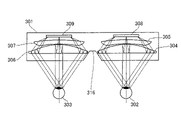
図10の画像表示装置の接眼光学系を参照して第3実施形態に係る画像表示装置の構成を説明する。図10は、第3実施形態に係る画像表示装置の概略図である。図中、301はHMD、302は観察者の右眼、303は観察者の左眼である。レンズ304、レンズ305で右眼用接眼光学系を構成し、レンズ306、レンズ307で左眼用接眼光学系を構成している。308は右眼用画像表示素子、309は左眼用画像表示素子であり、有機ELディスプレイである。
(Third embodiment)
The configuration of the image display device according to the third embodiment will be described with reference to the eyepiece optical system of the image display device in FIG. FIG. 10 is a schematic diagram of an image display device according to the third embodiment. In the figure, 301 is the HMD, 302 is the observer's right eye, and 303 is the observer's left eye. The
右眼用接眼光学系は右眼用画像表示素子308に表示された原画像を拡大投影して観察者の右眼302に導き、左眼用接眼光学系は左眼用画像表示素子309に表示された原画像を拡大投影して観察者の左眼303に導く。右眼用接眼光学系と左眼用接眼光学系の水平表示画角は65°、垂直表示画角65°、対角表示画角84°であり、アイレリーフは18mmである。
The right-eye eyepiece optical system enlarges and projects the original image displayed on the right-eye
本実施形態の接眼光学系は実施形態1、2と同様に偏光を利用して光路を折り畳む光学系であり、その光路について右眼用接眼光学系で説明する。まず、レンズ305と右眼用画像表示素子308との間に、右眼用画像表示素子308側から順に偏光板とλ/4板を形成し、レンズ304のレンズ305側の面にハーフミラーを蒸着する。ハーフミラーを蒸着する面が半透過反射面として作用し、接眼光学系の中で最も光学パワーが強い面としている。また、レンズ304の観察者の右眼302側の平面に右眼用画像表示素子308側から順にλ/4板と反射偏光板のPBSを形成する。このとき、右眼用画像表示素子308側のλ/4板の遅相軸と、観察者の右眼302側のλ/4板の遅相軸とは直交する関係になっている。したがって、レンズ305と右眼用画像表示素子308側との間の偏光板が透過する偏光方向とλ/4板の遅相軸が45°傾いているとき、レンズ304の観察者の右眼302側の平面のλ/4板の遅相軸は-45°傾いている。また、レンズ305と右眼用画像表示素子308側との間の偏光板が透過する偏光方向とPBSが透過する偏光方向は直交している。
The eyepiece optical system of the present embodiment is an optical system that uses polarized light to fold the optical path as in the first and second embodiments, and the optical path will be described in the eyepiece optical system for the right eye. First, between the
このような構成の場合に、右眼用画像表示素子308から出射した光は偏光板を透過して直線偏光となり、λ/4板を透過して円偏光となる。ハーフミラーを透過してλ/4板を透過して直線偏光になり、この直線偏光の偏光方向がPBSで透過する偏光方向と直交しているため、PBSで反射しλ/4板を透過して円偏光となる。ハーフミラーで反射してλ/4板を透過して直線偏光になるが、この直線偏光の偏光方向は先ほどと異なり、PBSで透過する偏光方向と一致するため、PBSを透過して観察者の右眼302に導かれる。左眼用接眼光学系についても同様の光路である。
In such a configuration, the light emitted from the right-eye
本実施形態のように偏光を利用して光路を折り畳む光学系とすることで、薄型かつ接眼光学系の焦点距離を短くでき、広画角な画像観察を実現できる。HMDは頭部装着型の画像表示装置であるため、軽量であることが望ましい。そのため、接眼光学系を構成するレンズは硝子よりも比重の小さい樹脂で製作することが望ましく、本実施形態のレンズはすべて樹脂レンズとしている。 By adopting an optical system that uses polarized light to fold the optical path as in the present embodiment, it is possible to reduce the focal length of the eyepiece optical system and reduce the thickness of the eyepiece optical system, thereby realizing image observation with a wide angle of view. Since the HMD is a head-mounted image display device, it is desirable that it be lightweight. Therefore, it is desirable that the lenses constituting the eyepiece optical system are made of resin whose specific gravity is smaller than that of glass, and the lenses in this embodiment are all resin lenses.
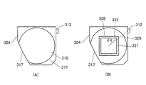
図11は、第3実施形態に係る右眼用接眼光学系のレンズ304の成形ゲート位置について説明する図である。図11を参照して右眼用接眼光学系のレンズ304の成形ゲート位置について説明する。図11(A)は、レンズ304の成形ゲート位置の一例を示す図である。レンズ304の外周の一部に成形ゲート312が設けられており、光学有効領域310の周囲に非光学有効領域311があり、非光学有効領域311の外側に成形ゲート312が配置されている。非光学有効領域311があることで、光学有効領域310と成形ゲート312の距離を離すことができ、成形ゲート312付近の複屈折が大きくても光学有効領域310に影響を与えにくくすることができる。
FIG. 11 is a diagram illustrating the shaping gate position of the
また、図11(B)に示すように光軸と垂直な断面においてレンズ304の光軸上の点と成形ゲート312の中心とを結ぶ直線を直線320とする。レンズ304の光軸上の点と成形ゲート312に最も近い画像表示領域321の頂点とを結ぶ直線を直線322とする。直線320と直線322とがなす角度θ6の絶対値は10°であり、成形ゲート312は観察画像の頂点方向に設けられる。観察画像において頂点方向が最も画角が大きい方向であり、その方向で複屈折による画質低下が起こっても目立ちにくい。そのため、直線320と直線322とがなす角度θ6の絶対値は30°以下であることが望ましい。更に望ましくは15°以下とするのが良い。
Also, as shown in FIG. 11B, a
成形ゲート付近の複屈折を小さくする方法として、成形ゲートの断面積を大きくすることが考えられる。レンズ304の成形ゲートの断面積Sは4mm×2mm=8mm2である。また、光学有効領域における成形ゲート付近の複屈折の影響を小さくするために、成形ゲート位置を光学有効領域から遠ざける方法が考えられる。光学有効領域310と成形ゲート312との最短距離Lは5mmである。そのため、レンズ304のL/S1/2は1.8となる。
As a method for reducing the birefringence near the shaping gate, it is conceivable to increase the cross-sectional area of the shaping gate. The cross-sectional area S of the shaping gate of
次に図12を参照して左眼用接眼光学系のレンズ306の成形ゲート位置について説明する。図12は、第3実施形態に係る左眼用接眼光学系のレンズ306の成形ゲート位置について説明する図である。図12(A)は、レンズ306の成形ゲート位置の一例を示す図である。レンズ306の外周の一部に成形ゲート315が設けられており、光学有効領域313の周囲に非光学有効領域314があり、非光学有効領域314の外側に成形ゲート315が配置されている。非光学有効領域314があることで、光学有効領域313と成形ゲート314の距離を離すことができ、成形ゲート315付近の複屈折は大きくても光学有効領域313に影響を与えにくくすることができる。
Next, the shaping gate position of the
また、図12(B)に示すように光軸と垂直な断面においてレンズ306の光軸上の点と成形ゲート315の中心とを結ぶ直線を直線323とする。レンズ306の光軸上の点と成形ゲート315に最も近い画像表示領域324の頂点とを結ぶ直線を直線325とする。直線323と直線325とがなす角度θ7の絶対値は10°であり、成形ゲート315は観察画像の頂点方向に設けられる。観察画像において頂点方向が最も画角が大きい方向であり、その方向で複屈折による画質低下が起こっても目立ちにくい。
Further, as shown in FIG. 12B, a straight line 323 connects a point on the optical axis of the
レンズ306の成形ゲートの断面積Sは4mm×2mm=8mm2であり、光学有効領域313と成形ゲート315との最短距離Lは5mmである。そのため、レンズ306のL/S1/2は1.8となる。
The cross-sectional area S of the shaping gate of
図11、図12に示すように本実施形態ではレンズ304とレンズ306の成形ゲート位置を右上として揃えている。これは、観察者がHMDを観察した際に左右で複屈折の影響が似た画像を観察した方が、両眼で融像した際に快適に観察できるからである。もしも、左右のレンズの成形ゲート位置が異なり、複屈折の影響による画質低下の発生する場所が左右で大きく異なる場合、両眼で融像した際に視野闘争が発生して快適に観察できない。また、左右それぞれの画質の悪い方の画像を認識してしまい、左上と右上の両方が画質低下したように観察される。
As shown in FIGS. 11 and 12, in this embodiment, the molding gate positions of the
そのため、左右のレンズの成形ゲート位置は近い方が望ましい。本実施形態の光軸と垂直な断面においてレンズ304の光軸上の点と成形ゲート312の中心とを結ぶ直線320と、レンズ306の光軸上の点と成形ゲート315の中心とを結ぶ直線323と、の差の絶対値は0°である。換言すると、レンズ304の光軸上の点と、レンズ306の光軸上の点とを重ねた場合に、直線320と直線323とがなす角度φ2の絶対値は0°である。
図12では、説明を簡単にするため、レンズ304の光軸上の点と成形ゲート312の中心とを結ぶ直線320を図示している。本図では、直線320と直線323とがなす角度φ2は0°であるため、直線320と直線323とは同一直線となっている。この数値は30°以下が望ましく、このようにすることで、左右のレンズの成形ゲート位置が近く、観察者がHMDを観察した際に左右で複屈折の影響が似た画像となり、両眼で融像した際に快適に観察できる。更に望ましくは15°以下とするのが良い。
Therefore, it is desirable that the molding gate positions of the left and right lenses are close to each other. A
In FIG. 12, a
図10に示すようにHMD301は観察者が頭に装着した際に観察者の鼻がぶつからないように鼻逃げ部316を有している。鼻逃げ部とは、右眼用のレンズの左下、左眼用レンズの右下に設けられた、使用者の鼻との干渉と避けるためにレンズ端面を斜めにした(切欠きを設けた、或いは面取りした)形状(鼻逃げ形状)のことである。具体的には、図11に示すように、右眼用のレンズの左下側の端部が、左から右に向かうに連れて下に下がるような面形状にして、第1鼻逃げ部317を設けている。同様に、図12に示すように左眼用のレンズの右下側の端部が、右から左に向かうに連れて下に下がるような面形状にして第2鼻逃げ部318を設けている。この第1鼻逃げ部317および第2鼻逃げ部318は、レンズの他の角部と比べて大きく面取りされている(えぐれている)構成となっている。別の言い方をすれば、レンズの光軸からレンズの対角方向の4つの角部までの距離を比べると、第1鼻逃げ部317または第2鼻逃げ部318に最も近い角部までの距離が他の3つよりも短い(好ましくは他の3つの距離のうち最も長い距離の0.9倍(更に望ましくは0.8倍)より短い)。ここでの対角方向とは、画像表示素子(矩形の画像表示領域)の対角方向のことである。
As shown in FIG. 10, the
接眼光学系を構成するレンズに鼻逃げ形状がある場合、レンズ304とレンズ306のように左右のレンズの形状は同じではなく左右対称となる。そのため、モールド成形でレンズを製作する場合には、1つのモールドで左右のレンズを同時に成形することが望ましい。そうすることで、左右それぞれの型を製作する場合に比べて、型製作コストを削減し、左右のレンズを成形する時間を短くすることができる。
If the lenses constituting the eyepiece optical system have a nose relief shape, the shapes of the left and right lenses are not the same as in the
図13は、左右のレンズのモールド成形について説明する図である。左右のレンズを1つのモールドで成形する場合、通常は図13(B)に示すように成形ランナー326を配置するのが一般的である。しかし、本実施形態のように左右のレンズの成形ゲート位置を揃える場合には図13(A)に示すように成形ランナーを配置するのが良い。このように成形ランナーを配置して左右のレンズを成形し、成形ゲート位置がそれぞれの接眼光学系の光軸上の点に対する画像表示領域の頂点の方向と一致するように、接眼光学系を組み立てる。これにより、成形ゲート付近の複屈折影響が少ない接眼光学系を製造することができる。
13A and 13B are diagrams for explaining the molding of left and right lenses. When molding left and right lenses with one mold, it is common to arrange
レンズ305とレンズ307の成形ゲート位置については、レンズ304とレンズ306の成形ゲート位置と離れた左上として揃えることが望ましく、鼻逃げ形状があることを考慮して1つのモールドで成形することが望ましい。また、レンズ304の成形ゲート位置とレンズ305の成形ゲート位置、及び、レンズ306とレンズ307の成形ゲート位置は離れて配置することが望ましい。
The molding gate positions of the
図11、図12のように接眼光学系を構成しているレンズの成形ゲートは上側に設けている。上側にしている理由は、人間の視野は上側と下側を比較すると下側の方が広く下側を観察する機会が多いからである。そのため、複屈折による画質低下が発生する場合、下側よりも上側に発生した方が観察者は気付きにくい。そのため、成形ゲートは上側に設けることが望ましい。 As shown in FIGS. 11 and 12, the molding gate of the lens constituting the eyepiece optical system is provided on the upper side. The reason for the upper side is that the human visual field is wider in the lower side than in the lower side, and there are many opportunities to observe the lower side. Therefore, when image quality deterioration due to birefringence occurs, it is harder for the observer to notice it when it occurs on the upper side than on the lower side. Therefore, it is desirable to provide the shaping gate on the upper side.
図14は、レンズの鼻逃げ部の加工について説明する図である。本実施形態のようにレンズに鼻逃げ形状を設ける場合、例えば、図14(A)に示すように、まず鼻逃げ形状が無い状態でレンズを成形する。モールドの成形ランナー326からモールドに材料を流し込むことによって鼻逃げ形状が無い状態のレンズが成形される。その後、、鼻逃げ部を追加工で製作する方法でも良い。その場合、成形ゲートを除去するように鼻逃げ部を加工しても良い。すなわち、成形ゲートと歪み領域の一部とを除去して鼻逃げ部を形成する。鼻逃げ部に対応する位置に成形ゲートを配置することで、成形ゲート付近の複屈折が大きい領域を追加工で無くすことができる。これにより、成形ゲート付近の複屈折の影響を低減することが可能となる。
14A and 14B are diagrams illustrating processing of the nose relief portion of the lens. In the case of providing the nose relief shape to the lens as in this embodiment, for example, as shown in FIG. 14A, the lens is molded without the nose relief shape. A lens without the nose relief shape is molded by pouring the material into the mold from the
なお、不要なゴースト光を低減して観察画像のコントラストを高めるために、PBSの後に偏光板を配置しても良い。また、本実施形態では画像表示素子は有機ELとして無偏光の光が放射される画像表示素子としたが、液晶ディスプレイとして直線偏光の光が放射されるようにすることで、画像表示素子側の偏光板を配置せずにコスト低減と薄型化しても良い。 A polarizing plate may be placed after the PBS in order to reduce unnecessary ghost light and increase the contrast of the observed image. In the present embodiment, the image display element is an organic EL image display element that emits non-polarized light. The cost and thickness may be reduced without arranging the polarizing plate.
(その他の実施形態)
以上、本発明の実施の形態を説明してきたが、本発明はこれらの実施の形態に限定されず、その要旨の範囲内において様々な変更が可能である。
(Other embodiments)
Although the embodiments of the present invention have been described above, the present invention is not limited to these embodiments, and various modifications are possible within the scope of the gist thereof.
101、201、301 HMD
102、202、302 観察者の右眼
103、203、303 観察者の左眼
104、105、106、107、204、205、304、305 右眼用接眼光学系を構成するレンズ
108、109、110、111、206、207、306、307 左眼用接眼光学系を構成するレンズ
112、208、308 右眼用画像表示素子
113、209、309 左眼用画像表示素子
132、221、224、227、321、324 画像表示領域
121、212、215、218、312、315 成形ゲート
101, 201, 301 HMDs
102, 202, 302 Observer's
Claims (10)
前記接眼光学系は、偏光素子と、外周の一部に成形ゲート跡が設けられた光学素子とを含み、
前記接眼光学系の光軸に垂直な断面における前記光学素子の外形は矩形であり、
前記画像表示素子及び前記光学素子を前記光軸方向から見たときの、前記成形ゲート跡に最も近い前記画像表示領域の頂点と前記光軸とを結ぶ直線と、前記成形ゲート跡の中心と前記光軸とを結ぶ直線とのなす角をθAとするとき、
|θA|≦20°
なる条件式を満足することを特徴とする画像表示装置。 An image display device having an image display element and an eyepiece optical system for guiding light from a rectangular image display area of the image display element to an observer,
The eyepiece optical system includes a polarizing element and an optical element provided with a molding gate trace on a part of the outer periphery,
The outer shape of the optical element in a cross section perpendicular to the optical axis of the eyepiece optical system is rectangular,
A straight line connecting the vertex of the image display region closest to the shaping gate trace and the optical axis when the image display device and the optical device are viewed from the optical axis direction , and the center of the shaping gate trace. When the angle formed by the straight line connecting the optical axis is θA,
|θA|≦ 20 °
An image display device characterized by satisfying the following conditional expression:
1≦L/S 1/2 ≦4
なる条件式を満足することを特徴とする請求項1又は2に記載の画像表示装置。 When the cross-sectional area of the shaping gate trace is S, and the shortest distance between the shaping gate trace and the optically effective region of the optical element is L,
1≦L/S 1/2 ≦4
3. The image display device according to claim 1, wherein the following conditional expression is satisfied.
前記第1の光学素子には前記成形ゲート跡としての第1の成形ゲート跡が設けられ、
前記第2の光学素子には前記成形ゲート跡としての第2の成形ゲート跡が設けられ、
前記第1及び第2の光学素子を前記光軸方向から見たときの、前記光軸と前記第1の成形ゲート跡の中心とを結ぶ直線と、前記光軸と前記第2の成形ゲート跡の中心とを結ぶ直線とのなす角をθBとするとき、
60°≦|θB|≦120°
なる条件式を満足することを特徴とする請求項1から4のいずれか一項に記載の画像表示装置。 The eyepiece optical system includes first and second optical elements as the optical elements,
The first optical element is provided with a first shaping gate trace as the shaping gate trace,
The second optical element is provided with a second shaping gate trace as the shaping gate trace,
A straight line connecting the optical axis and the center of the first shaping gate trace, and the optical axis and the second shaping gate trace when the first and second optical elements are viewed from the optical axis direction. Let θB be the angle between the straight line connecting the center of
60°≦|θB|≦120°
5. The image display device according to claim 1, wherein the following conditional expression is satisfied.
前記右眼用の接眼光学系は、前記光学素子としての右眼用の光学素子を含み、
前記左眼用の接眼光学系は、前記光学素子としての左眼用の光学素子を含み、
前記右眼用の光学素子及び前記左眼用の光学素子を前記右眼用の接眼光学系の光軸方向から見たときの、前記右眼用の接眼光学系の光軸と前記右眼用の光学素子の成形ゲート跡の中心とを結ぶ直線と、前記左眼用の接眼光学系の光軸と前記左眼用の光学素子の成形ゲート跡の中心とを結ぶ直線とのなす角をφとするとき、
|φ|≦30°
なる条件式を満足することを特徴とする請求項1から5のいずれか一項に記載の画像表示装置。 an image display element for the right eye and an image display element for the left eye as the image display elements, and an eyepiece optical system for the right eye and an eyepiece optical system for the left eye as the eyepiece optical system,
The eyepiece optical system for the right eye includes an optical element for the right eye as the optical element,
The eyepiece optical system for the left eye includes an optical element for the left eye as the optical element,
The optical axis of the eyepiece optical system for the right eye and the optical element for the right eye when the optical element for the right eye and the optical element for the left eye are viewed from the optical axis direction of the eyepiece optical system for the right eye. and the straight line connecting the optical axis of the eyepiece optical system for the left eye and the center of the shaping gate trace of the optical element for the left eye. When
|φ|≦30°
6. The image display device according to any one of claims 1 to 5, wherein the following conditional expression is satisfied.
前記反射偏光板は、第1の直線偏光を反射し、かつ偏光方向が該第1の直線偏光と直交する第2の直線偏光を透過させることを特徴とする請求項1から6のいずれか一項に記載の画像表示装置。 The eyepiece optical system includes a first λ/4 plate, a transflective surface, a second λ/4 plate, and a reflective polarizing plate, which are arranged in order from the image display device side to the observer side. ,
7. The reflective polarizing plate according to any one of claims 1 to 6, wherein the reflective polarizing plate reflects the first linearly polarized light and transmits the second linearly polarized light whose polarization direction is orthogonal to the first linearly polarized light. The image display device according to the item.
前記第2のλ/4板の遅相軸と前記第1の直線偏光の偏光方向とのなす角が-45°であることを特徴とする請求項7に記載の画像表示装置。 The angle formed by the slow axis of the first λ/4 plate and the polarization direction of the first linearly polarized light is 45°,
8. The image display device according to claim 7, wherein the angle formed by the slow axis of the second λ/4 plate and the polarization direction of the first linearly polarized light is -45°.
Priority Applications (2)
| Application Number | Priority Date | Filing Date | Title |
|---|---|---|---|
| JP2018215326A JP7183003B2 (en) | 2018-11-16 | 2018-11-16 | Image display device, eyepiece optical system, and eyepiece optical system manufacturing method |
| US16/678,279 US11112562B2 (en) | 2018-11-16 | 2019-11-08 | Image display device, ocular optical system, and method of manufacturing ocular optical system |
Applications Claiming Priority (1)
| Application Number | Priority Date | Filing Date | Title |
|---|---|---|---|
| JP2018215326A JP7183003B2 (en) | 2018-11-16 | 2018-11-16 | Image display device, eyepiece optical system, and eyepiece optical system manufacturing method |
Publications (3)
| Publication Number | Publication Date |
|---|---|
| JP2020085956A JP2020085956A (en) | 2020-06-04 |
| JP2020085956A5 JP2020085956A5 (en) | 2021-12-23 |
| JP7183003B2 true JP7183003B2 (en) | 2022-12-05 |
Family
ID=70727062
Family Applications (1)
| Application Number | Title | Priority Date | Filing Date |
|---|---|---|---|
| JP2018215326A Active JP7183003B2 (en) | 2018-11-16 | 2018-11-16 | Image display device, eyepiece optical system, and eyepiece optical system manufacturing method |
Country Status (2)
| Country | Link |
|---|---|
| US (1) | US11112562B2 (en) |
| JP (1) | JP7183003B2 (en) |
Families Citing this family (10)
| Publication number | Priority date | Publication date | Assignee | Title |
|---|---|---|---|---|
| JP7207986B2 (en) | 2018-12-14 | 2023-01-18 | キヤノン株式会社 | Image display device and eyepiece optical system |
| CN110161696B (en) * | 2019-06-03 | 2021-02-05 | 歌尔光学科技有限公司 | Compensation lens group and virtual reality device having the same |
| JP7358258B2 (en) | 2020-01-28 | 2023-10-10 | キヤノン株式会社 | Image observation device |
| JP7414561B2 (en) | 2020-01-31 | 2024-01-16 | キヤノン株式会社 | Image observation device |
| JP7486964B2 (en) | 2020-01-31 | 2024-05-20 | キヤノン株式会社 | Image Observation Device |
| JP7566648B2 (en) * | 2021-01-29 | 2024-10-15 | キヤノン株式会社 | Optical system and image display device |
| TWI769815B (en) * | 2021-02-03 | 2022-07-01 | 大立光電股份有限公司 | Plastic light-folding element, imaging lens assembly module and electronic device |
| JP7731752B2 (en) * | 2021-09-30 | 2025-09-01 | キヤノン株式会社 | Eyepiece optical system and image display device |
| CN116338959A (en) | 2023-01-20 | 2023-06-27 | 诚瑞光学(常州)股份有限公司 | Optical system |
| CN117492312A (en) * | 2023-06-15 | 2024-02-02 | 武汉华星光电技术有限公司 | display device |
Citations (6)
| Publication number | Priority date | Publication date | Assignee | Title |
|---|---|---|---|---|
| JP2001356295A (en) | 2000-06-13 | 2001-12-26 | Minolta Co Ltd | Eyepiece optical system |
| JP2003021771A (en) | 2001-07-10 | 2003-01-24 | Pioneer Electronic Corp | Optical lens device and its manufacturing method |
| JP2005285177A (en) | 2004-03-29 | 2005-10-13 | Konica Minolta Opto Inc | Optical element and optical pickup apparatus including the optical element |
| JP2018010031A (en) | 2016-07-11 | 2018-01-18 | キヤノン株式会社 | Observation device |
| US20180101020A1 (en) | 2016-10-12 | 2018-04-12 | Oculus Vr, Llc | Head mounted display including pancake lens block |
| WO2018156941A1 (en) | 2017-02-23 | 2018-08-30 | Google Llc | Compact eye tracking using folded display optics |
Family Cites Families (5)
| Publication number | Priority date | Publication date | Assignee | Title |
|---|---|---|---|---|
| JPH0540203A (en) * | 1991-07-09 | 1993-02-19 | Asahi Optical Co Ltd | Resin molded optical element |
| JP3645698B2 (en) | 1997-11-17 | 2005-05-11 | オリンパス株式会社 | Optical prism, lens frame and optical assembly |
| US20070222092A1 (en) * | 2004-03-31 | 2007-09-27 | Masahiko Hayashi | Mold for Injection Molding Light Guide Plate and Process for Producing Light Guide Plate Using the Mold |
| JP5364965B2 (en) * | 2005-07-26 | 2013-12-11 | コニカミノルタ株式会社 | Imaging optical system, imaging lens device, and digital device |
| KR102706133B1 (en) * | 2019-02-28 | 2024-09-12 | 삼성디스플레이 주식회사 | Augmented reality providing device |
-
2018
- 2018-11-16 JP JP2018215326A patent/JP7183003B2/en active Active
-
2019
- 2019-11-08 US US16/678,279 patent/US11112562B2/en active Active
Patent Citations (6)
| Publication number | Priority date | Publication date | Assignee | Title |
|---|---|---|---|---|
| JP2001356295A (en) | 2000-06-13 | 2001-12-26 | Minolta Co Ltd | Eyepiece optical system |
| JP2003021771A (en) | 2001-07-10 | 2003-01-24 | Pioneer Electronic Corp | Optical lens device and its manufacturing method |
| JP2005285177A (en) | 2004-03-29 | 2005-10-13 | Konica Minolta Opto Inc | Optical element and optical pickup apparatus including the optical element |
| JP2018010031A (en) | 2016-07-11 | 2018-01-18 | キヤノン株式会社 | Observation device |
| US20180101020A1 (en) | 2016-10-12 | 2018-04-12 | Oculus Vr, Llc | Head mounted display including pancake lens block |
| WO2018156941A1 (en) | 2017-02-23 | 2018-08-30 | Google Llc | Compact eye tracking using folded display optics |
Also Published As
| Publication number | Publication date |
|---|---|
| US11112562B2 (en) | 2021-09-07 |
| US20200158953A1 (en) | 2020-05-21 |
| JP2020085956A (en) | 2020-06-04 |
Similar Documents
| Publication | Publication Date | Title |
|---|---|---|
| JP7183003B2 (en) | Image display device, eyepiece optical system, and eyepiece optical system manufacturing method | |
| JP7207986B2 (en) | Image display device and eyepiece optical system | |
| CN206479716U (en) | A kind of equipment and head-mounted display for being used together with head-mounted display | |
| US9465217B2 (en) | Virtual image display apparatus | |
| KR102618809B1 (en) | Imaging optical unit and display device including such imaging optical unit | |
| KR101421199B1 (en) | Lens system for head mounted display | |
| JP2017514168A (en) | Near eye display system with pellicle as combiner | |
| JP2018528446A (en) | Addition of prescription correction to eyepiece for see-through head wearable display | |
| JP6637881B2 (en) | A spectacle lens for a display device that generates an image and that can be mounted on the user's head, and a display device including the spectacle lens | |
| JP2019053152A (en) | Virtual image display device | |
| JP7414561B2 (en) | Image observation device | |
| JP2020020858A (en) | Virtual image display | |
| KR102353457B1 (en) | Eyeglass lens for a display device, which display device can be placed on the head of a user and produces an image | |
| CN109507803B (en) | Virtual image display device | |
| CN109073896A (en) | Eyeglass and data goggles for image formation optical unit | |
| US11640060B2 (en) | Head-mounted display | |
| CN115552295B (en) | Eyebox steering and field of view expansion using beam steering elements | |
| JP7438811B2 (en) | Optical system and image display device | |
| KR101362873B1 (en) | Lens system for head mounted display | |
| JP2021124540A (en) | Image display device | |
| JP7486964B2 (en) | Image Observation Device | |
| JP6613729B2 (en) | Light guide device and virtual image display device | |
| JP2019179083A (en) | Image display device | |
| JP2021124537A (en) | Image observation device | |
| JP7830152B2 (en) | Eyepiece optical system and image display device having the same |
Legal Events
| Date | Code | Title | Description |
|---|---|---|---|
| A521 | Request for written amendment filed |
Free format text: JAPANESE INTERMEDIATE CODE: A523 Effective date: 20211110 |
|
| A621 | Written request for application examination |
Free format text: JAPANESE INTERMEDIATE CODE: A621 Effective date: 20211110 |
|
| A131 | Notification of reasons for refusal |
Free format text: JAPANESE INTERMEDIATE CODE: A131 Effective date: 20220809 |
|
| A977 | Report on retrieval |
Free format text: JAPANESE INTERMEDIATE CODE: A971007 Effective date: 20220810 |
|
| A521 | Request for written amendment filed |
Free format text: JAPANESE INTERMEDIATE CODE: A523 Effective date: 20221011 |
|
| TRDD | Decision of grant or rejection written | ||
| A01 | Written decision to grant a patent or to grant a registration (utility model) |
Free format text: JAPANESE INTERMEDIATE CODE: A01 Effective date: 20221025 |
|
| A61 | First payment of annual fees (during grant procedure) |
Free format text: JAPANESE INTERMEDIATE CODE: A61 Effective date: 20221122 |
|
| R151 | Written notification of patent or utility model registration |
Ref document number: 7183003 Country of ref document: JP Free format text: JAPANESE INTERMEDIATE CODE: R151 |