JP7181908B2 - model parts - Google Patents
model parts Download PDFInfo
- Publication number
- JP7181908B2 JP7181908B2 JP2020072916A JP2020072916A JP7181908B2 JP 7181908 B2 JP7181908 B2 JP 7181908B2 JP 2020072916 A JP2020072916 A JP 2020072916A JP 2020072916 A JP2020072916 A JP 2020072916A JP 7181908 B2 JP7181908 B2 JP 7181908B2
- Authority
- JP
- Japan
- Prior art keywords
- layer
- region
- model component
- model
- texturing
- Prior art date
- Legal status (The legal status is an assumption and is not a legal conclusion. Google has not performed a legal analysis and makes no representation as to the accuracy of the status listed.)
- Active
Links
Images


Classifications
-
- B—PERFORMING OPERATIONS; TRANSPORTING
- B29—WORKING OF PLASTICS; WORKING OF SUBSTANCES IN A PLASTIC STATE IN GENERAL
- B29C—SHAPING OR JOINING OF PLASTICS; SHAPING OF MATERIAL IN A PLASTIC STATE, NOT OTHERWISE PROVIDED FOR; AFTER-TREATMENT OF THE SHAPED PRODUCTS, e.g. REPAIRING
- B29C33/00—Moulds or cores; Details thereof or accessories therefor
- B29C33/42—Moulds or cores; Details thereof or accessories therefor characterised by the shape of the moulding surface, e.g. ribs or grooves
- B29C33/424—Moulding surfaces provided with means for marking or patterning
-
- A—HUMAN NECESSITIES
- A63—SPORTS; GAMES; AMUSEMENTS
- A63H—TOYS, e.g. TOPS, DOLLS, HOOPS OR BUILDING BLOCKS
- A63H9/00—Special methods or compositions for the manufacture of dolls, toy animals, toy figures, or parts thereof
-
- B—PERFORMING OPERATIONS; TRANSPORTING
- B29—WORKING OF PLASTICS; WORKING OF SUBSTANCES IN A PLASTIC STATE IN GENERAL
- B29C—SHAPING OR JOINING OF PLASTICS; SHAPING OF MATERIAL IN A PLASTIC STATE, NOT OTHERWISE PROVIDED FOR; AFTER-TREATMENT OF THE SHAPED PRODUCTS, e.g. REPAIRING
- B29C33/00—Moulds or cores; Details thereof or accessories therefor
- B29C2033/0005—Moulds or cores; Details thereof or accessories therefor with transparent parts, e.g. permitting visual inspection of the interior of the cavity
Landscapes
- Engineering & Computer Science (AREA)
- Mechanical Engineering (AREA)
- Laminated Bodies (AREA)
- Toys (AREA)
Description
本発明は、模型部品に関する。 The present invention relates to model parts.
いわゆるプラモデル(登録商標)と呼ばれるような組み立て模型の部品(パーツとも言う)、例えば、パーツに模様を施すために複数パーツを組み合わせて模様を構成し、模様に対応するシールを貼付する、或いは、パーツへの模様の塗装が行われている(特許文献1を参照)。 Parts (also referred to as parts) of an assembly model called a so-called plastic model (registered trademark), for example, a pattern is formed by combining a plurality of parts in order to apply a pattern to the part, and a sticker corresponding to the pattern is attached, or Parts are painted with patterns (see Patent Document 1).
しかしながら、簡易な組み立てにより模様表現が可能な模型部品はこれまで提供されていなかった。 However, no model component has been provided so far that allows pattern expression by simple assembly.
そこで、本発明は、簡易な組み立てにより模様表現が可能な模型部品を提供することを目的とする。 SUMMARY OF THE INVENTION Accordingly, it is an object of the present invention to provide a model component that can express a pattern by simple assembly.
上記課題を解決するための発明は、光の透過率が異なる第1の領域と第2の領域とが交互に周期的に形成された第1の層が、第2の層の上に積層されて構成された模型部品であって、
前記第1の領域は半透明な領域であり、前記第2の領域は透明な領域である。
また本発明は、光の透過率が異なる第1の領域と第2の領域とが交互に周期的に形成された第1の層が、第2の層の上に積層されて構成された模型部品であって、
前記第1の領域は半透明な領域であり、前記第2の領域は透明な領域であり、前記第2の層は、前記第1の層と積層された状態において、前記第1の領域の直下に位置する領域にシボ加工がなされている。
In the invention for solving the above problems, a first layer in which first regions and second regions having different light transmittances are alternately and periodically formed is laminated on a second layer. A model part configured by
The first area is a translucent area and the second area is a transparent area.
The present invention also provides a model in which a first layer in which first regions and second regions having different light transmittances are alternately and periodically formed is laminated on a second layer. is a part,
The first region is a semi-transparent region, the second region is a transparent region, and the second layer, in a state of being laminated with the first layer, is a transparent region of the first region. Texturing is applied to the area located directly below.
本発明によれば、簡易な組み立てにより模様表現が可能な模型部品を提供することができる。 ADVANTAGE OF THE INVENTION According to this invention, the model component which can express a pattern by simple assembly can be provided.
以下、例示的な実施形態について図面を参照して説明する。模型部品は、透明材料で両面に周期的にシボ加工がなされた領域が形成された第1の層と、不透明な第2の色の材料で形成された第2の層が積層されて構成され、第1の層においてシボ加工された領域と、シボ加工されていない領域とが存在することにより、第1の層を介して第2の層の見え方を変えることで、所定の模様を知覚可能としている。 Exemplary embodiments are described below with reference to the drawings. The model component is constructed by laminating a first layer made of a transparent material on both sides of which regions are periodically textured and a second layer made of an opaque material of a second color. , The presence of texturing regions and non-texturing regions in the first layer changes the appearance of the second layer through the first layer, thereby perceiving a predetermined pattern. It is possible.
なお、各図において、同じ参照符号は、同じ要素を示している。また、各図において、紙面に対する上下左右方向を、本実施形態における部品(またはパーツ)の上下左右方向として、本文中の説明の際に用いることとする。なお、以下に説明する実施形態おいて成形材料としてポリスチレンを例示するがこれに限定されず、他の材質(ポリエチレン、ABS等の熱可塑性樹脂、熱硬化性樹脂、ガラス、金属等)の利用を排除するものではない。 In each figure, the same reference numerals denote the same elements. Also, in each drawing, the up, down, left, and right directions with respect to the paper surface are used as the up, down, left, and right directions of the components (or parts) in this embodiment in the description of the text. In the embodiments described below, polystyrene is exemplified as a molding material, but it is not limited to this, and other materials (polyethylene, thermoplastic resins such as ABS, thermosetting resins, glass, metals, etc.) can be used. not excluded.
以下、実施形態の一例を図1から図6に示し、図面を参照しつつ、模型部品について説明する。 An example of the embodiment is shown in FIGS. 1 to 6, and model parts will be described below with reference to the drawings.
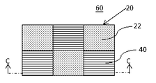
図1は、実施形態に対応する模型部品のパーツである第1の層20の構成例を示す。第1の層20は、シボ加工部22と透明部24とを含むように構成される。シボ加工部22は、例えば、シボ加工により物理的にシワ模様や梨地(これらを総称してシボという)が形成されている。ここで、シボ加工とは、例えば、成形部品を成形またはプレス加工する際に金型(鋳型・プレス型)の表面に細かい模様(凹凸)や梨地をつけ成形部品にその模様を転写する加工方法の他、塗装、或いは、サンドブラスト等による荒らし加工により、物品表面にシボを形成する方法を含む。塗装においては、例えば、つや消し用の塗料を用いて、吹き付けの圧力を変えることでまばらに吹き付けることができる。
FIG. 1 shows a configuration example of a
シボ加工部22と透明部24とは光の透過率が異なり、第1の層20において二次元的に交互に周期的に配置されている。シボ加工部22は、シボ加工が施された領域であり、当該領域は、所望の形状、大きさ、厚さとすることができる。所望の形状としては、具体的には正円や長円等の各種円、三角形、四角形等の各種多角形、線状体、星形等の図形の他、文字や記号とすることができる。シボ加工部22は、第1の層20の表面及び裏面において同じ場所に位置する領域にシボ加工がなされて構成され、これにより可視光の透過率をより下げることができる。なお、表面のみ或いは、裏面のみにシボ加工を施してもよい。透明部24にはシボ加工がされておらず、入射した可視光はそのまま透明部24を透過する。なお、透明部24は、所望の形状、大きさ、厚さとすることができる。
The texturing
第1の層20は、所定の色(例えば、緑色、黄色、赤色等の有彩色の他、無彩色或いは無色であってもよい)の透明材料により構成することができる。但し、第1の層20は、透明性を妨げない程度に着色されていてもよく、また、透明性を妨げない程度に材料中に他の可視光を反射あるいは吸収するような添加剤を含んでいてもよい。第1の層20の形状は特に限定しないが、平板状の他、曲面で構成される凹部及び凸部を一部あるいは全体に備えるものであってよい。第1の層20のシボ加工によって形成された領域の表面の粗さは、特に数値を限定するものではなく、シボ加工された領域が半透明であればよい。
The
次に、図2は実施形態に対応する模型部品のパーツである第2の層40の構成例を示す。図2に示す第2の層40は、可視光を透過しない所定の色(例えば、青色、緑色、赤色といった有彩色の他、黒色のような無彩色であってもよい)の不透明の材料で構成され、ポリスチレンの他、ガラス、各種樹脂、金属等を使用することができる。第2の層40の色は、材料の色であってもよいし、成形後に塗装により着色してもよい。第2の層40は所定の色の不透明な材料であって、第1の層20と積層可能な形状を有する。第2の層40において、少なくとも第1の層20の透明部24を介して外部から視認可能な領域には、シボ加工や鏡面処理等がされていても良い。また、第1の層20と積層された際にシボ加工部22の直下に位置する領域に同様にシボ加工を行い、透明部24の直下に位置する領域に鏡面処理を行うようにしてもよい。これにより、第1の層20と第2の層40とを積層した際の模様を構成する濃淡がより際立って知覚されるようになる。
Next, FIG. 2 shows a configuration example of the
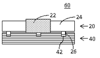
図3は、実施形態に対応する模型部品の構造の一例を示す。模型部品60は、第1の層20が、第2の層40の上に積層されて構成される。模型部品60は、第1の層20が上側に位置しており、シボ加工部22ではシボ加工により第2の層40の色をほぼ視認できない一方、透明部24により下側に位置する第2の層40の色を視認できる。これにより模型部品60の表面では、二次元的に色味が周期的に異なることとなり市松模様を知覚することができる。なお、本実施形態における模型部品60は、少なくとも2つの層から構成されるが、2つの層の間に更に透明性材料等を配置することにより、3層以上の積層構造としてもよい。
FIG. 3 shows an example of the structure of a model component corresponding to the embodiment. The
上述の模型部品60は、例えば玩具の本体を構成するパーツの一部として用いてもよいし、或いは、玩具の装飾品の一部として用いてもよい。また、複数の模型部品60を組み合わせることにより、玩具の本体を構成するパーツを構成することもできる。より具体的に、模型部品60を、玩具の羽織部品とすることができ、該羽織部品は、2色の配色で周期的に形成された市松模様を全体的に有する。また、模型部品60は、シボ加工部22と透明部24とを交互に周期的に配置する配置パターンに限らず、任意の配置パターンにおいて配置してもよい。これにより、市松模様以外の任意の模様を形成することができる。
The
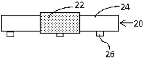
図4は、図1に示した模型部品のパーツのA-A線での断面図を示す。図4においては、パーツの厚みを理解の容易のために強調して記載している。第1の層20は、シボ加工部22が透明部24よりも厚く構成されている。また、第2の層40との積層時に位置合わせをするための位置決め部材として、凸部26を有している。凸部26は、例えば、第1の層20の左端に3つ、第1の層20の中央に2つ、第1の層20の右端に3つ配置することができるが、これに限定されるものではない。なお、凸部26の位置、形状、大きさ、数量等は特に限定されるものではないが、第2の層40と係合可能な範囲で変更することができる。
FIG. 4 shows a cross-sectional view of the part of the model component shown in FIG. 1 along line AA. In FIG. 4, the thickness of the parts is emphasized for easy understanding. The
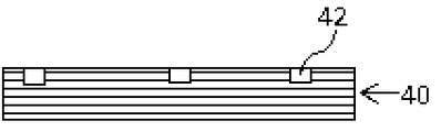
図5は、図2に示した模型部品のパーツのB-B線での断面図を示す。図5においても、パーツの厚みを理解の容易のために強調して記載している。第2の層40は、第1の層20との積層時に位置決めするための位置決め部材として、凹部42を有する。凹部42は、凸部26と係合する大きさで形成され、例えば、第2の層の左端に3つ、第2の層の中央に2つ、第2の層の右端に3つ配置される。なお、凹部42の位置、形状、大きさ、数量等は特に限定されるものではないが、第1の層20と係合可能な範囲で変更することができる。
FIG. 5 shows a cross-sectional view of the parts of the model component shown in FIG. 2 along line BB. Also in FIG. 5, the thickness of the parts is emphasized for easy understanding. The
次に図6は、図3に示した模型部品60のC-C線での断面図を示す。図6においては、模型部品60の厚みを理解の容易のために強調して記載している。ここでは、模型部品60が、第1の層20が、第1の層の凸部26と第2の層40の凹部42により位置決めされ、第2の層40の上に積層される。図6に示すように第1の層20は、シボ加工部22の厚みが透明部24よりも厚いため、透明部24と第2の層40との間に隙間が形成されているが、第1の層20の厚みを全体的に均一として隙間をなくしてもよい。シボ加工部22を透明部24よりも厚く形成することで、透かしたくない部分をより透けにくく、透かしたい部分をより透かすことが可能となる。なお、第1の層20と第2の層40とは、第1の層20と第2の層40との間に粘着剤または接着剤を付与することにより接合されてもよい。
Next, FIG. 6 shows a cross-sectional view of the
また、上記においては、第1の層20に凸部26、第2の層40に凹部42を配置する場合を示したが、第1の層20に凹部42、第2の層40に凸部26を配置する構成、或いは、両方の層にそれぞれ凸部と凹部とを備える構成としてもよい。
In addition, in the above description, the case where the
以上に説明したように、本実施形態に対応する模型部品60は、第1の層20におけるシボ加工部22の周期的な配置により、表面の色の濃淡が強調された模様を知覚することができる。模型部品60は、少なくとも2つの層を積層することにより、このような模様を表現することが可能となるため、従来にない彩色品質と部品の組み立て容易性を兼ね備える。
As described above, in the
Claims (6)
前記第1の領域は半透明な領域であり、前記第2の領域は透明な領域であり、前記第2の層は、前記第1の層と積層された状態において、前記第1の領域の直下に位置する領域にシボ加工がなされている模型部品。 A model component comprising a first layer in which first regions and second regions having different light transmittances are alternately and periodically formed and laminated on a second layer,
The first region is a translucent region , the second region is a transparent region, and the second layer is in a state of being laminated with the first layer, the first region A model part that has texturing in the area located directly under the .
Priority Applications (2)
| Application Number | Priority Date | Filing Date | Title |
|---|---|---|---|
| JP2020072916A JP7181908B2 (en) | 2020-04-15 | 2020-04-15 | model parts |
| CN202110279950.2A CN113021693B (en) | 2020-04-15 | 2021-03-16 | model parts |
Applications Claiming Priority (1)
| Application Number | Priority Date | Filing Date | Title |
|---|---|---|---|
| JP2020072916A JP7181908B2 (en) | 2020-04-15 | 2020-04-15 | model parts |
Publications (2)
| Publication Number | Publication Date |
|---|---|
| JP2021168779A JP2021168779A (en) | 2021-10-28 |
| JP7181908B2 true JP7181908B2 (en) | 2022-12-01 |
Family
ID=76470533
Family Applications (1)
| Application Number | Title | Priority Date | Filing Date |
|---|---|---|---|
| JP2020072916A Active JP7181908B2 (en) | 2020-04-15 | 2020-04-15 | model parts |
Country Status (2)
| Country | Link |
|---|---|
| JP (1) | JP7181908B2 (en) |
| CN (1) | CN113021693B (en) |
Citations (1)
| Publication number | Priority date | Publication date | Assignee | Title |
|---|---|---|---|---|
| US20170118822A1 (en) | 2014-11-13 | 2017-04-27 | Kurt C. Kosted | Illuminated foil balloon with lights synchronized to music |
Family Cites Families (12)
| Publication number | Priority date | Publication date | Assignee | Title |
|---|---|---|---|---|
| JPS5525998Y2 (en) * | 1976-10-01 | 1980-06-23 | ||
| JPS5976300U (en) * | 1982-11-17 | 1984-05-23 | 株式会社タカラ | cooking toys |
| US5184849A (en) * | 1991-05-07 | 1993-02-09 | Taylor Geoffrey L | Security system method and article for photocopiers and telefax machines |
| JPH09187575A (en) * | 1995-12-30 | 1997-07-22 | Koito Mfg Co Ltd | Illuminated goods |
| US7224945B2 (en) * | 2003-06-10 | 2007-05-29 | Nokia Corporation | Mobile station having overlapping translucent material layers and method of forming the same |
| DE102007034716A1 (en) * | 2007-07-23 | 2009-01-29 | Giesecke & Devrient Gmbh | security element |
| US20110195224A1 (en) * | 2008-09-24 | 2011-08-11 | Bing Zhang | Shell, mobile communication terminal containing the same and preparation methods thereof |
| JP2010264014A (en) * | 2009-05-13 | 2010-11-25 | Namco Bandai Games Inc | Moving toy |
| CN109196420B (en) * | 2016-06-03 | 2022-11-15 | Asml荷兰有限公司 | Pattern forming apparatus |
| CN207530900U (en) * | 2018-01-30 | 2018-06-22 | 深圳市蓝禾技术有限公司 | Mobile phone protecting case |
| JP2020051043A (en) * | 2018-09-25 | 2020-04-02 | 大日本印刷株式会社 | Decorative material |
| CN209888780U (en) * | 2018-11-14 | 2020-01-03 | 上海延锋金桥汽车饰件系统有限公司 | Light-permeable gadget |
-
2020
- 2020-04-15 JP JP2020072916A patent/JP7181908B2/en active Active
-
2021
- 2021-03-16 CN CN202110279950.2A patent/CN113021693B/en active Active
Patent Citations (1)
| Publication number | Priority date | Publication date | Assignee | Title |
|---|---|---|---|---|
| US20170118822A1 (en) | 2014-11-13 | 2017-04-27 | Kurt C. Kosted | Illuminated foil balloon with lights synchronized to music |
Also Published As
| Publication number | Publication date |
|---|---|
| CN113021693A (en) | 2021-06-25 |
| CN113021693B (en) | 2024-02-02 |
| JP2021168779A (en) | 2021-10-28 |
Similar Documents
| Publication | Publication Date | Title |
|---|---|---|
| JP5221634B2 (en) | Three-dimensional appearance exterior material | |
| JP7345160B2 (en) | Decorative sheets and decorative products | |
| JP2025094215A (en) | Model parts | |
| JP7181908B2 (en) | model parts | |
| KR20150086329A (en) | Printing decorative film having stereo effect and decorative plastic product thereof | |
| CN212920983U (en) | Light-transmitting instrument board decorative board | |
| JP2007054998A (en) | Decorative molded product and its manufacturing method | |
| JP5510765B2 (en) | Decorative synthetic resin molded product | |
| JPH0825604A (en) | Decorative sheet and manufacturing method thereof | |
| JP7069981B2 (en) | Cosmetic material | |
| KR101258606B1 (en) | A patten make method of case cap | |
| CN215792918U (en) | Light-transmitting three-dimensional decorative material | |
| JP4904110B2 (en) | Decorative sheet and decorative molded body | |
| JPH0687201A (en) | Makeup film | |
| JPH0493246A (en) | Decorative sheet | |
| WO2012176921A1 (en) | Hairline transfer sheet | |
| JP2012011614A (en) | Decorative synthetic resin molding | |
| JP2019025856A (en) | Decorative molded products | |
| JP3390862B2 (en) | Plural color fusion decorative sheet, and method and apparatus for manufacturing the same | |
| JP2007216088A (en) | Manufacturing method for decorated material | |
| JP3244597U (en) | Laminated decorative sheet body | |
| JP2968278B2 (en) | Decorative sheet and manufacturing method thereof | |
| JP7546947B2 (en) | Illumination and decoration materials | |
| CN213355465U (en) | Hose with villus texture | |
| JPS6218464Y2 (en) |
Legal Events
| Date | Code | Title | Description |
|---|---|---|---|
| RD02 | Notification of acceptance of power of attorney |
Free format text: JAPANESE INTERMEDIATE CODE: A7422 Effective date: 20210114 |
|
| A621 | Written request for application examination |
Free format text: JAPANESE INTERMEDIATE CODE: A621 Effective date: 20210315 |
|
| A977 | Report on retrieval |
Free format text: JAPANESE INTERMEDIATE CODE: A971007 Effective date: 20220218 |
|
| A131 | Notification of reasons for refusal |
Free format text: JAPANESE INTERMEDIATE CODE: A131 Effective date: 20220225 |
|
| A601 | Written request for extension of time |
Free format text: JAPANESE INTERMEDIATE CODE: A601 Effective date: 20220426 |
|
| A521 | Request for written amendment filed |
Free format text: JAPANESE INTERMEDIATE CODE: A523 Effective date: 20220616 |
|
| TRDD | Decision of grant or rejection written | ||
| A01 | Written decision to grant a patent or to grant a registration (utility model) |
Free format text: JAPANESE INTERMEDIATE CODE: A01 Effective date: 20221021 |
|
| A61 | First payment of annual fees (during grant procedure) |
Free format text: JAPANESE INTERMEDIATE CODE: A61 Effective date: 20221118 |
|
| R150 | Certificate of patent or registration of utility model |
Ref document number: 7181908 Country of ref document: JP Free format text: JAPANESE INTERMEDIATE CODE: R150 |
|
| R250 | Receipt of annual fees |
Free format text: JAPANESE INTERMEDIATE CODE: R250 |