JP7181568B2 - game machine - Google Patents
game machine Download PDFInfo
- Publication number
- JP7181568B2 JP7181568B2 JP2017247138A JP2017247138A JP7181568B2 JP 7181568 B2 JP7181568 B2 JP 7181568B2 JP 2017247138 A JP2017247138 A JP 2017247138A JP 2017247138 A JP2017247138 A JP 2017247138A JP 7181568 B2 JP7181568 B2 JP 7181568B2
- Authority
- JP
- Japan
- Prior art keywords
- effect
- special
- game
- executed
- pattern
- Prior art date
- Legal status (The legal status is an assumption and is not a legal conclusion. Google has not performed a legal analysis and makes no representation as to the accuracy of the status listed.)
- Active
Links
Images


Description
本発明は、パチンコ遊技機等に代表される遊技機に関する。 TECHNICAL FIELD The present invention relates to gaming machines typified by pachinko gaming machines and the like.
従来よりパチンコ遊技機では、遊技者に有利な特別遊技状態に制御するかの判定が行われ、その判定の結果が示されるまでの間に、様々な演出が行われる。演出の中には、上記の判定よりも前に特別遊技状態になるかを判定し、その判定(事前判定)の結果に基づいて行われる演出がある。 Conventionally, in a pachinko game machine, it is determined whether or not to control to a special game state advantageous to the player, and various effects are performed until the result of the determination is shown. Among the effects, there is an effect that determines whether or not the special game state is entered before the above determination, and is performed based on the result of the determination (preliminary determination).
例えば下記特許文献1には、事前判定の結果に基づく演出として、連続する複数回の図柄変動において同一のキャラクタを表示したり、同一種類のリーチを実行したりする遊技機が記載されている。
For example,
ところで、事前判定の結果に基づく演出については、遊技の興趣向上のため、改善の余地がある。 By the way, the effect based on the result of the preliminary determination has room for improvement in order to make the game more interesting.
本発明の課題は、演出を通じて遊技の興趣向上に寄与する遊技機を提供することである。 SUMMARY OF THE INVENTION An object of the present invention is to provide a gaming machine that contributes to enhancing the interest of a game through presentation.
本発明の遊技機は、
所定の入球口への入球に基づいて、遊技者に有利な特別遊技状態にするかの当否判定を行う判定手段と、
前記入球に基づいて、前記判定手段による当否判定よりも前に、前記特別遊技状態になるかの先読み判定を行う先読み判定手段と、
演出を制御可能な演出制御手段と、を備え、
前記演出制御手段は、
前記当否判定が行われることに応じて、演出図柄を変動表示させてから当該当否判定の結果を示す態様で停止表示させる図柄変動を行うことが可能であり、
前記当否判定の結果に基づいて、当該当否判定に応じた前記図柄変動において、所定の可動体を用いた駆動予告演出を実行することと、前記演出図柄を用いた特定の予告演出を実行することとが可能であり、
前記入球口への特定の入球に基づく前記先読み判定の結果に基づいて、前記特定の入球よりも前に生じた前記入球口への入球に基づく前記図柄変動から前記特定の入球に基づく前記図柄変動までの連続する複数回の前記図柄変動において、事前演出を行うことが可能であり、
前記事前演出には、前記所定の可動体を用いた第1事前演出、前記演出図柄を用いた第2事前演出、及び、前記所定の可動体を用いない演出であって前記第2事前演出とは異なる第3事前演出とがあり、
前記演出制御手段は、
前記第1事前演出を実行した場合でも、前記第2事前演出を実行した場合でも、前記第3事前演出を実行した場合でも、前記特定の入球に基づく前記図柄変動において前記駆動予告演出を行うことがあり、
前記第2事前演出を実行している場合、前記図柄変動において前記特定の予告演出を実行しないことを特徴とする遊技機である。
The gaming machine of the present invention is
a determination means for determining whether or not a special game state advantageous to the player is to be established based on the entry of a ball into a predetermined ball entrance;
Based on the ball entry, pre-reading determination means for performing a pre-reading determination whether to enter the special game state prior to the success/failure determination by the determination means;
and a production control means capable of controlling production,
The production control means is
In response to the success/failure determination, it is possible to perform a symbol variation that causes the performance symbols to be variably displayed and then stop-displayed in a manner that indicates the result of the success/failure determination,
Based on the result of the success/failure determination, in the symbol variation corresponding to the success/failure determination, executing a driving advance notice effect using a predetermined movable body, and executing a specific advance notice effect using the effect pattern. and
Based on the result of the look-ahead determination based on the specific ball entering the entrance, the symbol variation based on the ball entering the entrance that occurred before the specific entrance is changed to the specific entrance. It is possible to perform a preliminary effect in a plurality of consecutive pattern variations up to the symbol variation based on the ball,
The preliminary performance includes a first preliminary performance using the predetermined movable body, a second preliminary performance using the performance pattern , and a performance not using the predetermined movable body and the second preliminary performance. There is a third pre-production that is different from
The production control means is
Regardless of whether the first preliminary performance is executed, the second preliminary performance is executed, or the third preliminary performance is executed, the driving notice performance is performed in the symbol variation based on the specific ball entry. there is a
The gaming machine is characterized in that when the second preliminary effect is being executed, the specific advance notice effect is not executed in the symbol variation .
本発明によれば、演出を通じて遊技の興趣向上に寄与する遊技機が提供される。 According to the present invention, there is provided a gaming machine that contributes to the enhancement of interest in games through presentation.
以下、本発明の遊技機の実施形態を、図面を参照して具体的に説明する。参照される各図において、同一の部分には同一の符号を付し、同一の部分に関する重複する説明を原則として省略する。なお、本明細書では、記述の簡略化上、情報、信号、物理量又は部材等を参照する記号又は符号を記すことによって、該記号又は符号に対する情報、信号、物理量又は部材等の名称を省略又は略記することがある。また、後述の任意のフローチャートにおいて、任意の複数のステップにおける複数の処理は、処理内容に矛盾が生じない範囲で、任意に実行順序を変更できる又は並列に実行できる。 EMBODIMENT OF THE INVENTION Hereinafter, embodiment of the gaming machine of this invention is concretely described with reference to drawings. In each figure referred to, the same parts are denoted by the same reference numerals, and redundant descriptions of the same parts are omitted in principle. In this specification, for simplification of description, by describing symbols or codes that refer to information, signals, physical quantities or members, etc., the names of the information, signals, physical quantities or members, etc. corresponding to the symbols or codes are omitted or may be abbreviated. Further, in any flow chart described later, a plurality of processes in a plurality of arbitrary steps can be arbitrarily changed in execution order or executed in parallel as long as there is no contradiction in the processing contents.
1.遊技機の構造
本発明の遊技機の実施形態であるパチンコ遊技機PY1について説明する。最初に、パチンコ遊技機PY1の構造について図1~図6を用いて説明する。なお、以下の説明において、パチンコ遊技機PY1の各部の左右上下方向は、そのパチンコ遊技機PY1に対面する遊技者にとっての(正面視の)左右上下方向のことである。また、「前方」は、パチンコ遊技機PY1から当該パチンコ遊技機PY1に対面する遊技者に近づく方向とし、「後方」は、パチンコ遊技機PY1に対面する遊技者から当該パチンコ遊技機PY1に近づく方向とする。
1. Structure of Gaming Machine A pachinko gaming machine PY1, which is an embodiment of the gaming machine of the present invention, will be described. First, the structure of the pachinko game machine PY1 will be described with reference to FIGS. 1 to 6. FIG. In the following description, the left, right, up and down directions of each part of the pachinko gaming machine PY1 are the left, right, up and down directions for the player facing the pachinko gaming machine PY1 (as seen from the front). Further, "forward" is the direction from the pachinko gaming machine PY1 toward the player facing the pachinko gaming machine PY1, and "backward" is the direction from the player facing the pachinko gaming machine PY1 toward the pachinko gaming machine PY1. and
図1及び図2に示すように、パチンコ遊技機PY1は、遊技機枠2を備えている。遊技機枠2は、後述する遊技盤ユニットYUが取り付けられる遊技盤取付枠2Aと、遊技盤取付枠2Aにヒンジ2Bを介して回転自在に支持される前枠23mと、を備える。前枠23mは遊技盤取付枠2Aに対して開閉が可能である。前枠23mには、透明板23tが取り付けられている。前枠23mが閉じられているとき、遊技盤取付枠2Aに取り付けられた遊技盤1と透明板23tとは対面する。よって、パチンコ遊技機PY1が遊技店に設置されると、当該パチンコ遊技機PY1の前方にいる遊技者は、透明板23tを通して、遊技盤1に形成された遊技領域6を視認することができる。透明板23tは、透明なガラス板や透明な合成樹脂板等を用いることができる。パチンコ遊技機PY1の前方から遊技領域6を視認可能であればよい。
As shown in FIGS. 1 and 2, the pachinko game machine PY1 has a
前枠23mの前面の右下部には、遊技球を発射させるための回転操作が可能なハンドル72kが設けられている。ハンドル72kが操作された量(回転角度)が、遊技球を発射させるために遊技球に与えられる力(後述する発射装置72が発射ソレノイド72sに駆動させる量)の大きさ(発射強度)に対応付けられている。よって、遊技球は、ハンドル72kの回転操作に応じた発射強度で発射される。また、前枠23mの前面の下部中央には、前方に向けて大きく突出した下部装飾体36が設けられている。下部装飾体36の上面には、ハンドル72kに供給される遊技球を貯留するための上皿34が形成されている。また、下部装飾体36の正面の下部中央には、上皿34に収容しきれない余剰の遊技球を貯留するための下皿35が設けられている。
A
下部装飾体36の上面の上皿34より前方側には、下方に押下操作可能な第1入力装置(以下「半球型ボタン」)40が設けられている。また、前枠23mの表面の右縁部から前方に突出して形成されている右部装飾体32において、下方に押下操作可能な第2入力装置(以下「剣型ボタン」)41が設けられている。
A first input device (hereinafter referred to as a “hemispherical button”) 40 that can be pressed downward is provided on the upper surface of the lower
また、前枠23mの表面の上部から前方に突出して形成されている上部装飾体31の底面に、音を出力可能なスピーカ52が設けられている。スピーカ52は、左側に配置された左スピーカ52Lと、右側に配置された右スピーカ52Rと、からなる。また、前枠23mの右縁部と、下部装飾体36における正面の下皿35の左側および右側とに、発光可能な枠ランプ53が設けられている。さらに、前枠23mの左縁部および右縁部の上側には、遊技興趣を高めることを目的とする演出装置としての可動式の枠可動装置58が取り付けられている。枠可動装置58は、左側に配置された左枠可動装置58Lと、右側に配置された右枠可動装置58Rと、で構成される。
A
なお、遊技機枠2に設けられる部材や装置の位置や数は、遊技に支障をきたさない範囲で適宜に変更可能である。
It should be noted that the positions and numbers of the members and devices provided in the
次に、遊技盤ユニットYUについて、主に図3~図6を用いて説明する。遊技盤ユニットYUは、遊技盤1と、遊技盤1の背面側に取り付けられた演出用ユニット1Uと、を有する。最初に、遊技盤1について説明する。遊技盤1は透明な合成樹脂板で構成されている。遊技盤1の略中央には正面視略円形の開口部1Aが形成されている。開口部1Aに沿って、遊技球が流下可能な遊技領域6を区画するための略リング状の内側壁部1Bが前方に突出して形成されている。また、内側壁部1Bの外側にも、遊技領域6を区画するための略リング状の外側壁部1Cが前方に突出して形成されている。
Next, the game board unit YU will be described mainly with reference to FIGS. 3 to 6. FIG. The game board unit YU has a
遊技盤1の前面には、内側壁部1B、外側壁部1Cなどで囲まれた遊技領域6が形成されている。すなわち、遊技盤1の前面が、内側壁部1Bおよび外側壁部1Cによって、遊技領域6とそれ以外の領域とに仕切られている。
A
遊技領域6は、ハンドル72kの操作によって発射された遊技球が流下可能な領域であり、パチンコ遊技機PY1で遊技を行うために設けられている。なお、遊技領域6には、多数の遊技くぎ(図示なし)が突設されている。遊技くぎは、遊技領域6に進入して遊技領域6を流下する遊技球を、後述する第1始動口11、第2始動口12、一般入賞口10、ゲート13、第1大入賞口14、および、第2大入賞口15などに適度に誘導する経路を構成している。
The
遊技領域6における内側壁部1Bの中央直下には、上方が開口した第1始動口11が形成された第1始動入賞装置11Dが設けられている。第1始動口11の左下には、右側方が開口した第2始動口12が設けられている。第2始動口12の右脇には、第2始動口12への入球を可能または不可能にさせる第2始動入賞装置(所謂「電チュー」)12Dが設けられている。
Directly below the center of the
第1始動入賞装置11Dは不動である。そのため、第1始動口11は、遊技球の入球し易さが変化せずに一定(不変)である。遊技球の第1始動口11への入賞は、第1特別図柄(以下、「特図1」という)の抽選(後述の特図1関係乱数の取得と判定:以下、「特図1抽選」という)および特図1の可変表示の契機となっている。また、遊技球が第1始動口11へ入賞すると、所定個数(例えば4個)の遊技球が賞球として払い出される。
The first
電チュー12Dは、作動可能な電チュー開閉部材12kを備えている。電チュー開閉部材12kは平面視で左斜め下方向に下降する略横長長方形状の舌状片からなる。平面視で、電チュー開閉部材12kの上面左端が、第2始動口12の最下点の右隣に位置する。電チュー開閉部材12kは、通常は(通常状態では)その先端(前方側側面)が遊技領域6、すなわち遊技盤1の前面辺りに位置するよう、遊技盤1より後方に収納されている。電チュー開閉部材12kはその収納されている状態から前後方向に移動(進退)することができる。そして、特別状態になると、電チュー開閉部材12kが前方へ移動する。電チュー開閉部材12kが前方へ移動すると、電チュー開閉部材12kが第2始動口12への誘導する経路となる。よって、電チュー開閉部材12kが遊技領域6より後方に収納された通常状態では、この誘導する経路がないので、第2始動口12へ遊技球を入球させることはほとんど不可能である。このように、電チュー開閉部材12kが突出状態になることを第2始動口12または電チュー12Dの「開状態」ともいい、開状態であるときだけ遊技球の第2始動口12への入球が可能となる。一方、電チュー開閉部材12kが収納されている状態を第2始動口12または電チュー12Dの「閉状態」ともいう。このように、電チュー開閉部材12kの作動によって第2始動口12が開閉する。また、第2始動口12または電チュー12Dが「開状態」になることを「電チュー12Dが開放する」ともいい、電チュー12Dが「閉状態」になることを「電チュー12Dが閉鎖する」ともいう。
The
遊技球の第2始動口12への入賞は、第2特別図柄(以下、「特図2」という)の抽選(後述の特図2関係乱数の取得と判定:以下、「特図2抽選」という)および特図2の可変表示の契機となっている。また、遊技球が第2始動口12へ入賞すると、所定個数(例えば4個)の遊技球が賞球として払い出される。
The winning of the game ball to the
また、遊技領域6における第1始動入賞装置11Dの左側には、2つの一般入賞口10が設けられている。また、電チュー12Dの右側には、1つの一般入賞口10が設けられている。遊技球が一般入賞口10へ入賞すると、所定個数(例えば3個)の遊技球が賞球として払い出される。
In addition, two general winning
また、遊技盤1の開口部1Aの右斜め下側に、遊技球が通過可能なゲート13が設けられている。遊技球のゲート13の通過は、普通図柄(以下、「普図」という)の抽選(すなわち普通図柄乱数の取得と判定:以下、「普図抽選」という)および普図の可変表示の契機となっている。補助遊技が実行されることによって電チュー12Dを開放する。すなわち、補助遊技は、電チュー12Dの開放を伴う遊技である。
In addition, a
また、遊技領域6における第1始動入賞装置11Dの右側でゲート13の直下には、第1大入賞口14が形成された第1大入賞装置14D(以下、「通常AT14D」ともいう)が設けられている。
In addition, on the right side of the first start-up winning
第1大入賞装置14Dは、開状態と閉状態とをとる通常AT開閉部材14kを備える。通常AT開閉部材14kの作動により第1大入賞口14が開閉する。通常AT開閉部材14kは正面視略横長矩形状の平板からなり、通常は第1大入賞口14を塞いでいる。通常AT開閉部材14kは下端を中心に、上端が前方へ倒れるように略90度回転することができる。通常AT開閉部材14kが回転すると、通常AT開閉部材14kが遊技領域6に垂直に突出した状態になり、流下する遊技球を受け止めて第1大入賞口14の中に入球させる。このように、通常AT開閉部材14kが開状態であるときだけ遊技球の第1大入賞口14への入球が可能となる。遊技球が第1大入賞口14へ入賞すると、所定個数(例えば14個)の遊技球が賞球として払い出される。
The first big
また、遊技領域6における第1大入賞装置14Dの直下には、その上面が左斜め下方に形成され、遊技球を第2始動口12へ誘導する誘導ステージ12gが遊技領域6(遊技盤1の前面)から前方に突出して設けられている。なお、誘導ステージ12gの上面を転動する遊技球は、第2始動口12の方へ向かって流下可能であるが、基本的には第1始動口11へ入賞することはできない。
In addition, immediately below the first
遊技領域6におけるゲート13や第1大入賞口14の右斜め上方、換言すると、上流側に、第2大入賞口15が形成された第2大入賞装置15D(以下、「VAT15D」ともいう)が設けられている。第2大入賞装置15Dは、作動可能なVAT開閉部材15kを備えている。VAT開閉部材15kは正面視で羽根のような形状を呈している棒状体であり、通常は水平方向に対して略90度の姿勢で保持され、第2大入賞口15を塞いでいる。VAT開閉部材15kは下端を中心に、上端が左側へ倒れるように略70度回転し、開状態をとることができる。VAT開閉部材15kが開状態であるときだけ遊技球の第2大入賞口15への入球が可能となる。一方、VAT開閉部材15kが第2大入賞口15を塞いでいる状態を「閉状態」ともいう。このように、VAT開閉部材15kの作動によって第2大入賞口15が開閉する。遊技球が第2大入賞口15へ入賞すると、所定個数(例えば14個)の遊技球が賞球として払い出される。
A second big winning
ここで、図4を用いて、第2大入賞装置15Dについて詳細に説明する。第2大入賞装置15Dの内部には、第2大入賞口15に入球した遊技球を検知し、遊技球を下方へ通過させることが可能なゲート状の第2大入賞口センサ15aが設けられている。
Here, with reference to FIG. 4, the second big winning
第2大入賞口センサ15aの下流域には、遊技球が通過(進入)可能な特定領域16と非特定領域17とが設けられている。第2大入賞口センサ15aを通過した遊技球は、振分装置16Dによって、特定領域16か非特定領域17かに振り分けられる。振分装置16Dは、略矩形状の平板からなる振分部材16kと、振分部材16kを駆動する振分ソレノイド16sとを備えている。振分部材16kは、振分ソレノイド16sの駆動により、左右にスライド可能に構成されている。
A
振分ソレノイド16sが通電されていないとき、振分部材16kは特定領域16への遊技球の通過を妨げる第1状態(通過阻止状態:図4(A)の正面視で振分部材16kの左端が特定領域16の左端よりやや右側に位置し、振分部材16kが特定領域16をその直上で覆う状態)にある。振分部材16kが第1状態にあるときは、第2大入賞口15に入賞した遊技球は、第2大入賞口センサ15aを通過した後、特定領域16を通過することは不可能であり、非特定領域17を通過する。この第2大入賞口15から非特定領域17まで流下する遊技球のルートを第1のルートという。
When the
一方、振分ソレノイド16sが通電されているとき、振分部材16kは遊技球の特定領域16の通過(進入)を許容する第2状態(通過許容状態:図4(B)の正面視で振分部材16kの左端が特定領域16の右端よりやや左側に位置し、振分部材16kが特定領域16をその直上で覆わず、特定領域16の直上が開放している状態)にある。振分部材16kが第2状態にあるときは、第2大入賞口15に入賞した遊技球は、第2大入賞口センサ15aを通過したあと特定領域16を通過容易である。この第2大入賞口15から特定領域16まで流下する遊技球のルートを第2のルートという。
On the other hand, when the
なお、基本的に、振分部材16kは第1状態で保持されている。すなわち、第1状態が、振分部材16kの通常の状態であるといえる。そして、後述する大当たり遊技の最後のラウンド遊技(16R)においてのみ、振分ソレノイド16sが通電され、第2状態に変化することができる。
Basically, the
特定領域16と非特定領域17には、各領域16、17を通過(進入)した遊技球を検知し、遊技球を下方へ通過させる特定領域センサ16a、非特定領域センサ17aが設けられている。
The
なお、第1大入賞装置14Dおよび第2大入賞装置15Dは、遊技に支障をきたさない範囲で、一方だけを設けるようにすることが可能である。
Only one of the first
また図3に示すように、遊技領域6の略最下部には、遊技領域6へ打ち込まれたもののいずれの入賞口にも入賞しなかった遊技球を遊技領域6の外部へ排出する2つのアウト口19が設けられている。
Also, as shown in FIG. 3, substantially at the bottom of the
ところで、遊技球が流下可能な遊技領域6は、左右方向の中央より左側の左遊技領域(第1遊技領域)と、右側の右遊技領域(第2遊技領域)と、に分けることができる。遊技球が左遊技領域を流下するように遊技球を発射させるハンドル72kの操作態様を「左打ち」という。一方、遊技球が右遊技領域を流下するように遊技球を発射させるハンドル72kの操作態様を「右打ち」という。パチンコ遊技機PY1において、左打ちにて遊技球を発射したときに遊技球が流下可能な流路を、第1流路R1といい、右打ちにて遊技球を発射したときに遊技球が流下可能な流路を、第2流路R2という。第1流路R1および第2流路R2は、多数の遊技くぎなどによっても構成されている。
By the way, the
第1流路R1上には、第1始動口11と、2つの一般入賞口10と、が設けられている。よって、遊技者は、左打ちにより第1流路R1を流下するように遊技球を発射させることで、第1始動口11、または、一般入賞口10への入賞を狙うことができる。一方、第2流路R2上には、第2始動口12と、ゲート13と、第1大入賞口14と、第2大入賞口15と、が設けられている。よって、遊技者は、右打ちにより第2流路R2を流下するように遊技球を発射させることで、ゲート13の通過や、第2始動口12、第1大入賞口14、または、第2大入賞口15への入賞を狙うことができる。
A
なお、何れの入賞口(第1始動口11、第2始動口12、一般入賞口10、第1大入賞口14、および第2大入賞口15)にも入球しなかった遊技球は、アウト口19へ誘導されて排出される。また、各入賞口への入賞による賞球数は、適宜に設定することが可能である。
In addition, game balls that did not enter any of the winning openings (first starting
また、遊技盤1の前面に形成された遊技領域6の下方の左隣(遊技領域6以外の部分)には表示器類8が配置されている。図5に示すように、表示器類8には、特図1を可変表示する特図1表示器81a、特図2を可変表示する特図2表示器81b、及び、普図を可変表示する普図表示器82が含まれている。また、表示器類8には、後述する特図1保留数(U1:特図1表示器81aによる特図1の可変表示が保留されている数)を表示する特図1保留表示器83a、および後述する特図2保留数(U2:特図2表示器81bによる特図2の可変表示が保留されている数)を表示する特図2保留表示器83bが含まれている。
In addition, a
特図1の可変表示は、第1始動口11への遊技球の入賞を契機に特図1抽選が行われると実行される。また、特図2の可変表示は、第2始動口12への遊技球の入賞を契機に特図2抽選が行われると実行される。なお、以下の説明では、特図1および特図2を総称して特図といい、特図1抽選および特図2抽選を総称して特図抽選という。また、特図1表示器81aおよび特図2表示器81bを総称して特図表示器81という。さらに、特図1保留表示器83aおよび特図2保留表示器83bを総称して特図保留表示器83という。
The variable display of the special figure 1 is executed when the special figure 1 lottery is performed with the winning of the game ball to the
特図の可変表示は、特図抽選の結果を報知する。特図の可変表示では、特図が可変表示したあと停止表示する。停止表示される特図(停止特図、可変表示の表示結果として導出表示される特別図柄)は、特図抽選によって複数種類の特図の中から選択された一つの特図である。停止特図が予め定めた特定の特図(特定の停止態様の特図すなわち大当たり図柄)である場合には、大入賞口(第1大入賞口14及び第2大入賞口15)を開放させる大当たり遊技(特別遊技の一例)が行われる。
The variable display of the special figure notifies the result of the special figure lottery. In the variable display of the special figure, it is stopped and displayed after the special figure is variably displayed. The special figure to be stopped and displayed (stop special figure, special symbol derived and displayed as a display result of variable display) is one special figure selected from a plurality of kinds of special figures by a special figure lottery. When the stop special figure is a predetermined special figure (a special figure of a specific stop mode, i.e., a jackpot pattern), the large winning openings (the first large winning
特図表示器81は、例えば横並びに配された8個のLED(Light Emitting Diode)から構成され、その点灯態様によって特図抽選の結果に応じた特図を表示する。例えば特図抽選の結果が大当たり(後述の複数種類の大当たりのうちの一つ)である場合には、特図表示器81は、「□□■■□□■■」(□:点灯、■:消灯)というように左から1,2,5,6番目にあるLEDの点灯で構成される大当たり図柄を表示する。また、特図抽選の結果がハズレである場合には、特図表示器81「■■■■■■■□」というように一番右にあるLEDのみの点灯で構成されるハズレ図柄を表示する。なお、特図抽選の結果に対応するLEDの点灯態様は限定されず、適宜に設定することができる。よって、例えば、ハズレ図柄として全てのLEDを消灯させてもよい。
The
また、特図の可変表示において、特図が停止表示される前には所定の変動時間にわたって特図の可変表示がなされる。特図の可変表示の態様は、例えば左から右へ光が繰り返し流れるように各LEDが点灯する態様である。なお、特図の可変表示の態様は、特に限定されず、各LEDが停止表示(特定の態様での点灯表示)されていなければ、全LEDが一斉に点滅するなど適宜に設定してよい。 Moreover, in the variable display of the special figure, the variable display of the special figure is performed over a predetermined fluctuation time before the special figure is stopped and displayed. The aspect of the variable display of the special figure is, for example, the aspect in which each LED is lit so that the light flows repeatedly from left to right. In addition, the aspect of the variable display of the special figure is not particularly limited, and if each LED is not displayed (lighting display in a specific aspect), all LEDs may be set as appropriate, such as blinking all at once.
ところで、パチンコ遊技機PY1では、第1始動口11または第2始動口12への遊技球の入賞(入球)があると、特図抽選などを行うための各種乱数(数値情報や判定情報の一例)が取得されることがある。この各種乱数は、特図保留として後述の特図保留記憶部105に一旦記憶される。なお、以下において、第1始動口11への遊技球の入賞(入球)により取得された各種乱数のことを「特図1関係乱数」といい、第2始動口12への遊技球の入賞(入球)により取得された各種乱数のことを「特図2関係乱数」という。ここで、特図1関係乱数は、特図1保留として、特図保留記憶部105の中の特図1保留記憶部105aに記憶される。一方、特図2関係乱数は、特図2保留として、特図保留記憶部105の中の特図2保留記憶部105bに記憶される。特図1保留記憶部105aに記憶可能な特図1保留の数(特図1保留数)および特図2保留記憶部105bに記憶可能な特図2保留の数(特図2保留数)には上限(例えば4個)を設定することが可能である。なお、以下において、特図1保留と特図2保留を総称して「特図保留」といい、特図1保留数と特図2保留数を総称して「特図保留数」という。また、特図1関係乱数と特図2関係乱数とを総称して「特図関係乱数」という。
By the way, in the pachinko game machine PY1, when a game ball enters the
パチンコ遊技機PY1では、遊技球が第1始動口11または第2始動口12へ入賞した後すぐに特図の可変表示が行われない場合、具体的には、特図の可変表示の実行中や大当たり遊技の実行中に入賞があった場合、その入賞に対する特図の可変表示(あるいは、特図抽選の権利)を留保することができる。特図保留記憶部105に記憶された特図保留は、その特図保留に基づく特図の可変表示が可能となったときに消化される。すなわち、特図保留の消化とは、その特図保留に対応する特図関係乱数等を判定して、その判定結果を示すための特図の可変表示を実行することをいう。
In the pachinko game machine PY1, when the variable display of the special symbol is not performed immediately after the game ball enters the
そして、特図保留数は、特図保留表示器83に表示される。特図1保留表示器83aと特図2保留表示器83bのそれぞれは、例えば4個のLEDで構成されており、特図保留数の分だけLEDを点灯させることにより特図保留数を表示することが可能である。
And the special figure reservation number is displayed on the special
また、普図の可変表示は、普図抽選の結果を報知する。普図の可変表示では、普図が可変表示したあと停止表示する。停止表示される普図(停止普図、可変表示の表示結果として導出表示される普図)は、普図抽選によって複数種類の普図の中から選択された一つの普図である。停止表示された普図が予め定めた特定の普図(所定の停止態様の普図すなわち当たり図柄)である場合には、第2始動口12(電チュー12D)を開放させる補助遊技が行われる。
In addition, the variable display of the general map notifies the result of the general map lottery. In the variable display of the normal map, after the normal map is displayed variably, the display is stopped. The normal map to be stopped and displayed (stop normal map, normal map derived and displayed as a display result of variable display) is one normal map selected from a plurality of types of normal map lottery. When the stop-displayed normal pattern is a predetermined specific normal pattern (predetermined stop state normal pattern, i.e. winning pattern), an auxiliary game for opening the second starting port 12 (
普図表示器82は、例えば2個のLEDから構成されており、その点灯態様によって普図抽選の結果に応じた普図を表示する。普図抽選の結果が当たりである場合には、普図表示器82は、「□□」(□:点灯、■:消灯)というように両LEDの点灯で構成される当たり図柄を表示する。また普図抽選の結果がハズレである場合には、「■□」というように右のLEDのみの点灯で構成されるハズレ図柄を表示する。ハズレ図柄として全てのLEDを消灯させる態様を採用してもよい。なお、普図抽選の結果に対応するLEDの点灯態様は限定されず、適宜に設定することができる。
The
また、普図が停止表示される前には所定の変動時間にわたって普図の可変表示が行われる。普図の可変表示の態様は、例えば両LEDが交互に点灯するという態様である。なお、普図の可変表示の態様は、特に限定されず、各LEDが停止表示(特定の態様での点灯表示)されていなければ、全LEDが一斉に点滅するなど適宜に設定してもよい。 Also, before the normal map is stopped and displayed, the variable display of the normal map is performed for a predetermined fluctuation time. The mode of the variable display of the normal map is, for example, a mode in which both LEDs are lit alternately. In addition, the aspect of the variable display of the normal figure is not particularly limited, and if each LED is not displayed stopped (lighting display in a specific aspect), all LEDs may be set as appropriate, such as blinking all at once .
パチンコ遊技機PY1では、遊技球がゲート13を通過すると、普図抽選を行うための普通図柄乱数(数値情報や判定情報の一例)が取得されることがある。この乱数は、普図の可変表示または補助遊技が実行されていないことを条件に、後述の普図保留記憶部106に記憶される。普図保留記憶部106に記憶可能な普図保留の数(普図保留数)には上限(例えば4個)を設定することが可能である。なお、以下において、遊技球がゲート13を通過することにより取得された普通図柄乱数のことを「普図関係乱数」ともいう。
In the pachinko game machine PY1, when a game ball passes through the
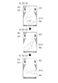
次に、図6を用いて、遊技盤1の背面に取り付けられた演出用ユニット1Uについて説明する。演出用ユニット1Uは、主に演出を行う複数の装置をユニット化したものである。演出用ユニット1Uには、画像表示装置50、第1盤可動装置(以下「盤前可動装置」)55、第2盤可動装置(以下「盤後可動装置」)56、および第3盤可動装置(以下「ロゴ役物装置」)57が搭載されている。
Next, the
画像表示装置50は、例えば20インチの3D液晶ディスプレイ2枚で構成され、3D画像を表示可能な表示部50aを具備する。
The
盤前可動装置55は、例えばさらにその中で上に配置される盤前上可動装置55UL,55URと、下に配される盤前下可動装置55Dと、を備え、盤前上可動装置55ULは、移動可能に構成され、主に前面部分が立体的な装飾が施された盤前上左可動体55ULkを具備する。盤前上可動装置55URは、移動可能に構成され、主に前面部分が立体的な装飾が施された盤前上右可動体55URkを具備する。盤前下可動装置55Dは、移動可能に構成され、主に前面部分に立体的な装飾が施された盤前下可動体55Dkを具備する。
The board front
盤後可動装置56は、例えばさらにその中で上側に配置される盤後上可動装置56Uと、下側に配される盤後下可動装置56Dと、を備え、盤後上可動装置56Uは、移動可能に構成され、平面的な装飾が施された盤後上可動体56Ukを具備する。盤後下可動装置56Dは、移動可能に構成され、平面的な装飾が施された盤後下可動体56Dkを具備する。
The post-board
ロゴ役物装置57は、例えばパチンコ遊技機PY1の題材である主人公キャラクタ「ロゴ」のロゴタイプ「L・O・G・O」が前面側に施されたロゴ可動体57kを備え、ロゴ可動体57kは、表示部50aに沿って平面的に上昇および下降が可能に構成される。
The
図6(A)は、盤後上可動体56Ukおよび盤後下可動体56Dkが作動していない通常の待機状態(初期位置)で保持されている様子を概略化して表している。盤後上可動体56Ukおよび盤後下可動体56Dkは、前後方向に略直交する平面上、言い換えると、画像表示装置50の表面に沿って上下方向に移動可能である(上昇および下降が可能である)。そして、盤後上可動装置56Uおよび盤後下可動装置56Dのそれぞれの駆動源が駆動すると、盤後下可動体56Dkは正面視でその上端が画像表示装置50の高さ方向中央あたりに位置するように上向きに移動する(上昇する)(図6(B)参照)。一方、盤後上可動体56Ukは正面視でその下端が画像表示装置50の高さ方向中央あたりに位置するよう下向きに移動する(下降する)(図6(C)参照)。その結果、正面視で画像表示装置50の高さ方向中央あたりで、盤後上可動体56Ukと盤後下可動体56Dkとが上下方向に接合して合体し、それぞれの表面に施された模様(デザイン)が全体で一つになり、パチンコ遊技機PY1の題材である主人公キャラクタの顔を表す(図6(D)参照)。このとき、画像表示装置50の大部分は合体した盤後上可動体56Ukと盤後下可動体56Dkに覆われるので、画像表示装置50は視認困難となる。
FIG. 6(A) schematically shows how the upper rear board movable body 56Uk and the lower rear board movable body 56Dk are held in a normal standby state (initial position) in which they are not in operation. The upper rear board movable body 56Uk and the lower rear board movable body 56Dk can move vertically along the surface of the
なお、遊技盤ユニットYUに設けられる部材や装置の位置や数は、遊技に支障をきたさない範囲で適宜に変更可能である。 It should be noted that the positions and numbers of members and devices provided in the game board unit YU can be appropriately changed within a range that does not interfere with the game.
2.遊技機の電気的構成
次に、図7~図8に基づいて、パチンコ遊技機PY1における電気的な構成を説明する。図7~図8に示すように、パチンコ遊技機PY1は、特図抽選、特図の可変表示、大当たり遊技、後述する遊技状態の設定、普図抽選、普図の可変表示、補助遊技などの遊技利益に関する制御(遊技の進行)を行う遊技制御基板(以下「主制御基板」)100、主制御基板100による遊技の進行に応じた遊技演出(特図変動演出、保留演出、大当たり遊技演出)、客待ち演出、半球型ボタン40や剣型ボタン41の操作が有効な期間(操作有効期間)において操作を促す操作促進演出などの演出に関する制御を行う演出制御基板(以下「サブ制御基板」)120、および、遊技球の払い出しに関する制御などを行う払出制御基板170等を、遊技盤1の画像表示装置50よりさらに背面側に備えている。主制御基板100を、遊技の制御を行う遊技制御部と位置づけることができる。また、サブ制御基板120を、後述する画像制御基板140、ランプ制御回路151、および音声制御回路161とともに、演出の制御を行う演出制御部と位置づけることができる。なお、演出制御部は、少なくともサブ制御基板120を備え、演出手段(画像表示装置50、スピーカ52、枠ランプ53、盤ランプ54、および、可動装置55,56,57等)を用いた遊技演出、客待ち演出、および操作促進演出を制御可能であればよい。
2. Electrical Configuration of Gaming Machine Next, the electrical configuration of the pachinko gaming machine PY1 will be described with reference to FIGS. 7 and 8. FIG. As shown in FIGS. 7 and 8, the pachinko game machine PY1 has a special figure lottery, a variable display of a special figure, a jackpot game, a game state setting described later, a normal figure lottery, a variable display of a normal figure, an auxiliary game, and the like. A game control board (hereinafter referred to as "main control board") 100 that controls the game profit (progress of the game), and a game effect (special figure fluctuation effect, holding effect, jackpot game effect) according to the progress of the game by the
また、パチンコ遊技機PY1は、電源基板190を備えている。電源基板190は、主制御基板100、サブ制御基板120、及び払出制御基板170に対して電力を供給するとともに、これらの基板を介してその他の機器に対して必要な電力を供給する。電源基板190には、バックアップ電源回路192が設けられている。バックアップ電源回路192は、パチンコ遊技機PY1に対して電力が供給されていない場合に、後述する主制御基板100の遊技用RAM104やサブ制御基板120の演出用RAM124に対して電力を供給する。従って、主制御基板100の遊技用RAM104やサブ制御基板120の演出用RAM124に記憶されている情報は、パチンコ遊技機PY1の電断時であっても保持される。また、電源基板190には、電源スイッチ191が接続されている。電源スイッチ191のON/OFF操作により、電源の投入/遮断が切り換えられる。なお、主制御基板100の遊技用RAM104に対するバックアップ電源回路を主制御基板100に設けたり、サブ制御基板120の演出用RAM124に対するバックアップ電源回路をサブ制御基板120に設けたりしてもよい。
Moreover, the pachinko game machine PY1 is provided with a
図7に示すように、主制御基板100には、プログラムに従ってパチンコ遊技機PY1の遊技の進行を制御する遊技制御用ワンチップマイコン(以下「遊技制御用マイコン」)101が実装されている。遊技制御用マイコン101には、遊技の進行を制御するためのプログラムやテーブル等を記憶した遊技用ROM(Read Only Memory)103、ワークメモリとして使用される遊技用RAM(Random Access Memory)104、および遊技用ROM103に記憶されたプログラムを実行する遊技用CPU(Central Processing Unit)102が含まれている。
As shown in FIG. 7, the
遊技用ROM103には、後述する主制御メイン処理やメイン側タイマ割り込み処理などを行うためのプログラムが格納されている。また、遊技用ROM103には、後述する大当たり判定テーブル、大当たり図柄種別判定テーブル、リーチ判定テーブル、特図変動パターン判定テーブル、先読み判定テーブル、大当たり遊技制御テーブル、当たり判定テーブル、普図変動パターン判定テーブル、補助遊技制御テーブルなどが格納されている。なお、遊技用ROM103は外付けであってもよい。また、遊技用RAM104には、前述した特図保留記憶部105や普図保留記憶部106などが設けられている。
The
また、主制御基板100には、データや信号の入出力を行うための遊技用I/O(Input/Output)ポート部118、および遊技用RAM104に記憶されている情報を遊技用CPU102にクリアさせるためのRAMクリアスイッチ119が実装されている。
In addition, the
主制御基板100には、所定の中継基板(図示なし)を介して各種センサ類やソレノイド類が接続されている。そのため、主制御基板100には、各種センサ類が出力した信号が入力する。また、主制御基板100は、各種ソレノイド類に信号を出力する。
Various sensors and solenoids are connected to the
主制御基板100に接続されている各種センサ類には、第1始動口センサ11a、第2始動口センサ12a、一般入賞口センサ10a、ゲートセンサ13a、第1大入賞口センサ14a、第2大入賞口センサ15a、特定領域センサ16a、および、非特定領域センサ17aが含まれている。
The various sensors connected to the
第1始動口センサ11aは、第1始動口11に入賞した遊技球を検知する。第2始動口センサ12aは、第2始動口12に入賞した遊技球を検知する。一般入賞口センサ10aは、一般入賞口10に入賞した遊技球を検知する。ゲートセンサ13aは、ゲート13に設けられており、ゲート13を通過した遊技球を検知する。第1大入賞口センサ14aは、第1大入賞口14に入賞した遊技球を検知する。第2大入賞口センサ15aは、第2大入賞口15に入賞した遊技球を検知する。特定領域センサ16aは、特定領域16を通過(特定領域16に進入)した遊技球を検知する。非特定領域センサ17aは、非特定領域17を通過(非特定領域17に進入)した遊技球を検知する。各センサは、遊技球を検知すると、その検知内容に応じた信号を主制御基板100に出力する。
The first
なお、主制御基板100に接続されるセンサの種類や数は、遊技に支障をきたさない範囲で適宜に変更可能である。
The types and number of sensors connected to the
また、主制御基板100に接続されている各種アクチュエーター類には、電チューソレノイド12s、第1大入賞口ソレノイド14s、第2大入賞口ソレノイド15sおよび振分ソレノイド16sが含まれている。電チューソレノイド12sは、電チュー12Dの電チュー開閉部材12kを駆動する。第1大入賞口ソレノイド14sは、第1大入賞装置14Dの通常AT開閉部材14kを駆動する。第2大入賞口ソレノイド15sは、第2大入賞装置15DのVAT開閉部材15kを駆動する。振分ソレノイド16sは、振分装置16Dの振分部材16kを駆動する。
The various actuators connected to the
なお、主制御基板100に接続されるアクチュエーターの種類や数は、遊技に支障をきたさない範囲で適宜に変更可能である。
It should be noted that the type and number of actuators connected to the
さらに主制御基板100には、表示器類8(特図表示器81、普図表示器82、および、特図保留表示器83)が接続されている。これらの表示器類8の表示制御は、遊技制御用マイコン101によりなされる。
Furthermore, the
また主制御基板100は、払出制御基板170に各種コマンドを送信するとともに、払い出し監視のために払出制御基板170から信号を受信する。払出制御基板170には、カードユニットCU(パチンコ遊技機PY1に隣接して設置され、挿入されているプリペイドカード等の情報に基づいて球貸しを可能にするもの)、および賞球払出装置73が接続されているとともに、発射制御回路175を介して発射装置72が接続されている。なお、発射装置72には、ハンドル72k(図1参照)が含まれる。
The
払出制御基板170は、遊技制御用マイコン101からの信号や、接続されたカードユニットCUからの信号に基づいて、賞球払出装置73の賞球モーター73mを駆動して賞球の払い出しを行ったり、貸球の払い出しを行ったりする。払い出される遊技球は、その計数のための賞球センサ73aにより検知されて、賞球センサ73aによる検知信号が払出制御基板170に出力される。
The
また、発射装置72には、遊技者などの人のハンドル72k(図1参照)への接触を検知可能なタッチスイッチ72aが設けられている。遊技者によるハンドル72kの操作があった場合には、タッチスイッチ72aが遊技者のハンドル72kへの接触を検知し、検知信号を払出制御基板170に出力する。また、発射装置72には、ハンドル72kの回転角度(操作量)を検出可能な発射ボリュームつまみ72bが接続されている。発射装置72は、発射ボリュームつまみ72bが検出したハンドル72kの回転角度に応じた強さで遊技球が発射されるよう発射ソレノイド72sを駆動させる。なお、パチンコ遊技機PY1においては、ハンドル72kへの回転操作が維持されている状態では、約0.6秒毎に1球の遊技球が発射されるようになっている。
The
また主制御基板100は、遊技の進行に応じて、サブ制御基板120に対し、遊技に関する情報を含んだ各種コマンドを送信する。サブ制御基板120は、主制御基板100から送られる各種コマンドに基づいて、主制御基板100による遊技の進行状況(遊技の制御内容)を把握することができる。なお、主制御基板100とサブ制御基板120との接続は、主制御基板100からサブ制御基板120への信号の送信のみが可能な単方向通信接続となっている。すなわち、主制御基板100とサブ制御基板120との間には、通信方向規制手段としての図示しない単方向性回路(例えばダイオードを用いた回路)が介在している。
In addition, the
図8に示すように、サブ制御基板120には、プログラムに従ってパチンコ遊技機PY1の演出を制御する演出制御用ワンチップマイコン(以下「演出制御用マイコン」)121が実装されている。演出制御用マイコン121には、主制御基板100による遊技の進行に伴って演出を制御するためのプログラム等を記憶した演出用ROM123、ワークメモリとして使用される演出用RAM124、および演出用ROM123に記憶されたプログラムを実行する演出用CPU122が含まれている。
As shown in FIG. 8, the
また、演出用ROM123には、後述するサブ制御メイン処理、受信割り込み処理、1msタイマ割り込み処理、および、10msタイマ割り込み処理などを行うためのプログラムが格納されている。なお、演出用ROM123は外付けであってもよい。
The
また、サブ制御基板120には、データや信号の入出力を行うための演出用I/Oポート部138、およびRTC(Real Time Clock)139が実装されている。RTC139は、現時点の日時(日付及び時刻)を計測する。RTC139は、パチンコ遊技機PY1に、所定の島電源供給装置(図示なし)から電力が供給されているときにはその電力によって動作し、島電源供給装置から電力が供給されていないときには、電源基板190が備えるバックアップ電源回路192から供給される電力によって動作する。このため、RTC139は、パチンコ遊技機PY1の電源が投入されていないときにも現在の日時を計測することが可能である。なお、RTC139に対するバックアップ電源回路をサブ制御基板120に設けてもよい。バックアップ電源回路には、コンデンサや内蔵電池(ボタン電池等)を含む回路を採用することができる。
Also, the
サブ制御基板120には、画像制御基板140が接続されている。サブ制御基板120の演出制御用マイコン121は、主制御基板100から受信したコマンドに基づいて、すなわち、主制御基板100による遊技の進行に応じて、画像制御基板140の画像用CPU141に画像表示装置50の表示制御を行わせる。なお、サブ制御基板120と画像制御基板140との接続は、サブ制御基板120から画像制御基板140への信号の送信と、画像制御基板140からサブ制御基板120への信号の送信の双方が可能な双方向通信接続となっている。
An
画像制御基板140は、画像制御のためのプログラム等を記憶した画像用ROM142、ワークメモリとして使用される画像用RAM143、及び、画像用ROM142に記憶されたプログラムを実行する画像用CPU141を備えている。また、画像制御基板140は、画像表示装置50に表示される画像のデータを記憶したCGROM145、CGROM145に記憶されている画像データの展開等に使用されるVRAM146、及び、VDP(Video Display Processor)144を備えている。勿論、これらの電子部品の全部又は一部がワンチップで構成されていてもよい。CGROM145には、例えば、画像表示装置50に表示される画像を表示するための画像データ(静止画データや動画データ、具体的にはキャラクタ、アイテム、図形、文字、数字および記号等(演出図柄を含む)や背景画像等の画像データ)が格納されている。
The
VDP144は、演出制御用マイコン121からの指令に基づき画像用CPU141によって作成されるディスプレイリストに従って、CGROM145から画像データを読み出してVRAM146内の展開領域に展開する。そして、展開した画像データを適宜合成してVRAM146内のフレームバッファに画像を描画する。そしてフレームバッファに描画した画像をRGB信号として画像表示装置50に出力する。これにより、種々の演出画像が表示部50aに表示される。
The VDP 144 reads the image data from the
なお、ディスプレイリストは、フレーム単位で描画の実行を指示するためのコマンド群で構成されている。ディスプレイリストには、描画する画像の種類、画像を描画する位置、表示の優先順位、表示倍率、画像の透過率等の種々のパラメータの情報が含まれている。 Note that the display list is composed of a command group for instructing execution of drawing on a frame-by-frame basis. The display list contains information on various parameters such as the type of image to be drawn, the position to draw the image, the order of priority of display, the display magnification, and the transmittance of the image.
演出制御用マイコン121は、主制御基板100から受信したコマンドに基づいて、すなわち、主制御基板100による遊技の進行に応じて、音声制御回路161を介してスピーカ52から音声、楽曲、効果音等を出力する。
Based on the command received from the
スピーカ52から出力する音声等の音声データは、サブ制御基板120の演出用ROM123に格納されている。なお、音声制御回路161を、基板にしてCPUを実装してもよい。この場合、そのCPUに音声制御を実行させてもよい。さらにこの場合、基板にROMを実装し、そのROMに音声データを格納してもよい。また、スピーカ52を画像制御基板140に接続し、画像制御基板140の画像用CPU141に音声制御を実行させてもよい。さらにこの場合、画像制御基板140の画像用ROM142に音声データを格納してもよい。
Sound data such as sound output from the
また、サブ制御基板120には、所定の中継基板(図示なし)を介して、入力部となる各種スイッチ類、駆動源となる各種アクチュエーター類、各種ランプ類が接続されている。サブ制御基板120には、各種スイッチ類が出力した信号が入力する。また、サブ制御基板120は、各種アクチュエーター類に信号を出力する。また、サブ制御基板120は、主制御基板100から受信したコマンドなどに基づいて、ランプ制御回路151を介して各種ランプ類の点灯制御を行う。
In addition, various switches serving as input units, various actuators serving as drive sources, and various lamps are connected to the
サブ制御基板120に接続されている各種スイッチ類には、半球型ボタン検出スイッチ40aおよび剣型ボタン検出スイッチ41aが含まれている。半球型ボタン検出スイッチ40aは、半球型ボタン40が押下操作されたことを検出する。剣型ボタン検出スイッチ41aは、剣型ボタン41が押下操作されたことを検出する。各検出スイッチ40a,41aは、検出内容に応じた信号をサブ制御基板120に出力する。
Various switches connected to the
なお、サブ制御基板120に接続されるスイッチの種類や数は、遊技に支障をきたさない範囲で適宜に変更可能である。
The type and number of switches connected to the
サブ制御基板120に接続された各種アクチュエーター類には、左枠可動体モーター58Lm、右枠可動体モーター58Rm、盤前上可動体モーター55Um、盤前下可動体モーター55Dm、盤後上可動体モーター56Um、盤後下可動体モーター56Dm、およびロゴ可動体モーター57mが含まれている。左枠可動体モーター58Lmは、左枠可動装置58Lを駆動して、所定の動作を行わせることが可能である。右枠可動体モーター58Rmは、右枠可動装置58Rを駆動して、所定の動作を行わせることが可能である。盤前上可動体モーター55Umは、盤前上可動体55ULk,55URkを駆動して、それぞれ所定の動作を行わせることが可能である。盤前下可動体モーター55Dmは、盤前下可動体55Dkを駆動して、表示部50a上をスライドさせることが可能である。盤後上可動体モーター56Umは、盤後上可動体56Ukを駆動して、表示部50a上をスライドさせることが可能である。盤後下可動体モーター56Dmは、盤後下可動体56Dkを駆動して、表示部50a上をスライドさせることが可能である。ロゴ可動体モーター57mは、ロゴ可動体57kを駆動して、所定の動作を行わせることが可能である。詳細には演出制御用マイコン121は、盤前上可動体55ULk,55URk、盤前下可動体55Dk、盤後上可動体56Uk、および盤後下可動体56Dkの動作態様を決める動作パターンデータを作成し、ランプ制御回路151を介して、盤前上可動体55ULk,55URk、盤前下可動体55Dk、盤後上可動体56Uk、および盤後下可動体56Dkの動作を制御する。また演出制御用マイコン121は、ロゴ可動体57kの動作態様を決める動作パターンデータを作成し、ランプ制御回路151を介して、ロゴ可動体57kの動作を制御する。
Various actuators connected to the
なお、サブ制御基板120に接続されるアクチュエーターの種類や数は、遊技に支障をきたさない範囲で適宜に変更可能である。
The type and number of actuators connected to the
サブ制御基板120に接続された各種ランプ類には、枠ランプ53(左枠発光装置53L、右枠発光装置53R)および盤ランプ54(盤後上点発光装置54Ua、盤後上面発光装置54Ub、盤後下点発光装置54Da、盤後下面発光装置54Db)が含まれる。詳細には演出制御用マイコン121は、枠ランプ53および盤ランプ54の発光態様を決める発光パターンデータ(点灯/消灯や発光色等を決めるデータ、ランプデータともいう)を作成し、発光パターンデータに従って枠ランプ53および盤ランプ54の発光を制御する。なお、発光パターンデータの作成にはサブ制御基板120の演出用ROM123に格納されているデータを用いる。
Various lamps connected to the
なお、ランプ制御回路151を基板にしてCPUを実装してもよい。この場合、そのCPUに、枠ランプ53および盤ランプ54等の点灯制御、および、盤前可動装置55、盤後可動装置56、ロゴ役物装置57および枠可動装置58等の動作制御を実行させてもよい。さらにこの場合、基板にROMを実装して、そのROMに発光パターンや動作パターンに関するデータを格納してもよい。また、サブ制御基板120に接続されるランプの種類や数は、遊技に支障をきたさない範囲で適宜に変更可能である。
A CPU may be mounted using the lamp control circuit 151 as a substrate. In this case, the CPU is made to control the lighting of the
3.遊技機による主な遊技
次に、パチンコ遊技機PY1により行われる主な遊技について、図9~図16を用いて説明する。
3. Principal Games Performed by Gaming Machine Next, the principal games performed by the pachinko gaming machine PY1 will be described with reference to FIGS. 9 to 16. FIG.
3-1.普図に関わる遊技
最初に、普図に関わる遊技について説明する。パチンコ遊技機PY1は、発射された遊技球がゲート13を通過すると、普図抽選を行う。普図抽選を行うと、普図表示器82において、普図の可変表示(変動表示を行った後に停止表示)を行う。ここで、停止表示される普図には、当たり図柄とハズレ図柄とがある。なお、普図のハズレ図柄については、後述する特図のハズレ図柄と区別をするために「ハズレ普図」ともいう。当たり図柄が停止表示されると補助遊技が実行されて、当該ゲート13の通過に係る遊技が終了する。一方、ハズレ普図が停止表示されると、補助遊技は行われず、当該ゲート13の通過に係る遊技が終了する。また、以下において、普図の可変表示または補助遊技が行われていないときに遊技球がゲート13を通過することを「普図変動始動条件の成立」という。
3-1. Games Related to Universal Figures First, games related to universal charts will be described. The pachinko game machine PY1 conducts a normal drawing lottery when the shot game ball passes through the
パチンコ遊技機PY1は、このような一連の遊技(普図抽選、普図の可変表示、補助遊技)を行うにあたり、普図変動始動条件の成立により、普図関係乱数を取得する。取得する普図関係乱数には、図9(A)に示すように、普通図柄乱数がある。普通図柄乱数は当たり判定を行うための乱数(判定情報)である。各乱数には、適宜に範囲が設けられている。 The pachinko gaming machine PY1 acquires a general-pattern related random number when the general-pattern fluctuation start condition is established in performing such a series of games (normal-pattern lottery, variable display of the general-pattern, auxiliary game). As shown in FIG. 9A, normal pattern random numbers are included in general pattern random numbers to be obtained. The normal symbol random number is a random number (determination information) for performing a hit determination. Each random number is appropriately bounded.
3-1-1.当たり判定
当たり判定は、図10(A)に示すような当たり判定テーブルを用いて、当たりか否か(補助遊技を実行するか否か)を決定するための判定である。当たり判定テーブルは、後述する遊技状態に関連付けることが可能である。すなわち、当たり判定テーブルには、非時短状態で用いる当たり判定テーブル(非時短用当たり判定テーブル)と、時短状態で用いる当たり判定テーブル(時短用当たり判定テーブル)と、がある。各当たり判定テーブルでは、当たり判定の結果である当たりとハズレに、普通図柄乱数の判定値(普通図柄乱数値)が振り分けられている。よって、パチンコ遊技機PY1は、取得した普通図柄乱数を当たり判定テーブルに照合して、当たりかハズレかの当たり判定を行う。そして、当たり判定の結果に基づいて、普図の可変表示を行うための普図変動パターン判定を行う。当たり判定の結果が当たりであると、基本的には、普図の可変表示で当たり図柄が停止表示される。一方、当たり判定の結果がハズレであると、基本的には、普図の可変表示でハズレ普図が停止表示される。また、当たりの当選確率については、適宜に変更することが可能である。
3-1-1. Hit Judgment Hit judgment is a judgment for determining whether or not there is a hit (whether or not an auxiliary game is executed) using a hit judgment table as shown in FIG. 10(A). The hit determination table can be associated with a game state, which will be described later. That is, the hit determination table includes a hit determination table (non-time-saving hit determination table) used in a non-time-saving state and a hit determination table (time-saving hit determination table) used in a time-saving state. In each hit determination table, the determination value of the normal symbol random number (normal symbol random number) is distributed to the hit and the loss, which are the results of the hit determination. Therefore, the pachinko game machine PY1 collates the acquired normal symbol random numbers with the hit determination table, and performs hit determination as to whether it is a hit or a miss. Then, based on the result of the hit determination, the normal pattern fluctuation pattern determination for performing the variable display of the normal pattern is performed. If the result of the hit determination is hit, basically, the hit pattern is displayed in a variable display of the normal pattern and stopped. On the other hand, if the result of the hit determination is a loss, basically, the lost normal figure is stopped and displayed in variable display of the normal figure. Also, the probability of winning a prize can be changed as appropriate.
3-1-2.普図変動
普図変動パターン判定は、図10(B)に示すような普図変動パターン判定テーブルを用いて、普図変動パターンを決定するための判定である。普図変動パターンとは、普図変動時間などの普図の可変表示に関する所定事項に関する識別情報である。
3-1-2. Normal pattern fluctuation Normal pattern fluctuation pattern determination is a determination for determining a normal pattern fluctuation pattern using a normal pattern fluctuation pattern determination table as shown in FIG. 10(B). The normal pattern fluctuation pattern is identification information related to predetermined matters related to the variable display of the normal pattern, such as the normal pattern fluctuation time.
普図変動パターン判定テーブルは、遊技状態(非時短状態/時短状態)に関連付けることが可能である。すなわち、普図変動パターン判定テーブルには、非時短状態のときに用いられる普図変動パターン判定テーブル(非時短普図変動パターン判定テーブル)と時短状態のときに用いられる普図変動パターン判定テーブル(時短普図変動パターン判定テーブル)とがある。 The normal figure fluctuation pattern determination table can be associated with the game state (non-time saving state/time saving state). That is, the normal pattern fluctuation pattern determination table includes the normal pattern fluctuation pattern determination table (non-short-time normal pattern determination table) used in the non-short-time state and the normal-fluctuation pattern determination table used in the short-time state ( There is a time-saving normal figure fluctuation pattern judgment table).
各普図変動パターン判定テーブルには、普図変動パターン判定の結果である普図変動パターンが、停止される普図毎に1つ格納されている。すなわち、パチンコ遊技機PY1は、非時短状態においてと時短状態においてとで、普図変動時間を異ならせることが可能である。例えば、非時短状態においては、ハズレの普図(ハズレ普図)を停止表示する場合の普図の可変表示については普図変動時間が例えば30秒となる普図変動パターンに決定し、当たり図柄を停止表示する場合の普図の可変表示については普図変動時間が例えば30秒となる普図変動パターンに決定する。また、時短状態においては、ハズレ普図を停止表示する場合の普図の可変表示については普図変動時間が例えば5秒となる普図変動パターンに決定し、当たり図柄を停止表示する場合の普図の可変表示については普図変動時間が例えば5秒となる普図変動パターンに決定する。この判定で決定された普図変動パターンに対応付けられた普図変動時間の普図の可変表示が、普図表示器82で行われる。また、これら普図変動時間については、適宜に変更することが可能である。このように、当たり判定、および、普図変動パターン判定が行われることによって、普図表示器82において普図の可変表示が行われる。
In each normal pattern fluctuation pattern determination table, one normal pattern fluctuation pattern, which is the result of the normal pattern fluctuation pattern determination, is stored for each normal pattern to be stopped. That is, the pachinko game machine PY1 can vary the normal figure fluctuation time between the non-time saving state and the time saving state. For example, in a non-time-saving state, for the variable display of the normal figure when stopping the normal figure of loss (losing general figure), the normal figure fluctuation time is determined to be a normal figure fluctuation pattern, for example, 30 seconds, and the winning pattern For the variable display of the normal pattern in the case of stop display, the normal pattern fluctuation time is determined to be, for example, 30 seconds. In addition, in the time saving state, the variable display of the normal pattern when the losing normal pattern is stopped and displayed is determined to be a normal pattern fluctuation pattern in which the normal pattern fluctuation time is, for example, 5 seconds, and the normal pattern when the winning pattern is stopped and displayed For the variable display of the figure, a normal figure variation pattern is determined in which the normal figure variation time is, for example, 5 seconds. The variable display of the normal pattern fluctuation time associated with the normal pattern fluctuation pattern determined by this determination is performed by the normal
3-1-3.補助遊技
補助遊技は、普図の可変表示で、表示結果(普図抽選の結果)として、当たり図柄が停止表示(導出)されると実行される。
3-1-3. Auxiliary game Auxiliary game is a variable display of the general pattern, and as a display result (the result of the general pattern lottery), it is executed when the winning design is stopped and displayed (derived).
補助遊技を構成する要素(補助遊技構成要素)、すなわち、電チュー12Dが開放する回数、および各開放についての開放時間などの様々な要素が含まれている。そして、これらの各要素は、遊技状態(非時短状態/時短状態)に対応付けられている。パチンコ遊技機PY1は、遊技状態(非時短状態/時短状態)に基づいて、図10(C)に示すような補助遊技制御テーブルを用いて補助遊技を制御する。補助遊技制御テーブルは、遊技状態(非時短状態/時短状態)に対応付けられている。各補助遊技制御テーブルには、補助遊技構成要素が格納されている。また、これらの各要素における開放回数や開放時間については、適宜に変更することが可能である。
Elements constituting the auxiliary game (auxiliary game components), that is, various elements such as the number of times the
パチンコ遊技機PY1は、非時短状態における補助遊技と時短状態における補助遊技とで、電チュー12Dの開放時間を異ならせることが可能である。例えば、非時短状態における補助遊技では、第1の開放時間(遊技球を電チュー12Dに入賞させるのが困難な時間(例えば0.08秒))だけ電チュー12Dを開放する。なお、以下において、非時短状態における補助遊技のことを「ショート開放補助遊技」ともいう。また、時短状態における補助遊技では、第1の開放時間よりも長い第2の開放時間(遊技球を電チュー12Dに入賞させるのが容易な時間(例えば3.00秒))だけ電チュー12Dを開放する。なお、以下において、時短状態における補助遊技のことを「ロング開放補助遊技」ともいう。
The pachinko game machine PY1 can vary the opening time of the
3-2.特図に関わる遊技
次に、特図に関わる遊技について説明する。パチンコ遊技機PY1は、発射された遊技球が第1始動口11に入賞すると、特図1抽選を行う。特図1抽選が行われると、特図1表示器81aにおいて、特図1の可変表示(変動表示を行った後に停止表示)を行って、特図1抽選の結果を報知する。ここで、停止表示される特図1には、大当たり図柄およびハズレ図柄がある。すなわち、特図1抽選の結果には大当たり、およびハズレがある。大当たり図柄が停止表示されると大当たり遊技が実行され、新たな遊技状態が設定されて、当該入賞に基づく遊技が終了する。一方、ハズレ図柄が停止表示されると、大当たり遊技が行われず、当該入賞に基づく遊技が終了する。
3-2. Games Related to Special Figures Next, games related to special figures will be described. The pachinko game machine PY1 performs a special figure 1 lottery when the launched game ball wins the first start hole 11.例文帳に追加When the special figure 1 lottery is performed, the special figure 1 variable display (stopped display after performing the variable display) is performed on the special figure 1
同様に、パチンコ遊技機PY1は、発射された遊技球が第2始動口12に入賞すると、特図2抽選を行う。特図2抽選が行われると、特図2表示器81bにおいて、特図2の可変表示(変動表示を行った後に停止表示)を行って、特図2抽選の結果を報知する。ここで、停止表示される特図2には、大当たり図柄、およびハズレ図柄がある。すなわち、特図2抽選の結果には、大当たり、およびハズレがある。大当たり図柄が停止表示されると大当たり遊技が実行され、新たな遊技状態が設定されて、当該入賞に基づく遊技が終了する。一方、ハズレ図柄が停止表示されると大当たり遊技が行われず、当該入賞に基づく遊技が終了する。
Similarly, the pachinko game machine PY1 performs a special figure 2 lottery when the launched game ball wins the second start hole 12.例文帳に追加When the special figure 2 lottery is performed, the special figure 2 variable display (stop display after performing the variable display) is performed in the special figure 2
なお、以下において、第1始動口11に遊技球が入賞することを「第1始動条件の成立」といい、第2始動口12に遊技球が入賞することを「第2始動条件の成立」という。また、「第1始動条件の成立」と「第2始動条件の成立」をまとめて「始動条件の成立」と総称する。また、特別図柄のハズレ図柄については、前述の普図のハズレ図柄と区別するために「ハズレ特図」ともいう。
In the following, the winning of the game ball in the
パチンコ遊技機PY1は、このような一連の遊技(特図抽選、特図の可変表示、大当たり遊技、遊技状態の設定)を行うにあたり、始動条件の成立により、特図関係乱数を取得し、当該乱数について種々の判定を行う。取得する特図関係乱数には、図9(B)に示すように、特別図柄乱数(大当たり乱数)、大当たり図柄種別乱数、リーチ乱数および特図変動パターン乱数がある。特別図柄乱数は大当たり判定を行うための乱数(判定情報)である。大当たり図柄種別乱数は大当たり図柄種別判定を行うための乱数(判定情報)である。リーチ乱数はリーチ判定を行うための乱数(判定情報)である。特図変動パターン乱数は特別図柄の変動パターン判定を行うための乱数(判定情報)である。各乱数には、適宜に範囲が設けられている。 The pachinko gaming machine PY1 acquires a special figure-related random number when the starting condition is established in performing such a series of games (special figure lottery, special figure variable display, jackpot game, game state setting), Various decisions are made on random numbers. As shown in FIG. 9B, the special symbol-related random numbers to be acquired include special symbol random numbers (jackpot random numbers), jackpot symbol type random numbers, reach random numbers, and special symbol variation pattern random numbers. The special symbol random number is a random number (determination information) for judging the jackpot. The jackpot symbol type random number is a random number (determination information) for judging the jackpot symbol type. The reach random number is a random number (determination information) for performing reach determination. The special figure variation pattern random number is a random number (determination information) for determining the variation pattern of the special symbol. Each random number is appropriately bounded.
3-2-1.大当たり判定
大当たり判定は、図11(A)に示すような大当たり判定テーブルを用いて、大当たりか否か(大当たり遊技を実行するか否か)を決定するための判定である。大当たり判定テーブルは、遊技状態、詳細には、通常確率状態であるか高確率状態であるかに関連付けられている。すなわち、大当たり判定テーブルには、通常確率状態において用いられる大当たり判定テーブル(通常確率用大当たり判定テーブル)と高確率状態において用いられる大当たり判定テーブル(高確率用大当たり判定テーブル)とがある。
3-2-1. Jackpot Judgment Jackpot judgment is a judgment for determining whether or not a jackpot (whether or not to execute a jackpot game) using a jackpot determination table as shown in FIG. 11(A). The jackpot determination table is associated with the game state, more specifically, whether it is a normal probability state or a high probability state. That is, the jackpot determination table includes a jackpot determination table used in the normal probability state (normal probability jackpot determination table) and a jackpot determination table used in the high probability state (high probability jackpot determination table).
各大当たり判定テーブルでは、大当たり判定の結果である大当たり、およびハズレに、特別図柄乱数の判定値(特別図柄乱数値)が振り分けられている。パチンコ遊技機PY1は、取得した特別図柄乱数を大当たり判定テーブルに照合して、大当たり、またはハズレの何れであるかを判定する。図11(A)に示すように、高確率用大当たり判定テーブルの方が、通常確率用大当たり判定テーブルよりも、大当たりと判定される特別図柄乱数判定値が多く設定されている。また、大当たりの当選確率については、適宜に変更することが可能である。 In each big hit determination table, the judgment value of the special symbol random number (special symbol random number value) is distributed to the big hit and loss, which are the results of the big hit determination. The pachinko game machine PY1 collates the acquired special symbol random numbers with a big win determination table to determine whether it is a big win or a loss. As shown in FIG. 11A, the high-probability jackpot determination table is set with more special symbol random number determination values that are determined to be a jackpot than the normal-probability jackpot determination table. In addition, it is possible to appropriately change the probability of winning the jackpot.
3-2-2.大当たり図柄種別判定
大当たり図柄種別判定は、大当たり判定の結果が大当たりである場合に、図11(B)に示すような大当たり図柄種別判定テーブルを用いて大当たり図柄の種別(大当たり図柄種別)を決定するための判定である。大当たり図柄の種別毎に、大当たりの内容、換言すれば、遊技者に付与される遊技特典などで構成される大当たりの構成要素を対応付けることが可能である。
3-2-2. Judgment of jackpot pattern type Judgment of jackpot pattern type determines the jackpot pattern type (jackpot pattern type) using a jackpot pattern type determination table as shown in FIG. It is a decision for For each type of jackpot symbol, it is possible to associate the content of the jackpot, in other words, the constituent elements of the jackpot constituted by the game privilege given to the player.
大当たり図柄種別判定テーブルは、可変表示される特別図柄の種別(特図1/特図2)、言い換えれば、当該大当たり図柄種別判定が起因する(当該大当たり図柄種別判定を発生させた)入賞が行われた始動口の種別(第1始動口11/第2始動口12)に関連付けられている。すなわち、大当たり図柄種別判定テーブルには、特図1の可変表示を行うときに用いられる大当たり図柄種別判定テーブル(第1大当たり図柄種別判定テーブル)と特図2の可変表示を行うときに用いられる大当たり図柄種別判定テーブル(第2大当たり図柄種別判定テーブル)とがある。
In the jackpot symbol type determination table, the types of special symbols that are variably displayed (special figure 1/special figure 2), in other words, the winning caused by the jackpot symbol type determination (the jackpot symbol type determination is generated) is performed. It is associated with the type of starting port (first starting
大当たり図柄には複数種類の種別があり、各大当たり図柄種別判定テーブルでは、大当たり図柄種別判定の結果である大当たり図柄種別に、大当たり図柄種別乱数の判定値(大当たり図柄種別乱数値)が振り分けられている。よって、パチンコ遊技機PY1は、取得した大当たり図柄種別乱数を大当たり図柄種別判定テーブルに照合して、大当たり図柄の種別を判定する。そして、第1大当たり図柄種別判定テーブルおよび第2大当たり図柄種別判定テーブルでは、大当たり図柄種別乱数値が各種大当たり図柄に適宜に振り分けられている。また、大当たり図柄種別の振分率については、適宜に変更することが可能である。また、大当たり図柄の種別については、適宜に増加したり減少したりすることが可能である。 There are multiple types of jackpot patterns, and in each jackpot pattern type determination table, the judgment value of the jackpot pattern type random number (jackpot pattern type random number) is distributed to the jackpot pattern type that is the result of the jackpot pattern type determination. there is Therefore, the pachinko gaming machine PY1 collates the acquired jackpot design type random number with the jackpot design type determination table to determine the type of the jackpot design. In the first jackpot symbol type determination table and the second jackpot symbol type determination table, the jackpot symbol type random numbers are appropriately distributed to various jackpot symbols. In addition, it is possible to appropriately change the distribution rate of the jackpot symbol type. Also, the types of jackpot symbols can be increased or decreased as appropriate.
例えば、図11(B)に示すように、特図1についての大当たり図柄種別判定による大当たり図柄種別の振分率を、大当たり図柄Aが50%、大当たり図柄Bが50%にし、特図2についての大当たり図柄種別判定による大当たり図柄種別の振分率を、大当たり図柄Cが100%にすることが可能である。このように、第1始動口11に遊技球が入賞して行われる特図1抽選と、第2始動口12に遊技球が入賞して行われる特図2抽選とで、大当たり図柄種別の振分率を異ならせることが可能である。
For example, as shown in FIG. 11(B), the allocation rate of the jackpot pattern type by the jackpot pattern type determination for the
3-2-3.リーチ判定
リーチ判定は、大当たり判定の結果がハズレである場合に、図11(C)に示すようなリーチ判定テーブルを用いて、後述する特図変動演出でリーチを発生させるか否かを決定するための判定である。
3-2-3. Reach determination Reach determination determines whether or not to generate a reach with a special figure fluctuation effect described later using a reach determination table as shown in FIG. 11 (C) when the result of the big hit determination is a loss It is a decision for
リーチ判定テーブルは、遊技状態(非時短状態/時短状態)に関連付けることが可能である。すなわち、リーチ判定テーブルには、非時短状態のときに用いられるリーチ判定テーブル(非時短用リーチ判定テーブル)と時短状態のときに用いられるリーチ判定テーブル(時短用リーチ判定テーブル)とがある。 The reach determination table can be associated with the game state (non-time saving state/time saving state). That is, the reach determination table has a reach determination table (non-time-saving reach determination table) used in the non-time-saving state and a reach determination table (time-saving reach determination table) used in the time-saving state.
各リーチ判定テーブルでは、リーチ判定の結果である「リーチ有り(リーチを発生させる)」と「リーチ無し(リーチを発生させない)」に、リーチ乱数の判定値(リーチ乱数値)が振り分けられている。よって、パチンコ遊技機PY1は、取得したリーチ乱数をリーチ判定テーブルに照合して、リーチ有りかリーチ無しか(リーチを発生させる否か)を判定する。図11(C)に示すように、非時短用リーチ判定テーブルと時短用リーチ判定テーブとで、「リーチ有り(リーチを発生させる)」と判定されるリーチ乱数値の数を異ならせることが可能である。なお、以下において、大当たり判定の結果が「ハズレ」であることを前提に行われる「リーチ有り(リーチを発生させる)」のことを「リーチ有りハズレ」といい、「リーチ無し(リーチを発生させない)」のことを「リーチ無しハズレ」ということもある。 In each reach determination table, the reach random number determination value (reach random value) is distributed to the reach determination results "with reach (generate reach)" and "no reach (not generate reach)". . Therefore, the pachinko gaming machine PY1 collates the acquired reach random number with the reach determination table to determine whether there is reach or not (whether or not to generate reach). As shown in FIG. 11 (C), it is possible to change the number of reach random numbers that are determined to be “with reach (generate reach)” between the non-time-saving reach determination table and the time-saving reach determination table. is. In the following, "with reach (generate reach)" performed on the premise that the result of the jackpot judgment is "losing" is referred to as "losing with reach", and "no reach (not generating reach)". )” is sometimes called “no reach”.
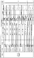
3-2-4.特図変動パターン判定
特図変動パターン判定は、図12~図13に示すような特別図柄の変動パターン判定テーブル(特図変動パターン判定テーブル)を用いて、特図の可変表示の変動パターン(特図変動パターン)を決定するための判定であり、大当たり判定の結果が大当たり、およびハズレの何れの場合にも行われる。特図変動パターンとは、特図変動時間や後述する特図変動演出の演出フロー(演出内容)などに関する所定事項を識別するための識別情報である。なお、特図変動パターンには、特図変動時間や特図変動演出の演出フロー(演出内容)の他、大当たり判定の結果とリーチ判定の結果に関する識別情報を含ませることが可能である。特図変動パターンとして、それぞれ識別情報が異なる複数種類の特図変動パターンを用いることが可能であり、その数は適宜に変更することが可能である。
3-2-4. Special figure variation pattern determination Special figure variation pattern determination uses a special symbol variation pattern determination table (special figure variation pattern determination table) as shown in FIGS. It is a determination for determining the figure fluctuation pattern), and is performed when the result of the jackpot determination is a jackpot or a loss. The special figure fluctuation pattern is identification information for identifying predetermined matters related to the special figure fluctuation time and the production flow (production content) of the special figure fluctuation production described later. It should be noted that the special figure fluctuation pattern, in addition to the special figure fluctuation time and production flow (production content) of special figure fluctuation production, it is possible to include identification information regarding the result of jackpot determination and the result of reach determination. As a special figure variation pattern, it is possible to use a plurality of types of special figure variation patterns with different identification information, respectively, and the number can be changed as appropriate.
特図変動パターン判定テーブルは、判定対象となる可変表示を行う特別図柄の種別(特図1/特図2)、言い換えれば、当該特図変動パターン判定が起因する入賞が行われた始動口の種別(第1始動口11/第2始動口12)に関連付けることが可能である。すなわち、特図変動パターン判定テーブルには、特図1の可変表示を行うときに用いられる特図変動パターン判定テーブル(特図1変動パターン判定テーブル:図12)と、特図2の可変表示を行うときに用いられる特図変動パターン判定テーブル(特図2変動パターン判定テーブル:図13)とがある。
The special figure variation pattern determination table is the type of special symbol that performs variable display to be determined (special figure 1 / special figure 2), in other words, the starting opening where the winning caused by the special figure variation pattern determination was performed It is possible to associate with the type (first starting
そして、各特図変動パターン判定テーブルは、遊技状態(非時短状態/時短状態)にも関連付けることが可能である。すなわち、特図1変動パターン判定テーブルには、非時短状態のときに用いられる特図1変動パターン判定テーブル(非時短用特図1変動パターン判定テーブル)と時短状態のときに用いられる特図1変動パターン判定テーブル(時短用特図1変動パターン判定テーブル)とがある。一方、特図2変動パターン判定テーブルについても同様に、非時短状態のときに用いられる特図2変動パターン判定テーブル(非時短用特図2変動パターン判定テーブル)と、時短状態のときに用いられる特図2変動パターン判定テーブル(時短用特図2変動パターン判定テーブル)と、がある。 And each special figure fluctuation pattern determination table can also be associated with the game state (non-time saving state/time saving state). That is, in the special figure 1 variation pattern determination table, the special figure 1 variation pattern determination table used in the non-time saving state (non-time saving special figure 1 variation pattern determination table) and the special figure 1 used in the time saving state There is a variation pattern determination table (time saving special figure 1 variation pattern determination table). On the other hand, the special figure 2 variation pattern determination table is also used when the special figure 2 variation pattern determination table (special figure 2 variation pattern determination table for non-time saving) used in the non-time saving state and the time saving state There is a special figure 2 variation pattern determination table (time saving special figure 2 variation pattern determination table).
また、遊技状態(非時短状態/時短状態)に関連付けられた各特図変動パターン判定テーブルは、さらに、大当たり判定結果およびリーチ判定結果にも関連付けることが可能である。すなわち、非時短用特図1変動パターン判定テーブルおよび非時短用特図2変動パターン判定テーブルにはそれぞれ、大当たり用、リーチ有りハズレ用、およびリーチ無しハズレ用がある。同様に、時短用特図1変動パターン判定テーブルおよび時短用特図2変動パターン判定テーブルにもそれぞれ、大当たり用、リーチ有りハズレ用、およびリーチ無しハズレ用がある。 In addition, each special figure variation pattern determination table associated with the gaming state (non-time saving state/time saving state) can be further associated with the jackpot determination result and the reach determination result. That is, the non-time-saving special figure 1 variation pattern determination table and the non-time-saving special figure 2 variation pattern determination table each have a big hit, a loss with reach, and a loss without reach. Similarly, the time-saving special figure 1 variation pattern determination table and the time-saving special figure 2 variation pattern determination table each have a big hit, a reach loss, and a reach no loss.
さらに、各リーチ無しハズレ用の特図1変動パターン判定テーブルは、特図保留数にも関連付けることが可能である。例えば、特図1保留数(U1)が0~2のときに用いられるリーチ無しハズレ用の特図1変動パターン判定テーブルと、特図1保留数(U1)が3~4のときに用いられるリーチ無しハズレ用の特図1変動パターン判定テーブルと、がある。また、各リーチ無しハズレ用の特図2変動パターン判定テーブルは、特図保留数にも関連付けられている。具体的には、特図2保留数(U2)が0~2のときに用いられるリーチ無しハズレ用の特図2変動パターン判定テーブルと、特図2保留数(U2)が3~4のときに用いられるリーチ無しハズレ用の特図2変動パターン判定テーブルと、がある。 Furthermore, the special figure 1 variation pattern determination table for each reach no loss can be associated with the number of special figures pending. For example, the special figure 1 variation pattern determination table for reach no loss used when the special figure 1 reservation number (U1) is 0 to 2, and the special figure 1 reservation number (U1) is used when it is 3 to 4 There is a special figure 1 variation pattern determination table for reachless loss. In addition, the special figure 2 fluctuation pattern determination table for each reach no loss is also associated with the number of special figures pending. Specifically, when the special figure 2 reservation number (U2) is 0 to 2 and the special figure 2 variation pattern determination table for reachless loss used when the special figure 2 reservation number (U2) is 3 to 4 There is a special figure 2 variation pattern determination table for reachless loss used for .
そして、各特図変動パターン判定で決定された特図変動パターンに応じた特図変動時間の特図の可変表示が、特図表示器81で行われる。そして、特図の可変表示で、表示結果(特図抽選の結果)として、大当たり図柄が停止表示されると、即座に次の特図の可変表示が行われず、引き続いて、大当たり遊技が実行される。
Then, the variable display of the special figure of the special figure variation time according to the special figure variation pattern determined by each special figure variation pattern determination is performed by the special
また、各特図変動パターンには、図12~図13の表の右から2番目の欄に示すような特図変動演出の演出フローに関連付けることが可能である。 In addition, each special figure fluctuation pattern can be associated with the effect flow of the special figure fluctuation production as shown in the second column from the right of the table in FIGS.
なお、図12~図13の表の一番右の欄に示すように、特図変動パターンについて、特図(大当たり判定結果)および特図変動演出の演出内容などに関連付けて名称を付すことがある。例えば、大当たりに係る特図変動パターンのことを「大当たり変動」といい。一方、リーチ有りハズレの中で、リーチの一種であるSPリーチが行われる特図変動パターンのことを「SPハズレ変動」、リーチ有りハズレの中で、リーチの一種であるLリーチが行われる特図変動パターンのことを「Lハズレ変動」、リーチ有りハズレの中で、リーチの一種であるNリーチで特図変動演出が終わる特図変動パターンのことを「Nハズレ変動」、リーチ無しハズレに係る特図変動パターンのことを「通常ハズレ変動」という。通常ハズレ変動には、変動時間が互いに異なる3種類の変動(通常Aハズレ変動、通常Bハズレ変動、通常Cハズレ変動)がある。 In addition, as shown in the rightmost column of the table of FIGS. 12 to 13, the special figure fluctuation pattern can be named in association with the special figure (jackpot determination result) and the production contents of the special figure fluctuation production. be. For example, the special figure variation pattern related to the jackpot is called “jackpot variation”. On the other hand, in the loss with reach, SP reach, which is a type of reach, is performed. The figure fluctuation pattern is "L loss fluctuation", and in the loss with reach, the special fluctuation pattern where the special figure fluctuation effect ends with N reach, which is a type of reach, is "N loss fluctuation", and the loss without reach Such a special figure variation pattern is referred to as "normal loss variation". There are three kinds of normal losing fluctuations (normal A losing fluctuation, normal B losing fluctuation, normal C losing fluctuation) with different fluctuation times.
3-2-5.先読み判定
パチンコ遊技機PY1は、取得した特図関係乱数に基づいて、図14に示すような先読み判定テーブルを用いて先読み判定を行う。先読み判定には、例えば、特別図柄乱数が大当たり判定で大当たりと判定されるか否かの判定、大当たり図柄種別乱数が大当たり図柄種別判定で何れの大当たり図柄の種別に決定されるかの判定、特図変動パターン乱数が特図変動パターン判定で何れの特図変動パターンに決定されるかの判定、などがある。先読み判定テーブルは、その始動入賞に係る始動口の種別(第1始動口11/第2始動口12)に関連付けることが可能である。すなわち、先読み判定テーブルには、第1始動口11に入賞した場合の先読み判定テーブル(第1先読み判定テーブル)と、第2始動口12に入賞した場合の先読み判定テーブル(第2先読み判定テーブル)と、がある。
3-2-5. Prefetching Determination The pachinko gaming machine PY1 performs prefetching determination using a prefetching determination table as shown in FIG. 14 based on the obtained special figure-related random number. For the look-ahead determination, for example, determination of whether or not the special symbol random number is determined to be a big hit in the big hit determination, determination of which jackpot symbol type the jackpot symbol type random number is determined in the jackpot symbol type determination, special There is a determination of which special figure variation pattern the figure variation pattern random number is determined in the special figure variation pattern determination. The look-ahead determination table can be associated with the type of starting opening (first starting
また、先読み判定テーブルは、遊技状態(非時短状態/時短状態)にも関連付けることが可能である。すなわち、先読み判定テーブルには、非時短状態のときに用いられる先読み判定テーブル(非時短用先読み判定テーブル)と、時短状態のときに用いられる先読み判定テーブル(時短用先読み判定テーブル)と、がある。 In addition, the look-ahead determination table can be associated with the game state (non-time saving state/time saving state). That is, the lookahead determination table includes a lookahead determination table (non-time-saving lookahead determination table) used in the non-time-saving state and a look-ahead determination table (time-saving lookahead determination table) used in the time-saving state. .
つまり、先読み判定テーブルには、非時短状態のときに用いられる第1先読み判定テーブルと、時短状態のときに用いられる第1先読み判定テーブルと、非時短状態のときに用いられる第2先読み判定テーブルと、時短状態のときに用いられる第2先読み判定テーブルと、がある。なお、先読み判定にどのような判定を含ませるかは適宜に変更可能である。 That is, the look-ahead determination table includes the first look-ahead determination table used in the non-time-saving state, the first look-ahead determination table used in the time-saving state, and the second look-ahead determination table used in the non-time-saving state. and a second look-ahead determination table used in the time saving state. It should be noted that it is possible to appropriately change what kind of determination is included in the prefetch determination.
3-3.大当たり遊技
次に、大当たり遊技について説明する。大当たり遊技は、大入賞口(第1大入賞口14および第2大入賞口15)の開閉を伴う複数回のラウンド遊技と、大当たり遊技が開始してから初回のラウンド遊技が開始されるまでのオープニング(OPとも表記する)と、最終回のラウンド遊技が終了してから大当たり遊技が終了するまでのエンディング(EDとも表記する)とを含んでいる。各ラウンド遊技は、オープニングの終了又は前のラウンド遊技の終了によって開始し、次のラウンド遊技の開始又はエンディングの開始によって終了する。また、OPやEDを設けないようすることが可能である。なお、以下において、所定回数目(所定の順番)のラウンド遊技を、単に「ラウンド」という。例えば、初回(1回目)のラウンド遊技のことを「1ラウンド(1R)」といい、10回目のラウンド遊技のことを「10ラウンド(10R)」という。
3-3. Jackpot Game Next, the jackpot game will be described. The jackpot game includes multiple round games with opening and closing of the jackpot (
このような大当たり遊技を構成する要素(大当たり遊技構成要素)には、ラウンド遊技の回数、各回のラウンド遊技における大入賞口(第1大入賞口14および第2大入賞口15)の開放回数、各開放が行われる大入賞口の種別および開放時間(開放パターン)、次回の開放まで閉鎖させる時間(閉鎖時間)、オープニングの時間(オープニング時間)、およびエンディングの時間(エンディング時間)などが含まれている。パチンコ遊技機PY1は、特図の停止表示後、図15に示すような大当たり遊技制御テーブルを用いて大当たり遊技を制御する。大当たり遊技制御テーブルには、大当たり遊技毎に大当たり遊技構成要素が格納されている。大当たり遊技として、1種類又は複数種類の大当たり遊技を制御することが可能である。
Elements that make up such a jackpot game (jackpot game components) include the number of round games, the number of openings of the big winning holes (first big winning
例えば、図15に示すように、1Rから15Rまでは、最大で29.5秒にわたって第1大入賞口14が開放するラウンド遊技、または、最大で0.1秒にわたって第1大入賞口14が開放するラウンド遊技、が行われる。そして、16R(最終ラウンド)では、最大で29.5秒にわたって第2大入賞口15が開放するラウンド遊技、または、最大で0.1秒にわたって第2大入賞口15が開放するラウンド遊技、が行われる。また、各ラウンド遊技では、予め定めた所定個数(例えば10個)の遊技球が大入賞口センサ14a,15aによって検出されると、大入賞口14,15の最大開放時間が経過する前であっても、ラウンド遊技を終了させる。
For example, as shown in FIG. 15, from 1R to 15R, the round game in which the first big winning
また、各要素における回数や時間については、適宜に変更することが可能である。また、大当たり遊技を、第1大入賞口14および第2大入賞口15の両方を用いて行うことも一方だけを用いて行うことも可能である。なお、第1大入賞口14だけを用いる大当たり遊技しか行わない構成、あるいは、第2大入賞口15だけを用いる大当たり遊技しか行わない構成とする場合には、用いない方の大入賞口を備えない構成としてもよい。
Also, the number of times and time for each element can be changed as appropriate. In addition, the jackpot game can be performed using both the first big winning
ここで、特定領域16について詳細に説明する。特定領域16は、振分部材16kによって、入賞不可能な閉状態と、入賞可能な開状態とをとるので、振分部材16kの作動態様は、特定領域16の開閉態様ということができる。以下において、振分部材16kの作動態様のことを「特定領域16の開閉態様」ともいう。このように、振分部材16kが一定の作動態様(特定領域16が一定の開閉態様)で制御されるが、振分部材16kの一定の作動態様(特定領域16の一定の開閉態様)と、大当たり遊技における第2大入賞口15の開閉態様との組み合わせで、大当たり遊技において遊技球を特定領域16に進入させることの困難性(容易性)が設定されることになる。なお、以下において、特定領域16が開状態にあることを「V開放」ともいう。また、特定領域16が閉状態にあることを「V閉鎖」ともいう。
Here, the
第2大入賞口の開放が開始してから15秒間、振分ソレノイド16sが通電され、振分部材16kが第2状態(図4(B))に制御される。よって、最大で29.5秒にわたって第2大入賞口15が開放するラウンド遊技では、第2大入賞口15の開放時間およびタイミングと、振分部材16kの第2状態に制御されている時間およびタイミングとの関係から、遊技球が特定領域16を通過する(遊技球を特定領域16に進入させる)ことが容易である。一方、最大で0.1秒にわたって第2大入賞口15が開放するラウンド遊技では、第2大入賞口15の開放時間およびタイミングと、振分部材16kの第2状態に制御されている時間およびタイミングとの関係から、遊技球が特定領域16を通過する(遊技球を特定領域16に進入させる)ことはほぼ不可能(困難)である。このように、大当たり遊技には、当該大当たり遊技中に、遊技球の特定領域16の通過(以下、「V通過」ともいう)が容易な第1開放パターン(Vロング開放パターン)でVAT開閉部材15k及び振分部材16kが作動する大当たり遊技と、遊技球の特定領域16の通過が不可能又は困難な第2開放パターン(Vショート開放パターン)でVAT開閉部材15k及び振分部材16kが作動する大当たり遊技と、を実行することが可能である。このように、Vロング開放パターンでVAT開閉部材15k及び振分部材16kが作動する大当たり遊技を「Vロング大当たり」という。一方、Vショート開放パターンでVAT開閉部材15k及び振分部材16kが作動する大当たり遊技を「Vショート大当たり」という。
The
次に、遊技状態について説明する。パチンコ遊技機PY1は、図16に示すように、「低確率低ベース遊技状態」、「低確率高ベース遊技状態」、「高確率低ベース遊技状態」、「高確率高ベース遊技状態」および「大当たり遊技状態」の何れかの遊技状態にすることが可能である。なお、「低確率低ベース遊技状態」を「低確低ベース状態」と、「低確率高ベース遊技状態」を「低確高ベース状態」と、「高確率低ベース遊技状態」を「高確低ベース状態」と、「高確率高ベース遊技状態」を「高確高ベース状態」と、それぞれ略称することができる。遊技状態を構成する状態として、大当たり判定において「大当たり」と判定される確率に係る状態と、電チュー12Dの開放の容易性に係る状態とがある。前者としては、通常確率状態と高確率状態とがある。一方、後者としては非時短状態と時短状態とがある。
Next, the game state will be explained. As shown in FIG. 16, the pachinko machine PY1 has a "low probability low base game state", "low probability high base game state", "high probability low base game state", "high probability high base game state" and It is possible to make it into any game state of "jackpot game state". In addition, "low probability low base game state" is "low probability low base state", "low probability high base game state" is "low probability high base state", and "high probability low base game state" is "high probability". "Low base state" and "high probability high base gaming state" can be abbreviated as "high probability high base state", respectively. As states constituting the game state, there are a state related to the probability of being determined as a "big win" in the big win determination and a state related to the ease of opening the
通常確率状態は、「低確率低ベース遊技状態」または「低確率高ベース遊技状態」において設定され、大当たり判定で大当たりと判定される確率が通常の確率である状態である。高確率状態は、「高確率低ベース遊技状態」または「高確率高ベース遊技状態」において設定され、大当たり判定で大当たりと判定される確率が通常確率より高い高確率である状態である。従って、高確率状態は通常確率状態よりも遊技者に有利な状態であると言える。パチンコ遊技機PY1で初めて電源投入されたときには通常確率状態が設定される。そして、大当たりに当選することによって通常確率状態から高確率状態に切り替えることが可能になる。例えば、大当たり遊技において遊技球が特定領域16を通過することによって高確率状態に切り替えることが可能である。また、大当たり図柄の種別によって高確率状態に切り替えることも可能である。高確率状態に切り替える契機をV通過とするか、大当たり図柄の種別とするかは、実現したい遊技性に応じて適宜定めておけばよい。高確率状態は、大当たりに当選することなく所定回数の大当たり判定が行われることや、次回の大当たりに当選することで、高確率状態から通常確率状態に切り替えることが可能である。
The normal probability state is set in the "low-probability low-base game state" or "low-probability high-base game state", and is a state in which the probability of being judged as a big hit in the jackpot judgment is a normal probability. The high-probability state is set in the "high-probability low-base game state" or "high-probability high-base game state", and is a state in which the probability of being judged as a big hit in the jackpot judgment is higher than the normal probability. Therefore, it can be said that the high-probability state is more advantageous to the player than the normal-probability state. When the pachinko game machine PY1 is powered on for the first time, a normal probability state is set. Then, by winning a jackpot, it becomes possible to switch from the normal probability state to the high probability state. For example, it is possible to switch to a high probability state by passing a game ball through the
非時短状態は、「低確率低ベース遊技状態」、「高確率低ベース遊技状態」または「大当たり遊技状態」において設定される。時短状態は、「低確率高ベース遊技状態」または「高確率高ベース遊技状態」において設定され、非時短状態に比べて、1回の補助遊技における電チュー12Dの開放時間が長くなり易い遊技状態である。例えば、時短状態においては、非時短状態における電チュー12Dの開放時間(例えば0.08秒)よりも長い開放時間(例えば3.0秒)となる。また、時短状態では、特図変動時間の短い特図変動パターンが選択されることが非時短状態よりも多くなるように定められた特図変動パターン判定テーブルを用いて、特図変動パターン判定が行われるようにすることも可能である(図12~図13参照)。その結果、時短状態では、特図保留の消化のペースが速くなり、始動口への有効な入賞(特図保留として記憶され得る入賞)が発生しやすくなる。そのため、スムーズな遊技の進行のもとで大当たりを狙うことができる。
The non-time saving state is set in the "low probability low base game state", "high probability low base game state" or "jackpot game state". The time-saving state is set in the "low-probability high-base game state" or "high-probability high-base game state", and compared to the non-time-saving state, the game state in which the opening time of the
また、時短状態は、非時短状態に比べて、普図変動時間が短くなり易くすることが可能である。例えば、時短状態においては、非時短状態において決定される普図変動時間(30秒)よりも短い普図変動時間(5秒)が決定される。よって、時短状態の方が、単位時間当たりにおける普図抽選の実行回数が多い。 Moreover, compared with a non-work-saving state, a time-saving state can make normal figure fluctuation|variation time short easily. For example, in the time saving state, the normal figure fluctuation time (5 seconds) shorter than the normal figure fluctuation time (30 seconds) determined in the non-working time saving state is determined. Therefore, the number of executions of the normal drawing lottery per unit time is greater in the time saving state.
また、時短状態は、非時短状態に比べて、当たり判定で当たりと判定され易くすることが可能である。例えば、時短状態では、非時短状態で当たりと判定される確率(例えば6600/65536)よりも高い確率(例えば59936/65536)で当たりと判定される。よって、時短状態の方が、単位時間当たりにおいて当たり判定で当たりと判定される回数が多い。 Moreover, the time saving state can be made easier to be determined to be a hit in the hit determination as compared with the non-time saving state. For example, in the time saving state, it is determined to be a hit with a probability (eg, 59936/65536) higher than the probability (eg, 6600/65536) determined to be a hit in the non-time saving state. Therefore, the time-saving state has a larger number of hit determinations per unit time.
このように時短状態では、非時短状態に比して、単位時間当たりの電チュー12Dの開放時間が長くなり、第2始動口12へ遊技球が頻繁に入賞し易くなる。その結果、発射球数に対する賞球数の割合であるベースが高くなる。そのため、ベースの高い時短状態では、所持する遊技球を大きく減らすことなく大当たり当選を狙うことができる。従って、時短状態は非時短状態よりも遊技者に有利な状態であると言える。
Thus, in the time-saving state, the opening time of the
パチンコ遊技機PY1で初めて電源投入されたときには非時短状態が設定される。そして、例えば、大当たりに当選することによって時短状態が設定可能になる。時短状態は、大当たりに当選することなく所定回数の大当たり判定が行われることや、次回の大当たりに当選することで、時短状態から非時短状態に変更することが可能である。 When the pachinko game machine PY1 is powered on for the first time, a non-time-saving state is set. Then, for example, by winning a jackpot, a time saving state can be set. The time-saving state can be changed from the time-saving state to the non-time-saving state by performing a predetermined number of big win determinations without winning the big win or by winning the next big win.
なお、時短状態では、非時短状態に比して、当たりに当選し易く、普図変動時間が短くなり易く、且つ、1回の補助遊技における電チュー12Dの開放時間が長くなり易い。普図に係る遊技について3つの点で、遊技者に有利に設定されている。しかし、この遊技者に有利に設定されている点はこれらの中の一部であってもよい。
In addition, in the time-saving state, it is easier to win a win than in the non-time-saving state, the normal pattern fluctuation time is easy to be short, and the opening time of the
なお、パチンコ遊技機PY1で初めて電源投入された後の遊技状態は、通常確率状態且つ非時短状態が設定される「低確率低ベース遊技状態」である。この遊技状態を「通常遊技状態」ともいう。なお、「大当たり遊技状態」では、当たり判定は行われるが大当たり判定は行われないため、大当たり遊技の開始に伴って、非時短状態が設定される。また、遊技状態については、前述した遊技状態の全てを用いることも一部だけを用いることも可能である。 The game state after the pachinko game machine PY1 is powered on for the first time is a "low-probability low-base game state" in which the normal probability state and the non-time-saving state are set. This game state is also called "normal game state". In addition, in the "jackpot game state", the hit determination is performed, but the jackpot determination is not performed, so a non-time-saving state is set with the start of the jackpot game. As for the game state, it is possible to use all or part of the game states described above.
4.遊技機による主な演出
次に、パチンコ遊技機PY1により行われる主な演出について、図17~図28を用いて説明する。
4. Main Effects by Game Machine Next, main effects performed by the pachinko game machine PY1 will be described with reference to FIGS. 17 to 28. FIG.
4-1.演出モード
最初に、演出モードについて説明する。演出モードは、演出の区分(あるいは、上位概念的な属性)のことである。パチンコ遊技機PY1は、演出モードとして、客待ち演出モード、通常演出モードと、確変演出モード、時短演出モードおよび大当たり演出モードを設定することが可能である。
4-1. Production Mode First, the production mode will be described. The production mode is a division of production (or a higher-level attribute). The pachinko game machine PY1 can set, as production modes, a customer waiting production mode, a normal production mode, a variable probability production mode, a short working hours production mode and a jackpot production mode.
客待ち演出モードは、「低確率低ベース遊技状態」、「低確率高ベース遊技状態」、「高確率低ベース遊技状態」および「高確率高ベース遊技状態」において特図変動演出が行われていないときに設定可能であり、特図変動演出が行われていない待機状態であることを示す演出モードである。客待ち演出モードが設定されているときに客待ち演出が行われる。客待ち演出では、例えば、図17(A)に示すように、表示部50aにおいてパチンコ遊技機PY1を紹介する客待ちデモ動画G100が表示される。また、客待ちデモ動画G100が表示されているときに半球型ボタン40が操作されると、図17(B)に示すように、パチンコ遊技機PY1の演出に関する設定を行うための設定画面G101が表示される。演出に関する設定には、スピーカ52から出力される音の音量設定、表示部50aの輝度設定、実行される演出の頻度設定などがある。
In the customer waiting production mode, a special variable production is performed in the "low probability low base game state", "low probability high base game state", "high probability low base game state" and "high probability high base game state". It is a production mode that can be set when there is no special figure fluctuation production and indicates that it is in a standby state. A customer waiting performance is performed when the customer waiting performance mode is set. In the customer waiting effect, for example, as shown in FIG. 17A, a customer waiting demonstration video G100 introducing the pachinko gaming machine PY1 is displayed on the
通常演出モードは、「低確率低ベース遊技状態」または「高確率低ベース遊技状態」において特図変動演出が行われているときに設定可能であり、非時短状態であることを示す演出モードである。通常演出モードには、例えば、図18(A)に示すように、表示部50aにおいて昼間の山の景色を表す背景画像(昼間通常用背景画像G102)が表示される第1通常演出モードと、図18(B)に示すように、表示部50aにおいて夕方の山の景色を表す背景画像(夕方通常用背景画像G103)が表示される第2通常演出モードと、図18(C)に示すように、表示部50aにおいて夜間の山の景色を表す背景画像(夜間通常用背景画像G104)が表示される第3通常演出モードと、があり、大当たりに当選することなく1回または複数回の特図変動演出が行われることを1つの条件として切り替えられる。さらに、第1~第3通常演出モードのそれぞれには、特図変動演出において、リーチが成立する前の通常前段演出モードと、リーチが成立した後の通常後段演出モードと、がある。通常前段演出モードでは、表示部50aにおいて、昼間通常用背景画像G102、夕方通常用背景画像G103および夜間通常用背景画像G104の何れかが表示されるが、通常後段演出モードでは、リーチの種類に応じた専用の背景画像が表示される。また、「高確率低ベース遊技状態」においてのみ設定される特殊演出モードを設けても良い。
Normal production mode can be set when special figure fluctuation production is performed in "low probability low base game state" or "high probability low base game state", and it is a production mode indicating that it is a non-time saving state be. In the normal effect mode, for example, as shown in FIG. 18A, a first normal effect mode in which a background image (daytime normal background image G102) representing daytime mountain scenery is displayed on the
確変演出モードは、「高確率高ベース遊技状態」において特図変動演出が行われているときに設定可能な演出モードであり、高確率状態且つ時短状態であることを示す演出モードである。確変演出モードでは、例えば、図18(D)に示すように、表示部50aにおいて宇宙を表す背景画像(確変用背景画像G105)が表示される。さらに、確変演出モードには、特図変動演出において、リーチが成立する前の確変前段演出モードと、リーチが成立した後の確変後段演出モードと、がある。確変前段演出モードでは、表示部50aにおいて、確変用背景画像G105が表示されるが、確変後段演出モードでは、リーチの種類に応じた専用の背景画像が表示される。
The probability variable production mode is a production mode that can be set when the special figure fluctuation production is performed in the "high probability high base game state", and is a production mode indicating that it is a high probability state and a time saving state. In the probability variation effect mode, for example, as shown in FIG. 18(D), a background image representing the universe (probability variation background image G105) is displayed on the
時短演出モードは、「低確率高ベース遊技状態」において特図変動演出が行われているときに設定可能な演出モードであり、通常確率状態且つ時短状態であることを示す演出モードである。時短演出モードでは、例えば、図18(E)に示すように、表示部50aにおいて空を表す背景画像(時短用背景画像G106)が表示される。さらに、時短演出モードには、特図変動演出において、リーチが成立する前の時短前段演出モードと、リーチが成立した後の時短後段演出モードと、がある。時短前段演出モードでは、表示部50aにおいて、時短用背景画像G106が表示されるが、時短後段演出モードでは、リーチの種類に応じた専用の背景画像が表示される。
The time-saving performance mode is a performance mode that can be set when the special figure variation performance is performed in the "low-probability high-base game state", and is a performance mode indicating that it is a normal probability state and a time-saving state. In the time saving effect mode, for example, as shown in FIG. 18(E), a background image representing the sky (background image for time saving G106) is displayed on the
大当たり演出モードは、「大当たり遊技状態」において大当たり遊技が行われているときに設定可能な演出モードであり、大当たり遊技が行われていることを示す演出モードである。大当たり演出モードでは、例えば、大当たり遊技におけるオープニング中には、図19(A)に示すように、表示部50aにおいて、大当たり遊技の開始を示唆するオープニング画像G107や「右打ち」を促す右打ち画像G108が表示される大当たりオープニング演出が行われる。大当たり遊技におけるラウンド中には、図19(B)に示すように、表示部50aにおいて、ラウンド数を示すラウンド画像G109や払い出された賞球数を示唆する賞球数画像G110が表示されるラウンド演出が行われる。大当たり遊技におけるエンディング中には、図19(C)に示すように、表示部50aにおいて、大当たり遊技後に設定される演出モードを示唆するエンディング画像G111や払い出された総賞球数を示唆する総賞球数画像G112が表示される大当たりエンディング演出が行われる。
The jackpot production mode is a production mode that can be set when a jackpot game is being performed in the "jackpot game state", and is a production mode indicating that the jackpot game is being performed. In the jackpot effect mode, for example, during the opening of the jackpot game, as shown in FIG. 19A, an opening image G107 suggesting the start of the jackpot game and a right-hand shot image prompting "right-hand shot" are displayed on the
なお、演出モードの種類については、適宜に変更または追加することが可能である。 It should be noted that the types of production modes can be changed or added as appropriate.
4-2.特図変動演出
次に、特図変動演出(単に「変動演出」とも言う)について説明する。パチンコ遊技機PY1は、特図の可変表示が開始されると、特図の可変表示に係る特図変動パターンおよび特図抽選結果(大当たり判定結果、大当たり図柄種別判定結果、リーチ判定結果、および、特図変動パターン判定結果)などに基づいて、特図変動演出を実行する。特図変動演出では、表示部50aにおいて、所定の背景画像に重畳的に、演出図柄の変動表示が行われる。演出図柄の変動表示では、演出図柄が変動した後に停止する。すなわち、特図変動時間、演出図柄の変動表示が行われた後に、当該変動が停止して、演出図柄の停止表示が行われる。そして、演出図柄の停止表示によって特図抽選の結果が報知される。
4-2. Special figure fluctuation production Next, the special figure fluctuation production (also simply referred to as "variation production") will be described. Pachinko gaming machine PY1, when the variable display of the special figure is started, the special figure variation pattern and the special figure lottery result related to the variable display of the special figure (jackpot determination result, jackpot pattern type determination result, reach determination result, and Based on the special figure fluctuation pattern determination result) etc., the special figure fluctuation production is executed. In the special figure variation effect, the variation display of the effect symbol is performed in the
なお、特図変動演出では、演出図柄の変動表示以外に、画像表示装置50、スピーカ52、枠ランプ53、盤ランプ54、可動装置55,56,57,58、半球型ボタン40、剣型ボタン41などの様々な演出装置を用いた演出を行うことが可能である。
In addition, in the special figure variation effect, in addition to the variation display of the effect pattern, the
4-2-1.演出図柄表示領域
画像表示装置50の表示部50aには、図20(A)に示すように、表示部50aを水平方向に3つに略均等に分けた左側、中央および右側それぞれに、左演出図柄領域50b1、中演出図柄領域50b2、および右演出図柄領域50b3を設けることが可能である。左演出図柄領域50b1は、特図変動演出における演出図柄の停止表示のときに、左演出図柄EZ1を表示する領域である。同様に、中演出図柄領域50b2および右演出図柄領域50b3は、中演出図柄EZ2および右演出図柄EZ3を表示する領域である。
4-2-1. Effect Symbol Display Area In the
また、図20(A)に示すように、表示部50aの上端部の左端(左上隅)の一区画に、小図柄領域50cを設けることが可能である。小図柄領域50cは、特図の可変表示が行われているときに小図柄KZ1,KZ2,KZ3を変動表示する領域である。
Further, as shown in FIG. 20A, it is possible to provide a
なお、図20(A)において、左演出図柄領域50b1、中演出図柄領域50b2、右演出図柄領域50b3、および小図柄領域50cは破線で明示されているが、これは左演出図柄領域50b1、中演出図柄領域50b2、右演出図柄領域50b3、および小図柄領域50cの範囲を表すために記載したものであり、実際には表示されていない。
In FIG. 20(A), the left effect pattern region 50b1, the middle effect pattern region 50b2, the right effect pattern region 50b3, and the
4-2-2.通常変動
パチンコ遊技機PY1は、特図変動演出において、先ず通常変動を行うことが可能である。通常変動は、特図の可変表示が開始されたことを示唆する演出として機能する。
4-2-2. Normal variation The pachinko game machine PY1 can perform normal variation first in the special figure variation effect. The normal variation functions as an effect suggesting that the variable display of the special figure has started.
特図の可変表示が開始されると、例えば、図20(A)に示すように、表示部50aにおいて、左演出図柄EZ1、中演出図柄EZ2および右演出図柄EZ3が停止表示されていると共に、左小図柄KZ1、中小図柄KZ2および右小図柄KZ3が停止表示されており、特図の可変表示が行われておらず、特図の可変表示を待機している状態から、図20(B)に示すように、その開始に伴って演出図柄EZ1,EZ2,EZ3の変動表示が開始されると共に、左小図柄KZ1、中小図柄KZ2および右小図柄KZ3の変動表示が開始される。そして、この特図の可変表示の特図変動パターンがリーチ無しハズレの特図変動パターン(例えば、通常ハズレ変動)であると、リーチが発生することなく、特図の可変表示の終了(特図の停止表示)に伴って、リーチ無しハズレに特有なハズレ目(所謂「バラケ目」)で演出図柄EZ1,EZ2,EZ3の停止表示が行われる。演出図柄EZ1,EZ2,EZ3の停止表示に向けて、例えば、最初に図20(C)に示すように、左演出図柄EZ1が上下方向略中央位置で仮停止し、次に図20(D)に示すように、右演出図柄EZ3が上下方向略中央位置で仮停止し、さらに、図20(E)に示すように、中演出図柄EZ2が上下方向略中央位置で仮停止する。そして、最後に、上下方向略中央位置で水平方向に並んだ状態で仮停止している演出図柄EZ1,EZ2,EZ3が、図20(F)に示すように、そのまま一斉に完全に停止し、停止が確定する(演出図柄EZ1,EZ2,EZ3の停止表示が行われる)。仮停止していた演出図柄EZ1,EZ2,EZ3がバラケ目で完全に停止するとき、すなわち、演出図柄EZ1,EZ2,EZ3の停止表示が行われるとき、3つの小図柄KZ1,KZ2,KZ3が、演出図柄EZ1,EZ2,EZ3と同一のバラケ目で一斉に停止し、小図柄KZ1,KZ2,KZ3の停止表示も行われる。 When the variable display of the special figure is started, for example, as shown in FIG. Left small pattern KZ1, medium and small pattern KZ2, and right small pattern KZ3 are stopped and displayed, variable display of special symbols is not performed, and from the state of waiting for variable display of special symbols, FIG. 20 (B) , along with the start, the variable display of the performance symbols EZ1, EZ2, and EZ3 is started, and the variable display of the left small pattern KZ1, the medium and small patterns KZ2, and the right small pattern KZ3 is also started. Then, if the special figure variation pattern of the variable display of this special figure is a special figure variation pattern of no reach loss (for example, normal loss variation), the end of the variable display of the special figure (special figure stop display), the stop display of the performance symbols EZ1, EZ2, and EZ3 is performed with a losing streak (so-called “break streak”) peculiar to the reach-less losing. Toward the stop display of the performance symbols EZ1, EZ2, and EZ3, for example, first, as shown in FIG. 20(C), the left performance symbol EZ1 is temporarily stopped at the approximately center position in the vertical direction, and then, as shown in FIG. 20(D). , the right performance symbol EZ3 is temporarily stopped at approximately the vertical center position, and further, as shown in FIG. 20(E), the middle performance symbol EZ2 is temporarily stopped at the approximately vertical center position. Finally, the performance symbols EZ1, EZ2, and EZ3, which are temporarily stopped in a state of being horizontally aligned at a substantially central position in the vertical direction, are completely stopped all at once, as shown in FIG. The stop is confirmed (the effect symbols EZ1, EZ2 and EZ3 are stopped and displayed). When the performance symbols EZ1, EZ2, and EZ3 which have been temporarily stopped are completely stopped by loose stitches, that is, when the stop display of the performance symbols EZ1, EZ2, and EZ3 is performed, the three small symbols KZ1, KZ2, and KZ3 are The performance symbols EZ1, EZ2, and EZ3 are stopped all at once at the same loose stitches, and the small symbols KZ1, KZ2, and KZ3 are also stopped and displayed.
なお、図20の例では、演出図柄EZ1,EZ2,EZ3の停止表示が行われる際に、左演出図柄EZ1→右演出図柄EZ3→中演出図柄EZ2の順で演出図柄が仮停止したが、仮停止する態様はこれに限られず、適宜に設定することができる。 In the example of FIG. 20, when the performance symbols EZ1, EZ2, and EZ3 are stopped and displayed, the performance symbols are temporarily stopped in the order of left performance design EZ1→right performance design EZ3→middle performance design EZ2. The mode of stopping is not limited to this, and can be set as appropriate.
一方、特図の可変表示の特図変動パターンがリーチ有りハズレの特図変動パターン(例えば、Nハズレ変動)であると、前述のリーチ無しの場合と同様に、表示部50aにおいて、図21(A)に示すように、左演出図柄EZ1、中演出図柄EZ2および右演出図柄EZ3が停止表示されていると共に、左小図柄KZ1、中小図柄KZ2および右小図柄KZ3が停止表示されている状態から、特図の可変表示が開始されて、図21(B)に示すように、演出図柄EZ1,EZ2,EZ3の変動表示が開始されると共に、左小図柄KZ1、中小図柄KZ2および右小図柄KZ3の変動表示が開始される。そして、例えば図21(C)に示すように、数字「5」からなる左演出図柄EZ1が上下方向略中央位置で仮停止し、次に、図21(D)に示すように、同一の数字「5」からなる右演出図柄EZ3が上下方向略中央位置で水平方向に並んで仮停止して、リーチになる(リーチが発生または成立する)。演出図柄でリーチが成立しても、左小図柄KZ1、中小図柄KZ2および右小図柄KZ3の変動表示は継続して行われている。
On the other hand, if the special figure variation pattern of the variable display of the special figure is a special figure variation pattern with reach and loss (for example, N loss variation), as in the case of no reach described above, in the
なお、図21の例では、リーチが成立する際に、左演出図柄EZ1→右演出図柄EZ3の順で演出図柄が仮停止したが、仮停止する態様はこれに限られず、適宜に設定することができる。また、リーチを構成する演出図柄の数字も「5」に限られない。また、仮停止する位置も上下方向略中央位置に限られない。また、リーチを構成する演出図柄が並ぶ方向も水平方向に限られず斜め方向など他の方向であってもよい。 In the example of FIG. 21, when the ready-to-win is established, the performance symbols are temporarily stopped in the order of the left performance symbol EZ1→the right performance symbol EZ3, but the mode of temporary stop is not limited to this, and can be set as appropriate. can be done. Also, the number of the production pattern that constitutes the ready-to-win is not limited to "5". Further, the temporary stop position is not limited to the substantially central position in the vertical direction. Also, the direction in which the performance symbols constituting the ready-to-win are arranged is not limited to the horizontal direction, and may be another direction such as an oblique direction.
4-2-3.Nリーチ
パチンコ遊技機PY1は、通常変動の後にリーチが成立するとNリーチを行うことが可能である。Nリーチは、特図抽選の抽選結果が「大当たり」であった可能性があることを示唆する演出であり、遊技者に大当たりを期待させるための演出として機能する。
4-2-3. N-reach Pachinko game machine PY1 can perform N-reach when reach is established after normal variation. The N-reach is an effect suggesting that the lottery result of the special lottery may have been a "big win", and functions as an effect for making the player expect a big win.
リーチが成立すると、例えば、図21(D)に示すように、その時点からNリーチが行われる。Nリーチでは、図22(A)に示すように、リーチが成立した状態が所定時間(例えば、10秒)維持される。Nリーチが開始されると、図22(B)に示すように、通常態様の高速で変動表示(スクロール)をしている中演出図柄EZ2が徐々に減速していく。 When reach is established, for example, as shown in FIG. 21(D), N reach is performed from that point. In the N reach, as shown in FIG. 22A, the state in which the reach is established is maintained for a predetermined time (for example, 10 seconds). When the N-reach is started, as shown in FIG. 22(B), the middle effect symbol EZ2 that is displayed (scrolled) at high speed in the normal mode gradually decelerates.
特図の可変表示の特図変動パターンがリーチ有りハズレの特図変動パターン(例えば、Nハズレ変動)であると、リーチが成立した状態から、中演出図柄EZ2が上下方向略中央位置で仮停止してハズレを示す演出図柄の停止表示が行われる。このとき、リーチが成立しているので、図22(C-1)に示すように、リーチを構成する数字とは異なる数字(図22(C-1)において「4」)からなる中演出図柄EZ2が仮停止する。そして、特図の可変表示の終了(特図の停止表示)に伴って、図22(D-1)に示すように、仮停止状態が完全な停止状態になり、リーチ有りハズレに特有なハズレ目で左演出図柄EZ1、中演出図柄EZ2および右演出図柄EZ3の停止表示が行われる。また、仮停止していた演出図柄EZ1,EZ2,EZ3がリーチ有りハズレに特有なハズレ目で完全に停止するとき、すなわち、演出図柄EZ1,EZ2,EZ3の停止表示が行われるとき、3つの小図柄KZ1,KZ2,KZ3が、演出図柄EZ1,EZ2,EZ3と同一のリーチ有りハズレに特有なハズレ目で一斉に停止し、小図柄KZ1,KZ2,KZ3の停止表示も行われる。 When the special figure variation pattern of the variable display of the special figure is the special figure variation pattern of the loss with reach (for example, N loss variation), from the state where the reach is established, the middle production pattern EZ2 is temporarily stopped at the vertical direction approximately center position. Then, the stop display of the production pattern indicating the loss is performed. At this time, since the reach is established, as shown in FIG. 22 (C-1), the middle production pattern consisting of numbers ("4" in FIG. 22 (C-1)) different from the numbers constituting the reach EZ2 temporarily stops. Then, with the end of the variable display of the special figure (stop display of the special figure), as shown in FIG. Stop display of the left effect symbol EZ1, the middle effect symbol EZ2 and the right effect symbol EZ3 is performed with the eyes. In addition, when the temporarily stopped performance symbols EZ1, EZ2, and EZ3 are completely stopped with the losing eyes peculiar to the loss with reach, that is, when the stop display of the performance symbols EZ1, EZ2, and EZ3 is performed, three small The symbols KZ1, KZ2 and KZ3 are stopped all at once with the same loss with reach as the performance symbols EZ1, EZ2 and EZ3, and the small symbols KZ1, KZ2 and KZ3 are also stopped and displayed.
一方、特図の可変表示の特図変動パターンが大当たりの特図変動パターン(例えば、N大当たり変動)であると、図22(C-2)に示すように、例えば、リーチを構成する数字と同一の数字からなる中演出図柄EZ2が上下方向略中央位置で仮停止し、特図の可変表示の終了(特図の停止表示)に伴って、図22(D-2)に示すように、仮停止状態が完全な停止状態になり、ゾロ目などの大当たりに特有な当たり目で左演出図柄EZ1、中演出図柄EZ2および右演出図柄EZ3の停止表示が行われる。また、仮停止していた演出図柄EZ1,EZ2,EZ3が大当たりに特有な当たり目で完全に停止するとき、すなわち、演出図柄EZ1,EZ2,EZ3の停止表示が行われるとき、3つの小図柄KZ1,KZ2,KZ3が、演出図柄EZ1,EZ2,EZ3と同一の大当たりに特有な当たり目で一斉に停止し、小図柄KZ1,KZ2,KZ3の停止表示も行われる。 On the other hand, when the special figure variation pattern of the variable display of the special figure is the special figure variation pattern of the jackpot (for example, N jackpot variation), as shown in FIG. The middle production pattern EZ2 consisting of the same number is temporarily stopped at the vertical direction approximately center position, and with the end of the variable display of the special figure (stop display of the special figure), as shown in FIG. 22 (D-2), The temporary stop state becomes a complete stop state, and the stop display of the left performance symbol EZ1, the middle performance symbol EZ2 and the right performance symbol EZ3 is performed with a winning combination peculiar to the jackpot such as double eyes. Further, when the performance symbols EZ1, EZ2, and EZ3 that have been temporarily stopped are completely stopped with a hit peculiar to the big hit, that is, when the performance symbols EZ1, EZ2, and EZ3 are stopped and displayed, three small symbols KZ1 are displayed. , KZ2 and KZ3 are stopped all at once with the same hits peculiar to the big win as the performance symbols EZ1, EZ2 and EZ3, and the stop display of the small symbols KZ1, KZ2 and KZ3 is also performed.
なお、Nリーチの演出内容は、中演出図柄EZ2が徐々に減速することに限られず、適宜に変更または追加することが可能である。 It should be noted that the content of the N reach effect is not limited to the gradual deceleration of the medium effect symbol EZ2, and can be changed or added as appropriate.
4-2-4.SPリーチ
パチンコ遊技機PY1は、Nリーチの後にSPリーチを行うことが可能である。SPリーチは、特図抽選の抽選結果が「大当たり」であった可能性が、Nリーチよりも高いことを示唆する演出であり、遊技者に大当たりを期待させるための演出として機能する。
4-2-4. SP reach The pachinko game machine PY1 can perform SP reach after N reach. The SP reach is an effect suggesting that the possibility of the lottery result of the special lottery being a "big hit" is higher than the N reach, and functions as an effect for making the player expect a big win.
Nリーチの後に、例えば、図24(A)に示すように、表示部50aにSPリーチ専用の背景画像(SPリーチ用背景画像G113)が表示され、敵キャラクタAが出現し、図24(B)に示すように、主人公キャラクタと敵キャラクタAが対峙しているシーンが表示される。そして、図24(C)に示すように、表示部50aの中央にSPリーチが開始されたことを表す画像(SPリーチ開始タイトル画像)G1が表示される。SPリーチ開始タイトル画像G1は、SPリーチのタイトルを表すタイトル画像G11「図24(C)において「敵Aを撃破せよ!」」と、タイトル画像G11を引き立てるエフェクト画像G12とで構成される。
After the N reach, for example, as shown in FIG. 24A, a background image dedicated to the SP reach (background image G113 for SP reach) is displayed on the
そして、SPリーチにおけるバトルがさらに進み、図25(A)に示すように、SPリーチ用背景画像G113にて、特別状態に変身した主人公キャラクタの横顔のアップが表示され、図25(B)に示すように、敵キャラクタAの横顔のアップが表示されると、図25(C)に示すように、両者の剣が差し違えようとし、主人公キャラクタと敵キャラクタAとのバトルに決着がつこうとする場面を迎える。この場面は、バトルで主人公キャラクタが勝利するか敗北するかの分岐点(勝敗分岐点)を構成する。そして、この勝敗分岐点後、特図の可変表示の特図変動パターンが大当たりの特図変動パターン(例えば、SP大当たり変動)であると、図27(A)に示すように、表示部50aに、バトルに勝利して仁王立ちしている特別状態の主人公キャラクタが表示されると共に、スピーカ52から所定の効果音が出力される。このとき、演出図柄EZ1,EZ2,EZ3は大当たりを示す態様で仮停止表示している。このように、バトルに勝利して仁王立ちしている特別状態に変身した主人公キャラクタの表示と、所定の効果音の出力とが、大当たりを報知する演出(大当たり報知演出)を構成する。その後、図27(B)に示すように、演出図柄EZ1,EZ2,EZ3および小図柄KZ1,KZ2,KZ3の停止表示が行われる。
Then, the SP reach battle progresses further, and as shown in FIG. As shown in FIG. 25C, when a close-up of the profile of enemy character A is displayed, as shown in FIG. We have a scene to say. This scene constitutes a turning point (victory turning point) at which the main character wins or loses in the battle. Then, after this winning/losing branch point, if the special figure variation pattern of the variable display of the special figure is the special figure variation pattern of the jackpot (for example, the SP jackpot variation), as shown in FIG. , the main character in a special state standing tall after winning the battle is displayed, and a predetermined sound effect is output from the
一方、勝敗分岐点後、特図の可変表示の特図変動パターンがリーチ有りハズレの特図変動パターン(例えば、SPハズレ変動)であると、大当たり報知演出が行われることなく、SPリーチ用背景画像G113にて、主人公キャラクタがバトルに敗北する映像が流れるハズレ報知演出が行われる。そして、例えば図22(C-1)に示すように、ハズレ目で演出図柄EZ1,EZ2,EZ3の仮停止表示が行われ、図22(D-1)に示すように、そのままハズレ目で演出図柄EZ1,EZ2,EZ3および小図柄KZ1,KZ2,KZ3の停止表示が行われる。 On the other hand, after the winning/losing branch point, the special figure fluctuation pattern of the variable display of the special figure is the special figure fluctuation pattern of the loss with reach (for example, the SP loss fluctuation), the background for SP reach without the big hit notification production being performed In the image G113, a loss notification effect is performed in which an image of the main character losing the battle is displayed. Then, for example, as shown in FIG. 22(C-1), the effect symbols EZ1, EZ2, and EZ3 are temporarily stopped and displayed with the losing eye, and as shown in FIG. Symbols EZ1, EZ2, EZ3 and small symbols KZ1, KZ2, KZ3 are stopped and displayed.
なお、SPリーチの演出内容は、キャラクタ同士がバトルする内容に限られず、適宜に変更または追加することが可能である。 It should be noted that the content of the SP reach effect is not limited to the content in which characters battle each other, and can be changed or added as appropriate.
ここで、各リーチに対する演出図柄EZ1,EZ2,EZ3が大当たりを示す態様で停止される可能性(大当たり期待度)について詳細に説明する。各リーチに対する大当たり期待度は、特図抽選の抽選結果に基づく実行確率によって定められる。例えば、Nリーチの実行確率を、特図抽選の抽選結果が「ハズレ」の場合には10%とし、特図抽選の抽選結果が「大当たり」の場合には100%とした場合、SPリーチの実行確率を、特図抽選の抽選結果が「ハズレ」の場合には4%とし、特図抽選の抽選結果が「大当たり」の場合には100%とすれば、SPリーチの大当たり期待度を、Nリーチの大当たり期待度よりも高く設定することが可能である。また、SPリーチとしてSPリーチAとSPリーチBとを実行可能にし、SPリーチAの実行確率を、特図抽選の抽選結果が「ハズレ」の場合には2%とし、特図抽選の抽選結果が「大当たり」の場合には20%とした場合、SPリーチBの実行確率を、特図抽選の抽選結果が「ハズレ」の場合には2%とし、特図抽選の抽選結果が「大当たり」の場合には30%とすれば、SPリーチBの大当たり期待度を、SPリーチAの大当たり期待度よりも高く設定することが可能である。このように、特図抽選の抽選結果に応じた実行確率を適宜に設定することで、大当たり期待度を設定することが可能である。 Here, the possibility that the performance symbols EZ1, EZ2, and EZ3 for each ready-to-win are stopped in a mode indicating a big win (big win expectation) will be described in detail. The jackpot expectation for each reach is determined by the execution probability based on the lottery result of the special lottery. For example, the execution probability of N reach is 10% when the lottery result of the special lottery is "losing", and 100% when the lottery result of the special lottery is "jackpot", SP reach If the execution probability is 4% when the lottery result of the special lottery is "losing", and 100% when the lottery result of the special lottery is "jackpot", the expectation of SP reach is It is possible to set higher than the N reach jackpot expectation. In addition, SP reach A and SP reach B are made executable as SP reach, the execution probability of SP reach A is set to 2% when the lottery result of the special lottery is ``losing'', and the lottery result of the special lottery. If is 20% in the case of "jackpot", the execution probability of SP reach B is set to 2% if the lottery result of the special lottery is "losing", and the lottery result of the special lottery is "jackpot" If it is 30% in the case of , it is possible to set the SP reach B jackpot expectation higher than the SP reach A jackpot expectation. Thus, by appropriately setting the execution probability according to the lottery result of the special figure lottery, it is possible to set the degree of expectation for the big hit.
4-2-5.Lリーチ
パチンコ遊技機PY1は、Nリーチの後にLリーチを行うことが可能である。Lリーチは、特図抽選の抽選結果が「大当たり」であった可能性が、SPリーチよりは低いがNリーチよりも高いことを示唆する演出であり、遊技者に大当たりを期待させるための演出として機能する。なお、Lリーチのリーチ演出の実行時間は、SPリーチのリーチ演出の演出時間よりも短い(図12および図13)。よって、Lリーチのリーチ演出では、例えば、SPリーチのリーチ演出よりも短い動画が表示部50aに表示される。なお、Lリーチのリーチ演出の内容は適宜変更可能である。また、Lリーチのリーチ演出の後にSPリーチのリーチ演出が発展的に実行される特図変動パターンを設けてもよい。
4-2-5. L reach Pachinko game machine PY1 can perform L reach after N reach. The L reach is an effect that suggests that the possibility that the lottery result of the special lottery was a "jackpot" is lower than the SP reach but higher than the N reach, and is an effect for making the player expect a big win. function as In addition, the execution time of the ready-to-win effect of the L reach is shorter than the effect time of the ready-to-win effect of the SP ready-to-win (FIGS. 12 and 13). Therefore, in the reach effect of the L reach, for example, a shorter moving image than the reach effect of the SP reach is displayed on the
4-3.保留アイコン表示領域
画像表示装置50の表示部50aには、図28(A)に示すように、4つの表示領域からなる保留アイコン表示領域50dを設けることが可能である。保留アイコン表示領域50dは、第1表示領域50d1、第2表示領域50d2、第3表示領域50d3および第4表示領域50d4で構成され、特図1保留数または特図2保留数に応じて、各表示領域50d1,50d2,50d3,50d4に、保留アイコンHAを表示することが可能である。例えば、特図1保留数が『1』の場合には、第1表示領域50d1に保留アイコンHAが表示され、特図1保留数が『2』の場合には、第1表示領域50d1と第2表示領域50d2とに保留アイコンHAが表示される。
4-3. Suspended Icon Display Area The
また、保留アイコン表示領域50dの近傍に、図28(A)に示すように、1つの表示領域からなる当該アイコン表示領域50eを設けることが可能である。当該アイコン表示領域50eは、特図変動演出が開始されることに応じて、保留アイコンHAと同じまたは異なる当該アイコンTAを表示することが可能である。
Further, as shown in FIG. 28A, it is possible to provide an
なお、保留アイコン表示領域50dを構成する表示領域の数については、適宜に変更することが可能である。また、保留アイコン表示領域50dを、特図1保留数および特図2保留数の両方を表示する表示領域とすることも一方だけを表示する表示領域とすることも可能である。
It should be noted that the number of display areas constituting the pending
4-3-1.保留演出
パチンコ遊技機PY1は、遊技球が第1始動口11または第2始動口12に入賞することに応じて、保留演出を行うことが可能である。保留演出は、特図1保留または特図2保留の数を遊技者に報知することが可能である。
4-3-1. Suspension effect The pachinko game machine PY1 can perform a suspension effect in response to the winning of the game ball in the
例えば、特図1保留数が『0』のときに遊技球が第1始動口11に入賞すると、特図変動演出が開始され、図28(B)に示すように、当該アイコン表示領域50eに当該アイコンTAが表示される。そして、特図変動演出中に更に2個の遊技球が第1始動口11に入賞すると、図28(C)に示すように、保留アイコン表示領域50dの第1表示領域50d1と第2表示領域50d2とに保留アイコンHAが表示され、特図1保留数が『2』であることが遊技者に報知される。その後、特図変動演出が終了し、新たな特図変動演出が開始されると、図28(D)に示すように、保留アイコン表示領域50dの第1表示領域50d1に表示されていた保留アイコンHAが、当該アイコン表示領域50eに移動して当該アイコンTAとして表示され、保留アイコン表示領域50dの第2表示領域50d2に表示されていた保留アイコンHAが、第1表示領域50d1に移動して表示され、特図1保留数が『1』であることが遊技者に報知される。
For example, when the game ball wins the
4-4.予告演出
パチンコ遊技機PY1は、特図変動演出中の任意のタイイングで予告演出を行うことが可能である。予告演出は、画像表示装置50、スピーカ52、枠ランプ53、盤ランプ54、可動装置55,56,57,58、入力装置40,41等を用いた演出であり、大当たり判定の結果や特図変動パターン判定の結果を示唆することが可能である。
4-4. Notice Effect The pachinko game machine PY1 is capable of performing a notice effect with arbitrary tying during the special figure variation effect. The notice effect is a effect using the
4-4-1.可動体演出
パチンコ遊技機PY1は、予告演出として、可動装置55,56,57,58を用いた可動体演出を行うことが可能である。可動体演出は、可動装置55,56,57,58を作動させる演出であり、その後に行われる演出(例えばSPリーチ)への発展などを事前に示唆することが可能である。
4-4-1. Movable Body Effect The pachinko game machine PY1 is capable of performing a movable body effect using the
例えば、特図変動パターン判定の結果がSP大当たり変動またはSPハズレ変動であった場合、NリーチからSPリーチに発展する際に、図23(A)に示すように、まず盤前可動装置55が作動して、盤前上左可動体55ULk、盤前上右可動体55URkおよび盤前下可動体55Dkが合体して、表示部50aに表示されている通常状態の主人公キャラクタを覆う。そして、図23(B)に示すように、盤後可動装置56が作動して、盤後上可動体56Ukおよび盤後下可動体56Dkが合体して、表示部50aに表示されている通常状態の主人公キャラクタと、合体して一体化している盤前上左可動体55ULk、盤前上右可動体55URkおよび盤前下可動体55Dkとの間に入り込み、通常状態の主人公キャラクタを覆う。そして、図23(C)に示すように、一旦、盤前上左可動体55ULk、盤前上右可動体55URkおよび盤前下可動体55Dkが通常の待機状態(初期位置)に戻る。このとき、表示部50aの全域では、消灯しているように黒い画像が表示(ブラックアウト)され、SPリーチに発展することが示唆される。
For example, if the result of special figure variation pattern determination is SP jackpot variation or SP losing variation, when developing from N reach to SP reach, as shown in FIG. When activated, the front upper left movable body 55ULk, the front upper right movable body 55URk, and the front lower movable body 55Dk are combined to cover the main character in the normal state displayed on the
その後、図23(D)に示すように、再び、盤前可動装置55が作動して、盤前上左可動体55ULk、盤前上右可動体55URkおよび盤前下可動体55Dkが合体し、合体して一体化している盤後上可動体56Ukおよび盤後下可動体56Dkを覆い、図23(E)~図23(F)に示すように、盤前可動装置55と盤後可動装置56とが通常の待機状態(初期位置)に戻ってSPリーチに発展する。この可動体演出は、発展演出の一例である。
After that, as shown in FIG. 23(D), the front
なお、可動体演出については、SPリーチへの発展示唆に限られず、適宜に変更または追加することが可能である。また、可動体演出における可動装置の作動内容は、適宜に変更または追加することが可能である。また、演出が発展しない場合(例えばNリーチハズレ変動の場合)に、所謂ガセ演出として、可動体演出を行うようにすることも可能である。 Note that the movable body presentation is not limited to suggestions for developing SP reach, and can be changed or added as appropriate. In addition, the operation contents of the movable device in the movable body presentation can be changed or added as appropriate. In addition, when the effect does not develop (for example, in the case of N reach losing variation), it is possible to perform a movable object effect as a so-called false effect.
4-4-2.操作演出
パチンコ遊技機PY1は、予告演出として、半球型ボタン40や剣型ボタン41を用いた操作促進演出および半球型ボタン40や剣型ボタン41の操作に応じた操作結果演出を含む操作演出を行うことが可能である。操作演出は、遊技者が半球型ボタン40や剣型ボタン41を操作する演出であり、演出図柄EZ1,EZ2,EZ3が大当たりを示す態様で停止することを示唆することが可能である。
4-4-2. Operation Effect The pachinko game machine PY1 provides an operation effect including an operation promotion effect using the
例えば、図25(C)に示すように、SPリーチにおいて、剣型ボタン41の押下操作が有効な期間(剣型ボタン操作有効期間)が発生し、この剣型ボタン操作有効期間の発生に伴って、図26(A)に示すように、剣型ボタン41の操作を促す演出(剣型ボタン操作促進演出)が行われる。剣型ボタン操作促進演出において、表示部50aに、剣型ボタン操作促進画像G3が表示される。剣型ボタン操作促進画像G3は、剣型ボタン41を表す画像(剣型ボタン画像)G31と、剣型ボタン41の操作態様(すなわち、押下操作)を表す画像(押下操作画像)G32と、剣型ボタン41の操作に係る操作有効期間(剣型ボタン操作有効期間)の残り時間を表す画像(操作有効期間残り時間画像)G33と、を含む。なお、操作有効期間残り時間画像G33は、おおむね曲線状のプログレスバーからなり、時間の経過に伴って、遊技者が操作有効期間の残り時間を容易に理解できるように変化する。図26(B)は、剣型ボタン操作有効期間が発生して、剣型ボタン操作有効時間の1/3の時間が経過した様子を表している。
For example, as shown in FIG. 25C, in SP reach, a period during which the operation of pressing the sword-shaped
その後、大当たり判定の結果が「大当たり」であった場合には、剣型ボタン操作有効期間において剣型ボタン41が押下操作された後、または、剣型ボタン操作有効期間において剣型ボタン41が操作されることなく操作有効期間の残り時間がなくなった後、特図の可変表示が終了する前に、図26(C)に示すように、盤前可動装置55が作動して、盤前上左可動体55ULk、盤前上右可動体55URkおよび盤前下可動体55Dkが合体し、盤後可動装置56が作動して、盤後上可動体56Uk、盤後下可動体56Dkが合体して一体化する操作結果演出(大当たり示唆演出)が行われる。一方、大当たり判定の結果が「ハズレ」であった場合には、剣型ボタン操作有効期間において剣型ボタン41が押下操作されても、または、剣型ボタン41が押下操作されることなく演出ボタン操作有効期間の残り時間がなくなっても、特図の可変表示が終了する前に、盤前可動装置55および盤後可動装置56が作動しない操作結果演出(ハズレ示唆演出)が行われる。
Thereafter, when the result of the jackpot determination is "jackpot", the sword-shaped
なお、操作結果演出については、盤前可動装置55や盤後可動装置56の作動に限られず、適宜に変更または追加することが可能である。また、大当たり判定の結果が「ハズレ」の場合に、所謂ガセ演出として、大当たり判定の結果が「大当たり」の場合と同じ操作結果演出を行うようにすることも可能である。
The operation result effect is not limited to the operation of the front board
4-4-3.先読み演出
パチンコ遊技機PY1は、予告演出として、特図抽選が行われていない特図1保留または特図2保留に対する先読み演出を行うことが可能である。先読み演出は、特図1保留または特図2保留に対する特図抽選の抽選結果を事前に示唆することが可能である。
4-4-3. Prefetching Effect The pachinko game machine PY1 can perform a prefetching effect for the special figure 1 reserve or the special figure 2 reserve in which the special figure lottery is not performed as the notice effect. The look-ahead effect can suggest in advance the lottery result of the special figure lottery for the special figure 1 reservation or the special figure 2 reservation.
例えば、特図1保留に対する先読み判定の結果が「大当たり」の場合、図28(C)に示すように、保留アイコン表示領域50dに通常は「〇」で表示される保留アイコンHAを「☆」で表示することがある。また、先読み判定の結果が「ハズレ」の場合に、所謂ガセ演出として、保留アイコンHAを「☆」で表示することがある。 For example, if the result of the pre-reading determination for the special figure 1 suspension is "jackpot", as shown in FIG. may be displayed in Further, when the result of the pre-reading determination is "missing", the pending icon HA may be displayed as "*" as a so-called fake effect.
なお、先読み演出は、特図1保留および特図2保留の両方または一方に対して行うことが可能である。また、保留アイコンHAの表示態様の変化に限られず、適宜に変更または追加することが可能である。 In addition, the look-ahead effect can be performed for both or one of the special figure 1 reservation and the special figure 2 reservation. Moreover, it is not limited to changing the display mode of the hold icon HA, and it is possible to change or add as appropriate.
5.遊技制御用マイコン101による遊技の制御
次に図29~図30に基づいて遊技制御用マイコン101による遊技の制御について説明する。なお、以下において説明する遊技制御用マイコン101による遊技の制御において登場するカウンタ、タイマ、バッファ等は、遊技用RAM104に設けられている。
5. Game Control by
[1.主制御メイン処理]
主制御基板100に備えられた遊技制御用マイコン101は、パチンコ遊技機PY1が電源投入されると、遊技用ROM103から図29に示した主制御メイン処理のプログラムを読み出して実行する。同図に示すように、主制御メイン処理では、まず、電源投入時処理(S001)を行う。電源投入時処理では、遊技用RAM104へのアクセスの許可設定、遊技用CPU102の設定、SIO、PIO、CTC(割り込み時間の管理のための回路)の設定等が行われる。
[1. Main control main processing]
The
電源投入時処理に次いで、割り込みを禁止し(S002)、普通図柄・特別図柄主要乱数更新処理(S003)を実行する。この普通図柄・特別図柄主要乱数更新処理(S003)では、図9(A)および図9(B)に示した種々の乱数のカウンタ値を1加算して更新する。各乱数のカウンタ値は上限値に達すると「0」に戻って再び加算される。なお各乱数のカウンタの初期値は「0」以外の値であってもよく、ランダムに変更されるものであってもよい。また各乱数のうちの少なくとも一部は、カウンタIC等からなる公知の乱数生成回路を利用して生成される所謂ハードウェア乱数であってもよい。 Following the power-on process, interrupts are prohibited (S002), and a normal symbol/special symbol main random number update process (S003) is executed. In this normal symbol/special symbol main random number update process (S003), the counter values of various random numbers shown in FIGS. 9A and 9B are updated by adding 1 to them. When the counter value of each random number reaches the upper limit, it returns to "0" and is added again. The initial value of each random number counter may be a value other than "0", or may be changed randomly. At least part of each random number may be a so-called hardware random number generated using a known random number generation circuit such as a counter IC.
普通図柄・特別図柄主要乱数更新処理(S003)が終了すると、割り込みを許可する(S004)。割り込み許可中は、メイン側タイマ割り込み処理(S005)の実行が可能となる。メイン側タイマ割り込み処理(S005)は、例えば4msec周期で遊技用CPU102に繰り返し入力される割り込みパルスに基づいて実行される。すなわち、メイン側タイマ割り込み処理(S005)は4msec周期で実行される。そして、メイン側タイマ割り込み処理(S005)が終了してから、次にメイン側タイマ割り込み処理(S005)が開始されるまでの間に、普通図柄・特別図柄主要乱数更新処理(S003)による種々の乱数のカウンタ値の更新処理が繰り返し実行される。なお、割り込み禁止状態のときに遊技用CPU102に割り込みパルスが入力された場合は、メイン側タイマ割り込み処理(S005)はすぐには開始されず、割り込み許可(S004)がされてから開始される。
When the normal symbol/special symbol main random number update process (S003) is completed, an interrupt is permitted (S004). While interrupts are enabled, it is possible to execute main-side timer interrupt processing (S005). The main-side timer interrupt processing (S005) is executed based on an interrupt pulse that is repeatedly input to the
[2.メイン側タイマ割り込み処理]
次に、メイン側タイマ割り込み処理(S005)について説明する。図30に示すように、メイン側タイマ割り込み処理(S005)では、まず出力処理(S101)を実行する。出力処理(S101)では、以下に説明する各処理において主制御基板100の遊技用RAM104に設けられた出力バッファにセットされたコマンド等を、サブ制御基板120や払出制御基板170等に出力する。
[2. Main side timer interrupt processing]
Next, the main-side timer interrupt processing (S005) will be described. As shown in FIG. 30, in the main-side timer interrupt process (S005), first, the output process (S101) is executed. In the output process (S101), commands set in the output buffer provided in the
出力処理(S101)に次いで行われる入力処理(S102)では、遊技制御用マイコン101は、例えば、下皿35の満杯を検出する下皿満杯スイッチからの検出信号を取り込み、下皿満杯データとして遊技用RAM104の出力バッファに記憶する。
In the input process (S102) performed subsequent to the output process (S101), the
次に行われる普通図柄・特別図柄主要乱数更新処理(S103)は、図29の主制御メイン処理で行う普通図柄・特別図柄主要乱数更新処理(S003)と同じである。即ち、図9(A)および図9(B)に示した各種乱数のカウンタ値の更新処理は、メイン側タイマ割り込み処理(S005)の実行期間と、それ以外の期間(メイン側タイマ割り込み処理(S005)の終了後、次のメイン側タイマ割り込み処理(S005)が開始されるまでの期間)との両方で行われている。 The normal symbol/special symbol main random number update process (S103) performed next is the same as the normal symbol/special symbol main random number update process (S003) performed in the main control main process of FIG. That is, the processing for updating the counter values of various random numbers shown in FIGS. 9A and 9B includes the execution period of the main-side timer interrupt processing (S005) and the other period (main-side timer interrupt processing ( S005) is completed and the period until the next main side timer interrupt process (S005) is started).
普通図柄・特別図柄主要乱数更新処理(S103)に次いで、遊技制御用マイコン101は、センサ検出処理(S104)を行い、続いて普通動作処理(S105)を行い、さらに特別動作処理(S106)を行う。センサ検出処理、普通動作処理および特別動作処理については後述する。
After the normal symbol/special symbol main random number update process (S103), the
特別動作処理(S106)に次いで、振分装置16Dを制御するための振分装置制御処理を行う(S107)。
After the special operation process (S106), a sorting device control process for controlling the
次に、遊技制御用マイコン101は、その他の処理(S108)を実行して、メイン側タイマ割り込み処理(S005)を終了する。その他の処理(S108)としては、電源が断たれる際の電源断監視処理、遊技用RAM104に設けられているタイマの更新などが行われる。また、その他の処理(S108)として、遊技者に賞球を払い出す払出制御処理が行われる。払出制御処理では、各入賞口への遊技球の入賞に応じて、賞球要求信号を払出制御基板170に送信する。つまり、払出制御基板170は、賞球要求信号に基づいて、賞球を払い出す。
Next, the
そして、遊技制御用マイコン101は、次に遊技用CPU102に割り込みパルスが入力されるまでは主制御メイン処理のステップS002~S004の処理を繰り返し実行し(図29参照)、割り込みパルスが入力されると(約4msec後)、再びメイン側タイマ割り込み処理(S005)を実行する。遊技制御用マイコン101は、再び実行されたメイン側タイマ割り込み処理(S005)の出力処理(S101)において、前回のメイン側タイマ割り込み処理(S005)にて遊技用RAM104の出力バッファにセットされたコマンド等を出力する。
Then, the
[2-1.センサ検出処理]
センサ検出処理(S104)では、一般入賞口センサ処理、ゲートセンサ処理、第2始動口センサ処理、第1始動口センサ処理、第1大入賞口センサ処理、第2大入賞口センサ処理、特定領域センサ処理を順次行う。そして、各処理において生成されたコマンドを遊技用RAM104の出力バッファにセットする。
[2-1. Sensor detection processing]
In the sensor detection process (S104), the general winning opening sensor process, the gate sensor process, the second starting opening sensor process, the first starting opening sensor process, the first big winning opening sensor process, the second big winning opening sensor process, the specific area Sensor processing is performed sequentially. Then, commands generated in each process are set in the output buffer of the
一般入賞口センサ処理では、一般入賞口センサ10aによって遊技球が検出されたか否かを判定する。また、当該処理の結果に応じて、一般入賞口センサ用コマンドを生成する。
In the general winning opening sensor process, it is determined whether or not a game ball is detected by the general winning
ゲートセンサ処理では、ゲートセンサ13aによって遊技球が検出されたか否かを判定する。遊技球が検出されたと判定されると、普通図柄乱数カウンタのカウンタ値が示す普通図柄乱数を取得し、取得した普通図柄乱数を、遊技用RAM104に設けられた普図保留記憶部106に記憶する。なお、普図保留記憶部106に普通図柄乱数が所定数(例えば4個)記憶されている場合には、新たに取得された普通図柄乱数は記憶されない。また、当該処理の結果に応じて、ゲートセンサ用コマンドを生成する。
In the gate sensor process, it is determined whether or not the game ball is detected by the
第2始動口センサ処理では、第2始動口センサ12aによって遊技球が検出されたか否かを判定する。遊技球が検出されたと判定されると、特別図柄乱数カウンタ、大当たり図柄種別乱数カウンタ、リーチ乱数カウンタ及び特図変動パターン乱数カウンタからなる特図2関係乱数を取得し、取得した特図2関係乱数を、遊技用RAM104に設けられた特図2保留記憶部105bに記憶する。特図2保留記憶部105bは、第1領域から第n領域まで(nは2以上の整数)の複数の記憶領域があり、取得された特図2関係乱数は、第1領域から順に記憶される。なお、第n領域まで特図2関係乱数が記憶されている場合には、新たに取得された特図2関係乱数は記憶されない。また、取得した特図2関係乱数と第2先読み判定テーブル(図14参照)とを用いて第2先読み判定を行う。また、当該処理の結果に応じて、特図2保留記憶部105bに記憶されている特図2関係乱数の数(特図2保留数)を表す特図2保留数コマンドおよび第2先読み判定の結果を表す第2始動入賞コマンドを含む第2始動口センサ用コマンドを生成する。
In the second starting hole sensor process, it is determined whether or not the game ball is detected by the second
第1始動口センサ処理では、第1始動口センサ11aによって遊技球が検出されたか否かを判定する。遊技球が検出されたと判定されると、特別図柄乱数カウンタ、大当たり図柄種別乱数カウンタ、リーチ乱数カウンタ及び特図変動パターン乱数カウンタからなる特図1関係乱数を取得し、取得した特図1関係乱数を、遊技用RAM104に設けられた特図1保留記憶部105aに記憶する。特図1保留記憶部105aは、第1領域から第n領域まで(nは2以上の整数)の複数の記憶領域があり、取得された特図1関係乱数は、第1領域から順に記憶される。なお、第n領域まで特図1関係乱数が記憶されている場合には、新たに取得した特図1関係乱数は記憶されない。また、取得した特図1関係乱数と第1先読み判定テーブル(図14参照)とを用いて第1先読み判定を行う。また、当該処理の結果に応じて、特図1保留記憶部105aに記憶されている特図1関係乱数の数(特図1保留数)を表す特図1保留数コマンドおよび第1先読み判定の結果を表す第1始動入賞コマンドを含む第1始動口センサ用コマンドを生成する。
In the first starting hole sensor process, it is determined whether or not the game ball is detected by the first
第1大入賞口センサ処理では、第1大入賞口センサ14aによって遊技球が検出されたか否かを判定する。また、当該処理の結果に応じた第1大入賞口センサ用コマンドを生成する。
In the first big winning hole sensor process, it is determined whether or not a game ball is detected by the first big winning
第2大入賞口センサ処理では、第2大入賞口センサ15aによって遊技球が検出されたか否かを判定する。また、当該処理の結果に応じた第2大入賞口センサ用コマンドを生成する。
In the second big winning hole sensor process, it is determined whether or not the game ball is detected by the second big winning
特定領域センサ処理では、特定領域センサ16aによって遊技球が検出されたか否か判定する。また、当該処理の結果に応じて、特定領域センサ用コマンドを生成する。
In the specific area sensor process, it is determined whether or not a game ball is detected by the
[2-2.普通動作処理]
普通動作処理(S105)では、普通図柄待機処理、普通図柄変動処理、普通図柄確定処理、補助遊技制御処理を順次行う。そして、各処理において生成されたコマンドを遊技用RAM104の出力バッファにセットする。
[2-2. Normal operation processing]
In the normal operation process (S105), the normal symbol standby process, normal symbol variation process, normal symbol determination process, and auxiliary game control process are sequentially performed. Then, commands generated in each process are set in the output buffer of the
普通図柄待機処理は、普図の可変表示および補助遊技が行われていない待機中に行われる処理である。普通図柄待機処理では、普図保留記憶部106に記憶された普通図柄乱数に基づいて当たり判定を行う。また、現在の遊技状態に基づいて普図変動パターン判定を行って普図変動パターンを決定する。そして、当たり判定および普図変動パターンの結果に関する情報を含む普図変動開始コマンドを生成する。それから、決定した普図変動パターンに対応付けられた普図変動時間に基づいて、普図の可変表示を普図表示器82に開始させる。
The normal symbol standby process is a process that is performed during standby when the normal symbol variable display and auxiliary game are not performed. In the normal symbol standby process, the hit determination is performed based on the normal symbol random number stored in the normal symbol
普通図柄変動処理は、普図の可変表示中に行われる処理である。普通図柄変動処理では、実行中の普図の可変表示が開始してから普図変動時間が経過することに応じて、当たり判定結果に基づいて普図の停止表示を行う。そして、普図の可変表示の終了を示す普図変動停止コマンドを生成する。 The normal symbol variation process is a process performed during the variable display of the normal pattern. In the normal pattern variation process, the normal pattern is stopped and displayed based on the hit determination result in response to the lapse of the normal pattern variation time after the start of the variable display of the normal pattern being executed. Then, it generates a general pattern fluctuation stop command indicating the end of the variable display of the general pattern.
普通図柄確定処理は、普図が停止表示しているときに行われる処理である。普通図柄確定処理では、実行中の普図の停止表示が開始してから所定の停止時間(例えば、0.8秒)が経過することに応じて、停止表示している普図が当たり図柄であるか否かを判定する。当たり図柄が停止表示していれば、現在の遊技状態および補助遊技制御テーブルに基づいて補助遊技を開始させ、補助遊技の開始を示す補助遊技開始コマンドを生成する。 The normal symbol determination process is a process performed when the normal symbol is stopped and displayed. In the normal design determination process, after a predetermined stop time (for example, 0.8 seconds) has elapsed since the start of the stop display of the normal pattern being executed, the normal pattern that is stopped and displayed is a winning pattern. Determine whether or not there is If the winning pattern is stopped and displayed, the auxiliary game is started based on the current game state and the auxiliary game control table, and an auxiliary game start command indicating the start of the auxiliary game is generated.
補助遊技制御処理は、補助遊技が行われているときに行われる処理である。補助遊技制御処理では、現在の遊技状態および補助遊技制御テーブルに基づいて補助遊技を制御する。また、当該処理の結果に応じて、補助遊技制御用コマンドを生成する。 Auxiliary game control processing is a process that is performed when the auxiliary game is being performed. In the auxiliary game control process, the auxiliary game is controlled based on the current game state and the auxiliary game control table. Moreover, according to the result of the said process, the command for auxiliary game control is produced|generated.
[2-3.特別動作処理]
特別動作処理(S106)では、特別図柄待機処理、特別図柄変動処理、特別図柄確定処理、大当たり遊技制御処理、遊技状態設定処理を順次行う。そして、各処理において生成されたコマンドを遊技用RAM104の出力バッファにセットする。
[2-3. Special operation processing]
In the special action process (S106), a special symbol standby process, a special symbol variation process, a special symbol confirmation process, a big hit game control process, and a game state setting process are sequentially performed. Then, commands generated in each process are set in the output buffer of the
[2-3-1.特別図柄待機処理]
特別図柄待機処理は、大当たり遊技状態ではなく、特図の可変表示が行われていない待機中に行われる処理である。特別図柄待機処理では、特図2保留記憶部105bに記憶されている特図2関係乱数に基づいて、特図2判定処理及び特図2変動パターン判定処理を行うとともに、特図2保留記憶部シフト処理を行う。また、特図1保留記憶部105aに記憶されている特図1関係乱数に基づいて、特図1判定処理及び特図1変動パターン判定処理を行うとともに、特図1保留記憶部シフト処理を行う。
[2-3-1. Special symbol standby process]
The special symbol standby process is not a jackpot game state, but a process performed during standby when variable display of special symbols is not performed. In the special symbol standby process, based on the special figure 2 relationship random number stored in the special figure 2
特図2判定処理では、特図2保留記憶部105bの第1領域に記憶されていた特図2関係乱数のうちの特別図柄乱数と、現在の遊技状態に応じた大当たり判定テーブル(図11(A)参照)と、を用いて、大当たり、または、ハズレの何れであるかを判定する大当たり判定を行う。大当たり判定の結果が大当たりであれば、特図2関係乱数のうちの大当たり図柄種別乱数と特図2大当たり図柄種別判定テーブル(図11(B)参照)とを用いて、大当たり図柄の種別を判定する大当たり図柄種別判定を行う。そして、判定された大当たり図柄種別を表す図柄指定コマンドを生成する。また、大当たり判定の結果がハズレであれば、ハズレを表す図柄指定コマンドを生成する。
In the special figure 2 determination process, the special symbol random number of the special figure 2 relation random numbers stored in the first area of the special figure 2
特図2変動パターン判定処理は、特図2判定処理の後に行われる処理である。特図2変動パターン判定処理では、特図2保留記憶部105bの第1領域に記憶されていた特図2関係乱数のうちの特図変動パターン乱数と、現在の遊技状態に応じた特図2変動パターンテーブル(図13参照)と、を用いて、特図2変動パターンを判定する。大当たり判定の結果がハズレであった場合の特図2変動パターン判定処理では、リーチ判定がなされ、そのリーチ判定の結果に応じて、特図2変動パターンが判定される。なお、特図2変動パターンの判定は、特図2保留記憶部105bに記憶されている特図2関係乱数の数(特図2保留数)にも関連付けられる。そして、判定された特図2変動パターンを表す特図2変動開始コマンドを生成する。特図2変動開始コマンドには、特図2であることに関する情報、大当たり判定の結果に関する情報、大当たり図柄種別判定の結果に関する情報、リーチ判定の結果に関する情報、特図2変動パターンに対応付けられた特図変動時間の情報などが含まれる。そして、判定された特図2変動パターンに対応付けられた特図変動時間に基づいて特図2表示器81bに特図2の可変表示を開始させる。
Special figure 2 fluctuation pattern decision processing is the processing which is done after special figure 2 decision processing. In the special figure 2 variation pattern determination process, the special figure variation pattern random number of the special figure 2 relation random numbers stored in the first area of the special figure 2
特図2保留記憶部シフト処理は、特図2判定処理及び特図2変動パターン判定処理が行われる際に行われる処理である。特図2保留記憶部シフト処理では、特図2保留記憶部105bに記憶されていた特図2関係乱数を第1領域側に一つシフトするとともに、第1領域の特図2関係乱数を特図2保留記憶部105bからクリアする。このようにして、特図2関係乱数は取得された順に消化される。そして、当該処理後の特図2保留数を表す特図2保留数コマンド生成する。
Special figure 2 reservation storage unit shift processing is a process performed when special figure 2 determination processing and special figure 2 variation pattern determination processing are performed. In the special figure 2 reservation storage unit shift process, the special figure 2 relationship random number stored in the special figure 2
特図1判定処理では、特図1保留記憶部105aの第1領域に記憶されていた特図1関係乱数のうちの特別図柄乱数と、現在の遊技状態に応じた大当たり判定テーブル(図11(A)参照)と、を用いて、大当たり、または、ハズレの何れであるかを判定する大当たり判定を行う。大当たり判定の結果が大当たりであれば、特図1関係乱数のうちの大当たり図柄種別乱数と特図1大当たり図柄種別判定テーブル(図11(B)参照)とを用いて、大当たり図柄の種別を判定する大当たり図柄種別判定を行う。そして、判定された大当たり図柄種別を表す図柄指定コマンドを生成する。また、大当たり判定の結果がハズレであれば、ハズレを表す図柄指定コマンドを生成する。
In the special figure 1 determination process, the special symbol random number among the special figure 1 related random numbers stored in the first area of the special figure 1
特図1変動パターン判定処理は、特図1判定処理の後に行われる処理である。特図1変動パターン判定処理では、特図1保留記憶部105aの第1領域に記憶されていた特図1関係乱数のうちの特図変動パターン乱数と、現在の遊技状態に応じた特図1変動パターンテーブル(図12参照)と、を用いて、特図1変動パターンを判定する。大当たり判定の結果がハズレであった場合の特図1変動パターン判定処理では、リーチ判定がなされ、そのリーチ判定の結果に応じて、特図1変動パターンが判定される。なお、特図1変動パターンの判定は、特図1保留記憶部105aに記憶されている特図1関係乱数の数(特図1保留数)にも関連付けられる。そして、判定された特図1変動パターンを表す特図1変動開始コマンドを生成する。特図1変動開始コマンドには、特図1であることに関する情報、大当たり判定の結果に関する情報、大当たり種別判定の結果に関する情報、リーチ判定の結果に関する情報、特図1変動パターンに対応付けられた特図変動時間の情報などが含まれる。そして、判定された特図1変動パターンに対応付けられた特図変動時間に基づいて特図1表示器81aに特図1の可変表示を開始させる。
The special figure 1 variation pattern determination process is a process performed after the special figure 1 determination process. In the special figure 1 variation pattern determination process, the special figure variation pattern random number of the special figure 1 relation random numbers stored in the first area of the special figure 1
特図1保留記憶部シフト処理は、特図1判定処理及び特図1変動パターン判定処理が行われる際に行われる処理である。特図1保留記憶部シフト処理では、特図1保留記憶部105aに記憶されていた特図1関係乱数を第1領域側に一つシフトするとともに、第1領域の特図1関係乱数を特図1保留記憶部105aからクリアする。このようにして、特図1関係乱数は取得された順に消化される。そして、当該処理後の特図1保留数を表す特図1保留数コマンド生成する。
Special figure 1 reservation storage unit shift processing is a process performed when special figure 1 determination processing and special figure 1 variation pattern determination processing are performed. In the special figure 1 reservation storage unit shift process, the special figure 1 relationship random number stored in the special figure 1
なお、特図2保留数および特図1保留数の何れも存在する場合、特図2判定処理が優先して行われ、特図2の可変表示と特図1の可変表示とが並行して行われないようになっている。 It should be noted that if there are both the special figure 2 pending number and the special figure 1 pending number, the special figure 2 determination process is performed with priority, and the variable display of the special figure 2 and the variable display of the special figure 1 are in parallel This is no longer done.
[2-3-2.特別図柄変動処理]
特別図柄変動処理は、特図の可変表示中に行われる処理である。特別図柄変動処理では、特図変動時間が経過することに応じて、特図表示器81に、特図の可変表示を終了させるとともに、大当たり判定の結果に応じた特図を停止表示させる。大当たり判定の結果が大当たりであれば、大当たりを示す大当たり図柄を停止表示させ、大当たり判定の結果がハズレであれば、ハズレを示すハズレ図柄を停止表示させる。そして、特図の可変表示の終了を示す特図変動停止コマンドを生成する。
[2-3-2. Special symbol variation processing]
The special symbol variation process is a process performed during variable display of special symbols. In the special symbol variation processing, when the special symbol variation time elapses, the
[2-3-3.特別図柄確定処理]
特別図柄確定処理は、特図が停止表示しているときに行われる処理である。特別図柄確定処理では、現在停止表示している特図が大当たり図柄である場合には、大当たり遊技状態に移行させる。そして、大当たり遊技の開始を示すオープニングコマンドを生成する。オープニングコマンドには、大当たり種別判定の結果に関する情報が含まれる。また、現在停止表示している特図がハズレ図柄であり且つ高確率状態を終了させる場合には、通常確率状態を設定する。そして、通常確率状態への移行を示す高確率終了コマンドを生成する。また、現在停止表示している特図がハズレ図柄であり且つ時短状態を終了させる場合には、非時短状態を設定する。そして、非時短状態への移行を示す時短終了コマンドを生成する。なお、現在停止表示している特図がハズレ図柄であり且つ特図2保留数および特図1保留数が「0」の場合には、パチンコ遊技機PY1が待機状態であることを示す客待ちコマンドを生成する。
[2-3-3. Special symbol confirmation process]
The special symbol determination process is a process performed when the special symbol is stopped and displayed. In the special symbol determination process, when the currently stopped and displayed special symbol is a big winning symbol, the game state is shifted to a big winning game state. Then, an opening command indicating the start of the jackpot game is generated. The opening command includes information about the result of the jackpot type determination. In addition, when the currently stopped and displayed special figure is a lost symbol and the high probability state is terminated, the normal probability state is set. Then, it generates a high-probability end command indicating transition to the normal-probability state. In addition, when the special figure currently stopped and displayed is a lost pattern and the time saving state is terminated, the non-time saving state is set. And the time saving end command which shows transition to non-time saving state is produced|generated. In addition, when the currently stopped and displayed special figure is a losing pattern and the number of reserved special figures 2 and the number of reserved special figures 1 are "0", the pachinko machine PY1 is waiting for a customer indicating that it is in a standby state. Generate commands.
[2-3-4.大当たり遊技制御処理]
大当たり遊技制御処理は、大当たり遊技状態において行われる処理である。大当たり遊技制御処理では、大当たり遊技制御テーブル(図15参照)を用いて、大当たり遊技を行う。大当たり遊技状態への移行後、オープニング時間または閉鎖時間の経過に応じて、各ラウンド遊技を開始する。そして、ラウンド遊技の開始を示すラウンド遊技コマンドを生成する。また、最終のラウンド遊技を終了させることに応じて、エンディングを開始する。そして、大当たり遊技の終了を示すエンディングコマンドを生成する。エンディングコマンドには、大当たり種別判定の結果に関する情報が含まれる。
[2-3-4. Jackpot game control process]
The jackpot game control process is a process performed in the jackpot game state. In the jackpot game control process, a jackpot game is played using a jackpot game control table (see FIG. 15). After shifting to the jackpot game state, each round game is started according to the lapse of opening time or closing time. Then, a round game command indicating the start of the round game is generated. Also, the ending is started in accordance with the end of the final round game. Then, an ending command indicating the end of the jackpot game is generated. The ending command includes information about the result of jackpot type determination.
[2-3-5.遊技状態設定処理]
遊技状態設定処理は、大当たり遊技状態が終了する際に行われる処理である。遊技状態設定処理では、通常確率状態から高確率状態に変更する場合は、大当たり遊技状態の終了の際に高確率状態を設定する。高確率状態の継続期間を制限する場合には、高確率状態の継続期間(例えば、大当たりに当選することなく高確率状態が継続できる特図の可変表示の回数)も併せて設定する。そして、高確率状態の設定を示す高確率設定コマンドを生成する。また、非時短状態から時短状態に変更する場合は、大当たり遊技状態の終了の際に時短状態を設定する。時短状態の継続期間を制限する場合には、時短状態の継続期間(例えば、大当たりに当選することなく時短状態が継続できる特図の可変表示の回数)も併せて設定する。そして、時短状態の設定を示す時短設定コマンドを生成する。
[2-3-5. Game state setting process]
The game state setting process is a process performed when the jackpot game state ends. In the game state setting process, when changing from the normal probability state to the high probability state, the high probability state is set at the end of the jackpot game state. When the duration of the high probability state is limited, the duration of the high probability state (for example, the number of times of variable display of a special figure that allows the high probability state to continue without winning a jackpot) is also set. Then, it generates a high-probability setting command indicating the setting of the high-probability state. In addition, when changing from the non-time-saving state to the time-saving state, the time-saving state is set when the jackpot game state ends. When limiting the duration of the time saving state, the duration of the time saving state (for example, the number of times of variable display of a special figure that allows the time saving state to continue without winning a jackpot) is also set. And the time saving setting command which shows the setting of a time saving state is produced|generated.
なお、遊技制御用マイコン101が各処理において生成するコマンドは、適宜に追加または変更することが可能である。
The command generated by the
6.演出制御用マイコン121による演出の制御
次に、図31~図33に基づいて演出制御用マイコン121による演出の制御について説明する。なお、以下の演出制御用マイコン121による演出の制御の説明において登場するカウンタ、タイマ、フラグ、バッファ等は、演出用RAM124に設けられている。
6. Effect Control by
[1.サブ制御メイン処理]
サブ制御基板120に備えられた演出制御用マイコン121は、パチンコ遊技機PY1が電源投入されると、図31に示したサブ制御メイン処理のプログラムを演出用ROM123から読み出して実行する。同図に示すように、サブ制御メイン処理では、最初に、電源投入に応じた電源投入時処理を行う(S4001)。電源投入時処理では、例えば、演出用CPU122の設定、SIO、PIO、CTC(割り込み時間の管理のための回路)等の設定等を行う。
[1. Sub control main processing]
The
次に、割り込みを禁止し(S4002)、乱数更新処理を実行する(S4003)。乱数更新処理(S4003)では、種々の演出に関する判定を行うための種々の演出判定用乱数カウンタの値を更新する。種々の演出についての演出判定用乱数カウンタの更新方法は、一例として、前述の主制御基板100が行う乱数更新処理と同様の方法をとることができる。更新に際して乱数値を1ずつ加算するのではなく、2ずつ加算するなどしてもよい。これは、前述の主制御基板100が行う乱数更新処理においても同様である。
Next, interrupts are prohibited (S4002), and random number update processing is executed (S4003). In the random number update process (S4003), the values of various effect determination random number counters for determining various effects are updated. As an example of a method for updating the effect determination random number counter for various effects, the same method as the random number update process performed by the
乱数更新処理が終了すると、コマンド送信処理を実行する(S4004)。コマンド送信処理では、サブ制御基板120の演出用RAM124内の出力バッファに格納されている各種のコマンドを、画像制御基板140に送信する。コマンドを受信した画像制御基板140は、受信したコマンドに従って、表示部50aに画像を表示する(画像による種々の演出を実行する)。また、サブ制御基板120は、画像制御基板140によって行われる種々の演出とともに、音声制御回路161を介してスピーカ52から音声を出力させたり(音声による種々の音演出を実行したり)、ランプ制御回路151を介して枠ランプ53、および盤ランプ54を発光させたり(発光による種々の発光演出を実行したり)、可動装置55,56,57,58を作動させたり(動作による種々の可動体演出を実行したり)する。
When the random number update process ends, the command transmission process is executed (S4004). In the command transmission process, various commands stored in the output buffer in the
演出制御用マイコン121は続いて、割り込みを許可する(S4005)。以降、ステップS4002~ステップS4005をループさせる。割り込み許可中においては、受信割り込み処理(S4010)、1msタイマ割り込み処理(S4011)、および10msタイマ割り込み処理(S4012)の実行が可能となる。
The
受信割り込み処理(S4010)は、主制御基板100から送られた各種のコマンドが演出制御用マイコン121に入力される度に実行される。受信割り込み処理(S4010)では、演出制御用マイコン121は主制御基板100の出力処理(S101)により送信されてきて受信した各種のコマンドを演出用RAM124の受信バッファに格納する。この受信割り込み処理は、他の割り込み処理(S4011、S4012)に優先して実行される。
The reception interrupt process (S4010) is executed each time various commands sent from the
[2.1msタイマ割り込み処理]
1msタイマ割り込み処理(S4011)は、サブ制御基板120に1msec周期の割り込みパルスが入力される度に実行される。1msタイマ割り込み処理(S4011)では、図32に示すように、入力処理(S4101)、発光データ出力処理(S4102)、可動装置制御処理(S4103)、ウォッチドッグタイマ処理(S4104)を順次行う。
[2.1 ms timer interrupt processing]
The 1ms timer interrupt process (S4011) is executed each time an interrupt pulse with a period of 1msec is input to the
入力処理では、半球型ボタン検出スイッチ40aや剣型ボタン検出スイッチ41aなどの遊技者が操作可能な操作部に対する操作を検出し、検出結果に応じてコマンドをセットしたり演出用データを作成したりする。発光データ出力処理では、入力処理や後述する演出データ作成処理等で作成された演出用データに基づいて、画像による演出等に合うタイミングなどで枠ランプ53、および盤ランプ54などのランプを発光させるべく、発光データをランプ制御回路151に出力する。つまり、演出制御用マイコン121は、発光データに従って枠ランプ53、および盤ランプ54などを所定の発光態様で発光させる。可動装置制御処理では、入力処理や後述する演出データ作成処理等で作成された演出用データに基づいて、所定のタイミングで可動装置55,56,57,58などの可動装置を動作させる可動体演出を行うべく、駆動データを出力する。つまり、演出制御用マイコン121は、駆動データに従って、可動装置55,56,57,58などを所定の動作態様で動作させる可動体演出を行う。ウォッチドッグタイマ処理では、ウォッチドッグタイマのリセット設定を行う。
In the input process, operations are detected on operation units that can be operated by the player, such as the hemispherical
[3.10msタイマ割り込み処理]
10msタイマ割り込み処理(S4012)は、サブ制御基板120に10msec周期の割り込みパルスが入力される度に実行される。10msタイマ割り込み処理(S4012)では、図33に示すように、受信コマンド解析処理(S4201)、演出タイマ更新処理(S4202)、音声制御処理(S4203)、演出用データ作成処理(S4204)を順次行う。
[3.10 ms timer interrupt processing]
The 10ms timer interrupt process (S4012) is executed each time an interrupt pulse with a period of 10msec is input to the
受信コマンド解析処理では、受信割り込み処理(S4010)によって演出用RAM124の受信バッファに格納されたコマンドを解析し、そのコマンドに応じた処理(例えば演出の選択や演出モードの設定、コマンドのセット等)を行う。演出タイマ更新処理では、各演出に関する時間を計測するためのタイマを更新する。音声制御処理では、入力処理や受信コマンド解析処理の処理結果に基づいて、音声データ(スピーカ52からの音声の出力を制御するデータ)の作成と音声制御回路161への出力が行われる。演出用データ作成処理では、受信コマンド解析処理の処理結果に基づいて、演出用データの作成が行われる。
In the received command analysis process, the received interrupt process (S4010) analyzes the command stored in the reception buffer of the
<第1実施形態>
以下、第1実施形態として、本発明の特徴部を詳細にしたパチンコ遊技機PY1を説明する。最初に、パチンコ遊技機PY1が実行可能な特徴的な演出の種類について、図34~図39に基づいて説明する。本形態における特徴的な演出は、先読み演出と変動時予告演出の両方にある。先読み演出は、演出制御用マイコン121が第1始動入賞コマンドあるいは第2始動入賞コマンドを受信したときに、そのコマンドに基づく演出抽選(先読み演出の実行抽選)の結果に応じて行う演出である。また、変動時予告演出は、演出制御用マイコン121が特図1変動開始コマンドあるいは特図2変動開始コマンドを受信したときに、そのコマンドに基づく演出抽選(変動時予告演出の実行抽選)の結果に応じて行う演出である。先読み演出は、大当たり遊技が実行される可能性を変動開始前から示唆する演出として機能する。また、変動時予告演出は、演出図柄EZ1,EZ2,EZ3がリーチになる可能性を示唆する演出として機能したり、大当たり遊技が実行される可能性を変動開始後に示唆する演出として機能したりする。変動時予告演出は、これらの両機能を発揮する演出であってもよいし、いずれか一方の機能を発揮する演出であってもよい。
<First Embodiment>
Hereinafter, as a first embodiment, a pachinko game machine PY1 in which features of the present invention are detailed will be described. First, the types of characteristic effects that can be executed by the pachinko gaming machine PY1 will be described with reference to FIGS. 34 to 39. FIG. The characteristic production in this form is in both the look-ahead production and the notice production at the time of fluctuation. The look-ahead performance is a performance performed according to the result of a performance lottery (execution lottery of the look-ahead performance) based on the command when the
図34に示すように本形態では、先読み演出として3種類の連続演出を行うことが可能である。連続演出とは、連続する複数回の特図変動にわたって実行され得る演出であり、演出内容が互いに関連する演出である。本形態では、連続演出として、演出モードをCHANCEゾーンに制御する演出(以下「ゾーン演出」)、ロゴ可動体57kに昇降動作を行わせる演出(以下「第1ロゴ演出」)、演出図柄EZ1,EZ2,EZ3を同色チャンス目で停止表示させる演出(以下「チャンス目演出」)、を行うことが可能である。複数の連続演出が重複して実行されることもある。なお、実行可能な先読み演出の種類や内容は適宜変更可能である。
As shown in FIG. 34, in this embodiment, it is possible to perform three types of continuous effects as look-ahead effects. The continuous effect is a effect that can be executed over a plurality of continuous special figure fluctuations, and is a effect in which the contents of the effect are related to each other. In this embodiment, as continuous effects, the effect of controlling the effect mode to the CHANCE zone (hereinafter referred to as "zone effect"), the effect of moving the logo
具体的には、ゾーン演出は、「CHANCEゾーン」の文字を含むエンブレム画像G41を表示部50aの上下左右の略中央に表示し(図35(A))、その後、「CHANCE」と「ゾーン」の文字を含む帯画像G42を表示部50aの中央よりも上側と下側とに表示する演出である(図35(B))。
Specifically, the zone effect is to display an emblem image G41 including characters of "CHANCE ZONE" in the approximate center of the
第1ロゴ演出は、ロゴ可動体57kを所定回数(本形態では2回)、昇降させる演出である。具体的には、ロゴ可動体57kを待機位置(図36(A))と第1の演出位置(図36(B))との間で一定速度で所定回数、往復移動させる演出である。第1の演出位置は、待機位置よりも上方で且つ後述の第2の演出位置(図36(C))よりも下方の位置である。第1ロゴ演出におけるロゴ可動体57kの動作パターンを動作パターン1という。動作パターン1をどのような動作にするかは適宜に変更可能である。
The first logo effect is a effect of moving the logo
チャンス目演出は、3つの演出図柄EZ1,EZ2,EZ3を同じ色の図柄で確定的に停止表示する演出である。本形態では、演出図柄EZ1,EZ2,EZ3は、1~9までの数字をデザインした数字図柄であり、「1」、「5」、「9」の数字図柄は緑色を基調とする図柄となっており、「2」、「4」、「6」、「8」は青色を基調とする図柄となっており、「3」、「7」は赤色を基調とする図柄となっている。よって例えば、「2・4・6」の出目は演出図柄EZ1,EZ2,EZ3が青色で統一された同色チャンス目となり(図37(A)~(C))、「1・5・9」の出目は演出図柄EZ1,EZ2,EZ3が緑色で統一された同色チャンス目となり(図37(D))、「3・7・7」の出目は演出図柄EZ1,EZ2,EZ3が赤色で統一された同色チャンス目となる(図37(E))。 The chance eye effect is a effect in which the three effect symbols EZ1, EZ2, and EZ3 are definitely stop-displayed with the symbols of the same color. In this form, the production patterns EZ1, EZ2, and EZ3 are number patterns designed with numbers from 1 to 9, and the number patterns "1", "5", and "9" are based on green. "2", "4", "6", and "8" are patterns based on blue, and "3" and "7" are patterns based on red. Therefore, for example, the outcome of "2, 4, 6" is a same-color chance eye in which the production symbols EZ1, EZ2, and EZ3 are unified in blue (FIGS. 37(A) to (C)), and "1, 5, 9". The result of ``3, 7, 7'' is a chance pattern of the same color in which production symbols EZ1, EZ2, and EZ3 are green and unified (Fig. It becomes a unified chance eye of the same color (FIG. 37(E)).
なお、演出図柄EZ1,EZ2,EZ3が同色チャンス目で停止表示される場合、演出図柄EZ1,EZ2,EZ3の周りに、エフェクト画像G7が表示される。エフェクト画像G7は、同色チャンス目と同じ色で表示される。以下、エフェクト画像G7を、色エフェクト画像G7と称する。色エフェクト画像G7は、同色チャンス目が停止表示された次の変動演出において、演出図柄EZ1,EZ2,EZ3の変動が定速に達するまで表示され続ける(図37(C)参照)。なお、色エフェクト画像G7の表示を一切行わない構成や、次の変動演出まで継続させない構成としてもよい。 When the performance symbols EZ1, EZ2 and EZ3 are stop-displayed at the same color chance eye, an effect image G7 is displayed around the performance symbols EZ1, EZ2 and EZ3. The effect image G7 is displayed in the same color as the same-color chance eye. The effect image G7 is hereinafter referred to as a color effect image G7. The color effect image G7 continues to be displayed until the variation of the performance symbols EZ1, EZ2, and EZ3 reaches a constant speed in the next variation performance after the same-color chance eye is stop-displayed (see FIG. 37(C)). It should be noted that a configuration in which the color effect image G7 is not displayed at all, or a configuration in which it is not continued until the next variation effect may be employed.
また本形態では、図34に示すように、変動時予告演出として、演出モードをCHANCEゾーンに制御する演出(ゾーン演出)、ロゴ可動体57kに上昇動作を行わせる演出(以下「第2ロゴ演出」)、演出図柄EZ1,EZ2,EZ3の変動開始に合わせて演出図柄EZ1,EZ2,EZ3の周囲に炎のエフェクト画像を表示する演出(以下「図柄エフェクト」)、ミニキャラおよびセリフを表示する演出(以下「ミニキャラ予告」)を行うことが可能である。複数の変動時予告演出が重複して実行されることもある。なお、実行可能な変動時予告演出の種類や内容は、適宜変更可能である。
In addition, in this embodiment, as shown in FIG. 34, as the notice effect at the time of change, the effect of controlling the effect mode to the CHANCE zone (zone effect), the effect of causing the logo
変動時予告演出としてのゾーン演出は、先読み演出としてのゾーン演出と同様、「CHANCEゾーン」の文字を含むエンブレム画像G41を表示部50aの上下左右の略中央に表示し、その後、「CHANCE」と「ゾーン」の文字を含む帯画像G42を表示部50aの中央よりも上側と下側とに表示する演出である(図35参照)。
In the zone effect as the forewarning effect at the time of change, similar to the zone effect as the look-ahead effect, the emblem image G41 including the characters "CHANCE ZONE" is displayed in the approximate center of the
第2ロゴ演出は、待機位置にあるロゴ可動体57kを第2の演出位置(図36(C))まで上昇させ、一定時間(第1ロゴ演出よりも長い時間、本形態では5秒)、第2の演出位置に位置させ続ける演出である。図36(C)に示すように、第2の演出位置は、表示部50aの中央よりも下方の位置である。なお、ロゴ可動体57kの第2の演出位置と、盤後下可動体56Dkの演出位置(図6(B))とは、上下方向の位置が略同じである。第2ロゴ演出におけるロゴ可動体57kの動作パターンを動作パターン2という。動作パターン2をどのような動作にするかは適宜に変更可能である。
In the second logo effect, the logo
図柄エフェクトは、演出図柄EZ1,EZ2,EZ3の変動表示を開始する際に、演出図柄EZ1,EZ2,EZ3の周囲に炎のエフェクト画像G5を表示する演出である(図38(A)~(C)参照)。以下では、炎のエフェクト画像G5を、炎エフェクト画像G5とも称する。なお、図柄エフェクトとして表示するエフェクト画像は、適宜変更可能である。 The pattern effect is an effect of displaying a flame effect image G5 around the production patterns EZ1, EZ2, and EZ3 when the variable display of the production patterns EZ1, EZ2, and EZ3 is started (see FIGS. 38A to 38C). )reference). Below, the flame effect image G5 is also referred to as the flame effect image G5. The effect image displayed as the pattern effect can be changed as appropriate.
ミニキャラ予告は、まずミニキャラG61を表示させ(図39(A))、その後、そのミニキャラG61のセリフG62(例えば「ワクワク」)を表示させる演出である(図39(B))。ミニキャラ予告として表示させるミニキャラやセリフは、適宜変更可能である。また、表示可能なミニキャラやセリフの種類は、それぞれ複数種類あってもよい。この場合、ミニキャラの種類やセリフの種類によって、リーチ期待度(リーチになることに対する期待度)や大当たり期待度(大当たり遊技が実行されることに対する期待度)が異なるように構成してもよい。 The mini-character advance notice is an effect in which the mini-character G61 is first displayed (FIG. 39A), and then the mini-character G61's dialogue G62 (for example, "excited") is displayed (FIG. 39B). The mini-characters and lines displayed as the mini-character notice can be changed as appropriate. Also, there may be a plurality of types of displayable mini-characters and lines. In this case, depending on the type of mini-character and the type of dialogue, the reach expectation level (expectation level for becoming a reach) and the jackpot expectation level (expectation level for the execution of a jackpot game) may be configured to differ.
次に、先読み演出の実行抽選について図40に基づいて説明する。図40は、非時短状態における先読み演出抽選テーブル(特図1用)を示している。非時短状態では演出制御用マイコン121は、第1始動口11への入賞に対して、各種の先読み演出を図40に示す実行確率で実行する。なお、非時短状態における第2始動口への入賞に対する先読み演出、及び、時短状態における先読み演出の実行抽選については、適宜に実行されるものとし、説明を省略する。図40に示す抽選テーブルを特図2や時短状態に係る先読み演出の抽選に応用してもよい。
Next, the execution lottery for the look-ahead effect will be described with reference to FIG. FIG. 40 shows a look-ahead effect lottery table (for special figure 1) in the non-time saving state. In the non-time-saving state, the
図40に示すように、演出制御用マイコン121は、受信した第1始動入賞コマンドが示す先読み判定の結果が、何れの特図変動パターンであるかに応じて、各種の先読み演出を異なる確率で実行する。なお以下では、SP大当たり変動、L大当たり変動、N大当たり変動を「大当たり変動」と総称することがある。また、SPハズレ変動、Lハズレ変動、Nハズレ変動を「リーチ有りハズレ変動」と総称することがある。また、リーチ有りハズレ変動と通常ハズレ変動を「ハズレ変動」と総称することがある。また、SP大当たり変動とSPハズレ変動を「SPリーチ変動」と総称することがある。また、L大当たり変動とLハズレ変動を「Lリーチ変動」と総称することがある。また、N大当たり変動とNハズレ変動を「Nリーチ変動」と総称することがある。既に述べたが、各特図変動パターンの大当たり期待度の高さは、SPリーチ変動>Lリーチ変動>Nリーチ変動>通常ハズレ変動の関係となっている。
As shown in FIG. 40, the
演出制御用マイコン121は、先読み判定の結果が「SP大当たり変動」又は「L大当たり変動」であった場合、「ゾーン演出」を50%の確率で実行し、「第1ロゴ演出(昇降動作)」を30%の確率で実行し、「チャンス目演出」を25%の確率で実行する。また、先読み判定の結果が「N大当たり変動」であった場合、「ゾーン演出」を実行することはなく、「第1ロゴ演出(昇降動作)」を30%の確率で実行し、「チャンス目演出」を25%の確率で実行する。
When the result of the look-ahead determination is "SP jackpot change" or "L jackpot change", the
また演出制御用マイコン121は、先読み判定の結果が「SPハズレ変動」又は「Lハズレ変動」であった場合、「ゾーン演出」を10%の確率で実行し、「第1ロゴ演出(昇降動作)」を15%の確率で実行し、「チャンス目演出」を20%の確率で実行する。また、先読み判定の結果が「Nハズレ変動」であった場合、「ゾーン演出」を実行することはなく、「第1ロゴ演出(昇降動作)」を15%の確率で実行し、「チャンス目演出」を20%の確率で実行する。また、先読み判定の結果が「通常ハズレ変動」であった場合、「ゾーン演出」を実行することはなく、「第1ロゴ演出(昇降動作)」を3%の確率で実行し、「チャンス目演出」を7%の確率で実行する。
In addition, when the result of the look-ahead determination is “SP loss variation” or “L loss variation”, the
このように本形態では、CHANCEゾーンの先読み演出は、SPリーチあるいはLリーチが実行されることを示唆する演出として機能する。また、第1ロゴ演出(昇降動作)やチャンス目演出は、リーチになる可能性が高いことを示唆する演出として機能する。また本形態では、各先読み演出の大当たり期待度の高さは、「ゾーン演出」>「第1ロゴ演出(昇降動作)」>「チャンス目演出」の関係となっている。なお、先読み演出の大当たり期待度は、大当たり当選の判定がなされたときに実行される確率が高いほど、また、ハズレの判定(大当たり非当選の判定)がなされたときに実行される確率が低いほど、高くなる。各演出の実行確率は適宜変更可能である。 Thus, in this embodiment, the look-ahead effect of the CHANCE zone functions as an effect suggesting that SP reach or L reach will be executed. In addition, the first logo effect (lifting motion) and the chance effect function as effects suggesting that there is a high possibility of becoming a reach. Further, in this embodiment, the degree of expectation for a big hit in each look-ahead effect has a relationship of "zone effect">"first logo effect (lifting action)">"chance effect". It should be noted that the higher the probability of execution of the prediction effect of the jackpot effect when the judgment of winning the jackpot is made, the lower the probability of execution when the judgment of loss (judgment of non-winning of the jackpot) is made. the higher the The execution probability of each effect can be changed as appropriate.
次に、変動時予告演出の実行抽選について図41に基づいて説明する。図41は、非時短状態における変動時予告演出抽選テーブル(特図1用)を示している。非時短状態では演出制御用マイコン121は、特図1の変動に伴って、各種の変動時予告演出を図41に示す実行確率で実行する。なお、非時短状態における特図2の変動に伴う変動時予告演出、及び、時短状態における変動時予告演出の実行抽選については、適宜に実行されるものとし、説明を省略する。図41に示す抽選テーブルを特図2や時短状態に係る変動時予告演出の抽選に応用してもよい。
Next, the execution lottery for the advance notice effect at the time of change will be described with reference to FIG. 41 . FIG. 41 shows the fluctuation time notice effect lottery table (for special figure 1) in the non-time saving state. In the non-time-saving state, the
図41に示すように、演出制御用マイコン121は、受信した特図1変動開始コマンドが示す特図変動パターンが、何れの特図変動パターンであるかに応じて、各種の変動時予告演出を異なる確率で実行する。
As shown in FIG. 41, the
具体的には演出制御用マイコン121は、特図変動パターンが「SP大当たり変動」又は「L大当たり変動」であった場合、「ゾーン演出」を70%の確率で実行し、「第2ロゴ演出(上昇動作)」を50%の確率で実行し、「図柄エフェクト」を30%の確率で実行し、「ミニキャラ予告」を18%の確率で実行する。また、特図変動パターンが「N大当たり変動」であった場合、「ゾーン演出」を実行することはなく、「第2ロゴ演出(上昇動作)」を5%の確率で実行し、「図柄エフェクト」を30%の確率で実行し、「ミニキャラ予告」を18%の確率で実行する。
Specifically, the
また演出制御用マイコン121は、特図変動パターンが「SPハズレ変動」又は「Lハズレ変動」であった場合、「ゾーン演出」を5%の確率で実行し、「第2ロゴ演出(上昇動作)」を10%の確率で実行し、「図柄エフェクト」を12%の確率で実行し、「ミニキャラ予告」を14%の確率で実行する。また、特図変動パターンが「Nハズレ変動」であった場合、「ゾーン演出」を実行することはなく、「第2ロゴ演出(上昇動作)」を3%の確率で実行し、「図柄エフェクト」を12%の確率で実行し、「ミニキャラ予告」を14%の確率で実行する。また、特図変動パターンが「通常ハズレ変動」(つまり「通常Aハズレ変動」、「通常Bハズレ変動」、又は「通常Cハズレ変動」)であった場合、「ゾーン演出」を実行することはなく、「第2ロゴ演出(上昇動作)」を1%の確率で実行し、「図柄エフェクト」を5%の確率で実行し、「ミニキャラ予告」を10%の確率で実行する。
In addition, the
このように本形態では、CHANCEゾーンの変動時予告演出は、特図変動パターンが「SPリーチ変動」あるいは「Lリーチ変動」である場合に限って実行される。よって、SPリーチあるいはLリーチが実行されることを示唆する演出として機能する。また、第2ロゴ演出(ロゴ可動体57kの上昇動作)は、CHANCEゾーンの変動時予告演出が実行される可能性のある特図変動パターン(つまり「SPリーチ変動」や「Lリーチ変動」)であったときの実行確率が、CHANCEゾーンの変動時予告演出が実行される可能性のない特図変動パターンであったときの実行確率よりも高い。よって、CHANCEゾーンが実行される可能性が高いことを示唆する演出として機能する。
Thus, in this embodiment, the change-time notice effect of the CHANCE zone is executed only when the special-figure change pattern is "SP reach change" or "L reach change". Therefore, it functions as an effect suggesting that SP reach or L reach is executed. In addition, the second logo effect (rising action of the logo
また、第2ロゴ演出(上昇動作)、図柄エフェクト、及びミニキャラ予告は、リーチになる特図変動パターン(つまり「大当たり変動」や「リーチ有りハズレ変動」)であったときの実行確率が、「通常ハズレ変動」であったときの実行確率よりも高い。よって、リーチになる可能性が高いことを示唆する演出として機能する。 In addition, the execution probability when the second logo effect (rising motion), pattern effect, and mini character notice is a special figure fluctuation pattern that becomes reach (that is, "big hit fluctuation" or "losing fluctuation with reach") is " It is higher than the execution probability when it is "normal loss variation". Therefore, it functions as an effect suggesting that there is a high possibility of becoming a reach.
また本形態では、各変動時予告演出の大当たり期待度の高さは、「ゾーン演出」>「第2ロゴ演出(上昇動作)」>「図柄エフェクト」>「ミニキャラ予告」の関係となっている。なお、変動時予告演出の大当たり期待度は、大当たり変動のときの実行確率が高いほど、また、ハズレ変動のときの実行確率が低いほど、高くなる。各演出の実行確率は適宜変更可能である。例えば、第2ロゴ演出(上昇動作)の大当たり期待度を最も高くしてもよいし、ゾーン演出の大当たり期待度を他の何れかの変動時予告演出と同等、あるいは最も低くしてもよい。 In addition, in this form, the degree of expectation for the jackpot of each change notice effect has a relationship of "zone effect" > "second logo effect (rising action)" > "symbol effect" > "mini character notice". . It should be noted that the degree of expectation for the big win of the advance notice effect at the time of fluctuation becomes higher as the execution probability at the time of the big win fluctuation is higher and as the execution probability at the time of the losing fluctuation is lower. The execution probability of each effect can be changed as appropriate. For example, the second logo effect (rising action) may have the highest level of expectation for a big win, or the level of expectation for a big win in the zone effect may be the same as or the lowest for any other change-time notice effect.
次に、先読み演出を実行している場合の変動時予告演出の禁則について図42に基づいて説明する。図42に示すように、演出制御用マイコン121は、CHANCEゾーンの先読み演出を実行している場合、変動時予告演出としてゾーン演出を実行することはない。既に演出モードをCHANCEゾーンに制御しているからである。
Next, with reference to FIG. 42, a description will be given of the prohibition of the notice effect at the time of change when the look-ahead effect is being executed. As shown in FIG. 42, the
また演出制御用マイコン121は、チャンス目演出(同色チャンス目の先読み演出)を実行している場合、図柄エフェクトの変動時予告演出を実行することはない。チャンス目演出と図柄エフェクトは、演出図柄EZ1,EZ2,EZ3を用いた演出という点で共通しており、チャンス目演出の実行中に図柄エフェクトを実行してしまうと、演出が煩雑になりこれらの演出の良さが遊技者に十分認識されない可能性があるからである。
Further, the
また演出制御用マイコン121は、第1ロゴ演出(ロゴ可動体57kに昇降動作を行わせる先読み演出)を実行している場合であっても、変動時予告演出として第2ロゴ演出(ロゴ可動体57kに上昇動作を行わせる演出)を実行する。詳細には、演出制御用マイコン121は、第1ロゴ演出を実行しているときに第2ロゴ演出を実行すると決定した場合、その決定に係る変動では、ロゴ可動体57kに昇降動作を行わせることなく、上昇動作を行わせる。つまり本形態では、ロゴ可動体57kの上昇動作は昇降動作に優先して実行される。なお本形態では、ロゴ可動体57kの上昇動作の開始タイミングは、昇降動作を開始させるはずだったタイミングと同じである。
In addition, the
このように本形態では、比較的大当たり期待度の高い第2ロゴ演出が、第1ロゴ演出の実行中であっても、第1ロゴ演出を実行していないときと変わらない確率で実行される。よって、第2ロゴ演出の実行による遊技興趣を保つことが可能である。 As described above, in the present embodiment, the second logo effect with a relatively high expectation of a big win is executed with the same probability even during the execution of the first logo effect as when the first logo effect is not executed. . Therefore, it is possible to maintain the interest in the game by executing the second logo presentation.
なお、上記以外の先読み演出と変動時予告演出の組み合わせについては、両演出とも制限されることなく実行される。 Note that combinations of the look-ahead effect and the notice effect at the time of fluctuation other than the above are executed without any restriction.
次に上記の演出の実行に関する演出制御用マイコン121の処理について図43~図46に基づいて説明する。
Next, processing of the
[始動入賞コマンドを受信したときの処理]演出制御用マイコン121は、受信コマンド解析処理(S4201、図33参照)において、第1始動入賞コマンド又は第2始動入賞コマンドを受信したか否かを判定し、受信したと判定した場合には、図43に示す入賞コマンド受信時処理を行う。
[Processing when a starting winning command is received] The
[入賞コマンド受信時処理]図43に示すように、入賞コマンド受信時処理では演出制御用マイコン121はまず、連続演出の実行中であることを示す連続演出フラグがONであるか否かを判定する(S4801)。連続演出フラグがONであれば(S4801でYES)、直ちに本処理を終える。一方、連続演出フラグがONでなければ(S4801でNO)、先読み演出の抽選を行い、各種の先読み演出の実行の有無を決定する(S4802)。この処理において、ゾーン演出、第1ロゴ演出、チャンス目演出のそれぞれについて実行するか否かが決定される。各演出の実行確率は図40に示した通りである。
[Processing when receiving winning command] As shown in FIG. 43, in the processing when receiving a winning command, the
先読み演出を実行しない場合には(S4803でNO)、本処理を終えるが、先読み演出(複数種類の先読み演出のうち少なくとも1つ)を実行する場合には(S4803でYES)、連続演出フラグをONするとともに(S4804)、連続演出カウンタに、現在の特図1保留数(第1始動入賞コマンドの受信時)又は現在の特図2保留数(第2始動入賞コマンドの受信時)をセットする(S4805)。そして、ステップS4802の抽選で実行すると決定した先読み演出を示す先読み演出種別データをセットする(S4806)。つまり、ステップS4802の抽選でゾーン演出を実行すると決定した場合にはゾーン演出を示す先読み演出種別データをセットし、第1ロゴ演出を実行すると決定した場合には第1ロゴ演出を示す先読み演出種別データをセットし、チャンス目演出を実行すると決定した場合にはチャンス目演出を示す先読み演出種別データをセットする。 If the look-ahead effect is not executed (NO in S4803), this process ends, but if the look-ahead effect (at least one of a plurality of types of look-ahead effect) is executed (YES in S4803), the continuous effect flag is set. Along with turning ON (S4804), set the current special figure 1 pending number (when receiving the first start winning command) or the current special figure 2 pending number (when receiving the second start winning command) to the continuous effect counter (S4805). Then, the look-ahead effect type data indicating the look-ahead effect determined to be executed by the lottery of step S4802 is set (S4806). That is, if it is determined to execute the zone effect in the lottery of step S4802, the prefetch effect type data indicating the zone effect is set, and if it is determined to execute the first logo effect, the prefetch effect type indicating the first logo effect is set. Data is set, and when it is decided to execute a chance game performance, read-ahead performance type data indicating a chance performance is set.
[変動開始コマンドを受信したときの処理]演出制御用マイコン121は、受信コマンド解析処理(S4201、図33参照)において、特図1変動開始コマンド又は特図2変動開始コマンドを受信したか否かを判定し、受信したと判定した場合には、図44に示す変動開始コマンド受信時処理を行う。
[Processing when a variation start command is received] The
[変動開始コマンド受信時処理]変動開始コマンド受信時処理では、特別図柄の変動表示に伴ってどのような演出を行うかを決定する。図44に示すように、変動開始コマンド受信時処理では演出制御用マイコン121はまず、変動演出選択処理(S5001)を行う。変動演出選択処理(S5001)では、変動演出としてどのような演出パターンのものを行うか(リーチの有無、演出展開、演出図柄EZ1,EZ2,EZ3の最終的な停止態様等)を決定し、決定した変動演出の演出パターンをセットする。次に、演出制御用マイコン121は、連続演出の実行に係る連続演出処理(S5002)を行い、続いて、変動時予告演出(先読み演出以外の予告演出)の実行に係る変動時予告演出処理(S5003)を行う。
[Processing When Receiving Variation Start Command] In the processing when receiving a variation start command, it is determined what kind of effect is to be performed along with the variation display of the special symbols. As shown in FIG. 44, in the fluctuation start command receiving process, the
[連続演出処理]図45に示すように、連続演出処理(S5001)では演出制御用マイコン121はまず、連続演出フラグがONであるかを判定する(S5101)。ONでなければ(S5101でNO)、本処理を終える。ONであれば(S5101でYES)、連続演出カウンタの値を1ディクリメントするとともに(S5102)、先読み演出種別データに対応する連続演出データをセットする(S5103)。例えば、ゾーン演出の先読み演出種別データがセットされていれば、CHANCEゾーンに制御することを指定する連続演出データをセットする。また、第1ロゴ演出の先読み演出種別データがセットされていれば、ロゴ可動体57kに昇降動作を行わせることを指定する連続演出データをセットする。また、チャンス目演出の先読み演出種別データがセットされていれば、演出図柄EZ1,EZ2,EZ3を同色チャンス目で確定的に停止表示させることを指定する連続演出データをセットする。
[Continuous effect processing] As shown in Fig. 45, in the continuous effect processing (S5001), the
[変動時予告演出処理]図46に示すように、変動時予告演出処理(S5002)では演出制御用マイコン121はまず、変動時予告演出の抽選を行い、各種の変動時予告演出の実行の有無を決定する(S5201)。この処理において、変動時予告演出としてのゾーン演出、第2ロゴ演出、図柄エフェクト、ミニキャラ予告のそれぞれについて実行するか否かが決定される。各演出の実行確率は図41に示した通りである。
[Change-Time Notice Effect Processing] As shown in FIG. 46, in the change-time notice effect processing (S5002), the
変動時予告演出を実行しない場合には(S5202でNO)、ステップS5206に進むが、変動時予告演出(複数種類の変動時予告演出のうち少なくとも1つ)を実行する場合には(S5202でYES)、ステップS5201で実行すると決定した変動時予告演出に図42に示した禁則対象の演出が含まれていないかを判定する(S5203)。つまり、先読み演出との関係で実行することができない変動時予告演出を選択していないかを判定する。 If the change time notice effect is not executed (NO in S5202), the process proceeds to step S5206, but if the change time notice effect (at least one of multiple types of change time notice effect) is executed (YES in S5202 ), it is determined whether or not the forbidden effect shown in FIG. 42 is included in the change-time notice effect determined to be executed in step S5201 (S5203). That is, it is determined whether or not the change-time notice effect that cannot be executed in relation to the look-ahead effect is selected.
禁則対象の変動時予告演出を選択していなければ(S5203でYES)、ステップS5201の抽選結果の通りに、実行すると決定した変動時予告演出を示す変動時予告演出データをセットして(S5204)、ステップS5206に進む。 If the prohibited change-time notice effect is not selected (YES in S5203), the change-time notice effect data indicating the change-time notice effect determined to be executed is set according to the lottery result of step S5201 (S5204). , go to step S5206.
一方、禁則対象の変動時予告演出を選択していれば(S5203でNO)、ステップS5201の抽選にて実行すると決定した変動時予告演出のうち禁則対象の演出以外の変動時予告演出を示す変動時予告演出データをセットして(S5205)、ステップS5206に進む。この処理により、チャンス目演出中の図柄エフェクトの実行や、CHANCEゾーンの連続演出中に変動時予告演出としてゾーン演出が実行されることが禁止される。 On the other hand, if the prohibited change-time notice effect is selected (NO in S5203), the change indicating the change-time notice effect other than the prohibited effect among the change-time notice effects determined to be executed by the lottery in step S5201. The hour notice effect data is set (S5205), and the process proceeds to step S5206. This process inhibits the execution of the pattern effect during the chance performance and the execution of the zone performance as the notice performance at the time of change during the continuous performance of the CHANCE zone.
ステップS5206では、演出制御用マイコン121は、連続演出カウンタの値が「0」であるか否かを判定する。そして、「0」でなければ(S5206でNO)、本処理を終える。一方、「0」であれば(S5206でYES)、連続演出フラグをOFFするとともに(S5207)、先読み演出種別データをクリアして(S5208)、本処理を終える。
In step S5206, the
なお、上記処理にてセットされた変動演出の演出パターン、連続演出データ、変動時予告演出データの情報は、変動演出開始コマンドに含められ、コマンド送信処理(S4004、図31)にて画像制御基板140に送信される。これを受信した画像制御基板140は、そのコマンドが示す演出内容を実現するため、画像表示装置50を制御する。
It should be noted that the information of the effect pattern of the variable effect set in the above process, the continuous effect data, and the notice effect data at the time of change is included in the command to start the change effect, and the image control board in the command transmission process (S4004, FIG. 31). 140. The
また、上記処理にてセットされた変動演出の演出パターン、連続演出データ、変動時予告演出データに基づいて、発光データ出力処理(S4102、図32)、可動装置制御処理(S4103、図32)、音声制御処理(S4203、図33)が実行されることにより、選択した演出内容の発光演出、可動体演出(ロゴ可動体57kを用いた演出を含む)、音演出が実行される。なお、第1ロゴ演出(昇降動作)を示す連続演出データと、第2ロゴ演出(上昇動作)を示す変動時予告演出データとが共にセットされている場合には、可動装置制御処理(S4103、図32)では、演出制御用マイコン121は、ロゴ可動体57kに上昇動作を行わせる(つまり第2ロゴ演出を実行する)。
In addition, based on the effect pattern of the variable effect set in the above processing, the continuous effect data, and the notice effect data at the time of change, the light emission data output process (S4102, FIG. 32), the movable device control process (S4103, FIG. 32), By executing the voice control process (S4203, FIG. 33), the light emission effect, the movable body effect (including the effect using the logo
なお、保留アイコンHAや当該アイコンTAの表示(図28参照)は、演出制御用マイコン121が入賞コマンド(第1始動入賞コマンドや第2始動入賞コマンド)を受信したとき、及び、変動開始コマンド(特図1変動開始コマンドや特図2変動開始コマンド)を受信したときに行う。つまり、演出制御用マイコン121は、始動入賞時に保留アイコンHAの表示を開始し、変動開始時に保留アイコンHAをシフト表示したり、当該アイコンTAの表示を終了させたりする。保留アイコンHAや当該アイコンTAの表示制御については公知の技術を適宜採用することができる。
In addition, the display of the pending icon HA and the icon TA (see FIG. 28) is performed when the
次に、本形態における特徴的な演出の実行例について図47~図54に基づいて説明する。これらの演出実行例は、上記構成により実現される。 Next, an execution example of a characteristic effect in this embodiment will be described with reference to FIGS. 47 to 54. FIG. These effect execution examples are realized by the above configuration.
[先読み演出の単独例]まず先読み演出単独の実行例について図47(A)に基づいて説明する。図47(A)に示す演出実行例A~Cはいずれも、4個目の特図1保留の発生時の先読み判定において連続演出を実行すると判定された例である。 [Single example of look-ahead effect] First, an example of executing a look-ahead effect alone will be described with reference to FIG. 47(A). Production execution examples A to C shown in FIG. 47 (A) are both examples in which it is determined to execute continuous production in the look-ahead determination at the time of occurrence of the fourth special figure 1 hold.
なお、連続演出を実行する契機となった保留をターゲット保留と称することとする。また、図47の表では、ターゲット保留の位置が保留4(4個目の保留)、保留3(3個目の保留)、保留2(2個目の保留)、保留1(1個目の保留)、当該変動(ターゲット保留に基づく特図変動)と変化していく際の演出の実行状況を示している。なお、図47に示す表中の当該変動の欄におけるタイミング2は、タイミング1よりも後のタイミングである。具体的にはタイミング1は、演出図柄EZ1,EZ2,EZ3が変動表示を開始したタイミングであり、タイミング2は、演出図柄EZ1,EZ2,EZ3が変動表示を開始してから所定時間経過したタイミング(本形態では演出図柄EZ1,EZ2,EZ3がリーチになった後のタイミング)である。タイミング1やタイミング2は適宜変更可能である。
In addition, suppose that the suspension|holding used as the opportunity which performs continuous production|presentation is called target suspension. In addition, in the table of FIG. 47, the positions of target holds are hold 4 (fourth hold), hold 3 (third hold), hold 2 (second hold), hold 1 (first hold) Suspension), and shows the execution status of the production when it changes with the variation (special figure variation based on target suspension). It should be noted that
演出実行例Aは、連続演出としてゾーン演出を実行している例である。ターゲット保留が保留3にあるときの変動演出において、CHANCEゾーンのエンブレム画像G41が所定時間(例えば3秒)表示され(図35(A))、続いて「CHANCE」と「ゾーン」の文字を含む帯画像G42が表示される(図35(B))。帯画像G42の表示は、ターゲット保留に基づく変動演出における所定のタイミングまで(本形態では発展演出が開始されるまで)継続される。
Effect execution example A is an example in which a zone effect is executed as a continuous effect. In the variable effect when the target hold is
演出実行例Bは、連続演出として第1ロゴ演出(ロゴ可動体57kの昇降動作)を実行している例である。ターゲット保留が保留3、保留2、保留1にあるときの変動演出、及び、ターゲット保留に基づく変動演出において、演出図柄EZ1,EZ2,EZ3が変動表示を開始する際に、ロゴ可動体57kが昇降動作を行う第1ロゴ演出(図36(A)(B))が実行される。
Effect execution example B is an example in which the first logo effect (lifting movement of logo
演出実行例Cは、連続演出としてチャンス目演出を実行している例である。ターゲット保留が保留3~保留1にあるときの変動演出において、演出図柄EZ1,EZ2,EZ3が同色チャンス目(図37(B)(D)(E))で確定的に停止表示され、色エフェクト画像G7が表示される。また、同色チャンス目が停止表示された次の変動演出(ターゲット保留が保留2、保留1にあるときの変動演出およびターゲット保留に基づく変動演出)において演出図柄EZ1,EZ2,EZ3が変動表示を開始するときにも、色エフェクト画像G7は表示されている。
Effect execution example C is an example in which a chance effect is executed as a continuous effect. In the variable production when the target hold is hold 3 to hold 1, the production patterns EZ1, EZ2, and EZ3 are definitely stopped and displayed at the same color chance eyes (FIGS. 37 (B) (D) (E)), and the color effect Image G7 is displayed. In addition, in the next variable performance where the same-color chance eye is stop-displayed (variable performance when target hold is
[変動時予告演出の単独例]次に変動時予告演出単独の実行例について図47(B)に基づいて説明する。変動時予告演出は、その演出を実行する契機となった入賞に基づく変動演出において実行される。図47(B)に示す演出実行例aは、変動時予告演出としてゾーン演出を実行している例である。演出実行例aでは、演出図柄EZ1,EZ2,EZ3がリーチになった後のタイミング(タイミング2)で、ゾーン演出が実行される。 [Single example of notice effect at time of change] Next, an example of execution of notice effect at time of change alone will be described with reference to FIG. 47(B). The notice effect at the time of change is executed in the change effect based on the prize winning that triggered the execution of the effect. Effect execution example a shown in FIG. 47(B) is an example in which a zone effect is executed as a change-time notice effect. In the effect execution example a, the zone effect is executed at the timing (timing 2) after the effect symbols EZ1, EZ2 and EZ3 become ready.
演出実行例bは、第2ロゴ演出(ロゴ可動体57kの上昇動作)を実行している例である。演出実行例bでは、演出図柄EZ1,EZ2,EZ3の変動表示の開始時に(タイミング1)、第2ロゴ演出(図36(A)(C))が実行される。
Effect execution example b is an example in which the second logo effect (upward motion of the logo
演出実行例cは、図柄エフェクトを実行している例である。演出実行例cでは、演出図柄EZ1,EZ2,EZ3の変動表示の開始時に(タイミング1)、図柄エフェクトが実行される。つまり、演出図柄EZ1,EZ2,EZ3の周囲に炎エフェクト画像G5が表示される(図38(A)~(C))。 Effect execution example c is an example in which a symbol effect is executed. In the effect execution example c, the symbol effect is executed at the start of the variable display of the effect symbols EZ1, EZ2, and EZ3 (timing 1). That is, the flame effect image G5 is displayed around the performance symbols EZ1, EZ2, and EZ3 (FIGS. 38(A) to (C)).
演出実行例dは、ミニキャラ予告を実行している例である。演出実行例dでは、演出図柄EZ1,EZ2,EZ3の変動表示の開始時に(タイミング1)、ミニキャラ予告が実行される。つまり、ミニキャラG61が表示された後(図39(A))、セリフG62が表示される(図39(B))。 Effect execution example d is an example of executing a mini-character announcement. In effect execution example d, a mini character announcement is executed at the start of the variable display of effect symbols EZ1, EZ2, and EZ3 (timing 1). That is, after the mini character G61 is displayed (FIG. 39(A)), the lines G62 are displayed (FIG. 39(B)).
[先読み演出と変動時予告演出の複合例]次に先読み演出と変動時予告演出の複合的な実行例について説明する。図47(C)に示す演出実行例1~5はいずれも、4個目の特図1保留の発生時の先読み判定において連続演出を実行すると判定された例である。なお、以下に示す演出実行例1~5の説明においては、ターゲット保留に対応する保留アイコンHA及び当該アイコンTAを「☆」の表示態様で図示する。 [Composite example of look-ahead effect and change-time notice effect] Next, a compound execution example of the look-ahead effect and change-time notice effect will be described. Production execution examples 1 to 5 shown in FIG. 47 (C) are all examples in which it is determined to execute continuous production in the look-ahead determination at the time of occurrence of the fourth special figure 1 hold. In addition, in the description of production execution examples 1 to 5 shown below, the hold icon HA corresponding to the target hold and the icon TA are illustrated in the display mode of "☆".
図47(C)に示す演出実行例1では、ターゲット保留が保留3~保留1にある間、ターゲット保留よりも前に記憶されている特図1保留に基づく各特図変動に対応する変動演出の開始に応じて、ロゴ可動体57kが昇降動作を行う第1ロゴ演出が実行される(図48(A)~(G))。つまり、連続する3回の特図変動にわたって各変動の開始の際に、第1ロゴ演出が実行される。そして、ターゲット保留に基づく特図変動が開始されると、図柄エフェクト(炎エフェクト画像G5の表示)が実行され(図48(H))、続いて、ロゴ可動体57kが上昇動作を行う第2ロゴ演出が実行される(図49(A)(B))。
In the production execution example 1 shown in FIG. 47 (C), while the target hold is in
演出実行例2では、ターゲット保留が保留3~保留1にある間、ターゲット保留よりも前に記憶されている特図1保留に基づく各特図変動に対応する変動演出において、演出図柄EZ1,EZ2,EZ3を同色チャンス目で確定的に停止表示するとともに色エフェクト画像G7を表示するチャンス目演出が実行される(図50(A)~(G))。つまり、連続する3回の特図変動にわたって、各変動の停止に際してチャンス目演出が実行される。この演出実行例2においても、ターゲット保留に基づく特図変動が開始されると(図50(H))、演出実行例1と同様、ロゴ可動体57kが上昇動作を行う第2ロゴ演出が実行される(図49(A)(B))。
In the effect execution example 2, while the target hold is in the
つまり本形態では、先読み演出としてロゴ可動体57kを用いた演出(第1ロゴ演出)が実行された場合でも、ロゴ可動体57kを用いない演出(チャンス目演出)が実行された場合でも、ターゲット保留に基づく特図変動時の変動時予告演出として、ロゴ可動体57kを用いた演出(第2ロゴ演出)を実行することが可能である。なお、演出制御用マイコン121は、どちらの先読み演出を実行している場合でも、変動時予告演出として第2ロゴ演出を同じ確率で実行する(図41参照)。
That is, in the present embodiment, even if the effect (first logo effect) using the logo
演出実行例3では、ターゲット保留が保留3にあるときに実行されている変動演出において、CHANCEゾーンに突入させるゾーン演出が実行される(図51(A)~(D))。CHANCEゾーンは、ターゲット保留に基づく特図変動に対応する変動演出まで継続される(図51(A)~(H)及び図52(A)~(C))。また、演出実行例3では、ターゲット保留に基づく特図変動が開始されると、図柄エフェクト(炎エフェクト画像G5の表示)が実行され(図52(A))、続いて、ロゴ可動体57kが上昇動作を行う第2ロゴ演出が実行される(図52(B))。
In effect execution example 3, in the variable effect being executed when the target hold is
演出実行例4は、ターゲット保留が保留3にあるときからチャンス目演出が実行されること(図50)、ターゲット保留に基づく変動演出において第2ロゴ演出が実行されること(図49)までは、演出実行例2と同じである。演出実行例4では、第2ロゴ演出が実行された後、Nリーチの実行中に、ゾーン演出が実行される(図53(A)~(C))。つまり、変動時予告演出としてゾーン演出が実行される。このゾーン演出では、まず、「CHANCEゾーン」に制御されることを示唆するエンブレム画像G41が表示され(図53(B))、その後、CHANCEゾーンであることを示唆する帯画像G42(「CHANCE ゾーン」の文字が右から左に流れるように表示される帯画像G42)が表示される(図53(C))。本形態では、変動時予告演出としてのゾーン演出と、先読み演出としてのゾーン演出は同じである。なお両演出は、CHANCEゾーンに移行したことを認識させることができる程度に類似していれば、演出内容に違い(例えばエンブレム画像G41の表示の有無や帯画像G42の色の違い等)があってもよい。
In production execution example 4, when the target hold is in
このように本形態では、先読み演出によりCHANCEゾーンに制御される場合と、先読み演出によるCHANCEゾーンへの制御はされなかったが、変動時予告演出としてCHANCEゾーンに制御される場合とがある。よって、ゾーン演出よりも大当たり期待度の低い先読み演出(チャンス目演出等)が実行された場合でも(図40参照)、変動時予告演出としてゾーン演出が実行されることに期待して遊技をすることが可能となっている。 As described above, in the present embodiment, there are cases where control to the CHANCE zone is performed by the look-ahead effect, and control to the CHANCE zone is performed as a notice effect at the time of fluctuation, although control to the CHANCE zone is not performed by the look-ahead effect. Therefore, even when a look-ahead effect (chance effect, etc.) with a lower expectation for a big hit than the zone effect is executed (see FIG. 40), the game is played expecting that the zone effect will be executed as the notice effect at the time of fluctuation. It is possible.
演出実行例5では、ターゲット保留が保留3にあるときからチャンス目演出が実行される(図50)。これは、演出実行例4と同じである。但し、演出実行例5では、ターゲット保留に基づく変動演出において第2ロゴ演出が実行されず、ミニキャラ予告が実行される(図54(A)(B))。また、演出実行例5では、変動時予告演出としてのゾーン演出は実行されない。 In effect execution example 5, the chance effect is executed from when the target hold is in hold 3 (FIG. 50). This is the same as the effect execution example 4. However, in the effect execution example 5, the second logo effect is not executed in the variable effect based on the target hold, and the mini character announcement is executed (FIGS. 54(A) and (B)). Further, in the effect execution example 5, the zone effect as the notice effect at the time of change is not executed.
本形態では演出制御用マイコン121は、変動時予告演出としてのゾーン演出(図53)を実行する場合、その前に実行する演出として、ミニキャラ予告よりも第2ロゴ演出を選択することが多い(図41)。つまり、第2ロゴ演出は、変動時予告演出としてのゾーン演出の実行示唆となっている。よって、第2ロゴ演出が実行された場合、遊技者はその後にゾーン演出が実行されることに期待することが可能となっている。
In this embodiment, when the
なお本形態では、演出制御用マイコン121は、先読み演出として第1ロゴ演出(昇降動作)やゾーン演出を実行している場合には、図柄エフェクトを実行することがあるが(図47(C)の演出実行例1、演出実行例3参照)、先読み演出としてチャンス目演出を実行している場合には、図柄エフェクトを実行することはない(図47(C)の演出実行例2、演出実行例4及び演出実行例5参照)。チャンス目演出も図柄エフェクトも演出図柄EZ1,EZ2,EZ3を利用した演出であり、その点において紛らわしいと感じさせる可能性があるからである。
In this embodiment, the
次に図47(C)に示した演出実行例1~5について、図48から図54に基づいてより詳細に説明する。 Effect execution examples 1 to 5 shown in FIG. 47(C) will now be described in more detail with reference to FIGS. 48 to 54. FIG.
演出実行例1:図48(A)は、昼モード(昼間通常用背景画像G102が表示される第1通常演出モード)において演出図柄EZ1,EZ2,EZ3が「1・4・9」の停止態様で確定的に停止表示されたときを示している。4個目の特図1保留としてターゲット保留が記憶されている。ターゲット保留を示す保留アイコンHAとして、「☆」の保留アイコンが表示されている。 Effect Execution Example 1: Fig. 48(A) shows a stop mode in which the effect symbols EZ1, EZ2, and EZ3 are "1, 4, 9" in the daytime mode (the first normal effect mode in which the daytime normal background image G102 is displayed). It shows when the display is definitely stopped at . Target hold is stored as the fourth special figure 1 hold. A pending icon "☆" is displayed as the pending icon HA indicating target pending.
演出図柄EZ1,EZ2,EZ3の変動表示が開始されると(つまりターゲット保留が保留3の位置にあるときの変動演出では)、第1ロゴ演出が実行される(図48(B))。この変動表示は、「2・3・9」のバラケ目で確定的に停止表示される(図48(C))。
When the variable display of the performance symbols EZ1, EZ2, and EZ3 is started (that is, in the variable performance when the target hold is at the
次の変動演出(ターゲット保留が保留2の位置にあるときの変動演出)でも、第1ロゴ演出が実行される(図48(D))。この変動演出は、「4・9・5」のバラケ目で確定的に停止表示される(図48(E))。さらに次の変動演出(ターゲット保留が保留1の位置にあるときの変動演出)でも、第1ロゴ演出が実行される(図48(F))。この変動演出は、「3・5・6」のバラケ目で確定的に停止表示される(図48(G))。そして、ターゲット保留に基づく変動演出が開始される際に、図柄エフェクト(炎エフェクト画像G5の表示)が実行され(図48(H))、続いて、第2ロゴ演出が実行される(図49(A)(B))。
The first logo effect is executed also in the next variable effect (variable effect when the target hold is at the
演出実行例2:図50(A)は、図48(A)と同じ状況を示している。ターゲット保留が保留3の位置にあるときの変動演出では、演出図柄EZ1,EZ2,EZ3が同色チャンス目(この変動演出では「2・4・6」からなる青色の同色チャンス目)で確定的に停止表示され、色エフェクト画像G7が表示される(図50(B)(C))。次の変動演出(ターゲット保留が保留2の位置にあるときの変動演出)でも、演出図柄EZ1,EZ2,EZ3が同色チャンス目(この変動演出では「1・5・9」からなる緑色の同色チャンス目)で確定的に停止表示され、色エフェクト画像G7が表示される(図50(D)(E))。さらに次の変動演出(ターゲット保留が保留1の位置にあるときの変動演出)でも、演出図柄EZ1,EZ2,EZ3が同色チャンス目(この変動演出では「3・7・7」からなる赤色の同色チャンス目)で確定的に停止表示され、色エフェクト画像G7が表示される(図50(F)(G))。そして、ターゲット保留に基づく変動演出が開始されると、第2ロゴ演出が実行される(図50(H)→図49(A)(B))。
Effect execution example 2: Fig. 50(A) shows the same situation as Fig. 48(A). In the variable production when the target hold is at the
演出実行例3:図51(A)は、図48(A)と同じ状況を示している。ターゲット保留が保留3の位置にあるときの変動演出において、CHANCEゾーンのエンブレム画像G41(「CHANCEゾーン」に移行することを示す画像)が表示され(図51(B)(C))、その後は「CHANCE」と「ゾーン」の文字を含む帯画像G42(「CHANCEゾーン」中であることを示す画像)が表示され続け、演出図柄EZ1,EZ2,EZ3が「2・3・9」の停止態様で停止表示される(図51(D))。
Effect Execution Example 3: FIG. 51(A) shows the same situation as FIG. 48(A). In the change effect when the target hold is at the
次の変動演出(ターゲット保留が保留2の位置にあるときの変動演出)でも、「CHANCE」と「ゾーン」の文字を含む帯画像G42が表示され続ける(図51(E))。この変動演出では、演出図柄EZ1,EZ2,EZ3が「4・9・5」の停止態様で停止表示される(図51(F))。さらに次の変動演出(ターゲット保留が保留1の位置にあるときの変動演出)でも、「CHANCE」と「ゾーン」の文字を含む帯画像G42が表示され続ける(図51(G))。この変動演出では、演出図柄EZ1,EZ2,EZ3が「3・5・6」の停止態様で停止表示される(図51(H))。
The band image G42 including the characters "CHANCE" and "ZONE" continues to be displayed even in the next variable effect (variable effect when the target hold is at the
そして、ターゲット保留に基づく変動演出においても、「CHANCE」と「ゾーン」の文字を含む帯画像G42が表示され続ける(図52(A)~(C))。この変動演出では、演出図柄EZ1,EZ2,EZ3の変動表示に際して図柄エフェクト(炎エフェクト画像G5の表示)が実行され(図52(A))、続いて、第2ロゴ演出が実行される(図52(B))。また、この変動演出では、演出図柄EZ1,EZ2,EZ3がリーチとなり(図52(C))、発展演出が実行される(図52(D))。以降の演出の流れは、図23~図27に示した通りである。なお、帯画像G42の表示は、発展演出の実行直前まで行われる。 Then, the band image G42 including the characters "CHANCE" and "ZONE" continues to be displayed even in the variable effect based on the target hold (FIGS. 52(A) to (C)). In this variable production, a pattern effect (display of flame effect image G5) is executed when the production patterns EZ1, EZ2, and EZ3 are displayed in a variable manner (FIG. 52(A)), followed by execution of the second logo production (FIG. 52A). 52(B)). Also, in this variable effect, the effect symbols EZ1, EZ2, and EZ3 become reach (FIG. 52(C)), and the development effect is executed (FIG. 52(D)). The subsequent flow of effects is as shown in FIGS. 23-27. Note that the display of the band image G42 is performed until immediately before the development effect is executed.
演出実行例4:ターゲット保留が保留4の位置にあるときからターゲット保留に基づく変動演出が開始されるまでの演出の流れは、図50(A)~(H)及び図49(A)(B)に示した演出実行例2と同様である。つまり、ターゲット保留に基づく変動演出が開始されるまではチャンス目演出が実行され(図50)、ターゲット保留に基づく変動演出が開始されると第2ロゴ演出が実行される(図49)。この演出実行例4では、図49(B)の後、変動時予告演出としてゾーン演出が実行される。具体的には、図49(B)の後、演出図柄EZ1,EZ2,EZ3がリーチになると(図53(A))、「CHANCEゾーン」に移行することを示すエンブレム画像G41が表示される(図53(B))。その後、「CHANCE」と「ゾーン」の文字を含む帯画像G42が表示され、つまりNリーチがなされている中、帯画像G42が表示され(図53(C))、発展演出が実行される(図53(D))。発展演出が実行されることに伴って、帯画像G42の表示は終了する。つまり、発展演出の直前まで帯画像G42は表示される。なお、帯画像G42(つまり「CHANCEゾーン」中であることを示す画像)をいつまで表示するかは適宜変更可能である。
Effect Execution Example 4: The flow of effects from when the target hold is at the
演出実行例5:ターゲット保留が保留4の位置にあるときからターゲット保留に基づく変動演出が開始されるまでの演出の流れは、図50(A)~(H)に示した演出実行例2と同様である。つまり、チャンス目演出が実行される(図50)。この演出実行例5では、ターゲット保留に基づく変動演出が開始されると、ミニキャラ予告が実行される(図54(A)(B))。ミニキャラ予告では、ミニキャラG61およびセリフG62が表示される。なお本形態では、ミニキャラ予告は、図34に示した変動時予告演出の中で最も大当たり期待度が低い(図41参照)。演出実行例5では、ミニキャラ予告の後、演出図柄EZ1,EZ2,EZ3をリーチにするが(図54(C))、Nリーチを経て、ハズレ目で確定的に停止表示する(図54(D))。
Effect execution example 5: The flow of effects from when the target hold is at the
次に、先読み演出と変動時予告演出の複合的な実行例と大当たり期待度との関係について、図55に基づいて説明する。なお図47と同様、図55に示す演出実行例はいずれも、4個目の特図1保留の発生時の先読み判定において連続演出を実行すると判定された例であり、ターゲット保留の位置が保留4~保留1、そして、当該変動(ターゲット保留に基づく特図変動)と変化していく際の演出の実行状況を示している。 Next, a relationship between an example of complex execution of the look-ahead effect and the notice effect at the time of fluctuation and the degree of expectation for a big win will be described with reference to FIG. As in FIG. 47, all of the production execution examples shown in FIG. 55 are examples in which it is determined to execute continuous production in the look-ahead judgment at the time of occurrence of the fourth special figure 1 hold, and the position of the target hold is held. 4 to hold 1, and shows the execution status of the effect when changing with the change (special figure change based on target hold).
図55に示す演出実行例11~16は、先読み演出として第1ロゴ演出(ロゴ可動体57kの昇降動作)を実行している例である。演出実行例11~14では、当該変動において、第1ロゴ演出に替えて第2ロゴ演出(ロゴ可動体57kの上昇動作)が実行される。これに対して、演出実行例15及び16では、当該変動においても、第1ロゴ演出が実行される。また、演出実行例11及び12では、当該変動においてゾーン演出が実行される。これに対して、演出実行例13~16では、当該変動においてゾーン演出が実行されない。また、演出実行例11,13,15では、当該変動において図柄エフェクトが実行され、ミニキャラ予告は実行されない。これに対して、演出実行例12,14,16では、当該変動において図柄エフェクトは実行されず、ミニキャラ予告が実行される。そして、演出実行例11~15は、SPリーチを行う特図変動パターンであり、演出実行例16は、Nリーチを行うがSPリーチを行わない特図変動パターンである。なお、演出実行例13は、図47(C)に示した演出実行例1と同じである。
Effect execution examples 11 to 16 shown in FIG. 55 are examples in which the first logo effect (lifting motion of the logo
本形態のパチンコ遊技機PY1では、このような演出実行例11~16が実行されることがある。各演出の実行確率を勘案すれば、これらの演出実行例における大当たり期待度の関係は、演出実行例11>演出実行例12>演出実行例13>演出実行例14>演出実行例15>演出実行例16である。 In the pachinko game machine PY1 of this embodiment, such production execution examples 11 to 16 may be executed. Considering the execution probability of each effect, the relationship of the expected degree of jackpot in these effect execution examples is: effect execution example 11> effect execution example 12> effect execution example 13> effect execution example 14> effect execution example 15> effect execution Example 16.
また、図55に示す演出実行例21~23は、先読み演出としてチャンス目演出を実行している場合の例である。演出実行例21及び22では、当該変動において、第2ロゴ演出(ロゴ可動体57kの上昇動作)が実行され、ミニキャラ予告は実行されない。これに対して、演出実行例23では、当該変動において第2ロゴ演出は実行されず、ミニキャラ予告が実行される。また、演出実行例21では、当該変動においてゾーン演出が実行される。これに対して、演出実行例22及び23では、当該変動においてゾーン演出は実行されない。そして、演出実行例21及び22は、SPリーチを行う特図変動パターンであり、演出実行例23は、Nリーチを行うがSPリーチを行わない特図変動パターンである。なお、演出実行例21は図47(C)に示した演出実行例4と、演出実行例22は図47(C)に示した演出実行例2と、演出実行例23は図47(C)に示した演出実行例5と、それぞれ同じである。
Effect execution examples 21 to 23 shown in FIG. 55 are examples in which a chance effect is executed as a look-ahead effect. In the effect execution examples 21 and 22, the second logo effect (upward motion of the logo
本形態のパチンコ遊技機PY1では、このような演出実行例21~23が実行されることがある。各演出の実行確率を勘案すれば、これらの演出実行例における大当たり期待度の関係は、演出実行例21>演出実行例22>演出実行例23である。 In the pachinko game machine PY1 of this embodiment, such production execution examples 21 to 23 may be executed. Considering the execution probability of each effect, the relation of the degree of expectation for a big win in these effect execution examples is effect execution example 21 > effect execution example 22 > effect execution example 23 .
また、図55に示す演出実行例31~33は、先読み演出としてゾーン演出を実行している場合の例である。演出実行例31及び32では、当該変動において、第2ロゴ演出(ロゴ可動体57kの上昇動作)が実行されるが、演出実行例33では、当該変動において第2ロゴ演出は実行されない。また、演出実行例31及び33では、当該変動において図柄エフェクトが実行されるが、演出実行例32では、当該変動において図柄エフェクトは実行されない。また、演出実行例32及び33では、当該変動においてミニキャラ予告が実行されるが、演出実行例31では、当該変動においてミニキャラ予告は実行されない。そして、演出実行例31~33は何れも、SPリーチを行う特図変動パターンである。なお、演出実行例31は、図47(C)に示した演出実行例3と同じである。
Effect execution examples 31 to 33 shown in FIG. 55 are examples in which a zone effect is executed as a look-ahead effect. In effect execution examples 31 and 32, the second logo effect (upward movement of the
本形態のパチンコ遊技機PY1では、このような演出実行例31~33が実行されることがある。各演出の実行確率を勘案すれば、これらの演出実行例における大当たり期待度の関係は、演出実行例31>演出実行例32>演出実行例33である。 In the pachinko game machine PY1 of this embodiment, such production execution examples 31 to 33 may be executed. Considering the execution probability of each effect, the relation of the degree of expectation for a big win in these effect execution examples is effect execution example 31 > effect execution example 32 > effect execution example 33 .
このように本形態では、先読み演出、変動時予告演出、リーチ演出(SPリーチやNリーチ等)が複合的に実行されることで、遊技者が様々なタイミングで大当たりに期待できるようになっており、これにより高い遊技興趣が実現されている。 In this way, in this form, the look-ahead effect, the notice effect at the time of fluctuation, and the reach effect (SP reach, N reach, etc.) are executed in a complex manner, so that the player can expect a big hit at various timings. As a result, high amusement is realized.
なお、各種の先読み演出の大当たり期待度や、変動時予告演出の大当たり期待度あるいはリーチ期待度は、遊技に支障をきたさない範囲で適宜に変更可能である。例えば、第1ロゴ演出よりもチャンス目演出の大当たり期待度を高くしたり、ゾーン演出の大当たり期待度を先読み演出として行う場合だけ高くしたり、あるいは変動時予告演出として行う場合だけ高くしたり、どちらの場合も同じように高くしたりすることが可能である。 It should be noted that the expected jackpot levels of various look-ahead effects, the expected jackpot levels or the expected reach levels of predictive effects at the time of fluctuation can be appropriately changed within a range that does not interfere with the game. For example, the degree of expectation for the jackpot of the chance stage effect is set higher than that of the first logo effect, or the degree of expectation for the jackpot of the zone effect is set higher only when performing the look-ahead effect, or only when performing the change-time notice effect, In both cases, it is possible to increase the height in the same way.
<第1実施形態の効果>
以下、第1実施形態で説明したパチンコ遊技機PY1の効果について説明する。
<Effects of the first embodiment>
The effects of the pachinko game machine PY1 described in the first embodiment will be described below.
(1)本形態のパチンコ遊技機PY1によれば、先読み判定(第2判定)に基づいてロゴ可動体57kを用いた第1ロゴ演出(図48、第1事前演出)が行われていても、ロゴ可動体57kを用いないチャンス目演出(図50、第2事前演出)が行われているときと同様に、大当たり判定(第1判定)が行われることに応じて、ロゴ可動体57kを用いた第2ロゴ演出(図49、駆動予告演出)を行うことが可能である(図47に示す演出実行例1及び演出実行例2)。よって、大当たり判定が行われることに応じて、変動時予告演出として第2ロゴ演出が実行される面白さを保つことが可能であり、第2ロゴ演出が制限されることによる遊技興趣の低下を抑制することが可能である。言い換えれば、先読み演出として可動体演出が実行されていても、変動時予告演出として可動体演出が行われる面白さを維持することが可能である。
(1) According to the pachinko game machine PY1 of the present embodiment, even if the first logo effect (FIG. 48, first preliminary effect) using the logo
なお本形態では、先読み演出としての可動体演出(第1ロゴ演出、図36(B)参照)よりも、変動時予告演出としての可動体演出(第2ロゴ演出、図36(C)参照)の方が、ロゴ可動体57kを上方まで移動させる。このため、第1ロゴ演出は、第2ロゴ演出が実行されることに対する煽り演出としても機能する。よって、遊技興趣を向上可能である。
Note that in this embodiment, the movable body effect (second logo effect, see FIG. 36(C)) is used as a change notice effect (second logo effect, see FIG. 36(C)) rather than the movable body effect (first logo effect, see FIG. 36(B)) as a look-ahead effect. moves the logo
(2)また本形態のパチンコ遊技機PY1によれば、第1ロゴ演出が行われていても、チャンス目演出が行われているときと変わらない実行確率で第2ロゴ演出が実行される(図41参照)。そのため、変動時予告演出として第2ロゴ演出が実行される面白さを一定に保つことが可能である。 (2) According to the pachinko game machine PY1 of the present embodiment, even when the first logo effect is being performed, the second logo effect is executed with the same execution probability as when the chance effect is being performed ( See Figure 41). Therefore, it is possible to keep the fun of the execution of the second logo effect as the forewarning effect at the time of change constant.
(3)また本形態のパチンコ遊技機PY1によれば、第2ロゴ演出(ロゴ可動体57kの上昇動作)は、大当たり遊技状態になる可能性が比較的高いことを示唆する演出として機能する(図41参照)。本形態では、このように演出として重要な第2ロゴ演出の実行が、先読み演出の実行状況で制限されるのを防止することが可能となっている。よって、遊技興趣の低下を防ぐことが可能である。
(3) Further, according to the pachinko gaming machine PY1 of the present embodiment, the second logo effect (upward movement of the
(4)また本形態のパチンコ遊技機PY1によれば、第1ロゴ演出が実行されている場合でもチャンス目演出が実行されている場合でも、先読み演出(事前演出)の実行状況による制限を受けることなく、大当たり判定が行われることに応じて、共通の予告演出(例えば第2ロゴ演出)が実行され得る。よって、変動時予告演出による面白さを保つことが可能であり、変動時予告演出の実行が制限されることによる遊技興趣の低下を抑制することが可能である。 (4) Further, according to the pachinko game machine PY1 of the present embodiment, even when the first logo effect is being executed and the chance eye effect is being executed, it is restricted by the execution status of the look-ahead effect (preliminary effect). A common advance notice effect (for example, a second logo effect) can be executed in response to the determination of the big win. Therefore, it is possible to maintain the interest of the advance notice effect at the time of fluctuation, and it is possible to suppress the decline in the interest in the game due to the restriction on the execution of the notice effect at the time of change.
(5)特に本形態のパチンコ遊技機PY1によれば、大当たり遊技状態になる可能性が比較的高いことを示唆する第2ロゴ演出(ロゴ可動体57kの上昇動作)の実行が、先読み演出の種類で制限されることがないため、遊技興趣の低下を防ぐことが可能である。
(5) Especially according to the pachinko gaming machine PY1 of the present embodiment, execution of the second logo effect (lifting motion of the
(6)なお本形態では、連続演出としてチャンス目演出が実行されたときには、変動時予告演出として図柄エフェクトを行わないこととしている(図42)。そのため、先読み演出の実行状況による制限を受けることなく第2ロゴ演出が実行されることの面白さを保ちつつも、図柄エフェクト(一部の変動時予告演出)については、先読み演出と変動時予告演出とが邪魔をし合ってそれぞれの演出効果を十分に発揮できないといった事態の発生を防止可能となっている。なお本形態では、図柄エフェクトは比較的大当たり期待度の低い演出であるため(図41参照)、図柄エフェクトの実行が制限されることによる遊技興趣の低下は小さい。 (6) In this embodiment, when the chance effect is executed as the continuous effect, the symbol effect is not performed as the change notice effect (FIG. 42). Therefore, while maintaining the fun that the second logo effect is executed without being restricted by the execution status of the look-ahead effect, the pattern effect (partial notice effect at the time of change) is It is possible to prevent the occurrence of a situation in which the performances interfere with each other and the respective performance effects cannot be fully exhibited. In the present embodiment, since the symbol effect is an effect with a relatively low degree of expectation for a big win (see FIG. 41), the restriction on the execution of the symbol effect does not reduce the interest in the game.
(7)また本形態のパチンコ遊技機PY1によれば、連続演出としてチャンス目演出が実行された場合でも、これよりも大当たり期待度が高い連続演出であるゾーン演出と同じ演出が、所謂当該変動用の演出として実行されることがある。つまり、変動時予告演出としてゾーン演出が実行されることがある(図53)。よって、遊技興趣を向上可能である。 (7) According to the pachinko game machine PY1 of the present embodiment, even if the chance effect is executed as a continuous effect, the same effect as the zone effect, which is a continuous effect with a higher degree of expectation for a big win than the continuous effect, is performed. It may be executed as a production for In other words, the zone effect may be executed as the notice effect at the time of fluctuation (FIG. 53). Therefore, the game interest can be improved.
(8)また本形態のパチンコ遊技機PY1によれば、第2ロゴ演出が実行されたときの方がミニキャラ予告が実行されたときよりも、変動時予告演出としてのゾーン演出が実行され易い(図41)。よって、ゾーン演出が実行されるかどうかを、変動時予告演出の種類によって示唆することが可能となっている。よって、変動時予告演出の実行状況からゾーン演出の実行に期待させることが可能であり、遊技興趣を向上可能である。 (8) Further, according to the pachinko machine PY1 of the present embodiment, when the second logo effect is executed, it is easier to execute the zone effect as the change-time notice effect than when the mini character notice is executed ( Figure 41). Therefore, it is possible to indicate whether or not the zone effect is to be executed by the type of the change-time notice effect. Therefore, it is possible to expect the execution of the zone effect from the execution status of the notice effect at the time of change, and it is possible to improve the amusement of the game.
(9)なお本形態における各種の連続演出および変動時予告演出は、それぞれ単独の演出としても、それぞれの演出内容、実行タイミング、実行確率等に応じた面白さを遊技者に与えるものである。 (9) It should be noted that the various continuous effects and fluctuation-time notice effects in this embodiment, even if they are independent effects, give the player amusement according to their respective effects, execution timings, execution probabilities, and the like.
<第1実施形態の変更例>
以下、第1実施形態で説明したパチンコ遊技機PY1の変更例について説明する。
<Modified example of the first embodiment>
A modification of the pachinko game machine PY1 described in the first embodiment will be described below.
第1実施形態では、第2ロゴ演出(ロゴ可動体57kの上昇動作)が実行された場合の方が、ミニキャラ予告等の他の変動時予告演出が実行された場合よりも、変動時予告演出としてゾーン演出が実行され易い構成とした。これに対して、第2ロゴ演出が実行された場合の方が、実行されなかった場合よりも、変動時予告演出としてゾーン演出が実行され易い構成としてもよい。この構成とする場合、演出制御用マイコン121は、変動時予告演出としてゾーン演出を実行すると決定した場合に比較的高確率(例えば50%)で第2ロゴ演出を実行すると決定し、ゾーン演出を実行しないと決定した場合には比較的低確率(例えば10%)で第2ロゴ演出を実行すると決定するように構成することができる。
In the first embodiment, when the second logo effect (upward motion of the logo
このような構成とすれば、変動時予告演出としてのゾーン演出が実行されるかどうかを、第2ロゴ演出の実行状況で示唆することが可能となるため、第2ロゴ演出の実行状況から変動時予告演出としてのゾーン演出の実行に期待させることが可能となり、遊技興趣を向上可能である。またこのような構成とした場合、第2ロゴ演出は、チャンス目演出等のゾーン演出とは異なる先読み演出が行われた際にも実行され得るように構成するとよい。このように構成すれば、ゾーン演出とは異なる先読み演出が行われた場合に、第2ロゴ演出の後の演出展開に興味を持たせることが可能となり、遊技興趣を向上可能である。 With such a configuration, it is possible to indicate whether or not the zone effect as the advance notice effect at the time of change is to be executed by the execution status of the second logo effect. It is possible to expect the execution of the zone performance as the time advance notice performance, and the amusement of the game can be improved. Further, in such a configuration, the second logo effect may be configured to be executed even when a look-ahead effect different from the zone effect such as chance effect is performed. By configuring in this way, when the look-ahead effect different from the zone effect is performed, it is possible to make the player interested in the development of the effect after the second logo effect, thereby improving the amusement of the game.
また第1実施形態では、先読み演出の実行状況に関わらず、変動時予告演出として第2ロゴ演出(ロゴ可動体57kの上昇動作)が行われるように構成したが、第2ロゴ演出の実行確率が先読み演出の実行状況によって変化する構成としてもよい。例えば、第1ロゴ演出が実行された場合には変動時予告演出として第2ロゴ演出を30%で選択し、チャンス目演出が実行された場合には変動時予告演出として第2ロゴ演出を10%で選択する構成としてもよい。
In addition, in the first embodiment, the second logo effect (upward movement of the
また第1実施形態では、第2ロゴ演出の大当たり期待度を、変動時予告演出としてのゾーン演出の大当たり期待度よりも低くしたが、高くしてもよい。なお、各種の演出における大当たり期待度は適宜変更することが可能である。 Also, in the first embodiment, the degree of expectation for the big win of the second logo effect is lower than the degree of expectation for the big win of the zone effect as the advance notice effect at the time of change, but it may be higher. It should be noted that the degree of expectation for a big win in various effects can be changed as appropriate.
また第1実施形態では、大当たり遊技状態を特別遊技状態としたが、特別遊技状態は遊技者に有利な遊技状態であれば、他の遊技状態(高確率状態、時短状態等)であってもよい。この場合、第1判定は、大当たり判定ではなく、高確率状態にするかの判定や時短状態にするかの判定であってもよい。また、第2判定は、大当たり遊技状態になるかについての先読み判定ではなく、高確率状態になるかの先読み判定や時短状態になるかの先読み判定であってもよい。 In the first embodiment, the jackpot game state is the special game state. good. In this case, the first determination may be not the jackpot determination, but may be the determination of whether to make the high probability state or the time saving state. Further, the second determination may be not the prefetching determination as to whether or not the big hit gaming state is entered, but may be the prefetching determination as to whether the high probability state is entered or the prefetch determination as to whether the time saving state is entered.
また第1実施形態では、第1判定(大当たり判定)に基づく演出を変動時予告演出とし、第2判定(先読み判定)に基づく演出を連続演出としたが、これらの演出は、大当たり遊技中の演出であってもよい。 In the first embodiment, the effect based on the first determination (jackpot determination) is the change-time notice effect, and the effect based on the second determination (forecasting determination) is the continuous effect. It can be a performance.
また第1実施形態では、変動時予告演出や連続演出は、大当たり期待度を示唆する演出としたが、大当たり期待度を示唆しない演出としてもよい。具体的には例えば、単なるステージ変更等であってもよい。 Further, in the first embodiment, the change-time notice effect and the continuous effect are effects suggesting the degree of expectation for the big win, but they may be effects not suggesting the degree of expectation for the big win. Specifically, for example, it may be a simple stage change or the like.
また第1実施形態では、第1判定(大当たり判定)に基づく演出として複数種類の変動時予告演出を実行可能な構成としたが、必ずしも実行可能な変動時予告演出が複数種類ある必要はない。例えば、第2ロゴ演出(ロゴ可動体57kに上昇動作を行わせる演出)だけを実行可能な構成や、ゾーン演出(図53)だけを実行可能な構成などとしてもよい。
In addition, in the first embodiment, a plurality of types of change-time advance notice effects are executable as effects based on the first determination (big win determination), but it is not always necessary to have a plurality of types of change-time notice effects that can be executed. For example, the configuration may be such that only the second logo effect (the effect of causing the
また第1実施形態では、第2ロゴ演出を「共通の予告演出」(第1ロゴ演出が実行されていてもチャンス目演出が実行されていても実行されることがある演出)としたが、「共通の予告演出」は、ロゴ可動体57k等の可動体を動作させる演出でなくてもよい。つまり、音演出であってもよいし、発光演出であってもよいし、表示部50aに画像を表示する画像表示演出であってもよい。
In addition, in the first embodiment, the second logo effect is a "common notice effect" (a effect that may be executed even if the first logo effect is being executed or the chance effect is being executed). The "common advance notice effect" does not have to be the effect of moving a movable body such as the logo
なお第1実施形態における各演出実行例(図47(C)や図55)では、ターゲット保留の位置が保留3~保留1にある間、各種の変動時予告演出(第2ロゴ演出や図柄エフェクト、ミニキャラ予告)が何れも実行されていないが、ターゲット保留の位置が保留3~保留1にある間であっても、演出制御用マイコン121は各種の変動時予告演出を実行することが可能である。この点は図46に示した通りである。
In addition, in each effect execution example (FIG. 47 (C) and FIG. 55) in the first embodiment, while the position of the target hold is
また第1実施形態では、先読み演出としての可動体演出(第1ロゴ演出、図36(B))と、変動時予告演出としての可動体演出(第2ロゴ演出、図36(C)参照)とは、異なる動作パターンとしたが、同じ動作パターン(例えばどちらの演出も図36(B)に示す動作パターン1等)としてもよい。
Further, in the first embodiment, a movable body effect (first logo effect, FIG. 36(B)) as a look-ahead effect, and a movable body effect (second logo effect, see FIG. 36(C)) as an announcement effect at the time of change are different motion patterns, but the same motion pattern (for example,
また第1実施形態では、先読み演出として第1ロゴ演出(ロゴ可動体57kの昇降動作)を行っているときに、変動時予告演出として第2ロゴ演出(ロゴ可動体57kの上昇動作)を行う場合には、特図変動の開始に際して、ロゴ可動体57kに昇降動作を行わせることなく、上昇動作を行わせる構成とした(図56(A)(B)参照)。これに対して、ロゴ可動体57kに昇降動作と上昇動作の両方を行わせる構成としてもよい。具体的には例えば、図56(C)に示すように、特図変動に際してロゴ可動体57kに昇降動作を行わせ(つまり連続演出としての第1ロゴ演出と同じタイミングで昇降動作を行わせ)、その昇降動作の後で上昇動作を行わせてもよい。なおこの構成では、第1ロゴ演出を実行していないときに変動時予告演出として第2ロゴ演出を実行する場合の該演出の実行タイミングも、図56(C)に示した第2ロゴ演出の実行タイミングと同じタイミングにするとよい。つまり、第2ロゴ演出の実行タイミングを、図56(D)に示すタイミング(第1ロゴ演出の実行期間に重ならないタイミング)にするとよい。
Further, in the first embodiment, when the first logo effect (lifting motion of the
また第1実施形態において、図柄エフェクトはターゲット保留の位置が保留3~保留1のときに実行されることがあってもよい。 Further, in the first embodiment, the pattern effect may be executed when the position of the target hold is hold 3 to hold 1.
また第1実施形態において、同色チャンス目の先読み演出が実行されている場合でも図柄エフェクトの変動時予告演出が実行される構成としてもよい。 Further, in the first embodiment, even when the look-ahead effect of the chance of the same color is being executed, the notice effect at the time of change of the symbol effect may be executed.
また第1実施形態において、先読み演出にて移行される演出モードとして、CHANCEゾーンの他に、CHANCEゾーンよりも期待度の低い演出モード(YY演出モードとする)があってもよい。また、CHANCEゾーンよりも期待度の高い演出モード(MM演出モードとする)があってもよい。この場合、YY演出モードからCHANCEゾーンに移行したり、CHANCEゾーンからMM演出モードに移行したりすることがあってもよい。この演出モードの移行は、1変動内で行われてもよいし、複数の変動にわたって行われてもよい。 In addition, in the first embodiment, as the effect mode to be shifted in the look-ahead effect, in addition to the CHANCE zone, there may be a effect mode (YY effect mode) with a lower degree of expectation than the CHANCE zone. Moreover, there may be an effect mode (MM effect mode) with a higher degree of expectation than the CHANCE zone. In this case, the YY production mode may shift to the CHANCE zone, or the CHANCE zone may shift to the MM production mode. This production mode transition may be performed within one variation, or may be performed over a plurality of variations.
<その他の変更例>
以下、本発明の遊技機について、実施形態で説明したパチンコ遊技機PY1のその他の変更例について説明する。
<Other modification examples>
Other modifications of the pachinko gaming machine PY1 described in the embodiment will be described below with respect to the gaming machine of the present invention.
実施形態では、特図可変表示に略同調して小図柄KZ1,KZ2,KZ3の可変表示が行われるが、小図柄KZ1,KZ2,KZ3のように3つの図柄で構成させるのではなく、2つなど3つ以外の図柄で構成させてもよい。例えば、特図1と特図2とで分けた2つの図柄を設けても良い。また、特図1と特図2とで共通の1つの図柄を設けても良い。そして、これらの場合、画像表示装置50の表示部50aで表示し、サブ制御基板120にその制御を行わせても良い。また、遊技盤1の遊技領域6以外の領域において、図柄を表示するLED装置を設けても良い。この場合、そのLED装置の制御を主制御基板100またはサブ制御基板120に行わせても良い。
In the embodiment, the variable display of the small patterns KZ1, KZ2, and KZ3 is performed substantially in synchronism with the variable display of the special symbols. You may make it consist by patterns other than three, such as. For example, you may provide two designs divided by special figure 1 and special figure 2. Moreover, you may provide one design common with the special figure 1 and the special figure 2. In these cases, the
また、実施形態では、特図2判定処理が優先的に行われるが、特図1判定処理が優先的に行われるように構成しても良い。また、特図1関係乱数と特図2関係乱数とについて、保留記憶部に記憶された順番で特図判定処理が行われるようにしても良い。 Further, in the embodiment, the special figure 2 determination process is preferentially performed, but the special figure 1 determination process may be preferentially performed. Also, for the special figure 1 relation random number and the special figure 2 relation random number, the special figure determination process may be performed in the order stored in the reservation storage unit.
また、実施形態では、特図1の可変表示と特図2の可変表示とが並行して行われていないが、特図1の可変表示と特図2の可変表示とが並行して行われるように構成しても良い。 Also, in the embodiment, the variable display of the special figure 1 and the variable display of the special figure 2 are not performed in parallel, but the variable display of the special figure 1 and the variable display of the special figure 2 are performed in parallel. It can be configured as follows.
また、実施形態では、遊技の進行に係る基本的な制御を主制御基板100が行い、遊技の進行(遊技の制御)に応じた演出の進行に係る基本的な制御をサブ制御基板120が行うというように、遊技の制御と演出の制御とを異なる基板で行っているが、一つの基板で行うよう構成しても良い。この場合、画像制御基板140を、その一つの基板に含めても良く、また、その一つの基板とは別に設けても良い。
In addition, in the embodiment, the
また、本発明の遊技機を、アレンジボール機、雀球遊技機等の他の弾球遊技機などに適用することも可能である。 Also, the game machine of the present invention can be applied to other pinball game machines such as an arrange ball machine and a mahjong game machine.
<本明細書に開示されている発明>
この[発明を実施するための形態]における前段落までには、以下の発明が開示されている。以下の説明では、実施形態における対応する構成の名称や表現、図面に使用した符号を参考のためにかっこ書きで付記している。但し、各発明の構成要素はこの付記に限定されるものではない。なお、発明Aは、以下の発明A1~A4の総称であり、発明Bは、以下の発明B1~B3の総称であり、発明Cは、以下の発明C1~C4の総称である。
<Invention Disclosed in the Present Specification>
The following inventions have been disclosed up to the preceding paragraph in this [Mode for Carrying Out the Invention]. In the following description, the names and expressions of corresponding configurations in the embodiments and the reference numerals used in the drawings are added in parentheses for reference. However, the constituent elements of each invention are not limited to this appendix. Invention A is a generic term for inventions A1 to A4 below, invention B is a generic term for inventions B1 to B3 below, and invention C is a generic term for inventions C1 to C4 below.
発明A1:
遊技者に有利な特別遊技状態(大当たり遊技状態)にするかの第1判定(大当たり判定)を行う第1判定手段(遊技制御用マイコン101による大当たり判定に関する処理)と、
前記第1判定よりも前に、前記特別遊技状態になるかの第2判定(先読み判定)を行う第2判定手段(遊技制御用マイコン101による先読み判定に関する処理)と、
演出を制御可能な演出制御手段(演出制御用マイコン121)と、
動作可能な演出用可動体(ロゴ可動体57k)と、を備え、
前記演出制御手段は、
前記第2判定の結果に基づいて、前記演出用可動体を用いた第1事前演出(第1ロゴ演出、図48)を実行するときと、前記演出用可動体を用いない第2事前演出(チャンス目演出、図50)を実行するときとがあり、
前記第1事前演出を実行していても前記第2事前演出を実行していても、前記第1判定が行われることに応じて、前記演出用可動体を用いた駆動予告演出(第2ロゴ演出、図49)を実行することがある(図47(C)参照)ことを特徴とする遊技機。
Invention A1:
A first determination means (processing related to the jackpot determination by the game control microcomputer 101) for performing a first determination (jackpot determination) as to whether to make a special game state (jackpot game state) advantageous to the player;
Before the first determination, a second determination means (processing related to the look-ahead determination by the game control microcomputer 101) for performing a second determination (look-ahead determination) whether to become the special game state,
Production control means (production control microcomputer 121) capable of controlling production,
and an operable presentation movable body (logo
The production control means is
Based on the result of the second determination, when executing the first preliminary effect (first logo effect, FIG. 48) using the movable body for effect, and when executing the second preliminary effect (not using the movable body for effect) There is a time to execute the chance eye production (Fig. 50),
Whether the first preliminary effect is being executed or the second preliminary effect is being executed, in response to the first determination being made, a driving announcement effect using the effect movable body (second logo A gaming machine characterized in that a performance (see FIG. 49) may be executed (see FIG. 47(C)).
この構成の遊技機によれば、演出用可動体を用いた第1事前演出が行われていても、演出用可動体を用いない第2事前演出が行われているときと同様に、第1判定が行われることに応じて、演出用可動体を用いた駆動予告演出を行うことがある。よって、第1判定が行われることに応じて駆動予告演出が実行される面白さを保つことが可能であり、駆動予告演出が制限されることによる遊技興趣の低下を抑制することが可能である。 According to the gaming machine with this configuration, even when the first preliminary effect using the movable body for effect is being performed, the first preliminary effect is performed in the same manner as when the second preliminary effect is being performed without using the movable body for effect. Depending on the determination, a driving announcement effect using the effect movable body may be performed. Therefore, it is possible to maintain the fun of executing the driving advance notice effect in response to the first determination, and it is possible to suppress the deterioration of the game interest due to the limitation of the driving notice effect. .
発明A2:
発明A1に記載の遊技機であって、
前記演出制御手段は、前記第1事前演出を実行していても前記第2事前演出を実行していても、同じ確率(図41参照)で前記駆動予告演出を実行することを特徴とする遊技機。
Invention A2:
The gaming machine according to Invention A1,
A game characterized in that the performance control means executes the driving announcement performance with the same probability (see FIG. 41) whether the first preliminary performance is executed or the second preliminary performance is executed. machine.
この構成の遊技機によれば、演出用可動体を用いた第1事前演出が行われていても、演出用可動体を用いない第2事前演出が行われているときと変わらない確率で駆動予告演出が実行されるため、第1判定が行われることに応じて駆動予告演出が実行される面白さを一定に保つことが可能である。 According to the game machine with this configuration, even if the first preliminary performance using the movable body for performance is performed, the driving probability is the same as when the second preliminary performance is performed without using the movable body for performance. Since the advance notice effect is executed, it is possible to keep the enjoyment of the execution of the drive advance notice effect constant in response to the first determination being made.
発明A3:
発明A1又は発明A2に記載の遊技機であって、
前記駆動予告演出(ロゴ可動体57kの上昇動作)は、前記特別遊技状態になる可能性が高いことを示唆する演出である(図41参照)ことを特徴とする遊技機。
Invention A3:
A gaming machine according to Invention A1 or Invention A2,
The gaming machine is characterized in that the drive announcement effect (moving logo
この構成の遊技機によれば、特別遊技状態になる可能性が高いことを示唆する駆動予告演出の実行が、事前演出の種類で制限されるのを防止することが可能であり、遊技興趣の低下を防ぐことが可能である。 According to the gaming machine of this configuration, it is possible to prevent the execution of the driving notice performance suggesting that the special game state is likely to be entered from being restricted by the type of the preliminary performance, and to enhance the enjoyment of the game. It is possible to prevent the decline.
発明A4:
第1条件(第1始動口11又は第2始動口12への入賞)の成立により、遊技者に有利な特別遊技状態(大当たり遊技状態)にするかの第1判定(大当たり判定)に用いる判定情報(大当たり乱数等)を取得する取得手段(遊技制御用マイコン101による特図関係乱数の取得に関する処理)と、
第2条件(特図変動や大当たり遊技の実行中でなく特図保留があること)の成立により、前記取得手段によって取得された判定情報に基づいて、前記第1判定を行う第1判定手段(遊技制御用マイコン101による大当たり判定に関する処理)と、
前記第2条件が成立する前に、前記取得手段によって取得された判定情報に基づいて、前記特別遊技状態になるかの第2判定(先読み判定)を行う第2判定手段(遊技制御用マイコン101による先読み判定に関する処理)と、
演出を制御可能な演出制御手段(演出制御用マイコン121)と、
動作可能な演出用可動体(ロゴ可動体57k)と、を備え、
前記演出制御手段は、
前記取得手段によって取得された特定の判定情報(例えば実施形態のターゲット保留)に基づく前記第2判定の結果に基づいて、前記特定の判定情報よりも前に前記取得手段によって取得された判定情報に基づく前記第1判定が行われることに応じて、前記演出用可動体を用いた第1事前演出(第1ロゴ演出、図48)を実行するときと、前記演出用可動体を用いない第2事前演出(チャンス目演出、図50)を実行するときとがあり、
前記第1事前演出を実行していても前記第2事前演出を実行していても、前記特定の判定情報に基づく前記第1判定が行われることに応じて、前記演出用可動体を用いた駆動予告演出(第2ロゴ演出、図49)を実行することがある(図47(C)参照)ことを特徴とする遊技機。
Invention A4:
Determination used for the first determination (jackpot determination) of whether to make a special game state (jackpot game state) advantageous to the player by establishment of the first condition (winning to the
Based on the determination information acquired by the acquisition means, the first determination means ( Processing related to jackpot determination by the game control microcomputer 101);
Before the second condition is satisfied, based on the determination information acquired by the acquisition means, the second determination means (
Production control means (production control microcomputer 121) capable of controlling production,
and an operable presentation movable body (logo
The production control means is
Based on the result of the second determination based on the specific determination information (for example, target hold in the embodiment) acquired by the acquisition means, the determination information acquired by the acquisition means prior to the specific determination information. When executing the first preliminary effect (first logo effect, FIG. 48) using the effect movable body and the second not using the effect movable body in response to the first determination based on the There is a time to execute a preliminary effect (chance eye effect, FIG. 50),
Whether the first preliminary performance is being executed or the second preliminary performance is being executed, the performance movable body is used in response to the first determination being made based on the specific determination information. A gaming machine characterized in that a driving announcement effect (second logo effect, FIG. 49) may be executed (see FIG. 47(C)).
この構成の遊技機によれば、演出用可動体を用いた第1事前演出が行われていても、演出用可動体を用いない第2事前演出が行われているときと同様に、特定の判定情報に基づく第1判定が行われることに応じて、演出用可動体を用いた駆動予告演出を行うことがある。よって、特定の判定情報に基づく第1判定が行われることに応じて駆動予告演出が実行される面白さを保つことが可能であり、駆動予告演出が制限されることによる遊技興趣の低下を抑制することが可能である。 According to the gaming machine with this configuration, even when the first pre-rendering using the movable body for performance is being performed, the specific In response to making the first determination based on the determination information, there is a case where a drive announcement effect using the effect movable body is performed. Therefore, it is possible to maintain the fun of executing the driving announcement effect in response to the first determination based on the specific determination information, and suppress the decline in the game interest due to the limitation of the driving announcement effect. It is possible to
ところで、従来よりパチンコ遊技機では、遊技者に有利な特別遊技状態に制御するかの判定が行われ、その判定の結果が示されるまでの間に、様々な演出が行われる。演出の中には、上記の判定よりも前に特別遊技状態になるかを判定し、その判定(事前判定)の結果に基づいて行われる演出がある。例えば特開2004-33671号公報には、事前判定の結果に基づく演出として、連続する複数回の図柄変動において同一のキャラクタを表示したり、同一種類のリーチを実行したりする遊技機が記載されている。しかしながら、事前判定の結果に基づく演出については、遊技の興趣向上のため、改善の余地がある。上記した発明Aは、特開2004-33671号公報に記載の遊技機に対して、「演出制御手段は、第2判定の結果に基づいて、演出用可動体を用いた第1事前演出を実行するときと、演出用可動体を用いない第2事前演出を実行するときとがあり、第1事前演出を実行していても第2事前演出を実行していても、第1判定が行われることに応じて、演出用可動体を用いた駆動予告演出を実行することがある」という点で相違している。これにより、「演出を通じて遊技の興趣向上に寄与する遊技機を提供する」という課題を解決する(作用効果を奏する)ことが可能である。 By the way, conventionally, in pachinko gaming machines, it is determined whether or not to control to a special game state advantageous to the player, and various effects are performed until the result of the determination is shown. Among the effects, there is an effect that determines whether or not the special game state is entered before the above determination, and is performed based on the result of the determination (preliminary determination). For example, Japanese Patent Application Laid-Open No. 2004-33671 describes a gaming machine that displays the same character or executes the same type of reach in a plurality of consecutive symbol variations as an effect based on the result of prior determination. ing. However, the effect based on the result of the preliminary determination has room for improvement in order to make the game more interesting. The invention A described above provides a game machine described in Japanese Patent Application Laid-Open No. 2004-33671, in which "the effect control means executes a first preliminary effect using the effect movable body based on the result of the second determination. There are times when the second preliminary performance is executed and times when the second preliminary performance is executed without using the movable body for performance, and the first determination is performed regardless of whether the first preliminary performance is executed or the second preliminary performance is executed. Depending on the situation, the drive announcement effect using the effect movable body may be executed.” As a result, it is possible to solve the problem of "providing a gaming machine that contributes to enhancing the interest of a game through performance" (provides an action and effect).
発明B1:
遊技者に有利な特別遊技状態(大当たり遊技状態)にするかの第1判定(大当たり判定)を行う第1判定手段(遊技制御用マイコン101による大当たり判定に関する処理)と、
前記第1判定よりも前に、前記特別遊技状態になるかの第2判定(先読み判定)を行う第2判定手段(遊技制御用マイコン101による先読み判定に関する処理)と、
演出を制御可能な演出制御手段(演出制御用マイコン121)と、を備え、
前記演出制御手段は、
前記第2判定の結果に基づいて、第1事前演出(第1ロゴ演出、図48)と第2事前演出(チャンス目演出、図50)とを含む複数種類の事前演出のうちのいずれかを実行することと、
前記第1判定が行われることに応じて、複数種類の予告演出(第2ロゴ演出、図柄エフェクト、ミニキャラ予告など)のうちのいずれかを実行することと、が可能であり、
前記第1事前演出を実行していても前記第2事前演出を実行していても、共通の予告演出(第2ロゴ演出)を行うことがある(図47(C)参照)ことを特徴とする遊技機。
Invention B1:
A first determination means (processing related to the jackpot determination by the game control microcomputer 101) for performing a first determination (jackpot determination) as to whether to make a special game state (jackpot game state) advantageous to the player;
Before the first determination, a second determination means (processing related to the look-ahead determination by the game control microcomputer 101) for performing a second determination (look-ahead determination) whether to become the special game state,
Equipped with production control means (production control microcomputer 121) capable of controlling production,
The production control means is
Based on the result of the second determination, any one of a plurality of types of preliminary effects including a first preliminary effect (first logo effect, FIG. 48) and a second preliminary effect (chance effect, FIG. 50) is performed. to perform;
It is possible to execute any one of a plurality of types of announcement effects (second logo effect, pattern effect, mini character announcement, etc.) in response to the first determination,
A common announcement effect (second logo effect) may be performed whether the first preliminary effect is being executed or the second preliminary effect is being executed (see FIG. 47(C)). game machine.
この構成の遊技機によれば、第1事前演出が実行されている場合でも第2事前演出が実行されている場合でも、事前演出の実行状況による制限を受けることなく、第1判定が行われることに応じて共通の予告演出が実行され得る。よって、予告演出による面白さを保つことが可能であり、予告演出が制限されることによる遊技興趣の低下を抑制することが可能である。 According to the gaming machine having this configuration, the first determination is performed without being restricted by the execution status of the preliminary performance regardless of whether the first preliminary performance is being executed or the second preliminary performance is being executed. A common advance notice effect can be executed accordingly. Therefore, it is possible to maintain the interest of the advance notice effect, and to suppress the deterioration of the game interest due to the limitation of the notice effect.
発明B2:
発明B1に記載の遊技機であって、
前記共通の予告演出(ロゴ可動体57kに上昇動作を行わせる第2ロゴ演出)は、前記特別遊技状態になる可能性が高いことを示唆する演出である(図41参照)ことを特徴とする遊技機。
Invention B2:
The gaming machine according to Invention B1,
The common notice effect (the second logo effect in which the
この構成の遊技機によれば、特別遊技状態になる可能性が高いことを示唆する予告演出の実行が、事前演出の種類で制限されるのを防止することが可能であり、遊技興趣の低下を防ぐことが可能である。 According to the gaming machine of this configuration, it is possible to prevent the execution of the advance notice performance suggesting that the special game state is likely to be entered from being restricted by the type of the preliminary performance, thereby reducing the interest in the game. can be prevented.
発明B3:
発明B1又は発明B2に記載の遊技機であって、
前記複数種類の予告演出には、前記共通の予告演出とは異なる特定の予告演出(図柄エフェクト、図38)が含まれ、
前記演出制御手段は、前記第2事前演出(チャンス目演出)を実行している場合には、前記特定の予告演出を実行しない(図42参照)ことを特徴とする遊技機。
Invention B3:
A gaming machine according to Invention B1 or Invention B2,
The plurality of types of notice effects include specific notice effects (symbol effects, FIG. 38) different from the common notice effects,
A gaming machine characterized in that the effect control means does not execute the specific advance effect (see FIG. 42) when the second preliminary effect (chance effect) is being executed.
この構成の遊技機によれば、第2事前演出が実行されたときには、特定の予告演出を行わないこととしている。そのため、事前演出の実行状況による制限を受けることなく共通の予告演出が実行されることの面白さを保ちつつも、特定の予告演出については、事前演出と予告演出とが邪魔をし合ってそれぞれの演出効果を十分に発揮できないといった事態の発生を防止可能である。 According to the gaming machine with this configuration, when the second pre-performance is executed, the specific pre-notification effect is not performed. Therefore, while maintaining the fun of executing the common notice effect without being restricted by the execution status of the advance effect, for a specific notice effect, the advance effect and the notice effect interfere with each other. It is possible to prevent the occurrence of a situation in which the production effect of is not sufficiently exhibited.
ところで、従来よりパチンコ遊技機では、遊技者に有利な特別遊技状態に制御するかの判定が行われ、その判定の結果が示されるまでの間に、様々な演出が行われる。演出の中には、上記の判定よりも前に特別遊技状態になるかを判定し、その判定(事前判定)の結果に基づいて行われる演出がある。例えば特開2004-33671号公報には、事前判定の結果に基づく演出として、連続する複数回の図柄変動において同一のキャラクタを表示したり、同一種類のリーチを実行したりする遊技機が記載されている。しかしながら、事前判定の結果に基づく演出については、遊技の興趣向上のため、改善の余地がある。上記した発明Bは、特開2004-33671号公報に記載の遊技機に対して、「演出制御手段は、第1事前演出を実行していても第2事前演出を実行していても、共通の予告演出を行うことがある」という点で相違している。これにより、「演出を通じて遊技の興趣向上に寄与する遊技機を提供する」という課題を解決する(作用効果を奏する)ことが可能である。 By the way, conventionally, in pachinko gaming machines, it is determined whether or not to control to a special game state advantageous to the player, and various effects are performed until the result of the determination is shown. Among the effects, there is an effect that determines whether or not the special game state is entered before the above determination, and is performed based on the result of the determination (preliminary determination). For example, Japanese Patent Application Laid-Open No. 2004-33671 describes a gaming machine that displays the same character or executes the same type of reach in a plurality of consecutive symbol variations as an effect based on the result of prior determination. ing. However, the effect based on the result of the preliminary determination has room for improvement in order to make the game more interesting. The invention B described above provides the gaming machine described in Japanese Patent Application Laid-Open No. 2004-33671, "the effect control means is common even if the first preliminary effect is being executed or the second preliminary effect is being executed. There is a difference in that there may be a notice performance of As a result, it is possible to solve the problem of "providing a gaming machine that contributes to enhancing the interest of a game through performance" (provides an action and effect).
発明C1:
遊技者に有利な特別遊技状態(大当たり遊技状態)にするかの第1判定(大当たり判定)を行う第1判定手段(遊技制御用マイコン101による大当たり判定に関する処理)と、
前記第1判定よりも前に、前記特別遊技状態になるかの第2判定(先読み判定)を行う第2判定手段(遊技制御用マイコン101による先読み判定に関する処理)と、
演出を制御可能な演出制御手段(演出制御用マイコン121)と、を備え、
前記演出制御手段は、
前記第2判定の結果に基づいて、前記特別遊技状態になる可能性が高いことを示唆する特定の事前演出(ゾーン演出、図51)を含む複数種類の事前演出(ゾーン演出、チャンス目演出など)のうちのいずれかを実行することがあり、
前記特定の事前演出とは異なる他の事前演出(チャンス目演出、図50)を実行した場合に、前記第1判定が行われた後で、前記特定の事前演出と同じ又は類似する演出(ゾーン演出、図53)を行うことがある(図47(C)参照)ことを特徴とする遊技機。
Invention C1:
A first determination means (processing related to the jackpot determination by the game control microcomputer 101) for performing a first determination (jackpot determination) as to whether to make a special game state (jackpot game state) advantageous to the player;
Before the first determination, a second determination means (processing related to the look-ahead determination by the game control microcomputer 101) for performing a second determination (look-ahead determination) whether to become the special game state,
Equipped with production control means (production control microcomputer 121) capable of controlling production,
The production control means is
Based on the result of the second determination, a plurality of types of preliminary performances (zone performance, chance eye performance, etc.) including a specific preliminary performance (zone performance, FIG. 51) suggesting that the special game state is likely to occur. ),
When another pre-performance (chance eye effect, FIG. 50) different from the specific pre-performance is executed, after the first determination is made, a performance (zone A gaming machine characterized in that a performance (see FIG. 53) may be performed (see FIG. 47(C)).
この構成の遊技機によれば、他の事前演出が実行された場合でも、特別遊技状態になる可能性が高いことを示唆する特定の事前演出と同じ演出(若しくは特定の事前演出と類似する演出)の実行に期待させることが可能となり、遊技興趣を向上可能である。 According to the gaming machine with this configuration, even if another pre-performance is executed, the same performance as the specific pre-performance suggesting that the special game state is likely to occur (or a performance similar to the specific pre-performance) ) can be expected to be executed, and the amusement of the game can be improved.
発明C2:
発明C1に記載の遊技機であって、
前記演出制御手段は、前記第1判定が行われたことに応じて、特定の予告演出(ロゴ可動体57kに上昇動作を行わせる第2ロゴ演出)を実行することがあり、
前記特定の予告演出が実行されたときと、実行されなかったときとで、前記特定の事前演出と同じ又は類似する演出(ゾーン演出、図53)が実行される確率が異なることを特徴とする遊技機。
Invention C2:
The gaming machine according to Invention C1,
The effect control means may execute a specific announcement effect (a second logo effect that causes the
The probability of execution of the same or similar performance (zone performance, FIG. 53) as the specific preliminary performance is different between when the specific advance performance is executed and when it is not executed. game machine.
この構成の遊技機によれば、特定の事前演出と同じ演出(若しくは特定の事前演出と類似する演出)が実行されるかどうかを、特定の予告演出の実行状況で示唆することが可能となる。よって、特定の予告演出の実行状況から特定の事前演出と同じ演出(若しくは特定の事前演出と類似する演出)の実行に期待させることが可能となり、遊技興趣を向上可能である。 According to the gaming machine with this configuration, it is possible to suggest whether or not the same performance as the specific pre-performance (or the performance similar to the specific pre-performance) will be executed by the execution status of the specific advance performance. . Therefore, it is possible to expect the execution of the same performance as the specific advance performance (or the performance similar to the specific preliminary performance) from the execution status of the specific advance performance, thereby improving the amusement of the game.
発明C3:
発明C2に記載の遊技機であって、
前記演出制御手段は、前記特定の事前演出(ゾーン演出、図51)を実行していても前記他の事前演出(チャンス目演出、図50)を実行していても、前記特定の予告演出(ロゴ可動体57kに上昇動作を行わせる第2ロゴ演出)を実行することがある(図47(C)に示す演出実行例3、演出実行例4)ことを特徴とする遊技機。
Invention C3:
The gaming machine according to invention C2,
The effect control means controls whether the specific preliminary effect (zone effect, FIG. 51) is executed or the other preliminary effect (chance effect, FIG. 50) is executed, or the specific advance effect ( A gaming machine characterized in that it may execute a second logo effect (effect execution example 3 and effect execution example 4 shown in FIG. 47(C)) in which the logo
この構成の遊技機によれば、他の事前演出が行われた際にも実行され得る特定の予告演出が、特定の事前演出と同じ演出(若しくは特定の事前演出と類似する演出)の実行示唆として機能するため、特定の予告演出の後の演出展開に興味を持たせることが可能となり、遊技興趣を向上可能である。 According to the gaming machine with this configuration, the specific advance performance that can be executed even when another preliminary performance is performed suggests execution of the same performance as the specific preliminary performance (or a performance similar to the specific preliminary performance). , it is possible to make the player interested in the development of the performance after the specific advance notice performance, thereby improving the amusement of the game.
発明C4:
発明C1に記載の遊技機であって、
前記演出制御手段は、前記第1判定が行われたことに応じて、複数種類の予告演出(第2ロゴ演出、ミニキャラ予告など)のうちのいずれかを実行することが可能であり、
実行された前記予告演出の種類に応じて、前記特定の事前演出と同じ又は類似する演出(ゾーン演出、図53)が実行される確率が異なる(図41参照)ことを特徴とする遊技機。
Invention C4:
The gaming machine according to Invention C1,
The effect control means is capable of executing any one of a plurality of types of announcement effects (second logo effect, mini character announcement, etc.) in response to the first determination,
The gaming machine is characterized in that the probability of execution of an effect (zone effect, FIG. 53) that is the same as or similar to the specific preliminary effect (see FIG. 41) differs according to the type of the executed advance notice effect (see FIG. 41).
この構成の遊技機によれば、特定の事前演出と同じ演出(若しくは特定の事前演出と類似する演出)が実行されるかどうかを、予告演出の種類によって示唆することが可能となる。よって、予告演出の実行状況から特定の事前演出と同じ演出(若しくは特定の事前演出と類似する演出)の実行に期待させることが可能となり、遊技興趣を向上可能である。 According to the gaming machine with this configuration, it is possible to suggest whether or not the same effect as the specific preliminary effect (or the effect similar to the specific preliminary effect) will be executed by the type of the advance effect. Therefore, it is possible to expect the execution of the same performance as the specific preliminary performance (or the performance similar to the specific preliminary performance) from the execution status of the advance performance, thereby improving the amusement of the game.
ところで、従来よりパチンコ遊技機では、遊技者に有利な特別遊技状態に制御するかの判定が行われ、その判定の結果が示されるまでの間に、様々な演出が行われる。演出の中には、上記の判定よりも前に特別遊技状態になるかを判定し、その判定(事前判定)の結果に基づいて行われる演出がある。例えば特開2004-33671号公報には、事前判定の結果に基づく演出として、連続する複数回の図柄変動において同一のキャラクタを表示したり、同一種類のリーチを実行したりする遊技機が記載されている。しかしながら、事前判定の結果に基づく演出については、遊技の興趣向上のため、改善の余地がある。上記した発明Cは、特開2004-33671号公報に記載の遊技機に対して、「演出制御手段は、第1判定よりも前に行われる第2判定の結果に基づいて、特別遊技状態になる可能性が高いことを示唆する特定の事前演出を含む複数種類の事前演出のうちのいずれかを実行することがあり、特定の事前演出とは異なる他の事前演出を実行した場合に、特別遊技状態にするかの第1判定が行われた後で、特定の事前演出と同じ又は類似する演出を行うことがある」という点で相違している。これにより、「演出を通じて遊技の興趣向上に寄与する遊技機を提供する」という課題を解決する(作用効果を奏する)ことが可能である。 By the way, conventionally, in pachinko gaming machines, it is determined whether or not to control to a special game state advantageous to the player, and various effects are performed until the result of the determination is shown. Among the effects, there is an effect that determines whether or not the special game state is entered before the above determination, and is performed based on the result of the determination (preliminary determination). For example, Japanese Patent Application Laid-Open No. 2004-33671 describes a gaming machine that displays the same character or executes the same type of reach in a plurality of consecutive symbol variations as an effect based on the result of prior determination. ing. However, the effect based on the result of the preliminary determination has room for improvement in order to make the game more interesting. The invention C described above is a game machine described in Japanese Patent Application Laid-Open No. 2004-33671. Any of multiple types of pre-staging, including a specific pre-staging that suggests that there is a high possibility that the After the first determination as to whether to enter the game state, an effect that is the same as or similar to a specific preliminary effect may be performed." As a result, it is possible to solve the problem of "providing a gaming machine that contributes to enhancing the interest of a game through performance" (provides an action and effect).
PY1…パチンコ遊技機
50…画像表示装置
57k…ロゴ可動体
101…遊技制御用マイコン
121…演出制御用マイコン
PY1...
Claims (1)
前記入球に基づいて、前記判定手段による当否判定よりも前に、前記特別遊技状態になるかの先読み判定を行う先読み判定手段と、
演出を制御可能な演出制御手段と、を備え、
前記演出制御手段は、
前記当否判定が行われることに応じて、演出図柄を変動表示させてから当該当否判定の結果を示す態様で停止表示させる図柄変動を行うことが可能であり、
前記当否判定の結果に基づいて、当該当否判定に応じた前記図柄変動において、所定の可動体を用いた駆動予告演出を実行することと、前記演出図柄を用いた特定の予告演出を実行することとが可能であり、
前記入球口への特定の入球に基づく前記先読み判定の結果に基づいて、前記特定の入球よりも前に生じた前記入球口への入球に基づく前記図柄変動から前記特定の入球に基づく前記図柄変動までの連続する複数回の前記図柄変動において、事前演出を行うことが可能であり、
前記事前演出には、前記所定の可動体を用いた第1事前演出、前記演出図柄を用いた第2事前演出、及び、前記所定の可動体を用いない演出であって前記第2事前演出とは異なる第3事前演出とがあり、
前記演出制御手段は、
前記第1事前演出を実行した場合でも、前記第2事前演出を実行した場合でも、前記第3事前演出を実行した場合でも、前記特定の入球に基づく前記図柄変動において前記駆動予告演出を行うことがあり、
前記第2事前演出を実行している場合、前記図柄変動において前記特定の予告演出を実行しないことを特徴とする遊技機。 a determination means for determining whether or not a special game state advantageous to the player is to be established based on the entry of a ball into a predetermined ball entrance;
Based on the ball entry, pre-reading determination means for performing a pre-reading determination whether to enter the special game state prior to the success/failure determination by the determination means;
and a production control means capable of controlling production,
The production control means is
In response to the success/failure determination, it is possible to perform a symbol variation that causes the performance symbols to be variably displayed and then stop-displayed in a manner that indicates the result of the success/failure determination,
Based on the result of the success/failure determination, in the symbol variation corresponding to the success/failure determination, executing a driving advance notice effect using a predetermined movable body, and executing a specific advance notice effect using the effect pattern. and
Based on the result of the look-ahead determination based on the specific ball entering the entrance, the symbol variation based on the ball entering the entrance that occurred before the specific entrance is changed to the specific entrance. It is possible to perform a preliminary effect in a plurality of consecutive pattern variations up to the symbol variation based on the ball,
The preliminary performance includes a first preliminary performance using the predetermined movable body, a second preliminary performance using the performance pattern , and a performance not using the predetermined movable body and the second preliminary performance. There is a third pre-production that is different from
The production control means is
Regardless of whether the first preliminary performance is executed, the second preliminary performance is executed, or the third preliminary performance is executed, the driving notice performance is performed in the symbol variation based on the specific ball entry. there is a
The game machine is characterized in that when the second preliminary performance is being executed, the specific advance notice performance is not executed in the symbol variation .
Priority Applications (1)
| Application Number | Priority Date | Filing Date | Title |
|---|---|---|---|
| JP2017247138A JP7181568B2 (en) | 2017-12-25 | 2017-12-25 | game machine |
Applications Claiming Priority (1)
| Application Number | Priority Date | Filing Date | Title |
|---|---|---|---|
| JP2017247138A JP7181568B2 (en) | 2017-12-25 | 2017-12-25 | game machine |
Publications (3)
| Publication Number | Publication Date |
|---|---|
| JP2019111148A JP2019111148A (en) | 2019-07-11 |
| JP2019111148A5 JP2019111148A5 (en) | 2021-01-28 |
| JP7181568B2 true JP7181568B2 (en) | 2022-12-01 |
Family
ID=67223432
Family Applications (1)
| Application Number | Title | Priority Date | Filing Date |
|---|---|---|---|
| JP2017247138A Active JP7181568B2 (en) | 2017-12-25 | 2017-12-25 | game machine |
Country Status (1)
| Country | Link |
|---|---|
| JP (1) | JP7181568B2 (en) |
Citations (4)
| Publication number | Priority date | Publication date | Assignee | Title |
|---|---|---|---|---|
| JP2014138841A (en) | 2013-12-24 | 2014-07-31 | Fujishoji Co Ltd | Game machine |
| JP2015077174A (en) | 2013-10-15 | 2015-04-23 | 京楽産業.株式会社 | Game machine |
| JP2016128106A (en) | 2016-04-14 | 2016-07-14 | 株式会社ソフイア | Game machine |
| JP2017000174A (en) | 2015-06-04 | 2017-01-05 | 株式会社三共 | Game machine |
-
2017
- 2017-12-25 JP JP2017247138A patent/JP7181568B2/en active Active
Patent Citations (4)
| Publication number | Priority date | Publication date | Assignee | Title |
|---|---|---|---|---|
| JP2015077174A (en) | 2013-10-15 | 2015-04-23 | 京楽産業.株式会社 | Game machine |
| JP2014138841A (en) | 2013-12-24 | 2014-07-31 | Fujishoji Co Ltd | Game machine |
| JP2017000174A (en) | 2015-06-04 | 2017-01-05 | 株式会社三共 | Game machine |
| JP2016128106A (en) | 2016-04-14 | 2016-07-14 | 株式会社ソフイア | Game machine |
Also Published As
| Publication number | Publication date |
|---|---|
| JP2019111148A (en) | 2019-07-11 |
Similar Documents
| Publication | Publication Date | Title |
|---|---|---|
| JP2018043107A (en) | Game machine | |
| JP7160325B2 (en) | game machine | |
| JP7181569B2 (en) | game machine | |
| JP2019150709A (en) | Game machine | |
| JP7113496B2 (en) | game machine | |
| JP7277891B2 (en) | game machine | |
| JP2018043106A (en) | Game machine | |
| JP7171014B2 (en) | game machine | |
| JP6496964B2 (en) | Game machine | |
| JP7181567B2 (en) | game machine | |
| JP7120617B2 (en) | game machine | |
| JP7113495B2 (en) | game machine | |
| JP7169617B2 (en) | game machine | |
| JP7169616B2 (en) | game machine | |
| JP7169621B2 (en) | game machine | |
| JP7165962B2 (en) | game machine | |
| JP7181568B2 (en) | game machine | |
| JP7146272B2 (en) | game machine | |
| JP7253268B2 (en) | game machine | |
| JP7146236B2 (en) | game machine | |
| JP7169618B2 (en) | game machine | |
| JP7169619B2 (en) | game machine | |
| JP7169620B2 (en) | game machine | |
| JP7350309B2 (en) | gaming machine | |
| JP7357312B2 (en) | gaming machine |
Legal Events
| Date | Code | Title | Description |
|---|---|---|---|
| A521 | Request for written amendment filed |
Free format text: JAPANESE INTERMEDIATE CODE: A523 Effective date: 20201211 |
|
| A621 | Written request for application examination |
Free format text: JAPANESE INTERMEDIATE CODE: A621 Effective date: 20201211 |
|
| A977 | Report on retrieval |
Free format text: JAPANESE INTERMEDIATE CODE: A971007 Effective date: 20211029 |
|
| A131 | Notification of reasons for refusal |
Free format text: JAPANESE INTERMEDIATE CODE: A131 Effective date: 20211109 |
|
| A521 | Request for written amendment filed |
Free format text: JAPANESE INTERMEDIATE CODE: A523 Effective date: 20211227 |
|
| A131 | Notification of reasons for refusal |
Free format text: JAPANESE INTERMEDIATE CODE: A131 Effective date: 20220510 |
|
| A521 | Request for written amendment filed |
Free format text: JAPANESE INTERMEDIATE CODE: A523 Effective date: 20220627 |
|
| TRDD | Decision of grant or rejection written | ||
| A01 | Written decision to grant a patent or to grant a registration (utility model) |
Free format text: JAPANESE INTERMEDIATE CODE: A01 Effective date: 20221018 |
|
| A61 | First payment of annual fees (during grant procedure) |
Free format text: JAPANESE INTERMEDIATE CODE: A61 Effective date: 20221111 |
|
| R150 | Certificate of patent or registration of utility model |
Ref document number: 7181568 Country of ref document: JP Free format text: JAPANESE INTERMEDIATE CODE: R150 |