JP7178317B2 - Dimensionally variable lid manufacturing method and dimensionally variable lid manufacturing apparatus - Google Patents
Dimensionally variable lid manufacturing method and dimensionally variable lid manufacturing apparatus Download PDFInfo
- Publication number
- JP7178317B2 JP7178317B2 JP2019072935A JP2019072935A JP7178317B2 JP 7178317 B2 JP7178317 B2 JP 7178317B2 JP 2019072935 A JP2019072935 A JP 2019072935A JP 2019072935 A JP2019072935 A JP 2019072935A JP 7178317 B2 JP7178317 B2 JP 7178317B2
- Authority
- JP
- Japan
- Prior art keywords
- lid
- lid sheet
- cutter
- sheet
- reference side
- Prior art date
- Legal status (The legal status is an assumption and is not a legal conclusion. Google has not performed a legal analysis and makes no representation as to the accuracy of the status listed.)
- Active
Links
Images


Classifications
-
- B—PERFORMING OPERATIONS; TRANSPORTING
- B31—MAKING ARTICLES OF PAPER, CARDBOARD OR MATERIAL WORKED IN A MANNER ANALOGOUS TO PAPER; WORKING PAPER, CARDBOARD OR MATERIAL WORKED IN A MANNER ANALOGOUS TO PAPER
- B31B—MAKING CONTAINERS OF PAPER, CARDBOARD OR MATERIAL WORKED IN A MANNER ANALOGOUS TO PAPER
- B31B50/00—Making rigid or semi-rigid containers, e.g. boxes or cartons
- B31B50/004—Closing boxes
- B31B50/0044—Closing boxes the boxes having their opening facing upwardly
-
- B—PERFORMING OPERATIONS; TRANSPORTING
- B31—MAKING ARTICLES OF PAPER, CARDBOARD OR MATERIAL WORKED IN A MANNER ANALOGOUS TO PAPER; WORKING PAPER, CARDBOARD OR MATERIAL WORKED IN A MANNER ANALOGOUS TO PAPER
- B31B—MAKING CONTAINERS OF PAPER, CARDBOARD OR MATERIAL WORKED IN A MANNER ANALOGOUS TO PAPER
- B31B50/00—Making rigid or semi-rigid containers, e.g. boxes or cartons
- B31B50/14—Cutting, e.g. perforating, punching, slitting or trimming
- B31B50/20—Cutting sheets or blanks
-
- B—PERFORMING OPERATIONS; TRANSPORTING
- B31—MAKING ARTICLES OF PAPER, CARDBOARD OR MATERIAL WORKED IN A MANNER ANALOGOUS TO PAPER; WORKING PAPER, CARDBOARD OR MATERIAL WORKED IN A MANNER ANALOGOUS TO PAPER
- B31B—MAKING CONTAINERS OF PAPER, CARDBOARD OR MATERIAL WORKED IN A MANNER ANALOGOUS TO PAPER
- B31B50/00—Making rigid or semi-rigid containers, e.g. boxes or cartons
- B31B50/006—Controlling; Regulating; Measuring; Improving safety
-
- B—PERFORMING OPERATIONS; TRANSPORTING
- B31—MAKING ARTICLES OF PAPER, CARDBOARD OR MATERIAL WORKED IN A MANNER ANALOGOUS TO PAPER; WORKING PAPER, CARDBOARD OR MATERIAL WORKED IN A MANNER ANALOGOUS TO PAPER
- B31B—MAKING CONTAINERS OF PAPER, CARDBOARD OR MATERIAL WORKED IN A MANNER ANALOGOUS TO PAPER
- B31B50/00—Making rigid or semi-rigid containers, e.g. boxes or cartons
- B31B50/74—Auxiliary operations
- B31B50/88—Printing; Embossing
-
- B—PERFORMING OPERATIONS; TRANSPORTING
- B65—CONVEYING; PACKING; STORING; HANDLING THIN OR FILAMENTARY MATERIAL
- B65B—MACHINES, APPARATUS OR DEVICES FOR, OR METHODS OF, PACKAGING ARTICLES OR MATERIALS; UNPACKING
- B65B49/00—Devices for folding or bending wrappers around contents
- B65B49/08—Reciprocating or oscillating folders
-
- B—PERFORMING OPERATIONS; TRANSPORTING
- B65—CONVEYING; PACKING; STORING; HANDLING THIN OR FILAMENTARY MATERIAL
- B65B—MACHINES, APPARATUS OR DEVICES FOR, OR METHODS OF, PACKAGING ARTICLES OR MATERIALS; UNPACKING
- B65B57/00—Automatic control, checking, warning, or safety devices
- B65B57/10—Automatic control, checking, warning, or safety devices responsive to absence, presence, abnormal feed, or misplacement of articles or materials to be packaged
- B65B57/12—Automatic control, checking, warning, or safety devices responsive to absence, presence, abnormal feed, or misplacement of articles or materials to be packaged and operating to control, or stop, the feed of wrapping materials, containers, or packages
-
- B—PERFORMING OPERATIONS; TRANSPORTING
- B65—CONVEYING; PACKING; STORING; HANDLING THIN OR FILAMENTARY MATERIAL
- B65B—MACHINES, APPARATUS OR DEVICES FOR, OR METHODS OF, PACKAGING ARTICLES OR MATERIALS; UNPACKING
- B65B59/00—Arrangements to enable machines to handle articles of different sizes, to produce packages of different sizes, to vary the contents of packages, to handle different types of packaging material, or to give access for cleaning or maintenance purposes
- B65B59/001—Arrangements to enable adjustments related to the product to be packaged
-
- B—PERFORMING OPERATIONS; TRANSPORTING
- B65—CONVEYING; PACKING; STORING; HANDLING THIN OR FILAMENTARY MATERIAL
- B65B—MACHINES, APPARATUS OR DEVICES FOR, OR METHODS OF, PACKAGING ARTICLES OR MATERIALS; UNPACKING
- B65B7/00—Closing containers or receptacles after filling
- B65B7/01—Machines characterised by incorporation of means for making the closures before applying
-
- B—PERFORMING OPERATIONS; TRANSPORTING
- B65—CONVEYING; PACKING; STORING; HANDLING THIN OR FILAMENTARY MATERIAL
- B65B—MACHINES, APPARATUS OR DEVICES FOR, OR METHODS OF, PACKAGING ARTICLES OR MATERIALS; UNPACKING
- B65B7/00—Closing containers or receptacles after filling
- B65B7/16—Closing semi-rigid or rigid containers or receptacles not deformed by, or not taking-up shape of, contents, e.g. boxes or cartons
- B65B7/28—Closing semi-rigid or rigid containers or receptacles not deformed by, or not taking-up shape of, contents, e.g. boxes or cartons by applying separate preformed closures, e.g. lids, covers
- B65B7/2807—Feeding closures
-
- B—PERFORMING OPERATIONS; TRANSPORTING
- B65—CONVEYING; PACKING; STORING; HANDLING THIN OR FILAMENTARY MATERIAL
- B65D—CONTAINERS FOR STORAGE OR TRANSPORT OF ARTICLES OR MATERIALS, e.g. BAGS, BARRELS, BOTTLES, BOXES, CANS, CARTONS, CRATES, DRUMS, JARS, TANKS, HOPPERS, FORWARDING CONTAINERS; ACCESSORIES, CLOSURES, OR FITTINGS THEREFOR; PACKAGING ELEMENTS; PACKAGES
- B65D5/00—Rigid or semi-rigid containers of polygonal cross-section, e.g. boxes, cartons or trays, formed by folding or erecting one or more blanks made of paper
- B65D5/42—Details of containers or of foldable or erectable container blanks
- B65D5/54—Lines of weakness to facilitate opening of container or dividing it into separate parts by cutting or tearing
- B65D5/548—Lines of weakness to facilitate opening of container or dividing it into separate parts by cutting or tearing for opening containers formed by erecting a blank to U-shape
-
- B—PERFORMING OPERATIONS; TRANSPORTING
- B65—CONVEYING; PACKING; STORING; HANDLING THIN OR FILAMENTARY MATERIAL
- B65D—CONTAINERS FOR STORAGE OR TRANSPORT OF ARTICLES OR MATERIALS, e.g. BAGS, BARRELS, BOTTLES, BOXES, CANS, CARTONS, CRATES, DRUMS, JARS, TANKS, HOPPERS, FORWARDING CONTAINERS; ACCESSORIES, CLOSURES, OR FITTINGS THEREFOR; PACKAGING ELEMENTS; PACKAGES
- B65D5/00—Rigid or semi-rigid containers of polygonal cross-section, e.g. boxes, cartons or trays, formed by folding or erecting one or more blanks made of paper
- B65D5/42—Details of containers or of foldable or erectable container blanks
- B65D5/64—Lids
-
- B—PERFORMING OPERATIONS; TRANSPORTING
- B31—MAKING ARTICLES OF PAPER, CARDBOARD OR MATERIAL WORKED IN A MANNER ANALOGOUS TO PAPER; WORKING PAPER, CARDBOARD OR MATERIAL WORKED IN A MANNER ANALOGOUS TO PAPER
- B31B—MAKING CONTAINERS OF PAPER, CARDBOARD OR MATERIAL WORKED IN A MANNER ANALOGOUS TO PAPER
- B31B2120/00—Construction of rigid or semi-rigid containers
- B31B2120/10—Construction of rigid or semi-rigid containers provided with covers, e.g. lids
-
- B—PERFORMING OPERATIONS; TRANSPORTING
- B31—MAKING ARTICLES OF PAPER, CARDBOARD OR MATERIAL WORKED IN A MANNER ANALOGOUS TO PAPER; WORKING PAPER, CARDBOARD OR MATERIAL WORKED IN A MANNER ANALOGOUS TO PAPER
- B31B—MAKING CONTAINERS OF PAPER, CARDBOARD OR MATERIAL WORKED IN A MANNER ANALOGOUS TO PAPER
- B31B50/00—Making rigid or semi-rigid containers, e.g. boxes or cartons
- B31B50/02—Feeding or positioning sheets, blanks or webs
- B31B50/04—Feeding sheets or blanks
-
- B—PERFORMING OPERATIONS; TRANSPORTING
- B31—MAKING ARTICLES OF PAPER, CARDBOARD OR MATERIAL WORKED IN A MANNER ANALOGOUS TO PAPER; WORKING PAPER, CARDBOARD OR MATERIAL WORKED IN A MANNER ANALOGOUS TO PAPER
- B31B—MAKING CONTAINERS OF PAPER, CARDBOARD OR MATERIAL WORKED IN A MANNER ANALOGOUS TO PAPER
- B31B50/00—Making rigid or semi-rigid containers, e.g. boxes or cartons
- B31B50/25—Surface scoring
-
- B—PERFORMING OPERATIONS; TRANSPORTING
- B65—CONVEYING; PACKING; STORING; HANDLING THIN OR FILAMENTARY MATERIAL
- B65B—MACHINES, APPARATUS OR DEVICES FOR, OR METHODS OF, PACKAGING ARTICLES OR MATERIALS; UNPACKING
- B65B2210/00—Specific aspects of the packaging machine
- B65B2210/04—Customised on demand packaging by determining a specific characteristic, e.g. shape or height, of articles or material to be packaged and selecting, creating or adapting a packaging accordingly, e.g. making a carton starting from web material
-
- B—PERFORMING OPERATIONS; TRANSPORTING
- B65—CONVEYING; PACKING; STORING; HANDLING THIN OR FILAMENTARY MATERIAL
- B65B—MACHINES, APPARATUS OR DEVICES FOR, OR METHODS OF, PACKAGING ARTICLES OR MATERIALS; UNPACKING
- B65B43/00—Forming, feeding, opening or setting-up containers or receptacles in association with packaging
- B65B43/12—Feeding flexible bags or carton blanks in flat or collapsed state; Feeding flat bags connected to form a series or chain
- B65B43/126—Feeding carton blanks in flat or collapsed state
-
- B—PERFORMING OPERATIONS; TRANSPORTING
- B65—CONVEYING; PACKING; STORING; HANDLING THIN OR FILAMENTARY MATERIAL
- B65B—MACHINES, APPARATUS OR DEVICES FOR, OR METHODS OF, PACKAGING ARTICLES OR MATERIALS; UNPACKING
- B65B43/00—Forming, feeding, opening or setting-up containers or receptacles in association with packaging
- B65B43/12—Feeding flexible bags or carton blanks in flat or collapsed state; Feeding flat bags connected to form a series or chain
- B65B43/14—Feeding individual bags or carton blanks from piles or magazines
- B65B43/145—Feeding carton blanks from piles or magazines
-
- B—PERFORMING OPERATIONS; TRANSPORTING
- B65—CONVEYING; PACKING; STORING; HANDLING THIN OR FILAMENTARY MATERIAL
- B65B—MACHINES, APPARATUS OR DEVICES FOR, OR METHODS OF, PACKAGING ARTICLES OR MATERIALS; UNPACKING
- B65B61/00—Auxiliary devices, not otherwise provided for, for operating on sheets, blanks, webs, binding material, containers or packages
- B65B61/26—Auxiliary devices, not otherwise provided for, for operating on sheets, blanks, webs, binding material, containers or packages for marking or coding completed packages
-
- B—PERFORMING OPERATIONS; TRANSPORTING
- B65—CONVEYING; PACKING; STORING; HANDLING THIN OR FILAMENTARY MATERIAL
- B65B—MACHINES, APPARATUS OR DEVICES FOR, OR METHODS OF, PACKAGING ARTICLES OR MATERIALS; UNPACKING
- B65B65/00—Details peculiar to packaging machines and not otherwise provided for; Arrangements of such details
- B65B65/003—Packaging lines, e.g. general layout
-
- B—PERFORMING OPERATIONS; TRANSPORTING
- B65—CONVEYING; PACKING; STORING; HANDLING THIN OR FILAMENTARY MATERIAL
- B65B—MACHINES, APPARATUS OR DEVICES FOR, OR METHODS OF, PACKAGING ARTICLES OR MATERIALS; UNPACKING
- B65B7/00—Closing containers or receptacles after filling
- B65B7/16—Closing semi-rigid or rigid containers or receptacles not deformed by, or not taking-up shape of, contents, e.g. boxes or cartons
- B65B7/28—Closing semi-rigid or rigid containers or receptacles not deformed by, or not taking-up shape of, contents, e.g. boxes or cartons by applying separate preformed closures, e.g. lids, covers
- B65B7/2842—Securing closures on containers
- B65B7/2871—Securing closures on containers by gluing
Landscapes
- Engineering & Computer Science (AREA)
- Mechanical Engineering (AREA)
- Making Paper Articles (AREA)
- Cartons (AREA)
Description
この発明は、寸法可変の蓋製造方法および寸法可変の蓋製造装置に関する。 The present invention relates to a dimensionally variable lid manufacturing method and a dimensionally variable lid manufacturing apparatus.
近年、通信販売の急速な拡大や人手不足により、商品の配送コストが上昇している。 In recent years, due to the rapid expansion of mail-order sales and labor shortages, product delivery costs have risen.
この商品の配送コストを抑える方法として、商品を収容する箱のサイズを可変にする方法がある(例えば、特許文献1)。すなわち、商品を配送する際、商品は箱に収容した状態で配送されることが多い。ここで、個々の商品のサイズにあわせて、商品を収容する箱のサイズを可変にし、そのような箱を個々の商品ごとに製造することができれば、配送仕分けの作業スペースや、配送待ちの商品を保管するためのスペースを抑えることができるとともに、一度に配送車に積むことができる商品を増やすことができるので、商品の配送コストを効果的に抑えることが可能となる。 As a method of suppressing the delivery cost of the product, there is a method of varying the size of the box containing the product (for example, Patent Document 1). That is, when delivering products, the products are often delivered in a boxed state. Here, if it were possible to make the size of the box containing the products variable according to the size of each product and to manufacture such a box for each product, it would be possible to reduce the work space for sorting delivery and the products waiting for delivery. In addition, the number of commodities that can be loaded on a delivery vehicle at one time can be increased, so that the delivery cost of commodities can be effectively suppressed.
本願の発明者らは、大きさが互いに異なる個々の商品ごとにその商品の大きさに応じた寸法をもつ箱を製造し、これと並行して、所定寸法の矩形の蓋シートから、箱の矩形の上端開口の寸法に応じた寸法で蓋を製造し、その蓋を、商品を収容した箱にかぶせる自動包装ラインを検討した。ここで、箱の上端開口にかぶせる蓋を製造するとき、その蓋の寸法は、箱の上端開口の寸法に応じて変化させる必要がある。 The inventors of the present application manufactured boxes having dimensions corresponding to the sizes of individual products of different sizes. An automatic packaging line that manufactures lids with dimensions corresponding to the dimensions of the rectangular upper end opening and covers boxes containing products with the lids was studied. Here, when manufacturing a lid to cover the top opening of the box, it is necessary to change the dimensions of the lid according to the dimensions of the top opening of the box.
所定寸法の矩形の蓋シートから、寸法可変で蓋を製造する方法として、例えば、所定寸法の蓋シートを、個々の箱の上端開口の寸法に応じた寸法に切断するとともに、個々の箱の上端開口の寸法に応じた位置に、罫線やミシン目線等を加工する方法が考えられる。ここで、蓋に加工する罫線は、箱の上端開口にかぶせた蓋を、箱の上端開口の辺に沿って下方に折り曲げるための折り目線であり、蓋に加工するミシン目線は、箱を開封するときに蓋の破断を誘導するための複数の切れ目である。 As a method for manufacturing lids with variable dimensions from a rectangular lid sheet of predetermined dimensions, for example, a lid sheet of predetermined dimensions is cut into dimensions corresponding to the dimensions of the top opening of each box, and the top edge of each box is cut. A method of processing ruled lines, perforated lines, etc., at positions corresponding to the dimensions of the opening is conceivable. Here, the crease lines processed on the lid are crease lines for folding the lid placed over the top opening of the box downward along the sides of the top opening of the box, and the perforation lines processed on the lid are used to open the box. A plurality of cuts for inducing breakage of the lid when the lid is opened.
しかしながら、同一寸法の多数のシートの同じ位置に罫線とミシン目線を加工するのであれば、その加工は比較的容易であるが、個々の箱の寸法に応じて切断されたシートの、個々の箱の上端開口の寸法に応じた位置に、個々に罫線やミシン目線等を加工しようとすると、安定した加工を行なうことが難しい。 However, if creases and perforations are to be processed at the same positions on many sheets of the same size, the processing is relatively easy. If creases, perforations, etc. are to be processed individually at positions corresponding to the dimensions of the upper end opening, it is difficult to perform stable processing.
この発明が解決しようとする課題は、寸法が互いに異なる複数の箱にかぶせるそれぞれの蓋を、寸法可変で安定して製造することが可能な寸法可変の蓋製造方法を提供することである。 The problem to be solved by the present invention is to provide a variable dimension lid manufacturing method capable of stably manufacturing respective lids to cover a plurality of boxes having different dimensions.
上記課題を解決するために、この発明では、以下の構成の寸法可変の蓋製造方法を提供する。
すなわち、寸法が互いに異なる複数の箱にかぶせるそれぞれの蓋を、個々の箱の上端開口の寸法に応じた寸法で製造する寸法可変の蓋製造方法であって、
前記蓋の材料として、第1基準辺と、前記第1基準辺と直角に交わる第2基準辺と、前記第1基準辺と平行な第1調整辺と、前記第2基準辺と平行な第2調整辺とで囲まれる矩形の蓋シートを使用し、
前記蓋シートには、前記蓋を前記箱の上端開口の第1辺に沿って下方に折り曲げるための第1罫線と、前記蓋の破断用のミシン目線とが、あらかじめ前記第1基準辺に沿って前記第1基準辺と平行に延びて形成され、
前記蓋シートの前記第1調整辺に沿った領域を第1カッターで帯状に切り落とす第1寸法調整工程と、前記蓋シートの前記第2調整辺に沿った領域を第2カッターで帯状に切り落とす第2寸法調整工程とを行ない、
前記第1寸法調整工程を行なうときに、前記第1カッターから所定間隔をおいて配置した罫線ローラで、前記蓋シートに、前記箱の上端開口の前記第1辺に対向する第2辺に沿って前記蓋を下方に折り曲げるための第2罫線を前記第1罫線と平行に加工し、
前記第1カッターによる前記蓋シートの切り落とし幅と前記第2カッターによる前記蓋シートの切り落とし幅とを、前記箱の上端開口の寸法に応じて変化させる、
寸法可変の蓋製造方法を提供する。
In order to solve the above problems, the present invention provides a dimensionally variable lid manufacturing method having the following configuration.
Namely, a dimension variable lid manufacturing method for manufacturing respective lids to cover a plurality of boxes having different dimensions with dimensions corresponding to the dimensions of the upper end opening of each box,
The material of the lid includes a first reference side, a second reference side perpendicular to the first reference side, a first adjustment side parallel to the first reference side, and a second reference side parallel to the second reference side. Using a rectangular lid sheet surrounded by 2 adjustable sides,
On the lid sheet, a first ruled line for bending the lid downward along the first side of the upper end opening of the box and a perforation line for breaking the lid are preformed along the first reference side. formed extending parallel to the first reference side,
a first dimension adjusting step of cutting off a band-shaped region of the lid sheet along the first adjustment side with a first cutter; and a second cutter of cutting a band-shaped region of the lid sheet along the second adjustment side. performing a two-dimensional adjustment process,
When performing the first dimension adjustment step, a creasing roller arranged at a predetermined distance from the first cutter is used to apply a ruled line to the lid sheet along the second side opposite to the first side of the top opening of the box. forming a second ruled line parallel to the first ruled line for bending the lid downward,
changing the cut-off width of the lid sheet by the first cutter and the cut-off width of the lid sheet by the second cutter according to the dimension of the upper end opening of the box;
To provide a method for manufacturing lids with variable dimensions.
このようにすると、第1基準辺に沿った領域に第1罫線とミシン目線とをあらかじめ形成した矩形の蓋シートを用い、その蓋シートの第1調整辺に沿った領域を第1カッターで帯状に切り落とすとともに、蓋シートの第2調整辺に沿った領域を第2カッターで帯状に切り落とすことで、蓋を製造することができる。そして、第1カッターによる蓋シートの切り落とし幅と第2カッターによる蓋シートの切り落とし幅とを、箱の上端開口の寸法に応じて変化させることで、蓋の寸法を可変とすることが可能である。すなわち、蓋の寸法によらず、蓋シートの第1基準辺に沿った領域を切り落とさずに使用するので、あらかじめ蓋シートに第1罫線とミシン目線とを加工しておくことが可能である。このように、第1罫線とミシン目線をあらかじめ同じ位置に加工した同一寸法の蓋シートを用いることができるので、寸法可変で安定して蓋の製造を行なうことが可能である。 In this way, a rectangular lid sheet having the first ruled lines and perforated lines formed in advance in the area along the first reference side is used, and the area along the first adjustment side of the lid sheet is cut into a belt shape by the first cutter. In addition, the lid sheet can be manufactured by cutting off the area along the second adjustment side of the lid sheet into a belt shape with a second cutter. By changing the cutting width of the lid sheet by the first cutter and the cutting width of the lid sheet by the second cutter according to the dimensions of the top opening of the box, the dimensions of the lid can be made variable. . That is, since the area along the first reference side of the lid sheet is used without being cut off regardless of the size of the lid, it is possible to process the first ruled line and the perforated line on the lid sheet in advance. In this manner, lid sheets having the same size and having the first ruled lines and the perforated lines pre-processed at the same position can be used, so that the lid can be stably manufactured with variable dimensions.
前記蓋シートとしては、前記第1調整辺と前記第2調整辺に沿ったL字状の寸法調整領域と、前記L字状の寸法調整領域と前記第1基準辺と前記第2基準辺とで囲まれる矩形の基準領域とを有し、前記基準領域に、独立したオブジェクトがあらかじめ印刷されたものを使用することができる。 The lid sheet includes an L-shaped dimension adjustment region along the first adjustment side and the second adjustment side, the L-shaped dimension adjustment region, the first reference side, and the second reference side. A pre-printed independent object can be used in the reference area.
このようにすると、蓋の寸法によらず、常に、L字状の寸法調整領域と第1基準辺と第2基準辺とで囲まれる矩形の基準領域が切り落とされずに残る。そのため、蓋シートの基準領域に、独立したオブジェクト(例えば、荷扱い指示マークや、ブランドのロゴマーク等)の印刷をあらかじめ施しておくことで、蓋の寸法を変化させたときにも、そのオブジェクトが途切れずに印刷された蓋を得ることが可能となる。 In this way, regardless of the size of the lid, the rectangular reference area surrounded by the L-shaped size adjustment area, the first reference side, and the second reference side remains without being cut off. Therefore, by printing an independent object (for example, a cargo handling instruction mark, a brand logo mark, etc.) in the reference area of the lid sheet in advance, the object can be printed even when the dimensions of the lid are changed. It is possible to obtain a lid printed without interruption.
複数種類の大きさの前記蓋シートをそれぞれストックする複数の蓋シートマガジンから、前記箱の前記上端開口の寸法に対応する大きさの蓋シートを選択的に取り出して使用すると好ましい。 It is preferable to selectively take out a lid sheet having a size corresponding to the size of the top opening of the box from a plurality of lid sheet magazines stocked with the lid sheets of a plurality of sizes.
このようにすると、第1カッターによる蓋シートの切り落とし幅と第2カッターによる蓋シートの切り落とし幅とを小さく抑えることができるので、蓋シートの材料費を低減することが可能となる。さらに、蓋シートが、第1調整辺と第2調整辺に沿ったL字状の寸法調整領域と、L字状の寸法調整領域と第1基準辺と第2基準辺とで囲まれる矩形の基準領域とを有し、基準領域に、独立したオブジェクトをあらかじめ印刷しておく場合には、蓋シートの基準領域の大きさを、蓋シートの大きさの種類ごとに異ならせることで、基準領域に印刷するオブジェクトの大きさも、蓋の大きさに応じたものとすることが可能となる。 In this way, the width of the lid sheet cut off by the first cutter and the width of the lid sheet cut off by the second cutter can be kept small, so that the material cost of the lid sheet can be reduced. Further, the lid sheet has an L-shaped dimension adjustment area along the first adjustment side and the second adjustment side, and a rectangular shape surrounded by the L-shaped dimension adjustment area, the first reference side, and the second reference side. When an independent object is printed in advance in the reference area, the size of the reference area of the lid sheet is changed for each type of size of the lid sheet. The size of the object printed on the lid can also be made to correspond to the size of the lid.
また、この発明では、寸法が互いに異なる複数の箱にかぶせるそれぞれの蓋を、寸法可変で安定して製造することが可能な寸法可変の蓋製造装置として、以下の製造装置をあわせて提供する。 In addition, the present invention also provides the following manufacturing apparatus as a dimensionally variable lid manufacturing apparatus capable of stably manufacturing respective lids to be placed on a plurality of boxes having different dimensions.
すなわち、寸法が互いに異なる複数の箱にかぶせるそれぞれの蓋を、個々の箱の上端開口の寸法に応じた寸法で製造する寸法可変の蓋製造装置であって、
前記蓋の材料として、第1基準辺と、前記第1基準辺と直角に交わる第2基準辺と、前記第1基準辺と平行な第1調整辺と、前記第2基準辺と平行な第2調整辺とで囲まれる矩形の蓋シートを使用し、
前記蓋シートには、前記蓋を前記箱の上端開口の第1辺に沿って下方に折り曲げるための第1罫線と、前記蓋の破断用のミシン目線とが、あらかじめ前記第1基準辺に沿って前記第1基準辺と平行に延びて形成され、
前記蓋シートの前記第1調整辺に沿った領域を帯状に切り落とす第1カッターと、
前記蓋シートの前記第2調整辺に沿った領域を帯状に切り落とす第2カッターと、
前記第1カッターで前記蓋シートの前記第1調整辺に沿った領域を帯状に切り落とすときに、前記蓋シートに、前記箱の上端開口の前記第1辺に対向する第2辺に沿って前記蓋を下方に折り曲げるための第2罫線を前記第1罫線と平行に加工するように、前記第1カッターから所定間隔をおいて配置した罫線ローラと、
前記第1カッターによる前記蓋シートの切り落とし幅と前記第2カッターによる前記蓋シートの切り落とし幅とを、前記箱の上端開口の寸法に応じて変化させる切り落とし幅調整機構と、
を有する寸法可変の蓋製造装置を提供する。
Namely, a dimensionally variable lid manufacturing apparatus for manufacturing respective lids to cover a plurality of boxes having different dimensions with dimensions corresponding to the dimensions of the upper end opening of each box,
The material of the lid includes a first reference side, a second reference side perpendicular to the first reference side, a first adjustment side parallel to the first reference side, and a second reference side parallel to the second reference side. Using a rectangular lid sheet surrounded by 2 adjustable sides,
On the lid sheet, a first ruled line for bending the lid downward along the first side of the upper end opening of the box and a perforation line for breaking the lid are preformed along the first reference side. formed extending parallel to the first reference side,
a first cutter that cuts off an area along the first adjustment side of the lid sheet in a strip shape;
a second cutter that cuts off the region of the lid sheet along the second adjustment side in a strip shape;
When the region along the first adjustment side of the lid sheet is cut off in a band shape by the first cutter, the lid sheet is cut along the second side opposite to the first side of the upper end opening of the box. a crease roller arranged at a predetermined distance from the first cutter so as to process a second crease for downwardly bending the lid parallel to the first crease;
a trimming width adjustment mechanism for changing the trimming width of the lid sheet by the first cutter and the trimming width of the lid sheet by the second cutter according to the dimension of the upper end opening of the box;
To provide a dimensionally variable lid manufacturing apparatus having:
このようにすると、第1罫線とミシン目線をあらかじめ同じ位置に加工した同一寸法の蓋シートを用いることができるので、寸法可変で安定して蓋の製造を行なうことが可能である。 In this way, it is possible to use a cover sheet of the same size in which the first ruled line and the perforated line are processed in advance at the same position, so that the size of the cover can be varied and the production of the cover can be stably performed.
上記の蓋製造装置として、以下の構成を更に有するものを採用すると好ましい。
前記蓋シートを前記第1基準辺と平行な方向に搬送する蓋シート搬送装置を有し、
前記第1カッターは、前記蓋シート搬送装置で搬送中の前記蓋シートを搬送方向に切断するように、前記蓋シートの通過位置に配置され、
前記罫線ローラは、前記蓋シート搬送装置で搬送中の前記蓋シートを押圧することで前記第2罫線を加工するように、前記蓋シートの通過位置に配置され、
前記第2カッターは、前記蓋シートの搬送を停止した状態で、前記蓋シートを前記第1基準辺と直交する方向に切断するように、前記蓋シート搬送装置による前記蓋シートの搬送方向と直交する方向に前記第2カッターを走行させる第2カッター走行装置に支持されている。
As the above lid manufacturing apparatus, it is preferable to employ one further having the following configuration.
a lid sheet conveying device for conveying the lid sheet in a direction parallel to the first reference side;
The first cutter is arranged at a passage position of the lid sheet so as to cut the lid sheet being conveyed by the lid sheet conveying device in the conveying direction,
The ruled line roller is arranged at a passage position of the lid sheet so as to process the second ruled line by pressing the lid sheet being conveyed by the lid sheet conveying device,
The second cutter cuts the lid sheet in a direction orthogonal to the first reference side in a state in which conveyance of the lid sheet is stopped. It is supported by a second cutter traveling device that causes the second cutter to travel in the direction of cutting.
このようにすると、第1カッターによる切り落とし加工と、罫線ローラによる第2罫線の加工とを、蓋シート搬送装置で蓋シートを搬送しながら行なうことができるので効率的である。また、第2カッターによる切り落とし加工は、蓋シートの搬送を停止した状態で行なうので、蓋シート搬送装置による蓋シートの搬送方向を直交方向に変化させる必要がなく、蓋シート搬送装置の構成を単純にすることが可能である。 In this way, the cut-off processing by the first cutter and the processing of the second ruled lines by the ruled line roller can be performed while conveying the lid sheet by the lid sheet conveying device, which is efficient. In addition, since the cut-off process by the second cutter is performed while the lid sheet is not conveyed, there is no need to change the conveying direction of the lid sheet by the lid sheet conveying device to the orthogonal direction, and the configuration of the lid sheet conveying device is simplified. It is possible to
前記蓋シート搬送装置は、前記蓋シートを上下から把持する蓋シートクランプ部と、前記蓋シートクランプ部を前記第1基準辺と平行な方向に水平に移動させる蓋シートクランプ移動装置とを有する構成とすると好ましい。 The lid sheet conveying device has a lid sheet clamping section that grips the lid sheet from above and below, and a lid sheet clamp moving device that horizontally moves the lid sheet clamping section in a direction parallel to the first reference side. is preferable.
このようにすると、蓋シート搬送装置で搬送中の蓋シートの姿勢が安定するので、第1カッターによる切り落とし加工と、罫線ローラによる第2罫線の加工とを、精度よく行なうことが可能となる。 In this way, the posture of the lid sheet being conveyed by the lid sheet conveying device is stabilized, so that the cut-off processing by the first cutter and the processing of the second ruled lines by the ruled line roller can be performed with high accuracy.
この発明の寸法可変の蓋製造方法は、第1基準辺に沿った領域に第1罫線とミシン目線とをあらかじめ形成した矩形の蓋シートを用い、その蓋シートの第1調整辺に沿った領域を第1カッターで帯状に切り落とすとともに、蓋シートの第2調整辺に沿った領域を第2カッターで帯状に切り落とすことで、蓋を製造することができる。そして、第1カッターによる蓋シートの切り落とし幅と第2カッターによる蓋シートの切り落とし幅とを、箱の上端開口の寸法に応じて変化させることで、蓋の寸法を可変とすることが可能である。すなわち、蓋の寸法によらず、蓋シートの第1基準辺に沿った領域を切り落とさずに使用するので、あらかじめ蓋シートに第1罫線とミシン目線とを加工しておくことが可能である。このように、第1罫線とミシン目線をあらかじめ同じ位置に加工した同一寸法の蓋シートを用いることができるので、寸法可変で安定して蓋の製造を行なうことが可能である。 In the method of manufacturing a lid with variable dimensions according to the present invention, a rectangular lid sheet having first ruled lines and perforated lines formed in advance in an area along a first reference side is used, and an area along the first adjustment side of the lid sheet is used. is cut off in a band shape with a first cutter, and a region along the second adjustment side of the cover sheet is cut off in a band shape with a second cutter, whereby the lid can be manufactured. By changing the cutting width of the lid sheet by the first cutter and the cutting width of the lid sheet by the second cutter according to the dimensions of the top opening of the box, the dimensions of the lid can be made variable. . That is, since the area along the first reference side of the lid sheet is used without being cut off regardless of the size of the lid, it is possible to process the first ruled line and the perforated line on the lid sheet in advance. In this manner, lid sheets having the same size and having the first ruled lines and the perforated lines pre-processed at the same position can be used, so that the lid can be stably manufactured with variable dimensions.
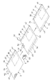
図1に示す自動包装ラインに基づいて、この発明の実施形態の寸法可変の蓋製造方法を説明する。この自動包装ラインは、大きさが互いに異なる個々の商品1ごとにその商品1の大きさに応じた寸法をもつ段ボール箱2を製造し、これと並行して、所定寸法の矩形の蓋シート3から、段ボール箱2の矩形の上端開口の寸法に応じた寸法で蓋4を製造し、その蓋4を、商品1を収容した段ボール箱2にかぶせる自動包装ラインである。この自動包装ラインは、商品供給部5、箱ブランク製造装置6、箱組み立て部7、蓋シート供給部8、蓋製造装置9、蓋かぶせ部10を有する。
Based on the automatic packaging line shown in FIG. 1, a method for manufacturing a lid with variable dimensions according to an embodiment of the present invention will be described. This automatic packaging line manufactures
商品供給部5は、商品1を搬送するコンベヤ装置11と、商品1のサイズを測定する商品サイズ測定装置12と、商品1に付された商品識別コードを読み取る商品コードリーダー13とを有する。商品サイズ測定装置12は、コンベヤ装置11の途中に設けられ、コンベヤ装置11で搬送中の商品1の縦寸法、横寸法、高さ寸法をそれぞれ測定するゲートセンサーである。商品サイズ測定装置12で測定した商品サイズ情報と、商品コードリーダー13で読み取った商品識別コードの情報は、図示しない管理制御装置に送信される。商品1に付された商品識別コードは、一次元コード(バーコード)または二次元コード(QRコード、DataMatrixコードなど)である。商品コードリーダー13は、商品識別コードを撮影するイメージセンサ(CMOSエリアセンサ、CCDエリアセンサ)と、そのイメージセンサで取得した画像データから商品識別コードの情報を読み取る内蔵の演算部とからなる。商品供給部5は、商品識別コードが付された商品1をコンベヤ装置11でその下流側の箱組み立て部7に供給する。
The
箱ブランク製造装置6は、商品サイズ測定装置12で読み取った商品サイズ情報に基づいて、その商品1の大きさに応じた寸法をもつ段ボール箱2の箱ブランク14を製造する。箱ブランク14は、矩形の底板15と、底板15の4辺に罫線を介してそれぞれ連接された4枚の側板16とを有する。
The box
4枚の側板16のうち、底板15を挟んで対向する一対の側板16の両側には継ぎ代17が連設されている。継ぎ代17は、他の一対の側板16に糊付けされる部分である。また、4枚の側板16のうち、底板15を挟んで対向する他の一対の側板16の上端にはフラップ18が連設されている。
箱ブランク14は、段ボールで形成されている。段ボールは、波形に成形した中しんの両側に表ライナと裏ライナとを貼り合わせた両面段ボール、または両面段ボールの裏ライナに更に第2の中しんと第2の裏ライナとを貼り合わせた複両面段ボールである。箱ブランク14の底板15の下面には、商品コードリーダー13で読み取った商品識別コードに対応する情報をもつ商品識別コード(図示せず)が印刷されている。
The box blank 14 is made of cardboard. Corrugated board is double-faced corrugated board in which a front liner and a back liner are pasted on both sides of a corrugated medium, or a double-faced board in which a second medium and a second back liner are pasted on the back liner of double-faced corrugated board. It is cardboard. A product identification code (not shown) having information corresponding to the product identification code read by the
ここで、箱ブランク14の底板15に印刷される商品識別コードの種類(バーコード、QRコード、DataMatrixコードなど)は、商品1に付された商品識別コードの種類(バーコード、QRコード、DataMatrixコードなど)と必ずしも一致している必要はなく、例えば、商品1に付された商品識別コードがQRコードである場合に、QRコードとは異なる種類の二次元コードであるDataMatrixコードを、箱ブランク14の底板15に印刷するようにしてもよい。この場合、商品1に付されたQRコードと対応する情報をもつDataMatrixコードを箱ブランク14の底板15に印刷する。
Here, the type of product identification code (barcode, QR code, DataMatrix code, etc.) printed on the
箱組み立て部7は、箱ブランク製造装置6で製造された箱ブランク14に糊を塗布する糊塗布装置20と、箱ブランク14の底板15の部分に商品1を移載する商品移載部21と、商品1を載せた状態の箱ブランク14の側板16の部分を底板15の部分に対して直角に折り曲げることで段ボール箱2を成形するケース成形装置22とを有する。
The
ケース成形装置22は、箱ブランク14の底板15の上に商品1を載置した状態で、箱ブランク14を組み立てることで、商品1を収容しかつその商品1に付された商品識別コードが上方に露出するように上端が開口した状態の段ボール箱2を得る。ここで、ケース成形装置22で箱ブランク14を組み立てたとき、4枚の側板16は四角筒状の胴部19を構成する。段ボール箱2は、胴部19の下端が底板15で閉じ、胴部19の上端が矩形に開口した身箱である。段ボール箱2の上端開口は、4枚の側板16の上縁を4辺とする矩形である。段ボール箱2の上端開口の寸法は、底板15の寸法と同じであり、段ボール箱2の高さ寸法は、各側板16の高さ寸法と同じである。
By assembling the box blank 14 with the
また、ケース成形装置22には、商品側コードリーダー23と箱側コードリーダー24とが設けられている。商品側コードリーダー23は、蓋かぶせ部10で蓋4をかぶせる前に、段ボール箱2内の商品1に付された商品識別コードを読み取るように段ボール箱2の上側に対向して配置されている。箱側コードリーダー24は、蓋かぶせ部10で蓋4をかぶせる前に、段ボール箱2の底板15に付された商品識別コードを読み取るように段ボール箱2の底板15の下側に対向して配置されている。商品側コードリーダー23と箱側コードリーダー24は、図示しないマッチング検査装置に電気的に接続されている。マッチング検査装置は、商品側コードリーダー23で読み取った商品識別コードと箱側コードリーダー24で読み取った商品識別コードとを照合することで、段ボール箱2内の商品1が、その商品1を収容する段ボール箱2と正しく対応しているか否かを検査する装置である。
The
蓋シート供給部8は、複数種類の大きさの蓋シート3をそれぞれ積み重ねた状態でストックする複数の蓋シートマガジン25から、商品サイズ測定装置12で読み取った商品サイズ情報に基づいてその商品1を収容する段ボール箱2の上端開口の寸法に対応する大きさの蓋シート3を選択的に取り出し、その取り出した蓋シート3を蓋製造装置9に供給する。蓋製造装置9は、蓋シート3に加工を施すことで、寸法が互いに異なる複数の段ボール箱2にかぶせるそれぞれの蓋4を、個々の段ボール箱2の上端開口の寸法に応じた寸法で製造する。
The lid
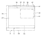
図2、図3に示すように、蓋4の材料としての蓋シート3は、第1基準辺31と、第1基準辺31と直角に交わる第2基準辺32と、第1基準辺31と平行な第1調整辺33と、第2基準辺32と平行な第2調整辺34とで囲まれる矩形のシートである。蓋シート3は、この実施形態では段ボールで形成されている。段ボールは、波形に成形した中しんの両側に表ライナと裏ライナとを貼り合わせた両面段ボール、または両面段ボールの裏ライナに更に第2の中しんと第2の裏ライナとを貼り合わせた複両面段ボールである。第1基準辺31と第1調整辺33は、段ボールの段目に直角な辺であり、第2基準辺32と第2調整辺34は、段ボールの段目と平行な辺である。
As shown in FIGS. 2 and 3, the
蓋シート3には、蓋4を段ボール箱2の上端開口の第1辺35(図1参照)に沿って下方に折り曲げるための第1罫線36と、蓋4の破断用のミシン目線37とが、あらかじめ第1基準辺31に沿って第1基準辺31と平行に延びて形成されている。第1罫線36は、蓋シート3の下面を直線状に凹ませて形成した折り目線である。ミシン目線37は、段ボール箱2を開封するときに蓋4の破断を誘導するための複数の切れ目である。ミシン目線37は、第1罫線36と第1基準辺31の間に配置されている。
The
図4に示すように、ミシン目線37は、第1基準辺31と平行な方向に並ぶ複数の切れ目38で構成されている。各切れ目38は、第1基準辺31と平行に延びる直線部39と、各直線部39を共通して通る直線の位置から第1基準辺31に向けて斜めに延びる傾斜部40とからなる。各傾斜部40は、ミシン目線37の破断開始側(図では右側)から破断終了側(図では左側)に向かうに従って、各直線部39を共通して通る直線に次第に近づく向きに傾斜している。傾斜部40と直線部39は、いずれも蓋シート3を厚さ方向に貫通して形成されている。図では、傾斜部40を、直線部39から離して形成した例を示したが、傾斜部40と直線部39を繋げて形成してもよい。蓋シート3の第2基準辺32のミシン目線37が交わる位置に、第2基準辺32からミシン目線37に向かって凹んだ形状をもつ凹縁41が形成され、この凹縁41と第1基準辺31との間に、ミシン目線37の破断開始用のつまみ部42が形成されている。
As shown in FIG. 4 , the
図2、図3に示すように、蓋シート3は、第1調整辺33と第2調整辺34に沿ったL字状の寸法調整領域43と、L字状の寸法調整領域43と第1基準辺31と第2基準辺32とで囲まれる矩形の基準領域44とを有する。基準領域44には、独立したオブジェクト(図示せず)があらかじめ印刷されている。独立したオブジェクトとは、途中で途切れても問題が生じない連続図柄等ではなく、途中で途切れると意味を失う表示であり、例えば、荷扱い指示マーク(JIS規格Z0150またはISO規格780に規定されたマーク。例えば、上方向マーク(いわゆる天地無用マーク)や水ぬれ防止マークなど)や、ブランドのロゴマークや、商品配送に関する注意事項や段ボール箱2の開封方法の説明などを文字で記載したものなどが挙げられる。
As shown in FIGS. 2 and 3, the
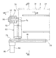
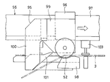
図2に示すように、蓋製造装置9は、蓋シート3を第1基準辺31と平行な方向に搬送する蓋シート搬送装置50と、蓋シート搬送装置50で搬送中の蓋シート3を搬送方向に切断することで蓋シート3の第1調整辺33に沿った領域を帯状に切り落とす第1カッター51と、蓋シート搬送装置50で搬送中の蓋シート3を押圧することで搬送方向に延びる第2罫線54を加工する罫線ローラ53と、蓋シート3の搬送をいったん停止した状態で第1基準辺31と直交する方向に蓋シート3を切断することで蓋シート3の第2調整辺34に沿った領域を帯状に切り落とす第2カッター52とを有する。
As shown in FIG. 2, the
蓋シート搬送装置50は、蓋シート3の第1基準辺31を基準にして蓋シート3を搬送するようになっている。すなわち、複数の蓋シートマガジン25から選択的に供給される複数種類の大きさの蓋シート3を、蓋シート搬送装置50で搬送するときに、蓋シート搬送装置50は、いずれの大きさの蓋シート3についても、その蓋シート3の第1基準辺31の位置が同じ位置にくるように搬送する。
The lid
第1カッター51および罫線ローラ53は、蓋シート搬送装置50で搬送中の蓋シート3の通過位置に配置されている。罫線ローラ53は、第1カッター51で蓋シート3の第1調整辺33に沿った領域を帯状に切り落とすときに、第2罫線54を加工する。第2罫線54は、第1罫線36と平行に延びている。第2罫線54は、図1に示すように、段ボール箱2の上端開口の第2辺55(第1辺35に対向する辺)に沿って蓋4を下方に折り曲げるために、蓋シート3の下面を直線状に凹ませて形成した折り目線である。
The
図2に示すように、第1カッター51と罫線ローラ53は、蓋シート3の搬送方向と直交する方向に所定間隔をおいて配置されている。ここで、第1カッター51と罫線ローラ53の間隔は、蓋シート3の第1基準辺31と第1罫線36の間隔に対応する大きさに設定されている。第2カッター52は、第2カッター走行装置56(図5参照)で蓋シート搬送装置50による蓋シート3の搬送方向と直交する方向に走行するように支持されている。
As shown in FIG. 2 , the
第1カッター51による蓋シート3の切り落とし幅と第2カッター52による蓋シート3の切り落とし幅は、後述の切り落とし幅調整機構57(図5参照)によって、段ボール箱2の上端開口の寸法に応じて変化させることができるようになっている。
The cutting width of the
図1に示すように、蓋かぶせ部10は、蓋製造装置9で加工して送り出された蓋4に糊を塗布する糊塗布装置60と、糊塗布装置60で糊が塗布された蓋4を、商品1を収容した段ボール箱2の上端開口にかぶせて圧着する蓋圧着装置61とを有する。蓋かぶせ部10では、箱組み立て部7で得た段ボール箱2の上端開口に蓋4がかぶせられ、その蓋4で段ボール箱2の上端開口が閉じた状態となる。
As shown in FIG. 1, the lid-covering
蓋かぶせ部10の下流側には、ラベラー62とラベラー用コードリーダー63とが設けられている。ラベラー62は、段ボール箱2内の商品1に対応する配送伝票64を段ボール箱2にかぶせられた蓋4に貼付するように、段ボール箱2の蓋4の上側に対向して配置されている。配送伝票64は、蓋4の基準領域44(図2、図3参照)のうちの独立したオブジェクト(荷扱い指示マークなど)が印刷されていない部分に貼付される。
A
ラベラー用コードリーダー63は、ラベラー62で配送伝票64を貼付する前に、段ボール箱2の底板15に付された商品識別コードを読み取るように、段ボール箱2の底板15の下側に対向して配置されている。ラベラー用コードリーダー63は、第2のマッチング検査装置(図示せず)に電気的に接続されている。第2のマッチング検査装置は、ラベラー用コードリーダー63で読み取った商品識別コードと、ラベラー62で貼付しようとする配送伝票64の情報とを照合することで、段ボール箱2が配送伝票64と正しく対応しているか否かを検査する装置である。
The
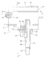
図5に、蓋製造装置9を示す。蓋製造装置9は、蓋シート3を水平方向に真っ直ぐ搬送する蓋シート搬送装置50と、蓋シート搬送装置50の下流側に配置された蓋搬送装置70とを有する。蓋搬送装置70は、蓋シート搬送装置50から蓋シート3を受け取り、その蓋シート3を蓋シート搬送装置50と同じ方向に搬送するように、蓋シート搬送装置50の下流側に隣接して配置されている。
FIG. 5 shows the
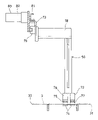
第1カッター51による蓋シート3の切り落とし幅と、第2カッター52による蓋シート3の切り落とし幅とを変化させる切り落とし幅調整機構57は、蓋シート3を切断するときの第1カッター51の位置を蓋シート3の搬送方向と直交する方向に任意に変化させることができるように構成した第1カッター位置調整装置71と、蓋シート3の搬送停止位置(第2カッター52が蓋シート3を切断するときの蓋シート3の位置)を任意に変化させることができるように構成した蓋シート搬送装置50とで構成されている。
A trimming
図6~図8に示すように、蓋シート搬送装置50は、蓋シート3を上下から把持する蓋シートクランプ部72と、蓋シートクランプ部72を蓋シート3の第1基準辺31と平行な方向に移動させる蓋シートクランプ移動装置73とを有する。蓋シートクランプ部72は、蓋シート3の搬送方向の後端部(すなわち、蓋シート3の第2調整辺34に沿った領域)を把持する。
As shown in FIGS. 6 to 8, the lid
図7に示すように、蓋シートクランプ部72は、蓋シート3の後端部を下側から支持する下側クランプ部材74と、下側クランプ部材74の上側に対向して配置された上側クランプ部材75と、上側クランプ部材75を上下に移動させるクランプアクチュエータ76とを有する。クランプアクチュエータ76は、例えば、空気圧で作動するエアシリンダである。下側クランプ部材74には、蓋シート3の後端とシート搬送方向に対向する起立壁77が固定して設けられ、この起立壁77で搬送方向の後側から蓋シート3を支持し、蓋シート3の加工時の抵抗で蓋シート3に搬送方向のずれが生じるのを防止している。
As shown in FIG. 7, the lid
図8に示すように、蓋シートクランプ移動装置73は、蓋シートクランプ部72(下側クランプ部材74と上側クランプ部材75とクランプアクチュエータ76とがユニット化されたもの)を支持する蓋シートクランプブラケット78と、蓋シートクランプブラケット78を蓋シート搬送装置50の搬送方向に移動可能に支持する蓋シート搬送リニヤガイド79と、蓋シートクランプブラケット78を蓋シート搬送装置50の搬送方向に移動させる蓋シート搬送アクチュエータ80とを有する。蓋シート搬送アクチュエータ80は、蓋シートクランプブラケット78に接続された環状のベルト81と、ベルト81を駆動する電動モータ82とからなる。蓋シート搬送装置50は、この電動モータ82の回転量を制御することで、蓋シート3の搬送停止位置を任意に変化させることが可能となっている。
As shown in FIG. 8, the lid sheet
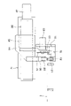
図9、図10に示すように、第1カッター51には、第1カッター51を回転駆動する電動モータ83が取り付けられている。電動モータ83は、減速機を内蔵したギヤードモータである。第1カッター51は、蓋シート搬送装置50による蓋シート3の搬送方向と直交する水平方向の中心軸まわりに回転する丸形の回転刃(図11参照)である。第1カッター51および電動モータ83は、第1カッター位置調整装置71に支持されている。
As shown in FIGS. 9 and 10, the
第1カッター位置調整装置71は、第1カッター51を蓋シート搬送装置50による蓋シート3の搬送方向と直交する方向に移動させることで、第1カッター51による蓋シート3の切り落とし幅を変化させる装置である。第1カッター位置調整装置71は、第1カッター51および電動モータ83を支持する第1カッターブラケット84を、蓋シート搬送装置50による蓋シート3の搬送方向と直交する水平方向に移動可能に支持する第1カッターリニヤガイド85と、第1カッターブラケット84を第1カッターリニヤガイド85に沿って移動させる第1カッター位置調整アクチュエータ86とを有する。第1カッター位置調整アクチュエータ86は、電動モータ87で駆動する送りねじ機構である。
The first cutter
図10に示すように、第1カッターブラケット84には、罫線ローラ53と受けローラ88が取り付けられている。罫線ローラ53は、蓋シート3の下側を押圧するように蓋シート3の下側に配置され、受けローラ88は、受けローラ88と罫線ローラ53とで蓋シート3を上下で挟み込むように罫線ローラ53の上側に対向して配置されている。第1カッターブラケット84は、罫線ローラ53を回転可能に支持する罫線ローラ支持部89と、受けローラ88を回転可能に支持する受けローラ支持部90と、罫線ローラ支持部89と受けローラ支持部90を連結する連結部91とを有する。連結部91は、蓋シート3の第1調整辺33と水平に対向するように配置されている。第1カッター51の下側には、第1カッター受け92が設けられている。第1カッター受け92は、第1カッターブラケット84の罫線ローラ支持部89に固定されている。
As shown in FIG. 10, the ruled
図11に示すように、第1カッターブラケット84には、第1カッター51で切り落される蓋シート3の帯状の部分を、第1カッター51の下流側で下方に誘導する第1耳落としガイド93が設けられている。
As shown in FIG. 11, the
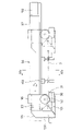
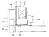
図12に示すように、第2カッター52には、第2カッター52を回転駆動する電動モータ94が取り付けられている。電動モータ94は、減速機を内蔵したギヤードモータである。第2カッター52は、蓋シート搬送装置50による蓋シート3の搬送方向と平行な水平方向の中心軸まわりに回転する丸形の回転刃(図13参照)である。第2カッター52および電動モータ94は、蓋シート搬送装置50による蓋シート3の搬送方向と直交する水平方向に第2カッター52を走行させる第2カッター走行装置56に支持されている。第2カッター52の走行領域の下流側には、蓋シート3を上下から挟んで保持することが可能な保持クランプ装置103が設けられている。
As shown in FIG. 12, the
図12、図13に示すように、第2カッター走行装置56は、第2カッター52および電動モータ94(図12参照)を支持する第2カッターブラケット95を、蓋シート搬送装置50による蓋シート3の搬送方向と直交する水平方向に移動可能に支持する第2カッターリニヤガイド96と、第2カッターブラケット95を第2カッターリニヤガイド96に沿って移動させる第2カッター走行アクチュエータ97とを有する。第2カッター走行アクチュエータ97は、電動モータ102で駆動する送りねじ機構である。
As shown in FIGS. 12 and 13 , the second
図13に示すように、第2カッター52の下側には、第2カッター受け98が設けられている。第2カッターブラケット95は、第2カッター52および電動モータ94(図12参照)を支持するカッター支持部99と、カッター支持部99と第2カッター受け98を連結する連結部100とを有する。
As shown in FIG. 13 , a
図14に示すように、連結部100は、第2カッター52が蓋シート3の第2調整辺34に沿った領域を帯状に切り落とすときに、蓋シート3の第2調整辺34と水平に対向する位置を走行するように配置されている。保持クランプ装置103は、ここでは蓋シート3の上側に対向して配置されたエアシリンダであり、エアシリンダのロッドを昇降させる動作により、蓋シート3の保持と保持解除とを切り替えることができるようになっている。
As shown in FIG. 14 , the connecting
図13、図15に示すように、第2カッターブラケット95には、第2カッター52が第1基準辺31から第1調整辺33に向かう方向(図の左側から右側に向かう方向)に走行するときに、第2カッター52で切り落される蓋シート3の帯状の部分を、第2カッター52の下流側で下方に誘導する第2耳落としガイド101が設けられている。
As shown in FIGS. 13 and 15, on the
この蓋製造装置9を使用すると、例えば、蓋シート供給部8(図1参照)から供給された蓋シート3に、以下のようにして切断加工および罫入れ加工を施し、個々の段ボール箱2の上端開口の寸法に応じた寸法で蓋4を製造することができる。
When the
図2に示すように、第1基準辺31に沿った領域に第1罫線36とミシン目線37とをあらかじめ形成した矩形の蓋シート3を、蓋シート搬送装置50で真っ直ぐ搬送し、このとき、搬送中の蓋シート3の第1調整辺33に沿った領域を第1カッター51で帯状に切り落とす第1寸法調整工程を行なう。またこの第1寸法調整工程を行なうときに、第1カッター51に対して第1基準辺31の側に所定間隔をおいて配置した罫線ローラ53で、搬送中の蓋シート3の下面に第2罫線54を加工する。
As shown in FIG. 2, a
次に、蓋シート搬送装置50による蓋シート3の搬送を停止する。そして、その蓋シート3の搬送を停止した状態で、蓋シート搬送装置50による蓋シート3の搬送方向と直交する方向に第2カッター52を走行させることにより、蓋シート3の第2調整辺34に沿った領域を第2カッター52で帯状に切り落とす第2寸法調整工程を行なう。このとき、保持クランプ装置103を作動させ、蓋シート3を上下から挟んで保持することで、第2カッター52で蓋シート3を切断するときの抵抗で蓋シート3に位置ずれが生じるのを防止する。
Next, the conveyance of the
ここで、第1寸法調整工程の第1カッター51による蓋シート3の切り落とし幅と、第2寸法調整工程の第2カッター52による蓋シート3の切り落とし幅とを、段ボール箱2の上端開口の寸法に応じて変化させることで、蓋4の寸法が可変となる。具体的には、第1カッター51で蓋シート3を切断するときに、あらかじめ第1カッター位置調整装置71(図5参照)で第1カッター51の位置を蓋シート3の搬送方向と直交する方向に変化させることで、第1寸法調整工程の第1カッター51による蓋シート3の切り落とし幅を変化させることが可能となっている。また、蓋シート搬送装置50による蓋シート3の搬送停止位置(第2カッター52が蓋シート3を切断するときの蓋シート3の位置)を変化させることで、第2寸法調整工程の第2カッター52による蓋シート3の切り落とし幅を変化させることが可能となっている。
Here, the cutoff width of the
以上のように、この実施形態の蓋製造方法では、図3に示すように、蓋4の寸法によらず、蓋シート3の第1基準辺31に沿った領域を切り落とさずに使用するので、あらかじめ蓋シート3に第1罫線36とミシン目線37とを加工しておくことが可能であり、第1罫線36とミシン目線37をあらかじめ同じ位置に加工した同一寸法の蓋シート3を用いることができる。そのため、寸法可変で安定して蓋4の製造を行なうことが可能である。
As described above, in the lid manufacturing method of this embodiment, as shown in FIG. The first ruled
また、この実施形態の蓋製造方法では、蓋4の寸法によらず、常に、L字状の寸法調整領域43と第1基準辺31と第2基準辺32とで囲まれる矩形の基準領域44が切り落とされずに残る。そのため、蓋シート3の基準領域44に、独立したオブジェクト(例えば、荷扱い指示マークや、ブランドのロゴマーク等)の印刷をあらかじめ施しておくことで、蓋4の寸法を変化させたときにも、そのオブジェクトが途切れずに印刷された蓋4を得ることが可能である。
Further, in the lid manufacturing method of this embodiment, regardless of the dimensions of the
また、この実施形態の蓋製造方法では、複数種類の大きさの蓋シート3をそれぞれストックする複数の蓋シートマガジン25から、段ボール箱2の上端開口の寸法に対応する大きさの蓋シート3を選択的に取り出して使用するので、第1カッター51による蓋シート3の切り落とし幅と第2カッター52による蓋シート3の切り落とし幅とを小さく抑えることができる。そのため、蓋シート3の材料費を低減することが可能である。さらに、蓋シート3の基準領域44の大きさを、蓋シート3の大きさの種類ごとに異ならせることで、基準領域44に印刷するオブジェクトの大きさを、蓋4の大きさに応じたものとすることが可能である。
In addition, in the lid manufacturing method of this embodiment, the
また、この実施形態の蓋製造装置9は、第1カッター51による切り落とし加工と、罫線ローラ53による罫線の加工とを、蓋シート搬送装置50で蓋シート3を搬送しながら行なうことができるので効率的である。また、第2カッター52による切り落とし加工は、蓋シート3の搬送を停止した状態で行なうので、蓋シート搬送装置50による蓋シート3の搬送方向を直交方向に変化させる必要がなく、蓋シート搬送装置50の構成を単純にすることが可能となっている。
In addition, the
また、この実施形態の蓋製造装置9は、蓋シート3を上下から把持する蓋シートクランプ部72と、蓋シートクランプ部72を第1基準辺31と平行な方向に水平に移動させる蓋シートクランプ移動装置73とで構成された蓋シート搬送装置50を採用しているので、蓋シート搬送装置50で搬送中の蓋シート3の姿勢が安定している。そのため、第1カッター51による切り落とし加工と、罫線ローラ53による罫線の加工とを、精度よく行なうことが可能となっている。
Further, the
今回開示された実施の形態はすべての点で例示であって制限的なものではないと考えられるべきである。本発明の範囲は上記した説明ではなくて特許請求の範囲によって示され、特許請求の範囲と均等の意味および範囲内でのすべての変更が含まれることが意図される。 It should be considered that the embodiments disclosed this time are illustrative in all respects and not restrictive. The scope of the present invention is indicated by the scope of the claims rather than the above description, and is intended to include all modifications within the meaning and range of equivalents of the scope of the claims.
2 段ボール箱
3 蓋シート
4 蓋
25 蓋シートマガジン
31 第1基準辺
32 第2基準辺
33 第1調整辺
34 第2調整辺
35 第1辺
36 第1罫線
37 ミシン目線
43 寸法調整領域
44 基準領域
50 蓋シート搬送装置
51 第1カッター
52 第2カッター
53 罫線ローラ
54 第2罫線
55 第2辺
56 第2カッター走行装置
57 切り落とし幅調整機構
72 蓋シートクランプ部
73 蓋シートクランプ移動装置
2
Claims (6)
前記蓋(4)の材料として、第1基準辺(31)と、前記第1基準辺(31)と直角に交わる第2基準辺(32)と、前記第1基準辺(31)と平行な第1調整辺(33)と、前記第2基準辺(32)と平行な第2調整辺(34)とで囲まれる矩形の蓋シート(3)を使用し、
前記蓋シート(3)には、前記蓋(4)を前記箱(2)の上端開口の第1辺(35)に沿って下方に折り曲げるための第1罫線(36)と、前記蓋(4)の破断用のミシン目線(37)とが、あらかじめ前記第1基準辺(31)に沿って前記第1基準辺(31)と平行に延びて形成され、
前記蓋シート(3)の前記第1調整辺(33)に沿った領域を第1カッター(51)で帯状に切り落とす第1寸法調整工程と、前記蓋シート(3)の前記第2調整辺(34)に沿った領域を第2カッター(52)で帯状に切り落とす第2寸法調整工程とを行ない、
前記第1寸法調整工程を行なうときに、前記第1カッター(51)から所定間隔をおいて配置した罫線ローラ(53)で、前記蓋シート(3)に、前記箱(2)の上端開口の前記第1辺(35)に対向する第2辺(55)に沿って前記蓋(4)を下方に折り曲げるための第2罫線(54)を前記第1罫線(36)と平行に加工し、
前記第1カッター(51)による前記蓋シート(3)の切り落とし幅と前記第2カッター(52)による前記蓋シート(3)の切り落とし幅とを、前記箱(2)の上端開口の寸法に応じて変化させる、
寸法可変の蓋製造方法。 A variable dimension lid manufacturing method for manufacturing respective lids (4) to cover a plurality of boxes (2) having different dimensions with dimensions corresponding to the dimensions of the upper end openings of the individual boxes (2),
As materials for the lid (4), a first reference side (31), a second reference side (32) perpendicular to the first reference side (31), and a material parallel to the first reference side (31). Using a rectangular cover sheet (3) surrounded by a first adjustment side (33) and a second adjustment side (34) parallel to the second reference side (32),
The lid sheet (3) has a first crease (36) for folding the lid (4) downward along the first side (35) of the top opening of the box (2), and the lid (4). ) are formed in advance along the first reference side (31) to extend in parallel with the first reference side (31), and
A first dimension adjusting step of cutting off a band-like region along the first adjustment side (33) of the lid sheet (3) with a first cutter (51); 34) and a second dimension adjustment step of cutting off the area along the line 34) into a strip shape with a second cutter (52),
When performing the first dimension adjustment step, a creasing roller (53) arranged at a predetermined distance from the first cutter (51) is used to align the upper end opening of the box (2) with the lid sheet (3). processing a second ruled line (54) for bending the lid (4) downward along a second side (55) opposite to the first side (35) parallel to the first ruled line (36);
The cut-off width of the lid sheet (3) by the first cutter (51) and the cut-off width of the lid sheet (3) by the second cutter (52) are determined according to the size of the top opening of the box (2). change by
Dimensionally variable lid manufacturing method.
請求項1に記載の寸法可変の蓋製造方法。 The lid sheet (3) includes an L-shaped dimension adjustment area (43) along the first adjustment side (33) and the second adjustment side (34), and an L-shaped dimension adjustment area (43) ) and a rectangular reference area (44) surrounded by the first reference side (31) and the second reference side (32), and an independent object is printed in advance in the reference area (44). has been
2. The method of manufacturing the dimensionally variable lid according to claim 1.
前記蓋(4)の材料として、第1基準辺(31)と、前記第1基準辺(31)と直角に交わる第2基準辺(32)と、前記第1基準辺(31)と平行な第1調整辺(33)と、前記第2基準辺(32)と平行な第2調整辺(34)とで囲まれる矩形の蓋シート(3)を使用し、
前記蓋シート(3)には、前記蓋(4)を前記箱(2)の上端開口の第1辺(35)に沿って下方に折り曲げるための第1罫線(36)と、前記蓋(4)の破断用のミシン目線(37)とが、あらかじめ前記第1基準辺(31)に沿って前記第1基準辺(31)と平行に延びて形成され、
前記蓋シート(3)の前記第1調整辺(33)に沿った領域を帯状に切り落とす第1カッター(51)と、
前記蓋シート(3)の前記第2調整辺(34)に沿った領域を帯状に切り落とす第2カッター(52)と、
前記第1カッター(51)で前記蓋シート(3)の前記第1調整辺(33)に沿った領域を帯状に切り落とすときに、前記蓋シート(3)に、前記箱(2)の上端開口の前記第1辺(35)に対向する第2辺(55)に沿って前記蓋(4)を下方に折り曲げるための第2罫線(54)を前記第1罫線(36)と平行に加工するように、前記第1カッター(51)から所定間隔をおいて配置した罫線ローラ(53)と、
前記第1カッター(51)による前記蓋シート(3)の切り落とし幅と前記第2カッター(52)による前記蓋シート(3)の切り落とし幅とを、前記箱(2)の上端開口の寸法に応じて変化させる切り落とし幅調整機構(57)と、
を有する寸法可変の蓋製造装置。 A size-variable lid manufacturing apparatus for manufacturing respective lids (4) to cover a plurality of boxes (2) having different dimensions with dimensions corresponding to the dimensions of the upper end openings of the individual boxes (2),
As materials for the lid (4), a first reference side (31), a second reference side (32) perpendicular to the first reference side (31), and a material parallel to the first reference side (31). Using a rectangular cover sheet (3) surrounded by a first adjustment side (33) and a second adjustment side (34) parallel to the second reference side (32),
The lid sheet (3) has a first crease (36) for folding the lid (4) downward along the first side (35) of the top opening of the box (2), and the lid (4). ) are formed in advance along the first reference side (31) to extend in parallel with the first reference side (31), and
a first cutter (51) for cutting off a band-like region along the first adjustment side (33) of the lid sheet (3);
a second cutter (52) for cutting off a band-like region along the second adjustment side (34) of the lid sheet (3);
When the region along the first adjustment side (33) of the lid sheet (3) is cut off in a belt shape by the first cutter (51), the top opening of the box (2) is formed in the lid sheet (3). A second crease (54) for bending the lid (4) downward is processed parallel to the first crease (36) along a second side (55) opposite to the first side (35) of the a ruled line roller (53) arranged at a predetermined interval from the first cutter (51),
The cut-off width of the lid sheet (3) by the first cutter (51) and the cut-off width of the lid sheet (3) by the second cutter (52) are determined according to the size of the top opening of the box (2). A trimming width adjustment mechanism (57) that changes by
A dimensionally variable lid manufacturing apparatus comprising:
前記第1カッター(51)は、前記蓋シート搬送装置(50)で搬送中の前記蓋シート(3)を搬送方向に切断するように、前記蓋シート(3)の通過位置に配置され、
前記罫線ローラ(53)は、前記蓋シート搬送装置(50)で搬送中の前記蓋シート(3)を押圧することで前記第2罫線(54)を加工するように、前記蓋シート(3)の通過位置に配置され、
前記第2カッター(52)は、前記蓋シート(3)の搬送を停止した状態で、前記蓋シート(3)を前記第1基準辺(31)と直交する方向に切断するように、前記蓋シート搬送装置(50)による前記蓋シート(3)の搬送方向と直交する方向に前記第2カッター(52)を走行させる第2カッター走行装置(56)に支持されている、
請求項4に記載の寸法可変の蓋製造装置。 a lid sheet conveying device (50) for conveying the lid sheet (3) in a direction parallel to the first reference side (31);
The first cutter (51) is arranged at a passage position of the lid sheet (3) so as to cut the lid sheet (3) being conveyed by the lid sheet conveying device (50) in the conveying direction,
The ruled line roller (53) presses the lid sheet (3) being conveyed by the lid sheet conveying device (50) so as to process the second ruled line (54). is placed at the passing position of
The second cutter (52) cuts the cover sheet (3) in a direction perpendicular to the first reference side (31) while the conveyance of the cover sheet (3) is stopped. supported by a second cutter travel device (56) that travels the second cutter (52) in a direction perpendicular to the conveying direction of the cover sheet (3) by the sheet conveying device (50),
5. The dimensionally variable lid manufacturing apparatus according to claim 4.
請求項5に記載の寸法可変の蓋製造装置。 The lid sheet conveying device (50) includes a lid sheet clamp part (72) that grips the lid sheet (3) from above and below, and a lid sheet clamp part (72) that is parallel to the first reference side (31). a lid sheet clamp movement device (73) for moving horizontally in the direction of
6. The dimensionally variable lid manufacturing apparatus according to claim 5.
Priority Applications (5)
| Application Number | Priority Date | Filing Date | Title |
|---|---|---|---|
| JP2019072935A JP7178317B2 (en) | 2019-04-05 | 2019-04-05 | Dimensionally variable lid manufacturing method and dimensionally variable lid manufacturing apparatus |
| CN202080025887.3A CN113631360B (en) | 2019-04-05 | 2020-03-30 | Method and apparatus for manufacturing variable-size lid |
| US17/601,181 US11833774B2 (en) | 2019-04-05 | 2020-03-30 | Dimensionally variable lid manufacturing method and dimensionally variable lid manufacturing device |
| EP20783298.1A EP3950295A4 (en) | 2019-04-05 | 2020-03-30 | Dimensionally variable lid manufacturing method, and dimensionally variable lid manufacturing device |
| PCT/JP2020/014577 WO2020203978A1 (en) | 2019-04-05 | 2020-03-30 | Dimensionally variable lid manufacturing method, and dimensionally variable lid manufacturing device |
Applications Claiming Priority (1)
| Application Number | Priority Date | Filing Date | Title |
|---|---|---|---|
| JP2019072935A JP7178317B2 (en) | 2019-04-05 | 2019-04-05 | Dimensionally variable lid manufacturing method and dimensionally variable lid manufacturing apparatus |
Publications (2)
| Publication Number | Publication Date |
|---|---|
| JP2020168839A JP2020168839A (en) | 2020-10-15 |
| JP7178317B2 true JP7178317B2 (en) | 2022-11-25 |
Family
ID=72668170
Family Applications (1)
| Application Number | Title | Priority Date | Filing Date |
|---|---|---|---|
| JP2019072935A Active JP7178317B2 (en) | 2019-04-05 | 2019-04-05 | Dimensionally variable lid manufacturing method and dimensionally variable lid manufacturing apparatus |
Country Status (5)
| Country | Link |
|---|---|
| US (1) | US11833774B2 (en) |
| EP (1) | EP3950295A4 (en) |
| JP (1) | JP7178317B2 (en) |
| CN (1) | CN113631360B (en) |
| WO (1) | WO2020203978A1 (en) |
Families Citing this family (4)
| Publication number | Priority date | Publication date | Assignee | Title |
|---|---|---|---|---|
| EP4269260A3 (en) * | 2019-04-25 | 2024-01-24 | Agfa Nv | Manufacturing of packaging |
| JP7551115B2 (en) * | 2021-01-22 | 2024-09-17 | 株式会社古川製作所 | Large capacity bag supply device |
| FR3163928A1 (en) * | 2024-06-26 | 2026-01-02 | Exotec Product France | Container manufacturing process |
| JP7782008B1 (en) * | 2024-12-04 | 2025-12-08 | レンゴー株式会社 | Packaging box, blank and method for sealing the packaging box |
Citations (3)
| Publication number | Priority date | Publication date | Assignee | Title |
|---|---|---|---|---|
| JP2009132049A (en) | 2007-11-30 | 2009-06-18 | Tomei Kogyo Kk | Processing apparatus for corrugated cardboard sheet |
| JP2011230806A (en) | 2010-04-28 | 2011-11-17 | Rengo Co Ltd | Packaging box |
| JP2015093698A (en) | 2013-11-12 | 2015-05-18 | レンゴー株式会社 | Press-fitting mechanism |
Family Cites Families (24)
| Publication number | Priority date | Publication date | Assignee | Title |
|---|---|---|---|---|
| NL229676A (en) | 1958-07-17 | 1960-06-15 | ||
| US3844201A (en) * | 1971-06-02 | 1974-10-29 | Fmc Corp | Apparatus for cutting sheet material |
| US3812641A (en) * | 1973-04-03 | 1974-05-28 | R Bemiss | Method of forming, filling and closing cartons, and specific cartons therefor |
| GB1483620A (en) * | 1973-12-14 | 1977-08-24 | St Regis Paper Co | Dispenser package and method of making the same |
| US3913300A (en) * | 1974-01-04 | 1975-10-21 | Champion Int Corp | Roll forming carton lidding machine |
| US3976241A (en) * | 1974-03-20 | 1976-08-24 | Bemiss Robert P | Method of forming, filling and closing cartons, and specific cartons therefor |
| DE3408488C2 (en) * | 1984-03-08 | 1986-12-04 | Alcan Ohler GmbH, 5970 Plettenberg | Method and device for the production of lids with pull tabs |
| CN1113744C (en) * | 1998-03-09 | 2003-07-09 | 斯坦利M·利 | Equipment for scoring and folding sheet materials |
| WO2002096755A1 (en) * | 2001-05-30 | 2002-12-05 | United States Postal Service | Automatic lidder and/or un-lidder system and method |
| SE535525C2 (en) * | 2010-10-05 | 2012-09-11 | Gunnar Backman | Packaging for butter and margarine, sheets and ways to make a sheet |
| WO2013108829A1 (en) * | 2012-01-18 | 2013-07-25 | レンゴー株式会社 | Method and device for assembling height-variable box |
| FR2987824B1 (en) * | 2012-03-08 | 2014-03-14 | Gerard Guy Martorella | CARDBOARD WITH VARIABLE VOLUME |
| ITBO20120463A1 (en) | 2012-08-31 | 2014-03-01 | Ponti Group Holding S P A | METHOD FOR REALIZING CARTONS FOR PACKAGING AND EQUIPMENT THAT ACTIVATE THIS METHOD |
| CN202911191U (en) * | 2012-10-31 | 2013-05-01 | 何西 | Slotting die cutting combinational machine based on corrugated board |
| WO2014117816A1 (en) * | 2013-01-29 | 2014-08-07 | Neopost Technologies | A method and system for automatically processing blanks for packaging boxes |
| US10543945B2 (en) * | 2013-01-29 | 2020-01-28 | Neopost Technologies | Method and system for automatically forming packaging boxes |
| EP2951011B1 (en) * | 2013-01-29 | 2019-12-25 | Neopost Technologies | Method and system for automatically forming packaging boxes |
| CN104669678A (en) * | 2013-12-03 | 2015-06-03 | 钟志刚 | Processing method of one-piece customized packing container with variable proportion and volume |
| NZ724952A (en) * | 2014-03-14 | 2020-03-27 | Rengo Co Ltd | Packing box and box manufacturing apparatus |
| US9892212B2 (en) * | 2014-05-19 | 2018-02-13 | Xerox Corporation | Creation of variable cut files for package design |
| CN105691797B (en) * | 2016-03-17 | 2018-05-29 | 河南科技大学 | A kind of electric business express delivery packing case that can adjust built-in space size |
| EP3354581B1 (en) | 2017-01-31 | 2021-05-19 | Quadient Technologies France | System and method for automating packaging of varying shipment sets |
| DE112019003075T5 (en) * | 2018-06-21 | 2021-03-25 | Packsize Llc | PACKAGING DEVICE AND SYSTEMS |
| CN208558418U (en) * | 2018-08-03 | 2019-03-01 | 永顺和纸业(苏州)有限公司 | A kind of box cover molding machine |
-
2019
- 2019-04-05 JP JP2019072935A patent/JP7178317B2/en active Active
-
2020
- 2020-03-30 CN CN202080025887.3A patent/CN113631360B/en active Active
- 2020-03-30 WO PCT/JP2020/014577 patent/WO2020203978A1/en not_active Ceased
- 2020-03-30 US US17/601,181 patent/US11833774B2/en active Active
- 2020-03-30 EP EP20783298.1A patent/EP3950295A4/en active Pending
Patent Citations (3)
| Publication number | Priority date | Publication date | Assignee | Title |
|---|---|---|---|---|
| JP2009132049A (en) | 2007-11-30 | 2009-06-18 | Tomei Kogyo Kk | Processing apparatus for corrugated cardboard sheet |
| JP2011230806A (en) | 2010-04-28 | 2011-11-17 | Rengo Co Ltd | Packaging box |
| JP2015093698A (en) | 2013-11-12 | 2015-05-18 | レンゴー株式会社 | Press-fitting mechanism |
Also Published As
| Publication number | Publication date |
|---|---|
| US11833774B2 (en) | 2023-12-05 |
| US20220176670A1 (en) | 2022-06-09 |
| JP2020168839A (en) | 2020-10-15 |
| EP3950295A1 (en) | 2022-02-09 |
| EP3950295A4 (en) | 2022-06-22 |
| WO2020203978A1 (en) | 2020-10-08 |
| CN113631360A (en) | 2021-11-09 |
| CN113631360B (en) | 2023-04-07 |
Similar Documents
| Publication | Publication Date | Title |
|---|---|---|
| JP7178317B2 (en) | Dimensionally variable lid manufacturing method and dimensionally variable lid manufacturing apparatus | |
| US12202223B2 (en) | Packaging machine infeed, separation, and creasing mechanisms | |
| JP7182665B2 (en) | corrugator process control system | |
| EP1905693B1 (en) | Packaging method and apparatus | |
| CN105197336B (en) | Alterable height case | |
| JP5795536B2 (en) | Box gluing device | |
| US20120275881A1 (en) | Machine for producing books, in particular photo books and/or illustrated books | |
| EP3521006B1 (en) | Method and system for creating custom-sized cardboard blanks for packagings and method and system for automatically packaging shipment sets in boxes | |
| WO2014118629A2 (en) | Method and system for automatically forming packaging boxes | |
| JP7264702B2 (en) | Variable dimension box blank manufacturing device, variable dimension box blank manufacturing method, box blank assembly method, and variable dimension automatic packaging line | |
| US20140238214A1 (en) | Label device | |
| US11731448B2 (en) | Apparatus and method for automated production of book covers and/or box lids | |
| AU2021359304A1 (en) | Machine for forming and printing cardboard boxes | |
| CN223291196U (en) | Paper forming equipment | |
| US12214925B2 (en) | Methods and machine for forming a container from a blank and applying an identification tag | |
| CN112192895A (en) | Feeding and indentation device of packaging carton | |
| WO2024086287A1 (en) | Methods and machine for forming a container with identification tag and identifying indicia | |
| JP2016087946A (en) | Paper container manufacturing method and manufacturing apparatus | |
| EP1194357A1 (en) | Device and method for stacking continuous forms | |
| JPH01254525A (en) | Packaging sheet cutting and folding device |
Legal Events
| Date | Code | Title | Description |
|---|---|---|---|
| A621 | Written request for application examination |
Free format text: JAPANESE INTERMEDIATE CODE: A621 Effective date: 20220118 |
|
| TRDD | Decision of grant or rejection written | ||
| A01 | Written decision to grant a patent or to grant a registration (utility model) |
Free format text: JAPANESE INTERMEDIATE CODE: A01 Effective date: 20221101 |
|
| A61 | First payment of annual fees (during grant procedure) |
Free format text: JAPANESE INTERMEDIATE CODE: A61 Effective date: 20221114 |
|
| R150 | Certificate of patent or registration of utility model |
Ref document number: 7178317 Country of ref document: JP Free format text: JAPANESE INTERMEDIATE CODE: R150 |
|
| R250 | Receipt of annual fees |
Free format text: JAPANESE INTERMEDIATE CODE: R250 |