JP7175268B2 - Transcatheter valve prosthesis - Google Patents
Transcatheter valve prosthesis Download PDFInfo
- Publication number
- JP7175268B2 JP7175268B2 JP2019523580A JP2019523580A JP7175268B2 JP 7175268 B2 JP7175268 B2 JP 7175268B2 JP 2019523580 A JP2019523580 A JP 2019523580A JP 2019523580 A JP2019523580 A JP 2019523580A JP 7175268 B2 JP7175268 B2 JP 7175268B2
- Authority
- JP
- Japan
- Prior art keywords
- tubular body
- valve
- fabric
- outflow
- outflow end
- Prior art date
- Legal status (The legal status is an assumption and is not a legal conclusion. Google has not performed a legal analysis and makes no representation as to the accuracy of the status listed.)
- Active
Links
Images


Classifications
-
- A—HUMAN NECESSITIES
- A61—MEDICAL OR VETERINARY SCIENCE; HYGIENE
- A61F—FILTERS IMPLANTABLE INTO BLOOD VESSELS; PROSTHESES; DEVICES PROVIDING PATENCY TO, OR PREVENTING COLLAPSING OF, TUBULAR STRUCTURES OF THE BODY, e.g. STENTS; ORTHOPAEDIC, NURSING OR CONTRACEPTIVE DEVICES; FOMENTATION; TREATMENT OR PROTECTION OF EYES OR EARS; BANDAGES, DRESSINGS OR ABSORBENT PADS; FIRST-AID KITS
- A61F2/00—Filters implantable into blood vessels; Prostheses, i.e. artificial substitutes or replacements for parts of the body; Appliances for connecting them with the body; Devices providing patency to, or preventing collapsing of, tubular structures of the body, e.g. stents
- A61F2/02—Prostheses implantable into the body
- A61F2/24—Heart valves ; Vascular valves, e.g. venous valves; Heart implants, e.g. passive devices for improving the function of the native valve or the heart muscle; Transmyocardial revascularisation [TMR] devices; Valves implantable in the body
- A61F2/2412—Heart valves ; Vascular valves, e.g. venous valves; Heart implants, e.g. passive devices for improving the function of the native valve or the heart muscle; Transmyocardial revascularisation [TMR] devices; Valves implantable in the body with soft flexible valve members, e.g. tissue valves shaped like natural valves
- A61F2/2418—Scaffolds therefor, e.g. support stents
-
- A—HUMAN NECESSITIES
- A61—MEDICAL OR VETERINARY SCIENCE; HYGIENE
- A61F—FILTERS IMPLANTABLE INTO BLOOD VESSELS; PROSTHESES; DEVICES PROVIDING PATENCY TO, OR PREVENTING COLLAPSING OF, TUBULAR STRUCTURES OF THE BODY, e.g. STENTS; ORTHOPAEDIC, NURSING OR CONTRACEPTIVE DEVICES; FOMENTATION; TREATMENT OR PROTECTION OF EYES OR EARS; BANDAGES, DRESSINGS OR ABSORBENT PADS; FIRST-AID KITS
- A61F2/00—Filters implantable into blood vessels; Prostheses, i.e. artificial substitutes or replacements for parts of the body; Appliances for connecting them with the body; Devices providing patency to, or preventing collapsing of, tubular structures of the body, e.g. stents
- A61F2/02—Prostheses implantable into the body
- A61F2/24—Heart valves ; Vascular valves, e.g. venous valves; Heart implants, e.g. passive devices for improving the function of the native valve or the heart muscle; Transmyocardial revascularisation [TMR] devices; Valves implantable in the body
- A61F2/2412—Heart valves ; Vascular valves, e.g. venous valves; Heart implants, e.g. passive devices for improving the function of the native valve or the heart muscle; Transmyocardial revascularisation [TMR] devices; Valves implantable in the body with soft flexible valve members, e.g. tissue valves shaped like natural valves
- A61F2/2415—Manufacturing methods
-
- A—HUMAN NECESSITIES
- A61—MEDICAL OR VETERINARY SCIENCE; HYGIENE
- A61F—FILTERS IMPLANTABLE INTO BLOOD VESSELS; PROSTHESES; DEVICES PROVIDING PATENCY TO, OR PREVENTING COLLAPSING OF, TUBULAR STRUCTURES OF THE BODY, e.g. STENTS; ORTHOPAEDIC, NURSING OR CONTRACEPTIVE DEVICES; FOMENTATION; TREATMENT OR PROTECTION OF EYES OR EARS; BANDAGES, DRESSINGS OR ABSORBENT PADS; FIRST-AID KITS
- A61F2/00—Filters implantable into blood vessels; Prostheses, i.e. artificial substitutes or replacements for parts of the body; Appliances for connecting them with the body; Devices providing patency to, or preventing collapsing of, tubular structures of the body, e.g. stents
- A61F2/02—Prostheses implantable into the body
- A61F2/24—Heart valves ; Vascular valves, e.g. venous valves; Heart implants, e.g. passive devices for improving the function of the native valve or the heart muscle; Transmyocardial revascularisation [TMR] devices; Valves implantable in the body
- A61F2/2442—Annuloplasty rings or inserts for correcting the valve shape; Implants for improving the function of a native heart valve
- A61F2/2454—Means for preventing inversion of the valve leaflets, e.g. chordae tendineae prostheses
- A61F2/2457—Chordae tendineae prostheses
-
- A—HUMAN NECESSITIES
- A61—MEDICAL OR VETERINARY SCIENCE; HYGIENE
- A61F—FILTERS IMPLANTABLE INTO BLOOD VESSELS; PROSTHESES; DEVICES PROVIDING PATENCY TO, OR PREVENTING COLLAPSING OF, TUBULAR STRUCTURES OF THE BODY, e.g. STENTS; ORTHOPAEDIC, NURSING OR CONTRACEPTIVE DEVICES; FOMENTATION; TREATMENT OR PROTECTION OF EYES OR EARS; BANDAGES, DRESSINGS OR ABSORBENT PADS; FIRST-AID KITS
- A61F2/00—Filters implantable into blood vessels; Prostheses, i.e. artificial substitutes or replacements for parts of the body; Appliances for connecting them with the body; Devices providing patency to, or preventing collapsing of, tubular structures of the body, e.g. stents
- A61F2/82—Devices providing patency to, or preventing collapsing of, tubular structures of the body, e.g. stents
- A61F2002/828—Means for connecting a plurality of stents allowing flexibility of the whole structure
-
- A—HUMAN NECESSITIES
- A61—MEDICAL OR VETERINARY SCIENCE; HYGIENE
- A61F—FILTERS IMPLANTABLE INTO BLOOD VESSELS; PROSTHESES; DEVICES PROVIDING PATENCY TO, OR PREVENTING COLLAPSING OF, TUBULAR STRUCTURES OF THE BODY, e.g. STENTS; ORTHOPAEDIC, NURSING OR CONTRACEPTIVE DEVICES; FOMENTATION; TREATMENT OR PROTECTION OF EYES OR EARS; BANDAGES, DRESSINGS OR ABSORBENT PADS; FIRST-AID KITS
- A61F2220/00—Fixations or connections for prostheses classified in groups A61F2/00 - A61F2/26 or A61F2/82 or A61F9/00 or A61F11/00 or subgroups thereof
- A61F2220/0025—Connections or couplings between prosthetic parts, e.g. between modular parts; Connecting elements
- A61F2220/0075—Connections or couplings between prosthetic parts, e.g. between modular parts; Connecting elements sutured, ligatured or stitched, retained or tied with a rope, string, thread, wire or cable
-
- A—HUMAN NECESSITIES
- A61—MEDICAL OR VETERINARY SCIENCE; HYGIENE
- A61F—FILTERS IMPLANTABLE INTO BLOOD VESSELS; PROSTHESES; DEVICES PROVIDING PATENCY TO, OR PREVENTING COLLAPSING OF, TUBULAR STRUCTURES OF THE BODY, e.g. STENTS; ORTHOPAEDIC, NURSING OR CONTRACEPTIVE DEVICES; FOMENTATION; TREATMENT OR PROTECTION OF EYES OR EARS; BANDAGES, DRESSINGS OR ABSORBENT PADS; FIRST-AID KITS
- A61F2230/00—Geometry of prostheses classified in groups A61F2/00 - A61F2/26 or A61F2/82 or A61F9/00 or A61F11/00 or subgroups thereof
- A61F2230/0002—Two-dimensional shapes, e.g. cross-sections
- A61F2230/0004—Rounded shapes, e.g. with rounded corners
- A61F2230/001—Figure-8-shaped, e.g. hourglass-shaped
-
- A—HUMAN NECESSITIES
- A61—MEDICAL OR VETERINARY SCIENCE; HYGIENE
- A61F—FILTERS IMPLANTABLE INTO BLOOD VESSELS; PROSTHESES; DEVICES PROVIDING PATENCY TO, OR PREVENTING COLLAPSING OF, TUBULAR STRUCTURES OF THE BODY, e.g. STENTS; ORTHOPAEDIC, NURSING OR CONTRACEPTIVE DEVICES; FOMENTATION; TREATMENT OR PROTECTION OF EYES OR EARS; BANDAGES, DRESSINGS OR ABSORBENT PADS; FIRST-AID KITS
- A61F2230/00—Geometry of prostheses classified in groups A61F2/00 - A61F2/26 or A61F2/82 or A61F9/00 or A61F11/00 or subgroups thereof
- A61F2230/0002—Two-dimensional shapes, e.g. cross-sections
- A61F2230/0028—Shapes in the form of latin or greek characters
- A61F2230/005—Rosette-shaped, e.g. star-shaped
-
- A—HUMAN NECESSITIES
- A61—MEDICAL OR VETERINARY SCIENCE; HYGIENE
- A61F—FILTERS IMPLANTABLE INTO BLOOD VESSELS; PROSTHESES; DEVICES PROVIDING PATENCY TO, OR PREVENTING COLLAPSING OF, TUBULAR STRUCTURES OF THE BODY, e.g. STENTS; ORTHOPAEDIC, NURSING OR CONTRACEPTIVE DEVICES; FOMENTATION; TREATMENT OR PROTECTION OF EYES OR EARS; BANDAGES, DRESSINGS OR ABSORBENT PADS; FIRST-AID KITS
- A61F2230/00—Geometry of prostheses classified in groups A61F2/00 - A61F2/26 or A61F2/82 or A61F9/00 or A61F11/00 or subgroups thereof
- A61F2230/0002—Two-dimensional shapes, e.g. cross-sections
- A61F2230/0028—Shapes in the form of latin or greek characters
- A61F2230/0054—V-shaped
-
- A—HUMAN NECESSITIES
- A61—MEDICAL OR VETERINARY SCIENCE; HYGIENE
- A61F—FILTERS IMPLANTABLE INTO BLOOD VESSELS; PROSTHESES; DEVICES PROVIDING PATENCY TO, OR PREVENTING COLLAPSING OF, TUBULAR STRUCTURES OF THE BODY, e.g. STENTS; ORTHOPAEDIC, NURSING OR CONTRACEPTIVE DEVICES; FOMENTATION; TREATMENT OR PROTECTION OF EYES OR EARS; BANDAGES, DRESSINGS OR ABSORBENT PADS; FIRST-AID KITS
- A61F2230/00—Geometry of prostheses classified in groups A61F2/00 - A61F2/26 or A61F2/82 or A61F9/00 or A61F11/00 or subgroups thereof
- A61F2230/0063—Three-dimensional shapes
- A61F2230/0073—Quadric-shaped
- A61F2230/0078—Quadric-shaped hyperboloidal
-
- A—HUMAN NECESSITIES
- A61—MEDICAL OR VETERINARY SCIENCE; HYGIENE
- A61F—FILTERS IMPLANTABLE INTO BLOOD VESSELS; PROSTHESES; DEVICES PROVIDING PATENCY TO, OR PREVENTING COLLAPSING OF, TUBULAR STRUCTURES OF THE BODY, e.g. STENTS; ORTHOPAEDIC, NURSING OR CONTRACEPTIVE DEVICES; FOMENTATION; TREATMENT OR PROTECTION OF EYES OR EARS; BANDAGES, DRESSINGS OR ABSORBENT PADS; FIRST-AID KITS
- A61F2240/00—Manufacturing or designing of prostheses classified in groups A61F2/00 - A61F2/26 or A61F2/82 or A61F9/00 or A61F11/00 or subgroups thereof
- A61F2240/001—Designing or manufacturing processes
-
- A—HUMAN NECESSITIES
- A61—MEDICAL OR VETERINARY SCIENCE; HYGIENE
- A61F—FILTERS IMPLANTABLE INTO BLOOD VESSELS; PROSTHESES; DEVICES PROVIDING PATENCY TO, OR PREVENTING COLLAPSING OF, TUBULAR STRUCTURES OF THE BODY, e.g. STENTS; ORTHOPAEDIC, NURSING OR CONTRACEPTIVE DEVICES; FOMENTATION; TREATMENT OR PROTECTION OF EYES OR EARS; BANDAGES, DRESSINGS OR ABSORBENT PADS; FIRST-AID KITS
- A61F2250/00—Special features of prostheses classified in groups A61F2/00 - A61F2/26 or A61F2/82 or A61F9/00 or A61F11/00 or subgroups thereof
- A61F2250/0014—Special features of prostheses classified in groups A61F2/00 - A61F2/26 or A61F2/82 or A61F9/00 or A61F11/00 or subgroups thereof having different values of a given property or geometrical feature, e.g. mechanical property or material property, at different locations within the same prosthesis
- A61F2250/0029—Special features of prostheses classified in groups A61F2/00 - A61F2/26 or A61F2/82 or A61F9/00 or A61F11/00 or subgroups thereof having different values of a given property or geometrical feature, e.g. mechanical property or material property, at different locations within the same prosthesis differing in bending or flexure capacity
-
- A—HUMAN NECESSITIES
- A61—MEDICAL OR VETERINARY SCIENCE; HYGIENE
- A61F—FILTERS IMPLANTABLE INTO BLOOD VESSELS; PROSTHESES; DEVICES PROVIDING PATENCY TO, OR PREVENTING COLLAPSING OF, TUBULAR STRUCTURES OF THE BODY, e.g. STENTS; ORTHOPAEDIC, NURSING OR CONTRACEPTIVE DEVICES; FOMENTATION; TREATMENT OR PROTECTION OF EYES OR EARS; BANDAGES, DRESSINGS OR ABSORBENT PADS; FIRST-AID KITS
- A61F2250/00—Special features of prostheses classified in groups A61F2/00 - A61F2/26 or A61F2/82 or A61F9/00 or A61F11/00 or subgroups thereof
- A61F2250/0014—Special features of prostheses classified in groups A61F2/00 - A61F2/26 or A61F2/82 or A61F9/00 or A61F11/00 or subgroups thereof having different values of a given property or geometrical feature, e.g. mechanical property or material property, at different locations within the same prosthesis
- A61F2250/0036—Special features of prostheses classified in groups A61F2/00 - A61F2/26 or A61F2/82 or A61F9/00 or A61F11/00 or subgroups thereof having different values of a given property or geometrical feature, e.g. mechanical property or material property, at different locations within the same prosthesis differing in thickness
-
- A—HUMAN NECESSITIES
- A61—MEDICAL OR VETERINARY SCIENCE; HYGIENE
- A61F—FILTERS IMPLANTABLE INTO BLOOD VESSELS; PROSTHESES; DEVICES PROVIDING PATENCY TO, OR PREVENTING COLLAPSING OF, TUBULAR STRUCTURES OF THE BODY, e.g. STENTS; ORTHOPAEDIC, NURSING OR CONTRACEPTIVE DEVICES; FOMENTATION; TREATMENT OR PROTECTION OF EYES OR EARS; BANDAGES, DRESSINGS OR ABSORBENT PADS; FIRST-AID KITS
- A61F2250/00—Special features of prostheses classified in groups A61F2/00 - A61F2/26 or A61F2/82 or A61F9/00 or A61F11/00 or subgroups thereof
- A61F2250/0014—Special features of prostheses classified in groups A61F2/00 - A61F2/26 or A61F2/82 or A61F9/00 or A61F11/00 or subgroups thereof having different values of a given property or geometrical feature, e.g. mechanical property or material property, at different locations within the same prosthesis
- A61F2250/0039—Special features of prostheses classified in groups A61F2/00 - A61F2/26 or A61F2/82 or A61F9/00 or A61F11/00 or subgroups thereof having different values of a given property or geometrical feature, e.g. mechanical property or material property, at different locations within the same prosthesis differing in diameter
-
- A—HUMAN NECESSITIES
- A61—MEDICAL OR VETERINARY SCIENCE; HYGIENE
- A61F—FILTERS IMPLANTABLE INTO BLOOD VESSELS; PROSTHESES; DEVICES PROVIDING PATENCY TO, OR PREVENTING COLLAPSING OF, TUBULAR STRUCTURES OF THE BODY, e.g. STENTS; ORTHOPAEDIC, NURSING OR CONTRACEPTIVE DEVICES; FOMENTATION; TREATMENT OR PROTECTION OF EYES OR EARS; BANDAGES, DRESSINGS OR ABSORBENT PADS; FIRST-AID KITS
- A61F2250/00—Special features of prostheses classified in groups A61F2/00 - A61F2/26 or A61F2/82 or A61F9/00 or A61F11/00 or subgroups thereof
- A61F2250/0014—Special features of prostheses classified in groups A61F2/00 - A61F2/26 or A61F2/82 or A61F9/00 or A61F11/00 or subgroups thereof having different values of a given property or geometrical feature, e.g. mechanical property or material property, at different locations within the same prosthesis
- A61F2250/0048—Special features of prostheses classified in groups A61F2/00 - A61F2/26 or A61F2/82 or A61F9/00 or A61F11/00 or subgroups thereof having different values of a given property or geometrical feature, e.g. mechanical property or material property, at different locations within the same prosthesis differing in mechanical expandability, e.g. in mechanical, self- or balloon expandability
Description
毎年、全世界で約300、000人の人が心臓の弁疾患に罹患している。これらの弁疾患によって、弁尖組織の異常、例えば、組織の過剰な増殖、組織の退化/断裂、組織の硬化/石灰化等が生じる。また、これらの弁疾患によって、心臓周期内で組織の位置の異常、例えば、弁輪の拡張や心室の再成形等が生じる。このような弁尖組織の異常及び組織の位置の異常は、漏れ/血液の逆流(弁不全症)又は血流に対する抵抗(弁狭窄症)等を含む、弁の機能低下につながる。 Heart valve disease affects approximately 300,000 people worldwide each year. These valve diseases result in valve leaflet tissue abnormalities such as tissue overgrowth, tissue degeneration/tears, tissue hardening/calcification, and the like. These valve disorders also cause tissue misalignment within the cardiac cycle, such as dilation of the valve annulus and reshaping of the ventricles. Such cusp tissue abnormalities and tissue position abnormalities lead to valve dysfunction, including leakage/regurgitation of blood (valvular insufficiency) or resistance to blood flow (valvular stenosis).
弁を置換する手術は、患者の欠陥のある心臓弁が修復される、最小限の侵襲性の外科手術である。このように、弁尖組織の異常や組織の位置の異常を、心臓弁の機能を回復させるために修復することができる。弁を置換する手術において、人工弁は、患者の生来の心臓弁を除去せずに、患者の生来の心臓弁に搬送される。その代わりに、人工弁は、生来の心臓弁の機能を置換する。 Valve replacement surgery is a minimally invasive surgical procedure in which a patient's defective heart valve is repaired. In this manner, leaflet tissue abnormalities and tissue position abnormalities can be repaired to restore heart valve function. In valve replacement surgery, a prosthetic valve is delivered to the patient's native heart valve without removing the patient's native heart valve. Instead, prosthetic valves replace the function of native heart valves.
本発明の多様な態様によって、心臓弁のシステムが提供される。本システムは、流入端と流出端を持つ、半径方向に自己拡張可能な筒状体を有する。前記筒状体には弁を連結することができ、該弁は複数の弁尖を含む。これに加えて、流入端と流出端(本システムが患者に移植されたときの血流の向きによる)を有する筒状布が、前記筒状体の外表面に配置される。前記布の前記流出端は、前記弁の外周縁と直接連結されることができる。 According to various aspects of the present invention, heart valve systems are provided. The system has a radially self-expandable tubular body with an inflow end and an outflow end. A valve may be coupled to the tubular body, the valve including a plurality of leaflets. Additionally, a tubular fabric having an inflow end and an outflow end (depending on the direction of blood flow when the system is implanted in a patient) is placed on the outer surface of the tubular body. The outflow end of the fabric can be directly connected with the outer peripheral edge of the valve.
さらに、本発明の多様な態様によって、置換弁の製造方法が提供される。本方法は、弁の外周縁と筒状布の流出端を直接連結させてサブアセンブリを形成する工程を含む。その後、半径方向に自己拡張可能な筒状体をサブアセンブリの中へスライドさせる。これに加えて、本方法は、前記弁の弁尖が、流出方向に、前記筒状体の流出端の遠位に伸びるように、前記筒状体を前記サブアセンブリと連結させてアセンブリを形成する工程を含む。 Further, various aspects of the present invention provide methods of manufacturing replacement valves. The method includes directly connecting the outer periphery of the valve and the outflow end of the tubular fabric to form a subassembly. The radially self-expanding tubular body is then slid into the subassembly. In addition, the method connects the tubular body with the subassembly to form an assembly such that the leaflets of the valve extend in an outflow direction distal to the outflow end of the tubular body. including the step of
図中で、異なる見方の複数の図を通じて、同じ符号は同じ部分を示す。図は必ずしも正確な縮尺ではなく、概して本発明の原理を示すために強調されている。下記の説明では、次に示す図に言及して多様な実施形態が説明される。 In the figures, the same reference numerals refer to the same parts through multiple views of different views. The figures are not necessarily to scale and are generally exaggerated to illustrate the principles of the invention. In the description below, various embodiments are described with reference to the following figures.
以下の詳細な説明では、開示された形態を実施することができる具体的な細部を描いた添付の図に言及する。他の実施形態も利用することができ、本発明の範囲から外れることなく構造的、論理的変更を行うこともできる。異なる複数の実施形態は必ずしも相互に排他的ではなく、いくつかの実施形態は、1つ以上の他の実施形態と組み合わせて新たな実施形態とすることができる。 DETAILED DESCRIPTION The following detailed description refers to the accompanying drawings that depict specific details in which the disclosed embodiments can be implemented. Other embodiments may be utilized, and structural and logical changes may be made without departing from the scope of the present invention. Different embodiments are not necessarily mutually exclusive, and some embodiments can be combined with one or more other embodiments to form new embodiments.
開示する実施形態は、接続チャンネル内で患者の生来の心臓弁を機能的に置換するための経カテーテル式人工弁1に関するものである。患者の生来の心臓弁は、例えば僧帽弁又は三尖弁でもよい。経カテーテル式人工弁1は、患者の生来の弁の人工置換弁として働くことができる。
The disclosed embodiments relate to a transcatheter
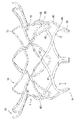
図1に示されるように、経カテーテル式人工弁1は、長手方向の軸20に沿って伸びている流入端10と流出端15(本システムが患者に移植されたときの血流の向きによる)を持つ、半径方向に自己拡張可能な筒状体5を含む。いくつかの実施形態では、筒状体5は、バルーン拡張可能であってもよい。筒状体5は、搬送カテーテルを介して患者の体内に搬送される、メッシュ状の構造体から成る外周部3を含むことができる。筒状体5のメッシュ状の構造体は、ニッケル、チタン及び/又は貴金属(例えば金)を含む超合金及び/又は形状記憶合金から形成される複数のストラット9を含むことができる。いくつかの実施形態で、筒状体5はニチノールから形成される。別の実施形態では、筒状体5は、ポリマーから形成され、このポリマーとしては、ポリ塩化ビニル、ポリスチレン、ポリプロピレン、及び/又は他のポリマーが挙げられる。例えば、筒状体5は1つ以上の生体吸収性高分子から形成されることができる。
As shown in FIG. 1, the transcatheter
筒状体5は概して円柱形状であってもよい。筒状体5の流出端15は、半径方向の外側に傾斜する円錐台形状をとってもよい。これに代わって、筒状体5の流出端15は内側に向かって細くなってもよい。さらに、図1~16は筒状体5のストラット9の多様な形状を示す。よって、ストラット9の構造と形状をさらに変更することは本発明の範囲内である。
The
図1に示されるように、1つ以上の止め輪4を、筒状体5の流入端10で外周部3に連結させることができる。止め輪4は、患者の内部における人工弁1の搬送と除去の補助とすることができる。
As shown in FIG. 1 , one or more
筒状体5は、筒状体5の半径方向の外側に向かって開口する外部に予め形成された溝7を含むことができる。予め形成された溝7は、筒状体5のメッシュ状の構造体におけるチャンネルを定める窪みであることができる。図1に示されるように、予め形成された溝7は、筒状体5の外周全体にわたって伸びていてもよい。別の実施形態では、予め形成された溝7は、筒状体5の外周全体より少ない部分にわたって伸びていてもよい。予め形成された溝7は連続的な、中断されない溝であってもよく、また、例えば、2つ以上の溝の部分を有する、中断された溝であってもよい。いくつかの実施形態では、予め形成された溝7は、筒状体5の流入端10と流出端15から、軸20に沿った、軸方向の距離に位置していてもよい。このように、予め形成された溝7は、筒状体5の最近位端と最遠位端から軸方向に離れていてもよい。
The
予め形成された溝7は、筒状体5から外向きに突き出る突起群(不図示)によって境界を定めることができる。このように、いくつかの実施形態では、筒状体5は、流入方向に、予め形成された溝7より上に設置された第1の突起群と、流出方向に、予め形成された溝7より下に設置された第2の突起群とを含むことができる。このように、第1と第2の突起群は、予め形成された溝7の上と下の部分を取り囲むことができる。第1と第2の突起群は、互いに向き合っていてもよい。これに加えて、第1と第2の突起群は、組織を刺し通すように構成された部材、例えば、スパイク、三角形状の突起、掛かりなどであってもよい。
The
筒状布25を、布25が流入端30と流出端35を持つように、筒状体5の外表面上に設置することができる。布25は、筒状体5の外周部3の外表面全体、又は、外周部3の外表面の一部分だけを覆うことができる。図1に示されるように、布25は、予め形成された溝7の輪郭に沿うように、予め形成された溝7内に設置することができる。布25は、たるんだ状態又は張った状態で筒状体5上に設置することができる。下で述べるように、筒状体5の周りに捕捉部材150を設置することができる。布25は、捕捉部材150が筒状体5の周りに設置されるまでたるんだ状態であるように、筒状体5上に設置することができる。このように、捕捉部材150は、布25が張った状態になるように、布25を予め形成された溝内に移動させることができる。
A
布25の素材としては、例えば、ポリエステル生地(例えばダクロン(登録商標)又は他のPTFEグラフト素材)を含むポリマー素材が挙げられる。これに加えて、又はこれに代わって、布25は心膜及び/又は金属メッシュ素材(例えば、ニチノールから形成される金属メッシュ)であってもよい。いくつかの実施形態では、布25は1つ以上の構成部分を含むことができる。例えば、布25は、2つ、4つ、又は6つの構成部分を含むことができる。複数の構成部分は空間的に隔てられ、隣接する構成部分の間に隙間があってもよい。これに代わって、又はこれに加えて、一部の又はすべての隣接する構成部分は、重なっていてもよい。布25は、1つ、又は複数の素材の層を含むことができる。いくつかの実施形態では、布25は皮膜又はライナーを含んでもよい。
Materials for
布25は、既知の、どのような固定機構によって筒状体5に取り付けてもよい。例えば、布25と筒状体5は、接着剤及び/又は縫合によって固定することができる。図1、2に示されるように、布25は、筒状体5とともに、展開、拡張された形態と、収縮、縮小された形態をとるように構成することができる。このように、布25は、筒状体5の状態に応じて拡張し、収縮することができる。
筒状体5は、人工心臓弁40の少なくとも一部分が筒状体5の流出端15を超えて遠位に伸びるように、弁40に連結することができる(図3A)。図3Bに示されるように、弁40は複数の弁尖45を有してもよい。弁40は、患者の生来の心臓弁(例えば、僧帽弁及び/又は三尖弁)を人工置換する役割を果たすことができる。
The
筒状体5は、弁尖45の外周縁50が布25の流出端35に直接連結されるように、弁40と連結することができる(図4A、4B)。このように、図3A、4A、及び4Bに示されるように、弁尖45は、流出方向に、筒状体5の流出端15の遠位に伸びることができる。弁尖45は、流出方向に、予め形成された溝7の遠位にあってもよい。弁尖45の外周縁50は、1つ以上の縫合55によって布25の流出端35と連結されるように、流出端35と軸方向に重なり合うことができる。これに加えて、又はこれに代わって、外周縁50は、例えば、接着剤、クリップ、クランプなど、どのような適切な固定機構を使って流出端35と連結させてもよい。
The
さらに、筒状体5は、筒状体5のストラット9が、1つ以上の縫合55によって布25に連結されるように、布25に直接連結することができる(図4A)。これに加えて、又はこれに代わって、ストラット9は、例えば、接着剤、クリップ、クランプなど、どのような適切な固定機構を使って布25と連結させてもよい。このように、図4Aに示されるように、弁尖45は、筒状体5と直接連結されていない。従って、弁40も筒状体5と直接連結されていない。その代わりに、弁40は、布25を介して間接的に筒状体5と連結されている。
Furthermore, the
図4A、4Bに示されるように、弁尖45の外周縁50は、弁40の流入側に設置することができる。このように、弁尖45の外周縁50は、布25の流出端35に直接連結することができる。このとき、弁尖45の外周縁50は、弁40と布25が直接連結するように、布25の流出端35と軸方向に重なり合う。
As shown in FIGS. 4A and 4B, the outer
さらに、布25と直接連結された筒状体5のストラット9は、筒状体5の流出端15に位置するストラット12であってもよい(図1、4A)。ストラット12は、布25と軸方向に重なり合ってもよい。このように、ストラット12によって、筒状体5と布25を直接連結することができる。
Furthermore, the
いくつかの実施形態では、布25と筒状体5のストラット12との間の結合は、布25と弁尖45の外周縁50との間の結合よりも筒状体5の流入端10に近いところに位置することができる(図4A、4B)。このように、布25と筒状体5との間の結合は、布25と弁40との間の結合の近位にあってもよい(図4A、4B)。また、布25と筒状体5との間の結合は、結合同士が軸方向に重なり合うように、布25と弁40との間の結合と軸方向に同じところに位置することも考えられる。
In some embodiments, the bond between the
これに加えて、図4A、4Bに示されるように、弁尖45の外周縁50は、流出方向に、ストラット12の遠位に設置することができる。このように、外周縁50は、流出方向に、筒状体5の外周部3の遠位に設置することができる。このように、弁尖45の外周縁50は、筒状体5の外周部3と半径方向に重なり合わなくてもよい。
Additionally, as shown in FIGS. 4A, 4B, the outer
上述したように、弁40の外周縁50は、弁尖45が、流出方向に、筒状体5の流出端15の遠位に伸びるように、布25の流出端35と連結している(図3A、4B)。このように、弁40は、筒状体5の外周部3と軸方向に重なり合わなくてもよく、筒状体5は、圧縮能力が増し、好都合である。従って、筒状体5は、通常の人工弁よりもさらに圧縮することができ、筒状体5は、より小さい搬送形態をとることができる。
As mentioned above, the outer
これに代わる別の実施形態では、弁40は、1つ以上の縫合55によって、筒状体5の流出端15と直接連結することができる。これに加えて、又はこれに代わって、弁40は、例えば、接着剤、クリップ、クランプなど、どのような適切な固定機構を使って筒状体5の流出端15と連結させてもよい。これらの実施形態において、弁尖45は、弁尖45が筒状体5の流出端15と連結されるように、ストラット12と直接連結することができる。これに加えて、弁尖45布25と直接連結されている、及び/又は、布25は、ストラット12と直接連結されていてもよい。
In another alternative embodiment,
図4A、4Bに示されるように、布25の流出端35は、流出方向に、弁尖45の外周縁50を超えて遠位に伸びなくてもよい。このように、流出端35は、外周縁50の位置で終結してもよい。布25の流出端35は、筒状体5のストラット12を超えて遠位に伸びてもよいが、布25の流出端35は、ストラット12の周りに巻き付かない。このように、布25は、筒状体5の流出端15の周りに巻き付かない。いくつかの実施形態では、布25の流出端35はストラット12の周りに部分的にのみ(よって、筒状体5の流出端15の周りにも部分的に)巻き付く。これらの実施形態においては、布25の流出端35は、ストラット12の周りに完全には巻き付かない。さらに別の実施形態においては、布25の流出端35は、筒状体5の流出端15の周りに完全に巻き付く。
As shown in FIGS. 4A, 4B, the
図5に示されるように、筒状体5のストラット12は、筒状体5の流出端15において、複数のアーチ状のビーム60を形成することができる。ビーム60は、上述したように、布25と直接連結することができる。上述したように、ビーム60は、弁尖45が流出方向に、ビーム60の遠位に伸びるように、布25と連結することができる。各ビーム60は、複数のビーム60が流出端15において、筒状体5の外周全体の周りに伸びるように、隣接するビーム60と直接連結することができる。これに加えて、隣接するビーム60同士は、ビーム60が流出端15において、筒状体5の外周全体の周りで連続するように、直接連結することができる。
As shown in FIG. 5, the
筒状体5は、流入端10において最近位端13を、流出端15において最遠位端14を有することができる。図5~7に示されるように、アーチ状のビーム60は、筒状体5の最遠位端14を形成することができる。さらに、各ビーム60は、流出方向に、第2の端69が第1の端67の遠位にあるように、第1の端67と第2の端69を有することができる。第1と第2の端67、69は、ビーム60のアーチ状の形状を形成することができる。これに加えて、第2の端69は、弁尖45と連結するための接合部を成すことができる。
The
図5~7に示されるように、例えば、ビーム60の第2の端69は、1つ以上の保持部材78と連結することができる。このように、筒状体5の最遠位端14も保持部材78と連結することができる。いくつかの実施形態では、保持部材78は、流出方向に、筒状体5の外周部3の遠位にある。保持部材78は、患者の内部に筒状体5を固定するときの補助とすることができる。布25は、保持部材78の上に設置されないように、筒状体5の上に設置することができる。いくつかの実施形態では、布25は流出方向に、筒状体5の最遠位端14の遠位に伸びなくてもよい。このように、布25は、保持部材78の遠位に伸びなくてもよい。
For example, the
いくつかの実施形態では、各弁尖45は、複数のビーム60のうち、2つのビーム60のみによって支えられてもよい。このように、例えば、図3B、5に示されるように、単一の弁尖45は、第1のビーム61と第2のビーム63によって支えられてもよい。上述したように、各弁尖45は、弁尖45が、ビーム61、63と直接連結された布25と直接連結されるように、ビーム61、63によって支えられてもよい。このように、弁尖45、布25、及びビーム60の間の結合は、ビーム60と弁尖45の間の支えとなる。別の実施形態では、各弁尖45は、2つ、3つ、又はそれ以上のビーム60によって支えることができる。図5~7では、6つのビームが示されているが、より多くの、またはより少ないビームを使うことも考えられる。このように、筒状体5は、少なくとも6つのビーム60を有することができる。
In some embodiments, each
図5~7に示されるように、連結部65は、筒状体5の流入端10をビーム60と直接連結することができる。流入端10とビーム60の間のすべての直接の連結は、連結部65のみによって行われてもよい。図5~7における実施形態では、3つの連結部65が設けられている。図3Bに示されるように、連結部65の数は、弁尖45の数と等しくてもよい。このように、別の実施形態では、弁尖45の数に合わせて4つ、5つ、又はそれ以上の連結部65が設けられてもよい。連結部65の数が、弁尖の数の倍数であることも考えられる。いくつかの実施形態では、図5~7に示されるように、ビーム60の第1の端67には連結部65がある。
As shown in FIGS. 5-7, the
流入端10とビーム60を直接連結することで、連結部65は、ビーム60と筒状体5の流入端10の動作の無相関を提供する。このように、連結部65は、流入端10とビーム60の間の軸方向及び半径方向の動作を分離することができる。例えば、連結部65は、筒状体5の流入端10の動作を弱めるように構成することができる。このように、流入端10の動作は完全にはビーム60には伝搬されていない。連結部65は、流入端10の動作を吸収することができ、無相関効果を生む。いくつかの実施形態では、連結部65は、流入端10の動作をすべて吸収する。別の実施形態では、連結部65は、流入端10の動作の一部だけ吸収する。
By directly connecting the
図5~7に示されるように、筒状体5の流入端10は、山70と谷75を有するストラット9を有する。山70は、谷75が山70よりも筒状体5の流出端15の近くに位置するように、谷75の近位に設置される。さらに、山70と谷75は、筒状体5の最近位端13を形成することができる。
As shown in FIGS. 5-7, the
いくつかの実施形態では、山70と谷75は、山70の半径方向の内側に向かった動きによって、谷75が半径方向の外側に張り出すように構成することができる(図8)。例えば、筒状体5が患者に移植されたときに、患者の心房壁が山70を半径方向の内側に押すことがある(患者の生来の心臓による通常の収縮運動によって)。これにより、図8に示されるように、山70が変形し、半径方向の内側に動く。よって、山70の内向きの動きによって、谷75は変形し、半径方向の外側に動く。谷75の半径方向の外側に向かった変形により、流入端10はさらに患者の心房壁に接触するように押し込まれ、このように、患者の内部における流入端10の密閉効果を改善する。
In some embodiments, peaks 70 and
布25が筒状体5を覆うように設置されているとき、上述したように、山70の半径方向の内向きの動きによって、谷75と布25がともに半径方向の外側に張り出してもよい。このように、布25は、患者の内部における筒状体5の密閉効果をさらに高めるように、谷70とともにさらに患者の心房壁に接触するように押し込まれる。
When
図1、9に示されるように、例えば、筒状体5の流出端15は、ビーム60と近位部分80を有することができる。ビーム60と近位部分80はともに、流出方向に、予め形成された溝7の遠位に設置されてもよい。近位部分80はさらに、流出方向に、山70と谷75の遠位に設置されてもよい。さらに、ビーム60は、流出方向に、近位部分80の遠位に設置されてもよい。従って、図10に示されるように、近位部分80の半径方向の内側に向かった動きによって、筒状体5の流入端10半径方向の外側に張り出してもよい。例えば、患者の生来の自然弁の自然な動きによって、筒状体5が内向きに圧縮されてもよい。より具体的には、いくつかの例では、患者の生来の弁によって弁尖45が内向きに圧縮され、これにより、筒状体5が内向きに圧縮されてもよい。このように、このような圧縮によって近位部分80が半径方向の内向きに圧縮されてもよい。筒状体5の構造により、近位部分80の半径方向の内側に向かった動きにより、流入端10が半径方向の外側に張り出してもよい。流入端10の外向きの動きによって、流入端10と患者の心房壁との間の密閉効果を高めることができ、このように、筒状体5と患者の心房壁との間をより強く密閉することができ、好都合である。さらに、近位部分80が半径方向の内側に向かって動き、流入端10が半径方向の外側に張り出すとき、ビーム60は動かないようにすることができる。このように、連結部65は、このような近位部分80の動きをビーム60から分離することができる。
For example, the
図9、10に示されるように、連結部65は、近位部分80の中に設置することができる。これに代わって、連結部65は、流出方向に、近位部分80の遠位に設置することができる。さらに、いくつかの実施形態では、弁尖45は、流出方向に、完全に近位部分80の遠位に伸びていてもよい。別の実施形態では、弁尖45は、近位部分80と軸方向に重なり合ってもよい。
As shown in FIGS. 9 and 10, coupling 65 can be placed in
図11は、ストラット9のさらなる構成で、筒状体5の流入端10がS字形のストラット9を有するものを示す。S字形のストラットは、筒状体5が拡張された状態にあるときに、山70と谷75がともに流入方向に、S字形のストラットの上に設置されるように、山70と直接連結してもよい。S字形のストラットはそれぞれ、筒状体6の最近位端13と筒状体5の流出端15との間の動きを分離するような、無相関部を形成することができる。このように、S字形のストラットは、流入端10又は流出端15の動きに応じて、圧迫、収縮するように構成することができる。このように、S字形のストラットが伸張、及び/又は収縮するため、筒状体5の一端における動きは、筒状体5の他方の端には移動又は伝達しない。S字形のストラットは、流入方向に、完全に予め形成された溝7の近位に設置することができる。
FIG. 11 shows a further configuration of
いくつかの実施形態では、筒状体5は、筒状体5に組み込まれた動作緩衝部材90有することができる(図11~13B)。動作緩衝部材90は、例えば、しずく形(図11)又は三角形(図12)の形状をした、1つ以上のストラット9を有することができる。動作緩衝部材90は、筒状体5が一つの部材を形成するように、筒状体5の残りの部分と一体となっていてもよい。これに加えて、布25は、動作緩衝部材90の外表面に設置されてもよい。
In some embodiments, the
患者の内部における弁尖45の動きによって、患者の内部で筒状体5も動くことがある。より具体的には、患者の内部における生来の弁の機能を置換するとき、弁尖45は内向き及び外向きに動くことがある。このような動きによって、例えば、筒状体5の流出端15が患者の心房壁に対して半径方向の内側及び外側に押されることがある。このような流出端15の動きによって、布25も患者の心房壁に対して半径方向の内側及び外側に押されることがある。この、患者の生来の自然弁に対する布25の動きは、布25に摩擦及び摩耗を引き起こすことがある。さらに、筒状体5は患者の生来の弁との継続した接触によって摩擦及び摩耗を受けることがある。
Movement of the
動作緩衝部材90は、布25と筒状体5に対するそのような摩擦及び摩耗を低減させる、バンパー効果を生むことができる。例えば、図13A、13Bに示されるように、弁尖45の動きによって筒状体5の流出端15が半径方向の内側に動くとき、動作緩衝部材90は流出端15とともに半径方向の内側に動かないように構成することができる。その代わりに、動作緩衝部材90は、流出端15の内向きの動きに対して、半径方向の外側に向かって動く、又は、同じ位置にとどまることができる。このように、動作緩衝部材90は、流出端15が半径方向の内側に向かって動くとき、半径方向の外側に向かって布25及び患者の生来の弁尖を押すことができる。このように、動作緩衝部材90が半径方向の外側に向かって押すことにより、バンパー効果を生むことができる。このように、流出端15と布25が半径方向の内向きの位置から半径方向の外向きの位置に押し出されるとき、(弁尖45の動きにより)、動作緩衝部材90は、既に外向きに突き出ているため、流出端15と布25の患者の生来の弁尖に対する半径方向の外向きの力を和らげる、緩衝効果を生む。
The
従って、動作緩衝部材90は、弁尖45の動きによる筒状体5に対する摩擦と摩耗を吸収することができる。このように、動作緩衝部材90は、筒状体5、特にビーム60の耐久性を好適に向上させることができる。これに加えて、動作緩衝部材90は、弁尖45の動きによる布25に対する摩擦及び摩耗を吸収することができる。このように、動作緩衝部材90は、布25の耐久性も向上させることができる。
Accordingly, the
図13Aは、筒状体5の中間的な状態を示し、図13Bは、流出端15が半径方向の内側に向かって動き、動作緩衝部材90が半径方向の外側に向かって動いた筒状体5の状態を示す。動作緩衝部材90の構造及び/又は位置によって、動作緩衝部材90が、流出端15の動きに応じて半径方向の外側に向かって動く、又は同じ位置にとどまるようにすることができる。図11~13Bに示されるように、動作緩衝部材90は、ビーム60と隣接するように、そして、流出方向に予め形成された溝7の遠位に、設置することができる。動作緩衝部材90は、近位部分80内部に設置することができる。これに加えて、動作緩衝部材90のストラット幅は、ビーム60のストラット幅より小さくてもよい。このように、動作緩衝部材90は、上述したように、半径方向の外側に向かって動く、又は、同じ位置にとどまるのに十分な柔軟性を有してもよい。
13A shows an intermediate state of the
いくつかの実施形態では、動作緩衝部材90は、半径方向に、弁尖45と同じ断面に位置することができる。このように、動作緩衝部材90と弁尖45は、長手方向の軸20に沿って軸方向に重なり合ってもよい。これに加えて、動作緩衝部材90は、半径方向に、少なくとも部分的に連結部65と同じ断面に位置することができる。このように、動作緩衝部材90と連結部65は、長手方向の軸20に沿って、軸方向に重なり合うことができる。
In some embodiments, the
図14は、筒状体5が異なる厚さのストラット9を有する実施形態を示す。このように、例えば、ストラット9は、比較的小さい厚さ100と、比較的大きい厚さ110を有することができる。さらに、ストラット9は、第1のセル120と第2のセル130を形成するように、曲線状であってもよい。図14に示されるように、第1のセル120は、比較的小さい厚さ100のストラットから形成され、第2のセル130は、比較的大きい厚さ110のストラットから形成される。これに加えて、第1のセル120と第2のセル130の間に、第3のセル140が設置されてもよい。第3のセルは、比較的小さい厚さ100のストラットと、比較的大きい厚さ110のストラットの両方から形成されることができる。
FIG. 14 shows an embodiment in which the
第1のセル120、第2のセル130、及び第3のセル140は、筒状体5が開かれて拡張されたときに、一様に開いて拡張するように構成することができる。このように、比較的小さい厚さと大きい厚さ100、110のストラットによって、すべてのセル120、130、140は、同じ割合でともに開く。対照的に、従来の人工器官装置においては、いくつかのストラットセルは、人工器官装置のメッシュ構造体内の配置によってはより弱い外向きの力でも開くことがある。従って、いくつかのストラットセルは、他のストラットセルよりも簡単に、速く開くことがある。これにより、人工弁はばらばらに拡張され、開かれることになる。例えば、より簡単に開くストラットセルは、より開きにくいストラットセルより前に完全に開くことがある。このような、一様でない拡張は、人工器官装置の不正確な配置につながり、人工弁の性能を変化させることがある。セル120、130、140が同じ割合でともに開くため、人工弁1は製造の際に、一様に拡張する(例えば、熱成形工程の際)。従って、セル120、130、140は、従来の人工器官装置と比べて簡単に製造することができる人工器官装置を提供する。
The
図14の実施形態において、比較的大きい厚さ110のストラットは、筒状体5の、比較的簡単に開く位置に設置することができる。比較的小さい厚さ100のストラットは、筒状体5の、比較的開きにくい位置に設置することができる。このように、ストラットの厚さは、筒状体5のすべてのセルに渡って一様に拡張するように、開けやすさと釣り合いをとることができる。
In the embodiment of FIG. 14, struts of relatively
すべての人工弁1の実施形態は、筒状体5の相対的な及び/又は絶対的な位置決めを容易にするための位置決め及び/又は方位決め装置を有することができる(不図示)。これらの装置は、筒状体5に取り付けられる複数のパッシブマーカーを有することができる。パッシブマーカーは、例えば磁気共鳴又はX線に基づくイメージング技術を用いた医療的なイメージング中でコントラストを向上させるために、筒状体5と異なる素材からなることができる。パッシブマーカーは、例えば、放射線透過性が低い素材からなることができ、これによって、患者の身体に対する人工弁1の構成部分の相対的な及び/又は絶対的な位置を正確に捕捉することができる。
All
人工弁1の構造は、従来の人工弁よりも小さい形態を可能にすることができる。このように、例えば、人工弁1は、人体の構造によって大きさを変えることができ、患者の内部へ搬送するために26FID配管カテーテルの中へ収縮することができる。これに加えて、弁尖45が筒状体5を超えて遠位に伸びているため、筒状体5の骨組みの、弁40を支えるために必要な大きさは、縮小することができる。例えば、ストラット9の数を減らすことができ、これにより、より柔軟な構造とすることができる。これに加えて、人工弁1の構成は、従来の人工弁に比べて、弁尖45にとってより高い安定性を有することができる。
The construction of
図15に示されるように、人工弁1は、カテーテルを介して患者に展開されることができる。人工弁1を搬送する方法は、搬送カテーテルから、筒状体5と弁40を搬送することを含むことができる。次に、筒状体5と弁40は、筒状5のビーム60が患者の心臓の心房と心室との間の接続チャンネルの組織に対して設置されるように拡張されることができる。このように、例えば、人工弁1は、機能を回復させるために、患者の、欠陥のある僧帽弁又は三尖弁へ搬送されることができる。人工弁1は、予め形成された溝7が生来の弁の弁輪の心室側に位置するように患者に搬送することができる(例えば、生来の弁の弁輪から距離をおいて)。
As shown in Figure 15, the
人工弁1を患者の心臓弁の内部に配置するために、以下のアプローチを用いることができる。(1)大動脈から心臓内腔に進入する動脈逆行性アプローチ、(2)静脈アクセス及び心房中隔穿刺を介したアプローチ(経中隔アプローチ)、(3)心尖を貫通する穿刺によるアプローチ(経心尖アプローチ)、(4)心臓の外側から心房壁を穿刺するアプローチ、(5)動脈アクセス(例えば鼠径の穿刺を介した大腿動脈からのアクセス)、(6)直接大静脈を通る、右心房の中へのアプローチ(例えば、三尖弁の置換において)、又は(7)当業者に知られた他のアプローチ。
To place the
患者の心臓弁を機能的に置換するため、人工弁1は、人工弁1の外側の血流に対して密閉されるように、接続チャンネル壁構造25に対して固定されることができる。これを達成するため、予め形成された溝7に隣接する接続チャンネル壁構造25の組織は予め形成された溝7に押し込まれるか予め形成された溝7内に配置される。
To functionally replace a patient's heart valve, the
この方法はさらに、捕捉部材150を筒状体5の周りと予め形成された溝7の周りに推進させることを含んでもよい。このように、捕捉部材150は、予め形成された溝7内で、生来の弁尖160及び/又は腱索170の部分を捕捉することができる。これは、筒状体5を患者の中に固定する補助とすることができる。捕捉部材150は、完全な、又は部分的な環を有することができる。これに加えて、捕捉部材150は、筒状体5が完全に拡張された後、又は筒状体5部分的にのみ拡張されたとき、筒状体5の周りで動かすことができる。捕捉部材150は、捕捉部材150と予め形成された溝7の間の締まり嵌めによって筒状体5が固定されるように、予め形成された溝の内部に緩く設置することができる。このように、捕捉部材150は、人工弁1を、患者の内部に固定する機能を有することができる。別の実施形態では、捕捉部材150は、人工弁1を患者の内部に固定するために、筒状体5に対する内向きの、半径方向の力を生じさせることができる。このように、この実施形態では、捕捉部材150は、弁尖160及び/又は腱索170に対して摩擦力を生じさせることできる。
The method may further include propelling the
捕捉部材150は、搬送カテーテル内では、搬送形態をとり、捕捉部材150が搬送カテーテルから展開された際に展開形態をとることができる。実施形態において、捕捉部材150は展開形態に形状を変化させる。例えば、捕捉部材150は、ニチノールやニチノール系合金などの形状記憶合金を含むことができる。
The
いくつかの実施形態では、細長い外部部材180も筒状体5の周りと予め形成された溝7の周りに推進させることができる。細長い外部部材180は、筒状体5が完全に拡張された後、又は筒状体5が部分的にのみ拡張されたときに筒状体5を囲んでもよい。細長い外部部材180は、患者の生来の弁尖160及び/又は腱索170を予め形成された溝7へと押し込んでもよい。その後、捕捉部材150は、捕捉部材150を筒状体5の周りに、そして予め形成された溝7の内部へと押し込むために、細長い外部部材180にそって、細長い外部部材180を覆うように設置することができる。細長い外部部材180は、捕捉部材150が筒状体5の周りに設置された後に、患者から除去することができる。細長い外部部材180が患者から除去された後、捕捉部材150は、患者の生来の弁尖160及び/又は腱索170を予め形成された溝7の内部に保つことができる。
In some embodiments, an elongated
いくつかの実施形態では、細長い外部部材180はガイドワイヤーであってもよい。細長い外部部材180は、捕捉部材150よりも小さい直径を有することができる。
In some embodiments, elongated
開示された人工弁1の使用方法は、患者の弁の閉塞を最小限に抑えながら筒状体5を患者の接続チャンネル壁構造内に固定することができる。
The disclosed method of using the
開示された実施形態は、人工弁1を製造する方法も含む。本製造方法は、弁40の外周縁50を布25の流出端35と直接連結して、サブアセンブリを形成することを含むことができる。次に、筒状体5は、サブアセンブリの中へスライドさせることができる。そして、筒状体5は、流出方向に、弁尖45が筒状体5の流出端15の遠位に伸びるようにサブアセンブリと連結して、アセンブリを形成することができる。筒状体5は、筒状体5の流出端15と布25を連結することによって、サブアセンブリと直接連結することができる。図4Aと4Bに示されるように、布25は外周縁50と直接連結することができ、1つ以上の縫合55によって筒状体5と直接連結することができる。
The disclosed embodiments also include a method of manufacturing the
Claims (13)
前記システムは、流入端と流出端を持つ、半径方向に自己拡張可能な筒状体と、
前記筒状体と連結され、複数の弁尖を含む弁と、
前記筒状体の外表面上に設置され、流入端と流出端を有する筒状布とを有し、
前記布の前記流出端が、流出方向に前記筒状体の前記流出端の遠位の位置で、前記弁の外周縁と直接連結されており、かつ、
前記布の前記流出端は、流出方向に、前記弁の前記外周縁を超えて遠位に伸びていないものであることを特徴とするシステム。 A heart valve system comprising:
The system comprises a radially self-expandable tubular body having an inflow end and an outflow end;
a valve coupled with the tubular body and including a plurality of leaflets;
a tubular fabric placed on the outer surface of the tubular body and having an inflow end and an outflow end;
the outflow end of the fabric is directly connected to the outer peripheral edge of the valve at a location distal to the outflow end of the tubular body in the outflow direction ; and
A system , wherein the outflow end of the fabric does not extend distally beyond the outer perimeter of the valve in the outflow direction .
前記布は、前記筒状体の前記外周部の前記外表面全体を取り囲むものであることを特徴とする請求項1に記載のシステム。 The tubular body includes an outer peripheral portion and one or more holding members,
2. The system of claim 1, wherein the fabric surrounds the entire outer surface of the perimeter of the tubular body.
Applications Claiming Priority (3)
| Application Number | Priority Date | Filing Date | Title |
|---|---|---|---|
| US15/343,694 | 2016-11-04 | ||
| US15/343,694 US11376121B2 (en) | 2016-11-04 | 2016-11-04 | Transcatheter valve prosthesis |
| PCT/IB2017/001555 WO2018083541A1 (en) | 2016-11-04 | 2017-11-06 | Transcatheter valve prosthesis |
Publications (2)
| Publication Number | Publication Date |
|---|---|
| JP2019533532A JP2019533532A (en) | 2019-11-21 |
| JP7175268B2 true JP7175268B2 (en) | 2022-11-18 |
Family
ID=60972253
Family Applications (1)
| Application Number | Title | Priority Date | Filing Date |
|---|---|---|---|
| JP2019523580A Active JP7175268B2 (en) | 2016-11-04 | 2017-11-06 | Transcatheter valve prosthesis |
Country Status (7)
| Country | Link |
|---|---|
| US (2) | US11376121B2 (en) |
| EP (1) | EP3534841B1 (en) |
| JP (1) | JP7175268B2 (en) |
| CN (1) | CN110035713B (en) |
| AU (1) | AU2017353942B2 (en) |
| CA (1) | CA3042841A1 (en) |
| WO (1) | WO2018083541A1 (en) |
Families Citing this family (18)
| Publication number | Priority date | Publication date | Assignee | Title |
|---|---|---|---|---|
| US9554897B2 (en) | 2011-04-28 | 2017-01-31 | Neovasc Tiara Inc. | Methods and apparatus for engaging a valve prosthesis with tissue |
| US9345573B2 (en) | 2012-05-30 | 2016-05-24 | Neovasc Tiara Inc. | Methods and apparatus for loading a prosthesis onto a delivery system |
| US10561509B2 (en) | 2013-03-13 | 2020-02-18 | DePuy Synthes Products, Inc. | Braided stent with expansion ring and method of delivery |
| US10292851B2 (en) | 2016-09-30 | 2019-05-21 | DePuy Synthes Products, Inc. | Self-expanding device delivery apparatus with dual function bump |
| US9999502B2 (en) | 2016-11-04 | 2018-06-19 | Highlife Sas | Transcather valve prosthesis |
| US10188514B2 (en) * | 2016-11-04 | 2019-01-29 | Highlife Sas | Transcatheter valve prosthesis |
| US11666444B2 (en) | 2017-08-03 | 2023-06-06 | The Regents Of The University Of California | Atrial cage for placement, securing and anchoring of atrioventricular valves |
| CA3073834A1 (en) | 2017-08-25 | 2019-02-28 | Neovasc Tiara Inc. | Sequentially deployed transcatheter mitral valve prosthesis |
| AU2019204522A1 (en) * | 2018-07-30 | 2020-02-13 | DePuy Synthes Products, Inc. | Systems and methods of manufacturing and using an expansion ring |
| US10456280B1 (en) | 2018-08-06 | 2019-10-29 | DePuy Synthes Products, Inc. | Systems and methods of using a braided implant |
| EP3876870B1 (en) | 2018-11-08 | 2023-12-20 | Neovasc Tiara Inc. | Ventricular deployment of a transcatheter mitral valve prosthesis |
| CA3135753C (en) | 2019-04-01 | 2023-10-24 | Neovasc Tiara Inc. | Controllably deployable prosthetic valve |
| AU2020279750B2 (en) | 2019-05-20 | 2023-07-13 | Neovasc Tiara Inc. | Introducer with hemostasis mechanism |
| EP3986332A4 (en) | 2019-06-20 | 2023-07-19 | Neovasc Tiara Inc. | Low profile prosthetic mitral valve |
| US11484407B2 (en) * | 2020-01-07 | 2022-11-01 | Highlife Sas | Transcatheter valve prosthesis |
| EP4262628A1 (en) * | 2020-12-18 | 2023-10-25 | Cephea Valve Technologies, Inc. | Collapsible gasket seal for heart valve |
| EP4351478A1 (en) * | 2021-06-11 | 2024-04-17 | Edwards Lifesciences Corporation | Prosthetic heart valve |
| WO2023249682A1 (en) * | 2022-06-20 | 2023-12-28 | St. Jude Medical, Cardiology Division, Inc. | Fabric suture valve suspension system |
Citations (8)
| Publication number | Priority date | Publication date | Assignee | Title |
|---|---|---|---|---|
| JP2012504031A (en) | 2008-09-29 | 2012-02-16 | カルディアック バルブ テクノロジーズ,インコーポレーテッド | Heart valve |
| JP2013540484A (en) | 2010-09-20 | 2013-11-07 | セント・ジュード・メディカル,カーディオロジー・ディヴィジョン,インコーポレイテッド | Valve leaflet mounting device in foldable artificial valve |
| US20140277417A1 (en) | 2013-03-14 | 2014-09-18 | St. Jude Medical, Cardiology Division, Inc. | Cuff configurations for prosthetic heart valve |
| US20140324160A1 (en) | 2010-03-05 | 2014-10-30 | Edwards Lifesciences Corporation | Low-profile heart valve and delivery system |
| JP2014532457A (en) | 2011-10-19 | 2014-12-08 | トゥエルヴ, インコーポレイテッド | Prosthetic heart valve device, prosthetic mitral valve, and related systems and methods |
| JP2015521916A (en) | 2012-06-29 | 2015-08-03 | セント・ジュード・メディカル,カーディオロジー・ディヴィジョン,インコーポレイテッド | System that facilitates release of foldable stent from delivery device |
| WO2015132667A1 (en) | 2014-02-28 | 2015-09-11 | Highlife Sas | Transcatheter valve prosthesis |
| US20160220365A1 (en) | 2015-02-03 | 2016-08-04 | Boston Scientific Scimed, Inc. | Prosthetic Heart Valve Having Tubular Seal |
Family Cites Families (56)
| Publication number | Priority date | Publication date | Assignee | Title |
|---|---|---|---|---|
| JP4292710B2 (en) | 1997-09-24 | 2009-07-08 | エム イー ディ インスチィチュート インク | Radially expandable stent |
| US6395019B2 (en) | 1998-02-09 | 2002-05-28 | Trivascular, Inc. | Endovascular graft |
| US6264700B1 (en) * | 1998-08-27 | 2001-07-24 | Endonetics, Inc. | Prosthetic gastroesophageal valve |
| US6139575A (en) | 1999-04-02 | 2000-10-31 | Medtronic, Inc. | Hybrid mechanical heart valve prosthesis |
| US6325825B1 (en) | 1999-04-08 | 2001-12-04 | Cordis Corporation | Stent with variable wall thickness |
| US6458153B1 (en) | 1999-12-31 | 2002-10-01 | Abps Venture One, Ltd. | Endoluminal cardiac and venous valve prostheses and methods of manufacture and delivery thereof |
| US7195641B2 (en) | 1999-11-19 | 2007-03-27 | Advanced Bio Prosthetic Surfaces, Ltd. | Valvular prostheses having metal or pseudometallic construction and methods of manufacture |
| US6454799B1 (en) * | 2000-04-06 | 2002-09-24 | Edwards Lifesciences Corporation | Minimally-invasive heart valves and methods of use |
| US20030109923A1 (en) | 2001-12-12 | 2003-06-12 | Chinn Joseph A. | Polymer heart valve with perforated stent and sewing cuff |
| US7037344B2 (en) * | 2002-11-01 | 2006-05-02 | Valentx, Inc. | Apparatus and methods for treatment of morbid obesity |
| WO2005011535A2 (en) * | 2003-07-31 | 2005-02-10 | Cook Incorporated | Prosthetic valve for implantation in a body vessel |
| US8007528B2 (en) | 2004-03-17 | 2011-08-30 | Boston Scientific Scimed, Inc. | Bifurcated stent |
| WO2005097012A2 (en) * | 2004-03-26 | 2005-10-20 | Satiety, Inc. | Systems and methods for treating obesity |
| EP1883375B1 (en) * | 2005-05-24 | 2016-12-07 | Edwards Lifesciences Corporation | Rapid deployment prosthetic heart valve |
| DE102005052628B4 (en) | 2005-11-04 | 2014-06-05 | Jenavalve Technology Inc. | Self-expanding, flexible wire mesh with integrated valvular prosthesis for the transvascular heart valve replacement and a system with such a device and a delivery catheter |
| US20080275550A1 (en) | 2006-02-24 | 2008-11-06 | Arash Kheradvar | Implantable small percutaneous valve and methods of delivery |
| US8500799B2 (en) | 2006-06-20 | 2013-08-06 | Cardiacmd, Inc. | Prosthetic heart valves, support structures and systems and methods for implanting same |
| JP5367700B2 (en) | 2007-06-04 | 2013-12-11 | セント ジュード メディカル インコーポレイテッド | Prosthetic heart valve |
| EP2484311B1 (en) | 2007-08-24 | 2015-05-06 | St. Jude Medical, Inc. | Prosthetic aortic heart valve |
| JP5628673B2 (en) | 2007-09-26 | 2014-11-19 | セント ジュード メディカル インコーポレイテッド | Foldable prosthetic heart valve |
| WO2009053497A1 (en) | 2007-10-25 | 2009-04-30 | Symetis Sa | Stents, valved-stents and methods and systems for delivery thereof |
| US20110160836A1 (en) * | 2008-06-20 | 2011-06-30 | Vysera Biomedical Limited | Valve device |
| US20100217382A1 (en) | 2009-02-25 | 2010-08-26 | Edwards Lifesciences | Mitral valve replacement with atrial anchoring |
| BRPI1008902A2 (en) | 2009-02-27 | 2016-03-15 | St Jude Medical | prosthetic heart valve. |
| JP5603934B2 (en) | 2009-06-05 | 2014-10-08 | メドトロニック エイティーエス メディカル インコーポレイテッド | Flexible commissure structure for attaching a bioprosthetic valve |
| US8449599B2 (en) | 2009-12-04 | 2013-05-28 | Edwards Lifesciences Corporation | Prosthetic valve for replacing mitral valve |
| US9522062B2 (en) | 2010-02-24 | 2016-12-20 | Medtronic Ventor Technologies, Ltd. | Mitral prosthesis and methods for implantation |
| US9072603B2 (en) | 2010-02-24 | 2015-07-07 | Medtronic Ventor Technologies, Ltd. | Mitral prosthesis and methods for implantation |
| EP2611388B1 (en) | 2010-09-01 | 2022-04-27 | Medtronic Vascular Galway | Prosthetic valve support structure |
| US8845720B2 (en) | 2010-09-27 | 2014-09-30 | Edwards Lifesciences Corporation | Prosthetic heart valve frame with flexible commissures |
| PT3626208T (en) * | 2010-10-05 | 2021-04-22 | Edwards Lifesciences Corp | Prosthetic heart valve |
| WO2012177942A2 (en) | 2011-06-21 | 2012-12-27 | Hanson Gifford, Iii | Prosthetic heart valve devices and associated systems and methods |
| US9216076B2 (en) | 2011-09-09 | 2015-12-22 | Endoluminal Sciences Pty. Ltd. | Means for controlled sealing of endovascular devices |
| US9039757B2 (en) * | 2011-10-19 | 2015-05-26 | Twelve, Inc. | Prosthetic heart valve devices, prosthetic mitral valves and associated systems and methods |
| CA2892838A1 (en) | 2011-12-01 | 2013-06-06 | The Trustees Of The University Of Pennsylvania | Percutaneous valve replacement devices |
| US20150094802A1 (en) | 2012-02-28 | 2015-04-02 | Mvalve Technologies Ltd. | Single-ring cardiac valve support |
| US9289292B2 (en) | 2012-06-28 | 2016-03-22 | St. Jude Medical, Cardiology Division, Inc. | Valve cuff support |
| WO2014015212A1 (en) * | 2012-07-20 | 2014-01-23 | Cook Medical Technologies Llc | Implantable medical device having a sleeve |
| US10206775B2 (en) | 2012-08-13 | 2019-02-19 | Medtronic, Inc. | Heart valve prosthesis |
| US9066801B2 (en) | 2013-01-08 | 2015-06-30 | Medtronic, Inc. | Valve prosthesis and method for delivery |
| US10413401B2 (en) | 2013-02-01 | 2019-09-17 | Medtronic CV Luxembourg S.a.r.l. | Anti-paravalvular leakage component for a transcatheter valve prosthesis |
| US9439763B2 (en) | 2013-02-04 | 2016-09-13 | Edwards Lifesciences Corporation | Prosthetic valve for replacing mitral valve |
| US20140277427A1 (en) | 2013-03-14 | 2014-09-18 | Cardiaq Valve Technologies, Inc. | Prosthesis for atraumatically grasping intralumenal tissue and methods of delivery |
| GB2513195A (en) | 2013-04-19 | 2014-10-22 | Strait Access Tech Holdings Pty Ltd | A stent for a prosthetic heart valve |
| WO2014191994A1 (en) | 2013-05-29 | 2014-12-04 | Mvalve Technologies Ltd. | Cardiac valve support device fitted with valve leaflets |
| US20150005874A1 (en) | 2013-06-27 | 2015-01-01 | Tendyne Holdings, Inc. | Atrial Thrombogenic Sealing Pockets for Prosthetic Mitral Valves |
| US9901444B2 (en) | 2013-12-17 | 2018-02-27 | Edwards Lifesciences Corporation | Inverted valve structure |
| US9763779B2 (en) | 2014-03-11 | 2017-09-19 | Highlife Sas | Transcatheter valve prosthesis |
| US9889003B2 (en) | 2014-03-11 | 2018-02-13 | Highlife Sas | Transcatheter valve prosthesis |
| US10064719B2 (en) * | 2014-03-11 | 2018-09-04 | Highlife Sas | Transcatheter valve prosthesis |
| AU2015221855B2 (en) | 2014-02-28 | 2019-06-13 | Highlife Sas | Transcatheter valve prosthesis |
| US9687343B2 (en) | 2014-03-11 | 2017-06-27 | Highlife Sas | Transcatheter valve prosthesis |
| JP6576944B2 (en) | 2014-03-18 | 2019-09-18 | セント・ジュード・メディカル,カーディオロジー・ディヴィジョン,インコーポレイテッド | Toggle cell fixation in mitral valve replacement |
| US10500042B2 (en) | 2014-05-22 | 2019-12-10 | St. Jude Medical, Cardiology Division, Inc. | Stents with anchoring sections |
| US9693860B2 (en) * | 2014-12-01 | 2017-07-04 | Medtronic, Inc. | Segmented transcatheter valve prosthesis having an unsupported valve segment |
| US10143554B2 (en) * | 2015-12-03 | 2018-12-04 | Medtronic Vascular, Inc. | Venous valve prostheses |
-
2016
- 2016-11-04 US US15/343,694 patent/US11376121B2/en active Active
-
2017
- 2017-11-06 CA CA3042841A patent/CA3042841A1/en active Pending
- 2017-11-06 AU AU2017353942A patent/AU2017353942B2/en active Active
- 2017-11-06 EP EP17829278.5A patent/EP3534841B1/en active Active
- 2017-11-06 WO PCT/IB2017/001555 patent/WO2018083541A1/en active Search and Examination
- 2017-11-06 CN CN201780075189.2A patent/CN110035713B/en active Active
- 2017-11-06 JP JP2019523580A patent/JP7175268B2/en active Active
-
2018
- 2018-01-30 US US15/883,460 patent/US10736739B2/en active Active
Patent Citations (8)
| Publication number | Priority date | Publication date | Assignee | Title |
|---|---|---|---|---|
| JP2012504031A (en) | 2008-09-29 | 2012-02-16 | カルディアック バルブ テクノロジーズ,インコーポレーテッド | Heart valve |
| US20140324160A1 (en) | 2010-03-05 | 2014-10-30 | Edwards Lifesciences Corporation | Low-profile heart valve and delivery system |
| JP2013540484A (en) | 2010-09-20 | 2013-11-07 | セント・ジュード・メディカル,カーディオロジー・ディヴィジョン,インコーポレイテッド | Valve leaflet mounting device in foldable artificial valve |
| JP2014532457A (en) | 2011-10-19 | 2014-12-08 | トゥエルヴ, インコーポレイテッド | Prosthetic heart valve device, prosthetic mitral valve, and related systems and methods |
| JP2015521916A (en) | 2012-06-29 | 2015-08-03 | セント・ジュード・メディカル,カーディオロジー・ディヴィジョン,インコーポレイテッド | System that facilitates release of foldable stent from delivery device |
| US20140277417A1 (en) | 2013-03-14 | 2014-09-18 | St. Jude Medical, Cardiology Division, Inc. | Cuff configurations for prosthetic heart valve |
| WO2015132667A1 (en) | 2014-02-28 | 2015-09-11 | Highlife Sas | Transcatheter valve prosthesis |
| US20160220365A1 (en) | 2015-02-03 | 2016-08-04 | Boston Scientific Scimed, Inc. | Prosthetic Heart Valve Having Tubular Seal |
Also Published As
| Publication number | Publication date |
|---|---|
| AU2017353942B2 (en) | 2023-03-16 |
| EP3534841B1 (en) | 2022-08-24 |
| CN110035713A (en) | 2019-07-19 |
| CN110035713B (en) | 2022-03-08 |
| JP2019533532A (en) | 2019-11-21 |
| EP3534841A1 (en) | 2019-09-11 |
| US11376121B2 (en) | 2022-07-05 |
| US10736739B2 (en) | 2020-08-11 |
| AU2017353942A1 (en) | 2019-05-23 |
| US20180125649A1 (en) | 2018-05-10 |
| WO2018083541A1 (en) | 2018-05-11 |
| US20180161156A1 (en) | 2018-06-14 |
| CA3042841A1 (en) | 2018-05-11 |
Similar Documents
| Publication | Publication Date | Title |
|---|---|---|
| JP7175268B2 (en) | Transcatheter valve prosthesis | |
| CN110035712B (en) | Transcatheter valve prosthesis | |
| CN110049745B (en) | Transcatheter valve prosthesis | |
| CN110049746B (en) | Transcatheter valve prosthesis | |
| CN110035714B (en) | Transcatheter valve prosthesis |
Legal Events
| Date | Code | Title | Description |
|---|---|---|---|
| A621 | Written request for application examination |
Free format text: JAPANESE INTERMEDIATE CODE: A621 Effective date: 20200918 |
|
| A977 | Report on retrieval |
Free format text: JAPANESE INTERMEDIATE CODE: A971007 Effective date: 20210818 |
|
| A131 | Notification of reasons for refusal |
Free format text: JAPANESE INTERMEDIATE CODE: A131 Effective date: 20210824 |
|
| A521 | Request for written amendment filed |
Free format text: JAPANESE INTERMEDIATE CODE: A523 Effective date: 20211116 |
|
| A131 | Notification of reasons for refusal |
Free format text: JAPANESE INTERMEDIATE CODE: A131 Effective date: 20220412 |
|
| A521 | Request for written amendment filed |
Free format text: JAPANESE INTERMEDIATE CODE: A523 Effective date: 20220629 |
|
| TRDD | Decision of grant or rejection written | ||
| A01 | Written decision to grant a patent or to grant a registration (utility model) |
Free format text: JAPANESE INTERMEDIATE CODE: A01 Effective date: 20221101 |
|
| A61 | First payment of annual fees (during grant procedure) |
Free format text: JAPANESE INTERMEDIATE CODE: A61 Effective date: 20221108 |
|
| R150 | Certificate of patent or registration of utility model |
Ref document number: 7175268 Country of ref document: JP Free format text: JAPANESE INTERMEDIATE CODE: R150 |