JP7169593B2 - Smart self-driving system with lateral following and obstacle avoidance - Google Patents
Smart self-driving system with lateral following and obstacle avoidance Download PDFInfo
- Publication number
- JP7169593B2 JP7169593B2 JP2019548423A JP2019548423A JP7169593B2 JP 7169593 B2 JP7169593 B2 JP 7169593B2 JP 2019548423 A JP2019548423 A JP 2019548423A JP 2019548423 A JP2019548423 A JP 2019548423A JP 7169593 B2 JP7169593 B2 JP 7169593B2
- Authority
- JP
- Japan
- Prior art keywords
- user
- luggage
- proximity sensors
- predetermined direction
- moving
- Prior art date
- Legal status (The legal status is an assumption and is not a legal conclusion. Google has not performed a legal analysis and makes no representation as to the accuracy of the status listed.)
- Active
Links
- 230000000712 assembly Effects 0.000 claims description 12
- 238000000429 assembly Methods 0.000 claims description 12
- 230000007704 transition Effects 0.000 claims description 6
- 238000001514 detection method Methods 0.000 claims description 3
- 230000000903 blocking effect Effects 0.000 claims 2
- 230000003247 decreasing effect Effects 0.000 description 2
- 238000010586 diagram Methods 0.000 description 2
- 230000000007 visual effect Effects 0.000 description 2
Images


Classifications
-
- G—PHYSICS
- G05—CONTROLLING; REGULATING
- G05D—SYSTEMS FOR CONTROLLING OR REGULATING NON-ELECTRIC VARIABLES
- G05D1/00—Control of position, course or altitude of land, water, air, or space vehicles, e.g. automatic pilot
- G05D1/0088—Control of position, course or altitude of land, water, air, or space vehicles, e.g. automatic pilot characterized by the autonomous decision making process, e.g. artificial intelligence, predefined behaviours
-
- A—HUMAN NECESSITIES
- A45—HAND OR TRAVELLING ARTICLES
- A45C—PURSES; LUGGAGE; HAND CARRIED BAGS
- A45C13/00—Details; Accessories
- A45C13/26—Special adaptations of handles
- A45C13/262—Special adaptations of handles for wheeled luggage
-
- A—HUMAN NECESSITIES
- A45—HAND OR TRAVELLING ARTICLES
- A45C—PURSES; LUGGAGE; HAND CARRIED BAGS
- A45C13/00—Details; Accessories
- A45C13/26—Special adaptations of handles
- A45C13/28—Combinations of handles with other devices
-
- A—HUMAN NECESSITIES
- A45—HAND OR TRAVELLING ARTICLES
- A45C—PURSES; LUGGAGE; HAND CARRIED BAGS
- A45C15/00—Purses, bags, luggage or other receptacles covered by groups A45C1/00 - A45C11/00, combined with other objects or articles
-
- A—HUMAN NECESSITIES
- A45—HAND OR TRAVELLING ARTICLES
- A45C—PURSES; LUGGAGE; HAND CARRIED BAGS
- A45C5/00—Rigid or semi-rigid luggage
- A45C5/03—Suitcases
-
- A—HUMAN NECESSITIES
- A45—HAND OR TRAVELLING ARTICLES
- A45C—PURSES; LUGGAGE; HAND CARRIED BAGS
- A45C5/00—Rigid or semi-rigid luggage
- A45C5/14—Rigid or semi-rigid luggage with built-in rolling means
-
- G—PHYSICS
- G05—CONTROLLING; REGULATING
- G05D—SYSTEMS FOR CONTROLLING OR REGULATING NON-ELECTRIC VARIABLES
- G05D1/00—Control of position, course or altitude of land, water, air, or space vehicles, e.g. automatic pilot
- G05D1/02—Control of position or course in two dimensions
- G05D1/021—Control of position or course in two dimensions specially adapted to land vehicles
- G05D1/0231—Control of position or course in two dimensions specially adapted to land vehicles using optical position detecting means
- G05D1/0246—Control of position or course in two dimensions specially adapted to land vehicles using optical position detecting means using a video camera in combination with image processing means
-
- A—HUMAN NECESSITIES
- A45—HAND OR TRAVELLING ARTICLES
- A45C—PURSES; LUGGAGE; HAND CARRIED BAGS
- A45C13/00—Details; Accessories
- A45C13/26—Special adaptations of handles
- A45C13/262—Special adaptations of handles for wheeled luggage
- A45C2013/267—Special adaptations of handles for wheeled luggage the handle being slidable, extractable and lockable in one or more positions
-
- G—PHYSICS
- G05—CONTROLLING; REGULATING
- G05D—SYSTEMS FOR CONTROLLING OR REGULATING NON-ELECTRIC VARIABLES
- G05D1/00—Control of position, course or altitude of land, water, air, or space vehicles, e.g. automatic pilot
- G05D1/02—Control of position or course in two dimensions
- G05D1/021—Control of position or course in two dimensions specially adapted to land vehicles
- G05D1/0231—Control of position or course in two dimensions specially adapted to land vehicles using optical position detecting means
- G05D1/0242—Control of position or course in two dimensions specially adapted to land vehicles using optical position detecting means using non-visible light signals, e.g. IR or UV signals
-
- G—PHYSICS
- G05—CONTROLLING; REGULATING
- G05D—SYSTEMS FOR CONTROLLING OR REGULATING NON-ELECTRIC VARIABLES
- G05D1/00—Control of position, course or altitude of land, water, air, or space vehicles, e.g. automatic pilot
- G05D1/02—Control of position or course in two dimensions
- G05D1/021—Control of position or course in two dimensions specially adapted to land vehicles
- G05D1/0255—Control of position or course in two dimensions specially adapted to land vehicles using acoustic signals, e.g. ultra-sonic singals
-
- G—PHYSICS
- G05—CONTROLLING; REGULATING
- G05D—SYSTEMS FOR CONTROLLING OR REGULATING NON-ELECTRIC VARIABLES
- G05D1/00—Control of position, course or altitude of land, water, air, or space vehicles, e.g. automatic pilot
- G05D1/02—Control of position or course in two dimensions
- G05D1/021—Control of position or course in two dimensions specially adapted to land vehicles
- G05D1/0257—Control of position or course in two dimensions specially adapted to land vehicles using a radar
Description
本明細書に開示されている実施形態は、側方追従及び障害物回避を備えたスマート自己駆動システムに関する。 Embodiments disclosed herein relate to smart self-driving systems with side following and obstacle avoidance.
旅行者はしばしば空港ターミナルの長い廊下の中のような長距離にわたってラゲッジを運搬する必要がある。ラゲッジの運搬は、不便でストレスがかかり、望ましくないレベルの肉体的運動を必要とする可能性がある。車輪で転がすことができるラゲッジでも引くか又は押す必要があり、ラゲッジを運搬する人の腕や背中に負担をかける可能性がある。自己駆動ラゲッジを提供するために、電子機器やモーターをそれらの製品に組み込んでいる開発者もいる。しかしながら、現在の自己駆動ラゲッジ設計は、後ろからユーザーの目に触れないところで追従して、特に空港、ホテル、又は忙しい歩道のような混雑した場所で使用されるとき、障害物を回避するためのそれらの操縦性で制限される。 Travelers often need to carry luggage over long distances, such as through the long corridors of airport terminals. Carrying luggage can be inconvenient, stressful, and require an undesirable level of physical exertion. Even luggage that can be rolled on wheels must be pulled or pushed, which can strain the arms and back of the person carrying the luggage. Some developers have incorporated electronics and motors into their products to provide self-driving luggage. However, current self-driving luggage designs follow out of sight of the user from behind to avoid obstacles, especially when used in busy areas such as airports, hotels, or busy sidewalks. Limited in their maneuverability.
従って、改良された新しいスマート自己駆動システムが必要とされている。 Therefore, there is a need for new and improved smart self-driving systems.
スマート自己駆動システムは、本体と、前記本体に結合され、前記本体が物体の隣の側方追従位置にある間に所定方向に移動する物体を検出するように構成された1つ以上の近接センサとを含む。 A smart self-driving system includes a body and one or more proximity sensors coupled to the body and configured to detect an object moving in a predetermined direction while the body is in a laterally following position next to the object. including.
理解を容易にするために、可能な場合には、図面に共通の同一の要素を示すために同一の参照番号が使用されている。一実施形態に開示された要素は、具体的な記載なしに他の実施形態と共に有益に利用されてもよいと考えられる。 For ease of understanding, identical reference numbers have been used, where possible, to designate identical elements that are common to the drawings. It is contemplated that elements disclosed in one embodiment may be beneficially utilized with other embodiments without specific recitation.
本開示の実施形態は、自己駆動式であり、1つ以上の電動ホイールアッセンブリを有するスマートラゲッジシステムを含む。スマートラゲッジシステムは、所定方向に移動するユーザーなどの任意のタイプの物体を自主的に追従するように構成される。本明細書においてスマートラゲッジシステムの実施形態は、スーツケースに関して説明及び図示されているが、これらの実施形態は、ショッピングカートなどの他のタイプの携帯装置とともに使用されてもよい。 Embodiments of the present disclosure include smart luggage systems that are self-driving and have one or more electric wheel assemblies. Smart luggage systems are configured to autonomously follow any type of object, such as a user, moving in a given direction. Although embodiments of the smart luggage system are described and illustrated herein with respect to suitcases, these embodiments may be used with other types of portable devices such as shopping carts.
一実施形態では、スマートラゲッジシステムは、所定方向にユーザーの側方に沿って追従するように構成される。一実施形態では、スマートラゲッジシステムは、システムによって検出された予め定められた領域内にユーザーの側方に沿って追従するように構成される。一実施形態では、スマートラゲッジシステムは、ユーザーの側方に沿って追従し、ユーザーの後ろの追従位置に移行して障害物を回避し、その後、隣の側方追従位置に戻るように構成される。一実施形態では、スマートラゲッジシステムは、ラゲッジの頭部方向とは異なる前進方向に移動することができる。 In one embodiment, the smart luggage system is configured to follow along the side of the user in a predetermined direction. In one embodiment, the smart luggage system is configured to follow along the side of the user within a predetermined area detected by the system. In one embodiment, the smart luggage system is configured to follow along the side of the user, transition to a following position behind the user to avoid obstacles, and then return to an adjacent side following position. be. In one embodiment, the smart luggage system can move in a forward direction that is different than the head of luggage direction.
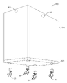
図1は一実施形態によるスマートラゲッジシステム100の斜視図である。スマートラゲッジシステム100は、運搬の物品を格納するために使用され得るスーツケースなどのラゲッジ10の形態の本体を含む。ラゲッジ10は、4つのホイールアッセンブリ20によって支持される。各ホイールアッセンブリ20は、所定方向に回転し且つ所定方向に転がるように構成される。一実施例によれば、ホイールアッセンブリ20はキャスタ式のホイールであってもよい。すべての4つのホイールアッセンブリ20は、ラゲッジを所定方向に移動させるように電動化され得る。ハンドル30は、ユーザーがラゲッジ10を押す、引く、及び/又は持ち上げることを可能にするために提供される。
FIG. 1 is a perspective view of a
システム100は、ラゲッジ10に結合された1つ以上のカメラ40を含む。任意の数のカメラ40が使用されてもよいが、1つのカメラ40がラゲッジ10の上端の近くのラゲッジ10の前側11に配置されるのが示される。カメラ40は、視覚画像を記録し、及び/又は近くの物体の存在を検出する(近接センサ50に類似する)ように構成され、単眼カメラ、双眼カメラ、及び/又は立体カメラを含んでもよい。
システム100は、ラゲッジ10の前側11に結合された1つ以上の前方近接センサ50を含む。3つの前方近接センサ50は、ラゲッジ10の上端に近くのラゲッジ10の前側に配置されるのが示される。任意の数の前方近接センサ50が使用されラゲッジ10の前側11の異なる位置に配置されてもよい。
システム100は、ラゲッジ10の右側12に結合された1つ以上の側方近接センサ55を含む。2つの側方近接センサ55は、ラゲッジ10の上端の近くのラゲッジ10の右側12に配置されるのが示される。近接センサ55はラゲッジ10の右側に示されるが、近接センサ55は、ラゲッジ10の左側、又は右側と左側の両方に配置することができる。任意の数の側方近接センサ55は使用され、ラゲッジ10のどちらかの側の異なる位置に配置されてもよい。
前方及び側方近接センサ50、55は、静止又は移動している近くの物体の存在を検出するように構成される。例えば、前方近接センサ50は、ラゲッジ10がユーザーの後ろの後方追従位置にある間に所定方向に移動するユーザーを検出するように構成される。例えば、側方近接センサ55は、ラゲッジ10がユーザーの側方の側方追従位置にある間に所定方向に移動するユーザーを検出するように構成される。
The front and
前方及び側方近接センサ50、55は、カメラ、ソナーセンサ、赤外センサ、レーダセンサ、及び/又はLiDARセンサを含んでもよい。カメラ40、前方近接センサ50、及び/又は側方近接センサ55によって記録、検出、及び/又は測定された情報の組み合わせは、ユーザーの近くの後方追従位置及び側方追従位置にラゲッジ10を自主的に維持するのを支援するために使用される。カメラ40、前方近接センサ50、及び側方近接センサ55によって記録、検出、及び/又は測定された情報の組み合わせはまた、近くの障害物を回避しながら、ユーザーとともにラゲッジ10を所定方向に自主的に移動させるのを支援するために使用される
Front and
一実施形態では、単一の近接センサは、ラゲッジ10の前方及び側方の両方の近くにある物体の存在を検出するために使用することができる。例えば、単一の近接センサは、360度の視野範囲を有するカメラ又はLiDARセンサとすることができる。単一の近接センサは、以下にさらに説明するように、側方及び後方追従位置の両方にラゲッジ10を自主的に移動させるために使用することができる。
In one embodiment, a single proximity sensor can be used to detect the presence of objects near both the front and sides of
図2は別の実施形態によるスマートラゲッジシステム100の斜視図である。図示のように、前方近接センサ50及び側方近接センサはそれぞれハンドル30の前側及び右側に配置されている。システム100の実施形態は、ラゲッジ10及び/又はハンドル30の前側11に配置された任意の組み合わせ又は数の前方近接センサ50、ならびにラゲッジ10及び/又はハンドル30右側及び/又は左側に配置された任意の組み合わせ又は数の側方近接センサ55を含む。
FIG. 2 is a perspective view of
図3は、一実施形態による、ユーザー300として示される物体の側方の側方追従位置にあるスマートラゲッジシステム100の平面図である。システム100は、ユーザー300が所定方向に移動するときにラゲッジ10を側方追従位置に維持するように構成される。システム100は、ラゲッジ10をユーザー300の側方距離D1内に維持するように構成される。側方距離D1は、システム100の動作の前、最中、及び/又は後にユーザー300の希望に応じて調整(例えば、増加又は減少)及び設定することができる。側方距離D1は、携帯電話、リストバンド、及び/又はカメラ40により識別されるようなユーザー300のジェスチャーによって調整及び設定することができる。側方追従位置は、ユーザー300の右側又は左側にあり得る。
FIG. 3 is a plan view of
図4は、一実施形態による、側方近接センサ55によって検出されるような予め定められた領域250内にいるユーザー300を示す、側方追従位置にあるスマートラゲッジシステム100の平面図である。予め定められた領域250は、前方境界251と後方境界252とを含む。予め定められた領域250は、側方近接センサ55によって検出することができる領域200内に位置する。システム100は、ユーザー300が所定方向に移動するときに、予め定められた領域250内に位置するユーザー300とともにラゲッジ10を側方追従位置に維持するように構成される。予め定められた領域250及び/又は領域200は、システム100の動作の前、最中、及び/又は後にユーザー300の希望に応じて調整(例えば、増加又は減少)することができる。
FIG. 4 is a plan view of
図5は、一実施形態による、側方近接センサ55によって検出されるような予め定められた領域250の前方境界251の近く又は少なくとも部分的にその外側にいるユーザー300を示す、側方追従位置にあるスマートラゲッジシステム100の平面図である。ユーザー300が前方境界251の近く又は少なくとも部分的にその外側にいることをシステム100が検出すると、システム100は、ホイールアッセンブリ20を加速してラゲッジ10をより速く移動させ、ユーザー300を予め定められた領域250内に維持するように構成される。同様に、ユーザー300が後方境界252の近く又は少なくとも部分的にその外側にいることをシステム100が検出すると、システム100は、ホイールアッセンブリ20を減速してラゲッジ10をより遅く移動させ、ユーザー300を予め定められた領域250内に維持するように構成される。
FIG. 5 shows a lateral following
図6A~6Cは、一実施形態による、ユーザー300とラゲッジ10との間で移動する第三者350の形態の別の移動物体を示すスマートラゲッジシステム100の動作シーケンスを示す。システム100は、動作中にユーザー300の速度を連続的に監視し測定するように構成される。第三者350がユーザー300とラゲッジ10との間で移動する場合、前方境界251又は後方境界251のいずれかから、システム100は、ユーザー300の速度を覚えて、第三者350の速度ではなく記憶された速度で移動し続けるように構成される。
6A-6C illustrate the operational sequence of
図6Aは、予め定められた領域250内に速度S1で移動するユーザー300を示す。システム100は、ユーザー300の速度S1を連続的に監視し測定する。第三者350は、ユーザー300とラゲッジ10との間の位置で後部境界252に接近し、速度S2で移動しているのが示されている。速度S2は、速度S1とは異なる(例えば、より高速又はより低速)。
FIG. 6A shows
図6Bは、ユーザー300とラゲッジ10との間にいる第三者350を示す。システム100は、第三者350と、第三者350が移動している速度S2とを検出するように構成される。第三者350が側方近接センサ55によるユーザー300の検出を少なくとも部分的に又は完全にブロックすると、システム100は、以前に測定され記憶されたユーザー300の速度S1で移動し続けるように構成される。
FIG. 6B shows a
図6Cは、側方近接センサ55が再び速度S1で移動しているユーザー300を検出することができるように領域200の外に移動した第三者350を示す。システム100は、ラゲッジ10を所定方向に移動させ続け、ラゲッジ10を側方追従位置に維持する。
FIG. 6C shows the
図7A~7Cは、一実施形態による、所定方向330にユーザー300を追従し且つラゲッジ10の前方に位置する障害物400を回避するときのスマートラゲッジシステム100の移動経路を示す。
7A-7C illustrate the travel path of
図7Aは、所定方向330にユーザー300を追従し且つ側方追従位置にあるラゲッジ10を示す。ラゲッジ10の前方は、所定方向330と平行な頭部方向320に面している。カメラ40及び/又は前方近接センサ50は、ラゲッジ10の前方にある障害物400を検出する。システム100は、ラゲッジ10を側方追従位置から後方追従位置に移動させるように構成される。
FIG. 7A shows the
図7Bは、ユーザー300の後ろの後方追従位置に移行しているラゲッジ10を示す。ホイールアッセンブリ20は、ラゲッジ10の前側を真っ直ぐな頭部方向320に向けたままラゲッジ10が斜めの前進方向340に移動することを可能にする。真っ直ぐな頭部方向320は、斜めの前進方向340とは異なる。予め定められた時間の量、予め定められた距離の量の後、又はユーザー300によって指示されるとき、システム100は、ラゲッジ10を後方追従位置から側方追従位置に移動させるように構成される。
FIG. 7B shows
図7Cは、ユーザー300の側方の側方追従位置に移行しているラゲッジ10を示す。ホイールアッセンブリ20は、ラゲッジ10の前側を真っ直ぐな頭部方向320に向けたままラゲッジ10が別の斜めの前進方向350に移動することを可能にする。真っ直ぐな頭部方向320は、斜めの前進方向350とは異なる。側方追従位置に入ると、システム100は、上述のように、ラゲッジ10をユーザー300と共に所定方向330に移動させ続ける。
FIG. 7C shows the
図7A~7Cは、1つの動作シーケンスのみを示す。スマートラゲッジシステム100は、任意の数の移動経路をわたって操縦し、任意の数の障害物を回避することができる。スマートラゲッジシステム100はまた、右側追従位置と後方追従位置との間で移行することができる。スマートラゲッジシステム100はまた、左側追従位置と後方追従位置との間で移行することができる。スマートラゲッジシステム100はまた、右側追従位置から後方追従位置へ、次に左側方追従位置へ移行することができる。この実施形態では、ラゲッジ10は、ラゲッジ10の両側に側方近接センサ55を含んでもよい。
Figures 7A-7C show only one operating sequence. The
図8は、一実施形態によるスマートラゲッジシステムのブロック図である。システム100は、配電モジュール71と通信する電池70を含む。配電モジュール71は、電池70によって供給された電力をシステム100の別の構成要素に配電するように構成される。
FIG. 8 is a block diagram of a smart luggage system according to one embodiment.
システム100は、リストバンド通信モジュール75と通信する中央処理装置(「CPU」)72を含む。リストバンド76は、超広帯域、無線周波数識別装置(アクティブ及び/又はパッシブ)、ブルートゥース(登録商標)(低エネルギー)、WiFi、及び/又は当技術分野で知られている他の任意の形態の通信を介してリストバンド通信モジュール75と通信するために使用される。リストバンド76は、ユーザーがCPU72に命令を送信することを可能にするように構成される。リストバンド76はまた、ユーザーがシステム100の動作に関する情報をCPU72から受信することを可能にするように構成される。一実施形態では、遠隔制御(リストバンド76など)は、ラゲッジ10を所定方向に移動されるようにCPU72に指示するために使用されてもよい。ユーザーは、遠隔制御を使用してラゲッジ10を所定方向にナビゲートすることができる。
CPU72はまた、カメラ40、前方近接センサ50及び側方近接センサ55と通信する。カメラ40は、カメラ40が記録及び/又は検出した視覚画像及び近くの物体の存在に関する情報をCPU72に伝達するように構成される。前方及び側方近接センサ50、55は、ラゲッジ10の近くの物体の存在に関する情報をCPU72に伝達するように構成される。
CPU72はまた、ホイール制御モジュール73と通信する。ホイール制御モジュール73は、各ホイールアッセンブリ20の回転速度及び/又は向きを制御するように構成される。ホイール制御モジュール73はまた、ホイールの回転速度及び/又は向きなどのホイールアッセンブリ20に関する情報をCPU72に伝達するように構成される。1つのホイール制御モジュール73しか図示されていないが、各ホイールアッセンブリ20は、CPU72と通信する別々のホイール制御モジュール73を含むことができる。一実施形態では、ホイール制御モジュール73は、単一の処理装置としてCPU72に統合することができる。一例によれば、CPU72は、すべての4つのホイールアッセンブリ20を制御するための単一のホイール制御モジュール73を含む。一例によれば、CPU72は、各ホイールアッセンブリ20に一つずつ、4つのホイール制御モジュール73を含む。
CPU72は、システム100の様々な構成要素(例えば、カメラ40、近接センサ50、55、リストバンド通信モジュール75、及び/又はホイール制御モジュール73)から受信した情報を分析し、本明細書に記載されるようにシステム100を動作させるために情報に基づいてCPU72にプログラムされた計算機能を実行するように構成される。例えば、CPU72は、情報に基づいて所定方向及び速度を決定するように構成される。CPU72は、ユーザー及び/又は周囲の環境に対するラゲッジ10の方向及び速度を制御するように構成される。例えば、CPU72は、各ホイールアッセンブリ20の向き及び/又は速度調整(例えば、増加、減少、変更など)するようにホイール制御モジュール73に指示することによって、ラゲッジ10の方向及び速度を制御するように構成される。
一実施形態では、CPU72は、カメラ40、前方近接センサ50、及び/又は側方近接センサ55の少なくとも1つから受信した情報に基づいてラゲッジ10を(図3に示すように)側方距離D1内に維持するようにホイール制御モジュール73及びホイールアッセンブリ20に指示するように構成される。
In one embodiment,
一実施形態では、CPU72は、カメラ40、前方近接センサ50、及び/又は側方近接センサ55の少なくとも1つから受信した情報に基づいてユーザー300を(図4に示すように)予め定められた領域250内に維持するようにホイール制御モジュール73及びホイールアッセンブリ20に指示するように構成される。
In one embodiment,
一実施形態では、CPU72は、(図6A~6Cに示すように)第三者350が側方近接センサ55によるユーザー300の検出を少なくとも部分的に又は完全にブロックするときに、カメラ40、前方近接センサ50、及び/又は側方近接センサ55の少なくとも1つから受信した情報に基づいて、ラゲッジ10を記録されたユーザー300の速度で移動させ続けるようにホイール制御モジュール73及びホイールアッセンブリ20に指示するように構成される。
In one embodiment,
一実施形態では、CPU72は、カメラ40、前方近接センサ50、及び/又は側方近接センサ55の少なくとも1つから受信した情報に基づいて、(図7A~7Cに示すように)ラゲッジ10を側方追従位置から後方追従位置に移行させ、そして側方追従位置に戻すようにホイール制御モジュール73及びホイールアッセンブリ20に指示するように構成される。
In one embodiment,
一実施形態では、CPU72は、予め定められた時間の量の後、又はユーザー300によって指示されるとき、(図7A~7Cに示すように)ラゲッジ10を後方追従位置から側方追従位置に戻すようにホイール制御モジュール73及びホイールアッセンブリ20に指示するように構成される。
In one embodiment, the
一実施形態では、スマートラゲッジシステム100は、所定方向に人などの任意の1つ以上のユーザーを自主的に側方又は後方に追従するように構成される。一実施形態では、スマートラゲッジシステム100は、所定方向に任意の1つ以上の物体を自主的に側方又は後方に追従するように構成される。一実施形態では、スマートラゲッジシステム100は、遠隔制御を介してユーザーから受信した命令に基づいて所定方向に自主的に移動するように構成される。一実施形態では、スマートラゲッジシステム100は、ユーザーによって提供された1組の事前プログラムされた命令に基づいて、ある場所から別の場所へ任意の所定方向に自主的に移動するように構成される。
In one embodiment,
図9は、一実施形態によるスマートショッピングカートシステム500の斜視図。スマートラゲッジシステム100に関して本明細書で説明されているすべての実施形態は、スマートショッピングカートシステム500に組み込まれてもよい。例えば、システム500は、側方追従位置にシステムを移動させるために、スマートラゲッジシステム100に関して上述したようなホイールアッセンブリ20を含む。
FIG. 9 is a perspective view of a smart
システム500は、ベース520に結合された本体510を含む。本体510は、カート、バスケット、又は品目を収容及び/又は運搬するために使用することができる他の任意の種類の容器であってもよい。電池70、配電モジュール71、CPU72、リストバンド通信モジュール75、及び/又はホイール制御モジュール73など、システム500の任意の構成要素は、本体510及び/又はベース520に配置されてもよい。ホイールアッセンブリ20は、ベース520に結合され、上述したラゲッジ10の移動と同様にシステム500を所定方向に移動させるように構成される。ホイールアッセンブリ20は、本体510の頭部方向とは異なる前進方向に沿って本体510を移動させるように構成される。
システム500の前側は、参照番号530によって識別されるように、1つ以上のカメラ、近接センサ、及び/又は任意の他の種類の感知装置を含んでもよい。システム500の左側も、参照番号540によって識別されるように、1つ以上のカメラ、近接センサ、及び/又は任意の他の種類の感知装置を含んでもよい。任意の数のカメラ、近接センサ、及び/又は任意の他の種類の感知装置は、本体510及び/又はベース520の任意の側面に結合されてもよい。
The front side of
図10は、一実施形態によるスマート自己駆動システム600の斜視図である。スマートラゲッジシステム100に関して本明細書で説明されているすべての実施形態は、スマート自己駆動システム600に組み込まれてもよい。例えば、システム600は、側方追従位置にシステム600を移動させるために、スマートラゲッジシステム100に関して上述したようなホイールアッセンブリ20を含む。
FIG. 10 is a perspective view of a smart self-driving
システム600は、ベース620に結合された本体610を含む。本体610及びベース620は、別々の構成要素であってもよいし、単一の構成要素として形成されてもよい。電池70、配電モジュール71、CPU72、リストバンド通信モジュール75、及び/又はホイール制御モジュール73など、システム600の任意の構成要素は、本体610及び/又はベース620に配置されてもよい。ホイールアッセンブリ20は、ベース620に結合され、上述したラゲッジ10の移動と同様にシステム600を所定方向に移動させるように構成される。ホイールアッセンブリ20は、本体610の頭部方向とは異なる前進方向に沿って本体610を移動させるように構成される。
システム600の前側は、参照番号630で識別されるように、1つ以上のカメラ、近接センサ、及び/又は他のタイプの感知装置を含んでもよい。システム600の右側も、照会番号640によって識別されるように、1つ以上のカメラ、近接センサ、及び/又は任意の他の種類の感知装置を含んでもよい。任意の数のカメラ、近接センサ、及び/又は任意の他の種類の感知装置は、本体610及び/又はベース620の任意の側面に結合されてもよい。
The front side of
一実施形態では、本体610は、本体610の内部に置かれた物品を収容及び/又は運搬するために使用される容器であってもよい。一実施形態では、本体610は、本体610の上に置かれた物品を支持及び/又は運搬するために使用される支持部材であってもよい。一実施形態では、本体610は、システム600の構成要素を保護するために使用されるハウジングであってもよく、他の物品の重量を支える必要はない。例えば、システム600は、家、ホテルの部屋、及び/又はレストランのテーブルに食物を配達するために使用することができる。別の例では、システム600は、所与の領域を動き回って監視するように構成されたセキュリティ監視装置として使用することができる。
In one embodiment,
上記は本開示の実施形態を対象としているが、本開示の他の更なる実施形態は、その基本的な範囲から逸脱することなく考案されてもよく、その範囲は特許請求の範囲によって決定される。 While the above is directed to embodiments of the disclosure, other and further embodiments of the disclosure may be devised without departing from its basic scope, which is determined by the claims. be.
Claims (15)
運搬用の物品を格納するように構成されたラゲッジと、
前記ラゲッジに結合され、前記ラゲッジがユーザーの側方追従位置にある間に、障害物および所定方向に移動する前記ユーザーを検出するように構成された1つ以上の近接センサと、
前記ラゲッジに結合され、1つ以上の前記近接センサから情報を受信して前記所定方向を決定し、かつ、前方境界と後方境界とを有し、前記近接センサの視野領域である第1領域内の第2領域を決定するように構成された中央処理装置と、を含み、
前記中央処理装置は、所定方向へ移動しながら前記ユーザーの側方に追従する側方追従態様と、所定方向へ移動しながら前記ユーザーの後方に追従する後方追従態様との間で前記ラゲッジを移動するように構成され、
前記側方追従態様において前記ラゲッジは前記所定方向に移動しつつ側方追従位置における前記ユーザーの側方に沿って追従し、
前記後方追従態様において前記ラゲッジは前記所定方向に移動しつつ後方追従位置における前記ユーザーの後方に沿って追従し、
前記中央処理装置は、1つ以上の前記近接センサから受信した情報に基づいて、前記側方追従位置から前記後方追従位置への前記ラゲッジの移動、および前記後方追従位置から前記側方追従位置への前記ラゲッジの移動を行うように構成され、
前記側方追従態様において1つ以上の前記近接センサから受信した情報に基づいて前記ラゲッジを前記ユーザーの側方距離内に維持するように構成され、
前記中央処理装置はさらに、前記ラゲッジが、ユーザーの側方に沿って追従し、ユーザーの後ろの追従位置に移行して障害物を回避し、その後、隣の側方追従位置に戻るように構成され、1つ以上の前記近接センサから受信した情報に基づいて前記ユーザーの側方距離内に維持するために前記ラゲッジを加速又は減速するように構成され、
前記中央処理装置はさらに、前記ラゲッジが、前記所定方向に移動している間、前記ユーザーを前記第2領域内に維持し、1つ以上の前記近接センサから受信した情報に基づいて前記ユーザーが移動する速度を記録し、かつ、第3者が、前記前方境界からまたは前記後方境界から、前記第2領域内における前記ユーザーと前記ラゲッジとの間に移動して前記1つ以上の前記近接センサによる前記ユーザーの検出を部分的にまたは完全にブロックした場合に、前記1つ以上の前記近接センサが、記録された速度で移動するユーザーを再び検出できるようになるまで、前記ユーザーの記録された速度で前記ラゲッジを移動させ続け、前記第3者が前記第2領域の外に移動した場合に前記ラゲッジを前記側方追従位置に維持するように構成される、
ことを特徴とするシステム。 A smart luggage system,
luggage configured to store items for transportation;
one or more proximity sensors coupled to the luggage and configured to detect obstacles and the user moving in a predetermined direction while the luggage is in the user 's side-following position;
within a first area coupled to the luggage, receiving information from one or more of the proximity sensors to determine the predetermined direction, and having a forward boundary and a rearward boundary and being a field of view of the proximity sensors; a central processing unit configured to determine a second region of
The central processing unit moves the luggage between a lateral following mode in which the luggage follows the side of the user while moving in a predetermined direction, and a rear following mode in which the luggage follows the user to the rear while moving in a predetermined direction. is configured to
In the side following mode, the luggage follows along the side of the user at the side following position while moving in the predetermined direction,
In the rearward following mode, the luggage moves in the predetermined direction and follows along the rear of the user at the rearward following position,
The central processing unit controls movement of the luggage from the side-following position to the rear-following position and from the rear-following position to the side-following position based on information received from the one or more proximity sensors. configured to move the luggage of
configured to keep the luggage within lateral distance of the user based on information received from one or more of the proximity sensors in the lateral following mode;
The central processing unit further directs the luggage to follow along the side of the user, transition to a following position behind the user to avoid obstacles, and then return to an adjacent side following position. configured to accelerate or decelerate the luggage to maintain within lateral distance of the user based on information received from one or more of the proximity sensors;
The central processing unit further maintains the user within the second region while the luggage is moving in the predetermined direction, and controls the user based on information received from the one or more proximity sensors. recording a speed of movement and a third party moving from the front boundary or from the rear boundary between the user and the luggage in the second area to detect the one or more proximity sensors; until the one or more proximity sensors are again able to detect the user moving at the recorded speed. configured to continue to move the luggage at a velocity and maintain the luggage in the side following position if the third party moves out of the second area ;
A system characterized by:
前記1つ以上の近接センサは、前記ラゲッジが前記ユーザーの後ろの後方追従位置にある間に前記ユーザーに面するように前記ラゲッジの前側に結合された前方近接センサを含む、ことを特徴とする請求項1に記載のシステム。 further comprising one or more proximity sensors configured to detect the user moving in a predetermined direction while the luggage is in a rearward following position behind the user ;
The one or more proximity sensors include a front proximity sensor coupled to a front side of the luggage so as to face the user while the luggage is in a rearward trailing position behind the user . The system of claim 1.
前記ハンドルは、前記ハンドルの前側に結合され、前記ラゲッジが前記ユーザーの後ろの後方追従位置にある間に前記所定方向に移動する前記ユーザーを検出するように構成された1つ以上の前方近接センサを更に含み、
前記前方近接センサは、前記ラゲッジが前記ユーザーの後ろの後方追従位置にある間に前記ユーザーに面する、
ことを特徴とする請求項1に記載のシステム。 The luggage includes a handle that allows the user to push, pull, or lift the luggage, and the one or more proximity sensors are activated while the luggage is in a laterally following position next to the user. a lateral proximity sensor coupled to the right or left side of the handle so as to face the user;
The handle has one or more forward proximity sensors coupled to a front side of the handle and configured to detect the user moving in the predetermined direction while the luggage is in a rearward trailing position behind the user . further comprising
the forward proximity sensor faces the user while the luggage is in a rearward following position behind the user ;
2. The system of claim 1, wherein:
本体と、
前記本体に結合され、前記本体がユーザーの追従位置にある間に、障害物および所定方向に移動する前記ユーザーを検出するように構成された1つ以上の近接センサと、
前記本体に結合され、1つ以上の前記近接センサから情報を受信して前記所定方向を決定し、かつ、前方境界と後方境界とを有し、前記近接センサの視野領域である第1領域内の第2領域を決定するように構成された中央処理装置と、
を含み、
前記中央処理装置は、所定方向へ移動しながら前記ユーザーの側方に追従する側方追従態様と、所定方向へ移動しながら前記ユーザーの後方に追従する後方追従態様との間で前記本体を移動するように構成され、
前記側方追従態様において前記本体は前記所定方向に移動しつつ側方追従位置における前記ユーザーの側方に沿って追従し、
前記後方追従態様において前記本体は前記所定方向に移動しつつ後方追従位置における前記ユーザーの後方に沿って追従し、
前記中央処理装置は、1つ以上の前記近接センサから受信した情報に基づいて、前記側方追従位置から前記後方追従位置への前記本体の移動、および前記後方追従位置から前記側方追従位置への前記本体の移動を行うように構成され、
前記側方追従態様において1つ以上の前記近接センサから受信した情報に基づいて前記本体を前記ユーザーの側方距離内に維持するように構成され、
前記中央処理装置はさらに、前記本体が、ユーザーの側方に沿って追従し、ユーザーの後ろの追従位置に移行して障害物を回避し、その後、隣の側方追従位置に戻るように構成され、1つ以上の前記近接センサから受信した情報に基づいて前記ユーザーの側方距離内に維持するために前記本体を加速又は減速するように構成され、
前記中央処理装置はさらに、前記本体が、前記所定方向に移動している間、前記ユーザーを前記第2領域内に維持し、1つ以上の前記近接センサから受信した情報に基づいて前記ユーザーが移動する速度を記録し、かつ、第3者が、前記前方境界からまたは前記後方境界から、前記第2領域内における前記ユーザーと前記本体との間に移動して前記1つ以上の前記近接センサによる前記ユーザーの検出を部分的にまたは完全にブロックした場合に、前記1つ以上の前記近接センサが、記録された速度で移動するユーザーを再び検出できるようになるまで、第3者前記ユーザーの記録された速度で前記本体を移動させ続け、前記第3者が前記第2領域の外に移動した場合に前記本体を前記側方追従位置に維持するように構成される、
ことを特徴とするシステム。 A smart self-driving system,
the main body;
one or more proximity sensors coupled to the body and configured to detect obstacles and the user moving in a predetermined direction while the body is in a user -following position;
within a first area coupled to the body, receiving information from one or more of the proximity sensors to determine the predetermined direction, and having a front boundary and a rear boundary and being a field-of-view area of the proximity sensors; a central processing unit configured to determine a second region of
including
The central processing unit moves the main body between a lateral following mode in which the user follows the side while moving in a predetermined direction, and a backward following mode in which the user follows the user backward while moving in a predetermined direction. is configured to
In the side following mode, the main body follows along the side of the user at the side following position while moving in the predetermined direction,
In the backward following mode, the main body follows along the back of the user at the backward following position while moving in the predetermined direction,
The central processing unit is adapted to move the body from the side-following position to the rear-following position and from the rear-following position to the side-following position based on information received from the one or more proximity sensors. configured to move the body of
configured to keep the body within lateral distance of the user based on information received from one or more of the proximity sensors in the lateral following mode;
The central processing unit further directs the main body to follow along the side of the user, transition to a following position behind the user to avoid obstacles, and then return to an adjacent side following position. configured to accelerate or decelerate the body to maintain within a lateral distance of the user based on information received from one or more of the proximity sensors;
The central processing unit further maintains the user within the second region while the main body is moving in the predetermined direction, and determines whether or not the user based on information received from the one or more proximity sensors. record a speed of movement and a third party moves from the front boundary or from the rear boundary between the user and the body in the second area to detect the one or more proximity sensors; partially or completely blocking the detection of the user by a third party until the one or more proximity sensors are again able to detect the user moving at a recorded speed. configured to continue to move the body at the recorded velocity and to maintain the body in the side following position if the third party moves out of the second area;
A system characterized by:
前記1つ以上の近接センサは、前記本体が前記ユーザーの後ろの後方追従位置にある間に前記ユーザーに面するように前記本体の前側に結合された前方近接センサを含む、
ことを特徴とする請求項7に記載のシステム。 further comprising one or more proximity sensors configured to detect the user moving in a predetermined direction while the body is in the rearward trailing position;
the one or more proximity sensors includes a front proximity sensor coupled to a front side of the body to face the user while the body is in a rearward following position behind the user ;
8. The system of claim 7 , wherein:
前記ハンドルは、前記ハンドルの前側に結合され、前記本体が前記ユーザーの後ろの後方追従位置にある間に前記所定方向に移動する前記ユーザーを検出するように構成された1つ以上の前方近接センサを更に含み、
前記前方近接センサは、前記本体が前記ユーザーの後ろの後方追従位置にある間に前記ユーザーに面する、
ことを特徴とする請求項7に記載のシステム。 The body includes a handle that allows the user to push, pull, or lift the body, and the one or more proximity sensors are activated while the body is in a laterally following position next to the user. a lateral proximity sensor coupled to the right or left side of the handle so as to face the user in
The handle has one or more front proximity sensors coupled to a front side of the handle and configured to detect the user moving in the predetermined direction while the body is in a rearward following position behind the user . further comprising
the front proximity sensor faces the user while the body is in a rearward following position behind the user ;
8. The system of claim 7 , wherein:
本体と、前記本体は、ユーザーが該本体を押す、引く、又は持ち上げることを可能にするハンドルを有し、
前記ハンドルの右側または左側に結合され、前記本体が前記ユーザーの追従位置にある間に、障害物および所定方向に移動する前記ユーザーの少なくともいずれかを検出するように構成された1つ以上の側方近接センサと、
前記ハンドルの前側に結合され、前記本体が前記ユーザーの後の後方追従位置にある間に前記所定方向に移動する前記ユーザーを検出するように構成された1つ以上の前方近接センサと、
前記側方近接センサまたは前記前方近接センサから情報を受信して前記所定方向を決定し、前方境界と後方境界とを有し、前記側方近接センサまたは前記前方近接センサの視野領域である第1領域内の第2領域を決定し、さらに、側方追従態様と後方追従態様との間で前記本体を移動するように構成された中央処理装置と、
を含み、
前記側方追従態様において前記本体は前記所定方向に移動しつつ側方追従位置における前記ユーザーの側方に沿って追従し、
前記後方追従態様において前記本体は前記所定方向に移動しつつ前記後方追従位置における前記ユーザーの後方に沿って追従し、
前記側方追従態様において1つ以上の側方近接センサから受信した情報に基づいて前記本体を前記ユーザーの側方距離内に維持するために前記本体を加速又は減速するように構成され、
前記中央処理装置はさらに、前記本体が、前記所定方向に移動している間、前記ユーザーを前記第2領域内に維持し、前記側方近接センサおよび前記前方近接センサの少なくともいずれかから受信した情報に基づいて前記ユーザーが移動する速度を記録し、かつ、第3者が、前記前方境界からまたは前記後方境界から、前記第2領域内における前記ユーザーと前記本体との間に移動して前記1つ以上の前記側方近接センサおよび前記前方近接センサの少なくともいずれかかによる前記ユーザーの検出を部分的にまたは完全にブロックした場合に、前記側方近接センサおよび前記前方近接センサの少なくともいずれかが、記録された速度で移動するユーザーを再び検出できるようになるまで、前記ユーザーの記録された速度で前記本体を移動させ続け、前記第3者が前記第2領域の外に移動した場合に前記本体を前記側方追従位置に維持するように構成される、ことを特徴とするシステム。 A smart self-driving system,
a body, said body having a handle that allows a user to push, pull or lift said body;
One or more sides coupled to the right or left side of the handle and configured to detect obstacles and/or the user moving in a predetermined direction while the body is in a following position of the user. a proximity sensor;
one or more forward proximity sensors coupled to the front side of the handle and configured to detect the user moving in the predetermined direction while the body is in a rearward following position behind the user;
a second proximity sensor receiving information from the side proximity sensor or the front proximity sensor to determine the predetermined direction, having a front boundary and a rear boundary, and being a field of view area of the side proximity sensor or the front proximity sensor; a central processing unit configured to determine a second region within one region and to move the body between a side-tracking mode and a backward-tracking mode;
including
In the side following mode, the main body follows along the side of the user at the side following position while moving in the predetermined direction,
In the backward following mode, the main body follows along the back of the user at the backward following position while moving in the predetermined direction,
configured to accelerate or decelerate the body to maintain the body within lateral distance of the user based on information received from one or more lateral proximity sensors in the lateral following mode;
The central processing unit further maintains the user within the second region while the body is moving in the predetermined direction and receives from at least one of the side proximity sensor and the front proximity sensor. and recording a speed at which the user moves based on the information received, and a third party moving between the user and the main body in the second area from the front boundary or from the rear boundary. the one or more side proximity sensors and/or the front proximity sensors when partially or completely blocking detection of the user by the one or more side proximity sensors and/or the front proximity sensors continues to move said body at said user's recorded speed until said third person moves out of said second area until it can again detect the user moving at said recorded speed; a system configured to maintain said body in said laterally following position during a period of time.
Applications Claiming Priority (1)
| Application Number | Priority Date | Filing Date | Title |
|---|---|---|---|
| PCT/CN2018/096544 WO2020014991A1 (en) | 2018-07-20 | 2018-07-20 | Smart self-driving systems with side follow and obstacle avoidance |
Publications (2)
| Publication Number | Publication Date |
|---|---|
| JP2020529050A JP2020529050A (en) | 2020-10-01 |
| JP7169593B2 true JP7169593B2 (en) | 2022-11-11 |
Family
ID=66673506
Family Applications (1)
| Application Number | Title | Priority Date | Filing Date |
|---|---|---|---|
| JP2019548423A Active JP7169593B2 (en) | 2018-07-20 | 2018-07-20 | Smart self-driving system with lateral following and obstacle avoidance |
Country Status (4)
| Country | Link |
|---|---|
| US (2) | US10310506B1 (en) |
| EP (1) | EP3824364B1 (en) |
| JP (1) | JP7169593B2 (en) |
| WO (1) | WO2020014991A1 (en) |
Families Citing this family (12)
| Publication number | Priority date | Publication date | Assignee | Title |
|---|---|---|---|---|
| DE102017218389B4 (en) * | 2017-10-13 | 2020-12-24 | Ford Global Technologies, Llc | Transport auxiliary vehicle, transport auxiliary system and method for operating a transport auxiliary vehicle |
| WO2019080559A1 (en) | 2017-10-27 | 2019-05-02 | Lingdong Technology (Beijing) Co. Ltd | Smart self-driving systems with motorized wheels |
| WO2020047792A1 (en) | 2018-09-06 | 2020-03-12 | Lingdong Technology (Beijing) Co. Ltd | Slef-driving vehicle system with retractable sensor head |
| WO2020140255A1 (en) | 2019-01-04 | 2020-07-09 | Lingdong Technology (Beijing) Co. Ltd | Smart luggage system with camera installed in pull rod |
| US11585934B2 (en) * | 2019-04-30 | 2023-02-21 | Lg Electronics Inc. | Cart robot having auto-follow function |
| US11511785B2 (en) * | 2019-04-30 | 2022-11-29 | Lg Electronics Inc. | Cart robot with automatic following function |
| KR102109112B1 (en) * | 2019-08-09 | 2020-05-28 | 하희목 | Attachable suitcase controlling device and smart suitcase comprising thereof |
| JP7221839B2 (en) * | 2019-10-08 | 2023-02-14 | 国立大学法人静岡大学 | Autonomous Mobile Robot and Control Program for Autonomous Mobile Robot |
| CN111079607A (en) * | 2019-12-05 | 2020-04-28 | 灵动科技(北京)有限公司 | Automatic driving system with tracking function |
| US20210267330A1 (en) * | 2020-02-29 | 2021-09-02 | Oladayo Luke | Child carrier seat arrangement and method for navigation thereof |
| US11820380B2 (en) * | 2020-08-06 | 2023-11-21 | Piaggio Fast Forward Inc. | Etiquette-based vehicle having pair mode and smart behavior mode and control systems therefor |
| US11731274B2 (en) * | 2021-03-24 | 2023-08-22 | Ford Global Technologies, Llc | Predictive time horizon robotic motion control |
Citations (5)
| Publication number | Priority date | Publication date | Assignee | Title |
|---|---|---|---|---|
| JP2002255037A (en) | 2001-02-28 | 2002-09-11 | Nippon Soken Inc | Mobile case |
| JP2004299025A (en) | 2003-04-01 | 2004-10-28 | Honda Motor Co Ltd | Mobile robot control device, mobile robot control method and mobile robot control program |
| JP4316477B2 (en) | 2004-11-18 | 2009-08-19 | パナソニック株式会社 | Tracking method of mobile robot |
| WO2017033367A1 (en) | 2015-08-25 | 2017-03-02 | 川崎重工業株式会社 | Remote control robot system |
| US20170220040A1 (en) | 2016-02-02 | 2017-08-03 | Justin London | Smart luggage systems |
Family Cites Families (23)
| Publication number | Priority date | Publication date | Assignee | Title |
|---|---|---|---|---|
| US5316096A (en) | 1992-07-22 | 1994-05-31 | Good Marketing, Inc. | Portable motorized suitcase |
| US5339934A (en) * | 1993-01-25 | 1994-08-23 | Joseph Liang | Luggage steering device |
| JPH08166822A (en) * | 1994-12-13 | 1996-06-25 | Nippon Telegr & Teleph Corp <Ntt> | User tracking type moving robot device and sensing method |
| JPH08272443A (en) * | 1995-03-31 | 1996-10-18 | Hitachi Kiden Kogyo Ltd | Attitude control method for unmanned carrier using front and back wheels |
| US8989972B2 (en) * | 2008-09-11 | 2015-03-24 | Deere & Company | Leader-follower fully-autonomous vehicle with operator on side |
| CN103376803A (en) * | 2012-04-16 | 2013-10-30 | 鸿富锦精密工业(深圳)有限公司 | Baggage moving system and method thereof |
| US9443366B2 (en) * | 2012-06-27 | 2016-09-13 | Treefrog Developments, Inc. | Tracking and control of personal effects |
| PL2898384T3 (en) * | 2012-09-19 | 2020-05-18 | Follow Inspiration Unipessoal, Lda. | Self tracking system and its operation method |
| US20140107868A1 (en) | 2012-10-15 | 2014-04-17 | Mirko DiGiacomcantonio | Self-propelled luggage |
| US20140277841A1 (en) * | 2013-03-15 | 2014-09-18 | Elizabeth Klicpera | Motorized Luggage or Luggage Platform with Wired or Wireless Guidance and Distance Control |
| CN105022396B (en) * | 2014-04-29 | 2018-03-06 | 世洋科技股份有限公司 | The lateral following device of forward direction and left and right and its follow-up control method |
| US20150327638A1 (en) * | 2014-05-15 | 2015-11-19 | Debashis Ghosh | Apparatus, system, and method of providing linkage between two or more objects such that they can passively track or follow one another |
| US9250627B2 (en) * | 2014-05-28 | 2016-02-02 | Acrox Technologies Co., Ltd. | Forward and lateral tracking system and control method thereof |
| US9215561B1 (en) * | 2014-08-20 | 2015-12-15 | Kambiz Arman | Luggage tracking assembly |
| JP6438155B2 (en) | 2015-03-02 | 2018-12-12 | ケビン オドネル | Electric luggage |
| JP6402429B2 (en) * | 2015-03-26 | 2018-10-10 | 株式会社エクォス・リサーチ | Moving body |
| US20170049202A1 (en) * | 2015-08-21 | 2017-02-23 | Edinaldo Nascimento | Automatic Following Luggage System |
| US9795199B2 (en) * | 2015-09-26 | 2017-10-24 | Amber Caputo | Motorized luggage assembly |
| CA2997160C (en) * | 2015-10-16 | 2023-10-03 | Lemmings LLC | Robotic golf caddy |
| CN105717927A (en) * | 2016-04-13 | 2016-06-29 | 京东方科技集团股份有限公司 | Bearing device and control method used for bearing device |
| US9870683B1 (en) * | 2016-04-19 | 2018-01-16 | Jerome Pious | Luggage notification system |
| CN207370256U (en) * | 2017-06-12 | 2018-05-18 | 灵动科技(北京)有限公司 | Luggage case, smart machine and the system of automatically walk |
| JP6436215B2 (en) * | 2017-11-09 | 2018-12-12 | 富士ゼロックス株式会社 | Working device and working system |
-
2018
- 2018-07-20 WO PCT/CN2018/096544 patent/WO2020014991A1/en unknown
- 2018-07-20 JP JP2019548423A patent/JP7169593B2/en active Active
- 2018-07-20 EP EP18899034.5A patent/EP3824364B1/en active Active
- 2018-07-26 US US16/046,206 patent/US10310506B1/en active Active
-
2019
- 2019-03-18 US US16/357,016 patent/US10423159B1/en active Active
Patent Citations (5)
| Publication number | Priority date | Publication date | Assignee | Title |
|---|---|---|---|---|
| JP2002255037A (en) | 2001-02-28 | 2002-09-11 | Nippon Soken Inc | Mobile case |
| JP2004299025A (en) | 2003-04-01 | 2004-10-28 | Honda Motor Co Ltd | Mobile robot control device, mobile robot control method and mobile robot control program |
| JP4316477B2 (en) | 2004-11-18 | 2009-08-19 | パナソニック株式会社 | Tracking method of mobile robot |
| WO2017033367A1 (en) | 2015-08-25 | 2017-03-02 | 川崎重工業株式会社 | Remote control robot system |
| US20170220040A1 (en) | 2016-02-02 | 2017-08-03 | Justin London | Smart luggage systems |
Also Published As
| Publication number | Publication date |
|---|---|
| EP3824364B1 (en) | 2023-10-11 |
| JP2020529050A (en) | 2020-10-01 |
| WO2020014991A1 (en) | 2020-01-23 |
| EP3824364A1 (en) | 2021-05-26 |
| US10423159B1 (en) | 2019-09-24 |
| EP3824364A4 (en) | 2022-03-09 |
| US10310506B1 (en) | 2019-06-04 |
Similar Documents
| Publication | Publication Date | Title |
|---|---|---|
| JP7169593B2 (en) | Smart self-driving system with lateral following and obstacle avoidance | |
| US10271623B1 (en) | Smart self-driving systems with motorized wheels | |
| US9563205B2 (en) | Sensor configurations and methods for mobile robot | |
| US20180224853A1 (en) | Systems and methods for robotic mobile platforms | |
| EP2595024A1 (en) | Autonomous locomotion body | |
| JP6066668B2 (en) | Following cart system | |
| US20210147202A1 (en) | Systems and methods for operating autonomous tug robots | |
| US10239544B1 (en) | Guided delivery vehicle | |
| US11089855B2 (en) | Smart luggage system with camera installed in pull rod | |
| WO2021109890A1 (en) | Autonomous driving system having tracking function | |
| WO2021139684A1 (en) | Self-driven system and method | |
| JP2014092861A (en) | Follow-up carriage system | |
| KR102215618B1 (en) | Carts moving parallel to the installation and method of movement | |
| US20200189107A1 (en) | Artificial intelligence moving robot and method for controlling the same | |
| US20210368952A1 (en) | Smart luggage system with ultra-wideband based target tracking system | |
| JP2014164315A (en) | Self-propelled transporting device and system | |
| US11511425B2 (en) | Robot stopping parallel to installed object and method of stopping the same | |
| KR102318942B1 (en) | Robot stopping parallel to the installed object and method of parking thereof | |
| CN112930503B (en) | Manual directional control device for self-driven vehicle | |
| KR102152820B1 (en) | Lawn mover robot and controlling method for the same | |
| US11358274B2 (en) | Autonomous mobile robot with adjustable display screen | |
| US20230264354A1 (en) | Moving robot and moving robot assembly including the same | |
| KR20210008903A (en) | Artificial intelligence lawn mower robot and controlling method for the same | |
| Mahesh et al. | Arduino Based Human Following Robot |
Legal Events
| Date | Code | Title | Description |
|---|---|---|---|
| A521 | Request for written amendment filed |
Free format text: JAPANESE INTERMEDIATE CODE: A523 Effective date: 20190905 |
|
| A621 | Written request for application examination |
Free format text: JAPANESE INTERMEDIATE CODE: A621 Effective date: 20190905 |
|
| A871 | Explanation of circumstances concerning accelerated examination |
Free format text: JAPANESE INTERMEDIATE CODE: A871 Effective date: 20190905 |
|
| A975 | Report on accelerated examination |
Free format text: JAPANESE INTERMEDIATE CODE: A971005 Effective date: 20200918 |
|
| A131 | Notification of reasons for refusal |
Free format text: JAPANESE INTERMEDIATE CODE: A131 Effective date: 20200929 |
|
| A521 | Request for written amendment filed |
Free format text: JAPANESE INTERMEDIATE CODE: A523 Effective date: 20201211 |
|
| A02 | Decision of refusal |
Free format text: JAPANESE INTERMEDIATE CODE: A02 Effective date: 20210119 |
|
| A521 | Request for written amendment filed |
Free format text: JAPANESE INTERMEDIATE CODE: A523 Effective date: 20210518 |
|
| C60 | Trial request (containing other claim documents, opposition documents) |
Free format text: JAPANESE INTERMEDIATE CODE: C60 Effective date: 20210518 |
|
| A911 | Transfer to examiner for re-examination before appeal (zenchi) |
Free format text: JAPANESE INTERMEDIATE CODE: A911 Effective date: 20210527 |
|
| C21 | Notice of transfer of a case for reconsideration by examiners before appeal proceedings |
Free format text: JAPANESE INTERMEDIATE CODE: C21 Effective date: 20210601 |
|
| A912 | Re-examination (zenchi) completed and case transferred to appeal board |
Free format text: JAPANESE INTERMEDIATE CODE: A912 Effective date: 20210625 |
|
| C211 | Notice of termination of reconsideration by examiners before appeal proceedings |
Free format text: JAPANESE INTERMEDIATE CODE: C211 Effective date: 20210629 |
|
| C22 | Notice of designation (change) of administrative judge |
Free format text: JAPANESE INTERMEDIATE CODE: C22 Effective date: 20211012 |
|
| C22 | Notice of designation (change) of administrative judge |
Free format text: JAPANESE INTERMEDIATE CODE: C22 Effective date: 20220412 |
|
| C13 | Notice of reasons for refusal |
Free format text: JAPANESE INTERMEDIATE CODE: C13 Effective date: 20220426 |
|
| A521 | Request for written amendment filed |
Free format text: JAPANESE INTERMEDIATE CODE: A523 Effective date: 20220722 |
|
| C22 | Notice of designation (change) of administrative judge |
Free format text: JAPANESE INTERMEDIATE CODE: C22 Effective date: 20220906 |
|
| C23 | Notice of termination of proceedings |
Free format text: JAPANESE INTERMEDIATE CODE: C23 Effective date: 20220913 |
|
| C03 | Trial/appeal decision taken |
Free format text: JAPANESE INTERMEDIATE CODE: C03 Effective date: 20221011 |
|
| C30A | Notification sent |
Free format text: JAPANESE INTERMEDIATE CODE: C3012 Effective date: 20221011 |
|
| A61 | First payment of annual fees (during grant procedure) |
Free format text: JAPANESE INTERMEDIATE CODE: A61 Effective date: 20221021 |
|
| R150 | Certificate of patent or registration of utility model |
Ref document number: 7169593 Country of ref document: JP Free format text: JAPANESE INTERMEDIATE CODE: R150 |
|
| S111 | Request for change of ownership or part of ownership |
Free format text: JAPANESE INTERMEDIATE CODE: R313113 |
|
| R350 | Written notification of registration of transfer |
Free format text: JAPANESE INTERMEDIATE CODE: R350 |