JP7167045B2 - Location devices and systems for positioning acoustic sensors - Google Patents
Location devices and systems for positioning acoustic sensors Download PDFInfo
- Publication number
- JP7167045B2 JP7167045B2 JP2019548395A JP2019548395A JP7167045B2 JP 7167045 B2 JP7167045 B2 JP 7167045B2 JP 2019548395 A JP2019548395 A JP 2019548395A JP 2019548395 A JP2019548395 A JP 2019548395A JP 7167045 B2 JP7167045 B2 JP 7167045B2
- Authority
- JP
- Japan
- Prior art keywords
- location
- acoustic sensor
- transducer array
- transmit
- ultrasound
- Prior art date
- Legal status (The legal status is an assumption and is not a legal conclusion. Google has not performed a legal analysis and makes no representation as to the accuracy of the status listed.)
- Active
Links
Images


Classifications
-
- A—HUMAN NECESSITIES
- A61—MEDICAL OR VETERINARY SCIENCE; HYGIENE
- A61B—DIAGNOSIS; SURGERY; IDENTIFICATION
- A61B8/00—Diagnosis using ultrasonic, sonic or infrasonic waves
- A61B8/08—Detecting organic movements or changes, e.g. tumours, cysts, swellings
- A61B8/0833—Detecting organic movements or changes, e.g. tumours, cysts, swellings involving detecting or locating foreign bodies or organic structures
- A61B8/0841—Detecting organic movements or changes, e.g. tumours, cysts, swellings involving detecting or locating foreign bodies or organic structures for locating instruments
-
- G—PHYSICS
- G01—MEASURING; TESTING
- G01S—RADIO DIRECTION-FINDING; RADIO NAVIGATION; DETERMINING DISTANCE OR VELOCITY BY USE OF RADIO WAVES; LOCATING OR PRESENCE-DETECTING BY USE OF THE REFLECTION OR RERADIATION OF RADIO WAVES; ANALOGOUS ARRANGEMENTS USING OTHER WAVES
- G01S7/00—Details of systems according to groups G01S13/00, G01S15/00, G01S17/00
- G01S7/52—Details of systems according to groups G01S13/00, G01S15/00, G01S17/00 of systems according to group G01S15/00
- G01S7/52017—Details of systems according to groups G01S13/00, G01S15/00, G01S17/00 of systems according to group G01S15/00 particularly adapted to short-range imaging
- G01S7/52085—Details related to the ultrasound signal acquisition, e.g. scan sequences
-
- A—HUMAN NECESSITIES
- A61—MEDICAL OR VETERINARY SCIENCE; HYGIENE
- A61B—DIAGNOSIS; SURGERY; IDENTIFICATION
- A61B34/00—Computer-aided surgery; Manipulators or robots specially adapted for use in surgery
- A61B34/20—Surgical navigation systems; Devices for tracking or guiding surgical instruments, e.g. for frameless stereotaxis
-
- A—HUMAN NECESSITIES
- A61—MEDICAL OR VETERINARY SCIENCE; HYGIENE
- A61B—DIAGNOSIS; SURGERY; IDENTIFICATION
- A61B5/00—Measuring for diagnostic purposes; Identification of persons
- A61B5/06—Devices, other than using radiation, for detecting or locating foreign bodies ; determining position of probes within or on the body of the patient
-
- A—HUMAN NECESSITIES
- A61—MEDICAL OR VETERINARY SCIENCE; HYGIENE
- A61B—DIAGNOSIS; SURGERY; IDENTIFICATION
- A61B8/00—Diagnosis using ultrasonic, sonic or infrasonic waves
- A61B8/42—Details of probe positioning or probe attachment to the patient
- A61B8/4245—Details of probe positioning or probe attachment to the patient involving determining the position of the probe, e.g. with respect to an external reference frame or to the patient
- A61B8/4254—Details of probe positioning or probe attachment to the patient involving determining the position of the probe, e.g. with respect to an external reference frame or to the patient using sensors mounted on the probe
-
- G—PHYSICS
- G01—MEASURING; TESTING
- G01S—RADIO DIRECTION-FINDING; RADIO NAVIGATION; DETERMINING DISTANCE OR VELOCITY BY USE OF RADIO WAVES; LOCATING OR PRESENCE-DETECTING BY USE OF THE REFLECTION OR RERADIATION OF RADIO WAVES; ANALOGOUS ARRANGEMENTS USING OTHER WAVES
- G01S7/00—Details of systems according to groups G01S13/00, G01S15/00, G01S17/00
- G01S7/52—Details of systems according to groups G01S13/00, G01S15/00, G01S17/00 of systems according to group G01S15/00
- G01S7/52017—Details of systems according to groups G01S13/00, G01S15/00, G01S17/00 of systems according to group G01S15/00 particularly adapted to short-range imaging
- G01S7/52023—Details of receivers
- G01S7/52036—Details of receivers using analysis of echo signal for target characterisation
-
- A—HUMAN NECESSITIES
- A61—MEDICAL OR VETERINARY SCIENCE; HYGIENE
- A61B—DIAGNOSIS; SURGERY; IDENTIFICATION
- A61B34/00—Computer-aided surgery; Manipulators or robots specially adapted for use in surgery
- A61B34/20—Surgical navigation systems; Devices for tracking or guiding surgical instruments, e.g. for frameless stereotaxis
- A61B2034/2046—Tracking techniques
- A61B2034/2063—Acoustic tracking systems, e.g. using ultrasound
-
- A—HUMAN NECESSITIES
- A61—MEDICAL OR VETERINARY SCIENCE; HYGIENE
- A61B—DIAGNOSIS; SURGERY; IDENTIFICATION
- A61B90/00—Instruments, implements or accessories specially adapted for surgery or diagnosis and not covered by any of the groups A61B1/00 - A61B50/00, e.g. for luxation treatment or for protecting wound edges
- A61B90/36—Image-producing devices or illumination devices not otherwise provided for
- A61B90/37—Surgical systems with images on a monitor during operation
- A61B2090/378—Surgical systems with images on a monitor during operation using ultrasound
- A61B2090/3782—Surgical systems with images on a monitor during operation using ultrasound transmitter or receiver in catheter or minimal invasive instrument
- A61B2090/3784—Surgical systems with images on a monitor during operation using ultrasound transmitter or receiver in catheter or minimal invasive instrument both receiver and transmitter being in the instrument or receiver being also transmitter
-
- A—HUMAN NECESSITIES
- A61—MEDICAL OR VETERINARY SCIENCE; HYGIENE
- A61B—DIAGNOSIS; SURGERY; IDENTIFICATION
- A61B90/00—Instruments, implements or accessories specially adapted for surgery or diagnosis and not covered by any of the groups A61B1/00 - A61B50/00, e.g. for luxation treatment or for protecting wound edges
- A61B90/39—Markers, e.g. radio-opaque or breast lesions markers
- A61B2090/3925—Markers, e.g. radio-opaque or breast lesions markers ultrasonic
-
- A—HUMAN NECESSITIES
- A61—MEDICAL OR VETERINARY SCIENCE; HYGIENE
- A61B—DIAGNOSIS; SURGERY; IDENTIFICATION
- A61B8/00—Diagnosis using ultrasonic, sonic or infrasonic waves
- A61B8/42—Details of probe positioning or probe attachment to the patient
- A61B8/4245—Details of probe positioning or probe attachment to the patient involving determining the position of the probe, e.g. with respect to an external reference frame or to the patient
- A61B8/4263—Details of probe positioning or probe attachment to the patient involving determining the position of the probe, e.g. with respect to an external reference frame or to the patient using sensors not mounted on the probe, e.g. mounted on an external reference frame
Description
本発明は、音響センサーを位置決めするための、たとえば、対象内の埋め込まれた物体を位置決めするためのデバイス及び方法に関する。これは、ガイドワイヤ、カテーテル又は針先端の追跡に関係し、したがって、概して、誘導される脈管アクセスに関係する。 The present invention relates to devices and methods for positioning acoustic sensors, for example for positioning implanted objects within a subject. It concerns the tracking of a guidewire, catheter or needle tip, and thus in general guided vascular access.
針、カテーテル及び他の介入ツールは、しばしば、超音波の下で、それらの鏡面性及び好ましくない入射角のために視覚化することが困難である。超音波誘導の下で針先端をマークするための1つのソリューションは、針の先端に小さい超音波センサーを埋め込むことである。そのようなセンサーは、超音波イメージングプローブからのイメージングビームが視野を掃引するとき、そのセンサーに当たる直接超音波信号を受信する。センサーはまた、体内の状態をモニタするために、体内に埋め込まれる。 Needles, catheters and other interventional tools are often difficult to visualize under ultrasound due to their specularity and unfavorable angles of incidence. One solution for marking the needle tip under ultrasonic guidance is to embed a small ultrasonic sensor at the tip of the needle. Such sensors receive direct ultrasound signals that impinge on them as an imaging beam from an ultrasound imaging probe sweeps through the field of view. Sensors are also implanted in the body to monitor conditions within the body.
音響センサーデバイスは、概して、外部刺激に応答して変形する膜を有し、共振周波数を有する。音響センサーデバイスは、ある周波数スペクトルをもつ音響信号を受信及び放射することができる。センサーデバイスの共振周波数は、デバイスの特性、たとえば、膜音響センサーの内圧、又はデバイスのサイズ及び材料に依存する。外部環境もデバイス共振周波数に影響を及ぼす。その結果、外部環境に関する情報が、センサーによって生成された共振周波数から抽出され得る。 An acoustic sensor device generally has a membrane that deforms in response to an external stimulus and has a resonant frequency. Acoustic sensor devices are capable of receiving and emitting acoustic signals having a certain frequency spectrum. The resonant frequency of a sensor device depends on the properties of the device, eg the internal pressure of a membrane acoustic sensor, or the size and material of the device. The external environment also affects the device resonant frequency. As a result, information about the external environment can be extracted from the resonant frequencies produced by the sensors.
音響センサーデバイスは、そのロケーションにおいて識別可能な信号を生成することによって、ロケーションのためにのみ機能する。しかしながら、センサーの周波数応答を較正することによって、外部環境に関する情報(流体流れ場における圧力など)はまた、音響センサーから受信された信号中で符号化され得る。たとえば、圧力センサーの場合、デバイス共振周波数と周辺圧力との間の関係が較正され得る。検出された周波数に基づいて、デバイスの周りの周辺圧力が決定され得る。 Acoustic sensor devices serve only location by producing a distinguishable signal at that location. However, by calibrating the sensor's frequency response, information about the external environment (such as pressure in the fluid flow field) can also be encoded in the signal received from the acoustic sensor. For example, for pressure sensors, the relationship between device resonant frequency and ambient pressure can be calibrated. Based on the detected frequencies, the ambient pressure around the device can be determined.
センサーから受信された信号を使用して超音波画像中のセンサーの位置をハイライトする様々なやり方が提案されてきた。これらは、センサーの範囲座標を推定するために、イメージングプローブからセンサーまでの超音波の飛行時間に依拠し、横方向座標を復元するために、イメージングビームが視野を掃引するときの受信される信号の強度に依拠する。 Various ways have been proposed to use the signal received from the sensor to highlight the location of the sensor in the ultrasound image. They rely on the time-of-flight of ultrasound from the imaging probe to the sensor to estimate the range coordinates of the sensor, and the received signal as the imaging beam sweeps the field of view to recover the lateral coordinates. depends on the strength of
音響センサーデバイスは、しばしば、ステント又は人工心臓弁など、他の介入デバイスを用いて埋め込まれる。その結果、Bモード超音波の下でデバイスを位置決めすることは難しい。 Acoustic sensor devices are often implanted with other interventional devices such as stents or artificial heart valves. As a result, it is difficult to position the device under B-mode ultrasound.
超音波アレイトランスデューサが、2次元(2D)画像平面をイメージングするための1次元(1D)アレイとして、又は3次元領域をイメージングするためのトランスデューサ要素の2次元(2D)アレイとして構成される。2Dアレイは、方位角方向と仰角方向との両方に延びる要素を備え、これは、任意の方位角方向又は仰角方向においてビームを集束することとステアリングすることとの両方を完全に独立して行うように操作され得る。これらのアレイは、平坦な配向又は湾曲した配向のいずれかで構成され得る。 An ultrasound array transducer is configured as a one-dimensional (1D) array for imaging a two-dimensional (2D) image plane or as a two-dimensional (2D) array of transducer elements for imaging a three-dimensional area. A 2D array comprises elements extending in both azimuth and elevation directions, which both focus and steer the beam in any azimuth or elevation direction completely independently. can be operated as These arrays can be configured in either a flat or curved orientation.
トランスデューサアレイの各要素は、送信及び受信ビームフォーミングを使用して、送信及び受信に関して個々に制御される。2Dアレイは、一方の次元に100~200行の要素と、他方の次元に100~200列の要素とを有し、合計数千個の個々の要素になる。この数の要素に対処するために、マイクロビームフォーマ集積回路が、トランスデューサアレイに取り付けられ得、これは、パッチと呼ばれる要素のグループの部分ビームフォーミングを実施する。各パッチの個々に遅延及び加算された信号が、標準サイズのケーブルを介して超音波システムビームフォーマに伝えられ、ここで、各パッチからの加算された信号は、システムビームフォーマのチャネルに印加され、ビームフォーミング動作が完了する。 Each element of the transducer array is individually controlled for transmission and reception using transmit and receive beamforming. A 2D array has 100-200 rows of elements in one dimension and 100-200 columns of elements in the other dimension, for a total of thousands of individual elements. To accommodate this number of elements, a microbeamformer integrated circuit can be attached to the transducer array, which performs partial beamforming on groups of elements called patches. The individually delayed and summed signals of each patch are conveyed through standard size cables to the ultrasound system beamformer, where the summed signals from each patch are applied to channels of the system beamformer. , the beamforming operation is completed.
2D超音波トランスデューサアレイを利用して、(プローブを機械的に移動する代わりに)ビームフォーミングを電子的に変形することによって、ボリュメトリック関心領域のイメージングを与えることが知られており、これは高フレームレート、効率的なワークフロー、及びロバストな仰角集束(elevation focusing)の利点を有する。平行ビームフォーミング手法が、高速イメージングを可能にする。ビームフォーミングの電子制御は、平面波ビーム、発散波ビーム並びに集束ビームが送信されることをも可能にする。 It is known to utilize a 2D ultrasound transducer array to provide volumetric region-of-interest imaging by electronically modifying the beamforming (instead of mechanically moving the probe), which is highly It has the advantages of frame rate, efficient workflow, and robust elevation focusing. A parallel beamforming technique enables high-speed imaging. Electronic control of beamforming also allows plane wave beams, diverging wave beams as well as converging beams to be transmitted.
たとえば、周囲環境に関する情報を抽出する前に、超音波トランスデューサを使用して音響センサーの効果的なロケーションを可能にする手法が依然として必要である。したがって、電子ビームフォーミング制御の能力を利用して、改善されたロケーション手法を与えることが望ましい。 For example, there remains a need for techniques that enable effective location of acoustic sensors using ultrasonic transducers prior to extracting information about the surrounding environment. Therefore, it is desirable to exploit the power of electronic beamforming control to provide improved location techniques.
本発明は特許請求の範囲によって定義される。 The invention is defined by the claims.
本発明の態様による例によれば、音響センサーのロケーションを決定するためのロケーションデバイスであって、ロケーションデバイスは、
複数の超音波ビームを送信し、対応する反射されたエコー信号を受信するように構成された超音波トランスデューサアレイと、
コントローラ構成部であって、コントローラ構成部が、
超音波トランスデューサアレイの各トランスデューサからの送信を含む送信ビームを与えるように、超音波トランスデューサアレイの送信される信号を制御するための送信コントローラと、
受信された反射されたエコー信号を分析するための受信コントローラと
を備える、コントローラ構成部と
を備え、
コントローラ構成部が、複数の送信された超音波ビームの各々について、周波数分析を実施して、音響センサーから反射された信号があるかどうかを識別し、ロケーションエリアを識別し、複数の周波数分析からロケーションエリア内の漸進的により正確な最終ロケーションを導出することを含むロケーションプロセスを実施するように適応された、
ロケーションデバイスが与えられる。
According to an example according to aspects of the invention, a location device for determining a location of an acoustic sensor, the location device comprising:
an ultrasound transducer array configured to transmit a plurality of ultrasound beams and receive corresponding reflected echo signals;
A controller component, the controller component comprising:
a transmit controller for controlling the transmitted signals of the ultrasonic transducer array to provide a transmit beam comprising transmissions from each transducer of the ultrasonic transducer array;
a receiver controller for analyzing received reflected echo signals; and a controller component comprising
A controller component performs a frequency analysis on each of the plurality of transmitted ultrasound beams to identify whether there is a signal reflected from the acoustic sensor, identifies a location area, and determines from the plurality of frequency analyses. adapted to perform a location process including deriving a progressively more accurate final location within a location area;
A location device is provided.
分析のセットを実施することによって、複数の送信ビームの各々について、より正確なロケーション情報が取得される。本デバイスは、音響センサーデバイスを精密に位置決めするために、適応送信ビームパターンを利用する。 By performing a set of analyses, more accurate location information is obtained for each of the multiple transmit beams. The device utilizes an adaptive transmit beam pattern to precisely position the acoustic sensor device.
このようにして、本デバイスは、センサーデバイスを位置決めすることにおいて、不確実性を低減し、ワークフローを改善することが可能である。送信ビームは、トランスデューサが機械的に移動されることなしに、電子的にステアリング及び掃引され得る。 In this way, the device can reduce uncertainty and improve workflow in positioning sensor devices. The transmit beam can be electronically steered and swept without the transducer being mechanically moved.
最終ロケーションは、正確さを漸進的に高める様式で取得される。これは、ロケーション情報が、最初に比較的低い精度で取得され(すなわち、ロケーションエリアのみを識別する)、次いで、その粗いロケーションエリア情報を使用して異なるイメージング手法が行われて、より高い精度のロケーションが取得されることを意味する。スキャニング手法は、異なるタイプ(集束されていないタイプ及び集束されたタイプなど)のものであるか、又は、スキャニング手法は、同じタイプのものであるが、異なるスキャニングパラメータ(スキャンラインの異なる密度など)を用いるものである。全体的に、その目的は、所望のロケーションの正確さに達するために必要とされる時間及び/又は画像処理の量を低減するやり方で、高精度のロケーションが識別されることを可能にすることである。 The final location is obtained in a manner of progressively increasing accuracy. This is because location information is first obtained with relatively low accuracy (i.e., only identifies the location area), and then different imaging techniques are performed using the coarser location area information to achieve higher accuracy. It means that the location is obtained. The scanning modalities are of different types (such as unfocused and focused types) or the scanning modalities are of the same type but with different scanning parameters (such as different densities of scan lines). is used. Overall, the objective is to allow high-precision locations to be identified in a manner that reduces the amount of time and/or image processing required to reach desired location accuracy. is.
例の1つのセットでは、コントローラ構成部は、
第1の集束されていない送信ビームを与え、第1のロケーションエリアを取得することと、
第1のロケーションエリア内のより小さい関心領域に、少なくとも1つのさらなる集束された送信ビームを与え、少なくとも1つのより正確なロケーションを取得することと
を含むロケーションプロセスを実施するように適応される。
In one set of examples, the controller component:
providing a first unfocused transmit beam and obtaining a first location area;
providing at least one additional focused transmit beam to a smaller region of interest within the first location area to obtain at least one more accurate location.
このプロセスでは、ロケーションの正確さは、適応送信パターンを利用して反復ステップにおいて高められる。パターンは、広いビームパターンなどの集束されていないビームとして開始し、音響センサーからの共振信号の成分を有する受信ビームに基づく、集束されたビームへと狭くなる。広いビームパターンは、粗いロケーション(すなわち、ロケーションエリア)を与え、集束されたビームの空間分解能及び帯域幅は、より精密なロケーションが決定されることを可能にする。 In this process, location accuracy is enhanced in iterative steps using adaptive transmission patterns. The pattern starts out as an unfocused beam, such as a wide beam pattern, and narrows to a focused beam based on the received beam with a component of the resonant signal from the acoustic sensor. A wide beam pattern gives a coarse location (ie, location area), and the spatial resolution and bandwidth of the focused beam allows a finer location to be determined.
コントローラ構成部は、連続的により小さい被写界深度をもつ連続的により小さい関心領域に、複数の送信ビームを反復的に与えることと、連続的により正確なロケーションを取得することとを含むロケーションプロセスを実施するように適応される。被写界深度が低減されるにつれて、センサーロケーションは、送信ビームの焦点にますます近くなる。 A controller component performs a location process that includes iteratively applying multiple transmit beams to successively smaller regions of interest with successively smaller depths of field and successively obtaining more accurate locations. is adapted to implement As the depth of field is reduced, the sensor location gets closer and closer to the focal point of the transmitted beam.
例の第2のセットでは、コントローラ構成部は、関心領域にわたって第1の複数の集束された送信ビームをスキャンして、第1の間隔をもつ集束位置(第1のビーム密度)を与えることと、関心領域にわたって少なくとも第2の複数の集束された送信ビームをスキャンして、より間隔が密な集束位置(より密に詰まったスキャニングライン)を与えることとを含むロケーションプロセスを実施するように適応される。より大きい第1の間隔は、第1のロケーションエリアのより低い精度に対応するが、より間隔が密な集束位置は、より精密なロケーションに対応する。各スキャニングラインを収集することは時間がかかり、したがって、この実施形態は、コース精度で第1のロケーションをより高速に定義し、より密に詰まったスキャニングビーム(ライン)を用いて第1のロケーションエリア内のより小さい関心領域をさらにスキャンし、それにより、追加の時間を投資することなしに音響センサーのさらなるロケーションをさらなる正確さで取得することを可能にする。 In a second set of examples, the controller component scans a first plurality of focused transmit beams over a region of interest to provide focused positions with a first spacing (first beam density); , scanning at least a second plurality of focused transmit beams over a region of interest to provide more closely spaced focused locations (closer packed scanning lines). be done. A larger first spacing corresponds to a lower accuracy of the first location area, while a more closely spaced focal position corresponds to a more precise location. Acquiring each scanning line is time consuming, so this embodiment defines the first location with course accuracy faster and uses a more densely packed scanning beam (line) to define the first location. A smaller region of interest within the area can be further scanned, thereby allowing additional locations of the acoustic sensor to be obtained with greater accuracy without investing additional time.
このようにして、より低い分解能の掃引から、音響センサーデバイスに固有の信号を搬送するビームが識別され、この情報によって、より高い分解能の掃引から、より正確なロケーションが見つけられる。 In this way, from the lower resolution sweep the beams carrying the characteristic signal of the acoustic sensor device are identified, and with this information a more precise location can be found from the higher resolution sweep.
コントローラ構成部は、音響センサーの配向を識別するようにさらに適応される。これは、膜共振が、垂直に向けられるエコー信号を生じるので、膜センサーについて達成され得る。送信ビーム方向及び関連付けられた受信されたエコー信号の知識に基づいて、音響センサーのロケーションとその膜配向の両方が導出される。 The controller component is further adapted to identify the orientation of the acoustic sensor. This can be achieved for a membrane sensor because membrane resonance produces a vertically oriented echo signal. Based on knowledge of the transmitted beam direction and the associated received echo signal, both the location of the acoustic sensor and its membrane orientation are derived.
したがって、コントローラ構成部は、たとえば、受信されたエコー(又は反射角度に対応する信号)が最も強い、送信角度及び放射(反射)角度を決定することによって、音響センサーの配向を識別するように適応される。 Accordingly, the controller component is adapted to identify the orientation of the acoustic sensor, for example by determining the transmission and emission (reflection) angles at which the received echo (or signal corresponding to the reflection angle) is strongest. be done.
本デバイスは、音響センサー反射に対して最も強いロケーション信号特性を与えるロケーションに、超音波トランスデューサアレイを移動するように、ユーザに指示するための出力を備える。これは、センサーの真上にあり得るが、角度付きセンサーについて、トランスデューサアレイのロケーションは、送信ビームが垂直に膜に向けられ、受信ビームが同じ垂直方向から受信されるように、センサーからオフセットされる。 The device has an output for instructing the user to move the ultrasound transducer array to a location that gives the strongest location signal characteristic for acoustic sensor reflections. This can be directly above the sensor, but for an angled sensor the location of the transducer array is offset from the sensor so that the transmit beam is directed perpendicular to the membrane and the receive beam is received from the same vertical direction. be.
このようにして、送信及び受信ビームフォーミングに基づいて、ロケーションプロセスの感度が改善されて、センサーに達する音響圧力を最大にし、並びに受信ビームフォーミングプロセスによって与えられるビーム加算(beamsum)データを最大にする。 Thus, based on transmit and receive beamforming, the sensitivity of the location process is improved to maximize the acoustic pressure reaching the sensor as well as the beamsum data provided by the receive beamforming process. .
トランスデューサアレイは、好ましくは、3Dローカライゼーションのために、トランスデューサ要素の2Dアレイを備える。 The transducer array preferably comprises a 2D array of transducer elements for 3D localization.
本発明は、音響センサーと、上記で定義されたロケーションデバイスとを備える、ロケーションシステムをも与える。 The invention also provides a location system comprising an acoustic sensor and a location device as defined above.
音響センサーは、たとえば、音響トランスデューサアレイの受信周波数範囲内の共振周波数においてエコーを生成するための、その共振周波数を持つ膜を備える。 An acoustic sensor, for example, comprises a membrane with a resonant frequency for generating echoes at the resonant frequency within the reception frequency range of the acoustic transducer array.
本発明は、音響センサーを位置決めする方法であって、方法が、
トランスデューサアレイの各トランスデューサからの送信を含む送信ビームを与えるように、トランスデューサアレイの超音波信号の送信を制御するステップと、
受信された反射された信号を分析するステップと
を有し、
方法が、複数の送信ビームの各々について、周波数分析を実施して、音響センサーから反射された信号があるかどうかを識別し、ロケーションエリアを決定し、複数の周波数分析からロケーションエリア内の漸進的により正確な最終ロケーションを導出するステップを有する、
方法をも与える。
The present invention is a method of positioning an acoustic sensor, the method comprising:
controlling transmission of ultrasound signals of the transducer array to provide a transmit beam comprising transmissions from each transducer of the transducer array;
analyzing the received reflected signal;
A method performs frequency analysis for each of a plurality of transmit beams to identify whether there is a signal reflected from an acoustic sensor, determines a location area, and progressively determines within the location area from the multiple frequency analyses. deriving an accurate final location by
give you a way too.
この手法は、複数のイメージングプロセスを組み合わせることに基づいて、短時間で正確なロケーションが取得されることを可能にする。 This approach allows an accurate location to be obtained in a short period of time based on combining multiple imaging processes.
例の1つのセットでは、本方法は、
第1の集束されていない送信ビームを与え、第1のロケーションエリアを取得するステップと、
第1のロケーションエリア内のより小さい関心領域に、少なくとも1つのさらなる集束された送信ビームを与え、少なくとも1つのより正確なロケーションを取得するステップと
を有する。
In one set of examples, the method comprises:
providing a first unfocused transmit beam and obtaining a first location area;
and applying at least one further focused transmit beam to a smaller region of interest within the first location area to obtain at least one more precise location.
例の別のセットでは、本方法は、
関心領域にわたって第1の複数の集束された送信ビームをスキャンして、第1の間隔をもつ集束位置を与えるステップと、
関心領域にわたって少なくとも第2の複数の集束された送信ビームをスキャンして、より間隔が密な集束位置を与えるステップと
を有する。
In another set of examples, the method comprises:
scanning a first plurality of focused transmit beams over a region of interest to provide focused positions having a first spacing;
scanning at least a second plurality of focused transmit beams over a region of interest to provide more closely spaced focus positions.
また、音響センサーの配向が、送信角度と、受信されたエコーが最も強い対応する反射角度とを決定することと、最も強いロケーション信号を与えるロケーションに超音波トランスデューサアレイを移動するようにユーザに指示することとによって取得される。 Also, the orientation of the acoustic sensor determines the angle of transmission and the corresponding angle of reflection at which the received echo is strongest, and instructs the user to move the ultrasonic transducer array to a location that gives the strongest location signal. obtained by doing and
本発明は、少なくとも部分的にコンピュータソフトウェアで実施される。 The present invention is at least partially implemented in computer software.
本発明のこれら及び他の態様は、以下で説明される(1つ又は複数の)実施形態から明らかになり、それらに関して解明されるであろう。 These and other aspects of the invention will be apparent from and elucidated with respect to the embodiment(s) described below.
次に、添付の図面を参照しながら本発明の例が詳細に説明される。 Examples of the invention will now be described in detail with reference to the accompanying drawings.
図を参照しながら本発明が説明される。 The invention is described with reference to the figures.
詳細な説明及び特定の例は、装置、システム及び方法の例示的な実施形態を示すが、単に説明のためのものであり、本発明の範囲を限定するためのものではないことを理解されたい。本発明の装置、システム及び方法のこれら及び他の特徴、態様、及び利点が、以下の説明、添付の特許請求の範囲、及び添付の図面からより良く理解されるようになるであろう。図は概略であるにすぎず、一定の縮尺で描画されていないことを理解されたい。また、同じ又は同様の部分を示すために、図全体にわたって、同じ参照番号が使用されることを理解されたい。 It should be understood that the detailed description and specific examples, while indicating exemplary embodiments of apparatus, systems and methods, are intended for purposes of illustration only and are not intended to limit the scope of the invention. . These and other features, aspects, and advantages of the apparatus, systems, and methods of the present invention will become better understood from the following description, appended claims, and accompanying drawings. It should be understood that the figures are schematic only and are not drawn to scale. Also, it should be understood that the same reference numbers are used throughout the figures to designate the same or like parts.
本発明は、音響センサーのロケーションを決定するためのロケーションデバイスを与える。ロケーションプロセスが、音響センサーから反射された信号があるかどうかを識別するために、周波数分析とともに、複数の送信ビーム(ビームが、超音波アレイのすべてのトランスデューサからの送信として定義される)を利用する。ロケーションは、漸進的に高くなる分解能、したがって漸進的に高くなる正確さでロケーションを取得することで、複数の周波数分析から取得される。 The present invention provides a location device for determining the location of acoustic sensors. The location process utilizes multiple transmit beams (beams are defined as transmissions from all transducers of an ultrasound array) along with frequency analysis to identify if there is a signal reflected from the acoustic sensor. do. Locations are obtained from multiple frequency analyzes by obtaining locations with progressively higher resolutions and thus progressively higher accuracies.
本発明は、適応ビームフォーミングを利用する。 The present invention utilizes adaptive beamforming.
送信ビームフォーミングは、信号エネルギーの大部分が1つの角度方向に伝搬する干渉パターンを作成するために、トランスデューサアレイからの送信される超音波信号に遅延を与えることを伴う。適応送信ビームフォーミングは、平面波伝搬、又は、特定の点に向けられ、超音波トランスデューサアレイからの特定の深度における、集束されたビームを含む、様々な干渉パターンが作成されることを可能にする。 Transmit beamforming involves delaying transmitted ultrasound signals from a transducer array to create an interference pattern in which most of the signal energy propagates in one angular direction. Adaptive transmit beamforming allows a variety of interference patterns to be created, including plane wave propagation or focused beams directed to specific points and at specific depths from the ultrasound transducer array.
受信ビームフォーミングは、選定された角度方向からの受信を測定するために、各要素に関して、受信された信号の振幅及び遅延を調整することを伴う。したがって、画像を作り上げるために、受信ビームフォーミングは、各点に関してトランスデューサアレイに適用されて、その点から受信された信号強度を導出する。 Receive beamforming involves adjusting the amplitude and delay of the received signal for each element to measure reception from a chosen angular direction. Therefore, to build up an image, receive beamforming is applied to the transducer array for each point to derive the received signal strength from that point.
画像が、複数の送信スキャンラインを組み合わせることによって形成され、1つのスキャンラインは、送信及び受信された狭ビームである。ラインのセットについて、受信されたエコーデータを組み合わせることによって、超音波画像が作成される。 An image is formed by combining multiple transmit scanlines, one scanline being the transmitted and received narrow beam. An ultrasound image is created by combining the received echo data for a set of lines.
本明細書では、「送信ビーム」は、トランスデューサ要素のセットから放射される音響圧力場を示すことが意図されている。送信ビームは、設計(イメージング深度、分解能など)に応じて、すべてのトランスデューサ要素又は要素のサブセットを使用することができる。送信ビームの形状は、変化することもあり、たとえば、送信ビームは、集束を有することも有しない(たとえば、発散ビーム又は平面波ビーム)こともある。 As used herein, "transmit beam" is intended to denote an acoustic pressure field emanating from a set of transducer elements. The transmit beam can use all transducer elements or a subset of elements, depending on the design (imaging depth, resolution, etc.). The shape of the transmit beam may vary, eg, the transmit beam may or may not have convergence (eg, divergent beam or plane wave beam).
最初に、ブロック図の形態のアレイトランスデューサプローブ4をもつ超音波診断イメージングシステム2を示す図1を参照しながら、超音波イメージングシステムの一般的なアーキテクチャが説明される。
First, the general architecture of an ultrasound imaging system is described with reference to FIG. 1, which shows an ultrasound diagnostic imaging system 2 with an
アレイトランスデューサプローブ4は、トランスデューサセル8のアレイ6を備える。旧来、超音波トランスデューサのために圧電材料が使用されてきた。例としては、チタン酸ジルコン酸鉛(PZT)及びポリビニリデンジフルオリド(PVDF)材料があり、PZTは、選ばれる材料として特に普及している。高性能トランスデューサのための高い圧電性及び電気機械結合定数を達成するために、単結晶圧電材料が使用される。
最近の開発により、医療超音波トランスデューサが半導体プロセスによってバッチ製造され得るという見通しがもたらされた。望ましくは、これらのプロセスは、特に3D超音波の場合、CMOSプロセスなど、超音波プローブによって必要とされる特定用途向け集積回路(ASIC)を製作するために使用されるのと同じであるべきである。これらの開発により、微細加工された超音波トランスデューサ又はMUTが製作され、その好ましい形態は、容量性MUT(CMUT)である。CMUTトランスデューサは、受信された超音波信号の音振動を、変調されたキャパシタンスに変換する電極をもつ、小さいダイヤフラムのようなデバイスである。 Recent developments have provided the prospect that medical ultrasound transducers can be batch manufactured by semiconductor processes. Desirably, these processes should be the same as those used to fabricate the application specific integrated circuits (ASICs) required by the ultrasound probe, such as CMOS processes, especially for 3D ultrasound. be. These developments have led to the fabrication of microfabricated ultrasonic transducers or MUTs, the preferred form of which is the capacitive MUT (CMUT). A CMUT transducer is a small diaphragm-like device with electrodes that convert the sound vibrations of a received ultrasonic signal into a modulated capacitance.
CMUTトランスデューサは、特に、広い帯域幅にわたって機能し、高分解能及び高感度イメージングを可能にし、超音波周波数において大きい被写界深度の音響信号が受信され得るように、大きい圧力の出力を生成することが可能である。 CMUT transducers are particularly capable of operating over a wide bandwidth, enabling high-resolution and high-sensitivity imaging, and producing large pressure outputs so that large depth-of-field acoustic signals can be received at ultrasonic frequencies. is possible.
図1は、超音波を送信し、エコー情報を受信するための、上記で説明されたCMUTセル8のトランスデューサアレイ6を示す。システム2のトランスデューサアレイ6は、概して、3Dイメージングのために2D平面で又は3次元でスキャンすることが可能なトランスデューサ要素の1次元又は2次元アレイである。
FIG. 1 shows a
トランスデューサアレイ6は、CMUTアレイセルによって信号の送信及び受信を制御するマイクロビームフォーマ12に結合される。マイクロビームフォーマは、たとえば、米国特許第5,997,479号(Savordら)、米国特許第6,013,032号(Savord)、及び米国特許第6,623,432号(Powersら)に記載されているように、トランスデューサ要素のグループ又は「パッチ」によって受信された信号の少なくとも部分的なビームフォーミングが可能である。
The
マイクロビームフォーマ12は、プローブケーブル、たとえば同軸ワイヤによって送信/受信(T/R)スイッチ16に結合され、T/Rスイッチ16は、マイクロビームフォーマが存在しないか又は使用されず、トランスデューサアレイ6がメインシステムビームフォーマ20によって直接操作されるとき、送信モードと受信モードとの間で切り替わり、メインビームフォーマ20を高エネルギー送信信号から保護する。マイクロビームフォーマ12の制御下のトランスデューサアレイ6からの超音波ビームの送信は、T/Rスイッチ16によってマイクロビームフォーマと、メインシステムビームフォーマ20とに結合されたトランスデューサコントローラ18によって指示され、トランスデューサコントローラ18は、ユーザインターフェース又はコントロールパネル38のユーザの動作からの入力を受信する。トランスデューサコントローラ18によって制御される機能のうちの1つは、ビームがステアリング及び集束される方向である。ビームは、トランスデューサアレイ6からまっすぐに(それに直角に)、又はより広い視野のために異なる角度でステアリングされる。
The
トランスデューサコントローラ18は、トランスデューサアレイのための電圧源45を制御するために結合される。たとえば、電圧源45は、たとえば、送信モードで超音波RFパルスを生成するために、CMUTアレイ6のCMUTセルに印加される(1つ又は複数の)DC及びACバイアス電圧を設定する。
マイクロビームフォーマ12によって生成された部分的にビームフォーミングされた信号は、メインビームフォーマ20にフォワーディングされ、ここで、トランスデューサ要素の個々のパッチからの部分的にビームフォーミングされた信号が組み合わせられて、完全にビームフォーミングされた信号になる。たとえば、メインビームフォーマ20は、128個のチャネルを有し、それらの各々は、数十個又は数百個のCMUTトランスデューサセル8のパッチから、部分的にビームフォーミングされた信号を受信する。このようにして、トランスデューサアレイ410の数千個のトランスデューサ要素によって受信された信号は、単一のビームフォーミングされた信号に効率的に資することができる。
The partially beamformed signals generated by the
ビームフォーミングされた信号は、信号プロセッサ22に結合される。信号プロセッサ22は、帯域通過フィルタ処理、デシメーション、I及びQ成分分離、並びに高調波信号分離など、様々なやり方で、受信されたエコー信号を処理することができ、高調波信号分離は、組織及び微小気泡から戻される、非線形(基本周波数のより高い高調波)エコー信号の識別を可能にするために、線形信号と非線形信号とを分離するように働く。
The beamformed signals are coupled to signal
信号プロセッサ22は、随意に、スペックル低減、信号コンパウンディング、及びノイズ除去など、追加の信号強調を実施する。信号プロセッサ22中の帯域通過フィルタは、追跡フィルタであり、その通過帯域は、エコー信号がより深い深度から受信されるにつれて、より高い周波数帯域からより低い周波数帯域にスライドし、それにより、より深い深度からのより高い周波数におけるノイズを除去し、ここで、これらの周波数は、解剖学的情報がない。
処理された信号は、Bモードプロセッサ26に、及び、随意に、ドップラープロセッサ28に結合される。Bモードプロセッサ26は、体内の器官の組織及び血管など、体内の構造のイメージングのために、受信された超音波信号の振幅の検出を利用する。体の構造のBモード画像が、たとえば、米国特許第6,283,919号(Roundhillら)及び米国特許第6,458,083号(Jagoら)に記載されているように、高調波画像モード又は基本画像モードのいずれか或いはその両方の組合せで形成される。
The processed signals are coupled to B-
ドップラープロセッサ28は、存在する場合、画像フィールド中の血球の流れなどの物質の動きの検出のために、組織移動及び血流からの固有の信号を時間的に処理する。ドップラープロセッサは、一般に、体内の選択されたタイプの材料から戻されたエコーを通過させ及び/又は除去するように設定されるパラメータをもつウォールフィルタを含む。たとえば、ウォールフィルタは、高速度の材料からの比較的低い振幅の信号を通過させ、より低い又はゼロ速度の材料からの比較的強い信号を除去する、通過帯域特性を有するように設定され得る。
A
この通過帯域特性は、流れる血液からの信号を通過させ、心臓の壁などのすぐ近くの静止した又は低速で動く物体からの信号を除去する。組織ドップラーイメージングと呼ばれるものについて、逆の特性が、心臓の動く組織からの信号を通過させ、血流信号を除去し、組織の動きを検出し、表す。ドップラープロセッサは、画像フィールド中の異なる点からの時間的に離散したエコー信号のシーケンスを受信し、処理し、特定の点からのエコーのシーケンスはアンサンブルと呼ばれる。比較的短い間隔にわたって迅速に連続して受信されたエコーのアンサンブルが、流れる血液のドップラーシフト周波数を推定するために使用され、ドップラー周波数と速度の対応は、血流速度を示す。より遅く流れる血液又はゆっくり動く組織の速度を推定するために、より長い時間期間にわたって受信されたエコーのアンサンブルが使用される。 This passband characteristic passes signals from flowing blood and rejects signals from nearby stationary or slow moving objects such as the walls of the heart. For what is referred to as tissue Doppler imaging, the opposite property passes signals from the heart's moving tissue, rejects blood flow signals, and detects and represents tissue motion. A Doppler processor receives and processes a sequence of time-discrete echo signals from different points in the image field, the sequence of echoes from a particular point being called an ensemble. An ensemble of echoes received in rapid succession over a relatively short interval is used to estimate the Doppler shift frequency of flowing blood, and the correspondence between Doppler frequency and velocity indicates blood flow velocity. An ensemble of echoes received over a longer period of time is used to estimate the velocity of slower flowing blood or slower moving tissue.
(1つ又は複数の)Bモード(及びドップラー)プロセッサによって生成された構造信号及び動き信号は、スキャンコンバータ32とマルチプレーナリフォーマッタ44とに結合される。スキャンコンバータ32は、所望の画像フォーマットでエコー信号が受信された空間的関係に、エコー信号を構成する。たとえば、スキャンコンバータは、2次元(2D)扇形フォーマット又はピラミッド形3次元(3D)画像にエコー信号を構成する。
The structural and motion signals generated by the B-mode (and Doppler) processor(s) are coupled to scan
スキャンコンバータは、Bモード構造画像に、画像フィールド中の点における動きに対応する色を、それらのドップラー推定された速度とともに、オーバーレイして、画像フィールド中の組織の動き及び血流を表すカラードップラー画像を生成することができる。マルチプレーナリフォーマッタ44は、たとえば、米国特許第6,443,896号(Detmer)に記載されているように、体のボリュメトリック領域中の共通平面における点から受信されたエコーをその平面の超音波画像に変換する。ボリュームレンダラ42は、米国特許第6,530,885号(Entrekinら)に記載されているように、3Dデータセットのエコー信号を、所与の基準点から見たときの投影された3D画像に変換する。
The scan converter overlays the B-mode structural image with colors corresponding to motion at points in the image field, along with their Doppler-estimated velocities, to produce color Doppler representations of tissue motion and blood flow in the image field. Images can be generated. The
画像ディスプレイ40上での表示のためのさらなる拡張、バッファリング及び一時的記憶のために、2D又は3D画像は、スキャンコンバータ32、マルチプレーナリフォーマッタ44及びボリュームレンダラ42から画像プロセッサ30に結合される。イメージングのために使用されることに加えて、ドップラープロセッサ28によって生成された血流値及びBモードプロセッサ26によって生成された組織構造情報は、定量化プロセッサ34に結合される。定量化プロセッサは、血流のボリュームレートなどの異なる流れ条件の尺度、並びに器官のサイズ及び妊娠期間などの構造測定値を生成する。定量化プロセッサは、測定が行われるべきである画像の解剖学的構造における点などのユーザコントロールパネル38からの入力を受信する。
2D or 3D images are coupled from
定量化プロセッサからの出力データが、ディスプレイ40上での画像を伴う測定グラフィックス及び値の再生のために、グラフィックスプロセッサ36に結合される。グラフィックスプロセッサ36はまた、超音波画像とともに表示するためのグラフィックオーバーレイを生成することができる。これらのグラフィックオーバーレイは、患者名、画像の日時、イメージングパラメータなど、標準的な識別情報を含んでいることがある。これらの目的のために、グラフィックスプロセッサは、患者名など、ユーザインターフェース38からの入力を受信する。
Output data from the quantification processor is coupled to
ユーザインターフェースはまた、トランスデューサアレイ6からの超音波信号の生成、したがってトランスデューサアレイ及び超音波システムによって生成される画像を制御するために、送信コントローラ18に結合される。ユーザインターフェースはまた、複数のマルチプレーナリフォーマット(MPR)画像の平面の選択及び制御のためのマルチプレーナリフォーマッタ44に結合され、MPR画像は、MPR画像の画像フィールドにおいて定量化された測定を実施するために使用される。
A user interface is also coupled to the
当業者によって理解されるように、超音波診断イメージングシステムの上記の実施形態は、そのような超音波診断イメージングシステムの非限定的な例を与えるためのものである。当業者は、超音波診断イメージングシステムのアーキテクチャにおけるいくつかの変形形態が、本発明の教示から逸脱することなく実現可能であることを直ちに了解されよう。たとえば、同じく上記の実施形態で示されているように、マイクロビームフォーマ12は省略されることがある、超音波プローブ4は3Dイメージング能力を有しないことがある、などである。他の変形形態が当業者には明らかであろう。
As will be appreciated by those skilled in the art, the above-described embodiments of ultrasonic diagnostic imaging systems are intended to provide non-limiting examples of such ultrasonic diagnostic imaging systems. Those skilled in the art will readily appreciate that several variations in the architecture of an ultrasound diagnostic imaging system can be implemented without departing from the teachings of the present invention. For example, as also shown in the embodiments above, the
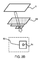
図2は、ロケーションプロセスの第1の例を示すために使用される。 FIG. 2 is used to illustrate a first example of the location process.
図2Aは、平面波送信ビーム50を生成するトランスデューサアレイ6を示す。埋め込まれた音響センサーデバイスが、52として示されている。
FIG. 2A shows a
音響センサーデバイスは、システム2の受信機の帯域通過周波数帯域内、たとえば1~5MHz内の共振周波数を有する膜を備える。 The acoustic sensor device comprises a membrane having a resonant frequency within the bandpass frequency band of the receiver of system 2, eg within 1-5 MHz.
放射された超音波は、音響センサーデバイスの膜を励起し、次いで、その共振周波数においてエコー信号を生成する。音響センサーの共振周波数は、圧力など、周囲環境に依存する。センサーから放射される音響信号は、トランスデューサ6から送信された入射信号の周波数成分と、センサー52の共振周波数の周波数成分と、超音波トランスデューサアレイ6から送信された信号と比較してシフトされた周波数成分とを有する。センサーの共振周波数の成分は、必ずしも超音波アレイによってカバーされる周波数帯域幅内にある必要はないが、シフトされた周波数成分は、その周波数帯域幅内にある。各受信ビーム中のシフトされた周波数成分の存在を検出することによって、音響センサーデバイスのロケーションが識別され得る。受信された信号の周波数成分は、一般に、フーリエ変換を使用して分析される。さらに、センサーからの放射された周波数が、どの程度シフトされたかを計算することによって、共振周波数は決定され得る。前述のように、この共振周波数は、周囲圧力に関する情報を搬送する。
The emitted ultrasonic waves excite the membrane of the acoustic sensor device, which in turn produces echo signals at its resonant frequency. The resonant frequency of an acoustic sensor depends on the ambient environment, such as pressure. The acoustic signal emitted from the sensor includes frequency components of the incident signal transmitted from the
音響センサーは、共振エコー信号を生成することによって、入射音響波に応答する。例として、センサーは、米国特許出願公開第2013/0060139号で開示されているタイプのものである。センサーは、局所圧力変動に対するセンサーの周波数応答の変化に基づく、圧力モニタリングのために使用される。 Acoustic sensors respond to incident acoustic waves by producing resonant echo signals. By way of example, the sensor is of the type disclosed in US Patent Application Publication No. 2013/0060139. The sensor is used for pressure monitoring, based on changes in the sensor's frequency response to local pressure fluctuations.
本発明は、特に、センサーを位置決めすることに関する。センサーの読みの取得及び処理が、知られている様式で、上記で説明されたように実施される。 The invention particularly relates to positioning sensors. Acquisition and processing of sensor readings is performed in a known manner and as described above.
受信されたビームのうち、周波数分析(すなわちフーリエ変換分析)に基づいて音響センサーの共振周波数が検出されるセットがある。それらの受信ビームは、空間的に受信されたビームを表す画像56内の領域54によって示されている。画像56は、仰角対方位角を表す。
Among the received beams, there is a set in which the resonant frequencies of the acoustic sensors are detected based on frequency analysis (ie Fourier transform analysis). These receive beams are indicated by
したがって、図2Aの受信されたビームは、第1の平面波送信ビームを与えることに基づいて取得され、これから、領域54は、超音波センサーについての第1の取得されたロケーションを定義する。この第1の取得されたロケーションは、必要とされるよりも低い精度の概略的なロケーションエリアである。平面波ビームの場合、平面波を異なる角度にステアリングするために、又はビームがどの程度発散しているかを調整するために、遅延が適用される。
Thus, the received beams of FIG. 2A are acquired based on providing a first plane wave transmit beam, from which
集束されていない(たとえば平面波)ビームイメージングの場合、放射された音響信号(ビーム)は、より大きいエリアをカバーする。これらの送信ビームの各々について、(集束されたビームイメージングと比較して低い品質で)大きい視野が生成され得る。しかしながら、これらの大きい個々に再構成された視野(FOV)をコヒーレントに加算することによって、送信集束されたビームに匹敵する画像品質で最終画像が生成され得る。集束されていないビームイメージングの利点は、より速いフレームレート(画像全体を再構成するために必要とされる、より少ない送信)を含むが、より大きい視野を再構成するために、より多くの平行線処理が必要とされるので、システムの複雑さが増大するという犠牲を払う。 For unfocused (eg plane wave) beam imaging, the emitted acoustic signal (beam) covers a larger area. For each of these transmit beams, a large field of view can be produced (with reduced quality compared to focused beam imaging). However, by coherently summing these large individually reconstructed fields of view (FOV), a final image can be produced with image quality comparable to that of transmit focused beams. Advantages of unfocused beam imaging include a faster frame rate (fewer transmissions required to reconstruct the entire image), but more collimation to reconstruct a larger field of view. Since line processing is required, it comes at the cost of increased system complexity.
1つの送信ビームのために使用される送信及び受信要素は、2Dトランスデューサアレイの複数の行及び列を含むことができる。受信された信号は、記憶され、ビームフォーミングのために使用される。 The transmit and receive elements used for one transmit beam can include multiple rows and columns of a 2D transducer array. The received signals are stored and used for beamforming.
センサーからの受信されたエコー信号は、トランスデューサの複数の要素において受信される。これらの信号は、進行している経路に基づいて、異なる時間に要素に到着する。したがって、後続の受信ビームフォーミング中に、ソース信号のロケーションが識別され得る。受信ビームフォーミングは、視野中のあらゆる点について行われ、トランスデューサ要素の利用されたセットに対する遅延和動作を含む。受信された信号は、様々な振幅及び周波数を有し、それらから、センサーのロケーションが識別され得るが、センサーの外部の環境に関する情報も識別され得る(すなわち、埋め込まれた音響センサーの圧力検知機能を利用する)。 Received echo signals from the sensor are received at multiple elements of the transducer. These signals arrive at the elements at different times based on the path they are taking. Thus, during subsequent receive beamforming, the location of the source signal can be identified. Receive beamforming is done for every point in the field of view and involves delay-and-sum operations on the utilized set of transducer elements. The received signals have various amplitudes and frequencies, from which the location of the sensor can be identified, but also information about the environment external to the sensor (i.e., the pressure-sensing function of the implanted acoustic sensor). ).
平面波送信ビームが処理された後、図2Bに示されているように、集束されたビーム58が形成される。これは、平面波イメージングによって決定された粗いセンサーロケーションの背後の点に集束する。集束は、送信ビームフォーミングによって達成される。
After the plane wave transmit beam has been processed, a
集束されたビームイメージングは、たとえば、スキャンライン手法に基づき、それにより、このイメージングは、単一の集束を各々が有するスキャンラインのシーケンスとして実施される。受信されたエコー情報は、スキャンラインのセットとして漸進的に画像を作り上げるために使用される。 Focused beam imaging is based, for example, on the scanline approach, whereby the imaging is performed as a sequence of scanlines each having a single focus. The received echo information is used to build up the image progressively as a set of scanlines.
この手法は、より小さい関心領域についての第1の集束された送信ビームを与える。これから、ペイン60として示されているように、図2Aにおいて見つけられたロケーションエリア内のより正確なロケーションが見つけられる。
This approach provides a first focused transmit beam for a smaller region of interest. From this, a more precise location within the location area found in FIG. 2A is found, shown as
このプロセスは反復的に繰り返され、その結果、第2の集束されたビーム62が、図2Cに示されているように与えられ、領域60辺りのより集束されたビームになる。これは、ペイン64に示されている改善されたロケーションをもたらし、領域54は、この場合も、センサーからの共振信号を含んでいる受信ビームのロケーションを表す。
This process is repeated iteratively, resulting in a second
したがって、このようにして、送信ビームは、広いビーム面内パターンとして開始し、音響センサーからの共振信号の成分を有する受信ビームに基づく、集束されたビームへと漸進的に狭くなる。この適応送信パターンは、センサーを位置決めする高速なやり方を与える。広いビームは、ロケーションプロセスの最初にセンサーの粗いロケーションを与えるが、集束ビームのより大きい空間分解能及びより小さいビーム幅が、より精密なロケーションを可能にする。 Thus, in this manner, the transmit beam starts as a wide beam in-plane pattern and progressively narrows to a focused beam based on the receive beam having a component of the resonant signal from the acoustic sensor. This adaptive transmission pattern provides a fast way to position the sensor. A broad beam gives a coarse location of the sensor at the beginning of the location process, but the greater spatial resolution and smaller beam width of the focused beam allows for more precise location.
また、図2の手法は、ある送信ビームによる受信されたセンサー信号ロケーションを、前の送信ビームによる受信されたセンサー信号ロケーションと比較することによって、音響センサーの移動を検出するために使用される。それらの間に重複がない場合、トランスデューサが異なるロケーションに移動したことを示す。円54は、異なる画像におけるセンサーの可能なロケーションを示す。送信ビームパターンが変化する(集束されていないビームが集束されたビームにますます近づく)につれて、円54は小さくなり、より精密なロケーションを与えるべきであり、したがって、円54は、前のロケーションの円と重複する(又はそれに含まれている)べきである。イメージングプロセスが進むときにそのような重複がない場合、外部トランスデューサと内部センサーとの相対位置が変化したことを意味し、したがって、その場合、シーケンスは、集束されていない送信ビームから再開されるべきである。
The technique of FIG. 2 is also used to detect acoustic sensor movement by comparing the sensor signal location received by one transmit beam with the sensor signal location received by a previous transmit beam. If there is no overlap between them, it indicates that the transducers have moved to different locations.
一代替例は、関心領域全体にわたって送信集束ビームを掃引し、音響センサーデバイスに固有の信号を搬送するビームを識別することである。第1の掃引は、たとえば、第Nのスキャンラインごと(たとえば、第5のスキャンラインごと)の送信ビームを用いた、より低い分解能のものである。センサーからエコーが受信されたスキャンラインから、より高い分解能の画像が、たとえば、隣接するスキャンラインのサブセット(たとえば、スキャンライン番号10~15)に基づいて取得される。次いで、複数のスキャンが行われる場合、分解能が漸進的に高くなる。ちょうど2つのイメージングプロセスがあり得るが、漸進的に精度が高くなる3つのイメージングプロセスも可能である。このコンテキストでは、イメージングプロセスは、センサーをローカライズするためのいくつかの送信シーケンスとして理解されるべきである。たとえば、第1のシーケンスは、3Dボリューム全体について5つのスキャンラインごとに送信することを伴う。次いで、第2のシーケンスは、より小さい領域60を用いて3つのスキャンラインごとに送信することを伴い、次いで、第3のシーケンスは、最も小さい領域54を用いて最終シーケンスのためにスキャンラインごとに送信することを伴う。
One alternative is to sweep the transmit focused beam over the region of interest and identify beams that carry signals specific to the acoustic sensor device. The first sweep is of lower resolution, eg, with a transmit beam every Nth scanline (eg, every fifth scanline). From the scanlines for which echoes were received from the sensor, a higher resolution image is acquired, eg, based on a subset of adjacent scanlines (eg, scanline numbers 10-15). The resolution is then progressively higher when multiple scans are taken. There can be just two imaging processes, but three imaging processes with progressively higher precision are also possible. In this context, the imaging process should be understood as several transmission sequences to localize the sensor. For example, the first sequence involves transmitting every 5 scanlines for the entire 3D volume. The second sequence then involves transmitting every three scanlines using the
音響センサーデバイスは、センサー膜に垂直な方向においてより強くなる圧力波を放射し、それらは、膜配向に垂直に向けられた入射超音波によって、より強く共振される。したがって、最も強いロケーション信号を受信するために、超音波トランスデューサの位置は、センサーの配向及び/又は位置を考慮に入れて選択される。 Acoustic sensor devices emit pressure waves that become stronger in directions perpendicular to the sensor membrane, and they are more strongly resonated by incident ultrasound waves directed perpendicular to the membrane orientation. Therefore, in order to receive the strongest location signal, the position of the ultrasonic transducer is selected taking into account the orientation and/or position of the sensor.
比較的静止したままであるセンサーの場合、最良の信号を取得するために超音波トランスデューサアレイを再配置することが望ましい。 For sensors that remain relatively stationary, it is desirable to reposition the ultrasound transducer array to obtain the best signal.
図3は、超音波トランスデューサアレイ6に対して中心を外れたセンサー52に向けられたビームを示す。図3Aは、(センサー膜平面が、トランスデューサアレイの平面に平行であると仮定して)集束されたビーム60が横方向に向けられ、その結果、集束されたビーム60がセンサーの最適な励起を与えないことを示す。センサーから反射されたエコーが、62として示されている。
FIG. 3 shows the beam directed at the
トランスデューサアレイの改善された位置を導出するために、集束されたビームの知られている方向角度が使用される。次いで、ユーザは、図3Bに示されている、より良い位置に超音波トランスデューサアレイを移動するように命令される。 The known directional angle of the focused beam is used to derive the refined position of the transducer array. The user is then instructed to move the ultrasound transducer array to a better position, shown in FIG. 3B.
インジケータ64は、たとえば、ユーザが、最良のロケーション信号を取得するためにトランスデューサアレイを移動するように指示され得るように、共振信号強度の測度を与える。
センサーは、トランスデューサアレイ平面に平行なセンサーの膜を有しないことがある。 A sensor may not have the membrane of the sensor parallel to the plane of the transducer array.
図4は、センサー52に向けられた送信ビームを示し、センサー52は、超音波トランスデューサアレイ6に対して中心にあるが、膜は平行でない。図4Aは、反射されたエコー信号62が、横方向に向けられていることを示す。共振の励起は最適化されない。
FIG. 4 shows the transmit beam directed at the
トランスデューサアレイの改善された位置を導出するために、受信されたビームの知られている方向角度が使用される。次いで、ユーザは、図4Bに示されている、より良い位置に超音波トランスデューサアレイを移動するように命令される。次いで、送信ビームは膜に垂直に向けられて共振励起を与え、アレイ6の方向に向かう最大強度の反射されたエコー62が生じる。
The known directional angles of the received beams are used to derive the refined position of the transducer array. The user is then instructed to move the ultrasound transducer array to a better position, shown in FIG. 4B. The transmit beam is then directed perpendicular to the film to provide resonant excitation, resulting in a reflected
インジケータ64は、この場合も、たとえば、ユーザが、最良のロケーション信号を取得するためにトランスデューサアレイを移動するように指示され得るように、共振信号強度の測度を与える。
垂直にエコー信号を受信することによって、センサーは、分析のための改善された信号対雑音比を有する。膜表面に垂直に送信ビームを与えることによって、共振励起は改善される。 By receiving echo signals perpendicularly, the sensor has an improved signal-to-noise ratio for analysis. Resonance excitation is improved by providing the transmit beam perpendicular to the film surface.
トランスデューサ位置が、比較的長い期間の間、固定される場合、トランスデューサとセンサーとの相対位置が変化するとき、信号強度が損失することがある。信号処理は、いくつかの隣接する送信ビームから導出された信号強度を比較し、センサーからの信号強度が最も高くなるビームを選択する。これは、モニタリング期間全体にわたって間欠的に起こり得、選択されたビームは更新され、位置及び信号強度のための参照として使用され得る。 If the transducer position is fixed for a relatively long period of time, signal strength can be lost when the relative position of the transducer and sensor changes. Signal processing compares the signal strength derived from several adjacent transmit beams and selects the beam with the highest signal strength from the sensor. This can occur intermittently throughout the monitoring period and the selected beam can be updated and used as a reference for position and signal strength.
上記の例は、単一の外部トランスデューサアレイに基づく。ただし、より大きいエリアをカバーするために各々が同じように挙動する、複数のトランスデューサアレイが使用され得る。 The examples above are based on a single external transducer array. However, multiple transducer arrays can be used, each behaving similarly to cover a larger area.
超音波システムのイメージング能力が上記で説明された。しかしながら、ロケーションのために、エンドユーザに超音波画像を与える必要はない。したがって、本発明は、その最も基本的な形態では、たとえば、次いでセンサー測定を実施するためにロケーション情報を与えるにすぎず、実際の超音波画像は、生成される必要がない。もちろん、多くの場合、ロケーション機能はイメージング機能と連携し、その結果、識別されたロケーションは、周囲エリアの画像と組み合わせて提示される。 The imaging capabilities of ultrasound systems have been described above. However, because of location, it is not necessary to give the end user an ultrasound image. Thus, in its most basic form, the present invention only provides location information, for example to then perform sensor measurements, and no actual ultrasound images need be generated. Of course, location functionality is often combined with imaging functionality so that the identified location is presented in combination with images of the surrounding area.
周波数分析は、受信された信号に関して実施される。これは、たとえば、プロセッサ18によって実施される。周波数分析は、たとえば、送信されたビームに対する受信された信号のドップラーシフトを識別することである。超音波センサーなど、共振器の共振周波数を識別するこの一般的な方法は、たとえば、米国特許出願公開第2004/0211260号に記載されている。
A frequency analysis is performed on the received signal. This is performed by
開示された実施形態に対する他の変形形態が、請求される本発明を実施する際に当業者によって、図面、本開示、及び添付の特許請求の範囲の検討により理解され、実施され得る。特許請求の範囲において、「備える/有する/含む(comprising)」という単語は他の要素又はステップを除外せず、不定冠詞「1つの(a)」又は「1つの(an)」は複数を除外しない。いくつかの方策が、相互に異なる従属請求項に記載されているという単なる事実は、これらの方策の組合せが有利には使用され得ないことを示しているわけではない。特許請求の範囲中のいかなる参照符号も、その範囲を限定するものと解釈されるべきではない。 Other variations to the disclosed embodiments can be understood and effected by those skilled in the art, upon study of the drawings, this disclosure, and the appended claims, in practicing the claimed invention. In the claims, the words "comprising/having/comprising" do not exclude other elements or steps and the indefinite articles "a" or "an" exclude a plurality. do not do. The mere fact that certain measures are recited in mutually different dependent claims does not indicate that a combination of these measures cannot be used to advantage. Any reference signs in the claims should not be construed as limiting the scope.
Claims (15)
複数の超音波ビームを送信し、対応する反射されたエコー信号を受信する超音波トランスデューサアレイと、
コントローラ構成部とを備え、前記コントローラ構成部が、
前記超音波トランスデューサアレイの各トランスデューサからの送信を含む送信ビームを与えるように、前記超音波トランスデューサアレイの送信される信号を制御するための送信コントローラと、
受信された前記反射されたエコー信号を分析するための受信コントローラと
を備え、
前記コントローラ構成部が、複数の送信された前記超音波ビームの各々について、受信された前記反射されたエコー信号の周波数分析を実施して、前記音響センサーから反射された信号があるかどうかを識別し、前記音響センサーのロケーションエリアを識別し、前記送信ビームのパターン又はタイプを適応させることによって、複数の前記周波数分析から前記ロケーションエリア内の漸進的により正確な最終ロケーションを導出することを含むロケーションプロセスを実施する、
ロケーションデバイス。 A location device for determining the location of an acoustic sensor, said location device comprising:
an ultrasound transducer array that transmits a plurality of ultrasound beams and receives corresponding reflected echo signals;
and a controller configuration unit, wherein the controller configuration unit
a transmit controller for controlling transmitted signals of the ultrasonic transducer array to provide a transmit beam comprising transmissions from each transducer of the ultrasonic transducer array;
a receive controller for analyzing the received reflected echo signal;
The controller component performs frequency analysis of the received reflected echo signals for each of the plurality of transmitted ultrasound beams to identify whether any signals are reflected from the acoustic sensor. and deriving progressively more accurate final locations within said location areas from said multiple frequency analyzes by identifying a location area of said acoustic sensor and adapting said transmit beam pattern or type. carry out the process,
location device.
第1の集束されていない送信ビームを与え、第1のロケーションエリアを取得することと、
前記第1のロケーションエリア内のより小さい関心領域に、少なくとも1つのさらなる集束された送信ビームを与え、前記音響センサーの少なくとも1つのより正確なロケーションを取得することと
を含むロケーションプロセスを実施する、請求項1に記載のロケーションデバイス。 The controller configuration unit
providing a first unfocused transmit beam and obtaining a first location area;
providing at least one additional focused transmit beam to a smaller region of interest within the first location area to obtain a more precise location of at least one of the acoustic sensors; The location device of claim 1.
関心領域にわたって第1の複数の集束された送信ビームをスキャンして、第1の間隔をもつ集束位置を与えることと、
前記関心領域にわたって少なくとも第2の複数の集束された送信ビームをスキャンして、より間隔が密な集束位置を与えることと
を含むロケーションプロセスを実施する、請求項1に記載のロケーションデバイス。 The controller configuration unit
scanning a first plurality of focused transmit beams over a region of interest to provide focused positions having a first spacing;
scanning at least a second plurality of focused transmit beams over the region of interest to provide more closely spaced focus positions.
請求項1から8のいずれか一項に記載のロケーションデバイスと
を備える、ロケーションシステム。 an acoustic sensor;
A location system comprising a location device according to any one of claims 1 to 8.
トランスデューサアレイの各トランスデューサからの送信を含む送信ビームを与えるように、前記トランスデューサアレイの超音波信号の送信を制御するステップと、
受信された反射された信号を分析するステップと
を有し、
前記方法は、前記コントローラ構成部が、複数の送信ビームの各々について、受信された反射された信号の周波数分析を実施して、前記音響センサーから反射された信号があるかどうかを識別し、前記音響センサーのロケーションエリアを決定し、前記送信ビームのパターン又はタイプを適応させることによって、複数の前記周波数分析から前記ロケーションエリア内の漸進的により正確な最終ロケーションを導出するステップを有する、
方法。 A method of operating a location device for positioning an acoustic sensor, the location device comprising: an ultrasonic transducer array for transmitting a plurality of ultrasonic beams and receiving corresponding reflected echo signals; and a controller component . wherein the controller component comprises :
controlling transmission of ultrasound signals of the transducer array to provide a transmit beam comprising transmissions from each transducer of the transducer array;
analyzing the received reflected signal;
The method includes the controller component performing a frequency analysis of received reflected signals for each of a plurality of transmit beams to identify whether there is a signal reflected from the acoustic sensor; determining a location area of an acoustic sensor and adapting the transmit beam pattern or type to derive a progressively more accurate final location within said location area from said multiple frequency analyzes;
Method.
第1の集束されていない送信ビームを与え、第1のロケーションエリアを取得するステップと、
前記第1のロケーションエリア内のより小さい関心領域に、少なくとも1つのさらなる集束された送信ビームを与え、少なくとも1つのより正確なロケーションを取得するステップと
を有する、請求項11に記載の方法。 The method comprises: the controller component comprising :
providing a first unfocused transmit beam and obtaining a first location area;
and providing at least one additional focused transmit beam to a smaller region of interest within the first location area to obtain at least one more accurate location.
関心領域にわたって第1の複数の集束された送信ビームをスキャンして、第1の間隔をもつ集束位置を与えるステップと、
前記関心領域にわたって少なくとも第2の複数の集束された送信ビームをスキャンして、より間隔が密な集束位置を与えるステップと
を有する、請求項12に記載の方法。 The method comprises: the controller component comprising :
scanning a first plurality of focused transmit beams over a region of interest to provide focused positions having a first spacing;
13. The method of claim 12, scanning at least a second plurality of focused transmit beams over the region of interest to provide more closely spaced focal positions.
Applications Claiming Priority (7)
| Application Number | Priority Date | Filing Date | Title |
|---|---|---|---|
| US201762469592P | 2017-03-10 | 2017-03-10 | |
| EP17160264 | 2017-03-10 | ||
| EP17160264.2 | 2017-03-10 | ||
| US62/469,592 | 2017-03-10 | ||
| US201762577198P | 2017-10-26 | 2017-10-26 | |
| US62/577,198 | 2017-10-26 | ||
| PCT/EP2018/054999 WO2018162305A1 (en) | 2017-03-10 | 2018-03-01 | Location device and system for locating an acoustic sensor |
Publications (3)
| Publication Number | Publication Date |
|---|---|
| JP2020509821A JP2020509821A (en) | 2020-04-02 |
| JP2020509821A5 JP2020509821A5 (en) | 2021-04-08 |
| JP7167045B2 true JP7167045B2 (en) | 2022-11-08 |
Family
ID=61386862
Family Applications (1)
| Application Number | Title | Priority Date | Filing Date |
|---|---|---|---|
| JP2019548395A Active JP7167045B2 (en) | 2017-03-10 | 2018-03-01 | Location devices and systems for positioning acoustic sensors |
Country Status (4)
| Country | Link |
|---|---|
| US (1) | US11747456B2 (en) |
| EP (1) | EP3592240B1 (en) |
| JP (1) | JP7167045B2 (en) |
| CN (1) | CN110392553B (en) |
Families Citing this family (2)
| Publication number | Priority date | Publication date | Assignee | Title |
|---|---|---|---|---|
| EP3809160A1 (en) * | 2019-10-18 | 2021-04-21 | Furuno Electric Company Limited | Apparatus and method for detecting objects in water bodies |
| CN111938583A (en) * | 2020-07-20 | 2020-11-17 | 南昌大学 | Multi-focus large-depth-of-field photoacoustic microscopic imaging method and device |
Citations (3)
| Publication number | Priority date | Publication date | Assignee | Title |
|---|---|---|---|---|
| JP2003225226A (en) | 2001-12-21 | 2003-08-12 | Biosense Inc | Implantable and insertable passive tag |
| US6685645B1 (en) | 2001-10-20 | 2004-02-03 | Zonare Medical Systems, Inc. | Broad-beam imaging |
| JP2016506793A (en) | 2013-02-05 | 2016-03-07 | マフィン・インコーポレイテッドMuffin Incorporated | Echogenic markers over time |
Family Cites Families (29)
| Publication number | Priority date | Publication date | Assignee | Title |
|---|---|---|---|---|
| NL7806362A (en) * | 1977-07-27 | 1979-01-30 | Siemens Ag | DEVICE FOR EXAMINING BODIES BY ULTRASOUND SCANNING. |
| US4249539A (en) | 1979-02-09 | 1981-02-10 | Technicare Corporation | Ultrasound needle tip localization system |
| US4697595A (en) | 1984-07-24 | 1987-10-06 | Telectronics N.V. | Ultrasonically marked cardiac catheters |
| FR2642640B1 (en) * | 1989-02-08 | 1991-05-10 | Centre Nat Rech Scient | METHOD AND DEVICE FOR FOCUSING ULTRASOUND IN TISSUES |
| JPH03254738A (en) * | 1990-03-02 | 1991-11-13 | Nkk Corp | Blood vessel position-measuring device |
| US5301674A (en) * | 1992-03-27 | 1994-04-12 | Diasonics, Inc. | Method and apparatus for focusing transmission and reception of ultrasonic beams |
| US20100081893A1 (en) | 2008-09-19 | 2010-04-01 | Physiosonics, Inc. | Acoustic palpation using non-invasive ultrasound techniques to identify and localize tissue eliciting biological responses and target treatments |
| DE10115341A1 (en) | 2001-03-28 | 2002-10-02 | Philips Corp Intellectual Pty | Method and imaging ultrasound system for determining the position of a catheter |
| US6544179B1 (en) * | 2001-12-14 | 2003-04-08 | Koninklijke Philips Electronics, Nv | Ultrasound imaging system and method having automatically selected transmit focal positions |
| US7270634B2 (en) * | 2003-03-27 | 2007-09-18 | Koninklijke Philips Electronics N.V. | Guidance of invasive medical devices by high resolution three dimensional ultrasonic imaging |
| US7134341B2 (en) | 2003-04-28 | 2006-11-14 | Zuli Holdings Ltd | Methods and devices for determining the resonance frequency of passive mechanical resonators |
| WO2004107963A2 (en) | 2003-06-03 | 2004-12-16 | Allez Physionix Limited | Non-invasive determination of intracranial pressure via acoustic transducers |
| JP2008514264A (en) | 2004-09-29 | 2008-05-08 | コーニンクレッカ フィリップス エレクトロニクス エヌ ヴィ | Method and apparatus for performing ultrasonic diagnostic imaging of breast with high accuracy |
| WO2006044868A1 (en) * | 2004-10-20 | 2006-04-27 | Nervonix, Inc. | An active electrode, bio-impedance based, tissue discrimination system and methods and use |
| US7713210B2 (en) | 2004-11-23 | 2010-05-11 | St. Jude Medical, Atrial Fibrillation Division, Inc. | Method and apparatus for localizing an ultrasound catheter |
| CN1803226A (en) * | 2005-01-10 | 2006-07-19 | 重庆微海软件开发有限公司 | Assistant positioning and monitoring device for high intensity focused ultrasound therapeutic head |
| US8376947B2 (en) * | 2008-03-26 | 2013-02-19 | Bioquantetics, Inc. | Application of image-based dynamic ultrasound spectrography (IDUS) in detection and localization of breast microcalcifcation |
| WO2010142286A1 (en) * | 2009-06-12 | 2010-12-16 | Technische Universität Dresden | Assembly and method for the combined determination of sonic speeds and distances in media using ultrasound |
| CN102869308B (en) | 2010-05-03 | 2015-04-29 | 皇家飞利浦电子股份有限公司 | Apparatus and method for ultrasonic tracking of ultrasound transducer(s) aboard an interventional tool |
| US8622909B1 (en) * | 2010-10-19 | 2014-01-07 | Quantason, LLC | Method of locating the position of a microcalcification in a human breast |
| US9168022B2 (en) * | 2011-01-07 | 2015-10-27 | General Electric Company | Abdominal sonar system and apparatus |
| US9192788B2 (en) * | 2011-01-18 | 2015-11-24 | Koninklijke Philips N.V. | Therapeutic apparatus, computer program product, and method for determining an achievable target region for high intensity focused ultrasound |
| EP2717772B1 (en) | 2011-06-13 | 2021-05-26 | Koninklijke Philips N.V. | Three-dimensional needle localization with a two-dimensional imaging probe |
| US9743839B2 (en) | 2011-11-02 | 2017-08-29 | Seno Medical Instruments, Inc. | Playback mode in an optoacoustic imaging system |
| CN102879472B (en) * | 2012-09-22 | 2015-01-28 | 华南理工大学 | Adaptive steel rail ultrasonic flaw detection method and device based on frequency spectrum recognition |
| US10610196B2 (en) | 2013-06-28 | 2020-04-07 | Koninklijke Philips N.V. | Shape injection into ultrasound image to calibrate beam patterns in real-time |
| JP6556445B2 (en) * | 2014-02-10 | 2019-08-07 | キヤノンメディカルシステムズ株式会社 | Ultrasonic diagnostic apparatus, image processing apparatus, and image processing method |
| US10349917B2 (en) * | 2014-06-11 | 2019-07-16 | The Johns Hopkins University | Synthetic aperture ultrasound system |
| JP2016107061A (en) * | 2014-11-28 | 2016-06-20 | 株式会社東芝 | Ultrasonic diagnostic apparatus |
-
2018
- 2018-03-01 JP JP2019548395A patent/JP7167045B2/en active Active
- 2018-03-01 US US16/492,446 patent/US11747456B2/en active Active
- 2018-03-01 CN CN201880017100.1A patent/CN110392553B/en active Active
- 2018-03-01 EP EP18707716.9A patent/EP3592240B1/en active Active
Patent Citations (3)
| Publication number | Priority date | Publication date | Assignee | Title |
|---|---|---|---|---|
| US6685645B1 (en) | 2001-10-20 | 2004-02-03 | Zonare Medical Systems, Inc. | Broad-beam imaging |
| JP2003225226A (en) | 2001-12-21 | 2003-08-12 | Biosense Inc | Implantable and insertable passive tag |
| JP2016506793A (en) | 2013-02-05 | 2016-03-07 | マフィン・インコーポレイテッドMuffin Incorporated | Echogenic markers over time |
Also Published As
| Publication number | Publication date |
|---|---|
| JP2020509821A (en) | 2020-04-02 |
| CN110392553A (en) | 2019-10-29 |
| EP3592240B1 (en) | 2021-05-12 |
| US20200041630A1 (en) | 2020-02-06 |
| EP3592240A1 (en) | 2020-01-15 |
| US11747456B2 (en) | 2023-09-05 |
| CN110392553B (en) | 2023-04-04 |
Similar Documents
| Publication | Publication Date | Title |
|---|---|---|
| JP6932192B2 (en) | Methods and systems for filtering ultrasound image clutter | |
| US6464638B1 (en) | Ultrasound imaging system and method for spatial compounding | |
| KR102134763B1 (en) | Determining material stiffness using multiple aperture ultrasound | |
| JP7346542B2 (en) | Ultrasonic controller unit and method | |
| CN113729764A (en) | Ultrasound imaging with sparse array probe | |
| KR20190088165A (en) | Ultrasound probe and manufacturing method for the same | |
| JP2007513672A (en) | Stereoscopic ultrasound imaging system using a two-dimensional array transducer | |
| KR20190087041A (en) | Ultrasonic imaging device and controlling method thereof | |
| JP7346586B2 (en) | Method and system for acquiring synthetic 3D ultrasound images | |
| JP7167045B2 (en) | Location devices and systems for positioning acoustic sensors | |
| KR102545007B1 (en) | Ultrasound imaging apparatus and controlling method for the same | |
| WO2018162305A1 (en) | Location device and system for locating an acoustic sensor | |
| WO2018099867A1 (en) | Methods and systems for filtering ultrasound image clutter | |
| JP2005169123A (en) | Volumetric ultrasonic imaging system using two-dimensional array transducer | |
| JP2017159028A (en) | Ultrasound diagnostic apparatus | |
| JPH08191834A (en) | Ultrasonic measuring device | |
| JP7261870B2 (en) | Systems and methods for tracking tools in ultrasound images | |
| KR20180096342A (en) | Ultrasound probe and manufacturing method for the same | |
| US20210321981A1 (en) | Systems and methods for performing bi-plane imaging | |
| JP6552724B2 (en) | Ultrasonic diagnostic apparatus and control method of ultrasonic diagnostic apparatus | |
| KR20150118732A (en) | ultrasonic apparatus and control method for the same | |
| US20230161020A1 (en) | Acoustic imaging probe with a transducer element | |
| Kim et al. | Hybrid beamformation for volumetric ultrasound imaging scanners using 2-D array transducers | |
| JP2023510047A (en) | Method and system for acquiring 3D vector flow fields | |
| KR20200089000A (en) | Ultrasound image apparatus and method for controlling thereof |
Legal Events
| Date | Code | Title | Description |
|---|---|---|---|
| A521 | Request for written amendment filed |
Free format text: JAPANESE INTERMEDIATE CODE: A523 Effective date: 20210226 |
|
| A621 | Written request for application examination |
Free format text: JAPANESE INTERMEDIATE CODE: A621 Effective date: 20210226 |
|
| A977 | Report on retrieval |
Free format text: JAPANESE INTERMEDIATE CODE: A971007 Effective date: 20220131 |
|
| A131 | Notification of reasons for refusal |
Free format text: JAPANESE INTERMEDIATE CODE: A131 Effective date: 20220210 |
|
| A521 | Request for written amendment filed |
Free format text: JAPANESE INTERMEDIATE CODE: A523 Effective date: 20220506 |
|
| TRDD | Decision of grant or rejection written | ||
| A01 | Written decision to grant a patent or to grant a registration (utility model) |
Free format text: JAPANESE INTERMEDIATE CODE: A01 Effective date: 20220928 |
|
| A61 | First payment of annual fees (during grant procedure) |
Free format text: JAPANESE INTERMEDIATE CODE: A61 Effective date: 20221026 |
|
| R150 | Certificate of patent or registration of utility model |
Ref document number: 7167045 Country of ref document: JP Free format text: JAPANESE INTERMEDIATE CODE: R150 |