JP7164560B2 - Appearance inspection device for crimp terminals - Google Patents
Appearance inspection device for crimp terminals Download PDFInfo
- Publication number
- JP7164560B2 JP7164560B2 JP2020060676A JP2020060676A JP7164560B2 JP 7164560 B2 JP7164560 B2 JP 7164560B2 JP 2020060676 A JP2020060676 A JP 2020060676A JP 2020060676 A JP2020060676 A JP 2020060676A JP 7164560 B2 JP7164560 B2 JP 7164560B2
- Authority
- JP
- Japan
- Prior art keywords
- crimp terminal
- image
- edge
- wire
- inspection apparatus
- Prior art date
- Legal status (The legal status is an assumption and is not a legal conclusion. Google has not performed a legal analysis and makes no representation as to the accuracy of the status listed.)
- Active
Links
Images


Classifications
-
- G—PHYSICS
- G01—MEASURING; TESTING
- G01N—INVESTIGATING OR ANALYSING MATERIALS BY DETERMINING THEIR CHEMICAL OR PHYSICAL PROPERTIES
- G01N21/00—Investigating or analysing materials by the use of optical means, i.e. using sub-millimetre waves, infrared, visible or ultraviolet light
- G01N21/84—Systems specially adapted for particular applications
Description
本発明は、電線の先端部に圧着された圧着端子をカメラで撮影して外観を検査する圧着端子の外観検査装置に関する。 The present invention relates to a crimp terminal visual inspection apparatus for inspecting the appearance of a crimp terminal crimped to the tip of an electric wire by photographing the crimp terminal with a camera.
この種の外観検査装置が特許文献1等において知られている。特許文献1に記載の外観検査装置は、画像上の端子(スズメッキ端子)と電線芯線(銅線)の色の違いを利用して圧着端子の状態を検査していた。
A visual inspection apparatus of this type is known in
しかし、色の違いを利用するのみでは、圧着端子の状態を検査することが難しい場合があった。例えば、銅電線ではなくアルミ電線に対してスズメッキ端子を圧着した場合には、画像上、端子の色と電線の芯線の色との区別が難しく、検査できなかった。また、端子上の変形箇所(例えば、後述するベルマウス)に関しても、通常の加締部(平らな部分)とベルマウス(傾斜した部分)との色の差や明るさの差も小さいことから、正確な検査が難しかった。 However, it was sometimes difficult to inspect the condition of the crimp terminal only by using the difference in color. For example, when a tin-plated terminal is crimped to an aluminum electric wire instead of a copper electric wire, it is difficult to distinguish between the color of the terminal and the color of the core wire of the electric wire on the image, making inspection impossible. In addition, regarding the deformed portion (for example, the bell mouth, which will be described later) on the terminal, the difference in color and brightness between the normal crimped portion (flat portion) and the bell mouth (inclined portion) is small. was difficult to inspect accurately.
本発明は、上述した事情に鑑みてなされたものであり、その目的は、端子と芯線が同系色(例えば、スズメッキ端子とアルミ芯線の組み合わせ)である場合にも、電線加締部からの芯線の出寸法やベルマウスの寸法の良否を評価することのできる圧着端子の外観検査装置を提供することにある。 The present invention has been made in view of the above-mentioned circumstances, and its object is to prevent the core wire from the wire crimping portion even when the terminal and the core wire have similar colors (for example, a combination of a tin-plated terminal and an aluminum core wire). To provide a crimp terminal visual inspection device capable of evaluating whether the protruding dimension of a crimp terminal or the dimension of a bell mouth is good or bad.
前述した目的を達成するために、本発明に係る圧着端子の外観検査装置は、下記(1)~(4)を特徴としている。
(1) 電線の先端部に圧着された圧着端子をカメラで撮影して外観を検査する圧着端子の外観検査装置であって、
撮影空間の定位置に設定された端子セット部と、
前記端子セット部に配置される圧着端子の電線加締部を上方から撮影するカメラと、
前記カメラの撮影したデジタル画像を処理する画像処理部と、
を備え、
前記画像処理部は、前記デジタル画像に対し空間フィルタリング処理することで該画像中のエッジを抽出した抽出画像を生成し、該抽出画像から前記電線加締部とその周辺の複数の特徴点の位置を割り出し、割り出した結果に基づいて前記圧着端子を評価し、
前記画像処理部は、
前記電線加締め部における加締め治具で挟み込まれて平らとなった部分の前後両端に形成される前記加締め治具で挟み込まれずに斜めに開いた部分、であるベルマウスの根元の位置に対応するエッジと、前記ベルマウスの先端の位置に対応するエッジとの間の距離を検出することで、前記ベルマウスの長さを推定する、
ことを特徴とする圧着端子の外観検査装置。
In order to achieve the above object, a crimp terminal visual inspection apparatus according to the present invention is characterized by the following (1) to ( 4 ).
(1) A crimp terminal visual inspection apparatus for inspecting the appearance of a crimp terminal crimped to a tip of an electric wire by photographing the crimp terminal with a camera,
A terminal set part set at a fixed position in the shooting space,
a camera for photographing from above the wire crimping portion of the crimp terminal arranged in the terminal set portion;
an image processing unit that processes a digital image captured by the camera;
with
The image processing unit performs spatial filtering on the digital image to generate an extracted image by extracting edges in the image, and from the extracted image, positions of the wire crimping portion and a plurality of feature points around it. is determined, and the crimp terminal is evaluated based on the determined result,
The image processing unit
The position of the base of the bell mouth, which is the portion that is not pinched by the crimping jig and is formed at both the front and rear ends of the portion flattened by the crimping jig in the electric wire crimping portion. estimating the length of the bell mouth by detecting the distance between the edge corresponding to and the edge corresponding to the position of the tip of the bell mouth ;
A crimp terminal visual inspection apparatus characterized by:
(2) 前記画像処理部は、前記抽出画像に対しパターンマッチング処理することで、特定のエッジパターンに対応する特徴点の位置を割り出し、その特徴点の位置に基づいて前記圧着端子を評価する、
ことを特徴とする上記(1)に記載の圧着端子の外観検査装置。
(2) The image processing unit performs pattern matching processing on the extracted image to determine the positions of feature points corresponding to a specific edge pattern, and evaluates the crimp terminal based on the positions of the feature points.
The crimp terminal visual inspection apparatus according to (1) above, characterized in that:
(3) 前記カメラの撮影対象空間に向けて一定の指向性を有した照明光を当てる照明手段を備える、
ことを特徴とする上記(1)または(2)に記載の圧着端子の外観検査装置。
(3) illuminating means for applying illumination light having a certain directivity toward the shooting target space of the camera;
A crimp terminal visual inspection apparatus according to the above (1) or (2) characterized by:
(4) 前記画像処理部は、前記デジタル画像に対し空間フィルタリング処理することで、前記電線加締部における電線の芯線の長さ方向に垂直な方向のエッジと前記芯線の長さ方向に平行な方向のエッジとの少なくともいずれか一方のエッジを抽出した抽出画像を生成し、生成した前記抽出画像に基づいて前記圧着端子を評価する、
ことを特徴とする上記(1)~(3)のいずれかに記載の圧着端子の外観検査装置。
(4) The image processing unit performs a spatial filtering process on the digital image so that an edge in the direction perpendicular to the length direction of the core wire of the wire crimping portion and an edge in the direction parallel to the length direction of the core wire in the wire crimping portion generating an extracted image in which at least one edge of the direction edge is extracted, and evaluating the crimp terminal based on the generated extracted image;
A crimp terminal visual inspection apparatus according to any one of the above (1) to (3), characterized in that:
上記(1)の構成の圧着端子の外観検査装置によれば、カメラで撮影したデジタル画像に対し空間フィルタリング処理を行うことで、画像中のエッジ(画素の明るさや色などの急激な変化)を際立たせることができる。そして、エッジの画像から電線加締部とその周辺の複数の特徴点の位置を割り出すことができ、複数の特徴点間の距離に基づいて圧着端子の外観形状を評価することができる。
例えば、圧着端子の電線加締部の前端の位置やその前端から突出した電線の芯線の前端の位置は、デジタル画像中のエッジとして空間フィルタリング処理により特徴的に抽出することができる。そのため、圧着端子の電線加締部の前端の位置に対応するエッジと、電線の芯線の前端の位置に対応するエッジとの間の距離を検出することにより、圧着端子の電線加締部からの芯線の出寸法を推定することができ、その芯線の出寸法が適正範囲にあるかどうかを評価することができる。
また、圧着端子を電線の芯線に加締める場合、アンビルとクリンパで直接電線加締部を挟み込んで変形させるのが一般的である。その際、電線加締部の、アンビルとクリンパで直接挟み込まれて平らになった部分の前後両端(芯線の長さ方向における両端)に、「ベルマウス」と呼ばれる、アンビルとクリンパで直接挟み込まれずに斜めに開いた部分が形成される。このベルマウスが適切に形成されているかどうかも、圧着端子の外観検査における重要な検査項目である。このベルマウスの根元の位置と先端(電線加締部の前端に相当)の位置も、前者が形状変化位置であったり後者が外縁輪郭部であったりするため、画像中のエッジとして空間フィルタリング処理により特徴的に抽出される。そのため、ベルマウスの根元の位置に対応するエッジとベルマウスの先端の位置に対応するエッジとの間の距離を検出することにより、ベルマウスの長さを推定することができ、ベルマウスの有無は勿論、ベルマウスの長さが適正寸法範囲内に形成されているかどうかを評価することができる。また、ベルマウスの長さを含めて、圧着端子の電線加締めによる実際の拘束位置(ベルマウスの根元付近)からの芯線の精細な出寸法を評価することができる。
また、エッジの画像から特定の評価領域におけるエッジの占有面積を割り出すことにより、例えば、電線加締部から突出した電線の芯線の量、即ち、芯線の出寸法を推定することができ、芯線の出寸法が適正範囲にあるかどうかを評価することができる。つまり、芯線を構成する1本1本の細線(例えば、芯線が複数本の細線による撚線の場合など)は個別の輪郭を持つので、空間フィルタリング処理により、1本1本の細線をエッジとして抽出することができる。したがって、圧着端子の電線加締部から突出している芯線の長さ(芯線に相当する画像部分の長さ)が大きくなれば、エッジとして抽出される部分の背景画面に対する占有面積が大きくなる。そこで、エッジの占有面積の大きさにより、芯線の出寸法を推定することができ、それにより、芯線の出寸法が適正範囲にあるかどうかを評価することができる。
上記のように、カメラの画像上で色の変化が少ない場合(例えば、スズメッキ端子とアルミ電線のアルミ芯線との関係のように同系色の場合)や、高さ方向に傾斜しているだけでカメラの画像上で明るさの変化の少ない領域(例えば、ベルマウスの部分)など、従来では画像により判別・評価が難しかった場合や領域であっても、空間フィルタリング処理によるエッジの抽出画像に基づいて的確に判別・評価することが可能になる。
According to the appearance inspection apparatus for crimp terminals having the above configuration (1), by performing spatial filtering processing on a digital image taken by a camera, edges in the image (rapid changes in brightness, color, etc. of pixels) can be detected. can stand out. Then, the positions of the wire crimping portion and a plurality of characteristic points in the vicinity thereof can be determined from the image of the edge, and the external shape of the crimp terminal can be evaluated based on the distances between the plurality of characteristic points.
For example, the position of the front end of the wire crimping portion of the crimp terminal and the position of the front end of the core wire of the wire protruding from the front end can be characteristically extracted as edges in the digital image by spatial filtering processing. Therefore, by detecting the distance between the edge corresponding to the position of the front end of the wire crimping portion of the crimp terminal and the edge corresponding to the position of the front end of the core wire of the wire, The projected dimension of the core wire can be estimated, and whether or not the projected dimension of the core wire is within an appropriate range can be evaluated.
When crimping a crimp terminal onto a core wire of an electric wire, it is common to deform the crimped portion by directly pinching it between an anvil and a crimper. At that time, the front and rear ends (both ends in the length direction of the core wire) of the wire crimping part, which is directly sandwiched between the anvil and the crimper, are not directly sandwiched between the anvil and the crimper. A diagonally open portion is formed in the Whether the bell mouth is properly formed is also an important inspection item in the appearance inspection of the crimp terminal. The position of the root and the tip of the bell mouth (equivalent to the front end of the wire crimping part) are also spatially filtered as edges in the image because the former is the shape change position and the latter is the outer edge contour part. characteristically extracted by Therefore, the length of the bell mouth can be estimated by detecting the distance between the edge corresponding to the position of the base of the bell mouth and the edge corresponding to the position of the tip of the bell mouth. Needless to say, it is possible to evaluate whether the length of the bell mouth is formed within the proper dimension range. In addition, including the length of the bell mouth, it is possible to evaluate the fine projection dimension of the core wire from the actual restraint position (near the base of the bell mouth) by crimping the wire of the crimp terminal.
Further, by calculating the area occupied by the edge in a specific evaluation region from the image of the edge, for example, the amount of the core wire of the wire protruding from the wire crimping portion, that is, the protruding dimension of the core wire can be estimated. It is possible to evaluate whether the dimensions are within the appropriate range. In other words, each thin wire that makes up the core wire (for example, when the core wire is a twisted wire made up of multiple thin wires) has an individual contour, so by spatial filtering processing, each thin wire is treated as an edge. can be extracted. Therefore, as the length of the core wire protruding from the wire crimping portion of the crimp terminal (the length of the image portion corresponding to the core wire) increases, the area of the background screen occupied by the portion extracted as the edge increases. Therefore, it is possible to estimate the protruding dimension of the core wire from the size of the area occupied by the edge, and thereby to evaluate whether or not the protruding dimension of the core wire is within an appropriate range.
As mentioned above, when there is little change in color on the camera image (for example, when the tin plated terminal and the aluminum core wire of the aluminum wire have similar colors), or when it is only inclined in the height direction Even in cases where it was difficult to distinguish and evaluate from conventional images, such as areas with little change in brightness on the camera image (for example, bell mouth), even in areas where it is difficult to distinguish and evaluate by image, based on the edge extraction image by spatial filtering processing It is possible to accurately determine and evaluate
上記(2)の構成の圧着端子の外観検査装置によれば、パターンマッチング処理を利用することにより、容易にエッジ画像中の特徴点の位置を割り出すことができる。 According to the crimp terminal visual inspection apparatus having the configuration (2), the position of the feature point in the edge image can be easily determined by using the pattern matching process.
上記(3)の構成の圧着端子の外観検査装置によれば、一般的な拡散光の照明を当てるのではなく、指向性を高めた照明光を撮影対象部分に当てることにより、ベルマウスのような傾斜のある部分を意図的に暗く写し出したりすることができる。そのため、明暗を際立たせることで、エッジを一層はっきりと際立たせることができるようになる。 According to the visual inspection apparatus for crimp terminals having the configuration (3) above, instead of illuminating with general diffused light, illumination light with enhanced directivity is applied to the part to be photographed, so that it can be It is possible to intentionally make a part with a steep slope appear darker. Therefore, by making the brightness stand out, the edges can be made stand out more clearly.
上記(4)の構成の圧着端子の外観検査装置によれば、電線加締部における芯線の長さ方向に垂直な方向のエッジと芯線の長さ方向に平行な方向のエッジとの少なくともいずれか一方を抽出することにより、電線加締部とその周辺の複数の特徴点の位置および特定の評価領域におけるエッジの占有面積の割り出しを有利に行うことができる。例えば、空間フィルタとしてソベルフィルタ(Sobel filter)を用いる場合、垂直方向(画像の上下方向=縦方向)のフィルタリングと水平方向(画像の水平方向=横方向)のフィルタリングを選択的に行うことができる。
芯線の長さ方向に垂直な方向を垂直方向とし、芯線の長さ方向に沿う方向を水平方向として、カメラの撮影したデジタル画像を取り込んだ場合、垂直方向のフィルタリングを行うことによって、垂直方向のエッジ(縦線)のみを抽出することができる。例えば、ベルマウスの根元の括れや先端の輪郭線は、芯線の長さ方向に垂直な方向に延在するので、垂直用のフィルタで検出することができる。また、水平方向のフィルタリングを行うことによって、水平方向のエッジ(横線)のみを抽出することができる。例えば、芯線を構成する1本1本の細線は水平方向に延在しているので、芯線の領域は水平用のフィルタで検出することができる。このように、ベルマウス領域や芯線領域など、領域ごとにそれぞれ最適なフィルタを使用することで、求めたいエッジの画像を正確に得ることができ、画像処理の的確化と迅速化に貢献することができる。
According to the crimp terminal visual inspection apparatus having the above configuration (4), at least one of the edge in the direction perpendicular to the length direction of the core wire and the edge in the direction parallel to the length direction of the core wire in the wire crimping portion By extracting one of them, it is possible to advantageously determine the positions of the wire crimping portion and a plurality of feature points in the vicinity thereof, and the occupied area of the edge in the specific evaluation region. For example, when a Sobel filter is used as a spatial filter, filtering in the vertical direction (vertical direction of the image = vertical direction) and filtering in the horizontal direction (horizontal direction of the image = horizontal direction) can be selectively performed. .
The direction perpendicular to the length of the core wire is defined as the vertical direction, and the direction along the length of the core wire is defined as the horizontal direction. Only edges (vertical lines) can be extracted. For example, the constriction at the base of the bell mouth and the contour line at the tip extend in a direction perpendicular to the length direction of the core wire, so they can be detected by a vertical filter. Further, by performing horizontal filtering, only horizontal edges (horizontal lines) can be extracted. For example, since each fine line forming the core line extends in the horizontal direction, the region of the core line can be detected by a horizontal filter. In this way, by using the optimum filter for each area, such as the bellmouth area and core line area, it is possible to accurately obtain the image of the desired edge, contributing to the accuracy and speed of image processing. can be done.
本発明によれば、カメラの画像上において色や明るさの変化が少ない場合でも、空間フィルタリング処理によるエッジの抽出画像に基づいて的確に判別・評価することが可能になる。 According to the present invention, even when there is little change in color or brightness on the camera image, it is possible to accurately determine and evaluate based on the edge extraction image obtained by spatial filtering processing.
以上、本発明について簡潔に説明した。更に、以下に説明される発明を実施するための形態(以下、「実施形態」という。)を添付の図面を参照して通読することにより、本発明の詳細は更に明確化されるであろう。 The present invention has been briefly described above. Furthermore, the details of the present invention will be further clarified by reading the following detailed description of the invention (hereinafter referred to as "embodiment") with reference to the accompanying drawings. .
本発明に関する具体的な実施形態について、各図を参照しながら以下に説明する。 Specific embodiments relating to the present invention will be described below with reference to each drawing.
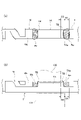
図1は、本発明の実施形態に係る外観検査装置の構成図で、図1(a)は平面図、図1(b)は側面図、図2は正面図である。 1A and 1B are configuration diagrams of an appearance inspection apparatus according to an embodiment of the present invention, in which FIG. 1A is a plan view, FIG. 1B is a side view, and FIG. 2 is a front view.
図1、図2に示すように、本実施形態の外観検査装置は、電線Wの先端に圧着された圧着端子Tを照明光を当てながらカメラで撮影して外観を検査するものである。 As shown in FIGS. 1 and 2, the appearance inspection apparatus of this embodiment inspects the appearance of a crimp terminal T crimped to the tip of an electric wire W by photographing it with a camera while illuminating it with illumination light.
カメラによる撮影空間の定位置には端子セット部1が設定されている。図1においては、端子セット部1に圧着端子Tが配置されている。この端子セット部1は、カメラによる撮影空間の中央に設定されている。
A
この端子セット部1には、前方に圧着端子Tの前端を向け、上方に圧着端子Tの電線加締部の上面を向け、後方に圧着端子Tが接続された電線Wの延在方向を向け、左右側方に圧着端子Tの左右側面を向けた姿勢で、圧着端子Tが挿入セットされるようになっている。電線Wの先端に圧着接続(加締め接続)された圧着端子Tは、例えば、電線Wの延在方向と垂直な水平方向(左右方向)から、あるいは、電線Wの延在方向と平行な後方から前方に向かって、端子セット部1に挿入セットされる。端子セット部1は、支持部材(不図示)によって圧着端子Tおよび電線Wの少なくとも一方を支持している。
In the terminal set
この外観検査装置には、端子セット部1に配置される圧着端子Tに対して一定方向から照明光を当てる照明手段として、上部照明手段3が設けられている。上部照明手段3は、端子セット部1に配置される圧着端子Tの上方に位置している。上部照明手段3には、多数のLEDを配置した平面光源の出光面にプリズムシートを張り付けて、高指向性の平行光を照明光として出射するものが用いられている。この上部照明手段3は、圧着端子Tに対し上方から高指向性の平行光を当てる。
This visual inspection apparatus is provided with an upper illumination means 3 as an illumination means for illuminating the crimp terminals T arranged in the terminal set
また、この外観検査装置には、端子セット部1に配置される圧着端子Tを一定方向から撮影するカメラとして、上方カメラ2と、正面カメラ(図示略)との2台のカメラが固定的に設けられている。上方カメラ2は、端子セット部1(圧着端子T)の真上に配置されており、端子セット部1に配置された圧着端子Tの上面像を真上から撮影する。また、正面カメラは、端子セット部1(圧着端子T)の正面に配置されており、端子セット部に配置された圧着端子Tを正面から撮影する。この正面カメラは、挿入された圧着端子Tの傾きを見るためのものである。
In addition, two cameras, an
また、この外観検査装置は、上方から圧着端子Tの状態を撮影する上方カメラ2のデジタル画像を処理する画像処理部10を備えている。この画像処理部10は、カメラの撮影したデジタル画像に対し空間フィルタリング処理することで該画像中のエッジを抽出した画像を生成し、該エッジの画像から電線加締部とその周辺の複数の特徴点の位置および特定の評価領域におけるエッジの占有面積の少なくとも一方を割り出し、割り出した結果に基づいて圧着端子を評価する機能を備えている。
This visual inspection apparatus also includes an
以下、画像処理部の機能について説明する。
図3は、外観検査装置のデータ処理部の概略構成を示すブロック図である。
画像処理部10は、上方カメラ2の撮影したデジタル画像をソフトウエア処理して、電線加締部やその周辺の形状の良否判定のための評価を行うようになっている。
The functions of the image processing unit will be described below.
FIG. 3 is a block diagram showing a schematic configuration of a data processing section of the visual inspection apparatus.
The
図3に示すように、この画像処理部10は、概略的に述べると、画像データの取込部11と、取り込んだ画像中のエッジを抽出するエッジ抽出部12と、エッジ間の長さを検出するエッジ間長さ検出部13と、エッジ間の長さに基づいて芯線の出寸法を算出する芯線出寸法算出部14と、エッジ間の長さに基づいてベルマウスの寸法を算出するベルマウス寸法算出部15と、を有している。また、画像処理部10は、エッジ相当部である白面積検出部17を設けていてもよい。この場合、芯線出寸法算出部14やベルマウス寸法算出部15は、白面積検出部17の検出結果に基づいて芯線の出寸法やベルマウスの寸法を算出する機能を持つようにする。
As shown in FIG. 3, the
図4は、外観検査装置による検査対象部位の説明図で、図4(a)は圧着端子の電線加締部の周辺部位の平面図、図4(b)は同部位の側面図である。 FIGS. 4A and 4B are explanatory diagrams of parts to be inspected by the visual inspection apparatus, FIG. 4A being a plan view of the peripheral part of the wire crimping portion of the crimp terminal, and FIG. 4B being a side view of the same part.
図4(a)、(b)に示すように、圧着端子Tは、電線Wの先端部に加締められている。電線Wの先端部では、被覆Wbが除去されて芯線Waが所定長さ露出しており、その露出した芯線Waに圧着端子Tの電線加締部(芯線加締部)TAが加締め接続(圧着接続)されている。加締め接続には、クランパ100とアンビル101が用いられ、クランパ100とアンビル101に挟み込まれる箇所は平らに変形させられ、クランパ100とアンビル101に挟み込まれない箇所(電線加締部の前後両端)には、斜めに開いたベルマウスTBが形成される。
As shown in FIGS. 4A and 4B, the crimp terminal T is crimped to the tip of the electric wire W. As shown in FIGS. At the tip of the electric wire W, the covering Wb is removed to expose the core wire Wa for a predetermined length. crimp connection). A
圧着端子Tの圧着形状評価(圧着品質評価)には、電線加締部TAの前端TAaからの芯線Waの出寸法SAや前端側のベルマウスTBの長さSBが重要であり、画像処理部10は、それらの寸法評価のためのデータ処理を行う。 For crimping shape evaluation (crimping quality evaluation) of the crimp terminal T, the projecting dimension SA of the core wire Wa from the front end TAa of the wire crimping portion TA and the length SB of the bell mouth TB on the front end side are important. 10 performs data processing for their dimensional evaluation.
図5は、電線加締部の周辺部位を撮影した画像データおよびエッジ抽出画像の説明図で、図5(a)はカメラで撮影したデジタル画像、図5(b)および図5(c)は、図5(a)に示した元画像をソベルフィルタで処理したエッジ抽出画像であり、図5(b)は垂直方向のフィルタで処理したエッジ抽出画像、図5(c)は水平方向のフィルタで処理したエッジ抽出画像を示す図である。 5A and 5B are explanatory diagrams of image data and edge-extracted images of the area around the wire crimping part, in which FIG. 5A is a digital image taken by a camera, and FIGS. 5A is an edge-extracted image obtained by processing the original image shown in FIG. 5A with a Sobel filter, FIG. 5B is an edge-extracted image processed by a vertical filter, and FIG. FIG. 10 is a diagram showing an edge-extracted image processed by .
画像処理において、画像上のエッジとは、画像の色や明るさの変化が急である事象を指す。画像の色や明るさの急な変化は、次のような事象と一致する可能性が高い。
・深さが不連続である。
・面の向きが不連続である。
・材質が変化している。
In image processing, an edge on an image refers to a phenomenon in which the color or brightness of the image changes abruptly. Sudden changes in image color or brightness are likely to coincide with events such as:
• The depth is discontinuous.
・The orientation of the surface is discontinuous.
- The material has changed.
圧着端子Tの電線加締部TAの前端と芯線Waとの境界や、芯線Waの輪郭や、ベルマウスTBの根元や先端の画像上の変化は、上記の事象に合致するので、画像上のエッジとして認識できる。そこで、画像処理部10では、カメラの撮影したデジタル画像を空間フィルタリングしてエッジを抽出しエッジの画像を生成する。空間フィルタリングによりエッジを抽出することで、画像中のエッジを際立たせることができる。勿論、エッジの画像は、ディスプレイ上に具体的に表示しなくてもよく、仮想空間上に存在しているだけでよい。
The boundary between the front end of the wire crimping portion TA of the crimp terminal T and the core wire Wa, the outline of the core wire Wa, and the changes in the image of the root and tip of the bell mouth TB match the above events. recognizable as an edge. Therefore, in the
ここでは、エッジ抽出のための空間フィルタとして、ソベルフィルタを利用する場合を説明するが、それ以外のフィルタを利用することも可能である。ソベルフィルタは、垂直方向(画像の上下方向=縦方向)のフィルタリング(縦線検出)と水平方向(画像の水平方向=横方向)のフィルタリング(横線検出)の2つのフィルタ機能を持つ。どちらか一方だけのフィルタ機能を利用してもよいし、両方のフィルタ機能を利用してもよい。 Here, a case where a Sobel filter is used as a spatial filter for edge extraction will be described, but other filters can also be used. The Sobel filter has two filter functions: filtering in the vertical direction (vertical direction of the image = vertical direction) (vertical line detection) and filtering in the horizontal direction (horizontal direction of the image = horizontal direction) (horizontal line detection). Only one filter function may be used, or both filter functions may be used.
画像処理部10は、まず、芯線Waの長さ方向に垂直な方向を垂直方向とし、芯線Waの長さ方向に沿う方向を水平方向として、カメラの撮影したデジタル画像を取り込む。図5(a)は取り込んだ画像である。この画像に対し、垂直方向のフィルタリングを行うことによって、図5(b)に示すように、垂直方向のエッジ(縦線)のみを抽出することができる。例えば、ベルマウスTBの根元の括れや先端の輪郭線は、芯線Waの長さ方向に垂直な方向に延在するので、垂直用のフィルタで検出することができる。同様に、芯線Waの先端も、垂直用のフィルタで検出することができる。
First, the
また、水平方向のフィルタリングを行うことによって、図5(c)に示すように、水平方向のエッジ(横線)のみを抽出することができる。例えば、芯線Waを構成する1本1本の細線は水平方向に延在しているので、芯線Waの領域は水平用のフィルタで検出することができる。 Further, by performing horizontal filtering, only horizontal edges (horizontal lines) can be extracted as shown in FIG. 5(c). For example, since each fine line forming the core wire Wa extends in the horizontal direction, the region of the core wire Wa can be detected by a horizontal filter.
このように、ベルマウス領域や芯線領域など、領域ごとにそれぞれ最適なフィルタを使用することで、求めたいエッジの画像を正確に得ることができる。そして、エッジの画像から電線加締部TAとその周辺の複数の特徴点の位置を割り出すことができる。 By using the optimum filter for each region such as the bellmouth region and the core line region in this way, it is possible to accurately obtain the desired edge image. Then, the positions of the wire crimping portion TA and a plurality of characteristic points around it can be determined from the image of the edge.
特徴点の位置の割り出しにはパターンマッチングを利用する。即ち、画像処理部10は、エッジの画像に対しパターンマッチング処理することで、特定のエッジパターンに対応する特徴点の位置を割り出す。
Pattern matching is used to determine the positions of feature points. That is, the
例えば、図5(b)に示すように、枠20で示す仮想のパターンを移動させていき、枠内における白い領域の割合が所定値を超えたら、その位置にエッジがあると判定する。予め、モデルパターンデータで、ベルマウスTBの大まかな位置はわかっているので、その近傍から枠20の移動を開始する。枠20を移動させていき、ベルマウスTBの想定領域で最初に所定値を超えた位置をベルマウスTBのエッジと判定する。左側のエッジ(根元)と右側のエッジ(先端)の間隔がベルマウスの長さSBとなる。ベルマウスBが規定値より長すぎたり短すぎたり、また、位置が規定範囲外にある、あるいは、ベルマウスTBが形成されていないと見なした場合は、形状不良と評価する。このようにパターンマッチング処理を利用することにより、容易にエッジ画像中の特徴点の位置を割り出すことができる。
For example, as shown in FIG. 5B, the imaginary pattern indicated by the
また、電線加締部TAの前端TAaの位置やその前端から突出した芯線Waの前端の位置も、デジタル画像中のエッジとして特徴的に抽出されるので、電線加締部TAの前端TAaの位置に対応するエッジと、芯線Waの前端の位置に対応するエッジとの間の距離を検出することにより、電線加締部TAからの芯線Waの出寸法SAを検出することができる。また、ベルマウスTBの長さを含めて、圧着端子の電線加締めによる実際の拘束位置(ベルマウスの根元付近)からの芯線の精細な出寸法も評価することができる。 In addition, since the position of the front end TAa of the wire clamping portion TA and the position of the front end of the core wire Wa projecting from the front end thereof are also characteristically extracted as edges in the digital image, the position of the front end TAa of the wire clamping portion TA is By detecting the distance between the edge corresponding to and the edge corresponding to the position of the front end of the core wire Wa, the protruding dimension SA of the core wire Wa from the wire crimping portion TA can be detected. In addition, including the length of the bell mouth TB, it is also possible to evaluate the fine projection dimension of the core wire from the actual restraint position (near the base of the bell mouth) by crimping the wire of the crimp terminal.
このように、エッジの抽出により、特徴点の検出が容易にできるようになるので、複数の特徴点間の距離に基づいて圧着端子の外観形状を的確に評価することができる。 In this way, extraction of edges makes it possible to easily detect characteristic points, so that the external shape of the crimp terminal can be accurately evaluated based on the distances between a plurality of characteristic points.
また、エッジ間の距離の他に、抽出したエッジの面積により、圧着端子の状態を評価することもできる。即ち、エッジの画像から特定の評価領域におけるエッジの占有面積を割り出すことによって、例えば、電線加締部TAから突出した芯線Waの量、即ち、芯線Waの出寸法を推定することができ、芯線の出寸法が適正範囲にあるかどうかを評価することができる。 In addition to the distance between edges, the condition of the crimp terminal can also be evaluated based on the area of the extracted edges. That is, by calculating the area occupied by the edge in a specific evaluation area from the image of the edge, for example, the amount of the core wire Wa protruding from the wire crimping portion TA, that is, the protruding dimension of the core wire Wa can be estimated. It is possible to evaluate whether the projecting dimensions are within the appropriate range.
つまり、芯線Waを構成する1本1本の細線(例えば、芯線が複数本の細線による撚線の場合など)は個別の輪郭を持つので、水平方向のソベルフィルタにより、図5(b)に示すように、1本1本の細線をエッジとして抽出することができる。したがって、圧着端子の電線加締部から突出している芯線Waの長さ(芯線に相当する画像部分の長さ)が大きくなれば、エッジとして抽出される部分の背景画面に対する占有面積が大きくなる。例えば、水平方向のソベルフィルタによりエッジを抽出し、芯線Waのエッジを黒背景に白点あるいは白線で表示する場合、評価領域22内における黒面積に対する白面積の割合や量で芯線領域の大きさを評価することができる。つまり、芯線領域については、芯線Waの存在を表すエッジの合計面積が所定値以上であるか否かを判定することによって、芯線Waの電線加締部TAからのはみ出し量(出寸法)を評価することが可能となる。また、所定値未満の場合は、芯線Waが存在すべき場所に必要量の芯線が無い状態、つまり、芯線Waの出寸法SAが足りないと評価することができる。
In other words, since each fine wire constituting the core wire Wa (for example, when the core wire is a twisted wire made up of a plurality of fine wires) has an individual contour, the horizontal Sobel filter produces a line as shown in FIG. As shown, each fine line can be extracted as an edge. Therefore, as the length of the core wire Wa protruding from the wire crimping portion of the crimp terminal (the length of the image portion corresponding to the core wire) increases, the area of the background screen occupied by the portion extracted as the edge increases. For example, when an edge is extracted by a horizontal Sobel filter and the edge of the core line Wa is displayed as a white point or a white line on a black background, the size of the core line area is determined by the ratio or amount of the white area to the black area in the
また、ベルマウスTBについては、次のように評価することができる。
例えば、カメラの撮影対象空間に向けて一定の指向性を有した照明光を当てる。そうした場合、ベルマウスTBの部分だけを黒く(暗く)写すことができる。
Moreover, the bell mouth TB can be evaluated as follows.
For example, illumination light having a certain directivity is applied toward the shooting target space of the camera. In such a case, only the portion of the bell mouth TB can be photographed black (dark).
図6は、撮影対象部位(主にベルマウス)に対する照明光の違いによる反射光の違いを説明するための図で、図6(a)は一般的な拡散光で照明した場合のベルマウスからの光の反射方向を示す図、図6(b)は高指向性の平行光で照明した場合のベルマウスからの光の反射方向を示す図である。これらの図では、入射光の方向をN、反射光の方向をFの矢印で簡略に示す。 FIG. 6 is a diagram for explaining the difference in reflected light due to the difference in illumination light for the part to be imaged (mainly the bell mouth). FIG. FIG. 6B is a diagram showing the direction of reflection of light from the bell mouth when illuminated with highly directional parallel light. In these figures, the direction of incident light is indicated by an arrow N, and the direction of reflected light is indicated by an arrow F. FIG.
図6(a)に示すように、拡散照明では多方向から光が当たるため、斜面(ベルマウスTB)でも他の部分と同じく明るくなりやすい。しかし、図6(b)に示すように、指向性照明では、ベルマウスTBは光が横に反射するために暗くなる。 As shown in FIG. 6(a), since light is applied from multiple directions in diffuse lighting, even the slope (bellmouth TB) tends to be as bright as the other portions. However, as shown in FIG. 6(b), with directional lighting, the bellmouth TB becomes dark because the light is reflected sideways.
このように、一般的な拡散光の照明を当てるのではなく、指向性を高めた照明光を撮影対象部分に当てることにより、ベルマウスTBのような傾斜のある部分を意図的に暗く写し出したりすることができる。そのため、明暗を際立たせることで、エッジを一層はっきりと際立たせることができるようになり、その後の画像処理の迅速化に貢献できる。 In this way, instead of illuminating with general diffused light, by illuminating the target area with illumination light with enhanced directivity, the inclined area such as the bell mouth TB can be intentionally darkened. can do. Therefore, by making the brightness stand out, the edges can be made stand out more clearly, which can contribute to speeding up the subsequent image processing.
以上の説明のように、実施形態の外観検査装置は、カメラで撮影したデジタル画像に対して空間フィルタリングによりエッジ抽出を行った上で圧着端子の評価を行う。したがって、カメラの画像上で色の変化が少ない場合(例えば、スズメッキ端子とアルミ電線のアルミ芯線との関係のように同系色の場合)や、高さ方向に傾斜しているだけでカメラの画像上で明るさの変化の少ない領域(例えば、ベルマウスの部分)など、従来では画像により判別・評価が難しかった場合や領域であっても、空間フィルタリング処理によるエッジの抽出画像に基づいて的確に判別・評価することが可能になる。 As described above, the appearance inspection apparatus of the embodiment performs edge extraction by spatial filtering on a digital image captured by a camera, and then evaluates the crimp terminal. Therefore, when there is little change in color on the camera image (for example, when the tin plated terminal and the aluminum core wire of the aluminum wire have similar colors), or when the camera image is tilted in the height direction Even in areas where it was difficult to distinguish and evaluate by conventional images, such as areas with little change in brightness (for example, bell mouth areas), accurate detection is possible based on the edge extraction image by spatial filtering processing. It becomes possible to discriminate and evaluate.
ここで、上述した本発明の実施形態に係る圧着端子の外観検査装置の特徴をそれぞれ以下[1]~[5]に簡潔に纏めて列記する。
[1] 電線(W)の先端部に圧着された圧着端子(T)をカメラ(2)で撮影して外観を検査する圧着端子の外観検査装置であって、
撮影空間の定位置に設定された端子セット部(1)と、
前記端子セット部(1)に配置される圧着端子の電線加締部(TA)を上方から撮影するカメラ(2)と、
前記カメラ(2)の撮影したデジタル画像を処理する画像処理部(10)と、
を備え、
前記画像処理部(10)は、前記デジタル画像に対し空間フィルタリング処理することで該画像中のエッジを抽出した抽出画像を生成し、該抽出画像から前記電線加締部とその周辺の複数の特徴点の位置および特定の評価領域におけるエッジの占有面積の少なくとも一方を割り出し、割り出した結果に基づいて前記圧着端子を評価する、
ことを特徴とする圧着端子の外観検査装置。
Here, the features of the crimp terminal visual inspection apparatus according to the embodiments of the present invention described above are briefly listed in [1] to [5] below.
[1] A crimp terminal visual inspection apparatus for inspecting the appearance of a crimp terminal (T) crimped to the tip of an electric wire (W) by photographing the crimp terminal (T) with a camera (2),
a terminal set portion (1) set at a fixed position in the shooting space;
a camera (2) for photographing from above the wire crimping portion (TA) of the crimp terminal arranged in the terminal set portion (1);
an image processing unit (10) for processing a digital image captured by the camera (2);
with
The image processing unit (10) performs spatial filtering processing on the digital image to generate an extracted image by extracting edges in the image, and from the extracted image, a plurality of features of the wire crimping portion and its surroundings. Determining at least one of the position of the point and the area occupied by the edge in a specific evaluation area, and evaluating the crimp terminal based on the result of the determination;
A crimp terminal visual inspection apparatus characterized by:
[2] 前記画像処理部(10)は、前記抽出画像に対しパターンマッチング処理することで、特定のエッジパターンに対応する特徴点の位置を割り出し、その特徴点の位置に基づいて前記圧着端子を評価する、
ことを特徴とする上記[1]に記載の圧着端子の外観検査装置。
[2] The image processing unit (10) performs pattern matching processing on the extracted image to determine the positions of feature points corresponding to a specific edge pattern, and determines the crimp terminal based on the positions of the feature points. evaluate,
The crimp terminal visual inspection apparatus according to the above [1], characterized in that:
[3] 前記カメラの撮影対象空間に向けて一定の指向性を有した照明光を当てる照明手段(3)を備える、
ことを特徴とする上記[1]または[2]に記載の圧着端子の外観検査装置。
[3] Provided with lighting means (3) that irradiates illumination light with a certain directivity toward the shooting target space of the camera,
The crimp terminal visual inspection apparatus according to the above [1] or [2], characterized in that:
[4] 前記画像処理部(10)は、前記デジタル画像に対し空間フィルタリング処理することで、前記電線加締部における電線の芯線の長さ方向に垂直な方向のエッジと前記芯線の長さ方向に平行な方向のエッジとの少なくともいずれか一方のエッジを抽出した抽出画像を生成し、生成した前記抽出画像に基づいて前記圧着端子を評価する、
ことを特徴とする上記[1]~[3]のいずれかに記載の圧着端子の外観検査装置。
[4] The image processing unit (10) performs a spatial filtering process on the digital image so that an edge in the direction perpendicular to the length direction of the core wire of the wire crimping portion and the edge in the direction perpendicular to the length direction of the core wire generating an extracted image that extracts at least one of the edges in the direction parallel to and evaluating the crimp terminal based on the generated extracted image,
The crimp terminal visual inspection apparatus according to any one of [1] to [3], characterized in that:
[5] 前記抽出画像の中の特定の領域におけるエッジの占有面積を算出し、その結果に基づいて前記圧着端子を評価する、
ことを特徴とする上記[4]に記載の圧着端子の外観検査装置。
[5] calculating an area occupied by edges in a specific region in the extracted image, and evaluating the crimp terminal based on the result;
The crimp terminal visual inspection apparatus according to the above [4], characterized in that:
1 端子セット部
2 上方カメラ
10 画像処理部
T 圧着端子
TA 電線加締部
TB ベルマウス
W 電線
Wa 芯線
REFERENCE SIGNS
Claims (4)
撮影空間の定位置に設定された端子セット部と、
前記端子セット部に配置される圧着端子の電線加締部を上方から撮影するカメラと、
前記カメラの撮影したデジタル画像を処理する画像処理部と、
を備え、
前記画像処理部は、前記デジタル画像に対し空間フィルタリング処理することで該画像中のエッジを抽出した抽出画像を生成し、該抽出画像から前記電線加締部とその周辺の複数の特徴点の位置を割り出し、割り出した結果に基づいて前記圧着端子を評価し、
前記画像処理部は、
前記電線加締め部における加締め治具で挟み込まれて平らとなった部分の前後両端に形成される前記加締め治具で挟み込まれずに斜めに開いた部分、であるベルマウスの根元の位置に対応するエッジと、前記ベルマウスの先端の位置に対応するエッジとの間の距離を検出することで、前記ベルマウスの長さを推定する、
ことを特徴とする圧着端子の外観検査装置。 A crimp terminal visual inspection apparatus for inspecting the appearance of a crimp terminal crimped to the tip of an electric wire by photographing the crimp terminal with a camera,
A terminal set part set at a fixed position in the shooting space,
a camera for photographing from above the wire crimping portion of the crimp terminal arranged in the terminal set portion;
an image processing unit that processes a digital image captured by the camera;
with
The image processing unit performs spatial filtering on the digital image to generate an extracted image by extracting edges in the image, and from the extracted image, positions of the wire crimping portion and a plurality of feature points around it. is determined, and the crimp terminal is evaluated based on the determined result,
The image processing unit
The position of the base of the bell mouth, which is the portion that is not pinched by the crimping jig and is formed at both the front and rear ends of the portion flattened by the crimping jig in the electric wire crimping portion. estimating the length of the bell mouth by detecting the distance between the edge corresponding to and the edge corresponding to the position of the tip of the bell mouth ;
A crimp terminal visual inspection apparatus characterized by:
ことを特徴とする請求項1に記載の圧着端子の外観検査装置。 The image processing unit performs pattern matching processing on the extracted image to determine the position of a feature point corresponding to a specific edge pattern, and evaluates the crimp terminal based on the position of the feature point.
The crimp terminal visual inspection apparatus according to claim 1, characterized in that:
ことを特徴とする請求項1または2に記載の圧着端子の外観検査装置。 Illuminating means for applying illumination light having a certain directivity toward the shooting target space of the camera,
3. A crimp terminal visual inspection apparatus according to claim 1 or 2, characterized in that:
ことを特徴とする請求項1~3のいずれか1項に記載の圧着端子の外観検査装置。 The image processing unit performs a spatial filtering process on the digital image so that an edge in the direction perpendicular to the length direction of the core wire and an edge in the direction parallel to the length direction of the core wire in the wire crimping portion Generate an extracted image that extracts at least one edge of and evaluate the crimp terminal based on the generated extracted image,
The crimp terminal visual inspection apparatus according to any one of claims 1 to 3, characterized in that:
Priority Applications (2)
| Application Number | Priority Date | Filing Date | Title |
|---|---|---|---|
| JP2020060676A JP7164560B2 (en) | 2020-03-30 | 2020-03-30 | Appearance inspection device for crimp terminals |
| CN202110339293.6A CN113466227A (en) | 2020-03-30 | 2021-03-30 | Appearance inspection device and appearance inspection method for crimp terminal |
Applications Claiming Priority (1)
| Application Number | Priority Date | Filing Date | Title |
|---|---|---|---|
| JP2020060676A JP7164560B2 (en) | 2020-03-30 | 2020-03-30 | Appearance inspection device for crimp terminals |
Publications (2)
| Publication Number | Publication Date |
|---|---|
| JP2021162878A JP2021162878A (en) | 2021-10-11 |
| JP7164560B2 true JP7164560B2 (en) | 2022-11-01 |
Family
ID=77868425
Family Applications (1)
| Application Number | Title | Priority Date | Filing Date |
|---|---|---|---|
| JP2020060676A Active JP7164560B2 (en) | 2020-03-30 | 2020-03-30 | Appearance inspection device for crimp terminals |
Country Status (2)
| Country | Link |
|---|---|
| JP (1) | JP7164560B2 (en) |
| CN (1) | CN113466227A (en) |
Citations (6)
| Publication number | Priority date | Publication date | Assignee | Title |
|---|---|---|---|---|
| JP2004125754A (en) | 2002-10-07 | 2004-04-22 | Yaskawa Electric Corp | Crimp contact inspection device for robot |
| JP2011174719A (en) | 2010-02-23 | 2011-09-08 | True Soltec Kk | Device for detection of terminal crimping failure |
| JP2013114547A (en) | 2011-11-30 | 2013-06-10 | Canon Inc | Image processing device, image processing program, robot apparatus, and image processing method |
| JP2014134409A (en) | 2013-01-09 | 2014-07-24 | Sumitomo Wiring Syst Ltd | Inspection method of electric wire and inspection device of electric wire |
| JP2017009469A (en) | 2015-06-24 | 2017-01-12 | トルーソルテック株式会社 | Device for detection of terminal crimping failure |
| JP2017156298A (en) | 2016-03-04 | 2017-09-07 | 住友電装株式会社 | Terminal position identification method, inspection method, terminal position identification device, and inspection device |
Family Cites Families (6)
| Publication number | Priority date | Publication date | Assignee | Title |
|---|---|---|---|---|
| JPS6086430A (en) * | 1983-10-18 | 1985-05-16 | Shin Meiwa Ind Co Ltd | Device for testing terminal treatment status of electric wire |
| JP2517381B2 (en) * | 1989-01-18 | 1996-07-24 | 新明和工業株式会社 | Crimp terminal crimp condition inspection device |
| JPH06213817A (en) * | 1993-01-18 | 1994-08-05 | Sumitomo Wiring Syst Ltd | Lighting method in processing and inspection for image contact-bonded terminal |
| JP3008796B2 (en) * | 1994-12-22 | 2000-02-14 | 住友電装株式会社 | Illumination method and illumination device in wire processing unit inspection device of stripped terminal crimping machine |
| JP2011107024A (en) * | 2009-11-19 | 2011-06-02 | Sumitomo Wiring Syst Ltd | Appearance inspection apparatus for cylindrical crimp terminal |
| CN109974582B (en) * | 2019-04-04 | 2023-10-31 | 江南大学 | Device and method for non-contact visual detection of core wire size of automobile wire harness |
-
2020
- 2020-03-30 JP JP2020060676A patent/JP7164560B2/en active Active
-
2021
- 2021-03-30 CN CN202110339293.6A patent/CN113466227A/en active Pending
Patent Citations (6)
| Publication number | Priority date | Publication date | Assignee | Title |
|---|---|---|---|---|
| JP2004125754A (en) | 2002-10-07 | 2004-04-22 | Yaskawa Electric Corp | Crimp contact inspection device for robot |
| JP2011174719A (en) | 2010-02-23 | 2011-09-08 | True Soltec Kk | Device for detection of terminal crimping failure |
| JP2013114547A (en) | 2011-11-30 | 2013-06-10 | Canon Inc | Image processing device, image processing program, robot apparatus, and image processing method |
| JP2014134409A (en) | 2013-01-09 | 2014-07-24 | Sumitomo Wiring Syst Ltd | Inspection method of electric wire and inspection device of electric wire |
| JP2017009469A (en) | 2015-06-24 | 2017-01-12 | トルーソルテック株式会社 | Device for detection of terminal crimping failure |
| JP2017156298A (en) | 2016-03-04 | 2017-09-07 | 住友電装株式会社 | Terminal position identification method, inspection method, terminal position identification device, and inspection device |
Non-Patent Citations (2)
| Title |
|---|
| Huong Giang Nguyen et al.,"Deep learning-based automated optical inspection system for crimp connections",2020 10th International Electric Drives Production Conference (EDPC),米国,IEEE,2020年12月08日,pp.1-5 |
| 村瀬 智光、外5名,"導線の被覆剥ぎ及びピン圧着の良否判定システム",第74回(平成24年)全国大会講演論文集(2),日本,一般社団法人情報処理学会,2012年03月06日,pp.233-234 |
Also Published As
| Publication number | Publication date |
|---|---|
| JP2021162878A (en) | 2021-10-11 |
| CN113466227A (en) | 2021-10-01 |
Similar Documents
| Publication | Publication Date | Title |
|---|---|---|
| CN108445007B (en) | Detection method and detection device based on image fusion | |
| JP5769875B2 (en) | Wire rope inspection device | |
| KR101867256B1 (en) | Apparatus for inspecting surface defects of steel sheet and method for inspecting surface defects | |
| JP4150390B2 (en) | Appearance inspection method and appearance inspection apparatus | |
| US8640326B2 (en) | Electric wire testing apparatus and electric wire processor equipped therewith | |
| JP2009168582A (en) | Appearance inspecting equipment | |
| EA021862B1 (en) | Method for analyzing the quality of a glazing unit | |
| JP4633245B2 (en) | Surface inspection apparatus and surface inspection method | |
| TWI512284B (en) | Bubble inspection system for glass | |
| WO2019124508A1 (en) | Wire shape inspecting device and wire shape inspecting method | |
| KR20160108644A (en) | Device for detecting defect of device | |
| JPH07218451A (en) | Device for optically inspecting steel plate for surface flaw | |
| JP2022533848A (en) | Systems and methods for determining if camera components are damaged | |
| JP2002022671A (en) | Apparatus and method for inspecting inner wall surface of cylinder | |
| JP7164560B2 (en) | Appearance inspection device for crimp terminals | |
| JP2001021332A (en) | Surface inspecting device and its method | |
| JP5475167B1 (en) | Work detection device and work detection method | |
| JP3871963B2 (en) | Surface inspection apparatus and surface inspection method | |
| JP3935048B2 (en) | Covered wire inspection equipment | |
| JP2016070723A (en) | Solder inspection equipment and method | |
| JP2002250700A (en) | Method and device for inspecting pattern | |
| JP4195980B2 (en) | Appearance inspection method and appearance inspection apparatus using color image | |
| CN110441315B (en) | Electronic component testing apparatus and method | |
| JP4967132B2 (en) | Defect inspection method for object surface | |
| TWI510776B (en) | Bubble inspection processing method for glass |
Legal Events
| Date | Code | Title | Description |
|---|---|---|---|
| A621 | Written request for application examination |
Free format text: JAPANESE INTERMEDIATE CODE: A621 Effective date: 20210617 |
|
| A977 | Report on retrieval |
Free format text: JAPANESE INTERMEDIATE CODE: A971007 Effective date: 20220523 |
|
| A131 | Notification of reasons for refusal |
Free format text: JAPANESE INTERMEDIATE CODE: A131 Effective date: 20220531 |
|
| A521 | Request for written amendment filed |
Free format text: JAPANESE INTERMEDIATE CODE: A523 Effective date: 20220720 |
|
| A131 | Notification of reasons for refusal |
Free format text: JAPANESE INTERMEDIATE CODE: A131 Effective date: 20220816 |
|
| A521 | Request for written amendment filed |
Free format text: JAPANESE INTERMEDIATE CODE: A523 Effective date: 20220928 |
|
| TRDD | Decision of grant or rejection written | ||
| A01 | Written decision to grant a patent or to grant a registration (utility model) |
Free format text: JAPANESE INTERMEDIATE CODE: A01 Effective date: 20221018 |
|
| A61 | First payment of annual fees (during grant procedure) |
Free format text: JAPANESE INTERMEDIATE CODE: A61 Effective date: 20221020 |
|
| R150 | Certificate of patent or registration of utility model |
Ref document number: 7164560 Country of ref document: JP Free format text: JAPANESE INTERMEDIATE CODE: R150 |
|
| S531 | Written request for registration of change of domicile |
Free format text: JAPANESE INTERMEDIATE CODE: R313531 |
|
| R350 | Written notification of registration of transfer |
Free format text: JAPANESE INTERMEDIATE CODE: R350 |