JP7164515B2 - Optical element that improves human color vision - Google Patents
Optical element that improves human color vision Download PDFInfo
- Publication number
- JP7164515B2 JP7164515B2 JP2019512684A JP2019512684A JP7164515B2 JP 7164515 B2 JP7164515 B2 JP 7164515B2 JP 2019512684 A JP2019512684 A JP 2019512684A JP 2019512684 A JP2019512684 A JP 2019512684A JP 7164515 B2 JP7164515 B2 JP 7164515B2
- Authority
- JP
- Japan
- Prior art keywords
- optical element
- color
- colorant
- layers
- thin film
- Prior art date
- Legal status (The legal status is an assumption and is not a legal conclusion. Google has not performed a legal analysis and makes no representation as to the accuracy of the status listed.)
- Active
Links
Images


Classifications
-
- G—PHYSICS
- G02—OPTICS
- G02C—SPECTACLES; SUNGLASSES OR GOGGLES INSOFAR AS THEY HAVE THE SAME FEATURES AS SPECTACLES; CONTACT LENSES
- G02C7/00—Optical parts
- G02C7/10—Filters, e.g. for facilitating adaptation of the eyes to the dark; Sunglasses
- G02C7/108—Colouring materials
-
- B—PERFORMING OPERATIONS; TRANSPORTING
- B29—WORKING OF PLASTICS; WORKING OF SUBSTANCES IN A PLASTIC STATE IN GENERAL
- B29D—PRODUCING PARTICULAR ARTICLES FROM PLASTICS OR FROM SUBSTANCES IN A PLASTIC STATE
- B29D11/00—Producing optical elements, e.g. lenses or prisms
- B29D11/00865—Applying coatings; tinting; colouring
- B29D11/00923—Applying coatings; tinting; colouring on lens surfaces for colouring or tinting
-
- B—PERFORMING OPERATIONS; TRANSPORTING
- B32—LAYERED PRODUCTS
- B32B—LAYERED PRODUCTS, i.e. PRODUCTS BUILT-UP OF STRATA OF FLAT OR NON-FLAT, e.g. CELLULAR OR HONEYCOMB, FORM
- B32B3/00—Layered products comprising a layer with external or internal discontinuities or unevennesses, or a layer of non-planar form; Layered products having particular features of form
- B32B3/02—Layered products comprising a layer with external or internal discontinuities or unevennesses, or a layer of non-planar form; Layered products having particular features of form characterised by features of form at particular places, e.g. in edge regions
- B32B3/06—Layered products comprising a layer with external or internal discontinuities or unevennesses, or a layer of non-planar form; Layered products having particular features of form characterised by features of form at particular places, e.g. in edge regions for securing layers together; for attaching the product to another member, e.g. to a support, or to another product, e.g. groove/tongue, interlocking
-
- B—PERFORMING OPERATIONS; TRANSPORTING
- B32—LAYERED PRODUCTS
- B32B—LAYERED PRODUCTS, i.e. PRODUCTS BUILT-UP OF STRATA OF FLAT OR NON-FLAT, e.g. CELLULAR OR HONEYCOMB, FORM
- B32B7/00—Layered products characterised by the relation between layers; Layered products characterised by the relative orientation of features between layers, or by the relative values of a measurable parameter between layers, i.e. products comprising layers having different physical, chemical or physicochemical properties; Layered products characterised by the interconnection of layers
- B32B7/02—Physical, chemical or physicochemical properties
- B32B7/023—Optical properties
-
- B—PERFORMING OPERATIONS; TRANSPORTING
- B42—BOOKBINDING; ALBUMS; FILES; SPECIAL PRINTED MATTER
- B42D—BOOKS; BOOK COVERS; LOOSE LEAVES; PRINTED MATTER CHARACTERISED BY IDENTIFICATION OR SECURITY FEATURES; PRINTED MATTER OF SPECIAL FORMAT OR STYLE NOT OTHERWISE PROVIDED FOR; DEVICES FOR USE THEREWITH AND NOT OTHERWISE PROVIDED FOR; MOVABLE-STRIP WRITING OR READING APPARATUS
- B42D15/00—Printed matter of special format or style not otherwise provided for
-
- G—PHYSICS
- G02—OPTICS
- G02B—OPTICAL ELEMENTS, SYSTEMS OR APPARATUS
- G02B5/00—Optical elements other than lenses
- G02B5/20—Filters
- G02B5/22—Absorbing filters
- G02B5/223—Absorbing filters containing organic substances, e.g. dyes, inks or pigments
-
- G—PHYSICS
- G02—OPTICS
- G02B—OPTICAL ELEMENTS, SYSTEMS OR APPARATUS
- G02B5/00—Optical elements other than lenses
- G02B5/20—Filters
- G02B5/28—Interference filters
- G02B5/285—Interference filters comprising deposited thin solid films
-
- G—PHYSICS
- G02—OPTICS
- G02C—SPECTACLES; SUNGLASSES OR GOGGLES INSOFAR AS THEY HAVE THE SAME FEATURES AS SPECTACLES; CONTACT LENSES
- G02C7/00—Optical parts
- G02C7/10—Filters, e.g. for facilitating adaptation of the eyes to the dark; Sunglasses
- G02C7/104—Filters, e.g. for facilitating adaptation of the eyes to the dark; Sunglasses having spectral characteristics for purposes other than sun-protection
-
- G—PHYSICS
- G02—OPTICS
- G02C—SPECTACLES; SUNGLASSES OR GOGGLES INSOFAR AS THEY HAVE THE SAME FEATURES AS SPECTACLES; CONTACT LENSES
- G02C7/00—Optical parts
- G02C7/10—Filters, e.g. for facilitating adaptation of the eyes to the dark; Sunglasses
- G02C7/107—Interference colour filters
-
- B—PERFORMING OPERATIONS; TRANSPORTING
- B32—LAYERED PRODUCTS
- B32B—LAYERED PRODUCTS, i.e. PRODUCTS BUILT-UP OF STRATA OF FLAT OR NON-FLAT, e.g. CELLULAR OR HONEYCOMB, FORM
- B32B2307/00—Properties of the layers or laminate
- B32B2307/40—Properties of the layers or laminate having particular optical properties
- B32B2307/402—Coloured
- B32B2307/4026—Coloured within the layer by addition of a colorant, e.g. pigments, dyes
Description
本出願は、各々が発明者としてキーナン・ヴァレンタインを挙げている、2016年8月30日に発明の名称「人の色覚を改善する光学素子、その設計方法、透過スペクトルおよび明度評価の方法」として提出された中国特許出願第201610758199.3号、2016年8月30日に発明の名称「人の色覚を最適化する光学素子の透過スペクトルのモデル」として提出された中国特許出願第201620978769.5号、2016年8月30日に発明の名称「着色剤をベースとする光学素子のモデルと、人工知能を用いたその設計方法」として提出された中国特許出願第201610756979.4号、2016年8月30日に発明の名称「着色剤をベースとする光学素子のモデルと、人工知能を用いたその設計方法」として提出された中国特許出願第201610756979.4号、2016年8月30日に発明の名称「着色剤を活性成分として用いる光学素子のモデル」として提出された中国特許出願第201620980335.9号、2016年8月30日に発明の名称「色覚を高めて色覚異常を矯正する人工知能光学素子およびその設計方法」として提出された中国特許出願第201610761687.X号、および2016年8月30日に発明の名称「青・黄の色覚異常を矯正する光学素子のモデルおよびその設計方法」として提出された中国特許出願第201610761686.5号からの優先権の利益を主張するものであって、各々の内容は参照により本明細書に組み込まれる。 This application is filed on August 30, 2016 under the title "Optical element for improving human color vision, method of design thereof, transmission spectrum and method of lightness evaluation", each citing Keenan Valentine as the inventor. Chinese Patent Application No. 201610758199.3 filed, Chinese Patent Application No. 201620978769.5 filed on Aug. 30, 2016 with the title "Model of Transmission Spectrum of Optical Elements for Optimizing Human Color Vision" , Chinese patent application no. Chinese Patent Application No. 201610756979.4 filed on Aug. 30, 2016 with the title of the invention "Colorant-based optical element model and its design method using artificial intelligence"; Chinese Patent Application No. 201620980335.9 filed with the name “Model of Optical Element Using Colorants as Active Ingredients”; Chinese Patent Application No. 201610761687.X filed as "Element and Design Method Thereof" and titled on Aug. 30, 2016 as "Model of Optical Element Correcting Blue-Yellow Color Blindness and Design Method Thereof" It claims the benefit of priority from filed Chinese Patent Application No. 201610761686.5, the contents of each of which are incorporated herein by reference.
本発明は、人の色覚を改善するための光学素子に関し、より具体的には、人の色覚を改善する、システム、光学素子の製作方法、および素子を提供する。 The present invention relates to optical elements for improving human color vision, and more particularly provides systems, optical element fabrication methods, and elements that improve human color vision.
遺伝性および後天性の色覚異常(CVD)は、現在は眼科業界が一般的にうまく解決できていない人の色覚の欠陥である。単純な赤みを帯びた、または同様に色付けされたレンズが製造され販売されてきた。そのような解決策は、色相を歪ませることによって、知覚される色のコントラストを作り出すが、それらの色相はCVDの個々人が区別することのできる色相と混同するので、その人を混乱させる可能性がある。この種の製品は、CVDの人が元の色を知覚する助けにならないので、一般的に満足のいくものではない。 Inherited and acquired color blindness (CVD) are defects in human color vision that currently the ophthalmic industry is generally unsuccessful in resolving. Simple reddish or similarly tinted lenses have been manufactured and sold. Such solutions create perceived color contrast by distorting hues, but can be confusing to individuals with CVD because those hues are confused with hues they can distinguish. There is This type of product is generally unsatisfactory as it does not help people with CVD perceive the original color.
他の種類のレンズは、CVDの人がこれらの色をよりよく区別できるようにしようとして、混同しやすい色の彩色度を上げることによって効果を発揮する。これらのレンズの有効性は上記の解決策ほど高くはない。 Other types of lenses work by increasing the saturation of confusing colors in an attempt to help people with CVD better distinguish between these colors. The effectiveness of these lenses is not as high as the above solutions.
レンズによるこの種の解決策に使用されてきた伝統的な設計方法および製造方法の故に、性能特性は制限されたものである。さらに、レンズによるこれらの解決策は、異なる種類の照明および色覚条件下でも実質的に不変のまたは抑制可能に変化する性能特性を有するようには設計されていない。 Performance characteristics are limited because of the traditional design and manufacturing methods used for this type of lens solution. Furthermore, these lens solutions are not designed to have performance characteristics that are substantially invariant or controllably variable under different types of lighting and color vision conditions.
また、黄色に着色された人の天然水晶体または黄色の眼内レンズ(IOL)による黄色色覚(YCV)は、色知覚の歪みを引き起こす。しかし、現在の眼の解決策は、YCV用の色補正レンズの使用に対処していない。 Also, yellow color vision (YCV) due to yellow colored human natural lens or yellow intraocular lens (IOL) causes distortion of color perception. However, current eye solutions do not address the use of color correction lenses for YCV.
したがって、これらの、および他の視覚問題に対するより質の高い解決策が必要とされている。 Therefore, there is a need for higher quality solutions to these and other vision problems.
人の色覚を改善する、システム、光学素子の製作方法、および素子が開示される。このシステム、光学素子の製作方法、および素子は、基板と、前記基板上に設けられた複数の薄膜層と、前記複数の薄膜層に塗布された複数の着色剤層と、を備えて、前記複数の薄膜層は、各々がそれぞれ固有の屈折率を有する複数の選択した材料に基づいて薄膜固有反射スペクトルを生成する材料を含み、前記複数の着色剤層は少なくとも一つの着色剤を含んで、前記着色剤は選択した濃度によって決まる着色剤固有の吸収スペクトルに基づいて作成される。 Disclosed are systems, optical element fabrication methods, and elements that improve human color vision. The system, optical element fabrication method, and element comprise a substrate, a plurality of thin film layers provided on the substrate, and a plurality of colorant layers applied to the plurality of thin film layers, wherein the a plurality of thin film layers comprising a material that produces a thin film intrinsic reflectance spectrum based on a plurality of selected materials each having a respective unique refractive index, the plurality of colorant layers comprising at least one colorant; The colorant is made based on the colorant's unique absorption spectrum as determined by the selected concentration.
前記光学素子の製作方法は、複数の着色剤を選択することによって着色剤固有の吸収スペクトルを作製することと、選択した前記複数の着色剤の濃度を作って前記着色剤を含む一つ以上の層を作成することと、各々がそれぞれ固有の屈折率を有する複数の材料を選択することによって薄膜固有反射スペクトルを生成することと、前記薄膜中の層の数を選択することと、各薄膜層を形成することと、前記着色剤および形成された前記薄膜層を含む一つ以上の形成された層を備える光学素子を構成することと、を含む。 The method for fabricating the optical element comprises: creating an absorption spectrum specific to a colorant by selecting a plurality of colorants; and creating concentrations of the selected colorants to create one or more creating a layer; generating a thin film intrinsic reflectance spectrum by selecting a plurality of materials each having a respective unique index of refraction; selecting the number of layers in the thin film; and constructing an optical element comprising one or more formed layers including the colorant and the formed thin film layer.
添付の図面を使用し例として述べる以下の説明から、より詳細な理解が得られよう。図面の内容を次に示す。
以下の説明では、本実施形態を完全に理解できるように、特定の構造、構成要素、材料、寸法、処理工程、および技法など、多数の具体的な項目を詳細に説明する。しかし、当業者であれば、各実施形態はこれらの具体的な詳細がなくても実施できる場合があることが理解できるであろう。他の例では、各実施形態が不明瞭になることを避けるために、周知の構造または処理工程については詳細に説明していない。層、領域、または基板などの要素が別の要素の「上」または「上方」にあると言うとき、当該要素は他の要素の真上に存在するか、または介在する要素も同様に存在してもよいことが理解できるであろう。対照的に、ある要素が別の要素の「直上に」または「直接上方に」あると言うとき、介在する要素は存在しない。また、ある要素が別の要素の「真下に」、「下方に」、または「下に」あると言うとき、当該要素は他の要素の真下または下に存在するか、または介在する要素が存在してもよいことが理解できるであろう。対照的に、ある要素が別の要素の「すぐ下に」または「真下に」にあると言うとき、介在する要素は存在しない。 In the following description, numerous specific items are set forth in detail, such as specific structures, components, materials, dimensions, processing steps, and techniques, in order to provide a thorough understanding of the present embodiments. However, it will be understood by those skilled in the art that embodiments may be practiced without these specific details. In other instances, well-known structures or processing steps have not been described in detail to avoid obscuring the embodiments. When an element such as a layer, region, or substrate is referred to as being “on” or “above” another element, that element may be directly above the other element or there may be intervening elements as well. You can understand that In contrast, when an element is referred to as being "directly on" or "directly above" another element, there are no intervening elements present. Also, when an element is referred to as being "directly below," "below," or "under" another element, that element is located directly below or below the other element or there are intervening elements. You can understand what you can do. In contrast, when an element is referred to as being "immediately below" or "immediately below" another element, there are no intervening elements present.
以下の詳細な説明において実施形態が提示する内容を曖昧にしないために、当技術分野で知られるいくつかの構造、構成要素、材料、寸法、処理工程、および技法を提示したり例示したりする目的で組み合わせる場合があるし、場合によっては詳細に説明しないかもしれない。他の例では、当技術分野で知られるいくつかの構造、構成要素、材料、寸法、処理工程、および技法は、まったく説明しない場合がある。以下の説明は、むしろ、本明細書で説明する様々な実施形態の独特の特徴または要素に焦点を当てていることを理解されたい。 In order not to obscure what the embodiments present in the following detailed description, some structures, components, materials, dimensions, processing steps, and techniques known in the art are presented or illustrated. They may be combined for purposes, and in some cases they may not be described in detail. In other instances, some structures, components, materials, dimensions, processing steps, and techniques known in the art may not be described at all. Rather, it should be understood that the following description focuses on unique features or elements of the various embodiments described herein.
本明細書に説明されているのは、人の色覚を高め、色覚異常(CVD)および黄色色覚(YCV)を矯正する吸収性着色剤および/または反射性薄膜を使用した光学素子の様々な設計および構成である。これらの光学素子によって、メタメリズム、すなわち色ずれを抑制しながら上記の効果を達成する透過スペクトルが提供される。メタメリズムは、素子の性能と、朝、昼、および午後の昼光、蛍光灯、および発光ダイオード(LED)照明のような様々な照明による外観的善し悪しと、に影響を与える。また、各光学素子によって、黄変天然水晶体レンズまたは黄色眼内レンズ(IOL)などに起因するYCVを矯正および/または低減する適切な透過スペクトルが提供される。さらに、上記の影響を結び付けて、光源の可変入射角(AOI)による素子性能の変動を低減する径方向可変フィルタ(RVF)も説明する。光学素子の設計および構成の提供方法も説明する。 Described herein are various designs of optical elements using absorptive colorants and/or reflective thin films that enhance human color vision and correct color blindness (CVD) and yellow color vision (YCV). and configuration. These optical elements provide a transmission spectrum that achieves the above effects while suppressing metamerism, ie, color shift. Metamerism affects the device's performance and appearance under various lighting conditions, such as morning, noon, and afternoon daylight, fluorescent lighting, and light-emitting diode (LED) lighting. Each optic also provides an appropriate transmission spectrum to correct and/or reduce YCV, such as from yellowing natural crystalline lenses or yellow intraocular lenses (IOLs). In addition, we describe a radially variable filter (RVF) that combines the above effects to reduce device performance variation with variable angle of incidence (AOI) of the light source. Methods of providing optical element designs and configurations are also described.
本発明は、正常な人の色覚を高め、赤・緑および青・黄の色覚異常(CVD)を矯正し、黄色色覚(YCV)を矯正する所望の透過スペクトルを有する光学素子および光学素子の構成方法を提供するものである。このような光学素子の目標透過スペクトルは、赤・緑の色覚分離と、青・黄の色覚分離と、メタメリズム抑制と、を含む一組の比色性能指標(CPI)を繰り返して作製することによって完成する。メタメリズム抑制には、各光学素子の外観的要素である白色点(WP)の色相と、光学素子の中性点からのWPシフト(WPS)と、異なる照明条件下で異なる視覚を有する観察者によって評価された各素子の明度変化と、を制限することが含まれる。 The present invention provides optical elements and configurations of optical elements having desired transmission spectra that enhance color vision in normal humans, correct red-green and blue-yellow color blindness (CVD), and correct yellow color vision (YCV). It provides a method. A target transmission spectrum for such an optical element is generated by iteratively creating a set of colorimetric performance indices (CPIs) that include red-green color vision separation, blue-yellow color vision separation, and metamerism suppression. Complete. Metamerism suppression includes the hue of the white point (WP), which is the appearance factor of each optic, and the WP shift (WPS) from the neutral point of the optic, by observers with different vision under different lighting conditions. and limiting the brightness variation of each element evaluated.
本発明は、(1)赤・緑の色覚障害(CVD)を矯正するために赤・緑の色分離を増大させるのに適するように作製された透過スペクトルを有する光学素子、(2)青・黄CVDを矯正するために青・黄の色分離を増大させるのに適するように作製された透過スペクトルを有する別の光学素子、(3)人の黄変した色覚を中間色またはほぼ中間色の白色点(WP)に矯正するのに適するように作製された透過スペクトルを有する別の光学素子、の設計および製造について説明するものである。中間色とは、白とモノクロ階調を体現している。本明細書で説明する光学素子はまた、所望の明度レベル、無着色を含む外観上の着色、を有し、他のスペクトル・比色性能特性の間のメタメリズムを抑制できるように設計および製作されてもよい。光学素子は、レンズ、眼鏡(glasses)、サングラス、眼鏡(spectacles)、コンタクトレンズ、光学フィルタ、ディスプレイ、フロントガラス、眼内レンズ、窓および透過に適した他の任意の光学または眼科材料、および/または光を変える他の形態であってもよい。光学素子は、任意の光学倍率、曲率または光学素子用に設計された他の特性を有してもよい。 The present invention provides (1) an optical element having a transmission spectrum adapted to increase red/green color separation to correct red/green color blindness (CVD); Another optical element with a transmission spectrum tailored to increase blue-yellow color separation to correct yellow CVD, (3) correcting yellowed human color vision with a neutral or near-neutral white point. We describe the design and fabrication of another optical element with a transmission spectrum tailored to correct (WP). Neutral colors represent white and monochrome tones. The optical elements described herein are also designed and fabricated to have desired brightness levels, appearance coloring, including no coloring, and to suppress metamerism among other spectral and colorimetric performance characteristics. may Optical elements include lenses, glasses, sunglasses, spectacles, contact lenses, optical filters, displays, windshields, intraocular lenses, windows and any other optical or ophthalmic material suitable for transmission, and/or Or it may be in some other form that alters the light. The optical element may have any optical power, curvature or other properties designed for the optical element.
透過スペクトルが目標の透過スペクトルに最も近く一致するように光学素子を製作することには、(1)対応するモル吸光スペクトルを有する着色剤を選択することによって着色剤固有の吸収スペクトルを作製し、選択した着色剤の各々ごとに濃度を作り、色素の各濃度を含む厚さを有する一つ以上の層または基板全体を作成すること、および/または、(2)材料およびそれらの屈折率を選択することによって薄膜固有の反射率スペクトルを作製し、薄膜の層数を選択し、交互積層順序などの材料積層順序を選択し 、各薄膜層の光学的または物理的厚さを開発することと、(3)吸収性着色剤および反射性薄膜層からの透過スペクトルを組み合わせることによって光学素子の全体透過スペクトルを作製することと、(4)作製透過スペクトルが目標透過スペクトルに到達した場合、または最大許容繰り返し回数に達するか事前定義されたある繰り返し回数後に(作製透過スペクトルと目標透過スペクトルとの間で)スペクトルの不一致に変化がない場合、または一つ以上の他の停止基準に達した場合に繰り返しを終了して結果を格納することと、が含まれる。結果として得られる光学素子の製作内容は、目標透過スペクトルに最も近く一致する、光学素子の作製透過スペクトルと、着色剤の選択と、着色剤層または基板全体の厚さと、着色剤濃度と、それらの屈折率を有する薄膜材料と、薄膜層の光学的または物理的な厚さと、薄膜層の総数と、層の積層順序と、によって構成され、(4)の停止基準に達していない場合は、光学素子の目標透過スペクトルを達成するために着色剤および/または薄膜作成を繰り返し続ける。 Fabricating an optical element with a transmission spectrum that most closely matches a target transmission spectrum involves (1) creating a colorant-specific absorption spectrum by choosing a colorant with a corresponding molar absorption spectrum; creating concentrations for each of the selected colorants and creating one or more layers or the entire substrate having a thickness that includes each concentration of dye; and/or (2) selecting materials and their refractive indices. creating a thin film-specific reflectance spectrum by estimating, selecting the number of layers in the thin film, selecting a material stacking order, such as an alternating stacking order, and developing the optical or physical thickness of each thin film layer; (3) creating an overall transmission spectrum for the optical element by combining the transmission spectra from the absorbing colorant and the reflective thin film layer; Repeat if the number of iterations is reached or if there is no change in the spectral mismatch (between the generated transmission spectrum and the target transmission spectrum) after some predefined number of iterations, or if one or more other stopping criteria are reached. and storing the results. The resulting optical element fabrication includes the optical element fabrication transmission spectrum, colorant selection, colorant layer or substrate overall thickness, and colorant concentration that most closely matches the target transmission spectrum. , the optical or physical thickness of the thin film layers, the total number of thin film layers, and the stacking order of the layers, and if the stopping criterion of (4) is not reached, Continue to iterate on the colorants and/or thin films to achieve the target transmission spectrum of the optical element.
光学素子の目標透過スペクトルを作製するための具体的な処理は、一つ以上の光源を作成することと、カラーマッチング関数を作成することと、色強調のためのカラースペクトルを作製することと、CVD矯正および/または黄変色覚矯正を評価することと、色空間を作成することと、最小透過要件を満たす光学素子のための透過スペクトルを作製することと、赤・緑の色分離および/または青・黄の色分離のCPIと、光学素子の明度と、光源の白色点シフトと、メタメリズム量と、色のスペクトルの彩度値と、を評価することと、CPI目標が達成されるか、新しい透過スペクトルの最大繰り返し回数に達するか、何回か繰り返してもCPIに変化がないか、他の停止基準に達するか、した場合、繰り返しを終了し、380nmから780nmまでの光学素子の最良出力透過スペクトルを保存することと、から構成される。しかし、停止基準のいずれにも達していない場合には、光学素子の別の透過スペクトルについて繰り返し処理を続ける。一連の人工知能による方法を用いて、380nmから780nmの間の波長におけるナノメートルごとに、色強調、CVD矯正、および/または黄変色覚矯正用途のための光学素子の透過スペクトルを見つける繰り返し処理を行う。 Specific processes for creating a target transmission spectrum for an optical element include creating one or more light sources, creating a color matching function, creating a color spectrum for color enhancement, assessing CVD correction and/or yellow color vision correction; creating a color space; creating transmission spectra for optical elements that meet minimum transmission requirements; red-green color separation and/or Evaluating the CPI of the blue-yellow color separation, the brightness of the optical element, the white point shift of the light source, the amount of metamerism, and the saturation value of the color spectrum, and whether the CPI target is achieved; When the maximum number of iterations of the new transmission spectrum is reached, no change in CPI after several iterations, or another stopping criterion is reached, the iteration is terminated and the best output of the optics from 380 nm to 780 nm is reached. and storing the transmission spectrum. However, if none of the stopping criteria are met, the iteration continues with another transmission spectrum of the optical element. An iterative process of finding the transmission spectra of optical elements for color enhancement, CVD correction, and/or yellow color vision correction applications, nanometer by nanometer at wavelengths between 380 nm and 780 nm, using a series of artificial intelligence methods. conduct.
最後に、特定の種類の薄膜層作成物としての径方向可変フィルタ(RVF)の設計と作成について開示する。本発明の用途では光学素子の透過スペクトルは異なる入射角(AOI)の下でできるだけ不変であるべきなので、RVFは、可変AOLから生じる波長シフトを含む、薄膜層(FC)の透過スペクトルの変化を減少または排除する解決策である。 Finally, the design and fabrication of a radially variable filter (RVF) is disclosed as a particular type of thin film layer fabrication. Since in our application the transmission spectrum of the optical element should be as invariant as possible under different angles of incidence (AOI), the RVF accounts for changes in the transmission spectrum of the thin film layer (FC), including the wavelength shift resulting from the variable AOL. solution to reduce or eliminate.
光源は、光の透過を可能にするために主に使用される透明または半透明の光学体とは見なされない任意の発光源または発光媒体である。光源には、太陽または人工照明などの一次光源、および/または反射面などの二次光源、および/または蛍光着色剤などのさらに別の光源が含まれる。本明細書で説明する光学素子は、そのような媒体そのものの、人工的な、合成した、シミュレートした、混合した組合わせを含む表面や本体などの、反射媒体からの反射スペクトルを使用してもよい。また、この光学素子は、そのような媒体そのものの、人工的な、合成した、シミュレートした、混合した組合せを含む表面や本体などの、蛍光媒体、例えば、蛍光染料でコーティングされた服からの蛍光スペクトルを使用してもよい。この光学素子は、様々な光源のスペクトルパワー分布(SPD)、例えば、CIE(国際照明委員会)標準光源D55, D65, D75,F2,F7,F11および発光ダイオード(LED)用のLシリーズを利用してもよい。混合光源は、複数の光源を用いる環境に適している場合がある。本発明は、複数の光源を混合光源(BI)に組み合わせる複数の手法について説明する。一例を式1に示す。
[数式1]

[Formula 1]
BIを形成する別の例を式2に提供する。
[数式2]
![]()
[Formula 2]
![]()
光学素子は、CIE1931色空間、CIE1964色空間、およびCIE1976色空間のような色空間を、色覚を定量化する基礎として使用してもよい。色知覚は、人の色知覚錐体視細胞上への透過光の異なる波長に対する対象観察者の色応答によって測定される。人の三色色覚の反応は、カラーマッチング関数(CMF)を用いて定量化され、CIE1931 2°の光で標準観察者(通常の色覚を有する)の場合、L-錐体でのCMFのピーク感度は599nmで発生し、 M-錐体では555nmで発生し、S-錐体では446nmで発生する。1型色覚の観察者の場合は、M-錐体でのCMFのピーク感度が標準観測者の場合よりも長い波長で、例えば、556nmで発生する。また、1型色覚の観察者の場合のM-錐体のピーク感度の値は、標準観察者の場合の100%以下である。2型色覚の観測者の場合、L-錐体でのCMFのピーク感度は、標準観測者の場合よりも短い波長、例えば598nmで発生する。また、2型色覚の観測者の場合のL-錐体のピーク感度の値は、標準観察者の場合の100%以下である。3型色覚の観測者の場合、S-錐体でのCMFのピーク感度は、標準観測者の場合とは異なる波長、例えば447nmまたは445nmで発生する。また、3型色覚の観測者の場合のS-錐体のピーク感度の値は、標準観測者の場合の100%以下である。
Optical elements may use color spaces such as the CIE 1931 color space, the CIE 1964 color space, and the CIE 1976 color space as a basis for quantifying color vision. Color perception is measured by the target observer's color response to different wavelengths of light transmitted onto the human color-sensing cone photoreceptors. The human trichromatic response is quantified using the Color Matching Function (CMF), which peaks at the L-cones for a standard observer (with normal color vision) in CIE 1931 2° light. Sensitivity occurs at 599 nm, 555 nm for M-cones and 446 nm for S-cones. For a protanopia observer, the peak sensitivity of CMF at the M-cones occurs at a longer wavelength, eg, 556 nm, than for a normal observer. Also, the value of the peak sensitivity of the M-cones in the case of an observer with


赤色と緑色、および、青色と黄色の代表的な反射率スペクトルを用いて、赤・緑の色分離と、青・黄の色分離と、(色相、彩度および明度の知覚からなる)通常の色知覚と、を測定してもよい。例えば、石原式の赤色および緑色の反射率スペクトルは、石原式等色プレート検査における反射率スペクトルを走査することによって得られるし、石原式の青色および黄色の反射率スペクトルについても同様である。赤色と緑色、および、青色と黄色の別の代表的な反射率スペクトルは、マンセル表色系から得られる。赤色の代表的な反射スペクトルは、次のマンセル色の一つ以上から得られる:2.5YR 5/4,7.5R 5/4、2.5R 5/4,5RP 5/4,10P 5/4,10YR 5/4,10R 5/4、10RP 5/4。緑色の代表的な反射率スペクトルは、次のマンセル色の一つ以上から得られる:5BG 5/4、10G 5/4,5G 5/4,10GY 5/4,5GY 5/4,10BG 5/4。青色についての代表的な反射スペクトルは、次のマンセル色の一つ以上から得られる:5B 5/4、10BG 5/4,5BG 5/4,5P 5/4,10B 5/4,10P 5/4,10PB 5/4。黄色の代表的な反射率スペクトルは、次のマンセル色の一つ以上から得られる:10GY 5/4,5GY 5/4,5Y 5/4,10YR 5/4,2.5YR 5/4,10Y 5/4,10YR 5/4。赤色,緑色,青色,および黄色の別の反射率スペクトルは、葉、花、および木などの自然色の反射率走査から得られる。
Using the representative reflectance spectra of red and green and blue and yellow, the red/green color separation, the blue/yellow color separation and the normal (consisting of hue, saturation and lightness perception) Color perception and may be measured. For example, the Ishihara red and green reflectance spectra are obtained by scanning the reflectance spectra in the Ishihara color matching plate test, and similarly for the Ishihara blue and yellow reflectance spectra. Another representative reflectance spectrum for red and green and blue and yellow is obtained from the Munsell color system. Red representative reflectance spectra are obtained from one or more of the following Munsell colors: 2.5
選択した色および白色点(WP)の色空間座標を評価目的で決定する処理においては、三刺激値を使用してもよい。色空間座標を用いて、色分離などの比色性能指標(CPI)を評価してもよい。三刺激値は、式3~式6を使用して決定してもよい。
[数式3]
![]()
![]()
![]()

[Formula 3]
![]()
![]()
![]()
光源は、CIE D65標準光源、CIE D55標準光源、CIE D75標準光源、CIE F2標準光源、CIE F7標準光源、CIE F11標準光源、CIE LシリーズLED標準光源、CIE D65標準光源のSPDの20%をCIE F7のSPDの80%に加えることによって得られる混合光源であって昼光と蛍光灯で照らされた室内空間の代用光源、CIE F11のSPDの20%をCIE D55標準光源のSPDの80%に加えることによって得られる混合光源であって昼光と蛍光灯で照らされた室内空間の二番目の代用光源、CIE D75標準光源のSPDの50%をCIE F11標準光源のSPDの50%に加えることによって得られる混合光源であって昼光と蛍光灯で照らされた室内空間の代用光源、CIE D75標準光源のSPDの50%をCIE LシリーズLEDのSPDの50%に加えることによって得られる混合光源であって昼光とLEDで照らされた室内空間の代用光源、CIE D65標準光源のSPDの50%をCIE D55標準光源のSPDの50%に加えることによって得られる混合光源であって標準昼光源の代用光源、であってもよい。 20% SPD of CIE D65 standard light source, CIE D55 standard light source, CIE D75 standard light source, CIE F2 standard light source, CIE F7 standard light source, CIE F11 standard light source, CIE L series LED standard light source, CIE D65 standard light source A mixed illuminant obtained by adding 80% of the SPD of CIE F7 to substitute illuminants for daylight and fluorescent-lit indoor spaces, 20% of the SPD of CIE F11 to 80% of the SPD of the CIE D55 standard illuminant. 50% of the SPD of the CIE D75 standard illuminant is added to 50% of the SPD of the CIE F11 standard illuminant as a second substitute illuminant for daylight and fluorescently lit indoor spaces. A mixed illuminant obtained by adding 50% of the SPD of the CIE D75 standard illuminant to 50% of the SPD of the CIE L-series LED as a substitute illuminant for daylight and fluorescently lit indoor spaces. A light source that is a substitute light source for daylight and LED-illuminated indoor spaces, a mixed light source obtained by adding 50% of the SPD of the CIE D65 standard illuminant to 50% of the SPD of the CIE D55 standard illuminant, and the standard daylight. It may be a substitute light source for the light source.
色空間は、色を配置し、色分離、白色点(WP)、明度、および様々な実用的なケースでのメタメリズムなどの重要な比色性能指標(CPI)を評価するために作成された有名なツールである。色配置に影響を与えるパラメータには、光源、評価色の反射スペクトル、CMF、光学素子の透過スペクトル、および特定の種類の色空間自体が含まれる。サンプル光源、CMF、評価色の反射率スペクトルは、上記の通りである。CIEの典型的な色空間は、xyY、XYZ、LUV、LAB、Hunterなどで他にも多くある。しかし、最も有用な色空間は知覚的均等性を有する。 A color space is a well-known color space created for arranging colors and evaluating important colorimetric performance indicators (CPI) such as color separation, white point (WP), lightness, and metamerism in various practical cases. is a useful tool. Parameters affecting color placement include the light source, the reflection spectrum of the evaluative color, the CMF, the transmission spectrum of the optical elements, and the particular kind of color space itself. The sample light source, CMF, and reflectance spectra for the evaluated colors are as described above. Typical color spaces for CIE are xyY, XYZ, LUV, LAB, Hunter, and many others. However, most useful color spaces have perceptual uniformity.

![]()
![]()
![]()
![]()
赤緑の色分離は、本明細書で説明する光学素子が達成するための目標比色性能指標(CPI)である。実際、赤・緑の色分離が大きいほど、赤と緑の間の彩度、色相、および/または明度の差が大きくなるため、赤・緑CVDの人は、赤色、緑色、およびそれらの派生色をより正確に区別することができる。赤色iと緑色jとの間の色分離は、式9のように定式化できる。
[数式9]
![]()
[Formula 9]
![]()
M(λ)は任意の選択した色のスペクトルアドミタンスなので、色<u、v>の色空間座標はスペクトルアドミタンスに依存し、したがって、光源または混合光源、および光学素子の透過スペクトルによって変化する。したがって、赤・緑の色分離は、光学素子の作製透過率によって変化する。透過スペクトルが異なれば、赤緑の色分離が異なって生成されてもよい。 Since M(λ) is the spectral admittance of any chosen color, the color space coordinates of color <u,v> depend on the spectral admittance and thus vary with the light source or mixed light source and the transmission spectrum of the optical element. Therefore, the red/green color separation varies with the fabrication transmittance of the optical element. Different transmission spectra may produce different red-green color separations.
赤色および緑色を評価する場合には常に赤・緑の色分離を評価するので、光学素子の透過スペクトルの設計・作製例と、赤・緑の色分離の達成に対応する作製例と、について説明する。赤・緑の色分離率は式10で表される。
[数式10]

[Formula 10]
色分離率は重要なCPIであり、少なくても10%としてもよい。CIE LAB色空間を用い、「u」を置換する「a」と、「v」を置換する「b」と、を使用する公式で、赤・緑の色分離率を決定してもよい。また、CIE xyY色空間を用い、「u」を置換する「x」と、「v」を置換する「y」を使用する公式で、赤・緑の色分離率を決定してもよい。 Color separation is an important CPI and may be at least 10%. Using the CIE LAB color space, a formula using 'a' replacing 'u' and 'b' replacing 'v' may be used to determine the red/green color separation ratio. Alternatively, the CIE xyY color space may be used to determine the red/green color separation ratio using a formula that uses 'x' to replace 'u' and 'y' to replace 'v'.
青・黄の色分離は、本明細書で説明する光学素子にとって別の目標CPIである。青・黄の色分離が大きいほど、青と黄の間の彩度、色相、および/または明度の差が大きくなるため、青・黄CVDの人は、青色と黄色をより正確に区別することができる。青色iと黄色jの間の色分離は式11のように定式化される。
[数式11]

[Formula 11]
青色と黄色は、マンセルの青色と黄色でもよい。 The blue and yellow may be Munsell's blue and yellow.
赤・緑の色分離の場合のように、青・黄色の色分離は、光学素子の設計された透過率によって変わる。光学素子を利用する際に、透過スペクトルが異なれば、異なる青・黄の色分離を生じさせる可能性がある。 As with the red-green color separation, the blue-yellow color separation depends on the designed transmittance of the optical element. Different transmission spectra can result in different blue-yellow color separations when using optical elements.
青色および黄色を評価する場合には常に青・黄の色分離を評価するので、光学素子の透過スペクトルの設計・作製例と、青・黄の色分離の達成に対応する作製例と、について説明する。 Since the color separation of blue and yellow is always evaluated when evaluating blue and yellow, an example of designing and manufacturing the transmission spectrum of the optical element and a manufacturing example corresponding to the achievement of the color separation of blue and yellow are explained. do.
青・黄の色分離率は、式12のように定式化される。
[数式12]

[Formula 12]
色分離%は重要なCPIであり、少なくても1%であってもよい。CIE LAB色空間を用い、「u」を置換する「a」と、「v」を置換する「b」と、を使用する公式で、青・黄の色分離%を決定してもよい。また、CIE xyY色空間を用い、「u」を置換する「x」と、「v」を置換する「y」と、を使用する公式で、青・黄の色分離%を決定してもよい。 Color separation % is an important CPI and can be at least 1%. Using the CIE LAB color space, a formula using 'a' replacing 'u' and 'b' replacing 'v' may be used to determine the percent blue-yellow color separation. The CIE xyY color space may also be used to determine the blue-yellow color separation % with a formula using 'x' to replace 'u' and 'y' to replace 'v'. .


光学素子の外観的要素であるWPSは、式14で評価される。
[数式14]

[Formula 14]
CIE LAB色空間を使用し、「u」を置換する「a」と、「v」を置換する「b」と、を使用する公式でWPSを決定してもよい。CIE xyY色空間を使用し、「u」を置換する「x」と、「v」を置換する「y」と、を使用する公式でWPSを決定してもよい。 Using the CIE LAB color space, the WPS may be determined with a formula that uses 'a' to replace 'u' and 'b' to replace 'v'. Using the CIE xyY color space, the WPS may be determined with a formula that uses 'x' to replace 'u' and 'y' to replace 'v'.
メタメリズムは、素子の外観上の要素と、正常な人、2型色覚の人、1型色覚の人、および3型色覚の人を含む観察者の色覚と、の両方を対象とし、様々な照明条件下で観察される、光学素子または光学システムの透過スペクトルに対応する、一組の明度、WP色相、およびWPS値である。メタメリズムを抑制するには、明度、WP色相、および制限すべきWPS値の設定を行う必要がある。光学素子のメタメリズム(色ずれ)を評価するために、光学素子のWPSは、単一のCIE標準光源D55、D65、D75、F2、F7、F11、Lシリーズ、および/またはこれらの標準光源の任意の組合せによる混合光源を用いて、個別に評価される。WPの色相と明度を記録してもよい。メタメリズムは、評価済みの単一光源または混合光源の下での光学素子のWPS集合と、それらに付随するWP色相と、に関する任意の統計値として定義することができる。このような統計値には、平均、中間値、最頻値、最大値、最小値、および範囲を含めることができる。 Metamerism addresses both the appearance factors of the device and the color vision of the observer, including normal, deuteranopeous, deuteranopeous, and deuteranopeous individuals, and uses a variety of illuminations. A set of lightness, WP hue, and WPS values corresponding to the transmission spectrum of an optical element or system observed under conditions. In order to suppress metamerism, it is necessary to set lightness, WP hue, and WPS values to be restricted. To evaluate the metamerism (color shift) of an optic, the WPS of the optic was measured using a single CIE standard illuminant D55, D65, D75, F2, F7, F11, L series, and/or any of these standard illuminants. are evaluated individually using a mixed light source with a combination of The hue and lightness of the WP may be recorded. Metamerism can be defined as any statistic about the WPS set of optical elements and their associated WP hues under an evaluated single or mixed light source. Such statistics can include mean, median, mode, maximum, minimum, and range.
彩度は特定の色相の彩色度であり、光学素子の有無にかかわらず、WPと対照させた色を評価するために使用される。赤、緑、青、および黄色からなる原色目標と、紫、青緑色、褐色、オレンジおよびピンクを含む派生色目標と、は式15を用いて評価され、それらの彩度の値が決まる。
[数式15]
![]()
[Formula 15]
![]()
彩度変化率は、式16を使用して評価される。
[数式16]

[Formula 16]
光学素子の明るさが重要なCPIであってもよい。明度は、式17~19によって定義してもよい。
[数式17]
![]()


[Formula 17]
![]()
図1は、人の視覚を改善するための光学素子100の断面図を示している。この光学素子は、基板110と、基板110上に設けられた複数の薄膜層130と、複数の薄膜層130に塗布された複数の着色剤層120と、を含む。複数の薄膜層130は、本明細書で説明するように各々が固有の屈折率を有する、選択した複数の材料に基づいて薄膜固有の反射率スペクトルを作製する材料を含む。複数の着色剤層120は少なくとも一つの着色剤を含み、着色剤は選択した濃度によって決まる着色剤固有の吸収スペクトルに基づいて作られる。
FIG. 1 shows a cross-sectional view of an
染料および顔料のような着色剤を使用して所望の波長の入射光を吸収し、それによって光学素子の透過スペクトルに所望の阻止帯域および通過帯域を作製してもよい。着色剤は、ポリカーボネート、PMMA、CR―39、Trivexまたは他の材料などの光学基材と一つの層に混合して注入してもよい。また、着色剤は、ポリカーボネート、PMMA、CR―39、Trivexまたは他の材料などの光学基材と二つ以上の層に混合して注入してもよい。着色剤は、浸漬、噴霧、紡糸、物理蒸着(PVD)、化学蒸着(CVD)、任意の他のコーティング方法、またはこれらの組合せによって光学基材上にコーティングしてもよい。このようなコーティング方法を素子に適用する際は、屈折力が発生する用途の場合のように、厚さの変動を伴っても伴わなくてもよい。着色剤の部分集合を様々な層で光学基材と混合して注入してもよく、それらを組み合わせて単一の光学系または単一の光学基材を作れば、当該光学系の有効透過スペクトルで所望の阻止帯域および通過帯域を生じさせることができる。このような構成は、光学系の各層に染料を有してもよいし、いくつかの層には染料を有するが他の層は染料を有さなくてもよい。着色剤を光学素子の中または上に組み込んで、混合、基材への注入、基材へのコーティング、および基材への積層の任意の組合わせによって所望の透過スペクトルを作製してもよい。着色剤は、光学素子の表面、または当該素子内の一つ以上の光学層の表面にコーティングしてもよい。これら着色剤コーティングの各々の物理的厚さは、これらの染料の濃度を変えることによって光学素子の所望の全体透過スペクトルが生じるような任意の距離測定値、例えば20mm未満とすることができる。 Colorants such as dyes and pigments may be used to absorb incident light of desired wavelengths, thereby creating desired stopbands and passbands in the transmission spectrum of the optical element. The colorants may be mixed and injected in one layer with an optical substrate such as polycarbonate, PMMA, CR - 39, Trivex or other materials. Colorants may also be mixed and injected in two or more layers with optical substrates such as polycarbonate, PMMA, CR - 39, Trivex or other materials. The colorant may be coated onto the optical substrate by dipping, spraying, spinning, physical vapor deposition (PVD), chemical vapor deposition (CVD), any other coating method, or combinations thereof. The application of such coating methods to the elements may or may not involve thickness variations, such as in power generation applications. Subsets of colorants may be mixed and injected in various layers with an optical substrate and combined to create a single optical system or single optical substrate, the effective transmission spectrum of the optical system can produce the desired stopband and passband. Such a configuration may have dye in each layer of the optic, or may have dye in some layers and no dye in other layers. Colorants may be incorporated into or onto the optical element to produce the desired transmission spectra by any combination of mixing, infusion into substrates, coating onto substrates, and lamination onto substrates. The colorant may be coated on the surface of the optical element or on one or more optical layers within the element. The physical thickness of each of these colorant coatings can be any distance measurement such that varying the concentration of these dyes produces the desired overall transmission spectrum of the optical element, eg, less than 20 mm.
干渉フィルムのような薄膜を光学基板の表面上にコーティングすることによって、所望の波長の入射光を反射し、それによって光学素子の透過スペクトルに所望の阻止帯域および通過帯域を生じさせてもよい。この薄膜を、光学素子の表面上にコーティングされた高屈折率および低屈折率の交互の層で形成して、所望の波長を反射してもよい。所望の透過スペクトルは、着色剤と薄膜とを組み合わせた、透過スペクトルに対するこれらの効果が望ましくなるように、これらの組合せによって作製してもよい。一つ以上の干渉薄膜を光学素子の表面にコーティングすることによって、所望の可視透過スペクトルを作製してもよい。薄膜の光透過スペクトルは、フィルム材料の屈折率、層の物理的厚さ、層の数、および層の積層順によって決まる。これらのパラメータを変えることによって、所望の入射角(AOI)の範囲内で光学素子の所望の全体透過スペクトルを作製してもよい。 A thin film, such as an interference film, may be coated onto the surface of the optical substrate to reflect desired wavelengths of incident light, thereby producing desired stopbands and passbands in the transmission spectrum of the optical element. The thin film may be formed of alternating layers of high and low refractive index coated on the surface of the optical element to reflect desired wavelengths. A desired transmission spectrum may be produced by a combination of colorants and thin films such that their combined effect on the transmission spectrum is desirable. A desired visible transmission spectrum may be produced by coating one or more interference films onto the surface of the optical element. The optical transmission spectrum of a thin film is determined by the refractive index of the film material, the physical thickness of the layers, the number of layers, and the stacking order of the layers. By varying these parameters, the desired overall transmission spectrum of the optical element may be produced within the desired angle of incidence (AOI).
着色剤はピーク吸光度および半値全幅(FWHM)によって記述することができる吸収スペクトルを有するので、透過スペクトルに対するそれらの吸収の影響はよく知られており、ランベルト・ベールの法則によって記述される。吸収スペクトルは、波長ごとの着色剤のモル吸光度、光学媒体中の濃度、および着色剤を担持する光学媒体の物理的厚さに依存する。既知のモル吸光度の吸収染料を光学レンズのような0.5mmを超える物理的厚さを有する基材内で使用して、これらの染料の濃度を変えると光学素子の所望の透過スペクトルが生じるようにしてもよい。既知のモル吸光度の吸収染料を、各々が、例えば光学レンズの層における20mm未満などの、任意の距離測定値の物理的厚さを有する一つ以上の基材層内で使用して、これらの染料の濃度を変えると光学素子内の一つ以上の光学層の所望の透過スペクトルが生じるようにしてもよい。複数の層を組み合わせて使用すれば、光学素子全体の所望の有効透過スペクトルを生じさせることができる。このように複数の光学層を組み合わせて使用することには、所望の透過スペクトルを生じさせる目的で、例えば積層工程を使い複数の層を物理的に混合して一つの固体光学素子に入れるか、または物理的には分離した状態で複数の光学層を使用することが含まれる。 Since colorants have absorption spectra that can be described by peak absorbance and full width at half maximum (FWHM), their absorption effects on transmission spectra are well known and are described by Beer-Lambert's law. The absorption spectrum depends on the molar absorbance of the colorant per wavelength, its concentration in the optical medium, and the physical thickness of the optical medium carrying the colorant. Absorbing dyes of known molar absorbance are used in substrates having a physical thickness greater than 0.5 mm, such as optical lenses, such that varying concentrations of these dyes produce the desired transmission spectrum of the optical element. can be Using an absorbing dye of known molar absorbance in one or more substrate layers, each having a physical thickness of any distance measurement, such as less than 20 mm in a layer of an optical lens, these Varying the concentration of the dye may produce a desired transmission spectrum of one or more optical layers within the optical element. Multiple layers can be used in combination to produce the desired effective transmission spectrum of the overall optical element. The use of multiple optical layers in combination in this way involves physically mixing multiple layers into one solid optical element, for example using a lamination process, in order to produce the desired transmission spectrum, or or using multiple optical layers in physical separation.
以下の図3において説明する設計工程から得られる目標透過スペクトルの出力は、一つ以上の着色剤および/または薄膜を使用した光学素子が作製する透過スペクトルと実質的に一致させてもよい。目標透過スペクトルと作製透過スペクトルとの間に不一致があれば、その不一致は繰り返して低減または最小化される。着色剤を予め選択し光学媒体(例えば、基板や被膜層)の厚さを予め決定しておくことによって、380nmから780nmの間の波長に亘って合計した、光学素子の目標透過スペクトルと作製透過スペクトルとの間の差が最小化されるように、染料の濃度を繰り返し変化させて記録してもよい。光学素子は、予め選択した複数の染料を、それらの最終濃度で、予め決められた物理的厚さを有する光学基材上の一つの層として、または当該光学基材の中に混合した状態で、含んでもよい。 The target transmission spectrum output resulting from the design process described in FIG. 3 below may substantially match the transmission spectrum produced by the optical element using one or more colorants and/or thin films. Any mismatch between the target transmission spectrum and the fabricated transmission spectrum is iteratively reduced or minimized. By preselecting the colorant and predetermining the thickness of the optical medium (e.g., substrate or coating layer), the target transmission spectrum and fabricated transmission of the optical element summed over wavelengths between 380 nm and 780 nm The concentration of the dye may be repeatedly changed and recorded so that the difference between the spectra is minimized. The optical element comprises preselected dyes at their final concentrations as a layer on or mixed into an optical substrate having a predetermined physical thickness. , may include
着色剤を(予め決定するのではなく)繰り返し選択し、物理的担体(例えば、基板または被膜層)の厚さを予め決定して、繰り返し選択した染料の濃度もまた繰り返し変化させて記録することによって、380nmから780nmの間の波長に亘って合計した、光学素子の目標透過スペクトルと発生透過スペクトルとの間の差を最小化するか減少させてもよい。光学素子は、最終選択所定の各染料を、それらの最終濃度で、予め決められた物理的厚さを有する光学基材上の層状に、または当該光学基材の中に混合した状態で、含んでもよい。 Iteratively selecting (rather than predetermining) a colorant, predetermineding the thickness of a physical carrier (e.g., substrate or coating layer), and repeatedly varying and recording the concentration of the repeatedly selected dye. may minimize or reduce the difference between the target and generated transmission spectra of the optical element, summed over wavelengths between 380 nm and 780 nm. The optical element comprises each of the final selected predetermined dyes at their final concentration in a layer on or mixed within the optical substrate having a predetermined physical thickness. It's okay.
光学素子の物理的な厚さは、380nmから780nmの間の波長に亘って合計した、光学素子の目標透過スペクトルと発生透過スペクトルとの間の差が最小化するか減少するように、繰り返し変えてもよい。 The physical thickness of the optical element is iteratively varied such that the difference between the target transmission spectrum of the optical element and the generated transmission spectrum, summed over wavelengths between 380 nm and 780 nm, is minimized or reduced. may
薄膜材料、材料の積層順序および屈折率は予め決定しておいてもよいし、各薄膜層の厚さが100nmと1200nmとの間になり層の総数が121層未満となるように繰り返し変化させて、380nmから780nmの間の波長に亘って合計した、光学素子の目標透過スペクトルと発生透過スペクトルとの間の差を、最小化するか減少させてもよい。 The thin film materials, the stacking order of the materials, and the refractive indices may be determined in advance, or may be repeatedly changed so that the thickness of each thin film layer is between 100 nm and 1200 nm and the total number of layers is less than 121 layers. may minimize or reduce the difference between the target transmission spectrum of the optical element and the generated transmission spectrum, summed over wavelengths between 380 nm and 780 nm.
各着色剤と各薄膜の組合わせを使用して、380nmから780nmの間の波長に亘って合計した、光学素子の目標透過スペクトルと発生透過スペクトルとの間の差が最小化するか減少するように、使用染料、それらの濃度、および各薄膜層の物理的厚さを選択的に変えることによって、光学素子の有効透過スペクトルを発生させてもよい。 Each colorant and each thin film combination is used to minimize or reduce the difference between the target transmission spectrum of the optical element and the generated transmission spectrum, summed over wavelengths between 380 nm and 780 nm. Additionally, by selectively varying the dyes used, their concentrations, and the physical thickness of each thin film layer, the effective transmission spectrum of the optical element may be generated.
380nm~780nmの間の波長ごとに可変重みを適用し、光学素子の目標透過スペクトルと発生透過スペクトルとの間の合計差が、より高い重み付けが適用された波長のほうに重み付けされるようにしてもよい。この重み付けは、最小透過要件を厳守する目的で500nmから650nmの間の波長など、特定の波長に特に注意を払うために適用してもよい。 A variable weight is applied to each wavelength between 380 nm and 780 nm such that the total difference between the target transmission spectrum of the optical element and the generated transmission spectrum is weighted towards the wavelength to which the higher weight is applied. good too. This weighting may be applied to give particular attention to certain wavelengths, such as wavelengths between 500 nm and 650 nm, for the purpose of adhering to minimum transmission requirements.
図2は、図1の光学素子を製作する方法200であって、着色剤および/または薄膜を使用することによって所望の透過スペクトルを達成する。方法200は、光学素子の所望の出力透過スペクトルを作製するように設計される。方法200は、ステップ210で着色剤固有の吸収スペクトルを作製すること、および/またはステップ250で薄膜固有の反射スペクトルを作製することを含む。色特異的な吸収スペクトルは、ステップ215で、各着色剤をそれらのモル吸光スペクトルで選択し、ステップ225で、選択した着色剤ごとに複数の濃度を作り、ステップ235で、各染料濃度を含む厚さを有する一つ以上の層または基板全体を作ることによって、作製することができる。薄膜固有の反射スペクトルは、ステップ255で、材料およびそれらの屈折率を選択し、ステップ265で、薄膜の層数を選択し、ステップ275で、交互積層順序などの材料積層順序を選択し、ステップ285で、各薄膜層の光学的または物理的厚さを作成することによって、作製することができる。
FIG. 2 is a
方法200は、ステップ290で、光学素子の全透過スペクトルを作製することを含む。作製された透過スペクトル(CTS)は、式20の全吸収スペクトル(TAS)および全反射スペクトル(TRS)を用いて定義される。
[数式20]
![]()
[Formula 20]
![]()
方法200は、作製された透過スペクトルが目標透過スペクトルまたは他の終了条件に到達した状態で完了する。他の終了条件には、最大許容繰り返し回数に達したか、または予め定義された回数だけ繰り返した後でも、作製された透過スペクトルと目標透過スペクトルとの間に、スペクトル不一致の変化がないこと、が含まれる。
方法200の各結果によって、光学素子の最適に作製された透過スペクトル、着色剤の選択、着色剤層または基板全体の厚さ、着色剤濃度、固有の屈折率を有する薄膜材料、各薄膜の光学的または物理的な厚さ、薄膜層の総数、および積層順序が提供されるが、停止基準に達していない場合は、光学素子の目標透過スペクトルを作製するために、着色剤および薄膜の形成をさらに繰り返してもよい。
Each outcome of
データベース内には、図1の光学素子を製作する際に選択する、820を超える着色剤(染料、顔料および他の着色剤)がある。着色剤には、シアニン、トリアリールメタン、クマリン、ローダミン、キサンテン、オキサジン、プリレン、フルオレセイン、金属ベースの着色剤およびペリレンなどの多種多様な化学形態および誘導体が包含される。データベース中の追加の着色剤としては、金属酸化物に富む無機顔料、つまり、マンガンバイオレット、コバルトバイオレット、ハンパープル、プルシアンブルー、コバルトアルミニウムブルー、エジプトブルー、ハンブルー、アズライト、インジウムブルー、チタン酸ニッケルアンチモンチタン、クロムアンチモンチタンバフ、クロムイエロー、針鉄鉱、赤鉄鉱、鱗鉄鉱、黄色酸化鉄、オーレオリン・コバルト黄色、ニッケルアンチモンチタン黄色、が含まれる。他の着色剤としては、金属硫化物に富む無機顔料、つまり、オーピメント、カドミウムイエロー、およびモザイクゴールド、が含まれる。さらに他の着色剤としては、合成有機物、つまり、(以下、PYはピグメントイエローの略)モノアリーリドイエローとしてPY1(ハンザG)、PY3(ハンザ10G)、PY65、PY73、PY74、PY75、PY97、PY98、PY116、ジアリリドイエローとしてAAAイエロー、MXイエロー、OTイエロー、イエローNCG、OAイエロー、PTイエロー、イエローH10G、イエローHR、イエローGGR、イエローH19GL、イエローG3R、イエローDGR、イエローGRL、イエローYR、ベンズイミダゾロンイエローとしてイエローH2G、イエローH4G、イエローH3G、イエローHLR、イエローH6G、複素環黄色およびアゾ縮合黄色としてテトラクロロイソインドリノン黄色、テトラクロロイソインドリノン黄色、アゾメチン黄色、キノフタロン黄色、ニッケルダイオキシン黄色、アゾ縮合黄色、イソインドロン黄色、トリアジニル黄色、および銅フタロシアニンブルーとしてフタロシアニンブルーBN、が含まれる。このデータベースには、380nmから780nmまでのほぼすべての可視波長にピーク吸収を有し、10nm未満から200nmを超えるまでのFWHMを有する、広域スペクトルでかつノッチ吸収可能な複数の着色剤が含まれる。 There are over 820 colorants (dyes, pigments and other colorants) in the database to choose from when fabricating the optical element of FIG. Colorants include a wide variety of chemical forms and derivatives such as cyanines, triarylmethanes, coumarins, rhodamines, xanthenes, oxazines, pylenes, fluoresceins, metal-based colorants and perylenes. Additional colorants in the database include metal oxide-rich inorganic pigments: manganese violet, cobalt violet, humpur, Prussian blue, cobalt aluminum blue, egyptian blue, hamblue, azurite, indium blue, nickel antimony titanate. Titanium, chromium antimony titanium buff, chrome yellow, goethite, hematite, lepidocrocite, yellow iron oxide, aureolin cobalt yellow, nickel antimony titanium yellow. Other colorants include inorganic pigments rich in metal sulfides, namely Orpiment, Cadmium Yellow, and Mosaic Gold. Further, other colorants include synthetic organic substances, namely, PY1 (Hansa G), PY3 (Hansa 10G), PY65, PY73, PY74, PY75, PY97, PY65, PY73, PY74, PY75, PY97, PY98, PY116, AAA yellow as diarylide yellow, MX yellow, OT yellow, yellow NCG, OA yellow, PT yellow, yellow H10G, yellow HR, yellow GGR, yellow H19GL, yellow G3R, yellow DGR, yellow GRL, yellow YR , yellow H2G as benzimidazolone yellow, yellow H4G, yellow H3G, yellow HLR, yellow H6G, heterocyclic yellow and azocondensed yellow as tetrachloroisoindolinone yellow, tetrachloroisoindolinone yellow, azomethine yellow, quinophthalone yellow, nickel Phthalocyanine blue BN as dioxin yellow, azo condensation yellow, isoindolone yellow, triazinyl yellow, and copper phthalocyanine blue. This database contains multiple colorants capable of broad spectrum and notch absorption with peak absorption at nearly all visible wavelengths from 380 nm to 780 nm and FWHM from less than 10 nm to greater than 200 nm.
光学素子中の着色剤層の数は1~60層まで含まれ、各層の厚さは0.01mmから40mmの間であり、各着色剤の濃度は0.001から1000マイクロモルの間である。 The number of colorant layers in the optical element includes from 1 to 60 layers, the thickness of each layer is between 0.01 mm and 40 mm, and the concentration of each colorant is between 0.001 and 1000 micromolar. .
光学素子の前処理および/または後処理は、スペクトル活性着色剤の最初の層および/または薄膜層が形成される前か、最後の層が形成された後か、または任意の数の層が形成される間に施される。このような処理には、反射防止(AR)、傷防止(AS)、疎水性などが含まれる。これらの処理の透過スペクトルは、式21に従って当該スペクトルをスペクトルアドミタンスに適用することによって光学素子の製作に組み込まれる。
[数式21]

[Formula 21]
光学素子の透過スペクトルを異なる複数の波長で変える着色剤および/または薄膜層は、赤・緑の色覚分離および/または青・黄色の色覚分離を増加させるために、連携して機能する。また、これらの着色剤および/または薄膜層は、光学素子の外観的側面および観察者の色覚の両面で、正常者、2型色覚者、1型色覚者、3型色覚者など異なる色覚を有する観察者のために、明度を維持し、白色点を抑制し、異なる照明条件下でメタメリズムを抑制する。緑・黄、黄、および黄 ・赤のスペクトル領域(550nm~610nm)を吸収する様々な着色剤および薄膜の形成を活用して、人間の赤・緑および/または青・黄の色覚分離を改善することができる。しかし、これらの染料は光学素子のメタメリズム(明度、WP色相およびWPS)および観察者の色覚にも大きな影響を与えるので、染料の選択およびそれらの濃度は、CPIを満たすように慎重に設計および実施される。青、シアン、緑、および赤、すなわち黄色(570nm~585nm)以外の残りのスペクトル領域を吸収する様々な着色剤および薄膜形成を利用して、様々な照明環境下で素子の外観的側面および異なる観察者の色覚のメタメリズムを抑制することができる。
Colorants and/or thin film layers that alter the transmission spectrum of the optical element at different wavelengths work in concert to increase red-green color vision separation and/or blue-yellow color separation. In addition, these coloring agents and/or thin film layers have different color visions, such as normal people, people with
図3は、最小透過制約を満たしCPI目標を達成する、図1の光学素子の透過スペクトルを設計するための方法300を示す。方法300は、ステップ310で、一つ以上の光源および/または混合光源を作成および/または選択することを含む。方法300は、ステップ320で、CMFを作成および/または選択することを含む。方法300は、ステップ330で、色強調、CVD矯正および/または黄変色覚矯正の評価用の色スペクトルを作製および/または選択することを含む。方法300は、ステップ340で、色空間を選択または作成することを含む。方法300は、ステップ350で、最小透過要件を満たす光学素子用透過スペクトルを作製することを含む。方法300は、ステップ360で、赤・緑の色分離および/または青・黄の色分離のCPI、光学素子の明度、光源の白色点シフト、ならびに色スペクトルのメタメリズムの量および彩度値を評価することを含む。
FIG. 3 shows a
方法300は,CPI目標が達成されるか別の終了条件に達した場合、処理を終了し、380nmから780nmまでの光学素子の出力透過スペクトルを保存してもよい。他の終了条件には、到達した新しい透過スペクトルで最大繰り返し回数に達したか、一定回数繰り返した後にもCPIが変化しなかったか、その他の停止基準に達したか、などが含まれる。
The
人工知脳による方法を使用して、380nm~780nmの間の波長のナノメートルごとに、色強調、CVD矯正および/または黄変色覚矯正用の光学素子の透過スペクトルを見つけることを繰り返してもよい。また、1nmよりも粗いナノメートル分離能を使用してもよい。人工知能による方法には、例えば、線形計画法、非線形計画法、混合整数計画法、二次計画法、勾配降下法、およびランダム探索法が含まれる。 Artificial intelligence methods may be used to iteratively find the transmission spectra of optical elements for color enhancement, CVD correction and/or yellow color vision correction for each nanometer of wavelength between 380 nm and 780 nm. . Also, nanometric resolution coarser than 1 nm may be used. Artificial intelligence methods include, for example, linear programming, nonlinear programming, mixed integer programming, quadratic programming, gradient descent, and random search.
光学素子の透過スペクトルは、CIE LUV色空間を評価空間として使用しながら、赤・緑の色差を最大化し、光学素子の光を70%以上に維持し、CIE D65によって照明される光学素子のWPSを0.02以内に保つと同時にCIE F11によって照明される光学素子のWPSを0.018以内に保つことによってメタメリズムの抑制を維持して、設計してもよい。光学素子の透過スペクトルは、CIE LUV色空間を評価空間として使用しながら、青・黄の色差を最大化し、光学素子の光を75%以上に維持し、CIE D55によって照明される光学素子のWPSを0.025以内に保つと同時にCIE F2によって照明される光学素子のWPSを0.022以内に保つことによってメタメリズムの抑制を維持して、設計してもよい。光学素子の透過スペクトルは、CIE LUV色空間を評価空間として使用しながら、光学素子の明度を最大化し、赤・緑の色分離率を10%超に維持し、波長ごとに0.5%の最小透過要件を満たし、CIE D11によって照明される光学素子のWPSを0.02以内に保つと同時に、混合光源を含めて、説明された光源についての(色覚および光学素子の)WPSメタメリズムが0.009以内に納まる範囲に保つことによってメタメリズムの抑制を維持して、設計してもよい。 The transmission spectrum of the optic was determined using the CIE LUV color space as the evaluation space while maximizing the red-green color difference, keeping the light of the optic above 70%, and the WPS of the optic illuminated by CIE D65. within 0.02 while maintaining metamerism suppression by keeping the WPS of the optical element illuminated by CIE F11 within 0.018. The transmission spectrum of the optic maximizes the blue-yellow color difference while using the CIE LUV color space as the evaluation space, keeping the light of the optic above 75%, and the WPS of the optic illuminated by CIE D55. within 0.025 while maintaining suppression of metamerism by keeping the WPS of the optical element illuminated by CIE F2 within 0.022. The transmission spectrum of the optic was determined using the CIE LUV color space as the evaluation space while maximizing the brightness of the optic, maintaining the red/green color separation above 10%, and 0.5% per wavelength. Meeting the minimum transmission requirements and keeping the WPS of optics illuminated by CIE D11 within 0.02 while maintaining a WPS metamerism (of color vision and optics) of 0.02 for the illuminants described, including mixed illuminants. 009 may be designed to maintain suppression of metamerism.
例として、図4は、正午の昼光照明条件としてCIE D65光源を使用した三つの色域のプロット400を示す。プロット400は、その外側に示したように、赤、緑、青、黄、シアン、紫、および他の派生色からなる一組のマンセル色を使用して生成される。 色域410は、標準または正常な色覚を有する人が知覚するマンセル色を示す。正常な色覚の白色点(WP)415も示してある。色域420は、矯正されていない2型色覚異常(CVD)を有する典型的な人が知覚するのと同じマンセル色を示す。未矯正者の色覚のWP425も示してある。色域430は、本明細書で説明する、CVDの矯正を行う光学素子を使用した、色域420の場合と同じ人が知覚する同じマンセル色を示す。矯正された色覚のWP435も示してある。
As an example, FIG. 4 shows a
プロット400は、矯正された(改善された、とも称される)色覚が、未矯正の色覚よりも正常な色覚に一致していることを示す。矯正に使用される光学素子は、赤・緑の色分離のCPIを高めることができる。また、紫、シアン、オレンジを含む派生色も矯正されている。白色点シフトのCPIは、よく抑制されており、正常な色覚のWPに近い。さらに、矯正に使用される光学素子は、例えば青色のような、どの色群の彩色度(彩度)も著しく減少させることのないように設計されている。 Plot 400 shows that corrected (also referred to as improved) color vision matches normal color vision more than uncorrected color vision. The optics used for correction can increase the CPI of red-green color separation. It also corrects derivative colors, including purple, cyan, and orange. The CPI of white point shift is well controlled and close to the WP of normal color vision. Furthermore, the optics used for correction are designed so as not to significantly reduce the chroma (saturation) of any color group, such as blue.
図5は、図4で使用した光学素子についてCIE F2光源を使用した三つの色域のプロット500を示す。プロット500は、その外側に示したように、赤、緑、青、黄、シアン、紫、および他の派生色からなる一組のマンセル色を使用して生成される。図5で検査した光学素子は、図4で検査したものと同じであるが、図5のCPIは、一般的な蛍光照明条件を表す別の光源としてCIE F2を用いて決定したものである。色域510は、標準または正常な色覚を有する人が知覚するマンセル色を示す。また、正常な色覚の白色点(WP)515も示してある。色域520は、未矯正の2型色覚異常(CVD)を有する典型的な人が知覚するのと同じマンセル色を示す。未矯正者の色覚のWP525も示してある。色域530は、本明細書で説明する、CVDの矯正を行う光学素子を使用した、色域520の場合と同じ人が知覚する同じマンセル色を示す。矯正された色覚のWP535も示してある。
FIG. 5 shows
プロット500は、プロット400の場合と同様に、矯正された(改善された、とも称される)色覚が、未矯正の色覚よりも正常な色覚に一致していることを示す。矯正に使用される光学素子は、赤・緑の色分離のCPIを高めることができる。また、紫、シアン、オレンジを含む派生色も矯正されている。白色点シフトのCPIは、よく抑制されており、正常な色覚のWPに近い。さらに、矯正に使用される光学素子は、例えば青色のような、どの色群の彩色度(彩度)も著しく減少させることのないように設計されている。
Plot 500, as with
図6は、赤・緑CVDの矯正用の目標透過スペクトルの追加例であるプロット600を示す。これらのスペクトル610、620、630は、図3の光学素子設計工程の三つの代表的な結果であって、この設計工程で、CPI目標を達成する、光学素子の透過スペクトルが作製される。スペクトル610のCPI目標には、すべてCIE D65、D55、D75、F2、およびF7光源の下で、赤・緑の色分離が20%~35%の間、WPSが0.02未満、光学素子の明度が70超(光源のメイドで正規化したもの)の達成が含まれ、その結果、光学素子の(またはそれを使用中の)外観上の善し悪し、比色性能、および/または人間の色覚のメタメリズムを抑制することができる。
FIG. 6 shows
スペクトル620のCPI目標には、すべてCIE D65、D55、D75、F2、およびF7光源による照明条件の下で、赤・緑の色分離が25%~40%の間、WPSが0.02未満、光学素子の明度が65超(光源の明度で正規化したもの)の達成が含まれ、その結果、メタメリズムを抑制することができる。
CPI targets for
スペクトル630のCPI目標には、すべてCIE D65、D55、D75、F2、およびF7光源の照明条件の下で、赤・緑の色分離が30%~60%の間、WPSが0.03未満、光学素子の明度が60超(光源の明度で正規化したもの)の達成と、当該CPIが、下記の表1~9にあるような、2型色覚および/または1型色覚に固有のカラーマッチング機能(CMF)を有することと、が含まれる。
CPI targets for
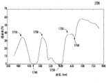
図7は、本発明の構成について、透過スペクトルの透過率対波長のプロット700を示す。図7に示す構成では、ポリメチルメタクリレート(PMMA)を図1の光学素子の基板として使用してもよい。PMMAはメチルメタクリレートの重合から製造された合成樹脂であり、一般的には透明で硬質のプラスチックである。PMMAは、厚さ3mmで直径65mmの光学素子基板として作ってもよい。この構成によって、正常な色覚を改善させたり、赤・緑CVDを矯正したりできる。プロット700は、380nm~780nmの間で少なくとも三つの通過帯域710、720、730を有する、この光学素子の透過スペクトルを描いたものである。通過帯域740も同様に通過帯域であってもよい。しかし、通過帯域740は、一般に人間の視覚範囲を超えた近赤外線に近接しているので、比色性能にほとんど影響を与えない可能性が高い。阻止帯域790は、他の赤白色点(WP)を低減する目的を有する。
FIG. 7 shows a transmittance versus
プロット700は、540nmから610nmの間では1%の最小透過率制約を示す曲線であると言っても差し支えない。390nm(760)および590nm(750)の両方でピーク吸収がある双ピーク吸収染料を、465nm(770)および490nm(780)でピーク吸収がある二つの染料、570nm(750)で同様になる別の染料、および665nm(790)で同様になる最後の染料と、いっしょに使用する。これらの染料の濃度は、3マイクロモルから70マイクロモルまでの範囲にある。これらのスペクトル吸収750、760、770、780、790は、下記の表1に示される比色性能を生成するために、特定の通過帯域および阻止帯域と、均一な100%透過率からの他のスペクトル差と、が生成されるように選択してもよい。例えば、光学素子の明度を制限し、光学素子のWP色相およびWPシフトを抑制し、かつメタメリズム(異なる光源の下での性能差)を抑制しながら、赤・緑の分離を増すために上記選択をしてもよい。曖昧な、経験則的な、または概括的なやり方によれば、阻止帯域750によって赤・緑の分離度が高まり、通過帯域710、720、730によって青/緑/赤の色のコントラストが増し透けて見えるようになる。通過帯域および阻止帯域の実際の透過量およびそれらのスペクトル配置は、表1に示す比色性能を生成するために実際の染料を用いて決定してもよい。現実の染料は、それぞれの目標ノッチ(尖鋭的な)吸収に加えて「ノイズ吸収」を有するので(つまり、550nmを吸収する染料は、通常は吸収程度が低いが他の波長も吸収する場合がある)、比色性能のための複数染料およびそれらの濃度の最良の組合わせを決定するために一つの染料を選択することによって、この染料の「ノイズ吸収」が生じる場合がある。
It is safe to say that
図7に示された透過特性を有する図1の素子について、表1にまとめたCPIはCIE LUV色空間を用いて評価される。図8に示す製造工程800は、ステップ810で、適切な濃度を達成するために押出機を使用して必要な複数の染料を混合してPMMA樹脂に入れることから始まる。 ステップ820で、染料を注入した樹脂を、射出成形によって230℃未満の作業温度で製品形状に成形する。
The CPIs summarized in Table 1 are evaluated using the CIE LUV color space for the device of FIG. 1 with the transmission properties shown in FIG. The
表1は、図7の透過特性を有する図1の素子についての比色性能を表す。

波長の赤方シフトおよび青方シフトは、それぞれ、より長い波長およびより短い波長への比色シフトおよび/またはスペクトルシフトに対応する。こうすることによって、色覚タイプと光源の様々な条件下で、一貫して20%を超える、赤・緑の色分離の改善をもたらす。図7に示す透過特性を有する図1の光学素子は、明度変動を10未満に、WP色相が黄と黄・赤の間に維持されるように、WPS範囲を0.005未満に、することによって、メタメリズムをうまく抑制することができる。図7の透過特性を有する図1の素子の黄色および黄・赤色のWP(色合い)によって、CVD検査で使用されるCVD混同色、例えば、石原式検査カラーおよび/またはファーンズワース D15検査カラーと、CPIを評価する際に使用する色と、を移動させて、2型色覚と1型色覚にとっての色混同線から離れるようにする。この色合いは、CVDの人にとって混乱しやすい色を見分ける能力をさらに改善させる。 Red and blue shifts in wavelength correspond to colorimetric and/or spectral shifts to longer and shorter wavelengths, respectively. This results in an improvement in red-green color separation of more than 20% consistently under various conditions of color vision type and light source. 1 with the transmission characteristics shown in FIG. 7 should have a brightness variation of less than 10 and a WPS range of less than 0.005 so that the WP hue remains between yellow and yellow-red. can successfully suppress metamerism. The yellow and yellow-red WPs (tints) of the device of FIG. 1 having the transmission characteristics of FIG. Move the colors used in assessing and away from the color confusion line for deuteranopia and deuteranopia. This tint further improves the ability to discriminate colors that are confusing to people with CVD.
図7に示される透過特性を有する図1の光学素子は、天然および人工の青色および非青色の色同士の色距離およびコントラストを増す効果をもたらす。彩度が低い青色、シアン色、紫色、および白色は、この光学素子の黄および/または黄・赤のWPによって、より容易に黄色および他のより暖色にシフトされる。追加の色強調によって、結果として生じる、より暖色と青色がさらに分離する。この光学素子の透過スペクトルによる暖色系の色付けおよび色強調の効果を組み合わせた光学素子を作ることによって、青色と非青色との優れたコントラストが生み出される。この種の光学素子の特殊な用途として、運転や釣りが含まれてもよく、これらの活動では、様々な青と他の色との間の色のコントラストが増せば、コントラストおよび奥行きの知覚にとって有益である。 The optical element of FIG. 1 with the transmission properties shown in FIG. 7 provides the effect of increasing color distance and contrast between natural and artificial blue and non-blue colors. Desaturated blues, cyans, violets, and whites are more easily shifted to yellows and other warmer colors by the yellow and/or yellow-red WP of this optical element. Additional color enhancement further separates the resulting warmer colors and blues. By creating an optical element that combines the effects of warm coloring and color enhancement due to the transmission spectrum of this optical element, excellent contrast between blue and non-blue colors is produced. Special uses for this type of optic may include driving and fishing, where increased color contrast between various blues and other colors may be beneficial for contrast and depth perception. Beneficial.
図9は、本発明の構成について、透過スペクトルの透過率対波長のプロット900を示す。図9に示す構成では、トライベックスを図1の光学素子の基板として使用してもよい。トライベックスは、優れた耐衝撃性のために使用されるウレタンベースのプレポリマーである。トライベックス基板の例としては、厚さ1.5mmで直径75mmとして作られる場合が多く、この構成の素子を、正常な色覚を改善させたり、赤・緑CVDを矯正したりする目的で使用してもよい。プロット900は、380nmと780nmとの間に少なくとも三つの通過帯域910、920、930を有する、この光学素子の透過スペクトルを描いたものである。プロット900は、555nmと610nmとの間で1%の最小透過率制約を示す曲線を描く。395nm(950)と570nm(960)の両方でピーク吸収がある双ピーク吸収染料を、470nm(970)でピーク吸収がある一つの染料、595nm(980)で同様になる別の染料、および660nm(990)で同様になる最後の染料といっしょに使用する。これらの染料の濃度は、20マイクロモルから110マイクロモルまでの範囲にある。繰り返しになるが、図7に関して上述したように、これらの吸収によって、光学素子の明度を制限し、光学素子のWP色相およびWPシフトを抑制し、かつメタメリズム(異なる光源の下での性能差)を抑制しながら、赤・緑の分離を増すことができる。光源および/またはCMFが変われば、同等か、より優れた比色性能指標(CPI)を達成するために、使用する染料を変えてもよい。
FIG. 9 shows a transmittance versus
図9に示された透過特性を有する図1の素子について、表2にまとめたCPIはCIE LUV色空間を用いて評価される。図10に示す製造工程1000は、ステップ1010で、各染料を機械的に混合してトライベックスの少なくとも一つの未重合部分、例えば、モノマーに入れることから始まる。プロセス1000は、ステップ1020で、重合のためにトライベックスの二つ以上の部分を一緒に混合して所望の形状にすることを含む。このような幾何学的形状は、その後、最終的な所望の仕様に切断および/または研磨されてもよい。
For the device of FIG. 1 with the transmission properties shown in FIG. 9, the CPIs summarized in Table 2 are evaluated using the CIE LUV color space. The
表2は、図9の透過特性を有する図1の素子についての比色性能を表す。

この構成の光学素子は、一貫して40%を超える、赤・緑の色分離の改善をもたらす。図9に示す透過特性を有する図1の光学素子は、明度変動を20未満に、WP色相が暖色系内に維持されるように、WPS範囲を0.025未満に、制限した状態で、メタメリズムを抑制する。図9の透過特性を有する図1の光学素子の一貫した暖色系WP(色合い)によって、CVD検査で使用されるCVD混同色と、CPIを評価する際に使用する色と、を移動させて、2型色覚と1型色覚にとっての色混同線から離れるようにする。これらの色合いは、CVDの人が混乱しやすい色を見分ける能力をさらに改善させる。 An optical element of this configuration consistently yields an improvement in red-green color separation of over 40%. The optical element of FIG. 1, having the transmission characteristics shown in FIG. 9, exhibits metamerism while limiting the lightness variation to less than 20 and the WPS range to less than 0.025 so that the WP hue remains within the warm color system. suppress The consistent warm WP (hue) of the optics of FIG. 1 with the transmission properties of FIG. Stay away from the color confusion line for deuteranopia and deuteranopia. These shades further improve the ability of people with CVD to distinguish confusing colors.
図11は、本発明の構成について、透過スペクトルの透過率対波長のプロット1100を示す。 図11に示す構成では、ポリカーボネート(PC)を図1の光学素子の基板として使用してもよい。PCは、化学構造中にカーボネート基を含有する一群の熱可塑性ポリマーを表す。PC基板の例としては、厚さ2mmで直径72mmとして作られる場合が多く、この構成の素子を、正常な色覚を改善させたり、赤・緑CVDを矯正したりする目的で使用してもよい。プロット1100は、380nmと780nmとの間に少なくとも三つの通過帯域1110、1120、1130を有する、この光学素子の透過スペクトルを描いたものである。プロット1100は、565nmと610nmとの間で0.5%の最小透過率制約を示す曲線を描く。400nm(1150)と595nm(1160)の両方でピーク吸収がある双ピーク吸収染料を、498nm(1170)でピーク吸収がある一つの染料、570nm(1180)および640nm(1190)で同様になる二つの他の染料、および665nm(1195)で同様になる最後の染料といっしょに使用する。これらの染料の濃度は28マイクロモルから150マイクロモルまでの範囲にある。
FIG. 11 shows a transmittance versus
図11に示された透過特性を有する図1の素子について、表3にまとめたCPIはCIE LUV色空間を用いて評価される。図12に示す製造プロセス1200は、ステップ1210で、必要な複数の染料を混合してPC樹脂に入れ、押出機を使用して適切な濃度を達成することから始まる。ステップ1220で、染料を注入した樹脂を、230℃を超える作業温度で、射出成形によって製品形状に成形する。
For the device of FIG. 1 with the transmission properties shown in FIG. 11, the CPIs summarized in Table 3 are evaluated using the CIE LUV color space. The
表3は、図11に示した透過特性を有する図1の光学素子についての比色性能を表す。

この構成の光学素子は、一貫して12%を超える、赤・緑の色分離の改善をもたらす。この光学素子は、明度変動を5未満に、WP色相が黄と黄・赤との間に維持されるように、WPS範囲を0.01未満に、制限した状態で、メタメリズムを抑制する。 An optical element of this configuration consistently yields an improvement in red-green color separation of over 12%. This optical element suppresses metamerism with a WPS range limited to less than 0.01 such that the lightness variation is less than 5 and the WP hue is maintained between yellow and yellow-red.
図13は、本発明の構成について、透過スペクトルの透過率対波長のプロット1300を示す。図13に示す構成では、PCを図1の光学素子の基板として使用してもよい。PCは、厚さ2mmで直径68mmの光学素子基板として作られてもよい。この構成によって、正常な色覚を改善したり、赤・緑および青・黄のCVDを矯正したりできる。プロット1300は、380nmと780nmとの間に少なくとも三つの通過帯域1310、1320、1330を有する、この光学素子の透過スペクトルを描いたものである。プロット1300は、550nmと625nmとの間で1%の最小透過率制約を示し、吸収半値全幅(FWHM)が40nmを超える阻止帯域が560nm(1350)と610nm(1360)との間に中心を有する曲線を描く。560nm(1350)と660nmで二つのピーク吸収がある染料を、470nm(1370)と500nm(1375)でピーク吸収がある二つの染料、575nm(1380)と595nm(1385)で同様になる二つの他の染料、550nm(1390)と610nmで同様になる二つの追加染料、および620nmで同様になる最後の染料といっしょに使用する。550nmと620nmとの間の各吸収によって、WPおよび色域を冷色にシフトさせ、赤・緑の色分離/コントラストが増し、青・黄の色分離/コントラストが増す。450nmと500nmとの間の各吸収によって、青への色シフトの抑制が確実になる。(双ピーク吸収がある染料による)660nmでの吸収によって、青方シフトが、「青と赤の混色」として知覚される紫色にはならないことが確実になる。
FIG. 13 shows a transmittance versus
図13に示された透過特性を有する図1の素子について、表4にまとめたCPIはCIE LUV色空間を用いて評価される。図14に示す製造プロセス1400は、ステップ1410で、染料を溶媒に溶解することから始まる。ステップ1420で、染料を含む溶媒を、浸漬、高速回転、および/または噴霧によってPC光学基板上に転写する。染料注入層の厚さは、20ミクロンから50ミクロンの間であり、3ミクロンから70ミクロンまでの範囲にあってもよい。これらの染料の濃度は、薄い染料層であるが故に、20マイクロモルから20,000マイクロモルまでの範囲にあってもよい。
For the device of FIG. 1 with the transmission properties shown in FIG. 13, the CPIs summarized in Table 4 are evaluated using the CIE LUV color space. The
表4は、図13に示した透過特性を有する図1の光学素子についての比色性能を表す。

図13に示す透過特性を有する図1の光学素子は、一貫して14%を超える、赤・緑の色分離の改善と、一貫して8%を超える青・黄の色分離の改善と、をもたらす。この光学素子は、明度変動を10未満に、WP色相が青色に維持されるように、WPSを0.043と0.069との間に、制限した状態で、メタメリズムを抑制する。この光学素子の一貫した青WP(色合い)によって、CVD検査で使用されるCVD混同色と、CPIを評価する際に使用される色と、を移動させて、2型色覚と1型色覚と3型色覚にとっての色混同線から離れるようにするために特別に作ってもよい。この色合いは、CVDの人が混乱しやすい色を見分ける能力を改善させる。この光学素子は、天然および人工の暖色系および寒色系の色同士の色距離およびコントラストを増してもよい。彩度が低い黄色、オレンジ色、赤色、および白色は、この光学素子の青または寒色系の色のWPによって、より容易に青および他の寒色系の色にシフトされる。追加の色強調によって、結果として生じる、より寒色系の色と残りの暖色がさらに分離される。この光学素子の透過スペクトルによる寒色系色付けおよび色強調の効果を組み合わせた光学素子を製作することによって、暖色と寒色との優れたコントラストが生み出される。また、この光学素子の青または他の寒色系色合いは、暖色系の色をより中間色にカラーバランスさせるのに役立つ。この種の光学素子の特殊な用途としては、日の出および/または日没での運転が含まれてもよく、この場合、光源が暖色系なので、色コントラストおよび/または奥行き知覚および/またはもっと中間色のWPによる色覚が強調された方が望ましい。 The optical element of FIG. 1 with the transmission properties shown in FIG. 13 consistently improved the red-green color separation by more than 14%, improved the blue-yellow color separation by more than 8% consistently, bring. This optical element suppresses metamerism with a WPS limited to between 0.043 and 0.069 such that the lightness variation is less than 10 and the WP hue remains blue. The consistent blue WP (hue) of this optic shifts the CVD confusion colors used in CVD tests and the colors used in assessing CPI to give a deuteranopia, a deuteranopia and a tritanopia. It may be specially made to stay away from the color confusion line for protanopia. This tint improves the ability of people with CVD to distinguish confusing colors. This optical element may increase the color distance and contrast between natural and artificial warm and cool colors. Desaturated yellows, oranges, reds, and whites are more easily shifted to blue and other cold colors by the blue or cold color WP of this optic. Additional color enhancement further separates the resulting cooler colors from the remaining warm colors. Excellent contrast between warm and cool colors is produced by fabricating an optic that combines the effects of cold tinting and color enhancement through the transmission spectrum of this optic. Also, the blue or other cool tint of this optic helps color balance the warm colors more neutral. Special applications for this type of optical element may include driving at sunrise and/or sunset, where the light source is warm, thus improving color contrast and/or depth perception and/or more neutral colors. It is desirable that the color vision by WP is emphasized.
図15は、本発明の構成について、透過スペクトルの透過率対波長のプロット1500を示す。図15に示す構成では、CR39を図1の光学素子の基板として使用してもよい。CR39は、光学レンズの製造に使用される一般的なプラスチックである。CR39は、厚さ2.5mmで直径72mmの光学素子基板として作られる。この構成によって、正常な色覚を改善させたり、赤・緑CVDを矯正したりできる。プロット1500は、380nmと780nmとの間に少なくとも三つの通過帯域1510、1520、1530を有する、この光学素子の透過スペクトルを描いたものである。プロット1500は、550nmと630nmとの間で1%の最小透過制約を示し、吸収FWHMが40nmを超える阻止帯域が560nm(1540)と615nm(1550)との間に中心を有する曲線を描く。558nm(1555)でピーク吸収がある染料を、470nm(1560)および500nm(1565)でピーク吸収がある二つの染料、575nmと595nmで同様になる二つの他の染料、550nmと610nmで同様になる二つの追加染料、および620nmで同様になる最後の染料といっしょに使用してもよい。
FIG. 15 shows a transmittance versus
図15に示した透過特性を有する図1の素子について、表5にまとめたCPIはCIE LUV色空間を用いて評価される。図16に示す製造工程1600は、ステップ1610で、染料を溶媒に溶解することから始まる。ステップ1620で、溶解した染料を、浸漬、高速回転、および/または噴霧によってCR39光学基板上に転写する。染料注入層の厚さは、20ミクロンから50ミクロンの間であり、3ミクロンから70ミクロンまでの範囲にあってもよい。これらの染料の濃度は、薄い染料層であるが故に、20マイクロモルから20,000マイクロモルまでの範囲にしてよい。
The CPIs summarized in Table 5 are evaluated using the CIE LUV color space for the device of FIG. 1 with the transmission properties shown in FIG. The
表5は、図15に示した透過特性を有する図1の光学素子についての比色性能を表す。

図15に示した透過特性を有する図1の光学素子は、一貫して30%を超える赤・緑の色分離の改善をもたらす。この光学素子は、明度変動を10未満に、WP色相がマゼンタとピンクの間に維持されるように、WPSを0.01と0.034との間に、制限した状態でメタメリズムを抑制する。この光学素子の一貫したマゼンタまたはピンク色のWP(色合い)は、CVD検査で使用されるCVD混同色と、CPIを評価する際に使用する色と、を移動させて、2型色覚と1型色覚にとっての色混同線から離れるようにするために構成してもよい。この色合いは、CVDの人が混乱しやすい色を見分ける能力を改善させる。この光学素子は、天然および人工の緑色、黄緑色、黄色、および白色の色同士の色距離およびコントラストを増やしてもよい。彩度が低い緑色、黄緑色、黄色および白色は、この光学素子のマゼンタおよび/またはピンク色のWPによって、より容易に暖色にシフトされる。追加の色強調によって、結果として生じる、暖色と緑色がさらに分離される。この素子の透過スペクトルによる暖色系色付けおよび赤・緑の色強調の効果を組み合わせた光学素子を作ることによって、緑色と黄緑色と黄色と白色との優れたコントラストが生み出される。この種の光学素子の特殊な用途としては、ゴルフ、野球、テニスが含まれてもよく、これらのケースでは、様々な緑色と他の色との色同士の色コントラストが強調された方が有益である。 The optical element of FIG. 1 with the transmission properties shown in FIG. 15 consistently provides an improvement in red-green color separation of over 30%. This optical element suppresses metamerism with a WPS limited to between 0.01 and 0.034 such that the lightness variation is less than 10 and the WP hue is maintained between magenta and pink. The consistent magenta or pink WP (hue) of this optic shifts the CVD confusion colors used in CVD testing and the colors used in assessing CPI to improve protanopia and protanopia. It may be configured to move away from the color confusion line for color vision. This tint improves the ability of people with CVD to distinguish confusing colors. This optical element may increase the color distance and contrast between natural and artificial green, yellow-green, yellow, and white colors. Desaturated greens, yellow-greens, yellows and whites are more easily shifted warm by the magenta and/or pink WP of this optical element. Additional color enhancement further separates the resulting warm and green colors. By creating an optical element that combines the effects of warm coloring and red/green color enhancement due to the transmission spectrum of this element, excellent contrast between green, yellow-green, yellow, and white is produced. Special applications for this type of optic may include golf, baseball, and tennis, in which case it would be beneficial to enhance color-to-color contrast between various greens and other colors. is.
図17は、本発明の構成について、透過スペクトルの透過率対波長のプロット1700を示す。図17に示す構成では、トライベックス(Trivex)が図1の光学素子の基板であってもよい。トライベックスは、優れた耐衝撃性を提供することができ、厚さ2mmで直径75mmの光学素子基板として作ってもよい。この構成によって、正常な色覚を改善させたり、赤・緑CVDを矯正したりできる。プロット1700は、380nmと780nmとの間に少なくとも三つの通過帯域1710、1720、1730を有する、この光学素子の透過スペクトルを描いたものである。475nm(1740)でピーク吸収がある吸収染料を、590nm(1750)でピーク吸収がある別の染料、および658nm(1760)で同様になる最後の染料といっしょに使用し、光学基板内に完全に混合してもよい。これらの染料の濃度は5マイクロモルから95マイクロモルまでの範囲にある。
FIG. 17 shows a transmittance versus
図17に示した透過特性を有する図1の素子について、表6にまとめたCPIはCIE LUV色空間を用いて評価される。図18に示す製造工程1800は、ステップ1810で、複数の染料を機械的に混合して、例えばモノマーのような、トライベックスの少なくとも一つの未重合部分に入れることから始まる。ステップ1820で、トライベックスの二つ以上の部分を重合のために混合して所望の形状にし、ステップ1830で、切断および/または研磨する。
The CPIs summarized in Table 6 are evaluated using the CIE LUV color space for the device of FIG. 1 with the transmission properties shown in FIG. The
表6は、図17に示した透過特性を有する図1の光学素子についての比色性能を表す。

図17に示した透過特性を有する図1の光学素子は、一貫して50%を超える赤・緑の色分離の改善をもたらす。この光学素子は、明度変動を5未満に、WP色相が中間色に維持されるように、最大WPSを0.005(ほとんど知覚できない彩度)に、制限した状態で、メタメリズムを抑制する。 この光学素子によって、メタメリズム、すなわち、色覚および光源が妥当ではあっても異なる場合の、WP色相、WPS、および明度の変動を排除または最小化しつつ、非常に顕著な赤・緑の色分離性能を有する構造が提供される。この光学素子は、正常な色覚およびCVD色覚を有する人々にとって、メタメリズムがほとんどまたは全くない、中間色的な色合いを達成するように製作してもよい。 The optical element of FIG. 1 with the transmission properties shown in FIG. 17 consistently provides over 50% improvement in red-green color separation. This optical element suppresses metamerism, limiting the lightness variation to less than 5 and the maximum WPS to 0.005 (almost imperceptible saturation) so that the WP hue remains neutral. This optic eliminates or minimizes metamerism, i.e. variations in WP hue, WPS, and lightness when color vision and illuminants are reasonably but different, while providing very pronounced red-green color separation performance. A structure is provided having: The optic may be fabricated to achieve neutral hues with little or no metamerism for people with normal and CVD color vision.
図19は、本発明の構成について透過スペクトルの透過率対波長のプロット1900を示す。図19に示す構成では、光学ガラスまたはプラスチックを図1の光学素子の基板として使用してもよい。光学ガラスまたはプラスチックは、厚さ2mmで直径68mmの光学素子基板として作ってもよい。この構成によって、正常な色覚を改善させたり、赤 ・緑および/または青・黄CVDを矯正したりできる。プロット1900は、薄膜層によって形成され、380nmと780nmとの間に少なくとも三つの通過帯域1910、1920、1930を有する、この光学素子の透過スペクトルを描いたものである。プロット1900は、全可視スペクトル範囲で少なくとも1%の最小透過制約を示し、少なくとも25nmのFWHM反射率を有する阻止帯域1940が560nmと620nmとの間の中心にあり、少なくとも35nmのFWHM反射率を有する別の阻止帯域1950が450nmと555nmとの間の中心にある曲線を示す。
FIG. 19 shows a transmittance versus
薄膜層を基材に形成してもよい。薄膜層は、交互に積層する順番で高屈折率材料と低屈折率材料とで構成し、例えば合計21層のように、合計で多数の層を成してもよい。高屈折率材料は、ZnSおよび/またはTiO2であってもよい。低屈折率材料はSiO2および/またはクリオライトであってもよい。薄膜層材料の任意の層の物理的厚さは、100nmと1500nmの間、例えば、低屈折率材料については280nm、高屈折率材料については440nmである。薄膜層は、物理気相成長法(PVD)を用いて光学基材上に堆積させることができる。クリオライトを使う場合は、湿気を避けるために二つ以上のシーラント層を使ってもよい。 A thin film layer may be formed on the substrate. The thin film layers may consist of high and low refractive index materials in alternating stacking order to form a number of layers in total, for example 21 layers in total. The high refractive index material may be ZnS and/or TiO2 . The low refractive index material may be SiO2 and/or cryolite. The physical thickness of any layer of thin film layer material is between 100 nm and 1500 nm, eg 280 nm for low refractive index materials and 440 nm for high refractive index materials. Thin film layers can be deposited on optical substrates using physical vapor deposition (PVD). When using cryolite, two or more sealant layers may be used to avoid moisture.
図19に示した透過特性を有する図1の素子について、表7にまとめたCPIはCIE LUV色空間を用いて評価される。 The CPIs summarized in Table 7 are evaluated using the CIE LUV color space for the device of FIG. 1 with the transmission properties shown in FIG.
表7は、図19に示した透過特性を有する図1の光学素子についての比色性能を表す。

図19に示した透過特性を有する図1の光学素子は、一貫して5%を超える青・黄の色分離の改善をもたらす。この光学素子は、明度変動を7未満に、WP色相が青またはシアンに維持されるように、WPSを0.007と0.012との間に、制限した状態で、メタメリズムを抑制する。この光学素子の一貫した青/シアンのWP(色合い)は、CVD検査で使用されるCVD混同色と、CPIを評価する際に使用する色と、を移動させて、3型色覚にとっての色混同線から離れるようにするために構成してもよい。この色合いは、3型色覚の人が混乱しやすい色を見分ける能力をさらに改善させる。 The optical element of FIG. 1 with the transmission properties shown in FIG. 19 consistently yields an improvement in blue-yellow color separation of more than 5%. This optical element suppresses metamerism with a WPS limited to between 0.007 and 0.012 such that the lightness variation is less than 7 and the WP hue is maintained at blue or cyan. The consistent blue/cyan WP (hue) of this optic shifts the CVD confusion colors used in CVD testing and the colors used in assessing CPI to provide color confusion for tritanopia. It may be configured to move away from the line. This tint further improves the ability of people with protanopia to distinguish confusing colors.
図20は、本発明の構成について、透過スペクトルの透過率対波長のプロット2000を示す。図20に示す構成では、光学ガラスまたはプラスチックを図1の光学素子の基板として使用してもよい。光学ガラスまたはプラスチックは、厚さ3mmで直径75mmの光学素子基板として作ってもよい。この構成によって、正常な色覚を改善させたり、赤・緑CVDを矯正したりできる。プロット2000は、薄膜層によって形成され、380nmと780nmとの間に少なくとも三つの通過帯域2010、2020、2030を有する、この光学素子の透過スペクトルを描いたものである。プロット2000は、全可視スペクトル範囲で少なくとも0.5%の最小透過制約を示し、少なくとも10nmのFWHM反射率を有する阻止帯域2040が560nmと590nmとの間の中心にあり、少なくとも8nmのFWHM反射率を有する別の阻止帯域2050が465nmと500nmとの間の中心にある曲線を示す。
FIG. 20 shows a transmittance versus
薄膜層を基材に形成してもよい。薄膜層は、交互に積層する順番で高屈折率材料と低屈折率材料とで構成し、例えば合計11層のように、合計で多数の層を成してもよい。高屈折率材料は、ZnSであってもよい。低屈折率材料はクリオライトであってもよい。薄膜層材料の任意の層の物理的厚さは、150nmから1000nmの間、例えば、低屈折率材料については290nm、高屈折率材料については445nmである。薄膜層は、物理蒸着(PVD)を用いて基板上に被膜させてもよい。クリオライトを使う場合は、湿気を避けるために二つ以上のシーラント層を使う。 A thin film layer may be formed on the substrate. The thin film layers may consist of high and low refractive index materials in alternating stacking order to form a number of layers in total, for example 11 layers in total. The high refractive index material may be ZnS. The low refractive index material may be cryolite. The physical thickness of any layer of thin film layer material is between 150 nm and 1000 nm, eg 290 nm for low refractive index materials and 445 nm for high refractive index materials. The thin film layers may be deposited onto the substrate using physical vapor deposition (PVD). When using cryolite, use two or more sealant layers to avoid moisture.
図20に示した透過特性を有する図1の素子に対して、表8にまとめたCPIはCIE LUV色空間を用いて評価される。 For the device of FIG. 1 with the transmission properties shown in FIG. 20, the CPIs summarized in Table 8 are evaluated using the CIE LUV color space.
表8は、図20に示した透過特性を有する図1の光学素子についての比色性能を表す。

図20に示した透過特性を有する図1の光学素子は、一貫して30%を超える赤・緑の色分離の改善をもたらす。この光学素子は、明度変動を10未満に、WP色相がCIE昼光光源の下で中間色に、またはCIE F7光源の下でパステルブルー/シアン色にほぼ維持されるように、WPSを0.003と0.007との間に、制限した状態で、メタメリズムを抑制する。この光学素子の一貫した中間色または淡青色/シアン色のWP(色合い)によって、この光学素子の概ね中間色の外観的美観または心地よい寒色系美観を維持するように製作してもよい。このように製作することによって、明度が68以上の光学素子が製作され、これは室内と室外での両用に適している。明度が65未満の光学素子が製作される他の作製物は、一般的に、屋外や明るい照明下の屋内のような、明るい環境において使用される。 The optical element of FIG. 1 with the transmission properties shown in FIG. 20 consistently provides an improvement in red-green color separation of more than 30%. This optic achieves a WPS of 0.003 such that the lightness variation is less than 10 and the WP hue is maintained approximately neutral under CIE daylight illuminants or pastel blue/cyan under CIE F7 illuminants. and 0.007, suppressing metamerism in a limited manner. The optic's consistent neutral or light blue/cyan WP (tint) may be made to maintain the optic's generally neutral or pleasant cool color aesthetic. By making it in this way, an optical element with a brightness of 68 or higher is produced, which is suitable for both indoor and outdoor use. Other productions in which optical elements with a brightness of less than 65 are produced are generally used in bright environments, such as outdoors or indoors under bright lighting.
図21は、本発明の構成について、透過スペクトルの透過率対波長のプロット2100を示す。図21に示す構成では、PMMAを図1の光学素子の基板として使用してもよい。PMMAは、厚さ2mmで直径70mmの光学素子基板として作ってもよい。この構成によって、正常な色覚を改善させたり、赤・緑CVDを矯正したりできる。プロット2100は、380nmと780nmとの間に少なくとも三つの通過帯域2110、2120、2130を有する、この光学素子の透過スペクトルを描いたものである。478nm(2140)でピーク吸収がある吸収染料および588nm(2150)でピーク吸収がある染料を使用してもよい。これらの染料の濃度は、0.5マイクロモルから35マイクロモルまでの範囲にある。
FIG. 21 shows a transmittance versus
図21に示した透過特性を有する図1の素子について、表9にまとめたCPIはCIE LUV色空間を用いて評価される。 The CPIs summarized in Table 9 are evaluated using the CIE LUV color space for the device of FIG. 1 with the transmission properties shown in FIG.
上述の基板の製造方法2200を図22に示す。ステップ2210で、複数の染料を混合して樹脂に入れる。ステップ2220で、混合した染料を含む樹脂を、染料が光学基板に完全に注入されるように、所望の形状に成形する。ステップ2230で、耐摩耗性、反射防止性、およびUVコーティングを含む任意の後処理を実行してもよい。
A
表9は、図21に示した透過特性を有する図1の光学素子についての比色性能を表す。

図21に示した透過特性を有する図1の光学素子は、一貫して7%を超える赤・緑の色分離の改善をもたらす。この光学素子は、最小明度が76で明度変動を6未満に、WP色相が中間色またはパステルブルーに維持されるように、白色点シフト(WPS)を0.007の範囲に、制限した状態で、メタメリズムを抑制する。この光学素子は、色覚および昼光・蛍光の光源が異なる場合に起因するメタメリズムを抑制および/または最小化しながら、非常に高い明度および良好な赤・緑の色分離性能を有するように製作することができる。 The optical element of FIG. 1 with the transmission properties shown in FIG. 21 consistently provides an improvement in red-green color separation of more than 7%. This optic limits the white point shift (WPS) to a range of 0.007 such that the minimum brightness is 76 and the brightness variation is less than 6 and the WP hue is maintained neutral or pastel blue, Suppress metamerism. The optical element shall be fabricated to have very high brightness and good red/green color separation performance while suppressing and/or minimizing metamerism caused by different color vision and daylight/fluorescent light sources. can be done.
黄化・黄変ヒト水晶体および黄色代替IOLは、人の色覚のWPを黄色の色相にシフトさせる。要するに、これは黄色色覚(YCV)と呼ばれる。YCVによって、他の原色と派生色の知覚が正常な知覚からシフトされる。矯正光学素子がある場合とない場合の、YCVで見た任意の色iについてのスペクトルアドミタンスは式22によって定義される。
[数式22]

[Formula 22]
YCVスペクトルアドミタンスにおいて使用する色は、赤(2.5YR 5/4、7.5R 5/4、2.5R 5/4、5RP 5/4、10P 5/4、10YR 5/4、 10R 5/4、10RP 5/4、緑(5BG 5/4、10G 5/4、5G 5/4、10GY 5/4、5GY 5/4、10BG 5/4)、青(5B 5/4、10BG 5/4、5BG 5/4、5P 5/4、10B 5/4、10P 5/4、10PB 5/4)、および黄(10GY 5/4、5GY 5/4、5Y 5/4、 10YR 5/4、2.5YR 5/4、10Y 5/4、10YR 5/4)の代表的なマンセル色を含む。YCVスペクトルアドミタンスに使用する色には、代表的な石原CVD検査色を含んでもよい。YCVスペクトルアドミタンスに使用する色は、例えば、葉、花、木など天然の代表的な色を含んでもよい。
The colors used in the YCV spectral admittance are red (2.5

光学素子の最小透過値が少なくとも0.5%になるように作って、安全性または他の理由で、可視波長での最小透過率を保証してもよい。また、光学素子の最小透過率値が少なくとも0.5%になるように作って、安全性または他の理由で、500nmから650nm以内の波長の任意の部分からの最小透過率を保証してもよい。また、光学素子の最小透過率値が少なくとも0.5%になるように作って、安全性または他の理由で400nmから500nm以内の波長の任意の部分からの最小透過率を保証してもよい。 The optical element may be made to have a minimum transmission value of at least 0.5% to ensure minimum transmission at visible wavelengths for safety or other reasons. The optical element may also be made to have a minimum transmission value of at least 0.5% to ensure minimum transmission from any portion of the wavelength within 500 nm to 650 nm for safety or other reasons. good. The optical element may also be made to have a minimum transmission value of at least 0.5% to ensure minimum transmission from any portion of the wavelength within 400nm to 500nm for safety or other reasons. .
光学素子にとっての重要なCPIは、光学素子の着用後に観察者の色覚の白色点シフト(WPS)を減少させることによって、観察者のYCVを矯正するか、矯正しようとすることであってもよい。光学素子にとって別の重要なCPIは、光学素子の着用後にYCVを有する観察者から見た代表色と、正常な色覚を有する別の観察者が見た代表色との間の不一致を減少させることによって、観察者のYCVを矯正するか、矯正しようすることであってもよい。不一致の測定には、代表的な色について、二人の観察者の色知覚の間の色距離を合計することを含んでもよい。 An important CPI for an optic may be to correct, or attempt to correct, the observer's YCV by reducing the white point shift (WPS) of the observer's color vision after wearing the optic. . Another important CPI for the optic is to reduce the discrepancy between the representative colors seen by an observer with YCV and another observer with normal color vision after wearing the optic. By correcting or attempting to correct the YCV of the observer. A measure of discrepancy may involve summing the color distances between the color perceptions of two observers for a representative color.
様々な光源または混合光源の下で、(矯正前はYCVを有していた)観察者の矯正された色覚におけるメタメリズムは、この光学素子の作製された透過スペクトルを使用して抑制および/または最小化する重要なCPIであってもよい。また、様々な光源または混合光源の下で、光学素子の外観的善し悪しのメタメリズムは、作製されたそれ自体の透過スペクトルを使用して抑制および/または最小化する重要なCPIであってもよい。また、様々な光源または混合光源の下で、観察者の矯正された色覚の明度は、この光学素子の目標透過スペクトルおよび作製透過スペクトルを使用して抑制および/または最大化する重要なCPIであってもよい。また、様々な光源または混合光源の下で、この光学素子の明度は、それ自体の目標透過スペクトルおよび作製透過スペクトルを使用して抑制および/または最大化する重要なCPIであってもよい。 Under various or mixed light sources, metamerism in the corrected color vision of observers (who had YCV before correction) was suppressed and/or minimized using the fabricated transmission spectrum of this optic. It may also be a significant CPI that Also, under various or mixed light sources, metamerism in the appearance of an optical element may be an important CPI to suppress and/or minimize using its own transmission spectrum that has been fabricated. Also, under various or mixed light sources, the brightness of the observer's corrected color vision is an important CPI to suppress and/or maximize using the target and fabricated transmission spectra of this optic. may Also, under various or mixed light sources, the brightness of this optical element may be an important CPI to suppress and/or maximize using its own target and fabricated transmission spectra.
図23は、最小透過制約を満たし、黄色色覚(YCV)矯正という応用例について、CPI目標を達成するか、または割り当てられた探索繰り返し回数または所定の時間内に最良のCPIを達成する、光学素子の透過スペクトルを見つける方法2300を示す。方法2300は、本明細書で上述した方法300と同様である。
FIG. 23 shows an optical element that meets the minimum transmission constraint and achieves the CPI target or achieves the best CPI within an assigned number of search iterations or a given time for the yellow color vision (YCV) correction application. shows a
方法2300は、ステップ2310で、一つ以上の光源および/または混合光源を作成および/または選択することを含む。方法2300は、ステップ2320で、例えば黄色の水晶体および黄色のIOLの透過スペクトルなどの、YCVスペクトルを作製および/または選択することを含む。方法2300は、ステップ2330で、YCV矯正判定のための評価カラースペクトルを作製および/または選択することを含む。方法2300は、ステップ2340で、色空間を選択または作成することを含む。方法2300は、ステップ2350で、最小透過要件を満たす、光学素子の透過スペクトルを作製することを含む。方法2300は、ステップ2360で、矯正された色覚の白色点シフト(WPS)の各CPI、補正された色覚によって知覚される評価色と正常な色覚を有する他の人によって知覚される同じ色との間の色距離、矯正された色覚のメタメリズム、光学素子のメタメリズム、矯正された色覚の明度、および光学素子の明度、を評価することを含む。
The
方法2300は、CPI目標が達成された場合、または新しい透過スペクトルを繰り返し作製する回数が最大回数に達した場合、または何回かの繰り返し回数後にCPIの変化がない場合、または他の停止基準に達した場合、に終了する。完了すると、380nmから780nmまでの、光学素子の最良の出力透過スペクトルを保存してもよい。
The
YCV矯正と同時に、色強調、赤・緑CVDおよび青・黄CVDの矯正も行うことが、単一の光学素子または光学系のCPIであってもよい。このような透過率を有する光学素子の設計は、二ステップからなる。第一ステップは、YCVが完全にまたは部分的に矯正されるような透過スペクトルを有する光学素子を設計することである。このステップは、図23の方法2300を使用して実行することができる。第二ステップは、第一ステップによる透過スペクトルを有効光源入力として使用し、例えば赤・緑の色分離を最大化する、色強調および/またはCVD矯正をCPIとして目標にするような異なる透過スペクトルを有する別の光学素子を設計することである。この第二ステップは、図3の方法300を用いて行うことができる。二つのステップによる二つの透過スペクトルを掛け合わせたスペクトルは、YCVを完全にまたは部分的に矯正すると同時に色強調を行うかおよび/またはCVDを完全にまたは部分的に矯正する単一の光学素子または光学系の有効目標透過スペクトルである。これらのステップは、順番を逆にしてもよい。すなわち、色強調および/またはCVD矯正をまず行い次にYCV矯正を行うという逆の順序も同様に許容できる。
It may be the CPI of a single optical element or optical system to perform YCV correction as well as color enhancement, red-green CVD and blue-yellow CVD corrections. The design of an optical element with such transmittance consists of two steps. The first step is to design an optical element with a transmission spectrum such that the YCV is fully or partially corrected. This step can be performed using
図2の方法200を用いて、二つの方法、すなわち着色剤を使用するスペクトル吸収方法と薄膜を使用するスペクトル反射方法との組合せによって生じる目標透過スペクトルを有する光学素子を製作してもよい。例えば、複数の着色剤を混合して光学基板内に入れた、および/または光学基板の上に塗布した、および/または薄膜を光学基板の上に塗布したものを使用して、YCVを矯正する、および/または色強調を行う、および/または完全にもしくは部分的にCVDを矯正する目標透過スペクトルを有する光学素子を製作してもよい。
The
天然の黄変水晶体または同様の黄変眼内レンズ(IOL)の透過スペクトルを、YCVを矯正するために使用される光学素子の透過スペクトルと共にグラフ2400として図24に示す。曲線2410は、天然の黄変水晶体または同様の黄変IOLの透過スペクトルである。実線で示される曲線2420は、YCVを矯正する光学素子の透過スペクトルである。
The transmission spectrum of a natural yellowing lens or similar yellowing intraocular lens (IOL) is shown in FIG. 24 as
図25は、プロット2500に存在する色覚域を描いたものである。色覚域は、色空間内でまたは光学素子によって正確に表すことができる複数の色の部分集合のような、一式の色部分集合である。プロット2500は、CIE D65光源を用いたCIE LUV色空間において、選択したマンセル色の赤、緑、青、黄および派生色によって囲まれた色覚範囲を示す。YCVに対応する黄色WP2515を含む、黄変水晶体または黄変IOLに起因するYCV2510が、示してある。正常な色覚2520が、この色覚の対応する中間色WP2525と共に示してある。光学素子が図24の対応する透過スペクトル2420と合致することによって矯正された色覚2530が、矯正された色覚に対応する中間色WP2535と共に示してある。光学素子の外観的要素である青色WP2540も示してある。
FIG. 25 depicts the color vision gamut present in
図24も参照すると、この光学素子の透過スペクトル2420は、380nmと780nmとの間に少なくとも三つの通過帯域2430、2440、2450を有する。プロット2420は、560nmから610nmの間で1%の最小透過率制約を示し、380nmと510nmとの間または650nmと780nmとの間でピーク透過率値を有する。500nm(2460)および520nm(2470)の両方でピーク吸収がある双ピーク吸収染料を、590nm(2480)でピーク吸収がある一つの染料、および663nm(2490)で同様になる最後の染料といっしょに使用する。この光学素子の青色または寒色のWP(色合い)は、透過スペクトルの一連の通過帯域および阻止帯域とあわせて、両者がYCVのWPを矯正し、および/または、この光学素子を着用後にYCVの観察者が見た、図25に示す各色および/または色域と、正常な色覚の別の観察者が見た各色と、の間の不一致を解消または低減する。矯正光学素子の作成は、眼鏡、サングラス、およびコンタクトレンズを含む、眼に着用する任意の形態であってもよい。
Referring also to FIG. 24, the
光学ガラスまたはプラスチックは、厚さ2mmで直径が68mmの、眼鏡またはサングラス作成用の基板であってもよい。これらの染料の濃度は、染料を注入した光学基板の場合、1マイクロモルから90マイクロモルまでの範囲にある。 The optical glass or plastic may be a substrate for making eyeglasses or sunglasses with a thickness of 2 mm and a diameter of 68 mm. The concentrations of these dyes range from 1 micromolar to 90 micromolar for dye-infused optical substrates.
図24に示した透過特性スペクトル2420を有するこの素子について、表10にまとめたCPIはCIE LUV色空間を用いて評価される。これらの染料は、浸漬、高速回転、噴霧、または蒸着などの周知の配合/成形または被覆処理を用いて、光学基材に注入するか、または基板表面に被覆してもよい。この光学素子の透過スペクトルは、スペクトル2420と実質的に一致する薄膜コーティングを用いて作製され、光学基板上にコーティング/被膜させてもよい。YCVおよび様々な光源を用いて、正常な観察者についてYCVの矯正を達成してもよい。この光学素子は、明度変動を6未満に、WP色相が中間色に維持されるように、WPS範囲を0.002(認識不可能な彩度)未満に、制限した状態で、矯正された色覚のメタメリズムを抑制する。この光学機器は、暗い明度で、青のWP/色合いのサングラス、または光学素子である。この素子は、明度変動を5未満に、WP色相が青色に維持されるように、WPS範囲を0.015未満(平均WPSの13.6%に相当する)に、制限した状態でメタメリズムを抑制する。
The CPI summarized in Table 10 is evaluated using the CIE LUV color space for this device with transmission
表10は、図24に示した透過特性を有する光学素子についての比色性能を表す。

図26は、本発明の構成について、透過率対波長のプロット2600を示す。この構成では、天然の黄変水晶体または同様に黄変したIOLの透過スペクトル2610は、少なくとも部分的にYCVを矯正できる光学素子の透過スペクトル2620で矯正できる。プロット2600は、380nmと780nmとの間に少なくとも二つの通過帯域を有するように作製された、光学素子の透過スペクトル2620を示す。曲線2620は、560nmと610nmとの間で1%の最小透過率制約を示し、380nmと510nm(2630)との間または620nmと780nm(2640)との間でピーク透過率値を有する。639nm(2650)および664nm(2660)でピーク吸収を有する双ピーク吸収染料を、582nm(2670)でピーク吸収を有する一つの染料と共に使用する。この光学素子の青色または寒色のWP(色合い)は、透過スペクトルの一連の通過帯域および阻止帯域とあわせて、両者がYCVのWPを部分的に矯正し、および/または、この光学素子を着用後にYCVの観察者が見た各色と、正常な色覚の別の観察者が見た各色との間の不一致を低減する。矯正光学素子の作成は、眼鏡、サングラス、およびコンタクトレンズを含む、眼に着用する任意の形態であってもよい。
FIG. 26 shows a
光学ガラスまたはプラスチックを、眼鏡またはサングラスを作成する光学基板として使用してもよい。基板の厚さは2mmで直径は68mmとしてもよい。これらの染料の濃度は、樹脂を成形し配合するために染料を注入した光学基板の場合、0.1マイクロモルから70マイクロモルまでの範囲にある。 Optical glasses or plastics may be used as optical substrates to make eyeglasses or sunglasses. The substrate may be 2 mm thick and 68 mm in diameter. Concentrations of these dyes range from 0.1 micromolar to 70 micromolar for dye infused optical substrates for molding and compounding resins.
図26の透過率曲線(2620)を示す光学素子について、表11にまとめたCPIはCIE LUV色空間を用いて評価してもよい。これらの染料は、浸漬、高速回転、噴霧、または蒸着などの周知の被膜処理を用いて、基板表面上に被膜してもよい。この光学素子の透過スペクトルは、曲線2620の透過スペクトルを提供するために薄膜層を使用して作製してもよい。YCVおよび様々な光源を用いて、屋内および屋外の両方で使用するために視界および光学素子自体の高い明度を維持しながら、見えるものの黄色度を減少させることによって、YCVの部分的な矯正を達成する。この光学素子は、明度変動を5未満に、WP色相が淡い黄色に維持されるように、WPS範囲を0.022未満に、制限した状態で、部分的に矯正された色覚のメタメリズムを抑制する。CIE F2光源が評価から除外される場合、WPS範囲は0.009未満である。なぜなら、WPS自体が、部分的に矯正される解決策については0.008に過ぎないからである。この光学素子は、青いWP/色合いを有してもよい。この光学素子は、明度変動を5未満に、WP色相が青色に維持されるように、WPS範囲を0.016未満(平均WPSの26%に相当する)に、制限した状態でメタメリズムを抑制してもよい。
For optical elements exhibiting the transmittance curve (2620) of FIG. 26, the CPI summarized in Table 11 may be evaluated using the CIE LUV color space. These dyes may be coated onto the substrate surface using well-known coating processes such as dipping, spinning, spraying, or vapor deposition. The transmission spectrum of this optical element may be made using thin film layers to provide the transmission spectrum of
表11は、図26に示した透過特性を有する光学素子についての比色性能を表す。

干渉ベースの層状薄膜層を用いて、本明細書で説明する透過スペクトルを作製してもよい。干渉ベースの層状層は、薄膜層および多層被膜層と称される場合が多い。本明細書では、「薄膜層」を使用して、これらの干渉ベースの層状薄膜層と、干渉ベースの層状薄膜層を指す他の手法と、を指す。このような薄膜層には、反射防止層、二色性フィルタ、および通過帯域フィルタを含めてもよい。 Interference-based layered thin film layers may be used to produce the transmission spectra described herein. Interference-based layered layers are often referred to as thin film layers and multilayer coating layers. "Thin film layer" is used herein to refer to these interference-based layered thin film layers and other approaches to refer to interference-based layered thin film layers. Such thin film layers may include antireflection layers, dichroic filters, and passband filters.
薄膜コーティングは、高屈折率材料と低屈折率材料との交互層からなるものや、層ごとに可変の光学的および/または物理的厚さを有するものや、一つの層内に薄膜上の位置の距離関数として配置されるものなどの、広範な可能性を網羅する様々な幾何学的設計が考えられる。例えば、線形可変フィルタ(LVF)は、線形距離寸法の関数として、薄膜層の一つ以上の層において直線的に変化する光学的厚さを有する。薄膜層を基にしたRVFは、色強調、CVD矯正、およびYCV矯正を行うために、一つ以上の層の光学的または物理的厚さが少なくとも一つの中心からの径方向距離寸法の関数である光学素子を定義してもよい。 Thin film coatings may consist of alternating layers of high and low refractive index materials, may have variable optical and/or physical thickness from layer to layer, or may have multiple locations on the thin film within a single layer. Various geometric designs are conceivable covering a wide range of possibilities, such as those arranged as a distance function of . For example, a linear variable filter (LVF) has an optical thickness that varies linearly in one or more of the thin film layers as a function of linear distance dimension. Thin-film layer-based RVFs have optical or physical thicknesses of one or more layers as a function of at least one radial distance dimension from the center to provide color enhancement, CVD correction, and YCV correction. An optical element may be defined.
薄膜層の既存の設計では、0°からの入射角(AOI)が増加しても安定しているわけではない。具体的には、AOIが増加するにつれて、透過スペクトル特性はより短い波長にシフトする。この現象は青方シフトとして知られている。例えば、0°AOIで600nmを中心とする通過帯域を有する帯域通過フィルタは、より高いAOIでは通過帯域中心が600nm未満へシフトするのを経験するかもしれない。 Existing designs of thin film layers are not stable with increasing angles of incidence (AOI) from 0°. Specifically, as the AOI increases, the transmission spectral characteristics shift to shorter wavelengths. This phenomenon is known as blueshift. For example, a bandpass filter with a passband centered at 600 nm at 0° AOI may experience a shift of the passband center below 600 nm at higher AOIs.
複数の薄膜層を眼鏡類に適用する際、光学素子は着用者の目の前に固定されると考えられる。着用時のレンズ・目の配置に起因して、AOIは光学素子の曲率に大きく依存する。 例えば、図27に示すように、眼2730に対するレンズ(光学素子1 2710および光学素子2 2720)の配置が描かれている。図27には、眼鏡類などの光学素子に対して実質的に固定位置の光学受信機としての眼2730(または別の受信機)が描かれ、光学素子1 2710および光学素子2 2720は別々に素子形状の例としての役割を果たす。光学素子1 2710の場合、AOIは、平坦または比較的平坦な素子形状に沿って移動するので、0°から60°超までの範囲にある。光学素子2 2720の場合、AOIは、はるかに湾曲した素子形状に沿って移動するので、0°または実質的に0°にずっと近いままである。湾曲した素子形状にしてAOIを減少させるのは、可変AOIによる比色およびスペクトル性能シフトを抑制する一つの方法である。
When applying multiple thin film layers to eyewear, the optical element is believed to be secured in front of the wearer's eyes. Due to the lens-eye placement when worn, the AOI is highly dependent on the curvature of the optical element. For example, as shown in FIG. 27, the placement of lenses (
青方シフトをゼロまたはゼロに近い値に維持するには、光学素子2710、2720上の位置でAOIを0°に近い値にする。この結果を達成するために、光学素子2710、2720の曲率半径(ROC)は、眼2730から眼鏡類の観察位置までの実際の半径方向距離とする。光学素子2710、2720のROCが処方から逸脱すると、ゼロでないAOIが結果として得られる。このゼロでないAOIによって青方シフトが発生する。AOIの0°からの差分は、中心が眼2730である光学素子2710、2720のROCを増減させることによって小さくできる。しかしながら、青方シフトが例えば15nm未満のように比較的小さければ、装着者は、光学素子2710、2720のCPIのわずかに逸脱した性能にほとんど気付かないか、気付いたとしても許容できる場合が多い。 To keep the blue shift at or near zero, the AOI at the positions above the optical elements 2710, 2720 is near 0°. To achieve this result, the radius of curvature (ROC) of the optics 2710, 2720 is the actual radial distance from the eye 2730 to the viewing position of the eyewear. Any deviation of the ROC of the optical elements 2710, 2720 from the prescription results in a non-zero AOI. This non-zero AOI causes a blue shift. The AOI difference from 0° can be reduced by increasing or decreasing the ROC of the optical elements 2710, 2720 centered on the eye 2730. FIG. However, if the blue shift is relatively small, eg, less than 15 nm, the wearer will often notice little or tolerable slightly deviant CPI performance of the optics 2710, 2720.
多くの場合、外観的、形状的、および/または性能上の理由で、球面湾曲レンズのROCが小さいのは望ましくない。RVFを使用して、光学素子の着用者の観点から、広範囲のAOIに亘って光学素子のCPIの同様の性能を実質的に維持してもよい。 In many cases, it is undesirable for a spherically curved lens to have a low ROC for cosmetic, geometrical, and/or performance reasons. RVF may be used to substantially maintain similar performance of the CPI of the optic over a wide range of AOIs from the perspective of the wearer of the optic.
RVFを、光学素子の視中心からの径方向距離の関数として各薄膜層の光学的または物理的厚さを変えることによって作成し、AOI変動に起因するCPIの性能偏差を実質的に補償してもよい。図28は、RVF2800を有する光学素子の上から見た断面図を示す。眼2810(または別の受信機)は、眼鏡類などの、RVF2800を有する光学素子に対して実質的に固定位置の光学受信機である。RVF2820全体を基板2830上にコーティングしてもよい。RVF2820は、薄膜層としての使用に適した一つ以上の材料層(例えば、層1 2824から層n 2828まで)を含んでもよい。薄膜層の一例である層i 2850は、径方向可変の厚さを示すためにy寸法が誇張されている。xは、薄膜層2870の視中心からの径方向距離2860であり、yは、層i2850のx 2860における光学的または物理的厚さ2880である。一例として、例えば、x 2860がミリメートル単位でy 2880が数百ナノメートル単位であるなど、x 2860はy 2880よりはるかに大きくてもよい。こうすれば、事実上、dy/dx?0、すなわち、x 2860に対するy 2880の傾きは非常に小さい。その結果、RVFの任意の層上のAOIは、基板2830上のAOIとほぼ等しい。 図示していないが、基板2830は平坦な形状を含む任意の曲面形状としてもよい。
RVFs were created by varying the optical or physical thickness of each thin film layer as a function of radial distance from the optical element's visual center, substantially compensating for CPI performance deviations due to AOI variations. good too. FIG. 28 shows a top cross-sectional view of an optical element with RVF2800. The eye 2810 (or another receiver) is an optical receiver that is substantially fixed relative to the optics comprising the
図29は、視中心からの径方向距離x 2920の関数としての、RVFの層iの光学的または物理的厚さであるy 2910を示すために分解図示した光学素子2900を上から見た断面図であって、yo 2930は、光学素子2900の視中心における、RVFの層iの光学的または物理的厚さである。y 2910およびyo 2930は、RVF上の各点での厚さ(図29では誇張されている)であり、RVF全体、つまり、単一の層だけでなく複数のRVF層を組み合わせたものの厚さであってもよい。視中心は、眼2940または他の固定位置光受信機の位置に合わせてもよい。RVFは、最上層2950と最下層2960と(両方とも陰影を付けてある)の間に配置してもよい。これら二つの層2950、2960は、例えば、傷防止層と基板など、任意の目的のための任意の材料であってもよい。また、これら二つの層2950、2960は、任意の種類の先行層および後続層であってもよい。追加の距離変数としては、概念的な非屈折入射光線と眼2940との間の仮想距離を表すD 2970、光学素子2900と眼2940との間の距離を表すE 2980、先行層2950の平均の厚さを表すds1 2990、および後続層2960の平均の厚さを表すds22995が含まれる。屈折率(RI)は、ni(外部環境)、nsi(先行層2950)、nS2(後続層2960)、およびnt(RVF層または層間の平均または全RVFの平均)である。光学角は、θ1(AOI)、θ2(先行層の屈折光線角)、およびθ3(後続層の屈折光線角)である。
FIG. 29 is a top cross-section of an exploded
図29の光学系の構成では、寸法パラメータおよび光学パラメータは複数のRVF層の合計に相当する。少なくとも一つの薄膜層の厚さyは、式23で定義される。
[数式23]

[数式24]

[Formula 23]
[Formula 24]
yは、xの増加につれて単調に減少させずに、眼鏡類のような光学素子にとって増加するAOIに起因する、CPIの性能ずれを減少させるか影響をなくすようにしてもよい。また、yは、xの特定の値を除いて、xの増加につれて一般的に減少させずに、光学素子にとって増加するAOIに起因する、CPIの性能ずれを減少させるか影響をなくすようにしてもよい。 y may not decrease monotonically with increasing x, so as to reduce or eliminate performance deviations in CPI due to increasing AOI for optical elements such as eyewear. Also, y does not generally decrease as x increases, except for certain values of x, so as to reduce or eliminate performance deviations in CPI due to increasing AOI for the optical element. good too.
コンピュータシステムを用いて、一つ以上のRVF薄膜層の光学的または物理的な厚さyが、xの特定の値を除いて、xの増加につれて単調に減少しないかまたは概ね減少しないかどうかを決定するために使用する薄膜の透過スペクトルを計算することによって、光学素子にとって増加するAOIに起因する、CPIの性能ずれを減少させるか影響をなくすようにしてもよい。 A computer system is used to determine whether the optical or physical thickness y of one or more RVF thin film layers does not decrease monotonically or substantially decrease with increasing x, except for certain values of x. By calculating the transmission spectrum of the thin film used to make the determination, the CPI performance deviation due to increased AOI for the optical element may be reduced or eliminated.
図30は、本明細書で説明する光学素子について、視中心からの径方向距離の関数としての、RVFの一つ以上の層の光学的または物理的な厚さプロファイル3000の一例を示している。RVF層には、ZnSとクリオライトの交互層を含めてもよい。一例では、合計7つの層を利用してもよい。解析的設計では、ZnS3030およびクリオライト3020の両方について、径方向距離が増加するにつれて層の厚さも単調に増加し、増加するAOIに起因するCPI性能ずれを減少させるか影響をなくすようにすることが必要になる。ZnS 3040の方がより高い屈折率(RI)を有するので、その厚さは、より低いRIを有するクリオライト 3010の厚さよりも概して遅い速度で増加してもよい。ZnSおよびクリオライトの両方について、径方向距離が増加するにつれて、層厚が減少しないが必ずしも単調には増加しないことも含めて、増加するAOIに起因するCPI性能ずれを減少させるか影響をなくすようにするという設計があってもよい。繰り返すが、ZnSの方がより高い屈折率(RI)を有するので、その厚さもまた、より低いRIを有するクリオライトの厚さよりも概ね遅い速度で増加してもよい。一例では、光学素子基板の幾何学的表面曲率は、眼科用レンズへ適用する際にベースカーブとして8を有する曲率以下である。
FIG. 30 shows an example optical or
図31は、AOIに対する径方向距離のプロット3100を示す。プロット3100は、図29でのE=1.2cm、dsi=dS2=0の例を示しており、光学素子上の視中心からの径方向距離xとAOIとの間の直接関係は、厳密に相関性のある増加となる。すなわち、径方向距離が増すにつれて、AOIも単調に増加する。光学素子上の視中心からの径方向距離xとAOIとの間の関係は、概ね相関関係のある増加となる。すなわち、径方向距離が増すにつれて、AOIも、径方向距離測定値の特定の値を除いて、概ね増加する。
FIG. 31 shows a
図30はRVFの物理的または光学的な厚さ比のAOIに対する関係の四つの例を示し、図31はAOIと視中心からの径方向距離との関係の一つの例を示すので、これら二つの図に含まれる関係を用いて、物理的または光学的な厚さ比と、RVFまたはその任意の単一層または複数層の組合せについての視中心からの径方向距離と、の間の各関係を直接に決定できる。 Since FIG. 30 shows four examples of the relationship of RVF physical or optical thickness ratio to AOI and FIG. 31 shows one example of the relationship between AOI and radial distance from the visual center, these two Using the relationships contained in the two figures, each relationship between physical or optical thickness ratios and radial distances from the visual center for the RVF or any single layer or multiple layer combination thereof can be determined directly.
RVFは、少なくとも二つの異なる薄膜材料からなる二つ以上の層で作られてもよい。RVFは、少なくとも二つの異なる薄膜材料からなる二つ以上の交互層で作られてもよい。図32は、様々なAOIでの、7層構造のRVFの透過スペクトル3200を描いたものである。0°AOI(3210)、20°AOI(3220)、40°AOI(3230)、および60°AOI(3240)での透過スペクトル3200が示されている。例えば ZnSおよびTiO2などの高RI材料と、例えばSiO2およびクリオライトなどの低RI材料との交互層を使用して、各層の物理的厚さが80nm~1400nmの間である光学素子を製作する。AOIの増加による透過スペクトルの青方シフトは、光学的または物理的な厚さデータが図30に提示されたものと実質的に同一であるRVFをこのように作成することによって実質的に減少または排除することができる。
The RVF may be made of two or more layers of at least two different thin film materials. The RVF may be made of two or more alternating layers of at least two different thin film materials. FIG. 32 depicts
図33は、RVFの作成に対して達成された色域3300を示す。色域3300は、赤、緑、青、黄色および派生色にとっての代表的なマンセル色によって囲まれた実質的に不変の色域であり、複数のAOIに亘って実質的に不変の白色点である。内側の色域はパステルカラーで構成され、外側の色域は飽和色で構成されている。例示したRVFは、合計15層のTiO 2とSiO 2の交互層から成る。すべてのTiO 2層は、物理的厚さが150nmと1450nmとの間であり、すべてのSiO 2層は、厚さが100nmと1340nmとの間である。光学的または物理的な厚さデータは、特定の径方向距離測定値に対応する層厚が実質的に一定となる、40°超の特定AOIを除き、一般に、光学素子の視中心から径方向距離が増すにつれて増加する。平均して、SiO2の光学的または物理的な厚さデータは、AOIが10°増すごとに1%~30%の割合で大きくなる。TiO2の厚さデータは、AOIが10°増すごとに0.2%~20%の割合で大きくなる。
FIG. 33 shows the
色覚障害に関しては、2.5yr 5/4、7.5r 5/4、2.5r 5/4、5rp 5/4、10p 5/4、10yr 5/4、10r 5/4、10rp 5/4のマンセル色の一つ以上を含む赤色セットと、5bg 5/4、10g 5/4、5g 5/4、10gy 5/4、5gy 5/4、10bg 54のマンセル色の一つ以上を含む緑色のセットと、5b 54、10bg 5/4、5bg 5/4、5p 5/4、10b 5/4、10p 5/4、10pb 5/4のマンセル色の一つ以上を含む青色セットと、10gy 5/4、5gy 5/4、5y 5/4、10yr 5/4、2.5yr 5/4、10y 5/4、10yr 5/4のマンセル色の一つ以上を含む黄色セットと、が記されている。 赤・緑の色分離は、赤色セット内の任意の一つ以上の色と、緑色セット内の任意の一つ以上の色と、を使用して評価してもよい。青・黄の色分離は、青色セット内の任意の一つ以上の色と、黄色セット内の任意の一つ以上の色と、を使用して評価してもよい。
For color blindness: 2.5
1976 CIE LUV色空間および本文中に記された式を使用して(CIED65の光源だけで照らした場合の)65を下回る明度を有する光学素子の場合、CIE D55、D65、またはD75光源のいずれか二つの単体光源もしくはこれらの任意の混合光源について、矯正されるか色強調された色覚の赤・緑の色分離は、正常者、2型色覚者および/または1型色覚者にとって、矯正なしか色強調なしの色覚の赤・緑の色分離よりも10%以上改善し、矯正されるか色強調された色覚の青・黄の色分離は、正常者、2型色覚者および/または1型色覚者にとって、矯正なしか色強調なしの色覚の青・黄の色分離よりも2%以上改善し、光学素子の白色点シフトは、正常者、2型色覚者および/または1型色覚者にとって、中間色の0.35以内である。 Either a CIE D55, D65, or D75 illuminant for optics with a brightness below 65 (when illuminated by a CIED65 illuminant alone) using the 1976 CIE LUV color space and the formulas given in the text. Corrected or color-enhanced color-blind red-green color separation for two single sources or any mixture of these sources may provide corrective 10% or more improvement over red-green color separation in no or no color-enhanced color vision and blue-yellow color separation in corrected or color-enhanced color vision in normal, deuteranopia and/or 2% or more improvement over the blue-yellow color separation in uncorrected or unenhanced color vision for deuteranopes, and the white point shift of the optic is similar to normal, deuteranopes and/or deuteranopes It is within 0.35 of the neutral color for colorblind people.
1976 CIE LUV色空間および本文中に記された式を使用して(CIED65の光源だけで照らした場合の)65またはそれ以上の明度を有する光学素子の場合、CIE D55、D65、D75,F2,F7,F11、またはLシリーズLED光源のいずれか二つの単体光源もしくはこれらの任意の混合光源について、矯正されるか色強調された色覚の赤・緑の色分離は、正常者、2型色覚者および/または1型色覚者にとって、矯正なしか色強調なしの色覚の赤・緑の色分離よりも4%以上改善し、矯正されるか色強調された色覚の青・黄の色分離は、正常者、2型色覚者および/または1型色覚者にとって、矯正なしか色強調なしの色覚の青・黄の色分離よりも2%以上改善し、光学素子の白色点シフトは、正常者、2型色覚者および/または1型色覚者について、中間色の0.30以内である。
CIE D55, D65, D75, F2, for optics with a brightness of 65 or greater (when illuminated only with a CIED65 light source) using the 1976 CIE LUV color space and the formulas given in the text. Corrected or color-enhanced color vision red/green color separation for any two single sources of F7, F11, or L series LED sources or any combination thereof 4% or more improvement over red-green color separation in uncorrected or unenhanced color vision and blue-yellow color separation in corrected or color-enhanced color vision for individuals with and/or
1976 CIE LUV色空間および本文中に記された式を使用し、CIE D55、D65、D75,F2,F7,F11、またはLシリーズLED光源のいずれかの単体光源もしくはこれらの任意の混合光源について、光学素子を使用した観察者の黄色の色覚の白色点シフトは、光学素子を使用しない場合よりも小さくなる。 Using the 1976 CIE LUV color space and the formulas given in the text, for any single CIE D55, D65, D75, F2, F7, F11, or L-series LED light source, or any mixed light source: The observer's yellow color vision white point shift with the optic is smaller than without the optic.
例えば眼科用レンズ、サングラス、およびコンタクトなどのウェアラブル光学素子について、光学素子の白色点は、、青、シアン、緑、または紫の色相である場合が多く、白色点シフトは、素子の着用者の視点から見ると少なくとも0.001である。 For wearable optics such as ophthalmic lenses, sunglasses, and contacts, the white point of the optical element is often a blue, cyan, green, or violet hue, and the white point shift affects the wearer's It is at least 0.001 from the point of view.
光学素子は、500nmと650nmとの間の光を吸収し、反射し、および/または散乱させる。このようなスペクトル特性は、眼内レンズ(IOL)や他の眼内移植物体の中または上に、その物体の黄色度を低下させる比色効果として、設計・作製してもよい。 The optical element absorbs, reflects and/or scatters light between 500 nm and 650 nm. Such spectral features may be designed and fabricated in or on an intraocular lens (IOL) or other intraocular implant as a colorimetric effect that reduces the yellowness of that object.
径方向可変フィルタは、干渉薄膜層の少なくとも一つの材料層の光学的厚さが、材料層上の少なくとも一つの中心から始まって、径方向に変化する光学素子を含むものとして説明してある。この光学素子内の少なくとも一つの材料層について、入射角(AOI)が20°と85°との間にある少なくとも一つの位置の光学的または物理的な厚さは、AOIが0°と19.99°との間にある少なくとも一つの位置の光学的または物理的な厚さよりも大きい。この光学素子の明度は、CIE D55、D65、D75、F2、F7、F11、またはLシリーズLED、またはこれらの光源の任意の混合物を用いて評価した場合、5と95との間である。 A radially variable filter is described as including an optical element in which the optical thickness of at least one material layer of the interference thin film layer varies radially starting from at least one center on the material layer. For at least one material layer within the optical element, the optical or physical thickness at at least one location with an angle of incidence (AOI) between 20° and 85° is between 0° and 19.5°. greater than the optical or physical thickness in at least one position between 99°. The brightness of this optic is between 5 and 95 when evaluated using CIE D55, D65, D75, F2, F7, F11, or L-series LEDs, or any mixture of these light sources.
一般に、本明細書で説明する光学素子は、575nmから585nmまでの間で0.5%の最小透過率と、380nmと780nmとの間に実質的に中心がある一つ以上の阻止帯域を提供し、この阻止帯域は、550nmと605nmとの間に実質的に中心がある少なく一つの阻止帯域、450nmと505nmとの間に実質的に中心がある少なくとも一つの追加の阻止帯域、および/または400nmと449nmとの間に実質的に中心がある少なくとも一つの追加の阻止帯域である。2型色覚異常については、(CMF xによってモデル化されたと同じ)CIE 1931 2°標準観測者の場合よりも少なくとも1nmだけ長い波長へのM錐体感受性のピークシフトを用いて評価してもよい。1型色覚異常については、(CMF yによってモデル化されたと同じ)CIE 1931 2°標準観測者の場合よりも少なくとも1nmだけ短い波長へのL錐体感受性のピークシフトを用いて評価してもよい。
In general, the optical elements described herein provide a minimum transmission of 0.5% between 575 nm and 585 nm and one or more stopbands centered substantially between 380 nm and 780 nm. and the stopband has at least one stopband centered substantially between 550 nm and 605 nm, at least one additional stopband centered substantially between 450 nm and 505 nm, and/or at least one additional stopband centered substantially between 400 nm and 449 nm;
CIE D 55、D 65、D 75、F 2、F7、F11、またはLシリーズのLED光源のいずれか二つの単体光源、もしくはこれらの任意の混合光源の下で、光学素子を使用する前後で、赤色セットの少なくとも一色は、黄、オレンジ、赤、ピンク、または紫の暖色系色相を維持してもよいし、緑色セットの少なくとも一色は、緑、シアン、青、または紫色の寒色系色相を維持してもよい。
Before and after using the optical element under any two single sources of CIE D 55, D 65, D 75,
所望の透過スペクトルを有する光学素子の製作方法には、着色剤を基板に注入すること、または着色剤を基板上に積層すること、および/または着色剤を基板上にコーティングすること、が含まれる。この基板は、総厚で0.1mmと10cmとの間の厚さを有してもよい。 Methods of fabricating optical elements with desired transmission spectra include infusing a colorant into a substrate, or laminating a colorant onto a substrate and/or coating a colorant onto a substrate. . The substrate may have a total thickness of between 0.1 mm and 10 cm.
所望の透過スペクトルを有する光学素子の製作方法には、二つのフィルム材料からなり少なくとも一つの層が1500nm未満の光学的または物理的な厚さを有する、少なくとも三つの薄膜層を有する薄膜を被膜することが含まれる。 A method of fabricating an optical element having a desired transmission spectrum includes coating a thin film having at least three thin film layers of two film materials, at least one layer having an optical or physical thickness of less than 1500 nm. includes.
眼および眼内移植物体の外側にあるものを含む光学素子のメタメリズム抑制は、列挙された光源のうち任意の二つを用いて評価した場合、白色点シフトの差が0.1未満であり、明度の差が30未満であるという点に制約される。 Metamerism suppression of optical elements, including those external to the eye and intraocular implants, when evaluated using any two of the listed light sources, has a white point shift difference of less than 0.1; Constraint is that the brightness difference is less than 30.
以上、複数の特徴および複数の要素を特定の組合わせで説明してきたが、当業者は、各特徴または各要素が単独でまたは他の特徴および要素の有無にかかわらず任意の組合わせで使用できることを理解するであろう。また、本明細書で説明する方法は、コンピュータまたはプロセッサによる実行のためにコンピュータ可読媒体に組み込まれたコンピュータプログラム、ソフトウェア、またはファームウェアとして実施してもよい。コンピュータ可読媒体の例としては、(有線または無線の接続を介して送信される)電子信号およびコンピュータ可読記憶媒体が含まれる。コンピュータ可読記憶媒体の例としては、これらに限らないが、読み取り専用メモリ(ROM)、ランダムアクセスメモリ(RAM)、レジスタ、キャッシュメモリ、半導体メモリデバイス、内蔵ハードディスクおよびリムーバブルディスクなどの磁気媒体、光磁気媒体、およびCD ? ROMディスクならびにデジタル多用途ディスク(DVD)などの光学媒体が含まれる。 Although features and elements have been described in particular combinations, those skilled in the art will appreciate that each feature or element can be used alone or in any combination with or without other features and elements. will understand. Also, the methods described herein may be implemented as a computer program, software, or firmware embodied on a computer-readable medium for execution by a computer or processor. Examples of computer-readable media include electronic signals (transmitted over wired or wireless connections) and computer-readable storage media. Examples of computer readable storage media include, but are not limited to, read only memory (ROM), random access memory (RAM), registers, cache memory, semiconductor memory devices, magnetic media such as internal hard disks and removable disks, magneto-optical media, and optical media such as CD-ROM discs and Digital Versatile Discs (DVDs).
Claims (21)
基板と、
前記基板の上に塗布されるか、および/または、前記基板に混合された一つ以上の着色剤層と、
前記基板および前記一つ以上の着色剤層の上に設けられた一つ以上の薄膜層と、を備え、
前記一つ以上の着色剤層は少なくとも一つの着色剤を含んで、前記着色剤は選択した濃度によって決まる着色剤固有の吸収スペクトルを形成し、
前記一つ以上の薄膜層は、各々がそれぞれ固有の屈折率を有する一つ以上の選択した材料に基づいて一つ以上の薄膜固有の反射スペクトルを生成する一つ以上の材料を含み、
前記着色剤固有の吸収スペクトルと、前記薄膜固有の反射スペクトルと、前記基板と、が相まって、前記光学素子の全体透過スペクトルを生成し、
前記一つ以上の薄膜層および前記一つ以上の着色剤層のうち少なくとも一つがあることで、前記光学素子の前記全体透過スペクトルが、550nmと605nmとの間に中心がある少なくとも一つの阻止帯域と、570nmと585nmとの間の波長域以外での複数のスペクトル吸収と、を含み、
前記光学素子の前記全体透過スペクトルは、前記光学素子の前記全体透過スペクトルの外観上の着色によって、二つ以上の光源から成る集合のうちいずれの下でも白色点シフトが0.35以内となり、しかも、前記光源が、あるものから別のものに代わっても明度の差が30未満となるような色ずれ抑制を呈し、
前記光源はCIE D 55、D 65、D 75、F 2、F7、F11、およびLシリーズLED光源の集団から選択される
ことを特徴とする光学素子。 An optical element that improves human color vision,
a substrate;
one or more colorant layers applied onto and/or mixed with the substrate;
one or more thin film layers provided over the substrate and the one or more colorant layers;
said one or more colorant layers comprising at least one colorant, said colorant forming a colorant-specific absorption spectrum determined by a selected concentration;
the one or more thin film layers comprise one or more materials each producing one or more thin film specific reflectance spectra based on one or more selected materials each having a unique refractive index;
the intrinsic absorption spectrum of the colorant, the intrinsic reflection spectrum of the thin film, and the substrate together produce an overall transmission spectrum of the optical element;
With at least one of the one or more thin film layers and the one or more colorant layers, the overall transmission spectrum of the optical element has at least one stopband centered between 550 nm and 605 nm. and a plurality of spectral absorptions outside of the wavelength range between 570 nm and 585 nm;
the overall transmission spectrum of the optical element has a white point shift of within 0.35 under any set of two or more light sources due to the apparent coloring of the overall transmission spectrum of the optical element ; and , the light source exhibits color shift suppression such that the difference in brightness is less than 30 when changing from one light source to another;
An optical element, wherein said light source is selected from the group of CIE D 55, D 65, D 75, F2, F7, F11, and L series LED light sources.
ことを特徴とする、請求項1に記載の光学素子。 One of Munsell color 2.5YR 5/4, 7.5R 5/4, 2.5R 5/4, 5RP 5/4, 10P 5/4, 10YR 5/4, 10R 5/4, 10RP 5/4 The red set, including the above, maintains a warm yellow, orange, red, pink, or purple hue when viewed through the optical element, Munsell colors 5BG 5/4, 10G 5/4, 5G 5/4, 10GY at least one color of the green set comprising one or more of 5/4, 5GY 5/4, 10BG 5/4 maintains a cool hue of green, cyan, blue, or purple when viewed through said optical element. 2. An optical element according to claim 1, characterized in that:
ことを特徴とする、請求項1に記載の光学素子。 Red/green color separation is Munsell color 2.5YR 5/4, 7.5R 5/4, 2.5R 5/4, 5RP 5/4, 10P 5/4, 10YR 5/4, 10R 5/4 , 10RP 5/4, and Munsell colors 5BG 5/4, 10G 5/4, 5G 5/4, 10GY 5/4, 5GY 5/4 , and any one or more colors in the green set, including one or more of 10BG 5/4, and the blue-yellow color separation is the Munsell color 5B 5/4, 10BG 5/4, Any one or more colors in the blue set including one or more of 5BG 5/4, 5P 5/4, 10B 5/4, 10P 5/4, 10PB 5/4 and Munsell color 10GY 5/4, any one or more colors in the yellow set, including one or more of 5GY 5/4, 5Y 5/4, 10YR 5/4, 2.5YR 5/4, 10Y 5/4, 10YR 5/4; The optical element according to claim 1, characterized in that it is evaluated using
ことを特徴とする、請求項1に記載の光学素子。 2. An optical element according to claim 1, characterized in that the minimum transmittance of the total transmission spectrum is 0.5% between 575 nm and 585 nm.
ことを特徴とする、請求項1に記載の光学素子。 2. The optical element of claim 1, wherein the overall transmission spectrum includes a stopband centered between 450nm and 505nm.
ことを特徴とする、請求項1に記載の光学素子。 2. The optical element of claim 1, wherein the overall transmission spectrum includes a stopband centered between 400nm and 449nm.
ことを特徴とする、請求項1に記載の光学素子。 At least one of the one or more thin film layers, the one or more colorant layers, and the substrate provides red and green color separation at a brightness of less than 65 for color vision without the assistance of the optical element. 2. An optical element according to claim 1, characterized in that it can improve color separation by at least 7% or more.
ことを特徴とする、請求項1に記載の光学素子。 At least one of the one or more thin film layers, the one or more colorant layers, and the substrate may provide a white point shift within 0.35 of midtone at a brightness below 65. The optical element according to claim 1, characterized in that it can.
ことを特徴とする、請求項1に記載の光学素子。 At least one of the one or more thin film layers, the one or more colorant layers, and the substrate provides red and green color separation at a brightness greater than 65 for color vision without the aid of the optical element. 2. An optical element according to claim 1, characterized in that the color separation can be increased by at least 4% or more.
ことを特徴とする、請求項1に記載の光学素子。 At least one of the one or more thin film layers, the one or more colorant layers, and the substrate has a blue-yellow color separation that is at least 2 greater than the color separation of color vision without the optical element assistance. % or more.
ことを特徴とする、請求項1に記載の光学素子。 2. An optical element according to claim 1, characterized in that the white point shift of yellow color vision can be less than 0.01.
前記径方向可変フィルタの少なくとも一つの層の光学的厚さは、視中心から前記光学素子の周辺部に向かって径方向に増加する
ことを特徴とする、請求項1に記載の光学素子。 the plurality of thin film layers provided on the substrate includes a radially variable filter;
2. The optical element of claim 1, wherein the optical thickness of at least one layer of the radially variable filter increases radially from the visual center towards the periphery of the optical element.
ことを特徴とする、請求項12に記載の光学素子。 The claim characterized in that at angles of incidence between 0° and 75° the white point shift of the coloration due to appearance reasons is within 0.2 of the corresponding white point at an angle of incidence of 0°. 13. The optical element according to 12 .
ことを特徴とする、請求項1に記載の光学素子。 The colorimetric performance index is assessed by shifting the peak sensitivity of the Y color matching function (of the M cones) to wavelengths at least 1 nm longer than for the CIE 1931 2° standard observer for type 2 color blindness, For type 1 deuteranomaly, evaluated by shifting the peak sensitivity of the X color matching function (of L-cones) to wavelengths at least 1 nm shorter than for the CIE 1931 2° standard observer, and for type 3 deuteranopia , CIE 1931 2° shifts the peak sensitivity of the Z color matching function (for S cones) by at least 1 nm relative to that for a standard observer.
ことを特徴とする、請求項1に記載の光学素子。 4. The shift of the stopband of the transmission spectrum of the optical element at angles of incidence between 0° and 60° is less than 40 nm from the corresponding stopband at an angle of incidence of 0°. 2. The optical element according to 1.
複数の着色剤を選択することによって着色剤固有の吸収スペクトルを作製し、選択した着色剤の各々ごとに複数の濃度を作り、前記着色剤を含む一つ以上の層を作成することと、
各々が固有の屈折率を有する一つ以上の材料を選択することによって薄膜固有の反射スペクトルを作製し、薄膜の層数を選択して、各薄膜層を作成することと、
それぞれ作成された、前記着色剤を含む一つ以上の層と、前記薄膜層と、を備える光学素子を製作することと、を含み、
前記着色剤固有の吸収スペクトルと、前記薄膜固有の反射スペクトルと、が相まって、550nmと605nmとの間に中心がある少なくとも一つの阻止帯域と、570nmと585nmとの間の波長域以外での複数のスペクトル吸収と、を含む前記光学素子の全体透過スペクトルを生成し、
前記光学素子の全体透過スペクトルは、前記光学素子の前記全体透過スペクトルの外観上の着色によって、二つ以上の光源から成る集合のうちいずれの下でも白色点シフトが0.35以内となり、前記光源が、あるものから別のものに代わっても明度の差が30未満となるような色ずれ抑制を呈し、
前記光源はCIE D 55、D 65、D 75、F 2、F7、F11、およびLシリーズLED光源の集団から選択される
ことを特徴とする光学素子製作方法。 A method of fabricating an optical element that improves human color vision, the method comprising:
creating a colorant-specific absorption spectrum by selecting multiple colorants, creating multiple concentrations for each of the selected colorants, and creating one or more layers comprising the colorants;
creating a thin film specific reflectance spectrum by selecting one or more materials each having a unique refractive index and selecting the number of layers in the thin film to create each thin film layer;
fabricating an optical element comprising one or more layers containing the colorant and the thin film layer, each fabricated;
The intrinsic absorption spectrum of the colorant combined with the intrinsic reflection spectrum of the thin film provides at least one stopband centered between 550 nm and 605 nm and generating a total transmission spectrum of the optical element comprising a plurality of spectral absorptions of
wherein the overall transmission spectrum of the optical element is within a white point shift of 0.35 under any set of two or more light sources due to the apparent coloring of the overall transmission spectrum of the optical element, and the light sources However, even if it changes from one to another, it exhibits color shift suppression such that the difference in brightness is less than 30,
A method of fabricating an optical element, wherein the light source is selected from the group of CIE D55, D65, D75, F2, F7, F11, and L series LED light sources.
ことを特徴とする、請求項16に記載の光学素子製作方法。 further comprising at least one of injecting the plurality of selected colorants into a substrate of the optical element, laminating the substrate on the substrate, and coating the substrate on the substrate; 17. The method of manufacturing an optical element according to claim 16 .
ことを特徴とする、請求項1に記載の光学素子。 2. The optical element of claim 1, wherein the plurality of thin film layers provide at least one of an antireflection layer, an anti-scratch layer, and a hydrophobic layer.
基板と、
前記基板の上に塗布されるか、および/または、前記基板に混合された一つ以上の着色剤層と、
前記光学素子の表面に塗布された一つ以上のコーティングと、を備え、
前記一つ以上の着色剤層は少なくとも一つの着色剤を含んで、前記着色剤は選択した濃度によって決まる着色剤固有の吸収スペクトルを形成し、
前記着色剤固有の吸収スペクトルと、前記一つ以上のコーティングと、前記基板と、が相まって、前記光学素子の全体透過スペクトルを生成し、
前記一つ以上の着色剤層および前記一つ以上のコーティングがあることで、前記光学素子の前記全体透過スペクトルが、550nmと605nmとの間に中心がある少なくとも一つの阻止帯域と、570nmと585nmとの間の波長域以外での複数のスペクトル吸収と、を含み、
前記光学素子の前記全体透過スペクトルは、前記光学素子の前記全体透過スペクトルの外観上の着色によって、二つ以上の光源から成る集合のうちいずれの下でも白色点シフトが0.35以内となり、前記光源が、あるものから別のものに代わっても明度の差が30未満となるような色ずれ抑制を呈し、
前記光源はCIE D 55、D 65、D 75、F 2、F7、、F11、およびLシリーズLED光源の集団から選択される
ことを特徴とする光学素子。 An optical element that improves human color vision,
a substrate;
one or more colorant layers applied onto and/or mixed with the substrate;
one or more coatings applied to the surface of the optical element ;
said one or more colorant layers comprising at least one colorant, said colorant forming a colorant-specific absorption spectrum determined by a selected concentration;
the intrinsic absorption spectrum of the colorant, the one or more coatings, and the substrate together produce an overall transmission spectrum of the optical element;
The one or more colorant layers and the one or more coatings cause the overall transmission spectrum of the optical element to include at least one stopband centered between 550 nm and 605 nm. , a plurality of spectral absorptions outside the wavelength range between 570 nm and 585 nm;
wherein the overall transmission spectrum of the optical element has a white point shift of within 0.35 under any set of two or more light sources due to the apparent coloring of the overall transmission spectrum of the optical element ; The light source exhibits color shift suppression such that the difference in lightness is less than 30 when changing from one light source to another,
An optical element, wherein said light source is selected from the group of CIE D 55, D 65, D 75, F2, F7, F11, and L series LED light sources.
ことを特徴とする、請求項19に記載の光学素子。 20. The optical element according to claim 19, characterized by:
ことを特徴とする、請求項19に記載の光学素子。 20. The optical element according to claim 19, characterized by:
Priority Applications (1)
| Application Number | Priority Date | Filing Date | Title |
|---|---|---|---|
| JP2022167594A JP2022191435A (en) | 2016-08-30 | 2022-10-19 | Optical device for enhancing human color vision |
Applications Claiming Priority (13)
| Application Number | Priority Date | Filing Date | Title |
|---|---|---|---|
| CN201620980335.9 | 2016-08-30 | ||
| CN201610761687.X | 2016-08-30 | ||
| CN201610758199.3A CN106326582A (en) | 2016-08-30 | 2016-08-30 | Optical device design method for optimizing human color vision perception, spectrum and brightness measuring method |
| CN201620978769.5 | 2016-08-30 | ||
| CN201610761687.XA CN106249406B (en) | 2016-08-30 | 2016-08-30 | Improve Color perception and corrects the artificial intelligence lens and design method of colour blindness anomalous trichromatism vision |
| CN201610761686.5 | 2016-08-30 | ||
| CN201610756979.4A CN106199953B (en) | 2016-08-30 | 2016-08-30 | A kind of design method of Optical devices and its artificial intelligence based on colorant |
| CN201620980335 | 2016-08-30 | ||
| CN201620978769.5U CN206460462U (en) | 2016-08-30 | 2016-08-30 | A kind of Optical devices for the transmitted spectrum that there is optimization human color vision to perceive |
| CN201610758199.3 | 2016-08-30 | ||
| CN201610761686.5A CN106199954B (en) | 2016-08-30 | 2016-08-30 | A kind of Optical devices and its design method for correcting the weak colour blindness of blue yellow |
| CN201610756979.4 | 2016-08-30 | ||
| PCT/US2017/049395 WO2018045040A1 (en) | 2016-08-30 | 2017-08-30 | Optical device for enhancing human color vision |
Related Child Applications (1)
| Application Number | Title | Priority Date | Filing Date |
|---|---|---|---|
| JP2022167594A Division JP2022191435A (en) | 2016-08-30 | 2022-10-19 | Optical device for enhancing human color vision |
Publications (3)
| Publication Number | Publication Date |
|---|---|
| JP2019528484A JP2019528484A (en) | 2019-10-10 |
| JP2019528484A5 JP2019528484A5 (en) | 2020-10-08 |
| JP7164515B2 true JP7164515B2 (en) | 2022-11-01 |
Family
ID=61301574
Family Applications (2)
| Application Number | Title | Priority Date | Filing Date |
|---|---|---|---|
| JP2019512684A Active JP7164515B2 (en) | 2016-08-30 | 2017-08-30 | Optical element that improves human color vision |
| JP2022167594A Pending JP2022191435A (en) | 2016-08-30 | 2022-10-19 | Optical device for enhancing human color vision |
Family Applications After (1)
| Application Number | Title | Priority Date | Filing Date |
|---|---|---|---|
| JP2022167594A Pending JP2022191435A (en) | 2016-08-30 | 2022-10-19 | Optical device for enhancing human color vision |
Country Status (9)
| Country | Link |
|---|---|
| US (3) | US10852567B2 (en) |
| EP (1) | EP3507087A4 (en) |
| JP (2) | JP7164515B2 (en) |
| KR (1) | KR102388209B1 (en) |
| AU (2) | AU2017321591B2 (en) |
| BR (1) | BR112019004184A2 (en) |
| CA (1) | CA3035431A1 (en) |
| SG (1) | SG11201901721RA (en) |
| WO (1) | WO2018045040A1 (en) |
Families Citing this family (17)
| Publication number | Priority date | Publication date | Assignee | Title |
|---|---|---|---|---|
| JP7151981B2 (en) * | 2017-08-10 | 2022-10-12 | 東海光学株式会社 | spectacle lenses and spectacles |
| KR20200095523A (en) * | 2017-12-06 | 2020-08-10 | 후에.에이아이, 엘엘씨 | Optical device for enhancing human color vision with improved appearance |
| EP3579044A1 (en) * | 2018-06-08 | 2019-12-11 | Essilor International | Determining method for an ophthalmic lens with targeted transmission spectrum |
| CN112236718B (en) * | 2018-06-12 | 2022-11-01 | 依视路国际公司 | Color balancing lenses exhibiting reduced blue light transmission |
| JP7223966B2 (en) | 2018-06-28 | 2023-02-17 | パナソニックIpマネジメント株式会社 | Color vision correction filters and optical components |
| EP3605202B1 (en) * | 2018-07-31 | 2022-11-09 | Essilor International | Method and system for determining a lens of customized color |
| WO2020176444A1 (en) * | 2019-02-28 | 2020-09-03 | Hue.Ai, LLC | Optical device with transmission inhibition plateau in blue spectral range |
| EP3800499A1 (en) * | 2019-10-03 | 2021-04-07 | Medicontur Kft. | Method of designing a colour filter for modifying human colour vision, such colour filter and colour filter set |
| US11835739B2 (en) * | 2020-02-14 | 2023-12-05 | Texas Instruments Incorporated | Dark mirror thin films |
| US20230213789A1 (en) * | 2020-05-29 | 2023-07-06 | Essilor International | A filter and a method for determining a filter taking into account the spectral transmittance of an ocular media of an eye of a wearer |
| CN115769132A (en) * | 2020-06-30 | 2023-03-07 | 依视路国际公司 | Article having a filter selected to have a metameric transmission spectrum and method for determining the filter |
| CA3193791A1 (en) | 2020-09-04 | 2022-03-10 | Enchroma, Inc. | Spectral glare control eyewear for color blindness and low vision assistance |
| WO2022132532A1 (en) * | 2020-12-15 | 2022-06-23 | Duke University | Light therapy for relief of pain |
| US20220357594A1 (en) * | 2021-05-04 | 2022-11-10 | Khalifa University of Science and Technology | Method of manufacturing contact lens for treating color vision deficiency |
| US11899289B2 (en) * | 2021-05-04 | 2024-02-13 | Khalifa University of Science and Technology | Contact lens for treating color vision deficiency and method of manufacturing same |
| US11645790B2 (en) * | 2021-09-30 | 2023-05-09 | Adobe Inc. | Systems for generating accessible color themes |
| US20230204982A1 (en) * | 2021-12-22 | 2023-06-29 | Oakley, Inc. | Eyewear with chroma enhancement |
Citations (4)
| Publication number | Priority date | Publication date | Assignee | Title |
|---|---|---|---|---|
| JP2000047146A (en) | 1998-02-26 | 2000-02-18 | Seiko Epson Corp | Color vision correction contact lens |
| JP2012522270A (en) | 2009-03-25 | 2012-09-20 | ハイ・パフォーマンス・オプティクス・インコーポレイテッド | Photochromic ophthalmic system that selectively filters out specific blue light wavelengths |
| JP2014513315A (en) | 2011-03-03 | 2014-05-29 | エンクロマ, インコーポレイテッド | Multi-band color vision filter and LP optimization method |
| JP2016503196A (en) | 2013-01-14 | 2016-02-01 | スリーエム イノベイティブ プロパティズ カンパニー | Filter for improving color discrimination of color blind people |
Family Cites Families (33)
| Publication number | Priority date | Publication date | Assignee | Title |
|---|---|---|---|---|
| US3442572A (en) | 1964-08-25 | 1969-05-06 | Optical Coating Laboratory Inc | Circular variable filter |
| US3877797A (en) * | 1973-10-23 | 1975-04-15 | Westinghouse Electric Corp | Optical filter combination for improving color discrimination |
| US4824246A (en) | 1987-11-23 | 1989-04-25 | Thornton Jr William A | Colored object which exhibits improved constancy of color appearance upon change of illuminants and method |
| US4826286A (en) | 1988-05-06 | 1989-05-02 | Thornton Jr William A | Filter with three-band transmission for good seeing |
| DE3837884A1 (en) * | 1988-11-08 | 1990-05-10 | Mutzhas Maximilian F | LIGHT FILTER FOR IMPROVING VISION |
| US5408278A (en) | 1990-11-23 | 1995-04-18 | Christman; Ernest H. | Method and device for enhancing visual and color perception |
| US5218386A (en) | 1991-06-19 | 1993-06-08 | Levien Raphael L | Eyeglasses with spectral color shift |
| US5872655A (en) | 1991-07-10 | 1999-02-16 | Optical Coating Laboratory, Inc. | Monolithic linear variable filter and method of manufacture |
| US6753044B2 (en) * | 1991-11-27 | 2004-06-22 | Reveo, Inc. | Coloring media having improved brightness and color characteristics |
| EP0716758A1 (en) * | 1993-08-18 | 1996-06-19 | György Abraham | Method and optical means for improving or modifying colour vision and method for making said optical means |
| CN1071901C (en) | 1993-09-10 | 2001-09-26 | 科洛里脱匈牙利光学研究发展制造股份公司 | Method and optical means for improving or modifying color vision and method of making said optical means |
| US5646781A (en) | 1995-05-15 | 1997-07-08 | Omega Optical, Inc. | Optical filters for forming enhanced images |
| KR100355378B1 (en) | 1996-01-15 | 2002-12-26 | 삼성전자 주식회사 | Color image display method under various illumination lights |
| US5969868A (en) * | 1997-09-11 | 1999-10-19 | Vari-Lite, Inc. | Sequential cross-fading color filters and system |
| US6145984A (en) | 1997-12-23 | 2000-11-14 | Maui Jim, Inc. | Color-enhancing polarized lens |
| JP3773230B2 (en) | 1998-02-26 | 2006-05-10 | セイコーエプソン株式会社 | Color correction eyeglass lenses |
| HU0004712D0 (en) | 2000-11-24 | 2001-02-28 | Duha Tibor | |
| US6847483B2 (en) * | 2001-12-21 | 2005-01-25 | Bose Corporation | Selective reflecting |
| US7106509B2 (en) | 2002-09-06 | 2006-09-12 | Colorlink, Inc. | Filter for enhancing vision and/or protecting the eyes and method of making a filter |
| GB0326207D0 (en) | 2003-04-30 | 2003-12-17 | Ici Plc | A method for imparting expected colour to a surface of large area |
| US6811258B1 (en) | 2003-06-23 | 2004-11-02 | Alan H. Grant | Eyeglasses for improved visual contrast using hetero-chromic light filtration |
| US7393100B2 (en) | 2004-12-28 | 2008-07-01 | Pierre Mertz | Eyewear for viewing liquid crystal displays |
| EP1889102A1 (en) | 2005-06-07 | 2008-02-20 | OC Oerlikon Balzers AG | Multiple bandpass filter for projection arrangements |
| CN101004463B (en) | 2006-01-20 | 2011-04-27 | 义平有限公司 | Lens for enhancing color contrast |
| US7520608B2 (en) | 2006-03-20 | 2009-04-21 | High Performance Optics, Inc. | Color balanced ophthalmic system with selective light inhibition |
| US8210678B1 (en) | 2009-12-21 | 2012-07-03 | Farwig Michael J | Multiband contrast-enhancing light filter and polarized sunglass lens comprising same |
| US8770749B2 (en) | 2010-04-15 | 2014-07-08 | Oakley, Inc. | Eyewear with chroma enhancement |
| US8939576B2 (en) | 2011-08-05 | 2015-01-27 | Nitto Denko Corporation | Optical element for correcting color blindness |
| WO2013070417A1 (en) | 2011-10-20 | 2013-05-16 | Oakley, Inc. | Eyewear with chroma enhancement |
| EP2602653B1 (en) | 2011-12-08 | 2020-09-16 | Essilor International | Method of determining the configuration of an ophthalmic filter |
| TW201341886A (en) | 2012-04-13 | 2013-10-16 | Cornerstone Optical Co Ltd | Color contrast enhancing sunglass lens |
| JP2018509661A (en) | 2015-03-13 | 2018-04-05 | エンクロマ, インコーポレイテッド | Optical filter that affects color vision in a desired manner and its design method by nonlinear optimization |
| US9876931B2 (en) | 2016-05-23 | 2018-01-23 | Ecole Polytechnique Fédérale Lausanne (EPFL) | Color changing effects with cross-halftone prints |
-
2017
- 2017-08-30 JP JP2019512684A patent/JP7164515B2/en active Active
- 2017-08-30 WO PCT/US2017/049395 patent/WO2018045040A1/en active Search and Examination
- 2017-08-30 EP EP17847474.8A patent/EP3507087A4/en active Pending
- 2017-08-30 US US16/329,563 patent/US10852567B2/en active Active
- 2017-08-30 BR BR112019004184A patent/BR112019004184A2/en not_active Application Discontinuation
- 2017-08-30 AU AU2017321591A patent/AU2017321591B2/en active Active
- 2017-08-30 CA CA3035431A patent/CA3035431A1/en active Pending
- 2017-08-30 SG SG11201901721RA patent/SG11201901721RA/en unknown
- 2017-08-30 KR KR1020197009212A patent/KR102388209B1/en active IP Right Grant
-
2020
- 2020-11-30 US US17/107,751 patent/US11714298B2/en active Active
-
2022
- 2022-05-06 AU AU2022203045A patent/AU2022203045A1/en not_active Abandoned
- 2022-10-19 JP JP2022167594A patent/JP2022191435A/en active Pending
-
2023
- 2023-07-28 US US18/227,578 patent/US20230367142A1/en active Pending
Patent Citations (4)
| Publication number | Priority date | Publication date | Assignee | Title |
|---|---|---|---|---|
| JP2000047146A (en) | 1998-02-26 | 2000-02-18 | Seiko Epson Corp | Color vision correction contact lens |
| JP2012522270A (en) | 2009-03-25 | 2012-09-20 | ハイ・パフォーマンス・オプティクス・インコーポレイテッド | Photochromic ophthalmic system that selectively filters out specific blue light wavelengths |
| JP2014513315A (en) | 2011-03-03 | 2014-05-29 | エンクロマ, インコーポレイテッド | Multi-band color vision filter and LP optimization method |
| JP2016503196A (en) | 2013-01-14 | 2016-02-01 | スリーエム イノベイティブ プロパティズ カンパニー | Filter for improving color discrimination of color blind people |
Also Published As
| Publication number | Publication date |
|---|---|
| CA3035431A1 (en) | 2018-03-08 |
| WO2018045040A1 (en) | 2018-03-08 |
| BR112019004184A2 (en) | 2019-05-28 |
| KR20190050799A (en) | 2019-05-13 |
| EP3507087A4 (en) | 2020-04-29 |
| EP3507087A1 (en) | 2019-07-10 |
| SG11201901721RA (en) | 2019-03-28 |
| AU2022203045A1 (en) | 2022-06-02 |
| AU2017321591A1 (en) | 2019-03-14 |
| JP2019528484A (en) | 2019-10-10 |
| US11714298B2 (en) | 2023-08-01 |
| KR102388209B1 (en) | 2022-04-18 |
| US20230367142A1 (en) | 2023-11-16 |
| US20210080754A1 (en) | 2021-03-18 |
| US10852567B2 (en) | 2020-12-01 |
| JP2022191435A (en) | 2022-12-27 |
| AU2017321591B2 (en) | 2022-06-02 |
| US20190258087A1 (en) | 2019-08-22 |
Similar Documents
| Publication | Publication Date | Title |
|---|---|---|
| JP7164515B2 (en) | Optical element that improves human color vision | |
| US11789293B2 (en) | Optical device for enhancing human color vision with improved cosmetic appearance | |
| CN103688145B (en) | Multiband color vision filter and method of optimization using linear program solver | |
| US20220187628A1 (en) | Optical device with transmission inhibition plateau in blue spectral range | |
| US10371967B2 (en) | Predefined reflective appearance eyewear lens with balance chroma enhancement visual perception | |
| CN109239918A (en) | A kind of Optical devices changing human color vision's perception | |
| US10437079B2 (en) | Predefined reflective appearance eyewear lens with neutral balance visual perception | |
| TWI813693B (en) | Multi-band color vision filters and method by lp-optimization | |
| WO2020025595A1 (en) | Method and system for determining a lens of customized color | |
| CN110234499B (en) | Optical device for enhancing human color vision | |
| CN115769132A (en) | Article having a filter selected to have a metameric transmission spectrum and method for determining the filter |
Legal Events
| Date | Code | Title | Description |
|---|---|---|---|
| A521 | Request for written amendment filed |
Free format text: JAPANESE INTERMEDIATE CODE: A523 Effective date: 20190426 |
|
| A529 | Written submission of copy of amendment under article 34 pct |
Free format text: JAPANESE INTERMEDIATE CODE: A529 Effective date: 20190426 |
|
| A521 | Request for written amendment filed |
Free format text: JAPANESE INTERMEDIATE CODE: A523 Effective date: 20190808 |
|
| A521 | Request for written amendment filed |
Free format text: JAPANESE INTERMEDIATE CODE: A523 Effective date: 20200827 |
|
| A621 | Written request for application examination |
Free format text: JAPANESE INTERMEDIATE CODE: A621 Effective date: 20200827 |
|
| A977 | Report on retrieval |
Free format text: JAPANESE INTERMEDIATE CODE: A971007 Effective date: 20210531 |
|
| A131 | Notification of reasons for refusal |
Free format text: JAPANESE INTERMEDIATE CODE: A131 Effective date: 20210615 |
|
| A601 | Written request for extension of time |
Free format text: JAPANESE INTERMEDIATE CODE: A601 Effective date: 20210914 |
|
| A601 | Written request for extension of time |
Free format text: JAPANESE INTERMEDIATE CODE: A601 Effective date: 20211115 |
|
| A521 | Request for written amendment filed |
Free format text: JAPANESE INTERMEDIATE CODE: A523 Effective date: 20211214 |
|
| A521 | Request for written amendment filed |
Free format text: JAPANESE INTERMEDIATE CODE: A523 Effective date: 20211215 |
|
| A131 | Notification of reasons for refusal |
Free format text: JAPANESE INTERMEDIATE CODE: A131 Effective date: 20220412 |
|
| A601 | Written request for extension of time |
Free format text: JAPANESE INTERMEDIATE CODE: A601 Effective date: 20220712 |
|
| A521 | Request for written amendment filed |
Free format text: JAPANESE INTERMEDIATE CODE: A523 Effective date: 20220722 |
|
| TRDD | Decision of grant or rejection written | ||
| A01 | Written decision to grant a patent or to grant a registration (utility model) |
Free format text: JAPANESE INTERMEDIATE CODE: A01 Effective date: 20220920 |
|
| A61 | First payment of annual fees (during grant procedure) |
Free format text: JAPANESE INTERMEDIATE CODE: A61 Effective date: 20221020 |
|
| R150 | Certificate of patent or registration of utility model |
Ref document number: 7164515 Country of ref document: JP Free format text: JAPANESE INTERMEDIATE CODE: R150 |