JP7164511B2 - Wheel house structure and vehicle - Google Patents
Wheel house structure and vehicle Download PDFInfo
- Publication number
- JP7164511B2 JP7164511B2 JP2019223625A JP2019223625A JP7164511B2 JP 7164511 B2 JP7164511 B2 JP 7164511B2 JP 2019223625 A JP2019223625 A JP 2019223625A JP 2019223625 A JP2019223625 A JP 2019223625A JP 7164511 B2 JP7164511 B2 JP 7164511B2
- Authority
- JP
- Japan
- Prior art keywords
- wheel house
- vehicle
- tire
- wheelhouse
- component
- Prior art date
- Legal status (The legal status is an assumption and is not a legal conclusion. Google has not performed a legal analysis and makes no representation as to the accuracy of the status listed.)
- Active
Links
Images


Description
本発明は、車両のホイールハウス構造に関する。 The present invention relates to a vehicle wheel house structure.
特許文献1は、車両のホイールハウスの中を前方から後方に流れる空気流をホイールハウスの外側に排出する技術を開示している。より詳細には、ダクト状のガイド部が、ホイールハウスの後方の位置に形成される。そのガイド部の空気導入口は、ホイールハウスに向けて開口している。また、そのガイド部の空気排出口は、空気導入口よりも後方の位置において、車両下側に向けて開口している。それら空気導入口と空気排出口との間を結ぶように、ガイド部がダクト状に形成されている。
特許文献2は、ホイールハウスの中を前方から後方に流れる空気流が車体の側方に向かって吹き出す際の勢いを弱くする技術を開示している。
本発明の1つの目的は、車両の安定性及び運動性能を向上させることができる技術を提供することにある。 One object of the present invention is to provide a technique capable of improving the stability and dynamic performance of a vehicle.
本発明の第1の観点において、ホイールハウス構造が提供される。ホイールハウス構造は、車両のタイヤを覆い、ホイールハウスを挟んでタイヤと対向するホイールハウス構成部材を備えている。ホイールハウス構成部材は、ホイールハウス中を車両の上下方向に流れる空気流を車両の外側に向かう方向にガイドするように構成されている。 In a first aspect of the invention, a wheel house structure is provided. The wheelhouse structure includes wheelhouse constituent members that cover the tires of the vehicle and face the tires with the wheelhouse sandwiched therebetween. The wheel house component is configured to guide an airflow flowing in the vehicle up-down direction in the wheel house in a direction toward the outside of the vehicle.
本発明の第2の観点において、車両が提供される。車両は、タイヤと、タイヤを覆い、ホイールハウスを挟んでタイヤと対向するホイールハウス構成部材と、を備えている。ホイールハウス構成部材は、ホイールハウス中を車両の上下方向に流れる空気流を車両の外側に向かう方向にガイドするように構成されている。 In a second aspect of the invention, a vehicle is provided. A vehicle includes a tire and a wheelhouse component covering the tire and facing the tire with the wheelhouse in between. The wheel house component is configured to guide an airflow flowing in the vehicle up-down direction in the wheel house in a direction toward the outside of the vehicle.
本発明の第1の観点によれば、ホイールハウス構成部材は、ホイールハウス中を車両の上下方向に流れる空気流を車両の外側に向かう方向にガイドするように構成されている。これにより、ホイールハウス中を上下方向に流れる空気流を、ホイールハウスの外側に積極的に排出することが可能となる。その結果、ホイールハウス内の圧力が低下する。ホイールハウス内の圧力が低下すると、ダウンフォースが発生するため、タイヤの接地荷重が向上し、車両の安定性及び運動性能が向上する。 According to the first aspect of the present invention, the wheel house component is configured to guide the airflow flowing in the vehicle up-down direction in the wheel house in the direction toward the outside of the vehicle. As a result, it is possible to positively discharge the airflow flowing vertically in the wheel house to the outside of the wheel house. As a result, the pressure in the wheelhouse is reduced. When the pressure in the wheelhouse decreases, downforce is generated, which increases the ground load of the tire, thereby improving the stability and dynamic performance of the vehicle.
本発明の第2の観点によれば、車両は、上記のホイールハウス構成部材を備えている。従って、車両の安定性及び運動性能が向上する。 According to a second aspect of the present invention, a vehicle is equipped with the above-described wheelhouse component. Therefore, the stability and motion performance of the vehicle are improved.
添付図面を参照して、本発明の実施の形態を説明する。 Embodiments of the present invention will be described with reference to the accompanying drawings.
1.概略構成
まず、図1を参照して、本実施の形態において着目される空気流を説明する。図1には、車両側方から見た左側のタイヤ(車輪)1とその周辺構造が概略的に示されている。以下の説明において、FR方向は、車両の後方から前方に向かう方向である。UP方向は、車両の下側から上側に向かう方向である。LH方向は、車両の右側から左側に向かう方向、つまり、車両の側面に向かう方向である。
1. Schematic Configuration First, with reference to FIG. 1, an air flow focused on in the present embodiment will be described. FIG. 1 schematically shows a left tire (wheel) 1 and its peripheral structure as viewed from the side of the vehicle. In the following description, the FR direction is the direction from the rear to the front of the vehicle. The UP direction is the direction from the bottom to the top of the vehicle. The LH direction is the direction from the right side to the left side of the vehicle, that is, the direction toward the side of the vehicle.
車両が前進する際、タイヤ1は、図1において左回りに回転する。そのようなタイヤ1の回転によって、タイヤ1の周囲のホイールハウス2内に空気流AFが引き込まれる。そのようにして引き込まれた空気流AFは、ホイールハウス2内において、タイヤ1の回転方向に沿って後方から前方に流れる。特にホイールハウス2の中でも後方側の空間では、空気流AFはUP方向に流れる。本実施の形態では、このような空気流AFをホイールハウス2の外側に積極的に排出するための「ホイールハウス構造」が提供される。
When the vehicle moves forward, the
図2は、本実施の形態に係るホイールハウス構造を示す概略図である。図1の場合と同様に、図2には、車両側方から見た左側のタイヤ1とその周辺構造が概略的に示されている。
FIG. 2 is a schematic diagram showing the wheel house structure according to this embodiment. As in the case of FIG. 1, FIG. 2 schematically shows the
タイヤ1の周りにはホイールハウス2が形成されている。より詳細には、タイヤ1を覆うようにホイールハウス構成部材10が配置されている。このホイールハウス構成部材10とタイヤ1との間の空間が、ホイールハウス2である。言い換えれば、ホイールハウス構成部材10は、ホイールハウス2を挟んでタイヤ1と対向している。
A
図2に示されるタイヤ1は、例えばリヤタイヤである。この場合、ホイールハウス構成部材10は、例えば、フェンダライナ11とバンパシール12を含んでいる。フェンダライナ11は、タイヤ1の上方に配置されており、タイヤ1を車両上側から覆っている。バンパシール12は、タイヤ1の後方に配置されており、泥や小石がリヤバンパカバーに当たることを防止する役割を果たす。典型的には、フェンダライナ11とバンパシール12とは互いに連結されている。
The
本実施の形態によれば、ホイールハウス構成部材10は、ホイールハウス2に突出する「突出部15」を有している。特に、突出部15は、ホイールハウス2の中でも後方側の空間に突出している。
According to the present embodiment, the
より詳細には、図2に示されるように、ホイールハウス2は、中心線CLによって、前方側空間2Fと後方側空間2Rとに区分けされる。ここで、中心線CLとは、タイヤ1の回転中心Cを通り、且つ、UP方向と平行な線である。前方側空間2Fは、ホイールハウス2のうち、回転中心C(中心線CL)よりも前方側の空間である。一方、後方側空間2Rは、ホイールハウス2のうち、回転中心C(中心線CL)よりも後方側の空間である。本実施の形態に係るホイールハウス構成部材10の突出部15は、ホイールハウス2の後方側空間2Rに向けて突出している。
More specifically, as shown in FIG. 2, the
突出部15は、ホイールハウス構成部材10を構成する他の部品(フェンダライナ11、バンパシール12、等)とは別に作製された部品であってもよい。この場合、突出部15は、当該他の部品の内面(後方側空間2Rに向かう面)上に配置される。あるいは、突出部15は、ホイールハウス構成部材10を構成する部品の一部として最初から形成されてもよい。いずれの場合であっても、ホイールハウス構成部材10が、ホイールハウス2の後方側空間2Rに突出する突出部15を有していると言える。
The projecting
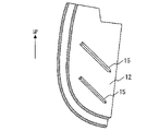
図3は、図2中のA点から見たときの突出部15の配置の一例を示している。尚、図3には、2つの突出部15が示されている。図3に示されるように、各々の突出部15は、細長い形状を有しており、その延在方向はUP方向(車両の下側から上側に向かう方向)から傾いている。より詳細には、各々の突出部15は、UP方向に向かうほど車両の側面に近づくように延在している。このような突出部15の配置の結果、後方側空間2R中の空気流AFの向きが、UP方向からLH方向(車両の側面に向かう方向)に変えられる。すなわち、突出部15は、後方側空間2R中の空気流AFを車両側面方向にガイドする役割を果たす。言い換えれば、突出部15は、後方側空間2R中の空気流AFをホイールハウス2の外側に積極的に排出する役割を果たす。
FIG. 3 shows an example of the arrangement of the
図4は、本実施の形態に係るホイールハウス構造の作用及び効果を要約的に示している。本実施の形態によれば、ホイールハウス構成部材10が、ホイールハウス2の後方側空間2Rに突出する突出部15を有している。更に、その突出部15は、UP方向に向かうほど車両の側面に近づくように延在している。そのような突出部15の配置により、後方側空間2Rに引き込まれた空気流AFの少なくとも一部を、ホイールハウス2の外側に排出することが可能となる。
FIG. 4 summarizes the actions and effects of the wheel house structure according to this embodiment. According to the present embodiment, the
また、後方側空間2Rに引き込まれた空気流AFがホイールハウス2の外側に排出されるため、突出部15が設けられない場合と比較して、ホイールハウス2内の圧力が低下する。ホイールハウス2内の圧力の低下の結果、図4に示されるようにダウンフォースが発生する。特に、突出部15が後方側空間2Rに配置されているため、ダウンフォースが効果的に発生する。なぜなら、後方側空間2Rに引き込まれた空気流AFが前方側空間2Fに到達することが抑制され、ホイールハウス2の頂部を含む比較的大きな領域において圧力が低下するからである。ダウンフォースの発生により、タイヤ1の接地荷重が向上する。結果として、車両の安定性及び運動性能が向上する。
Further, since the air flow AF drawn into the
2.具体例及び変形例
図5は、一例として、突出部15が設けられたバンパシール12を概略的に示している。図5に示されるバンパシール12は、車両の右側のリヤタイヤの後方に設けられるものであり、図中の左方向が車両の側面に向かう方向となっている。
2. Specific Examples and Modifications FIG. 5 schematically shows, as an example, a
図5に示される例では、突出部15は、ホイールハウス構成部材10のうちバンパシール12の内面(後方側空間2Rに向く面)上に設けられている。その突出部15は、山型のフィンである。つまり、突出部15の延在方向に直交する面における突出部15の断面形状は、三角形である。その三角形の頂部が後方側空間2Rに向くように、突出部15は形成されている。更に、突出部15は、UP方向に向かうほど車両の側面に近づくように延在している。これにより、空気流AFを車両側面方向にガイドすることが可能となる。
In the example shown in FIG. 5, the projecting
突出部15の形状は、図5に示されるものに限られない。空気流AFを車両側面方向にガイドすることができるのであれば、突出部15の形状はどのようなものでも構わない。例えば、突出部15は、板状のフィンであってもよい。その板状のフィンは、ホイールハウス構成部材10の内面(後方側空間2Rに向く面)から後方側空間2Rに向けて立ち上がるように設けられる。好適には、板状のフィンとホイールハウス構成部材10の内面とのなす角は90度である。あるいは、突出部15は、ビードで形成されてもよい。
The shape of the projecting
突出部15は、ホイールハウス構成部材10のうちバンパシール12以外の部品の内面上に設けられていてもよい。例えば、突出部15は、ホイールハウス構成部材10のフェンダライナ11の内面上に設けられてもよい。要するに、後方側空間2Rに面するホイールハウス構成部材10の部品であれば、いかなる部品の内面上に突出部15が設けられてもよい。
The projecting
突出部15は、ホイールハウス構成部材10を構成する他の部品(フェンダライナ11、バンパシール12、等)とは別の部品である必要はない。突出部15は、ホイールハウス構成部材10を構成する部品の一部として最初から形成されてもよい。例えば、突出部15は、バンパシール12の一部として形成されてもよい。
The projecting
突出部15は、図3や図5で示されたように直線的に延びている必要はない。突出部15は、曲線的に延びていてもよい。
The
1つのホイールハウス2内に設けられる突出部15の個数はいくつでもよい。突出部15の個数は、所望の機能及びコストの観点から適宜決定すればよい。
Any number of
ハンドリングや走行感をアレンジするため、突出部15の有効面積を動的に制御してもよい。例えば、車速に応じて、突出部15の有効面積を動的に制御してもよい。あるいは、走行モードスイッチにより、突出部15の有効面積を切り替えてもよい。
The effective area of the
本実施の形態に係るホイールハウス構造は、フロントタイヤ及びリヤタイヤのいずれにも適用可能である。 The wheel house structure according to this embodiment can be applied to both front tires and rear tires.
3.比較例との対比
<特許文献1(特開2014-208514号公報)との対比>
特許文献1は、車両のホイールハウスの中を前方から後方に流れる空気流をホイールハウスの外側に排出する技術を開示している。より詳細には、ダクト状のガイド部が、ホイールハウスの後方の位置に形成される。そのガイド部の空気導入口は、ホイールハウスに向けて開口している。また、そのガイド部の空気排出口は、空気導入口よりも後方の位置において、車両下側に向けて開口している。それら空気導入口と空気排出口との間を結ぶように、ガイド部がダクト状に形成されている。
3. Comparison with Comparative Example <Comparison with Patent Document 1 (Japanese Patent Application Laid-Open No. 2014-208514)>
しかしながら、当該ダクト状のガイド部が、車室内外をつなぐ通気ダクト(ベントダクト)と連通する場合、ガイド部及び通気ダクトを介して車室内に埃が入るおそれがある。特に過酷地では、そのような埃入りが顕著となるため、ダクト形状のガイド部を設けることは難しい。一方、本実施の形態にかかるホイールハウス構造には、ダクト形状のガイド部は設けられないため、埃入りの懸念は軽減される。本実施の形態に係るホイールハウス構造は、過酷地で使用される車両にも適用可能である。 However, when the duct-shaped guide portion communicates with a ventilation duct (vent duct) that connects the interior and exterior of the vehicle, dust may enter the vehicle interior via the guide portion and the ventilation duct. Especially in harsh environments, it is difficult to provide a duct-shaped guide part because such dust is noticeable. On the other hand, since the wheelhouse structure according to the present embodiment is not provided with a duct-shaped guide portion, the concern about dust entering is reduced. The wheel house structure according to this embodiment can also be applied to vehicles used in harsh terrain.
また、ダクト状のガイド部の場合、雪や泥の付着・堆積によって、ガイド部が詰まってしまうおそれがある。ガイド部が詰まると、所望の性能が得られなくなる。よって、ガイド部の詰まりを取り除くメンテナンス作業が必要である。しかしながら、狭いホイールハウス内では、ダクト状のガイド部の詰まりを取り除くメンテナンス作業は煩雑となる。一方、本実施の形態に係るホイールハウス構造の突出部15の場合、そのような詰まりは発生しない。よって、メンテナンス性が向上する。
Further, in the case of a duct-shaped guide portion, there is a risk that the guide portion will be clogged due to adhesion and accumulation of snow and mud. If the guide portion is clogged, desired performance cannot be obtained. Therefore, maintenance work is required to clear the clogging of the guide portion. However, in a narrow wheelhouse, the maintenance work for clearing the clogging of the duct-shaped guide portion becomes complicated. On the other hand, in the case of the projecting
また、本実施の形態に係る突出部15の設計自由度は高い。そのため、突出部15を雪や泥が付着しにくい形状とすることが可能である。また、たとえ突出部15の表面に雪や泥が付着したとしても、ダクト形状の場合と比較して、メンテナンスは容易である。
Moreover, the degree of freedom in designing the projecting
雪や泥の付着の観点から、突出部15を洗浄する洗浄機構を設けてもよい。例えば、洗浄機構は、突出部15に液体をスプレーする。定期的に突出部15を洗浄することにより、安定した性能を維持することができる。
A cleaning mechanism for cleaning the projecting
あるいは、突出部15に対する着氷が発生した場合に備えて、突出部15に加熱機構を設けてもよい。加熱の方法としては、電熱や温水分配が考えられる。
Alternatively, a heating mechanism may be provided on the projecting
<特許文献2(特開2015-009749号公報)との対比>
特許文献2は、車両の側方における空気乱れの発生を抑制することを課題としている。そのために、特許文献2は、ホイールハウスの中を前方から後方に流れる空気流が車体の側方に向かって吹き出す際の勢いを弱くしている。つまり、特許文献2は、ホイールハウスの中を流れる空気流をホイールハウスの外側に排出しにくくしている。この技術思想は、ホイールハウスの中を流れる空気流をホイールハウスの外側に積極的に排出するという本実施の形態の技術思想とは正反対である。
<Comparison with Patent Document 2 (Japanese Unexamined Patent Application Publication No. 2015-009749)>
また、特許文献2では、上記の課題を達成するために、フェンダライナ上にフィンが設けられている。しかし、そのフィンは、車両の下側から上側に向かうにつれて、車両内側方向に近づくように傾斜している。この傾斜方向は、本実施の形態における突出部15の傾斜方向と正反対である。このような傾斜方向の違いは、本発明と特許文献2との間の技術思想の差異を顕著に表していると言える。
Further, in
1 タイヤ
2 ホイールハウス
2F 前方側空間
2R 後方側空間
10 ホイールハウス構成部材
11 フェンダライナ
12 バンパシール
15 突出部
AF 空気流
C 回転中心
CL 中心線
REFERENCE SIGNS
Claims (3)
前記ホイールハウス構成部材は、前記ホイールハウス中を前記車両の上方向に流れる空気流を前記車両の外側に向かう方向であって前記車両の側面に向かう方向にガイドするように構成されている
ホイールハウス構造。 Covering the tire of the vehicle, comprising a wheel house component facing the tire across the wheel house,
The wheel house component member is configured to guide an airflow flowing upward through the wheel house in a direction toward the outside of the vehicle and toward the side surface of the vehicle. structure.
請求項1に記載のホイールハウス構造。 The wheelhouse structure according to claim 1.
前記タイヤを覆い、ホイールハウスを挟んで前記タイヤと対向するホイールハウス構成部材と
を備える車両であって、
前記ホイールハウス構成部材は、前記ホイールハウス中を前記車両の上方向に流れる空気流を前記車両の外側に向かう方向であって前記車両の側面に向かう方向にガイドするように構成されている
車両。 tires and
and a wheel house component covering the tire and facing the tire with the wheel house interposed therebetween,
The wheel house component member is configured to guide an airflow flowing upward through the wheel house in a direction toward the outside of the vehicle and toward the side surface of the vehicle.
Priority Applications (1)
| Application Number | Priority Date | Filing Date | Title |
|---|---|---|---|
| JP2019223625A JP7164511B2 (en) | 2019-12-11 | 2019-12-11 | Wheel house structure and vehicle |
Applications Claiming Priority (1)
| Application Number | Priority Date | Filing Date | Title |
|---|---|---|---|
| JP2019223625A JP7164511B2 (en) | 2019-12-11 | 2019-12-11 | Wheel house structure and vehicle |
Related Parent Applications (1)
| Application Number | Title | Priority Date | Filing Date |
|---|---|---|---|
| JP2016121503A Division JP6631416B2 (en) | 2016-06-20 | 2016-06-20 | Wheel house structure |
Publications (2)
| Publication Number | Publication Date |
|---|---|
| JP2020037412A JP2020037412A (en) | 2020-03-12 |
| JP7164511B2 true JP7164511B2 (en) | 2022-11-01 |
Family
ID=69737427
Family Applications (1)
| Application Number | Title | Priority Date | Filing Date |
|---|---|---|---|
| JP2019223625A Active JP7164511B2 (en) | 2019-12-11 | 2019-12-11 | Wheel house structure and vehicle |
Country Status (1)
| Country | Link |
|---|---|
| JP (1) | JP7164511B2 (en) |
Citations (4)
| Publication number | Priority date | Publication date | Assignee | Title |
|---|---|---|---|---|
| JP2009161101A (en) | 2008-01-09 | 2009-07-23 | Toyota Motor Corp | Vehicular aerodynamic structure |
| JP2013233887A (en) | 2012-05-10 | 2013-11-21 | Kojima Press Industry Co Ltd | Fender liner |
| US20160137236A1 (en) | 2014-11-14 | 2016-05-19 | Hyundai Motor Company | Apparatus for improving aerodynamic characteristics of vehicle |
| JP6223875B2 (en) | 2014-03-14 | 2017-11-01 | 三井造船株式会社 | Film forming apparatus, film forming method, and cylinder member with film |
Family Cites Families (1)
| Publication number | Priority date | Publication date | Assignee | Title |
|---|---|---|---|---|
| JP3856957B2 (en) * | 1998-07-01 | 2006-12-13 | 日野自動車株式会社 | Inner fender |
-
2019
- 2019-12-11 JP JP2019223625A patent/JP7164511B2/en active Active
Patent Citations (4)
| Publication number | Priority date | Publication date | Assignee | Title |
|---|---|---|---|---|
| JP2009161101A (en) | 2008-01-09 | 2009-07-23 | Toyota Motor Corp | Vehicular aerodynamic structure |
| JP2013233887A (en) | 2012-05-10 | 2013-11-21 | Kojima Press Industry Co Ltd | Fender liner |
| JP6223875B2 (en) | 2014-03-14 | 2017-11-01 | 三井造船株式会社 | Film forming apparatus, film forming method, and cylinder member with film |
| US20160137236A1 (en) | 2014-11-14 | 2016-05-19 | Hyundai Motor Company | Apparatus for improving aerodynamic characteristics of vehicle |
Also Published As
| Publication number | Publication date |
|---|---|
| JP2020037412A (en) | 2020-03-12 |
Similar Documents
| Publication | Publication Date | Title |
|---|---|---|
| JP5854021B2 (en) | Wheelhouse rear structure | |
| JP4229204B1 (en) | Aerodynamic structure for vehicles | |
| KR20080100496A (en) | Electric potential treatment device | |
| WO2011126085A1 (en) | Front underfloor structure of vehicle | |
| WO2011126086A1 (en) | Vehicle underfloor structure | |
| JP4229206B1 (en) | Aerodynamic structure for vehicles | |
| CN110461688B (en) | Front body structure of vehicle | |
| JP5983568B2 (en) | Vehicle lower structure | |
| JPH10226369A (en) | Automobile provided with air guide device on front side | |
| JP4903352B2 (en) | Car with lower body | |
| JP5522254B2 (en) | Vehicle front underfloor structure | |
| JP4333788B2 (en) | Aerodynamic structure for vehicles | |
| JP2015016835A (en) | Floor undercover structure | |
| JP5994742B2 (en) | Wheel house structure | |
| JP7164511B2 (en) | Wheel house structure and vehicle | |
| JP6849048B2 (en) | Wheelhouse structure and vehicle | |
| JP2006298312A (en) | Vehicle body lower part structure | |
| JP6631416B2 (en) | Wheel house structure | |
| JP2006219019A (en) | Front rectifying structure of vehicle | |
| JP6485472B2 (en) | Tire deflector device | |
| JP7451933B2 (en) | Vehicle undercarriage | |
| JP7322677B2 (en) | vehicle undercarriage | |
| JP2023069384A (en) | Undercover for vehicle | |
| WO2021015614A1 (en) | Rounded wheelbay | |
| JP2022012837A (en) | Mud guard |
Legal Events
| Date | Code | Title | Description |
|---|---|---|---|
| A621 | Written request for application examination |
Free format text: JAPANESE INTERMEDIATE CODE: A621 Effective date: 20191211 |
|
| A131 | Notification of reasons for refusal |
Free format text: JAPANESE INTERMEDIATE CODE: A131 Effective date: 20200811 |
|
| A521 | Request for written amendment filed |
Free format text: JAPANESE INTERMEDIATE CODE: A523 Effective date: 20200930 |
|
| A131 | Notification of reasons for refusal |
Free format text: JAPANESE INTERMEDIATE CODE: A131 Effective date: 20210126 |
|
| A02 | Decision of refusal |
Free format text: JAPANESE INTERMEDIATE CODE: A02 Effective date: 20210824 |
|
| C60 | Trial request (containing other claim documents, opposition documents) |
Free format text: JAPANESE INTERMEDIATE CODE: C60 Effective date: 20211115 |
|
| C22 | Notice of designation (change) of administrative judge |
Free format text: JAPANESE INTERMEDIATE CODE: C22 Effective date: 20220510 |
|
| C22 | Notice of designation (change) of administrative judge |
Free format text: JAPANESE INTERMEDIATE CODE: C22 Effective date: 20220531 |
|
| C13 | Notice of reasons for refusal |
Free format text: JAPANESE INTERMEDIATE CODE: C13 Effective date: 20220621 |
|
| A521 | Request for written amendment filed |
Free format text: JAPANESE INTERMEDIATE CODE: A523 Effective date: 20220804 |
|
| C23 | Notice of termination of proceedings |
Free format text: JAPANESE INTERMEDIATE CODE: C23 Effective date: 20220830 |
|
| C03 | Trial/appeal decision taken |
Free format text: JAPANESE INTERMEDIATE CODE: C03 Effective date: 20220927 |
|
| C30A | Notification sent |
Free format text: JAPANESE INTERMEDIATE CODE: C3012 Effective date: 20220927 |
|
| A61 | First payment of annual fees (during grant procedure) |
Free format text: JAPANESE INTERMEDIATE CODE: A61 Effective date: 20221020 |
|
| R151 | Written notification of patent or utility model registration |
Ref document number: 7164511 Country of ref document: JP Free format text: JAPANESE INTERMEDIATE CODE: R151 |