JP2006219019A - Front rectifying structure of vehicle - Google Patents
Front rectifying structure of vehicle Download PDFInfo
- Publication number
- JP2006219019A JP2006219019A JP2005034694A JP2005034694A JP2006219019A JP 2006219019 A JP2006219019 A JP 2006219019A JP 2005034694 A JP2005034694 A JP 2005034694A JP 2005034694 A JP2005034694 A JP 2005034694A JP 2006219019 A JP2006219019 A JP 2006219019A
- Authority
- JP
- Japan
- Prior art keywords
- vehicle body
- vehicle
- width direction
- air dam
- air
- Prior art date
- Legal status (The legal status is an assumption and is not a legal conclusion. Google has not performed a legal analysis and makes no representation as to the accuracy of the status listed.)
- Granted
Links
Images


Abstract
Description
本発明は、車体前部において車両走行中の空気の流れを整流する車両の前部整流構造に関する。 The present invention relates to a vehicle front rectification structure that rectifies the flow of air during vehicle travel at the front of a vehicle body.
周知のように、例えば自動車等の車両においては、動力性能及び燃費等を向上させるために空気抵抗を低減することが求められている。空気抵抗係数(Cd値)を用いて評価される空気抵抗は、車体まわりの空気の流れに影響される。車体側面に空気の剥離が生じ、車体後方に流れる空気が乱れると、空気抵抗係数が大きくなり空気抵抗の増加を引き起こすことが知られている。 As is well known, for example, in vehicles such as automobiles, it is required to reduce air resistance in order to improve power performance and fuel consumption. The air resistance evaluated using the air resistance coefficient (Cd value) is influenced by the air flow around the vehicle body. It is known that when air separation occurs on the side surface of the vehicle body and the air flowing behind the vehicle body is disturbed, the air resistance coefficient increases and the air resistance increases.
この空気抵抗を低減させるための構造として、例えば特許文献1には、車体のサイドコーナ部に碗型突起面を形成することにより、車体側面の空気流の剥離を抑制し、空気抵抗を減少させることを企図した構造が開示されている。また、例えば特許文献2には、フロントバンパに、左右の前輪の前方にそれぞれ舌状に下方に突出するエアスポイラを一体に設けることにより、前輪付近の整流作用を高め、空気抵抗を減少させることを企図した構造が開示されている。
ところで、自動車等の車両においては、走行性能だけでなく、ユーザの好みに応じた車体のデザイン性も非常に重要視される。車体デザインは空気特性に直接的に影響を及ぼすので、この車体デザインと空気抵抗とを如何に両立させるかが問題となる。車体デザインの観点から車体前端部分が前方に大きく絞り込まれた車両においては、車両走行中に車体側面に生じ得る空気の剥離がより大きくなる。 By the way, in a vehicle such as an automobile, not only the running performance but also the design of the vehicle body according to the user's preference is very important. Since the vehicle body design directly affects the air characteristics, how to make this vehicle body design and air resistance compatible is a problem. In a vehicle in which the front end portion of the vehicle body is greatly squeezed forward from the viewpoint of vehicle body design, the separation of air that can occur on the side surface of the vehicle body during vehicle traveling is further increased.
上記車両では、空気の剥離に伴い前輪後部の車体側面に低圧領域が形成され、そのために車体下面に沿って車幅方向内方部を車体後方に流れる空気流が車幅方向外方へ吹き出される。このことは、車体側面に渦を発生させるとともに、空気抵抗の増加をもたらし、車両の走行性能を低下させることとなる。 In the vehicle described above, a low pressure region is formed on the side of the vehicle body at the rear of the front wheel as the air is separated, and for this reason, an air flow that flows backward in the vehicle width direction along the vehicle body lower surface is blown outward in the vehicle width direction. The This causes vortices on the side of the vehicle body, increases air resistance, and lowers the running performance of the vehicle.
この発明は上記技術的課題に鑑みてなされたもので、車体下面に沿って車幅方向内方部を車体後方に流れる空気が車幅方向外方へ吹き出されることを抑制する車両の前部整流構造を提供することを目的としてなされたものである。 The present invention has been made in view of the above technical problem, and it is a front part of a vehicle that suppresses the air flowing in the vehicle width direction inward in the vehicle width direction along the lower surface of the vehicle body from being blown outward in the vehicle width direction. The object is to provide a rectifying structure.
このため、本願の請求項1に係る発明は、車体前部において車体後方への走行風を受ける受風面部を備え下方に突出するエアダム部と、前輪が収められるホイールハウスの車体前側で略車幅方向に延びるデフレクタ部とを有する車両の前部整流構造であって、前記エアダム部は、その車幅方向外方端部が車体後方に延びるとともに前記デフレクタ部の車幅方向外方端部と略連続するように配設されていることを特徴としたものである。 For this reason, the invention according to claim 1 of the present application is substantially arranged on the front side of the vehicle body of the wheel house in which the wind dam receiving portion that receives the traveling wind toward the rear of the vehicle body at the front portion of the vehicle body and protruding downward, and the front wheel is housed. A front rectifying structure for a vehicle having a deflector portion extending in a width direction, wherein the air dam portion has a vehicle width direction outer end portion extending rearward of the vehicle body and a vehicle width direction outer end portion of the deflector portion. It is characterized by being arranged so as to be substantially continuous.
また、本願の請求項2に係る発明は、請求項1に係る発明において、前記デフレクタ部の車幅方向外方端部に、略車幅方向外方に延びるサイドエアダム部が配設されていることを特徴としたものである。
In the invention according to
更に、本願の請求項3に係る発明は、請求項1又は2に係る発明において、前記エアダム部の下端部の地上高が、前記デフレクタ部の下端部の地上高よりも高くなるように構成されていることを特徴としたものである。
Furthermore, the invention according to
また更に、本願の請求項4に係る発明は、請求項2又は3に係る発明において、前記サイドエアダム部が、前記エアダム部と一体化されていることを特徴としたものである。
Still further, the invention according to claim 4 of the present application is characterized in that, in the invention according to
また更に、本願の請求項5に係る発明は、請求項2〜4の何れか一に係る発明において、前記車体前部が、平面視において略半円形状を有していることを特徴としたものである。
Furthermore, the invention according to
本願の請求項1の発明に係る車両の前部整流構造によれば、車体前部において下方に突出するエアダム部は、その車幅方向外方端部が車体後方に延びるとともに、ホイールハウスの車体前側で略車幅方向に延びるデフレクタ部の車幅方向外方端部と略連続するように配設されることにより、エアダム部とデフレクタ部との間をそれらの車幅方向外方端部において略塞いでいる。従って、車体前端部分からホイールハウスにわたる領域において、前輪後部の車体側面に生ずる低圧領域よりも更に低い低圧領域を形成することができ、車体下面に沿って車幅方向内方部を車体後方に流れる空気流が車幅方向外方へ吹き出されることを抑制することができる。 According to the vehicle front rectifying structure according to the first aspect of the present invention, the air dam portion projecting downward at the front portion of the vehicle body extends outward in the vehicle width direction toward the rear of the vehicle body, and the vehicle body of the wheel house. By being arranged so as to be substantially continuous with the vehicle width direction outer end portion of the deflector portion extending in the vehicle width direction on the front side, between the air dam portion and the deflector portion at the vehicle width direction outer end portion thereof It is almost closed. Therefore, in the region extending from the front end portion of the vehicle body to the wheel house, a low pressure region lower than the low pressure region generated on the side surface of the vehicle body at the rear of the front wheel can be formed, and the vehicle width direction inner portion flows rearward of the vehicle body along the lower surface of the vehicle body. It is possible to suppress the air flow from being blown outward in the vehicle width direction.
また、本願の請求項2の発明によれば、基本的には上記請求項1の発明と同様の効果を奏することができる。特に、デフレクタ部の車幅方向外方端部に、略車幅方向に外方に延びるサイドエアダム部が配設されることにより、前輪後部の車体側面に生ずる低圧領域を更に小さくすることができるので、車体下面に沿って車幅方向内方部を車体後方に流れる空気流が車幅方向外方へ吹き出されることを更に抑制することが可能である。
Further, according to the invention of
更に、本願の請求項3の発明によれば、基本的には上記請求項1又は2の発明と同様の効果を奏することができる。特に、エアダム部の下端部の地上高が、デフレクタ部の下端部の地上高よりも高くなるように構成されることにより、車体前部下端から前輪タイヤ外周への接平面が地面となす最小角度である車体のアプローチアングルを確保することができる。
Furthermore, according to the invention of
また更に、本願の請求項4の発明によれば、基本的には上記請求項2又は3の発明と同様の効果を奏することができる。特に、サイドエアダム部が、エアダム部と一体化されることにより、それらの間に分割線あるいは間隙が存在しないので、車体前部の外観を向上させることができる。
Furthermore, according to the invention of claim 4 of the present application, basically the same effect as that of the invention of
また更に、本願の請求項5の発明によれば、基本的には上記請求項2〜4の何れか一の発明と同様の効果を奏することができる。特に、車体前部が平面視において略半円形状を有する車両では、車体前部において車体側面を流れる空気の剥離が大きくなる。かかるタイプの車両に適用することで、より顕著な効果を奏することができる。
Furthermore, according to the invention of
以下、本発明の実施形態を、添付図面に基づいて説明する。 Embodiments of the present invention will be described below with reference to the accompanying drawings.
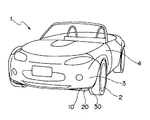
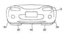
図1は、本発明の実施形態に係る前部整流構造を備えた車両1の斜視図である。図2は、図1に示した車両の車体前部の正面説明図、図3及び図4はそれぞれ、図1に示した車両の車体前部の底面図及び左側面図である。図5は、図1に示した車両の右前部を拡大して示した斜視図である。 FIG. 1 is a perspective view of a vehicle 1 including a front rectifying structure according to an embodiment of the present invention. 2 is a front explanatory view of the front part of the vehicle body shown in FIG. 1, and FIGS. 3 and 4 are a bottom view and a left side view of the front part of the vehicle body shown in FIG. 1, respectively. FIG. 5 is an enlarged perspective view of the right front portion of the vehicle shown in FIG.
これらの図に示されるように、上記車両1は、前輪2の車体前方にフロントバンパ3を備え、前輪2の上方にはフロントフェンダ4を備えている。上記フロントバンパ3及び上記フロントフェンダ4にわたって、それらの下方にはホイールハウス6が形成されており、上記ホイールハウス6内に前輪2が収められている。
As shown in these drawings, the vehicle 1 includes a
車体前端部分を構成するフロントバンパ3は、図3に示されるように、平面視で略半円形状に形成されており、本実施形態にかかる車両1は、車体前方に大きく絞り込まれた形状で構成されている。
As shown in FIG. 3, the
上記車体前部には、上記フロントバンパ3の下方にエアダム部10が配設されており、該エアダム部10は、車体前面に投影される面を有するように車体後方への走行風を受ける受風面部11を備え下方に突出している。上記エアダム部10の車体後方には、ホイールハウス6の車体前側で略車幅方向に延びるデフレクタ部20が配設されており、該デフレクタ部20の車幅方向外方端部には略車幅方向外方に延びるサイドエアダム部30が配設されている。
左右の前輪2の車体前方にそれぞれ設けられる上記エアダム部10、上記デフレクタ部20、及び上記サイドエアダム部30は、本実施形態に係る前部整流構造を構成しており、例えば合成樹脂材料などからなる板状部材で形成されている。
An
The
本実施形態では、エアダム部10とサイドエアダム部30とが一体化して形成されており、図6及び7に、それらを拡大して示している。図6は、本実施形態に係るエアダム部及びサイドエアダム部の正面図であり、図7は本実施形態に係るエアダム部及びサイドエアダム部の平面図である。
In this embodiment, the
上記エアダム部10は、フロントバンパ3の外周部に略沿って曲線形状に形成されており、その車幅方向外方端部は車体後方に延びている。上記エアダム部10の車体後方には取付部12が設けられており、上記取付部12には孔部13、14、15が形成されている。上記孔部13、14、15を用いて、エアダム部10が車体下面5に取り付けられる。
The
図8は、図2におけるY8―Y8線に沿ったエアダム部の断面説明図である。上記エアダム部10の取付部12は、フロントバンパ3の下端部8に備えられたクリップ16を介し、取付ボルト17を締め付けることにより、上記フロントバンパ3に取り付けられている。
FIG. 8 is a cross-sectional explanatory view of the air dam portion taken along line Y8-Y8 in FIG. The attachment portion 12 of the
上記エアダム部10と一体化されているサイドエアダム部30は、図3及び4に示されるように、略車幅方向に延びるとともに、フロントバンパ3の車体側面の外周部に沿って車体上方に延びている。上記サイドエアダム部30は、その上方に取付部31を備え、上記取付部31には孔部32、33が形成されている。
As shown in FIGS. 3 and 4, the side
図9は、図2におけるY9―Y9線に沿ったサイドエアダム部の断面説明図である。上記サイドエアダム部30は、その取付部31がホイールハウス内に取り付けられたスプラッシュシールド7とフロントバンパ3の後端部9の間に挟み込まれ、グロメット34を介して車体に取り付けられている。
FIG. 9 is a cross-sectional explanatory view of the side air dam portion taken along line Y9-Y9 in FIG. The side
上記のように、エアダム部10の車体後方にはデフレクタ部20が配設されており、該デフレクタ部20は、ホイールハウス6の車体前側で略車幅方向に延びるとともに、図4に示されるように車体下方に延びている。また、上記デフレクタ部20は、その上部にフランジ部21を備え、該フランジ部21により車体下面5に取り付けられている。
As described above, the
図10には、図3におけるY10−Y10線に沿ったエアダム部及びデフレクタ部の断面説明図が示されている。上記のように車体下面に配設され、断面略L字状に形成されたエアダム部10とデフレクタ部20が示されている。図に示されるように、上記エアダム部10の下端部の地上高H1が、上記デフレクタ部20の下端部の地上高H2よりも高くなるように構成されている。
FIG. 10 is a cross-sectional explanatory view of the air dam part and the deflector part along the line Y10-Y10 in FIG. The
本実施形態では、図3に示されるように、上記エアダム部10は、その車幅方向外方端部が車体後方に延びるとともに上記デフレクタ部20の車幅方向外方端部と略連続するように配設され、上記デフレクタ部20の車幅方向外方端部には、略車幅方向外方に延びるサイドエアダム部12が配設されている。
In the present embodiment, as shown in FIG. 3, the
次に、本実施形態に係る車両の走行状態における車体側面及び車体下面に沿う空気の流れについて説明する。
図11は、車体前端部分が大きく絞り込まれた車両101について走行時の車体まわりの空気の流れを概略的に示した説明図であり、車体下方から見た空気の流れを示している。車体前部が略半円形状に形成されている車両においては、車体前方からの空気流L1は車体右前部に沿って流れ、ホイールハウス106及びその後方の車体側面に空気の剥離を生じている。この空気の剥離が生じる領域である車体側面には低圧領域A1が形成されている。
Next, the flow of air along the vehicle body side surface and the vehicle body lower surface in the traveling state of the vehicle according to the present embodiment will be described.
FIG. 11 is an explanatory diagram schematically showing the flow of air around the vehicle body during travel for the
車体下面に沿って流れる空気流L2は、車体下面に沿って車体後方に流れているが、車体側面に形成された上記低圧領域A1により車幅方向外方に引き寄せられ、車体側面に吹き出される。これにより車体側面を流れる空気流L3は、渦を発生させながら車体後方に流れる。この空気流L3は更に、車体後方の流れも乱し空気抵抗を増大させることとなる。 The air flow L2 that flows along the lower surface of the vehicle body flows toward the rear of the vehicle body along the lower surface of the vehicle body, but is drawn outward in the vehicle width direction by the low pressure region A1 formed on the side surface of the vehicle body and blown out to the side surface of the vehicle body. . As a result, the air flow L3 flowing on the side surface of the vehicle body flows toward the rear of the vehicle body while generating vortices. This air flow L3 further disturbs the flow behind the vehicle body and increases the air resistance.
図12は、本実施形態に係る前部整流構造を備えた車両1について走行時の車体まわりの空気の流れを概略的に示した説明図であり、車体下方から見た空気の流れを示している。図11と同様に、車体前部が略半円形状に形成されている車両においては、車体前方からの空気流L11は車体右前部に沿って流れ、車体側面に空気の剥離を生じ、この空気の剥離が生じる領域である車体側面に低圧領域A11が形成されている。 FIG. 12 is an explanatory view schematically showing the flow of air around the vehicle body during traveling for the vehicle 1 provided with the front rectifying structure according to the present embodiment, showing the flow of air viewed from below the vehicle body. Yes. As in FIG. 11, in a vehicle in which the front portion of the vehicle body is formed in a substantially semicircular shape, the air flow L11 from the front of the vehicle body flows along the right front portion of the vehicle body, causing air separation on the side surface of the vehicle body. A low pressure region A11 is formed on the side surface of the vehicle body where the peeling occurs.
しかし、本実施形態に係る車両の前部整流構造によれば、車体前部において下方に延びるエアダム部10は、その車幅方向外方端部が車体後方に延びるとともに、ホイールハウス6の車体前側で略車幅方向に延びるデフレクタ部20の車幅方向外方端部と略連続するように配設されることにより、エアダム部10とデフレクタ20との間をそれらの車幅方向外方端部において略塞いでいる。従って、車体前端部分からホイールハウス6にわたる領域において、前輪後部の車体側面に生ずる低圧領域A11よりも更に低い低圧領域A12を形成することができ、車体下面に沿って車幅方向内方部を車体後方に流れる空気流L12が車幅方向外方へ吹き出されることを抑制することができる。
However, according to the front rectifying structure for a vehicle according to the present embodiment, the
このように、車幅方向内方部を流れる空気流L12が、車幅方向外方へ吹き出されることが抑制されているので、車体側面を流れる空気流L11と車体下面を流れる空気流L12とが分離した状態で車体後方に流れ、車体側面及び車体下面の空気の流れを整流させることが可能であり、空気抵抗を低減させることができる。 As described above, since the air flow L12 flowing in the vehicle width direction inner portion is suppressed from being blown out in the vehicle width direction outward, the air flow L11 flowing on the vehicle body side surface and the air flow L12 flowing on the vehicle body lower surface It is possible to flow to the rear of the vehicle body in a separated state, rectify the air flow on the vehicle body side surface and the vehicle body lower surface, and to reduce the air resistance.
本実施形態では、上記デフレクタ部20の車幅方向外方端部に、略車幅方向に外方に延びるサイドエアダム部30が配設されることにより、前輪後部の車体側面に生ずる低圧領域A11を更に小さくすることができるので、車体下面に沿って車幅方向内方部を車体後方に流れる空気流L12が車幅方向外方へ吹き出されることを更に抑制することが可能である。
In the present embodiment, the side
また、図10に示されるように、上記エアダム部10の下端部の地上高H1が、上記デフレクタ部20の下端部の地上高H2よりも高くなるように構成されているので、車体前部下端から前輪タイヤ外周への接平面が地面となす最小角度である車体のアプローチアングルを確保することができる。
従って、上記エアダム部及び上記サイドエアダム部を備えた車両が、例えば平坦な道路から斜面に向かう場合などにおいて、車体前部と路面などとの干渉の防止を確保することができる。
Also, as shown in FIG. 10, the ground height H1 at the lower end of the
Accordingly, when the vehicle including the air dam portion and the side air dam portion is directed from a flat road to a slope, for example, it is possible to ensure prevention of interference between the front portion of the vehicle body and the road surface.
上記のように、エアダム部10を車体下面に配設することにより、車体前方からの空気流は、車体下面を平らにすることが困難である左右の前輪にかかる領域において車体下面から離れ、上記領域の車体後方において再び車体下面に沿って流れることができる。このことは、空気抵抗係数(Cd値)を低減させるとともに空気揚力係数(Cl値)を低減させることができ、走行安定性も向上させることができる。
As described above, by disposing the
本実施形態では、上記エアダム部の車体後方にデフレクタ部20を備え、上記エアダム部10の地上高H1が、上記デフレクタ部20の地上高H2よりも高くなるように構成されているので、上記効果をより有効に奏することができる。
In the present embodiment, the
また、上記サイドエアダム部30が、エアダム部10と一体化されることにより、例えば、上記サイドエアダム部30と上記エアダム部10とが別部材で構成される場合のように、それらの間に分割線あるいは間隙などが存在しないので車体前部の外観を向上させることができる。
Further, the side
更に、本実施形態のように、車体前部が平面視において略半円形状を有する車両では、車体前部において車体側面を流れる空気の剥離が大きくなるので、車体下面の車幅方向内方部を車体後方に流れる空気流L12が車幅方向外方へ吹き出されることをより有効に抑制することができる。 Further, as in the present embodiment, in a vehicle in which the front part of the vehicle body has a substantially semicircular shape in plan view, separation of the air flowing on the side surface of the vehicle body at the front part of the vehicle body becomes large, so the inner part in the vehicle width direction on the lower surface of the vehicle body Can be more effectively suppressed from being blown outward in the vehicle width direction.
本実施形態に係るエアダム部の変形例が図13及び図14に示されている。
図13は、本実施形態に係るエアダム部の変形例を備えた車体前部の正面図であり、図14は、本実施形態に係るエアダム部の変形例を備えた車体前部の底面図である。なお、以下の説明において、上記実施形態と同様の構成を備え、同様の作用をなすものについては、同一符号を付し、それ以上の説明は省略する。
The modification of the air dam part which concerns on this embodiment is shown by FIG.13 and FIG.14.
FIG. 13 is a front view of a vehicle body front portion provided with a modification of the air dam portion according to the present embodiment, and FIG. 14 is a bottom view of the vehicle body front portion provided with a modification of the air dam portion according to the present embodiment. is there. In the following description, components having the same configuration as those of the above-described embodiment and having the same functions are denoted by the same reference numerals, and further description thereof is omitted.
車体前部が平面視で略半円形状に形成される車両は、上記実施形態と同様に、ホイールハウス6の車体前方において略車幅方向に延びるデフレクタ部20と、上記デフレクタ部30の車幅方向外方端部に、略車幅方向外方に延びるサイドエアダム部30を備えている。図に示されるように、左右のエアダム部が一体化された構造を備えたエアダム部40が、車体前部において下方に延びるとともにフロントバンパ3の外周部に略沿って配設されている。
A vehicle in which the front part of the vehicle body is formed in a substantially semicircular shape in a plan view includes a
上記実施形態と同様に、上記エアダム部40の車幅方向外方端部は、車体後方に延びるとともに上記デフレクタ部20の車幅方向外方端部と略連続するように配設されている。それによりエアダム部40とデフレクタ部20との間をそれらの車幅方向外方端部において略塞いでいるので、車体前端部分からホイールハウス6にわたる領域において、前輪後部の車体側面に生ずる低圧領域よりも更に低い低圧領域を形成することができ、車体下面に沿って車幅方向内方部を車体後方に流れる空気流が車幅方向外方へ吹き出されることを抑制することができる。
Similar to the above-described embodiment, the outer end portion in the vehicle width direction of the
上記エアダム部40が車幅方向にわたって延在しているので、車体前方からの空気流が、車体下面を平らにすることが困難である左右の前輪にかかる領域において車体下面から離れ、上記領域の車体後方において再び車体下面に沿って流れることをより効果的に行うことができる。このことは、空気抵抗係数及び/又は空気揚力係数を更に低減させるので、更に空気抵抗を低減させるとともに走行安定性を向上させることが可能である。
Since the
本実施形態では、エアダム部10とサイドエアダム部30が一体化して構成されており、車体前部の外観を向上させているが、それらを別体で構成することも可能である。エアダム部10、サイドエアダム部30、及びデフレクタ部20をそれぞれ別体で構成しても、それらの何れかの組み合わせを一体化として構成してもよい。これらの場合においても上記実施形態と同様の効果を得ることができる。
In the present embodiment, the
以上のように、本発明は、例示された実施の形態に限定されるものではなく、本発明の要旨を逸脱しない範囲において、種々の改良及び設計上の変更が可能であることは言うまでもない。 As described above, the present invention is not limited to the illustrated embodiments, and it goes without saying that various improvements and design changes can be made without departing from the gist of the present invention.
本発明は、例えば自動車等の車両、特に、車体前部が平面視で大きな絞込みを有する車両などに好適に適用可能である。 The present invention is preferably applicable to a vehicle such as an automobile, in particular, a vehicle in which the front portion of the vehicle body has a large narrowing in a plan view.
2 前輪
3 フロントバンパ
6 ホイールハウス
10、40 エアダム部
11 受風面部
20 デフレクタ部
30 サイドエアダム部
H 地上高
2
Claims (5)
前記エアダム部は、その車幅方向外方端部が車体後方に延びるとともに前記デフレクタ部の車幅方向外方端部と略連続するように配設されていることを特徴とする車両の前部整流構造。 A front portion of a vehicle having an air dam portion that protrudes downward with a wind receiving surface portion that receives traveling wind toward the rear of the vehicle body at a front portion of the vehicle body, and a deflector portion that extends substantially in the vehicle width direction on the vehicle body front side of the wheel house in which the front wheels are housed. A rectifying structure,
The front portion of the vehicle, wherein the air dam portion is disposed so that an outer end portion in the vehicle width direction extends rearward of the vehicle body and is substantially continuous with an outer end portion in the vehicle width direction of the deflector portion. Rectification structure.
Priority Applications (1)
| Application Number | Priority Date | Filing Date | Title |
|---|---|---|---|
| JP2005034694A JP4613630B2 (en) | 2005-02-10 | 2005-02-10 | Vehicle front rectification structure |
Applications Claiming Priority (1)
| Application Number | Priority Date | Filing Date | Title |
|---|---|---|---|
| JP2005034694A JP4613630B2 (en) | 2005-02-10 | 2005-02-10 | Vehicle front rectification structure |
Publications (2)
| Publication Number | Publication Date |
|---|---|
| JP2006219019A true JP2006219019A (en) | 2006-08-24 |
| JP4613630B2 JP4613630B2 (en) | 2011-01-19 |
Family
ID=36981617
Family Applications (1)
| Application Number | Title | Priority Date | Filing Date |
|---|---|---|---|
| JP2005034694A Expired - Fee Related JP4613630B2 (en) | 2005-02-10 | 2005-02-10 | Vehicle front rectification structure |
Country Status (1)
| Country | Link |
|---|---|
| JP (1) | JP4613630B2 (en) |
Cited By (4)
| Publication number | Priority date | Publication date | Assignee | Title |
|---|---|---|---|---|
| DE102015001039A1 (en) | 2014-02-12 | 2015-08-13 | Mazda Motor Corporation | Front air flow flow optimization structure of a vehicle and method for directing a front air flow of a vehicle |
| JP2015150914A (en) * | 2014-02-12 | 2015-08-24 | マツダ株式会社 | Front rectification structure of automobile |
| JP2016002827A (en) * | 2014-06-16 | 2016-01-12 | マツダ株式会社 | Vehicle substructure |
| JP2016128275A (en) * | 2015-01-09 | 2016-07-14 | マツダ株式会社 | Lower structure for automobile |
Families Citing this family (1)
| Publication number | Priority date | Publication date | Assignee | Title |
|---|---|---|---|---|
| JP5712994B2 (en) | 2012-12-11 | 2015-05-07 | トヨタ自動車株式会社 | Vehicle lower structure |
Citations (4)
| Publication number | Priority date | Publication date | Assignee | Title |
|---|---|---|---|---|
| JPS63139182U (en) * | 1987-03-06 | 1988-09-13 | ||
| JPH0411189U (en) * | 1990-05-21 | 1992-01-30 | ||
| JPH10305784A (en) * | 1997-05-06 | 1998-11-17 | Nissan Shatai Co Ltd | Car body front structure |
| JPH1199971A (en) * | 1997-09-29 | 1999-04-13 | Mazda Motor Corp | Front car body structure of vehicle |
-
2005
- 2005-02-10 JP JP2005034694A patent/JP4613630B2/en not_active Expired - Fee Related
Patent Citations (4)
| Publication number | Priority date | Publication date | Assignee | Title |
|---|---|---|---|---|
| JPS63139182U (en) * | 1987-03-06 | 1988-09-13 | ||
| JPH0411189U (en) * | 1990-05-21 | 1992-01-30 | ||
| JPH10305784A (en) * | 1997-05-06 | 1998-11-17 | Nissan Shatai Co Ltd | Car body front structure |
| JPH1199971A (en) * | 1997-09-29 | 1999-04-13 | Mazda Motor Corp | Front car body structure of vehicle |
Cited By (6)
| Publication number | Priority date | Publication date | Assignee | Title |
|---|---|---|---|---|
| DE102015001039A1 (en) | 2014-02-12 | 2015-08-13 | Mazda Motor Corporation | Front air flow flow optimization structure of a vehicle and method for directing a front air flow of a vehicle |
| JP2015150913A (en) * | 2014-02-12 | 2015-08-24 | マツダ株式会社 | Front rectification structure of automobile |
| JP2015150914A (en) * | 2014-02-12 | 2015-08-24 | マツダ株式会社 | Front rectification structure of automobile |
| US9573634B2 (en) | 2014-02-12 | 2017-02-21 | Mazda Motor Corporation | Front air-flow streamlining structure of automotive vehicle |
| JP2016002827A (en) * | 2014-06-16 | 2016-01-12 | マツダ株式会社 | Vehicle substructure |
| JP2016128275A (en) * | 2015-01-09 | 2016-07-14 | マツダ株式会社 | Lower structure for automobile |
Also Published As
| Publication number | Publication date |
|---|---|
| JP4613630B2 (en) | 2011-01-19 |
Similar Documents
| Publication | Publication Date | Title |
|---|---|---|
| JP5737257B2 (en) | Vehicle front structure | |
| JP5686106B2 (en) | Lower body structure of the vehicle | |
| JPWO2007119270A1 (en) | Aerodynamic structure for vehicles | |
| JP5233927B2 (en) | Vehicle lower structure | |
| JP5943093B2 (en) | Mudguard structure for vehicles | |
| JP4613630B2 (en) | Vehicle front rectification structure | |
| JP5831410B2 (en) | Vehicle front structure | |
| JP5994742B2 (en) | Wheel house structure | |
| JP2007216913A (en) | Air resistance reduction structure for vehicle | |
| JP5522539B2 (en) | Lower body structure of the vehicle | |
| JP5482616B2 (en) | Automotive front structure | |
| JP7153238B2 (en) | bumper skirt | |
| JP3261335B2 (en) | Body front structure | |
| JP6156396B2 (en) | Automobile undercarriage | |
| JP2021147003A (en) | Vehicle with improved aerodynamic characteristics | |
| JP5849922B2 (en) | Rectification structure for vehicles | |
| US10393003B2 (en) | Stamped aerodynamic deflector for vehicle muffler | |
| JP7289605B2 (en) | vehicle front structure | |
| JP2015231807A (en) | Vehicular aerodynamic structure | |
| JP5818320B2 (en) | Car with rear bumper | |
| JP7322677B2 (en) | vehicle undercarriage | |
| JP3692807B2 (en) | Rear under cover structure | |
| JP2017024446A (en) | Vehicular spats and vehicle lower part structure | |
| JP2003312550A (en) | Lower structure of vehicle front | |
| JP6606915B2 (en) | Tire upper protection structure |
Legal Events
| Date | Code | Title | Description |
|---|---|---|---|
| A621 | Written request for application examination |
Free format text: JAPANESE INTERMEDIATE CODE: A621 Effective date: 20071107 |
|
| RD03 | Notification of appointment of power of attorney |
Free format text: JAPANESE INTERMEDIATE CODE: A7423 Effective date: 20071107 |
|
| A977 | Report on retrieval |
Free format text: JAPANESE INTERMEDIATE CODE: A971007 Effective date: 20100106 |
|
| A131 | Notification of reasons for refusal |
Free format text: JAPANESE INTERMEDIATE CODE: A131 Effective date: 20100119 |
|
| A521 | Written amendment |
Free format text: JAPANESE INTERMEDIATE CODE: A523 Effective date: 20100319 |
|
| A131 | Notification of reasons for refusal |
Free format text: JAPANESE INTERMEDIATE CODE: A131 Effective date: 20100629 |
|
| A521 | Written amendment |
Free format text: JAPANESE INTERMEDIATE CODE: A523 Effective date: 20100830 |
|
| TRDD | Decision of grant or rejection written | ||
| A01 | Written decision to grant a patent or to grant a registration (utility model) |
Free format text: JAPANESE INTERMEDIATE CODE: A01 Effective date: 20100921 |
|
| A01 | Written decision to grant a patent or to grant a registration (utility model) |
Free format text: JAPANESE INTERMEDIATE CODE: A01 |
|
| A61 | First payment of annual fees (during grant procedure) |
Free format text: JAPANESE INTERMEDIATE CODE: A61 Effective date: 20101004 |
|
| R150 | Certificate of patent or registration of utility model |
Ref document number: 4613630 Country of ref document: JP Free format text: JAPANESE INTERMEDIATE CODE: R150 Free format text: JAPANESE INTERMEDIATE CODE: R150 |
|
| FPAY | Renewal fee payment (event date is renewal date of database) |
Free format text: PAYMENT UNTIL: 20131029 Year of fee payment: 3 |
|
| LAPS | Cancellation because of no payment of annual fees |