JP7163748B2 - Vehicle display control device - Google Patents
Vehicle display control device Download PDFInfo
- Publication number
- JP7163748B2 JP7163748B2 JP2018228534A JP2018228534A JP7163748B2 JP 7163748 B2 JP7163748 B2 JP 7163748B2 JP 2018228534 A JP2018228534 A JP 2018228534A JP 2018228534 A JP2018228534 A JP 2018228534A JP 7163748 B2 JP7163748 B2 JP 7163748B2
- Authority
- JP
- Japan
- Prior art keywords
- vehicle
- information
- display control
- display
- glasses
- Prior art date
- Legal status (The legal status is an assumption and is not a legal conclusion. Google has not performed a legal analysis and makes no representation as to the accuracy of the status listed.)
- Active
Links
- 238000001514 detection method Methods 0.000 claims description 19
- 230000002093 peripheral effect Effects 0.000 claims description 12
- 239000011521 glass Substances 0.000 description 91
- 238000000034 method Methods 0.000 description 42
- 230000008569 process Effects 0.000 description 41
- 238000012545 processing Methods 0.000 description 12
- 238000010295 mobile communication Methods 0.000 description 9
- 238000013459 approach Methods 0.000 description 6
- 238000004891 communication Methods 0.000 description 6
- 238000010586 diagram Methods 0.000 description 6
- 230000004397 blinking Effects 0.000 description 4
- 230000000903 blocking effect Effects 0.000 description 3
- 238000003384 imaging method Methods 0.000 description 3
- 230000002194 synthesizing effect Effects 0.000 description 3
- 230000006872 improvement Effects 0.000 description 2
- 230000009466 transformation Effects 0.000 description 2
- 230000003190 augmentative effect Effects 0.000 description 1
- 230000008901 benefit Effects 0.000 description 1
- 238000012790 confirmation Methods 0.000 description 1
- 210000005069 ears Anatomy 0.000 description 1
- 230000000694 effects Effects 0.000 description 1
- 238000005516 engineering process Methods 0.000 description 1
- 210000003128 head Anatomy 0.000 description 1
- 230000003287 optical effect Effects 0.000 description 1
- 230000036544 posture Effects 0.000 description 1
- 230000004044 response Effects 0.000 description 1
Images


Classifications
-
- B—PERFORMING OPERATIONS; TRANSPORTING
- B60—VEHICLES IN GENERAL
- B60K—ARRANGEMENT OR MOUNTING OF PROPULSION UNITS OR OF TRANSMISSIONS IN VEHICLES; ARRANGEMENT OR MOUNTING OF PLURAL DIVERSE PRIME-MOVERS IN VEHICLES; AUXILIARY DRIVES FOR VEHICLES; INSTRUMENTATION OR DASHBOARDS FOR VEHICLES; ARRANGEMENTS IN CONNECTION WITH COOLING, AIR INTAKE, GAS EXHAUST OR FUEL SUPPLY OF PROPULSION UNITS IN VEHICLES
- B60K35/00—Arrangement of adaptations of instruments
-
- G—PHYSICS
- G06—COMPUTING; CALCULATING OR COUNTING
- G06F—ELECTRIC DIGITAL DATA PROCESSING
- G06F3/00—Input arrangements for transferring data to be processed into a form capable of being handled by the computer; Output arrangements for transferring data from processing unit to output unit, e.g. interface arrangements
- G06F3/01—Input arrangements or combined input and output arrangements for interaction between user and computer
- G06F3/011—Arrangements for interaction with the human body, e.g. for user immersion in virtual reality
- G06F3/013—Eye tracking input arrangements
-
- B—PERFORMING OPERATIONS; TRANSPORTING
- B60—VEHICLES IN GENERAL
- B60R—VEHICLES, VEHICLE FITTINGS, OR VEHICLE PARTS, NOT OTHERWISE PROVIDED FOR
- B60R11/00—Arrangements for holding or mounting articles, not otherwise provided for
- B60R11/02—Arrangements for holding or mounting articles, not otherwise provided for for radio sets, television sets, telephones, or the like; Arrangement of controls thereof
- B60R11/0229—Arrangements for holding or mounting articles, not otherwise provided for for radio sets, television sets, telephones, or the like; Arrangement of controls thereof for displays, e.g. cathodic tubes
- B60R11/0235—Arrangements for holding or mounting articles, not otherwise provided for for radio sets, television sets, telephones, or the like; Arrangement of controls thereof for displays, e.g. cathodic tubes of flat type, e.g. LCD
-
- B60K35/23—
-
- B60K35/28—
-
- B60K35/85—
-
- G—PHYSICS
- G02—OPTICS
- G02B—OPTICAL ELEMENTS, SYSTEMS OR APPARATUS
- G02B27/00—Optical systems or apparatus not provided for by any of the groups G02B1/00 - G02B26/00, G02B30/00
- G02B27/0093—Optical systems or apparatus not provided for by any of the groups G02B1/00 - G02B26/00, G02B30/00 with means for monitoring data relating to the user, e.g. head-tracking, eye-tracking
-
- G—PHYSICS
- G02—OPTICS
- G02B—OPTICAL ELEMENTS, SYSTEMS OR APPARATUS
- G02B27/00—Optical systems or apparatus not provided for by any of the groups G02B1/00 - G02B26/00, G02B30/00
- G02B27/01—Head-up displays
- G02B27/017—Head mounted
-
- B60K2360/176—
-
- B60K2360/177—
-
- B60K2360/178—
-
- B60K2360/21—
-
- B60K2360/589—
-
- B60K2360/5915—
-
- B60K35/285—
-
- B—PERFORMING OPERATIONS; TRANSPORTING
- B60—VEHICLES IN GENERAL
- B60R—VEHICLES, VEHICLE FITTINGS, OR VEHICLE PARTS, NOT OTHERWISE PROVIDED FOR
- B60R2300/00—Details of viewing arrangements using cameras and displays, specially adapted for use in a vehicle
- B60R2300/20—Details of viewing arrangements using cameras and displays, specially adapted for use in a vehicle characterised by the type of display used
- B60R2300/205—Details of viewing arrangements using cameras and displays, specially adapted for use in a vehicle characterised by the type of display used using a head-up display
-
- B—PERFORMING OPERATIONS; TRANSPORTING
- B60—VEHICLES IN GENERAL
- B60R—VEHICLES, VEHICLE FITTINGS, OR VEHICLE PARTS, NOT OTHERWISE PROVIDED FOR
- B60R2300/00—Details of viewing arrangements using cameras and displays, specially adapted for use in a vehicle
- B60R2300/30—Details of viewing arrangements using cameras and displays, specially adapted for use in a vehicle characterised by the type of image processing
- B60R2300/307—Details of viewing arrangements using cameras and displays, specially adapted for use in a vehicle characterised by the type of image processing virtually distinguishing relevant parts of a scene from the background of the scene
- B60R2300/308—Details of viewing arrangements using cameras and displays, specially adapted for use in a vehicle characterised by the type of image processing virtually distinguishing relevant parts of a scene from the background of the scene by overlaying the real scene, e.g. through a head-up display on the windscreen
-
- B—PERFORMING OPERATIONS; TRANSPORTING
- B60—VEHICLES IN GENERAL
- B60R—VEHICLES, VEHICLE FITTINGS, OR VEHICLE PARTS, NOT OTHERWISE PROVIDED FOR
- B60R2300/00—Details of viewing arrangements using cameras and displays, specially adapted for use in a vehicle
- B60R2300/80—Details of viewing arrangements using cameras and displays, specially adapted for use in a vehicle characterised by the intended use of the viewing arrangement
- B60R2300/8033—Details of viewing arrangements using cameras and displays, specially adapted for use in a vehicle characterised by the intended use of the viewing arrangement for pedestrian protection
-
- B—PERFORMING OPERATIONS; TRANSPORTING
- B60—VEHICLES IN GENERAL
- B60R—VEHICLES, VEHICLE FITTINGS, OR VEHICLE PARTS, NOT OTHERWISE PROVIDED FOR
- B60R2300/00—Details of viewing arrangements using cameras and displays, specially adapted for use in a vehicle
- B60R2300/80—Details of viewing arrangements using cameras and displays, specially adapted for use in a vehicle characterised by the intended use of the viewing arrangement
- B60R2300/8093—Details of viewing arrangements using cameras and displays, specially adapted for use in a vehicle characterised by the intended use of the viewing arrangement for obstacle warning
-
- G—PHYSICS
- G02—OPTICS
- G02B—OPTICAL ELEMENTS, SYSTEMS OR APPARATUS
- G02B27/00—Optical systems or apparatus not provided for by any of the groups G02B1/00 - G02B26/00, G02B30/00
- G02B27/01—Head-up displays
- G02B27/0101—Head-up displays characterised by optical features
- G02B2027/0138—Head-up displays characterised by optical features comprising image capture systems, e.g. camera
-
- G—PHYSICS
- G02—OPTICS
- G02B—OPTICAL ELEMENTS, SYSTEMS OR APPARATUS
- G02B27/00—Optical systems or apparatus not provided for by any of the groups G02B1/00 - G02B26/00, G02B30/00
- G02B27/01—Head-up displays
- G02B27/0101—Head-up displays characterised by optical features
- G02B2027/014—Head-up displays characterised by optical features comprising information/image processing systems
-
- G—PHYSICS
- G02—OPTICS
- G02B—OPTICAL ELEMENTS, SYSTEMS OR APPARATUS
- G02B27/00—Optical systems or apparatus not provided for by any of the groups G02B1/00 - G02B26/00, G02B30/00
- G02B27/01—Head-up displays
- G02B27/017—Head mounted
- G02B2027/0178—Eyeglass type
-
- G—PHYSICS
- G02—OPTICS
- G02B—OPTICAL ELEMENTS, SYSTEMS OR APPARATUS
- G02B27/00—Optical systems or apparatus not provided for by any of the groups G02B1/00 - G02B26/00, G02B30/00
- G02B27/01—Head-up displays
- G02B27/0179—Display position adjusting means not related to the information to be displayed
- G02B2027/0187—Display position adjusting means not related to the information to be displayed slaved to motion of at least a part of the body of the user, e.g. head, eye
Description
本発明は車両用表示制御装置に関する。 The present invention relates to a vehicle display control device.
特許文献1には、車両が交差点に進入する前に、当該交差点における交通状況に関するインフラ情報を取得した場合、右折または左折の注意喚起情報の出力を予告する予告情報を出力し、車両が交差点に進入した場合、当該注意喚起情報を出力することで車両の運転を支援する技術が記載されている。
In
特許文献1に記載の技術は、車両に搭載された機器メータ内のディスプレイに予告情報および注意喚起情報を表示する。このため、例えば、車両が右左折する交差点付近に歩行者が存在していたなどの場合、ディスプレイに表示される歩行者の情報を視認するための乗員の視線の方向は、右左折する交差点を確認するための乗員の視線の方向、すなわち実際に歩行者が存在している方向と大きく相違している。従って、ディスプレイに表示した情報が乗員に直感的に把握されにくいという課題がある。
The technology described in
本発明は上記事実を考慮して成されたもので、車両の進行先に存在する対象物の情報を乗員に容易に把握させることができる車両用表示制御装置を得ることが目的である。 SUMMARY OF THE INVENTION It is an object of the present invention to provide a display control device for a vehicle that allows a passenger to easily grasp information about an object existing in the destination of the vehicle.
第1の態様に係る車両用表示制御装置は、車両の進行先に存在する対象物の情報を取得する取得部と、前記取得部によって取得された情報に基づき、表示部が設けられていると共に前記車両の乗員に装着されるメガネ型のウェアラブル端末の前記表示部に、前記対象物の情報を表示させる表示制御部と、を含み、前記表示制御部は、前記対象物が前記乗員から見て前記車両のフロントウインドシールドに設けられたヘッドアップディスプレイに映らない方向に存在すると判定した場合に、前記対象物の情報を前記ウェアラブル端末の前記表示部に表示させる。 A vehicular display control device according to a first aspect includes an acquisition unit that acquires information about an object existing in a destination of the vehicle, and a display unit based on the information acquired by the acquisition unit. a display control unit for displaying information of the object on the display unit of the glasses-type wearable terminal worn by the passenger of the vehicle , wherein the display control unit controls the object to be seen by the passenger. information of the object is displayed on the display unit of the wearable terminal when it is determined that the object exists in a direction that is not reflected on the head-up display provided on the front windshield of the vehicle .
第1の態様では、車両の進行先に存在する対象物の情報が、表示部が設けられていると共に車両の乗員に装着されるメガネ型のウェアラブル端末の前記表示部に表示される。これにより、ウェアラブル端末の表示部に表示された対象物の情報を視認するための乗員の視線の方向が、乗員から見て車両の進行先の前記対象物が存在している方向に近づくことになる。従って、車両の進行先に存在する対象物の情報を乗員に容易に把握させることができる。
また第1の態様では、車両のフロントウインドシールドにヘッドアップディスプレイ(Head Up Display、以下「HUD」という)が設けられている態様において、対象物が乗員から見てHUDに映らない方向に存在すると判定した場合に、対象物の情報をウェアラブル端末の表示部に表示させる。これにより、HUDとウェアラブル端末とで協働して対象物の情報を表示する態様において、HUDには表示できない範囲の情報をウェアラブル端末に表示させることができ、HUDによる表示をウェアラブル端末によって補完することができる。また、HUDとウェアラブル端末とに分けて情報を表示することで、HUDを小さくすることも可能になる。
In the first aspect , information about an object existing in the destination of the vehicle is displayed on the display section of a glasses-type wearable terminal that is provided with a display section and worn by the occupant of the vehicle. As a result, the line-of-sight direction of the occupant for visually recognizing the information on the object displayed on the display unit of the wearable terminal approaches the direction in which the object exists in the destination of the vehicle as seen from the occupant. Become. Therefore, it is possible to allow the occupant to easily grasp the information of the object existing in the destination of the vehicle.
In a first mode, in a mode in which a head up display (hereinafter referred to as "HUD") is provided on the front windshield of the vehicle, if an object exists in a direction that is not reflected on the HUD as seen from the passenger, When determined, the information of the object is displayed on the display unit of the wearable terminal. As a result, in a mode in which the HUD and the wearable terminal work together to display the information of the object, the wearable terminal can display information in a range that cannot be displayed on the HUD, and the display by the HUD is complemented by the wearable terminal. be able to. In addition, by displaying information separately on the HUD and the wearable terminal, it is possible to make the HUD smaller.
第2の態様は、第1の態様において、前記表示制御部は、前記表示部のうち前記乗員から見て前記対象物が存在する方向に対応する位置に前記対象物の情報を表示させる。 In a second aspect based on the first aspect , the display control section displays the information of the object at a position corresponding to the direction in which the object exists as viewed from the passenger in the display section.
第2の態様では、表示部のうち乗員から見て対象物が存在する方向に対応する位置に前記対象物の情報を表示させる。これにより、ウェアラブル端末の表示部に表示された対象物の情報を視認するための乗員の視線の方向を、乗員から見て車両の進行先の前記対象物が存在している方向にさらに近づけることができる。従って、車両の進行先に存在する対象物の情報を乗員により容易に把握させることができる。 In the second aspect , the information of the object is displayed at a position corresponding to the direction in which the object exists as viewed from the passenger in the display section. As a result, the line-of-sight direction of the occupant for visually recognizing the information of the target object displayed on the display unit of the wearable terminal can be brought closer to the direction in which the target object exists in the destination of the vehicle as viewed from the occupant. can be done. Therefore, it is possible for the occupant to easily grasp the information of the object existing in the destination of the vehicle.
第3の態様は、第1の態様または第2の態様において、前記表示制御部は、前記対象物が前記乗員から見て遮蔽物で遮蔽されていると判定した場合に、前記対象物の情報を前記ウェアラブル端末の前記表示部に表示させる。 In a third aspect , in the first aspect or the second aspect , when the display control unit determines that the object is blocked by a shield when viewed from the passenger, information about the object is displayed on the display unit of the wearable terminal.
第3の態様では、対象物が乗員から見て遮蔽物で遮蔽されていると判定した場合に、前記対象物の情報をウェアラブル端末の表示部に表示させる。これにより、対象物が乗員から見て遮蔽物で遮蔽されている場合、すなわち、対象物の存在を乗員に認識させる必要性が高い場合に、対象物の情報がウェアラブル端末に表示されることになり、ウェアラブル端末の表示部の表示が繁雑になることを抑制することができる。 In the third aspect , when it is determined that the object is blocked by a shield when viewed from the occupant, information on the object is displayed on the display unit of the wearable terminal. As a result, information about the target can be displayed on the wearable device when the target is blocked from the passenger's view, that is, when there is a high need for the passenger to recognize the presence of the target. As a result, it is possible to prevent the display on the display unit of the wearable terminal from becoming complicated.
第4の態様は、第3の態様において、前記表示制御部は、前記ウェアラブル端末に設けられた周辺撮影部によって前記車両の周辺が撮影された周辺撮影画像に基づいて、前記対象物が前記乗員から見て遮蔽物で遮蔽されているか否かを判定する。 In a fourth aspect based on the third aspect , the display control unit detects that the object is the occupant, based on a surrounding photographed image obtained by photographing the surroundings of the vehicle by a surrounding photographing unit provided in the wearable terminal. It is determined whether or not it is blocked by a shield when viewed from the side.
対象物が乗員から見て遮蔽物で遮蔽されているか否かの判定は、例えば車両に設けられた撮影部によって撮影された画像などを用いることも可能であるが、乗員の眼の位置に対する撮影部の撮影位置の相違が前記判定の誤差の原因となる。これに対し、第4の態様では、ウェアラブル端末に設けられた周辺撮影部によって車両の周辺が撮影された周辺撮影画像に基づいて前記判定を行う。これにより、乗員の眼の位置に対して周辺撮影部の撮影位置が近づくことで、前記判定の誤差を小さくすることができる。 It is possible to use an image captured by an imaging unit provided in the vehicle, for example, to determine whether or not an object is blocked by a shield when viewed from the occupant. Differences in the photographing positions of the parts cause errors in the determination. On the other hand, in the fourth aspect , the above determination is performed based on a surrounding photographed image obtained by photographing the surroundings of the vehicle by the surrounding photographing unit provided in the wearable terminal. As a result, the photographing position of the peripheral photographing unit approaches the position of the eyes of the occupant, so that the error in the determination can be reduced.
第5の態様は、第1の態様~第4の態様の何れかにおいて、前記表示制御部は、前記対象物の情報として、前記対象物の外形を模式的に表す図形を表示させる。 According to a fifth aspect, in any one of the first to fourth aspects , the display control unit displays, as the information about the object, a figure that schematically represents the outline of the object.
第5の態様では、対象物の情報として、対象物の外形を模式的に表す図形を表示させるので、特に、対象物が乗員から見て遮蔽物で遮蔽されている状況において、対象物の存在を乗員に直感的に把握させることができる。 In the fifth aspect , as the information about the object, a figure that schematically represents the outline of the object is displayed. can be intuitively grasped by the occupant.
第6の態様は、第1の態様~第5の態様の何れかにおいて、前記表示制御部は、前記ウェアラブル端末の前記表示部に前記対象物の情報を表示させた後に、前記乗員によって前記対象物の情報が認識されたと判定した場合に、前記対象物の情報の表示を消去させる。 In a sixth aspect , in any one of the first to fifth aspects, the display control unit causes the display unit of the wearable terminal to display the information of the object, and then the occupant When it is determined that the information of the object has been recognized, the display of the information of the object is erased.
第6の態様では、ウェアラブル端末の表示部に対象物の情報を表示させた後に、乗員によって前記対象物の情報が認識されたと判定した場合に、前記対象物の情報の表示を消去させる。これにより、ウェアラブル端末の表示部の表示が繁雑になることを抑制することができ、乗員に認識されていない対象物の存在を乗員に認識させることを促進することができる。 In the sixth aspect , when it is determined that the information of the object is recognized by the occupant after displaying the information of the object on the display unit of the wearable terminal, the display of the information of the object is erased. As a result, it is possible to prevent the display on the display unit of the wearable terminal from becoming complicated, and it is possible to promote the occupant to recognize the presence of an object that is not recognized by the occupant.
第7の態様は、第6の態様において、前記表示制御部は、前記ウェアラブル端末に設けられた視線検出部によって前記乗員の視線の方向が検出された結果に基づいて、前記乗員によって前記対象物の情報が認識されたか否かを判定する。 In a seventh aspect based on the sixth aspect , the display control unit causes the occupant to detect the target object based on a result of detection of the line-of-sight direction of the occupant by a line-of-sight detection unit provided in the wearable terminal. is recognized.
乗員によって対象物の情報が認識されたか否かの判定は、例えば、乗員によりスイッチなどの操作部を操作させることで行うことも可能であるが、乗員の操作が煩雑になる。これに対して第7の態様では、ウェアラブル端末に設けられた視線検出部によって乗員の視線の方向が検出された結果に基づいて前記判定を行うので、乗員の操作が煩雑になることを回避することができる。 Whether or not the information on the object has been recognized by the passenger can be determined by, for example, having the passenger operate an operation unit such as a switch, but the operation by the passenger becomes complicated. On the other hand, in the seventh aspect , since the determination is performed based on the result of detection of the line-of-sight direction of the occupant by the line-of-sight detection unit provided in the wearable terminal, the operation of the occupant can be avoided from becoming complicated. be able to.
本発明は、車両の進行先に存在する対象物の情報を乗員に容易に把握させることができる、という効果を有する。 ADVANTAGE OF THE INVENTION This invention has the effect that a passenger|crew can be easily grasped|ascertained about the information of the target object which exists in the traveling destination of a vehicle.
以下、図面を参照して本発明の実施形態の一例を詳細に説明する。図1には本実施形態に係る交通状況表示システム10が示されている。交通状況表示システム10は、路側に設けられる交通状況提供システム12、車両22(図5参照)に各々搭載された車載システム24、および、車載システム24が搭載された個々の車両22の乗員に装着されるAR(Augmented Reality:拡張現実)グラス40を含んでいる。
An example of an embodiment of the present invention will be described in detail below with reference to the drawings. FIG. 1 shows a traffic
交通状況提供システム12は、ITS(Intelligent Transport System:高度道路交通システム)サーバ14、交通状況検知システム16およびITS無線装置18を含んでいる。ITS無線装置18は、移動体通信ネットワーク20を経由して車両22の車載システム24と通信を行う。
The traffic
交通状況検知システム16は、路側の複数箇所、例えば交差点などに設置された交通状況センサを含んでいる。交通状況センサは、設置箇所やその周辺において、例えば、車両、歩行者、自転車などの対象物を撮影するカメラ、赤外域のレーザ光により対象物を検出するライダ(LIDAR;Light Detection and Ranging又はLaser Imaging Detection and Ranging)、および、所定の波長の電磁波により対象物を検出するレーダの少なくとも1つを含んでいる。交通状況検知システム16は、交通状況センサによる対象物の検出結果に基づいて、対象物の位置などを検出してITSサーバ14へ通知する。
The traffic
ITSサーバ14は、車載システム24が搭載された個々の車両22の現在位置を含む情報を、車載システム24が搭載された個々の車両22から定期的に受信する。なお、車両22の現在位置(緯度・経度)は後述するGPS(Global Positioning System)センサ28によって検出される。ITSサーバ14は、車載システム24が搭載された車両22が交差点(処理対象の交差点)から所定距離L1以内に近づいている場合に、当該車両22に対して処理対象の交差点の交通状況に関するインフラ情報を送信する。
The ITS
ITSサーバ14から車載システム24へ送信されるインフラ情報は、少なくとも交差点情報を含む。交差点情報は、少なくとも、処理対象の交差点の位置に関する情報を含んでおり、さらに、処理対象の交差点の形状、および、処理対象の交差点の信号に関する情報のうち少なくとも一方も含んでいてもよい。処理対象の交差点の形状は、例えば、十字路、T字路、Y字路、スクランブル交差点、ロータリー交差点などを含む。また、処理対象の交差点の信号は、例えば、青信号、黄信号、赤信号、青矢印、黄矢印、黄信号の点滅、赤信号の点滅などを含む。
The infrastructure information transmitted from the
またインフラ情報は、処理対象の交差点の周辺に存在している対象物が検出されている場合、対象物情報も含んでいる。対象物情報は、例えば、処理対象の交差点に進入しようとしている車両が検出されている場合、車両情報を含んでいる。車両情報は、少なくとも、検出された車両の位置および前記車両の進行方向に関する情報を含んでおり、さらに、前記車両の車速および前記車両の交差点までの到達時間(TTC:Time To Collision)に関する情報も含んでいてもよい。 The infrastructure information also includes object information when an object existing around the intersection to be processed is detected. Object information includes vehicle information, for example, when a vehicle is detected that is about to enter the intersection to be processed. The vehicle information includes at least information about the detected position of the vehicle and the traveling direction of the vehicle, and also information about the speed of the vehicle and the time to collision (TTC) of the vehicle. may contain.
また対象物情報は、例えば、処理対象の交差点の周辺に存在している歩行者や自転車などが検出されている場合、歩行者情報を含んでいる。歩行者情報は、少なくとも、歩行者や自転車などの位置に関する情報を含んでおり、さらに、歩行者や自転車などの移動方向、歩行者や自転車などの移動速度に関する情報も含んでいてもよい。 Further, the object information includes pedestrian information, for example, when pedestrians, bicycles, etc. existing around the intersection to be processed are detected. Pedestrian information includes at least information about the positions of pedestrians and bicycles, and may also include information about moving directions of pedestrians and bicycles and information about moving speeds of pedestrians and bicycles.
車載システム24は、ITS-ECU26、GPSセンサ28、移動体通信部30、車載センサ群32および無線通信部34を含んでいる。移動体通信部30は、移動体通信ネットワーク20を経由して交通状況提供システム12と通信を行い、無線通信部34はARグラス40と近距離の無線通信を行う。
The in-
GPSセンサ28は、自車両の位置を検出する。車載センサ群32は、車両22の周囲を撮影するカメラ、赤外域のレーザ光により車両22の周囲に存在する物体を検出するライダ、および、所定の波長の電磁波により車両22の周囲に存在する物体を検出するレーダの少なくとも1つを含んでいる。また、車載センサ群32は、ウインカスイッチなどを含んでいる。ITS-ECU26は交通状況提供システム12から受信したインフラ情報に基づいて、後述する対象物通知処理を行う。
A
なお、車載システム24は車両用表示制御装置の一例であり、移動体通信部30は取得部の一例であり、ITS-ECU26は表示制御部の一例である。
The in-
ARグラス40は、ARグラス制御部42、無線通信部44、表示部46、周辺撮影カメラ48、視線カメラ50、スピーカ52およびマイク54を含んでいる。無線通信部44は車載システム24と近距離の無線通信を行う。
The
図2に示すように、ARグラス40は、左右のテンプル58L,58Rの基部が取り付けられたフレーム56に、光透過性を有する左右のグラス部60L,60Rが取り付けられている。グラス部60L,60Rの内側の面(ARグラス40を装着した乗員の眼部と対向する面)には、画像を表示可能な表示部46が各々設けられている。
As shown in FIG. 2, the
表示部46は、グラス部60L,60Rの外側の面からグラス部60L,60Rに入射した光が、表示部46を透過して、ARグラス40を装着した乗員の眼部に入射されるように、シースルー型とされている。これにより、表示部46に画像を表示すると、ARグラス40を装着した乗員には、グラス部60L,60Rを通じた実視野(例えば車両22の前方の実像)に、表示部46に表示された画像(虚像)が重畳されて視認される。
The
なお、ARグラス40を通じた視野は、車両22の幅方向に、車両22のAピラーやサイドウインドウを含む範囲に及んでおり、表示部46は車両22のAピラーやサイドウインドウに対応する位置にも画像を表示可能とされている。
The field of view through the
グラス部60L,60Rの外側の面には、ARグラス40を装着した乗員の視界を遮らない位置に、ARグラス40の前方を撮影する一対の周辺撮影カメラ48が取り付けられている。また、グラス部60L,60Rの内側の面には、ARグラス40を装着した乗員の視界を遮らない位置に、ARグラス40を装着した乗員の眼部を撮影して乗員の視線を検出する一対の視線カメラ50が取り付けられている。
A pair of
また、テンプル58L,58Rのうち、ARグラス40が乗員に装着された状態で乗員の耳部に対応する位置には一対のスピーカ52が設けられている。ARグラス制御部42は、車載システム24からの指示に応じて表示部46に画像を表示させると共に、周辺撮影カメラ48によって撮影された画像や視線カメラ50による視線の検出結果を車載システム24へ送信する。また、ARグラス制御部42は必要に応じてスピーカ52から音声を出力させる。
A pair of
ARグラス制御部42は、マイク54と共に、例えばフレーム56に内蔵されており、例えばテンプル58L,58Rには、バッテリ(図示省略)が内蔵され給電ジャック(図示省略)が設けられている。なお、ARグラス制御部42、マイク54、バッテリおよび給電ジャックの配置位置は上記に限定されるものではない。ARグラス40はウェアラブル端末の一例であり、周辺撮影カメラ48は周辺撮影部の一例であり、視線カメラ50は視線検出部の一例である。
The AR glasses control
次に本実施形態の作用として、図3を参照し、車両22のイグニッションスイッチがオンになっている間、ITS-ECU26によって実行される対象物通知処理について説明する。
Next, referring to FIG. 3, the operation of the present embodiment will be described for object notification processing executed by the ITS-
対象物通知処理のステップ100において、ITS-ECU26は、交通状況提供システム12からインフラ情報を受信したか否か判定する。ステップ100の判定が否定された場合は、判定が肯定される迄、ステップ100を繰り返す。車載システム24は、車両22が交差点から所定距離L1以内に接近すると、交通状況提供システム12からインフラ情報を受信する。これにより、ステップ100の判定が肯定されてステップ102へ移行する。
At
ステップ102において、ITS-ECU26は、車載センサ群32に含まれるウインカスイッチの情報などに基づいて、交通状況提供システム12から受信したインフラ情報に対応する処理対象の交差点を自車両が曲折するか否か判定する。なお、ステップ102の判定はカーナビゲーション装置から走行予定経路の情報を取得して行うことも可能である。ステップ102の判定が否定された場合はステップ100に戻る。また、処理対象の交差点を自車両が曲折する場合には、ステップ102の判定が肯定されてステップ104へ移行する。
At
ステップ104において、ITS-ECU26は、処理対象の交差点内に自車両が進入したか否か判定する。ステップ104の判定が肯定された場合はステップ106へ移行する。ステップ106において、ITS-ECU26は、受信したインフラ情報に含まれる交差点の位置と、GPSセンサ28によって検出された自車両の位置と、の距離を演算し、自車両が処理対象の交差点まで所定距離L2(L2<L1)以内に接近したか否か判定する。ステップ106の判定が否定された場合はステップ100に戻り、ステップ106の判定が肯定された場合はステップ108へ移行する。
At
ステップ108において、ITS-ECU26は、自車両が処理対象の交差点を曲折した先に、歩行者や自転車などの対象物が存在しているか否か判定する。具体的には、まず、受信したインフラ情報に歩行者情報が含まれているか否かを判定する。インフラ情報に歩行者情報が含まれている場合、当該歩行者情報が表す歩行者や自転車などの対象物の中に、自車両が処理対象の交差点を曲折して通行する予定経路から所定範囲内に位置している歩行者や自転車などの対象物が含まれているか否かを判定する。ステップ108の判定が否定された場合はステップ100に戻る。なお、ここでは歩行者や自転車などの存在を判定しているが、車両も判定対象に含めてもよい。
At
一方、自車両が処理対象の交差点を曲折して通行する予定経路から所定範囲内に歩行者や自転車などの対象物が存在している場合、自車両が処理対象の交差点を曲折することに伴い、上記の対象物と所定距離以下に接近する可能性がある。このため、ステップ108の判定が肯定された場合はステップ110へ移行し、通行予定ルートから所定範囲内に位置している歩行者や自転車を通知対象に設定する。そしてステップ112において、ITS-ECU26は、AR表示制御処理を行う。
On the other hand, if there is an object such as a pedestrian or a bicycle within a predetermined range from the planned route along which the vehicle will turn at the intersection to be processed, there will be , may approach the above-mentioned object within a predetermined distance or less. Therefore, when the determination in
図4に示すように、AR表示制御処理のステップ150において、ITS-ECU26は、1つの通知対象の情報を読み込む。なお、ここで読み込む通知対象の情報には、通知対象の位置や種別(歩行者か自転車か対向車かなど)の情報が含まれている。ステップ152において、ITS-ECU26は、ステップ150で読み込んだ情報に含まれる通知対象の位置と、GPSセンサ28によって検出された自車両の位置と、に基づいて、ARグラス40を装着している乗員から見て通知対象が存在する方向を演算する。そしてITS-ECU26は、ARグラス40を装着している乗員から見て通知対象が存在する方向に基づいて、ARグラス40の表示部46上での通知対象の位置を演算する。
As shown in FIG. 4, in
ステップ154において、ITS-ECU26は、ARグラス40の周辺撮影カメラ48によって撮影された周辺撮影画像を取得する。そしてステップ156において、ITS-ECU26は、ステップ154で取得した周辺撮影画像上で、通知対象が遮蔽物によって遮蔽されていないか否かを判定する。この判定は、周辺撮影画像のうち、ステップ152で演算したARグラス40の表示部46上での通知対象の位置に対応する領域に通知対象が映っているか否かを判定することで行うことができる。なお、この遮蔽判定に際し、周辺撮影画像に代えて、車載センサ群32に含まれるカメラで撮影された車両22の周囲の画像を用いてもよい。
At
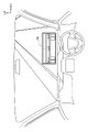
一例として、図5に示す状況は、車両22が交差点60を右折しようとしており、車両22が交差点60を右折して通行する予定経路(図5に示す矢印Rを参照)の近傍には歩行者62が存在している。車両22のITS-ECU26は、交通状況提供システム12からITS無線装置18を介してインフラ情報を受信することで、歩行者62の存在を通知対象として認識している。但し、車両22の乗員から見て、歩行者62は遮蔽物64(図5の例では樹木)によって遮蔽されており、車両22の乗員は、図5に示す状況では歩行者62を直接視認することはできない。このような場合は、通知対象が遮蔽物64によって遮蔽されていると判定される。また、仮に遮蔽物64が存在していない場合には、通知対象が遮蔽物64によって遮蔽されていないと判定される。
As an example, the situation shown in FIG. 5 is that the
次のステップ158において、ITS-ECU26は、ステップ156の判定で通知対象が遮蔽物64によって遮蔽されていると判定されたか否か判定する。ステップ158の判定が肯定された場合はステップ160へ移行する。ステップ160において、ITS-ECU26は、ARグラス40に対し、ARグラス40の表示部46上での通知対象の位置および通知対象の種別を通知し、通知対象の外形を模式的に表す図形を表示部46に表示するよう指示する。これにより、ARグラス制御部42は、通知対象の外形を模式的に表す図形を、表示部46上の指示された位置に表示させる。また、ステップ158の判定が否定された場合は、ステップ160をスキップしてステップ162へ移行する。
In the
ステップ162において、ITS-ECU26は、ARグラス40に対し、ARグラス40の表示部46上での通知対象の位置を通知し、通知対象が存在する領域を強調する枠を表示部46に表示するよう指示する。これにより、ARグラス制御部42は、通知対象が存在する領域を強調する矩形状の枠を、表示部46上の指示された位置に表示させる。
In
図5に示す状況において、上記の処理を経て、ARグラス40を装着している乗員に、ARグラス40を通じて視認される視界の一例を図6に示す。図6に示す例では、ARグラス40を装着している乗員から見て遮蔽物64によって遮蔽されている歩行者62を表す図形66が視界に入っている。これにより、遮蔽物64によって遮蔽された歩行者62が存在していることが乗員に認識される。また、図6に示す例では、遮蔽物64によって遮蔽されている歩行者62が存在する領域を強調する矩形状の枠68が視界に入っている。これにより、図形66を表示することで通知した遮蔽物64によって遮蔽されている歩行者62の存在が乗員から見落とされることが抑制される。
FIG. 6 shows an example of the field of view seen through the
なお、通知対象が存在する領域を強調する枠68は、ARグラス40を装着している乗員から見て通知対象が遮蔽物によって遮蔽されていない場合にも表示される。これにより、通知対象が遮蔽物によって遮蔽されていない場合にも、当該通知対象の存在が乗員から見落とされることが抑制される。
Note that the
ステップ164において、ITS-ECU26は、全ての通知対象の情報を読み込んだか否か判定する。また、ステップ164の判定が否定された場合はステップ150に戻り、ステップ164の判定が肯定される迄、ステップ150~ステップ164を繰り返す。ステップ164の判定が肯定された場合はAR表示制御処理を終了し、図3の対象物通知処理へ戻る。
At
また、自車両が処理対象の交差点内に進入すると、ステップ104の判定が否定されてステップ114へ移行する。ステップ114において、ITS-ECU26は、処理対象の交差点における自車両の曲折が、対向車線を横断する曲折(左側通行での右折または右側通行での左折)か否か判定する。ステップ114の判定が否定された場合はステップ120へ移行する。
Also, when the own vehicle enters the intersection to be processed, the determination at
また、ステップ114の判定が肯定された場合はステップ116へ移行し、ステップ116において、ITS-ECU26は、処理対象の交差点で自車両とすれ違う対向車が存在しているか判定する。具体的には、まず、受信したインフラ情報に車両情報が含まれているか否かを判定する。インフラ情報に車両情報が含まれている場合、当該車両情報が表す車両の位置および進行方向に基づき、自車両と処理対象の交差点ですれ違う対向車が存在しているか否かを判定する。ステップ116の判定が否定された場合はステップ120へ移行する。
If the determination in
一方、自車両と処理対象の交差点ですれ違う対向車が存在している場合、自車両が処理対象の交差点を曲折することに伴い、上記の対向車と所定距離以下に接近する可能性がある。このため、ステップ116の判定が肯定された場合はステップ118へ移行し、ステップ118において、ITS-ECU26は、自車両と処理対象の交差点ですれ違う対向車を通知対象に設定する。
On the other hand, if there is an oncoming vehicle passing by the own vehicle at the intersection to be processed, the own vehicle may approach the oncoming vehicle within a predetermined distance as the vehicle makes a turn at the intersection to be processed. Therefore, if the determination in
なお、ここでは通知対象とする車両の一例として対向車を挙げたが、これに限定されるものではなく、自車両が走行中の道路と処理対象の交差点で交差する道路上に車両が存在している場合に、当該車両を通知対象としてもよい。 Here, an oncoming vehicle is given as an example of a vehicle to be notified, but it is not limited to this. vehicle, the vehicle may be subject to notification.
次のステップ120において、ITS-ECU26は、前述したステップ108と同様に、自車両が処理対象の交差点を曲折した先に、歩行者や自転車などの対象物が存在しているか否か判定する。ステップ120の判定が肯定された場合はステップ122へ移行し、前述したステップ110と同様に、通行予定ルートから所定範囲内に位置している歩行者や自転車を通知対象に設定する。なお、ステップ120の判定が否定された場合は、ステップ122をスキップしてステップ124へ移行する。
In the
そしてステップ124において、ITS-ECU26は、先に説明したAR表示制御処理(図4)を行う。なお、ステップ124におけるAR表示処理では、例えば、通知対象が存在する領域を強調する枠を点滅表示させる等、ステップ112におけるAR表示処理と表示を相違させるようにしてもよい。また、通知対象が未設定の場合(対向車や歩行者などが存在していない場合)は、ステップ124のAR表示制御処理の実行はスキップされる。
Then, at
次のステップ126において、ITS-ECU26は、自車両が通知対象と所定距離L3(L3<L2<L1)以内に接近したか否か判定する。ステップ126の判定が否定された場合はステップ130へ移行するが、ステップ126の判定が肯定された場合はステップ128へ移行する。
In the
ステップ128において、ITS-ECU26は、ARグラス40に対して通知対象との接近に対して注意を喚起する音声の出力を指示する。これにより、ARグラス制御部42は、通知対象との接近に対して注意を喚起する音声をスピーカ52から出力させので、自車両が所定距離L3以内に接近した通知対象が存在することを乗員に認識させることができる。なお、音声で通知することに加えて、例えば、通知対象が存在する領域を強調する枠を点滅表示させるようにしてもよい。
At step 128, the ITS-
次のステップ130において、ITS-ECU26は、ARグラス40の視線カメラ50により、ARグラス40を装着した乗員の視線を検出した結果を取得する。ステップ132において、ITS-ECU26は、ステップ130で取得した視線検出結果に基づいて、ARグラス40の表示部46に表示した図形66や枠68が、ARグラス40を装着した乗員によって視認されたか否か判定する。具体的には、例えば、ARグラス40を装着した乗員の視線が、ARグラス40の表示部46上の図形66や枠68の表示位置に所定時間(例えば1秒程度の時間)以上滞留したかを判定する。
In the next step 130 , the ITS-
ステップ132の判定が否定された場合はステップ136へ移行する。また、ステップ132の判定が肯定された場合、ARグラス40を装着した乗員によって視認された図形66や枠68に対応する通知対象の存在は、ARグラス40を装着した乗員によって認識されたと判断できるので、ステップ134へ移行する。
If the determination at
ステップ134において、ITS-ECU26は、ARグラス40の表示部46に表示されており、かつARグラス40を装着した乗員によって視認されたと判定した図形66や枠68の表示を消去する。これにより、ARグラス40の表示部46上で図形66や枠68の表示が繁雑になることを抑制することができる。
At step 134 , the ITS-
但し、ARグラス40を装着した乗員によって視認された図形66や枠68の表示を消去することは必須の処理ではない。例えば、ステップ134を省略し、ARグラス40の表示部46に表示されている図形66や枠68を、ARグラス40を装着した乗員によって視認されたと判定した以降も、継続して表示するようにしてもよい。
However, erasing the display of the graphic 66 and the
次のステップ136において、ITS-ECU26は、自車両が処理対象の交差点から退去したか否かを判定する。ステップ136の判定が否定された場合はステップ126に戻り、ステップ126以降を繰り返す。また、ステップ136の判定が肯定された場合は、ARグラス40の表示部46に表示されている図形66や枠68の表示を消去した後にステップ100に戻る。
In the
このように、本実施形態では、移動体通信部30が、車両の進行先に存在する対象物の情報を交通状況提供システム12から取得し、ITS-ECU26は、移動体通信部30によって取得された情報に基づき、表示部46が設けられていると共に車両22の乗員に装着されるARグラス40の表示部46に、対象物の情報を表示させる。これにより、車両22の進行先に存在する対象物の情報を乗員に容易に把握させることができる。
As described above, in the present embodiment, the
また、本実施形態では、ITS-ECU26は、ARグラス40の表示部46のうち乗員から見て対象物が存在する方向に対応する位置に対象物の情報を表示させる。これにより、車両22の進行先に存在する対象物の情報を乗員により容易に把握させることができる。
Further, in the present embodiment, the ITS-
また、本実施形態では、ITS-ECU26は、対象物が乗員から見て遮蔽物で遮蔽されていると判定した場合に、前記対象物の情報をARグラス40の表示部46に表示させる。これにより、ARグラス40の表示部46の表示が繁雑になることを抑制することができる。
Further, in the present embodiment, the ITS-
さらに、本実施形態では、ITS-ECU26は、ARグラス40に設けられた周辺撮影カメラ48によって車両の周辺が撮影された周辺撮影画像に基づいて、対象物が乗員から見て遮蔽物で遮蔽されているか否かを判定する。これにより、対象物が乗員から見て遮蔽物で遮蔽されているか否かの判定の誤差を小さくすることができる。
Furthermore, in the present embodiment, the ITS-
また、本実施形態では、ITS-ECU26は、対象物の情報として、対象物の外形を模式的に表す図形を表示させる。これにより、対象物の存在を乗員に直感的に把握させることができる。
Further, in the present embodiment, the ITS-
また、本実施形態では、ITS-ECU26は、ARグラス40に対象物の情報を表示させた後に、乗員によって対象物の情報が認識されたと判定した場合に、対象物の情報の表示を消去させる。これにより、ウェアラブル端末の表示部の表示が繁雑になることを抑制することができ、乗員に認識されていない対象物の存在を乗員に把握させることを促進できる。
Further, in the present embodiment, when the ITS-
さらに、本実施形態では、ITS-ECU26は、ARグラス40に設けられた視線検出部によって乗員の視線の方向が検出された結果に基づいて、乗員によって対象物の情報が認識されたか否かを判定する。これにより、乗員の操作が煩雑になることを回避することができる。
Furthermore, in the present embodiment, the ITS-
なお、上記では、車両22の進行先に存在する対象物の情報を交通状況提供システム12から取得する態様を説明したが、これに限定されるものではない。例えば、上記の対象物の情報は、車載センサ群32に含まれるカメラ、ライダおよびレーダの少なくとも1つから取得することも可能である。
In the above description, a mode in which information on an object existing in the destination of the
また、上記では車両22が交差点を通過する際に、車両や歩行者、自転車などの対象物の存在に注意を促す画像(図形66や枠68)をARグラス40の表示部46に表示させる態様を説明した。しかし、ARグラス40の表示部46に画像を表示させる状況や、ARグラス40の表示部46に表示させる画像は上記に限られるものではない。一例として以下では、ITS-ECU26が図7に示す前方視界補助処理を行うことで、自車両の前方を走行する先行車両によって前方視界が阻害されている場合に、前方視界を補助する画像をARグラス40の表示部46に表示させる態様を説明する。
Further, in the above, when the
前方視界補助処理のステップ170において、ITS-ECU26は、自車両およびその前方の車両を識別するための変数iを0をリセットする。ステップ172において、ITS-ECU26は、自車両の車載センサ群32に含まれるカメラから、自車両の前方を撮影した前方画像を取得する。なお、以下では、自車両のi台前の車両によって撮影された前方画像を「前方画像i」という。自車両によって撮影された前方画像は「前方画像0」になる。「前方画像0」の撮影範囲の一例を図8に「B」の符号を付して示す。
At step 170 of the forward visibility assistance process, the ITS-
ステップ174において、ITS-ECU26は、前方画像iに基づいて、自車両のi+1台前に車両が存在しているか否か判定する。ステップ174の判定が否定された場合はステップ186へ移行し、ステップ186において、ITS-ECU26は、変数iが1以上か否か判定する。ステップ186の判定が否定された場合はステップ170に戻る。このように、自車両の前方に車両が存在しない場合は、ARグラス40の表示部46に画像を表示させる処理は行われない。
At
また、自車両のi+1台前に車両が存在している場合には、ステップ174の判定が肯定されてステップ176へ移行する。ステップ176において、ITS-ECU26は、自車両のi+1台前の車両による前方画像iの遮蔽率を演算する。なお、ここでいう遮蔽率としては、例えば、前方画像iの総面積に占めるi+1台前の車両に相当する画像領域の面積の比率を用いることができる。但し、これに限定されるものではなく、前方画像iが表す前方視界のうちi+1台前の車両によって遮られている領域の比率に関連する別の指標を用いてもよい。
If there is a vehicle (i+1) ahead of the own vehicle, the determination in
次のステップ178において、ITS-ECU26は、ステップ176で演算した遮蔽率が所定値以上か否か判定する。ステップ178の判定が否定された場合はステップ186へ移行する。一方、例えば図8に示すように、自車両72の前方にトラックやバスなどの車高の高い先行車両74が存在している場合には、一例として図9に示すように、前方の視界が大きく遮られた状態になる。このような場合には、ステップ178の判定が肯定されてステップ180へ移行する。
At the
ステップ180において、ITS-ECU26は、前方画像iに含まれる自車両のi+1台前の車両の画像領域から、道路の路面に近い下側部分を表す画像(以下、この画像を基部画像i+1という)を抽出する。基部画像の一例を図10に符号「76」を付して示す。次のステップ182において、ITS-ECU26は、i+1台前の車両に設けられたカメラによって撮影された前方画像(前方画像i+1)を、i+1台前の車両の位置情報(緯度・経度)と共にi+1台前の車両から移動体通信ネットワーク20を通じて取得する。「前方画像1」の撮影範囲の一例を図8に「A」の符号を付して示す。
In
またステップ184において、ITS-ECU26は、変数iを1だけインクリメントし、ステップ174へ戻る。これにより、ステップ174又はステップ178の判定が否定される迄の間、ステップ174~ステップ184が繰り返される。従って、例えば自車両の1台前に自車両からの前方視界に対する遮蔽率の高い先行車両aが存在しており、先行車両Aの1台前に先行車両aからの前方視界に対する遮蔽率の高い先行車両bが存在していた場合、先行車両a,bの基部画像が各々抽出されることになる。
Also in step 184, the ITS-
ステップ174又はステップ178の判定が否定されるとステップ186へ移行する。また、先行車両の基部画像の抽出を行った場合は変数iがインクリメントされているので、ステップ186の判定が肯定されてステップ188へ移行する。ステップ188において、ITS-ECU26は、前方画像iに1~i-1台前の車両の基部画像を合成する。
If the determination at
次のステップ190において、ITS-ECU26は、ARグラス40の周辺撮影カメラ48によって撮影された周辺撮影画像を取得する。ステップ192において、ITS-ECU26は、GPSセンサ28によって検出された自車両72の位置(緯度・経度)に対する、前方画像iを撮影したi台前の車両の位置(緯度・経度)の差に基づき、基部画像を合成した前方画像iに対し、自車両72の乗員からの視界を模擬するように座標変換などを行う。そして、基部画像を合成して座標変換などを経た前方画像iを周辺撮影画像と合成することで、前方画像iと周辺撮影画像との差分に相当する画像を生成し、生成した画像をARグラス40の表示部46に表示させる。ステップ192の処理を行うとステップ170に戻る。
In the next step 190 , the ITS-
上記の処理を経て、ARグラス40を装着している乗員に、ARグラス40を通じて視認される視界の一例を図10に示す。図10に示す例では、ARグラス40を装着している乗員から見て前方視界のうち先行車両の上側部分により遮られていた部分が視界に入っている。これにより、ARグラス40を装着している乗員からの前方視界が改善される。また、図10に示す例では、先行車両の下側部分が基部画像76としてARグラス40を装着している乗員の視界に入っている。これにより、ARグラス40を装着している乗員に先行車両の存在が認識される。
FIG. 10 shows an example of the field of view viewed through the
図10は、先行車両の下側部分を基部画像76として表示させる例を示しているが、これに限定されるものではない。例えば、自車両72がレベル4以上の自動運転を行っている場合には、ARグラス40を装着している乗員に先行車両の存在を認識させる必要性は低い。このような場合には、一例として図11に示すように基部画像76を表示しないようにしてもよい。
Although FIG. 10 shows an example in which the lower portion of the preceding vehicle is displayed as the
また、上記では、車両22のフロントウインドシールドにHUDが設けられていない態様を説明した。上記で説明したARグラス40と同等の機能をHUDによって実現しようとすると、非常に大型のHUDが必要になることから、コスト、質量および消費電力が嵩み、組付け作業性および交換時のサービス性が低下する。また、HUDの表示面を車両のAピラー付近やサイドウインドウまで拡大することは、搭載スペースの点で物理的に困難である。またHUDにおいて、乗員の視線と対象物とを結ぶ線とフロントウインドシールドとの交点に相当する位置に対象物の情報を表示させようとすると、乗員毎に着座姿勢が異なり視線高さが異なることの影響を受け、乗員毎に表示調整の手間がかかるので、現実的ではない。
Also, in the above description, a mode in which the front windshield of the
これに対し、ARグラス40は乗員の眼部に近接した位置に配置されるので、表示範囲を車両のAピラー付近やサイドウインドウを含む範囲に設定しても表示部46の表示面積が小さくて済み、コスト、質量および消費電力が小さく抑えられる。また、乗員の視線と対象物とを結ぶ線とフロントウインドシールドとの交点に相当する位置に対象物の情報を表示させることも、乗員毎に着座姿勢が異なり視線高さが異なることの影響を受けないので容易に実現できる。
On the other hand, since the
但し、本発明は車両22にHUDが設けられていない態様に限定されるものではなく、一例として図12に示すように、車両22の車載システム24にHUD80が設けられた構成に本発明を適用することも可能である。この場合、ITS-ECU26は、対象物が乗員から見てHUD80に映る方向に存在すると判定した場合は対象物の情報をHUD80に表示させる。また、ITS-ECU26は、対象物が乗員から見てHUD80に映らない方向に存在すると判定した場合は、対象物の情報をARグラス40の表示部46に表示させる。これにより、HUD80には表示できない範囲、例えば車両のAピラー付近やサイドウインドウに相当する範囲の情報をARグラス40に表示させることができ、HUD80による表示をARグラス40によって補完することができる。
However, the present invention is not limited to a mode in which the
10 交通状況表示システム
12 交通状況提供システム
14 ITSサーバ
16 交通状況検知システム
18 ITS無線装置
22 車両
24 車載システム
26 ITS-ECU(表示制御部)
30 移動体通信部(取得部)
32 車載センサ群
40 ARグラス(ウェアラブル端末)
42 グラス制御部
46 表示部
48 周辺撮影カメラ(周辺撮影部)
50 視線カメラ(視線検出部)
52 スピーカ
10 traffic
30 mobile communication unit (acquisition unit)
32 In-
42
50 line-of-sight camera (line-of-sight detection unit)
52 speaker
Claims (7)
前記取得部によって取得された情報に基づき、表示部が設けられていると共に前記車両の乗員に装着されるメガネ型のウェアラブル端末の前記表示部に、前記対象物の情報を表示させる表示制御部と、
を含み、
前記表示制御部は、前記対象物が前記乗員から見て前記車両のフロントウインドシールドに設けられたヘッドアップディスプレイに映らない方向に存在すると判定した場合に、前記対象物の情報を前記ウェアラブル端末の前記表示部に表示させる 車両用表示制御装置。 an acquisition unit that acquires information about an object existing in a destination of the vehicle;
a display control unit for displaying information on the target object on the display unit of a glasses-type wearable terminal provided with a display unit and worn by an occupant of the vehicle, based on the information acquired by the acquisition unit; ,
includesfruit,
When the display control unit determines that the object exists in a direction that is not reflected on a head-up display provided on the front windshield of the vehicle as seen from the passenger, the display control unit outputs the information of the object to the wearable terminal. displayed on the display unit Vehicle display control device.
Priority Applications (3)
| Application Number | Priority Date | Filing Date | Title |
|---|---|---|---|
| JP2018228534A JP7163748B2 (en) | 2018-12-05 | 2018-12-05 | Vehicle display control device |
| CN201911022716.0A CN111273765B (en) | 2018-12-05 | 2019-10-25 | Vehicle display control device, vehicle display control method, and storage medium |
| US16/701,654 US11198398B2 (en) | 2018-12-05 | 2019-12-03 | Display control device for vehicle, display control method for vehicle, and storage medium |
Applications Claiming Priority (1)
| Application Number | Priority Date | Filing Date | Title |
|---|---|---|---|
| JP2018228534A JP7163748B2 (en) | 2018-12-05 | 2018-12-05 | Vehicle display control device |
Publications (2)
| Publication Number | Publication Date |
|---|---|
| JP2020091663A JP2020091663A (en) | 2020-06-11 |
| JP7163748B2 true JP7163748B2 (en) | 2022-11-01 |
Family
ID=70972422
Family Applications (1)
| Application Number | Title | Priority Date | Filing Date |
|---|---|---|---|
| JP2018228534A Active JP7163748B2 (en) | 2018-12-05 | 2018-12-05 | Vehicle display control device |
Country Status (3)
| Country | Link |
|---|---|
| US (1) | US11198398B2 (en) |
| JP (1) | JP7163748B2 (en) |
| CN (1) | CN111273765B (en) |
Families Citing this family (5)
| Publication number | Priority date | Publication date | Assignee | Title |
|---|---|---|---|---|
| US10909866B2 (en) * | 2018-07-20 | 2021-02-02 | Cybernet Systems Corp. | Autonomous transportation system and methods |
| DE102019206749A1 (en) * | 2019-05-09 | 2020-11-12 | Volkswagen Aktiengesellschaft | Human-machine interaction in a motor vehicle |
| JP2022105922A (en) * | 2021-01-05 | 2022-07-15 | 日立Astemo株式会社 | Control system, on-vehicle device, and control apparatus |
| WO2022216558A1 (en) * | 2021-04-05 | 2022-10-13 | Meta Platforms Technologies, Llc | Systems and methods for dynamic image processing and segmentation |
| CN114516270B (en) * | 2022-03-11 | 2023-09-12 | 禾多科技(北京)有限公司 | Vehicle control method, apparatus, electronic device, and computer-readable medium |
Citations (2)
| Publication number | Priority date | Publication date | Assignee | Title |
|---|---|---|---|---|
| WO2017145645A1 (en) | 2016-02-25 | 2017-08-31 | 富士フイルム株式会社 | Driving assistance apparatus, driving assistance method, and driving assistance program |
| JP2018181168A (en) | 2017-04-20 | 2018-11-15 | 株式会社Subaru | Information presentation device |
Family Cites Families (10)
| Publication number | Priority date | Publication date | Assignee | Title |
|---|---|---|---|---|
| JP2004322680A (en) | 2003-04-21 | 2004-11-18 | Denso Corp | Head-up display device |
| US8395529B2 (en) * | 2009-04-02 | 2013-03-12 | GM Global Technology Operations LLC | Traffic infrastructure indicator on head-up display |
| US8629903B2 (en) * | 2009-04-02 | 2014-01-14 | GM Global Technology Operations LLC | Enhanced vision system full-windshield HUD |
| US8346426B1 (en) * | 2010-04-28 | 2013-01-01 | Google Inc. | User interface for displaying internal state of autonomous driving system |
| JP2013025635A (en) | 2011-07-22 | 2013-02-04 | Toyota Motor Corp | Driving support device and driving support method |
| EP2762950B1 (en) * | 2013-02-01 | 2020-10-21 | Volvo Car Corporation | Vehicle head-up display arrangement |
| EP3007029B1 (en) * | 2014-10-07 | 2017-12-27 | LG Electronics Inc. | Mobile terminal and wearable device |
| US9836814B2 (en) * | 2015-01-09 | 2017-12-05 | Panasonic Intellectual Property Management Co., Ltd. | Display control apparatus and method for stepwise deforming of presentation image radially by increasing display ratio |
| JP2017021546A (en) * | 2015-07-10 | 2017-01-26 | 田山 修一 | Image displaying system, and method, for on-vehicle use |
| JP6390035B2 (en) * | 2016-05-23 | 2018-09-19 | 本田技研工業株式会社 | Vehicle control system, vehicle control method, and vehicle control program |
-
2018
- 2018-12-05 JP JP2018228534A patent/JP7163748B2/en active Active
-
2019
- 2019-10-25 CN CN201911022716.0A patent/CN111273765B/en active Active
- 2019-12-03 US US16/701,654 patent/US11198398B2/en active Active
Patent Citations (2)
| Publication number | Priority date | Publication date | Assignee | Title |
|---|---|---|---|---|
| WO2017145645A1 (en) | 2016-02-25 | 2017-08-31 | 富士フイルム株式会社 | Driving assistance apparatus, driving assistance method, and driving assistance program |
| JP2018181168A (en) | 2017-04-20 | 2018-11-15 | 株式会社Subaru | Information presentation device |
Also Published As
| Publication number | Publication date |
|---|---|
| US20200180519A1 (en) | 2020-06-11 |
| CN111273765A (en) | 2020-06-12 |
| CN111273765B (en) | 2023-09-12 |
| JP2020091663A (en) | 2020-06-11 |
| US11198398B2 (en) | 2021-12-14 |
Similar Documents
| Publication | Publication Date | Title |
|---|---|---|
| JP7163748B2 (en) | Vehicle display control device | |
| JP6700623B2 (en) | Driving support device and computer program | |
| KR102344171B1 (en) | Image generating apparatus, image generating method, and program | |
| EP1961613B1 (en) | Driving support method and driving support device | |
| KR102309316B1 (en) | Display apparatus for vhhicle and vehicle including the same | |
| EP1939040B1 (en) | Driving support method and driving support apparatus | |
| WO2019097763A1 (en) | Superposed-image display device and computer program | |
| JP5160564B2 (en) | Vehicle information display device | |
| KR100936558B1 (en) | Perimeter monitoring apparatus and image display method for vehicle | |
| US11511627B2 (en) | Display device and computer program | |
| JP4719590B2 (en) | In-vehicle peripheral status presentation device | |
| US11525694B2 (en) | Superimposed-image display device and computer program | |
| JP4784572B2 (en) | Driving support method and driving support device | |
| CN112052716B (en) | Identification device, identification method, and storage medium | |
| KR102635265B1 (en) | Apparatus and method for around view monitoring using lidar | |
| WO2018180579A1 (en) | Imaging control device, control method for imaging control device, and mobile object | |
| JP7151073B2 (en) | Display device and computer program | |
| JP4848644B2 (en) | Obstacle recognition system | |
| TWM518653U (en) | Driving image auxiliary device | |
| JP7143728B2 (en) | Superimposed image display device and computer program | |
| KR20150074753A (en) | Driver assistance apparatus and Vehicle including the same | |
| JP6984341B2 (en) | Superimposed image display device and computer program | |
| JP6946962B2 (en) | Driving support device and computer program | |
| TWM510877U (en) | Three-dimensional driving image auxiliary device | |
| JP2020085897A (en) | Overlapping image display device and computer program |
Legal Events
| Date | Code | Title | Description |
|---|---|---|---|
| A621 | Written request for application examination |
Free format text: JAPANESE INTERMEDIATE CODE: A621 Effective date: 20210325 |
|
| A977 | Report on retrieval |
Free format text: JAPANESE INTERMEDIATE CODE: A971007 Effective date: 20220216 |
|
| A131 | Notification of reasons for refusal |
Free format text: JAPANESE INTERMEDIATE CODE: A131 Effective date: 20220322 |
|
| A521 | Request for written amendment filed |
Free format text: JAPANESE INTERMEDIATE CODE: A523 Effective date: 20220519 |
|
| TRDD | Decision of grant or rejection written | ||
| A01 | Written decision to grant a patent or to grant a registration (utility model) |
Free format text: JAPANESE INTERMEDIATE CODE: A01 Effective date: 20220920 |
|
| A61 | First payment of annual fees (during grant procedure) |
Free format text: JAPANESE INTERMEDIATE CODE: A61 Effective date: 20221003 |
|
| R151 | Written notification of patent or utility model registration |
Ref document number: 7163748 Country of ref document: JP Free format text: JAPANESE INTERMEDIATE CODE: R151 |