JP7163693B2 - projector - Google Patents
projector Download PDFInfo
- Publication number
- JP7163693B2 JP7163693B2 JP2018180117A JP2018180117A JP7163693B2 JP 7163693 B2 JP7163693 B2 JP 7163693B2 JP 2018180117 A JP2018180117 A JP 2018180117A JP 2018180117 A JP2018180117 A JP 2018180117A JP 7163693 B2 JP7163693 B2 JP 7163693B2
- Authority
- JP
- Japan
- Prior art keywords
- substrate
- light
- light source
- source device
- exterior housing
- Prior art date
- Legal status (The legal status is an assumption and is not a legal conclusion. Google has not performed a legal analysis and makes no representation as to the accuracy of the status listed.)
- Active
Links
Images


Classifications
-
- H—ELECTRICITY
- H04—ELECTRIC COMMUNICATION TECHNIQUE
- H04N—PICTORIAL COMMUNICATION, e.g. TELEVISION
- H04N9/00—Details of colour television systems
- H04N9/12—Picture reproducers
- H04N9/31—Projection devices for colour picture display, e.g. using electronic spatial light modulators [ESLM]
- H04N9/3141—Constructional details thereof
- H04N9/3144—Cooling systems
-
- G—PHYSICS
- G03—PHOTOGRAPHY; CINEMATOGRAPHY; ANALOGOUS TECHNIQUES USING WAVES OTHER THAN OPTICAL WAVES; ELECTROGRAPHY; HOLOGRAPHY
- G03B—APPARATUS OR ARRANGEMENTS FOR TAKING PHOTOGRAPHS OR FOR PROJECTING OR VIEWING THEM; APPARATUS OR ARRANGEMENTS EMPLOYING ANALOGOUS TECHNIQUES USING WAVES OTHER THAN OPTICAL WAVES; ACCESSORIES THEREFOR
- G03B21/00—Projectors or projection-type viewers; Accessories therefor
- G03B21/14—Details
- G03B21/16—Cooling; Preventing overheating
-
- G—PHYSICS
- G03—PHOTOGRAPHY; CINEMATOGRAPHY; ANALOGOUS TECHNIQUES USING WAVES OTHER THAN OPTICAL WAVES; ELECTROGRAPHY; HOLOGRAPHY
- G03B—APPARATUS OR ARRANGEMENTS FOR TAKING PHOTOGRAPHS OR FOR PROJECTING OR VIEWING THEM; APPARATUS OR ARRANGEMENTS EMPLOYING ANALOGOUS TECHNIQUES USING WAVES OTHER THAN OPTICAL WAVES; ACCESSORIES THEREFOR
- G03B17/00—Details of cameras or camera bodies; Accessories therefor
- G03B17/55—Details of cameras or camera bodies; Accessories therefor with provision for heating or cooling, e.g. in aircraft
-
- G—PHYSICS
- G03—PHOTOGRAPHY; CINEMATOGRAPHY; ANALOGOUS TECHNIQUES USING WAVES OTHER THAN OPTICAL WAVES; ELECTROGRAPHY; HOLOGRAPHY
- G03B—APPARATUS OR ARRANGEMENTS FOR TAKING PHOTOGRAPHS OR FOR PROJECTING OR VIEWING THEM; APPARATUS OR ARRANGEMENTS EMPLOYING ANALOGOUS TECHNIQUES USING WAVES OTHER THAN OPTICAL WAVES; ACCESSORIES THEREFOR
- G03B21/00—Projectors or projection-type viewers; Accessories therefor
- G03B21/14—Details
- G03B21/20—Lamp housings
- G03B21/2006—Lamp housings characterised by the light source
- G03B21/2013—Plural light sources
-
- G—PHYSICS
- G03—PHOTOGRAPHY; CINEMATOGRAPHY; ANALOGOUS TECHNIQUES USING WAVES OTHER THAN OPTICAL WAVES; ELECTROGRAPHY; HOLOGRAPHY
- G03B—APPARATUS OR ARRANGEMENTS FOR TAKING PHOTOGRAPHS OR FOR PROJECTING OR VIEWING THEM; APPARATUS OR ARRANGEMENTS EMPLOYING ANALOGOUS TECHNIQUES USING WAVES OTHER THAN OPTICAL WAVES; ACCESSORIES THEREFOR
- G03B21/00—Projectors or projection-type viewers; Accessories therefor
- G03B21/14—Details
- G03B21/20—Lamp housings
- G03B21/2006—Lamp housings characterised by the light source
- G03B21/2033—LED or laser light sources
- G03B21/204—LED or laser light sources using secondary light emission, e.g. luminescence or fluorescence
-
- H—ELECTRICITY
- H04—ELECTRIC COMMUNICATION TECHNIQUE
- H04N—PICTORIAL COMMUNICATION, e.g. TELEVISION
- H04N23/00—Cameras or camera modules comprising electronic image sensors; Control thereof
- H04N23/50—Constructional details
- H04N23/51—Housings
-
- H—ELECTRICITY
- H04—ELECTRIC COMMUNICATION TECHNIQUE
- H04N—PICTORIAL COMMUNICATION, e.g. TELEVISION
- H04N9/00—Details of colour television systems
- H04N9/12—Picture reproducers
- H04N9/31—Projection devices for colour picture display, e.g. using electronic spatial light modulators [ESLM]
- H04N9/3102—Projection devices for colour picture display, e.g. using electronic spatial light modulators [ESLM] using two-dimensional electronic spatial light modulators
- H04N9/3105—Projection devices for colour picture display, e.g. using electronic spatial light modulators [ESLM] using two-dimensional electronic spatial light modulators for displaying all colours simultaneously, e.g. by using two or more electronic spatial light modulators
-
- H—ELECTRICITY
- H04—ELECTRIC COMMUNICATION TECHNIQUE
- H04N—PICTORIAL COMMUNICATION, e.g. TELEVISION
- H04N9/00—Details of colour television systems
- H04N9/12—Picture reproducers
- H04N9/31—Projection devices for colour picture display, e.g. using electronic spatial light modulators [ESLM]
- H04N9/3141—Constructional details thereof
- H04N9/315—Modulator illumination systems
- H04N9/3158—Modulator illumination systems for controlling the spectrum
-
- H—ELECTRICITY
- H04—ELECTRIC COMMUNICATION TECHNIQUE
- H04N—PICTORIAL COMMUNICATION, e.g. TELEVISION
- H04N9/00—Details of colour television systems
- H04N9/12—Picture reproducers
- H04N9/31—Projection devices for colour picture display, e.g. using electronic spatial light modulators [ESLM]
- H04N9/3141—Constructional details thereof
- H04N9/315—Modulator illumination systems
- H04N9/3161—Modulator illumination systems using laser light sources
-
- H—ELECTRICITY
- H04—ELECTRIC COMMUNICATION TECHNIQUE
- H04N—PICTORIAL COMMUNICATION, e.g. TELEVISION
- H04N9/00—Details of colour television systems
- H04N9/12—Picture reproducers
- H04N9/31—Projection devices for colour picture display, e.g. using electronic spatial light modulators [ESLM]
- H04N9/3141—Constructional details thereof
- H04N9/315—Modulator illumination systems
- H04N9/3164—Modulator illumination systems using multiple light sources
-
- H—ELECTRICITY
- H05—ELECTRIC TECHNIQUES NOT OTHERWISE PROVIDED FOR
- H05K—PRINTED CIRCUITS; CASINGS OR CONSTRUCTIONAL DETAILS OF ELECTRIC APPARATUS; MANUFACTURE OF ASSEMBLAGES OF ELECTRICAL COMPONENTS
- H05K7/00—Constructional details common to different types of electric apparatus
- H05K7/20—Modifications to facilitate cooling, ventilating, or heating
- H05K7/2039—Modifications to facilitate cooling, ventilating, or heating characterised by the heat transfer by conduction from the heat generating element to a dissipating body
- H05K7/20409—Outer radiating structures on heat dissipating housings, e.g. fins integrated with the housing
-
- G—PHYSICS
- G03—PHOTOGRAPHY; CINEMATOGRAPHY; ANALOGOUS TECHNIQUES USING WAVES OTHER THAN OPTICAL WAVES; ELECTROGRAPHY; HOLOGRAPHY
- G03B—APPARATUS OR ARRANGEMENTS FOR TAKING PHOTOGRAPHS OR FOR PROJECTING OR VIEWING THEM; APPARATUS OR ARRANGEMENTS EMPLOYING ANALOGOUS TECHNIQUES USING WAVES OTHER THAN OPTICAL WAVES; ACCESSORIES THEREFOR
- G03B21/00—Projectors or projection-type viewers; Accessories therefor
- G03B21/14—Details
- G03B21/20—Lamp housings
- G03B21/2066—Reflectors in illumination beam
-
- G—PHYSICS
- G03—PHOTOGRAPHY; CINEMATOGRAPHY; ANALOGOUS TECHNIQUES USING WAVES OTHER THAN OPTICAL WAVES; ELECTROGRAPHY; HOLOGRAPHY
- G03B—APPARATUS OR ARRANGEMENTS FOR TAKING PHOTOGRAPHS OR FOR PROJECTING OR VIEWING THEM; APPARATUS OR ARRANGEMENTS EMPLOYING ANALOGOUS TECHNIQUES USING WAVES OTHER THAN OPTICAL WAVES; ACCESSORIES THEREFOR
- G03B21/00—Projectors or projection-type viewers; Accessories therefor
- G03B21/14—Details
- G03B21/20—Lamp housings
- G03B21/2073—Polarisers in the lamp house
Description
本発明は、プロジェクターに関する。 The present invention relates to projectors.
近年、プロジェクターの高性能化を目的として、広色域かつ高効率な光源であるレーザー光源を用いたプロジェクターが注目されている。下記の特許文献1および2に、複数の半導体発光素子が一つのパッケージに収容された光源装置が開示されている。この構成によれば、小型で高出力の光源装置が実現できる。
2. Description of the Related Art In recent years, in order to improve the performance of projectors, attention has been paid to projectors using a laser light source, which is a light source with a wide color gamut and high efficiency.
また、下記の特許文献3に、半導体発光素子と、熱拡散板と、ヒートシンクと、熱電素子と、冷却ファンと、断熱用空気流路と、を備え、プロジェクターの光源として用いられる半導体光源装置が開示されている。
Further,
特許文献1および2の光源装置においては、複数の半導体発光素子が一つのパッケージ内に実装されていることによって、小型化が図れる反面、熱密度が高くなって半導体発光素子の温度上昇が大きくなり、発光効率が低下する、という問題がある。この問題を解決するためには、例えば特許文献3のような空冷式の冷却手段を用いて半導体発光素子を十分に冷却する必要がある。この構成において、冷却性能を高める手段として、ヒートシンクを大きくすることが考えられる。
In the light source devices of
ところが、特許文献3の光源装置において、光源装置は小型であったとしても、ヒートシンクを大きくすることによってプロジェクターが大型化する、という問題が生じる。したがって、発光素子を十分に冷却できる冷却性能を有するとともに、小型化に寄与できる光源装置を備えたプロジェクターの提供が求められている。
However, in the light source device of
上記の目的を達成するために、本発明の一つの態様のプロジェクターは、光を射出する光源装置と、前記光源装置から射出された光を画像情報に応じて変調する光変調装置と、前記光変調装置により変調された光を投射する投射光学装置と、前記光源装置と前記光変調装置と前記投射光学装置とを収容する外装筐体と、前記光源装置の熱を放出する放熱フィンを有するヒートシンクと、を備えている。前記光源装置は、第1基板面と、前記第1基板面の反対側に位置する第2基板面と、を有する基板と、前記基板の前記第1基板面側に設けられた複数の発光素子と、前記複数の発光素子を囲むように前記基板の前記第1基板面側に設けられた枠体と、前記複数の発光素子から射出された光を透過させる透光性部材を有し、前記第1基板面に対向して設けられ、前記枠体の前記基板とは反対側に接合された蓋体と、を有し、前記複数の発光素子は、前記基板と前記枠体と前記蓋体とにより形成された収容空間に収容されている。前記外装筐体は、第1面と、前記第1面に交差する第2面と、前記第1面および前記第2面に交差する第3面と、を有し、前記第1面の面積は、前記第2面および前記第3面の面積よりも大きい。前記第1基板面または前記第2基板面は、前記第1面に対向し、前記放熱フィンの長手方向は、前記外装筐体の前記第1面に沿っている。 In order to achieve the above object, a projector according to one aspect of the present invention includes a light source device that emits light, a light modulation device that modulates the light emitted from the light source device according to image information, the light A projection optical device for projecting light modulated by a modulation device, an exterior housing for housing the light source device, the light modulation device, and the projection optical device, and a heat sink having radiation fins for releasing heat from the light source device. and have. The light source device includes a substrate having a first substrate surface and a second substrate surface opposite to the first substrate surface, and a plurality of light emitting elements provided on the first substrate surface side of the substrate. a frame provided on the first substrate surface side of the substrate so as to surround the plurality of light emitting elements; and a translucent member that transmits light emitted from the plurality of light emitting elements, a lid provided to face the first substrate surface and joined to a side of the frame opposite to the substrate, wherein the plurality of light emitting elements are connected to the substrate, the frame, and the lid. It is housed in the housing space formed by and. The exterior housing has a first surface, a second surface that intersects with the first surface, and a third surface that intersects with the first surface and the second surface, and the area of the first surface is greater than the areas of the second and third surfaces. The first substrate surface or the second substrate surface faces the first surface, and the longitudinal direction of the radiation fins extends along the first surface of the exterior housing.
本発明の一つの態様のプロジェクターにおいて、前記第1基板面または前記第2基板面は、前記第1面に沿っていてもよい。 In one aspect of the projector of the present invention, the first substrate surface or the second substrate surface may be along the first surface.
本発明の一つの態様のプロジェクターにおいて、前記外装筐体は、前記外装筐体の前記第1面に沿い、前記第1面に対向する第4面をさらに有し、前記光源装置は、前記第1面に対向して設けられた第1光源装置と、前記第4面に対向して設けられた第2光源装置と、を有し、前記第1光源装置は、前記第4面に向けて光を射出し、前記第2光源装置は、前記第1面に向けて光を射出してもよい。 In the projector according to one aspect of the present invention, the exterior housing further has a fourth surface along the first surface of the exterior housing and facing the first surface, and the light source device A first light source device provided facing one surface and a second light source device provided facing the fourth surface, wherein the first light source device faces the fourth surface Light may be emitted, and the second light source device may emit light toward the first surface.
本発明の一つの態様のプロジェクターは、前記放熱フィンを冷却する気流を生成するファンをさらに備えていてもよい。 The projector according to one aspect of the present invention may further include a fan that generates an airflow that cools the radiation fins.
本発明の一つの態様のプロジェクターにおいて、前記ファンの回転軸は、前記外装筐体の前記第1面に沿っていてもよい。 In one aspect of the projector of the present invention, the rotation axis of the fan may be along the first surface of the exterior housing.
本発明の一つの態様のプロジェクターにおいて、前記基板の前記第2基板面は、前記外装筐体の前記第1面に交差していてもよい。 In one aspect of the projector of the present invention, the second substrate surface of the substrate may intersect the first surface of the exterior housing.
本発明の一つの態様のプロジェクターにおいて、前記気流の下流側における前記放熱フィンの短手方向の寸法は、前記気流の上流側における前記放熱フィンの短手方向の寸法よりも長くてもよい。 In one aspect of the projector of the present invention, the transverse dimension of the radiation fins on the downstream side of the airflow may be longer than the transverse dimension of the radiation fins on the upstream side of the airflow.
[第1実施形態]
以下、本発明の第1実施形態について、図1~図5を用いて説明する。
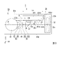
図1は、第1実施形態のプロジェクターの概略構成図である。図2は、プロジェクターの斜視図である。図3は、プロジェクターを側面から見た模式図である。図4は、光源装置の斜視図である。図5は、図4のV-V線に沿う光源装置の断面図である。
以下の全ての図面においては各構成要素を見やすくするため、構成要素によって寸法の縮尺を異ならせて示すことがある。また、図面によっては、最小限の構成要素のみを図示し、それ以外の構成要素の図示を省略することがある。
[First embodiment]
A first embodiment of the present invention will be described below with reference to FIGS. 1 to 5. FIG.
FIG. 1 is a schematic configuration diagram of the projector of the first embodiment. FIG. 2 is a perspective view of the projector. FIG. 3 is a schematic diagram of the projector viewed from the side. FIG. 4 is a perspective view of the light source device. FIG. 5 is a cross-sectional view of the light source device taken along line VV in FIG.
In all the drawings below, in order to make each component easy to see, the scale of dimensions may be changed depending on the component. Also, depending on the drawing, only the minimum number of constituent elements may be illustrated, and illustration of other constituent elements may be omitted.
本実施形態に係るプロジェクターの一例について説明する。
本実施形態のプロジェクター1は、スクリーン(被投射面)SCR上にカラー映像を表示する投射型画像表示装置である。プロジェクター1は、赤色光、緑色光、青色光の各色光に対応した3つの液晶光変調装置を備えている。プロジェクター1は、照明装置の光源として、高輝度・高出力な光が得られる半導体レーザーを備えている。
An example of the projector according to this embodiment will be described.
The
図1および図2に示すように、プロジェクター1は、第1照明装置100と、第2照明装置102と、色分離導光光学系200と、光変調装置400Rと、光変調装置400Gと、光変調装置400Bと、光合成光学系500と、投射光学装置600と、ファン32と、外装筐体33と、を備えている。第1照明装置100、第2照明装置102、色分離導光光学系200、光変調装置400R、光変調装置400G、光変調装置400B、光合成光学系500、投射光学装置600およびファン32は、外装筐体33の内部空間に収容されている。
As shown in FIGS. 1 and 2, the
以下の説明において、投射光学装置600の光軸と平行な方向をX軸方向と称し、後述する仮想面Pの面内において投射光学装置600の光軸と垂直な方向をY軸方向と称し、X軸方向およびY軸方向に垂直な方向をZ軸方向と称する。
In the following description, the direction parallel to the optical axis of the projection
第1照明装置100は、第1光源装置10と、ヒートシンク35と、偏向ミラー37と、ホモジナイザー光学系38と、ダイクロイックミラー80と、コリメート集光光学系90と、回転蛍光板30と、モーター50と、第1レンズアレイ120と、第2レンズアレイ130と、偏光変換素子140と、重畳レンズ150と、を備えている。本実施形態の第1光源装置10は、特許請求の範囲の光源装置に対応する。
The
第1光源装置10は、レーザー光からなる第1波長帯の光Eを射出する。第1光源装置10から射出される光Eは、回転蛍光板30に含まれる蛍光体の励起光として機能する。第1波長帯は、例えば400nm~495nmの青色波長帯である。あるいは、第1波長帯は、例えば400nm未満の紫外波長帯であってもよい。第1光源装置10は、後で詳しく説明するように、複数のレーザーチップが一つのパッケージ内に収容されたマルチレーザーチップパッケージ等の光源装置から構成されている。
The first
図4および図5に示すように、第1光源装置10は、基板12と、複数のサブマウント13と、複数の発光素子14と、枠体15と、蓋体16と、複数のリード端子17と、を備えている。基板12、枠体15および蓋体16は、各々が別体の部材であり、後述する接合材を介して接合されている。以下、基板12と枠体15とが接合された接合部を第1接合部21と称し、枠体15と蓋体16とが接合された接合部を第2接合部22と称する。
As shown in FIGS. 4 and 5, the first
基板12は、第1基板面12aと、第1基板面12aとは反対側に位置する第2基板面12bと、を有する。基板12は、第1基板面12aの法線方向から見た平面視において、略正方形もしくは略長方形等の四角形の形状を有する。基板12の第1基板面12a側には、後述する複数のサブマウント13を介して複数の発光素子14が設けられている。
The
基板12の第2基板面12bには、発光時に複数の発光素子14から発せられる熱を放出するためのヒートシンク35が設けられる。そのため、基板12は、熱伝導率が高い金属材料で構成されている。この種の金属材料として、銅、アルミニウムなどが好ましく用いられ、銅が特に好ましく用いられる。
The
図4に示すように、複数のサブマウント13は、基板12の第1基板面12aにおいて、基板12の一辺と平行な方向に所定の間隔を空けて設けられている。複数のサブマウント13の各々は、複数の発光素子14に対応して設けられている。本構成例では、サブマウント13は、4個の発光素子14に対して共通に設けられているが、発光素子14の数は特に限定されない。
As shown in FIG. 4, the plurality of
サブマウント13は、例えば窒化アルミニウム、アルミナ等のセラミック材料で構成されている。サブマウント13は、基板12と発光素子14との間に介在し、基板12と発光素子14との線膨張係数の違いにより生じる熱応力を緩和する。サブマウント13は、銀ロウ、金-スズはんだ等の接合材により基板12に接合されている。
The
複数の発光素子14は、基板12の第1基板面12a側に設けられている。発光素子14は、例えば半導体レーザー、発光ダイオードなどの固体光源から構成されている。発光素子14は、第1光源装置10の用途に応じて任意の波長の発光素子を用いればよい。本実施形態では、蛍光体励起用の波長帯である400nm~495nmの青色光を射出する発光素子14として、例えば窒化物系半導体(InXAlYGa1-X-YN、0≦X≦1、0≦Y≦1、X+Y≦1)で構成される端面発光型の半導体レーザーが用いられる。また、上記の一般式に加えて、III族元素の一部がホウ素原子で置換されたもの、V族元素として窒素原子の一部がリン原子、ヒ素原子で置換されたもの等を含んでもよい。
The plurality of
複数の発光素子14は、基板12の第1基板面12aの法線方向から見て、(m×n)個(m,n:2以上の自然数)の半導体レーザーがm行n列の格子状に配列された構成を有する。第1実施形態では、複数の発光素子14として、例えば16個の半導体レーザーが4行4列の格子状に配列されている。基板12の第1基板面12aの法線方向から見た場合を平面視と称する。
The plurality of
図5に示すように、発光素子14は、直方体状の発光素子14の6つの面のうち、光射出面14aとは反対側の面が基板12の第1基板面12aと対向するように、サブマウント13上に設けられている。この配置により、複数の発光素子14の各々は、基板12の第1基板面12aと略垂直な方向に光Eを射出する。また、発光素子14は、光射出面14aがサブマウント13の一つの端面13aと略同一平面上に揃うように、サブマウント13上に設けられている。発光素子14は、銀ロウ、金-スズはんだ等の接合材(図示略)によりサブマウント13に接合されている。
As shown in FIG. 5, the
枠体15は、複数の発光素子14を囲むように、基板12の第1基板面12a側に設けられている。枠体15は、平面視において、四角形の環状の形状を有する。枠体15は、四角形の4辺が全て一体の部材であってもよいし、複数の部材が接合された構成であってもよい。枠体15は、基板12と蓋体16との間の距離(間隔)を一定に保持し、複数の発光素子14が収容される収容空間Sの一部を構成する。そのため、枠体15は、所定の剛性を有することが好ましい。
The
枠体15は、蓋体16に発生する応力を緩和する役目を果たす。そのため、枠体15は、基板12の線膨張係数よりも小さく、蓋体16の線膨張係数よりも大きい線膨張係数を有する材料で構成されることが好ましい。枠体15の材料として、例えばコバール等の金属材料、アルミナ、炭化珪素、窒化珪素等のセラミック材料が好ましく用いられ、コバールやアルミナが特に好ましく用いられる。
The
蓋体16は、複数の発光素子14から射出された光Eを透過させる透光性部材18から構成されている。蓋体16は、基板12の第1基板面12aに対向して設けられ、枠体15の基板12とは反対側に接合されている。蓋体16は、平面視において、正方形、長方形を含む四角形の形状を有する。透光性部材18の材料としては、光透過率の高い透光性材料が好ましく用いられる。透光性部材18の具体例として、例えばBK7等のホウケイ酸ガラス、石英ガラス、合成石英ガラス等を含む光学ガラス、水晶、およびサファイア等が用いられる。ここでは、図示を省略するが、発光素子14から射出された光Eを透過させるレンズが透光性部材18と一体に形成されていてもよい。
The
第1接合部21において、基板12と枠体15とは、有機接着剤を含む接合材211によって接合されている。第1接合部21は、枠体15と同様、平面視において、四角形の環状の形状を有する。有機接着剤としては、例えばシリコーン系接着剤、エポキシ樹脂系接着剤、アクリル樹脂系接着剤等が好ましく用いられる。
At the first
第2接合部22において、枠体15と蓋体16とは、銀ロウ、金-スズはんだ等の金属材料、もしくは低融点ガラス等の無機材料を含む接合材221によって接合されている。第2接合部22は、枠体15と同様、平面視において、四角形の環状の形状を有する。
At the second
このように、基板12と枠体15とが接合された第1接合部21、および、枠体15と蓋体16とが接合された第2接合部22の少なくとも一方は、有機接着剤を含む。基板12と枠体15とが第1接合部21において接合され、枠体15と蓋体16とが第2接合部22において接合されたことにより、基板12と枠体15と蓋体16とによって囲まれた空間は、外気から遮断され、複数の発光素子14が気密に収容されるための密閉空間となる。以下、この密閉空間を収容空間Sと称する。すなわち、複数の発光素子14は、基板12と枠体15と蓋体16とにより形成された収容空間Sに収容されている。
Thus, at least one of the first joint 21 where the
複数の発光素子14が収容空間Sに収容されることにより、発光素子14への有機物や水分等の異物の付着が低減される。収容空間Sは、減圧状態であることが好ましい。もしくは、収容空間Sは、窒素ガスなどの不活性ガス、もしくは乾燥空気で満たされていてもよい。なお、減圧状態は、大気圧より低い圧力の気体で満たされた空間の状態のことである。減圧状態において、収容空間Sに満たされる気体は、不活性ガスや乾燥空気であることが好ましい。
Since the plurality of
図4に示すように、枠体15には、複数の貫通孔15cが設けられている。複数の貫通孔15cの各々には、複数の発光素子14の各々に電力を供給するためのリード端子17が設けられている。リード端子17の構成材料としては、例えばコバールが用いられる。リード端子17の表面には、例えばニッケル-金からなるめっき層が設けられている。
As shown in FIG. 4, the
図4では、一つのサブマウント13に実装された複数の発光素子14が直列に接続され、各サブマウント13の側方に一対のリード端子17が設けられた例が示されている。ただし、複数の発光素子14の電気的な接続やリード端子17の配置については、この例に限らず、適宜変更が可能である。
FIG. 4 shows an example in which a plurality of
収容空間Sには、リード端子17の一端と発光素子14の端子とを電気的に接続するボンディングワイヤー(図示略)が設けられている。リード端子17の他端は、外部回路(図示略)と接続されている。枠体15の貫通孔15cの内壁とリード端子17との間の隙間は、封止材によって封止されている。封止材としては、例えば低融点ガラスなどが好ましく用いられる。
A bonding wire (not shown) that electrically connects one end of the
図3に示すように、ヒートシンク35は、第1光源装置10の基板12の第2基板面12bに設けられている。ヒートシンク35は、複数の発光素子14が点灯した際に発生する熱を第1光源装置10の外部に放出する。ヒートシンク35は、基板351と、基板351の第1面351aに設けられた複数の放熱フィン352と、から構成されている。第1光源装置10の熱は、複数の放熱フィン352を介して外部に放出される。
As shown in FIG. 3, the
本実施形態において、放熱フィン352の形状は長方形状であり、放熱フィン352の長手方向は外装筐体33の第1面33aに沿って配置されている。放熱フィン352の輪郭をなす長方形の4つの辺のうち、2つの長辺352a,352bは外装筐体33の第1面33aおよび仮想面Pに対して略平行に配置され、2つの短辺352c,352dは外装筐体33の第1面33aおよび仮想面Pに対して略垂直に配置されている。なお、外装筐体33の第1面33aおよび仮想面Pについては後述する。
In this embodiment, the shape of the
ファン32は、放熱フィン352の長手方向の一端と対向するように、ヒートシンク35と外装筐体33との間に設けられている。ファン32は、回転軸32cが外装筐体33の第1面33aに沿ってX軸方向と平行に配置されている。また、ファン32の近傍にあたる外装筐体33の一部には排気口(図示略)が設けられている。ファン32は、外装筐体33内の空気を外部に排気する排気ファンとして機能する。したがって、ファン32が作動した際に、外装筐体33内にはファン32に遠い側から近い側に向かって流れる気流Fが発生する。ファン32は、例えば軸流ファンで構成されていてもよいし、遠心ファンで構成されていてもよい。
The
図3に示すように、偏向ミラー37は、第1光源装置10から射出された光Eを反射させて光路を折り曲げ、後段のホモジナイザー光学系38に向けて射出する。偏向ミラー37は、仮想面Pに対して45°の角度をなすように配置されている。
As shown in FIG. 3, the
ホモジナイザー光学系38は、第1レンズアレイ381と、第2レンズアレイ382と、を有する。ホモジナイザー光学系38は、コリメート集光光学系90と協働して被照明領域(蛍光体層42)における照度分布を均一化する。第1レンズアレイ381および第2レンズアレイ382の各々は、アレイ状に配列された複数のレンズから構成されている。
The homogenizer
図1に示すように、ダイクロイックミラー80は、ホモジナイザー光学系38から射出される光Eの光軸および第2照明装置102から射出される光Bの光軸に対して45°の角度で交わるように配置されている。ダイクロイックミラー80は、青色光を反射し、赤色光と緑色光とを含む黄色の蛍光を透過させる波長選択性を有する。
As shown in FIG. 1, the
コリメート集光光学系90は、ダイクロイックミラー80から射出された光Eを集光した状態で回転蛍光板30の蛍光体層42に入射させる機能と、回転蛍光板30から射出された蛍光Yを略平行化する機能と、を有する。コリメート集光光学系90は、第1レンズ92と、第2レンズ94と、を備える。第1レンズ92および第2レンズ94の各々は、凸レンズから構成されている。
The collimating condensing
回転蛍光板30は、モーター50と、円板40と、反射膜41と、蛍光体層(波長変換層)42と、を備えている。回転蛍光板30は、光Eが入射する側と同じ側に向けて蛍光Yを射出する反射型の波長変換素子である。
The
円板40は、例えばアルミニウムや銅といった放熱性に優れた金属製の円板から構成されている。円板40は、モーター50により回転可能とされている。モーター50は、回転軸とハブ55とを含む。
The
蛍光体層42は、平面形状が円盤状の無機材料から構成されている。蛍光体層42の外径は、円板40の外径よりも小さく設定されている。蛍光体層42は、第1光源装置10から射出された光Eによって励起され、第3波長帯の蛍光Yを射出する。第3波長帯は、例えば500nm~750nmの黄色波長帯である。すなわち、蛍光Yは、赤色光と緑色光とを成分として含む黄色光である。
The
蛍光体層42の材料としては、例えばイットリウム・アルミニウム・ガーネット(YAG)系蛍光体が用いられる。セリウムを賦活剤とするYAG:Ceを例にとると、Y2O3、Al2O3、CeO3等の構成元素を含む原料粉末を混合して固相反応させたもの、共沈法やソルゲル法等の湿式法により得られるY-Al-Oアモルファス粒子、噴霧乾燥法や火炎熱分解法、熱プラズマ法等の気相法により得られるYAG粒子等を用いることができる。
As a material for the
反射膜41は、蛍光体層42と円板40との間に設けられている。反射膜41は、例えば金属膜、誘電体多層膜等から構成され、蛍光体層42から円板40側に向けて進行した蛍光Yを反射する。
本実施形態において、蛍光体層42にレーザー光からなる光Eが入射するため、蛍光体層42において熱が発生する。本実施形態では、円板40を回転させることにより、蛍光体層42における光Eの入射位置を随時変化させている。これにより、光Eが蛍光体層42の特定の領域に常時照射されることにより、蛍光体層42が部分的に加熱されて劣化する、といった不具合の発生を抑制している。
In this embodiment, the
第2照明装置102は、第2光源装置710と、集光光学系760と、光拡散板732と、コリメート光学系770と、を備えている。
The
第2光源装置710は、第1光源装置10と同一の発光素子から構成されていてもよいし、第1光源装置10とは異なる発光素子から構成されていてもよい。第2光源装置710は、第2波長帯の光を射出する。第2波長帯は、例えば450nm~495nmの青色波長帯である。第2光源装置710から射出される光Bの第2波長帯と、第1光源装置10から射出される光Eの第1波長帯とは、波長範囲が完全に重なっていてもよいし、ずれていてもよい。
The second
集光光学系760は、凸レンズから構成されている。集光光学系760は、第2光源装置710から射出された光Bを光拡散板732付近に集光する。
The condensing
光拡散板732は、第2光源装置710から射出された光Bを拡散させ、回転蛍光板30から射出される蛍光Yの配光分布に類似した配光分布を有する光Bに変換する。光拡散板732としては、例えば光学ガラスからなる磨りガラスなどを用いることができる。
The
コリメート光学系770は、凸レンズから構成されている。コリメート光学系770は、光拡散板732から射出された光を略平行化する。
The collimating
本実施形態において、第2照明装置102から射出された光Bは、ダイクロイックミラー80で反射される。これにより、回転蛍光板30から射出され、ダイクロイックミラー80を透過した黄色の蛍光Yと青色の光Bとが合成され、白色光Wが生成される。白色光Wは、第1レンズアレイ120に入射する。
In this embodiment, the light B emitted from the
第1レンズアレイ120は、ダイクロイックミラー80から射出された光を複数の部分光束に分割するための複数の第1レンズ122を有する。複数の第1レンズ122は、後述する第2光軸J2と直交する面内においてマトリクス状に配列されている。
The
第2レンズアレイ130は、第1レンズアレイ120の複数の第1レンズ122に対応する複数の第2レンズ132を有する。第2レンズアレイ130は、重畳レンズ150とともに、第1レンズアレイ120の各第1レンズ122の像を光変調装置400R,400G,400Bの画像形成領域の近傍に結像させる。複数の第2レンズ132は、第2光軸J2に直交する面内においてマトリクス状に配列されている。
The
偏光変換素子140は、第1レンズアレイ120により分割された各部分光束を、直線偏光光に変換する。
The
重畳レンズ150は、偏光変換素子140から射出された各部分光束を集光し、光変調装置400R,400G,400Bの画像形成領域の近傍で互いに重畳させる。第1レンズアレイ120、第2レンズアレイ130および重畳レンズ150は、回転蛍光板30から射出された光の光強度分布を均一にするインテグレーター光学系を構成する。
The superimposing
色分離導光光学系200は、ダイクロイックミラー210と、ダイクロイックミラー220と、反射ミラー230と、反射ミラー240と、反射ミラー250と、リレーレンズ215と、リレーレンズ225と、リレーレンズ260と、リレーレンズ270と、を備えている。色分離導光光学系200は、重畳レンズ150から射出された白色光Wを赤色光Rと緑色光Gと青色光Bとに分離し、赤色光Rと緑色光Gと青色光Bとを各々が対応する光変調装置400Rと、光変調装置400Gと、光変調装置400Bと、に導く。
The color separation light guiding
色分離導光光学系200と光変調装置400Rとの間に、フィールドレンズ300Rが配置されている。同様に、色分離導光光学系200と光変調装置400Gとの間に、フィールドレンズ300Gが配置されている。色分離導光光学系200と光変調装置400Bとの間に、フィールドレンズ300Bが配置されている。
A
ダイクロイックミラー210は、赤色光を反射させ、緑色光および青色光を透過させる。ダイクロイックミラー220は、緑色光を反射させ、青色光を透過させる。反射ミラー230は、赤色光を反射させる。反射ミラー240および反射ミラー250は、青色光を反射させる。
ダイクロイックミラー210で反射した赤色光は、反射ミラー230で反射した後、フィールドレンズ300Rを透過し、赤色光用の光変調装置400Rの画像形成領域に入射する。
The red light reflected by the
ダイクロイックミラー210を透過した緑色光と青色光のうち、緑色光は、ダイクロイックミラー220で反射した後、フィールドレンズ300Gを透過し、緑色光用の光変調装置400Gの画像形成領域に入射する。
Of the green light and blue light that have passed through the
一方、青色光は、ダイクロイックミラー220を透過した後、リレーレンズ260、反射ミラー240、リレーレンズ270、反射ミラー250、フィールドレンズ300Bを経て青色光用の光変調装置400Bの画像形成領域に入射する。
On the other hand, the blue light passes through the
光変調装置400R、光変調装置400Gおよび光変調装置400Bの各々は、液晶パネルを備えている。各光変調装置400R,400G,400Bは、入射された色光を画像情報に応じて変調して各色光に対応するカラー画像を形成する。なお、図示を省略したが、各光変調装置400R,400G,400Bの光入射側には、入射側偏光板がそれぞれ配置され、各光変調装置400R,400G,400Bの光射出側には、射出側偏光板がそれぞれ配置されている。
Each of the
光合成光学系500は、クロスダイクロイックプリズムから構成されている。光合成光学系500は、各光変調装置400R,400G,400Bから射出された各画像光を合成してカラー画像を形成する。クロスダイクロイックプリズムは、4つの直角プリズムが貼り合わされた構成を有し、平面視略正方形状をなしている。直角プリズム同士を貼り合わせた略X字状の界面には、誘電体多層膜が設けられている。
The light synthesizing
投射光学装置600は、複数の投射レンズ6から構成されている。光合成光学系500から射出されたカラー画像光は、投射光学装置600によって拡大投射され、スクリーンSCR上で画像を形成する。
A projection
投射光学装置600の光軸を第1光軸J1とする。投射光学装置600、光合成光学系500、光変調装置400G、フィールドレンズ300Gおよびダイクロイックミラー220は、第1光軸J1上に配置されている。また、ダイクロイックミラー220の中心を通り、第1光軸J1に垂直な光軸を第2光軸J2とする。反射ミラー240、リレーレンズ260、ダイクロイックミラー220、リレーレンズ225、ダイクロイックミラー210、重畳レンズ150、偏光変換素子140、第2レンズアレイ130、第1レンズアレイ120、ダイクロイックミラー80、コリメート集光光学系90および偏光変換素子140は、第2光軸J2上に配置されている。第1光軸J1はX軸と平行であり、第2光軸J2はY軸と平行である。
Let the optical axis of the projection
図2に示すように、外装筐体33は、略直方体状の形状を有し、6つの面を有する。外装筐体33は、第1面33aと、第1面33aに交差する第2面33bと、第1面33aおよび第2面33bに交差する第3面33cと、第1面33aに沿い、第1面33aに対向する第4面33dと、を有する。第1面33aおよび第4面33dは、第1光軸J1と第2光軸J2とが含まれる仮想的な平面(XY平面)と平行な面である。第2面33bは、第1光軸J1に垂直な面である。第3面33cは、第2光軸J2に垂直な面である。第1面33aの面積は、第2面33bおよび第3面33cの面積よりも大きい。プロジェクター1は、通常状態において、外装筐体33の第1面33aが鉛直方向上方を向く姿勢で使用される。なお、外装筐体33の形状は完全な直方体でなくてもよく、例えば第1面33a、第2面33bおよび第3面33cが互いに接する縁部や角部に丸みが付けられていてもよいし、面取りがなされていてもよい。
As shown in FIG. 2, the
上述したように、外装筐体33の内部空間に収容される光学部品の多くは、互いに交差する第1光軸J1と第2光軸J2とが含まれる仮想的な平面内に各部品の一部が位置するように配置されている。以下の説明においては、投射光学装置600と光変調装置400R,400G,400Bとが配置された仮想的な平面であって、かつ、第1光軸J1と第2光軸J2とが含まれる仮想的な平面を、仮想面Pと称する。仮想面Pは、XY平面と平行な面であり、外装筐体33の第1面33aに沿っている。
As described above, many of the optical components housed in the internal space of the
図3に示すように、第1光源装置10は、基板12の第1基板面12aまたは第2基板面12bが外装筐体33の第1面33aに対向し、第1面33aに沿って設けられている。本実施形態においては、基板12の第1基板面12aおよび第2基板面12bは、外装筐体33の第1面33aに平行である。第1光源装置10およびヒートシンク35は、仮想面P上には位置しておらず、仮想面Pに対して一方側の空間(上方空間)に位置している。
As shown in FIG. 3, in the first
本実施形態のプロジェクター1では、図4に示したように、複数の発光素子14が一つの収容空間S内に高密度に実装された第1光源装置10が用いられている。このような第1光源装置10においては、小型化が図れる反面、点灯時に熱密度が高くなることで発光素子14の温度上昇が大きくなり、発光効率が低下する、という問題がある。そこで、この問題を対策するため、ヒートシンク35をできるだけ大きくし、第1光源装置10を十分に冷却することにより発光素子14の温度上昇を抑制することが求められる。
In the
ところが、従来のプロジェクターにおいては、本実施形態のプロジェクター1とは異なり、光源装置の基板面が光学部品の配置面に対して垂直となるように光源装置が配置される構成が一般的であった。この構成において、ヒートシンクを大きくすると、配置面に垂直な方向の寸法を大きくせざるを得ず、外装筐体の内部に無駄なスペースが多くなり、プロジェクターが大型化するという問題がある。例えば、従来の構成を図2に示す本実施形態のプロジェクター1に適用したとすると、特にプロジェクターの高さ方向(Z軸方向)の寸法が非常に大きくなる、という問題が生じる。
However, unlike the
これに対し、本実施形態のプロジェクター1においては、図3に示すように、第1光源装置10は基板12の第1基板面12aおよび第2基板面12bが外装筐体33の最も面積の大きい第1面33aに沿うように配置されているため、ヒートシンク35の放熱フィン352の長手方向(X軸方向)の寸法Lxを大きくしても、仮想面Pの上方空間に効率良く収容することができ、外装筐体33が無駄に大きくなることがない。これにより、第1光源装置10を十分に冷却することができ、発光効率に優れた第1光源装置10を備えた小型のプロジェクター1を実現することができる。
On the other hand, in the
また、図3に示すように、ファン32は、回転軸32cが外装筐体33の第1面33aに沿い、放熱フィン352の長手方向の一端と対向する位置に設けられている。そのため、気流Fは、隣り合う放熱フィン352の間の空間を放熱フィン352の長手方向に沿って流れる。すなわち、気流Fは、第1光源装置10とヒートシンク35とが接触し、最も冷却を必要とする面に平行に流れる。これにより、気流Fによって複数の放熱フィン352を効率良く冷却することができ、第1光源装置10の発光効率を確保することができる。
Further, as shown in FIG. 3, the
[第2実施形態]
以下、本発明の第2実施形態について、図6を用いて説明する。
第2実施形態のプロジェクターの基本構成は第1実施形態と同様であり、光源装置およびヒートシンクの構成が第1実施形態と異なる。そのため、プロジェクターおよび光源装置の説明は省略し、第1実施形態と異なる点のみを説明する。
図6は、第2実施形態のプロジェクターの断面図である。
図6において、第1実施形態で用いた図面と共通の構成要素には同一の符号を付し、詳細な説明を省略する。
[Second embodiment]
A second embodiment of the present invention will be described below with reference to FIG.
The basic configuration of the projector of the second embodiment is the same as that of the first embodiment, and the configurations of the light source device and the heat sink are different from those of the first embodiment. Therefore, the description of the projector and the light source device is omitted, and only the differences from the first embodiment are described.
FIG. 6 is a cross-sectional view of the projector of the second embodiment.
In FIG. 6, the same reference numerals are given to the same constituent elements as in the drawing used in the first embodiment, and detailed description thereof will be omitted.
図6に示すように、第2実施形態のプロジェクター2において、第1光源装置10は、基板12の第2基板面12bが仮想面Pおよび外装筐体33の第1面33aに交差して配置されている。すなわち、第1光源装置10の基板12の第2基板面12bは、仮想面Pおよび外装筐体33の第1面33aに対して角度θ1だけ傾いている。また、第1光源装置10およびヒートシンク44は、第1実施形態と同様、仮想面Pよりも上方の空間に配置されている。
As shown in FIG. 6, in the
本実施形態において、放熱フィン442の形状は略台形状であり、放熱フィン442の長手方向は外装筐体33の第1面33aに沿って配置されている。放熱フィン442の輪郭をなす四角形の4つの辺のうち、外装筐体33の第1面33aに対向する第1辺442aは、外装筐体33の第1面33aおよび仮想面Pに対して略平行に配置されている。第1辺442aと対向する第2辺442bは、外装筐体33の第1面33aおよび仮想面Pに対して傾いて配置されている。互いに平行な第3辺442cおよび第4辺442dは、外装筐体33の第1面33aおよび仮想面Pに対して略垂直に配置されている。気流Fの上流側にあたる第3辺442cの寸法をW3とし、気流Fの下流側にあたる第4辺442dの寸法をW4とすると、寸法W4は寸法W3よりも長い。放熱フィン442の短手方向の寸法は、気流Fの上流側から下流側に向かって長くなっている。
In this embodiment, the shape of the
本実施形態の場合、偏向ミラー37は、仮想面Pと偏向ミラー37とのなす角度θ3が45°よりも小さくなるように配置されている。具体的には、図6に示すように、仮想面Pに対する第1光源装置10の傾斜角をθ1(°)とし、鉛直面Gに対する光Eの射出角をθ2(°)とすると、射出角θ2は傾斜角θ1と等しい(θ2=θ1)。仮想面Pと偏向ミラー37とのなす角度をθ3(°)とすると、θ3=45°-(θ1/2)である。この構成によれば、第1光源装置10を傾けて配置しても、偏向ミラー37よりも後段の光学系に対して光を垂直に入射させることができる。
プロジェクター2のその他の構成は、第1実施形態と同様である。
In this embodiment, the
Other configurations of the
本実施形態においても、第1光源装置10を十分に冷却することができ、発光効率に優れた第1光源装置10を備えた小型のプロジェクター2を実現できる、といった第1実施形態と同様の効果が得られる。
Also in this embodiment, the first
また、気流Fは、複数の放熱フィン442の間を流れる間に、放熱フィン442との熱交換によって温度が徐々に上昇する。そのため、放熱フィン442のうち、気流Fの下流側の部分では上流側の部分に比べて冷却能力が低下する傾向にある。この問題に対して、本実施形態では、気流Fの上流側から下流側に向かって放熱フィン442の短手方向の寸法が長くなっているため、下流側での放熱フィン442の面積増大によって冷却能力の低下を補うことができる。
Further, the temperature of the airflow F gradually rises due to heat exchange with the
[第3実施形態]
以下、本発明の第3実施形態について、図7を用いて説明する。
第3実施形態のプロジェクターの基本構成は第1実施形態と同様であり、光源装置およびヒートシンクの構成が第1実施形態と異なる。そのため、プロジェクターおよび光源装置の説明は省略し、第1実施形態と異なる点のみを説明する。
図7は、第3実施形態のプロジェクターの断面図である。
図7において、第1実施形態で用いた図面と共通の構成要素には同一の符号を付し、詳細な説明を省略する。
[Third embodiment]
A third embodiment of the present invention will be described below with reference to FIG.
The basic configuration of the projector of the third embodiment is the same as that of the first embodiment, and the configurations of the light source device and the heat sink are different from those of the first embodiment. Therefore, the description of the projector and the light source device is omitted, and only the differences from the first embodiment are described.
FIG. 7 is a cross-sectional view of the projector of the third embodiment.
In FIG. 7, the same reference numerals are given to the same constituent elements as in the drawings used in the first embodiment, and detailed description thereof will be omitted.
図7に示すように、第2実施形態のプロジェクター3において、第1光源装置10は、基板12の第2基板面12bが仮想面Pおよび外装筐体33の第1面33aに交差して配置されている。すなわち、第1光源装置10の基板12の第2基板面12bは、仮想面Pおよび外装筐体33の第1面33aに対して角度θ1だけ傾いている。第1光源装置10は、仮想面Pよりも上方の空間に配置されている。ヒートシンク45は、ヒートシンク45の一部が仮想面P上に位置するように配置されている。
As shown in FIG. 7, in the
本実施形態において、放熱フィン452の形状は略三角形状である。放熱フィン452の輪郭をなす三角形の3つの辺のうち、外装筐体33の第1面33aに対向する第1辺452aは、外装筐体33の第1面33aおよび仮想面Pに対して略平行に配置されている。第1光源装置10が設けられた第2辺452bは、外装筐体33の第1面33aおよび仮想面Pに対して傾いて配置され、仮想面Pと交差している。第3辺452cは、外装筐体33の第1面33aおよび仮想面Pに対して傾いて配置され、仮想面Pと交差している。
In this embodiment, the shape of the
本実施形態においては、複数の発光素子から射出される複数の光Eの光路に対応して、複数の偏向ミラー39が設けられている。この構成によれば、本実施形態のように、第1光源装置10が仮想面Pにかなり近い位置で傾いて配置されている場合でも、後段の光学系に対して光を垂直に入射させることができる。
プロジェクター3のその他の構成は、第1実施形態と同様である。
In this embodiment, a plurality of deflection mirrors 39 are provided corresponding to the optical paths of the plurality of lights E emitted from the plurality of light emitting elements. According to this configuration, even when the first
Other configurations of the
本実施形態においても、第1光源装置10を十分に冷却することができ、発光効率に優れた第1光源装置10を備えた小型のプロジェクター3を実現できる、といった第1実施形態と同様の効果が得られる。
Also in this embodiment, the first
また、本実施形態においても、気流Fの上流側よりも下流側の放熱フィン452の面積が大きくなっているため、放熱フィン452の下流側の冷却能力の低下を補うことができる、といった第2実施形態と同様の効果が得られる。
Also in this embodiment, since the area of the
[第4実施形態]
以下、本発明の第4実施形態について、図8を用いて説明する。
第4実施形態のプロジェクターの基本構成は第1実施形態と同様であり、光源装置および偏向ミラーの構成が第1実施形態と異なる。そのため、プロジェクターおよび光源装置の説明は省略し、第1実施形態と異なる点のみを説明する。
図8は、第4実施形態のプロジェクターの断面図である。
図8において、第1実施形態で用いた図面と共通の構成要素には同一の符号を付し、詳細な説明を省略する。
[Fourth embodiment]
A fourth embodiment of the present invention will be described below with reference to FIG.
The basic configuration of the projector of the fourth embodiment is the same as that of the first embodiment, and the configurations of the light source device and the deflection mirror are different from those of the first embodiment. Therefore, the description of the projector and the light source device is omitted, and only the differences from the first embodiment are described.
FIG. 8 is a sectional view of the projector of the fourth embodiment.
In FIG. 8, the same reference numerals are given to the same constituent elements as in the drawing used in the first embodiment, and detailed description thereof will be omitted.
図8に示すように、第4実施形態のプロジェクター4においては、仮想面Pの上方空間および下方空間のそれぞれに、第1光源装置10A,10Bおよびヒートシンク35A,35Bが設けられている。以下の説明では、仮想面Pの上方空間に設けられた第1光源装置10Aを上側第1光源装置10Aと称し、仮想面Pの下方空間に設けられた第1光源装置10Bを下側第1光源装置10Bと称する。上側第1光源装置10Aは、外装筐体33の第4面33d、すなわち鉛直方向下方に向けて光を射出する。下側第1光源装置10Bは、外装筐体33の第1面33a、すなわち鉛直方向上方に向けて光を射出する。上側第1光源装置10Aは、基板12の第2基板面12bが仮想面Pおよび外装筐体33の第1面33aに対向して設けられている。下側第1光源装置10Bは、基板12の第2基板面12bが仮想面Pおよび外装筐体33の第4面33dに対向して設けられている。すなわち、各第1光源装置10A,10Bの基板12の第2基板面12bは、仮想面Pおよび外装筐体33の第1面33aおよび第4面33dに対して略平行に配置されている。以下の実施形態において、上側第1光源装置は、特許請求の範囲の第1光源装置に対応する。下側第1光源装置は、特許請求の範囲の第2光源装置に対応する。
As shown in FIG. 8, in the projector 4 of the fourth embodiment, the spaces above and below the virtual plane P are provided with the first
本実施形態において、放熱フィン352の形状は略長方形状であり、放熱フィン352の長手方向は外装筐体33の第1面33aに沿って配置されている。上側第1光源装置10Aに設けられたヒートシンク35Aと、下側第1光源装置10Bに設けられたヒートシンク35Bとは、互いに同一であって、第1実施形態のヒートシンク35と同一である。
In this embodiment, the shape of the
本実施形態の場合、偏向ミラーは、上側第1光源装置10Aから射出された光Eを偏向させるための第1偏向ミラー37Aと、下側第1光源装置10Bから射出された光Eを偏向させるための第2偏向ミラー37Bと、から構成されている。第1偏向ミラー37Aと第2偏向ミラー37Bとは、各々が短冊状の複数のミラーから構成されており、第1偏向ミラー37Aを構成する複数のミラーと第2偏向ミラー37Bを構成する複数のミラーとが互いに交差した構成を有する。この構成によれば、上側第1光源装置10Aおよび下側第1光源装置10Bから射出された光Eの双方を後段の光学系に導くことができる。
プロジェクター4のその他の構成は、第1実施形態と同様である。
In the case of this embodiment, the deflection mirrors are a
Other configurations of the projector 4 are the same as those of the first embodiment.
本実施形態においても、各第1光源装置10A,10Bを十分に冷却することができ、発光効率に優れた第1光源装置10A,10Bを備えた小型のプロジェクター4を実現できる、といった第1実施形態と同様の効果が得られる。
Also in the present embodiment, the first
また、本実施形態においては、上側第1光源装置10Aと下側第1光源装置10Bとで同一の構成を有するヒートシンク35A,35Bが用いられているため、各ヒートシンク35A,35Bに流れる気流Fの流動抵抗が略同じになる。その結果、各第1光源装置10A,10Bに対して気流Fを均等に流すことができ、各第1光源装置10A,10Bを効率的に冷却することができる。
In addition, in the present embodiment, the
[第5実施形態]
以下、本発明の第5実施形態について、図9を用いて説明する。
第5実施形態のプロジェクターの基本構成は第1実施形態と同様であり、光源装置、ヒートシンクおよび偏向ミラーの構成が第1実施形態と異なる。そのため、プロジェクターおよび光源装置の説明は省略し、第1実施形態と異なる点のみを説明する。
図9は、第5実施形態のプロジェクターの断面図である。
図9において、第1実施形態で用いた図面と共通の構成要素には同一の符号を付し、詳細な説明を省略する。
[Fifth embodiment]
A fifth embodiment of the present invention will be described below with reference to FIG.
The basic configuration of the projector of the fifth embodiment is the same as that of the first embodiment, and the configurations of the light source device, heat sink, and deflecting mirror are different from those of the first embodiment. Therefore, the description of the projector and the light source device is omitted, and only the differences from the first embodiment are described.
FIG. 9 is a sectional view of the projector of the fifth embodiment.
In FIG. 9, the same reference numerals are assigned to the same constituent elements as in the drawings used in the first embodiment, and detailed description thereof will be omitted.
図9に示すように、第5実施形態のプロジェクター5においては、仮想面Pの上方空間および下方空間のそれぞれに、第1光源装置10A,10Bおよびヒートシンク44A,44Bが設けられている。上側第1光源装置10Aおよび下側第1光源装置10Bの各々は、基板12の第2基板面12bが仮想面Pおよび外装筐体33の第1面33aに対して傾いて配置されている。
As shown in FIG. 9, in the
本実施形態において、放熱フィン442の形状は略台形状であり、放熱フィン442の長手方向は外装筐体33の第1面33aに沿って配置されている。上側第1光源装置10Aに設けられたヒートシンク44Aと下側第1光源装置10Bに設けられたヒートシンク44Bとは、互いに同一であって、第2実施形態のヒートシンク44と同一である。
In this embodiment, the shape of the
偏向ミラーは、上側第1光源装置10Aから射出された光Eを偏向させるための第1偏向ミラー37Aと、下側第1光源装置10Bから射出された光Eを偏向させるための第2偏向ミラー37Bと、から構成されている。第1偏向ミラー37Aと第2偏向ミラー37Bとは、各々が短冊状の複数のミラーから構成されており、第1偏向ミラー37Aを構成する複数のミラーと第2偏向ミラー37Bを構成する複数のミラーとが互いに交差した構成を有する。
プロジェクター5のその他の構成は、第1実施形態と同様である。
The deflection mirrors are a
Other configurations of the
本実施形態においても、各第1光源装置10A,10Bを十分に冷却することができ、発光効率に優れた第1光源装置10A,10Bを備えた小型のプロジェクター5を実現できる、といった第1実施形態と同様の効果が得られる。
Also in the present embodiment, the first
本実施形態のプロジェクター5は、2つの第1光源装置10A,10Bを備えているため、明るい画像が得られる。
Since the
本実施形態においても、気流Fの上流側よりも下流側の放熱フィン442の面積が大きくなっているため、放熱フィン442の下流側の冷却能力の低下を補うことができる、といった第2実施形態と同様の効果が得られる。
Also in this embodiment, since the area of the
本実施形態においても、双方の第1光源装置10A,10Bに対して気流を均等に流すことができるため、双方の第1光源装置10A,10Bを効率的に冷却することができる、といった第4実施形態と同様の効果が得られる。
In the present embodiment as well, since the airflow can be evenly distributed to both the first
[第6実施形態]
以下、本発明の第6実施形態について、図10を用いて説明する。
第6実施形態のプロジェクターの基本構成は第1実施形態と同様であり、光源装置、ヒートシンクおよび偏向ミラーの構成が第1実施形態と異なる。そのため、プロジェクターおよび光源装置の説明は省略し、第1実施形態と異なる点のみを説明する。
図10は、第6実施形態のプロジェクターの断面図である。
図10において、第1実施形態で用いた図面と共通の構成要素には同一の符号を付し、詳細な説明を省略する。
[Sixth embodiment]
A sixth embodiment of the present invention will be described below with reference to FIG.
The basic configuration of the projector of the sixth embodiment is the same as that of the first embodiment, and the configurations of the light source device, heat sink, and deflection mirror are different from those of the first embodiment. Therefore, the description of the projector and the light source device is omitted, and only the differences from the first embodiment are described.
FIG. 10 is a sectional view of the projector of the sixth embodiment.
In FIG. 10, the same reference numerals are given to the same constituent elements as in the drawings used in the first embodiment, and detailed description thereof will be omitted.
第6実施形態のプロジェクター6においては、各ヒートシンク46A,46Bの放熱フィン462の形状のみが第5実施形態と異なる。図10に示すように、放熱フィン462の形状は略台形状である。放熱フィン462の輪郭をなす台形の4つの辺のうち、外装筐体33の第1面33aに対向する第1辺462aは、外装筐体33の第1面33aおよび仮想面Pに対して略平行に配置されている。第1辺462aと対向する第2辺462bは、外装筐体33の第1面33aおよび仮想面Pに対して傾いて配置されている。気流Fの上流側にあたる第3辺462cおよび下流側にあたる第4辺462dは、外装筐体33の第1面33aおよび仮想面Pの法線方向に対して傾いている。
プロジェクター6のその他の構成は、第5実施形態と同様である。
The
Other configurations of the
本実施形態においても、各第1光源装置10A,10Bを十分に冷却することができ、発光効率に優れた第1光源装置10A,10Bを備えた小型のプロジェクター6を実現できる、といった第1実施形態と同様の効果が得られる。
Also in the present embodiment, the first
本実施形態においても、明るい画像が得られるプロジェクター6を実現できる、といった第5実施形態と同様の効果が得られる。
Also in this embodiment, it is possible to obtain the same effect as in the fifth embodiment, such as realizing the
本実施形態においても、気流Fの上流側よりも下流側の放熱フィン462の面積が大きくなっているため、放熱フィン462の下流側での冷却能力の低下を補うことができる、といった第2実施形態と同様の効果が得られる。
Also in this embodiment, since the area of the
本実施形態においても、双方の第1光源装置10A,10Bに対して気流を均等に流すことができるため、双方の第1光源装置10A,10Bを効率的に冷却することができる、といった第4実施形態と同様の効果が得られる。
In the present embodiment as well, since the airflow can be evenly distributed to both the first
[第7実施形態]
以下、本発明の第7実施形態について、図11を用いて説明する。
第7実施形態のプロジェクターの基本構成は第1実施形態と同様であり、光源装置、ヒートシンクおよび偏向ミラーの構成が第1実施形態と異なる。そのため、プロジェクターおよび光源装置の説明は省略し、第1実施形態と異なる点のみを説明する。
図11は、第7実施形態のプロジェクターの断面図である。
図11において、前の実施形態で用いた図面と共通の構成要素には同一の符号を付し、詳細な説明を省略する。
[Seventh embodiment]
A seventh embodiment of the present invention will be described below with reference to FIG.
The basic configuration of the projector of the seventh embodiment is the same as that of the first embodiment, and the configurations of the light source device, heat sink, and deflection mirror are different from those of the first embodiment. Therefore, the description of the projector and the light source device is omitted, and only the differences from the first embodiment are described.
FIG. 11 is a sectional view of the projector of the seventh embodiment.
In FIG. 11, the same reference numerals are given to the same constituent elements as in the drawings used in the previous embodiment, and detailed description thereof will be omitted.
図11に示すように、第7実施形態のプロジェクター7においては、仮想面Pの上方空間および下方空間のそれぞれに、第1光源装置10A,10Bおよびヒートシンク46A,35Bが設けられている。上側第1光源装置10Aは、基板12の第2基板面12bが仮想面Pおよび外装筐体33の第1面33aに対して傾いて配置されている。下側第1光源装置10Bは、基板12の第2基板面12bが仮想面Pおよび外装筐体33の第1面33aに対して平行に配置されている。上側第1光源装置10Aに設けられたヒートシンク46Aの放熱フィン462の形状と、下側第1光源装置10Bに設けられたヒートシンク35Bの放熱フィン352の形状とは、互いに異なっている。
プロジェクター7のその他の構成は、第6実施形態と同様である。
As shown in FIG. 11, in the
Other configurations of the
本実施形態においても、各第1光源装置10A,10Bを十分に冷却することができ、発光効率に優れた第1光源装置10A,10Bを備えた小型のプロジェクター7を実現できる、といった第1実施形態と同様の効果が得られる。
Also in the present embodiment, the first
本実施形態においても、明るい画像が得られるプロジェクター7を実現できる、といった第5実施形態と同様の効果が得られる。
Also in this embodiment, it is possible to obtain the same effect as in the fifth embodiment, such as realizing the
本実施形態においても、上側第1光源装置10Aについては、気流Fの上流側よりも下流側の放熱フィン462の面積が大きくなっているため、放熱フィン462の下流側の冷却能力の低下を補うことができる。
In the present embodiment as well, in the upper first
本実施形態においては、放熱フィン462,352の形状が上下で異なるため、双方のヒートシンク46A,35Bに対して気流Fを均等に流すことはできないが、各第1光源装置10A,10Bに必要とされる冷却性能に合わせて放熱フィン462,352の形状を適宜異ならせることができる。
In the present embodiment, since the
上記各実施形態のプロジェクター1,2,3,4,5,6,7は、上記の第1光源装置10に代えて、以下に示す変形例の第1光源装置を備えていてもよい。
The
[第1変形例]
図12は、第1変形例の第1光源装置の断面図である。
図12において、第1実施形態で用いた図5と共通の構成要素には同一の符号を付し、詳細な説明を省略する。
[First modification]
FIG. 12 is a cross-sectional view of a first light source device of a first modified example.
In FIG. 12, the same reference numerals are assigned to the same constituent elements as in FIG. 5 used in the first embodiment, and detailed description thereof will be omitted.
図12に示すように、第1変形例の第1光源装置60は、基板12と、複数のサブマウント13と、複数の発光素子14と、枠体15と、蓋体64と、複数のリード端子17と、を備えている。基板12、枠体15および蓋体64は、各々が別体の部材であり、後述する接合材により接合されている。
As shown in FIG. 12, a first
蓋体64は、複数の透光性部材62と、複数の透光性部材62が接合された支持部材63と、を有している。複数の透光性部材62は、支持部材63の2つの面のうち、基板12の第1基板面12aと対向する面63b(図12における下面)に接合されている。
The
支持部材63は、平面視において矩形の板材で構成され、各発光素子14から射出される光Lの経路に対応する位置に開口部63hを有している。すなわち、支持部材63は、発光素子14の数と同数の開口部63hを有している。支持部材63は、枠体15の基板12とは反対側に接合されている。支持部材63は、例えば銅、アルミニウム等の金属材料で構成されている。支持部材63の表面に、例えばニッケル等からなるメッキ層が設けられていてもよい。
The
複数の透光性部材62の各々は、平凸レンズで構成されている。平凸レンズからなる透光性部材62は、各発光素子14から射出される光Lを集光させる機能を有する。透光性部材62は、平面視において、支持部材63の開口部63hよりも一回り大きな外形寸法を有している。透光性部材62の材料としては、光透過率の高い透光性材料が好ましく用いられる。透光性部材62の具体例として、例えばBK7等のホウケイ酸ガラス、石英ガラス、合成石英ガラス等を含む光学ガラス、水晶、およびサファイア等が用いられる。
Each of the plurality of
なお、透光性部材62は、必ずしも平凸レンズで構成されていなくてもよく、特に集光機能を求めないのであれば、平板で構成されていてもよい。また、各透光性部材62は、支持部材63の面63bと反対側の面(図12における上面)に接合されていてもよい。
Note that the
第1接合部21において、基板12と枠体15とは、有機接着剤を含む接合材211によって接合されている。有機接着剤としては、例えばシリコーン系接着剤、エポキシ樹脂系接着剤、アクリル樹脂系接着剤等が好ましく用いられる。
At the first
第3接合部51(第2接合部)において、枠体15と支持部材63(蓋体64)とは、銀ロウ、金-スズはんだ等の金属材料、もしくは低融点ガラス等の無機材料を含む接合材511によって接合されている。
In the third joint portion 51 (second joint portion), the
第4接合部52において、支持部材63と各透光性部材62とは、銀ロウ、金-スズはんだ等の金属材料、もしくは低融点ガラス等の無機材料を含む接合材521によって接合されている。
At the fourth
[第2変形例]
図13は、第2変形例の第1光源装置の断面図である。
図13において、第1実施形態で用いた図5と共通の構成要素には同一の符号を付し、詳細な説明を省略する。
[Second modification]
FIG. 13 is a cross-sectional view of a first light source device of a second modified example.
In FIG. 13, the same reference numerals are assigned to the same constituent elements as in FIG. 5 used in the first embodiment, and detailed description thereof will be omitted.
図13に示すように、第2変形例の第1光源装置65は、基板66と、複数のサブマウント13と、複数の発光素子14と、蓋体16と、複数のリード端子17(図示略)と、を備えている。基板66と蓋体16とは、各々が別体の部材であり、後述する接合材により接合されている。
As shown in FIG. 13, a first
基板66は、第1基板面66aと、第2基板面66bと、第1基板面66aに設けられた壁部67と、を有する板材で構成されている。基板66の第1基板面66a側には、複数のサブマウント13を介して複数の発光素子14が設けられている。
The
壁部67は、基板66の第1基板面66aから突出して複数の発光素子14を囲むように、基板66と一体に設けられている。壁部67は、第1実施形態の枠体15と同様、基板66と蓋体16との間の距離(間隔)を一定に保持し、複数の発光素子14が収容される収容空間Sの一部を構成する。基板66は、銅、アルミニウム等の熱伝導率が高い金属材料で構成されている。
The wall portion 67 is provided integrally with the
蓋体16は、複数の発光素子14から射出された光Lを透過させる透光性部材18から構成されている。透光性部材18には、ホウケイ酸ガラス、石英ガラス等を含む光学ガラス、水晶、およびサファイア等が用いられる。蓋体16は、基板66の第1基板面66aに対向して設けられ、第1基板面66aから突出した壁部67の上面に接合されている。
The
第2接合部68において、壁部67と蓋体16とは、有機接着剤を含む接合材681によって接合されている。有機接着剤としては、例えばシリコーン系接着剤、エポキシ樹脂系接着剤、アクリル樹脂系接着剤等が好ましく用いられる。すなわち、壁部67と蓋体16とが接合された第2接合部68は、有機接着剤を含んでいる。
At the second
なお、本発明の技術範囲は上記実施形態に限定されるものではなく、本発明の趣旨を逸脱しない範囲において種々の変更を加えることが可能である。
例えば上記実施形態では、光源装置がサブマウントを備えている例を示したが、光源装置は必ずしもサブマウントを備えていなくてもよい。また、サブマウントの有無に係わらず、複数の発光素子からの光の射出方向は、基板の第1基板面に対して垂直な方向であってもよいし、基板の第1基板面に対して平行な方向であってもよい。光の射出方向が基板の第1基板面に対して平行な場合には、プリズム等の光学素子を用いて発光素子からの光の光路を折り曲げ、透光性部材に導くようにすればよい。
The technical scope of the present invention is not limited to the above embodiments, and various modifications can be made without departing from the scope of the present invention.
For example, in the above embodiments, the light source device has a submount, but the light source device does not necessarily have a submount. In addition, regardless of the presence or absence of a submount, the direction in which light is emitted from the plurality of light emitting elements may be a direction perpendicular to the first substrate surface of the substrate, or may be a direction perpendicular to the first substrate surface of the substrate. It may be parallel. When the direction of light emission is parallel to the first substrate surface of the substrate, an optical element such as a prism may be used to bend the optical path of the light from the light emitting element and guide the light to the translucent member.
また、光源装置を構成する基板、発光素子、枠体、蓋体、支持部材、透光性部材等を含む各種部材の形状、大きさ、数、配置、材料等の具体的な構成に関する具体的な記載については、上記の実施形態に限定されることなく、適宜変更が可能である。 In addition, specific configurations such as the shape, size, number, arrangement, materials, etc. of various members including substrates, light emitting elements, frames, lids, support members, translucent members, etc. that constitute the light source device The description is not limited to the above embodiment, and can be modified as appropriate.
上記実施形態においては、透過型のプロジェクターに本発明を適用した場合の例について説明したが、本発明は、反射型のプロジェクターにも適用することも可能である。ここで、「透過型」とは、液晶パネル等を含む液晶ライトバルブが光を透過する形態であることを意味する。「反射型」とは、液晶ライトバルブが光を反射する形態であることを意味する。なお、光変調装置は、液晶ライトバルブに限られず、例えばデジタルマイクロミラーデバイスが用いられてもよい。 In the above embodiment, an example in which the present invention is applied to a transmissive projector has been described, but the present invention can also be applied to a reflective projector. Here, the term “transmissive type” means that the liquid crystal light valve including the liquid crystal panel or the like transmits light. "Reflective" means that the liquid crystal light valve is in a form that reflects light. Note that the light modulation device is not limited to a liquid crystal light valve, and a digital micromirror device, for example, may be used.
上記実施形態において、3つの液晶パネルを用いたプロジェクターの例を挙げたが、本発明は、1つの液晶ライトバルブのみを用いたプロジェクター、4つ以上の液晶ライトバルブを用いたプロジェクターにも適用可能である。 In the above embodiment, an example of a projector using three liquid crystal panels was given, but the present invention can also be applied to a projector using only one liquid crystal light valve and a projector using four or more liquid crystal light valves. is.
上記実施形態では、反射型の波長変換素子を備えたプロジェクターの例を示したが、透過型の波長変換素子を備えたプロジェクターであってもよい。さらに、プロジェクターが波長変換素子を備えた例を示したが、波長変換素子を備えていなくてもよい。その場合、プロジェクターの光源装置として、赤色光を射出する光源装置、緑色光を射出する光源装置、青色光を射出する光源装置、のうち少なくとも一つに上記光源装置が用いられればよい。 In the above embodiment, an example of a projector provided with a reflective wavelength conversion element was shown, but the projector may be provided with a transmission type wavelength conversion element. Furthermore, although an example in which the projector includes the wavelength conversion element has been shown, the wavelength conversion element may not be included. In this case, the light source device may be used for at least one of a light source device that emits red light, a light source device that emits green light, and a light source device that emits blue light as a light source device of the projector.
また、上記実施形態のプロジェクターでは、青色光を生成する第2光源装置として、発光素子を備えた光源装置の例を挙げたが、必ずしも発光素子を備えていなくてもよく、例えば、第1光源装置から射出される光を偏光分離素子によって2つの光束に分離し、一方の光束を回転蛍光板に導き、他方の光束を拡散素子に導く構成としてもよい。 Further, in the projectors of the above embodiments, the light source device including the light emitting element was exemplified as the second light source device that generates blue light. The light emitted from the device may be split into two beams by the polarization separation element, one beam may be guided to the rotating fluorescent plate, and the other beam may be guided to the diffusing element.
1,2,3,4,5,6,7…プロジェクター、10…第1光源装置(光源装置)、10A…上側第1光源装置(第1光源装置)、10B…下側第1光源装置(第2光源装置)、12…基板、12a…第1基板面、12b…第2基板面、14…発光素子、15…枠体、16…蓋体、18…透光性部材、32…ファン、32c…回転軸、33…外装筐体、33a…(外装筐体の)第1面、33b…(外装筐体の)第2面、33c…(外装筐体の)第3面、33d…(外装筐体の)第4面、35,35A,35B,44,44A,44B,45,46A…ヒートシンク、352,442,452,462…放熱フィン、400R,400G,400B…光変調装置、600…投射光学装置、S…収容空間。
1, 2, 3, 4, 5, 6, 7... projector, 10... first light source device (light source device), 10A... upper first light source device (first light source device), 10B... lower first light source device ( second light source device), 12... substrate, 12a... first substrate surface, 12b... second substrate surface, 14... light emitting element, 15... frame, 16... lid, 18... translucent member, 32... fan, 32c... rotating shaft, 33...exterior housing, 33a... first surface (of exterior housing), 33b... second surface (of exterior housing), 33c... third surface (of exterior housing), 33d... ( 4th surface of exterior housing) 35, 35A, 35B, 44, 44A, 44B, 45, 46A... Heat sinks 352, 442, 452, 462...
Claims (8)
前記光源装置から射出された光を画像情報に応じて変調する光変調装置と、
前記光変調装置により変調された光を投射する投射光学装置と、
前記光源装置と前記光変調装置と前記投射光学装置とを収容する外装筐体と、
前記光源装置の熱を放出する複数の放熱フィンを有するヒートシンクと、
前記複数の放熱フィンを冷却する気流を生成するファンと、を備え、
前記光源装置は、
第1基板面と、前記第1基板面の反対側に位置する第2基板面と、を有する基板と、
前記基板の前記第1基板面側に設けられた複数の発光素子と、
前記複数の発光素子を囲むように前記基板の前記第1基板面側に設けられた枠体と、
前記複数の発光素子から射出された光を透過させる透光性部材を有し、前記第1基板面に対向して設けられ、前記枠体の前記基板とは反対側に接合された蓋体と、を有し、
前記複数の発光素子は、前記基板と前記枠体と前記蓋体とにより形成された収容空間に収容され、
前記外装筐体は、第1面と、前記第1面に交差する第2面と、前記第1面および前記第2面に交差する第3面と、を有し、
前記第1面の面積は、前記第2面および前記第3面の面積よりも大きく、
前記第1基板面または前記第2基板面は、前記第1面に対向し、
前記放熱フィンの長手方向は、前記外装筐体の前記第1面に沿い、
前記複数の放熱フィンは、前記気流における上流側となる前記複数の放熱フィンの表面積に対して、前記気流における下流側となる前記複数の放熱フィンの表面積の方が大きく、
前記光源装置の前記第2基板面は、前記ヒートシンクに当接し、
前記複数の放熱フィンは、前記複数の放熱フィンの延在方向に直交する方向からみたとき、前記光源装置に対して前記気流の上流側に張り出す第1張り出し部と、前記光源装置に対して前記気流の下流側に張り出す第2張り出し部と、を有し、
前記複数の放熱フィンの前記延在方向における前記第2張り出し部の長さは、前記第1張り出し部の長さより長い、プロジェクター。 a light source device that emits light;
a light modulating device that modulates light emitted from the light source device according to image information;
a projection optical device that projects the light modulated by the light modulation device;
an exterior housing that houses the light source device, the light modulation device, and the projection optical device;
a heat sink having a plurality of heat radiating fins for radiating heat from the light source device;
a fan that generates an airflow that cools the plurality of heat radiating fins,
The light source device
a substrate having a first substrate surface and a second substrate surface opposite the first substrate surface;
a plurality of light emitting elements provided on the first substrate surface side of the substrate;
a frame provided on the first substrate surface side of the substrate so as to surround the plurality of light emitting elements;
a lid body having a translucent member that transmits light emitted from the plurality of light emitting elements, provided to face the first substrate surface, and joined to a side of the frame body opposite to the substrate; , has
the plurality of light emitting elements are housed in a housing space formed by the substrate, the frame and the lid;
the exterior housing has a first surface, a second surface that intersects with the first surface, and a third surface that intersects with the first surface and the second surface;
The area of the first surface is larger than the areas of the second surface and the third surface,
the first substrate surface or the second substrate surface faces the first surface;
the longitudinal direction of the heat radiating fins is along the first surface of the exterior housing,
In the plurality of heat radiation fins, the surface area of the plurality of heat radiation fins on the downstream side in the airflow is larger than the surface area of the plurality of heat radiation fins on the upstream side in the airflow,
the second substrate surface of the light source device is in contact with the heat sink;
When viewed from a direction perpendicular to the extending direction of the plurality of heat dissipating fins, the plurality of heat dissipating fins includes: a first projecting portion projecting upstream of the airflow with respect to the light source device; a second projecting portion projecting downstream of the airflow;
The projector , wherein the length of the second projecting portion in the extending direction of the plurality of radiation fins is longer than the length of the first projecting portion .
前記光源装置は、前記第1面に対向して設けられた第1光源装置と、前記第4面に対向して設けられた第2光源装置と、を有し、
前記第1光源装置は、前記第4面に向けて光を射出し、前記第2光源装置は、前記第1面に向けて光を射出する、請求項1または請求項2に記載のプロジェクター。 the exterior housing further has a fourth surface along the first surface of the exterior housing and facing the first surface;
The light source device has a first light source device provided facing the first surface and a second light source device provided facing the fourth surface,
3. The projector according to claim 1, wherein said first light source device emits light toward said fourth surface, and said second light source device emits light toward said first surface.
前記光源装置から射出された光を画像情報に応じて変調する光変調装置と、 a light modulating device that modulates light emitted from the light source device according to image information;
前記光変調装置により変調された光を投射する投射光学装置と、 a projection optical device that projects the light modulated by the light modulation device;
前記光源装置と前記光変調装置と前記投射光学装置とを収容する外装筐体と、 an exterior housing that houses the light source device, the light modulation device, and the projection optical device;
前記光源装置の熱を放出する複数の放熱フィンを有するヒートシンクと、 a heat sink having a plurality of heat radiating fins for radiating heat from the light source device;
前記複数の放熱フィンを冷却する気流を生成するファンと、を備え、 a fan that generates an airflow that cools the plurality of heat radiating fins,
前記光源装置は、 The light source device
第1基板面と、前記第1基板面の反対側に位置する第2基板面と、を有する基板と、 a substrate having a first substrate surface and a second substrate surface opposite the first substrate surface;
前記基板の前記第1基板面側に設けられた複数の発光素子と、 a plurality of light emitting elements provided on the first substrate surface side of the substrate;
前記複数の発光素子を囲むように前記基板の前記第1基板面側に設けられた枠体と、 a frame provided on the first substrate surface side of the substrate so as to surround the plurality of light emitting elements;
前記複数の発光素子から射出された光を透過させる透光性部材を有し、前記第1基板面に対向して設けられ、前記枠体の前記基板とは反対側に接合された蓋体と、を有し、 a lid body having a translucent member that transmits light emitted from the plurality of light emitting elements, provided to face the first substrate surface, and joined to a side of the frame body opposite to the substrate; , has
前記複数の発光素子は、前記基板と前記枠体と前記蓋体とにより形成された収容空間に収容され、 the plurality of light emitting elements are housed in a housing space formed by the substrate, the frame and the lid;
前記外装筐体は、第1面と、前記第1面に交差する第2面と、前記第1面および前記第2面に交差する第3面と、を有し、 the exterior housing has a first surface, a second surface that intersects with the first surface, and a third surface that intersects with the first surface and the second surface;
前記第1面の面積は、前記第2面および前記第3面の面積よりも大きく、 The area of the first surface is larger than the areas of the second surface and the third surface,
前記第1基板面または前記第2基板面は、前記第1面に対向し、 the first substrate surface or the second substrate surface faces the first surface;
前記放熱フィンの長手方向は、前記外装筐体の前記第1面に沿い、 the longitudinal direction of the heat radiating fins is along the first surface of the exterior housing,
前記複数の放熱フィンは、前記気流における上流側となる前記複数の放熱フィンの表面積に対して、前記気流における下流側となる前記複数の放熱フィンの表面積の方が大きく、 In the plurality of heat radiation fins, the surface area of the plurality of heat radiation fins on the downstream side in the airflow is larger than the surface area of the plurality of heat radiation fins on the upstream side in the airflow,
前記外装筐体は、前記外装筐体の前記第1面に沿い、前記第1面に対向する第4面をさらに有し、 the exterior housing further has a fourth surface along the first surface of the exterior housing and facing the first surface;
前記光源装置は、前記第1面に対向して設けられた第1光源装置と、前記第4面に対向して設けられた第2光源装置と、を有し、 The light source device has a first light source device provided facing the first surface and a second light source device provided facing the fourth surface,
前記第1光源装置は、前記第4面に向けて光を射出し、前記第2光源装置は、前記第1面に向けて光を射出する、プロジェクター。 The projector, wherein the first light source device emits light toward the fourth surface, and the second light source device emits light toward the first surface.
前記光源装置から射出された光を画像情報に応じて変調する光変調装置と、 a light modulating device that modulates light emitted from the light source device according to image information;
前記光変調装置により変調された光を投射する投射光学装置と、 a projection optical device that projects the light modulated by the light modulation device;
前記光源装置と前記光変調装置と前記投射光学装置とを収容する外装筐体と、 an exterior housing that houses the light source device, the light modulation device, and the projection optical device;
前記光源装置の熱を放出する複数の放熱フィンを有するヒートシンクと、 a heat sink having a plurality of heat radiating fins for radiating heat from the light source device;
前記複数の放熱フィンを冷却する気流を生成するファンと、を備え、 a fan that generates an airflow that cools the plurality of heat radiating fins,
前記光源装置は、 The light source device
第1基板面と、前記第1基板面の反対側に位置する第2基板面と、を有する基板と、 a substrate having a first substrate surface and a second substrate surface opposite the first substrate surface;
前記基板の前記第1基板面側に設けられた複数の発光素子と、 a plurality of light emitting elements provided on the first substrate surface side of the substrate;
前記複数の発光素子を囲むように前記基板の前記第1基板面側に設けられた枠体と、 a frame provided on the first substrate surface side of the substrate so as to surround the plurality of light emitting elements;
前記複数の発光素子から射出された光を透過させる透光性部材を有し、前記第1基板面に対向して設けられ、前記枠体の前記基板とは反対側に接合された蓋体と、を有し、 a lid body having a translucent member that transmits light emitted from the plurality of light emitting elements, provided to face the first substrate surface, and joined to a side of the frame body opposite to the substrate; , has
前記複数の発光素子は、前記基板と前記枠体と前記蓋体とにより形成された収容空間に収容され、 the plurality of light emitting elements are housed in a housing space formed by the substrate, the frame and the lid;
前記外装筐体は、第1面と、前記第1面に交差する第2面と、前記第1面および前記第2面に交差する第3面と、を有し、 the exterior housing has a first surface, a second surface that intersects with the first surface, and a third surface that intersects with the first surface and the second surface;
前記第1面の面積は、前記第2面および前記第3面の面積よりも大きく、 The area of the first surface is larger than the areas of the second surface and the third surface,
前記第1基板面または前記第2基板面は、前記第1面に対向し、 the first substrate surface or the second substrate surface faces the first surface;
前記放熱フィンの長手方向は、前記外装筐体の前記第1面に沿い、 the longitudinal direction of the heat radiating fins is along the first surface of the exterior housing,
前記複数の放熱フィンは、前記気流における上流側となる前記複数の放熱フィンの表面積に対して、前記気流における下流側となる前記複数の放熱フィンの表面積の方が大きく In the plurality of heat radiation fins, the surface area of the plurality of heat radiation fins on the downstream side in the airflow is larger than the surface area of the plurality of heat radiation fins on the upstream side in the airflow.
、,
前記基板は、前記外装筐体の前記第1面に対して傾斜し、前記基板の前記ファン側の端部は、前記基板の前記ファン側の端部とは反対側の端部よりも、前記ファンの回転軸上に近くなるように傾斜する、プロジェクター。 The substrate is slanted with respect to the first surface of the exterior housing, and the fan-side end of the substrate is positioned further than the fan-side end of the substrate opposite to the fan-side end. A projector that tilts closer to the fan's axis of rotation.
Priority Applications (6)
| Application Number | Priority Date | Filing Date | Title |
|---|---|---|---|
| JP2018180117A JP7163693B2 (en) | 2018-09-26 | 2018-09-26 | projector |
| CN202111241628.7A CN113917775B (en) | 2018-09-26 | 2019-09-25 | Projector with a light source for projecting light |
| CN202111241588.6A CN113917774B (en) | 2018-09-26 | 2019-09-25 | Projector with a light source for projecting light |
| CN201910908819.0A CN110955102B (en) | 2018-09-26 | 2019-09-25 | Projector with a light source |
| US16/582,480 US10863152B2 (en) | 2018-09-26 | 2019-09-25 | Projector |
| JP2022111210A JP7306538B2 (en) | 2018-09-26 | 2022-07-11 | projector |
Applications Claiming Priority (1)
| Application Number | Priority Date | Filing Date | Title |
|---|---|---|---|
| JP2018180117A JP7163693B2 (en) | 2018-09-26 | 2018-09-26 | projector |
Related Child Applications (1)
| Application Number | Title | Priority Date | Filing Date |
|---|---|---|---|
| JP2022111210A Division JP7306538B2 (en) | 2018-09-26 | 2022-07-11 | projector |
Publications (3)
| Publication Number | Publication Date |
|---|---|
| JP2020052172A JP2020052172A (en) | 2020-04-02 |
| JP2020052172A5 JP2020052172A5 (en) | 2021-09-02 |
| JP7163693B2 true JP7163693B2 (en) | 2022-11-01 |
Family
ID=69884803
Family Applications (1)
| Application Number | Title | Priority Date | Filing Date |
|---|---|---|---|
| JP2018180117A Active JP7163693B2 (en) | 2018-09-26 | 2018-09-26 | projector |
Country Status (3)
| Country | Link |
|---|---|
| US (1) | US10863152B2 (en) |
| JP (1) | JP7163693B2 (en) |
| CN (3) | CN110955102B (en) |
Families Citing this family (3)
| Publication number | Priority date | Publication date | Assignee | Title |
|---|---|---|---|---|
| CN111610685B (en) * | 2019-02-26 | 2022-05-10 | 中强光电股份有限公司 | Light source heat dissipation device and projector |
| CN114280877A (en) * | 2020-10-01 | 2022-04-05 | 株式会社理光 | Image projection apparatus |
| US11758089B2 (en) * | 2021-08-13 | 2023-09-12 | Vtech Telecommunications Limited | Video communications apparatus and method |
Citations (7)
| Publication number | Priority date | Publication date | Assignee | Title |
|---|---|---|---|---|
| JP2006091257A (en) | 2004-09-22 | 2006-04-06 | Olympus Corp | Light guiding apparatus, illumination apparatus and image projection apparatus |
| JP2007024939A (en) | 2005-07-12 | 2007-02-01 | Olympus Corp | Light source device, and projector |
| JP2007052950A (en) | 2005-08-16 | 2007-03-01 | Sony Corp | Light emitting diode lighting system and image display device |
| US20100066982A1 (en) | 2008-09-12 | 2010-03-18 | Hon Hai Precision Industry Co., Ltd. | Small-sized projector with high heat-dissipating efficiency |
| CN101726974A (en) | 2008-10-20 | 2010-06-09 | 鸿富锦精密工业(深圳)有限公司 | Projector |
| JP2015060137A (en) | 2013-09-20 | 2015-03-30 | 株式会社日立メディアエレクトロニクス | Optical module and projection type image display device |
| JP2017211569A (en) | 2016-05-27 | 2017-11-30 | セイコーエプソン株式会社 | Light source device, projector, and method for manufacturing light source device |
Family Cites Families (13)
| Publication number | Priority date | Publication date | Assignee | Title |
|---|---|---|---|---|
| JP4096896B2 (en) * | 2004-03-10 | 2008-06-04 | セイコーエプソン株式会社 | projector |
| JP5534306B2 (en) | 2009-09-29 | 2014-06-25 | カシオ計算機株式会社 | Semiconductor light source device and projector |
| CN201600540U (en) * | 2009-12-04 | 2010-10-06 | 彩亿科技(深圳)有限公司 | Cooling device of mini projector optical engine |
| JP2013008950A (en) * | 2011-05-23 | 2013-01-10 | Panasonic Corp | Light source device and image display apparatus |
| CN103941530A (en) * | 2013-01-23 | 2014-07-23 | 鸿富锦精密工业(深圳)有限公司 | Projector cooling apparatus |
| DE102013224420A1 (en) | 2013-05-13 | 2014-11-13 | Osram Gmbh | Laser component and method for its production |
| CN112483911B (en) | 2015-05-20 | 2023-02-21 | 日亚化学工业株式会社 | Light emitting device |
| JP6288132B2 (en) | 2015-05-20 | 2018-03-07 | 日亜化学工業株式会社 | Light emitting device |
| CN106200227B (en) * | 2015-05-26 | 2018-02-27 | 精工爱普生株式会社 | Projecting apparatus |
| US9971235B2 (en) * | 2016-01-29 | 2018-05-15 | Seiko Epson Corporation | Light source device, projector, and method of manufacturing light source device |
| JP2017167415A (en) * | 2016-03-17 | 2017-09-21 | セイコーエプソン株式会社 | Light source device and projector |
| JP6900173B2 (en) * | 2016-11-25 | 2021-07-07 | キヤノン株式会社 | Lighting device and image display device using it |
| DE102018205315A1 (en) * | 2018-04-09 | 2019-10-10 | Osram Gmbh | Optical system with diffusers and honeycomb condensers |
-
2018
- 2018-09-26 JP JP2018180117A patent/JP7163693B2/en active Active
-
2019
- 2019-09-25 CN CN201910908819.0A patent/CN110955102B/en active Active
- 2019-09-25 US US16/582,480 patent/US10863152B2/en active Active
- 2019-09-25 CN CN202111241588.6A patent/CN113917774B/en active Active
- 2019-09-25 CN CN202111241628.7A patent/CN113917775B/en active Active
Patent Citations (7)
| Publication number | Priority date | Publication date | Assignee | Title |
|---|---|---|---|---|
| JP2006091257A (en) | 2004-09-22 | 2006-04-06 | Olympus Corp | Light guiding apparatus, illumination apparatus and image projection apparatus |
| JP2007024939A (en) | 2005-07-12 | 2007-02-01 | Olympus Corp | Light source device, and projector |
| JP2007052950A (en) | 2005-08-16 | 2007-03-01 | Sony Corp | Light emitting diode lighting system and image display device |
| US20100066982A1 (en) | 2008-09-12 | 2010-03-18 | Hon Hai Precision Industry Co., Ltd. | Small-sized projector with high heat-dissipating efficiency |
| CN101726974A (en) | 2008-10-20 | 2010-06-09 | 鸿富锦精密工业(深圳)有限公司 | Projector |
| JP2015060137A (en) | 2013-09-20 | 2015-03-30 | 株式会社日立メディアエレクトロニクス | Optical module and projection type image display device |
| JP2017211569A (en) | 2016-05-27 | 2017-11-30 | セイコーエプソン株式会社 | Light source device, projector, and method for manufacturing light source device |
Also Published As
| Publication number | Publication date |
|---|---|
| CN110955102A (en) | 2020-04-03 |
| US10863152B2 (en) | 2020-12-08 |
| CN113917774A (en) | 2022-01-11 |
| US20200099902A1 (en) | 2020-03-26 |
| JP2020052172A (en) | 2020-04-02 |
| CN113917775B (en) | 2023-11-03 |
| CN110955102B (en) | 2021-11-12 |
| CN113917774B (en) | 2023-11-03 |
| CN113917775A (en) | 2022-01-11 |
Similar Documents
| Publication | Publication Date | Title |
|---|---|---|
| CN108121139B (en) | Wavelength conversion element, light source device, and projector | |
| JP7163693B2 (en) | projector | |
| JP6740713B2 (en) | Light source device and projector | |
| JP7124831B2 (en) | WAVELENGTH CONVERTER AND PROJECTION DISPLAY DEVICE | |
| WO2016185850A1 (en) | Optical conversion device, light source device, and projector | |
| JPWO2018074125A1 (en) | Light source device and projection display device | |
| JP7207903B2 (en) | Light source device and projection display device having the same | |
| JP7110851B2 (en) | Light source device and projector | |
| JP2017208288A (en) | Light source device and projector | |
| JP7306538B2 (en) | projector | |
| JP2017212385A (en) | Light source device and projector | |
| JP6728931B2 (en) | Light source device and projector | |
| WO2018061897A1 (en) | Wavelength conversion device, light source device, and projector | |
| CN112346291B (en) | Light source device and projector | |
| WO2021085164A1 (en) | Light source device and lighting device | |
| JP7428129B2 (en) | Light emitting device and projection display device | |
| JP2018006477A (en) | Light-source device and projector | |
| JP2017212363A (en) | Light source device and projector | |
| JP6690259B2 (en) | Light source device and projector | |
| US20230305376A1 (en) | Light source apparatus and projector | |
| JP6759714B2 (en) | Light source device and projector | |
| CN113448153B (en) | Light source device and projector | |
| JP7294152B2 (en) | Light source device and projector | |
| CN113448152A (en) | Projector with a light source | |
| JP2021156991A (en) | projector |
Legal Events
| Date | Code | Title | Description |
|---|---|---|---|
| A521 | Request for written amendment filed |
Free format text: JAPANESE INTERMEDIATE CODE: A523 Effective date: 20210726 |
|
| A621 | Written request for application examination |
Free format text: JAPANESE INTERMEDIATE CODE: A621 Effective date: 20210726 |
|
| A977 | Report on retrieval |
Free format text: JAPANESE INTERMEDIATE CODE: A971007 Effective date: 20220428 |
|
| A131 | Notification of reasons for refusal |
Free format text: JAPANESE INTERMEDIATE CODE: A131 Effective date: 20220510 |
|
| A521 | Request for written amendment filed |
Free format text: JAPANESE INTERMEDIATE CODE: A523 Effective date: 20220711 |
|
| A131 | Notification of reasons for refusal |
Free format text: JAPANESE INTERMEDIATE CODE: A131 Effective date: 20220726 |
|
| A521 | Request for written amendment filed |
Free format text: JAPANESE INTERMEDIATE CODE: A523 Effective date: 20220907 |
|
| TRDD | Decision of grant or rejection written | ||
| A01 | Written decision to grant a patent or to grant a registration (utility model) |
Free format text: JAPANESE INTERMEDIATE CODE: A01 Effective date: 20220920 |
|
| A61 | First payment of annual fees (during grant procedure) |
Free format text: JAPANESE INTERMEDIATE CODE: A61 Effective date: 20221003 |
|
| R150 | Certificate of patent or registration of utility model |
Ref document number: 7163693 Country of ref document: JP Free format text: JAPANESE INTERMEDIATE CODE: R150 |