JP7159042B2 - battery system - Google Patents
battery system Download PDFInfo
- Publication number
- JP7159042B2 JP7159042B2 JP2018245864A JP2018245864A JP7159042B2 JP 7159042 B2 JP7159042 B2 JP 7159042B2 JP 2018245864 A JP2018245864 A JP 2018245864A JP 2018245864 A JP2018245864 A JP 2018245864A JP 7159042 B2 JP7159042 B2 JP 7159042B2
- Authority
- JP
- Japan
- Prior art keywords
- terminal
- battery
- connection terminal
- negative
- positive
- Prior art date
- Legal status (The legal status is an assumption and is not a legal conclusion. Google has not performed a legal analysis and makes no representation as to the accuracy of the status listed.)
- Active
Links
Images


Classifications
-
- H—ELECTRICITY
- H02—GENERATION; CONVERSION OR DISTRIBUTION OF ELECTRIC POWER
- H02J—CIRCUIT ARRANGEMENTS OR SYSTEMS FOR SUPPLYING OR DISTRIBUTING ELECTRIC POWER; SYSTEMS FOR STORING ELECTRIC ENERGY
- H02J7/00—Circuit arrangements for charging or depolarising batteries or for supplying loads from batteries
- H02J7/0013—Circuit arrangements for charging or depolarising batteries or for supplying loads from batteries acting upon several batteries simultaneously or sequentially
- H02J7/0024—Parallel/serial switching of connection of batteries to charge or load circuit
-
- H—ELECTRICITY
- H01—ELECTRIC ELEMENTS
- H01M—PROCESSES OR MEANS, e.g. BATTERIES, FOR THE DIRECT CONVERSION OF CHEMICAL ENERGY INTO ELECTRICAL ENERGY
- H01M10/00—Secondary cells; Manufacture thereof
- H01M10/42—Methods or arrangements for servicing or maintenance of secondary cells or secondary half-cells
- H01M10/4207—Methods or arrangements for servicing or maintenance of secondary cells or secondary half-cells for several batteries or cells simultaneously or sequentially
-
- H—ELECTRICITY
- H01—ELECTRIC ELEMENTS
- H01M—PROCESSES OR MEANS, e.g. BATTERIES, FOR THE DIRECT CONVERSION OF CHEMICAL ENERGY INTO ELECTRICAL ENERGY
- H01M10/00—Secondary cells; Manufacture thereof
- H01M10/42—Methods or arrangements for servicing or maintenance of secondary cells or secondary half-cells
- H01M10/425—Structural combination with electronic components, e.g. electronic circuits integrated to the outside of the casing
-
- H—ELECTRICITY
- H01—ELECTRIC ELEMENTS
- H01M—PROCESSES OR MEANS, e.g. BATTERIES, FOR THE DIRECT CONVERSION OF CHEMICAL ENERGY INTO ELECTRICAL ENERGY
- H01M50/00—Constructional details or processes of manufacture of the non-active parts of electrochemical cells other than fuel cells, e.g. hybrid cells
- H01M50/20—Mountings; Secondary casings or frames; Racks, modules or packs; Suspension devices; Shock absorbers; Transport or carrying devices; Holders
- H01M50/204—Racks, modules or packs for multiple batteries or multiple cells
-
- H—ELECTRICITY
- H01—ELECTRIC ELEMENTS
- H01M—PROCESSES OR MEANS, e.g. BATTERIES, FOR THE DIRECT CONVERSION OF CHEMICAL ENERGY INTO ELECTRICAL ENERGY
- H01M50/00—Constructional details or processes of manufacture of the non-active parts of electrochemical cells other than fuel cells, e.g. hybrid cells
- H01M50/20—Mountings; Secondary casings or frames; Racks, modules or packs; Suspension devices; Shock absorbers; Transport or carrying devices; Holders
- H01M50/296—Mountings; Secondary casings or frames; Racks, modules or packs; Suspension devices; Shock absorbers; Transport or carrying devices; Holders characterised by terminals of battery packs
-
- H—ELECTRICITY
- H02—GENERATION; CONVERSION OR DISTRIBUTION OF ELECTRIC POWER
- H02J—CIRCUIT ARRANGEMENTS OR SYSTEMS FOR SUPPLYING OR DISTRIBUTING ELECTRIC POWER; SYSTEMS FOR STORING ELECTRIC ENERGY
- H02J7/00—Circuit arrangements for charging or depolarising batteries or for supplying loads from batteries
- H02J7/0013—Circuit arrangements for charging or depolarising batteries or for supplying loads from batteries acting upon several batteries simultaneously or sequentially
- H02J7/0014—Circuits for equalisation of charge between batteries
-
- H—ELECTRICITY
- H01—ELECTRIC ELEMENTS
- H01M—PROCESSES OR MEANS, e.g. BATTERIES, FOR THE DIRECT CONVERSION OF CHEMICAL ENERGY INTO ELECTRICAL ENERGY
- H01M4/00—Electrodes
- H01M4/02—Electrodes composed of, or comprising, active material
- H01M2004/026—Electrodes composed of, or comprising, active material characterised by the polarity
- H01M2004/027—Negative electrodes
-
- H—ELECTRICITY
- H01—ELECTRIC ELEMENTS
- H01M—PROCESSES OR MEANS, e.g. BATTERIES, FOR THE DIRECT CONVERSION OF CHEMICAL ENERGY INTO ELECTRICAL ENERGY
- H01M4/00—Electrodes
- H01M4/02—Electrodes composed of, or comprising, active material
- H01M2004/026—Electrodes composed of, or comprising, active material characterised by the polarity
- H01M2004/028—Positive electrodes
-
- H—ELECTRICITY
- H01—ELECTRIC ELEMENTS
- H01M—PROCESSES OR MEANS, e.g. BATTERIES, FOR THE DIRECT CONVERSION OF CHEMICAL ENERGY INTO ELECTRICAL ENERGY
- H01M10/00—Secondary cells; Manufacture thereof
- H01M10/42—Methods or arrangements for servicing or maintenance of secondary cells or secondary half-cells
- H01M10/425—Structural combination with electronic components, e.g. electronic circuits integrated to the outside of the casing
- H01M2010/4271—Battery management systems including electronic circuits, e.g. control of current or voltage to keep battery in healthy state, cell balancing
-
- H—ELECTRICITY
- H01—ELECTRIC ELEMENTS
- H01M—PROCESSES OR MEANS, e.g. BATTERIES, FOR THE DIRECT CONVERSION OF CHEMICAL ENERGY INTO ELECTRICAL ENERGY
- H01M10/00—Secondary cells; Manufacture thereof
- H01M10/42—Methods or arrangements for servicing or maintenance of secondary cells or secondary half-cells
- H01M10/425—Structural combination with electronic components, e.g. electronic circuits integrated to the outside of the casing
- H01M2010/4278—Systems for data transfer from batteries, e.g. transfer of battery parameters to a controller, data transferred between battery controller and main controller
-
- H—ELECTRICITY
- H01—ELECTRIC ELEMENTS
- H01M—PROCESSES OR MEANS, e.g. BATTERIES, FOR THE DIRECT CONVERSION OF CHEMICAL ENERGY INTO ELECTRICAL ENERGY
- H01M2220/00—Batteries for particular applications
- H01M2220/20—Batteries in motive systems, e.g. vehicle, ship, plane
-
- Y—GENERAL TAGGING OF NEW TECHNOLOGICAL DEVELOPMENTS; GENERAL TAGGING OF CROSS-SECTIONAL TECHNOLOGIES SPANNING OVER SEVERAL SECTIONS OF THE IPC; TECHNICAL SUBJECTS COVERED BY FORMER USPC CROSS-REFERENCE ART COLLECTIONS [XRACs] AND DIGESTS
- Y02—TECHNOLOGIES OR APPLICATIONS FOR MITIGATION OR ADAPTATION AGAINST CLIMATE CHANGE
- Y02E—REDUCTION OF GREENHOUSE GAS [GHG] EMISSIONS, RELATED TO ENERGY GENERATION, TRANSMISSION OR DISTRIBUTION
- Y02E60/00—Enabling technologies; Technologies with a potential or indirect contribution to GHG emissions mitigation
- Y02E60/10—Energy storage using batteries
Description
本開示は、バッテリパックと電動作業機とを備えるバッテリシステムに関する。 The present disclosure relates to a battery system including a battery pack and an electric working machine.
特許文献1に記載の電池パックは、複数のセルユニット(すなわち、バッテリブロック)を備え、複数のセルユニットを並列に接続して低電圧を出力できるとともに、複数のセルユニットを直列に接続して高電圧を出力できるように構成されている。このため、上記電池パックは、定格電圧が異なる複数の電気機器に適用することができる。
The battery pack described in
ところで、複数のセルユニットの電圧は、複数のセルユニットを直列に接続して使用した場合などに、セルユニット間で不均衡になることがある。上記電池パックは、電気機器から外した場合に、複数のセルユニットが独立した状態になる。そのため、上記電池パックは、複数のセルユニットの電圧が不均衡になっていても、保管中にその不均衡を解消することができない。 By the way, voltages of a plurality of cell units may become unbalanced among the cell units, for example, when a plurality of cell units are connected in series and used. When the battery pack is detached from the electric device, the plurality of cell units become independent. Therefore, even if the voltages of the plurality of cell units are unbalanced, the battery pack cannot resolve the imbalance during storage.
複数のセルユニットの電圧が不均衡な状態で電池パックを使用すると、電圧の低いセルユニットによって電池パックの使用が制限されることがある。また、複数のセルユニットの電圧が不均衡な状態で電池パックを充電すると、電圧の高いセルユニットによって充電が停止されることがある。したがって、複数のセルユニットの電圧が不均衡な状態のままで電池パックを運用すると、効率よく運用できない可能性がある。 If the battery pack is used with the voltages of a plurality of cell units unbalanced, the use of the battery pack may be restricted by the cell unit with the lower voltage. Also, if the battery pack is charged while the voltages of the plurality of cell units are unbalanced, charging may be stopped by the cell unit with the higher voltage. Therefore, if the battery pack is operated while the voltages of the plurality of cell units are unbalanced, it may not be operated efficiently.
本開示の1つの局面は、複数の定格電圧に対応し、複数のバッテリブロック間の電圧を均衡させることが可能なバッテリシステムを提供する。 One aspect of the present disclosure provides a battery system capable of supporting multiple rated voltages and balancing voltages between multiple battery blocks.
本開示の1つの局面は、バッテリパックと、第1電動作業機と、第2電動作業機と、を備えるバッテリシステムである。バッテリパックは、複数のバッテリブロックと端子部とを有する。第1電動作業機は、第1電圧に適合する。第2電動作業機は、第1電圧よりも高い第2電圧に適合する。端子部は、少なくとも1つの並列接続用端子と、複数の出力用端子と、を備える。少なくとも1つの並列接続用端子は、複数のバッテリブロックを並列に接続するように構成される。複数の出力用端子は、出力用端子のそれぞれが複数のバッテリブロックのそれぞれに接続されている。第1電動作業機は、複数の出力用端子の少なくとも1つに接続されるように構成された第1接続端子を備える。第2電動作業機は、複数の出力用端子のそれぞれに電気的に分離して接続されるように構成された第2接続端子を備える。少なくとも一つの並列接続用端子は、複数の出力用端子の少なくとも1つに第1接続端子が接続されている場合、及び、複数の出力用端子のいずれにも接続対象が接続されていない場合に、複数のバッテリブロックを並列に接続し、複数の出力用端子のそれぞれに第2接続端子が接続されている場合に、複数のバッテリブロックを互いに切り離して独立させるように構成される。バッテリパックは、端子部に第1電動作業機が接続されている場合に、第1電動作業機へ第1電圧を出力し、端子部に第2電動作業機が接続されている場合に、第2電動作業機へ複数の第1電圧を個別に出力する。 One aspect of the present disclosure is a battery system that includes a battery pack, a first electric working machine, and a second electric working machine. The battery pack has a plurality of battery blocks and terminals. The first electric working machine is compatible with the first voltage. The second electric working machine is adapted to a second voltage higher than the first voltage. The terminal section includes at least one parallel connection terminal and a plurality of output terminals. At least one parallel connection terminal is configured to connect a plurality of battery blocks in parallel. The plurality of output terminals are each connected to each of the plurality of battery blocks. The first electric working machine includes a first connection terminal configured to be connected to at least one of the plurality of output terminals. The second electric working machine includes a second connection terminal configured to be electrically separated and connected to each of the plurality of output terminals. At least one parallel connection terminal is provided when the first connection terminal is connected to at least one of the plurality of output terminals and when the connection target is not connected to any of the plurality of output terminals. a plurality of battery blocks are connected in parallel, and the plurality of battery blocks are separated from each other and made independent when the second connection terminal is connected to each of the plurality of output terminals. The battery pack outputs the first voltage to the first electric working machine when the first electric working machine is connected to the terminal portion, and outputs the first voltage to the second electric working machine when the second electric working machine is connected to the terminal portion. A plurality of first voltages are individually output to two electric working machines.
本開示の1つの局面のバッテリシステムによれば、出力用端子に第1電動作業機の第1接続端子が接続されている場合、複数のバッテリブロックが並列に接続される。これにより、バッテリパックから第1電動作業機へ並列接続されたバッテリブロックの第1電圧が出力され、第1電動作業機は比較的低い第1電圧を用いることができる。また、出力用端子に第2電動作業機の第2接続端子が接続されている場合、複数のバッテリブロックが切り離され独立する。これにより、バッテリパックから第2電動作業機へ複数のバッテリブロックの第1電圧が個別に出力される。よって、第2電動作業機は、複数の第1電圧を自由に組み合わせて使用することができる。また、バッテリパック内で各バッテリブロックを直列に接続してバッテリパックから高電圧を出力することを回避したことにより、バッテリパックの絶縁構造を簡素化し、バッテリパックを小型化することができる。さらに、端子部に接続対象が接続されていない場合、複数のバッテリブロックが並列に接続される。これにより、バッテリパックの保管中に、複数のバッテリブロック間の電圧を均衡させることができる。したがって、本開示の1つの局面のバッテリシステムは、複数の定格電圧に対応し、且つ、複数のバッテリブロック間の電圧を均衡させることができる。 According to the battery system of one aspect of the present disclosure, when the first connection terminal of the first electric working machine is connected to the output terminal, the plurality of battery blocks are connected in parallel. As a result, the first voltage of the battery block connected in parallel from the battery pack to the first electric working machine is output, and the first electric working machine can use the relatively low first voltage. Further, when the second connection terminal of the second electric working machine is connected to the output terminal, the plurality of battery blocks are separated and become independent. As a result, the first voltages of the plurality of battery blocks are individually output from the battery pack to the second electric working machine. Therefore, the second electric operating machine can freely combine and use a plurality of first voltages. In addition, by avoiding outputting high voltage from the battery pack by connecting each battery block in series within the battery pack, the insulation structure of the battery pack can be simplified and the size of the battery pack can be reduced. Furthermore, when the connection target is not connected to the terminal portion, a plurality of battery blocks are connected in parallel. This allows the voltages between the battery blocks to be balanced during storage of the battery pack. Therefore, the battery system of one aspect of the present disclosure can accommodate multiple rated voltages and balance voltages between multiple battery blocks.
また、第2電動作業機は、第2接続端子を介して入力された複数の第1電圧を加算するように構成された加算部を備えてもよい。
第2電動作業機は、加算部を備えていることにより、複数の第1電圧を加算して、第1電圧よりも高い第2電圧を使用することができる。
Further, the second electric working machine may include an adding section configured to add the plurality of first voltages input via the second connection terminal.
Since the second electric working machine includes the adder, it is possible to add a plurality of first voltages and use a second voltage higher than the first voltage.
また、少なくとも一つの並列接続用端子は、それぞれ、接続又は切り離し可能な第1部材と第2部材とを含んでもよい。第1部材及び第2部材は、複数のバッテリブロックのうちの異なるバッテリブロックの同じ電極に接続されてもよい。 Also, each of the at least one parallel connection terminal may include a first member and a second member that can be connected or disconnected. The first member and the second member may be connected to the same electrodes of different ones of the plurality of battery blocks.
第1部材と第2部材とが接続されている場合には、第1部材と第2部材のそれぞれに接続されているバッテリブロックを並列に接続することができる。また、第1部材と第2部材とが切り離されている場合には、第1部材と第2部材のそれぞれに接続されているバッテリブロックを電気的に切り離すことができる。 When the first member and the second member are connected, the battery blocks connected to the first member and the second member can be connected in parallel. Moreover, when the first member and the second member are separated, the battery blocks connected to the first member and the second member can be electrically separated.
また、複数のバッテリブロックは、それぞれ第1電極と第2電極とを備えてもよい。少なくとも一つの並列接続用端子は、それぞれ、複数のバッテリブロックのそれぞれの第1電極に接続される第1並列接続用端子と、複数のバッテリブロックのそれぞれの第2電極に接続される第2並列接続用端子と、を含んでもよい。 Also, each of the plurality of battery blocks may have a first electrode and a second electrode. The at least one parallel connection terminal includes a first parallel connection terminal connected to the first electrodes of the plurality of battery blocks and a second parallel connection terminal connected to the second electrodes of the plurality of battery blocks. and connection terminals.
このような構成により、各バッテリブロックの第1電極を第1並列接続用端子によって接続し、且つ、各バッテリブロックの第2電極を第2並列用接続端子によって接続することによって、複数のバッテリブロックを並列に接続することができる。また、各バッテリブロックの第2電極を第1並列接続用端子によって切り離し、且つ、各バッテリブロックの第2電極を第2並列用接続端子によって切り離すことによって、各バッテリブロックを独立させることができる。 With such a configuration, the first electrodes of each battery block are connected by the first parallel connection terminals, and the second electrodes of each battery block are connected by the second parallel connection terminals, whereby a plurality of battery blocks are connected. can be connected in parallel. Further, each battery block can be made independent by separating the second electrode of each battery block by the first parallel connection terminal and by separating the second electrode of each battery block by the second parallel connection terminal.
また、並列接続用端子は、バッテリパックの充電中に、複数のバッテリブロックを並列に接続してもよい。
複数のバッテリブロックを並列に接続して充電することにより、複数のバッテリブロックを直列に接続して充電する場合と比べて、充電器の出力電圧を低くすることができる。ひいては、充電器の絶縁構造を簡素化し小型化することができる。
Also, the parallel connection terminals may connect a plurality of battery blocks in parallel while the battery pack is being charged.
By connecting a plurality of battery blocks in parallel for charging, the output voltage of the charger can be lowered compared to charging by connecting a plurality of battery blocks in series. As a result, the insulation structure of the charger can be simplified and the size thereof can be reduced.
また、バッテリパックは、通信端子と、1つの制御部と、を備えてもよい。制御部は、複数のバッテリブロックのそれぞれのバッテリ情報を纏め、纏めたバッテリ情報を、通信端子を介して端子部に接続された接続対象へ送信してもよい。 Also, the battery pack may include a communication terminal and one controller. The control unit may collect battery information for each of the plurality of battery blocks, and transmit the collected battery information to a connection target connected to the terminal unit via the communication terminal.
1つの制御部で複数のバッテリ情報を纏めて送信することにより、制御部の数を抑制し、バッテリパックの体格を小型化することができる。
また、第2電動作業機は、アダプタ部と、本体部と、を備えてもよい。アダプタ部は、第2接続端子と、アダプタ側端子と、を備えてもよい。本体部は、アダプタ側端子に接続される本体側端子を備えてもよい。
By collectively transmitting a plurality of pieces of battery information from one controller, the number of controllers can be suppressed and the size of the battery pack can be reduced.
Moreover, the second electric working machine may include an adapter portion and a main body portion. The adapter section may include a second connection terminal and an adapter-side terminal. The body portion may include body-side terminals that are connected to the adapter-side terminals.
第2電圧に適合し、バッテリパックに適合しない本体部であっても、アダプタ部を接続することにより、バッテリパックを接続して第2電圧を使用することができる。
また、アダプタ部は、第2接続端子を介して入力された複数の第1電圧を加算するように構成された加算部を備えてもよい。
Even if the main body part is compatible with the second voltage and is not compatible with the battery pack, by connecting the adapter part, the battery pack can be connected and the second voltage can be used.
The adapter section may also include an adder configured to add the plurality of first voltages input via the second connection terminal.
複数の第1電圧を加算する機能を備えていない本体部であっても、アダプタ部を接続することにより、複数の第1電圧を加算して使用することができる。
また、バッテリパックは、複数のバッテリブロックのそれぞれの正極に接続された切替部であって、端子部に接続対象が接続されていない場合に、正極と出力端子との導通を遮断する遮断状態と、正極と出力端子とを導通させる導通状態と、の中間の状態であって、導通状態よりも少ない電流を流す半導通状態に切り替えるように構成された切替部を備えてもよい。
Even if the main unit does not have a function of adding a plurality of first voltages, it is possible to add and use a plurality of first voltages by connecting the adapter unit.
In addition, the battery pack is a switching unit connected to the positive electrodes of the plurality of battery blocks, and has a cutoff state in which conduction between the positive electrodes and the output terminals is cut off when a connection target is not connected to the terminal unit. and a conductive state in which the positive electrode and the output terminal are electrically connected, and a switching unit configured to switch to a semi-conductive state in which a smaller current flows than in the conductive state.
このような構成によれば、バッテリパックの保管中に、バッテリブロックの正極と出力端子との間が半導通状態になる。これにより、バッテリブロック間の電圧差が比較的大きくなっている場合でも、電圧が高いバッテリブロックから電圧が低いバッテリブロックへ過大な電流が流れることを抑制して、バッテリパックの故障を抑制することができる。 According to such a configuration, the positive terminal of the battery block and the output terminal are in a semi-conducting state during storage of the battery pack. As a result, even when the voltage difference between the battery blocks is relatively large, excessive current flow from a battery block with a high voltage to a battery block with a low voltage is suppressed, thereby suppressing failure of the battery pack. can be done.
以下、図面を参照しながら、本開示を実施するための形態を説明する。
(第1実施形態)
本実施形態に係るバッテリシステムは、バッテリパック10と、第1電動作業機70と、第2電動作業機80と、充電器90と、を備える。
EMBODIMENT OF THE INVENTION Hereinafter, the form for implementing this disclosure is demonstrated, referring drawings.
(First embodiment)
The battery system according to this embodiment includes a
<1-1.バッテリパックの構成>
まず、バッテリパック10の構成について、図1~図3を参照して説明する。バッテリパック10は、樹脂製のケースの後面に端子部15を備える。また、バッテリパック10は、ケース内に、2つのバッテリブロック21,22と、バッテリブロック21に接続された第1バッテリ回路210と、バッテリブロック22に接続された第2バッテリ回路220と、を備える。
<1-1. Configuration of Battery Pack>
First, the configuration of the
バッテリブロック21,22は、同じ定格電圧のバッテリブロックであり、それぞれ、複数のバッテリセルが直列接続されて構成されている。バッテリブロック21,22は、例えばリチウムイオン二次電池であり、その定格電圧は、例えば18Vである。 The battery blocks 21 and 22 are battery blocks with the same rated voltage, and are each configured by connecting a plurality of battery cells in series. The battery blocks 21 and 22 are, for example, lithium-ion secondary batteries, and their rated voltage is, for example, 18V.
図2に示すように、バッテリブロック21の正極には、第1正極ライン211が接続されており、バッテリブロック21の負極には、グランドに接続された第1負極ライン212が接続されている。第1負極ライン212の電位が、第1バッテリ回路210のグランドレベルになる。第1正極ライン211には、第1正極端子TP1が接続されており、第1負極ライン212には、第1負極端子TN1が接続されている。また、第1正極ライン211に接続された第1充電ライン213には、第1充電端子TC1が接続されている。
As shown in FIG. 2 , the positive electrode of the
また、バッテリブロック22の正極には、第2正極ライン221が接続されており、バッテリブロック22の負極には、グランドに接続された第2負極ライン222が接続されている。第2負極ライン222の電位が、第2バッテリ回路220のグランドレベルになる。第2正極ライン221には、第2正極端子TP2が接続されており、第2負極ライン222には、第2負極端子TN2が接続されている。第1負極端子TN1と第2負極端子TN2とが電気的に接続されている場合、第1バッテリ回路210のグランドレベルと第2バッテリ回路220のグランドレベルとが同一電位になる。また、第2正極ライン221に接続された第2充電ライン223には、第2充電端子TC2が接続されている。
A second
第1バッテリ回路210と第2バッテリ回路220は、基本的な構成は同じである。まず、第1バッテリ回路210と第2バッテリ回路220の共通する構成について説明する。第1バッテリ回路210及び第2バッテリ回路220は、セル状態検出部421,422、温度検出部411,412、レギュレータ431,432、Self Control Protector(以下、SCP)回路561,562、放電逆流防止FET531,532、半導通抵抗511,512、充電逆流防止FET551,552、放電検出回路571,572、充電検出回路581,582及びスイッチ61,62のそれぞれを備える。
The
レギュレータ431,432は、第1正極ライン211,第2正極ライン221に接続されている。レギュレータ431,432は、それぞれバッテリブロック21,22から電源供給を受けて、それぞれ第1バッテリ回路210,第2バッテリ回路220において使用する電源電圧を生成する。レギュレータ431により生成される電源電圧は、第1バッテリ回路210のグランドレベルを基準にした電圧であり、レギュレータ432により生成される電源電圧は、第2バッテリ回路220のグランドレベルを基準にした電圧である。
The
セル状態検出部421,422は、バッテリブロック21,22に接続されており、バッテリブロック21,22に含まれる各バッテリセルのセル電圧を検出する。また、セル状態検出部421,422は、バッテリブロック21,22に流れ込む充電電流、及びバッテリブロック21,22から流れ出る放電電流を検出する。セル状態検出部421,422は、検出した各検出値をデジタル信号に変換し、後述するマイコン30へ出力する。
温度検出部411,412は、サーミスタを含み、バッテリブロック21,22に含まれる少なくとも1つのバッテリセルのセル温度を検出する。温度検出部411,412は、検出したセル温度をアナログ信号で、後述するマイコン30へ出力する。
SCP回路561,562は、第1充電ライン213,第2充電ライン223上に設けられており、バッテリブロック21,22の過充電状態を回避するための回路である。スイッチ61,62は、SCP回路561,562と第1負極ライン212,第2負極ライン222との間に接続されている。
The
SCP回路561,562は、自己溶断ヒューズと発熱抵抗体とを備える。マイコン30は、バッテリブロック21,22が継続的に利用不可能な場合に、スイッチ61,62へオンを指令する。マイコン30からの指令によってスイッチ61,62がオンになると、通電によりSCP回路561,562の発熱抵抗体が発熱して、自己溶断ヒューズが溶断する。これにより、第1充電ライン213,第2充電ライン223が遮断され、バッテリブロック21,22の充電が不可能な状態になる。
放電逆流防止FET531,532は、第1正極ライン211,第2正極ライン221に設けられている。放電逆流防止FET531,532は、寄生ダイオード521,522を備え、寄生ダイオード521,522は、アノード側がバッテリブロック21,22の正極に接続され、カソード側が第1正極端子TP1,第2正極端子TP2に接続されている。放電検出回路571,572は、寄生ダイオード521,522を用いて、第1正極端子TP1,第2正極端子TP2からバッテリブロック21,22の正極へ電流が流れることを防止する。
The discharge
放電検出回路571,572は、FET531,532のそれぞれのドレイン端子及びソース端子に接続されており、FET531,532のそれぞれのドレイン-ソース間の電位差を測定する。放電検出回路571,572は、この電位差により、寄生ダイオード521,522の順方向に放電電流が流れたことを検出するまでは、放電逆流防止FET531,532をオフにする。また、放電検出回路571,572は、寄生ダイオード521,522の順方向に放電電流が流れたことを検出すると、放電逆流防止FET531,532をオンにする。
半導通抵抗511,512は、放電逆流防止FET531,532のドレイン-ソース間に並列に接続されている。半導通抵抗511,512は、バッテリブロック21,22の正極と第1正極端子TP1,第2正極端子TP2との間を半導通状態にする。半導通状態は、バッテリブロック21,22の正極と第1正極端子TP1,第2正極端子TP2との導通を遮断する遮断状態と、バッテリブロック21,22の正極と第1正極端子TP1,第2正極端子TP2とを導通させる導通状態との中間の状態である。半導通状態は、バッテリブロック21,22の正極と第1正極端子TP1,第2正極端子TP2との間で、導通状態よりも少ない電流を流す。すなわち、半導通抵抗511、512は、放電逆流防止FET531,532がオンのときよりも、少ない電流を流すように抵抗値が調整されている。
バッテリブロック21とバッテリブロック22は、使用によって電圧差が生じることがある。特に、後述するように、バッテリブロック21とバッテリブロック22とを独立させた状態で長期間使用すると、電圧差が大きくなることがありうる。バッテリブロック21とバッテリブロック22は、電圧を均等にするため、後述するように、バッテリパック10の保管時に並列に接続される。
A voltage difference may occur between the
電圧差の大きいバッテリブロック21,22を並列接続する場合に、放電逆流防止FET531,532をオンにしていると、電圧が高い方から電圧が低い方へ過大な電流が流れ、故障が生じる可能性がある。そこで、バッテリパック10の保管時には、放電逆流防止FET531,532をオフにして、バッテリブロック21,22を並列接続する。これにより、バッテリブロック21,22の電圧差が大きい場合でも、半導通抵抗511,512を介して、高い方から低い方へ比較的小さい電流が流れる。その結果、過電流が抑制されつつ、バッテリブロック21,22の電圧が均等化される。半導通抵抗511,512の抵抗値は、過電流を抑制しつつ、数時間でバッテリブロック21,22の電圧を均等化できる程度の大きさに設定されている。
When the battery blocks 21 and 22 with a large voltage difference are connected in parallel, if the discharge
充電逆流防止FET551,552は、第1充電ライン213,第2充電ライン223に設けられている。充電逆流防止FET551,552は、寄生ダイオード541,542を備え、寄生ダイオード541,542は、アノード側が第1充電端子TC1,第2充電端子TC2に接続され、カソード側がSCP回路561,562に接続されている。充電検出回路581,582は、寄生ダイオード541,542を用いて、バッテリブロック21,22の正極から第1充電端子TC1,第2充電端子TC2へ電流が流れることを防止する。
The charge
充電検出回路581,582は、FET551,552のそれぞれのドレイン端子及びソース端子に接続されており、FET551,552のそれぞれのドレイン-ソース間の電位差を測定する。充電検出回路581,582は、この電位差により、寄生ダイオード541,542の順方向に受電電流が流れたことを検出するまでは、充電逆流防止FET551,552をオフにする。また、充電検出回路581,582は、寄生ダイオード541,542の順方向に充電電流が流れたことを検出すると、充電逆流防止FET551,552をオンにする。
次に、第1バッテリ回路210と第2バッテリ回路220の異なる構成について説明する。第1バッテリ回路210は、フォトカプラ44と、電源45と、を備える。一方、第2バッテリ回路220は、マイコン30及びLED63を備える。
Next, different configurations of the
バッテリパック10は、第2バッテリ回路220の第2負極ライン222が基準電位(すなわち、基準のグランドレベル)となるように、接続対象に接続される。よって、マイコン30は、基準電位となる第2バッテリ回路220に設けられており、第1バッテリ回路210には設けられていない。
The
マイコン30は、CPU31と、ROM及びRAM等のメモリ32と、を備えるマイクロコンピュータである。マイコン30は、CPU31がメモリ32に記憶されているプログラムを実行することにより、各種処理を実行する。
The
マイコン30は、信号線を介して第1通信端子TASに接続されているとともに、信号線を介して第2通信端子TDに接続されている。第1通信端子TASは、第1電動作業機70又は第2電動作業機80に接続される。第2通信端子TDは、充電器90に接続される。
The
また、マイコン30は、信号線を介して温度検出部411,412及びセル状態検出部422に接続されている。さらに、マイコン30は、信号線を介してフォトカプラ44に接続されている。フォトカプラ44の入力側は、セル状態検出部421に接続されており、フォトカプラ44の出力側は、マイコン30に接続されている。フォトカプラ44の入力側は電源45からの給電によって動作し、フォトカプラ44の出力側は第2バッテリ回路220からの給電によって動作する。よって、バッテリブロック21とマイコン30とは絶縁されている。そのため、マイコン30は、バッテリブロック21の電位に影響されない。
The
マイコン30は、温度検出部411,412及びセル状態検出部421,422から取得したバッテリブロック21,22のバッテリ情報に基づいて、バッテリブロック21,22が放電可能な状態か否か判断する。そして、マイコン30は、バッテリブロック21,22の両方が放電可能な状態の場合には、放電許可信号を、第1通信端子TASを介して、第1電動作業機70又は第2電動作業機80へ送信する。また、マイコン30は、バッテリブロック21,22の少なくとも一方が放電不可能な状態(すなわち、過放電状態)の場合には、放電停止信号を、第1通信端子TASを介して、第1電動作業機70又は第2電動作業機80へ送信する。また、マイコン30は、第1通信端子TASを介して、第1電動作業機70又は第2電動作業機80から作業機に関する情報を受信してもよい。
The
また、マイコン30は、バッテリブロック21のバッテリ情報とバッテリブロック22のバッテリ情報とを纏めて、纏めたバッテリ情報を、第2通信端子TDを介して充電器90へ送信する。さらに、マイコン30は、第2通信端子TDを介して、充電器90から充電情報を受信する。
Further, the
また、マイコン30は、発光ダイオード(以下、LED)63に接続されており、バッテリパック10の状態に応じて、LED63を点灯、点滅、消灯させる。LED63は、バッテリパック10の使用者に視認しやすい場所に設けられている。マイコン30は、例えば、バッテリパック10の残容量をLED63に表示させる。
The
ここで、第1バッテリ回路210と第2バッテリ回路220との構成の違いにより、消費電力に差が生じる。第2バッテリ回路220は、マイコン30が搭載されているため、第1バッテリ回路210よりも消費電力が多くなる。その結果、バッテリブロック22は、バッテリブロック21よりも残容量の減少速度が速くなる。よって、バッテリパック10では、定期的に、バッテリブロック21,22の均等化が行われる。
Here, a difference in power consumption occurs due to a difference in configuration between the
具体的には、第1バッテリ回路210と第2バッテリ回路220との消費電力差は、予め算出することができる。そこで、消費電力差の蓄積が所定量に達する所定期間ごとに、バッテリブロック21にコンデンサを接続してバッテリブロック21の残容量の一部をコンデンサに移す。そして、コンデンサをバッテリブロック21から切り離してバッテリブロック22に接続して、コンデンサに蓄積されたエネルギーをバッテリブロック22へ移す。コンデンサの容量は、所定期間ごとに消費電力差を均等化できる値に設定されている。
Specifically, the power consumption difference between the
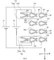
次に、バッテリパック10の端子部15の詳細な構成について説明する。図1に示すように、バッテリパック10の端子部15は、第1挿入口11と、第2挿入口12と、第3挿入口13と、第4挿入口14と、を備える。第1挿入口11、第2挿入口12、第3挿入口13及び第4挿入口14は、それぞれ、上下方向に延伸し下端が開口した挿入口であり、接続対象の板状の接続端子が下端から上方へ向けて挿入される。また、第1挿入口11、第2挿入口12、第3挿入口13、第4挿入口14は、この順に、左から右へ配置されている。
Next, a detailed configuration of the
図3に示すように、第1挿入口11には、第1正極端子TP1と、第2正極端子TP2と、第1並列接続用端子T31とが、この順で下から上へ設けられている。第2挿入口12には、第1充電端子TC1と、第2充電端子TC2とが、この順で下から上へ設けられている。第3挿入口13には、第2通信端子TDと、第1通信端子TASとが、この順で下から上へ設けられている。第4挿入口14には、第1負極端子TN1と、第2負極端子TN2と、第2並列接続用端子T32とが、この順で下から上へ設けられている。
As shown in FIG. 3, the
図3では、端子部15を後側からみた平面面である。第1正極端子TP1は、金属製の平板をU字形状に曲げて構成されており、開口端部DP付近の両側側面を内側に向けて凹ませた形状の凹み部HPを有する。第1正極端子TP1は、開口端部DPが下側になるように配置され、凹み部HPが板状の接続端子の両面と接触するように構成されている。また、第1正極端子TP1は、接触する板状の接続端子を下方から上方へ貫通させた状態で保持するため、開口端部DPと反対側の上側にも開口部UPが形成されている。
FIG. 3 is a plan view of the
第2正極端子TP2、第1充電端子TC1、第2充電端子TC2、第1通信端子TAS、第2通信端子TD、第1負極端子TN1及び第2負極端子TN2は、第1正極端子TP1と同様の形状に構成されている。 The second positive terminal TP2, the first charging terminal TC1, the second charging terminal TC2, the first communication terminal TAS, the second communication terminal TD, the first negative terminal TN1, and the second negative terminal TN2 are the same as the first positive terminal TP1. is configured in the shape of
第1並列接続用端子T31は、第1部材T31aと第2部材T31bとを備える。第1部材T31a及び第2部材T31bは板状の金属部材であり、上下方向に延伸するように配置されている。また、第1部材T31a及び第2部材T31bは、左右に並べて配置されている。そして、第1部材T31aは、下端付近が第2部材T31bに向かって凹んだ形状の凹み部LHPを有する。また、第2部材T31bは、下端付近が第1部材T31aに向かって凹んだ形状の凹み部RHPを有する。 The first parallel connection terminal T31 includes a first member T31a and a second member T31b. The first member T31a and the second member T31b are plate-shaped metal members, and are arranged so as to extend in the vertical direction. Also, the first member T31a and the second member T31b are arranged side by side on the left and right. The first member T31a has a recessed portion LHP in the vicinity of the lower end thereof recessed toward the second member T31b. Further, the second member T31b has a recessed portion RHP having a shape recessed toward the first member T31a in the vicinity of the lower end.
第1部材T31a及び第2部材T31bは、第1部材T31aの凹み部LHPと第2部材T31bの凹み部RHPとを接触させることで接続し、第1部材T31aの凹み部LHPと第2部材T31bの凹み部RHPとを遠ざけることで切り離される。すなわち、第1部材T31a及び第2部材T32bは、接続又は切り離し可能に構成されている。第1部材T31a及び第2部材T31bは、第1並列接続用端子T31に何も挿入されていない場合には、接続されている。また、第1部材T31a及び第2部材T31bは、第1並列接続用端子T31に板状の接続端子が挿入されている場合に、切り離される。 The first member T31a and the second member T31b are connected by contacting the recessed portion LHP of the first member T31a and the recessed portion RHP of the second member T31b, and the recessed portion LHP of the first member T31a and the second member T31b are connected. It is separated by moving away from the recessed portion RHP of . That is, the first member T31a and the second member T32b are configured to be connectable or detachable. The first member T31a and the second member T31b are connected when nothing is inserted into the first parallel connection terminal T31. Further, the first member T31a and the second member T31b are separated when the plate-shaped connection terminal is inserted into the first parallel connection terminal T31.
同様に、第2並列接続用端子T32は、第1部材T32aと第2部材T32bとを備える。第1部材T32a及び第2部材T32bは、第1部材T31a及び第2部材T31bと同様に構成されている。 Similarly, the second parallel connection terminal T32 includes a first member T32a and a second member T32b. The first member T32a and the second member T32b are configured similarly to the first member T31a and the second member T31b.
そして、第1並列接続用端子T31の第1部材T31aは、第1正極端子TP1に接続されており、第1正極端子TP1は、バッテリブロック21の正極に接続されている。第1並列接続用端子T31の第2部材T31bは、第2正極端子TP2に接続されており、第2正極端子TP2は、バッテリブロック22の正極に接続されている。したがって、第1部材T31aと第2部材T31bとを接続することによって、バッテリブロック21の正極とバッテリブロック22の正極とが接続される。また、第1部材T31aと第2部材T31bとを切り離すことによって、バッテリブロック21の正極とバッテリブロック22の正極とが切り離される。
A first member T31a of the first parallel connection terminal T31 is connected to the first positive electrode terminal TP1, and the first positive electrode terminal TP1 is connected to the positive electrode of the
また、第2並列接続用端子T32の第1部材T32aは、第1負極端子TN1に接続されており、第1負極端子TN1は、バッテリブロック21の負極に接続されている。第2並列接続用端子T32の第2部材T32bは、第2負極端子TN2に接続されており、第2負極端子TN2は、バッテリブロック22の負極に接続されている。したがって、第1部材T32aと第2部材T32bとを接続することによって、バッテリブロック21の負極とバッテリブロック22の負極とが接続される。また、第1部材T32aと第2部材T32bとを切り離すことによって、バッテリブロック21の負極とバッテリブロック22の負極とが切り離される。よって、端子部15に接続対象が接続されていない場合には、バッテリブロック21とバッテリブロック22とは並列に接続される。
The first member T32a of the second parallel connection terminal T32 is connected to the first negative terminal TN1, and the first negative terminal TN1 is connected to the negative electrode of the
なお、本実施形態では、第1正極端子TP1及び第2正極端子TP2と、第1負極端子TN1及び第2負極端子TN2とが、端子部が備える出力用端子の一例に相当し、第1並列接続用端子T31及び第2並列接続用端子T32が、並列接続用端子の一例に相当する。また、本実施形態では、放電逆流防止FET531及び半導通抵抗511と、放電逆流防止FET532及び半導通抵抗512とが、切替部の一例に相当する。
Note that in the present embodiment, the first positive terminal TP1 and the second positive terminal TP2, and the first negative terminal TN1 and the second negative terminal TN2 correspond to an example of output terminals included in the terminal section, and are the first parallel terminals. The connection terminal T31 and the second parallel connection terminal T32 correspond to an example of a parallel connection terminal. Further, in this embodiment, the discharge
<1-2.第1電動作業機の構成>
次に、第1電動作業機70の概略構成について、図4及び図5を参照して説明する。
第1電動作業機70は、比較的低い電圧(例えば、18V)に適合した作業機である。第1電動作業機70は、例えば、草刈機、インパクトドライバ、チェーンソー、ヘッジトリマ、ブロワ―などの電動工具である。
<1-2. Configuration of First Electric Working Machine>
Next, a schematic configuration of the first
The first
第1電動作業機70は、モータ72と、駆動回路73と、制御回路71と、トリガスイッチ74と、正極入力端子75と、負極入力端子76と、信号入力端子77と、装着部78と、を備える。モータ72は、3相のブラシ付き直流モータである。駆動回路73は、モータ72に電流を流すための回路である。トリガスイッチ74は、使用者により図示しないトリガが引かれるとオンになり、トリガオン信号を制御回路71へ送信する。制御回路71は、トリガオン信号を受信すると、駆動回路73を制御して、モータ72を回転させる。また、制御回路71は、信号入力端子77から放電停止信号が入力された場合に、駆動回路73を制御して、モータ72の回転を停止させる。なお、モータ72は、3相のブラシレスモータでもよい。
The first
装着部78は、バッテリパック10の端子部15に装着される。装着部78は、正極側の接続端子である正極接続端子781と、負極側の接続端子である負極接続端子782と、通信接続端子783と、を備える。正極接続端子781、負極接続端子782、通信接続端子783は、それぞれ、正極入力端子75、負極入力端子76、信号入力端子77に接続されている。
The mounting
図5は、装着部78を前側からみた平面図であり、バッテリパック10の端子部15と対向する面を示している。正極接続端子781、負極接続端子782、及び通信接続端子783は、それぞれ、板状の金属部材である。
図6に示すように、正極接続端子781は、第1挿入口11に対応する位置に設けられており、第1挿入口11に挿入される。正極接続端子781は、第1正極端子TP1を貫通し、且つ、第2正極端子TP2の凹み部HPを通って第2正極端子TP2を貫通しない長さに構成されている。
FIG. 5 is a plan view of the mounting
As shown in FIG. 6 , the positive
負極接続端子782は、第4挿入口14に対応する位置に設けられており、第4挿入口14に挿入される。負極接続端子782は、第1負極端子TN1を貫通し、且つ、第2負極端子TN2の凹み部HPを通って第2負極端子TN2を貫通しない長さに構成されている。
The
通信接続端子783は、第3挿入口13の第1通信端子TASに対応する位置に設けられており、第3挿入口13に挿入される。通信接続端子783は、第1通信端子TASの開口端部DPから第1通信端子TASの凹み部HPまでの距離よりも長く構成されている。
The
図6に示すように、バッテリパック10の端子部15に対して下方から上方へ装着部78を差し込むことにより、バッテリパック10の端子部15に装着部78が装着される。端子部15に装着部78が装着されると、正極接続端子781と第1正極端子TP1及び第2正極端子TP2とが電気的に接続される。その結果、正極入力端子75は、バッテリブロック21,22の正極に接続される。また、負極接続端子782と第1負極端子TN1及び第2負極端子TN2とが電気的に接続され、負極入力端子76は、バッテリブロック21,22の負極に接続される。
As shown in FIG. 6 , the mounting
したがって、端子部15に装着部78が装着されると、バッテリブロック21とバッテリブロック22とが並列に接続され、バッテリパック10の端子部15から第1電動作業機70へ、並列接続されたバッテリブロック21,22の電圧が出力される。そして、第1電動作業機70の正極入力端子75と負極入力端子76との間には、並列接続されたバッテリブロック21,22の電圧が入力される。
Therefore, when the mounting
また、端子部15に装着部78が装着されると、通信接続端子783と第1通信端子TASとが電気的に接続される。
なお、この場合、第1並列接続用端子T31の第1部材T31aと第2部材T31bとは接続されており、第2並列接続用端子T32の第1部材T32aと第2部材T32bとは接続されている。したがって、第1正極端子TP1及び第2正極端子TP2の一方と正極接続端子781とが接続され、第1負極端子TN1及び第2負極端子TN2の一方と負極接続端子782とが接続されれば、正極入力端子75と負極入力端子76との間に、並列接続されたバッテリブロック21,22の電圧が入力される。よって、正極接続端子781は、第1正極端子TP1及び第2正極端子TP2の一方のみと接続可能に構成されていてもよい。また、負極接続端子782は、第1負極端子TN1及び第2負極端子TN2の一方のみと接続可能に構成されていてもよい。
Further, when the mounting
In this case, the first member T31a and the second member T31b of the first parallel connection terminal T31 are connected, and the first member T32a and the second member T32b of the second parallel connection terminal T32 are connected. ing. Therefore, if one of the first positive terminal TP1 and the second positive terminal TP2 is connected to the
なお、本実施形態では、正極接続端子781及び負極接続端子782が、第1接続端子の一例に相当する。
<1-3.第2電動作業機の構成>
次に、第2電動作業機80の概略構成について、図7及び図8を参照して説明する。
In addition, in this embodiment, the
<1-3. Configuration of Second Electric Operating Machine>
Next, a schematic configuration of the second
第2電動作業機80は、比較的高い電圧(例えば、36V)に適合した作業機である。第2電動作業機80は、例えば、草刈機、インパクトドライバ、チェーンソー、ヘッジトリマ、ブロワ―などの電動工具である。
The second
第2電動作業機80は、本体部81と、アダプタ部82と、装着部84と、を備える。装着部84は、アダプタ部82に設けられており、バッテリパック10の端子部15に装着される。本体部81とアダプタ部82は別個の機器であり、アダプタ部82は本体部81に接続されている。
The second
本体部81は、モータ812と、駆動回路813と、レギュレータ814と、制御回路811と、停止回路815と、トリガスイッチ816と、を備える。また、本体部81は、本体側端子である、正極入力端子817と、負極入力端子818と、信号入力端子819と、を備える。
The
レギュレータ814は、本体部81内の各回路に供給する電源を生成する。モータ812は、3相のブラシ付き直流モータである。駆動回路813は、モータ812に電流を流すための回路である。トリガスイッチ816は、使用者により図示しないトリガが引かれるとオンになり、トリガオン信号を制御回路811へ送信する。制御回路811は、トリガオン信号を受信すると、駆動回路813を制御して、モータ812を回転させる。また、制御回路811は、信号入力端子819から放電停止信号が入力された場合に、駆動回路813を制御して、モータ812の回転を停止させる。停止回路815は、信号入力端子819から放電停止信号が入力された場合に、制御回路811を介さずに、駆動回路813を制御してモータ812を停止させる。停止回路815は、非常用の回路である。なお、モータ812は、3相のブラシレスモータでもよい。
A
アダプタ部82は、レギュレータ822、変換回路821と、を備える。また、アダプタ部82は、各種のアダプタ側端子を備える。アダプタ側端子は、正極出力端子823、負極出力端子824、信号出力端子825、正極入力端子826、負極入力端子827、第1入力端子828、第2入力端子829、及び信号入力端子830を含む。
The
正極入力端子826は、正極出力端子823を介して、本体部81の正極入力端子817に接続されている。負極入力端子827は、負極出力端子824を介して、本体部81の負極入力端子818に接続されている。信号入力端子830は、変換回路821及び信号出力端子825を介して、本体部81の信号入力端子819に接続されている。また、第1入力端子828と第2入力端子829とは、接続線831によって接続されている。
The
レギュレータ822は、変換回路821に供給する電源を生成する。変換回路821は、信号入力端子830から入力された放電許可信号又は放電停止信号を、本体部81のロジックや信号レベルに適合するように変換して、信号出力端子825から出力する。
The
装着部84は、正極側の接続端子である正極接続端子841と、負極側の接続端子である負極接続端子842と、通信接続端子843と、を備える。正極接続端子841、負極接続端子842、通信接続端子843は、それぞれ、アダプタ部82の正極入力端子826、負極入力端子827、信号入力端子830に接続されている。
The mounting
図8は、装着部84を前側から見た平面図であり、バッテリパック10の端子部15と対向する面を示している。正極接続端子841、負極接続端子842、及び通信接続端子843は、それぞれ、板状の金属部材である。
図9に示すように、正極接続端子841は、第1挿入口11に対応する位置に設けられており、第1挿入口11に挿入される。正極接続端子841は、第1正極端子TP1及び第2正極端子TP2を貫通し、第1並列接続用端子T31の凹み部LHP,RHPを通る長さに構成されている。
FIG. 8 is a plan view of the mounting
As shown in FIG. 9 , the positive
また、正極接続端子841は、第1正極通電部841aと、第2正極通電部841bと、第1正極絶縁部841cと、第2正極絶縁部841dと、を含む。第1正極通電部841aは、正極接続端子841の下端、且つ、第1正極端子TP1の凹み部HPに対応する位置に設けられている。第1正極絶縁部841cは、第1正極通電部841aに隣接した上側、且つ、第1正極端子TP1の上側の開口部UPに対応する位置に設けられている。第2正極通電部841bは、第1正極絶縁部841cに隣接した上側、且つ、第2正極端子TP2の凹み部HPに対応する位置に設けられている。第2正極絶縁部841dは、第2正極通電部841bに隣接した上側、且つ、第2正極端子TP2の上側の開口部UP及び第1並列接続用端子T31の凹み部LHP,RHPに対応する位置に設けられている。
Also, the positive
負極接続端子842は、第1負極通電部842aと、第2負極通電部842bと、第1負極絶縁部842cと、第2負極絶縁部842dと、を含む。第1負極通電部842aは、負極接続端子842の下端、且つ、第1負極端子TN1の凹み部HPに対応する位置に設けられている。第1負極絶縁部842cは、第1負極通電部842aに隣接した上側、且つ、第1負極端子TN1の上側の開口部UPに対応する位置に設けられている。第2負極通電部842bは、第1負極絶縁部842cに隣接した上側、且つ、第2負極端子TN2の凹み部HPに対応する位置に設けられている。第2負極絶縁部842dは、第2負極通電部842bに隣接した上側、且つ、第2負極端子TN2の上側の開口部UP及び第2並列接続用端子T32の凹み部LHP,RHPに対応する位置に設けられている。
The negative
そして、図7に示すように、第1正極通電部841aは、正極入力端子826に接続されており、第2正極通電部841bは、第2入力端子829に接続されている。また、第1負極通電部842aは、第1入力端子828に接続されており、第2負極通電部842bは、負極入力端子827に接続されている。
As shown in FIG. 7, the first positive current carrying
正極接続端子841及び負極接続端子842は、第1電動作業機70の正極接続端子781及び負極接続端子782よりも上下方向の長さが長く構成されている。また、通信接続端子843は、第1電動作業機70の通信接続端子783と同様に構成されている。
The positive
図9に示すように、端子部15に装着部84が装着されると、第1正極通電部841aと第1正極端子TP1とが電気的に接続され、第2正極通電部841bと第2正極端子TP2とが電気的に接続される。そして、第1正極端子TP1と第2正極端子TP2とは、第1正極絶縁部841cによって電気的に分離される。第1並列接続用端子T31の第1部材T31aと第2部材T31bとは、第2正極絶縁部841dによって電気的に切り離される。
As shown in FIG. 9, when the mounting
また、第1負極通電部842aと第1負極端子TN1とが電気的に接続され、第2負極通電部842bと第2負極端子TN2とが電気的に接続される。そして、第1負極端子TN1と第2負極端子TN2とは、第1負極絶縁部842cによって電気的に分離される。第2並列接続用端子T32の第1部材T32aと第2部材T32bとは、第2負極絶縁部842dによって電気的に切り離される。
Also, the first negative
また、通信接続端子783と第1通信端子TASとが電気的に接続される。
したがって、端子部15に装着部84が装着されると、バッテリブロック21とバッテリブロック22とは互いに切り離されて独立し、バッテリパック10の端子部15から第2電動作業機80へ、バッテリブロック21,22の電圧が個別に出力される。そして、正極入力端子826と第1入力端子828との間には、バッテリブロック21の電圧が入力され、第2入力端子829と負極入力端子827との間には、バッテリブロック22の電圧が入力される。
Also, the
Therefore, when the mounting
ここで、第1入力端子828と第2入力端子829とは接続線831によって接続されている。よって、正極入力端子826と負極入力端子827との間には、バッテリブロック21とバッテリブロック22の電圧を足し合わせた電圧が印加される。ひいては、本体部81の正極入力端子817と負極入力端子818との間に、バッテリブロック21とバッテリブロック22の電圧を足し合わせた電圧が入力される。したがって、第2電動作業機80は、バッテリブロック21,22のそれぞれの電圧の略2倍の電圧を使用することができる。
Here, the
なお、本実施形態では、正極接続端子841及び負極接続端子842が、第2接続端子の一例に相当する。また、接続線831が加算部の一例に相当する。
<1-4.充電器の構成>
次に、充電器90の概略構成について、図10及び図11を参照して説明する。
Note that, in the present embodiment, the
<1-4. Configuration of charger>
Next, a schematic configuration of the
充電器90は、制御回路91と、充電用電源回路92と、装着部96と、正極出力端子93と、負極出力端子94と、通信端子95と、を備える。
制御回路91は、通信端子95を介して入力されたバッテリ情報に基づいて、充電用電源回路92を制御する。充電用電源回路92は、商業用のAC電源に接続されている。充電用電源回路92は、制御回路91からに指令に応じて、AC電源から直流電源を生成し、生成した直流電源を、正極出力端子93及び負極出力端子94を介して、バッテリパック10へ供給する。
The
The
装着部96は、バッテリパック10の端子部15に装着される。装着部96は、正極接続端子961と、負極接続端子962と、通信接続端子963と、を備える。正極接続端子961、負極接続端子962、通信接続端子963は、それぞれ、正極出力端子93、負極出力端子94、通信端子95に接続されている。
The mounting
図11は、装着部96を前側から見た平面図であり、バッテリパック10の端子部15に対向する面を示している。正極接続端子961、負極接続端子962、及び通信接続端子963は、それぞれ、板状の金属部材である。正極接続端子961は、第2挿入口12に対応する位置に設けられており、第2挿入口12に挿入される。正極接続端子961は、第1充電端子TC1を貫通し、且つ、第2充電端子TC2の凹み部HPを通って第2充電端子TC2貫通しない長さに構成されている。
FIG. 11 is a plan view of the mounting
負極接続端子962は、第4挿入口に対応する位置に設けられており、第4挿入口14に挿入される。負極接続端子962は、第1電動作業機70の負極接続端子782と同様に構成されている。
The negative
通信接続端子963は、第3挿入口13の第2通信端子TDに対応する位置に設けられており、第3挿入口13に挿入される。通信接続端子963は、第2通信端子TDの開口端部HPから第2通信端子TDの凹み部DPまでの距離よりも長く構成されている。
The
端子部15に装着部96が装着されると、正極接続端子961と第1充電端子TC1及び第2充電端子TC2とが電気的に接続される。その結果、正極出力端子93は、バッテリブロック21,22の正極に接続される。また、負極接続端子962と第1負極端子TN1及び第2負極端子TN2とが電気的に接続され、負極出力端子94は、バッテリブロック21,22の負極に接続される。
When the mounting
第1並列接続用端子T31の第1部材T31aと第2部材T31bとは接続されており、第2並列接続用端子T32の第1部材T32aと第2部材T32bとは接続されている。したがって、端子部15に装着部78が装着されると、第1並列接続用端子T31及び第2並列接続用端子T32によって、バッテリブロック21及びバッテリブロック22は、並列に接続され、並列に接続された状態で充電される。
The first member T31a and the second member T31b of the first parallel connection terminal T31 are connected, and the first member T32a and the second member T32b of the second parallel connection terminal T32 are connected. Therefore, when the mounting
また、端子部15に装着部96が装着されると、通信接続端子963と第2通信端子TDとが電気的に接続される。
<1-6.効果>
以上説明した第1実施形態によれば、以下の効果が得られる。
Also, when the mounting
<1-6. Effect>
According to the first embodiment described above, the following effects are obtained.
(1)端子部15に第1電動作業機70の装着部78が装着されている場合、バッテリブロック21,22が並列に接続される。これにより、バッテリパック10から第1電動作業機70へ、並列接続されたバッテリブロック21,22の電圧が出力され、第1電動作業機70は、比較的低い第1電圧を用いることができる。また、端子部15に第2電動作業機80の装着部84が装着されている場合、バッテリブロック21,22が切り離され独立する。これにより、バッテリパック10から第2電動作業機80へ、バッテリブロック21,22の電圧が個別に出力され、第2電動作業機80は、複数の出力電圧を自由に組み合わせて使用することができる。
(1) When the mounting
(2)バッテリパック10内でバッテリブロック21,22を直列に接続してバッテリパック10から高電圧を出力することを回避したことにより、バッテリパック10の絶縁構造を簡素化し、バッテリパック10を小型化することができる。
(2) By avoiding outputting a high voltage from the
(3)端子部15に接続対象が接続されていない場合、バッテリブロック21,22が並列に接続される。これにより、バッテリパック10の保管中に、バッテリブロック21,22の電圧を均衡させることができる。
(3) When the connection target is not connected to the
(4)第2電動作業機80へ個別に入力されたバッテリブロック21,22の電圧は、接続線831によって加算される。このため、第2電動作業機80は、個々のバッテリブロック21,22の電圧よりも高い電圧を使用することができる。
(4) The voltages of the battery blocks 21 and 22 individually input to the second
(5)第1部材T31a,T32aと第2部材T31b,T32bとが接続されている場合には、バッテリブロック21,22の互いの正極を接続するとともに互いの負極を接続して、バッテリブロック21,22を並列に接続することができる。また、第1部材T31a,T32aと第2部材T31b,T32bとが切り離されている場合には、バッテリブロック21,22の互いの正極を電気的に切り離すとともに、互いの負極を電気的に切り離すことができる。 (5) When the first members T31a and T32a and the second members T31b and T32b are connected, the positive electrodes of the battery blocks 21 and 22 are connected to each other, and the negative electrodes of the battery blocks 21 and 22 are connected to each other. , 22 can be connected in parallel. When the first members T31a and T32a and the second members T31b and T32b are separated, the positive electrodes of the battery blocks 21 and 22 are electrically separated and the negative electrodes of the battery blocks 21 and 22 are electrically separated. can be done.
(6)バッテリブロック21,22を並列に接続して充電することにより、バッテリブロック21,22を直列に接続して充電する場合と比べて、充電器90の出力電圧を低くすることができる。ひいては、充電器90の絶縁構造を簡素化し小型化することができる。
(6) By connecting the battery blocks 21 and 22 in parallel for charging, the output voltage of the
(7)バッテリブロック21,22のバッテリ情報を纏めて1つのマイコン30で送信することにより、バッテリパック10に搭載するマイコンの数を抑制し、バッテリパック10の体格を小型化することができる。
(7) By collectively transmitting the battery information of the battery blocks 21 and 22 by one
(8)第2電動作業機80の本体部81にアダプタ部82を接続することにより、本体部81が、バッテリパック10を直接適用できない構成であっても、本体部81がバッテリパック10を使用することができる。
(8) By connecting the
(9)アダプタ部82が接続線831を備えていることにより、本体部81がバッテリブロック21,22の電圧を加算する機能を備えていない場合であっても、本体部81は、加算された電圧を使用することができる。
(9) Since the
(10)放電逆流防止FET531,532と半導通抵抗511,512とを備えていることにより、バッテリパック10の保管中に、バッテリブロック21,22の正極と第1及び第2正極端子TP1,TP2との間が半導通状態になる。これにより、バッテリブロック21,22間の電圧差が比較的大きくなっている場合でも、電圧が高いバッテリブロックから電圧が低いバッテリブロックへ過大な電流が流れることを抑制して、バッテリパック10の故障を抑制することができる。
(10) By providing the discharge
(第2実施形態)
<2-1.第1実施形態との相違点>
第2実施形態は、基本的な構成は第1実施形態と同様であるため、共通する構成については説明を省略し、相違点を中心に説明する。なお、第1実施形態と同じ符号は、同一の構成を示すものであって、先行する説明を参照する。
(Second embodiment)
<2-1. Difference from First Embodiment>
Since the basic configuration of the second embodiment is the same as that of the first embodiment, description of common configurations will be omitted, and differences will be mainly described. Note that the same reference numerals as in the first embodiment indicate the same configurations, and refer to the preceding description.
第2実施形態では、第2電動作業機80Aの構成が、第1実施形態の第2電動作業機80の構成と異なる。それ以外のバッテリシステムの構成は、第1実施形態と同じである。
図12に示すように、第2電動作業機80Aは、第2電動作業機80のアダプタ部82が本体部81の内部に含まれた構成になっている。よって、第2電動作業機80Aは、正極入力端子817と、負極入力端子818と、信号入力端子819と、正極出力端子823と、負極出力端子824と、信号出力端子825と、変換回路821と、を備えていない。
In the second embodiment, the configuration of the second
As shown in FIG. 12 , the second
<2-2.効果>
以上説明した第2実施形態によれば、前述した第1実施形態の効果(1)~(7)及び(10)の効果を奏する。
<2-2. Effect>
According to the second embodiment described above, the effects (1) to (7) and (10) of the first embodiment described above are achieved.
(第3実施形態)
<3-1.第1実施形態との相違点>
第3実施形態は、基本的な構成は第1実施形態と同様であるため、共通する構成については説明を省略し、相違点を中心に説明する。なお、第1実施形態と同じ符号は、同一の構成を示すものであって、先行する説明を参照する。
(Third Embodiment)
<3-1. Difference from First Embodiment>
Since the basic configuration of the third embodiment is the same as that of the first embodiment, the description of the common configuration will be omitted, and the differences will be mainly described. Note that the same reference numerals as in the first embodiment indicate the same configurations, and refer to the preceding description.
第3実施形態では、第2電動作業機80Bの構成が、第1実施形態の第2電動作業機80の構成と異なる。それ以外のバッテリシステムの構成は、第1実施形態と同じである。
図13に示すように、第2電動作業機80Bは、本体部81Bと、アダプタ部82Bと、装着部84と、を備える。本体部81Bは、元々は、2つのバッテリパックを接続して使用するように構成されている。
In the third embodiment, the configuration of the second
As shown in FIG. 13, the second
本体部81Bは、モータ112と、駆動回路113と、レギュレータ114と、制御回路111と、トリガスイッチ110と、を備える。また、本体部81Bは、本体側端子である、正極入力端子115と、第1入力端子116と、第1信号入力端子119と、第2入力端子117と、負極入力端子118と、第2信号入力端子120と、を備える。そして、第1入力端子116と第2入力端子117とは、接続線121によって接続されている。
The
正極入力端子115、第1入力端子116、及び第1信号入力端子119は、元々は、2つのバッテリパックのうちの一方に接続されるように構成されている。また、第2入力端子117、負極入力端子118、及び第2信号入力端子120は、元々は、2つのバッテリパックのうちの他方に接続されるように構成されている。そして、第2電動作業機80Bは、2つのバッテリパックの出力電圧を接続線121によって接続して、2つのバッテリパックの出力電圧を足し合わせた電力を使用可能に構成されている。
The
レギュレータ114は、本体部81B内の各回路に供給する電源を生成する。モータ112は、3相のブラシ付き直流モータである。駆動回路113は、モータ112に電流を流すための回路である。トリガスイッチ110は、使用者により図示しないトリガが引かれるとオンになり、トリガオン信号を制御回路111へ送信する。制御回路111は、トリガオン信号を受信すると、駆動回路113を制御して、モータ112を回転させる。また、制御回路111は、第1信号入力端子119及び第2信号入力端子120の少なくとも一方から放電停止信号が入力された場合に、駆動回路113を制御して、モータ112の回転を停止させる。なお、モータ112は、3相のブラシレスモータでもよい。
The
アダプタ部82Bは、変換回路131,132と、各種のアダプタ側端子を備える。アダプタ側端子は、正極出力端子133、第1出力端子134、第1信号出力端子137、第2出力端子135、負極出力端子136、第2信号出力端子138、正極入力端子141、負極入力端子142、第1入力端子143、第2入力端子144、及び信号入力端子145を含む。
The
正極入力端子141は、正極出力端子133を介して、本体部81Bの正極入力端子115に接続されている。第1入力端子143は、第2出力端子135を介して、本体部81Bの第2入力端子117に接続されている。第2入力端子144は、負極出力端子136を介して、本体部81Bの負極入力端子118に接続されている。負極入力端子142は、第1出力端子134を介して、本体部81Bの第1入力端子116に接続されている。
The
信号入力端子145は、変換回路131及び第1信号出力端子137を介して、本体部81Bの第1信号入力端子119に接続されているとともに、変換回路132及び第2信号出力端子138を介して、本体部81Bの第2信号入力端子120に接続されている。本体部81Bには2つの信号入力端子119,120が設けられているため、信号入力端子145から入力された信号は2つに分岐されて、2つの信号入力端子119,120に入力される。
The
そして、図13に示すように、第1正極通電部841aは、正極入力端子141に接続されており、第2正極通電部841bは、第1入力端子143に接続されている。また、第1負極通電部842aは、負極入力端子142に接続されており、第2負極通電部842bは、第2入力端子144に接続されている。
Then, as shown in FIG. 13 , the first positive
したがって、端子部15に第2電動作業機80Bの装着部84が装着されると、正極入力端子115と第1入力端子116との間には、バッテリブロック21の電圧が入力され、第2入力端子117と負極入力端子118との間には、バッテリブロック22の電圧が入力される。よって、第2電動作業機80Bは、本体部81Bに直接2つのバッテリパックを接続した場合と同様に、バッテリブロック21とバッテリブロック22との電圧を足し合わせた電圧を使用することができる。
Therefore, when the mounting
なお、本実施形態では、接続線121が加算部の一例に相当する。
<3-2.効果>
以上説明した第3実施形態によれば、前述した第1実施形態の効果(1)~(8)及び(10)の効果を奏する。
Note that, in the present embodiment, the
<3-2. Effect>
According to the third embodiment described above, the effects (1) to (8) and (10) of the first embodiment described above are obtained.
(第4実施形態)
次に、第4実施形態に係るバッテリシステムについて、図14~図20を参照して説明する。第4実施形態に係るバッテリシステムは、バッテリパック10Aと、第1電動作業機70Aと、第2電動作業機80Cと、充電器90Aと、を備える。
(Fourth embodiment)
Next, a battery system according to a fourth embodiment will be described with reference to FIGS. 14 to 20. FIG. The battery system according to the fourth embodiment includes a
<4-1.バッテリパックの構成>
まず、バッテリパック10Aの構成について、バッテリパック10との相違点を中心に、図14及び図15を参照して説明する。
<4-1. Configuration of Battery Pack>
First, the configuration of the
バッテリパック10Aは、3つのバッテリブロック21,22,20と、バッテリブロック21に接続された第1バッテリ回路210と、バッテリブロック22に接続された第2バッテリ回路220と、バッテリブロック20に接続された第3バッテリ回路200と、を備える。すなわち、バッテリパック10Aは、バッテリパック10よりもバッテリブロック及びバッテリ回路を多く備える。
The
バッテリブロック20は、バッテリブロック21,22と同じ定格電圧のバッテリブロックであり、バッテリブロック21,22と同様に、複数のバッテリセルが直列接続されて構成されている。第3バッテリ回路200は、第1バッテリ回路210と同じ構成であるため、説明は省略する。第3バッテリ回路200は、第1バッテリ回路210の第1正極端子TP1、第1負極端子TN1及び第1充電端子TC1の代わりに、第3正極端子TP0、第3負極端子TN0及び第3充電端子TC0を備える。
The
図15は、バッテリパック10Aの端子部15Aの構成を示す。端子部15Aは、端子部15の構成に加えて、第3正極端子TP0、第3負極端子TN0、第3充電端子TC0、第1並列接続用端子T33、及び第2並列接続用端子T34を備える。第3正極端子TP0、第3負極端子TN0、及び第3充電端子TC0は、第1正極端子TP1と同様に構成されている。また、第1並列接続用端子T33及び第2並列接続用端子T34は、第1並列接続用端子T31と同様に構成されている。
FIG. 15 shows the configuration of the
第1挿入口11には、第3正極端子TP0と、第1正極端子TP1と、第2正極端子TP2と、第1並列接続用端子T31と、第2並列接続用端子T33とが、この順で下から上へ設けられている。第2挿入口12には、第3充電端子TC0と、第1充電端子TC1と、第2充電端子TC2とが、この順で下から上へ設けられている。第3挿入口13には、第2通信端子TDと、第1通信端子TASとが、この順で下から上へ設けられている。第4挿入口には、第3負極端子TN0と、第1負極端子TN1と、第2負極端子TN2と、第2並列接続用端子T32と、第2並列接続用端子T34と、が、この順で下から上へ設けられている。
In the
そして、第1並列接続用端子T33の第1部材T33aは、第3正極端子TP0に接続されており、第3正極端子TP0は、バッテリブロック20の正極に接続されている。第1並列接続用端子T33の第2部材T33bは、第2正極端子TP2に接続されており、第2正極端子TP2は、バッテリブロック22の正極に接続されている。したがって、第1部材T31aと第2部材T31bとを接続するとともに、第1部材T33aと第2部材T33bとを接続することによって、バッテリブロック20,21,22の各正極が接続される。また、第1部材T31aと第2部材T31bとを切り離すとともに、第1部材T33aと第2部材T33b切り離すことによって、バッテリブロック20,21,22の各正極が互に切り離される。
A first member T<b>33 a of the first parallel connection terminal T<b>33 is connected to the third positive terminal TP<b>0 , and the third positive terminal TP<b>0 is connected to the positive terminal of the
また、第2並列接続用端子T34の第1部材T34aは、第3負極端子TN0に接続されており、第3負極端子TN0は、バッテリブロック20の負極に接続されている。第2並列接続用端子T34の第2部材T34bは、第2負極端子TN2に接続されており、第2負極端子TN2は、バッテリブロック22の負極に接続されている。したがって、第1部材T32aと第2部材T32bとを接続し、第1部材T34aと第2部材T34bとを接続することによって、バッテリブロック20,21,22の各負極が接続される。また、第1部材T32aと第2部材T32bとを切り離し、第1部材T34aと第2部材T34bとを切り離すことによって、バッテリブロック20,21,22の各負極が互に切り離される。したがって、端子部15に接続対象が接続されていない場合には、バッテリブロック20,21,22は並列に接続される。
The first member T34a of the second parallel connection terminal T34 is connected to the third negative terminal TN0, and the third negative terminal TN0 is connected to the negative electrode of the
なお、本実施形態では、第1正極端子TP1、第2正極端子TP2及び第3正極端子TP0と、第1負極端子TN1、第2負極端子TN2及び第3負極端子TN0とが、端子部が備える出力用端子の一例に相当する。また、第1並列接続用端子T31,T33及び第2並列接続用端子T32,T34が、並列接続用端子の一例に相当する。また、本実施形態では、放電逆流防止FET531及び半導通抵抗511と、放電逆流防止FET532及び半導通抵抗512と、放電逆流防止FET530及び半導通抵抗510とが、切替部の一例に相当する。
In the present embodiment, the terminal portion includes the first positive terminal TP1, the second positive terminal TP2, the third positive terminal TP0, and the first negative terminal TN1, the second negative terminal TN2, and the third negative terminal TN0. It corresponds to an example of an output terminal. Also, the first parallel connection terminals T31 and T33 and the second parallel connection terminals T32 and T34 correspond to an example of parallel connection terminals. Further, in this embodiment, the discharge
<4-2.第1電動作業機の構成>
第4実施形態に係る第1電動作業機70Aの構成について、第1電動作業機70と異なる点について説明する。第1電動作業機70Aは、第1電動作業機70の装着部78と異なる装着部78Aを備える。装着部78Aは、バッテリパック10Aの端子部15Aに装着される。
<4-2. Configuration of First Electric Working Machine>
Concerning the configuration of the first electric working machine 70A according to the fourth embodiment, points different from the first
図16に示すように、装着部78Aは、装着部78の正極接続端子781及び負極接続端子782の代わりに、正極接続端子781A及び負極接続端子782Aを備える。
図15及び図17に示すように、正極接続端子781Aは、第1挿入口11に対応する位置に設けられており、第1挿入口11に挿入される。正極接続端子781Aは、第3正極端子TP0及び第1正極端子TP1を貫通し、且つ、第2正極端子TP2の凹み部HPを通って第2正極端子TP2を貫通しない長さに構成されている。
As shown in FIG. 16, the mounting
As shown in FIGS. 15 and 17 , the positive
負極接続端子782Aは、第4挿入口14に対応する位置に設けられており、第4挿入口14に挿入される。負極接続端子782Aは、第3負極端子TN0及び第1負極端子TN1を貫通し、且つ、第2負極端子TN2の凹み部HPを通って第2負極端子TN2を貫通しない長さに構成されている。
The negative
よって、図17に示すように、端子部15Aに装着部78Aを装着すると、正極接続端子781Aと、第3正極端子TP0、第1正極端子TP1及び第2正極端子TP2と、が電気的に接続される。その結果、正極入力端子75は、バッテリブロック20,21,22の正極に接続される。また、負極接続端子782Aと、第3負極端子TN0、第1負極端子TN1及び第2負極端子TN2と、が電気的に接続され、負極入力端子76は、バッテリブロック20,21,22の負極に接続される。
Therefore, as shown in FIG. 17, when the mounting
したがって、端子部15Aに装着部78Aが装着されると、バッテリブロック20,21,22が並列に接続され、バッテリパック10Aの端子部15Aから第1電動作業機70Aへ、並列接続されたバッテリブロック20,21,22の電圧が出力される。そして、第1電動作業機70Aの正極入力端子75と負極入力端子76との間には、並列接続されたバッテリブロック20,21,22の電圧が入力される。
Therefore, when the mounting
なお、本実施形態では、正極接続端子781A及び負極接続端子782Aが、第1接続端子の一例に相当する。
<4-2.第2電動作業機の構成>
第4実施形態に係る第2電動作業機80Cの構成について、第2電動作業機80と異なる点について説明する。第2電動作業機80Cは、第2電動作業機80の装着部84と異なる装着部84Cを備える。装着部84Cは、バッテリパック10Aの端子部15Aに装着される。
In addition, in the present embodiment, the
<4-2. Configuration of Second Electric Operating Machine>
Regarding the configuration of the second electric working machine 80C according to the fourth embodiment, the points that differ from the second
図18に示すように、装着部84Cは、装着部84の正極接続端子841及び負極接続端子842の代わりに、正極接続端子841C及び負極接続端子842Cを備える。正極接続端子841Cは、第1~第3正極通電部841e~841gと、第1~第3正極絶縁部841h~841jと、を含む。負極接続端子842Cは、第1~第3負極通電部842e~842gと、第1~第3負極絶縁部842h~842jと、を含む。
As shown in FIG. 18 , the mounting
図15及び19に示すように、第1正極通電部841e、第2正極通電部841f、第3正極通電部841gは、それぞれ、第3正極端子TP0、第1正極端子TP1、第2正極端子TP2の凹み部HPに対応する位置に設けられている。第1正極絶縁部841h、第2正極絶縁部841i、第3正極絶縁部841jは、それぞれ、第3正極端子TP0の上側の開口部UP、第1正極端子TP1の上側の開口部UP、第1並列接続用端子T31,T33の凹み部LHP,RHPに対応する位置に設けられている。
As shown in FIGS. 15 and 19, the first positive current carrying
また、第1負極通電部842e、第2負極通電部842f、第3負極通電部842gは、それぞれ、第3負極端子TN0、第1負極端子TN1、第2負極端子TN2の凹み部HPに対応する位置に設けられている。第1負極絶縁部842h、第2負極絶縁部842i、第3負極絶縁部842jは、それぞれ、第3負極端子TN0の上側の開口部UP、第1負極端子TN1の上側の開口部UP、第2並列接続用端子T32,T34の凹み部LHP,RHPに対応する位置に設けられている。
Also, the first negative
したがって、端子部15Aに装着部84Cが装着されると、第1正極通電部841eと第3正極端子TP0とが電気的に接続され、第2正極通電部841fと第1正極端子TP1とが電気的に接続され、第3正極通電部841gと第2正極端子TP2とが電気的に接続される。そして、第3正極端子TP0と第1正極端子TP1と第2正極端子TP2とは、第1正極絶縁部841h及び第2正極絶縁部841iによって互いに電気的に分離される。第1並列接続用端子T31の第1部材T31aと第2部材T31b、及び第2並列接続用端子T33の第1部材T33aと第2部材T33bは、第3正極絶縁部841jによって電気的に切り離される。
Therefore, when the mounting
また、第1負極通電部842eと第3負極端子TN0とが電気的に接続され、第2負極通電部842fと第1負極端子TN1とが電気的に接続され、第3負極通電部842gと第2負極端子TN2とが電気的に接続される。そして、第3負極端子TN0と第1負極端子TN1と第2負極端子TN2とは、第1負極絶縁部842h及び第2負極絶縁部842iによって互いに電気的に分離される。第2並列接続用端子T32の第1部材T32aと第2部材T32b、及び、第2並列接続用端子T34の第1部材T34aと第2部材T34bは、第3負極絶縁部842jによって電気的に切り離される。
In addition, the first negative
したがって、端子部15Aに装着部84Cが装着されると、バッテリブロック20,21,22は互いに切り離されて独立し、バッテリパック10Aの端子部15Aから第2電動作業機80Cへ、バッテリブロック20,21,22の電圧が個別に出力される。第2電動作業機80Cは、バッテリブロック20,21,22の各出力電圧を加算して用いることができる。
Therefore, when the mounting
なお、本実施形態では、正極接続端子841C及び負極接続端子842Cが、第2接続端子の一例に相当する。
<4-3.充電器の構成>
第4実施形態に係る充電器90Aの構成について、充電器90と異なる点について説明する。充電器90Aは、充電器90の装着部96と異なる装着部96Aを備える。装着部96Aは、バッテリパック10Aの端子部15Aに接続される。
In addition, in the present embodiment, the
<4-3. Configuration of charger>
Concerning the configuration of the charger 90A according to the fourth embodiment, points different from the
図15及び図20に示すように、装着部96Aは、装着部96の正極接続端子961及び負極接続端子962の代わりに、正極接続端子961A及び負極接続端子962Aを備える。
正極接続端子961Aは、第2挿入口12に対応する位置に設けられており、第2挿入口12に挿入される。正極接続端子961Aは、第3充電端子TC0及び第1充電端子TC1を貫通し、且つ、第2充電端子TC2の凹み部HPを通って第2充電端子TC2貫通しない長さに構成されている。
As shown in FIGS. 15 and 20, the mounting
The positive
負極接続端子962Aは、第4挿入口に対応する位置に設けられており、第4挿入口14に挿入される。負極接続端子962Aは、第1電動作業機70Aの負極接続端子782Aと同様に構成されている。
The negative
端子部15Aに装着部96Aが装着されると、正極接続端子961Aと、第3充電端子TC0、第1充電端子TC1及び第2充電端子TC2と、が電気的に接続される。その結果、正極出力端子93は、バッテリブロック20,21,22の正極に接続される。また、負極接続端子962Aと、第3負極端子TN0、第1負極端子TN1及び第2負極端子TN2と、が電気的に接続され、負極出力端子94は、バッテリブロック20,21,22の負極に接続される。よって、バッテリブロック20,21,22は、並列に接続された状態で充電される。
When the mounting
<4-4.効果>
以上説明した第4実施形態によれば、前述した第1実施形態の効果(1)~(10)の効果を奏する。また、3個のバッテリブロック20,21,22を備えるバッテリパック10Aを用いることにより、より高い電圧に適合した第2電動作業機80Cを使用することができる。さらに、第4実施形態と同様にして、4個以上のバッテリブロックを備えるバッテリパックを用いることもできる。
<4-4. Effect>
According to the fourth embodiment described above, the effects (1) to (10) of the first embodiment described above are achieved. Moreover, by using the
(他の実施形態)
以上、本開示を実施するための形態について説明したが、本開示は上述の実施形態に限定されることなく、種々変形して実施することができる。
(Other embodiments)
Although the embodiments for implementing the present disclosure have been described above, the present disclosure is not limited to the above-described embodiments, and can be implemented with various modifications.
(a)上記実施形態では、第1~第3バッテリ回路210,220,200が、それぞれ、半導通抵抗511,512,510のそれぞれを備えていたが、半導通抵抗511,512,510を備えていなくてもよい。代わりに、バッテリパック10,10Aの保管中は、放電逆流防止FET531,532,530のソース-ドレイン間に印加する電圧を調整して、放電逆流防止FET531,532,530をハーフオン状態にしてもよい。放電逆流防止FET531,532,530をハーフオン状態にすることにより、第1~第3正極端子TP1,TP2,TP0とバッテリブロック21,22,20の正極との間を半導通状態にすることができる。
(a) In the above embodiment, the first to
(b)上記実施形態における1つの構成要素が有する複数の機能を、複数の構成要素によって実現したり、1つの構成要素が有する1つの機能を、複数の構成要素によって実現したりしてもよい。また、複数の構成要素が有する複数の機能を、1つの構成要素によって実現したり、複数の構成要素によって実現される1つの機能を、1つの構成要素によって実現したりしてもよい。また、上記実施形態の構成の一部を省略してもよい。また、上記実施形態の構成の少なくとも一部を、他の上記実施形態の構成に対して付加又は置換してもよい。 (b) A plurality of functions possessed by one component in the above embodiment may be realized by a plurality of components, or a function possessed by one component may be realized by a plurality of components. . Moreover, a plurality of functions possessed by a plurality of components may be realized by one component, or one function realized by a plurality of components may be realized by one component. Also, part of the configuration of the above embodiment may be omitted. Also, at least part of the configuration of the above embodiment may be added or replaced with respect to the configuration of the other above embodiment.
10,10A…バッテリパック、15,15A…端子部、20,21,22…バッテリブロック、30…マイコン、70,70A…第1電動作業機、78,78A,84,84C,96,96A…装着部、80,80A,80B,80C…第2電動作業機、81,81B…本体部、82,82B…アダプタ部、90,90A…充電器、121,831…接続線、200…第3バッテリ回路、210…第1バッテリ回路、220…第2バッテリ回路、510,511,512…半導通抵抗、530,531,532…放電逆流防止FET、781,781A,841,841C,961,961A…正極接続端子、782,782A,842,842C,962,962A…負極接続端子、783,843,963…通信接続端子、T31,T33…第1並列接続用端子、T31a,T32a,T33a,T34a…第1部材、T31b,T32b,T33b,T34b…第2部材、T32,T34…第2並列接続用端子、TC0…第3充電端子、TC1…第1充電端子、TC2…第2充電端子、TD…第2通信端子、TN0…第3負極端子、TN1…第1負極端子、TN2…第2負極端子。
10, 10A...
Claims (8)
第1電圧に適合した第1電動作業機と、
前記第1電圧よりも高い第2電圧に適合した第2電動作業機と、を備え、
前記端子部は、
前記複数のバッテリブロックを並列に接続するように構成された少なくとも1つの並列接続用端子と、
複数の出力用端子であって、前記複数の出力用端子のそれぞれが前記複数のバッテリブロックのそれぞれに接続されている複数の出力用端子と、を備え、
前記第1電動作業機は、前記複数の出力用端子の少なくとも1つに接続されるように構成された第1接続端子を備え、
前記第2電動作業機は、前記複数の出力用端子のそれぞれに電気的に分離して接続されるように構成された第2接続端子を備え、
前記少なくとも1つの並列接続用端子は、
前記複数の出力用端子の少なくとも1つに前記第1接続端子が接続されている場合、及び、前記複数の出力用端子のいずれにも接続対象が接続されていない場合に、前記複数のバッテリブロックを並列に接続し、前記複数の出力用端子のそれぞれに前記第2接続端子が接続されている場合に、前記複数のバッテリブロックを互いに切り離して独立させるように構成され、
前記バッテリパックは、
前記端子部に前記第1電動作業機が接続されている場合に、前記第1電動作業機へ前記第1電圧を出力し、
前記端子部に前記第2電動作業機が接続されている場合に、前記第2電動作業機へ複数の前記第1電圧を個別に出力し、
前記第2電動作業機は、
前記第2接続端子を介して入力された前記複数の前記第1電圧を加算するように構成された加算部を更に備える、
バッテリシステム。 a battery pack having a plurality of battery blocks and terminals;
a first electric working machine adapted to the first voltage;
a second electric working machine adapted to a second voltage higher than the first voltage,
The terminal portion is
at least one parallel connection terminal configured to connect the plurality of battery blocks in parallel;
a plurality of output terminals, each of said plurality of output terminals being connected to each of said plurality of battery blocks;
The first electric working machine includes a first connection terminal configured to be connected to at least one of the plurality of output terminals,
The second electric working machine includes a second connection terminal configured to be electrically separated and connected to each of the plurality of output terminals,
The at least one parallel connection terminal,
When the first connection terminal is connected to at least one of the plurality of output terminals and when a connection target is not connected to any of the plurality of output terminals, the plurality of battery blocks are connected in parallel, and when the second connection terminal is connected to each of the plurality of output terminals, the plurality of battery blocks are separated from each other and independent,
The battery pack is
outputting the first voltage to the first electric operating machine when the first electric operating machine is connected to the terminal portion;
outputting a plurality of the first voltages individually to the second electric working machine when the second electric working machine is connected to the terminal portion ;
The second electric working machine is
Further comprising an addition unit configured to add the plurality of first voltages input via the second connection terminal,
battery system.
前記第2接続端子と、アダプタ側端子と、を備えるアダプタ部と、
前記アダプタ側端子に接続される本体側端子を備える本体部と、を備える、
請求項1に記載のバッテリシステム。 The second electric operating machine is
an adapter section including the second connection terminal and an adapter-side terminal;
a main body portion including a main body terminal connected to the adapter side terminal;
The battery system according to claim 1 .
第1電圧に適合した第1電動作業機と、
前記第1電圧よりも高い第2電圧に適合した第2電動作業機と、を備え、
前記端子部は、
前記複数のバッテリブロックを並列に接続するように構成された少なくとも1つの並列接続用端子と、
複数の出力用端子であって、前記複数の出力用端子のそれぞれが前記複数のバッテリブロックのそれぞれに接続されている複数の出力用端子と、を備え、
前記第1電動作業機は、前記複数の出力用端子の少なくとも1つに接続されるように構成された第1接続端子を備え、
前記第2電動作業機は、
前記複数の出力用端子のそれぞれに電気的に分離して接続されるように構成された第2接続端子と、アダプタ側端子と、を備えるアダプタ部と、
前記アダプタ側端子に接続される本体側端子を備える本体部と、
を備え、
前記少なくとも1つの並列接続用端子は、
前記複数の出力用端子の少なくとも1つに前記第1接続端子が接続されている場合、及び、前記複数の出力用端子のいずれにも接続対象が接続されていない場合に、前記複数のバッテリブロックを並列に接続し、前記複数の出力用端子のそれぞれに前記第2接続端子が接続されている場合に、前記複数のバッテリブロックを互いに切り離して独立させるように構成され、
前記バッテリパックは、
前記端子部に前記第1電動作業機が接続されている場合に、前記第1電動作業機へ前記第1電圧を出力し、
前記端子部に前記第2電動作業機が接続されている場合に、前記第2電動作業機へ複数の前記第1電圧を個別に出力し、
前記アダプタ部は、前記第2接続端子を介して入力された前記複数の前記第1電圧を加算するように構成された加算部を更に備える、
バッテリシステム。 a battery pack having a plurality of battery blocks and terminals;
a first electric working machine adapted to the first voltage;
a second electric working machine adapted to a second voltage higher than the first voltage,
The terminal portion is
at least one parallel connection terminal configured to connect the plurality of battery blocks in parallel;
a plurality of output terminals, each of said plurality of output terminals being connected to each of said plurality of battery blocks;
The first electric working machine includes a first connection terminal configured to be connected to at least one of the plurality of output terminals,
The second electric working machine is
an adapter unit including a second connection terminal configured to be electrically separated and connected to each of the plurality of output terminals ; and an adapter-side terminal.
a body portion including body-side terminals connected to the adapter-side terminals;
with
The at least one parallel connection terminal,
When the first connection terminal is connected to at least one of the plurality of output terminals and when a connection target is not connected to any of the plurality of output terminals, the plurality of battery blocks are connected in parallel, and when the second connection terminal is connected to each of the plurality of output terminals, the plurality of battery blocks are separated from each other and independent,
The battery pack is
outputting the first voltage to the first electric operating machine when the first electric operating machine is connected to the terminal portion;
outputting a plurality of the first voltages individually to the second electric working machine when the second electric working machine is connected to the terminal portion;
The adapter section further comprises an addition section configured to add the plurality of first voltages input via the second connection terminal,
battery system.
前記第1部材及び前記第2部材は、前記複数のバッテリブロックのうちの異なるバッテリブロックの同じ電極に接続される、
請求項1~3のいずれか1項に記載のバッテリシステム。 each of the at least one parallel connection terminal includes a first member and a second member that can be connected or disconnected;
wherein the first member and the second member are connected to the same electrode of different battery blocks among the plurality of battery blocks;
The battery system according to any one of claims 1-3.
前記少なくとも1つの並列接続用端子は、それぞれ、前記複数のバッテリブロックのそれぞれの前記第1電極に接続される第1並列接続用端子と、前記複数のバッテリブロックのそれぞれの前記第2電極に接続される第2並列接続用端子と、を含む、
請求項1~4のいずれか1項に記載のバッテリシステム。 each of the plurality of battery blocks includes a first electrode and a second electrode;
The at least one parallel connection terminal is connected to a first parallel connection terminal connected to the first electrode of each of the plurality of battery blocks and to the second electrode of each of the plurality of battery blocks. and a second parallel connection terminal to be
The battery system according to any one of claims 1-4 .
請求項1~5のいずれか1項に記載のバッテリシステム。 The parallel connection terminal connects the plurality of battery blocks in parallel during charging of the battery pack.
The battery system according to any one of claims 1-5 .
通信端子と、
前記複数のバッテリブロックのそれぞれのバッテリ情報を纏め、纏めた前記バッテリ情報を、前記通信端子を介して前記端子部に接続された接続対象へ送信するように構成された1つの制御部と、を備える、
請求項1~6のいずれか1項に記載のバッテリシステム。 The battery pack is
a communication terminal;
a control unit configured to collect battery information of each of the plurality of battery blocks and transmit the collected battery information to a connection target connected to the terminal unit via the communication terminal; prepare
The battery system according to any one of claims 1-6 .
前記複数のバッテリブロックのそれぞれの正極に接続された切替部であって、前記端子部に接続対象が接続されていない場合に、前記正極と前記出力用端子との導通を遮断する遮断状態と、前記正極と前記出力用端子とを導通させる導通状態と、の中間の状態であって、前記導通状態よりも少ない電流を流す半導通状態に切り替えるように構成された切替部を備える、
請求項1~7のいずれか1項に記載のバッテリシステム。 The battery pack is
a switching unit connected to the positive electrode of each of the plurality of battery blocks, wherein the switching unit cuts off conduction between the positive electrode and the output terminal when a connection target is not connected to the terminal unit; A switching unit configured to switch to a semi-conducting state, which is an intermediate state between a conducting state in which the positive electrode and the output terminal are conducted, and a semi-conducting state in which a smaller current flows than the conducting state,
The battery system according to any one of claims 1-7 .
Priority Applications (4)
| Application Number | Priority Date | Filing Date | Title |
|---|---|---|---|
| JP2018245864A JP7159042B2 (en) | 2018-12-27 | 2018-12-27 | battery system |
| CN201911050707.2A CN111384746A (en) | 2018-12-27 | 2019-10-31 | Battery system |
| US16/711,743 US11183857B2 (en) | 2018-12-27 | 2019-12-12 | Battery pack and battery system |
| DE102019134931.1A DE102019134931A1 (en) | 2018-12-27 | 2019-12-18 | Battery pack and battery system |
Applications Claiming Priority (1)
| Application Number | Priority Date | Filing Date | Title |
|---|---|---|---|
| JP2018245864A JP7159042B2 (en) | 2018-12-27 | 2018-12-27 | battery system |
Publications (2)
| Publication Number | Publication Date |
|---|---|
| JP2020107510A JP2020107510A (en) | 2020-07-09 |
| JP7159042B2 true JP7159042B2 (en) | 2022-10-24 |
Family
ID=71079731
Family Applications (1)
| Application Number | Title | Priority Date | Filing Date |
|---|---|---|---|
| JP2018245864A Active JP7159042B2 (en) | 2018-12-27 | 2018-12-27 | battery system |
Country Status (4)
| Country | Link |
|---|---|
| US (1) | US11183857B2 (en) |
| JP (1) | JP7159042B2 (en) |
| CN (1) | CN111384746A (en) |
| DE (1) | DE102019134931A1 (en) |
Families Citing this family (3)
| Publication number | Priority date | Publication date | Assignee | Title |
|---|---|---|---|---|
| CN113681518A (en) * | 2020-05-18 | 2021-11-23 | 南京德朔实业有限公司 | Electric tool |
| CN115803143A (en) | 2020-06-23 | 2023-03-14 | 村田机械株式会社 | Laser processing machine and workpiece processing method |
| WO2022172633A1 (en) * | 2021-02-12 | 2022-08-18 | 工機ホールディングス株式会社 | Electrical device and battery pack |
Citations (4)
| Publication number | Priority date | Publication date | Assignee | Title |
|---|---|---|---|---|
| JP2013109894A (en) | 2011-11-18 | 2013-06-06 | Makita Corp | Battery adapter |
| WO2017100787A1 (en) | 2015-12-11 | 2017-06-15 | Milwaukee Electric Tool Corporation | Method and apparatus for connecting a plurality of battery cells in series or parallel |
| WO2018079724A1 (en) | 2016-10-31 | 2018-05-03 | 日立工機株式会社 | Battery pack, and electric appliance using battery pack |
| JP2018192621A (en) | 2018-08-28 | 2018-12-06 | 株式会社マキタ | Adapter for connecting multiple battery packs to body of electric power tool |
Family Cites Families (5)
| Publication number | Priority date | Publication date | Assignee | Title |
|---|---|---|---|---|
| JP4848265B2 (en) * | 2006-12-26 | 2011-12-28 | Fdk株式会社 | Power storage module and power storage system |
| JP5887521B2 (en) * | 2010-08-04 | 2016-03-16 | パナソニックIpマネジメント株式会社 | Electric tool system |
| KR102240177B1 (en) * | 2014-09-24 | 2021-04-14 | 미쓰미덴기가부시기가이샤 | Battery protection circuit, battery protection apparatus, and battery pack, and battery protection mathod |
| JP6577229B2 (en) * | 2015-02-13 | 2019-09-18 | 株式会社マキタ | Battery pack and battery system |
| CN107302248B (en) * | 2017-07-14 | 2024-01-19 | 宁波锂想电子有限公司 | Electric tool |
-
2018
- 2018-12-27 JP JP2018245864A patent/JP7159042B2/en active Active
-
2019
- 2019-10-31 CN CN201911050707.2A patent/CN111384746A/en active Pending
- 2019-12-12 US US16/711,743 patent/US11183857B2/en active Active
- 2019-12-18 DE DE102019134931.1A patent/DE102019134931A1/en active Pending
Patent Citations (4)
| Publication number | Priority date | Publication date | Assignee | Title |
|---|---|---|---|---|
| JP2013109894A (en) | 2011-11-18 | 2013-06-06 | Makita Corp | Battery adapter |
| WO2017100787A1 (en) | 2015-12-11 | 2017-06-15 | Milwaukee Electric Tool Corporation | Method and apparatus for connecting a plurality of battery cells in series or parallel |
| WO2018079724A1 (en) | 2016-10-31 | 2018-05-03 | 日立工機株式会社 | Battery pack, and electric appliance using battery pack |
| JP2018192621A (en) | 2018-08-28 | 2018-12-06 | 株式会社マキタ | Adapter for connecting multiple battery packs to body of electric power tool |
Also Published As
| Publication number | Publication date |
|---|---|
| US20200212688A1 (en) | 2020-07-02 |
| US11183857B2 (en) | 2021-11-23 |
| JP2020107510A (en) | 2020-07-09 |
| CN111384746A (en) | 2020-07-07 |
| DE102019134931A1 (en) | 2020-07-02 |
Similar Documents
| Publication | Publication Date | Title |
|---|---|---|
| JP7159042B2 (en) | battery system | |
| JP6828296B2 (en) | Power storage device and charge control method for power storage device | |
| US10277064B2 (en) | Power tool and control method thereof | |
| JP5615995B1 (en) | Power supply system and charge / discharge control method for power supply system | |
| EP2317597B1 (en) | Battery pack | |
| JP5488877B2 (en) | Electric tool | |
| JP4488381B2 (en) | Battery pack system | |
| CN102870305A (en) | Protection circuit, battery control device, and battery pack | |
| US9815541B2 (en) | Boat with electric drive | |
| JP7205489B2 (en) | Charging control device, power storage device, charging method | |
| JP6087675B2 (en) | Battery module | |
| KR102591536B1 (en) | Energy Storage System | |
| JP6589948B2 (en) | Power supply | |
| JP2014143795A (en) | Storage battery device and storage battery system | |
| JP6373661B2 (en) | Battery pack | |
| JP2023134808A (en) | battery pack | |
| JPWO2019053786A1 (en) | Storage battery | |
| JP6903820B2 (en) | Battery equipment and vehicles | |
| US10744899B2 (en) | Balancing energy in a parallelized battery system | |
| JP5845408B2 (en) | Photovoltaic power supply system | |
| JP2020072620A (en) | Power supply circuit protective device | |
| JP7056755B2 (en) | Battery pack and electrical equipment using it | |
| KR102626903B1 (en) | Energy Storage System | |
| KR20070105726A (en) | Hybrid battery pack and self charging method thereof | |
| JP6066449B2 (en) | Power supply |
Legal Events
| Date | Code | Title | Description |
|---|---|---|---|
| A621 | Written request for application examination |
Free format text: JAPANESE INTERMEDIATE CODE: A621 Effective date: 20210909 |
|
| A977 | Report on retrieval |
Free format text: JAPANESE INTERMEDIATE CODE: A971007 Effective date: 20220713 |
|
| A131 | Notification of reasons for refusal |
Free format text: JAPANESE INTERMEDIATE CODE: A131 Effective date: 20220719 |
|
| A521 | Request for written amendment filed |
Free format text: JAPANESE INTERMEDIATE CODE: A523 Effective date: 20220916 |
|
| TRDD | Decision of grant or rejection written | ||
| A01 | Written decision to grant a patent or to grant a registration (utility model) |
Free format text: JAPANESE INTERMEDIATE CODE: A01 Effective date: 20221004 |
|
| A61 | First payment of annual fees (during grant procedure) |
Free format text: JAPANESE INTERMEDIATE CODE: A61 Effective date: 20221012 |
|
| R150 | Certificate of patent or registration of utility model |
Ref document number: 7159042 Country of ref document: JP Free format text: JAPANESE INTERMEDIATE CODE: R150 |