JP7150488B2 - Image projection device and its control method - Google Patents
Image projection device and its control method Download PDFInfo
- Publication number
- JP7150488B2 JP7150488B2 JP2018108164A JP2018108164A JP7150488B2 JP 7150488 B2 JP7150488 B2 JP 7150488B2 JP 2018108164 A JP2018108164 A JP 2018108164A JP 2018108164 A JP2018108164 A JP 2018108164A JP 7150488 B2 JP7150488 B2 JP 7150488B2
- Authority
- JP
- Japan
- Prior art keywords
- time
- image
- image projection
- projection device
- projector
- Prior art date
- Legal status (The legal status is an assumption and is not a legal conclusion. Google has not performed a legal analysis and makes no representation as to the accuracy of the status listed.)
- Active
Links
Images


Classifications
-
- H—ELECTRICITY
- H04—ELECTRIC COMMUNICATION TECHNIQUE
- H04N—PICTORIAL COMMUNICATION, e.g. TELEVISION
- H04N9/00—Details of colour television systems
- H04N9/12—Picture reproducers
- H04N9/31—Projection devices for colour picture display, e.g. using electronic spatial light modulators [ESLM]
- H04N9/3141—Constructional details thereof
- H04N9/3147—Multi-projection systems
-
- H—ELECTRICITY
- H04—ELECTRIC COMMUNICATION TECHNIQUE
- H04N—PICTORIAL COMMUNICATION, e.g. TELEVISION
- H04N9/00—Details of colour television systems
- H04N9/12—Picture reproducers
- H04N9/31—Projection devices for colour picture display, e.g. using electronic spatial light modulators [ESLM]
- H04N9/3141—Constructional details thereof
- H04N9/315—Modulator illumination systems
- H04N9/3155—Modulator illumination systems for controlling the light source
-
- G—PHYSICS
- G03—PHOTOGRAPHY; CINEMATOGRAPHY; ANALOGOUS TECHNIQUES USING WAVES OTHER THAN OPTICAL WAVES; ELECTROGRAPHY; HOLOGRAPHY
- G03B—APPARATUS OR ARRANGEMENTS FOR TAKING PHOTOGRAPHS OR FOR PROJECTING OR VIEWING THEM; APPARATUS OR ARRANGEMENTS EMPLOYING ANALOGOUS TECHNIQUES USING WAVES OTHER THAN OPTICAL WAVES; ACCESSORIES THEREFOR
- G03B21/00—Projectors or projection-type viewers; Accessories therefor
- G03B21/14—Details
- G03B21/20—Lamp housings
- G03B21/206—Control of light source other than position or intensity
-
- G—PHYSICS
- G09—EDUCATION; CRYPTOGRAPHY; DISPLAY; ADVERTISING; SEALS
- G09G—ARRANGEMENTS OR CIRCUITS FOR CONTROL OF INDICATING DEVICES USING STATIC MEANS TO PRESENT VARIABLE INFORMATION
- G09G3/00—Control arrangements or circuits, of interest only in connection with visual indicators other than cathode-ray tubes
- G09G3/001—Control arrangements or circuits, of interest only in connection with visual indicators other than cathode-ray tubes using specific devices not provided for in groups G09G3/02 - G09G3/36, e.g. using an intermediate record carrier such as a film slide; Projection systems; Display of non-alphanumerical information, solely or in combination with alphanumerical information, e.g. digital display on projected diapositive as background
- G09G3/002—Control arrangements or circuits, of interest only in connection with visual indicators other than cathode-ray tubes using specific devices not provided for in groups G09G3/02 - G09G3/36, e.g. using an intermediate record carrier such as a film slide; Projection systems; Display of non-alphanumerical information, solely or in combination with alphanumerical information, e.g. digital display on projected diapositive as background to project the image of a two-dimensional display, such as an array of light emitting or modulating elements or a CRT
-
- H—ELECTRICITY
- H04—ELECTRIC COMMUNICATION TECHNIQUE
- H04N—PICTORIAL COMMUNICATION, e.g. TELEVISION
- H04N9/00—Details of colour television systems
- H04N9/12—Picture reproducers
- H04N9/31—Projection devices for colour picture display, e.g. using electronic spatial light modulators [ESLM]
- H04N9/3102—Projection devices for colour picture display, e.g. using electronic spatial light modulators [ESLM] using two-dimensional electronic spatial light modulators
- H04N9/312—Driving therefor
-
- H—ELECTRICITY
- H04—ELECTRIC COMMUNICATION TECHNIQUE
- H04N—PICTORIAL COMMUNICATION, e.g. TELEVISION
- H04N9/00—Details of colour television systems
- H04N9/12—Picture reproducers
- H04N9/31—Projection devices for colour picture display, e.g. using electronic spatial light modulators [ESLM]
- H04N9/3179—Video signal processing therefor
- H04N9/3182—Colour adjustment, e.g. white balance, shading or gamut
-
- H—ELECTRICITY
- H04—ELECTRIC COMMUNICATION TECHNIQUE
- H04N—PICTORIAL COMMUNICATION, e.g. TELEVISION
- H04N9/00—Details of colour television systems
- H04N9/12—Picture reproducers
- H04N9/31—Projection devices for colour picture display, e.g. using electronic spatial light modulators [ESLM]
- H04N9/3191—Testing thereof
- H04N9/3194—Testing thereof including sensor feedback
-
- G—PHYSICS
- G09—EDUCATION; CRYPTOGRAPHY; DISPLAY; ADVERTISING; SEALS
- G09G—ARRANGEMENTS OR CIRCUITS FOR CONTROL OF INDICATING DEVICES USING STATIC MEANS TO PRESENT VARIABLE INFORMATION
- G09G2320/00—Control of display operating conditions
- G09G2320/06—Adjustment of display parameters
- G09G2320/0626—Adjustment of display parameters for control of overall brightness
Landscapes
- Engineering & Computer Science (AREA)
- Multimedia (AREA)
- Signal Processing (AREA)
- Physics & Mathematics (AREA)
- General Physics & Mathematics (AREA)
- Computer Hardware Design (AREA)
- Theoretical Computer Science (AREA)
- Controls And Circuits For Display Device (AREA)
- Projection Apparatus (AREA)
- Transforming Electric Information Into Light Information (AREA)
- Video Image Reproduction Devices For Color Tv Systems (AREA)
- Control Of Indicators Other Than Cathode Ray Tubes (AREA)
Description
本発明は、複数台の画像投射装置(以下、プロジェクタという)間で互いに同期をとって画像投射の調整に関する動作を行わせる技術に関する。 The present invention relates to a technique for synchronizing a plurality of image projection apparatuses (hereinafter referred to as projectors) to perform operations related to adjustment of image projection.
複数台のプロジェクタによる投射画像を繋ぎ合わせて大きな画像を投射する場合には、それぞれの投射画像の明るさや色合い等の特性は均一である必要があり、そのためには該複数台のプロジェクタの画像投射に関する特性を揃える必要がある。 When projecting a large image by combining projection images from a plurality of projectors, the characteristics such as brightness and color of each projection image must be uniform. It is necessary to match the characteristics related to
特許文献1には、第1および第2のプロジェクタにカメラを設け、各カメラによる第1のプロジェクタの投射画像の一部と第2のプロジェクタの投射画像の一部を含む領域の撮像により得られた画像を用いて各プロジェクタの特性を調整する方法が開示されている。また特許文献2には、複数のカメラのそれぞれにより複数のプロジェクタのうち対応付けられたプロジェクタにより投射されたテストパターンを撮像することで得られた画像を用いて、各プロジェクタの特性を調整する方法が開示されている。
In
さらに特許文献3には、より鮮明な投射画像を表示するために、投射画像に応じてその明るさ(絞り値)を調整することで、コントラストを向上させる方法が開示されている。
Furthermore,
しかしながら、特許文献1および2にて開示された方法を用いる場合には、複数台のプロジェクタによる画像投射とカメラによる撮像とが正確に同期して行われる必要がある。また、複数のプロジェクタにより画像投射を行う際に特許文献3にて開示されているように明るさ調整を行う場合にも、該複数のプロジェクタでの明るさ調整タイミングが互いに一致している必要がある。
However, when using the methods disclosed in
本発明は、複数台のプロジェクタによる画像投射を行う際に、該複数台のプロジェクタによる画像投射に関する調整のための複数の動作が互いに同期したタイミング行われるようにすることを目的の1つとする。 SUMMARY OF THE INVENTION It is an object of the present invention to perform a plurality of operations for adjusting image projection by a plurality of projectors at mutually synchronized timings when image projection is performed by the plurality of projectors.
本発明の一側面としての画像投射装置は、他の画像投射装置と通信可能であり、第1の内部時刻を有する。該画像投射装置は、通信により他の画像投射装置が有する第2の内部時刻の情報を取得する時刻取得手段と、第1の内部時刻と第2の内部時刻との差を算出し、該差を用いて、第1の動作と第2の動作が行われる動作時刻を設定する制御手段とを有する。第1の動作は、画像投射装置および他の画像投射装置のうち上記一方の画像投射装置による画像投射であり、第2の動作は、撮像手段による上記一方の画像投射装置からの投射画像の撮像、または、分光手段による上記一方の画像投射装置からの画像投射光の分光測定であることを特徴とする。
また、本発明の他の一側面としての画像投射装置は、他の画像投射装置と通信可能であり、第1の内部時刻を有する。該画像投射装置は、通信により他の画像投射装置が有する第2の内部時刻の情報を取得する時刻取得手段と、第1の内部時刻と第2の内部時刻との差を算出し、該差を用いて、第1の動作と第2の動作が行われる動作時刻を設定する制御手段とを有する。画像投射装置および他の画像投射装置はそれぞれ、映像信号に応じて画像投射を行うとともに、投射画像の輝度を取得する特徴量取得手段を有する。第1の動作および第2の動作はそれぞれ、画像投射装置および他の画像投射装置において画像投射光の光量または投射画像の色を輝度に応じて調整する動作であることを特徴とする。
An image projection device as one aspect of the present invention is communicable with another image projection device and has a first internal time. The image projection device includes time acquisition means for acquiring information on a second internal time possessed by another image projection device through communication, and calculates a difference between the first internal time and the second internal time, and calculates the difference between the first internal time and the second internal time. and a control means for setting an operation time at which the first operation and the second operation are performed using. The first operation is image projection by one of the image projection device and the other image projection device, and the second operation is imaging of the projection image from the one image projection device by the imaging means. Alternatively, spectroscopic measurement of the image projection light from the one image projection device is performed by spectroscopic means.
Further, an image projection device as another aspect of the present invention is communicable with another image projection device and has a first internal time. The image projection device includes time acquisition means for acquiring information on a second internal time possessed by another image projection device through communication, and calculates a difference between the first internal time and the second internal time, and calculates the difference between the first internal time and the second internal time. and a control means for setting an operation time at which the first operation and the second operation are performed using. Each of the image projection device and the other image projection device projects an image according to a video signal and has a feature amount obtaining means for obtaining the brightness of the projected image . Each of the first operation and the second operation is characterized by adjusting the amount of image projection light or the color of the projected image in the image projection device and the other image projection device according to the luminance .
また、本発明の他の一側面としての制御方法は、他の画像投射装置と通信可能であり、第1の内部時刻を有する画像投射装置に適用される。該制御方法は、通信により他の画像投射装置から第2の内部時刻の情報を取得するステップと、第1の内部時刻と第2の内部時刻との差を算出し、該差を用いて、第1の動作と第2の動作が行われる動作時刻を設定するステップとを有する。第1の動作は画像投射装置および他の画像投射装置のうち上記一方の画像投射装置による画像投射であり、第2の動作は、撮像手段による上記一方の画像投射装置からの投射画像の撮像、または、分光手段による上記一方の画像投射装置からの画像投射光の分光測定であることを特徴とする。
また、本発明の他の一側面としての制御方法は、他の画像投射装置と通信可能であり、第1の 内部時刻を有する画像投射装置に適用される。該制御方法は、通信により他の画像投射装置が有する第2の内部時刻の情報を取得するステップと、第1の内部時刻と第2の内部時刻との差を算出し、該差を用いて、第1の動作と第2の動作が行われる動作時刻を設定するステップとを有する。画像投射装置および他の画像投射装置はそれぞれ、映像信号に応じて画像投射を行うとともに、投射画像の輝度を取得する。第1の動作および第2の動作はそれぞれ、画像投射装置および他の画像投射装置において画像投射光の光量または投射画像の色を輝度に応じて調整する動作であることを特徴とする。
Also, a control method as another aspect of the present invention is applied to an image projection device that can communicate with another image projection device and has a first internal time. The control method comprises the steps of: obtaining information on a second internal time from another image projection device through communication; calculating a difference between the first internal time and the second internal time; A step of setting operation times at which the first operation and the second operation are performed. The first operation is image projection by one of the image projection device and the other image projection device, and the second operation is imaging of the projected image from the one image projection device by the imaging means. Alternatively, spectroscopic measurement of the image projection light from the one image projection device is performed by spectroscopic means.
Also, a control method as another aspect of the present invention is applied to an image projection device that can communicate with another image projection device and has a first internal time. The control method includes the steps of acquiring information of a second internal time possessed by another image projection device through communication, calculating the difference between the first internal time and the second internal time, and using the difference , setting operation times at which the first operation and the second operation are performed. Each of the image projection device and the other image projection device projects an image according to a video signal and acquires the brightness of the projected image . Each of the first operation and the second operation is characterized by adjusting the amount of image projection light or the color of the projected image in the image projection device and the other image projection device according to the luminance .
さらに、画像投射装置のコンピュータに、上記制御方法に従う処理を実行させるコンピュータプログラムも、本発明の他の一側面を構成する。 Further, a computer program that causes a computer of the image projection apparatus to execute processing according to the control method also constitutes another aspect of the present invention.
本発明によれば、画像投射装置と他の画像投射装置による画像投射に関する調整のための第1および第2の動作を互いに同期したタイミングで行わせることができる。 According to the present invention, the first and second operations for adjusting image projection by an image projection apparatus and another image projection apparatus can be performed at mutually synchronized timings .
以下、本発明の実施例について図面を参照しながら説明する。 BEST MODE FOR CARRYING OUT THE INVENTION Hereinafter, embodiments of the present invention will be described with reference to the drawings.
図1は、本発明の実施例1である画像投射装置としてのプロジェクタ100の構成を示す。図2は、図1に示したプロジェクタ100およびこれと同じ構成を有する別の2台のプロジェクタ100a,100bを含む複数台(計3台)のプロジェクタを使用して画像投射を行う場合の使用形態を示す。
図2において、DVDプレーヤ等の画像供給装置10は、映像信号をケーブル12を介して分配器20に出力する。ここにいう映像信号には、HDMI(登録商標)規格やDisplayPort規格等、様々な規格の映像信号を含む。また、映像信号の解像度も、1280×720画素、1920×1080画素、2560×1440画素、4K(3840×2160)画素または8K(7680×4320)画素等、様々なものを含む。分配器20は、入力された映像信号を3分割して、ケーブル112,112a,112bを介して3台のプロジェクタ100,100a,100bに出力する。なお、分配器20から映像信号を3分割することなく単に分配し、各プロジェクタにおいて映像信号のうち表示する領域をトリミングしてもよい。
In FIG. 2, an
なお、本実施例では3台のプロジェクタが用いられる場合について説明するが、これは例に過ぎず、2台のプロジェクタを用いてもよいし、4台以上のプロジェクタを用いてもよい。例えば、それぞれ解像度が1920×1200画素の画像を投射可能な4台のプロジェクタを分配器20に接続する。そして、画像供給装置10から出力された解像度が4K画素の映像信号を分配器20により4分割し、4台のプロジェクタから上下左右の4領域に分割画像を投射させることで、これら4つの分割画像を繋ぎ合わせた4K画像を投射することができる。
In this embodiment, a case where three projectors are used will be described, but this is merely an example, and two projectors may be used, or four or more projectors may be used. For example, four projectors each capable of projecting an image with a resolution of 1920×1200 pixels are connected to the
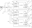
プロジェクタ100は、画像処理部130、制御部210、光源部180、光源制御部170、光学部190、光変調部140、調光部150、光量制御部200、撮像制御部270および時刻部260を含むエンジン部300を有する。同様に、プロジェクタ100a,100bもエンジン部300a,300bを有する。
プロジェクタ100,100a,100bのエンジン部300,300a,300bは、分配器20からの映像信号を受信部110,110a,110bを介して受信し、該映像信号に対して各種画像処理を行って光変調部140を駆動する駆動信号を生成する。駆動信号により駆動された光変調部140は、光源部180から光学部190を介して入射する照明光を変調する。これにより、プロジェクタ100,100a,100bはそれぞれ、投射部160,160a,160bを介してスクリーン等の被投射面に画像(投射画像)400,400a,400bを投射する。
プロジェクタ100,100a,100bはそれぞれ、通信手段としての送受信部120,120a,120bを有する。各送受信部は、無線や有線により通信を行うことができる。通信は、EthernetによるLANを通して行ってもよい。
プロジェクタ100の送受信部120はエンジン部300(制御部210)に接続され、同様にプロジェクタ100a,100bの送受信部120a,120bはエンジン部300a,300bに接続されている。それぞれのプロジェクタの制御部210,210a,210bは、そのプロジェクタにおける画像処理情報、固有情報およびメンテナンスに関する情報を他のプロジェクタの制御部との間で送受信する。また、それぞれのプロジェクタの制御部210,210a,210bは、他のプロジェクタの制御部との間で各種コマンドを送受信する。
The transmitting/receiving
送受信部120,120a,120bは、無線またはケーブル122,122a,122bを介してネットワーク切替え手段であるハブ(HUB)40に接続されている。HUB40は、無線接続用のアクセスポイント、スイッチングハブ、ブリッジ等であり、OSI参照モデルにおけるL2スイッチ(レイヤー2のデータリンク層にてMACアドレスにより切り替えを行うスイッチ)である。
The transmitting/
また、HUB40には、PC30がケーブル32を介して接続されてもよい。PC30は、各プロジェクタの内部状態やメンテナンス履歴等を示す情報を収集して管理する。
Also, the PC 30 may be connected to the HUB 40 via the
次に、図1に示したプロジェクタ100の画像投射に関する動作について説明する。この動作は、図2に示す他のプロジェクタ100a,100bについても同様である。
Next, the image projection operation of the
光源制御部170は、光源部180を駆動する。光源部180は、高圧水銀ランプ、LEDまたはレーザダイオード(LD)等により構成される。LEDやLDは、それを駆動する電流または電圧を変えることで発光輝度を変化させることができる。
Light
光学部190は、ミラー、プリズム、偏光板およびレンズ等の様々な光学素子により構成されている。光変調部140は、透過型液晶パネル、反射型液晶パネルまたはデジタルマイクロミラーデバイス等の光変調素子(以下、光変調パネルという)と、これを駆動するパネル駆動回路とにより構成されている。光変調パネルの解像度は、例えば、WUXGA(1920×1200画素)やFHD(1920×1080画素)であってもよいし、それよりも高い又は低い解像度であってもよい。
The
R(赤)、G(緑)およびB(青)用の3つの光変調パネルを使用する場合は、光源部180からの光を光学部190によりR光、G光およびB光に分離してそれぞれの色光を、照明光として、対応する光変調パネルに導く。これら光変調パネルは、パネル駆動回路によって画像処理部130からの駆動信号に応じて駆動されることでそれぞれの色光を変調する。変調されたR光、G光およびB光は不図示の合成光学系により合成されて画像投射光となる。
When using three light modulation panels for R (red), G (green) and B (blue), light from the
また、1つの光変調パネルを使用する場合は、光源部180からの白色光を不図示のカラーホイール等によって時間的に分割してR光、G光およびB光を順次生成する。そして、光変調パネルは、パネル駆動回路によって画像処理部130からの駆動信号に応じて駆動されることで各色光を変調する。変調されたR光、G光およびB光がそれぞれ画像投射光となる。
When one light modulation panel is used, white light from the
光変調部140から出射した画像投射光の光量は、調光部150により調整される。調光部150は絞り等により構成され、入射した画像投射光の一部を遮断することでその光量を調整する。調光部150にて調光された画像投射光が投射部160(他のプロジェクタ100a,100bでは投射部160a,160b)により被投射面に拡大投射される。これにより、投射画像が表示される。
The amount of image projection light emitted from the
ここで、光変調部140の光変調パネルは、線順次駆動走査方式または面順次駆動走査方式で駆動される。例えば、光変調パネルの解像度が1920×1200画素である場合には、線順次駆動走査方式では、画像処理部130からの駆動信号に応じて、先ず1行目の横方向の1920画素が駆動され、次に2行目の1920画素が駆動される。この駆動画素行の変更は、映像信号の水平同期信号の発生タイミングで行われる。例えば、フレームレートが60Hzである場合は、水平同期信号はその1200倍以上である72kHz以上の周波数を有する同期信号となる。
Here, the light modulating panel of the
こうして縦方向の1200行目の1920画素の駆動が終了すると、映像信号の垂直同期信号(所定周期を有するタイミング信号)が発生し、そのタイミングで次のフレームの駆動が開始される。例えば、フレームレートが60Hzである場合は、垂直同期信号の周波数は60Hzとなる。この垂直同期信号を図1に135Vsyncとして示す。Vsync信号は、光変調部140で光変調パネルが駆動される際の各フレームの先頭を表す垂直同期信号である。投射画像に対して同期をとる場合は、この垂直同期信号のタイミングを検出する必要がある。
When the driving of the 1,920 pixels in the 1,200th row in the vertical direction is finished in this way, a vertical synchronization signal (timing signal having a predetermined period) of the video signal is generated, and the driving of the next frame is started at that timing. For example, if the frame rate is 60 Hz, the frequency of the vertical synchronization signal will be 60 Hz. This vertical synchronization signal is shown in FIG. 1 as 135Vsync. The Vsync signal is a vertical synchronization signal representing the beginning of each frame when the light modulation panel is driven by the
このように線順次駆動走査方式では、横方向の画素行を垂直方向に1画素行ごとに駆動する。これに対して、面順次駆動走査方式では、予め映像信号の1フレーム分の光変調パネルの全画素の駆動データをメモリに書き込んでおき、垂直同期信号に合わせて一斉に全画素に対してそれぞれの駆動データを反映して全画素を一括で駆動する。 As described above, in the line-sequential driving scanning method, horizontal pixel rows are driven vertically one pixel row at a time. On the other hand, in the field sequential drive scanning method, drive data for all pixels of the light modulation panel for one frame of the video signal is written in memory in advance, and all the pixels are simultaneously scanned in synchronization with the vertical synchronizing signal. All the pixels are driven at once by reflecting the drive data of .
垂直同期信号は、映像信号におけるフレームの先頭のタイミングまたはフレームの書き替えタイミングを表すため、垂直同期信号を検出することで、パネルの駆動方式によらず、投射画像が順次更新される更新(切り替え)タイミングを検出することができる。 Since the vertical synchronization signal indicates the timing of the beginning of the frame in the video signal or the timing of rewriting the frame, by detecting the vertical synchronization signal, the projected image can be updated sequentially regardless of the panel driving method. ) timing can be detected.
図1において、プロジェクタ100は、投射画像を撮像可能な撮像部(撮像手段)280を有する。撮像部280は、CCDセンサやCMOSセンサ等の撮像素子と、該撮像素子上に被写体(投射画像)の光学像を結像させる撮像光学系とを有する。
In FIG. 1, the
撮像制御部270は、撮像部280の撮像タイミングをタイミング信号275により制御し、撮像部280からの撮像データを画像処理部130に送信する。同様に他のプロジェクタ100a,100bもそれぞれ、撮像部280a,280bを有する。
The
以下では、プロジェクタ100をマスタープロジェクタ(第1の画像投射装置)とし、他のプロジェクタ100aとプロジェクタ100bをスレーブプロジェクタ(第2の画像投射装置)とする場合について説明する。マスタープロジェクタ100の撮像部280は、該プロジェクタ100が投射した投射画像400を撮像できるだけでなく、スレーブプロジェクタ100a,100bが投射した投射画像400a,400bの少なくとも一部も撮像することができる。
A case will be described below in which the
投射画像の明るさ(輝度)やRGBの色合いは、投射画像が投射される被投射面や環境光の状態に応じて変化し、プロジェクタ自体の設定(特性)によっても異なる。このため、投射画像を撮像してその輝度や色合いを確認し、複数台のプロジェクタの設定を目標とする輝度や色合いの投射画像が投射されるように調整することが望ましい。このとき、撮像部280,280a,280bの撮像感度が必ずしも一致しているとは限らず、同じ投射画像を撮像した場合でも撮像画像における輝度や色合いが異なる場合がある。
The brightness (luminance) and RGB hues of the projected image change depending on the projection surface on which the projected image is projected and the state of the ambient light, and also vary depending on the settings (characteristics) of the projector itself. Therefore, it is desirable to pick up a projection image, check its brightness and color tone, and adjust the settings of the plurality of projectors so that the projection image with the target brightness and color tone is projected. At this time, the imaging sensitivities of the
この場合に有効な調整方法の1つとして、マスターおよびスレーブプロジェクタ100,100a,100bに投射画像400,400a,400bを投射させ、マスタープロジェクタ100の撮像部280にこれら投射画像400,400a,400bを撮像させる。そして、撮像部280により得られた撮像画像を用いて、スレーブプロジェクタ100a,100bの設定を調整する。
As one effective adjustment method in this case,
このときの各プロジェクタの動作について、図1、図3および図4を用いて説明する。図1に示したプロジェクタ100の制御部210には、コマンド制御部220が含まれている。コマンド制御部220は、プロジェクタ100の送受信部120を介して、他のプロジェクタ100a,100bまたは図2に示したPC30との間でコマンドを送受信する。
The operation of each projector at this time will be described with reference to FIGS. 1, 3 and 4. FIG.
図3のフローチャートは、マスタープロジェクタ100とスレーブプロジェクタ100a,100bが行う処理(制御方法)の流れを示している。マスタープロジェクタ100における制御部210は、時刻取得手段および制御手段として機能する。また、コンピュータとしての制御部210は、コンピュータプログラムに従って本処理を実行する。このことは、後述する他の実施例で行われる処理についても同じである。なお、以下の説明では、特に必要がない限り、マスタープロジェクタおよびスレーブプロジェクタの符号(100,100a,100b)を省略する。
The flowchart in FIG. 3 shows the flow of processing (control method) performed by the
Step-10では、マスタープロジェクタ(制御部210)は、ユーザがPC30を通じて送信した調整コマンドを受信する。この調整コマンドは、スレーブプロジェクタに画像投射を行わせるとともに、マスタープロジェクタの撮像部280に撮像を行わせるためのコマンドである。これら画像投射と撮像がそれぞれ、画像投射に関する調整のための第1の動作と第2の動作に相当する。Step-11では、スレーブプロジェクタは処理を開始する。
At Step-10, the master projector (control unit 210) receives the adjustment command sent by the user via PC30. This adjustment command is a command for causing the slave projector to perform image projection and for causing the
調整コマンドを受信したマスタープロジェクタ(コマンド制御部220)は、Step-20において、後述する時刻計測コマンドを生成する。時刻計測コマンドは、スレーブプロジェクタに、時刻計測コマンドを受信した内部時刻と後述するVsync時刻とを計測させるコマンドである。以下の説明において、スレーブプロジェクタの内部時刻をスレーブ時刻という。 Upon receiving the adjustment command, the master projector (command control section 220) generates a time measurement command, which will be described later, in Step-20. The time measurement command is a command that causes the slave projector to measure the internal time at which the time measurement command was received and the Vsync time, which will be described later. In the following description, the internal time of the slave projector will be referred to as slave time.
さらにマスタープロジェクタは、Step-30において、時刻計測コマンドをスレーブプロジェクタに送信するとともに、その送信時刻を示すマスタープロジェクタの内部時刻を計測する。以下の説明において、マスタープロジェクタの内部時刻をマスター時刻という。 Further, in Step-30, the master projector transmits a time measurement command to the slave projector and measures the internal time of the master projector indicating the transmission time. In the following description, the internal time of the master projector is called master time.
Step-31にて時刻計測コマンドを受信したスレーブプロジェクタは、Step-35において、該時刻計測コマンドを受信したスレーブ時刻としてのスレーブ受信時刻とその直後に垂直同期信号Vsyncが発生したスレーブ時刻であるVsync時刻とを計測する。 Upon receiving the time measurement command in Step-31, the slave projector sets in Step-35 the slave reception time as the slave time at which the time measurement command was received and Vsync which is the slave time at which the vertical synchronization signal Vsync was generated immediately after that. measure the time.
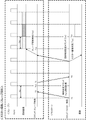
図4は、本実施例におけるマスター時刻、スレーブ時刻およびコマンド送受信タイミングの例を示す。プロジェクタ100,100a,100bはそれぞれ、時刻部260,260a,260bを有する。それぞれの時刻部260,260a,260bは、NTP(Network Time Protocol)サーバー等の特定サーバーにより設定された各プロジェクタの設置場所におけるタイムゾーンの標準時刻を内部時刻として用いる。また、それぞれの時刻部260,260a,260bは、それが設けられたプロジェクタにおける独自の(ローカルな)内部時刻をカウントしてもよい。このローカルな内部時刻は、1ms以下の分解能を有していればよい。本実施例では、第1の画像投射装置としてのマスタープロジェクタが有する内部時刻(マスター時刻)が第1の内部時刻に相当し、第2の画像投射装置としてのスレーブプロジェクタが有する内部時刻(スレーブ時刻)が第2の内部時刻に相当する。
FIG. 4 shows an example of master time, slave time and command transmission/reception timing in this embodiment.
Step-30では、マスタープロジェクタは、時刻計測コマンドをスレーブプロジェクタに送信したマスター時刻であるコマンド送信時刻T1を計測する。また、Step-35では、スレーブプロジェクタは、時刻計測コマンドを受信したスレーブ時刻であるコマンド受信時刻T2とVsync時刻Tv1とを計測する。垂直同期信号Vsyncの周期(以下、同期周期という)をTvsとし、映像信号のフレームレートを60Hzとすると、Tvs=16.66msである。スレーブプロジェクタの時刻部260は、その時刻計測分解能を1msとすると、垂直同期信号Vsyncに同期したVsync時刻Tv1を1ms程度の精度で特定することができる。
At Step-30, the master projector measures the command transmission time T1, which is the master time at which the time measurement command was transmitted to the slave projector. In Step-35, the slave projector measures the command reception time T2 and the Vsync time Tv1, which are the slave times when the time measurement command was received. Assuming that the period of the vertical synchronization signal Vsync (hereinafter referred to as synchronization period) is Tvs and the frame rate of the video signal is 60 Hz, Tvs=16.66 ms. Assuming that the time measurement resolution is 1 ms, the
Step-35において、スレーブプロジェクタは、マスタープロジェクタに対して、T2およびTv1と、これらをマスタープロジェクタ100に返信するスレーブ時刻である情報返信時刻T3とをまとめてスレーブ時刻情報として返信する。
In Step-35, the slave projector returns T2 and Tv1 together with the information reply time T3, which is the slave time at which these are returned to the
マスタープロジェクタ(制御部210)は、Step-36においてスレーブプロジェクタからのスレーブ時刻情報の返信を待ち、スレーブ時刻情報を受信するとStep-40に進む。Step-40では、マスタープロジェクタは、スレーブ時刻情報(T2、Tv1およびT3)を受信したマスター時刻である情報受信時刻T4を計測する。そして、制御部210内の時刻ずれ算出部230は、以下の式(1)を用いて、マスター時刻とスレーブ時刻との差(ずれ量)ΔTを算出する。
The master projector (control unit 210) waits for slave time information from the slave projector in Step-36, and proceeds to Step-40 when the slave time information is received. In Step-40, the master projector measures the information reception time T4, which is the master time when the slave time information (T2, Tv1 and T3) is received. Then, the time
ΔT={(T2-T1)-(T4-T3)}/2 (1)
例えば、T1=0として、スレーブ時刻がマスター時刻に対して5msだけずれていて(進んでいて)、マスタープロジェクタとスレーブプロジェクタ間でのコマンド送受信にそれぞれ1msの時間を要し、スレーブプロジェクタがマスタープロジェクタから時刻計測コマンドを受信してからスレーブ時刻情報を返信するまでに3msの時間だけ要したとする。この場合、T1=0、T2=5+1=6、T3=6+3=9、T4=5となり、これを式(1)に代入すると、
ΔT={(6-0)-(5-9)}/2=5
となり、スレーブ時刻がマスター時刻に対してΔT=5msだけずれている(進んでいる)ことが算出される。
ΔT={(T2-T1)-(T4-T3)}/2 (1)
For example, when T1=0, the slave time is 5ms ahead of the master time, and it takes 1ms for each command to be sent and received between the master projector and the slave projector. It is assumed that it takes 3 ms from the reception of the time measurement command to the return of the slave time information. In this case, T1=0, T2=5+1=6, T3=6+3=9, and T4=5.
ΔT={(6−0)−(5−9)}/2=5
Thus, it is calculated that the slave time is shifted (advanced) from the master time by ΔT=5 ms.
また、制御部210内の周期時刻算出部240は、Vsync時刻Tvnを、Tv1を用いて以下の式(2)により算出する。
Also, the period
Tvn=Tv1+m×Tvs (2)
(但し、mは1以上の整数)
式(2)は、スレーブ時刻としての垂直同期信号Vsyncのタイミングを表す一般式である。
Tvn=Tv1+m×Tvs (2)
(However, m is an integer of 1 or more)
Equation (2) is a general equation representing the timing of the vertical synchronization signal Vsync as slave time.
さらに、制御部210内の同期時刻算出部250は、Vsync時刻Tvnに同期してスレーブプロジェクタが画像投射を行うスレーブ時刻であるスレーブ投射時刻(第1の動作時刻)Tvxを以下の式(3)を用いて算出する。コマンド制御部220は、スレーブプロジェクタにスレーブ投射時刻Tvxを示す投射時刻指定コマンドを送信する。
Tvx=Tv1+n×Tvs (3)
(但し、nは1以上の整数)
また、同期時刻算出部250は、マスタープロジェクタの撮像部280がスレーブプロジェクタによる画像投射に同期して投射画像の撮像を行うマスター時刻であるマスター撮像時刻(第2の動作時刻)Tcxを以下の式(4)を用いて算出する。
Furthermore, the synchronous
Tvx=Tv1+n×Tvs (3)
(However, n is an integer of 1 or more)
Further, the synchronous
Tcx=Tvx-ΔT (4)
Step-41にて投射時刻指定コマンドを受信したスレーブプロジェクタは、Step-45において、スレーブ投射時刻Tvxから所定の校正パターン画像を投射させるための動作(後述する投射準備動作および投射動作)を開始させる。
Tcx=Tvx-ΔT (4)
Upon receiving the projection time designation command in Step-41, the slave projector starts an operation (projection preparation operation and projection operation to be described later) for projecting a predetermined calibration pattern image from the slave projection time Tvx in Step-45. .
一方、マスタープロジェクタ(制御部210)は、Step-50において、マスター撮像時刻Tcxから撮像部280に校正パターン画像の撮像を行わせる。
On the other hand, in Step-50, the master projector (control section 210) causes the
スレーブプロジェクタは、Step-65において、1つ又は複数用意された校正パターン画像の全てを投射したか否かを判定する。まだ投射していない校正パターン画像が残っている場合はStep-45に戻ってその校正パターン画像を投射する。一方、未投射の校正パターン画像が残っていない場合は、スレーブプロジェクタはStep-75にて本処理を終了する。 At Step-65, the slave projector determines whether or not one or all of the prepared calibration pattern images have been projected. If there remains a calibration pattern image that has not yet been projected, the process returns to Step-45 to project the calibration pattern image. On the other hand, if there is no unprojected calibration pattern image left, the slave projector ends this process at Step-75.
マスタープロジェクタの制御部210も同様に、Step-60において、1つ又は複数の校正パターン画像の撮像が全て終了したか否かを判定する。まだ撮像していない校正パターン画像が残っている場合はStep-40および-50の処理を行う。一方、未撮像の校正パターン画像が残っていない場合は、制御部210は、Step-70にて本処理を終了する。
Likewise, in Step-60, the
図4において、スレーブプロジェクタは、スレーブ投射時刻Tvxから同期周期Tvsの間の斜線で示す投射準備期間に、該スレーブプロジェクタの光変調パネルを校正パターン画像に応じて駆動するための投射準備動作を行う。この投射準備動作は、線順次駆動走査方式で光変調パネルを駆動する場合には、該光変調パネルに校正パターン画像に対応する駆動データを一画素行ごとに書き込む動作である。また、面順次駆動走査方式で光変調パネルを駆動する場合には、光変調パネルの全画素に1フレーム分の駆動データを書き込む動作である。光変調パネルへの駆動データの書き込み(投射画像の更新)が完了すると、図中に灰色で示した期間に入る。 In FIG. 4, the slave projector performs a projection preparation operation for driving the light modulation panel of the slave projector according to the calibration pattern image during the projection preparation period indicated by oblique lines between the slave projection time Tvx and the synchronization period Tvs. . This projection preparation operation is an operation of writing drive data corresponding to the calibration pattern image to the light modulation panel for each pixel row when the light modulation panel is driven by the line-sequential driving scanning method. Further, when the light modulation panel is driven by the frame sequential driving scanning method, it is an operation of writing drive data for one frame to all the pixels of the light modulation panel. When the writing of the driving data to the light modulation panel (updating the projection image) is completed, the period shown in gray in the drawing is entered.
灰色で示した期間は、スレーブプロジェクタの光変調パネルが校正パターン画像に対応する駆動データに応じて駆動されている期間、すなわち校正パターン画像を投射する投射動作が行われている投射期間である。マスタープロジェクタは、この投射期間に合わせて、マスター撮像時刻Tcxから所定時間の間に、投射されている校正パターン画像の撮像を行う。図4では、校正パターン画像の1フレーム分の撮像が示されている。 The period shown in gray is the period during which the light modulation panel of the slave projector is driven according to the drive data corresponding to the calibration pattern image, that is, the projection period during which the calibration pattern image is projected. In accordance with this projection period, the master projector captures the projected calibration pattern image for a predetermined period of time from the master imaging time Tcx. FIG. 4 shows imaging of one frame of the calibration pattern image.
そして、この校正パターン画像の投射期間が終了すると同時に斜線で示す投射準備期間に入り、この投射準備期間にスレーブプロジェクタは次のフレームの校正パターン画像に応じて光変調パネルを駆動するための準備動作を行う。 At the same time as the projection period of this calibration pattern image ends, a projection preparation period indicated by oblique lines begins. During this projection preparation period, the slave projector performs a preparatory operation for driving the light modulation panel according to the calibration pattern image of the next frame. I do.
本実施例では、スレーブプロジェクタによる画像投射とマスタープロジェクタによる撮像とは1msオーダで同期がとれている。このため、スレーブプロジェクタが校正パターン画像を正しく投射している期間においてマスタープロジェクタが該校正パターン画像を撮像することができる。すなわち、光変調パネルへの駆動データの書き込み(書き換え)途中に撮像が行われることを回避することができ、3つのプロジェクタからの投射画像の輝度や色合いを合わせるための調整に必要な撮像画像(第2の動作の結果)を取得することができる。この結果、該調整に要する時間を短くすることができる。 In this embodiment, image projection by the slave projector and imaging by the master projector are synchronized on the order of 1 ms. Therefore, the master projector can capture the calibration pattern image while the slave projector is correctly projecting the calibration pattern image. In other words, it is possible to avoid taking an image while driving data is being written (rewritten) to the light modulation panel. result of the second operation) can be obtained. As a result, the time required for the adjustment can be shortened.
このようにしてスレーブプロジェクタに校正パターン画像を投射させてマスタープロジェクタの撮像部280により撮像画像を取得し、さらにマスタープロジェクタにも校正パターン画像を投射させて該マスタープロジェクタの撮像部280により撮像画像を取得する。そして、これら撮像画像を比較して、3台のプロジェクタからの投射画像の輝度や色合いが互いに等しくなるようにスレーブプロジェクタの設定を調整する。
In this way, the slave projector is caused to project the calibration pattern image, and the captured image is acquired by the
例えば、輝度に関する設定の調整は、光量制御部200の光量調整値算出部202が算出した目標電流値で光源部(光量調整手段)180が駆動されるように、光源制御部170で光源180を駆動する電流値を制御することで行うことができる。また、光量制御部200の光量調整値算出部202が算出した目標絞り値になるように、調光部(光量調整手段)150の絞りを制御することで行ってもよい。
For example, adjustment of brightness settings is performed by the light
また、色合いに関する設定の調整は、画像処理部(色調整手段)130により、映像信号に対する光変調部140のR、GおよびBのゲインを制御することで行うことができる。
Further, the adjustment of the setting regarding the hue can be performed by controlling the R, G, and B gains of the
これら投射画像の輝度や色合いの調整は、マスタープロジェクタおよびスレーブプロジェクタのうち少なくとも一方で行えばよい。 At least one of the master projector and the slave projector may adjust the brightness and color of the projected image.
なお、各プロジェクタは、撮像部に代えて、プリズム、回折格子およびレンズ等を組み合わせて構成され、画像投射光のスペクトルを測定する分光器(分光手段)を有してもよい。分光器による分光測定(第2の動作)の結果を用いることで、撮像部を用いる場合と同様に、3台のプロジェクタからの投射画像の輝度や色合いを合わせるようにスレーブプロジェクタの設定を調整することができる。このことは、後述する他の実施例でも同じである。 Note that each projector may have a spectroscope (spectroscopic means) configured by combining a prism, a diffraction grating, a lens, etc., and measuring the spectrum of the image projection light, instead of the imaging section. By using the result of spectroscopic measurement (second operation) by the spectrometer, the settings of the slave projectors are adjusted so that the brightness and color of the images projected from the three projectors are matched in the same way as when using the imaging unit. be able to. This also applies to other embodiments described later.
本実施例によれば、マスタープロジェクタは、スレーブプロジェクタの画像投射に正確に同期して投射画像の撮像または画像投射光の分光測定を行うため、スレーブプロジェクタの設定の調整に必要な良好な撮像画像または分光測定結果を取得することができる。このため、複数台のプロジェクタからの投射画像の輝度や色合いを良好に、かつ短時間で合わせることができる。 According to this embodiment, the master projector captures a projection image or performs spectroscopic measurement of image projection light in synchronism with the image projection of the slave projectors. Or spectroscopic measurement results can be acquired. Therefore, it is possible to match the brightness and color tone of images projected from a plurality of projectors satisfactorily and in a short period of time.
なお、PC30は画像供給装置も兼ねてもよい。また、校正パターン画像の投射は所定の複数フレーム数(時間)であってもよい。
Note that the
次に、本発明の実施例2について説明する。実施例2では、マスタープロジェクタが校正パターン画像を投射し、スレーブプロジェクタがそれを撮像する場合について説明する。なお、本実施例における各プロジェクタの構成は、図1および図2に示した構成と同じである。 Next, Example 2 of the present invention will be described. In the second embodiment, a case will be described where the master projector projects a calibration pattern image and the slave projector images it. The configuration of each projector in this embodiment is the same as the configuration shown in FIGS.
図5のフローチャートは、本実施例におけるマスタープロジェクタとスレーブプロジェクタにおけるコマンド送受信処理を示している。 The flowchart of FIG. 5 shows command transmission/reception processing between the master projector and the slave projectors in this embodiment.
Step-10aでは、マスタープロジェクタ(制御部210)は、ユーザがPC30を通じて送信した調整コマンドを受信する。この調整コマンドは、マスタープロジェクタの画像投射を行わせるとともに、スレーブプロジェクタの撮像部280a,280bに撮像を行わせるためのコマンドである。Step-11aでは、スレーブプロジェクタは処理を開始する。
At Step-10a, the master projector (control unit 210) receives the adjustment command sent by the user through the PC30. This adjustment command is a command for causing the master projector to project an image and causing the
調整コマンドを受信したマスタープロジェクタ(コマンド制御部220)は、Step-20において、時刻計測コマンドを生成する。本実施例における時刻計測コマンドは、スレーブプロジェクタに時刻計測コマンドを受信した時刻を計測させるコマンドである。 Upon receiving the adjustment command, the master projector (command control section 220) generates a time measurement command in Step-20. The time measurement command in this embodiment is a command that causes the slave projector to measure the time when the time measurement command is received.
次にマスタープロジェクタは、Step-30aにおいて、時刻計測コマンドをスレーブプロジェクタに送信するとともに、その送信時刻を示すマスター時刻とその直後のVsync時刻とを計測する。時刻計測コマンドを受信したスレーブプロジェクタは、Step-35aにおいて、該時刻計測コマンドを受信したスレーブ時刻を計測する。 Next, in Step-30a, the master projector transmits a time measurement command to the slave projector, and measures the master time indicating the transmission time and the Vsync time immediately after that. The slave projector that has received the time measurement command measures the slave time at which it received the time measurement command in Step-35a.
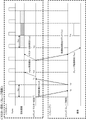
図6は、本実施例におけるマスター時刻、スレーブ時刻およびコマンド送受信タイミングの例を示す。実施例1と同様に、マスターおよびスレーブプロジェクタは、特定サーバーにより設定された標準時刻またはプロジェクタ独自の内部時刻をマスター時刻およびスレーブ時刻として有する。 FIG. 6 shows an example of master time, slave time and command transmission/reception timing in this embodiment. As in the first embodiment, the master and slave projectors have the standard time set by a specific server or the projector's own internal time as the master time and slave time.
Step-30aでは、マスタープロジェクタは、時刻計測コマンドをスレーブプロジェクタに送信したマスター時刻であるコマンド送信時刻T1とVsync時刻とを計測する。また、Step-31aにて時刻計測コマンドを受信したスレーブプロジェクタは、Step-35aにおいて、時刻計測コマンドを受信したスレーブ時刻であるコマンド受信時刻T2を計測する。そして、このT2とこれをマスタープロジェクタに返信するスレーブ時刻である情報返信時刻T3とをまとめてスレーブ時刻情報としてマスタープロジェクタに返信する。 At Step-30a, the master projector measures the command transmission time T1, which is the master time when the time measurement command was transmitted to the slave projector, and the Vsync time. Further, the slave projector that received the time measurement command in Step-31a measures the command reception time T2, which is the slave time at which the time measurement command was received, in Step-35a. Then, this T2 and the information reply time T3, which is the slave time for replying this to the master projector, are collectively sent back to the master projector as slave time information.
Step-36aにてスレーブ時刻情報を受信したマスタープロジェクタ(制御部210)は、Step-40aにおいて、スレーブプロジェクタからスレーブ時刻情報(T2およびT3)を受信したマスター時刻である情報受信時刻T4を計測する。そして、制御部210内の時刻ずれ算出部230は、T1、T2、T3およびT4と実施例1で説明した式(1)を用いて、マスター時刻とスレーブ時刻とのずれ量ΔTを算出する。
The master projector (control unit 210) that has received the slave time information in Step-36a measures information reception time T4, which is the master time at which the slave time information (T2 and T3) is received from the slave projector in Step-40a. . Then, the time
制御部210内の周期時刻算出部240は、Vsync時刻Tvnを、Tv1を用いて実施例1で説明した式(2)を用いて算出する。また、制御部210内の同期時刻算出部250は、Vsync時刻Tvnに同期してマスタープロジェクタが画像投射を行うマスター時刻であるマスター投射時刻(第1の動作時刻)Tvxを実施例1で説明した式(3)を用いて算出する。
The period
さらに、同期時刻算出部250は、スレーブプロジェクタの撮像部280a,280bがマスタープロジェクタによる画像投射に同期して投射画像の撮像を行うスレーブ時刻であるスレーブ撮像時刻(第2の動作時刻)Tcxを以下の式(5)を用いて算出する。コマンド制御部220は、スレーブプロジェクタにスレーブ撮像時刻Tcxを示す撮像時刻指定コマンドを送信する。
Tcx=Tv1+n×Tvs+ΔT (5)
(但し、nは1以上の整数)
マスタープロジェクタ(制御部210)は、Step-50aにおいて、マスター投射時刻Tvxから校正パターン画像を投射させるための動作(投射準備動作および投射動作)を開始させる。
Furthermore, the synchronous
Tcx=Tv1+n×Tvs+ΔT (5)
(However, n is an integer of 1 or more)
In Step-50a, the master projector (control unit 210) starts an operation (projection preparation operation and projection operation) for projecting the calibration pattern image from master projection time Tvx.
一方、Step-41aにて撮像時刻指定コマンドを受信したスレーブプロジェクタは、Step-45aにおいて、スレーブ撮像時刻Tcxから撮像部280a,280bに校正パターン画像の撮像を行わせる。
On the other hand, in Step-41a, the slave projector that has received the imaging time specification command causes the
マスタープロジェクタ(制御部210)は、Step-60aにおいて、1つ又は複数用意された校正パターン画像の全てを投射したか否かを判定する。まだ投射していない校正パターン画像が残っている場合はStep-40に戻ってその校正パターン画像を投射する。一方、未投射の校正パターン画像が残っていない場合は、マスタープロジェクタはStep-70にて本処理を終了する。 In Step-60a, the master projector (control unit 210) determines whether or not all of one or more prepared calibration pattern images have been projected. If there remains a calibration pattern image that has not yet been projected, the process returns to Step-40 to project the calibration pattern image. On the other hand, if there is no unprojected calibration pattern image left, the master projector ends this process at Step-70.
一方、スレーブプロジェクタも同様に、Step-65aにおいて、1つ又は複数の校正パターン画像の撮像が全て終了したか否かを判定する。まだ撮像していない校正パターン画像が残っている場合はStep-45aにてその撮像を行う。一方、未撮像の校正パターン画像が残っていない場合は、Step-75にて本処理を終了する。 On the other hand, the slave projector similarly determines in Step-65a whether or not all one or more calibration pattern images have been captured. If there remains a calibration pattern image that has not been captured yet, it is captured in Step-45a. On the other hand, if there is no calibration pattern image that has not yet been captured, the process ends at Step-75.
図6において、マスタープロジェクタは、マスター投射時刻Tvxから同期周期Tvsの間の斜線で示す投射準備期間に、該マスタープロジェクタの光変調パネルを校正パターン画像に応じて駆動するための投射準備動作を行う。この投射準備動作は、実施例1にて図4を用いて説明した線順次駆動走査方式または面順次駆動走査方式で行う動作と同じである。 In FIG. 6, the master projector performs a projection preparation operation for driving the light modulation panel of the master projector according to the calibration pattern image during the projection preparation period indicated by oblique lines between the master projection time Tvx and the synchronization period Tvs. . This projection preparation operation is the same as the operation performed in the line-sequential driving scanning method or the field-sequential driving scanning method described with reference to FIG. 4 in the first embodiment.
灰色で示した期間は、マスタープロジェクタの光変調パネルが校正パターン画像に応じて駆動されている期間、すなわち校正パターン画像を投射する投射動作が行われている投射期間である。スレーブプロジェクタは、この投射期間に合わせて、スレーブ撮像時刻Tcxから所定時間の間に、投射されている校正パターン画像の撮像を行う。図6では、校正パターン画像の1フレーム分の撮像が示されている。 The period shown in gray is the period during which the light modulation panel of the master projector is driven according to the calibration pattern image, that is, the projection period during which the projection operation for projecting the calibration pattern image is performed. The slave projector captures the projected calibration pattern image for a predetermined period of time from the slave capturing time Tcx in accordance with this projection period. FIG. 6 shows imaging of one frame of the calibration pattern image.
そして、この撮像が終了すると同時に斜線で示す投射準備期間に入り、この投射準備期間にマスタープロジェクタは次のフレームの校正パターン画像に応じて光変調パネルを駆動するための準備動作を行う。 At the same time when this imaging is completed, a projection preparation period indicated by oblique lines is entered. During this projection preparation period, the master projector performs a preparation operation for driving the light modulation panel according to the calibration pattern image of the next frame.
本実施例では、マスタープロジェクタによる画像投射とスレーブプロジェクタによる撮像とは1msオーダで同期がとれている。このため、マスタープロジェクタが校正パターン画像を正しく投射している期間においてスレーブプロジェクタが該校正パターン画像を撮像することができる。すなわち、光変調パネルへの駆動データの書き込み(書き換え)途中に撮像が行われることを回避することができ、投射画像の輝度や色合いを合わせるための調整に必要な撮像画像を取得することができる。この結果、該調整に要する時間を短くすることができる。 In this embodiment, image projection by the master projector and imaging by the slave projector are synchronized on the order of 1 ms. Therefore, the slave projector can capture the calibration pattern image while the master projector is correctly projecting the calibration pattern image. That is, it is possible to avoid taking an image while driving data is being written (rewritten) to the light modulation panel, and it is possible to obtain a captured image necessary for adjusting the brightness and color of the projected image. . As a result, the time required for the adjustment can be shortened.
このようにしてマスタープロジェクタに校正パターン画像を投射させてスレーブプロジェクタの撮像部280a,280bにより撮像画像を取得し、さらにスレーブプロジェクタに校正パターン画像を投射させてその撮像部280a,280bにより撮像画像を取得する。そして、これら撮像画像を比較して、3台のプロジェクタからの投射画像の輝度や色合いが互いに等しくなるようにスレーブプロジェクタの設定を調整する。また、撮像部280,280a,280bの撮像感度が互いに等しくなるようにそれぞれのプロジェクタの撮像制御部270により撮像感度を制御してもよい。
In this manner, the master projector is caused to project the calibration pattern image, and the
本実施例によれば、スレーブプロジェクタは、マスタープロジェクタの画像投射に正確に同期して投射画像の撮像または画像投射光の分光測定を行うため、スレーブプロジェクタの設定の調整に必要な良好な撮像画像または分光測定結果を取得することができる。このため、複数台のプロジェクタからの投射画像の輝度や色合いを良好に、かつ短時間で合わせることができる。 According to this embodiment, the slave projector captures the projection image or performs spectral measurement of the image projection light in synchronism with the image projection of the master projector. Or spectroscopic measurement results can be obtained. Therefore, it is possible to match the brightness and color tone of images projected from a plurality of projectors satisfactorily and in a short period of time.
次に、本発明の実施例3について、図7を用いて説明する。実施例3は実施例2の変形例であり、マスタープロジェクタ100が校正パターン画像を投射する点は実施例2と同じである。ただし、マスタープロジェクタ100により投射された校正パターン画像の撮像は、スレーブプロジェクタ100a′,100b′とは別に設けられた撮像デバイス(撮像手段)280x,280yが行う。撮像デバイス280x,280yはそれぞれ、無線通信機能および有線通信機能のうち少なくとも一方を有する。
Next, Example 3 of the present invention will be described with reference to FIG. The third embodiment is a modification of the second embodiment, and is the same as the second embodiment in that the
プロジェクタ100,100a′,100b′はそれぞれ、Wi-Fi等の無線LAN124,124a,124bによりアクセスポイント50を介してPC30に接続されている。なお、図3では、図1に示した画像供給装置10は省略されている。
The
撮像デバイス280xは、無線LAN282xによりアクセスポイント50に接続されている。また、撮像デバイス280yはケーブル(USBケーブル等)282yを介してスレーブプロジェクタ100b′に接続され、スレーブプロジェクタ100b′を介して通信が可能である。このように、プロジェクタ100,100a′,100b′および撮像デバイス280x,280yは互いに通信可能に接続されている。
The
ただし、撮像デバイス280yがケーブルを介してスレーブプロジェクタ100a′に接続されていてもよいし、無線LANによりアクセスポイント50に接続されていてもよい。
However, the
本実施例におけるマスターおよびスレーブプロジェクタの動作は、スレーブデバイスとしての撮像デバイス280x,280yが実施例2の撮像部280a,280bに代わって撮像を行う点を除き、実施例2と同様である。
The operations of the master and slave projectors in this embodiment are the same as those in the second embodiment except that
撮像デバイス280x,280yは、NTPサーバー等の特定サーバーより設定された標準時刻を内部時刻(以下、撮像デバイス時刻という)として用いる。撮像デバイス280xまたは撮像デバイス280yは、マスタープロジェクタ100から時刻計測コマンドを受信する。以下の説明では、マスタープロジェクタと撮像デバイスの符号を省略する。
The
時刻計測コマンドを受信した撮像デバイスは、時刻計測コマンドを受信した撮像デバイス時刻であるコマンド受信時刻T2とこれをマスタープロジェクタ100に返信する撮像デバイス時刻である情報返信時刻T3とを撮像デバイス時刻情報としてまとめてマスタープロジェクタに送信する。
The imaging device that has received the time measurement command uses the command reception time T2, which is the imaging device time at which the time measurement command was received, and the information reply time T3, which is the imaging device time at which this is returned to the
マスタープロジェクタは、図5のStep-40と同様に、式(1)を用いてマスター時刻と撮像デバイス時刻とのずれ量ΔTを算出する。さらに、マスタープロジェクタは、式(3)と式(5)を用いて、マスター投射時刻(第1の動作時刻)と垂直同期信号Vsyncに同期した撮像デバイス280xによる撮像時刻(第2の動作時刻:以下、デバイス撮像時刻という)とを算出する。マスタープロジェクタは、デバイス撮像時刻を撮像デバイスに送信する。 The master projector calculates the amount of deviation ΔT between the master time and the imaging device time using Equation (1), as in Step-40 of FIG. Further, the master projector uses equations (3) and (5) to determine the master projection time (first operation time) and the imaging time (second operation time: hereinafter referred to as device imaging time). The master projector transmits the device imaging time to the imaging device.
そして、マスタープロジェクタは、図5のStep-50aと同様にマスター投射時刻Tvxにて校正パターン画像を投射する。撮像デバイスは、Step-45aにてデバイス撮像時刻から所定時間の間、校正パターンを撮像する。これ以降の動作は、実施例2と同様であるので説明を省略する。 Then, the master projector projects the calibration pattern image at the master projection time Tvx as in Step-50a of FIG. The imaging device images the calibration pattern for a predetermined time from the device imaging time in Step-45a. Since the operation after this is the same as that of the second embodiment, the explanation is omitted.
本実施例において、実施例1と同様に、校正パターン画像の投射をスレーブプロジェクタ100a′またはスレーブプロジェクタ100b′が行ってもよい。この場合も、マスタープロジェクタがマスター時刻と撮像デバイス時刻とのずれ量ΔTを算出し、該ずれ量ΔTを用いて、スレーブ投射時刻とデバイス撮像時刻とを算出して校正パターン画像の投射と撮像を行う。
In this embodiment, as in the first embodiment, the projection of the calibration pattern image may be performed by the
なお、撮像デバイス280x,280yに代えて、実施例1にて説明したように画像投射光を分光測定する分光器を設け、その分光測定結果を用いてスレーブプロジェクタの設定の調整を行ってもよい。
Note that instead of the
本実施例によれば、プロジェクタの画像投射に正確に同期して撮像デバイスによる投射画像の撮像または画像投射光の分光測定を行うため、スレーブプロジェクタの設定の調整に必要な良好な撮像画像または分光測定結果を取得することができる。このため、複数台のプロジェクタからの投射画像の輝度や色合いを良好に、かつ短時間で合わせることができる。 According to this embodiment, since the imaging device captures the projected image or the spectral measurement of the image projection light is performed in synchronism with the projection of the image by the projector, it is possible to obtain a good captured image or spectroscopic image necessary for adjusting the settings of the slave projector. Measurement results can be obtained. Therefore, it is possible to match the brightness and color tone of images projected from a plurality of projectors satisfactorily and in a short period of time.
次に、本発明の実施例4について説明する。実施例4における各プロジェクタの構成は、図1および図2に示した構成と同様である。 Next, Example 4 of the present invention will be described. The configuration of each projector in Example 4 is the same as the configuration shown in FIGS.
投射画像には高いコントラスト比が望まれることが多い。コントラスト比とは、投射画像における最大輝度(白)と最小輝度(黒)の輝度比である。コントラスト比が高いと、明るさと暗さとの差が大きくなり、より鮮明な投射画像が得られる。 A high contrast ratio is often desired for the projected image. The contrast ratio is the luminance ratio between maximum luminance (white) and minimum luminance (black) in the projected image. A high contrast ratio increases the difference between brightness and darkness, resulting in a sharper projected image.
コントラスト比を向上させる方法として、映像信号の明るさに応じて投射画像の輝度を変更(調整)する方法がある。例えば、映像信号が明るい場合はより高輝度な画像を投射し、映像信号が暗い場合はより低輝度な画像を投射する。この投射画像の輝度を調整は、図1に示した投射部160からの投射光量を調整する調光部(絞り)150を制御することで行うことができる。また、光源部180にLDやLEDが用いられている場合は、光源制御部170により光源部180を駆動する電流値を制御することで行うことができる。
As a method of improving the contrast ratio, there is a method of changing (adjusting) the brightness of the projected image according to the brightness of the video signal. For example, when the video signal is bright, an image with higher luminance is projected, and when the video signal is dark, an image with lower luminance is projected. The brightness of the projected image can be adjusted by controlling the light adjustment section (diaphragm) 150 that adjusts the amount of light projected from the
映像としての投射画像の輝度は、フレームごとに異なる。例えば、フレームレートが60Hzである場合は、16.6msごとに輝度が変化することがある。さらに、フレームレートがハイフレームレートと呼ばれる120Hzである場合は、8.3msごとに輝度が変化することがある。コントラスト比を向上させるには、フレームレートと同等の時間で調光部150や光源部180を制御できることが望ましい。
The brightness of the projected image as video differs from frame to frame. For example, if the frame rate is 60Hz, the brightness may change every 16.6ms. Furthermore, if the frame rate is 120 Hz, which is called high frame rate, the luminance may change every 8.3 ms. In order to improve the contrast ratio, it is desirable to be able to control the
一方、投射画像の「輝度」は、図1に示した画像処理部130において画像特徴量として計算される。「輝度」は、例えば、投射画像の最大輝度、最小輝度または平均輝度としてフレームごとに計算および更新される。
On the other hand, the "brightness" of the projection image is calculated as an image feature quantity in the
例えば、画像供給装置10からの映像信号を分配器20により分割して複数台のプロジェクタにより画像投射を行う場合は、各プロジェクタの画像処理部(特徴量取得手段)130にて算出された画像特徴量をマスタープロジェクタが収集する。マスタープロジェクタは、収集した画像特徴量から全投射画像の最大輝度、最小輝度および平均輝度のうち少なくとも1つを求め、その結果に応じてマスターおよびスレーブプロジェクタの調光部150または光源部180の制御量(調整量)を算出する。
For example, when the video signal from the
そして、マスタープロジェクタは、スレーブプロジェクタ用に算出した調整量をスレーブプロジェクタに送信するとともに、自身用の調整量に応じて自身の調光部150または光源部180を制御する。スレーブプロジェクタは、受信した調整量に応じて自身の調光部150または光源部180を調整(制御)する。これらスレーブプロジェクタとマスタープロジェクタのそれぞれにおける調光部150または光源部180の調整、すなわち光量調整が、画像投射に関する調整のための第1の動作と第2の動作に相当する。
Then, the master projector transmits the adjustment amount calculated for the slave projector to the slave projector, and controls its own
このとき、画像特徴量の収集から調光部150または光源部180の制御までを1フレーム内で終了することが望ましい。このためには、マスターおよびスレーブプロジェクタ間での画像特徴量や調整量の送受信における遅延時間を極力短くして、全てのプロジェクタの調光部150または光源部180が制御されるタイミングが同期している必要がある。
At this time, it is desirable to complete the process from collection of the image feature amount to control of the
図8のフローチャートは、マスタープロジェクタ100とスレーブプロジェクタ100a,100bが行う処理を示している。以下の説明でも、マスターおよびスレーブプロジェクタの符号を省略する。
The flowchart in FIG. 8 shows the processing performed by the
マスタープロジェクタ(制御部210)は、Step-110において、ユーザがPC30を通じて送信したコントラスト同期調整コマンドを受信する。このコントラスト同期調整コマンドは、マスターおよびスレーブプロジェクタに投射画像のコントラスト比の調整を行わせるためのコマンドである。Step-111では、スレーブプロジェクタは処理を開始する。
The master projector (control unit 210) receives the contrast synchronization adjustment command sent by the user through the
コントラスト同期調整コマンドを受信したマスタープロジェクタ(コマンド制御部220)は、Step-120において時刻計測コマンドと画像特徴量取得コマンドを生成する。そして、マスタープロジェクタは、Step-130にてこれらスレーブプロジェクタに対して時刻計測コマンドと画像特徴量取得コマンドを送信する。時刻計測コマンドは、実施例1と同様にスレーブプロジェクタにスレーブ時刻とVsync時刻を計測または取得させるものである。画像特徴量取得コマンドは、スレーブプロジェクタに映像信号の画像特徴量を取得させるコマンドである。また、同じStep-130において、マスタープロジェクタは、マスター時刻とVsync時刻を計測するとともに、自身に入力されている映像信号の画像特徴量を取得する。 Upon receiving the contrast synchronization adjustment command, the master projector (command control section 220) generates a time measurement command and an image feature amount acquisition command in Step-120. Then, in Step-130, the master projector transmits a time measurement command and an image feature value acquisition command to these slave projectors. The time measurement command causes the slave projector to measure or acquire the slave time and the Vsync time, as in the first embodiment. The image feature amount acquisition command is a command that causes the slave projector to acquire the image feature amount of the video signal. Also, in the same Step-130, the master projector measures the master time and the Vsync time, and acquires the image feature amount of the video signal input to itself.
Step-131にて時刻計測コマンドと画像特徴量取得コマンドを受信したスレーブプロジェクタは、Step-135において、時刻計測コマンドと画像特徴量取得コマンドを受信したスレーブ時刻と後述するVsync時刻とを計測または取得する。さらにスレーブプロジェクタは、自身に入力されている映像信号から画像特徴量を取得する。 The slave projector that received the time measurement command and the image feature amount acquisition command in Step-131 measures or acquires the slave time at which the time measurement command and the image feature amount acquisition command were received and the Vsync time described later in Step-135. do. Furthermore, the slave projector acquires the image feature amount from the video signal input to itself.
図9は、本実施例におけるマスター時刻、スレーブ時刻およびコマンド送受信タイミングの例を示す。本実施例でも、マスタープロジェクタおよびスレーブプロジェクタはそれぞれ、実施例1と同様に時刻部260を有しており、特定サーバーにより設定された標準時刻または独自にカウントした内部時刻をマスター時刻およびスレーブ時刻として用いる。
FIG. 9 shows an example of master time, slave time and command transmission/reception timing in this embodiment. In this embodiment, each of the master projector and the slave projector has a
Step-130では、マスタープロジェクタは、時刻計測コマンドと画像特徴量取得コマンドをスレーブプロジェクタに送信したマスター時刻であるコマンド送信時刻T1を計測する。また、Step-135では、スレーブプロジェクタは、時刻計測コマンドと画像特徴量取得コマンドを受信したスレーブ時刻であるコマンド受信時刻T2を計測する。また、スレーブプロジェクタは、周期Tvsの垂直同期信号Vsyncの次の発生時刻をVsync時刻Tv1として予測して取得するか、直前に発生した垂直同期信号Vsyncの発生時刻をVsync時刻Tv1として計測する。そして、マスターおよびスレーブプロジェクタは、それぞれに入力されている映像信号の最大輝度、最小輝度または平均輝度等の画像特徴量をフレームごとに取得する。 At Step-130, the master projector measures the command transmission time T1, which is the master time at which the time measurement command and the image feature value acquisition command are transmitted to the slave projector. Also, in Step-135, the slave projector measures the command reception time T2, which is the slave time when the time measurement command and the image feature value acquisition command are received. Also, the slave projector predicts and acquires the next generation time of the vertical synchronization signal Vsync of the period Tvs as Vsync time Tv1, or measures the generation time of the immediately preceding vertical synchronization signal Vsync as Vsync time Tv1. Then, the master and slave projectors acquire image feature amounts such as the maximum luminance, minimum luminance, or average luminance of the video signals input thereto for each frame.
スレーブプロジェクタは、取得したT2およびTv1と、これらをマスタープロジェクタに返信するスレーブ時刻である情報返信時刻T3と、取得した画像特徴量とをまとめてスレーブ時刻/特徴量情報としてマスタープロジェクタに返信する。 The slave projector collectively returns the obtained T2 and Tv1, the information reply time T3 which is the slave time at which these are returned to the master projector, and the obtained image feature amount as slave time/feature amount information to the master projector.
Step-136にてスレーブ時刻/特徴量情報を受信したマスタープロジェクタは、Step-140において、スレーブ時刻/特徴量情報を受信したマスター時刻である情報受信時刻T4を計測する。そして、T1、T2、T3およびT4と実施例1で説明した式(1)を用いて、マスター時刻とスレーブ時刻とのずれ量ΔTを算出する。 The master projector that has received the slave time/feature amount information in Step-136 measures the information reception time T4, which is the master time at which the slave time/feature amount information is received, in Step-140. Then, using T1, T2, T3, and T4 and Equation (1) described in the first embodiment, the amount of deviation ΔT between the master time and the slave time is calculated.
また、マスタープロジェクタは、自身およびスレーブプロジェクタから収集した画像特徴量から全投射画像の最大輝度、最小輝度および平均輝度のうち少なくとも1つを求める。そして、その結果に応じて、マスターおよびスレーブプロジェクタのそれぞれの調光部150または光源部180の調整量(以下、それぞれをマスター光量調整量およびスレーブ光量調整量という)を算出する。マスターおよびスレーブ光量調整量は、例えば、映像信号の最大輝度が高いほど調光部150の絞りをより開放側に調整するための調整量や、光源部180からの発光量をより増加させるための駆動電流値の調整量である。
Also, the master projector obtains at least one of the maximum luminance, minimum luminance, and average luminance of all projected images from the image feature quantities collected from itself and from the slave projectors. Then, according to the result, the adjustment amount of the
さらに、マスタープロジェクタは、スレーブプロジェクタが垂直同期信号の発生時刻のうち光量調整を行うVsync時刻であるスレーブ光量調整時刻(第1の動作時刻)Ta1を算出する。また、マスタープロジェクタは、Ta1と同期してマスタープロジェクタが光量調整を行うマスター光量調整時刻(第2の動作時刻)Tb1を算出する。Ta1とTb1は、
Tb1=Ta1-ΔT
の関係を有する。
Further, the master projector calculates slave light amount adjustment time (first operation time) Ta1, which is the Vsync time at which the slave projector adjusts the light amount among the generation times of the vertical synchronization signal. In addition, the master projector calculates master light amount adjustment time (second operation time) Tb1 at which the master projector performs light amount adjustment in synchronization with Ta1. Ta1 and Tb1 are
Tb1 = Ta1 - ΔT
have a relationship of
2台のスレーブプロジェクタ間にVsync時刻にずれがある場合は、それらの平均時刻を求め、その平均時刻をスレーブ光量調整時刻としてもよい。 If there is a difference in Vsync times between the two slave projectors, the average time may be calculated and used as the slave light amount adjustment time.
マスタープロジェクタは、スレーブ光量調整値を示す光量調整値指定コマンドとスレーブ光量調整時刻Ta1を示す撮像時刻指定コマンドとをスレーブプロジェクタに送信する。 The master projector transmits to the slave projectors a light amount adjustment value designation command indicating the slave light amount adjustment value and an imaging time designation command indicating the slave light amount adjustment time Ta1.
Step-141にて光量調整値指定コマンドと撮像時刻指定コマンドを受信したスレーブプロジェクタは、Step-145において、スレーブ光量調整値に応じて、スレーブ光量調整時刻Ta1に調光部150または光源部180の調整を行う。一方、マスタープロジェクタは、Step-150において、マスター光量調整量に応じてマスター光量調整時刻Tb1に調光部150または光源部180の調整を行う。
In Step-145, the slave projector that has received the light amount adjustment value designation command and the imaging time designation command in Step-141 switches the
次のフレームに対する光量調整を行う場合は、マスタープロジェクタはStep-160からStep-120に戻り、スレーブプロジェクタはStep-165からStep-135に戻る。次のフレームに対する光量調整を行わない場合は、それぞれStep-170およびStep-175で本処理を終了する。 When adjusting the amount of light for the next frame, the master projector returns from Step-160 to Step-120, and the slave projector returns from Step-165 to Step-135. If the light amount adjustment for the next frame is not to be performed, the process ends at Step-170 and Step-175.
なお、本実施例ではマスターおよびスレーブ光量調整時刻をスレーブプロジェクタにおいて取得されるVsync時刻として説明したが、マスタープロジェクタにおいて取得したVsync時刻をマスターおよびスレーブ光量調整時刻としてもよい。 In this embodiment, the master and slave light intensity adjustment times are described as the Vsync times acquired by the slave projectors, but the Vsync times acquired by the master projector may be used as the master and slave light intensity adjustment times.
本実施例によれば、スレーブまたはマスタープロジェクタにおける垂直同期信号の発生時刻等に同期してこれらプロジェクタの光量調整を行い、全投射画像のコントラストをほとんど時間ずれなく増加させることができる。 According to this embodiment, the light amounts of the slave or master projectors are adjusted in synchronization with the generation time of the vertical synchronizing signal, etc., and the contrast of the entire projected image can be increased almost without time lag.
次に、本発明の実施例5について説明する。図10は、複数台(計3台)のプロジェクタ100″100a″,100b″を使用して画像投射を行う場合の使用形態を示す。図10において、図1および図2に示した構成要素と同じ構成要素については図2と同符号を付して説明に代える。
Next, Example 5 of the present invention will be described. FIG. 10 shows a usage pattern when image projection is performed using a plurality of (three in total)
プロジェクタ100″,100a″,100b″はそれぞれ、送受信部120x,120y,120zを有する。送受信部120xはケーブル122xを介して送受信部120yと接続され、送受信部120yはケーブル122yを介して送受信部120zと接続されている。この通信ネットワークは、例えば産業用オープンネットワークのEtherCATに相当するものである。以下では、EtherCATにより相互通信を行う場合について、実施例4で用いた図8のフローチャートを再度用いて説明する。
マスタープロジェクタ100″は、Step-110において、ユーザが不図示のPCを通じて送信したコントラスト同期調整コマンドを受信する。
In Step-110, the
コントラスト同期調整コマンドを受信したマスタープロジェクタ100″は、Step-120において時刻計測コマンドと画像特徴量取得コマンドを生成する。そして、マスタープロジェクタ100″は、Step-130において、スレーブプロジェクタ100a″に対して、送受信部120x、ケーブル122xおよび送受信部120yを通じて時刻計測コマンドと画像特徴量取得コマンドを送信する。さらにスレーブプロジェクタ100a″は、スレーブプロジェクタ100b″に対して、送受信部120y、ケーブル122yおよび送受信部120zを通じて時刻計測コマンドと画像特徴量取得コマンドを送信する。また、同じStep-130において、マスタープロジェクタ100″は、マスター時刻とVsync時刻を計測するとともに、自身に入力されている映像信号の画像特徴量を取得する。
Upon receiving the contrast synchronization adjustment command, the
時刻計測コマンドと画像特徴量取得コマンドを受信したスレーブプロジェクタ100a″,100b″は、Step-135にて、上記両コマンドを受信したスレーブ受信時刻T2と実施例4で説明したVsync時刻Tv1とを計測または取得する。また、自身に入力されている映像信号から画像特徴量を取得する。スレーブプロジェクタ100a″,100b″は、T2およびTv1と、これらをマスタープロジェクタに返信するスレーブ時刻である情報返信時刻T3と、取得した画像特徴量とをまとめてスレーブ時刻/特徴量情報としてマスタープロジェクタ100″に返信する。このとき、スレーブプロジェクタ100a″は、送受信部120y、ケーブル122xおよび送受信部120xを通じてスレーブ時刻/特徴量情報をマスタープロジェクタ100″に送信する。スレーブプロジェクタ100b″は、送受信部120z、ケーブル122y、送受信部120y、ケーブル122xおよび送受信部120xを通じてスレーブ時刻/特徴量情報をマスタープロジェクタ100″に送信する。
The
マスタープロジェクタ100は、Step-140において、スレーブ時刻/特徴量情報を受信したマスター時刻である情報受信時刻T4を計測し、T1、T2、T3およびT4と実施例1で説明した式(1)を用いて、マスター時刻とスレーブ時刻とのずれ量ΔTを算出する。
In Step-140, the
また、マスタープロジェクタ100は、自身およびスレーブプロジェクタ100a″,100b″から収集した画像特徴量から全投射画像の最大輝度、最小輝度および平均輝度のうち少なくとも1つを求める。そして、その結果に応じてマスター光量調整量およびスレーブ光量調整量を算出する。
Also, the
さらに、マスタープロジェクタ100″はスレーブ光量調整時刻Ta1を算出するとともに、これと同期したマスター光量調整時刻Tb1を算出する。マスタープロジェクタ100″は、光量調整値指定コマンド(スレーブ光量調整値)と撮像時刻指定コマンド(スレーブ光量調整時刻)を送受信部120x、ケーブル122xおよび送信部120yを通じてスレーブプロジェクタ100a″に送信する。さらにスレーブプロジェクタ100a″は、光量調整値指定コマンドと撮像時刻指定コマンドを送受信部120y、ケーブル122yおよび送信部120zを通じてスレーブプロジェクタ100b″に送信する。
Further, the
光量調整値指定コマンドおよび撮像時刻指定コマンドを受信したスレーブプロジェクタ100a″,100b″は、Step-145において、スレーブ光量調整値に応じて、スレーブ光量調整時刻Ta1に、図1に示した調光部150または光源部180の調整を行う。一方、マスタープロジェクタ100″は、Step-150において、マスター光量調整量に応じてマスター光量調整時刻Tb1に調光部150または光源部180の調整を行う。
The
EtherCATを用いた通信では、マスターからスレーブに対してコマンドを送信し、該コマンドを受信したスレーブはさらに下流のスレーブに該コマンドを送信する。一方、コマンドを受信した最下流のスレーブは、1つ上流のスレーブにコマンドに対応する情報を送信し、該情報を受信したスレーブはさらに上流のスレーブに情報を送信し、最後にマスターに情報が到達する。この通信方式では、Ethernetとは異なり、マスターとスレーブのハンドシェイクやソフトウエアのプロトコル処理がないため、より高速な通信が可能となる。このため、複数台のプロジェクタ間での通信時間を短縮し、該複数台のプロジェクタの動作の同期をとり易くなる。 In communication using EtherCAT, a command is transmitted from the master to the slave, and the slave that receives the command transmits the command to further downstream slaves. On the other hand, the most downstream slave that received the command transmits information corresponding to the command to the slave one upstream, the slave that received the information transmits the information to the further upstream slave, and finally the information is sent to the master. reach. Unlike Ethernet, this communication method does not require master-slave handshake or software protocol processing, thus enabling faster communication. Therefore, the communication time between the plurality of projectors can be shortened, and the operations of the plurality of projectors can be easily synchronized.
また、EtherCATによる通信は、実施例1や実施例2で説明したように複数台のプロジェクタが画像投射と撮像または分光測定を行う場合にも有効である。 Communication by EtherCAT is also effective when a plurality of projectors perform image projection and imaging or spectral measurement as described in the first and second embodiments.
次に、本発明の実施例6について説明する。図11は、実施例6のプロジェクタ100kの構成を示している。図6において、図1に示した構成要素と同じ構成要素については図1と同符号を付して説明に代える。
Next, Example 6 of the present invention will be described. FIG. 11 shows the configuration of a
本実施例のプロジェクタ100kは、エンジン部300kにタイミング調整部132が設けられている点で実施例1と異なる。図12は、マスタープロジェクタ、スレーブプロジェクタ1およびスレーブプロジェクタ2からなる3台のプロジェクタのそれぞれにおける垂直同期信号Vsyncの発生時刻を示す。いずれのプロジェクタにおいても垂直同期信号の周期はTvsである。スレーブプロジェクタ1,2の構成は、実施例1のプロジェクタ100またはプロジェクタ100a,100bと同様である。
A
マスタープロジェクタおよびスレーブプロジェクタ1,2は、他の実施例と同様に、特定サーバーにより設定された標準時刻またはプロジェクタ独自の内部時刻をマスター時刻およびスレーブ時刻として有する。マスター時刻とスレーブ時刻のずれ量やVsync時刻の算出または取得方法は他の実施例と同様である。
The master projector and
マスタープロジェクタは、スレーブプロジェクタ1,2に対して時刻計測コマンドを送信する。マスタープロジェクタは、自身が取得したコマンド送信時刻T1および情報受信時刻T4と、スレーブプロジェクタ1,2から返信されたコマンド受信時刻T2および情報返信時刻T3と、式(1)とを用いてマスター時刻とスレーブ時刻のずれ量ΔTを算出する。
The master projector transmits a time measurement command to
さらに、マスタープロジェクタは、スレーブプロジェクタ1およびスレーブプロジェクタ2のそれぞれにおけるVsync時刻Tv1,Tv2を算出する。
Further, the master projector calculates Vsync times Tv1 and Tv2 for
スレーブプロジェク1,2の垂直同期信号Vsyncの発生時刻はそれぞれ、マスタープロジェクタの垂直同期信号Vsyncの発生時刻Tv0に対してΔTs1,ΔTs2だけ遅延している。この遅延時間が垂直同期信号Vsyncの周期Tvsの1/2よりも大きい場合は、その垂直同期信号Vsyncはマスタープロジェクタのそれよりも進んでいると判定してもよい。例えば、ΔTs1>Tvs/2である場合には、スレーブプロジェクタ1の垂直同期信号Vsyncはマスタープロジェクタの垂直同期信号Vsyncに対してTvs-ΔTs1だけ進み、Vsync時刻はTv1′となる。
The generation times of the vertical synchronization signal Vsync of the
複数台のプロジェクタの垂直同期信号Vsyncのタイミング(すなわち画像投射タイミング)を互いに一致させるためには、最も遅延している垂直同期信号Vsyncに対して他の垂直同期信号Vsyncを一致させる。図12では、スレーブプロジェクタ2垂直同期信号Vsyncが最も遅延している。この場合、マスタープロジェクタおよびスレーブプロジェクタ1の垂直同期信号Vsyncのタイミングをスレーブプロジェクタ2の垂直同機器信号Vsyncのタイミングに一致させる。
In order to match the timings of the vertical synchronization signals Vsync (that is, the image projection timings) of a plurality of projectors, other vertical synchronization signals Vsync are made to match the most delayed vertical synchronization signal Vsync. In FIG. 12, the slave projector 2 vertical synchronization signal Vsync is the most delayed. In this case, the timing of the vertical synchronization signal Vsync of the master projector and the
具体的には、マスタープロジェクタにおいて垂直同期信号VsyncのタイミングをΔTs2だけ遅延させ、スレーブプロジェクタ1において垂直同期信号Vsyncのタイミングを、
Tvs-ΔTs1+ΔTs2
だけ遅延させる。各プロジェクタにおける垂直同期信号Vsyncのタイミング制御は、上述したタイミング調整部(時刻取得手段およびタイミング制御手段)132が行う。
Specifically, the master projector delays the timing of the vertical synchronization signal Vsync by ΔTs2, and the
Tvs - ΔTs1 + ΔTs2
delay only. Timing control of the vertical synchronization signal Vsync in each projector is performed by the above-described timing adjustment section (time acquisition means and timing control means) 132 .
映像信号のフレームレートが60Hzである場合はTvs=16.66msであり、各プロジェクタの内部時刻の分解能を1msとすると、スレーブプロジェクタ1,2はVsync時刻Tv1,Tv2を1ms程度の精度で調整することができる。より高精度に垂直同期信号Vsyncのタイミングを合わせたい場合には、各プロジェクタが有する時刻部260を1ms以下の分解能で動作するカウンタとすればよい。
When the frame rate of the video signal is 60 Hz, Tvs=16.66 ms, and if the internal time resolution of each projector is 1 ms, the
なお、各プロジェクタは、EthernetによるLANにより通信可能であってもよいし、EtherCATにより通信可能であってもよい。 It should be noted that each projector may be capable of communicating via LAN via Ethernet, or may be capable of communicating via EtherCAT.
本実施例によれば、複数台のプロジェクタ間の垂直同期信号のタイミングを互いに一致させることができるので、該複数台のプロジェクタが互いに同期したタイミングで画像投射を行うことができる。
(その他の実施例)
本発明は、上述の実施形態の1以上の機能を実現するプログラムを、ネットワーク又は記憶媒体を介してシステム又は装置に供給し、そのシステム又は装置のコンピュータにおける1つ以上のプロセッサーがプログラムを読出し実行する処理でも実現可能である。また、1以上の機能を実現する回路(例えば、ASIC)によっても実現可能である。
According to this embodiment, the timings of the vertical synchronization signals of the plurality of projectors can be matched with each other, so that the plurality of projectors can project images at mutually synchronized timings.
(Other examples)
The present invention supplies a program that implements one or more functions of the above-described embodiments to a system or device via a network or a storage medium, and one or more processors in the computer of the system or device reads and executes the program. It can also be realized by processing to It can also be implemented by a circuit (for example, ASIC) that implements one or more functions.
以上説明した各実施例は代表的な例にすぎず、本発明の実施に際しては、各実施例に対して種々の変形や変更が可能である。 Each embodiment described above is merely a representative example, and various modifications and changes can be made to each embodiment in carrying out the present invention.
100 マスタープロジェクタ
100a,100b スレーブプロジェクタ
210 制御部
160 投射部
280 撮像部
100
Claims (8)
前記通信により前記他の画像投射装置が有する第2の内部時刻の情報を取得する時刻取得手段と、
前記第1の内部時刻と前記第2の内部時刻との差を算出し、該差を用いて、第1の動作と第2の動作が行われる動作時刻を設定する制御手段とを有し、
前記第1の動作は、前記画像投射装置および前記他の画像投射装置のうち一方の画像投射装置による画像投射であり、
前記第2の動作は、撮像手段による前記一方の画像投射装置からの投射画像の撮像、または、分光手段による前記一方の画像投射装置からの画像投射光の分光測定であることを特徴とする画像投射装置。 An image projection device communicable with another image projection device and having a first internal time,
a time acquiring means for acquiring information of a second internal time possessed by the other image projection apparatus through the communication;
a control means for calculating the difference between the first internal time and the second internal time, and using the difference to set the operation time at which the first operation and the second operation are performed;
the first operation is image projection by one of the image projection device and the other image projection device;
The image characterized in that the second operation is imaging of the projection image from the one image projection device by imaging means, or spectral measurement of the image projection light from the one image projection device by spectroscopic means. projection device.
前記動作時刻は、前記投射画像の各更新が完了する時刻であることを特徴とする請求項1に記載の画像投射装置。 The one image projection device sequentially updates a projected image by driving a light modulation element that modulates light from a light source according to an input video signal by a line-sequential driving scanning method or a field-sequential driving scanning method,
2. The image projection apparatus according to claim 1, wherein said operation time is a time when each update of said projection image is completed.
前記通信により前記他の画像投射装置が有する第2の内部時刻の情報を取得する時刻取得手段と、
前記第1の内部時刻と前記第2の内部時刻との差を算出し、該差を用いて、第1の動作と第2の動作が行われる動作時刻を設定する制御手段とを有し、
前記画像投射装置および前記他の画像投射装置はそれぞれ、映像信号に応じて画像投射を行うとともに、投射画像の輝度を取得する特徴量取得手段を有しており、
前記第1の動作および前記第2の動作はそれぞれ、前記画像投射装置および前記他の画像投射装置において画像投射光の光量または前記投射画像の色を前記輝度に応じて調整する動作であることを特徴とする画像投射装置。 An image projection device communicable with another image projection device and having a first internal time,
a time acquiring means for acquiring information of a second internal time possessed by the other image projection apparatus through the communication;
a control means for calculating the difference between the first internal time and the second internal time, and using the difference to set the operation time at which the first operation and the second operation are performed;
Each of the image projection device and the other image projection device projects an image according to a video signal, and has a feature amount acquiring means for acquiring the brightness of the projected image ,
The first operation and the second operation are respectively operations for adjusting the amount of image projection light or the color of the projected image in the image projection device and the other image projection device according to the luminance . An image projection device characterized by:
前記動作時刻は、前記タイミング信号の発生時刻であることを特徴とする請求項1から3のいずれか一項に記載の画像投射装置。 The other image projection device updates the projection image each time a timing signal having a predetermined cycle is generated,
4. The image projection apparatus according to claim 1, wherein the operating time is the time when the timing signal is generated.
前記通信により前記他の画像投射装置が有する第2の内部時刻の情報を取得するステップと、
前記第1の内部時刻と前記第2の内部時刻との差を算出し、該差を用いて、第1の動作と第2の動作が行われる動作時刻を設定するステップとを有し、
前記第1の動作は、前記画像投射装置および前記他の画像投射装置のうち一方の画像投射装置による画像投射であり、
前記第2の動作は、撮像手段による前記一方の画像投射装置からの投射画像の撮像、または、分光手段による前記一方の画像投射装置からの画像投射光の分光測定であることを特徴とする画像投射装置の制御方法。 A control method for an image projection device communicable with another image projection device and having a first internal time, comprising:
acquiring second internal time information possessed by the other image projection device through the communication;
calculating a difference between the first internal time and the second internal time, and using the difference to set an operation time at which the first operation and the second operation are performed;
the first operation is image projection by one of the image projection device and the other image projection device;
The image characterized in that the second operation is imaging of the projection image from the one image projection device by imaging means, or spectral measurement of the image projection light from the one image projection device by spectroscopic means. A method of controlling a projection device.
前記通信により前記他の画像投射装置が有する第2の内部時刻の情報を取得するステップと、
前記第1の内部時刻と前記第2の内部時刻との差を算出し、該差を用いて、第1の動作と第2の動作が行われる動作時刻を設定するステップとを有し、
前記画像投射装置および前記他の画像投射装置はそれぞれ、映像信号に応じて画像投射を行うとともに、投射画像の輝度を取得し、
前記第1の動作および前記第2の動作はそれぞれ、前記画像投射装置および前記他の画像投射装置において画像投射光の光量または前記投射画像の色を前記輝度に応じて調整する動作であることを特徴とする画像投射装置の制御方法。 A control method for an image projection device communicable with another image projection device and having a first internal time, comprising:
acquiring second internal time information possessed by the other image projection device through the communication;
calculating a difference between the first internal time and the second internal time, and using the difference to set an operation time at which the first operation and the second operation are performed;
each of the image projection device and the other image projection device projects an image according to a video signal and acquires the luminance of the projected image ;
The first operation and the second operation are respectively operations for adjusting the amount of image projection light or the color of the projected image in the image projection device and the other image projection device according to the luminance . A control method for an image projection apparatus characterized by:
Priority Applications (2)
| Application Number | Priority Date | Filing Date | Title |
|---|---|---|---|
| JP2018108164A JP7150488B2 (en) | 2018-06-05 | 2018-06-05 | Image projection device and its control method |
| US16/427,547 US10757381B2 (en) | 2018-06-05 | 2019-05-31 | Image projection apparatus and its control method |
Applications Claiming Priority (1)
| Application Number | Priority Date | Filing Date | Title |
|---|---|---|---|
| JP2018108164A JP7150488B2 (en) | 2018-06-05 | 2018-06-05 | Image projection device and its control method |
Publications (2)
| Publication Number | Publication Date |
|---|---|
| JP2019211645A JP2019211645A (en) | 2019-12-12 |
| JP7150488B2 true JP7150488B2 (en) | 2022-10-11 |
Family
ID=68693395
Family Applications (1)
| Application Number | Title | Priority Date | Filing Date |
|---|---|---|---|
| JP2018108164A Active JP7150488B2 (en) | 2018-06-05 | 2018-06-05 | Image projection device and its control method |
Country Status (2)
| Country | Link |
|---|---|
| US (1) | US10757381B2 (en) |
| JP (1) | JP7150488B2 (en) |
Families Citing this family (3)
| Publication number | Priority date | Publication date | Assignee | Title |
|---|---|---|---|---|
| CN110099263B (en) | 2016-03-28 | 2021-05-14 | 麦克赛尔株式会社 | Projection type image display device |
| JP2019078786A (en) * | 2017-10-20 | 2019-05-23 | セイコーエプソン株式会社 | Image projection system, projector, and control method of image projection system |
| AT524138A1 (en) * | 2020-09-02 | 2022-03-15 | Stops & Mops Gmbh | Method for emulating a headlight partially covered by a mask |
Citations (5)
| Publication number | Priority date | Publication date | Assignee | Title |
|---|---|---|---|---|
| JP2001054131A (en) | 1999-05-31 | 2001-02-23 | Olympus Optical Co Ltd | Color image display system |
| JP2012147225A (en) | 2011-01-12 | 2012-08-02 | Seiko Epson Corp | Projector, projector system, data output method for projector, and data output method for projector system |
| JP2016133608A (en) | 2015-01-19 | 2016-07-25 | キヤノン株式会社 | Display device, display system, and display method |
| JP2017200060A (en) | 2016-04-27 | 2017-11-02 | キヤノン株式会社 | Projection type display device and control method thereof |
| JP2018036478A (en) | 2016-08-31 | 2018-03-08 | 株式会社リコー | Image projection system, information processing apparatus, image projection method, and program |
Family Cites Families (7)
| Publication number | Priority date | Publication date | Assignee | Title |
|---|---|---|---|---|
| JP5404989B2 (en) | 2005-12-28 | 2014-02-05 | パナソニック株式会社 | Video display device and multi-display device |
| KR101713366B1 (en) * | 2010-09-10 | 2017-03-07 | 인텔 코포레이션 | A Method and Device for Projecting an Image |
| JP2016004086A (en) | 2014-06-13 | 2016-01-12 | 株式会社リコー | Image projection device, image projection method, and multi-projection system |
| JP6798108B2 (en) | 2016-01-20 | 2020-12-09 | セイコーエプソン株式会社 | Image projection system and control method of image projection system |
| JP7015981B2 (en) | 2016-02-02 | 2022-02-04 | パナソニックIpマネジメント株式会社 | Projection image adjustment system and projection image adjustment method |
| JP6840980B2 (en) | 2016-10-13 | 2021-03-10 | 株式会社リコー | Electronics, display systems, time synchronization methods, and programs |
| JP6946647B2 (en) * | 2017-01-11 | 2021-10-06 | セイコーエプソン株式会社 | Display device and control method |
-
2018
- 2018-06-05 JP JP2018108164A patent/JP7150488B2/en active Active
-
2019
- 2019-05-31 US US16/427,547 patent/US10757381B2/en active Active
Patent Citations (5)
| Publication number | Priority date | Publication date | Assignee | Title |
|---|---|---|---|---|
| JP2001054131A (en) | 1999-05-31 | 2001-02-23 | Olympus Optical Co Ltd | Color image display system |
| JP2012147225A (en) | 2011-01-12 | 2012-08-02 | Seiko Epson Corp | Projector, projector system, data output method for projector, and data output method for projector system |
| JP2016133608A (en) | 2015-01-19 | 2016-07-25 | キヤノン株式会社 | Display device, display system, and display method |
| JP2017200060A (en) | 2016-04-27 | 2017-11-02 | キヤノン株式会社 | Projection type display device and control method thereof |
| JP2018036478A (en) | 2016-08-31 | 2018-03-08 | 株式会社リコー | Image projection system, information processing apparatus, image projection method, and program |
Also Published As
| Publication number | Publication date |
|---|---|
| US10757381B2 (en) | 2020-08-25 |
| JP2019211645A (en) | 2019-12-12 |
| US20190373228A1 (en) | 2019-12-05 |
Similar Documents
| Publication | Publication Date | Title |
|---|---|---|
| JP6701669B2 (en) | Image projection system, projector, and control method of image projection system | |
| US7692866B2 (en) | Display systems with and methods for multiple source colour illumination | |
| JP6016068B2 (en) | Image projection apparatus, control method therefor, and program | |
| US20040140982A1 (en) | Image projection with display-condition compensation | |
| JP7150488B2 (en) | Image projection device and its control method | |
| CN103543581B (en) | The light-emitting control method of projector and projector | |
| WO2010116837A1 (en) | Multiprojection display system and screen forming method | |
| JP2005020581A (en) | Correction data acquisition method for image display device, and calibration system | |
| US11303862B2 (en) | Projector, display system, image correction method, and colorimetric method | |
| CN101448166A (en) | Back projection device and multi-display system | |
| JP2017129728A (en) | Image quality correction method and image projection system | |
| JP2012003213A (en) | Projection type display | |
| JP2012018214A (en) | Projection type video display device | |
| US11323673B2 (en) | Method for operating control apparatus, and projector | |
| JP2023136450A (en) | Image correction apparatus, imaging system, control method, and program | |
| JP5082137B2 (en) | Projection-type image display device, image display system, and color unevenness correction method | |
| JP2016111689A (en) | Image reading apparatus | |
| JP2003018502A (en) | Projection display device | |
| JP6665543B2 (en) | Projector and method of correcting captured image | |
| JP6565224B2 (en) | Projector and projector control method | |
| JP6813037B2 (en) | Projector, display system, projector control method, and image correction method | |
| JP6866915B2 (en) | Image projection system and control method of image projection system | |
| JP2008310156A (en) | Rear projector device | |
| JP2020113811A (en) | Color measurement method, image display method, color measurement device, image display device, and image display system | |
| JP5455506B2 (en) | Image display device |
Legal Events
| Date | Code | Title | Description |
|---|---|---|---|
| A621 | Written request for application examination |
Free format text: JAPANESE INTERMEDIATE CODE: A621 Effective date: 20210524 |
|
| A977 | Report on retrieval |
Free format text: JAPANESE INTERMEDIATE CODE: A971007 Effective date: 20220328 |
|
| A131 | Notification of reasons for refusal |
Free format text: JAPANESE INTERMEDIATE CODE: A131 Effective date: 20220405 |
|
| A521 | Request for written amendment filed |
Free format text: JAPANESE INTERMEDIATE CODE: A523 Effective date: 20220602 |
|
| A131 | Notification of reasons for refusal |
Free format text: JAPANESE INTERMEDIATE CODE: A131 Effective date: 20220614 |
|
| A521 | Request for written amendment filed |
Free format text: JAPANESE INTERMEDIATE CODE: A523 Effective date: 20220805 |
|
| TRDD | Decision of grant or rejection written | ||
| A01 | Written decision to grant a patent or to grant a registration (utility model) |
Free format text: JAPANESE INTERMEDIATE CODE: A01 Effective date: 20220830 |
|
| A61 | First payment of annual fees (during grant procedure) |
Free format text: JAPANESE INTERMEDIATE CODE: A61 Effective date: 20220928 |
|
| R151 | Written notification of patent or utility model registration |
Ref document number: 7150488 Country of ref document: JP Free format text: JAPANESE INTERMEDIATE CODE: R151 |