JP7144877B2 - Valve assembly with directional flow path - Google Patents
Valve assembly with directional flow path Download PDFInfo
- Publication number
- JP7144877B2 JP7144877B2 JP2021079023A JP2021079023A JP7144877B2 JP 7144877 B2 JP7144877 B2 JP 7144877B2 JP 2021079023 A JP2021079023 A JP 2021079023A JP 2021079023 A JP2021079023 A JP 2021079023A JP 7144877 B2 JP7144877 B2 JP 7144877B2
- Authority
- JP
- Japan
- Prior art keywords
- conduit
- flexible
- branch
- loop
- flexible conduit
- Prior art date
- Legal status (The legal status is an assumption and is not a legal conclusion. Google has not performed a legal analysis and makes no representation as to the accuracy of the status listed.)
- Active
Links
- 239000012530 fluid Substances 0.000 claims description 18
- 230000000717 retained effect Effects 0.000 claims description 3
- 230000002411 adverse Effects 0.000 claims description 2
- 230000015572 biosynthetic process Effects 0.000 claims 1
- 230000002452 interceptive effect Effects 0.000 claims 1
- 238000000034 method Methods 0.000 description 12
- 238000004587 chromatography analysis Methods 0.000 description 10
- 238000004519 manufacturing process Methods 0.000 description 10
- 230000008569 process Effects 0.000 description 9
- 229960000074 biopharmaceutical Drugs 0.000 description 8
- 239000003814 drug Substances 0.000 description 8
- 239000000463 material Substances 0.000 description 8
- 229940079593 drug Drugs 0.000 description 7
- 230000000712 assembly Effects 0.000 description 6
- 238000000429 assembly Methods 0.000 description 6
- 239000000047 product Substances 0.000 description 6
- BASFCYQUMIYNBI-UHFFFAOYSA-N platinum Chemical compound [Pt] BASFCYQUMIYNBI-UHFFFAOYSA-N 0.000 description 4
- 229920001296 polysiloxane Polymers 0.000 description 4
- 229920002725 thermoplastic elastomer Polymers 0.000 description 4
- 230000008901 benefit Effects 0.000 description 3
- 238000010364 biochemical engineering Methods 0.000 description 3
- 238000004140 cleaning Methods 0.000 description 3
- 239000007769 metal material Substances 0.000 description 3
- -1 polyethylene Polymers 0.000 description 3
- 230000002441 reversible effect Effects 0.000 description 3
- 229910001220 stainless steel Inorganic materials 0.000 description 3
- 239000010935 stainless steel Substances 0.000 description 3
- 239000002033 PVDF binder Substances 0.000 description 2
- 229920001774 Perfluoroether Polymers 0.000 description 2
- 239000004697 Polyetherimide Substances 0.000 description 2
- 239000004698 Polyethylene Substances 0.000 description 2
- 239000004743 Polypropylene Substances 0.000 description 2
- 239000003153 chemical reaction reagent Substances 0.000 description 2
- 238000013329 compounding Methods 0.000 description 2
- 238000010586 diagram Methods 0.000 description 2
- 238000001914 filtration Methods 0.000 description 2
- 239000012467 final product Substances 0.000 description 2
- 238000005304 joining Methods 0.000 description 2
- 239000002184 metal Substances 0.000 description 2
- 229910052751 metal Inorganic materials 0.000 description 2
- 230000000813 microbial effect Effects 0.000 description 2
- 238000000465 moulding Methods 0.000 description 2
- 239000004033 plastic Substances 0.000 description 2
- 229920003023 plastic Polymers 0.000 description 2
- 229910052697 platinum Inorganic materials 0.000 description 2
- 238000009428 plumbing Methods 0.000 description 2
- 229920002492 poly(sulfone) Polymers 0.000 description 2
- 229920001601 polyetherimide Polymers 0.000 description 2
- 229920000573 polyethylene Polymers 0.000 description 2
- 229920001155 polypropylene Polymers 0.000 description 2
- 229920001343 polytetrafluoroethylene Polymers 0.000 description 2
- 239000004810 polytetrafluoroethylene Substances 0.000 description 2
- 229920002981 polyvinylidene fluoride Polymers 0.000 description 2
- 238000011112 process operation Methods 0.000 description 2
- 230000004044 response Effects 0.000 description 2
- 230000001954 sterilising effect Effects 0.000 description 2
- 238000004659 sterilization and disinfection Methods 0.000 description 2
- 239000000126 substance Substances 0.000 description 2
- 239000004953 Aliphatic polyamide Substances 0.000 description 1
- 206010002329 Aneurysm Diseases 0.000 description 1
- 229930091051 Arenine Natural products 0.000 description 1
- 239000004677 Nylon Substances 0.000 description 1
- 229920000491 Polyphenylsulfone Polymers 0.000 description 1
- 229920003295 Radel® Polymers 0.000 description 1
- 229920004738 ULTEM® Polymers 0.000 description 1
- 238000009825 accumulation Methods 0.000 description 1
- 239000004676 acrylonitrile butadiene styrene Substances 0.000 description 1
- 229920003231 aliphatic polyamide Polymers 0.000 description 1
- 238000013459 approach Methods 0.000 description 1
- 239000012620 biological material Substances 0.000 description 1
- 238000001311 chemical methods and process Methods 0.000 description 1
- 150000001875 compounds Chemical class 0.000 description 1
- 239000012141 concentrate Substances 0.000 description 1
- 238000010276 construction Methods 0.000 description 1
- 238000012864 cross contamination Methods 0.000 description 1
- 238000000855 fermentation Methods 0.000 description 1
- 230000004151 fermentation Effects 0.000 description 1
- 229920002313 fluoropolymer Polymers 0.000 description 1
- 239000004811 fluoropolymer Substances 0.000 description 1
- 230000000670 limiting effect Effects 0.000 description 1
- 230000007246 mechanism Effects 0.000 description 1
- 230000000116 mitigating effect Effects 0.000 description 1
- 102000039446 nucleic acids Human genes 0.000 description 1
- 108020004707 nucleic acids Proteins 0.000 description 1
- 150000007523 nucleic acids Chemical class 0.000 description 1
- 235000015097 nutrients Nutrition 0.000 description 1
- 229920001778 nylon Polymers 0.000 description 1
- 238000012856 packing Methods 0.000 description 1
- 239000004417 polycarbonate Substances 0.000 description 1
- 229920000515 polycarbonate Polymers 0.000 description 1
- 229920000642 polymer Polymers 0.000 description 1
- 239000002861 polymer material Substances 0.000 description 1
- 229920000098 polyolefin Polymers 0.000 description 1
- 102000004169 proteins and genes Human genes 0.000 description 1
- 108090000623 proteins and genes Proteins 0.000 description 1
- 239000000376 reactant Substances 0.000 description 1
- 230000009467 reduction Effects 0.000 description 1
- 230000002829 reductive effect Effects 0.000 description 1
- 238000010992 reflux Methods 0.000 description 1
- 230000001105 regulatory effect Effects 0.000 description 1
- 238000000926 separation method Methods 0.000 description 1
- 230000001568 sexual effect Effects 0.000 description 1
- 229920001169 thermoplastic Polymers 0.000 description 1
- 239000012815 thermoplastic material Substances 0.000 description 1
- 239000004416 thermosoftening plastic Substances 0.000 description 1
- 238000011144 upstream manufacturing Methods 0.000 description 1
- 238000005406 washing Methods 0.000 description 1
- 239000002699 waste material Substances 0.000 description 1
Images


Classifications
-
- F—MECHANICAL ENGINEERING; LIGHTING; HEATING; WEAPONS; BLASTING
- F16—ENGINEERING ELEMENTS AND UNITS; GENERAL MEASURES FOR PRODUCING AND MAINTAINING EFFECTIVE FUNCTIONING OF MACHINES OR INSTALLATIONS; THERMAL INSULATION IN GENERAL
- F16K—VALVES; TAPS; COCKS; ACTUATING-FLOATS; DEVICES FOR VENTING OR AERATING
- F16K7/00—Diaphragm valves or cut-off apparatus, e.g. with a member deformed, but not moved bodily, to close the passage ; Pinch valves
- F16K7/02—Diaphragm valves or cut-off apparatus, e.g. with a member deformed, but not moved bodily, to close the passage ; Pinch valves with tubular diaphragm
- F16K7/04—Diaphragm valves or cut-off apparatus, e.g. with a member deformed, but not moved bodily, to close the passage ; Pinch valves with tubular diaphragm constrictable by external radial force
- F16K7/06—Diaphragm valves or cut-off apparatus, e.g. with a member deformed, but not moved bodily, to close the passage ; Pinch valves with tubular diaphragm constrictable by external radial force by means of a screw-spindle, cam, or other mechanical means
-
- F—MECHANICAL ENGINEERING; LIGHTING; HEATING; WEAPONS; BLASTING
- F16—ENGINEERING ELEMENTS AND UNITS; GENERAL MEASURES FOR PRODUCING AND MAINTAINING EFFECTIVE FUNCTIONING OF MACHINES OR INSTALLATIONS; THERMAL INSULATION IN GENERAL
- F16K—VALVES; TAPS; COCKS; ACTUATING-FLOATS; DEVICES FOR VENTING OR AERATING
- F16K11/00—Multiple-way valves, e.g. mixing valves; Pipe fittings incorporating such valves
- F16K11/10—Multiple-way valves, e.g. mixing valves; Pipe fittings incorporating such valves with two or more closure members not moving as a unit
- F16K11/20—Multiple-way valves, e.g. mixing valves; Pipe fittings incorporating such valves with two or more closure members not moving as a unit operated by separate actuating members
- F16K11/22—Multiple-way valves, e.g. mixing valves; Pipe fittings incorporating such valves with two or more closure members not moving as a unit operated by separate actuating members with an actuating member for each valve, e.g. interconnected to form multiple-way valves
-
- B—PERFORMING OPERATIONS; TRANSPORTING
- B29—WORKING OF PLASTICS; WORKING OF SUBSTANCES IN A PLASTIC STATE IN GENERAL
- B29C—SHAPING OR JOINING OF PLASTICS; SHAPING OF MATERIAL IN A PLASTIC STATE, NOT OTHERWISE PROVIDED FOR; AFTER-TREATMENT OF THE SHAPED PRODUCTS, e.g. REPAIRING
- B29C45/00—Injection moulding, i.e. forcing the required volume of moulding material through a nozzle into a closed mould; Apparatus therefor
- B29C45/14—Injection moulding, i.e. forcing the required volume of moulding material through a nozzle into a closed mould; Apparatus therefor incorporating preformed parts or layers, e.g. injection moulding around inserts or for coating articles
- B29C45/14598—Coating tubular articles
- B29C45/14614—Joining tubular articles
-
- B—PERFORMING OPERATIONS; TRANSPORTING
- B29—WORKING OF PLASTICS; WORKING OF SUBSTANCES IN A PLASTIC STATE IN GENERAL
- B29C—SHAPING OR JOINING OF PLASTICS; SHAPING OF MATERIAL IN A PLASTIC STATE, NOT OTHERWISE PROVIDED FOR; AFTER-TREATMENT OF THE SHAPED PRODUCTS, e.g. REPAIRING
- B29C66/00—General aspects of processes or apparatus for joining preformed parts
- B29C66/01—General aspects dealing with the joint area or with the area to be joined
-
- F—MECHANICAL ENGINEERING; LIGHTING; HEATING; WEAPONS; BLASTING
- F16—ENGINEERING ELEMENTS AND UNITS; GENERAL MEASURES FOR PRODUCING AND MAINTAINING EFFECTIVE FUNCTIONING OF MACHINES OR INSTALLATIONS; THERMAL INSULATION IN GENERAL
- F16K—VALVES; TAPS; COCKS; ACTUATING-FLOATS; DEVICES FOR VENTING OR AERATING
- F16K27/00—Construction of housing; Use of materials therefor
- F16K27/003—Housing formed from a plurality of the same valve elements
-
- F—MECHANICAL ENGINEERING; LIGHTING; HEATING; WEAPONS; BLASTING
- F16—ENGINEERING ELEMENTS AND UNITS; GENERAL MEASURES FOR PRODUCING AND MAINTAINING EFFECTIVE FUNCTIONING OF MACHINES OR INSTALLATIONS; THERMAL INSULATION IN GENERAL
- F16K—VALVES; TAPS; COCKS; ACTUATING-FLOATS; DEVICES FOR VENTING OR AERATING
- F16K27/00—Construction of housing; Use of materials therefor
- F16K27/02—Construction of housing; Use of materials therefor of lift valves
- F16K27/0236—Diaphragm cut-off apparatus
-
- F—MECHANICAL ENGINEERING; LIGHTING; HEATING; WEAPONS; BLASTING
- F16—ENGINEERING ELEMENTS AND UNITS; GENERAL MEASURES FOR PRODUCING AND MAINTAINING EFFECTIVE FUNCTIONING OF MACHINES OR INSTALLATIONS; THERMAL INSULATION IN GENERAL
- F16K—VALVES; TAPS; COCKS; ACTUATING-FLOATS; DEVICES FOR VENTING OR AERATING
- F16K7/00—Diaphragm valves or cut-off apparatus, e.g. with a member deformed, but not moved bodily, to close the passage ; Pinch valves
- F16K7/02—Diaphragm valves or cut-off apparatus, e.g. with a member deformed, but not moved bodily, to close the passage ; Pinch valves with tubular diaphragm
- F16K7/04—Diaphragm valves or cut-off apparatus, e.g. with a member deformed, but not moved bodily, to close the passage ; Pinch valves with tubular diaphragm constrictable by external radial force
- F16K7/07—Diaphragm valves or cut-off apparatus, e.g. with a member deformed, but not moved bodily, to close the passage ; Pinch valves with tubular diaphragm constrictable by external radial force by means of fluid pressure
-
- F—MECHANICAL ENGINEERING; LIGHTING; HEATING; WEAPONS; BLASTING
- F16—ENGINEERING ELEMENTS AND UNITS; GENERAL MEASURES FOR PRODUCING AND MAINTAINING EFFECTIVE FUNCTIONING OF MACHINES OR INSTALLATIONS; THERMAL INSULATION IN GENERAL
- F16L—PIPES; JOINTS OR FITTINGS FOR PIPES; SUPPORTS FOR PIPES, CABLES OR PROTECTIVE TUBING; MEANS FOR THERMAL INSULATION IN GENERAL
- F16L41/00—Branching pipes; Joining pipes to walls
- F16L41/02—Branch units, e.g. made in one piece, welded, riveted
- F16L41/03—Branch units, e.g. made in one piece, welded, riveted comprising junction pieces for four or more pipe members
-
- F—MECHANICAL ENGINEERING; LIGHTING; HEATING; WEAPONS; BLASTING
- F16—ENGINEERING ELEMENTS AND UNITS; GENERAL MEASURES FOR PRODUCING AND MAINTAINING EFFECTIVE FUNCTIONING OF MACHINES OR INSTALLATIONS; THERMAL INSULATION IN GENERAL
- F16L—PIPES; JOINTS OR FITTINGS FOR PIPES; SUPPORTS FOR PIPES, CABLES OR PROTECTIVE TUBING; MEANS FOR THERMAL INSULATION IN GENERAL
- F16L41/00—Branching pipes; Joining pipes to walls
- F16L41/08—Joining pipes to walls or pipes, the joined pipe axis being perpendicular to the plane of the wall or to the axis of another pipe
- F16L41/16—Joining pipes to walls or pipes, the joined pipe axis being perpendicular to the plane of the wall or to the axis of another pipe the branch pipe comprising fluid cut-off means
-
- F—MECHANICAL ENGINEERING; LIGHTING; HEATING; WEAPONS; BLASTING
- F16—ENGINEERING ELEMENTS AND UNITS; GENERAL MEASURES FOR PRODUCING AND MAINTAINING EFFECTIVE FUNCTIONING OF MACHINES OR INSTALLATIONS; THERMAL INSULATION IN GENERAL
- F16B—DEVICES FOR FASTENING OR SECURING CONSTRUCTIONAL ELEMENTS OR MACHINE PARTS TOGETHER, e.g. NAILS, BOLTS, CIRCLIPS, CLAMPS, CLIPS OR WEDGES; JOINTS OR JOINTING
- F16B13/00—Dowels or other devices fastened in walls or the like by inserting them in holes made therein for that purpose
Description
〔関連出願〕
この出願は、2015年10月1日に出願された米国仮特許出願第62/236,007号に対する優先権を主張し、その全体が参照により本明細書に組み込まれる。優先権は、35U.S.C.119およびその他の適用される法律に従って主張される。
[Related Application]
This application claims priority to US Provisional Patent Application No. 62/236,007, filed October 1, 2015, which is hereby incorporated by reference in its entirety. Priority is 35 U.S.C. S. C. § 119 and other applicable laws.
本発明の分野は、一般的に、調剤またはバイオプロセス用途関連において使用するバルブシステムに関する。より具体的には、本発明の分野は、調剤またはバイオプロセス用途において使用され得る、可撓性の滅菌導管または配管を組み込んだバルブシステムに関する。本明細書に記載のバルブアッセンブリは、特に、逆流を利用するクロマトグラフィ、濾過、または捕捉用途での使用に適している。 The field of the invention relates generally to valve systems for use in connection with pharmaceutical or bioprocessing applications. More specifically, the field of the invention relates to valve systems incorporating flexible, sterile conduits or tubing that can be used in pharmaceutical or bioprocessing applications. The valve assemblies described herein are particularly suitable for use in chromatographic, filtration, or trapping applications that utilize reverse flow.
多くの市販製品は、生物学的および化学的プロセスを用いて製造される。例えば、薬剤は、スケールアップされた化学反応炉および他の装置を使用して、商業的な量製造される。いわゆる生物製剤は、細胞または組織などの生物から生成または分離される薬剤またはその他の化合物である。生物製剤は、タンパク質、核酸、またはこれらの物質の複雑な組み合わせから構成することができる。それらは、細胞のような生体物質を含むことさえある。商業規模で生物製剤を生産するためには、洗練された高価な装置が必要である。例えば、薬剤および生物製剤の両方に、最終的な製品を得る前に様々なプロセスが起こる必要がある。例えば、生物製剤の場合、成長チャンバなどの中にて細胞を増殖させ、成長チャンバ内への栄養物を注意深く調節する必要がある。さらに、細胞から生じた廃棄物は、発酵チャンバから制御された様式で除去されなければならない。別の例では、生体細胞またはその他の有機体によって生成された生物製剤を抽出および濃縮する必要がある。このプロセスは、様々な濾過および分離技術を含み得る。 Many commercial products are manufactured using biological and chemical processes. For example, drugs are manufactured in commercial quantities using scaled-up chemical reactors and other equipment. So-called biologics are drugs or other compounds produced or isolated from living organisms such as cells or tissues. Biologics can be composed of proteins, nucleic acids, or complex combinations of these substances. They may even contain biological material such as cells. Sophisticated and expensive equipment is required to produce biopharmaceuticals on a commercial scale. For example, both pharmaceuticals and biologics require various processes to occur before obtaining the final product. For example, in the case of biologics, cells must be grown in growth chambers or the like and the nutrients into the growth chamber must be carefully regulated. Additionally, the waste products generated by the cells must be removed from the fermentation chamber in a controlled manner. In another example, there is a need to extract and concentrate biologics produced by living cells or other organisms. This process may involve various filtration and separation techniques.
最終的な製品を生産するのに必要な個々のプロセスは数あり、様々な反応物、溶液および洗浄液が、頻繁に、多様なサブシステムに、導管および関連するバルブを使用することで圧送、または輸送される。これらのシステムは、システムに必要とされる多数の導管、バルブ、センサなどにより、かなり煩雑で組織的に複雑になり得る。これらのシステムは、視覚的に複雑(例えば、スパゲッティのような)であるだけでなく、クロスコンタミネーションの問題を避けるため、使用中に滅菌する必要のある多くの構成部品を含んでいる。実際、薬剤および生物製剤を調合するにあたって、食品医薬品局(FDA)は、薬剤および薬剤の調合に必要とされる洗浄、滅菌または汚染微生物数軽減の手順をますます厳しくしている。これらの製品の多くは、様々な構成部品に対し繰り返し洗浄、滅菌または汚染微生物の軽減を行う必要のあるバッチで製造されるため、このことは特に重要な懸念事項となる。 There are a number of individual processes required to produce the final product, and various reactants, solutions and cleaning fluids are frequently pumped to various subsystems using conduits and associated valves, or be transported. These systems can be quite cumbersome and organizationally complex due to the large number of conduits, valves, sensors, etc. required by the system. Not only are these systems visually complex (eg, spaghetti-like), they contain many components that must be sterilized during use to avoid cross-contamination problems. In fact, in compounding drugs and biologics, the Food and Drug Administration (FDA) is increasingly stringent with the cleaning, sterilization, or microbial load reduction procedures required for drug and drug compounding. This is of particular concern as many of these products are manufactured in batches that require repeated cleaning, sterilization or microbial mitigation of various components.
より最近には、製造プロセス中に可撓性チューブ(例えば、シリコーン)を利用する使い捨て可能な解決策が提案されている。可撓性チューブは、使用後に廃棄して新しいチューブに交換することができるため、装置の一部または全部を滅菌する必要がない。バルブを操作するにあたり、可撓性チューブは、ツーピースバルブの内側に配置され、バルブアクチュエータが、可撓性チューブを選択的に挟むために使用される。バルブは、可撓性チューブがバルブアクチュエータによって締められたときに閉じられ、アクチュエータが可撓性チューブをそのままの開放状態としたときに開く。これらのバルブは、頻繁に、他のプロセス操作と相互作用するか、または結びつけられる必要がある。多くの調剤またはバイオプロセス用途において、特定のプロセス操作は、流体の流れを逆にする必要がある。この状況においては、クロマトグラフィカラムを使用する場合と同様に、所望の逆流を達成するために、多数の別個のバルブおよび導管を必要とする。したがって、可撓性かつ使い捨て可能なチューブを使用する利点をも組み込んだ、逆流に対するよりエレガントかつコンパクトな解決策が必要である。 More recently, disposable solutions have been proposed that utilize flexible tubing (eg, silicone) during the manufacturing process. The flexible tubing can be discarded after use and replaced with new tubing, eliminating the need to sterilize part or all of the device. In operating the valve, a flexible tube is placed inside the two-piece valve and a valve actuator is used to selectively pinch the flexible tube. The valve is closed when the flexible tube is squeezed by the valve actuator and opened when the actuator holds the flexible tube open. These valves frequently need to interact with or be coupled with other process operations. In many pharmaceutical or bioprocess applications, certain process operations require fluid flow to be reversed. In this situation, as with chromatography columns, a number of separate valves and conduits are required to achieve the desired reverse flow. Therefore, there is a need for a more elegant and compact solution to reflux that also incorporates the benefits of using flexible and disposable tubing.
一実施形態において、多方向流路を有するバルブアッセンブリは、バルブ本体を具えており、そのバルブ本体は、それぞれ閉状態においてバルブ本体を通って延在するそれぞれの通路を画定する複数のヒンジ部を具える。ループ部と、ループ部から延在する複数の分岐部とを有する可撓性導管または配管が、バルブ本体内に少なくとも部分的に配置される。いくつかの実施形態において、ループ部は、バルブ本体内に全体が収容される。ループがバルブ本体を越えて延在する実施形態の場合、これらの部分は、それぞれ剛性のジャケットによって覆われる。複数のバルブは、バルブ本体に配置されており、特定の分岐部へと流体を導くか、または特定の分岐部から流体を導くため、異なるピンチ構造でループ部を選択的に挟むように使用される。バルブアッセンブリは、任意選択的な追加のジャケットを可撓性導管の分岐部を覆うために使用して、製造工程または他の生産工程に組み込むことができる。 In one embodiment, a valve assembly having a multi-directional flow path includes a valve body having a plurality of hinge portions each defining a respective passageway extending through the valve body in the closed state. equip. A flexible conduit or tubing having a loop portion and a plurality of branches extending from the loop portion is disposed at least partially within the valve body. In some embodiments, the loop portion is contained entirely within the valve body. For embodiments in which the loop extends beyond the valve body, each of these portions is covered by a rigid jacket. A plurality of valves are positioned in the valve body and are used to selectively pinch the loops with different pinch structures to direct fluid to or from particular branches. be. The valve assembly may be incorporated into the manufacturing or other production process, with optional additional jackets used to cover the branches of the flexible conduit.
別の実施形態では、多方向流路を有するバルブアッセンブリは、1またはそれ以上のヒンジで互いに接続された第1の本体部(例えば、半分)および第2の本体部(例えば、半分)を有するバルブ本体を具えており、第1の本体部および第2の本体部は、閉状態でバルブ本体を通って延在するそれぞれの通路を画定する。可撓性導管が、バルブ本体の通路内に配置されている。可撓性導管は、第1の分岐部、第2の分岐部、第3の分岐部および第4の分岐部に接続されたループまたはループ部を有しており、第2および第4の分岐部は、(バイパスとして使用される)コネクタ部分を介してループ部を横切って互いに流体的に接続される。第1バルブは、バルブ本体に配置されており、ピンチ要素を作動させるよう構成されたアクチュエータを具えることで、第1の分岐部と第2の分岐部との間で可撓性導管のループを挟む。第2バルブは、バルブ本体に配置されており、ピンチ要素を作動させるように構成されたアクチュエータを具えることで、第2の分岐部と第3の分岐部との間で可撓性導管のループを挟む。第3バルブは、バルブ本体に配置されており、ピンチ要素を作動させるように構成されたアクチュエータを具えることで、第3の分岐部と第4の分岐部との間で可撓性導管のループを挟む。第4バルブは、バルブ本体に配置されており、ピンチ要素を作動させるように構成されたアクチュエータを具えることで、第4の分岐部と第1の分岐部との間で可撓性導管のループを挟む。第5バブルは、バルブ本体に配置されており、ピンチ要素を作動させるように構成されたアクチュエータを具えることで、コネクタ部分(例えば、バイパス部分)内の可撓性導管を挟む。この実施形態では、ループの第1部分は、バルブ本体の外側に延在しており、剛性の第1のジャケットに収容され、ループの第2部分は、バルブ本体の外側に延在しており、剛性の第2のジャケットに収容される。バルブアッセンブリは、バルブ本体を閉状態で固定する少なくとも1つの留め具をその上に具えることができる。 In another embodiment, a valve assembly having a multi-directional flow path has a first body portion (e.g., half) and a second body portion (e.g., half) connected together by one or more hinges. A valve body is provided, the first body portion and the second body portion defining respective passageways extending through the valve body in a closed state. A flexible conduit is disposed within the passageway of the valve body. The flexible conduit has a loop or loops connected to the first branch, the second branch, the third branch and the fourth branch, wherein the second and fourth branches The sections are fluidly connected to each other across the loop section via a connector section (used as a bypass). A first valve is disposed in the valve body and includes an actuator configured to actuate the pinch element to loop the flexible conduit between the first branch and the second branch. between A second valve is disposed in the valve body and includes an actuator configured to actuate the pinch element to move the flexible conduit between the second branch and the third branch. pinch the loop. A third valve is disposed in the valve body and includes an actuator configured to actuate the pinch element to move the flexible conduit between the third branch and the fourth branch. pinch the loop. A fourth valve is disposed in the valve body and includes an actuator configured to actuate the pinch element to move the flexible conduit between the fourth branch and the first branch. pinch the loop. A fifth bubble is disposed in the valve body and includes an actuator configured to actuate a pinch element to pinch the flexible conduit within the connector portion (eg, bypass portion). In this embodiment, a first portion of the loop extends outside the valve body and is contained in a rigid first jacket, and a second portion of the loop extends outside the valve body. , is housed in a rigid second jacket. The valve assembly may have at least one fastener thereon to secure the valve body in the closed state.
別の実施形態において、多方向流路を有するバルブアッセンブリは、1またはそれ以上のヒンジで互いに接続された第1の本体部(例えば、半分)および第2の本体部(例えば、半分)を有するバルブ本体を具えており、第1の本体部および第2の本体部は、閉状態でバルブ本体を通って延在するそれぞれの通路を画定する。可撓性導管は、バルブ本体の通路内に配置されている。可撓性導管は、バルブ本体内に収容されて、第1の分岐部、第2の分岐部、第3の分岐部および第4の分岐部に接続されたループまたはループ部を有しており、第2および第4の分岐部は、コネクタ部分を介してループ部を横切って互いに流体的に接続される。第1バルブは、バルブ本体に配置されており、ピンチ要素を作動させるように構成されたアクチュエータを具えることで、第1の分岐部と第2の分岐部との間で可撓性導管のループを挟む。第2バルブは、バルブ本体に配置されており、ピンチ要素を作動させるように構成されたアクチュエータを具えることで、第1の分岐部と第2の分岐部との間で可撓性導管のループを挟む。第3バルブは、バルブ本体に配置されており、ピンチ要素を作動させるように構成されたアクチュエータを具えることで、第2の分岐部と第3の分岐部との間で可撓性導管のループを挟む。第4バルブは、バルブ本体に配置されており、ピンチ要素を作動させるように構成されたアクチュエータを具えることで、第2の分岐部と第3の分岐部との間で可撓性導管のループを挟む。第5バルブは、バルブ本体に配置されており、ピンチ要素を作動させるように構成されたアクチュエータを具えることで、第3の分岐部と第4の分岐部との間で可撓性導管のループを挟む。第6バルブは、バルブ本体に配置されており、ピンチ要素を作動させるように構成されたアクチュエータを具えることで、第3の分岐部と第4の分岐部との間で可撓性導管のループを挟む。第7バルブは、バルブ本体に配置されており、ピンチ要素を作動させるように構成されたアクチュエータを具えることで、第4の分岐部と第1の分岐部との間で可撓性導管のループを挟む。第8バルブは、バルブ本体に配置されており、ピンチ要素を作動させるように構成されたアクチュエータを具えることで、第4の分岐部と第1の分岐部との間で可撓性導管のループを挟む。第9バルブは、バルブ本体に配置されており、ピンチ要素を作動させるように構成されたアクチュエータを具えることで、コネクタ部分(例えば、バイパス部分)内の可撓性導管を挟む。バルブアッセンブリは、閉状態でバルブ本体を固定するように構成された少なくとも1つの留め具を具える。 In another embodiment, a valve assembly having a multi-directional flow path has a first body portion (e.g., half) and a second body portion (e.g., half) connected together by one or more hinges. A valve body is provided, the first body portion and the second body portion defining respective passageways extending through the valve body in a closed state. A flexible conduit is disposed within the passageway of the valve body. A flexible conduit is contained within the valve body and has a loop or loop portions connected to the first branch, the second branch, the third branch and the fourth branch. , the second and fourth branches are fluidly connected to each other across the loop portion via the connector portion. The first valve is disposed in the valve body and includes an actuator configured to actuate the pinch element, thereby extending the flexible conduit between the first branch and the second branch. pinch the loop. A second valve is disposed in the valve body and includes an actuator configured to actuate the pinch element to move the flexible conduit between the first branch and the second branch. pinch the loop. A third valve is disposed in the valve body and includes an actuator configured to actuate the pinch element to move the flexible conduit between the second branch and the third branch. pinch the loop. A fourth valve is disposed in the valve body and includes an actuator configured to actuate the pinch element to move the flexible conduit between the second branch and the third branch. pinch the loop. A fifth valve is disposed in the valve body and includes an actuator configured to actuate the pinch element to move the flexible conduit between the third branch and the fourth branch. pinch the loop. A sixth valve is disposed in the valve body and includes an actuator configured to actuate the pinch element to move the flexible conduit between the third branch and the fourth branch. pinch the loop. A seventh valve is disposed in the valve body and includes an actuator configured to actuate the pinch element to move the flexible conduit between the fourth branch and the first branch. pinch the loop. An eighth valve is disposed in the valve body and includes an actuator configured to actuate the pinch element to move the flexible conduit between the fourth branch and the first branch. pinch the loop. A ninth valve is disposed in the valve body and includes an actuator configured to actuate a pinch element to pinch the flexible conduit within the connector portion (eg, the bypass portion). The valve assembly includes at least one fastener configured to secure the valve body in the closed state.
別の実施形態において、多方向流路で使用する可撓性導管または配管は、第1の分岐部、第2の分岐部、第3の分岐部および第4の分岐部を有するループを具えており、第2および第4の分岐部は、コネクタ部分を介してループ部を横切って互いに流体的に接続されており、このループは、4つの接合箇所に接続された3つのピースで形成される。接合箇所は、その接合箇所にバブルコネクタなどのコネクタをオーバーモールドすることにより形成できる。一実施形態において、3つのピースは、4つの接合箇所において、2つのTEE部品に結合されたセントラルダブルクロスピースを具える。 In another embodiment, a flexible conduit or tubing for use in a multidirectional flow path comprises a loop having a first branch, a second branch, a third branch and a fourth branch. and the second and fourth branches are fluidly connected to each other via the connector portion across a loop portion, the loop being formed of three pieces connected at four joints. . The joint can be formed by overmolding a connector, such as a bubble connector, over the joint. In one embodiment, the three pieces comprise a central double crosspiece joined to two TEE parts at four joints.
別の実施形態において、ループ部を有する可撓性導管の製造方法は、下記のステップまたは操作を具える:配管のダブルクロス形状部分を提供するステップと、配管の第1のTEE部分および配管の第2のTEE部分を提供するステップと、第1のTEE部分の一端を第1のオーバーモールドされたコネクタを介して配管のダブルクロス形状部分に固定するステップと、第2のTEE部分の一端を第2のオーバーモールドされたコネクタを介して配管のダブルクロス形状部分に固定するステップと、第1のTEE部分の第2の端部を第3のオーバーモールドされたコネクタを介して配管のダブルクロス形状部分に固定するステップと、第2のTEE部分の第2の端部を第4のオーバーモールドされたコネクタを介して配管のダブルクロス形状に固定するステップ。 In another embodiment, a method of manufacturing a flexible conduit having loops comprises the steps or operations of: providing a double-cross shaped section of tubing; providing a second TEE portion; securing one end of the first TEE portion to the double cross-shaped portion of tubing via a first overmolded connector; securing the second end of the first TEE portion to the double cross of tubing via a second overmolded connector; Securing to the profile portion and securing the second end of the second TEE portion to the double cross profile of the tubing via a fourth overmolded connector.
図1乃至図10は、一実施形態による多方向流路を形成するために使用されるバルブアッセンブリ10の一実施形態を示している。バルブアッセンブリ10は、1またはそれ以上のヒンジ18(図2、3、4、5、6に見られる)を介して互いに接続された第1の本体部14と第2の本体部16とを含むバルブ本体12を具える。バルブ本体12および各部分14、16は、典型的に金属材料(例えば、ステンレス鋼)から作られるが、適切な硬質プラスチック材料から形成することもできる。第1および第2の本体部14、16は、閉状態にあるとき、可撓性導管70を収容する閉じたバルブ本体12を通って延在する通路20(図5および図6に最もよく示されている)を画定する。一実施形態において、バルブ本体12が閉状態にあるとき、通路20は実質的に円形の断面である。例えば、第1の本体部14は、第2の本体部16の表面に形成された対応する半環状または半円形の通路と合わさって環状または円形の通路20を作り出すための、表面に形成された半環状または半円形の通路を具えてもよい。円形の通路20が好ましいが、他の形状も利用することができる。通路20の特定のレイアウトは、その中に配置された可撓性チューブまたは導管70を収容するように形成される。通路20のサイズおよび形状は、可撓性導管70がその中にすっぽりと納まるようなものである。例えば、通路20の内径は、可撓性導管20の外径にほぼ合致する。以下により詳細に説明するように、可撓性チューブまたは導管70は、本明細書に記載の一連のバルブと組み合わせて使用する際、多方向流路を作るために用いられるループ部72を具える。可撓性導管70は、流体が通過するルーメン71(図1に見られる)を具える。
Figures 1-10 illustrate one embodiment of a
第1および第2の本体部14、16は、1またはそれ以上の留め具22を用いて閉状態に固定されてもよい。留め具22は、締め付けおよび/または緩めて、選択的にバルブ本体12を開閉することが可能な、ノブ26が回転するねじ山を有する枢動ラッチ24を具えてもよい。枢動ラッチ24を回転させて、第1および第2の本体部14、16上に位置するノッチ25など(図1および図5参照)の中に入れ、ノブ26を締めて、バルブ本体12を閉状態に維持することができる。逆にノブ26を緩め、枢動ラッチ24をノッチ25から外へと回転させて、バルブ本体12を1またはそれ以上のヒンジ18を介して開くことができる。
The first and
図1乃至図4、図7Aおよび図7Fを参照すると、この実施形態で使用される可撓性導管70は、循環流体経路を画定するループ部72を具える。この実施形態において、ループ部72に流体接続されるものは、第1の分岐部74、第2の分岐部76、第3の分岐部78および第4の分岐部80である。可撓性導管70は、ループ部72の対向する側を流体的に接続するコネクタ部分82を具える。コネクタ部分82は、分岐部76、78の間にバイパス経路を形成するために使用される。このコネクタ部分82は、第2の分岐部76と第4の分岐部80との間に配置してもよいが、ループ部を介して分岐部76、80と間接的に接続することもできる。重要な要件は、コネクタ部分82が、以下に説明する閉鎖点の内側にあるループ部72内に配置されることである。
1-4, 7A and 7F, the
可撓性導管70は、流体をバルブアッセンブリ10に通すのに使用される。図示の実施形態では、可撓性導管70は、加圧流体、例えば、50psigを超える圧力流体を運ぶ。可撓性導管70は、シリコーン(例えば、白金硬化シリコーン)を含むことができるが、他の材料を使用してもよい。これらには、例えば、熱可塑性エラストマ(TPE)、熱可塑性ゴム(TPR)などのポリマが含まれる。可撓性導管70は、図示のように補強されていなくてもよいし、いくつかの実施形態では補強されてもよい。本明細書に記載の実施形態は、補強されていない可撓性導管70に対して特に適用可能である。可撓性導管70は、様々なサイズを有することができる。例えば、本発明を限定することなく、可撓性導管70は、0.5インチの内径および0.75インチの外径を有することができる。もちろん、これは単なる例示であり、その他の直径もまた使用され得る。
A
図7Aにおいて、第1の分岐部74、第2の分岐部76、第3の分岐部78および第4の分岐部80の端部は、比較的短いセグメントとして示されているが、これらの分岐部74、76、78および80をより長く(または短く)できることは理解されたい。さらに、分岐部74、76、78および80の端部は、他のセグメント(図示せず)がコネクタなどを使用して分岐部74、76、78および80の端部に接続できるように、フランジなどで終端してもよい。第1の分岐部74、第2の分岐部76、第3の分岐部78および第4の分岐部80は、バルブアッセンブリ10を越えていくらかの距離延びることができ、図11に示すように、1またはそれ以上のジャケット120で覆ったり、囲ったりしてもよい。ジャケット120は、ヒンジなどを介して互いに取り付けられたツーピースのジャケットを具えることができる。ジャケット120は、可撓性導管または配管70の周りで閉じられ、本明細書に開示される1またはそれ以上の留め具を用いて閉状態で固定して、可撓性導管70が高い流体圧力下で膨張して破損するのを防止するようにしてもよい。ジャケット120はまた、製造プロセスの一部である隣接する構成要素または操作へと可撓性導管または配管70を導くために使用されてもよい。ジャケット120は、可撓性導管または配管70を三次元空間に導いて、可撓性導管または配管70を使用する製造または製造プロセスを規則的に配置して管理する能力を提供する。
Although the ends of
図7A乃至図7Fを参照すると、一実施形態では、可撓性導管70のループ部72は、可撓性導管70の複数の異なるセグメントを接合して形成でき、図7Aに示すような最終構造を形成する。この実施例では、完成したループ部72を形成するため、成形プロセスにおいて、可撓性導管70の3つの異なるピースまたは部分が互いに結合またはその他の方法で固定される。例えば、一実施形態では、可撓性導管70を形成するプロセス中に形成されるダブルクロスセグメント84にTEEセグメント86’、86’’のそれぞれの端部を接続するオーバモールドされたバブルコネクタ88a、88b、88c、88dを使用して、ダブルクロスセグメント84を2つの「Y」セグメントまたはTEEセグメント86’、86’’に結合してもよい。この実施形態では、形成される4つのインターフェース箇所(すなわち、バブルコネクタ(88a、88b、88c、88d))があり、2つのYセグメントまたはTEEセグメント86’、86’’がクロスセグメント84の端部に固定される。他の実施形態では、ループまたはループ部72は、図示されている4つの分岐部74、76、78、80を超えて形成された追加の分岐部を有することができることに留意されたい。
7A-7F, in one embodiment, the
可撓性導管70をループ部72と共に形成するため、第1のYセグメントまたはTEEセグメント86’が、図7Bに示すようにダブルクロスセグメント84に固定される。ダブルクロスセグメント84およびYまたはTEEセグメント86’を形成する可撓性チューブの内径とほぼ同じ外径を有する金属シャフトなどであり得るマンドレル90が、図示するように挿入される。次いで、接合された構造体は、バブルコネクタ88aを画定するキャビティを含む金型(図示せず)内に配置される。次いで、シリコーンのようなポリマ材料を金型内に注入し、硬化させて(例えば白金硬化)、第1のYセグメントまたはTEEセグメント86’とダブルクロスセグメント84との間のインターフェースにバブルコネクタ88aを形成する。その後、マンドレル90は、マンドレル90をその際に形成された構造体から図7Bの矢印Aの方向に引っ張ることによって取り外すことができる。次に、図7Cに示すように、第2のYセグメントまたはTEEセグメント86’’が、ダブルクロスセグメント84に固定される。マンドレル90が、第2のYセグメントまたはTEEセグメント86’’およびダブルクロスセグメント84に挿入される。次いで、前述したように、接合された構造体を金型内に配置し、ここで図7Cに示されているように、第2のYまたはTEEセグメント86’’とダブルクロスセグメント84との間の接合部の周囲にバブルコネクタ88bが形成される。硬化後、マンドレル90は、矢印Bの方向に引っ張ることにより同様に取り外される。
To form
次に、図7Dに示すように、マンドレル90は、図示のように、第1のYセグメントまたはTEEセグメント86’およびダブルクロスセグメント84のセグメントまたはレッグ内に配置される。次いで、前述のように、接合された構造体を型内に配置し、図7Cに示すように、第2のYセグメントまたはTEEセグメント86’’とダブルクロスセグメント84との間の接合部の周囲にバブルコネクタ88cが形成される。硬化後、マンドレル90は、矢印Cの方向に引っ張ることにより取り外される。図7Eを参照すると、マンドレル90は、その後、図示されるように、第2のYまたはTEEセグメント86’’の残りのセグメントまたはレッグおよびダブルクロスセグメント84に配置される。次いで、前述のように接合された構造体が、型内に配置され、ここで第2のYまたはTEEセグメント86’’とダブルクロスセグメント84との間の接合部の周囲にバブルコネクタ88dが形成される。硬化後、マンドレル90は、矢印Dの方向に引っ張ることにより取り外される。代替的に、第2のYまたはTEEセグメント86’’のセグメントまたはレッグは、第1のYまたはTEEセグメント86’のセグメントまたはレッグを接合する前に、ダブルクロスセグメント84に接合することができることに留意されたい。
Next, as shown in FIG. 7D,
図7Fは、ループ部72を有する完成した可撓性導管70の図を示す。ループ部72から延びる4つの分岐部74、76、78、80または端部があることに留意されたい。これらの分岐部74、76、78、80は、様々な長さであってもよい。さらに、可撓性導管70の分岐部74、76、78、80には、1またはそれ以上の任意の端部またはコネクタ(図示せず)を追加できる。これらは、別の成形方法によって加えられてもよい。これらには、透明チューブ、編み込みホース、ホースバーブまたは成型トリクランプガスケットによる延長が含まれる。
FIG. 7F shows a view of a completed
このようにループ部72に可撓性導管70を形成することの重要な利点は、ループ部72における滞留容積をなくすか、または大きく減らす位置に、バルブ閉鎖点92a、92b、92c、92d、92e、92f、92g、92h、92iを配置できることである。その他の製造プロセスは、様々な交差経路の間にかさばるか、球根状のオーバーモールドコネクタを適用する。バルブ閉鎖点92a、92b、92c、92d、92e、92f、92g、92h、92iは、これらの大きなオーバーモールド構造が位置するところに配置できない。対照的に、図7Fに示すように、バルブ閉鎖点92a、92b、92c、92d、92e、92f、92g、92h、92iは、交差する流体経路に非常に近接して配置できる。重要なことは、これらのバルブ閉鎖点92a、92b、92c、92d、92e、92f、92g、92h、92iが、オーバーモールドまたは他のかさばる接合材料で覆われていない、または閉塞されていない生来の可撓性導管70がある位置にすべて配置されることである。
An important advantage of forming the
好ましくは、閉鎖点92a、92b、92c、92d、92e、92f、92g、92h、92iは、交差または隣接流路または流体経路から1cm未満にある。さらに好ましくは、閉鎖点92a、92b、92c、92d、92e、92f、92g、92h、92iは、別の流路または流体経路に侵入またはマイナス影響を与えない限りで、交差または隣接する流路または流体経路に可能な限り近接して配置される。例えば、図7Fに示すように、ダブルクロスセグメント84の交差流路のすぐ隣に形成される4つのバルブ閉鎖点92a、92b、92c、92dがある。これらのバルブ閉鎖点92a、92b、92c、92dの閉鎖は、ダブルクロスセグメント84または第1または第2のYまたはTEEセグメント86’、86’’のレッグまたはセグメントにおける貴重な試薬または製品の滞留を防止する。例えば、図1乃至図6に示す5つのバルブを有するバルブアッセンブリ10において、バルブは、閉鎖点92a、92b、92c、92d、92eを形成するように配置され、それらの閉鎖点は、分岐部76、80とコネクタセグメント82との間に形成されたバイパス経路近くに密接して配置される。
Preferably, the closure points 92a, 92b, 92c, 92d, 92e, 92f, 92g, 92h, 92i are less than 1 cm from intersecting or adjacent flow paths or fluid paths. More preferably, the closure points 92a, 92b, 92c, 92d, 92e, 92f, 92g, 92h, 92i do not intersect or adjacent flow paths or It is placed as close as possible to the fluid path. For example, as shown in FIG. 7F, there are four
図7Fに示すように、追加のバルブ閉鎖点92f、92g、92h、92iがあってもよい。例えば、図7Fでは、YまたはTEEセグメント86’、86’’のレッグまたはセグメントの近くに配置された4つの追加のバルブ閉鎖点92f、92g、92h、92iがある。これらのバルブ閉鎖点92f、92g、92h、92iは、分岐部74、78からの流体の滞留を防ぐ。これらの付加的な閉鎖点92f、92g、92h、92iは、例えば、図12Aおよび図12Bにおける、9つのバルブを使用するバルブアッセンブリにて使用される。ループ部72における滞留容積を最小限にするかなくせるという特徴は、少量の薬剤または生成物でさえも有意な金額となり得る製薬および生物医薬品用途にとって特に重要である。さらに、滞留容積エリアは、製造作業中に起こる他のプロセスを汚染する、またはそれらのプロセスに悪影響を及ぼすことのある残留流体および/または試薬を含み得る。これらは、例えば、製品の歩留まりに影響を与える可能性がある。
There may be additional
図1乃至図4および図8に示すように、バルブアッセンブリ10は、一実施形態において、可撓性導管70の一部を覆う剛性のジャケット30を具える。特に、剛性のジャケット30は、バルブ本体12の外側に延びるループ部72の部分を覆う。各ジャケット30は、1またはそれ以上のヒンジ36を介して互いに接続された第1の半部32と第2の半部34とを具える。バルブ本体12と同様に、ジャケット30の第1の半部32および第2の半部34が閉じられると、通路38がジャケット30の中に形成され、可撓性導管70の一部を収容する。これらの通路38は、可撓性導管70を収容するように寸法決めされている(例えば、完全に閉じているときは円形形状)。各ジャケット30の第1の半部32および第2の半部34は、半環状または半円形の凹みを具えており、一緒にして閉状態にすると、可撓性導管70を収容する円形または環状の通路38を形成する。通路38の寸法は、バルブ本体12と同様に可撓性導管70がぴったりと保持されるものとなっている。
As shown in FIGS. 1-4 and 8, the
一態様では、ジャケット30は、硬質なポリマ系材料から形成される。例えば、これらには、アクリロニトリルブタジエンスチレン(ABS)などのポリマ材料または環境または用途に適したその他の加工熱可塑性材料が含まれる。例えば、ポリエチレン(PE)およびポリプロピレン(PP)、ポリエーテルイミド(PEI)(例えば、ULTEM樹脂)、脂肪族ポリアミド(例えば、ナイロン)、ポリフェニルスルホン(例えば、RADEL)などの標準熱可塑性樹脂およびポリオレフィン、ポリフッ化ビニリデン(PVDF)またはペルフルオロアルコキシ(PFA)、ポリテトラフルオロエチレン(PTFE)、ポリカーボネート(より耐熱性であり得る)、ポリスルホン(PSU)などのフルオロポリマを含む。もちろん、ジャケット30は、金属材料(例えば、ステンレス鋼)で作ることもできる。
In one aspect,
一実施形態では、ジャケット30は、バルブ本体12によって閉状態で保持、または維持される。特に、図5および図6に示すように、第1および第2のバルブ本体部14、16は、その中に形成された凹部40を具えることができ、それは、ジャケット30の端部を受け入れ、それにより、バルブ本体12が閉状態にあるときに、ジャケット30の外側部分周りを閉じる。代替的に、ジャケット30は、本明細書に記載の留め具22のような1またはそれ以上の留め具によって閉じた状態で保持されてもよい。ジャケット30はまた、摩擦嵌合/圧入または同様の技術を用いて一緒に保持されてもよい。他の実施形態では、ジャケット30の端部は、バルブ本体12の対応する受け部と適合するように構成(またはその逆)されたフランジ付き端部などを具える。これらは、フランジ付き端部を受容し収容するように寸法決めされた凹部40に形成された肩部または溝を含むことができる。ジャケット30の端部は、図5、図6および図8に示すように、バルブ本体12に対してジャケット30が固定されるのを助けるために、バルブ本体12において開口部または孔13に挿入するポスト31などの1またはそれ以上の突起を具えることができる。
In one embodiment,
さらに別の実施形態では、ジャケット30は、バルブ本体12の内部に接続することなく、その外面に単に当接してもよい(またはバルブ本体12の縁に隣接して配置されてもよい)。さらに別の実施形態では、ジャケット30を完全に省略して、可撓性導管70のループ部72全体を保持するようにバルブ本体12をより大きくしている。この実施形態を図12Aおよび図12Bに示す。
In yet another embodiment, the
図1に戻ると、この特定の実施形態では、バルブ本体12の第1のバルブ本体部14に固定された5つの別々のバルブ50、52、54、56、58がある。これらのバルブは、第1のバルブ50、第2のバルブ52、第3のバルブ54、第4のバルブ56および第5のバルブ58として参照する。バルブ50、52、54、56、58は、第1のバルブ本体部14に固定するように図示されているが、第2の本体部16に固定しても良いし、または両方の部分12、14上に配置することもできる(例えば、バルブ間により多くの空間を設けるため)。本明細書で説明するように、バルブ50、52、54、56、58は、バルブ本体12内に収容される可撓性導管70を選択的に挟むのに使用する。図示する実施形態では、各バルブ50、52、54、56、58は、クランプ60を使用してバルブ本体12に固定されているが、このクランプ60はオプションであり、いくつかの別の実施形態では、バルブ50、52、54、56、58は、バルブ本体12に直接固定されてもよい。
Returning to FIG. 1, in this particular embodiment there are five
各バルブ50、52、54、56、58は、矢印A(図9)の方向に移動して、可撓性導管70の中央ルーメン71を選択的に開閉するピンチ要素64を具えるアクチュエータ62を具える。アクチュエータ62は、様々なアプローチを使用して移動させることができる。例えば、アクチュエータ62は、空気ポート66(図示はしないが、空気ラインに接続されている)を使用する空気圧作動式バルブであってもよい。また、アクチュエータ62は、回転するボンネット等を用いて手動で前進/後退させることができる。アクチュエータ62はまた、ボンネット等の回転を必要としない手動起動のトグルタイプの機構を用いて作動させることもできる。これにより、バルブのオン/オフ状態を迅速に切り替えることが可能になる。アクチュエータ62はまた、電気的に駆動されるモータやサーボによって作動してもよい。典型的には、バルブ50、52、54、56、58は、開閉状態を制御するため、オフバルブエレクトロニクスを用いて自動的に制御される。例えば、別個の制御パネルアッセンブリ(図示せず)に配置されたソレノイドを使用して、空気ポート66への空気流を制御して、バルブ50、52、54、56、58をオン/オフすることができる。
Each
図4、図5および図10に示すように、第1のバルブ50は、第1のバルブ本体部14に配置された開口部65を通過するピンチ要素64を作動させて、図4に示すように閉鎖点#1で可撓性導管70を挟む。閉鎖点#1は、第1の分岐部74と第2の分岐部76との間に位置する。第2のバルブ52は、第1のバルブ本体部14に配置された開口部65を通過するピンチ要素64を作動させて、閉鎖点#2で可撓性導管70を挟む。閉鎖ポイント#2は、第2の分岐部76と第3の分岐部78との間に位置する。第3のバルブ54は、第1のバルブ本体部14に配置された開口部65を通過するピンチ要素64を作動させて、閉鎖点#3で可撓性導管70を挟む。閉鎖点#3は、第3の分岐部78と第4の分岐部80との間に位置する。第4のバルブ56は、第1のバルブ本体部14に配置された開口部65を通過するピンチ要素64を作動させて、閉鎖点#4で可撓性導管70を挟む。閉鎖点#4は、第4の分岐部80と第1の分岐部74との間に位置する。第5のバルブ58は、第1の本体部14に配置された開口部65を通過するピンチ要素64を作動させて、閉鎖点#5に可撓性導管70を挟む。閉鎖点#5は、コネクタセグメント82内に位置する。
As shown in FIGS. 4, 5 and 10, the
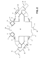
図10は、クロマトグラフィカラム100に関連したバルブアッセンブリ10を使用するための配管および計装図を示す。この実施形態では、クロマトグラフィカラム100は、順流または逆流のいずれかで作動することができる。図1のバルブアッセンブリ10を参照すると、可撓性導管70の第1の分岐部74が、クロマトグラフィカラム100の入口ポート接続部に連結されている。可撓性導管70の第3の分岐部78が、クロマトグラフィカラム100の出口ポートに連結されている。製薬またはバイオプロセス操作(例えば、供給ポンプおよび上流の器具)からの流体が、可撓性導管70の第2の分岐部76を介してバルブアッセンブリ10に入り、可撓性導管70の第4の分岐部80(図2を参照)を介してバルブアッセンブリ10から出る(下流の(排水用)器具)。図10において、PY-001、PY-002、PY-003、PY-004、PY-005は、バルブ50、52、54、56、58それぞれに関連するソレノイドバルブを示す。
FIG. 10 shows a plumbing and instrumentation diagram for using
カラム充填または通常捕獲モード中のような順流が使用されるクロマトグラフィカラム100の動作中、バルブ50、52、54、56、58は、以下の表1に従って開/閉状態にある。
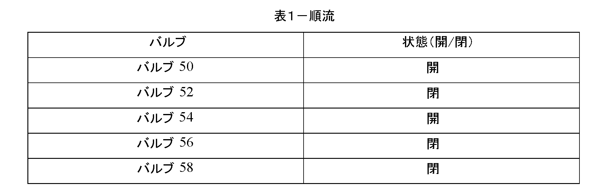
カラム洗浄または膨張床処理のような逆流が使用されるクロマトグラフィカラム100の動作中、バルブ50、52、54、56、58は、以下の表2に従って開/閉状態にある。

クロマトグラフィカラム100をバイパスする必要のある動作中、バルブ50、52、54、56、58は、以下の表3に従って開/閉状態にある。

図11は、例示的な高圧プロセスで使用されるバルブアッセンブリ10を示す。この実施形態では、バルブアッセンブリ10の外側に配置された可撓性チューブ70は、それ自体が別々のジャケット120によって取り囲まれている。ジャケット120は、可撓性チューブ70を取り囲む第1および第2の半部から形成されてもよく、留め具(バルブアッセンブリ10に関連して本明細書で説明されているもののようなもの)、圧入構造などを使用して固定できる。ジャケット120は、金属またはポリマ材料(本明細書に記載されているものなど)のような適当に硬質な材料から作ることができ、可撓性チューブ70を収容するための外骨格型構造として作用し、高圧流体の運搬に対応して、可撓性チューブ70の「動脈瘤」のような故障を防止する。ジャケット120は、モジュール式であり、可撓性チューブ70に露出した領域がないよう互いに(またはその他の構成要素と)連結することができる。クランプ122(1つが図11に示されている)が、隣接するジャケット120を連結するために使用しても良いし、または様々な構成要素を連結するのに使用する取付金具をジャケット120が具えても良い。ジャケット120は、それらが使用されるプロセスに従って、可撓性チューブ70を規則的に配列する多くのサイズおよび形状を有し得る。
FIG. 11 shows
図12Aおよび図12Bは、バルブアッセンブリ200の別の実施形態を示す。この実施形態では、バルブアッセンブリ200は、1またはそれ以上のヒンジ208を介して互いに接続された第1の本体部204および第2の本体部206を具えたバルブ本体部202を具える。バルブ本体部202および各部分204、206は、典型的には金属材料(例えば、ステンレス鋼)から作られるが、適当な硬質プラスチック材料から形成することもできる。この実施形態では、可撓性導管70のループ部72(図12B)全体が、バルブ本体202内に収容されている。したがって、この実施形態では、可撓性導管70のループ部72の一部を覆うために使用する剛性のジャケットは存在しない。この実施形態において、第1の本体部204および第2の本体部206の内側に面する各表面は、それぞれの半環状または半円形の通路を画定しており、その通路は、合わさった閉状態のとき、可撓性導管70のループ部72を保持する通路209(例えば、円形の通路)を画定する。バルブ本体202は、本明細書に記載の1またはそれ以上の留め具210を使用して閉状態で固定され得る。留め具210は、ノブ214が回転するネジ山を有する枢動ラッチ212を具え、バルブ本体202を選択的に開閉するために締め付けられ、および/または緩めることができる。枢動ラッチ212を回転させて、第1および第2の本体部204、206に位置するノッチ216(図12B)またはその類似物の中に入れることができ、ノブ214を締めると、閉状態でバルブ本体202が保持される。反対に、ノブ214を緩め、枢動ラッチ212をノッチ216から外すように回転させて、バルブ本体202を1またはそれ以上のヒンジ208を介して開くことができる。
12A and 12B show another embodiment of
この実施形態では、バルブ本体202に固定された9つの別個のバルブ220、222、224、226、228、230、232、234、236がある。図示の実施形態では、これら5つのバルブ220、222、224、226、228は、第1の本体部204に固定されるが、残りの4つのバルブ230、232、234、236は、第2の本体部206に固定される。各バルブ220、222、224、226、228、230、232、234、236は、クランプ238を介してバルブ本体202に固定されている。クランプ238はオプションであるが、いくつかの他の実施形態では、バルブ220、222、224、226、228、230、232、234、236は、バルブ本体部202に直接固定することができる。バルブ220、222、224、226、228、230、232、234、236は、本明細書に記載された任意のタイプのバルブであってよく、それぞれが、バルブ本体202内に収容された可撓性導管70の選択的に挟むために使用される。各バルブ220、222、224、226、228、230、232、234、236は、可撓性導管70の中央ルーメン71を選択的に開閉するため、本明細書における先の実施形態において説明したように、アクチュエータおよびピンチ要素(図示せず)を具える。
In this embodiment, there are nine
この実施形態では、バルブ220、222、224、226、228、230、232、234、236は、図7Fに示すように閉鎖点を提供するように配置される。したがって、この実施形態では、可撓性導管70のループ部72内の交差流路の近くに閉鎖点92a、92b、92c、92d、92e、92f、92g、92h、92iを配置することにより、図7Fに示すようなダブルクロスセグメント84または第1または第2のYまたはTEEセグメント86’、86’’のレッグまたはセグメントにおける潜在的な滞留体積が減少または排除される(閉鎖点92f-92b間、92h-92a間、92i-92c間、92d-92g間の体積が、流体から隔離される)。さらに、この実施形態では、バルブ220、222、224、226、228、230、232、234、236は、バルブ本体202の両側に配置されており、9つのバルブ220、222、224,226、228、230、232、234、236を取付ける適当な空間を提供する。この実施形態では、2つのバルブ228、232は閉じて、第1の分岐部74と第2の分岐部76との間の流路を隔離することができる。別の2つのバルブ222、230を閉じて、第2の分岐部76と第3の分岐部78との間の流路を隔離することができる。別の2つのバルブ220、234は閉じて、第3の分岐部78と第4の分岐部80との間の流路を隔離することができる。別の2つのバルブ226、236は閉じて、第4の分岐部80と第1の分岐部74との間の流路を隔離することができる。単一のバルブ224は、コネクタセグメント82(例えば、バイパス経路)内の流路を閉じるために使用される。
In this embodiment,
本明細書に記載のバルブアッセンブリ10、200の1つの利点は、それらが比較的コンパクトであり、複雑な取り付け構造または工具を必要とせずに、手動で開閉し、配置できることにある。さらに、バルブアッセンブリ10、200は、可撓性導管70を別の置換可撓性導管70と迅速に交換することが可能である。無菌状態または無菌条件が必要なアプリケーションにおいて、可撓性導管70は、新しい可撓性導70と交換して取り替えることができる。このことは、留め具22、210を使用してバルブアッセンブリ10、200を開き、古いまたは使い捨て可撓性導管70を取り外してバルブアッセンブリ10、200に新しい可撓性導管70を挿入し、留め具22、210を使用してバルブアッセンブリ10、200を閉じることによって迅速に行うことができる。バルブアッセンブリ10、200は、比較的コンパクトであるばかりでなく、可撓性導管70を他のプロセスユニットまたは構成要素へと多次元に方向付けして管理するために使用することができる追加のジャケット120と共に選択的に使用することができる。
One advantage of the
本発明の実施形態を図示し説明してきたが、本発明の範囲から逸脱することなく様々な変更を行うことができる。例えば、バルブアッセンブリ10、200は、クロマトグラフィカラム関連で使用されると説明されているが、バルブアッセンブリ10、200は、流れを逆にしたり、バイパスしたりする必要のある様々な用途に使用できる。別の例として、ループ部72を含む可撓性導管70は、4つの分岐部74、76、78、80を有するものとして示されているが、ループ部72に連結されるより多くの分岐部が存在してもよい。そのような構造においては、バルブアッセンブリに更なるバルブが追加される。さらに、図12Aおよび図12Bの9つのバルブの実施形態では、ループ部72全体をバルブ本体202に含むように示されているが、図1乃至図6の5つのバルブの実施形態もまた、ループ部72全体がバルブ本体12内にあり、それにより剛性のジャケット30が存在しないよう構成することができる。さらに、様々な実施形態が本明細書に記載されているが、一実施形態における様々な特徴は、他の実施形態と組み合わせて使用することができることを理解されたい。すなわち、一実施形態の特徴は、別の実施形態で置換または使用されてもよい。したがって、本発明は、以下の特許請求の範囲およびそれらの均等物を除き、限定されるべきではない。
While embodiments of the invention have been illustrated and described, various changes can be made without departing from the scope of the invention. For example, although
Claims (13)
導管のループと;
前記導管のループから延在する第1の導管の分岐部と;
前記導管のループから延在する第2の導管の分岐部と;
前記第1の導管の分岐部と前記第2の導管の分岐部とを接続するコネクタセグメントと;を具え、
前記第1の導管の分岐部と前記第2の導管の分岐部と前記コネクタセグメントとのそれぞれが、中を通る流体通路を画定しており、
可撓性の前記導管のループが、互いに結合された3つの別個の可撓性チューブピースから作成され、当該3つの別個の可撓性チューブピースが、前記コネクタセグメントと前記導管のループの交差位置から離れてともに結合されており、前記交差位置に隣接する可撓性チューブの部分が、前記交差位置の周囲に配置された複数のバルブが閉鎖された時に前記交差位置に沿った前記可撓性導管内の滞留容積を最小限にすることを特徴とする可撓性導管。 In flexible conduits:
a conduit loop;
a first conduit branch extending from the conduit loop;
a second conduit branch extending from the conduit loop;
a connector segment connecting a branch of the first conduit and a branch of the second conduit;
each of said first conduit branch, said second conduit branch and said connector segment defining a fluid passage therethrough ;
The flexible conduit loop is made from three separate flexible tubing pieces coupled together, the three separate flexible tubing pieces intersecting the connector segments and the conduit loops. and the portion of the flexible tube adjacent the intersection location is connected to the flexible tube along the intersection location when a plurality of valves disposed about the intersection location are closed. A flexible conduit characterized in that it minimizes the amount of retained volume within the conduit.
第1の一対の隣接する分岐部および第2の一対の隣接する分岐部を有するダブルクロスピースと;
前記ダブルクロスピースの第1の一対の隣接する分岐部を連結する第1の導管ピースと;
前記ダブルクロスピースの第1の一対の隣接する分岐部に対向する前記ダブルクロスピースの第2の一対の隣接する分岐部を連結する第2の導管ピースと;を具えることを特徴とする可撓性導管。 2. The flexible conduit of claim 1 , wherein three said flexible tube pieces are:
a double crosspiece having a first pair of adjacent tines and a second pair of adjacent tines;
a first conduit piece connecting a first pair of adjacent branches of said double crosspiece;
a second conduit piece connecting a second pair of adjacent branches of said double crosspiece opposite to a first pair of adjacent branches of said double crosspiece; Flexible conduit.
前記第1の導管ピースによって形成されて、前記導管のループから離れて延在する第3の導管の分岐部と;
前記第2の導管ピースによって形成されて、前記導管のループから離れて延在する第4の導管の分岐部と;を具えることを特徴とする可撓性導管。 The flexible conduit of claim 2 , further comprising:
a third conduit branch formed by said first conduit piece and extending away from said conduit loop;
a fourth conduit branch formed by said second conduit piece and extending away from said conduit loop.
前記第1の導管ピースがYまたはT形の導管ピースを有し、
前記第2の導管ピースがYまたはT形の導管ピースを有することを特徴とする可撓性導管。 A flexible conduit according to claim 2 or 3 , wherein
said first conduit piece having a Y or T shaped conduit piece;
A flexible conduit, wherein said second conduit piece comprises a Y or T shaped conduit piece.
Applications Claiming Priority (3)
| Application Number | Priority Date | Filing Date | Title |
|---|---|---|---|
| US201562236007P | 2015-10-01 | 2015-10-01 | |
| US62/236,007 | 2015-10-01 | ||
| JP2018516160A JP6886193B2 (en) | 2015-10-01 | 2016-09-30 | Valve assembly with directional flow path |
Related Parent Applications (1)
| Application Number | Title | Priority Date | Filing Date |
|---|---|---|---|
| JP2018516160A Division JP6886193B2 (en) | 2015-10-01 | 2016-09-30 | Valve assembly with directional flow path |
Publications (3)
| Publication Number | Publication Date |
|---|---|
| JP2021131161A JP2021131161A (en) | 2021-09-09 |
| JP2021131161A5 JP2021131161A5 (en) | 2021-10-21 |
| JP7144877B2 true JP7144877B2 (en) | 2022-09-30 |
Family
ID=58427958
Family Applications (2)
| Application Number | Title | Priority Date | Filing Date |
|---|---|---|---|
| JP2018516160A Active JP6886193B2 (en) | 2015-10-01 | 2016-09-30 | Valve assembly with directional flow path |
| JP2021079023A Active JP7144877B2 (en) | 2015-10-01 | 2021-05-07 | Valve assembly with directional flow path |
Family Applications Before (1)
| Application Number | Title | Priority Date | Filing Date |
|---|---|---|---|
| JP2018516160A Active JP6886193B2 (en) | 2015-10-01 | 2016-09-30 | Valve assembly with directional flow path |
Country Status (7)
| Country | Link |
|---|---|
| US (2) | US10738900B2 (en) |
| EP (2) | EP3896319A1 (en) |
| JP (2) | JP6886193B2 (en) |
| KR (1) | KR20180055891A (en) |
| CN (2) | CN108138974B (en) |
| AU (2) | AU2016332061B2 (en) |
| WO (1) | WO2017059370A1 (en) |
Families Citing this family (14)
| Publication number | Priority date | Publication date | Assignee | Title |
|---|---|---|---|---|
| EP3234424B1 (en) * | 2014-12-19 | 2022-03-16 | Repligen Corporation | Encapsulated system for pressurized fluid processes |
| WO2017106901A1 (en) * | 2015-12-24 | 2017-06-29 | Heriot Eyecare Pty. Ltd. | Pressure management device |
| KR20230096140A (en) | 2017-01-31 | 2023-06-29 | 알피니티 유에스에이, 인크. | Bioprocess vessels with integrated pump |
| EP3635287B1 (en) * | 2017-05-15 | 2022-04-06 | Carten Controls Limited | A pinch valve |
| WO2019185442A1 (en) | 2018-03-26 | 2019-10-03 | Ge Healthcare Bio-Sciences Ab | A bioprocess flow system |
| US11259928B2 (en) * | 2018-08-07 | 2022-03-01 | Shouyan Lee | Hybrid heart valve function tester specifically designed for production evaluation of prosthetic heart valve products |
| GB202105923D0 (en) | 2021-04-26 | 2021-06-09 | Cytiva Sweden Ab | Reconfigurable bioprocessing systems |
| CN216033602U (en) * | 2021-05-31 | 2022-03-15 | 比亚迪股份有限公司 | Valve bank integrated module |
| DE102021114567A1 (en) * | 2021-06-07 | 2022-12-08 | Gemü Gebr. Müller Apparatebau Gmbh & Co. Kommanditgesellschaft | Valve block body and device for arranging the valve block body on a drive body |
| WO2023016626A1 (en) * | 2021-08-09 | 2023-02-16 | Carten Controls Limited | Interchangeable multiport pinch valve assembly |
| US20230191671A1 (en) * | 2021-12-21 | 2023-06-22 | Repligen Corporation | Tubing coupler moldings and systems, and associated methods |
| CN114001180B (en) * | 2022-01-04 | 2022-04-08 | 浙江金仪盛世生物工程有限公司 | Pinch valve head for switching and pinch valve group |
| CN114001181B (en) * | 2022-01-04 | 2022-04-08 | 浙江金仪盛世生物工程有限公司 | Pinch valve head and pinch valve group with same |
| CN114576387A (en) * | 2022-02-17 | 2022-06-03 | 马俊 | Fluid hose pinch valve |
Citations (3)
| Publication number | Priority date | Publication date | Assignee | Title |
|---|---|---|---|---|
| US5906223A (en) | 1996-09-16 | 1999-05-25 | Itt Industries, Inc. | Chromatography valve assembly |
| JP2004293769A (en) | 2003-03-28 | 2004-10-21 | Japan Aviation Electronics Industry Ltd | Flow controller |
| US20140224335A1 (en) | 2011-04-18 | 2014-08-14 | Martin John Hofmann | Apparatus and methods for fluid processing and flow control |
Family Cites Families (46)
| Publication number | Priority date | Publication date | Assignee | Title |
|---|---|---|---|---|
| US2825524A (en) | 1956-12-17 | 1958-03-04 | Knox P Fox | Pinch valve |
| US2931387A (en) | 1957-08-22 | 1960-04-05 | Robertson Co H H | Control apparatus for domestic water distribution system |
| GB1055426A (en) | 1963-11-22 | 1967-01-18 | Kelsto Engineering Company Ltd | Improvements in or relating to pinch valves |
| GB1120037A (en) | 1964-11-10 | 1968-07-17 | British Telecomm Res Ltd | Improvements in fluid control devices |
| US3559683A (en) * | 1969-06-12 | 1971-02-02 | Samsonite Corp | Fluid control device |
| DE2821801C3 (en) | 1978-05-19 | 1981-06-25 | Friedrich Wilhelm 6535 Gau-Algesheim Schmitt | Valve arrangement with diaphragm valves |
| US4254797A (en) | 1979-01-26 | 1981-03-10 | Bi-M Instrument Company | Apparatus for producing calibration gases suitable for analytical instrumentation |
| US4993456A (en) | 1982-03-02 | 1991-02-19 | Akos Sule | Pinch valve assembly |
| US4457339A (en) | 1982-03-03 | 1984-07-03 | Coulter Electronics, Inc. | Multiprogrammable pinch valve module |
| US4618114A (en) | 1982-09-29 | 1986-10-21 | Lof Plastics Inc. | Conduit spacer and support |
| US4895341A (en) | 1988-09-30 | 1990-01-23 | Whitey Co. | Pinch valve |
| US5197708A (en) | 1992-08-11 | 1993-03-30 | Flow-Rite Controls, Ltd. | Tubing pinch valve device |
| US5402823A (en) | 1992-12-07 | 1995-04-04 | George S. Cole & Associates, Incorporated | Pinch valve |
| US5350290A (en) | 1993-01-19 | 1994-09-27 | Amf Machinery Systems, Inc. | Manifold and valving arrangement for dough divider |
| US5549134A (en) | 1994-05-27 | 1996-08-27 | Marcvalve Corporation | Diaphragm valve |
| JP2001500948A (en) | 1995-09-21 | 2001-01-23 | アボツト・ラボラトリーズ | Tension reaction pinch valve |
| US6068751A (en) | 1995-12-18 | 2000-05-30 | Neukermans; Armand P. | Microfluidic valve and integrated microfluidic system |
| US5901745A (en) | 1997-06-19 | 1999-05-11 | The Hoover Company | Multi-solution dispensing valve |
| EP1009944A4 (en) | 1997-07-03 | 2004-06-30 | Prec Dispensing Systems Ltd | A flexible tube pinch mechanism |
| US6036166A (en) | 1997-09-25 | 2000-03-14 | Imi Cornelius Inc. | Chamber valve |
| WO1999045302A1 (en) | 1998-03-05 | 1999-09-10 | The Swagelok Company | Modular surface mount manifold |
| WO2000025049A1 (en) | 1998-10-23 | 2000-05-04 | Chemand Corporation | Fluid handling port array |
| GB0012541D0 (en) * | 2000-05-23 | 2000-07-12 | Satchwell Control Systems | Valve sub-assembly |
| DE10035763B4 (en) | 2000-07-22 | 2006-07-27 | Nucellsys Gmbh | Device for dosing a gaseous medium |
| US7104275B2 (en) | 2002-04-01 | 2006-09-12 | Emerson Electric Co. | Pinch valve |
| US20040163711A1 (en) | 2003-02-20 | 2004-08-26 | Graham Packaging Company, L.P. | Fluid regulating pinch valve |
| US6799607B1 (en) | 2003-06-18 | 2004-10-05 | Pbm, Inc. | Sanitary conduit support systems and methods |
| US6976664B2 (en) | 2003-08-11 | 2005-12-20 | Mitos Technologies, Inc. | Free flow valve and element |
| US8038639B2 (en) | 2004-11-04 | 2011-10-18 | Baxter International Inc. | Medical fluid system with flexible sheeting disposable unit |
| DE102004006889B3 (en) | 2004-02-12 | 2005-08-11 | Tuchenhagen Gmbh | Distribution device for valves has housing in two parts, each with channel recess complementary to cavity |
| US7383853B2 (en) * | 2004-09-07 | 2008-06-10 | Parker-Hannifin Corp. | Multi-port free flow valve and element |
| US7819139B2 (en) | 2005-07-14 | 2010-10-26 | Pdc Facilities, Inc. | Liner for a flow meter |
| US20070295867A1 (en) * | 2006-06-21 | 2007-12-27 | Hennon John | Conduit support apparatus |
| JP5221534B2 (en) * | 2006-07-14 | 2013-06-26 | インテグリス・インコーポレーテッド | Valve connection pipe assembly |
| WO2008011132A2 (en) | 2006-07-21 | 2008-01-24 | Amgen, Inc. | Rupture valve |
| JP4994082B2 (en) | 2007-03-30 | 2012-08-08 | 旭有機材工業株式会社 | Piping material |
| US8091455B2 (en) | 2008-01-30 | 2012-01-10 | Cummins Filtration Ip, Inc. | Apparatus, system, and method for cutting tubes |
| BRPI0910925B8 (en) * | 2008-03-18 | 2021-06-22 | Saint Gobain Performance Plastics Corp | liquid transfer sets and related methods |
| US8079385B2 (en) * | 2008-04-09 | 2011-12-20 | Liquid Molding Systems, Inc. | Valve assembly |
| FR2939348B1 (en) | 2008-12-10 | 2014-10-10 | Sartorius Stedim Biotech Sa | SECTIONING A FLEXIBLE TUBE FOR BIOPHARMACEUTICAL APPLICATIONS |
| CA2749557C (en) * | 2009-01-30 | 2017-06-13 | Nestec S.A. | Infusion pump cassette with anti-free-flow valve mechanism |
| JP5406607B2 (en) * | 2009-02-16 | 2014-02-05 | 積水化学工業株式会社 | Resin pipe joining method and fiber-reinforced resin molded product molding method |
| US8235067B2 (en) * | 2009-05-15 | 2012-08-07 | Alphabio, Inc. | Encapsulated valve system |
| JP5802065B2 (en) * | 2011-06-24 | 2015-10-28 | 矢崎総業株式会社 | Covered connector |
| CN202778069U (en) | 2012-09-20 | 2013-03-13 | 兰州纵横石油化工有限责任公司 | Multi-tube oil filter |
| SG11201605760PA (en) | 2014-01-17 | 2016-08-30 | Alphinity Llc | Fluid monitoring assembly with sensor functionality |
-
2016
- 2016-09-30 KR KR1020187011980A patent/KR20180055891A/en not_active Application Discontinuation
- 2016-09-30 AU AU2016332061A patent/AU2016332061B2/en active Active
- 2016-09-30 JP JP2018516160A patent/JP6886193B2/en active Active
- 2016-09-30 EP EP21174692.0A patent/EP3896319A1/en active Pending
- 2016-09-30 US US15/763,057 patent/US10738900B2/en active Active
- 2016-09-30 WO PCT/US2016/055016 patent/WO2017059370A1/en active Application Filing
- 2016-09-30 EP EP16852791.9A patent/EP3356708B1/en active Active
- 2016-09-30 CN CN201680057308.7A patent/CN108138974B/en active Active
- 2016-09-30 CN CN202110057960.1A patent/CN112762196A/en active Pending
-
2020
- 2020-07-15 US US16/930,300 patent/US11898645B2/en active Active
-
2021
- 2021-05-07 JP JP2021079023A patent/JP7144877B2/en active Active
-
2022
- 2022-07-01 AU AU2022204749A patent/AU2022204749A1/en active Pending
Patent Citations (3)
| Publication number | Priority date | Publication date | Assignee | Title |
|---|---|---|---|---|
| US5906223A (en) | 1996-09-16 | 1999-05-25 | Itt Industries, Inc. | Chromatography valve assembly |
| JP2004293769A (en) | 2003-03-28 | 2004-10-21 | Japan Aviation Electronics Industry Ltd | Flow controller |
| US20140224335A1 (en) | 2011-04-18 | 2014-08-14 | Martin John Hofmann | Apparatus and methods for fluid processing and flow control |
Also Published As
| Publication number | Publication date |
|---|---|
| AU2022204749A1 (en) | 2022-07-21 |
| AU2016332061A1 (en) | 2018-04-12 |
| JP2018532082A (en) | 2018-11-01 |
| CN108138974A (en) | 2018-06-08 |
| US11898645B2 (en) | 2024-02-13 |
| JP6886193B2 (en) | 2021-06-16 |
| EP3896319A1 (en) | 2021-10-20 |
| CN108138974B (en) | 2021-02-02 |
| JP2021131161A (en) | 2021-09-09 |
| AU2016332061B2 (en) | 2022-04-07 |
| WO2017059370A1 (en) | 2017-04-06 |
| EP3356708B1 (en) | 2021-06-23 |
| US20210033207A1 (en) | 2021-02-04 |
| EP3356708A4 (en) | 2019-07-03 |
| US20180274689A1 (en) | 2018-09-27 |
| US10738900B2 (en) | 2020-08-11 |
| CN112762196A (en) | 2021-05-07 |
| KR20180055891A (en) | 2018-05-25 |
| EP3356708A1 (en) | 2018-08-08 |
Similar Documents
| Publication | Publication Date | Title |
|---|---|---|
| JP7144877B2 (en) | Valve assembly with directional flow path | |
| KR101925889B1 (en) | Encapsulated valve system | |
| JP7406840B2 (en) | Containment systems for pressurized fluid processes | |
| US20240133472A1 (en) | Valve assembly with directional flow path | |
| KR102653403B1 (en) | Flexible piping management systems for pharmaceutical, bioprocess applications, and food/dairy applications |
Legal Events
| Date | Code | Title | Description |
|---|---|---|---|
| A521 | Request for written amendment filed |
Free format text: JAPANESE INTERMEDIATE CODE: A523 Effective date: 20210604 |
|
| A621 | Written request for application examination |
Free format text: JAPANESE INTERMEDIATE CODE: A621 Effective date: 20210604 |
|
| A521 | Request for written amendment filed |
Free format text: JAPANESE INTERMEDIATE CODE: A523 Effective date: 20210816 |
|
| A131 | Notification of reasons for refusal |
Free format text: JAPANESE INTERMEDIATE CODE: A131 Effective date: 20220405 |
|
| A521 | Request for written amendment filed |
Free format text: JAPANESE INTERMEDIATE CODE: A523 Effective date: 20220705 |
|
| TRDD | Decision of grant or rejection written | ||
| A01 | Written decision to grant a patent or to grant a registration (utility model) |
Free format text: JAPANESE INTERMEDIATE CODE: A01 Effective date: 20220823 |
|
| A61 | First payment of annual fees (during grant procedure) |
Free format text: JAPANESE INTERMEDIATE CODE: A61 Effective date: 20220909 |
|
| R150 | Certificate of patent or registration of utility model |
Ref document number: 7144877 Country of ref document: JP Free format text: JAPANESE INTERMEDIATE CODE: R150 |