JP7144310B2 - Mold for vulcanization molding - Google Patents
Mold for vulcanization molding Download PDFInfo
- Publication number
- JP7144310B2 JP7144310B2 JP2018237715A JP2018237715A JP7144310B2 JP 7144310 B2 JP7144310 B2 JP 7144310B2 JP 2018237715 A JP2018237715 A JP 2018237715A JP 2018237715 A JP2018237715 A JP 2018237715A JP 7144310 B2 JP7144310 B2 JP 7144310B2
- Authority
- JP
- Japan
- Prior art keywords
- blade
- mold
- circumferential
- sector
- blades
- Prior art date
- Legal status (The legal status is an assumption and is not a legal conclusion. Google has not performed a legal analysis and makes no representation as to the accuracy of the status listed.)
- Active
Links
Images


Classifications
-
- B—PERFORMING OPERATIONS; TRANSPORTING
- B29—WORKING OF PLASTICS; WORKING OF SUBSTANCES IN A PLASTIC STATE IN GENERAL
- B29D—PRODUCING PARTICULAR ARTICLES FROM PLASTICS OR FROM SUBSTANCES IN A PLASTIC STATE
- B29D30/00—Producing pneumatic or solid tyres or parts thereof
- B29D30/06—Pneumatic tyres or parts thereof (e.g. produced by casting, moulding, compression moulding, injection moulding, centrifugal casting)
- B29D30/0601—Vulcanising tyres; Vulcanising presses for tyres
- B29D30/0606—Vulcanising moulds not integral with vulcanising presses
-
- B—PERFORMING OPERATIONS; TRANSPORTING
- B60—VEHICLES IN GENERAL
- B60C—VEHICLE TYRES; TYRE INFLATION; TYRE CHANGING; CONNECTING VALVES TO INFLATABLE ELASTIC BODIES IN GENERAL; DEVICES OR ARRANGEMENTS RELATED TO TYRES
- B60C11/00—Tyre tread bands; Tread patterns; Anti-skid inserts
- B60C11/03—Tread patterns
- B60C11/04—Tread patterns in which the raised area of the pattern consists only of continuous circumferential ribs, e.g. zig-zag
-
- B—PERFORMING OPERATIONS; TRANSPORTING
- B60—VEHICLES IN GENERAL
- B60C—VEHICLE TYRES; TYRE INFLATION; TYRE CHANGING; CONNECTING VALVES TO INFLATABLE ELASTIC BODIES IN GENERAL; DEVICES OR ARRANGEMENTS RELATED TO TYRES
- B60C11/00—Tyre tread bands; Tread patterns; Anti-skid inserts
- B60C11/03—Tread patterns
- B60C11/12—Tread patterns characterised by the use of narrow slits or incisions, e.g. sipes
- B60C11/1204—Tread patterns characterised by the use of narrow slits or incisions, e.g. sipes with special shape of the sipe
- B60C11/1218—Three-dimensional shape with regard to depth and extending direction
-
- B—PERFORMING OPERATIONS; TRANSPORTING
- B60—VEHICLES IN GENERAL
- B60C—VEHICLE TYRES; TYRE INFLATION; TYRE CHANGING; CONNECTING VALVES TO INFLATABLE ELASTIC BODIES IN GENERAL; DEVICES OR ARRANGEMENTS RELATED TO TYRES
- B60C11/00—Tyre tread bands; Tread patterns; Anti-skid inserts
- B60C11/03—Tread patterns
- B60C11/12—Tread patterns characterised by the use of narrow slits or incisions, e.g. sipes
- B60C11/1272—Width of the sipe
- B60C11/1281—Width of the sipe different within the same sipe, i.e. enlarged width portion at sipe bottom or along its length
-
- B—PERFORMING OPERATIONS; TRANSPORTING
- B29—WORKING OF PLASTICS; WORKING OF SUBSTANCES IN A PLASTIC STATE IN GENERAL
- B29D—PRODUCING PARTICULAR ARTICLES FROM PLASTICS OR FROM SUBSTANCES IN A PLASTIC STATE
- B29D30/00—Producing pneumatic or solid tyres or parts thereof
- B29D30/06—Pneumatic tyres or parts thereof (e.g. produced by casting, moulding, compression moulding, injection moulding, centrifugal casting)
- B29D30/0601—Vulcanising tyres; Vulcanising presses for tyres
- B29D30/0606—Vulcanising moulds not integral with vulcanising presses
- B29D2030/0607—Constructional features of the moulds
- B29D2030/0612—Means for forming recesses or protrusions in the tyres, e.g. grooves or ribs, to create the tread or sidewalls patterns
-
- B—PERFORMING OPERATIONS; TRANSPORTING
- B29—WORKING OF PLASTICS; WORKING OF SUBSTANCES IN A PLASTIC STATE IN GENERAL
- B29D—PRODUCING PARTICULAR ARTICLES FROM PLASTICS OR FROM SUBSTANCES IN A PLASTIC STATE
- B29D30/00—Producing pneumatic or solid tyres or parts thereof
- B29D30/06—Pneumatic tyres or parts thereof (e.g. produced by casting, moulding, compression moulding, injection moulding, centrifugal casting)
- B29D30/0601—Vulcanising tyres; Vulcanising presses for tyres
- B29D30/0606—Vulcanising moulds not integral with vulcanising presses
- B29D2030/0607—Constructional features of the moulds
- B29D2030/0613—Means, e.g. sipes or blade-like elements, for forming narrow recesses in the tyres, e.g. cuts or incisions for winter tyres
-
- B—PERFORMING OPERATIONS; TRANSPORTING
- B60—VEHICLES IN GENERAL
- B60C—VEHICLE TYRES; TYRE INFLATION; TYRE CHANGING; CONNECTING VALVES TO INFLATABLE ELASTIC BODIES IN GENERAL; DEVICES OR ARRANGEMENTS RELATED TO TYRES
- B60C11/00—Tyre tread bands; Tread patterns; Anti-skid inserts
- B60C11/03—Tread patterns
- B60C2011/0337—Tread patterns characterised by particular design features of the pattern
- B60C2011/0339—Grooves
-
- B—PERFORMING OPERATIONS; TRANSPORTING
- B60—VEHICLES IN GENERAL
- B60C—VEHICLE TYRES; TYRE INFLATION; TYRE CHANGING; CONNECTING VALVES TO INFLATABLE ELASTIC BODIES IN GENERAL; DEVICES OR ARRANGEMENTS RELATED TO TYRES
- B60C11/00—Tyre tread bands; Tread patterns; Anti-skid inserts
- B60C11/03—Tread patterns
- B60C11/12—Tread patterns characterised by the use of narrow slits or incisions, e.g. sipes
- B60C2011/129—Sipe density, i.e. the distance between the sipes within the pattern
- B60C2011/1295—Sipe density, i.e. the distance between the sipes within the pattern variable
Description
本発明は、タイヤトレッドに幅方向溝を形成する加硫成形用金型に関する。 TECHNICAL FIELD The present invention relates to a vulcanization mold for forming widthwise grooves in a tire tread.
タイヤトレッドにタイヤ幅方向に延設されるサイプ等の幅方向溝は、エッヂ効果を期待できるとともに排水性に寄与するものである。
しかし、走行によりトレッド表面の摩耗が進んだ場合、トレッド部の剛性が増し、エッヂ効果が低下したり、溝深さが浅くなるにつれて排水性が劣ってウェット性能が低下することがある。
Width direction grooves such as sipes extending in the tire width direction in the tire tread can be expected to have an edge effect and contribute to drainage.
However, when the wear of the tread surface progresses due to running, the rigidity of the tread portion increases and the edge effect decreases, and as the groove depth becomes shallower, drainage performance deteriorates and wet performance deteriorates.
そこで、タイヤトレッドの幅方向溝の底部の幅を拡大することで、トレッド表面の摩耗が進んだ場合でも、エッヂ効果およびウェット性能を維持することができるようにした例(例えば、特許文献1参照)がある。 Therefore, an example in which the edge effect and wet performance can be maintained even when the wear of the tread surface progresses by increasing the width of the bottom of the width direction groove of the tire tread (see, for example, Patent Document 1) ).
特許文献1に開示された空気入りタイヤは、タイヤトレッドの主溝と横溝により区画されたブロックにタイヤ幅方向に複数のサイプが延設されている。
サイプの中には、底部に拡大部を有する底部拡大サイプが含まれており、底部拡大サイプは、タイヤトレッドの外周面に周方向に偏ることなく略均等に設けられている。
A pneumatic tire disclosed in
The sipes include a bottom enlarged sipe having an enlarged bottom portion, and the bottom enlarged sipe is provided substantially evenly on the outer circumferential surface of the tire tread without bias in the circumferential direction.
通常、空気入りタイヤのトレッド部は、加硫成形用金型の環状金型により加硫成形される。
環状金型は、周方向に複数のセクターモールドに分割され、各セクターモールドが中心方向に移動して合体することで、内側の生タイヤを型締めし加硫成形する(例えば、特許文献2参照)。
Normally, the tread portion of a pneumatic tire is vulcanized using an annular vulcanization mold.
The annular mold is divided into a plurality of sector molds in the circumferential direction, and each sector mold moves toward the center and unites to clamp and vulcanize the raw tire inside (see, for example, Patent Document 2). ).
セクターモールドの型面には、サイプ等を形成するタイヤ幅方向に延びる薄板状部材であるブレードが植設されている。
サイプは、トレッド外周面に対して垂直に、すなわちタイヤ中心軸に向かって切り込まれるように形成されるので、セクターモールドの型面に設けられるブレードは、型面に対して垂直に、すなわち環状に合体したときに中心軸に向かって突出するように植設されている。
底部拡大サイプを形成するブレードは、先端側に板厚方向に拡大した先端側厚肉部を有する。
A blade, which is a thin plate-like member extending in the tire width direction and forming a sipe or the like, is implanted in the mold surface of the sector mold.
Since the sipe is formed perpendicular to the outer peripheral surface of the tread, that is, cut toward the central axis of the tire, the blades provided on the mold surface of the sector mold are arranged perpendicular to the mold surface, that is, in an annular shape. It is implanted so as to protrude toward the central axis when combined with the body.
The blade that forms the bottom-enlarged sipe has a tip-side thick-walled portion that expands in the plate thickness direction on the tip side.
各セクターモールドは中心方向に移動して環状に合体して加硫成形するので、加硫成形した後に、型開きするときは、各セクターモールドは中心から離れる放射方向に移動する。 Since the sector molds are moved toward the center and united into an annular shape for vulcanization molding, when the molds are opened after vulcanization molding, the sector molds move radially away from the center.
したがって、セクターモールドの型面に垂直に突出されたブレードの突出方向は、セクターモールドの周方向中央部側領域では、型開き時のタイヤトレッドから引き抜かれる方向(セクターモールドの中心から離れる放射方向)と略平行であり、先端側厚肉部を有するブレードであっても先端側厚肉部が突出方向と略平行に抜けるので、抵抗が小さく型抜きし易い。 Therefore, the protruding direction of the blade protruding perpendicularly to the mold surface of the sector mold is the direction in which the blade is pulled out from the tire tread when the mold is opened (radial direction away from the center of the sector mold) in the circumferentially central region of the sector mold. , and even if the blade has a tip-side thick-walled portion, the tip-side thick-walled portion can be pulled out substantially parallel to the projecting direction, so the resistance is small and die-cutting is easy.
しかし、セクターモールドの周方向端部側領域のブレードは、その突出方向が型開き時のタイヤトレッドから引き抜かれる方向に対して平行でなく、ある程度角度を有するので、先端側厚肉部を有するブレードは、先端側厚肉部が突出方向と角度を有する方向に引き抜かれようとするため、相当の抵抗があり型抜きが容易でなく、場合によってはブロックの一部が欠損したり、ブレードが破損するなどの不具合が生じ易い。 However, the protruding direction of the blade in the circumferential end region of the sector mold is not parallel to the direction in which the tire tread is pulled out when the mold is opened, but has a certain angle. Since the thick part on the tip side tends to be pulled out in a direction that forms an angle with the projecting direction, there is considerable resistance and it is not easy to pull out, and in some cases, part of the block is lost or the blade is damaged. It is easy to cause problems such as
本発明は、かかる点に鑑みなされたもので、その目的とする処は、先端側厚肉部を有するブレードを備えた金型であり、不具合を生じることなく型抜きが円滑に行われる加硫成形用金型を供する点にある。 The present invention has been made in view of this point, and an object of the present invention is to provide a mold having a blade having a thick-walled portion on the tip side, and a vulcanization mold in which mold removal can be performed smoothly without causing any problems. The point is to provide a mold for molding .
上記目的を達成するために、本第1の発明は、
空気入りタイヤのタイヤトレッドを形成する環状金型が、周方向に複数のセクターモールドに分割され、各セクターモールドが中心方向に移動して合体することで内側の生タイヤを型締めし加硫成形する加硫成形用金型であって、
前記セクターモールドには、型面にタイヤ幅方向に延びる薄板状部材であってタイヤトレッドに溝条を形成するブレードが植設され、
前記ブレードが、前記セクターモールドに埋め込まれるブレード基端部と、先端側の板厚方向に拡大したブレード先端側厚肉部と、前記ブレード基端部と前記ブレード先端側厚肉部とを連結するブレード連結部とからなる加硫成形用金型において、
前記セクターモールドに植設される前記ブレードの周方向の単位長さ当たりの数であるブレード密度は、前記セクターモールドの周方向中央部側領域の前記ブレードより周方向端部側領域の前記ブレードの方が、小さいことを特徴とする加硫成形用金型を提供する。
In order to achieve the above object, the first invention is
An annular mold that forms the tire tread of a pneumatic tire is divided into multiple sector molds in the circumferential direction, and each sector mold moves toward the center and unites to clamp the inner raw tire and vulcanize it. A vulcanization mold for
In the sector mold, a blade, which is a thin plate-shaped member extending in the tire width direction and forming grooves in the tire tread, is planted on the mold surface,
The blade connects the base end portion of the blade embedded in the sector mold, the thick portion of the blade tip side expanding in the plate thickness direction on the tip side, and the base end portion of the blade and the thick portion of the blade tip side. In a vulcanization molding mold consisting of a blade connection part,
The blade density, which is the number per unit length in the circumferential direction of the blades implanted in the sector mold, is higher than the blades in the circumferential center side region of the sector mold. To provide a mold for vulcanization molding characterized by being smaller.
セクターモールドに植設される前記ブレードの周方向の単位長さ当たりの数であるブレード密度は、型抜きの難易度を示し、ブレード密度が小さいほど型抜き時の抵抗が小さく型抜きが容易である。
上記構成によれば、セクターモールドの周方向中央部側領域のブレードより型抜きが容易でない周方向端部側領域のブレードのブレード密度を、周方向中央部側領域のブレードのブレード密度より小さくすることで、加硫成形用金型の型開き時にセクターモールド全体の型抜けを、不具合を生じさせることなく円滑に行うことができる。
The blade density, which is the number per unit length in the circumferential direction of the blades implanted in the sector mold, indicates the degree of difficulty in demolding. be.
According to the above configuration, the blade density of the blades in the circumferential end side region, which is not easier to demold than the blades in the circumferential direction center side region of the sector mold, is made smaller than the blade density of the blades in the circumferential direction center side region. As a result, when the vulcanization mold is opened, the entire sector mold can be removed smoothly without causing any trouble.
本発明の好適な実施形態では、
前記ブレードのタイヤ幅方向に垂直な断面形状で、前記ブレード先端側厚肉部の厚みの最大幅の幅で前記ブレード先端側厚肉部から型面までの面積から前記ブレード連結部の断面積を減算した掃き面積を、前記ブレード密度に乗算した乗算値は、前記セクターモールドの周方向中央部側領域の前記ブレードより周方向端部側領域の前記ブレードの方が、小さい加硫成形用金型である。
In a preferred embodiment of the invention,
In the cross-sectional shape of the blade perpendicular to the tire width direction, the cross-sectional area of the blade connection portion is calculated from the area from the blade tip side thick portion to the mold surface at the maximum width of the thickness of the blade tip side thick portion. The multiplied value obtained by multiplying the blade density by the swept area after subtraction is smaller for the blades in the circumferential end side regions than in the circumferential center side region of the sector mold. is.
ブレードのタイヤ幅方向に垂直な断面形状で、ブレード先端側厚肉部の厚みの最大幅の幅でブレード先端側厚肉部から型面までの面積からブレード連結部の断面積を減算した掃き面積は、型抜きの難易度を示し、掃き面積が小さいほど型抜きが容易である。
よって、この掃き面積をブレード密度に乗算した乗算値は、型抜きの難易度を示し、該乗算値が小さいほど型抜きが容易である。
Swept area obtained by subtracting the cross-sectional area of the blade connecting part from the area from the thick part on the tip side of the blade to the mold surface at the maximum width of the thickness of the thick part on the tip side of the blade in the cross-sectional shape perpendicular to the tire width direction of the blade. indicates the degree of difficulty of die-cutting, and the smaller the swept area, the easier the die-cutting.
Therefore, the multiplied value obtained by multiplying the swept area by the blade density indicates the degree of difficulty of die cutting, and the smaller the multiplied value, the easier the die cutting.
上記構成によれば、セクターモールドの中央部側領域のブレードより型抜きが容易でない周方向端部側領域の掃き面積とブレード密度の乗算値を、中央部側領域の掃き面積とブレード密度の乗算値より小さくすることで、加硫成形用金型の型開き時にセクターモールド全体の型抜けを、不具合を生じさせることなく円滑に行うことができる。 According to the above configuration, the multiplication value of the swept area and the blade density in the circumferential end side region, which is not easier to mold than the blade in the central side region of the sector mold, is the multiplication of the swept area and the blade density in the central side region. By making it smaller than the value, the entire sector mold can be removed smoothly without causing any trouble when the mold for vulcanization is opened.
本発明の好適な実施形態では、
前記ブレードの前記セクターモールドから突出する前記ブレード連結部の突出辺の全長を、前記ブレード密度に乗算した乗算値は、前記セクターモールドの周方向中央部側領域の前記ブレードより周方向端部側領域の前記ブレードの方が、小さい加硫成形用金型である。
In a preferred embodiment of the invention,
The multiplied value obtained by multiplying the blade density by the total length of the protruding side of the blade connection portion protruding from the sector mold of the blade is the peripheral direction end side region from the blade in the peripheral direction center side region of the sector mold The blade of is a smaller vulcanization mold.
ブレードのセクターモールドから突出するブレード連結部の突出辺(型面から突出する辺)の全長は、型抜きの難易度を示し、ブレード連結部の突出辺の全長が短いほど型抜き時の抵抗が小さく型抜きが容易である。
よって、このブレード連結部の突出辺の全長をブレード密度に乗算した乗算値は、型抜きの難易度を示し、該乗算値が小さいほど型抜きが容易である。
The total length of the protruding side of the blade connecting part that protrudes from the sector mold of the blade (the side that protrudes from the mold surface) indicates the difficulty of demolding. It is small and can be easily demolded.
Therefore, the multiplied value obtained by multiplying the blade density by the total length of the protruding side of the blade connecting portion indicates the degree of difficulty of die cutting, and the smaller the multiplied value, the easier the die cutting.
上記構成によれば、セクターモールドの周方向中央部側領域のブレードより型抜きが容易でない周方向端部側領域のブレードのブレード連結部の突出辺の全長とブレード密度の乗算値を、周方向中央部側領域のブレードのブレード連結部の突出辺の全長とブレード密度の乗算値より小さくすることで、加硫成形用金型の型開き時にセクターモールド全体の型抜けを、不具合を生じさせることなく円滑に行うことができる。 According to the above configuration, the product of the total length of the protruding side of the blade connecting portion of the blade in the peripheral end side region, which is not easier to mold than the blade in the peripheral direction center side region of the sector mold, and the blade density By making it smaller than the product of the total length of the protruding side of the blade connecting portion of the blade in the central region and the blade density, the entire sector mold will come off when the mold for vulcanization molding is opened. can be done smoothly without
本発明の好適な実施形態では、
前記ブレードのタイヤ幅方向に垂直な断面形状で、前記ブレード先端側厚肉部の厚みの最大幅の幅で前記ブレード先端側厚肉部から型面までの面積から前記ブレード連結部の断面積を減算した掃き面積と前記ブレードの前記セクターモールドから突出する前記ブレード連結部の突出辺の全長を、前記ブレード密度に乗算した乗算値は、前記セクターモールドの周方向中央部側領域の前記ブレードより周方向端部側領域の前記ブレードの方が、小さい加硫成形用金型である。
In a preferred embodiment of the invention,
In the cross-sectional shape of the blade perpendicular to the tire width direction, the cross-sectional area of the blade connection portion is calculated from the area from the blade tip side thick portion to the mold surface at the maximum width of the thickness of the blade tip side thick portion. The multiplied value obtained by multiplying the blade density by the subtracted swept area and the total length of the protruding side of the blade connecting portion protruding from the sector mold is the peripheral part of the sector mold in the peripheral direction center side region. Said blades in the direction end region are smaller vulcanization molds.
ブレードのタイヤ幅方向に垂直な断面形状で、ブレード先端側厚肉部の厚みの最大幅の幅でブレード先端側厚肉部から型面までの面積からブレード連結部の断面積を減算した掃き面積は、型抜きの難易度を示し、掃き面積が小さいほど型抜きが容易である。
また、ブレードのセクターモールドから突出するブレード連結部の突出辺(型面から突出する辺)の全長は、型抜きの難易度を示し、ブレード連結部の突出辺の全長が短いほど型抜き時の抵抗が小さく型抜きが容易である。
よって、掃き面積とブレード連結部の突出辺の全長をブレード密度に乗算した乗算値は、型抜きの難易度を示し、該乗算値が小さいほど型抜きが容易である。
Swept area obtained by subtracting the cross-sectional area of the blade connecting part from the area from the thick part on the tip side of the blade to the mold surface at the maximum width of the thickness of the thick part on the tip side of the blade in the cross-sectional shape perpendicular to the tire width direction of the blade. indicates the degree of difficulty of die-cutting, and the smaller the swept area, the easier the die-cutting.
In addition, the total length of the protruding side of the blade connecting part that protrudes from the sector mold of the blade (the side that protrudes from the mold surface) indicates the difficulty of demolding. It has low resistance and can be easily demolded.
Therefore, the multiplied value obtained by multiplying the blade density by the swept area and the total length of the protruding side of the blade connecting portion indicates the degree of difficulty of die cutting, and the smaller the multiplied value is, the easier the die cutting is.
上記構成によれば、セクターモールドの周方向中央部側領域のブレードより型抜きが容易でない周方向端部側領域のブレードの掃き面積とブレード連結部の突出辺の全長とブレード密度の乗算値を、周方向中央部側領域のブレードの掃き面積とブレード連結部の突出辺の全長とブレード密度の乗算値より小さくすることで、加硫成形用金型の型開き時にセクターモールド全体の型抜けを、不具合を生じさせることなく円滑に行うことができる。 According to the above configuration, the swept area of the blade in the peripheral end side region, which is not easier to mold than the blade in the peripheral direction center side region of the sector mold, the total length of the protruding side of the blade connecting portion, and the blade density multiplied by , By making it smaller than the multiplication value of the swept area of the blade in the circumferential center side region, the total length of the protruding side of the blade connection part, and the blade density, the entire sector mold is removed when the vulcanization mold is opened. , can be performed smoothly without causing any trouble.
本発明は、セクターモールドの周方向中央部側領域のブレードより型抜きが容易でない周方向端部側領域のブレードのブレード密度を、周方向中央部側領域のブレードのブレード密度より小さくすることで、加硫成形用金型の型開き時にセクターモールド全体の型抜けを、不具合を生じさせることなく円滑に行うことができる。 In the present invention, the blade density of the blades in the circumferential end side region, which is not easier to demold than the blades in the circumferential center side region of the sector mold, is made smaller than the blade density of the blades in the circumferential center side region. , the entire sector mold can be removed smoothly without causing any trouble when the mold for vulcanization molding is opened.
以下、本発明に係る一実施の形態について図1ないし図6に基づいて説明する。
本実施の形態に係るタイヤの加硫成形用金型1は、図1に示すように周方向に複数のセクターに分割され(本実施の形態では9分割)、各セクターのホルダー2が内周側にタイヤのトレッド部を成形するセクターモールド3を保持している。
An embodiment according to the present invention will be described below with reference to FIGS. 1 to 6. FIG.
A
ホルダー2に保持されるセクターモールド3自体が、複数の分割モールド4を組み合わせて構成される割りモールド式金型であり、各ホルダー2が周方向に分割された複数の分割モールド4を保持してセクターモールド3を構成する。
The
各ホルダー2は、径方向に摺動可能で、全ホルダー2が遠心方向に一斉に摺動することで、加硫成形用金型1は大径同心円に開き、内側中心に生タイヤをセットすることができる。
Each
そして、全ホルダー2が中心方向に一斉に摺動することで、生タイヤを内側に納めて、図1に示すように、タイヤ加硫金型1は閉じて円環状の金型が構成され、内側の生タイヤの加硫成形がなされる。
Then, all the
図2は、1セクターのホルダー2とこれに保持される複数の分割モールド4の斜視図である。
分割モールド4の型面4fにはタイヤ周方向に延びる周方向突条5が突出されていて、分割モールド4が組み合されたセクターモールド3には周方向溝を形成する連続した周方向突条5がタイヤ幅方向に5本平行に形成されている。
FIG. 2 is a perspective view of the one-
A
そして、セクターモールド3の型面4fには、隣合う周方向突条5,5間に薄板状部材であるブレード6,7がタイヤ幅方向に若干傾いて延びて植設されている。
複数のブレード6,7は、タイヤ周方向に略均等に互いに平行に配列されている。
On the
The plurality of
図3は、製造された空気入りタイヤ20のセクターモールド3により成形されるタイヤトレッド21のトレッド面の展開図である。
タイヤ周方向にタイヤ周方向溝25が、セクターモールド3の周方向突条5によりタイヤ幅方向に5本配列されて形成される。
FIG. 3 is a developed view of the tread surface of the
Five tire
隣合うタイヤ周方向溝25,25間の陸部には、タイヤ周方向溝25,25を連通するように幅方向溝であるサイプ26,27が、セクターモールド3のブレード6,7により形成される。
In land portions between adjacent tire
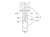
図4は、セクターモールド3のタイヤ幅方向に垂直な断面図である。
同図4を参照して、周方向中央部側領域Cのブレード6と周方向端部側領域Eのブレード7は、型面4fから垂直に突出している。
なお、周方向中央部側領域Cは、セクターモールド3の周方向全領域幅の50%程度の領域幅を有し、該周方向中央部側領域Cの両側が周方向端部側領域Eである。
FIG. 4 is a cross-sectional view of the
Referring to FIG. 4, the
The circumferential center region C has a width of about 50% of the width of the entire circumferential region of the
型開きするときは、セクターモールド3は中心から離れる放射方向Rに移動する。
すなわち、放射方向Rは、型開き時にブレード6,7がタイヤトレッド21から引き抜かれる方向である。
When opening the mold, the
That is, the radial direction R is the direction in which the
周方向中央部側領域Cの型面4fに垂直に突出されたブレード6は、その突出方向が型開き時のタイヤトレッドから引き抜かれる方向Rと略平行であり、ブレード先端側厚肉部6cを有するブレード6であってもブレード先端側厚肉部6cが突出方向と平行に抜けるので、抵抗が小さく型抜きし易い。
The
しかし、セクターモールド3の周方向端部側領域Eのブレード7は、その突出方向が型開き時のタイヤトレッドから引き抜かれる方向Rに対して平行でなく、ある程度角度を有するので、ブレード先端側厚肉部7cを有するブレード7は、ブレード先端側厚肉部7cが突出方向と角度を有する方向Rに引き抜かれようとするので、相当の抵抗があり、周方向中央部側領域Cのブレード6に比べて型抜きが容易でない。
However, the protruding direction of the
周方向中央部側領域Cのブレード6と周方向端部側領域Eのブレード7は、互いに形状が同じである。
周方向中央部側領域Cのブレード6の拡大断面図を図5に示す。
ブレード6は、セクターモールド3に埋め込まれるブレード基端部6aと、先端側の板厚方向に拡大したブレード先端側厚肉部6cと、ブレード基端部6aとブレード先端側厚肉部6cとを連結するブレード連結部6bとからなる。
The
FIG. 5 shows an enlarged cross-sectional view of the
The
ブレード基端部6aとブレード連結部6bは、一定の板厚の薄板状をなし、断面が直線状をなしており、ブレード連結部6bの図5に示す断面形状は、セクターモールド3から突出するブレード連結部6bの突出辺6bsと同じ形状であるので、図5に示されるブレード連結部6bの断面に突出辺の符号6bsを付しておく。
The blade
以下、ブレードの断面図には、ブレード連結部の断面に突出辺の符号を付す。
このブレード連結部6bの突出辺6bsの全長(薄板状のブレード連結部6bの型面4fから突出する辺の長さ、図5に示される破線の長さ)は、Lcである。
In the cross-sectional views of the blades, the cross-sections of the connecting portions of the blades are denoted by the reference numerals of the projecting sides.
The total length of the protruding side 6bs of the blade connecting portion 6b (the length of the side protruding from the
ブレード先端側厚肉部6cは、図5に示す断面形状が長円形をしており、その板厚方向に拡大した厚みはWcである。
図5に示す断面図で、ブレード先端側厚肉部6cの厚みの最大幅Wcの幅でブレード先端側厚肉部6cから型面4fまでの面積からブレード連結部6bの断面積を減算した掃き面積(図5で散点模様を施した部分の面積)をScとする。
The blade tip-side
In the cross-sectional view shown in FIG. 5, the sweep obtained by subtracting the cross-sectional area of the blade connecting portion 6b from the area from the blade tip-side
周方向端部側領域Eのブレード7の拡大断面図を図6に示す。
ブレード7は、セクターモールド3に埋め込まれるブレード基端部7aと、先端側の板厚方向に拡大したブレード先端側厚肉部7cと、ブレード基端部7aとブレード先端側厚肉部7cとを連結するブレード連結部7bとからなる。
FIG. 6 shows an enlarged cross-sectional view of the
The
ブレード7は、ブレード6と同じ形状をしている。
したがって、ブレード7のブレード連結部7bの突出辺7bsの全長Leは、ブレード6のブレード連結部6bの突出辺6bsの全長Lcと等しく、ブレード7の掃き面積Seは、ブレード6の掃き面積Scと等しい。
Therefore, the total length Le of the protruding side 7bs of the blade connecting portion 7b of the
このように周方向中央部側領域Cのブレード6と周方向端部側領域Eのブレード7は形状が同じであるが、図4(および図2)に示されるように、セクターモールド3に植設されるブレードの周方向の単位長さ当たりの数であるブレード密度は、セクターモールド3の周方向中央部側領域Cと周方向中央部側領域Eとでは異なる。
すなわち、周方向中央部側領域Cのブレード6のブレード密度Dcより周方向中央部側領域Eのブレード7のブレード密度Deの方が小さい(De<Dc)。
Thus, the
That is, the blade density De of the
セクターモールド3に植設されるブレードの周方向の単位長さ当たりの数であるブレード密度は、型抜きの難易度を示し、ブレード密度が小さいほど型抜き時の抵抗が小さく型抜きが容易である。
The blade density, which is the number per unit length in the circumferential direction of the blades implanted in the
セクターモールド3の周方向中央部側領域Cのブレード6より型抜きが容易でない周方向端部側領域Eのブレード7のブレード密度Deを、周方向中央部側領域Cのブレード6のブレード密度Dcより小さくすることで、加硫成形用金型の型開き時にセクターモールド全体の型抜けを、不具合を生じさせることなく円滑に行うことができる。
The blade density De of the
加硫成形用金型1を用いて製造した空気入りタイヤ20は、型開き時の型抜けを円滑にし、ブロックの一部の欠損などの型抜け不良を生じさせることがなく、生産効率を上げることができる。
The
次に、別の実施の形態に係る加硫成形用金型について図7ないし図9に基づいて説明する。
本加硫成形用金型のセクターモールドは、前記セクターモールド3と同じ構造のものであり、分割モールドおよび周方向突条とともに同じ符号を用いる。
同様に、空気入りタイヤおよびタイヤトレッドも同じ符号を用いる。
Next, a vulcanization mold according to another embodiment will be described with reference to FIGS. 7 to 9. FIG.
The sector mold of this mold for vulcanization molding has the same structure as the
Similarly, pneumatic tires and tire treads use the same reference numerals.
そして、セクターモールド3の型面4fには、隣合う周方向突条5,5間に薄板状部材であるブレード8,9がタイヤ幅方向に若干傾いて延びて植設されている。
On the
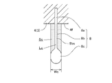
図7は、本加硫成形用金型のセクターモールド3のタイヤ幅方向に垂直な断面図である。
同図7を参照して、周方向中央部側領域Cのブレード8と周方向端部側領域Eのブレード9は、型面4fから垂直に突出している。
型開き時にブレード8,9は、セクターモールド3が中心から離れる放射方向Rにタイヤトレッド21から引き抜かれる。
FIG. 7 is a cross-sectional view perpendicular to the tire width direction of the
Referring to FIG. 7, the
During mold opening the
前記したように、セクターモールド3の周方向端部側領域Eのブレード9は、その突出方向が型開き時のタイヤトレッドから引き抜かれる方向Rに対して平行でなく、ある程度角度を有するので、ブレード先端側厚肉部9cを有するブレード9は、ブレード先端側厚肉部9cが突出方向と角度を有する方向Rに引き抜かれようとするので、比較的大きい抵抗があり、周方向中央部側領域Cのブレード8に比べて型抜きが容易でない。
As described above, the protruding direction of the
そこで、周方向中央部側領域Cのブレード8と周方向端部側領域Eのブレード9は、互いに形状を異にしている。
周方向中央部側領域Cのブレード8の拡大断面図を図8に示す。
ブレード8は、セクターモールド3に埋め込まれるブレード基端部8aと、先端側の板厚方向に拡大したブレード先端側厚肉部8cと、ブレード基端部8aとブレード先端側厚肉部8cとを連結するブレード連結部8bとからなる。
Therefore, the
FIG. 8 shows an enlarged cross-sectional view of the
The
ブレード8は、前記ブレード6,7と同じ形状をしており、ブレード基端部8aとブレード連結部8bは、一定の板厚の薄板状をなし、断面が直線状をなし、ブレード連結部8bの突出辺8bsの全長(図8に示される破線の長さ)はLcである。
ブレード先端側厚肉部8cは、図8に示す断面形状が長円形をしており、その板厚方向に拡大した厚みはWcである。
The
The blade tip side
図8に示す断面図で、ブレード先端側厚肉部8cの厚みの最大幅Weの幅でブレード先端側厚肉部8cから型面4fまでの面積からブレード連結部8bの断面積を減算した掃き面積(図8で散点模様を施した部分の面積)をScとする。
In the cross-sectional view shown in FIG. 8, the sweep obtained by subtracting the cross-sectional area of the blade connecting portion 8b from the area from the blade tip-side
周方向端部側領域Eのブレード9の拡大断面図を図9に示す。
ブレード9は、セクターモールド3に埋め込まれるブレード基端部9aと、先端側の板厚方向に拡大したブレード先端側厚肉部9cと、ブレード基端部9aとブレード先端側厚肉部9cとを連結するブレード連結部9bとからなる。
FIG. 9 shows an enlarged cross-sectional view of the
The
ブレード基端部9aとブレード連結部9bは、一定の板厚の薄板状をなし、断面が直線状をなしている。
このブレード連結部9bの突出辺9bsの全長(薄板状のブレード連結部9bの型面4fから突出する辺の長さ、図9に示される破線の長さ)は、Leである。
The blade
The total length of the protruding side 9bs of the blade connecting portion 9b (the length of the side protruding from the
ブレード先端側厚肉部9cは、図9に示す断面形状が円形をしており、その円形の直径はブレード先端側厚肉部9cの板厚方向に拡大した厚みWcである。
図9に示す断面図で、ブレード先端側厚肉部9cの厚みの最大幅Wcの幅でブレード先端側厚肉部9cから型面4fまでの面積からブレード連結部9bの断面積を減算した掃き面積(図9で散点模様を施した部分の面積)をSeとする。
The blade tip-side
In the cross-sectional view shown in FIG. 9, the sweep obtained by subtracting the cross-sectional area of the blade connecting portion 9b from the area from the blade tip-side
図8と図9を参照して、周方向端部側領域Eのブレード9の掃き面積Seは、周方向中央部側領域Cのブレード8の掃き面積Scより大きい(Sc<Se)。
8 and 9, the swept area Se of the
前記したように、掃き面積Seは、型開き時にタイヤトレッド21に埋設されているブレード先端側厚肉部9cとブレード連結部9bを抜き取るときに抵抗となる面積であり、型抜きの難易度を示し、掃き面積Seが小さいほど型抜きが容易である。
As described above, the swept area Se is an area that acts as a resistance when removing the blade tip side
図8と図9を参照して、周方向中央部側領域Cのブレード8と周方向端部側領域Eのブレード9を比較すると、周方向中央部側領域Cのブレード8のブレード密度Dcより周方向端部側領域Eのブレード9のブレード密度Deの方が小さいが、ブレード9の掃き面積Seは、ブレード8の掃き面積Scより大きく、型抜きが容易でない。
8 and 9, when comparing the
そこで、本実施の形態では、ブレード密度だけでなく別の型抜きの難易度を示す掃き面積も考慮して設計し、セクターモールド全体の型抜けを容易にするものである。 Therefore, in the present embodiment, not only the blade density but also the swept area indicating the degree of difficulty of demolding is taken into account in designing to facilitate demolding of the entire sector mold.
すなわち、周方向中央部側領域Cのブレード8のブレード密度Dcにブレード8の掃き面積Scを乗算した乗算値Mc(=Dc×Sc)と、周方向端部側領域Eのブレード9のブレード密度Deにブレード9の掃き面積Seを乗算した乗算値Me(=De×Se)とを比較して、周方向中央部側領域Cのブレード8の乗算値Mcよりも周方向端部側領域Eのブレード9の乗算値Meを小さくしている(Me<Mc)。
That is, the multiplied value Mc (=Dc × Sc) obtained by multiplying the sweep area Sc of the
ブレードのブレード密度にブレードの掃き面積を乗算した乗算値は、小さいほど型抜きが容易である。
したがって、セクターモールド3の周方向中央部側領域Cのブレード8より型抜きが容易でない周方向端部側領域Eのブレード9の乗算値Me(=De×Se)を、周方向中央部側領域Cのブレード8の乗算値Mc(=Dc×Sc)より小さくすることで、加硫成形用金型の型開き時にセクターモールド全体の型抜けを、不具合を生じさせることなく円滑に行うことができる。
The smaller the multiplication value obtained by multiplying the blade density of the blade by the swept area of the blade, the easier it is to remove the die.
Therefore, the multiplication value Me (=De×Se) of the
本実施の形態の加硫成形用金型を用いて製造した空気入りタイヤ20は、型開き時の型抜けを円滑にし、ブロックの一部の欠損などの型抜け不良を生じさせることがなく、生産効率を上げることができる。
The
次に、また別の実施の形態に係る加硫成形用金型について図10ないし図12に基づいて説明する。
本加硫成形用金型のセクターモールドは、前記セクターモールド3と同じ構造のものであり、分割モールドおよび周方向突条とともに同じ符号を用いる。
同様に、空気入りタイヤおよびタイヤトレッドも同じ符号を用いる。
Next, a vulcanization mold according to another embodiment will be described with reference to FIGS. 10 to 12. FIG.
The sector mold of this mold for vulcanization molding has the same structure as the
Similarly, pneumatic tires and tire treads use the same reference numerals.
そして、セクターモールド3の型面4fには、隣合う周方向突条5,5間に薄板状部材であるブレード10,11がタイヤ幅方向に若干傾いて延びて植設されている。
On the
図10は、本加硫成形用金型のセクターモールド3のタイヤ幅方向に垂直な断面図である。
同図10を参照して、周方向中央部側領域Cのブレード10と周方向端部側領域Eのブレード11は、型面4fから垂直に突出している。
型開き時にブレード10,11は、セクターモールド3が中心から離れる放射方向Rにタイヤトレッド21から引き抜かれる。
FIG. 10 is a sectional view perpendicular to the tire width direction of the
Referring to FIG. 10, the
When opening the mold, the
前記したように、セクターモールド3の周方向端部側領域Eのブレード11は、その突出方向が型開き時のタイヤトレッドから引き抜かれる方向Rに対して平行でなく、ある程度角度を有するので、ブレード先端側厚肉部11cを有するブレード11は、ブレード先端側厚肉部11cが突出方向と角度を有する方向Rに引き抜かれようとするので、比較的大きい抵抗があり、周方向中央部側領域Cのブレード10に比べて型抜きが容易でない。
As described above, the protruding direction of the
そこで、周方向中央部側領域Cのブレード10と周方向端部側領域Eのブレード11は、互いに形状を異にしている。
周方向中央部側領域Cのブレード10の拡大断面図を図11に示す。
ブレード10は、セクターモールド3に埋め込まれるブレード基端部10aと、先端側の板厚方向に拡大したブレード先端側厚肉部10cと、ブレード基端部10aとブレード先端側厚肉部10cとを連結するブレード連結部10bとからなる。
Therefore, the
FIG. 11 shows an enlarged cross-sectional view of the
The
ブレード10は、前記ブレード8と同じ形状をしており、ブレード基端部10aとブレード連結部10bは、一定の板厚の薄板状をなし、断面が直線状をなし、ブレード連結部10bの突出辺10bsの全長(図11に示される破線の長さ)はLcである。
ブレード先端側厚肉部10cは、図11に示す断面形状が長円形をしており、その板厚方向に拡大した厚みはWcである。
The
The blade tip side
図11に示す断面図で、ブレード先端側厚肉部10cの厚みの最大幅Wcの幅でブレード先端側厚肉部10cから型面4fまでの面積からブレード連結部10bの断面積を減算した掃き面積(図11で散点模様を施した部分の面積)をScとする。
In the cross-sectional view shown in FIG. 11, the sweep obtained by subtracting the cross-sectional area of the
周方向端部側領域Eのブレード11の拡大断面図を図12に示す。
ブレード11は、セクターモールド3に埋め込まれるブレード基端部11aと、先端側の板厚方向に拡大したブレード先端側厚肉部11cと、ブレード基端部11aとブレード先端側厚肉部11cとを連結するブレード連結部11bとからなる。
FIG. 12 shows an enlarged cross-sectional view of the
The
ブレード基端部11aとブレード連結部11bは、一定の板厚の薄板状をなし、ブレード基端部11aは断面が直線状をなしているが、ブレード連結部11bは断面がジグザグ状に屈曲している。
The blade
ブレード連結部11bの断面のジグザグ状に屈曲した長さ(薄板状のブレード連結部11bの型面4fから突出する辺の長さの総和、図12に示される破線の長さ)が、ブレード連結部11bの突出辺11bsの全長Leである。
このブレード連結部11bの突出辺11bsの全長Leは、屈曲している分、型面4fからの突出距離より長い。
The zigzag-bent length of the section of the blade connecting portion 11b (the sum of the lengths of the sides protruding from the
The total length Le of the protruding side 11bs of the blade connecting portion 11b is longer than the protruding distance from the
図11と図12を参照して、周方向端部側領域Eのブレード11のブレード連結部11bの突出辺11bsの全長Leは、周方向中央部側領域Cのブレード10のブレード連結部11bの突出辺11bsの全長Lcより長い(Lc<Le)。
11 and 12, the total length Le of the protruding side 11bs of the blade connecting portion 11b of the
ブレード連結部11bの突出辺11bsの全長Leは、タイヤトレッド21に埋設され、型開き時にブレード連結部11bを抜き取るときに抵抗となる長さであり、型抜きの難易度を示し、ブレード連結部11bの突出辺11bsの全長Leが短いほど型抜きが容易である。
The total length Le of the protruding side 11bs of the blade connecting portion 11b is embedded in the
ブレード先端側厚肉部11cは、図12に示す断面形状が長円形をしており、その板厚方向に拡大した厚みはWeである。
図12に示す断面図で、ブレード先端側厚肉部11cの厚みの最大幅Weの幅でブレード先端側厚肉部11cから型面4fまでの面積からブレード連結部11bの断面積を減算した掃き面積(図12で散点模様を施した部分の面積)をSeとする。
The blade tip side
In the cross-sectional view shown in FIG. 12, the sweep obtained by subtracting the cross-sectional area of the blade connecting portion 11b from the area from the blade tip side
図11と図12を参照して、周方向中央部側領域Cのブレード10と周方向端部側領域Eのブレード11を比較すると、周方向中央部側領域Cのブレード10のブレード密度Dcより周方向端部側領域Eのブレード11のブレード密度Deの方が小さいが、ブレード11のブレード連結部11bの突出辺11bsの全長Leは、ブレード10のブレード連結部10bの突出辺10bsの全長Lcより長く、型抜きが容易でない。
11 and 12, when comparing the
そこで、本実施の形態では、ブレード密度だけでなく別の型抜きの難易度を示すブレード連結部の突出辺の全長も考慮して設計し、セクターモールド全体の型抜けを容易にするものである。 Therefore, in this embodiment, not only the blade density but also the overall length of the protruding side of the blade connecting portion, which indicates the difficulty of demolding, is taken into account in designing, and the demolding of the entire sector mold is facilitated. .
すなわち、周方向中央部側領域Cのブレード10のブレード密度Dcにブレード10のブレード連結部10bの突出辺10bsの全長Lcを乗算した乗算値Mc(=Dc×Lc)と、周方向端部側領域Eのブレード11のブレード密度Deにブレード11のブレード連結部11bの突出辺11bsの全長Leを乗算した乗算値Me(=De×Le)とを比較して、周方向中央部側領域Cのブレード10の乗算値Mcよりも周方向端部側領域Eのブレード11の乗算値Meを小さくしている(Me<Mc)。
That is, the multiplication value Mc (=Dc × Lc) obtained by multiplying the total length Lc of the protruding side 10bs of the
ブレードのブレード密度にブレードのブレード連結部の突出辺の全長を乗算した乗算値は、小さいほど型抜きが容易である。
したがって、セクターモールド3の周方向中央部側領域Cのブレード10より型抜きが容易でない周方向端部側領域Eのブレード11の乗算値Me(=De×Le)を、周方向中央部側領域Cのブレード10の乗算値Mc(=Dc×Lc)より小さくすることで、加硫成形用金型の型開き時にセクターモールド全体の型抜けを、不具合を生じさせることなく円滑に行うことができる。
The smaller the multiplication value obtained by multiplying the blade density of the blade by the total length of the projecting side of the blade connecting portion of the blade, the easier the die cutting.
Therefore, the multiplication value Me (=De×Le) of the
本実施の形態の加硫成形用金型を用いて製造した空気入りタイヤ20は、型開き時の型抜けを円滑にし、ブロックの一部の欠損などの型抜け不良を生じさせることがなく、生産効率を上げることができる。
The
次に、さらに別の実施の形態に係る加硫成形用金型について図13ないし図15に基づいて説明する。
本加硫成形用金型のセクターモールドは、前記セクターモールド3と同じ構造のものであり、分割モールドおよび周方向突条とともに同じ符号を用いる。
同様に、空気入りタイヤおよびタイヤトレッドも同じ符号を用いる。
Next, a vulcanization mold according to still another embodiment will be described with reference to FIGS. 13 to 15. FIG.
The sector mold of this mold for vulcanization molding has the same structure as the
Similarly, pneumatic tires and tire treads use the same reference numerals.
そして、セクターモールド3の型面4fには、隣合う周方向突条5,5間に薄板状部材であるブレード12,13がタイヤ幅方向に若干傾いて延びて植設されている。
On the
図13は、本加硫成形用金型のセクターモールド3のタイヤ幅方向に垂直な断面図である。
同図13を参照して、周方向中央部側領域Cのブレード12と周方向端部側領域Eのブレード13は、型面4fから垂直に突出している。
型開き時にブレード12,13は、セクターモールド3が中心から離れる放射方向Rにタイヤトレッド21から引き抜かれる。
FIG. 13 is a sectional view perpendicular to the tire width direction of the
Referring to FIG. 13, the
When opening the mold, the
前記したように、セクターモールド3の周方向端部側領域Eのブレード13は、その突出方向が型開き時のタイヤトレッドから引き抜かれる方向Rに対して平行でなく、ある程度角度を有するので、ブレード先端側厚肉部13cを有するブレード13は、ブレード先端側厚肉部13cが突出方向と角度を有する方向Rに引き抜かれようとするので、比較的大きい抵抗があり、周方向中央部側領域Cのブレード12に比べて型抜きが容易でない。
As described above, the protruding direction of the
そこで、周方向中央部側領域Cのブレード12と周方向端部側領域Eのブレード13は、互いに形状を異にしている。
周方向中央部側領域Cのブレード12の拡大断面図を図14に示す。
ブレード12は、セクターモールド3に埋め込まれるブレード基端部12aと、先端側の板厚方向に拡大したブレード先端側厚肉部12cと、ブレード基端部12aとブレード先端側厚肉部12cとを連結するブレード連結部12bとからなる。
Therefore, the
FIG. 14 shows an enlarged cross-sectional view of the
The
ブレード12は、前記ブレード10と同じ形状をしており、ブレード基端部12aとブレード連結部12bは、一定の板厚の薄板状をなし、断面が直線状をなし、ブレード連結部12bの突出辺12bsの全長(図14に示される破線の長さ)はLcである。
ブレード先端側厚肉部12cは、図14に示す断面形状が長円形をしており、その板厚方向に拡大した厚みはWcである。
The
The blade tip side
図14に示す断面図で、ブレード先端側厚肉部12cの厚みの最大幅Wcの幅でブレード先端側厚肉部12cから型面4fまでの面積からブレード連結部12bの断面積を減算した掃き面積(図14で散点模様を施した部分の面積)をScとする。
In the cross-sectional view shown in FIG. 14, the sweep obtained by subtracting the cross-sectional area of the blade connecting portion 12b from the area from the blade tip side
周方向端部側領域Eのブレード13の拡大断面図を図15に示す。
ブレード13は、セクターモールド3に埋め込まれるブレード基端部13aと、先端側の板厚方向に拡大したブレード先端側厚肉部13cと、ブレード基端部13aとブレード先端側厚肉部13cとを連結するブレード連結部13bとからなる。
FIG. 15 shows an enlarged cross-sectional view of the
The
ブレード基端部13aとブレード連結部13bは、一定の板厚の薄板状をなし、ブレード基端部13aは断面が直線状をなしているが、ブレード連結部13bは断面がジグザグ状に屈曲している。
The blade
ブレード連結部13bの断面のジグザグ状に屈曲した長さ(薄板状のブレード連結部11bの型面4fから突出する辺の長さの総和、図15に示される破線の長さ)が、ブレード連結部13bの突出辺13bsの全長Leである。
このブレード連結部13bの突出辺13bsの全長Leは、屈曲している分、型面4fからの突出距離より長い。
The zigzag bent length of the cross section of the blade connecting portion 13b (sum of the lengths of the sides protruding from the
The total length Le of the protruding side 13bs of the blade connecting portion 13b is longer than the protruding distance from the
図14と図15を参照して、周方向端部側領域Eのブレード13のブレード連結部13bの突出辺13bsの全長Leは、周方向中央部側領域Cのブレード12のブレード連結部12bの突出辺12bsの全長Lcより長い(Lc<Le)。
14 and 15, the total length Le of the projecting side 13bs of the blade connecting portion 13b of the
ブレード連結部13bの突出辺13bsの全長Leは、タイヤトレッド21に埋設され、型開き時にブレード連結部13bを抜き取るときに抵抗となる長さであり、型抜きの難易度を示し、ブレード連結部13bの突出辺13bsの全長Leが短いほど型抜きが容易である。
The total length Le of the protruding side 13bs of the blade connecting portion 13b is embedded in the
ブレード先端側厚肉部13cは、図15に示す断面形状が円形をしており、その板厚方向に拡大した厚みはWeである。
図15に示す断面図で、ブレード先端側厚肉部13cの厚みの最大幅Weの幅でブレード先端側厚肉部13cから型面4fまでの面積からブレード連結部13bの断面積を減算した掃き面積(図115で散点模様を施した部分の面積)をSeとする。
The blade tip side
In the cross-sectional view shown in FIG. 15, the sweep obtained by subtracting the cross-sectional area of the blade connecting portion 13b from the area from the blade tip-side
図14と図15を参照して、周方向端部側領域Eのブレード13の掃き面積Seは、周方向中央部側領域Cのブレード12の掃き面積Scより大きい(Sc<Se)。
14 and 15, the swept area Se of the
前記したように、掃き面積Seは、型開き時にタイヤトレッド21に埋設されているブレード先端側厚肉部9cとブレード連結部9bを抜き取るときに抵抗となる面積であり、型抜きの難易度を示し、掃き面積Seが小さいほど型抜きが容易である。
As described above, the swept area Se is an area that acts as a resistance when removing the blade tip side
図14と図15を参照して、周方向中央部側領域Cのブレード12と周方向端部側領域Eのブレード13を比較すると、周方向中央部側領域Cのブレード12のブレード密度Dcより周方向端部側領域Eのブレード13のブレード密度Deの方が小さいが、ブレード13の掃き面積Seはブレード12の掃き面積Scより大きく、かつブレード13のブレード連結部13bの突出辺13bsの全長Leはブレード12のブレード連結部12bの突出辺12bsの全長Lcより長いので、型抜きが容易でない。
14 and 15, when comparing the
そこで、本実施の形態では、ブレード密度だけでなく別の型抜きの難易度を示す掃き面積とブレード連結部の突出辺の全長も考慮して設計し、セクターモールド全体の型抜けを容易にするものである。 Therefore, in this embodiment, not only the blade density but also the swept area and the total length of the protruding side of the blade connecting part, which indicate the difficulty of removing the mold, are considered to facilitate the removal of the entire sector mold. It is.
すなわち、周方向中央部側領域Cのブレード12のブレード密度Dcにブレード12の掃き面積Scとブレード連結部12bの突出辺12bsの全長Lcを乗算した乗算値Mc(=Dc×Sc×Lc)と、周方向端部側領域Eのブレード13のブレード密度Deにブレード13の掃き面積Seとブレード連結部13bの突出辺13bsの全長Leを乗算した乗算値Me(=De×Se×Le)とを比較して、周方向中央部側領域Cのブレード12の乗算値Mcよりも周方向端部側領域Eのブレード13の乗算値Meを小さくしている(Me<Mc)。
That is, the multiplication value Mc (=Dc × Sc × Lc) obtained by multiplying the blade density Dc of the
ブレードのブレード密度にブレードの掃き面積とブレード連結部の突出辺の全長を乗算した乗算値は、小さいほど型抜きが容易である。
したがって、セクターモールド3の周方向中央部側領域Cのブレード12より型抜きが容易でない周方向端部側領域Eのブレード13の乗算値Me(=De×Se×Le)を、周方向中央部側領域Cのブレード12の乗算値Mc(=Dc×Sc×Lc)より小さくすることで、加硫成形用金型の型開き時にセクターモールド全体の型抜けを、不具合を生じさせることなく円滑に行うことができる。
The smaller the multiplication value obtained by multiplying the blade density of the blade by the swept area of the blade and the total length of the projecting side of the blade connecting portion, the easier the die-cutting.
Therefore, the multiplication value Me (=De x Se x Le) of the
本実施の形態の加硫成形用金型を用いて製造した空気入りタイヤ20は、型開き時の型抜けを円滑にし、ブロックの一部の欠損などの型抜け不良を生じさせることがなく、生産効率を上げることができる。
The
以上、本発明に係る2つの実施の形態に係る加硫成形用金型について説明したが、本発明の態様は、上記実施の形態に限定されず、本発明の要旨の範囲で、多様な態様で実施されるものを含むものである。 As described above, the vulcanization mold according to the two embodiments of the present invention has been described. , including those implemented in
例えば、本発明のブレードの形状は、実施形態に開示されたブレードに限らず種々のものが考えられるが、請求項1の要件を備えるブレードであればよい。
特に、ブレード先端側厚肉部の断面形状が円形や長円形に限らず、フラスコ形である三角形状、その他多角形状等、種々の形状が考えられる。
なお、ブレード先端側厚肉部は、ブレードの先端側にある厚肉部であり、ブレードの先端にあるとは限らず、厚肉部から径方向内側に向かって厚みが減少するような形状のものでもよい。
For example, the shape of the blade of the present invention is not limited to the blades disclosed in the embodiments, and various shapes are conceivable as long as the blade satisfies the requirements of
In particular, the cross-sectional shape of the thick portion on the tip side of the blade is not limited to a circular or oval shape, and various shapes such as a flask-shaped triangular shape and other polygonal shapes are conceivable.
Note that the thick portion on the tip side of the blade is a thick portion on the tip side of the blade, and is not necessarily on the tip of the blade, and has a shape such that the thickness decreases from the thick portion toward the inside in the radial direction. Anything is fine.
また、セクターモールドの型面に植設されるブレードの前記ブレード密度または前記乗算値が、周方向中央部のブレードから周方向端部側のブレードにいくに従って、徐々に小さくなるようにしてもよい。
さらに、ブレードにより形成される溝は、幅狭の細溝であるサイプに限らずタイヤ幅方向に延びる多少幅広の幅方向溝も含む。
さらにまた、前記実施形態では、周方向突条が5本であったが、周方向突条は5本に限らず、5本より少なくても、また多くてもよい。
Further, the blade density or the multiplied value of the blades implanted on the mold surface of the sector mold may gradually decrease from the blades at the center in the circumferential direction to the blades at the ends in the circumferential direction. .
Furthermore, the grooves formed by the blades are not limited to sipes, which are narrow narrow grooves, but also include somewhat wide width direction grooves extending in the tire width direction.
Furthermore, in the above embodiment, the number of circumferential ridges is five, but the number of circumferential ridges is not limited to five, and may be less or more than five.
1…加硫成形用金型、2…ホルダー、3…セクターモールド、4…分割モールド、4f…型面、5…周方向突条、
6…ブレード、6a…ブレード基端部、6b…ブレード連結部、6bs…突出辺、6c…ブレード先端側厚肉部、
7…ブレード、7a…ブレード基端部、7b…ブレード連結部、7bs…突出辺、7c…ブレード先端側厚肉部、
8…ブレード、8a…ブレード基端部、8b…ブレード連結部、8bs…突出辺、8c…ブレード先端側厚肉部、
9…ブレード、9a…ブレード基端部、9b…ブレード連結部、9bs…突出辺、9c…ブレード先端側厚肉部、
10…ブレード、10a…ブレード基端部、10b…ブレード連結部、10bs…突出辺、10c…ブレード先端側厚肉部、
11…ブレード、11a…ブレード基端部、11b…ブレード連結部、11bs…突出辺、11c…ブレード先端側厚肉部、
12…ブレード、12a…ブレード基端部、12b…ブレード連結部、12bs…突出辺、12c…ブレード先端側厚肉部、
13…ブレード、13a…ブレード基端部、13b…ブレード連結部、13bs…突出辺、13c…ブレード先端側厚肉部、
20…空気入りタイヤ、21…タイヤトレッド、25…タイヤ周方向溝、26…サイプ、27…サイプ、
C…周方向中央部側領域、E…周方向端部側領域、
Sc,Se…掃き面積、Lc,Le…ブレード連結部の突出辺の全長。
DESCRIPTION OF
6... blade, 6a... blade base end, 6b... blade connecting portion, 6bs... projecting side, 6c... blade tip side thick portion,
7... blade, 7a... blade base end, 7b... blade connection part, 7bs... projecting side, 7c... blade tip side thick part,
8... Blade, 8a... Blade base end portion, 8b... Blade connecting portion, 8bs... Protruding side, 8c... Blade tip side thick portion,
9... Blade, 9a... Blade base end, 9b... Blade connection part, 9bs... Protruding side, 9c... Blade tip side thick part,
10... blade, 10a... blade base end, 10b... blade connection part, 10bs... projecting side, 10c... blade tip side thick part,
11... blade, 11a... blade base end, 11b... blade connection part, 11bs... projecting side, 11c... blade tip side thick part,
12... blade, 12a... blade base end, 12b... blade connection part, 12bs... projecting side, 12c... blade tip side thick part,
13... blade, 13a... blade base end, 13b... blade connection part, 13bs... projecting side, 13c... blade tip side thick part,
20... pneumatic tire, 21... tire tread, 25... tire circumferential groove, 26... sipe, 27... sipe,
C... Circumferential direction center side area, E... Circumferential direction end side area,
Sc, Se: swept area, Lc, Le: total length of projecting side of blade connecting portion.
Claims (4)
前記セクターモールドには、型面にタイヤ幅方向に延びる薄板状部材であってタイヤトレッドに溝条を形成するブレードが植設され、
前記ブレードが、前記セクターモールドに埋め込まれるブレード基端部と、先端側の板厚方向に拡大したブレード先端側厚肉部と、前記ブレード基端部と前記ブレード先端側厚肉部とを連結するブレード連結部とからなる加硫成形用金型において、
前記セクターモールドに植設される前記ブレードの周方向の単位長さ当たりの数であるブレード密度は、前記セクターモールドの周方向中央部側領域の前記ブレードより周方向端部側領域の前記ブレードの方が、小さいことを特徴とする加硫成形用金型。 An annular mold that forms the tire tread of a pneumatic tire is divided into multiple sector molds in the circumferential direction, and each sector mold moves toward the center and unites to clamp the inner raw tire and vulcanize it. A vulcanization mold for
In the sector mold, a blade, which is a thin plate-shaped member extending in the tire width direction and forming grooves in the tire tread, is planted on the mold surface,
The blade connects the base end portion of the blade embedded in the sector mold, the thick portion of the blade tip side expanding in the plate thickness direction on the tip side, and the base end portion of the blade and the thick portion of the blade tip side. In a vulcanization molding mold consisting of a blade connection part,
The blade density, which is the number per unit length in the circumferential direction of the blades implanted in the sector mold, is higher than the blades in the circumferential center side region of the sector mold. A mold for vulcanization molding, characterized in that the diameter is smaller.
Priority Applications (5)
| Application Number | Priority Date | Filing Date | Title |
|---|---|---|---|
| JP2018237715A JP7144310B2 (en) | 2018-12-19 | 2018-12-19 | Mold for vulcanization molding |
| EP19899526.8A EP3900906B1 (en) | 2018-12-19 | 2019-11-15 | Vulcanization mold and pneumatic tire manufactured with the mold |
| PCT/JP2019/044941 WO2020129504A1 (en) | 2018-12-19 | 2019-11-15 | Vulcanization molding mold and pneumatic tire manufactured by said mold |
| US17/311,124 US20210379849A1 (en) | 2018-12-19 | 2019-11-15 | Vulcanization mold and pneumatic tire manufactured with the mold |
| CN201980083865.XA CN113195188B (en) | 2018-12-19 | 2019-11-15 | Vulcanization molding mold and pneumatic tire manufactured by using same |
Applications Claiming Priority (1)
| Application Number | Priority Date | Filing Date | Title |
|---|---|---|---|
| JP2018237715A JP7144310B2 (en) | 2018-12-19 | 2018-12-19 | Mold for vulcanization molding |
Publications (2)
| Publication Number | Publication Date |
|---|---|
| JP2020100003A JP2020100003A (en) | 2020-07-02 |
| JP7144310B2 true JP7144310B2 (en) | 2022-09-29 |
Family
ID=71102155
Family Applications (1)
| Application Number | Title | Priority Date | Filing Date |
|---|---|---|---|
| JP2018237715A Active JP7144310B2 (en) | 2018-12-19 | 2018-12-19 | Mold for vulcanization molding |
Country Status (5)
| Country | Link |
|---|---|
| US (1) | US20210379849A1 (en) |
| EP (1) | EP3900906B1 (en) |
| JP (1) | JP7144310B2 (en) |
| CN (1) | CN113195188B (en) |
| WO (1) | WO2020129504A1 (en) |
Citations (1)
| Publication number | Priority date | Publication date | Assignee | Title |
|---|---|---|---|---|
| JP2010202009A (en) | 2009-03-02 | 2010-09-16 | Toyo Tire & Rubber Co Ltd | Pneumatic tire |
Family Cites Families (18)
| Publication number | Priority date | Publication date | Assignee | Title |
|---|---|---|---|---|
| JP3494511B2 (en) * | 1995-08-04 | 2004-02-09 | 横浜ゴム株式会社 | Mold for forming sectional tires and pneumatic tires |
| JPH09216504A (en) * | 1996-02-14 | 1997-08-19 | Yokohama Rubber Co Ltd:The | Pneumatic tire for snow and ice road |
| JP3607011B2 (en) * | 1996-08-12 | 2005-01-05 | 株式会社ブリヂストン | Tire vulcanizing mold and pneumatic tire |
| FR2858578B1 (en) * | 2003-08-04 | 2006-02-24 | Michelin Soc Tech | METHOD FOR MANUFACTURING A PNEUMATIC COMPRISING AT LEAST ONE INSERT |
| JP2006334872A (en) | 2005-06-01 | 2006-12-14 | Bridgestone Corp | Tire vulcanizing mold |
| JP5115299B2 (en) * | 2008-04-16 | 2013-01-09 | 横浜ゴム株式会社 | Pneumatic tire and tire mold |
| JP2010023324A (en) * | 2008-07-17 | 2010-02-04 | Bridgestone Corp | Tire vulcanizing mold and method for producing pneumatic tire |
| JP2010173099A (en) * | 2009-01-27 | 2010-08-12 | Bridgestone Corp | Tire vulcanization molding mold |
| JP5515873B2 (en) * | 2010-03-05 | 2014-06-11 | 横浜ゴム株式会社 | Pneumatic tire and tire mold |
| JP5612391B2 (en) * | 2010-08-09 | 2014-10-22 | 株式会社ブリヂストン | STUDABLE TIRE MANUFACTURING METHOD AND TIRE MOLD |
| JP5541791B2 (en) * | 2010-08-09 | 2014-07-09 | 株式会社ブリヂストン | STUDABLE TIRE MANUFACTURING METHOD AND TIRE MOLD |
| JP5513345B2 (en) * | 2010-11-02 | 2014-06-04 | 株式会社ブリヂストン | Vulcanization mold for spike tire and spike tire |
| CN103547422B (en) * | 2011-07-27 | 2016-09-07 | 不二商事株式会社 | Tire curing metal mold and the method manufacturing tire with this tire curing metal mold |
| JP5675580B2 (en) | 2011-12-21 | 2015-02-25 | 株式会社ブリヂストン | Pneumatic tire |
| JP2014079949A (en) * | 2012-10-16 | 2014-05-08 | Sumitomo Rubber Ind Ltd | Tire vulcanization mold |
| JP5702433B2 (en) * | 2013-05-02 | 2015-04-15 | 株式会社ブリヂストン | Tire molding mold and tire |
| JP2014237434A (en) * | 2014-05-26 | 2014-12-18 | 株式会社ブリヂストン | Tire |
| WO2016200392A1 (en) * | 2015-06-11 | 2016-12-15 | Compagnie Generale Des Etablissements Michelin | Set of molding elements and mold |
-
2018
- 2018-12-19 JP JP2018237715A patent/JP7144310B2/en active Active
-
2019
- 2019-11-15 US US17/311,124 patent/US20210379849A1/en active Pending
- 2019-11-15 EP EP19899526.8A patent/EP3900906B1/en active Active
- 2019-11-15 CN CN201980083865.XA patent/CN113195188B/en active Active
- 2019-11-15 WO PCT/JP2019/044941 patent/WO2020129504A1/en unknown
Patent Citations (1)
| Publication number | Priority date | Publication date | Assignee | Title |
|---|---|---|---|---|
| JP2010202009A (en) | 2009-03-02 | 2010-09-16 | Toyo Tire & Rubber Co Ltd | Pneumatic tire |
Also Published As
| Publication number | Publication date |
|---|---|
| WO2020129504A1 (en) | 2020-06-25 |
| US20210379849A1 (en) | 2021-12-09 |
| EP3900906B1 (en) | 2024-03-06 |
| CN113195188A (en) | 2021-07-30 |
| JP2020100003A (en) | 2020-07-02 |
| EP3900906A1 (en) | 2021-10-27 |
| EP3900906A4 (en) | 2022-11-09 |
| CN113195188B (en) | 2023-03-10 |
Similar Documents
| Publication | Publication Date | Title |
|---|---|---|
| EP1616719B1 (en) | Pneumatic tire | |
| JP4669052B2 (en) | Pneumatic tire | |
| JP5820274B2 (en) | Tire tread | |
| JP4438881B2 (en) | PNEUMATIC TIRE, MANUFACTURING METHOD THEREOF, AND TIRE VULCANIZATION MOLD | |
| CN105764679A (en) | Method for forming a tire having a zero thickness sipe and tire obtained thereby | |
| JP7144308B2 (en) | Mold for vulcanization molding | |
| JP7144309B2 (en) | Mold for vulcanization molding | |
| JP2005262973A (en) | Pneumatic tire, sipe forming blade, and tire molding die having the sipe forming blade | |
| WO2015080799A1 (en) | Method of moulding tire treads having a zero thickness sipe and tire obtained thereby | |
| EP3160722B1 (en) | Mould insert having a high-contrast textured surface | |
| WO2007017991A1 (en) | Tire vulcanizing mold | |
| JP7144310B2 (en) | Mold for vulcanization molding | |
| JP2021062547A (en) | Tire vulcanization mold and tire manufacturing method | |
| JP6609214B2 (en) | Tire mold and tire | |
| JP5541791B2 (en) | STUDABLE TIRE MANUFACTURING METHOD AND TIRE MOLD | |
| JP2019018492A (en) | Tire molding die | |
| JP5614102B2 (en) | Tire manufacturing method, sipe blade used for tire molding die, and tire molding die | |
| CN114643730A (en) | Tire mold | |
| CN111065529A (en) | Mold for tire tread including hidden channels | |
| WO2016054244A1 (en) | Tire treads having a zero thickness sipe |
Legal Events
| Date | Code | Title | Description |
|---|---|---|---|
| A621 | Written request for application examination |
Free format text: JAPANESE INTERMEDIATE CODE: A621 Effective date: 20210720 |
|
| A131 | Notification of reasons for refusal |
Free format text: JAPANESE INTERMEDIATE CODE: A131 Effective date: 20220322 |
|
| A521 | Request for written amendment filed |
Free format text: JAPANESE INTERMEDIATE CODE: A523 Effective date: 20220426 |
|
| TRDD | Decision of grant or rejection written | ||
| A01 | Written decision to grant a patent or to grant a registration (utility model) |
Free format text: JAPANESE INTERMEDIATE CODE: A01 Effective date: 20220913 |
|
| A61 | First payment of annual fees (during grant procedure) |
Free format text: JAPANESE INTERMEDIATE CODE: A61 Effective date: 20220915 |
|
| R150 | Certificate of patent or registration of utility model |
Ref document number: 7144310 Country of ref document: JP Free format text: JAPANESE INTERMEDIATE CODE: R150 |