JP7141284B2 - regulator circuit - Google Patents
regulator circuit Download PDFInfo
- Publication number
- JP7141284B2 JP7141284B2 JP2018167461A JP2018167461A JP7141284B2 JP 7141284 B2 JP7141284 B2 JP 7141284B2 JP 2018167461 A JP2018167461 A JP 2018167461A JP 2018167461 A JP2018167461 A JP 2018167461A JP 7141284 B2 JP7141284 B2 JP 7141284B2
- Authority
- JP
- Japan
- Prior art keywords
- transistor
- voltage
- regulator
- circuit
- load
- Prior art date
- Legal status (The legal status is an assumption and is not a legal conclusion. Google has not performed a legal analysis and makes no representation as to the accuracy of the status listed.)
- Active
Links
Images


Classifications
-
- G—PHYSICS
- G05—CONTROLLING; REGULATING
- G05F—SYSTEMS FOR REGULATING ELECTRIC OR MAGNETIC VARIABLES
- G05F1/00—Automatic systems in which deviations of an electric quantity from one or more predetermined values are detected at the output of the system and fed back to a device within the system to restore the detected quantity to its predetermined value or values, i.e. retroactive systems
- G05F1/10—Regulating voltage or current
- G05F1/46—Regulating voltage or current wherein the variable actually regulated by the final control device is dc
- G05F1/56—Regulating voltage or current wherein the variable actually regulated by the final control device is dc using semiconductor devices in series with the load as final control devices
- G05F1/575—Regulating voltage or current wherein the variable actually regulated by the final control device is dc using semiconductor devices in series with the load as final control devices characterised by the feedback circuit
-
- G—PHYSICS
- G05—CONTROLLING; REGULATING
- G05F—SYSTEMS FOR REGULATING ELECTRIC OR MAGNETIC VARIABLES
- G05F1/00—Automatic systems in which deviations of an electric quantity from one or more predetermined values are detected at the output of the system and fed back to a device within the system to restore the detected quantity to its predetermined value or values, i.e. retroactive systems
- G05F1/10—Regulating voltage or current
- G05F1/46—Regulating voltage or current wherein the variable actually regulated by the final control device is dc
- G05F1/461—Regulating voltage or current wherein the variable actually regulated by the final control device is dc using an operational amplifier as final control device
-
- H—ELECTRICITY
- H03—ELECTRONIC CIRCUITRY
- H03K—PULSE TECHNIQUE
- H03K5/00—Manipulating of pulses not covered by one of the other main groups of this subclass
- H03K5/22—Circuits having more than one input and one output for comparing pulses or pulse trains with each other according to input signal characteristics, e.g. slope, integral
- H03K5/24—Circuits having more than one input and one output for comparing pulses or pulse trains with each other according to input signal characteristics, e.g. slope, integral the characteristic being amplitude
- H03K5/2472—Circuits having more than one input and one output for comparing pulses or pulse trains with each other according to input signal characteristics, e.g. slope, integral the characteristic being amplitude using field effect transistors
-
- G—PHYSICS
- G05—CONTROLLING; REGULATING
- G05F—SYSTEMS FOR REGULATING ELECTRIC OR MAGNETIC VARIABLES
- G05F3/00—Non-retroactive systems for regulating electric variables by using an uncontrolled element, or an uncontrolled combination of elements, such element or such combination having self-regulating properties
- G05F3/02—Regulating voltage or current
- G05F3/08—Regulating voltage or current wherein the variable is dc
- G05F3/10—Regulating voltage or current wherein the variable is dc using uncontrolled devices with non-linear characteristics
- G05F3/16—Regulating voltage or current wherein the variable is dc using uncontrolled devices with non-linear characteristics being semiconductor devices
- G05F3/20—Regulating voltage or current wherein the variable is dc using uncontrolled devices with non-linear characteristics being semiconductor devices using diode- transistor combinations
- G05F3/26—Current mirrors
- G05F3/262—Current mirrors using field-effect transistors only
Description
本発明は、リニアレギュレータに関する。 The present invention relates to linear regulators.
さまざまな電子回路、電子機器において、ある電圧値の直流電圧を、別の電圧値の直流電圧に安定化するリニアレギュレータが使用される。図1は、リニアレギュレータの回路図である。リニアレギュレータ800は、入力端子802に直流電圧VINを受け、所定の目標電圧VOUT(REF)に安定化された出力電圧VOUTを出力端子804に発生する。リニアレギュレータ800は、主として、出力トランジスタ806、エラーアンプ808、フィードバック回路810を備える。
2. Description of the Related Art Linear regulators are used in various electronic circuits and electronic devices to stabilize a DC voltage of a certain voltage value to a DC voltage of another voltage value. FIG. 1 is a circuit diagram of a linear regulator.
出力トランジスタ806は、入力端子802と出力端子804の間に設けられる。フィードバック回路810は、出力電圧VOUTを分圧し、出力電圧VOUTに応じたフィードバック電圧VFBを生成する。エラーアンプ808は、フィードバック電圧VFBと所定の基準電圧VREFの誤差を増幅し、出力トランジスタ806の制御端子(ゲート)の電圧を調節する。フィードバックによって、出力電圧VOUTは、以下の目標電圧VOUT(REF)に安定化される。
VOUT(REF)=VREF×(R11+R12)/R12
An
VOUT(REF) =VREF *( R11 + R12 )/ R12
アプリケーションによっては、リニアレギュレータの出力電流IOUTが、非常に広範囲に変動する場合がある。図1のリニアレギュレータ800では、幅広い負荷領域のすべてにおいて、安定性を維持することが難しく、一部の負荷領域(あるいは全負荷領域)での位相・ゲイン余裕が低下する。全負荷領域での安定性を確保するためには、それと引きかえに応答性を下げる必要があり、過渡特性が悪化する要因となっていた。
Depending on the application, the linear regulator's output current IOUT may vary over a very wide range. In the
この問題を解決するために、複数のリニアレギュレータを並列に接続し、負荷領域ごとに切りかえて使用する技術が提案されている(特許文献1)。 In order to solve this problem, a technique has been proposed in which a plurality of linear regulators are connected in parallel and switched for each load region (Patent Document 1).
特許文献1に記載の技術では、消費電力の低減のために、軽負荷状態において重負荷対応エラーアンプを完全にオフしている。図2は、従来技術の課題を説明する図である。オフ状態のエラーアンプの動作が復帰するまでにはある遅延時間が存在する。したがって軽負荷状態から重負荷状態に急変した場合に、重負荷対応エラーアンプの応答遅れによって、出力電圧VOUTの変動が大きくなる。
In the technique described in
場合によっては、以下の動作を繰り返すことにより、発振を引き起こすおそれもある。
(i)出力電圧VOUTのオーバーシュート
(ii)出力電圧を低下させるために重負荷対応エラーアンプが重負荷側のトランジスタをオフ
(iii)軽負荷と誤判定され、重負荷対応エラーアンプがオフ
(iv) 出力電圧VOUTが低下
(v) 出力電流が増大し、重負荷判定され、重負荷対応エラーアンプがオン
In some cases, repeating the following operations may cause oscillation.
(i) Overshoot of the output voltage V OUT (ii) The heavy load error amplifier turns off the transistor on the heavy load side in order to reduce the output voltage (iii) The heavy load error amplifier is turned off due to misjudgment as a light load (iv) Output voltage VOUT drops (v) Output current increases, heavy load is judged, heavy load error amplifier turns on
すなわち特許文献1に記載の技術では、必ずしも幅広い負荷領域で安定な動作が保証されているわけではない。
That is, the technique described in
本発明はかかる課題に鑑みてなされたものであり、そのある態様の例示的な目的のひとつは、幅広い負荷領域で安定動作可能なレギュレータ回路の提供にある。 The present invention has been made in view of such problems, and one exemplary object of certain aspects thereof is to provide a regulator circuit capable of stable operation over a wide load range.
1. 本発明のある態様は、負荷に出力電圧を供給するレギュレータ回路に関する。レギュレータ回路は、第1トランジスタと、第1トランジスタと並列であり、相対的にサイズが小さい第2トランジスタと、出力電圧に応じた第1フィードバック信号および第2フィードバック信号を生成するフィードバック回路と、第1フィードバック信号が第1基準値VREF1に近づくように第1トランジスタを制御する第1エラーアンプと、第2フィードバック信号が第2基準値VREF2に近づくように第2トランジスタを制御する第2エラーアンプと、を備える。軽負荷状態において、第1エラーアンプの動作が維持される。 1. One aspect of the present invention relates to a regulator circuit that supplies an output voltage to a load. The regulator circuit includes a first transistor, a second transistor in parallel with the first transistor and having a relatively small size, a feedback circuit for generating a first feedback signal and a second feedback signal responsive to the output voltage, and a second transistor. A first error amplifier controlling a first transistor such that one feedback signal approaches a first reference value V REF1 and a second error amplifier controlling a second transistor such that a second feedback signal approaches a second reference value V REF2 and an amplifier. In light load conditions, the operation of the first error amplifier is maintained.
この態様によると、軽負荷状態において、第1エラーアンプはその動作状態を維持しつつ、第1トランジスタをオフすることができる。これにより、軽負荷状態から重負荷状態に急激に切り替わった場合においても、第1エラーアンプによって速やかに第1トランジスタをオンすることができ、出力電圧変動を抑制できる。 According to this aspect, in a light load state, the first error amplifier can turn off the first transistor while maintaining its operating state. As a result, even when the light load state is abruptly switched to the heavy load state, the first error amplifier can quickly turn on the first transistor, and output voltage fluctuation can be suppressed.
第2トランジスタおよび第2エラーアンプの組み合わせによる出力電圧の目標電圧は、第1トランジスタおよび第1エラーアンプの組み合わせによる出力電圧の目標電圧より高くてもよい。
これにより、軽負荷状態と重負荷状態の動作を自動的かつシームレスに切りかえることができる。
A target output voltage for the combination of the second transistor and the second error amplifier may be higher than a target output voltage for the combination of the first transistor and the first error amplifier.
As a result, the operation of the light load state and the heavy load state can be automatically and seamlessly switched.
第1フィードバック信号の帰還率をα1、第2フィードバック信号の帰還率をα2とするとき、VREF1/α1<VREF2/α2が成り立ってもよい。 When the feedback rate of the first feedback signal is α 1 and the feedback rate of the second feedback signal is α 2 , V REF1 /α 1 <V REF2 /α 2 may be established.
第2基準値VREF2は第1基準値VREF1より高くてもよい。 The second reference value V REF2 may be higher than the first reference value V REF1 .
第1エラーアンプと第2エラーアンプの少なくとも一方は、入力オフセット電圧を有するように構成されていてもよい。
第1エラーアンプと第2エラーアンプに共通の基準電圧を供給した場合に、第1目標値と第2目標値を実質的にシフトさせることができる。
At least one of the first error amplifier and the second error amplifier may be configured to have an input offset voltage.
When a common reference voltage is supplied to the first error amplifier and the second error amplifier, the first target value and the second target value can be substantially shifted.
入力オフセット電圧は、第1エラーアンプと第2エラーアンプの少なくとも一方の差動入力対のサイズのミスマッチにより導入されてもよい。 The input offset voltage may be introduced by a size mismatch of the differential input pair of at least one of the first and second error amplifiers.
ある態様においてレギュレータ回路は、基準電圧を生成する基準電圧源と、基準電圧源をシフトするレベルシフト回路と、をさらに備えてもよい。第1基準値VREF1と第2基準値VREF2の一方はレベルシフト前の基準電圧であり、それらの他方は、レベルシフト後の基準電圧であってもよい。 In one aspect, the regulator circuit may further include a reference voltage source that generates a reference voltage and a level shift circuit that shifts the reference voltage source. One of the first reference value V REF1 and the second reference value V REF2 may be the reference voltage before level shifting, and the other of them may be the reference voltage after level shifting.
第2フィードバック信号は、第1フィードバック信号より小さくてもよい。 The second feedback signal may be less than the first feedback signal.
第1フィードバック信号と第2フィードバック信号の一方は、それらの他方をレベルシフトして得られてもよい。 One of the first feedback signal and the second feedback signal may be obtained by level-shifting the other of them.
第2フィードバック信号の帰還率α2は、第1フィードバック信号の帰還率α1より低い。 The feedback rate α2 of the second feedback signal is lower than the feedback rate α1 of the first feedback signal.
ある態様においてレギュレータ回路は、軽負荷状態を検出する判定回路と、軽負荷状態において、第1トランジスタの制御端子の電圧を、第1トランジスタが実質的にオフとなる電圧レベルに変化させる強制オフ回路と、をさらに備えてもよい。 In one aspect, the regulator circuit includes a determination circuit that detects a light load state, and a forced off circuit that changes the voltage of the control terminal of the first transistor to a voltage level at which the first transistor is substantially turned off in the light load state. and may further comprise.
強制オフ回路は、第1トランジスタの制御端子とレギュレータ回路の入力端子の間の電圧を、所定電圧より小さくならないように高くクランプしてもよい。 The forced-off circuit may clamp the voltage between the control terminal of the first transistor and the input terminal of the regulator circuit so that it does not fall below a predetermined voltage.
2. 本発明のある態様は、負荷に出力電圧を供給するレギュレータ回路に関する。レギュレータ回路は、第1トランジスタと、第1トランジスタと並列であり、相対的にサイズが小さい第2トランジスタと、出力電圧に応じた第1フィードバック信号および第2フィードバック信号を生成するフィードバック回路と、第1フィードバック信号が第1基準値VREF1に近づくように第1トランジスタを制御する第1エラーアンプと、第2フィードバック信号が第2基準値VREF2に近づくように第2トランジスタを制御する第2エラーアンプと、を備える。第2トランジスタおよび第2エラーアンプの組み合わせによる出力電圧の目標電圧は、第1トランジスタおよび第1エラーアンプの組み合わせによる出力電圧の目標電圧より高く規定される。負荷電流が所定のしきい値電流より小さいときに、第1エラーアンプはオフする。 2. One aspect of the present invention relates to a regulator circuit that supplies an output voltage to a load. The regulator circuit includes a first transistor, a second transistor in parallel with the first transistor and having a relatively small size, a feedback circuit for generating a first feedback signal and a second feedback signal responsive to the output voltage, and a second transistor. A first error amplifier controlling a first transistor such that one feedback signal approaches a first reference value V REF1 and a second error amplifier controlling a second transistor such that a second feedback signal approaches a second reference value V REF2 and an amplifier. A target voltage of the output voltage by the combination of the second transistor and the second error amplifier is defined higher than the target voltage of the output voltage by the combination of the first transistor and the first error amplifier. The first error amplifier turns off when the load current is less than a predetermined threshold current.
この構成によれば、ある電流ITHを境界として、第1エラーアンプEA1による制御が有効な重負荷状態と、第2エラーアンプEA2による制御が有効な軽負荷状態とを、自動的かつシームレスに切りかえることができる。 According to this configuration, a heavy load state in which the control by the first error amplifier EA1 is effective and a light load state in which the control by the second error amplifier EA2 is effective are automatically and seamlessly controlled with a certain current ITH as a boundary. You can switch.
また、負荷電流IOUTが、境界の電流ITHより低く規定されたしきい値電流IMINより小さい範囲(最軽負荷状態と称する)では、第1エラーアンプを停止することにより、自動切りかえの機能を維持しつつも、最軽負荷状態における回路全体の消費電流を小さくできる。 In a range in which the load current IOUT is lower than the boundary current ITH and smaller than the defined threshold current IMIN ( referred to as the lightest load state), the first error amplifier is stopped to prevent automatic switching. It is possible to reduce the current consumption of the entire circuit in the lightest load state while maintaining the functions.
「第1エラーアンプのオフ状態」には、完全に動作を停止する場合のほか、一部分を完全に停止する場合や、能力を落として待機状態とする場合が含まれる。すなわち、第1エラーアンプのオフ状態は、動作電流が、通常のオン状態よりも減っている状態と把握することもできる。 The "off state of the first error amplifier" includes a case where the operation is completely stopped, a case where a part is completely stopped, and a case where the capacity is lowered and the state is set to a standby state. That is, the OFF state of the first error amplifier can also be grasped as a state in which the operating current is reduced compared to the normal ON state.
レギュレータ回路は、負荷電流をしきい値電流と比較する監視回路をさらに備えてもよい。 The regulator circuit may further comprise a monitoring circuit that compares the load current to a threshold current.
監視回路は、第2トランジスタに流れる電流を検出電圧に変換し、検出電圧を、しきい値電流に対応するしきい値電圧と比較してもよい。第2トランジスタの電流を利用することにより、最軽負荷状態を判定できる。 The monitoring circuit may convert the current through the second transistor to a detection voltage and compare the detection voltage to a threshold voltage corresponding to the threshold current. By using the current in the second transistor, the lightest load condition can be determined.
監視回路は、第2トランジスタと制御端子が共通に接続された第3トランジスタと、第3トランジスタと直列に設けられたセンス抵抗と、を含み、センス抵抗の電圧降下が、検出電圧であってもよい。 The monitoring circuit includes a third transistor having a control terminal commonly connected to the second transistor, and a sense resistor provided in series with the third transistor, and the voltage drop across the sense resistor is the detection voltage. good.
レギュレータ回路は、検出電圧がゲートソース間に印加された第4トランジスタをさらに備えてもよい。第4トランジスタのオン、オフに応じて、第1エラーアンプが制御されてもよい。 The regulator circuit may further include a fourth transistor having the detection voltage applied between its gate and source. The first error amplifier may be controlled depending on whether the fourth transistor is turned on or off.
第1エラーアンプのオン、オフは、第1エラーアンプに供給されるバイアス電流によって制御されてもよい。 Turning on and off of the first error amplifier may be controlled by a bias current supplied to the first error amplifier.
レギュレータ回路は、最軽負荷状態において、第1エラーアンプに、非ゼロの微小のバイアス電流を供給する電流源をさらに備えてもよい。これにより最軽負荷状態において、第1エラーアンプに最低限の電流を供給することで、最軽負荷状態から重負荷状態への負荷の急変時の応答性を改善できる。 The regulator circuit may further comprise a current source that provides a small non-zero bias current to the first error amplifier under lightest load conditions. Thus, by supplying the minimum current to the first error amplifier in the lightest load state, it is possible to improve the responsiveness when the load suddenly changes from the lightest load state to the heavy load state.
3. 本発明のある態様は、負荷に出力電圧を供給するレギュレータ回路に関する。レギュレータ回路は、第1リニアレギュレータと、第1リニアレギュレータと入力、出力がそれぞれ共通に接続され、電流能力が相対的に小さい第2リニアレギュレータと、を備える。第2リニアレギュレータの目標電圧と第1リニアレギュレータの目標電圧の差分は、負荷の状態に応じて変化する。 3. One aspect of the present invention relates to a regulator circuit that supplies an output voltage to a load. The regulator circuit includes a first linear regulator and a second linear regulator whose input and output are commonly connected to the first linear regulator and whose current capability is relatively small. The difference between the target voltage of the second linear regulator and the target voltage of the first linear regulator changes according to the state of the load.
この態様によると、第1リニアレギュレータと第2リニアレギュレータに差を設定することで、軽負荷状態では第1リニアレギュレータを実質的にオフ状態とし、第2リニアレギュレータを動作させ、重負荷状態では、第1リニアレギュレータと第2リニアレギュレータの両方を動作させることができる。また重負荷状態において、第2リニアレギュレータの出力トランジスタがフルオンしないように、目標電圧を調節することにより、電源電圧変動除去比を高めることができる。 According to this aspect, by setting the difference between the first linear regulator and the second linear regulator, the first linear regulator is substantially turned off in a light load state, the second linear regulator is operated, and in a heavy load state, , both the first linear regulator and the second linear regulator can be operated. Also, by adjusting the target voltage so that the output transistor of the second linear regulator is not fully turned on in a heavy load state, the power supply rejection ratio can be increased.
第2リニアレギュレータの目標電圧は、軽負荷状態において第1リニアレギュレータの目標電圧より高く、重負荷状態において、第1リニアレギュレータの目標電圧に近づいてもよい。 The target voltage of the second linear regulator may be higher than the target voltage of the first linear regulator under light load conditions and closer to the target voltage of the first linear regulator under heavy load conditions.
第2リニアレギュレータの目標電圧は、負荷電流に応じて連続的に変化してもよい。 The target voltage of the second linear regulator may continuously change according to the load current.
第2リニアレギュレータの目標電圧は、負荷電流に応じて離散的に変化してもよい。 The target voltage of the second linear regulator may discretely change according to the load current.
第1リニアレギュレータは、第1トランジスタと、出力電圧に応じた第1フィードバック信号VFB1が第1基準値VREF1に近づくように第1トランジスタを制御する第1エラーアンプと、を含んでもよい。第2リニアレギュレータは、第1トランジスタと並列であり、相対的にサイズが小さい第2トランジスタと、出力電圧に応じた第2フィードバック信号VFB2が第2基準値VREF2に近づくように第2トランジスタを制御する第2エラーアンプと、を含んでもよい。 The first linear regulator may include a first transistor and a first error amplifier controlling the first transistor such that a first feedback signal VFB1 corresponding to the output voltage approaches a first reference value VREF1 . The second linear regulator is in parallel with the first transistor and has a relatively small size and a second transistor such that a second feedback signal V FB2 responsive to the output voltage approaches a second reference value V REF2 . and a second error amplifier that controls the .
VFB1=VFB2であってもよい。レギュレータ回路は、負荷電流にもとづいて、第1基準値VREF1と第2基準値VREF2の差を変化させるオフセット制御部をさらに備えてもよい。 VFB1 may be VFB2 . The regulator circuit may further comprise an offset controller that varies the difference between the first reference value V REF1 and the second reference value V REF2 based on the load current.
VREF1=VREF2であってもよい。レギュレータ回路は、負荷電流にもとづいて、第1フィードバック信号VFB1と第2フィードバック信号VFB2の差を変化させるオフセット制御部をさらに備えてもよい。 VREF1 may be VREF2 . The regulator circuit may further comprise an offset control that varies the difference between the first feedback signal VFB1 and the second feedback signal VFB2 based on the load current.
VREF1<VREF2であってもよい。レギュレータ回路は、負荷電流にもとづいて、第1フィードバック信号VFB1と第2フィードバック信号VFB2の差を変化させるオフセット制御部をさらに備えてもよい。 V REF1 <V REF2 may be satisfied. The regulator circuit may further comprise an offset control that varies the difference between the first feedback signal VFB1 and the second feedback signal VFB2 based on the load current.
VFB1>VFB2であってもよい。レギュレータ回路は、負荷電流にもとづいて、第1基準値VREF1と第2基準値VREF2の差を変化させるオフセット制御部をさらに備えてもよい。 V FB1 >V FB2 may be satisfied. The regulator circuit may further comprise an offset controller that varies the difference between the first reference value V REF1 and the second reference value V REF2 based on the load current.
レギュレータ回路は、ひとつの半導体基板に一体集積化されてもよい。「一体集積化」とは、回路の構成要素のすべてが半導体基板上に形成される場合や、回路の主要構成要素が一体集積化される場合が含まれ、回路定数の調節用に一部の抵抗やキャパシタなどが半導体基板の外部に設けられていてもよい。回路を1つのチップ上に集積化することにより、回路面積を削減することができるとともに、回路素子の特性を均一に保つことができる。 The regulator circuit may be monolithically integrated on one semiconductor substrate. "Integrated integration" includes the case where all circuit components are formed on a semiconductor substrate, and the case where the main components of a circuit are integrated. A resistor, capacitor, or the like may be provided outside the semiconductor substrate. By integrating the circuits on one chip, the circuit area can be reduced and the characteristics of the circuit elements can be kept uniform.
なお、以上の構成要素の任意の組み合わせや本発明の構成要素や表現を、方法、装置、システムなどの間で相互に置換したものもまた、本発明の態様として有効である。 It should be noted that arbitrary combinations of the above-described constituent elements and mutually replacing the constituent elements and expressions of the present invention in methods, devices, systems, etc. are also effective as aspects of the present invention.
さらに、この項目(課題を解決するための手段)の記載は、本発明の欠くべからざるすべての特徴を説明するものではなく、したがって、記載されるこれらの特徴のサブコンビネーションも、本発明たり得る。 Furthermore, the description in this section (Summary of the Invention) does not describe all the essential features of the invention, and thus subcombinations of those described features can also be the invention. .
本発明のある態様によれば、幅広い負荷領域で安定動作可能なレギュレータ回路を提供できる。 According to one aspect of the present invention, it is possible to provide a regulator circuit capable of stable operation over a wide load range.
以下、本発明を好適な実施の形態をもとに図面を参照しながら説明する。各図面に示される同一または同等の構成要素、部材、処理には、同一の符号を付するものとし、適宜重複した説明は省略する。また、実施の形態は、発明を限定するものではなく例示であって、実施の形態に記述されるすべての特徴やその組み合わせは、必ずしも発明の本質的なものであるとは限らない。 BEST MODE FOR CARRYING OUT THE INVENTION The present invention will be described below based on preferred embodiments with reference to the drawings. The same or equivalent constituent elements, members, and processes shown in each drawing are denoted by the same reference numerals, and duplication of description will be omitted as appropriate. Moreover, the embodiments are illustrative rather than limiting the invention, and not all features and combinations thereof described in the embodiments are necessarily essential to the invention.
本明細書において、「部材Aが、部材Bと接続された状態」とは、部材Aと部材Bが物理的に直接的に接続される場合や、部材Aと部材Bが、電気的な接続状態に影響を及ぼさず、あるいは機能を阻害しない他の部材を介して間接的に接続される場合も含む。 In this specification, "a state in which member A is connected to member B" refers to a case in which member A and member B are physically directly connected, or a case in which member A and member B are electrically connected. It also includes the case of being indirectly connected through other members that do not affect the state or impede the function.
同様に、「部材Cが、部材Aと部材Bの間に設けられた状態」とは、部材Aと部材C、あるいは部材Bと部材Cが直接的に接続される場合のほか、電気的な接続状態に影響を及ぼさず、あるいは機能を阻害しない他の部材を介して間接的に接続される場合も含む。 Similarly, "the state in which the member C is provided between the member A and the member B" includes the case where the member A and the member C or the member B and the member C are directly connected, as well as the case where the member is electrically connected. Indirect connection through other members that do not affect the connected state or impede the function is also included.
また、「信号A(電圧、電流)が信号B(電圧、電流)に応じている」とは、信号Aが信号Bと相関を有することを意味し、具体的には、(i)信号Aが信号Bである場合、(ii)信号Aが信号Bに比例する場合、(iii)信号Aが信号Bをレベルシフトして得られる場合、(iv)信号Aが信号Bを増幅して得られる場合、(v)信号Aが信号Bを反転して得られる場合、(vi)あるいはそれらの任意の組み合わせ、等を意味する。「応じて」の範囲は、信号A、Bの種類、用途に応じて定まることが当業者には理解される。 Further, "signal A (voltage, current) corresponds to signal B (voltage, current)" means that signal A has a correlation with signal B. Specifically, (i) signal A is signal B, (ii) signal A is proportional to signal B, (iii) signal A is obtained by level-shifting signal B, (iv) signal A is obtained by amplifying signal B. (v) if signal A is obtained by inverting signal B; (vi) or any combination thereof; It will be understood by those skilled in the art that the range of "depending on" is determined according to the types of signals A and B and the application.
本明細書において参照する波形図やタイムチャートの縦軸および横軸は、理解を容易とするために適宜拡大、縮小したものであり、また示される各波形も、理解の容易のために簡略化され、あるいは誇張もしくは強調されている。 The vertical and horizontal axes of the waveform diagrams and time charts referred to in this specification are enlarged or reduced as appropriate for ease of understanding, and each waveform shown is also simplified for ease of understanding. or exaggerated or emphasized.
(第1の実施の形態)
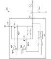
図3は、第1の実施の形態に係るレギュレータ回路100の回路図である。レギュレータ回路100は、入力端子102に入力電圧VINを受け、出力端子104に接続される負荷(不図示)に、ある目標電圧VOUT(REF)に安定化された出力電圧VOUTを供給する。レギュレータ回路100は、LDO(Low Drop Output)回路とも称される。出力端子104には、出力電圧VOUTの平滑化用の出力キャパシタCOUTが接続される。レギュレータ回路100のうち、出力キャパシタCOUTを除く部分は、ひとつの半導体基板に一体集積化されてもよい。
(First embodiment)
FIG. 3 is a circuit diagram of the
レギュレータ回路100は、第1トランジスタM1、第2トランジスタM2、第1エラーアンプEA1、第2エラーアンプEA2を備える。第1トランジスタM1および第1エラーアンプEA1は、主として重負荷状態において負荷に電力を供給可能な第1のリニアレギュレータ(重負荷用レギュレータ)REG1を形成し、第2トランジスタM2および第2エラーアンプEA2は、主として軽負荷状態において負荷に電力を供給可能な第2のリニアレギュレータ(軽負荷用レギュレータ)REG2を形成する。第2トランジスタM2の素子サイズは、第1トランジスタM1の素子サイズより相対的に小さく構成される。
The
より具体的には、第1トランジスタM1および第2トランジスタM2は、入力端子102と出力端子104の間に並列に設けられる。本実施の形態において第1トランジスタM1および第2トランジスタM2は、PチャンネルMOSFETであるが、PNP型バイポーラトランジスタであってもよい。
More specifically, the first transistor M1 and the second transistor M2 are provided in parallel between the
フィードバック回路110は、出力電圧VOUTに応じた第1フィードバック信号VFB1および第2フィードバック信号VFB2を生成する。通常、フィードバック回路110は抵抗分圧回路で構成することができるが、レギュレータ回路100がバッファ(ボルテージフォロア)である場合、フィードバック回路110は単なる配線となりうる。
第1エラーアンプEA1は、第1フィードバック信号VFB1が第1基準値VREF1に近づくように第1トランジスタM1の制御端子(ゲート)の電圧(ゲート電圧)を制御する。また第2エラーアンプEA2は、第2フィードバック信号VFB2が第2基準値VREF2に近づくように第2トランジスタM2のゲート電圧を制御する。 The first error amplifier EA1 controls the voltage (gate voltage) of the control terminal (gate) of the first transistor M1 so that the first feedback signal VFB1 approaches the first reference value VREF1 . Also, the second error amplifier EA2 controls the gate voltage of the second transistor M2 so that the second feedback signal VFB2 approaches the second reference value VREF2 .
第2トランジスタM2および第2エラーアンプEA2の組み合わせである軽負荷用のリニアレギュレータREG2による出力電圧VOUTの目標電圧VOUT(REF2)は、第1トランジスタM1および第1エラーアンプEA1の組み合わせである重負荷用のリニアレギュレータREG2による出力電圧VOUTの目標電圧VOUT(REF1)よりわずかに高く設定される。
VOUT(REF2)>VOUT(REF1)
The target voltage V OUT (REF2) of the output voltage V OUT by the linear regulator REG2 for light load, which is the combination of the second transistor M2 and the second error amplifier EA2, is the combination of the first transistor M1 and the first error amplifier EA1. It is set slightly higher than the target voltage V OUT (REF1) of the output voltage V OUT from the heavy load linear regulator REG2.
V OUT (REF2) > V OUT (REF1)
一例として、VOUT=5Vのアプリケーションにおいて、VOUT(REF2)は、VOUT(REF1)よりも数十mV~数百mV高く設定される。 As an example, in an application where V OUT =5V, V OUT(REF2) is set tens to hundreds of mV higher than V OUT(REF1) .
以上がレギュレータ回路100の構成である。続いてその動作を説明する。
図4は、図3のレギュレータ回路100の動作状態を示す図である。横軸は負荷電流IOUTを、縦軸は出力電圧VOUTを示す。重負荷状態と軽負荷状態の境界は、破線で示される。
The above is the configuration of the
FIG. 4 is a diagram showing operating states of the
重負荷状態においては、第1トランジスタM1と第1エラーアンプEA1の能力の方が大きいため、出力電圧VOUTは、第1目標電圧VOUT(REF1)に安定化される。 In a heavy load state, the output voltage V OUT is stabilized at the first target voltage V OUT (REF1) because the capabilities of the first transistor M1 and the first error amplifier EA1 are greater.
軽負荷状態では、第2トランジスタM2と第2エラーアンプEA2によって、出力電圧VOUTは、第2目標電圧VOUT(REF2)に安定化される。軽負荷状態においても第1エラーアンプEA1の動作状態は維持されており、第1エラーアンプEA1は、第1トランジスタM1がオフ状態となるようにゲート電圧VGを生成する。 In a light load state, the output voltage V OUT is stabilized to the second target voltage V OUT (REF2) by the second transistor M2 and the second error amplifier EA2. The operating state of the first error amplifier EA1 is maintained even in the light load state, and the first error amplifier EA1 generates the gate voltage VG so that the first transistor M1 is turned off.
軽負荷状態から重負荷状態に切り替わると、負荷電流IOUTが第2トランジスタM2の電流供給能力を超えるため、出力電圧VOUTがドロップし、自動的に第1エラーアンプEA1および第1トランジスタM1が活性化され、出力電圧VOUTが第1目標電圧VOUT(REF1)に安定化される。 When the light load state is switched to the heavy load state, the load current IOUT exceeds the current supply capability of the second transistor M2, so the output voltage VOUT drops and the first error amplifier EA1 and the first transistor M1 are automatically turned on. is activated and the output voltage V OUT is stabilized to the first target voltage V OUT (REF1) .
以上がレギュレータ回路100の動作である。続いてその利点を説明する。
このレギュレータ回路100では、軽負荷用のレギュレータと重負荷用のレギュレータの併用により、幅広い負荷範囲において、位相余裕、ゲイン余裕を最適化することができる。
The above is the operation of the
In this
また、軽負荷状態と重負荷状態とで、重負荷用レギュレータREG1と軽負荷用レギュレータREG2を自動的に、かつシームレスに切りかえることができる。すなわち、負荷電流IOUTをしきい値と比較し、比較結果に応じて2つのレギュレータREG1,REG2を切りかえるための回路構成が不要であるという利点がある。 Further, the heavy load regulator REG1 and the light load regulator REG2 can be automatically and seamlessly switched between the light load state and the heavy load state. That is, there is an advantage that a circuit configuration for comparing the load current IOUT with the threshold value and switching between the two regulators REG1 and REG2 according to the comparison result is not required.
もし、比較結果にもとづいて2つのレギュレータを選択的に切りかえるとすれば、重負荷と軽負荷の境界で負荷電流IOUTが変動するときに、レギュレータREG1,REG2がオン、オフを繰り返し、回路の安定性が低下する。これに対して、本実施の形態では、レギュレータREG1,REG2がシームレスに切り替わるため、回路の安定性を高めることができる。 If the two regulators are selectively switched based on the comparison result, the regulators REG1 and REG2 are repeatedly turned on and off when the load current IOUT fluctuates at the boundary between the heavy load and the light load. Less stable. In contrast, in the present embodiment, the regulators REG1 and REG2 are switched seamlessly, so that circuit stability can be improved.
また、軽負荷状態においても第1エラーアンプEA1の動作が維持されるため、負荷電流IOUTが急激に増大した場合においても、直ちに第1トランジスタM1をオンすることができ、出力電圧VOUTが、VOUT(REF1)を通過してさらにドロップするのを防止できる。 Further, since the operation of the first error amplifier EA1 is maintained even in a light load state, even when the load current IOUT suddenly increases, the first transistor M1 can be immediately turned on, and the output voltage VOUT , V OUT(REF1) to prevent further drops.
本発明は、図2のブロック図や回路図として把握され、あるいは上述の説明から導かれるさまざまな装置、回路に及ぶものであり、特定の構成に限定されるものではない。以下、本発明の範囲を狭めるためではなく、発明の本質や回路動作の理解を助け、またそれらを明確化するために、より具体的な構成例や変形例を説明する。 The present invention extends to various devices and circuits that can be grasped as the block diagram or circuit diagram of FIG. 2 or derived from the above description, and is not limited to any particular configuration. Hereinafter, more specific configuration examples and modified examples will be described not for narrowing the scope of the present invention, but for helping to understand the essence of the invention and circuit operation and clarifying them.
VOUT(REF1)<VOUT(REF2)とするための構成について、いくつかの実施例を説明する。 Several embodiments will be described with respect to the configuration to satisfy V OUT (REF1) < V OUT (REF2) .
(実施例1.1)
図5は、一実施例に係るレギュレータ回路100Aの回路図である。この実施例において、VFB1=VFB2、VREF1>VREF2が成り立つ。フィードバック回路110Aは、抵抗R1,R2を含む。第1フィードバック信号VFB1の帰還率α1と、第2フィードバック信号VFB2の帰還率α2は等しく、α=R2/(R1+R2)である。
VFB1=VFB2=VOUT×α
(Example 1.1)
FIG. 5 is a circuit diagram of a
V FB1 =V FB2 =V OUT ×α
第2エラーアンプEA2の基準値VREF2は、第1エラーアンプEA1の基準値VREF1より高い。基準電圧源120は、所定の基準電圧VREFを生成する。基準電圧VREFは、そのまま第1エラーアンプEA1に供給され、第1基準値VREF1となる。また基準電圧VREFに、正のオフセット電圧ΔVが付加されて、第2基準値VREF2が生成される。
The reference value V REF2 of the second error amplifier EA2 is higher than the reference value V REF1 of the first error amplifier EA1. A
あるいは基準電圧VREFを第2基準電圧VREF2とし、基準電圧VREFに負のオフセット電圧-ΔVを付加して、第1基準電圧VREF1を生成してもよい。 Alternatively, the reference voltage V REF may be the second reference voltage V REF2 and a negative offset voltage -ΔV may be added to the reference voltage V REF to generate the first reference voltage V REF1 .
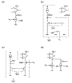
図6(a)、(b)は、オフセットされた2つの基準値VREF1,VREF2を生成するための構成を示す回路図である。図6(a)のレギュレータ回路100Aは、抵抗R3および電流源CS3を備える。抵抗R3の一端には、基準電圧源120が生成した基準電圧VREFが印加される。抵抗R3の他端は、エラーアンプEA2の入力と接続される。また抵抗R3の他端には、電流源CS3が接続される。電流源CS3が生成する電流Icが抵抗R3に流れることにより、オフセット電圧ΔVに相当する電圧降下が発生する。
FIGS. 6A and 6B are circuit diagrams showing a configuration for generating two offset reference values V REF1 and V REF2 . The
図6(b)のレギュレータ回路100Aは、抵抗R4~R6を備える。抵抗R4~R6は直列に接続される。目標電圧VREF1,VREF2は、2つのタップから取り出されている。抵抗R5の電圧降下が、オフセット電圧ΔVに相当する。抵抗R4は省略してもよい。
The
(実施例1.2)
図7は、一実施例に係るレギュレータ回路100Bの回路図である。レギュレータ回路100Bにおいて、第2エラーアンプEA2に、意図的な入力オフセット電圧VOFSが導入され、この入力オフセット電圧VOFS2によって、実効的な基準値VREF2がシフトする。別の観点から見ると、この入力オフセット電圧VOFS2によって、実効的な第2フィードバック信号VFB2がシフトしているものと把握することもできる。
(Example 1.2)
FIG. 7 is a circuit diagram of a
第1エラーアンプEA1は、VREF=VFBが成り立つように、第1トランジスタM1のゲート電圧を調節する。一方、第2エラーアンプEA2は、VREF+VOFS2=VFBが成り立つように、第2トランジスタM2のゲート電圧を調節する。
したがって、
VOUT(REF1)=VREF×(R1+R2)/R2
VOUT(REF2)=(VREF+VOFS2)×(R1+R2)/R2
となり、VOUT(REF2)>VOUT(REF1)が成り立つ。
The first error amplifier EA1 adjusts the gate voltage of the first transistor M1 so that VREF = VFB . Meanwhile, the second error amplifier EA2 adjusts the gate voltage of the second transistor M2 so that V REF +V OFS2 =V FB .
therefore,
VOUT(REF1) = VREF *(R1+R2)/R2
V OUT (REF2) = ( VREF + V OFS2 ) x (R1 + R2)/R2
Thus, V OUT (REF2) >V OUT (REF1) holds.
第2エラーアンプEA2への入力オフセット電圧VOFS2の導入に代えて、あるいはそれに加えて、第1エラーアンプEA1に入力オフセット電圧VOFS1を導入しうてもよい。この場合、オフセット電圧VOFS1の極性は、オフセット電圧VOFS2の極性の逆である。 Instead of or in addition to introducing the input offset voltage VOFS2 into the second error amplifier EA2, the input offset voltage VOFS1 may be introduced into the first error amplifier EA1. In this case, the polarity of the offset voltage VOFS1 is opposite to the polarity of the offset voltage VOFS2 .
図8(a)、(b)は、入力オフセット電圧VOFS2が導入された第2エラーアンプEA2の構成例を示す回路図である。図8(a)、(b)には、エラーアンプの初段に設けられた差動アンプのみが示される。図8(a)の第2エラーアンプEA2では、差動入力対130を構成する2個のトランジスタM11,M12のサイズがN:1となっており、ミスマッチが導入される。
FIGS. 8A and 8B are circuit diagrams showing configuration examples of the second error amplifier EA2 into which the input offset voltage VOFS2 is introduced. FIGS. 8A and 8B show only the differential amplifier provided at the first stage of the error amplifier. In the second error amplifier EA2 of FIG. 8A, the size of the two transistors M11 and M12 forming the
図8(b)のエラーアンプEAでは、カレントミラー負荷132に電流源134が接続され、電流源134が生成する電流によって、バランスを崩し、入力オフセット電圧VOFS2が導入される。
In the error amplifier EA of FIG. 8B, a current source 134 is connected to a
入力オフセット電圧VOFSを導入するための構成はこれらに限定されない。図6(a)の回路構成も、入力オフセット電圧VOFSを導入しているものと把握できる。 The configuration for introducing the input offset voltage VOFS is not limited to these. It can be understood that the circuit configuration of FIG. 6(a) also introduces the input offset voltage VOFS .
(実施例1.3)
図9は、一実施例に係るレギュレータ回路100Cの回路図である。この実施例では、VFB1<VFB2、VREF1=VREF2が成り立つ。すなわちVFB1<VFB2の関係は、フィードバック回路110Cにおいて、オフセット電圧ΔVを導入することで実現できる。
(Example 1.3)
FIG. 9 is a circuit diagram of a
図10(a)、(b)は、フィードバック回路110Cの構成例を示す回路図である。図10(a)のフィードバック回路110Cは、直列に接続された3個の抵抗R7~R9を含む。フィードバック信号VFB1,VFB2は、2つのタップから取り出されている。抵抗R8の電圧降下が、オフセット電圧ΔVに相当する。このオフセット電圧ΔVは出力電圧VOUTに比例する。
10A and 10B are circuit diagrams showing configuration examples of the
図10(a)のフィードバック回路110Cは、別の観点から見ると、フィードバック信号VFB1,VFB2の帰還率が異なっていると把握することもできる。
α1=(R8+R9)/(R7+R8+R9)
α2=R9/(R7+R8+R9)
つまりα2<α1が成り立つ。
From another point of view, the
α 1 = (R8+R9)/(R7+R8+R9)
α 2 =R9/(R7+R8+R9)
That is, α 2 <α 1 holds.
図10(b)のフィードバック回路110Cの構成は、抵抗R10および電流源CS4を備える。抵抗R10に、電流源CS4が生成する電流が流れることにより、電圧降下が発生する。この電圧降下が、オフセット電圧となる。なおこのフィードバック回路110Cでは、電流源CS4が生成する電流によって、第1フィードバック信号VFB1がシフトするため、そのシフト量を考慮して、抵抗値R1,R2および電流量を設計すればよい。もし、レギュレータ回路200がボルテージフォロアの場合には、抵抗R1,R2が省略され、出力端子104の電圧VOUTが第1フィードバック信号VFB1となるため、電流源CS4が生成する電流によって、第1フィードバック信号VFB1は影響を受けない。
The configuration of
(第2の実施の形態)
図11は、第2の実施の形態に係るレギュレータ回路200の回路図である。レギュレータ回路200は、入力端子202に入力電圧VINを受け、出力端子204に接続される負荷(不図示)に、ある目標電圧VOUT(REF)に安定化された出力電圧VOUTを供給する。
(Second embodiment)
FIG. 11 is a circuit diagram of the
エラーアンプEA1,EA2およびトランジスタM1,M2は、第1の実施の形態と同様であり、重負荷用レギュレータREG1、軽負荷用レギュレータREG2の2系統のレギュレータが設けられる。 The error amplifiers EA1 and EA2 and the transistors M1 and M2 are the same as in the first embodiment, and two regulators, a heavy load regulator REG1 and a light load regulator REG2, are provided.
第2の実施の形態においても、レギュレータ回路200は、第1の実施の形態と同様に、軽負荷状態において第1エラーアンプEA1の動作を維持するように構成される。レギュレータ回路200は、重負荷用レギュレータREG1、軽負荷用レギュレータREG2に加えて、判定回路210および強制オフ回路220を備える。判定回路210は軽負荷状態を検出する。軽負荷状態の検出方法は特に限定されないが、たとえば第2トランジスタM2(あるいは第1トランジスタM1)に流れる電流をしきい値と比較することにより、軽負荷判定が可能である。
Also in the second embodiment, the
強制オフ回路220は、軽負荷状態が検出されると、第1トランジスタM1の制御端子の電圧(ゲート電圧)を、第1トランジスタM1が実質的にオフとなる電圧レベルに変化させる。第1トランジスタM1がPチャンネルMOSFETの場合、ゲート電圧が、入力電圧VIN付近までプルアップされる。
When the light load state is detected, the forced off
以上がレギュレータ回路200の構成である。続いてその利点を説明する。このレギュレータ回路200は、軽負荷状態においても第1エラーアンプEA1の動作が維持される。したがって、軽負荷状態から重負荷状態への急峻な変動が生じた場合においても、出力電圧VOUTのドロップを小さく抑えることができる。また、第2エラーアンプEA2のオン、オフに起因する発振も抑制できる。
The above is the configuration of the
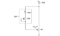
(実施例2.1)
図12は、図11のレギュレータ回路200の実施例2.1の回路図である。強制オフ回路220は、第1トランジスタM1の制御端子(ゲート)とレギュレータ回路200の入力端子202の間に設けられたスイッチSW1を含む。判定回路210は、軽負荷状態と判定すると、スイッチSW1をターンオンし、第1トランジスタM1をオフさせる。
(Example 2.1)
FIG. 12 is a circuit diagram of embodiment 2.1 of
判定回路210は、トランジスタM3、抵抗R13、アンプAMP3を備える。トランジスタM3は、第2トランジスタM2とゲート、ソースが共通に接続される。トランジスタM3には、第2トランジスタM2に流れる電流に比例した検出電流が流れる。抵抗R13には、トランジスタM3の電流に比例した電圧降下が発生する。この電圧降下を、アンプ(コンパレータ)AMP3によってしきい値と比較することにより、軽負荷判定が行われる。
The
図13は、強制オフ回路220の別の構成例を示す回路図である。強制オフ回路220は、第1トランジスタM1の制御端子とレギュレータ回路200の入力端子202の間の電圧VGSを、所定電圧VMINより小さくならないように高くクランプする。所定電圧VMINは、第1トランジスタM1のゲートソース間しきい値VGS(th)より小さく、ゼロより大きい。このために強制オフ回路220は、スイッチSW1と直列に設けられたクランプ素子222を含む。クランプ素子222は、ダイオードや、ゲートドレイン間を結線したMOSFET、ベースコレクタ間を結線したバイポーラトランジスタで構成してもよい。
FIG. 13 is a circuit diagram showing another configuration example of the forced off
(第3の実施の形態)
図14は、第3の実施の形態に係るレギュレータ回路100の回路図である。レギュレータ回路100は、入力端子102に入力電圧VINを受け、出力端子104に接続される負荷(不図示)に、ある目標電圧VOUT(REF)に安定化された出力電圧VOUTを供給する。レギュレータ回路100は、LDO(Low Drop Output)回路とも称される。出力端子104には、出力電圧VOUTの平滑化用の出力キャパシタCOUTが接続される。レギュレータ回路100のうち、出力キャパシタCOUTを除く部分は、ひとつの半導体基板に一体集積化されてもよい。
(Third Embodiment)
FIG. 14 is a circuit diagram of the
レギュレータ回路100は、第1トランジスタM1、第2トランジスタM2、第1エラーアンプEA1、第2エラーアンプEA2を備える。第1トランジスタM1および第1エラーアンプEA1は、主として重負荷状態において負荷に電力を供給可能な第1のリニアレギュレータ(重負荷用レギュレータ)REG1を形成し、第2トランジスタM2および第2エラーアンプEA2は、主として軽負荷状態において負荷に電力を供給可能な第2のリニアレギュレータ(軽負荷用レギュレータ)REG2を形成する。第2トランジスタM2の素子サイズは、第1トランジスタM1の素子サイズより相対的に小さく構成される。
The
より具体的には、第1トランジスタM1および第2トランジスタM2は、入力端子102と出力端子104の間に並列に設けられる。本実施の形態において第1トランジスタM1および第2トランジスタM2は、PチャンネルMOSFETであるが、PNP型バイポーラトランジスタであってもよい。
More specifically, the first transistor M1 and the second transistor M2 are provided in parallel between the
フィードバック回路110は、出力電圧VOUTに応じた第1フィードバック信号VFB1および第2フィードバック信号VFB2を生成する。通常、フィードバック回路110は抵抗分圧回路で構成することができるが、レギュレータ回路100がバッファ(ボルテージフォロア)である場合、フィードバック回路110は単なる配線となりうる。
第1エラーアンプEA1は、第1フィードバック信号VFB1が第1基準値VREF1に近づくように第1トランジスタM1の制御端子(ゲート)の電圧(ゲート電圧)を制御する。また第2エラーアンプEA2は、第2フィードバック信号VFB2が第2基準値VREF2に近づくように第2トランジスタM2のゲート電圧を制御する。 The first error amplifier EA1 controls the voltage (gate voltage) of the control terminal (gate) of the first transistor M1 so that the first feedback signal VFB1 approaches the first reference value VREF1 . Also, the second error amplifier EA2 controls the gate voltage of the second transistor M2 so that the second feedback signal VFB2 approaches the second reference value VREF2 .
第2トランジスタM2および第2エラーアンプEA2の組み合わせである軽負荷用のリニアレギュレータREG2による出力電圧VOUTの目標電圧VOUT(REF2)は、第1トランジスタM1および第1エラーアンプEA1の組み合わせである重負荷用のリニアレギュレータREG2による出力電圧VOUTの目標電圧VOUT(REF1)よりわずかに高く設定される。
VOUT(REF2)>VOUT(REF1)
The target voltage V OUT (REF2) of the output voltage V OUT by the linear regulator REG2 for light load, which is the combination of the second transistor M2 and the second error amplifier EA2, is the combination of the first transistor M1 and the first error amplifier EA1. It is set slightly higher than the target voltage V OUT (REF1) of the output voltage V OUT from the heavy load linear regulator REG2.
V OUT (REF2) > V OUT (REF1)
一例として、VOUT=5Vのアプリケーションにおいて、VOUT(REF2)は、VOUT(REF1)よりも数十mV~数百mV高く設定される。 As an example, in an application where V OUT =5V, V OUT(REF2) is set tens to hundreds of mV higher than V OUT(REF1) .
ここで軽負荷用レギュレータREG2の目標電圧VOUT(REF2)を、重負荷用レギュレータREG1の目標電圧VOUT(REF1)より高い状態で固定すると、重負荷状態において軽負荷用レギュレータREG2は、第2トランジスタM2がフルオンした状態で動作することとなる。このため、入力電圧VINが変動したときに、その変動が出力電圧VOUTの変動として現れ、PSRR(電源電圧除去比)が低くなる場合があった。 If the target voltage V OUT (REF2) of the light-load regulator REG2 is fixed higher than the target voltage V OUT (REF1) of the heavy-load regulator REG1, the light-load regulator REG2 will operate at the second It operates with the transistor M2 fully turned on. Therefore, when the input voltage VIN fluctuates, the fluctuation appears as a fluctuation in the output voltage VOUT , and PSRR (power supply voltage rejection ratio) may become low.
そこで軽負荷用レギュレータREG2の目標電圧VOUT(REF2)と重負荷用レギュレータREG1の目標電圧VOUT(REF1)の差分ΔVは、負荷の状態(すなわち負荷電流IOUT)に応じて動的に変化する。つまり差分ΔVは、負荷電流IOUTの関数f(IOUT)で表すことができる。
ΔV=f(IOUT)
Therefore, the difference ΔV between the target voltage V OUT (REF2) of the light load regulator REG2 and the target voltage V OUT (REF1) of the heavy load regulator REG1 dynamically changes according to the load state (that is, the load current I OUT ). do. That is, the difference ΔV can be represented by a function f(I OUT ) of the load current I OUT .
ΔV=f(I OUT )
重負荷状態において、軽負荷用レギュレータREG2のトランジスタM2がフルオンしないように、目標電圧VOUT(REF2)を動的に変化させることにより、電源電圧変動除去比を高めることができる。 The power supply rejection ratio can be increased by dynamically changing the target voltage V OUT (REF2) so that the transistor M2 of the light load regulator REG2 is not fully turned on in a heavy load state.
好ましくは軽負荷用レギュレータREG2の目標電圧VOUT(REF2)は、軽負荷状態において重負荷用レギュレータREG1の目標電圧VOUT(REF1)より高く、重負荷状態において、目標電圧VOUT(REF1)に近づけてもよい。 Preferably, the target voltage V OUT (REF2) of the light load regulator REG2 is higher than the target voltage V OUT (REF1) of the heavy load regulator REG1 in a light load state, and is higher than the target voltage V OUT (REF1) in a heavy load state. You can bring it closer.
以上がレギュレータ回路100の構成である。続いてその動作を説明する。
はじめに理解の容易化のために、VOUT(REF1),VOUT(REF2)の差分(電位差ΔV)を固定したときの動作を説明する。
The above is the configuration of the
First, for ease of understanding, the operation when the difference (potential difference ΔV) between V OUT(REF1) and V OUT(REF2) is fixed will be described.
図15は、図14のレギュレータ回路100において、電位差ΔVを固定したときの動作を示す図である。横軸は負荷電流IOUTを、縦軸は出力電圧VOUTを示す。重負荷状態と軽負荷状態の境界は、破線で示される。
FIG. 15 is a diagram showing the operation of the
重負荷状態においては、第1トランジスタM1と第1エラーアンプEA1の能力の方が大きいため、出力電圧VOUTは、第1目標電圧VOUT(REF1)に安定化される。 In a heavy load state, the output voltage V OUT is stabilized at the first target voltage V OUT (REF1) because the capabilities of the first transistor M1 and the first error amplifier EA1 are greater.
軽負荷状態では、第2トランジスタM2と第2エラーアンプEA2によって、出力電圧VOUTは、第2目標電圧VOUT(REF2)に安定化される。軽負荷状態においても第1エラーアンプEA1の動作状態は維持されており、第1エラーアンプEA1は、第1トランジスタM1がオフ状態となるようにゲート電圧VGを生成する。 In a light load state, the output voltage V OUT is stabilized to the second target voltage V OUT (REF2) by the second transistor M2 and the second error amplifier EA2. The operating state of the first error amplifier EA1 is maintained even in the light load state, and the first error amplifier EA1 generates the gate voltage VG so that the first transistor M1 is turned off.
軽負荷状態から重負荷状態に切り替わると、負荷電流IOUTが第2トランジスタM2の電流供給能力を超えるため、出力電圧VOUTがドロップし、自動的に第1エラーアンプEA1および第1トランジスタM1が活性化され、出力電圧VOUTが第1目標電圧VOUT(REF1)に安定化される。 When the light load state is switched to the heavy load state, the load current IOUT exceeds the current supply capability of the second transistor M2, so the output voltage VOUT drops and the first error amplifier EA1 and the first transistor M1 are automatically turned on. is activated and the output voltage V OUT is stabilized to the first target voltage V OUT (REF1) .
このレギュレータ回路100では、軽負荷用のレギュレータと重負荷用のレギュレータの併用により、幅広い負荷範囲において、位相余裕、ゲイン余裕を最適化することができる。
In this
また、軽負荷状態と重負荷状態とで、重負荷用レギュレータREG1と軽負荷用レギュレータREG2を自動的に、かつシームレスに切りかえることができる。すなわち、負荷電流IOUTをしきい値と比較し、比較結果に応じて2つのレギュレータREG1,REG2を切りかえるための回路構成が不要であるという利点がある。 Further, the heavy load regulator REG1 and the light load regulator REG2 can be automatically and seamlessly switched between the light load state and the heavy load state. That is, there is an advantage that a circuit configuration for comparing the load current IOUT with the threshold value and switching between the two regulators REG1 and REG2 according to the comparison result is not required.
もし、比較結果にもとづいて2つのレギュレータを選択的に切りかえるとすれば、重負荷と軽負荷の境界で負荷電流IOUTが変動するときに、レギュレータREG1,REG2がオン、オフを繰り返し、回路の安定性が低下する。これに対して、本実施の形態では、レギュレータREG1,REG2がシームレスに切り替わるため、回路の安定性を高めることができる。 If the two regulators are selectively switched based on the comparison result, the regulators REG1 and REG2 are repeatedly turned on and off when the load current IOUT fluctuates at the boundary between the heavy load and the light load. Less stable. In contrast, in the present embodiment, the regulators REG1 and REG2 are switched seamlessly, so that circuit stability can be enhanced.
また、軽負荷状態においても第1エラーアンプEA1の動作が維持されるため、負荷電流IOUTが急激に増大した場合においても、直ちに第1トランジスタM1をオンすることができ、出力電圧VOUTが、VOUT(REF1)を通過してさらにドロップするのを防止できる。 Further, since the operation of the first error amplifier EA1 is maintained even in a light load state, even when the load current IOUT suddenly increases, the first transistor M1 can be immediately turned on, and the output voltage VOUT , V OUT(REF1) to prevent further drops.
続いて電位差ΔVを動的に変化させたときの動作を説明する。
図16は、図14のレギュレータ回路100において、電位差ΔVを第1の態様で変化させたときの動作を示す図である。軽負荷状態では、第1トランジスタM1のゲート電圧VG1は、実質的に入力電圧VINと等しくなっており、第1トランジスタM1に流れる電流IOUT1は実質的にゼロである。第2トランジスタM2のゲート電圧VG2がエラーアンプEA2によって調節され、出力電圧VOUTが目標電圧VOUT(REF2)に安定化される。
Next, the operation when the potential difference ΔV is dynamically changed will be described.
FIG. 16 is a diagram showing the operation of
重負荷状態では、第1エラーアンプEA1によって、出力電圧VOUTが目標電圧VOUT(REF1)に安定化される。このとき、ΔVを固定した場合には、一点鎖線に示すように第2トランジスタM2のゲート電圧VG2は0V付近まで低下し、第2トランジスタM2がフルオンとなる。一方、電位差ΔVを可変にすると、重負荷状態において、第2トランジスタM2のゲート電圧VG2は0Vまで低下せず、負荷電流IOUTに応じて緩やかに低下していく。 In a heavy load state, the first error amplifier EA1 stabilizes the output voltage V OUT to the target voltage V OUT (REF1) . At this time, if ΔV is fixed, the gate voltage VG2 of the second transistor M2 drops to near 0 V as indicated by the dashed line, and the second transistor M2 is fully turned on. On the other hand, if the potential difference ΔV is made variable, the gate voltage VG2 of the second transistor M2 does not drop to 0V in a heavy load state, but gradually drops according to the load current IOUT .
これにより、重負荷状態で、入力電圧VINが変動しても、変動をキャンセルするようにゲート電圧VG2をフィードバックにより調節でき、出力電圧VOUTを安定化できる。 As a result, even if the input voltage VIN fluctuates in a heavy load state, the gate voltage VG2 can be adjusted by feedback so as to cancel the fluctuation, and the output voltage VOUT can be stabilized.
図17は、図14のレギュレータ回路100において、電位差ΔVを第2の態様で変化させたときの動作を説明する図である。図16では、第2基準値VREF2が、負荷電流IOUTに応じて実質的に2値で変化し、したがって軽負荷用レギュレータREG2の目標電圧VOUT(REF2)も、2値で離散的に変化した。これに対して図17では、第2基準値VREF2が、負荷電流IOUTに応じて連続的に変化しており、したがって目標電圧VOUT(REF2)も、連続的に変化する。なお第2リニアレギュレータREG2の目標電圧VOUT(REF2)は、負荷電流IOUTに応じて離散的に変化してもよい。
FIG. 17 is a diagram for explaining the operation of the
なお、図16や図17では、目標電圧の電位差ΔVを変化させるために、基準電圧VREF1,VREF2を制御しているが、以下の実施例からも理解されるように、その限りでない。 In FIGS. 16 and 17, the reference voltages V REF1 and V REF2 are controlled in order to change the potential difference ΔV of the target voltage, but as understood from the following embodiments, this is not the only option.
本発明の一態様は、図14のブロック図や回路図として把握され、あるいは上述の説明から導かれるさまざまな装置、回路に及ぶものであり、特定の構成に限定されるものではない。以下、本発明の範囲を狭めるためではなく、発明の本質や回路動作の理解を助け、またそれらを明確化するために、より具体的な構成例や変形例を説明する。 One aspect of the present invention extends to various devices and circuits grasped as block diagrams and circuit diagrams in FIG. 14 or derived from the above description, and is not limited to any particular configuration. Hereinafter, more specific configuration examples and modified examples will be described not for narrowing the scope of the present invention, but for helping to understand the essence of the invention and circuit operation and clarifying them.
以下、第3の実施の形態に係るレギュレータ回路100について、実施例3.1~3.4を参照して具体的に説明する。
The
(実施例3.1)
図18は、実施例3.1に係るレギュレータ回路100Dの回路図である。この実施例において、VFB1=VFB2、VREF1≧VREF2が成り立つ。第1フィードバック信号VFB1の帰還率α1と、第2フィードバック信号VFB2の帰還率α2は等しく、α=R2/(R1+R2)である。
VFB1=VFB2=VOUT×α
(Example 3.1)
FIG. 18 is a circuit diagram of a
V FB1 =V FB2 =V OUT ×α
この実施例3.1において、第1基準値VREF1は固定されており、たとえば基準電圧源120が生成する基準電圧VREF(またはそれを分圧した電圧)が使用される。フィードバック信号VFB1とVFB2は等しい。第2基準値VREF2は、第1基準値VREF1に、負荷電流IOUTに依存したオフセットΔVを加算した電圧である。
VREF1=VREF
VREF2=VREF+ΔV
In this embodiment 3.1, the first reference value V REF1 is fixed, for example the reference voltage V REF generated by the reference voltage source 120 (or its divided voltage) is used. Feedback signals V FB1 and V FB2 are equal. The second reference value V REF2 is a voltage obtained by adding an offset ΔV that depends on the load current I OUT to the first reference value V REF1 .
V REF1 =V REF
V REF2 =V REF +ΔV
レギュレータ回路100Dは、オフセット制御部140および監視回路150を備える。監視回路150は負荷電流IOUTを監視する。オフセット制御部140は、基準電圧VREFにオフセットΔVを加算するとともに、監視回路150による監視結果、すなわち負荷電流IOUTにもとづいて、第1基準値VREF1と第2基準値VREF2の電位差ΔVを変化させる。
軽負荷状態では、第2トランジスタM2に流れる電流IOUT2は、負荷電流IOUTと実質的に等しい。そこでオフセット制御部140は、第2トランジスタM2に流れる電流IOUT2にもとづいて、電位差ΔVを制御してもよい。監視回路150による軽負荷状態と重負荷状態の判定方法およびその構成は特に限定されない。
Under light load conditions, the current I OUT2 flowing through the second transistor M2 is substantially equal to the load current I OUT . Therefore, the offset
オフセット制御部140については、図6(a)、(b)と同様に構成することができる。
The offset
図19は、負荷電流IOUTを監視する監視回路150の構成例を示す回路図である。監視回路150は、トランジスタM3、抵抗R13、アンプAMP3を備える。トランジスタM3は、第2トランジスタM2とゲート、ソースが共通に接続される。トランジスタM3には、第2トランジスタM2に流れる電流に比例した検出電流が流れ、抵抗R13には、トランジスタM3の電流に比例した電圧降下が発生する。この電圧降下を、コンパレータAMP3によってしきい値と比較することにより、軽負荷判定が行われる。
FIG. 19 is a circuit diagram showing a configuration example of the
あるいはアンプAMP3を、非反転アンプあるいは非反転アンプで構成し、その出力電圧に応じて、2つの目標値VOUT(REF1)、VOUT(REF2)の電位差ΔVを連続的に変化させてもよい。 Alternatively, the amplifier AMP3 may be composed of a non-inverting amplifier or a non-inverting amplifier, and the potential difference ΔV between the two target values V OUT(REF1) and V OUT(REF2) may be continuously changed according to the output voltage. .
(実施例3.2)
図20は、実施例3.2に係るレギュレータ回路100B’の回路図である。レギュレータ回路100B’において、第2エラーアンプEA2に、負荷電流IOUTに依存する意図的な入力オフセット電圧VOFSが導入され、この入力オフセット電圧VOFS2によって、実効的な基準値VREF2がシフトする。別の観点から見ると、この入力オフセット電圧VOFS2によって、実効的な第2フィードバック信号VFB2がシフトしているものと把握することもできる。なお、以降の実施例において監視回路150は省略する。
(Example 3.2)
FIG. 20 is a circuit diagram of a
第1エラーアンプEA1は、VREF=VFBが成り立つように、第1トランジスタM1のゲート電圧を調節する。一方、第2エラーアンプEA2は、VREF+VOFS2=VFBが成り立つように、第2トランジスタM2のゲート電圧を調節する。
したがって、
VOUT(REF1)=VREF×(R1+R2)/R2
VOUT(REF2)=(VREF+VOFS2)×(R1+R2)/R2
となり、オフセット電圧VOFS2に応じて、VOUT(REF2)とVOUT(REF1)の関係が変化する。
The first error amplifier EA1 adjusts the gate voltage of the first transistor M1 so that VREF = VFB . Meanwhile, the second error amplifier EA2 adjusts the gate voltage of the second transistor M2 so that V REF +V OFS2 =V FB .
therefore,
VOUT(REF1) = VREF *(R1+R2)/R2
V OUT (REF2) = ( VREF + V OFS2 ) x (R1 + R2)/R2
Thus, the relationship between V OUT (REF2) and V OUT (REF1) changes according to the offset voltage V OFS2 .
第2エラーアンプEA2への入力オフセット電圧VOFS2の導入に代えて、あるいはそれに加えて、第1エラーアンプEA1に入力オフセット電圧VOFS1を導入してもよい。この場合、オフセット電圧VOFS1の極性は、オフセット電圧VOFS2の極性の逆である。 Instead of or in addition to introducing the input offset voltage VOFS2 to the second error amplifier EA2, the input offset voltage VOFS1 may be introduced to the first error amplifier EA1. In this case, the polarity of the offset voltage VOFS1 is opposite to the polarity of the offset voltage VOFS2 .
入力オフセット電圧VOFS2が導入された第2エラーアンプEA2については、図8(a)、(b)と同様に構成することができる。入力オフセット電圧VOFSを導入するための構成はこれらに限定されない。たとえば図6(a)の回路構成も、入力オフセット電圧VOFSを導入しているものと把握できる。 The second error amplifier EA2 into which the input offset voltage VOFS2 is introduced can be configured in the same manner as in FIGS. 8(a) and 8(b). The configuration for introducing the input offset voltage VOFS is not limited to these. For example, the circuit configuration of FIG. 6(a) can also be understood to introduce the input offset voltage VOFS .
(実施例3.3)
図21は、実施例3.3に係るレギュレータ回路100Eの回路図である。この実施例において、第1エラーアンプEA1と第2エラーアンプEA2には、等しい基準値VREF1=VREF2=VREFが与えられる。
(Example 3.3)
FIG. 21 is a circuit diagram of a
オフセット制御部140は、第2フィードバック信号VFB2に、負荷電流IOUT2に応じたオフセット電圧ΔVを重畳する。
VFB2=VFB-ΔV
このとき、第2目標電圧VOUT(REF2)は、以下の式で与えられる。
VOUT(REF2)=(VREF+ΔV)×(R1+R2)/R2
The offset
V FB2 =V FB -ΔV
At this time, the second target voltage V OUT (REF2) is given by the following equation.
V OUT (REF2) = (V REF +ΔV) x (R1 + R2)/R2
ΔVをゼロと非ゼロの間で変化させることにより、VOUT(REF2)を変化させることができる。 By varying ΔV between zero and non-zero, V OUT(REF2) can be varied.
図22(a)、(b)は、図21のフィードバック回路110Eの構成例を示す回路図である。図22(a)のフィードバック回路110Eは、直列に接続された3個の抵抗R7~R9と、セレクタ112を含む。一方のフィードバック信号VFB1は、ひとつのタップから取り出されている。セレクタ112は、2つのタップの電圧のうち、負荷電流IOUTに応じた一方を選択し、他方のフィードバック信号VFB2として出力する。抵抗R8の電圧降下が、オフセット電圧ΔVに相当する。
22A and 22B are circuit diagrams showing configuration examples of the
図22(a)のフィードバック回路110Eは、別の観点から見ると、フィードバック信号VFB2の帰還率を、2値で変化させているものと把握することもできる。
α1=(R8+R9)/(R7+R8+R9)
α2=R9/(R7+R8+R9)
From another point of view, the
α 1 = (R8+R9)/(R7+R8+R9)
α 2 =R9/(R7+R8+R9)
図22(b)のフィードバック回路110Eの構成は、抵抗R10および電流源CS4を備える。抵抗R10に、電流源CS4が生成する電流Icが流れることにより、電圧降下が発生する。この電圧降下が、オフセット電圧となる。電流Icを、負荷電流IOUTに応じて変化させることにより、オフセット電圧を制御できる。
The configuration of the
(実施例3.4)
図23は、実施例3.4に係るレギュレータ回路100Fの回路図である。この実施例において、VREF2=VREF1+ΔV1が成り立っている。オフセット制御部140は、第2フィードバック信号VFB2に、負荷電流IOUT2に応じたオフセット電圧ΔV2を重畳する。オフセット電圧ΔV1とΔV2は同極性である。
VREF2=VREF+ΔV1
VFB2=VFB+ΔV2
このとき、第2目標電圧VOUT(REF2)は、以下の式で与えられる。
VOUT(REF2)=(VREF+ΔV1-ΔV2)×(R1+R2)/R2
軽負荷状態においては、ΔV2=0とする。このときVOUT(REF2)は、VOUT(REF1)より大きくなる。重負荷状態ではΔV2=ΔV1とする。このときVOUT(REF2)=VOUT(REF1)となる。
(Example 3.4)
FIG. 23 is a circuit diagram of a
V REF2 =V REF +ΔV 1
V FB2 =V FB +ΔV 2
At this time, the second target voltage V OUT (REF2) is given by the following equation.
V OUT (REF2) = ( VREF + ΔV 1 - ΔV 2 ) x (R1 + R2)/R2
In the light load state, ΔV 2 =0. At this time, V OUT (REF2) becomes larger than V OUT (REF1) . ΔV 2 =ΔV 1 in the heavy load state. At this time, V OUT(REF2) =V OUT(REF1) .
図24は、図23のレギュレータ回路100Fの一部の構成例を示す回路図である。トランジスタM4は、トランジスタM2とゲート、ソースが共通に接続される。トランジスタM4には、電流IOUT2に応じた検出電流IOUT2が流れる。この検出電流IOUT2’を、抵抗R14に流すことにより、その電圧降下がオフセット電圧ΔV2となる。これにより、軽負荷状態においては、検出電流IOUT2’が小さくなり、ΔV2=0となる。重負荷状態では検出電流IOUT2’が大きくなり、ΔV2が増大する。図24の構成によれば、図17の動作が実現できる。
FIG. 24 is a circuit diagram showing a configuration example of part of the
(実施例3.5)
図25は、実施例3.5に係るレギュレータ回路100Gの回路図である。この実施例では、図22とオフセットの極性が逆であり、ΔV1が可変である。
VREF2=VREF-ΔV1
VFB2=VFB-ΔV2
このとき、第2目標電圧VOUT(REF2)は、以下の式で与えられる。
VOUT(REF2)=(VREF-ΔV1+ΔV2)×(R1+R2)/R2
軽負荷状態においては、ΔV1=0とする。このときVOUT(REF2)は、VOUT(REF1)より大きくなる。重負荷状態ではΔV1=ΔV2とする。このときVOUT(REF2)=VOUT(REF1)となる。
(Example 3.5)
FIG. 25 is a circuit diagram of a
V REF2 =V REF -ΔV 1
V FB2 =V FB -ΔV 2
At this time, the second target voltage V OUT (REF2) is given by the following equation.
V OUT (REF2) = (V REF - ΔV 1 + ΔV 2 ) x (R1 + R2)/R2
In the light load state, ΔV 1 =0. At this time, V OUT (REF2) becomes larger than V OUT (REF1) . ΔV 1 =ΔV 2 in the heavy load state. At this time, V OUT(REF2) =V OUT(REF1) .
(第4の実施の形態)
第3の実施の形態において、重負荷用の第1エラーアンプEA1は、軽負荷状態の全電流範囲において動作を維持するように構成されていた。したがって軽負荷状態において、第1エラーアンプEA1の消費電流を低減できないという問題がある。第4の実施の形態では、この問題を解決するための構成を説明する。
(Fourth embodiment)
In the third embodiment, the heavy-load first error amplifier EA1 is configured to maintain operation over the entire current range under light-load conditions. Therefore, there is a problem that the consumption current of the first error amplifier EA1 cannot be reduced in a light load state. A fourth embodiment describes a configuration for solving this problem.
図26は、第4の実施の形態に係るレギュレータ回路100Hの回路図である。レギュレータ回路100Hにおいても、重負荷用レギュレータREG1の目標電圧VOUT(REF1)と、軽負荷用レギュレータREG2の目標電圧VOUT(REF2)には、以下の関係が成り立っている。
VOUT(REF2)>VOUT(REF1)
この関係を満たすためのレギュレータ回路100Hの基本構成は、第3の実施の形態で説明した実施例のいずれかを採用することができる。
FIG. 26 is a circuit diagram of the
V OUT (REF2) > V OUT (REF1)
For the basic configuration of the
レギュレータ回路100Hでは、負荷電流IOUTが、軽負荷状態の範囲内に規定されたしきい値電流IMINより小さいときに、第1エラーアンプEA1をオフする。このしきい値電流IMINは、重負荷状態と軽負荷状態の境界を与える電流ITHより低く規定される。たとえば、ITH=1mAのとき、しきい値電流IMINはその1/10の100μA程度としてもよい。
In the
レギュレータ回路100Hは、負荷電流IOUTをしきい値電流IMINと比較する監視回路150をさらに備える。第1エラーアンプEA1のオン、オフは、監視回路150の判定結果にもとづいて制御される。
以上がレギュレータ回路100Hの構成である。続いてその動作を説明する。図27は、図26のレギュレータ回路100Hの動作を説明する図である。負荷電流IOUTがしきい値電流IMINより小さい最軽負荷状態では、第1エラーアンプEA1がオフし、回路の動作電流が最小化される。
The above is the configuration of the
負荷電流IOUTがしきい値電流IMINより大きくなると、重負荷状態への遷移に備えて、第1エラーアンプEA1が動作状態となる。さらに負荷電流IOUTが、軽負荷と重負荷の境界の電流量ITHまで増えると、第1エラーアンプEA1の制御が支配的となり、出力電圧VOUTが第1目標値VOUT(REF1)に安定化される。 When the load current IOUT becomes larger than the threshold current IMIN , the first error amplifier EA1 is activated in preparation for the transition to the heavy load state. When the load current IOUT further increases to the current amount ITH at the boundary between the light load and the heavy load, the control of the first error amplifier EA1 becomes dominant, and the output voltage VOUT reaches the first target value VOUT (REF1) . stabilized.
このように、第4の実施の形態に係るレギュレータ回路100Hによれば、最軽負荷状態における消費電力の低減と、軽負荷状態と重負荷状態における2つのレギュレータREG1,REG2のシームレスな自動切りかえを両立できる。
As described above, according to the
(実施例4.1)
図28は、実施例4.1に係るレギュレータ回路100Iの回路図である。レギュレータ回路の基本構成は、図16のレギュレータ回路100Aと同様である。
(Example 4.1)
FIG. 28 is a circuit diagram of a
監視回路150は、第2トランジスタM2に流れる電流IOUT2にもとづいて、最軽負荷状態を判定する。監視回路150は、第3トランジスタM3およびセンス抵抗R3を含む。第3トランジスタM3は、制御端子(ゲート)が第2トランジスタM2と共通に接続され、ソース同士が共通に接続される。第3トランジスタM3には、第2トランジスタM2に流れる電流IOUT2に比例した検出電流IDETが流れる。センス抵抗R3は、検出電流IDETの経路上に設けられる。センス抵抗R3には、検出電流IDET、すなわち電流IOUT2に比例した電圧降下が発生する。監視回路150は、この電圧降下(検出電圧VDET)を、しきい値電流IMINに対応するしきい値電圧VMINと比較することにより、最軽負荷状態を検出する。監視回路150は、電圧比較手段152として、電圧コンパレータを含んでもよい。あるいは、ゲートソース間に検出電圧VDETが印加されたMOSトランジスタを、コンパレータとして用いてもよい。電圧比較手段152の出力は、最軽負荷状態か否かを示す判定信号S4として第1エラーアンプEA1に供給される。
The
図29(a)~(d)は、第1エラーアンプEA1のオン、オフ制御に関連する部分の構成例を示す回路図である。図29(a)に示すように、第1エラーアンプEA1のオン、オフの切りかえは、バイアス電流IBIASを生成するバイアス電流源160のオン、オフに応じて制御してもよい。
FIGS. 29(a) to 29(d) are circuit diagrams showing configuration examples of portions related to on/off control of the first error amplifier EA1. As shown in FIG. 29(a), ON/OFF switching of the first error amplifier EA1 may be controlled according to ON/OFF of the bias
図29(b)に示すように、バイアス電流源160は、基準電流IREFを折り返すカレントミラー回路162を含んでもよい。カレントミラー回路162のゲートに接続されたトランジスタ164のオン、オフによって、バイアス電流IBIASを制御できる。たとえば最軽負荷状態においてハイレベルとなるように判定信号S4の信号レベルを設計し、トランジスタ164のゲートに判定信号S4を供給してもよい。これにより最軽負荷状態においてトランジスタ164がオンし、カレントミラー回路162がオフし、バイアス電流IBIASが遮断される。
As shown in FIG. 29(b), the bias
図29(c)では、バイアス電流IBIASの経路上に、トランジスタ166が設けられ、そのオン、オフによってバイアス電流IBIASを制御できる。たとえば最軽負荷状態においてローレベルとなるように判定信号S4の信号レベルを設計し、トランジスタ164のゲートに判定信号S4を供給してもよい。これにより最軽負荷状態においてトランジスタ166がオフし、バイアス電流IBIASが遮断される。この構成において、トランジスタ166のゲートに、図27の検出電圧VDETを供給し、トランジスタ166を、電圧比較手段152として機能させてもよい。
In FIG. 29(c), a
図29(d)では、バイアス電流源160に加えて、電流源170が設けられる。電流源170は、最軽負荷状態において第1エラーアンプEA1に、非ゼロの微小のバイアス電流IBIAS0を供給する。これにより最軽負荷状態において、第1エラーアンプEA1を完全にオフするのではなく、最低限の電流IBIAS0を供給して待機状態とすることで、最軽負荷状態から重負荷状態への負荷の急変時の応答性を改善できる。
In FIG. 29(d), in addition to the bias
(第5の実施の形態)
図30は、第5の実施の形態に係るレギュレータ回路100Jの回路図である。レギュレータ回路100Jは、第3の実施の形態と第4の実施の形態の組み合わせである。
具体的には、負荷電流IOUTにもとづいて、第1目標電圧VOUT(REF1)と第2目標電圧VOUT(REF2)の差分ΔVを変化させ、さらに最軽負荷状態において第1エラーアンプEA1を実質的にオフする。
(Fifth embodiment)
FIG. 30 is a circuit diagram of the
Specifically, based on the load current IOUT, the difference ΔV between the first target voltage VOUT (REF1) and the second target voltage VOUT (REF2) is changed, and the first error amplifier EA1 is effectively turned off.
図31は、図30のレギュレータ回路100Jの動作を説明する図である。第5の実施の形態によれば、第3の実施の形態と第4の実施の形態の両方の効果を得ることができる。
FIG. 31 is a diagram explaining the operation of the
なお、第5の実施の形態において、2つの目標電圧VOUT(REF2),VOUT(REF2)の電位差ΔVを変化させるための手段については、第3の実施の形態で説明した通りであるから説明を省略する。また、第1エラーアンプEA1を制御するための手段については、第4の実施の形態で説明した通りであるから説明を省略する。 In the fifth embodiment, the means for changing the potential difference ΔV between the two target voltages V OUT(REF2) and V OUT(REF2) is as described in the third embodiment. Description is omitted. Further, since the means for controlling the first error amplifier EA1 is as described in the fourth embodiment, description thereof will be omitted.
以上、本発明について、実施の形態をもとに説明した。この実施の形態は例示であり、それらの各構成要素や各処理プロセスの組み合わせにいろいろな変形例が可能なこと、またそうした変形例も本発明の範囲にあることは当業者に理解されるところである。以下、こうした変形例について説明する。 The present invention has been described above based on the embodiments. It should be understood by those skilled in the art that this embodiment is merely an example, and that various modifications can be made to the combination of each component and each treatment process, and that such modifications are within the scope of the present invention. be. Such modifications will be described below.
(変形例1)
第1トランジスタM1、第2トランジスタM2の少なくとも一方を、NチャンネルMOSFETあるいはNPN型バイポーラトランジスタで構成してもよい。この場合、エラーアンプの非反転入力端子と反転入力端子を入れ替えればよい。
(Modification 1)
At least one of the first transistor M1 and the second transistor M2 may be composed of an N-channel MOSFET or an NPN bipolar transistor. In this case, the non-inverting input terminal and the inverting input terminal of the error amplifier should be exchanged.
(変形例2)
いくつかの実施例では、レギュレータ回路100に監視回路150を設けたがその限りでない。たとえば外部のマイコンなどから、負荷電流IOUTに関する情報を取得できる場合、その情報にもとづいて目標電圧の差分ΔVを制御してもよい。
(Modification 2)
In some embodiments,
(変形例3)
いくつかの実施例では、軽負荷状態を監視するために、軽負荷用レギュレータREG2の電流を検出したがその限りでなく、重負荷用レギュレータREG1と軽負荷用レギュレータREG2それぞれに流れる電流の両方を監視してもよい。あるいは、第1トランジスタM1と第2トランジスタM2の共通のドレインと、出力端子104を結ぶラインに流れる電流を監視してもよい。あるいはレギュレータ回路100の出力電流と入力電流は相関を有するから、レギュレータ回路100の入力電流にもとづいて負荷状態を監視してもよい。
(Modification 3)
In some embodiments, the current of the light load regulator REG2 is detected to monitor the light load condition, but both the currents flowing through the heavy load regulator REG1 and the light load regulator REG2 are detected. may be monitored. Alternatively, the current flowing in the line connecting the common drain of the first transistor M1 and the second transistor M2 and the
実施の形態にもとづき、具体的な語句を用いて本発明を説明したが、実施の形態は、本発明の原理、応用を示しているにすぎず、実施の形態には、請求の範囲に規定された本発明の思想を逸脱しない範囲において、多くの変形例や配置の変更が認められる。 Although the present invention has been described using specific terms based on the embodiments, the embodiments merely show the principles and applications of the present invention, and the embodiments are defined in the scope of claims. Many modifications and changes in arrangement are permitted without departing from the spirit of the present invention.
100…レギュレータ回路、102…入力端子、104…出力端子、M1…第1トランジスタ、M2…第2トランジスタ、EA1…第1エラーアンプ、EA2…第2エラーアンプ、110…フィードバック回路、120…基準電圧源、130…差動入力対、132…カレントミラー負荷、134…電流源、140…オフセット制御部、150…監視回路、152…電圧比較手段、160…バイアス電流源、162…カレントミラー回路、REG1…重負荷用レギュレータ、REG2…軽負荷用レギュレータ、200…レギュレータ回路、202…入力端子、204…出力端子、210…判定回路、220…強制オフ回路。
DESCRIPTION OF
Claims (6)
第1リニアレギュレータと、
前記第1リニアレギュレータと入力、出力がそれぞれ共通に接続され、電流能力が相対的に小さい第2リニアレギュレータと、
を備え、
前記第1リニアレギュレータの目標電圧と前記第2リニアレギュレータの目標電圧の差分が、負荷の状態に応じて変化し、
前記第1リニアレギュレータは、
第1トランジスタと、
前記出力電圧に応じた第1フィードバック信号V FB1 が第1基準値V REF1 に近づくように前記第1トランジスタを制御する第1エラーアンプと、
を含み、
前記第2リニアレギュレータは、
前記第1トランジスタと並列であり、相対的にサイズが小さい第2トランジスタと、
前記出力電圧に応じた第2フィードバック信号V FB2 が第2基準値V REF2 に近づくように前記第2トランジスタを制御する第2エラーアンプと、
を含み、
VFB1=VFB2であり、
負荷電流にもとづいて、前記第1基準値VREF1と前記第2基準値VREF2の差を変化させるオフセット制御部をさらに備えることを特徴とするレギュレータ回路。 A regulator circuit for supplying an output voltage to a load,
a first linear regulator;
a second linear regulator having an input and an output commonly connected to the first linear regulator and having a relatively small current capability;
with
A difference between the target voltage of the first linear regulator and the target voltage of the second linear regulator changes according to the state of the load,
The first linear regulator is
a first transistor;
a first error amplifier that controls the first transistor such that a first feedback signal VFB1 corresponding to the output voltage approaches a first reference value VREF1 ;
including
The second linear regulator is
a second transistor of relatively small size in parallel with the first transistor;
a second error amplifier that controls the second transistor such that a second feedback signal VFB2 corresponding to the output voltage approaches a second reference value VREF2 ;
including
V FB1 =V FB2 and
A regulator circuit according to claim 1, further comprising an offset controller that changes the difference between the first reference value V REF1 and the second reference value V REF2 based on the load current.
第1リニアレギュレータと、
前記第1リニアレギュレータと入力、出力がそれぞれ共通に接続され、電流能力が相対的に小さい第2リニアレギュレータと、
を備え、
前記第1リニアレギュレータの目標電圧と前記第2リニアレギュレータの目標電圧の差分が、負荷の状態に応じて変化し、
前記第1リニアレギュレータは、
第1トランジスタと、
前記出力電圧に応じた第1フィードバック信号V FB1 が第1基準値V REF1 に近づくように前記第1トランジスタを制御する第1エラーアンプと、
を含み、
前記第2リニアレギュレータは、
前記第1トランジスタと並列であり、相対的にサイズが小さい第2トランジスタと、
前記出力電圧に応じた第2フィードバック信号V FB2 が第2基準値V REF2 に近づくように前記第2トランジスタを制御する第2エラーアンプと、
を含み、
VFB1>VFB2であり、
負荷電流にもとづいて、前記第1基準値VREF1と前記第2基準値VREF2の差を変化させるオフセット制御部をさらに備えることを特徴とするレギュレータ回路。 A regulator circuit for supplying an output voltage to a load,
a first linear regulator;
a second linear regulator having an input and an output commonly connected to the first linear regulator and having a relatively small current capability;
with
A difference between the target voltage of the first linear regulator and the target voltage of the second linear regulator changes according to the state of the load,
The first linear regulator is
a first transistor;
a first error amplifier that controls the first transistor such that a first feedback signal VFB1 corresponding to the output voltage approaches a first reference value VREF1 ;
including
The second linear regulator is
a second transistor of relatively small size in parallel with the first transistor;
a second error amplifier that controls the second transistor such that a second feedback signal VFB2 corresponding to the output voltage approaches a second reference value VREF2 ;
including
V FB1 >V FB2 and
A regulator circuit according to claim 1, further comprising an offset controller that changes the difference between the first reference value V REF1 and the second reference value V REF2 based on the load current.
Priority Applications (2)
| Application Number | Priority Date | Filing Date | Title |
|---|---|---|---|
| JP2018167461A JP7141284B2 (en) | 2017-09-13 | 2018-09-07 | regulator circuit |
| US16/130,291 US10613563B2 (en) | 2017-09-13 | 2018-09-13 | Regulator circuit including error amplifiers respectively controlling transistors having different sizes according to state of load |
Applications Claiming Priority (7)
| Application Number | Priority Date | Filing Date | Title |
|---|---|---|---|
| JP2017175445 | 2017-09-13 | ||
| JP2017175446 | 2017-09-13 | ||
| JP2017175445 | 2017-09-13 | ||
| JP2017175444 | 2017-09-13 | ||
| JP2017175446 | 2017-09-13 | ||
| JP2017175444 | 2017-09-13 | ||
| JP2018167461A JP7141284B2 (en) | 2017-09-13 | 2018-09-07 | regulator circuit |
Publications (2)
| Publication Number | Publication Date |
|---|---|
| JP2019053728A JP2019053728A (en) | 2019-04-04 |
| JP7141284B2 true JP7141284B2 (en) | 2022-09-22 |
Family
ID=65631961
Family Applications (1)
| Application Number | Title | Priority Date | Filing Date |
|---|---|---|---|
| JP2018167461A Active JP7141284B2 (en) | 2017-09-13 | 2018-09-07 | regulator circuit |
Country Status (2)
| Country | Link |
|---|---|
| US (1) | US10613563B2 (en) |
| JP (1) | JP7141284B2 (en) |
Families Citing this family (15)
| Publication number | Priority date | Publication date | Assignee | Title |
|---|---|---|---|---|
| DE112019006058T5 (en) * | 2018-12-05 | 2021-08-19 | Rohm Co., Ltd. | Linear power supply device |
| US10488876B1 (en) * | 2018-12-20 | 2019-11-26 | Dialog Semiconductor (Uk) Limited | Wide range high accuracy current sensing |
| CN110069092A (en) * | 2019-04-18 | 2019-07-30 | 上海华力微电子有限公司 | The current foldback circuit of LDO circuit device and LDO circuit |
| CN110888480B (en) * | 2019-10-11 | 2022-03-04 | 思瑞浦微电子科技(苏州)股份有限公司 | Circuit for improving transient response of LDO (low dropout regulator) load |
| CN111193383A (en) * | 2020-01-22 | 2020-05-22 | 维沃移动通信有限公司 | Power control circuit and electronic device |
| CN111446932B (en) * | 2020-04-07 | 2022-08-12 | 思瑞浦微电子科技(苏州)股份有限公司 | Control circuit based on operational amplifier |
| JP2021179683A (en) * | 2020-05-11 | 2021-11-18 | ソニーセミコンダクタソリューションズ株式会社 | Semiconductor device and voltage control method |
| JP7449802B2 (en) | 2020-07-21 | 2024-03-14 | ニチコン株式会社 | power supply |
| FR3114457B1 (en) * | 2020-09-18 | 2022-09-09 | Commissariat Energie Atomique | Control of two switches in series |
| US20220334604A1 (en) * | 2021-04-15 | 2022-10-20 | Samsung Electronics Co., Ltd. | Integrated circuit and electronic device including the same |
| KR20230001052A (en) | 2021-06-25 | 2023-01-04 | 삼성전자주식회사 | Power module and electronic device therewith |
| US11822359B1 (en) * | 2021-08-25 | 2023-11-21 | Acacia Communications, Inc. | Current balancing of voltage regulators |
| US11829170B2 (en) * | 2021-11-10 | 2023-11-28 | Nvidia Corporation | Low-power dynamic offset calibration of an error amplifier |
| WO2023190066A1 (en) * | 2022-03-31 | 2023-10-05 | ラピステクノロジー株式会社 | Semiconductor device and semiconductor device control method |
| CN116346113B (en) * | 2023-05-23 | 2023-08-11 | 晶艺半导体有限公司 | High-precision current-controlled load switch circuit and trimming method thereof |
Citations (11)
| Publication number | Priority date | Publication date | Assignee | Title |
|---|---|---|---|---|
| JP2000330654A (en) | 1999-05-21 | 2000-11-30 | Sharp Corp | Stabilized power supply |
| JP2005168170A (en) | 2003-12-02 | 2005-06-23 | Ricoh Co Ltd | Power supply circuit and its output voltage raising method |
| JP2006133935A (en) | 2004-11-04 | 2006-05-25 | Rohm Co Ltd | Power supply device and portable device |
| JP2006204090A (en) | 2005-01-18 | 2006-08-03 | Micrel Inc | Dual-mode voltage regulator |
| JP2007011425A (en) | 2005-06-28 | 2007-01-18 | Hoya Corp | Regulator circuit |
| JP2007233807A (en) | 2006-03-02 | 2007-09-13 | Akita Denshi Systems:Kk | Power supply circuit |
| JP2008043086A (en) | 2006-08-08 | 2008-02-21 | Toshiba Corp | Power supply device and control method therefor |
| JP2008059313A (en) | 2006-08-31 | 2008-03-13 | Ricoh Co Ltd | Voltage regulator |
| US20080191670A1 (en) | 2005-07-21 | 2008-08-14 | Freescale Semiconductor, Inc. | Voltage Regulator With Pass Transistors Carrying Different Ratios Of The Total Load Current And Method Of Operation Therefor |
| JP2012088987A (en) | 2010-10-21 | 2012-05-10 | Mitsumi Electric Co Ltd | Semiconductor integrated circuit for regulators |
| JP2014026457A (en) | 2012-07-26 | 2014-02-06 | Seiko Instruments Inc | Voltage regulator |
Family Cites Families (7)
| Publication number | Priority date | Publication date | Assignee | Title |
|---|---|---|---|---|
| US4672566A (en) * | 1981-12-01 | 1987-06-09 | Nissan Motor Company, Limited | Device for measuring variable with automatic compensation for offset |
| JP3015388B2 (en) * | 1989-07-25 | 2000-03-06 | 株式会社東芝 | Monolithic integrated circuit for power supply |
| JP3180831B2 (en) * | 1991-03-22 | 2001-06-25 | 富士電機株式会社 | Insulated gate control semiconductor device |
| TWI317056B (en) * | 2006-08-01 | 2009-11-11 | Novatek Microelectronics Corp | Voltage regulator |
| US8581560B2 (en) * | 2010-07-01 | 2013-11-12 | Elite Semiconductor Memory Technology Inc. | Voltage regulator circuit for generating a supply voltage in different modes |
| WO2013033622A1 (en) * | 2011-09-02 | 2013-03-07 | Rambus Inc. | On -chip regulator with variable load compensation |
| KR102153907B1 (en) * | 2013-12-11 | 2020-09-10 | 삼성전자주식회사 | Voltage regulator, memory controller and voltage supplying method thereof |
-
2018
- 2018-09-07 JP JP2018167461A patent/JP7141284B2/en active Active
- 2018-09-13 US US16/130,291 patent/US10613563B2/en active Active
Patent Citations (11)
| Publication number | Priority date | Publication date | Assignee | Title |
|---|---|---|---|---|
| JP2000330654A (en) | 1999-05-21 | 2000-11-30 | Sharp Corp | Stabilized power supply |
| JP2005168170A (en) | 2003-12-02 | 2005-06-23 | Ricoh Co Ltd | Power supply circuit and its output voltage raising method |
| JP2006133935A (en) | 2004-11-04 | 2006-05-25 | Rohm Co Ltd | Power supply device and portable device |
| JP2006204090A (en) | 2005-01-18 | 2006-08-03 | Micrel Inc | Dual-mode voltage regulator |
| JP2007011425A (en) | 2005-06-28 | 2007-01-18 | Hoya Corp | Regulator circuit |
| US20080191670A1 (en) | 2005-07-21 | 2008-08-14 | Freescale Semiconductor, Inc. | Voltage Regulator With Pass Transistors Carrying Different Ratios Of The Total Load Current And Method Of Operation Therefor |
| JP2007233807A (en) | 2006-03-02 | 2007-09-13 | Akita Denshi Systems:Kk | Power supply circuit |
| JP2008043086A (en) | 2006-08-08 | 2008-02-21 | Toshiba Corp | Power supply device and control method therefor |
| JP2008059313A (en) | 2006-08-31 | 2008-03-13 | Ricoh Co Ltd | Voltage regulator |
| JP2012088987A (en) | 2010-10-21 | 2012-05-10 | Mitsumi Electric Co Ltd | Semiconductor integrated circuit for regulators |
| JP2014026457A (en) | 2012-07-26 | 2014-02-06 | Seiko Instruments Inc | Voltage regulator |
Also Published As
| Publication number | Publication date |
|---|---|
| US10613563B2 (en) | 2020-04-07 |
| JP2019053728A (en) | 2019-04-04 |
| US20190079552A1 (en) | 2019-03-14 |
Similar Documents
| Publication | Publication Date | Title |
|---|---|---|
| JP7141284B2 (en) | regulator circuit | |
| US8169202B2 (en) | Low dropout regulators | |
| US8754620B2 (en) | Voltage regulator | |
| US9292026B2 (en) | Circuits and method for controlling transient fault conditions in a low dropout voltage regulator | |
| TWI435198B (en) | Voltage regulator and related voltage regulating method thereof | |
| JP5516320B2 (en) | Semiconductor integrated circuit for regulator | |
| US7135842B2 (en) | Voltage regulator having improved IR drop | |
| TW202024839A (en) | Adaptive gate-biased field effect transistor for low-dropout regulator | |
| JP3889402B2 (en) | Overcurrent detection circuit and regulator provided with the same | |
| US7446514B1 (en) | Linear regulator for use with electronic circuits | |
| EP1865397B1 (en) | Low drop-out voltage regulator | |
| US20170102724A1 (en) | Voltage regulator with dropout detector and bias current limiter and associated methods | |
| US20150188421A1 (en) | Voltage regulator | |
| KR20060047972A (en) | Voltage regulator | |
| US10877502B2 (en) | Input dependent voltage regulator with a charge pump | |
| US20170205840A1 (en) | Power-supply circuit | |
| US10310526B2 (en) | Quiescent current limitation for a low-dropout regulator in dropout condition | |
| JP2014197383A (en) | Voltage regulator | |
| US7969127B1 (en) | Start-up circuit for a shunt regulator | |
| US10761549B2 (en) | Voltage sensing mechanism to minimize short-to-ground current for low drop-out and bypass mode regulators | |
| US11507120B2 (en) | Load current based dropout control for continuous regulation in linear regulators | |
| US7042280B1 (en) | Over-current protection circuit | |
| US10775823B2 (en) | Method of forming a semiconductor device | |
| CN111417239A (en) | Voltage/current regulator supplying PVT regulation headroom to controlled current | |
| US7804286B2 (en) | Multiple output amplifiers and comparators |
Legal Events
| Date | Code | Title | Description |
|---|---|---|---|
| A621 | Written request for application examination |
Free format text: JAPANESE INTERMEDIATE CODE: A621 Effective date: 20210819 |
|
| A977 | Report on retrieval |
Free format text: JAPANESE INTERMEDIATE CODE: A971007 Effective date: 20220609 |
|
| A131 | Notification of reasons for refusal |
Free format text: JAPANESE INTERMEDIATE CODE: A131 Effective date: 20220705 |
|
| A521 | Request for written amendment filed |
Free format text: JAPANESE INTERMEDIATE CODE: A523 Effective date: 20220815 |
|
| TRDD | Decision of grant or rejection written | ||
| A01 | Written decision to grant a patent or to grant a registration (utility model) |
Free format text: JAPANESE INTERMEDIATE CODE: A01 Effective date: 20220830 |
|
| A61 | First payment of annual fees (during grant procedure) |
Free format text: JAPANESE INTERMEDIATE CODE: A61 Effective date: 20220909 |
|
| R150 | Certificate of patent or registration of utility model |
Ref document number: 7141284 Country of ref document: JP Free format text: JAPANESE INTERMEDIATE CODE: R150 |