JP7134996B2 - Method for joining objects and object to be joined to member to be joined - Google Patents
Method for joining objects and object to be joined to member to be joined Download PDFInfo
- Publication number
- JP7134996B2 JP7134996B2 JP2019551554A JP2019551554A JP7134996B2 JP 7134996 B2 JP7134996 B2 JP 7134996B2 JP 2019551554 A JP2019551554 A JP 2019551554A JP 2019551554 A JP2019551554 A JP 2019551554A JP 7134996 B2 JP7134996 B2 JP 7134996B2
- Authority
- JP
- Japan
- Prior art keywords
- protrusion
- thermoplastic material
- distal
- proximal
- mechanical
- Prior art date
- Legal status (The legal status is an assumption and is not a legal conclusion. Google has not performed a legal analysis and makes no representation as to the accuracy of the status listed.)
- Active
Links
Images


Classifications
-
- B—PERFORMING OPERATIONS; TRANSPORTING
- B29—WORKING OF PLASTICS; WORKING OF SUBSTANCES IN A PLASTIC STATE IN GENERAL
- B29C—SHAPING OR JOINING OF PLASTICS; SHAPING OF MATERIAL IN A PLASTIC STATE, NOT OTHERWISE PROVIDED FOR; AFTER-TREATMENT OF THE SHAPED PRODUCTS, e.g. REPAIRING
- B29C66/00—General aspects of processes or apparatus for joining preformed parts
- B29C66/80—General aspects of machine operations or constructions and parts thereof
- B29C66/83—General aspects of machine operations or constructions and parts thereof characterised by the movement of the joining or pressing tools
- B29C66/832—Reciprocating joining or pressing tools
- B29C66/8322—Joining or pressing tools reciprocating along one axis
-
- B—PERFORMING OPERATIONS; TRANSPORTING
- B29—WORKING OF PLASTICS; WORKING OF SUBSTANCES IN A PLASTIC STATE IN GENERAL
- B29C—SHAPING OR JOINING OF PLASTICS; SHAPING OF MATERIAL IN A PLASTIC STATE, NOT OTHERWISE PROVIDED FOR; AFTER-TREATMENT OF THE SHAPED PRODUCTS, e.g. REPAIRING
- B29C65/00—Joining or sealing of preformed parts, e.g. welding of plastics materials; Apparatus therefor
- B29C65/02—Joining or sealing of preformed parts, e.g. welding of plastics materials; Apparatus therefor by heating, with or without pressure
- B29C65/08—Joining or sealing of preformed parts, e.g. welding of plastics materials; Apparatus therefor by heating, with or without pressure using ultrasonic vibrations
-
- B—PERFORMING OPERATIONS; TRANSPORTING
- B29—WORKING OF PLASTICS; WORKING OF SUBSTANCES IN A PLASTIC STATE IN GENERAL
- B29C—SHAPING OR JOINING OF PLASTICS; SHAPING OF MATERIAL IN A PLASTIC STATE, NOT OTHERWISE PROVIDED FOR; AFTER-TREATMENT OF THE SHAPED PRODUCTS, e.g. REPAIRING
- B29C66/00—General aspects of processes or apparatus for joining preformed parts
- B29C66/01—General aspects dealing with the joint area or with the area to be joined
- B29C66/05—Particular design of joint configurations
- B29C66/10—Particular design of joint configurations particular design of the joint cross-sections
- B29C66/11—Joint cross-sections comprising a single joint-segment, i.e. one of the parts to be joined comprising a single joint-segment in the joint cross-section
- B29C66/112—Single lapped joints
- B29C66/1122—Single lap to lap joints, i.e. overlap joints
-
- B—PERFORMING OPERATIONS; TRANSPORTING
- B29—WORKING OF PLASTICS; WORKING OF SUBSTANCES IN A PLASTIC STATE IN GENERAL
- B29C—SHAPING OR JOINING OF PLASTICS; SHAPING OF MATERIAL IN A PLASTIC STATE, NOT OTHERWISE PROVIDED FOR; AFTER-TREATMENT OF THE SHAPED PRODUCTS, e.g. REPAIRING
- B29C66/00—General aspects of processes or apparatus for joining preformed parts
- B29C66/01—General aspects dealing with the joint area or with the area to be joined
- B29C66/05—Particular design of joint configurations
- B29C66/10—Particular design of joint configurations particular design of the joint cross-sections
- B29C66/13—Single flanged joints; Fin-type joints; Single hem joints; Edge joints; Interpenetrating fingered joints; Other specific particular designs of joint cross-sections not provided for in groups B29C66/11 - B29C66/12
- B29C66/131—Single flanged joints, i.e. one of the parts to be joined being rigid and flanged in the joint area
-
- B—PERFORMING OPERATIONS; TRANSPORTING
- B29—WORKING OF PLASTICS; WORKING OF SUBSTANCES IN A PLASTIC STATE IN GENERAL
- B29C—SHAPING OR JOINING OF PLASTICS; SHAPING OF MATERIAL IN A PLASTIC STATE, NOT OTHERWISE PROVIDED FOR; AFTER-TREATMENT OF THE SHAPED PRODUCTS, e.g. REPAIRING
- B29C66/00—General aspects of processes or apparatus for joining preformed parts
- B29C66/01—General aspects dealing with the joint area or with the area to be joined
- B29C66/05—Particular design of joint configurations
- B29C66/20—Particular design of joint configurations particular design of the joint lines, e.g. of the weld lines
- B29C66/21—Particular design of joint configurations particular design of the joint lines, e.g. of the weld lines said joint lines being formed by a single dot or dash or by several dots or dashes, i.e. spot joining or spot welding
-
- B—PERFORMING OPERATIONS; TRANSPORTING
- B29—WORKING OF PLASTICS; WORKING OF SUBSTANCES IN A PLASTIC STATE IN GENERAL
- B29C—SHAPING OR JOINING OF PLASTICS; SHAPING OF MATERIAL IN A PLASTIC STATE, NOT OTHERWISE PROVIDED FOR; AFTER-TREATMENT OF THE SHAPED PRODUCTS, e.g. REPAIRING
- B29C66/00—General aspects of processes or apparatus for joining preformed parts
- B29C66/01—General aspects dealing with the joint area or with the area to be joined
- B29C66/05—Particular design of joint configurations
- B29C66/302—Particular design of joint configurations the area to be joined comprising melt initiators
- B29C66/3022—Particular design of joint configurations the area to be joined comprising melt initiators said melt initiators being integral with at least one of the parts to be joined
- B29C66/30221—Particular design of joint configurations the area to be joined comprising melt initiators said melt initiators being integral with at least one of the parts to be joined said melt initiators being point-like
-
- B—PERFORMING OPERATIONS; TRANSPORTING
- B29—WORKING OF PLASTICS; WORKING OF SUBSTANCES IN A PLASTIC STATE IN GENERAL
- B29C—SHAPING OR JOINING OF PLASTICS; SHAPING OF MATERIAL IN A PLASTIC STATE, NOT OTHERWISE PROVIDED FOR; AFTER-TREATMENT OF THE SHAPED PRODUCTS, e.g. REPAIRING
- B29C66/00—General aspects of processes or apparatus for joining preformed parts
- B29C66/01—General aspects dealing with the joint area or with the area to be joined
- B29C66/05—Particular design of joint configurations
- B29C66/302—Particular design of joint configurations the area to be joined comprising melt initiators
- B29C66/3022—Particular design of joint configurations the area to be joined comprising melt initiators said melt initiators being integral with at least one of the parts to be joined
- B29C66/30223—Particular design of joint configurations the area to be joined comprising melt initiators said melt initiators being integral with at least one of the parts to be joined said melt initiators being rib-like
-
- B—PERFORMING OPERATIONS; TRANSPORTING
- B29—WORKING OF PLASTICS; WORKING OF SUBSTANCES IN A PLASTIC STATE IN GENERAL
- B29C—SHAPING OR JOINING OF PLASTICS; SHAPING OF MATERIAL IN A PLASTIC STATE, NOT OTHERWISE PROVIDED FOR; AFTER-TREATMENT OF THE SHAPED PRODUCTS, e.g. REPAIRING
- B29C66/00—General aspects of processes or apparatus for joining preformed parts
- B29C66/01—General aspects dealing with the joint area or with the area to be joined
- B29C66/05—Particular design of joint configurations
- B29C66/303—Particular design of joint configurations the joint involving an anchoring effect
- B29C66/3032—Particular design of joint configurations the joint involving an anchoring effect making use of protusions or cavities belonging to at least one of the parts to be joined
- B29C66/30325—Particular design of joint configurations the joint involving an anchoring effect making use of protusions or cavities belonging to at least one of the parts to be joined making use of cavities belonging to at least one of the parts to be joined
- B29C66/30326—Particular design of joint configurations the joint involving an anchoring effect making use of protusions or cavities belonging to at least one of the parts to be joined making use of cavities belonging to at least one of the parts to be joined in the form of porosity
-
- B—PERFORMING OPERATIONS; TRANSPORTING
- B29—WORKING OF PLASTICS; WORKING OF SUBSTANCES IN A PLASTIC STATE IN GENERAL
- B29C—SHAPING OR JOINING OF PLASTICS; SHAPING OF MATERIAL IN A PLASTIC STATE, NOT OTHERWISE PROVIDED FOR; AFTER-TREATMENT OF THE SHAPED PRODUCTS, e.g. REPAIRING
- B29C66/00—General aspects of processes or apparatus for joining preformed parts
- B29C66/01—General aspects dealing with the joint area or with the area to be joined
- B29C66/05—Particular design of joint configurations
- B29C66/304—Joining through openings in an intermediate part of the article
-
- B—PERFORMING OPERATIONS; TRANSPORTING
- B29—WORKING OF PLASTICS; WORKING OF SUBSTANCES IN A PLASTIC STATE IN GENERAL
- B29C—SHAPING OR JOINING OF PLASTICS; SHAPING OF MATERIAL IN A PLASTIC STATE, NOT OTHERWISE PROVIDED FOR; AFTER-TREATMENT OF THE SHAPED PRODUCTS, e.g. REPAIRING
- B29C66/00—General aspects of processes or apparatus for joining preformed parts
- B29C66/40—General aspects of joining substantially flat articles, e.g. plates, sheets or web-like materials; Making flat seams in tubular or hollow articles; Joining single elements to substantially flat surfaces
- B29C66/47—Joining single elements to sheets, plates or other substantially flat surfaces
- B29C66/472—Joining single elements to sheets, plates or other substantially flat surfaces said single elements being substantially flat
-
- B—PERFORMING OPERATIONS; TRANSPORTING
- B29—WORKING OF PLASTICS; WORKING OF SUBSTANCES IN A PLASTIC STATE IN GENERAL
- B29C—SHAPING OR JOINING OF PLASTICS; SHAPING OF MATERIAL IN A PLASTIC STATE, NOT OTHERWISE PROVIDED FOR; AFTER-TREATMENT OF THE SHAPED PRODUCTS, e.g. REPAIRING
- B29C66/00—General aspects of processes or apparatus for joining preformed parts
- B29C66/40—General aspects of joining substantially flat articles, e.g. plates, sheets or web-like materials; Making flat seams in tubular or hollow articles; Joining single elements to substantially flat surfaces
- B29C66/47—Joining single elements to sheets, plates or other substantially flat surfaces
- B29C66/474—Joining single elements to sheets, plates or other substantially flat surfaces said single elements being substantially non-flat
-
- B—PERFORMING OPERATIONS; TRANSPORTING
- B29—WORKING OF PLASTICS; WORKING OF SUBSTANCES IN A PLASTIC STATE IN GENERAL
- B29C—SHAPING OR JOINING OF PLASTICS; SHAPING OF MATERIAL IN A PLASTIC STATE, NOT OTHERWISE PROVIDED FOR; AFTER-TREATMENT OF THE SHAPED PRODUCTS, e.g. REPAIRING
- B29C66/00—General aspects of processes or apparatus for joining preformed parts
- B29C66/70—General aspects of processes or apparatus for joining preformed parts characterised by the composition, physical properties or the structure of the material of the parts to be joined; Joining with non-plastics material
- B29C66/72—General aspects of processes or apparatus for joining preformed parts characterised by the composition, physical properties or the structure of the material of the parts to be joined; Joining with non-plastics material characterised by the structure of the material of the parts to be joined
- B29C66/721—Fibre-reinforced materials
- B29C66/7212—Fibre-reinforced materials characterised by the composition of the fibres
-
- B—PERFORMING OPERATIONS; TRANSPORTING
- B29—WORKING OF PLASTICS; WORKING OF SUBSTANCES IN A PLASTIC STATE IN GENERAL
- B29C—SHAPING OR JOINING OF PLASTICS; SHAPING OF MATERIAL IN A PLASTIC STATE, NOT OTHERWISE PROVIDED FOR; AFTER-TREATMENT OF THE SHAPED PRODUCTS, e.g. REPAIRING
- B29C66/00—General aspects of processes or apparatus for joining preformed parts
- B29C66/70—General aspects of processes or apparatus for joining preformed parts characterised by the composition, physical properties or the structure of the material of the parts to be joined; Joining with non-plastics material
- B29C66/72—General aspects of processes or apparatus for joining preformed parts characterised by the composition, physical properties or the structure of the material of the parts to be joined; Joining with non-plastics material characterised by the structure of the material of the parts to be joined
- B29C66/727—General aspects of processes or apparatus for joining preformed parts characterised by the composition, physical properties or the structure of the material of the parts to be joined; Joining with non-plastics material characterised by the structure of the material of the parts to be joined being porous, e.g. foam
-
- B—PERFORMING OPERATIONS; TRANSPORTING
- B29—WORKING OF PLASTICS; WORKING OF SUBSTANCES IN A PLASTIC STATE IN GENERAL
- B29C—SHAPING OR JOINING OF PLASTICS; SHAPING OF MATERIAL IN A PLASTIC STATE, NOT OTHERWISE PROVIDED FOR; AFTER-TREATMENT OF THE SHAPED PRODUCTS, e.g. REPAIRING
- B29C66/00—General aspects of processes or apparatus for joining preformed parts
- B29C66/70—General aspects of processes or apparatus for joining preformed parts characterised by the composition, physical properties or the structure of the material of the parts to be joined; Joining with non-plastics material
- B29C66/72—General aspects of processes or apparatus for joining preformed parts characterised by the composition, physical properties or the structure of the material of the parts to be joined; Joining with non-plastics material characterised by the structure of the material of the parts to be joined
- B29C66/729—Textile or other fibrous material made from plastics
-
- B—PERFORMING OPERATIONS; TRANSPORTING
- B29—WORKING OF PLASTICS; WORKING OF SUBSTANCES IN A PLASTIC STATE IN GENERAL
- B29C—SHAPING OR JOINING OF PLASTICS; SHAPING OF MATERIAL IN A PLASTIC STATE, NOT OTHERWISE PROVIDED FOR; AFTER-TREATMENT OF THE SHAPED PRODUCTS, e.g. REPAIRING
- B29C66/00—General aspects of processes or apparatus for joining preformed parts
- B29C66/70—General aspects of processes or apparatus for joining preformed parts characterised by the composition, physical properties or the structure of the material of the parts to be joined; Joining with non-plastics material
- B29C66/73—General aspects of processes or apparatus for joining preformed parts characterised by the composition, physical properties or the structure of the material of the parts to be joined; Joining with non-plastics material characterised by the intensive physical properties of the material of the parts to be joined, by the optical properties of the material of the parts to be joined, by the extensive physical properties of the parts to be joined, by the state of the material of the parts to be joined or by the material of the parts to be joined being a thermoplastic or a thermoset
- B29C66/731—General aspects of processes or apparatus for joining preformed parts characterised by the composition, physical properties or the structure of the material of the parts to be joined; Joining with non-plastics material characterised by the intensive physical properties of the material of the parts to be joined, by the optical properties of the material of the parts to be joined, by the extensive physical properties of the parts to be joined, by the state of the material of the parts to be joined or by the material of the parts to be joined being a thermoplastic or a thermoset characterised by the intensive physical properties of the material of the parts to be joined
- B29C66/7313—Density
-
- B—PERFORMING OPERATIONS; TRANSPORTING
- B29—WORKING OF PLASTICS; WORKING OF SUBSTANCES IN A PLASTIC STATE IN GENERAL
- B29C—SHAPING OR JOINING OF PLASTICS; SHAPING OF MATERIAL IN A PLASTIC STATE, NOT OTHERWISE PROVIDED FOR; AFTER-TREATMENT OF THE SHAPED PRODUCTS, e.g. REPAIRING
- B29C66/00—General aspects of processes or apparatus for joining preformed parts
- B29C66/70—General aspects of processes or apparatus for joining preformed parts characterised by the composition, physical properties or the structure of the material of the parts to be joined; Joining with non-plastics material
- B29C66/73—General aspects of processes or apparatus for joining preformed parts characterised by the composition, physical properties or the structure of the material of the parts to be joined; Joining with non-plastics material characterised by the intensive physical properties of the material of the parts to be joined, by the optical properties of the material of the parts to be joined, by the extensive physical properties of the parts to be joined, by the state of the material of the parts to be joined or by the material of the parts to be joined being a thermoplastic or a thermoset
- B29C66/739—General aspects of processes or apparatus for joining preformed parts characterised by the composition, physical properties or the structure of the material of the parts to be joined; Joining with non-plastics material characterised by the intensive physical properties of the material of the parts to be joined, by the optical properties of the material of the parts to be joined, by the extensive physical properties of the parts to be joined, by the state of the material of the parts to be joined or by the material of the parts to be joined being a thermoplastic or a thermoset characterised by the material of the parts to be joined being a thermoplastic or a thermoset
- B29C66/7392—General aspects of processes or apparatus for joining preformed parts characterised by the composition, physical properties or the structure of the material of the parts to be joined; Joining with non-plastics material characterised by the intensive physical properties of the material of the parts to be joined, by the optical properties of the material of the parts to be joined, by the extensive physical properties of the parts to be joined, by the state of the material of the parts to be joined or by the material of the parts to be joined being a thermoplastic or a thermoset characterised by the material of the parts to be joined being a thermoplastic or a thermoset characterised by the material of at least one of the parts being a thermoplastic
- B29C66/73921—General aspects of processes or apparatus for joining preformed parts characterised by the composition, physical properties or the structure of the material of the parts to be joined; Joining with non-plastics material characterised by the intensive physical properties of the material of the parts to be joined, by the optical properties of the material of the parts to be joined, by the extensive physical properties of the parts to be joined, by the state of the material of the parts to be joined or by the material of the parts to be joined being a thermoplastic or a thermoset characterised by the material of the parts to be joined being a thermoplastic or a thermoset characterised by the material of at least one of the parts being a thermoplastic characterised by the materials of both parts being thermoplastics
-
- B—PERFORMING OPERATIONS; TRANSPORTING
- B29—WORKING OF PLASTICS; WORKING OF SUBSTANCES IN A PLASTIC STATE IN GENERAL
- B29C—SHAPING OR JOINING OF PLASTICS; SHAPING OF MATERIAL IN A PLASTIC STATE, NOT OTHERWISE PROVIDED FOR; AFTER-TREATMENT OF THE SHAPED PRODUCTS, e.g. REPAIRING
- B29C66/00—General aspects of processes or apparatus for joining preformed parts
- B29C66/70—General aspects of processes or apparatus for joining preformed parts characterised by the composition, physical properties or the structure of the material of the parts to be joined; Joining with non-plastics material
- B29C66/74—Joining plastics material to non-plastics material
- B29C66/742—Joining plastics material to non-plastics material to metals or their alloys
- B29C66/7422—Aluminium or alloys of aluminium
-
- B—PERFORMING OPERATIONS; TRANSPORTING
- B29—WORKING OF PLASTICS; WORKING OF SUBSTANCES IN A PLASTIC STATE IN GENERAL
- B29C—SHAPING OR JOINING OF PLASTICS; SHAPING OF MATERIAL IN A PLASTIC STATE, NOT OTHERWISE PROVIDED FOR; AFTER-TREATMENT OF THE SHAPED PRODUCTS, e.g. REPAIRING
- B29C66/00—General aspects of processes or apparatus for joining preformed parts
- B29C66/70—General aspects of processes or apparatus for joining preformed parts characterised by the composition, physical properties or the structure of the material of the parts to be joined; Joining with non-plastics material
- B29C66/74—Joining plastics material to non-plastics material
- B29C66/742—Joining plastics material to non-plastics material to metals or their alloys
- B29C66/7428—Transition metals or their alloys
- B29C66/74283—Iron or alloys of iron, e.g. steel
-
- B—PERFORMING OPERATIONS; TRANSPORTING
- B29—WORKING OF PLASTICS; WORKING OF SUBSTANCES IN A PLASTIC STATE IN GENERAL
- B29C—SHAPING OR JOINING OF PLASTICS; SHAPING OF MATERIAL IN A PLASTIC STATE, NOT OTHERWISE PROVIDED FOR; AFTER-TREATMENT OF THE SHAPED PRODUCTS, e.g. REPAIRING
- B29C66/00—General aspects of processes or apparatus for joining preformed parts
- B29C66/80—General aspects of machine operations or constructions and parts thereof
- B29C66/81—General aspects of the pressing elements, i.e. the elements applying pressure on the parts to be joined in the area to be joined, e.g. the welding jaws or clamps
- B29C66/814—General aspects of the pressing elements, i.e. the elements applying pressure on the parts to be joined in the area to be joined, e.g. the welding jaws or clamps characterised by the design of the pressing elements, e.g. of the welding jaws or clamps
- B29C66/8141—General aspects of the pressing elements, i.e. the elements applying pressure on the parts to be joined in the area to be joined, e.g. the welding jaws or clamps characterised by the design of the pressing elements, e.g. of the welding jaws or clamps characterised by the surface geometry of the part of the pressing elements, e.g. welding jaws or clamps, coming into contact with the parts to be joined
- B29C66/81427—General aspects of the pressing elements, i.e. the elements applying pressure on the parts to be joined in the area to be joined, e.g. the welding jaws or clamps characterised by the design of the pressing elements, e.g. of the welding jaws or clamps characterised by the surface geometry of the part of the pressing elements, e.g. welding jaws or clamps, coming into contact with the parts to be joined comprising a single ridge, e.g. for making a weakening line; comprising a single tooth
- B29C66/81429—General aspects of the pressing elements, i.e. the elements applying pressure on the parts to be joined in the area to be joined, e.g. the welding jaws or clamps characterised by the design of the pressing elements, e.g. of the welding jaws or clamps characterised by the surface geometry of the part of the pressing elements, e.g. welding jaws or clamps, coming into contact with the parts to be joined comprising a single ridge, e.g. for making a weakening line; comprising a single tooth comprising a single tooth
-
- B—PERFORMING OPERATIONS; TRANSPORTING
- B29—WORKING OF PLASTICS; WORKING OF SUBSTANCES IN A PLASTIC STATE IN GENERAL
- B29C—SHAPING OR JOINING OF PLASTICS; SHAPING OF MATERIAL IN A PLASTIC STATE, NOT OTHERWISE PROVIDED FOR; AFTER-TREATMENT OF THE SHAPED PRODUCTS, e.g. REPAIRING
- B29C66/00—General aspects of processes or apparatus for joining preformed parts
- B29C66/80—General aspects of machine operations or constructions and parts thereof
- B29C66/81—General aspects of the pressing elements, i.e. the elements applying pressure on the parts to be joined in the area to be joined, e.g. the welding jaws or clamps
- B29C66/814—General aspects of the pressing elements, i.e. the elements applying pressure on the parts to be joined in the area to be joined, e.g. the welding jaws or clamps characterised by the design of the pressing elements, e.g. of the welding jaws or clamps
- B29C66/8141—General aspects of the pressing elements, i.e. the elements applying pressure on the parts to be joined in the area to be joined, e.g. the welding jaws or clamps characterised by the design of the pressing elements, e.g. of the welding jaws or clamps characterised by the surface geometry of the part of the pressing elements, e.g. welding jaws or clamps, coming into contact with the parts to be joined
- B29C66/81431—General aspects of the pressing elements, i.e. the elements applying pressure on the parts to be joined in the area to be joined, e.g. the welding jaws or clamps characterised by the design of the pressing elements, e.g. of the welding jaws or clamps characterised by the surface geometry of the part of the pressing elements, e.g. welding jaws or clamps, coming into contact with the parts to be joined comprising a single cavity, e.g. a groove
-
- B—PERFORMING OPERATIONS; TRANSPORTING
- B29—WORKING OF PLASTICS; WORKING OF SUBSTANCES IN A PLASTIC STATE IN GENERAL
- B29C—SHAPING OR JOINING OF PLASTICS; SHAPING OF MATERIAL IN A PLASTIC STATE, NOT OTHERWISE PROVIDED FOR; AFTER-TREATMENT OF THE SHAPED PRODUCTS, e.g. REPAIRING
- B29C66/00—General aspects of processes or apparatus for joining preformed parts
- B29C66/80—General aspects of machine operations or constructions and parts thereof
- B29C66/81—General aspects of the pressing elements, i.e. the elements applying pressure on the parts to be joined in the area to be joined, e.g. the welding jaws or clamps
- B29C66/814—General aspects of the pressing elements, i.e. the elements applying pressure on the parts to be joined in the area to be joined, e.g. the welding jaws or clamps characterised by the design of the pressing elements, e.g. of the welding jaws or clamps
- B29C66/8141—General aspects of the pressing elements, i.e. the elements applying pressure on the parts to be joined in the area to be joined, e.g. the welding jaws or clamps characterised by the design of the pressing elements, e.g. of the welding jaws or clamps characterised by the surface geometry of the part of the pressing elements, e.g. welding jaws or clamps, coming into contact with the parts to be joined
- B29C66/81433—General aspects of the pressing elements, i.e. the elements applying pressure on the parts to be joined in the area to be joined, e.g. the welding jaws or clamps characterised by the design of the pressing elements, e.g. of the welding jaws or clamps characterised by the surface geometry of the part of the pressing elements, e.g. welding jaws or clamps, coming into contact with the parts to be joined being toothed, i.e. comprising several teeth or pins, or being patterned
-
- B—PERFORMING OPERATIONS; TRANSPORTING
- B29—WORKING OF PLASTICS; WORKING OF SUBSTANCES IN A PLASTIC STATE IN GENERAL
- B29C—SHAPING OR JOINING OF PLASTICS; SHAPING OF MATERIAL IN A PLASTIC STATE, NOT OTHERWISE PROVIDED FOR; AFTER-TREATMENT OF THE SHAPED PRODUCTS, e.g. REPAIRING
- B29C66/00—General aspects of processes or apparatus for joining preformed parts
- B29C66/90—Measuring or controlling the joining process
- B29C66/95—Measuring or controlling the joining process by measuring or controlling specific variables not covered by groups B29C66/91 - B29C66/94
- B29C66/951—Measuring or controlling the joining process by measuring or controlling specific variables not covered by groups B29C66/91 - B29C66/94 by measuring or controlling the vibration frequency and/or the vibration amplitude of vibrating joining tools, e.g. of ultrasonic welding tools
- B29C66/9517—Measuring or controlling the joining process by measuring or controlling specific variables not covered by groups B29C66/91 - B29C66/94 by measuring or controlling the vibration frequency and/or the vibration amplitude of vibrating joining tools, e.g. of ultrasonic welding tools characterised by specific vibration amplitude values or ranges
-
- B—PERFORMING OPERATIONS; TRANSPORTING
- B32—LAYERED PRODUCTS
- B32B—LAYERED PRODUCTS, i.e. PRODUCTS BUILT-UP OF STRATA OF FLAT OR NON-FLAT, e.g. CELLULAR OR HONEYCOMB, FORM
- B32B15/00—Layered products comprising a layer of metal
- B32B15/04—Layered products comprising a layer of metal comprising metal as the main or only constituent of a layer, which is next to another layer of the same or of a different material
- B32B15/08—Layered products comprising a layer of metal comprising metal as the main or only constituent of a layer, which is next to another layer of the same or of a different material of synthetic resin
- B32B15/085—Layered products comprising a layer of metal comprising metal as the main or only constituent of a layer, which is next to another layer of the same or of a different material of synthetic resin comprising polyolefins
-
- B—PERFORMING OPERATIONS; TRANSPORTING
- B32—LAYERED PRODUCTS
- B32B—LAYERED PRODUCTS, i.e. PRODUCTS BUILT-UP OF STRATA OF FLAT OR NON-FLAT, e.g. CELLULAR OR HONEYCOMB, FORM
- B32B15/00—Layered products comprising a layer of metal
- B32B15/20—Layered products comprising a layer of metal comprising aluminium or copper
-
- B—PERFORMING OPERATIONS; TRANSPORTING
- B32—LAYERED PRODUCTS
- B32B—LAYERED PRODUCTS, i.e. PRODUCTS BUILT-UP OF STRATA OF FLAT OR NON-FLAT, e.g. CELLULAR OR HONEYCOMB, FORM
- B32B3/00—Layered products comprising a layer with external or internal discontinuities or unevennesses, or a layer of non-planar form; Layered products having particular features of form
- B32B3/26—Layered products comprising a layer with external or internal discontinuities or unevennesses, or a layer of non-planar form; Layered products having particular features of form characterised by a particular shape of the outline of the cross-section of a continuous layer; characterised by a layer with cavities or internal voids ; characterised by an apertured layer
- B32B3/266—Layered products comprising a layer with external or internal discontinuities or unevennesses, or a layer of non-planar form; Layered products having particular features of form characterised by a particular shape of the outline of the cross-section of a continuous layer; characterised by a layer with cavities or internal voids ; characterised by an apertured layer characterised by an apertured layer, the apertures going through the whole thickness of the layer, e.g. expanded metal, perforated layer, slit layer regular cells B32B3/12
-
- B—PERFORMING OPERATIONS; TRANSPORTING
- B32—LAYERED PRODUCTS
- B32B—LAYERED PRODUCTS, i.e. PRODUCTS BUILT-UP OF STRATA OF FLAT OR NON-FLAT, e.g. CELLULAR OR HONEYCOMB, FORM
- B32B3/00—Layered products comprising a layer with external or internal discontinuities or unevennesses, or a layer of non-planar form; Layered products having particular features of form
- B32B3/26—Layered products comprising a layer with external or internal discontinuities or unevennesses, or a layer of non-planar form; Layered products having particular features of form characterised by a particular shape of the outline of the cross-section of a continuous layer; characterised by a layer with cavities or internal voids ; characterised by an apertured layer
- B32B3/30—Layered products comprising a layer with external or internal discontinuities or unevennesses, or a layer of non-planar form; Layered products having particular features of form characterised by a particular shape of the outline of the cross-section of a continuous layer; characterised by a layer with cavities or internal voids ; characterised by an apertured layer characterised by a layer formed with recesses or projections, e.g. hollows, grooves, protuberances, ribs
-
- B—PERFORMING OPERATIONS; TRANSPORTING
- B32—LAYERED PRODUCTS
- B32B—LAYERED PRODUCTS, i.e. PRODUCTS BUILT-UP OF STRATA OF FLAT OR NON-FLAT, e.g. CELLULAR OR HONEYCOMB, FORM
- B32B7/00—Layered products characterised by the relation between layers; Layered products characterised by the relative orientation of features between layers, or by the relative values of a measurable parameter between layers, i.e. products comprising layers having different physical, chemical or physicochemical properties; Layered products characterised by the interconnection of layers
- B32B7/02—Physical, chemical or physicochemical properties
-
- B—PERFORMING OPERATIONS; TRANSPORTING
- B29—WORKING OF PLASTICS; WORKING OF SUBSTANCES IN A PLASTIC STATE IN GENERAL
- B29C—SHAPING OR JOINING OF PLASTICS; SHAPING OF MATERIAL IN A PLASTIC STATE, NOT OTHERWISE PROVIDED FOR; AFTER-TREATMENT OF THE SHAPED PRODUCTS, e.g. REPAIRING
- B29C66/00—General aspects of processes or apparatus for joining preformed parts
- B29C66/70—General aspects of processes or apparatus for joining preformed parts characterised by the composition, physical properties or the structure of the material of the parts to be joined; Joining with non-plastics material
- B29C66/71—General aspects of processes or apparatus for joining preformed parts characterised by the composition, physical properties or the structure of the material of the parts to be joined; Joining with non-plastics material characterised by the composition of the plastics material of the parts to be joined
-
- B—PERFORMING OPERATIONS; TRANSPORTING
- B29—WORKING OF PLASTICS; WORKING OF SUBSTANCES IN A PLASTIC STATE IN GENERAL
- B29C—SHAPING OR JOINING OF PLASTICS; SHAPING OF MATERIAL IN A PLASTIC STATE, NOT OTHERWISE PROVIDED FOR; AFTER-TREATMENT OF THE SHAPED PRODUCTS, e.g. REPAIRING
- B29C66/00—General aspects of processes or apparatus for joining preformed parts
- B29C66/90—Measuring or controlling the joining process
- B29C66/91—Measuring or controlling the joining process by measuring or controlling the temperature, the heat or the thermal flux
- B29C66/919—Measuring or controlling the joining process by measuring or controlling the temperature, the heat or the thermal flux characterised by specific temperature, heat or thermal flux values or ranges
-
- B—PERFORMING OPERATIONS; TRANSPORTING
- B29—WORKING OF PLASTICS; WORKING OF SUBSTANCES IN A PLASTIC STATE IN GENERAL
- B29C—SHAPING OR JOINING OF PLASTICS; SHAPING OF MATERIAL IN A PLASTIC STATE, NOT OTHERWISE PROVIDED FOR; AFTER-TREATMENT OF THE SHAPED PRODUCTS, e.g. REPAIRING
- B29C66/00—General aspects of processes or apparatus for joining preformed parts
- B29C66/90—Measuring or controlling the joining process
- B29C66/95—Measuring or controlling the joining process by measuring or controlling specific variables not covered by groups B29C66/91 - B29C66/94
- B29C66/951—Measuring or controlling the joining process by measuring or controlling specific variables not covered by groups B29C66/91 - B29C66/94 by measuring or controlling the vibration frequency and/or the vibration amplitude of vibrating joining tools, e.g. of ultrasonic welding tools
- B29C66/9513—Measuring or controlling the joining process by measuring or controlling specific variables not covered by groups B29C66/91 - B29C66/94 by measuring or controlling the vibration frequency and/or the vibration amplitude of vibrating joining tools, e.g. of ultrasonic welding tools characterised by specific vibration frequency values or ranges
-
- B—PERFORMING OPERATIONS; TRANSPORTING
- B29—WORKING OF PLASTICS; WORKING OF SUBSTANCES IN A PLASTIC STATE IN GENERAL
- B29K—INDEXING SCHEME ASSOCIATED WITH SUBCLASSES B29B, B29C OR B29D, RELATING TO MOULDING MATERIALS OR TO MATERIALS FOR MOULDS, REINFORCEMENTS, FILLERS OR PREFORMED PARTS, e.g. INSERTS
- B29K2101/00—Use of unspecified macromolecular compounds as moulding material
- B29K2101/12—Thermoplastic materials
-
- B—PERFORMING OPERATIONS; TRANSPORTING
- B29—WORKING OF PLASTICS; WORKING OF SUBSTANCES IN A PLASTIC STATE IN GENERAL
- B29L—INDEXING SCHEME ASSOCIATED WITH SUBCLASS B29C, RELATING TO PARTICULAR ARTICLES
- B29L2031/00—Other particular articles
- B29L2031/30—Vehicles, e.g. ships or aircraft, or body parts thereof
- B29L2031/3005—Body finishings
- B29L2031/3041—Trim panels
-
- B—PERFORMING OPERATIONS; TRANSPORTING
- B29—WORKING OF PLASTICS; WORKING OF SUBSTANCES IN A PLASTIC STATE IN GENERAL
- B29L—INDEXING SCHEME ASSOCIATED WITH SUBCLASS B29C, RELATING TO PARTICULAR ARTICLES
- B29L2031/00—Other particular articles
- B29L2031/30—Vehicles, e.g. ships or aircraft, or body parts thereof
- B29L2031/3076—Aircrafts
-
- B—PERFORMING OPERATIONS; TRANSPORTING
- B29—WORKING OF PLASTICS; WORKING OF SUBSTANCES IN A PLASTIC STATE IN GENERAL
- B29L—INDEXING SCHEME ASSOCIATED WITH SUBCLASS B29C, RELATING TO PARTICULAR ARTICLES
- B29L2031/00—Other particular articles
- B29L2031/727—Fastening elements
-
- B—PERFORMING OPERATIONS; TRANSPORTING
- B32—LAYERED PRODUCTS
- B32B—LAYERED PRODUCTS, i.e. PRODUCTS BUILT-UP OF STRATA OF FLAT OR NON-FLAT, e.g. CELLULAR OR HONEYCOMB, FORM
- B32B2605/00—Vehicles
- B32B2605/003—Interior finishings
Description
本発明は、機械工学および建築、特に、機械建築、たとえば自動車工学の分野に属する。 The invention belongs to the field of mechanical engineering and architecture, in particular mechanical architecture, eg automotive engineering.
自動車産業、航空産業、および他の産業で使用または製造されている装置は、ユーザまたは当局による物理的な要求を満たす必要がある表面を含む。そのような要求は、特に光学特性、音響特性、熱的特性および機械特性に関係がある。たとえば、装置の品質および価値は、外面によって与えられる視覚的印象に関連し、装置のまたは装置内の振動によるノイズの発生を制限および/または適合させる必要があり、表面は、特定の感触、および/または装置の使用による劣化に対する特定の抵抗を生成するものでなければならない。 Devices used or manufactured in the automotive, aeronautical, and other industries include surfaces that must meet physical demands by users or authorities. Such requirements relate in particular to optical, acoustic, thermal and mechanical properties. For example, the quality and value of a device is related to the visual impression given by the external surface, the noise generation due to vibrations of or within the device should be limited and/or adapted, the surface should have a certain feel, and and/or must produce a certain resistance to deterioration through use of the device.
表面に取付けられたカバーは、上記の要求を満たす1つの手法である。そのため、カバーを表面に直接取付ける、または、それを用いてカバーを表面に取付け可能なコネクタをカバーに取付ける2つの方法が普及している。 A surface-mounted cover is one way of meeting the above requirements. Therefore, two methods are prevalent: attaching the cover directly to the surface or attaching a connector to the cover with which the cover can be attached to the surface.
第1の方法では、接着剤が用いられる。しかしながら、接着剤は、長期間の安定性という面で欠点がある。特に、たとえば多孔性および/または繊維性の表面を用いて、もしくはこれにカバーを取付けるために接着剤を使用する場合、安定性は不十分である。なぜなら、繊維および/または孔の最も外側の部分は接着剤に埋込まれ、接合に寄与するだけだからである。 The first method uses an adhesive. However, adhesives suffer from long-term stability. In particular, for example, with porous and/or fibrous surfaces or when using adhesives to attach covers thereto, the stability is insufficient. This is because the outermost portions of the fibers and/or pores are embedded in the adhesive and only contribute to bonding.
さらに、接着剤の使用は時間を要し(たとえば、硬化プロセスのため)、一般に広い領域の処理を行わなければならず、たとえば、摩擦溶接の場合と同様、特定の本体形状に制限されることがある。 Furthermore, the use of adhesives is time consuming (e.g. due to the curing process), generally large areas must be treated and, as with friction welding, for example, they are restricted to specific body geometries. There is
第2の方法では、通常、カバーに貫入する締結具が用いられる。リベット、釘およびねじが、そのような締結具の例である。締結具の使用、および、取付け中に生成される、または事前に開けられた穴の通過を利用した関連方法には、少なくとも光学特性および音響特性の点で欠点がある。 The second method typically uses fasteners that penetrate the cover. Rivets, nails and screws are examples of such fasteners. The use of fasteners and related methods utilizing passage through holes created during installation or pre-drilled has drawbacks, at least in terms of optical and acoustic properties.
そのため、物体を接合する、特に、自動車および機械などの装置の表面に対して特定の物理特性を有するカバーを接合する他の方法が必要とされる。 Therefore, there is a need for other methods of bonding objects, particularly covers with specific physical properties to surfaces of equipment such as automobiles and machines.
本発明の目的は、従来技術の方法の欠点を克服する、物体の接合方法を提供することである。 SUMMARY OF THE INVENTION It is an object of the present invention to provide a method for joining objects which overcomes the drawbacks of prior art methods.
特に、本発明の目的は、第1の物体を第2の物体に接合する方法を提供することであり、この方法では、これらの物体のうち1つは、特定の密度プロファイルを有する。当該密度プロファイルは、たとえば、音響(たとえば、減衰)特性、熱(たとえば、断熱)特性、機械特性、および光学特性のうち少なくとも1つに関する要求から生じる。 In particular, it is an object of the invention to provide a method of joining a first object to a second object, one of these objects having a specific density profile. The density profile results, for example, from requirements relating to at least one of acoustic (eg, attenuation), thermal (eg, thermal insulation), mechanical, and optical properties.
機械特性は、特定の、たとえば、柔軟な感触、および/または、頻繁に使用されることによる劣化に対する高抵抗の生成を含んでもよい。光学特性は、第1の物体の第2の物体への接合によって影響されない表面の要求に依存してもよい。 Mechanical properties may include the production of specific, eg, soft feel and/or high resistance to deterioration through frequent use. The optical properties may depend on surface requirements that are unaffected by the bonding of the first object to the second object.
本発明に係る方法は、第1の物体の第2の物体への接合に好適である。基本的な実施形態では、方法は以下のステップを備える。 The method according to the invention is suitable for joining a first object to a second object. In a basic embodiment, the method comprises the following steps.
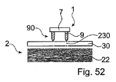
・近位端部と遠位端部との間で延在し、固体の状態の熱可塑性材料を含む第1の物体を設けるステップ。 • Providing a first body extending between the proximal end and the distal end and comprising a thermoplastic material in a solid state.
・近位面を含む第2の物体を設けるステップ。
・熱可塑性材料の流動部分が流動可能になり第2の物体の構造に貫入するまで、機械的押圧力および熱可塑性材料を液化可能な機械的励起を第1の物体と第2の物体とのうち少なくとも1つに対して加えるステップ。
- Providing a second object comprising a proximal surface.
applying a mechanical pressing force and a mechanical excitation capable of liquefying the thermoplastic material between the first body and the second body until the flowable portion of the thermoplastic material becomes flowable and penetrates the structure of the second body; adding to at least one of them.
・機械的励起を停止し熱可塑性材料を再固化させて、第1の物体と第2の物体との間にポジティブフィット接続を生じるステップ。 - Ceasing the mechanical excitation and allowing the thermoplastic material to re-solidify to create a positive fit connection between the first and second objects.
本方法はその基本的な実施形態において、設けられた第2の物体が低密度の領域を含むこと、および、遠位端部が、熱可塑性材料が流動可能になる前に少なくとも部分的に低密度の領域に貫入することを特徴とする。 The method comprises in its basic embodiment the second object provided comprising a region of low density and the distal end portion being at least partially low density before the thermoplastic material is flowable. Characterized by penetrating areas of density.
熱可塑性材料が流動可能になる前に遠位端部によって少なくとも部分的に貫入される低密度の領域は、必ずしも第2の物体の低密度の領域でなくてもよい。これはまた、第1の物体が第2の物体の最も密度の低い領域において必ずしも固定されないことを表す。 The region of low density that is at least partially penetrated by the distal end before the thermoplastic material is allowed to flow is not necessarily the region of low density of the second object. This also means that the first object is not necessarily fixed in the least dense area of the second object.
たとえば、遠位端部によって少なくとも部分的に貫入される低密度の領域は、たとえば、第1の物体の露出面を形成する、さらに低密度の領域のための基部を形成可能である。そのような実施形態は、たとえば、車体の一部が第1の物体の一部を形成し、カバーが第2の物体を形成する場合に存在可能である。 For example, a region of low density that is at least partially penetrated by the distal end can form a base for a region of further low density that, for example, forms the exposed surface of the first object. Such an embodiment can exist, for example, if the body part forms part of a first object and the cover forms a second object.
好ましい実施形態は、以下の特徴のうちの少なくとも1つを含んでもよい。
・機械的励起を加えるステップは、近位面に対して角度を有して延びる軸に沿って機械的振動を加えることを含み、設けられた第2の物体の近位面は、低密度である。
Preferred embodiments may include at least one of the following features.
- the step of applying mechanical excitation comprises applying mechanical vibration along an axis extending at an angle to the proximal surface, wherein the proximal surface of the provided second object is sparsely populated; be.
少なくとも本実施形態では、低密度の領域は、近位面に対して直角に、すなわち、近位面から遠位方向に延在する。この低密度の領域は、低密度の近位領域でもよい。低密度の近位領域は、近位面を含んでもよい。 In at least this embodiment, the regions of low density extend perpendicular to the proximal surface, i.e., distally from the proximal surface. This region of low density may be a proximal region of low density. The proximal region of low density may include a proximal face.
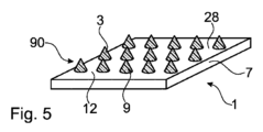
・設けられた第1の物体は、第1の物体本体と、少なくとも1つの第1の物体本体の遠位方向の突出部とを含む。突出部は、遠位端部を形成し、固体の状態の熱可塑性材料を含む。 - the provided first object comprises a first object body and at least one distal projection of the first object body; A projection forms the distal end and includes a thermoplastic material in a solid state.
本実施形態では、熱可塑性材料が流動可能になる前に少なくとも部分的に低密度の領域に貫入するのは、1つの突出部(または複数の突出部)である。さらに、第1の物体は、熱可塑性材料を再固化させるステップの後で突出部分を含み、突出部分は、少なくとも部分的に低密度の領域に貫入する。 In this embodiment, it is the protrusion (or protrusions) that at least partially penetrates the region of low density before the thermoplastic material is able to flow. Further, the first object includes protruding portions after the step of resolidifying the thermoplastic material, the protruding portions at least partially penetrating the regions of low density.
・少なくとも局所的に低密度の領域の圧縮強度を変化させるステップ。
ここでいう「圧縮強度」という用語は、ある領域が変位される前に、すなわち、当該領域を規定する材料が(さらに)圧縮される前に領域によって生成される、1平方ミリメートルあたりの最大の力を表す。それゆえ、圧縮強度はまた、さらなる圧縮に対する抵抗または剛性とみなすこともできる。
- Varying the compressive strength of the region of low density at least locally.
As used herein, the term "compressive strength" refers to the maximum strength per square millimeter produced by a region before it is displaced, i.e. before the material defining that region is (further) compressed. represent power. Therefore, compressive strength can also be viewed as resistance or stiffness to further compression.
圧縮強度は、たとえば、応力ひずみ実験で測定されるような応力に相当する。
圧縮強度(応力)の変化は、加えられた機械的押圧力および機械的励起が熱可塑性材料を液化させることができるようなものでもよい。言い換えると、低密度の領域は、圧縮強度を変えることなく、機械的押圧力および機械的励起を加えるステップにおいて熱可塑性材料を液化させるために必要な圧縮強度を提供することができないようなものでよい。
Compressive strength corresponds to stress as measured, for example, in stress-strain experiments.
The change in compressive strength (stress) may be such that the applied mechanical pressing force and mechanical excitation can cause the thermoplastic material to liquefy. In other words, the regions of low density are such that they are unable to provide the necessary compressive strength to liquefy the thermoplastic material in the steps of applying mechanical pressing force and mechanical excitation without altering the compressive strength. good.
少なくとも局所的に低密度の領域の圧縮強度を変更するステップは、臨界圧縮強度が生成されるまで、すなわち、機械的押圧力および機械的励起を用いて熱可塑性材料を液化させるために必要な圧縮強度に到達するまで、行うことが可能である。 Altering the compressive strength of the region of low density at least locally until a critical compressive strength is produced, i.e., the compression required to liquefy the thermoplastic material using mechanical pressing force and mechanical excitation. It can be done until the intensity is reached.
機械的押圧力および機械的励起を加えるステップにおいて熱可塑性材料を液化させるために必要な圧縮強度の変化は、加えられる機械的押圧力および機械的励起によって決まることがある。 The change in compressive strength required to liquefy the thermoplastic material in the step of applying mechanical pressing force and mechanical excitation may depend on the applied mechanical pressing force and mechanical excitation.
特に、圧縮強度の変化は、圧縮強度の増加である。
多くの実施形態では、圧縮強度の増加は、少なくとも低密度の領域の局所圧縮によって引き起こされる。言い換えると、本方法は、少なくとも局所的に低密度の領域を圧縮するステップを含んでもよい。
In particular, the change in compressive strength is an increase in compressive strength.
In many embodiments, the increase in compressive strength is caused by local compression of at least regions of low density. In other words, the method may comprise compressing the region of low density at least locally.
特に、圧縮強度は、低密度の領域の高密度化によって決まることがあり、当該高密度化は、圧縮によって引き起こされる。 In particular, compressive strength may depend on the densification of regions of low density, which is caused by compression.
低密度の領域は、熱可塑性材料を液化するために加えられる機械的押圧力によって圧縮可能である。 The areas of low density are compressible by a mechanical pressing force applied to liquefy the thermoplastic material.
熱可塑性材料を液化するために機械的押圧力および機械的励起を加えるステップでは、加えられた機械的押圧力および機械的励起を用いた熱可塑性材料の液化に十分な圧縮強度の増加を引き起こした低密度の領域の圧縮の後で、機械的励起を加える、すなわち、スイッチを入れることが可能である。 Applying a mechanical pressing force and mechanical excitation to liquefy the thermoplastic material caused an increase in compressive strength sufficient to liquefy the thermoplastic material using the applied mechanical pressing force and mechanical excitation. After compression of the low density regions, it is possible to apply, ie switch on, a mechanical excitation.
少なくとも局所的に低密度の領域の圧縮強度を変更するステップ、または、少なくとも局所的に低密度の領域を圧縮するステップによって、本方法は、第1の物体と第2の物体との間のポジティブフィット接続による第1の物体の第2の物体への接続に好適になる。この方法では、ポジティブフィット接続は、第1の物体が第2の物体に接合される前に、低密度の領域に相当する第2の物体の領域において確立される。 By varying the compressive strength of the at least locally low-density region or compressing the at least locally low-density region, the method provides a positive pressure between the first object and the second object. It is suitable for connecting a first object to a second object by means of a fit connection. In this method, a positive fit connection is established in areas of the second object that correspond to areas of low density before the first object is joined to the second object.
実施形態では、低密度の領域は、基本的にインコヒーレント材料、すなわち、たとえば圧縮力などの外力にさらされると相互作用が弱くなるだけである構成要素を含む材料で形成される。 In embodiments, the regions of low density are formed of an essentially incoherent material, ie, a material comprising components that interact only weakly when subjected to external forces, eg, compressive forces.
互いにある程度移動可能な力がかかっている状態の繊維を含む、またはこれらで構成される材料は、インコヒーレント材料の例である。 A material comprising or consisting of fibers that are under some force that allows them to move relative to each other is an example of an incoherent material.
構成要素間の弱い相互作用が、設けられたような第2の物体に存在している必要はない。そうではなく、この弱い相互作用は、方法が行われている間に第2の物体に作用する力の結果生じることがある。そのような力は、構成要素間の接続を切断させることがある。たとえば、材料は、バインダ材料によって局所的に接続された繊維、たとえば、熱処理と組合わされて材料の特定の密度を規定する樹脂粉末または溶融繊維でもよい。 Weak interactions between components need not exist in the second body as provided. Instead, this weak interaction may result from forces acting on the second object while the method is being performed. Such forces can break connections between components. For example, the material may be fibers locally connected by a binder material, such as resin powder or molten fibers that, combined with heat treatment, define a particular density of the material.
多くの実施形態では、第2の物体内に貫入する、またはこれを貫通する遠位端部は、1つまたは複数の突出部である。 In many embodiments, the distal end that penetrates into or through the second object is one or more protrusions.
本明細書では、物体、製品、装置などの内部の相対的な配置、および物体間、製品間、装置間などの相対的な配置は、第1の物体の中間に位置する起点に対して与えられる。他の態様で説明されていない場合、起点の最も近くに配置された物体の表面を物体の近位面と呼び、物体の対応する表面、たとえば、物体の反対側に配置された対応する面を遠位面と呼ぶ。第1の物体の場合、第1の物体が接触させられる、および/または場合によっては、接合される他の物体の近位面に向けられた面は、第1の物体の遠位面と呼ばれる。言い換えると、近位面は常に、方法が行われている間は遠位面に接触させられている、および/または、場合によっては接合されている。その結果、1つ(または複数)の突出部が第1の物体上で遠位方向に配置される。 As used herein, relative placement within objects, products, devices, etc., and relative placement between objects, products, devices, etc. is given with respect to an origin located in the middle of the first object. be done. Unless otherwise described, the surface of the object located closest to the origin is referred to as the proximal surface of the object, and the corresponding surface of the object, e.g., the corresponding surface located on the opposite side of the object. called the distal plane. In the case of a first object, the surface facing the proximal surface of the other object with which the first object is brought into contact and/or possibly joined is called the distal surface of the first object. . In other words, the proximal surface is always in contact with and/or possibly joined to the distal surface during the method. As a result, one (or more) protrusions are distally disposed on the first object.
多くの実施形態では、突出部分は、熱可塑性材料を再固化させるステップの後で残される、突出部の一部があることを意味する。この一部、つまり突出部分は、第2の物体の最も外側の領域に制限されないが、第2の物体の体積内に延在する。残されるということは、突出部分を規定する材料が第2の物体の構造内に貫入していないことを意味する。 In many embodiments, protruding portion means that there is a portion of the protruding portion left after the step of resolidifying the thermoplastic material. This portion, or protruding portion, is not restricted to the outermost region of the second object, but extends within the volume of the second object. By left is meant that the material defining the projecting portion has not penetrated into the structure of the second object.
突出部分が第2の物体に貫入する距離は、応用例によって決まる。しかしながら、第2の物体の近位面に直角な突出部分の貫入深さは、第2の物体の近位面に平行な方向の突出部分の延在部よりも大きな場合がある。これは、近位面に直角の延在部と近位面に平行な延在部との比率が少なくとも1、特に1~5、たとえば1.5~4または2~3であることを表す。 The distance that the protruding portion penetrates the second object depends on the application. However, the depth of penetration of the protruding portion perpendicular to the proximal face of the second object may be greater than the extension of the protruding portion in the direction parallel to the proximal face of the second object. This means that the ratio of the extension perpendicular to the proximal plane and the extension parallel to the proximal plane is at least 1, in particular 1-5, eg 1.5-4 or 2-3.
突出部分のわずかに異なる定義および/または突出部分を特徴付ける他の特徴は、以下の通りである。 A slightly different definition of a protrusion and/or other features that characterize a protrusion are as follows.
本明細書では、低密度の面または領域は、多孔性であること、線維性であること、および/または柔軟であることのうち少なくとも1つであること、ならびに/または、複数の構造、空隙、開口部などを含むことを表す。当該構造、空隙、および/または開口部は、減衰可能である、特に、たとえば音響減衰および/または振動減衰可能である。 As used herein, a low-density surface or region is at least one of porous, fibrous, and/or flexible, and/or has a plurality of structures, voids, , openings, etc. The structures, voids and/or openings are dampable, in particular sound damping and/or vibration damping, for example.
実施形態では、特に詳細に以下で説明するような低密度の領域を圧縮するステップを含む方法の実施形態では、低密度の領域は、機械的押圧力および機械的励起を加えるステップの間に、それに沿って機械的押圧力が加えられる軸に沿って圧縮可能である。このような圧縮によって、低密度の領域の厚さを、たとえば10~90%低減可能である。この厚さは、機械的押圧力が加えられる軸に沿って測定される。特に、厚さを30~90%、たとえば60~80%、または20~80%、たとえば30~70%低減可能である。 In embodiments, particularly in embodiments of the method comprising compressing the region of low density as described in greater detail below, the region of low density undergoes, during the steps of applying mechanical pressing force and mechanical excitation, It is compressible along an axis along which a mechanical pressing force is applied. Such compression can reduce the thickness of the low density regions by, for example, 10-90%. This thickness is measured along the axis along which the mechanical pressing force is applied. In particular, the thickness can be reduced by 30-90%, such as 60-80%, or 20-80%, such as 30-70%.
圧縮比は、低密度の領域の圧縮の場合の他の測定値である。特に、圧縮比は、局所圧縮が考慮される場合は好適な測定値である。 突出部の領域における圧縮比は、1.1~10、特に1.25~5、たとえば、1.4~3.3でよい。 Compression ratio is another measure for compression of areas of low density. In particular, compression ratio is a good measure when local compression is considered. The compression ratio in the region of the protrusions may be between 1.1 and 10, especially between 1.25 and 5, for example between 1.4 and 3.3.
低密度の領域を形成する材料または材料組成は、局所的に圧縮可能になるようなものでよい。たとえば、第1の物体の突出部または第2の物体に取付けられた製品の突出部領域によって発生するような局所的な機械的負荷は、低密度の領域の局所圧縮を引き起こすことがある。 The material or material composition forming the low density region may be such that it is locally compressible. For example, localized mechanical loads, such as those generated by protrusions of a first object or protrusion areas of a product attached to a second object, can cause localized compression of areas of low density.
低密度の領域の局所的なおよび/または「全体的な」圧縮は、弾性圧縮でよい、または主として弾性圧縮でもよい。これは、圧縮を引き起こす機械的負荷を取り除いた後で圧縮が緩和する(消滅する)、または、ほとんど緩和することを意味する。言い換えると、設けられた第2の物体は、弾性変形可能でもよい。また、弾性圧縮可能な第2の物体に対する接合方法の適用可能性は、硬い、すなわち圧縮可能でない物体、または、塑性的に変形する、すなわち、不可逆的な部分を含む物体のみ、たとえば中空構造板(HCB)を利用した公知の接合方法と比べると、重要な利点である。 Local and/or "global" compression of areas of low density may be elastic compression or may be predominantly elastic compression. This means that the compression relaxes (disappears) or almost relaxes after the mechanical load that causes it is removed. In other words, the provided second object may be elastically deformable. Also, the applicability of the joining method to elastically compressible second bodies only applies to rigid, i.e. incompressible bodies, or to bodies that plastically deform, i.e. contain irreversible parts, e.g. This is a significant advantage compared to known joining methods using (HCB).
それゆえ、低密度の面または領域は、多くの実施形態では、多孔性であること、線維性であること、柔軟であることのうち少なくとも1つ、および/または、複数の構造、空隙、開口部などを含む面もしくは領域だけでなく、圧縮可能、特に弾性圧縮可能な面または領域を表す。さらに、面または領域は局所的に圧縮可能である、すなわち、異なる態様で圧縮される領域を含むことができるように圧縮可能である。 Therefore, the low density surface or region, in many embodiments, is at least one of porous, fibrous, flexible, and/or has a plurality of structures, voids, openings. Compressible, in particular elastically compressible, surfaces or regions, as well as surfaces or regions containing parts or the like. Further, the surface or region is locally compressible, ie, compressible so that it can contain regions that compress differently.
圧縮は、圧縮強度の増加につながることがある。
実施形態では、第2の物体は第2の物体組成で構成されてもよく、第2の物体の構造は、本質的に当該組成によって形成されてもよい。たとえば、構造は孔、空隙、チャネルなどでもよい。
Compression can lead to increased compressive strength.
In embodiments, the second body may be composed of a second body composition and the structure of the second body may be formed essentially by said composition. For example, the structures may be pores, voids, channels, and the like.
たとえば、第2の物体は繊維、布、発泡樹脂製品、多孔性材料、厚紙などを含んでもよい、または、これらで構成されてもよい。第2の物体は一連の層で形成されてもよく、それらの層のうち一部は、剛性であること、非圧縮性であること、高密度である(すなわち、孔、空隙、チャネルなどの密度が低い)こと、および耐負荷であることのうち少なくとも1つでよい。第2の物体を形成する第2の物体および/または層は、位置に依存しない組成を有してもよい。さらにまたは代替的に、一連の層は位置に依存しなくてもよい。 For example, the second object may comprise or consist of fibers, cloth, foam products, porous materials, cardboard, and the like. The second body may be formed of a series of layers, some of which are rigid, incompressible, dense (i.e., contain pores, voids, channels, etc.). low density) and load bearing. The second body and/or layers forming the second body may have a position-independent composition. Additionally or alternatively, the sequence of layers may be position independent.
特に、熱可塑性材料を再固化させるステップの後に突出部が生じる方法の実施形態では、構造は、非常に効果的な固定、すなわち、第2の物体の表面上だけでなくその体積における固定も可能になるようになっている。しかしながら、非常に効果的な固定のための特定の構造が必要でない実施形態も想定可能である。以下で説明するような近位最上層を含む実施形態、または以下で説明するような、第3の物体の取付けを目的とした、第3の物体が突出部分の低密度の領域内への少なくとも部分的な貫入を保証する実施形態は、そのような実施形態の例である。 In particular in embodiments of the method in which protrusions occur after the step of re-solidifying the thermoplastic material, the structure allows for very effective anchoring, i.e. anchoring not only on the surface of the second object, but also in its volume. is designed to be However, embodiments are also conceivable in which no particular structure is required for highly effective fixation. Embodiments comprising a proximal top layer as described below, or a third object at least within a low density region of the protruding portion for attachment of the third object as described below. Embodiments that ensure partial penetration are examples of such embodiments.
さらにまたは代替的に、たとえば第2の物体の表面を粗くすることによって、および/または、そのような構造を生成する第2の物体のための生産プロセスを使用して、第2の物体の構造を生成することも想定可能である。 Additionally or alternatively, the structure of the second object, for example by roughening the surface of the second object and/or using a production process for the second object that produces such structure. It is also conceivable to generate
機械的励起は、機械的押圧力を加える前後に、またはそれと同時に開始可能である。機械的励起の前に開始する機械的押圧力は、接合の質という点で、特に生成される接合の深さおよび接合強度の点で、好ましいことがある。しかしながら、機械的励起によって1つ(または複数)の突出部の貫入挙動を最適化しやすくする構成も想定可能である。これらの構成のうち一部については、以下で説明する。 Mechanical excitation can be initiated before, after, or simultaneously with the application of the mechanical pressing force. A mechanical pressing force starting before mechanical excitation may be preferable in terms of bond quality, particularly in terms of the depth and bond strength of the bond produced. However, configurations are also conceivable in which mechanical excitation facilitates optimizing the penetration behavior of the projection(s). Some of these configurations are described below.
機械的押圧力は、機械的励起を停止した後で熱可塑性材料の再固化に十分な時間にわたって持続可能である。 The mechanical pressing force can be sustained for a period of time sufficient to re-solidify the thermoplastic material after mechanical excitation is discontinued.
機械的押圧力は、機械的押圧力および機械的励起を加えるステップの間、場合によっては熱可塑性材料の再固化の間に変化してもよい。 The mechanical pressing force may change during the steps of applying the mechanical pressing force and the mechanical excitation, possibly during the resolidification of the thermoplastic material.
第1の物体の熱可塑性材料は、機械的励起によって生成される機械的エネルギーの吸収によって、特に物体が互いに押圧されている間は機械的発振/振動によって、流動可能になることが可能である。たとえば、機械的振動エネルギーは、第1の物体および/または第2の物体を通じて第1の物体の熱可塑性材料および第2の物体の材料によって生成された界面に結合可能である。界面では、外部摩擦、そしておそらく内部摩擦によって、熱可塑性材料が加熱し流動可能になる。流動可能な熱可塑性材料はその後、加えられた圧力によって、第2の物体の構造内に押圧される。 The thermoplastic material of the first body can become flowable by absorption of mechanical energy generated by mechanical excitation, especially by mechanical oscillation/vibration while the bodies are pressed together. . For example, mechanical vibrational energy can be coupled through the first body and/or the second body to the interface created by the thermoplastic material of the first body and the material of the second body. At the interface, external friction, and possibly internal friction, causes the thermoplastic material to heat up and become flowable. The flowable thermoplastic material is then pressed into the structure of the second object by the applied pressure.
当該界面を形成する第1の物体および/または第2の物体の一部は、エネルギー誘導部として機能可能なプロファイルを含んでもよい、すなわち、エネルギー吸収および発熱が、自動的にそれぞれの界面上またはその周囲に集中する。 A portion of the first body and/or the second body forming the interface may comprise a profile capable of acting as an energy director, i.e., energy absorption and heat generation automatically occur on the respective interface or concentrate around it.
一実施形態では、設けられた第2の物体は、近位面からの距離の関数として増加する密度プロファイルを含む。特に、密度は、近位面に直角の遠位方向に増加する。 In one embodiment, the second object provided includes a density profile that increases as a function of distance from the proximal surface. In particular, the density increases in the distal direction perpendicular to the proximal plane.
この密度の増加は、連続的または段階的でもよい。
第2の物体が近位面と遠位面との間で延在する場合、密度は第2の物体の制限された範囲にわたってのみ増加可能である。
This density increase may be continuous or stepwise.
If the second body extends between the proximal and distal surfaces, the density can only increase over a limited extent of the second body.
低密度の領域は近位面に位置してもよい、低密度の領域は遠位面に位置してもよい、または、低密度の領域は、近位面と遠位面との間のどこかに位置してもよい。 The region of low density may be located on the proximal plane, the region of low density may be located on the distal plane, or the region of low density may be located anywhere between the proximal and distal planes. It can be located anywhere.
たとえば、低密度の第2の領域、近位面に位置する領域と遠位面に位置する他の領域とを想定可能である。 For example, it is possible to envisage a second region of low density, one located in the proximal plane and another located in the distal plane.
一実施形態では、第2の物体は、近位面に位置する低密度の領域(すなわち、低密度の領域が近位領域である)と、低密度の領域の遠位方向に位置する他の高密度の領域とを含む。 In one embodiment, the second object comprises a region of low density located in the proximal plane (i.e., the region of low density is the proximal region) and another region of low density located distal to the region of low density. including areas of high density.
そうすると、低密度の領域は、高密度の領域よりも(すなわち、他の領域よりも)密度の低い領域である。 A region of low density is then a region that is less dense than a region of high density (ie, than other regions).
高密度の領域における「高密度」という用語または高密度の領域は、他の領域の密度、特に低密度の領域の密度に対する当該領域の密度を表すために使用される。しかしながら、この用語は必ずしも、「高密度」の領域が複数の構造、空隙、開口部などを含まないことを表すわけではない。また、当該領域が圧縮可能でないこと、または当該領域を圧縮して臨界密度および/または圧縮強度(詳細は以下で説明)を生成する必要がないことを表すわけでもない。そうではなく、当該領域は、低密度の領域にまつわる全ての物理的特性を有してもよい。しかしながら、第2の物体は、当該「高密度」の領域よりも密度の低い少なくとも1つの領域を含む。 The term "high density" in a high density region or high density region is used to denote the density of the region relative to the density of other regions, particularly the density of low density regions. However, the term does not necessarily imply that a "dense" region does not contain multiple structures, voids, openings, and the like. Nor does it imply that the region is not compressible or that the region need not be compressed to produce a critical density and/or compressive strength (discussed in more detail below). Instead, the regions may have all the physical properties associated with regions of low density. However, the second object includes at least one region that is less dense than the "dense" region.
他の実施形態では、他の領域が低密度の領域の遠位方向に配置されており、この低密度の領域は近位面に位置していない。 In other embodiments, other regions are located distal to the region of low density and the region of low density is not located on the proximal plane.
代替的にまたは他の領域に加えて、低密度の領域は、近位面からの距離の関数として増加する密度を有してもよい。 Alternatively, or in addition to other regions, the regions of low density may have densities that increase as a function of distance from the proximal face.
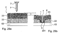
一実施形態では、設けられた第2の物体は近位最上層を含み、低密度の領域が近位最上層の遠位方向に配置されており、方法は、熱可塑性材料の液化の前に突出部に近位最上層を通過させるステップを含む。 In one embodiment, the provided second object comprises a proximal top layer, the region of low density being disposed distally of the proximal top layer, the method comprising: prior to liquefaction of the thermoplastic material The step of passing the protrusion through the proximal top layer.
近位最上層は、第2の物体の必須の部分、たとえば、「中空コア」状の板のカバー層でもよく、低密度の領域は、少なくとも部分的にコア領域、たとえば、(人工)皮革で形成された装飾および/もしくは機能カバー層などのカバー層、または他の外装材などを充填する。 The proximal top layer may be an integral part of the second object, e.g. the cover layer of a plate in the form of a "hollow core", the lower density region being at least partly a core region, e.g. (artificial) leather. Fill with cover layers, such as formed decorative and/or functional cover layers, or other facing materials and the like.
近位最上層は、方法の他のステップで設けられてもよい、および、方法のさらに他のステップで第2の物体の近位面上に位置してもよい。特に、近位最上層は、以下で説明するような第3の物体、たとえば、金属シート、ホイル、またはカバー層でもよい。しかしながら、たとえば、上述のようなカバー層または外装でもよい。 The proximal top layer may be provided in another step of the method and may be located on the proximal surface of the second object in yet another step of the method. In particular, the proximal top layer may be a third object, such as a metal sheet, foil, or cover layer, as described below. However, it may also be a cover layer or a sheath, for example as described above.
一般に、近位最上層の密度は低密度の領域の密度よりも高い。
近位最上層は、他の高密度の領域でもよい。
In general, the density of the proximal top layer is higher than that of the less dense regions.
The proximal top layer may be other dense regions.
近位最上層は、上述の第2の物体のいずれかの密度プロファイルに寄与してもよい、または、そのような密度プロファイルに対して付加的なものでもよい。 The proximal top layer may contribute to the density profile of any of the second bodies described above, or may be additive to such density profile.
特に、低密度の領域、存在する場合は、他の領域のいずれかの密度プロファイルに対して付加的なものでもよい。 In particular, regions of low density, if present, may be additive to the density profile of any of the other regions.
高密度の領域が必要でない構成を想定可能である。たとえば、第1のステップで、遠位端部が部分的に低密度の領域に貫入するように、機械的押圧力を加えることができる。続く第2のステップでは、熱可塑性材料が流動可能になるような振幅で、機械的振動を加えることができる。さらに、第1の物体が第2の物体に貫入する速度を低減させるために、機械的押圧力を低減可能である。 It is possible to envision a configuration in which a high density area is not required. For example, in a first step, a mechanical pressing force can be applied so that the distal end partially penetrates the region of low density. In a subsequent second step, mechanical vibration can be applied with an amplitude that allows the thermoplastic material to flow. Furthermore, the mechanical pressing force can be reduced in order to reduce the speed at which the first object penetrates the second object.
代替的にまたはさらに、近位最上層または低密度の領域の近位方向に配置された他の層は、突出部が当該層に押込まれると熱可塑性材料を温めることができる。このように温めることは熱可塑性材料の液化に十分ではないが、機械的押圧力および熱可塑性材料を液化可能な機械的励起を加えるステップで必要な機械的押圧力および機械的励起を低減させる。 Alternatively or additionally, the proximal top layer or other layer placed proximally of the region of low density can warm the thermoplastic material when the protrusions are pushed into that layer. Although such warming is not sufficient to liquefy the thermoplastic material, it reduces the mechanical pressing force and mechanical excitation required in the step of applying the mechanical pressing force and mechanical excitation capable of liquefying the thermoplastic material.
上述のようないずれかの密度プロファイルを有する第2の物体を含む、および場合によっては近位最上層を含む実施形態では、第1の物体の遠位端部(1つ(または複数)の突出部のこともある)が、熱可塑性材料が流動可能になる前に少なくとも部分的に低密度の領域に貫入する。 In embodiments comprising a second body having any density profile as described above, and optionally including a proximal top layer, the distal end of the first body (one (or more) protrusions At least partially penetrates the low density region before the thermoplastic material is able to flow.
密度プロファイルは、低密度の領域における第2の物体の密度が熱可塑性材料の液化に必要な圧力を生成するほど高くならないようにすることができる。特に、低密度の領域の密度は、機械的押圧力および機械的励起が15秒未満または10秒未満、たとえば5秒または2秒未満加えられると熱可塑性材料を液化させるほど高くはない。特に、当該密度は、機械的押圧力および機械的励起が0.1秒~1秒、たとえば0.1~0.5秒間加えられると液化を引き起こすほど高くはない。 The density profile may be such that the density of the second body in regions of low density is not so high as to create the pressure required to liquefy the thermoplastic material. In particular, the density of the regions of low density is not so high as to liquefy the thermoplastic material when mechanical pressing force and mechanical excitation are applied for less than 15 seconds or less than 10 seconds, such as less than 5 seconds or 2 seconds. In particular, the density is not so high as to cause liquefaction when mechanical pressing force and mechanical excitation are applied for 0.1 seconds to 1 second, for example 0.1 to 0.5 seconds.
代替的にまたはさらに、熱可塑性材料の液化に必要な機械的励起を加えるステップは、低密度の領域を通って第1の物体の遠位端部に貫入した後に開始する。 Alternatively or additionally, applying the mechanical excitation necessary to liquefy the thermoplastic material begins after penetrating the distal end of the first object through the region of low density.
第2の物体および/または低密度の領域のいずれかの密度プロファイルに適用可能な実施形態では、方法は、熱可塑性材料の液化に必要な臨界密度が生成されるように、低密度の領域を少なくとも局所的に加えるステップを含む。 In embodiments applicable to the density profile of any of the second body and/or the region of low density, the method includes: At least locally adding.
臨界密度は、臨界圧縮強度が確立される密度に相当する。
少なくとも局所的に低密度の領域を圧縮するステップは、機械的押圧力および熱可塑性材料を液化可能な機械的励起を加えるステップのサブステップでもよい。
Critical density corresponds to the density at which critical compressive strength is established.
Compressing the region of low density at least locally may be a substep of applying a mechanical pressing force and a mechanical excitation capable of liquefying the thermoplastic material.
特に、低密度の領域を少なくとも局所的に臨界密度まで圧縮するステップは、機械的励起を加えるステップの前でもよい。 In particular, the step of at least locally compressing the region of low density to a critical density may precede the step of applying the mechanical excitation.
確立されることが必要な臨界密度は、液化が発生した後で機械的押圧力および機械的励起を加える目標時間によって決まる。 The critical density that needs to be established depends on the target time to apply the mechanical pressing force and mechanical excitation after liquefaction occurs.
圧縮は、全体的な圧縮および/または局所的な圧縮でもよい。
全体的な圧縮は、1つ(または複数)の突出部の周囲だけではなくより広い領域にわたって低密度の領域を圧縮することによって、確立することができる。たとえばこれは、第1の物体本体によって行うことができる、特に、その遠位面またはその一部によって行うことができる。特に、第1の物体本体は、少なくとも部分的に低密度の領域に貫入可能である。
Compression may be global compression and/or local compression.
Global compression can be established by compressing areas of low density over a wider area than just around one (or more) protrusions. For example, this can be done by the first object body, in particular by its distal face or part thereof. In particular, the first body of matter is at least partially penetrable into regions of low density.
代替的に、全体的な圧縮は、第1の物体を使用して第2の物体に取付けられた他の物体によって同じ態様で確立可能である。 Alternatively, global compression can be established in the same manner by other bodies attached to the second body using the first body.
局所圧縮は、1つ(または複数)の突出部によって、たとえば、1つ(または複数)の突出部がその内部に押し進められる低密度の領域の1つ(または複数)の部分を変位させることによって、確立することができる。 Localized compression is achieved by one (or more) protrusions, for example by displacing one (or more) portions of a region of low density into which the one (or more) protrusions are forced. , can be established.
実験によると、特にインコヒーレント材料、たとえば繊維性材料から形成されるパネルは、力(負荷)がそのような材料に局所的に加えられると驚くべき応力ひずみ挙動を示すことが分かった。ここでいう「局所的に」は、力(負荷)がインコヒーレント材料によって形成された製品の領域に加えられることを表し、当該領域は、当該製品の対応する延在部よりも大幅に小さい。 Experiments have shown that especially panels formed from incoherent materials, such as fibrous materials, exhibit surprising stress-strain behavior when forces (loads) are locally applied to such materials. "Locally" here means that the force (load) is applied to an area of the product formed by the incoherent material, which area is significantly smaller than the corresponding extension of the product.
以下の挙動は、押圧力を製品に対して直角に局所的に加えると、インコヒーレント材料の様々な製品において観察された。 The following behavior was observed in various products of incoherent material when a pressing force was locally applied perpendicular to the product.
・ひずみに対する応力のほぼ線形の依存性は、ひずみを製品に加えるとすぐに観察可能である。当該ほぼ線形の依存性は、線形の依存性の第1の領域を形成する。第1の領域におけるひずみに対する応力の線形の依存性は、第1の傾きを有する直線によって近似可能である。 • An approximately linear dependence of stress on strain is observable as soon as strain is applied to the product. The approximately linear dependence forms a first region of linear dependence. A linear dependence of stress on strain in the first region can be approximated by a straight line with a first slope.
・ひずみに対する応力の依存性が、ひずみがさらに増大されると線形の依存性の第1の領域を着実に辿る遷移領域。 • A transition region in which the stress dependence on strain steadily tracks the first region of linear dependence as strain is further increased.
・ひずみがさらに増大されると、ひずみに対する応力のほぼ線形の依存性を有する第2の領域が、遷移領域を辿る。当該第2の領域におけるひずみに対する応力のほぼ線形の依存性は、第2の傾きを有する直線によって近似可能であり、第2の傾きは第1の傾きよりも大きい。 - When the strain is further increased, a second region with an approximately linear dependence of stress on strain follows the transition region. The substantially linear dependence of stress on strain in the second region can be approximated by a straight line with a second slope, the second slope being greater than the first slope.
押圧力(負荷)は、4~200m2の妥当な表面積を有するインテンダによって加えられた。しかしながら、先に要約した挙動が、妥当な表面積の範囲に制限されると示唆しているわけではない。 The pushing force (load) was applied by an intender with a reasonable surface area of 4-200 m 2 . However, this does not imply that the behavior summarized above is limited to a range of reasonable surface areas.
この挙動のおかげで、広範囲のインコヒーレント材料が、機械的押圧力および機械的励起、特に振動を用いた、熱可塑性材料の液化に依存する接合方法での使用に驚くほど好適である。なぜなら、広範囲のインコヒーレント材料は、線形の依存性の第2の領域が存在するだけで、熱可塑性材料の液化に必要な応力レベル、すなわち、臨界圧縮強度に到達するからである。 This behavior makes a wide range of incoherent materials surprisingly suitable for use in joining methods that rely on liquefaction of thermoplastic materials using mechanical pressing force and mechanical excitation, especially vibration. This is because a wide range of incoherent materials reach the stress level required for liquefaction of thermoplastic materials, ie the critical compressive strength, only in the presence of a second region of linear dependence.
それゆえ、低密度の領域を圧縮するステップは、材料の応力ひずみ挙動が線形の依存性の第2の領域内になるようなものでよい。 Therefore, the step of compressing the region of low density may be such that the stress-strain behavior of the material is within the second region of linear dependence.
応力ひずみ図において第1の傾きと第2の傾きとが交差するひずみ値は、観察された応力ひずみ挙動の固有値である。 The strain value at which the first and second slopes intersect in the stress-strain diagram is the eigenvalue of the observed stress-strain behavior.
低密度の領域を圧縮するステップは、少なくとも材料が当該固有値まで圧縮されるようなものでよい。 Compressing the regions of low density may be such that the material is at least compressed to the characteristic value.
代替的にまたはさらに、当該固有値は、機械的押圧力および熱可塑性材料を液化可能な機械的励起を加えるステップにおいて使用される機械的励起を加える、すなわち、このような機械的励起を作動させるための低閾値を規定可能である。言い換えると、機械的励起は、当該固有ひずみ値を引き起こす押圧力が加えられると作動可能である。 Alternatively or additionally, the eigenvalue applies a mechanical pressing force and a mechanical excitation used in the step of applying a mechanical excitation capable of liquefying the thermoplastic material, i.e. to actuate such mechanical excitation. A low threshold of can be defined. In other words, the mechanical excitation is operable upon application of a pressing force that induces the intrinsic strain value of interest.
さらに、パネルが本来の形状に戻ることをパネルの孔、開口部などに押圧された液化された熱可塑性材料が妨げない限り、パネルの変形は大半は可逆的なものでよいことが分かった。 Further, it has been found that the deformation of the panel may be largely reversible as long as the liquefied thermoplastic material pressed into the panel's holes, openings, etc. does not prevent the panel from returning to its original shape.
しかしながら、たとえばパネル内に結合されたエネルギーが永久的な高密度化につながるほど高くない場合、低密度の領域の変形が不可逆的な物である構成もある。たとえば、低密度の領域は、方法が行われている間に溶融する繊維を含んでもよい。 However, in some configurations the deformation of the low density areas is an irreversible one, for example if the energy coupled into the panel is not high enough to lead to permanent densification. For example, regions of low density may include fibers that melt while the method is being performed.
接合力という点で、いずれの永久的な変形にも利点がある。
特にインコヒーレント材料では、臨界密度は1つ(または複数)の突出部の周囲にのみ、たとえば、臨界密度に到達するには十分ではない量だけ全体的な圧縮の局所的な増加によって確立可能である。
Any permanent deformation has advantages in terms of bonding strength.
Especially for incoherent materials, the critical density can only be established around one (or more) protrusions, e.g., by locally increasing the overall compression by an amount that is not sufficient to reach the critical density. be.
低密度の領域とは異なる第2の物体の領域、および/または、近位最上層、および/または、第2の物体に取付けられる、もしくは取付けられた任意の物体(たとえば、第3の物体、カバー層、外装材)の少なくとも一部も圧縮可能でよい。それゆえ、これらの領域および/または物体は、熱可塑性材料の液化を好み、第1の物体を第2の物体に接合する方法が行われている間に確立される密度プロファイルに寄与することがある。特に、液化は、そのような領域および/または物体でも起こることがある。 A region of the second object different from the region of low density and/or the proximal top layer and/or any object attached or attached to the second object (e.g., a third object, At least a portion of the cover layer, sheath) may also be compressible. These regions and/or bodies therefore favor liquefaction of the thermoplastic material and may contribute to the density profile established during the method of joining the first body to the second body. be. In particular, liquefaction may also occur in such areas and/or objects.
さらに、第1の物体の遠位端部、特に1つ(または複数)の突出部は、第2の物体内に押し進められると第2の物体の局所圧縮を促進するように設計および配置された構造を有してもよい。特に、当該構造が低密度の領域内に押し進められると少なくとも局所的に圧縮されるのは、低密度の領域である。 Additionally, the distal end of the first object, particularly the protrusion(s), was designed and arranged to promote local compression of the second object when pushed into the second object. It may have a structure. In particular, it is the regions of low density that are at least locally compressed when the structure is forced into the regions of low density.
第1の物体の第2の物体内への押込みは、第2の物体に対する第1の物体の移動、特に(部分的な)貫入移動を含む他のステップで行うことができる。一般に、局所圧縮は、当該構造の設計および配置によって、ならびに当該相対移動によって生じる効果である。 Pushing of the first object into the second object can be done in other steps including movement of the first object relative to the second object, in particular (partial) penetrating movement. In general, local compression is an effect caused by the design and placement of the structures and by the relative movements.
局所圧縮を促進するように設計および配置された構造は、低密度の領域を局所的に圧縮する(すなわち、局所的に密度を増加させる)効果に加えて、以下の効果のうち少なくとも1つを有してもよい。 Structures designed and arranged to promote local compression, in addition to the effect of locally compressing regions of low density (i.e., locally increasing density), have at least one of the following effects: may have.
・第1の物体が低密度の領域内に押込まれると、第2の物体の材料、たとえば繊維が遠位方向に引っ張られる。これによって、特に第2の物体が繊維を含む場合、フェルト化というさらなる効果につながる。 - When a first object is pushed into a region of low density, the material, eg fibers, of the second object is pulled distally. This leads to the additional effect of felting, especially if the second object contains fibres.
・第2の物体の材料が当該構造、それゆえ、1つ(または複数)の突出部に埋込まれる。これによって、使用の際に接合された第1の物体および第2の物体に作用する負荷がより均一に分散する。 - The material of the second object is embedded in the structure and hence the protrusion(s). This distributes the load acting on the joined first and second objects more evenly during use.
溶接部が当該構造または突出部一般と第2の物体との間に形成されるように、および/または、第2の物体の変化が構造的な特性であるように、第2の物体が熱可塑性材料を含む場合、実施形態の質を増大させることができる。溶接部を含む実施形態は、以下で詳細に説明する。 The second body is subjected to heat such that a weld is formed between the structure or protrusion in general and the second body and/or the change in the second body is a structural property. The quality of the embodiment can be increased if it includes a plastic material. Embodiments that include welds are described in detail below.
たとえば、第1の物体は、少なくとも1つのとげ、たとえば捕獲用とげおよび/または引張用とげの形状のとげを含んでもよい。とげは、突出部よりも大幅に小さくてもよい、または、とげが突出部の全体的な形状に寄与するような大きさを有してもよい。後者の場合、突出部の長手方向軸(突出軸とも呼ばれる)に垂直な平面における突出部の断面は、とげの形状に大きく依存することがある、および/または、たとえばとげの存在によって当該平面の位置に依存することがある。 For example, the first object may comprise at least one barb, for example a barb in the form of a trapping barb and/or a pulling barb. The barbs may be significantly smaller than the protrusions or may have a size such that the barbs contribute to the overall shape of the protrusions. In the latter case, the cross-section of the protrusion in a plane perpendicular to the longitudinal axis of the protrusion (also called the protrusion axis) may be highly dependent on the shape of the barbs and/or may vary in that plane, for example due to the presence of barbs. May be location dependent.
突出軸に沿ってずれを有してまたはずれを有さずに配置された複数の先端部は、局所圧縮を促進するように設計および配置された構造の他の例である。 Multiple tips arranged with or without offset along the projection axis are other examples of structures designed and arranged to promote localized compression.
そのようなとげまたは構造一般は、遠位端部を貫入することによって、たとえば、繊維を収集することによって、面する密度を増大させるように配置可能である。言い換えると、とげによって確実に、遠位端部の第2の物体への貫入深さに依存して遠位端部の前方の密度が増加する。 Such barbs or structures in general can be arranged to increase facing density by penetrating the distal end, eg, by collecting fibers. In other words, the barbs ensure an increased density in front of the distal end depending on the depth of penetration of the distal end into the second object.
そのようなとげは、第2の物体が増加する密度プロファイルを含む実施形態でも存在可能である。 Such barbs can also be present in embodiments in which the second object includes an increasing density profile.
低密度の領域の圧縮に加えて、低密度の領域の材料をこれに応じて選択することによって、溶接部を、熱可塑性材料と1つ(または複数)の突出部を取り囲む圧縮領域との間で形成可能である。 In addition to compressing the areas of low density, by selecting the material of the areas of low density accordingly, the weld is formed between the thermoplastic material and the compression area surrounding the protrusion(s). can be formed with
溶接部が形成される実施形態について、以下で詳細に説明する。たとえば、低密度の領域は、熱可塑性プラスチック繊維を含んでもよい。 Embodiments in which welds are formed are described in detail below. For example, the low density regions may include thermoplastic fibers.
低密度の領域の圧縮を含む実施形態の利点は、当該領域が、概ねまたは特定の位置において熱可塑性材料の液化に必要な密度を有する必要がないことである。そうではなく、密度は低くてもよい、および/または均一でもよい。先に指摘したように、必要な密度または密度プロファイルは、第1の物体を第2の物体に接合するプロセスの間に生成可能である。 An advantage of embodiments involving compression of regions of low density is that the regions need not generally or at specific locations have the necessary density to liquefy the thermoplastic material. Instead, the density may be low and/or uniform. As pointed out earlier, the required density or density profile can be generated during the process of joining the first object to the second object.
第2の物体の正確な密度プロファイルとは関係なく、遠位端部または遠位端部の一部、たとえば、複数の突出部のうち少なくとも1つは、第2の物体を近位端部から遠位端部に貫通することができる。その後、第1の物体の第2の物体への接合は、頭部形成凹部を有する近位面を含むアンビルを使用して確立可能である。本実施形態では、方法は、第1の物体の貫入している遠位端部が頭部形成凹部に入るように、アンビルの近位面を第2の物体の遠位端部に対して位置決めするステップを含む。 Regardless of the exact density profile of the second object, the distal end or a portion of the distal end, e.g. The distal end can be penetrated. A bond of the first object to the second object can then be established using an anvil that includes a proximal surface having a head-forming recess. In this embodiment, the method includes positioning the proximal surface of the anvil relative to the distal end of the second object such that the penetrating distal end of the first object enters the head forming recess. including the step of
低密度の領域を有する、たとえば表面で、場合によっては、当該表面に直角の方向に増加する密度を有する第2の物体の例は、自動車、列車、飛行機などの乗り物で、たとえば荷物室で、乗り物の内部で、または操舵室の周囲で使用されるパネル、絶縁体、覆い、フェアリング、トリム、担体、緩衝材、および装飾品である。 Examples of second objects with areas of low density, e.g. on a surface, possibly with increasing density in a direction perpendicular to the surface, are vehicles such as cars, trains, planes, e.g. luggage compartments, Panels, insulation, coverings, fairings, trim, carriers, cushioning and ornaments used in the interior of a vehicle or around the wheelhouse.
たとえば、第2の物体は、天然繊維または合成繊維、たとえば、綿花またはポリエステル繊維を含んでもよい。これらの繊維は、プラスチック、特に熱可塑性材料に埋込まれてもよく、これらの繊維の自由端、すなわちプラスチックに埋込まれていない繊維の一部は、低密度の領域を形成する。繊維およびプラスチックの配置は、密度が近位面から始まって連続して増加するような、場合によっては、遠位面に向かって再び減少するようなものでもよい。しかしながら、繊維およびプラスチックの配置は、密度が繊維の自由端によって形成された領域において、すなわち、低密度の領域において基本的に一定であるように、および/または、密度がプラスチックに埋込まれた繊維によって形成された領域において基本的に一定になるようなものでもよい。特に、プラスチックに埋込まれた繊維によって形成された領域に入ると、基本的に階段状に密度が増加することがある。 For example, the second object may comprise natural or synthetic fibers, such as cotton or polyester fibers. These fibers may be embedded in a plastic, especially a thermoplastic material, and the free ends of these fibers, ie the part of the fibers not embedded in the plastic, form areas of low density. The arrangement of fibers and plastic may be such that the density increases continuously starting from the proximal face, possibly decreasing again towards the distal face. However, the arrangement of the fibers and the plastic should be such that the density is essentially constant in the areas formed by the free ends of the fibers, i.e. in the areas of low density and/or the density is embedded in the plastic. It may also be essentially constant in the area formed by the fibres. In particular, entering the region formed by the fibers embedded in the plastic, there may be an essentially stepwise increase in density.
どこか、特に近位面においてまたはこれに近接してその表面に直角な方向に密度が増加する第2の物体の他のグループは、コアに取付けられた機能層を含むパネル、覆い、フェアリング、トリム、および担体である。たとえば、機能層は、特に複数の開口部、空隙、移動可能な構成要素および/または非剛性の構成要素を含むことによって、柔軟な状態、柔軟にできる状態、減衰できる状態、および抑制できる状態のうちの少なくとも1つでもよい。 Another group of second bodies that increase in density in a direction perpendicular to their surface somewhere, especially at or close to the proximal face, are panels, coverings, fairings that include a functional layer attached to a core. , trim, and carrier. For example, the functional layer can be flexible, flexible, dampable, and constrainable, especially by including a plurality of openings, voids, movable components and/or non-rigid components. At least one of them may be used.
他の例は、発泡樹脂製品上に配置された最上層、たとえば、人工皮革で形成された最上層を含むダッシュボードであり、発泡樹脂製品は、最上層からの距離が大きくなるほど、密度および剛性が増大する。そのようなダッシュボードは、近位最上層を含む第2の物体の例とみなすことができ、低密度の領域は、近位最上層の遠位方向に配置される。 Another example is a dashboard comprising a top layer, e.g. made of artificial leather, placed on a foam product, the foam product increasing in density and stiffness with increasing distance from the top layer. increases. Such a dashboard can be considered an example of a second object that includes a proximal top layer, with regions of low density disposed distally of the proximal top layer.
一群の実施形態では、第1の物体は、ねじ山、ケーブルホルダ、スナップロックまたは差込みロックの要素などの、接続装置の要素を含む。 In one group of embodiments, the first object comprises an element of a connection device, such as a screw thread, cable holder, snap lock or bayonet lock element.
実施形態では、第1の物体はコネクタである。特に、第1の物体は、接続装置の当該要素を形成してもよい、または、当該要素でもよい。 In embodiments, the first object is a connector. In particular, the first object may form or be that element of the connecting device.
一実施形態では、方法はさらに、接続装置の要素に適合された取付け場所を含む他の物体を設けるステップと、第1の物体および第2の物体を他の物体に接続するステップとを備える。 In one embodiment, the method further comprises the steps of providing another object including attachment sites adapted to the elements of the connection device, and connecting the first object and the second object to the other object.
特に、他の目的は、第2の物体、たとえば、パネル、覆い、フェアリング、トリム、または担体を搭載予定の装置でもよい。 In particular, another object may be a device intended to mount a second object, such as a panel, covering, fairing, trim or carrier.
取付け場所は、第1の物体で構成される、または形成される接続装置の要素の等価物でもよい。 The mounting location may be the equivalent of an element of the connecting device that is constructed or formed by the first object.
一実施形態では、方法は、他の物体を設けるステップを含み、第1の物体は、他の物体との接続を形成するように設計された第1の物体本体を含む。第1の物体本体は、以下で説明する実施形態のいずれか1つに係るものでもよい。 In one embodiment, the method includes providing another object, the first object comprising a first object body designed to form a connection with the other object. The first body of object may be according to any one of the embodiments described below.
他の物体は、くぎ、ねじ、リベットなどの固定要素でもよい。
他の物体は、第1の物体、第2の物体、および他の物体とは異なる物体を第1の物体および/または第2の物体に搭載するように備え付けられてもよい。
Other objects may be fixing elements such as nails, screws, rivets and the like.
The other object may be equipped to mount the first object, the second object, and an object different from the other object to the first object and/or the second object.
特に、設けられた他の物体は、遠位端部、たとえば先細りの遠位端部を含んでもよく、第1の物体本体と他の物体との間の接続は、少なくとも部分的に第1の物体本体に貫入する他の物体の遠位端部によって生成される。 In particular, the other object provided may comprise a distal end, for example a tapered distal end, and the connection between the first object body and the other object is at least partially the first It is produced by the distal end of another object penetrating the body of the object.
方法は、他の物体の遠位端部を第1の物体本体に対して位置決めする他のステップと、第1の物体、第2の物体、または他の物体のうち少なくとも1つに機械的押圧力を加える他のステップとを含んでもよく、機械的押圧力は、他の物体の遠位端部が少なくとも部分的に第1の物体本体に貫入するようになっている。 The method includes another step of positioning a distal end of another object relative to the first object body and mechanically pressing at least one of the first object, the second object, or the other object. applying pressure, wherein the mechanical pressing force is such that the distal end of the other object at least partially penetrates the first object body.
特に、当該他のステップは、機械的励起を停止し熱可塑性材料を再固化させるステップの後で、すなわち、第1の物体を第2の物体に接合した後で行われる。 In particular, said other step is performed after stopping the mechanical excitation and allowing the thermoplastic material to resolidify, ie after joining the first object to the second object.
たとえば、第1の物体は強化要素でもよい。そのような強化要素は、第2の物体に接合された後に第2の物体の機械的安定性を増大させる効果を有する。言い換えると、第1の物体は、第1の物体を介した他の物体と第2の物体との間の確実な接続が確立可能になるように、第2の物体を局所的に強化するように設計されている。 For example, the first object may be a reinforcing element. Such reinforcing elements have the effect of increasing the mechanical stability of the second object after being joined to it. In other words, the first object locally strengthens the second object such that a secure connection can be established between the second object and the other object via the first object. is designed to
強化要素としての第1の物体の使用は、特に第2の物体の密度プロファイルが特定の接続、たとえば、くぎ、ねじ、リベットなどを利用した接続を認めない場合に利点を有する、および/または、第2の物体の機械的安定性は、様々な接続方法をたとえば第2の物体を曲げることができることによる、確実な接続のために使用することはできない場合に利点を有する。くぎ、ねじ、リベットを利用した接続、および、接着剤を利用した方法は、たとえば第2の物体を折り曲げることができる場合に、他の物体と第2の物体との間に確実な接続をもたらさない接続の例である。 The use of a first body as a reinforcing element has advantages, particularly when the density profile of the second body does not allow certain connections, e.g. connections utilizing nails, screws, rivets, etc. and/or The mechanical stability of the second body has advantages when various connection methods cannot be used for a secure connection, eg by being able to bend the second body. Connections using nails, screws, rivets, and methods using adhesives provide a secure connection between another object and a second object, for example when the second object can be bent. This is an example of no connection.
さらにまたは代替的に、第1の物体本体と他の物体との間の接続は、上述のような接続装置の要素を含む第1の物体本体によって、および、関連する等価要素を含む他の物体によって生成可能である。 Additionally or alternatively, the connection between the first object body and the other object is by means of the first object body including elements of the connection device as described above and the other object body including relevant equivalent elements. can be generated by
接続場所として作用する第1の物体を使用して(すなわち、二段階プロセスを使用して)、第1の物体および第2の物体と異なる物体を第2の物体に接続する、および/または取付けることの重要な利点は、当該物体を再び取り外すことができることである。この説明は、当該接続および/または取付けの具体的な実現とは関係なく当てはまる。特に、第1の物体は、接続装置の要素を含んでもよい、または、第1の物体本体は、当該接続を形成するように設計されてもよい。 Connecting and/or attaching an object different from the first object and the second object to the second object using the first object acting as a connection location (i.e., using a two-step process) An important advantage of this is that the object can be removed again. This description applies regardless of the specific realization of the connection and/or attachment. In particular, the first object may comprise elements of the connection device or the first object body may be designed to form said connection.
一実施形態では、第1の物体本体は、近位面、遠位面、および接続場所を含む。接続場所は、第1の物体本体の近位面の少なくとも一部を含む。たとえば、接続場所もしくはその一部は、当該近位面部分から突出部として延在し、または、接続場所の一部は、第1の物体本体における開口部であり、当該近位面部分は、開口部の口部を形成する。 In one embodiment, the first body of object includes a proximal surface, a distal surface, and a connection location. The connection location includes at least a portion of the proximal surface of the first body. For example, the connection location or part thereof extends as a protrusion from the proximal surface portion, or the connection location portion is an opening in the first object body, the proximal surface portion comprising: forming the mouth of the opening;
本実施形態では、第1の物体は、突出部領域、特に以下で説明する実施形態のいずれか1つにおける、第1の物体本体の遠位面に配置された突出部領域と、機能領域、特に以下で説明する実施形態のいずれか1つにおける、突出部を含まない機能領域とを含み、機能領域は、接続場所によって構成される近位面部分の反対側である。 In this embodiment, the first object comprises a protrusion region, in particular a protrusion region located on the distal face of the first body body in any one of the embodiments described below, a functional region, and a functional area that does not include protrusions in any one of the embodiments described below, the functional area being opposite the proximal face portion constituted by the connection location.
実施形態では、機械的押圧力および機械的励起は、第1の物体および第2の物体のうち少なくとも1つに対して局所的に加えられる。言い換えると、第1の物体は、互いに分離した接合場所において第2の物体に接合されている、すなわち、接合が、連続した広い接合領域ではなく、接続地点を使用することによって生成される。 In embodiments, the mechanical pressing force and the mechanical excitation are applied locally to at least one of the first object and the second object. In other words, the first object is joined to the second object at joint locations separate from each other, i.e. the joint is produced by using connection points rather than continuous large joint areas.
たとえば、接合場所は、その全体にわたって第1の物体および第2の物体が接合される固有の延在部よりも大幅に小さな固有の長さを有する、円形、楕円形、矩形、または四角形でもよい。特に、固有の長さは、数mm~数cm、たとえば、1mm~10cm、特に1mm~5cm、たとえば、0.5mm、1cm、2cm、3cm、4cm、または5cmである。しかしながら、たとえば、第1の物体が閉鎖した形状、または、中心開口部を有する部分的に閉鎖した形状を形成する場合、10cmより大きい固有の長さが必要となる状況を想定可能である。 For example, the joint location may be circular, oval, rectangular, or square with a characteristic length that is significantly smaller than the characteristic extension over which the first and second objects are joined. . In particular, the characteristic length is a few mm to a few cm, such as 1 mm to 10 cm, especially 1 mm to 5 cm, such as 0.5 mm, 1 cm, 2 cm, 3 cm, 4 cm or 5 cm. However, situations are conceivable where a specific length of more than 10 cm is required, for example when the first object forms a closed shape or a partially closed shape with a central opening.
そのような実施形態では、機械的押圧力および機械的励起を加えるステップと機械的励起を停止し熱可塑性材料を再固化させるステップとは、第1の物体または第2の物体のうち少なくとも1つの上の異なる位置で複数回繰り返される。 In such embodiments, the steps of applying the mechanical pressing force and the mechanical excitation and stopping the mechanical excitation and allowing the thermoplastic material to re-solidify are performed on at least one of the first object or the second object. Repeated multiple times in different positions above.
第1の物体と第2の物体が接合場所を含むこれらの物体の組立品を形成するように配置可能な限り、および、機械的押圧力および機械的励起を加えるために使用される道具がこれらの場所がアクセス可能である限り、これらの物体の形状に関する制限がないことが本実施形態の利点である。 To the extent that the first and second bodies can be arranged to form an assembly of these bodies including the joint site, and the tools used to apply the mechanical pressing force and mechanical excitation are these It is an advantage of this embodiment that there are no restrictions on the shape of these objects, as long as the location of the is accessible.
特に、第1の物体および/または第2の物体は、基本的に平面である必要はなく、これらの物体のうち1つまたは双方は曲線状でもよい。さらに、各々について接合場所の位置に関する規制はない。たとえば、互いに平行に延びる1つまたは複数の平面上に接合場所を配置する必要はない。 In particular, the first body and/or the second body need not be essentially planar, one or both of these bodies may be curvilinear. Furthermore, there are no restrictions on the location of the joint sites for each. For example, it is not necessary to arrange the bond locations on one or more planes that run parallel to each other.
機械的押圧力および機械的励起を加えるように備え付けられる道具の例は、手持ち式のソノトロード、またはロボットアームに搭載されたソノトロードである。 Examples of tools equipped to apply mechanical pressing force and mechanical excitation are hand-held sonotrodes or sonotrodes mounted on robotic arms.
機械的押圧力および機械的励起を加えるステップと機械的励起を停止し熱可塑性材料を再固化させるステップとを繰り返す回数は、第1の物体と第2の物体との形状および材料、ならびに必要とされる接合強度によって決まる。 The number of times to repeat the steps of applying the mechanical pressing force and mechanical excitation and stopping the mechanical excitation and allowing the thermoplastic material to re-solidify depends on the shape and materials of the first and second objects and the required determined by the bond strength to be made.
実施形態では、それに沿って機械的振動が発生する軸は、近位面に対して基本的に垂直である。 In embodiments, the axis along which the mechanical vibration occurs is essentially perpendicular to the proximal plane.
別々の接合場所の場合、それに沿って機械的振動が発生する軸は、接合場所を画定する近位面の部分に基本的に垂直である。 For discrete bond sites, the axis along which mechanical vibration occurs is essentially perpendicular to the portion of the proximal surface defining the bond sites.
第1の物体の近位端部は、機械的押圧力および機械的励起を受けるために備え付けられたカップリングイン面を含んでもよい。第1の物体と第2の物体との組立品が形成されるように第1の物体および第2の物体を互いに関連して配置するステップの後のカップリングイン面は、近位面または接合場所を画定する近位面の一部に対して平行に配置可能である。 The proximal end of the first object may include a coupling-in surface equipped to receive mechanical pressing force and mechanical excitation. The coupling-in surface after the step of placing the first and second objects in relation to each other such that an assembly of the first and second objects is formed is a proximal surface or joint surface. It can be arranged parallel to a portion of the proximal plane that defines the location.
一実施形態では、設けられた第1の物体はカップリングイン面を含み、方法はさらに、カップリングイン面に適合されたカップリングアウト面を含むソノトロードを設けるステップと、機械的押圧力を加えるステップの前にカップリングアウト面をカップリングイン面に接触させるステップとを備える。 In one embodiment the first object provided comprises a coupling-in surface and the method further comprises providing a sonotrode comprising a coupling-out surface adapted to the coupling-in surface and applying a mechanical pressing force. contacting the coupling-out surface with the coupling-in surface prior to the step.
代替的に、第2の物体、特に第2の物体の遠位面は、カップリングイン面を含んでもよい。言い換えると、熱可塑性材料の液化に必要な機械的押圧力および機械的励起は、第2の物体の遠位面に加えることができる。 Alternatively, the second object, in particular the distal surface of the second object, may comprise the coupling-in surface. In other words, the mechanical pressing force and mechanical excitation necessary to liquefy the thermoplastic material can be applied to the distal surface of the second object.
一実施形態では、第1の物体、第2の物体、およびソノトロードは、第2の物体が第1の物体とソノトロードとの間になるように、ならびに、方法が行われている間に第2の物体の近位面が少なくとも1つの突出部と接触しているように、または第1の物体の少なくとも1つの突出部と接触するように、互いに関連して配置可能である。 In one embodiment, the first object, the second object and the sonotrode are connected to the second object such that the second object is between the first object and the sonotrode and while the method is being performed. can be arranged in relation to each other such that the proximal faces of the two bodies are in contact with the at least one protrusion or in contact with the at least one protrusion of the first body.
たとえば、第1の物体を、熱可塑性材料を含む少なくとも1つの突出部が配置された車体の一部で形成することができる。第2の物体はカバーでもよい。カバーの形状は、車体の形状および/または1つ(もしくは複数)の第1の物体の配置に適合可能である。例示的な本実施形態によると、第2の物体は第1の物体上に位置決めされ、ソノトロードは、突出部と接触している第2の物体の表面領域と反対側である、第2の物体の表面領域上に当てられる。 For example, the first object can be formed by a part of the vehicle body in which at least one projection comprising thermoplastic material is arranged. The second object may be a cover. The shape of the cover can be adapted to the shape of the vehicle body and/or the placement of the first object(s). According to this exemplary embodiment, the second object is positioned on the first object and the sonotrode is opposite the surface area of the second object in contact with the projection. is applied over the surface area of the
機械的押圧力および機械的励起は、ソノトロードを用いて第2の物体の遠位面に加えることができる。方法の本実施形態では、第2の物体の遠位面は、物体の表面が第1の物体の中間の起点に対して規定されるために、ソノトロードを操作するユーザにとっての、露出した「近位」面である。 A mechanical pressing force and mechanical excitation can be applied to the distal surface of the second object using a sonotrode. In this embodiment of the method, the distal surface of the second object is an exposed "near" surface for a user operating the sonotrode because the surface of the object is defined with respect to the intermediate origin of the first object. It is the “rank” side.
ソノトロードが第2の物体に当てられる実施形態では、方法は、第2の物体を圧縮するステップ、たとえば、低密度の領域を圧縮するステップを備えてもよい。特に、圧縮は、第2の物体が第2の物体の遠位面に加えられる機械的励起を伝達可能になるようなものでよい。 In embodiments in which the sonotrode is applied to the second object, the method may comprise compressing the second object, eg compressing the area of low density. In particular, the compression may be such that the second object is able to transmit mechanical excitation applied to the distal surface of the second object.
上述の驚くべき応力ひずみ挙動によって、広範囲のインコヒーレント材料が、機械的押圧力および機械的励起、特に振動を用いて熱可塑性材料の液化に依存する接合方法において使用される機械的励起を伝達するために好適になる。また、これはなぜなら、線形依存性の第2の領域が存在していることによってのみ、広範囲のインコヒーレント材料は、機械的励起を伝達するために必要な応力レベルに到達するからである。 Due to the surprising stress-strain behavior described above, a wide range of incoherent materials transmit mechanical compressive forces and mechanical excitations, especially those used in joining methods that rely on the liquefaction of thermoplastic materials using vibration. become suitable for Also, this is because only the presence of the second region of linear dependence allows a wide range of incoherent materials to reach the stress levels required to transmit mechanical excitation.
それゆえ、低密度の領域を圧縮するステップは、材料の応力ひずみ挙動が線形依存性の第2の領域内になるように、および/または、材料が第1の傾きおよび第2の傾きの交差によって与えられる固有のひずみ値まで圧縮されるようなものでよい。 Therefore, the step of compressing the region of low density is such that the stress-strain behavior of the material is within the second region of linear dependence and/or the material is at the intersection of the first slope and the second slope. may be compressed to a specific strain value given by
ソノトロードが第1の物体に当てられる実施形態では、機械的押圧力および機械的励起 を第1の物体/第2の物体に加えるステップは、第2の物体が任意に支持部(ソノトロードが作用する横方向の位置において第2の物体に対して直接支持可能である、または、第2の物体を支持するより複雑な物体の枠組みによって構成可能である。そのような複雑な枠組みは、たとえば車体など、組立てられるべき製品の本体でもよい)によって直接または間接的に支持されてもよい一方で、ソノトロードが第1の物体のカップリングイン面に対して押圧されることによって行うことができる。 In embodiments in which the sonotrode is applied to the first object, the step of applying a mechanical pressing force and a mechanical excitation to the first/second object is performed by the second object optionally having a support (the sonotrode acts on). It can be directly supported in a lateral position against a second object, or it can be constituted by a more complex frame of bodies supporting the second object, such a complex frame, for example a car body. , which may be the body of the product to be assembled), while the sonotrode may be pressed against the coupling-in surface of the first object.
方法は任意に、カップリングアウト面をカップリングイン面に接触させるステップの後で第1の物体をソノトロードに係止するステップを、さらに備えてもよい。 The method may optionally further comprise locking the first object to the sonotrode after bringing the coupling out surface into contact with the coupling in surface.
カップリングアウト面を含むソノトロードの遠位端部は、第1の物体の近位突出部がソノトロードの使用によって影響を受けないように、開口部および凹部を含んでもよい。 The distal end of the sonotrode, including the coupling-out surface, may include openings and recesses so that the proximal protrusion of the first object is unaffected by use of the sonotrode.
接続装置の上述の要素は、第1の物体の実現可能な近位突出部の例である。
ソノトロードは、リングソノトロードでもよい。
The above-described elements of the connecting device are examples of possible proximal projections of the first object.
The sonotrode may be a ring sonotrode.
ソノトロードの遠位端部、特にカップリングアウト面、および第1の物体の延在部、特に第1の物体のその近位端部の延在部、たとえばカップリングイン面は、ソノトロードの遠位端部が接合中に少なくとも第1の物体の近位端部を覆うようなものでよい。 The distal end of the sonotrode, in particular the coupling-out surface, and the extension of the first object, in particular the extension of its proximal end of the first object, such as the coupling-in surface, are the distal end of the sonotrode. The end may be such that it covers at least the proximal end of the first object during joining.
しかしながら、ソノトロードの遠位端部と第1の物体の延在部とが、ソノトロードによって第1の物体に加えられる機械的押圧力および機械的振動が局所的なものにすぎないようなものであることも可能である。 However, the distal end of the sonotrode and the extension of the first object are such that the mechanical pressing forces and mechanical vibrations exerted by the sonotrode on the first object are only local. is also possible.
機械的押圧力および機械的励起を同時に複数の接合場所に加えることも想定可能である。たとえば、これは、確立されるべき接合場所に適合された遠位接合面を含むソノトロードによって行うことができる。 It is also conceivable to apply a mechanical pressing force and a mechanical excitation simultaneously to multiple bonding locations. For example, this can be done with a sonotrode that includes a distal joint surface adapted to the joint site to be established.
一実施形態では、設けられた第1の物体は第1の物体の遠位方向の突出部領域を含み、第1の物体は遠位面を含み、突出部領域は、熱可塑性材料を含む複数の突出部を含む。 In one embodiment, the first object provided comprises a distal protrusion region of the first object, the first object comprising a distal surface, the protrusion region comprising a thermoplastic material. including protrusions of
全ての突出部ではなく、たとえば多数の突出部が、機械的励起を停止し熱可塑性材料を再固化させるステップの後で突出部分を含むと想定可能である。 It is conceivable, for example, that many, but not all, protrusions contain protrusions after the step of stopping the mechanical excitation and allowing the thermoplastic material to resolidify.
各突出部は、遠位方向の延在部および厚さを含む。たとえば、遠位方向の延在部は、長手方向突出軸が遠位面に対して垂直の軸に沿って延びる場合、突出部の長さである。 Each projection includes a distal extension and a thickness. For example, the distal extension is the length of the projection if the longitudinal projection axis extends along an axis perpendicular to the distal surface.
遠位方向の突出部の延在部は、突出部領域に含まれる複数の突出部内で異なってもよい。 The extension of the distal protrusions may vary among multiple protrusions included in a protrusion region.
特に、第1の物体は、熱可塑性材料を含む少なくとも1つの第1の種類の突出部と、熱可塑性材料を含む少なくとも1つの第2の種類の突出部とを含んでもよく、第1の種類の突出部の遠位方向の延在部は、対応する第2の種類の突出部の遠位方向の延在部よりも大きい。それゆえ、第1の種類の突出部によって確立されるポジティブフィット接続は、第2の種類の突出部によって確立されるポジティブフィット接続と異なる遠位位置にある。 In particular, the first object may comprise at least one first type of protrusion comprising thermoplastic material and at least one second type of protrusion comprising thermoplastic material, wherein the first type The distal extension of the projections of the second type is greater than the distal extension of the corresponding projections of the second type. Therefore, the positive-fit connections established by the first type of protrusions are at a different distal location than the positive-fit connections established by the second type of protrusions.
第1の種類の突出部と第2の種類の突出部(ならびに、場合によっては、他の種類の突出部、すなわち、第1の種類、第2の種類、および互いの突出部の遠位方向の延在部と異なる遠位方向の延在部を有する突出部)とを含む実施形態は、以下のうち少なくとも1つを含む。 a first type of protrusion and a second type of protrusion (and possibly other types of protrusions, i.e., the first type, the second type, and the distal direction of each other's protrusions) and protrusions having different distal extensions) include at least one of the following:
・第1の物体の第2の物体に対する接合が、遠位方向の等しい延在部を有する延在部に基づく接合と比較して、第2の物体の体積よりも大きな体積を含むことによって確立されるように、突出部の遠位方向の延在部が選択される。 - established by the coaptation of the first object to the second object involving a larger volume than the volume of the second object compared to coaptation based on extensions having equal extensions in the distal direction; The distal extension of the protrusion is selected so that
・遠位方向に大きなまたはより大きな延在部を有し、遠位方向に小さなまたはより小さな延在部を有する突出部が、後の処理ステップ、たとえば、第2の物体に接合された第1の物体を含む製品の形成ステップが可能になるように配置される。 - Protrusions with a large or larger extension in the distal direction and a smaller or smaller extension in the distal direction may be removed in a later processing step, e.g. is arranged to enable the step of forming a product including objects of
・遠位方向に大きなまたはより大きな延在部を有し、遠位方向に小さなまたはより小さな延在部を有する突出部が、曲げ強度および/または引張強度が最適化されるように配置される。 - Protrusions with large or larger distal extensions and smaller or smaller distal extensions are positioned such that bending and/or tensile strength is optimized .
たとえば、大きな延在部を有する突出部が、第1の物体本体の1つのまたは複数の横方向縁部の隣の遠位面上に配置可能であり、より小さな延在部を有する突出部が、第1の物体本体の遠位面の中心に配置可能である。 For example, protrusions with a large extension can be arranged on the distal surface next to one or more lateral edges of the first object body, and protrusions with a smaller extension can be , can be arranged centrally on the distal surface of the first object body.
・場合によっては、特定の応用例および当該応用例に付随する引張強度/曲げ強度について最適化され、遠位方向の異なる延在部を有する配置と組合わされる、材料費という点で最適化される遠位方向の異なる延在部を有する突出部。 Optimized for material cost, possibly optimized for the specific application and associated tensile/flexural strength, combined with a configuration having different extensions in the distal direction; protrusions having different extensions in the distal direction.
方法または装置(すなわち、第1の物体)の具体的な実施形態とは関係なく、突出部分は、機械的励起を停止し熱可塑性材料を再固化させるステップの間の変形後の関連突出部に相当する。それゆえ、突出部分は、第1の物体本体に対して初期の突出部の領域内に位置する。特に、突出部分は、機械的押圧力および機械的励起を加える前の突出部として第1の物体の遠位面から同じ位置で突出する。 Irrespective of the specific embodiment of the method or apparatus (i.e., the first object), the protruding portion may be oriented to the associated protruding portion after deformation during the steps of stopping the mechanical excitation and allowing the thermoplastic material to resolidify. Equivalent to. The projecting portion is therefore located in the area of the initial projection with respect to the first object body. In particular, the protruding portion protrudes from the distal face of the first object at the same position as the protruding portion before applying the mechanical pressing force and the mechanical excitation.
たとえば、突出部分は、機械的押圧力および機械的励起を加えるステップの間は液化しない突出部の一部でもよい。しかしながら、突出部分は、機械的押圧力および機械的励起を加えるステップの前に突出部が存在していた第1の物体に対する領域において、再固化された材料を堆積したものでもよい。 For example, the protruding portion may be a portion of the protruding portion that does not liquefy during the steps of applying the mechanical pressing force and the mechanical excitation. However, the protruding portion may have deposited re-solidified material in the area relative to the first object where the protruding portion was present prior to the step of applying the mechanical pressing force and mechanical excitation.
機械的励起を停止し熱可塑性材料を再固化させるステップの後の1つ(または複数)の突出部分の効果は、第2の部分内に延在する、すなわち、第2の物体の表面積に制限されない接合領域のみである。言い換えると、ディープアンカリングが確立される。これによって、突出部分を有さない接合と比較して、接合の機械強度、特にその機械的負荷容量が大幅に増大する。 After stopping the mechanical excitation and allowing the thermoplastic material to resolidify, the effect of the protruding portion(s) extends into the second portion, i.e., is confined to the surface area of the second body. The only bonding areas that are not In other words, deep anchoring is established. This significantly increases the mechanical strength of the joint, in particular its mechanical load capacity, compared to a joint without protrusions.
本発明の実施形態で使用される1つ(または複数)の突出部は、以下で説明するエネルギー誘導部ではない。たとえば、1つ(または複数)の突出部は、非常に効果的な固定が可能になるように、第1の物体本体の遠位面に対して垂直な軸に沿った大きさになっている。すなわち、遠位面に垂直な軸に沿ったそれらの延在部は、エネルギー誘導部の対応する延在部よりも大きい。さらに、1つ(または複数)の突出部は、機械的励起を停止し熱可塑性材料を再固化させるステップの後で突出部分を形成可能である。エネルギー誘導部は、そのような突出部分を形成しない。なぜなら、それらは、液化が開始する位置を規定する、つまり、機械的押圧力および機械的励起を加えるステップの間に分散するからである。 The protrusion(s) used in embodiments of the present invention are not energy directing features as described below. For example, the protrusion(s) are sized along an axis perpendicular to the distal face of the first object body to allow for very effective fixation. . That is, their extension along an axis perpendicular to the distal face is greater than the corresponding extension of the energy guide. Additionally, the protrusion(s) can form protrusions after stopping the mechanical excitation and allowing the thermoplastic material to resolidify. The energy guide does not form such protrusions. Because they define the position where liquefaction begins, ie they are dispersed during the steps of applying mechanical pressing force and mechanical excitation.
しかしながら、1つ(または複数)の突出部は、エネルギー誘導部を含んでもよい。
1つ(または複数)の突出部は、先細りになっていてもよく、たとえば、稜線または先端などの任意のとがった、および/または鋭い形状を有していてもよい。
However, one (or more) of the protrusions may comprise an energy directing portion.
The protrusion (or protrusions) may be tapered and may have any pointed and/or sharp shape, such as, for example, a ridge or tip.
1つ(または複数)の突出部は、階段状に寸法が減少してもよい、または、直径が一定でもよい。 The protrusion(s) may be stepwise decreasing in size or may be constant in diameter.
1つの突出部、複数の突出部、または全ての突出部は、上述の局所圧縮を促進するように設計および配置された構造を含んでもよい。 A protrusion, multiple protrusions, or all protrusions may include structures designed and arranged to facilitate the local compression described above.
1つの突出部または複数の突出部のうち少なくとも1つは、非対称形状でもよい。特に、第1の物体本体の遠位面に垂直な軸に対して回転対称でない形状を有してもよい。 At least one of the protrusion or protrusions may be asymmetrically shaped. In particular, it may have a shape that is not rotationally symmetrical about an axis perpendicular to the distal face of the first object body.
一実施形態では、1つの突出部または複数の突出部のうち少なくとも1つは、以下のうち少なくとも1つである。 In one embodiment, at least one of the protrusion or protrusions is at least one of the following.
・機械的押圧力および機械的励起を加えるステップの間に変形方向を規定するために備え付けられる。 - provided for defining the direction of deformation during the step of applying the mechanical pressing force and the mechanical excitation;
たとえば、突出部は、突出部が搭載されると特定の方向に変形するように配置された凹部を含んでもよい、および/または、突出部は、機械的押圧力および機械的励起を加えるステップの前の第1の物体本体の遠位面に垂直な軸から離れるように曲げられてもよい。 For example, the protrusions may include recesses arranged to deform in a particular direction when the protrusions are mounted, and/or the protrusions are subject to the steps of applying mechanical pressing force and mechanical excitation. It may be bent away from an axis perpendicular to the distal surface of the previous first object body.
・機械的押圧力および機械的励起を加えるステップの間に、液化された熱可塑性材料が流れ込む方向を定義するために備え付けられる。 • Provision is made to define the direction in which the liquefied thermoplastic material flows during the step of applying mechanical pressing force and mechanical excitation.
・第1の物体本体の遠位面に対して角度を有して延びる突出軸を含む。当該角度は直角ではない。 • includes a projecting axis extending at an angle to the distal surface of the first object body; The angle is not a right angle.
各突出部は、上述のように、遠位方向の延在部および厚さを含む。遠位方向の延在部は、長手方向突出軸が遠位面に対して垂直な軸に沿って延びる場合、突出部の長さである。 Each projection includes a distal extension and thickness as described above. The distal extension is the length of the projection when the longitudinal projection axis extends along an axis perpendicular to the distal surface.
一実施形態では、遠位方向の延在部と厚さとの比率は1以上であり、特に1~5、たとえば1.5~4または2~3である。言い換えると、遠位面に垂直な軸に沿った1つ(または複数)の突出部の延在部は、当該垂直な軸に対して径方向の方向に沿った厚さよりも大きい。 In one embodiment, the ratio of distal extension to thickness is 1 or more, in particular 1-5, eg 1.5-4 or 2-3. In other words, the extension of the projection(s) along an axis perpendicular to the distal face is greater than the thickness along a direction radial to the perpendicular axis.
実施形態では、1つ(または複数)の突出部の遠位方向の延在部は、第2の物体の対応する厚さの10%~80%、または、第2の物体の具体的な実現によって、低密度の領域の対応する厚さの10%~80%である。特に、1つ(または複数)の突出部の遠位方向の延在部は、当該対応する厚さの15%~70%または20%~50%に相当する。 In embodiments, the distal extension of the projection(s) is 10% to 80% of the corresponding thickness of the second object, or a specific realization of the second object. 10% to 80% of the corresponding thickness of the low density region, depending on the thickness. In particular, the distal extension of one (or more) protrusions corresponds to 15% to 70% or 20% to 50% of the corresponding thickness.
複数の突出部を含む実施形態では、突出部領域は、突出部間に間隙を含む。
本明細書では、「間隙」は、突出部間の距離ではなく、ある突出部を他の突出部から分離する全体的な空間を表す。
In embodiments that include multiple protrusions, the protrusion region includes gaps between the protrusions.
As used herein, "gap" refers to the overall space separating one protrusion from another, rather than the distance between protrusions.
当該間隙は、第1の物体本体の遠位面まで延在可能である。特に、突出部は、遠位面の平面領域が突出部間に形成されるような態様で、第1の物体本体の遠位面上に配置可能である。 The gap can extend to the distal surface of the first object body. In particular, the projections can be arranged on the distal surface of the first object body in such a way that a planar area of the distal surface is formed between the projections.
当該平面領域は、以下で説明するような停止面を形成可能である。
上述したように、当該間隙を規定する第1の物体の表面は、第1の物体、特に低密度の領域を、熱可塑性材料の液化前に圧縮するように配置可能である。
The planar region can form a stop surface as described below.
As mentioned above, the surface of the first body defining the gap can be arranged to compress the first body, particularly the low density region, prior to liquefaction of the thermoplastic material.
特に、当該面は、全体的な圧縮および付加的な局所圧縮が生じるように配置され、局所圧縮は、突出部の周囲で発生し、熱可塑性材料の液化に必要な臨界圧縮を保証する。 In particular, the surfaces are arranged such that global compression and additional local compression occurs around the protrusions to ensure the critical compression required for liquefaction of the thermoplastic material.
さらに、加えられた機械的押圧力に対して着実に増大する反力が生成されるために、当該面によって接合プロセスが安定する。これはまた、第2の物体または低密度の領域の意図しない貫入の防止、および、第2の物体または低密度の領域の密度の変化の補償にも役立つ。 Furthermore, the surfaces stabilize the joining process, since a steadily increasing reaction force is generated against the applied mechanical pressing force. This also helps prevent unintentional penetration of the second object or low density area and compensates for changes in the density of the second object or low density area.
突出部領域の全体積は、突出部と遠位方向の突出部領域の延在部とを含む第1の物体本体の遠位面の部分によって与えることができる。たとえば、遠位方向の突出部領域の延在部は、遠位面に垂直な軸に沿った突出部の延在部でよく、突出部領域の全体積が遠位面の当該部分と当該延在部との積によって与えられるように、全ての突出部は同じ延在部を有し、突出部を含む遠位面の部分は突出部領域の基部を形成する。 The total volume of the lobe region may be provided by a portion of the distal surface of the first body body including the lobe and the extension of the lobe region in the distal direction. For example, the distal protrusion region extension may be the protrusion extension along an axis perpendicular to the distal surface, such that the total volume of the protrusion region is the portion of the distal surface and the extension. All projections have the same extension, as given by the product of the projections, and the portion of the distal surface containing the projections forms the base of the projection region.
一実施形態では、全体積は、複数の突出部の体積と突出部領域内の間隙の体積(すなわち、上述の空間の全体積)とで構成され、間隙の体積は、突出部の体積よりも大きい。言い換えると、間隙の体積と突出部の体積との比率は、1よりも大きい、特に、2よりも大きい、たとえば、3、4、5である。多くの実施形態では、当該比率は10よりも小さい。 In one embodiment, the total volume is made up of the volume of the plurality of lobes and the volume of the gaps within the lobes region (i.e., the total volume of the spaces mentioned above), wherein the volume of the gaps is greater than the volume of the lobes. big. In other words, the ratio between the volume of the gap and the volume of the protrusion is greater than 1, in particular greater than 2, eg 3,4,5. In many embodiments, the ratio is less than ten.
一実施形態では、第1の物体本体の遠位面は、機能領域、すなわち、第1の物体と第2の物体との接合とは異なる機能を有する領域を含む。それゆえ、機能領域は突出部を含まない。 In one embodiment, the distal surface of the first body of the object comprises a functional region, ie a region having a different function than the junction of the first and second objects. Therefore, the functional area does not contain protrusions.
機能領域は、全く存在しない、または、第2の物体の近位面と接触している接合のまさに端部においてのみ存在する。そのため、その機械的負荷および/または熱負荷は、突出部を含む第1の物体本体の遠位面の領域と比べて大幅に減少する。 The functional area is either not present at all or is present only at the very end of the junction in contact with the proximal surface of the second object. As such, its mechanical and/or thermal load is significantly reduced compared to the region of the distal face of the first body body that includes the protrusion.
たとえば、機能領域は、第1の物体本体を貫通する開口部の遠位口部を含む。開口部は、たとえば、ワイヤもしくはセンサのためのガイドでもよい、および/または、第2の物体の開口部の仕上げを形成してもよい。 For example, the functional area includes the distal mouth of the opening through the first object body. The opening may be, for example, a guide for wires or sensors and/or may form the finish of the opening of the second object.
実施形態では、突出部は熱可塑性材料で構成可能である、または、熱可塑性材料は、より硬い材料のコアの周囲に少なくとも部分的に配置可能である。ここでいうより硬い材料は、加えられる機械的押圧力および機械的励起によって流動可能にならない材料を表す。 In embodiments, the protrusions can be composed of a thermoplastic material, or the thermoplastic material can be disposed at least partially around a core of harder material. Harder materials, as used herein, refer to materials that are not rendered flowable by applied mechanical pressing forces and mechanical excitations.
より硬い材料は、たとえば、熱可塑性材料とは異なるプラスチックでもよい、または、金属製でもよい。 The harder material may be, for example, a plastic different than a thermoplastic material, or it may be made of metal.
特に、第1の物体の第2の物体に対する配置の後で第2の物体と接触している1つ(または複数)の突出部の先端または稜線の部分は、熱可塑性材料によって覆われていない、より硬い材料で形成可能である。 In particular, the tip or ridge portion of the protrusion(s) in contact with the second object after placement of the first object relative to the second object is not covered by thermoplastic material. , can be made of a harder material.
代替的に、突出部の遠位端部、段、および縁部のうち少なくとも1つは、熱可塑性材料を含んでもよい。そのような実施形態では、突出部は、それらの形状によっていわゆるエネルギー誘導部を形成する。すなわち、熱可塑性材料の液化が開始する1つ以上の地点を規定する。 Alternatively, at least one of the distal end, step and edge of the projection may comprise a thermoplastic material. In such an embodiment the protrusions form so-called energy guides due to their shape. That is, it defines one or more points at which liquefaction of the thermoplastic material begins.
エネルギー誘導部は、加えられる機械的振動および/または押圧力が集められる、および/または、効率的な態様で熱可塑性材料内に結合される構造である。 An energy director is a structure in which applied mechanical vibrations and/or pressing forces are collected and/or bonded in a thermoplastic material in an efficient manner.
いずれかの実施形態の第1の物体は、たとえば先細りで階段状の鋭い形状の突出部によって、たとえば、突出部の側面に配置された他の先端および稜線によって生成されるであろうエネルギー誘導部とは異なるエネルギー誘導部を含んでもよい。 The first object of either embodiment is an energy guide that may be produced by, for example, a tapered, stepped, sharp-shaped protrusion, for example, by other tips and ridges located on the sides of the protrusion. may include an energy directing portion different from the .
設けられた第1の物体がその遠位端部に突出部を含む実施形態では、方法は、突出部が近位面と物理的に接触するように、第1の物体を第2の物体に対して配置するステップを含んでもよい。 In embodiments in which the provided first object includes projections at its distal end, the method includes moving the first object to the second object such that the projections are in physical contact with the proximal surface. placing against.
さらに、機械的押圧力を加えるステップは、突出部が低密度の領域と低密度の領域の近位方向に任意に配置された他の領域とを貫通するような強度の機械的押圧力を加えることを含んでもよい。 Further, the step of applying a mechanical compressive force applies a mechanical compressive force of an intensity such that the protrusions penetrate through the region of low density and other regions optionally located proximal to the region of low density. may include
熱可塑性材料の液化に好適な圧力を加える前に、および/または、機械的振動を加える前に低密度の領域に貫入する効果は、第2の物体内に延在する、すなわち、第2の物体の表面積だけに制限されない接合領域である。 The effect of penetrating the region of low density prior to applying pressure suitable for liquefying the thermoplastic material and/or prior to applying mechanical vibration extends into the second object, i.e. the second It is the bonding area that is not limited only to the surface area of the object.
この効果は、突出部が高密度の領域に貫入するような強度の機械的押圧力を加えることによって、さらに増大可能である。 This effect can be further increased by applying a strong mechanical pressing force such that the protrusions penetrate into the dense region.
特に、機械的押圧力を加えるステップは、第1の機械的押圧力および第2の機械的押圧力を加えることを含み、第1の機械的押圧力は第2の機械的押圧力よりも小さい、またはこれに等しい。 In particular, applying the mechanical pushing force comprises applying a first mechanical pushing force and a second mechanical pushing force, wherein the first mechanical pushing force is less than the second mechanical pushing force. , or equal to this.
たとえば、第1の機械的押圧力は、第1の物体の遠位端部、たとえば突出部が第2の物体の低密度の領域に貫入するような強度を有する。第2の機械的押圧力は、第1の物体の遠位端部、たとえば突出部がより高密度の領域内に貫入するような強度を有してもよい。 For example, the first mechanical pressing force has an intensity such that the distal end, eg the protrusion, of the first object penetrates the low density region of the second object. The second mechanical pressing force may have an intensity such that the distal end of the first object, eg the protrusion, penetrates into the region of higher density.
第2の機械的押圧力は、より高密度の領域内への、たとえば貫入速度について適切に制御された貫入を保証するように適合可能である。 The second mechanical pressing force can be adapted to ensure well-controlled penetration, for example of penetration speed, into the higher density region.
概して、第2の機械的押圧力は、熱可塑性材料を液化可能な機械的励起の前に開始する。 Generally, the second mechanical pressing force begins before the mechanical excitation capable of liquefying the thermoplastic material.
第1の機械的押圧力から第2の機械的押圧力への増加は、連続的でも階段状でもよい。
一実施形態では、方法はさらに以下のステップを備える。
The increase from the first mechanical pressing force to the second mechanical pressing force may be continuous or stepped.
In one embodiment, the method further comprises the following steps.
・第3の物体近位面と第3の物体遠位面とを含む第3の物体を設けるステップ。
・第3の物体遠位面が第2の物体の近位面と物理的に接触するように、第3の物体を第2の物体に対して配置するステップ。
- Providing a third object comprising a third object proximal surface and a third object distal surface.
• Positioning the third object relative to the second object such that the distal surface of the third object is in physical contact with the proximal surface of the second object.
・熱可塑性材料を液化可能な、および、熱可塑性材料の流動可能な部分を第2の物体の構造に貫入させることが可能な機械的励起を加えるステップの前に、第1の物体の少なくとも一部に、第3の物体をその近位面からその遠位面に通過させるステップ。 at least one of the first bodies before applying a mechanical excitation capable of liquefying the thermoplastic material and causing the flowable portion of the thermoplastic material to penetrate the structure of the second body; passing a third object from its proximal face to its distal face.
しかしながら、固体の状態の熱可塑性材料を含む1つ(または複数)の突出部と熱可塑性材料で構成される1つ(または複数)の突出部との双方を使用して、機械的押圧力、機械的励起、および機械的押圧力の始まりに対する機械的励起の始まりを最適化することによって様々な材料および寸法の第3の物体に貫入できることが、本発明の他の考察である。 However, using both the protrusion (or protrusions) comprising thermoplastic material in a solid state and the protrusion (or protrusions) composed of thermoplastic material, the mechanical pressing force, It is another consideration of the present invention that by optimizing the mechanical excitation and the onset of the mechanical excitation relative to the onset of the mechanical pushing force, it is possible to penetrate third objects of various materials and dimensions.
一実施形態では、第3の物体は事前に開けられた穴を有さないシート材料を含んでもよい、またはこれで構成されてもよく、方法は、機械的押圧力および熱可塑性材料を液化可能な機械的励起が加えられる前にシート材料を穿孔するステップを備えてもよい。しかしながら、これは、金属シートを穿孔するステップの間に機械的押圧力および/または機械的励起が加えられないと示唆しているわけではない。 In one embodiment, the third object may comprise or consist of a sheet material without pre-drilled holes, and the method is capable of liquefying the mechanical pressing force and the thermoplastic material. perforating the sheet material before the mechanical excitation is applied. However, this does not imply that no mechanical pressing force and/or mechanical excitation is applied during the step of perforating the metal sheet.
穿孔されるべきシート材料は、第3の物体を第2の物体に固定するように配置されたフランジでもよい。 The sheet material to be perforated may be a flange arranged to secure the third object to the second object.
シート材料は、第1の物体の第2の物体への接合の前に第1の物体の第1の突出部がシート材料を穿孔するように、かつ、方法が行われている間に第2の突出部がシート材料と接触しないように、第1の物体および第2の物体に対して配置可能である。 The sheet material is formed such that the first projections of the first object perforate the sheet material prior to joining the first object to the second object and the second object while the method is being performed. is positionable with respect to the first object and the second object such that the projections of the are not in contact with the sheet material.
特に、シート材料は金属シートでよい。
実験によると、少なくとも、最大で0.3mmの厚さ(強度)を有するチタンシート、および最大で0.5mmの厚さを有するアルミニウムシートの穿孔が可能であることが分かっている。
In particular, the sheet material may be a metal sheet.
Experiments have shown that it is possible to perforate at least titanium sheets with a thickness (strength) of up to 0.3 mm and aluminum sheets with a thickness of up to 0.5 mm.
第3の物体を提供することを含む、または含まない実施形態では、方法は、機械的励起を用いて1つ(または複数)の突出部の貫入挙動を調節するステップを備えてもよい。 In embodiments with or without providing a third object, the method may comprise adjusting the penetrating behavior of the protrusion(s) using mechanical excitation.
熱可塑性材料に作用する圧力と組合わされて使用される機械的励起が熱可塑性材料を液化できない場合、1つ(または複数)の突出部の第2の物体への貫入深さを調節可能である。 If the mechanical excitation used in combination with the pressure acting on the thermoplastic material fails to liquefy the thermoplastic material, the depth of penetration of the protrusion(s) into the second object is adjustable. .
熱可塑性材料に作用する圧力と組合わされて使用される機械的励起が熱可塑性材料を液化可能な場合、熱可塑性材料は、液化可能である、かつ、連続して第2の物体内に押圧可能である。これによって、第2の物体における層状の領域、または第2の物体の遠位面上の頭部状構造、それゆえより確実な結合が生じる。 If the mechanical excitation used in combination with the pressure acting on the thermoplastic material is capable of liquefying the thermoplastic material, the thermoplastic material is capable of being liquefied and can be continuously pressed into the second object. is. This results in a layered region in the second object or a head-like structure on the distal face of the second object and hence a more secure bond.
さらに、本実施形態に係る方法は、熱可塑性材料の液化に必要な臨界密度に到達するために、第2の物体の一部を局所的におよび/または全体的に圧縮するステップを備えてもよい。 Further, the method according to this embodiment may comprise locally and/or globally compressing a portion of the second body in order to reach the critical density required for liquefaction of the thermoplastic material. good.
一実施形態では、第1の物体は、熱可塑性材料を含む少なくとも1つの第1の種類の突出部と、熱可塑性材料を含む少なくとも1つの第2の種類の突出部とを含む。第1の種類の突出部の形状は、熱可塑性材料の流動可能な部分が第2の物体の構造に貫入するようなものでよい、ならびに、第2の種類の突出部の形状は、熱可塑性材料の流動可能な部分が、機械的押圧力および熱可塑性材料を液化可能な機械的励起を加えるステップの間に第3の物体の構造内に貫入するようなものでよい。 In one embodiment, the first object comprises at least one first type of protrusion comprising a thermoplastic material and at least one second type of protrusion comprising a thermoplastic material. The shape of the projections of the first type may be such that the flowable portion of thermoplastic material penetrates the structure of the second object, and the shape of the projections of the second type may be thermoplastic The flowable portion of the material may be such that it penetrates into the structure of the third body during the step of applying a mechanical pressing force and a mechanical excitation capable of liquefying the thermoplastic material.
たとえば、第1の種類の突出部の寸法、特に長さおよび厚さ、ならびに第2の種類の突出部の寸法は、それぞれの液化が第2の物体および第3の物体における所望の位置でそれぞれ開始するように、互いに、ならびに、第2の物体および第3の物体の厚さに適合可能である。 For example, the dimensions, in particular the length and thickness, of the first type of protrusions and the dimensions of the second type of protrusions are such that the respective liquefaction is at the desired location in the second and third bodies, respectively. To begin with, they are adaptable to each other and to the thickness of the second and third bodies.
特に、第3の物体は、第2の物体と同じ密度プロファイルを有してもよい。この場合、第1の種類の突出部の長さおよび第2の種類の突出部の長さは、第3の物体の近位面からの低密度の領域の距離に適合可能である。 In particular, the third object may have the same density profile as the second object. In this case, the length of the first type of protrusions and the length of the second type of protrusions can be adapted to the distance of the low density region from the proximal surface of the third object.
第2の物体における接合領域の深さは、機械的励起を加える前に加えられる機械的押圧力の期間および/または機械的押圧力の強度によって、調節可能である。 The depth of the bond region in the second object is adjustable by the duration and/or intensity of the mechanical pressing force applied prior to applying the mechanical excitation.
設けられた第1の物体は、機械的圧力と熱可塑性材料を液化可能な機械的励起との双方を加えるステップの前に、第2の物体内への第1の物体の貫入深さを示す印を含んでもよい。 The first object provided indicates the penetration depth of the first object into the second object prior to the step of applying both mechanical pressure and mechanical excitation capable of liquefying the thermoplastic material. May contain markings.
第2の物体の接合領域の深さは、再固化後の第2の物体への第1の物体の熱可塑性材料の最大貫入深さに相当する。最大貫入深さは、それに沿って第1の物体が第2の物体に押込まれる軸に沿って測定される。 The depth of the joining area of the second object corresponds to the maximum penetration depth of the thermoplastic material of the first object into the second object after resolidification. The maximum penetration depth is measured along the axis along which the first object is pushed into the second object.
最大貫入深さは、第2の物体の近位面に直角の、または、場合によっては接合場所を規定する近位面の部分に対して直角の軸に沿って測定されることがある。 The maximum penetration depth may be measured along an axis perpendicular to the proximal face of the second object, or possibly perpendicular to the portion of the proximal face defining the joint location.
実施形態では、機械的圧力を加えるステップは、第1の物体および第2の物体(または、場合によっては第1の物体および第3の物体)の当接面部分が互いに当たるまで実施してもよい。 In embodiments, the step of applying mechanical pressure may be performed until the abutting surface portions of the first and second objects (or possibly the first and third objects) hit each other. good.
特に、停止面を含む第1の物体が設けられる。たとえば、停止面は、第1の物体の第2の物体への接合後の第2の(第3の)物体上に水平に位置するように配置された面である。 In particular, a first object is provided that includes a stop surface. For example, a stop surface is a surface arranged to lie horizontally on a second (third) object after joining the first object to the second object.
そのような停止面は、第2の物体への第1の物体の熱可塑性材料の最大貫入深さを規定可能である。 Such a stop surface can define a maximum penetration depth of the thermoplastic material of the first object into the second object.
第1の物体が突出部を含む場合、突出部は、停止面から遠位方向に突出する。
第1の物体が第1の物体の液化前に第2の物体への第1の物体の貫入深さを示す印を含む場合、停止面は、印の近位方向に配置される。
If the first object includes a projection, the projection projects distally from the stop surface.
If the first object includes indicia indicating the depth of penetration of the first object into the second object prior to liquefaction of the first object, the stop surface is located proximal to the indicia.
第1の物体を第2の物体に接合する方法によって影響を受けてはならない遠位面を含む第2の物体の場合、接合領域の適切に規定された深さの効果を有する測定には利点がある。 For a second object that includes a distal surface that should not be affected by the method of joining the first object to the second object, measurements that have the effect of a well defined depth of the joining area are advantageous. There is
装飾層、いわゆる「A面」、または接合後の使用で目に見える他の面は、接合方法によって影響を受けてはならない面の例である。 A decorative layer, the so-called "A side", or other side visible in use after bonding, is an example of a side that should not be affected by the bonding method.
一実施形態では、方法はさらに、第3の物体近位面および第3の物体遠位面を含む第3の物体を設けるステップと、第2の物体遠位面の少なくとも一部が第2の物体の近位面と物理的に接触するように、第3の物体を第2の物体に対して配置するステップと、突出部の少なくとも一部に第3の物体をその近位面からその遠位面まで通過させるステップとを備える。 In one embodiment, the method further comprises providing a third object comprising a third object proximal surface and a third object distal surface; positioning a third object relative to the second object such that it is in physical contact with the proximal surface of the object; and passing to the phase plane.
そのような実施形態では、第3の物体は、特に以下のうち少なくとも1つである。
・貫通孔を含む金属シート。貫通孔は、遠位方向に湾曲される領域を形成可能である。
In such embodiments, the third object is at least one of the following, among others:
• A metal sheet containing through-holes. The through-hole can form a distally curved region.
湾曲領域は、湾曲領域を第2の物体内に押圧するステップの間に、第2の物体の局所圧縮につながることがある。 The curved region may lead to local compression of the second body during the step of pressing the curved region into the second body.
貫通孔は、第1の物体の第2の物体への接合後、すなわち、第1の物体の第2の物体への接合による第3の物体の第2の物体への取付け後に、第2の物体に突出部分が存在するように設計されている。これはまた、突出部が、(さらに、場合によっては)開口部の領域における第2の物体の局所圧縮をもたらすことがあることを表す。 The through-hole is formed in the second object after bonding the first object to the second object, i.e. after attaching the third object to the second object by bonding the first object to the second object. Designed to have protruding parts on the object. This also means that the protrusion may (and possibly) lead to local compression of the second object in the area of the opening.
方法は、突出部の一部に横方向の圧縮力を加えて、突出部の当該部分と第3の物体との間の接続面で溶融区間を生成する他のステップを備えてもよい。 The method may comprise another step of applying a lateral compressive force to a portion of the protrusion to create a fused zone at the interface between that portion of the protrusion and the third object.
たとえば、湾曲領域は弾性変形可能であり、湾曲領域を形成する貫通孔は、突出部の直径よりも小さな直径を有してもよい。それゆえ、弾性変形可能な湾曲領域は、突出部を開口部に押込むことによって変形可能である。この変形によって、突出部の部分に対する横方向の圧縮力が生じる可能性がある。 For example, the curved region may be elastically deformable and the through holes forming the curved region may have a smaller diameter than the diameter of the protrusion. Therefore, the elastically deformable curved region is deformable by pushing the projection into the opening. This deformation can create lateral compressive forces on portions of the protrusion.
・突出部によって貫入可能に設計されているホイル。特に、穴あきホイルとして設けられてもよい。代替的に、ホイルは、方法が行われている間に突出部によって貫通可能になるような厚さおよび強度を有してもよい。 • A foil that is designed to be penetrable by means of protrusions. In particular, it may be provided as a perforated foil. Alternatively, the foil may have a thickness and strength such that it can be penetrated by the protrusions while the method is being performed.
任意に、ホイルは、ホイルと突出部との間で溶接部が形成可能になるように、熱可塑性材料を含んでもよい、または、これで形成されてもよい。 Optionally, the foil may comprise or be formed of a thermoplastic material such that a weld can be formed between the foil and the projection.
それでもやはり、ホイルではなく、突出部によって貫通可能な、および/または熱可塑性材料を含む第3の物体を設けることも想定可能である。 Nevertheless, it is also conceivable to provide a third body that is penetrable by projections and/or comprises a thermoplastic material rather than a foil.
・突出部の熱可塑性材料を第3の物体の表面内でまたは表面において液化させることなく、機械的押圧力および機械的励起を加えるステップの間に、突出部が第3の物体に貫入するような厚さおよび密度プロファイルを含む第3の物体。 - such that the protrusion penetrates the third object during the step of applying the mechanical pressing force and the mechanical excitation without causing the thermoplastic material of the protrusion to liquefy within or at the surface of the third object; A third object comprising a thickness and density profile.
第3の物体を設ける他のステップを備える方法のさらに他の実施形態では、設けられた第1の物体は、第1の物体本体の近位面を含む第1の物体本体を含み、設けられた第3の物体は、第3の物体近位面および第3の物体遠位面を含み、方法は、第3の物体遠位面が第1の物体本体の近位面と物理的に接触するように、第3の物体を第1の物体に対して配置する他のステップを含む。 In yet another embodiment of the method comprising the further step of providing a third object, the provided first object comprises a first object body including a proximal surface of the first object body, the provided The third object includes a third object proximal surface and a third object distal surface, and the method comprises: bringing the third object distal surface into physical contact with the first object body proximal surface; Another step is to position the third object relative to the first object so as to do so.
任意に、第3の物体を、第3の物体が第2の物体と直接接触しないように、第1の物体上に配置または固定可能である。 Optionally, a third object can be placed or fixed on the first object such that the third object does not come into direct contact with the second object.
第3の物体を、第1の物体本体の近位面に貼付けることができる。
一実施形態では、設けられた第2の物体は遠位面を含み、設けられた第1の物体と機械的押圧力および機械的励起を加えるステップとは、遠位面が方法によって影響を受けないようなものでよい。
A third object can be affixed to the proximal surface of the first object body.
In one embodiment, the second provided object comprises a distal surface, and the step of applying the mechanical pressing force and the mechanical excitation with the first provided object comprises: the distal surface being affected by the method; It can be something like
特に、機械的励起を、第2の物体の遠位面に加えることが可能であり、少なくとも1つの突出部を低密度の領域内に前進させるための力を、第1の物体に加えることが可能である。機械的励起および1つ(または複数)の突出部を第2の物体内に前進させるための力のそのような配置は、低密度の領域の密度プロファイルを生成するために使用可能である。低密度の領域では、最大高密度化が第2の物体の遠位面ではなく突出部の遠位端部において発生する。 In particular, a mechanical excitation can be applied to the distal surface of the second object and a force can be applied to the first object to advance the at least one protrusion into the region of low density. It is possible. Such an arrangement of mechanical excitation and force to advance the protrusion(s) into the second object can be used to generate a density profile of regions of low density. In regions of low density, maximum densification occurs at the distal end of the protrusion rather than at the distal face of the second object.
第2の物体の遠位面は、低密度の領域の遠位面でもよい。たとえば、第2の物体は、少なくとも第1の物体が第2の物体に接合されるべき位置において、低密度の領域で構成可能である。 The distal surface of the second object may be the distal surface of the region of low density. For example, the second object can be configured with regions of low density, at least at locations where the first object is to be joined to the second object.
少なくとも1つの突出部を低密度の領域内に前進させるための力は、熱可塑性材料を液化させるために必要な機械的押圧力でもよい、または、これを生じてもよい。 The force for advancing the at least one protrusion into the region of low density may be or cause the mechanical pressing force required to liquefy the thermoplastic material.
特に、接合領域の深さは、第2の物体の近位面と遠位面との間の距離として定義される第2の物体の厚さよりも小さく、第1の物体の第2の物体への接合の間に第2の物体の厚さを減少させる圧縮効果が考えられる。 In particular, the depth of the junction region is less than the thickness of the second object, defined as the distance between the proximal and distal surfaces of the second object, and the depth of the first object to the second object. Compression effects are conceivable that reduce the thickness of the second object during the joining of the two.
しかしながら、これは、突出部の長さが第2の物体の厚さよりも小さいと示唆しているわけではない。言い換えると、突出部は、それに沿って第1の物体が第2の物体に押込まれる軸に沿った長さを有していてもよく、この長さは、第2の物体の厚さよりも大きい。これは、第2の物体の構造内への、それゆえ当該軸から異なる方向における熱可塑性材料の貫入によるものである。 However, this does not imply that the length of the protrusion is less than the thickness of the second object. In other words, the protrusion may have a length along the axis along which the first object is pushed into the second object, the length being greater than the thickness of the second object. big. This is due to the penetration of the thermoplastic material into the structure of the second object and therefore in different directions from the axis.
第2の物体の遠位面が近位面とは異なる層および/またはコア層で形成されている実施形態では、接合領域の深さは、接合領域が遠位面を形成する当該層と接触しないようなものでよい。特に、第1の物体を第2の物体に接合する方法は、当該層のいずれの物理特性にも依存しない。 In embodiments in which the distal surface of the second object is formed of a different layer and/or core layer than the proximal surface, the depth of the bonding area is such that the bonding area is in contact with that layer forming the distal surface. It's okay if you don't. In particular, the method of joining the first object to the second object does not depend on any physical properties of the layers in question.
上述の停止面、印、機械的励起を加える前に加えられる機械的押圧力の期間、およびこれらの任意の組合せは、第1の物体、および、遠位面が接合によって影響を受けないように適合された方法の実施形態の例である。 The stop surfaces, markings, duration of mechanical pressing force applied prior to application of mechanical excitation, and any combination thereof, described above, are such that the first object and the distal surface are unaffected by the coaptation. Fig. 4 is an example of an adapted method embodiment;
第1の物体を第2の物体に押込むために用いられる機械的押圧力と組合わせた、熱可塑性材料を液化させるために十分でない振幅を有する機械的振動の使用は、第1の物体を第2の物体に押込むために必要な機械的押圧力、遠位面の機械的負荷、ならびに第2の物体内および第2の物体の遠位面に引き起こされた応力のうち少なくとも1つを低減する役に立つことがある。 The use of mechanical vibrations having insufficient amplitude to liquefy the thermoplastic material, in combination with the mechanical pressing force used to force the first object into the second object, pushes the first object into the second object. to help reduce at least one of the mechanical pressing force required to push into the object of There is
一実施形態では、設けられた第2の物体は、方法において加えられるような機械的圧力および機械的励起にさらされると液化可能になる熱可塑性材料を含む。そこで、機械的励起を加えるステップは、第2の物体の液化された熱可塑性材料と熱可塑性材料の再固化後の第1の物体の液化された熱可塑性材料とによって溶接部が形成されるように、第2の物体の熱可塑性材料の少なくとも部分的な液化を含んでもよい。 In one embodiment, the second body provided comprises a thermoplastic material that becomes liquefiable upon exposure to mechanical pressure and mechanical excitation as applied in the method. Thus, the step of applying mechanical excitation is such that a weld is formed by the liquefied thermoplastic material of the second body and the liquefied thermoplastic material of the first body after resolidification of the thermoplastic material. may include at least partial liquefaction of the thermoplastic material of the second body.
第2の物体の溶融性は、第2の物体の構造が変化するようなものでよい。
たとえば、第2の物体は、先に開示されたような熱可塑性繊維を含んでもよい。そうすると、熱可塑性繊維は、加えられた機械的押圧力および機械的励起の衝撃によって、1つ(または複数)の突出部の周囲の領域で共に溶融可能である。言い換えると、熱可塑性繊維が当該領域で接続する。
The meltability of the second body may be such that the structure of the second body changes.
For example, the second body may comprise thermoplastic fibers as previously disclosed. The thermoplastic fibers can then be melted together in the area around the protrusion(s) by the impact of the applied mechanical pressing force and mechanical excitation. In other words, the thermoplastic fibers connect in that area.
第2の物体の構造のそのような変化は、第1の物体と第2の物体との間の接合場所を強化する、特に、その強度および剛性を増大させる。言い換えると、第1の物体と第2の物体との間の接合の質は、第2の物体の組成によって、特に低密度の領域の組成によって増大可能である。 Such a change in the structure of the second body strengthens the joint site between the first and second bodies, in particular increases its strength and stiffness. In other words, the quality of the bond between the first body and the second body can be increased by the composition of the second body, especially in the regions of low density.
以下の特徴のうち少なくとも1つは、第2の物体の構造の当該変化を促進するために利点を有する場合がある。 At least one of the following features may have advantages for facilitating such changes in the structure of the second object.
・接合場所になる第2の物体の領域における熱可塑性材料、たとえば熱可塑性繊維の濃度が高い。 • A high concentration of thermoplastic material, eg thermoplastic fibers, in the area of the second object that will be the joining site.
・第2の物体の熱可塑性材料の融点が、第1の物体の熱可塑性材料の融点と同じまたはそれより低い。 - The melting point of the thermoplastic material of the second body is the same as or lower than the melting point of the thermoplastic material of the first body.
そのような溶接部は、第3の物体においても形成可能である。
第2の物体がたとえばプラスチックに埋込まれた天然繊維または合成繊維からなる実施形態では、当該プラスチックは、第2の物体の熱可塑性材料でもよい。
Such welds can also be formed in the third object.
In embodiments where the second object consists of natural or synthetic fibers embedded in plastic, for example, the plastic may be the thermoplastic material of the second object.
たとえば、第2の物体は、以下のステップを備える方法によって生成可能である。
・第1の種類の繊維と第2の種類の繊維とを設け、第1の種類の繊維の融点は、第2の種類の繊維の融点よりも低いステップ。
For example, the second object can be produced by a method comprising the following steps.
- providing a first type of fiber and a second type of fiber, the melting point of the first type of fiber being lower than the melting point of the second type of fiber;
・第1の種類の繊維と第2の種類の繊維との組立品が生成されるように、第1の種類の繊維と第2の種類の繊維とを混合するステップ。 • Mixing the first type of fibers with the second type of fibers such that an assembly of the first type of fibers and the second type of fibers is produced.
・第1の種類の繊維と第2の種類の繊維との組立品を、第1の種類の繊維が少なくとも部分的に溶融し第2の種類の溶融していない繊維を埋込むような温度に加熱するステップ。 - subjecting the assembly of the first type of fibers and the second type of fibers to a temperature such that the first type of fibers at least partially melts and embeds the second type of unmelted fibers; heating step.
第1の物体と第2の物体との間の溶接部が形成される方法の一実施形態では、当該溶接部を、第1の物体の熱可塑性材料と第1の種類の繊維(これらは共に流動していた)との間に、第1の物体の熱可塑性材料と第2の種類の繊維との間に、または、第1の物体の熱可塑性材料と第1の種類の繊維および第2の種類の繊維双方との間に形成可能である。 In one embodiment of the method by which a weld between a first object and a second object is formed, the weld is formed by forming the weld between the thermoplastic material of the first object and the first type of fiber (both of which are between the thermoplastic material of the first body and the fibers of the second type, or between the thermoplastic material of the first body and the fibers of the first type and the fibers of the second type. types of fibers.
どの構成要素間に接合部が形成されるか、および、第1の物体と第2の物体との組立品のどこに溶接部が形成されるかは、構成要素の物理特性(特に、融点および融和性)ならびに第1の物体と第2の物体との形状および相対的な配置によって決まる。 The physical properties of the components (especially melting point and melting point) determine which joints are formed between the components and where the welds are formed in the assembly of the first and second bodies. nature) and the shape and relative placement of the first and second objects.
一実施形態では、第1の種類の繊維は、ポリプロピレンを含む、またはこれで構成される。 In one embodiment, the first type of fiber comprises or consists of polypropylene.
第1の物体は、たとえば、ガラス繊維強化プラスチック(たとえば、ポリプロピレン)コネクタでもよい。 The first object may be, for example, a fiberglass reinforced plastic (eg, polypropylene) connector.
第1の物体がガラス繊維強化プラスチック(たとえば、ポリプロピレン)コネクタであり、第1の種類の繊維が同じプラスチック(たとえば、ポリプロピレン)で構成されている場合、溶接部の場所は、最大加熱場所を規定することによって、たとえば、カップリングアウト面の形状、カップリングイン面の形状、および/またはエネルギー誘導部の使用によって、容易に配置可能である。 If the first object is a fiberglass reinforced plastic (e.g., polypropylene) connector and the first type of fiber is composed of the same plastic (e.g., polypropylene), the location of the weld defines the maximum heat location. For example, by the shape of the coupling-out surface, the shape of the coupling-in surface, and/or the use of energy guides.
溶接部は、第1の物体の液化した熱可塑性材料を第2の物体の構造に相互貫入させることに加えて形成可能である。 The weld can be formed in addition to interpenetrating the liquefied thermoplastic material of the first object into the structure of the second object.
一実施形態では、第2の物体は、第2の物体の所望の形状に適合した金型内に設けられる。機械的押圧力および機械的励起を加えるステップは、金型によって支持された第2の物体の上で行うことができる。これによって、第1の物体の第2の物体への接合中に加えられる圧力による、第2の物体の遠位面の変形を避けることができる。 In one embodiment, the second object is provided in a mold that conforms to the desired shape of the second object. Applying the mechanical pressing force and the mechanical excitation can be performed on the second object supported by the mold. This avoids deformation of the distal surface of the second object due to pressure exerted during joining of the first object to the second object.
本発明はさらに、いずれかの実施形態における方法による製品への接合に好適な装置に関する。これによると、装置は第1の物体に相当し、製品は第2の物体に相当する。 The invention further relates to an apparatus suitable for joining products by the method of any of the embodiments. According to this, the device corresponds to the first object and the product to the second object.
装置は、第1の物体について開示されたいずれかの特徴を含んでもよい。
装置は、近位端部と遠位端部との間に延在し、近位面と遠位面とを形成する装置本体を含む。装置は、遠位面から突出する複数の突出部を含む。
The device may include any of the features disclosed for the first object.
The device includes a device body extending between proximal and distal ends and forming proximal and distal surfaces. The device includes a plurality of projections projecting from the distal surface.
装置はさらに、固体の状態の熱可塑性材料を含む。特に、突出部は、外面において熱可塑性材料を含む。 The device further includes a thermoplastic material in a solid state. In particular, the protrusion comprises a thermoplastic material on its outer surface.
突出部は、その周囲に熱可塑性材料が配置される(上述の)より硬い材料のコアを含んでもよい。 The protrusion may comprise a core of harder material (described above) around which the thermoplastic material is disposed.
代替的に、突出部、突出部と装置本体または装置は、熱可塑性材料で構成される。
各突出部は、1つ以上の点、すなわち1つの先端または複数の先端に向かって先細りになっていてもよい、または線、すなわち稜線状の線に向かって先細りになっていてもよい。線は直線でも湾曲していてもよい。
Alternatively, the protrusion, protrusion and device body or device are constructed of a thermoplastic material.
Each protrusion may taper to one or more points, i.e., a tip or tips, or may taper to a line, i.e., a ridge-like line. The lines can be straight or curved.
突出部は、連続してまたは階段状に先細りになっていてもよい。
突出部は、全体形状によって、たとえば先細りになることによって、もしくは段を含むことによってエネルギー方向構造を形成してもよい、および/または、専らエネルギー誘導部として機能する構造を含んでもよい。
The projections may taper continuously or stepwise.
The protrusions may form energy-directing structures by virtue of their overall shape, eg, by tapering or by including steps, and/or may include structures that function exclusively as energy directing portions.
一実施形態では、上述の装置は、突出部を支持しない遠位面の部分によって生成された停止面を含む。 In one embodiment, the device described above includes a stop surface created by a portion of the distal surface that does not support the protrusion.
特に、突出部は、それに沿って突出部が延在する、たとえば、先細りになる軸に対して停止面が基本的に垂直に延びるように、遠位面に対して基本的に直角に突出する。 In particular, the protrusions project essentially perpendicular to the distal surface along which the protrusions extend, e.g., such that the stop surface extends essentially perpendicular to the tapering axis. .
特に、停止面は、突出部間の遠位面の部分によって形成される。しかしながら、突出部が近隣の1つ(または複数)の突出部と直接接触するように突出部を配置することも想定可能である。本実施形態では、停止面は突出部間に延びる線まで低減される。 In particular, the stop surface is formed by portions of the distal surface between the projections. However, it is also conceivable to arrange the protrusions so that they are in direct contact with the neighboring protrusion(s). In this embodiment, the stop surface is reduced to a line extending between the protrusions.
一実施形態では、装置はコネクタである。たとえば、装置はさらに、接続装置の要素を含む、および/または、装置本体は、他の物体が装置本体において取付け、たとえば、接合または固定可能になるようなものである。 In one embodiment the device is a connector. For example, the device further includes elements of a connecting device and/or the device body is such that other objects can be attached, eg joined or secured, to the device body.
当該要素は、機械的および/または電気的接続装置の要素でもよい。
特に、コネクタは、コネクタの近位端部に他の物体を取付けるように備え付けられてもよく、コネクタは、その遠位端部において製品に接合されている。
The element may be an element of a mechanical and/or electrical connection device.
In particular, the connector may be equipped to attach another object to the proximal end of the connector, the connector being joined to the product at its distal end.
たとえば、接続装置の要素は、他の物体上に配置された接続装置の等価要素がそれと係合可能になるように、近位面上に配置されている。 For example, the elements of the connecting device are arranged on the proximal face such that an equivalent element of the connecting device positioned on another object is engagable therewith.
コネクタは、近位機能構造を含んでもよい。これは、装置本体の近位面上またはその中に配置された機能構造を意味する。 A connector may include a proximal feature. By this is meant functional structures located on or in the proximal face of the device body.
近位機能構造は、接続場所、特に全ての寸法(x、y、z)について規定された接続場所を規定する接続構造でもよい。 The proximal functional structure may be a connection structure defining a connection location, in particular a connection location defined for all dimensions (x, y, z).
機能構造(機能構造が接続構造である場合は接続場所)は、その貫入軸(一般に、装置本体および/または突出部領域に対して中心でもよい近位‐遠位軸)の周囲のコネクタの方位が接続場所の位置および方位を決定するように、貫入軸に対して中心がずれていてもよい。この場合、機能構造はたとえば、この軸と同軸の締結穴(ねじ山を含む、または含まない)、近位方向に向かって突出する同軸くぎもしくはねじ切りされた棒、頭部など、または、他の従来の公知の締結具の締結構造と異なる。 The functional structure (connection location if the functional structure is a connecting structure) determines the orientation of the connector about its penetration axis (generally the proximal-distal axis, which may be centered relative to the device body and/or protrusion region). may be off-center with respect to the axis of penetration, such that the will determine the location and orientation of the connection site. In this case, the functional structure may be, for example, a fastening hole (with or without thread) coaxial with this axis, a coaxial nail or threaded rod protruding proximally, a head, etc., or other It differs from the fastening structure of conventional known fasteners.
方法は、適切に規定されたx、yおよびz位置、および適切に規定された方位において第2の物体に対してコネクタを接合することを含んでもよい。 The method may include mating the connector to the second object at appropriately defined x, y and z positions and at a suitably defined orientation.
この目的のために、以下の対策のうち1つ以上を実行可能である。
・機械的押圧力、場合によっては機械的励起を加える道具は、コネクタが適切に規定されたz位置に到達するとプロセスを停止する位置制御装置を含む。
To this end, one or more of the following measures can be implemented.
- The tool for applying the mechanical pressing force, and possibly the mechanical excitation, includes a position controller that stops the process when the connector reaches a well-defined z-position.
・コネクタは停止面、すなわち、遠位方向に面する当接面を有し、プロセスは、停止面が第2の物体の近位面に、もしくは第2の物体の対応する近位方向に面する構造に当たる状態で、第2の物体に向かうコネクタのさらなる前進移動に対する機械抵抗が特定の値に到達する状態で(力制御)、または、装置本体(またはその一部)の近位面が第2の物体の近位面の一部と面一になる状態で、停止する。 - the connector has a stop surface, i.e., a distally facing abutment surface, and the process is such that the stop surface is on the proximal surface of the second object, or a corresponding proximal surface on the second object; with the mechanical resistance to further forward movement of the connector towards the second object reaching a certain value (force control), or with the proximal face of the device body (or part thereof) Stop flush with a portion of the proximal face of the object in 2.
・コネクタは、方位を規定する道具の対応する構造と協働する、(貫入軸について)回転対称でない案内構造を有していない。 - The connector does not have a non-rotationally symmetrical (about the axis of penetration) guiding structure cooperating with corresponding structure of the orientation tool.
コネクタのカップリングイン面は、案内構造を含んでもよい、または形成してもよい。
道具、特にソノトロードのカップリングアウト面は、対応する構造を含んでもよい、または形成してもよい。
The coupling-in surface of the connector may include or form a guiding structure.
The coupling-out surface of the tool, in particular the sonotrode, may comprise or form a corresponding structure.
・コネクタは遠位案内構造を有し、この遠位案内構造は、貫入軸について回転対称ではなく、第2の物体の回転対称ではない位置決め穴と協働する。 • The connector has a distal guiding structure that is not rotationally symmetrical about the axis of penetration and cooperates with a rotationally non-symmetrical locating hole in the second object.
より一般的に、機能構造は、当接構造に遠位方向に面する構造をさらに含んでもよい機能部分の一部でもよく、機械的押圧力または機械的押圧力は、当接構造が第2の物体の近位面または当該近位面の一部に当接するまで加えられる。そのような当接構造は、板状装置本体の遠位面でもよい、または、機能部分の他の特徴によって構成されてもよい。当接部分は、1つ(または複数)の遠位突出部と近位機能部分との間に分離面を画定する。 More generally, the functional structure may be part of a functional portion that may further include a structure facing distally to the abutment structure, wherein the mechanical pressing force or the mechanical pressing force is applied when the abutment structure is second. is applied until it abuts the proximal surface of the object or a portion of the proximal surface. Such abutment structure may be the distal surface of the plate-like device body, or may be constituted by other features of the functional portion. The abutment portion defines a separation surface between the distal projection(s) and the proximal feature portion.
特に、コネクタは、複数の突出部、すなわち、複数の分離された接合場所を含む突出部領域と組合わされた近位機能構造を含んでもよい。 In particular, the connector may include a proximal feature combined with a plurality of protrusions, i.e., a protrusion region that includes a plurality of separated junction sites.
一実施形態では、装置、またはより一般的に第1の物体は、切断構造を含んでもよい。特に、1つ(または複数)の突出部は、切断構造を含むように形成可能である。 In one embodiment, the device, or more generally the first object, may include a cutting structure. In particular, one (or more) of the protrusions can be formed to include a cutting structure.
上述の方法のいずれかの実施形態で使用されるような装置(第1の物体)は、固有振動を含む。これらの固有振動は、熱可塑性材料を液化するために使用される機械的励起が固有振動を引き起こす周波数の機械的振動であるとき、装置、特に装置本体(第1の物体本体)に悪影響を及ぼすことがある。言い換えると、破壊的な固有振動が装置において引き起こされることがある。 A device (first object) as used in any of the embodiments of the methods described above comprises a natural vibration. These natural vibrations adversely affect the device, particularly the device body (first body body), when the mechanical excitation used to liquefy the thermoplastic material is mechanical vibration at a frequency that causes the natural vibration. Sometimes. In other words, destructive natural vibrations can be induced in the device.
(それぞれの第1の物体の)装置の実施形態では、装置は、破壊的な固有振動を避ける、または減衰することが可能な特徴を含む。たとえば、装置は、以下のうち少なくとも1つを含む。 In embodiments of the device (of the respective first body), the device includes features capable of avoiding or damping destructive natural vibrations. For example, the apparatus includes at least one of the following.
・装置本体の遠位面に配置された減衰要素。特に、減衰要素は、方法が行われている間に第2の物体または第3の物体に接触するように設計されている。 - An attenuation element located on the distal face of the device body. In particular, the damping element is designed to contact the second or third object while the method is being performed.
・固定要素接続手段を含む固定要素と、接続要素接続手段を含む接続要素。固定要素接続手段および接続要素接続手段は、少なくとも固定要素が製品に固定されると接続要素接続手段が固定要素接続手段に堅固に接続可能になるような態様で、互いに適合されている。 - A fixation element comprising fixation element connection means and a connection element comprising connection element connection means. The fixing element connecting means and the connecting element connecting means are adapted to each other in such a way that the connecting element connecting means can be firmly connected to the fixing element connecting means at least when the fixing element is fixed to the product.
固定要素と接続要素とを含む第1の物体を設けるステップを備える方法は、第1の物体と第2の物体との間にポジティブフィット接続を形成するために使用される機械的押圧力および機械的励起を加えるステップの後で、機械的押圧力および機械的励起を加える第2のステップを備えてもよい。この場合、ポジティブフィット接続は、固定要素と第2の物体との間に形成される。機械的押圧力および機械的励起を加える第2のステップによって、特に固定要素接続手段および接続要素接続手段を用いて、固定接続と接続要素との間に接合がもたらされる。 A method comprising the step of providing a first object including a fixation element and a connection element includes a mechanical pressing force and a machine used to form a positive fit connection between the first object and the second object. After the step of applying the mechanical excitation, there may be a second step of applying the mechanical pressing force and the mechanical excitation. In this case a positive fit connection is formed between the fixation element and the second object. A second step of applying a mechanical pressing force and a mechanical excitation brings about a bond between the fixed connection and the connecting element, in particular with the fixed element connecting means and the connecting element connecting means.
固定要素および接続要素は、機械的押圧力および機械的励起を加える第2のステップの間に接続要素において破壊的な固有振動が引き起こされないように、設計可能である。 The fixing element and the connecting element can be designed such that no destructive natural vibrations are induced in the connecting element during the second step of applying the mechanical pressing force and the mechanical excitation.
しかしながら、接続要素を固定要素に接合する熱可塑性材料を含まない他の要素、たとえば、スナップロック、差込みロック、締付具を想定可能である。 However, other elements that do not contain thermoplastic material joining the connecting element to the fixing element are conceivable, for example snap locks, bayonet locks, fasteners.
・互いに離れた複数の突出部領域。
装置本体(第1の物体本体)の固有振動の周波数は、複数の別個の突出部領域を第1の物体本体の遠位面上に配置することによって熱可塑性材料を液化させるために必要とされ、かつ加えられる機械的励起の周波数から外れるように調節されてもよいことが分かっている。特に、固有振動の周波数は、別個の突出部領域間の距離、別個の突出部領域の数、および第1の物体本体の遠位面上を覆う別個の突出部領域の面積によって調整可能である。
- A plurality of protrusion regions spaced apart from each other.
The frequency of the natural vibration of the device body (first body body) is required to liquefy the thermoplastic material by placing a plurality of discrete protrusion regions on the distal surface of the first body body. , and may be adjusted away from the frequency of the applied mechanical excitation. In particular, the frequency of the natural vibration can be adjusted by the distance between the discrete protrusion regions, the number of discrete protrusion regions, and the area of the discrete protrusion regions overlying the distal surface of the first object body. .
さらに、熱可塑性材料の液化に必要な機械的励起のエネルギーは、広く妨げられていない突出部領域ではなく、第1の物体本体の遠位面上に複数の別個の突出部領域を配置することによって、低減可能である。これによって、熱可塑性材料の液化に必要なエネルギーが減少し、そのため、引き起こされた固有振動が破壊的になることが避けられる。 Furthermore, the energy of the mechanical excitation required to liquefy the thermoplastic material is reduced by locating a plurality of discrete protrusion regions on the distal face of the first object body rather than a broadly unobstructed protrusion region. can be reduced by This reduces the energy required to liquefy the thermoplastic material, thus avoiding destructive induced natural vibrations.
・物理特性が均一でない装置本体。
この特徴は、空隙(開口部)を含む装置本体を含む。特に、空隙は、装置本体の形状がソノトロードのカップリングアウト面の形状に適合されるようなものでよい。
- Device bodies with non-uniform physical properties.
This feature includes a device body that includes a void (opening). In particular, the air gap may be such that the shape of the device body is adapted to the shape of the coupling out surface of the sonotrode.
上述の種類の固有振動、破壊的な変形、すなわち、応力による材料破壊につながる変形、およびこれらの組合せは、第1の物体によって第2の物体に固定される第3の物体において発生させることができる。 Natural vibrations of the kind described above, destructive deformations, i.e. deformations leading to material failure due to stress, and combinations thereof, can be generated in a third body that is fixed by the first body to the second body. can.
特に、これは、第3の物体が剛性を有する、たとえば、金属シートである場合、および/または、第3の物体が第1の物体の1つ(または複数)の突出部のための開口部または1つ(または複数)の突出部に適合されていない開口部を含まない場合である。開口部は、突出部の直径よりも小さな直径を有することによって、または、貫通孔ではないことによって、突出部に適合しなくてもよく、突出部の長さは開口部の深さよりも大きい。 In particular, this is the case if the third object is rigid, e.g. a metal sheet, and/or if the third object is an opening for the protrusion(s) of the first object. or does not include openings that are not adapted to the protrusion(s). The opening may not fit into the protrusion by having a diameter smaller than that of the protrusion or by not being a through hole, the length of the protrusion being greater than the depth of the opening.
方法が行われている間の第3の物体の制御されない材料破壊は、製品の破壊の起点であることがあるため、第1の物体によって第2の物体に接合される第3の物体を含む製品の信頼性に悪影響を及ぼすことがある。たとえば、製品の使用中にひびが拡大し、広がることがある。 Uncontrolled material failure of the third object during the method may be the origin of failure of the product, thus including the third object joined by the first object to the second object. Product reliability may be adversely affected. For example, cracks may grow and spread during use of the product.
破壊的な固有振動および破壊的な変形は、第1の物体を適切に設計することによって避けることが可能である。特に、第1の物体は、以下の特徴のうち少なくとも1つを含んでもよい。 Destructive natural vibrations and destructive deformations can be avoided by proper design of the first body. In particular, the first object may include at least one of the following features.
・第1の物体は、第3の物体の固有振動を減衰させることが可能な、および/または、第3の物体が臨界位置で変形することを防ぐことが可能な突出部の配置を含む。 • The first body includes an arrangement of protrusions capable of damping the natural vibrations of the third body and/or preventing the third body from deforming at critical positions.
突出部は、同じ長さでもよい、すなわち、遠位方向に等しく延在してもよい。
一実施形態では、第1の物体は、突出部の第1の列および突出部の第2の列を含んでもよい。これらの列は、直線または湾曲した線を辿ってもよい。これらの列は、互いに平行に延びてもよい。
The protrusions may be of the same length, ie extend equally in the distal direction.
In one embodiment, the first object may include a first row of protrusions and a second row of protrusions. These columns may follow straight or curved lines. These columns may run parallel to each other.
・第1の物体の遠位面は、遠位方向に互いにずれた領域を含んでもよい。
たとえば、第1の列と第2の列との間の領域は、第1の物体の遠位面上の他の領域からずれていてもよい。
- The distal surface of the first object may comprise regions that are distally offset from each other.
For example, the area between the first row and the second row may be offset from other areas on the distal surface of the first object.
・第1の物体は、第1の物体の遠位面に配置された減衰要素を含んでもよい。特に、減衰要素は、方法が行われている間に第3の物体と接触するように設計可能である。 - The first object may comprise a dampening element arranged on a distal surface of the first object. In particular, the damping element can be designed to contact the third object while the method is being performed.
列の突出部は、減衰要素を形成可能である。しかしながら、固有振動を減衰させるために、ただ1つの突出部でも十分である。減衰要素の正確な設計は、第1の物体の大きさ、第3の物体の大きさおよび材料など、様々なパラメータによって決まる。 The rows of projections can form damping elements. However, even a single protrusion is sufficient to damp the natural vibrations. The exact design of the damping element depends on various parameters such as the size of the first body, the size and material of the third body.
本明細書では、「たとえば機械的振動によって流動可能になる熱可塑性材料」、省略すると、「液化可能な熱可塑性材料」または「液化可能な材料」または「熱可塑性」という表現が、少なくとも1つの熱可塑性構成要素を含む材料を説明するために使用される。この材料は、加熱されると、特に摩擦で加熱されると、すなわち、互いに接触しており互いに相対的に振動によって移動する表面(接触面)の対のうち1つに配置されると、液状になり(流動可能になり)、振動の周波数は、前述の性質を有する。いくつかの状況では、たとえば第1の物体自体がかなりの負荷に耐える必要がある場合、材料が0.5GPaより大きい弾力性係数を有していると利点がある。他の実施形態では、第1の物体の熱可塑性材料の振動伝導特性はプロセスにおいて役割を果たさないので、弾力性係数はこの値よりも低くてもよい。特に、プロファイル本体は近位‐遠位方向に比較的小さな延在部を有していてもよいため、および、方法はそのため比較的薄い第1の物体または第2の物体を第2の物体または第1の物体(双方の物体が薄い可能性を含む)に固定するために好適でもあるため、本発明の手法は、不十分な振動導体である熱可塑性材料、たとえば、低弾性率および/またはゴム状弾性を有する熱可塑性材料に有効である。特にこれは、プロファイル本体の形状が、それぞれの物体との接触が基本的に線状であることを保証するような場合の事例である。これは高エネルギー集中効果を有し、熱可塑性材料が強減衰性を有していない場合であっても、局所的な液化を可能にする。 As used herein, the expression "thermoplastic material made flowable by, for example, mechanical vibration", for short "thermoplastic material capable of being liquefied" or "material capable of being liquefied" or "thermoplastic" means at least one Used to describe materials that contain thermoplastic components. When heated, in particular heated by friction, i.e. placed on one of a pair of surfaces (contact surfaces) in contact with each other and moving by vibration relative to each other, the material becomes liquid. (becomes flowable) and the frequency of vibration has the properties described above. In some situations it is advantageous if the material has a modulus of elasticity greater than 0.5 GPa, for example when the first object itself has to withstand considerable loads. In other embodiments, the modulus of elasticity may be lower than this value, as the vibration-conducting properties of the thermoplastic material of the first body do not play a role in the process. In particular, since the profiled body may have a relatively small extension in the proximal-distal direction, and the method therefore allows the relatively thin first or second body to Since it is also suitable for anchoring to the first object (including the possibility that both objects are thin), the inventive approach uses thermoplastic materials that are poor vibration conductors, e.g. Effective for thermoplastic materials with rubber-like elasticity. In particular this is the case when the shape of the profile body ensures that the contact with the respective object is essentially linear. This has a high energy concentration effect and allows local liquefaction even if the thermoplastic material does not have strong damping properties.
熱可塑性材料は、自動車産業および航空産業で周知である。本発明に係る方法の目的のために、特にこれらの産業における応用例で知られている熱可塑性材料を使用可能である。 Thermoplastic materials are well known in the automotive and aviation industries. For the purposes of the method according to the invention, it is possible to use thermoplastic materials which are known for their application in particular in these industries.
本発明に係る方法に好適な熱可塑性材料は、室温で(または方法を実施する温度で)固体である。熱可塑性材料は、次のような高分子相(特に、C、P、CまたはSi鎖ベースの)を含むことが好ましい。この高分子相は、たとえば溶融により、臨界温度範囲を上回ると固体から液体に変態するかまたは流動可能になり、たとえば結晶化によって再び冷却されて臨界温度範囲を下回ると固体材料に再度変態する。このため、固体相の粘性は、液体相の粘性よりも数桁(少なくとも3桁)高い。熱可塑性材料は一般的に、共有結合で架橋していないポリマー成分、または、融点範囲までまたは融点範囲を超えるまで加熱されると架橋結合が可逆的に開くように架橋されているポリマー成分を含む。ポリマー材料はさらに、充填材、たとえば、熱可塑性特性がない材料、または、ベースポリマーの融点範囲よりもかなり高い融点範囲を含む熱可塑性特性を有する材料の、繊維または粒子を含んでもよい。 Thermoplastic materials suitable for the method according to the invention are solid at room temperature (or at the temperature at which the method is carried out). The thermoplastic material preferably comprises a polymeric phase (especially based on C, P, C or Si chains) such as: This polymeric phase transforms from a solid to a liquid above a critical temperature range, eg by melting, or becomes flowable, and is cooled again, eg by crystallization, and transforms again into a solid material below the critical temperature range. For this reason, the viscosity of the solid phase is several orders of magnitude (at least three orders of magnitude) higher than that of the liquid phase. Thermoplastic materials generally comprise polymer components that are not covalently crosslinked or that are crosslinked such that the crosslinks are reversibly opened when heated to or above the melting point range. . The polymeric material may further include fillers, such as fibers or particles of a material that lacks thermoplastic properties or has thermoplastic properties that include a range of melting points that is significantly higher than that of the base polymer.
本明細書において、一般に「液化不能な」材料は、プロセス中に到達する温度で、したがって、特に第1の物体の熱可塑性材料が液化する温度で液化しない材料である。これは、液化不能な材料が、一般にはプロセス中に液化する1つまたは複数の熱可塑性材料の液化温度よりも遥かに(たとえば少なくとも80℃)高い、プロセス中に到達しない温度では液化可能であるという可能性を、排除するわけではない。液化温度は、結晶性ポリマーの融点である。非晶質の熱可塑性物質の場合、液化温度(本明細書では「融点」とも呼ぶ)は、「流れ温度」(押出成形が可能な最低温度として定義されることがある)と呼ばれることもある、十分に流動可能になるガラス転移温度を上回る温度であり、たとえば熱可塑性材料の粘度が104Pa*sよりも低い粘度(実施形態では、特に実質的に繊維で強化されていないポリマーの場合、103Pa*sよりも低い粘度)に低下する温度である。 As used herein, a "non-liquefiable" material in general is a material that does not liquefy at the temperature reached during the process, and thus in particular at the temperature at which the thermoplastic material of the first body liquefies. This means that the non-liquefiable material is liquefiable at a temperature not reached during the process which is generally much (e.g. at least 80°C) higher than the liquefying temperature of the thermoplastic material or materials that are liquefied during the process. I do not rule out the possibility that. The liquefaction temperature is the melting point of the crystalline polymer. For amorphous thermoplastics, the liquefaction temperature (also referred to herein as the "melting point") is sometimes referred to as the "flow temperature" (sometimes defined as the lowest temperature at which extrusion is possible). , the temperature above the glass transition temperature at which the thermoplastic material becomes sufficiently flowable , e.g. , viscosity lower than 10 3 Pa * s).
たとえば、液化不能な材料は、アルミニウムもしくは鋼鉄等の金属、または硬質プラスチック、たとえば強化もしくは非強化熱硬化性ポリマー、または強化もしくは非強化熱可塑性材料であり、その融点(および/またはガラス転移温度)は、液化可能な部分の融点/ガラス転移温度よりも非常に高く、たとえば、融点および/またはガラス転移温度は、少なくとも50℃または80℃高い。 For example, non-liquefiable materials are metals such as aluminum or steel, or hard plastics, such as reinforced or unreinforced thermoset polymers, or reinforced or unreinforced thermoplastic materials, the melting point (and/or glass transition temperature) of which is much higher than the melting point/glass transition temperature of the liquefiable moiety, eg the melting point and/or glass transition temperature is at least 50°C or 80°C higher.
熱可塑性材料の具体的な実施形態は、ポリエーテルケトン(PEEK)、ポリエステル、たとえばポリブチレンテレフタレート(PBT)またはポリエチレンテレフタレート(PET)、ポリエーテルイミド、ポリアミド、たとえばポリアミド12、ポリアミド11、ポリアミド6、もしくはポリアミド66、ポリメチルメタクリレート(PMMA)、ポリオキシメチレン、またはポリカーボネートウレタン、ポリカーボネートまたはポリエステルカーボネート、またはアクリロニトリルブタジエンスチレン(ABS)、アクリルエステル‐スチロール‐アクリルニトリル(ASA)、スチレン‐アクリロニトリル、ポリ塩化ビニル(PVC)、ポリエチレン、ポリプロピレン、およびポリスチレン、またはこれらの共重合体または混合物である。
Specific embodiments of thermoplastic materials are polyetherketone (PEEK), polyesters such as polybutylene terephthalate (PBT) or polyethylene terephthalate (PET), polyetherimides, polyamides such as
第1の物体と第2の物体との双方が熱可塑性材料を含み溶接が望ましくない実施形態では、第2の物体の材料の融点が第1の物体の材料の融点よりも実質的に高くなるように、たとえば少なくとも50度高くなるように、材料の組合せが選択される。好適な材料の組合せは、たとえば、第1の物体についてはポリカーボネートまたはPBTであり、第2の物体についてはPEEKである。 In embodiments where both the first and second bodies comprise thermoplastic materials and welding is not desired, the melting point of the material of the second body will be substantially higher than the melting point of the material of the first body. The combination of materials is selected so as to be at least 50 degrees higher, for example. A suitable material combination is, for example, polycarbonate or PBT for the first body and PEEK for the second body.
熱可塑性重合体に加えて、熱可塑性材料も、好適な充填剤、たとえば、ガラスおよび/または炭素繊維などの強化繊維を含んでもよい。これらの繊維は、短繊維でもよい。長繊維または連続繊維は、特に、プロセスの間は液化されない第1の物体および/または第2の物体の部分について使用可能である。 In addition to the thermoplastic polymer, the thermoplastic material may also contain suitable fillers, eg reinforcing fibers such as glass and/or carbon fibres. These fibers may be staple fibers. Long fibers or continuous fibers can be used in particular for those parts of the first body and/or the second body that are not liquefied during the process.
繊維材料は(もしあれば)、繊維強化について知られている任意の材料、特に、炭素、ガラス、ケブラー(登録商標)、セラミック、たとえば、炭化ケイ素、窒化ケイ素、高強度ポリエチレン(ダイニーマ、登録商標)などでもよい。 The fibrous material (if any) is any material known for fiber reinforcement, in particular carbon, glass, Kevlar®, ceramics such as silicon carbide, silicon nitride, high strength polyethylene (Dyneema® ) and so on.
粉末粒子などの、繊維の形状を有さない他の充填剤も可能である。
本発明に係る方法に好適な機械的振動または発振は、好ましくは、2~200kHzの周波数(さらに好ましくは、10~100kHzまたは20~40kHzの周波数を有する超音波信号)および作用面1平方ミリメートルあたり0.2~20Wの振動エネルギーを有する。振動ツール(ソノトロード)は、たとえば、その接続面が主に道具の軸の方向に(長手方向振動)、1~100μm、好ましくは約30~60μmの振幅で振動するように設計されている。そのような好ましい振動は、たとえば超音波溶接で知られる超音波装置によって生成される。
Other fillers that do not have the form of fibres, such as powder particles, are also possible.
Mechanical vibrations or oscillations suitable for the method according to the invention preferably have a frequency of 2-200 kHz (more preferably an ultrasonic signal with a frequency of 10-100 kHz or 20-40 kHz) and per square millimeter of working surface It has a vibration energy of 0.2-20W. A vibrating tool (sonotrode) is, for example, designed such that its connecting surface vibrates mainly in the direction of the axis of the tool (longitudinal vibration) with an amplitude of 1 to 100 μm, preferably about 30 to 60 μm. Such preferred vibrations are produced, for example, by an ultrasonic device known from ultrasonic welding.
本明細書では、「近位」および「遠位」という用語は、方向および場所を表すために使用される。すなわち、「近位」はオペレータまたは機械が機械的振動を加える接合の側である一方で、遠位は、その反対側である。本明細書における近位側のコネクタの広がりを「頭部」と呼ぶ一方で、遠位側の広がりを「足部」と呼ぶ。 The terms "proximal" and "distal" are used herein to denote direction and location. That is, "proximal" is the side of the joint to which the operator or machine applies mechanical vibrations, while distal is the opposite side. The proximal extension of the connector is referred to herein as the "head" while the distal extension is referred to as the "foot".
以降では、本発明の実施形態が図面を参照して説明される。図面は全て概略的なものであり、原寸通りではない。図面では、同様の参照番号は、同様または類似の要素を指す。図面は、本発明およびその実施形態を説明するために使用され、本発明の範囲を制限することを意味する物ではない。「近位」、「遠位」などのように方位を示す用語は、全ての実施形態および図面について同様に使用される。 Embodiments of the invention are described below with reference to the drawings. All drawings are schematic and not to scale. In the drawings, like reference numbers refer to like or similar elements. The drawings are used to illustrate the invention and its embodiments and are not meant to limit the scope of the invention. Orientational terms such as "proximal", "distal" etc. are used similarly for all embodiments and figures.
本発明に係る方法は、第1の物体1を設けること、第2の物体2を設けること、および、第1の物体1が第2の物体2の近位面4と物理的に接触するように、かつ、第1の物体と第2の物体との組立品が形成されるように、第1の物体を第2の物体に対して配置することを含む。そのような組立品の例示的な実施形態が、図1に示されている。
The method according to the invention comprises providing a
図示された実施形態では、第1の物体1と第2の物体2との双方は、延在領域にわたって広がる。第1の物体1は、第2の物体と同じ大きさでもよい。しかしながら、第1の物体1が第2の物体2の近位面4を部分的におよび/または局所的にのみ覆うことも可能である。
In the illustrated embodiment, both the
第2の物体2および/または第1の物体1は、平面でなくてもよい。特に、第2の物体2が第1の物体1よりも大きな領域にわたって広がる構成では、第2の物体2は、たとえば、第2の物体2によって覆われる必要がある表面の形状に適合した形状を有することによって平面でなくてもよい一方で、第1の物体1は平面である。その後、平面の第1の物体1は、第2の物体2の平面の近位面領域に接合可能である、または、第1の物体1は、その形状が第2の物体の形状に適合するように、接合プロセス中に変形可能である。
The
図示された実施形態では、第1の物体1は、近位端部5と遠位端部6との間で広がり、熱可塑性材料で構成される。
In the illustrated embodiment, the
第1の物体1は、図1に示す実施形態では、その遠位端部6において稜線形状の、先細りの突出部9を含む。
The
稜線は、第1の物体1の本体7(第1の物体本体または装置本体とも呼ばれる)から突出し、本体7は、第1の物体1の近位端部5を形成する。
The ridge protrudes from a
本体7および/または本体7に取付けられた、もしくは取付け可能な接続装置の要素15は、第1の物体1に対して他の物体を接続するために備え付けることができる。
The
第2の物体2は、近位面4に対して直角方向に増加する密度を含み、液化された材料が貫入可能な構造10、たとえば孔を含む。
The
増加する密度は、たとえば、当該方向に沿った第2の物体2の組成の変化によるものでもよい、および/または、当該構造の減少によるものでもよい。
The increased density may, for example, be due to a change in composition of the
そのような変化のために、第2の物体2は、それ自体の遠位方向に配置された領域23の密度よりも低い密度の領域22を含む。
Due to such variations, the
その遠位方向に配置された領域23の密度よりも低い密度の領域22は近位領域22とも呼ばれる一方で、近位領域22の遠位方向に配置された領域23は、他の領域23ともばれる。
A
図1に示す実施形態では、第2の物体2は、プラスチックに少なくとも部分的に埋込まれた複数の繊維を含む(図1の拡大部分)。プラスチックに埋込まれていない繊維の部分は、柔軟な表面層を形成する。柔軟な表面層は、繊維がプラスチックに埋込まれた領域で、第2の物体2の密度よりも低い密度を有する。
In the embodiment shown in Figure 1, the
それゆえ、構造10の組成と密度との双方は、近位面4に対して直角の方向で変化する。柔軟な表面層は低密度の領域22に相当し、プラスチックに埋込まれた繊維を有する領域は、高密度の領域23に相当する。
Both the composition and the density of
図1の第2の物体2の密度プロファイルは、第2の物体2の拡大部分の隣に示されている。第2の物体2は、他の密度領域、たとえば、第2の物体2の近位面を形成する低密度の第2の領域、または、低密度の領域と高密度の領域との間で延在する遷移領域を含んでもよい。
The density profile of the
上述したように、高密度の領域は、複数の構造、空隙、開口部などを含んでもよい。さらに、高密度の領域は圧縮可能である、たとえば、臨界密度に対して、および/または、高密度の領域が臨界圧縮強度をもたらすような態様で圧縮可能である。「臨界」という用語は、方法において熱可塑性材料の液化に必要な密度および/または圧縮強度に関する。 As noted above, the high density region may include multiple structures, voids, openings, and the like. Additionally, the dense regions are compressible, eg, compressible to a critical density and/or in such a manner that the dense regions provide a critical compressive strength. The term "critical" relates to the density and/or compressive strength required to liquefy the thermoplastic material in the process.
図2は、機械的押圧力(図2において矢印で示される)および機械的振動(両矢印で示される)を第2の物体2の近位面4に対して基本的に垂直な軸8に沿って加えるステップの間の、第1の物体および第2の物体の組立品を示す。
FIG. 2 shows mechanical pressing forces (indicated by arrows in FIG. 2) and mechanical vibrations (indicated by double arrows) on an
機械的振動だけでなく機械的押圧力も、ソノトロード20によって加えられる。ソノトロード20は、第1の物体1の近位面4と物理的に接触するカップリングアウト面21を含む。
Mechanical pressure as well as mechanical vibrations are applied by the
図示された実施形態では、カップリングアウト面21は、第1の物体1の一部を機械的振動および/または機械的押圧力にさらすように設計されているだけである。したがって、好適に規定された局所的な接合場所13が、接合プロセス中に生成される。図2では、4つの接合場所13が示されている。しかしながら、接合場所13の数は、たとえば、第1の物体の形状および大きさ、第2の物体2の形状および材料、ならびに接合における要求(たとえば、強度)によって決まる。
In the illustrated embodiment, the coupling out
図示された接合方法の利点は、接合場所13の数および配置が容易に、および、ソノトロード20を第1の物体1の近位面上の位置に当てることによって接合されている間であっても、適合可能であることである。
An advantage of the illustrated joining method is that the number and arrangement of joining
また、図示された実施形態では、機械的押圧力は機械的振動の軸8に沿って向けられる。しかしながら、機械的押圧力は、機械的振動の前に開始する。これには、少なくとも液化される前に、突出部9が低密度の領域22を貫通するという効果がある。そうすることによって、第1の物体と第2の物体との接合は近位面4だけに制限されるのではなく、第2の物体2内の構造10にも依存する。換言すると、たとえば、接着剤によって確立されるような表面固定とは対照的な、ディープアンカリング(deep anchoring)が生じる。
Also, in the illustrated embodiment, the mechanical pressing force is directed along the
第2の物体2の密度プロファイルは、機械的振動の前に機械的押圧力を加え始める必要がないようなものでよい。この場合、熱可塑性材料3の液化は、第2の物体の密度が、液化が開始する程度まで熱可塑性材料3の圧縮を可能な値に到達するや否や、開始する。
The density profile of the
第2の物体は、図2に模式的に示されているに過ぎない。図2に示す第2の物体は、特に図2、図3、または図10~図13に示す第2の物体に対応可能である。 The second object is only schematically shown in FIG. The second object shown in FIG. 2 can correspond in particular to the second objects shown in FIGS. 2, 3 or 10-13.
図3aは、図2に示す軸AAに沿った、図1に示すような第2の物体2に関する断面図を示す。
FIG. 3a shows a cross-sectional view of the
機械的圧力および機械的振動が組合わされた効果によって、高密度の領域23と接触する突出部9の熱可塑性材料3の部分が液化し、第2の物体2の構造10に貫入している。これによって、ポジティブフィット接続、特に、液化された熱可塑性材料3の再固化の後で、第1の物体と第2の物体との間の振動(すなわち、近位面4に対して直角の第1の物体と第2の物体との相対移動を防止するポジティブフィット接続)の軸8に対してポジティブフィット接続が生じる。
Due to the combined effect of mechanical pressure and mechanical vibration, the portion of the
図3b~図3dは、第1の物体1と、第2の物体2の近位面4に垂直な方向で一定の密度プロファイルを有する第2の物体2との間の接合の確立を示す断面図である。
3b-3d are cross-sections showing the establishment of a bond between a
図3bは、第1の物体1の突出部9を第2の物体2内に押込む前の状況を示す。
図3cは、第2の物体2において、第2の物体の密度が、第1の物体または第2の物体および/またはそれらの特性を破壊することなく、本体を第2の物体内に押込むことができるような場合の、突出部9と本体7とを押すステップの間の状況を示す。
FIG. 3b shows the situation before pushing the
Figure 3c shows in the
少なくとも、突出部9は、および場合によっては本体7の貫入は、突出部9の遠位端部の周囲で局所的に第2の物体2を圧縮する。このため、機械的押圧力および機械的励起を加えることによって、突出部9の熱可塑性材料3を液化するために必要な密度プロファイルになる。
At least the
図3dは、機械的励起を停止するステップの後の状況を示す。液化された熱可塑性材料3は、第2の物体2の構造10に貫入している。
Figure 3d shows the situation after the step of stopping the mechanical excitation. The liquefied
液化された熱可塑性材料3は、圧縮されていない、またはわずかに圧縮されただけの第2の物体2の領域に貫入可能である。この場合、第1の物体の第2の物体への接合は、ディープエフェクトアンカリング(deep-effective anchoring)を保証する突出部分91によって与えられるよりも、第2の物体2内にさらに深くなる。
The liquefied
図4は、第1の物体1の第2の物体2への接合方法において設けられるような、図1および図2に示されるものと同様の第1の物体1の実施形態を示す。
FIG. 4 shows an embodiment of a
図4に示すもの以外の突出部9を想定することも可能である。図5は、第1の物体1の例示的な実施形態を示し、突出部9は、複数の先端部によって付与されている。
It is also possible to envisage
突出部9は、第1の物体1の本体7の遠位面28から突出しており、第1の物体1の本体7の遠位面28の遠位方向に位置する突出部領域90において配置されている。
The
第1の物体1はさらに、第1の物体1の本体7の近位面29を含み(図4および図5では隠れている、図6、図8、図9を参照)、当該近位面は、方法が行われる間におよびその後で、第1の物体1の近位端部5を形成する。
The
図1~図3に示す方法は、接続装置の要素15を第2の物体2に接合するために使用可能である。これは、そのような要素15を含む第1の物体1によって行うことができる。
The methods shown in FIGS. 1-3 can be used to join the
第1の物体1は、接続装置の1つ以上の要素15を含んでもよい。たとえば、複数の要素15を、図4または図5に示す第1の物体1の近位面上に配置可能である。
The
図6は、接続装置の要素15を含む第1の物体1の例示的な実施形態を示す。図7は、ソノトロード20が当てられた当該第1の物体1の断面図を示す。
FIG. 6 shows an exemplary embodiment of the
図示された実施形態では、接続装置の要素15は、内部ねじ山を含むロッドである。
第1の物体1は、図示された実施形態では、突出要素15の周囲の第1の物体1の近位面上に配置されたカップリングイン面11を含む。
In the illustrated embodiment, the connecting
The
ソノトロード20の遠位端部、すなわち、カップリングアウト面21を含むソノトロード20の端部は、接合プロセス中に搭載されることがないようにロッドを挿入可能な開口部を含むことによって、第1の物体1に適合されている。
The distal end of the
また、図6の実施形態では、突出部9は稜線状である。しかしながら、第1の物体1は、先端部などのように異なった形状の突出部を含んでもよい。
Moreover, in the embodiment of FIG. 6, the
第1の物体1は、たとえば、1、2、3、または4つの端部を含んでもよい。図7に示すように、第1の物体1が小さいおよび/またはそれ自体によって1つの接合場所13を規定する実施形態では、少ない数の突出部9で十分である。
The
また、突出部9は、第1の物体1の本体7の遠位面28の遠位方向の突出部領域90に配置されている。
The
カップリングアウト面21の面積は、特に第1の物体1がそれ自体で1つの接合場所13を規定する場合は、近位面の面積と同じ、またはそれより大きくてもよい。
The area of the coupling out
図8および図9はそれぞれ、実際はコネクタ16である第1の物体1の模式図および断面図である。言い換えると、第1の物体1は、接合方法のいずれかの実施形態によって第2の物体2に接合可能な熱可塑性装置上に搭載されたラッチ機構の要素を含む。
8 and 9 are schematic and cross-sectional views, respectively, of a
図9は、第1の物体1の断面図を示す。図示された例示的な実施形態では、突出部9は、第1の物体1の本体7の近位面29まで延在する間隙27によって互いに分離されている。
FIG. 9 shows a cross-sectional view of the
図示された実施形態では、突出部9は、近位面29の平らな領域がそれらの間で延在するように、配置および設計されている。これらの平面領域は、停止層として作用可能である。
In the illustrated embodiment, the
図10~図12は、第1の物体、たとえば、図4~図9に示す第1の物体1が、熱可塑性材料3の液化が開始する前に高密度の領域に貫入する方法の実施形態を示す。
10-12 illustrate embodiments of methods in which a first object, such as
図10~図13では、第2の物体は、近位面層17、遠位面層18、およびコア層19を含み、遠位面層および近位面層の密度は、コア層17の密度よりも低い。しかしながら、以下で説明される方法は、異なる態様で生成される密度プロファイルを有する第2の物体2、たとえば、図1に示す第2の物体2にも好適である。
10-13, the second object includes a
たとえば、近位面層と遠位面層とは制振材料を含む、または本質的にこれで構成される一方で、コア層17は、他の材料に埋込まれた制振材料で構成される、または、制振材料以外の材料で構成される。当該他の材料は、制振材料と比べて高い密度を有し、制振材料と比べて高い機械的安定性を示してもよい。
For example, the proximal and distal surface layers may comprise or consist essentially of a damping material, while the
図10は、方法の次のステップにおいて第1の物体1に加えられる第2の機械的押圧力よりも小さな第1の機械的押圧力(図10の上部で小さな矢印で示される)を第1の物体1に加えるステップの後の状況を示す。機械的振動はまだ加えられていない。
FIG. 10 illustrates a first mechanical pressing force (indicated by a small arrow at the top of FIG. 10) which is less than the second mechanical pressing force applied to the
第1の物体1の突出部9は、近位面層17を貫通しているが、コア層19には貫入していない。
The
図11は、第2の機械的押圧力(図11の上部で大きな矢印で示される)を加えるステップの最中の状況を示す。機械的振動はまだ加えられていない。 FIG. 11 shows the situation during the step of applying a second mechanical pressing force (indicated by the large arrow at the top of FIG. 11). Mechanical vibration has not yet been applied.
突出部9はさらに、コア層19に貫入しており、コア層19にさらに貫入可能である。これは、貫入軸に沿った第1の物体1の第2の物体2に対する移動が、第1の物体または第2の物体の任意の要素によって妨げられていないことを示す。
The
特に、任意で設けられる停止層は、第1の物体1の第2の物体2へのさらなる貫入が妨げられるように、加えられた押圧力に対する反力をまだ生じていない。
In particular, the optionally provided stop layer has not yet produced a reaction force to the applied pressing force, such that further penetration of the
図11に示す段階が確立されると、機械的振動(両矢印で示される)が加えられる。
図12は、接合プロセスの後の状況を示す。熱可塑性材料3は、コア層19の構造10に貫入しており、第1の物体と第2の物体との間にポジティブフィット接続を、特に、第1の物体1の貫入方向に直角にポジティブフィット接続を形成する。
Once the stage shown in FIG. 11 is established, mechanical vibration (indicated by double arrows) is applied.
FIG. 12 shows the situation after the bonding process. The
しかしながら、突出部9は、たとえば方法が実施されている間に「こすられる」ことによって完全に消失していない。そうではなく、突出部分91は、突出部9が機械的振動を加えられる前の位置において存在する。これによって、たとえば、ディープエフェクトアンカリング(deep effective anchoring)につながる。
However, the
停止面12は、接合プロセスの最終局面において第2の機械的押圧力に対する反力を発生させており、この反力は、第1の物体1の遠位面層18に向かう移動が制限されるようになっていた。それゆえ、第2の物体2への第1の物体1の最大貫入深さは、停止面12と停止面に直角の突出部9の長さとによって規定される。
The
図示された実施形態では、停止面12は、第1の物体1の貫入方向に直角に、すなわち、機械的振動の軸8に対して直角に広がる、第1の物体1の面である。
In the illustrated embodiment, the
図示された実施形態では、突出部9のこの長さは、第2の物体2の遠位面14が熱可塑性材料3と接触せず、かつ、その影響を受けることがないようになっている。さらに、少なくとも接合場所13におけるコア層19(高密度の領域23)の密度は、他の材料または表面を必要とすることなく熱可塑性材料の液化が可能になるようになっている。
In the illustrated embodiment, this length of
19と示されるコア層は、第2の物体2の機械的安定性を生成する材料を含む、またはそのような安定性を生成する組成で構成される。第2の物体2は曲げることが可能であり、特に、弾性的に曲げることが可能である。それでもやはり、コア層19の材料または組成は、機械的振動および機械的押圧力の影響下で熱可塑性材料3が熱可塑性材料3と当該コア層19の材料または組成との間の界面で液化可能になるようになっている。特に、材料または組成は、当該液化に必要な剛性を含む。
The core layer, designated 19, comprises a material that produces mechanical stability of the
特に、遠位層18の物理特性は、熱可塑性材料3の液化において必要でもなければ、これと関係があるわけでもない。
In particular, the physical properties of the
図13は、図10~図12に示す方法によるが、第2の機械的圧力を加えずに、または、機械的押圧力および機械的振動を同時に加えることによる、接合の確立を示す。 FIG. 13 shows the establishment of a bond according to the method shown in FIGS. 10-12, but without applying a second mechanical pressure or by applying a mechanical pressing force and a mechanical vibration simultaneously.
熱可塑性材料3の貫入深さは、近位面領域17およびコア層19の近接領域に制限されている。
The depth of penetration of the
図14および図15は、第1の物体、第2の物体、および第3の物体の組立品の断面図を示し、第3の物体30は、第1の物体1によって第2の物体2に取付けられており、第1の物体1は、方法の一実施形態によって第2の物体2に接合されている。
14 and 15 show cross-sectional views of an assembly of a first object, a second object and a third object, the
第3の物体30は、第3の物体近位面31と第3の物体遠位面32とを含む。第3の物体30は、その遠位面32が第2の物体2の近位面4と物理的に接触するように、第2の物体2に対して配置されている。
図14に示す実施形態では、第3の物体30は、第3の物体近位面31から、第1の物体1の1つ(または複数)の突出部9によって貫通可能な第3の物体遠位面32までの密度プロファイルを有してもよい。
In the embodiment shown in FIG. 14, the
特に、第3の物体30は、第2の物体2について説明された密度プロファイルを有してもよい。
In particular,
それゆえ、第1の物体1を、方法の対応するステップおよび第3の物体30の対応する構造35を用いて、第3の物体30に接合することが可能になる。
It is therefore possible to join the
図15に示す実施形態では、第3の物体30は、その近位面31において低密度の領域36も含む。さらに、第1の物体1は、第1の種類の突出部33および第2の種類の突出部34を含む。
In the embodiment shown in FIG. 15, the
第1の種類の突出部33は、第1の種類の突出部33の遠位端部が少なくとも部分的に第2の物体2の低密度の領域22に貫入するような、および、第1の種類の突出部33の遠位端部が接合プロセス中に第2の物体2の構造10に貫入するような長さおよび直径を有する。
The first type of
第2の種類の突出部34は、第2の種類の突出部34の遠位端部が少なくとも部分的に第3の物体30の低密度の領域36に貫入するような、および、第1の種類の突出部34の遠位端部が接合プロセス中に第3の物体30の構造35に貫入するような長さおよび直径を有する。
The second type of
特に、第1の種類の突出部33の直径は、第2の種類の突出部34の直径よりも大きい。
In particular, the diameter of the
図16および図17a~図17eは、第1の物体1の例示的な実施形態を示す。
図16に示す実施形態は、図15に示すような第1の物体、第2の物体、および第3の物体の組立品をもたらす方法において提供される実施形態に相当する。
16 and 17a-17e show an exemplary embodiment of the
The embodiment shown in FIG. 16 corresponds to an embodiment provided in a method of providing an assembly of first, second and third objects as shown in FIG.
図21~図23は、図16に示す第1の物体1の実施形態を使用可能な他の構成を示す。
FIGS. 21-23 show other configurations in which the embodiment of the
同一および/または円形の第1の種類の突出部33と、第2の種類の突出部34との断面積は必要ではない。
The cross-sectional areas of the first type of
しかしながら、図16に示す第1の物体1の多くの実施形態では、第1の種類の突出部33の断面積は、第2の種類の突出部34の断面積よりも大きい。
However, in many embodiments of the
図16は、突出部9の厚さ26および遠位方向のその延在部25を示す。当該延在部は、突出部の最遠位地点から第1の物体1の本体7の遠位面28までの距離に等しい。図17a~図17eに示す第1の物体1の実施形態は、(たとえば、図3b~図3dに示すように)第2の物体2の突出部変位材料によって第2の物体2の密度を局所的に増加させるだけでなく、第2の物体2、特に低密度の領域22の局所圧縮を促進するように設計および配置された構造24を含むことによって増加する。
FIG. 16 shows the
さらに、構造24は、たとえばより広い面積にわたって任意の負荷を分散するために、第2の物体2の線維性材料を下に引っ張るように、および/または、そのような材料をさらにフェルト状にするように、および/または、構造24を含む突出部9を第2の物体2の材料により適切に埋込むように、設計および配置されている。
Further, the
図17a、図17b、および図17eに示す第1の物体1の実施形態は、いわゆるとげ24、すなわち、突出部9の貫入深さの機能において突出部9が面する第2の物体2の密度を増加させることができるように、突出部9での形状および配置を有する構造を含む。
The embodiment of the
図17aに示すように、とげを突出部9の遠位端部に配置可能である。これにより、突出部の遠位端部の周囲に配置された熱可塑性材料3の液化を好む第2の物体2が局所圧縮される。
A barb can be arranged at the distal end of the
代替的にまたはさらに、とげ24を突出部9の側面に配置可能である。例として、図17bは、突出部9の大きさと比較して小さな引張りとげを示し、図27eは、突出部の全体形状に寄与するような大きさを有する捕獲とげを示す。
Alternatively or additionally,
側面において、とげ24が均一に分散している必要はない。そうではなく、熱可塑性材料3の液化が突出部9の特定の位置で開始するように、および/または、液化された熱可塑性材料による第2の物体2の貫入が特定の方向に沿って規制されるように、とげ24を配置可能である。
It is not necessary for the
図17cおよび図17dでは、第2の物体2の局所圧縮を促進するように設計および配置されたとげ24は、突出部の遠位端部の形状によって、特に、たとえば繊維を捕らえる複数の先端部を有することによって付与される。
In Figures 17c and 17d, the
特に、とげは繊維状の第2の物体2における使用に好適であり、貫入されている間に繊維を収集し、それによって、突出部9の周囲の繊維の密度を増大可能である。
In particular, barbs are suitable for use in the fibrous
とげは、熱可塑性材料3の材料またはより硬い材料で形成可能である。
熱可塑性材料3で形成されたとげは、さらに、突出部9および突出部分91それぞれの埋込みを向上可能である。
The barbs can be made of
Barbs formed of
また、とげは、第1の種類の突出部33および/または第2の種類の突出部34において配置可能である。
Also, the barbs can be arranged on the first type of
図14~図17に示す第1の物体1はさらに、接続装置の少なくとも1つの要素15を含んでもよい。
The
図14~図17に示す第1の物体1は、上述のようにコネクタでもよい。
図18は、第1の物体および第2の物体とは異なる物体100が、他の物体40を第1の物体1に接続することによって、第2の物体に取付けられる方法の実施形態の結果を示す断面図である。
The
FIG. 18 shows the result of an embodiment of the method in which an
図示された実施形態では、第1の物体1は強化要素である。
他の要素40は、先端の形状で遠位端部41を有する、くぎなどの固定要素である。他の要素40はさらに取付け場所42を含み、取付け場所42は、物体100を貫通して第2の物体2に取付けられるように、かつ、第1の物体7の本体7に貫入するように配置されている。
In the illustrated embodiment, the
The
第1の物体1は、上述の実施形態のいずれか1つにおける方法で第2の物体2に接合される。特に、第1の物体1は、機械的励起を停止し熱可塑性材料を固化させるステップの後で第2の物体に存在する突出部分91をもたらす方法によって、第2の物体2に接合される。
A
図19aは、第1の物体1の第2の物体2への接合によって第2の物体2に取付けられる前の第3の物体30の断面図を示す。図示された実施形態では、第3の物体は少なくとも、第3の物体30が突出部9によって貫入される領域において熱可塑性材料を含む。たとえば、図19に示す第3の物体30は、熱可塑性ホイルでもよい。
FIG. 19a shows a cross-sectional view of the
図19bは、第2の物体2に取付けられた第3の物体30の断面図を示す。第1の物体1を第2の物体2に接合する方法が行われている間に、溶接部203が第1の物体1と第3の物体30との間に形成される。これは、突出部によって貫通された領域において熱可塑性材料を含む第3の物体3によって生じる。
19b shows a cross-sectional view of the
突出部9の近位端部に配置された第1の物体1の熱可塑性材料だけでなく、第3の物体30の熱可塑性材料、および/または、本体7の遠位面28の近隣の熱可塑性材料は、機械的押圧力および機械的励起が加えられている状態で液化するようになっている。しかしながら、当該1つ(または複数)の熱可塑性材料の液化についての条件は、本体7を第2の物体2内に押込むことによって、第2の物体2が圧縮された後でのみ満たされると想定可能である。
Not only the thermoplastic material of the
図19bは、第1の物体と第2の物体との間の接合の質をさらに増大させることが可能な機構を示す。第1の物体と第3の物体との間の溶接部203の確立と組合わせて示されているが、当該機構は、方法のいずれかの実施形態で、第3の物体30の存在とは独立して使用可能である。
Figure 19b shows a mechanism capable of further increasing the quality of the bond between the first and second objects. Although shown in combination with establishing a
当該機構を含む実施形態は、第1の物体と第2の物体との間の接合が確立される1つ(または複数)の領域において、熱可塑性材料を含む第2の物体2を有する。当該熱可塑性材料は、第1の物体1を第2の物体2に接合する方法が行われている間に加えられる機械的圧力および機械的励起の影響下で、液化可能である、または、少なくとも軟化可能である。実施形態の変形では、当該熱可塑性材料は、突出部9および/または本体7を第2の物体2内に押込むことによる圧縮の後で、液化/軟化が可能になるにすぎない。
Embodiments comprising such a mechanism have a
当該液化または軟化によって、第2の物体2は、(この場合「全ての」)熱可塑性材料を再固化させるステップの後で変化した構造的特性を有する領域202を含む。より適切に相互結合された第2の物体2の高い密度および/または材料は、当該変化した構造的特性の例である。
Due to such liquefaction or softening, the
図20aおよび図20bは、低密度の領域22の一部ではない近位最上層200を含む第2の物体2への、第1の物体1の接合を示す。
Figures 20a and 20b show the bonding of a
たとえば、近位最上層200は、中空構造板(HCB)の剛性カバー層である。
図20aは、第1の物体1を第2の物体2に対して位置決めした後の状況を示す。第1の物体2の突出部9は、大幅な変形を伴うことなく、近位最上層200に貫入するように設計されている。さらに、突出部9は、遠位先端または縁部を含んでもよい。
For example, proximal
20a shows the situation after positioning the
図20bは、第1の物体1を第2の物体2へ接合した後の状況を示す。図示されているのは、業務で実用的な期間内に熱可塑性材料3の液化をもたらすほど、近位最上層200の遠位方向に配置された、影響を受けない層の濃度が高くはない場合である。また、これは、第1の物体1の第2の物体2への接合を可能にする、圧縮領域201の確立である。
20b shows the situation after joining the
図21~図23は、長さが適合された、たとえば、第2の物体2の厚さに、第2の物体2の積層構造に、本体7の機械的特性に、本体の形状に、および/または、第1の物体1の第2の物体2への接合に続く製造ステップに適合された突出部を含む方法の実施形態を示す。
21 to 23 are adapted in length, for example to the thickness of the
図21aおよび図21bは、第1の物体1が第1の種類の突出部33および第2の種類の突出部34を含み、第1の種類の突出部33が第2の種類の突出部34よりも長い実施形態を示す。
Figures 21a and 21b show that the
第1の種類の1つ(または複数)の突出部33は、第1の種類の突出部33の第2の物体2への貫入および貫通方向において、第2の物体2の厚さよりも大きな長さを有する。
The projection(s) 33 of the first kind have a length greater than the thickness of the
この場合、方法は、変形凹部61を含むアンビル60を設ける他のステップを含む。変形凹部61は、突出部9の遠位端部が第2の物体2を貫通した後で変形凹部61と係合するように位置決めされている。その後、突出部9の遠位端部は、機械的圧力および機械的励起を第1の物体1またはアンビル60に加えることによって、遠位ヘッド62において変形可能である。
In this case, the method includes another step of providing the
第2の種類の1つ(または複数)の突出部34は、方法のいずれかの実施形態に従った、たとえば圧縮領域201を確立することを含む方法による、第2の物体2内での第1の物体1の第2の物体2への接合を可能にする長さを有する。
The second type of one (or more)
第1の種類の突出部33が終端、すなわち、本体部7の側面縁部210の近くに配置されており、第2の種類の本体7の突出部34が第1の種類の突出部33内で径方向に配置されている突出部の配置には、構成において例えば次のような利点がある。
The
・第1の物体1の本体7は、広い面積にわたっておよび/または時間にわたって位置を保つために十分な剛性を有していない。
• The
・第2の物体2は、第2の物体2を第1の物体1に予備的ではあるが永続的な態様で接合した後に変形する。
• the
図22は、第1の物体1を第2の物体2に接合した後の、異なる長さの突出部9の他の配置を示す。図示された実施形態では、残りの突出部分91の長さは、突出部の長さと関連する。
FIG. 22 shows another arrangement of
図22に示す実施形態は、特定の応用例において、材料費および第1の物体と第2の物体との間の接合に作用する力の観点で最適化された突出部を含む第1の物体1の例を示す。図示された実施形態は、接合された第1の製品および第2の製品が湾曲される応用例、すなわち、湾曲力を生じる応用例に特に好適である。 The embodiment shown in FIG. 22 provides a first body with protrusions optimized in terms of material cost and forces acting on the joint between the first body and the second body in certain applications. 1 example. The illustrated embodiment is particularly suitable for applications in which the joined first and second products are curved, i.e., applications that produce a curving force.
図23は、第2の物体2が積層構造を含む実施形態を示す。また、第1の物体1は、第1の種類の突出部33および第2の種類の突出部34を含む。突出部の長さは、低密度の第1の領域204、または、低密度の第1の領域204よりもさらに遠位方向に配置された低密度の第2の領域205において接合が形成されるように適合されている。
Figure 23 shows an embodiment in which the
図23は、第2の物体2を形成する層の簡単な配置を示す。しかしながら、第1の種類の突出部33、第2の種類の突出部34、場合によっては他の種類の突出部の長さおよび配置は、より複雑な層の配置に適合可能である。特に、層は互いに平行に伸びる必要はなく、均一の厚さを有する必要はない、および/または、第2の物体2の全ての広がりにわたって広がっている必要はない。たとえば、低密度の層などの層は局所的に、すなわち、第1の物体1の第2の物体2への接合が生じなければならない位置においてのみ配置可能である。
FIG. 23 shows a simple arrangement of layers forming the
さらに、第2の物体2が、低密度の領域の間に剛性の近位最上層200または剛性の層206を含む必要はない。
Moreover, it is not necessary for the
原則として、任意の剛性層206または第2の物体2に耐荷力を付与する密度の領域は必要ではない。この場合、方法は少なくとも、第1の物体1を第2の物体2に接合する方法を行っている間に支持部63を設けるステップを含んでもよい。この構成を、図24に示す。
In principle, any
図24は、熱可塑性材料3の液化が開始した直後の状況を示す。第2の物体2が高密度の領域を全く含まない場合、圧縮領域201は、熱可塑性材料3の液化が開始する前に確立される必要がある。
FIG. 24 shows the situation immediately after the liquefaction of the
アンビル60は、そのような支持部63の例である。しかしながら、支持部63は、第2の物体2が取付けられる製品によって付与することも可能である。
図25aは、機械的押圧力および機械的励起が第1の物体1に局所的に加えられ、機械的押圧力および機械的励起を加えるステップが第1の物体1および第2の物体上の異なる位置で複数回繰り返される方法の応用例を示す。それゆえ、ただ1つの平面に配置されることはなく、機械的押圧力および機械的励起を加えるただ1つのステップにおいて取り扱われることはない、複数の接合場所13が存在する。
Figure 25a shows that a mechanical pressing force and a mechanical excitation are locally applied to the
図示された応用例では、第1の物体1は、第2の物体2の縁部または角部を保護する。
図25bは、第2の物体2に取付けられた、図25aに示す第1の物体1の断面図を示す。第1の接合場所13は、第2の物体2の第1の側に配置されており、第2の接合場所13は、第1の側に平行ではない第2の物体2の第2の側に配置されている。
In the illustrated application, the
25b shows a cross-sectional view of the
図示された実施形態では、第1の物体1は、本体7の遠位面28が第2の物体2の対応する面と同じ高さになるような態様で、第2の物体2内に押込まれる。第1の物体および第2の物体のこの配置は、図25aおよび図25bに示す応用例に特有ではないが、第1の物体本体7における押込みが可能になるような、近位面4を有する第2の物体2を含む方法のいずれかの実施形態において実現可能である。
In the illustrated embodiment, the
多くの実施形態では、第2の物体2の当該対応する面は、近位面4である。
本体7の1つ(または複数)の遠位面28が第2の物体2の1つ(または複数)の対応する面と同じ高さになるように本体7を第2の物体2内に押込む効果は、少なくとも、本体7が第2の物体2内に押込まれる領域における第2の物体2の全体的な圧縮である。詳細に説明したように、結果として生じる圧縮領域201は、特に突出部9によって生じる局所圧縮と組合わされると、熱可塑性材料3の効率的な液化にとって必須のものである場合がある。
In many embodiments, the corresponding surface of
The
図26および図27は、第3の物体30を設ける方法、および第1の物体1を第2の物体2に接合する方法のいずれかの実施形態に従って第1の物体1を第2の物体2に接合することによって、第3の物体30を第2の物体2に取付ける他のステップを含む方法の実施形態を示す。
Figures 26 and 27 illustrate connecting the
図26および図27に示す実施形態では、第3の物体30は、第3の物体30の遠位側の開口部231を規定する貫通孔230を含む。
26 and 27, the
図26および図27に示す第3の物体30の実施形態は、遠位方向に湾曲された貫通孔230の周囲の領域232の光学的な特徴を含む。その結果、遠位開口部231全体またはその少なくとも一部が、貫通孔230に近接して配置されていない第3の物体30の部分に対して遠位方向に変位される。
The embodiment of
図26および図27に示す方法は、第3の物体30の遠位面32を第2の物体2の近位面4に接触させ、湾曲領域232を第2の物体2内に押込むステップを含む。そうすることによって、湾曲領域232は、湾曲領域に近接して位置する第2の物体2の領域において圧縮領域201を確立する。任意に、第3の物体30は、図26bに示すような全体的な圧縮領域201が生じるように、第2の物体2に向かってさらに押圧可能である。
The method shown in FIGS. 26 and 27 includes contacting the
特に、湾曲領域は、湾曲領域232を第2の物体2内に押込むステップの間に生成された負荷を受けることができるような機械的安定性を有する。
In particular, the curved region has mechanical stability such that it can take the loads generated during the step of pushing the
湾曲領域232が第2の物体2内に押込まれる方法の実施形態では、この方法は、装置を押し、押さえつける他のステップを備えることができる。言い換えると、第3の物体30および/または湾曲領域232は、第1の物体に加えられた押圧力によって第2の物体2内に押込まれないが、装置を押し押さえつけることを利用して第3の物体30に加えられた押圧力によって押圧される。
In embodiments of the method in which the
湾曲領域232に近接して位置する圧縮領域201は、突出部9を遠位開口部231を通って第2の物体2内に押込む後のステップにおいて、さらに圧縮される。この種類の圧縮領域201の確立または圧縮領域201の密度の増大については詳細に説明した。しかしながら、当該確立または増大は、第2の物体2へ貫入する液化された材料によるものではない、またはこれだけによるものではなく、液化前の第2の物体2内へ貫入する突出部9の固体部分によるものであると留意することが重要である。突出部9の当該部分は、熱可塑性材料3を液化するステップの間に突出部分91に変えられる。
The
それゆえ、機械的押圧力および機械的励起を加えるステップの間に、突出部9の熱可塑性材料3の液化に必要な、かつ、第1の物体1を第2の物体2に接合するために必要な密度プロファイルを確立するのは、湾曲領域232の第2の物体2内への押込みによって生じる圧縮と組合わされて突出部9を第2の物体2内へ押込むことから生じる圧縮である。
Therefore, during the step of applying the mechanical pressing force and the mechanical excitation, the amount necessary for the liquefaction of the
しかしながら、湾曲領域232を有さない第3の物体30を設けること、および、突出部9の第2の物体2内への押込みによって確立される圧縮領域201が、機械的押圧力および機械的励起を加えるステップの間に熱可塑性材料3を液化させるために必要な密度プロファイルを確立するのに十分になる態様で、突出部9を設計することも想定可能である。
However, the provision of the
図26a~図26dでは、第3の物体30は、遠位方向に湾曲された貫通孔230の周囲の領域232の光学的特徴を含む金属シート、たとえば、アルミニウムシートである。さらに、湾曲領域232は、弾性変形可能に設計されている。特に、遠位開口部231を形成する縁233は、近位方向に、すなわち、湾曲領域232の一部でない第3の物体30の部分に向かって延在する切欠き234を含む。そのような結果として生じる湾曲領域232の実施形態を、図26eに示す。
In FIGS. 26a-26d, the
弾性変形可能な湾曲領域232を含む実施形態では、突出部9の直径は、湾曲領域232の直径より大きくてもよい。それゆえ、湾曲領域232と縁233とを広げるという点で、弾性変形が確立される。これは、図26bで2つの黒い矢印で示されている。
In embodiments including an elastically deformable
以下の2つの効果は、突出部9の少なくとも一部を貫通孔230に押込んだ後で起こる(図26c)。第1に、第2の物体2に貫入する突出部9は、湾曲領域232を第2の物体2に押込むことによって、圧縮領域201の他の局所圧縮をもたらす。第2の物体2に貫入する突出部9は、圧縮領域201の延在部、特に、遠位方向の延在部を生じることが可能である。第2に、弾性変形した湾曲領域232は、突出部9の一部に圧縮力239を生じる。この圧縮力は、図26bで2つの黒い矢印によって示されている。
The following two effects occur after pushing at least part of the
圧縮力239によって、圧縮力239が加えられる領域において機械的押圧力および機械的励起を加えるステップの間に、突出部9に溶融区間236が生じる。言い換えると、圧縮力239ならびに対応するステップの間に加えられる機械的押圧力および機械的励起によって、突出部9の熱可塑性材料3が液化する。これによって、第2の物体2の材料に貫入した熱可塑性材料によってポジティブフィット接続が確立されることに加えて、湾曲領域232が突出部9に(より正確には、突出部分91に)埋込まれる。
The
これは、図26a~図26eに示す方法が、湾曲領域232を少なくとも部分的に突出部分91に埋込む他のステップを備えることを表す。
This represents that the method shown in FIGS. 26a-26e comprises another step of embedding the
図26dは、湾曲領域232を少なくとも部分的に突出部分91に埋込む他のステップを備える方法の実施形態に基づく、取付けの例示的な実施形態の断面図を示す。
26d shows a cross-sectional view of an exemplary embodiment of an attachment according to an embodiment of the method comprising another step of at least partially embedding the
図27a~図27cは、第3の物体に湾曲領域232を設けるステップを含む方法の他の実施形態を示す。
Figures 27a-27c show another embodiment of a method that includes providing a
図示された実施形態では、湾曲領域232は、第1の物体1を第2の物体2に接合する方法が行われている間に、遠位開口部231がそれに沿って第1の物体1を第2の物体2に対して移動させる挿入軸235に対する径方向開口部となる態様で、設計されている。
In the illustrated embodiment, the
また、圧縮領域201は、湾曲領域232を第2の物体2内に押込むことによって確立される。
Also, the
図26の実施形態とは対照的に、湾曲領域232は、突出部9に対して圧縮力239を生成するように設計されていない。しかしながら、湾曲領域232および突出部9は、突出部9を湾曲領域232の一部に対して押圧するステップにおいて突出部9が遠位開口部231に向かって変形するように設計されている。
In contrast to the embodiment of FIG. 26,
図27に示す実施形態では、湾曲領域232は、挿入軸235に対して垂直に配置された部分を含む。この部分は、特に当該部分に対して押圧されると変形する突出部と組合わされて、突出部9を湾曲領域232の当該部分に押圧するステップにおいて、突出部9を遠位開口部231に向けることができる。
In the embodiment shown in FIG. 27,
たとえば、突出部は、変形空洞93、または、あらかじめ定められた方向の突出部9の変形を好む、制限された機械的安定性を有する領域を含んでもよい。
For example, the protrusion may comprise a
代替的にまたはさらに、突出部9は変形面94を含んでもよい。変形面94は、突出部9のあらかじめ定められた方向への変形を好む、突出部9と湾曲領域232の部分との間の接触面が確立されるような態様で設計されている。
Alternatively or additionally, the
図27dは、そのような突出部9の例示的な実施形態を示す。しかしながら、突出部が押圧される湾曲領域232の部分が、方法が行われている間に加えられる機械的負荷を吸収できるような機械的安定性を有する限り、突出部9が遠位開口部231に向かって湾曲する部分、および/または、変形空洞を含む必要はない。
FIG. 27d shows an exemplary embodiment of
たとえば、突出部9は、直線状、先細り形状、および/または、突出軸92について回転対称でもよい。
For example, the
突出部9を開口部231に向ける湾曲領域235の部分は、挿入軸235に対して垂直(すなわち、90度)ではなく、90度よりも小さな角度、たとえば、30~80度または50~80度であると想定可能である。
The portion of
突出部9の遠位開口部231に向かう変形は、突出部9を軟化または部分的に軟化させることを含んでもよい。
Deformation of
図26および図27に示す実施形態の変形では、設けられた第3の物体30は、貫通孔230および湾曲領域232が設けられている場合、これらを含まない。そうではなく、貫通孔230および湾曲領域232は、もしこれらが設けられている場合、方法の他のステップにおいて製造される。この他のステップは、特に、第3の物体30の遠位面32を第2の物体2の近位面4に接触させるステップの後に行われる。
In a variant of the embodiment shown in Figures 26 and 27, the provided
図28は、複数の突出部9を含む第1の物体1の例示的な実施形態を示し、全ての突出部9のまとめられた体積は、当該体積の条件を満たす。
Figure 28 shows an exemplary embodiment of a
複数の突出部9を含む多くの実施形態では、突出部は、第2の物体の遠位面14によって形成された領域の下位領域に配置されている。当該下位領域は、突出部領域90の基部211を画定する。図28において、基部211は、遠位面14上の破線内の領域である。
In many embodiments comprising
突出部領域90の全体積は、基部211と、遠位方向の突出部9の延在部25に対応する、またはこれに近い値または関数とから計算可能である。
The total volume of the
多くの実施形態では(しかし全てではない、たとえば、図15、図16、図21~図23)、突出部9は、遠位方向に等しい延在部25を有する。言い換えると、突出部9は、等しい長さを有する。この場合、突出部9の延在部25に対応する値は、それらの長さである。
In many embodiments (but not all, eg FIGS. 15, 16, 21-23), the
突出部領域90内の突出部9は、間隙27、すなわち空間によって分離されている。この空間は、突出部9によって覆われていない突出部領域90の体積を埋める。
The
図28に示す例示的な実施形態によって、および第1の物体1の多くの他の実施形態によって満たされる体積条件は、以下の通りである。突出部9の体積は、空間の体積の半分以下である。言い換えると、突出部9の体積は、突出部領域90の全体積の3分の1以下、たとえば、4分の1、5分の1以下、または5分の1以下、たとえば10分の1に相当する。
Volumetric conditions met by the exemplary embodiment shown in FIG. 28 and by many other embodiments of the
図29は、高密度の領域23が第2の物体2の近位領域を形成し、低密度の領域22が高密度の領域23の遠位方向に配置された方法の実施形態を示す。
FIG. 29 shows an embodiment of the method in which the
さらに、第1の物体1の第2の物体2への接合の間のみ存在する支持部63、または、第2の物体2が取り付けられる、もしくは取り付けられる予定の製品、または、第2の物体2の一体部分の光学的特徴。
Furthermore, a
図29aは、第1の物体1を第2の物体2に接合する前の状況を示す。図29bは、第1の物体1を第2の物体2に接合した後の状況を示す。
29a shows the situation before joining the
図29aおよび図29bは、高密度の領域23も圧縮可能である、第2の物体2の実施形態を示す。これは、高密度の領域23に押込まれ、低密度の領域22において固定された第1の物体1の衝撃によって生じる高密度の領域23の局所圧縮を可視化した、両矢印によって示される。
Figures 29a and 29b show an embodiment of the
高密度の領域23は、変形可能、特に圧縮可能になっている。これによって、接合後の第2の物体の近位面4から突出しない態様で、第1の物体1において押込むことが可能になる。さらに、低密度の領域22に貫入する突出部9によってもたらされる圧縮に加えて、低密度の領域22の圧縮が生じる。また、熱可塑性材料3の効率的な液化をもたらすのは、この圧縮領域201である。
図示された実施形態では、低密度の領域22のこの圧縮によって、突出部9を支持部63に接触させる必要はない。
In the illustrated embodiment, this compression of the
図29の実施形態では、第1の物体1の本体7は頭部まで減少している。
図30は、さらに他の種類の第2の物体2に接合された第1の物体1の断面図である。本実施形態によると、設けられた第2の物体2は、低密度の領域22上に配置された近位最上層200に特徴があり、低密度の領域22は、第2の物体2に機械的安定性を与えることが可能な、高密度の領域23上に配置されている。
In the embodiment of Figure 29, the
FIG. 30 is a cross-sectional view of a
高密度の領域23上に配置された低密度の領域22上に配置された近位最上層を含むこのような構成は、剛性であるとともに手触りが快適でなければならない製品で見られる。そのような製品は、「ソフトタッチ」または「ソフトタッチ面」を有する製品と呼ばれることもある。
Such configurations, including a proximal top layer disposed over regions of
実施形態では、近位最上層は皮革、人工皮革、またはホイルであり、低密度の領域22は、発泡樹脂製品または他の多孔性材料および弾性変形可能な材料を含む、またはこれで構成される。高密度の領域23は、任意の種類の支持部でよい。
In embodiments, the proximal top layer is leather, synthetic leather, or foil, and the
上述の構造を有する「ソフトタッチな製品」の例は、ダッシュボード、たとえば、車のダッシュボードである。 An example of a "soft-touch product" having the structure described above is a dashboard, for example a car dashboard.
一例として、図30は、前述の構造を有するダッシュボードである第2の物体2に接合された表示要素である第1の物体1を示す。
As an example, Figure 30 shows a
図30aは、設けられたような第2の物体2(ダッシュボード)を示し、これは、近位最上層200と、高密度の領域23上に配置された低密度の領域22とを含むことを表す。設けられた第2の物体2はさらに、第1の物体1(表示要素)および設けられることもあるワイヤ209を収容するように設計されたフィードスルー207を含む。
FIG. 30a shows a second object 2 (dashboard) as provided, comprising a proximal
図30bは、第1の物体(表示要素)を第2の物体2(ダッシュボード)に挿入した後の状況を示す。接合方法、ならびに圧縮領域201、突出部分91、および低密度の領域22(たとえば、発泡樹脂製品)の構造10に貫入された液化された熱可塑性材料3を含むメカニズムは、上述したものと同じである。
Figure 30b shows the situation after inserting the first object (display element) into the second object 2 (dashboard). The bonding method and mechanism involving liquefied
第1の物体1(たとえば、表示要素)を全体として搭載する代わりに、まずコネクタ16を第2の物体2に接合し、次のステップで、取付けられる実際の要素を第2の物体2に接合することも想定可能である。本実施形態は、図30bで破線によって示されている。
Instead of mounting the first object 1 (e.g. display element) as a whole, first the
ダッシュボードに搭載される表示要素の例を再び用いた本実施形態では、第1の物体1はコネクタ16であり、表示要素は、第2の物体2、すなわちダッシュボードに第1の物体1を使用して搭載される第3の物体30である。
In this embodiment, again using the example of a display element mounted on a dashboard, the
たとえば、コネクタ16は、表示要素(第3の物体30)をたとえば締付け機構によってコネクタ16に取付けるための要素15を含む。
For example,
突出部9は、近位最上層200を貫通するように設計可能であり、これは、近位最上層200の貫入の前に行われる必要は無い。特に、突出部9は、流動可能になることなく近位最上層200を貫通するように設計可能である。
The
当然ながら、低密度の領域22上に配置された近位最上層200に特徴がある第2の物体2に取付けられた第1の物体1は、開示された第1の物体のいずれかの実施形態、たとえばコネクタでもよい。この場合、第2の物体2は、表示要素の搭載に固有のいずれかの特徴を含まない。たとえば、フィードスルー207を含まない。
Of course, a
図31は、第1の物体1によって低密度の領域22を含む第2の物体2に取付けられている第3の物体30の断面図を示し、第1の物体1は、頭部212と、頭部212の遠位方向に配置された突出部9とを含む。
FIG. 31 shows a cross-sectional view of a
第3の物体30は、事前に穴をあけられた開口部を含んでもよく、第3の物体30および突出部9は、第1の物体1を第3の物体30に向けて押圧するステップにおいて突出部が第3の物体30を貫通できるように設計可能である。
The
頭部212は、第3の物体30の一部が頭部212と第2の物体、特に第2の物体2の近位面4との間で締付けられるような態様で設計されている。
The
また、第1の物体1の第2の物体2への接合は、突出部9を第2の物体2内に押込むステップの間の圧縮領域201の生成によって確立される。
Also, the joining of the
図32aおよび図32bは、1つ(または複数)の突出部9を第2の物体2内に押込むステップの前に、接着剤240を設ける他のステップを含む方法の実施形態を示す。
32a and 32b show a method embodiment comprising another step of applying an adhesive 240 before the step of pressing the protrusion(s) 9 into the
図32aは、接着剤240を第2の物体2の近位面4上に設けた後の状況を示す。
本実施形態では、第1の物体1は、光学的特徴として、本体7の側方端の領域に配置された保持突出部213を含んでもよい。保持突出部213は、本体7の遠位面28から遠位方向へと突出する。
32a shows the situation after the adhesive 240 has been applied on the
In this embodiment, the
保持突出部213は、接着剤240が、第1の物体1の側方延在部、特に第1の物体本体7を超えて側方に押圧されることを防ぐように設計されている。言い換えると、保持突出部213は、接合プロセス中の第1の物体1の第2の物体2への接合に寄与する接着剤の量の減少を防ぐように設計されている。
The retaining
特に、保持突出部213は、接合プロセス後の外側領域である第2の物体2の近位面4の領域の接着剤240による汚染を防ぐ。
In particular, the retaining
突出部9だけでなく保持突出部213も、接着剤が堆積可能な保持開口部214を画定可能である。
The
図32bは、接着剤240を設ける他のステップを含む方法によって第1の物体1を第2の物体2に接合した後の状況を示す。
FIG. 32b shows the situation after joining the
接着剤240は、第1の物体1を第2の物体2内に押圧するステップの間に、第2の物体2内に押圧される。それゆえ、接着剤240によって貫入される区画241が、少なくとも突出部9の周囲に生成されている。この区画241では、低密度の領域22を形成する材料は、接着剤によって増強されている。たとえば、低密度の領域22は、接着剤の存在によって共に貼られる繊維を含む。
The adhesive 240 is pressed into the
それゆえ、接着剤240を設ける他のステップは、本方法によって第2の物体2に接合されている第1の物体の品質、特に機械的安定性および信頼性を改善する他の手法である。
The provision of the adhesive 240 is therefore another way of improving the quality, in particular the mechanical stability and reliability, of the first object being joined to the
図33aおよび図33bは、コネクタ16である第1の物体1の他の例示的な実施形態を示す。
33a and 33b show another exemplary embodiment of the
図示されたコネクタ16は、複数の突出部9と、全ての寸法(x、y、z)に対して規定された接続場所を画定する接続構造とを有する突出部領域90を含む。図示された実施形態の接続構造は、突出部9および本体7と一体化された、コネクタペグ250によって構成される。
The illustrated
接続構造、つまり、図示された実施形態のコネクタペグ250は、特に側方に配置されるようになっている。これは、接続構造250の配置が貫通軸235について対称ではなく、貫通軸235に対して中心がずれていることを表す。貫通軸235は、それに沿って挿入の間に押圧力が一般に加えられ、それに沿って挿入中の移動が少なくとも主として起こる軸である。貫通軸235は一般に、第1の物体の固有の軸、たとえば、回転軸、中心軸である、および/または、突出軸と一致する。後者は、第1の物体1がただ1つの突出部9または中心突出部9を含む場合である。そのため、この軸は、第1の物体1の突出部および/または全体形状によって特に規定される。
The connecting structure, ie the
そのため、接続場所の位置は、軸235の周囲の回転角度によって決まる。したがって、コネクタが第2の物体に対して位置決めされそこで固定されている場合、位置だけでなくその方位も規定しなければならないことがある。
As such, the location of the connection location is determined by the angle of rotation about
固定接続構造の例は、たとえば、ヒンジのピボットまたはその等価物などの、規定された方向に1つ(または複数)の突出部から遠ざかるように突出する構造(ペグなど)、他の製品をその上に留めるための構造、ねじ接続のための固定装置などでもよい。 Examples of fixed connection structures are structures (such as pegs) that project away from one (or more) protrusions in a defined direction, such as the pivot of a hinge or equivalent, and other products that attach to it. It may be a structure for clamping, a fixing device for a screw connection, or the like.
図33aおよび図33bのコネクタ16は、遠位方向に面する停止面12を画定する板状本体7を含む。本体7から近位方向に向かって、コネクタは、そこからコネクタペグ250が側方に突出する基部壁253を含む。この基部壁は、軸235に対して中心がずれて配置されている。さらに、コネクタは、基部壁253に垂直に延在しコネクタペグに作用する力に対する機械的安定性を強化する、複数の強化壁254を含む。
The
遠位方向に面する停止面は、停止面12が第2の物体2の近位面4に当接するまで押圧力が加えられるという点で、プロセス後の接続構造のz位置を規定する。
The distally facing stop surface defines the z-position of the connection structure after processing in that a pressing force is applied until the
図33aおよび図33bの実施形態のコネクタ16は、たとえば、自動車のリアパーセルシェルフの台でもよい。
The
コネクタを固定するために使用されるソノトロード20は、コネクタの形状に適合するように成形可能である。とりわけ、図33aに示すように、コネクタは、強化壁254と基部壁253との間で係合することによって、近位方向から本体7に当たるように成形されてもよい。さらにまたは代替的に、図33aに点線で示すように、コネクタ16の突出カラー255を設けることも可能である。しかし、本体7の直接上の壁の間で係合するソノトロード、必要であれば1つ(または複数)の強化壁のためのくぼみを有するソノトロードを有する配置は、押圧力および振動(より一般的には機械的励起)が突出部内に一直線に結合されているという利点に特徴がある。
The
その位置および/または方位がその軸235の周囲のコネクタの方位によって決まる接続場所を含む実施形態では、固定プロセスの間にコネクタの方位を案内することが必要になる場合がある。なぜなら、振動の入力(より一般的には機械的励起)のために、コネクタは、挿入されている間に何らかの制御不可能なねじり動きにさらされることがあるからである。図33aおよび図33bに示す実施形態では、基部壁253および/または強化壁254は、ソノトロードの対応する形状と共にこのために使用可能であり、これによって、ソノトロードの方位はコネクタの方位を規定する。
In embodiments involving connection locations whose position and/or orientation depend on the orientation of the connector about its
図33aおよび図33bの例示的な実施形態はさらに、たとえば、近位最上層を貫通するように設計された切断構造252の光学的特徴を含む。
The exemplary embodiment of Figures 33a and 33b further includes optical features of the cutting
図33およびたとえば図7の実施形態は、コネクタである第1の物体1の形状に適合されたソノトロードの使用を含む。これは必ずしも必要なわけではない。本体7が汎用ソノトロード用の略平面の結合面を形成するコネクタである第1の物体1の実施形態を想定可能である。
The embodiment of Figure 33 and for example Figure 7 involves the use of a sonotrode adapted to the shape of the
突出部9の数および/または配置および/または寸法が、機械的押圧力、および場合によっては機械的励起を加える最初に第2の物体に対して所望の位置にコネクタが保持できないようなものである場合、コネクタは、当接突出部を制御する少なくとも1つのプロセスを含んでもよい。1つ(または複数)の当接突出部は突出部と共に、コネクタを第2の物体の近位面と接触させたときにコネクタを安定して立たせることができる。言い換えると、コネクタの位置は、適切に規定されており安定している。
The number and/or arrangement and/or dimensions of the
この種類の当接突出部は、次のプロセスの間に、崩壊または溶融してもよい。必ずしも、第2の物体の体積内に貫入する必要はない。 Abutment projections of this kind may collapse or melt during the following processes. It does not necessarily have to penetrate into the volume of the second object.
プロセスの初期段階にコネクタを安定させることに加えて、本体7が実質的に横方向の延在部を有する場合、望ましくない湾曲振動を減衰することも可能である。
In addition to stabilizing the connector in the early stages of the process, it is also possible to damp undesired bending vibrations if the
図34~図39は、第1の物体1の突出部領域90および装置のそれぞれの様々な例示的な実施形態を示す。
Figures 34-39 show various exemplary embodiments of the
図34に示す例示的な実施形態では、突出部9は、第1の物体1の本体7の遠位面28の垂線に平行に延びない突出軸92を含む。
In the exemplary embodiment shown in FIG. 34 the
当該垂線に平行に伸びない突出軸92は、突出部9が開示された実施形態のいずれか1つの方法が行われている間に突出部9が変形する方向を規定する。
The
第1の物体1の本体7の遠位面28の法線に平行に延びない突出軸92の他の結果は、突出部の長さが遠位方向の突出部の延材部25よりも大きいことである。
Another consequence of the
少なくとも以下の特徴が、図34~図39に示される第1の物体1の例示的な実施形態において示される。
At least the following features are shown in the exemplary embodiments of the
・機能領域50。図38および図39の実施形態では、機能領域は、近位面29から第1の物体1の本体7の遠位面28まで延在する貫通孔の遠位口部によって与えられる。
-
貫通孔を含む第1の物体1は、確立された、たとえば第2の物体2内に打ち抜かれたフィードスルーの縁部を安定させる、または固定するために応用可能である。
A
・突出部9間の間隙27であって、間隙の体積および突出部の体積は、上述の比率を有する。
• the
・延在部25と厚さ26との比率が上述のようになるような、すなわち、少なくとも1であり、特に1~5であり、たとえば1.5~4または2~3であるような、遠位方向の突出部9の延在部25および突出部9の厚さ26。
such that the ratio between the
図40~図43は、第1の物体1および装置それぞれの様々な例示的な実施形態を示す模式図である。
Figures 40-43 are schematic diagrams showing various exemplary embodiments of the
接続装置の様々な接続要素15が、突出部領域90に関連する特徴に加えて示されている。当該要素は、第1の物体1の本体7の近位面29上に配置されている。
Various connecting
図示された実施形態は、接続装置の要素15が第1の物体1に接続された接続場所51を含む。図示された実施形態では、接続場所51は、第1の物体1の本体7の近位面29の一部を含み、かつこれに制限されている。この一部は、第1の物体1の本体7の遠位面28上に配置された機能領域50の反対側である。
The illustrated embodiment includes a
図40に示す第1の物体1の接続要素15は、第1の物体、およびしたがって第2の物体に対してケーブルおよび/またはワイヤを取付けるために好適である。
The connecting
図42に示す第1の物体1の接続要素15は、第1の物体、およびしたがって第2の物体に製品をねじ留めするのに好適な接続要素の例である。図示された接続要素は、第1の物体1の本体7の遠位面28まで貫通する長手方向開口部を含んでもよい。
The connecting
図42に示す第1の物体1の接続要素15は、板状および/またはシート状の製品を第1の物体、およびしたがって第2の物体に取付けるために好適である。
The connecting
図43に示す第1の物体1の接続要素15は、クリップの解決策のための接続要素の例である。
The connecting
通常、図34~図43に示す第1の物体1はたとえば、第2の物体2に、接続要素15または接続装置のどの要素にも覆われていない第1の物体1の近位面29の部分において当てられたソノトロード20を使用して接合されている。さらに、機械的励起すなわち機械的振動は、特に近位面29に対して角度を有して、特に直角に延びる軸8に沿って加えられることが好ましい。
Typically, the
この場合、ソノトロード20のカップリングアウト面21は、第1の物体1の遠位面28上の突出部9によって覆われた反対側の領域に匹敵する、機械的押圧力および機械的励起を加えるステップを行っている間に、第1の物体1の近位面29の領域にわって延在することが好ましい。たとえば、カップリングアウト面21と接触する領域は、第1の物体1の遠位面28上の突出部によって覆われている領域の少なくとも80%を覆う。たとえば、突出部9によって覆われる領域の0.8~2倍、特に 0.8~1倍.5、0.8~1.2倍、または0.8~1倍の領域にわたって延在する。言い換えると、近位面29の当該領域の径方向延在部は、任意の径方向の遠位面28上の突出部によって覆われた領域の径方向延在部の少なくとも80%であり、特にこれよりも大きい。
In this case the coupling out
カップリングアウト面21は、第1の物体1の本体7にわたって突出可能である。
図44~図49は、第1の物体の本体7にとって破壊的なこともある力の、第1の物体本体7における固有振動の発生を予防可能な特徴を含む、第1の物体1の例示的な実施形態を示す。
A coupling out
44-49 are illustrations of a
図44に示す実施形態は、第1の物体の遠位面に配置された減衰要素52を含む。
減衰要素52は、第2の物体2の近位面4と接触する、または場合によっては、第1の物体1を第2の物体2に接合する方法を行っている間に、第3の物体3の近位面31と接触する。これによって、熱可塑性材料3を液化するために機械的励起を加えるステップの間に第1の物体の本体7で発生した固有振動は、減衰要素52と第2の物体、または場合によっては第3の物体3との間で生成された物理的接触によって減衰可能である。
The embodiment shown in Figure 44 includes a dampening
The dampening
図示された実施形態では、減衰要素52は熱可塑性材料も含む。言い換えると、減衰要素52は、当該固有振動を減衰させるだけでなく、第1の物体と第2の(または第3の)物体との間の接合を増大させることも可能である。
In the illustrated embodiment, damping
図45および図46に示す実施形態は、熱可塑性材料の液化に必要な機械的励起のエネルギーを最小限にするように設計された、複数の個別の突出部領域90を含む。
The embodiment shown in Figures 45 and 46 includes a plurality of
さらに、図45および図46は各々、熱可塑性材料を液化させるために加えられた周波数から第1の物体本体7の固有振動の周波数を調和させることができる一組の突出部領域を示す。
Further, Figures 45 and 46 each show a set of protrusion areas that can match the frequency of the natural vibration of the
突出部領域90のうち少なくとも1つは、図45および図46に示すような減衰要素52として作用するように配置することも可能である。しかしながら、複数の突出部領域のうち1つの突出部が減衰要素52として設計および配置されることは必須ではない。
At least one of the
図47および図48は、本発明に係る方法によって第2の物体2に接合されるように設計された固定要素1.1と、固定要素1.1に接合されるように設計された接続要素1.2とを含む第1の物体1を示す。
47 and 48 show a fixing element 1.1 designed to be joined to a
固定要素1.1は固定要素接続手段110を含み、接続要素1.2は、固定要素1.1と接続要素1.2との間の接合が確立されるような態様で互いに適合された接続要素接続手段120を含む。 The fixing element 1.1 comprises fixing element connecting means 110 and the connecting element 1.2 is a connection adapted to each other in such a way that a joint between the fixing element 1.1 and the connecting element 1.2 is established. An element connection means 120 is included.
図示された実施形態では、固定要素接続手段110は、固定要素1.1の本体7.1における貫通穴であり、接続要素接続手段120は、貫通穴の直径に適合された直径を有する突出部である。 In the illustrated embodiment, the fixing element connecting means 110 are through holes in the body 7.1 of the fixing element 1.1 and the connecting element connecting means 120 are projections with a diameter adapted to the diameter of the through holes. is.
突出部120は、熱可塑性材料を含み、固定要素1.1の本体7.1における貫通穴110を通って押込まれた後で第2の物体2に接合可能な態様で設計されている。
The
さらにまたは代替的に、突出部120は、熱可塑性材料を含み、固定要素1.1の熱可塑性材料、特に、前記方法によって第2の物体2に固定要素1.1を接合するように設計された突出部9の熱可塑性材料3に対する溶接部であるような態様で設計されている。
Additionally or alternatively, the
接続要素1.2を固定要素1.1に接合するための他の手段、たとえば、締付け手段、クリップ留め手段、および/または差込みロックの要素を想定可能である。 Other means for joining the connecting element 1.2 to the fixing element 1.1 are conceivable, for example clamping means, clipping means and/or bayonet locking elements.
図49は、固定要素1.1および接続要素1.2を含む第1の物体1の固定要素1.1を詳細に示す。
Figure 49 shows in detail the fixation element 1.1 of the
固定要素1.1の本体7.1および対応する接続要素1.2の本体は、熱可塑性材料を含む。固定要素1.1は固定要素エネルギー誘導部111を含み、接続要素1.2は、接続要素エネルギー誘導部120を含む可能性がある。そのようなエネルギー誘導部(111および120)は、機械的押圧力および機械的励起を加える他のステップにおいて固定要素1.1および接続要素1.2の熱可塑性材料が液化する領域を画定する。
The body 7.1 of the fixing element 1.1 and the corresponding body of the connecting element 1.2 comprise thermoplastic material. The anchoring element 1.1 includes an anchoring element
当該他のステップによって、固定要素1.1と接続要素との間の接続(特に溶接部)が生じる。 This further step results in a connection (in particular a weld) between the fixing element 1.1 and the connecting element.
特に、当該他のステップは、機械的押圧力と1つ(または複数)の突出部の熱可塑性材料を液化させる機械的励起とを加えるステップの後で適用される。これは、固定要素1.1を第2の物体2に接合させた後に適用されることを表す。
In particular, said other step is applied after applying a mechanical pressing force and a mechanical excitation to liquefy the thermoplastic material of the projection(s). This means that it applies after joining the fixing element 1.1 to the
機械的押圧力および機械的励起を加える2つのステップ、つまり、固定要素1.1を第2の物体2に接合するための第1のステップと、接続要素1.2を固定要素1.1に接合するための第2のステップとを備える方法の利点は、次のうち少なくとも1つである。
Two steps of applying a mechanical pressing force and a mechanical excitation, namely a first step for joining the fixing element 1.1 to the
・接続装置15の要素を支える第1の物体1の部分に作用するエネルギーを減少可能である。
• the energy acting on the part of the
・ソノトロード20のカップリングアウト面21を、固定要素1.1の形状および/または接続要素1.2の形状に適合可能である。
- the coupling out
・第1の物体1(すなわち、固定要素1.1)を第2の物体2に接合する間に必要な機械的励起の周波数に近い、第1の物体本体7の固有振動の周波数に基づく問題を避けることができる。
a problem based on the frequency of the natural vibration of the
図50および図51は、第1の物体1によって第3の物体30を第2の物体2に固定するための他の方法を示す。
50 and 51 show another method for fixing the
この方法(図50)によると、第3の物体30は、第1の物体の本体7の近位面29に貼付けられる。
According to this method (Fig. 50) the
図50および図51に示す方法で使用されるように設計された第1の物体1は、広い領域にわたって延在する近位面29を含む。図51は、そのような第1の物体1を示す。特に、第1の物体の本体7は、第3の物体30を固定可能な領域を形成する。
A
さらに、図50および図51に示す方法において使用されるように設計された第1の物体1は、図44~図48に関して示される破壊的な固有振動を防止するための特徴のいずれか1つを含んでもよい。
Furthermore, the
たとえば、図1~図5、図14、図16、図17、図20、図26a、図28、図29a、図31、および図34~図43に示されるような上述の実施形態のうちいずれかにおける第1の物体1は、第3の物体30を第2の物体2に取付けるために使用可能である。
For example, any of the above-described embodiments as shown in FIGS. A
特に、第3の物体30は、シート材料、たとえば、金属シートでもよい。
第3の物体30の取付けは、第2の物体2の少なくとも局所圧縮を含んでもよく、臨界密度および/または臨界圧縮強度が生成されるような態様である。
In particular, the
Attachment of the
図52は、第1の物体1、第2の物体2、およびシート材料30の配置および設計を示す断面図であり、シート材料30は、第1の物体1によって第2の物体2に固定される。
FIG. 52 is a cross-sectional view showing the arrangement and design of
図示されたシート材料30は、第1の物体1の1つ(または複数)の突出部9の形状および数において適合された貫通孔230を含む。
The illustrated
たとえば、突出部9は、図1および図5などに示すような稜線でもよい。この場合、シート材料30は、長手方向スリット形状の貫通孔230を含んでもよい。
For example, the
たとえば、第1の物体1は、図5、図28、図34、図36、および図37などに示すような突出部領域90を含んでもよい。この場合、シート材料30は、円形または矩形専有面積を有する貫通孔230を含んでもよい。
For example, the
たとえば、第1の物体1は、図35などに示すような突出部領域90を含んでもよい。この場合、シート材料30は、円形スリット形状の貫通孔230を含んでもよい。
For example, the
貫通孔230は、第1の物体1に対するシート材料30の位置を調節可能なものでよい。線に沿って配置された複数の突出部9を有する突出部領域90を含む第1の物体1の場合、シート材料30は、突出部9一列につき、1つの長手方向スリット形状の貫通孔230を含んでもよい。
The through-
図53は、第1の物体1、第2の物体2、およびシート材料30の他の配置および設計を示す断面図であり、シート材料30は、第1の物体1によって第2の物体2に固定される。
FIG. 53 is a cross-sectional view showing another arrangement and design of
この例示的な実施形態によると、第1の物体1は、少なくとも2つの突出部9を備えてもよく、対応する方法は、少なくとも1つの突出部9が材料シートの径方向端部を超えて配置されるように、かつ、少なくとも1つの突出部9が第3の物体30の近位端部に接触するように、第1の物体1、第2の物体2、および第3の物体30を配置するステップを備える。
According to this exemplary embodiment, the
第3の物体30は、図52について説明された種類の貫通孔230を備えてもよく、第1の物体1は、少なくとも1つの突出部が貫通孔230と係合するように、第2の物体に対して配置可能である。
The
図示された実施形態では、第3の物体30は、第2の物体上に位置決めされるために、および、第1の物体1によって第2の物体に取付けられるために設計されたフランジ237を含む。フランジ237は、貫通孔230を含む。
In the illustrated embodiment, the
特に、第1の物体1は、図1~図5、図20、図28、および図34~図43などに示されるようなものでもよい。
In particular, the
図53の実施形態では、第3の物体は金属シートである。第3の物体30が金属シートの場合、金属シート30は、上記方法を行っている間に加熱される、または加熱可能である。これによって、低密度の領域22の密度のさらなる増加、およびそのさらなる強化をもたらす、第2の物体2の局所的な溶融を生じることができる。言い換えると、第2の物体2は、局所的にコヒーレント材料に変えることができる。
In the embodiment of Figure 53, the third object is a metal sheet. If the
図54aおよび図54bは、第2の物体2に金属シートである第3の物体30を固定するための方法を視覚化したものであり、金属シート30は、1つ(または複数)の突出部9のための貫通孔230を有していない。
Figures 54a and 54b visualize a method for fixing a
この方法はさらに、以下のステップを含む。
・金属シート30の近位面31が突出部9に接触するように、かつ、金属シート30の遠位面32が第2の物体2に接触するように、第1の物体1、第2の物体2、および金属シート30を互いに相対的に配置するステップ。
The method further includes the following steps.
the
・第1の物体1および金属シート30が振動によって互いに結合するように、第1の物体1を金属シート30に対して押圧するステップ。
• pressing the
・第1の物体1に対して機械的振動を加え、金属シート30が第2の物体2内へと変形するように、押圧力を増大させるステップ。
- Applying a mechanical vibration to the
・1つ(または複数)の突出部9が金属シート30に貫入するまで、さらに押圧力を増大させるステップ。言い換えると、金属シート30において貫入領域260が生成される。
increasing the pressing force further until the protrusion(s) 9 penetrate the
・第2の物体の圧縮領域201において金属シートに貫入した熱可塑性材料を液化させ、および/または、圧縮領域201において液化された熱可塑性材料を押圧するステップ。
- liquefying the thermoplastic material penetrated into the metal sheet in the
上記方法の本実施形態は、材料シート一般に好適である。しかしながら、この方法の金属シート30への適用には、前記方法が行われている間に金属シートが第2の物体2を加熱するという利点がある。これによって、第2の物体2の局所溶融(溶融区間261)を発生可能である。この局所溶融は、圧縮領域201の密度をさらに増大させ、低密度の領域22をさらに強化する。言い換えると、第2の物体2は、局所的にコヒーレント材料に変えることができる。
This embodiment of the above method is suitable for sheets of material in general. However, applying this method to the
図55は、図54aおよび図54bに示す方法において使用可能な第1の物体の例示的な実施形態を示す。図示される実施形態は、以下を含む。 Figure 55 shows an exemplary embodiment of a first object that can be used in the method shown in Figures 54a and 54b. The illustrated embodiment includes the following.
・突出部の第1の列と、突出部の第2の列。図示された実施形態では、第1の列の突出部は、第2の列の突出部と同じ長さを有する。さらに、突出部は先細りになっている。 • a first row of protrusions and a second row of protrusions; In the illustrated embodiment, the first row of protrusions has the same length as the second row of protrusions. Furthermore, the projection is tapered.
・遠位面上の第2の領域264から遠位方向にずれた第1の物体1の遠位面上の第1の領域263。図示された実施形態では、第2の領域264(中心領域)は、第1の領域263(突出部の2つの列間の領域)よりも遠位方向にある。
- A
特に、より遠位方向の領域は、方法が行われている間に、特に、物体に結合されるエネルギーが最も高いときの方法の最終局面の間に、固有振動を減衰するように配置されている。 In particular, the more distal regions are arranged to damp natural vibrations while the method is being performed, particularly during the final phase of the method when the energy coupled to the object is the highest. there is
・材料が流れるためのチャネル262。
図55に示すような第1の物体は、特に第3の物体が金属シート30の場合、第3の物体30の破壊的な固有振動および破壊的な変形の防止に役立つ。
• Channels 262 for material flow.
A first object such as that shown in FIG. 55 helps prevent destructive natural vibrations and destructive deformations of the
図56は、ソノトロード20を第2の物体2に当てる方法の実施形態について、第1の物体および第2の物体の基本的な配置を示す断面図である。
FIG. 56 is a cross-sectional view showing the basic arrangement of the first and second objects for an embodiment of the method of applying the
図示された例示的な配置では、第1の物体1は、突出部9を接続可能な製品である。第1の物体1の近位面29がアクセス可能でない、または容易にアクセス可能でない構成を想定可能である。たとえば、製品は車体の一部でもよい。
In the exemplary arrangement shown, the
特にそのような構成では、上記方法が行われている間は少なくとも部分的に突出部9によって貫入されるべき第2の物体2の部分に突出部9が接触するように、第2の物体2を突出部9に対して設けることができる。
In particular in such an arrangement the
図56に示す実施形態では、第2の物体2は、開口して配置された面を形成する低密度の第1の領域204と、第1の物体と第2の物体とのポジティブフィット接続が形成される低密度の第2の領域205とを含むカバーである。しかしながら、この構造は、図56(ならびに図57aおよび図57b)に示す方法/応用例に必須ではない。第2の物体2は、より精巧な構造を有してもよい、または、同質でもよい。
In the embodiment shown in Figure 56, the
図57aおよび図57bは、ソノトロード20が第2の物体2に当てられる方法の実施形態の例示的な応用例を示す。
57a and 57b show an exemplary application of an embodiment of the method in which the
図57aは、機械的押圧力および熱可塑性材料を液化可能な機械的励起を加えるステップの前の、第1の物体1、第2の物体2、およびソノトロードの配置を示す。
Figure 57a shows the arrangement of the
図57bは、第1の物体1を第2の物体2に接合した後の状況を示す。
図57aおよび図57bは、以下を示す。
57b shows the situation after joining the
Figures 57a and 57b show the following.
・第1の物体1のためのカバーである第2の物体2、たとえば、車体の一部であり、カバーは、第1の物体1の形状に適合されている、または、適合可能である。
a
・カバー2が第1の物体1に確実に固定可能になるような態様で、第1の物体1上に配置された複数の突出部9。
a plurality of
・製品2の近位面4上の接合場所が突出部と接触するように、第1の物体1上に配置された製品2。
- The
・突出部9の位置に対応する製品2の遠位面14の領域に対して局所的に、または連続して当てられたソノトロード20。
• a
ソノトロードは、製品が第1の物体1に対して所望の端部位置に到達するまで、製品2に当てられる。
The sonotrode is applied to the
図58は、第2の物体2が第1の物体1とソノトロード20との間に配置されている方法の変形を示す。
FIG. 58 shows a variant of the method in which the
この変形によると、1つ(または複数)の突出部9を第2の物体2内に前進させるための任意の力が、第1の物体1(第1の物体1の下の矢印によって示されている)に加えられる。
According to this variant, any force for advancing the protrusion(s) 9 into the
ソノトロード20は、第2の物体2の遠位面14に接触しており、機械的振動を第2の物体2に結合する。さらに、ソノトロード20は、第2の物体2のための支持部として作用するが、第2の物体2を第1の物体1に向かって積極的に押すことはない。
The sonotrode 20 contacts the
ソノトロードを第2の物体2に当てる、および押す力を第1の物体1に加える配置には、圧縮領域201が1つ(または複数)の突出部の周囲に生成されるという効果があり、第2の物体2の遠位面14の圧縮は、最小限に保たれる。
The arrangement of applying the sonotrode to the
図59は、実験による結果を代表する2つの応力ひずみカーブ(AおよびB)を示す。これらの結果は、様々なインコヒーレント材料は、機械的押圧力および機械的励起、特に振動を使用した熱可塑性材料の液化に依存する接合方法での使用に好適であるという、驚くべき発見につながった。 Figure 59 shows two stress-strain curves (A and B) representative of experimental results. These results led to the surprising discovery that various incoherent materials are suitable for use in joining methods that rely on liquefaction of thermoplastic materials using mechanical pressing force and mechanical excitation, especially vibration. rice field.
応力ひずみカーブAおよびBの相対的な挙動は、それを介して負荷が材料に加えられる、変化している表面の影響を示す。カーブBの圧子は、カーブAの圧子と比較して、より大きな材料との接触面積を有する。 The relative behavior of stress-strain curves A and B show the effect of the changing surface through which the load is applied to the material. The curve B indenter has a larger contact area with the material compared to the curve A indenter.
図59は、応力がひずみにほぼ直線的に依存する、観察された第1の領域と、観察された遷移領域と、応力がひずみにほぼ直線的に依存する、観察された第2の領域とを示す。 FIG. 59 shows a first observed region of approximately linear dependence of stress on strain, an observed transition region, and a second observed region of approximately linear dependence of stress on strain. indicates
線形依存の異なる領域においてほぼ線形の依存性に近づく直線は、破線として示されている。 A straight line approaching a nearly linear dependence in different regions of linear dependence is shown as a dashed line.
ほぼ線形の依存性の第1の領域の傾きとほぼ線形の依存性の第2の領域の傾きが交差するひずみεcは、材料の応力ひずみ挙動の特性値である。当該特性値は、ポジティブフィット接続が低密度の領域に確立される方法の実施形態で必要な最小圧縮を規定するために使用可能である。 The strain ε c at which the slope of the first region of approximately linear dependence intersects the slope of the second region of approximately linear dependence is a characteristic value of the stress-strain behavior of the material. The characteristic value can be used to define the minimum compression required in embodiments of the method in which positive fit connections are established in areas of low density.
Claims (21)
前記第1の物体(1)を設けるステップを備え、前記第1の物体(1)は、近位端部(5)と遠位端部(6)との間で延在し、第1の物体本体(7)と前記第1の物体本体(7)から遠位方向の少なくとも1つの突出部(9)とを含み、前記突出部(9)は、前記遠位端部(6)を形成し、固体の状態の熱可塑性材料(3)を含み、前記方法はさらに、
近位面(4)を含む前記第2の物体(2)を設けるステップと、
前記熱可塑性材料の流動部分が流動可能になり、前記第2の物体(2)の構造(10)に貫入するまで、機械的押圧力と前記熱可塑性材料(3)を液化可能な機械的励起とを前記第1の物体と前記第2の物体とのうち少なくとも1つに対して加えるステップと、
前記機械的励起を停止し前記熱可塑性材料を再固化させて、前記第1の物体と前記第2の物体との間にポジティブフィット接続を生じるステップとを備え、
設けられた前記第2の物体(2)が低密度の領域(22、204、205)を含み、前記突出部(9)が少なくとも部分的に、前記熱可塑性材料が流動可能になる前に前記低密度の領域(22、204、205)に貫入し、、該低密度の領域は繊維を含むかまたは繊維で構成され、前記第1の物体(1)が前記熱可塑性材料を再固化させるステップの後で突出部分(91)を含み、前記突出部分(91)は前記低密度の領域(22、204、205)に少なくとも部分的に貫入し、
前記方法はさらに、前記熱可塑性材料(3)の液化に必要な臨界密度が生成されるように、前記低密度の領域(22、204、205)を少なくとも局所的に圧縮するステップを備える、方法。 A method of joining a first object (1) to a second object (2), said method comprising:
providing said first object (1), said first object (1) extending between a proximal end (5) and a distal end (6), a first comprising an object body (7) and at least one projection (9) distally from said first object body (7), said projection (9) forming said distal end (6) and comprising a thermoplastic material (3) in a solid state, the method further comprising:
providing said second object (2) comprising a proximal surface (4);
mechanical pressing force and mechanical excitation capable of liquefying said thermoplastic material (3) until said flowable portion of said thermoplastic material becomes flowable and penetrates structure (10) of said second body (2). to at least one of said first object and said second object;
ceasing the mechanical excitation and allowing the thermoplastic material to resolidify to create a positive fit connection between the first object and the second object;
Said second body (2) provided comprises regions of low density (22, 204, 205) and said projections (9) are at least partially, before said thermoplastic material is flowable. penetrating said regions of low density (22 , 204, 205), said regions of low density comprising or consisting of fibers, said first body (1) causing said thermoplastic material to resolidify. a protruding portion (91) after the step, said protruding portion (91) at least partially penetrating said regions of low density (22, 204, 205) ;
The method further comprises at least locally compressing the regions of low density (22, 204, 205) such that the critical density required for liquefaction of the thermoplastic material (3) is created. .
前記第3の物体遠位面(32)が前記第2の物体(2)の前記近位面(4)と物理的に接触するように、前記第3の物体(30)を前記第2の物体(2)に対して配置するステップと、
前記熱可塑性材料(3)を液化可能な、および、前記熱可塑性材料(3)の前記流動可能な部分を前記第2の物体(2)の前記構造(10)に貫入させることが可能な前記機械的励起を加えるステップの前に、前記第1の物体(1)の少なくとも一部に、前記第3の物体(30)をその近位面(31)からその遠位面(32)に通過させるステップとをさらに備える、請求項1から5のいずれか1項に記載の方法。 further comprising providing a third object (30) comprising a third object proximal surface (31) and a third object distal surface (32);
said third object (30) to said second object (30) such that said third object distal surface (32) is in physical contact with said proximal surface (4) of said second object (2); placing against the object (2);
said capable of liquefying said thermoplastic material (3) and capable of penetrating said flowable portion of said thermoplastic material (3) into said structure (10) of said second object (2); passing said third object (30) from its proximal surface (31) to its distal surface (32) to at least a portion of said first object (1) prior to the step of applying mechanical excitation; 6. The method of any one of claims 1-5 , further comprising the step of causing
前記物体(1)は、前記被接合部材(2)に面する遠位端部(6)と、該遠位端部(6)とは反対側の近位端部(5)との間に延在するとともに、物体本体(7)と、該物体本体(7)の前記被接合部材(2)に面する遠位側にある複数の突出部(9)を含み、The object (1) is located between a distal end (6) facing the member to be joined (2) and a proximal end (5) opposite the distal end (6). extending and comprising an object body (7) and a plurality of projections (9) on the distal side of the object body (7) facing said joined member (2);
各前記突出部(9)の先端は前記遠位端部(6)を構成し、前記突出部(9)は固体状態の熱可塑性材料(3)を含み、 the tip of each said projection (9) constitutes said distal end (6), said projection (9) comprising a solid state thermoplastic material (3);
前記物体(1)は、前記被接合部材(2)に押し込まれたときに前記被接合部材(2)の局所的な圧縮を促進するように設計および配置された構造(24)を含み、 said object (1) comprising a structure (24) designed and arranged to promote localized compression of said joined members (2) when pressed into said joined members (2);
前記物体(1)は、前記物体本体(7)の遠位側に突起領域(90)を含み、該突起領域(90)は、前記複数の突出部(9)を含み、各前記突出部(9)は、遠位方向の伸長長さ(25)および厚さ(26)を含み、前記遠位方向の伸長長さ(25)と厚さ(26)との比率は、1以上であり、Said object (1) comprises a protruding area (90) on the distal side of said object body (7), said protruding area (90) comprising said plurality of protrusions (9), each of said protrusions ( 9) comprises a distal extension length (25) and a thickness (26), wherein the ratio of said distal extension length (25) to thickness (26) is greater than or equal to 1;
前記突起領域(90)は、前記突出部(9)間のギャップ(27)をさらに含み、前記物体本体(7)の遠位側表面(28)は、前記突起領域の基部を形成し、前記突起領域(90)は、前記突起領域(90)の基部の表面積と、前記突起領域(90)の遠位方向の伸長長さとの積である全体積を有し、該全体積は、前記複数の突出部(9)の体積およびおよび前記ギャップ(27)の体積からなり、前記ギャップの体積(27)は前記複数の前記突出部(9)の体積よりも大きい、被接合部材に接合される物体。The protrusion regions (90) further comprise gaps (27) between the protrusions (9), the distal surface (28) of the object body (7) forming the base of the protrusion regions, the Protruding region (90) has a total volume that is the product of the surface area of the base of said protruding region (90) and the length of distal extension of said protruding region (90), said total volume being equal to said plurality of and the volume of said gap (27), wherein said gap volume (27) is larger than the volume of said plurality of said protrusions (9), to be joined to a member to be joined object.
前記第1の種類の突出部の遠位方向の延在部が前記第2の種類の突出部の遠位方向の対応する延在部よりも大きい、請求項11から15のいずれか1項に記載の物体。16. Any one of claims 11 to 15, wherein the distal extension of the first type of projection is greater than the corresponding distal extension of the second type of projection. described object.
前記物体本体(7)の前記遠位側表面(28)に配置された減衰要素(52)と、
固定要素接続手段(110)を含む固定要素(1.1)および接続要素接続手段(120)を含む接続要素(1.2)であって、前記固定要素接続手段(110)と前記接続要素接続手段(120)とは、少なくとも前記固定要素(1.1)が前記被接合部材に固定されると前記接続要素接続手段(120)が前記固定要素接続手段(110)に堅固に接続されるような態様で互いに適合されている固定要素(1.1)および接続要素(1.2)と、
互いに離れている複数の突起領域(90)と、
物理特性において不均一の物体本体(7)との特徴のうち少なくとも1つを含む、請求項11から19のいずれか1項に記載の物体。 capable of avoiding destructive natural vibrations,
a dampening element (52) disposed on the distal surface (28) of the object body (7);
A fixation element (1.1) comprising fixation element connection means (110) and a connection element (1.2) comprising connection element connection means (120), wherein said fixation element connection means (110) and said connection element connection The means (120) are such that said connecting element connecting means (120) are rigidly connected to said fixing element connecting means (110) at least when said fixing element (1.1) is fixed to said member to be joined . a fixing element (1.1) and a connecting element (1.2) which are adapted to each other in a suitable manner;
a plurality of protruding regions (90) spaced apart from each other;
20. An object according to any one of claims 11 to 19 , comprising at least one of the features with an object body (7) that is non-uniform in physical properties.
Applications Claiming Priority (5)
| Application Number | Priority Date | Filing Date | Title |
|---|---|---|---|
| CH00363/17 | 2017-03-20 | ||
| CH3632017 | 2017-03-20 | ||
| CH11832017 | 2017-09-27 | ||
| CH01183/17 | 2017-09-27 | ||
| PCT/EP2018/057082 WO2018172385A1 (en) | 2017-03-20 | 2018-03-20 | Bonding objects together |
Publications (3)
| Publication Number | Publication Date |
|---|---|
| JP2020511339A JP2020511339A (en) | 2020-04-16 |
| JP2020511339A5 JP2020511339A5 (en) | 2021-04-30 |
| JP7134996B2 true JP7134996B2 (en) | 2022-09-12 |
Family
ID=61655801
Family Applications (1)
| Application Number | Title | Priority Date | Filing Date |
|---|---|---|---|
| JP2019551554A Active JP7134996B2 (en) | 2017-03-20 | 2018-03-20 | Method for joining objects and object to be joined to member to be joined |
Country Status (8)
| Country | Link |
|---|---|
| US (2) | US11529765B2 (en) |
| EP (1) | EP3600851A1 (en) |
| JP (1) | JP7134996B2 (en) |
| KR (1) | KR102476729B1 (en) |
| CN (2) | CN110636935B (en) |
| BR (1) | BR112019019563A2 (en) |
| MX (1) | MX2019011140A (en) |
| WO (1) | WO2018172385A1 (en) |
Families Citing this family (10)
| Publication number | Priority date | Publication date | Assignee | Title |
|---|---|---|---|---|
| JP7390144B2 (en) * | 2019-09-24 | 2023-12-01 | 三菱重工業株式会社 | Composite joint members and joint structures |
| DE102020200184A1 (en) * | 2020-01-09 | 2021-07-15 | Magna Exteriors (Bohemia) s.r.o. | Process for the ultrasonic welding of two plastic components and the plastic components produced in this way |
| US11433622B2 (en) | 2020-04-27 | 2022-09-06 | GM Global Technology Operations LLC | Energy director design |
| CN111531907B (en) * | 2020-05-13 | 2021-03-16 | 常州市新创智能科技有限公司 | Aluminum plate with thorns and processing device thereof |
| JP2023531549A (en) | 2020-07-03 | 2023-07-24 | ウッドウェルディング・アクチェンゲゼルシャフト | Manufacturing an assembly of the first and second objects |
| CN112455052B (en) * | 2020-11-06 | 2022-09-06 | 北京星航机电装备有限公司 | Device for improving interlayer adhesion |
| CN112455055B (en) * | 2020-11-06 | 2022-09-06 | 北京星航机电装备有限公司 | Method for improving interlayer adhesion |
| JP7470868B2 (en) | 2021-07-02 | 2024-04-18 | マルチマテリアル-ウェルディング・アクチェンゲゼルシャフト | Connector element and method for joining such a connector element to a substrate - Patents.com |
| DE102022202854A1 (en) | 2022-03-23 | 2023-09-28 | Magna Exteriors (Bohemia) s.r.o. | Method for producing a connection between a first plastic component and a second plastic component and component connection produced thereby |
| WO2024062103A1 (en) * | 2022-09-23 | 2024-03-28 | Basf Se | Process for producing a composite component comprising at least one metal layer and one polymer layer |
Citations (4)
| Publication number | Priority date | Publication date | Assignee | Title |
|---|---|---|---|---|
| JP2001030359A (en) | 1999-07-27 | 2001-02-06 | Nippon Pop Rivets & Fasteners Ltd | Bonding method for plastic clip, and plastic clip |
| JP2003502602A (en) | 1999-06-18 | 2003-01-21 | ウッドウェルディング・アクチェンゲゼルシャフト | Integral joint |
| JP2015536267A (en) | 2012-12-05 | 2015-12-21 | ウッドウェルディング・アクチェンゲゼルシャフト | Combining objects |
| WO2016198545A1 (en) | 2015-06-11 | 2016-12-15 | Woodwelding Ag | Anchoring in a lightweight building element |
Family Cites Families (17)
| Publication number | Priority date | Publication date | Assignee | Title |
|---|---|---|---|---|
| JPH0834739B2 (en) * | 1991-07-13 | 1996-03-29 | 大協株式会社 | Ultrasonic welding method of foam molded plate and injection molded product |
| CA2349795A1 (en) * | 2001-06-07 | 2002-12-07 | Stephen Field | Fenestration sealed frame, insulating glazing panels |
| EP1614525A1 (en) * | 2004-07-07 | 2006-01-11 | Woodwelding AG | Method for joining two objects and corresponding joining element |
| WO2007109855A1 (en) | 2006-03-28 | 2007-10-04 | Crc For Advanced Composite Structures Limited | Welding of functional components to polymer composite components |
| JP5725648B2 (en) * | 2007-10-30 | 2015-05-27 | ウッドウェルディング・アクチェンゲゼルシャフト | Method, apparatus and kit for generating anchorage in non-human animal tissue |
| PL2202050T3 (en) * | 2008-12-23 | 2011-06-30 | Woodwelding Ag | Method of anchoring a connector, and connector |
| GB2484267A (en) * | 2010-10-01 | 2012-04-11 | Concepts For Success | Ultrasonic welding using helical anvil |
| DE102011080923A1 (en) * | 2011-08-12 | 2013-02-14 | Robert Bosch Gmbh | Plastic closure device for tubular bags |
| BR112015010332B1 (en) * | 2012-11-13 | 2021-05-04 | Woodwelding Ag | method of manufacturing an article of fiber reinforced composite material |
| CN105939834B (en) * | 2013-12-13 | 2019-03-29 | 伍德韦尔丁公司 | For reinforcing and/or the method for charging lining material |
| EP3102836B8 (en) * | 2014-02-04 | 2021-12-29 | WoodWelding AG | Method of bonding a connector |
| DE102014204449A1 (en) * | 2014-03-11 | 2015-09-17 | Ejot Gmbh & Co. Kg | Method for joining components, one of which consists of a fiber-reinforced plastic |
| WO2015181300A1 (en) * | 2014-05-28 | 2015-12-03 | Woodwelding Ag | Method of joining two objects |
| CN106794635B (en) * | 2014-10-09 | 2021-01-29 | 伍德韦尔丁公司 | Method for anchoring a first object in a second object |
| DE102015110403B3 (en) * | 2015-06-29 | 2016-08-04 | Lisa Dräxlmaier GmbH | Equipment part with glued airbag arrangement |
| EP3319785B1 (en) * | 2015-07-09 | 2021-09-29 | WoodWelding AG | Bonding objects together |
| EP3433500B1 (en) * | 2016-03-21 | 2023-12-13 | Multimaterial-Welding AG | Securing a second object to a first object |
-
2018
- 2018-03-20 EP EP18711359.2A patent/EP3600851A1/en active Pending
- 2018-03-20 KR KR1020197027945A patent/KR102476729B1/en active IP Right Grant
- 2018-03-20 MX MX2019011140A patent/MX2019011140A/en unknown
- 2018-03-20 JP JP2019551554A patent/JP7134996B2/en active Active
- 2018-03-20 WO PCT/EP2018/057082 patent/WO2018172385A1/en unknown
- 2018-03-20 BR BR112019019563A patent/BR112019019563A2/en active Search and Examination
- 2018-03-20 US US16/495,176 patent/US11529765B2/en active Active
- 2018-03-20 CN CN201880032882.6A patent/CN110636935B/en active Active
- 2018-03-20 CN CN202211114065.XA patent/CN115476518A/en active Pending
-
2022
- 2022-09-07 US US17/939,268 patent/US20230018518A1/en active Pending
Patent Citations (4)
| Publication number | Priority date | Publication date | Assignee | Title |
|---|---|---|---|---|
| JP2003502602A (en) | 1999-06-18 | 2003-01-21 | ウッドウェルディング・アクチェンゲゼルシャフト | Integral joint |
| JP2001030359A (en) | 1999-07-27 | 2001-02-06 | Nippon Pop Rivets & Fasteners Ltd | Bonding method for plastic clip, and plastic clip |
| JP2015536267A (en) | 2012-12-05 | 2015-12-21 | ウッドウェルディング・アクチェンゲゼルシャフト | Combining objects |
| WO2016198545A1 (en) | 2015-06-11 | 2016-12-15 | Woodwelding Ag | Anchoring in a lightweight building element |
Also Published As
| Publication number | Publication date |
|---|---|
| US20230018518A1 (en) | 2023-01-19 |
| CN110636935A (en) | 2019-12-31 |
| EP3600851A1 (en) | 2020-02-05 |
| JP2020511339A (en) | 2020-04-16 |
| US20200016843A1 (en) | 2020-01-16 |
| CN115476518A (en) | 2022-12-16 |
| US11529765B2 (en) | 2022-12-20 |
| CN110636935B (en) | 2022-10-04 |
| KR20200003368A (en) | 2020-01-09 |
| KR102476729B1 (en) | 2022-12-13 |
| MX2019011140A (en) | 2020-02-05 |
| BR112019019563A2 (en) | 2020-04-22 |
| WO2018172385A1 (en) | 2018-09-27 |
Similar Documents
| Publication | Publication Date | Title |
|---|---|---|
| JP7134996B2 (en) | Method for joining objects and object to be joined to member to be joined | |
| US11027497B2 (en) | Anchoring in a lightweight building element | |
| EP3307521B1 (en) | Securing a second object to a first object | |
| US11084226B2 (en) | Securing a second object to a first object | |
| US20220410496A1 (en) | Securing a second object to a first object | |
| CN112533751B (en) | Attaching an object to a substrate | |
| CN117922023A (en) | Anchoring within lightweight structural elements |
Legal Events
| Date | Code | Title | Description |
|---|---|---|---|
| A521 | Request for written amendment filed |
Free format text: JAPANESE INTERMEDIATE CODE: A523 Effective date: 20210319 |
|
| A621 | Written request for application examination |
Free format text: JAPANESE INTERMEDIATE CODE: A621 Effective date: 20210319 |
|
| A977 | Report on retrieval |
Free format text: JAPANESE INTERMEDIATE CODE: A971007 Effective date: 20220121 |
|
| A131 | Notification of reasons for refusal |
Free format text: JAPANESE INTERMEDIATE CODE: A131 Effective date: 20220201 |
|
| A601 | Written request for extension of time |
Free format text: JAPANESE INTERMEDIATE CODE: A601 Effective date: 20220428 |
|
| A521 | Request for written amendment filed |
Free format text: JAPANESE INTERMEDIATE CODE: A523 Effective date: 20220623 |
|
| TRDD | Decision of grant or rejection written | ||
| A01 | Written decision to grant a patent or to grant a registration (utility model) |
Free format text: JAPANESE INTERMEDIATE CODE: A01 Effective date: 20220802 |
|
| A61 | First payment of annual fees (during grant procedure) |
Free format text: JAPANESE INTERMEDIATE CODE: A61 Effective date: 20220831 |
|
| R150 | Certificate of patent or registration of utility model |
Ref document number: 7134996 Country of ref document: JP Free format text: JAPANESE INTERMEDIATE CODE: R150 |