CN110636935B - Joining objects together - Google Patents
Joining objects together Download PDFInfo
- Publication number
- CN110636935B CN110636935B CN201880032882.6A CN201880032882A CN110636935B CN 110636935 B CN110636935 B CN 110636935B CN 201880032882 A CN201880032882 A CN 201880032882A CN 110636935 B CN110636935 B CN 110636935B
- Authority
- CN
- China
- Prior art keywords
- thermoplastic material
- protrusions
- protrusion
- distal
- mechanical
- Prior art date
- Legal status (The legal status is an assumption and is not a legal conclusion. Google has not performed a legal analysis and makes no representation as to the accuracy of the status listed.)
- Active
Links
Images


Classifications
-
- B—PERFORMING OPERATIONS; TRANSPORTING
- B29—WORKING OF PLASTICS; WORKING OF SUBSTANCES IN A PLASTIC STATE IN GENERAL
- B29C—SHAPING OR JOINING OF PLASTICS; SHAPING OF MATERIAL IN A PLASTIC STATE, NOT OTHERWISE PROVIDED FOR; AFTER-TREATMENT OF THE SHAPED PRODUCTS, e.g. REPAIRING
- B29C65/00—Joining or sealing of preformed parts, e.g. welding of plastics materials; Apparatus therefor
- B29C65/02—Joining or sealing of preformed parts, e.g. welding of plastics materials; Apparatus therefor by heating, with or without pressure
- B29C65/08—Joining or sealing of preformed parts, e.g. welding of plastics materials; Apparatus therefor by heating, with or without pressure using ultrasonic vibrations
-
- B—PERFORMING OPERATIONS; TRANSPORTING
- B29—WORKING OF PLASTICS; WORKING OF SUBSTANCES IN A PLASTIC STATE IN GENERAL
- B29C—SHAPING OR JOINING OF PLASTICS; SHAPING OF MATERIAL IN A PLASTIC STATE, NOT OTHERWISE PROVIDED FOR; AFTER-TREATMENT OF THE SHAPED PRODUCTS, e.g. REPAIRING
- B29C66/00—General aspects of processes or apparatus for joining preformed parts
- B29C66/01—General aspects dealing with the joint area or with the area to be joined
- B29C66/05—Particular design of joint configurations
- B29C66/10—Particular design of joint configurations particular design of the joint cross-sections
- B29C66/11—Joint cross-sections comprising a single joint-segment, i.e. one of the parts to be joined comprising a single joint-segment in the joint cross-section
- B29C66/112—Single lapped joints
- B29C66/1122—Single lap to lap joints, i.e. overlap joints
-
- B—PERFORMING OPERATIONS; TRANSPORTING
- B29—WORKING OF PLASTICS; WORKING OF SUBSTANCES IN A PLASTIC STATE IN GENERAL
- B29C—SHAPING OR JOINING OF PLASTICS; SHAPING OF MATERIAL IN A PLASTIC STATE, NOT OTHERWISE PROVIDED FOR; AFTER-TREATMENT OF THE SHAPED PRODUCTS, e.g. REPAIRING
- B29C66/00—General aspects of processes or apparatus for joining preformed parts
- B29C66/01—General aspects dealing with the joint area or with the area to be joined
- B29C66/05—Particular design of joint configurations
- B29C66/10—Particular design of joint configurations particular design of the joint cross-sections
- B29C66/13—Single flanged joints; Fin-type joints; Single hem joints; Edge joints; Interpenetrating fingered joints; Other specific particular designs of joint cross-sections not provided for in groups B29C66/11 - B29C66/12
- B29C66/131—Single flanged joints, i.e. one of the parts to be joined being rigid and flanged in the joint area
-
- B—PERFORMING OPERATIONS; TRANSPORTING
- B29—WORKING OF PLASTICS; WORKING OF SUBSTANCES IN A PLASTIC STATE IN GENERAL
- B29C—SHAPING OR JOINING OF PLASTICS; SHAPING OF MATERIAL IN A PLASTIC STATE, NOT OTHERWISE PROVIDED FOR; AFTER-TREATMENT OF THE SHAPED PRODUCTS, e.g. REPAIRING
- B29C66/00—General aspects of processes or apparatus for joining preformed parts
- B29C66/01—General aspects dealing with the joint area or with the area to be joined
- B29C66/05—Particular design of joint configurations
- B29C66/20—Particular design of joint configurations particular design of the joint lines, e.g. of the weld lines
- B29C66/21—Particular design of joint configurations particular design of the joint lines, e.g. of the weld lines said joint lines being formed by a single dot or dash or by several dots or dashes, i.e. spot joining or spot welding
-
- B—PERFORMING OPERATIONS; TRANSPORTING
- B29—WORKING OF PLASTICS; WORKING OF SUBSTANCES IN A PLASTIC STATE IN GENERAL
- B29C—SHAPING OR JOINING OF PLASTICS; SHAPING OF MATERIAL IN A PLASTIC STATE, NOT OTHERWISE PROVIDED FOR; AFTER-TREATMENT OF THE SHAPED PRODUCTS, e.g. REPAIRING
- B29C66/00—General aspects of processes or apparatus for joining preformed parts
- B29C66/01—General aspects dealing with the joint area or with the area to be joined
- B29C66/05—Particular design of joint configurations
- B29C66/302—Particular design of joint configurations the area to be joined comprising melt initiators
- B29C66/3022—Particular design of joint configurations the area to be joined comprising melt initiators said melt initiators being integral with at least one of the parts to be joined
- B29C66/30221—Particular design of joint configurations the area to be joined comprising melt initiators said melt initiators being integral with at least one of the parts to be joined said melt initiators being point-like
-
- B—PERFORMING OPERATIONS; TRANSPORTING
- B29—WORKING OF PLASTICS; WORKING OF SUBSTANCES IN A PLASTIC STATE IN GENERAL
- B29C—SHAPING OR JOINING OF PLASTICS; SHAPING OF MATERIAL IN A PLASTIC STATE, NOT OTHERWISE PROVIDED FOR; AFTER-TREATMENT OF THE SHAPED PRODUCTS, e.g. REPAIRING
- B29C66/00—General aspects of processes or apparatus for joining preformed parts
- B29C66/01—General aspects dealing with the joint area or with the area to be joined
- B29C66/05—Particular design of joint configurations
- B29C66/302—Particular design of joint configurations the area to be joined comprising melt initiators
- B29C66/3022—Particular design of joint configurations the area to be joined comprising melt initiators said melt initiators being integral with at least one of the parts to be joined
- B29C66/30223—Particular design of joint configurations the area to be joined comprising melt initiators said melt initiators being integral with at least one of the parts to be joined said melt initiators being rib-like
-
- B—PERFORMING OPERATIONS; TRANSPORTING
- B29—WORKING OF PLASTICS; WORKING OF SUBSTANCES IN A PLASTIC STATE IN GENERAL
- B29C—SHAPING OR JOINING OF PLASTICS; SHAPING OF MATERIAL IN A PLASTIC STATE, NOT OTHERWISE PROVIDED FOR; AFTER-TREATMENT OF THE SHAPED PRODUCTS, e.g. REPAIRING
- B29C66/00—General aspects of processes or apparatus for joining preformed parts
- B29C66/01—General aspects dealing with the joint area or with the area to be joined
- B29C66/05—Particular design of joint configurations
- B29C66/303—Particular design of joint configurations the joint involving an anchoring effect
- B29C66/3032—Particular design of joint configurations the joint involving an anchoring effect making use of protusions or cavities belonging to at least one of the parts to be joined
- B29C66/30325—Particular design of joint configurations the joint involving an anchoring effect making use of protusions or cavities belonging to at least one of the parts to be joined making use of cavities belonging to at least one of the parts to be joined
- B29C66/30326—Particular design of joint configurations the joint involving an anchoring effect making use of protusions or cavities belonging to at least one of the parts to be joined making use of cavities belonging to at least one of the parts to be joined in the form of porosity
-
- B—PERFORMING OPERATIONS; TRANSPORTING
- B29—WORKING OF PLASTICS; WORKING OF SUBSTANCES IN A PLASTIC STATE IN GENERAL
- B29C—SHAPING OR JOINING OF PLASTICS; SHAPING OF MATERIAL IN A PLASTIC STATE, NOT OTHERWISE PROVIDED FOR; AFTER-TREATMENT OF THE SHAPED PRODUCTS, e.g. REPAIRING
- B29C66/00—General aspects of processes or apparatus for joining preformed parts
- B29C66/01—General aspects dealing with the joint area or with the area to be joined
- B29C66/05—Particular design of joint configurations
- B29C66/304—Joining through openings in an intermediate part of the article
-
- B—PERFORMING OPERATIONS; TRANSPORTING
- B29—WORKING OF PLASTICS; WORKING OF SUBSTANCES IN A PLASTIC STATE IN GENERAL
- B29C—SHAPING OR JOINING OF PLASTICS; SHAPING OF MATERIAL IN A PLASTIC STATE, NOT OTHERWISE PROVIDED FOR; AFTER-TREATMENT OF THE SHAPED PRODUCTS, e.g. REPAIRING
- B29C66/00—General aspects of processes or apparatus for joining preformed parts
- B29C66/40—General aspects of joining substantially flat articles, e.g. plates, sheets or web-like materials; Making flat seams in tubular or hollow articles; Joining single elements to substantially flat surfaces
- B29C66/47—Joining single elements to sheets, plates or other substantially flat surfaces
- B29C66/472—Joining single elements to sheets, plates or other substantially flat surfaces said single elements being substantially flat
-
- B—PERFORMING OPERATIONS; TRANSPORTING
- B29—WORKING OF PLASTICS; WORKING OF SUBSTANCES IN A PLASTIC STATE IN GENERAL
- B29C—SHAPING OR JOINING OF PLASTICS; SHAPING OF MATERIAL IN A PLASTIC STATE, NOT OTHERWISE PROVIDED FOR; AFTER-TREATMENT OF THE SHAPED PRODUCTS, e.g. REPAIRING
- B29C66/00—General aspects of processes or apparatus for joining preformed parts
- B29C66/40—General aspects of joining substantially flat articles, e.g. plates, sheets or web-like materials; Making flat seams in tubular or hollow articles; Joining single elements to substantially flat surfaces
- B29C66/47—Joining single elements to sheets, plates or other substantially flat surfaces
- B29C66/474—Joining single elements to sheets, plates or other substantially flat surfaces said single elements being substantially non-flat
-
- B—PERFORMING OPERATIONS; TRANSPORTING
- B29—WORKING OF PLASTICS; WORKING OF SUBSTANCES IN A PLASTIC STATE IN GENERAL
- B29C—SHAPING OR JOINING OF PLASTICS; SHAPING OF MATERIAL IN A PLASTIC STATE, NOT OTHERWISE PROVIDED FOR; AFTER-TREATMENT OF THE SHAPED PRODUCTS, e.g. REPAIRING
- B29C66/00—General aspects of processes or apparatus for joining preformed parts
- B29C66/70—General aspects of processes or apparatus for joining preformed parts characterised by the composition, physical properties or the structure of the material of the parts to be joined; Joining with non-plastics material
- B29C66/71—General aspects of processes or apparatus for joining preformed parts characterised by the composition, physical properties or the structure of the material of the parts to be joined; Joining with non-plastics material characterised by the composition of the plastics material of the parts to be joined
-
- B—PERFORMING OPERATIONS; TRANSPORTING
- B29—WORKING OF PLASTICS; WORKING OF SUBSTANCES IN A PLASTIC STATE IN GENERAL
- B29C—SHAPING OR JOINING OF PLASTICS; SHAPING OF MATERIAL IN A PLASTIC STATE, NOT OTHERWISE PROVIDED FOR; AFTER-TREATMENT OF THE SHAPED PRODUCTS, e.g. REPAIRING
- B29C66/00—General aspects of processes or apparatus for joining preformed parts
- B29C66/70—General aspects of processes or apparatus for joining preformed parts characterised by the composition, physical properties or the structure of the material of the parts to be joined; Joining with non-plastics material
- B29C66/72—General aspects of processes or apparatus for joining preformed parts characterised by the composition, physical properties or the structure of the material of the parts to be joined; Joining with non-plastics material characterised by the structure of the material of the parts to be joined
- B29C66/727—General aspects of processes or apparatus for joining preformed parts characterised by the composition, physical properties or the structure of the material of the parts to be joined; Joining with non-plastics material characterised by the structure of the material of the parts to be joined being porous, e.g. foam
-
- B—PERFORMING OPERATIONS; TRANSPORTING
- B29—WORKING OF PLASTICS; WORKING OF SUBSTANCES IN A PLASTIC STATE IN GENERAL
- B29C—SHAPING OR JOINING OF PLASTICS; SHAPING OF MATERIAL IN A PLASTIC STATE, NOT OTHERWISE PROVIDED FOR; AFTER-TREATMENT OF THE SHAPED PRODUCTS, e.g. REPAIRING
- B29C66/00—General aspects of processes or apparatus for joining preformed parts
- B29C66/70—General aspects of processes or apparatus for joining preformed parts characterised by the composition, physical properties or the structure of the material of the parts to be joined; Joining with non-plastics material
- B29C66/72—General aspects of processes or apparatus for joining preformed parts characterised by the composition, physical properties or the structure of the material of the parts to be joined; Joining with non-plastics material characterised by the structure of the material of the parts to be joined
- B29C66/729—Textile or other fibrous material made from plastics
-
- B—PERFORMING OPERATIONS; TRANSPORTING
- B29—WORKING OF PLASTICS; WORKING OF SUBSTANCES IN A PLASTIC STATE IN GENERAL
- B29C—SHAPING OR JOINING OF PLASTICS; SHAPING OF MATERIAL IN A PLASTIC STATE, NOT OTHERWISE PROVIDED FOR; AFTER-TREATMENT OF THE SHAPED PRODUCTS, e.g. REPAIRING
- B29C66/00—General aspects of processes or apparatus for joining preformed parts
- B29C66/70—General aspects of processes or apparatus for joining preformed parts characterised by the composition, physical properties or the structure of the material of the parts to be joined; Joining with non-plastics material
- B29C66/73—General aspects of processes or apparatus for joining preformed parts characterised by the composition, physical properties or the structure of the material of the parts to be joined; Joining with non-plastics material characterised by the intensive physical properties of the material of the parts to be joined, by the optical properties of the material of the parts to be joined, by the extensive physical properties of the parts to be joined, by the state of the material of the parts to be joined or by the material of the parts to be joined being a thermoplastic or a thermoset
- B29C66/731—General aspects of processes or apparatus for joining preformed parts characterised by the composition, physical properties or the structure of the material of the parts to be joined; Joining with non-plastics material characterised by the intensive physical properties of the material of the parts to be joined, by the optical properties of the material of the parts to be joined, by the extensive physical properties of the parts to be joined, by the state of the material of the parts to be joined or by the material of the parts to be joined being a thermoplastic or a thermoset characterised by the intensive physical properties of the material of the parts to be joined
- B29C66/7313—Density
-
- B—PERFORMING OPERATIONS; TRANSPORTING
- B29—WORKING OF PLASTICS; WORKING OF SUBSTANCES IN A PLASTIC STATE IN GENERAL
- B29C—SHAPING OR JOINING OF PLASTICS; SHAPING OF MATERIAL IN A PLASTIC STATE, NOT OTHERWISE PROVIDED FOR; AFTER-TREATMENT OF THE SHAPED PRODUCTS, e.g. REPAIRING
- B29C66/00—General aspects of processes or apparatus for joining preformed parts
- B29C66/70—General aspects of processes or apparatus for joining preformed parts characterised by the composition, physical properties or the structure of the material of the parts to be joined; Joining with non-plastics material
- B29C66/73—General aspects of processes or apparatus for joining preformed parts characterised by the composition, physical properties or the structure of the material of the parts to be joined; Joining with non-plastics material characterised by the intensive physical properties of the material of the parts to be joined, by the optical properties of the material of the parts to be joined, by the extensive physical properties of the parts to be joined, by the state of the material of the parts to be joined or by the material of the parts to be joined being a thermoplastic or a thermoset
- B29C66/739—General aspects of processes or apparatus for joining preformed parts characterised by the composition, physical properties or the structure of the material of the parts to be joined; Joining with non-plastics material characterised by the intensive physical properties of the material of the parts to be joined, by the optical properties of the material of the parts to be joined, by the extensive physical properties of the parts to be joined, by the state of the material of the parts to be joined or by the material of the parts to be joined being a thermoplastic or a thermoset characterised by the material of the parts to be joined being a thermoplastic or a thermoset
- B29C66/7392—General aspects of processes or apparatus for joining preformed parts characterised by the composition, physical properties or the structure of the material of the parts to be joined; Joining with non-plastics material characterised by the intensive physical properties of the material of the parts to be joined, by the optical properties of the material of the parts to be joined, by the extensive physical properties of the parts to be joined, by the state of the material of the parts to be joined or by the material of the parts to be joined being a thermoplastic or a thermoset characterised by the material of the parts to be joined being a thermoplastic or a thermoset characterised by the material of at least one of the parts being a thermoplastic
- B29C66/73921—General aspects of processes or apparatus for joining preformed parts characterised by the composition, physical properties or the structure of the material of the parts to be joined; Joining with non-plastics material characterised by the intensive physical properties of the material of the parts to be joined, by the optical properties of the material of the parts to be joined, by the extensive physical properties of the parts to be joined, by the state of the material of the parts to be joined or by the material of the parts to be joined being a thermoplastic or a thermoset characterised by the material of the parts to be joined being a thermoplastic or a thermoset characterised by the material of at least one of the parts being a thermoplastic characterised by the materials of both parts being thermoplastics
-
- B—PERFORMING OPERATIONS; TRANSPORTING
- B29—WORKING OF PLASTICS; WORKING OF SUBSTANCES IN A PLASTIC STATE IN GENERAL
- B29C—SHAPING OR JOINING OF PLASTICS; SHAPING OF MATERIAL IN A PLASTIC STATE, NOT OTHERWISE PROVIDED FOR; AFTER-TREATMENT OF THE SHAPED PRODUCTS, e.g. REPAIRING
- B29C66/00—General aspects of processes or apparatus for joining preformed parts
- B29C66/70—General aspects of processes or apparatus for joining preformed parts characterised by the composition, physical properties or the structure of the material of the parts to be joined; Joining with non-plastics material
- B29C66/74—Joining plastics material to non-plastics material
- B29C66/742—Joining plastics material to non-plastics material to metals or their alloys
- B29C66/7422—Aluminium or alloys of aluminium
-
- B—PERFORMING OPERATIONS; TRANSPORTING
- B29—WORKING OF PLASTICS; WORKING OF SUBSTANCES IN A PLASTIC STATE IN GENERAL
- B29C—SHAPING OR JOINING OF PLASTICS; SHAPING OF MATERIAL IN A PLASTIC STATE, NOT OTHERWISE PROVIDED FOR; AFTER-TREATMENT OF THE SHAPED PRODUCTS, e.g. REPAIRING
- B29C66/00—General aspects of processes or apparatus for joining preformed parts
- B29C66/70—General aspects of processes or apparatus for joining preformed parts characterised by the composition, physical properties or the structure of the material of the parts to be joined; Joining with non-plastics material
- B29C66/74—Joining plastics material to non-plastics material
- B29C66/742—Joining plastics material to non-plastics material to metals or their alloys
- B29C66/7428—Transition metals or their alloys
- B29C66/74283—Iron or alloys of iron, e.g. steel
-
- B—PERFORMING OPERATIONS; TRANSPORTING
- B29—WORKING OF PLASTICS; WORKING OF SUBSTANCES IN A PLASTIC STATE IN GENERAL
- B29C—SHAPING OR JOINING OF PLASTICS; SHAPING OF MATERIAL IN A PLASTIC STATE, NOT OTHERWISE PROVIDED FOR; AFTER-TREATMENT OF THE SHAPED PRODUCTS, e.g. REPAIRING
- B29C66/00—General aspects of processes or apparatus for joining preformed parts
- B29C66/80—General aspects of machine operations or constructions and parts thereof
- B29C66/81—General aspects of the pressing elements, i.e. the elements applying pressure on the parts to be joined in the area to be joined, e.g. the welding jaws or clamps
- B29C66/814—General aspects of the pressing elements, i.e. the elements applying pressure on the parts to be joined in the area to be joined, e.g. the welding jaws or clamps characterised by the design of the pressing elements, e.g. of the welding jaws or clamps
- B29C66/8141—General aspects of the pressing elements, i.e. the elements applying pressure on the parts to be joined in the area to be joined, e.g. the welding jaws or clamps characterised by the design of the pressing elements, e.g. of the welding jaws or clamps characterised by the surface geometry of the part of the pressing elements, e.g. welding jaws or clamps, coming into contact with the parts to be joined
- B29C66/81427—General aspects of the pressing elements, i.e. the elements applying pressure on the parts to be joined in the area to be joined, e.g. the welding jaws or clamps characterised by the design of the pressing elements, e.g. of the welding jaws or clamps characterised by the surface geometry of the part of the pressing elements, e.g. welding jaws or clamps, coming into contact with the parts to be joined comprising a single ridge, e.g. for making a weakening line; comprising a single tooth
- B29C66/81429—General aspects of the pressing elements, i.e. the elements applying pressure on the parts to be joined in the area to be joined, e.g. the welding jaws or clamps characterised by the design of the pressing elements, e.g. of the welding jaws or clamps characterised by the surface geometry of the part of the pressing elements, e.g. welding jaws or clamps, coming into contact with the parts to be joined comprising a single ridge, e.g. for making a weakening line; comprising a single tooth comprising a single tooth
-
- B—PERFORMING OPERATIONS; TRANSPORTING
- B29—WORKING OF PLASTICS; WORKING OF SUBSTANCES IN A PLASTIC STATE IN GENERAL
- B29C—SHAPING OR JOINING OF PLASTICS; SHAPING OF MATERIAL IN A PLASTIC STATE, NOT OTHERWISE PROVIDED FOR; AFTER-TREATMENT OF THE SHAPED PRODUCTS, e.g. REPAIRING
- B29C66/00—General aspects of processes or apparatus for joining preformed parts
- B29C66/80—General aspects of machine operations or constructions and parts thereof
- B29C66/81—General aspects of the pressing elements, i.e. the elements applying pressure on the parts to be joined in the area to be joined, e.g. the welding jaws or clamps
- B29C66/814—General aspects of the pressing elements, i.e. the elements applying pressure on the parts to be joined in the area to be joined, e.g. the welding jaws or clamps characterised by the design of the pressing elements, e.g. of the welding jaws or clamps
- B29C66/8141—General aspects of the pressing elements, i.e. the elements applying pressure on the parts to be joined in the area to be joined, e.g. the welding jaws or clamps characterised by the design of the pressing elements, e.g. of the welding jaws or clamps characterised by the surface geometry of the part of the pressing elements, e.g. welding jaws or clamps, coming into contact with the parts to be joined
- B29C66/81431—General aspects of the pressing elements, i.e. the elements applying pressure on the parts to be joined in the area to be joined, e.g. the welding jaws or clamps characterised by the design of the pressing elements, e.g. of the welding jaws or clamps characterised by the surface geometry of the part of the pressing elements, e.g. welding jaws or clamps, coming into contact with the parts to be joined comprising a single cavity, e.g. a groove
-
- B—PERFORMING OPERATIONS; TRANSPORTING
- B29—WORKING OF PLASTICS; WORKING OF SUBSTANCES IN A PLASTIC STATE IN GENERAL
- B29C—SHAPING OR JOINING OF PLASTICS; SHAPING OF MATERIAL IN A PLASTIC STATE, NOT OTHERWISE PROVIDED FOR; AFTER-TREATMENT OF THE SHAPED PRODUCTS, e.g. REPAIRING
- B29C66/00—General aspects of processes or apparatus for joining preformed parts
- B29C66/80—General aspects of machine operations or constructions and parts thereof
- B29C66/81—General aspects of the pressing elements, i.e. the elements applying pressure on the parts to be joined in the area to be joined, e.g. the welding jaws or clamps
- B29C66/814—General aspects of the pressing elements, i.e. the elements applying pressure on the parts to be joined in the area to be joined, e.g. the welding jaws or clamps characterised by the design of the pressing elements, e.g. of the welding jaws or clamps
- B29C66/8141—General aspects of the pressing elements, i.e. the elements applying pressure on the parts to be joined in the area to be joined, e.g. the welding jaws or clamps characterised by the design of the pressing elements, e.g. of the welding jaws or clamps characterised by the surface geometry of the part of the pressing elements, e.g. welding jaws or clamps, coming into contact with the parts to be joined
- B29C66/81433—General aspects of the pressing elements, i.e. the elements applying pressure on the parts to be joined in the area to be joined, e.g. the welding jaws or clamps characterised by the design of the pressing elements, e.g. of the welding jaws or clamps characterised by the surface geometry of the part of the pressing elements, e.g. welding jaws or clamps, coming into contact with the parts to be joined being toothed, i.e. comprising several teeth or pins, or being patterned
-
- B—PERFORMING OPERATIONS; TRANSPORTING
- B29—WORKING OF PLASTICS; WORKING OF SUBSTANCES IN A PLASTIC STATE IN GENERAL
- B29C—SHAPING OR JOINING OF PLASTICS; SHAPING OF MATERIAL IN A PLASTIC STATE, NOT OTHERWISE PROVIDED FOR; AFTER-TREATMENT OF THE SHAPED PRODUCTS, e.g. REPAIRING
- B29C66/00—General aspects of processes or apparatus for joining preformed parts
- B29C66/80—General aspects of machine operations or constructions and parts thereof
- B29C66/83—General aspects of machine operations or constructions and parts thereof characterised by the movement of the joining or pressing tools
- B29C66/832—Reciprocating joining or pressing tools
- B29C66/8322—Joining or pressing tools reciprocating along one axis
-
- B—PERFORMING OPERATIONS; TRANSPORTING
- B29—WORKING OF PLASTICS; WORKING OF SUBSTANCES IN A PLASTIC STATE IN GENERAL
- B29C—SHAPING OR JOINING OF PLASTICS; SHAPING OF MATERIAL IN A PLASTIC STATE, NOT OTHERWISE PROVIDED FOR; AFTER-TREATMENT OF THE SHAPED PRODUCTS, e.g. REPAIRING
- B29C66/00—General aspects of processes or apparatus for joining preformed parts
- B29C66/90—Measuring or controlling the joining process
- B29C66/95—Measuring or controlling the joining process by measuring or controlling specific variables not covered by groups B29C66/91 - B29C66/94
- B29C66/951—Measuring or controlling the joining process by measuring or controlling specific variables not covered by groups B29C66/91 - B29C66/94 by measuring or controlling the vibration frequency and/or the vibration amplitude of vibrating joining tools, e.g. of ultrasonic welding tools
- B29C66/9513—Measuring or controlling the joining process by measuring or controlling specific variables not covered by groups B29C66/91 - B29C66/94 by measuring or controlling the vibration frequency and/or the vibration amplitude of vibrating joining tools, e.g. of ultrasonic welding tools characterised by specific vibration frequency values or ranges
-
- B—PERFORMING OPERATIONS; TRANSPORTING
- B32—LAYERED PRODUCTS
- B32B—LAYERED PRODUCTS, i.e. PRODUCTS BUILT-UP OF STRATA OF FLAT OR NON-FLAT, e.g. CELLULAR OR HONEYCOMB, FORM
- B32B15/00—Layered products comprising a layer of metal
- B32B15/04—Layered products comprising a layer of metal comprising metal as the main or only constituent of a layer, which is next to another layer of the same or of a different material
- B32B15/08—Layered products comprising a layer of metal comprising metal as the main or only constituent of a layer, which is next to another layer of the same or of a different material of synthetic resin
- B32B15/085—Layered products comprising a layer of metal comprising metal as the main or only constituent of a layer, which is next to another layer of the same or of a different material of synthetic resin comprising polyolefins
-
- B—PERFORMING OPERATIONS; TRANSPORTING
- B32—LAYERED PRODUCTS
- B32B—LAYERED PRODUCTS, i.e. PRODUCTS BUILT-UP OF STRATA OF FLAT OR NON-FLAT, e.g. CELLULAR OR HONEYCOMB, FORM
- B32B15/00—Layered products comprising a layer of metal
- B32B15/20—Layered products comprising a layer of metal comprising aluminium or copper
-
- B—PERFORMING OPERATIONS; TRANSPORTING
- B32—LAYERED PRODUCTS
- B32B—LAYERED PRODUCTS, i.e. PRODUCTS BUILT-UP OF STRATA OF FLAT OR NON-FLAT, e.g. CELLULAR OR HONEYCOMB, FORM
- B32B3/00—Layered products comprising a layer with external or internal discontinuities or unevennesses, or a layer of non-planar form; Layered products having particular features of form
- B32B3/26—Layered products comprising a layer with external or internal discontinuities or unevennesses, or a layer of non-planar form; Layered products having particular features of form characterised by a particular shape of the outline of the cross-section of a continuous layer; characterised by a layer with cavities or internal voids ; characterised by an apertured layer
- B32B3/266—Layered products comprising a layer with external or internal discontinuities or unevennesses, or a layer of non-planar form; Layered products having particular features of form characterised by a particular shape of the outline of the cross-section of a continuous layer; characterised by a layer with cavities or internal voids ; characterised by an apertured layer characterised by an apertured layer, the apertures going through the whole thickness of the layer, e.g. expanded metal, perforated layer, slit layer regular cells B32B3/12
-
- B—PERFORMING OPERATIONS; TRANSPORTING
- B32—LAYERED PRODUCTS
- B32B—LAYERED PRODUCTS, i.e. PRODUCTS BUILT-UP OF STRATA OF FLAT OR NON-FLAT, e.g. CELLULAR OR HONEYCOMB, FORM
- B32B3/00—Layered products comprising a layer with external or internal discontinuities or unevennesses, or a layer of non-planar form; Layered products having particular features of form
- B32B3/26—Layered products comprising a layer with external or internal discontinuities or unevennesses, or a layer of non-planar form; Layered products having particular features of form characterised by a particular shape of the outline of the cross-section of a continuous layer; characterised by a layer with cavities or internal voids ; characterised by an apertured layer
- B32B3/30—Layered products comprising a layer with external or internal discontinuities or unevennesses, or a layer of non-planar form; Layered products having particular features of form characterised by a particular shape of the outline of the cross-section of a continuous layer; characterised by a layer with cavities or internal voids ; characterised by an apertured layer characterised by a layer formed with recesses or projections, e.g. hollows, grooves, protuberances, ribs
-
- B—PERFORMING OPERATIONS; TRANSPORTING
- B32—LAYERED PRODUCTS
- B32B—LAYERED PRODUCTS, i.e. PRODUCTS BUILT-UP OF STRATA OF FLAT OR NON-FLAT, e.g. CELLULAR OR HONEYCOMB, FORM
- B32B7/00—Layered products characterised by the relation between layers; Layered products characterised by the relative orientation of features between layers, or by the relative values of a measurable parameter between layers, i.e. products comprising layers having different physical, chemical or physicochemical properties; Layered products characterised by the interconnection of layers
- B32B7/02—Physical, chemical or physicochemical properties
-
- B—PERFORMING OPERATIONS; TRANSPORTING
- B29—WORKING OF PLASTICS; WORKING OF SUBSTANCES IN A PLASTIC STATE IN GENERAL
- B29C—SHAPING OR JOINING OF PLASTICS; SHAPING OF MATERIAL IN A PLASTIC STATE, NOT OTHERWISE PROVIDED FOR; AFTER-TREATMENT OF THE SHAPED PRODUCTS, e.g. REPAIRING
- B29C66/00—General aspects of processes or apparatus for joining preformed parts
- B29C66/70—General aspects of processes or apparatus for joining preformed parts characterised by the composition, physical properties or the structure of the material of the parts to be joined; Joining with non-plastics material
- B29C66/72—General aspects of processes or apparatus for joining preformed parts characterised by the composition, physical properties or the structure of the material of the parts to be joined; Joining with non-plastics material characterised by the structure of the material of the parts to be joined
- B29C66/721—Fibre-reinforced materials
- B29C66/7212—Fibre-reinforced materials characterised by the composition of the fibres
-
- B—PERFORMING OPERATIONS; TRANSPORTING
- B29—WORKING OF PLASTICS; WORKING OF SUBSTANCES IN A PLASTIC STATE IN GENERAL
- B29C—SHAPING OR JOINING OF PLASTICS; SHAPING OF MATERIAL IN A PLASTIC STATE, NOT OTHERWISE PROVIDED FOR; AFTER-TREATMENT OF THE SHAPED PRODUCTS, e.g. REPAIRING
- B29C66/00—General aspects of processes or apparatus for joining preformed parts
- B29C66/90—Measuring or controlling the joining process
- B29C66/91—Measuring or controlling the joining process by measuring or controlling the temperature, the heat or the thermal flux
- B29C66/919—Measuring or controlling the joining process by measuring or controlling the temperature, the heat or the thermal flux characterised by specific temperature, heat or thermal flux values or ranges
-
- B—PERFORMING OPERATIONS; TRANSPORTING
- B29—WORKING OF PLASTICS; WORKING OF SUBSTANCES IN A PLASTIC STATE IN GENERAL
- B29C—SHAPING OR JOINING OF PLASTICS; SHAPING OF MATERIAL IN A PLASTIC STATE, NOT OTHERWISE PROVIDED FOR; AFTER-TREATMENT OF THE SHAPED PRODUCTS, e.g. REPAIRING
- B29C66/00—General aspects of processes or apparatus for joining preformed parts
- B29C66/90—Measuring or controlling the joining process
- B29C66/95—Measuring or controlling the joining process by measuring or controlling specific variables not covered by groups B29C66/91 - B29C66/94
- B29C66/951—Measuring or controlling the joining process by measuring or controlling specific variables not covered by groups B29C66/91 - B29C66/94 by measuring or controlling the vibration frequency and/or the vibration amplitude of vibrating joining tools, e.g. of ultrasonic welding tools
- B29C66/9517—Measuring or controlling the joining process by measuring or controlling specific variables not covered by groups B29C66/91 - B29C66/94 by measuring or controlling the vibration frequency and/or the vibration amplitude of vibrating joining tools, e.g. of ultrasonic welding tools characterised by specific vibration amplitude values or ranges
-
- B—PERFORMING OPERATIONS; TRANSPORTING
- B29—WORKING OF PLASTICS; WORKING OF SUBSTANCES IN A PLASTIC STATE IN GENERAL
- B29K—INDEXING SCHEME ASSOCIATED WITH SUBCLASSES B29B, B29C OR B29D, RELATING TO MOULDING MATERIALS OR TO MATERIALS FOR MOULDS, REINFORCEMENTS, FILLERS OR PREFORMED PARTS, e.g. INSERTS
- B29K2101/00—Use of unspecified macromolecular compounds as moulding material
- B29K2101/12—Thermoplastic materials
-
- B—PERFORMING OPERATIONS; TRANSPORTING
- B29—WORKING OF PLASTICS; WORKING OF SUBSTANCES IN A PLASTIC STATE IN GENERAL
- B29L—INDEXING SCHEME ASSOCIATED WITH SUBCLASS B29C, RELATING TO PARTICULAR ARTICLES
- B29L2031/00—Other particular articles
- B29L2031/30—Vehicles, e.g. ships or aircraft, or body parts thereof
- B29L2031/3005—Body finishings
- B29L2031/3041—Trim panels
-
- B—PERFORMING OPERATIONS; TRANSPORTING
- B29—WORKING OF PLASTICS; WORKING OF SUBSTANCES IN A PLASTIC STATE IN GENERAL
- B29L—INDEXING SCHEME ASSOCIATED WITH SUBCLASS B29C, RELATING TO PARTICULAR ARTICLES
- B29L2031/00—Other particular articles
- B29L2031/30—Vehicles, e.g. ships or aircraft, or body parts thereof
- B29L2031/3076—Aircrafts
-
- B—PERFORMING OPERATIONS; TRANSPORTING
- B29—WORKING OF PLASTICS; WORKING OF SUBSTANCES IN A PLASTIC STATE IN GENERAL
- B29L—INDEXING SCHEME ASSOCIATED WITH SUBCLASS B29C, RELATING TO PARTICULAR ARTICLES
- B29L2031/00—Other particular articles
- B29L2031/727—Fastening elements
-
- B—PERFORMING OPERATIONS; TRANSPORTING
- B32—LAYERED PRODUCTS
- B32B—LAYERED PRODUCTS, i.e. PRODUCTS BUILT-UP OF STRATA OF FLAT OR NON-FLAT, e.g. CELLULAR OR HONEYCOMB, FORM
- B32B2605/00—Vehicles
- B32B2605/003—Interior finishings
Abstract
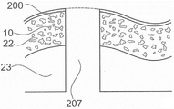
The invention relates to the field of mechanical engineering and manufacturing, in particular to the field of mechanical manufacturing, such as automobile engineering. The invention relates to a method of bonding a first object (1) to a second object (2). The method comprises the following steps: -providing the first object (1) comprising a thermoplastic material (3) in a solid state, -providing the second object (2) comprising a proximal face (4), -applying a mechanical pressing force and a mechanical excitation capable of liquefying the thermoplastic material (3) until a flowing part of the thermoplastic material is capable of flowing and penetrating into the second object (2), -stopping the mechanical excitation and re-solidifying the thermoplastic material to form a form-fit connection between the first object and the second object. In the method according to the invention, the second object (2) provided comprises a low density region (22), wherein the protrusions (9) penetrate at least partially into the low density region (22) before the thermoplastic material becomes flowable, and wherein the first object (1) comprises protruding portions (91) after the step of causing the thermoplastic material to re-solidify, the protruding portions (91) penetrating at least partially into the low density region (22). The invention also relates to a device, in particular a connector, designed to be coupled to an object by using the method according to the invention.
Description
Technical Field
The invention relates to the field of mechanical engineering and manufacturing, in particular to the field of mechanical manufacturing, such as automobile engineering.
Background
Devices used or fabricated in the automotive, aerospace and other industries include surfaces that are required to meet physical requirements set forth by users or authorities. This requirement relates in particular to optical, acoustic, thermodynamic and mechanical properties. For example, the quality and value of the device is closely related to the visual impression given by the outer surface, the noise generated due to the vibration of the device or the interior of the device needs to be limited and/or adjusted, and the surface needs to produce a certain feel and/or a certain resistance to resist degradation due to use of the device.
A cover attached to a surface is one way to meet the requirements. Thus, there are currently two methods of attaching the cover directly to a surface or attaching a connector to the cover by which the cover can be attached to a surface.
The first method uses an adhesive. However, the binder is disadvantageous for long-term stability. In particular, if an adhesive is used to attach the cover to, for example, a porous and/or fibrous surface or to, for example, a porous and/or fibrous surface, the stability is poor, since the adhesive is embedded only in the outermost portions of the fibers and/or porous material and facilitates the joining.
In addition, the use of adhesives is time consuming (e.g. due to the hardening process), e.g. often requires extensive processing and may be limited to certain body dimensions, e.g. as is the case with friction welding.
The second method typically employs fasteners that can access the cover. Examples of such fasteners are rivets, nails and screws. The use of fasteners and related methods based on passing through holes prepared in an attachment or pre-drilling process are disadvantageous at least in terms of optical and acoustic performance.
Thus, there is a need for alternative methods of bonding objects together, in particular to bond covers having specific physical properties to surfaces of devices such as automobiles and machinery.
Disclosure of Invention
It is an object of the present invention to provide a method for joining objects together which overcomes the disadvantages of the prior art methods.
In particular, it is an object of the invention to provide a method for bonding a first object to a second object, wherein one of the first object and the second object has a specific density distribution. This density distribution is formed by requirements related to, for example, at least one of acoustic (e.g., damping) properties, thermodynamic (e.g., adiabatic) properties, mechanical properties, and optical properties.
The mechanical properties may include generating a particular (e.g., softness) feel and/or high resistance to degradation due to frequent use. The optical performance may depend on the requirements of the surface that is not affected by bonding the first object to the second object.
The method according to the invention is suitable for bonding a first object to a second object. In its basic embodiment, the method comprises the steps of:
providing a first object, wherein the first object extends between a proximal end and a distal end, wherein the first object comprises a thermoplastic material in a solid state.
Providing a second object comprising a proximal face.
Applying a mechanical pressing force and a mechanical excitation capable of liquefying the thermoplastic material to at least one of the first and second objects until the flow portion of the thermoplastic material is capable of flowing and penetrating the structure of the second object.
Stopping the mechanical excitation and causing the thermoplastic material to re-solidify to form a form-fitting connection between the first and second objects.
A basic embodiment of the method is characterized in that a second object is provided which comprises a low-density zone and the distal end at least partly penetrates the low-density zone before the thermoplastic material becomes flowable.
The low density region at least partially penetrated by the distal end before the thermoplastic material becomes flowable is not necessarily the lowest density region of the second object. This also means that the first object is not necessarily anchored in the region of lowest density of the second object.
For example, a low density region that is at least partially penetrated by the distal end may form a substrate, for example, of a lower density region that forms the exposed surface of the first object. This embodiment may for example be present in a situation where the body part forms part of the first object and the cover forms the second object.
Preferred embodiments may include at least one of the following features:
the step of applying a mechanical excitation comprises applying a mechanical oscillation along an axis extending at an angle with respect to the proximal face, the proximal face of the second object being provided with a low density.
At least in this embodiment, the low density region extends normal to (which means distal to) the proximal face. The low density region may be a proximal low density region. The proximal low density region may include a proximal face.
The provided first object comprises a first object body and at least one protrusion located at a distal side of the first object body, wherein the protrusion forms a distal end and comprises a thermoplastic material in a solid state.
In this embodiment, the protrusion(s) at least partially penetrate the low density region before the thermoplastic material becomes flowable. Further, the first object comprises a protruding portion after the step of causing the thermoplastic material to re-solidify, wherein the protruding portion penetrates at least partially into the low density region.
A step of at least locally varying the compressive strength of the low-density region.
In this context, the term "compressive strength" means the maximum force per square millimeter generated by an area before it is displaced, which means that the area is further compressed before the material is defined. Thus, the compressive strength may also be viewed as a resistance to further compression or as a stiffness.
The compressive strength corresponds, for example, to the stress as measured in a stress-strain experiment.
Changes in compressive strength (stress) can cause liquefaction of the thermoplastic by applied mechanical compression forces and mechanical excitation. In other words, the low-density region cannot provide the compressive strength required for liquefying the thermoplastic material in the step of applying the mechanical pressing force and the mechanical excitation without changing the compressive strength.
The step of at least locally varying the compressive strength of the low-density region may be carried out until a critical compressive strength is formed, which means until the compressive strength required for liquefying the thermoplastic material by means of the applied mechanical pressing force and mechanical excitation is reached.
The change in compressive strength required to liquefy the thermoplastic material in the step of applying the mechanical pressing force and the mechanical excitation may depend on the applied mechanical pressing force and the mechanical excitation.
Specifically, the change in the compressive strength refers to an increase in the compressive strength.
In many embodiments, the increase in compressive strength is caused by at least partial compression of the low density region. In other words, the method may comprise the step of at least locally compressing the low density region.
In particular, the compressive strength may depend on the densification of the low density region, wherein the densification is caused by compression.
The low density region may be compressed by a mechanical pressing force applied to liquefy the thermoplastic material.
In the step of applying mechanical pressing force and mechanical excitation for liquefying the thermoplastic material, the mechanical excitation may be applied after the compression of the low-density region has caused an increase in the compressive strength (sufficient for liquefying the thermoplastic material by the applied mechanical pressing force and mechanical excitation).
The step of at least locally varying the compressive strength of the low-density regions or the step of at least locally compressing the low-density regions may make the method suitable for bonding a first object to a second object by a form-fit connection between the first object and the second object, wherein the form-fit connection is established in a region of the second object corresponding to the low-density regions before bonding the first object to the second object.
In an embodiment, the low density area is formed substantially of a non-stick material, which means a material comprising components that interact only weakly, e.g. when subjected to an external force such as a compressive force.
Examples of non-stick materials are materials comprising or consisting of fibres which are able to move to some extent relative to each other under the action of an applied force.
The provided second objects do not require the presence of a weak interaction between the components. Rather, the weak interaction may be the result of a force acting on the second object in the method. This force can cause the breaking of the inter-component connection. For example, the material may include fibers that are partially connected by a bonding material, such as resin powder or melted fibers in combination with a heat treatment to define a particular density of the material.
In many embodiments, the protrusion or protrusions are penetrating or pass through the distal end of the second object.
In this context, any relative arrangement within and between objects, articles, devices, etc. is given with respect to an origin located at an intermediate position of the first object. When no other statement is given, the surface of the object that is disposed closest to the origin is referred to as the proximal face of the object, and the opposite surface of the object (e.g., the corresponding surface disposed on the opposite side of the object) is referred to as the distal face. In the example of a first object, a surface pointing towards a near side of another object to which the first object is to be arranged to contact and/or (as the case may be) be referred to as a far side of the first object. In other words, the proximal face is always in contact with and/or (as the case may be) bonded to the distal face in this method. Thereby, the protrusion(s) is/are arranged distal to the first object.
In many embodiments, the protruding portion means a portion of the protrusion remaining after the step of causing the thermoplastic material to re-solidify, wherein the portion (here denoted protruding portion) is not limited to the outermost region of the second object, but extends into the volume of the second object. The remaining means that the material defining the protruding portion does not penetrate into the structure of the second object.
The distance that the protruding portion penetrates the second object depends on the application. However, the penetration depth of the protruding portion in a normal direction of the proximal face of the second object is typically larger than the extension of the protruding portion in a direction parallel to the proximal face of the second object. This means that the ratio of the extension in the direction normal to the proximal face to the extension parallel to the proximal face is at least 1, in particular between 1 and 5, for example between 1.5 and 4 or between 2 and 3.
A slightly different definition of the projections and/or other features characterizing the projections is given below.
As used herein, a low density surface or region means that it is at least one of porous, fibrous, and soft and/or that it includes a variety of structures, pores, openings, and the like. The structures, holes and/or openings can be used for damping, in particular for example sound damping and/or vibration damping.
In an embodiment, in particular an embodiment of the method comprising the step of compressing the low density region as described in detail below, the low density region can be compressed along an axis along which a mechanical pressing force is applied in the step of applying the mechanical pressing force and the mechanical excitation. The compression may result in a reduction of the thickness of the low density region, for example by 10-90%, wherein the thickness is measured along the axis of application of the mechanical pressing force. In particular, the thickness may be reduced by 30-90%, such as 60-80%, or 20-80%, such as 30-70%.
The compression ratio is another measure of the compression of the low density region. In particular, the compression ratio is a suitable measure when considering compression. The compression ratio in the raised area may be between 1.1 and 10, in particular between 1.25 and 5, for example between 1.4 and 3.3.
The material or material composition forming the low density region may be locally compressed. For example, local mechanical loads, such as formed by protrusions of a first object or protruding zones of an article attached to a second object, may cause local compression of the low density region.
The local and/or "global" compression of the low density region may be elastic or primarily elastic. This means that the compression will relax (disappear) or mostly relax after the mechanical load causing the compression is removed. In other words: a second object is provided that is elastically deformable. The applicability of the bonding method also with respect to the elastically compressible second object has important advantages compared to known bonding methods based on hard (here denoted incompressible) objects or objects comprising parts that are only plastically deformable (here denoted irreversible), such as hollow plates (HCB).
Thus, a low density surface or region is in many embodiments not only denoted as a surface or region having at least one of the properties of porous, fibrous and soft and/or which comprises various structures, pores, openings, etc., but also a surface or region which is compressible, in particular elastically compressible. In addition, the surface or region may be locally compressed, which means that it can be compressed in such a way that it may comprise areas of differentiated compression.
This compression may result in an increase in compressive strength.
In embodiments, the second object may be comprised of a second object composition, and the mechanism of the second object may be inherently formed from the composition. For example, the structure may be a pore, hole, channel, or the like.
For example, the second object may comprise or consist of fibres, textile material, foam, porous material, cardboard or the like. It may be formed from a series of layers, some of which may have at least one of rigidity, incompressibility, compactness (meaning here a low concentration of pores, holes, channels, etc.) and load-bearing properties. The second object and/or the layer forming the second object may have a composition that is position dependent. Additionally or alternatively, the order of layers is location dependent.
In particular in an embodiment of the method of forming the protruding portion after the step of re-solidifying the thermoplastic material, the structure achieves a depth-influenced anchoring, which means an anchoring not only on the surface of the second object but also within the volume of the second object. One can think of embodiments in which no special structure for the anchoring of the depth influence is required. Examples of this embodiment are an embodiment comprising a proximal top layer as described below or an embodiment intended to be attached with a third object as described below, wherein the third object ensures that the protruding portion at least partially penetrates into the low density area.
Additionally or alternatively, one may also think of forming the structure of the second object, for example by a rough surface of the second object and/or by employing a preparation process of the second object for forming such a structure.
The mechanical excitation may be turned on after, before, or simultaneously with the application of the mechanical pressing force. The switching on of the mechanical pressing force before the mechanical excitation is advantageous with regard to the quality of the bond, in particular the depth of the bond, and the strength of the bond formed. One could conceive of a configuration in which mechanical stimulation could help to optimize the penetration performance of the protrusion(s). Some of these configurations are discussed below.
The mechanical pressing force may last for a time sufficient to re-solidify the thermoplastic material after the mechanical activation is stopped.
The mechanical pressing force may be varied during the step of applying the mechanical pressing force and the mechanical excitation and, as the case may be, during the re-solidification of the thermoplastic material.
The thermoplastic material of the first object can be made flowable by absorbing mechanical energy generated by mechanical excitation, in particular mechanical oscillations/vibrations, when the objects are pressed against each other. For example, the mechanical vibration energy may be coupled through the first object and/or the second object to an interface formed by the thermoplastic material of the first object and the material of the second object. At the interface, external and possibly also internal friction will cause the thermoplastic material to heat up and become flowable. The flowable thermoplastic material will then be pressed into the structure of the second object as a result of the applied pressure.
The portion of the first and/or second object forming the interface may comprise a profile that acts as an energy director, i.e. energy absorption and energy generation will automatically focus on or around the corresponding interface.
In an embodiment, the second object provided comprises a density profile which increases in relation to the spacing from the proximal face. In particular, the density increases in a distal direction orthogonal to the proximal face.
The increase in density may be continuous or stepwise.
If the second object extends between the proximal and distal faces, the density may only be increased over a limited range of the second object.
The low density region may be located on the proximal face, the low density region may be located on the distal face, or the low density region may be located somewhere between the proximal face and the distal face.
One could also think of a second low density area, for example one low density area at the proximal side and another low density area at the distal side.
In an embodiment, the second object comprises a low density region at the proximal face (i.e. the low density region is the proximal region) and a further high density region distal to the low density region.
The low density region is followed by a region that is less dense (i.e., more dense) than the high density region.
The term "high density" in the high density region or high density region is used to express the density of the region relative to the density of another region (especially low density region). However, this term does not necessarily mean that the "high density" regions do not include structures, holes, openings, etc. The term also does not imply that the region is incompressible or that the region need not be compressed to form a critical density and/or compressive strength (details described below). Rather, the regions may also have all of the physical properties attributed to the low density regions. However, the second object comprises at least one region having a lower density than the "high density" region.
In another embodiment, the further region is arranged distal to the low density region, wherein the low density region is not located at the proximal face.
Alternatively or additionally to the further region, the low-density region may have an increasing density in relation to the distance of the proximal face.
In an embodiment, the provided second object comprises a proximal top layer, wherein the low-density region is arranged distally of the proximal top layer, and wherein the method comprises the step of forcing the protrusion to penetrate the proximal top layer before the thermoplastic material liquefies.
The proximal top layer may be an integral part of the second object, for example a cover layer within a "hollow" shaped plate, wherein the low density area at least partially fills the core area, or a cover layer, such as a decorative and/or functional cover layer, for example made of (synthetic) leather or any other outer cover layer.
The proximal top layer may be provided in the next step of the method and may be positioned over the proximal face of the second object in the further next step of the method. In particular, the proximal top layer may be a third object as described below, such as a metal sheet, foil or cover layer. However, it may also be a cover or coating, for example as described above.
The density of the proximal top layer is typically higher than the density of the low density region.
The proximal topsheet may be another high-density region.
The proximal top layer may contribute to any of the density distributions of the second object described above, or may be a complement to such density distributions.
In particular, it may be any density distribution of the low density region and, if present, a complement of the density distribution of the further region.
One can envision configurations in which high density regions are not required. For example, a mechanical pressing force may be applied to cause the distal end to partially penetrate the low density region in a first step. In a subsequent second step, mechanical oscillations may be applied at an amplitude that may enable the thermoplastic material to become flowable. In addition, the mechanical pressing force may be reduced to reduce the speed at which the first object penetrates the second object.
Alternatively or additionally, the proximal top layer or any other layer disposed proximal to the low density region may cause the thermoplastic material to warm when the protrusion is pushed through the layer. The temperature change is not sufficient to liquefy the thermoplastic material, but it reduces the mechanical pressing force and mechanical excitation required in the step of applying the mechanical pressing force and mechanical excitation capable of liquefying the thermoplastic material.
In embodiments comprising a second object having an arbitrary density distribution as described above, and optionally a proximal top layer, the distal ends of the first object(s), typically the protrusion(s), penetrate at least partially into the low density region before the thermoplastic material becomes flowable.
The density distribution may be such that the density of the second object in the low density region is not high enough to create the pressure required to liquefy the thermoplastic material. In particular, the density in the low density region is not high enough to cause liquefaction of the thermoplastic material when a mechanical pressing force and mechanical excitation are applied for less than 15 seconds(s) or less than 10s (e.g., less than 5s or 2 s). In particular, the density is not high enough to cause liquefaction when a mechanical pressing force and mechanical excitation are applied for 0.1 to 1s, e.g. 0.1 to 0.5 s.
Alternatively or additionally, the step of applying the mechanical stimulus required to liquefy the thermoplastic material is started after passing the distal end of the first object through the low density region.
In an embodiment of any density distribution that can be applied to the second object and/or the low density zone, the method comprises the step of at least locally compressing the low density zone to generate the critical density required to liquefy the thermoplastic material.
The critical density corresponds to the density at which the critical compressive strength is established.
The step of at least locally compressing the low density region may be a sub-step of the step of applying a mechanical pressing force and a mechanical excitation capable of liquefying the thermoplastic material.
In particular, the step of at least locally compressing the low density region to a critical density may precede the step of applying the mechanical stimulus.
The critical density that needs to be established depends on the target duration of the application of the mechanical pressing force and the mechanical excitation, after which the liquefaction should start.
The compression may be global compression and/or partial compression.
The overall compression may be established by compressing the low density region over a greater range but not just around the protrusion(s). This may be done, for example, by the first object body, in particular by its distal face or by a part thereof. In particular, the first object body may penetrate at least partially within the low density region.
Alternatively, the overall compression may be established in the same manner by employing a first object and another object attached to a second object.
The local compression may be formed by the protrusion(s), for example by displacing the portion(s) of the low density region into which the protrusion(s) are forced.
Experiments have shown that especially non-stick materials, such as panels made of fibrous material, show unexpected stress-strain behavior when a force (load) is locally applied to this material. "local" in this context means that a force (load) is applied to an area of the article formed by the non-adhesive material, which area is significantly smaller than the corresponding extension of the article.
The following are properties that have been found on various articles made from non-stick materials when pressure is applied locally and orthogonally to the article:
an approximately linear relationship of stress to strain may be observed when a strain is applied to an article. The substantially linear relationship forms a first region of the linear relationship. The linear relationship of stress to strain in the first region may be approximated by a straight line having a first slope.
A transition region, where the stress versus strain relationship steadily increases following a linearly related first region as strain further increases.
The second region where stress and strain are approximately linear follows the transition region as strain increases further. The substantially linear relationship of stress to strain in the region may be approximated by a line having a second object slope, wherein the second slope is greater than the first slope.
The pressure (load) is from 4 to 200 square millimeters (mm) 2 Of) is applied by a given object with respect to surface area. However, there is no suggestion that the properties summarized above are limited to this range of relevant surface areas.
Because of this property, a wide range of tack-free materials are unexpectedly suitable for bonding processes that rely on liquefaction of thermoplastic materials through the use of mechanical compression forces and mechanical excitation (especially vibration). This is because the large range of non-tacky materials achieves the stress level required to liquefy the thermoplastic material, i.e. the critical compressive strength, solely due to the presence of the linearly dependent second zone.
Thus, the step of compressing the low density region may cause the stress-strain behavior of the material to lie within the linearly dependent second region.
The strain value at which the first slope and the second slope intersect in the stress-strain chart is a characteristic value of the observed stress-strain performance.
The step of compressing the low density region may cause the material to be compressed at least to the characteristic value.
Alternatively or additionally, the characteristic value may define a minimum threshold value applied, which means that the mechanical excitation used in the step of applying the mechanical pressing force and the mechanical excitation capable of liquefying the thermoplastic material is turned on. In other words, the mechanical excitation may be turned on at an applied pressure that causes the characteristic strain value.
In addition, it has been observed that the deformation of the panel is mostly reversible, as long as liquefied thermoplastic material that has been pressed into the pores, openings, etc. of the panel does not prevent the panel from returning to its original shape.
However, there are configurations in which the deformation of the low density region is irreversible, for example if the energy coupled into the panel is high enough to cause permanent densification. For example, the low density region may comprise fibers that melt during the process.
Any permanent deformation is advantageous for the bonding strength.
Particularly with non-adhesive materials, the critical density may be formed only around the protrusion(s), for example by locally increasing the overall compression by an amount sufficient to reach the critical density.
At least a portion of the area of the second object other than the low density area and/or the proximal top layer and/or any object to be attached or affixed to the second object (e.g., a third object, a cover layer, or an outer cover) may also be compressed. Thereby, these areas and/or objects may contribute to a density distribution which is favorable for liquefaction of the thermoplastic material and which is established during the method of bonding the first object to the second object. In particular, liquefaction may also take place in this area and/or object.
In addition, the distal end of the first object (and in particular the protrusion (s)) may comprise a structure designed and arranged to promote local compression of the second object when it is forced into the second object. In particular, when the structure is forced into the low density region, the low density region is at least partially compressed.
Forcing the first object into the second object may be done in a next step comprising a movement, in particular a (partially) penetrating movement, of the first object relative to the second object. Typically, local compression is the effect of the design and arrangement of the structures and the relative movement.
The structure designed and arranged to promote local compression has, in addition to the effect of locally compressing the low density region (in other words, locally increasing the density), at least one of the following effects:
when the first object is pushed into the low density region, the material (e.g. fibers) of the second object is pulled in a distal direction. This may lead to an additional effect of complexation, especially if the second object comprises fibres.
The material of the second object is embedded within the structure and in particular in the protrusion(s). This results in a more even distribution of the load acting on the combined first and second objects when in use.
The embedding quality is improved if the second object comprises a thermoplastic material to form a weld between the structure or generally the protrusion and the second object and/or to modify the structural properties of the second object. Embodiments including fusion splicing are described in more detail below.
For example, the first object may comprise at least one barb, such as a grab barb and/or a pull-down barb. The barb may be significantly smaller than the projection or may be sized such that the barb contributes to the overall shape of the projection. In the latter case, the cross-section of the protuberance in a plane perpendicular to the longitudinal axis of the protuberance (also called the protuberance axis) depends strongly on the shape of the barb and/or it may depend on the position of said plane, e.g. due to the presence of the barb.
Multiple tips arranged offset or unbiased along the axis of the protrusion are other examples designed and arranged to promote local compression.
This barb or said structure may generally be arranged to increase the density towards which the penetrating distal end is directed, e.g. by collecting fibers. In other words: the barbs ensure that the density in front of the distal end increases in relation to the penetration depth of the distal end into the second object.
Such barbs may also be present in embodiments wherein the second object comprises an increasing density profile.
In addition to the compression of the low-density regions, a weld can also be formed between the thermoplastic material and the compression zone surrounding the protrusion(s) by a corresponding selection of the material of the low-density regions.
An example in which the fusion splice is formed is described in detail below. For example, the low density region may include thermoplastic fibers.
An advantage of an embodiment comprising compression of the low density areas is that the areas need not have the density required to liquefy the thermoplastic material extensively or at specific locations. More specifically, the density may be low and/or uniform. As noted above, the desired density or density profile may be formed during the bonding of the first object to the second object.
Regardless of the exact density profile of the second object, the distal end or a portion of the distal end (e.g., at least one of the plurality of protrusions) may penetrate the second object from the proximal end to the distal end. The bonding of the first object to the second object may then be established using an anvil including a concave proximal surface having a head. In this embodiment, the method includes the step of positioning the proximal face of the anvil opposite the distal end of the second object such that the penetrating distal end of the second object penetrates the recess forming the head.
Examples of second objects, for example having low density areas at the surface and as the case may be having an increased density in the direction normal to the surface, are panels, insulators, sheaths, outer coverings, trims, carriers, absorbent members and trim for vehicles such as cars, trains and planes, for example in luggage compartments, in the interior of vehicles or around cabs.
For example, the second object may comprise natural or synthetic fibers, such as wool or polyester fibers. The fibres may be embedded in a plastic, in particular a thermoplastic material, wherein the free ends of the fibres (here representing the parts of the fibres not embedded in the plastic) form low density regions. The arrangement of fibers and plastic is such that the density increases continuously from the proximal face and decreases again selectively towards the distal face. However, the arrangement of fibres and plastics material may be such that the density is substantially uniform in the region formed by the free ends of the fibres (i.e. in the low density region) and/or in the region formed by the fibres embedded in the plastics material. In particular, the density may increase substantially stepwise when entering the region formed by the fibers embedded in the plastic.
Another group of second objects comprising a certain position of increased density in a direction orthogonal to its surface, in particular a position at or close to the proximal side, are panels, sheaths, outer covering panels, edging, carriers comprising a functional layer attached to a core. For example, the functional layer may be at least one of soft, softened, damped, and dampened, including, inter alia, a plurality of openings, holes, movable components, and/or non-rigid components.
Another example is an instrument panel comprising a top layer, for example made of artificial leather, arranged on a foam, wherein the foam becomes more dense and rigid with a larger distance from the top layer. This instrument panel may be regarded as an example of a second object comprising a proximal top layer, wherein the low density region is arranged distal to the proximal top layer.
In one set of embodiments, the first object comprises a connection means element, such as a thread, a thread stand, a catch element or a snap lock.
In an embodiment, the first object is a connector. In particular, the first object may form or be the connecting means element.
In an embodiment, the method further comprises the step of providing a further object comprising attachment sites conforming to the connection means elements, and the step of connecting the combined first and second objects to the further object.
In particular, the further object may be a second object such as a panel, a sheath, a cover plate, a trim, a device on which the carrier has to be mounted.
The attachment site may be a counterpart of a connecting device element comprised or formed by the first object.
In an embodiment, the method comprises the step of providing a further object and the first object comprises a first object body designed for forming a connection with the further object. The first object body may be a first object body according to any one of the embodiments described below.
The other object may be a fixing element such as a nail, screw, rivet, etc.
The other object may be configured to mount an object other than the first object, the second object, and the other object to the first and/or second object.
In particular, the further object provided may comprise a distal end, e.g. a tapered distal end, and the connection between the first object body and the further object is formed by at least part of the further object penetrating the distal end within the first object body.
The method may comprise the steps of positioning the distal end of the further object relative to the first object body such that the distal end of the further object at least partially penetrates the first object body and applying a mechanical pressing force to at least one of the first object, the second object or the further object.
In particular, said further step is performed after the step of stopping the mechanical excitation and causing the thermoplastic material to re-solidify (which means after bonding the first object to the second object).
For example, the first object may be a stiffener. The reinforcement, after being bonded to the second object, serves to enhance the mechanical stability of the second object. In other words: the first object is designed to locally reinforce the second object in order to establish a reliable connection between the further object and the second object via the first object.
The use of the first object as a reinforcement is advantageous, especially in cases where the density distribution of the second object does not allow for a specific connection, for example a connection based on nails, screws, rivets, etc., and/or the mechanical stability of the second object makes various connection methods unusable for a reliable connection, for example because the second object is bendable. Connections based on nails, screws, rivets and adhesive based methods are examples that do not result in a reliable connection between the first and second object, e.g. if the second object is bendable
Additionally or alternatively, the connection between the first object body and the second object may be formed by the first object body comprising the connecting device element as described above and the further object comprising the associated counter element.
An important advantage of connecting and/or attaching an object different from the first and second object to the second object by using the first object as a connection site, i.e. by using a two-step process, is that the object can be moved again. This statement is indeed irrelevant to the specific implementation of the connection and/or attachment. In particular, the first object may comprise a connecting means element or the first object body may be designed for forming said connection.
In an embodiment, the first object comprises a proximal face, a distal face and a connection site. The attachment site includes at least a portion of the proximal surface of the first object body. For example, the connection site or a part thereof extends as a protrusion from said proximal side surface portion, or the connection site or a part thereof is an opening of the body of the first object, wherein said proximal side surface portion forms the mouth of the opening.
In this embodiment, the first object comprises a protruding zone arranged at the distal side of the body of the first object, in particular in any of the embodiments described below, and comprises a functional zone without any protrusion, in particular in any of the embodiments described below, wherein the functional zone is opposite to the proximal side portion comprised by the connection site.
In an embodiment, the mechanical pressing force and the mechanical excitation are locally applied to at least one of the first object and the second object. In other words, the first object is joined to the second object at joint sites that are separate from each other, i.e. the joint is built up by using joint points instead of using continuously extending joint areas.
For example, the bond site may be a circle, an ellipse, a rectangle, or a square having a characteristic length that is significantly less than the extension of the feature at which the first and second objects are bonded together. In particular, the characteristic length lies between a few millimetres and a few centimetres, for example between 1 millimetre (mm) and 10 centimetres (cm), in particular between 1mm and 5cm, for example 0.5mm, 1cm, 2cm, 3cm, 4cm or 5cm. However, one can think of the case where a characteristic length of more than 10cm is required, for example if the first object forms a closed or partially closed form with the intermediate opening.
In this embodiment, the steps of applying the mechanical pressing force and the mechanical excitation and stopping the mechanical excitation and causing the thermoplastic material to re-solidify are repeated a plurality of times at different locations on at least one of the first object or the second object.
An advantage of this embodiment is that there is no limitation on the shape of the first and second objects as long as they can be arranged to form an assembly of the first and second objects comprising the bonding sites and as long as these locations are transparent to the means for applying the mechanical pressing force and the mechanical stimulus.
In particular, the first and/or second object need not be substantially flat. Rather, one or both of the objects may be curved. In addition, there is no limitation on the positioning of the binding sites with respect to each other. For example, the bonding sites need not be arranged on a plane or on planes extending parallel to each other.
An example of a tool equipped for applying mechanical pressing force and mechanical excitation is a hand-held welding electrode or a welding electrode mounted on a robot arm.
The steps of applying a mechanical pressing force and a mechanical excitation and stopping the mechanical excitation and causing the thermoplastic material to re-solidify are repeated a number of times depending on various parameters such as the shape and material of the first and second objects and the required bonding strength.
In an embodiment, the axis along which the mechanical oscillation is generated is substantially perpendicular to the proximal face.
With the joint separated, the axis along which the mechanical oscillation occurs is substantially perpendicular to the portion of the proximal face defining the joint.
The proximal end of the first object may comprise a coupling-in face configured for receiving the mechanical pressing force and the mechanical excitation. After the step of arranging the first object relative to the second object in such a way as to form an assembly of the first object and the second object, the coupling-in face may be arranged parallel to the proximal face or to a portion of the proximal face defining the joining site.
In an embodiment, the provided first object comprises a coupling-in face, and the method further comprises the steps of: the method comprises the steps of providing a solder electrode comprising a coupling-out face conforming to a coupling-in face, and contacting the coupling-out face with the coupling-in face prior to the step of applying a mechanical pressing force.
Alternatively, the second object, in particular the distal side of the second object, may comprise the coupling-in face. In other words: a mechanical pressing force and a mechanical excitation required to liquefy the thermoplastic material may be applied to the distal side of the second object.
In an embodiment, the first object, the second object and the welding electrode are arranged with respect to one another such that the second object is located between the first object and the welding electrode and such that the proximal side of the second object is in contact with or makes contact with the at least one projection of the first object in the method.
For example, the first object may be formed by a part of a vehicle body on which the at least one protrusion comprising thermoplastic material is arranged. The second object may be a cover. The shape of the cover may conform to the shape of the vehicle body and/or the structure of the first object(s). According to this exemplary embodiment, the second object is positioned over the first object and the welding electrode is applied over a surface area of the second object opposite to a surface area of the second object in contact with the protrusion.
Mechanical pressing force and mechanical excitation may be applied onto the distal face of the second object by using a welding electrode. In this embodiment of the method, the distal face of the second object is an exposed, "proximal" surface to the user operating the welding electrode, due to the fact that the surface of the object is defined relative to the central origin of the first object.
In embodiments in which the weld is applied to the second object, the method may include the step of compressing the second object, for example compressing the low density region. In particular, the compression may enable the second object to become capable of transmitting a mechanical stimulus applied to a distal face of the second object.
The unexpected stress-strain properties discussed above make a wide range of non-stick materials suitable for delivering mechanical stimuli used in bonding methods that rely on liquefaction of thermoplastic materials by employing mechanical compression forces and mechanical stimuli (particularly vibration). Again, thanks to the presence of the second zone of linear correlation, this is simply because the large range of non-adhesive material reaches the level of stress required to transmit the mechanical excitation.
Thus, the step of compressing the low density region may cause the stress-strain properties of the material to lie within the linearly dependent second region and/or cause the material to be compressed to a characteristic strain value given by the intersection of the first and second object diagonal lines.
In embodiments in which the sonotrode is applied to the first object, the step of applying the mechanical pressing force and the mechanical excitation to the first/second object may be accomplished by the sonotrode being pressed against the coupling-out face of the first object, while the second object may optionally be directly or indirectly supported by a support (which may be directly supported against the second object at a lateral position on which the sonotrode acts, or it may consist of a frame of a more complex object supporting the second object; this complex frame may for example be the body of an object to be mounted to, such as a car body).
Optionally, the method may further comprise the step of locking the first object to the electrode after the step of bringing the outcoupling face into contact with the incoupling face.
The distal end of the electrode comprising the outcoupling face may comprise openings and recesses so that the proximal protrusion of the first object is not affected by the use of the electrode.
The mentioned connection means elements are examples of possible proximal protrusions of the first object.
The electrode may be a ring electrode.
The distal end of the electrode, in particular the out-coupling face, and the extension of the first object, in particular the extension of the first object at its distal end (e.g. the in-coupling face) may be such that the distal end of the electrode covers at least the proximal end of the first object during bonding.
However, it is also possible that the welded distal end and the extension of the first object are such that the mechanical pressing force and the mechanical oscillation applied to the first object by the welding electrode are only local.
One may think of applying mechanical pressing force and mechanical excitation to multiple joint sites simultaneously. This can be done, for example, by a welding electrode comprising a distal coupling face adapted to the joint site to be established.
In an embodiment, a first object is provided that includes a protruding region located distal to a first object body, wherein the first object body includes a distal surface and wherein the protruding region includes a plurality of protrusions comprising a thermoplastic material.
It is conceivable that not all protrusions (but for example a large number of protrusions) comprise protruding parts after the step of stopping the mechanical activation and causing the thermoplastic material to re-solidify.
Each protrusion comprises an extension and a thickness in the distal direction. For example, the extension in the distal direction is the length of the protrusion if the longitudinal protrusion axis extends along an axis perpendicular to the distal face.
The extension of the protrusion in the distal direction may be different in a plurality of protrusions comprised within the protrusion zone.
In particular, the first object may comprise at least one first type of protrusions comprising thermoplastic material and at least one second type of protrusions comprising thermoplastic material, wherein the extension in the distal direction of the first type of protrusions is larger than the corresponding extension in the distal direction of the second type of protrusions. Thereby, the form-fit connection established by the first type of protrusions is located at a different distal position than the form-fit connection established by the second type of protrusions.
Embodiments comprising a first type of protrusions and a second type of protrusions (and, as the case may be, other types of protrusions having an extension in the distal direction different from the first type of protrusions and the second type of protrusions and from each other in the distal direction) may comprise at least one of the following:
the extension of the protrusion in the distal direction may be selected such that the bond of the first object to the second object is formed by involving the second object having a larger volume than the bond based on the extension having the same extension in the distal direction.
It is feasible that the protrusions with a large or larger extension in the distal direction and the protrusions with a small or smaller extension in the distal direction are arranged such that a subsequent processing step of the article, such as a forming step, comprises the first object bonded to the second object.
The protrusions having a large or larger extension in the distal direction and the protrusions having a small or smaller extension in the distal direction are arranged such that the bending strength and/or the tensile strength is optimized.
For example, a protrusion with a large extension may be arranged on the distal surface adjacent to the lateral edge or lateral edges of the first object body, wherein a protrusion with a smaller extension may be arranged in a central position of the distal side of the first object body.
Protrusions with different extensions in the distal direction, optimized in terms of material costs, are selectively combined with protrusion structures with different extensions in the distal direction, optimized for the specific application and the pulling/bending forces to be accomplished by said application.
Regardless of the specific embodiment of the method or of the device (here denoted first object), the protruding portion corresponds to the relative protrusion after it has been deformed in the step of stopping the mechanical excitation and causing the re-solidification of the thermoplastic material. It is therefore located in the area of the initial protrusion with respect to the first object body. Specifically, the protruding portion protrudes from the distal surface of the first object at the same position as the protrusion before the mechanical pressing force and the mechanical excitation are applied.
For example, the protruding portion may be a portion of the protrusion that does not liquefy during the step of applying the mechanical pressing force and the mechanical excitation. However, the protruding portion may also be an accumulation of re-solidified material in an area opposite the first object where the protrusion is already present prior to the step of applying the mechanical pressing force and the mechanical excitation.
The effect of the protruding portion(s) after the step of stopping the mechanical excitation and causing the thermoplastic material to re-solidify is to extend into the bonded area of the second object, which means that the bonded area is not limited to only the surface area of the second object. In other words: anchoring of the depth effect is established. This significantly improves the mechanical strength of the bond, especially its mechanical load-bearing capacity, compared to a bond without protruding parts.
The protrusion(s) used in embodiments of the present invention are not energy directors as described below. For example, the protrusion(s) are dimensioned along an axis perpendicular to the distal face of the first object body such that they allow for anchoring of depth effects. This means that their extension along an axis perpendicular to the distal face is larger than the corresponding extension of the energy director. In addition, the protrusion(s) may form a protruding portion after the step of stopping the mechanical activation and causing the thermoplastic material to re-solidify. The energy directors do not form such a protruding part because they define the location where liquefaction starts, which also means that they are discrete in the step of applying mechanical pressing force and mechanical excitation.
However, the protrusion(s) may comprise an energy director.
The protrusion(s) may be tapered and have any pointed and/or pointed form, such as, for example, ridges or points.
The protrusion(s) may also decrease in size in a stepwise manner or they may be constant in size.
The protrusions, some or all of the protrusions may include structures designed and arranged to promote the localized compression described above.
The or at least one of the protrusions may be symmetrically shaped. In particular, it may have a shape that is not rotationally symmetric about an axis perpendicular to the distal face of the first object body.
In an embodiment, the protrusion or at least one of the protrusions is at least one of:
assembling for defining the deformation direction in the steps of applying mechanical pressing force and mechanical excitation.
For example, the protrusion may comprise a groove arranged such that the protrusion deforms in a certain direction upon loading and/or the protrusion may be bent away from an axis perpendicular to the distal face of the first object body prior to the steps of applying the mechanical pressing force and the mechanical excitation.
An arrangement for defining the direction of inflow of the liquefied thermoplastic material in the step of applying a mechanical pressing force and a mechanical excitation, and
comprises a protrusion axis extending at an angle with respect to the distal face of the first object body, wherein the angle is not a right angle.
Each protrusion comprises an extension and a thickness in the distal direction as described above. If the longitudinal projection axis extends along an axis perpendicular to the distal face, the extension in the distal direction is the length of the projection.
In an embodiment, the ratio of extension to thickness in the distal direction is at least 1, in particular between 1 and 5, for example between 1.5 and 4 or between 2 and 3. In other words: the protrusion(s) have an extension along an axis perpendicular to the distal face that is greater than a thickness along a direction that is radial to the perpendicular axis.
In an embodiment, the extension in the distal direction of the protrusion(s) corresponds to 10-80% of the corresponding thickness of the second object or, depending on the specific implementation of the second object, to 10-80% of the corresponding thickness of the low density region. In particular, the extension of the protrusion(s) in the distal direction corresponds to 15-70% or 20-50% of said corresponding thickness.
In embodiments including a plurality of protrusions, the protrusion areas include gaps between the protrusions.
In this context, "gap" means the total space separating one protrusion from the other protrusion, not the distance between the protrusions.
The gap may extend to a distal side of the first object body. In particular, the protrusions may be arranged on the distal side of the first object body in such a way that flat areas of the distal side are formed between the protrusions.
The flat region may form a stop surface as described below.
As mentioned above, the surface of the first object defining the gap may be arranged to compress the first object, in particular the low density region, before liquefying the thermoplastic material.
In particular, the surface is arranged to form a global compression and an applied local compression, wherein the local compression is generated around the protrusion and guarantees a critical compression required for the liquefaction of the thermoplastic material.
In addition, the surface acts to stabilize the bonding process due to the fact that a steadily increasing reaction force is created against the applied mechanical pressing force. This also helps to avoid undesired puncturing of the second object or low density region and compensates for density variations within the second object or within the low density region.
The total volume of the protruding zone may be given by the portion of the distal side of the first object body comprising the protrusion and the extension of the protruding zone in the distal direction. For example, the extension of the protruding zone in the distal direction may be the extension of the protrusion along an axis perpendicular to the distal face, wherein all protrusions have the same extension and the portion of the distal face comprising the protrusion forms the base of the protruding zone, such that the total volume of said protrusion is given by the distal face and the product between said portion and said extension.
In an embodiment, the total volume is constituted by the volume of the plurality of protrusions and the volume of the gaps within the protrusion area (which represents the total volume of the spaces mentioned above), wherein the volume of the gaps is larger than the volume of the gaps. In other words: the ratio between the volume of the gap and the volume of the protrusion is greater than 1, in particular greater than 2, for example 3, 4, 5. In many embodiments, the ratio is less than 10.
In an embodiment, the distal side of the first object body comprises a functional zone, meaning a region having a different function than the function of combining the first and second objects. Thus, the functional region does not comprise any protrusions.
The functional zone is not located at all at the junction with the proximal face of the second object or only at the tip of the junction. Thereby, its mechanical and/or thermal load is significantly reduced compared to the region of the distal side of the first object body comprising the protrusion.
For example, the functional zone includes a distal port through an opening of the first object body. The opening may be a lead of a wire or sensor and/or it may form, for example, the end of an opening in the second object.
In embodiments, the protrusion may be comprised of a thermoplastic material or the thermoplastic material may be at least partially disposed around a core of a more rigid material. In this context, a harder material means a material that does not become flowable due to the applied mechanical pressing force and mechanical excitation.
The hard material may for example be a plastic different from a thermoplastic or a metallic material.
In particular, after the first object is so arranged relative to the second object, the tips or portions of the ridges of the protrusion(s) that are in contact with the second object may be made of a more rigid material that is not covered by the thermoplastic material.
Alternatively, the distal end, the step, and the edge of at least one of the projections may comprise a thermoplastic material. In this embodiment, the protrusions form a so-called energy director by their shape. This means that they may define one or more locations where the thermoplastic material starts to liquefy.
An energy director is a structure at which applied mechanical oscillations and/or pressure are focused and coupled into the thermoplastic material in an efficient manner.
The first object in any of the embodiments may comprise an energy director which is different from energy directors which may be formed by e.g. conical, stepped or sharp protrusions, e.g. other tips and ridges arranged on the sides of the protrusions.
In embodiments where the first object comprises a protrusion at its distal end, the method may comprise the step of arranging the first object opposite the second object such that the protrusion is in physical contact with the proximal face.
In addition, the step of applying a mechanical pressing force may include applying a mechanical pressing force of an intensity to cause the protrusion to pass through the low-density region and other regions selectively disposed on the proximal side of the low-density region.
The effect of extending the low-density region before applying a pressure suitable for forming a liquefaction of the thermoplastic material and/or before applying the mechanical oscillation is that it extends into the bonding area of the second object, i.e. the bonding area is not limited to the surface area of the second object.
This effect can be further enhanced by applying a mechanical pressing force of a strength such that the protrusions penetrate into the high density areas.
In particular, the step of applying a mechanical pressing force comprises applying a first mechanical pressing force and a second mechanical pressing force, wherein the first mechanical pressing force is smaller than or equal to the second mechanical pressing force.
For example, the first mechanical pressing force has such a strength that the distal end (e.g., protrusion) of the first object penetrates into the low-density region of the second object. The strength of the second mechanical pressing force is such that the distal ends (e.g. protrusions) of the first object penetrate into the areas with higher density.
The second mechanical pressing force can be adjusted, for example, to ensure a precisely controlled penetration into the region of higher density in terms of penetration speed.
Typically, the second object mechanical pressing force is turned on before the mechanical excitation that can liquefy the thermoplastic material.
The increase from the first mechanical pressing force to the second mechanical pressing force may be continuous or stepwise.
In one embodiment, the method further comprises the steps of:
providing a third object comprising a third object proximal face and a third object distal face.
Arranging the third object with respect to the second object such that the third object distal face is in physical contact with the second object proximal face;
forcing at least a portion of the first object through the third object from a proximal face of the third object to a distal face of the third object, prior to the step of applying a mechanical stimulus capable of liquefying the thermoplastic material and causing the flowable portion of the thermoplastic material to infiltrate into the structure of the second object.
However, another insight of the present invention is that both protrusion(s) comprising thermoplastic material in solid state and protrusion(s) made of thermoplastic material can be used to pierce a third object of various material and size by optimizing the mechanical pressing force, the mechanical excitation and the start time of the mechanical excitation with respect to the mechanical pressing force.
In an embodiment, the third object may comprise or consist of a sheet material without pre-drilled holes, and the method may comprise the step of piercing the sheet material before applying the mechanical pressing force and the mechanical stimulus capable of liquefying the thermoplastic material. However, this does not mean that a mechanical pressing force and/or a mechanical excitation is applied in the middle of the step of piercing the metal sheet.
The pierced sheet may be a flange arranged to secure a third object to a second object.
The sheet may be arranged opposite the first object and the second object such that the first protrusion of the first object pierces the sheet prior to bonding the first object to the second object and such that the second protrusion does not contact the sheet during the method.
In particular, the sheet may be a metal sheet.
Experiments have shown that at least titanium sheets up to 0.3mm in thickness (strength) and aluminium sheets up to 0.5mm in thickness can be pierced.
In embodiments where a third object is or is not provided, the method may comprise the step of employing mechanical actuation to adjust the penetration behavior of the protrusion(s).
The penetration depth of the protrusion(s) through the second object can be adjusted if a mechanical stimulus is used in combination with a pressure acting on the thermoplastic material that is not capable of liquefying the thermoplastic material.
If mechanical stimulation is used in combination with a pressure acting on the thermoplastic material that is capable of liquefying the thermoplastic material, the thermoplastic material may be liquefied and pressed into the second body in a continuous manner. This may form a layered region within the second object or a head-like structure on the distal side of the second object and thereby form a more reliable bond.
Additionally, the method according to this embodiment may comprise the step of locally and/or globally compressing the portion of the second object to reach the critical density required for liquefaction of the thermoplastic material.
In an embodiment, the first object comprises at least one first type of protrusions comprising a thermoplastic material and at least one second type of protrusions comprising a thermoplastic material. In the step of applying a mechanical pressing force and a mechanical excitation capable of liquefying the thermoplastic material, the first type of protrusions may have a shape such that the flowable portion of the thermoplastic material infiltrates into the structure of the second object, and the second type of protrusions may have a shape such that the flowable portion of the thermoplastic material infiltrates into the structure of the third object.
For example, the dimensions (in particular the length and thickness) of the first type of protrusions and the dimensions of the second type of protrusions may conform to each other and to the thickness of the second and second objects, such that their liquefaction starts at the desired location within the second and third objects, respectively.
In particular, the third object may have the same density distribution as the second object. In this case, the length of the first type of protrusions and the length of the second type of protrusions may be adapted to the distance of the low density region from the proximal side of the third object.
The depth of the bonded area within the second object may be adjusted by the duration of the mechanical compression force applied before the mechanical excitation and/or the intensity of the mechanical compression force is applied.
The provided first object may comprise a marking indicating a penetration depth of the first object into the second object prior to the step of applying a mechanical pressing force and a mechanical excitation capable of liquefying the thermoplastic material.
The depth of the bonded area in the second object corresponds to the maximum penetration depth of the thermoplastic material of the first object into the second object after re-solidification. The maximum penetration depth is measured along the axis along which the first object is forced into the second object.
Typically, the maximum penetration depth is measured along an axis orthogonal to the proximal face of the second object or, as the case may be, to the portion of the proximal face defining the junction site.
In an embodiment, the step of applying a mechanical pressing force may be performed until abutting surface portions of the first and second objects (or the first and second objects as the case may be) abut each other.
In particular, a first object is provided that includes a stop surface. For example, the stop surface is a surface arranged to lie flat over the second (third) object after the first object is bonded to the second object.
This stop surface may define a maximum penetration depth of the thermoplastic material of the first object into the second object.
If the first object comprises a protrusion, the protrusion protrudes distally from the stop surface.
If the first object comprises a marking indicating the penetration depth of the first object into the second object before the first object is liquefied, the stop surface is arranged proximal to the marking.
In the case where the second object comprises a far side which must not be affected by the method of bonding the first object to the second object, it is advantageous to be able to act as a measure to well define the depth of the bonding zone.
A decorative layer, a so-called "a-surface" or any other surface visible to the user after bonding, is an example of a surface that must not be affected by the bonding method.
In an embodiment, the method further comprises the steps of: providing a third object comprising a third object proximal face and a third object distal face, arranging the third object relative to the second object such that at least a portion of the third object distal face is in physical contact with the second object proximal face, and forcing at least a portion of the protrusion through the third object from the third object proximal face to the third object distal face.
In this embodiment, the third object is specifically at least one of the following:
a metal sheet comprising through holes. The through hole may form a region curved in the distal direction.
The curved region may cause a local compression of the second object during the step of pressing the curved region into the second object.
The through hole is designed such that there is a protruding portion inside the second object after bonding the first object to the second object, which means after attaching the third object to the second object by bonding the first object to the second object. This also means that the protrusion can lead to (if appropriate) local compression of the second object in the region of the opening.
The method may include the steps of applying a compressive force to a portion of the protrusion and forming a melt zone at a contact surface between the portion of the protrusion and the third object.
For example, the bending region is elastically deformable and the diameter of the through hole forming the bending region is smaller than the diameter of the protrusion. Thereby, the elastically deformable bending region can be deformed by pushing the protrusion through the opening. This deformation may generate a lateral compressive force applied to the portion of the protrusion.
A foil, wherein the foil is designed to be penetrated by the protrusion. In particular, it may be provided as a perforated foil. Alternatively, the foil is of such a thickness and strength that it can be penetrated by the protrusion in the method.
Optionally, the foil may comprise or be made of a thermoplastic material to form a weld between the foil and the protrusion.
One could conceivably provide a third object that is not foil, but nevertheless that can be penetrated by the protrusion and/or that comprises a thermoplastic material.
The third object comprises a thickness and density distribution such that the protrusions can penetrate the third object in the step of applying the mechanical pressing force and the mechanical excitation without causing liquefaction of the thermoplastic material of the protrusions at the interior or at the surface of the third object.
In another embodiment of the method comprising the further step of providing a third object, the provided first object comprises a first object body having a proximal side of the first object body, the provided third object comprises a third object proximal side and a third object distal side, the method comprising the further step of arranging the third object with respect to the first object such that the third object distal side is in physical contact with the proximal side of the first object body.
Optionally, a third object may be arranged and fixed on the first object such that the third object is not in direct contact with the second object.
The third object may be glued to the proximal side of the body of the first object.
In an embodiment, the provided second object comprises a distal face, the provided first object and the step of applying the mechanical pressing force and the mechanical excitation may be such that the distal face is not affected by the method.
In particular, a mechanical stimulus may be applied to a distal side of the first object, and a force for driving the at least one protrusion through the low density region may be applied to the first object. This arrangement of mechanical excitation and force for driving the protrusion(s) into the second object can be used to create a density distribution in the low density region, where maximum densification is created at the distal end of the protrusion and not at the distal face of the second object.
The distal face of the second object may be the distal face of the low density region. For example, the second object is comprised of low density regions at least at locations where the first object is to be bonded to the second object.
The force for driving the at least one protrusion into the low density region may be or cause the mechanical pressing force required for the thermoplastic material to liquefy.
In particular, the depth of the bonding area is smaller than the thickness of the second object, which is defined as the distance between the proximal and distal faces of the second object, wherein any compression effect that causes the thickness of the second object to decrease during bonding of the first object to the second object is taken into account.
However, this does not mean that the protrusion has a length smaller than the thickness of the second object. In other words, the length of the protrusion along the axis along which the first object is forced into the second object is greater than the thickness of the second object. This is because the thermoplastic material penetrates into the structure of the second object and is thus in a direction different from said axis.
In embodiments where the distal face of the second object is formed from a different layer than the proximal face and/or the core layer, the depth of the bonded region may be such that the bonded region does not contact the layer forming the distal face. In particular, the method of bonding a first object to a second object does not depend on any physical properties of the layers.
The above-described stop surfaces, markers, duration of the mechanical pressing force applied before applying the mechanical excitation, and any combination thereof are examples of the first object and embodiments of the method adapted such that the distal surface is not affected by the binding.
The use of mechanical oscillations having an amplitude insufficient to cause liquefaction of the thermoplastic material in combination with the mechanical pressing force for forcing the first object into the second object may help to reduce at least one of the mechanical pressing force for forcing the first object into the second object, the mechanical load on the distal face, the stress induced into the second object, and on the distal face of the second object.
In an embodiment, the provided second object comprises a thermoplastic material capable of liquefying when subjected to mechanical pressing forces and mechanical oscillations as applied in the method. The step of applying the mechanical stimulus may then comprise at least partial liquefaction of the thermoplastic material of the second object to form a weld by the liquefied thermoplastic material of the second object and the liquefied thermoplastic material of the first object after the thermoplastic materials resolidify.
The meltability of the second object may cause the structure of the second object to change.
For example, the second object may comprise thermoplastic fibres, for example as described above. Next, the thermoplastic fibers may melt together in the area around the protrusion(s) due to the applied mechanical pressing force and the impact of the mechanical excitation. In other words: the thermoplastic fibers are connected in said region.
This structural change of the second object reinforces (especially reinforces and hardens) the joint between the first and second objects. In other words: the quality of the bond between the first and second objects can be improved by the composition of the second object, in particular by the composition of the low-density regions.
In order to facilitate structural changes of the second object, at least one of the following features may be advantageous:
a high concentration of thermoplastic material, e.g. thermoplastic fibres, in the area of the second object that becomes the bond site.
The melting position of the thermoplastic material of the second object is similar to or lower than the melting position of the thermoplastic material of the first object.
This weld may also be formed in a third object.
In embodiments where the second object comprises natural or synthetic fibers, for example, embedded within a plastic, the plastic may be a thermoplastic material of the second object.
For example, the second object may be prepared by a method comprising the steps of:
providing a first type of fibers and a second type of fibers, wherein the first type of fibers has a lower melting temperature than the second type of fibers.
Mixing the first type of fibres and the second type of fibres to form an assembly of the first type of fibres and the second type of fibres.
Heating the first type of fibres and the second type of fibres to a temperature at which the first type of fibres at least partially melt and are embedded with unmelted second type of fibres.
In embodiments of the method in which the weld is formed between the first and second objects, the weld may be formed between the thermoplastic material of the first object and the first type of fibres (flowing together), between the thermoplastic material of the first object and the second type of fibres or between the thermoplastic material of the first object and the first type of fibres and the second type of fibres.
Which parts the weld is formed between and where the weld is formed in the assembly of the first and second objects depends on the physical properties of the parts (especially the melting temperature and compatibility) and the shape and relative arrangement of the first and second objects.
In embodiments, the first type of fiber comprises or consists of polypropylene.
The first object may for example be a glass fibre reinforced plastic (e.g. polypropylene) connector.
If the first object is a glass fiber reinforced plastic (e.g., polypropylene) connector and the first type of fibers are composed of the same plastic (e.g., polypropylene), the fusion splice locations can be arranged by: the location of highest heating is defined, for example, by the shape of the coupling-out face, the shape of the coupling-in face and/or the use of an energy director.
The weld may be formed by infiltration of the liquefied thermoplastic material of the second object into the structure of the second object.
In an embodiment, the second object is disposed in a mold that conforms to a desired shape of the second object. The steps of applying a mechanical pressing force and a mechanical excitation may be performed on a second object supported by the mold. This may avoid deformation of the distal face of the second object due to pressure applied during bonding of the first object to the second object.
The invention also relates to a device suitable for being incorporated into an article by the method of any of the embodiments. Thus, the device corresponds to a first object and the article corresponds to a second object.
The apparatus may include any of the features disclosed with respect to the first object.
The device extends between a proximal end and a distal end and includes a device body defining a proximal face and a distal face. The device includes a plurality of protrusions extending from the distal face.
The device also includes a thermoplastic material in a solid state. In particular, the protrusion comprises a thermoplastic material at its outer surface.
The protrusion may comprise a core of a more rigid material as described above, around which the thermoplastic material is arranged.
Alternatively, the protrusion and the device body or the device is constructed of a thermoplastic material.
Each protrusion may taper towards one or more points, i.e. be a tip or tips, or taper towards a line, i.e. be a ridge, wherein the line may be straight or curved.
The protrusion may be continuously narrowed or stepped.
The protrusions may form the energy directing structure by their overall shape (e.g., by being tapered or by including a step) and/or they may include a structure that acts specifically as an energy director.
In an embodiment, the device comprises a stop surface formed by a portion of the distal face without the support protrusion.
In particular, the protrusion projects substantially orthogonally to the distal face, so that the stop face extends substantially perpendicularly to an axis along which the protrusion extends, for example, conically.
In particular, the stop surface is formed by the portion of the distal face located between the protrusions. However, it is also conceivable to arrange the protrusions such that one protrusion is in direct contact with its neighboring protrusion(s). In this embodiment, the stop surface is reduced to a line extending between the projections.
In an embodiment, the device is a connector. For example, the device may further comprise a connecting device element and/or the body of the device such that another object may be attached (e.g., bonded or anchored) within the body of the device.
The elements may be mechanical and/or electrical connection device elements.
In particular, the connector may be fitted to attach another object to the proximal end of the connector, wherein the connector is bonded to the article at its distal end.
For example, an element of the connector is arranged on the proximal face such that a corresponding element of the connection mechanism arranged on another object can be engaged with the element of the connector.
The connector may include a proximal functional feature. Here, functional structures are shown disposed on or within the proximal face of the device body.
The proximal functional structure may be a connecting structure defining a connection site, in particular a connection site defined with reference to all dimensions (x, y, z).
The functional structure (connection site, if the functional structure is a connection structure) may be eccentric with respect to the insertion axis, such that the orientation of the connector about its insertion axis (typically the proximal-distal axis centered with respect to the device body and/or the protruding region) determines the location and orientation of the connection site. The functional structure differs here, for example, from a fastening bore (with or without a thread) coaxial to the axis, a coaxial pin or a threaded shank projecting proximally, a head or the like or any other conventional fastening structure of known fasteners.
The method may include bonding the connector at well-defined x, y and z positions and in well-defined orientations relative to the second object.
Thus, one or more of the following actions may be taken:
the tool by means of which the mechanical pressing force and, as the case may be, the mechanical excitation is applied comprises a position controller which stops the process when the connector has reached a well-defined z-position.
The connector has a stop face, here denoted distally facing abutment face, stopping the progress under the following conditions: the stop surface abuts against a proximal face of the second object or a corresponding proximally directed structure of the second object, or the mechanical resistance against further forward movement of the connector towards the second object has reached a certain value (force control), or the proximal face of the device body (or a part of the device body) is flush with a part of the proximal face of the second object.
The connector has a non-rotationally symmetric (about the insertion axis) guiding structure which cooperates with a corresponding structure of the tool to define the orientation.
The coupling-in face of the connector may comprise or form a guide structure.
The tool, in particular the soldered coupling-in face, can comprise or form a corresponding structure.
The connector has a distal guiding structure which is non-rotationally symmetric about the insertion axis and which mates with a corresponding non-rotationally symmetric positioning hole of the second object.
More generally, the functional structure may be part of the functional portion which may further comprise a distally facing abutment structure, wherein the mechanical pressing force or the mechanical pressing force is applied until the abutment structure abuts against the proximal face or a part of said proximal face of the second object. This abutment structure may be the distal face of the plate-like device body, or it may be constituted by another feature of the functional part. The abutment portion defines a separation plane between the distal protrusion(s) and the proximal functional portion.
In particular, the connector may comprise a proximal functional mechanism in combination with a protruding region comprising a plurality of protrusions (here representing a plurality of separate engagement sites).
In an embodiment, the device, or more generally the first object, may comprise a cutting structure. In particular, the protrusion(s) may be formed to include a cutting structure.
The device (first object) as used in any of the embodiments of the method described above comprises a natural oscillation. When the mechanical excitation for liquefying the thermoplastic material is mechanical oscillations having a frequency that allows natural oscillations to be excited, these natural oscillations can have a negative effect on the device, in particular on the device body (first object body). In other words, destructive natural oscillations may be excited in the device.
In an embodiment of the device (of the first object, respectively), the device comprises features that enable avoiding or damping of destructive natural oscillations. For example, the apparatus comprises at least one of:
a damping element arranged at the distal face of the device body. In particular, the damping element is designed to come into contact with a second or third object in the method.
A fixation element comprising a fixation element connection mechanism and a connection element comprising a connection element connection mechanism. The fastening element attachment mechanism and the attachment element attachment mechanism are adapted to each other in such a way that the attachment element attachment mechanism is rigidly attached to the fastening element attachment mechanism at least when the fastening element is fastened to the article.
The method comprising the step of providing the first object with the fixation element and the connection element may comprise a second step of applying a mechanical pressing force and a mechanical excitation after the step of applying a mechanical pressing force and a mechanical excitation for forming a form-fitting connection between the first object and the second object. In this case, a form-fitting connection is formed between the fastening element and the connecting element. The second step of applying the mechanical pressing force and the mechanical excitation forms a bond between the fixation element and the connection element, in particular by using the fixation element connection mechanism and the connection element connection mechanism.
The fastening element and the connecting element can be designed such that no disruptive natural oscillations are excited in the connecting element in the second step of the application of the mechanical pressing force and the mechanical excitation.
However, other tools for joining the connecting element to the fixing element, which do not comprise thermoplastic material, are also conceivable, such as snap locks, clamping mechanisms.
A plurality of protruding regions separated from each other.
It has been found that the frequency of the natural oscillation of the device body (first object body) can be adjusted away from the frequency of the mechanical excitation required and applied to cause liquefaction of the thermoplastic material by arranging a plurality of distinct protruding regions on the distal side of the first object body. In particular, the frequency of the natural oscillation can be adjusted by: the distance between the different protruding regions, the number of different protruding regions and the area covered by the distal protruding region on the distal side of the first object body.
In addition, the energy of the mechanical stimulus required to liquefy the thermoplastic material can be reduced by arranging a plurality of distinct raised areas on the distal side of the first object body instead of large, uninterrupted raised areas. This reduces the energy required to liquefy the thermoplastic material and may thereby avoid the excited natural oscillations becoming destructive.
Device body with non-uniform physical properties.
This feature includes a device body that contains a hole (opening). In particular, the apertures may cause the shape of the device body to conform to the shape of the coupling-out face of the electrode.
Natural oscillations, destructive deformations (here meaning deformations resulting in material failure due to stress) and combinations thereof of the type described above may be formed in a third object that is secured to the second object by the first object.
This is in particular the case when the third object is rigid, e.g. a metal sheet, and/or if the third object does not comprise an opening for or does not conform to the protrusion(s) of the first object. The openings may not be adapted to the protrusions by having a smaller diameter than the protrusions or by not being through holes, wherein the length of the protrusions is larger than the depth of the openings.
Uncontrolled material failure of the third object during the method can adversely affect the reliability of an article comprising the third object bonded to the second object by the first object, as such material failure can be the origin of the article failure. For example, cracks can enlarge and propagate during use of the article.
Destructive natural oscillations and destructive deformations can be avoided by a rational design of the first object. In particular, the first object may comprise at least one of the following features:
the first object comprises a protruding structure capable of damping the natural oscillations of the third object and/or capable of preventing the third object from deforming at critical locations.
The protrusions may have the same length, which means that they may extend equidistantly in the distal direction.
In an embodiment, the first object may comprise a first row of protrusions and a second row of protrusions. The rows may follow straight or curved lines. The rows may extend parallel to each other.
The distal side of the first object may comprise regions extending offset from each other in the distal direction.
For example, the area between the first and second rows may be offset from another area on the distal face of the first object.
The first object may comprise a damping element arranged on a distal side of the first object. In particular, the damping element may be designed to come into contact with a third object during the method.
The rows of protrusions may form damping elements. However, a single protrusion is sufficient to dampen the natural oscillation. The exact design of the damping element depends on various parameters, such as the size of the first object, the size and material of the third object, etc.
In this context, the expression "thermoplastic material which can be made flowable, for example by mechanical vibration" or simply "liquefiable thermoplastic material" or "liquefiable material" or "thermoplastic" is used to describe a material comprising at least one thermoplastic component which becomes liquid (flowable) when heated, in particular when heated by friction, i.e. when arranged on one of a pair of surfaces (contact faces) which are in contact with each other and are vibrationally moved relative to each other, wherein the frequency of the vibration has the properties discussed above. In some cases it may be advantageous if the material has a coefficient of elasticity of more than 0.5GPa, for example if the first object itself has to carry a considerable load. In other embodiments, the coefficient of elasticity may be lower than this value, since the vibration conducting properties of the first body thermoplastic material do not play a role during processing. In particular, since the profile body has a relatively small extension in the proximal-distal direction, the method is also suitable for fixing a relatively thin first or second object to a second or first object (including the possibility of both objects being thin), and the method of the invention also works with thermoplastic materials that are poor vibration conductors, such as thermoplastic materials having a low modulus of elasticity and/or having elastomeric properties. In particular in this case, i.e. due to the shape of the profile body, a substantially linear contact with the counter-object is ensured. This has a high energy concentration effect, which makes local liquefaction possible even if the thermoplastic material has strong damping properties.
Thermoplastic materials are well known in the automotive and aerospace industries. For the purposes of the process according to the invention, it is possible in particular to use thermoplastic materials known for these industries.
Thermoplastic materials suitable for use in the process according to the invention are solid at room temperature (or at the temperature at which the process is carried out). It preferably comprises a polymeric phase (in particular based on C, P, S or Si chains) which transforms from a solid state into a liquid or flowable state above a critical temperature range (e.g. by melting) and transforms back into a solid material when cooled again below the critical temperature range (e.g. by crystallization), whereby the viscosity of the solid phase is several orders of magnitude (at least three orders of magnitude) higher than the viscosity of the liquid phase. The thermoplastic material will typically include a polymeric component that is not covalently crosslinked or crosslinked, the crosslinks reversibly opening when heated to or above the melting temperature range. The polymeric material may also include fillers, such as fibrous or particulate materials, which are not thermoplastic or have a thermoplastic with a melting temperature range that is significantly higher than the melting temperature range of the base polymer.
In this context, a material which is normally "non-liquefiable" is a material which cannot be liquefied at the temperatures reached during the process, and therefore in particular at the temperatures at which the thermoplastic material of the connector is liquefied. This does not exclude the possibility that the non-liquefiable material is capable of liquefying at a temperature not reached during the process, typically well above the liquefaction temperature (e.g. at least 80 ℃) of the thermoplastic material or of the thermoplastic material being liquefied during the process. The liquefaction temperature is the melting temperature of the crystalline polymer. For amorphous thermoplastics, the liquefaction temperature (also referred to as "melting temperature" herein) is the temperature above the glass transition temperature at which it becomes sufficiently flowable, sometimes referred to as the "flow temperature" (sometimes defined as the lowest temperature at which extrusion is possible), e.g. the viscosity of the thermoplastic material drops to below 104pa s (in embodiments, in particular substantially free of fibre-reinforced polymer, below 103pa s).
For example, the non-liquefiable material may be a metal, such as aluminium or steel or a hard plastic, such as a reinforced or unreinforced thermosetting polymer or a reinforced or unreinforced thermoplastic having a melting temperature (and/or glass transition temperature) significantly higher than the melting temperature/glass transition temperature of the liquefiable part, for example at least higher than 50 ℃ or 80 ℃ or 100 ℃.
Specific examples of thermoplastic materials are: polyetherketones (PEEK), polyesters such as polybutylene terephthalate (PBT) or polyethylene terephthalate (PET), polyetherimides, polyamides, for example polyamide 12, polyamide 11, polyamide 6 or polyamide 66, polymethyl methacrylate (PMMA), polyoxymethylene or polycarbonate polyurethane, polycarbonate or polyester carbonate, or Acrylonitrile Butadiene Styrene (ABS), acrylate-styrene-acrylonitrile (ASA), styrene-acrylonitrile, polyvinyl chloride (PVC), polyethylene, polypropylene and polystyrene, or copolymers or mixtures of these.
In embodiments where the first and second objects both comprise thermoplastic material and it is not desired to form a weld, the material pairs are selected such that the melting temperature of the second object material is substantially higher than the melting temperature of the first object material, for example at least 50 deg. higher. Suitable material pairs are for example polycarbonate or PBT for the first object and PEEK for the second object.
In addition to thermoplastic polymers, the thermoplastic material may also include suitable fillers, for example reinforcing fibers, such as glass fibers and/or carbon fibers. The fibers may be staple fibers. Long or continuous fibers may be used in particular for the part of the first and/or second object that is not liquefied in the process.
The fibrous material, if any, may be any material known for fibre reinforcement, in particular carbon, glass, kevlar (Kevlar), ceramics, such as mullite, silicon carbide or silicon nitride, high strength polyethylene (Dyneema), etc.
Other fillers that do not have a fibrous shape are also possible, such as powder particles.
Mechanical vibrations or oscillations suitable for use in embodiments of the method according to the invention preferably have a frequency between 2 and 200 kilohertz (kHz), even preferably between 10 and 100kHz, or between 20 and 40kHz, and a vibrational energy between 0.2 and 20W/mm square active surface. The vibrating tool (e.g. sonotrode) is, for example, designed such that its contact face oscillates predominantly in the direction of the tool axis (longitudinal vibration) and with an amplitude of between 1 and 100 micrometers, preferably about 30 to 60 micrometers. Such preferred vibrations are generated, for example, by ultrasonic equipment known, for example, from ultrasonic welding.
In this context, the terms "proximal" and "distal" are used to refer to directions and positions, i.e., "proximal" refers to the combined side of the operator or machine applying mechanical vibrations, while "distal" is the opposite side. The widening of the connector at the proximal side is referred to herein as the "head" and the widening at the distal side is the "foot".
Drawings
Hereinafter, embodiments of the present invention are described with reference to the drawings. The figures are schematic and not to scale. In the drawings, like reference characters designate the same or similar elements. The drawings are intended to illustrate the invention and embodiments thereof, but are not intended to limit the scope of the invention. Directional terms such as "proximal", "distal", and the like are used in the same manner throughout the embodiments and drawings.
The figures show:
FIG. 1: an assembly of the first and second objects prior to bonding the first object to the second object;
FIG. 2 is a schematic diagram: a first object and a second object in a bonding process;
FIG. 3a: a cross-sectional view of an example bond site;
FIGS. 3b-3d: cross-sectional views of another exemplary bond site at three stages in the bonding process;
FIGS. 4 and 5: an example embodiment of a first object;
fig. 6 and 7: example embodiments of a first object comprising a connecting device element;
fig. 8 and 9: example embodiments of a first object forming a connecting means element;
FIGS. 10 to 13: example embodiments of a method to join a first object to a second object include an increased density along an axis that drives the first object into the second object;
fig. 14 and 15: a cross-sectional view of a third object attached to a second object by employing an embodiment of the first object and method;
FIG. 16: another embodiment of the first object;
FIGS. 17a-17e: other embodiments of the first object include a structure for facilitating local compression of the second object;
FIG. 18: a cross-sectional view of an object attached to a second object by employing embodiments of the first object, the other object, and the method;
fig. 19a and 19b: a cross-sectional view before and after attaching a third object to the second object by using the first object;
fig. 20a and 20b: a cross-sectional view of the first object after attachment between and to a second object, the second object comprising a rigid proximal top layer;
fig. 21a and 21b: a cross-sectional view of an example embodiment of a first object comprising protrusions of different lengths before and after attachment to a second object;
fig. 22 and 23: cross-sectional views of various exemplary embodiments of a first object comprising protrusions of different lengths after it is attached to a second object;
FIG. 24: example embodiments of methods comprising a support for a second object;
fig. 25a and 25b: example embodiments of a second object designed to protect an edge of a first object;
FIGS. 26a-26e: a cross-sectional view of a third object attached to a second object by employing the first object at a different stage of the bonding process;
FIGS. 27a-27d: a cross-sectional view of another third object attached to the second object by employing the first object at a different stage of the bonding process;
FIG. 28: an example embodiment of a first object comprising a plurality of protrusions, wherein the plurality of protrusions are volume limited;
fig. 29a and 29b: a cross-sectional view of the first object bonded to a second object of another type before and after bonding;
fig. 30a and 30b: a cross-sectional view of a second object of still another type and the first object bonded to the second object of this type before and after bonding;
FIG. 31: a cross-sectional view of still another third object bonded to the second object by using the first object;
fig. 32a and 32b: a cross-sectional view of a first object bonded to a second object by a method comprising the step of providing an adhesive;
fig. 33a and 33b: an example embodiment of a first object that is a connector;
FIGS. 34-39: various exemplary embodiments of protruding regions of a first object and a device, respectively, are shown;
FIGS. 40-43: various exemplary embodiments of a first object and an apparatus, respectively, are shown;
FIGS. 44-46: three exemplary embodiments of a first object assembled to prevent destructive natural oscillations from occurring;
FIGS. 47-49: an exemplary embodiment of a first object comprising a fixation element and a connection element;
fig. 50 and 51: the third object is fixed to the second object by the first object instead of the second object;
fig. 52 and 53: a cross-sectional view of a third object attached to the second object by employing the first object;
fig. 54a and 54b: attaching a metal sheet without pre-drilled holes to a cross-sectional view of a second object by using a first object;
FIG. 55: an exemplary embodiment of a first object usable in the method according to fig. 54a and 54 b;
FIG. 56: a basic arrangement of the first and second objects between the bonding of the first object to the second object by applying a weld electrode to the second object;
fig. 57a and 57b: example applications of the method according to fig. 56 before and after bonding;
FIG. 58: an embodiment of the method, wherein the welding electrode is applied to the second object and a force for driving the protrusion into the low density region is applied to the first object; and
FIG. 59: two representative stress-strain curves for panels formed from uncrosslinked material.
Detailed Description
The method according to the invention comprises providing a first object 1, providing a second object 2, and arranging the first object 1 opposite the second object 2 such that the first object 1 is in physical contact with the proximal side 4 of the second object 2 and forms an assembly of the first and second objects. An exemplary embodiment of such an assembly is shown in fig. 1.
In the illustrated embodiment, both the first object 1 and the second object 2 extend over an extended area. The first object 1 may have the same size as the second object. However, it is also possible that the first object 1 only partially and/or partially covers the proximal side 4 of the second object 2.
The second object 2 and/or the first object 1 may be non-planar. Especially in configurations where the second object 2 extends over a larger area than the first object 1, the second object 2 may be non-planar, for example due to having a shape that conforms to the surface that has to be covered by the second object 2, whereas the first object 1 is planar. The planar first object 1 may then be bonded to the planar proximal side region of the second object 2, or the first object 1 may be deformed during the bonding process so that its shape becomes conformal to the shape of the second object 2.
In the embodiment shown, the first object 1 extends between a proximal end 5 and a distal end 6 and is made of a thermoplastic material.
In the embodiment shown in fig. 1, the first object 1 comprises a conical protrusion 9 in the form of a ridge at its distal end 6.
The ridge extends from a body 7 of the first object 1 (also referred to as first object body or device body), said body 7 forming the proximal end 5 of the first object 1.
For connecting another object to the first object 1, the body 7 and/or the connecting device element 15 attached or attachable to the body 7 may be provided.
The second object 2 has an increased density in a direction normal to the proximal side 4, the second object 2 further comprising structures 10, such as pores, into which the liquefied material may penetrate.
This increased density may for example be due to a change in composition of the second object 2 in said direction and/or due to a reduction of said structure.
Due to this variation, the second object 2 comprises a region 22, the density of which region 22 is lower than the density of region 23, the region 23 being arranged distally of the low-density region 22.
A region 22 having a density smaller than that of the region 23 disposed on the distal side is also referred to as a proximal region 22, whereas a distal region 23 disposed on the proximal region 22 is also referred to as another region 23.
In the embodiment shown in fig. 1, the second object 2 comprises a plurality of fibers at least partially embedded in plastic (enlarged portion in fig. 1). The part of the fibres that is not embedded in the plastic forms a soft surface layer. In the region where the fibres are embedded in the plastic, the density of the soft surface layer is less than the density of the second object 2.
Thereby, the composition and density of the structure 10 varies along the normal to the proximal face 4. The soft surface layer corresponds to the low density zone 22 and the zone with fibres embedded in the plastic corresponds to the high density zone 2.
The enlarged portion next to the second object 2 shows the density distribution of the second object 2 of fig. 1. The second object 2 may comprise further density zones, for example a low density second zone forming a proximal side of the second object 2 or a transition zone extending between the low density and the high density zone.
As noted above, the high density region may include a plurality of structures, voids, openings, and the like. In addition, it is compressible, e.g. capable of being compressed to a critical density and/or compressed in a manner that provides a critical compressive strength by a region of high density. The term "critical" relates to the density and/or compressive strength required to liquefy the thermoplastic material in the process.
Fig. 2 shows the assembly of the first and second objects in a step of applying a mechanical pressing force (indicated by the arrows in fig. 2) and a mechanical oscillation (indicated by the double-headed arrows) along an axis 8, which axis 8 is substantially perpendicular to the proximal face 4 of the second object 2.
The mechanical pressing force and the mechanical oscillation are applied by a welding electrode 20 comprising a coupling-out face 21 in object contact with the proximal face 4 of the first object 1.
In the embodiment shown, this coupling-out face 21 is concerned with a means for subjecting a portion of the first object 1 to mechanical oscillations and/or mechanical pressing forces only. Thereby, a precisely defined, local bonding site 13 is formed during the bonding process. Four bond sites 13 are shown in fig. 2. However, the number of bonding sites 13 depends, for example, on the shape and size of the first object 1, the shape and material of the second object 2 and the bonding requirements (e.g. its strength).
The shown bonding method has the advantage that the number and arrangement of the bonding sites 13 can easily be adjusted even during bonding by applying the electrodes 20 to positions on the proximal side of the first object 1.
In the illustrated embodiment, the mechanical pressing force is also oriented along the axis 8 of the mechanical oscillation. But the mechanical pressing force is turned on before the mechanical oscillation. This has the effect that the protrusions 9 at least pass through the low density region 22 before liquefying. By doing so, the bonding of the first and second objects 2 is no longer limited to the proximal face 4, but depends on the structure 10 within the second object 2. In other words: a deep anchorage is formed compared to a surface anchorage, for example by means of an adhesive.
The density distribution of the second object 2 may be such that it is not necessary to start applying the mechanical pressing force before the mechanical oscillation. In this case, the thermoplastic material 3 starts to liquefy once the density of the second object has reached a level that allows the compressed thermoplastic material 3 to start to liquefy.
The second object is shown in fig. 2 only in a schematic way. The second object shown in fig. 2 may specifically correspond to the second object shown in fig. 2, 3 or 10-13.
Fig. 3a shows a sectional view along the AA axis shown in fig. 2 and the second object 2 shown in fig. 1.
The combined effect of the mechanical pressing force and the mechanical oscillation has caused a structure in which parts of the thermoplastic material 3 of the protrusions 9 are in contact with the areas of high density 23 to liquefy and penetrate the second object 2. This results in a form-fitting connection between the first and second object after the liquefied thermoplastic material 3 has re-solidified, in particular about the axis 8 of oscillation, i.e. a form-fitting that prevents relative movement of the first and second object in a direction normal to the proximal face 4.
Fig. 3b-3d show cross-sectional views of the bond established between the first object 1 and the second object 2, the second object 2 having a uniform density distribution in a direction perpendicular to the proximal face 4 of the second object 2.
Fig. 3b shows the situation before the protrusion 9 of the first object 1 is pushed into the second object 2.
Fig. 3c shows the situation in the step of pushing the protrusion 9 and the body 7 into the second object 2, if the density of the second object is such that the body can be pushed into the second object without destroying the first or the second object and/or their properties.
Penetration of the protrusion 9 (and optionally also the body 7) compresses the second object 2 at least partially around the distal end of the protrusion 9. This results in the density distribution required for liquefying the thermoplastic material 3 of the protrusions 9 by applying a mechanical pressing force and a mechanical excitation.
Fig. 3d shows the situation after the step of stopping the mechanical excitation. The liquefied thermoplastic material 3 has penetrated the structure 10 of the second object 2.
The liquefied thermoplastic material 3 can penetrate into regions of the second object 2 that are not compressed or are only slightly compressed. In this case, the bonding of the first object to the second object penetrates deeper into the second object 2 than the protruding portion 91 which ensures a deep effective anchoring.
Fig. 4 shows an embodiment of the first object 1, which is similar to the first object shown in fig. 1 and 2 as provided in the method of bonding the first object 1 to the second object 2.
One can imagine that the protrusion 9 differs from the one shown in fig. 4. Fig. 5 shows an exemplary embodiment of the first object 1, wherein the protrusions 9 are given as a plurality of tips.
The protrusion 9 extends from a distal side 28 of the body 7 of the first object 1. They are arranged in a protruding zone 90 located distally of the distal side 28 of the body 7 of the first object 1.
The first object 1 further comprises a proximal side 29 (hidden in fig. 4 and 5, visible in fig. 6, 8 and 9) of the body 7 of the first object 1, said proximal side forming the proximal end 5 of the first object 1 during and after the method.
The method shown in fig. 1-3 may be used to join the connecting device element 15 to the second object 2. This can be done by the first object 1 comprising this element 15.
The first object 1 may comprise the first object 1 or a plurality of elements 15 of the connection mechanism. For example, a plurality of elements 15 may be arranged according to fig. 4 or 5 on the proximal side of the first object 1.
Fig. 6 shows an exemplary embodiment of the first object 1, which comprises a connecting means element 15. Fig. 7 shows a cross-sectional view of the first object 1 with the applied electrode 20.
In the shown embodiment the connecting means element 15 is a rod with an internal thread.
In the embodiment shown, the first object 1 comprises a coupling-in face 11, which is arranged on a proximal face of the first object 1 around the protruding element 15.
The distal end of the electrode 20, i.e. the end of the electrode 20 comprising the coupling-out face 21, conforms to the first object 1 by comprising an opening into which the rod can be inserted so that it does not carry loads during bonding.
In the embodiment of fig. 6, the protrusion 9 is again ridged. However, the first object 1 may comprise protrusions of different shapes, such as tips.
The first object 1 may for example comprise one, two, three or four tips. In embodiments where the first object 1 is small and/or defines a coupling site 13 by itself, a small number of protrusions 9 may be sufficient, as shown in fig. 7.
Again, the protrusion 9 is arranged within the protrusion zone 90 distally of the distal side 28 of the body 7 of the first object 1.
The area of the coupling-out face 21 may be equal to or larger than the area of the proximal face, especially if the first object 1 itself defines a binding site 13.
Fig. 8 and 9 show a schematic view and a cross-sectional view of the first object 1, which is actually a connector 16. In other words, the first object 1 comprises the elements of the latch mechanism mounted on the thermoplastic device, which can be bonded to the second object 2 by any embodiment of the bonding method.
Fig. 9 shows a cross-sectional view of the first object 1. In the exemplary embodiment shown, the protrusions 9 are separated from each other by a gap 27 extending to a proximal face 29 of the body 7 of the first object 1.
In the shown embodiment, the protrusions 9 are arranged and designed such that a flat area of the proximal face 29 extends between them. The flat region may be used as a stop surface.
Fig. 10-12 show an embodiment of the method, wherein the first object 1, for example the first object 1 according to fig. 4-9, penetrates into the area of high density before the thermoplastic material 3 starts to liquefy.
In fig. 10-13, the second object comprises a proximal face layer 17, a distal face layer 18, and a core layer 19, wherein the distal and proximal face layers have a density less than the density of the core layer 19. However, the method described below is also applicable to a second object 2 having a density distribution that is, for example, generated differently from the second object 2 according to fig. 1.
For example, the proximal and distal facing layers comprise or are substantially made of a damping material, although the core layer 1 is made of a damping material embedded within another material or it consists of a material other than a damping material. The other materials are denser than the damping material and they have a higher mechanical stability than the damping material.
Fig. 10 shows the situation after the step of applying a first mechanical pressing force (indicated by the small arrow at the top of fig. 10) to the first object 1, which is smaller than a second mechanical pressing force applied to the first object 1 in the subsequent steps of the method. No mechanical oscillation has been applied at present.
The protrusions 9 of the first object 1 have penetrated the proximal facing 17 but have not yet penetrated the core layer 19.
Fig. 11 shows the situation in the step of applying a second mechanical pressing force (indicated by the large arrow at the top of fig. 11). No mechanical oscillation has been applied at present.
The protrusion 9 has penetrated the core layer 19 and is able to penetrate further through the core layer 19. This means that the movement of the first object 1 relative to the second object 2 along the penetration axis is not prevented by any element of the first or second object.
In particular, the optionally present stop surface has not yet generated a reaction force against the applied pressure to prevent the first object 1 from penetrating further through the second object 2.
If the stage shown in fig. 11 is formed, a mechanical oscillation (indicated by the double-headed arrow) is applied.
Fig. 12 shows the situation after the bonding process. The thermoplastic material 3 has penetrated into the structure 10 of the core layer 19 and a form-fit connection is formed between the first and second objects, in particular in a direction orthogonal to the penetration direction of the first object 1.
However, the protrusions 9 do not disappear completely, for example by "blurring" during the process. But the protruding part 91 is still in the position where the protrusion 9 was before the mechanical oscillation was applied. This forms, for example, a depth-influencing anchoring.
This stop face 12 generates a reaction force for the second mechanical pressing force in the final phase of the joining process, wherein the reaction force restricts the movement of the first object 1 towards the distal side layer 18. The maximum penetration depth of the first object 1 through the second object 2 is thereby defined by the length of the stop surface 12 and the projection 9 in the normal direction of the stop surface.
In the embodiment shown, the stop face 12 is a surface of the first object 1, which extends normal to the direction of penetration of the first object 1 (i.e. normal to the axis 8 of mechanical oscillation).
In the shown embodiment said length of the protrusion 9 is such that the distal side 14 of the second object 2 is neither in contact with nor affected by the thermoplastic material 3. In addition, the density of the core layer 19 (high-density regions 23) at any joint 13 is at least such that liquefaction of the thermoplastic material is possible without the need to involve other materials or surfaces.
The core layer 19 shown comprises a material or consists of a composite material which constitutes the mechanical stability of the second object 2. The second object 2 may be bendable, in particular elastically bendable. However, this material or composite material of the core layer 19 is such that the thermoplastic material 3 may liquefy at the interface between the thermoplastic material 3 and said material or composite material of the core layer 19 under the influence of mechanical oscillations and mechanical pressing forces. In particular, the material or composite material comprises the rigidity required for the liquefaction.
In particular, the physical properties of the distal layer 18 are neither necessary nor relevant during liquefaction of the thermoplastic material 3.
Fig. 13 shows the bond established by the method according to fig. 10-12, but without the application of a second mechanical pressing force or with the simultaneous application of a second mechanical pressing force and a mechanical oscillation.
The penetration depth of the thermoplastic material 3 is limited to the proximal side region 17 of the core layer 19 and adjacent regions of the core layer 19.
Fig. 14 and 15 show cross-sectional views through an assembly of a first object, a second and a third object, wherein the third object 30 is attached to the second object 2 by the first object 1, and wherein the first object 1 is joined to the second object 2 by an embodiment of the method.
In the embodiment shown in fig. 14, the third object 30 may have an arbitrary density distribution from a third object proximal surface 31 to a third object distal surface 32, which may be penetrated by the protrusion(s) 9 of the first object 1.
In particular, the third object 30 may have any density distribution described with reference to the second object 2.
Thereby, it is possible that the first object 1 is bonded to the third object 30 by employing corresponding method steps and corresponding structures 35 of the third object 30.
In the embodiment shown in fig. 15, the third object 30 also comprises a low density region 36 at its proximal side 31. In addition, the first object 1 comprises a first type of protrusions 33 and a second type of protrusions 34.
The length and diameter of the first type of protrusions 33 are such that the distal ends of the first type of protrusions 33 penetrate at least partially into the low density region 22 of the second object 2 and such that the distal ends of the first type of protrusions 33 penetrate into the structure 10 of the second object 2 during bonding.
The length and diameter of the second type of protrusions 34 are such that the distal ends of the second type of protrusions 34 at least partially penetrate into the low density region 36 of the third object 30 and such that the distal ends of the first type of protrusions 34 penetrate into the structure 35 of the third object 30 during bonding.
Specifically, the first type of protrusions 33 have a diameter larger than the diameter of the second type of protrusions 34.
Fig. 16 and 17a-17e show an exemplary embodiment of the first object 1.
The embodiment shown in fig. 16 corresponds to the embodiment provided in the method of forming the assembly of the first, second and third objects as shown in fig. 15.
Fig. 21-23 show other configurations in which the first object 1 according to fig. 16 may be used.
The cross-sections of the first type of protrusions 33 and the second type of protrusions 34 do not have to be identical and/or circular.
However, in many embodiments of the first object 1 shown in fig. 16, the cross-sectional area of the first type of protrusions 33 is larger than the cross-sectional area of the second type of protrusions 34.
Fig. 16 shows the thickness 26 of the protrusions 9 and their extension 25 in the distal direction. Said extension is equal to the distance of the majority of the distal point of the protrusion from the distal face 28 of the body 7 of the first object 1. The embodiment of the first object 1 shown in fig. 17a-e not only locally increases the density of the second object 2 by replacing material by protrusions of the second object 2 (as shown for example in fig. 3b-3 d) but also by including structures 24 specifically designed and arranged for facilitating local compression of the second object 2, in particular the low density areas 22.
The illustrated structure 24 is also designed and arranged to pull down the fibrous material of the second object 2 and/or to further bond this material and/or to better embed the protrusions 9 comprising this structure 24 within the material of the second object 2, e.g. to distribute any load over a larger area.
The embodiment of the first object 1 shown in fig. 17a, 17b and 17e comprises so-called barbs 2, i.e. structures having a shape and arranged at the protrusions 9 to be able to increase the density of the second object 2 towards which the protrusions 9 are directed at the penetration depth of the protrusions 9.
The barb is arranged at the distal end of the projection 9 as shown in fig. 17 a. This results in a local compression of the second object 2, which contributes to the liquefaction of the thermoplastic material 3 arranged around the distal end of the protrusion.
Alternatively or additionally, the barbs 24 may be arranged on lateral sides of the projection 9. Figure 17b shows a pull-down barb which is small compared to the size of the protuberance 9 and figure 17e shows a grabbing barb which has a size which contributes to the overall shape of the protuberance.
The barbs 24 need not be evenly distributed on the lateral sides. But the barbs 24 may be arranged such that liquefaction of the thermoplastic material 3 starts at some locations on the protrusions 9 and/or that the penetration of the liquefied thermoplastic material into the second object 2 is limited in a certain direction.
In fig. 17c and 17d, the structure 24 designed and arranged for facilitating local compression of the second object 2 is given by the shape of the distal end of the protrusion, in particular by having a plurality of tips, for example, causing grabbing of fibers.
In particular, barbs are suitable for fibrous second objects 2 in which they can collect fibers during penetration and thereby increase the density of the fibers around the protrusions 9.
The barbs may be made of thermoplastic material 3 or a more rigid material.
Barbs made of thermoplastic material 3 may further increase the embedment of the protrusions 9 and the projections 91, respectively.
Barbs may also be arranged at the first type of protuberances 33 and/or the second type of protuberances 34.
The first object 1 shown in fig. 14-17 may further comprise at least one connecting means element 15.
The first object 1 shown in fig. 14-17 may be a connector as described above.
Fig. 18 shows a cross-sectional view of the result of an embodiment of the method, wherein an object 100 different from the first and second objects is attached to the second object by connecting a further object 40 to the first object 1.
In the shown embodiment the first object 1 is a stiffener.
Another object 40 is a fastener (e.g., a nail) having a distal end 41 in the form of a pointed tip. The further object 40 further comprises an attachment site 42 arranged to penetrate through the object 100 to be attached to the second object 2 and into the body 7 of the first object 7.
The first object 1 is bonded to the second object 2 by any of the embodiments described above. In particular, the first object 1 is bonded to the second object 2 in this way, in particular, by having the protruding portion 91 located within the second object after the step of stopping the mechanical excitation and causing the thermoplastic material to solidify.
Fig. 19a shows a cross-sectional view of the third object 30 before attachment to the second object 2 by bonding the first object 1 to the second object 2. In the shown embodiment the third object comprises thermoplastic material at least in the area where the third object is pierced by the protrusion 9. For example, the third object 30 shown in fig. 19 may be a thermoplastic foil.
Fig. 19b shows a cross-sectional view of a third object 30 attached to the second object 2. A weld 203 is formed between the first object 1 and the third object 30 during the method of bonding the first object 1 to the second object 2. This is formed by the third object 30 comprising thermoplastic material in the area pierced by the protrusion.
The thermoplastic material of the third object 30 and the thermoplastic material 3 of the first object 1 arranged at the proximal end of the protrusion 9 and/or the thermoplastic material of the adjacent distal side 28 of the body 7 liquefy under the application of mechanical pressing force and mechanical excitation. However, it is conceivable that the liquefaction condition of the thermoplastic material(s) is only reached after compressing the second object 2 by pushing the body 7 into the second object 2.
Fig. 19b shows a mechanism that can further increase the quality of the bond between the first and second objects. Although shown in connection with establishing a weld 203 between the first and third objects, the mechanism may be used in any embodiment of the present invention, regardless of the presence of the third object 30.
The embodiment comprising the mechanism has a second object 2 comprising a thermoplastic material in the area where the bond between the first and second object is established. This thermoplastic material is capable of becoming liquid or at least softening under the influence of the mechanical pressing force and mechanical excitation applied during the method of bonding the first object 1 to the second object 2. In a variant of embodiment, the thermoplastic material can only be liquefied/softened after it has been compressed by pushing the protrusion 9 and/or the body 7 into the second object 2.
Due to the liquefaction or softening, the second object 2 comprises a region 202 having altered structural properties after the step of causing (in this case all) the thermoplastic material to re-solidify. A higher density and/or more cross-linking material of the second object 2 is an example of such a modified structural property.
Fig. 20a and 20b show that a first object 1 is bonded to a second object 2 comprising a proximal top layer 200 that does not belong to part of the low density zone 22.
For example, the proximal top layer 200 is a rigid top layer of a Hollow Core (HCB).
Fig. 20a shows the situation after positioning the first object 1 relative to the second object 2. The protrusion 9 of the second object 2 is designed to penetrate the proximal top layer 200 without significant deformation. In addition, they may also include a distal tip or edge.
Fig. 20b shows the situation after bonding the first object 1 to the second object 2. The situation shown is one in which the unaffected layer arranged on the far side of the proximal top layer 200 is not sufficiently dense to liquefy the thermoplastic material 3 within the time frame practical in professional use. Again, the establishment of the compression zone 201 achieves that the first object 1 is bonded to the second object 2.
Fig. 21-23 illustrate an embodiment of a method including a protrusion having an adjusted length, for example, according to the following: the thickness of the second object 2, the layer structure of the second object 2, the mechanical properties of the body 7, the shape of the body and/or the preparation steps after bonding the first object 1 to the second object 2.
Fig. 21a and 21b show a situation in which the first object 1 comprises a first type of protrusions 33 and a second type of protrusions 34, wherein the first type of protrusions 33 are longer than the second type of protrusions 34.
The length of the first type projection(s) 33 is larger than the thickness of the second object 2 in the direction in which the first type projection 33 penetrates through and passes the second object 2.
In this case, the method comprises the further step of providing an anvil 60 comprising a deformation recess 61. The deforming recess 61 is positioned such that the distal end of the protrusion 9 engages with the deforming recess 61 after passing through the second object 2. The distal end of the protrusion 9 may then be deformed within the distal head 62 by applying a mechanical pressing force and a mechanical excitation to the first object 1 or to the anvil 60.
The second type of protrusion(s) 34 have a length that allows for bonding of the first object 1 to the second object 2 within the second object 2 and according to any embodiment of the invention, for example by a method comprising establishing a compression zone 201.
A protrusion arrangement in which the first type of protrusions 33 are arranged close to the ends (which means that the lateral edges of the body 7 and the second type of protrusions 34 are arranged radially inside the first type of protrusions 33) is structurally advantageous, wherein for example:
the body 7 of the first object 1 is not sufficiently rigid to remain in place over a larger area and/or for a longer period of time;
after bonding the second object 2 to the first type of protrusions in an initial but permanent manner, the second object 2 is deformed.
Fig. 22 shows another arrangement of protrusions 9 of different lengths after joining the first object 1 to the second object 2. In the illustrated embodiment, the length of the existing projection 91 is related to the length of the protrusion.
The embodiment shown in fig. 22 is an example of a first object 1 comprising a protrusion that is optimized in terms of material costs and forces acting on the bond between the first and second object in a particular application. The illustrated embodiment is particularly suitable for applications in which the combined first and second objects are bent, which means applications that cause bending forces.
Fig. 23 shows an embodiment in which the second object 2 comprises a layer structure. The first object 1 again comprises protrusions of the first type 33 and protrusions of the second type 34. The length of the protrusions is adjusted such that a bond is formed within the low density first zone 204 or the low density second zone 205, which is arranged more distally than the low density first zone 204.
Fig. 23 shows a simple arrangement of layers forming the second object 2. However, the length and arrangement of the first type of protrusions 33, the second type of protrusions 34 and possibly other types of protrusions as the case may be adjusted according to a more complex arrangement of the layers. In particular, the layers need not extend parallel to each other, have a uniform thickness and/or extend over the entire extension of the second object 2. For example, a layer (such as a layer of low density) may be locally arranged, which means that it only has to be present at the location where the first object 1 is bonded to the second object 2.
In addition, the second object 2 need not include a rigid proximal layer 200 or a rigid layer 206 between the low density regions.
In principle, there is no need for any rigid layer 206 or any area with a density that gives the second object 2a load-bearing capacity. In this case, the method may at least comprise the step of providing the support 63 during the method of bonding the first object 1 to the second object 2. This configuration is shown in fig. 24.
Fig. 24 shows the situation after the thermoplastic material 3 has started to liquefy. If the second object 2 does not comprise a high-density zone at all, the compression zone 201 needs to be established before the thermoplastic material 3 starts to liquefy.
The anvil 60 is an example of such a support 63. However, the support 63 may also be given by the article to which the second object 2 is attached.
Fig. 25a shows a method application in which a mechanical pressing force and a mechanical excitation are locally applied to the first object 1 and the steps of applying the mechanical pressing force and the mechanical excitation are repeated a plurality of times at different locations on the first and second object. Thereby, there are a plurality of bonding sites 13 which are not arranged on a single plane and cannot be processed in a single step of applying a mechanical pressing force and a mechanical excitation.
In the shown embodiment the first object 1 is a protective body for an edge or corner of the second object 2.
Fig. 25b shows a cross-sectional view of the first object 1 attached to the second object 2 according to fig. 25 a. The first bonding site 13 is arranged at a first side of the second object 2 and the second bonding site 13 is arranged at a second side of the second object 2, the first side being non-parallel to the second side.
In the shown embodiment the first object 1 is pushed into the second object 2 in such a way that the distal side 28 of the body 7 is at the same height as the corresponding surface of the second object 2. This arrangement of the first and second objects is not specific to the application shown in fig. 25a and 25b, but may be implemented in any embodiment of the method comprising a second object 2 having a proximal side 4 allowing to be pushed into the first object body 7.
In many embodiments, the corresponding surface of the second object 2 is the proximal face 4.
Pressing the body 7 into the second object 2 such that the distal surface(s) 28 of the body 7 are at the same height as the corresponding surface(s) of the second object 2 has the effect of at least fully compressing the second object 2 into the region in which the body 7 is pushed into the second object 2. The resulting compressed zone 201, in particular in combination with the local compression caused by the protrusions 9, may be required for an efficient liquefaction of the thermoplastic material 3, as described in detail above.
Fig. 26 and 27 show an embodiment of a method comprising the steps of: a third object 30 is provided and the third object 30 is attached to the second object 2 by bonding the first object 1 to the second object 2 according to any embodiment of the method of bonding the first object 1 to the second object 2.
In the embodiment shown in fig. 26 and 27, the third object 30 comprises a through hole 230 defining an opening 231 in the distal side of the third object 30.
The embodiment of third object 30 shown in fig. 26 and 27 includes optional features surrounding region 232 of distally curved through-hole 230. Thereby, the distal opening 231 is displaced towards the distal direction in whole or at least in part with respect to the portion of the third object 30 not arranged close to the through hole 230.
The method illustrated in fig. 26 and 27 includes the steps of: bringing the distal side 32 of the third object 30 into contact with the proximal side 4 of the second object 2 and pushing the bending zone 232 into the second object 2. By doing so, the bending zone 232 establishes a compression zone 201 in the area of the second object 2 close to the bending zone. Alternatively, the third object 30 may be pushed further towards the second object 2, thereby forming an integral compression zone 201 as shown in fig. 26 b.
In particular, the bending zone has a mechanical stability such that it can withstand the load generated in the step of pushing the bending zone 232 into the second object 2.
In an embodiment of the method wherein the bending zone 232 is pushed into the second object 2, the method may comprise the further step of providing a push down and press down means. In other words: the third object 30 and/or the bending zone 232 are pushed into the second object 2 not by pressure applied to the first object but by pressure applied to the third object 30 with a push-down and press-down device.
The compression zone 201 arranged close to the bending zone 232 is further compressed in a subsequent step of pushing the protrusion 9 through the second object 2 through the distal opening 231. Such establishing the compression region 201 or increasing the density of the compression region 201 has been described in detail. It is important to note, however, that the build-up or increase is not or not only a result of the liquefied material penetrating into the second object 2, but rather a result of the protrusions 9 penetrating the solid parts within the second object 2 before it liquefies. The portion of the protrusion 9 is transformed into the protruding portion 91 in the step of liquefying the thermoplastic material 3.
The combination of the compression resulting from pushing the protrusions 9 into the second object and the compression resulting from pushing the bending zones 232 into the second object 2 thus establishes the density distribution required for liquefying the thermoplastic material 3 of the protrusions 9 and for bonding the first object 1 to the second object 2 in the step of applying the mechanical pressing force and the mechanical excitation.
However, it is conceivable to provide a third object 30 without a bending zone 232 and to design the protrusions in such a way that the compression zone 201 established by pushing the protrusions 9 into the second object 2 is sufficient to form the density distribution required to cause liquefaction of the thermoplastic material 3 during the step of applying the mechanical pressing force and the mechanical excitation.
In fig. 26a to 26e, the third object 30 is a metal sheet, such as a sheet of aluminum, which includes optional features surrounding the area 232 of the distally curved through hole 230. In addition, the bending zone 232 is designed such that it is elastically deformable. In particular, the edge 233 forming the distal opening 231 comprises a proximally extending cut 234, which means that part of the part facing the third object 30 that is not the bending zone 232. An embodiment of the formed bending zone 232 is shown in fig. 26 e.
In embodiments comprising an elastically deformed bending zone 232, the diameter of the protrusion 9 is larger than the diameter of the bending zone 232. Thereby, an elastic deformation in the sense of widening the bending zone 232 and the edge 233 is established. This is indicated by the two black arrows in fig. 26 b.
The following two effects are caused by pushing at least a part of the protrusion 9 through the through hole 230 (fig. 26 c): first, penetration of the protrusion 9 within the second object 2 affects further local compression of the compression zone 201 formed by pushing the bending zone 232 through the second object 2. The protrusion 9 penetrating the second object 2 may cause an extension of the compression zone 201, in particular in the distal direction. Second, the elastically deformed flexure zone 232 induces a compressive force 239 on a portion of the protrusion 9. This compressive force is indicated by two black arrows in fig. 26 b.
In the step of applying a mechanical pressing force and mechanical excitation to the region where the compressive force 239 is applied, the compressive force 239 forms a molten zone 236 on the protrusion 9. In other words, the thermoplastic material 3 of the protrusions 9 liquefies due to the compression force 239 and the mechanical pressing force and mechanical excitation applied in the corresponding steps. This causes the bending zone 232 to embed in the protrusion 9 or more precisely in the protruding portion 91, in addition to the form-fit connection established by the thermoplastic material that has penetrated the material of the second object 2.
This means that the method according to fig. 26a-26e comprises the further step of embedding the bending zone 232 at least partially in the protruding part 91.
Fig. 26d shows a cross-sectional view of an exemplary embodiment of an attachment based on an embodiment of the method comprising the further step of embedding the bending zone 232 at least partially in the protruding part 91.
Fig. 27a to 27c show another embodiment of a method comprising the step of providing a bending zone 232 for a third object.
In the embodiment shown, the bending zone 232 is designed in such a way that the distal opening 231 is a radial opening with respect to an insertion axis 235 along which the first object 1 is moved relative to the second object 2 during the method of bonding the first object 1 to the second object 2.
The compression zone 201 is in turn established by pushing the bending zone 232 into the second object 2.
In contrast to the embodiment of fig. 26, the bending zone 232 is not designed to generate a compressive force 239 applied to the protrusion 9. However, the bending zone 232 and the protrusion 9 are designed such that the protrusion 9 is deformed towards the distal opening 231 in the step of pressing the protrusion 9 over a portion of the bending zone 232.
In the embodiment illustrated in fig. 27, bending zone 232 includes a portion disposed perpendicular to insertion axis 235. This portion (in particular the projection that deforms when pressed against said portion) may, in the step of pressing the projection 9 against said portion of the bending zone 232, bring the projection 9 towards the distal opening 231.
For example, the protrusion may comprise deformation cavities 93 or areas of limited mechanical stability that contribute to the deformation of the protrusion 9 in the preset direction.
Alternatively or additionally, the projection 9 may comprise a deformation surface 94, which may be designed in the following manner: a contact surface is established between the projection 9 and the portion of the bending zone 232 that contributes to the deformation of the projection 9 in the predetermined direction.
Fig. 27d shows an exemplary embodiment of this protrusion 9. However, the protrusion 9 need not comprise a portion that is curved towards the distal opening 231 and/or a deformation cavity, as long as the portion of the curved area 232 against which the protrusion is pressed has a mechanical stability such that it can absorb the mechanical energy applied in the method.
For example, the protrusion 9 may be linear or conical and/or rotationally symmetrical about the protrusion axis 92.
It is conceivable that the portion of the bending zone 232 that orients the protrusion 9 towards the opening 231 is not perpendicular (i.e. at 90 degrees) to the insertion axis 235, but at an angle of less than 90 degrees to the insertion axis, for example between 30 and 80 degrees or between 50 and 80 degrees.
The deformation of the protrusion 9 towards the distal opening 231 may comprise a softening or partial softening of the protrusion 9.
In a variation of the embodiment shown in fig. 26 and 27, a third object 30 is provided that does not include a via 230 and a bend region 232 (if present). Rather, the via 230 and the bending zone 23 (if present) are formed in a further step of the method. This further step is performed in particular after the step of bringing the distal face 32 of the third object 30 into contact with the proximal face 4 of the second object 2.
Fig. 28 shows a first object 1 comprising a plurality of protrusions 9, wherein the total volume of all protrusions 9 fulfils the volume condition.
In many embodiments comprising a plurality of protrusions 9, the protrusions are arranged in sub-areas of the area formed by the distal face 14 of the second object. The sub-regions define the base 211 of the raised region 90. In fig. 28, the base 211 is the area of the distal face 14 that is within the dashed line.
The total volume of the protrusion area 90 may be calculated from the base 211 and a value or formula corresponding to or close to the extension 25 of the protrusion 9 in the distal direction.
In many, but not all embodiments, e.g. fig. 15, 16, 21-23, the protrusions 9 have the same extension 25 in the distal direction. In other words: they have the same length. In this case, the value corresponding to the extension 5 of the projections 9 is their length.
The protrusions 9 in the protrusion areas 90 are separated by gaps 27, which represent empty spaces. This space fills the volume of the raised area 90 not covered by the projections 9.
The volume condition fulfilled by the exemplary embodiment shown in fig. 28 and many other embodiments of the first object 1 is as follows: the volume of the protrusions 9 is half or less of the volume of the empty space. In other words: the reference to protrusions 9 corresponds to 1/3 or less, such as 1/4,1/5, or less than 1/5, such as 1/10, of the total volume of the protrusion areas 90.
Fig. 29 shows an embodiment of this method, wherein the (or one) high-density region 23 forms a proximal region of the second object 2, and the low-density region 22 is arranged distally of the high-density region 23.
In addition, an optional feature of the support 63 is present during the bonding of the first object 1 only to the second object 2, or to an article to which the second object 2 is attached or is to be attached, or to an integral part of the second object 2.
Fig. 29a shows the situation before the first object 1 is joined to the second object 2. Fig. 29b shows the situation after bonding of the first object 1 to the second object 2.
Fig. 29a and 29b show an embodiment of the second object 2 in which the high-density regions 23 can also be compressed. The visible local compression of the high-density zone 23 under the impact of the first object 1, which has been pushed through the high-density zone 23 and which has been anchored in the low-density zone 22, is indicated by a double-headed arrow.
The high-density regions 23 are deformable, in particular compressible. This allows the first object 1 to be pushed in such a way that the first object does not protrude from the proximal side 4 of the second object after bonding. In addition, it causes compression of the low-density region 22 in addition to the compression created by the projections 9 penetrating the low-density region 22. It is also this compression zone 201 that results in an effective liquefaction of the thermoplastic material 3.
In the embodiment shown, the protrusions 9 do not need to be in contact with the support 63 due to said compression of the low density areas 22.
In the embodiment of fig. 29, the body 7 of the first object 1 is simplified to a head.
Fig. 30 shows a cross-sectional view of a first object 1 bonded to another type of second object 2. According to this embodiment, the second object 2 provided features a proximal top layer 200 arranged on a low density zone 22, wherein the low density zone 22 is arranged above a high density zone 23 capable of imparting mechanical stability to the second object 2.
Such a construction comprising a proximal top layer arranged above a low density area 22 located on a high density area 23 can be found in articles that must be rigid and comfortable to the touch. Sometimes, this article is also referred to as a "soft touch" or an article having a "soft touch surface".
In an embodiment, the proximal top layer is leather, synthetic leather or foil, and the low-density area 2 comprises or consists of foam or another porous and elastically deformable material. The high density area 23 may be followed by any type of support.
An example of a "soft touch item" having the described structure is a control panel, such as an automobile control panel.
As an example, fig. 30 shows a first object 1 as a display element, which is bonded to a second object 2 as a control board having the structure described previously.
Fig. 30a shows a second object 2 (control panel) provided, which means comprising a proximal top layer 200 and a low density zone 22 arranged above a high density zone 23. The second object 2 provided also comprises a feed-through 207 designed for housing the first object 1 (display element) and possibly the cables 209.
Fig. 30b shows the situation after the first object (display element) is inserted into the second object 2 (control panel). The bonding method and mechanism including the compression zone 201, the projections 91, and the liquefied thermoplastic material 3 within the structure 10 that has penetrated the low density region 22 (e.g., foam) is the same as previously described.
Instead of mounting the first object 1 (e.g. the display element) as a whole, it is also conceivable to first bond the connector 16 to the second object 2, in a subsequent step bonding the actual elements to be attached to the second object 2. This embodiment is shown in phantom in fig. 30.
In this embodiment and again taking the example of a display element to be mounted to a control board, the first object 1 is the connector 16 and the display element is a third object 30 to be mounted to the second object 2 by the first object 1, here denoted control board.
For example, the connector 16 comprises an element 15 for attaching the display element (third object 30) to the connector 16, for example by means of a clamping mechanism.
The protrusions 9 may be designed to penetrate the proximal top layer 200 without previously perforating the proximal top layer 200. In particular, the protrusion 9 may be designed to penetrate the proximal top layer 200 without becoming flowable.
Needless to say, the first object 1 attached to the second object 2 is characterized in that the proximal top layer 200 arranged above the low-density region 22 may be any embodiment of the disclosed first object 1, such as a connector. In this case, the second object 2 does not include any feature dedicated to mounting the display element. For example, it does not include feedthrough 207.
Fig. 31 shows a cross-sectional view of a third object 30, which third object 30 is attached to a second object 2 comprising a low-density region 22 by a first object 1, wherein the first object 1 comprises a head 212 and a protrusion 9 arranged distally of the head 212.
The third object 30 may comprise a predrilled hole or the third object 30 and the protrusion 9 may be designed such that the protrusion may penetrate the third object 30 during the step of pressing the first object 1 towards the third object.
The head 212 is designed in such a way that a part of the third object 30 is clamped between the head and the second object 2, in particular the proximal side 4 of the second object 2.
The bonding of the first object 1 to the second object 2 is again formed by the compression zone 201 formed in the step of pushing the protrusion 9 into the second object 2.
Fig. 32a and 32b show an embodiment of the method comprising the step of providing an adhesive 240 before the step of pushing the protrusion(s) 9 into the second object 2.
Fig. 32a shows the situation after the adhesive 240 is provided on the proximal side 4 of the second object 2.
In this embodiment, the first object 1 may optionally feature a retaining protrusion 213 arranged in the region of a lateral end of the main body 7. The holding projection 213 projects from the distal surface 28 of the main body 7 in the distal direction.
The holding protrusions 213 are designed to prevent the adhesive 240 from being pressed laterally beyond the lateral extension of the first object 1, in particular the first object body 7. In other words: the holding protrusion 213 is designed to prevent a reduction in the amount of adhesive that contributes to bonding the first object 1 to the second object 2 during the bonding process.
In particular, the retaining protrusion 213 prevents the area of the proximal side 4 of the second object 2, which is the outer area after the bonding process, from being contaminated by the adhesive 240.
The retention projection 213, as well as the projection 9, may define a retention opening 214 in which adhesive accumulates.
Fig. 32b shows the situation after bonding the first object 1 to the second object 2 by employing a method comprising the further step of providing an adhesive 240.
The adhesive 240 is pressed into the second object 2 in the step of pressing the first object 1 into the second object 2. Thereby, a region 241 into which the adhesive 240 is impregnated is formed at least around the protrusion 9. In this region 241, the material forming the low density region 22 is reinforced by the adhesive. For example, the low density region 22 includes fibers stacked together due to the presence of a binder.
Thus, a further step of providing the adhesive 240 is another way of improving the quality, in particular the mechanical stability and reliability, of the first object 1 bonded to the second object 2 by this method.
Fig. 33a and 33b show another exemplary embodiment of the first object 1 being a connector 16.
The illustrated connector 16 includes a tab area 90 having a plurality of tabs 9 and a connection structure defining connection locations defined with reference to all dimensions (x, y, z). The connection mechanism in the embodiment shown is constituted by a connection pin 250 which is in one piece with the projection 9 and the body 7.
The connecting means (in the illustrated embodiment the connecting pins) are in particular arranged transversely. It is meant that the connection mechanism 250 is not symmetrically disposed about the insertion axis 235, but is eccentrically disposed about the axis 235. The insertion axis is the axis along which pressure is usually applied during insertion and along which the movements occurring during insertion take place at least predominantly. This insertion axis 235 is typically a characteristic axis of the first object 1, such as the rotational axis, the central axis and/or it coincides with the protrusion axis. The latter may be the case when the first object 1 comprises a single protrusion 9 or a central protrusion 9. Thereby, the axis is defined, inter alia, by the protrusion and/or the overall shape of the first object 1.
Thus, the positioning of the connection points depends on the rotation angle about the axis 235. Thereby, not only the positioning but also the orientation is defined when the connector is positioned and anchored in relation to the second object 2.
Examples of corresponding connecting structures may e.g. be structures (e.g. pins) protruding away from the protrusion(s) towards a defined direction, a pivot such as a hinge or the like, a structure for clamping another item thereto, an anchor for a screw connection, etc.
The connector 16 of fig. 33a and 33b comprises a plate-like body 7 defining a distally directed stop face 12. Proximally from the body 7, the connector comprises a base wall 253, from which base wall 253 the connecting pin 250 projects laterally. The base wall is eccentrically disposed about axis 235. The connector also includes a plurality of reinforcing walls 254 that extend perpendicular to the base wall 253 and enhance mechanical stability with respect to forces acting on the connecting pin.
After the application of pressure until the stop surface 12 abuts against the proximal surface 4 of the second object 2, the distally facing stop surface defines the z-position of the connecting structure.
The connector 16 in the embodiment of fig. 33a and 33b may be, for example, a bracket of a rear shelf of an automobile.
The solder pole 20 used to anchor the connector may be shaped to conform to the shape of the connector. In particular, as shown in fig. 33a, the connector may be shaped so as to act proximally on the body 7 by engaging between the reinforcing wall 254 and the base wall 253. Additionally or alternatively, it is also possible to provide a protruding flange of the connector 16, as shown in dashed lines in fig. 33 a. The arrangement in which the welding electrode engaged between the walls acts directly on the body 7 (however if it is desired that the welding electrode has a recess for the reinforcing wall (s)) has the feature that pressure and vibration (more generally mechanical excitation) are coupled directly into the projection.
In embodiments including connection sites whose positioning and/or orientation depends on the orientation of the connector about its axis 235, it may be necessary to guide the orientation of the connector during anchoring, as the connector may undergo some uncontrolled torsional movement during insertion due to vibrational inputs (more commonly mechanical excitations). In the embodiment of fig. 33a and 33b, the base wall 253 and/or the reinforcing wall 254 may be used together with a corresponding shape of the solder pole for this purpose, whereby the orientation of the solder pole defines the orientation of the connector.
The exemplary embodiment of fig. 33a and 33b also includes optional features such as a cutting structure 252 that is designed to penetrate the proximal top layer.
The embodiment of fig. 33 (for example also fig. 7) comprises employing electrodes conforming to the geometry of the first object 1 as connector. This is not always necessary. It is conceivable that the body 7 forms a substantially flat coupling surface for a universal electrode in the embodiment of the first object 1 as connector.
The connector may comprise at least one process control abutment protrusion, if the number and/or arrangement and/or dimensions of the protrusions 9 are such that the connector may be held in a desired position relative to the second object when the application of the mechanical pressing force and, as the case may be, the mechanical actuation is initiated. The protrusion(s) and the protrusion together may stabilize the connector upright when the connector is in contact with the proximal face of the second object. In other words: the connector positioning is well defined and stable.
Such an abutment projection may collapse or melt in a subsequent process. It is not necessary to penetrate into the volume of the second object.
In addition to stabilizing the connector at the initial stage of the process, undesirable bending can be prevented when the body 7 has a substantial lateral extension.
Fig. 34-39 show various exemplary embodiments of a protruding area 90 and a device, respectively, of the first object 1.
In the example embodiment shown in fig. 34, the protrusion 9 comprises a protrusion axis 92, which extends non-parallel to the normal of the distal face 28 of the body 7 of the first object 1.
A projection axis 92, which does not extend parallel to said normal, defines a direction in which the projection 9 is deformed in the method in any of the disclosed embodiments.
A further effect of the protrusion axis 92 not extending parallel to the normal of the distal face 28 of the body 7 of the first object 1 is that the length of the protrusion is larger in the distal direction than the extension 25 of the protrusion.
In the exemplary embodiments of the first object 1 shown in fig. 34-39 at least the following features are shown:
The first object 1 comprising the through hole may be applied to stabilize or fix the edge of the formed feed-through, e.g. penetrating the second object 2.
The extension 25 of the protrusion 9 in the distal direction and the thickness 26 of the protrusion 9 are such that the ratio between said extension 25 and said thickness 26 is, for example, as described above, which means that the ratio is at least 1, in particular between 1 and 5, for example between 1.5 and 4 or between 2 and 3.
Fig. 40-43 show perspective views of various embodiments of the first object 1 and the device, respectively.
In addition to the features relating to the protruding areas 90, the individual connecting elements 1 of the connecting mechanism are also shown. Said element is arranged on the proximal face 29 of the body 7 of the first object 1.
The illustrated embodiment comprises a connection site 51 where the connection device element 15 is coupled to the first object 1. In the embodiment shown, the connection site 51 comprises and is limited to a portion of the proximal face of the body 7 of the first object 1, which is opposite to the functional zone 50 arranged on the distal face 28 of the body 7 of the first object 1.
The connecting element 15 of the first object 1 shown in fig. 40 is suitable for attaching an electrical cable and/or a cable to the first object and thereby to the second object.
The connecting element 15 of the first object 1 shown in fig. 42 is an example of a connecting element suitable for screwing an object into the first object and thereby into the second object by means of screws. The illustrated connecting element may comprise a longitudinal opening through the distal side 28 of the body 7 of the first object 1.
The connecting element 15 of the first object 1 shown in fig. 42 is suitable for attaching plate-like and/or sheet-like articles to the first object and thereby to the second object.
The connecting element 15 of the first object 1 shown in fig. 43 is an example of a connecting element for a clamping solution.
The first object 1 shown in fig. 34-43 is bonded to the second object 2, for example by employing an electrode 20, which is typically applied to a portion of the proximal side 29 of the first object 1 that is not covered by the connecting element 15 or any element of the connecting mechanism. In addition, the mechanical excitation (here denoted mechanical oscillation) is preferably applied along an axis 8, which axis 8 extends at an angle, in particular along its normal, with respect to the proximal face 29.
In this case, the coupling-out face 21 of the electrode 20 preferably extends, in the step of applying the mechanical pressing force and the mechanical excitation, over an area of the proximal face 29 of the first object 1 which corresponds to an opposing area on the distal face 28 of the first object 1 which is covered by the protrusions 9. For example, the area in contact with the coupling-out face 21 covers at least 80% of the area covered by the protrusions on the distal side 28 of the first object 1. For example, it extends over an area of 0.8 to 2 times, in particular 0.8 to 1.5 times, 0.8 to 1.2 times or 0.8 to 1 times the area covered by the protrusions 9. In other words: the radial extension of said area of the proximal face 29 is at least 80% greater (in particular greater) than the radial extension in any radial direction of the area covered by the protuberances on the distal face 28.
The coupling-out face 21 may protrude over the body 7 of the first object 1.
Fig. 44-49 show exemplary embodiments of the first object 1 comprising natural oscillations that can prevent destructive strength to the first object body 7 from being generated within the first object body 7.
The embodiment according to fig. 44 comprises a damping element 52 arranged at the distal side of the first object body.
The damping element 52 is in contact with the proximal side 4 of the second object 2, or as the case may be, with the proximal side 31 of the third object 30, in the method of bonding the first object 1 to the second object 2. Thereby, natural oscillations generated in the first object body 7 in the step of applying the mechanical excitation to liquefy the thermoplastic material 3 may be damped due to the physical contact created between the damping element 52 and the second object 2 (or the third object 30 as the case may be).
In the illustrated embodiment, the damping element 52 also comprises a thermoplastic material. In other words, the damping member 52 can not only damp the natural oscillation but also enhance the bonding between the first object and the second object (or the third object).
The embodiment according to fig. 45 and 46 includes a plurality of distinct raised areas 90 designed to minimize the mechanical activation energy required to liquefy the thermoplastic material.
Fig. 45 and 46 also show a set of protruding areas, respectively, which are able to adjust the natural oscillation frequency of the first body 7 away from the frequency applied to cause liquefaction of the thermoplastic material.
At least one of the raised areas 90 may also be arranged to act as a damping element 52, as shown in fig. 45 and 4. It is not mandatory that one of the plurality of raised areas be designed and arranged as a damping element 52.
Fig. 47 and 48 show a first object 1 comprising a fixing element 1.1 and a connecting element 1.2, which fixing element 1.1 is designed to be joined to a second object 2 by means of the method according to the invention, which connecting element 1.2 is designed to be joined to the fixing element 1.1.
The fixation element 1.1 comprises a fixation element connection mechanism 110, the connection element 1.2 comprises a connection element connection mechanism 120, the fixation element connection mechanism 110 and the connection element connection mechanism 120 conform to each other in such a way that a bond can be established between the fixation element 1.1 and the connection element 1.2.
In the illustrated embodiment, the fixation element attachment mechanism 110 is a through hole within the body 7.1 of the fixation element 1.1 and the attachment element attachment mechanism 120 is a protrusion having a diameter that conforms to the diameter of the through hole.
The protrusion 9 comprises a thermoplastic material and is designed in such a way that it can be bonded to the second object 2 after being pushed through the through hole 110 in the body 7.1 of the fixation element 1.1.
In addition or alternatively, the protrusion 9 comprises a thermoplastic material and is designed in such a way that it can be welded to the thermoplastic material of the fixing element 1.1, in particular the thermoplastic material of the protrusion 9 designed for joining the fixing element 1.1 to the second object 2 by means of a method.
One can also envisage other mechanisms for coupling the connecting element 1.2 to the fixing element 1.1, such as clamps, pliers and/or snap locks.
Fig. 49 shows in detail the fixing element 1.1 of the first object 1 comprising the fixing element 1.1 and the connecting element 1.2.
The fixing element 1.1 and the body 7.1 of the counter connecting element 1.2 comprise a thermoplastic material. The fixation element 1.1 comprises a fixation element energy guide 111 and the connection element 1.2 may comprise a coupling element energy guide 120. This energy guide (111 and 120) defines the area where the thermoplastic material of the fixation element 1.1 and the connection element 1.2 liquefies in a further step of applying a mechanical pressing force and a mechanical excitation.
Said further step causes a connection (in particular a welding) between the fixing element 1.1 and the connecting element.
In particular, said further step is applied after the step of applying a mechanical pressing force and a mechanical excitation causing liquefaction of the thermoplastic material of the protrusion(s). This means that the further step is applied after bonding the fixation element 1.1 to the second object 2.
The method comprising the two steps of applying a mechanical pressing force for bonding the fixation element 1.1 to the second object 2 and applying a mechanical excitation for bonding the connection element 1.2 to the fixation element 1.1 has at least one of the following advantages:
the energy acting on the part of the first object 1 that abuts against the element of the connection means 15 can be reduced;
the coupling-out face 21 of the electrode 20 can conform to the shape of the fixing element 1.1 and/or the shape of the connecting element 12;
any problems arising from the approach of the fixed oscillation frequency of the first object body 7 to the mechanical excitation frequency required during the bonding of the first object 1 (which means the fixation element 1.1) to the second object 2 can be avoided.
Fig. 50 and 51 show another method of fixing the third object 30 to the second object 2 by the first object 1.
According to this method (fig. 50), a third object 30 is glued on the proximal face of the first object body 7.
The first object 1 designed for use in the method according to fig. 50 and 51 comprises a large-area extended proximal face 29. Fig. 51 shows this first object 1. Specifically, the first object body 7 forms an area to which the third object 30 can be fixed.
In addition, the first object 1 designed for use in the method according to fig. 50 and 51 may comprise any of the features for preventing the destructive natural oscillations present with reference to fig. 44-48.
The first object 1 (e.g., as shown in fig. 1-5, 14, 16,1, 7, 20, 26a, 28, 29a, 31, and 34-43) in any of the embodiments described above may be used to attach the third object 30 to the second object 2.
Specifically, the third object 30 may be a sheet material, such as a metal sheet.
The attachment of the third object 30 may comprise at least partial compression of the second object 2, wherein the compression is in such a way that a critical density and/or a critical compressive strength is established.
Fig. 52 shows a cross-sectional view of the structure and design of the first object 1, the second object 2 and the sheet 30, wherein the sheet 30 is to be fixed to the second object 2 by the first object 1.
The illustrated sheet 30 comprises through holes 230, the shape and number of which are adapted to the protrusion(s) 9 of the first object 1.
For example, the protrusion 9 may be ridged, for example as shown in fig. 1 and 5. In this case, the sheet 30 may include a through-hole 230 in a longitudinal slit shape.
For example, the first object 1 may for example comprise a raised area 90 as shown in fig. 5, 28, 34, 36 and 37. In this case, the sheet 30 may include through holes 230 having a circular or rectangular footprint.
For example, the first object 1 may for example comprise a protruding area 90 as shown in fig. 35. In this case, the sheet 30 may include a through-hole 230 in the shape of an annular slit.
The through hole 230 enables the relative position of the sheet 30 and the first object 1 to be adjusted. In case the first object 1 comprises a protruding area 90 having a plurality of protrusions 9 arranged along a line, the sheet 30 may comprise a through hole 230 in the form of a longitudinal slit on the line of each protrusion 9.
Fig. 53 shows a cross-sectional view of another configuration and design of the first object 1, the second object 2 and the sheet 30, wherein the sheet 30 is fixed to the second object 2 by the first object 1.
According to such an example arrangement, the first object 1 may comprise at least two protrusions 9 and the corresponding method comprises the step of arranging the first object 1, the second object 2 and the third object 30 such that at least one protrusion 9 is arranged beyond a radial end of the sheet and at least one protrusion 9 is in contact with a proximal end of the third object 30.
The third object 30 may comprise a type of through hole 230 as described with reference to fig. 52, and the first object 1 may be arranged relative to the second object such that the at least one protrusion engages with the through hole 230.
In the illustrated embodiment, the third object 30 includes a flange 237 designed to be positioned on the second object and attached to the second object by the first object. The flange 237 includes a through hole 230.
In particular, the first object 1 may be, for example, as shown in fig. 1-5, 20, 28 and 34-43.
In the embodiment of fig. 53, the third object is a metal sheet. If the third object 30 is a metal sheet, the metal sheet 30 is or can be heated in the method. This causes a local melting of the second object 2, resulting in a further increase in the density of the low-density region 22 and a further enhancement thereof. In other words: the second object 2 may be locally converted into an adhesive material.
Fig. 54a and 54b see a method for fixing a third object 30, which is a metal sheet, to the second object 2, wherein the metal sheet 30 is free of through holes 230 for the protrusion(s) 9.
The method comprises the following steps:
arranging the first object 1, the second object 2 and the metal sheet 30 opposite each other such that the proximal face 31 of the metal sheet 30 is in contact with the protrusion 9 and such that the distal face 32 of the metal sheet 30 is in contact with the second object 2.
Pressing the first object 1 to the metal sheet 30 to vibrationally couple the first object 1 and the metal sheet 30 to each other.
Applying mechanical vibrations to the first object 1 and increasing the pressure to deform the metal sheet 30 through the second object 2.
The pressure is further increased until the protrusion(s) 9 penetrate the metal sheet 30. In other words, the penetration region 260 is formed in the metal sheet 30.
The thermoplastic material that has penetrated the metal sheet liquefies in the compression zone 201 of the second object and/or presses the liquefied thermoplastic material within the compression zone 201.
Embodiments of the method are generally applicable to sheet metal. However, the application of this method to the metal sheet 30 has the advantage that the metal sheet heats the second object 2 in the method. This causes local melting of the second object 2 (melting zone 261), which in turn leads to a further increase in the density of the compression zone 201 and a further enhancement of the low density region. In other words, the second object 2 may be locally converted into an adhesive material.
Fig. 55 shows an example embodiment of a first object that can be used in the method according to fig. 54a and 54 b. The illustrated embodiment includes:
first and second rows of protrusions. In the illustrated embodiment, the first row of projections has the same length as the second row of projections. In addition, the protrusion is tapered.
The first zone 263 on the far side of the first object 1 is offset in the far direction from the second zone 264 on the far side. In the illustrated embodiment, the second region 264 (the central region) is located further to the first region 263 (the region between the two rows of protrusions).
The further lateral region is in particular arranged to prevent natural oscillations during the method, in particular in the final phase of the method when the energy coupled into the object is highest.
Channels for the material flow.
The first object as shown in fig. 55 may help to avoid destructive stationary oscillations and destructive deformations of the third object 30, especially if the third object is a metal sheet 30.
Fig. 56 shows a cross-sectional view of the basic configuration of the first and second objects of an embodiment of the method in which the electrode 20 is applied to the second object 2.
In the example arrangement shown, the first object 1 is an article to which the protrusion 9 is attached. One could think of a configuration in which the proximal side of the first object 1 is not or not easily accessible. For example, the article may be a vehicle body component.
In particular in such a configuration, the second object 2 may be arranged opposite the protrusion 9 such that the protrusion 9 is in contact with a portion of the second object 2 that should at least partly be penetrated by the protrusion 9 during the method.
In the embodiment shown in fig. 56, the second object 2 is a cover comprising a low density first zone 204 forming an opening arrangement layer and a low density second zone 205 in which a form-fitting connection is to be formed between the first and second object. However, this structure is not mandatory for the method/application shown in fig. 56 (and fig. 57a and 5 7b). The second object 2 may have a more complex structure or it may be homogeneous.
Fig. 57a and 57b show an example application of an embodiment of the method in which the electrode 20 is applied to the second object 2.
Fig. 57a shows the arrangement of the first object 1, the second object 2 and the welding electrode before the step of applying a mechanical pressing force and a mechanical excitation capable of liquefying the thermoplastic material.
Fig. 57b shows the situation after bonding of the first object 1 to the second object 2.
Fig. 57a and 57b show:
a second object 2, which is a covering of the first object 1, for example a part of a vehicle body, wherein the covering is or can be conformed to the first object 1.
A plurality of protrusions 9 arranged on the first object 1 in such a way that the cover 2 is reliably fixed to the first object 1.
An article 2 arranged on the first object 1 such that the bonding site on the proximal side 4 of the article 2 is in contact with the protrusion.
The welding electrode is applied to the article 2 until the article has reached a desired end position relative to the first object 1.
Fig. 58 shows a variant of the method in which the second object 2 is arranged between the first object 1 and the welding electrode 20.
According to this variant, any force for driving the protrusion(s) 9 through the second object 2 is applied to the first object 1 (indicated by the arrow below the first object 1).
The welding electrode 20 is in contact with the distal side 14 of the second object 2 and couples the mechanical oscillation into the second object 2. The welding electrode also acts as a support for the second object 2, but it does not actively push the second object 2 towards the first object 1.
This arrangement of applying the weld electrode to the second object 2 and any pushing force to the first object 1 acts to form a compression zone 201 around the protrusion(s), wherein the compression of the distal face 14 of the second object 2 remains small.
Fig. 59 shows two stress-strain curves (a and B) representing experimental results leading to the surprising discovery that various non-stick materials are suitable for bonding methods relying on liquefaction of thermoplastic materials by employing mechanical pressing forces and mechanical excitation, particularly vibration.
The relative performance of the stress-strain curves a and B show the effect of the varying surface through which the load is applied to the material. The test indenter of curve B has a greater surface area in contact with the material than the test indenter of curve a.
Fig. 59 shows a first region where the observed stress versus strain is approximately linear, a transition region where the observed stress versus strain is approximately linear, and a second region where the observed stress versus strain is approximately linear.
In the different regions of linear correlation, the straight lines that approach linear correlation are shown as dashed lines.
The oblique line of the first area approximately linearly related and the oblique line of the second area approximately linearly relatedStrain epsilon of the intersection of c Is a characteristic value of the stress-strain performance of the material. The characteristic value may be used to define the minimum compression required in an embodiment of the method in which a form-fit connection is to be formed in the low-density region.
Claims (48)
1. A method of bonding a first object (1) to a second object (2), the method comprising:
providing the first object (1), wherein the first object (1) extends between a proximal end (5) and a distal end (6) and comprises a first object body (7) and at least one protrusion (9) located distally of the first object body (7), wherein the protrusion (9) forms the distal end (6) and comprises a thermoplastic material (3) in a solid state,
providing the second object (2) comprising a proximal face (4),
applying a mechanical pressing force and a mechanical stimulus capable of liquefying the thermoplastic material (3) to at least one of the first and second objects until a flowing portion of the thermoplastic material is capable of flowing and penetrating into the structure (10) of the second object (2),
stopping the mechanical excitation and re-solidifying the thermoplastic material to form a form-fit connection between the first and second objects;
wherein the second object (2) provided comprises a low density area (22, 204, 205) and the protrusions (9) penetrate at least partially into the low density area (22, 204, 205) comprising or consisting of fibres when the thermoplastic material becomes flowable, characterized in that the first object (1) comprises a protruding portion (91) after the step of causing the thermoplastic material to resolidify, wherein the protruding portion (91) penetrates at least partially into the low density area (22, 204, 205), and wherein the method comprises the step of compressing the low density area (22, 204, 205) at least partially to form a critical density required for liquefying the thermoplastic material (3);
wherein the step of applying a mechanical stimulus capable of liquefying the thermoplastic material is initiated after penetrating the distal end of the first object into the low density zone.
2. The method according to claim 1, comprising the step of at least locally varying the compressive strength of the low-density region (22, 204, 205) to establish a critical compressive strength required for liquefying the thermoplastic material (3).
3. The method according to any one of the preceding claims, wherein the second object (2) provided comprises a density distribution which increases in relation to the spacing from the proximal face (4), the distal end (6) penetrating the low density region (22, 204, 205) before the thermoplastic material becomes flowable.
4. The method of claim 3, wherein the density profile is formed by at least one of:
the low-density region (22, 204, 205) having an increasing density in relation to the spacing from the proximal face (4), and
-a further region (23) arranged distal to the low density region (22, 204, 205), wherein the density of the low density region (22, 204, 205) is lower than the density of the further region (23).
5. The method according to claim 1 or 2, wherein the second object (2) provided comprises a proximal top layer (200), wherein the low-density region (22, 204, 205) is arranged distally of the proximal top layer (200), and wherein the method comprises the step of forcing the protrusions (9) through the proximal top layer (200) before the thermoplastic material (3) is liquefied.
6. Method according to claim 1 or 2, wherein the protrusion (9) comprises an extension (25) in a distal direction and a thickness (26), wherein the ratio between the extension (25) and the thickness (26) in the distal direction is at least 1.
7. The method of claim 1 or 2, wherein the step of applying the mechanical excitation comprises applying a mechanical oscillation along an axis (8), the axis (8) extending at an angle with respect to the proximal face (4).
8. The method according to claim 7, wherein the axis (8) is perpendicular to the proximal face (4).
9. The method of claim 1 or 2, wherein the mechanical excitation is mechanical vibration.
10. The method according to claim 1 or 2, wherein the step of providing the first object (1) comprises the step of providing the first object (1) with a protruding area (90) located distally of the first object body (7), wherein the first object body (7) comprises a distal side (28) and wherein the protruding area (90) comprises a plurality of protrusions (9) comprising the thermoplastic material (3).
11. The method according to claim 10, wherein the first object (1) comprises at least one first type of protrusions (33) comprising the thermoplastic material (3) and at least one second type of protrusions (34) comprising the thermoplastic material (3), wherein an extension of the first type of protrusions (33) in a distal direction is larger than a corresponding extension of the second type of protrusions (34) in the distal direction, such that a form-fit connection formed by the first type of protrusions (33) and a form-fit connection formed by the second type of protrusions (34) are located at different distal positions.
12. The method according to claim 10, wherein the protruding zone (90) further comprises gaps (27) between the protrusions (9), wherein a distal side (28) of the first object body (7) forms a base of the protruding zone (90), wherein a total volume of the protruding zone is given by a surface area of the base and an extension of the protruding zone (90) in a distal direction, wherein the total volume consists of a volume of a plurality of the protrusions (9) and a volume of the gaps (27), wherein the volume of the gaps (27) is larger than the volume of the protrusions (9).
13. The method according to claim 10, wherein the distal side (28) of the first object body (7) comprises a functional area (50), wherein the functional area does not comprise any protrusions.
14. The method according to claim 10, wherein the distal side (28) of the first object body (7) comprises flat areas between the protrusions (9).
15. The method according to claim 10, wherein the at least one protrusion (9) is at least one of:
configured to deform in a deformation direction in the step of applying a mechanical pressing force and a mechanical excitation,
configured to define an inflow direction of the liquefied thermoplastic material in the step of applying a mechanical pressing force and a mechanical excitation, and
-comprises a protrusion axis (92) extending at an angle with respect to a distal face (28) of the first object body (7), wherein the angle is not a right angle.
16. The method according to claim 1 or 2, wherein the mechanical pressing force and the mechanical excitation are locally applied to at least one of the first and second objects, and wherein the steps of applying the mechanical pressing force and the mechanical excitation and stopping the mechanical excitation and causing the thermoplastic material to re-solidify are repeated a plurality of times at different locations on the at least one of the first and second objects.
17. The method according to claim 1 or 2, further comprising the step of providing a third object (30), the third object (30) comprising a third object proximal face (31) and a third object distal face (32), further comprising the steps of:
-arranging the third object (30) with respect to the second object (2) such that the third object distal face (32) is in physical contact with the proximal face (4) of the second object (2);
forcing at least a portion of the first object (1) from a proximal face (31) of the third object (30) through the third object (30) to a distal face (32) of the third object (30) before the step of applying a mechanical stimulus capable of liquefying the thermoplastic material (3) and causing a flowable portion of the thermoplastic material (3) to infiltrate into the structure (10) of the second object (2).
18. The method according to claim 17, wherein the first object (1) comprises at least one first type of protrusions (33) comprising the thermoplastic material (3) and at least one second type of protrusions (34) comprising the thermoplastic material (3), wherein the first type of protrusions (33) has a shape such that a flowable part of the thermoplastic material (3) penetrates into the structures (10) of the second object (2), and wherein the second type of protrusions (34) has a shape such that the flowable part of the thermoplastic material (3) penetrates into the structures (35) of the third object (30) during the step of applying a mechanical pressing force and a mechanical stimulus capable of liquefying the thermoplastic material (3).
19. The method according to claim 1 or 2, further comprising the step of providing a third object (30), the third object (30) comprising a third object proximal face (31) and a third object distal face (32), further comprising the steps of:
-arranging the third object (30) relative to the second object (2) such that at least a portion of the third object distal face (32) is in physical contact with the proximal face (4) of the second object (2);
forcing at least a portion of the protrusion (9) through the third object (30) from its proximal face (31) to its distal face (32);
wherein at least one of the following conditions applies:
-the third object (30) is a metal sheet comprising through holes (230);
-the third object (30) is a foil, wherein the foil is designed to be penetrable by the protrusion (9);
-the third object (30) comprises a thickness and density distribution such that the protrusions (9) can penetrate the third object in the step of applying a mechanical pressing force and a mechanical excitation, but without causing the thermoplastic material to liquefy within the third object (30) or at the surface of the third object (30).
20. The method according to claim 1 or 2, wherein the first object body (7) comprises a proximal side (29) of the first object body (7), the method further comprising the steps of providing a third object (30) having a third object proximal side (31) and a third object distal side (32) and arranging the third object (30) with respect to the first object (1) such that the third object distal side (32) is in physical contact with the proximal side (29) of the first object body (7).
21. The method according to claim 20, comprising the additional step of gluing the third object distal face (32) to the proximal face (29) of the first object body (7).
22. The method according to claim 1 or 2, wherein the step of providing the first object (1) comprises providing the first object (1) with a stop surface (12).
23. The method according to claim 1 or 2, wherein the method comprises providing a welding electrode (20) and arranging the first object (1), the second object (2) and the welding electrode (20) with respect to each other such that the second object (2) is located between the first object (1) and the welding electrode (20) and such that the proximal side (4) of the second object (2) is in contact with at least one protrusion (9) or is brought into contact with at least one protrusion (9) during the method.
24. The method according to claim 23, wherein the mechanical pressing force and the mechanical excitation are applied to the distal side (14) of the second object by using an electrode.
25. The method according to claim 1 or 2, wherein the second object (2) comprises a distal side (14), and wherein the first object (1) is provided and the steps of applying a mechanical pressing force and a mechanical excitation are such that the distal side (14) of the second object (2) is not affected by the method.
26. The method according to claim 25, wherein the mechanical stimulus is applied to a distal side (14) of the second object (2) and a force for driving the at least one protrusion (9) to penetrate the low density region (22, 204, 205) is applied to the first object (1).
27. The method according to claim 1 or 2, wherein the step of providing the second object (2) comprises providing a second object (2) comprising a thermoplastic material, and wherein the thermoplastic material is at least partially liquefied in the step of applying a mechanical stimulus to form a weld from the liquefied thermoplastic material and the liquefied thermoplastic material (3) of the first object (1) after re-solidification of the thermoplastic material.
28. A method according to claim 1 or 2, wherein the first object (1) comprises a coupling-in face (11), and wherein the method further comprises the step of providing a solder (20) having a coupling-out face (21) conforming to the coupling-in face (11), and the step of bringing the coupling-out face (21) into contact with the coupling-in face (11).
29. The method according to claim 1 or 2, wherein the second object (2) is arranged within a mould adapted to the desired shape of the second object (2), and wherein the steps of applying a mechanical pressing force and a mechanical excitation are performed on the second object (2) supported by the mould.
30. The method according to claim 1 or 2, wherein the first object (1) comprises a connecting means element (15).
31. A method according to claim 30, wherein the first object (1) is a connector (16) forming the connecting device element (15).
32. Method according to claim 30, further comprising the step of providing a further object (40) having an attachment site (42) adapted to the connection device element (15) and the step of connecting the combined first and second object to the further object (40).
33. Method according to claim 1 or 2, further comprising the step of providing a further object (40), wherein the first object body (7) is designed to form a connection with the further object (40).
34. The method according to claim 33, wherein the connection with the other object (40) is formed by at least one of:
-the distal end (41) of the further object (40) at least partially penetrates the first object body (7), and
a connection device element (15).
35. The method according to claim 33, wherein the first object body (7) comprises a proximal face (29), a distal face (28) and a connection site (51), wherein the connection site (51) comprises at least a part of the proximal face (29) of the first object body (7), wherein the first object (1) comprises the protruding zone (90) which is arranged at the distal face of the first object body (7) and comprises a functional zone (50) without any protrusions (9), wherein the functional zone (50) is opposite to the proximal face part comprised by the connection site (51).
36. The method according to claim 1 or 2, wherein the step of applying a mechanical pressing force comprises applying a first mechanical pressing force and a second mechanical pressing force, wherein the first mechanical pressing force is less than or equal to the second mechanical pressing force.
37. A device for bonding to an article by a method according to any of the preceding claims, said device being the first object (1), said article being the second object (2), wherein said device extends between a proximal end (5) and a distal end (6) and comprises a device body (7) and a plurality of protrusions (9) located distally of said device body, wherein said protrusions (9) form said distal end (6) and comprise thermoplastic material (3) in a solid state, characterized in that said device comprises a structure (24), said structure (24) being designed and arranged to promote local compression within said article when forced to penetrate said article, wherein said first object (1) comprises a protrusion zone (90) located distally of said first object body (7), and wherein said protrusion zone (90) comprises a plurality of said protrusions (9), wherein each protrusion (9) comprises an extension (25) and a thickness (26) in a distal direction, wherein the ratio of said extension (25) to said thickness (26) in a distal direction is at least the ratio of said extension (25) to said thickness (26) in a distal direction, wherein the protrusion zone (9) comprises a total volume of said protrusion zone (28) located between said base zones (7), wherein the protrusion zones (28) and wherein the total volume of said protrusion zone (28) is given by the protrusion zone (28) is the protrusion zone (28) located distally of said base zone, wherein the total volume is constituted by the volume of the plurality of protrusions (9) and the volume of the gap (27), wherein the volume of the gap (27) is larger than the volume of the protrusions (9).
38. The device according to claim 37, wherein the device body (7) forms a proximal face (29) and a distal face (28), wherein the device comprises a plurality of protrusions (9) protruding from the distal face and wherein the protrusions (9) comprise the thermoplastic material (3) at an outer side face.
39. The device of claim 38, wherein the distal face forms a stop face (12).
40. The device of any one of claims 37-39, wherein the device is a connector.
41. The device according to claim 40, wherein the connector is configured to attach another object (40) to the proximal end (5) of the connector.
42. The device according to any one of claims 37-39, wherein the at least one protrusion (9) is constituted by the thermoplastic material (3).
43. The device according to any one of claims 37-39, wherein the device comprises a first type of protrusions (33) and a second type of protrusions (34), wherein the first type of protrusions (33) are designed for anchoring in the article and the second type of protrusions (34) are designed for anchoring in a third object (30) different from the article.
44. The device according to any of claims 37-39, wherein the device comprises barbs (24).
45. The device according to any of claims 37-39, wherein at least one protrusion comprises a protruding portion designed such that it is not liquefied in the method according to any of claims 1-36.
46. The device according to any one of claims 37-39, wherein the distal side (28) of the first object body (7) comprises a functional area (50), wherein the functional area does not comprise any protrusions.
47. The device of any one of claims 37-39, wherein the device is a stiffener.
48. The apparatus of any one of claims 37-39, comprising at least one of the following features capable of avoiding destructive natural oscillations:
a damping element (52) arranged at a distal face (28) of the device body (7);
-a fixation element (1.1) comprising a fixation element connection mechanism (110) and a connection element (1.2) comprising a connection element connection mechanism (120), wherein the fixation element connection mechanism (110) and the connection element connection mechanism (120) are adapted to each other in such a way that the connection element connection mechanism (120) is rigidly connectable to the fixation element connection mechanism (110) at least when the fixation element (1.1) is fixed to the item;
a plurality of raised areas (90) spaced apart from each other;
a device body (7) having heterogeneous physical properties.
Priority Applications (1)
| Application Number | Priority Date | Filing Date | Title |
|---|---|---|---|
| CN202211114065.XA CN115476518A (en) | 2017-03-20 | 2018-03-20 | Joining objects together |
Applications Claiming Priority (5)
| Application Number | Priority Date | Filing Date | Title |
|---|---|---|---|
| CH00363/17 | 2017-03-20 | ||
| CH3632017 | 2017-03-20 | ||
| CH11832017 | 2017-09-27 | ||
| CH01183/17 | 2017-09-27 | ||
| PCT/EP2018/057082 WO2018172385A1 (en) | 2017-03-20 | 2018-03-20 | Bonding objects together |
Related Child Applications (1)
| Application Number | Title | Priority Date | Filing Date |
|---|---|---|---|
| CN202211114065.XA Division CN115476518A (en) | 2017-03-20 | 2018-03-20 | Joining objects together |
Publications (2)
| Publication Number | Publication Date |
|---|---|
| CN110636935A CN110636935A (en) | 2019-12-31 |
| CN110636935B true CN110636935B (en) | 2022-10-04 |
Family
ID=61655801
Family Applications (2)
| Application Number | Title | Priority Date | Filing Date |
|---|---|---|---|
| CN201880032882.6A Active CN110636935B (en) | 2017-03-20 | 2018-03-20 | Joining objects together |
| CN202211114065.XA Pending CN115476518A (en) | 2017-03-20 | 2018-03-20 | Joining objects together |
Family Applications After (1)
| Application Number | Title | Priority Date | Filing Date |
|---|---|---|---|
| CN202211114065.XA Pending CN115476518A (en) | 2017-03-20 | 2018-03-20 | Joining objects together |
Country Status (8)
| Country | Link |
|---|---|
| US (2) | US11529765B2 (en) |
| EP (1) | EP3600851A1 (en) |
| JP (1) | JP7134996B2 (en) |
| KR (1) | KR102476729B1 (en) |
| CN (2) | CN110636935B (en) |
| BR (1) | BR112019019563A2 (en) |
| MX (1) | MX2019011140A (en) |
| WO (1) | WO2018172385A1 (en) |
Families Citing this family (10)
| Publication number | Priority date | Publication date | Assignee | Title |
|---|---|---|---|---|
| JP7390144B2 (en) * | 2019-09-24 | 2023-12-01 | 三菱重工業株式会社 | Composite joint members and joint structures |
| DE102020200184A1 (en) * | 2020-01-09 | 2021-07-15 | Magna Exteriors (Bohemia) s.r.o. | Process for the ultrasonic welding of two plastic components and the plastic components produced in this way |
| US11433622B2 (en) | 2020-04-27 | 2022-09-06 | GM Global Technology Operations LLC | Energy director design |
| CN111531907B (en) * | 2020-05-13 | 2021-03-16 | 常州市新创智能科技有限公司 | Aluminum plate with thorns and processing device thereof |
| JP2023531549A (en) | 2020-07-03 | 2023-07-24 | ウッドウェルディング・アクチェンゲゼルシャフト | Manufacturing an assembly of the first and second objects |
| CN112455052B (en) * | 2020-11-06 | 2022-09-06 | 北京星航机电装备有限公司 | Device for improving interlayer adhesion |
| CN112455055B (en) * | 2020-11-06 | 2022-09-06 | 北京星航机电装备有限公司 | Method for improving interlayer adhesion |
| JP7470868B2 (en) | 2021-07-02 | 2024-04-18 | マルチマテリアル-ウェルディング・アクチェンゲゼルシャフト | Connector element and method for joining such a connector element to a substrate - Patents.com |
| DE102022202854A1 (en) | 2022-03-23 | 2023-09-28 | Magna Exteriors (Bohemia) s.r.o. | Method for producing a connection between a first plastic component and a second plastic component and component connection produced thereby |
| WO2024062103A1 (en) * | 2022-09-23 | 2024-03-28 | Basf Se | Process for producing a composite component comprising at least one metal layer and one polymer layer |
Citations (5)
| Publication number | Priority date | Publication date | Assignee | Title |
|---|---|---|---|---|
| JPH0834739B2 (en) * | 1991-07-13 | 1996-03-29 | 大協株式会社 | Ultrasonic welding method of foam molded plate and injection molded product |
| EP1072391A2 (en) * | 1999-07-27 | 2001-01-31 | Emhart Inc. | Plastic clip bonding method and plastic clip |
| WO2007109855A1 (en) * | 2006-03-28 | 2007-10-04 | Crc For Advanced Composite Structures Limited | Welding of functional components to polymer composite components |
| CN104853903A (en) * | 2012-11-13 | 2015-08-19 | 伍德韦尔丁公司 | Manufacturing plastic composite articles |
| CN106103051A (en) * | 2014-03-11 | 2016-11-09 | 伊卓特有限两合公司 | For connecting the method for one of them parts being made up of fibre-reinforced plastics |
Family Cites Families (16)
| Publication number | Priority date | Publication date | Assignee | Title |
|---|---|---|---|---|
| CH694058A5 (en) | 1999-06-18 | 2004-06-30 | Woodwelding Ag | Fabric conclusive Connect. |
| CA2349795A1 (en) * | 2001-06-07 | 2002-12-07 | Stephen Field | Fenestration sealed frame, insulating glazing panels |
| EP1614525A1 (en) * | 2004-07-07 | 2006-01-11 | Woodwelding AG | Method for joining two objects and corresponding joining element |
| JP5725648B2 (en) * | 2007-10-30 | 2015-05-27 | ウッドウェルディング・アクチェンゲゼルシャフト | Method, apparatus and kit for generating anchorage in non-human animal tissue |
| PL2202050T3 (en) * | 2008-12-23 | 2011-06-30 | Woodwelding Ag | Method of anchoring a connector, and connector |
| GB2484267A (en) * | 2010-10-01 | 2012-04-11 | Concepts For Success | Ultrasonic welding using helical anvil |
| DE102011080923A1 (en) * | 2011-08-12 | 2013-02-14 | Robert Bosch Gmbh | Plastic closure device for tubular bags |
| ES2624624T3 (en) | 2012-12-05 | 2017-07-17 | Woodwelding Ag | Union of objects together |
| CN105939834B (en) * | 2013-12-13 | 2019-03-29 | 伍德韦尔丁公司 | For reinforcing and/or the method for charging lining material |
| EP3102836B8 (en) * | 2014-02-04 | 2021-12-29 | WoodWelding AG | Method of bonding a connector |
| WO2015181300A1 (en) * | 2014-05-28 | 2015-12-03 | Woodwelding Ag | Method of joining two objects |
| CN106794635B (en) * | 2014-10-09 | 2021-01-29 | 伍德韦尔丁公司 | Method for anchoring a first object in a second object |
| PL3307520T3 (en) * | 2015-06-11 | 2021-10-11 | Multimaterial-Welding Ag | Anchoring in a lightweight building element |
| DE102015110403B3 (en) * | 2015-06-29 | 2016-08-04 | Lisa Dräxlmaier GmbH | Equipment part with glued airbag arrangement |
| EP3319785B1 (en) * | 2015-07-09 | 2021-09-29 | WoodWelding AG | Bonding objects together |
| EP3433500B1 (en) * | 2016-03-21 | 2023-12-13 | Multimaterial-Welding AG | Securing a second object to a first object |
-
2018
- 2018-03-20 EP EP18711359.2A patent/EP3600851A1/en active Pending
- 2018-03-20 KR KR1020197027945A patent/KR102476729B1/en active IP Right Grant
- 2018-03-20 MX MX2019011140A patent/MX2019011140A/en unknown
- 2018-03-20 JP JP2019551554A patent/JP7134996B2/en active Active
- 2018-03-20 WO PCT/EP2018/057082 patent/WO2018172385A1/en unknown
- 2018-03-20 BR BR112019019563A patent/BR112019019563A2/en active Search and Examination
- 2018-03-20 US US16/495,176 patent/US11529765B2/en active Active
- 2018-03-20 CN CN201880032882.6A patent/CN110636935B/en active Active
- 2018-03-20 CN CN202211114065.XA patent/CN115476518A/en active Pending
-
2022
- 2022-09-07 US US17/939,268 patent/US20230018518A1/en active Pending
Patent Citations (5)
| Publication number | Priority date | Publication date | Assignee | Title |
|---|---|---|---|---|
| JPH0834739B2 (en) * | 1991-07-13 | 1996-03-29 | 大協株式会社 | Ultrasonic welding method of foam molded plate and injection molded product |
| EP1072391A2 (en) * | 1999-07-27 | 2001-01-31 | Emhart Inc. | Plastic clip bonding method and plastic clip |
| WO2007109855A1 (en) * | 2006-03-28 | 2007-10-04 | Crc For Advanced Composite Structures Limited | Welding of functional components to polymer composite components |
| CN104853903A (en) * | 2012-11-13 | 2015-08-19 | 伍德韦尔丁公司 | Manufacturing plastic composite articles |
| CN106103051A (en) * | 2014-03-11 | 2016-11-09 | 伊卓特有限两合公司 | For connecting the method for one of them parts being made up of fibre-reinforced plastics |
Also Published As
| Publication number | Publication date |
|---|---|
| US20230018518A1 (en) | 2023-01-19 |
| CN110636935A (en) | 2019-12-31 |
| EP3600851A1 (en) | 2020-02-05 |
| JP2020511339A (en) | 2020-04-16 |
| JP7134996B2 (en) | 2022-09-12 |
| US20200016843A1 (en) | 2020-01-16 |
| CN115476518A (en) | 2022-12-16 |
| US11529765B2 (en) | 2022-12-20 |
| KR20200003368A (en) | 2020-01-09 |
| KR102476729B1 (en) | 2022-12-13 |
| MX2019011140A (en) | 2020-02-05 |
| BR112019019563A2 (en) | 2020-04-22 |
| WO2018172385A1 (en) | 2018-09-27 |
Similar Documents
| Publication | Publication Date | Title |
|---|---|---|
| CN110636935B (en) | Joining objects together | |
| US11027497B2 (en) | Anchoring in a lightweight building element | |
| US11203166B2 (en) | Securing a second object to a first object | |
| US20190168464A1 (en) | Securing a second object to a first object | |
| CN112533751B (en) | Attaching an object to a substrate | |
| US20220410496A1 (en) | Securing a second object to a first object | |
| CN117922023A (en) | Anchoring within lightweight structural elements |
Legal Events
| Date | Code | Title | Description |
|---|---|---|---|
| PB01 | Publication | ||
| PB01 | Publication | ||
| SE01 | Entry into force of request for substantive examination | ||
| SE01 | Entry into force of request for substantive examination | ||
| CB02 | Change of applicant information | ||
| CB02 | Change of applicant information |
Address after: Bill Switzerland Applicant after: MULTIMATERIAL-WELDING AG Address before: Stansted, Switzerland Applicant before: MULTIMATERIAL-WELDING AG |
|
| GR01 | Patent grant | ||
| GR01 | Patent grant |