JP7133710B2 - damper device - Google Patents
damper device Download PDFInfo
- Publication number
- JP7133710B2 JP7133710B2 JP2021522327A JP2021522327A JP7133710B2 JP 7133710 B2 JP7133710 B2 JP 7133710B2 JP 2021522327 A JP2021522327 A JP 2021522327A JP 2021522327 A JP2021522327 A JP 2021522327A JP 7133710 B2 JP7133710 B2 JP 7133710B2
- Authority
- JP
- Japan
- Prior art keywords
- pair
- damper
- side walls
- rack body
- case
- Prior art date
- Legal status (The legal status is an assumption and is not a legal conclusion. Google has not performed a legal analysis and makes no representation as to the accuracy of the status listed.)
- Active
Links
Images


Classifications
-
- B—PERFORMING OPERATIONS; TRANSPORTING
- B60—VEHICLES IN GENERAL
- B60R—VEHICLES, VEHICLE FITTINGS, OR VEHICLE PARTS, NOT OTHERWISE PROVIDED FOR
- B60R7/00—Stowing or holding appliances inside vehicle primarily intended for personal property smaller than suit-cases, e.g. travelling articles, or maps
- B60R7/04—Stowing or holding appliances inside vehicle primarily intended for personal property smaller than suit-cases, e.g. travelling articles, or maps in driver or passenger space, e.g. using racks
- B60R7/06—Stowing or holding appliances inside vehicle primarily intended for personal property smaller than suit-cases, e.g. travelling articles, or maps in driver or passenger space, e.g. using racks mounted on or below dashboards
-
- F—MECHANICAL ENGINEERING; LIGHTING; HEATING; WEAPONS; BLASTING
- F16—ENGINEERING ELEMENTS AND UNITS; GENERAL MEASURES FOR PRODUCING AND MAINTAINING EFFECTIVE FUNCTIONING OF MACHINES OR INSTALLATIONS; THERMAL INSULATION IN GENERAL
- F16F—SPRINGS; SHOCK-ABSORBERS; MEANS FOR DAMPING VIBRATION
- F16F9/00—Springs, vibration-dampers, shock-absorbers, or similarly-constructed movement-dampers using a fluid or the equivalent as damping medium
- F16F9/10—Springs, vibration-dampers, shock-absorbers, or similarly-constructed movement-dampers using a fluid or the equivalent as damping medium using liquid only; using a fluid of which the nature is immaterial
- F16F9/12—Devices with one or more rotary vanes turning in the fluid any throttling effect being immaterial, i.e. damping by viscous shear effect only
-
- F—MECHANICAL ENGINEERING; LIGHTING; HEATING; WEAPONS; BLASTING
- F16—ENGINEERING ELEMENTS AND UNITS; GENERAL MEASURES FOR PRODUCING AND MAINTAINING EFFECTIVE FUNCTIONING OF MACHINES OR INSTALLATIONS; THERMAL INSULATION IN GENERAL
- F16H—GEARING
- F16H19/00—Gearings comprising essentially only toothed gears or friction members and not capable of conveying indefinitely-continuing rotary motion
- F16H19/02—Gearings comprising essentially only toothed gears or friction members and not capable of conveying indefinitely-continuing rotary motion for interconverting rotary or oscillating motion and reciprocating motion
- F16H19/04—Gearings comprising essentially only toothed gears or friction members and not capable of conveying indefinitely-continuing rotary motion for interconverting rotary or oscillating motion and reciprocating motion comprising a rack
Description
本発明は、例えば、自動車のグローブボックスの開閉動作等の制動に用いられる、ダンパー装置に関する。 BACKGROUND OF THE INVENTION 1. Field of the Invention The present invention relates to a damper device used for braking, for example, opening and closing operations of a glove box of an automobile.
例えば、自動車のグローブボックスには、リッドが急に開くのを抑制して緩やかに開かせるために、ダンパー装置が用いられることがある。 For example, a damper device is sometimes used in a glove compartment of an automobile to prevent the lid from opening suddenly and allow the lid to open gently.
このようなダンパー装置として、下記特許文献1には、略四角枠状をなした支持体と、該支持体内に回動支持された回転ダンパー体と、支持体内にスライド可能に配置されると共に、回転ダンパー体のピニオン部に歯合するラック体とからなる、ダンパー装置が記載されている。 As such a damper device, the following Patent Document 1 discloses a substantially rectangular frame-shaped support, a rotary damper body rotatably supported in the support, and a slidable damper disposed in the support. A damper device is described which consists of a rack body which meshes with a pinion portion of a rotary damper body.
また、下記特許文献2には、ラックギアを有する基部と、前記基部に相対して動作可能な台車と、前記ラックギアに係合するダンパーとを備える、ダンパー組立体が記載されている。前記台車は、板状の本体と、この本体に連設され、ダンパーを回動可能に収容する円形容器状のウェル部と、前記本体の両側から立設した一対のフォロアーとからなる。また、基部は、長板状のベースプレートと、その長辺側の両側辺から垂設した一対のトラックとからなる。そして、台車の一対のフォロアー間の開口部から、ダンパーを軸方向に押込んでウェル部に収容した後、台車に対して基部を押込んで、一対のフォロアーの間に、一対のトラックを挿入することで、一対のフォロアーによって一対のトラックが挟持されて、基部に台車が装着されるようになっている。 Patent Document 2 below describes a damper assembly that includes a base having a rack gear, a carriage that can move relative to the base, and a damper that engages with the rack gear. The carriage comprises a plate-shaped main body, a circular container-shaped well section connected to the main body and rotatably accommodating a damper, and a pair of followers erected from both sides of the main body. The base portion is composed of a long plate-like base plate and a pair of tracks extending vertically from both long sides of the base plate. Then, after the damper is axially pushed in through the opening between the pair of followers of the truck and accommodated in the well, the base is pushed into the truck to insert the pair of tracks between the pair of followers. A pair of tracks are sandwiched by a pair of followers, and a carriage is attached to the base.
上記特許文献1のダンパー装置では、略四角枠状の支持体内に、回転ダンパー体及びラック体が挿入配置され、支持体が回転ダンパー体及びラック体を覆う形状であるため、ダンパー装置全体が厚くなりやすい。 In the damper device of Patent Document 1, the rotary damper body and the rack body are inserted and arranged in the substantially square frame-shaped support body, and the support body has a shape that covers the rotary damper body and the rack body. Prone.
一方、特許文献2のダンパー組立体では、台車の開口部から、ダンパーを軸方向に押込むとと共に、台車に対して基部を押込んで、一対のフォロアーの間に、一対のトラックが挿入される構成であるので、台車の開口部の大きさ(一対のフォロアーの間の距離)を、ダンパー外径よりも大きくする必要があり、基部(ラック体)が幅広になりやすい。 On the other hand, in the damper assembly of Patent Document 2, the damper is axially pushed through the opening of the truck and the base is pushed into the truck to insert a pair of tracks between a pair of followers. Because of the configuration, the size of the opening of the truck (the distance between the pair of followers) needs to be larger than the outer diameter of the damper, and the base (rack body) tends to be wide.
したがって、本発明の目的は、ラック体を幅狭にすることができると共に、装置の薄型化を図ることができる、ダンパー装置を提供することにある。 SUMMARY OF THE INVENTION Accordingly, it is an object of the present invention to provide a damper device capable of narrowing the width of the rack body and reducing the thickness of the device.
上記目的を達成するため、本発明は、互いに近接離反する一対の部材の間に取付けられ、該一対の部材が近接又は離反するときに制動力を付与するダンパー装置であって、一方の部材に固定されるケースと、他方の部材に連結されると共に、前記ケースにスライド可能に支持されるラック体と、前記ケースに収容され、前記ラック体がスライドするときに制動力を作用させる、回転ダンパーとを有しており、前記ラック体は、所定長さで延びる基板と、該基板の対向する箇所から立設された一対の第1側壁と、各第1側壁の外面から突出する一対のガイドレールと、一方の第1側壁の内面に形成されたラックギヤとを有しており、前記回転ダンパーは、前記一対の第1側壁の間に配置され、前記ラックギヤに歯合するピニオンギヤを有しており、前記ケースは、前記回転ダンパーを回転可能に支持する支持壁と、該支持壁の、対向する箇所から立設された一対の第2側壁と、該一対の第2側壁の先端側から内側に向かって延出され、前記ガイドレールにオーバーラップして前記ラック体を抜け止めする一対の抜け止め部とを有しており、前記一対の抜け止め部の、延出方向先端に位置する対向面どうしの最小距離が、前記回転ダンパーの最大外径よりも小さく形成されており、前記対向面間に形成される領域内に、前記基板及び/又は前記第1側壁の一部が入り込むように構成されていることを特徴とする。 In order to achieve the above object, the present invention provides a damper device that is attached between a pair of members that are close to each other and separates from each other, and that applies a braking force when the pair of members come close to or separate from each other, the damper device comprising: A fixed case, a rack body connected to the other member and slidably supported by the case, and a rotary damper housed in the case and applying a braking force when the rack body slides. The rack body includes a substrate extending for a predetermined length, a pair of first side walls erected from opposite portions of the substrate, and a pair of guides protruding from the outer surface of each first side wall. It has a rail and a rack gear formed on the inner surface of one of the first side walls, and the rotary damper is arranged between the pair of first side walls and has a pinion gear meshing with the rack gear. The case includes a support wall that rotatably supports the rotary damper, a pair of second side walls that stand from opposing portions of the support wall, and an inner side from the tip side of the pair of second side walls. and a pair of retaining portions that extend toward the guide rail and overlap the guide rails to retain the rack body. The minimum distance between the surfaces is formed to be smaller than the maximum outer diameter of the rotary damper, and the substrate and/or the first side wall partially enters the area formed between the opposing surfaces. It is characterized by:
本発明によれば、一対の抜け止め部の、対向面どうしの最小距離が、回転ダンパーの最大外径よりも小さく形成されているので、一対の抜け止め部の対向面どうしの最小距離をなるべく小さくすることができ、それによって、ラック体の基板の幅を小さくすることができ、ダンパー装置を幅狭にすることができる。また、一対の抜け止め部の対向面間に形成される領域内に、ラック体の基板及び/又は第1側壁の一部が入り込むので、一対の抜け止め部の厚さ方向に、ラック体が重なることになり、その分だけダンパー装置を薄くすることができる。 According to the present invention, since the minimum distance between the opposing surfaces of the pair of retaining portions is formed to be smaller than the maximum outer diameter of the rotary damper, the minimum distance between the opposing surfaces of the pair of retaining portions is minimized. It is possible to reduce the width of the substrate of the rack body, thereby narrowing the width of the damper device. In addition, since part of the substrate and/or the first side wall of the rack body enters the area formed between the opposed surfaces of the pair of retaining portions, the rack body is arranged in the thickness direction of the pair of retaining portions. The damper device can be made thinner by that amount.
以下、図面を参照して、本発明に係るダンパー装置の、一実施形態について説明する。 An embodiment of a damper device according to the present invention will be described below with reference to the drawings.
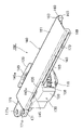
図1に示されるダンパー装置100は、互いに近接離反する一対の部材に取付けられ、該一対の部材が近接又は離反するときに制動力を付与するものであって、例えば、自動車のインストルメントパネルに設けられた収容部の開口部に、開閉可能に取付けられたグローブボックスやリッド等の、制動用として用いることができる。なお、以下の実施形態においては、一方の部材を、インストルメントパネルの収容部等の固定体とし、他方の部材を、固定体の開口部に開閉可能に取付けられた、グローブボックスやリッド等の開閉体として説明するが、一対の部材は互いに近接離反可能なものであれば、特に限定はされない。
A
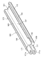
図1や図2に示すように、この実施形態のダンパー装置100は、一方の部材に固定されるケース130と、他方の部材に連結されると共に、ケース130にスライド可能に支持されるラック体160と、ケース130に収容され、ラック体160が、一方向にスライドするときに制動力を作用させ、一方向とは反対方向にスライドするときに制動力を解除する、回転ダンパー110と、前記ケース130内に収容される遊星ギヤ150とを有している。
As shown in FIGS. 1 and 2, the
図3、図9、及び図10を併せて参照すると、回転ダンパー110は、ロータ111と、このロータ111を粘性流体を介して囲み、ロータ111の回転に対して制動力を与えるギヤハウジング115とを有している。ギヤハウジング115は、内側にロータ111を収容する凹部117を有し、外周にギヤが形成された大径ギヤ116と、この大径ギヤ116の凹部117の開口部を封止するキャップ118とを有している。キャップ118の中央部には、ロータ111に設けられた軸部112が挿通される軸挿通孔119が形成されている。また、図10に示すように、大径ギヤ116の下面には、後述するケース130の支持壁131に設けられた円弧状リブ132が嵌合し、回転ダンパー110を回転可能に支持するための環状溝123が形成されている。
3, 9, and 10, the
ロータ111は、全体として円板状をなし、その片面の中央部から軸部112が突設され、軸部112は、シールリング113を介してキャップ118の軸挿通孔119に挿通され、ギヤハウジング115の外部に突出している。また、図9に示すように、この軸部112の先端には、ラック体160の後述する基板161の裏面に点接触可能な、半球状をなした突部112aが突設されている。更に図3に示すように、ピニオンギヤ120は、外周にギヤ部121を有し、中心部に軸孔122が形成されており、この軸孔122に前記軸部112が挿入されて固着され、軸部112とピニオンギヤ120とが一体に回転するようになっている。
The
したがって、大径ギヤ116が回転規制された状態でピニオンギヤ120が回転すると、軸部112を介してロータ111がギヤハウジング115に対して相対回転するので、粘性流体を介してロータ111の回転に対して制動力が付与されるようになっている。また、図8に示すように、ピニオンギヤ120は、ラック体160の、後述する一対の第1側壁163,163(図9参照)の間に配置されて、図11に示すように、一方の第1側壁163の内面に形成されたラックギヤ167に歯合するようになっている。なお、この実施形態では、軸部112先端に突部112aを設けたが、例えば、ピニオンギヤ120の表面中央から突部を突設させて、この突部を、ラック体160の基板裏面に点接触可能とするようにしてもよい。
Therefore, when the
次に、ラック体160について説明する。図4や図8に示すように、このラック体160は、所定長さで長板状に延びる基板161と、この基板161の対向する箇所から立設された一対の第1側壁163,163(ここでは基板161の長手方向に沿って、その両側に一対の第1側壁163,163が設けられている)と、各第1側壁163の外面の、基板161の表面から下がった位置から突出する一対のガイドレール165,165と、一方の第1側壁163の内面に形成されたラックギヤ167とを有している。
Next, the
前記ラックギヤ167は、図4に示すように、一方の第1側壁163の内面側において、第1側壁163の長手方向に沿って形成されており、回転ダンパー110の軸部112に装着されたピニオンギヤ120と歯合するようになっている。したがって、ケース130に対してラック体160がスライド動作すると、ラックギヤ167に歯合するピニオンギヤ120が回転し、軸部112を介してロータ111が回転するようになっている。
As shown in FIG. 4, the
また、図2や図9に示すように、一対のガイドレール165,165の、一対の第1側壁163,163との連結部分には、テーパ面169,169がそれぞれ形成されている。各テーパ面169は、各ガイドレール165の外面側(ケース130の、後述する抜け止め部135に対向する面側)であって、各ガイドレール165の外縁部側から第1側壁163側に向けて、次第に突出量が大きくなるように傾斜し(図9参照)、かつ、ガイドレール165の長手方向全域に亘って形成されている(図2参照)。
2 and 9, tapered
更に、ラック体160の一方の端部には、一対のブラケット171が平行に延出されており、各ブラケット171には取付孔171aがそれぞれ形成されている。この取付孔171aに、例えば、グローブボックスの側壁に突設された取付軸が挿入されて、ラック体160の一端がグローブボックスなどの制動力を付与したい部品に取付けられるようになっている。
Further, a pair of
更に、ラック体160の一対のガイドレール165,165の長手方向の一端部に近接した部分には、それぞれストッパ部173が突設されている。これらのストッパ部173,173は、図8(b)に示すように、ケース130に対してラック体160が引き出されたときに、ケース130の、後述する一対の第2側壁133,133に設けたストッパ係止部134,134(図5及び図7参照)にそれぞれ当接して、ラック体160のそれ以上の引き出しが規制されるようになっている。
Furthermore, a
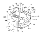
次に、ケース130について説明する。図5~7に示すように、この実施形態のケース130は、回転ダンパー110を回転可能に支持する支持壁131と、この支持壁131の、対向する箇所から立設された、一対の第2側壁133,133と、これらの一対の第2側壁133,133の先端側から内側に向かって延出され、ラック体160の、一対のガイドレール165,165にオーバーラップして、ラック体160を抜け止めする一対の抜け止め部135,135と、一対の抜け止め部135,135との間で、一対のガイドレール165,165を支持するガイドレール支持壁137とを有している。
Next,
より具体的に説明すると、図6に示すように、前記支持壁131は、回転ダンパー110の形状に対応して、略円形状をなしている。この支持壁131の内面側(回転ダンパー110の支持面側)には、一対の円弧状リブ132,132が形成されている。そして、図10に示すように、これらの円弧状リブ132,132が、回転ダンパー110の大径ギヤ116の底面に形成された環状溝123に嵌合して、大径ギヤ116を回転可能に支持するようになっている。
More specifically, as shown in FIG. 6, the
前記一対の第2側壁133,133は、支持壁131の幅方向両側から対向して立設している。図5に示すように、一対の第2側壁133,133は、円弧状に立設すると共に、一端どうしが離間した円弧状壁部133a,133aと、該円弧状壁部133aの他端から互いに平行となるように延出した延出壁部133b,133bとから構成されている。
The pair of
一対の第2側壁133,133の一端側、すなわち、円弧状壁部133a,133aの一端側は、上述したように互いに離間しており、これらの間に、回転ダンパー110を、ケース130の横方向(回転ダンパー110の軸方向に直交する方向)から挿入可能とする、開口部139が設けられている。この開口部139に関連して、前記支持壁131の、開口部139側の位置には、図5に示すように、ケース130に対する回転ダンパー110の挿入方向奥側に向かって、次第に突出高さが高くなるように傾斜したガイド面131aが設けられている。このガイド面131aは、ケース130内への回転ダンパー110の挿入作業性の向上に寄与する。
One end sides of the pair of
また、前記ガイドレール支持壁137は、一対の第2側壁133,133の他端側に、前記開口部139と対向して配置されている。すなわち、図5や図6に示すように、一対の第2側壁133,133を構成する延出壁部133b,133bの他端側に、ガイドレール支持壁137が配置されており、かつ、このガイドレール支持壁137によって、両延出壁部133b,133bどうしが互いに連結されている。また、図6に示すように、このガイドレール支持壁137は、ケース130を回転ダンパー110の軸方向から見たときに、回転ダンパー110の外周から離反して配置されるようになっている。
The guide
更に図7に示すように、ガイドレール支持壁137は、支持壁131の内面側から、第2側壁133の立設方向先端(抜け止め部135が設けられた位置)には至らない長さで立設している(ここでは、回転ダンパー110のギヤハウジング115をカバー可能な高さで立設している)。その結果、図7に示すように、ガイドレール支持壁137の上端面と、一対の抜け止め部135,135の下面(内面)との間に、ラック体160をケース130の横方向から挿入可能とするラック挿入開口141が形成されるようになっている。
Furthermore, as shown in FIG. 7, the guide
また、図5~7に示すように、ガイドレール支持壁137の上端面には、一対の支持突部137a,137aが突設されており、ラック体160の一対のガイドレール165,165をスライド支持可能となっている(図8及び図9参照)。この状態では、ラック体160の基板161の裏面が、回転ダンパー110の軸部112先端の突部112aに支持されて、ラック体160は、突部112aと、一対の支持突部137a,137aとで、3点支持されるようになっている。なお、図9では、支持突部137aとガイドレール165との間にクリアランスがあるが、これは便宜上のものである。
5 to 7, a pair of
更に図7に示すように、一対の第2側壁133,133の内面側であって、ラック挿入開口141に整合する位置には、ラック体160に設けた一対のストッパ部173,173に当接して、ラック体160のケース130からの引出し量を規制する、ストッパ係止部134,134がそれぞれ突設されている。
Further, as shown in FIG. 7 , a pair of
また、図6に示すように、ガイドレール支持壁137の幅方向中央であって、その内面側からは、係合部142が突設されており、該係合部142を介して、一対の第2側壁133,133の間に、収容部140,140が画成されている。更に、図11や図12に示すように、一方の収容部140には、回転ダンパー110の大径ギヤ116に歯合する遊星ギヤ150が、回転可能に収容配置されている。この遊星ギヤ150は、係合部142の角部に係合することで回転規制されて、大径ギヤ116の回転を規制すると共に(図11参照)、係合部142の角部から離反することで回転可能となって、大径ギヤ116の回転を許容するようになっている(図12参照)。
As shown in FIG. 6, an engaging
図6に示すように、前記一対の抜け止め部135,135は、一対の第2側壁133,133の立設方向の先端部の向き合う面から、互いに近づく方向となるようにそれぞれ延出しており、それらの延出方向先端に位置する対向面135a,135aどうしが互いに平行となるように延設されている。
As shown in FIG. 6, the pair of retaining
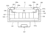
そして、このダンパー装置100においては、図9に示すように、一対の抜け止め部135,135の、延出方向先端に位置する対向面135a,135aどうしの最小距離L(ここでは、後述する弾接部145,145に設けた突部145a,145aどうしの距離)が、回転ダンパー110の最大外径R(ここでは大径ギヤ116の外径)よりも小さく形成されており、前記対向面135a,135a間に形成される領域E(図7参照)内に、ラック体160の基板161及び/又は第1側壁163の一部が入り込むように構成されている。図9に示すように、この実施形態では、一対の抜け止め部135,135のの対向面135a,135a間の領域E内に、一対の第1側壁163,163の基端部側が入り込むように構成されている。ただし、一対の抜け止め部135,135の間に、基板161のみを入り込むように構成したり、基板161及び抜け止め部135の一部の両方を入り込むように構成したりしてもよい。
In the
また、図6~10に示すように、一対の抜け止め部135,135の対向面135a,135aには、前記領域E(図7参照)内に、ラック体160の基板161及び/又は第1側壁163の少なくとも一部が入り込んだときに、ラック体160のテーパ面169に弾接する弾接部145が設けられている。図6に示すように、この実施形態では、各抜け止め部135の、第2側壁133の他端寄りの部分(ガイドレール支持壁137寄りの部分)から、第2側壁133の一端側に向けて、所定長さのスリット144が形成されており、該スリット144を介して撓み変形可能な弾接部145が設けられている。また、一方の抜け止め部135に設けた弾接部145の外面側(対向面135a側)からは、他方の抜け止め部135に向けて、突部145aが突設されている。なお、弾性部の弾性付与構造としては、抜け止め部にスリットを形成する以外にも、例えば、抜け止め部を肉薄にしたりしてもよく、特に限定はされない。
Further, as shown in FIGS. 6 to 10, the opposing
そして、ケース130内に回転ダンパー110を回転可能に収容配置すると共に、一対の抜け止め部135,135の対向面135a,135a間の領域E内に、ラック体160の基板161及び/又は第1側壁163の一部が入り込んで、ラック体160をケース130にスライド可能に装着した状態では、図9に示すように、抜け止め部135,135の弾接部145,145に設けた突部145a,145aが、一対のガイドレール165,165に形成したテーパ面169,169にそれぞれ当接するようになっている。
Rotating
また、図9に示すように、支持壁131外面(下面)側には、ダンパー作用を与える部材に取付けるためのフック147が設けられている。例えば、グローブボックスに適用される場合には、このフック147が車体側に設けられた本体部の側壁に取付けられ、ラック体160のブラケット171が、本体部に対して開閉可能に装着されるグローブボックスの側壁に連結されるようになっている。
Further, as shown in FIG. 9, the outer surface (lower surface) of the
なお、以上説明した、ケースや、ラック体、回転ダンパー等の形状や構造は、あくまでも一例であり、上記のような構造に限定されるものではない。 The shapes and structures of the case, rack body, rotary damper, etc. described above are merely examples, and the structures are not limited to those described above.
次に、上記構成からなるダンパー装置100の作用効果について説明する。
Next, the effects of the
ダンパー装置100を組立てる際には、例えば、次のようにして行うことができる。まず、図1の矢印K1に示すように、ケース130の上方開口部から、一方の収容部143に、遊星ギヤ150を載置する。次に、図1の矢印K2に示すように、一対の第2側壁133,133の一端側の開口部139から、回転ダンパー110をケース130の横方向から挿入して、支持壁131の内面に載置し、一対の円弧状リブ132,132を、大径ギヤ116下面の環状溝123に嵌入することで、ケース130内に回転ダンパー110を横ずれしないように回転支持する。
For example, the
次に、図1の矢印K3に示すように、ガイドレール支持壁137と一対の抜け止め部135,135との間に形成した、ラック挿入開口141(図7参照)から、ラック体160を、ケース130の横方向から挿入していく(すなわち、ケース130内への回転ダンパー110の挿入方向K1と、ケース130内への回転ダンパー110の挿入方向K2とは、互いに逆向きとなる)。すると、ガイドレール支持壁137の上端面に設けた一対の支持突部137a,137aによって、一対のガイドレール165,165が支持されながら、ラック体160が押込まれていき、一対の第1側壁163,163の間に、回転ダンパー110のピニオンギヤ120が挿入されつつ、一対の抜け止め部135,135の間に、一対の第1側壁163,163の基端部が入り込む。それと共に、弾接部145,145の突部145a,145aが、一対のガイドレール165,165のテーパ面169,169に押圧されて、弾接部145,145が撓み変形する。そして、ラック体160に設けた一対のストッパ部173,173が、ケース130側の一対のストッパ係止部134,134(図7参照)を乗り越えると、ストッパ部173とストッパ係止部134とが係止可能となり、ケース130からラック体160が抜け外れないように、スライド可能に装着される。このようにして、各構成部材からなるダンパー装置100を組立てることができる。ただし、例えば、ケース130内に回転ダンパー110を回転可能に配置した後、遊星ギヤ150を載置し、その後、ラック体160をスライド可能となるように組付けてもよく(図1のK2、K1、K3の順)、組立手順は特に限定されない。
Next, as indicated by the arrow K3 in FIG. 1, the
そして、このダンパー装置100においては、図9に示すように、一対の抜け止め部135,135の対向面135a,135aどうしの最小距離L(ここでは、弾接部145,145に設けた突部145a,145aどうしの距離)が、回転ダンパー110の最大外径R(ここでは大径ギヤ116の外径)よりも小さく形成されており、前記対向面135a,135a間に形成される領域E(図7参照)内に、ラック体160の基板161及び/又は第1側壁163の一部が入り込む(ここでは、一対の第1側壁163,163の基端部側が入り込む)ように構成されている。
In this
そのため、一対の抜け止め部135,135の対向面135a,135aどうしの最小距離Lをなるべく小さくすることができ、それによって、ラック体160の基板161の幅を小さくすることができ、ダンパー装置100を幅狭にすることができる。また、図7に示すような領域E内に、ラック体160の基板161及び/又は第1側壁163の一部が入り込むように構成されているので、一対の抜け止め部135,135の厚さ方向に、ラック体160が重なる(ラップする)ことになり、その分だけ、ダンパー装置100を薄くすることができる。
Therefore, the minimum distance L between the facing
また、この実施形態においては、図5に示すように、ケース130には、抜け止め部135との間で、ガイドレール165を支持するガイドレール支持壁137が設けられており、このガイドレール支持壁137は、図6に示すように、ケース130を回転ダンパー110の軸方向から見たときに、回転ダンパー110の外周から離間して配置されている。そのため、ケース130内のスペースを有効活用して、回転ダンパー110を収容配置しつつ、ガイドレール支持壁137を設けることができ、ダンパー装置100の幅狭化及び薄型化を、より効果的に図ることができる(仮に、回転ダンパー110の外周とガイドレール支持壁137と離間していないと、ケース130の支持壁131を、一対の抜け止め部135,135から離反させて、回転ダンパー110を下げたり、或いは、支持壁131を広げたりして、ガイドレール支持壁137を設ける必要があり、ダンバー装置10の大型化につながる)。
In this embodiment, as shown in FIG. 5, the
また、この実施形態においては、図5や図6に示すように、一対の第2側壁133,133の一端側に、回転ダンパー110を挿入可能とする、開口部139が設けられていると共に、一対の第2側壁133,133の他端側に、ガイドレール支持壁137が配置され、一対の第2側壁133,133どうしを連結するように構成されている。そのため、一対の第2側壁133,133の一端側の開口部139から、回転ダンパー110を挿入して、ケース130内に収容することができる。また、一対の第2側壁133,133の他端側から、ガイドレール支持壁137で支持させながらラック体160を挿入することができる。このように、一対の第2側壁133,133の一端側及び他端側から、回転ダンパー110とラック体160をそれぞれ挿入して組付けることができるので、ダンパー装置100の組立て作業性を向上させることができる。また、一対の第2側壁133,133の他端側に配置されたガイドレール支持壁137によって、一対の第2側壁133,133どうしが連結されるので、一対の第2側壁133,133の剛性を確保することができる。
Further, in this embodiment, as shown in FIGS. 5 and 6, an
更にこの実施形態においては、回転ダンパー110には、基板161の裏面に点接触可能な突部112aが設けられている。そのため、図9に示すように、ラック体160は、その一対のガイドレール165,165が、ガイドレール支持壁137で支持されると共に(ここではガイドレール支持壁137の上端面に突設した、一対の支持突部137a,137aにより支持される)、基板161の裏面が、回転ダンパー110の軸部112の突部112aで支持されて、3点によって支持されるため、ラック体160のガタ付きを少なくしつつスライド可能に支持することができる。また、回転ダンパー110に設けた突部112aが、基板161の裏面に点接触するので、突部112aが基板161の裏面に当接するまで、一対の第1側壁163,163どうしの間に、軸部112を深く挿入することができ、ピニオンギヤ120とラックギヤ167とを、回転ダンパー110の軸方向に近接させることが可能となり、ダンパー装置100の薄型化に寄与する。
Furthermore, in this embodiment, the
また、この実施形態においては、図2や図9に示すように、一対のガイドレール165,165の、一対の第1側壁163,163との連結部分には、テーパ面169,169がそれぞれ形成されていると共に、図6~9に示すように、一対の抜け止め部135,135の対向面135a,135aには、図7に示すような領域E内に、ラック体160の基板161及び/又は第1側壁163の少なくとも一部が入り込んだときに、ラック体160のテーパ面169に弾接する(ラック体160のテーパ面169に押圧されて撓み変形する)弾接部145が設けられている(ここでは弾接部145,145の外面側に設けた突部145a,145aがテーパ面169,169にそれぞれ当接する)。そのため、ラック体160をケース130にスライド可能に支持させたときに、一対の抜け止め部135,135の弾接部145,145が、一対のガイドレール165,165のテーパ面169,169にそれぞれ押圧されて(図9の矢印F1参照)、その反力の一部が、テーパ面169によって矢印F2に示すような下向きの力に変換されて、ラック体160を回転ダンパー110に近接する方向に向けて押し付けるため、ラック体160のガタ付きを、より少なくすることができる。
Further, in this embodiment, as shown in FIGS. 2 and 9, tapered
また、このダンパー装置100は、制動力を与えたい、近接離反する一対の部品間に装着される。例えば、グローブボックスの場合には、前述したように、車体側に設けられた本体部の側壁にケース130のフック147が連結され、本体部に対して開閉動作を行うグローブボックスの側壁にブラケット171が取付孔171aを介して連結される。そして、グローブボックスを閉じた状態では、図8(a)に示すように、ブラケット171がケース130に近接した位置にあり、グローブボックスが引き出されるときには、ケース130に対してラック体160が引き出されてストッパ部173がケース130のストッパ係止部134(図5参照)に当接したところで、それ以上の引き出しが規制されるようになっている。この実施形態では、グローブボックスを引き出すとき、すなわち、図8(a)から同図(b)に至る過程において、回転ダンパー110による制動力が付与され、グローブボックスが急激に開かないようにするために、ダンパー装置100が用いられている。
Also, the
図11に示すように、ケース130に対してラック体160がA方向に引き出されるとき、ラックギヤ167に歯合するピニオンギヤ120が図中の矢印Cで示す反時計回りの方向に回転する。すると、ピニオンギヤ120に軸部112を介して連設されたロータ111が回転し、粘性流体を介してロータ111に接触するギヤハウジング115も同方向に回転しようとする。その結果、大径ギヤ116が図11中の矢印Cで示す反時計回り方向に回転し、大径ギヤ116に歯合する遊星ギヤ150が収容部143内にて反時計回りの方向に移動する。すると、遊星ギヤ150が係合部142の角部に係合し、遊星ギヤ150の回転が規制されるので、大径ギヤ116の回転が停止し、ギヤハウジング115内でロータ111のみが回転することになる。このため、粘性流体を介してロータ111の回転に対する制動力が付与され、ラック体160の矢印A方向への移動に対する制動力として作用する。それによってグローブボックスが急激に開くことを抑制できる。
As shown in FIG. 11, when
次に、図12に示すように、ケース130に対してラック体160がB方向に押し込まれるとき、ラックギヤ167に歯合するピニオンギヤ120が図12中の矢印Dで示す時計回りの方向に回転する。すると、ピニオンギヤ120に軸部112を介して連設されたロータ111が回転し、粘性流体を介してロータ111に接触するギヤハウジング115も同方向に回転しようとする。その結果、大径ギヤ116が図12中の矢印Dで示す時計回り方向に回転し、大径ギヤ116に歯合する遊星ギヤ150が収容部143内にて時計回りの方向に移動する。すると、収容部140内での遊星ギヤ150の回転が許容されるので、ロータ111と一緒に大径ギヤ116も回転し、ラック体160の移動に対する制動力が解除される。その結果、ラック体160はケース130に対して抵抗感が少なく押し込まれ、グローブボックスが閉じる動作を迅速に行わせることができる。
Next, as shown in FIG. 12, when
なお、本発明は、上述した実施形態に限定されるものではなく、本発明の要旨の範囲内で、各種の変形実施形態が可能であり、そのような実施形態も本発明の範囲に含まれる。 The present invention is not limited to the above-described embodiments, and various modified embodiments are possible within the scope of the present invention, and such embodiments are also included in the scope of the present invention. .
100 ダンパー装置
110 回転ダンパー
112 軸部
112a 突部
120 ピニオンギヤ
130 ケース
131 支持壁
133 第2側壁
135 抜け止め部
137 ガイドレール支持壁
139 開口部
145 弾接部
150 遊星ギヤ
160 ラック体
161 基板
163 第1側壁
165 ガイドレール
167 ラックギヤ
169 テーパ面100
Claims (5)
一方の部材に固定されるケースと、他方の部材に連結されると共に、前記ケースにスライド可能に支持されるラック体と、前記ケースに収容され、前記ラック体がスライドするときに制動力を作用させる、回転ダンパーとを有しており、
前記ラック体は、所定長さで延びる基板と、該基板の対向する箇所から立設された一対の第1側壁と、各第1側壁の外面から突出する一対のガイドレールと、一方の第1側壁の内面に形成されたラックギヤとを有しており、
前記回転ダンパーは、前記一対の第1側壁の間に配置され、前記ラックギヤに歯合するピニオンギヤを有しており、
前記ケースは、前記回転ダンパーを回転可能に支持する支持壁と、該支持壁の、対向する箇所から立設された一対の第2側壁と、該一対の第2側壁の先端側から内側に向かって延出され、前記ガイドレールにオーバーラップして前記ラック体を抜け止めする一対の抜け止め部とを有しており、
前記一対の抜け止め部の、延出方向先端に位置する対向面どうしの最小距離が、前記回転ダンパーの最大外径よりも小さく形成されており、前記対向面間に形成される領域内に、前記基板及び/又は前記第1側壁の一部が入り込むように構成されていることを特徴とするダンパー装置。A damper device that is attached between a pair of members that approach and separate from each other and applies a braking force when the pair of members approach or separate,
A case fixed to one member, a rack body connected to the other member and slidably supported by the case, and a braking force applied when the rack body slides are housed in the case. and a rotary damper,
The rack body includes a substrate extending with a predetermined length, a pair of first side walls erected from opposing portions of the substrate, a pair of guide rails projecting from the outer surface of each first side wall, and one first rail. and a rack gear formed on the inner surface of the side wall,
The rotary damper has a pinion gear disposed between the pair of first side walls and meshing with the rack gear,
The case includes a support wall that rotatably supports the rotary damper, a pair of second side walls that are erected from opposing portions of the support wall, and a pair of second side walls extending inward from tip sides of the pair of second side walls. and a pair of retaining portions that extend through the guide rails and overlap the guide rails to retain the rack body,
The minimum distance between the facing surfaces located at the ends in the extending direction of the pair of retaining parts is formed to be smaller than the maximum outer diameter of the rotary damper, and in the region formed between the facing surfaces, A damper device, wherein a part of the substrate and/or the first side wall is recessed.
前記一対の抜け止め部の対向面には、前記領域内に、前記基板及び/又は前記第1側壁の一部が入り込んだときに、前記テーパ面に弾接する弾接部が設けられている請求項1~4のいずれか1つに記載のダンパー装置。A tapered surface is formed in each of the pair of guide rails at a portion connected to the first side wall,
The opposed surfaces of the pair of retaining portions are provided with elastic contact portions that make elastic contact with the tapered surfaces when the substrate and/or the first side wall partially enters the region. Item 5. The damper device according to any one of items 1 to 4.
Applications Claiming Priority (3)
| Application Number | Priority Date | Filing Date | Title |
|---|---|---|---|
| JP2019099441 | 2019-05-28 | ||
| JP2019099441 | 2019-05-28 | ||
| PCT/JP2020/020393 WO2020241519A1 (en) | 2019-05-28 | 2020-05-22 | Damper device |
Publications (2)
| Publication Number | Publication Date |
|---|---|
| JPWO2020241519A1 JPWO2020241519A1 (en) | 2020-12-03 |
| JP7133710B2 true JP7133710B2 (en) | 2022-09-08 |
Family
ID=73553437
Family Applications (1)
| Application Number | Title | Priority Date | Filing Date |
|---|---|---|---|
| JP2021522327A Active JP7133710B2 (en) | 2019-05-28 | 2020-05-22 | damper device |
Country Status (2)
| Country | Link |
|---|---|
| JP (1) | JP7133710B2 (en) |
| WO (1) | WO2020241519A1 (en) |
Citations (5)
| Publication number | Priority date | Publication date | Assignee | Title |
|---|---|---|---|---|
| JP2008163667A (en) | 2006-12-28 | 2008-07-17 | Nifco Inc | Damper device |
| JP2009516132A (en) | 2005-11-14 | 2009-04-16 | イリノイ トゥール ワークス インコーポレイティド | Viscous strand damper assembly |
| JP2009203990A (en) | 2008-02-26 | 2009-09-10 | Piolax Inc | Damper device |
| WO2012117654A1 (en) | 2011-03-02 | 2012-09-07 | 株式会社ニフコ | Rotary damper device and method for producing same |
| WO2018181905A1 (en) | 2017-03-31 | 2018-10-04 | 株式会社ニフコ | One-way damper mechanism |
Family Cites Families (1)
| Publication number | Priority date | Publication date | Assignee | Title |
|---|---|---|---|---|
| WO2012070583A1 (en) * | 2010-11-24 | 2012-05-31 | 株式会社ニフコ | Damper device |
-
2020
- 2020-05-22 JP JP2021522327A patent/JP7133710B2/en active Active
- 2020-05-22 WO PCT/JP2020/020393 patent/WO2020241519A1/en active Application Filing
Patent Citations (5)
| Publication number | Priority date | Publication date | Assignee | Title |
|---|---|---|---|---|
| JP2009516132A (en) | 2005-11-14 | 2009-04-16 | イリノイ トゥール ワークス インコーポレイティド | Viscous strand damper assembly |
| JP2008163667A (en) | 2006-12-28 | 2008-07-17 | Nifco Inc | Damper device |
| JP2009203990A (en) | 2008-02-26 | 2009-09-10 | Piolax Inc | Damper device |
| WO2012117654A1 (en) | 2011-03-02 | 2012-09-07 | 株式会社ニフコ | Rotary damper device and method for producing same |
| WO2018181905A1 (en) | 2017-03-31 | 2018-10-04 | 株式会社ニフコ | One-way damper mechanism |
Also Published As
| Publication number | Publication date |
|---|---|
| JPWO2020241519A1 (en) | 2020-12-03 |
| WO2020241519A1 (en) | 2020-12-03 |
Similar Documents
| Publication | Publication Date | Title |
|---|---|---|
| JP6038136B2 (en) | Opening and closing body locking device | |
| US10480223B2 (en) | Lock device for opening and closing body | |
| JP6467523B2 (en) | Opening and closing body locking device | |
| US5195272A (en) | Lid switching device | |
| JP6175130B2 (en) | Switchgear | |
| EP2776652B1 (en) | Self-aligning rotary damper assembly | |
| KR20030076197A (en) | Sliding and rotational motion guide mechanism and opening/closing mechanism for lid body by using the same and on-vehicle interior equipment by using the opening/closing mechanism | |
| JP5396067B2 (en) | Tray device | |
| JPWO2018181905A1 (en) | One-way damper mechanism | |
| US20170253195A1 (en) | Tether clip and structure for coupling the tether clip to a pillar garnish | |
| JP7133710B2 (en) | damper device | |
| JP7133709B2 (en) | damper device | |
| JPWO2020080342A1 (en) | Locking device for opening and closing body | |
| KR101996289B1 (en) | Flow Protection Device of Damper for Glovebox | |
| US20220161731A1 (en) | Locking device for opening/closing body | |
| US20170072862A1 (en) | Console assembly | |
| JP2000055021A (en) | Part attaching clip | |
| JP2013133874A (en) | Vibration control clamp | |
| JP7269372B2 (en) | unlocking device | |
| US9777519B1 (en) | Door checker unit for vehicle | |
| KR100645137B1 (en) | Structure for preventing the brake way of glove box for motors | |
| WO2021045066A1 (en) | Boosting device for opening/closing body | |
| JP7191480B2 (en) | Fastener | |
| KR102335393B1 (en) | Variable hidden cup holder for vehicle | |
| JP6759123B2 (en) | Box door device |
Legal Events
| Date | Code | Title | Description |
|---|---|---|---|
| A621 | Written request for application examination |
Free format text: JAPANESE INTERMEDIATE CODE: A621 Effective date: 20211119 |
|
| TRDD | Decision of grant or rejection written | ||
| A01 | Written decision to grant a patent or to grant a registration (utility model) |
Free format text: JAPANESE INTERMEDIATE CODE: A01 Effective date: 20220823 |
|
| A61 | First payment of annual fees (during grant procedure) |
Free format text: JAPANESE INTERMEDIATE CODE: A61 Effective date: 20220829 |
|
| R150 | Certificate of patent or registration of utility model |
Ref document number: 7133710 Country of ref document: JP Free format text: JAPANESE INTERMEDIATE CODE: R150 |