JP7133709B2 - damper device - Google Patents
damper device Download PDFInfo
- Publication number
- JP7133709B2 JP7133709B2 JP2021522326A JP2021522326A JP7133709B2 JP 7133709 B2 JP7133709 B2 JP 7133709B2 JP 2021522326 A JP2021522326 A JP 2021522326A JP 2021522326 A JP2021522326 A JP 2021522326A JP 7133709 B2 JP7133709 B2 JP 7133709B2
- Authority
- JP
- Japan
- Prior art keywords
- gear
- planetary gear
- damper device
- damper
- rotation
- Prior art date
- Legal status (The legal status is an assumption and is not a legal conclusion. Google has not performed a legal analysis and makes no representation as to the accuracy of the status listed.)
- Active
Links
Images


Classifications
-
- E—FIXED CONSTRUCTIONS
- E05—LOCKS; KEYS; WINDOW OR DOOR FITTINGS; SAFES
- E05F—DEVICES FOR MOVING WINGS INTO OPEN OR CLOSED POSITION; CHECKS FOR WINGS; WING FITTINGS NOT OTHERWISE PROVIDED FOR, CONCERNED WITH THE FUNCTIONING OF THE WING
- E05F3/00—Closers or openers with braking devices, e.g. checks; Construction of pneumatic or liquid braking devices
- E05F3/14—Closers or openers with braking devices, e.g. checks; Construction of pneumatic or liquid braking devices with fluid brakes of the rotary type
-
- E—FIXED CONSTRUCTIONS
- E05—LOCKS; KEYS; WINDOW OR DOOR FITTINGS; SAFES
- E05F—DEVICES FOR MOVING WINGS INTO OPEN OR CLOSED POSITION; CHECKS FOR WINGS; WING FITTINGS NOT OTHERWISE PROVIDED FOR, CONCERNED WITH THE FUNCTIONING OF THE WING
- E05F3/00—Closers or openers with braking devices, e.g. checks; Construction of pneumatic or liquid braking devices
- E05F3/22—Additional arrangements for closers, e.g. for holding the wing in opened or other position
- E05F3/221—Mechanical power-locks, e.g. for holding the wing open or for free-moving zones
-
- F—MECHANICAL ENGINEERING; LIGHTING; HEATING; WEAPONS; BLASTING
- F16—ENGINEERING ELEMENTS AND UNITS; GENERAL MEASURES FOR PRODUCING AND MAINTAINING EFFECTIVE FUNCTIONING OF MACHINES OR INSTALLATIONS; THERMAL INSULATION IN GENERAL
- F16D—COUPLINGS FOR TRANSMITTING ROTATION; CLUTCHES; BRAKES
- F16D41/00—Freewheels or freewheel clutches
- F16D41/18—Freewheels or freewheel clutches with non-hinged detent
-
- F—MECHANICAL ENGINEERING; LIGHTING; HEATING; WEAPONS; BLASTING
- F16—ENGINEERING ELEMENTS AND UNITS; GENERAL MEASURES FOR PRODUCING AND MAINTAINING EFFECTIVE FUNCTIONING OF MACHINES OR INSTALLATIONS; THERMAL INSULATION IN GENERAL
- F16F—SPRINGS; SHOCK-ABSORBERS; MEANS FOR DAMPING VIBRATION
- F16F9/00—Springs, vibration-dampers, shock-absorbers, or similarly-constructed movement-dampers using a fluid or the equivalent as damping medium
- F16F9/10—Springs, vibration-dampers, shock-absorbers, or similarly-constructed movement-dampers using a fluid or the equivalent as damping medium using liquid only; using a fluid of which the nature is immaterial
- F16F9/12—Devices with one or more rotary vanes turning in the fluid any throttling effect being immaterial, i.e. damping by viscous shear effect only
-
- F—MECHANICAL ENGINEERING; LIGHTING; HEATING; WEAPONS; BLASTING
- F16—ENGINEERING ELEMENTS AND UNITS; GENERAL MEASURES FOR PRODUCING AND MAINTAINING EFFECTIVE FUNCTIONING OF MACHINES OR INSTALLATIONS; THERMAL INSULATION IN GENERAL
- F16H—GEARING
- F16H19/00—Gearings comprising essentially only toothed gears or friction members and not capable of conveying indefinitely-continuing rotary motion
- F16H19/02—Gearings comprising essentially only toothed gears or friction members and not capable of conveying indefinitely-continuing rotary motion for interconverting rotary or oscillating motion and reciprocating motion
- F16H19/04—Gearings comprising essentially only toothed gears or friction members and not capable of conveying indefinitely-continuing rotary motion for interconverting rotary or oscillating motion and reciprocating motion comprising a rack
-
- E—FIXED CONSTRUCTIONS
- E05—LOCKS; KEYS; WINDOW OR DOOR FITTINGS; SAFES
- E05Y—INDEXING SCHEME RELATING TO HINGES OR OTHER SUSPENSION DEVICES FOR DOORS, WINDOWS OR WINGS AND DEVICES FOR MOVING WINGS INTO OPEN OR CLOSED POSITION, CHECKS FOR WINGS AND WING FITTINGS NOT OTHERWISE PROVIDED FOR, CONCERNED WITH THE FUNCTIONING OF THE WING
- E05Y2900/00—Application of doors, windows, wings or fittings thereof
- E05Y2900/50—Application of doors, windows, wings or fittings thereof for vehicles
- E05Y2900/53—Application of doors, windows, wings or fittings thereof for vehicles characterised by the type of wing
- E05Y2900/538—Interior lids
Description
本発明は、例えば車両のグローブボックスなどに適用して、グローブボックスを開く時などの所定の動作時にダンパー作用を与えるダンパー装置に関する。 BACKGROUND OF THE INVENTION 1. Field of the Invention The present invention relates to a damper device that is applied to, for example, a glove box of a vehicle and that exerts a damping action during a predetermined operation such as opening the glove box.
例えば車両のグローブボックスなどの開閉体には、開閉体が急激に開いたりすることを抑制するため、ダンパー装置が設けられることがある。このようなダンパー装置は、各種の機構のものが知られており、その1つとして、回転ダンパーを利用したものが知られている。回転ダンパーを利用したダンパー装置は、装置をコンパクト化しやすいという利点を有している。 For example, an opening/closing body such as a glove box of a vehicle is sometimes provided with a damper device in order to suppress the sudden opening of the opening/closing body. Such damper devices are known to have various mechanisms, one of which is known to use a rotary damper. A damper device using a rotary damper has the advantage that the device can be easily made compact.
回転ダンパーを利用したダンパー装置として、下記特許文献1には、第一パーツと、この第一パーツに回転又は相対的に回転可能に組み合わされた第二パーツと、両パーツ間に充填された粘性流体とを備え、この粘性流体により前記回転に制動力を作用させるように構成されると共に、前記第一パーツ及び第二パーツのいずれか一方にピニオン部を備えさせてなる回転ダンパー体と、この回転ダンパー体の前記第一パーツ及び第二パーツの他方に設けられた凹所に対する突所を備え、この凹所に突所を納めてこの回転ダンパー体を回転可能に支持する支持体とを備えてなり、この凹所及び突所に、前記ピニオン部に組み合わされるラック体の一方向に向けた移動又は相対的な移動時にこのラック体と同じ方向への回転ダンパー体の移動により係合し合うと共に、このラック体の他方向に向けた移動又は相対的な移動時にはこのラック体と同じ方向への回転ダンパー体の移動により係合を解く、係合部を形成させてなることを特徴とするダンパー装置が開示されている。 As a damper device using a rotary damper, the following patent document 1 discloses a first part, a second part that is combined to be rotatable or relatively rotatable with this first part, and a viscous a rotary damper body configured to apply a braking force to the rotation by the viscous fluid, and having a pinion portion provided on either one of the first part and the second part; a supporting body for rotatably supporting the rotary damper body by housing the protrusion in the recess provided in the other of the first part and the second part of the rotary damper body; The depression and the protrusion are engaged with each other by the movement of the rotary damper body in the same direction as the rack body when the rack body combined with the pinion part is moved in one direction or when the rack body is moved relative to the pinion part. Also, when the rack is moved in the other direction or relatively moved, the engagement is released by moving the rotary damper in the same direction as the rack. A damper device is disclosed.
しかしながら、上記特許文献1のダンパー装置では、ラック体の移動に伴って回転ダンパー体自体を支持体に対して移動させて、凹所と突所の係合及び係合解除をするようにしているので、ラック体の移動方向の反転時における係合解除状態から係合状態への切り替えを円滑に行い難く、制動力応答性が良好でないという問題があった。 However, in the damper device of Patent Document 1, the rotary damper body itself is moved with respect to the support body as the rack body is moved to engage and disengage the recess and the projection. Therefore, it is difficult to smoothly switch from the disengaged state to the engaged state when the moving direction of the rack body is reversed, and the braking force response is not good.
したがって、本発明の目的は、ラック体の移動方向の反転時における制動力応答性の良好なダンパー装置を提供することにある。 SUMMARY OF THE INVENTION Accordingly, it is an object of the present invention to provide a damper device having a good damping force response when the moving direction of the rack body is reversed.
上記目的を達成するため、本発明のダンパー装置は、
長さ方向に沿って形成されたラックギヤを有するラック体と、前記ラックギヤに歯合するピニオンギヤ及び外周に設けられた大径ギヤを有する回転ダンパーと、前記大径ギヤに歯合して配置される遊星ギヤと、前記ラック体をスライド可能に保持すると共に、前記回転ダンパー及び前記遊星ギヤを回転可能に収容するケースとを備え、
前記回転ダンパーは、前記ピニオンギヤに連結されたロータと、粘性流体を介して前記ロータを囲み、前記ロータに対して相対回転可能に装着され、外周に前記大径ギヤを有するギヤハウジングとを有しており、
前記ケースは、前記遊星ギヤを前記回転ダンパーの前記大径ギヤに歯合させた状態で前記大径ギヤの周方向に沿って所定距離移動可能に収容する収容部と、該収容部の内壁の一側に設けられ、前記遊星ギヤが当接したとき、その回転を規制する係合部と、前記収容部の内壁の前記一側に対向する他側に設けられ、前記遊星ギヤが当接した状態でその回転を許容する回転許容部とを有しており、
前記ラック体が所定方向に移動するとき、前記ギヤハウジングの回転に伴って前記遊星ギヤが前記収容部の一側に移動し、前記係合部に係合して回転を規制され、前記ラック体が前記とは反対側に移動するとき、前記ギヤハウジングの回転に伴って前記遊星ギヤが前記収容部の他側に移動し、前記回転許容部に当接して回転を許容されるように構成されていることを特徴とする。In order to achieve the above object, the damper device of the present invention includes:
A rack body having a rack gear formed along the length direction, a rotary damper having a pinion gear meshing with the rack gear and a large-diameter gear provided on the outer periphery, and arranged to mesh with the large-diameter gear. A planetary gear, and a case that slidably holds the rack body and rotatably houses the rotary damper and the planetary gear,
The rotary damper has a rotor connected to the pinion gear, and a gear housing that surrounds the rotor via a viscous fluid, is mounted rotatably relative to the rotor, and has the large-diameter gear on its outer periphery. and
The case includes an accommodating portion that accommodates the planetary gear so as to be movable by a predetermined distance along the circumferential direction of the large-diameter gear in a state in which the planetary gear is meshed with the large-diameter gear of the rotary damper, and an inner wall of the accommodating portion. An engaging portion provided on one side for restricting the rotation of the planetary gear when the planetary gear abuts thereon; and a rotation permitting portion that permits the rotation in a state,
When the rack body moves in a predetermined direction, the planetary gear moves to one side of the accommodating portion as the gear housing rotates, engages with the engaging portion to be restricted from rotating, and rotates the rack body. When the gear housing moves to the opposite side, the planetary gear moves to the other side of the receiving portion with the rotation of the gear housing, contacts the rotation allowing portion, and is allowed to rotate. It is characterized by
本発明によれば、ラック体が所定方向に移動するとき、ギヤハウジングの回転に伴って遊星ギヤが収容部の一側に移動し、係合部に係合して回転を規制されるので、遊星ギヤを介してギヤハウジングの回転が停止し、ギヤハウジングに対してロータが回転することにより、粘性流体を介してロータの回転に対して制動力が付与され、ラック体の移動に対する制動力が付与される。 According to the present invention, when the rack body moves in a predetermined direction, the planetary gear moves to one side of the accommodating portion as the gear housing rotates, and engages with the engaging portion to restrict rotation. The rotation of the gear housing stops via the planetary gears, and the rotor rotates with respect to the gear housing, so that a braking force is applied to the rotation of the rotor via the viscous fluid, and a braking force is applied to the movement of the rack body. Granted.
また、ラック体が前記とは反対側に移動するときには、ギヤハウジングの回転に伴って遊星ギヤが収容部の他側に移動し、回転許容部に当接して回転を許容されるので、ロータの回転に連れまわるようにギヤハウジングが回転し、ロータの回転に対する制動力が解除され、ラック体の移動に対する制動力が解除される。 Further, when the rack body moves to the opposite side to the above, the planetary gear moves to the other side of the accommodating portion with the rotation of the gear housing and abuts against the rotation permitting portion to allow rotation, thereby preventing the rotor from rotating. The gear housing rotates along with the rotation, the braking force against the rotation of the rotor is released, and the braking force against the movement of the rack body is released.
そして、ギヤハウジングの回転規制や回転規制解除は、遊星ギヤが収容部内を移動することによってなされるので、切り替え動作を円滑に行うことができ、ラック体の移動方向の反転時における制動力応答性を良好にすることができる。 Since the rotation of the gear housing is restricted or released by the movement of the planetary gears within the accommodating portion, the switching operation can be performed smoothly, and the braking force response when the moving direction of the rack body is reversed. can be improved.
以下、図面を参照して、本発明に係るダンパー装置の実施形態について説明する。図1~11には、本発明に係るダンパー装置の一実施形態が示されている。 An embodiment of a damper device according to the present invention will be described below with reference to the drawings. 1 to 11 show an embodiment of a damper device according to the invention.
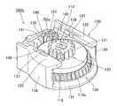
図1,2に示すように、このダンパー装置100は、回転ダンパー110と、該回転ダンパー110を回転可能に保持するケース130と、回転ダンパー110に対してスライド可能に装着され、回転ダンパー110に設けられたピニオンギヤ120に歯合するラックギヤ170(図6参照)を有するラック体160とを備えている。
As shown in FIGS. 1 and 2, the
図3,4,5を併せて参照すると、回転ダンパー110は、ロータ111と、このロータ111を粘性流体を介して囲み、ロータ111の回転に対して制動力を与えるギヤハウジング115とを有している。ギヤハウジング115は、内側にロータ111を収容する凹部117を有し、外周にギヤが形成された大径ギヤ116と、この大径ギヤ116の凹部117の開口部を封止するキャップ118とを有している。キャップ118の中央部には、ロータ111に設けられた支軸112が挿通される軸挿通孔119が形成されている。また、大径ギヤ116の下面には、後述するケース130の底壁131に設けられた円弧状リブ132が嵌合し、回転ダンパー110を回転可能に支持するための環状溝123が形成されている(図5参照)。
3, 4 and 5 together, the
ロータ111は、全体として円板状をなし、その片面の中央部から支軸112が突設され、支軸112は、シールリング113を介してキャップ118の軸挿通孔119に挿通され、ギヤハウジング115の外部に突出している。ピニオンギヤ120は、外周にギヤ部121を有し、中心部に軸孔122が形成されており、この軸孔122に前記支軸112が挿入固定されて、支軸112とピニオンギヤ120とが一体に回転するようになっている。
The
したがって、大径ギヤ116が回転規制された状態でピニオンギヤ120が回転すると、支軸112を介してロータ111がギヤハウジング115に対して相対回転するので、粘性流体を介してロータ111の回転に対して制動力が付与されるようになっている。
Therefore, when the
図1,2,4,5を併せて参照すると、ケース130は、底壁131と、この底壁131の両側から立設された一対の側壁134と、一対の側壁134の一方の端部どうしを連結するように、底壁131から立設された前壁139とを有しており、前壁139と反対側は、回転ダンパー110を挿入するための挿入開口部138をなしている。また、底壁131の内面には、円弧状リブ132が形成されており、回転ダンパー110の大径ギヤ116の底面に形成された環状溝123に、上記円弧状リブ132が嵌合して(図5参照)、大径ギヤ116を回転可能に支持するようになっている。
1, 2, 4 and 5, the
また、底壁131の外面(下面)側には、ダンパー作用を与える部材に取付けるためのフック133が設けられている。例えばグローブボックスに適用される場合には、このフック133が車体側に設けられた本体部の側壁に取付けられ、後述するラック体160のブラケット165が、本体部に対して開閉可能に装着されるグローブボックスの側壁に連結されるようになっている。
Further, a
一対の側壁134の上端縁には、互いに内側に向かって押えフランジ135が延出されており、この押えフランジ135が後述するラック体160の両側のガイドリブ163の上に覆い被さって、ラック体160をスライド可能に保持するようになっている。また、一対の押えフランジ135の向き合った対向する辺部には、それぞれスリットを介して弾性片136が形成され、この弾性片136の中間部には、後述するラック体160の側壁162に弾性的に当接する押圧凸部137が形成されている。
Pressing
また、図8,9を併せて参照すると、ケース130の一対の側壁134と前壁139との連結部分の内側には、後述する遊星ギヤ150を収容する収容部140がそれぞれ形成されている。収容部140は、遊星ギヤ150を大径ギヤ116の外周に沿って所定距離だけ移動可能に遊星ギヤ150を保持する形状をなしており、図8に示す中心線Lに対して線対称な形状をなして一対設けられている。収容部140の、遊星ギヤ150の移動方向の一方の端部(図8における中心線Lに近接した端部)には、遊星ギヤ150のギヤ部151が当接したとき、遊星ギヤ150の回転を規制する係合部141が設けられている。この実施形態の場合、係合部141は、遊星ギヤ150のギヤ部151に噛み込み可能な角部で構成されている。また、収容部140の、遊星ギヤ150の移動方向の他方の端部(図8における中心線Lから離れた端部)には、遊星ギヤ150が当接したとき、遊星ギヤ150の回転を許容する回転許容部142が設けられている。この実施形態の場合、回転許容部142は、平面的に見て円弧状をなす凹状湾曲面で構成されており、遊星ギヤ150はこの湾曲面に当接しながら回転が可能となっている。
Also referring to FIGS. 8 and 9,
図6,7を併せて参照すると、ラック体160は、細長い板状をなす基板161と、この基板161の幅方向の両側に基板161の内面側(回転ダンパー110に向く方向)に向けて立設された一対の側壁162と、側壁162の突出方向の端部からそれぞれ外方に延出されたガイドリブ163とを有している。
Referring to FIGS. 6 and 7 together, the
図4に示すように、ラック体160は、ケース130に挿入されたとき、基板161の内面側(下面側)の幅方向中央部に支軸112の突出端面に形成された凸部114が当接し、ガイドリブ163の上面側に押えフランジ135が覆い被さって、ケース130の内側にスライド可能に保持されるようになっている。このとき、図7に示すように、押えフランジ135に設けられた弾性片136の押圧凸部137が、ラック体160の側壁162に弾性的に当接し、ラック体160はケース130内でガタ付きなく保持される。
As shown in FIG. 4 , when the
図6に示すように、一方の側壁162の内面側には長手方向に沿ってラックギヤ170が形成されており、このラックギヤ170が回転ダンパー110の支軸112に装着されたピニオンギヤ120と歯合するようになっている。したがって、ケース130に対してラック体160がスライド動作すると、ラックギヤ170に歯合するピニオンギヤ120が回転し、支軸112を介してロータ111が回転するようになっている。
As shown in FIG. 6 , a
ラック体160の一方の端部には、一対のブラケット165が平行に延出されており、各ブラケット165には取付孔166がそれぞれ形成されている。この取付孔166に、例えばグローブボックスの側壁に突設された取付軸が挿入されて、ラック体160の一端がグローブボックスなどの制動力を付与したい部品に取付けられるようになっている。
A pair of
また、ラック体160の一対のガイドリブ163の長手方向の一端部に近接した部分には、それぞれストッパ部164が突設されており、図7(b)に示すように、ケース130に対してラック体160が引き出されるとき、ケース130の一対の側壁134の端部がストッパ部164に当接すると、それ以上の引き出しが規制されるようになっている。
Further, a
また、図5及び図8に示すように、ラック体160の下面が遊星ギヤ150の上端面の一部にオーバーラップするように配置されており、遊星ギヤ150はそれによってケース130からの抜け止めがなされるようになっている。このようにラック体160を用いた遊星ギヤ150の抜け止めができるので、簡素な構造にしてコンパクト化を図ることができる。
5 and 8, the lower surface of the
次に、上記構成からなるダンパー装置100の作用について説明する。
Next, the operation of the
ダンパー装置100は、制動力を与えたい、近接離反する一対の部品間に装着される。例えばグローブボックスの場合には、前述したように、車体側に設けられた本体部の側壁にケース130のフック133が連結され、本体部に対して開閉動作を行うグローブボックスの側壁にブラケット165が取付孔166を介して連結される。そして、グローブボックスを閉じた状態では、図7(a)に示すように、ブラケット165がケース130に近接した位置にあり、グローブボックスが引き出されるときには、ケース130に対してラック体160が引き出されてストッパ部164がケース130に当接したところで、それ以上の引き出しが規制されるようになっている。この実施形態では、グローブボックスを引き出すとき、すなわち、図7(a)から同図(b)に至る過程において、回転ダンパー110による制動力が付与され、グローブボックスが急激に開かないようにするために、ダンパー装置100が用いられている。
The
図8に示すように、ケース130に対してラック体160がA方向に引き出されるとき、ラックギヤ170に歯合するピニオンギヤ120が図中の矢印Cで示す反時計回りの方向に回転する。すると、ピニオンギヤ120に支軸112を介して連設されたロータ111が回転し、粘性流体を介してロータ111に接触するギヤハウジング115も同方向に回転しようとする(図5参照)。その結果、大径ギヤ116が図8中の矢印Cで示す反時計回り方向に回転し、大径ギヤ116に歯合する遊星ギヤ150が収容部140内にて反時計回りの方向に移動する。すると、遊星ギヤ150のギヤ部151が収容部140の係合部141に係合し、遊星ギヤ150の回転が規制されるので、大径ギヤ116の回転が停止し、ギヤハウジング115内でロータ111のみが回転することになる。このため、粘性流体を介してロータ111の回転に対する制動力が付与され、ラック体160の矢印A方向への移動に対する制動力として作用する。それによってグローブボックスが急激に開くことを抑制できる。
As shown in FIG. 8, when
次に、図9に示すように、ケース130に対してラック体160がB方向に押し込まれるとき、ラックギヤ170に歯合するピニオンギヤ120が図中の矢印Dで示す時計回りの方向に回転する。すると、ピニオンギヤ120に支軸112を介して連設されたロータ111が回転し、粘性流体を介してロータ111に接触するギヤハウジング115も同方向に回転しようとする(図5参照)。その結果、大径ギヤ116が図9中の矢印Dで示す時計回り方向に回転し、大径ギヤ116に歯合する遊星ギヤ150が収容部140内にて時計回りの方向に移動する。すると、遊星ギヤ150のギヤ部151が収容部140の回転許容部142の内壁に当接し、遊星ギヤ150の回転が許容されるので、ロータ111と一緒に大径ギヤ116も回転し、ラック体160の移動に対する制動力が解除される。その結果、ラック体160はケース130に対して抵抗感が少なく押し込まれ、グローブボックスが閉じる動作を迅速に行わせることができる。
Next, as shown in FIG. 9, when
そして、このダンパー装置100では、ラック体160の移動方向が反転するとき、大径ギヤ116よりも外径の小さい遊星ギヤ150が収容部140内を移動することによって制動力の切り替えがなされるので、切り替えに必要な移動距離を短くして、制動力切り替えの応答性を良好にすることができる。
In the
また、この実施形態では、図8に示すように、ケース130が中心線Lに対して線対称な形状に形成されていて、中心線Lに対して線対称な位置に一対の収容部140が形成されている。このため、遊星ギヤ150を挿入配置する収容部140を選択することによって、ラック体160の制動方向を変更することができる。
Further, in this embodiment, as shown in FIG. 8, the
すなわち、図10に示すように、図8とは反対側の収容部140に遊星ギヤ150を配置すると、ラック体160が矢印A方向に移動するとき、ピニオンギヤ120が矢印Cで示す反時計方向に回転し、遊星ギヤ150が収容部140の回転許容部142に当接して回転を許容されるので、制動力が付与しないようにすることができる。
That is, as shown in FIG. 10, when the
また、図11に示すように、図9とは反対側の収容部140に遊星ギヤ150を配置すると、ラック体160が矢印B方向に移動するとき、ピニオンギヤ120が矢印Dで示す時計回りの方向に回転し、遊星ギヤ150が収容部140の係合部141に係合して回転を規制され、大径ギヤ116の回転が規制されるので、ラック体160の移動に対して制動力を付与することができる。
11, when the
したがって、同じダンパー装置100で、遊星ギヤ150の配置を変えるだけで、ケース130に対するラック体160の制動方向を適宜変更することが可能となる。
Therefore, with the
図12、13には、本発明の他の実施形態が示されている。なお、以下の実施形態の説明においては、図1~11に示した実施形態と実質的に同じ部分には同符号を付してその説明を省略することにする。 12 and 13 show another embodiment of the invention. In the following description of the embodiment, portions that are substantially the same as those of the embodiment shown in FIGS. 1 to 11 are denoted by the same reference numerals, and description thereof will be omitted.
このダンパー装置100aは、遊星ギヤ150のケース130内からの抜け止め構造が前記実施形態と異なっている。すなわち、回転ダンパー110のギヤハウジング115を構成する大径ギヤ116とキャップ118のうち、キャップ118の外径が大きくされて大径ギヤ116の外径より外方に突出している。一方、遊星ギヤ150の軸方向長さが前記実施形態よりも短くされて、前記突出したキャップ118の外周縁部が、遊星ギヤ150の軸方向端面の少なくとも一部に当接可能に配置され、それによって遊星ギヤ150の抜け止めがなされている。
This
上記実施形態によれば、ギヤハウジング115のキャップ118によって遊星ギヤ150の抜け止めがなされるので、ケース130の底壁131に対して低い位置で遊星ギヤ150を抜け止めでき、遊星ギヤ150が傾きにくくすることができる。
According to the above-described embodiment, the
図14~16には、本発明の更に他の実施形態が示されている。このダンパー装置100bは、遊星ギヤ150aと大径ギヤ116aの形状が前記実施形態と異なっている。
Figures 14-16 show yet another embodiment of the invention. This
すなわち、この実施形態では、遊星ギヤ150aのギヤ部151がハスバギヤをなし、大径ギヤ116aも遊星ギヤ150aに歯合可能なハスバギヤをなしている。それぞれのハスバギヤの傾き方向は、特に限定されないが、遊星ギヤ150aが収容部140の回転許容部142に移動し、大径ギヤ116aに歯合して回転する際に、遊星ギヤ150aをケース130の底壁131に押し付ける力が作用するように、ハスバギヤの傾き方向が設定されていることが好ましい。それによって遊星ギヤ150aをケース130の底壁131に押し付けて、遊星ギヤ150aのガタ付きを抑制することができる。
That is, in this embodiment, the
図17~19には、本発明の更に他の実施形態が示されている。このダンパー装置100cは、遊星ギヤ150bの形状が前記実施形態と異なっている。
Figures 17-19 show yet another embodiment of the invention. This
すなわち、この実施形態の遊星ギヤ150bは、ギヤ部151の軸方向端面に隣接して、ギヤ部151の外径と同じか、それより大きい外径の円板部152が形成されている。このため、図19に示すように、遊星ギヤ150bが収容部140の回転許容部142に当接して回転するとき、円板部152が回転許容部142の内周に当接して滑らかな回転がなされ、異音の発生を抑制することができる。なお、収容部140の係合部141は、前記実施形態よりも低くされ、円板部152は、係合部141には当接しないようになっている。
That is, in the
図20、21には、本発明の更に他の実施形態が示されている。このダンパー装置100dは、遊星ギヤ150cの形状及び収容部140の底面の形状が前記実施形態と異なっている。
20 and 21 show yet another embodiment of the invention. This
すなわち、このダンパー装置100dの遊星ギヤ150cは、図17~19の実施形態と同様に、ギヤ部151の軸方向端面(図中上端面)に隣接して、ギヤ部151の外径と同じか、それより大きい外径の円板部152が形成されていると共に、円板部152と反対側の端面の中心部に、ギヤ部151よりも小さい外径で下方に突出する円柱部153が形成されている。
17 to 19, the
また、ケース130の収容部140の底面には、前記円柱部153が挿入される支持溝143が設けられている。この支持溝143は、大径ギヤ116の外周に沿って遊星ギヤ150cが大径ギヤ116に適切に噛み合う距離をおいて移動できる形状をなしている。また、支持溝143の回転許容部142に近接する一方の端部は、円柱部153の外周が適合する円弧状をなし、遊星ギヤ150が回転許容部142に移動したとき、円柱部153を支持して遊星ギヤ150の回転が円滑に行われるようにしている。このように、この実施形態では、遊星ギヤ150cの移動が、円柱部153が支持溝143にガイドされながらなされるので、遊星ギヤ150cをガタ付きなく移動させることができ、遊星ギヤ150cの回転や移動による異音の発生をより効果的に抑制することができる。
A
図22には、本発明の更に他の実施形態が示されている。このダンパー装置100eは、大径ギヤ116の形状が前記実施形態と異なっている。すなわち、この実施形態では、大径ギヤ116の上縁部116aがキャップ118の外周を囲むようにフランジ状に延出され、上記上縁部116aの下面が遊星ギヤ150の上端面の一部を覆うように配置されて、遊星ギヤ150のケース130内からの抜け止め構造をなしている。
Yet another embodiment of the present invention is shown in FIG. This
上記実施形態によれば、ギヤハウジング115の大径ギヤ116の上縁部116aによって遊星ギヤ150の抜け止めがなされるので、ケース130の底壁131に対して低い位置で遊星ギヤ150を抜け止めでき、遊星ギヤ150が傾きにくくすることができる。
According to the above embodiment, the
100、100a、100b、100c、100d ダンパー装置
110 回転ダンパー
111 ロータ
115 ギヤハウジング
116 大径ギヤ
118 キャップ
120 ピニオンギヤ
130 ケース
140 収容部
141 係合部
142 回転許容部
143 支持溝
150、150a、150b、150c 遊星ギヤ
151 ギヤ部
152 円板部
153 円柱部
160 ラック体
170 ラックギヤ
L 中心線100, 100a, 100b, 100c,
Claims (8)
前記回転ダンパーは、前記ピニオンギヤに連結されたロータと、粘性流体を介して前記ロータを囲み、前記ロータに対して相対回転可能に装着され、外周に前記大径ギヤを有するギヤハウジングとを有しており、
前記ケースは、前記遊星ギヤを前記回転ダンパーの前記大径ギヤに歯合させた状態で前記大径ギヤの周方向に沿って所定距離移動可能に収容する収容部と、該収容部の内壁の一側に設けられ、前記遊星ギヤが当接したとき、その回転を規制する係合部と、前記収容部の内壁の前記一側に対向する他側に設けられ、前記遊星ギヤが当接した状態でその回転を許容する回転許容部とを有しており、
前記ラック体が所定方向に移動するとき、前記ギヤハウジングの回転に伴って前記遊星ギヤが前記収容部の一側に移動し、前記係合部に係合して回転を規制され、前記ラック体が前記とは反対側に移動するとき、前記ギヤハウジングの回転に伴って前記遊星ギヤが前記収容部の他側に移動し、前記回転許容部に当接して回転を許容されるように構成されていることを特徴とするダンパー装置。A rack body having a rack gear formed along the length direction, a rotary damper having a pinion gear meshing with the rack gear and a large-diameter gear provided on the outer periphery, and arranged to mesh with the large-diameter gear. A planetary gear, and a case that slidably holds the rack body and rotatably houses the rotary damper and the planetary gear,
The rotary damper has a rotor connected to the pinion gear, and a gear housing that surrounds the rotor via a viscous fluid, is mounted rotatably relative to the rotor, and has the large-diameter gear on its outer periphery. and
The case includes an accommodating portion that accommodates the planetary gear so as to be movable by a predetermined distance along the circumferential direction of the large-diameter gear in a state in which the planetary gear is meshed with the large-diameter gear of the rotary damper, and an inner wall of the accommodating portion. An engaging portion provided on one side for restricting the rotation of the planetary gear when the planetary gear abuts thereon; and a rotation permitting portion that permits the rotation in a state,
When the rack body moves in a predetermined direction, the planetary gear moves to one side of the accommodating portion as the gear housing rotates, engages with the engaging portion to be restricted from rotating, and rotates the rack body. When the gear housing moves to the opposite side, the planetary gear moves to the other side of the receiving portion with the rotation of the gear housing, contacts the rotation allowing portion, and is allowed to rotate. A damper device characterized in that
Applications Claiming Priority (3)
| Application Number | Priority Date | Filing Date | Title |
|---|---|---|---|
| JP2019099113 | 2019-05-28 | ||
| JP2019099113 | 2019-05-28 | ||
| PCT/JP2020/020389 WO2020241518A1 (en) | 2019-05-28 | 2020-05-22 | Damper device |
Publications (2)
| Publication Number | Publication Date |
|---|---|
| JPWO2020241518A1 JPWO2020241518A1 (en) | 2020-12-03 |
| JP7133709B2 true JP7133709B2 (en) | 2022-09-08 |
Family
ID=73553480
Family Applications (1)
| Application Number | Title | Priority Date | Filing Date |
|---|---|---|---|
| JP2021522326A Active JP7133709B2 (en) | 2019-05-28 | 2020-05-22 | damper device |
Country Status (3)
| Country | Link |
|---|---|
| JP (1) | JP7133709B2 (en) |
| CN (1) | CN113853470B (en) |
| WO (1) | WO2020241518A1 (en) |
Families Citing this family (2)
| Publication number | Priority date | Publication date | Assignee | Title |
|---|---|---|---|---|
| WO2023074538A1 (en) * | 2021-10-26 | 2023-05-04 | 株式会社パイオラックス | Terminal-equipped damper device |
| WO2023074537A1 (en) * | 2021-10-26 | 2023-05-04 | 株式会社パイオラックス | Terminal-equipped damper device |
Citations (5)
| Publication number | Priority date | Publication date | Assignee | Title |
|---|---|---|---|---|
| JP2008163667A (en) | 2006-12-28 | 2008-07-17 | Nifco Inc | Damper device |
| JP2009516132A (en) | 2005-11-14 | 2009-04-16 | イリノイ トゥール ワークス インコーポレイティド | Viscous strand damper assembly |
| JP2009203990A (en) | 2008-02-26 | 2009-09-10 | Piolax Inc | Damper device |
| WO2012117654A1 (en) | 2011-03-02 | 2012-09-07 | 株式会社ニフコ | Rotary damper device and method for producing same |
| WO2018181905A1 (en) | 2017-03-31 | 2018-10-04 | 株式会社ニフコ | One-way damper mechanism |
Family Cites Families (4)
| Publication number | Priority date | Publication date | Assignee | Title |
|---|---|---|---|---|
| CN101258299A (en) * | 2005-11-14 | 2008-09-03 | 伊利诺斯工具制品有限公司 | Viscous strand damper assembly |
| DE102010009375B4 (en) * | 2010-02-12 | 2022-06-30 | Illinois Tool Works Inc. | damper device |
| JP5836281B2 (en) * | 2010-11-24 | 2015-12-24 | 株式会社ニフコ | Damper device |
| CN204127101U (en) * | 2014-10-10 | 2015-01-28 | 上海度邦电子制品有限公司 | With the unidirectional resistance rotation damper of independent fitting seat |
-
2020
- 2020-05-22 JP JP2021522326A patent/JP7133709B2/en active Active
- 2020-05-22 WO PCT/JP2020/020389 patent/WO2020241518A1/en active Application Filing
- 2020-05-22 CN CN202080036664.7A patent/CN113853470B/en active Active
Patent Citations (5)
| Publication number | Priority date | Publication date | Assignee | Title |
|---|---|---|---|---|
| JP2009516132A (en) | 2005-11-14 | 2009-04-16 | イリノイ トゥール ワークス インコーポレイティド | Viscous strand damper assembly |
| JP2008163667A (en) | 2006-12-28 | 2008-07-17 | Nifco Inc | Damper device |
| JP2009203990A (en) | 2008-02-26 | 2009-09-10 | Piolax Inc | Damper device |
| WO2012117654A1 (en) | 2011-03-02 | 2012-09-07 | 株式会社ニフコ | Rotary damper device and method for producing same |
| WO2018181905A1 (en) | 2017-03-31 | 2018-10-04 | 株式会社ニフコ | One-way damper mechanism |
Also Published As
| Publication number | Publication date |
|---|---|
| CN113853470B (en) | 2023-06-09 |
| CN113853470A (en) | 2021-12-28 |
| JPWO2020241518A1 (en) | 2020-12-03 |
| WO2020241518A1 (en) | 2020-12-03 |
Similar Documents
| Publication | Publication Date | Title |
|---|---|---|
| JP6038136B2 (en) | Opening and closing body locking device | |
| JP7133709B2 (en) | damper device | |
| TWI399477B (en) | Furniture hinge with damping device | |
| JP4056906B2 (en) | Heart cam-damper unit and opening / closing control device using the same | |
| JP6782356B2 (en) | One-way damper mechanism | |
| JP3966842B2 (en) | Open / close braking device | |
| US8789863B2 (en) | Lock apparatus | |
| JP7427101B2 (en) | Locking device for opening/closing body | |
| JP6806653B2 (en) | Gear shift device for powered vehicles | |
| JP2013189148A (en) | Storage device | |
| JP4609292B2 (en) | Vehicle storage box | |
| JP4297493B2 (en) | Lid opening / closing mechanism and apparatus therefor | |
| KR101805762B1 (en) | Door checker for vehicle | |
| JP4907335B2 (en) | Damper device | |
| JP5836281B2 (en) | Damper device | |
| JP5016350B2 (en) | Vehicle storage device | |
| JP5153386B2 (en) | Interlocking mechanism of double lid | |
| JP3984216B2 (en) | Door opening / closing mechanism and device | |
| JP7269372B2 (en) | unlocking device | |
| JP7133710B2 (en) | damper device | |
| KR102335393B1 (en) | Variable hidden cup holder for vehicle | |
| JP6469607B2 (en) | Cup holder | |
| KR200451274Y1 (en) | Tray for vehicle | |
| KR20090112007A (en) | Hinge | |
| JP4152870B2 (en) | Slide tray device |
Legal Events
| Date | Code | Title | Description |
|---|---|---|---|
| A621 | Written request for application examination |
Free format text: JAPANESE INTERMEDIATE CODE: A621 Effective date: 20211028 |
|
| TRDD | Decision of grant or rejection written | ||
| A01 | Written decision to grant a patent or to grant a registration (utility model) |
Free format text: JAPANESE INTERMEDIATE CODE: A01 Effective date: 20220823 |
|
| A61 | First payment of annual fees (during grant procedure) |
Free format text: JAPANESE INTERMEDIATE CODE: A61 Effective date: 20220829 |
|
| R150 | Certificate of patent or registration of utility model |
Ref document number: 7133709 Country of ref document: JP Free format text: JAPANESE INTERMEDIATE CODE: R150 |