JP7128552B2 - playground - Google Patents

playground Download PDF

Info

Publication number
JP7128552B2
JP7128552B2 JP2021060328A JP2021060328A JP7128552B2 JP 7128552 B2 JP7128552 B2 JP 7128552B2 JP 2021060328 A JP2021060328 A JP 2021060328A JP 2021060328 A JP2021060328 A JP 2021060328A JP 7128552 B2 JP7128552 B2 JP 7128552B2
Authority
JP
Japan
Prior art keywords
special
game
state
movable body
ball
Prior art date
Legal status (The legal status is an assumption and is not a legal conclusion. Google has not performed a legal analysis and makes no representation as to the accuracy of the status listed.)
Active
Application number
JP2021060328A
Other languages
Japanese (ja)
Other versions
JP2021100663A (en
Inventor
弘志 川原
Current Assignee (The listed assignees may be inaccurate. Google has not performed a legal analysis and makes no representation or warranty as to the accuracy of the list.)
Daito Giken KK
Original Assignee
Daito Giken KK
Priority date (The priority date is an assumption and is not a legal conclusion. Google has not performed a legal analysis and makes no representation as to the accuracy of the date listed.)
Filing date
Publication date
Application filed by Daito Giken KK filed Critical Daito Giken KK
Priority to JP2021060328A priority Critical patent/JP7128552B2/en
Publication of JP2021100663A publication Critical patent/JP2021100663A/en
Application granted granted Critical
Publication of JP7128552B2 publication Critical patent/JP7128552B2/en
Active legal-status Critical Current
Anticipated expiration legal-status Critical

Links

Images

Landscapes

  • Pinball Game Machines (AREA)

Description

本発明は、弾球遊技機(パチンコ機)や封入式遊技機に代表される遊技台に関する。 The present invention relates to a game machine represented by a pinball game machine (pachinko machine) and an enclosed game machine.

パチンコ機などの遊技台では、遊技盤の遊技領域に遊技球の落下の方向に変化を与える障害物や、遊技球が入賞可能な入賞口、始動口、可変入賞口などを設けているのが一般的である。これらに遊技球が入賞すると賞球を払い出すなど遊技者に特典が与えられるようになっている(例えば、特許文献1等参照)。 In game machines such as pachinko machines, obstacles that change the direction in which game balls fall, and prize-winning openings, start-up openings, variable winning openings, etc. that allow game balls to win are provided in the game area of the game board. Common. When a game ball wins a prize, the player is given a privilege such as paying out a prize ball (see, for example, Patent Document 1, etc.).

また、こういった遊技台には、可変入球口への入球のし易さの状態を変化可能な変化手段を備えたものが知られている。 In addition, such game machines are known to have a changing means capable of changing the state of ease of ball entry into the variable ball entrance.

特開2008-200302号公報Japanese Unexamined Patent Application Publication No. 2008-200302

しかしながら、従来の遊技台では、変化手段に改良の余地がある。 However, in the conventional game machine, there is room for improvement in the changing means.

本発明は上記事情に鑑み、変化手段に特徴を持った遊技台を提供することを目的とする。 SUMMARY OF THE INVENTION An object of the present invention is to provide a game machine having a characteristic changing means.

上記目的を解決する本発明の遊技台は、
第一の可変入球口と、
第二の可変入球口と、
第一の状態から該第一の状態よりも前記第一の可変入球口に入球し易い第三の状態へ状態変化可能な第一の変化手段と、
第二の状態から該第二の状態よりも前記第二の可変入球口に入球し易い第四の状態へ状態変化可能な第二の変化手段と、
を備えた遊技台であって、
前記第一の状態では、前記第一の変化手段によって前記第一の可変入球口への入球を阻まれた遊技球が該第一の変化手段の上を転動可能であり、
前記第三の状態では、遊技球が前記第一の変化手段の上を転動不可能であり、
前記第二の状態では、前記第一の変化手段の上を転動してきた遊技球が前記第二の変化手段の上を転動不可能であり、
前記第四の状態では、前記第一の変化手段の上を転動してきた遊技球が前記第二の変化手段の上も転動して前記第二の可変入球口へと向かうことが可能であり、
前記第一の変化手段の上を遊技球が転動している状態で該第一の変化手段が前記第三の状態へ状態変化した場合、該遊技球は前記第一の可変入球口へ入球する場合があり、
前記第二の変化手段の上を遊技球が転動している状態で該第二の変化手段が前記第二の状態へ状態変化した場合、該遊技球は前記第二の可変入球口へ入球しない場合があ
前記第二の状態であっても、前記第一の変化手段の上を転動してきた遊技球が前記第二の可変入球口へと向かう場合がある、
ことを特徴とする。
The amusement machine of the present invention that solves the above object is
a first variable entrance;
a second variable entrance;
a first change means capable of changing the state from the first state to a third state in which the ball is more likely to enter the first variable entrance than the first state;
second change means capable of changing the state from the second state to a fourth state in which the ball is more likely to enter the second variable entrance than the second state;
A game machine comprising
In the first state, a gaming ball prevented from entering the first variable ball entrance by the first changing means can roll on the first changing means,
In the third state, the game ball cannot roll on the first change means,
In the second state, the game ball rolling on the first changing means cannot roll on the second changing means,
In the fourth state, the game ball rolling on the first changing means can also roll on the second changing means and head toward the second variable ball entrance. and
When the state of the game ball is rolling on the first change means and the state of the first change means changes to the third state, the game ball goes to the first variable ball entrance It may enter the ball,
When the second changing means changes state to the second state while the game ball is rolling on the second changing means, the game ball goes to the second variable ball entrance It may not enter the ball,
Even in the second state, a game ball rolling on the first changing means may head toward the second variable ball entrance.
It is characterized by

本発明の遊技台によれば、変化手段に特徴を持った遊技台を実現できる。 According to the game machine of the present invention, it is possible to realize a game machine characterized by the changing means.

本実施形態に係るパチンコ機を正面側(遊技者側)から見た外観斜視図である。1 is an external perspective view of the pachinko machine according to the present embodiment as seen from the front side (player side). パチンコ機を裏側から見た背面図である。It is the back view which looked at the pachinko machine from the back side. (a)は、遊技盤を前方側(遊技者側)から見た略示正面図であり、(b)は、遊技盤に配置された主制御ランプ基板に実装された各種ランプを拡大して表した図である。(a) is a schematic front view of the game board as seen from the front side (player side), and (b) is an enlarged view of various lamps mounted on the main control lamp board arranged on the game board. It is the figure which expressed. パチンコ機の機能ブロック図である。It is a functional block diagram of a pachinko machine. パチンコ機の表示図柄の一例であって、(a)は、特図1の停止表示図柄の一例を示し、(b)は特図2の停止表示図柄の一例を示し、(c)は装飾図柄の一例を示し、(d)は普図の停止表示図柄の一例を示す図である。An example of a display pattern of a pachinko machine, (a) shows an example of a stop display pattern of special figure 1, (b) shows an example of a stop display pattern of special figure 2, and (c) is a decorative pattern (d) is a diagram showing an example of a stop display pattern of a general pattern. 主制御部メイン処理の流れを示すフローチャートである。4 is a flow chart showing a flow of main processing of a main controller; 主制御部タイマ割込処理の流れを示すフローチャートである。7 is a flow chart showing the flow of main control unit timer interrupt processing; (a)は普図当否判定用テーブルの内容の一例を示す図であり、(b)は特図1・2当否判定用テーブルの内容の一例を示す図であり、(c)は特図決定用振分けテーブルの内容の一例を示す図である。(a) is a diagram showing an example of the contents of a table for judging the suitability of a normal figure, (b) is a diagram showing an example of the contents of a table for judging special figures 1 and 2, and (c) is a special figure determination FIG. 10 is a diagram showing an example of the contents of an application distribution table; パチンコ機の第1副制御部での処理の流れを示すフローチャートであり、(a)は第1副制御部メイン処理のフローチャートであり、(b)は第1副制御部コマンド受信割込処理のフローチャートであり、(c)は第1副制御部タイマ割込処理のフローチャートである。It is a flowchart showing the flow of processing in the first sub-controller of the pachinko machine, (a) is a flowchart of the first sub-controller main processing, (b) is the first sub-controller command reception interrupt processing It is a flowchart and (c) is a flowchart of a 1st sub-control part timer interruption process. パチンコ機の第2副制御部での処理の流れを示すフローチャートであり、(a)は第2副制御部メイン処理のフローチャートであり、(b)は第2副制御部コマンド受信割込処理のフローチャートであり、(c)は第2副制御部タイマ割込処理のフローチャートであり、(d)は第2副制御部画像制御処理のフローチャートである。It is a flowchart showing the flow of processing in the second sub-controller of the pachinko machine, (a) is a flowchart of the second sub-controller main processing, (b) is the second sub-controller command reception interrupt processing 4 is a flow chart, where (c) is a flow chart of a second sub-controller timer interrupt process, and (d) is a flow chart of a second sub-controller image control process; (A)は役物比率・設定表示器の具体的構成の一例を示す図であり、(B)はディップスイッチ基板の具体的構成の一例を示す図である。(A) is a diagram showing an example of a specific configuration of a character ratio/setting display, and (B) is a diagram showing an example of a specific configuration of a DIP switch board. ハンド可動体81が初期位置にある第2演出可動ユニット8を示す図である。It is a figure which shows the 2nd production|presentation movable unit 8 in which the hand movable body 81 is in an initial position. (a)は、遊技板201を図3に示すA-A’線で断面し、ステージ244とステージカバー245を前方側から表す斜視図であり、(b)は、後方側から表す斜視図である。(a) is a perspective view of the game board 201 taken along line AA' shown in FIG. 3, showing the stage 244 and the stage cover 245 from the front side, and (b) is a perspective view showing it from the rear side. be. ハンド可動体81が最大上昇位置まで上昇した第2演出可動ユニット8を示す図である。It is a figure which shows the 2nd production|presentation movable unit 8 which the hand movable body 81 raised to the maximum raising position. ハンド可動体81の動作を示した図である。4A and 4B are diagrams showing an operation of a hand movable body 81; FIG. (a)は、第2演出可動ユニット8から、ユニットベース80を図示省略し、ハンド可動体81が初期位置にある状態を、後方側から見た斜視図であり、(b)は、第2演出可動ユニット8から、ユニットベース80を図示省略し、回動突起881がサイド溝871の傾斜部8711を上昇し終えた状態を、後方側から見た斜視図である。(a) is a perspective view of the state in which the hand movable body 81 is in the initial position from the second effect movable unit 8, omitting the unit base 80, and (b) is a perspective view of the second effect movable unit 8. FIG. It is the perspective view which looked at the state from which the unit base 80 was abbreviate|omitted and the rotation protrusion 881 finished rising the inclination part 8711 of the side groove 871 from the production movable unit 8 from the back side. (a)は、最大上昇位置まで上昇したハンド可動体81の表側部材を取り外し、少し下方から見上げたときの斜視図であり、(b)は、ハンド可動体81の裏側部材811とLED基板813も取り外した様子を、少し上方から見たときの斜視図である。(a) is a perspective view when the front side member of the movable hand body 81 raised to the maximum raised position is removed and viewed slightly from below; (b) is a rear side member 811 and an LED substrate 813 of the movable hand body 81; 1 is a perspective view when viewed from slightly above, in a state in which the cover is also removed. FIG. 第1演出可動ユニット7の落下動作を説明するための図である。It is a figure for demonstrating the fall motion of the 1st production|movement movable unit 7. FIG. (a)は、図18(a)に示す第1演出可動ユニット7をロゴ可動体712後方側から見た斜視図であり、(b)は、図22に示す第1演出可動ユニット7を後方側から見た斜視図である。(a) is a perspective view of the first movable effect unit 7 shown in FIG. 18(a) viewed from the rear side of the logo movable body 712, and (b) is a perspective view of the first movable effect unit 7 shown in FIG. Fig. 3 is a perspective view seen from the side; ロゴ可動体712を後方側から見た斜視図である。7 is a perspective view of the movable logo body 712 as seen from the rear side. FIG. 図18(c)に示すロゴ可動体712を後方側から見た斜視図でありFIG. 18C is a perspective view of the logo movable body 712 shown in FIG. 18C as seen from the rear side; キャラ可動体713が演出動作を行っている様子を示す図である。It is a figure which shows a state that the character movable body 713 is performing production|presentation operation|movement. 昇降ユニット71からロゴ可動体712を取り外した状態を表す斜視図である。7 is a perspective view showing a state in which a movable logo body 712 is removed from the lifting unit 71. FIG. (a)は、図23に示す係止溝7132bに係止突起703が入り込んだ様子を斜め上方から拡大して示す図であり、(b)は、ギヤラック部材70が、左側に寄った初期位置から、モータ7111が駆動することで、右側に少し移動した様子を示す斜視図である。(a) is an enlarged view from obliquely above showing how the locking projection 703 enters the locking groove 7132b shown in FIG. 71 is a perspective view showing a state in which a motor 7111 is driven to move a little to the right. (a)は、キャラ可動体713が演出動作を行っている昇降ユニット71からロゴ可動体712を取り外した状態を表す斜視図であり、(b)は、(a)に示す上ギヤ715を取り外し、上ギヤ715の後方に配置された連動レバー7134が見えるようにした図である。(a) is a perspective view showing a state in which the logo movable body 712 is removed from the lifting unit 71 in which the character movable body 713 is performing the performance action, and (b) is a diagram showing a state in which the upper gear 715 shown in (a) is removed. , the interlocking lever 7134 arranged behind the upper gear 715 is visible. 図3に示す遊技台を前方側斜め上方から見た斜視図である。It is the perspective view which looked at the game stand shown in FIG. 3 from the diagonal upper front side. 図26に示す遊技盤200を真上から見た平面図であり、図の下側が前方側になる。FIG. 27 is a plan view of the game board 200 shown in FIG. 26 viewed from directly above, and the lower side of the drawing is the front side. 遊技盤200から裏ベース260を外した状態を後方側から見た斜視図である。FIG. 10 is a perspective view of the state in which the back base 260 is removed from the game board 200, as seen from the rear side; 、第1固定ピン261および第2固定ピン262と、第1搬送固定部材263および第2搬送固定部材264の取り付け構造を説明するための分解斜視図である。3 is an exploded perspective view for explaining a mounting structure of a first fixing pin 261 and a second fixing pin 262 and a first conveying fixing member 263 and a second conveying fixing member 264; FIG. 第1固定ピン261および第2固定ピン262が取り付けられた遊技盤200の上端部分を拡大して示す斜視図である。Fig. 11 is an enlarged perspective view showing the upper end portion of the game board 200 to which the first fixing pin 261 and the second fixing pin 262 are attached; 図3に示すランプユニット9を右斜め上方からみた斜視図である。FIG. 4 is a perspective view of the lamp unit 9 shown in FIG. 3 as seen obliquely from the upper right; ランプユニット9の分解斜視図である。4 is an exploded perspective view of the lamp unit 9; FIG. (a)は、左側に、ランプユニット9における発光演出部9aの前面側の斜視図を示し、右側に、その発光演出部9aの構造を模式的に示す断面図を示し、(b)は、外周側の発光ダイオードDOが発光した様子を示す図である。(a) shows a perspective view of the front side of the light emission effect portion 9a in the lamp unit 9 on the left side, shows a cross-sectional view schematically showing the structure of the light emission effect portion 9a on the right side, and (b) shows, It is a figure which shows a mode that the light emitting diode DO of the outer periphery side light-emitted. (a)は、内側の発光ダイオードDIが発光した様子を示す図であり、(b)は、共通の照明基板92に実装された、外周側の発光ダイオードDOと内側の発光ダイオードDIの両方が発光した様子を示す図である。(a) is a diagram showing how the inner light-emitting diode DI emits light, and (b) is a diagram showing that both the outer light-emitting diode DO and the inner light-emitting diode DI mounted on a common lighting board 92 It is a figure which shows a mode that it emitted light. 図3に示すアタッカユニット23からアタッカ前板2301を取り除いた状態を示す斜視図である。4 is a perspective view showing a state in which an attacker front plate 2301 is removed from the attacker unit 23 shown in FIG. 3. FIG. 図35で取り除いたアタッカ前板2301の裏面を示す図である。36 is a view showing the rear surface of the attacker front plate 2301 removed in FIG. 35; FIG. アタッカユニット23を図35(a)に示すB-B’線で断面し、真上から見た様子を示す図である。35(a) is a cross-sectional view of the attacker unit 23 taken along the line B-B' shown in FIG. (a)は、図35(a)に示すアタッカユニット23の第2可変入賞口235が入賞容易状態に変化した後の様子を示す斜視図であり、(b)は、図35(a)に示すアタッカユニット23の特図1始動口(可変)231が入賞容易状態に変化した後の様子を示す斜視図である。35(a) is a perspective view showing a state after the second variable winning port 235 of the attacker unit 23 shown in FIG. It is a perspective view showing a state after the special figure 1 starting opening (variable) 231 of the indicated attacker unit 23 is changed to the winning easy state. (a)は、第2可変入賞口235が入賞困難状態であるアタッカユニット23を示す図であり、(b)は、第2可変入賞口235が入賞容易状態であるアタッカユニット23を示す図である。(a) is a diagram showing the attacker unit 23 in which the second variable winning opening 235 is in a difficult-to-win state, and (b) is a diagram showing the attacker unit 23 in which the second variable winning opening 235 is in an easy-to-win state. be. アタッカユニット23の発光構造を説明するための図である。4 is a diagram for explaining the light emitting structure of the attacker unit 23; FIG. 図1に示す本体104から取り外した前面枠扉106及び球貯留皿付扉108を左斜め上方から見た斜視図である。1. It is the perspective view which looked at the front frame door 106 and the door with a ball storage tray 108 which were removed from the main body 104 shown in FIG. 1 from the upper left. (a)は、皿構成部材128を後方側から示す斜視図であり、(b)は、(a)に示した皿構成部材128と同じく、皿用可動部材129を後方側から示す斜視図であり、(c)は、図41と同じように初期位置にあるときの皿用可動部材129および皿構成部材128を下流側から示す斜視図である。(a) is a rear perspective view of the plate forming member 128, and (b) is a rear perspective view of the plate movable member 129, like the plate forming member 128 shown in (a). FIG. 41(c) is a perspective view showing the plate movable member 129 and the plate component member 128 at the initial positions as in FIG. 41 from the downstream side. 皿用可動部材129が可動する様子を段階的に示す図である。It is a figure which shows in steps how the plate movable member 129 moves. 球流しボタン131が押下されると皿用可動部材129が可動する仕組みを示した図である。It is the figure which showed the mechanism which moves the plate movable member 129, when the ball sink button 131 is pushed down. 球貯留皿126に滞留している一つの遊技球に可動片1292が接触する様子を段階的に示す図である。It is a figure which shows in steps how the movable piece 1292 contacts with one game ball which is staying in the ball storage tray 126. FIG. 球貯留皿126の上流側に滞留している一つの遊技球に可動片1292が接触する様子を段階的に示す図である。It is a figure which shows in steps how the movable piece 1292 comes into contact with one game ball staying on the upstream side of the ball storage dish 126 . 球貯留皿126に二つの遊技球が滞留している場合の例を段階的に示す図である。It is a figure which shows in steps an example in which two game balls are staying in the ball storage tray 126. FIG. 可動片1292が接触した遊技球よりも上流側に遊技球が滞留している場合の例を段階的に示す図である。It is a figure which shows in steps an example in which the game ball stays upstream of the game ball with which the movable piece 1292 is in contact. 球貯留皿126での球噛みを可動片1292で解消する例を段階的に示す図である。FIG. 12 is a diagram showing step by step an example of eliminating ball jamming in the ball storage dish 126 with a movable piece 1292. FIG. 本発明を適用可能な封入式のパチンコ機の正面図である。1 is a front view of an enclosed pachinko machine to which the present invention can be applied; FIG.

以下、図面を用いて、本発明に係る遊技台(例えば、パチンコ機100等の弾球遊技機やスロット機等の回胴遊技機)について詳細に説明する。
<全体構成>
まず、図1を用いて、本発明の第1実施形態に係るパチンコ機100の全体構成について説明する。なお、同図はパチンコ機100を前方側(遊技者側)から見た外観斜視図である。
Hereinafter, a game machine according to the present invention (for example, a pinball game machine such as the pachinko machine 100 or a reel game machine such as a slot machine) will be described in detail with reference to the drawings.
<Overall composition>
First, using FIG. 1, the overall configuration of a pachinko machine 100 according to the first embodiment of the present invention will be described. This figure is an external perspective view of the pachinko machine 100 viewed from the front side (player side).

パチンコ機100は、所定条件が成立すると遊技者が利益を獲得することができる遊技台であって、外枠102と、本体104と、前面枠扉106と、球貯留皿付扉108と、発射装置110と、遊技盤200と、をその前面(遊技者側)に備える。 A pachinko machine 100 is a game machine that allows a player to obtain a profit when a predetermined condition is established, and includes an outer frame 102, a main body 104, a front frame door 106, a door with a ball storage tray 108, and a launcher. A device 110 and a game board 200 are provided on the front side (on the side of the player).

外枠102は、遊技機設置営業店に設けられた設置場所(島設備等)へと固定させるための縦長方形状から成る木製の枠部材である。 The outer frame 102 is a vertically rectangular wooden frame member for fixing to an installation location (island facility, etc.) provided in a game machine installation business office.

本体104は、外枠102の内部に備えられ、施錠機能付きで且つ、ヒンジ部112を介して外枠102に回動自在に装着された縦長方形状の遊技機基軸体となる扉部材である。また、本体104は、枠状に形成され、内側に空間部114を有している。このパチンコ機100を設置した店舗(遊技店)の店員は、この本体104を開閉操作することが可能であり、本体104が開いたことを検出する本体開放センサ1041が設けられている。 The main body 104 is provided inside the outer frame 102, and is a vertically rectangular door member which has a locking function and is rotatably attached to the outer frame 102 via a hinge portion 112. . Further, the main body 104 is formed in a frame shape and has a space portion 114 inside. A clerk of the store (game parlor) in which the pachinko machine 100 is installed can open and close the main body 104, and a main body opening sensor 1041 is provided for detecting that the main body 104 is opened.

前面枠扉106は、施錠機能付きで且つ開閉自在となるようにパチンコ機100の前面側となる本体104の前面に対しヒンジ部112を介して装着され、枠状に構成されることでその内側を開口部とした扉部材である。遊技店の店員は、この前面枠扉106も開閉操作することが可能であり、前面枠扉106が開いたことを検出する前面枠扉センサ1061も設けられている。なお、この前面枠扉106には、開口部にガラス製又は樹脂製の透明板部材118が設けられ、前面側には、スピーカ120や左枠ランプ122L、右枠ランプ122R、および上部枠ランプ122Uが取り付けられている。前面枠扉106の後面と遊技盤200の前面とで遊技領域124が設けられる空間を区画形成する。前面枠扉106は、扉体の一例に相当する。なお、本実施形態では、光源をLEDとするものもランプと称する。 The front frame door 106 has a locking function and is attached to the front surface of the main body 104, which is the front side of the pachinko machine 100, via a hinge portion 112 so that it can be freely opened and closed. is a door member having an opening. The store clerk can also open and close this front frame door 106, and a front frame door sensor 1061 for detecting that the front frame door 106 is opened is also provided. A transparent plate member 118 made of glass or resin is provided at the opening of the front frame door 106, and a speaker 120, a left frame lamp 122L, a right frame lamp 122R, and an upper frame lamp 122U are provided on the front side. is installed. The rear surface of the front frame door 106 and the front surface of the game board 200 define a space in which a game area 124 is provided. The front frame door 106 corresponds to an example of a door. In the present embodiment, a lamp using an LED as a light source is also referred to as a lamp.

球貯留皿付扉108は、パチンコ機100の前面において本体104の下側に対して、施錠機能付きで且つ開閉自在となるように装着された扉部材である。この球貯留皿付扉108は、前面枠扉106を開放した状態で操作可能となる開放レバー1081を押すことによって開く。また、球貯留皿付扉108が開いたことを検出する球貯留皿付扉センサ1082も設けられている。球貯留皿付扉108は、複数の遊技球(以下、単に「球」と称する場合がある)が貯留可能で且つ発射装置110へと遊技球を案内させる通路が設けられている球貯留皿126と、球貯留皿126に貯留された遊技球を遊技者の操作によって球貯留皿126から排出させる球抜ボタン130と、遊技者の操作によって発射装置110へと案内された遊技球を遊技盤の遊技領域124へと打ち出す球発射ハンドル134と、遊技者の操作によって各種演出装置の演出態様に変化を与える演出ボタン136と、演出ボタン136に内蔵され、その演出ボタン136を発光させるボタンランプ138と、遊技店に設置されたカードユニット(CRユニット)に対して球貸し指示を行う球貸操作ボタン140と、を備える。また、図1では不図示であるが、球貸操作ボタン140の右横には、カードユニットに対して遊技者の残高の返却指示を行う返却操作ボタンも設けられている。さらに、十字キーや決定ボタンが配置された操作キーユニット190も備えている。 The ball storage tray door 108 is a door member attached to the lower side of the main body 104 on the front surface of the pachinko machine 100 so as to be capable of being opened and closed with a locking function. The door 108 with the ball storage tray is opened by pushing an open lever 1081 that can be operated with the front frame door 106 opened. A ball storage tray door sensor 1082 for detecting that the ball storage tray door 108 is opened is also provided. The door 108 with a ball storage tray has a ball storage tray 126 which can store a plurality of game balls (hereinafter sometimes simply referred to as "balls") and has a passage for guiding the game balls to the launching device 110. , a ball ejection button 130 for ejecting the game balls stored in the ball storage tray 126 from the ball storage tray 126 by the operation of the player, and a game ball guided to the shooting device 110 by the operation of the player on the game board. A ball shooting handle 134 that is shot into a game area 124, a performance button 136 that changes the performance mode of various performance devices by the player's operation, and a button lamp 138 that is built in the performance button 136 and causes the performance button 136 to emit light. , and a ball lending operation button 140 for giving a ball lending instruction to a card unit (CR unit) installed in the game parlor. Also, although not shown in FIG. 1, a return operation button is provided on the right side of the ball lending operation button 140 for instructing the card unit to return the player's balance. Furthermore, an operation key unit 190 having a cross key and an enter button is also provided.

発射装置110は、本体104の下方に取り付けられ、球発射ハンドル134が遊技者に操作されることによって回動する発射杆146と、遊技球を発射杆146の先端で打突する発射槌148と、を備える。この発射装置110は、遊技者に球発射ハンドル134が継続的に発射操作されている間は、所定の発射期間(例えば0.6秒)の経過ごとに遊技球を遊技盤の遊技領域124へ向けて発射し、発射手段の一例に相当する。 The shooting device 110 is attached to the lower part of the main body 104, and has a shooting rod 146 that rotates when the ball shooting handle 134 is operated by the player, and a shooting mallet 148 that hits the game ball with the tip of the shooting rod 146. , provided. While the ball shooting handle 134 is continuously operated by the player, the shooting device 110 shoots the game ball to the game area 124 of the game board every time a predetermined shooting period (for example, 0.6 seconds) elapses. It shoots toward and corresponds to an example of a launching means.

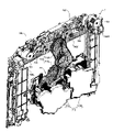
図2は、図1のパチンコ機100を裏側から見た背面図である。 FIG. 2 is a rear view of the pachinko machine 100 of FIG. 1 as seen from the back side.

パチンコ機100の背面上部には、上方に開口した開口部を有し、遊技球を一時的に貯留するための球タンク150と、この球タンク150の下方に位置し、球タンク150の底部に形成した連通孔を通過して落下する球を背面右側に位置する払出装置152に導くためのタンクレール154とを配設している。 A ball tank 150, which has an upwardly opening opening in the upper back of the pachinko machine 100 and is used to temporarily store game balls, is located below the ball tank 150 and is located at the bottom of the ball tank 150. A tank rail 154 is provided for guiding the falling ball through the formed communication hole to a dispensing device 152 located on the right side of the rear surface.

払出装置152は、筒状の部材からなり、その内部には、不図示の払出モータとスプロケットと払出センサとを備えている。この払出装置152は、着脱自在なものであり、所定位置に装着されると、タンクレール154の下流端に接続する。 The payout device 152 is made of a cylindrical member, and includes a payout motor, a sprocket, and a payout sensor (not shown) inside. The dispensing device 152 is detachable, and is connected to the downstream end of the tank rail 154 when installed at a predetermined position.

スプロケットは、払出モータによって回転可能に構成されており、タンクレール154を通過して払出装置152内に流下した遊技球を一時的に滞留させると共に、払出モータを駆動して所定角度だけ回転することにより、一時的に滞留した遊技球を払出装置152の下方へ1個ずつ送り出すように構成している。すなわち、払出装置152は、遊技球に駆動力を与えてその遊技球を搬送する球送り装置の一種である。 The sprocket is configured to be rotatable by a payout motor, temporarily retains game balls that have passed through the tank rail 154 and flowed down into the payout device 152, and rotates by a predetermined angle by driving the payout motor. Thus, the game balls temporarily retained are sent out one by one to the lower side of the payout device 152.例文帳に追加In other words, the payout device 152 is a kind of ball feeding device that imparts a driving force to the game ball and conveys the game ball.

払出センサは、スプロケットが送り出した遊技球の通過を検知するためのセンサであり、遊技球が通過しているときにハイまたはローの何れか一方の信号を、遊技球が通過していないときはハイまたはローの何れか他方の信号を払出制御部600(図4参照)へ出力する。この払出センサを通過した遊技球は、不図示の球レールを通過してパチンコ機100の前面側に配設した球貯留皿126に到達するように構成しており、パチンコ機100は、所定の付与条件が成立したことに基づいて遊技者にその付与条件に応じた量の遊技価値(遊技球)をこの構成により付与する(払い出す)。 The payout sensor is a sensor for detecting the passage of the game ball sent out by the sprocket, and when the game ball has passed, either a high or low signal, and when the game ball has not passed Either the high or low signal is output to the payout control unit 600 (see FIG. 4). A game ball that has passed through the payout sensor is configured to pass through a ball rail (not shown) and reach a ball storage tray 126 disposed on the front side of the pachinko machine 100. Based on the fulfillment of the granting condition, the amount of game value (game balls) corresponding to the granting condition is imparted (paid out) to the player by this configuration.

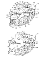
払出装置152の図中左側には、遊技全般の制御処理を行う主制御部300(図4参照)を構成する主基板156を収納する主基板ケース158、主制御部300が生成した処理情報に基づいて演出に関する制御処理を行う第1副制御部400(図4参照)を構成する第1副基板160を収納する第1副基板ケース162、第1副制御部400が生成した処理情報に基づいて演出に関する制御処理を行う第2副制御部500(図4参照)を構成する第2副基板164を収納する第2副基板ケース166、遊技球の払出に関する制御処理を行う払出制御部600(図4参照)を構成するとともに遊技店員の操作によってエラーを解除するエラー解除スイッチ168を備える払出基板170を収納する払出基板ケース172、遊技球の発射に関する制御処理を行う発射制御部630(図4参照)を構成する発射基板174を収納する発射基板ケース176、各種電気的遊技機器に電源を供給する電源制御部660(図4参照)を構成するとともに遊技店員の操作によって電源をオンオフする電源スイッチ178と電源投入時に操作されることによってRAMクリア信号を主制御部300に出力するRAMクリアスイッチ180とを備える電源基板182を収納する電源基板ケース184、および払出制御部600とカードユニットとの信号の送受信を行うCRインターフェース部186を配設している。 On the left side of the payout device 152 in the figure, there is a main board case 158 housing a main board 156 that constitutes a main control section 300 (see FIG. 4) that controls the entire game, and processing information generated by the main control section 300. Based on the processing information generated by the first sub-board case 162 that houses the first sub-board 160 that constitutes the first sub-controller 400 (see FIG. 4) that performs control processing related to the performance based on the processing information generated by the first sub-controller 400 A second sub-board case 166 that houses a second sub-board 164 that constitutes a second sub-controller 500 (see FIG. 4) that performs control processing related to performance, a payout control unit 600 (see FIG. 4) that performs control processing related to payout of game balls. 4) and includes a payout board 170 equipped with an error release switch 168 for canceling an error by the operation of a game clerk, and a launch control unit 630 (see FIG. 4) for controlling the launch of game balls. ), a power control unit 660 (see FIG. 4) that supplies power to various electric game machines, and a power switch that turns the power on and off by the operation of the game clerk. 178 and a RAM clear switch 180 that outputs a RAM clear signal to the main control unit 300 by being operated when the power is turned on. A CR interface unit 186 for transmitting and receiving is provided.

また、本実施形態では、主基板156上に、設定変更キー192と、設定変更ボタン194及び役物比率・設定表示器196が設けられている。本実施形態では、電源投入時にRAMクリアスイッチ180が押下されることを条件に設定変更キー192が操作されると、少なくとも大当り確率が異なる複数の設定からいずれかに設定することができる設定変更モードに移行することができる。設定変更モードにおいては、現在の設定が役物比率・設定表示器196に表示され、店員は、これを確認しながら設定変更ボタン194を押下することにより設定の変更を行うことができる。なお、電源投入時にRAMクリアスイッチ180の押下がなくとも、電源投入時に設定変更キー192が操作された場合に設定変更可能な構成としてもよい。 Further, in this embodiment, a setting change key 192 , a setting change button 194 and a character ratio/setting display 196 are provided on the main substrate 156 . In this embodiment, when the setting change key 192 is operated on the condition that the RAM clear switch 180 is pressed when the power is turned on, at least a setting change mode in which one of a plurality of settings with different jackpot probabilities can be set. can move to In the setting change mode, the current setting is displayed on the character ratio/setting display 196, and the clerk can change the setting by pressing the setting change button 194 while confirming this. It should be noted that even if the RAM clear switch 180 is not pressed when the power is turned on, the setting may be changed when the setting change key 192 is operated when the power is turned on.

役物比率・設定表示器196は、主基板156に実装されるとともに主基板ケース158の内部に配置される7セグLED基板であり、店員に視認可能な態様で取り付けられている。役物比率・設定表示器196は、図12(A)に示すように、2ケタの7セグLEDが上下に配置されるとともに、右側に1ケタの7セグLEDがモジュール化されたものであり、役物比率モニタは、役物比率(YH)及び連続役物比率(RY)を報知するインジケータであり、設定モニタは、現在の設定を確認するためのモニタである。役物比率・設定表示器196は、例えば、赤色の単色LEDにより構成されているが、赤・緑・オレンジの3色により発光可能なものとしてもよいし、フルカラーLEDであってもよい。なお、役物比率・設定表示器196のうちの少なくとも一部を、例えば、遊技盤200に設けて遊技者に視認可能としてもよい。 The character item ratio/setting display 196 is a 7-segment LED board mounted on the main board 156 and arranged inside the main board case 158, and is attached in a manner that can be visually recognized by the store clerk. As shown in FIG. 12(A), the character ratio/setting display 196 has two-digit seven-segment LEDs arranged vertically and a one-digit seven-segment LED modularized on the right side. , the character ratio monitor is an indicator for notifying the character ratio (YH) and the continuous character ratio (RY), and the setting monitor is a monitor for confirming the current setting. The character ratio/setting display 196 is composed of, for example, a red single-color LED, but it may be one capable of emitting light in three colors of red, green, and orange, or may be a full-color LED. At least part of the role product ratio/setting display 196 may be provided on the game board 200, for example, so that it can be visually recognized by the player.

また、本実施形態では、第1副基板ケース162の背面に、ディップスイッチ基板198が配設されている。ディップスイッチ基板198の詳細については後述する。 Further, in this embodiment, a DIP switch board 198 is arranged on the back surface of the first sub board case 162 . Details of the DIP switch board 198 will be described later.

図3(a)は、遊技盤200を正面から見た略示正面図である。ここで、矢印d2及びd3はパチンコ機100を設置場所に固定した状態における方向を示している。矢印d2はパチンコ機100の幅方向(左右方向と呼ぶ場合がある)を示し、正面視で左手を左、右手を右と呼ぶ場合がある。矢印d3はパチンコ機100の高さ方向(上下方向と呼ぶ場合がある)を示し、高い方を上、低い方を下と呼ぶ場合がある。なお、図3では図示しないが、パチンコ機100の奥行き方向(前後方向と呼ぶ場合がある)では、手前側を前方側又は正面側と呼ぶ場合があり、奥側を後方側又は背面側と呼ぶ場合がある。 FIG. 3(a) is a schematic front view of the game board 200 viewed from the front. Here, arrows d2 and d3 indicate the directions when the pachinko machine 100 is fixed at the installation location. The arrow d2 indicates the width direction (sometimes referred to as the left-right direction) of the pachinko machine 100, and the left hand may be referred to as the left and the right hand as the right when viewed from the front. An arrow d3 indicates the height direction (sometimes referred to as the vertical direction) of the pachinko machine 100, and the higher side may be referred to as the upper side, and the lower side may be referred to as the lower side. Although not shown in FIG. 3, in the depth direction (sometimes referred to as the front-back direction) of the pachinko machine 100, the front side may be called the front side or front side, and the back side may be called the rear side or back side. Sometimes.

遊技盤200は、前面に遊技領域124を有し、本体104の空間部114に臨むように、所定の固定部材を用いて本体104に着脱自在に装着されている。なお、遊技領域124は、遊技盤200を本体104に装着した後、開口部から観察することができる。 The game board 200 has a game area 124 on the front surface and is detachably attached to the main body 104 using a predetermined fixing member so as to face the space 114 of the main body 104 . Note that the game area 124 can be observed through the opening after the game board 200 is attached to the main body 104 .

本体104に対する遊技盤200の取付構造は、様々な構造を採用可能であるが、例えば、本体104の正面視左側(ヒンジ部112側)に遊技盤200の正面視左側部200aを挿入し、ここを回動中心として遊技盤200を回動させつつ遊技盤200の正面視右側部200bを本体104に押圧し、セットする構造を採用可能であり、このような構造であれば作業性を向上できる場合がある。 Various structures can be adopted for the mounting structure of the game board 200 to the main body 104. is the center of rotation, the right side 200b of the game board 200 when viewed from the front is pressed against the main body 104 and set. With such a structure, workability can be improved. Sometimes.

遊技盤200は、板状の本体となる遊技板201に各種の部品が取り付けられたユニットである。遊技板201は、例えば、樹脂により形成され、その表面(正面)は、パチンコ機100のキャラクタ等を表示した装飾面を構成する。装飾面は、例えば、パチンコ機100のキャラクタ等を印刷したシートを貼り付けることで形成してもよい。遊技板201の右下方には振動センサSR3が配設されている。振動センサSR3で検出された場合、エラー処理(例えば画像や音による報知、遊技の継続を不能とする遊技停止等)を行うことができる。振動センサSR3は磁気センサ等、他の不正検出センサであってもよい。 The game board 200 is a unit in which various parts are attached to a game board 201 serving as a plate-shaped main body. The game board 201 is made of, for example, resin, and its surface (front) constitutes a decorative surface on which characters and the like of the pachinko machine 100 are displayed. The decorative surface may be formed, for example, by attaching a sheet on which characters of the pachinko machine 100 are printed. A vibration sensor SR3 is arranged on the lower right side of the game board 201 . When detected by the vibration sensor SR3, it is possible to carry out error processing (for example, notification by image or sound, game stop to disable the continuation of the game, etc.). The vibration sensor SR3 may be another fraud detection sensor such as a magnetic sensor.

遊技盤200には、外レール202と内レール204とを配設し、遊技球が転動可能な遊技領域124を区画形成している。外レール202の一部は、本体104に着脱自在なレール部材209により形成されている。遊技領域124のうち、外レール202と内レール204との間の領域は発射された遊技球を案内する案内領域201aを形成している。 The game board 200 is provided with an outer rail 202 and an inner rail 204 to define a game area 124 in which game balls can roll. A portion of the outer rail 202 is formed by a rail member 209 that is detachable from the main body 104 . The area between the outer rail 202 and the inner rail 204 in the game area 124 forms a guide area 201a for guiding the shot game ball.

遊技盤200の遊技領域124以外の領域を非遊技領域と呼ぶ場合がある。遊技領域124と非遊技領域とは外レール202を境界として区別することができる。また、遊技球の発射強度を最大にした状態で遊技球が通過する領域よりも内側の領域は少なくとも遊技領域124と呼ぶことができる。遊技領域124は、遊技領域124内に演出装置等が存在することで遊技球が通過しない領域を含む場合がある。遊技中に遊技球が流下する点で遊技領域124を流下領域と呼び、メンテナンスやアクシデントを除いて遊技中に遊技球が流下しない点で非遊技領域を非流下領域と呼ぶ場合がある。遊技領域124は、その全域を流下領域と呼ぶことも可能であるが、演出装置等の存在により遊技球が流下することがない領域は非流下領域と呼んでもよい。 An area other than the game area 124 of the game board 200 may be called a non-game area. The play area 124 and the non-game area can be distinguished by using the outer rail 202 as a boundary. In addition, at least the area inside the area through which the game ball passes when the shooting intensity of the game ball is maximized can be called a game area 124 . The game area 124 may include an area through which game balls do not pass due to the presence of a production device or the like in the game area 124 . The game area 124 may be called a flowing area in that the game balls flow down during play, and the non-play area may be called a non-flowing area in that the game balls do not flow down during the game except for maintenance or accidents. The entire area of the game area 124 can be called a flowing area, but an area where game balls do not flow due to the presence of a production device or the like may be called a non-flowing area.

遊技領域124の略中央には、装飾図柄表示装置208を配設している。遊技領域124よりも下方には、主制御ランプ基板254が設けられており、図3(b)に示すように、主制御ランプ基板254上には、普通図柄表示装置210と、第1特別図柄表示装置212と、第2特別図柄表示装置214と、普通図柄保留ランプ216と、第1特別図柄保留ランプ218と、第2特別図柄保留ランプ220と、高確中ランプRKと、電サポ中ランプRDと、右打ちランプRMと、ラウンド表示ランプRRとを配設している。なお、以下、普通図柄を「普図」、特別図柄を「特図」と称する場合がある。 A decorative pattern display device 208 is arranged substantially in the center of the game area 124 . Below the game area 124, a main control lamp board 254 is provided, and as shown in FIG. A display device 212, a second special symbol display device 214, a normal symbol reservation lamp 216, a first special symbol reservation lamp 218, a second special symbol reservation lamp 220, a high accuracy lamp RK, and an electric sapo lamp. RD, a right-handed lamp RM, and a round indicator lamp RR are provided. In addition, hereinafter, the normal design may be referred to as "general figure" and the special design may be referred to as "special figure".

装飾図柄表示装置208は、装飾図柄ならびに演出に用いる様々な表示を行うための表示装置であり、本実施形態では液晶表示装置(LCD:Liquid Crystal Display)によって構成する。この装飾図柄表示装置208は、左図柄表示領域208a、中図柄表示領域208b、右図柄表示領域208cおよび演出表示領域208dの4つの表示領域に分割し、左図柄表示領域208a、中図柄表示領域208bおよび右図柄表示領域208cはそれぞれ異なった装飾図柄を表示し、演出表示領域208dは演出に用いる画像を表示する。さらに、各表示領域208a、208b、208c、208dの位置や大きさは、装飾図柄表示装置208の表示画面内で自由に変更することを可能としている。なお、装飾図柄表示装置208として液晶表示装置を採用しているが、液晶表示装置でなくとも、種々の演出や種々の遊技情報を表示可能に構成されていればよく、例えば、ドットマトリクス表示装置、7セグメント表示装置、有機EL(ElectroLuminescence)表示装置、リール(ドラム)式表示装置、リーフ式表示装置、プラズマディスプレイ、プロジェクタを含む他の表示デバイスを採用してもよい。 The decorative pattern display device 208 is a display device for performing various displays used for decorative patterns and effects, and in this embodiment, it is configured by a liquid crystal display (LCD). This decorative pattern display device 208 is divided into four display regions: a left pattern display region 208a, a middle pattern display region 208b, a right pattern display region 208c and a performance display region 208d. The and right design display areas 208c display different decorative designs, and the effect display area 208d displays images used for effects. Furthermore, the position and size of each display area 208a, 208b, 208c, 208d can be freely changed within the display screen of the decorative design display device 208. FIG. Although a liquid crystal display device is used as the decorative pattern display device 208, a liquid crystal display device may be used as long as it is capable of displaying various effects and various game information, for example, a dot matrix display device. , a 7-segment display, an organic EL (ElectroLuminescence) display, a reel (drum) display, a leaf display, a plasma display, and a projector.

図3(b)に示すように、普図表示装置210は、普図の表示を行うための表示装置であり、本実施形態では縦2つのLEDによって構成する。第1特図表示装置212および第2特図表示装置214は、特図の表示を行うための表示装置であり、本実施形態ではそれぞれ上下2段、合計8つのLEDによって構成する。 As shown in FIG. 3(b), the normal map display device 210 is a display device for displaying the normal map, and in this embodiment, it is composed of two vertical LEDs. The first special figure display device 212 and the second special figure display device 214 are display devices for displaying special figures, and in the present embodiment, they are each configured with two upper and lower stages and a total of eight LEDs.

普図保留ランプ216は、保留している普図変動遊技(詳細は後述)の数を示すためのランプであり、本実施形態では、普図変動遊技を所定数(例えば、4つ)まで保留することを可能としている。第1特図保留ランプ218は、保留している特図変動遊技の数を示すためのランプであり、本実施形態では、特図変動遊技を所定数(例えば、4つ)まで保留することを可能としている。また、第2特別図柄保留ランプ220は、保留している特図変動遊技の数を示すためのランプであり、本実施形態では、特図変動遊技を所定数(例えば、4つ)まで保留することを可能としている。 The general pattern holding lamp 216 is a lamp for indicating the number of general pattern fluctuation games that are reserved (details will be described later), and in this embodiment, the general pattern fluctuation game is held to a predetermined number (eg, four) making it possible to The first special figure holding lamp 218 is a lamp for indicating the number of reserved special figure fluctuation games. It is possible. In addition, the second special symbol reservation lamp 220 is a lamp for indicating the number of reserved special figure fluctuation games, and in this embodiment, the special figure fluctuation games are reserved up to a predetermined number (for example, four). making it possible.

また、高確中ランプRKは、遊技状態が大当りが発生し易い高確率状態であること、または高確率状態になることを示すためのランプである。電サポ中ランプRDは、普通図柄の変動表示時間が短縮されるとともに、後述する電動チューリップ(電チュー)の羽根部材2311(図35参照)が長時間開放しやすい電サポ状態であることを示すためのランプである。右打ち表示ランプRMは、大当り遊技状態、確変状態及び電サポ状態であって、遊技者が右打ちすることでその恩恵を得られる状態となったことを示すためのランプである。ラウンド表示ランプRRは、大当りとなった場合に、当該大当りに係る大当り遊技におけるラウンド数を示すためのランプである。 Further, the high-probability middle lamp RK is a lamp for indicating that the game state is a high-probability state in which a big win is likely to occur, or that the game state will be in a high-probability state. The lamp RD in the electric sapo indicates that the fluctuation display time of the normal pattern is shortened, and the electric sapot state is such that the blade member 2311 (see FIG. 35) of the electric tulip (electric chew) described later is likely to be opened for a long time. It is a lamp for The right-handed display lamp RM is a jackpot game state, a probability variable state, and an electric support state, and is a lamp for indicating that the player is in a state in which he/she can benefit from right-handed hitting. The round display lamp RR is a lamp for indicating the number of rounds in the jackpot game related to the jackpot when the jackpot is won.

図3(a)に示す遊技盤200には、遊技球の転動可能な領域にワープ装置242およびステージ244が設けられている。ワープ装置242は、装飾図柄表示装置208の左側に設けたワープ入口242aに入った遊技球をワープ出口242bからステージ244に排出する。ステージ244は、装飾図柄表示装置208よりも、下方でかつ前方側に設けられたものであり、ワープ装置242を抜けた遊技球が、往復動や回転運動等の動きをみせる舞台である。このステージ244では、遊技球が往復動や回転運動することで遊技球の滞留時間が長くなる。ステージ244にはステージカバー245が設けられている。ステージ244およびステージカバー245については、さらに後述する。 A game board 200 shown in FIG. 3(a) is provided with a warp device 242 and a stage 244 in an area where game balls can roll. The warp device 242 discharges game balls that have entered a warp entrance 242a provided on the left side of the decorative pattern display device 208 to a stage 244 from a warp exit 242b. The stage 244 is provided below and in front of the decorative pattern display device 208, and is a stage on which the game ball exiting the warp device 242 shows reciprocating motion, rotating motion, and the like. In this stage 244, the residence time of the game ball becomes longer as the game ball reciprocates and rotates. A stage cover 245 is provided on the stage 244 . Stage 244 and stage cover 245 are further described below.

また、遊技領域124の上部には、本体104に支持されて第1演出可動ユニット7が配置されている。さらに、ステージ244よりも下方かつ後方側には、本体104に支持されて第2演出可動ユニット8が配置されているが、この図3(a)では、第2演出可動ユニット8は見えていない。上部の第1演出可動ユニット7および、後方側に隠れている第2演出可動ユニット8についても、後述する。 Also, the first effect movable unit 7 is arranged above the game area 124 while being supported by the main body 104 . Furthermore, below the stage 244 and on the rear side, the second effect movable unit 8 is arranged supported by the main body 104, but the second effect movable unit 8 is not visible in FIG. 3(a). . The first movable effect unit 7 on the upper side and the second movable effect unit 8 hidden on the rear side will also be described later.

図3(a)に示すように、遊技領域124の上部の一部は、装飾上カバー203で覆われている。また、遊技領域124の右上部は、装飾右上カバー205で覆われており、装飾右上カバー205の奥(後方側)には、普図始動口228が配置されている。普図始動口228は、ゲートやスルーチャッカーと呼ばれる、遊技領域124の所定の領域を球が通過したか否かを判定するための装置で構成しており、本実施形態では遊技盤200の右側に1つ配設している。普図始動口228を通過した球は、遊技島側に排出することはないが、入球した場合に所定の個数(例えば、1個)の賞球を払い出すとともに、入球した遊技球をパチンコ機100の裏側に誘導して遊技島側に排出するようにしてもよい。球が普図始動口228を通過したことを所定の球検出センサが検出した場合、パチンコ機100は、普図表示装置210による普図変動遊技を開始する。 As shown in FIG. 3( a ), part of the upper part of the game area 124 is covered with a decorative upper cover 203 . In addition, the upper right portion of the game area 124 is covered with a decorative upper right cover 205 , and a normal figure start opening 228 is arranged at the back (rear side) of the decorative upper right cover 205 . The normal figure starting port 228 is configured with a device for determining whether or not the ball has passed through a predetermined area of the game area 124, called a gate or through chucker, and is located on the right side of the game board 200 in this embodiment. One is placed in the Balls that have passed through the normal figure start port 228 are not discharged to the game island side, but when they enter, a predetermined number (for example, one) of prize balls are paid out, and the entered game balls are released. It may be guided to the back side of the pachinko machine 100 and discharged to the game island side. When a predetermined ball detection sensor detects that the ball has passed through the normal pattern starting port 228 , the pachinko machine 100 starts the normal pattern fluctuation game by the normal pattern display device 210 .

また、本実施形態では遊技盤200の中央下部に第1特図始動口230が1つ配設されている。この第1特図始動口230は、左側に延びたランプユニット9の右端に設けられたものである。ランプユニット9についても詳細は後述するが、このランプユニット9には、一般入賞口も配置されている。一般入賞口は、図示省略しているが、この他にも遊技領域の複数箇所に設けられており、一般入賞口に入球すると所定の球検出センサ(図示省略)が検出し、一般入賞口に入賞したとして、払出装置152を駆動し、所定の個数(例えば、4個)の球を賞球として球貯留皿126に排出する。球貯留皿126に排出した球は遊技者が自由に取り出すことが可能であり、これらの構成により、入賞に基づいて賞球を遊技者に払い出すようにしている。なお、一般入賞口に入球した球は、パチンコ機100の裏側に誘導した後、遊技島側に排出する。 In addition, in this embodiment, one first special figure starting port 230 is arranged at the lower center of the game board 200 . This first special figure starting port 230 is provided at the right end of the lamp unit 9 extending to the left. Although the details of the lamp unit 9 will also be described later, this lamp unit 9 is also provided with a general winning opening. Although not shown, the general winning opening is provided at a plurality of other places in the game area. When a ball enters the general winning opening, a predetermined ball detection sensor (not shown) detects Assuming that a prize has been won, the payout device 152 is driven to discharge a predetermined number (for example, 4) of balls to the ball storage tray 126 as prize balls. A player can freely take out the balls discharged to the ball storage tray 126, and with these configurations, prize balls are paid out to the player based on winnings. Balls that enter the general winning slot are guided to the back side of the pachinko machine 100 and then discharged to the game island side.

また、遊技盤200の中央下部に1つ配設された第1特図始動口230への入球を所定の球検出センサが検出した場合、図2に示す払出装置152を駆動し、所定の個数(例えば、4個)の球を賞球として球貯留皿126に排出するとともに、第1特図表示装置212による特図変動遊技を開始する。第1特図始動口230に入球した球は、パチンコ機100の裏側に誘導した後、遊技島側に排出する。なお、本実施形態では、遊技領域124の右下部にアタッカユニット23が設けられており、このアタッカユニット23にも電チュータイプの第1特図始動口が別途設けられている。以下、遊技盤200の中央下部に設けられた第1特図始動口230を第1特図始動口(固定)230と称し、アタッカユニット23に別途設けられた電チュータイプの第1特図始動口を第1特図始動口(可変)231と称して両者を区別する場合がある。なお、第1特図始動口(可変)231については、後述するアタッカユニット23の説明の中で詳述する。 Also, when a predetermined ball detection sensor detects a ball entering the first special figure starting port 230 arranged at the lower center of the game board 200, the payout device 152 shown in FIG. A special figure fluctuation game by the first special figure display device 212 is started while discharging the balls of the number (for example, 4) to the ball storage tray 126 as prize balls. A ball entering the first special figure starting port 230 is guided to the back side of the pachinko machine 100 and then discharged to the game island side. In addition, in this embodiment, the attacker unit 23 is provided in the lower right part of the game area 124, and this attacker unit 23 is also provided with an electric chew type first special figure start port separately. Hereinafter, the first special figure starting port 230 provided at the lower center of the game board 200 is referred to as the first special figure starting port (fixed) 230, and the first special figure starting of the electric chew type separately provided in the attacker unit 23 The mouth may be called the first special figure start mouth (variable) 231 to distinguish between the two. It should be noted that the first special figure start opening (variable) 231 will be described in detail in the description of the attacker unit 23 described later.

また、アタッカユニット23には、第1特図始動口(可変)231の他に、第2特図始動口232や、複数の可変入賞口(アタッカ)234,235も設けられている。図3(a)に示す、中央下部に設けられた第1特図始動口(固定)230は、その配置上、右打ちした場合には、遊技球の入球が困難な構成となっている。一方、上述したステージ244の中央部には、ステージ244に到達した球が、遊技盤200の中央下部に設けられた第1特図始動口(固定)230へ入球し易くなるスペシャルルート244aが設けられている。なお、ステージ244を経由しなくても、左側から第1特図始動口(固定)230を狙うこともできる。したがって、遊技盤200の中央下部に設けられた第1特図始動口(固定)230は、左打ちを行うことで入球を期待することができる始動口である。 The attacker unit 23 is also provided with a second special figure starter opening 232 and a plurality of variable winning openings (attackers) 234 and 235 in addition to the first special figure starter opening (variable) 231 . As shown in FIG. 3(a), the first special-figure starting port (fixed) 230 provided in the lower part of the center has a configuration in which it is difficult for the game ball to enter when hitting to the right due to its arrangement. . On the other hand, in the central part of the stage 244 described above, there is a special route 244a that makes it easier for the ball that has reached the stage 244 to enter the first special figure start opening (fixed) 230 provided at the lower center of the game board 200. is provided. In addition, even if it does not pass through the stage 244, the 1st special figure start opening (fixed) 230 can also be aimed at from the left side. Therefore, the first special figure starting opening (fixed) 230 provided at the lower center of the game board 200 is a starting opening that can be expected to enter by hitting left.

さらに、遊技領域124には、風車と呼ばれる円盤状の打球方向変換部材236や、遊技釘を複数個、配設していると共に、内レール204の最下部には、いずれの入賞口や始動口にも入賞しなかった球をパチンコ機100の裏側に誘導した後、遊技島側に排出するためのアウト口240を設けている。 Furthermore, in the game area 124, a disk-shaped ball hitting direction changing member 236 called a windmill and a plurality of game nails are arranged, and at the bottom of the inner rail 204, any winning opening or starting opening An out port 240 is provided for discharging the balls that did not win the game to the game island side after guiding them to the back side of the pachinko machine 100.例文帳に追加

このパチンコ機100では、遊技者が球貯留皿126に貯留している球を発射レールの発射位置に供給し、遊技者の操作ハンドルの操作量に応じた強度で発射モータを駆動し、発射杆および発射槌によって外レール202、内レール204を通過させて遊技領域124に打ち出す。そして、遊技領域124の上部に到達した球は、打球方向変換部材236や遊技釘等によって進行方向を変えながら下方に流下し、各種の入賞口や始動口に入賞するか、いずれの入賞口や始動口にも入賞することなく、または普図始動口228を通過するのみでアウト口240に到達する。また、本実施形態では、本体104の空間部114の下辺に、遊技盤200から排出されるすべての遊技球を受け入れる排出球受入口(図示しない)が上方に開口するように形成されるとともに、排出球受入口に受け入れられた遊技球の通過を検出するアウト球検出センサSWoutが本体104の所定位置に設けられている。なお、アウト球検出センサSWoutは、遊技盤200側に設けられてもよい。本実施形態では、遊技盤200から排出されるすべての遊技球(アウト口240から排出された遊技球と各種入賞口に入賞した遊技球とを含む)は、この排出球受入口に受け入れられ、所定の排出通路を経由してパチンコ機100外に排出されるように構成されているが、アウト口240から排出された遊技球のみがアウト球検出センサSWoutを通過するようにしてもよい。 In this pachinko machine 100, the player supplies the balls stored in the ball storage tray 126 to the firing position of the firing rail, drives the firing motor with the intensity corresponding to the operation amount of the player's operation handle, and releases the firing rod. And the shot mallet passes through the outer rail 202 and the inner rail 204 and is launched into the game area 124.例文帳に追加Then, the ball that reaches the upper part of the game area 124 flows downward while changing the direction of travel by the hitting ball direction changing member 236, the game nail, etc., and enters various winning openings and starting openings. The player reaches the out port 240 without winning the starting port or only passing through the normal starting port 228.例文帳に追加In addition, in this embodiment, a discharge ball receiving port (not shown) for receiving all game balls discharged from the game board 200 is formed in the lower side of the space portion 114 of the main body 104 so as to open upward. An out ball detection sensor SWout for detecting passage of a game ball received in the discharge ball receiving port is provided at a predetermined position of the main body 104 . Note that the out ball detection sensor SWout may be provided on the game board 200 side. In this embodiment, all game balls discharged from the game board 200 (including game balls discharged from the out port 240 and game balls that have entered various winning ports) are received in this discharged ball receiving port, Although it is configured to be discharged to the outside of the pachinko machine 100 via a predetermined discharge passage, only game balls discharged from the out port 240 may pass through the out ball detection sensor SWout.

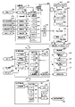
次に、図4を用いて、このパチンコ機100の制御部の回路構成について詳細に説明する。なお、同図は制御部の機能ブロック図を示したものである。パチンコ機100の制御部は、大別すると、遊技の中枢部分を制御する主制御部300と、主制御部300が送信するコマンド信号(以下、単に「コマンド」という)に応じて主に演出の制御を行う第1副制御部400と、第1副制御部400より送信されたコマンドに基づいて各種機器を制御する第2副制御部500と、主制御部300が送信するコマンドに応じて主に遊技球の払出しに関する制御を行う払出制御部600と、遊技球の発射制御を行う発射制御部630と、パチンコ機100に供給される電源を制御する電源制御部660とを備えて構成されている。 Next, the circuit configuration of the control section of the pachinko machine 100 will be described in detail with reference to FIG. This figure shows a functional block diagram of the control unit. The control unit of the pachinko machine 100 can be roughly divided into a main control unit 300 that controls the core part of the game, and a command signal (hereinafter simply referred to as "command") transmitted by the main control unit 300. A first sub-control unit 400 that performs control, a second sub-control unit 500 that controls various devices based on commands transmitted from the first sub-control unit 400, and a main control unit 300 according to commands transmitted by the main control unit 300 , a payout control unit 600 for controlling the payout of game balls, a launch control unit 630 for controlling the launch of game balls, and a power control unit 660 for controlling the power supplied to the pachinko machine 100. there is

まず、パチンコ機100の主制御部300について説明する。主制御部300は、主制御部300の全体を制御する基本回路302を備えている。基本回路302には、CPU304と、制御プログラムや各種データを記憶するためのROM306と、一時的にデータを記憶するためのRAM308と、各種デバイスの入出力を制御するためのI/O310と、時間や回数等を計測するためのカウンタタイマ312と、プログラム処理の異常を監視するWDT314と、乱数値生成回路(カウンタ回路)318(この回路には2つのカウンタを内蔵しているものとする)とを搭載している。なお、ROM306やRAM308については他の記憶装置を用いてもよく、この点は後述する第1副制御部400や第2副制御部500についても同様である。この基本回路302のCPU304は、水晶発振器316bが出力する所定周期のクロック信号をシステムクロックとして入力して動作する。また、乱数値生成回路318は、水晶発振器316aが出力するクロック信号を受信する度に0~65535の範囲で数値を変動させるハードウェア乱数カウンタとして使用している。なお、乱数値生成回路318は、基本回路302に内蔵したものとしているが、基本回路302に対して接続されるものであってもよい。 First, the main control section 300 of the pachinko machine 100 will be described. The main control section 300 includes a basic circuit 302 that controls the main control section 300 as a whole. The basic circuit 302 includes a CPU 304, a ROM 306 for storing control programs and various data, a RAM 308 for temporarily storing data, an I/O 310 for controlling input/output of various devices, a time A counter timer 312 for measuring the number of times, etc., a WDT 314 for monitoring abnormalities in program processing, and a random number generation circuit (counter circuit) 318 (assuming that this circuit contains two counters). is equipped with. Note that other storage devices may be used for the ROM 306 and RAM 308, and this also applies to the first sub-controller 400 and the second sub-controller 500, which will be described later. The CPU 304 of the basic circuit 302 operates by inputting a clock signal having a predetermined cycle output from the crystal oscillator 316b as a system clock. The random number generating circuit 318 is used as a hardware random number counter that changes the numerical value within the range of 0 to 65535 each time it receives the clock signal output from the crystal oscillator 316a. Although the random number generation circuit 318 is built in the basic circuit 302, it may be connected to the basic circuit 302. FIG.

また、基本回路302には、所定の球検出センサ、例えば各始動口、入賞口、可変入賞口を通過する遊技球を検出するセンサや球貯留皿満タンセンサを含む各種センサ320が出力する信号を受信し、増幅結果や基準電圧との比較結果を基本回路302におけるCPU304や乱数値生成回路318等に出力するためのセンサ回路322と、所定の図柄表示装置、例えば第1特図表示装置212や第2特図表示装置214の表示制御を行うための駆動回路324と、所定の図柄表示装置、例えば普図表示装置210の表示制御を行うための駆動回路326と、各種状態表示部328(例えば、普図保留ランプ216、特図1保留ランプ218、特図2保留ランプ220、高確中ランプRK、電サポ中ランプRD、右打ちランプRM、ラウンド表示ランプRR等)の表示制御を行うための駆動回路330と、所定の可動部材、例えば、普通電動役物としての第1特図始動口(可変)231の羽根部材2311(図35参照)を駆動する駆動手段や、特別電動役物としての可変入賞口234,235の扉部材2341,2351(図38参照)を駆動する駆動手段等を含む各種ソレノイド332を制御するための駆動回路334と、を接続している。本例では水晶発振器316aと乱数値生成回路318とが別に設けられているが、水晶発振器316aは乱数値生成回路318に含まれていてもよい。 In addition, the basic circuit 302 receives signals output from various sensors 320 including predetermined ball detection sensors, for example, sensors for detecting game balls passing through each start opening, winning opening, and variable winning opening, and a ball storage tray full sensor. A sensor circuit 322 for receiving and outputting the amplification result and the comparison result with the reference voltage to the CPU 304 and the random number generation circuit 318 in the basic circuit 302, and a predetermined symbol display device, for example, the first special figure display device 212 and A drive circuit 324 for performing display control of the second special figure display device 214, a predetermined pattern display device, for example, a drive circuit 326 for performing display control of the general figure display device 210, and various state display units 328 (for example , General Figure Reservation Lamp 216, Special Figure 1 Reservation Lamp 218, Special Figure 2 Reservation Lamp 220, High Accuracy Medium Lamp RK, Electric Sapo Medium Lamp RD, Right Strike Lamp RM, Round Display Lamp RR, etc.) for display control A drive circuit 330 and a predetermined movable member, for example, a drive means for driving the blade member 2311 (see FIG. 35) of the first special figure start port (variable) 231 as a normal electric accessory, and as a special electric accessory A driving circuit 334 for controlling various solenoids 332 including driving means for driving the door members 2341 and 2351 (see FIG. 38) of the variable winning ports 234 and 235 is connected. In this example, the crystal oscillator 316 a and the random value generation circuit 318 are provided separately, but the crystal oscillator 316 a may be included in the random value generation circuit 318 .

なお、第1特図始動口230,231に球が入賞したことを球検出センサが検出した場合には、センサ回路322は球を検出したことを示す信号を基本回路302における乱数値生成回路318に出力する。この信号を受信した乱数値生成回路318は、第1特図始動口230,231に対応するカウンタのそのタイミングにおける値をラッチし、ラッチした値を、特図1に対応する内蔵のカウンタ値記憶用レジスタに記憶する。また、乱数値生成回路318は、第2特図始動口232に球が入賞したことを示す信号を受信した場合も同様に、第2特図始動口232に対応するカウンタのそのタイミングにおける値をラッチし、ラッチした値を、特図2に対応する内蔵のカウンタ値記憶用レジスタに記憶する。 When the ball detection sensor detects that a ball has entered the first special figure start openings 230 and 231, the sensor circuit 322 outputs a signal indicating that the ball has been detected to the random value generation circuit 318 in the basic circuit 302. output to The random value generation circuit 318 that received this signal latches the value at that timing of the counter corresponding to the first special figure start ports 230 and 231, and stores the latched value in the built-in counter value storage corresponding to the special figure 1. stored in the register for Also, when the random value generation circuit 318 receives a signal indicating that the ball has won the second special figure starting port 232, similarly, the value of the counter corresponding to the second special figure starting port 232 at that timing Latch and store the latched value in a built-in counter value storage register corresponding to Special Figure 2.

さらに、基本回路302には、情報出力回路336を接続しており、主制御部300は、この情報出力回路336を介し、図示しない外部端子板を経由して、外部のホールコンピュータ(図示省略)等が備える情報入力回路350にパチンコ機100の遊技情報(例えば、遊技状態)を出力する。 Further, an information output circuit 336 is connected to the basic circuit 302, and the main control section 300 is connected to an external hall computer (not shown) via the information output circuit 336 and an external terminal board (not shown). The game information (for example, game state) of the pachinko machine 100 is output to the information input circuit 350 provided in the machine.

また、主制御部300には、電源制御部660から主制御部300に供給している電源の電圧値を監視する電圧監視回路338を設けており、この電圧監視回路338は、電源の電圧値が所定の値(本例では9V)未満である場合に電圧が低下したことを示す低電圧信号を基本回路302に出力する。 Further, the main control unit 300 is provided with a voltage monitoring circuit 338 for monitoring the voltage value of the power supply supplied from the power control unit 660 to the main control unit 300. The voltage monitoring circuit 338 monitors the voltage value of the power supply. is less than a predetermined value (9 V in this example), a low voltage signal is output to the basic circuit 302 to indicate that the voltage has dropped.

また、主制御部300には、電源が投入されると起動信号(リセット信号)を出力する起動信号出力回路(リセット信号出力回路)340を設けており、CPU304は、この起動信号出力回路340から起動信号を入力した場合に、遊技制御を開始する(後述する主制御部メイン処理を開始する)。 The main control unit 300 is also provided with a start signal output circuit (reset signal output circuit) 340 that outputs a start signal (reset signal) when the power is turned on. When the start signal is input, the game control is started (the main control unit main processing, which will be described later, is started).

また、主制御部300は、第1副制御部400にコマンドを送信するための出力インタフェースと、払出制御部600にコマンドを送信するための出力インタフェースとをそれぞれ備えており、この構成により、第1副制御部400および払出制御部600との通信を可能としている。なお、主制御部300と第1副制御部400との情報通信は一方向の通信であり、主制御部300と払出制御部600との情報通信は双方向の通信である。主制御部300は第1副制御部400にコマンド等の信号を送信できるように構成しているが、第1副制御部400からは主制御部300にコマンド等の信号を送信できないように構成している。ただし、主制御部300と第1副制御部400との情報通信が双方向通信により行われるように構成してもよい。また、払出制御部600は、主制御部300にコマンド等の信号を送信できるように構成しているが、払出制御部600から主制御部300にコマンド等の信号を送信できないように構成してもよい。 In addition, the main control unit 300 includes an output interface for transmitting commands to the first sub-control unit 400 and an output interface for transmitting commands to the payout control unit 600. With this configuration, the Communication with 1 sub control unit 400 and payout control unit 600 is enabled. Information communication between the main control unit 300 and the first sub-control unit 400 is one-way communication, and information communication between the main control unit 300 and the payout control unit 600 is two-way communication. The main control unit 300 is configured to be able to transmit signals such as commands to the first sub-control unit 400, but is configured so that signals such as commands cannot be transmitted from the first sub-control unit 400 to the main control unit 300. is doing. However, information communication between the main control unit 300 and the first sub-control unit 400 may be configured to be performed by two-way communication. Also, the payout control unit 600 is configured to be able to transmit signals such as commands to the main control unit 300, but is configured so that signals such as commands cannot be transmitted from the payout control unit 600 to the main control unit 300. good too.

次に、パチンコ機100の第1副制御部400について説明する。第1副制御部400は、主に主制御部300が送信したコマンド等に基づいて第1副制御部400の全体を制御する基本回路402を備えている。基本回路402には、CPU404と、一時的にデータを記憶するためのRAM408と、各種デバイスの入出力を制御するためのI/O410と、時間や回数等を計測するためのカウンタタイマ412と、シリアル通信制御回路424とを搭載している。この基本回路402のCPU404は、水晶発振器414が出力する所定周期のクロック信号をシステムクロックとして入力して動作する。また、基本回路402には、制御プログラムや各種演出データを記憶するためのROM406が接続されている。なお、ROM406は、制御プログラムと各種演出データとを別々のROMに記憶させてもよい。また、ROM406が基本回路402に備えらえた構成であってもよい。シリアル通信制御回路424は、遊技盤用ランプ442の制御を行うための遊技盤用ランプ駆動回路440と、遊技台枠用ランプ452の制御を行うための遊技台枠用ランプ駆動回路450とを接続し、遊技盤用ランプ駆動回路440及び遊技台枠用ランプ駆動回路450との間でシリアル通信による点灯制御を行う。なお、遊技盤用ランプ442には、第2演出可動ユニット8に配置されたの発光ダイオードD(図17参照)や、ランプユニット9に配置された発光ダイオードDO,DI,DL(図32参照)や、アタッカユニット23に配置された発光ダイオードD1~D3(図40参照)等が含まれている。 Next, the first sub-controller 400 of the pachinko machine 100 will be described. The first sub-controller 400 includes a basic circuit 402 that controls the entire first sub-controller 400 mainly based on commands and the like transmitted by the main controller 300 . The basic circuit 402 includes a CPU 404, a RAM 408 for temporarily storing data, an I/O 410 for controlling input/output of various devices, a counter timer 412 for measuring time, number of times, etc. A serial communication control circuit 424 is mounted. The CPU 404 of this basic circuit 402 operates by inputting a clock signal having a predetermined cycle output from the crystal oscillator 414 as a system clock. Also, the basic circuit 402 is connected to a ROM 406 for storing control programs and various effect data. Note that the ROM 406 may store the control program and various effect data in separate ROMs. Alternatively, the ROM 406 may be provided in the basic circuit 402 . The serial communication control circuit 424 connects the game board lamp driving circuit 440 for controlling the game board lamp 442 and the game frame lamp driving circuit 450 for controlling the game frame lamp 452 . Then, lighting control is performed by serial communication between the game board lamp drive circuit 440 and the game frame lamp drive circuit 450 . The game board lamp 442 includes the light emitting diode D (see FIG. 17) arranged in the second effect movable unit 8 and the light emitting diodes DO, DI, and DL arranged in the lamp unit 9 (see FIG. 32). , light-emitting diodes D1 to D3 (see FIG. 40) arranged in the attacker unit 23, and the like.

また、基本回路402には、スピーカ120(およびアンプ)の制御を行うための音源IC(S-ROM)416と、図3(a)に示す上部の第1演出可動ユニット7、後方側に隠れている第2演出可動ユニット8といった各種演出装置のモータ等の駆動制御を行うための駆動回路422と、センサ回路428と、スピーカ120から出力される音量を調整する音量スイッチ163と、を接続している。センサ回路428は、各種演出装置等の現在位置を検出する各種可動体センサ430や、演出ボタン136や操作キーユニット190を構成する各種ボタンの押下を検出するボタンセンサ426からの検出信号を基本回路402に出力する。なお、音量調整ボタン1903(図41参照)の押下をボタンセンサ426が検出した場合には、検出信号は音量スイッチ163に出力される。 In addition, the basic circuit 402 includes a sound source IC (S-ROM) 416 for controlling the speaker 120 (and amplifier), the first effect movable unit 7 shown in FIG. A drive circuit 422 for driving and controlling motors of various production devices such as the second production movable unit 8, a sensor circuit 428, and a volume switch 163 for adjusting the volume output from the speaker 120 are connected. ing. The sensor circuit 428 receives detection signals from various movable body sensors 430 that detect the current positions of various production devices, etc., and button sensors 426 that detect depression of various buttons that constitute the production button 136 and the operation key unit 190. Output to 402 . Note that when the button sensor 426 detects pressing of the volume adjustment button 1903 (see FIG. 41), a detection signal is output to the volume switch 163 .

次に、パチンコ機100の第2副制御部500について説明する。第2副制御部500は、第1副制御部400が送信した制御コマンドを入力インタフェースを介して受信し、この制御コマンドに基づいて第2副制御部500の全体を制御する基本回路502を備えている。基本回路502は、CPU504と、一時的にデータを記憶するためのメモリ508と、各種デバイスの入出力を制御するためのI/O510と、時間や回数等を計測するためのカウンタタイマ512と、CPU504からの信号に基づいてROM506に記憶された画像データ等を読み出してVRAM518のワークエリアを使用して表示画像を生成して装飾図柄表示装置208に画像を表示するVDP(ビデオ・ディスプレイ・プロセッサ)516と、を搭載している。基本回路502のCPU504は、水晶発振器514が出力する所定周期のクロック信号をシステムクロックとして入力して動作する。また、基本回路502には、第2副制御部500の全体を制御するための制御プログラムおよびデータ、画像表示用のデータ等が記憶されたROM506が接続されている。本実施形態では、一時的記憶領域としてメモリ508を用いており、メモリ508は、電源が遮断されても記憶状態を保持可能な記録媒体(例えば、EEPROMやフラッシュメモリ等)によって構成されている。これにより、例えば、大当り履歴に関する表示を表示するための情報を、主制御部300において初期化されたり設定変更が行われた場合にも保持することができる。なお、電源が遮断されると記憶情報が揮発するRAMを用いるようにしてもよい。 Next, the second sub-controller 500 of the pachinko machine 100 will be described. The second sub-controller 500 includes a basic circuit 502 that receives control commands transmitted by the first sub-controller 400 via an input interface and controls the entire second sub-controller 500 based on the control commands. ing. The basic circuit 502 includes a CPU 504, a memory 508 for temporarily storing data, an I/O 510 for controlling input/output of various devices, a counter timer 512 for measuring time, number of times, etc. A VDP (video display processor) that reads image data stored in the ROM 506 based on a signal from the CPU 504, generates a display image using the work area of the VRAM 518, and displays the image on the decorative pattern display device 208. 516 and are installed. The CPU 504 of the basic circuit 502 operates by inputting a clock signal having a predetermined cycle output from the crystal oscillator 514 as a system clock. The basic circuit 502 is also connected to a ROM 506 that stores a control program and data for controlling the entire second sub-control section 500, image display data, and the like. In this embodiment, the memory 508 is used as a temporary storage area, and the memory 508 is configured by a recording medium (for example, EEPROM, flash memory, etc.) capable of retaining the storage state even when power is cut off. As a result, for example, information for displaying a display relating to the history of big hits can be retained even when the main control unit 300 initializes or changes settings. A RAM in which stored information volatilizes when power is cut off may be used.

次に、パチンコ機100の払出制御部600、発射制御部630、電源制御部660について説明する。払出制御部600は、主に主制御部300が送信したコマンド等の信号に基づいて払出装置152の払出モータ602を制御するとともに、払出センサ604が出力する制御信号に基づいて賞球または貸球の払出しが完了したか否かを検出する。また払出制御部600は、インタフェース部606を介して、パチンコ機100とは別体で設けられたカードユニット608との通信を行う。また、払出制御部600は、所定個数(例えば、10個)の賞球の払出しが行われたことを示す賞球情報や、所定個数(例えば、25個)の貸球の払出しが行われたことを示す貸球情報等を、図示しない外部端子板を経由して、情報入力回路350に出力する。また、払出制御部600には、枠センサ605が接続されている。枠センサ605には、本体104が開いたことを検出する本体開放センサ1041や、前面枠扉106が開いたことを検出する前面枠扉センサ1061等が含まれており、本体104や前面枠扉106が開放されている場合にはこれらのセンサが検知し、開放信号を出力する。払出制御部600は、枠センサ605からの開放信号を出力すると、主制御部300に扉開放情報を出力する。 Next, the payout control unit 600, the launch control unit 630, and the power supply control unit 660 of the pachinko machine 100 will be described. The payout control unit 600 mainly controls the payout motor 602 of the payout device 152 based on signals such as commands transmitted by the main control unit 300, and provides prize balls or ball rental based on control signals output by the payout sensor 604. Detects whether or not the payout of has been completed. The payout control unit 600 also communicates with a card unit 608 provided separately from the pachinko machine 100 via an interface unit 606 . In addition, the payout control unit 600 provides prize ball information indicating that a predetermined number (for example, 10) of prize balls have been paid out, and information indicating that a predetermined number (for example, 25) of rental balls have been paid out. Rental ball information or the like indicating this is output to the information input circuit 350 via an external terminal board (not shown). A frame sensor 605 is connected to the payout control unit 600 . The frame sensor 605 includes a main body open sensor 1041 for detecting that the main body 104 is opened, a front frame door sensor 1061 for detecting that the front frame door 106 is opened, and the like. These sensors detect when 106 is open and output an open signal. When the frame sensor 605 outputs an open signal, the payout control unit 600 outputs door open information to the main control unit 300 .

発射制御部630は、払出制御部600が出力する、発射許可または停止を指示する制御信号や、球発射ハンドル134内に設けた発射強度出力回路が出力する、遊技者による球発射ハンドル134の操作量に応じた発射強度を指示する制御信号に基づいて、発射杆146および発射槌148を駆動する発射ソレノイド632の制御や、球貯留皿126から発射装置110に球を供給する球送り装置634の制御を行う。 The shooting control unit 630 outputs a control signal for instructing permission or stopping of shooting output by the payout control unit 600, and an operation of the ball shooting handle 134 by the player, which is output by a shooting intensity output circuit provided in the ball shooting handle 134. A firing solenoid 632 that drives the firing rod 146 and the firing mallet 148 is controlled, and a ball feeder 634 that supplies balls from the ball storage tray 126 to the firing device 110 is controlled based on a control signal that indicates the firing intensity corresponding to the amount. control.

電源制御部660は、パチンコ機100に外部から供給される交流電源を直流化し、所定の電圧に変換して主制御部300、第1副制御部400等の各制御部や払出装置152等の各装置に供給する。さらに、電源制御部660は、外部からの電源が断たれた後も所定の部品(例えば主制御部300のRAM308等)に所定の期間(例えば10日間)電源を供給するための蓄電回路(例えば、コンデンサ)を備えている。なお、本実施形態では、電源制御部660から払出制御部600と第2副制御部500に所定電圧の電源を供給し、払出制御部600から主制御部300と第2副制御部500と発射制御部630に所定電圧の電源を供給しているが、各制御部や各装置に他の電源経路で所定電圧の電源を供給してもよい。 The power control unit 660 converts AC power supplied from the outside to the pachinko machine 100 into DC power, converts it into a predetermined voltage, and controls each control unit such as the main control unit 300 and the first sub-control unit 400 and the payout device 152. Supply to each device. Furthermore, the power supply control unit 660 includes a power storage circuit (for example, , capacitor). In addition, in this embodiment, the power supply control unit 660 supplies a predetermined voltage to the payout control unit 600 and the second sub-control unit 500, and the payout control unit 600 supplies the main control unit 300 and the second sub-control unit 500. Although power of a predetermined voltage is supplied to the control unit 630, power of a predetermined voltage may be supplied to each control unit or each device through another power supply path.

次に、図5(a)~(d)を用いて、パチンコ機100の第1特図表示装置212、第2特図表示装置214、装飾図柄表示装置208、普図表示装置210が停止表示する特図および普図の種類について説明する。 Next, using FIGS. 5A to 5D, the first special figure display device 212, the second special figure display device 214, the decorative pattern display device 208, and the general figure display device 210 of the pachinko machine 100 are stopped and displayed. I will explain the types of Toku-zu and Universal-zu.

特図1始動口230,231に球が入球したことを球検出センサである第1始動口センサが検出したことを条件として特図1変動遊技が開始され、特図2始動口232に球が入球したことを球検出センサである第2始動口センサが検出したことを条件として特図2変動遊技が開始される。特図1変動遊技が開始されると、第1特図表示装置212は、8つのランプのうちの一部のランプ(例えば、左から1番目の下段のランプ)を点滅させる「特図1の変動表示」(特図変動遊技)を行う。また、特図2変動遊技が開始されると、第2特図表示装置214は、8つのランプのうちの一部のランプ(例えば、左から1番目の下段のランプ)を点滅させる「特図2の変動表示」(特図変動遊技)を行う。そして、特図1の変動開始前に決定した変動時間が経過すると、第1特図表示装置212は特図1の停止図柄態様を停止表示し、特図2の変動開始前に決定した変動時間が経過すると、第2特図表示装置214は特図2の停止図柄態様を停止表示する。以下、この「特図1又は2の変動表示」を開始してから特図1又は2の停止図柄態様を停止表示するまでの変動表示を特図の変動表示と称することがある。この特図の変動表示は複数回、連続して行われることがある。 The special figure 1 variation game is started on the condition that the first starting opening sensor, which is a ball detection sensor, detects that the ball has entered the special figure 1 starting openings 230 and 231, and the ball enters the special figure 2 starting opening 232. A special figure 2 variation game is started on the condition that the second start opening sensor, which is a ball detection sensor, has detected that the has entered. When the special figure 1 variation game is started, the first special figure display device 212 blinks some lamps of the eight lamps (for example, the first lower lamp from the left) "Special figure 1 Variation display” (special figure variation game) is performed. In addition, when the special figure 2 fluctuation game is started, the second special figure display device 214 blinks some lamps (for example, the first lower lamp from the left) of the eight lamps. 2 variation display” (special figure variation game) is performed. Then, when the fluctuation time determined before the start of the fluctuation of the special figure 1 elapses, the first special figure display device 212 stops and displays the stop pattern mode of the special figure 1, and the fluctuation time decided before the start of the fluctuation of the special figure 2 , the second special figure display device 214 stops displaying the stop symbol mode of the special figure 2. Hereinafter, the variable display from the start of this "special figure 1 or 2 variable display" to the stop display of the special figure 1 or 2 stop design mode may be referred to as special figure variable display. The variable display of this special figure may be performed several times in succession.

また、本実施形態では、特図1と特図2とで一方の特図が他方の特図の変動表示を行っているか否かにかかわらず、特図の変動表示を開始する仕様(このような仕様のパチンコ機を、「同時変動機」などと呼ばれる場合がある。)とされている。 In addition, in this embodiment, regardless of whether one of the special figures 1 and 2 is performing the variable display of the other special figure, the specification to start the variable display of the special figure (such A pachinko machine with such specifications is sometimes called a "simultaneous variation machine".)

図5(a)は、特図1の停止図柄態様の一例を示したものである。この図5(a)には、「特図A」から「特図D」の4種類の特図が示されている。図5(a)においては、図中の白抜きの部分が消灯するランプを示し、黒塗りの部分が点灯するランプを示している。 FIG. 5(a) shows an example of the stop symbol mode of the special figure 1. FIG. In this FIG. 5(a), four kinds of special figures from "special figure A" to "special figure D" are shown. In FIG. 5(a), the outline parts in the drawing indicate lamps that are turned off, and the black parts indicate lamps that are turned on.

本実施形態では、特図1の停止図柄態様として、2種類の大当り図柄(「特図A」及び「特図B」)が用意されている。「特図A」は6ラウンド(R)通常大当り図柄であり、「特図A」が停止表示されると第1可変入賞口234が開放する大当り遊技状態に移行し、当該大当り遊技が終了した後、制御状態が特図低確率普図高確率状態になる。また、「特図B」は6R確変大当り図柄であり、「特図B」が停止表示されると第1可変入賞口234が開放する大当り遊技状態に移行し、大当り遊技が終了した後、制御状態が特図高確率普図低確率状態になる。なお、本実施形態では、2種類の大当り図柄を用意しているが、3種類以上の大当り図柄を用意してもよいことは言うまでもない。また、一部のラウンドで実質的に入賞が困難(例えば、短開放により入賞が困難)な大当りを用意してもよい。 In this embodiment, two types of jackpot symbols (“special figure A” and “special figure B”) are prepared as the stop symbol mode of the special figure 1 . ``Special figure A'' is a 6-round (R) normal jackpot pattern, and when ``special figure A'' is stop-displayed, it shifts to a jackpot game state in which the first variable prize winning port 234 is opened, and the jackpot game ends. After that, the control state becomes a special figure low probability normal figure high probability state. In addition, the "special figure B" is a 6R probability variable big win pattern, and when the "special figure B" is stopped and displayed, the state shifts to a big win game state in which the first variable winning opening 234 is opened, and after the big win game ends, control is performed. The state becomes a special figure high probability normal figure low probability state. In this embodiment, two types of jackpot symbols are prepared, but it goes without saying that three or more types of jackpot patterns may be prepared. Also, in some rounds, a jackpot that is substantially difficult to win (for example, it is difficult to win due to short opening) may be prepared.

本実施形態のパチンコ機100では、特図変動遊技における大当りか否かの決定はハードウェア乱数の抽選によって行い、通常大当りとするか確変大当りとするかの決定はソフトウェア乱数の抽選によって行う。通常大当りと確変大当りの違いは、次回の特図変動遊技で、大当りに当選する確率が高い(確変大当り)か低い(通常大当り)かの違いである。以下、この大当りに当選する確率が高い状態のことを特図高確率状態(以下、「特図確変」または単に「確変」という場合がある)と称し、その確率が低い状態のことを特図低確率状態と称する。なお、本実施形態では、後述するように、特図低確率状態と特図高確率状態とで大当り確率にほとんど差はなく、特図低確率状態と特図高確率状態とで特図の変動時間が大きく異なるように構成されている。また、大当り遊技の終了後に時短状態(電サポ状態)に移行する場合がある。ここで、電サポ状態とは、特図変動遊技における大当りを終了してから、次の大当りを開始するまでの時間を短くする等して、遊技者の有利度が非電サポ状態より高い所定状態のことをいう。時短については詳しくは後述するが、時短状態のことを普図高確率状態(以下、「普図確変」という場合がある)と称し、時短状態でない状態のことを普図低確率状態と称する。このように、電サポ状態(時短状態)は、大当り遊技の終了を条件に開始される。なお、厳密にいえば、「電サポ状態」はあくまでも普図がらみの状態であり、「時短状態」は特図がらみの状態または普図および特図がらみの状態である。主制御部300のRAM308には時短フラグが用意されており、その時短フラグがオンに設定されていると、電サポ状態であり、普図高確率状態である。普図高確率状態では普図低確率状態に比べて、普図変動遊技に当選しやすくなる(普図確変)。例えば、普図変動遊技の当選確率が、普図低確率状態(非電サポ状態)では0/100(すなわち、必ずはずれとなる。)であるのに対し、普図高確率状態(電サポ状態)では100/100(すなわち、必ず当りとなる。)に上昇する。また、電サポ状態の方が、非電サポ状態に比べて普図変動遊技の変動時間は短くなる(普図変短)。例えば、非電サポ状態では10秒の普図変動遊技の変動時間が電サポ状態では2秒に短縮される。また、電サポ状態では、非電サポ状態に比べて、特図1始動口(可変)231の羽根部材2311(図35参照)の1回の開放における開放時間が長くなりやすい(電チュー開放期間延長)。例えば、非電サポ状態では0.5秒の電チュー開放期間が電サポ状態では2秒に延長される。さらに、電サポ状態では非電サポ状態に比べて、羽根部材2311は多く開きやすい(電チュー開放回数増加)。例えば、普図始動口228への1回の入賞につき非電サポ状態では1回しか開かない羽根部材2311が、電サポ状態では2回開く(2秒開放して1秒閉鎖してまた2秒開放)。電チュー開放期間延長や電チュー開放回数増加により、特図1始動口(可変)231に入球する確率が高まる。なお、時短フラグは、大当り遊技中にはオフに設定される。したがって、大当り遊技中には、非電サポ状態が維持される。これは、特に大当り遊技において賞球数の少ない電チューに遊技球が拾われてしまい、第1可変入賞口234あるいは第2可変入賞口235(これらの可変入賞口を「アタッカ」という場合がある。)への遊技球の入賞が減ってしまうと遊技者に不利益が生じる場合があるからである。なお、本実施形態では、電サポ状態(時短状態)では、普図確変、普図変短、電チュー開放期間延長、および電チュー開放回数増加の総てが行われるが、これらのうちの少なくともいずれか一つが行われれば、遊技者の有利度が高い状態になり、電サポ状態(時短状態)としてもよい。あるいは、特図1始動口(可変)231に入球する確率が高まる、電チュー開放期間延長または電チュー開放回数増加のうちのいずか一方が行われれば、電サポ状態(時短状態)としてもよい。非電サポ状態では、電サポ状態よりも遊技球が特図1始動口(可変)231に進入し難い。上述のごとく、特図1始動口(可変)231は、遊技球が進入し難い入賞困難状態と遊技球が進入しやすい入賞容易状態とに変化するものである。この特図1始動口(可変)231は、入り口が、電サポ状態では非電サポ状態よりも長期間にわたって入賞容易状態となる。本実施形態では、「特図A」が停止表示されると、その後に行われる大当り遊技終了後、特図変動遊技が50回行われる間、電サポ状態が維持され、51回目には非電サポ状態(普図低確率状態)に移行する。一方、電サポ無しの大当り(「特図B」)に当選した場合には、大当り遊技終了後に電サポ状態に移行しない。 In the pachinko machine 100 of this embodiment, determination of whether or not there is a big hit in the special figure variation game is made by lottery of hardware random numbers, and determination of whether to make a normal big win or a probability variable big win is made by a lottery of software random numbers. The difference between the normal jackpot and the probability variable jackpot is whether the probability of winning the jackpot in the next special variable game is high (variable jackpot) or low (normal jackpot). Hereinafter, the state with a high probability of winning this jackpot is called a special high probability state (hereinafter sometimes referred to as "special figure probability change" or simply "probability change"), and the state with a low probability is a special figure It is called a low probability state. In addition, in this embodiment, as will be described later, there is almost no difference in the jackpot probability between the special low probability state and the special high probability state, and the special low probability state and the special high probability state. The times are configured to be very different. In addition, after the big hit game is over, there is a case where it shifts to a time saving state (electrical support state). Here, the electric support state is a predetermined state in which the player's advantage is higher than the non-electric support state, such as by shortening the time from the end of the jackpot in the special variable game to the start of the next jackpot. refers to the state. The time saving will be described in detail later, but the time saving state is called the normal high probability state (hereinafter sometimes referred to as "normal high probability change"), and the state that is not in the time saving state is called the normal low probability state. Thus, the electric support state (time saving state) is started on the condition that the big hit game ends. Strictly speaking, the "electric sapo state" is the state related to the general map, and the "time saving state" is the state related to the special map or the state related to the general map and the special map. A time-saving flag is prepared in the RAM 308 of the main control unit 300, and when the time-saving flag is set to ON, it is in an electric sapo state and is in a normal state with high probability. In the general pattern high probability state, it becomes easier to win the general pattern variation game than in the general pattern low probability state (normal pattern probability variation). For example, the winning probability of the general pattern fluctuation game is 0/100 (that is, it will always be lost) in the general pattern low probability state (non-electrical sapo state), whereas the general pattern high probability state (electrical sapo state ) rises to 100/100 (ie, always wins). In addition, in the electric sapo state, the fluctuation time of the normal figure fluctuation game is shorter than in the non-electric sapo state (normal figure variable short). For example, in the non-electrical support state, the variation time of the normal figure fluctuation game of 10 seconds is shortened to 2 seconds in the electric support state. Also, in the electric sapo state, compared to the non-electric sapo state, the opening time for one opening of the blade member 2311 (see FIG. 35) of the special figure 1 starting port (variable) 231 tends to be longer (electric chew open period extension). For example, the electric chew open period of 0.5 seconds in the non-electrical support state is extended to 2 seconds in the electric support state. Furthermore, in the electric sapo state, the blade members 2311 are more likely to open than in the non-electric sapo state (increase in the number of times the electric chew is opened). For example, the blade member 2311, which opens only once in the non-electric sapo state per winning to the normal figure start port 228, opens twice in the electric sapo state (open for 2 seconds, close for 1 second, close again for 2 seconds open). The probability of entering the special figure 1 starting port (variable) 231 increases due to the extension of the electric chew open period and the increase in the number of times the electric chew is opened. In addition, the time saving flag is set to OFF during the jackpot game. Therefore, during the jackpot game, the non-electric support state is maintained. This is because game balls are picked up by an electric chew with a small number of winning balls, especially in a big hit game, and the first variable winning hole 234 or the second variable winning hole 235 (these variable winning holes are sometimes called "attackers"). ), the player may be disadvantaged if the number of winnings of the game balls to be reduced. In addition, in this embodiment, in the electric sapo state (time saving state), all of the normal map fixed change, normal map variable short, electric chew open period extension, and electric chew open number increase are performed, but at least of these If any one of them is performed, the player's advantage becomes high, and an electric support state (time saving state) may be established. Alternatively, the probability of entering the special figure 1 starting port (variable) 231 increases, and if either one of the extension of the electric chew open period or the increase in the number of electric chew open times is performed, as an electric support state (time saving state) good too. In the non-electrical support state, the game ball is less likely to enter the special figure 1 starting port (variable) 231 than in the electric support state. As described above, the special figure 1 starting opening (variable) 231 changes between a difficult-to-win state in which game balls are difficult to enter and an easy-to-win state in which game balls are easy to enter. This special figure 1 starting opening (variable) 231 is in an easy-to-win state over a long period of time in the electric sapo state than in the non-electric sapo state. In this embodiment, when the "special figure A" is stopped and displayed, after the end of the jackpot game performed after that, the electric support state is maintained while the special figure fluctuation game is performed 50 times, and in the 51st time, the electric support state is maintained. Move to the support state (low-probability normal state). On the other hand, when winning a jackpot without electric support ("special figure B"), the game does not shift to an electric support state after the jackpot game ends.

このように、本実施形態では、「特図A」が停止表示されると、大当り遊技が終了した後、制御状態が特図低確率普図高確率状態になる。また、「特図B」が停止表示されると、大当り遊技が終了した後、制御状態が特図高確率普図低確率状態になる。 Thus, in this embodiment, when the "special figure A" is stopped and displayed, the control state becomes the special figure low probability normal figure high probability state after the jackpot game is finished. Further, when the "special figure B" is stop-displayed, the control state becomes a special figure high probability normal figure low probability state after the jackpot game ends.

また、本実施形態では、特図1について、大当り図柄の他に小当り図柄(「特図C」)も用意されている。「特図C」で小当りした場合は、図柄の停止後に第2可変入賞口235の扉部材2351が0.06秒の開放を12回行う。なお、扉部材2351の開放時間及び開放回数は適宜設定することができる。小当り遊技では、第2可変入賞口235に遊技球が所定球数(例えば10球)進入してしまうと、あるいは所定量の遊技価値(所定球数)を獲得してしまうと、小当り遊技が終了し、それ以降の扉部材2351の開放は行われない。小当り遊技中には、特図低確率普図低確率状態へ移行する。小当りは、小当り遊技前後で制御状態が変化しない当りであり、小当り遊技終了後には小当り遊技開始前の制御状態に復帰する。 In addition, in the present embodiment, in addition to the big-hit design, a small-hit design ("special design C") is also prepared for the special-figure 1. FIG. In the case of a small hit with "special figure C", the door member 2351 of the second variable winning opening 235 is opened 12 times for 0.06 seconds after the symbols stop. The opening time and number of openings of the door member 2351 can be appropriately set. In the small-hit game, when a predetermined number of game balls (for example, 10 balls) enter the second variable winning hole 235, or when a predetermined amount of game value (predetermined number of balls) is obtained, a small-hit game is executed. is completed, and the door member 2351 is not opened thereafter. During the small hit game, it shifts to a special figure low probability normal figure low probability state. A small win is a win in which the control state does not change before and after the small win game, and after the small win game ends, the control state before the start of the small win game is restored.

なお、本実施形態では、上述したように、同時変動機であるので、特図1で小当りとなって小当り遊技に移行する場合に、特図2が変動表示中である状況が起こりうる。この場合は、特図1で小当りとなると特図2の変動表示が中断され、当該小当りに係る小当り遊技が終了すると特図2の変動表示が再開される。また、特図1で大当りとなって大当り遊技に移行する場合に特図2が変動表示中である状況や、特図2で大当りとなって大当り遊技に移行する場合に特図1が変動表示中である状況が起こりうるが、この場合は、一方の特図で大当りとなると他方の特図の変動表示は強制的に終了され、変動表示の結果が破棄されてはずれの結果が表示されることとなる。 In addition, in this embodiment, as described above, since it is a simultaneous variation machine, when the special figure 1 becomes a small hit and shifts to a small winning game, the situation where the special figure 2 is being displayed in a variable display can occur. . In this case, when the special figure 1 becomes a small hit, the variable display of the special figure 2 is interrupted, and when the small winning game related to the small win ends, the variable display of the special figure 2 is resumed. In addition, when the special figure 1 becomes a big hit and shifts to the big win game, the special figure 2 is displayed in a variable display, and when the special figure 2 becomes a big hit and shifts to the big win game, the special figure 1 is variablely displayed. A certain situation can occur, but in this case, if one of the special symbols becomes a big hit, the variable display of the other special symbol is forcibly terminated, the result of the variable display is discarded, and the wrong result is displayed. It will happen.

さらに、本実施形態では、ハズレ図柄として1種類の停止図柄が用意されている。「特図D」はハズレ図柄である。 Furthermore, in the present embodiment, one type of stop symbol is prepared as a losing symbol. "Special figure D" is a lost pattern.

図5(b)は、特図2の停止図柄態様の一例を示したものである。この図5(b)には、「特図a」から「特図d」の5種類の特図が示されており、そのうち3種類の特図が大当り図柄(「特図a」~「特図c」)となっている。「特図a」は6R通常大当り図柄であり、「特図a」が停止表示されると第1可変入賞口234が開放する大当り遊技状態に移行し、当該大当り遊技が終了した後、制御状態が特図低確率普図高確率状態になる。また、「特図b」は6R確変大当り図柄であり、「特図b」が停止表示されると第1可変入賞口234が開放する大当り遊技状態に移行し、大当り遊技が終了した後、制御状態が特図高確率普図低確率状態になる。「特図c」は、10R確変大当り図柄であって、「特図c」が停止表示されると第1可変入賞口234が開放する大当り遊技状態に移行し、当該大当り遊技が終了した後、制御状態が特図高確率普図低確率状態になる。なお、一部のラウンドで実質的に入賞が困難(例えば、短開放により入賞が困難)な大当りを用意してもよい。また、特図2では、3種類の大当り図柄を用意しているが、3種類以上の大当り図柄を用意してもよい。 FIG. 5(b) shows an example of the stop symbol mode of the special figure 2. FIG. In this FIG. 5 (b), five types of special figures from "special figure a" to "special figure d" are shown, and three kinds of special figures are big hit patterns ("special figure a" to "special figure d"). Figure c”). The "special figure a" is a 6R normal big win pattern, and when the "special figure a" is stopped and displayed, the state shifts to a big win game state in which the first variable winning opening 234 is opened, and after the big win game ends, the control state is reached. becomes a special low probability normal high probability state. In addition, the "special figure b" is a 6R probability variable big win pattern, and when the "special figure b" is stopped and displayed, the state shifts to a big win game state in which the first variable winning opening 234 is opened, and after the big win game ends, control is performed. The state becomes a special figure high probability normal figure low probability state. The "special figure c" is a 10R probability variable big win pattern, and when the "special figure c" is stopped and displayed, it shifts to a big win game state in which the first variable winning opening 234 is opened, and after the big win game ends, The control state becomes a special figure high probability normal figure low probability state. In some rounds, it is possible to prepare a jackpot that is substantially difficult to win (for example, it is difficult to win a prize due to a short opening). Also, in the special figure 2, three types of jackpot patterns are prepared, but three or more types of jackpot patterns may be prepared.

また、特図2でも、大当り図柄の他に小当り図柄(「特図d」)が用意されている。「特図d」で小当りした場合は、図柄の停止後に第2可変入賞口235の扉部材2351が0.06秒の開放を1回だけ行う。ここで、特図1の小当り図柄(「特図C」)と比較すると、特図2で小当り(「特図d」が停止表示)した場合よりも、特図1で小当り(特図C」が停止表示)した場合の方が、第2可変入賞口235により多くの遊技球が入球しやすく、より多くの出球を獲得することができるようになっている。換言すれば、特図2の小当りでは出球を与えず、特図1の小当りで出球を与えるといったゲーム性になる。なお、扉部材2351の開放時間及び開放回数は適宜設定することができる。 Also, in the special figure 2, a small winning figure ("special figure d") is prepared in addition to the big winning figure. In the case of a small hit with "special figure d", the door member 2351 of the second variable winning opening 235 is opened only once for 0.06 seconds after the symbols stop. Here, when compared with the small hit pattern of special figure 1 ("special figure C"), the small hit with special figure 1 ("special figure d" is stopped) In the case where FIG. In other words, it becomes a game property that the small hit of the special figure 2 does not give a ball and the small hit of the special figure 1 gives a ball. The opening time and number of openings of the door member 2351 can be appropriately set.

図5(c)は装飾図柄の一例を示したものである。本実施形態の装飾図柄には、「装飾1」~「装飾10」の10種類がある。特図1始動口(固定)230、特図1始動口(可変)231あるいは特図2始動口232に球が入賞したこと、すなわち、特図1始動口(固定)230あるいは特図1始動口(可変)231に球が入球したことを第1始動口センサが検出したこと、もしくは特図2始動口232に球が入球したことを第2始動口センサが検出したことを条件にして、装飾図柄表示装置208の左図柄表示領域208a、中図柄表示領域208b、右図柄表示領域208cの各図柄表示領域に、「装飾1」→「装飾2」→「装飾3」→・・・・「装飾9」→「装飾10」→「装飾1」→・・・の順番で表示を切り替える「装飾図柄の変動表示」を行う場合がある。すなわち、装飾図柄表示装置208は、第1特図表示装置212および第2特図表示装置214とは別に、装飾図柄を変動表示するものである。そして、装飾図柄の組合せである停止図柄態様を停止表示する。なお、本実施形態では、特図1が主として変動表示が行われる通常遊技状態及び電サポ状態においては、特図1の変動表示に合わせて装飾図柄の変動表示が行われ、特図2が主として変動表示が行われる確変状態では、特図2の変動表示に合わせて装飾図柄の変動表示が行われる。一方で、通常遊技状態及び電サポ状態では、特図2の変動表示が行われても装飾図柄の変動表示は行われず、後述する第4図柄や第2特図表示装置214においてのみ図柄変動表示が行われ、確変状態では、特図1の変動表示が行われても装飾図柄の変動表示は行われず、第4図柄や第1特図表示装置212においてのみ図柄変動表示が行われる。 FIG. 5(c) shows an example of the decorative design. There are 10 kinds of decoration patterns of this embodiment, "decoration 1" to "decoration 10". Special figure 1 starting opening (fixed) 230, special figure 1 starting opening (variable) 231 or special figure 2 starting opening 232, that is, special figure 1 starting opening (fixed) 230 or special figure 1 starting opening (Variable) On the condition that the first starting opening sensor detects that the ball has entered 231, or that the second starting opening sensor has detected that the ball has entered the special figure 2 starting opening 232 , "decoration 1" → "decoration 2" → "decoration 3" → . . . In some cases, the display is changed in the order of "decoration 9"→"decoration 10"→"decoration 1"→ . . . That is, the decorative design display device 208 variably displays the decorative design separately from the first special design display device 212 and the second special design display device 214 . Then, the stop symbol mode, which is a combination of decorative symbols, is stopped and displayed. In addition, in this embodiment, in the normal game state and the electric sapo state in which the special figure 1 is mainly displayed variably, the decorative symbols are variably displayed according to the variable display of the special figure 1, and the special figure 2 is mainly In the probability variation state where the variation display is performed, the variation display of the decorative pattern is performed according to the variation display of the special figure 2. On the other hand, in the normal game state and the electric support state, even if the special figure 2 is changed, the decorative pattern is not changed. is performed, and in the probability variation state, even if the variation display of the special figure 1 is performed, the variation display of the decorative design is not performed, and the design variation display is performed only in the 4th design and the 1st special figure display device 212.

通常遊技状態あるいは電サポ状態において第1特図表示装置212で6R確変大当りを確定報知する場合、確変状態において第2特図表示装置214で10R確変大当りであることを確定報知する場合以外の態様で大当り又は小当りを報知する場合には、図柄表示領域208a~208cに、「装飾3-装飾3-装飾3」及び「装飾7-装飾7-装飾7」以外の同じ数字の装飾図柄が3つ並んだ装飾図柄の組み合わせ(例えば、「装飾1-装飾1-装飾1」や「装飾4-装飾4-装飾4」等)を停止表示する。また、通常遊技状態あるいは電サポ状態において第1特図表示装置212で6R確変大当り(「特図B」)を確定報知する場合、確変状態において第2特図表示装置214で10R確変大当り(「特図c」)であることを確定報知する場合には、図柄表示領域208a~208cに、「装飾3-装飾3-装飾3」又は「装飾7-装飾7-装飾7」を停止表示する。また、「特図D」あるいは「特図e」のハズレ図柄を報知する場合には、図柄表示領域208a~208cに、これまで説明した装飾図柄の組合せ以外の装飾図柄の組合せ(例えば、ばらけ目)を停止表示する。 Modes other than the case of confirming the 6R probability variation big hit with the first special figure display device 212 in the normal game state or the electric support state, and the case of confirming the 10R probability variation big hit with the second special figure display device 214 in the probability variation state. When a big hit or a small win is reported in the pattern display areas 208a to 208c, there are 3 decorative patterns with the same number other than "decoration 3-decoration 3-decoration 3" and "decoration 7-decoration 7-decoration 7". A combination of decorative patterns arranged side by side (for example, "decoration 1-decoration 1-decoration 1" or "decoration 4-decoration 4-decoration 4") is stopped and displayed. In addition, when the 6R probability variation big hit ("special figure B") is confirmed and notified by the first special figure display device 212 in the normal game state or the electric support state, the second special figure display device 214 in the probability variation state 10R probability variation big hit (" In the case of confirming that it is a special figure c"), "decoration 3-decoration 3-decoration 3" or "decoration 7-decoration 7-decoration 7" are stopped and displayed in the pattern display areas 208a to 208c. Further, in the case of notifying the "special figure D" or "special figure e" of the lost pattern, the pattern display areas 208a to 208c display a combination of decorative patterns other than the combination of decorative patterns described so far (for example, a random eyes) to stop displaying.

以下、装飾図柄表示装置208において、この「装飾図柄の変動表示」を開始してから装飾図柄の停止図柄態様を停止表示するまでの表示を装飾図柄の変動表示(「装飾図柄変動表示」という場合もある。)と称することがある。装飾図柄の変動表示は、第2副制御部500が制御することによって行われる。 Hereinafter, in the decorative design display device 208, the display from the start of this "decorative design variable display" to the stop display of the decorative design stop design mode will be referred to as the decorative design variable display ("decorative design variable display"). There is also.) The variable display of decorative patterns is controlled by the second sub-controller 500 .

図5(d)は普図の停止図柄態様の一例を示したものである。本実施形態の普図の停止表示態様には、当り図柄である「普図A」と、はずれ図柄である「普図B」の2種類がある。普図始動口228を球が通過したことを球検出センサであるゲートセンサが検出したことに基づいて、普図表示装置210は、上下に並んだ2つのLEDを交互に点灯させる「普図の変動表示」(普図変動遊技)を行う。そして、変動時間が経過した後に、当り図柄である「普図A」とはずれ図柄である「普図B」の内のいずれか一方の図柄を停止表示する。この図5(d)においても、図中の白抜きの部分が消灯するランプの場所を示し、黒塗りの部分が点灯するランプの場所を示している。 FIG. 5(d) shows an example of a stop symbol mode of a normal pattern. In this embodiment, there are two types of stop display modes of the normal pattern: "normal pattern A", which is a winning pattern, and "normal pattern B", which is a losing pattern. Based on the gate sensor, which is a ball detection sensor, detecting that the ball has passed through the normal map starting port 228, the normal map display device 210 alternately lights the two LEDs arranged vertically. Variation display” (normal figure variation game) is performed. Then, after the fluctuation time has elapsed, either one of the winning pattern "normal pattern A" and the losing pattern "normal pattern B" is stopped and displayed. Also in FIG. 5(d), the white portions in the drawing indicate the locations of the lamps that are turned off, and the black portions indicate the locations of the lamps that are turned on.

以下、この「普図の変動表示」を開始してから普図の停止図柄態様を停止表示するまでの表示を普図の変動表示と称することがある。 Hereinafter, the display from the start of this "variable display of the normal pattern" to the stop display of the stop symbol mode of the normal pattern may be referred to as the variable display of the normal pattern.
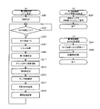
<主制御部メイン処理>
次に、図6を用いて、図4に示す主制御部300のCPU304が実行する主制御部メイン処理について説明する。なお、同図は主制御部メイン処理の流れを示すフローチャートである。
<Main control unit main processing>
Next, main control unit main processing executed by the CPU 304 of the main control unit 300 shown in FIG. 4 will be described with reference to FIG. It should be noted that this figure is a flow chart showing the flow of the main processing of the main controller.

図4に示す主制御部300のRAM308には、特図乱数値、特図ラウンド決定乱数値、特図電サポ決定乱数値、および特図図柄決定乱数値等が記憶される。また、このRAM308には、これら各種の乱数値を生成する乱数カウンタが設けられている。さらに、RAM308には、特図の保留数、特図当選乱数値、および各種の判定(抽選)結果等が記憶される。以下、RAM308における特図の保留数を記憶する領域を特図保留数記憶領域と称することがある。またさらに、RAM308には、当否判定(抽選)の開始を保留することができる最大数(この例では4つ)の領域に区分けされた特図用の始動情報記憶部が用意されているとともに、普図用の乱数値記憶領域も用意されている。特図用の始動情報記憶部には、後述するように、複数種類の始動情報を1セットにしてこれらの始動情報が入賞順(保留順)に1セットずつ1領域ごとに格納される。 The RAM 308 of the main control unit 300 shown in FIG. 4 stores a special figure random number, a special figure round determination random number, a special figure electric sapo decision random number, a special figure design random number, and the like. The RAM 308 is also provided with a random number counter for generating these various random numbers. Furthermore, the RAM 308 stores the reserved number of special figures, the special figure winning random number, various determination (lottery) results, and the like. Hereinafter, the area that stores the number of reserved special figures in the RAM 308 may be referred to as a special figure reserved number storage area. Furthermore, the RAM 308 is provided with a starting information storage unit for a special figure that is divided into the maximum number (in this example, four) areas that can hold the start of the success/failure determination (lottery), A random number storage area for normal maps is also provided. As will be described later, in the starting information storage unit for special figures, a plurality of types of starting information are set as one set, and these starting information are stored one by one in order of winning (reservation order) for each area.

上述したように、図4に示す主制御部300には、電源が投入されると起動信号(リセット信号)を出力する起動信号出力回路(リセット信号出力回路)340を設けている。この起動信号を入力した基本回路302のCPU304は、リセット割込によりリセットスタートしてROM306に予め記憶している制御プログラムに従って図6に示す主制御部メイン処理を実行する。 As described above, the main control unit 300 shown in FIG. 4 is provided with the activation signal output circuit (reset signal output circuit) 340 that outputs the activation signal (reset signal) when the power is turned on. The CPU 304 of the basic circuit 302 that has received this activation signal is reset-started by the reset interrupt and executes the main control section main processing shown in FIG.

ステップS101では、初期設定1を行う。この初期設定1では、CPU304のスタックポインタ(SP)へのスタック初期値の設定(仮設定)、割込マスクの設定、I/O310の初期設定、RAM308に記憶する各種変数の初期設定、WDT314への動作許可及び初期値の設定等を行う。なお、本実施形態では、WDT314に、初期値として32.8msに相当する数値を設定する。 In step S101, initial setting 1 is performed. In this initial setting 1, the stack initial value setting (temporary setting) to the stack pointer (SP) of the CPU 304, the interrupt mask setting, the initial setting of the I/O 310, the initial setting of various variables stored in the RAM 308, and the WDT 314 and set initial values. In this embodiment, the WDT 314 is set to a numerical value corresponding to 32.8 ms as an initial value.

ステップS103では、WDT314のカウンタの値をクリアし、WDT314による時間計測を再始動する。 In step S103, the counter value of WDT 314 is cleared, and time measurement by WDT 314 is restarted.

ステップS105では、低電圧信号がオンであるか否か、すなわち、電圧監視回路338が、電源制御部660が第2副制御部500を介して主制御部300に供給している電源の電圧値が所定の値(本実施形態では9v)未満である場合に電圧が低下したことを示す低電圧信号を出力しているか否かを監視する。そして、低電圧信号がオンの場合(CPU304が電源の遮断を検知した場合)にはステップS103に戻り、低電圧信号がオフの場合(CPU304が電源の遮断を検知していない場合)にはステップS107に進む。なお、電源が投入された直後で未だ上記所定の値(9V)に達しない場合にもステップS103に戻り、供給電圧がその所定の値以上になるまで、ステップS105は繰り返し実行される。 In step S105, whether or not the low voltage signal is on, that is, the voltage monitoring circuit 338 detects the voltage value of the power supply that the power supply control unit 660 supplies to the main control unit 300 via the second sub-control unit 500. is less than a predetermined value (9v in this embodiment), it monitors whether or not it outputs a low voltage signal indicating that the voltage has dropped. Then, if the low voltage signal is on (when the CPU 304 detects the power cutoff), the process returns to step S103, and when the low voltage signal is off (when the CPU 304 does not detect the power cutoff), step Proceed to S107. Even if the voltage does not reach the predetermined value (9 V) immediately after the power is turned on, the process returns to step S103, and step S105 is repeatedly executed until the supply voltage reaches or exceeds the predetermined value.

ステップS107では、初期設定2を行う。この初期設定2では、後述する主制御部タイマ割込処理を定期毎に実行するための周期を決める数値をタイマ回路312に設定する処理、I/O310の所定のポート(例えば試験用出力ポート、第1副制御部400への出力ポート)からクリア信号を出力する処理、RAM308への書き込みを許可する設定等を行う。 In step S107, initial setting 2 is performed. In this initial setting 2, a process of setting a numerical value for determining a period for periodically executing a main control unit timer interrupt process to be described later in the timer circuit 312, a predetermined port of the I/O 310 (for example, a test output port, The output port to the first sub-controller 400) outputs a clear signal, and the setting to permit writing to the RAM 308 is performed.

ステップS109では、電源の遮断前(電断前)の状態に復帰するか否かの判定を行い、電断前の状態に復帰しない場合(主制御部300の基本回路302を初期状態にする場合)には初期化処理を実行するべくステップS113以降の処理に進む。 In step S109, it is determined whether or not to return to the state before power interruption (before power interruption). ), the process proceeds to step S113 and subsequent steps in order to execute the initialization process.

電断前の状態に復帰すると判定しない場合は(ステップS109;No)、その要因が図2に示す電源基板182に設けたRAMクリアスイッチ180が遊技店の店員などにより操作されたものであるか否かを判定する(ステップS113)。すなわち、RAMクリアスイッチ180が操作された場合に送信されるRAMクリア信号がオン(操作があったことを示す)であるか否かを判定する。RAMクリア信号がオンと判定された場合は(ステップS113;Yes)、設定変更キー192がON側に操作されているか否かを判定する(ステップS115)、設定変更キー192がON側に操作されていると判定した場合は(ステップS115;Yes)、設定変更処理を実行する(ステップS117)。 If it is determined not to return to the state before the power interruption (step S109; No), is the reason for this the operation of the RAM clear switch 180 provided on the power supply board 182 shown in FIG. It is determined whether or not (step S113). That is, it is determined whether or not the RAM clear signal transmitted when the RAM clear switch 180 is operated is on (indicating that there has been an operation). If it is determined that the RAM clear signal is ON (step S113; Yes), it is determined whether or not the setting change key 192 is turned ON (step S115). If it is determined that there is (step S115; Yes), setting change processing is executed (step S117).

設定変更処理が実行されると、役物比率・設定表示器196における設定モニタに対応する7セグが「1」を示して点滅し、設定変更可能であることが示される。この状態で、設定変更ボタン194が押下操作されるごとに、設定モニタの7セグがインクリメントし、設定モニタに対応する7セグが「6」を示している状態で設定変更ボタン194が押下操作されると「1」に戻るようになっている。本実施形態では、少なくとも大当り確率の異なる設定1~6のうちからいずれかを選択可能とされており、所望とする設定に変更した後で設定変更キー192をOFF側に操作することで、設定が確定する。このとき、設定モニタに表示されている設定値は消去される。その後、設定が確定した後は、設定変更ボタン194を操作することにより設定値を設定モニタに一定時間(例えば、5秒間)再表示させることができる。なお、本実施形態では、設定値を役物比率・設定表示器196の設定モニタに表示させるようにしたが、例えば、装飾図柄表示装置208に表示させたり、音声出力により報知するようにしてもよい。また、本実施形態では、設定1~6の6段階設定としているが、6段階設定以外であってもよいし、設定変更を行わないものであってもよい。また、本実施形態では、設定モニタに表示される設定の初期値を「1」としたが、電源が遮断される前の設定値が保持され、保持された設定値が表示されるようにしてもよい。 When the setting change process is executed, the 7-segment corresponding to the setting monitor in the role product ratio/setting display 196 blinks indicating "1", indicating that the setting can be changed. In this state, each time the setting change button 194 is pressed, the 7 segments of the setting monitor are incremented, and the setting change button 194 is pressed while the 7 segments corresponding to the setting monitor indicate "6". When it is set, it returns to "1". In this embodiment, at least one of settings 1 to 6 with different jackpot probabilities can be selected. is determined. At this time, the setting values displayed on the setting monitor are erased. After that, after the setting is confirmed, the setting value can be redisplayed on the setting monitor for a certain period of time (for example, 5 seconds) by operating the setting change button 194 . In this embodiment, the setting value is displayed on the setting monitor of the character ratio/setting display 196, but for example, it may be displayed on the decorative pattern display device 208 or notified by voice output. good. Also, in the present embodiment, six levels of setting 1 to 6 are set, but settings other than six levels may be used, and settings may not be changed. Also, in this embodiment, the initial value of the setting displayed on the setting monitor is set to "1", but the setting value before the power is turned off is held and the held setting value is displayed. good too.

また、ステップS113において、RAMクリア信号がONであると判定しなかった場合(ステップS113;No)や、ステップS115において設定変更キー192がON側に操作されていると判定しなかった場合は(ステップS115;No)、ステップS117の設定変更処理を実行することなく、ステップS119に移行する。 If it is not determined in step S113 that the RAM clear signal is ON (step S113; No) or if it is not determined in step S115 that the setting change key 192 is turned ON ( Step S115; No), the process proceeds to step S119 without executing the setting change process of step S117.

ステップS119では、基本回路302を初期状態にすべく初期化処理を実行する(ステップS119)。ここでは、RAMクリア信号がONである場合、RAM308に設けた電源ステータス記憶領域に記憶した電源ステータスの情報を読み出し、この電源ステータスの情報がサスペンドを示す情報でない場合、RAM308の所定の領域(例えば全ての領域)に記憶している1バイトデータを初期値が0である1バイト構成のレジスタに全て加算することによりチェックサムを算出し、算出したチェックサムの結果が特定の値(例えば0)であるか否か(チェックサムの結果が正常であるか否か)を判定し、チェックサムの結果が特定の値(例えば0)以外である場合(チェックサムの結果が異常である場合)には、パチンコ機100を初期状態にすべく初期化処理を実行する。この初期化処理では、割込禁止の設定、スタックポインタへのスタック初期値の設定(本設定)、RAM308の全ての記憶領域の初期化などを行う。なお、本実施形態では、初期化が行われた場合であっても設定変更処理(ステップS117)で設定された設定値は保持される。さらにここで、主制御部300のRAM308に設けられた送信情報記憶領域に正常復帰コマンド及びステップS117で選択された設定を示す設定コマンドをセットする。この正常復帰コマンドは、主制御部300の初期化処理(ステップS119)が行われたことを表すコマンドであり、後述する復電コマンドと同じく、主制御部300のタイマ割込処理におけるステップS233において、第1副制御部400へ送信される。 In step S119, initialization processing is executed to initialize the basic circuit 302 (step S119). Here, when the RAM clear signal is ON, the power status information stored in the power status storage area provided in the RAM 308 is read. All areas) are added to a 1-byte register whose initial value is 0 to calculate the checksum, and the result of the calculated checksum is a specific value (for example, 0) (whether the checksum result is normal), and if the checksum result is other than a specific value (for example, 0) (if the checksum result is abnormal) executes initialization processing to initialize the pachinko machine 100 . In this initialization processing, interrupt inhibition setting, stack initial value setting to the stack pointer (main setting), initialization of all storage areas of the RAM 308, and the like are performed. Note that in this embodiment, even if the initialization is performed, the setting value set in the setting change process (step S117) is retained. Further, here, the normal return command and the setting command indicating the setting selected in step S117 are set in the transmission information storage area provided in the RAM 308 of the main control unit 300. FIG. This return-to-normal command is a command indicating that the initialization processing (step S119) of the main control unit 300 has been performed. , is transmitted to the first sub-controller 400 .

ステップS121では、割込禁止の設定を行った後、基本乱数初期値更新処理を行う。この基本乱数初期値更新処理では、普図当選乱数カウンタ、および特図乱数値カウンタの初期値をそれぞれ生成するための2つの初期値生成用乱数カウンタを更新する。例えば、普図当選乱数値として取り得る数値範囲が0~99とすると、RAM308に設けた普図当選乱数値を生成するための乱数カウンタ記憶領域から値を取得し、取得した値に1を加算してから元の乱数カウンタ記憶領域に記憶する。このとき、取得した値に1を加算した結果が100であれば0を元の乱数カウンタ記憶領域に記憶する。他の初期値生成用乱数カウンタ、乱数カウンタもそれぞれ同様に更新する。主制御部300は、所定の周期ごとに開始するタイマ割込処理を行っている間を除いて、このステップS121の処理を繰り返し実行する。 In step S121, after setting the interrupt prohibition, basic random number initial value update processing is performed. In this basic random number initial value update process, two initial value generating random number counters for generating the initial values of the general pattern winning random number counter and the special pattern random number counter are updated. For example, if the range of values that can be taken as the general pattern winning random number is 0 to 99, a value is obtained from the random number counter storage area for generating the general pattern winning random number value provided in the RAM 308, and 1 is added to the obtained value. After that, it is stored in the original random number counter storage area. At this time, if the result of adding 1 to the obtained value is 100, 0 is stored in the original random number counter storage area. Other random number counters for initial value generation and random number counters are similarly updated. The main control unit 300 repeatedly executes the processing of step S121 except while the timer interrupt processing that starts at predetermined intervals is being performed.

一方、ステップS111では、復電時処理を行う。この復電時処理では、電断時にRAM308に設けられたスタックポインタ退避領域に記憶しておいたスタックポインタの値を読み出し、スタックポインタに再設定(本設定)する。また、電断時にRAM308に設けられたレジスタ退避領域に記憶しておいた各レジスタの値を読み出し、各レジスタに再設定した後、割込許可の設定を行う。以降、CPU304が、再設定後のスタックポインタやレジスタに基づいて制御プログラムを実行する結果、パチンコ機100は電源断時の状態に復帰する。すなわち、電断直前にタイマ割込処理(後述)に分岐する直前に行った(ステップS121内の所定の)命令の次の命令から処理を再開する。また、図2に示す主制御部300における基本回路302に搭載されているRAM308には、送信情報記憶領域が設けられている。このステップS111では、その送信情報記憶領域に、復電コマンドをセットする。この復電コマンドは、電源断時の状態に復帰したことを表すコマンドであり、後述する、主制御部300のタイマ割込処理におけるステップS233において、第1副制御部400へ送信される。 On the other hand, in step S111, power recovery processing is performed. In this power recovery process, the value of the stack pointer stored in the stack pointer save area provided in the RAM 308 at the time of power failure is read out and reset (permanent setting) to the stack pointer. Also, when power is cut off, the value of each register stored in the register save area provided in the RAM 308 is read out, and after resetting in each register, interrupt permission is set. Thereafter, as a result of the CPU 304 executing the control program based on the reset stack pointer and register, the pachinko machine 100 returns to the state at the time of power failure. That is, the process is restarted from the instruction next to the instruction (predetermined in step S121) executed immediately before branching to the timer interrupt process (described later) immediately before the power failure. A transmission information storage area is provided in the RAM 308 mounted on the basic circuit 302 in the main control unit 300 shown in FIG. In this step S111, a power restoration command is set in the transmission information storage area. This power restoration command is a command indicating that the power has been restored to the state at the time of power failure, and is transmitted to the first sub-controller 400 in step S233 in the timer interrupt processing of the main controller 300, which will be described later.

<主制御部タイマ割込処理>
次に、図7を用いて、主制御部300のCPU304が実行する主制御部タイマ割込処理について説明する。なお、同図は主制御部タイマ割込処理の流れを示すフローチャートである。
<Main controller timer interrupt processing>
Next, the main controller timer interrupt processing executed by the CPU 304 of the main controller 300 will be described with reference to FIG. This figure is a flow chart showing the flow of the main controller timer interrupt processing.

図4に示す主制御部300は、所定の周期(本実施形態では約4msに1回)でタイマ割込信号を発生するタイマ回路312を備えており、このタイマ割込信号を契機として主制御部タイマ割込処理を所定の周期で開始する。 The main control unit 300 shown in FIG. 4 includes a timer circuit 312 that generates a timer interrupt signal at a predetermined cycle (once every 4 ms in this embodiment). A partial timer interrupt process is started at a predetermined cycle.

ステップS201では、タイマ割込開始処理を行う。このタイマ割込開始処理では、CPU304の各レジスタの値をスタック領域に一時的に退避する処理などを行う。 In step S201, timer interrupt start processing is performed. In this timer interrupt start processing, processing such as temporarily saving the values of each register of the CPU 304 to the stack area is performed.

ステップS203では、WDT314のカウント値が初期設定値(本実施形態では32.8ms)を超えてWDT割込が発生しないように(処理の異常を検出しないように)、WDT314を定期的に(本実施形態では、主制御部タイマ割込の周期である約2msに1回)リスタートを行う。 In step S203, the WDT 314 is periodically turned on so that the count value of the WDT 314 does not exceed the initial set value (32.8 ms in this embodiment) and a WDT interrupt does not occur (so that an abnormality in processing is not detected). In the embodiment, a restart is performed once every 2 ms, which is the cycle of the main controller timer interrupt.

ステップS205では、入力ポート状態更新処理を行う。この入力ポート状態更新処理では、I/O310の入力ポートを介して、各種の球検出センサを含む図4に示す各種センサ320の検出信号を入力して検出信号の有無を監視し、RAM308に各種センサ320ごとに区画して設けた信号状態記憶領域に記憶する。球検出センサの検出信号を例にして説明すれば、前々回のタイマ割込処理(約4ms前)で検出した各々の球検出センサの検出信号の有無の情報を、RAM308に各々の球検出センサごとに区画して設けた前回検出信号記憶領域から読み出し、この情報をRAM308に各々の球検出センサごとに区画して設けた前々回検出信号記憶領域に記憶し、前回のタイマ割込処理(約2ms前)で検出した各々の球検出センサの検出信号の有無の情報を、RAM308に各々の球検出センサごとに区画して設けた今回検出信号記憶領域から読み出し、この情報を上述の前回検出信号記憶領域に記憶する。また、今回検出した各々の球検出センサの検出信号を、上述の今回検出信号記憶領域に記憶する。 In step S205, input port state update processing is performed. In this input port state update process, detection signals from various sensors 320 shown in FIG. The information is stored in a signal state storage area provided separately for each sensor 320 . Taking the detection signal of the ball detection sensor as an example, the information on the presence or absence of the detection signal of each ball detection sensor detected in the timer interrupt process (about 4 ms before) before the last time is stored in the RAM 308 for each ball detection sensor. This information is read out from the previous detection signal storage area provided separately for each ball detection sensor in the RAM 308 and stored in the two-previous detection signal storage area provided separately for each ball detection sensor. ) is read out from the current detection signal storage area provided separately for each ball detection sensor in the RAM 308, and this information is stored in the previous detection signal storage area. memorize to In addition, the detection signal of each ball detection sensor detected this time is stored in the above-mentioned current detection signal storage area.

また、ステップS205では、上述の前々回検出信号記憶領域、前回検出信号記憶領域、および今回検出信号記領域の各記憶領域に記憶した各々の球検出センサの検出信号の有無の情報を比較し、各々の球検出センサにおける過去3回分の検出信号の有無の情報が入賞判定パターン情報と一致するか否かを判定する。一個の遊技球が一つの球検出センサを通過する間に、約2msという非常に短い間隔で起動を繰り返すこの主制御部タイマ割込処理は何回か起動する。このため、主制御部タイマ割込処理が起動する度に、上述のステップS205では、同じ遊技球が同じ球検出センサを通過したことを表す検出信号を確認することになる。この結果、上述の前々回検出信号記憶領域、前回検出信号記憶領域、および今回検出信号記憶領域それぞれに、同じ遊技球が同じ球検出センサを通過したことを表す検出信号が記憶される。すなわち、遊技球が球検出センサを通過し始めたときには、前々回検出信号無し、前回検出信号有り、今回検出信号有りになる。本実施形態では、球検出センサの誤検出やノイズを考慮して、検出信号無しの後に検出信号が連続して2回記憶されている場合には、入賞があったと判定する。図4に示す主制御部300のROM306には、入賞判定パターン情報(本実施形態では、前々回検出信号無し、前回検出信号有り、今回検出信号有りであることを示す情報)が記憶されている。このステップS205では、各々の球検出センサにおいて過去3回分の検出信号の有無の情報が、予め定めた入賞判定パターン情報(本実施形態では、前々回検出信号無し、前回検出信号有り、今回検出信号有りであることを示す情報)と一致した場合に、一般入賞口、第1可変入賞口234、第2可変入賞口235、第1特図始動口(固定)230、第1特図始動口(可変)231、および第2特図始動口232への入球、または普図始動口228の通過があったと判定する。すなわち、一般入賞口、これらの可変入賞口234,235、これらの始動口230,231,232,228への入球があったと判定する。例えば、第1特図始動口(固定)230への入球を検出する第1始動口センサにおいて過去3回分の検出信号の有無の情報が上述の入賞判定パターン情報と一致した場合には、第1特図始動口(固定)230へ入賞があった、すなわち所定領域を通過する遊技媒体を検出したと判定し、以降の第1特図始動口(固定)230への入賞に伴う処理を行うが、過去3回分の検出信号の有無の情報が上述の入賞判定パターン情報と一致しなかった場合には、以降の第1特図始動口(固定)230への入賞に伴う処理を行わずに後続の処理に分岐する。なお、主制御部300のROM306には、入賞判定クリアパターン情報(本実施形態では、前々回検出信号有り、前回検出信号無し、今回検出信号無しであることを示す情報)が記憶されている。入賞が一度あったと判定した後は、各々の球検出センサにおいて過去3回分の検出信号の有無の情報が、その入賞判定クリアパターン情報に一致するまで入賞があったとは判定せず、入賞判定クリアパターン情報に一致すれば、次からは上記入賞判定パターン情報に一致するか否かの判定を行う。 Further, in step S205, the information on the presence or absence of the detection signal of each ball detection sensor stored in each storage area of the detection signal storage area before last, the previous detection signal storage area, and the current detection signal storage area is compared. It is determined whether or not the information on the presence or absence of detection signals for the past three times in the ball detection sensor matches the winning determination pattern information. While one game ball passes one ball detection sensor, this main control section timer interrupt processing, which repeats activation at very short intervals of about 2 ms, is activated several times. Therefore, every time the main controller timer interrupt process is activated, in the above-described step S205, the detection signal indicating that the same game ball has passed the same ball detection sensor is confirmed. As a result, a detection signal indicating that the same game ball has passed through the same ball detection sensor is stored in each of the two-previous detection signal storage area, the previous detection signal storage area, and the current detection signal storage area. That is, when the game ball begins to pass through the ball detection sensor, there is no detection signal before the previous time, there is a previous detection signal, and there is this time detection signal. In this embodiment, in consideration of erroneous detection and noise of the ball detection sensor, it is determined that a prize has been won when a detection signal is stored twice consecutively after no detection signal. The ROM 306 of the main control unit 300 shown in FIG. 4 stores winning determination pattern information (in this embodiment, information indicating that there is no detection signal the previous time, there is a detection signal last time, and there is a detection signal this time). In this step S205, the information on the presence or absence of the detection signal for the past three times in each ball detection sensor is converted into predetermined prize winning determination pattern information (in this embodiment, there is no detection signal from the time before last, there is a detection signal from the previous time, and there is a detection signal this time). information indicating that it is), general winning mouth, first variable winning mouth 234, second variable winning mouth 235, first special figure start opening (fixed) 230, first special figure start opening (variable ) 231, and the second special figure start opening 232, or the passage of the normal figure start opening 228 is determined. That is, it is determined that the ball has entered the general winning openings, these variable winning openings 234 and 235, and these starting openings 230, 231, 232, and 228. For example, when the information on the presence or absence of the detection signal for the past three times in the first starting opening sensor that detects the ball entering the first special figure starting opening (fixed) 230 matches the above-described winning judgment pattern information, It is determined that there is a prize in the 1st special figure starting port (fixed) 230, that is, the game medium passing through the predetermined area is detected, and the subsequent processing associated with the winning of the 1st special figure starting port (fixed) 230 is performed. However, if the information on the presence or absence of the detection signal for the past three times does not match the above-described winning judgment pattern information, the processing associated with winning the subsequent first special figure start port (fixed) 230 Without performing Branch to subsequent processing. Note that the ROM 306 of the main control unit 300 stores winning determination clear pattern information (in this embodiment, information indicating that there is a detection signal the time before last, no detection signal last time, and no detection signal this time). After it is determined that there has been a winning, it is not determined that there has been a winning until the information on the presence or absence of detection signals for the past three times in each ball detection sensor matches the winning determination clear pattern information, and the winning determination is cleared. If it matches with the pattern information, then it is determined whether or not it matches with the winning determination pattern information.

ステップS207およびステップS209では、基本乱数初期値更新処理および基本乱数更新処理を行う。これらの基本乱数初期値更新処理および基本乱数更新処理では、上記ステップS121で行った初期値生成用乱数カウンタの値の更新を行い、次に主制御部300で使用する、普図当選乱数値および特図乱数値それぞれを生成するための乱数カウンタを更新する。例えば、普図当選乱数値として取り得る数値範囲が0~99とすると、RAM308に設けた普図当選乱数値を生成するための乱数カウンタ記憶領域から値を取得し、取得した値に1を加算してから元の乱数カウンタ記憶領域に記憶する。このとき、取得した値に1を加算した結果が100であれば0を元の乱数カウンタ記憶領域に記憶する。また、取得した値に1を加算した結果、乱数カウンタが一周していると判定した場合にはそれぞれの乱数カウンタに対応する初期値生成用乱数カウンタの値を取得し、乱数カウンタの記憶領域にセットする。例えば、0~99の数値範囲で変動する普図当選乱数値生成用の乱数カウンタから値を取得し、取得した値に1を加算した結果が、RAM308に設けた所定の初期値記憶領域に記憶している前回設定した初期値と等しい値(例えば7)である場合に、普図当選乱数値生成用の乱数カウンタに対応する初期値生成用乱数カウンタから値を初期値として取得し、普図当選乱数値生成用の乱数カウンタにセットすると共に、普図当選乱数値生成用の乱数カウンタが次に1周したことを判定するために、今回設定した初期値を上述の初期値記憶領域に記憶しておく。また、普図当選乱数値生成用の乱数カウンタが次に1周したことを判定するための上述の初期値記憶領域とは別に、特図乱数生成用の乱数カウンタが1周したことを判定するための初期値記憶領域をRAM308に設けている。 In steps S207 and S209, basic random number initial value update processing and basic random number update processing are performed. In these basic random number initial value update process and basic random number update process, the value of the random number counter for initial value generation performed in step S121 is updated, and then used by the main control unit 300, the normal figure winning random value and Update the random number counter for generating each special random number. For example, if the range of values that can be taken as the general pattern winning random number is 0 to 99, a value is obtained from the random number counter storage area for generating the general pattern winning random number value provided in the RAM 308, and 1 is added to the obtained value. After that, it is stored in the original random number counter storage area. At this time, if the result of adding 1 to the obtained value is 100, 0 is stored in the original random number counter storage area. As a result of adding 1 to the obtained value, if it is determined that the random number counter has completed one cycle, the value of the random number counter for initial value generation corresponding to each random number counter is obtained and stored in the memory area of the random number counter. set. For example, a value is obtained from a random number counter for generating a random number for general pattern winning that fluctuates in the numerical range of 0 to 99, and the result of adding 1 to the obtained value is stored in a predetermined initial value storage area provided in RAM 308. If the value is equal to the initial value set last time (for example, 7), the value is obtained as the initial value from the random number counter for initial value generation corresponding to the random number counter for generating the random number for normal figure winning, and In addition to setting the random number counter for generating the winning random numbers, the initial value set this time is stored in the above-mentioned initial value storage area in order to determine that the random number counter for generating the winning random numbers has made the next round. Keep In addition, in addition to the above-mentioned initial value storage area for determining that the random number counter for normal figure winning random number generation has made one round next, it is determined that the random number counter for special figure random number generation has made one round The RAM 308 is provided with an initial value storage area for this purpose.

ステップS211では、演出乱数更新処理を行う。この演出乱数更新処理では、主制御部300で使用する演出用乱数値を生成するための乱数カウンタを更新する。 In step S211, effect random number update processing is performed. In this effect random number update process, the random number counter for generating the effect random number value used in the main control unit 300 is updated.

ステップS213では、タイマ更新処理を行う。このタイマ更新処理では、普通図柄表示装置210に図柄を変動・停止表示する時間を計時するための普図表示図柄更新タイマ、第1特図表示装置212、第2特図表示装置214に図柄を変動・停止表示する時間を計時するための特図表示図柄更新タイマ、所定の入賞演出時間、所定の開放時間、所定の閉鎖時間、所定の終了演出期間などを計時するためのタイマなどを含む各種タイマを更新する。 In step S213, timer update processing is performed. In this timer update process, the normal pattern display pattern update timer for measuring the time for changing and stopping the display of the pattern on the normal pattern display device 210, the first special pattern display device 212, and the second special pattern display device 214. Various types of timers, including a special display symbol update timer for measuring the time for variable/stop display, a timer for timing a predetermined winning effect time, a predetermined opening time, a predetermined closing time, a predetermined end effect period, etc. Update the timer.

ステップS215では、入賞口カウンタ更新処理を行う。この入賞口カウンタ更新処理では、入賞口234、235や始動口230,231,232に入賞があった場合に、RAM308に各入賞口ごと、あるいは各始動口ごとに設けた賞球数記憶領域の値を読み出し、1を加算して、元の賞球数記憶領域に設定する。 In step S215, a winning opening counter update process is performed. In this winning opening counter update process, when there is a winning of winning openings 234, 235 or start openings 230, 231, 232, the number of winning balls storage area provided for each winning opening or each starting opening is stored in the RAM 308. The value is read out, 1 is added, and the value is set in the original number-of-balls-storage area.

また、ステップS217では、入賞受付処理を行う。入賞受付処理では、所定の条件が満足されていれば、複数種類の始動情報を取得する。ここで取得された複数種類の始動情報は、RAM308に設けた始動情報記憶部の、入賞順(保留順)に応じた空いている領域に、1セットの始動情報として記憶される。 Also, in step S217, a winning acceptance process is performed. In the winning acceptance process, if a predetermined condition is satisfied, a plurality of types of starting information are acquired. A plurality of types of starting information acquired here are stored as one set of starting information in an empty area corresponding to the winning order (holding order) of the starting information storage unit provided in the RAM 308 .

ステップS217に続いて実行されるステップS219では、払出要求数送信処理を行う。図4に示す払出制御部600に出力する出力予定情報および払出要求情報は1バイトで構成しており、ビット7にストローブ情報(オンの場合、データをセットしていることを示す)、ビット6に電源投入情報(オンの場合、電源投入後一回目のコマンド送信であることを示す)、ビット4~5に暗号化のための今回加工種別(0~3)、およびビット0~3に暗号化加工後の払出要求数を示すようにしている。 In step S219 executed subsequent to step S217, payout request number transmission processing is performed. The output schedule information and the payout request information output to the payout control unit 600 shown in FIG. , power-on information (if it is on, it indicates that it is the first command transmission after power-on), current processing type (0-3) for encryption in bits 4-5, and encryption in bits 0-3 It shows the number of payout requests after the processing.

ステップS221では、普図状態更新処理を行う。この普図状態更新処理は、普図の状態に対応する複数の処理のうちの1つの処理を行う。例えば、普図変動表示の途中(上述する普図表示図柄更新タイマの値が1以上)における普図状態更新処理では、普通図柄表示装置210を構成する2つのLEDの交互点滅を行う点灯・消灯駆動制御を行う。この制御を行うことで、普通図柄表示装置210は普図の変動表示(普図変動遊技)を行う。 In step S221, a general pattern state update process is performed. This general pattern state update process performs one process out of a plurality of processes corresponding to the general pattern state. For example, in the middle of the normal pattern fluctuation display (the value of the normal pattern display symbol update timer described above is 1 or more), in the normal pattern state update process, the two LEDs that make up the normal pattern display device 210 are alternately lit and extinguished. Drive control. By performing this control, the normal symbol display device 210 performs a normal pattern variation display (normal pattern variation game).

また、普図変動表示時間が経過したタイミング(普図表示図柄更新タイマの値が1から0になったタイミング)における普図状態更新処理では、当りフラグがオンの場合には、当り図柄の表示態様となるように普通図柄表示装置210を構成する2つのLEDの点灯・消灯駆動制御を行い、当りフラグがオフの場合には、ハズレ図柄の表示態様となるように普通図柄表示装置210を構成する2つのLEDの点灯・消灯駆動制御を行う。また、主制御部300のRAM308には、普図状態更新処理に限らず各種の処理において各種の設定を行う設定領域が用意されている。ここでは、上記点灯・消灯駆動制御を行うとともに、その設定領域に普図停止表示中であることを示す設定を行う。この制御を行うことで、普通図柄表示装置210は、当り図柄(図5(d)に示す普図A)およびハズレ図柄(図5(d)に示す普図B)いずれか一方の図柄の確定表示を行う。さらにその後、所定の停止表示期間(例えば500m秒間)、その表示を維持するためにRAM308に設けた普図停止時間管理用タイマの記憶領域に停止期間を示す情報を設定する。この設定により、確定表示された図柄が所定期間停止表示され、普図変動遊技の結果が遊技者に報知される。 In addition, in the general pattern state update process at the timing when the general pattern fluctuation display time has passed (the timing when the value of the general pattern display pattern update timer has changed from 1 to 0), if the hit flag is on, the display of the pattern The lighting/extinguishing drive control of the two LEDs constituting the normal symbol display device 210 is performed so as to be a mode, and when the hit flag is off, the normal symbol display device 210 is configured so that the display mode is a losing symbol. It controls the lighting and extinguishing of the two LEDs. In addition, the RAM 308 of the main control unit 300 is provided with a setting area for performing various settings in various processes, not limited to the general pattern state update process. Here, along with performing the lighting/extinguishing drive control described above, a setting is made in the setting area to indicate that the normal map stop display is in progress. By performing this control, the normal symbol display device 210 determines one of the winning symbols (normal symbol A shown in FIG. 5(d)) and the losing symbol (normal symbol B shown in FIG. 5(d)). display. Furthermore, after that, for a predetermined stop display period (for example, 500 msec), information indicating the stop period is set in the memory area of the normal chart stop time management timer provided in the RAM 308 in order to maintain the display. By this setting, the fixedly displayed symbols are stopped and displayed for a predetermined period, and the player is notified of the result of the normal pattern variation game.

また、普図変動遊技の結果が当りであれば、後述するように、普図当りフラグがオンされる。この普図当りフラグがオンの場合には、所定の停止表示期間が終了したタイミング(普図停止時間管理用タイマの値が1から0になったタイミング)における普図状態更新処理では、RAM308の設定領域に普図作動中を設定するとともに、所定の開放期間(例えば2秒間)、第1特図始動口(可変)231の羽根部材2311(図35参照)の開閉駆動用のソレノイド(図4に示す各種ソレノイド332の一部)に、羽根部材2311を開放状態に保持する信号を出力するとともに、RAM308に設けた羽根開放時間管理用タイマの記憶領域に開放期間を示す情報を設定する。 Also, if the result of the normal pattern variation game is hit, as described later, the normal pattern per flag is turned on. When this normal pattern per flag is on, in the normal pattern state update process at the timing when the predetermined stop display period has ended (the timing when the value of the normal pattern stop time management timer has changed from 1 to 0), the RAM 308 While setting normal figure operation in the setting area, for a predetermined opening period (for example, 2 seconds), the blade member 2311 (see FIG. 35) of the first special figure start port (variable) 231 Open/close drive solenoid (Fig. 4 (a part of various solenoids 332 shown in FIG. 2), a signal for holding the blade member 2311 in an open state is output, and information indicating an open period is set in the storage area of the timer for managing the blade open time provided in the RAM 308 .

また、所定の開放期間が終了したタイミング(羽根開放時間管理用タイマの値が1から0になったタイミング)で開始する普図状態更新処理では、所定の閉鎖期間(例えば500m秒間)、アタッカユニット23に設けられた第1特図始動口(可変)231の羽根部材2311の開閉駆動用のソレノイド(図4に示す各種ソレノイド332の一部)に、羽根部材2311を閉鎖状態に保持する信号を出力するとともに、RAM308に設けた羽根閉鎖時間管理用タイマの記憶領域に閉鎖期間を示す情報を設定する。 In addition, in the general pattern state update process that starts at the timing when the predetermined open period ends (the value of the blade open time management timer changes from 1 to 0), a predetermined closed period (for example, 500 ms), the attacker unit A signal to hold the blade member 2311 in the closed state is applied to the solenoid (part of the various solenoids 332 shown in FIG. 4) for opening and closing the blade member 2311 of the first special figure start port (variable) 231 provided in 23 Along with outputting, information indicating the closing period is set in the storage area of the blade closing time management timer provided in the RAM 308 .

また、所定の閉鎖期間が終了したタイミング(羽根閉鎖時間管理用タイマの値が1から0になったタイミング)で開始する普図状態更新処理では、RAM308の設定領域に普図非作動中を設定する。さらに、普図変動遊技の結果がハズレであれば、後述するように、普図ハズレフラグがオンされる。この普図ハズレフラグがオンの場合には、上述した所定の停止表示期間が終了したタイミング(普図停止時間管理用タイマの値が1から0になったタイミング)における普図状態更新処理でも、RAM308の設定領域に普図非作動中を設定する。普図非作動中の場合における普図状態更新処理では、何もせずに次のステップS223に移行するようにしている。 In addition, in the general pattern state update process that starts at the timing when the predetermined closing period ends (the timing when the value of the timer for blade closing time management changes from 1 to 0), the general pattern non-operating is set in the setting area of the RAM 308 do. Furthermore, if the result of the normal pattern fluctuation game is a loss, as described later, the normal pattern loss flag is turned on. When this general pattern loss flag is on, even in the general pattern state update process at the timing when the predetermined stop display period described above has ended (the value of the general pattern stop time management timer has changed from 1 to 0), In the setting area of the RAM 308, normal chart non-operation is set. In the normal map state update process when the normal map is not in operation, the process proceeds to the next step S223 without doing anything.

ステップS223では、普図関連抽選処理を行う。この普図関連抽選処理では、普図変動遊技および第1特図始動口(可変)231の開閉制御を行っておらず(普図の状態が非作動中)、且つ、保留している普図変動遊技の数が1以上である場合に、上述の乱数値記憶領域に記憶している普図当選乱数値に基づいた乱数抽選により普図変動遊技の結果を当選とするか、不当選とするかを決定する当り判定をおこない、当選とする場合にはRAM308に設けた当りフラグにオンを設定する。不当選の場合には、当りフラグにオフを設定する。なお、当り判定の結果に関わらず、所定の乱数カウンタの値を普図タイマ乱数値として取得し、取得した普図タイマ乱数値に基づいて複数の変動時間のうちから普図表示装置210に普図を変動表示する時間を1つ選択し、この変動表示時間を、普図変動表示時間として、RAM308に設けた普図変動時間記憶領域に記憶する。なお、保留している普図変動遊技の数は、RAM308に設けた普図保留数記憶領域に記憶するようにしており、当り判定をするたびに、保留している普図変動遊技の数から1を減算した値を、この普図保留数記憶領域に記憶し直すようにしている。また当り判定に使用した乱数値を消去する。 In step S223, normal figure related lottery processing is performed. In this general pattern related lottery process, the normal pattern fluctuation game and the opening and closing control of the first special pattern start port (variable) 231 are not performed (normal pattern state is not in operation), and the reserved normal pattern When the number of variable games is 1 or more, the result of the normal pattern fluctuation game is won or not by random number lottery based on the normal pattern winning random value stored in the random value storage area. A win determination is performed to determine whether or not, and in the case of winning, a win flag provided in the RAM 308 is set to ON. If the prize is not won, the winning flag is set to OFF. In addition, regardless of the result of the hit determination, the value of the predetermined random number counter is acquired as a normal figure timer random number value, and the normal figure display device 210 is displayed from among a plurality of fluctuation times based on the acquired general figure timer random number value. One time is selected for variable display of a figure, and this variable display time is stored in a normal figure variation time storage area provided in the RAM 308 as a normal figure variation display time. It should be noted that the number of the reserved normal pattern fluctuation game is stored in the normal pattern reservation number storage area provided in the RAM 308, and each time the hit determination is made, from the number of the reserved normal pattern fluctuation game The value obtained by subtracting 1 is re-stored in this normal pattern pending number storage area. Also, the random number used for the hit judgment is erased.

続いて、特図先読み処理(ステップS224)が実行される。特図先読み処理では、主制御部300は、特図1および特図2のそれぞれにおいて増加した始動情報を先読みして、当否判定処理よりも前に停止図柄や変動時間を事前判定し、事前判定結果(特図先読み結果)をRAM308内の先読み結果記憶部に記憶する。 Subsequently, a special figure prefetching process (step S224) is executed. In the special figure prefetching process, the main control unit 300 prefetches the increased starting information in each of the special figure 1 and the special figure 2, and determines in advance the stop pattern and the fluctuation time before the propriety determination process, and the prior determination The result (special figure lookahead result) is stored in the lookahead result storage unit in RAM308.

次いで、特図1および特図2それぞれについての特図状態更新処理を行うが、最初に、特図2についての特図状態更新処理(特図2状態更新処理)を行う(ステップS225)。この特図2状態更新処理では、特図2の状態に応じて、次の複数の処理のうちの1つの処理を行う。 Then, the special figure state update process for each of the special figure 1 and the special figure 2 is performed, but first, the special figure status update process for the special figure 2 (special figure 2 state update process) is performed (step S225). In this special figure 2 state update processing, according to the state of special figure 2, one of the following processes is performed.

例えば、特図2変動表示の途中(上述の特図2表示図柄更新タイマの値が1以上)における特図2状態更新処理では、特図2表示装置214を構成する8つのLEDのうちの所定のLEDの点灯と消灯を繰り返す点灯・消灯駆動制御を行う。この制御を行うことで、特図2表示装置214は特図2の変動表示(特図2変動遊技)を行う。また、コマンド設定送信処理(ステップS233)で回転開始設定送信処理を実行させることを示す所定の送信情報を上述の送信情報記憶領域に追加記憶してから処理を終了する。また、RAM308に設けられた時短回数記憶部に記憶された時短回数が1以上であれば、その時短回数から1を減算する。 For example, in the special figure 2 state update process in the middle of the special figure 2 fluctuation display (the above-mentioned special figure 2 display symbol update timer value is 1 or more), the predetermined out of the eight LEDs constituting the special figure 2 display device 214 It performs lighting/extinguishing drive control that repeats lighting and extinguishing of the LED. By performing this control, the special figure 2 display device 214 performs the special figure 2 variation display (special figure 2 variation game). Further, in the command setting transmission process (step S233), predetermined transmission information indicating that the rotation start setting transmission process is to be executed is additionally stored in the transmission information storage area, and then the process is terminated. Further, if the number of times of saving time stored in the number of times of saving time stored in the RAM 308 is 1 or more, 1 is subtracted from the number of times of saving time.

また、主制御部300のRAM308には、10R大当りフラグ、6R大当りフラグ、小当りフラグ、はずれフラグ、特図確率変動フラグ、および普図確率変動フラグ等のフラグが用意されている。これらのフラグは、後述する特図2関連抽選処理において、決定した停止図柄に基づいてオンまたはオフに設定される。特図2変動表示時間が経過したタイミング(特図2表示図柄更新タイマの値が1から0になったタイミング)で開始する特図2状態更新処理では、例えば、10R大当りフラグはオン、特図確率変動フラグもオン、普図確率変動フラグがオフの場合には図5(b)に示す特図c、6R大当りフラグはオン、特図確率変動フラグもオン、普図確率変動フラグはオフの場合には特図b、6R大当りフラグはオン、特図確率変動フラグはオフ、普図確率変動フラグはオンの場合には特図a、小当りフラグがオンの場合には特図d、ハズレフラグがオンの場合には特図eそれぞれの態様となるように、特図2表示装置214を構成するLEDの点灯・消灯駆動制御を行い、RAM308の設定領域に特図2停止表示中であることを表す設定を行う。この制御を行うことで、特図2表示装置214は、10R確変大当り図柄(特図e)、6R確変大当り図柄(特図b)、6R通常大当り図柄(特図a)、小当り図柄(特図d)、ハズレ図柄(特図e)のいずれか一つの図柄の確定表示を行う。なお、同時変動機である本実施形態に係るパチンコ機100では、特図2の変動表示中に特図1の変動表示が行われている場合があるが、特図2変動表示時間が経過したタイミングで大当り図柄が停止表示される場合には、特図1の抽選結果のいかんにかかわらず、特図2の大当り図柄表示のタイミングで特図1では抽選結果が破棄されてはずれ図柄が停止表示されることとなる。また、特図2の変動表示中に特図1の変動表示が行われている場合において、特図2変動表示時間が経過したタイミングで小当り図柄が停止表示される場合には、特図2の小当り図柄表示のタイミングで特図1の変動表示時間の進行が中断されることとなり、その結果、特図1の変動表示が開始してから特図1の図柄が停止表示されるまでの時間は、特図2の小当り図柄の停止表示から小当り遊技の終了までの時間だけ延ばされることとなる。 Also, the RAM 308 of the main control unit 300 is provided with flags such as a 10R big hit flag, a 6R big hit flag, a small hit flag, a losing flag, a special pattern probability change flag, and a normal pattern probability change flag. These flags are set to ON or OFF based on the determined stop design in the special figure 2 related lottery process to be described later. In the special figure 2 state update process starting at the timing when the special figure 2 fluctuation display time has passed (the timing when the value of the special figure 2 display symbol update timer becomes 0 from 1), for example, the 10R jackpot flag is on, special figure If the probability fluctuation flag is also ON, and the normal pattern probability fluctuation flag is off, the special pattern c shown in FIG. If special figure b, 6R big hit flag is on, special figure probability change flag is off, normal figure probability change flag is on special figure a, small hit flag is on special figure d, loss When the flag is on, so that each mode of the special figure e is performed, the LED that constitutes the special figure 2 display device 214 is controlled to turn on and off, and the special figure 2 is stopped and displayed in the setting area of the RAM 308. Make settings that represent By performing this control, the special figure 2 display device 214 includes 10R probability variation jackpot design (special figure e), 6R probability variation jackpot design (special figure b), 6R normal jackpot design (special figure a), small hit design (special figure Fig. d) or one of the lost patterns (special pattern e) is confirmed and displayed. In the pachinko machine 100 according to the present embodiment, which is a simultaneous variation machine, the variation display of the special figure 1 may be performed during the variation display of the special figure 2, but the special figure 2 variation display time has elapsed When the big hit pattern is stopped and displayed at the timing, regardless of the lottery result of the special figure 1, at the timing of the big hit pattern display of the special figure 2, the lottery result of the special figure 1 is discarded and the lost pattern is stopped and displayed. It will be done. Also, when the variation display of the special figure 1 is performed during the variation display of the special figure 2, when the small hit pattern is stopped and displayed at the timing when the special figure 2 variation display time has elapsed, the special figure 2 The progress of the variable display time of special figure 1 will be interrupted at the timing of the small hit symbol display, and as a result, from the start of the variable display of special figure 1 until the symbol of special figure 1 is stopped and displayed The time is extended by the time from the stop display of the small winning pattern of the special figure 2 to the end of the small winning game.

さらにその後、所定の停止表示期間(例えば500ms)その表示を維持するために、RAM308に設けた特図2停止時間管理用タイマの記憶領域に停止期間を示す情報を設定する。この設定により、確定表示された特図2が所定期間停止表示され、特図2変動遊技の結果が遊技者に報知される。また、RAM308に設けられた時短回数記憶部に記憶された時短回数が0であって時短フラグがオンであれば、時短フラグをオフにする。さらに、大当り遊技中(特別遊技状態中)にも、時短フラグをオフにする。 Furthermore, after that, in order to maintain the display for a predetermined stop display period (for example, 500ms), information indicating the stop period is set in the storage area of the special figure 2 stop time management timer provided in the RAM308. By this setting, the special figure 2 fixedly displayed is stopped and displayed for a predetermined period, and the result of the special figure 2 variation game is notified to the player. Further, if the number of times of shortening of working hours stored in the number of times of shortening of working hours storage unit provided in the RAM 308 is 0 and the shortening of working hours flag is turned on, the shortening of working hours flag is turned off. Furthermore, the time saving flag is turned off even during the jackpot game (during the special game state).

また、コマンド設定送信処理(ステップS233)で回転停止設定送信処理を実行させることを示す所定の送信情報を上述の送信情報記憶領域に追加記憶するとともに、変動表示を停止する図柄が特図2であることを示す特図2識別情報を、後述するコマンドデータに含める情報としてRAM308に追加記憶してから処理を終了する。 Further, in the command setting transmission process (step S233), predetermined transmission information indicating that the rotation stop setting transmission process is to be executed is additionally stored in the transmission information storage area, and the symbol for stopping the variable display is the special figure 2. The special figure 2 identification information indicating that there is, after additionally storing in the RAM308 as information to be included in the command data described later, the process is terminated.

また、特図2変動遊技の結果が大当りであれば、後述するように、大当りフラグがオンされる。この大当りフラグがオンの場合には、所定の停止表示期間が終了したタイミング(特図2停止時間管理用タイマの値が1から0になったタイミング)における特図2状態更新処理では、RAM308の設定領域に特図2作動中を設定するとともに、所定の入賞演出期間(例えば3秒間)すなわち装飾図柄表示装置208による大当りを開始することを遊技者に報知する画像を表示している期間待機するためにRAM308に設けた特図2待機時間管理用タイマの記憶領域に入賞演出期間を示す情報を設定する。また、コマンド設定送信処理(ステップS233)で入賞演出設定送信処理を実行させることを示す所定の送信情報を上述の送信情報記憶領域に追加記憶する。 Also, if the result of the special figure 2 variation game is a big hit, a big hit flag is turned on as described later. When this jackpot flag is on, in the special figure 2 state update process at the timing when the predetermined stop display period has ended (the timing when the value of the special figure 2 stop time management timer has changed from 1 to 0), the RAM 308 While setting the special figure 2 in operation in the setting area, it waits for a predetermined winning presentation period (for example, 3 seconds), that is, the period during which an image is displayed to notify the player of the start of the big hit by the decorative symbol display device 208.例文帳に追加Information indicating the winning effect period is set in the storage area of the special figure 2 waiting time management timer provided in the RAM 308 for this purpose. Further, in the command setting transmission process (step S233), predetermined transmission information indicating execution of the winning effect setting transmission process is additionally stored in the transmission information storage area.

また、所定の入賞演出期間が終了したタイミング(特図2待機時間管理用タイマの値が1から0になったタイミング)で開始する特図2状態更新処理では、所定の開放期間(例えば29秒間、または第1可変入賞口234に所定球数(例えば10球)の遊技球の入賞を検出するまで)第1可変入賞口234の扉部材2341の開閉駆動用のソレノイド(図4に示す各種ソレノイド332の一部)に、扉部材2341を開放状態に保持する信号を出力するとともに、RAM308に設けた扉開放時間管理用タイマの記憶領域に開放期間を示す情報を設定する。また、コマンド設定送信処理(ステップS233)で大入賞口開放設定送信処理を実行させることを示す所定の送信情報を上述の送信情報記憶領域に追加記憶する。 In addition, in the special figure 2 state update process that starts at the timing when the predetermined winning effect period ends (the timing when the value of the special figure 2 waiting time management timer changes from 1 to 0), a predetermined open period (for example, 29 seconds , or until a predetermined number of game balls (for example, 10) are detected in the first variable winning port 234). 332) to output a signal to hold the door member 2341 in the open state, and set information indicating the open period in the storage area of the door opening time management timer provided in the RAM 308. FIG. Further, in the command setting transmission process (step S233), predetermined transmission information indicating execution of the big winning opening setting transmission process is additionally stored in the transmission information storage area.

また、所定の開放期間が終了したタイミング(扉開放時間管理用タイマの値が1から0になったタイミング)で開始する特図2状態更新処理では、所定の閉鎖期間(例えば1.5秒間)第1可変入賞口234の扉部材2341の開閉駆動用のソレノイド(図4に示す各種ソレノイド332の一部)に、扉部材2341を閉鎖状態に保持する信号を出力するとともに、RAM308に設けた扉閉鎖時間管理用タイマの記憶領域に閉鎖期間を示す情報を設定する。また、コマンド設定送信処理(ステップS233)で大入賞口閉鎖設定送信処理を実行させることを示す所定の送信情報を上述の送信情報記憶領域に追加記憶する。 In addition, in the special figure 2 state update process that starts at the timing when the predetermined open period ends (when the value of the door opening time management timer changes from 1 to 0), a predetermined closed period (for example, 1.5 seconds) A signal for holding the door member 2341 in a closed state is output to the solenoid for opening and closing the door member 2341 of the first variable winning port 234 (part of the various solenoids 332 shown in FIG. 4), and the door provided in the RAM 308 Information indicating the closing period is set in the storage area of the closing time management timer. Further, in the command setting transmission process (step S233), predetermined transmission information indicating execution of the big winning opening closing setting transmission process is additionally stored in the transmission information storage area.

また、扉部材の開放・閉鎖制御を所定回数(本例示形態では、10ラウンド又は6ラウンド)繰り返し、終了したタイミングで開始する特図2状態更新処理では、所定の終了演出期間(例えば3秒間)すなわち装飾図柄表示装置208による大当りを終了することを遊技者に報知する画像を表示している期間待機するように設定するために、RAM308に設けた演出待機時間管理用タイマの記憶領域に演出待機期間を示す情報を設定する。また、普図確率変動フラグがオンに設定されていれば、この大当り遊技の終了と同時に、RAM308に設けられた時短回数記憶部に時短回数(例えば、50回)をセットするともに、RAM308に設けられた時短フラグをオンにする。なお、その普図確率変動フラグがオフに設定されていれば、時短回数記憶部に時短回数をセットすることもなく、また時短フラグをオンにすることもない。また、特図確率変動フラグがオンに設定されていれば、大当り遊技の終了と同時、RAM308に設けられた確変フラグをオンにする。 In addition, the opening and closing control of the door member is repeated a predetermined number of times (10 rounds or 6 rounds in this exemplary embodiment), and in the special figure 2 state update process that starts at the end timing, a predetermined end effect period (for example, 3 seconds) That is, in order to set the waiting period during which an image is displayed to inform the player that the decorative pattern display device 208 will end the big hit, the effect waiting time is stored in the storage area of the effect waiting time management timer provided in the RAM 308. Set information indicating the period. Also, if the normal pattern probability fluctuation flag is set to ON, at the same time as the end of this big hit game, the number of times of time saving (for example, 50 times) is set in the time saving number storage unit provided in RAM 308, and provided in RAM 308 turn on the short working hours flag. In addition, if the normal pattern probability fluctuation flag is set to OFF, the number of times of working hours is not set to the number of times of working hours storage, and the time saving flag is not turned on. Also, if the special figure probability variation flag is set to ON, the probability variation flag provided in the RAM 308 is turned ON simultaneously with the end of the big hit game.

ここにいう時短とは、特図変動遊技における大当りを終了してから、次の大当りを開始するまでの時間を短くするため、パチンコ機が遊技者にとって有利な状態になることをいう。時短フラグがオンに設定されていると、普図高確率状態(普図確変)である。普図高確率状態では普図低確率状態に比べて、普図変動遊技で当りになる確率が高い。また、普図高確率状態の方が、普図低確率状態に比べて普図変動遊技の変動時間は短くなる(普図変短)。さらに、普図高確率状態では普図低確率状態に比べて、特図1始動口(可変)231の一対の羽根部材2311の1回の開放における開放時間が長くなり易い(電チュー開延)。加えて、普図高確率状態では普図低確率状態に比べて、一対の羽根部材2311は多く開き易い。これらの普図確変、普図変短、電チュー開延のいずれかが設定される状態を電サポ(電動チューリップによる始動口入賞サポート)状態という。 The term "time saving" as used herein means that the pachinko machine is in an advantageous state for the player by shortening the time from the end of the big win in the special figure variation game to the start of the next big win. When the time saving flag is set to ON, it is a normal pattern high probability state (normal pattern probability change). In the general pattern high probability state, the probability of hitting in the general pattern variation game is higher than in the general pattern low probability state. In addition, in the general pattern high probability state, the fluctuation time of the general pattern fluctuation game is shorter than in the general pattern low probability state (normal pattern variable short). Furthermore, in the general pattern high probability state, compared to the general pattern low probability state, the opening time in one opening of the pair of blade members 2311 of the special figure 1 start port (variable) 231 tends to be longer (electric chew extension) . In addition, in the general pattern high probability state, the pair of blade members 2311 are likely to open more than in the general pattern low probability state. The state in which any of these normal map fixed variable, normal map variable short, and electric chu opening is set is called the electric sapo (starting mouth winning support by electric tulip) state.

また、上述のごとく、時短フラグは、大当り遊技中(特別遊技状態中)にはオフに設定される。したがって、大当り遊技中には、普図低確率状態が維持される。これは、大当り遊技中に普図高確率状態であると、大当り遊技中に第1可変入賞口234に所定の個数、遊技球が入球するまでの間に特図1始動口(可変)231に多くの遊技球が入球し、大当り中に獲得することができる遊技球の数(出球数)が多くなってしまい射幸性が高まってしまうという問題があり、これを解決するためのものである。なお、本実施形態では、特図1始動口(可変)231への入賞に対する賞球数が「1」であるので、実質的に大当り遊技中の出球数が多くなることがないので、大当り遊技中においても時短フラグをオンのままにしてもよい。 Also, as described above, the time saving flag is set to OFF during the big hit game (during the special game state). Therefore, during the jackpot game, the normal pattern low probability state is maintained. This is a special figure 1 start opening (variable) 231 until a predetermined number of game balls enter the first variable winning opening 234 during the jackpot game when the normal pattern high probability state is reached during the jackpot game. There is a problem that many game balls enter the game, and the number of game balls that can be obtained during the big win (the number of balls released) increases, increasing gambling. is. In addition, in this embodiment, since the number of prize balls for winning the special figure 1 start port (variable) 231 is "1", the number of balls released during the big hit game does not substantially increase, so the big hit The time saving flag may remain on even during the game.

さらに、コマンド設定送信処理(ステップS233)で終了演出設定送信処理を実行させることを示す所定の送信情報を上述の送信情報記憶領域に追加記憶する。 Furthermore, in the command setting transmission process (step S233), predetermined transmission information indicating execution of the end effect setting transmission process is additionally stored in the transmission information storage area.

また、所定の終了演出期間が終了したタイミング(演出待機時間管理用タイマの値が1から0になったタイミング)で開始する特図2状態更新処理では、RAM308の設定領域に特図2非作動中を設定する。 In addition, in the special figure 2 state update process that starts at the timing when the predetermined end production period ends (the timing when the value of the timer for production standby time management becomes 0 from 1), the special figure 2 non-operation in the setting area of RAM308 set medium.

以上、第1可変入賞口234を用いた大当り遊技の例について説明したが、第2可変入賞口235を用いた小当り遊技についても同様である。 As mentioned above, although the example of the big hit game using the 1st variable winning a prize mouth 234 was demonstrated, the small hitting game using the 2nd variable winning a prize mouth 235 is also the same.

さらに、特図2変動遊技の結果がはずれであれば、はずれフラグがオンにされる。このはずれフラグがオンの場合には、上述した所定の停止表示期間が終了したタイミング(特図2停止時間管理用タイマの値が1から0になったタイミング)における特図2状態更新処理でも、RAM308の設定領域に特図2非作動中を設定する。特図2非作動中の場合における特図2状態更新処理では、何もせずに次のステップS227に移行するようにしている。 Furthermore, if the result of the special figure 2 fluctuation game is lost, the lost flag is turned on. If this deviation flag is on, even in the special figure 2 state update process at the timing when the above-mentioned predetermined stop display period ends (the timing when the value of the special figure 2 stop time management timer becomes 1 to 0), Set special figure 2 non-operating in the setting area of RAM308. In the special figure 2 state update process when the special figure 2 is not in operation, the process proceeds to the next step S227 without doing anything.

続いて、特図1についての特図状態更新処理(特図1状態更新処理)を行う(ステップS227)。この特図1状態更新処理では、特図1の状態に応じて、上述の特図2状態更新処理で説明した各処理を行う。この特図1状態更新処理で行う各処理は、上述の特図2状態更新処理で説明した内容の「特図2」を「特図1」と読み替えた処理と同様であるため、その説明は省略する。なお、特図2状態更新処理と特図1状態更新処理の順番は逆でもよい。 Subsequently, special figure state update processing (special figure 1 state update processing) for special figure 1 is performed (step S227). In this special figure 1 state update process, according to the special figure 1 state, each process described in the special figure 2 state update process described above is performed. Each process performed in this special figure 1 state update process is the same as the process of replacing "special figure 2" with "special figure 1" in the content described in the above special figure 2 state update process, so the description is omitted. In addition, the order of special figure 2 state update processing and special figure 1 state update processing may be reversed.

ステップS225およびステップS227における特図状態更新処理が終了すると、今度は、特図1および特図2それぞれについての特図関連抽選処理を行う。特図2関連抽選処理(ステップS229)は、特図2の変動遊技を行っておらず、特図2の状態が非作動中であり、特図1及び特図2のいずれの大当り遊技中でもなく、かつ保留している特図2変動遊技の数が1以上であることを開始条件として、特図2乱数値記憶領域内の最先の特図2当選乱数値および特図2乱数値を用いて実行される。特図1関連抽選処理は、特図1の変動遊技を行っておらず、特図1の状態が非作動中であり、特図1及び特図2のいずれの大当り遊技中でもなく、かつ保留している特図1変動遊技の数が1以上であることを開始条件として、特図1乱数値記憶領域内の最先の特図1当選乱数値および特図1乱数値を用いて実行される。すなわち、本実施形態では、特図1は、特図2が変動遊技中であるか否かにかかわらず、変動遊技を開始することができ、特図2は、特図1が変動遊技中であるか否かにかかわらず、変動遊技を開始することができるように構成されている(同時変動機)。 When the special figure state update processing in step S225 and step S227 ends, this time, special figure related lottery processing for each of special figure 1 and special figure 2 is performed. In the special figure 2 related lottery process (step S229), the special figure 2 variation game is not performed, the special figure 2 state is inactive, and neither the special figure 1 nor the special figure 2 is in the jackpot game. And using the earliest special figure 2 winning random number and special figure 2 random number in the special figure 2 random number storage area as a starting condition that the number of reserved special figure 2 fluctuation games is 1 or more is executed. In the special figure 1 related lottery process, the special figure 1 variation game is not performed, the special figure 1 state is inactive, neither the special figure 1 nor the special figure 2 is in the jackpot game, and it is suspended. Executed using the earliest special figure 1 winning random number and special figure 1 random number in the special figure 1 random number storage area as a starting condition that the number of special figure 1 fluctuation games is 1 or more . That is, in this embodiment, the special figure 1 can start the variation game regardless of whether the special figure 2 is in the variation game, and the special figure 2 is the special figure 1 during the variation game Regardless of whether there is, it is configured to be able to start the variation game (simultaneous variation machine).

装飾図柄表示装置208による、特図変動遊技の当否判定の結果の報知は、第1副制御部400によって行われ、本実施形態では、確変状態においては、特図2始動口232への入賞に基づく抽選の抽選結果の報知が、特図1始動口(固定)230、特図1始動口(可変)231への入賞に基づく抽選の抽選結果の報知よりも優先して行われ、通常遊技状態及び時短状態においては、特図1始動口(固定)230、特図1始動口(可変)231への入賞に基づく抽選の抽選結果の報知が、特図2始動口232への入賞に基づく抽選の抽選結果の報知よりも優先して行われる。しかしながら、確変状態における特図1変動遊技の抽選結果が大当りとなる場合には、特図2始動口232への入賞に基づく抽選の抽選結果の報知と並行して、または、一旦特図2始動口232への入賞に基づく抽選の抽選結果の報知を中断して特図1始動口(固定)230、特図1始動口(可変)231への入賞に基づく抽選の抽選結果の報知が実行される場合がある。また、通常遊技状態及び時短状態における特図2変動遊技の抽選結果が大当りとなる場合には、特図1始動口(固定)230、特図1始動口(可変)231への入賞に基づく抽選の抽選結果の報知と並行して、または、特図1始動口(固定)230、特図1始動口(可変)231への入賞に基づく抽選の抽選結果の報知を中断して特図2始動口232への入賞に基づく抽選の抽選結果の報知が実行される場合がある。 The notification of the result of the success or failure of the special figure fluctuation game by the decorative symbol display device 208 is performed by the first sub-control unit 400, and in the present embodiment, in the variable probability state, the winning to the special figure 2 start port 232 The notification of the lottery result of the lottery based on is given priority over the notification of the lottery result of the lottery based on the winning of the special figure 1 start port (fixed) 230 and the special figure 1 start port (variable) 231, and the normal game state And in the time saving state, the notification of the lottery result of the lottery based on the winning to the special figure 1 start opening (fixed) 230 and the special figure 1 start opening (variable) 231 is the lottery based on the winning to the special figure 2 start opening 232 This will take precedence over the announcement of the results of the lottery. However, if the lottery result of the special figure 1 variable game in the probability variable state becomes a big hit, in parallel with the notification of the lottery result of the lottery based on the winning to the special figure 2 start port 232, or once the special figure 2 is started The notification of the lottery result of the lottery based on the winning to the mouth 232 is interrupted, and the notification of the lottery result of the lottery based on the winning to the special figure 1 start opening (fixed) 230 and the special figure 1 start opening (variable) 231 is executed. may occur. In addition, when the lottery result of the special figure 2 variable game in the normal game state and the time saving state becomes a big hit, the lottery based on the winning prize to the special figure 1 start opening (fixed) 230 and the special figure 1 start opening (variable) 231 In parallel with the notification of the lottery results, or the notification of the lottery results of the lottery based on the winning of the special figure 1 start opening (fixed) 230, special figure 1 start opening (variable) 231 is interrupted to start the special figure 2 A lottery result of the lottery based on the winning to the mouth 232 may be notified.

ステップS229の特図2関連抽選処理の場合には、主制御部300は、特図2乱数値記憶領域内の最先の(最も過去に記憶された)保留位置から特図2始動情報(特図2当選乱数値および特図2乱数値の組)を取得し、取得した特図2始動情報内の特図2当選乱数値およびRAM308内の特図確率変動フラグの値などに基づいて、ROM306に記憶された当否判定用テーブルを用いて大当りとするか、小当りとするか、あるいははずれとするかの決定(当否判定)を行う。次いで、主制御部300は、取得した特図2始動情報内の特図2乱数値および決定した当否判定結果などに基づいて、ROM306に記憶された特図決定用テーブルを用いて特図2の変動表示後に停止表示する図柄(停止図柄)の決定を行う。次いで、主制御部300は、例えば、決定した当否判定結果、停止図柄、当該当否判定時の特図2保留数、取得した特図変動時間決定用乱数値等に基づいて、ROM306に記憶された各種テーブルを用いて特図2の変動表示時間(タイマ番号)の決定を行う。 In the case of the special figure 2 related lottery process in step S229, the main control unit 300 selects the special figure 2 starting information (special 2 winning random number and special figure 2 random number), and based on the special figure 2 winning random number in the acquired special figure 2 start information and the value of the special figure probability fluctuation flag in RAM 308 ROM 306 Using the success/failure determination table stored in , it is determined (hit/failure determination) whether a big hit, a small hit, or a loss is made. Next, the main control unit 300 uses the special figure determination table stored in the ROM 306 based on the special figure 2 random number value in the acquired special figure 2 start information and the decided propriety determination result of the special figure 2 The symbols (stop symbols) to be stopped and displayed after the variable display are determined. Next, the main control unit 300, for example, based on the determined success/failure determination result, the stop pattern, the special figure 2 reservation number at the time of the success/failure determination, the acquired special figure fluctuation time determination random number, etc., was stored in the ROM 306 Determine the variable display time (timer number) of special figure 2 using various tables.

主制御部300は、特図2乱数値記憶領域から最先の特図2始動情報を取り出した後、当該最先の特図2始動情報を特図2乱数値記憶領域から消去するとともに、特図2保留数記憶領域の特図2保留数を1減算する。このとき、特図2乱数値記憶領域から取り出した特図2始動情報をRAM308に設けた一時領域に記憶し、この一時領域に記憶している特図2始動情報に基づいて上述の決定を行うようにしてもよい。 The main control unit 300, after retrieving the earliest special figure 2 start information from the special figure 2 random value storage area, erases the earliest special figure 2 start information from the special figure 2 random value storage area, and special 1 is subtracted from the special figure 2 reservation number of the FIG. 2 reservation number storage area. At this time, the special figure 2 starting information taken out from the special figure 2 random number storage area is stored in a temporary area provided in the RAM 308, and the above determination is made based on the special figure 2 starting information stored in this temporary area You may do so.

以上のような特図2関連抽選処理(ステップS229)の後に、特図1関連抽選処理(ステップS231)が同様にして行われる。なお、特図1関連抽選処理と特図2関連抽選処理の順番は逆でもよい。 After the special figure 2 related lottery process (step S229) as described above, the special figure 1 related lottery process (step S231) is similarly performed. In addition, the order of the special figure 1 related lottery process and the special figure 2 related lottery process may be reversed.

以上の説明では、前述の特図状態更新処理および特図関連抽選処理を特図1および特図2でそれぞれ独立して行うことで、複数の特図を同時に変動させるように構成したが、これに限定されるものではなく、一方の特図の状態に応じて他方の特図の保留に関する抽選処理や変動遊技を行わないものとしてもよい。本実施形態では、後述するように、複数の特図を同時に変動させる場合には、通常遊技状態及び時短状態では、特図1の変動表示に合わせた演出表示を装飾図柄表示装置208に行わせる一方で特図2の変動表示に関しては演出表示を行わず、確変状態では、特図2の変動表示に合わせた演出表示を装飾図柄表示装置208に行わせる一方で特図1の変動表示に関しては演出表示を行わないようにしたが、装飾図柄表示装置208にそれぞれの特図の抽選結果を表示する複数の領域を設けるか、またはそれぞれの特図の抽選結果を表示する複数の装飾図柄表示装置を設けて、それぞれの抽選結果を別箇に表示しても良い。また、複数の特図に関する変動が同時に行われている場合に、先に変動を停止した特図の抽選結果が後に変動を停止する特図の抽選結果に影響を与えても良い。 In the above description, the above-mentioned special figure status update processing and special figure related lottery processing are performed independently for special figure 1 and special figure 2, respectively, so that a plurality of special figures are configured to vary at the same time. However, depending on the state of one of the special symbols, the lottery process and the variation game regarding the holding of the other special symbol may not be performed. In this embodiment, as will be described later, when a plurality of special figures are to be varied simultaneously, the decorative pattern display device 208 is made to perform an effect display that matches the variation display of the special figure 1 in the normal game state and the time saving state. On the other hand, the effect display is not performed for the variable display of the special figure 2, and in the probability variation state, the decorative pattern display device 208 is made to perform the effect display according to the variable display of the special figure 2. On the other hand, regarding the variable display of the special figure 1 A decorative pattern display device 208 is provided with a plurality of areas for displaying the lottery results of the respective special symbols, or a plurality of decorative pattern display devices for displaying the lottery results of the respective special symbols, although the effect display is not performed. may be provided to display each lottery result separately. In addition, when the variation regarding a plurality of special symbols is performed at the same time, the lottery result of the special symbol that stops the variation first may affect the lottery result of the special symbol that stops the variation later.

ステップS231の次のステップS233では、コマンド設定送信処理を行う。このコマンド設定送信処理では、各種のコマンドが第1副制御部400に送信される。なお、第1副制御部400に送信する出力予定情報は例えば16ビットで構成しており、ビット15はストローブ情報(オンの場合、データをセットしていることを示す)、ビット11~14はコマンド種別(本例示形態では、基本コマンド、入賞口入賞コマンド、アウト球コマンド、発射位置コマンド、特図変動開始コマンド、特図変動停止コマンド、特図停止種別コマンド(特図1及び特図2の変動開始時に送信されるコマンドであって、特図1と特図2のいずれかが先に停止表示するかを特定するコマンド)、特図当り開始コマンド、特図当り終了コマンド、大入賞口開放コマンド、大当りラウンド数指定コマンド、復電コマンド、RAMクリアコマンド、先読み結果情報コマンド、設定コマンドなどコマンドの種類を特定可能な情報)、ビット0~10はコマンドデータ(コマンド種別に対応する所定の情報)で構成している。 In step S233 following step S231, command setting transmission processing is performed. In this command setting transmission process, various commands are transmitted to the first sub-controller 400 . The output schedule information to be transmitted to the first sub-control unit 400 is composed of, for example, 16 bits. Command type (in this example form, basic command, winning mouth winning command, out ball command, launch position command, special figure fluctuation start command, special figure fluctuation stop command, special figure stop type command (special figure 1 and special figure 2 A command to be sent at the start of the fluctuation, a command to specify which one of the special figures 1 and 2 is stopped first), per special figure start command, special figure per end command, large winning mouth open command, jackpot round number designation command, power recovery command, RAM clear command, prefetch result information command, setting command, etc. Information that can identify the type of command), bits 0 to 10 are command data (predetermined information corresponding to the command type ).

具体的には、ストローブ情報は上述のコマンド送信処理でオンまたはオフになるようにしている。また、コマンド種別が特図変動開始コマンドの場合であればコマンドデータに、各種大当りフラグ、小当りフラグ、はずれフラグ、特図関連抽選処理で選択したタイマ番号などを示す情報を含み、さらに本実施形態では、特図変動開始コマンドがセットされるに際し、停止図柄を特定可能な停止図柄情報が含まれる。特図変動停止コマンドの場合であれば、各種大当りフラグ、小当りフラグ、はずれフラグの値などを含み、大当りラウンド数指定コマンドの場合であれば大当りラウンド数などを含むようにしている。コマンド種別が基本コマンドを示す場合は、コマンドデータにデバイス情報、特図1始動口(固定)230への入賞の有無、特図1始動口(可変)231への入賞の有無、特図2始動口232への入賞の有無、第1可変入賞口234への入賞の有無、第2可変入賞口235への入賞の有無などを含む。先読み結果情報コマンドの場合であれば、特図1および特図2の種別、先読み数記憶領域に記憶された先読み数、先読み結果記憶部に記憶された停止図柄等の情報をコマンドデータに含む。設定コマンドの場合であれば、設定の情報などを含む。 Specifically, the strobe information is turned on or off in the command transmission process described above. In addition, if the command type is a special figure fluctuation start command, the command data includes information indicating various big hit flags, small hit flags, loss flags, timer numbers selected in the special figure related lottery process, etc., and further this implementation In the form, when the special figure fluctuation start command is set, the stop design information that can specify the stop design is included. In the case of the special figure fluctuation stop command, it includes the values of various big hit flags, small hit flags, loss flags, etc., and in the case of the big hit round number designation command, it contains the number of big hit rounds. If the command type indicates a basic command, device information in the command data, presence or absence of winning to special figure 1 start opening (fixed) 230, presence or absence of winning to special figure 1 start opening (variable) 231, special figure 2 start It includes the presence or absence of winning to the mouth 232, the presence or absence of winning to the first variable winning mouth 234, the presence or absence of winning to the second variable winning mouth 235, and the like. In the case of the lookahead result information command, the command data includes information such as the type of special figures 1 and 2, the number of lookaheads stored in the number of lookahead storage area, and the stop pattern stored in the lookahead result storage unit. In the case of a setting command, it includes setting information.

また、上述の回転開始設定送信処理では、コマンドデータに、RAM308に記憶している、各種大当りフラグ、小当りフラグ、はずれフラグの値、特図1関連抽選処理および特図2関連抽選処理で選択したタイマ番号、保留している特図1変動遊技または特図2変動遊技の数などを示す情報を設定する。上述の回転停止設定送信処理では、コマンドデータに、RAM308に記憶している、各種大当りフラグ、小当りフラグ、はずれフラグの値などを示す情報を設定する。 In addition, in the above-described rotation start setting transmission process, the command data, various jackpot flags, small hit flags, loss flag values, special figure 1 related lottery process and special figure 2 related lottery process selected by Set information indicating the timer number, the number of reserved special figure 1 fluctuation game or special figure 2 fluctuation game. In the rotation stop setting transmission process described above, information indicating the values of various big hit flags, small hit flags, loss flags, etc. stored in the RAM 308 is set in the command data.

上述の入賞演出設定送信処理では、コマンドデータに、RAM308に記憶している、入賞演出期間中に装飾図柄表示装置208・各種ランプ(442,452)・スピーカ120に出力する演出制御情報、保留している特図1変動遊技または特図2変動遊技の数などを示す情報を設定する。上述の終了演出設定送信処理では、コマンドデータに、RAM308に記憶している、演出待機期間中に装飾図柄表示装置208・各種ランプ(442,452)・スピーカ120に出力する演出制御情報、保留している特図1変動遊技または特図2変動遊技の数などを示す情報を設定する。上述の大入賞口開放設定送信処理では、コマンドデータに、RAM308に記憶している大当りラウンド数、保留している特図1変動遊技または特図2変動遊技の数などを示す情報を設定する。上述の大入賞口閉鎖設定送信処理では、コマンドデータに、RAM308に記憶している大当りラウンド数、保留している特図1変動遊技または特図2変動遊技の数などを示す情報を設定する。 In the above-described winning effect setting transmission process, the effect control information to be output to the decorative pattern display device 208, various lamps (442, 452), and the speaker 120 during the winning effect period, which is stored in the RAM 308, is reserved in the command data. Set information indicating the number of special figure 1 fluctuation game or special figure 2 fluctuation game. In the above-described end effect setting transmission process, the effect control information to be output to the decorative pattern display device 208, various lamps (442, 452), and the speaker 120 during the effect waiting period, which is stored in the RAM 308, is reserved in the command data. Set information indicating the number of special figure 1 fluctuation game or special figure 2 fluctuation game. In the above-described big winning opening setting transmission process, information indicating the number of jackpot rounds stored in the RAM 308, the number of reserved special figure 1 fluctuation games or special figure 2 fluctuation games, etc. is set in the command data. In the above-described large winning opening closing setting transmission process, information indicating the number of jackpot rounds stored in the RAM 308, the number of reserved special figure 1 fluctuation games or special figure 2 fluctuation games, etc. is set in the command data.

また、このステップS233では一般コマンド特図保留増加処理も行われる。この一般コマンド特図保留増加処理では、コマンドデータにRAM308の送信用情報記憶領域に記憶している特図識別情報(特図1または特図2を示す情報)、予告情報(事前予告情報、偽事前予告情報、または事前予告無情報のいずれか)を設定する。 In addition, in this step S233, general command special figure pending increase processing is also performed. In this general command special figure pending increase process, special figure identification information (information indicating special figure 1 or special figure 2) stored in the transmission information storage area of RAM 308 in the command data, notice information (advance notice information, false advance notice information or no advance notice information).

第1副制御部400では、受信した出力予定情報に含まれるコマンド種別により、主制御部300における遊技制御の変化に応じた演出制御の決定が可能になるとともに、出力予定情報に含まれているコマンドデータの情報に基づいて、演出制御内容を決定することができるようになる。 In the first sub-control unit 400, the command type included in the received output schedule information enables the determination of the effect control according to the change in the game control in the main control unit 300, and is included in the output schedule information. Based on the information of the command data, it becomes possible to determine the effect control contents.

ステップS233の次のステップS235では、外部出力信号設定処理を行う。この外部出力信号設定処理では、RAM308に記憶している遊技情報を、情報出力回路336を介してパチンコ機100とは別体の情報入力回路350に出力する。 In step S235 following step S233, an external output signal setting process is performed. In this external output signal setting process, the game information stored in the RAM 308 is output to the information input circuit 350 separate from the pachinko machine 100 via the information output circuit 336 .

ステップS235の次のステップS237では、デバイス監視処理を行う。このデバイス監視処理では、ステップS205において信号状態記憶領域に記憶した各種センサの信号状態を読み出して、所定のエラーの有無、例えば前面枠扉開放エラーの有無または球貯留皿満タンエラーの有無などを監視する。前面枠扉開放エラーまたは球貯留皿満タンエラーを検出した場合には、第1副制御部400に送信すべき送信情報に、前面枠扉開放エラーの有無または球貯留皿満タンエラーの有無を示すデバイス情報を設定する。また、各種ソレノイド332を駆動して第1特図始動口(可変)231や、第1可変入賞口234や第2可変入賞口235の開閉を制御したり、駆動回路324、326、330を介して普図表示装置210、特図1表示装置212、特図2表示装置214、各種状態表示部328などに出力する表示データを、I/O310の出力ポートに設定する。また、払出要求数送信処理(ステップS219)で設定した出力予定情報をI/O310の出力ポートを介して払出制御部600に出力する。 In step S237 following step S235, device monitoring processing is performed. In this device monitoring process, the signal states of various sensors stored in the signal state storage area in step S205 are read out to monitor the presence or absence of a predetermined error, such as the presence or absence of a front frame door open error or the ball storage tray full error. do. When a front frame door open error or a ball storage tray full error is detected, a device indicating whether there is a front frame door open error or a ball storage tray full error in the transmission information to be sent to the first sub-controller 400 Set information. In addition, various solenoids 332 are driven to control the opening and closing of the first special figure start port (variable) 231, the first variable winning port 234 and the second variable winning port 235, and drive circuits 324, 326, 330 The display data to be output to the general figure display device 210, the special figure 1 display device 212, the special figure 2 display device 214, various state display units 328, etc., is set to the output port of I / O310. Also, the output schedule information set in the payout request number transmission process (step S219) is output to the payout control unit 600 via the output port of the I/O 310. FIG.

ステップS237の次のステップS239では、低電圧信号がオンであるか否かを監視する。そして、低電圧信号がオンの場合(電源の遮断を検知した場合)にはステップS243に進み、低電圧信号がオフの場合(電源の遮断を検知していない場合)にはステップS241に進む。ステップS241では、タイマ割込終了処理を行う。このタイマ割込終了処理では、ステップS201で一時的に退避した各レジスタの値を元の各レジスタに設定したり、割込許可の設定などを行い、その後、図6に示す主制御部メイン処理に復帰する。一方、ステップS243では、復電時に電断時の状態に復帰するための特定の変数やスタックポインタを復帰データとしてRAM308の所定の領域に退避し、入出力ポートの初期化等の電断処理を行い、その後、HALT状態となる。 In step S239 following step S237, it is monitored whether the low voltage signal is on. If the low-voltage signal is on (power-off is detected), the process proceeds to step S243, and if the low-voltage signal is off (power-off is not detected), the process proceeds to step S241. In step S241, a timer interrupt ending process is performed. In this timer interrupt termination process, the values of each register temporarily saved in step S201 are set in the original registers, interrupt permission is set, and then the main control unit main process shown in FIG. return to On the other hand, in step S243, when power is restored, a specific variable and stack pointer for restoring the state at the time of power failure are saved as return data in a predetermined area of RAM 308, and power failure processing such as initialization of input/output ports is performed. after that, it enters the HALT state.

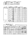
次に、図7に示される主制御部タイマ割込処理における普図関連抽選処理(ステップS223)、特図2関連抽選処理(ステップS229)及び特図1関連抽選処理(ステップS231)で用いられる判定用テーブルについて、図8を参照しながら説明する。ここで、図8(a)は、普図当否判定用テーブルの内容の一例を示す図であり、図8(b)は、特図1・2当否判定用テーブルの内容の一例を示す図であり、図8(c)は、特図決定用振分けテーブルの内容の一例を示す図である。 Next, the general figure related lottery process (step S223), the special figure 2 related lottery process (step S229) and the special figure 1 related lottery process (step S231) in the main control unit timer interrupt process shown in FIG. The determination table will be described with reference to FIG. Here, FIG. 8(a) is a diagram showing an example of the contents of the table for judging whether a normal figure is right or wrong, and FIG. There is, and FIG. 8(c) is a diagram showing an example of the contents of the special figure determination distribution table.

図8(a)に示す普図当否判定用テーブルは、普図当否判定時に用いられる普図用の当否判定用テーブルである。なお、このテーブルは、主制御部300のROM306に記憶されている。図8(a)に示すように、この当否判定用テーブルが用いられた場合、普図低確率状態では、当りとなる値は存在せず、すなわち、当りの確率は0%であり、普図高確率状態では、乱数の取りうる範囲は0~65535であって、当りとなる値は0~65535となっている。すなわち、当りの確率は65536/65536(つまり、100%)である。なお、普図低確率状態(時短非作動時)においては、一定の確率(例えば、1%)で当りとなるようにしてもよいし、普図高確率状態(時短作動時)においては、一定の確率(例えば、1%)ではずれとなるようにしてもよい。 The general pattern suitability determination table shown in FIG. 8( a ) is a general pattern suitability determination table used at the time of general pattern suitability determination. This table is stored in the ROM 306 of the main control unit 300. FIG. As shown in FIG. 8 (a), when this success/failure determination table is used, there is no hit value in the normal pattern low probability state, that is, the probability of winning is 0%, and the normal pattern In the high-probability state, the range of possible random numbers is 0-65535, and the winning value is 0-65535. That is, the probability of winning is 65536/65536 (ie, 100%). In addition, in the normal pattern low probability state (when short time operation is not activated), it may be possible to hit with a certain probability (for example, 1%), or in the normal pattern high probability state (when short time operation), a certain (eg, 1%).

図8(b)に示す特図1・2当否判定用テーブルは、特図1及び特図2の当否判定を行う際に参照されるテーブルであって、設定1~6のいずれであるか、特図低確率状態であるか特図高確率状態であるかによって参照するレコードを選択する。なお、このテーブルも、主制御部300のROM306に記憶されている。 The special figure 1 and 2 propriety determination table shown in FIG. Select the record to be referenced depending on whether it is a special figure low probability state or a special figure high probability state. This table is also stored in the ROM 306 of the main control unit 300. FIG.

設定1の特図低確率状態では、特図1及び特図2の大当り抽選の当否判定の結果として329/65536の確率(約1/200)で大当りが選択され、特図高確率状態では、特図1及び特図2の大当り抽選の当否判定の結果として330/65536の確率(約1/199)で大当りが選択される。 In the special figure low probability state of setting 1, the jackpot is selected with a probability of 329/65536 (about 1/200) as a result of the judgment of the jackpot lottery of the special figure 1 and the special figure 2, and in the special figure high probability state, A big hit is selected with a probability of 330/65536 (approximately 1/199) as a result of the determination of the success or failure of the special figure 1 and special figure 2 jackpot lottery.

設定2の特図低確率状態では、特図1及び特図2の大当り抽選の当否判定の結果として341/65536の確率(約1/193)で大当りが選択され、特図高確率状態では、特図1及び特図2の大当り抽選の当否判定の結果として342/65536の確率(約1/192)で大当りが選択される。 In the special figure low probability state of setting 2, the jackpot is selected with a probability of 341/65536 (about 1/193) as a result of the judgment of the jackpot lottery of the special figure 1 and the special figure 2, and in the special figure high probability state, A big hit is selected with a probability of 342/65536 (approximately 1/192) as a result of the success/fail determination of the big hit lottery of the special figure 1 and the special figure 2.例文帳に追加

設定3の特図低確率状態では、特図1及び特図2の大当り抽選の当否判定の結果として363/65536の確率(約1/181)で大当りが選択され、特図高確率状態では、特図1及び特図2の大当り抽選の当否判定の結果として364/65536の確率(約1/180)で大当りが選択される。 In the special figure low probability state of setting 3, the jackpot is selected with a probability of 363/65536 (about 1/181) as a result of the judgment of the jackpot lottery of the special figure 1 and the special figure 2, and in the special figure high probability state, A big hit is selected with a probability of 364/65536 (approximately 1/180) as a result of the determination of the success or failure of the big hit lottery of the special figures 1 and 2.

設定4の特図低確率状態では、特図1及び特図2の大当り抽選の当否判定の結果として375/65536の確率(約1/175)で大当りが選択され、特図高確率状態では、特図1及び特図2の大当り抽選の当否判定の結果として377/65536の確率(約1/174)で大当りが選択される。 In the special figure low probability state of setting 4, the jackpot is selected with a probability of 375/65536 (about 1/175) as a result of the judgment of the jackpot lottery of the special figure 1 and the special figure 2, and in the special figure high probability state, A big hit is selected with a probability of 377/65536 (approximately 1/174) as a result of the success/fail determination of the big hit lottery of the special figure 1 and the special figure 2.例文帳に追加

設定5の特図低確率状態では、特図1及び特図2の大当り抽選の当否判定の結果として451/65536の確率(約1/146)で大当りが選択され、特図高確率状態では、特図1及び特図2の大当り抽選の当否判定の結果として452/65536の確率(約1/145)で大当りが選択される。 In the special figure low probability state of setting 5, the jackpot is selected with a probability of 451/65536 (about 1/146) as a result of the judgment of the jackpot lottery of the special figure 1 and the special figure 2, and in the special figure high probability state, A big hit is selected with a probability of 452/65536 (approximately 1/145) as a result of the determination of the success or failure of the big hit lottery of the special figures 1 and 2.

設定6の特図低確率状態では、特図1及び特図2の大当り抽選の当否判定の結果として701/65536の確率(約1/94)で大当りが選択され、特図高確率状態では、特図1及び特図2の大当り抽選の当否判定の結果として703/65536の確率(約1/93)で大当りが選択される。 In the special figure low probability state of setting 6, the jackpot is selected with a probability of 701/65536 (about 1/94) as a result of the judgment of the jackpot lottery of the special figure 1 and the special figure 2, and in the special figure high probability state, A big hit is selected with a probability of 703/65536 (approximately 1/93) as a result of the determination of the success or failure of the special figure 1 and special figure 2 jackpot lottery.

また、設定1~6のいずれにかかわらず、また、特図高確率状態であるか特図低確率状態であるかにかかわらず、特図1の大当り抽選の当否判定の結果として6580/65536の確率(約1/10)で12回開閉の小当りが選択され、特図1の大当り抽選の当否判定の結果として6580/65536の確率(約1/10)で1回開閉の小当りが選択される。なお、特図1で小当りが発生しないようにして、特図2でのみ小当り(12回開放の小当りと1回開閉の小当り)が発生するようにしてもよい。また、小当りの確率を設定毎に異ならせるようにしてもよい。 Also, regardless of any of the settings 1 to 6, and regardless of whether it is a special high probability state or a special low probability state, 6580 / 65536 A small hit of opening and closing 12 times is selected with a probability (about 1/10), and a small hit of opening and closing once is selected with a probability of 6580/65536 (about 1/10) as a result of the judgment of the jackpot lottery of special figure 1. be done. It should be noted that a small hit may not occur in the special figure 1, and a small win only in the special figure 2 (a small win of opening 12 times and a small win of opening and closing once) may occur. Also, the probability of a small hit may be changed for each setting.

このように、本実施形態では、設定1~6のいずれにおいても、特図高確率状態における大当り確率の方が特図低確率状態における大当り確率よりもわずかに高いが、ほとんど同じ確率と同視しうるように設定されている。また、本実施形態では、設定により大当り確率が異なっており、設定が高いほど大当りがしやすく、設定が低いほど大当りがし難くなっている。したがって、設定が低いほど、大当りとなり難いが、確変状態に移行した場合には、高設定よりも小当りの発生回数が多くなる傾向があり、異なるゲーム性を持たせることができる場合がある。 Thus, in this embodiment, in any of the settings 1 to 6, the jackpot probability in the special high probability state is slightly higher than the jackpot probability in the special low probability state, but it is almost the same probability. It's set to run. In addition, in this embodiment, the probability of a big hit differs depending on the setting. The higher the setting, the easier it is to win a big hit, and the lower the setting, the harder it is to win a big hit. Therefore, the lower the setting is, the less likely it is to become a big hit, but when shifting to the variable probability state, the number of occurrences of small wins tends to increase compared to the high setting, and different game characteristics can be provided in some cases.

本実施形態では、いずれの設定においても、特図高確率状態と特図低確率状態とで大当り確率がほとんど同じに設定されているが、大きく異なる点として、特図2の変動表示時間が挙げられる。本実施形態では、特図高確率状態における特図2の変動時間は、例えば、1~5秒の変動時間が選択されるようになっている。特図高確率状態では、右打ちした場合には、第2特図始動口232へ多数の遊技球が入球しやすくなっており、特図2の変動表示を多数行うことができ、その結果、小当りの発生頻度が高くなるような仕組みとなっている。本実施形態では、特図高確率状態では小当りの発生頻度が高まる状態ということができるため、「小当りラッシュ」という場合がある。また、保留されている特図2の図柄変動表示が4つ(満タン)である状態において、全ての特図2の図柄変動表示を消化するのにかかる時間よりも特図1の1回の図柄変動表示を消化するのにかかる時間の方が長いので、特図1で大当りが発生しにくいようになっている。一方、特図低確率状態における特図2の変動時間は、例えば、580秒の変動時間が選択されるようになっている。したがって、特図低確率状態では、右打ちすれば特図2始動口232への入球頻度も小当り確率も変わらないものの、特図2の変動表示の結果が表示されるまでの時間がおよそ10分毎ということになるので、右打ちしても、遊技者にとっては実質的に不利益となる。なお、特図低確率状態における、特図2の変動時間は、はずれ及び小当りにあっては580秒に設定されているが、大当りとなる場合の変動時間は、それよりも短く、例えば、227秒に設定されている。 In this embodiment, in any setting, the jackpot probability is set to be almost the same in the special figure high probability state and the special figure low probability state, but the big difference is the fluctuation display time of the special figure 2 be done. In this embodiment, the variation time of the special figure 2 in the special figure high probability state is, for example, a variation time of 1 to 5 seconds is selected. In the special figure high probability state, when hitting to the right, a large number of game balls are likely to enter the second special figure start port 232, and it is possible to perform a large number of variable display of the special figure 2, as a result , It is designed to increase the frequency of small hits. In this embodiment, since it can be said that the frequency of occurrence of small hits increases in the special figure high probability state, it may be called "small hit rush". In addition, in the state where there are four (full) pattern variation displays of the special figure 2 that are being held, one time of the special figure 1 is longer than the time it takes to digest all the symbol variation displays of the special figure 2 Since it takes a longer time to digest the symbol variation display, it is difficult for the special figure 1 to generate a big hit. On the other hand, the variation time of the special figure 2 in the special figure low probability state, for example, the variation time of 580 seconds is selected. Therefore, in the special figure low probability state, if you hit to the right, the frequency of entering the special figure 2 starting port 232 and the small hit probability will not change, but the time until the result of the variation display of special figure 2 is displayed is about Since it is every 10 minutes, even if the player hits to the right, it is substantially disadvantageous for the player. In addition, in the special figure low probability state, the variation time of the special figure 2 is set to 580 seconds in the case of losing and small hits, but the variation time in the case of a big hit is shorter than that, for example, It is set to 227 seconds.

図8(c)は、特図決定用振分けテーブルの一例を示すものであり、上述したようにして特図1あるいは特図2の当否判定結果に基づいて、停止図柄を決定する。なお、このテーブルも、主制御部300のROM306に記憶されている。この特図決定用振分けテーブルは、当否判定結果ごとに特図の停止図柄態様(図5(a)、同図(b)参照)に対応した乱数範囲が規定されている。 FIG. 8(c) shows an example of a special figure determination sorting table, and the stop symbol is determined based on the result of determination of special figure 1 or special figure 2 as described above. This table is also stored in the ROM 306 of the main control unit 300. FIG. In this special figure determination distribution table, a random number range corresponding to a special figure stop design mode (see FIGS. 5(a) and 5(b)) is defined for each success/failure determination result.

まず、特図1当否判定の結果が大当りであれば、「特図A」と「特図B」からいずれか一方が選択される。上述したように、「特図A」は、第1可変入賞口234が開放する6R通常大当りであり、「特図B」は、第1可変入賞口234が開放する6R確変大当りである。各選択率は設定に関係なく1/2ずつとなっている。 First, if the result of special figure 1 success/failure determination is a big hit, one of "special figure A" and "special figure B" is selected. As described above, "special figure A" is the 6R normal jackpot opened by the first variable winning opening 234, and "special figure B" is the 6R probability variable jackpot opened by the first variable winning opening 234. Each selection rate is 1/2 regardless of the setting.

また、特図1当否判定の結果が小当りであれば、「特図C」が選択される。上述したように、「特図C」は、第2可変入賞口235が最大で12回の短開放を繰り返す小当りである。 Moreover, if the result of the special figure 1 propriety determination is a small hit, "special figure C" is selected. As described above, the "special figure C" is a small win in which the second variable winning opening 235 repeats short openings up to 12 times.

次に、特図2当否判定の結果が大当りであれば、「特図a」~「特図c」のうちいずれか一つが選択される。上述したように、「特図a」は、第1可変入賞口234が開放する6R通常大当りであり、「特図b」は、第1可変入賞口234が開放する6R確変大当りであり、「特図c」は、第1可変入賞口234が開放する10R確変大当りである。各選択率は、設定に関係なく、「特図a」は60/100、「特図b」は5/100、「特図c」は35/100となっている。 Next, if the result of special figure 2 success/failure determination is a big hit, one of "special figure a" to "special figure c" is selected. As described above, "special figure a" is the 6R normal jackpot opened by the first variable winning opening 234, "special figure b" is the 6R probability variable jackpot opened by the first variable winning opening 234, and " Special figure c" is a 10R probability variable jackpot opened by the first variable winning opening 234. Each selection rate is 60/100 for "special figure a", 5/100 for "special figure b", and 35/100 for "special figure c" regardless of the setting.

また、特図2当否判定の結果が小当りであれば、「特図d」が選択される。上述したように、「特図d」は、第2可変入賞口235が1回短開放する小当りである。 In addition, if the result of the special figure 2 propriety determination is a small hit, "special figure d" is selected. As described above, "special figure d" is a small hit in which the second variable winning opening 235 is opened once for a short period of time.

次に、第1副制御部400の処理について説明する。図9(a)は、第1副制御部400のCPU404が実行するメイン処理のフローチャートである。まず、図9(a)のステップS301では、各種の初期設定を行う。電源投入が行われると、まずステップS301で初期化処理が実行される。この初期化処理では、入出力ポートの初期設定や、RAM408内の記憶領域の初期化処理等を行う。 Next, processing of the first sub-controller 400 will be described. FIG. 9A is a flowchart of main processing executed by the CPU 404 of the first sub-controller 400. FIG. First, in step S301 of FIG. 9A, various initial settings are performed. When power is turned on, initialization processing is first executed in step S301. In this initialization processing, initial setting of input/output ports, initialization processing of storage areas in the RAM 408, and the like are performed.

ステップS301の次のステップS303では、タイマ変数が10以上か否かを判定し、タイマ変数が10となるまでこの処理を繰り返し、タイマ変数が10以上となったときには、ステップS305の処理に移行する。ステップS305では、タイマ変数に0を代入する。 In step S303 following step S301, it is determined whether or not the timer variable is 10 or more, and this process is repeated until the timer variable reaches 10. When the timer variable becomes 10 or more, the process proceeds to step S305. . In step S305, 0 is substituted for the timer variable.

ステップS305の次のステップS307では、コマンド処理を行う。第1副制御部400のCPU404は、主制御部300からコマンドを受信したか否かを判別する。 In step S307 following step S305, command processing is performed. The CPU 404 of the first sub-controller 400 determines whether or not a command has been received from the main controller 300 .

ステップS307の次のステップS309では、演出制御処理を行う。例えば、ステップS307で新たなコマンドがあった場合には、このコマンドに対応する演出データをROM406から読み出す等の処理を行い、演出データの更新が必要な場合には演出データの更新処理を行う。 In step S309 following step S307, effect control processing is performed. For example, if there is a new command in step S307, processing such as reading the effect data corresponding to this command from the ROM 406 is performed, and if the effect data needs to be updated, the effect data is updated.

ステップS309の次のステップS311では、チャンスボタン制御処理を行う。チャンスボタン制御処理では、演出ボタン136や操作キーユニット190の操作を検出し、その検出結果に応じて、ステップS309で更新した演出データを演出ボタン136や操作キーユニット190の操作に応じた演出データに変更する処理を行う。 In step S311 following step S309, chance button control processing is performed. In the chance button control process, the operation of the effect button 136 or the operation key unit 190 is detected, and in accordance with the detection result, the effect data updated in step S309 is changed to the effect data corresponding to the operation of the effect button 136 or the operation key unit 190. Perform processing to change to

ステップS311の次のステップS313では、音制御処理を行う。音制御処理では、ステップS309で読み出した演出データの中に音源IC416への命令がある場合には、この命令を音源IC416に出力する。 In step S313 following step S311, sound control processing is performed. In the sound control process, if there is a command for the sound source IC 416 in the effect data read out in step S309, this command is output to the sound source IC 416 .

ステップS313の次のステップS315では、ランプ制御処理を行う。ランプ制御処理では、ステップS309で読み出した演出データの中に各種ランプ442,452への命令がある場合には、この命令を遊技盤用ランプ駆動回路440及び遊技台枠用ランプ駆動回路450に出力する。こうして、第2演出可動ユニット8に配置された発光ダイオードD(図17参照)や、ランプユニット9に配置された発光ダイオードDO,DI,DL(図32参照)や、アタッカユニット23に配置された発光ダイオードD1~D3(図40参照)の発光制御が行われる。 In step S315 following step S313, lamp control processing is performed. In the lamp control process, if there is a command to the various lamps 442 and 452 in the performance data read out in step S309, this command is output to the game board lamp drive circuit 440 and the game frame lamp drive circuit 450. do. In this way, the light-emitting diode D (see FIG. 17) arranged in the second effect movable unit 8, the light-emitting diodes DO, DI, and DL (see FIG. 32) arranged in the lamp unit 9, and the light-emitting diodes arranged in the attacker unit 23 Light emission control of the light emitting diodes D1 to D3 (see FIG. 40) is performed.

ステップS315の次のステップS317では、可動体制御処理を行う。例えば、ステップS309で読み出した演出データの中に、図3(a)に示す上部の第1演出可動ユニット7や、後方側に隠れている第2演出可動ユニット8への命令がある場合には、この命令を駆動回路422に出力する。 In step S317 following step S315, movable body control processing is performed. For example, if the effect data read out in step S309 includes a command to the upper first movable effect unit 7 shown in FIG. 3(a) or the second movable effect unit 8 hidden behind , outputs this command to the drive circuit 422 .

ステップS317の次のステップS319では、情報送信処理を行う。情報送信処理では、ステップS309で読み出した演出データの中に第2副制御部500に送信する制御コマンドがある場合には、この制御コマンドを出力する設定を行う。その後、ステップS303に戻る。 In step S319 following step S317, information transmission processing is performed. In the information transmission process, if there is a control command to be transmitted to the second sub-control unit 500 in the effect data read out in step S309, setting is made to output this control command. After that, the process returns to step S303.

図9(b)は、第1副制御部400のCPU404が実行する第1副制御部コマンド受信割込処理(ストローブ割込処理)のフローチャートである。このコマンド受信割込処理は、第1副制御部400が主制御部300からのストローブ信号を検出した場合に実行する処理である。コマンド受信割込処理のステップS331では、主制御部300から受信したコマンドを未処理コマンドとしてRAM408に設けたコマンド記憶領域に記憶する。 FIG. 9B is a flowchart of first sub-controller command reception interrupt processing (strobe interrupt processing) executed by CPU 404 of first sub-controller 400 . This command reception interrupt process is a process executed when the first sub-controller 400 detects a strobe signal from the main controller 300 . In step S331 of the command reception interrupt process, the command received from the main control unit 300 is stored in the command storage area provided in the RAM 408 as an unprocessed command.

図9(c)は、第1副制御部400のCPU404が実行する第1副制御部タイマ割込処理のフローチャートである。第1副制御部400は、所定の周期(本実施形態では2msに1回)でタイマ割込を発生するハードウェアタイマを備えており、このタイマ割込を契機として、タイマ割込処理を所定の周期で実行する。第1副制御部タイマ割込処理のステップS341では、第1副制御部メイン処理のステップS303において説明したRAM408のタイマ変数記憶領域の値に、1を加算して元のタイマ変数記憶領域に記憶する。したがって、ステップS303において、タイマ変数の値が10以上と判定されるのは20ms毎(2ms×10)となる。 FIG. 9(c) is a flow chart of the first sub-controller timer interrupt process executed by the CPU 404 of the first sub-controller 400. FIG. The first sub-control unit 400 includes a hardware timer that generates a timer interrupt at a predetermined period (once every 2 ms in this embodiment). period. In step S341 of the first sub-controller timer interrupt process, 1 is added to the value in the timer variable storage area of the RAM 408 described in step S303 of the first sub-controller main process, and stored in the original timer variable storage area. do. Therefore, in step S303, the value of the timer variable is determined to be 10 or more every 20 ms (2 ms×10).

ステップS341の次のステップS343では、第1副制御部メイン処理の情報送信処理(ステップS319)で設定された第2副制御部500への制御コマンドの送信や、その他演出用乱数値の更新処理等を行う。 In step S343 following step S341, transmission of the control command to the second sub-control unit 500 set in the information transmission processing (step S319) of the first sub-control unit main processing, and other processing for updating the random value for effect etc.

次に、第2副制御部500の処理について説明する。図10(a)は、第2副制御部500の図示しないCPUが実行するメイン処理のフローチャートである。まず、図10(a)のステップS401では、各種の初期設定を行う。電源投入が行われると、まずステップS401で初期化処理が実行される。この初期化処理では、入出力ポートの初期設定や、RAM(不図示)内の記憶領域の初期化処理等を行う。 Next, processing of the second sub-controller 500 will be described. FIG. 10(a) is a flowchart of main processing executed by a CPU (not shown) of the second sub-controller 500. FIG. First, in step S401 of FIG. 10A, various initial settings are performed. When power is turned on, initialization processing is first executed in step S401. In this initialization processing, initial setting of input/output ports, initialization processing of storage areas in a RAM (not shown), and the like are performed.

ステップS401の次のステップS403では、タイマ変数が10以上か否かを判定し、タイマ変数が10となるまでこの処理を繰り返し、タイマ変数が10以上となったときには、ステップS405の処理に移行する。ステップS405では、タイマ変数に0を代入する。 In step S403 following step S401, it is determined whether or not the timer variable is 10 or more, and this process is repeated until the timer variable reaches 10. When the timer variable becomes 10 or more, the process proceeds to step S405. . In step S405, 0 is substituted for the timer variable.

ステップS405の次のステップS407では、コマンド処理を行う。第2副制御部500のCPUは、第1副制御部400からコマンドを受信したか否かを判別する。 In step S407 following step S405, command processing is performed. The CPU of the second sub-controller 500 determines whether or not a command has been received from the first sub-controller 400 .

ステップS407の次のステップS409では、演出制御処理を行う。例えば、ステップS407で新たなコマンドがあった場合には、このコマンドに対応する演出データ(装飾図柄表示装置208による演出データ)をROM(不図示)から読み出す等の処理を行い、演出データの更新が必要な場合には演出データの更新処理を行う。 In step S409 following step S407, effect control processing is performed. For example, when there is a new command in step S407, the performance data corresponding to this command (the performance data by the decorative pattern display device 208) is read out from the ROM (not shown), etc., and the performance data is updated. is required, the performance data is updated.

ステップS409の次のステップS411では、画像制御処理を行う。画像制御処理では、ステップS409で読み出した演出データの中にVDP516への命令がある場合には、この命令をVDP516に出力する(詳細は後述)。その後、ステップS403に戻る。 In step S411 following step S409, image control processing is performed. In the image control process, if there is a command to the VDP 516 in the effect data read in step S409, this command is output to the VDP 516 (details will be described later). After that, the process returns to step S403.

図10(b)は、第2副制御部500のCPUが実行するコマンド受信割込処理のフローチャートである。このコマンド受信割込処理は、第2副制御部500が第1副制御部400からのストローブ信号を検出した場合に実行する処理である。コマンド受信割込処理のステップS431では、第1副制御部400から受信したコマンドを未処理コマンドとしてRAMに設けたコマンド記憶領域に記憶する。 FIG. 10B is a flowchart of command reception interrupt processing executed by the CPU of the second sub-controller 500. FIG. This command reception interrupt process is a process executed when the second sub-controller 500 detects a strobe signal from the first sub-controller 400 . In step S431 of the command reception interrupt process, the command received from the first sub-controller 400 is stored as an unprocessed command in the command storage area provided in the RAM.

図10(c)は、第2副制御部500のCPUが実行するタイマ割込処理のフローチャートである。第2副制御部500は、所定の周期(本実施形態では2msに1回)でタイマ割込を発生するハードウェアタイマを備えており、このタイマ割込を契機として、タイマ割込処理を所定の周期で実行する。タイマ割込処理のステップS441では、第2副制御部メイン処理のステップS403において説明したRAMのタイマ変数記憶領域の値に、1を加算して元のタイマ変数記憶領域に記憶する。したがって、ステップS403において、タイマ変数の値が10以上と判定されるのは20ms毎(2ms×10)となる。ステップS441の次のステップS443では、その他演出用乱数値の更新処理等を行う。 FIG. 10(c) is a flowchart of timer interrupt processing executed by the CPU of the second sub-controller 500. FIG. The second sub-control unit 500 includes a hardware timer that generates a timer interrupt at a predetermined cycle (once every 2 ms in this embodiment). period. In step S441 of the timer interrupt process, 1 is added to the value in the timer variable storage area of the RAM explained in step S403 of the second sub-control unit main process and stored in the original timer variable storage area. Therefore, in step S403, the value of the timer variable is determined to be 10 or more every 20 ms (2 ms×10). In step S443 following step S441, processing for updating the random number value for effect, etc. is performed.

図10(d)は、第2副制御部メイン処理のステップS411における画像制御処理のフローチャートである。ステップS451では、画像データ(後述するムービーデータやテクスチャデータ)の転送指示を行う。ここでは、CPU504は、まず、VRAM518のフレームバッファ1とフレームバッファ2の描画領域の指定をスワップする。これにより、描画領域に指定されていないフレームバッファに記憶された1フレームの画像が装飾図柄表示装置208に表示される。次に、CPU504は、VDP516のアトリビュートレジスタに、位置情報等テーブルに基づいてROM座標(ROM506の転送元アドレス)、VRAM座標(VRAM518の転送先アドレス)などを設定した後、ROM506からVRAM518への画像データの転送開始を指示する命令を設定する。VDP516は、アトリビュートレジスタに設定された命令に基づいて画像データをROM506からVRAM518に転送する。その後、VDP516は、転送終了割込信号をCPU504に対して出力する。 FIG. 10D is a flowchart of image control processing in step S411 of the second sub-control unit main processing. In step S451, an instruction is given to transfer image data (movie data and texture data, which will be described later). Here, the CPU 504 first swaps the designation of the drawing areas of the frame buffers 1 and 2 of the VRAM 518 . As a result, one frame of the image stored in the frame buffer that is not designated as the drawing area is displayed on the decorative design display device 208 . Next, the CPU 504 sets the ROM coordinates (the transfer source address of the ROM 506), the VRAM coordinates (the transfer destination address of the VRAM 518), and the like in the attribute register of the VDP 516 based on the position information table, and then transfers the image from the ROM 506 to the VRAM 518. Set an instruction to start data transfer. The VDP 516 transfers the image data from the ROM 506 to the VRAM 518 based on the command set in the attribute register. After that, the VDP 516 outputs a transfer end interrupt signal to the CPU 504 .

ステップS451の次のステップS453では、VDP516からの転送終了割込信号が入力されたか否かを判定し、転送終了割込信号が入力された場合は(ステップS453:Yes)、ステップS455に進み、そうでない場合は(ステップS453:No)、転送終了割込信号が入力されるのを待つ。 In step S453 following step S451, it is determined whether or not a transfer end interrupt signal has been input from the VDP 516. If a transfer end interrupt signal has been input (step S453: Yes), the process proceeds to step S455. Otherwise (step S453: No), it waits for a transfer end interrupt signal to be input.

ステップS455では、演出シナリオ構成テーブルおよびアトリビュートデータなどに基づいて、パラメータ設定を行う。ここでは、CPU504は、ステップS451でVRAM518に転送した画像データに基づいてVRAM518のフレームバッファ1または2に表示画像を形成するために、表示画像を構成する画像データの情報(VRAM518の座標軸、画像サイズ、VRAM座標(配置座標)など)をVDP516に指示する。VDP516は、アトリビュートレジスタに格納された命令に基づいてアトリビュートに従ったパラメータ設定を行う。 In step S455, parameters are set based on the effect scenario configuration table, attribute data, and the like. Here, in order to form a display image in the frame buffer 1 or 2 of the VRAM 518 based on the image data transferred to the VRAM 518 in step S451, the CPU 504 generates information of the image data forming the display image (coordinate axes of the VRAM 518, image size, and so on). , VRAM coordinates (placement coordinates), etc.) to the VDP 516 . The VDP 516 sets parameters according to the attributes based on the instructions stored in the attribute registers.

ステップS455の次のステップS457では、描画指示を行う。この描画指示では、CPU504は、VDP516に画像の描画開始を指示する。VDP516は、CPU504の指示に従ってフレームバッファにおける画像描画を開始する。 In step S457 following step S455, a drawing instruction is given. In this drawing instruction, the CPU 504 instructs the VDP 516 to start drawing an image. The VDP 516 starts drawing an image in the frame buffer according to instructions from the CPU 504 .

ステップS457の次のステップS459では、画像の描画終了に基づくVDP516からの生成終了割込み信号が入力されたか否かを判定し、生成終了割込み信号が入力された場合は、(ステップS459:Yes)、ステップS461に進み、そうでない場合は(ステップS459:No)、生成終了割込み信号が入力されるのを待つ。 In step S459 following step S457, it is determined whether or not a generation end interrupt signal has been input from the VDP 516 based on the end of image rendering. If a generation end interrupt signal has been input (step S459: Yes), The process proceeds to step S461, and if not (step S459: No), it waits for the generation end interrupt signal to be input.

ステップS461では、RAM508の所定の領域に設定され、何シーンの画像を生成したかをカウントするシーン表示カウンタをインクリメント(+1)して処理を終了する。 In step S461, a scene display counter, which is set in a predetermined area of the RAM 508 and counts how many scenes of images have been generated, is incremented (+1), and the process ends.

次に、図11を参照して役物比率・設定表示器196及びディップスイッチ基板198の具体的構成について説明する。ここで、図11(A)は、役物比率・設定表示器196の具体的構成の一例を示す図であり、図11(B)は、ディップスイッチ基板198の具体的構成の一例を示す図である。 Next, specific configurations of the character item ratio/setting display 196 and the DIP switch board 198 will be described with reference to FIG. Here, FIG. 11A is a diagram showing an example of a specific configuration of the character ratio/setting display 196, and FIG. 11B is a diagram showing an example of a specific configuration of the DIP switch board 198. is.

役物比率・設定表示器196は、上述したように、役物比率モニタと設定モニタとを有して構成されており、役物比率モニタは、連続役物比率(RY)及び役物比率(YH)を表示し、設定モニタは、現在の設定値を表示している。 As described above, the character ratio/setting display 196 includes a character ratio monitor and a setting monitor. The character ratio monitor displays the continuous character ratio (RY) and the character ratio ( YH) is displayed, and the setting monitor displays the current set value.

ここで、連続役物比率とは、獲得する遊技球(すなわち、セーフ球)の数のうち役物が連続して作動する場合における当該役物の作動によるもの(すなわち、大当り遊技中において第1可変入賞口234が開放して入賞したことにより獲得する遊技球の数)の割合のことをいう。なお、アウト球の数に対する第1可変入賞口234への入賞により獲得する遊技球の数の割合であってもよい。また、役物比率とは、獲得する遊技球(すなわち、セーフ球)の数のうち役物の作動によるもの(すなわち、第1特図始動口(可変)231、第1可変入賞口234及び第2可変入賞口235が開放して入賞したことにより獲得する遊技球の数)の割合のことをいう。なお、アウト球の数に対する第1可変入賞口234、第2可変入賞口235、第1特図始動口(固定)230、第1特図始動口(可変)231、第2特図始動口232及び一般入賞口への入賞により獲得する遊技球の数の割合であってもよい。 Here, the continuous role ratio refers to the number of game balls (that is, safe balls) to be acquired, which is due to the operation of the role when the role is operated continuously (i.e., the first It means the ratio of the number of game balls obtained by winning with the variable winning opening 234 open. In addition, the ratio of the number of game balls obtained by winning the first variable winning hole 234 to the number of out balls may be used. In addition, the role ratio is the number of game balls (that is, safe balls) to be acquired due to the operation of the role (that is, the first special figure start port (variable) 231, the first variable winning port 234 and the second 2) refers to the ratio of the number of game balls obtained by winning with the variable winning port 235 open. In addition, the first variable winning opening 234, the second variable winning opening 235, the first special starting opening (fixed) 230, the first special starting opening (variable) 231, the second special opening opening 232 for the number of out balls And it may be a ratio of the number of game balls obtained by winning a prize in a general winning hole.

本実施形態では、連続役物比率を算出した結果、連続役物比率が60%を超えていると判定した場合は、連続役物比率を表示する2ケタの7セグLEDを点滅表示させ、その後に、セキュリティ信号(RY)を出力する。ここで、セキュリティ信号(RY)は、連続役物比率が60%を超えた場合に出力されるエラー信号であり、情報出力回路336を介してパチンコ機100外に出力される。なお、主基板156に実装可能な試験端子から出力されてもよい。これにより、遊技機の型式申請試験を円滑に行わせることができる場合がある。 In this embodiment, as a result of calculating the continuous role product ratio, when it is determined that the continuous role product ratio exceeds 60%, the two-digit 7-segment LED that displays the continuous role product ratio is displayed blinking, and then to output a security signal (RY). Here, the security signal (RY) is an error signal output when the continuous role product ratio exceeds 60%, and is output to the outside of the pachinko machine 100 via the information output circuit 336 . In addition, it may be output from a test terminal that can be mounted on the main board 156 . As a result, the model application test for the game machine may be smoothly performed.

また、役物比率を算出した結果、役物比率が70%を超えていると判定した場合は、役物比率を表示する2ケタの7セグLEDを点滅表示させ、その後に、セキュリティ信号(YH)を出力する。ここで、セキュリティ信号(YH)は、役物比率が70%を超えた場合に出力されるエラー信号であり、情報出力回路336を介してパチンコ機100外に出力される。 Also, as a result of calculating the role ratio, if it is determined that the ratio is over 70%, the 2-digit 7-segment LED that displays the role ratio is displayed blinking, and then the security signal (YH ). Here, the security signal (YH) is an error signal output when the role product ratio exceeds 70%, and is output to the outside of the pachinko machine 100 via the information output circuit 336 .

なお、本実施形態では、連続役物比率あるいは役物比率が正常値の上限を超えた場合には、所定の7セグLEDを点滅させるようにしたが、例えば、発光色を変化させるようにしてもよい。 In the present embodiment, when the continuous role product ratio or the role product ratio exceeds the upper limit of the normal value, the predetermined 7-segment LED blinks. good too.

図11(B)に示すように、ディップスイッチ基板198には、8つのディップスイッチが配設されている。各ディップスイッチは、第1副基板160に接続されており、電源投入時に各ディップスイッチの位置を読み取り、演出の出現確率を変更することができ、例えば、設定示唆を実行する頻度や、予告の出現率や、演出モードの突入率等を設定することができる。 As shown in FIG. 11B, the DIP switch board 198 is provided with eight DIP switches. Each DIP switch is connected to the first sub-board 160, and when the power is turned on, the position of each DIP switch can be read to change the appearance probability of the effect. Appearance rate, entry rate of production mode, etc. can be set.

なお、以上説明したパチンコ機100では、第2可変入賞口235のアタッタは大当り遊技では開放せず、小当り遊技でのみ開放したが、第2可変入賞口235のアタッタが開放する大当りを用意してもよい。例えば、特図2の大当りとして、第1可変入賞口234のアタッタではなく、第2可変入賞口235のアタッタが開放する、3R大当り(実質1R大当り)や、6R大当り等を用意してもよい。 In the pachinko machine 100 described above, the attacker of the second variable winning hole 235 is not opened in the big winning game, but is opened only in the small winning game. may For example, as the special figure 2 jackpot, a 3R jackpot (substantially a 1R jackpot), a 6R jackpot, or the like, which is opened by the second variable winning port 235 rather than the first variable winning port 234, may be prepared. .

また、特図1と特図2の両方に小当りが用意されていたが、特図2にのみ小当りを設けてもよい。すなわち、特図2に限って、第2可変入賞口235が、最大で或る回数(例えば、12回)の短開放を繰り返す小当りと、1回しか短開放しない小当りを設けてもよい。こうすることで、特図高確率普図低確率状態では、特図1始動口(可変)231が入賞容易状態にならず、第1可変入賞口234のアタッカが入賞困難状態であって、第2可変入賞口235のアタッカも入賞困難状態であれば、右打ちされた遊技球の多くは、第2特図始動口232に入球し、特図2変動遊技において大当りあるいは小当りを獲得することができる。特に、大当り遊技の当選確率よりも小当り遊技の当選確率の方が高い(例えば、およそ10倍程度高い)ことから、第2可変入賞口235が最大で或る回数(例えば、12回)の短開放を繰り返す小当りに当選しやすく、この小当り遊技で出球を稼ぐことが期待できる。 Moreover, although the small hit was prepared for both the special figure 1 and the special figure 2, the small hit may be provided only for the special figure 2. - 特許庁That is, only in the special figure 2, the second variable winning opening 235 may provide a small hit that repeats short opening a maximum of a certain number of times (for example, 12 times) and a small hit that only opens once. . By doing this, in the special figure high probability normal figure low probability state, the special figure 1 start port (variable) 231 does not become a winning easy state, and the attacker of the first variable winning port 234 is in a difficult winning state, If the attacker of the 2 variable winning opening 235 is also in a difficult winning state, most of the game balls hit to the right enter the 2nd special figure start opening 232, and win a big hit or a small hit in the special figure 2 variable game. be able to. In particular, since the winning probability of the small winning game is higher than the winning probability of the big winning game (for example, about 10 times higher), the second variable winning opening 235 can be set up to a certain number of times (for example, 12 times). It is easy to win a small win that repeats short opening, and it can be expected that this small winning game will earn more balls.

続いて、第2演出可動ユニット8について説明する。第2演出可動ユニット8は、魔女の手をイメージしたハンド可動体81を有する。このハンド可動体81は、昇降動作と、前方側へ向かって倒れ込む回動動作を行うことが可能な可動体である。 Next, the second effect movable unit 8 will be explained. The second effect movable unit 8 has a hand movable body 81 that resembles a witch's hand. The hand movable body 81 is a movable body capable of performing an up-and-down motion and a rotating motion of falling forward.

図12は、ハンド可動体81が初期位置にある第2演出可動ユニット8を示す図である。 FIG. 12 shows the second effect movable unit 8 with the hand movable body 81 at the initial position.

ハンド可動体81は、初期位置では、ステージ244よりも下方かつ後方側に位置している。図12(a)は、図3に示す遊技盤の断面図であり、左側が前方側になる。図3では、第2演出可動ユニット8全体が後方側に隠れてしまっていたが、この図12(a)では、遊技盤200を図3に示すA-A’線で断面したときの様子が示されており、第2演出可動ユニット8が図示されている。 The hand movable body 81 is positioned below and behind the stage 244 at the initial position. FIG. 12(a) is a sectional view of the game board shown in FIG. 3, and the left side is the front side. In FIG. 3, the entire second effect movable unit 8 is hidden on the rear side, but in FIG. , and a second effect movable unit 8 is shown.

図12(a)に示す遊技盤200のさらに後方側には、ここでは不図示の液晶表示装置である装飾図柄表示装置208(図3参照)が取り付けられる。初期位置にあるハンド可動体81は、その装飾図柄表示装置208に前方側からオーバーラップせず、装飾図柄表示装置208の下縁よりも下方に位置することになる。 Further behind the game board 200 shown in FIG. 12(a), a decorative pattern display device 208 (see FIG. 3) which is a liquid crystal display device (not shown) is attached. The hand movable body 81 at the initial position does not overlap the decorative design display device 208 from the front side, and is positioned below the lower edge of the decorative design display device 208 .

図12(b)は、同図(a)で1点鎖線で囲んだ部分から、第2演出可動ユニット8と、ステージ244と、ステージカバー245を抜き出しで示した図である。また、図13(a)は、遊技板201を図3に示すA-A’線で断面し、ステージ244とステージカバー245を前方側から表す斜視図であり、同図(b)は、後方側から表す斜視図である。図13(a)は、図の左手前側が前方側になり、同図(b)は、図の右手前側が後ろ側方側になる。 FIG. 12(b) is a diagram showing the second effect movable unit 8, the stage 244, and the stage cover 245 extracted from the portion surrounded by the dashed line in FIG. 12(a). 13(a) is a cross-sectional view of the game board 201 taken along the line AA' shown in FIG. 3, and is a perspective view showing the stage 244 and the stage cover 245 from the front side. FIG. 3 is a perspective view from the side; In FIG. 13(a), the left front side of the drawing is the front side, and in FIG. 13(b), the right front side of the drawing is the rear lateral side.

図13に示すステージ244は、遊技領域124に設けられたものである。遊技領域124は、図1に示す前面枠扉106に設けられた透明板部材118と、遊技板201の後面201bとの間の領域になる。ステージ244は、遊技板201に設けられた開口の縁201eに取り付けられており、図13(a)に示すように、遊技板201の厚みの中に収納されている。図13(a)には、スペシャルルート244aも示されており、スペシャルルート244aは、遊技球がステージ244から前方側に排出されるルートになる。ステージカバー245は、背面カバー部2451と、上方カバー部2452を有する透明なカバーである。なお、ステージカバー245は、半透明なカバーであってもよい。背面カバー部2451は、遊技板201に設けられた開口の縁201eに沿って、開口側に突出し、ステージ244よりも後方側への遊技球の移動を阻止するものである。また、上方カバー部2452は、ステージ244を上方から覆い、ステージ244よりも上方側への遊技球の移動も阻止するものである。図13(a)に示すように、上方カバー部2452は、ステージ244を超えて前方側に飛び出している。すなわち、上方カバー部2452の前側先端2452fは、遊技板201の前面201fよりも前方側に位置している。 A stage 244 shown in FIG. 13 is provided in the game area 124 . The game area 124 is an area between the transparent plate member 118 provided on the front frame door 106 and the rear surface 201b of the game board 201 shown in FIG. The stage 244 is attached to the edge 201e of the opening provided in the game board 201, and is accommodated in the thickness of the game board 201 as shown in FIG. 13(a). A special route 244a is also shown in FIG. 13(a), and the special route 244a is a route through which game balls are discharged from the stage 244 to the front side. The stage cover 245 is a transparent cover having a rear cover portion 2451 and an upper cover portion 2452 . Note that the stage cover 245 may be a translucent cover. The rear cover portion 2451 protrudes toward the opening side along the edge 201 e of the opening provided in the game board 201 and prevents the movement of the game ball to the rear side of the stage 244 . In addition, the upper cover portion 2452 covers the stage 244 from above and prevents the game ball from moving above the stage 244 . As shown in FIG. 13( a ), the upper cover portion 2452 protrudes forward beyond the stage 244 . That is, the front tip 2452f of the upper cover portion 2452 is positioned forward of the front surface 201f of the game board 201. As shown in FIG.

図12に示すように、初期位置にあるハンド可動体81の先端(指先)は、真上を向いている。すなわち、初期位置にあるハンド可動体81の姿勢(初期姿勢)は、先端(指先)が真上を向いた姿勢である。図12(b)には、ステージ244の最下端の高さ位置を太い2点鎖線で示し、初期位置にあるハンド可動体81の先端(指先)の高さ位置を細い2点鎖線で示している。これらの2点鎖線の関係から明らかなように、初期位置にあるハンド可動体81の先端(指先)は、ステージ244よりも上方に位置している。背面カバー部2451は突出したものであるものの透明であることから、遊技盤200の正面に座った遊技者から、初期位置にあるハンド可動体81の先端は、その透明な背面カバー部2451を通して視認可能である。また、 ステージ244に遊技球がある場合には、初期位置にあるハンド可動体81の一部(先端部分)に、その遊技球が前方側からオーバーラップすることになる。なお、背面カバー部2451は不透明なものであってもよく、この場合には、遊技盤200の正面に座った遊技者からは、初期位置にあるハンド可動体81は、不透明な背面カバー部2451によって視認困難になる。 As shown in FIG. 12, the tip (fingertip) of the hand movable body 81 at the initial position faces straight up. That is, the posture (initial posture) of the hand movable body 81 at the initial position is a posture in which the tip (fingertip) faces straight up. In FIG. 12B, the height position of the lowermost end of the stage 244 is indicated by a thick two-dot chain line, and the height position of the tip (fingertip) of the movable hand body 81 at the initial position is indicated by a thin two-dot chain line. there is As is clear from the relationship of these two-dot chain lines, the tip (fingertip) of the hand movable body 81 at the initial position is located above the stage 244 . Since the back cover part 2451 protrudes but is transparent, a player sitting in front of the game board 200 can visually recognize the tip of the hand movable body 81 at the initial position through the transparent back cover part 2451 . It is possible. Also, when there is a game ball on the stage 244, the game ball overlaps a part (tip portion) of the hand movable body 81 at the initial position from the front side. In addition, the back cover portion 2451 may be opaque. In this case, the player sitting in front of the game board 200 can see the hand movable body 81 at the initial position through the opaque back cover portion 2451. becomes difficult to see.

図14は、ハンド可動体81が最大上昇位置まで上昇した第2演出可動ユニット8を示す図である。図14(a)は、図13(a)と同じく図3に示す遊技盤の断面図であり、左側が前方側になる。図14(b)は、同図(a)で1点鎖線で囲んだ部分から、第2演出可動ユニット8と、ステージ244と、ステージカバー245を抜き出しで示した図である。 FIG. 14 is a diagram showing the second effect movable unit 8 with the hand movable body 81 raised to the maximum raised position. FIG. 14(a) is a cross-sectional view of the game board shown in FIG. 3, similar to FIG. 13(a), and the left side is the front side. FIG. 14(b) is a diagram showing the second effect movable unit 8, the stage 244, and the stage cover 245 extracted from the portion enclosed by the dashed line in FIG. 14(a).

図14に示すハンド可動体81は、最大上昇位置まで上昇するとともに前方側へ向かって倒れ込む回動動作が行われ、ハンド可動体81の先端部分(指先部分)が、ステージ244の上方に位置している。すなわち、ハンド可動体81は、後述するように、上昇しながら手首を返す動作を行い、先端部分(指先部分)が、前方へ進出してくる。図14に示すように、最大上昇位置にあるハンド可動体81の先端(指先)は、斜め上方を向いている。すなわち、最大上昇位置にあるハンド可動体81の姿勢(最大移動姿勢)は、先端(指先)が斜め上方を向いた姿勢である。 The movable hand body 81 shown in FIG. 14 is raised to the maximum elevated position and tilted forward, so that the distal end portion (fingertip portion) of the movable hand body 81 is positioned above the stage 244 . ing. That is, as will be described later, the hand movable body 81 moves upward while turning the wrist, and the distal end portion (fingertip portion) advances forward. As shown in FIG. 14, the tip (fingertip) of the hand movable body 81 at the maximum raised position faces obliquely upward. That is, the posture (maximum movement posture) of the hand movable body 81 at the maximum raised position is a posture in which the tip (fingertip) faces obliquely upward.

最大上昇位置にあるハンド可動体81の指部分は、ここでは不図示の装飾図柄表示装置208の表示画面の下方側に前方側からオーバーラップする。すなわち、最大上昇位置にあるハンド可動体81の指部分は、装飾図柄表示装置208の下縁よりも上方に位置することになる。 The finger portion of the hand movable body 81 at the maximum raised position overlaps the lower side of the display screen of the decorative pattern display device 208 (not shown) from the front side. That is, the finger portion of the movable hand body 81 at the maximum raised position is positioned above the lower edge of the decorative pattern display device 208 .

図14(b)には、前方側を向いた垂直面vp1が太い2点鎖線で図示されている。この垂直面vp1は、図1に示す前面枠扉106に設けられた透明板部材118と略平行な面であり、遊技盤200の正面に座った遊技者に対向する面になる。ステージ244には、前後方向に重なるようにして複数の垂直面(vp1,vp2等)がかかるが、図14(b)に太い2点鎖線で示す垂直面vp1は、ステージ244の最も後方側にかかる垂直面であり、ちょうど、ステージカバー245の背面カバー部2451の前側で背面カバー部2451に沿って拡がる面になる。図14(b)に示すハンド可動体81の一部は、この垂直面vp1上の位置に位置しており、ハンド可動体81の、前方側に回動した先端部分は、この垂直面vp1を超えてさらに前方側に突出している。回動動作を行ったハンド可動体81の最前端は、ステージ244の最も前方側にかかる、細い2点鎖線の垂直面vp2近傍の位置まで到達しているが、図1に示す前面枠扉106に設けられた透明板部材118に接触するまで、あるいは接触する一歩手前まで前方に進出してもよい。すなわち、ハンド可動体81の一部が、ステージ244上にある遊技球よりも前方側に位置する場合があってもよいし、あるいは、ハンド可動体81の一部が、遊技盤200上の遊技釘の先端よりも前方側に位置する場合があってもよい。 In FIG. 14(b), the vertical plane vp1 facing forward is indicated by a thick chain double-dashed line. This vertical plane vp1 is a plane substantially parallel to the transparent plate member 118 provided on the front frame door 106 shown in FIG. A plurality of vertical planes (vp1, vp2, etc.) overlap the stage 244 in the front-rear direction. It is such a vertical plane, and it is just a plane extending along the rear cover portion 2451 on the front side of the rear cover portion 2451 of the stage cover 245 . A part of the movable hand body 81 shown in FIG. 14(b) is positioned on the vertical plane vp1, and the front end portion of the movable hand body 81, which is rotated forward, is aligned with the vertical plane vp1. It protrudes further forward. The foremost end of the movable hand body 81 that has performed the pivoting operation has reached a position near the vertical plane vp2 indicated by the thin two-dot chain line, which is the most forward side of the stage 244. However, the front frame door 106 shown in FIG. It may move forward until it contacts the transparent plate member 118 provided at the bottom or until it is just one step short of contact. In other words, part of the movable hand body 81 may be positioned in front of the game ball on the stage 244 , or part of the movable hand body 81 may be positioned in front of the game ball on the stage 244 . It may be located on the front side of the tip of the nail.

図15は、ハンド可動体81の動作を示した図である。この図15では、図の右斜め手前側が前方側になる。 15A and 15B are diagrams showing the operation of the hand movable body 81. FIG. In FIG. 15, the diagonally right front side of the figure is the front side.

図15(a)は、ハンド可動体81が初期位置にある状態を示す図であり、図12に示す第2演出可動ユニット8と同じ状態である。第2演出可動ユニット8は、ハンド可動体81の他、ユニットベース80、駆動モータ82、回動部材83、昇降アーム84、可動ベース85、スライドベース86(図15(b)や図16参照)、およびサイドガイド87を備えている。 FIG. 15(a) is a diagram showing a state where the hand movable body 81 is at the initial position, which is the same state as the second effect movable unit 8 shown in FIG. In addition to the hand movable body 81, the second effect movable unit 8 includes a unit base 80, a drive motor 82, a rotating member 83, an elevating arm 84, a movable base 85, and a slide base 86 (see FIGS. 15B and 16). , and side guides 87 .

図16(a)は、第2演出可動ユニット8から、ユニットベース80を図示省略し、ハンド可動体81が初期位置にある状態を、後方側から見た斜視図であり、図の左斜め手前側が後方側になる。 FIG. 16(a) is a perspective view of the state in which the hand movable body 81 is at the initial position, with the unit base 80 omitted from the second effect movable unit 8, as seen from the rear side, and is obliquely to the left in the figure. side is posterior.

図15(a)に示すように、ユニットベース80の左側には、駆動モータ82が取り付けられている。また、昇降アーム84の一端部分(左端部分)は、駆動モータ82の下方でユニットベース80に回動自在に軸支されている。昇降アーム84の他端部分(右端部分)は、スライドベース86に連結しており(図17(b)参照)、スライドベース86にハンド可動体81の手首側は取り付けられている。図16(a)には、スライドベース86にハンド可動体81を取り付ける取り付けネジ861の一部が図示されている。 As shown in FIG. 15( a ), a drive motor 82 is attached to the left side of the unit base 80 . One end (left end) of the lift arm 84 is rotatably supported by the unit base 80 below the drive motor 82 . The other end portion (right end portion) of the lifting arm 84 is connected to a slide base 86 (see FIG. 17B), and the wrist side of the hand movable body 81 is attached to the slide base 86 . FIG. 16( a ) shows part of the attachment screw 861 for attaching the hand movable body 81 to the slide base 86 .

また、ハンド可動体81の後ろに設置された可動ベース85にハンド可動体81は、スライドベース86を介して係止されている。図16(a)に示す可動ベース85は、ユニットベース80(図15参照)に取り付けられたスライドレール803に沿って上下動可能であり、スライドレール803の両側には可動溝852が設けられている。ハンド可動体81が取り付けられたスライドベース86からは、この可動溝852に係止突起862が、可動溝852内で上下動可能に挿入されている。したがって、ハンド可動体81は、可動ベース85に対して、上下動可能である。 Further, the movable hand body 81 is locked to a movable base 85 installed behind the movable hand body 81 via a slide base 86 . A movable base 85 shown in FIG. 16(a) can move up and down along a slide rail 803 attached to the unit base 80 (see FIG. 15), and movable grooves 852 are provided on both sides of the slide rail 803. there is A locking projection 862 is inserted into the movable groove 852 from the slide base 86 to which the hand movable body 81 is attached so as to be vertically movable within the movable groove 852 . Therefore, the hand movable body 81 can move up and down with respect to the movable base 85 .

図15(a)に示すように、ユニットベース80には、左右方向に間隔をあけて一対の上下案内溝801が設けられており、可動ベース85の裏面にある裏面突起851(図16参照)がその上下案内溝801に挿入されており、可動ベース85は、ユニットベース80に対して上下動可能である。したがって、ハンド可動体81は、ユニットベース80に対しても、可動ベース85を介して上下動可能である。 As shown in FIG. 15(a), the unit base 80 is provided with a pair of vertical guide grooves 801 spaced apart in the horizontal direction. is inserted into the vertical guide groove 801 , and the movable base 85 is vertically movable with respect to the unit base 80 . Therefore, the hand movable body 81 can also move up and down with respect to the unit base 80 via the movable base 85 .

ハンド可動体81には図16(a)に示す回転レバー88が取り付けられており、その回転レバー88の端部には回動突起881が設けられている。回動突起881は、サイドガイド87に設けられたサイド溝871に、サイド溝871内で上下動することができるように挿入されている。サイド溝871には、下端から上方へ向かうにつれて後方側へ傾斜した傾斜部8711が設けられ、その傾斜部8711よりも上には、真っ直ぐ上方に延びた垂直部8712が設けられている。 A rotary lever 88 shown in FIG. 16A is attached to the hand movable body 81, and a rotary projection 881 is provided at the end of the rotary lever 88. As shown in FIG. The rotating protrusion 881 is inserted into a side groove 871 provided in the side guide 87 so as to be vertically movable within the side groove 871 . The side groove 871 is provided with a sloped portion 8711 that slopes rearward as it goes upward from the lower end, and a vertical portion 8712 that extends straight upward is provided above the sloped portion 8711 .

回動部材83は、ギヤ部831とアーム部832を有する。ギヤ部831は、駆動モータ82の回転ギヤ821(図16(a)参照)と噛合している。アーム部832は、中間部分に中間突起8321(図15(b)や図16(a)参照)を有し、先端部分に先端突起8322を有する。図15に示すように、中間突起8321は、ユニットベース80に設けられた円弧状案内溝802に挿入されている。また、先端突起8322は、昇降アーム84に設けられた直線状案内溝841に挿入されている。図15(a)に示すアーム部832の先端は下方を向いており、そのアーム部832の中間突起8321は、円弧状案内溝802の下端側に位置している。また、図15(a)に示す昇降アーム84は、ユニットベース80の下端部分で左右方向に延在した状態である。すなわち、昇降アーム84は寝た状態であり、図15(a)に示すアーム部832の先端突起8322は、直線状案内溝841の左端側に位置している。 The rotating member 83 has a gear portion 831 and an arm portion 832 . The gear portion 831 meshes with the rotating gear 821 of the driving motor 82 (see FIG. 16(a)). The arm portion 832 has an intermediate protrusion 8321 (see FIGS. 15(b) and 16(a)) at its intermediate portion and has a tip protrusion 8322 at its tip portion. As shown in FIG. 15, the intermediate protrusion 8321 is inserted into an arc-shaped guide groove 802 provided in the unit base 80. As shown in FIG. Further, the tip protrusion 8322 is inserted into a linear guide groove 841 provided in the lifting arm 84 . The tip of the arm portion 832 shown in FIG. 15A faces downward, and the intermediate projection 8321 of the arm portion 832 is positioned on the lower end side of the arcuate guide groove 802 . The lift arm 84 shown in FIG. 15( a ) extends in the left-right direction at the lower end portion of the unit base 80 . That is, the lifting arm 84 is in a lying state, and the tip projection 8322 of the arm portion 832 shown in FIG.

駆動モータ82が順回転すると、ギヤ部831が回動し、アーム部832は、中間突起8321が円弧状案内溝802に案内されて回動動作を行う。この結果、アーム部832の先端突起8322が、直線状案内溝841の右側に向かってスライドし、昇降アーム84は、回動自在に軸支された一端部分(左端部分)とは反対側の他端部分が持ち上げられるように、回動動作を行う。なお、昇降アーム84の一端部分(左端部分)には、回動方向とは逆方向に付勢するバネ部材843が設けられている。昇降アーム84の他端部分が、このバネ部材843の付勢力に抗して持ち上げられると、まず、ハンド可動体81は、図16に示す係止突起862が、可動ベース85に設けられた可動溝852に沿って上昇することで、上方に向けて移動する。やがて、係止突起862が、可動溝852の上縁に当接するまで上昇すると、今度は、可動ベース85が、図15に示すユニットベース80に設けられた一対の上下案内溝801に沿って上昇することで、ハンド可動体81の上昇は継続する。 When the drive motor 82 rotates forward, the gear portion 831 rotates, and the arm portion 832 rotates with the intermediate protrusion 8321 guided by the arcuate guide groove 802 . As a result, the tip projection 8322 of the arm portion 832 slides toward the right side of the linear guide groove 841, and the lift arm 84 moves to the other side opposite to the one end portion (left end portion) rotatably supported. A pivoting motion is performed so that the end portion is lifted. One end portion (left end portion) of the lifting arm 84 is provided with a spring member 843 that biases in a direction opposite to the rotating direction. When the other end portion of the lifting arm 84 is lifted against the biasing force of the spring member 843, the movable hand body 81 is first moved to the movable base 85 provided with the locking projection 862 shown in FIG. By rising along the groove 852, it moves upward. When the locking projection 862 eventually rises until it contacts the upper edge of the movable groove 852, the movable base 85 rises along the pair of upper and lower guide grooves 801 provided in the unit base 80 shown in FIG. By doing so, the upward movement of the hand movable body 81 continues.

ハンド可動体81が上昇するにつれて、図16に示す回動突起881は、サイド溝871の傾斜部8711を上昇する。回動突起881がサイド溝871の傾斜部8711を上昇するにつれて、ハンド可動体81の手首部分と、ユニットベース80との間隔が狭くなり、ハンド可動体81は、スライドベース86に設けられた回動軸864(図17(b)参照)を回動中心にしてスペースを確保するように前方側へ向けて徐々に回動する。 As the hand movable body 81 rises, the rotating projection 881 shown in FIG. As the rotating protrusion 881 ascends the inclined portion 8711 of the side groove 871 , the distance between the wrist portion of the hand movable body 81 and the unit base 80 narrows, and the hand movable body 81 moves toward the rotating portion provided on the slide base 86 . The drive shaft 864 (see FIG. 17(b)) is gradually rotated forward so as to secure a space.

図15(b)は、回動突起881がサイド溝871の傾斜部8711を上昇し終えた状態を示す図である。図15(b)に示すハンド可動体81は、前方側へ向かって倒れ込むように回動しており、手首を返したように見える。 FIG. 15(b) is a diagram showing a state in which the rotating protrusion 881 has finished moving up the inclined portion 8711 of the side groove 871. FIG. The hand movable body 81 shown in FIG. 15(b) is rotated so as to fall forward, and it looks like the wrist is turned back.

図16(b)は、第2演出可動ユニット8から、ユニットベース80を図示省略し、回動突起881がサイド溝871の傾斜部8711を上昇し終えた状態を、後方側から見た斜視図であり、図の左斜め手前側が後方側になる。 FIG. 16(b) is a perspective view from the rear side of the state where the unit base 80 is omitted from the second movable effect unit 8 and the rotating projection 881 has finished rising the inclined portion 8711 of the side groove 871. , and the diagonally left front side of the figure is the rear side.

図16(b)に示す係止突起862は、可動溝852の上縁に当接しており、可動ベース85が、スライドレール803から抜け出るまで上昇している。また、図16(b)に示す回動突起881は、サイド溝871の傾斜部8711と垂直部8712との境目に到達している。 The locking projection 862 shown in FIG. 16B is in contact with the upper edge of the movable groove 852, and is raised until the movable base 85 is removed from the slide rail 803. As shown in FIG. 16(b) reaches the boundary between the inclined portion 8711 and the vertical portion 8712 of the side groove 871. As shown in FIG.

図15(c)は、ハンド可動体81が最大上昇位置まで上昇した状態を示す図であり、図14に示す第2演出可動ユニット8と同じである。 FIG. 15(c) is a diagram showing a state in which the hand movable body 81 is raised to the maximum raised position, which is the same as the second effect movable unit 8 shown in FIG.

また、図17(a)は、最大上昇位置まで上昇したハンド可動体81の表側部材を取り外し、少し下方から見上げたときの斜視図である。この図17(a)では、図の右斜め手前側が前方側になる。 FIG. 17(a) is a perspective view of the movable hand body 81, which has been lifted to the maximum lifted position, with the front side member removed and looking up slightly from below. In FIG. 17(a), the diagonally right front side of the figure is the front side.

ハンド可動体81は、手の甲部分を含む表側部材と、手のひら部分を含む裏側部材811をネジ止めしたものである。図17(a)では、表側部材が取り外されたハンド可動体81の内部に、複数の発光ダイオードDを左右方向一列に実装したLED基板813が示されている。このLED基板813は、手首部分に設けられたものであり、実装された複数の発光ダイオードDは指先の方を向いている。ハンド可動体81の裏側部材811と表側部材の中には、ここでは不図示の、一回り小さな手の形をした導光板が配置され、発光ダイオードDからの光は、導光板の厚み面(端面)から入射される。図17(a)に示す発光ダイオードDは、斜め上方を向いている。これは、発光ダイオードDが、ハンド可動体81の手首部分に内蔵されたものであり、ハンド可動体81が前方側へ向かって倒れ込むように回動したことで、発光ダイオードDも斜め上方を向いた姿勢になっている。一方、図12や図15(a)に示すようにハンド可動体81が初期位置にある場合は、ハンド可動体81の指先は真上を向いており、発光ダイオードDも真上を向いた姿勢になっている。発光ダイオードDの姿勢は、ハンド可動体81が回動動作を行っている間、変化し続ける。ハンド可動体81の手首部分に内蔵された発光ダイオードDの発光タイミングは、ハンド可動体81が初期位置にある状態で発光する場合もあれば、ハンド可動体81が昇降中に発光する場合もあれば、ハンド可動体81が最大上昇位置に到達した時点で発光する場合もあれば、その最大上昇位置にある状態で発光する場合もある。発光ダイオードDの姿勢は、ハンド可動体81が回動動作を行っている間、変化し続けるため、発光ダイオードDからの光の出射方向も変化し続ける。 The hand movable body 81 is formed by screwing together a front member including the back of the hand and a back member 811 including the palm. FIG. 17A shows an LED board 813 on which a plurality of light emitting diodes D are mounted in a row in the horizontal direction inside the movable hand body 81 from which the front side member has been removed. This LED board 813 is provided on the wrist portion, and the plurality of mounted light-emitting diodes D face the fingertips. Between the back side member 811 and the front side member of the hand movable body 81, a slightly smaller hand-shaped light guide plate (not shown here) is arranged, and the light from the light emitting diode D is directed to the thickness surface of the light guide plate ( end face). The light-emitting diode D shown in FIG. 17(a) faces obliquely upward. This is because the light-emitting diode D is built in the wrist portion of the movable hand body 81, and when the movable hand body 81 rotates so as to fall forward, the light-emitting diode D also faces obliquely upward. It is in a posture. On the other hand, when the hand movable body 81 is in the initial position as shown in FIGS. 12 and 15A, the fingertips of the hand movable body 81 are directed upward, and the light-emitting diode D is also directed upward. It has become. The posture of the light-emitting diode D continues to change while the hand movable body 81 is rotating. The light emission timing of the light-emitting diode D built into the wrist portion of the movable hand body 81 may be when the movable hand body 81 is at the initial position or when the movable hand body 81 is moving up and down. For example, the light may be emitted when the hand movable body 81 reaches the maximum raised position, or may be emitted while the hand movable body 81 is at the maximum raised position. Since the posture of the light-emitting diode D continues to change while the hand movable body 81 is rotating, the direction of light emission from the light-emitting diode D also continues to change.

図17(b)は、ハンド可動体81の裏側部材811とLED基板813も取り外した様子を、少し上方から見たときの斜視図であり、この図17(b)でも、図の右斜め手前側が前方側になる。 FIG. 17(b) is a perspective view of a state in which the back side member 811 and the LED board 813 of the hand movable body 81 are also removed, as viewed slightly from above. side is forward.

図17(b)には、昇降アーム84の他端部分(右端部分)と、スライドベース86の連結構造が示されている。スライドベース86には、左右方向に延在した逃げ溝863が設けられている。昇降アーム84の他端部分(右端部分)に設けられた突起842は、この逃げ溝863に、逃げ溝863内で左右方向に移動可能に挿入されている。ハンド可動体81が初期位置にある場合は、昇降アーム84の突起842は、逃げ溝863の右端に位置しているが、昇降アーム84が回動動作により他端部分(右端部分)が持ち上げられてくると、突起842は逃げ溝863を左方向に移動し、ハンド可動体81が最大上昇位置まで上昇すると、突起842は、逃げ溝863の左端に到達する。 FIG. 17(b) shows the connection structure between the other end portion (right end portion) of the lifting arm 84 and the slide base 86. As shown in FIG. The slide base 86 is provided with a clearance groove 863 extending in the left-right direction. A protrusion 842 provided on the other end portion (right end portion) of the lifting arm 84 is inserted into the escape groove 863 so as to be movable in the lateral direction within the escape groove 863 . When the hand movable body 81 is at the initial position, the projection 842 of the lifting arm 84 is positioned at the right end of the escape groove 863, but the other end portion (right end portion) of the lifting arm 84 is lifted by the rotation operation. Then, the projection 842 moves to the left in the clearance groove 863 and reaches the left end of the clearance groove 863 when the hand movable body 81 rises to the maximum raised position.

また、図17(b)には、回動突起881がサイド溝871の傾斜部8711を上昇するにつれてハンド可動体81が回動する際の回動中心になるた回動軸864が図示されている。この回動軸864には、回転レバーバネ865が取り付けられている。回転レバーバネ865は、ハンド可動体81が前方側に回動する方向とは逆方向に付勢するものであり、ハンド可動体81は、初期位置から上昇するにつれて、この回転レバーバネ865の付勢力に抗して前方側に回動する。 FIG. 17(b) shows a rotation shaft 864 that serves as a rotation center when the hand movable body 81 rotates as the rotation protrusion 881 rises on the inclined portion 8711 of the side groove 871. there is A rotating lever spring 865 is attached to the rotating shaft 864 . The rotary lever spring 865 biases the movable hand body 81 in a direction opposite to the direction in which the movable hand body 81 rotates forward. It resists and rotates to the front side.

駆動モータ82が逆回転すると、アーム部832の先端突起8322が、直線状案内溝841の左側に向かってスライドし、昇降アーム84は他端部分(右端部分)が押し下げられるように、回動動作を行い、ハンド可動体81は初期位置へ向けて下降する。また、回動突起881が傾斜部8711に沿って下降すると、ハンド可動体81は後方側へ起き上がる回動動作を行う。すなわち、返された手首を元に戻すように見える動作を行う。 When the drive motor 82 rotates in the reverse direction, the tip projection 8322 of the arm portion 832 slides toward the left side of the linear guide groove 841, and the lift arm 84 rotates so that the other end portion (right end portion) is pushed down. , and the hand movable body 81 descends toward the initial position. Further, when the rotating protrusion 881 descends along the inclined portion 8711, the hand movable body 81 performs a rotating operation to rise rearward. In other words, perform an action that looks like returning the wrist that has been returned.

以上の記載によれば、
『 可動体[例えば、ハンド可動体81]と、
遊技球が流下する遊技領域[例えば、遊技領域124]と、
を備えた遊技台であって、
前記可動体は、前記遊技領域に設けられた或る領域(以下、「第一の領域」という。)[例えば、ステージ244]よりも後方側となる第一の位置[例えば、初期位置]に位置することが可能なものであり、
前記可動体の少なくとも一部[例えば、指先部分]は、前記第一の領域の最も後方側にかかる、前方側を向いた垂直面[例えば、図14(b)に太い2点鎖線で示す垂直面vp1]上の第二の位置[例えば、最大上昇位置]に位置することが可能なものである、
ことを特徴とする遊技台。』
について説明した。
According to the above description,
"A movable body [for example, a hand movable body 81],
A game area where game balls flow down [for example, game area 124],
A game machine comprising
The movable body is located in a first position [eg, initial position] behind a certain region (hereinafter referred to as "first region") [eg, stage 244] provided in the game area. It is possible to locate
At least a part of the movable body [for example, a fingertip part] is a vertical surface facing the front side [for example, a vertical surface indicated by a thick two-dot chain line in FIG. can be located in a second position [e.g. maximum elevation position] on the plane vp1],
A playground characterized by: 』
explained.

この遊技台によれば、前記第一の領域にある遊技球を比較対象として前記可動体の動作を強調して遊技者に見せることができる。 According to this gaming machine, the action of the movable body can be emphasized and shown to the player by using the game ball in the first area as a comparison target.

なお、前記可動体の少なくとも一部は、前記第一の領域の最も前方側にかかる、前方側の面と後方側の面からなる垂直面上に位置することが可能なものであってもよい。 At least a portion of the movable body may be positioned on a vertical plane, which is the most forward side of the first area and is composed of a front side surface and a rear side surface. .

前記可動体の少なくとも一部は、前記第一の領域よりも前方側に位置することが可能なものであってもよい。 At least part of the movable body may be positioned forward of the first region.

ここにいう少なくとも一部とは、前記可動体の前方側先端部であってもよいし、前方側先端部より後方側の部分であってもよい。 Here, at least a portion may be the front end portion of the movable body, or may be a portion behind the front end portion.

前記可動体の一部が、前記第二の位置に位置することが可能なものであってもよいし、前記可動体の全部が、前記第二の位置に位置することが可能なものであってもよい。 A part of the movable body may be positioned at the second position, or the entire movable body may be positioned at the second position. may

前記第二の位置は、前記第一の領域よりも、上方の位置であってもよいし、下方の位置であってもよいし、左側の位置であってもよいし、右側の位置であってもよい。すなわち、第一の領域から放射方向に広がったいずれの位置であってもよい。 The second position may be a position above, a position below, a position on the left side, or a position on the right side of the first region. may That is, it may be at any position radially extending from the first region.

また、
『 前記可動体は、発光手段[例えば、LED基板813]を有するものであり、
前記発光手段は、前記可動体が前記第一の位置と前記第二の位置のうちの一方から他方へ移動する際に姿勢が変化する手段である[例えば、真上を向いた姿勢と斜め上方を向いた姿勢との間で姿勢が変化する]、
ことを特徴とする遊技台。』
についても説明した。
again,
"The movable body has a light emitting means [for example, an LED board 813],
The light-emitting means is means for changing its posture when the movable body moves from one of the first position and the second position to the other [for example, an upward posture and an obliquely upward posture. The posture changes between the posture facing the ],
A playground characterized by: 』
also explained.

また、
『 前記発光手段は、基板[例えば、LED基板813]に実装された発光ダイオードであり、
前記可動体が前記第一の位置と前記第二の位置のうちの一方から他方へ移動する際に、前記発光ダイオードからの光の出射方向が変化する、
ことを特徴とする遊技台。』
についても説明した。
again,
``The light-emitting means is a light-emitting diode mounted on a substrate [e.g., an LED substrate 813],
When the movable body moves from one of the first position and the second position to the other, the direction of emission of light from the light emitting diode changes.
A playground characterized by: 』
also explained.

また、
『 第一の駆動手段[例えば、駆動モータ82]を備え、
前記可動体は、前記第一の駆動手段の第一の動作[例えば、順回転]で前記第一の位置と前記第二の位置のうちの一方から他方へ移動するものである[例えば、初期位置から最大上昇位置まで移動]、
ことを特徴とする遊技台。』
についても説明した。
again,
"Comprising a first drive means [e.g. drive motor 82],
The movable body moves from one of the first position and the second position to the other by a first operation [e.g., forward rotation] of the first driving means [e.g., initial position to maximum raised position],
A playground characterized by: 』
also explained.

また、
『 ステージカバー[例えば、ステージカバー245]を備え、
前記第一の領域は、ステージ[例えば、ステージ244]であり、
前記第二の位置は、前記ステージよりも上方の位置であり、
前記ステージカバーは、前記ステージよりも後方側への遊技球の移動を阻止するもの[例えば、背面カバー部2451]であり、
前記ステージカバーは、前記ステージよりも上方側への遊技球の移動も阻止するもの[例えば、上方カバー部2452]である、
ことを特徴とする遊技台。』
についても説明した。
again,
"A stage cover [e.g., stage cover 245] is provided;
the first region is a stage [e.g., stage 244];
The second position is a position above the stage,
The stage cover prevents movement of the game ball to the rear side of the stage [for example, the back cover part 2451],
The stage cover also prevents the movement of the game ball to the upper side of the stage [for example, the upper cover part 2452].
A playground characterized by: 』
also explained.

なお、前記ステージは、遊技球の滞留時間が長くなる領域である。例えば、前記ステージ内で遊技球が往復動することで遊技球の滞留時間が長くなる領域であったり、遊技球が遊技盤上の遊技釘に弾かれて流下してくるよりもゆっくりと下方へ向かう領域であったりする。 It should be noted that the stage is an area where the game ball stays for a long time. For example, in the area where the game ball reciprocates in the stage, the residence time of the game ball becomes longer, or the game ball is flipped by the game nail on the game board and flows down slowly. It can be an area to go to.

また、前記可動体の一部が、前記ステージ上にある遊技球よりも前方側に位置するようにしてもよいし、遊技盤上の遊技釘の先端よりも前方側に位置するようにしてもよい。 Further, a part of the movable body may be positioned in front of the game ball on the stage, or may be positioned in front of the tip of the game nail on the game board. good.

また、
『 前記ステージカバーは、透明又は半透明なものである、
ことを特徴とする遊技台。』
についても説明した。
again,
"The stage cover is transparent or translucent.
A playground characterized by: 』
also explained.

また、
『 演出手段[例えば、装飾図柄表示装置208]を備え、
前記可動体は、前記第一の位置に位置する場合には、前記演出手段にオーバーラップしないものであり、
前記可動体は、前記第二の位置に位置する場合には、前記演出手段に少なくとも一部[例えば、指部分]がオーバーラップするものである、
ことを特徴とする遊技台。』
についても説明した。
again,
"Producing means [for example, decorative pattern display device 208] is provided,
When the movable body is positioned at the first position, the movable body does not overlap the effect means,
When the movable body is positioned at the second position, at least a portion [for example, a finger portion] overlaps with the effect means.
A playground characterized by: 』
also explained.

すなわち、前記可動体は、前記第一の位置に位置する場合には、前記演出手段に前方側から重ならず、前記第二の位置に位置する場合には、前記演出手段に少なくとも一部が前方側から重なるものである。 That is, when the movable body is positioned at the first position, the movable body does not overlap the effect means from the front side, and when positioned at the second position, at least a portion of the movable body overlaps the effect means. It overlaps from the front side.

前記可動体は、前記第二の位置に位置する場合には、前記演出手段に、一部がオーバーラップするものであってもよいし、全部がオーバーラップするものであってもよい。 When the movable body is positioned at the second position, the movable body may partially or completely overlap the effect means.

前記演出手段は、表示手段であってもよい。 The effect means may be display means.

前記ステージは、前記表示手段の下に設けられたものであってもよい。 The stage may be provided under the display means.

前記可動体が、さらに可動部を有するものであってもよい。例えば、ハンド可動体81の指部分の指が伸びる可動部を設けてもよい。 The movable body may further have a movable portion. For example, a movable portion for extending the fingers of the finger portion of the hand movable body 81 may be provided.

前記遊技領域に設けられた或る領域(以下、「第二の領域」という。)[例えば、前記第一の領域と同じステージ244]よりも後方側に位置することが可能な第二の可動体[例えば、前記可動体が右手であった場合には第二の可動体は左手の可動体であってもよい]を備え、前記第二の可動体の少なくとも一部は、前記第二の領域の最も後方側にかかる、前方側を向いた垂直面上に位置することが可能なものであってもよい。 A certain area provided in the game area (hereinafter referred to as "second area") [for example, the same stage 244 as the first area] A second movable that can be located on the rear side a body [for example, if the movable body is the right hand, the second movable body may be the left-hand movable body], and at least part of the second movable body is the second movable body; It may be able to lie on a forward-facing vertical plane that spans the rearmost side of the region.

前記第二の領域は、前記第一の領域と同じ領域であってもよいし、異なる領域であってもよい。 The second area may be the same area as the first area, or may be a different area.

続いて、第1演出可動ユニット7について説明する。 Next, the first effect movable unit 7 will be described.

図18は、第1演出可動ユニット7の落下動作を説明するための図である。 FIG. 18 is a diagram for explaining the falling motion of the first effect movable unit 7. FIG.

第1演出可動ユニット7は、昇降ユニット71と、その昇降ユニット71を左右で支える左ベース72と右ベース73を有する。図3に示すように、左ベース72と右ベース73は、飾りパネル等によって隠され、遊技者からは見えないようになっている。左ベース72の上部には、左側モータ721が配置され、右ベース73の上部には、右側モータ731が配置されている。 The first effect movable unit 7 has an elevating unit 71 and a left base 72 and a right base 73 supporting the elevating unit 71 on the left and right sides. As shown in FIG. 3, the left base 72 and the right base 73 are hidden by a decorative panel or the like so as not to be seen by the player. A left motor 721 is arranged above the left base 72 , and a right motor 731 is arranged above the right base 73 .

図18(a)は、昇降ユニット71が初期位置にある状態を示す図である。すなわち、図3に示す第1演出可動ユニット7の状態と同じ状態を示す。図19(a)は、図18(a)に示す第1演出可動ユニット7を後方側から見た斜視図であり、図の右手前側が後方側になる。また、図19(a)は、後方側から見た図であるため、図の左側が前方側から見たときの右側になり、図の右側が前方側から見たときの左側になる。図19(a)を用いた説明では、左右方向を、前方側から見たときを基準にして説明する。この図19(a)では、左ベース72と右ベース73それぞれから、後方側カバー部材が取り外されており、左ベース72と右ベース73それぞれの内部構造が示されている。図19(a)に示すように、左ベース72の内部には、左側モータ721の駆動によって循環する左走行ベルト722と、その左走行ベルト722に固定された左押上部材723と、前後に配置されそれぞれが上下方向に延びた左ガイド棒7241,7242が配置されている。また、右ベース73の内部には、右側モータ731の駆動によって循環する右走行ベルト732と、その右走行ベルト732に固定された右押上部材733と、前後に配置されそれぞれが上下方向に延びた右ガイド棒7341,7342が配置されている。 FIG. 18(a) is a diagram showing a state in which the lifting unit 71 is at the initial position. That is, it shows the same state as the state of the first effect movable unit 7 shown in FIG. Fig. 19(a) is a perspective view of the first movable effect unit 7 shown in Fig. 18(a) as viewed from the rear side, and the right front side of the figure is the rear side. Also, since FIG. 19A is a diagram viewed from the rear side, the left side of the diagram is the right side when viewed from the front side, and the right side of the diagram is the left side when viewed from the front side. In the explanation using FIG. 19(a), the left-right direction is explained with reference to the time when viewed from the front side. In FIG. 19A, the rear side cover members are removed from the left base 72 and the right base 73, respectively, and the internal structures of the left base 72 and the right base 73 are shown. As shown in FIG. 19(a), inside the left base 72, a left running belt 722 circulated by driving a left motor 721 and a left push-up member 723 fixed to the left running belt 722 are arranged in front and rear. Left guide rods 7241 and 7242 each extending in the vertical direction are arranged. Inside the right base 73, a right running belt 732 circulated by driving a right motor 731, and a right push-up member 733 fixed to the right running belt 732 are arranged in the front and rear direction and each extend in the vertical direction. Right guide rods 7341 and 7342 are arranged.

また、左ベース72の上端部分と右ベース73の上端部分の間には、ロックユニット74が配置されている。ロックユニット74は、昇降ユニット71の後方側に配置され、その昇降ユニット71を初期位置に保持するためのユニットである。ロックユニット74は、ロックユニット74の前面を構成するロック前カバー740fと、ロックユニット74の後面を構成するロック後カバー740bと、そのロック後カバー740bに設けられた駆動ギヤ741と、駆動ギヤ741に噛合した直線状のギヤ7421が設けられたロックアーム742と、ロックアーム742の左右方向両側それぞれに設けられたレバー部材743を有する。駆動ギヤ741は、ロック前カバー740fとロック後カバー740bとの間に設けられた、ここでは不図示のモータの駆動を受けて回転する。そのモータが順方向に回転すると、駆動ギヤ741に噛合したロックアーム742は、図19(a)の右側にスライドし(矢印S1参照)、レバー部材743は後方側に向けて回動する(矢印R1参照)。左右のレバー部材743それぞれは、ロック部材744(図22参照)と係合している。ロック部材744は、ロック前カバー740fから昇降ユニット71に向けて突出しており、ロック部材744の突出した部分は、昇降ユニット71に係合し、昇降ユニット71を初期位置に保持している。レバー部材743が後方側に向けて回動すると、ロック部材744は後退し、昇降ユニット71との係合が解かれ、昇降ユニット71は初期位置に保持されなくなり、落下する。駆動ギヤ741を駆動するモータは、ロック部材744の係合が解除されるまで順方向に回転すると、今度は、逆方向に回転を切り替え、ロックアーム742は左側にスライドし、レバー部材743は前方側に向けて回動する。この結果、ロック部材744は、前方に突出した姿勢に復帰する。 A lock unit 74 is arranged between the upper end portion of the left base 72 and the upper end portion of the right base 73 . The lock unit 74 is arranged on the rear side of the lifting unit 71 and is a unit for holding the lifting unit 71 in the initial position. The lock unit 74 includes a front lock cover 740f that constitutes the front surface of the lock unit 74, a rear lock cover 740b that constitutes the rear surface of the lock unit 74, a drive gear 741 provided on the rear lock cover 740b, and a drive gear 741. It has a lock arm 742 provided with a linear gear 7421 that meshes with the lock arm 742 and lever members 743 provided on both sides of the lock arm 742 in the left-right direction. The drive gear 741 is driven by a motor (not shown) provided between the lock front cover 740f and the lock post cover 740b to rotate. When the motor rotates in the forward direction, the lock arm 742 engaged with the drive gear 741 slides to the right in FIG. R1). Each of the left and right lever members 743 is engaged with a lock member 744 (see FIG. 22). The lock member 744 protrudes from the lock front cover 740f toward the lifting unit 71, and the protruding portion of the locking member 744 engages with the lifting unit 71 to hold the lifting unit 71 at the initial position. When the lever member 743 rotates rearward, the lock member 744 retreats and disengages from the lifting unit 71, and the lifting unit 71 is no longer held at the initial position and falls. When the motor driving the driving gear 741 rotates in the forward direction until the lock member 744 is disengaged, it then reverses rotation, the lock arm 742 slides to the left, and the lever member 743 moves forward. Rotate to the side. As a result, the lock member 744 returns to its forward protruding posture.

また、左ベース72には、昇降ユニット71の左端部に接続する左スライダ725が設けられ、右ベース73には、昇降ユニット71の右端部に接続する右スライダ735が設けられている。左スライダ725には、前方側の左ガイド棒7241が挿通されている。右スライダ735には、前方側の右ガイド棒7341が挿通されている。昇降ユニット71は、左スライダ725が前方側の左ガイド棒7241に案内されるとともに右スライダ735が前方側の右ガイド棒7341に案内されることで、落下動作を行う。また、左スライダ725には、左定荷重バネ745Lに設けられた帯状部材7450(図19(b)参照)の先端部分が接続され、右スライダ735には、右定荷重バネ745Rに設けられた帯状部材7451(図19(b)参照)の先端部分が接続されている。これらの定荷重バネ745L,745Rは、昇降ユニット71の落下速度を減速させる目的で設けられたものであり、帯状部材7450,7451の引出しトルクが一定に保たれたものである。 The left base 72 is provided with a left slider 725 connected to the left end of the lifting unit 71 , and the right base 73 is provided with a right slider 735 connected to the right end of the lifting unit 71 . A front left guide rod 7241 is inserted through the left slider 725 . A right guide rod 7341 on the front side is inserted through the right slider 735 . The lifting unit 71 performs a falling operation by guiding the left slider 725 by the left guide rod 7241 on the front side and guiding the right slider 735 by the right guide rod 7341 on the front side. The left slider 725 is connected to the tip portion of a belt-like member 7450 (see FIG. 19B) provided on the left constant load spring 745L, and the right slider 735 is connected to the right constant load spring 745R. The tip portion of the belt-shaped member 7451 (see FIG. 19(b)) is connected. These constant force springs 745L and 745R are provided for the purpose of reducing the falling speed of the lifting unit 71, and keep the pull-out torque of the belt-shaped members 7450 and 7451 constant.

図18(b)は、昇降ユニット71が落下位置にある状態を示す図である。昇降ユニット71は、落下位置では、液晶表示装置である装飾図柄表示装置208の表示画面に前方側からオーバーラップする。ただし、この落下位置は、図14に示す第2演出可動ユニット8におけるハンド可動体81の最大上昇位置よりは上方であり、落下位置まで下降した昇降ユニット71が、最大上昇位置まで上昇したハンド可動体81の指先部分と干渉することはない。 FIG. 18(b) is a diagram showing a state in which the lifting unit 71 is in the drop position. At the drop position, the lift unit 71 overlaps the display screen of the decorative pattern display device 208, which is a liquid crystal display device, from the front side. However, this drop position is above the maximum raised position of the hand movable body 81 in the second movable effect unit 8 shown in FIG. There is no interference with the fingertip portion of the body 81 .

昇降ユニット71には、ロゴ可動体712と、キャラ可動体713との2種類の可動体が搭載されている。ロゴ可動体712と、キャラ可動体713は、前後方向に並んで配置されている。すなわち、ロゴ可動体712は、相対的に前方側に配置され、キャラ可動体713は、相対的に後方側に配置されている。図18(b)では、ロゴ可動体712も、その後方側に配置されたキャラ可動体713も、初期位置に位置し、初期姿勢である。遊技盤200の正面に座った遊技者からは、ロゴ可動体712は、初期位置にあるキャラ可動体713に比べて視認容易であるが、初期位置にあるキャラ可動体713はロゴ可動体712に比べて視認困難である。 The lifting unit 71 is equipped with two types of movable bodies, a logo movable body 712 and a character movable body 713 . The logo movable body 712 and the character movable body 713 are arranged side by side in the front-rear direction. That is, the logo movable body 712 is arranged relatively forward, and the character movable body 713 is arranged relatively rearward. In FIG. 18(b), both the logo movable body 712 and the character movable body 713 placed behind it are positioned at their initial positions and in their initial postures. From the player sitting in front of the game board 200, the logo movable body 712 is easier to see than the character movable body 713 at the initial position. It is difficult to see by comparison.

落下位置に位置する昇降ユニット71では、ロゴ可動体712が演出動作を実行する。ロゴ可動体712は、左側ロゴ部712Lと右側ロゴ部712Rを有する。 In the elevating unit 71 located at the falling position, the logo movable body 712 performs the rendering operation. The logo movable body 712 has a left logo portion 712L and a right logo portion 712R.

図20は、ロゴ可動体712を後方側から見た斜視図であり、図の右手前側が後方側になる。この図20も、図19(a)と同じく、後方側から見た図であるため、図の左側が前方側から見たときの右側になり、図の右側が前方側から見たときの左側になる。ここでの説明でも、左右方向を、前方側から見たときを基準にして説明する。 FIG. 20 is a perspective view of the logo movable body 712 viewed from the rear side, and the right front side of the drawing is the rear side. As in FIG. 19(a), FIG. 20 is also a view viewed from the rear side, so the left side of the drawing is the right side when viewed from the front side, and the right side of the drawing is the left side when viewed from the front side. become. Also in the description here, the left-right direction will be described based on the view from the front side.

図20(a)は、図18(a)に示す昇降ユニット71のロゴ可動体712を後方側から見た斜視図であり、図の右手前側が後方側になる。図20(a)では、昇降ユニット71における後方側の部材(キャラ可動体713等)を図示省略してある。 FIG. 20(a) is a perspective view of the logo movable body 712 of the lifting unit 71 shown in FIG. 18(a) as viewed from the rear side, and the right front side of the figure is the rear side. In FIG. 20A, the rear side members (character movable body 713, etc.) of the lifting unit 71 are omitted.

第1演出可動ユニット7は、ギヤラック部材70を有する。ギヤラック部材70は、詳しくは後述するように、ここでは不図示のモータの駆動力を受けて左右方向に移動可能な板部材である。図20(a)に示すギヤラック部材70は初期位置に位置している。また、図20(a)に示す左側ロゴ部712Lにしても右側ロゴ部712Rにしても、初期位置に位置し、初期姿勢である。 The first effect movable unit 7 has a gear rack member 70 . As will be described later in detail, the gear rack member 70 is a plate member that can move in the horizontal direction by receiving the driving force of a motor (not shown). The gear rack member 70 shown in FIG. 20(a) is located at the initial position. Also, both the left logo portion 712L and the right logo portion 712R shown in FIG. 20(a) are located at the initial positions and in the initial postures.

左側ロゴ部712Lおよび右側ロゴ部712Rと、ギヤラック部材70との間には、ロゴ可動体取付板75が設けられている。 A movable logo mounting plate 75 is provided between the left logo portion 712L and the right logo portion 712R and the gear rack member .

ギヤラック部材70には、左側溝70Lと右側溝70Rが形成されている。左側溝70Lには、左側ロゴ部712Lの後面に設けられた第1左用突起712L1が挿入されている。また、右側溝70Rには、右側ロゴ部712Rの後面に設けられた第1右用突起712R1が挿入されている。図20(a)に示す、初期位置にある左側ロゴ部712Lの第1左用突起712L1は、左側溝70Lの右端、すなわち左側溝70Lに設けられた傾斜部の上端に位置している。図20(a)に示す、初期位置にある右側ロゴ部712Rの第1右用突起712R1は、右側溝70Rの右端、すなわち右側溝70Rに設けられた傾斜部の上端からさらに右側に延びた部分に位置している。 The gear rack member 70 is formed with a left groove 70L and a right groove 70R. A first left projection 712L1 provided on the rear surface of the left logo portion 712L is inserted into the left groove 70L. A first right protrusion 712R1 provided on the rear surface of the right logo portion 712R is inserted into the right groove 70R. The first left protrusion 712L1 of the left logo portion 712L at the initial position shown in FIG. 20A is positioned at the right end of the left groove 70L, that is, at the upper end of the inclined portion provided in the left groove 70L. The first right projection 712R1 of the right logo portion 712R at the initial position shown in FIG. 20(a) is a portion extending further to the right from the right end of the right groove 70R, that is, the upper end of the inclined portion provided in the right groove 70R. located in

また、ギヤラック部材70の右上隅部(図20(a)では左上隅部)に設けられた連結部705は、右側ロゴ部712Rの後面に設けられた第2右用突起712R2と連結している。 A connecting portion 705 provided at the upper right corner (the upper left corner in FIG. 20A) of the gear rack member 70 is connected to the second right protrusion 712R2 provided on the rear surface of the right logo portion 712R. .

図20(b)は、同図(a)に示すギヤラック部材70を取り外した状態を示す図である。 FIG. 20(b) is a diagram showing a state in which the gear rack member 70 shown in FIG. 20(a) is removed.

左側ロゴ部712Lの後面には、第1左用突起712L1の他に、第2左用突起712L2が設けられている。ロゴ可動体取付板75には、第1左用溝751と第2左用溝752が形成されている。第1左用溝751にしても第2左用溝752にしても、右斜め下がり(図20(b)では左斜め下がり)の円弧状の溝である。第1左用溝751には、第1左用突起712L1が挿入され、図20(a)に示すように、第1左用突起712L1はさらにギヤラック部材70の左側溝70Lに挿入されている。図20(b)に示す第1左用突起712L1は、第1左用溝751の上側に位置している。第2左用溝752には、第2左用突起712L2が挿入され、図20(b)に示す第2左用突起712L2は、第2左用溝752の上側に位置している。 A second left projection 712L2 is provided on the rear surface of the left logo portion 712L in addition to the first left projection 712L1. A first left groove 751 and a second left groove 752 are formed in the logo movable body mounting plate 75 . Both the first left groove 751 and the second left groove 752 are arcuate grooves that slope downward to the right (diagonally downward to the left in FIG. 20(b)). A first left projection 712L1 is inserted into the first left groove 751, and the first left projection 712L1 is further inserted into the left groove 70L of the gear rack member 70, as shown in FIG. The first left projection 712L1 shown in FIG. 20(b) is located above the first left groove 751. As shown in FIG. A second left projection 712L2 is inserted into the second left groove 752, and the second left projection 712L2 shown in FIG.

また、図20(b)に示すように、ロゴ可動体取付板75には、第1右用溝753と第2右用溝754が形成されている。第1右用溝753と第2右用溝754はいずれも、右斜め下がり(図20(b)では左斜め下がり)の直線状の溝である。第1右用溝753には、第1右用突起712R1が挿入され、図20(a)に示すように、第1右用突起712R1はさらにギヤラック部材70の右側溝70Rに挿入されている。図20(b)に示す第1右用突起712R1は、第1右用溝753の上側に位置している。また、第2右用溝754には、第2右用突起712R2が挿入されている。図20(b)に示す第2右用突起712R2は、第2右用溝754の上側に位置している。 Further, as shown in FIG. 20B, the logo movable body mounting plate 75 is formed with a first right groove 753 and a second right groove 754 . Both the first right groove 753 and the second right groove 754 are linear grooves slanted downward to the right (slant downward to the left in FIG. 20(b)). A first right projection 712R1 is inserted into the first right groove 753, and the first right projection 712R1 is further inserted into the right groove 70R of the gear rack member 70, as shown in FIG. The first right projection 712R1 shown in FIG. 20(b) is located above the first right groove 753. As shown in FIG. A second right projection 712R2 is inserted into the second right groove 754. As shown in FIG. The second right projection 712R2 shown in FIG. 20(b) is positioned above the second right groove 754. As shown in FIG.

図18(c)は、ロゴ可動体712が演出動作を行っている様子を示す図である。この演出動作では、左側ロゴ部712Lが反時計周りの方向に回転し、右側ロゴ部712Rが時計周りの方向に回転する。ロゴ可動体712が演出動作を行うと、演出動作を行う前よりもキャラ可動体713が視認容易になる。 FIG. 18(c) is a diagram showing a state in which the logo movable body 712 is performing an effect action. In this effect operation, the left logo portion 712L rotates counterclockwise, and the right logo portion 712R rotates clockwise. When the logo movable body 712 performs the performance action, the character movable body 713 becomes easier to visually recognize than before the performance action.

図21は、図18(c)に示すロゴ可動体712を後方側から見た斜視図であり、図の右手前側が後方側になる。この図21も、図20と同じく、後方側から見た図であるため、図の左側が前方側から見たときの右側になり、図の右側が前方側から見たときの左側になる。ここでの説明でも、左右方向を、前方側から見たときを基準にして説明する。 FIG. 21 is a perspective view of the logo movable body 712 shown in FIG. 18(c) as seen from the rear side, and the right front side of the drawing is the rear side. As in FIG. 20, FIG. 21 is also a view viewed from the rear side, so the left side of the drawing corresponds to the right side when viewed from the front side, and the right side of the drawing corresponds to the left side when viewed from the front side. Also in the description here, the left-right direction will be described based on the view from the front side.

図21(a)では、図20(a)と同じく、昇降ユニット71における後方側の部材(キャラ可動体713等)を図示省略してある。図21(a)に示すギヤラック部材70は、右側(図21(a)では左側)に移動している。 In FIG. 21(a), as in FIG. 20(a), the rear side members (character movable body 713, etc.) of the elevation unit 71 are omitted. The gear rack member 70 shown in FIG. 21(a) has moved to the right (to the left in FIG. 21(a)).

図21(b)は、同図(a)に示すギヤラック部材70を取り外した状態を示す図である。 FIG. 21(b) is a diagram showing a state in which the gear rack member 70 shown in FIG. 21(a) is removed.

図21(b)に示す第1左用突起712L1は、円弧状の第1左用溝751に案内され第1左用溝751の中間位置に位置している。また、図21(b)に示す第2左用突起712L2は、円弧状の第2左用溝752に案内され第2左用溝752の中間位置に位置している。左側ロゴ部712Lの後面に設けられた、これらの第1左用突起712L1および第2左用突起712L2の移動によって、左側ロゴ部712Lは反時計周りの方向(図21では矢印Raが示す時計周りの方向)に回転する。 The first left projection 712L1 shown in FIG. 21(b) is guided by the arc-shaped first left groove 751 and positioned at the intermediate position of the first left groove 751. As shown in FIG. The second left projection 712L2 shown in FIG. 21(b) is guided by the arc-shaped second left groove 752 and positioned at the middle position of the second left groove 752. As shown in FIG. By moving the first left projection 712L1 and the second left projection 712L2 provided on the rear surface of the left logo portion 712L, the left logo portion 712L moves in the counterclockwise direction (the clockwise direction indicated by the arrow Ra in FIG. 21). ).

また、図21(b)に示す第1右用突起712R1は、第1右用溝753に案内され第1右用溝753の中間位置に位置している。また、図21(b)に示す第2右用突起712R2は、第2右用溝754に案内され第2右用溝754の中間位置に位置している。右側ロゴ部712Rの後面に設けられた、これらの第1右用突起712R1および第2右用突起712R2の移動によって、右側ロゴ部712Rは時計周りの方向(図21では矢印Rbが示す反時計周りの方向)に回転する。 Also, the first right projection 712R1 shown in FIG. Further, the second right projection 712R2 shown in FIG. 21(b) is guided by the second right groove 754 and positioned at the middle position of the second right groove 754. As shown in FIG. By moving the first right projection 712R1 and the second right projection 712R2 provided on the rear surface of the right logo portion 712R, the right logo portion 712R moves in the clockwise direction (counterclockwise direction indicated by the arrow Rb in FIG. 21). direction).

ギヤラック部材70が、左側(図21では右側)に移動すると、左側ロゴ部712Lも右側ロゴ部712Rも初期位置に戻る。 When the gear rack member 70 moves leftward (rightward in FIG. 21), both the left logo portion 712L and the right logo portion 712R return to their initial positions.

図22は、キャラ可動体713が演出動作を行っている様子を示す図である。この図22には、ロック前カバー740fよりも前方に突出した姿勢に復帰したロック部材744が示されている。 FIG. 22 is a diagram showing how the character movable body 713 performs a performance action. FIG. 22 shows the lock member 744 returned to a posture projecting forward from the lock front cover 740f.

ロゴ可動体712の演出動作が終了すると、今度は、後方側に配置されたキャラ可動体713が演出動作を開始する。キャラ可動体713は、左側キャラ部713Lと右側キャラ部713Rを有する。なお、左側キャラ部713Lにしても右側キャラ部713Rにしても、実際には前面にキャラクタの顔が印刷されたシールが貼付される。 When the effect action of the logo movable body 712 ends, this time the character movable body 713 arranged on the rear side starts the effect action. The character movable body 713 has a left character portion 713L and a right character portion 713R. Incidentally, in both the left character portion 713L and the right character portion 713R, a sticker printed with the character's face is actually attached to the front surface.

左側キャラ部713Lは、右側キャラ部713Rよりも前側に配置されている。左側キャラ部713Lにしても右側キャラ部713Rにしても、初期姿勢では寝た姿勢である。演出動作が開始されると、右側キャラ部713Rが、左側が持ち上がるように時計周りの方向に回動動作を行う。図22に示す右側キャラ部713Rは、先端部分が、90°近くまで持ち上がり、ロック前カバー740fの前方側からロック前カバー740fにオーバーラップする位置まで回動している。左側キャラ部713Lは、右側キャラ部713Rの回動動作に連動して、右側が持ち上がるように反時計周りの方向に回動動作を行う。キャラ可動体713の演出動作の機構的な説明は後述する。 The left character portion 713L is arranged in front of the right character portion 713R. The initial posture of both the left character portion 713L and the right character portion 713R is a lying posture. When the effect action is started, the right character part 713R rotates clockwise so that the left side is lifted. The tip portion of the right character portion 713R shown in FIG. 22 is lifted up to nearly 90° and rotated from the front side of the lock front cover 740f to a position overlapping the lock front cover 740f. The left character portion 713L rotates in the counterclockwise direction so that the right side is lifted in conjunction with the rotation of the right character portion 713R. A mechanical description of the performance action of the character movable body 713 will be given later.

図19(b)は、図22に示す第1演出可動ユニット7を後方側から見た斜視図であり、図の右手前側が後方側になる。この図19(b)も、同図(a)と同じく、後方側から見た図であるため、図の左側が前方側から見たときの右側になり、図の右側が前方側から見たときの左側になる。ここでの説明でも、左右方向を、前方側から見たときを基準にして説明する。 FIG. 19(b) is a perspective view of the first movable effect unit 7 shown in FIG. 22 as seen from the rear side, and the right front side of the figure is the rear side. Since FIG. 19(b) is also a view seen from the rear side as in FIG. When it becomes the left side. Also in the description here, the left-right direction will be described based on the view from the front side.

また、図19(b)でも、同図(a)と同じように、左ベース72と右ベース73それぞれから、後方側カバー部材が取り外されており、左ベース72と右ベース73それぞれの内部構造が示されている。左スライダ725には左後側ベース部726が取り付けられており、右スライダ735には右後側ベース部736が取り付けられている。左後側ベース部726には、後方側の左ガイド棒7242が挿通され、右後側ベース部736には、後方側の右ガイド棒7342が挿通されている。左走行ベルト722に固定された左押上部材723は、左後側ベース部726に下方から当接しており、右走行ベルト732に固定された右押上部材733は、右後側ベース部736に下方から当接している。 Also, in FIG. 19(b), as in FIG. 19(a), the rear side cover members are removed from the left base 72 and the right base 73, respectively, and the internal structures of the left base 72 and the right base 73 are shown. It is shown. A left rear base portion 726 is attached to the left slider 725 , and a right rear base portion 736 is attached to the right slider 735 . A rear left guide rod 7242 is inserted through the left rear base portion 726 , and a rear right guide rod 7342 is inserted through the right rear base portion 736 . The left push-up member 723 fixed to the left running belt 722 abuts the left rear base portion 726 from below, and the right push-up member 733 fixed to the right travel belt 732 contacts the right rear base portion 736 from below. abutting from

キャラ可動体713の演出動作が終了すると、落下位置では、キャラ可動体713が初期位置に向けての復帰動作を実行し、その復帰動作が完了すると、次いで、ロゴ可動体712も初期位置に向けての復帰動作を実行する。 When the effect action of the character movable body 713 is completed, at the falling position, the character movable body 713 performs a return action toward the initial position, and when the return action is completed, the logo movable body 712 also returns to the initial position. all recovery actions.

また、昇降ユニット71は、落下位置から初期位置に上昇動作を行う。この上昇動作では、左側モータ721と右側モータ731が同期して駆動し、左走行ベルト722が循環することにより、左押上部材723が上昇し、上昇する左押上部材723に左後側ベース部726が押される。また、右走行ベルト732が循環することにより、右押上部材733が上昇し、上昇する右押上部材733に右後側ベース部736が押される。昇降ユニット71は、左後側ベース部726が後方側の左ガイド棒7242に案内されるとともに右後側ベース部736が後方側の右ガイド棒7342に案内されることで、落下位置から初期位置に向けて、水平姿勢を保ったまま上昇動作を行う。初期位置近傍まで戻ってきた昇降ユニット71は、前方に突出しているロック部材744(図22参照)を一旦押し下げ、初期位置に復帰する。昇降ユニット71が初期位置に復帰するとともに、ロック部材744も前方に突出した姿勢に復帰し、ロック部材744が昇降ユニット71に係合する。こうして、昇降ユニット71は初期位置に保持される。 Also, the lifting unit 71 performs a lifting operation from the dropped position to the initial position. In this lifting operation, the left motor 721 and the right motor 731 are synchronously driven, and the left running belt 722 circulates to lift the left push-up member 723. The left rear base portion 726 is attached to the rising left push-up member 723. is pressed. In addition, the circulation of the right running belt 732 causes the right push-up member 733 to rise, and the right rear base portion 736 is pushed by the rising right push-up member 733 . The lifting unit 71 moves from the drop position to the initial position by guiding the rear left base portion 726 to the left guide rod 7242 on the rear side and guiding the rear right base portion 736 to the right guide rod 7342 on the rear side. Towards, perform a rising motion while maintaining a horizontal posture. The lift unit 71, which has returned to the vicinity of the initial position, once pushes down the lock member 744 (see FIG. 22) protruding forward, and returns to the initial position. As the lift unit 71 returns to its initial position, the lock member 744 also returns to its forward protruding posture, and the lock member 744 engages with the lift unit 71 . Thus, the lifting unit 71 is held at the initial position.

図23は、昇降ユニット71からロゴ可動体712を取り外した状態を表す斜視図である。この図23では、図の左手前側が前方側になる。 FIG. 23 is a perspective view showing a state where the logo movable body 712 is removed from the lifting unit 71. FIG. In FIG. 23, the left front side of the figure is the front side.

図23には、左右方向に移動可能なギヤラック部材70が図示されている。このギヤラック部材70は、上縁の中央部分に上ラックギヤ701が設けられているとともに、下縁の右端から左側に向かって下ラックギヤ702が設けられている。また、ギヤラック部材70の右上隅には、後方側に向かって突出した係止突起703が設けられている。なお、係止突起703とは反対側の前方側には、図20を用いて説明した連結部705が設けられている。 FIG. 23 shows a gear rack member 70 that can move in the horizontal direction. The gear rack member 70 is provided with an upper rack gear 701 at the central portion of the upper edge, and a lower rack gear 702 is provided from the right end of the lower edge to the left side. A locking projection 703 projecting rearward is provided at the upper right corner of the gear rack member 70 . Note that the connecting portion 705 described with reference to FIG. 20 is provided on the front side opposite to the locking projection 703 .

昇降ユニット71は、後面にベース板711を有する。このベース板711には、ギヤラック部材70を移動させるモータ7111が取り付けられている。また、昇降ユニット71には、下ギヤ714が設けられている。モータ7111の駆動力は、ギヤ列によって下ギヤ714に伝達する。下ギヤ714は、ギヤラック部材70の下ラックギヤ702に噛合している。図23に示すギヤラック部材70は、左側に寄った初期位置にあり、下ギヤ714は、下ラックギヤ702の右端部分に噛合している。すなわち、図23では、図20(a)において後方側から示したギヤラック部材70を前方側から示している。 The lifting unit 71 has a base plate 711 on its rear surface. A motor 7111 for moving the gear rack member 70 is attached to the base plate 711 . A lower gear 714 is provided in the lifting unit 71 . The driving force of the motor 7111 is transmitted to the lower gear 714 by a gear train. The lower gear 714 meshes with the lower rack gear 702 of the gear rack member 70 . The gear rack member 70 shown in FIG. 23 is in the leftward initial position, and the lower gear 714 is in mesh with the right end portion of the lower rack gear 702 . That is, in FIG. 23, the gear rack member 70 shown from the rear side in FIG. 20(a) is shown from the front side.

また、昇降ユニット71には、上ギヤ715も設けられている。上ギヤ715は前側ギヤ7151と後側ギヤ7152を有する。前側ギヤ7151は、上ラックギヤ701に噛合可能なギヤであるが、図23に示す前側ギヤ7151は、上ラックギヤ701に噛合していない。 The lifting unit 71 is also provided with an upper gear 715 . The upper gear 715 has a front gear 7151 and a rear gear 7152 . The front gear 7151 is a gear that can mesh with the upper rack gear 701 , but the front gear 7151 shown in FIG. 23 does not mesh with the upper rack gear 701 .

図23に示す右側キャラ部713Rも左側キャラ部713Lも初期位置に位置し、寝た姿勢(初期姿勢)である。右側キャラ部713Rは、右端部が、後面のベース板711に回動可能に軸支されており、回動軸周りには、スプリング7131が取り付けられている。このスプリング7131は、右側キャラ部713Rが左側が持ち上がるように時計周りの方向に回動する方向とは逆方向に付勢するものである。また、右側キャラ部713Rには、右側キャラ用レバー7132が取り付けられている。 Both the right side character portion 713R and the left side character portion 713L shown in FIG. 23 are positioned at the initial positions and are in the sleeping posture (initial posture). The right character portion 713R has its right end portion rotatably supported by the base plate 711 on the rear surface, and a spring 7131 is attached around the rotation shaft. The spring 7131 biases the right character portion 713R in a direction opposite to the direction in which the right character portion 713R rotates clockwise so that the left side is lifted. A right character lever 7132 is attached to the right character portion 713R.

図24(a)は、図23に示す右側キャラ用レバー7132を中心にその周辺を斜め上方から拡大して示す図である。 FIG. 24(a) is an enlarged view of the periphery of the right character lever 7132 shown in FIG. 23 from obliquely above.

右側キャラ用レバー7132には、ギヤ部7132aと係止溝7132bが設けられている。ギヤ部7132aは、上ギヤ715における後側ギヤ7152と噛合している。 The right character lever 7132 is provided with a gear portion 7132a and a locking groove 7132b. The gear portion 7132 a meshes with the rear gear 7152 of the upper gear 715 .

初期姿勢の右側キャラ部713Rに取り付けられた右側キャラ用レバー7132は、図24(a)に示すように、左斜め下方を向いた姿勢である。すなわち、左側に寄った初期位置にあるギヤラック部材70の方を向いた姿勢であり、この姿勢が右側キャラ用レバー7132の初期姿勢になる。 The right character lever 7132 attached to the right character portion 713R in the initial posture is oriented obliquely downward to the left as shown in FIG. 24(a). That is, it is a posture facing the gear rack member 70 at the initial position, which is shifted to the left, and this posture is the initial posture of the right character lever 7132 .

初期姿勢の右側キャラ用レバー7132の係止溝7132bには、初期位置にあるギヤラック部材70の係止突起703が入り込んでいる。係止溝7132bは、右方向が開放した溝であるが、上下方向は閉塞している。図18(a)および同図(b)に示すように、昇降ユニット71は初期位置から落下位置まで落下する。この際、上述のごとく、図19や図22に示す左定荷重バネ745Lおよび右定荷重バネ745Rによって、昇降ユニット71の落下速度は減速されるものの、落下位置での停止時には、慣性力が作用し、昇降ユニット71には上方へ弾む力が加わる。この結果、昇降ユニット71に対する右側キャラ部713Rの相対位置が変化する。特に、右側キャラ部713Rは、ロゴ可動体712や左側キャラ部713Lに比べて長いものであるため、上方へ弾むと、左端の動きが目立ちやすい。図24(a)に示すように、上ギヤ715の前側ギヤ7151は、ギヤラック部材70の上ラックギヤ701には噛合していない。詳しくは後述するが、モータ7111の駆動力(回転力)は、右側キャラ部713Rに伝わる状態ではない。すなわち、モータ7111の駆動力(回転力)が右側キャラ部713Rに伝わるように各種のギヤ部材が噛合した駆動力伝達機構はまだ形成されていない。駆動力伝達機構が形成されていれば、バックラッシを超えたズレは許容されないが、駆動力伝達機構が形成されていなければ、右側キャラ部713Rのズレ(上方へ弾むこと)が許容されてしまうことになる。 The locking projection 703 of the gear rack member 70 in the initial position is inserted into the locking groove 7132b of the right character lever 7132 in the initial posture. The locking groove 7132b is a groove that is open in the right direction, but is closed in the vertical direction. As shown in FIGS. 18(a) and 18(b), the lift unit 71 drops from the initial position to the drop position. At this time, as described above, although the falling speed of the lifting unit 71 is reduced by the left constant load spring 745L and the right constant load spring 745R shown in FIGS. Then, the lift unit 71 is applied with a force that bounces upward. As a result, the relative position of the right character portion 713R with respect to the elevation unit 71 changes. In particular, since the right character portion 713R is longer than the logo movable body 712 and the left character portion 713L, the movement of the left end tends to be conspicuous when it bounces upward. As shown in FIG. 24( a ), the front gear 7151 of the upper gear 715 does not mesh with the upper rack gear 701 of the gear rack member 70 . Although details will be described later, the driving force (rotational force) of the motor 7111 is not transmitted to the right character portion 713R. That is, a driving force transmission mechanism in which various gear members are meshed so that the driving force (rotational force) of the motor 7111 is transmitted to the right side character portion 713R has not yet been formed. If a driving force transmission mechanism is formed, a deviation beyond the backlash is not allowed, but if a driving force transmission mechanism is not formed, a deviation (upward bouncing) of the right curved portion 713R is allowed. become.

しかしながら、ギヤラック部材70の係止突起703が、右側キャラ用レバー7132の係止溝7132bに入り込んでいるため、落下停止時に右側キャラ部713Rに上方へ弾む力が加わったとしても、係止突起703が係止溝7132bの下壁に衝突して、右側キャラ部713Rが上方へ弾むことが抑えられる。なお、上述のごとく、左側キャラ部713Lは、右側キャラ部713Rの回動動作に連動するため、右側キャラ部713Rが上方へ弾むことが抑えられれば、左側キャラ部713Lも上方へ弾むことが抑えられる。 However, since the locking projection 703 of the gear rack member 70 is inserted into the locking groove 7132b of the right-hand lever 7132, the locking projection 703 does not move upward even if an upward force is applied to the right-hand locking lever 713R when the fall is stopped. collides with the lower wall of the locking groove 7132b, and the upward bouncing of the right character portion 713R is suppressed. As described above, the left character portion 713L is interlocked with the turning motion of the right character portion 713R. be done.

図24(b)は、ギヤラック部材70が、左側に寄った初期位置から、モータ7111が駆動することで、右側に少し移動した様子を示す斜視図である。この図24(b)でも、図の左手前側が前方側になる。図24(b)では、図21(a)において後方側から示したギヤラック部材70を前方側から示している。 FIG. 24(b) is a perspective view showing a state in which the gear rack member 70 is slightly moved rightward from the leftward initial position by being driven by the motor 7111. FIG. Also in FIG. 24(b), the front left side of the figure is the front side. 24(b) shows the gear rack member 70 shown from the rear side in FIG. 21(a) from the front side.

図24(b)に示すギヤラック部材70は、下ギヤ714が時計周りの方向に回転(矢印R2参照)することで右側に向けて(矢印S2参照)少し移動した状態である。図24(a)に示すように、ギヤラック部材70は、左側に寄った初期位置では、係止突起703が右側キャラ用レバー7132の係止溝7132bに入り込んでいたが、同図(b)に示す係止突起703は、係止溝7132bから抜け出ている。すなわち、右方向が開放した係止溝7132b内にあった係止突起703は、ギヤラック部材70が右側に移動することで、右側に抜け出ている。したがって、ロゴ可動体712の演出動作の実行中に、係止溝7132bから係止突起703が抜け出すことになり、右側キャラ部713Rに対する係止突起703の規制が解除される。 The gear rack member 70 shown in FIG. 24(b) is in a state of slightly moving rightward (see arrow S2) as the lower gear 714 rotates clockwise (see arrow R2). As shown in FIG. 24(a), in the initial position where the gear rack member 70 is shifted to the left side, the locking projection 703 has entered the locking groove 7132b of the right character lever 7132, but as shown in FIG. The locking projection 703 shown is out of the locking groove 7132b. That is, the locking projection 703 that was in the locking groove 7132b opened to the right is pulled out to the right as the gear rack member 70 moves to the right. Therefore, during the performance of the logo movable body 712, the engaging projection 703 is pulled out of the engaging groove 7132b, and the regulation of the engaging projection 703 with respect to the right character portion 713R is released.

なお、図24(b)に示す上ギヤ715の前側ギヤ7151は、ギヤラック部材70が右側に少し移動したことで、上ラックギヤ701の真横に位置しているが、上ラックギヤ701に噛合するまでには至っていない。 The front gear 7151 of the upper gear 715 shown in FIG. 24B is positioned right beside the upper rack gear 701 because the gear rack member 70 has moved slightly to the right. has not reached

モータ7111がさらに駆動し、下ギヤ714が時計周りの方向に回転を続けることで、前側ギヤ7151が、上ラックギヤ701に噛合し、上ギヤ715が回転を開始する。上ギヤ715が回転を開始すると、後側ギヤ7152に噛合した右側キャラ用レバー7132が回動を開始する。すなわち、これまで左斜め下方を向いた姿勢であった右側キャラ用レバー7132が、時計周りの方向に回動し始め、右斜め上方を向いた姿勢へと変化する。この右側キャラ用レバー7132の回動に合わせて、右側キャラ用レバー7132が取り付けられた右側キャラ部713Rも、左側が持ち上がるように時計周りの方向に回動動作を開始する。したがって、ロゴ可動体712の演出動作の実行が完了した後に、キャラ可動体713の演出動作の実行が開始される。 As the motor 7111 is further driven and the lower gear 714 continues to rotate clockwise, the front gear 7151 meshes with the upper rack gear 701 and the upper gear 715 starts rotating. When the upper gear 715 starts rotating, the right character lever 7132 meshed with the rear gear 7152 starts rotating. That is, the right character lever 7132, which has been oriented obliquely downward to the left, begins to rotate clockwise and changes to an orientation oriented obliquely upward to the right. Along with the rotation of the right character lever 7132, the right character portion 713R to which the right character lever 7132 is attached also starts to rotate clockwise so that the left side is lifted. Therefore, after the execution of the effect action of the logo movable body 712 is completed, the execution of the effect action of the character movable body 713 is started.

図25(a)は、キャラ可動体713が演出動作を行っている昇降ユニット71からロゴ可動体712を取り外した状態を表す斜視図である。この図25でも、図の左手前側が前方側になる。この図25に示すキャラ可動体713は、図19(b)に示すキャラ可動体713や、図22に示すキャラ可動体713と同じである。 FIG. 25(a) is a perspective view showing a state in which the logo movable body 712 is removed from the elevation unit 71 in which the character movable body 713 is performing the performance action. In this FIG. 25 as well, the left front side of the figure is the front side. The character movable body 713 shown in FIG. 25 is the same as the character movable body 713 shown in FIG. 19B and the character movable body 713 shown in FIG.

図19(b)に示すように、ベース板711には、円弧状の案内溝7112が形成されている。この円弧状の案内溝7112には、右側キャラ部713Rの後面に設けられた突部7133が挿入されている。右側キャラ部713Rは、この突部7133が案内溝7112に案内されて回動動作を行う。図19(b)に示す突部7133は、円弧状の案内溝7112の上端に位置している。 As shown in FIG. 19B, the base plate 711 is formed with an arcuate guide groove 7112 . A protrusion 7133 provided on the rear surface of the right shoulder portion 713R is inserted into the arcuate guide groove 7112 . The projection 7133 of the right character portion 713R is guided by the guide groove 7112 and rotates. A protrusion 7133 shown in FIG. 19B is positioned at the upper end of the arcuate guide groove 7112 .

図25(a)に示すギヤラック部材70は、最も右側まで移動した状態であり、右側キャラ用レバー7132は、右斜め上方を向いた姿勢になっている。また、図25に示す右側キャラ部713Rは、先端部分が、90°近くまで持ち上がっており、最大回動位置まで回動した状態である。 The gear rack member 70 shown in FIG. 25(a) is moved to the rightmost position, and the right character lever 7132 is directed obliquely upward to the right. In addition, the right character portion 713R shown in FIG. 25 is in a state where the tip portion is lifted up to nearly 90° and rotated to the maximum rotation position.

また、図25(a)に示す左側キャラ部713Lも回動し、右側が持ち上がっている。上ギヤ715の後方には、連動レバー7134が配置されている。 In addition, the left side character portion 713L shown in FIG. 25(a) is also rotated, and the right side is lifted. An interlocking lever 7134 is arranged behind the upper gear 715 .

図25(b)は、図25(a)に示す上ギヤ715を取り外し、上ギヤ715の後方に配置された連動レバー7134が見えるようにした図である。 FIG. 25(b) is a diagram in which the upper gear 715 shown in FIG. 25(a) is removed so that the interlocking lever 7134 arranged behind the upper gear 715 can be seen.

右側キャラ部713Rの前面には、連動レバー7134が取り付けられており、この連動レバー7134は、左側キャラ部713Lの下縁に下方から当接している。したがって、連動レバー7134は、右側キャラ部713Rとともに回動し、左側キャラ部713Lを下方から押し上げる。こうして、左側キャラ部713Lは、右側キャラ部713Rの回動動作に連動して、左側に設けられた回動軸7135を中心に、右側が持ち上がるように反時計周りの方向に回動動作を行う。図25に示す左側キャラ部713Lも、右側キャラ部713Rに連動して、最大回動位置まで回動した状態である。 An interlocking lever 7134 is attached to the front surface of the right character portion 713R, and this interlocking lever 7134 abuts on the lower edge of the left character portion 713L from below. Therefore, the interlocking lever 7134 rotates together with the right character portion 713R to push up the left character portion 713L from below. In this manner, the left character portion 713L rotates in the counterclockwise direction around the rotation shaft 7135 provided on the left side so that the right side is lifted in conjunction with the rotation of the right character portion 713R. . The left character portion 713L shown in FIG. 25 is also rotated to the maximum rotation position in conjunction with the right character portion 713R.

モータ7111が逆方向に駆動すると、ギヤラック部材70は、左方向に移動を開始し、初期位置まで戻る。ギヤラック部材70が左方向に移動すると、上ギヤ715が逆回転を開始し、後側ギヤ7152に噛合した右側キャラ用レバー7132が、図23に示す左斜め下方を向いた初期姿勢に向けて逆回動する。こうして右側キャラ用レバー7132が初期姿勢に向けて逆回動することで、右側キャラ部713Rも初期姿勢に向けて逆回動する。 When the motor 7111 drives in the reverse direction, the gear rack member 70 starts moving leftward and returns to the initial position. When the gear rack member 70 moves leftward, the upper gear 715 starts to rotate in the reverse direction, and the right character lever 7132 meshed with the rear gear 7152 reverses toward the initial posture of facing diagonally downward to the left shown in FIG. Rotate. In this way, the right character lever 7132 rotates backward toward the initial posture, and the right character portion 713R also rotates backward toward the initial posture.

左側キャラ部713Lには、回動軸7135近傍に引張バネ7136が設けられている。右側キャラ部713Rの逆回動に合わせて連動レバー7134の押し上げが解除されていくと、この引張バネ7136の付勢力によって、左側キャラ部713Lも初期姿勢に向けて逆回動する。 A tension spring 7136 is provided in the vicinity of the rotation shaft 7135 in the left character portion 713L. When the push-up of the interlocking lever 7134 is released in accordance with the reverse rotation of the right side character portion 713R, the biasing force of the tension spring 7136 causes the left side character portion 713L to also rotate in the reverse direction toward the initial posture.

なお、ここでの説明では、ロゴ可動体712の演出動作もキャラ可動体713の演出動作も、共通のギヤラック部材70を用いた動作であったため、ロゴ可動体712の演出動作が完了してからキャラ可動体713の演出動作が開始する構成であったが、ギヤラック部材70のような部材を別々に用意してもよい。こうすることで、ロゴ可動体712の演出動作と、キャラ可動体713が演出動作は、どちらか一方が先に開始することができるようになったり、同時に開始することができるようになったりする。また、いずれか一方のみの演出動作しか行われない場合があってもよい。さらに、キャラ可動体713の復帰動作と、ロゴ可動体712の復帰動作も、どちらか一方が先に開始することができるようになったり、同時に開始することができるようになったりする。また、いずれか一方のみの復帰動作しか行われない場合があってもよい。 In the description here, since both the effect action of the movable logo body 712 and the effect action of the movable character body 713 are actions using the common gear rack member 70, the effect action of the movable logo body 712 is completed. Although the configuration is such that the character movable body 713 starts the performance action, a member such as the gear rack member 70 may be prepared separately. By doing so, either the effect action of the logo movable body 712 or the effect action of the character movable body 713 can be started first, or they can be started simultaneously. . Also, there may be a case where only one of the effects is performed. Furthermore, either the return action of the character movable body 713 or the return action of the logo movable body 712 can be started first, or can be started at the same time. Also, there may be a case where only one of the return operations is performed.

また、図18~図25を用いて説明した右側キャラ部713R等の可動体の相対位置の変化を規制する構造は、回胴遊技機(スロットマシン)に設けられた可動体にも適用することができる。 Also, the structure for regulating the change in the relative position of the movable body such as the right character portion 713R described with reference to FIGS. can be done.

以上の記載によれば、
『 演出動作[例えば、落下動作]を実行可能な可動ユニット[例えば、第1演出可動ユニット7、あるいは昇降ユニット71]と、
前記可動ユニットに設けられた第一の可動体[例えば、キャラ可動体713、あるいは右側キャラ部713R]と、
を備えた遊技台であって、
前記可動ユニットは、規制手段[例えば、係止溝7132bに入り込んだ係止突起703]を有するものであり、
前記規制手段は、前記演出動作を実行する前後における、前記可動ユニットに対する前記第一の可動体の相対位置の変化[例えば、落下停止時に慣性力が作用し第一の可動体が弾んでしまうことによる、初期位置からの変化]を規制するものである、
ことを特徴とする遊技台[例えば、パチンコ機100]。』
について説明した。
According to the above description,
"A movable unit [for example, the first movable production unit 7 or the lifting unit 71] capable of executing a production action [for example, a falling action];
a first movable body [for example, the character movable body 713 or the right character part 713R] provided in the movable unit;
A game machine comprising
The movable unit has a regulating means [for example, a locking projection 703 inserted into a locking groove 7132b],
The regulating means controls the change in the relative position of the first movable body with respect to the movable unit before and after the execution of the performance action [for example, when the first movable body bounces due to the inertial force acting when the fall is stopped. change from the initial position due to],
A gaming machine [for example, a pachinko machine 100] characterized by: 』
explained.

この遊技台によれば、意図しない前記第一の可動体の動きによって遊技者に違和感を与えることなく前記演出動作を実行できる。 According to this amusement machine, the performance action can be executed without causing the player to feel uncomfortable due to the unintended movement of the first movable body.

なお、前記演出動作は、上昇動作であってもよいし、横方向のスライド動作であってもよいし、前方への進出動作であってもよいし、後方への後退動作であってもよい。 The effect motion may be a rising motion, a lateral sliding motion, a forward advancing motion, or a backward retreating motion. .

前記演出動作は、前記第一の可動体による演出を含まない動作であってもよい。ここにいう前記第一の可動体による演出とは、該第一の可動体の一部又は全部が姿勢変化をしたり、発光したり、回動したりする等といった、該第一の可動体が、演出開始前よりも目立つようになる演出のことであり、例えば、該第一の可動体が、目立たずに単に位置を変える(移動する)だけの演出等は該当しない。 The performance motion may be a motion that does not include performance by the first movable body. The production by the first movable body here means that part or all of the first movable body changes its posture, emits light, rotates, etc. However, it is an effect that makes it more conspicuous than before the start of the effect.

また、
『 前記第一の可動体は、第一の動作[例えば、回動動作]を実行可能なものであり、
前記第一の動作は、前記演出動作に含まれない動作である、
ことを特徴とする遊技台。』
についても説明した。
again,
``The first movable body is capable of performing a first motion [for example, a rotating motion],
The first motion is a motion not included in the production motion,
A playground characterized by: 』
also explained.

また、
『 第一の駆動手段[例えば、モータ7111]を備え、
前記第一の可動体は、前記第一の駆動手段の駆動によって前記第一の動作を実行可能なものであり[例えば、図25]、
前記第一の駆動手段の駆動によって、前記規制手段による規制が解除され[例えば、図24(b)]、前記第一の可動体が前記第一の動作を実行する、
ことを特徴とする遊技台。』
についても説明した。
again,
"Comprising a first driving means [e.g. motor 7111],
The first movable body is capable of executing the first action by being driven by the first drive means [for example, FIG. 25],
By driving the first drive means, the regulation by the regulation means is released [for example, FIG. 24(b)], and the first movable body performs the first operation.
A playground characterized by: 』
also explained.

さらに、
「 前記第一の駆動手段[例えば、モータ7111]の駆動力を前記第一の可動体に伝達する駆動力伝達手段[例えば、下ギヤ714、ギヤラック部材70、上ギヤ715]を備え、
前記規制手段は、前記駆動力伝達手段とは異なる手段である、
ことを特徴とする遊技台。」
についても説明した。
moreover,
" A driving force transmission means [e.g., lower gear 714, gear rack member 70, upper gear 715] for transmitting the driving force of said first driving means [e.g., motor 7111] to said first movable body,
The regulating means is means different from the driving force transmission means,
A playground characterized by: "
also explained.

また、
『 前記演出動作が、落下動作である[例えば、図18(b)]、
ことを特徴とする遊技台。』
についても説明した。
again,
"The effect action is a falling action [for example, FIG. 18(b)],
A playground characterized by: 』
also explained.

また、
『 前記可動ユニットに設けられた第二の可動体[例えば、ロゴ可動体712]を備え、
前記第二の可動体は、第二の動作[例えば、回転動作]を実行可能なものであり[例えば、図18(c)]、
前記第二の動作の実行中に、前記規制手段による規制が解除される[例えば、図24(b)]、
ことを特徴とする遊技台。』
についても説明した。
again,
`` A second movable body [for example, a logo movable body 712] provided in the movable unit,
The second movable body is capable of executing a second action [e.g., rotating action] [e.g., FIG. 18(c)],
During execution of the second operation, the regulation by the regulation means is canceled [for example, FIG. 24(b)];
A playground characterized by: 』
also explained.

また、
『 前記第二の動作の実行が完了した後に、前記第一の動作の実行が開始される[例えば、図25]、
ことを特徴とする遊技台。』
についても説明した。
again,
"After execution of said second action is completed, execution of said first action is initiated [e.g., FIG. 25];
A playground characterized by: 』
also explained.

前記第二の可動体は、前記第一の駆動手段の駆動によって前記第二の動作を実行可能なものであってもよい。 The second movable body may be capable of performing the second action by being driven by the first driving means.

次に、パチンコ機100の搬送時における昇降ユニット71の工夫について説明する。 Next, a device for the elevating unit 71 when the pachinko machine 100 is transported will be described.

図26は、図3に示す遊技台を前方側斜め上方から見た斜視図である。 FIG. 26 is a perspective view of the game table shown in FIG. 3 as viewed obliquely from above on the front side.

遊技盤200では、遊技板201よりも後方は、樹脂製の裏ベース260によって覆われている。 The game board 200 is covered with a back base 260 made of resin behind the game board 201 .

また、図3では説明を省略したが、装飾上カバー203および装飾右上カバー205と、昇降ユニット71との間には、イルミパネル207が配置されている。このイルミパネル207は、厚み面(端面)から光が入射され、入射された光を反射させて前面から出射するものである。 3, an illumination panel 207 is arranged between the decorative upper cover 203 and the decorative upper right cover 205 and the lifting unit 71. As shown in FIG. The illumination panel 207 receives light from a thick surface (end surface), reflects the incident light, and emits the light from the front surface.

昇降ユニット71は、前方側をこのイルミパネル207によって覆われており、前面枠扉106を開けても、昇降ユニット71には接触不能である。すなわち、イルミパネル207を取り外さなければ、昇降ユニット71に接触することはできない。昇降ユニット71は、上述した図22に示すロック部材744の係合によって初期位置に保持されている。したがって、パチンコ機100の搬送時には、衝撃等によって、ロック部材744の係合が外れる恐れがある。そこで、搬送時に、昇降ユニット71が落下しないように昇降ユニット71を初期位置に固定させておきたい。前面枠扉106を開けて接触可能な部材であれば、テープを貼る等して固定することができるが、上述のごとく、昇降ユニット71は、イルミパネル207によって覆われており、接触不能であるため、テープを貼る等して固定することができない。 The front side of the lifting unit 71 is covered with this illumination panel 207, and even if the front frame door 106 is opened, the lifting unit 71 cannot be contacted. That is, unless the illumination panel 207 is removed, the lifting unit 71 cannot be contacted. The lift unit 71 is held at the initial position by the engagement of the locking member 744 shown in FIG. 22 described above. Therefore, when the pachinko machine 100 is transported, there is a risk that the lock member 744 will be disengaged due to an impact or the like. Therefore, it is desirable to fix the lifting unit 71 at the initial position so that the lifting unit 71 does not drop during transportation. If it is a member that can be touched by opening the front frame door 106, it can be fixed by applying a tape or the like. Therefore, it cannot be fixed by applying tape or the like.

そこで、図26に示す遊技盤200では、第1固定ピン261と第2固定ピン262を用いて、昇降ユニット71を吊り上げて、昇降ユニット71を初期位置に固定させている。図26では、裏ベース260に設けられた切欠部から第1固定ピン261の一部と第2固定ピン262の一部がそれぞれ見えている。また、第1固定ピン261の前端部分2611は、装飾上カバー203から前方側に突出し、第2固定ピン262の前端部分2621は、装飾右上カバー205から前方側に突出している。 Therefore, in the game board 200 shown in FIG. 26, the lifting unit 71 is lifted using the first fixing pin 261 and the second fixing pin 262 to fix the lifting unit 71 at the initial position. In FIG. 26 , a part of the first fixing pin 261 and a part of the second fixing pin 262 are visible through the notch provided in the rear base 260 . A front end portion 2611 of the first fixing pin 261 protrudes forward from the decorative upper cover 203 , and a front end portion 2621 of the second fixing pin 262 protrudes forward from the decorative upper right cover 205 .

図27は、図26に示す遊技盤200を真上から見た平面図であり、図の下側が前方側になる。 FIG. 27 is a plan view of the game board 200 shown in FIG. 26 viewed from directly above, and the lower side of the drawing is the front side.

この図27でも、裏ベース260に設けられた切欠部から第1固定ピン261の一部と第2固定ピン262の一部がそれぞれ見えている。また、第1固定ピン261の前端部分2611が前方側に突出し、第2固定ピン262の前端部分2621も前方側に突出していることもわかる。 Also in FIG. 27, a part of the first fixing pin 261 and a part of the second fixing pin 262 can be seen through the notch provided in the rear base 260 . It can also be seen that the front end portion 2611 of the first fixing pin 261 projects forward, and the front end portion 2621 of the second fixing pin 262 also projects forward.

さらに、遊技盤200の後面からは、左右方向に間隔をあけて、第1搬送固定部材263と第2搬送固定部材264が差し込まれている。 Furthermore, from the rear surface of the game board 200, a first transport fixing member 263 and a second transport fixing member 264 are inserted with a gap in the left-right direction.

図28は、遊技盤200から裏ベース260を外した状態を後方側から見た斜視図であり、図の右手前側が後方側になる。この図28も、図19(a)等と同じく、後方側から見た図であるため、図の左側が前方側から見たときの右側になり、図の右側が前方側から見たときの左側になる。ここでの説明でも、左右方向を、前方側から見たときを基準にして説明する。 FIG. 28 is a perspective view of the state in which the back base 260 is removed from the game board 200 as viewed from the rear side, and the right front side of the figure is the rear side. 28, like FIG. 19(a), etc., is a view seen from the rear side, so the left side of the drawing is the right side when viewed from the front side, and the right side of the drawing is the view when viewed from the front side. turn left. Also in the description here, the left-right direction will be described based on the view from the front side.

この図28でも、昇降ユニット71を貫通した第1固定ピン261の一部と、同じく昇降ユニット71を貫通した第2固定ピン262の一部がそれぞれ見えている。また、図28には、図19(a)を用いて説明したロックユニット74が示されている。このロックユニット74のロック後カバー740bには、第1搬送固定部材263と第2搬送固定部材264がそれぞれ差し込まれている。 Also in FIG. 28, a part of the first fixing pin 261 penetrating the elevating unit 71 and a part of the second fixing pin 262 similarly penetrating the elevating unit 71 are visible. 28 shows the lock unit 74 described with reference to FIG. 19(a). The first transport fixing member 263 and the second transport fixing member 264 are inserted into the post-lock cover 740b of the lock unit 74, respectively.

図29は、第1固定ピン261および第2固定ピン262と、第1搬送固定部材263および第2搬送固定部材264の取り付け構造を説明するための分解斜視図である。この図29では、図の左奥側が前方側になり、図の右手前側が後方側になる。 FIG. 29 is an exploded perspective view for explaining the mounting structure of the first fixing pin 261 and the second fixing pin 262 and the first conveying fixing member 263 and the second conveying fixing member 264. FIG. In FIG. 29, the back left side of the drawing is the front side, and the front right side of the drawing is the rear side.

図29では、前方に、装飾上カバー203および装飾右上カバー205が示され、その後ろに、昇降ユニット71、ロック前カバー740fの順で示され、後方にロック後カバー740bが示されている。 In FIG. 29, the decorative upper cover 203 and the decorative upper right cover 205 are shown in the front, the elevating unit 71 and the lock front cover 740f are shown in order behind them, and the lock rear cover 740b is shown in the rear.

装飾上カバー203には、第1固定ピン261が挿通される貫通孔2031が設けられている。装飾右上カバー205には、第2固定ピン262が挿通される貫通孔2051が設けられている。 The decorative upper cover 203 is provided with a through hole 2031 through which the first fixing pin 261 is inserted. The decorative upper right cover 205 is provided with a through hole 2051 through which the second fixing pin 262 is inserted.

固定対象になる昇降ユニット71には、昇降ユニット71を固定するための第1固定ピン261が挿通される第1貫通孔7101と、同じく昇降ユニット71を固定するための第2固定ピン262が挿通される第2貫通孔7102が設けられている。第1貫通孔7101は、図23にも示したベース板711に設けられている。第2貫通孔7102は、図20にも示したロゴ可動体取付板75に設けられている。また、ベース板711には、第2固定ピン262が挿通される切欠き7103も設けられている。 In the lift unit 71 to be fixed, a first through hole 7101 through which a first fixing pin 261 for fixing the lift unit 71 is inserted, and a second fixing pin 262 for fixing the lift unit 71 are inserted. A second through hole 7102 is provided. The first through hole 7101 is provided in the base plate 711 also shown in FIG. The second through hole 7102 is provided in the logo movable body mounting plate 75 also shown in FIG. The base plate 711 is also provided with a notch 7103 through which the second fixing pin 262 is inserted.

ロック前カバー740fは、第1固定ピン261の後端部分2612が挿入される第1挿入部740fLと、第2固定ピン262の後端部分2622が挿入される第2挿入部740fRを有する。 The lock front cover 740f has a first insertion portion 740fL into which the rear end portion 2612 of the first fixing pin 261 is inserted, and a second insertion portion 740fR into which the rear end portion 2622 of the second fixing pin 262 is inserted.

固定対象になる昇降ユニット71が初期位置に位置した状態では、装飾上カバー203に設けられた貫通孔2031、昇降ユニット71の第1貫通孔7101、第1挿入部740fLは一直線上に並んでいる。また、装飾右上カバー205に設けられた貫通孔2051、昇降ユニット71の第2貫通孔7102および切欠き7103、第2挿入部740fRも一直線上に並んでいる。 When the lifting unit 71 to be fixed is positioned at the initial position, the through hole 2031 provided in the decorative upper cover 203, the first through hole 7101 of the lifting unit 71, and the first insertion portion 740fL are aligned. . Also, the through hole 2051 provided in the decorative upper right cover 205, the second through hole 7102 and the notch 7103 of the elevating unit 71, and the second insertion portion 740fR are also aligned.

パチンコ機100を搬送する前、すなわち工場出荷前に、第1固定ピン261および第2固定ピン262の取り付けが行われる。第1固定ピン261は、前方側から、後端部分2612が、装飾上カバー203に設けられた貫通孔2031に挿入される。第1固定ピン261を後方側に向けて挿入していくことで、第1固定ピン261の後端部分2612は、固定対象になる昇降ユニット71の第1貫通孔7101を通って、第1挿入部740fLに到達する。第1固定ピン261の後端部分2612が第1挿入部740fLに挿入されると、第1固定ピン261をそれ以上は後方側に向けて挿入することはできず、第1固定ピン261の後端部分2612は、第1挿入部740fLから突き出ることなく、第1挿入部740fL内に収納される。第2固定ピン262も同様に、前方側から、後端部分2622が、装飾右上カバー205に設けられた貫通孔2051に挿入される。第2固定ピン262を後方側に向けて挿入していくことで、第2固定ピン262の後端部分2622は、固定対象になる昇降ユニット71の第2貫通孔7102を通って、さらに切欠き7103も通り、第2挿入部740fRに到達する。第2固定ピン262の後端部分2612が第2挿入部740fRに挿入されると、第2固定ピン262をそれ以上は後方側に向けて挿入することはできず、第2固定ピン262の後端部分2622は、第2挿入部740fRから突き出ることなく、第2挿入部740fR内に収納される。第1挿入部740fLにしても第2挿入部740fRにしても樹脂製であり、可撓性を有する。第1挿入部740fLの収納空間は、第1固定ピン261の径よりもわずかに狭い空間であり、第2挿入部740fRの収納空間は、第2固定ピン262の径よりもわずかに狭い空間である。第1挿入部740fLにしても第2挿入部740fRにしても、それらの収納空間は、第1固定ピン261や第2固定ピン262といった固定ピンの後端部分が押し込まれることで、可撓性により一旦拡径した後、第1挿入部740fL、第2挿入部740fRは、その後端部分を締め付ける。この結果、固定ピンが前方側に抜け落ちることが防止されている。 Before transporting the pachinko machine 100, that is, before shipping from the factory, the first fixing pin 261 and the second fixing pin 262 are attached. The rear end portion 2612 of the first fixing pin 261 is inserted from the front side into the through hole 2031 provided in the decorative top cover 203 . By inserting the first fixing pin 261 toward the rear side, the rear end portion 2612 of the first fixing pin 261 passes through the first through hole 7101 of the lifting unit 71 to be fixed, and is inserted through the first insertion hole. Portion 740fL is reached. When the rear end portion 2612 of the first fixing pin 261 is inserted into the first insertion portion 740fL, the first fixing pin 261 cannot be inserted further rearward, and the rear end portion 2612 of the first fixing pin 261 cannot be inserted further. The end portion 2612 is housed within the first insert 740fL without protruding from the first insert 740fL. Similarly, the rear end portion 2622 of the second fixing pin 262 is inserted from the front side into the through hole 2051 provided in the decorative upper right cover 205 . By inserting the second fixing pin 262 toward the rear side, the rear end portion 2622 of the second fixing pin 262 passes through the second through hole 7102 of the lift unit 71 to be fixed, and further cuts out. It also passes through 7103 and reaches the second insertion portion 740fR. When the rear end portion 2612 of the second fixing pin 262 is inserted into the second insertion portion 740fR, the second fixing pin 262 cannot be inserted further rearward, and the rear end portion 2612 of the second fixing pin 262 cannot be inserted further. The end portion 2622 is housed within the second insert 740fR without protruding from the second insert 740fR. Both the first insertion portion 740fL and the second insertion portion 740fR are made of resin and have flexibility. The storage space for the first insertion portion 740fL is a space slightly narrower than the diameter of the first fixing pin 261, and the storage space for the second insertion portion 740fR is a space slightly narrower than the diameter of the second fixing pin 262. be. In the first insertion portion 740fL and the second insertion portion 740fR, the housing space for them is flexible by pushing the rear end portions of the fixing pins such as the first fixing pin 261 and the second fixing pin 262. After the first insertion portion 740fL and the second insertion portion 740fR are once expanded in diameter, the rear end portions thereof are tightened. As a result, the fixing pin is prevented from slipping forward.

図30は、第1固定ピン261および第2固定ピン262が取り付けられた遊技盤200の上端部分を拡大して示す斜視図であり、図の左手前側が前方側になる。 FIG. 30 is an enlarged perspective view showing the upper end portion of the game board 200 to which the first fixing pin 261 and the second fixing pin 262 are attached, and the left front side of the figure is the front side.

図30を見ると、昇降ユニット71に接触可能に見えるが、この図では、第1固定ピン261および第2固定ピン262が、初期位置にある昇降ユニット71を吊り上げている様子が見えやすいように、遊技盤200から、裏ベース260や遊技板201や外レール202等を取り外している。実際には、昇降ユニット71の上方は、裏ベース260や遊技板201や外レール202等によって覆われている。 Looking at FIG. 30, it appears that the lifting unit 71 can be contacted, but in this figure, the first fixing pin 261 and the second fixing pin 262 lift the lifting unit 71 in the initial position so that it can be easily seen. , the back base 260, the game board 201, the outer rails 202, etc. are removed from the game board 200. - 特許庁Actually, the upper side of the lifting unit 71 is covered with the back base 260, the game board 201, the outer rails 202, and the like.

図30には、装飾上カバー203および装飾右上カバー205が示され、そのすぐ後ろにイルミパネル207が配置さている様子も示されている。また、左側ロゴ部712L、右側ロゴ部712R、ロゴ可動体取付板75、昇降ユニット71のベース板711、ロックユニット74のロック前カバー740fおよびロック後カバー740bも示されている。図30に示すように、昇降ユニット71は、初期位置では、装飾上カバー203および装飾右上カバー205と、ロックユニット74(より具体的にはロック前カバー740f)の間に位置する。 FIG. 30 shows the decorative upper cover 203 and the decorative upper right cover 205, and also shows how the illumination panel 207 is arranged just behind them. The left logo portion 712L, the right logo portion 712R, the logo movable body mounting plate 75, the base plate 711 of the lifting unit 71, the lock front cover 740f and the lock rear cover 740b of the lock unit 74 are also shown. As shown in FIG. 30, the lift unit 71 is positioned between the decorative upper cover 203 and the decorative upper right cover 205 and the lock unit 74 (more specifically, the lock front cover 740f) in the initial position.

以上説明した固定ピン(261,262)は、前方側から後方側に向けて挿入し、固定対象である昇降ユニット71を貫通して前方側と後方側に架け渡されるものであった。一方、図29に示す第1搬送固定部材263および第2搬送固定部材264は、平板状の舌片部材であり、後方側から前方側に向けて挿入し、固定対象である昇降ユニット71を貫通せずに、昇降ユニット71のベース板711に前端部分が係止される。 The fixing pins (261, 262) described above are inserted from the front side toward the rear side, pass through the lifting unit 71 to be fixed, and span the front side and the rear side. On the other hand, the first conveying and fixing member 263 and the second conveying and fixing member 264 shown in FIG. 29 are plate-shaped tongue members, which are inserted from the rear side toward the front side and pass through the lift unit 71 to be fixed. The front end portion is locked to the base plate 711 of the lifting unit 71 without moving.

図29に示すロック後カバー740bは、左側(図29では右側)に第1開口740bLを有し、右側(図29では左側)に第2開口740bRを有する。また、ロック前カバー740fも、左側(図29では右側)に第1開口740fhを有し、右側(図29では左側)に第2開口740fmを有する。 A post-lock cover 740b shown in FIG. 29 has a first opening 740bL on the left side (right side in FIG. 29) and a second opening 740bR on the right side (left side in FIG. 29). The lock front cover 740f also has a first opening 740fh on the left side (right side in FIG. 29) and a second opening 740fm on the right side (left side in FIG. 29).

固定対象になる昇降ユニット71には、ベース板711の、左側(図29では右側)に第1係止口711Lが設けられるとともに、右側(図29では左側)に第2係止口711Rが設けられている。 The elevating unit 71 to be fixed is provided with a first locking opening 711L on the left side (right side in FIG. 29) of the base plate 711, and a second locking opening 711R on the right side (left side in FIG. 29). It is

固定対象になる昇降ユニット71が初期位置に位置した状態では、ロック後カバー740bの第1開口740bL、ロック前カバー740fの第1開口740fh、昇降ユニット71の第1係止口711Lは一直線上に並んでいる。また、ロック後カバー740bの第2開口740bR、ロック前カバー740fの第2開口740fm、昇降ユニット71の第2係止口711Rも一直線上に並んでいる。 When the lift unit 71 to be fixed is located at the initial position, the first opening 740bL of the post-lock cover 740b, the first opening 740fh of the front cover 740f, and the first lock opening 711L of the lift unit 71 are aligned. Lined up. The second opening 740bR of the post-lock cover 740b, the second opening 740fm of the pre-lock cover 740f, and the second lock opening 711R of the lift unit 71 are also aligned.

パチンコ機100の工場出荷前に、第1搬送固定部材263および第2搬送固定部材264の取り付けも行われる。第1搬送固定部材263は、後方側から、前端部分2631が、ロック後カバー740bの第1開口740bLに挿入される。第1搬送固定部材263を前方側に向けて挿入していくことで、第1搬送固定部材263の前端部分2631は、ロック前カバー740fの第1開口740fhを通って、固定対象になる昇降ユニット71の第1係止口711Lに到達する。第1搬送固定部材263の前端部分2631は、第1係止口711Lに係止される。第2搬送固定部材264も、第1搬送固定部材263と同じく後方側から、前端部分2641が、ロック後カバー740bの第2開口740bRに挿入される。第2搬送固定部材264を前方側に向けて挿入していくことで、第2搬送固定部材264の前端部分2641は、ロック前カバー740fの第2開口740fmを通って、固定対象になる昇降ユニット71の第2係止口711Rに到達する。第2搬送固定部材264の前端部分2641も、第2係止口711Rに係止される。 Before the pachinko machine 100 is shipped from the factory, the first conveying fixing member 263 and the second conveying fixing member 264 are also attached. The front end portion 2631 of the first transport fixing member 263 is inserted into the first opening 740bL of the post-lock cover 740b from the rear side. By inserting the first conveying and fixing member 263 forward, the front end portion 2631 of the first conveying and fixing member 263 passes through the first opening 740fh of the lock front cover 740f to move the lifting unit to be fixed. 71 reaches the first locking opening 711L. A front end portion 2631 of the first transport fixing member 263 is locked to the first locking opening 711L. As with the first conveying and fixing member 263, the front end portion 2641 of the second conveying and fixing member 264 is also inserted into the second opening 740bR of the post-lock cover 740b from the rear side. By inserting the second transporting and fixing member 264 forward, the front end portion 2641 of the second transporting and fixing member 264 passes through the second opening 740fm of the lock front cover 740f to move the lifting unit to be fixed. 71 reaches the second locking opening 711R. A front end portion 2641 of the second transport fixing member 264 is also locked to the second locking opening 711R.

こうして、初期位置にある昇降ユニット71は、前方側からも後方側からも保持される。パチンコ機100の搬送が終了し、パチンコ機100が遊技店に設置された後、前面枠扉106を開ければ、第1固定ピン261の前端部分2611および第2固定ピン262の前端部分2621は接触可能である。遊技店の店員は、第1固定ピン261の前端部分2611を持って第1固定ピン261を前方側に引き抜くとともに、第2固定ピン262の前端部分2621を持って第2固定ピン262も前方側に引き抜く。また、島の裏側から、第1搬送固定部材263および第2搬送固定部材264を後方側に引き抜く。第1固定ピン261、第2固定ピン262、第1搬送固定部材263、および第2搬送固定部材264を取り外すことで、昇降ユニット71は落下動作を実行することが可能になる。 Thus, the lifting unit 71 at the initial position is held from both the front side and the rear side. After transportation of the pachinko machine 100 is completed and the pachinko machine 100 is installed in the game parlor, if the front frame door 106 is opened, the front end portion 2611 of the first fixing pin 261 and the front end portion 2621 of the second fixing pin 262 come into contact with each other. It is possible. The store clerk holds the front end portion 2611 of the first fixing pin 261 and pulls the first fixing pin 261 forward, and also holds the front end portion 2621 of the second fixing pin 262 and pulls the second fixing pin 262 forward. pull out to Also, the first conveying and fixing member 263 and the second conveying and fixing member 264 are pulled out rearward from the back side of the island. By removing the first fixing pin 261, the second fixing pin 262, the first conveying fixing member 263, and the second conveying fixing member 264, the lifting unit 71 can perform the dropping operation.

なお、図26~図30を用いて説明した、第1固定ピン261や第2固定ピン262を用いた昇降ユニット71の搬送時の固定構造や、第1搬送固定部材263や第2搬送固定部材264を用いた昇降ユニット71の搬送時の固定構造は、回胴遊技機(スロットマシン)に設けられた可動体にも適用することができる。 26 to 30, the fixing structure during transportation of the lifting unit 71 using the first fixing pin 261 and the second fixing pin 262, the first transport fixing member 263 and the second transport fixing member The fixing structure for transporting the lifting unit 71 using 264 can also be applied to a movable body provided in a reel game machine (slot machine).

以上の記載によれば、
『 可動体[例えば、昇降ユニット71]を備えた遊技台であって、
遊技台の搬送時に前記可動体の移動を規制する移動規制手段[例えば、第1固定ピン261、第2固定ピン262、第1搬送固定部材263、第2搬送固定部材264]を取り付け可能に構成されている、
ことを特徴とする遊技台。』
について説明した。
According to the above description,
"A game machine equipped with a movable body [e.g., a lifting unit 71],
Movement restricting means [eg, first fixing pin 261, second fixing pin 262, first transport fixing member 263, second transport fixing member 264] for restricting the movement of the movable body when the game table is transported can be attached. has been
A playground characterized by: 』
explained.

この遊技台によれば、遊技台の搬送時に前記可動体の破損を防止することができる。 According to this game machine, it is possible to prevent the movable body from being damaged when the game machine is transported.

また、
『 開閉可能な扉体[例えば、前面枠扉106]を備え、
前記可動体は、閉じた状態の扉体よりも後方側に配置されたものであり、
前記可動体は、前記扉体を開いた状態であっても、接触不能なものである、
ことを特徴とする遊技台。』
についても説明した。
again,
"Equipped with an openable and closable door [e.g., front frame door 106],
The movable body is arranged on the rear side of the closed door body,
The movable body is non-contactable even when the door is open.
A playground characterized by: 』
also explained.

また、
『 前記扉体と前記可動体との間に板状の透過手段[例えば、イルミパネル207]を備え、
前記可動体は、前記扉体を開いた状態であっても、前記透過手段によって接触不能なものである、
ことを特徴とする遊技台。』
についても説明した。
again,
``A plate-like transmission means [for example, an illumination panel 207] is provided between the door body and the movable body,
The movable body cannot be contacted by the transmitting means even when the door is open.
A playground characterized by: 』
also explained.

なお、前記透過手段は、取り外し可能な手段であり、前記可動体は、前記扉体を開いた状態で、前記透過手段を取り外せば接触可能なものであってもよい。 The transmitting means may be detachable means, and the movable body may be accessible by removing the transmitting means while the door is open.

また、前記透過手段は、透明もしくは半透明の板部材であってもよい。 Further, the transmitting means may be a transparent or translucent plate member.

また、
『 前記透過手段は、発光演出を行うことが可能な手段である、
ことを特徴とする遊技台。』
についても説明した。
again,
"The transmitting means is a means capable of performing a light emitting effect,
A playground characterized by: 』
also explained.

なお、前記透過手段は、光が端面から入射されることにより演出表示を行うことが可能な導光板であってもよい。 In addition, the transmitting means may be a light guide plate capable of effecting display by light entering from the end face.

また、
『 前記可動体は、初期位置から移動可能なものであり[例えば、図18]、
前記移動規制手段は、前記初期位置にある前記可動体の移動を規制する手段であり、
前記移動規制手段を着脱可能に構成されている、
ことを特徴とする遊技台。』
についても説明した。
again,
"The movable body is movable from an initial position [for example, FIG. 18],
the movement restricting means is means for restricting movement of the movable body at the initial position;
The movement restricting means is configured to be detachable,
A playground characterized by: 』
also explained.

また、
『 第一の構造体[例えば、装飾上カバー203,装飾右上カバー205]と、
第二の構造体[例えば、ロック前カバー740f]と、
を備え、
前記可動体[例えば、昇降ユニット71]は、初期位置では、前記第一の構造体と前記第二の構造体の間に位置するものである[例えば、図30]、
ことを特徴とする遊技台。』
についても説明した。
again,
"First structure [for example, decorative upper cover 203, decorative upper right cover 205],
a second structure [e.g., lock front cover 740f];
with
The movable body [e.g. lifting unit 71] is located between the first structure and the second structure in the initial position [e.g. FIG. 30],
A playground characterized by: 』
also explained.

また、
『 前記可動体は、前記移動規制手段が貫通する貫通孔[例えば、第1貫通孔7101,第2貫通孔7102]を有するものであり、
前記第一の構造体は、前記移動規制手段が貫通する第一の孔[例えば、貫通孔2031,貫通孔2051]を有するものであり、
前記第二の構造体は、前記移動規制手段が挿入される挿入部[例えば、第1挿入部740fL、第2挿入部740fR]を有するものであり、
前記貫通孔と前記第一の孔と前記挿入部は、前記可動体が初期位置にある場合に、一直線上に並ぶように配置されている[例えば、図29]、
ことを特徴とする遊技台。』
についても説明した。
again,
"The movable body has a through-hole [for example, the first through-hole 7101 and the second through-hole 7102] through which the movement restricting means penetrates,
The first structure has a first hole through which the movement restricting means penetrates [for example, through hole 2031, through hole 2051],
The second structure has an insertion portion [for example, a first insertion portion 740fL and a second insertion portion 740fR] into which the movement restricting means is inserted,
The through hole, the first hole, and the insertion portion are arranged so as to align on a straight line when the movable body is in the initial position [e.g., FIG. 29],
A playground characterized by: 』
also explained.

なお、前記移動規制手段は、棒状部材であってもよい。 Note that the movement restricting means may be a rod-shaped member.

前記挿入部は、貫通した孔であってもよいし、貫通していない穴であってもよい。 The insertion portion may be a through hole or a non-through hole.

前記第一の構造体は、前記第二の構造体よりも、前側に設けられたものであってもよいし、後ろ側に設けられたものであってもよい。 The first structure may be provided on the front side or may be provided on the rear side of the second structure.

前記第一の構造体は、閉じた状態の前記扉体よりも後方側に配置されたものであり、前記第一の構造体は、前記扉体を開くと、接触可能になるものであってもよい。また、言い方を変えれば、前記第一の孔の縁は、閉じた状態の前記扉体よりも後方側に位置し、前記第一の孔の縁は、前記扉体を開くと、接触可能になるものであってもよい。これらの場合、前記挿通部の大きさは、前記第一の孔よりも小さくてもよいし、前記挿通部は、後方側に貫通していない穴であってもよい。このような構成によって、前記移動規制手段は、前方には引き抜けるが、後方には引き抜けないようにすることができる。 The first structure is arranged on the rear side of the door in a closed state, and the first structure becomes accessible when the door is opened. good too. In other words, the edge of the first hole is located on the rear side of the closed door, and the edge of the first hole becomes contactable when the door is opened. It can be anything. In these cases, the size of the insertion portion may be smaller than that of the first hole, and the insertion portion may be a hole that does not penetrate rearward. With such a configuration, the movement restricting means can be pulled out forward, but cannot be pulled out backward.

前記貫通孔は、円形、楕円形、半円形、矩形、多角形、鍵穴形等であってもよい。 The through holes may be circular, elliptical, semi-circular, rectangular, polygonal, keyhole-shaped and the like.

前記移動規制手段は複数あってもよく、移動規制手段ごとに、前記第一の孔と前記貫通孔と、前記挿入部が設けられている。 A plurality of movement restricting means may be provided, and the first hole, the through hole, and the insertion portion are provided for each movement restricting means.

また、
『 前記第一の構造体と前記第二の構造体のうちのいずれか一方の構造体[例えば、ロック前カバー740f]は、前記移動規制手段が貫通する第二の孔[例えば、第1開口740fL,第2開口740fR]を有するものであり、
前記可動体[例えば、昇降ユニット71]は、前記移動規制手段の先端が差し込まれる差込口[例えば、第1係止口711L,第2係止口711R]を有するものであり、
前記第二の孔と前記差込口は、前記可動体が初期位置にある場合に、一直線上に並ぶように配置されている[例えば、図29]、
ことを特徴とする遊技台。』
についても説明した。
again,
"Either one of the first structure and the second structure [for example, the lock front cover 740f] has a second hole [for example, the first opening] through which the movement restricting means passes. 740fL, second opening 740fR],
The movable body [e.g., lifting unit 71] has an insertion opening [e.g., first locking opening 711L, second locking opening 711R] into which the tip of the movement restricting means is inserted,
The second hole and the insertion port are arranged so as to be aligned when the movable body is in the initial position [e.g., FIG. 29],
A playground characterized by: 』
also explained.

この場合には、前記移動規制手段は、前記第二の孔を有する構造体側に引き抜くことが可能になる。 In this case, the movement restricting means can be pulled out toward the structure having the second hole.

前記移動規制手段は複数あってもよく、移動規制手段ごとに、前記第二の孔と前記差込口が設けられている。 A plurality of movement restricting means may be provided, and the second hole and the insertion opening are provided for each movement restricting means.

以上の記載によれば、
『 第一の構造体[例えば、装飾上カバー203,装飾右上カバー205]と、
第二の構造体[例えば、ロック前カバー740f]と、
可動体[例えば、昇降ユニット71]と、
を備えた遊技台であって、
前記可動体は、初期位置では、前記第一の構造体と前記第二の構造体の間に位置するものであり、
前記可動体は、貫通孔[例えば、第1貫通孔7101,第2貫通孔7102]を有するものであり、
前記第一の構造体は、第一の孔[例えば、貫通孔2031,貫通孔2051]を有するものであり、
前記第二の構造体は、挿入部[例えば、第1挿入部740fL、第2挿入部740fR]を有するものであり、
前記貫通孔と前記第一の孔と前記挿入部は、前記可動体が初期位置にある場合に、一直線上に並ぶように配置されており[例えば、図29]、
前記第一の孔と前記貫通孔を貫通し前記挿入部に挿入された第一の移動規制手段[例えば、第1固定ピン261,第2固定ピン262]を搬送時に備えることを特徴とする遊技台。』
についても説明した。
According to the above description,
"First structure [for example, decorative upper cover 203, decorative upper right cover 205],
a second structure [e.g., lock front cover 740f];
a movable body [e.g., the lifting unit 71];
A game machine comprising
the movable body is positioned between the first structure and the second structure in an initial position;
The movable body has a through hole [for example, the first through hole 7101 and the second through hole 7102],
The first structure has a first hole [for example, through hole 2031, through hole 2051],
The second structure has an insertion portion [for example, a first insertion portion 740fL and a second insertion portion 740fR],
The through hole, the first hole, and the insertion portion are arranged so as to align on a straight line when the movable body is in the initial position [for example, FIG. 29],
A game characterized by comprising, at the time of transportation, a first movement restricting means [for example, a first fixing pin 261 and a second fixing pin 262] inserted into the insertion portion through the first hole and the through hole. stand. 』
also explained.

搬送時には、初期位置にある可動体が、前記第一の構造体と前記第二の構造体の間に挿通した前記第一の移動規制手段によって吊り下げられ、移動することが規制されている。 During transportation, the movable body at the initial position is suspended by the first movement restricting means inserted between the first structure and the second structure, and its movement is restricted.

また、
『 前記第一の構造体と前記第二の構造体のうちのいずれか一方の構造体[例えば、ロック前カバー740f]は、第二の孔[例えば、第1開口740fh,第2開口740fm]を有するものであり、
前記可動体は、差込口[例えば、第1係止口711L,第2係止口711R]を有するものであり、
前記第二の孔と前記差込口は、前記可動体が初期位置にある場合に、一直線上に並ぶように配置されており[例えば、図29]、
前記第二の孔を通して前記差込口に先端が差し込まれた第二の移動規制手段[例えば、第1搬送固定部材263,第2搬送固定部材264]を搬送時に備えることを特徴とする遊技台。』
についても説明した。
again,
"Either one of the first structure and the second structure [e.g., lock front cover 740f] has a second hole [e.g., first opening 740fh, second opening 740fm]. and
The movable body has an insertion opening [for example, the first locking opening 711L and the second locking opening 711R],
The second hole and the insertion port are arranged so as to be aligned when the movable body is in the initial position [for example, FIG. 29],
A game machine characterized by being equipped with second movement restricting means [for example, a first transport fixing member 263 and a second transport fixing member 264] whose tip end is inserted into the insertion port through the second hole during transport. . 』
also explained.

搬送時には、初期位置にある可動体が、前記いずれか一方の構造体側から差し込まれた前記第二の移動規制手段によって支持され、移動することが規制されている。 During transportation, the movable body at the initial position is supported by the second movement restricting means inserted from one of the structures, and is restricted from moving.

続いて、遊技領域124の左下部に設けられたランプユニット9ついて説明する。なお、上述のごとく、光源をLEDとしていてもランプと称する。 Next, the lamp unit 9 provided in the lower left part of the game area 124 will be described. As described above, even if the light source is an LED, it is still called a lamp.

図31は、図3に示すランプユニット9を右斜め上方からみた斜視図である。 FIG. 31 is a perspective view of the lamp unit 9 shown in FIG. 3 as viewed obliquely from above on the right.

図3を用いて説明したごとく、ランプユニット9の右側には第1特図始動口(固定)230が設けられており、この第1特図始動口(固定)230は、遊技領域124の中央下部に位置することになる。第1特図始動口(固定)230は、始動口形成部材230aによって形成されており、第1特図始動口(固定)230の両側には、図3に示すアウト口240につながる開口241も形成されている。 As described with reference to FIG. 3, the right side of the lamp unit 9 is provided with the first special figure starting opening (fixed) 230, and this first special figure starting opening (fixed) 230 is located in the center of the game area 124. will be located below. The first special figure starting opening (fixed) 230 is formed by a starting opening forming member 230a, and on both sides of the first special figure starting opening (fixed) 230, openings 241 leading to the out opening 240 shown in FIG. formed.

また、ランプユニット9の中央には発光演出部9aが設けられており、左側には一般入賞口部9bが設けられている。 In addition, a light emitting effect portion 9a is provided in the center of the lamp unit 9, and a general winning opening portion 9b is provided on the left side.

図32は、ランプユニット9の分解斜視図であり、図の左手前側が前方側になる。 FIG. 32 is an exploded perspective view of the lamp unit 9, and the front left side of the figure is the front side.

図32には、ベース部材90が示されている。このベース部材90の右側部分には、始動口形成部材230aが前方側から取り付けられる。一方、ベース部材90の左側部分には3つの一般入賞口901と、一つのアウト口902が設けられている。ベース部材90におけるこの左側部分には、サイド前飾り部材91が前方側から取り付けられ、サイド前飾り部材91とベース部材90との間が、一般入賞口部9bへの入球口9bi(図31参照)になっている。3つの一般入賞口901は、一般入賞口部9bの左右方向中央部分の上方に設けられており、図31に示す入球口9biの中央部分から進入した遊技球は、3つの一般入賞口901のいずれかの入賞口に案内される。3つの一般入賞口901それぞれに別の球検出センサを配置し、それぞれの球検出センサにより入球を検出するようにしてもよいし、3つの一般入賞口901それぞれに入球した遊技球を案内する球通路を合流させて一つの共通の球検出センサにより検出させるようにしてもよい。 The base member 90 is shown in FIG. A starting port forming member 230a is attached to the right side portion of the base member 90 from the front side. On the other hand, the left portion of the base member 90 is provided with three general prize winning openings 901 and one out opening 902 . A side front decoration member 91 is attached to the left portion of the base member 90 from the front side, and the space between the side front decoration member 91 and the base member 90 is a ball entrance 9bi (Fig. reference). The three general prize-winning ports 901 are provided above the central portion of the general prize-winning portion 9b in the left-right direction. You will be guided to one of the winning entrances. A separate ball detection sensor may be arranged in each of the three general prize winning openings 901, and the ball detection sensor may detect the entering ball, or the game ball that has entered each of the three general prize winning openings 901 may be guided. It is also possible to merge the ball passages and detect them by one common ball detection sensor.

入球口9biの左端部分と右端部分から進入した遊技球は、図32に実線の矢印で示すように、アウト口902に案内される。一般入賞口901に入賞した遊技球も、アウト口902に入球した遊技球も、パチンコ機100の裏側に誘導された後、遊技島側に排出される。 Game balls that have entered from the left end portion and the right end portion of the entrance 9bi are guided to the out port 902 as indicated by the solid line arrows in FIG. Both the game balls that have won a prize in a general winning hole 901 and the game balls that have entered an out hole 902 are guided to the back side of the pachinko machine 100 and then discharged to the game island side.

図32に示すベース部材90には、後方側から照明基板92があてがわれ、その照明基板92は、さらに後方側から基板カバー93によって覆われる。照明基板92には、一般入賞口部9bに対応した左側領域92Lと、発光演出部9aに対応した右側領域92Rが設けられている。左側領域92Lには、一般入賞口901に対応した開口921や切り欠き922が形成されているとともに、アウト口902に対応した切り欠き923も形成されている。一方、右側領域92Rにおける外周部分92Roには、発光ダイオードDOが周方向に間隔をあけて実装され、外周部分92Roよりも内側になる内側部分92Riにも、複数の発光ダイオードDIが実装されている。外周部分92Roの発光ダイオードDOも、内側部分92Riの発光ダイオードDIも、前方側に向けて光を出射するものである。なお、左側領域92Lでも、開口921の近傍に発光ダイオードDLが実装されており、この発光ダイオードDLによって、一般入賞口901の周辺が照射される。 A lighting board 92 is attached to the base member 90 shown in FIG. 32 from the rear side, and the lighting board 92 is further covered with a board cover 93 from the rear side. The illumination board 92 is provided with a left area 92L corresponding to the general prize winning opening 9b and a right area 92R corresponding to the light emitting effect portion 9a. An opening 921 and a notch 922 corresponding to the general prize winning opening 901 are formed in the left area 92L, and a notch 923 corresponding to the out opening 902 is also formed. On the other hand, the outer peripheral portion 92Ro in the right region 92R is mounted with light-emitting diodes DO spaced apart in the circumferential direction, and the inner portion 92Ri inside the outer peripheral portion 92Ro is also mounted with a plurality of light-emitting diodes DI. . Both the light emitting diode DO of the outer peripheral portion 92Ro and the light emitting diode DI of the inner portion 92Ri emit light forward. Also in the left area 92L, a light-emitting diode DL is mounted in the vicinity of the opening 921, and the periphery of the general prize winning opening 901 is illuminated by the light-emitting diode DL.

図32に示すベース部材90の中央部分には、切抜部903が設けられており、この切抜部903は、後方側から、照明基板92の右側領域92Rによって塞がれる。すなわち、切抜部903の内側に、照明基板92の右側領域92Rが位置し、複数の発光ダイオードDI,DOが前方側を向いて配置される。この結果、外周部分92Roに実装された発光ダイオードDOは、切抜部903の縁よりも内側に、その縁に沿って配置される。 A cut-out portion 903 is provided in the central portion of the base member 90 shown in FIG. 32, and the cut-out portion 903 is closed by the right side region 92R of the illumination board 92 from the rear side. That is, the right side region 92R of the illumination board 92 is positioned inside the cutout portion 903, and the plurality of light emitting diodes DI and DO are arranged facing forward. As a result, the light-emitting diodes DO mounted on the outer peripheral portion 92Ro are arranged along the edge of the cut-out portion 903 inside.

リフレクタ部材94は、切抜部903の縁に沿って内側に配置された発光ダイオードDOのさらに内側に配置される。このリフレクタ部材94は、枠状の部材であって、内側部分92Riに実装された発光ダイオードDIの外周を取り囲むように配置され、その発光ダイオードDIから出射された光が外側に漏れ出さないように内側に向けて反射させる。 The reflector member 94 is arranged further inside the light emitting diode DO arranged inside along the edge of the cutout 903 . The reflector member 94 is a frame-shaped member and is arranged so as to surround the outer periphery of the light emitting diode DI mounted on the inner portion 92Ri so that the light emitted from the light emitting diode DI does not leak outside. Reflect inward.

模様表示シート95は、枠状のリフレクタ部材94の前方側を塞ぐものであり、詳しくは後述する。この模様表示シート95には、前方側から板状のレンズ96が重ねられ、さらにそのレンズ96には、前方側から板状のハーフミラー97が重ねられる。こうしてリフレクタ部材94に重ね合わされた光学部材(95~97)は、導光カバー98の内側に収容される。導光カバー98は側壁部981と前面部982を有する。すなわち、側壁部981の前方側は前面部982で覆われ、側壁部981の後端側は後方に開放している。側壁部981の後端は、ベース部材90の切抜部903に嵌め込まれる。この結果、側壁部981の後端面、すなわち側壁部981を構成する板部材の肉厚面は、照明基板92の外周部分92Roに周方向に配置された発光ダイオードDOの真上に位置する。 The pattern display sheet 95 blocks the front side of the frame-shaped reflector member 94, and will be described later in detail. A plate-shaped lens 96 is superimposed on the pattern display sheet 95 from the front side, and a plate-shaped half mirror 97 is further superimposed on the lens 96 from the front side. The optical members (95 to 97) superimposed on the reflector member 94 in this way are accommodated inside the light guide cover 98. As shown in FIG. The light guide cover 98 has a side wall portion 981 and a front portion 982 . That is, the front side of the side wall portion 981 is covered with the front side portion 982, and the rear end side of the side wall portion 981 is opened rearward. A rear end of the side wall portion 981 is fitted into the cutout portion 903 of the base member 90 . As a result, the rear end surface of the side wall portion 981, that is, the thick surface of the plate member forming the side wall portion 981, is located directly above the light emitting diodes DO circumferentially arranged on the outer peripheral portion 92Ro of the illumination board 92. FIG.

飾り部材99は、枠状の部材であって、この飾り部材99を、導光カバー98に前方側から被せる。導光カバー98の前面部982の外周部分は、飾り部材99によって装飾される。 The decorative member 99 is a frame-shaped member, and covers the light guide cover 98 from the front side. The outer peripheral portion of the front surface portion 982 of the light guide cover 98 is decorated with a decorative member 99 .

図33(a)は、左側に、ランプユニット9における発光演出部9aの前面側の斜視図を示し、右側に、その発光演出部9aの構造を模式的に示す断面図を示す。 FIG. 33(a) shows a perspective view of the front side of the light emission effect portion 9a in the lamp unit 9 on the left side, and shows a sectional view schematically showing the structure of the light effect effect portion 9a on the right side.

図33(a)の右側には、外周側に設けられた発光ダイオードDOと、内側部分に設けられた発光ダイオードDIが図示されている。外周側に設けられた発光ダイオードDOと、内側部分に設けられた発光ダイオードDIは、共通の照明基板92に実装された発光ダイオードである。 On the right side of FIG. 33(a), the light emitting diode DO provided on the outer peripheral side and the light emitting diode DI provided on the inner portion are illustrated. The light-emitting diode DO provided on the outer peripheral side and the light-emitting diode DI provided on the inner portion are light-emitting diodes mounted on a common illumination board 92 .

図33(a)の右側に示すように、外周側に設けられた発光ダイオードDOの上には、導光カバー98の側壁部981の後端面981aが位置している。また、図33(a)の右側に示すハーフミラー97は、前方側からの光は反射し、後方側からの光は透過させる光学部材である。 As shown on the right side of FIG. 33(a), the rear end surface 981a of the side wall portion 981 of the light guide cover 98 is positioned above the light emitting diode DO provided on the outer peripheral side. A half mirror 97 shown on the right side of FIG. 33(a) is an optical member that reflects light from the front side and transmits light from the rear side.

図33(a)では、外周側の発光ダイオードDOも、内側の発光ダイオードDIもいずれも発光しておらず、ハーフミラー97が機能して、左側に示す発光演出部9aの前面側の斜視図においては、外周部が飾り部材99で装飾された前面部982に、何も表示されていない。すなわち、内側の発光ダイオードDIの存在自体も前方側から確認することはできない。 In FIG. 33(a), neither the outer light-emitting diode DO nor the inner light-emitting diode DI emits light, and the half mirror 97 functions to show a perspective view of the front side of the light emission effect portion 9a shown on the left side. , nothing is displayed on the front part 982 whose outer periphery is decorated with the decorative member 99 . That is, the presence of the inner light emitting diode DI itself cannot be confirmed from the front side.

図33(b)は、外周側の発光ダイオードDOが発光した様子を示す図である。なお、この図33(b)では、内側の発光ダイオードDIは消灯したままである。 FIG. 33(b) is a diagram showing how the light-emitting diodes DO on the outer peripheral side emit light. In addition, in this FIG. 33(b), the inner light emitting diode DI remains extinguished.

図33(b)の右側に矢印で示すように、外周側の発光ダイオードDOから出射された光は、導光カバー98の側壁部981の後端面981aから入射される。導光カバー98の前面部982には、側壁部981の後端面981aから入射された光を反射させて前面から出射させる反射部982aが形成されている。外周側の発光ダイオードDOから出射された光は、この反射部982aで反射され、前面から出射される。 As indicated by arrows on the right side of FIG. 33( b ), light emitted from the outer peripheral light emitting diodes DO enters from the rear end surface 981 a of the side wall portion 981 of the light guide cover 98 . A front surface portion 982 of the light guide cover 98 is formed with a reflection portion 982a that reflects light incident from the rear end surface 981a of the side wall portion 981 and emits the light from the front surface. Light emitted from the light emitting diode DO on the outer peripheral side is reflected by the reflecting portion 982a and emitted from the front surface.

図33(b)の左側に示す発光演出部9aの前面側の斜視図では、反射部982aで反射されたことにより、前面部982に、内部が発光していないハートのマークの発光模様が表示されている。なお、灰色の部分が発光表示されている部分になる。 In the perspective view of the front side of the light emission effecting portion 9a shown on the left side of FIG. 33(b), a light emission pattern of a heart mark that does not emit light is displayed on the front portion 982 by being reflected by the reflection portion 982a. It is Note that the gray part is the part that is displayed by light emission.

図34(a)は、内側の発光ダイオードDIが発光した様子を示す図である。なお、この図34(a)では、外周側の発光ダイオードDOは消灯したままである。 FIG. 34(a) is a diagram showing how the inner light emitting diode DI emits light. In addition, in this FIG. 34(a), the light-emitting diodes DO on the outer peripheral side remain extinguished.

図34(a)の右側に矢印で示すように、内側の発光ダイオードDIから出射された光のうち、外側へ拡散した光は、リフレクタ部材94によって内側に向けて反射される。模様表示シート95は、外周部に光不透過部951を有し、その内側に光透過部952を有する。リフレクタ部材94によって内側に向けて反射された光は、光不透過部951によって再び反射され、前方側へ出射されない。一方、内側の発光ダイオードDIから出射された光のうち、光透過部952に到達した光は、その光透過部952を通過する際に、図34(a)の左側に示すように、星形の模様となって、前面部982に表示される。なお、左側に示す前面部982では、黒色の部分が発光表示されている部分になる。 As indicated by the arrows on the right side of FIG. 34( a ), of the light emitted from the inner light emitting diode DI, the light diffused outward is reflected inward by the reflector member 94 . The pattern display sheet 95 has a non-light-transmitting portion 951 on the outer periphery and a light-transmitting portion 952 on the inner side thereof. The light reflected inward by the reflector member 94 is reflected again by the light-impermeable portion 951 and is not emitted forward. On the other hand, of the light emitted from the inner light emitting diode DI, the light reaching the light transmitting portion 952 forms a star-shaped light as shown on the left side of FIG. pattern is displayed on the front part 982 . In addition, in the front part 982 shown on the left side, the black part is the part where the light emission display is performed.

図34(b)は、共通の照明基板92に実装された、外周側の発光ダイオードDOと内側の発光ダイオードDIの両方が発光した様子を示す図である。 FIG. 34(b) is a diagram showing how both the outer light emitting diode DO and the inner light emitting diode DI mounted on the common illumination board 92 emit light.

図33(b)を用いて説明したように、外周側の発光ダイオードDOから出射された光は、導光カバー98の側壁部981の後端面981aから入射され、反射部982aで反射されて、内部が発光していないハートの模様が発光表示される。また、図34(a)を用いて説明したように、内側の発光ダイオードDIから出射された光のうち、模様表示シート95の光透過部952に到達した光は、その光透過部952を通過する際に、星形の模様となって発光表示される。 As described with reference to FIG. 33(b), the light emitted from the light emitting diode DO on the outer peripheral side enters from the rear end surface 981a of the side wall portion 981 of the light guide cover 98, is reflected by the reflecting portion 982a, A heart pattern that does not emit light inside is displayed by light emission. Further, as described with reference to FIG. 34(a), among the light emitted from the inner light-emitting diodes DI, the light that reaches the light-transmitting portion 952 of the pattern display sheet 95 passes through the light-transmitting portion 952. When doing so, it becomes a star-shaped pattern and is displayed by light emission.

図34(b)に示すように、模様表示シート95の光透過部952の前方に、導光カバー98の、反射部982aが形成された部分が位置している。すなわち、導光カバー98の、反射部982aが形成された部分と、模様表示シート95の光透過部952は前後方向に重なっている。このため、図34(b)の左側に示す発光演出部9aの前面側の斜視図に示すように、外周側の発光ダイオードDOの発光期間と、内側の発光ダイオードDIの発光期間が重なった場合には、前面部982に、内部が発光していないハートのマークと、星形の模様が重なって表示される。 As shown in FIG. 34B, the portion of the light guiding cover 98 where the reflecting portion 982a is formed is located in front of the light transmitting portion 952 of the pattern display sheet 95. As shown in FIG. That is, the portion of the light guiding cover 98 where the reflecting portion 982a is formed and the light transmitting portion 952 of the pattern display sheet 95 overlap in the front-rear direction. For this reason, as shown in the perspective view of the front side of the light emission effect portion 9a shown on the left side of FIG. , a heart mark whose interior is not emitting light and a star-shaped pattern are superimposed and displayed on the front part 982 .

なお、図31~図34を用いて説明したランプユニット9は、回胴遊技機(スロットマシン)にも適用することができる。 The lamp unit 9 described with reference to FIGS. 31 to 34 can also be applied to reel game machines (slot machines).

以上の記載によれば、
『 第一の発光手段[例えば、内側の発光ダイオードDI]と、
第二の発光手段[例えば、外周側の発光ダイオードDO]と、
前記第一の発光手段の発光によって第一の模様[例えば、星形の模様]を表示可能な第一の模様表示部[例えば、模様表示シート95の光透過部952]と、
前記第二の発光手段の発光によって第二の模様[例えば、内部が発光していないハートの模様]を表示可能な第二の模様表示部[例えば、導光カバー98の、反射部982aが形成された部分]と、
を備えた遊技台であって、
前記第一の模様表示部の少なくとも一部は、前記第二の模様表示部の少なくとも一部と前後方向に重なるものであり[例えば、図34(b)]、
前記第一の発光手段と前記第二の発光手段は、共通の基板[例えば、照明基板92]に実装された手段である、
ことを特徴とする遊技台。』
について説明した。
According to the above description,
"A first light emitting means [e.g. an inner light emitting diode DI];
a second light emitting means [for example, a light emitting diode DO on the outer peripheral side];
a first pattern display portion [for example, the light-transmitting portion 952 of the pattern display sheet 95] capable of displaying a first pattern [for example, a star-shaped pattern] by light emission of the first light emitting means;
A second pattern display portion [for example, the reflecting portion 982a of the light guide cover 98 is formed, which can display a second pattern [for example, a heart pattern that does not emit light inside] by light emission of the second light emitting means. the part] and
A game machine comprising
At least a portion of the first pattern display portion overlaps at least a portion of the second pattern display portion in the front-rear direction [for example, FIG. 34(b)],
The first light emitting means and the second light emitting means are means mounted on a common substrate [e.g., illumination substrate 92].
A playground characterized by: 』
explained.

この遊技台によれば、前記第一の模様と前記第二の模様の一方または両方を同時に表示する演出を行うことができるとともに、前記第一の発光手段と前記第二の発光手段が共通の基板に実装されていることで断線や故障を同時に確認することができてメンテナンス性を高めることができる。 According to this game machine, it is possible to perform an effect of displaying one or both of the first pattern and the second pattern at the same time, and the first light emitting means and the second light emitting means are common. Since it is mounted on the substrate, disconnection and failure can be confirmed at the same time, and maintainability can be improved.

なお、前記第一の模様表示部の全部が、前記第二の模様表示部の全部と前後方向に重なるものであってもよいし、前記第一の模様表示部の一部が、前記第二の模様表示部の一部と前後方向に重なるものであってもよいし、前記第一の模様表示部の全部が、前記第二の模様表示部の一部と前後方向に重なるものであってもよいし、前記第一の模様表示部の一部が、前記第二の模様表示部の全部と前後方向に重なるものであってもよい。 The entire first pattern display portion may overlap the entire second pattern display portion in the front-rear direction, or a portion of the first pattern display portion may overlap the second pattern display portion. The first pattern display portion may overlap a part of the pattern display portion in the front-rear direction, or the entire first pattern display portion may overlap a part of the second pattern display portion in the front-rear direction. Alternatively, a portion of the first pattern display portion may overlap the entirety of the second pattern display portion in the front-rear direction.

前記第一の模様の少なくとも一部と、前記第二の模様の少なくとも一部は、重なって表示される場合があってもよい。すなわち、前記第一の模様の全部と、前記第二の模様の全部が、重なって表示される場合があってもよいし、前記第一の模様の一部と、前記第二の模様の一部が、重なって表示される場合があってもよいし、前記第一の模様の全部と、前記第二の模様の一部が、重なって表示される場合があってもよいし、前記第一の模様の一部と、前記第二の模様の全部が、重なって表示される場合があってもよい。 At least part of the first pattern and at least part of the second pattern may be displayed overlapping each other. That is, the entire first pattern and the entire second pattern may be displayed overlapping each other, or a portion of the first pattern and a portion of the second pattern may be displayed. There may be cases where the first pattern overlaps with a portion of the second pattern. Part of the first pattern and the entirety of the second pattern may be displayed overlapping each other.

また、
『 前記第二の発光手段は、前記第一の発光手段の発光期間中に発光可能なものである[例えば、図34(b)]、
ことを特徴とする遊技台。』
についても説明した。
again,
"The second light emitting means is capable of emitting light during the light emitting period of the first light emitting means [for example, FIG. 34(b)],
A playground characterized by: 』
also explained.

また、
『 前記第一の発光手段と前記第二の発光手段の両方の発光手段の発光中に、前記第一の模様と前記第二の模様が両方表示される[例えば、図34(b)]、
ことを特徴とする遊技台。』
についても説明した。
again,
"Both the first pattern and the second pattern are displayed while both the first light emitting means and the second light emitting means are emitting light [for example, FIG. 34(b)],
A playground characterized by: 』
also explained.

すなわち、前記第一の模様と前記第二の模様が同時に表示されている期間があることになる。 That is, there is a period during which the first pattern and the second pattern are displayed simultaneously.

また、
『 前記第一の模様表示部は、第一の表示方式[例えば、図34(a)に示す後面から入射される方式]によって前記第一の模様を表示するものであり、
前記第二の模様表示部は、第二の表示方式[例えば、図33(b)に示す端面から入射される方式]によって前記第二の模様を表示するものであり、
前記第一の表示方式は、前記第二の表示方式とは異なる方式である、
ことを特徴とする遊技台。』
についても説明した。
again,
``The first pattern display unit displays the first pattern by a first display method [for example, a method of entering from the rear surface shown in FIG. 34(a)],
The second pattern display unit displays the second pattern by a second display method [for example, a method of entering from the end surface shown in FIG. 33(b)],
The first display method is a method different from the second display method,
A playground characterized by: 』
also explained.

例えば、前記第一の表示形式と前記第二の表示形式のうちの、一方の表示形式は、端面から入射された光を反射させて前面から出射する方式であってもよい。また、他方の表示形式は、後面から光が入射され、前面に向けて通過する光によって模様が形成される方式であってもよく、さらには、不透過部では前面まで透過させず透過部では通過する光によって模様が形成される方式であってもよい。 For example, one of the first display format and the second display format may be a system in which light incident from an end surface is reflected and emitted from the front surface. In addition, the other display format may be a system in which light is incident from the rear surface and a pattern is formed by the light passing through toward the front surface. A pattern may be formed by passing light.

また、
『 前記第一の発光手段[例えば、内側の発光ダイオードDI]は、前記第一の模様表示部[例えば、模様表示シート95の光透過部952]によって表示された前記第一の模様[例えば、星形の模様]と前後方向に重なる位置に配置された手段であり[例えば、図34(a)]、
前記第二の発光手段[例えば、外周側の発光ダイオードDO]は、前記第二の模様表示部[例えば、導光カバー98の、反射部982aが形成された部分]によって表示された前記第二の模様[例えば、内部が発光していないハートの模様]と前後方向に重ならず該第二の模様からずれた位置に配置された手段である[例えば、図33(b)]、
ことを特徴とする遊技台。』
についても説明した。
again,
"The first light-emitting means [e.g., the inner light-emitting diode DI] emits the first pattern [e.g., means arranged at a position overlapping the star pattern] in the front-rear direction [for example, FIG. 34(a)],
The second light emitting means [for example, the light emitting diode DO on the outer peripheral side] is the second pattern displayed by the second pattern display portion [for example, the portion of the light guide cover 98 where the reflecting portion 982a is formed]. 33(b)], which does not overlap in the front-rear direction with the pattern [for example, a heart pattern that does not emit light inside], and is arranged at a position shifted from the second pattern
A playground characterized by: 』
also explained.

また、
『 前記第一の発光手段[例えば、内側の発光ダイオードDI]の前方にハーフミラー[例えば、ハーフミラー97]を備えた、
ことを特徴とする遊技台。』
についても説明した。
again,
`` A half mirror [e.g., half mirror 97] is provided in front of the first light emitting means [e.g., inner light emitting diode DI],
A playground characterized by: 』
also explained.

この遊技台によれば、前記ハーフミラーによって、前方側からは消灯している前記第一の発光手段が視認困難になり、該第一の発光手段の存在を発光するまで隠すことができる。 According to this amusement machine, the half mirror makes it difficult to see the first light emitting means that is turned off from the front side, and the presence of the first light emitting means can be hidden until it emits light.

なお、前記第二の模様表示部[例えば、導光カバー98の、反射部982aが形成された部分]と前記第一の発光手段[例えば、内側の発光ダイオードDI]の間にハーフミラー[例えば、ハーフミラー97]を備えた態様であってもよい。 In addition, a half mirror [for example, , half mirror 97].

また、前記第一の発光手段と、前記第二の発光手段と、前記第一の模様表示部と、前記第二の模様表示部とを有する発光ユニットであって、該発光ユニットが、移動可能なユニットであってもよいし、姿勢変化可能なユニットであってもよい。さらには、前記発光ユニットは、少なくとも一部(全部又は一部)が正面視で視認できない位置と視認できる位置との間で移動可能なユニットであってもよい。また、前記発光ユニットは、遊技者が接触可能な位置に取り付けられたユニットであってもよい。また、前記発光ユニットは、枠部材や扉体(例えば、前面枠扉106)、あるいは遊技盤に取り付けられたユニットであってもよい。 Further, the light emitting unit includes the first light emitting means, the second light emitting means, the first pattern display portion, and the second pattern display portion, wherein the light emitting unit is movable. It may be a unit that can change its posture, or it may be a unit that can change its posture. Furthermore, the light-emitting unit may be a unit in which at least a portion (all or a portion) is movable between a position that is invisible in front view and a position that is visible. Also, the light-emitting unit may be a unit attached to a position that the player can touch. Further, the light emitting unit may be a unit attached to a frame member, a door (for example, the front frame door 106), or a game board.

続いて、遊技領域124の右下部に設けられたアタッカユニット23について説明する。 Next, the attacker unit 23 provided in the lower right part of the game area 124 will be described.

図3に示すアタッカユニット23は、アタッカ前板2301(図39参照)にアタッカシール2302が貼られたものである。なお、図3では、アタッカシール2302の装飾模様等は図示省略されている。 The attacker unit 23 shown in FIG. 3 has an attacker seal 2302 attached to an attacker front plate 2301 (see FIG. 39). 3, the decorative pattern of the attacker seal 2302 is omitted.

図35は、図3に示すアタッカユニット23からアタッカ前板2301を取り除いた状態を示す斜視図である。 FIG. 35 is a perspective view showing a state in which the attacker front plate 2301 is removed from the attacker unit 23 shown in FIG.

アタッカユニット23は、電チュータイプの特図1始動口(可変)231、第1アタッカとなる第1可変入賞口234、第2アタッカとなる第2可変入賞口235、第2特図始動口232、およびアタッカベース板2303に開口したアウト口236を有する。 The attacker unit 23 includes an electric chew type special figure 1 starting opening (variable) 231, a first variable winning opening 234 serving as the first attacker, a second variable winning opening 235 serving as the second attacker, and a second special figure starting opening 232. , and an out port 236 that opens to the attacker base plate 2303 .

特図1始動口(可変)231は、羽根部材2311によって始動口の大きさが可変するものであり、図35(a)に示す羽根部材2311は、前方側に進出している。このように羽根部材2311が前方側に進出した状態では、進出した羽根部材2311の上を遊技球が通過する。すなわち、図35(a)では図の左側から右側に向けて遊技球が通過する。特図1始動口(可変)231の球検出センサ2312は、羽根部材2311よりも下方であって、かつ下流側に、上流側を向いて配置されている。したがって、図35(a)に示す特図1始動口(可変)231では、遊技球が球検出センサ2312を通過することは困難であり、図35(a)に示す特図1始動口(可変)231は、入賞困難状態である。 The special figure 1 starting opening (variable) 231 is such that the size of the starting opening can be changed by the blade member 2311, and the blade member 2311 shown in FIG. 35(a) advances forward. In this way, in the state where the blade member 2311 advances to the front side, the game ball passes over the advanced blade member 2311 . That is, in FIG. 35(a), the game ball passes from the left side to the right side of the drawing. The sphere detection sensor 2312 of the special figure 1 starting port (variable) 231 is arranged below the blade member 2311 and on the downstream side, facing the upstream side. Therefore, in the special figure 1 starting opening (variable) 231 shown in FIG. 35 (a), it is difficult for the game ball to pass through the ball detection sensor 2312, ) 231 is in a difficult-to-win state.

第1アタッカとなる第1可変入賞口234は、第2アタッカとなる第2可変入賞口235よりも、遊技球の転動方向上流側に配置されたものである。この第1可変入賞口234は、扉部材2341によって入賞口の大きさが可変するものであり、図35(a)に示す扉部材2341は、前方側に進出している。また、第1可変入賞口用の球検出センサ2342は、前方側に進出した扉部材2341よりも下方に、上方を向いて配置されている。扉部材2341が前方側に進出した状態では、進出した扉部材2341の上を遊技球が通過し、球検出センサ2342を通過することは困難である。したがって、図35(a)に示す第1可変入賞口234は、入賞困難状態である。 The first variable winning hole 234, which is the first attacker, is arranged upstream of the second variable winning hole 235, which is the second attacker, in the rolling direction of the game ball. The size of the first variable winning opening 234 is variable by means of a door member 2341, and the door member 2341 shown in FIG. 35(a) extends forward. In addition, the ball detection sensor 2342 for the first variable prize winning opening is arranged facing upward below the door member 2341 that has advanced to the front side. When the door member 2341 advances to the front side, the game ball passes over the advanced door member 2341 and it is difficult to pass the ball detection sensor 2342 . Therefore, the first variable winning port 234 shown in FIG. 35(a) is in a difficult-to-win state.

第2可変入賞口235も、第1可変入賞口234と同じく、扉部材2351によって入賞口の大きさが可変するものであるが、球検出センサの配置位置が第1可変入賞口234とは異なる。この第2可変入賞口235に向かって転動してくる遊技球は、図35(a)では図の右側から左側に向けて転動してくる。第2可変入賞口235用の球検出センサ2352は、扉部材2351よりも下方ではなく、扉部材2351よりも下流側に、上流側を向いて配置されている。第2可変入賞口235では、扉部材2351が前方側に進出した状態では、進出した扉部材2351の上を遊技球が通過し、球検出センサ2352に到達する。一方、図35(a)に示すように、扉部材2351が後方側に後退した状態では、遊技球は球検出センサ2352のない所に落下する。したがって、図35(a)に示す第2可変入賞口235は、入賞困難状態である。 The size of the second variable prize winning port 235 is also variable by the door member 2351 like the first variable prize winning port 234, but the arrangement position of the ball detection sensor is different from that of the first variable prize winning port 234. . The game ball rolling toward the second variable winning hole 235 rolls from the right side to the left side in FIG. 35(a). The ball detection sensor 2352 for the second variable winning port 235 is arranged not below the door member 2351 but on the downstream side of the door member 2351 facing the upstream side. In the second variable winning port 235 , when the door member 2351 advances forward, the game ball passes over the advanced door member 2351 and reaches the ball detection sensor 2352 . On the other hand, as shown in FIG. 35(a), when the door member 2351 is retracted rearward, the game ball falls where the ball detection sensor 2352 is not located. Therefore, the second variable winning port 235 shown in FIG. 35(a) is in a difficult-to-win state.

遊技球が落下した先には、第2特図始動口232が配置されている。この第2特図始動口232は、入賞口の大きさが固定されたものであり、第2特図始動口232用の球検出センサ2321は、上方を向いて配置されている。この球検出センサ2321を通過した遊技球は、第1案内口2322を通って、パチンコ機100の裏側に誘導された後、遊技島側に排出される。 A second special figure starting port 232 is arranged at the point where the game ball falls. The size of the winning opening of the second special figure starting opening 232 is fixed, and the ball detection sensor 2321 for the second special figure starting opening 232 is arranged facing upward. A game ball that has passed through the ball detection sensor 2321 is guided to the back side of the pachinko machine 100 through the first guide port 2322, and then discharged to the game island side.

以上をまとめると、図35(a)に示すアタッカユニット23では、最上流に位置する特図1始動口(可変)231は入賞困難状態であり、次に位置する第1可変入賞口234も入賞困難状態であり、第2可変入賞口235も入賞困難状態である。 To summarize the above, in the attacker unit 23 shown in FIG. 35(a), the special figure 1 start opening (variable) 231 located at the most upstream is in a state where it is difficult to win, and the first variable winning opening 234 located next also wins. It is in a difficult state, and the second variable winning port 235 is also in a difficult-to-win state.

図36は、図35で取り除いたアタッカ前板2301の裏面を示す図である。 FIG. 36 is a view showing the rear surface of the attacker front plate 2301 removed in FIG.

図36に示すように、アタッカ前板2301の裏面には、アタッカベース板2303に向けて突出した球通路形成壁230rが設けられている。球通路形成壁230rは、アタッカユニット23に入球した遊技球が転動していく、下流側に向かって傾斜した球通路を形成するものである。また、羽根部材2311が進出する位置や、扉部材2341,2351が進出する位置には、球通路形成壁230rが設けられておらず、進出した羽根部材2311や扉部材2341,2351が球通路形成壁になる。すなわち、羽根部材2311や扉部材2341,2351は、前方側へ進出した状態では下流側に向かって下方へ傾斜しており、この傾斜を利用して遊技球は下流側へ向かって転動していく。 As shown in FIG. 36, on the rear surface of the attacker front plate 2301, a ball passage forming wall 230r protruding toward the attacker base plate 2303 is provided. The ball passage forming wall 230r forms a ball passage slanted toward the downstream side through which a game ball entering the attacker unit 23 rolls. In addition, the position where the blade member 2311 advances and the position where the door members 2341 and 2351 advance are not provided with the ball passage forming wall 230r. become a wall. That is, the blade member 2311 and the door members 2341 and 2351 are inclined downward toward the downstream side in a state of advancing forward, and the game ball rolls toward the downstream side using this inclination. go.

図35(a)に示す実線の矢印は、図36に示す球通路形成壁230rや、進出した羽根部材2311や扉部材2341の上を転動したり、あるいは落下する遊技球の経路を示すものである(以下の図における矢印も同様。)。なお、アタッカユニット23に入球した遊技球は、実線の矢印で示す特図1始動口(可変)231側のルートに向かう場合と、アタッカユニット23に設けられたアウト口236へ向かう場合とがある。 Solid line arrows shown in FIG. 35(a) indicate paths of game balls rolling or falling on the ball passage forming wall 230r shown in FIG. (The same applies to arrows in the following figures.). It should be noted that the game ball that entered the attacker unit 23 may go to the route of the special figure 1 start opening (variable) 231 side indicated by the solid arrow, or may go to the out opening 236 provided in the attacker unit 23. be.

第2特図始動口232の手前まで落下してきた遊技球は、多くは第2特図始動口232に入球し、特図2変動遊技が開始される。第2特図始動口232に入球しなかった遊技球は、図3に示すアウト口240に到達し、遊技島側に排出される(二股に分かれた実線の矢印参照)。 Most of the game balls that have fallen before the second special figure starting port 232 enter the second special figure starting port 232, and the special figure 2 fluctuation game is started. The game ball that did not enter the second special figure starting port 232 reaches the out port 240 shown in FIG. 3 and is discharged to the game island side (see the bifurcated solid line arrow).

図35に示すように、アタッカベース板2303には、リブが複数本設けられている。また、図36に示すように、アタッカ前板2301にも、リブが複数本設けられている。遊技球の流れに沿って上流側から見ていくと、特図1始動口(可変)231の羽根部材2311の中間位置手前から右端までいき、折り返して第1可変入賞口234の扉部材2341の中間位置を超えたところまで、リブが設けられている。すなわち、上下2段に分かれて縦方向のリブが複数本設けられるとともに、折り返し部分では横方向のリブが1本設けられている。以下、アタッカベース板2303における、特図1始動口(可変)231側の上段の4本の縦方向のリブを、後側第1リブ23r1と称し、折り返し部分の1本の横方向のリブを後側横リブ23r2と称し、第1可変入賞口234側の下段の4本の縦方向のリブを、後側第2リブ23r3と称する。また、アタッカ前板2301における、特図1始動口(可変)231側の上段の3本の縦方向のリブを、前側第1リブ23f1と称し、折り返し部分の1本の横方向のリブを前側横リブ23f2と称し、第1可変入賞口234側の下段の3本の縦方向のリブを、前側第2リブ23f3と称する。 As shown in FIG. 35, the attacker base plate 2303 is provided with a plurality of ribs. Further, as shown in FIG. 36, the attacker front plate 2301 is also provided with a plurality of ribs. Looking from the upstream side along the flow of the game ball, it goes from the middle position front of the blade member 2311 of the special figure 1 start opening (variable) 231 to the right end, and folds back to the door member 2341 of the first variable winning opening 234. Ribs are provided beyond the intermediate position. That is, a plurality of vertical ribs are provided in two upper and lower stages, and one horizontal rib is provided at the folded portion. Hereinafter, the upper four vertical ribs on the attacker base plate 2303 on the Special Figure 1 start opening (variable) 231 side are referred to as rear first ribs 23r1, and one horizontal rib at the folded portion is referred to as The four vertical ribs on the lower side of the first variable winning opening 234 are called rear second ribs 23r3. Also, in the attacker front plate 2301, the upper three vertical ribs on the special figure 1 start opening (variable) 231 side are referred to as front first ribs 23f1, and one horizontal rib at the folded portion is referred to as the front It is called the horizontal rib 23f2, and the three vertical ribs in the lower row on the side of the first variable winning opening 234 are called the front side second rib 23f3.

なお、図36に示すアタッカ前板2301には、前側第1リブ23f1、前側横リブ23f2、前側第2リブ23f3、および後述する前側縦リブ23f5の他に、各種の球案内リブ23f6~23f8も設けられている。 In addition to the front first rib 23f1, the front lateral rib 23f2, the front second rib 23f3, and a front vertical rib 23f5, which will be described later, the attacker front plate 2301 shown in FIG. is provided.

後側第1リブ23r1にしても、後側横リブ23r2にしても、後側第2リブ23r3にしても、また、前側第1リブ23f1にしても、前側横リブ23f2にしても、前側第2リブ23f3にしても、遊技球の転動速度を低下させるための減速用のリブである。 Whether the rear first rib 23r1, the rear lateral rib 23r2, the rear second rib 23r3, the front first rib 23f1, or the front lateral rib 23f2, the front first rib 23r1 The second rib 23f3 is also a deceleration rib for reducing the rolling speed of the game ball.

後側第2リブ23r3および前側第2リブ23f3によって転動速度が低下した遊技球は、第1可変入賞口234の扉部材2341の上に滞留しやくすなる。特に、4本の後側第2リブ23r3のうち下流側の2本の後側第2リブ23r3は、進出した扉部材2341によって形成される球経路に設けられたものであり、3本の前側第2リブ23f3のうち下流側の2本の前側第2リブ23f3も、進出した扉部材2341によって形成される球経路に設けられたものである。 The game ball whose rolling speed is reduced by the rear second rib 23r3 and the front second rib 23f3 tends to stay on the door member 2341 of the first variable winning opening 234. In particular, of the four rear second ribs 23r3, the downstream two rear second ribs 23r3 are provided in the spherical path formed by the advanced door member 2341. Two front-side second ribs 23f3 on the downstream side of the second ribs 23f3 are also provided in the spherical path formed by the advanced door member 2341. As shown in FIG.

図37は、アタッカユニット23を図35(a)に示すB-B’線で断面し、真上から見た様子を示す図であり、図の下方側が前方側になる。なお、図37は断面を表すハッチングは省略している。 FIG. 37 is a cross-sectional view of the attacker unit 23 taken along line B-B' shown in FIG. Note that hatching representing a cross section is omitted in FIG.

図37には、右側に第1可変入賞口234が示され、左側に第2可変入賞口235が示されている。図37に示す第1可変入賞口234の扉部材2341は前方側に進出した状態であり、第1可変入賞口234は入賞困難状態である。一方、図37に示す第2可変入賞口235の扉部材2351も前方側に進出した状態であるが、この第2可変入賞口235は入賞容易状態である。また、この図37では、遊技球Ba~Bcも示されている。図37では、遊技球は図の右側から左側に向かって転動する。 In FIG. 37, the first variable winning opening 234 is shown on the right side, and the second variable winning opening 235 is shown on the left side. The door member 2341 of the first variable winning port 234 shown in FIG. 37 is in a state of advancing forward, and the first variable winning port 234 is in a difficult-to-win state. On the other hand, the door member 2351 of the second variable prize winning port 235 shown in FIG. 37 is also in a forward state, but the second variable prize winning port 235 is in an easy winning state. Also shown in FIG. 37 are game balls Ba to Bc. In FIG. 37, the game ball rolls from the right side to the left side of the figure.

第1可変入賞口234の近傍には、4本の後側第2リブ23r3と、3本の前側第2リブ23f3が示されている。遊技球Ba,Bbは、これら7本の第2リブ23r3,23f3に引っかかり、扉部材2341の上に滞留しやすくなる。なお、4本の後側第2リブ23r3において隣合うリブの間隔は、遊技球の直径以上であり、3本の前側第2リブ23f3において隣合うリブの間隔も、遊技球の直径以上である。 In the vicinity of the first variable winning opening 234, four rear second ribs 23r3 and three front second ribs 23f3 are shown. The game balls Ba and Bb are caught by these seven second ribs 23r3 and 23f3 and tend to stay on the door member 2341.例文帳に追加The interval between adjacent ribs in the four rear second ribs 23r3 is equal to or larger than the diameter of the game ball, and the interval between adjacent ribs in the three front second ribs 23f3 is also equal to or larger than the diameter of the game ball. .

以上説明した後側第2リブ23r3にしても前側第2リブ23f3にしても、第2可変入賞口235よりも遊技球の転動方向上流側に設けられている。また、後側第2リブ23r3にしても前側第2リブ23f3にしても、一部のリブのみが第1可変入賞口234よりも上流側に設けられているが、全部のリブが、第1可変入賞口234よりも上流側に設けられていてもよい。 Both the rear second rib 23r3 and the front second rib 23f3 described above are provided upstream of the second variable winning opening 235 in the rolling direction of the game ball. In addition, only a part of the ribs of both the rear second rib 23r3 and the front second rib 23f3 are provided on the upstream side of the first variable winning opening 234, but all the ribs are the first ribs. It may be provided upstream of the variable winning opening 234 .

また、後側第2リブ23r3と前側第2リブ23f3のうち、いずれか一方のリブのみを設けるようにしてもよい。このことは、第2リブに限ったことではなく、後側に設けられたリブと前側に設けられたリブが両方ある場合(例えば、第1リブの場合等)に、いずれか一方側のリブのみ設けるようにしてもよい。 Alternatively, only one of the rear second rib 23r3 and the front second rib 23f3 may be provided. This is not limited to the second rib, and when there are both a rib provided on the rear side and a rib provided on the front side (for example, in the case of the first rib), one of the ribs may be provided only.

また、図37に示すように、前方側に進出した状態の扉部材2341の前端とアタッカ前板2301との間には、隙間CS1が設けられている。この隙間CS1は、遊技球Ba,Bbの直径の半分以下であるが、前側第2リブ23f3の後方側への突出長よりは広い。一方、扉部材2341の前後方向の長さ(幅)は、遊技球Ba,Bbの直径程度である。この隙間CS1が設けられていることで、入賞困難状態から、短時間のうちに入賞容易状態へ変化することができる。 Further, as shown in FIG. 37, a gap CS1 is provided between the front end of the door member 2341 in a forwardly advanced state and the attacker front plate 2301. As shown in FIG. This gap CS1 is less than half the diameter of the game balls Ba and Bb, but is wider than the projection length to the rear side of the front side second rib 23f3. On the other hand, the length (width) of the door member 2341 in the front-rear direction is about the diameter of the game balls Ba and Bb. By providing this gap CS1, it is possible to change from the difficult-to-win state to the easy-to-win state in a short period of time.

図35(b)には、同図(a)に示すアタッカユニット23の第1可変入賞口234が入賞容易状態に変化した後の様子が示されている。すなわち、図35(b)に示す第1可変入賞口234の扉部材2341は後方側に後退している。 FIG. 35(b) shows a state after the first variable winning port 234 of the attacker unit 23 shown in FIG. 35(a) has changed to the winning easy state. That is, the door member 2341 of the first variable winning opening 234 shown in FIG. 35(b) is retracted rearward.

扉部材2341の上に遊技球が滞留した状態で、扉部材2341が後退すると、扉部材2341の上に滞留していた遊技球が一気に落下し、第1可変入賞口用の球検出センサ2342で検出される。したがって、遊技球が扉部材2341を通過している状態で扉部材2341が後退する場合に比べて、第1可変入賞口234への入賞率が向上し、後側第2リブ23r3および前側第2リブ23f3は、入賞率向上手段でもある。第1可変入賞口234が入賞容易状態である間は、特図1始動口(可変)231の羽根部材2311を通過して第1可変入賞口234に転動してきた遊技球は、第1可変入賞口234よりも下流側に転動することはなく、実線で示す矢印のように、球検出センサ2342を通過し、第2案内口2343を通って、パチンコ機100の裏側に誘導された後、遊技島側に排出される。 When the door member 2341 retreats with the game balls staying on the door member 2341, the game balls staying on the door member 2341 drop at once, and the ball detection sensor 2342 for the first variable winning opening detected. Therefore, compared with the case where the door member 2341 retreats while the game ball is passing through the door member 2341, the winning rate to the first variable winning port 234 is improved, and the rear second rib 23r3 and the front second The rib 23f3 is also winning rate improving means. While the first variable winning opening 234 is in the easy winning state, the game ball that has passed through the blade member 2311 of the special figure 1 starting opening (variable) 231 and rolled to the first variable winning opening 234 is the first variable After passing the ball detection sensor 2342 and passing through the second guide port 2343 as indicated by the solid line arrow, it does not roll downstream from the prize winning port 234 and is guided to the back side of the pachinko machine 100. , is discharged to the game island side.

図35(a)には、遊技球の流れとして2点鎖線でも示している。この2点鎖線は、第1可変入賞口234の扉部材2341から第2可変入賞口235に向かって飛び出した遊技球の流れを示す。 In FIG. 35(a), the flow of game balls is also indicated by a chain double-dashed line. The chain double-dashed line indicates the flow of the game ball jumping out from the door member 2341 of the first variable winning opening 234 toward the second variable winning opening 235 .

上述のごとく、図35(a)に示す第2可変入賞口235では、扉部材2351が後方側に後退した状態であり、入賞困難状態である。しかしながら、2点鎖線で示す流れで遊技球が飛んできた場合、球検出センサ2352を通過してしまう恐れがある。すなわち、入賞困難状態でありながらも第2可変入賞口235に入賞してしまう恐れがある。 As described above, in the second variable prize winning port 235 shown in FIG. 35(a), the door member 2351 is retracted rearward, which makes it difficult to win a prize. However, if the game ball flies in the flow indicated by the two-dot chain line, there is a possibility that it will pass through the ball detection sensor 2352 . That is, there is a possibility that the second variable winning port 235 may be won even though it is difficult to win.

しかしながら、後側第2リブ23r3および前側第2リブ23f3によって転動速度が低下した遊技球は、第1可変入賞口234の扉部材2341から第2可変入賞口235に向かって飛び出すほどの勢いはなくなり、扉部材2341から、図36に示す球通路形成壁230rにおけるアタッカ中間部230r1にのった後、図35(a)において実線で示すように、すぐに落下する。したがって、後側第2リブ23r3および前側第2リブ23f3は、第2可変入賞口235への入賞率を低下させる手段でもある。なお、厳密には、後側第2リブ23r3および前側第2リブ23f3は、第2可変入賞口235への、本来であれば許されない入賞(イレギュラー入賞)の入賞率を低下させる手段であるといえる。 However, the game ball whose rolling speed is reduced by the rear second rib 23r3 and the front second rib 23f3 does not have enough momentum to fly out from the door member 2341 of the first variable winning opening 234 toward the second variable winning opening 235. After the door member 2341 runs on the attacker intermediate portion 230r1 of the ball passage forming wall 230r shown in FIG. 36, it immediately drops as shown by the solid line in FIG. 35(a). Therefore, the rear second rib 23 r 3 and the front second rib 23 f 3 are means for reducing the winning rate of the second variable winning opening 235 . Strictly speaking, the rear-side second rib 23r3 and the front-side second rib 23f3 are means for reducing the winning rate of prizes (irregular prizes) that are normally not permitted to the second variable prize-winning port 235. It can be said.

ところが、以上説明した、第2可変入賞口235への入賞率を低下させる、後側第2リブ23r3および前側第2リブ23f3を設けていても、これらのリブ23r3,23f3によって減速されるはずの遊技球が、第2可変入賞口235に向かって飛び出してしまうことを完全になくすことは困難である。例えば、扉部材2341の上で遊技球が弾んでしまった場合等は、第2可変入賞口235に向かって飛び出してしまうことがある。そこで、第2可変入賞口235の扉部材2351の下流側(球検出センサ2352側)の端部に、前方側に突出した入賞阻止突起2351aを設けている。この入賞阻止突起2351aは、扉部材2351が後方側に後退した位置にあっても、球検出センサ2352の手前に突出している。このため、第2可変入賞口235に向かって飛び出してきた遊技球があっても、その遊技球は、入賞阻止突起2351aに衝突し、球検出センサ2352を通過できずに、点線で示すように落下する。さらに、図35(a)に示す、後退した位置にある扉部材2351における入賞阻止突起2351aの上には、縦リブの入賞阻止リブ23r4も設けられている。第2可変入賞口235に向かって飛び出してきた遊技球は、この入賞阻止リブ23r4に衝突し、入賞阻止突起2351aに衝突した場合と同じように、球検出センサ2352を通過できずに、点線で示すように落下する場合もある。 However, even with the provision of the rear second rib 23r3 and the front second rib 23f3, which reduce the winning rate of the second variable winning hole 235 as described above, the speed should be reduced by these ribs 23r3 and 23f3. It is difficult to completely eliminate the game ball from jumping out toward the second variable winning hole 235. - 特許庁For example, when a game ball bounces on the door member 2341 , it may fly out toward the second variable winning opening 235 . Therefore, at the end of the door member 2351 of the second variable winning port 235 on the downstream side (on the side of the ball detection sensor 2352), a winning prevention protrusion 2351a projecting forward is provided. The win-blocking protrusion 2351a protrudes in front of the ball detection sensor 2352 even when the door member 2351 is at a position retracted rearward. Therefore, even if there is a game ball that jumps out toward the second variable winning hole 235, the game ball collides with the winning prevention projection 2351a and cannot pass through the ball detection sensor 2352, as indicated by the dotted line. Fall. Furthermore, a win-blocking rib 23r4, which is a vertical rib, is also provided on the win-blocking protrusion 2351a of the door member 2351 in the retracted position shown in FIG. 35(a). The game ball that has jumped out toward the second variable winning port 235 collides with this winning prevention rib 23r4, and in the same way as when it collides with the winning prevention protrusion 2351a, it cannot pass through the ball detection sensor 2352 and is indicated by the dotted line. It may drop as shown.

なお、第1可変入賞口234の扉部材2341からすぐに落下した遊技球は、落下経路途中に設けられた、図35(a)に示す後側縦リブ23r5や、図36に示す前側縦リブ23f5に衝突して、減速したり、あるいは、第2特図始動口232に入球しやすくなる。 In addition, the game ball immediately dropped from the door member 2341 of the first variable winning opening 234 is provided in the middle of the falling path, the rear vertical rib 23r5 shown in FIG. 35(a) or the front vertical rib shown in FIG. It collides with 23f5 and decelerates, or it becomes easier to enter the second special figure start port 232.

図38(a)は、図35(a)に示すアタッカユニット23の第2可変入賞口235が入賞容易状態に変化した後の様子を示す斜視図である。 FIG. 38(a) is a perspective view showing a state after the second variable winning opening 235 of the attacker unit 23 shown in FIG. 35(a) has changed to the easy winning state.

図38(a)に示す第2可変入賞口235の扉部材2351は前方側に進出している。この結果、図38(a)に示すアタッカユニット23では、最上流に位置する特図1始動口(可変)231は入賞困難状態であり、次に位置する第1可変入賞口234も入賞困難状態であり、第2可変入賞口235が入賞容易状態である。第1可変入賞口234の扉部材2341よりも、第2可変入賞口235の扉部材2351は低い位置に設けられており、両扉部材2341,2351の間には、図36に示す球通路形成壁230rのアタッカ中間部230r1が配置されている。図37に示すように、そのアタッカ中間部230r1と第2可変入賞口235の扉部材2351は少し離れている。このため、第2可変入賞口235が入賞容易状態である間は、遊技球の多くは、実線で示す矢印のように、第2可変入賞口235の扉部材2351の上にのって、その扉部材2351の上を転がり、球検出センサ2352に到達するが、第2可変入賞口235の扉部材2351の上にのることができずに、下に落ちてしまい、第2特図始動口232側へ流下していく遊技球もある。第2可変入賞口235の球検出センサ2352を通過した遊技球は、第3案内口2353を通って、パチンコ機100の裏側に誘導された後、遊技島側に排出される。 A door member 2351 of the second variable prize winning opening 235 shown in FIG. 38(a) is advanced forward. As a result, in the attacker unit 23 shown in FIG. 38(a), the special figure 1 starting opening (variable) 231 positioned at the most upstream is in a difficult-to-win state, and the first variable winning opening 234 located next is also in a difficult-to-win state. , and the second variable winning port 235 is in the winning easy state. The door member 2351 of the second variable winning port 235 is provided at a lower position than the door member 2341 of the first variable winning port 234, and between the door members 2341 and 2351, a ball passage shown in FIG. An attacker middle portion 230r1 of the wall 230r is arranged. As shown in FIG. 37, the attacker intermediate portion 230r1 and the door member 2351 of the second variable winning opening 235 are slightly separated. Therefore, while the second variable winning opening 235 is in the easy winning state, most of the game balls ride on the door member 2351 of the second variable winning opening 235, as indicated by the solid line arrows. It rolls on the door member 2351 and reaches the ball detection sensor 2352, but it cannot get on the door member 2351 of the second variable winning opening 235 and falls down, the second special figure start opening There is also a game ball that flows down to the 232 side. A game ball that has passed through the ball detection sensor 2352 of the second variable winning hole 235 is guided to the back side of the pachinko machine 100 through the third guide hole 2353, and then discharged to the game island side.

また、図37に示すように、前方側に進出した状態の扉部材2351の前端とアタッカ前板2301との間には、隙間CS1と同程度の隙間CS2が設けられている。この隙間CS2によって、第2可変入賞口235が入賞困難状態から、短時間のうちに入賞容易状態へ変化することができる他、扉部材2351に設けられた入賞阻止突起2351aの突出長を長くとることができ、扉部材2351が後方側に後退した位置にあっても入賞阻止突起2351aに、第2可変入賞口235に向かって飛び出してきたイレギュラーな遊技球が確実に衝突するようになる。さらに、第2可変入賞口235の扉部材2351が0.06秒などの極めて短い開放を1回だけ行う場合には、後側第2リブ23r3および前側第2リブ23f3によって転動速度が低下した遊技球が扉部材2351に乗ったとしても、扉部材2351の上を転動して球検出センサ2352に到達するまでに隙間CS2によって扉部材2351が前方側に前進した位置から後方側に後退した位置に短時間で移動できるため、該遊技球が下に落ちて該開放による入賞率を低下させることができる。 Further, as shown in FIG. 37, between the front end of the door member 2351 extended forward and the attacker front plate 2301, a gap CS2 approximately equal to the gap CS1 is provided. Due to this gap CS2, the second variable prize winning port 235 can be changed from the difficult prize winning state to the easy prize winning state in a short time, and the projecting length of the prize preventing projection 2351a provided on the door member 2351 is increased. Thus, even if the door member 2351 is at a position retreated to the rear side, the irregular game ball jumping out toward the second variable winning port 235 surely collides with the winning prevention projection 2351a. Furthermore, when the door member 2351 of the second variable winning port 235 is opened only once for a very short time such as 0.06 seconds, the rolling speed is reduced by the rear second rib 23r3 and the front second rib 23f3. Even if the game ball rides on the door member 2351, it rolls on the door member 2351 and retreats backward from the position where the door member 2351 advances forward due to the clearance CS2 before reaching the ball detection sensor 2352. Since the game ball can move to the position in a short time, the game ball falls down and the winning rate due to the opening can be reduced.

図38(b)は、図35(a)に示すアタッカユニット23の特図1始動口(可変)231が入賞容易状態に変化した後の様子を示す斜視図である。 FIG. 38(b) is a perspective view showing a state after the special figure 1 starting opening (variable) 231 of the attacker unit 23 shown in FIG. 35(a) is changed to the winning easy state.

図38(b)に示す特図1始動口(可変)231の羽根部材2311は後方側に後退している。特図1始動口(可変)231が入賞容易状態である間は、アタッカユニット23に入球した遊技球は、特図1始動口(可変)231よりも下流側に転動することはなく、実線で示す矢印のように、球検出センサ2312を通過し、特図1変動遊技が開始される。球検出センサ2312を通過した遊技球は、第4案内口2313を通って、パチンコ機100の裏側に誘導された後、遊技島側に排出される。 The blade member 2311 of the special figure 1 starting opening (variable) 231 shown in FIG. 38(b) is retracted to the rear side. While the special figure 1 starting opening (variable) 231 is in the winning easy state, the game ball entering the attacker unit 23 does not roll downstream from the special figure 1 starting opening (variable) 231, Like the arrow indicated by the solid line, it passes through the ball detection sensor 2312, the special figure 1 fluctuation game is started. A game ball that has passed through the ball detection sensor 2312 is guided to the back side of the pachinko machine 100 through the fourth guide port 2313, and then discharged to the game island side.

以上、構造について詳述したアタッカユニット23では、第1可変入賞口234のアタッカは大当り専用のアタッカになり、第2可変入賞口235のアタッカは小当り専用のアタッカになる。特図高確率普図高確率状態では、右打ちが行われ、右打ちされた遊技球のほとんどが、特図1始動口(可変)231に入球してしまう。このため、第1可変入賞口234のアタッカが入賞容易状態になっても、第2可変入賞口235のアタッカが入賞容易状態になっても、アタッカへの入賞はほとんど期待することができない。一方、特図高確率普図低確率状態では、特図1始動口(可変)231は入球容易状態にならず、右打ちされた遊技球は、第1可変入賞口234のアタッカ、あるいは第2可変入賞口235のアタッカに入賞することを期待することができる。 In the attacker unit 23 whose structure has been described in detail above, the attacker of the first variable winning opening 234 is an attacker exclusively for big wins, and the attacker of the second variable winning opening 235 is an attacker exclusively for small winnings. In the special figure high probability normal figure high probability state, hitting to the right is performed, and most of the game balls hit to the right enter the special figure 1 start opening (variable) 231. Therefore, even if the attacker of the first variable winning port 234 is in the easy winning state, and even if the attacker of the second variable winning port 235 is in the easy winning state, winning of the attacker can hardly be expected. On the other hand, in the special figure high probability normal figure low probability state, the special figure 1 starting port (variable) 231 does not enter the ball easy state, and the game ball hit to the right is the attacker of the first variable winning port 234, or the second 2 variable winnings 235 attacker can expect to win.

図39(a)は、第2可変入賞口235が入賞困難状態であるアタッカユニット23を示す図である。図39(a)に示すアタッカユニット23では、アタッカ前板2301は残し、アタッカシール2302のみが取り除かれている。アタッカ前板2301には、第2可変入賞口235における扉部材2351の下流側(球検出センサ2352側)端部に対応する位置に、逃げ開口2301aが設けられている。この逃げ開口2301aは、アタッカシール2302が貼られると、前方側から塞がれてしまい、遊技者からは視認困難になる。 FIG. 39(a) is a diagram showing the attacker unit 23 in which the second variable winning port 235 is in a difficult-to-win state. In the attacker unit 23 shown in FIG. 39(a), the attacker front plate 2301 is left and only the attacker seal 2302 is removed. The attacker front plate 2301 is provided with an escape opening 2301a at a position corresponding to the downstream (ball detection sensor 2352 side) end of the door member 2351 in the second variable winning opening 235 . The escape opening 2301a is blocked from the front side when the attacker seal 2302 is attached, making it difficult for the player to visually recognize the escape opening 2301a.

図39(b)は、第2可変入賞口235が入賞容易状態であるアタッカユニット23を示す図である。この図39(b)に示すアタッカユニット23でも、アタッカ前板2301は残し、アタッカシール2302のみが取り除かれている。図39(b)に示す逃げ開口2301aには、前方側に進出した扉部材2351の入賞阻止突起2351aが入り込んでいる。逃げ開口2301aは、第2可変入賞口235の入賞容易状態において、前方側に突出した入賞阻止突起2351aが収納される空間である。入賞阻止突起2351aの先端は、逃げ開口2301aからさらに前方側に突出しておらず、アタッカシール2302が貼られると、アタッカシール2302によって、入賞阻止突起2351aの存在も遊技者からわからなくなる。ただし、アタッカシール2302にも開口を設けておき、入賞阻止突起2351aの先端が、逃げ開口2301aからさらに前方側へ突出するようにして、演出の一つとすることもできる。図37に示す逃げ開口2301aにも、前方側に進出した扉部材2351の入賞阻止突起2351aが入り込んでいる。なお、図37に示すアタッカユニット23には、アタッカシール2302が貼られており、アタッカシール2302によって、逃げ開口2301aが塞がれている。逃げ開口2301aを設けておくことで、図37に示す隙間CS2と同様に、入賞阻止突起2351aの突出長を長くとることができ、扉部材2351が後方側に後退した位置にあっても入賞阻止突起2351aに、第2可変入賞口235に向かって飛び出してきたイレギュラーな遊技球が確実に衝突するようになる。 FIG. 39(b) is a diagram showing the attacker unit 23 in which the second variable winning opening 235 is in the easy winning state. Also in the attacker unit 23 shown in FIG. 39(b), the attacker front plate 2301 is left and only the attacker seal 2302 is removed. A win-blocking protrusion 2351a of a door member 2351 extending forward is inserted into the escape opening 2301a shown in FIG. 39(b). The escape opening 2301a is a space in which a winning prevention projection 2351a protruding forward is accommodated in the easy winning state of the second variable winning port 235. As shown in FIG. The tip of the prize winning prevention projection 2351a does not protrude further forward from the escape opening 2301a, and when the attacker seal 2302 is attached, the player does not know the existence of the prize winning prevention projection 2351a. However, the attacker seal 2302 may also be provided with an opening so that the tip of the prize winning prevention projection 2351a projects further forward from the escape opening 2301a as one of effects. Winning preventing projections 2351a of the door member 2351 extending forward are also inserted into the relief openings 2301a shown in FIG. An attacker seal 2302 is attached to the attacker unit 23 shown in FIG. 37, and the escape opening 2301a is blocked by the attacker seal 2302. By providing the escape opening 2301a, similarly to the gap CS2 shown in FIG. 37, the projection length of the prize winning prevention protrusion 2351a can be increased, and even if the door member 2351 is in a position retreated to the rear side, winning is prevented. Irregular game balls flying out toward the second variable winning opening 235 collide with the projection 2351a without fail.

図40は、アタッカユニット23の発光構造を説明するための図である。図40(a)は、アタッカベース板2303を前方側から見た図である。 FIG. 40 is a diagram for explaining the light emitting structure of the attacker unit 23. As shown in FIG. FIG. 40(a) is a view of the attacker base plate 2303 as seen from the front side.

図40(a)の他、図35等にも示したように、アタッカユニット23の右下部分には、複数の発光ダイオードD1が実装された前側LED基板2304が、アタッカベース板2303の前面に取り付けられている。不図示のアタッカ前板2301の裏面側には、上述した球通路形成壁の他、後方側に延在した細長い導光リブ(不図示)が複数本設けられている。複数の発光ダイオードD1のうちの一部の発光ダイオードD1には、導光リブが接触している。導光リブが接触した発光ダイオードD1の光は、この導光リブを通して前方に発せられる。 In addition to FIG. 40(a), as shown in FIG. installed. On the back side of the attacker front plate 2301 (not shown), in addition to the ball passage forming wall described above, a plurality of elongated light guide ribs (not shown) extending rearward are provided. A light guide rib is in contact with some of the light emitting diodes D1 among the plurality of light emitting diodes D1. Light from the light-emitting diode D1 with which the light guide rib is in contact is emitted forward through the light guide rib.

アタッカユニット23には、前方LED基板2304の他に、後方LED基板2305および中間LED基板2306も設けられている。図40(a)では、特図1始動口(可変)231の羽根部材2311を取り外すとともに、第1可変入賞口234の扉部材2341および第2可変入賞口235の扉部材2351も取り外している。アタッカベース板2303における、羽根部材2311が進退する羽根用開口2303a、扉部材2341が進退する第1開口2303b、および扉部材2351が進退する第2開口2303cそれぞれの奥には、後方LED基板2305に実装された複数の発光ダイオードD3が見えている。羽根用開口2303aの奥側に位置する発光ダイオードD3は、羽根部材2311の動作期間中等に発光し、特図1始動口(可変)231の奥から光が漏れ出しているように見える。第1開口2303bの奥側に位置する発光ダイオードD3は、扉部材2341の動作期間中等に発光し、第1可変入賞口234の奥から光が漏れ出しているように見える。第2開口2303cの奥側に位置する発光ダイオードD3は、扉部材2351の動作期間中等に発光し、第2可変入賞口235の奥から光が漏れ出しているように見える。 The attacker unit 23 is also provided with a rear LED board 2305 and an intermediate LED board 2306 in addition to the front LED board 2304 . In FIG. 40(a), the blade member 2311 of the special figure 1 starting opening (variable) 231 is removed, and the door member 2341 of the first variable winning opening 234 and the door member 2351 of the second variable winning opening 235 are also removed. In the attacker base plate 2303, behind each of the blade opening 2303a through which the blade member 2311 advances and retreats, the first opening 2303b through which the door member 2341 advances and retreats, and the second opening 2303c through which the door member 2351 advances and retreats, the rear LED substrate 2305 is mounted. A plurality of mounted light emitting diodes D3 are visible. The light-emitting diode D3 located on the back side of the blade opening 2303a emits light during the operation period of the blade member 2311, and light seems to leak from the back of the special figure 1 start opening (variable) 231. The light-emitting diode D3 located on the far side of the first opening 2303b emits light while the door member 2341 is in operation, and light seems to leak out from the far side of the first variable prize winning opening 234. FIG. The light-emitting diode D3 located on the far side of the second opening 2303c emits light during the operation period of the door member 2351, and the light seems to leak out from the far side of the second variable prize winning opening 235.

図40(b)は、前方LED基板2304、中間LED基板2306、および後方LED基板2305の位置関係がわかるように、側方からこれら3枚のLED基板2304,2305,2306を示す斜視図であり、図の左側が前方側になる。 FIG. 40(b) is a perspective view showing these three LED boards 2304, 2305, and 2306 from the side so that the positional relationship of the front LED board 2304, intermediate LED board 2306, and rear LED board 2305 can be seen. , the left side of the figure is the anterior side.

中間LED基板2306は、アタッカベース板2303の後面(裏面)から後方側に間隔をあけて配置され、ここでは不図示のリフレクタ部材によって、中間LED基板2306とアタッカベース板2303との間は覆われている。アタッカベース板2303は、後方側が透けて見えない光透過性の部材であり、中間LED基板2306に実装された複数の発光ダイオードD2は、発光していない状態では、アタッカベース板2303に隠されて視認不能である。一方、これらの発光ダイオードD2が、発光すると、アタッカベース板2303から光が出射されている(面発光している)ように見える。 The intermediate LED board 2306 is arranged at a distance rearward from the rear surface (rear surface) of the attacker base plate 2303, and the space between the intermediate LED board 2306 and the attacker base plate 2303 is covered with a reflector member (not shown). ing. The attacker base plate 2303 is a light-transmitting member whose rear side cannot be seen through, and the plurality of light emitting diodes D2 mounted on the intermediate LED substrate 2306 are hidden by the attacker base plate 2303 when not emitting light. Not visible. On the other hand, when these light-emitting diodes D2 emit light, it appears that light is emitted from the attacker base plate 2303 (plane emission).

以上説明したように、アタッカユニット23では、複数のLED基板(2304~2306)が、前後方向に間隔をあけて配置されている。各LED基板(2304~2306)に設けられた発光ダイオードD1~D3どうしは重なっていないが、重なっていてもよく、また、発光ダイオードD1~D3の照射範囲が重なっていてもよい。 As described above, in the attacker unit 23, a plurality of LED boards (2304 to 2306) are arranged at intervals in the front-rear direction. Although the light emitting diodes D1 to D3 provided on each LED substrate (2304 to 2306) do not overlap each other, they may overlap, and the irradiation ranges of the light emitting diodes D1 to D3 may overlap.

以上の記載によれば、
『 第一の可変入球口[例えば、第1可変入賞口234]と、
第二の可変入球口[例えば、第2可変入賞口235]と、
第一の状態[例えば、進出状態]から該第一の状態よりも前記第一の可変入球口に入球し易い第三の状態[例えば、後退状態]へ状態変化可能な第一の変化手段[例えば、扉部材2341]と、
第二の状態[例えば、後退状態]から該第二の状態よりも前記第二の可変入球口に入球し易い第四の状態[例えば、進出状態]へ状態変化可能な第二の変化手段[例えば、扉部材2351]と、
を備えた遊技台であって、
前記第一の状態では、前記第一の変化手段によって前記第一の可変入球口への入球を阻まれた遊技球が該第一の変化手段の上を転動可能であり[例えば、図35(a)、図38(a)]、
前記第三の状態では、遊技球が前記第一の変化手段の上を転動不可能であり[例えば、図35(b)]、
前記第二の状態では、前記第一の変化手段の上を転動してきた遊技球が前記第二の変化手段の上を転動不可能であり[例えば、図35(a)]、
前記第四の状態では、前記第一の変化手段の上を転動してきた遊技球が前記第二の変化手段の上も転動して前記第二の可変入球口へと向かうことが可能であり[例えば、図38(a)]、
前記第一の変化手段の上を遊技球が転動している状態で該第一の変化手段が前記第三の状態へ状態変化した場合、該遊技球は前記第一の可変入球口へ入球する場合があり、
前記第二の変化手段の上を遊技球が転動している状態で該第二の変化手段が前記第二の状態へ状態変化した場合、該遊技球は前記第二の可変入球口へ入球しない場合がある、
ことを特徴とする遊技台。』
について説明した。
According to the above description,
"First variable entrance [for example, first variable winning opening 234],
a second variable entrance [for example, the second variable winning entrance 235];
A first change in which the state can be changed from a first state [e.g., advanced state] to a third state [e.g., retreated state] in which the ball is more likely to enter the first variable entrance than the first state. means [e.g., door member 2341];
A second change that can change the state from a second state [e.g., retreating state] to a fourth state [e.g., advancing state] in which the ball is more likely to enter the second variable entrance than the second state. means [e.g., door member 2351];
A game machine comprising
In the first state, the game ball prevented from entering the first variable ball entrance by the first changing means can roll on the first changing means [for example, FIG. 35(a), FIG. 38(a)],
In the third state, the game ball cannot roll on the first change means [for example, FIG. 35(b)],
In the second state, the game ball rolling on the first changing means cannot roll on the second changing means [for example, FIG. 35(a)],
In the fourth state, the game ball rolling on the first changing means can also roll on the second changing means and head toward the second variable ball entrance. and [for example, FIG. 38(a)],
When the state of the game ball is rolling on the first change means and the state of the first change means changes to the third state, the game ball goes to the first variable ball entrance It may enter the ball,
When the second changing means changes state to the second state while the game ball is rolling on the second changing means, the game ball goes to the second variable ball entrance may not enter the ball,
A playground characterized by: 』
explained.

また、
『 前記第二の状態であっても、前記第一の変化手段の上を転動してきた遊技球が前記第二の可変入球口へと向かう場合がある[例えば、図35(a)において2点鎖線で示す遊技球の流れ]、
ことを特徴とする遊技台。』
についても説明した。
また、以上の記載によれば、
『 第一の可変入球口[例えば、第1可変入賞口234]と、
第二の可変入球口[例えば、第2可変入賞口235]と、
第一の状態[例えば、進出状態]から該第一の状態よりも前記第一の可変入球口に入球し易い第三の状態[例えば、後退状態]へ状態変化可能な第一の変化手段[例えば、扉部材2341]と、
第二の状態[例えば、後退状態]から該第二の状態よりも前記第二の可変入球口に入球し易い第四の状態[例えば、進出状態]へ状態変化可能な第二の変化手段[例えば、扉部材2351]と、
を備えた遊技台であって、
前記第一の状態では、前記第一の変化手段によって前記第一の可変入球口への入球を阻まれた遊技球が該第一の変化手段の上を転動可能であり[例えば、図35(a)、図38(a)]、
前記第三の状態では、遊技球が前記第一の変化手段の上を転動不可能であり[例えば、図35(b)]、
前記第二の状態では、前記第一の変化手段の上を転動してきた遊技球が前記第二の変化手段の上を転動不可能であり[例えば、図35(a)]、
前記第四の状態では、前記第一の変化手段の上を転動してきた遊技球が前記第二の変化手段の上も転動して前記第二の可変入球口へと向かうことが可能であり[例えば、図38(a)]、
前記第一の変化手段の上を遊技球が転動している状態で該第一の変化手段が前記第三の状態へ状態変化した場合、該遊技球は前記第一の可変入球口へ入球する場合があり、
前記第二の変化手段の上を遊技球が転動している状態で該第二の変化手段が前記第二の状態へ状態変化した場合、該遊技球は前記第二の可変入球口へ入球しない場合があり、
前記第二の状態であっても、前記第一の変化手段の上を転動してきた遊技球が前記第二の可変入球口へと向かう場合がある[例えば、図35(a)において2点鎖線で示す遊技球の流れ]、
ことを特徴とする遊技台。』
についても説明した。
again,
"Even in the second state, a game ball rolling on the first changing means may head toward the second variable ball entrance [for example, in Fig. 35(a) Flow of game balls indicated by two-dot chain lines],
A playground characterized by: 』
also explained.
Also, according to the above description,
"First variable entrance [for example, first variable winning opening 234],
a second variable entrance [for example, the second variable winning entrance 235];
A first change in which the state can be changed from a first state [e.g., advanced state] to a third state [e.g., retreated state] in which the ball is more likely to enter the first variable entrance than the first state. means [e.g., door member 2341];
A second change that can change the state from a second state [e.g., retreating state] to a fourth state [e.g., advancing state] in which the ball is more likely to enter the second variable entrance than the second state. means [e.g., door member 2351];
A game machine comprising
In the first state, the game ball prevented from entering the first variable ball entrance by the first changing means can roll on the first changing means [for example, FIG. 35(a), FIG. 38(a)],
In the third state, the game ball cannot roll on the first change means [for example, FIG. 35(b)],
In the second state, the game ball rolling on the first changing means cannot roll on the second changing means [for example, FIG. 35(a)],
In the fourth state, the game ball rolling on the first changing means can also roll on the second changing means and head toward the second variable ball entrance. and [for example, FIG. 38(a)],
When the state of the game ball is rolling on the first change means and the state of the first change means changes to the third state, the game ball goes to the first variable ball entrance It may enter the ball,
When the second changing means changes state to the second state while the game ball is rolling on the second changing means, the game ball goes to the second variable ball entrance It may not enter the ball,
Even in the second state, a game ball rolling on the first changing means may head toward the second variable ball entrance [for example, in FIG. Flow of game balls indicated by dotted lines],
A playground characterized by: 』
also explained.

また、
『 前記第一の変化手段と前記第二の変化手段の間に中間部[例えば、アタッカ中間部230r1]を備え、
前記中間部は、前記第一の変化手段の上を転動してきた遊技球がのる場合があるものであり、
前記中間部と前記第四の状態にある前記第二の変化手段とは離れている、
ことを特徴とする遊技台。』
についても説明した。
again,
"An intermediate part [for example, an attacker intermediate part 230r1] is provided between the first changing means and the second changing means,
The intermediate portion may receive a game ball rolling on the first changing means,
the intermediate portion and the second changing means in the fourth state are separated;
A playground characterized by: 』
also explained.

また、
『 遊技球の速度を低下させる減速手段[例えば、後側第2リブ23r3および/または前側第2リブ23f3]を備え、
前記減速手段は、前記第一の可変入球口への入球率を向上させる手段であり、
前記減速手段は、前記第二の可変入球口への入球率を低下させる手段である、
ことを特徴とする遊技台。』
についても説明した。
again,
``Equipped with deceleration means [for example, the second rear rib 23r3 and/or the second front rib 23f3] for reducing the speed of the game ball,
The deceleration means is means for improving the rate of ball entry into the first variable ball entrance,
The deceleration means is means for reducing the rate of ball entry into the second variable ball entrance,
A playground characterized by: 』
also explained.

以上の記載によれば、
『 第一の可変入球口[例えば、第1可変入賞口234]と、
第二の可変入球口[例えば、第2可変入賞口235]と、
遊技球の速度を低下させる減速手段[例えば、後側第2リブ23r3および/または前側第2リブ23f3]と、
を備えた遊技台であって、
前記減速手段は、前記第一の可変入球口への入球率を向上させる手段であり、
前記減速手段は、前記第二の可変入球口への入球率を低下させる手段である、
ことを特徴とする遊技台。』
について説明した。
According to the above description,
"First variable entrance [for example, first variable winning opening 234],
a second variable entrance [for example, the second variable winning entrance 235];
Deceleration means for reducing the speed of the game ball [for example, the rear second rib 23r3 and/or the front second rib 23f3];
A game machine comprising
The deceleration means is means for improving the rate of ball entry into the first variable ball entrance,
The deceleration means is means for reducing the rate of ball entry into the second variable ball entrance,
A playground characterized by: 』
explained.

この遊技台によれば、前記第一の可変入球口と前記第二の可変入球口といった2つの可変入球口の入球率を、共通な減速手段で異ならせることができる。 According to this amusement machine, it is possible to vary the ball entry rates of the two variable ball entrances, that is, the first variable ball entrance and the second variable ball entrance, by the common deceleration means.

また、
『 前記第一の可変入球口[例えば、第1可変入賞口234]は、前記第二の可変入球口[例えば、第2可変入賞口235]よりも遊技球の転動方向上流側に位置する可変入球口である、
ことを特徴とする遊技台。』
についても説明した。
again,
" Said first variable ball entrance [for example, first variable winning hole 234] is upstream of said second variable ball entrance [for example, second variable winning hole 235] in the rolling direction of the game ball. is a variable entrance located at
A playground characterized by: 』
also explained.

また、
『 前記減速手段[例えば、後側第2リブ23r3および/または前側第2リブ23f3]は、前記第一の可変入球口[例えば、第1可変入賞口234]よりも遊技球の転動方向上流側に位置する手段である、
ことを特徴とする遊技台。』
についても説明した。
again,
"The decelerating means [for example, the rear second rib 23r3 and/or the front side second rib 23f3] is closer to the rolling direction of the game ball than the first variable ball entrance [for example, the first variable winning opening 234]." means located upstream,
A playground characterized by: 』
also explained.

また、
『 第一の状態[例えば、進出状態]から該第一の状態よりも前記第一の可変入球口に入球し易い第三の状態[例えば、後退状態]へ状態変化させる第一の変化手段[例えば、扉部材2341]を備え、
前記第一の状態では、前記第一の変化手段によって前記第一の可変入球口[例えば、第1可変入賞口234]への入球が阻まれ遊技球は該第一の変化手段の上を転動可能である、
ことを特徴とする遊技台。』
についても説明した。
again,
"A first change that changes the state from a first state [e.g., advancing state] to a third state [e.g., retreating state] in which the ball is more likely to enter the first variable entrance than the first state. means [e.g., door member 2341],
In the first state, the first change means prevents the ball from entering the first variable ball entrance [for example, the first variable winning hole 234], and the game ball is above the first change means. is rollable,
A playground characterized by: 』
also explained.

なお、前記第一の状態は、前記第一の変化手段によって前記第一の可変入球口への入球が阻まれる状態であってもよい。 The first state may be a state in which the ball is prevented from entering the first variable ball entrance by the first changing means.

前記第一の変化手段は、前記第一の可変入球口を開閉する手段であり、前記第一の状態は、前記第一の可変入球口が前記第一の変化手段によって閉鎖された状態であり、前記第三の状態は、前記第一の可変入球口が前記第一の変化手段によって開放された状態であってもよい。 The first changing means is means for opening and closing the first variable entrance, and the first state is a state in which the first variable entrance is closed by the first changing means. and the third state may be a state in which the first variable entrance is opened by the first changing means.

前記第一の変化手段は、前記第一の状態では、前記第一の可変入球口への入球経路を塞ぎ該入球経路と異なる球経路を形成する手段であり、前記第一の変化手段は、前記第三の状態では、前記入球経路から退避する手段であってもよい。 The first changing means, in the first state, is means for blocking the path of ball entry to the first variable ball entrance to form a ball path different from the path of ball entry, and the first change means The means may be means for retracting from the ball-entering path in the third state.

また、
『 前記減速手段[例えば、後側第2リブ23r3および/または前側第2リブ23f3]は、前記第二の可変入球口[例えば、第2可変入賞口235]よりも遊技球の転動方向上流側に位置する手段である、
ことを特徴とする遊技台。』
についても説明した。
again,
"The decelerating means [for example, the rear second rib 23r3 and/or the front side second rib 23f3] is more likely to roll the game ball than the second variable ball entrance [for example, the second variable winning opening 235]. means located upstream,
A playground characterized by: 』
also explained.

また、
『 第二の状態[例えば、後退状態]から該第二の状態よりも前記第二の可変入球口に入球し易い第四の状態[例えば、進出状態]へ状態変化させる第二の変化手段[例えば、扉部材2351]を備え、
前記第二の状態では、前記第二の変化手段の上を遊技球が転動不可能である、
ことを特徴とする遊技台。』
についても説明した。
again,
"A second change that changes the state from a second state [e.g., retreating state] to a fourth state [e.g., advancing state] in which the ball is more likely to enter the second variable entrance than the second state. means [e.g., door member 2351],
In the second state, the game ball cannot roll on the second change means,
A playground characterized by: 』
also explained.

なお、前記第二の状態は、前記第二の変化手段によって前記第二の可変入球口への入球がサポートされない状態であってもよい。 The second state may be a state in which the second change means does not support the entry of the ball into the second variable ball entrance.

前記第二の変化手段は、前記第二の可変入球口につながる空間に対して進退する手段であり、前記第二の状態は、前記第二の変化手段が前記空間から退避した状態であり、前記第四の状態は、前記第二の変化手段が前記空間に進出し前記第二の可変入球口への入球経路を形成した状態であってもよい。 The second changing means is a means for advancing and retreating with respect to the space leading to the second variable entrance, and the second state is a state in which the second changing means has retreated from the space. , The fourth state may be a state in which the second changing means advances into the space and forms a ball entry path to the second variable ball entrance.

前記第一の可変入球口と前記第二の可変入球口は、アタッカまたは電チューであってもよいし、あるいは、死に球領域における可変入球口、すなわち入球しても賞球が払い出されない入球口であってもよい。 The first variable entrance and the second variable entrance may be attackers or electric chews, or variable entrances in the dead ball area, that is, no winning ball It may be an entrance that is not paid out.

前記第一の変化手段と前記第二の変化手段は、球通路の振分装置であってもよい。 Said first change means and said second change means may be sorting devices for ball passages.

次いで、球貯留皿126について説明する。 Next, the ball storage plate 126 will be explained.

図41は、図1に示す本体104から取り外した前面枠扉106及び球貯留皿付扉108を左斜め上方から見た斜視図である。なお、図41に示す前面枠扉106からは、図3に示す左枠ランプ122L、右枠ランプ122R、および上部枠ランプ122Uが取り外されている。 FIG. 41 is a perspective view of the front frame door 106 and the ball storage tray door 108 removed from the main body 104 shown in FIG. Left frame lamp 122L, right frame lamp 122R, and upper frame lamp 122U shown in FIG. 3 are removed from front frame door 106 shown in FIG.

図41には、球貯留皿付扉108の中央に配置された演出ボタン136、その演出ボタン136の右斜め上に配置された球抜ボタン130が図示されている。また、右側に配置された操作パネルOPには、十字キー1901、決定ボタン1902、音量調整ボタン1903、および光量調整ボタン1904が配置された操作キーユニット190、球貸操作ボタン140、返却操作ボタン141が図示されている。 FIG. 41 shows a performance button 136 arranged in the center of the door 108 with a ball storage tray, and a ball ejection button 130 located obliquely above the performance button 136 . In addition, on the operation panel OP arranged on the right side, an operation key unit 190 in which a cross key 1901, an enter button 1902, a volume adjustment button 1903, and a light amount adjustment button 1904 are arranged, a ball rental operation button 140, and a return operation button 141. is shown.

また、球貯留皿付扉108の左側には、球貯留皿126が設けられ、球貯留皿126と演出ボタン136の間に球流しボタン131が配置されている。 A ball storage tray 126 is provided on the left side of the door 108 with a ball storage tray, and a ball flow button 131 is arranged between the ball storage tray 126 and a performance button 136. - 特許庁

球貯留皿126は、後面壁127と、皿構成部材128と、皿用可動部材129で構成されている。 The ball storage plate 126 is composed of a rear wall 127 , a plate component member 128 and a plate movable member 129 .

後面壁127には、球払出口1271と戻り球口1272が設けられている。球払出口1271からは、賞球や貸球が払い出される。戻り球口1272には、図1に示す発射装置110から発射された遊技球のうち図3に示す遊技領域124に到達しなかった遊技球が戻ってくる。球払出口1271と戻り球口1272とでは、球払出口1271の方が高い位置に設けられている。 The rear wall 127 is provided with a ball payout port 1271 and a return ball port 1272 . Prize balls and rental balls are paid out from the ball payout port 1271 . Of the game balls shot from the shooting device 110 shown in FIG. 1, the game balls that have not reached the game area 124 shown in FIG. Between the ball payout opening 1271 and the return ball opening 1272, the ball payout opening 1271 is provided at a higher position.

図42(a)は、皿構成部材128を後方側から示す斜視図であり、図の右手前側が後方側になる。また、図の左側が下流側になる。 FIG. 42(a) is a perspective view showing the plate constituting member 128 from the rear side, and the right front side of the figure is the rear side. Also, the left side of the figure is the downstream side.

皿構成部材128は、後面壁127に取り付けられ、前面壁128fと、第1傾斜面1281と、第2傾斜面1282を有する。第1傾斜面1281と第2傾斜面1282は連続している。第1傾斜面1281の方が第2傾斜面1282よりも高い位置にあり、第1傾斜面1281の下端が第2傾斜面1282の上端につながっている。したがって、球貯留皿126における遊技球の流れは、第1傾斜面1281から第2傾斜面1282に向かうことになる。以下の説明では、球貯留皿126における遊技球の流れを基準にして上流側、下流側と称する。また、第2傾斜面1282は第1傾斜面1281よりも傾斜が緩いが、その逆で、第1傾斜面1281が第2傾斜面1282よりも傾斜が緩くてもよい。球払出口1271から払い出される遊技球は、第1傾斜面1281に払い出される。球払出口1271は、球貯留皿126の上流端部に設けられたものであり、球払出口1271に近いほど上流側ともいえ、球払出口1271から離れるほど下流側ともいえる。 The dish component 128 is attached to the rear wall 127 and has a front wall 128f, a first inclined surface 1281 and a second inclined surface 1282. As shown in FIG. The first inclined surface 1281 and the second inclined surface 1282 are continuous. The first inclined surface 1281 is positioned higher than the second inclined surface 1282 , and the lower end of the first inclined surface 1281 connects to the upper end of the second inclined surface 1282 . Therefore, the flow of game balls in the ball storage tray 126 is directed from the first inclined surface 1281 to the second inclined surface 1282 . In the following description, the flow of game balls in the ball storage tray 126 will be referred to as the upstream side and the downstream side. Second inclined surface 1282 has a gentler inclination than first inclined surface 1281 , but vice versa, first inclined surface 1281 may have a gentler inclination than second inclined surface 1282 . A game ball paid out from the ball payout opening 1271 is paid out to the first inclined surface 1281 . The ball payout port 1271 is provided at the upstream end of the ball storage tray 126. The closer to the ball payout port 1271, the upstream side, and the further from the ball payout port 1271, the downstream side.

図42(a)に示す右側から左側に向かう矢印は、図42(a)が後面壁127側から示す図であるため、図41では左側から右側に向かう矢印になるが、球貯留皿126において遊技球が流れる方向(上流側から下流側に向かう方向)を表す矢印になる。 42(a) is a view from the rear wall 127 side, the arrow pointing from right to left in FIG. 42(a) is an arrow pointing from left to right in FIG. The arrow represents the direction in which game balls flow (from the upstream side to the downstream side).

第2傾斜面1282における下流側の後面壁127側には、切欠部1283が設けられている。この切欠部1283の大きさは、遊技球よりも大きい。 A notch 1283 is provided on the second inclined surface 1282 on the rear wall 127 side on the downstream side. The size of this notch 1283 is larger than the game ball.

図41に示す球貯留皿126では、この切欠部1283がシャッタ部1291で完全に塞がれている。シャッタ部1291は、左右方向に移動可能な皿用可動部材129に設けられたものである。図41には、皿用可動部材129が初期位置にあるときのシャッタ部1291が示されている。 In the ball storage dish 126 shown in FIG. 41, this cutout portion 1283 is completely closed by the shutter portion 1291 . The shutter portion 1291 is provided on the plate movable member 129 that can move in the horizontal direction. FIG. 41 shows the shutter portion 1291 when the plate movable member 129 is at the initial position.

図42(b)は、同図(a)に示した皿構成部材128と同じく、皿用可動部材129を後方側から示す斜視図であり、図の右手前側が後方側になり、図の左側が下流側になる。 FIG. 42(b) is a perspective view showing the plate movable member 129 from the rear side, like the plate component member 128 shown in FIG. 42(a). is downstream.

図42(b)に示すように、皿用可動部材129は、移動方向に延在したステー部1290の上流側にシャッタ部1291が設けられている。なお、ステー部1290の前方側には、取付突起1290aと、2つの摺動突起1290bが設けられている。 As shown in FIG. 42(b), the plate movable member 129 is provided with a shutter portion 1291 on the upstream side of a stay portion 1290 extending in the movement direction. A mounting projection 1290a and two sliding projections 1290b are provided on the front side of the stay portion 1290. As shown in FIG.

シャッタ部1291は、前側部分1291fと後側部分1291bの間が段差Bp1になっている。すなわち、前側部分1291fは第2傾斜面1282と同じ高さ位置にあるが、後側部分1291bは、前側部分1291fより一段下がった高さ位置になる。戻り球口1272から戻される遊技球は、この後側部分1291bに戻される。 The shutter portion 1291 has a step Bp1 between the front portion 1291f and the rear portion 1291b. That is, the front portion 1291f is at the same height as the second inclined surface 1282, but the rear portion 1291b is one step lower than the front portion 1291f. A game ball returned from the return ball port 1272 is returned to the rear portion 1291b.

図42(b)に示すようにシャッタ部1291の後側部分1291bは下流側に向かって下方へ傾斜している。 As shown in FIG. 42(b), the rear portion 1291b of the shutter portion 1291 is inclined downward toward the downstream side.

さらに、図42(a)に示すように、皿構成部材128には、下流側に向かって下方へ傾斜しながら続く球通路1284が設けられている。なお、球通路1284は、皿構成部材128の一部1286と、皿構成部材128とは別の通路部材1284aとで構成されている。 Furthermore, as shown in FIG. 42(a), the plate component 128 is provided with a ball passage 1284 that continues while being inclined downward toward the downstream side. The ball passage 1284 is composed of a portion 1286 of the dish-constituting member 128 and a passage member 1284a separate from the dish-constituting member 128 .

図42(c)は、図41と同じように初期位置にあるときの皿用可動部材129および皿構成部材128を下流側から示す斜視図であり、図の左手前側が下流側になる。また、この図42(c)では、図の右側が後方側になる。 FIG. 42(c) is a perspective view showing the plate movable member 129 and the plate component member 128 at the initial positions as in FIG. 41 from the downstream side, and the left front side of the drawing is the downstream side. Also, in FIG. 42(c), the right side of the drawing is the rear side.

図42(c)に示すように、皿用可動部材129が初期位置にあるときには、シャッタ部1291の後側部分1291bから球通路1284につながった状態になる。この球通路1284は、発射装置110につながる通路である。 As shown in FIG. 42(c), when the plate movable member 129 is at the initial position, the rear portion 1291b of the shutter portion 1291 is connected to the ball passage 1284. As shown in FIG. This ball passageway 1284 is the passageway leading to the launcher 110 .

なお、図42(a)や同図(c)に示すように、球通路1284の前側にも段差Bp2が設けられており、その段差Bp2よりも前側にある遊技球は、球通路1284に落下する。 In addition, as shown in FIGS. 42(a) and 42(c), a step Bp2 is also provided on the front side of the ball passage 1284, and the game ball in front of the step Bp2 falls into the ball passage 1284. do.

球貯留皿126に貯留された遊技球のうち下流側の遊技球は、この球通路1284に一列に並ぶ。図41に示す、演出ボタン136の右斜め上に配置された球抜ボタン130を押下すると、球通路1284の下流側から遊技球が排出される。 Of the game balls stored in the ball storage tray 126, the game balls on the downstream side line up in this ball passage 1284. - 特許庁When the ball ejection button 130 arranged obliquely to the upper right of the performance button 136 shown in FIG.

さらに、皿用可動部材129には、可動片1292が設けられている。この可動片1292は、シャッタ部1291の後側部分1291bから後面壁127に沿って立ち上がったものである。可動片1292には、第2傾斜面1282よりも上方に突出した作用部1292aが設けられている。 Further, the plate movable member 129 is provided with a movable piece 1292 . The movable piece 1292 rises along the rear wall 127 from the rear portion 1291 b of the shutter portion 1291 . The movable piece 1292 is provided with an action portion 1292a protruding upward from the second inclined surface 1282 .

図42(a)に示すように、第2傾斜面1282の後面壁127側の端部には前方側に凹んだ可動領域前溝1285が設けられている。この可動領域前溝1285は、第1傾斜面1281の、第2傾斜面1282側(下流側)端部まで延在している。後面壁127にも、この可動領域前溝1285に対応して後方側に凹んだ可動領域後溝1273(図43参照)が設けられている。可動領域後溝1273は、図42(b)に示す作用部1292aの幅w分だけ、可動領域前溝1285よりも下流側に延長されている。可動片1292は、皿用可動部材129の移動に合わせて、可動領域前溝1285と可動領域後溝1273によって形成された空間内を移動する。 As shown in FIG. 42(a), a movable area front groove 1285 recessed forward is provided at the end of the second inclined surface 1282 on the rear wall 127 side. The movable area front groove 1285 extends to the second inclined surface 1282 side (downstream side) end of the first inclined surface 1281 . The rear wall 127 is also provided with a rear movable area groove 1273 (see FIG. 43) recessed rearward corresponding to the front movable area groove 1285 . The movable area rear groove 1273 extends downstream from the movable area front groove 1285 by the width w of the acting portion 1292a shown in FIG. 42(b). The movable piece 1292 moves in the space formed by the movable area front groove 1285 and the movable area rear groove 1273 in accordance with the movement of the plate movable member 129 .

以上の説明では、シャッタ部1291と可動片1292は一体のものであったが、別体のものであってもよい。 In the above description, the shutter portion 1291 and the movable piece 1292 are integrated, but they may be separate.

図43は、皿用可動部材129が可動する様子を段階的に示す図である。この図43では、前面枠扉106及び球貯留皿付扉108を、真上より少し前方側から見たときの斜視図になっている。図43では、球貯留皿126における遊技球の流れは、左側から右側になる。 43A to 43C are diagrams showing in steps how the plate movable member 129 moves. FIG. 43 is a perspective view of the front frame door 106 and the ball storage tray door 108 as viewed slightly forward from directly above. In FIG. 43, the flow of game balls in the ball storage tray 126 is from left to right.

図43(a)は、皿用可動部材129が初期位置にあるときの様子を示す図である。すなわち、図43(a)に示す皿用可動部材129は、図41や図42に示す皿用可動部材129と同じ状態であり、第2傾斜面1282における切欠部1283は、皿用可動部材129のシャッタ部1291で完全に塞がれている。すなわち、シャッタ部1291が全閉状態である。また、可動片1292は、可動領域前溝1285と可動領域後溝1273によって形成された空間の最も下流側に位置し、その作用部1292aは、切欠部1283の上流端に位置している。 FIG. 43(a) is a diagram showing a state in which the plate movable member 129 is at the initial position. That is, the plate movable member 129 shown in FIG. 43(a) is in the same state as the plate movable member 129 shown in FIGS. is completely blocked by the shutter portion 1291 of the . That is, the shutter portion 1291 is in the fully closed state. Also, the movable piece 1292 is located on the most downstream side of the space formed by the movable area front groove 1285 and the movable area rear groove 1273 , and its acting portion 1292 a is located at the upstream end of the notch portion 1283 .

皿用可動部材129は、球貯留皿126と演出ボタン136の間に設けられた球流しボタン131を一番奥まで押下すると、初期位置から最大移動位置まで移動する。 The plate movable member 129 moves from the initial position to the maximum movement position when the ball flow button 131 provided between the ball storage plate 126 and the effect button 136 is pushed all the way.

図43(b)は、皿用可動部材129が初期位置と最大移動位置のちょうど中間になる中間位置にあるときの様子を示す図である。 FIG. 43(b) is a diagram showing a state in which the plate movable member 129 is in an intermediate position between the initial position and the maximum movement position.

皿用可動部材129のシャッタ部1291は、上流側(図では左側)に移動しており、第2傾斜面1282における切欠部1283は、上流側の半分しか、シャッタ部1291で塞がれておらず、下流側(図では右側)の半分には開口が形成されている。すなわち、シャッタ部1291が半分開いている状態である。この開口の大きさは、遊技球の大きさよりも大きく、遊技球は、この開口から下方へ排出される。すなわち、球流しボタン131を押下した場合であっても、シャッタ部1291が移動して開口の大きさが遊技球の大きさよりも大きくなれば、球貯留皿126に貯留されていた遊技球が、その開口から排出されるようになる。なお、開口の奥には、球抜き通路1266(図44参照)の一部が見えている。 The shutter portion 1291 of the plate movable member 129 has moved to the upstream side (left side in the drawing), and the cutout portion 1283 of the second inclined surface 1282 is blocked by the shutter portion 1291 only in half on the upstream side. However, an opening is formed in the half on the downstream side (the right side in the drawing). In other words, the shutter portion 1291 is half open. The size of this opening is larger than the size of the game ball, and the game ball is ejected downward from this opening. That is, even when the ball-flow button 131 is pressed, if the shutter part 1291 moves and the size of the opening becomes larger than the size of the game ball, the game balls stored in the ball storage tray 126 are It comes to be discharged from the opening. A part of the ball extraction passage 1266 (see FIG. 44) can be seen at the back of the opening.

また、可動片1292は、可動領域前溝1285と可動領域後溝1273によって形成された空間のちょうど中間位置に位置している。 Also, the movable piece 1292 is positioned exactly in the middle of the space formed by the front movable region groove 1285 and the rear movable region groove 1273 .

図43(b)に示す状態から球流しボタン131をさらに押下すると、皿用可動部材129は最大移動位置まで移送する。 When the ball sinking button 131 is further pressed from the state shown in FIG. 43(b), the plate movable member 129 is moved to the maximum movement position.

図43(c)は、皿用可動部材129が最大移動位置にあるときの様子を示す図である。 FIG.43(c) is a figure which shows a mode when the movable member 129 for plates is in a maximum movement position.

この図43(c)では、シャッタ部1291はさらに上流側(図では左側)に移動しており、第2傾斜面1282における切欠部1283から完全に外れた位置にある。すなわち、シャッタ部1291が全開状態である。このため、切欠部1283全体が開口になっており、遊技球が排出される。なお、ここでも、開口の奥に、球抜き通路1266(図44参照)の一部が見えている。 In FIG. 43(c), the shutter part 1291 has moved further upstream (to the left in the figure) and is at a position completely removed from the notch 1283 in the second inclined surface 1282. In FIG. That is, the shutter portion 1291 is fully open. Therefore, the entire notch 1283 is open, and the game ball is discharged. Also here, part of the ball removal passage 1266 (see FIG. 44) can be seen behind the opening.

また、可動片1292は、可動領域前溝1285と可動領域後溝1273によって形成された空間の最も上流側に位置している。すなわち、可動片1292は、これ以上、上流側に移動することはできない。図43(c)に示す可動片1292の作用部1292aは、第1傾斜面1281と第2傾斜面1282の境界brに位置している。すなわち、作用部1292aは、第1傾斜面1281の下流端に位置している。なお、皿用可動部材129を最大移動位置まで移動させると、作用部1292aが、その境界brよりもさらに上流側まで移動するようにしてもよいし、反対に、その境界brの手前までしか移動しないようにしてもよい。 Also, the movable piece 1292 is positioned on the most upstream side of the space formed by the movable area front groove 1285 and the movable area rear groove 1273 . That is, the movable piece 1292 cannot move further upstream. The acting portion 1292a of the movable piece 1292 shown in FIG. That is, the acting portion 1292a is located at the downstream end of the first inclined surface 1281. As shown in FIG. When the plate movable member 129 is moved to the maximum movement position, the action portion 1292a may be moved further upstream than the boundary br, or conversely, may be moved only to the front of the boundary br. You can choose not to.

図44は、球流しボタン131が押下されると皿用可動部材129が可動する仕組みを示した図であり、同図(a)は、球流しボタン131が押下される前の状態を前方側から示した図である。すなわち、図44(a)に示す球流しボタン131は初期位置にあり、同図(a)は、図43(a)に示す、皿用可動部材129が初期位置にあるときの状態を示した図である。一方、図44(b)は、球流しボタン131が一番奥まで押下された状態を前方側から示した図である。すなわち、図44(b)に示す球流しボタン131は最大押下位置にあり、同図(b)は、図43(c)に示す、皿用可動部材129が最大移動位置にあるときの状態を示した図である。 44A and 44B are diagrams showing a mechanism in which the plate movable member 129 is moved when the ball sink button 131 is pressed, and FIG. 1 is a diagram showing from . 44(a) is in the initial position, and FIG. 44(a) shows the state in which the plate movable member 129 is in the initial position shown in FIG. 43(a). It is a diagram. On the other hand, FIG. 44(b) is a front side view showing a state in which the ball sinking button 131 is pushed all the way down. 44(b) shows a state in which the ball sinking button 131 is at the maximum depression position, and FIG. Fig. 3 shows.

図44には、球流しボタン131と、皿用可動部材129の他、可動ベース部材1260、引張りバネ1263、ボタンベース1264、回動レバー1265、球抜き通路1266が示されている。 FIG. 44 shows a movable base member 1260, a tension spring 1263, a button base 1264, a rotating lever 1265, and a ball extraction passage 1266 in addition to the ball sink button 131 and the plate movable member 129. FIG.

可動ベース部材1260は、球流しボタン131が、ボタンベース1264を介して取り付けられているボタン部分1261と、皿用可動部材129が取り付けられている可動領域部分1262を有する。 The movable base member 1260 has a button portion 1261 to which the ball-flowing button 131 is attached via a button base 1264, and a movable area portion 1262 to which the plate movable member 129 is attached.

ボタンベース1264は、球流しボタン131の押下方向に延在したものであり、上端は球流しボタン131に固定されている。また、ボタンベース1264の下端には被係止部1264aが設けられ、中間位置には連動突起1264bが設けられている。ボタンベース1264は、可動ベース部材1260のボタン部分1261に上方から上下方向に移動可能に挿入されている。 The button base 1264 extends in the pressing direction of the ball-running button 131 , and its upper end is fixed to the ball-running button 131 . A locked portion 1264a is provided at the lower end of the button base 1264, and an interlocking projection 1264b is provided at an intermediate position. The button base 1264 is inserted into the button portion 1261 of the movable base member 1260 so as to be vertically movable from above.

引張りバネ1263の上端は、可動ベース部材1260におけるボタン部分1261の上端に係止され、下端は、ボタンベース1264の下端に設けられた被係止部1264aに係止されている。この結果、押下する手を球流しボタン131から離すと、この引張りバネ1263の作用により、球流しボタン131は初期位置に復帰する。 The upper end of the tension spring 1263 is locked to the upper end of the button portion 1261 of the movable base member 1260 , and the lower end is locked to the locked portion 1264 a provided at the lower end of the button base 1264 . As a result, when the pressing hand is released from the ball-running button 131, the action of the tension spring 1263 causes the ball-running button 131 to return to its initial position.

回動レバー1265は三角形状の部材であり、一つの頂点(図では左上の頂点)近傍に回動中心軸1265aが設けられている。残り二つの頂点近傍それぞれには、短い長孔が設けられている。回動中心軸1265aは、可動ベース部材1260のボタン部分1261に回動可能に取り付けられている。ボタンベース1264に設けられた連動突起1264bは、ボタン部分1261に形成された縦溝1261a(図44(b)参照)を貫通し、先端部分は、回動レバー1265に設けられた一方の短い長孔に挿入され、回動レバー1265に取り付けられている。また、皿用可動部材129におけるステー部1290(図42(b)参照)の前方側の下流端に設けられた取付突起1290aは、ボタン部分1261に形成された横溝1261bを貫通し、先端部分は、回動レバー1265のもう一方の短い長孔に挿入され、取付突起1290aは、回動レバー1265の下端部分に取り付けられている。 The rotating lever 1265 is a triangular member, and a rotating central shaft 1265a is provided near one vertex (upper left vertex in the drawing). A short elongated hole is provided near each of the remaining two vertices. The rotation center shaft 1265a is rotatably attached to the button portion 1261 of the movable base member 1260. As shown in FIG. An interlocking projection 1264b provided on the button base 1264 penetrates a vertical groove 1261a (see FIG. 44(b)) formed in the button portion 1261, and the tip portion is attached to one of the short lengths provided on the rotating lever 1265. It is inserted into the hole and attached to the pivot lever 1265 . A mounting projection 1290a provided at the front downstream end of the stay portion 1290 (see FIG. 42(b)) of the plate movable member 129 passes through a lateral groove 1261b formed in the button portion 1261, and the tip portion is , is inserted into the other short slot of the rotating lever 1265 , and the mounting protrusion 1290 a is attached to the lower end portion of the rotating lever 1265 .

可動ベース部材1260の可動領域部分1262は、ボタン部分1261から上流側に延在した部分であり、この可動領域部分1262に、上流側と下流側を結ぶ可動溝1262aが形成されている。可動溝1262aには、皿用可動部材129のステー部1290に設けられた2つの摺動突起1290bが挿入されている。これら2つの摺動突起1290bは、図44(a)では、1つの摺動突起1290bしか見えていないが可動溝1262aの下流側に位置している。一方、図44(b)では、これら2つの摺動突起1290bが可動溝1262aの上流側に位置している。 A movable region portion 1262 of the movable base member 1260 extends upstream from the button portion 1261, and a movable groove 1262a connecting the upstream side and the downstream side is formed in the movable region portion 1262. Two sliding protrusions 1290b provided on the stay portion 1290 of the plate movable member 129 are inserted into the movable groove 1262a. These two sliding projections 1290b are located downstream of the movable groove 1262a, although only one sliding projection 1290b is visible in FIG. 44(a). On the other hand, in FIG. 44(b), these two sliding protrusions 1290b are positioned upstream of the movable groove 1262a.

球流しボタン131が押下されはじめると(図44(b)に示す矢印P参照)、ボタンベース1264に設けられた連動突起1264bが縦溝1261aに沿って下がり、回動レバー1265は、回動中心軸1265aを中心に、図44では時計回りの方向(図44(b)に示す矢印RM参照)に回動を開始する。回動レバー1265の下端部分に取り付けられていた、皿用可動部材129の取付突起1290aは、この回動レバー1265の回動によって、横溝1261bに案内されて、上流側に向かって移動を開始する。この結果、皿用可動部材129は、2つの摺動突起1290bが可動溝1262aに案内されて上流側に移動し、図43(b)を用いて説明したように、シャッタ部1291も上流側に移動し切欠部1283に開口が形成されるとともに、可動片1292も上流側に移動する。 When the ball-flow button 131 starts to be pressed (see arrow P shown in FIG. 44(b)), the interlocking projection 1264b provided on the button base 1264 descends along the vertical groove 1261a, and the rotation lever 1265 moves toward the rotation center. Around the shaft 1265a, it starts rotating clockwise in FIG. 44 (see arrow RM shown in FIG. 44(b)). The mounting protrusion 1290a of the plate movable member 129 attached to the lower end portion of the rotating lever 1265 is guided by the lateral groove 1261b due to the rotation of the rotating lever 1265, and starts moving toward the upstream side. . As a result, the plate movable member 129 moves upstream with the two sliding protrusions 1290b guided by the movable groove 1262a, and the shutter portion 1291 also moves upstream as described with reference to FIG. 43(b). As the movable piece 1292 moves and an opening is formed in the notch 1283, the movable piece 1292 also moves upstream.

球流しボタン131を最大押下位置まで押下すると、図44(b)に示すように、皿用可動部材129は上流端となる最大移動位置まで移動し、図43(c)を用いて説明したように、シャッタ部1291は切欠部1283から完全に外れた位置まで移動し、切欠部1283全体が開口になるとともに、可動片1292も上流端まで移動する。図44に示す球抜き通路1266は、切欠部1283に形成される開口からつながった通路であり、球抜き通路1266を通過した遊技球は、パチンコ機100の外(例えば、遊技球収集容器(俗称、ドル箱))へ排出される。 When the ball sinking button 131 is pushed down to the maximum depression position, as shown in FIG. 44(b), the plate movable member 129 moves to the maximum movement position which is the upstream end, and as described with reference to FIG. 43(c). Then, the shutter portion 1291 moves to a position completely separated from the notch portion 1283, the entire notch portion 1283 becomes an opening, and the movable piece 1292 also moves to the upstream end. The ball extraction passage 1266 shown in FIG. 44 is a passage connected to the opening formed in the notch 1283, and the game balls that have passed through the ball extraction passage 1266 are collected outside the pachinko machine 100 (for example, a game ball collection container (commonly called , dollar box)).

なお、上述のごとく、押下する手を球流しボタン131から離すと、引張りバネ1263の作用により、球流しボタン131は初期位置に復帰し、皿用可動部材129は、図44(a)に示す状態になる。 As described above, when the pressing hand is released from the ball-feeding button 131, the tension spring 1263 causes the ball-feeding button 131 to return to its initial position, and the plate movable member 129 is shown in FIG. 44(a). become a state.

続いて、可動片1292の作用について説明する。なお、可動片1292の作用とは、厳密には、可動片1292に設けられた、第2傾斜面1282よりも上方に突出した作用部1292aの作用になる。 Next, the action of the movable piece 1292 will be described. Strictly speaking, the action of the movable piece 1292 is the action of an action portion 1292 a provided on the movable piece 1292 and protruding upward from the second inclined surface 1282 .

図45は、球貯留皿126に滞留している一つの遊技球に可動片1292が接触する様子を段階的に示す図である。この図45では、球貯留皿126を中心に、真上より少し前方側から見たときの状態を示しており、右側には球流しボタン131が示されている(図49まで同じ)。また、図45では、球貯留皿126における遊技球の流れは、左側から右側になる(図49まで同じ)。 FIG. 45 shows step by step how the movable piece 1292 comes into contact with one game ball retained in the ball storage tray 126. As shown in FIG. This FIG. 45 shows the state of the ball storage tray 126 as viewed slightly forward from directly above, and the ball flow button 131 is shown on the right side (the same applies to FIG. 49). Also, in FIG. 45, the flow of game balls in the ball storage tray 126 is from the left side to the right side (the same applies to FIG. 49).

図45(a)は、皿用可動部材129が初期位置にあるときの状態を示す図であり、切欠部1283はシャッタ部1291で完全に塞がれている。また、可動片1292は、可動領域前溝1285と可動領域後溝1273によって形成された空間(以下、可動空間SKという。)の最も下流側に位置し、その作用部1292aは、切欠部1283の上流端に位置している。この例では、一つの遊技球B1が、第2傾斜面1282における上流側の後面壁127側、すなわち可動空間SKにかかる位置に滞留している。より詳しくは、可動空間SKのうち、上流側と下流側の中間となる中間位置にかかる位置に滞留している。遊技球にホコリや油成分が付着していると、傾斜面であっても、遊技球はこのように滞留してしまうことがある。 FIG. 45(a) is a diagram showing a state in which the plate movable member 129 is in the initial position, and the cutout portion 1283 is completely closed by the shutter portion 1291. FIG. Further, the movable piece 1292 is located on the most downstream side of the space formed by the movable region front groove 1285 and the movable region rear groove 1273 (hereinafter referred to as movable space SK). Located at the upstream end. In this example, one game ball B1 stays on the upstream rear wall 127 side of the second inclined surface 1282, that is, at a position in the movable space SK. More specifically, in the movable space SK, it stays at an intermediate position between the upstream side and the downstream side. If the game ball has dust or oil attached to it, the game ball may stay in this way even on an inclined surface.

図45(b)では、球流しボタン131が押下され、可動片1292は、可動空間SKの最も下流側の位置から上流側に向けて移動し、中間位置に到達している。中間位置には、一つの遊技球B1が滞留しており、可動片1292はその遊技球B1に接触する。可動片1292が遊技球B1に接触すると、球流しボタン131から手を離す。すなわち、皿用可動部材129が最大移動位置に到達する前に、球流しボタン131の押下操作を終了する。球流しボタン131の押下操作を終了すると、皿用可動部材129は初期位置に戻る。 In FIG. 45(b), the ball sinking button 131 is pressed, and the movable piece 1292 moves from the most downstream position in the movable space SK toward the upstream side and reaches an intermediate position. One game ball B1 stays at the intermediate position, and the movable piece 1292 contacts the game ball B1. When the movable piece 1292 contacts the game ball B1, the hand is released from the ball sink button 131. - 特許庁In other words, the pressing operation of the ball sinking button 131 is completed before the plate movable member 129 reaches the maximum movement position. When the pressing operation of the ball sinking button 131 is completed, the plate movable member 129 returns to the initial position.

図45(c)は、皿用可動部材129が初期位置に戻ったときの状態を示す図である。可動片1292が遊技球B1に接触すると、接触した可動片1292によって遊技球B1には外力が付与され、滞留していた遊技球B1が動く。遊技球B1が少しでも動けば、あとは第2傾斜面1282における傾斜によって、遊技球B1は下流側へ流下する。図45(c)には、下流側へ流下する遊技球B1が示されている。 FIG.45(c) is a figure which shows the state when the movable member 129 for plates returns to an initial position. When the movable piece 1292 contacts the game ball B1, an external force is applied to the game ball B1 by the contacted movable piece 1292, and the staying game ball B1 moves. If the game ball B1 moves even a little, the inclination of the second inclined surface 1282 causes the game ball B1 to flow downstream. FIG. 45(c) shows a game ball B1 flowing downstream.

図45(c)から続く同図(d)に示すように、切欠部1283はシャッタ部1291で完全に塞がれており、遊技球B1は、シャッタ部1291の上を通って球通路1284に落下し、球通路1284を流下する。 As shown in FIG. 45(d) continuing from FIG. 45(c), the cutout portion 1283 is completely closed by the shutter portion 1291, and the game ball B1 passes over the shutter portion 1291 and enters the ball passage 1284. It drops and flows down the sphere passage 1284 .

図46は、球貯留皿126の上流側に滞留している一つの遊技球に可動片1292が接触する様子を段階的に示す図である。 FIG. 46 shows step by step how the movable piece 1292 comes into contact with one game ball retained on the upstream side of the ball storage tray 126. As shown in FIG.

図46(a)は、図45(a)と同じく、皿用可動部材129が初期位置にあるときの状態を示す図であり、切欠部1283はシャッタ部1291で完全に塞がれている。また、可動片1292は、可動空間SKの最も下流側に位置している。この例では、一つの遊技球B2が、可動空間SKの最も上流側となる上流端位置にかかる位置に滞留している。図46(a)に示す遊技球B2は、ちょうど、第1傾斜面1281と第2傾斜面1282の境界brに位置している。したがって、遊技球B2は、第2傾斜面1282の上流端に位置しているとも言えるし、第1傾斜面1281の下流端に位置しているとも言える。上述のごとく、遊技球にホコリや油成分が付着していると、傾斜面であっても、遊技球は滞留してしまうことがあるが、傾斜角度が変わる境界brであると、第1傾斜面1281と第2傾斜面1282の間に遊技球が挟まれ、滞留してしまうこがある。 FIG. 46(a) is a diagram showing a state in which the plate movable member 129 is at the initial position, as in FIG. Also, the movable piece 1292 is located on the most downstream side of the movable space SK. In this example, one game ball B2 stays at a position corresponding to the upstream end position which is the most upstream side of the movable space SK. The game ball B2 shown in FIG. 46(a) is positioned just at the boundary br between the first inclined surface 1281 and the second inclined surface 1282. As shown in FIG. Therefore, it can be said that the game ball B2 is located at the upstream end of the second inclined surface 1282, and it can be said that it is located at the downstream end of the first inclined surface 1281. As described above, if the game ball has dust or oil attached to it, the game ball may stay even on the inclined surface. A game ball may be caught between the surface 1281 and the second inclined surface 1282 and stay there.

図46(b)では、球流しボタン131が最大押下位置まで押下され、皿用可動部材129は最大移動位置まで移動する。この結果、切欠部1283全体が開口になるとともに、可動片1292は、可動空間SKの上流端位置まで到達しており、可動片1292は遊技球B2に接触する。可動片1292が遊技球B2に接触しても、球流しボタン131を最大押下位置まで押し続けたままにすると、皿用可動部材129は最大移動位置に留まった状態になる。 In FIG. 46(b), the ball sinking button 131 is pushed down to the maximum depression position, and the plate movable member 129 moves to the maximum movement position. As a result, the notch 1283 as a whole becomes an opening, and the movable piece 1292 reaches the upstream end position of the movable space SK, and the movable piece 1292 contacts the game ball B2. Even if the movable piece 1292 comes into contact with the game ball B2, the plate movable member 129 stays at the maximum movement position if the ball sinking button 131 is kept pressed to the maximum depression position.

図46(c)は、皿用可動部材129が最大移動位置に留まった状態を示す図である。 FIG. 46(c) is a diagram showing a state in which the plate movable member 129 remains at the maximum movement position.

可動片1292が遊技球B2に接触すると、接触した可動片1292によって遊技球B2には外力が付与され、上流側で滞留していた遊技球B2が動く。遊技球B2が少しでも動けば、ここでも第2傾斜面1282における傾斜によって、遊技球B2は下流側へ流下する。 When the movable piece 1292 contacts the game ball B2, an external force is applied to the game ball B2 by the contacted movable piece 1292, and the game ball B2 staying upstream moves. If the game ball B2 moves even a little, the inclination of the second inclined surface 1282 causes the game ball B2 to flow downstream.

図46(c)から続く同図(d)では、切欠部1283全体が開口になったままであり、流下する遊技球B2は、球通路1284に流入する前に、この開口に落下する。開口に落下した遊技球B2は、開口の奥側に一部が見えている球抜き通路1266を通って、パチンコ機100の外へ排出される。 In FIG. 46(d) continuing from FIG. 46(c), the notch 1283 as a whole remains open, and the falling game ball B2 falls into this opening before flowing into the ball passage 1284. The game ball B2 dropped into the opening is discharged out of the pachinko machine 100 through a ball extraction passage 1266 partly visible on the inner side of the opening.

可動片1292が移動する領域(可動空間SK)は、切欠部1283よりも上流側になる。したがって、可動片1292は、滞留している遊技球B2に切欠部1283よりも上流側で接し、外力を付与する。このため、可動片1292が接触して流下してきた遊技球B2は、シャッタ部1291が移動して開口の大きさが遊技球の大きさよりも大きくなったままであれば、その開口に落下する。 A region (movable space SK) in which the movable piece 1292 moves is upstream of the notch 1283 . Therefore, the movable piece 1292 comes into contact with the staying game ball B2 on the upstream side of the notch 1283 and applies an external force. For this reason, the game ball B2 that has come into contact with the movable piece 1292 and has flowed down falls into the opening if the shutter part 1291 moves and the size of the opening remains larger than the size of the game ball.

図47は、球貯留皿126に二つの遊技球が滞留している場合の例を段階的に示す図である。 FIG. 47 is a diagram showing step by step an example in which two game balls are retained in the ball storage tray 126. As shown in FIG.

図47(a)は、図45(a)と同じく、皿用可動部材129が初期位置にあるときの状態を示す図であり、切欠部1283はシャッタ部1291で完全に塞がれている。また、可動片1292は、可動空間SKの最も下流側に位置している。この例でも、図45(a)と同じく、一つの遊技球B3が、可動空間SKの中間位置にかかる位置に滞留している。この位置は、第2傾斜面1282の上流側の位置である。また、球貯留皿126における遊技球の流れる方向で見た場合、二つ目の遊技球B4は、一つ目の遊技球B3と、ほぼ同じレベルの位置に滞留している。すなわち、二つ目の遊技球B4も、第2傾斜面1282の上流側の位置に滞留している。 FIG. 47(a) is a diagram showing a state in which the plate movable member 129 is at the initial position, as in FIG. Also, the movable piece 1292 is located on the most downstream side of the movable space SK. Also in this example, as in FIG. 45(a), one game ball B3 stays at the intermediate position of the movable space SK. This position is on the upstream side of the second inclined surface 1282 . Also, when viewed in the direction in which the game balls flow in the ball storage tray 126, the second game ball B4 stays at a position substantially at the same level as the first game ball B3. That is, the second game ball B4 is also staying at a position on the upstream side of the second inclined surface 1282 .

図47(b)では、球流しボタン131が押下され、可動片1292は、可動空間SKの中間位置に到達しており、可動片1292は遊技球B3に接触する。可動片1292が遊技球B3に接触すると、球流しボタン131から手を離す。 In FIG. 47(b), the ball sinking button 131 is pressed, the movable piece 1292 reaches the intermediate position of the movable space SK, and the movable piece 1292 contacts the game ball B3. When the movable piece 1292 contacts the game ball B3, the hand is released from the ball sink button 131. - 特許庁

図47(c)では、接触した可動片1292によって外力が付与された遊技球B3が動き出し、動いた先に滞留していた二つ目の遊技球B4に衝突している。可動片1292が接触した遊技球B3と、その遊技球B3が衝突した遊技球B4はともに、第2傾斜面1282における傾斜によって下流側へ流下する。この例に示すように、可動片1292の可動領域から離れた位置に滞留している遊技球B4であっても流下させることができる場合がある。なお、可動片1292が接触した遊技球B3よりも下流側に滞留している遊技球であっても、可動片1292が接触した遊技球B3によって流下させることができる場合がある。 In FIG. 47(c), the game ball B3 to which the external force is applied by the contacting movable piece 1292 starts to move, and collides with the second game ball B4 that has been staying before moving. Both the game ball B3 with which the movable piece 1292 contacts and the game ball B4 with which the game ball B3 collides flow downstream due to the inclination of the second inclined surface 1282 . As shown in this example, even the game ball B4 staying at a position away from the movable area of the movable piece 1292 may be allowed to flow down. In addition, even a game ball staying downstream of the game ball B3 with which the movable piece 1292 contacts may be caused to flow down by the game ball B3 with which the movable piece 1292 contacts.

図48は、可動片1292が接触した遊技球よりも上流側に遊技球が滞留している場合の例を段階的に示す図である。以下、図47に示す例との相違点を中心に説明する。 FIG. 48 is a diagram showing step by step an example in which the game ball stays upstream of the game ball with which the movable piece 1292 is in contact. In the following, differences from the example shown in FIG. 47 will be mainly described.

この例でも、図47(a)と同じく、一つの遊技球B5が、可動空間SKの中間位置にかかる位置に滞留している。二つ目の遊技球B6は、一つ目の遊技球B5よりも上流側となる、球貯留皿126の上流端に滞留している。すなわち、一つ目の遊技球B5は、第2傾斜面1282の上流側の位置に滞留しており、二つ目の遊技球B6は、第1傾斜面1281の上流端に滞留している。 Also in this example, as in FIG. 47(a), one game ball B5 stays at the intermediate position of the movable space SK. The second game ball B6 is retained at the upstream end of the ball storage tray 126, which is upstream of the first game ball B5. That is, the first game ball B5 stays at the upstream position of the second inclined surface 1282 , and the second game ball B6 stays at the upstream end of the first inclined surface 1281 .

図48(b)では、球流しボタン131が押下され、可動片1292は、上流側に向かって移動し、可動空間SKの中間位置において遊技球B5に接触する。この例でも、可動片1292が遊技球B5に接触すると、球流しボタン131から手を離す。 In FIG. 48(b), the ball sinking button 131 is pressed, the movable piece 1292 moves toward the upstream side, and contacts the game ball B5 at the intermediate position of the movable space SK. Also in this example, when the movable piece 1292 comes into contact with the game ball B5, the hand is released from the ball sink button 131.

上流側に移動する可動片1292によって、上流側に向けての外力が付与された遊技球B5が、図48(c)では上流側へ動き出し、球貯留皿126の上流端に滞留していた二つ目の遊技球B6に衝突している。可動片1292が接触した遊技球B5と、その遊技球B5が衝突した遊技球B6はともに、第1傾斜面1281における傾斜によって下流側へ流下し、その後、第2傾斜面1282における傾斜によってさらに下流側へ流下する。この例に示すように、可動片1292の可動領域(可動空間SK)よりも上流側の位置に滞留している遊技球B6であっても流下させることができる場合がある。 The game ball B5 to which an external force is applied toward the upstream side by the movable piece 1292 moving upstream starts to move upstream in FIG. It collides with the second game ball B6. Both the game ball B5 with which the movable piece 1292 contacts and the game ball B6 with which the game ball B5 collides flow downstream due to the inclination of the first inclined surface 1281, and then further downstream due to the inclination of the second inclined surface 1282. flow to the side. As shown in this example, even the game ball B6 staying at a position on the upstream side of the movable area (movable space SK) of the movable piece 1292 may be allowed to flow down.

図49は、球貯留皿126での球噛みを可動片1292で解消する例を段階的に示す図である。 49A and 49B are diagrams showing step by step an example in which the movable piece 1292 is used to eliminate ball jamming in the ball storage dish 126. FIG.

図49(a)に示す球貯留皿126には、多くの遊技球が貯留されているが、遊技球は、球通路1284の上流端部分までしかきておらず、球通路1284の下流側に向かって1列に並んだ状態ではない。これは、球貯留皿126内で球噛みが生じており、遊技球どうしが引っかかって下流側へ流下することができない状態にある。 Many game balls are stored in the ball storage tray 126 shown in FIG. They are not in a row facing each other. This is a state in which balls are caught in the ball storage tray 126, and the game balls are caught by each other and cannot flow downstream.

図49(b)では、球流しボタン131が半分程度押下され、可動片1292は、可動空間SKの中間位置付近に到達している。球流しボタン131を半分程度押下したら、球流しボタン131から手を離す。図49(b)に示す可動片1292は、貯留されている遊技球に埋もれながらも、その中を移動し、複数の遊技球に接触して外力を付与している。また、シャッタ部1291も上流側に移動し、このシャッタ部1291も複数の遊技球の底に接触して外力を付与している。これらの結果、球貯留皿126内での球噛みが解消される。 In FIG. 49(b), the ball sinking button 131 is pressed about halfway, and the movable piece 1292 has reached the vicinity of the intermediate position of the movable space SK. When the ball-running button 131 is pressed down about halfway, the hand is released from the ball-running button 131. - 特許庁The movable piece 1292 shown in FIG. 49(b) is buried in the stored game balls, moves through them, contacts a plurality of game balls, and applies an external force. In addition, the shutter part 1291 also moves to the upstream side, and this shutter part 1291 also contacts the bottoms of a plurality of game balls to apply external force. As a result, ball engagement within the ball storage dish 126 is eliminated.

図49(c)では、球噛みが解消され、貯留されていた遊技球は球通路1284の下流側まで流れ込み、図49(c)に示す球通路1284には、遊技球が1列に並んでいる。 In FIG. 49(c), the jammed balls are eliminated, and the stored game balls flow into the downstream side of the ball passage 1284, and the game balls line up in a row in the ball passage 1284 shown in FIG. 49(c). there is

なお、球噛みがなかなか解消されない場合には、球流しボタン131を複数回連続ですばやく押下するように操作して、可動片1292を高速で往復動させてもよい。 In addition, when the ball biting is not resolved easily, the movable piece 1292 may be reciprocated at high speed by operating the ball drifting button 131 to be quickly pressed a plurality of times in succession.

また、押下していた球流しボタン131から手を離すことで可動片1292は下流側へ向かって移動する。この下流側へ向かって移動する可動片1292によっても、遊技球に接触することで、外力を付与することができ、遊技球を動かすことができる。特に、下流側へ向かう外力を付与することができ、遊技球を下流側へより勢いよく流下させることが可能になる。 Further, by releasing the pressed ball-flow button 131, the movable piece 1292 moves toward the downstream side. The movable piece 1292 moving toward the downstream side can also apply an external force by contacting the game ball, thereby moving the game ball. In particular, it is possible to apply an external force toward the downstream side, making it possible to force the game ball to flow downstream more vigorously.

さらに、可動片1292は下流側へ向かって移動する際には、作用部1292aが第2傾斜面1282よりも低くなるように下降し、上流側へ向かって移動する際のみ、作用部1292aが第2傾斜面1282よりも突出するようにしてもよいし、これとは反対に、可動片1292が上流側へ向かって移動する際には、作用部1292aが第2傾斜面1282よりも低くなるように下降し、下流側へ向かって移動する際のみ、作用部1292aが第2傾斜面1282よりも突出するようにしてもよいし
以上説明した皿用可動部材129は、滞留している遊技球に外力を付与する駆動部の一例であり、移動して位置を変化するものであったが、上記駆動部としては、位置は変化せず、振動するものであってもよいし、回転するものであってもよい。また、姿勢が変化するものであってもよい。さらには、球貯留皿126における球載置面となる底面の一部又は全部が、可動(例えば、昇降)したり、振動したり、回転したりするものであってもよいし、その底面の一部又は全部の傾斜角度が変化したりするものであってもよい。また、上記駆動部としては、滞留している遊技球に必ずしも接触するものでなくてもよく、例えば、滞留している遊技球から離れた位置から風を吹き付けるものであってもよい。
Further, when the movable piece 1292 moves toward the downstream side, the action portion 1292a descends so that it is lower than the second inclined surface 1282, and only when it moves toward the upstream side, the action portion 1292a moves downward. The second inclined surface 1282 may be protruded, or conversely, when the movable piece 1292 moves toward the upstream side, the action portion 1292a may be lower than the second inclined surface 1282. Only when the action portion 1292a descends to the downstream side and moves toward the downstream side, the action portion 1292a may protrude from the second inclined surface 1282. This is an example of a drive unit that applies an external force and moves to change its position. There may be. Moreover, the attitude|position may change. Furthermore, part or all of the bottom surface of the ball storage dish 126, which serves as the ball placement surface, may move (e.g., move up and down), vibrate, or rotate. A part or all of the inclination angle may be changed. Further, the drive unit does not necessarily have to come into contact with the stagnant game balls, and for example, it may blow wind from a position away from the stagnant game balls.

また、前面枠扉106と球貯留皿付扉108とは別体のものであって、別々に開閉可能であったが、一体の扉体であって、一体で開閉するものであってもよい。さらに、球貯留皿126の他に、第二の球貯留皿を設け、第二の球貯留皿にも、皿用可動部材129と同じ部材を設けてもよい。この第二の球貯留皿は、球貯留皿126よりも上流に配置されるものであってもよいし、下流に配置されるものであってもよいし、同レベルに配置されるものであってもよい。 In addition, the front frame door 106 and the ball storage tray door 108 are separate bodies and can be opened and closed separately, but they may be integral door bodies and be opened and closed together. . Further, a second ball storage dish may be provided in addition to the ball storage dish 126, and the same member as the plate movable member 129 may be provided for the second ball storage dish. This second ball storage dish may be arranged upstream of the ball storage dish 126, may be arranged downstream thereof, or may be arranged at the same level. may

以上の記載によれば、
『 球貯留皿[例えば、球貯留皿126]と、
操作部[例えば、球流しボタン131]と、
前記操作部が操作されると駆動する駆動部[例えば、皿用可動部材129あるいは可動片1292]と、
を備えた遊技台であって、
前記駆動部は、前記球貯留皿に設けられたものであり、
前記駆動部は、前記球貯留皿に貯留されている或る遊技球[例えば、遊技球B1~B6]に駆動すること[例えば、移動したり、回転したり、振動したり、流体を吐出したりすること]で外力を付与するものである、
ことを特徴とする遊技台。』
について説明した。
According to the above description,
"a sphere storage dish [e.g., sphere storage dish 126];
An operation unit [for example, a ball sink button 131],
a drive unit [for example, the plate movable member 129 or the movable piece 1292] that is driven when the operation unit is operated;
A game machine comprising
The drive unit is provided in the ball storage dish,
The drive unit drives certain game balls [for example, game balls B1 to B6] stored in the ball storage dish [for example, moves, rotates, vibrates, and discharges fluid. to give an external force by
A playground characterized by: 』
explained.

前記操作部を操作することで、前記球貯留皿に滞留する遊技球を、遊技者が手で触れることなく、前記駆動部からの外力によって下流側に流れ出す契機を与えることができ、衛生的であるとともに遊技者が遊技に集中することができる。 By operating the operation section, the game balls retained in the ball storage tray can be given a chance to flow downstream by an external force from the drive section without being touched by the player's hand, which is hygienic. At the same time, the player can concentrate on the game.

なお、前記球貯留皿は、遊技領域に向けて遊技球を発射する発射手段を備え、前記発射手段から発射された遊技球のうち前記遊技領域に到達しなかった遊技球が戻ってくる皿であってもよいし、賞球が払い出される皿であってもよいし、貸球が払い出される皿であってもよい。また、貯留された遊技球を排出可能な皿であってもよく、例えば、他の皿へ排出可能な皿であってもよいし、遊技球収集容器(いわゆるドル箱)へ排出可能な皿であってもよい。すなわち、前記球貯留皿は、いわゆる上皿であってもよいし、いわゆる下皿であってもよいし、上皿の機能と下皿の機能が合わさった皿(上皿兼下皿)であってもよい。 The ball storage tray is provided with shooting means for shooting game balls toward a game area, and is a tray for returning game balls that have not reached the game area out of the game balls shot from the shooting means. It may be a tray from which prize balls are dispensed, or a tray from which rental balls are dispensed. In addition, it may be a tray that can discharge the stored game balls, for example, it may be a tray that can be discharged to another tray, or a tray that can be discharged to a game ball collection container (so-called dollar box). There may be. That is, the ball storage plate may be a so-called upper plate, a so-called lower plate, or a plate that combines the functions of the upper plate and the lower plate (upper plate and lower plate). may

前記駆動部は、前記操作部が操作されると、振動するものであってもよいし、回転するものであってもよいし、姿勢変化するものであってもよいし、流体を吐出するものであってもよい。あるいは、或る動作(例えば、上下方向の動作または/および左右方向の動作)を行うものであってもよい。 The drive unit may vibrate, rotate, change its posture, or eject a fluid when the operation unit is operated. may be Alternatively, it may perform some movement (eg, up-down movement and/or left-right movement).

また、
『 前記駆動部は、前記操作部が操作されると、前記或る遊技球に非接触な位置[例えば、初期位置]から接触する位置に移動し、該或る遊技球に接触することで外力を付与するものである、
ことを特徴とする遊技台。』
についても説明した。
again,
"When the operation part is operated, the drive part moves from a non-contact position [eg, initial position] to a contact position with the certain game ball, and by contacting the certain game ball, an external force is applied. which gives
A playground characterized by: 』
also explained.

すなわち、前記駆動部は、可動部であってもよい。 That is, the drive section may be a movable section.

また、
『 前記球貯留皿は、開閉する球抜き開口[例えば、切欠部1283]が設けられたものであり、
前記球抜き開口は、前記駆動部が駆動することで閉じた状態[例えば、シャッタ部1291が閉じた状態]から開いた状態[例えば、シャッタ部1291が開いた状態]に変化するものである[例えば、図43]、
ことを特徴とする遊技台。』
についても説明した。
again,
"The ball storage dish is provided with a ball extraction opening [for example, a notch 1283] that opens and closes,
The ball extraction opening is driven by the drive unit to change from a closed state [for example, the shutter part 1291 is closed] to an open state [for example, the shutter part 1291 is open] [ For example, FIG. 43],
A playground characterized by: 』
also explained.

また、
『 前記駆動部は、前記球抜き開口よりも前記球貯留皿における上流側で、前記或る遊技球に外力を付与するものである、
ことを特徴とする遊技台。』
についても説明した。
again,
"The drive unit applies an external force to the game ball on the upstream side of the ball storage tray relative to the ball extraction opening.
A playground characterized by: 』
also explained.

なお、前記球貯留皿における上流側とは、前記球貯留皿を遊技球が流下する流下方向における上流側のことであってもよい(以下においても同じ。)。前記流下方向は、前記球貯留皿における下面(床面)の高さ位置の変化によって決まり、一般的に高い位置から低い位置に向かう方向が流下方向になる(以下においても同じ。)。 The upstream side of the ball storage dish may be the upstream side of the ball storage dish in the direction in which the game balls flow down (the same applies hereinafter). The flow direction is determined by a change in the height position of the bottom surface (floor surface) of the ball storage tray, and generally the direction from a high position to a low position is the flow direction (the same applies hereinafter).

前記球貯留皿は、前記流下方向上流側に、球払出口を有するものであってもよい。前記球払出口からは賞球や貸球が払い出される。前記球払出口に近いほど上流側ともいえ、該球払出口から離れるほど下流側ともいえる(以下においても同じ。)。なお、前記球貯留皿は、前記球払出口とは別に、戻り球口を有するものであってもよい。前記戻り球口は、前記球払出口よりも前記流下方向下流側に設けられていてもよい。 The ball storage tray may have a ball dispensing port on the upstream side in the flow direction. Prize balls and rental balls are paid out from the ball payout port. The closer to the ball payout port, the upstream side, and the farther away from the ball payout port, the downstream side (the same applies below). The ball storage tray may have a return ball opening in addition to the ball ejection opening. The return ball port may be provided further downstream in the flow direction than the ball payout port.

遊技領域へ遊技球を発射する発射手段を備え、前記球貯留皿は、下流側が前記発射手段につながったものであってもよい。 A shooting means for shooting game balls into the game area may be provided, and the ball storage tray may be connected to the shooting means on the downstream side.

また、
『 前記駆動部における駆動には、前記或る遊技球に外力を付与する部位[例えば、可動片1292あるいは作用部1292a]が、前記球貯留皿における上流側から下流側に向かって移動すること[例えば、押下していた球流しボタン131から手を離すことで移動すること]が含まれる、
ことを特徴とする遊技台。』
についても説明した。
again,
"For the drive in the drive unit, the part that applies an external force to the certain game ball [eg, the movable piece 1292 or the action part 1292a] moves from the upstream side to the downstream side of the ball storage dish [ For example, moving by releasing the hand from the pressed ball flow button 131]
A playground characterized by: 』
also explained.

なお、前記駆動部における駆動は、前記或る遊技球に外力を付与する部位が、前記球貯留皿における上流側から下流側に向かって移動することのみであってもよい。 In addition, the drive in the driving portion may be only that the part that applies the external force to the certain game ball moves from the upstream side toward the downstream side in the ball storage dish.

外力を付与する部位が上流側から下流側に向かって移動することで、前記或る球に下流側へ移動する外力を付与することができる。 By moving the part that applies the external force from the upstream side toward the downstream side, it is possible to apply the external force that moves the certain sphere downstream.

また、
『 前記駆動部における駆動には、前記或る遊技球に外力を付与する部位[例えば、可動片1292あるいは作用部1292a]が、前記球貯留皿における下流側から上流側に向かって移動すること[例えば、球流しボタン131を押下することで移動すること]が含まれる、
ことを特徴とする遊技台。』
についても説明した。
again,
"For the drive in the drive unit, the part that applies an external force to the certain game ball [eg, the movable piece 1292 or the action part 1292a] moves from the downstream side to the upstream side of the ball storage dish [ For example, moving by pressing the ball flow button 131]
A playground characterized by: 』
also explained.

なお、前記駆動部における駆動は、前記或る遊技球に外力を付与する部位が、前記球貯留皿における下流側から上流側に向かって移動することのみであってもよい。 In addition, the drive in the driving portion may be only that the part that applies the external force to the certain game ball moves from the downstream side to the upstream side in the ball storage dish.

外力を付与する部位が下流側から上流側に向かって移動することで、前記或る球に上流側へ一旦移動する外力を付与することができ、該或る球は、自身よりも上流側で滞留している遊技球にぶつかって、該遊技球とともに最終的には下流側へ流下していくことになる。 By moving the part that applies the external force from the downstream side toward the upstream side, it is possible to apply an external force that once moves the certain sphere to the upstream side, and the certain sphere moves upstream from itself. It collides with the stagnant game ball and finally flows downstream together with the game ball.

前記駆動部は、前記操作部が操作されると、前記球貯留皿における上流側と下流側の間で往復移動し、前記或る遊技球に接触することで外力を付与するものであってもよい。 When the operation part is operated, the drive part reciprocates between the upstream side and the downstream side of the ball storage dish, and applies an external force by contacting the game ball. good.

また、
『 前記駆動部は、直接接触していない遊技球[例えば、遊技球B4や遊技球B6]に対しても駆動することで外力を付与することができる場合があるものである[例えば、図47や図48に示す例]、
ことを特徴とする遊技台。』
についても説明した。
again,
"The drive unit may apply an external force by driving even a game ball that is not in direct contact [eg, game ball B4 or game ball B6] [eg, FIG. 47 and the example shown in FIG. 48],
A playground characterized by: 』
also explained.

すなわち、前記或る遊技球には、前記駆動部が直接接触する遊技球の他、直接は接触することができない遊技球も含まれる。これは、直接接触することで外力を付与された遊技球を介して、直接は接触することができない遊技球にも外力を付与することができるからである。 That is, the certain game ball includes not only the game ball with which the drive unit directly contacts but also the game ball with which the drive unit cannot directly contact. This is because the external force can be applied to the game ball that cannot be in direct contact via the game ball to which the external force is applied by direct contact.

また、
『 前記球貯留皿は、第一の傾斜部[例えば、第1傾斜面1281]と第二の傾斜部[例えば、第2傾斜面1282]を有するものであり、
前記第二の傾斜部は、前記第一の傾斜部よりも傾斜が緩い傾斜部であり[例えば、図42(a)]、
前記駆動部は、前記第二の傾斜部に貯留される或る遊技球[例えば、遊技球B1や遊技球B2]に駆動することで外力を付与するものである、
ことを特徴とする遊技台。』
についても説明した。
again,
"The sphere storage dish has a first inclined portion [e.g., first inclined surface 1281] and a second inclined portion [e.g., second inclined surface 1282],
The second inclined portion is an inclined portion with a gentler inclination than the first inclined portion [for example, FIG. 42(a)],
The drive unit applies an external force by driving a certain game ball [for example, game ball B1 or game ball B2] stored in the second inclined portion.
A playground characterized by: 』
also explained.

図50は、本発明を適用可能な封入式のパチンコ機の正面図である。 FIG. 50 is a front view of an enclosed pachinko machine to which the present invention can be applied.

図50に示す封入式のパチンコ機100hでは、所定数の遊技媒体(例えば、遊技球)を遊技台内部で循環させる。すなわち、発射手段101hから遊技領域102hに発射された遊技媒体が、遊技領域102hから排出されて再び発射手段101hへ供給可能としている。また、遊技媒体の数(賞球、貸球、総持玉数等)の情報や、その他の情報を表示する表示手段103hが遊技台前面の遊技領域102hの下方に配設されており、図1に示す、遊技者が接触可能な球貯留皿126は設けられていない。なお、遊技者が接触不能な球貯留皿は別途設けられており、図41~図49を用いて説明した球貯留皿の技術も適用することができ、遊技者が接触不能なことから、特に大きな効果を期待することができる。 In the enclosed pachinko machine 100h shown in FIG. 50, a predetermined number of game media (for example, game balls) are circulated inside the game table. That is, the game medium ejected from the ejection means 101h to the game area 102h can be ejected from the game area 102h and supplied to the ejection means 101h again. In addition, a display means 103h for displaying information on the number of game media (prize balls, rental balls, total number of balls, etc.) and other information is arranged below the game area 102h on the front surface of the game table. 1, the ball storage tray 126 that the player can touch is not provided. Note that the ball storage tray that the player cannot touch is separately provided, and the technique of the ball storage tray described with reference to FIGS. 41 to 49 can also be applied. You can expect great results.

以上説明したように、図50に示すパチンコ機100hは、球を封入し、封入した球をパチンコ機内で循環させて使用するものであって、封入した球を発射球として使用し、球の払出はクレジットによって実行されるものであってもよい。 As explained above, the pachinko machine 100h shown in FIG. may be carried out on credit.

なお、本発明の実施の形態に記載された作用および効果は、本発明から生じる最も好適な作用および効果を列挙したに過ぎず、本発明による作用および効果は、本発明の実施の形態に記載されたものに限定されるものではない。また、以上説明した、実施形態や実施例や変形例や各種の例や付記等の記載それぞれにのみ含まれている構成要件であっても、その構成要件を他の、実施形態や実施例や変形例や各種の例や付記等に適用してもよい。すなわち、適用させることを妨げる要因がない限りは、実施形態や実施例や変形例や各種の例や付記等の記載それぞれにのみ含まれている構成要件を他の、実施形態や実施例や変形例や各種の例や付記等に適用しても、一つのまとまりのある技術的思想として成り立つ。 It should be noted that the actions and effects described in the embodiments of the present invention are merely enumerations of the most suitable actions and effects resulting from the present invention, and the actions and effects of the present invention are described in the embodiments of the present invention. are not limited to those listed. In addition, even if the constituent elements are included only in the descriptions of the embodiments, examples, modifications, various examples, appendices, etc. described above, the constituent elements may be used in other embodiments, examples, or It may be applied to modified examples, various examples, additional remarks, and the like. That is, unless there is a factor that prevents the application, the constituent features included only in the descriptions of the embodiments, examples, modifications, various examples, appendices, etc. Even if it is applied to an example, various examples, notes, etc., it can be established as a unified technical idea.

100 パチンコ機
106 前面枠扉
124 遊技領域
126 球貯留皿
128 皿構成部材
1281 第1傾斜面
1282 第2傾斜面
1283 切欠部
129 皿用可動部材
1291 シャッタ部
1292 可動片
1292a 作用部
131 球流しボタン
B1,B2,B3,B4,B5,B6 遊技球
200 遊技盤
201 遊技板
203 装飾上カバー
205 装飾右上カバー
2031,2051 貫通孔
208 装飾図柄表示装置
23 アタッカユニット
23r3 後側第2リブ
23f3 前側第2リブ
234 第1可変入賞口
2341 扉部材
235 第2可変入賞口
2351 扉部材
D1,D2,D3 発光ダイオード
244 ステージ
2451 背面カバー部
2452 上方カバー部
245 ステージカバー
7 第1演出可動ユニット
70 ギヤラック部材
703 係止突起
71 昇降ユニット
7101 第1貫通孔
7102 第2貫通孔
711 ベース板
711L 第1係止口
711R 第2係止口
712 ロゴ可動体
712L 左側ロゴ部
712R 右側ロゴ部
713 キャラ可動体
713L 左側キャラ部
713R 右側キャラ部
7132 右側キャラ用レバー
7132b 係止溝
740f ロック前カバー
740fL 第1挿入部
740fR 第2挿入部
740fh 第1開口
740fm 第2開口
261 第1固定ピン
262 第2固定ピン
263 第1搬送固定部材
264 第2搬送固定部材
8 第2演出可動ユニット
81 ハンド可動体
813 LED基板
D 発光ダイオード
82 駆動モータ
83 回動部材
84 昇降アーム
85 可動ベース
86 スライドベース
87 サイドガイド
88 回転レバー
vp1,vp2 垂直面
9 ランプユニット
9a 発光演出部
9b 一般入賞口部
92 照明基板
95 模様表示シート
952 光透過部
97 ハーフミラー
98 導光カバー
982a 反射部
DO 外周側に設けられた発光ダイオード
DI 内側部分に設けられた発光ダイオード
100 Pachinko machine 106 Front frame door 124 Game area 126 Ball storage tray 128 Plate constituent member 1281 First inclined surface 1282 Second inclined surface 1283 Notch portion 129 Plate movable member 1291 Shutter portion 1292 Movable piece 1292a Action portion 131 Ball sink button B1 , B2, B3, B4, B5, B6 Game ball 200 Game board 201 Game board 203 Decorative upper cover 205 Decorative upper right cover 2031, 2051 Through hole 208 Decorative design display device 23 Attacker unit 23r3 Rear second rib 23f3 Front second rib 234 First variable winning port 2341 Door member 235 Second variable winning port 2351 Door members D1, D2, D3 Light emitting diode 244 Stage 2451 Rear cover portion 2452 Upper cover portion 245 Stage cover 7 First effect movable unit 70 Gear rack member 703 Locking Protrusion 71 Lifting unit 7101 First through hole 7102 Second through hole 711 Base plate 711L First lock opening 711R Second lock opening 712 Logo movable body 712L Left logo part 712R Right logo part 713 Character movable body 713L Left character part 713R Right hand lever portion 7132 Right hand lever 7132b Locking groove 740f Lock front cover 740fL First insertion portion 740fR Second insertion portion 740fh First opening 740fm Second opening 261 First fixing pin 262 Second fixing pin 263 First transport fixing member 264 second transport fixing member 8 second effect movable unit 81 hand movable body 813 LED board D light emitting diode 82 drive motor 83 rotating member 84 lifting arm 85 movable base 86 slide base 87 side guide 88 rotating levers vp1, vp2 vertical surface 9 Lamp unit 9a Light emission effect part 9b General winning mouth part 92 Lighting board 95 Pattern display sheet 952 Light transmission part 97 Half mirror 98 Light guide cover 982a Reflection part DO Light emitting diode DI provided on the outer peripheral side Light emitting diode provided on the inner part

Claims (1)

第一の可変入球口と、
第二の可変入球口と、
第一の状態から該第一の状態よりも前記第一の可変入球口に入球し易い第三の状態へ状態変化可能な第一の変化手段と、
第二の状態から該第二の状態よりも前記第二の可変入球口に入球し易い第四の状態へ状態変化可能な第二の変化手段と、
を備えた遊技台であって、
前記第一の状態では、前記第一の変化手段によって前記第一の可変入球口への入球を阻まれた遊技球が該第一の変化手段の上を転動可能であり、
前記第三の状態では、遊技球が前記第一の変化手段の上を転動不可能であり、
前記第二の状態では、前記第一の変化手段の上を転動してきた遊技球が前記第二の変化手段の上を転動不可能であり、
前記第四の状態では、前記第一の変化手段の上を転動してきた遊技球が前記第二の変化手段の上も転動して前記第二の可変入球口へと向かうことが可能であり、
前記第一の変化手段の上を遊技球が転動している状態で該第一の変化手段が前記第三の状態へ状態変化した場合、該遊技球は前記第一の可変入球口へ入球する場合があり、
前記第二の変化手段の上を遊技球が転動している状態で該第二の変化手段が前記第二の状態へ状態変化した場合、該遊技球は前記第二の可変入球口へ入球しない場合があ
前記第二の状態であっても、前記第一の変化手段の上を転動してきた遊技球が前記第二の可変入球口へと向かう場合がある、
ことを特徴とする遊技台。
a first variable entrance;
a second variable entrance;
a first change means capable of changing the state from the first state to a third state in which the ball is more likely to enter the first variable entrance than the first state;
second change means capable of changing the state from the second state to a fourth state in which the ball is more likely to enter the second variable entrance than the second state;
A game machine comprising
In the first state, a gaming ball prevented from entering the first variable ball entrance by the first changing means can roll on the first changing means,
In the third state, the game ball cannot roll on the first change means,
In the second state, the game ball rolling on the first changing means cannot roll on the second changing means,
In the fourth state, the game ball rolling on the first changing means can also roll on the second changing means and head toward the second variable ball entrance. and
When the state of the game ball is rolling on the first change means and the state of the first change means changes to the third state, the game ball goes to the first variable ball entrance It may enter the ball,
When the second changing means changes state to the second state while the game ball is rolling on the second changing means, the game ball goes to the second variable ball entrance It may not enter the ball,
Even in the second state, a game ball rolling on the first changing means may head toward the second variable ball entrance.
A playground characterized by:
JP2021060328A 2019-03-29 2021-03-31 playground Active JP7128552B2 (en)

Priority Applications (1)

Application Number Priority Date Filing Date Title
JP2021060328A JP7128552B2 (en) 2019-03-29 2021-03-31 playground

Applications Claiming Priority (2)

Application Number Priority Date Filing Date Title
JP2019068985A JP2020163030A (en) 2019-03-29 2019-03-29 Game board
JP2021060328A JP7128552B2 (en) 2019-03-29 2021-03-31 playground

Related Parent Applications (1)

Application Number Title Priority Date Filing Date
JP2019068985A Division JP2020163030A (en) 2019-03-29 2019-03-29 Game board

Publications (2)

Publication Number Publication Date
JP2021100663A JP2021100663A (en) 2021-07-08
JP7128552B2 true JP7128552B2 (en) 2022-08-31

Family

ID=72717017

Family Applications (2)

Application Number Title Priority Date Filing Date
JP2019068985A Pending JP2020163030A (en) 2019-03-29 2019-03-29 Game board
JP2021060328A Active JP7128552B2 (en) 2019-03-29 2021-03-31 playground

Family Applications Before (1)

Application Number Title Priority Date Filing Date
JP2019068985A Pending JP2020163030A (en) 2019-03-29 2019-03-29 Game board

Country Status (1)

Country Link
JP (2) JP2020163030A (en)

Citations (3)

* Cited by examiner, † Cited by third party
Publication number Priority date Publication date Assignee Title
JP2014239718A (en) 2013-06-11 2014-12-25 株式会社大一商会 Game machine
JP2016106755A (en) 2014-12-04 2016-06-20 タイヨーエレック株式会社 Game machine
JP2017060638A (en) 2015-09-25 2017-03-30 株式会社三共 Game machine

Family Cites Families (2)

* Cited by examiner, † Cited by third party
Publication number Priority date Publication date Assignee Title
JP3984581B2 (en) * 2003-09-26 2007-10-03 マルホン工業株式会社 Pachinko machine
JP5204193B2 (en) * 2010-10-28 2013-06-05 京楽産業.株式会社 Game machine

Patent Citations (3)

* Cited by examiner, † Cited by third party
Publication number Priority date Publication date Assignee Title
JP2014239718A (en) 2013-06-11 2014-12-25 株式会社大一商会 Game machine
JP2016106755A (en) 2014-12-04 2016-06-20 タイヨーエレック株式会社 Game machine
JP2017060638A (en) 2015-09-25 2017-03-30 株式会社三共 Game machine

Also Published As

Publication number Publication date
JP2021100663A (en) 2021-07-08
JP2020163030A (en) 2020-10-08

Similar Documents

Publication Publication Date Title
JP4870834B1 (en) Amusement stand
JP2021052952A (en) Game machine
JP2022115013A (en) playground
JP6518882B2 (en) Game console
JP7128552B2 (en) playground
JP7128551B2 (en) playground
JP7056949B2 (en) Game table
JP4914949B1 (en) Amusement stand
JP7390021B2 (en) game machine
JP2020163028A (en) Game machine
JP6923949B2 (en) Game table
JP4964998B1 (en) Amusement stand
JP6918369B2 (en) Game table
JP5485307B2 (en) Amusement stand
JP6890841B2 (en) Game table
JP5485306B2 (en) Amusement stand
JP7324511B2 (en) playground
JP2022115011A (en) playground
JP2021052951A (en) Game machine
JP5915870B2 (en) Amusement stand
JP4914948B1 (en) Amusement stand
JP5915869B2 (en) Amusement stand
JP7305214B2 (en) playground
JP5663754B2 (en) Amusement stand
JP5506764B2 (en) Amusement stand

Legal Events

Date Code Title Description
A621 Written request for application examination

Free format text: JAPANESE INTERMEDIATE CODE: A621

Effective date: 20210421

A131 Notification of reasons for refusal

Free format text: JAPANESE INTERMEDIATE CODE: A131

Effective date: 20220222

A977 Report on retrieval

Free format text: JAPANESE INTERMEDIATE CODE: A971007

Effective date: 20220225

A521 Request for written amendment filed

Free format text: JAPANESE INTERMEDIATE CODE: A523

Effective date: 20220425

TRDD Decision of grant or rejection written
A01 Written decision to grant a patent or to grant a registration (utility model)

Free format text: JAPANESE INTERMEDIATE CODE: A01

Effective date: 20220802

A61 First payment of annual fees (during grant procedure)

Free format text: JAPANESE INTERMEDIATE CODE: A61

Effective date: 20220812

R150 Certificate of patent or registration of utility model

Ref document number: 7128552

Country of ref document: JP

Free format text: JAPANESE INTERMEDIATE CODE: R150

R250 Receipt of annual fees

Free format text: JAPANESE INTERMEDIATE CODE: R250