JP7128324B2 - composite cable - Google Patents
composite cable Download PDFInfo
- Publication number
- JP7128324B2 JP7128324B2 JP2021095541A JP2021095541A JP7128324B2 JP 7128324 B2 JP7128324 B2 JP 7128324B2 JP 2021095541 A JP2021095541 A JP 2021095541A JP 2021095541 A JP2021095541 A JP 2021095541A JP 7128324 B2 JP7128324 B2 JP 7128324B2
- Authority
- JP
- Japan
- Prior art keywords
- separator
- wire
- composite cable
- wires
- covered
- Prior art date
- Legal status (The legal status is an assumption and is not a legal conclusion. Google has not performed a legal analysis and makes no representation as to the accuracy of the status listed.)
- Active
Links
Images


Classifications
-
- H—ELECTRICITY
- H01—ELECTRIC ELEMENTS
- H01B—CABLES; CONDUCTORS; INSULATORS; SELECTION OF MATERIALS FOR THEIR CONDUCTIVE, INSULATING OR DIELECTRIC PROPERTIES
- H01B9/00—Power cables
- H01B9/003—Power cables including electrical control or communication wires
-
- H—ELECTRICITY
- H01—ELECTRIC ELEMENTS
- H01B—CABLES; CONDUCTORS; INSULATORS; SELECTION OF MATERIALS FOR THEIR CONDUCTIVE, INSULATING OR DIELECTRIC PROPERTIES
- H01B11/00—Communication cables or conductors
- H01B11/02—Cables with twisted pairs or quads
- H01B11/04—Cables with twisted pairs or quads with pairs or quads mutually positioned to reduce cross-talk
-
- H—ELECTRICITY
- H01—ELECTRIC ELEMENTS
- H01B—CABLES; CONDUCTORS; INSULATORS; SELECTION OF MATERIALS FOR THEIR CONDUCTIVE, INSULATING OR DIELECTRIC PROPERTIES
- H01B9/00—Power cables
- H01B9/02—Power cables with screens or conductive layers, e.g. for avoiding large potential gradients
Description
本発明は、複合ケーブルに関する。 The present invention relates to composite cables.
従来、自動車等の車両分野では、特許文献1等に記載されるように、複数本の電線の外周を一括してシースにより被覆した多芯構造の複合ケーブルが知られている。同文献では、複数本の電線は、具体的には、複数本の信号線と、複数本の電力線と、1本の断線検知線とで構成されている。
2. Description of the Related Art Conventionally, in the field of vehicles such as automobiles, there has been known a composite cable having a multi-core structure in which the outer peripheries of a plurality of electric wires are collectively covered with a sheath, as described in
本発明は、ケーブル断面を円形状としやすくことを目的とする。 An object of the present invention is to make it easy to make the cross section of the cable circular.
本発明の一態様は、
一対の第1被覆電線が撚り合わされているツイストペア線と、前記第1被覆電線の断面積より大きい断面積である2本の第2被覆電線と、前記第2被覆電線より断面積が小さい第3被覆電線と、を含む電線束と、
前記電線束の外周を一括して覆い、前記電線束の外周面に一部が接触した状態とされ、かつ、非円形状の断面形状となるように配置されているセパレータと、
前記セパレータの外周を覆い、記セパレータと比べて、真円形に近い断面形状となるように配置されているシースと、
前記セパレータと前記シースとの間に介在する介在物と、を備え、
互いに接して配置された前記2本の第2被覆電線の中心を通る仮想線は、前記シースの断面の中心を通らず、
前記介在物の外周面は、前記シースの内周面に沿って延びており、かつ、前記セパレータと比べて、真円形に近い断面形状とされており、
前記介在物の内周面は、前記セパレータの外周面に当接している状態で前記セパレータの外周面に沿って非円形状の断面形状となるように延びている、複合ケーブルにある。
One aspect of the present invention is
A twisted pair wire in which a pair of first covered wires are twisted together, two second covered wires having a cross-sectional area larger than that of the first covered wires, and a third covered wire having a cross-sectional area smaller than that of the second covered wires. a wire bundle including a coated wire;
a separator that collectively covers the outer periphery of the bundle of wires, is in a state of being partially in contact with the outer peripheral surface of the bundle of wires, and is arranged to have a non-circular cross-sectional shape;
a sheath that covers the outer periphery of the separator and is arranged to have a cross-sectional shape that is closer to a perfect circle than the separator;
and an inclusion interposed between the separator and the sheath,
An imaginary line passing through the centers of the two second covered wires arranged in contact with each other does not pass through the center of the cross section of the sheath,
The outer peripheral surface of the inclusion extends along the inner peripheral surface of the sheath, and has a cross-sectional shape closer to a perfect circle than the separator,
The inner peripheral surface of the interposer is in the composite cable extending along the outer peripheral surface of the separator in a non-circular cross-sectional shape while in contact with the outer peripheral surface of the separator .
上記複合ケーブルは、上記構成を有しているため、ケーブル断面を円形状としやすい。 Since the composite cable has the structure described above, it is easy to make the cable cross section circular.
上記複合ケーブルにおいて、複数本の電線は、複数本の信号線と、複数本の電力線と、アース線とを含んでいる。なお、信号線は、電気信号の伝送に用いられる電線である。電力線は、電源線等、電力の供給に用いられる電線である。 In the above composite cable, the multiple electric wires include multiple signal lines, multiple power lines, and a ground line. Note that the signal line is an electric wire used for transmission of electric signals. A power line is an electric wire used for supplying electric power, such as a power line.
複数本の信号線は、2本の信号線が撚り合わされてなるツイストペア線を少なくとも1本含んでおり、ツイストペア線の外周がシールド導体で覆われている構成とすることができる。上記複合ケーブルでは、ノイズを発生する電力線の近くに信号線が配置される。上記構成によれば、2本の信号線が撚り合わされてなるので、ノイズの影響を受け難くなる。また、上記構成によれば、ツイストペア線がシールド導体により覆われているので、これによってもツイストペア線がノイズの影響を受け難くなる。そのため、上記構成によれば、電力線、アース線、信号線の上記配置によるノイズ低減効果に加え、シールド導体によるノイズ低減効果も得られることから、ノイズ対策に一層優れた複合ケーブルが得られる。また、上記構成によれば、上記複合ケーブルの一方端部側でシールド導体を接地させることができるが、上記複合ケーブルの他方端部側ではシールド導体を接地させ難い状況で使用される場合であっても、上記複合ケーブルの他方端部側でシールド導体をアース線に接続し、上記複合ケーブルの一方端部側でアース線を接地するように使用することができる。そのため、上記構成によれば、複合ケーブルの片端側での接地が制限される車両条件での使用に好適な複合ケーブルが得られる。例えば、車両の車輪側での接地が制限される後述の電動パーキングブレーキや電動ブレーキ等の車両の足回り(足廻り)用として特に好適な複合ケーブルが得られる。また他にも、上記構成によれば、信号線よりも外径が大きくなりやすい電力線ではなく、ツイストペア線がシールド導体で覆われているので、セパレータで各電線を覆った際の外径を真円状にしやすくなる。そのため、セパレータの外周に後述の介在物を形成した際の外径を小さくしやすくなる。それ故、上記構成によれば、真円状で細径化を図りやすい複合ケーブルを得やすくなる。なお、上記とは逆に、電力線がシールド導体で覆われている場合には、セパレータで各電線を覆った際の外径が楕円状になりやすい。そのため、上記楕円の長軸方向におけるセパレータの外周部分を覆う介在物の最小厚みを確保することが必要となる。それ故、この場合には、介在物によって真円状に形成した際に、介在物が占める領域が大きくなり、介在物を形成した際の外径が大きくなって、複合ケーブルの細径化を図る観点からは好ましくない。 The plurality of signal lines may include at least one twisted-pair line formed by twisting two signal lines, and the outer periphery of the twisted-pair line may be covered with a shield conductor. In the above composite cable, signal lines are arranged near power lines that generate noise. According to the above configuration, since the two signal lines are twisted together, it is less likely to be affected by noise. Further, according to the above configuration, the twisted pair wires are covered with the shield conductor, which also makes the twisted pair wires less susceptible to noise. Therefore, according to the above configuration, in addition to the noise reduction effect due to the above arrangement of the power line, the ground line, and the signal line, the noise reduction effect due to the shield conductor can be obtained, so that a composite cable with even better noise countermeasures can be obtained. Further, according to the above configuration, the shield conductor can be grounded at one end of the composite cable, but the other end of the composite cable may be used in a situation where it is difficult to ground the shield conductor. However, the shield conductor can be connected to the ground wire at the other end of the composite cable, and the ground wire can be grounded at the one end of the composite cable. Therefore, according to the above configuration, a composite cable suitable for use in vehicle conditions in which grounding at one end of the composite cable is restricted is obtained. For example, it is possible to obtain a composite cable that is particularly suitable for the undercarriage of a vehicle, such as an electric parking brake or an electric brake, which will be described later, in which ground contact on the wheel side of the vehicle is limited. In addition, according to the above configuration, since the twisted pair wire is covered with the shield conductor instead of the power wire, which tends to have an outer diameter larger than that of the signal wire, the outer diameter when each wire is covered with the separator is the true value. Makes it easier to make a circle. Therefore, it becomes easier to reduce the outer diameter when inclusions, which will be described later, are formed on the outer periphery of the separator. Therefore, according to the above configuration, it is easy to obtain a perfectly circular composite cable that can be easily reduced in diameter. Contrary to the above, when the power line is covered with a shield conductor, the outer diameter of each wire tends to be elliptical when each wire is covered with a separator. Therefore, it is necessary to ensure a minimum thickness of inclusions covering the outer peripheral portion of the separator in the major axis direction of the ellipse. Therefore, in this case, when the cable is formed into a perfect circle by the inclusions, the area occupied by the inclusions becomes large, and the outer diameter becomes large when the inclusions are formed. It is not preferable from the viewpoint of planning.
シールド導体としては、具体的には、編組線、金属素線、金属箔体などを例示することができる。シールド導体は、より具体的には、ツイストペア線の外周を横巻きにて覆う金属素線より構成することができる。この構成によれば、編組線と比べ、ケーブルの揺れ動きによる繰り返し屈曲に対するシールド導体の耐久性に優れた複合ケーブルが得られる。 Specific examples of the shield conductor include a braided wire, a metal wire, and a metal foil. More specifically, the shield conductor can be composed of a metal wire that covers the outer circumference of the twisted pair wire by lateral winding. According to this configuration, a composite cable is obtained in which the shield conductor is superior in durability against repeated bending due to rocking movement of the cable, as compared with a braided wire.
上記複合ケーブルにおいて、複数本の電力線は、少なくとも2本の電力線を含む構成とすることができる。この構成によれば、2本の電力線同士を接して配置することにより、ケーブル断面で見て、各電力線の中心軸間を結ぶ線の一方側に信号線を配置し、他方側にアース線を配置することが可能になる。そのため、この構成によれば、少なくとも2本の電力線が隔壁となり、アース線と複数本の信号線とを非接触の状態で確実に隔てて配置することができるので、上述した作用効果を発揮しやすくなる利点がある。より具体的には、複数本の電力線の表面の一部とセパレータの内周面の一部とで囲まれた空間内に、アース線を配置することができる。この場合には、上述した作用効果をより確実なものとすることができる。 In the composite cable, the plurality of power lines may include at least two power lines. According to this configuration, by arranging the two power lines in contact with each other, the signal line is arranged on one side of the line connecting the central axes of the respective power lines, and the ground line is arranged on the other side of the cable cross section. can be placed. Therefore, according to this configuration, at least two power lines serve as partition walls, and the ground line and the plurality of signal lines can be reliably separated from each other in a non-contact state, thereby exhibiting the above-described effects. It has the advantage of being easier. More specifically, the ground wire can be arranged in a space surrounded by part of the surfaces of the power lines and part of the inner peripheral surface of the separator. In this case, the effects described above can be made more reliable.
上記複合ケーブルにおいて、信号線、電力線、および、アース線は、具体的には、いずれも、導体と、導体の外周を覆う絶縁体とを有する構成とすることができる。また、上記複合ケーブルにおいて、電力線、アース線の各外径は、具体的には、例えば、アース線の外径<電力線の外径を満たすように構成することができる。この構成によれば、電力線によってアース線が阻まれやすく、ツイストペア線側にアース線が位置ずれし難い複合ケーブルが得られる。 In the above composite cable, specifically, each of the signal line, the power line, and the ground line can be configured to have a conductor and an insulator covering the outer periphery of the conductor. Further, in the above-described composite cable, the outer diameters of the power line and the ground line can be configured to satisfy, for example, the outer diameter of the ground line<the outer diameter of the power line. According to this configuration, it is possible to obtain a composite cable in which the ground line is easily blocked by the power line and the ground line is less likely to be displaced toward the twisted pair line.
上記複合ケーブルにおいて、セパレータは、例えば、紙類、ポリマなどの材料より構成することができる。 In the above composite cable, the separator can be made of materials such as papers and polymers.
上記複合ケーブルは、セパレータとシースとの間に介在する介在物をさらに有する構成とすることができる。この構成によれば、ケーブル断面を円形状としやすく、ケーブル端末もしくはケーブル中間加工の皮剥ぎ時にシースに入る刃の量を均一にしやすくなる。そのため、この構成によれば、シースの剥ぎ取り作業性を向上させることが可能な複合ケーブルが得られる。 The composite cable may further include an inclusion interposed between the separator and the sheath. According to this configuration, the cross section of the cable can be easily made circular, and the amount of the blade that enters the sheath during stripping of the cable terminal or cable intermediate processing can be made uniform. Therefore, according to this configuration, a composite cable capable of improving workability for stripping the sheath can be obtained.
介在物を構成する材料としては、例えば、ポリエチレン、ポリプロピレン、エチレン-酢酸ビニル共重合体(EVA)、エチレン-エチルアクリレート共重合体(EEA)、エチレン-メチルアクリレート共重合体(EMA)等のポリオレフィン系樹脂、ポリ塩化ビニル等の塩化ビニル系樹脂、フッ素系樹脂、シリコン系樹脂、ポリウレタン系樹脂などを例示することができる。これらは、1種または2種以上併用することができ、また、必要に応じて架橋されていてもよい。また、介在物には、難燃剤、充填剤、老化防止剤などの添加剤が1種または2種以上含まれていてもよい。 Examples of materials constituting inclusions include polyolefins such as polyethylene, polypropylene, ethylene-vinyl acetate copolymer (EVA), ethylene-ethyl acrylate copolymer (EEA), and ethylene-methyl acrylate copolymer (EMA). resins, vinyl chloride resins such as polyvinyl chloride, fluorine resins, silicon resins, polyurethane resins, and the like. These may be used singly or in combination of two or more, and may be crosslinked as necessary. Moreover, the inclusions may contain one or more additives such as flame retardants, fillers, anti-aging agents, and the like.
上記複合ケーブルが介在物を有する場合、セパレータは、ポリマーより構成されるベース層と、介在物側におけるベース層の表面に形成された接着層とを有する構成とすることができる。そして、上記複合ケーブルでは、接着層が介在物に接着している構成とすることができる。 When the composite cable has inclusions, the separator may have a base layer made of a polymer and an adhesive layer formed on the surface of the base layer on the side of the inclusions. In the composite cable, the adhesive layer may adhere to the inclusion.
この構成によれば、上記複合ケーブルのシース剥ぎ取り時には、剥ぎ取られたシースおよび介在物にセパレータが一緒に引っ付いていく。それ故、この構成によれば、シースおよび介在物とともにセパレータを除去しやすく、薄紙からなるセパレータを用いた複合ケーブルに比べ、シース剥ぎ取り時におけるセパレータ屑の脱落を抑制しやすい。また、薄紙からなるセパレータを用いた複合ケーブルでは、薄紙がアース線に固着することがある。これは、ケーブル製造時に、シースを構成する材料の一部または介在物を構成する材料の一部が薄紙に浸透するためであると考えられる。これに対して、上記構成によれば、電線側におけるセパレータのベース層の表面にアース線が接するように配置された場合でも、セパレータとアース線とが固着することがない。そのため、上記構成によれば、シース剥ぎ取り時に、比較的強度の低いアース線がセパレータに引っ付いて引っ張られることがなく、複合したアース線が切れ難い複合ケーブルが得られる。 According to this configuration, when the sheath of the composite cable is stripped off, the separator sticks to the stripped sheath and inclusions together. Therefore, according to this configuration, it is easy to remove the separator together with the sheath and inclusions, and it is easier to prevent separation of separator debris when the sheath is stripped off, compared to a composite cable using a separator made of thin paper. Moreover, in a composite cable using a separator made of thin paper, the thin paper may adhere to the ground wire. It is believed that this is because a portion of the material forming the sheath or a portion of the material forming the inclusion permeates the thin paper during cable manufacture. In contrast, according to the above configuration, even when the ground wire is arranged so as to be in contact with the surface of the base layer of the separator on the electric wire side, the separator and the ground wire are not fixed. Therefore, according to the above configuration, when the sheath is stripped off, the ground wire with relatively low strength is not pulled by the separator, and a composite cable is obtained in which the ground wire is hard to break.
上記セパレータにおいて、ベース層を構成するポリマーとしては、具体的には、各種の樹脂を適用することができる。上記ポリマーとしては、より具体的には、ポリエチレンテレフタレート等のポリエステル系樹脂、ポリ塩化ビニル等の塩化ビニル系樹脂、ポリウレタン系樹脂などを例示することができる。上記ポリマーとしては、接着層の形成性が良好である、大きさが大きく異なるセパレータの切れ端が残り難い、耐熱性、入手容易性などの観点から、ポリエチレンテレフタレート等のポリエステル系樹脂などを好適に用いることができる。なお、上記ポリマーには、難燃剤、充填剤、老化防止剤などの添加剤が1種または2種以上含まれていてもよい。ベース層の厚みは、セパレータ強度の確保、セパレータの切れ端を残り難くするなどの観点から、具体的には、好ましくは、10μm以上、より好ましくは、15μm以上、さらに好ましくは、20μm以上とすることができる。ベース層の厚みは、ケーブルの真円度を向上させやすくなる、ケーブル表面の周期的な凹凸抑制などの観点から、具体的には、好ましくは、200μm以下、より好ましくは、150μm以下、さらに好ましくは、100μm以下、さらにより好ましくは、50μm以下とすることができる。 In the above separator, specifically, various resins can be applied as the polymer constituting the base layer. More specifically, examples of the polymer include polyester-based resins such as polyethylene terephthalate, vinyl chloride-based resins such as polyvinyl chloride, and polyurethane-based resins. As the polymer, a polyester-based resin such as polyethylene terephthalate is preferably used from the viewpoints of good adhesion layer formation properties, difficulty in leaving pieces of separators that differ greatly in size, heat resistance, availability, and the like. be able to. The polymer may contain one or more additives such as flame retardants, fillers and anti-aging agents. Specifically, the thickness of the base layer is preferably 10 μm or more, more preferably 15 μm or more, and still more preferably 20 μm or more, from the viewpoints of securing the strength of the separator and making it difficult for shards of the separator to remain. can be done. Specifically, the thickness of the base layer is preferably 200 μm or less, more preferably 150 μm or less, and still more preferably 150 μm or less, from the viewpoint of easily improving the roundness of the cable and suppressing periodic irregularities on the cable surface. can be 100 μm or less, even more preferably 50 μm or less.
また、上記セパレータにおいて、接着層は、介在物およびベース層に対する接着性を有している。なお、接着層における接着には、粘着を含むものとする。接着層を構成する材料としては、具体的には、アクリル系樹脂もしくはエラストマーをベースとした樹脂、塩化ビニル-酢酸ビニル共重合体をベースとした樹脂などを例示することができる。これらは1種または2種以上併用することができる。アクリル系樹脂もしくはエラストマーをベースとした樹脂としては、例えば、エチレン-酢酸ビニル共重合体(EVA)、エチレン-エチルアクリレート共重合体(EEA)、SEBS、SBRなどを例示することができる。接着層を構成する材料としては、シースおよび介在物とともにセパレータを除去しやすく、セパレータ屑の脱落を抑制しやすくなるなどの観点から、エチレン-酢酸ビニル共重合体(EVA)や、塩化ビニル-酢酸ビニル共重合体をベースとした樹脂などを好適に用いることができる。なお、接着層は、ベース層の表面を表面改質することなどによって形成することもできる。接着層の厚みは、接着性の確保、介在物との接着剥がれ抑制などの観点から、具体的には、好ましくは、1μm以上、より好ましくは、1.5μm以上、さらに好ましくは、2μm以上とすることができる。接着層の厚みは、ベース層からはみ出した接着層と電線とのくっつきを抑制しやすくなるなどの観点から、好ましくは、30μm以下、より好ましくは、10μm以下、さらに好ましくは、5μm以下とすることができる。 Also, in the above separator, the adhesive layer has adhesiveness to the inclusions and the base layer. Adhesion in the adhesive layer includes adhesion. Specific examples of the material forming the adhesive layer include resins based on acrylic resins or elastomers, resins based on vinyl chloride-vinyl acetate copolymer, and the like. These can be used alone or in combination of two or more. Examples of resins based on acrylic resins or elastomers include ethylene-vinyl acetate copolymer (EVA), ethylene-ethyl acrylate copolymer (EEA), SEBS, and SBR. As a material for forming the adhesive layer, ethylene-vinyl acetate copolymer (EVA) and vinyl chloride-acetic acid are used from the viewpoint of easy removal of the separator together with the sheath and inclusions and easy suppression of separator debris falling off. A vinyl copolymer-based resin or the like can be suitably used. The adhesive layer can also be formed by modifying the surface of the base layer. Specifically, the thickness of the adhesive layer is preferably 1 μm or more, more preferably 1.5 μm or more, and still more preferably 2 μm or more, from the viewpoint of ensuring adhesion and suppressing adhesion peeling from inclusions. can do. The thickness of the adhesive layer is preferably 30 μm or less, more preferably 10 μm or less, and even more preferably 5 μm or less, from the viewpoint of making it easier to suppress sticking between the adhesive layer protruding from the base layer and the electric wire. can be done.
なお、上記複合ケーブルにおいて、セパレータの内側に形成されうる隙間(空間)に、ケーブル形状を整えるなどの目的で、セパレータ内介在物を配置することができる。セパレータ内介在物としては、例えば、糸(綿糸など)、紐(ポリプロピレン紐等の樹脂紐、紐状にした紙など)、棒状材(ポリエチレンテレフタレート樹脂棒等の樹脂棒)などを例示することができる。これらは、1種または2種以上併用することができる。 In addition, in the above composite cable, an inclusion in the separator can be arranged in the gap (space) that can be formed inside the separator for the purpose of arranging the shape of the cable. Examples of inclusions in the separator include thread (cotton thread, etc.), string (resin string such as polypropylene string, string-shaped paper, etc.), rod-shaped material (resin rod such as polyethylene terephthalate resin rod), and the like. can. These can be used alone or in combination of two or more.
上記複合ケーブルは、例えば、自動車等の車両に用いることができ、より具体的には、電動パーキングブレーキや電動ブレーキ等の車両の足回り(足廻り)用として好適に用いることができる。この構成によれば、アース線を複合した場合でも、アース線により生じたノイズが信号線にのり難い、電動パーキングブレーキや電動ブレーキ等の車両の足回り(足廻り)用複合ケーブルが得られる。上記複合ケーブルにおいて、電力線は、例えば、モーターの駆動に必要な電力の供給、各種車載機器に必要な電力の供給などに用いることができる。また、信号線は、例えば、モーターの制御に関する電気信号の送受信、車両における車輪の回転速度に関する電気信号の送受信、車両の車輪および車輪周囲に配置されたセンサーにより車両の状態を検出・収集するセンサーの電気信号の送受信、車両制御信号の通信等の各種車載ネットワーク通信などに用いることができる。 The composite cable can be used, for example, in vehicles such as automobiles, and more specifically, it can be suitably used as an underbody (suspension) of a vehicle such as an electric parking brake or an electric brake. According to this configuration, even when the ground wire is combined, noise generated by the ground wire is less likely to be transmitted to the signal line, and a composite cable for an electric parking brake, an electric brake, or the like of a vehicle can be obtained. In the above composite cable, the power line can be used, for example, to supply electric power necessary for driving a motor, supplying electric power necessary for various in-vehicle devices, and the like. In addition, the signal line is used, for example, to transmit and receive electrical signals related to motor control, to transmit and receive electrical signals related to the rotational speed of the wheels of the vehicle, and to detect and collect the state of the vehicle by means of sensors placed on and around the wheels of the vehicle. It can be used for various in-vehicle network communications such as transmission/reception of electric signals and communications of vehicle control signals.
なお、上述した各構成は、上述した各作用効果等を得るなどのために必要に応じて任意に組み合わせることができる。 In addition, each structure mentioned above can be combined arbitrarily as needed in order to obtain each effect etc. which were mentioned above.
以下、実施例の複合ケーブルについて、図面を用いて説明する。なお、同一部材については同一の符号を用いて説明する。 The composite cable of the embodiment will be described below with reference to the drawings. Identical members are described using the same reference numerals.
(実施例1)
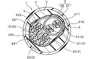
実施例1の複合ケーブルについて、図1を用いて説明する。図1に示されるように、本例の複合ケーブル1は、複数本の電線2と、複数本の電線2の外周を一括して覆うセパレータ3と、セパレータ3の外周を覆うシース4とを有している。複数本の電線2は、複数本の信号線21と、複数本の電力線22と、アース線23とを含んでいる。アース線23は、複数本の電力線22を間に挟んで複数本の信号線21と隔てられている。以下、詳説する。
(Example 1)
A composite cable of Example 1 will be described with reference to FIG. As shown in FIG. 1, the
本例では、複数本の電線2は、複数本の信号線21と、複数本の電力線22と、アース線23とが、全体で撚り合わされている。図1では、具体的には、複数本の電線2が、2本の信号線21と、2本の電力線22と、1本のアース線23とで構成されている例が示されている。また、2本の信号線21は、互いに撚り合わされることにより、ツイストペア線として構成されている。ツイストペア線の外周は、シールド導体6で覆われている。なお、図1中、2本の信号線21を囲む点線は、ツイストペア線の外径を意味している。本例では、アース線23は、2本の電力線22を間に挟んだ状態で、2本の信号線21より構成されるツイスペア線と隔てられている。したがって、アース線23は、2本の信号線21と接していない。また、アース線23は、セパレータ3と接するように配置されている。なお、複数本の電線2とセパレータ3の間には、隙間7が形成されている。
In this example, the plurality of
本例において、信号線21は、導体211と、導体211の外周を覆う絶縁体212とを有している。導体211は、金属素線が複数本撚り合わされてなる子撚線が、複数本撚り合わされてなる撚線導体より構成されている。金属素線は、例えば、銅または銅合金、あるいは、アルミニウムまたはアルミニウム合金等より形成することができる。絶縁体212は、例えば、架橋ポリエチレン(PE)等より形成することができる。
In this example, the
本例において、シールド導体6は、ツイストペア線の外周を横巻きにて覆う金属素線より構成されている。金属素線は、例えば、銅または銅合金、あるいは、アルミニウムまたはアルミニウム合金等より形成することができる。
In this example, the
本例において、電力線22は、導体221と、導体221の外周を覆う絶縁体222とを有している。導体221は、金属素線が複数本撚り合わされてなる子撚線が、複数本撚り合わされてなる撚線導体より構成されている。金属素線は、例えば、銅または銅合金、あるいは、アルミニウムまたはアルミニウム合金等より形成することができる。絶縁体222は、例えば、架橋ポリエチレン(PE)等より形成することができる。
In this example, the
本例において、アース線23は、導体231と、導体231の外周を覆う絶縁体232とを有している。導体231は、金属素線が複数本撚り合わされてなる撚線導体より構成されている。金属素線は、例えば、銅または銅合金、あるいは、アルミニウムまたはアルミニウム合金等より形成することができる。絶縁体232は、例えば、架橋ポリエチレン(PE)等より形成することができる。
In this example, the
本例において、複合ケーブル1は、セパレータ3とシース4との間に介在する介在物5をさらに有している。介在物5は、例えば、架橋ポリエチレン(PE)等より形成することができる。
In this example, the
本例において、セパレータ3は、ポリマーより構成されるベース層31と、介在物5側におけるベース層31の表面に形成された接着層32とを有している。セパレータ3の接着層32は、介在物5に接着している。
In this example, the
本例において、セパレータ3のベース層31は、例えば、ポリエチレンテレフタレート(PET)等より形成することができる。また、セパレータ3の接着層32は、例えば、エチレン-酢酸ビニル共重合体(EVA)等より形成することができる。
In this example, the
本例において、シース4は、例えば、ポリウレタン樹脂(PU)等より形成することができる。
In this example, the
次に、本例の複合ケーブルの作用効果について説明する。 Next, the effects of the composite cable of this example will be described.
本例の複合ケーブル1は、上記構成を有している。そして、本例の複合ケーブル1では、アース線23は、複数本の電力線22を間に挟んで複数本の信号線21と隔てられている。そのため、本例の複合ケーブル1によれば、複数本の電力線22を間に挟むことで、アース線23と信号線21との間の物理的な距離が確実に確保され、アース線23と信号線21とが同じ側にある場合に比べ、アース線23により生じたノイズが信号線21にのり難くなる。
The
(実施例2)
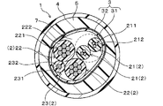
実施例2の複合ケーブルについて、図2を用いて説明する。本例の複合ケーブル1では、セパレータ3が、紙類より構成されている。その他の作用効果は、実施例1と同様である。
(Example 2)
A composite cable of Example 2 will be described with reference to FIG. In the
本例の複合ケーブル1によっても、実施例1と同様の作用効果を得ることができる。
With the
(実施例3)
実施例3の複合ケーブルについて、図3を用いて説明する。本例の複合ケーブル1では、2本の信号線21より構成されるツイスペア線の外周に、シールド導体6が設けられていない。その他の構成は、実施例1と同様である。
(Example 3)
A composite cable of Example 3 will be described with reference to FIG. In the
本例の複合ケーブル1によっても、実施例1と同様の作用効果を得ることができる。但し、実施例1の方が、実施例3よりも、ツイスペア線の外周がシールド導体6に覆われている分、アース線や電力線により生じたノイズが信号線にのり難く有利である。
With the
(実施例4)
実施例4の複合ケーブルについて、図4を用いて説明する。本例の複合ケーブル1では、実施例2と同様に、セパレータ3が、紙類より構成されている。また、本例の複合ケーブル1では、実施例3と同様に、2本の信号線21より構成されるツイスペア線の外周に、シールド導体6が設けられていない。その他の構成は、実施例1と同様である。
(Example 4)
A composite cable of Example 4 will be described with reference to FIG. In the
本例の複合ケーブル1によっても、実施例1と同様の作用効果を得ることができる。但し、実施例1の方が、実施例4よりも、ツイスペア線の外周がシールド導体6に覆われている分、アース線や電力線により生じたノイズが信号線にのり難く有利である。
With the
(実施例5)
実施例5の複合ケーブルについて、図5を用いて説明する。本例の複合ケーブル1では、複数本の電線2が、2本の信号線21が撚り合わされてなるツイストペア線を2本含んでいる。図5では、具体的には、複数本の電線2が、4本の信号線21と、2本の電力線22と、1本のアース線23とで構成されている例が示されている。そして、4本の信号線21のうち、2本の信号線21が撚り合わされてツイストペア線とされ、残りの2本の信号線21も撚り合わされて上記とは異なるツイストペア線とされている。いずれのツイストペア線の外周も、シールド導体6で覆われている。なお、アース線23は、電力線22を間に挟んで各ツイストペア線と隔てられている。
(Example 5)
A composite cable of Example 5 will be described with reference to FIG. In the
また、本例では、シールド導体6が編組線より構成されている。編組線は、複数本の金属素線が編み込まれて形成されている。金属素線は、例えば、銅または銅合金、あるいは、アルミニウムまたはアルミニウム合金等より形成することができる。その他の構成は、実施例1と同様である。
Further, in this example, the
本例の複合ケーブル1によっても、実施例1と同様の作用効果を得ることができる。
With the
<実験例>
以下、上記複合ケーブルを、実験例を用いてより具体的に説明する。
(実験例1)
以下の表1に示す構成の複合ケーブルを作製した。
<Experimental example>
Hereinafter, the composite cable will be described more specifically using experimental examples.
(Experimental example 1)
A composite cable having the configuration shown in Table 1 below was fabricated.
-試料1、試料2-
シールド導体により外周が覆われたツイストペア線1本と、電力線2本と、アース線1本とを、図1に示されるコア線構造となるように撚り合わせた。次いで、このコア線の外周にセパレータを被覆した。なお、セパレータは、接着層が外周面となるように被覆した。次いで、押し出し成形により、セパレータの外周面上に介在物を真円状に押し出し被覆した。次いで、押し出し成形により、介在物の外周面上にシースを押し出し被覆した。以上により試料1、試料2の複合ケーブルを得た。
-
One twisted pair wire whose outer periphery was covered with a shield conductor, two power wires, and one ground wire were twisted together to form the core wire structure shown in FIG. Next, the outer periphery of this core wire was covered with a separator. The separator was coated so that the adhesive layer was on the outer peripheral surface. Next, by extrusion molding, inclusions were extruded and covered in a perfect circle on the outer peripheral surface of the separator. A sheath was then extrusion coated onto the outer peripheral surface of the inclusion by extrusion molding. Composite cables of
-試料3、試料4-
シールド導体により外周が覆われたツイストペア線1本と、電力線2本と、アース線1本とを、図2に示されるコア線構造となるように撚り合わせた。次いで、このコア線の外周にセパレータを被覆した。次いで、押し出し成形により、セパレータの外周面上に介在物を真円状に押し出し被覆した。次いで、押し出し成形により、介在物の外周面上にシースを押し出し被覆した。以上により試料3、試料4の複合ケーブルを得た。
-
A twisted pair wire whose outer circumference was covered with a shield conductor, two power wires, and one ground wire were twisted together to form the core wire structure shown in FIG. Next, the outer periphery of this core wire was covered with a separator. Next, by extrusion molding, inclusions were extruded and covered in a perfect circle on the outer peripheral surface of the separator. A sheath was then extrusion coated onto the outer peripheral surface of the inclusion by extrusion molding. Composite cables of
-試料5-
シールド導体により外周が覆われていないツイストペア線1本と、電力線2本と、アース線1本とを、図3に示されるコア線構造となるように撚り合わせた。次いで、このコア線の外周にセパレータを被覆した。なお、セパレータは、接着層が外周面となるように被覆した。次いで、押し出し成形により、セパレータの外周面上に介在物を真円状に押し出し被覆した。次いで、押し出し成形により、介在物の外周面上にシースを押し出し被覆した。以上により試料5の複合ケーブルを得た。
-Sample 5-
One twisted pair wire whose outer periphery is not covered with a shield conductor, two power wires, and one ground wire were twisted together to form the core wire structure shown in FIG. Next, the outer periphery of this core wire was covered with a separator. The separator was coated so that the adhesive layer was on the outer peripheral surface. Next, by extrusion molding, inclusions were extruded and covered in a perfect circle on the outer peripheral surface of the separator. A sheath was then extrusion coated onto the outer peripheral surface of the inclusion by extrusion molding. A composite cable of
-試料6-
シールド導体により外周が覆われていないツイストペア線1本と、電力線2本と、アース線1本とを、図4に示されるコア線構造となるように撚り合わせた。次いで、このコア線の外周にセパレータを被覆した。次いで、押し出し成形により、セパレータの外周面上に介在物を真円状に押し出し被覆した。次いで、押し出し成形により、介在物の外周面上にシースを押し出し被覆した。以上により試料6の複合ケーブルを得た。なお、試料3、4、6におけるセパレータは、パルプ紙である。
-Sample 6-
One twisted pair wire whose outer periphery is not covered with a shield conductor, two power wires, and one ground wire were twisted together to form the core wire structure shown in FIG. Next, the outer periphery of this core wire was covered with a separator. Next, by extrusion molding, inclusions were extruded and covered in a perfect circle on the outer peripheral surface of the separator. A sheath was then extrusion coated onto the outer peripheral surface of the inclusion by extrusion molding. A composite cable of

作製した試料の複合ケーブルでは、アース線は、2本の電力線を間に挟んで2本の信号線と隔てられている。そのため、試料の複合ケーブルによれば、2本の電力線を間に挟むことで、アース線と信号線との間の物理的な距離が確実に確保され、アース線と信号線とが同じ側にある場合に比べ、アース線により生じたノイズが信号線にのり難くなる。 In the fabricated sample composite cable, the ground line is separated from the two signal lines with the two power lines interposed therebetween. Therefore, according to the sample composite cable, the physical distance between the ground line and the signal line is reliably secured by sandwiching the two power lines, and the ground line and the signal line are on the same side. Compared to other cases, noise generated by the ground line is less likely to get on the signal line.
(実験例2)
試料1、2、5の複合ケーブルを代表するものとして、試料1の複合ケーブルを選択した。そして、試料1の複合ケーブルを30本準備した。また、試料3、4、6の複合ケーブルを代表するものとして、試料3の複合ケーブルを選択した。そして、試料3の複合ケーブルを30本準備した。
(Experimental example 2)
The composite cable of
各試料について全自動電線切断皮剥機(小寺電子製作所製、「キャスティングC377A」)を用いて、ケーブル切断およびシースの剥ぎ取り試験を行った。ケーブル切断長の標準値は、1000mm、シース剥ぎ取り長は35mmおよび40mmの2条件とした。その結果を、表2に示す。 For each sample, cable cutting and sheath stripping tests were performed using a fully automatic wire cutting and stripping machine ("Casting C377A" manufactured by Kodera Denshi Seisakusho). The standard value of the cable cut length was set to 1000 mm, and the sheath stripped length was set to two conditions of 35 mm and 40 mm. The results are shown in Table 2.
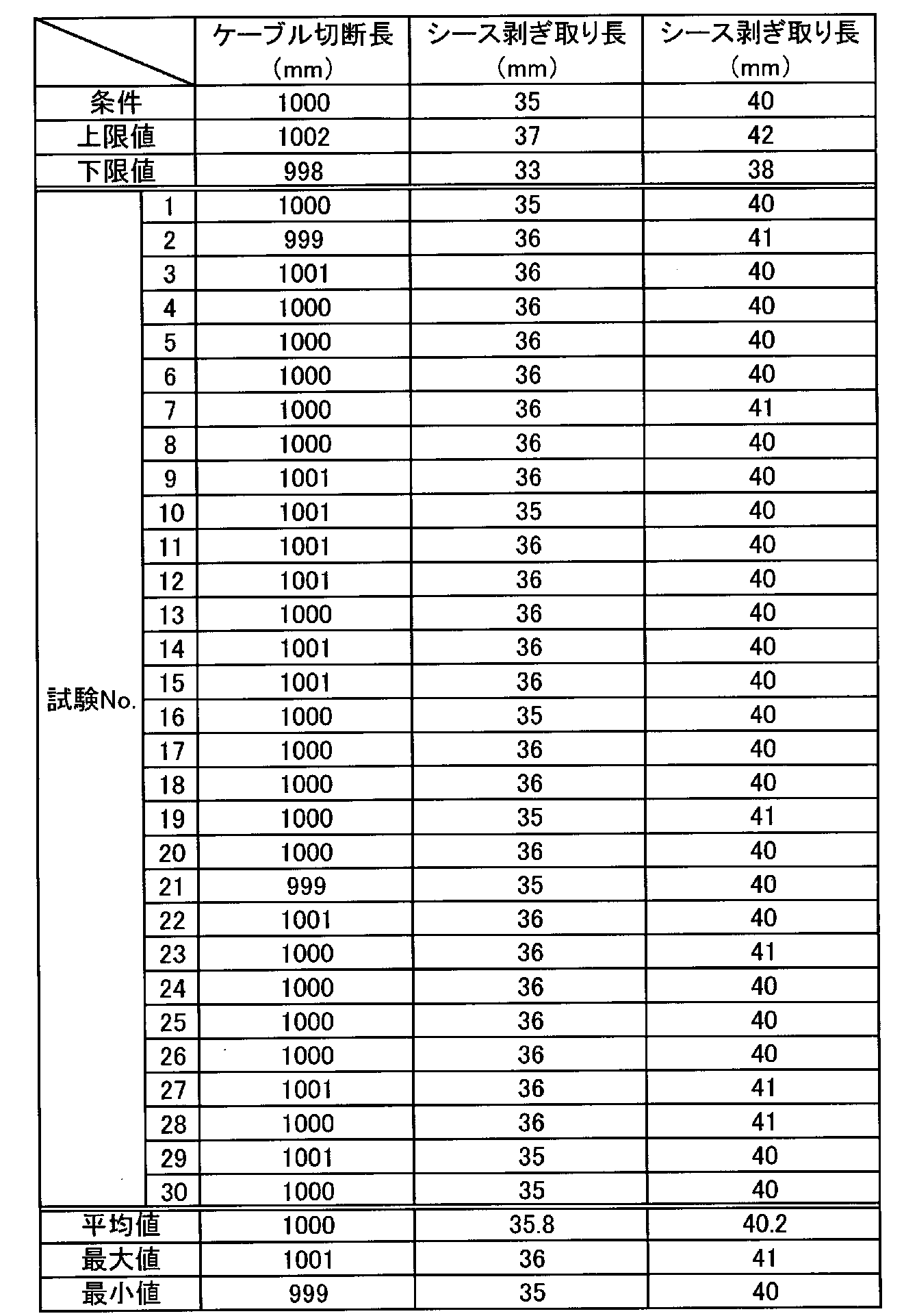
表2に示されるように、ケーブル切断長、シース剥ぎ取り長ともに、セパレータをベース層および接着層より構成したことによる悪影響はないことが確認された。 As shown in Table 2, it was confirmed that the separator composed of the base layer and the adhesive layer had no adverse effect on both the cable cut length and the sheath stripped length.
次に、上記試験によるセパレータ屑の発生状況、セパレータの切れ端残の発生状況を確認した。 Next, the occurrence of separator scraps and the occurrence of separator scraps remaining in the above test were checked.
その結果、試料3の複合ケーブルでは、セパレータ屑(本例では、紙屑)が発生した本数が、30本中30本であった。これに対し、試料1の複合ケーブルでは、セパレータ屑が発生した本数が、30本中0本であった。この結果から、セパレータを、ポリマーより構成されるベース層と、介在物側におけるベース層の表面に形成された接着層とを有する構成とすることにより、従来に比べ、シース剥ぎ取り時におけるセパレータ屑の脱落を抑制しやすくなることが確認された。これは、シース剥ぎ取り時に、剥ぎ取られたシースおよび介在物にセパレータが一緒に引っ付いていくことで、シースおよび介在物とともにセパレータを除去することができたためである。
As a result, in the composite cable of
また、試料3の複合ケーブルでは、セパレータの切れ端残が発生した本数が、30本中16本であった。これに対し、試料1の複合ケーブルでは、セパレータの切れ端残が発生した本数が、30本中14本であった。また、さらに、セパレータの切れ端の形状について確認したところ、試料3の複合ケーブルでは、不揃いで様々な大きさの切れ端が確認された。これに対し、試料1の複合ケーブルでは、セパレータの切れ端は、せいぜい2~3mm程度であり、量産工程上、許容範囲内であった。また、試料1の複合ケーブルでは、セパレータの切れ端は、シース抜き取り時に除去可能であることも確認された。これらの結果から、ベース層と接着層とを有するセパレータによれば、紙類からなるセパレータのように様々な大きさの切れ端が残ることを回避しやすいことが確認された。
In addition, in the composite cable of
なお、試料1の複合ケーブルの構成において、ベース層の厚みを10~200μmの範囲内、接着層の厚みを1~50μmの範囲内とした場合についても、同様の結果が得られた。なお、ベース層の厚みが上記範囲より薄くなると、破れやすくなって製造性が悪化する傾向が見られた。また、セパレータの端がちぎれる場合があった。ベース層の厚みが上記範囲より厚くなると、セパレータの反力から巻き径が大きくなり、ケーブルの真円度が低下する傾向が見られた。また、ケーブル表面に周期的な凹凸が生じる場合があった。接着層の厚みが上記範囲より薄くなると、介在物との接着剥がれが生じる傾向が見られた。接着層の厚みが上記範囲より厚くなると、ベース層から接着層がはみ出して電線とくっつき、加工性が低下する傾向が見られた。そのため、ベース層の厚み、接着層の厚みは、上記範囲内とすることが好ましいことが確認された。
Similar results were obtained when the thickness of the base layer was in the range of 10 to 200 μm and the thickness of the adhesive layer was in the range of 1 to 50 μm in the structure of the composite cable of
本願は下記各態様を開示する。
第1の態様は、複数本の電線と、上記複数本の電線の外周を一括して覆うセパレータと、上記セパレータの外周を覆うシースと、を有しており、上記複数本の電線は、複数本の信号線と、複数本の電力線と、アース線とを含んでおり、上記アース線は、上記複数本の電力線を間に挟んで上記複数本の信号線と隔てられている、複合ケーブルである。
第2の態様は、第1の態様に係る複合ケーブルであって、上記複数本の信号線は、2本の信号線が撚り合わされてなるツイストペア線を少なくとも1本含んでおり、上記ツイストペア線の外周がシールド導体で覆われている、複合ケーブルである。
第3の態様は、第1又は第2の態様に係る複合ケーブルであって、上記複数本の電力線は、少なくとも2本の電力線を含んでいる、複合ケーブルである。
第4の態様は、第1から第3のいずれか1つの態様に係る複合ケーブルであって、上記セパレータと上記シースとの間に介在する介在物をさらに有している、複合ケーブルである。
第5の態様は、第4の態様に係る複合ケーブルであって、上記セパレータは、ポリマーより構成されるベース層と、上記介在物側における上記ベース層の表面に形成された接着層とを有しており、上記接着層が上記介在物に接着している、複合ケーブルである。
以上、本発明の実施例について詳細に説明したが、本発明は上記実施例、実験例に限定されるものではなく、本発明の趣旨を損なわない範囲内で種々の変更が可能である。
The present application discloses the following aspects.
A first aspect has a plurality of electric wires, a separator that collectively covers the outer circumference of the plurality of electric wires, and a sheath that covers the outer circumference of the separator, and the plurality of electric wires includes a plurality of A composite cable including a signal line, a plurality of power lines, and a ground line, wherein the ground line is separated from the plurality of signal lines by the plurality of power lines. be.
A second aspect is the composite cable according to the first aspect, wherein the plurality of signal lines includes at least one twisted pair wire formed by twisting two signal wires, and the twisted pair wire It is a composite cable whose circumference is covered with a shield conductor.
A third aspect is the composite cable according to the first or second aspect, wherein the plurality of power lines includes at least two power lines.
A fourth aspect is the composite cable according to any one of the first to third aspects, further comprising an inclusion interposed between the separator and the sheath.
A fifth aspect is the composite cable according to the fourth aspect, wherein the separator has a base layer made of a polymer and an adhesive layer formed on the surface of the base layer on the side of the inclusion. and wherein the adhesive layer adheres to the interposer.
Although the embodiments of the present invention have been described in detail above, the present invention is not limited to the above-described embodiments and experimental examples, and various modifications can be made without departing from the scope of the present invention.
1 複合ケーブル
2 電線
21 信号線
22 電力線
23 アース線
3 セパレータ
4 シース
REFERENCE SIGNS
Claims (3)
前記電線束の外周を一括して覆い、前記電線束の外周面に一部が接触した状態とされ、かつ、非円形状の断面形状となるように配置されているセパレータと、
前記セパレータの外周を覆い、前記セパレータと比べて、真円形に近い断面形状となるように配置されているシースと、
前記セパレータと前記シースとの間に介在する介在物と、を備え、
互いに接して配置された前記2本の第2被覆電線の中心を通る仮想線は、前記シースの断面の中心を通らず、
前記介在物の外周面は、前記シースの内周面に沿って延びており、かつ、前記セパレータと比べて、真円形に近い断面形状とされており、
前記介在物の内周面は、前記セパレータの外周面に当接している状態で前記セパレータの外周面に沿って非円形状の断面形状となるように延びており、
前記仮想線の一方側には、前記第2被覆電線以外の電線として前記ツイストペア線のみが配置されており、
前記仮想線の他方側には、前記第2被覆電線以外の電線として前記第3被覆電線のみが配置されている、複合ケーブル。 A twisted pair wire in which a pair of first covered wires are twisted together, two second covered wires having a cross-sectional area larger than that of the first covered wires, and a third covered wire having a cross-sectional area smaller than that of the second covered wires. a wire bundle including a coated wire;
a separator that collectively covers the outer periphery of the bundle of wires, is in a state of being partially in contact with the outer peripheral surface of the bundle of wires, and is arranged to have a non-circular cross-sectional shape;
a sheath that covers the outer periphery of the separator and is arranged to have a cross-sectional shape that is closer to a perfect circle than the separator;
and an inclusion interposed between the separator and the sheath,
An imaginary line passing through the centers of the two second covered wires arranged in contact with each other does not pass through the center of the cross section of the sheath,
The outer peripheral surface of the inclusion extends along the inner peripheral surface of the sheath, and has a cross-sectional shape closer to a perfect circle than the separator,
The inner peripheral surface of the inclusion extends along the outer peripheral surface of the separator while in contact with the outer peripheral surface of the separator so as to have a non-circular cross-sectional shape ,
Only the twisted pair wire is arranged as an electric wire other than the second covered wire on one side of the virtual line,
A composite cable in which only the third covered electric wire is arranged as an electric wire other than the second covered electric wire on the other side of the virtual line .
Priority Applications (1)
| Application Number | Priority Date | Filing Date | Title |
|---|---|---|---|
| JP2021095541A JP7128324B2 (en) | 2017-04-28 | 2021-06-08 | composite cable |
Applications Claiming Priority (2)
| Application Number | Priority Date | Filing Date | Title |
|---|---|---|---|
| JP2017090041A JP6896500B2 (en) | 2017-04-28 | 2017-04-28 | Composite cable |
| JP2021095541A JP7128324B2 (en) | 2017-04-28 | 2021-06-08 | composite cable |
Related Parent Applications (1)
| Application Number | Title | Priority Date | Filing Date |
|---|---|---|---|
| JP2017090041A Division JP6896500B2 (en) | 2017-04-28 | 2017-04-28 | Composite cable |
Publications (3)
| Publication Number | Publication Date |
|---|---|
| JP2021141079A JP2021141079A (en) | 2021-09-16 |
| JP2021141079A5 JP2021141079A5 (en) | 2021-11-11 |
| JP7128324B2 true JP7128324B2 (en) | 2022-08-30 |
Family
ID=63918271
Family Applications (2)
| Application Number | Title | Priority Date | Filing Date |
|---|---|---|---|
| JP2017090041A Active JP6896500B2 (en) | 2017-04-28 | 2017-04-28 | Composite cable |
| JP2021095541A Active JP7128324B2 (en) | 2017-04-28 | 2021-06-08 | composite cable |
Family Applications Before (1)
| Application Number | Title | Priority Date | Filing Date |
|---|---|---|---|
| JP2017090041A Active JP6896500B2 (en) | 2017-04-28 | 2017-04-28 | Composite cable |
Country Status (4)
| Country | Link |
|---|---|
| US (1) | US10672538B2 (en) |
| JP (2) | JP6896500B2 (en) |
| CN (1) | CN110546718B (en) |
| WO (1) | WO2018198476A1 (en) |
Families Citing this family (6)
| Publication number | Priority date | Publication date | Assignee | Title |
|---|---|---|---|---|
| WO2017109939A1 (en) * | 2015-12-25 | 2017-06-29 | 日立金属株式会社 | Composite cable and composite harness |
| US11121557B2 (en) * | 2018-04-06 | 2021-09-14 | Aurora Flight Sciences Corporation | Power distribution system for aircraft |
| JP7279422B2 (en) * | 2019-03-07 | 2023-05-23 | 株式会社プロテリアル | Composite cable and composite harness |
| JP7455778B2 (en) | 2021-05-07 | 2024-03-26 | オリエンタルモーター株式会社 | integrated cable |
| GB2614180B (en) * | 2021-09-29 | 2023-12-20 | Amnack Ltd | A composite cable and method of manufacture |
| WO2023067712A1 (en) * | 2021-10-19 | 2023-04-27 | 住友電気工業株式会社 | Multicore cable and disconnection detection device |
Citations (3)
| Publication number | Priority date | Publication date | Assignee | Title |
|---|---|---|---|---|
| JP2005166450A (en) | 2003-12-02 | 2005-06-23 | Hitachi Cable Ltd | Cable for dynamo-electric brake |
| JP2014220043A (en) | 2013-05-01 | 2014-11-20 | 住友電気工業株式会社 | Insulation cable |
| WO2017109939A1 (en) | 2015-12-25 | 2017-06-29 | 日立金属株式会社 | Composite cable and composite harness |
Family Cites Families (23)
| Publication number | Priority date | Publication date | Assignee | Title |
|---|---|---|---|---|
| US2981788A (en) * | 1958-12-03 | 1961-04-25 | Anaconda Wire & Cable Co | Power cables |
| US3614300A (en) * | 1970-10-22 | 1971-10-19 | Anaconda Wire & Cable Co | Power cable with polypropylene covered ground-check strand |
| DE3011868A1 (en) * | 1980-03-27 | 1981-10-01 | Kabel- und Metallwerke Gutehoffnungshütte AG, 3000 Hannover | HUMIDITY PROTECTED ELECTRICAL POWER CABLE |
| US4374299A (en) * | 1980-05-19 | 1983-02-15 | Belden Corporation | Triboelectric transducer cable |
| JPH0644418B2 (en) * | 1988-06-13 | 1994-06-08 | 株式会社フジクラ | Transport cable and method of manufacturing the same |
| JP3669562B2 (en) * | 1999-09-22 | 2005-07-06 | 東京特殊電線株式会社 | Differential signal transmission cable with excellent terminal processability |
| JP2005166402A (en) * | 2003-12-02 | 2005-06-23 | Hitachi Cable Ltd | Shielded cable |
| JP2007535111A (en) * | 2004-04-27 | 2007-11-29 | プリスミアン・カビ・エ・システミ・エネルジア・ソチエタ・ア・レスポンサビリタ・リミタータ | Method for manufacturing cables resistant to external chemicals |
| US6998538B1 (en) * | 2004-07-30 | 2006-02-14 | Ulectra Corporation | Integrated power and data insulated electrical cable having a metallic outer jacket |
| EP1667169B1 (en) * | 2004-11-29 | 2010-02-24 | Nexans | Electrical cable |
| US7166802B2 (en) * | 2004-12-27 | 2007-01-23 | Prysmian Cavi E Sistemi Energia S.R.L. | Electrical power cable having expanded polymeric layers |
| EP2383754A4 (en) * | 2009-02-16 | 2013-11-27 | Fujikura Ltd | Transmission cable |
| JP5740817B2 (en) * | 2010-02-12 | 2015-07-01 | 日立金属株式会社 | High voltage cabtyre cable |
| US9583923B2 (en) * | 2013-03-15 | 2017-02-28 | Abl Ip Holding Llc | Class I and class II modular wiring system |
| JP2015138751A (en) * | 2014-01-24 | 2015-07-30 | 日立金属株式会社 | signal transmission cable |
| KR102244221B1 (en) * | 2014-06-05 | 2021-04-26 | 엘에스전선 주식회사 | Optical power signal cable |
| US20170302010A1 (en) * | 2014-10-03 | 2017-10-19 | Tatsuta Electric Wire & Cable Co., Ltd. | Shield wire |
| JP6227595B2 (en) | 2015-06-10 | 2017-11-08 | 株式会社フジクラ | Optical cable |
| CN204926834U (en) * | 2015-09-14 | 2015-12-30 | 安徽鸿海电缆有限公司 | Electric automobile charging cable |
| CN205069202U (en) * | 2015-09-24 | 2016-03-02 | 深圳市联嘉祥科技股份有限公司 | Electric automobile quick charge cable |
| JP6667190B2 (en) | 2015-10-14 | 2020-03-18 | 住友電装株式会社 | Automotive composite cable |
| JP6554023B2 (en) * | 2015-11-18 | 2019-07-31 | 昭和電線ケーブルシステム株式会社 | Internal cooling cable |
| US9959954B1 (en) * | 2016-01-11 | 2018-05-01 | Southwire Company | Power and control cable for healthcare facilities |
-
2017
- 2017-04-28 JP JP2017090041A patent/JP6896500B2/en active Active
-
2018
- 2018-02-07 US US16/603,530 patent/US10672538B2/en active Active
- 2018-02-07 CN CN201880026549.4A patent/CN110546718B/en active Active
- 2018-02-07 WO PCT/JP2018/004238 patent/WO2018198476A1/en active Application Filing
-
2021
- 2021-06-08 JP JP2021095541A patent/JP7128324B2/en active Active
Patent Citations (3)
| Publication number | Priority date | Publication date | Assignee | Title |
|---|---|---|---|---|
| JP2005166450A (en) | 2003-12-02 | 2005-06-23 | Hitachi Cable Ltd | Cable for dynamo-electric brake |
| JP2014220043A (en) | 2013-05-01 | 2014-11-20 | 住友電気工業株式会社 | Insulation cable |
| WO2017109939A1 (en) | 2015-12-25 | 2017-06-29 | 日立金属株式会社 | Composite cable and composite harness |
Also Published As
| Publication number | Publication date |
|---|---|
| CN110546718B (en) | 2022-03-04 |
| JP2021141079A (en) | 2021-09-16 |
| CN110546718A (en) | 2019-12-06 |
| JP6896500B2 (en) | 2021-06-30 |
| US10672538B2 (en) | 2020-06-02 |
| JP2018190524A (en) | 2018-11-29 |
| US20200066425A1 (en) | 2020-02-27 |
| WO2018198476A1 (en) | 2018-11-01 |
Similar Documents
| Publication | Publication Date | Title |
|---|---|---|
| JP7128324B2 (en) | composite cable | |
| WO2018198475A1 (en) | Composite cable | |
| JP5935343B2 (en) | cable | |
| JP6723158B2 (en) | Shielded wire | |
| JP4933344B2 (en) | Shielded twisted pair cable | |
| JP2017076515A (en) | Composite cable for automobile | |
| WO2016024544A1 (en) | Shielded wire | |
| WO2020116295A1 (en) | Composite cable | |
| JP6688215B2 (en) | Vehicle composite cable and vehicle harness | |
| JP5810618B2 (en) | Cable and manufacturing method thereof | |
| JP2016110836A (en) | Cabtyre cable and cable with connector | |
| JP6089141B1 (en) | Composite wire | |
| WO2020111162A1 (en) | Composite cable | |
| JP2018137243A (en) | Composite cable for automobile | |
| JP2017010851A (en) | Multifiber cable for automobile | |
| US11569003B2 (en) | Composite cable and composite harness | |
| CN110226206B (en) | Cable with operation part | |
| JP3680604B2 (en) | Shielded wire | |
| WO2023157190A1 (en) | Cable | |
| JP7136755B2 (en) | electrical insulated cable | |
| JP6377829B1 (en) | Multi-core insulated wire and manufacturing method thereof | |
| JP2023069616A (en) | composite cable | |
| JP2022161974A (en) | Cable and harness |
Legal Events
| Date | Code | Title | Description |
|---|---|---|---|
| A621 | Written request for application examination |
Free format text: JAPANESE INTERMEDIATE CODE: A621 Effective date: 20210707 |
|
| A521 | Request for written amendment filed |
Free format text: JAPANESE INTERMEDIATE CODE: A523 Effective date: 20211004 |
|
| A977 | Report on retrieval |
Free format text: JAPANESE INTERMEDIATE CODE: A971007 Effective date: 20220525 |
|
| A131 | Notification of reasons for refusal |
Free format text: JAPANESE INTERMEDIATE CODE: A131 Effective date: 20220614 |
|
| A521 | Request for written amendment filed |
Free format text: JAPANESE INTERMEDIATE CODE: A523 Effective date: 20220725 |
|
| TRDD | Decision of grant or rejection written | ||
| A01 | Written decision to grant a patent or to grant a registration (utility model) |
Free format text: JAPANESE INTERMEDIATE CODE: A01 Effective date: 20220802 |
|
| A61 | First payment of annual fees (during grant procedure) |
Free format text: JAPANESE INTERMEDIATE CODE: A61 Effective date: 20220818 |
|
| R150 | Certificate of patent or registration of utility model |
Ref document number: 7128324 Country of ref document: JP Free format text: JAPANESE INTERMEDIATE CODE: R150 |