JP7126530B2 - Road finisher and method for determining paving layer thickness - Google Patents
Road finisher and method for determining paving layer thickness Download PDFInfo
- Publication number
- JP7126530B2 JP7126530B2 JP2020083113A JP2020083113A JP7126530B2 JP 7126530 B2 JP7126530 B2 JP 7126530B2 JP 2020083113 A JP2020083113 A JP 2020083113A JP 2020083113 A JP2020083113 A JP 2020083113A JP 7126530 B2 JP7126530 B2 JP 7126530B2
- Authority
- JP
- Japan
- Prior art keywords
- layer thickness
- paving
- road finisher
- leveling
- distance
- Prior art date
- Legal status (The legal status is an assumption and is not a legal conclusion. Google has not performed a legal analysis and makes no representation as to the accuracy of the status listed.)
- Active
Links
Images


Classifications
-
- E—FIXED CONSTRUCTIONS
- E01—CONSTRUCTION OF ROADS, RAILWAYS, OR BRIDGES
- E01C—CONSTRUCTION OF, OR SURFACES FOR, ROADS, SPORTS GROUNDS, OR THE LIKE; MACHINES OR AUXILIARY TOOLS FOR CONSTRUCTION OR REPAIR
- E01C19/00—Machines, tools or auxiliary devices for preparing or distributing paving materials, for working the placed materials, or for forming, consolidating, or finishing the paving
- E01C19/48—Machines, tools or auxiliary devices for preparing or distributing paving materials, for working the placed materials, or for forming, consolidating, or finishing the paving for laying-down the materials and consolidating them, or finishing the surface, e.g. slip forms therefor, forming kerbs or gutters in a continuous operation in situ
-
- E—FIXED CONSTRUCTIONS
- E01—CONSTRUCTION OF ROADS, RAILWAYS, OR BRIDGES
- E01C—CONSTRUCTION OF, OR SURFACES FOR, ROADS, SPORTS GROUNDS, OR THE LIKE; MACHINES OR AUXILIARY TOOLS FOR CONSTRUCTION OR REPAIR
- E01C19/00—Machines, tools or auxiliary devices for preparing or distributing paving materials, for working the placed materials, or for forming, consolidating, or finishing the paving
- E01C19/004—Devices for guiding or controlling the machines along a predetermined path
- E01C19/006—Devices for guiding or controlling the machines along a predetermined path by laser or ultrasound
-
- E—FIXED CONSTRUCTIONS
- E01—CONSTRUCTION OF ROADS, RAILWAYS, OR BRIDGES
- E01C—CONSTRUCTION OF, OR SURFACES FOR, ROADS, SPORTS GROUNDS, OR THE LIKE; MACHINES OR AUXILIARY TOOLS FOR CONSTRUCTION OR REPAIR
- E01C19/00—Machines, tools or auxiliary devices for preparing or distributing paving materials, for working the placed materials, or for forming, consolidating, or finishing the paving
- E01C19/12—Machines, tools or auxiliary devices for preparing or distributing paving materials, for working the placed materials, or for forming, consolidating, or finishing the paving for distributing granular or liquid materials
- E01C19/18—Devices for distributing road-metals mixed with binders, e.g. cement, bitumen, without consolidating or ironing effect
- E01C19/185—Devices for distributing road-metals mixed with binders, e.g. cement, bitumen, without consolidating or ironing effect for both depositing and spreading-out or striking-off the deposited mixture
-
- E—FIXED CONSTRUCTIONS
- E01—CONSTRUCTION OF ROADS, RAILWAYS, OR BRIDGES
- E01C—CONSTRUCTION OF, OR SURFACES FOR, ROADS, SPORTS GROUNDS, OR THE LIKE; MACHINES OR AUXILIARY TOOLS FOR CONSTRUCTION OR REPAIR
- E01C19/00—Machines, tools or auxiliary devices for preparing or distributing paving materials, for working the placed materials, or for forming, consolidating, or finishing the paving
- E01C19/48—Machines, tools or auxiliary devices for preparing or distributing paving materials, for working the placed materials, or for forming, consolidating, or finishing the paving for laying-down the materials and consolidating them, or finishing the surface, e.g. slip forms therefor, forming kerbs or gutters in a continuous operation in situ
- E01C19/4833—Machines, tools or auxiliary devices for preparing or distributing paving materials, for working the placed materials, or for forming, consolidating, or finishing the paving for laying-down the materials and consolidating them, or finishing the surface, e.g. slip forms therefor, forming kerbs or gutters in a continuous operation in situ with tamping or vibrating means for consolidating or finishing, e.g. immersed vibrators, with or without non-vibratory or non-percussive pressing or smoothing means
- E01C19/4853—Apparatus designed for railless operation, e.g. crawler-mounted, provided with portable trackway arrangements
- E01C19/486—Apparatus designed for railless operation, e.g. crawler-mounted, provided with portable trackway arrangements with non-vibratory or non-percussive pressing or smoothing means; with supplemental elements penetrating the paving to work the material thereof
-
- G—PHYSICS
- G01—MEASURING; TESTING
- G01B—MEASURING LENGTH, THICKNESS OR SIMILAR LINEAR DIMENSIONS; MEASURING ANGLES; MEASURING AREAS; MEASURING IRREGULARITIES OF SURFACES OR CONTOURS
- G01B17/00—Measuring arrangements characterised by the use of infrasonic, sonic or ultrasonic vibrations
- G01B17/02—Measuring arrangements characterised by the use of infrasonic, sonic or ultrasonic vibrations for measuring thickness
-
- E—FIXED CONSTRUCTIONS
- E01—CONSTRUCTION OF ROADS, RAILWAYS, OR BRIDGES
- E01C—CONSTRUCTION OF, OR SURFACES FOR, ROADS, SPORTS GROUNDS, OR THE LIKE; MACHINES OR AUXILIARY TOOLS FOR CONSTRUCTION OR REPAIR
- E01C19/00—Machines, tools or auxiliary devices for preparing or distributing paving materials, for working the placed materials, or for forming, consolidating, or finishing the paving
- E01C19/002—Apparatus for preparing and placing the materials and for consolidating or finishing the paving
-
- E—FIXED CONSTRUCTIONS
- E01—CONSTRUCTION OF ROADS, RAILWAYS, OR BRIDGES
- E01C—CONSTRUCTION OF, OR SURFACES FOR, ROADS, SPORTS GROUNDS, OR THE LIKE; MACHINES OR AUXILIARY TOOLS FOR CONSTRUCTION OR REPAIR
- E01C19/00—Machines, tools or auxiliary devices for preparing or distributing paving materials, for working the placed materials, or for forming, consolidating, or finishing the paving
- E01C19/22—Machines, tools or auxiliary devices for preparing or distributing paving materials, for working the placed materials, or for forming, consolidating, or finishing the paving for consolidating or finishing laid-down unset materials
Description
本発明は、請求項1に記載の舗装層の層厚を決定するロードフィニッシャ、および独立請求項15に記載のロードフィニッシャによって層厚を決定する方法に関する。
The invention relates to a road finisher for determining the layer thickness of a paving layer according to
実際に、ロードフィニッシャは、交通路およびその表面の建設に使用されている。ロードフィニッシャは、例えばトラックから材料を受け取り、道路建設の要求に従って材料を舗装することができる。 In practice road finishers are used in the construction of roads and their surfaces. A road finisher may receive material from, for example, a truck and pave the material according to road construction requirements.
典型的には、いわゆるレベリングシステムが、舗装された層の平坦性を調整するためにロードフィニッシャ上で使用される。これらのシステムは、通常、走査された基準に基づいてロードフィニッシャ上に設置された舗装スクリードの高さを調整する。例えば、使用される基準は、ロードフィニッシャが上で移動している路床、ガタープレート、縁石、または舗装セクションに沿って伸びる基準ワイヤである。高さセンサが基準を走査するために使用される。路床と舗装中の層の相対レベルを走査するために複数のセンサを使用するいわゆるマルチプレックスシステムは、重要性を増している。原理では、舗装スクリードの高さを調整する基準値が、平均化によって計算される。これは、舗装スクリードの左側および右側について2つの別個のシステムを用いて行われ得る。 Typically, so-called leveling systems are used on road finishers to adjust the flatness of the paved layer. These systems typically adjust the height of the paving screed placed on the road finisher based on scanned fiducials. For example, the reference used is a reference wire running along the subgrade, gutter plate, curb, or pavement section over which the road finisher is moving. A height sensor is used to scan the fiducial. So-called multiplex systems, which use multiple sensors to scan the relative levels of the subgrade and the layer in the pavement, are gaining in importance. In principle, a reference value for adjusting the height of the paving screed is calculated by averaging. This can be done with two separate systems for the left and right sides of the paving screed.
主な舗装ターゲットの1つは、作られる層厚である。所定の層厚を維持することは、品質基準であるだけでなく、建設プロジェクトの経済効率にかなり大きい影響も有する。請負業者が要求された層厚を満たさない場合、これは、振り返ってみれば経済上の差引きという結果になり得る。他方で、層厚が超過する場合、これは、アスファルトの消費の増加をもたらし、したがって、コストがかなり大きくより高くなる。このため、層厚の調整は、舗装にとって本質的である。したがって、ロードフィニッシャの操作者は、ロードフィニッシャが要求された層厚で舗装しているかどうか、一定の間隔で検査しなければならない。 One of the main paving targets is the layer thickness to be made. Maintaining a given layer thickness is not only a quality criterion, but also has a significant impact on the economic efficiency of a construction project. If the contractor does not meet the required layer thickness, this can result in economic penalties in retrospect. On the other hand, if the layer thickness is exceeded, this leads to an increased consumption of asphalt and thus considerably higher costs. Therefore, layer thickness control is essential for pavement. Therefore, the road finisher operator must check at regular intervals whether the road finisher is paving with the required layer thickness.
現在でも、層厚は、未だにゲージを手動で突き刺すことによって、または折尺によって検査されている。この手法の欠点は、層厚がいくつかの点でしか決定されないことである。加えて、手動測定の正確さは、操作者の技能によって決定される。このように決定された値は、しばしば比較的不正確であり、もちろん、自動化または文書化のためにデジタル処理できない。 Even today, layer thickness is still checked by manually poking a gauge or by a ruler. A drawback of this approach is that the layer thickness is determined only at a few points. Additionally, the accuracy of manual measurements is determined by the skill of the operator. Values determined in this way are often relatively inaccurate and, of course, cannot be digitally processed for automation or documentation.
舗装された層厚を決定するさらなる測定方法として、磁界誘導による測定が知られている。ここで、道路の実際の舗装前に金属反射体箔が路床に施され、道路が舗装された後に層厚を決定するために測定デバイスによって測定される。これにより、舗装後に反射体箔が施された層厚が測定デバイスによって測定されることを可能にする。しかしながら、層厚を決定するこの方法は、リアルタイムで利用できない。加えて、前もって施された反射体箔は、層のコンパウンドを弱める可能性がある。プロセスを自動化する努力は知られているが、実際には、複雑な構造によりそれを確立することができていない。これは、層厚測定が手動測定を用いる前述した実務の場合のように、いくつかの点でしか実行され得ないことにやはり原因がある。 A further known measuring method for determining the paved layer thickness is magnetic-field-induced measurement. Here, a metallic reflector foil is applied to the roadbed before the actual paving of the road and measured by a measuring device to determine the layer thickness after the road has been paved. This allows the layer thickness of the applied reflector foil after paving to be measured by the measuring device. However, this method of determining layer thickness is not available in real time. In addition, pre-applied reflector foils can weaken the layer compound. Efforts to automate the process are known, but in practice it has not been possible to establish it due to the complex structure. This is again due to the fact that layer thickness measurements can only be performed at several points, as in the above-mentioned practice using manual measurements.
いわゆる「ハングオンシステム」である使用時に層厚を決定する解決策、すなわち、ロードフィニッシャ上に取り付けるために特別に設計された取付けモジュールが存在し、これは、ロードフィニッシャの機械システムに組み込まれることなく、厚さを決定するために特別なやり方でロードフィニッシャ上に別々に取り付けられ、独立して層厚を決定しなければならない。そのような「ハングオンシステム」の欠点は、特にセンサのハードウェア構成要素がロードフィニッシャに加えられるので、その使用がロードフィニッシャの構造をより複雑にさせることである。加えて、そのような追加のモジュールの別個の輸送および取り付け、ならびにそれらの独立した動作モードは、さらなる輸送、保管、および取り付けの装備、ならびに訓練された操作員を必要とし、これは、建設現場におけるロードフィニッシャの使用をより複雑にさせ、製造コストを増大させる。そのような「ハングオンシステム」に関する別の問題は、上に構築される路床が平坦でない場合、または舗装スクリードの迎角が変化する場合に、実際の層厚と検出された層厚との間に差があり得ることである。 Solutions exist for determining the layer thickness in use, so-called "hang-on systems", i.e. mounting modules specially designed for mounting on the road finisher, without being incorporated into the mechanical system of the road finisher. , separately mounted on the road finisher in a special way to determine the thickness and must independently determine the layer thickness. A drawback of such a "hang-on system" is that its use makes the construction of the road finisher more complex, especially since the sensor hardware components are added to the road finisher. In addition, the separate transportation and installation of such additional modules and their independent modes of operation require additional transportation, storage and installation equipment, as well as trained operators, which can complicates the use of road finishers in . Another problem with such "hang-on systems" is the difference between the actual layer thickness and the detected layer thickness if the subgrade built on is uneven or if the angle of attack of the paving screed changes. It is possible that there is a difference in
上述したような現況技術を背景にして、本発明は、設計および技術の観点でなんら問題なく、特に、大きな輸送および建設コストなしで使用することができ、かつ大きな製造費用なしでロードフィニッシャ上に実装することもできる層厚の検出システムをロードフィニッシャに装備するという目的に基づく。さらに、本発明の目的は、作られる舗装層の層厚をロードフィニッシャ上で測定することができる方法を提供することである。 Against the background of the state of the art as described above, the invention can be used without any problems from a design and technical point of view, in particular without significant transportation and construction costs, and can be mounted on a road finisher without significant manufacturing costs. Based on the objective of equipping the road finisher with a layer thickness detection system that can also be implemented. Furthermore, it is an object of the invention to provide a method by which the layer thickness of the pavement layer to be produced can be measured on the road finisher.
本発明の目的は、請求項1に記載のロードフィニッシャ、および独立請求項15に記載のロードフィニッシャを動作させる方法によって解決される。
The object of the invention is solved by a road finisher according to
本発明の有利なさらなる展開例は、従属請求項に示される。 Advantageous further developments of the invention are indicated in the dependent claims.
本発明は、舗装実行中に舗装方向に沿って路床上を移動し、路床上に舗装層を作るロードフィニッシャについて言及する。
本発明によるロードフィニッシャは、特に、路床の不平坦性を補償するために、舗装層を作るための高さ調整可能な舗装スクリードと、舗装スクリードの高さを調整するように構成されたレベリングシステムとを備える。レベリングシステムは、舗装実行中に路床の表面までの少なくとも第1の距離を非接触で測定するように構成された少なくとも第1のセンサユニットを備える第1の測定デバイスを備える。第1の測定デバイスは、舗装実行中に路床上に作られた舗装層の表面までの少なくとも第2の距離を非接触で測定するように構成された少なくとも第2のセンサユニットをさらに備える。
The present invention refers to a road finisher that moves over the roadbed along the paving direction during paving and creates a pavement layer on the roadbed.
The road finisher according to the invention comprises in particular a height-adjustable paving screed for making a paving layer and a leveling device adapted to adjust the height of the paving screed to compensate for unevenness of the roadbed. system. The leveling system comprises a first measuring device comprising at least a first sensor unit adapted to contactlessly measure at least a first distance to the surface of the subgrade during paving runs. The first measuring device further comprises at least a second sensor unit configured to contactlessly measure at least a second distance to the surface of the pavement layer produced on the subgrade during paving runs.
本発明によるロードフィニッシャは、舗装スクリードの高さを調整するためにレベリングシステムにどの実際のレベリング値が与えられ得るかに基づき、測定された第1および第2の距離に基づいて基準レベルを決定するようにさらになされている。特に、実際のレベリング値は、ターゲットの特に平均された基準レベルと比較してサンプリングされた差に基づいて形成される調整変数であり、舗装スクリードの高さの自動調節に使用することができ、それによって長い距離と短い距離の両方でサンプリングされた路床内の不平坦性は、舗装中に補償することができる。 A road finisher according to the present invention determines a reference level based on the measured first and second distances based on which actual leveling values can be applied to the leveling system to adjust the paving screed height. It is further made to In particular, the actual leveling value is an adjustment variable formed on the basis of the sampled difference compared to a target, specifically averaged reference level, and can be used for automatic adjustment of the height of the paving screed, Thereby unevenness in the subgrade sampled at both long and short distances can be compensated for during paving.
本発明によれば、ロードフィニッシャは、第1のセンサユニットによって測定された第1の距離、および第2のセンサユニットによって測定された第2の距離に基づいて路床上に作られた舗装層の層厚をさらに決定するように構成されている。これは、本発明によるロードフィニッシャ上の層厚測定機能は、ロードフィニッシャ上で働くレベリングシステムに組み込まれることを意味する。したがって、その実際のレベリング機能に加えて、レベリングシステムは、いわばシステムの一体の一部として、層厚を決定する機能も与える。 According to the present invention, the road finisher determines the quality of the pavement layer created on the roadbed based on the first distance measured by the first sensor unit and the second distance measured by the second sensor unit. It is configured to further determine the layer thickness. This means that the layer thickness measurement function on the road finisher according to the invention is integrated into the leveling system working on the road finisher. Therefore, in addition to its actual leveling function, the leveling system also provides the function of determining the layer thickness, so to speak as an integral part of the system.
この場合には、本発明によるロードフィニッシャのセンサは、ロードフィニッシャによって作られた舗装層の層厚を決定するために少なくとも一部使用される。言い換えれば、本発明によるロードフィニッシャは、レベリングシステムのための基準レベルを形成するとともに層厚を測定するために同じセンサユニットを使用する。これは、ロードフィニッシャ上のレベリングシステムのセンサユニットが、層厚を測定するためにも使用されることを意味する。これら組み合わせて使用されるセンサユニットは、それらの機能的な動作モードとロードフィニッシャのそれらの位置の観点で共に同一である。 In this case, the sensor of the road finisher according to the invention is used at least in part for determining the layer thickness of the pavement layer produced by the road finisher. In other words, the road finisher according to the invention uses the same sensor unit for forming the reference level for the leveling system and for measuring the layer thickness. This means that the sensor unit of the leveling system on the road finisher is also used to measure the layer thickness. The sensor units used in these combinations are both identical in terms of their functional mode of operation and their position on the road finisher.
舗装作業中に2つのセンサユニットによって検出されたそれぞれの路床までの距離測定が、レベリング機能と層厚検出機能との両方に同様に使用されるので、一方で、ロードフィニッシャ上の度量衡学的なセットアップが単純化され、他方で、ロードフィニッシャの製造コストが減少する。加えて、レベリングおよび層厚測定機能のための共通のデータベースとして使用される距離測定に関連したデータの量を減少させることができ、したがって、それぞれの機能に必要な計算量全体を最小にする。 On the one hand the metrology on the road finisher, since the distance measurements to the respective subgrade detected by the two sensor units during the paving operation are similarly used for both the leveling function and the layer thickness detection function. set-up is simplified, while the cost of manufacturing the road finisher is reduced. In addition, the amount of distance measurement related data used as a common database for leveling and layer thickness measurement functions can be reduced, thus minimizing the overall amount of computation required for each function.
加えて、仕事現場でレベリングシステムのセンサの使用において訓練された操作員は、本質的に何ら追加の訓練努力なしで層厚測定機能を扱うことができる。これは、特に、レベリングシステムおよび層厚決定のためのそれぞれのセンサユニットが、それらの動作モードに関して、およびそれらの設計、設置、および設置位置の観点で同一であるということによる。 Additionally, operators trained in the use of leveling system sensors at the job site can handle the layer thickness measurement function with essentially no additional training effort. This is due in particular to the fact that the leveling system and the respective sensor units for layer thickness determination are identical with respect to their mode of operation and in terms of their design, installation and installation position.
したがって、本発明によるロードフィニッシャは、一体のレベリングおよび層厚測定システムを形成する。最新式とは対照的に、レベリングシステムおよび層厚測定機能は、それぞれの目的のためにされているロードフィニッシャ上の別個のセンサユニットをもはや使用しないが、それぞれのレベリングシステムおよび層厚測定機能のための同じセンサユニットを使用する。 The load finisher according to the invention thus forms an integrated leveling and layer thickness measurement system. In contrast to the state-of-the-art, the leveling system and layer thickness measurement function no longer use separate sensor units on the road finisher that are dedicated to each purpose, but the respective leveling system and layer thickness measurement function using the same sensor unit for
好ましくは、層厚は、舗装実行中に継続的に決定することができる。代替として、層厚の測定は、間隔をおいて実行することができる。 Preferably, the layer thickness can be determined continuously during the paving run. Alternatively, layer thickness measurements can be performed at intervals.
好ましくは、ロードフィニッシャは、レベリングシステムのためにその上で使用されるハードウェア構成要素によってだけで層厚を決定するように設計されている。これは、層厚を決定するためのロードフィニッシャ上の追加のアタッチメントの必要を論理的になくす。レベリング機能と層厚測定機能の両方に使用される測定デバイスは、構成部品を減少させる一体設計を有し、取り外し可能なやり方でロードフィニッシャに取り付けられることが好ましい、ロードフィニッシャ上の多機能モジュールを形成する。 Preferably, the load finisher is designed to determine layer thickness solely by the hardware components used thereon for the leveling system. This logically eliminates the need for additional attachments on the load finisher for determining layer thickness. The measuring device used for both the leveling function and the layer thickness measuring function comprises a multifunctional module on the road finisher, which preferably has an integral design reducing the number of components and is attached to the road finisher in a detachable manner. Form.
一変形例は、測定デバイスのセンサユニットによって測定された距離は、舗装スクリードの自動レベリングにおよび層厚測定機能にともに基礎として使用され得ることを与える。これは、検出された距離測定は、自動レベリングおよび層厚決定のための計算に基礎として、好ましくは並列ステップで同様に使用されることを意味する。測定された値の共通の基礎により、自動レベリングと層厚測定との両方は、ほとんど設計および測定の努力なしで実行することができる。 A variant provides that the distance measured by the sensor unit of the measuring device can be used both as a basis for the automatic leveling of the paving screed and for the layer thickness measuring function. This means that the detected distance measurements are likewise used as a basis for calculations for automatic leveling and layer thickness determination, preferably in parallel steps. Due to the common basis of measured values, both automatic leveling and layer thickness measurements can be performed with little design and measurement effort.
ロードフィニッシャ上の自動レベリングが、層厚測定機能とは別々にまたは層厚測定機能と一緒に処理可能である場合が有利である。これにより、ロードフィニッシャの拡張動作を可能にする。このようにして、層厚測定は、別々に実行することができ、一方、舗装スクリードのレベリングは、例えばロードフィニッシャの外部調整ステーションで表示され得る走査された基準レベルに基づいて、操作者によって手動で調整される。 It would be advantageous if the automatic leveling on the load finisher could be handled separately from the layer thickness measurement function or together with the layer thickness measurement function. This enables extended operation of the load finisher. In this way, layer thickness measurements can be performed separately, while leveling of the paving screed is manually performed by the operator, for example, based on scanned reference levels that can be displayed at the external adjustment station of the road finisher. is adjusted by
好ましくは、ロードフィニッシャは、ロードフィニッシャ上に一体に設置されるレベリングシステムおよび層厚の決定のために共通の制御デバイスを与える。この場合には、制御デバイスは、レベリングシステム上に一体に設けられたレベリングシステムおよび層厚測定機能のために中央計算ユニットを形成する。これにより、ロードフィニッシャ上に設置された電子機器のさらなる減少を可能にする。オプションとして、制御デバイスは、舗装スクリードの両側で独立してレベリング機能および/または層厚測定機能が実行されることを可能にするそれぞれの計算構成要素を装備することもできる。 Preferably, the load finisher provides a leveling system integrally installed on the load finisher and a common control device for determination of layer thickness. In this case, the control device forms a central computing unit for the leveling system and the layer thickness measuring function integrated on the leveling system. This allows for a further reduction in electronics installed on the road finisher. Optionally, the control device can also be equipped with respective computational components that allow the leveling and/or layer thickness measuring functions to be performed independently on both sides of the paving screed.
本発明の有利な一変形例によれば、制御デバイスは、実際のレベリング値に基づいて、層厚を変更するためにフロントプリング点で舗装スクリードに取り付けられたレベリングシリンダの位置を調節するように構成されている。既存の路床の平坦性に応じて、レベリングシリンダは、不平坦性を補償するために使用することができ、フローティングモードにおける舗装スクリードが路床に不平坦性を再現せずに、平らな舗装層を敷設するようになっている。 According to an advantageous variant of the invention, the control device adjusts the position of the leveling cylinder attached to the paving screed at the front pulling point for changing the layer thickness on the basis of the actual leveling value. It is configured. Depending on the flatness of the existing subgrade, the leveling cylinders can be used to compensate for unevenness so that the paving screed in floating mode can produce a flat pavement without reproducing any unevenness on the subgrade. It is designed to lay layers.
好ましくは、第1の測定デバイスは、舗装方向に沿って延びる第1および第2のセンサユニットのための支持構造を有し、この支持構造の上に、第1のセンサユニットは舗装スクリードの前面に配置され、および第2のセンサユニットは舗装方向に舗装スクリードの背後に配置される。支持構造は、それぞれのセンサユニットが上に取り付けられる舗装方向に延びる複数のビームのアセンブリからなることができる。支持構造は、垂直投影平面内で見るとき、直線であってもよく、または階段状であってもよい。 Preferably, the first measuring device has a support structure for the first and second sensor units extending along the paving direction, on top of this support structure the first sensor unit is located on the front side of the paving screed. and a second sensor unit is arranged behind the paving screed in the paving direction. The support structure may consist of an assembly of multiple beams extending in the pavement direction on which respective sensor units are mounted. The support structure may be straight or stepped when viewed in the plane of vertical projection.
好ましくは、第1の測定デバイスは、路床の表面までのそれぞれの距離を測定するための第3および第4のセンサユニットをさらに備え、第3および第4のセンサユニットは、支持構造上で舗装スクリードの前面に舗装方向に配置される。 Preferably, the first measuring device further comprises third and fourth sensor units for measuring respective distances to the surface of the subgrade, the third and fourth sensor units being arranged on the support structure It is placed in the paving direction in front of the paving screed.
第1、第2、第3、および第4のセンサユニットは、互いに所定の距離の倍数で舗装方向に、第1の測定デバイスの支持構造上に配置されることが適切である。使用時、舗装スクリードの前面に配置されるセンサユニットは、等しい間隔をおいて配置される。舗装スクリードの背後に配置されるセンサユニットは、舗装スクリードの前面に配置されるセンサユニットと該舗装スクリードのすぐ前面に配置されるセンサユニットとの間の距離の2倍だけ間隔をおいて配置される。センサユニット間の距離を調節するために、取付けの助けとしてマーキングが支持構造上に設けられる。 Suitably the first, second, third and fourth sensor units are arranged on the support structure of the first measuring device in the pavement direction at multiples of the predetermined distance from each other. In use, the sensor units arranged in front of the paving screed are equally spaced. The sensor units arranged behind the paving screed are spaced apart by twice the distance between the sensor units arranged in front of the paving screed and the sensor units arranged immediately in front of the paving screed. be. To adjust the distance between the sensor units, markings are provided on the support structure as an aid in mounting.
好ましい一変形例は、ロードフィニッシャが層厚決定のために、人工衛星ベースの距離測定ユニットおよび機械的距離測定ユニットを有する少なくとも1つの距離測定手段を備え、または少なくとも1つの光学的距離測定ユニットを備える少なくとも1つの距離測定手段を与える。例えば、前述の組み合わされた距離測定手段は、ロードフィニッシャの駆動装置のGPSベースおよび距離測定ユニットからなり、それによって高い測定の正確さをこれらのセンサ測定システムの機能的な組み合わせによって実現することができる。人工衛星ベースの距離測定ユニットは、GPSシステム、特に、GNSS、DGPS、DGNSS、および/またはRTKユニットを有することが考えられる。 A preferred variant provides that the road finisher comprises at least one distance measuring means with a satellite-based distance measuring unit and a mechanical distance measuring unit or at least one optical distance measuring unit for determining the layer thickness. At least one distance measuring means is provided. For example, the aforementioned combined distance measuring means may consist of a GPS base in the drive of the road finisher and a distance measuring unit, whereby high measurement accuracy can be achieved by the functional combination of these sensor measuring systems. can. Satellite-based ranging units may comprise GPS systems, in particular GNSS, DGPS, DGNSS and/or RTK units.
距離測定手段は、例えば減算によって、これらの距離測定から正確に層の厚さを決定するために、同じ位置で、すなわち、所定の地理的な位置で、舗装された舗装層の路床までおよび表面までの距離を測定するために使用される。この場合には、1セットの距離測定が、層厚を決定するために互いに対してオフセットされ、それによって、舗装層上の所定の位置でオフセットされた距離測定は、互いまでのセンサユニットの距離に関して時間遅延を伴って記録される。したがって、オフセットされた距離測定は、舗装実行中に層厚が測定される地点に時間遅延が到達する場合にこの時間遅延を伴って、正確に同じ地理的位置における舗装スクリードの前面に配置されたセンサユニットのうち、少なくとも1つによる路床までの距離測定、および舗装スクリードの背後に配置されたセンサユニットによって行われた舗装層の表面までの距離測定からなる。 The distance measuring means are measured at the same position, i.e. at a given geographical position, to the subgrade of the pavement layer and Used to measure distance to a surface. In this case, a set of distance measurements are offset with respect to each other to determine the layer thickness, whereby the offset distance measurements at a given position on the pavement layer determine the distances of the sensor units to each other. is recorded with a time delay with respect to The offset distance measurement was therefore placed in front of the paving screed at exactly the same geographical position, with a time delay when reaching the point where the layer thickness is measured during the paving run. It consists of a distance measurement to the roadbed by at least one of the sensor units and a distance measurement to the surface of the pavement layer made by a sensor unit arranged behind the paving screed.
言い換えれば、作られた舗装層の表面までの舗装スクリードの背後で測定した距離は、以前に(すなわち、ロードフィニッシャが隣接したセンサユニット間の距離だけ移動完了する前に)舗装スクリードの前面に配置されたセンサユニットのうちの少なくとも1つにより、同じ位置で得た距離測定によって層厚に対してオフセットされ得る。舗装スクリードの前後に舗装実行中に同じ位置で得られたそれぞれの距離測定のリンクによって、距離測定手段によって実現される。 In other words, the distance measured at the back of the paving screed to the surface of the pavement layer created is the distance previously placed in front of the paving screed (i.e. before the road finisher has completed moving the distance between the adjacent sensor units). Distance measurements obtained at the same position can be offset with respect to the layer thickness by at least one of the sensor units used. Realized by the distance measurement means are links of respective distance measurements obtained at the same position during the paving run before and after the paving screed.
距離測定手段に加えて、同じ地理的地点で距離測定が実行される際の時間遅延を決定するために、速度センサが、ロードフィニッシャ上に、特にその駆動装置上に使用されてもよい。 In addition to the distance measuring means, a speed sensor may be used on the road finisher, in particular on its drive, to determine the time delay in which distance measurements are performed at the same geographical point.
距離測定手段によって測定することができる、舗装されて検出された層厚および距離に基づいて、他の舗装関連パラメータは、設定された舗装幅など、特にロードフィニッシャに関する他の動作セッティングと組み合わせて、決定される。距離測定は、舗装される材料の体積を決定するために、層厚決定および舗装スクリード幅測定を併せて使用してもよいと考えられる。加えて、舗装された材料の現在または累積の質量が、所定のアスファルト密度に基づいて決定される。さらに、妥当性確認が、特に検出された層厚および検出された距離測定データに基づいて、付着される順序の仕様(order specifications)に関して実行される。 Based on the pavement detected layer thickness and distance, which can be measured by the distance measuring means, other pavement related parameters, such as the set pavement width, in combination with other operational settings especially for the road finisher, It is determined. It is envisioned that distance measurement may be used in conjunction with layer thickness determination and paving screed width measurement to determine the volume of material to be paved. Additionally, a current or cumulative mass of paved material is determined based on a given asphalt density. Furthermore, validation is performed with respect to the order specifications of the deposition, especially on the basis of the detected layer thickness and the detected distance measurement data.
本発明の一変形例は、センサユニットが、互いに隣に、特に直線状に配置された複数のセンサセルを備えた超音波マルチセンサをそれぞれ有し、その各々は、路床または舗装層までの距離測定を実行するように設計されていることを提供する。したがって、センサユニットは、ワイドレンジセンサとして利用可能である。これは、所定の望ましい測定範囲、例えば、約30cmの測定幅の範囲内が、それぞれのセンサユニットによって検出でき、それによってセンサユニットのそれぞれの距離測定がレベリングシステムおよび層厚測定機能にとってより信頼できることを意味する。 A variant of the invention is that the sensor units each have an ultrasonic multisensor with a plurality of sensor cells arranged next to each other, in particular in a straight line, each of which has a distance to the roadbed or pavement layer. Provide that it is designed to perform measurements. Therefore, the sensor unit can be used as a wide range sensor. This is because within a given desired measuring range, for example a measuring width of about 30 cm, can be detected by the respective sensor unit, whereby the respective distance measurement of the sensor unit is more reliable for the leveling system and the layer thickness measuring function. means
好ましくは、ロードフィニッシャは、層厚を決定するときに、舗装スクリードが最適なやり方で高さ調節できるように、および/または明らかな測定誤差が補償されるように、自動レベリングのための、および/または層厚を決定するためのフィルタ機能を有する。この目的を達成するために、ロードフィニッシャは、それらの上に構成されたそれぞれのセンサセルによって検出される距離測定を考慮に入れるように設計されており、これは、舗装スクリードを平らにする、および/または層厚を決定するときに、それぞれのセンサユニットについて可変的に調節できる公称距離測定値に関して許容できることがもたらされる。所定の許容範囲から逸脱する他の距離測定は、舗装スクリードを平らにする、および/または層厚を決定するときに無視されてもよい。したがって、舗装スクリードを平らにする、および/または層厚を決定するときに、許容範囲よりも大きい偏差を表すそれらの測定された値を無視することが可能であり、すなわち、それらを含まないことが可能である。これは、それぞれのセンサユニットによって検出される、満たされない路床の不平坦性をフィルタで除外することを可能にするが、基準レベルを走査するときに、例えば、路床上の周囲に横たわりかつセンサユニットによって検出される工具を除外することも可能にする。 Preferably, the road finisher, when determining the layer thickness, so that the paving screed can be height-adjusted in an optimal manner and/or so that obvious measurement errors are compensated, for automatic leveling, and /or have a filter function to determine the layer thickness. To this end, road finishers are designed to take into account the distance measurements detected by the respective sensor cells arranged on them, which flatten the paving screed, and / or when determining the layer thickness, an allowance is provided for a nominal distance measurement that can be variably adjusted for each sensor unit. Other distance measurements that deviate from predetermined tolerances may be ignored when leveling the paving screed and/or determining the layer thickness. It is therefore possible to disregard those measured values representing deviations greater than the permissible range when leveling the paving screed and/or determining the layer thickness, i.e. not including them is possible. This makes it possible to filter out unfilled subgrade unevenness detected by the respective sensor unit, but when scanning the reference level, e.g. It also makes it possible to exclude tools detected by the unit.
本発明の一実施形態は、現在決定されている層厚またはある期間にわたって平均された層厚が、レベリングのためのさらなる実際の値として舗装スクリードの高さを調整するためにレベリングシステムに与えられ得ることを提供する。これは、舗装層の平坦性を調整および/または調節するときに、現在のまたは平均化された層厚が考慮に入れられ、これによって、特に、レベル舗装だけでなく、最適な層厚の範囲内の舗装が自動的に行われることも可能にすることを意味する。 An embodiment of the invention provides that the currently determined layer thickness or the layer thickness averaged over a period of time is given to the leveling system to adjust the height of the paving screed as a further actual value for leveling. Offer to get. This means that the current or averaged layer thickness is taken into account when adjusting and/or adjusting the flatness of the pavement layer, whereby in particular the optimum layer thickness range is not only for level pavement. This means that it also allows the paving inside to be done automatically.
好ましくは、レベリングシステムは、第2の測定デバイスを備え、第1の測定デバイスは、舗装方向にロードフィニッシャの一方の側に位置し、第2の測定デバイスは、舗装方向にロードフィニッシャの反対側に位置する。2つの測定デバイスは、同一の設計および機能であってもよい。これにより、舗装方向にロードフィニッシャの両側に設けられたレベリングおよび層厚決定の機能を可能にする。 Preferably, the leveling system comprises a second measuring device, the first measuring device being located on one side of the road finisher in the pavement direction and the second measuring device being on the opposite side of the road finisher in the pavement direction. Located in The two measuring devices may be of identical design and function. This allows for leveling and layer thickness determination functions on both sides of the road finisher in the paving direction.
特に、舗装スクリードのレベリングは、ロードフィニッシャのレベリングシリンダを用いて、すなわち、ロードフィニッシャの左側および右側で、別々に実行することができる。ロードフィニッシャの左側の第1の測定デバイスは、ロードフィニッシャの左側に取り付けられたレベリングシリンダを調整するために使用でき、ロードフィニッシャの右側の第2の測定デバイスは、ロードフィニッシャの右側に取り付けられたレベリングシリンダを調整するために使用できる。 In particular, leveling of the paving screed can be performed separately with the leveling cylinders of the road finisher, ie on the left and right sides of the road finisher. A first measurement device on the left side of the load finisher can be used to adjust a leveling cylinder mounted on the left side of the load finisher and a second measurement device on the right side of the load finisher can be used to adjust the leveling cylinder mounted on the right side of the load finisher. Can be used to adjust leveling cylinders.
好ましくは、レベリングシステムは、舗装実行中に記録された層厚の読取り値が文書化のために記憶され得るメモリユニットに機能的に接続される。一変形例は、それに取り付けられたディスプレイユニットによって、記録された層厚がロードフィニッシャの外部調整ステーションで視覚的に表示されることを実現する。そして、層厚は、ロードフィニッシャの動作中に、すなわち舗装実行中に、測定された層厚と所定の層厚との間に差がある場合に、舗装スクリードの高さを調節することができる操作者によって監視することができる。自動レベリングが作動されているとき、レベリングシリンダは、舗装スクリードの高さを自動的に調整する。 Preferably, the leveling system is functionally connected to a memory unit in which layer thickness readings recorded during a paving run can be stored for documentation purposes. A variant provides that the recorded layer thickness is visually displayed at the external adjustment station of the road finisher by means of a display unit attached thereto. The layer thickness can then adjust the height of the paving screed if there is a difference between the measured layer thickness and the predetermined layer thickness during operation of the road finisher, i.e. during the paving run. It can be monitored by an operator. When auto-leveling is activated, the leveling cylinders automatically adjust the height of the paving screed.
好ましくは、ロードフィニッシャは、伝送ユニットを備え、これによって検出された層厚値を外部デバイスへ、例えば、舗装材料の供給ステーションへ伝送することができる。 Preferably, the road finisher comprises a transmission unit, by means of which the detected layer thickness values can be transmitted to an external device, for example to a supply station for paving material.
本発明は、ロードフィニッシャを動作させる方法にも関する。本発明による方法では、ロードフィニッシャ上に設置された同じセンサユニットが、不平坦な路床を平らにすることについてロードフィニッシャ上で取り扱うことができるレベリングシステム機能と、ロードフィニッシャによって作られる舗装層の層厚を決定することについてロードフィニッシャ上で取り扱うこともできる層厚測定機能との両方に、局所的に使用される。したがって、ロードフィニッシャ上で使用されるレベリングシステムは、層厚測定機能と同じセンサユニットを使用する。これは、ロードフィニッシャ上に設置される電子機器を減少させることを可能にする。ロードフィニッシャ上の追加の輸送およびセットアップ手段は、層厚の測定に必要とされない。 The invention also relates to a method of operating a road finisher. In the method according to the invention, the same sensor unit installed on the road finisher can handle the leveling system function on the road finisher for leveling the uneven subgrade and the pavement layer created by the road finisher. It is used locally both with the layer thickness measurement function which can also be handled on the load finisher for determining layer thickness. Therefore, the leveling system used on the road finisher uses the same sensor unit as the layer thickness measurement function. This makes it possible to reduce the electronics installed on the road finisher. No additional transport and set-up means on the load finisher are required for layer thickness measurements.
本発明による方法は、ロードフィニッシャ上に設けられたレベリングシステムのための、ならびにロードフィニッシャによって決定された層厚のための共通のセンサユニットを使用し、それによってロードフィニッシャは、その上に取り付けられる構成部品の個数を減少させることにより建設現場でより速く作動させることができる。 The method according to the invention uses a common sensor unit for the leveling system provided on the road finisher and for the layer thickness determined by the road finisher, on which the road finisher is mounted. The reduced number of components allows faster operation on the construction site.
本発明の実施形態は、下記各図により詳細に説明される。 Embodiments of the invention are described in more detail in the following figures.
技術的特徴は、各図全体にわたって同じ参照番号で示されている。 Technical features are indicated by the same reference numerals throughout the figures.
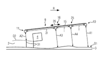
図1は、舗装実行中に舗装方向Rに沿って路床3上を移動し、路床3上に舗装層2を作るロードフィニッシャ1を示す。ロードフィニッシャ1は、舗装層2を(前もって)突き固めるために高さ調整可能な舗装スクリード4を装備する。舗装スクリード4、はスクリードバー5に取り付けられ、スクリードバー5は、前方トラクション点6でロードフィニッシャ1のレベリングシリンダ7に接続されている。スクリードバー5は、路床3の不平坦性8を特に補償するために、レベリングシリンダ位置の変化を舗装スクリード4の迎角の変化に変換するレバーとして働く。
FIG. 1 shows a
図2は、舗装実行中のロードフィニッシャ1を示す。図2では、舗装スクリード4は、伸縮式スクリードとして構成されている。第1の測定デバイス9は、スクリードバー5に位置する。測定デバイス9は、第1のセンサユニット10を備え、この第1のセンサユニット10は、舗装実行中に、例えば超音波によって、路床3の表面O1までの第1の距離A1を非接触で測定するように構成されている。測定デバイス9は、第2のセンサユニット11も有し、この第2のセンサユニット11は、舗装実行中に、例えば超音波によって、路床3上に作られた舗装層2の表面O2までの第2の距離A2を非接触で測定するように構成されている。
FIG. 2 shows the
第1のセンサユニット10および第2のセンサユニット11を用いて、これらの測定結果から基準レベル12を決定するために(図4を参照)、路床3と舗装された舗装層2の相対高さが図2中で走査される。これに基づいて、実際のレベリング値13a、13bが、舗装スクリード4のレベルを調整するために(図5を参照)レベリングシステム14中で使用され得る調整変数として生成される。
Using the
図2によれば、測定デバイス9は、ロードフィニッシャ1の側面で舗装方向Rに数メートルにわたって延びる支持構造15を備える。第1のセンサユニット10は、舗装方向Rに舗装スクリード4の前面で支持構造15上に位置する。第2のセンサユニット11は、舗装方向Rに舗装スクリード4の背後で支持構造15上に取り付けられている。図2は、さらなる第3のセンサユニット16が、舗装方向Rに舗装スクリード4の前面で短い距離に支持構造15上に取り付けられることも示す。
According to FIG. 2, the measuring
図2は、サイドシフト18によって舗装スクリード4に取り付けられた外部操作スタンド17も示す。外部操作スタンド17上で、(図3に示された第4のセンサユニット25を含む)それぞれのセンサユニット10、11、16の距離測定は、外部操作スタンド上に設けられた入力/ディスプレイユニット19によって監視および制御することができる。高さ測定に基づく基準レベル12がターゲット基準レベルに対応しない場合には、これは、入力/ディスプレイユニット19上に表示することができる。次いで、操作者は、ロードフィニッシャの左側よび/または右側で舗装スクリード4の高さを手動で変化させるために、例えば、路床の検出された不平坦性8を補償するために、入力/ディスプレイユニット19を使用することができる。自動レベリングシステムが、舗装スクリード4の高さを調整するための補足または代替とし使用されてもよい。
FIG. 2 also shows an external operating stand 17 attached to the
図2は、ロードフィニッシャ1が、屋根構造24上に人工衛星ベースの距離測定ユニット20(例えばGNSS、DGPS、DGNSS、および/またはRTKユニット)を有することも示す。人工衛星ベースの距離測定ユニット20は、ロードフィニッシャ1の人工衛星ベースのナビゲーションシステムの一部であってもよく、ロードフィニッシャ1の位置を決定するためにGPS測定を実行するようになされている。加えて、図2に示されたロードフィニッシャ1は、ロードフィニッシャ1の駆動装置21に取り付けられた機械的距離測定ユニット22を有する。機械的距離測定ユニット22は、例えば、舗装実行中のロードフィニッシャ1が移動する距離を決定する距離計デバイスとして構成されている。図2のロードフィニッシャ1では、人工衛星ベースの距離測定ユニット20および機械的距離測定ユニット22は、一体の距離測定手段として、舗装実行中のロードフィニッシャ1が移動する距離の非常に正確な測定を行うために、特に、舗装層の厚さを決定するために、互いに機能的にリンクされている。
FIG. 2 also shows that the
人工衛星ベースの距離測定ユニット20および機械的距離測定ユニット22の組み合わせによって形成された距離測定手段は、代替として、ロードフィニッシャ1のシャーシ上に特に配置される光学的距離測定ユニット23からなることもできる。
The distance measuring means formed by the combination of the satellite-based
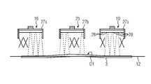
図3は、合計4つのセンサユニット10、11、16、25が上に配置された測定デバイス9の概略図を示す。舗装方向Rでは、第2のセンサユニット11は、舗装された舗装層2の表面O2までの第2の距離A2を測定するために、測定デバイス9の支持構造15上で舗装スクリード4の背後に配置される。舗装方向Rでは、3つのセンサユニット10、16、25は、路床3までの高さを測定するために舗装スクリード4の前面に配置される。第1のセンサユニット10は、測定デバイス9の支持構造15のまさに前面に配置される。第3のセンサユニット16、およびさらなる第4のセンサユニット25は、路床3の表面O1までの距離A3、A4を測定するために、舗装スクリードの舗装方向Rにその背後に配置される。最も前面の第1のセンサユニット10は、舗装方向Rにその背後に配置された第4のセンサユニット25から距離lだけ離れている。舗装方向Rに支持構造15上でそのさらに背後に配置された第3のセンサユニット16と第4のセンサユニット25との間も距離lである。
FIG. 3 shows a schematic view of a
さらに、図3は、支持構造15の端部に配置された第2のセンサユニット11が、舗装方向Rに前面に配置されている第3のセンサユニット16から距離lの2倍で配置されていること示す。測定デバイス9の支持構造15上のそれぞれのセンサユニット10、11、16、25間の距離は、可変的に調節することができ、これは、第3のセンサユニット16のエリア内に矢印26によって概略的に示されている。
Furthermore, FIG. 3 shows that the
図4は、測定デバイス9上で使用されるセンサユニット10、16、25の測定原理の概略図を示す。図4は、舗装スクリード4の前面で舗装方向Rに測定デバイス9の支持構造15上に配置されたセンサユニット10、16、および25の一例を示す。
FIG. 4 shows a schematic illustration of the measuring principle of the
第1、第3、および第4のセンサユニット10、16、25(ならびに図4に図示されていない、図3に示された第2のセンサユニット11)は、図4による超音波マルチセンサ27a、27b、27cとしてそれぞれ設計されている。それぞれの超音波マルチセンサ27a、27b、27cは、互いに隣りに配置された複数のセンサセル28を有する。図4では、それぞれの超音波マルチセンサ27a、27b、27cは、一列に配置された5つのセンサセル28をそれぞれ有する。センサセル28によって測定された路床3までのそれぞれの距離は、図4に示された仮想基準レベル12を決定するために使用される。
The first, third and
図4は、それぞれの超音波マルチセンサ27a、27b、27cで検出された3つの高さ測定だけを使用して基準レベル12を生成することを概略的に示す。記憶または計算された基準からの最大偏差を表すそれぞれのセンサユニット10、16、25で検出された測定値は、無視され、基準レベルの計算に含まれない。基準レベル12は、例えば、それぞれのセンサユニット10、16、25によって検出されたおよび考慮に入れられた測定値を平均化することによって確立することができる。
FIG. 4 schematically illustrates the generation of the
検出された基準レベル12に基づいて、図5に示されたレベリングシステム14は、舗装スクリード4のレベルを自動調整するために、特に路床3の不平坦性8を補償するために、ロードフィニッシャ1の左および右に取り付けられたそれぞれのレベリングシリンダ7a、7bに関する自動レベリング動作29を実行することができる。
Based on the detected
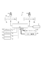
図5に示されたレベリングシステム14は、ロードフィニッシャ1上に一体に設置される。レベリングシステム14は、それぞれのセンサユニット10、11、16、25からの距離測定が連続的に供給される中央制御デバイス30を備える。中央制御デバイス30は、基準レベル12を決定し、これに基づいて、レベリングシリンダ7a、7bの位置を変化させるために、それぞれのレベリングシリンダ7a、7bがそれらを制御するための実際のレベリング値13a、13bを生成するように構成される。さらに、中央制御デバイス30は、センサユニット10、11、16、25のそれぞれ検出された距離A1、A2、A3、A4に基づいて層厚31を決定するように構成されている(図1および図3も参照)。
A leveling
図5は、レベリングシステム14が基準レベル12を生成するために、センサユニット10、11、16、25によって検出された距離A1、A2、A3、A4が、作られた舗装層2の層厚31を決定するためにも使用されることを示す。
FIG. 5 shows that the distances A1, A2, A3, A4 detected by the
図5のレベリングシステム14は、伝送デバイス32も有し、これによって計算された層厚値は、外部デバイス(図示せず)へ伝送される。
The leveling
さらに、図5は、レベリングシステム14が、機能的に接続された制御部33によって制御されることを示す。例えば、制御部33は、外部操作スタンド17、特にそこに配置された入力ユニット19の一体的な一部である。最後に、図5は、レベリングシステム14がメモリユニット34を有し、これは、図5によれば、文書化のために特に検出された層厚の測定を記憶するように、例えば、中央制御デバイス30の一体の一部として設計することができることを示す。
Furthermore, FIG. 5 shows that the leveling
Claims (15)
前記路床(3)の不平坦性(8)を補償するために、前記舗装層(2)を作るための高さ調整可能な舗装スクリード(4)と、前記舗装スクリード(4)の高さを調整するように構成されたレベリングシステム(14)とを備え、
前記レベリングシステム(14)は、前記舗装実行中に前記路床(3)の表面(O1)までの少なくとも第1の距離(A1)を非接触で測定するように構成された少なくとも第1のセンサユニット(10)と、前記舗装実行中に前記路床(3)上に作られた前記舗装層(2)の表面(O2)までの少なくとも第2の距離(A2)を非接触で測定するように構成された少なくとも1つの第2のセンサユニット(11)とを備えた、第1の測定デバイス(9)を備えており、
前記舗装スクリード(4)の高さを調整するために前記レベリングシステム(14)にどの実際のレベリング値(13)が与えられ得るかに基づき、前記測定された第1および第2の距離(A1、A2)に基づいて基準レベル(12)を決定するようになされており、さらに、前記第1のセンサユニット(10)によって測定された前記第1の距離(A1)と、前記第2のセンサユニット(11)によって測定された前記第2の距離(A2)とに基づいて、前記路床(3)上に作られた前記舗装層(2)の層厚(31)を決定するように構成され、
前記基準レベル(12)は、前記第1および第2のセンサユニット(10、11)で測定された第1および第2の距離(A1、A2)から、路床(3)と舗装された舗装層(2)の相対高さに基づいて、前記舗装スクリード(4)の高さを自動レベリングするための仮想基準レベルであり、
前記実際のレベリング値(13)は、前記第1および第2のセンサユニット(10、11)で測定された第1および第2の距離(A1、A2)と前記基準レベル(12)との差に基づいて生成される前記レベリングシステム(14)の調整変数である、
ことを特徴とするロードフィニッシャ(1)。 A road finisher (1) that moves along a pavement direction (R) on a roadbed (3) during paving and creates a pavement layer (2) on the roadbed (3),
Height adjustable paving screed (4) for making said paving layer (2) and height of said paving screed (4) to compensate for unevenness (8) of said subgrade (3) a leveling system (14) configured to adjust the
The leveling system (14) comprises at least a first sensor adapted to contactlessly measure at least a first distance (A1) to a surface (O1) of the subgrade (3) during the paving run. unit (10) and for contactlessly measuring at least a second distance (A2) to a surface (O2) of said paving layer (2) created on said subgrade (3) during said paving run. a first measuring device (9) comprising at least one second sensor unit (11) configured to
The measured first and second distances (A1 , A2), and further, said first distance (A1) measured by said first sensor unit (10) and said second sensor configured to determine a layer thickness (31) of said pavement layer (2) made on said subgrade (3) based on said second distance (A2) measured by a unit (11) is,
The reference level (12) is determined from the first and second distances (A1, A2) measured by the first and second sensor units (10, 11) to the subgrade (3) and paved pavement a virtual reference level for automatic leveling of the height of said paving screed (4) based on the relative heights of the layers (2);
Said actual leveling value (13) is the difference between said first and second distances (A1, A2) measured by said first and second sensor units (10, 11) and said reference level (12). is a tuning variable for said leveling system (14) generated based on
A road finisher (1) characterized by:
ことを特徴とする請求項1に記載のロードフィニッシャ。 the determination of said layer thickness (31) is made solely by the hardware components used for said leveling system (14);
The road finisher according to claim 1, characterized by:
ことを特徴とする請求項1または2に記載のロードフィニッシャ。 Said first and second distances (A1, A2) measured by said first and second sensor units (10, 11) of said measuring device (9) are used for automatic leveling of said paving screed (4) ( 29) and can be used together as a basis for layer thickness measurement functions,
The road finisher according to claim 1 or 2, characterized in that:
ことを特徴とする請求項3に記載のロードフィニッシャ。 said automatic leveling (29) can be handled separately from said layer thickness measurement function or together with said layer thickness measurement function;
The road finisher according to claim 3, characterized in that:
ことを特徴とする請求項1から4のいずれか1項に記載のロードフィニッシャ。 providing an integrally mounted common control device (30) for the determination of said leveling system (14) and said layer thickness (31);
The road finisher according to any one of claims 1 to 4, characterized in that:
ことを特徴とする請求項5に記載のロードフィニッシャ。 Said control device (30) controls a leveling cylinder attached to said paving screed (4) at a forward traction point (6) for said layer thickness (31) to vary based on said actual leveling value (13). configured to adjust the position of (7);
6. The road finisher according to claim 5, characterized in that:
ことを特徴とする請求項1から6のいずれか1項に記載のロードフィニッシャ。 Said measuring device (9) comprises a support structure (15) for said first and second sensor units (10, 11) extending along said paving direction (R), on which support structure (15) said first sensor unit (10) is arranged in front of said paving screed (4) and said second sensor unit (11) is behind said paving screed (4) in said paving direction (R) to be placed,
The road finisher according to any one of claims 1 to 6, characterized in that:
ことを特徴とする請求項1から7のいずれか1項に記載のロードフィニッシャ。 Said measuring device (9) comprises a third sensor unit (16) and a fourth sensor unit (25) measuring respective distances (A3, A4) to said surface (O1) of said subgrade (3). said third and fourth sensor units (16, 25) are arranged on said support structure (15) in front of said paving screed (4) in said paving direction (R), said first, The second, third and fourth sensor units (10, 11, 16, 25) are arranged in said paving direction (R) at multiples of a predetermined distance (l) from each other on said support structure (15) ,
The road finisher according to any one of claims 1 to 7, characterized in that:
ことを特徴とする請求項1から8のいずれか1項に記載のロードフィニッシャ。 at least one distance measuring means comprising a satellite-based distance measuring unit (20) and a mechanical distance measuring unit (22) or providing at least one optical distance measuring unit (23),
The road finisher according to any one of claims 1 to 8, characterized in that:
ことを特徴とする請求項1から9のいずれか1項に記載のロードフィニッシャ。 said sensor units (10, 11, 16, 25) each comprising an ultrasonic multi-sensor (27) having a plurality of sensor cells (28) arranged side by side, each adapted for distance measurement,
The road finisher according to any one of claims 1 to 9, characterized in that:
ことを特徴とする請求項10に記載のロードフィニッシャ。 It is adapted to take into account said distance measurements detected by said respective sensor cells (28) formed on said sensor unit, said distance measurements being taken when leveling said paving screed (4) and/or said allowable for a nominal distance measurement that is variably adjustable for each said sensor unit (10, 11, 16, 25) when determining the layer thickness (31),
The road finisher according to claim 10, characterized in that:
ことを特徴とする請求項1から11のいずれか1項に記載のロードフィニッシャ。 Said currently determined layer thickness (31) or layer thickness (31) averaged therefrom over a period of time is said for adjusting said height of said paving screed (4) as a further actual leveling value. may be provided in the leveling system (14),
The road finisher according to any one of claims 1 to 11, characterized in that:
ことを特徴とする請求項1から12のいずれか1項に記載のロードフィニッシャ。 Said leveling system (14) comprises a second measuring device, said first measuring device (9) being arranged on one side in said paving direction (R) and said second measuring device on the opposite side arranged in the pavement direction (R),
The road finisher according to any one of claims 1 to 12, characterized in that:
ことを特徴とする請求項1から13のいずれか1項に記載のロードフィニッシャ。 The leveling system (14) is operatively connected to a memory unit (34) on which layer thickness values detected during the paving run can be stored for documentation purposes. and/or said detected layer thickness (31) can be displayed visually by means of a display unit (19) mounted on an external operating stand (17) and/or has a transmission unit (32) , the layer thickness value determined by the transmission unit (32) can be transmitted to an external device;
The road finisher according to any one of claims 1 to 13, characterized in that:
前記ロードフィニッシャ(1)上に取り付けられた同じセンサユニット(10、11、16、25)が、路床不平坦性(8)を補償するためにその上で取り扱うことができるレベリングシステム機能と、前記ロードフィニッシャ(1)によって作られる舗装層(2)の層厚(31)を決定するためにその上で取り扱うこともできる層厚測定機能とに、局所的に使用される、方法。 A method of operating a road finisher (1) according to any one of claims 1 to 14 , comprising:
a leveling system function on which the same sensor units (10, 11, 16, 25) mounted on said road finisher (1) can be handled to compensate for subgrade unevenness (8); A method used locally with a layer thickness measurement function that can also be handled thereon to determine the layer thickness (31) of the pavement layer (2) produced by said road finisher (1).
Applications Claiming Priority (2)
| Application Number | Priority Date | Filing Date | Title |
|---|---|---|---|
| EP19174465.5 | 2019-05-14 | ||
| EP19174465.5A EP3739122B1 (en) | 2019-05-14 | 2019-05-14 | Road finisher and method for determining a thickness of a layer of an established installation layer |
Publications (2)
| Publication Number | Publication Date |
|---|---|
| JP2020190186A JP2020190186A (en) | 2020-11-26 |
| JP7126530B2 true JP7126530B2 (en) | 2022-08-26 |
Family
ID=66668686
Family Applications (1)
| Application Number | Title | Priority Date | Filing Date |
|---|---|---|---|
| JP2020083113A Active JP7126530B2 (en) | 2019-05-14 | 2020-05-11 | Road finisher and method for determining paving layer thickness |
Country Status (6)
| Country | Link |
|---|---|
| US (1) | US11560675B2 (en) |
| EP (1) | EP3739122B1 (en) |
| JP (1) | JP7126530B2 (en) |
| CN (2) | CN212983528U (en) |
| BR (1) | BR102020009320A2 (en) |
| PL (1) | PL3739122T3 (en) |
Families Citing this family (10)
| Publication number | Priority date | Publication date | Assignee | Title |
|---|---|---|---|---|
| EP3739122B1 (en) * | 2019-05-14 | 2021-04-28 | Joseph Vögele AG | Road finisher and method for determining a thickness of a layer of an established installation layer |
| US11933000B2 (en) * | 2020-10-13 | 2024-03-19 | Samuel C. Patterson | Depth guide for paving machine |
| US11542670B2 (en) * | 2021-02-12 | 2023-01-03 | Caterpillar Paving Products Inc. | System, apparatus, and method for determining distance to a ground surface covered with vegetation for operation of a milling or reclamation machine |
| EP4056760B1 (en) * | 2021-03-12 | 2023-08-09 | Joseph Vögele AG | Road finisher with levelling cascade control |
| EP4083322A1 (en) * | 2021-04-27 | 2022-11-02 | Leica Geosystems AG | System and method for controlling a road construction process |
| CN113445381B (en) * | 2021-07-09 | 2022-08-05 | 包头市公路工程股份有限公司 | Paver for cement gypsum composite stable steel slag base layer construction and construction method |
| CN113403910B (en) * | 2021-07-26 | 2022-09-16 | 广州睿控信息系统集成有限公司 | Detection method of 3D paving system based on matrix ultrasonic detection self-adaptive virtual paving thickness |
| CN114263085A (en) * | 2022-01-13 | 2022-04-01 | 武汉英途工程智能设备有限公司 | Intelligent paving control system of paver |
| DE102022201294A1 (en) * | 2022-02-08 | 2023-08-10 | Moba Mobile Automation Aktiengesellschaft | Leveling system for a construction machine |
| CN114622465B (en) * | 2022-04-01 | 2022-11-11 | 张艳龙 | Highway construction is with automatic leveling device that conveniently paves in road surface |
Citations (1)
| Publication number | Priority date | Publication date | Assignee | Title |
|---|---|---|---|---|
| JP2013002278A (en) | 2011-06-15 | 2013-01-07 | Joseph Voegele Ag | Road paving machine with layer thickness measuring device |
Family Cites Families (22)
| Publication number | Priority date | Publication date | Assignee | Title |
|---|---|---|---|---|
| JP2584823B2 (en) | 1988-04-22 | 1997-02-26 | 株式会社トキメック | Pavement thickness measuring device |
| WO1992008847A1 (en) * | 1990-11-14 | 1992-05-29 | Niigata Engineering Co., Ltd. | Method of controlling pavement thickness in motor grader and method of setting conditions for automatic control |
| JP2903719B2 (en) * | 1991-01-09 | 1999-06-14 | 株式会社新潟鉄工所 | How to operate the leveling machine |
| DE9214769U1 (en) | 1991-11-15 | 1993-04-01 | Moba - Electronic Gesellschaft Fuer Mobil-Automation Mbh, 6254 Elz, De | |
| DE9114281U1 (en) | 1991-11-15 | 1992-01-09 | Moba-Electronic Gesellschaft Fuer Mobil-Automation Mbh, 6254 Elz, De | |
| DE10060903C2 (en) * | 2000-12-07 | 2002-10-31 | Moba Mobile Automation Gmbh | Laser height control device for a construction machine |
| US7172363B2 (en) | 2004-08-31 | 2007-02-06 | Caterpillar Paving Products Inc | Paving machine output monitoring system |
| CN2823978Y (en) | 2005-03-16 | 2006-10-04 | 吴骏 | Ultrasonic level-meter |
| CN102174792B (en) | 2011-03-22 | 2013-07-10 | 苌安 | Intelligent GPS (global positioning system) elevation and average thickness control system of floated screed plate paver |
| PL2535456T3 (en) * | 2011-06-15 | 2014-05-30 | Voegele Ag J | Road finisher with coating measuring device |
| PL2535457T3 (en) * | 2011-06-15 | 2014-06-30 | Voegele Ag J | Road finisher with coating measuring device |
| CN102839592B (en) * | 2012-09-18 | 2014-10-29 | 中联重科股份有限公司 | Leveling device for spreading machine, control method thereof and spreading machine |
| EP3048199B2 (en) * | 2014-03-18 | 2020-01-22 | MOBA Mobile Automation AG | Road finisher with layer thickness detection device and method for detecting the thickness of an installed material layer |
| US9988733B2 (en) | 2015-06-09 | 2018-06-05 | Lam Research Corporation | Apparatus and method for modulating azimuthal uniformity in electroplating |
| PL3124698T3 (en) * | 2015-07-28 | 2018-01-31 | Voegele Ag J | Road finisher with roller indication display device |
| EP3130939A1 (en) | 2015-08-13 | 2017-02-15 | Joseph Vögele AG | Road finisher with a radar based levelling device and control method |
| CN106400662B (en) * | 2016-10-14 | 2018-12-21 | 天津大学 | A kind of pavement spread thickness real-time monitoring device balancing beam type |
| DE102016225502B4 (en) * | 2016-12-19 | 2019-01-03 | Moba Mobile Automation Ag | Measuring system for coating thickness detection |
| EP3498914A1 (en) * | 2017-12-13 | 2019-06-19 | Joseph Vögele AG | Adjustment of the levelling cylinder in a road finisher |
| CN109235204A (en) * | 2018-09-29 | 2019-01-18 | 徐工集团工程机械股份有限公司 | Paving thickness monitor control system, paver and method based on Radar Technology |
| EP3739122B1 (en) * | 2019-05-14 | 2021-04-28 | Joseph Vögele AG | Road finisher and method for determining a thickness of a layer of an established installation layer |
| US11554726B2 (en) * | 2020-03-11 | 2023-01-17 | Caterpillar Paving Products Inc. | Machine with sensor units retained by breakaway couplers |
-
2019
- 2019-05-14 EP EP19174465.5A patent/EP3739122B1/en active Active
- 2019-05-14 PL PL19174465T patent/PL3739122T3/en unknown
-
2020
- 2020-05-11 BR BR102020009320-7A patent/BR102020009320A2/en unknown
- 2020-05-11 JP JP2020083113A patent/JP7126530B2/en active Active
- 2020-05-13 CN CN202020797723.XU patent/CN212983528U/en not_active Withdrawn - After Issue
- 2020-05-13 CN CN202010406498.7A patent/CN111945524B/en active Active
- 2020-05-14 US US15/931,808 patent/US11560675B2/en active Active
Patent Citations (1)
| Publication number | Priority date | Publication date | Assignee | Title |
|---|---|---|---|---|
| JP2013002278A (en) | 2011-06-15 | 2013-01-07 | Joseph Voegele Ag | Road paving machine with layer thickness measuring device |
Also Published As
| Publication number | Publication date |
|---|---|
| BR102020009320A2 (en) | 2020-11-17 |
| US20200362522A1 (en) | 2020-11-19 |
| CN111945524A (en) | 2020-11-17 |
| CN111945524B (en) | 2023-04-28 |
| US11560675B2 (en) | 2023-01-24 |
| JP2020190186A (en) | 2020-11-26 |
| CN212983528U (en) | 2021-04-16 |
| PL3739122T3 (en) | 2021-11-29 |
| EP3739122A1 (en) | 2020-11-18 |
| EP3739122B1 (en) | 2021-04-28 |
Similar Documents
| Publication | Publication Date | Title |
|---|---|---|
| JP7126530B2 (en) | Road finisher and method for determining paving layer thickness | |
| CA2693146C (en) | Optical guidance system for a paving train for producing a concrete or asphalt surface layer | |
| CN101368361B (en) | Method and control system for laying a road paving | |
| US8371769B2 (en) | Paving machine control and method | |
| US9702096B2 (en) | Automotive construction machine and method for controlling an automotive construction machine | |
| AU2006219886B2 (en) | Method and system for controlling a construction machine | |
| US7643923B2 (en) | Method and device for monitoring a road processing machine | |
| US7172363B2 (en) | Paving machine output monitoring system | |
| US8070385B2 (en) | Paving machine control and method | |
| US11060249B2 (en) | Adjustment of the leveling cylinder setting in a road finisher | |
| US8033751B2 (en) | Gyro compensated inclinometer for cross slope control of concrete screed | |
| JP2010144505A (en) | Method for laying paving mat | |
| US10704211B2 (en) | Measuring paving layer thickness by means of a road roller | |
| US6352386B2 (en) | Road finisher having a laying beam with automatically adjustable extendable beams | |
| CN113494039B (en) | Pavement finisher with lateral profile control | |
| US20220364338A1 (en) | Measuring system and controller | |
| CN105780634B (en) | Paving thickness measuring system, method and paver | |
| CN216688925U (en) | Road finisher | |
| JPH04272303A (en) | Operation of leveling machine | |
| US20200378074A1 (en) | Method and system for positioning screed plates |
Legal Events
| Date | Code | Title | Description |
|---|---|---|---|
| A621 | Written request for application examination |
Free format text: JAPANESE INTERMEDIATE CODE: A621 Effective date: 20200803 |
|
| A977 | Report on retrieval |
Free format text: JAPANESE INTERMEDIATE CODE: A971007 Effective date: 20210820 |
|
| A131 | Notification of reasons for refusal |
Free format text: JAPANESE INTERMEDIATE CODE: A131 Effective date: 20210831 |
|
| A131 | Notification of reasons for refusal |
Free format text: JAPANESE INTERMEDIATE CODE: A131 Effective date: 20220401 |
|
| A521 | Request for written amendment filed |
Free format text: JAPANESE INTERMEDIATE CODE: A523 Effective date: 20220628 |
|
| TRDD | Decision of grant or rejection written | ||
| A01 | Written decision to grant a patent or to grant a registration (utility model) |
Free format text: JAPANESE INTERMEDIATE CODE: A01 Effective date: 20220722 |
|
| A61 | First payment of annual fees (during grant procedure) |
Free format text: JAPANESE INTERMEDIATE CODE: A61 Effective date: 20220816 |
|
| R150 | Certificate of patent or registration of utility model |
Ref document number: 7126530 Country of ref document: JP Free format text: JAPANESE INTERMEDIATE CODE: R150 |