JP7121925B2 - Coupling device, coupling traveling device and autonomous traveling device - Google Patents

Coupling device, coupling traveling device and autonomous traveling device Download PDF

Info

Publication number
JP7121925B2
JP7121925B2 JP2018167985A JP2018167985A JP7121925B2 JP 7121925 B2 JP7121925 B2 JP 7121925B2 JP 2018167985 A JP2018167985 A JP 2018167985A JP 2018167985 A JP2018167985 A JP 2018167985A JP 7121925 B2 JP7121925 B2 JP 7121925B2
Authority
JP
Japan
Prior art keywords
claw
self
connection
propelled robot
carriage
Prior art date
Legal status (The legal status is an assumption and is not a legal conclusion. Google has not performed a legal analysis and makes no representation as to the accuracy of the status listed.)
Active
Application number
JP2018167985A
Other languages
Japanese (ja)
Other versions
JP2020040459A (en
Inventor
一範 渡辺
Current Assignee (The listed assignees may be inaccurate. Google has not performed a legal analysis and makes no representation or warranty as to the accuracy of the list.)
Ricoh Co Ltd
Original Assignee
Ricoh Co Ltd
Priority date (The priority date is an assumption and is not a legal conclusion. Google has not performed a legal analysis and makes no representation as to the accuracy of the date listed.)
Filing date
Publication date
Application filed by Ricoh Co Ltd filed Critical Ricoh Co Ltd
Priority to JP2018167985A priority Critical patent/JP7121925B2/en
Publication of JP2020040459A publication Critical patent/JP2020040459A/en
Application granted granted Critical
Publication of JP7121925B2 publication Critical patent/JP7121925B2/en
Active legal-status Critical Current
Anticipated expiration legal-status Critical

Links

Images

Landscapes

  • Handcart (AREA)
  • Platform Screen Doors And Railroad Systems (AREA)

Description

本発明は、連結装置、連結走行装置及び自律走行装置に関するものである。 TECHNICAL FIELD The present invention relates to a coupling device, a coupling traveling device, and an autonomous traveling device.

従来、退避位置から連結位置へと移動することによって連結対象に連結する連結部材を備える連結装置が知られている。
例えば、特許文献1には、連結対象であるカゴ台車に連結部材である爪部材を引掛けて連結する連結装置が記載されている。
Conventionally, a connecting device is known that includes a connecting member that connects to a connection target by moving from a retracted position to a connecting position.
For example, Patent Literature 1 describes a connecting device that hooks and connects claw members, which are connecting members, to cage trucks to be connected.

特許文献1に記載の連結装置では、連結部材が、退避位置から連結位置まで移動しようとした際に、連結部材が連結対象に載置された荷物等の連結対象以外の物体に接触することがあり、改良の余地があった。 In the connection device described in Patent Document 1, when the connection member is about to move from the retracted position to the connection position, the connection member may contact an object other than the connection target, such as a load placed on the connection target. There was room for improvement.

上述した課題を解決するために、本発明は、退避位置から連結位置へと移動することによって連結対象に連結する連結部材を備える連結装置において、前記退避位置から前記連結位置へと前記連結部材が移動する移動経路上の物体の有無を検知する検知手段を備え、前記連結部材が前記退避位置から前記連結位置へと移動する際に前記検知手段の検知領域に前記物体が存在しても、前記検知手段が前記物体の有無を判断しないタイミングを有することを特徴とするものである。 In order to solve the above-described problems, the present invention provides a connecting device comprising a connecting member that connects to a connection target by moving from a retracted position to a connecting position, wherein the connecting member moves from the retracted position to the connecting position. A detecting means is provided for detecting the presence or absence of an object on the movement path of movement, and even if the object exists in the detection area of the detecting means when the connecting member moves from the retracted position to the connecting position, the It is characterized in that it has a timing at which the detection means does not judge the presence or absence of the object .

本発明によれば、連結部材が連結対象以外の物体に接触することを防止することが可能となる、という優れた効果がある。 ADVANTAGE OF THE INVENTION According to this invention, there exists an outstanding effect that it becomes possible to prevent a connection member contacting objects other than a connection object.

実施形態の自走ロボットとカゴ台車との説明図。Explanatory drawing of the self-propelled robot of embodiment, and a basket cart. ID表示パネルの説明図、(a)は、ID表示パネルが配置されたカゴ台車の斜視図、(b)は、カラーコードの一例の説明図、(c)は、濃淡バーコードの一例の説明図。Explanatory drawing of an ID display panel, (a) is a perspective view of a cage cart on which an ID display panel is arranged, (b) is an explanatory drawing of an example of a color code, and (c) is an explanation of an example of a gray bar code. figure. 物流倉庫の一例の説明図。Explanatory drawing of an example of a distribution warehouse. 本実施形態の搬送システムを模式的に示す説明図。BRIEF DESCRIPTION OF THE DRAWINGS FIG. 1 is an explanatory diagram schematically showing the conveying system of this embodiment; 自走ロボットが仮置きエリアから保管エリアにカゴ台車を搬送する動作の流れを示すフローチャート。4 is a flow chart showing the flow of operation of the self-propelled robot to transport the basket cart from the temporary placement area to the storage area. 第二保管エリアの拡大図。Enlarged view of the second storage area. 搬送システムの変形例を模式的に示す説明図。Explanatory drawing which shows the modification of a conveying system typically. 連結装置の説明図、(a)は連結爪が開いた状態の斜視図、(b)は連結爪が閉じた状態の斜視図、(c)は上面図。Explanatory drawing of a connection device, (a) is a perspective view of the state in which the connection nail|claw was opened, (b) is a perspective view of the state in which the connection nail|claw was closed, (c) is a top view. 連結装置における回動部材とともに固定板材に対して回動する部分の説明図、(a)は斜視図、(b)は上面図。Explanatory drawing of the part which rotates with respect to a fixed board|plate material with a rotation member in a coupling device, (a) is a perspective view, (b) is a top view. 回動部材に対する磁石の固定方法の説明する連結装置の断面説明図。Cross-sectional explanatory drawing of the connection apparatus explaining the fixing method of the magnet with respect to a rotation member. 連結爪の動作を説明する連結装置の断面説明図、(a)は連結爪が閉じた状態の断面図、(b)は連結爪が開いた状態の断面図。Sectional explanatory drawing of the connection apparatus explaining the operation|movement of a connection claw, (a) is sectional drawing of the state in which the connection claw was closed, (b) is sectional drawing in the state in which the connection claw was opened. 連結爪の先端形状の説明図、(a)は先端の曲がった部分が一枚の形状の説明図、(b)は先端の曲がった部分が二枚の形状の説明図。Explanatory drawing of the tip shape of a connecting nail, (a) is explanatory drawing of the shape with one curved part of a front-end|tip, (b) is explanatory drawing of the shape with two curved parts of a front-end|tip. 連結爪が閉じた状態の実施例1の連結装置の斜視図。Fig. 2 is a perspective view of the connecting device of the first embodiment with the connecting claws closed; 連結爪が開いた状態の実施例1の連結装置の斜視図。The perspective view of the connecting device of Example 1 in the state which the connecting nail|claw was opened. 図14に示す状態の連結装置10の側面図、(a)は連結装置全体の説明図、(b)は連結爪の先端近傍の拡大説明図。Fig. 14 is a side view of the connecting device 10 in the state shown in Fig. 14, (a) is an explanatory view of the entire connecting device, and (b) is an enlarged explanatory view of the vicinity of the tip of the connecting claw. z軸のプラス方向から連結爪及び接触検知センサを見た説明図。Explanatory drawing which looked at the connection nail|claw and the contact detection sensor from the positive direction of z-axis. 実施例1の連結装置が、カゴ台車に連結した状態を示す側面図。The side view which shows the state which the connection apparatus of Example 1 connected with the basket truck. カゴ台車の荷物にレバーが接触した状態の実施例1の連結装置の側面図。The side view of the coupling device of Example 1 in the state which the lever contacted the goods of the basket truck. 実施例1の連結装置における連結動作のフローチャート。4 is a flow chart of the connecting operation in the connecting device of the first embodiment; 実施例2の連結装置が備える連結爪の先端近傍の拡大斜視図。FIG. 11 is an enlarged perspective view of the vicinity of the tip of a connecting claw provided in the connecting device of Embodiment 2;

以下、図面を参照して本発明を適用可能な自律移動装置の実施形態の一例について説明する。
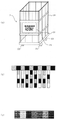
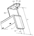
図1は、実施形態の自律移動装置である自走ロボット1と、連結対象であるカゴ台車2との説明図である。
本実施形態は、カゴ台車2のような被牽引台車に自動で接続して、牽引することで、所望の搬送先へ被牽引台車を自動搬送する自走ロボット1のような自律移動装置と、この自走ロボット1を用いた搬送システムに関する実施形態である。
An example of an embodiment of an autonomous mobile device to which the present invention can be applied will be described below with reference to the drawings.
FIG. 1 is an explanatory diagram of a self-propelled robot 1 that is an autonomous mobile device of the embodiment and a cage cart 2 that is a connection target.
In this embodiment, an autonomous mobile device such as a self-propelled robot 1 that automatically transports a towed carriage to a desired destination by automatically connecting to and towing a towed carriage such as a basket carriage 2, This embodiment relates to a transport system using this self-propelled robot 1. FIG.

自走ロボット1は、搬送物を積載するカゴ台車2に自動で連結する機能を持った自律移動装置である。これにより、自走ロボット1には積載が可能な構成を持たせることなく、簡易な移動装置によってカゴ台車2を牽引させることで、カゴ台車2に積載された多数の搬送物を搬送させることができる。 The self-propelled robot 1 is an autonomous mobile device having a function of automatically connecting to a basket cart 2 on which goods are loaded. As a result, the self-propelled robot 1 does not need to have a structure capable of being loaded, and by pulling the cage carriage 2 with a simple moving device, a large number of objects loaded on the cage carriage 2 can be transported. can.

自走ロボット1は、装置本体であるロボット本体部100、磁気センサ3、コントローラ4、カメラ5、電力源(バッテリー)6、動力モータ7、モータドライバ8、測域センサ9、連結装置10、駆動車輪71及び従動車輪72等を備える。
磁気センサ3及び測域センサ9は、自走ロボット1の周辺環境を認識する環境認識手段である。
The self-propelled robot 1 includes a robot body 100 as a device body, a magnetic sensor 3, a controller 4, a camera 5, a power source (battery) 6, a power motor 7, a motor driver 8, a range sensor 9, a coupling device 10, a drive A wheel 71, a driven wheel 72, and the like are provided.
The magnetic sensor 3 and range sensor 9 are environment recognition means for recognizing the surrounding environment of the self-propelled robot 1 .

本実施形態の搬送システムでは、自走ロボット1の走行可能な経路の床面に磁気テープを設置し、磁気センサ3を用いて磁気テープを検出することにより自走ロボット1が走行可能な経路上に位置していることを認識することができる。床面にテープを設置する誘導方式としては、磁気テープを用いる構成に限らず、光学テープを用いる構成としてもよい。光学テープを用いる場合は、磁気センサ3の代わりに反射センサやイメージセンサなどが利用できる。 In the transport system of the present embodiment, a magnetic tape is placed on the floor of the route on which the self-propelled robot 1 can travel, and the magnetic tape is detected using the magnetic sensor 3 to detect the position on the route on which the self-propelled robot 1 can travel. It can be recognized that it is located in The method of guiding the installation of the tape on the floor is not limited to the configuration using the magnetic tape, and may be the configuration using the optical tape. When using an optical tape, a reflective sensor, an image sensor, or the like can be used instead of the magnetic sensor 3 .

また、本実施形態の搬送システムでは、二次元あるいは三次元地図と測域センサ9の検出結果との照合によって自己位置を認識する自律走行を行うことができる。測域センサ9は物体にレーザー光を照射し、その反射光を受光して物体までの距離を測定するレーザー測域センサである。検出結果と二次元あるいは三次元地図との照合によって自己位置の認識に用いるセンサとしては、ステレオカメラやデプスカメラなども利用できる。 Further, in the transport system of this embodiment, it is possible to autonomously travel by recognizing its own position by collating the two-dimensional or three-dimensional map with the detection result of the range sensor 9 . The range sensor 9 is a laser range sensor that irradiates an object with laser light and receives the reflected light to measure the distance to the object. A stereo camera, a depth camera, or the like can be used as a sensor for recognizing the self-position by matching the detection result with a two-dimensional or three-dimensional map.

自走ロボット1は、磁気センサ3や測域センサ9の検出結果に基づいてコントローラ4がモータドライバ8を介して動力モータ7の駆動を制御し、動力モータ7が駆動車輪71を回動駆動することで自走ロボット1が自律走行を行う。
カゴ台車2は、カゴ部20を保持する底板22と、四角形状の底板22の四隅に配置されたキャスター23と、カゴ部20の側面に配置されたID表示パネル21とを備える。
In the self-propelled robot 1, the controller 4 controls the driving of the power motor 7 via the motor driver 8 based on the detection results of the magnetic sensor 3 and the range sensor 9, and the power motor 7 rotates the drive wheels 71. As a result, the self-propelled robot 1 runs autonomously.
The cage carriage 2 includes a bottom plate 22 that holds a cage portion 20 , casters 23 arranged at four corners of the rectangular bottom plate 22 , and an ID display panel 21 arranged on the side surface of the cage portion 20 .

所定の場所に置かれたカゴ台車2には認識用のマーカーが表示されたID表示パネル21が取り付けられている。マーカーは、二次元のカラーコード等を用いて、カゴ台車2の識別番号情報、搬送先情報、搬送の優先度情報がコード化されている。
ID表示パネル21は、カゴ台車2に取り付けられており、搬送位置などの情報もしくはテーブル参照によって認識できるID情報を読み取れるようになっている。マーカーのIDの表示方法は一般的なバーコードやQRコード(登録商標)が使える。また、IDとしてカラーコードや、濃淡バーコードによって単位面積当たりの情報量を増やすことで、より遠くから認識できるようになる。
An ID display panel 21 on which a recognition marker is displayed is attached to the cart 2 placed at a predetermined place. The marker is coded with the identification number information of the cart 2, the destination information, and the priority information of transportation using a two-dimensional color code or the like.
The ID display panel 21 is attached to the basket carriage 2, and can read information such as transport position or ID information that can be recognized by referring to a table. A common bar code or QR code (registered trademark) can be used to display the ID of the marker. In addition, by increasing the amount of information per unit area by using a color code or a gray bar code as an ID, it becomes possible to recognize from a greater distance.

自走ロボット1には、マーカー読取装置が設置されている。マーカー読取装置はID認識手段であるカメラ5と復号部とからなる。本実施形態ではコントローラ4が復号部としての機能を有する。カメラ5の撮影画像からマーカーの特徴の画像認識によってマーカーのコードを認識する。復号部では認識したマーカーのコード情報をデコードすることで、カゴ台車2の認識番号情報、搬送先情報、優先度情報を得る。 The self-propelled robot 1 is equipped with a marker reader. The marker reader comprises a camera 5 as ID recognition means and a decoding section. In this embodiment, the controller 4 functions as a decoding section. The code of the marker is recognized by image recognition of the features of the marker from the photographed image of the camera 5. - 特許庁The decoding unit decodes the code information of the recognized marker to obtain identification number information, transport destination information, and priority information of the cart 2 .

本実施形態では、カゴ台車2に設置されたマーカーとして、カラーコードを用いているため、カメラ5を用いて読み取っている。IDを表示するマーカーがバーコードやQRコードの場合は、ID認識手段としてバーコードリーダが使用できる。マーカーが濃淡バーコードの場合はレーザー測域センサの反射強度情報をIDコードに用いることができる。 In the present embodiment, a color code is used as the marker installed on the basket cart 2, so the camera 5 is used to read the color code. If the marker that displays the ID is a bar code or QR code, a bar code reader can be used as ID recognition means. When the marker is a grayscale bar code, the reflection intensity information of the laser range sensor can be used for the ID code.

自走ロボット1は、環境認識手段として、周辺環境との距離を取得する測域センサ9を備える。測域センサ9としては、レーザーレンジファインダ(LRF)等を用いることができる。コントローラ4は、測域センサ9によって位置を認識したID表示パネル21と測域センサ9との距離情報からID表示パネル21の位置座標を算出する。算出したID表示パネル21の位置座標を用いて、コントローラ4が動力モータ7の駆動制御を行うことで、カゴ台車2におけるID表示パネル21正面の所定の位置に自走ロボット1を位置決めする。 The self-propelled robot 1 includes a range sensor 9 that acquires the distance to the surrounding environment as environment recognition means. As the range sensor 9, a laser range finder (LRF) or the like can be used. The controller 4 calculates the position coordinates of the ID display panel 21 from distance information between the ID display panel 21 whose position is recognized by the range finding sensor 9 and the range finding sensor 9 . Using the calculated positional coordinates of the ID display panel 21 , the controller 4 drives and controls the power motor 7 to position the self-propelled robot 1 at a predetermined position in front of the ID display panel 21 on the cart 2 .

カゴ台車2との連結動作を制御するために、カゴ台車2に設置されたID表示パネル21の位置を認識するID表示パネル位置認識手段としては、ID認識手段でID表示パネル21の位置も読み取れる場合には兼用することが出来る。例えば、ID表示パネル21のマーカーのIDとして濃淡バーコードをID認識手段としてレーザー測域センサで読み取る場合は、レーザー測域センサによってID表示パネル21の位置を検出しながらID表示パネル21のIDを読み取ることができる。また、マーカーのIDとしてカラーコードを用いる場合もカメラ5で、ID表示パネル21の位置を検出しながらID表示パネル21のIDを読み取ることができる。 As ID display panel position recognition means for recognizing the position of the ID display panel 21 installed on the cage truck 2 in order to control the connection operation with the cage truck 2, the position of the ID display panel 21 can also be read by the ID recognition means. In some cases, it can be used in combination. For example, when reading a gray bar code as an ID of a marker on the ID display panel 21 with a laser range sensor as ID recognition means, the ID of the ID display panel 21 is detected while the position of the ID display panel 21 is detected by the laser range sensor. can be read. Also, when a color code is used as the marker ID, the camera 5 can read the ID of the ID display panel 21 while detecting the position of the ID display panel 21 .

また、濃淡バーコードは、レーザーレンジファインダによる検知が可能であり、レーザーレンジファインダは、高精度なID表示パネル21の位置検出手段及び自律走行のための環境認識センサとしても使用できる。 Further, the gray bar code can be detected by a laser range finder, and the laser range finder can be used as highly accurate position detection means for the ID display panel 21 and environment recognition sensor for autonomous driving.

図2にID表示パネル21の例を示す説明図である。
図2(a)は、カゴ台車2にIDがカラーコードからなるマーカーを表示するID表示パネル21が配置された例の斜視図である。図2(b)はカラーコードの一例の説明図であり、図2(c)は濃淡バーコードの一例の説明図である。
QRコードやカラーコードはバーコードと異なり、カメラを使った読み取りを行うことで、コードのID情報とともにカメラによって撮像された撮像画像に基づいてカメラに対するID表示パネル21の位置情報を同時に取得することができる。このため、読み取る対象物(本実施形態ではID表示パネル21)が置かれている位置を認識することができる。
FIG. 2 is an explanatory diagram showing an example of the ID display panel 21. As shown in FIG.
FIG. 2(a) is a perspective view of an example in which an ID display panel 21 for displaying a marker consisting of a color code as an ID is arranged on the cart 2. FIG. FIG. 2(b) is an explanatory diagram of an example of a color code, and FIG. 2(c) is an explanatory diagram of an example of a gray bar code.
Unlike a bar code, a QR code or a color code can be read by using a camera to simultaneously acquire the position information of the ID display panel 21 with respect to the camera based on the captured image captured by the camera together with the ID information of the code. can be done. Therefore, it is possible to recognize the position where the object to be read (the ID display panel 21 in this embodiment) is placed.

IDが濃淡バーコードの場合は、レーザー測域センサで読み取ることができる。図2(c)に示す濃淡バーコードは、黒色の濃度の異なる複数種類の線状マークを用いており、それぞれの濃度に対してコード番号が割り当てられている。濃淡バーコードを用いる構成では、コントローラ4に、各濃度の線状マークに対応した反射光の受光強度に対してコード番号を記憶しておき、レーザー測域センサの受光強度に応じて、コード番号を認識する。 If the ID is a grayscale bar code, it can be read with a laser ranging sensor. The dark/light bar code shown in FIG. 2(c) uses a plurality of types of linear marks with different black densities, and code numbers are assigned to the respective densities. In the configuration using the gradation bar code, code numbers are stored in the controller 4 for the received light intensity of the reflected light corresponding to the linear marks of each density, and the code numbers are stored according to the received light intensity of the laser range sensor. to recognize

レーザー測域センサは、レーザー光の照射部を水平方向に回動し、レーザー光の照射方向を周期的に変化させてレーザー光で周囲を走査し、照射したレーザー光の反射光によってレーザー光を反射した物体までの距離情報を取得することができる。また、レーザー光の照射方向に基づいてレーザー光を反射した物体の位置についてのレーザー測域センサからの角度情報を取得することができる。さらに、反射光の受光強度の変化に基づいて濃淡バーコードを見つけることができる。 The laser range sensor rotates the laser light irradiation part in the horizontal direction, periodically changes the irradiation direction of the laser light, scans the surroundings with the laser light, and uses the reflected light of the irradiated laser light to emit the laser light. Distance information to the reflected object can be obtained. Further, it is possible to obtain angle information from the laser range sensor regarding the position of the object that reflected the laser light based on the irradiation direction of the laser light. Furthermore, the gray bar code can be found based on the change in received intensity of the reflected light.

濃淡バーコードを見つけたときに、濃淡バーコードの距離情報と角度情報とに基づいて、濃淡バーコードが付されたID表示パネル21とレーザー測域センサとの相対的な位置情報を得ることが出来る。このため、濃淡バーコードをレーザー測域センサで読み取る構成では、レーザー測域センサで取得した情報を、連結時の自走ロボット1の位置決めに用いるフィードバック情報として用いることができる。 When the gradation bar code is found, relative positional information between the ID display panel 21 attached with the gradation bar code and the laser range sensor can be obtained based on the distance information and the angle information of the gradation bar code. I can. Therefore, in a configuration in which the grayscale barcode is read by a laser ranging sensor, the information acquired by the laser ranging sensor can be used as feedback information used for positioning the self-propelled robot 1 at the time of connection.

自走ロボット1を用いた本実施形態の搬送システムは、物流倉庫などにおける、カゴ台車などのキャスター付き搬送対象を搬送する作業を自動化するものである。
自走ロボット1による搬送動作は、次の(1)~(3)の三つの作業に分割される。
(1)仮置きエリアでの搬送対象の探索および連結。
(2)走行エリアの走行。
(3)保管エリアでの保管場所探索と荷卸し。
The transport system of the present embodiment using the self-propelled robot 1 automates the work of transporting a transport object with casters such as a cart in a distribution warehouse.
The transportation operation by the self-propelled robot 1 is divided into the following three operations (1) to (3).
(1) Searching and connecting objects to be transported in the temporary storage area.
(2) Driving in the driving area.
(3) Storage location search and unloading in the storage area.

図3は、本実施形態の搬送システムを適用することが想定される物流倉庫1000の一例の説明図である。図3に示す物流倉庫1000では、作業者Mが、トラック2000からプラットフォーム1001に荷卸しされた荷物を整列しておき、他の作業者Mがこの荷物をエレベータ1002の前のエリアに搬送して、他階に移送する。この物流倉庫1000では、上記(1)の仮置きエリアは、プラットフォーム1001で荷卸しされた荷物を整列しておく場所が想定される。上記(3)の保管エリアは、エレベータ1002で他階へ移送する場合のエレベータ前エリアが想定される。また、上記(2)の走行エリアは図3中の矢印によって仮置きエリアと保管エリアとの往復経路を示す場所が想定される。 FIG. 3 is an explanatory diagram of an example of a distribution warehouse 1000 to which the transport system of this embodiment is supposed to be applied. In the distribution warehouse 1000 shown in FIG. 3, a worker M arranges the cargo unloaded from the truck 2000 onto the platform 1001, and another worker M transports the cargo to the area in front of the elevator 1002. , to be transferred to another floor. In this physical distribution warehouse 1000, the temporary storage area (1) above is assumed to be a place where packages unloaded on the platform 1001 are arranged. The storage area of (3) above is assumed to be the area in front of the elevator when transferring to another floor by the elevator 1002 . Also, the travel area of (2) above is assumed to be a place where the round-trip route between the temporary placement area and the storage area is indicated by the arrows in FIG.

自走ロボット1は、本線動作は床面に設置された磁気テープや光学テープのラインをセンサで認識するライン認識による誘導方式で移動する。また、ラインの横にある番地マークを検出してエリアを判断する。また、ID表示パネル21は搬送エリアの情報と優先順位の情報が含まれている。 The self-propelled robot 1 moves on the main line by a guidance method based on line recognition in which a sensor recognizes lines of magnetic tapes or optical tapes placed on the floor. Also, the area is determined by detecting the address mark next to the line. Also, the ID display panel 21 contains information on the transport area and information on the priority order.

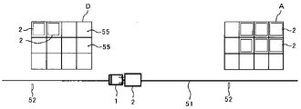
図4は、本実施形態の搬送システムを模式的に示す説明図である。
図4に示す搬送システムは、走行エリア50と、仮置きエリアAと、第一保管エリアBと、第二保管エリアCとを備える。走行エリア50には自走ロボット1の誘導用の磁気テープまたは光学テープがライン状に設けられ、自走ロボット1が走行する本線51が設けられている。本線51上には自走ロボット1のスタート位置Sがある。また、走行エリア50における仮置きエリアA、第一保管エリアB及び第二保管エリアCの入り口には、本線51の近傍に番地マーク52が配置されている。
FIG. 4 is an explanatory diagram schematically showing the transport system of this embodiment.
The transport system shown in FIG. 4 includes a travel area 50, a temporary placement area A, a first storage area B, and a second storage area C. As shown in FIG. A magnetic tape or an optical tape for guiding the self-propelled robot 1 is provided in a line in the travel area 50, and a main line 51 along which the self-propelled robot 1 travels is provided. A starting position S of the self-propelled robot 1 is located on the main line 51 . At the entrances of the temporary storage area A, the first storage area B, and the second storage area C in the traveling area 50, address marks 52 are arranged near the main road 51. As shown in FIG.

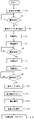
図5は、自走ロボット1が仮置きエリアAから保管エリア(BまたはC)にカゴ台車2を搬送する動作の流れを示すフローチャートである。
まず、本線51上に移動体である自走ロボット1を配置してライン認識できている状態でスタートさせることで、自走ロボット1は本線51に沿った走行を開始する(S1)。本線51を走行中はラインの位置を見て指定速度で走行する。仮置きエリアAの番地マーク52を探索しながら走行し、仮置きエリアAの番地マーク52を検出したら(S2で「Yes」)停止する。
FIG. 5 is a flow chart showing the flow of operations for the self-propelled robot 1 to transport the basket cart 2 from the temporary storage area A to the storage area (B or C).
First, the self-propelled robot 1, which is a mobile body, is placed on the main line 51 and started in a state where the line can be recognized, so that the self-propelled robot 1 starts traveling along the main line 51 (S1). While traveling on the main line 51, the vehicle travels at a designated speed while observing the position of the line. The vehicle travels while searching for the address mark 52 of the temporary placement area A, and stops when the address mark 52 of the temporary placement area A is detected ("Yes" in S2).

仮置きエリアAの番地マーク52を検出して(S2で「Yes」)停止すると、仮置きエリアAへの進入動作を開始する(S3)。
自走ロボット1は、本線51が設けられた走行エリア50から仮置きエリアAに進入すると、走行しながら、仮置きされているカゴ台車2のID表示パネル21のマーカーを読み取り、カゴ台車2のリストを生成する。このとき、ID、XY座標及び搬送先を記録し、優先順位があれば一緒に記録する。そして、仮置きエリアAの終端の番地マークで走行停止し、生成したカゴ台車2のリストから搬送対象を選定し(S4)、選定した搬送対象のカゴ台車2との連結動作を開始する(S5)。
When the address mark 52 of the temporary placement area A is detected and stopped ("Yes" in S2), the operation to enter the temporary placement area A is started (S3).
When the self-propelled robot 1 enters the temporary placement area A from the travel area 50 provided with the main line 51, the self-propelled robot 1 reads the marker on the ID display panel 21 of the temporarily placed cage cart 2 while traveling, and detects the cage cart 2. Generate a list. At this time, the ID, XY coordinates, and destination are recorded, and if there is an order of priority, they are recorded together. Then, it stops traveling at the address mark at the end of the temporary storage area A, selects the object to be conveyed from the generated list of the basket trucks 2 (S4), and starts the connection operation with the selected basket truck 2 to be conveyed (S5). ).

連結動作では、リスト上のXY座標を元に指定されたカゴ台車2の列まで移動する。ID表示パネル21との相対位置情報を使って、カゴ台車2の手前まで移動する。その後、カゴ台車2に近接したら連結装置10によってカゴ台車2と連結する。搬送対象のカゴ台車2との連結を検知すると(S6で「Yes」)、本線51に戻り(S7)、本線51を走行し(S8)、搬送中のカゴ台車2を保管する保管エリア(BまたはC)の番地マーク52を検出したら(S9で「Yes」)停止する。 In the connecting operation, the car carriage 2 is moved to the line specified based on the XY coordinates on the list. Using the relative position information with the ID display panel 21, it moves to the front of the basket carriage 2. - 特許庁After that, when it approaches the cage truck 2, it is connected with the cage truck 2 by the connecting device 10. - 特許庁When the connection with the basket carriage 2 to be transported is detected ("Yes" in S6), it returns to the main line 51 (S7), runs on the main line 51 (S8), and enters the storage area (B) for storing the basket trolley 2 being transported. Alternatively, when the address mark 52 of C) is detected ("Yes" in S9), the process is stopped.

保管エリア(BまたはC)の番地マーク52を検出して(S9で「Yes」)停止すると、保管エリア(BまたはC)への進入動作を開始する(S10)。
自走ロボット1は、本線51が設けられた走行エリア50から保管エリア(BまたはC)に進入すると、走行しながら、保管されているカゴ台車2のID表示パネル21のマーカーを読み取り、カゴ台車2のリストを生成する。このとき、IDとXY座標、搬送先、および優先順位があれば一緒に記録する。次に、保管エリア(BまたはC)の終端の番地マークで走行停止し、生成したカゴ台車2のリストから空き番地を探す(S11)。そして、空き番地の中から搬送中のカゴ台車2を車庫入れする番地を選定し(S12)、選定した空き番地への車庫入れ動作を開始する(S13)。
When the address mark 52 of the storage area (B or C) is detected and stopped ("Yes" in S9), the operation to enter the storage area (B or C) is started (S10).
When the self-propelled robot 1 enters a storage area (B or C) from a travel area 50 provided with a main line 51, the self-propelled robot 1 reads the marker on the ID display panel 21 of the cage trolley 2 being kept while traveling, and reads the marker of the cage trolley. Generate a list of 2. At this time, the ID, XY coordinates, destination, and priority, if any, are recorded together. Next, the vehicle stops running at the address mark at the end of the storage area (B or C), and searches for an empty address from the generated list of car trolleys 2 (S11). Then, an address is selected from among the vacant addresses for garage parking of the cart 2 being transported (S12), and the garage parking operation to the selected vacant address is started (S13).

車庫入れ動作では、リスト上のXY座標を元に指定された空き番地の車庫の列まで移動する。その後、指定された空き番地に着いたら搬送中のカゴ台車2との連結を解除する。
連結を解除したら保管エリア(BまたはC)から本線51に戻り、再び仮置きエリアAの探索を開始する。
In the garage entry operation, the vehicle moves to a garage line with an empty address specified based on the XY coordinates on the list. After that, when it arrives at the specified vacant address, it is disconnected from the basket truck 2 being transported.
After releasing the connection, it returns to the main line 51 from the storage area (B or C) and starts searching for the temporary storage area A again.

図6は、第二保管エリアCの拡大図である。図6では、X軸方向が「列方向」であり、Y軸方向が「行方向」である。
仮置きエリアA、保管エリア(BまたはC)は本線51から外れた位置に配置する。エリア内を探索走行するための走行ライン53と停止マーク54とを付けておく。カゴ台車2を置く位置(駐車場55)には、枠線やマークを付けておき、人が置き易くする。自走ロボット1は、仮置きエリアAまたは保管エリア(BまたはC)に進入したら停止マーク54を検知するまで走行ライン53上をライン誘導によって走行する。
6 is an enlarged view of the second storage area C. FIG. In FIG. 6, the X-axis direction is the "column direction" and the Y-axis direction is the "row direction."
The temporary placement area A and the storage area (B or C) are arranged at positions separated from the main line 51. - 特許庁A travel line 53 and a stop mark 54 for searching and traveling within the area are attached. The position (parking lot 55) where the basket trolley 2 is placed is marked with a frame line or a mark to make it easier for a person to place it. After entering the temporary placement area A or the storage area (B or C), the self-propelled robot 1 travels on the travel line 53 by line guidance until the stop mark 54 is detected.

このとき、仮置きエリアAでは最初に見つけたカゴ台車2に対して連結する動作を行っても良い。保管エリア(BまたはC)では最初に見つけた空き番地の駐車場55に駐車するように制御しても良い。
自走ロボット1は、移動しながら測域センサ9を使って置いてあるカゴ台車2を探索しリスト化し、停止マーク54を見つけたら停止して、連結対象のカゴ台車2または車庫入れを行う番地(駐車場55)を選定する。
At this time, in the temporary storage area A, an operation to connect the basket carriage 2 found first may be performed. In the storage area (B or C), the vehicle may be controlled to park in the parking lot 55 of the first vacant address found.
The self-propelled robot 1 searches for and lists the cage carts 2 that are placed using the range sensor 9 while moving, stops when it finds the stop mark 54, and puts the cage cart 2 to be connected or the address to put in the garage. (Parking lot 55) is selected.

連結の場合は、リスト化されたXY座標に移動を始めるが、番地の列方向に移動してから、90[°]旋回して、真っ直ぐに連結対象のカゴ台車2に接近していくと、連結動作がし易い。連結に際しては、ID表示パネル21との相対位置情報を用いて自走ロボット1の走行を制御することで、精度の高い位置決めができる。また、環境地図を使った自律走行を行っている場合には、連結対象のカゴ台車2を環境地図のデータ上に配置して、その座標を元に走行制御しても良い。
車庫入れ動作の場合は、駐車場55の番地のXY座標に位置決めするように環境認識をしながら移動しても良いし、位置決め用のラインを敷設して、ラインによる位置決めを行っても良い。
In the case of connection, it starts to move to the listed XY coordinates, but after moving in the column direction of the address, it turns 90[°] and approaches the car trolley 2 to be connected straight. Easy to connect. At the time of connection, by controlling the travel of the self-propelled robot 1 using relative position information with the ID display panel 21, highly accurate positioning can be achieved. Further, when autonomous travel is performed using an environmental map, the cart 2 to be connected may be placed on the data of the environmental map and the travel may be controlled based on the coordinates.
In the case of a garage parking operation, the robot may be moved while recognizing the environment so as to position the robot at the XY coordinates of the parking lot 55, or may be positioned by laying a positioning line.

図7は、本実施形態の自走ロボット1を用いることができる搬送システムの変形例を模式的に示す説明図である。
変形例の搬送システムでは、仮置きエリアAと保管エリアDとが本線51のすぐ横にある構成である。変形例では、自走ロボット1は、本線51を走行したまま、仮置きエリアAや保管エリアDのエリア内の探索を行う。仮置きエリアA内に搬送対象となるカゴ台車2を見つけたら、本線51上からカゴ台車2への連結動作に移行する。また、保管エリアDに対しても、本線51上から空き番地を探索して、車庫入れ動作を行う。
FIG. 7 is an explanatory diagram schematically showing a modification of the transport system that can use the self-propelled robot 1 of this embodiment.
In the transport system of the modified example, the temporary storage area A and the storage area D are arranged right beside the main line 51 . In the modified example, the self-propelled robot 1 searches the areas of the temporary placement area A and the storage area D while traveling along the main line 51 . When the basket trolley 2 to be transported is found in the temporary placement area A, the connection operation to the basket trolley 2 from the main line 51 is performed. Also, in the storage area D, a vacant address is searched from the main line 51, and the operation of putting the vehicle into the garage is performed.

変形例の構成では、一台の自走ロボット1が動作中のときは、他の自走ロボット1が通行不可になるが、仮置きエリアAと保管エリアDとの専有面積を狭くすることができ、作業時間も短縮することができる。 In the configuration of the modified example, when one self-propelled robot 1 is in operation, the other self-propelled robots 1 cannot pass, but the exclusive area of the temporary placement area A and the storage area D can be narrowed. and work time can be shortened.

物流倉庫や工場では、搬送物を積載する台車として、カゴ台車と呼ばれる四輪が自在キャスターで構成される汎用の台車がよく用いられる。一般に、自律移動装置による自動連結は、連結位置の認識と自律移動装置の位置決めとによって行われる。
具体的には、連結する対象にマーカーを取り付けて、自律移動装置に取り付けた距離情報の取得装置によってマーカーを認識し、マーカーの位置座標を算出することで、連結位置の認識を行う。そして、認識した連結位置で停止するように、自律移動装置の駆動を制御して位置決めを行う。
In logistics warehouses and factories, general-purpose carts called basket carts with four wheels made up of swivel casters are often used as carts for loading goods. Generally, automatic connection by an autonomous mobile device is performed by recognizing the connection position and positioning the autonomous mobile device.
Specifically, a marker is attached to an object to be connected, the marker is recognized by a distance information acquisition device attached to the autonomous mobile device, and the position coordinates of the marker are calculated to recognize the connection position. Then, positioning is performed by controlling the drive of the autonomous mobile device so that it stops at the recognized connecting position.

その後、アームのような連結機構を動作させて連結する。例えば、充電ステーションのような対象場所に自律移動装置を連結する場合に用いることができる。しかし、前述のような自在キャスターを備える台車に対して連結する場合は、自律移動装置のより正確な位置決めが必要となる。これは、台車に対して位置決めを行う途中で、自律移動装置が台車に接触する場合が考えられるからである。自律移動装置の位置決めと連結機構の動作が完了する前に接触すると、自律移動装置が台車を押してしまうことにより、台車が自律移動装置から離れていってしまう。 After that, a connecting mechanism such as an arm is operated to connect. For example, it can be used to link an autonomous mobile device to a target location, such as a charging station. However, when connecting to a carriage with swivel casters as described above, more accurate positioning of the autonomous mobile device is required. This is because the autonomous mobile device may come into contact with the carriage during positioning with respect to the carriage. If contact occurs before the positioning of the autonomous mobile device and the operation of the coupling mechanism are completed, the autonomous mobile device pushes the carriage, causing the carriage to move away from the autonomous mobile device.

上述した充電ステーションのように動かない対象物への位置決めであれば、位置決めの前に自律移動装置が連結対象に接触するような制御でもよい。しかし、頻繁にカゴ台車の搬送作業を行う現場など、キャスターを解除状態で置く運用を行うような台車に対して、同様の動作を行うと、上述した理由により容易には連結できないという問題が生じる。 In the case of positioning an object that does not move, such as the charging station described above, the control may be such that the autonomous mobile device contacts the connection object before positioning. However, if the same operation is performed on a cart that is operated with the casters in a disengaged state, such as at a site where basket carts are frequently transported, there arises a problem that it cannot be easily connected for the reason described above. .

カゴ台車2のような回転自在なキャスター23を有する台車は、上述したように、連結が完了する前に自走ロボット1が接触すると自走ロボット1から離れる方向に移動する可能性がある。このため、自走ロボット1の連結装置10をカゴ台車2に近接させ、かつ接触しないように自走ロボット1を精密に位置決め制御することが求められる。本実施形態の自走ロボット1の連結装置10では、自走ロボット1が接触したときにカゴ台車2が移動してしまわないように仮保持する機構を備えている。 A cart having rotatable casters 23, such as the basket cart 2, may move away from the self-propelled robot 1 if it comes into contact with the self-propelled robot 1 before the connection is completed, as described above. Therefore, it is required to precisely position and control the self-propelled robot 1 so that the connecting device 10 of the self-propelled robot 1 is brought close to the cage carriage 2 and does not come into contact with it. The coupling device 10 for the self-propelled robot 1 of the present embodiment has a mechanism for temporarily holding the cage carriage 2 so that it does not move when the self-propelled robot 1 comes into contact with it.

自走ロボット1には、搬送対象のカゴ台車2を保持するための連結装置10が取り付けられている。以下、自走ロボット1が備える連結装置10の詳細について説明する。
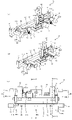
図8は、連結装置10の説明図であり、図8(a)は連結爪12が開いた状態の連結装置10の斜視図であり、図8(b)は連結爪12が閉じた状態の連結装置10の斜視図であり、図8(c)は連結装置10の上面図である。
A coupling device 10 is attached to the self-propelled robot 1 for holding the cage cart 2 to be transported. Details of the coupling device 10 provided in the self-propelled robot 1 will be described below.
8A and 8B are explanatory diagrams of the connecting device 10. FIG. 8A is a perspective view of the connecting device 10 with the connecting claw 12 opened, and FIG. 8B is a state with the connecting claw 12 closed. It is a perspective view of the coupling device 10, and FIG.8(c) is a top view of the coupling device 10. FIG.

連結装置10は、固定板材30、回動部材11、引掛け部材である連結爪12及び吸着部材である磁石13等を備える。
固定板材30は自走ロボット1のロボット本体部100に対して連結装置10を固定する部材であり、固定ネジ穴30aでロボット本体部100のフレームにネジ止めすることで固定する。
The connecting device 10 includes a fixed plate member 30, a rotating member 11, a connecting claw 12 that is a hooking member, a magnet 13 that is an attracting member, and the like.
The fixing plate member 30 is a member for fixing the coupling device 10 to the robot main body 100 of the self-propelled robot 1, and is fixed by screwing to the frame of the robot main body 100 through the fixing screw holes 30a.

回動部材11は、上下方向に延在する回動軸111を中心に固定板材30に対して回動可能な部材である。図9は、図8に示す連結装置10について、回動部材11に固定され、回動部材11とともに固定板材30に対して回動する部分に斜線を付した連結装置10の説明図である。図9(a)は斜視図であり、図9(b)は上面図である。回動部材11は、図9(b)中の矢印「G」で示すように回動軸111を中心に回動可能である。固定板材30は回動範囲規制部材32を備え、回動する回動部材11の前端(自走ロボット1の前後方向についての回動部材11の前側端)である回動部材前端部11eが回動範囲規制部材32に突き当たる位置で、回動部材11の回動範囲を規制する。 The rotating member 11 is a member that can rotate with respect to the fixed plate member 30 around a rotating shaft 111 that extends in the vertical direction. FIG. 9 is an explanatory diagram of the connecting device 10 shown in FIG. 8, in which the portion fixed to the rotating member 11 and rotating with the rotating member 11 with respect to the fixed plate member 30 is shaded. FIG. 9(a) is a perspective view, and FIG. 9(b) is a top view. The rotating member 11 is rotatable around a rotating shaft 111 as indicated by an arrow "G" in FIG. 9(b). The fixed plate member 30 is provided with a rotation range restricting member 32, and a rotating member front end portion 11e, which is the front end of the rotating rotating member 11 (the front end of the rotating member 11 in the longitudinal direction of the self-propelled robot 1), is rotated. The rotation range of the rotation member 11 is restricted at a position where it abuts against the movement range restriction member 32 .

本実施形態では仮保持する機構として磁石13の磁力を利用して仮保持した後に、連結爪12による本固定を行う。また、磁石13を回動部材11に配置して磁石13を用いた仮固定機構が回動可能な構成となっている。この構成によって、自走ロボット1がカゴ台車2に対して傾いた状態で近接した場合にも、回動部材11が回動して、二つの連結爪12をカゴ台車2の横フレームに対して平行にすることができる。これにより、連結爪12とカゴ台車2の横フレームとの位置関係を連結可能な位置関係とすることが容易となる。 In the present embodiment, after temporary holding is performed using the magnetic force of the magnet 13 as a temporary holding mechanism, the connection claws 12 perform permanent fixing. Also, the magnet 13 is arranged on the rotating member 11 so that the temporary fixing mechanism using the magnet 13 can rotate. With this configuration, even when the self-propelled robot 1 approaches the basket carriage 2 in a tilted state, the rotating member 11 rotates to move the two connecting claws 12 to the lateral frame of the basket carriage 2 . can be parallel. As a result, the positional relationship between the connecting claws 12 and the lateral frame of the car carriage 2 can be easily set to a positional relationship that allows connection.

固定板材30は板金からなり、回動軸111を保持する軸保持部31を備える。固定板材30をロボット本体部100に固定することで、回動部材11は回動軸111を中心にロボット本体部100に対して回動可能となっている。連結爪12及び磁石13は、回動部材11に取り付けられている。連結爪12は、カゴ台車2のフレームに引掛けて固定するためのものである。磁石13はカゴ台車2のフレームに吸着させるためのものである。 The fixed plate member 30 is made of sheet metal, and includes a shaft holding portion 31 that holds the rotating shaft 111 . By fixing the fixed plate member 30 to the robot body 100 , the rotating member 11 can rotate about the rotating shaft 111 with respect to the robot body 100 . The connecting claw 12 and the magnet 13 are attached to the rotating member 11 . The connecting claws 12 are for hooking and fixing to the frame of the basket truck 2 . The magnet 13 is for attracting the frame of the cage truck 2 .

一般的にカゴ台車2のフレームはスチール材でできており、本実施形態で用いるカゴ台車2は、スチール材のように磁石13が付くことができるものからなる。連結爪12は、連結していない状態では、連結動作の際にカゴ台車2のフレームに引掛らないように、図8(a)に示すように上方に退避させてある。
連結爪12と磁石13との両方を用いるのは、以下の理由による。
すなわち、連結爪12だけでは連結動作のタイミングが計れずに自走ロボット1の高精度な位置決めが必要になり、磁石13だけでは搬送対象であるカゴ台車2の重量が大きい場合に搬送中に離れることがあるためである。
Generally, the frame of the basket truck 2 is made of steel, and the basket truck 2 used in this embodiment is made of a steel material to which magnets 13 can be attached. The connecting claws 12 are retracted upward as shown in FIG. 8(a) so as not to be caught by the frame of the car carriage 2 during the connecting operation when they are not connected.
The reason why both the connecting claw 12 and the magnet 13 are used is as follows.
That is, the connecting claws 12 alone cannot measure the timing of the connecting operation, and high-precision positioning of the self-propelled robot 1 is required. It is because there is something.

カゴ台車2のID表示パネル21の正面の所定の位置への自走ロボット1の位置決めと連結動作は、次の三つのステップによって行う。
第一のステップとして、自走ロボット1をカゴ台車2に対して一定の距離でかつ略正対した姿勢になるように駆動する。
第二のステップとして、略正対した姿勢のままでカゴ台車に向かって速度を落として進む。
第三のステップとして、カゴ台車2のフレームに対する磁石13の吸着が確認された後に自走ロボット1を停止させると共に、連結爪12を動作させて固定する。
Positioning of the self-propelled robot 1 to a predetermined position in front of the ID display panel 21 of the cart 2 and connection operation are performed by the following three steps.
As a first step, the self-propelled robot 1 is driven so as to be at a fixed distance from the cage carriage 2 and in a posture substantially facing the same.
As a second step, while maintaining a substantially facing posture, slow down and advance toward the cart.
As a third step, after the attraction of the magnet 13 to the frame of the cage cart 2 is confirmed, the self-propelled robot 1 is stopped and the connecting claw 12 is operated to fix it.

自走ロボット1は、磁石13がフレームに吸着した際にフレームと接触する磁石13の表面と同一平面に物体が接触したことを検知することが可能な接触式スイッチであるマイクロスイッチ14を備えている。このマイクロスイッチ14によってカゴ台車2のフレームに対する磁石13の吸着を確認することができる。 The self-propelled robot 1 is provided with a microswitch 14 which is a contact switch capable of detecting contact of an object on the same plane as the surface of the magnet 13 contacting the frame when the magnet 13 is attracted to the frame. there is With this microswitch 14, it is possible to confirm that the magnet 13 is attracted to the frame of the car carriage 2. As shown in FIG.

ID表示パネル21の位置座標を求めるためのマーカーの読取においては、測域センサ9による検出の誤差及び算出の誤差が含まれる。また、自走ロボット1を駆動する際の車輪のスリップ等による誤差も生じる。このため、自走ロボット1がカゴ台車2に対して傾きと位置ずれを持った状態になることが通常で、完全に正対させることは困難である。 The reading of the markers for obtaining the position coordinates of the ID display panel 21 includes detection errors and calculation errors by the range sensor 9 . In addition, an error occurs due to a wheel slip or the like when the self-propelled robot 1 is driven. Therefore, it is normal for the self-propelled robot 1 to be tilted and misaligned with respect to the cage carriage 2, and it is difficult to make them face each other completely.

本実施形態では、第二のステップで磁石13がカゴ台車2に吸着するときに、速度を落として進むだけで良いので、自走ロボット1をカゴ台車2との接続位置で精度良く停止させるような高精度な位置決め動作が不要になる。このため、位置ずれに対して寛容となる。また、自走ロボット1がカゴ台車2に対して傾きを持って近づいた場合でも、回動部材11が回動することによって磁石13をカゴ台車2のフレーム面に対して平行にすることができ、確実に吸着させることができる。このような構成によって、高精度な位置決めを必要とすることなく、自走ロボット1とカゴ台車2とを確実に連結することが可能となる。 In the present embodiment, when the magnet 13 is attracted to the basket carriage 2 in the second step, it is only necessary to reduce the speed and proceed. high-precision positioning operation becomes unnecessary. For this reason, it becomes tolerant to the positional deviation. Further, even when the self-propelled robot 1 approaches the cage carriage 2 with an inclination, the rotation of the rotating member 11 allows the magnet 13 to be parallel to the frame surface of the cage carriage 2 . can be reliably adsorbed. With such a configuration, it is possible to reliably connect the self-propelled robot 1 and the cage carriage 2 without requiring highly accurate positioning.

磁石13としては、電磁石を用いることが好ましい。電磁石は電力の供給によりON-OFFの制御を行うため、吸着と解除とが自在である。このため、上述した位置決めと連結動作とを行う上記第二のステップのときに電力を「ON」とするなど、必要なときにだけ吸着させることができる。 As the magnet 13, it is preferable to use an electromagnet. Since the electromagnet performs ON-OFF control by power supply, it can be freely attracted and released. For this reason, it is possible to perform the chucking only when necessary, such as by turning the electric power "ON" during the second step of performing the above-described positioning and connecting operations.

電磁石としては永電磁式の電磁石を用いることもできる。永電磁式の電磁石は、電力がOFFのときは永久磁石として吸着でき、電力がONのときに解除を行うことができる。永電磁式の電磁石を用いると、停電や断線が生じた場合でも磁力が無くならないため、より確実にカゴ台車2の保持を行うことができる。いずれの電磁石を用いた場合も、自走ロボット1によって所定の場所に搬送したカゴ台車2を、簡単な操作で自動的に切り離し解除するようなシステムとして運用することが可能となる。 A permanent electromagnet can also be used as the electromagnet. A permanent electromagnet can be attracted as a permanent magnet when the power is off, and can be released when the power is on. If permanent electromagnetic electromagnets are used, the magnetic force will not be lost even in the event of a power failure or disconnection, so that the cage truck 2 can be held more reliably. In the case of using either electromagnet, it is possible to operate as a system that automatically separates and releases the cage carriage 2 transported to a predetermined location by the self-propelled robot 1 by a simple operation.

磁石13として、永久磁石を用いる構成の場合、所定の場所に搬送したカゴ台車2を切り離すために、カゴ台車2を押圧して、自走ロボット1から離間させる離間機構を設けても良い。 In the case of a configuration using a permanent magnet as the magnet 13 , a separation mechanism may be provided that presses the cage carriage 2 to separate it from the self-propelled robot 1 in order to separate the cage carriage 2 transported to a predetermined location.

次に、回動部材11に取り付ける磁石13について説明する。
磁石13としては、回動部材11に複数個配置することが好ましい。これは以下の理由による。
すなわち、カゴ台車2における連結対象となるフレームは、一般的に高さ方向に短く、幅方向に長い。これに対し汎用の磁石は円筒型また角型のものが多いので、例えば小型の磁石を二個横方向に並べて使うことで、横長のフレームに対して磁力を作用させる面を大きくでき、大型の磁石を一個用いるよりも安価で確実に吸着させることができる。
Next, the magnet 13 attached to the rotating member 11 will be described.
It is preferable to arrange a plurality of magnets 13 on the rotating member 11 . This is for the following reasons.
In other words, the frames to be connected in the basket truck 2 are generally short in the height direction and long in the width direction. On the other hand, most general-purpose magnets are cylindrical or rectangular. For example, by arranging two small magnets side by side, it is possible to increase the area on which the magnetic force acts on the horizontally long frame. It is less expensive than using a single magnet and can be reliably attracted.

図10は、回動部材11に対する磁石13の固定方法の説明する連結装置10の断面説明図である。図10は、図8(c)中のE-E断面における断面図である。
図10に示す断面では、回動部材11はL字型の断面となっており、水平方向に延在する回動部材11の後側(連結時の連結対象側、図10中の右側)の端部で折れ曲がり、鉛直下方に延在する回動部材磁石取付部11aを形成している。
FIG. 10 is a cross-sectional explanatory view of the coupling device 10 for explaining a method of fixing the magnet 13 to the rotating member 11. As shown in FIG. FIG. 10 is a cross-sectional view taken along line EE in FIG. 8(c).
In the cross section shown in FIG. 10, the rotating member 11 has an L-shaped cross section. The end portion is bent to form a rotating member magnet mounting portion 11a extending vertically downward.

回動部材磁石取付部11aは、図10中の左右方向に貫通する貫通孔を備える。連結装置10は、磁石13を保持する磁石保持部材131を備える。磁石保持部材131は、回動部材磁石取付部11aの貫通孔を貫通する磁石保持シャフト131bと、磁石保持シャフト131bを挟んで磁石13とは反対側に配置され、後述する第一バネ132が突き当たる磁石保持突き当て部131aとを備える。 The rotating member magnet mounting portion 11a has a through hole penetrating in the horizontal direction in FIG. The coupling device 10 includes a magnet holding member 131 that holds the magnet 13 . The magnet holding member 131 is disposed on the side opposite to the magnet 13 with the magnet holding shaft 131b passing through the through hole of the rotating member magnet mounting portion 11a and the magnet holding shaft 131b interposed therebetween, and is abutted against the first spring 132 described later. and a magnet holding butting portion 131a.

連結装置10は、磁石保持シャフト131bが内側に位置するように配置された第一バネ132と第二バネ133とを備える。第一バネ132は回動部材磁石取付部11aの前側(連結時の連結対象とは反対側、図10中の左側)の面と、磁石保持突き当て部131aの後側(連結時の連結対象側、図10中の右側)の面とに突き当たるように配置されている。第二バネ133は回動部材磁石取付部11aの後側(連結時の連結対象側、図10中の右側)の面と、磁石13の前側(連結時の連結対象とは反対側、図10中の左側)の面とに突き当たるように配置されている。
また、連結装置10は、磁石保持シャフト131bを介して回動部材磁石取付部11aに保持された磁石13が下方に移動して磁石保持シャフト131bが傾くことを防止する構成として磁石13の下面を保持する磁石下面保持部を備える。
The coupling device 10 includes a first spring 132 and a second spring 133 arranged so that the magnet holding shaft 131b is positioned inside. The first spring 132 is attached to the front side of the rotating member magnet mounting portion 11a (the side opposite to the connection target at the time of connection, the left side in FIG. 10) and the rear side of the magnet holding butting portion 131a (the connection target at the time of connection). side (right side in FIG. 10). The second spring 133 is attached to the rear side of the rotating member magnet mounting portion 11a (the side to be connected at the time of connection, the right side in FIG. 10) and the front side of the magnet 13 (the side opposite to the side to be connected at the time of connection, FIG. 10). It is arranged so that it abuts against the surface of the inner left side).
In addition, the connecting device 10 is configured to prevent the magnet 13 held by the rotating member magnet mounting portion 11a from moving downward through the magnet holding shaft 131b and tilting the magnet holding shaft 131b. It has a magnet lower face holding part for holding.

このような構成により、磁石保持突き当て部131aと回動部材磁石取付部11aとの間、及び、回動部材磁石取付部11aと磁石13との間を第一バネ132及び第二バネ133等の弾性部材を用いて接続することができる。
自走ロボット1がカゴ台車2に対して傾いた状態で連結しようとしている場合に、磁石13の吸着力によって回動部材11が回動する前に、磁石13の角が片当たりすることでカゴ台車2のフレームを突いてしまう可能性がある。これに対して、本実施形態の連結装置では、弾性部材によって片当たりした磁石13の向きを変えることができるので、より確実に吸着させることができる。
With such a configuration, the first spring 132, the second spring 133, etc. are provided between the magnet holding butting portion 131a and the rotating member magnet mounting portion 11a and between the rotating member magnet mounting portion 11a and the magnet 13. can be connected using an elastic member.
When the self-propelled robot 1 is about to be connected to the cage carriage 2 in an inclined state, before the rotating member 11 rotates due to the attractive force of the magnet 13, the corner of the magnet 13 makes a one-sided contact, causing the basket to move. There is a possibility that the frame of the truck 2 will be hit. On the other hand, in the coupling device of the present embodiment, the direction of the magnet 13 that has made a one-sided contact can be changed by the elastic member, so that the magnet can be attracted more reliably.

カゴ台車2のフレームに引掛けて保持した状態の連結爪12は、磁石13よりもカゴ台車2側へ突き出た構成であるため、図10に示すように、磁石13と連結爪12との間には隙間がある。自走ロボット1によるカゴ台車2の牽引時は、主に連結爪12によってカゴ台車を牽引する。このとき、上述した第一バネ132が収縮し、第二バネ133が伸びることで牽引中も磁石13がカゴ台車2のフレームから離れないようにすることができる。これによって搬送中に磁石13がカゴ台車2のフレームに対して吸着したり、離間したりすることに起因して搬送が不安定になることを防ぐことが可能となる。 Since the connecting claws 12 hooked to and held by the frame of the cage truck 2 are configured to protrude toward the cage truck 2 side more than the magnets 13, as shown in FIG. has a gap. When the self-propelled robot 1 pulls the cage carriage 2, the cage carriage is mainly towed by the connection claws 12. - 特許庁At this time, the above-described first spring 132 contracts and the second spring 133 expands, so that the magnet 13 can be prevented from separating from the frame of the car carriage 2 even during towing. As a result, it is possible to prevent the magnet 13 from being attracted to or separated from the frame of the basket carriage 2 during transportation, thereby preventing the transportation from becoming unstable.

図11は、連結爪12の動作を説明する連結装置10の断面説明図である。図11は、図8(c)中のF-F断面における断面図である。
図11(a)は、連結後の連結爪12が閉じた状態(図8(b)の状態)を示し、図11(b)は、連結前の連結爪12が開いた状態(図8(a)の状態)を示している。
連結爪12の動作を行う構成としては、カゴ台車2のフレーム等のカゴ台車2の一部に引掛けて、カゴ台車2を牽引または押圧することができる構成であればよい。本実施形態の連結装置10では、連結爪12の動作を行う構成として、直動シリンダによる機構を用いる。
11A and 11B are explanatory cross-sectional views of the connecting device 10 for explaining the operation of the connecting claw 12. FIG. FIG. 11 is a cross-sectional view taken along line FF in FIG. 8(c).
FIG. 11(a) shows a state in which the connecting claws 12 are closed after connection (the state in FIG. 8(b)), and FIG. 11(b) shows a state in which the connecting claws 12 are open before connection (the The state of a) is shown.
As a configuration for operating the connecting claws 12, any configuration may be used as long as it can be hooked on a part of the basket trolley 2 such as the frame of the basket trolley 2 to pull or push the basket trolley 2. In the connecting device 10 of the present embodiment, a mechanism using a direct-acting cylinder is used as a configuration for operating the connecting claw 12 .

回動部材11上に連結爪回動軸保持部材であるベアリングホルダ113を設置して、連結爪12が固定された連結爪シャフト120を保持する。連結爪12は、連結爪シャフト120の回動動作によって、連結爪12の先端(図11中の右側端部)が上下動するような回動動作が行われる。
連結動作を行う際には、まず、連結爪12の先端がカゴ台車2のフレームに引掛らないように上方に退避させておき、磁石13による吸着後に連結爪シャフト120の回動によって連結爪12の先端がカゴ台車2のフレーム高さに掛かるように下ろす。
連結を解除する動作を行う際には、同様に連結爪シャフト120を連結動作とは逆方向に回動させることで連結爪12の先端を上げる。
A bearing holder 113, which is a member for holding a connecting pawl rotating shaft, is installed on the rotating member 11 to hold a connecting pawl shaft 120 to which the connecting pawl 12 is fixed. The connection claw 12 is rotated by the rotation of the connection claw shaft 120 such that the tip of the connection claw 12 (the right end portion in FIG. 11) moves up and down.
When performing the connecting operation, first, the tip of the connecting claw 12 is retracted upward so as not to be caught on the frame of the car carriage 2 , and after being attracted by the magnet 13 , the connecting claw shaft 120 rotates to rotate the connecting claw 12 . lower it so that the tip of the basket hangs on the frame height of the basket truck 2.
When performing the operation of releasing the connection, the tip of the connection claw 12 is raised by rotating the connection claw shaft 120 in the opposite direction to the connection operation.

直動シリンダとしては、汎用の電動シリンダ121を用い、電動シリンダ121の非移動部は回動部材11に設けた直動シリンダ保持部材122上に固定される。
電動シリンダ121における移動部であって、電動シリンダ121の駆動によって上下方向に移動するシリンダ部123の先端は図11中の下側端部であり、シリンダ部123は所定の長さの範囲で伸縮させることができる。
A general-purpose electric cylinder 121 is used as the direct-acting cylinder, and the non-moving portion of the electric cylinder 121 is fixed on a direct-acting cylinder holding member 122 provided on the rotating member 11 .
The tip of the cylinder portion 123, which is a moving portion of the electric cylinder 121 and moves vertically by driving the electric cylinder 121, is the lower end portion in FIG. 11, and the cylinder portion 123 expands and contracts within a predetermined length range. can be made

シリンダ部123の先端には上下動接続部材124が固定されており、上下動接続部材124の下端には、シリンダ部123の上下動を連結爪シャフト120に伝達する上下動伝達部材125を備える。本実施形態の上下動伝達部材125は図11中の紙面に直交する回動軸を中心に回動可能なローラ状の部材である。 A vertical motion connection member 124 is fixed to the tip of the cylinder portion 123 , and a vertical motion transmission member 125 for transmitting the vertical motion of the cylinder portion 123 to the connecting pawl shaft 120 is provided at the lower end of the vertical motion connection member 124 . The up-and-down motion transmission member 125 of this embodiment is a roller-shaped member that can rotate about a rotation shaft perpendicular to the plane of FIG. 11 .

連結爪シャフト120には、上下動伝達部材125の下端部が接触し、上下動伝達部材125の上下動が伝達される上下動伝達板材127が固定されている。さらに、上下動伝達板材127の上には、凸形状の内壁面に上下動伝達部材125の上端部が接触するように配置された凸状板材126が固定されている。
図11(a)に示す状態から電動シリンダ121の駆動によりシリンダ部123が縮むと、上下動伝達部材125が上方に移動し、その上端が接触する凸状板材126を上方に押し上げる。これにより、凸状板材126が固定された上下動伝達板材127が上方に引き上げられ、上下動伝達板材127が固定された連結爪シャフト120が図11中の反時計回り方向に回転する。この回転によって連結爪シャフト120に固定された連結爪12も連結爪シャフト120を中心に図11中の反時計回り方向に回転して、図11(b)に示すように連結爪12が開いた状態となる。
A vertical motion transmission plate member 127 is fixed to the connection pawl shaft 120 , with which the lower end of the vertical motion transmission member 125 contacts and to which the vertical motion of the vertical motion transmission member 125 is transmitted. Further, a convex plate member 126 is fixed on the vertical motion transmission plate member 127 so that the upper end of the vertical motion transmission member 125 contacts the convex inner wall surface.
When the cylinder portion 123 is contracted by driving the electric cylinder 121 from the state shown in FIG. 11A, the vertical motion transmission member 125 moves upward and pushes upward the convex plate member 126 with which the upper end contacts. As a result, the vertical motion transmission plate member 127 to which the convex plate member 126 is fixed is lifted upward, and the connecting pawl shaft 120 to which the vertical motion transmission plate member 127 is fixed rotates counterclockwise in FIG. By this rotation, the connecting claw 12 fixed to the connecting claw shaft 120 also rotates counterclockwise in FIG. 11 around the connecting claw shaft 120, and the connecting claw 12 opens as shown in FIG. 11(b). state.

図11(b)に示す状態から電動シリンダ121の駆動によりシリンダ部123が伸びると、上下動伝達部材125が下方に移動し、その下端が接触する上下動伝達板材127を下方に押し下げる。これにより、上下動伝達板材127が固定された連結爪シャフト120が図11中の時計回り方向に回転する。この回転によって連結爪シャフト120に固定された連結爪12も連結爪シャフト120を中心に図11中の時計回り方向に回転して、図11(a)に示すように連結爪12が閉じた状態となる。 When the cylinder portion 123 is extended by driving the electric cylinder 121 from the state shown in FIG. 11B, the vertical motion transmission member 125 moves downward and pushes down the vertical motion transmission plate member 127 with which the lower end contacts. As a result, the connecting pawl shaft 120 to which the vertical motion transmission plate member 127 is fixed rotates clockwise in FIG. By this rotation, the connecting pawl 12 fixed to the connecting pawl shaft 120 also rotates clockwise in FIG. 11 around the connecting pawl shaft 120, and the connecting pawl 12 is closed as shown in FIG. becomes.

このように、簡易な構成によって直動シリンダである電動シリンダ121の伸縮駆動を連結爪12の回動運動に変換することが出来る。このような直動シリンダによる連結爪12の動作機構を用いることで、カゴ台車2の共通の形である跳ね上げ式の底板22とフレームとの間に連結爪12(引掛け部材)を差し込めるので、幅広い種類のカゴ台車2に対して無改造で対応することが可能である。 In this manner, the expansion and contraction drive of the electric cylinder 121, which is a direct-acting cylinder, can be converted into the rotational motion of the connecting claw 12 with a simple configuration. By using the operation mechanism of the connecting claw 12 by such a direct-acting cylinder, the connecting claw 12 (hook member) can be inserted between the flip-up bottom plate 22, which is a common shape of the basket cart 2, and the frame. Therefore, it is possible to deal with a wide variety of cage trucks 2 without modification.

次に、連結爪12の先端形状について説明する。
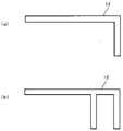
図12は、連結爪12の先端形状の説明図であり、図12(a)は上述した実施形態の連結装置10で用いた先端の曲がった部分が一枚の形状の説明図であり、図12(b)は先端の曲がった部分が二枚の形状の説明図である。
Next, the tip shape of the connecting claw 12 will be described.
12A and 12B are explanatory diagrams of the shape of the distal end of the connecting claw 12, and FIG. 12A is an explanatory diagram of a shape in which the bent portion of the distal end used in the connecting device 10 of the above-described embodiment is a single sheet. 12(b) is an explanatory diagram of a shape with two bent portions at the tip.

図12(a)のように、先端の曲がった部分が一枚の形状では、自走ロボット1が連結爪12によってカゴ台車2を主に牽引によって引っ張る場合に十分な構成である。
一方、図12(b)に示す先端の曲がった部分が二枚の形状では、二枚の曲がった部分の間にカゴ台車2のフレームを挟み込んで保持することができる。このため、自走ロボット1がカゴ台車2を牽引する場合だけでなく、自走ロボット1がカゴ台車2を所定の位置に押し入れるような動作を伴う場合に、より安定した動作を行うのに適した構成である。
As shown in FIG. 12( a ), the configuration in which the curved tip portion is formed of one sheet is sufficient for the case where the self-propelled robot 1 pulls the cage carriage 2 mainly by traction with the connecting claws 12 .
On the other hand, in the shape of two bent portions at the tip shown in FIG. 12(b), the frame of the car carriage 2 can be sandwiched and held between the two bent portions. Therefore, not only when the self-propelled robot 1 pulls the basket carriage 2, but also when the self-propelled robot 1 pushes the basket carriage 2 into a predetermined position, it is possible to perform a more stable operation. Good configuration.

引掛け部材としては連結爪12のような爪部材に限るものではない。本実施形態では、先端が直角に曲がった爪部材という簡易な構成で連結対象と連結する構成を実現することが出来る。 The hook member is not limited to a pawl member such as the connecting pawl 12 . In the present embodiment, it is possible to realize a structure that connects with a connection target with a simple structure of a claw member whose tip is bent at a right angle.

固定板材30に設けられた回動範囲規制部材32は、回動部材11が自走ロボット1のロボット本体部100に対して回転し過ぎないように、回動範囲を限定するためのものである。これによって、連結時やカゴ台車2の牽引時に、回動部材11とロボット本体部100、カゴ台車2と自走ロボット1との接触を防止することが可能となり、接触に起因する損傷を防ぐことが可能となる。 A rotation range restricting member 32 provided on the fixed plate member 30 is for limiting the rotation range so that the rotation member 11 does not rotate excessively with respect to the robot main body 100 of the self-propelled robot 1. . This makes it possible to prevent contact between the rotating member 11 and the robot main body 100, and between the cage carriage 2 and the self-propelled robot 1, when connecting or towing the cage carriage 2, thereby preventing damage due to contact. becomes possible.

また、本実施形態の自走ロボット1は、ロボット本体部100に対して、バンパー固定部41を設け、このバンパー固定部41から自走ロボット1の後方(図8(c)中の上方)に向けて延在するバンパー40を備える。バンパー40は、バンパー固定部41に一端が固定された棒状のバンパーシャフト40bと、バンパーシャフト40bの他端側に固定されたバンパー突当てゴム40aとを有する。 Further, the self-propelled robot 1 of the present embodiment is provided with a bumper fixing portion 41 for the robot main body 100, and from this bumper fixing portion 41 to the rear of the self-propelled robot 1 (upper side in FIG. 8(c)). It has a bumper 40 extending towards it. The bumper 40 has a bar-shaped bumper shaft 40b with one end fixed to the bumper fixing portion 41, and a bumper abutment rubber 40a fixed to the other end side of the bumper shaft 40b.

バンパー40の先端にバンパー突当てゴム40aのようなゴム材等の弾性部材を用いることで、カゴ台車2の牽引搬送時に、カゴ台車2とバンパー40とが接触することに起因する音の発生やカゴ台車2のフレームの損傷を防ぐことができる。
本実施形態では、連結時にバンパー40の先端が磁石13よりも先にカゴ台車2に接触しないように、磁石13よりもバンパー40が出っ張らない配置としている。また、連結爪12によるカゴ台車2との連結後に、バンパー40を伸ばすように駆動する構成としても良い。これにより、自走ロボット1による牽引搬送中のカゴ台車2の挙動をより安定させることができる。
このようなバンパー40を配置することで、カゴ台車2と自走ロボット1との接触を防止し、接触に起因する損傷を防ぐことが可能となる。
By using an elastic member such as a rubber material such as the bumper abutment rubber 40a at the tip of the bumper 40, when the car trolley 2 is towed and transported, the sound caused by the contact between the car trolley 2 and the bumper 40 is generated. Damage to the frame of the basket truck 2 can be prevented.
In this embodiment, the bumper 40 is arranged so as not to protrude more than the magnet 13 so that the tip of the bumper 40 does not come into contact with the car carriage 2 before the magnet 13 when connecting. Further, after the connection with the car carriage 2 by the connecting claws 12, the bumper 40 may be driven to extend. As a result, the behavior of the basket cart 2 being towed and transported by the self-propelled robot 1 can be made more stable.
By arranging such a bumper 40, it is possible to prevent contact between the cage cart 2 and the self-propelled robot 1, and prevent damage caused by the contact.

図8に示すように、本実施形態の連結装置10では、横方向における外側からバンパー40、連結爪12、磁石13の順に配置している。すなわち、横方向の中心から外側に向けて二つ磁石13を配置し、その外側に二つの連結爪12、さらに外側に二つのバンパー40を配置する構成である。これら三つの横方向の配置の順番としてはどのような順番であってもよい。 As shown in FIG. 8, in the coupling device 10 of the present embodiment, the bumper 40, the coupling claw 12, and the magnet 13 are arranged in this order from the outside in the lateral direction. That is, two magnets 13 are arranged outward from the center in the horizontal direction, two connecting claws 12 are arranged on the outside thereof, and two bumpers 40 are arranged on the outside. The order of arrangement of these three in the horizontal direction may be any order.

図1及び図2に示すように、カゴ台車2のカゴ部20は、複数の横フレームと複数の縦フレームとを組み合わせたカゴ状であり、連結装置10は、連結爪12をカゴ部20の横フレームに引掛ける構成である。
このため、連結装置10の連結爪12としては、カゴ台車2の連結面の中心に対して、二つの連結爪12がカゴ部20の縦フレームに干渉しない間隔となるように配置する。そして、上述したID表示パネル21をカゴ台車2の連結面における横方向の中心となる位置に設置し、このID表示パネル21の位置を測域センサ9を用いて認識することで、二つの連結爪12を縦フレームに干渉させずに連結させることが可能となる。
As shown in FIGS. 1 and 2 , the basket portion 20 of the basket truck 2 has a basket shape in which a plurality of horizontal frames and a plurality of vertical frames are combined. It is configured to be hooked on the horizontal frame.
Therefore, the connecting claws 12 of the connecting device 10 are arranged so that the two connecting claws 12 do not interfere with the vertical frame of the cage portion 20 with respect to the center of the connecting surface of the cage carriage 2 . Then, the ID display panel 21 described above is installed at the center position in the horizontal direction of the connection surface of the cage carriage 2, and the position of the ID display panel 21 is recognized using the range sensor 9, thereby enabling the two connections to be connected. It is possible to connect the claws 12 without interfering with the vertical frame.

自律移動装置と連結対象とを連結する構成として、磁石13のような吸着手段を備えず、連結爪12のような引掛け部材のみで連結する構成では次のような不具合がある。すなわち、自動で連結しようとしたときに、自律移動装置が連結対象に完全に正対して静止した状態で引掛け部材による連結固定動作ができないと、確実に連結できないという不具合が生じる。
これに対して、本実施形態の自走ロボット1では、連結対象であるカゴ台車2に対して完全に正対して静止した状態でなくても、引掛け部材である連結爪12による連結固定動作を行うことができる。
As a structure for connecting the autonomous mobile device and the object to be connected, the following problem occurs in a structure in which an attracting means such as the magnet 13 is not provided and only a hooking member such as the connecting claw 12 is used. That is, when attempting to automatically connect, if the connecting and fixing operation cannot be performed by the hooking member while the autonomous mobile device is completely standing still facing the connection target, there arises a problem that the connection cannot be reliably performed.
On the other hand, in the self-propelled robot 1 of the present embodiment, even if the robot 1 is not in a completely standing still state facing the cart 2 to be connected, the connecting hook 12 as a hooking member performs the connecting and fixing operation. It can be performed.

自律移動装置の高精度な位置決めを必要としない構成として、パラレルリンク機構を用いた自動連結方法が考えられるが、複雑な機構と高精度なパラレルリンク機構の制御が必要となる。これに対して、本実施形態の自走ロボット1では、磁石13と連結爪12という簡易な構成で自動連結を行うことができる。 An automatic connection method using a parallel link mechanism is conceivable as a configuration that does not require highly accurate positioning of the autonomous mobile device, but it requires a complicated mechanism and highly accurate control of the parallel link mechanism. On the other hand, in the self-propelled robot 1 of the present embodiment, automatic connection can be performed with a simple configuration of the magnet 13 and the connection claw 12 .

上述した実施形態では、動力モータ7及び駆動車輪71等の移動手段と、連結対象であるカゴ台車2と連結する連結装置10を備える連結走行装置が、移動手段をコントローラ4で制御する自律走行装置としての自走ロボット1である場合について説明した。連結装置10を備える連結走行装置としては、自律走行装置のように自動で走行するものに限らず、人間が運転する車等の走行装置であってもよい。
また、連結走行装置としては、連結した連結対象を牽引する構成に限らず、連結対象を押して移動させたり、持ち上げて移動させたりする構成であってもよい。
In the above-described embodiment, the connecting traveling device including the moving means such as the power motor 7 and the driving wheels 71 and the connecting device 10 that connects with the cage carriage 2 to be connected is an autonomous traveling device in which the moving means is controlled by the controller 4. The case of the self-propelled robot 1 as a robot has been described. The connected traveling device including the connecting device 10 is not limited to a traveling device such as an autonomous traveling device that travels automatically, and may be a traveling device such as a car driven by a person.
Further, the connecting traveling device is not limited to the structure for pulling the connected object to be connected, but may be the structure for pushing and moving the object to be connected or lifting and moving the object to be connected.

〔実施例1〕
次に、上述した実施形態の連結装置10に本発明を適用した一つ目の実施例(以下、「実施例1」と呼ぶ)について説明する。
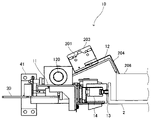
図13及び図14は、実施例1の連結装置10の斜視図であり、図13は、連結爪12が閉じた状態の説明図である。図14は、連結爪12が開いた状態の説明図である。
実施例1の連結装置10は、検知手段である接触検知センサ201を備える。図13及び図14では、便宜的に電動シリンダ121及び直動シリンダ保持部材122を取り外した状態の連結装置10を示している。
[Example 1]
Next, a first example (hereinafter referred to as "Example 1") in which the present invention is applied to the coupling device 10 of the embodiment described above will be described.
13 and 14 are perspective views of the connecting device 10 of Example 1, and FIG. 13 is an explanatory diagram of a state in which the connecting claws 12 are closed. FIG. 14 is an explanatory diagram of a state in which the connecting claw 12 is opened.
The connection device 10 of Example 1 includes a contact detection sensor 201 as a detection means. 13 and 14 show the coupling device 10 with the electric cylinder 121 and the linear cylinder holding member 122 removed for convenience.

図13及び図14に示すように、接触検知センサ201はブラケット203を介して連結爪12に固定されている。接触検知センサ201はブラケット203にネジで固定され、ブラケット203は連結爪12に対してネジで固定されている。接触検知センサ201は、一つの連結爪12に対して一つずつ配置されており、本実施形態の連結装置10は連結爪12を二つ備えるため、接触検知センサ201も二つ備えている。 As shown in FIGS. 13 and 14, the contact detection sensor 201 is fixed to the connecting claw 12 via a bracket 203. As shown in FIGS. The contact detection sensor 201 is fixed to the bracket 203 with screws, and the bracket 203 is fixed to the connecting claw 12 with screws. One contact detection sensor 201 is arranged for one connecting claw 12 , and since the connecting device 10 of the present embodiment has two connecting claws 12 , two contact detecting sensors 201 are also provided.

図15は、図14に示す状態の連結装置10の側面図であり、図15(a)は連結装置10全体の説明図、図15(b)は連結爪12の先端近傍の拡大説明図である。
接触検知センサ201は、センサの筐体からレバー204が連結爪12の先端側に向けて突き出しており、連結爪12に対してレバー204が図15(a)中の矢印「I」方向に所定の量変位するとスイッチが入るようになっている。
15A and 15B are side views of the connecting device 10 in the state shown in FIG. 14, FIG. 15A is an explanatory view of the entire connecting device 10, and FIG. be.
The contact detection sensor 201 has a lever 204 protruding from the housing of the sensor toward the distal end side of the connecting claw 12, and the lever 204 is positioned relative to the connecting claw 12 in the direction of the arrow "I" in FIG. 15(a). The switch is turned on when it is displaced by an amount of

図15(b)に示すように、レバー204の先端は連結爪12の先端よりも図15中の時計回り方向の先行側に飛び出している。ここで図15中の時計回りで先行側とは、連結爪12が開いた状態から閉じる状態まで回転する方向(図15中の矢印「H」で示す連結爪12の連結時動作方向)における先行側である。 As shown in FIG. 15(b), the tip of the lever 204 protrudes from the tip of the connecting claw 12 to the leading side in the clockwise direction in FIG. Here, the clockwise leading side in FIG. 15 means the leading side in the direction in which the connecting claw 12 rotates from the open state to the closed state (moving direction of the connecting claw 12 at the time of connection indicated by the arrow “H” in FIG. 15). on the side.

図15(b)に示すように、L字型の連結爪12の先端部と平行な方向(連結時動作方向)をx軸、回転軸である連結爪シャフト120と平行な方向をy軸、x軸とy軸との両方と直行する方向をz軸とする。このように三次元の軸を設定すると、レバー先端204aが爪先端12aよりもx軸のプラス側に位置している。 As shown in FIG. 15(b), the direction parallel to the tip of the L-shaped connecting claw 12 (operation direction at the time of connection) is the x-axis, the direction parallel to the connecting claw shaft 120, which is the rotation axis, is the y-axis. Let the direction perpendicular to both the x-axis and the y-axis be the z-axis. When the three-dimensional axis is set in this way, the lever tip 204a is located on the plus side of the x-axis with respect to the claw tip 12a.

図16は、図15(b)に示す三次元の軸のz軸のプラス方向から連結爪12及び接触検知センサ201を見た説明図である。図16中の矢印「W」は、連結爪12の幅を示している。図16に示すように、レバー204の左右方向(連結爪シャフト120に平行な方向)の位置は、連結爪12の幅の範囲内であれば任意の位置でよい。このように配置することで、連結爪12が連結爪シャフト120を中心に回転したとしても、連結爪12の先端側に位置し、連結時移動方向に移動する連結爪12の障害物となり得る物体の有無を検知することが可能となる。 FIG. 16 is an explanatory view of the connecting claw 12 and the contact detection sensor 201 viewed from the plus direction of the three-dimensional z-axis shown in FIG. 15(b). An arrow “W” in FIG. 16 indicates the width of the connecting claw 12 . As shown in FIG. 16 , the position of the lever 204 in the left-right direction (the direction parallel to the connecting pawl shaft 120 ) may be any position within the range of the width of the connecting pawl 12 . By arranging in this way, even if the connecting claw 12 rotates about the connecting claw shaft 120, an object that is located on the tip side of the connecting claw 12 and can become an obstacle to the connecting claw 12 that moves in the movement direction during connection. It is possible to detect the presence or absence of

図17は、実施例1の連結装置10が、カゴ台車2に連結した状態を示す側面図である。自走ロボット1がカゴ台車2に接続する前は、図15(a)に示すように連結装置10の連結爪12が開いた状態である。そして、自走ロボット1がカゴ台車2に接続すると、図17に示すように連結装置10の連結爪12は閉じた状態となる。 FIG. 17 is a side view showing a state in which the coupling device 10 of Example 1 is coupled to the basket truck 2. FIG. Before the self-propelled robot 1 is connected to the cage carriage 2, the connecting claws 12 of the connecting device 10 are opened as shown in FIG. 15(a). Then, when the self-propelled robot 1 is connected to the cart 2, the connecting claws 12 of the connecting device 10 are closed as shown in FIG.

具体的にはカゴ台車2が接触式スイッチであるマイクロスイッチ14に当接し、マイクロスイッチ14が入ったことを起点として、電動シリンダ121が動作を開始することで連結爪シャフト120が回転し始め、連結爪12がカゴ台車2のフレームに当接する。 Specifically, when the cart 2 comes into contact with the microswitch 14, which is a contact switch, and the microswitch 14 is turned on, the electric cylinder 121 starts operating, and the connecting pawl shaft 120 begins to rotate. The connecting claws 12 are brought into contact with the frame of the cage carriage 2 .

本実施形態の自走ロボット1では、連結対象であるカゴ台車2と連結する際には、連結装置10とカゴ台車2との相対的な位置を合わせて、引掛け部材である連結爪12をカゴ台車に引掛ける。このとき、カゴ台車2の上に荷物などの積載物が積載されており、連結爪12が移動する経路上に積載物があると、開いた状態の連結爪12が閉じる連結動作の過程において、連結動作で連結爪12がカゴ台車2に連結する前に連結爪12が積載物に接触する。連結爪12が積載物に接触すると、連結爪12が積載物に突き当たってしまい、カゴ台車2のフレーム等の狙いの位置に連結爪12をひっかけることができず、カゴ台車2と連結できないことが懸念される。 In the self-propelled robot 1 of the present embodiment, when connecting with the cage carriage 2 to be connected, the relative positions of the connecting device 10 and the cage carriage 2 are aligned, and the connecting hooks 12 as hook members are engaged. Hook it on the basket trolley. At this time, when a load such as luggage is loaded on the basket carriage 2 and there is a load on the path along which the connecting claw 12 moves, in the process of the connecting operation, the connecting claw 12 in the open state closes. Before the connecting claws 12 are connected to the cage carriage 2 by the connecting operation, the connecting claws 12 come into contact with the load. When the connecting claws 12 come into contact with the load, the connecting claws 12 collide with the load, making it impossible to hook the connecting claws 12 to a target position such as the frame of the cage carriage 2, thereby making it impossible to connect with the cage carriage 2.例文帳に追加Concerned.

また、連結爪12はカゴ台車2を引っ張るため、ある程度の強度が必要で、板金などの金属材料が用いられる。板金のエッジは面とりなどが施されるとはいえ、連結爪12が積載物に接触すると、積載物の材質や状態によっては、連結爪12が接触することで積載物を損傷し、積載物の外観品質を落とすことが懸念される。
さらに、連結爪12と積載物が接触した状態では、連結爪12が所定の位置まで回転できずにカゴ台車2のフレームに連結爪12を引掛けることができない。そのままではカゴ台車2と自走ロボット1とが連結できず、自走ロボット1のみで動いてしまうことになり、所望の機能が達成できない。
In addition, since the connecting claws 12 pull the cage carriage 2, a certain degree of strength is required, and a metallic material such as sheet metal is used. Although the edges of the sheet metal are chamfered or the like, when the connecting claws 12 come into contact with the load, depending on the material and condition of the load, the contact of the connecting claws 12 may damage the load, resulting in damage to the load. There is a concern that the appearance quality of the product will be deteriorated.
Furthermore, when the connecting claw 12 and the load are in contact with each other, the connecting claw 12 cannot be rotated to a predetermined position and cannot be hooked to the frame of the car carriage 2.例文帳に追加As it is, the cage carriage 2 and the self-propelled robot 1 cannot be connected, and the self-propelled robot 1 moves alone, and the desired function cannot be achieved.

図18は、積載物である荷物206が積載されたカゴ台車2に対して連結動作を行った際に、カゴ台車2の荷物206にレバー204が接触した状態を示す連結装置10の側面図である。連結爪12の回転動作の経路上に荷物206があると連結爪12は荷物206に接触する可能性がある。しかし、実施例1の連結装置10は、接触検知センサ201を上述したように配置することで、連結爪12の回転経路上に荷物206があったとしても、図18に示すように連結爪12よりも先にレバー204のレバー先端204aが荷物206に接触する。そして、レバー先端204aが荷物206に接触した状態でさらに連結爪12が連結位置の方向に回転し続けると、レバー204が連結爪12に対して連結爪12の回転方向とは逆方向(図15(a)中の矢印「I」方向)に移動する。そして、レバー204が所定の量変位すると、接触検知センサ201から出力される「ON/OFF」信号が切り替わる。この信号の切り替わりが入力されたコントローラ4は、接触検知センサ201が障害物を検知したと判断して連結爪12の回転動作を停止する。 FIG. 18 is a side view of the coupling device 10 showing a state in which the lever 204 is in contact with the cargo 206 of the basket carriage 2 when the basket carriage 2 loaded with the cargo 206 as a load is connected. be. If there is a load 206 on the path of the rotational movement of the connecting claw 12, the connecting claw 12 may come into contact with the load 206. - 特許庁However, in the coupling device 10 of the first embodiment, by arranging the contact detection sensor 201 as described above, even if there is a load 206 on the rotation path of the coupling claw 12, the coupling claw 12 can be detected as shown in FIG. The lever tip 204a of the lever 204 comes into contact with the load 206 earlier. Then, when the connecting claw 12 continues to rotate in the direction of the connecting position while the tip 204a of the lever is in contact with the load 206, the lever 204 rotates with respect to the connecting claw 12 in the direction opposite to the rotating direction of the connecting claw 12 (Fig. 15). (a) in the direction of the arrow "I"). Then, when the lever 204 is displaced by a predetermined amount, the "ON/OFF" signal output from the contact detection sensor 201 is switched. The controller 4 that has received this signal switching determines that the contact detection sensor 201 has detected an obstacle, and stops the rotation of the connecting claw 12 .

ここで爪先端12aに対するレバー先端204aのz軸プラス方向への突き出し量は、次の点に考慮する必要がある。すなわち、接触検知センサ201のスイッチが入り、スイッチが入った状態から電動シリンダ121が停止し、連結爪12が固定されている連結爪シャフト120の回転が止まるまでの間に、爪先端12aが荷物206に接触しないよう考慮する必要がある。 Here, the amount of protrusion of the lever tip 204a in the z-axis plus direction with respect to the claw tip 12a needs to be considered in the following points. That is, the contact detection sensor 201 is switched on, the electric cylinder 121 is stopped after the switch is turned on, and the connecting claw shaft 120 to which the connecting claw 12 is fixed stops rotating. 206 should be considered.

図19は、実施例1の連結装置10における連結動作のフローチャートである。マイクロスイッチ14がカゴ台車2のフレームに接触してマイクロスイッチ14が「ON」になると(S21)、連結動作を開始する。連結動作を開始すると、電動シリンダ121の正転動作を開始する(S22)。ここで正転動作とは、連結爪12が連結時動作方向(図15中の矢印「H」の方向)に回転するように、連結爪シャフト120を回転させる動作である。電動シリンダ121の正転動作を開始した後、レバー204が荷物206に接触すると、「OFF」の状態だった接触検知センサ201からのON/OFF信号が「ON」に切り替わる(S23で「Yes」)。 
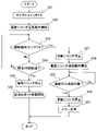
FIG. 19 is a flow chart of the connecting operation in the connecting device 10 of the first embodiment. When the microswitch 14 comes into contact with the frame of the car carriage 2 and turns "ON" (S21), the connecting operation is started. When the connecting operation is started, the forward rotation operation of the electric cylinder 121 is started (S22). Here, the normal rotation operation is an operation to rotate the connecting pawl shaft 120 so that the connecting pawl 12 rotates in the connecting operation direction (the direction of the arrow "H" in FIG. 15). After the electric cylinder 121 starts to rotate forward, when the lever 204 contacts the load 206, the ON/OFF signal from the contact detection sensor 201, which was in the "OFF" state, switches to "ON" ("Yes" in S23). ).

接触検知センサ201が「ON」になると、電動シリンダ121を停止する(S27)ことで連結爪12の回転を停止する。停止した後は、連結爪シャフト120が正転動作のときとは逆回転するように電動シリンダ121の逆転動作を開始する(S28)。電動シリンダ121の逆転動作を開始した後、連結爪12が図14及び図15に示す退避位置に戻る(S29で「Yes」)と、周囲の作業者(ロボット使用者などを含む)にエラー状態を伝える(S31)。本実施形態の自走ロボット1では、操作パネルやモニタにエラー表示を行うことで、周囲の作業者にエラー状態を伝える。 When the contact detection sensor 201 is turned "ON", the rotation of the connecting claw 12 is stopped by stopping the electric cylinder 121 (S27). After stopping, the electric cylinder 121 starts to rotate in the reverse direction so that the connecting pawl shaft 120 rotates in the reverse direction of the normal rotation (S28). After starting the reverse operation of the electric cylinder 121, when the connecting claw 12 returns to the retracted position shown in FIGS. (S31). In the self-propelled robot 1 of the present embodiment, an error is displayed on the operation panel or monitor to notify the surrounding workers of the error state.

作業者が荷物206を移動させた後、エラー解除を自走ロボット1に入力することで動作を復帰させる。連結爪12が移動する経路上に荷物206が無い状態は、マイクロスイッチ14が「ON」になり(S21)、電動シリンダ121の正転動作を開始した後(S22)、接触検知センサ201は「ON」にならず、所定時間が経過する(S24で「Yes」)。電動シリンダ121の正転動作を開始してから所定時間経過すると電動シリンダ121を停止し(S25)、自走ロボット1にカゴ台車2が接続されたとして自走ロボット1の移動を開始する(S26)。 After the worker moves the load 206, the self-propelled robot 1 is restored to operation by inputting error cancellation. When there is no load 206 on the path along which the connecting claw 12 moves, the microswitch 14 is turned "ON" (S21), and after starting the forward rotation of the electric cylinder 121 (S22), the contact detection sensor 201 detects " ON" and a predetermined period of time elapses ("Yes" in S24). When a predetermined time elapses after starting the forward rotation of the electric cylinder 121, the electric cylinder 121 is stopped (S25), and the self-propelled robot 1 starts to move assuming that the car carriage 2 is connected to the self-propelled robot 1 (S26). ).

ここで、レバー204の長さについて、レバー204があまりにも爪先端12aから出ていると、連結爪12がカゴ台車2のフレームに当る前に、レバー204がカゴ台車2の底面やフレームに接触する場合がある。この場合、連結爪12が移動する経路上に荷物206が無いにもかかわらずカゴ台車2を障害物と誤検知してしまう可能性がある。
そのため連結爪12が回転を始め、ある一定時間経過した後は接触検知センサ201の信号は無視することで誤検知を防ぐことができる。接触検知センサ201の信号を無視するタイミングとしては、回転を始めてから一定時間経過後でもよいし、連結爪12の回転状態や連結爪シャフト120の回転状態の検出結果に基づいた所定の回転量回転後でもよい。連結爪12をカゴ台車2のフレームに引っ掛ける連結動作の中で接触検知センサ201の信号を無視するタイミングを設けることで誤検知を防ぐことができる。
Here, regarding the length of the lever 204, if the lever 204 protrudes too far from the claw tip 12a, the lever 204 contacts the bottom surface or the frame of the car carriage 2 before the connecting claw 12 hits the frame of the car 2. sometimes. In this case, there is a possibility that the basket carriage 2 is erroneously detected as an obstacle even though there is no load 206 on the path along which the connecting claw 12 moves.
Therefore, by ignoring the signal from the contact detection sensor 201 after a certain period of time has passed after the connecting claw 12 starts rotating, it is possible to prevent erroneous detection. The timing for ignoring the signal from the contact detection sensor 201 may be after a certain period of time has passed since the start of rotation, or at a predetermined amount of rotation based on the detection results of the rotation state of the connecting claw 12 and the rotation state of the connecting claw shaft 120. You can do it later. False detection can be prevented by providing a timing for ignoring the signal of the contact detection sensor 201 during the connecting operation for hooking the connecting claw 12 on the frame of the cage carriage 2 .

〔実施例2〕
次に、上述した実施形態の連結装置10に本発明を適用した二つ目の実施例(以下、「実施例2」と呼ぶ)について説明する。
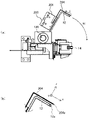
図20は、実施例2の連結装置10が備える連結爪12の先端近傍の拡大斜視図である。
[Example 2]
Next, a second example (hereinafter referred to as "second example") in which the present invention is applied to the coupling device 10 of the embodiment described above will be described.
FIG. 20 is an enlarged perspective view of the vicinity of the tip of the connecting claw 12 provided in the connecting device 10 of the second embodiment.

上述した実施例1の連結装置10は、検知手段として接触式の接触検知センサ201を備える構成であるであるのに対して、実施例2の連結装置10は、検知手段として非接触式の非接触検知センサ210を備える構成である。実施例2の連結装置10は、実施例1の接触式の検知手段を非接触式の検知手段に置き換えた点以外は実施例1の連結装置10と共通するため、相違点について説明する。 The connection device 10 of the first embodiment described above is configured to include a contact-type contact detection sensor 201 as detection means, whereas the connection device 10 of the second embodiment has a non-contact non-contact detection sensor 201 as detection means. It is the structure provided with the contact detection sensor 210. FIG. Since the connection device 10 of the second embodiment is common to the connection device 10 of the first embodiment except that the contact-type detection means of the first embodiment is replaced with the non-contact detection means, the differences will be described.

実施例2の非接触検知センサ210は、光学式の非接触式のセンサである。非接触検知センサ210は、センサの筐体に投光部211と受光部212とを備え、投光部211により出射されたレーザー光が、非検出物の表面で反射し、その反射光を受光部212が検知する構成となっている。
実施例2では、非接触検知センサ210として検知距離(図20中の矢印「L1」)が100[mm]程度のものを用いているが、これに限るものではない。そして、実施例2では、爪先端12aよりも矢印「L2」分(20[mm])だけ、先行側を検知できるように、非接触検知センサ210をブラケット203を介して連結爪12に取り付けている。
The non-contact detection sensor 210 of Example 2 is an optical non-contact sensor. The non-contact detection sensor 210 includes a light projecting unit 211 and a light receiving unit 212 in the housing of the sensor. It is configured to be detected by the unit 212 .
In the second embodiment, the non-contact detection sensor 210 having a detection distance (arrow "L1" in FIG. 20) of about 100 [mm] is used, but the non-contact detection sensor 210 is not limited to this. In the second embodiment, the non-contact detection sensor 210 is attached to the connecting claw 12 via the bracket 203 so that it can detect the leading side by the arrow "L2" (20 [mm]) from the claw tip 12a. there is

実施例2の連結装置10の動作の原理は、接触式センサを備える上述した実施例1の連結装置10と同様である。すなわち、カゴ台車2との接触を検知するセンサ(14)のスイッチが入ったことを基準(トリガ)にして連結爪12の回転を始める。このとき、爪先端12aよりも「L2(20[mm])」先の荷物206の有無を検知しながら回転を続ける。荷物206が無ければ連結爪12がカゴ台車2のフレームに当接し、連結状態となる。一方、非接触検知センサ210によって荷物206があることを検知すると、連結爪12の回転を停止し、連結爪12が退避位置に戻る。その後の動作は実施例1と同様である。 The principle of operation of the coupling device 10 of Example 2 is the same as that of the coupling device 10 of Example 1 having a contact sensor. That is, when the switch of the sensor (14) for detecting contact with the car 2 is turned on, the connecting claw 12 starts to rotate. At this time, the rotation is continued while detecting the presence or absence of the load 206 ahead of the claw tip 12a by "L2 (20 [mm])". If there is no load 206, the connecting claw 12 abuts on the frame of the cage carriage 2 to establish a connected state. On the other hand, when the non-contact detection sensor 210 detects the presence of the baggage 206, the rotation of the connecting claw 12 is stopped and the connecting claw 12 returns to the retracted position. Subsequent operations are the same as in the first embodiment.

実施例2のように、非接触検知センサ210を用いる構成であっても、連結爪12が回転してきたときに、非接触検知センサ210がカゴ台車2の下面やフレームを荷物206と誤検知する場合がある。このため、非接触検知センサ210の検知範囲が連結爪12の爪先端12aの近傍となるようにブラケット203を取り付けることが望ましい。また、実施例1と同様に、連結爪12が回転し始めてから一定時間経過後の非接触検知センサ210からの信号の変化を無視する構成としてもよい。 Even in the configuration using the non-contact detection sensor 210 as in the second embodiment, the non-contact detection sensor 210 erroneously detects the lower surface and frame of the basket carriage 2 as the load 206 when the connecting claw 12 rotates. Sometimes. Therefore, it is desirable to attach the bracket 203 so that the detection range of the non-contact detection sensor 210 is in the vicinity of the claw tip 12 a of the connecting claw 12 . Further, as in the first embodiment, a configuration may be adopted in which a change in the signal from the non-contact detection sensor 210 is ignored after a certain period of time has elapsed since the connecting claw 12 started rotating.

図8乃至図11を用いて説明した実施形態の連結装置10は、引掛け部材である連結爪12を備えるとともに、吸着部材である磁石13を備える構成である。そして、連結対象であるカゴ台車2のフレームを磁石13によって吸着することで、カゴ台車2と容易に連結できる構成である。また、連結装置10は、複数の磁石13と上下動可能な連結爪12と、これらを保持し、固定板材30に対して回動可能な回動部材11を有する。連結装置10を備える自走ロボット1とカゴ台車2とが相対的に傾いていたとしても、回動部材11が回動することで、複数の磁石13をカゴ台車2のフレームに吸着させることができ、自走ロボット1とカゴ台車2との連結を容易にする構成となっている。また、自走ロボット1は、動力モータ7や駆動車輪71を有するとともに、連結装置10を備える連結移動装置であって、この連結移動装置が制御手段であるコントローラ4を有することで自律走行する自律走行装置である。 The connecting device 10 of the embodiment described with reference to FIGS. 8 to 11 is configured to include a connecting claw 12 as a hooking member and a magnet 13 as an attracting member. By attracting the frame of the basket truck 2 to be connected with the magnet 13, it is possible to easily connect with the basket truck 2. As shown in FIG. The connecting device 10 also has a plurality of magnets 13 , a vertically movable connecting claw 12 , and a rotating member 11 that holds them and can rotate with respect to the fixed plate member 30 . Even if the self-propelled robot 1 provided with the coupling device 10 and the cage carriage 2 are tilted relative to each other, the plurality of magnets 13 can be attracted to the frame of the cage carriage 2 by rotating the rotating member 11 . The configuration facilitates connection between the self-propelled robot 1 and the cage carriage 2 . The self-propelled robot 1 has a power motor 7 and a driving wheel 71, and is a connecting and moving device provided with a connecting device 10. This connecting and moving device has a controller 4 as a control means, so that it can autonomously travel. It is a running device.

実施例1及び実施例2の連結装置10は、上述した実施形態の連結装置10に対して、連結爪12をカゴ台車2に引っ掛ける連結動作の際の移動の経路上に、荷物206が有るかないかを判断するために検知手段を設けた構成である。このような検知手段の検知結果に基づいて、制御手段であるコントローラ4が、連結爪12の駆動源である電動シリンダ121の駆動を制御する。具体的には、連結爪12を引掛ける連結動作を行う際に、連結爪12の移動方向前方側に荷物206等の障害物を検知手段が検知すると、電動シリンダ121の駆動を停止し、連結動作を停止する。これにより、連結装置10の連結動作時に発生し得る連結障害の解消と、引掛け部材である連結爪12による搬送物である荷物206の損傷を回避することができる。 In contrast to the connecting device 10 of the above-described embodiment, the connecting device 10 of the first and second embodiments is different from the connecting device 10 in that there is no load 206 on the movement path during the connecting operation of hooking the connecting claws 12 to the basket cart 2. It is a configuration in which a detection means is provided in order to determine whether or not. The controller 4, which is a control means, controls driving of the electric cylinder 121, which is a drive source of the connecting claw 12, based on the detection result of such a detection means. Specifically, when the detecting means detects an obstacle such as a load 206 on the front side of the moving direction of the connecting claw 12 when performing the connecting operation for hooking the connecting claw 12, the driving of the electric cylinder 121 is stopped and the connecting claw 12 is connected. stop working. As a result, it is possible to eliminate connection failures that may occur during the connecting operation of the connecting device 10, and to avoid damage to the load 206, which is a conveyed object, by the connecting hook 12, which is a hooking member.

実施例1及び実施例2の連結装置10は、検知手段を連結爪12に固定している。このため、電動シリンダ121の駆動によって回動する連結爪12がどの位置にあっても検知手段が連結爪12とともに移動し、連結動作の際の連結爪12の移動方向の先行側に位置する障害物となり得る荷物206を検知することができる。また、連結爪12に固定された検知手段は、連結爪12の移動に伴い、連結装置10における検知領域が変化し、連結動作の際の連結爪12の移動方向の先行側の位置を検知領域とすることができる。よって、連結爪12がどの位置にあっても連結動作の際の連結爪12の移動方向の先行側に位置する障害物となり得る荷物206を検知することができる。
実施例1及び実施例2の連結装置10を備える自走ロボット1は、連結爪12によってカゴ台車2等の連結対象と確実に連結でき、連結対象上の荷物206等の搬送物に対して外観品質を落とすことの無いように搬送物を連結対象によって搬送できる。
The connecting device 10 of the first and second embodiments has the detection means fixed to the connecting claw 12 . For this reason, the detecting means moves together with the connecting claw 12 regardless of the position of the connecting claw 12 rotated by the drive of the electric cylinder 121, and the obstacle located on the leading side of the moving direction of the connecting claw 12 during the connecting operation is detected. A package 206 that can be an object can be detected. Further, the detection means fixed to the connecting claw 12 changes the detection area in the connecting device 10 as the connecting claw 12 moves, and detects the position on the leading side of the moving direction of the connecting claw 12 during the connecting operation. can be Therefore, regardless of the position of the connecting claw 12, it is possible to detect the luggage 206 that can be an obstacle located on the leading side in the moving direction of the connecting claw 12 during the connecting operation.
The self-propelled robot 1 equipped with the connecting device 10 of the first and second embodiments can be reliably connected to the connecting object such as the cage cart 2 by the connecting claw 12, and the appearance of the article to be conveyed such as the cargo 206 on the connecting object is improved. Conveyed objects can be conveyed by connecting objects without deteriorating quality.

以上に説明したものは一例であり、次の態様毎に特有の効果を奏する。 What has been described above is only an example, and each of the following aspects has a unique effect.

(態様1)
退避位置から連結位置へと移動することによってカゴ台車2等の連結対象に連結する連結爪12等の連結部材を備える連結装置10等の連結装置において、退避位置から連結位置へと連結部材が移動する経路上の荷物206等の物体の有無を検知する接触検知センサ201または非接触検知センサ210等の検知手段を備えることを特徴とするものである。
これによれば、連結部材が移動する経路上にある物体に連結部材が接触する前に、検知手段によって物体を検知することができる。このため、検知結果に基づいて連結部材の連結位置への移動を停止する制御等、検知した物体に連結部材が接触することを防止する制御が可能となり、連結部材が連結対象以外の物体に接触することを防止することが可能となる。
(Aspect 1)
In a connecting device such as a connecting device 10 having a connecting member such as a connecting claw 12 that connects to a connection target such as a cage cart 2 by moving from a retracted position to a connecting position, the connecting member moves from the retracted position to the connecting position. It is characterized by comprising detection means such as a contact detection sensor 201 or a non-contact detection sensor 210 for detecting the presence or absence of an object such as a package 206 on the route.
According to this, the object can be detected by the detecting means before the connecting member contacts the object on the path along which the connecting member moves. Therefore, it is possible to prevent the connecting member from coming into contact with the detected object, such as control to stop the movement of the connecting member to the connecting position based on the detection result. It is possible to prevent

(態様2)
態様1において、検知手段が、連結部材に設置されていることを特徴とするものである。
これによれば、連結部材がどの位置にあっても連結部材が移動する経路上にある物体の有無を検知することが可能となる。
(Aspect 2)
Aspect 1 is characterized in that the detecting means is installed on the connecting member.
According to this, it is possible to detect the presence or absence of an object on the path along which the connecting member moves regardless of the position of the connecting member.

(態様3)
態様1または2において、連結部材の移動に伴い、検知手段による連結装置における検知領域が変化することを特徴とするものである。
これによれば、連結部材がどの位置にあっても連結部材が移動する経路上にある物体の有無を検知することが可能となる。
(Aspect 3)
Aspect 1 or 2 is characterized in that the detection area of the connecting device by the detecting means changes as the connecting member moves.
According to this, it is possible to detect the presence or absence of an object on the path along which the connecting member moves regardless of the position of the connecting member.

(態様4)
態様1乃至3の何れかの態様において、検知手段の検知領域は、退避位置から連結位置へと移動する前記連結部材の移動方向前方であることを特徴とするものである。
これによれば、退避位置から連結位置へと移動する連結動作の際に、連結部材の前方に位置する物体の有無を検知できる。これにより、連結部材の連結動作の際の障害物となり得る物体を予め検知することが可能となる。
(Aspect 4)
Aspects 1 to 3 are characterized in that the detection area of the detection means is forward in the moving direction of the connecting member that moves from the retracted position to the connecting position.
According to this, it is possible to detect the presence or absence of an object positioned in front of the connecting member during the connecting operation of moving from the retracted position to the connecting position. This makes it possible to detect in advance an object that may become an obstacle during the connecting operation of the connecting member.

(態様5)
態様1乃至4の何れかの態様において、検知手段が、移動経路上に物体を検知した場合は、連結位置への連結部材の移動を停止し、連結部材が前記退避位置に移動することを特徴とするものである。
これによれば、連結部材の移動経路上に物体がある場合であっても、それを検知した際に連結部材を退避位置に戻すことで、作業者等によって移動経路上の物体を移動させ易くなる。移動経路上の物体を移動させることで、再度の連結動作によって、連結装置と連結対象との連結が可能となる。
(Aspect 5)
In any one of modes 1 to 4, when the detecting means detects an object on the moving path, the connecting member stops moving to the connecting position, and the connecting member moves to the retracted position. and
According to this, even if there is an object on the moving path of the connecting member, by returning the connecting member to the retracted position when it is detected, an operator or the like can easily move the object on the moving path. Become. By moving the object on the movement path, it is possible to connect the connection device and the connection target by performing the connection operation again.

(態様6)
態様1乃至5の何れかの態様において、連結部材が退避位置から連結位置へと移動する際に検知手段の検知領域に物体が存在しても、検知手段が物体の有無を判断しないタイミングを有することを特徴とすることを特徴とするものである。
これによれば、カゴ台車2の底板等の連結対象の一部が検知手段の検知領域に位置する状態を、連結部材の経路上に、連結部材の移動の妨げとなる物体があると誤検知することを防止できる。
(Aspect 6)
In any one of modes 1 to 5, even if an object exists in the detection area of the detection means when the connection member moves from the retracted position to the connection position, there is a timing at which the detection means does not determine the presence or absence of the object. It is characterized by the following.
According to this, when a part of the object to be connected such as the bottom plate of the cart 2 is located in the detection area of the detecting means, it is erroneously detected that there is an object on the path of the connecting member that interferes with the movement of the connecting member. can be prevented.

(態様7)
動力モータ7及び駆動車輪71等の移動手段と、カゴ台車2等の連結対象と連結する連結手段と、を備える自走ロボット1等の連結走行装置において、連結手段として、態様1乃至6の何れかの態様に係る連結装置10等の連結装置を備えることを特徴とするものである。
これによれば、荷物206等の連結対象に載置された物体に連結部材が接触することを防止することが可能な連結走行装置を実現することができる。また、連結部材が移動する経路上に物体が存在するときには、連結部材の連結位置への移動を停止し、作業者等に経路上の物体を移動させることで、経路上の物体によって連結が行えないままの状態となることを防止できる。よって、連結走行装置と連結対象とを確実に連結することが可能となる。
(Aspect 7)
In a connecting traveling device such as a self-propelled robot 1 including moving means such as a power motor 7 and a driving wheel 71 and connecting means for connecting to a connecting object such as a cage cart 2, the connecting means may be any one of aspects 1 to 6. It is characterized by including a coupling device such as the coupling device 10 according to the aspect.
According to this, it is possible to realize a connecting traveling device capable of preventing the connecting member from coming into contact with an object placed on a connecting target such as the load 206 . In addition, when an object exists on the path along which the connecting member moves, the movement of the connecting member to the connecting position is stopped, and the worker or the like moves the object on the path so that the object on the path can be used for connection. You can prevent it from being left untouched. Therefore, it is possible to reliably connect the connecting traveling device and the object to be connected.

(態様8)
動力モータ7及び駆動車輪71等の移動手段と、カゴ台車2等の連結対象と連結する連結手段とを有する連結移動手段と、移動手段を制御するコントローラ4等の制御手段とを備える自走ロボット1等の自律走行装置において、連結移動手段として、態様7に係る連結走行装置の構成を備えることを特徴とするものである。
これによれば、連結対象に載置された物体に連結部材が接触することを防止することが可能な自律走行装置を実現することができる。また、検知手段が連結部材の移動経路上の物体を検知しない間は、作業者が介在しなくても自律走行装置と連結対象とを連結でき、自律走行によって連結対象を搬送することが可能となる。
(Aspect 8)
A self-propelled robot comprising a moving means such as a power motor 7 and a drive wheel 71, a connecting moving means having a connecting means for connecting to a connecting object such as a cage cart 2, and a control means such as a controller 4 for controlling the moving means. 1, etc., is characterized by comprising the configuration of the connected traveling device according to aspect 7 as connecting moving means.
According to this, it is possible to realize an autonomous mobile device capable of preventing the connection member from coming into contact with the object placed on the connection target. In addition, while the detection means does not detect an object on the moving path of the connecting member, the autonomous mobile device and the connection target can be connected without the intervention of a worker, and the connection target can be conveyed by autonomous traveling. Become.

1 自走ロボット
2 カゴ台車
3 磁気センサ
4 コントローラ
5 カメラ
7 動力モータ
8 モータドライバ
9 測域センサ
10 連結装置
11 回動部材
11a 回動部材磁石取付部
11e 回動部材前端部
12 連結爪
12a 爪先端
13 磁石
14 マイクロスイッチ
20 カゴ部
21 表示パネル
22 底板
23 キャスター
30 固定板材
30a 固定ネジ穴
31 軸保持部
32 回動範囲規制部材
40 バンパー
40a ゴム
40b バンパーシャフト
41 バンパー固定部
50 走行エリア
51 本線
52 番地マーク
53 走行ライン
54 停止マーク
55 駐車場
71 駆動車輪
72 従動車輪
100 ロボット本体部
111 回動軸
113 ベアリングホルダ
120 連結爪シャフト
121 電動シリンダ
122 直動シリンダ保持部材
123 シリンダ部
124 上下動接続部材
125 上下動伝達部材
126 凸状板材
127 上下動伝達板材
131 磁石保持部材
131a 磁石保持突き当て部
131b 磁石保持シャフト
132 第一バネ
133 第二バネ
201 接触検知センサ
203 ブラケット
204 レバー
204a レバー先端
206 荷物
210 非接触検知センサ
211 投光部
212 受光部
1000 物流倉庫
1001 プラットフォーム
1002 エレベータ
2000 トラック
A 仮置きエリア
B 第一保管エリア
C 第二保管エリア
D 保管エリア
M 作業者
S スタート位置
1 Self-propelled robot 2 Basket cart 3 Magnetic sensor 4 Controller 5 Camera 7 Power motor 8 Motor driver 9 Range sensor 10 Coupling device 11 Rotating member 11a Rotating member magnet mounting portion 11e Rotating member front end 12 Connecting claw 12a Tip of claw 13 Magnet 14 Microswitch 20 Basket 21 Display panel 22 Bottom plate 23 Caster 30 Fixing plate 30a Fixing screw hole 31 Shaft holding part 32 Rotation range regulating member 40 Bumper 40a Rubber 40b Bumper shaft 41 Bumper fixing part 50 Traveling area 51 Main line 52 Address Mark 53 Traveling line 54 Stop mark 55 Parking lot 71 Driving wheel 72 Driven wheel 100 Robot main body 111 Rotation shaft 113 Bearing holder 120 Connecting claw shaft 121 Electric cylinder 122 Direct acting cylinder holding member 123 Cylinder part 124 Vertical motion connecting member 125 Vertical Motion transmission member 126 Convex plate member 127 Vertical motion transmission plate member 131 Magnet holding member 131a Magnet holding butting portion 131b Magnet holding shaft 132 First spring 133 Second spring 201 Contact detection sensor 203 Bracket 204 Lever 204a Lever tip 206 Baggage 210 Non-contact Detection sensor 211 Light projecting unit 212 Light receiving unit 1000 Distribution warehouse 1001 Platform 1002 Elevator 2000 Truck A Temporary storage area B First storage area C Second storage area D Storage area M Worker S Start position

特開2005-178504号公報JP 2005-178504 A

Claims (7)

退避位置から連結位置へと移動することによって連結対象に連結する連結部材を備える連結装置において、
前記退避位置から前記連結位置へと前記連結部材が移動する移動経路上の物体の有無を検知する検知手段を備え
前記連結部材が前記退避位置から前記連結位置へと移動する際に前記検知手段の検知領域に前記物体が存在しても、前記検知手段が前記物体の有無を判断しないタイミングを有することを特徴とする連結装置。
A connection device comprising a connection member that connects to a connection target by moving from a retracted position to a connection position,
detecting means for detecting the presence or absence of an object on a movement path along which the connecting member moves from the retracted position to the connecting position ;
Even if the object exists in the detection area of the detection means when the connection member moves from the retracted position to the connection position, the detection means has a timing at which the presence or absence of the object is not determined. interlocking device.
請求項1の連結装置において、
前記検知手段が、前記連結部材に設置されていることを特徴とする連結装置。
The coupling device of claim 1,
A connecting device, wherein the detecting means is installed on the connecting member.
請求項1または2の連結装置において、
前記連結部材の移動に伴い、前記検知手段による前記連結装置における検知領域が変化することを特徴とする連結装置。
3. The coupling device of claim 1 or 2,
A connecting device, wherein a detection area of the connecting device by the detecting means changes as the connecting member moves.
請求項1乃至3の何れか一項に記載の連結装置において、
前記検知手段の検知領域は、前記退避位置から前記連結位置へと移動する前記連結部材の移動方向前方であることを特徴とする連結装置。
A coupling device according to any one of claims 1 to 3,
A connecting device, wherein a detection area of the detecting means is forward in a moving direction of the connecting member moving from the retracted position to the connecting position.
請求項1乃至4の何れか一項に記載の連結装置において、
前記検知手段が、前記移動経路上に前記物体を検知した場合は、前記連結位置への前記連結部材の移動を停止し、前記連結部材が前記退避位置に移動することを特徴とする連結装置
A coupling device according to any one of claims 1 to 4,
A connecting device, wherein when the detecting means detects the object on the moving path, movement of the connecting member to the connecting position is stopped, and the connecting member moves to the retracted position .
動手段と、
連結対象と連結する連結手段と、を備える連結走行装置において、
前記連結手段として、請求項1乃至の何れか一項に記載の連結装置を備えることを特徴とする連結走行装置。
means of transportation ;
A connecting traveling device comprising connecting means for connecting to a connecting object,
A connecting traveling device comprising the connecting device according to any one of claims 1 to 5 as the connecting means.
移動手段と、連結対象に連結する連結手段とを有する連結移動手段と、
前記移動手段を制御する制御手段とを備える自律走行装置において、
前記連結移動手段として、請求項に記載の連結走行装置を備えることを特徴とする自律走行装置。
A connecting moving means having a moving means and a connecting means for connecting to a connecting object;
In an autonomous mobile device comprising a control means for controlling the moving means,
An autonomous traveling apparatus comprising the connecting traveling apparatus according to claim 6 as the connecting movement means.
JP2018167985A 2018-09-07 2018-09-07 Coupling device, coupling traveling device and autonomous traveling device Active JP7121925B2 (en)

Priority Applications (1)

Application Number Priority Date Filing Date Title
JP2018167985A JP7121925B2 (en) 2018-09-07 2018-09-07 Coupling device, coupling traveling device and autonomous traveling device

Applications Claiming Priority (1)

Application Number Priority Date Filing Date Title
JP2018167985A JP7121925B2 (en) 2018-09-07 2018-09-07 Coupling device, coupling traveling device and autonomous traveling device

Publications (2)

Publication Number Publication Date
JP2020040459A JP2020040459A (en) 2020-03-19
JP7121925B2 true JP7121925B2 (en) 2022-08-19

Family

ID=69797259

Family Applications (1)

Application Number Title Priority Date Filing Date
JP2018167985A Active JP7121925B2 (en) 2018-09-07 2018-09-07 Coupling device, coupling traveling device and autonomous traveling device

Country Status (1)

Country Link
JP (1) JP7121925B2 (en)

Families Citing this family (1)

* Cited by examiner, † Cited by third party
Publication number Priority date Publication date Assignee Title
WO2025032824A1 (en) * 2023-08-10 2025-02-13 株式会社Fuji Unmanned conveyance vehicle

Citations (2)

* Cited by examiner, † Cited by third party
Publication number Priority date Publication date Assignee Title
US20160158942A1 (en) 2014-12-09 2016-06-09 Bizzy Robots, Inc. Robotic Touch Perception
JP2018090084A (en) 2016-12-02 2018-06-14 株式会社リコー Connecting device, connected traveling device and autonomous traveling device

Patent Citations (2)

* Cited by examiner, † Cited by third party
Publication number Priority date Publication date Assignee Title
US20160158942A1 (en) 2014-12-09 2016-06-09 Bizzy Robots, Inc. Robotic Touch Perception
JP2018090084A (en) 2016-12-02 2018-06-14 株式会社リコー Connecting device, connected traveling device and autonomous traveling device

Also Published As

Publication number Publication date
JP2020040459A (en) 2020-03-19

Similar Documents

Publication Publication Date Title
JP6792819B2 (en) Connecting device, connecting traveling device and autonomous traveling device
JP7004248B2 (en) Coupling device, connecting mobile device and autonomous mobile device
CA3172332A1 (en) Method for controlling an automatic guided vehicle and control system adapted to execute the method
US12515342B2 (en) Adaptive mobile robot behavior based on payload
JP7318244B2 (en) AUTONOMOUS MOBILE DEVICE, PROGRAM AND METHOD OF SELECTING OBJECT TO TRANSFER BY AUTONOMOUS MOBILE DEVICE
JP7400315B2 (en) Identification member, system for connecting an autonomous mobile device and an object to be transported using the identification member, and method for connecting an autonomous mobile device and an object to be transported using the identification member
JP7112803B1 (en) Transport system and transport control method
EP3656702A1 (en) Mobile industrial robot with security system for pallet docketing
JP7474419B2 (en) Coupling device, coupled mobile device, autonomous mobile device and guidance system
JP7207046B2 (en) Autonomous mobile device, guidance system, and method of moving autonomous mobile device
JP7121925B2 (en) Coupling device, coupling traveling device and autonomous traveling device
US20230202817A1 (en) Control method for mobile object, mobile object, and computer-readable storage medium
US20240338038A1 (en) Load handling system and load handling method
JP2020191008A (en) Autonomous mobile device, and conveyance information reading method for autonomous mobile device
JP2024128140A (en) MOBILE BODY CONTROL METHOD, MOBILE BODY, MOBILE CONTROL SYSTEM, AND PROGRAM
JP7365573B2 (en) Connecting devices, connecting moving devices, and autonomous moving devices
JP7595744B2 (en) Mobile system and management device
JP7135883B2 (en) Mobile body running system
JP7360619B2 (en) Connecting devices, connecting moving devices, and autonomous moving devices
JP7575836B1 (en) Conveyor
EP4628428A1 (en) Automated guided vehicle
JP7509490B1 (en) Coupling device
JP7702771B1 (en) coupling device
JP7627535B1 (en) Driving control method, driving control system, and program
JP2025113788A (en) Automated guided vehicle and method for controlling the automated guided vehicle

Legal Events

Date Code Title Description
A621 Written request for application examination

Free format text: JAPANESE INTERMEDIATE CODE: A621

Effective date: 20210616

A977 Report on retrieval

Free format text: JAPANESE INTERMEDIATE CODE: A971007

Effective date: 20220428

A131 Notification of reasons for refusal

Free format text: JAPANESE INTERMEDIATE CODE: A131

Effective date: 20220506

A521 Request for written amendment filed

Free format text: JAPANESE INTERMEDIATE CODE: A523

Effective date: 20220606

TRDD Decision of grant or rejection written
A01 Written decision to grant a patent or to grant a registration (utility model)

Free format text: JAPANESE INTERMEDIATE CODE: A01

Effective date: 20220708

A61 First payment of annual fees (during grant procedure)

Free format text: JAPANESE INTERMEDIATE CODE: A61

Effective date: 20220721

R151 Written notification of patent or utility model registration

Ref document number: 7121925

Country of ref document: JP

Free format text: JAPANESE INTERMEDIATE CODE: R151