JP7121679B2 - Disposable wearing article - Google Patents
Disposable wearing article Download PDFInfo
- Publication number
- JP7121679B2 JP7121679B2 JP2019050235A JP2019050235A JP7121679B2 JP 7121679 B2 JP7121679 B2 JP 7121679B2 JP 2019050235 A JP2019050235 A JP 2019050235A JP 2019050235 A JP2019050235 A JP 2019050235A JP 7121679 B2 JP7121679 B2 JP 7121679B2
- Authority
- JP
- Japan
- Prior art keywords
- sheet
- nonwoven fabric
- colored
- layer
- color
- Prior art date
- Legal status (The legal status is an assumption and is not a legal conclusion. Google has not performed a legal analysis and makes no representation as to the accuracy of the status listed.)
- Active
Links
Images


Classifications
-
- A—HUMAN NECESSITIES
- A61—MEDICAL OR VETERINARY SCIENCE; HYGIENE
- A61F—FILTERS IMPLANTABLE INTO BLOOD VESSELS; PROSTHESES; DEVICES PROVIDING PATENCY TO, OR PREVENTING COLLAPSING OF, TUBULAR STRUCTURES OF THE BODY, e.g. STENTS; ORTHOPAEDIC, NURSING OR CONTRACEPTIVE DEVICES; FOMENTATION; TREATMENT OR PROTECTION OF EYES OR EARS; BANDAGES, DRESSINGS OR ABSORBENT PADS; FIRST-AID KITS
- A61F13/00—Bandages or dressings; Absorbent pads
- A61F13/15—Absorbent pads, e.g. sanitary towels, swabs or tampons for external or internal application to the body; Supporting or fastening means therefor; Tampon applicators
- A61F13/51—Absorbent pads, e.g. sanitary towels, swabs or tampons for external or internal application to the body; Supporting or fastening means therefor; Tampon applicators characterised by the outer layers
- A61F13/514—Backsheet, i.e. the impermeable cover or layer furthest from the skin
- A61F13/51474—Backsheet, i.e. the impermeable cover or layer furthest from the skin characterised by its structure
- A61F13/51478—Backsheet, i.e. the impermeable cover or layer furthest from the skin characterised by its structure being a laminate, e.g. multi-layered or with several layers
-
- A—HUMAN NECESSITIES
- A61—MEDICAL OR VETERINARY SCIENCE; HYGIENE
- A61F—FILTERS IMPLANTABLE INTO BLOOD VESSELS; PROSTHESES; DEVICES PROVIDING PATENCY TO, OR PREVENTING COLLAPSING OF, TUBULAR STRUCTURES OF THE BODY, e.g. STENTS; ORTHOPAEDIC, NURSING OR CONTRACEPTIVE DEVICES; FOMENTATION; TREATMENT OR PROTECTION OF EYES OR EARS; BANDAGES, DRESSINGS OR ABSORBENT PADS; FIRST-AID KITS
- A61F13/00—Bandages or dressings; Absorbent pads
- A61F13/15—Absorbent pads, e.g. sanitary towels, swabs or tampons for external or internal application to the body; Supporting or fastening means therefor; Tampon applicators
- A61F13/51—Absorbent pads, e.g. sanitary towels, swabs or tampons for external or internal application to the body; Supporting or fastening means therefor; Tampon applicators characterised by the outer layers
- A61F13/514—Backsheet, i.e. the impermeable cover or layer furthest from the skin
- A61F13/51496—Backsheet, i.e. the impermeable cover or layer furthest from the skin having visual effects
-
- A—HUMAN NECESSITIES
- A61—MEDICAL OR VETERINARY SCIENCE; HYGIENE
- A61F—FILTERS IMPLANTABLE INTO BLOOD VESSELS; PROSTHESES; DEVICES PROVIDING PATENCY TO, OR PREVENTING COLLAPSING OF, TUBULAR STRUCTURES OF THE BODY, e.g. STENTS; ORTHOPAEDIC, NURSING OR CONTRACEPTIVE DEVICES; FOMENTATION; TREATMENT OR PROTECTION OF EYES OR EARS; BANDAGES, DRESSINGS OR ABSORBENT PADS; FIRST-AID KITS
- A61F13/00—Bandages or dressings; Absorbent pads
- A61F13/15—Absorbent pads, e.g. sanitary towels, swabs or tampons for external or internal application to the body; Supporting or fastening means therefor; Tampon applicators
- A61F13/51—Absorbent pads, e.g. sanitary towels, swabs or tampons for external or internal application to the body; Supporting or fastening means therefor; Tampon applicators characterised by the outer layers
- A61F13/514—Backsheet, i.e. the impermeable cover or layer furthest from the skin
- A61F13/51401—Backsheet, i.e. the impermeable cover or layer furthest from the skin characterised by the material
- A61F2013/51441—Backsheet, i.e. the impermeable cover or layer furthest from the skin characterised by the material being a fibrous material
- A61F2013/51452—Backsheet, i.e. the impermeable cover or layer furthest from the skin characterised by the material being a fibrous material being nonwovens
Description
本発明は、着色不織布を有する使い捨て着用物品に関するものである。 The present invention relates to a disposable wearing article having a colored nonwoven fabric.
使い捨ておむつ等の使い捨て着用物品では、より下着に近い外観を得るために、外面を形成する不織布を白色以外の色に着色したり、あるいはその他の部位を着色したりすることが知られている(例えば特許文献1、2参照)。 For disposable wearing articles such as disposable diapers, it is known to color the nonwoven fabric forming the outer surface in a color other than white or color other parts in order to obtain an appearance closer to that of underwear ( For example, see Patent Documents 1 and 2).
しかし、白色以外の色に着色した着色不織布の表裏いずれか一方の面に白色の下シート(不織布やフィルム等)を重ね、他方の面に何も重ねていない状態で、着色不織布の他方の面を視認すると、色の濃淡のムラ(以下、単に色ムラという)が目立ち、良好な見栄えが得られないという問題点があった。 However, a white lower sheet (nonwoven fabric, film, etc.) is placed on either the front or back of a colored non-woven fabric colored in a color other than white, and nothing is placed on the other side. , there is a problem that unevenness in color density (hereinafter simply referred to as unevenness in color) is conspicuous, and a good appearance cannot be obtained.
この色ムラは、着色不織布の地合い(質量分布)のムラに起因する色ムラが、着色不織布の色と白色の下シートの色との色差が大きいことにより、明瞭に現れることが原因である。 This color unevenness is caused by the fact that color unevenness due to uneven texture (mass distribution) of the colored nonwoven fabric clearly appears due to a large color difference between the color of the colored nonwoven fabric and the color of the white lower sheet.
したがって、例えば特許文献3に提案されているように、着色不織布の背後に位置する下シートを、着色不織布に近い色(色差が小さい色)に着色することは、一つの有効な解決策である。 Therefore, one effective solution is to color the lower sheet located behind the colored nonwoven fabric in a color close to the colored nonwoven fabric (a color with a small color difference), as proposed in Patent Document 3, for example. .
しかしながら、着色部材を増やすことは資材コストの増加につながるため、他の解決策が望まれた。 However, since increasing the number of colored members leads to an increase in material costs, another solution has been desired.
そこで、本発明の主たる課題は、下シートに着色を施す以外の手法で、着色不織布の外観上の色ムラを目立ちにくくすることにある。 Therefore, the main object of the present invention is to make the color unevenness in the appearance of the colored nonwoven fabric inconspicuous by a method other than coloring the lower sheet.
上記課題を解決した本発明の代表的態様は次のとおりである。
<第1の態様>
露出部分を有する着色不織布と、
前記着色不織布の内側に隣接する下シートと、
を備えた、使い捨て着用物品において、
前記着色不織布は、複数の層が積層された積層不織布であり、
前記着色不織布は、最も外側の層以外に、白色以外の第1明度の色に着色された着色層を有し、
前記着色不織布における最も外側の層は、前記第1明度よりも高い第2明度の色を有し、
前記下シートの外面は、前記第1明度よりも高い第3明度の色を有する、
ことを特徴とする、使い捨て着用物品。
A representative aspect of the present invention that solves the above problems is as follows.
<First Aspect>
a colored nonwoven fabric having an exposed portion;
a lower sheet adjacent to the inner side of the colored nonwoven fabric;
In a disposable wearing article comprising
The colored nonwoven fabric is a laminated nonwoven fabric in which a plurality of layers are laminated,
The colored nonwoven fabric has, in addition to the outermost layer, a colored layer colored with a first lightness color other than white,
The outermost layer in the colored nonwoven fabric has a color with a second lightness higher than the first lightness,
the outer surface of the lower sheet has a color of a third lightness higher than the first lightness;
A disposable wearing article characterized by:
(作用効果)
本使い捨て着用物品では、着色不織布層を積層不織布とし、その最も外側の層以外に、白色以外の第1明度の色に着色された着色層を設けるとともに、最も外側の層は、前記第1明度よりも高い第2明度の色を有するところに特徴を有する。この場合、着色不織布を外部から視認したとき、着色層は最も外側の層を透過して見ることになるため、着色層の色が薄まって(明るくなって)見える。しかも、最も外側の層も当然に地合いムラを有するため、着色層の視認色の薄まり加減にもムラを生じる。その結果、着色層の外観上の色が単に薄くなるだけでなく、色むらが細分化することにより、下シートの外面の色の明度が第1明度より高い(つまり、着色不織布の色ムラが目立ちやすい)場合でも、着色層の色ムラが予想外に目立ちにくくなる。したがって、下シートに着色を施すか否かに関係なく、着色不織布の外観上の色ムラを目立ちにくくすることができる。
(Effect)
In this disposable wearing article, the colored nonwoven fabric layer is a laminated nonwoven fabric, and in addition to the outermost layer, a colored layer colored with a first lightness other than white is provided, and the outermost layer has the first lightness. It is characterized by having a color with a second lightness higher than that. In this case, when the colored nonwoven fabric is viewed from the outside, the colored layer is seen through the outermost layer, so the color of the colored layer appears diluted (brightened). Moreover, since the outermost layer naturally has uneven texture, the degree of fading of the visible color of the colored layer also becomes uneven. As a result, not only does the color in the appearance of the colored layer become lighter, but also the color unevenness is subdivided, so that the brightness of the color of the outer surface of the lower sheet is higher than the first brightness (that is, the color unevenness of the colored nonwoven fabric is reduced). Even in the case where the color unevenness is conspicuous), the color unevenness of the colored layer is unexpectedly inconspicuous. Therefore, color unevenness in the appearance of the colored nonwoven fabric can be made inconspicuous regardless of whether or not the lower sheet is colored.
<第2の態様>
前記白色以外の第1明度の色は、CIELABのL*値が20~90であり、かつa*値及びb*値の少なくとも一方の絶対値が0~40であり、
前記第2明度の色及び第3明度の色は、それぞれCIELABのL*値が60~100であり、
前記第2明度の色及び第3明度の色の色差ΔEが30以下である、
第1の態様の使い捨て着用物品。
<Second Aspect>
The first lightness color other than white has a CIELAB L* value of 20 to 90 and an absolute value of at least one of a* value and b* value of 0 to 40,
The second lightness color and the third lightness color each have a CIELAB L* value of 60 to 100,
The color difference ΔE between the color of the second lightness and the color of the third lightness is 30 or less.
A disposable wearing article of the first aspect.
(作用効果)
着色不織布の着色層、最も外側の層、及び下シートの色は特に限定されるものではないが、本第2の態様の範囲内であると好ましい。特に、着色不織布の最も外側の層の色と、下シートの色とが近いと色ムラ防止効果が高いものとなる。
(Effect)
The colors of the colored layer of the colored nonwoven fabric, the outermost layer, and the lower sheet are not particularly limited, but are preferably within the scope of the second aspect. In particular, when the color of the outermost layer of the colored nonwoven fabric and the color of the lower sheet are close to each other, the effect of preventing color unevenness is high.
<第3の態様>
前記着色不織布は、繊度が1.5~5.0dtex、目付けが10~20g/m2の、2~4層の積層不織布である、
第1又は2の態様の使い捨て着用物品。
<Third Aspect>
The colored nonwoven fabric is a 2 to 4-layer laminated nonwoven fabric having a fineness of 1.5 to 5.0 dtex and a basis weight of 10 to 20 g/m 2 .
The disposable wearing article of the first or second aspect.
(作用効果)
肌触りを柔軟なものとするためには、着色不織布を上記範囲内のものとすることが好ましいが、この場合、不織布の地合いが色ムラとなって現れやすい。しかし、前述の色ムラ防止構造を有すると、柔軟でありながら、色ムラが少ないものとなる。
(Effect)
In order to make the touch soft, it is preferable that the colored nonwoven fabric is within the above range. However, if it has the above-mentioned color nonuniformity prevention structure, it will become flexible, and there will be little color nonuniformity.
<第4の態様>
第1シート層と、これに対向し、製品外面に露出する第2シート層との間に弾性シートが積層され、前記第1シート層及び第2シート層が、間隔を空けて配列された多数の接合部で、弾性シートを貫通する接合孔を通じて接合された、弾性シート伸縮構造を備えており、
前記着色不織布は、前記第2シート層であり、
前記下シートは、前記弾性シートである、
第1~3のいずれか1つの態様の使い捨て着用物品。
<Fourth Aspect>
An elastic sheet is laminated between the first sheet layer and the second sheet layer facing the outer surface of the product, and the first sheet layer and the second sheet layer are arranged at intervals. It has an elastic sheet elastic structure that is joined through a joint hole that penetrates the elastic sheet at the joint of
The colored nonwoven fabric is the second sheet layer,
The lower sheet is the elastic sheet,
A disposable wearing article according to any one of aspects 1 to 3.
(作用効果)
本使い捨て着用物品のような弾性シート伸縮構造において、前述の着色不織布及び下シートの構造を有すると好ましい。特に、このような弾性シート伸縮構造では、弾性シートの接合孔も、着色不織布を透過して視認可能となるため、これが見栄えを悪化させるおそれがある。例えば、異なる大きさの接合孔を有すると、人によっては色ムラと同様に外観に不均一な模様に見えるおそれがある。しかし、前述の色ムラ防止構造を有すると、着色不織布の色ムラだけでなく、接合孔も目立ちにくくなる。
(Effect)
It is preferable that the stretchable elastic sheet structure such as the present disposable wearing article has the structure of the colored nonwoven fabric and the lower sheet described above. In particular, in such an elastic sheet stretchable structure, the bonding holes of the elastic sheet are also visible through the colored nonwoven fabric, which may deteriorate the appearance. For example, if the joint holes have different sizes, some people may see an uneven pattern in appearance, similar to color unevenness. However, with the above-described structure for preventing color unevenness, not only the color unevenness of the colored nonwoven fabric but also the bonding holes become inconspicuous.
<第5の態様>
吸収体と、この吸収体の裏側を覆う液不透過性シートと、この液不透過性シートの裏側を覆う外装不織布とを有し、
前記着色不織布は、前記外装不織布であり、
前記下シートは、前記液不透過性シートである、
第1~4のいずれか1つの態様の使い捨て着用物品。
<Fifth Aspect>
Having an absorbent body, a liquid-impermeable sheet covering the back side of the absorbent body, and an exterior nonwoven fabric covering the back side of the liquid-impermeable sheet,
The colored nonwoven fabric is the exterior nonwoven fabric,
The lower sheet is the liquid-impermeable sheet,
A disposable wearing article according to any one of aspects 1 to 4.
(作用効果)
使い捨ておむつ等の、吸収体を有する使い捨て着用物品では、吸収体の裏側を防水フィルム等の液不透過性シートにより覆うことが一般的である。また、この場合、製品外面を布のような外観及び肌触りとするため、液不透過性シートの裏側を外装不織布で覆うことも広く行われている。したがって、このような使い捨て着用物品に着色を施す場合、外装不織布に着色不織布を用いることが好ましく、その場合には、前述の色ムラ防止構造を採用することが望ましい。
(Effect)
BACKGROUND ART Disposable wearing articles having an absorbent body, such as disposable diapers, generally cover the back side of the absorbent body with a liquid-impermeable sheet such as a waterproof film. Further, in this case, the back side of the liquid-impermeable sheet is widely covered with an exterior non-woven fabric in order to make the outer surface of the product look and feel like cloth. Therefore, when coloring such a disposable wearing article, it is preferable to use a colored nonwoven fabric for the exterior nonwoven fabric, and in that case, it is desirable to employ the above-described structure for preventing color unevenness.
本発明によれば、下シートに着色を施す以外の手法で、着色不織布の外観上の色ムラが目立ちにくくなる。 According to the present invention, color unevenness in the appearance of the colored nonwoven fabric becomes less noticeable by a method other than coloring the lower sheet.
以下、使い捨て着用物品の例について、添付図面を参照しつつ詳説する。なお、図中の点模様部分はその表側及び裏側に位置する各構成部材を接合する接合手段としての接着剤を示しており、ホットメルト接着剤のベタ、ビード、カーテン、サミット若しくはスパイラル塗布、又はパターンコート(凸版方式でのホットメルト接着剤の転写)などにより、あるいは弾性部材の固定部分はこれに代えて又はこれとともにコームガンやシュアラップ塗布などの弾性部材の外周面への塗布により形成されるものである。ホットメルト接着剤としては、例えばEVA系、粘着ゴム系(エラストマー系)、オレフィン系、ポリエステル・ポリアミド系などの種類のものが存在するが、特に限定無く使用できる。各構成部材を接合する接合手段としてはヒートシールや超音波シール等の素材溶着による手段を用いることもできる。 Examples of disposable wearing articles will be described in detail below with reference to the accompanying drawings. In addition, the dotted pattern portion in the figure indicates an adhesive as a joining means for joining each component located on the front side and the back side, and solid, bead, curtain, summit or spiral application of hot melt adhesive, or Pattern coating (transfer of hot-melt adhesive by letterpress method) or the like, or alternatively or together with this, the fixing portion of the elastic member is formed by coating the outer peripheral surface of the elastic member with a comb gun or Surewrap coating. It is. Hot-melt adhesives include, for example, EVA-based, adhesive rubber-based (elastomer-based), olefin-based, and polyester-polyamide-based adhesives, and can be used without particular limitation. As a joining means for joining each constituent member, a means by material welding such as heat sealing or ultrasonic sealing can be used.
また、以下の説明における不織布としては、部位や目的に応じて公知の不織布を適宜使用することができる。不織布の構成繊維としては、例えばポリエチレン又はポリプロピレン等のオレフィン系、ポリエステル系、ポリアミド系等の合成繊維(単成分繊維の他、芯鞘等の複合繊維も含む)の他、レーヨンやキュプラ等の再生繊維、綿等の天然繊維等、特に限定なく選択することができ、これらを混合して用いることもできる。不織布の柔軟性を高めるために、構成繊維を捲縮繊維とするのは好ましい。また、不織布の構成繊維は、親水性繊維(親水化剤により親水性となったものを含む)であっても、疎水性繊維若しくは撥水性繊維(撥水剤により撥水性となった撥水性繊維を含む)であってもよい。また、不織布は一般に繊維の長さや、シート形成方法、繊維結合方法、積層構造により、短繊維不織布、長繊維不織布、スパンボンド不織布、メルトブローン不織布、スパンレース不織布、サーマルボンド(エアスルー)不織布、ニードルパンチ不織布、ポイントボンド不織布、積層不織布(同一又は類似の不織布層が積層されたSSS不織布等の他、異なる不織布層が積層された、スパンボンド層間にメルトブローン層を挟んだSMS不織布、SMMS不織布等)等に分類されるが、これらのどの不織布も用いることができる。積層不織布は、すべての層を含む一体の不織布として製造され、すべての層にわたる繊維結合加工がなされたものを意味し、別々に製造された複数の不織布をホットメルト接着剤等の接合手段により貼り合わせたものは含まない。 In addition, as the nonwoven fabric in the following description, a known nonwoven fabric can be appropriately used depending on the site and purpose. Constituent fibers of non-woven fabric include, for example, olefin-based, polyester-based, and polyamide-based synthetic fibers such as polyethylene or polypropylene (including composite fibers such as core-sheath fibers in addition to single-component fibers), as well as recycled rayon and cupra. Fibers, natural fibers such as cotton, etc., can be selected without particular limitation, and these can also be mixed and used. In order to increase the softness of the nonwoven fabric, it is preferable to use crimped fibers as the constituent fibers. In addition, even if the constituent fibers of the nonwoven fabric are hydrophilic fibers (including those made hydrophilic by a hydrophilic agent), they may be hydrophobic fibers or water-repellent fibers (water-repellent fibers made water-repellent by a water-repellent agent). including). In addition, nonwoven fabrics are generally classified into short fiber nonwoven fabrics, long fiber nonwoven fabrics, spunbond nonwoven fabrics, meltblown nonwoven fabrics, spunlace nonwoven fabrics, thermal bonded (air-through) nonwoven fabrics, and needle punched nonwoven fabrics, depending on the fiber length, sheet forming method, fiber bonding method, and laminate structure. Non-woven fabrics, point-bonded non-woven fabrics, laminated non-woven fabrics (including SSS non-woven fabrics in which the same or similar non-woven fabric layers are laminated, SMS non-woven fabrics in which different non-woven fabric layers are laminated, in which a meltblown layer is sandwiched between spunbond layers, SMMS non-woven fabrics, etc.), etc. However, any of these nonwoven fabrics can be used. Laminated nonwoven fabrics are manufactured as a single nonwoven fabric containing all layers, and all layers have undergone a fiber bonding process, and multiple nonwoven fabrics manufactured separately are pasted together by a joining means such as a hot-melt adhesive. Does not include matching items.
図1~図6は、パンツタイプ使い捨ておむつ(以下、単におむつともいう。)の一例を示している。符号EDは伸縮領域の伸縮方向EDを示しており、本例ではおむつの幅方向WDと同じ方向となっている。符号XDは伸縮方向EDと直交する方向を示しており、本例ではおむつの前後方向LDと同じ方向となっている。 1 to 6 show an example of a pants-type disposable diaper (hereinafter also simply referred to as a diaper). Symbol ED indicates the stretching direction ED of the stretching region, which is the same direction as the width direction WD of the diaper in this example. Reference character XD indicates a direction orthogonal to the stretching direction ED, which is the same direction as the front-rear direction LD of the diaper in this example.
このパンツタイプ使い捨ておむつは、前身頃F及び後身頃Bをなす外装体20と、この外装体20の内面に固定され一体化された内装体10とを有しており、内装体10は液透過性のトップシート11と液不透過性シート12との間に吸収体13が介在されてなるものである。製造に際しては、外装体20の内面(上面)に対して内装体10の裏面がホットメルト接着剤などの接合手段によって接合された後に、内装体10及び外装体20が前身頃F及び後身頃Bの境界である前後方向LD(縦方向)の中央で折り畳まれ、その両側部が相互に熱溶着又はホットメルト接着剤などによって接合されてサイドシール部21が形成されることによって、ウエスト開口及び左右一対の脚開口が形成されたパンツタイプ使い捨ておむつとなる。
This pants-type disposable diaper has an
(内装体の構造例)
内装体10は、図4~図6に示すように、液透過性のトップシート11と、ポリエチレン等からなる液不透過性シート12との間に、排泄物を吸収し保持する吸収体13を介在させた構造を有しており、トップシート11を透過した排泄液を吸収保持するものである。内装体10の平面形状は特に限定されないが、図1に示されるようにほぼ長方形とすることが一般的である。
(Example of internal body structure)
As shown in FIGS. 4 to 6, the
吸収体13の表側(肌側)を覆うトップシート11としては、有孔又は無孔の不織布や多孔性プラスチックシートなどが好適に用いられる。トップシート11に多数の透孔を形成した場合には、尿などが速やかに吸収されるようになり、ドライタッチ性に優れたものとなる。トップシート11は、吸収体13の側縁部を巻き込んで吸収体13の裏側まで延在している。
As the
吸収体13の裏側(非肌当接側)を覆う液不透過性シート12は、ポリエチレン又はポリプロピレンなどの液不透過性プラスチックシートが用いられるが、近年はムレ防止の点から透湿性を有するものが好適に用いられる。この遮水・透湿性シートは、例えばポリエチレンやポリプロピレン等のオレフィン樹脂中に無機充填材を溶融混練してシートを形成した後、一軸又は二軸方向に延伸することにより得られる微多孔性シートである。
The liquid-
吸収体13としては、公知のもの、例えばパルプ繊維の積繊体、セルロースアセテート等のフィラメントの集合体、あるいは不織布を基本とし、必要に応じて高吸収性ポリマーを混合、固着等してなるものを用いることができる。この吸収体13は、形状及びポリマー保持等のため、必要に応じてクレープ紙等の、液透過性及び液保持性を有する包装シート14によって包装することができる。
The
吸収体13の形状は、股間部に前後両側よりも幅の狭い括れ部分13Nを有するほぼ砂時計状に形成されている。括れ部分13Nの寸法は適宜定めることができるが、括れ部分13Nの前後方向長さはおむつ全長の20~50%程度とすることができ、その最も狭い部分の幅は吸収体13の全幅の40~60%程度とすることができる。このような括れ部分13Nを有する場合において、内装体10の平面形状がほぼ長方形とされていると、内装体10における吸収体13の括れ部分13Nと対応する部分に、吸収体13を有しない無吸収体側部17が形成される。
The
液不透過性シート12は、トップシート11とともに吸収体13の幅方向両側で裏側に折り返されている。この液不透過性シート12としては、排便や尿などの褐色が出ないように不透明のものを用いるのが望ましい。不透明化としては、プラスチック中に、炭酸カルシウム、酸化チタン、酸化亜鉛、ホワイトカーボン、クレイ、タルク、硫酸バリウムなどの顔料や充填材を内添してフィルム化したものが好適に使用される。
The liquid-
内装体10の両側部には脚周りにフィットする立体ギャザー90が形成されている。この立体ギャザー90は、図5及び図6に示されるように、内装体10の裏面の側部に固定された固定部91と、この固定部91から内装体10の側方を経て内装体10の表面の側部上まで延在する本体部92と、本体部92の前後端部が倒伏状態で内装体10の表面(図示例ではトップシート11)の側部に固定されて形成された倒伏部分93と、この倒伏部分93間が非固定とされて形成された自由部分94とを有している。これらの各部は、不織布などのシートを折り返して二重シートとしたギャザーシート95により形成されている。ギャザーシート95は、内装体10の前後方向全体にわたり取り付けられており、倒伏部分93は無吸収体側部17よりも前側及び後側に設けられ、自由部分94は無吸収体側部17の前後両側に延在されている。また、二重のギャザーシート95間には、自由部分の先端部等に細長状のギャザー弾性部材96が配設されている。ギャザー弾性部材96は、製品状態において図5に示すように、弾性収縮力により自由部分94を立ち上げるためのものである。
Three-dimensional gathers 90 that fit around the legs are formed on both sides of the
図5及び図6に示す例では、倒伏部分93以外ではギャザー弾性部材96の位置のホットメルト接着剤を介して、ギャザー弾性部材96がギャザーシート95に接着固定されるとともに、ギャザーシート95の対向面が接合されているものの、倒伏部分93では、ギャザー弾性部材96の位置にホットメルト接着剤が無く、したがってギャザー弾性部材96とギャザーシート95とが接着されておらず、ギャザー弾性部材96を有する位置でギャザーシート95の対向面が接合されていないものである。
In the example shown in FIGS. 5 and 6, the elastic gather
図5及び図6に示される立体ギャザー90は、本体部92が折り返されていない例である。
A three-dimensional gather 90 shown in FIGS. 5 and 6 is an example in which the
ギャザー弾性部材96としては、通常使用されるスチレン系ゴム、オレフィン系ゴム、ウレタン系ゴム、エステル系ゴム、ポリウレタン、ポリエチレン、ポリスチレン、スチレンブタジエン、シリコーン、ポリエステル等の素材を用いることができる。また、外側から見え難くするため、太さは925dtex以下、テンションは150~350%、間隔は7.0mm以下として配設するのがよい。なお、ギャザー弾性部材96としては、図示例のような糸状の他、ある程度の幅を有するテープ状のものを用いることもできる。
Materials such as styrene rubber, olefin rubber, urethane rubber, ester rubber, polyurethane, polyethylene, polystyrene, styrene butadiene, silicone, and polyester can be used for the gather
ギャザーシート95の素材は限定されるものではないが、尿などの透過を防止するとともに、カブレを防止しかつ肌への感触性(ドライ感)を高めるために、シリコーン系、パラフィン金属系、アルキルクロミッククロライド系撥水剤などをコーティングした撥水処理不織布を用いるのが望ましい。
The material of the
図3~図6に示すように、内装体10はその裏面が、内外固定領域10B(斜線領域)において、外装体20の内面に対してホットメルト接着剤等により接合される。この内外固定領域10Bは、適宜定めることができ、内装体10の幅方向WDのほぼ全体とすることもできるが、幅方向両端部は外装体20に固定しないことが好ましい。
As shown in FIGS. 3 to 6, the rear surface of the
(外装体の構造例)
外装体20は図示例のように股間部において外装体20の側縁が内装体10の側縁より幅方向中央側に位置していても、また幅方向外側に位置していても良い。また、外装体20は、サイドシール部21と対応する前後方向範囲である胴周り部Tと、前身頃Fの胴周り部T及び後身頃Bの胴周り部Tの間の前後方向範囲である中間部Lとを有する。図示例の外装体20の平面形状は、全体として砂時計に似た形状をしており、中間部Lの幅方向両側縁がそれぞれ脚開口を形成するように括れているが、これに限定されるものではない。外装体20は、前身頃F及び後身頃Bで個別に形成し、両者が股間部でおむつの前後方向LDに離間するように配置しても良い。
(Structure example of exterior body)
The side edge of the
そして、図示例の外装体20では、その中間部Lの前後方向中間を除いて、図2及び図4~図6に示されるように、第1シート層20A及び第2シート層20Bの間に、弾性フィルム等の弾性シート30が介在されるとともに、図9に示されるように、第1シート層20A及び第2シート層20Bが、間隔を空けて配列された多数の接合部40で弾性シート30を貫通する接合孔31を通じて接合された弾性シート伸縮構造20Xを有している。この場合、伸縮方向EDは、おむつの幅方向WDとなっている。第1シート層20A及び第2シート層20Bは、弾性シート30の接合孔31を通じてではなく、弾性シート30を介して間接的に接合されていても良い。
In the illustrated example of the
図1及び図2に示す例は、弾性シート伸縮構造20Xがウエスト端部23まで延在されている例であるが、ウエスト端部23に弾性シート伸縮構造20Xを用いると、ウエスト端部23の締め付けが不十分になる等、必要に応じて、図7及び図8に示すようにウエスト端部23には弾性シート伸縮構造20Xを設けずに、従来の細長状のウエスト部弾性部材24による伸縮構造を設けることもできる。ウエスト部弾性部材24は、前後方向LDに間隔をおいて配置された複数の糸ゴム等の細長状の弾性部材であり、身体の胴周りを締め付けるように伸縮力を与えるものである。ウエスト部弾性部材24は、間隔を密にして実質的に一束として配置されるのではなく、所定の伸縮ゾーンを形成するように前後方向に3~8mm程度の間隔を空けて、3本以上、好ましくは5本以上配置される。ウエスト部弾性部材24の固定時の伸長率は適宜定めることができるが、通常の成人用の場合230~320%程度とすることができる。ウエスト部弾性部材24は、図示例では糸ゴムを用いたが、例えば平ゴム等、他の細長状の弾性部材を用いても良い。図示しないが、ウエスト端部23に弾性シート30を設けるとともに、弾性シート30と重なる位置に細長状のウエスト部弾性部材24を設け、両方の弾性部材による伸縮構造とすることもできる。また、図示例では、外装体20における脚開口の縁部分には、脚開口に沿って延びる細長状の弾性部材は設けられていないが、当該縁部分における弾性シート30と重なる位置に、又は当該縁部分の弾性シート30に代えて、細長状の弾性部材を設けることもできる。
The example shown in FIGS. 1 and 2 is an example in which the elastic sheet
他の例としては、図示しないが、前身頃Fの胴周り部Tと後身頃Bの胴周り部Tとの間の中間部Lには弾性シート伸縮構造20Xを設けない構造としたり、前身頃Fの胴周り部T内から中間部Lを経て後身頃Bの胴周り部T内まで前後方向LDに連続的に弾性シート伸縮構造20Xを設けたり、前身頃F及び後身頃Bのいずれか一方にのみ弾性シート伸縮構造20Xを設けたりすること等、適宜の変形も可能である。
As another example, although not shown, the intermediate portion L between the waist portion T of the front body F and the waist portion T of the back body B is not provided with the elastic sheet
(カバーシート)
図26及び図27にも示されるように、外装体20を補強する、又は外装体20の内面上に取り付けられた内装体10の前後端部をカバーする等の目的で、カバーシート50,51が設けられていても良い。図示例についてさらに詳細に説明すると、前側のカバーシート50は、前身頃F内面のうちウエスト側の折り返し部分20Cの内面から内装体10の前端部と重なる位置まで幅方向WDの全体にわたり延在しており、後側のカバーシート51は、後身頃B内面のうちウエスト側の折り返し部分20Cの内面から内装体10の後端部と重なる位置まで幅方向WDの全体にわたり延在している。
(cover sheet)
As shown in FIGS. 26 and 27,
図示例のように、カバーシート50,51を別体として取り付けると、素材選択の自由度が高くなる利点があるものの、資材や製造工程が増加する等のデメリットもある。そのため、外装体20をおむつ内面に折り返してなる折り返し部分20Cを、内装体10と重なる部分まで延在させて、前述のカバーシート50,51と同等の部分を形成することもできる(図示略)。
Attaching the
(伸縮領域)
外装体20における弾性シート伸縮構造20Xを有する領域は、幅方向WDに伸縮可能な伸縮領域を有している。伸縮領域80では、弾性シート30が幅方向WDに沿って直線的に連続する部分32(図12(a)参照)を有しており、かつ弾性シート30の収縮力により幅方向WDに収縮しているとともに、幅方向WDに伸長可能となっている。より具体的には、弾性シート30を幅方向WDに伸長した状態で、幅方向WD及びこれと直交する前後方向LD(伸縮方向と直交する方向LD)にそれぞれ間隔を空けて、弾性シート30の接合孔31を介して第1シート層20A及び第2シート層20Bを接合し、多数の接合部40を形成することにより、弾性シート伸縮構造20Xを形成するとともに、伸縮領域80では弾性シート30が幅方向WDに沿って直線的に連続する部分32(図12(a)参照)を有するように接合孔31を配置することによって、このような伸縮性を付与することができる。
(Stretching area)
A region having the elastic sheet
伸縮領域80では、後述する図25(a)に示す例のように弾性シート30が幅方向WDに沿って直線的に連続する部分(後述の離間間隔d)を有していても、図25(b)に示す例のように有していなくてもよい。
In the
伸縮領域80は、自然長状態では、図9及び図12(b)に示すように、接合部40間の第1シート層20A及び第2シート層20Bが互いに離間する方向に膨らんで、前後方向LDに延びる襞25Fが形成され、幅方向WDにある程度伸長した装着状態でも、襞25Fは伸ばされるものの、残るようになっている。また、図示例のように、第1シート層20A及び第2シート層20Bは、少なくとも接合部40における第1シート層20A及び第2シート層20B間以外では弾性シート30と接合されていないと、装着状態を想定した図9(c)、及び、第1シート層20A及び第2シート層20Bの展開状態を想定した図9(a)からも分かるように、これらの状態では、弾性シート30における接合孔31と、接合部40との間に隙間が形成され、弾性シート30の素材が無孔のフィルムやシートであっても、この隙間により通気性が付加される。また、自然長状態では、弾性シート30のさらなる収縮により接合孔31がすぼまり、接合孔31と接合部40との間に隙間がほとんど形成されない。
As shown in FIGS. 9 and 12(b), the
伸縮領域80の幅方向WDの弾性限界伸びは190%以上(好ましくは225~285%)とすることが望ましい。伸縮領域80の弾性限界伸びは、製造時の弾性シート30の伸長率を基本として、幅方向WDの収縮を阻害する要因により低下する。通常の場合、接合部40の長さLは接合部40の面積率と相関があるため、伸縮領域80の弾性限界伸びは接合部40の面積率により調整できる。
It is desirable that the elastic limit elongation in the width direction WD of the
伸縮領域80の伸長応力は、後述する図25(a)に示す例のように、弾性シート30が幅方向WDに沿って直線的に連続する部分(後述の離間間隔d)を有している場合には、主に弾性シート30が幅方向WDに沿って直線的に連続する部分の直交方向寸法(接合孔31の離間間隔dに等しい)の総和により調整することができる。一方、図25(b)に示す例のように、弾性シート30が幅方向WDに沿って直線的に連続する部分を有していない場合には、後述する角度γにより調整でき、通常の場合、角度γがそれぞれ0度より大きく45度以下、特に10~30度の範囲とすることが好ましい。
The stretching stress of the
伸縮領域80における接合部40の面積率及び個々の接合部40の面積は適宜定めることができるが、通常の場合、次の範囲内とするのが好ましい。
接合部40の面積:0.14~3.5mm2(特に0.14~1.0mm2)
接合部40の面積率:1.8~19.1%(特に1.8~10.6%)
The area ratio of the
Area of joint 40: 0.14 to 3.5 mm 2 (especially 0.14 to 1.0 mm 2 )
Area ratio of joint 40: 1.8 to 19.1% (especially 1.8 to 10.6%)
このように、伸縮領域80の弾性限界伸び及び伸長応力は接合部40の面積により調整できるため、図7に示すように、伸縮領域80内に接合部40の面積率が異なる複数の領域を設け、部位に応じてフィット性を変化させることができる。図7に示す例では、脚開口の縁部伸縮領域82を設け、この縁部伸縮領域82を、それ以外の領域と比べて接合部40の面積率が高く、従って伸長応力が弱く、柔軟に伸縮する領域としてある。
In this way, the elastic limit elongation and extension stress of the
個々の接合部40及び接合孔31の自然長状態での形状は、適宜定めることができるが、真円形、楕円形(図20(d)参照)、三角形、長方形(図9等参照)、ひし形(図20(b)参照)等の多角形、あるいは凸レンズ形(図20(a)参照)、凹レンズ形(図20(c)参照)、星形、雲形等、任意の形状とすることができる。個々の接合部40の寸法は特に限定されないが、最大長さ40y(接合孔31の直交方向の寸法31yにほぼ等しい)は0.5~3.0mm、特に0.7~1.1mmとするのが好ましく、最大幅40xは0.1~3.0mm、特に伸縮方向と直交する方向XDに長い形状の場合には0.1~1.1mmとするのが好ましい。
The shapes of the
接合孔31は、主に接合部40(41,42,43)の形状と、製造段階又は伸縮の程度に関係する。
The
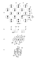
以下、伸縮領域に好適な接合部の配置例について順に説明するが、これに限定されるものではない。
(接合部の配置例1)
図9は特許文献1に代表例として示されたものである。すなわち、接合部40群は、千鳥状配列とされ、接合部40は伸縮方向と直交する方向に細長く、かつ伸縮方向の中央を通る中央線に関して線対称(図9(a)において左右対称)の形状とされている。各部の寸法は適宜定めることができるものの、接合部40の伸縮方向の幅40xは0.2~0.4mmとされ、伸縮方向に並ぶ接合部40の間隔d1は3~12.9mm、特に5~6.4mmとされ、伸縮方向と直交する方向に並ぶ接合部40の間隔d2は2~10.5mm、特に2.3~4.6mmとされていると好ましい。同様に、接合部40の伸縮方向と直交する方向の長さ40yは0.4~3.2mm、特に0.7~1.4mmであることが好ましい。
Examples of the arrangement of the joints suitable for the elastic region will be described in order below, but the present invention is not limited to this.
(Arrangement example 1 of joints)
FIG. 9 is shown in Patent Document 1 as a representative example. That is, the
このように、伸縮方向の幅40xが顕著に狭い接合部40が、伸縮方向にある程度広い離間間隔d1で千鳥状に配列されるとともに、弾性シート30の収縮力が各接合部40に対して直接的に作用し、弾性シート30の接合孔31の位置に各接合部40の配置・間隔がしっかりと維持される結果、柔軟性が低下しにくい。また、襞25fが伸縮方向と直交する方向に沿って殆ど真っ直ぐに延び、しかも、その襞25fと襞25fとの間に接合部40が隠れて目立たなくなる。よって、柔軟性の低下を抑えつつ、より布に近い外観の弾性シート伸縮構造20Xとなる。
In this way, the
接合部40の配列は千鳥状配列であるものの、接合部40の形状を円形とすることもできる。
Although the
接合部40の形状は伸縮方向と直交する方向に細長いものが望ましい。しかるに、接合部40の伸縮方向と直交する方向の最大長さが短すぎたり、長過ぎたりすると、襞25fの直線性が低下したり、柔軟性が低下したりするおそれがある。よって、これらの寸法は適宜定めることができるものの、接合部40の伸縮方向と直交する方向の長さ40yは0.4~3.2mm、特に0.7~1.4mmであることが好ましい。
It is desirable that the shape of the
他方、特許文献2では、図10(a)(b)に示す2例とも、伸縮性フィルムの接合部(やや縦長の長方形で図示されている)の配列は同じく千鳥状配列であり、(b)の例では小円形の副接合部が長方形の主接合部間に配置されているものである。(b)例においても千鳥状配列の思想に基づくものである。 On the other hand, in Patent Document 2, both the two examples shown in FIGS. ) has small circular sub-joints placed between rectangular main joints. The example (b) is also based on the concept of staggered arrangement.
そして、各接合部の配置及び寸法は、図10に記載した寸法範囲(単位はmmである。)であることが、主に外観、肌触り及び通気性などの点が好ましい。 It is preferable that the arrangement and dimensions of each joint are within the dimension range (unit: mm) shown in FIG.
(接合部の配置例2)
上述の配置例1では、伸縮方向と直交する方向の、弾性シート30の接合部間の離間間隔、図10(a)では符号Cを0.3mm以上と大きく設定してあるので、伸縮方向の伸縮応力が高く、例えばパンツ型使い捨ておむつに適用した場合に過度に(幅方向に)強く締め付けることになると感じる着用者も少なからず存在する。
(Arrangement example 2 of joints)
In Arrangement Example 1 described above, the distance between the joints of the
ここで、特許文献2においては、図10に示す接合部長さBが0.3~0.7mm、離間間隔Hが0.6~1.4mmと好ましいとされている。 Here, in Patent Document 2, it is said that the joint portion length B shown in FIG.
これに対して、図11に示すように、伸縮方向EDと直交する直交方向XDの、弾性シート30の接合部間の離間間隔dを小さく設定すると伸縮方向の伸縮応力を小さくでき、もって、パンツ型使い捨ておむつに適用した場合に弱い締付力により着用者に対してやさしくフィットさせることが可能である。
On the other hand, as shown in FIG. 11, if the spacing d between the joints of the
この理由は、接合部は、外部からの幅方向(弾性シート30の伸縮方向)に小さい伸長力を与えるだけで、図9のように幅方向に開口して接合孔31となるのに対し、接合部間の伸縮方向と直交する離間間隔領域では、幅方向に伸長させたとしても、接合部は存在しないので、弾性シート30の伸長応力がそのまま収縮力となって着用者を締め付けるようになるためであると考えられる。
The reason for this is that the joint portion opens in the width direction to form a
図11に示す例は、着用者に対してやさしくフィットさせることができるほか、接合部が占める面積率、幅方向に伸長した使用状態においては接合孔の占める面積率が高くなるので通気性に優れるとの利点ももたらされる。 In the example shown in FIG. 11, in addition to being able to fit the wearer gently, the area ratio occupied by the joints and the area ratio occupied by the joint holes in the state of use stretched in the width direction are high, so it is excellent in breathability. It also brings the advantage of
(接合部の配置例3)
上述の配置例2は、着用者に対してやさしくフィットさせることができる利点を有するが、さらに弱い収縮力を与えることが望ましい場合がある。図25は、この課題に対する一つの有効な解決策を示している。
(Arrangement example 3 of joints)
Although Arrangement Example 2 described above has the advantage of being able to provide a gentler fit to the wearer, it may be desirable to provide a weaker contractile force. FIG. 25 shows one possible solution to this problem.
すなわち、図25に示される例では、伸縮領域に、接合部40が、伸縮方向ED及びこれと直交する直交方向XDに離間して形成され、
伸縮領域の接合部40,40…群が、図25(b)のように、直交方向XDの各位置で伸縮方向線と交差する関係にある、あるいは図25(c)のように、伸縮方向線の直交方向XDの0.5mm以下の離間幅においては、伸縮方向線と交差しない関係にあり、かつ、
伸縮方向線と45度以下の角度γ範囲内で交差する斜線qの直交方向XDの斜線群(すなわち図25(b)の斜線q,q間の斜線群)における、所定の直交方向XD離間幅においては、前記接合部群が斜線と交差しない関係にある。
That is, in the example shown in FIG. 25, the
The
A predetermined orthogonal direction XD separation width in the diagonal line group in the orthogonal direction XD of the diagonal line q that intersects the stretch direction line within the range of angle γ of 45 degrees or less (that is, the diagonal line group between the diagonal lines q and q in FIG. 25(b)) In , the joints are in a relationship that does not intersect the oblique line.
この例が、着用者に対して過度の収縮力を与えない理由は、必ずしも明確ではないが次の現象が生じるからであると推測される。 The reason why this example does not apply excessive contractile force to the wearer is presumed to be because the following phenomenon occurs although it is not necessarily clear.
図25(b)のように、直交方向XDの各位置で伸縮方向線と交差する関係にある、あるいは図25(c)のように、伸縮方向線の直交方向XDの0.5mm以下の離間間隔dにおいては、伸縮方向線と交差しない関係にある場合、伸縮方向の伸長が生じないかと思われた。 As shown in FIG. 25(b), it intersects with the stretch direction line at each position in the orthogonal direction XD, or as shown in FIG. At the interval d, it was thought that elongation in the direction of elongation would not occur if there was a relationship that did not intersect with the direction of elongation.
しかし、着用時において伸縮方向EDに展開する場合の伸縮方向の力は、図25(b)のように迂回しながら伝搬する(伝搬経路を符号Sで示した。)。この伝搬経路Sを示す理由は、弾性シート30が幅方向のほか直交方向にも伸縮するからである。この結果、接合部40の幅方向両側に接合孔31,31を形成させながら、伸縮方向EDの伸長が生じることとなる。
However, the force in the expansion/contraction direction when deployed in the expansion/contraction direction ED at the time of wearing propagates while detouring as shown in FIG. The reason why this propagation path S is shown is that the
一般に、弾性シート30は製造時に伸長させた後、その伸長力を解放させたとき、元の長さに戻るのではなく、ひずみ分を差し引いた長さ分に戻るものである。例えば、自然長が50mmの弾性シートを、175mmまで3.5倍に伸長し、その伸長力を解放すると、70mmになったとすると、20mmのひずみがあり、ひずみの割合ε%としては、(70-50)×100/50=40%となる。
In general, the
このことを踏まえて、さらに検討すると、おむつの幅方向の展開状態では、接合部40の幅方向両側に接合孔31,31を形成させながら、伸縮方向の伸長が生じる。すなわち、接合部40幅方向両側においては、接合孔31,31の開口による、弾性シートの変形が生じるものである。一旦、変形してしまった部分は、収縮力が小さくなることは理解されるであろう。
Taking this into consideration, when the diaper is unfolded in the width direction, the joining
このように、おむつの展開力を解放させた場合、弾性シートの収縮力により、接合孔31,31の開口幅(開口長さ)を短くさせながら、幅方向に収縮する。この場合において、離間間隔dが大きい場合には、離間間隔d領域では弾性シートの変形が生じていないので、幅方向に収縮する量(長さ)が大きい。例えば、痩せ型の人では、接合孔31,31が閉じてしまうまで収縮する。これでは、接合孔31,31の開口からの通気性の確保が十分でなくなるおそれがある。
In this way, when the diaper is released from the unfolding force, the contraction force of the elastic sheet shortens the opening width (opening length) of the
これに対し、離間間隔dが小さい又はゼロであると、直交方向の全部又はほとんどで、接合孔31,31の開口による弾性シート30の変形が生じている状態(いわば弾性シートがダメージを受けている状態)となる。この結果、幅方向の伸長力を解放した場合において、一旦開口した接合孔31,31の開口幅(開口長さ)が短く割合が小さく、もって接合孔31,31の開口からの通気性の確保が過度に低下することはなくなる。
On the other hand, when the separation distance d is small or zero, the
しかも、幅方向の収縮力は、離間間隔dが大きい場合に比較して小さくなるから、着用者を過度に圧迫することがない。 Moreover, since the contractile force in the width direction is smaller than when the distance d is large, the wearer is not excessively pressed.
なお、例えば上記の伝搬経路Sで幅方向の伸縮が生じるためには、図25(b)のように、伸縮方向線と45度以下の角度γ範囲内で交差する斜線q,qの直交方向の斜線群における、所定の直交方向XDの離間間隔Hにおいては、接合部40,40…群が斜線と交差しない関係にあるのが必要である。
For example, in order for expansion and contraction in the width direction to occur in the propagation path S, as shown in FIG. It is necessary that the
ここで、伸縮方向線と45度以下の角度γは、例えば図17のように、左上から右下への斜線の場合においても、伸縮方向線と斜線qとの間の開き角度として定義されるものである。 Here, the angle γ of 45 degrees or less from the stretch direction line is defined as the opening angle between the stretch direction line and the diagonal line q, even in the case of the diagonal line from upper left to lower right as shown in FIG. It is.
上記直交方向XDに沿う離間間隔Hとしては、0.2~10mm、より望ましくは0.2~5.0mm、特に0.6~3.0mmが望ましい。 The spacing H along the orthogonal direction XD is preferably 0.2 to 10 mm, more preferably 0.2 to 5.0 mm, particularly 0.6 to 3.0 mm.
伸縮方向線と斜線との開き角度γは、より好ましくは30度以下、特に15度以下が望ましい。 The opening angle γ between the stretch direction line and the oblique line is more preferably 30 degrees or less, particularly 15 degrees or less.
接合部40は、伸縮方向の幅は、0.3~10.0mm、好ましくは0.5~5.0mm、特に好ましくは0.7~3.5mmで形成される。
The
接合部40の直交方向XD基準の長さLが0.3~7.0mm、好ましくは0.5~5.0mm、特に好ましくは0.7~2.5mmで形成される。 The length L of the joint 40 in the orthogonal direction XD is 0.3 to 7.0 mm, preferably 0.5 to 5.0 mm, particularly preferably 0.7 to 2.5 mm.
また、第1接合部40,40…列は、伸縮方向ED(WD)基準の形成ピッチS0が2.0~20.0mm、好ましくは3.0~15.0mm、特に好ましくは4.0~10.0mmで形成される。
In addition, the first
以下、上述の配置例3を基本とする種々の変形例について順に説明する。
(接合部の配置例4)
図12(a)に示す例の製品における使用状態では、直交方向XDに沿った接合部40,40…の列と、これと伸縮方向EDに離間する隣接する接合部40,40…の列との離間領域に、直交方向XDに沿った襞25Fが形成される。この襞25Fは、図12(b)に示すように、単に一様の山形状である。すなわち、特許文献1に示され、ここに図9(c)に示す横断面と異なるものである。
Various modifications based on the arrangement example 3 described above will be sequentially described below.
(Arrangement example 4 of joints)
In the state of use in the product of the example shown in FIG. A
図12に示す例では、通気性を有する第1シート層及び通気性を有する第2シート層の間に弾性シートが介在され、前記第1シート層及び第2シート層が、間隔を空けて配列された多数の接合部で、弾性シートを貫通する接合孔を通じて又は前記弾性シートを介して接合された、弾性シート伸縮構造を備えている。 In the example shown in FIG. 12, an elastic sheet is interposed between a first sheet layer having air permeability and a second sheet layer having air permeability, and the first sheet layer and the second sheet layer are arranged with a gap therebetween. It has an elastic sheet stretchable structure joined through a joint hole penetrating the elastic sheet or via the elastic sheet at a number of joined joints.
また、弾性シート伸縮構造を示す伸縮領域は、弾性シートの収縮力により伸縮方向に伸縮可能である。 In addition, the stretchable region showing the stretchable structure of the elastic sheet can be stretched in the stretching direction by the contractile force of the elastic sheet.
接合部は、第1接合部40,40…のほか、第2接合部41,41…を有する。
The joint portion has first
第1接合部40,40…は、直交方向XDに沿って間隔をおいて配列され、第1接合部列が形成されている。 The first joints 40 , 40 . . . are arranged at intervals along the orthogonal direction XD to form a first joint row.
後に例えば図19によって説明するように、第1接合部40,40…列は、直交方向XDに沿うことなく、伸縮方向EDと交差する角度θが30度~150度の範囲で傾斜している(したがって90度は含まない)、より望ましくは45度~135度の範囲で傾斜している(90度は含まない)のが望ましい。
As will be described later with reference to FIG. 19, for example, the first
図12に示される例では、傾斜していない交差する角度θが90度の例である。 In the example shown in FIG. 12, the non-inclined crossing angle θ is 90 degrees.
第1接合部40は、直交方向XD基準の長さLが0.3~7.0mm、好ましくは0.5~5.0mm、特に好ましくは0.7~2.5mmで形成される。
The first
また、第1接合部40,40…列は、伸縮方向ED(WD)基準の形成ピッチS0が2.0~20.0mm、好ましくは3.0~15.0mm、特に好ましくは4.0~10.0mmで形成される。
In addition, the first
さらに、第1接合部40,40…列における隣接する第1接合部40,40相互関係が定める、直交方向XD基準での距離として、(隣接する第1接合部間の離間間隔d)/(接合部の一点から隣接する第1接合部の対応する一点までの距離P)の割合の百分率Rが5~60%、好ましくは10~45%、特に20~35%とするのが望ましい。
Furthermore, as the distance in the orthogonal direction XD standard determined by the mutual relationship between the adjacent
この百分率が過度に高いと、製品に適用した場合、幅方向(伸縮方向)の伸縮応力が高く着用物品として適切なフィット性を得がたい傾向を示す。 If this percentage is excessively high, when applied to a product, the stretch stress in the width direction (stretch direction) tends to be high, making it difficult to obtain an appropriate fit as a wearable article.
また、百分率が過度に低いと、直交方向XDに隣接する第1接合部40,40相互が製造過程で連続化する可能性を排除できないとともに、より根本的には、接合部を形成するアンビル及び加熱ホーンに過度に設備的な負担がかかり、安定操業を阻害する原因になる可能性がある。
In addition, if the percentage is too low, the possibility that the
第2接合部41,41列内には、第1接合部40の長さL及びこれ以上の長さの接合部は形成されていないのが望ましい。
It is desirable that no joints longer than the length L of the
本例においては、代表的に次の利点又は特徴を示すものとなる。
(1)前述の百分率Rが低いので、伸縮方向の伸縮応力が低く、柔軟な伸びを有した伸縮シート部材となり、これを吸収性物品に適用した場合に着用感に優れたものとなる。
しかも、開口率が高くなるので通気性が高くなる。
This example typically exhibits the following advantages or features.
(1) Since the aforementioned percentage R is low, the elastic stress in the elastic direction is low, and the elastic sheet member has a soft elongation.
Moreover, since the opening ratio is increased, the air permeability is increased.
(2)第1接合部40,40…列のみでなく、第2接合部41,41…列が形成されているので、第1接合部40,40…列と第2接合部41,41…列との間に列間プリーツRを形成できる。先の図11に示す例においては、製品の伸縮領域全体としてデザインの観点からみたとき、直交方向XDに長い襞25Fが伸縮方向ED(WD)に一様の繰り返しで形成されているのに対して、本例では、列間プリーツRを形成することで、デザイン性を高めることができる。
(2) Not only the rows of the
(3)第2接合部41は、第1接合部40より小さい面積を示すので、模様状のものに見える。 (3) Since the second joint 41 has a smaller area than the first joint 40, it looks like a pattern.
(4)第1接合部40,40…列と第2接合部41,41…列との間に列間プリーツRを形成できることは、第1接合部40,40…列と第1接合部40,40…列との間に2つの列間プリーツを形成できることを意味する。しかしながら、第2接合部41,41…列では第2接合部41,41相互の間隔が長いので、アンビル及び加熱ホーンに過度に設備的な負担がかかることなくプリーツを形成できることを意味する。その結果、図11のように第1接合部40,40…列のみで列間プリーツを形成する場合に比較して、単位面積あたり細幅で多数のプリーツを設備負担をかけることなく形成できる。このようにして、着用者の肌に対する接触面積が低減し、快適性の向上と柔らかさの向上を図ることができる。
(4) The inter-row pleats R can be formed between the first
(接合部の配置例5)
図13に示すように、第2接合部41,41…群を、第1接合部40,40の直交方向XDの相互間に配置することができる。この場合は、第1接合部40の長さLが短くとも、第2接合部41が位置することで、伸縮応力を低減できる。
(Arrangement example 5 of joints)
As shown in FIG. 13, the
(接合部の配置例6)
図14に示すように、第2接合部41は、第1接合部40に対して1対1で隣接させるのではなく、例えば2つの第1接合部40,40に対して1つの第2接合部41を隣接配置することができる。
(Arrangement example 6 of joints)
As shown in FIG. 14, the
(接合部の配置例7)
図15に示すように、第1接合部40,40…列と第2接合部41,41…列との間に、直交方向XDの離間間隔が長い第3接合部42,42…列を形成することができる。第3接合部42の形成によって、第1実施例で示した列間プリーツRを、直交方向XDに分断した大プリーツbfを形成できる。第3接合部42と第1接合部40,40…列との間に小プリーツsfを形成できる。列間プリーツRが分断したプリーツ群は、伸縮部材の曲げ剛性が低く(曲がりやすく)、身体の動きに対する追従性が良好なものとなる。
(Arrangement example 7 of joints)
As shown in FIG. 15, between the
(接合部の配置例8)
図16に示すように第3接合部42の位置を第2接合部41と共に斜め配列することで、斜め配列の大プリーツbf群を形成でき、デザイン性が高いものとなる。
(Arrangement example 8 of joints)
As shown in FIG. 16, by obliquely arranging the positions of the
(接合部の配置例9)
図17に示すように第1接合部40,40…列に第4接合部43を挿入配置できる。この場合、第4接合部43,43…群は、伸縮方向EDに沿うほか、図示のように斜め配置にするができる。この場合、第4接合部43の面積は、第1接合部40の面積の5%以上で50%以下が好ましい。
(Arrangement example 9 of joints)
As shown in FIG. 17, the
(接合部の配置例10)
図18に示すように第1接合部40自体が傾斜していてもよい。第2接合部42も傾斜していてもよい。接合部長さは直交方向XDを基準とするから、図18に示すように、第1接合部40の長さLは一辺の中央から他辺の中央部までの直交方向XD長さが接合部長さとなる。離間間隔も辺の中央と対向する辺の中央との直交方向XD距離が離間間隔dとなる。
(Arrangement example 10 of joints)
As shown in FIG. 18, the first
(接合部の配置例11)
図19は、第1接合部40及び第2接合部42が共に傾斜しており、各接合部の列は、直交方向XDに沿うことなく、伸縮方向EDと交差する角度θが30度~150度、望ましくは45度~135度の範囲で傾斜している例を示している。交差する角度θは、特に好ましくは60度~120度である。ただし、傾斜を示すこれらの角度範囲においては当然に90度を含まない。
(Arrangement example 11 of joints)
In FIG. 19, both the first
この接合部列が、直交方向XDに沿うことなく、伸縮方向EDと交差して傾斜している利点は、図18に示す第8実施例とを比較すると明らかになる。すなわち、図19に示す例においては、直交方向XD線上についての、例えば第1接合部40,40間の離間間隔が、図18に示す第8実施例よりかなり大きいことが利点をもたらす原因である。
The advantage that this joint row is inclined not along the orthogonal direction XD but crossing the stretching direction ED becomes clear when compared with the eighth embodiment shown in FIG. That is, in the example shown in FIG. 19, the separation distance between, for example, the
すなわち、例えば、接合部40における第1シート層20A及び第2シート層20Bの接合は、ヒートシールや超音波シール等の素材溶着による接合手段によりなされるのが望ましい。
That is, for example, the joining of the
連続生産の場合には、アンビルロールと超音波ホーンとの間で超音波によるシール溶融を行うが、エネルギーロスを防ぐために、アンビルロールの軸線方向全体に、シートに対して超音波ホーンも密接していることが重要となるが、このために線接触する母線に沿って図12の接合部40,40…列のようにアンビルロール凸部割合が大きいパターンを形成する場合には大きな超音波出力を出す必要があり、このために線接触する母線に沿って過大な密接力を作用させるのでは、設備側の負担が大きい。
In the case of continuous production, ultrasonic seal melting is performed between the anvil roll and the ultrasonic horn, but in order to prevent energy loss, the ultrasonic horn is also closely attached to the sheet along the entire axial direction of the anvil roll. For this reason, when forming a pattern with a large proportion of anvil roll projections, such as the rows of
これに対して、本例の場合(一般に傾斜配置の場合)には、直交方向XDの線上に位置する接合部が占める割合が小さいものとなり、安定した線圧となるので、設備負担は小さいものとなり、安定操業が可能である。また、本例では、第1接合部40(及び第2接合部42)が傾斜しているために、デザイン性に優れた襞及びプリーツを形成できる利点もあわせ持っている。 On the other hand, in the case of this example (generally in the case of inclined arrangement), the proportion of the joints located on the line in the orthogonal direction XD is small, and the line pressure is stable, so the equipment burden is small. and stable operation is possible. In addition, in this example, since the first joint portion 40 (and the second joint portion 42) is inclined, there is also an advantage that folds and pleats with excellent design can be formed.
(非伸縮領域)
外装体20における弾性シート伸縮構造20Xを有する領域には、図7に示すように、伸縮領域80以外に非伸縮領域70を設けることができる。非伸縮領域70は、伸縮方向の弾性限界伸びが120%以下を意味する。非伸縮領域70の弾性限界伸びは110%以下であると好ましく、100%であるとより好ましい。伸縮領域80及び非伸縮領域70の配置は適宜定めることができる。図示例のようなパンツタイプ使い捨ておむつの外装体20の場合、吸収体13と重なる部分は伸縮が不要な領域であるため、図示例のように、吸収体13と重なる部分の一部又は全部(内外固定領域10Bのほぼ全体を含むことが望ましい)を非伸縮領域70とするのは好ましい。もちろん、吸収体13と重なる領域からその幅方向WD又は前後方向LDに位置する吸収体13と重ならない領域にかけて非伸縮領域70を設けることもでき、吸収体13と重ならない領域にのみ非伸縮領域70を設けることもできる。
(Non-stretch area)
A
非伸縮領域70における個々の接合部40の形状や配列、弾性シート30における接合孔31の形状や配列は適宜定めることができる。
The shape and arrangement of the
また、非伸縮領域における接合部40の面積率及び個々の接合部40の面積は適宜定めることができるが、通常の場合、次の範囲内とすると、各接合部40の面積が小さくかつ接合部40の面積率が低いことにより非伸縮領域70が硬くならないため好ましい。
In addition, the area ratio of the
接合部40の面積:0.10~0.75mm2(特に0.10~0.35mm2)
接合部40の面積率:4~13%(特に5~10%)
Area of joint 40: 0.10 to 0.75 mm 2 (especially 0.10 to 0.35 mm 2 )
Area ratio of joint 40: 4 to 13% (especially 5 to 10%)
非伸縮領域70は、弾性シート30の収縮力により第1シート層及び第2シート層が収縮して襞が形成されないように接合部40を密に配置すること等によって形成することができる。非伸縮領域70の形成手法の具体例としては、例えば特許第5980355号、特許第5918877号、特許第5980367号、特許第6049228号に示されるものを挙げることができる。
The
特に、非伸縮領域70は、弾性シート30は幅方向WDに連続するものの、接合孔31の存在により幅方向WDに沿って直線的に連続する部分を有しない領域とされていると好ましい。この場合、弾性シート30を幅方向WDに伸長した状態で、幅方向WD及びこれと直交する前後方向LDにそれぞれ間隔を空けて、弾性シート30の接合孔31を介して第1シート層20A及び第2シート層20Bを接合し、多数の接合部40を形成することにより、伸縮領域80及び非伸縮領域70の両者を含む弾性シート伸縮構造20X全体を形成するとしても、非伸縮領域70では、弾性シート30が幅方向WDに沿って直線的に連続しないため、弾性シート30の収縮力が第1シート層20A及び第2シート層20Bにほとんど作用せず、伸縮性がほぼ消失し、弾性限界伸びは100%に近くなるのである。
In particular, the
このような非伸縮領域70では、第1シート層20A及び第2シート層20Bが間隔を空けて配列された多数の接合部40で接合されており、接合部40が連続的とならないため、柔軟性の低下は防止される。
In such a
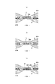
(接合部の接合構造)
接合部40における第1シート層20A及び第2シート層20Bの接合は、弾性シート30に形成された接合孔31を通じて接合される場合、少なくとも接合部40における第1シート層20A及び第2シート層20B間以外では、第1シート層20A及び第2シート層20Bは弾性シート30と接合されていないことが望ましい。
(joint structure of joint)
When joining the
接合部40における第1シート層20A及び第2シート層20Bの接合手段は特に限定されない。例えば、接合部40における第1シート層20A及び第2シート層20Bの接合はホットメルト接着剤によりなされていても、ヒートシールや超音波シール等の素材溶着による接合手段によりなされていても良い。
The means for joining the
接合部40において第1シート層20A及び第2シート層20Bが弾性シート30の接合孔31を通じて接合される場合、接合部40が素材溶着により形成される構造は、接合部40における第1シート層20A及び第2シート層20Bの少なくとも一方の大部分又は一部の溶融固化物20mのみにより第1シート層20A及び第2シート層20Bが接合される第1溶着構造(図21(a)参照)、接合部40における弾性シート30の全部若しくは大部分又は一部の溶融固化物30mのみにより第1シート層20A及び第2シート層20Bが接合される第2溶着構造(図21(b)参照)、及びこれらの両者が組み合わさった第3溶着構造(図21(c)参照)のいずれでも良いが、第2、第3溶着構造が好ましい。
When the
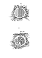
特に好ましいのは、第1シート層20A及び第2シート層20Bの一部の溶融固化物20mと、接合部40における弾性シート30の全部若しくは大部分の溶融固化物30mとにより第1シート層20A及び第2シート層20Bが接合される構造である。なお、図23(b)に示される第3溶着構造では、黒色に写っている第1シート層20A又は第2シート層20Bの繊維の溶融固化物20m間に、白色に写っている弾性シート30の溶融固化物30mが見られるのに対して、図23(a)に示される第1溶着構造では、第1シート層20A又は第2シート層20Bの繊維の溶融固化物20m間に弾性シート30の溶融固化物は見られない。
Particularly preferably, the
第1接着構造や第3接着構造のように、第1シート層20A及び第2シート層20Bの少なくとも一方の大部分又は一部の溶融固化物20mを接着剤として第1シート層20A及び第2シート層20Bを接合する場合、第1シート層20A及び第2シート層20Bの一部は溶融しない方が接合部40が硬質化しないため好ましい。
Like the first bonding structure and the third bonding structure, the
なお、第1シート層20A及び第2シート層20Bが不織布であるときには、第1シート層20A及び第2シート層20Bの一部が溶融しないことには、接合部40の全繊維について芯(複合繊維における芯だけでなく単成分繊維の中心部分を含む)は残るがその周囲部分(複合繊維における鞘だけでなく単成分繊維の表層側の部分を含む)は溶融する構造や、一部の繊維は全く溶融しないが、残りの繊維は全部が溶融する又は芯は残るがその周囲部分は溶融する構造を含む。
When the
第2溶着構造及び第3溶着構造のように、弾性シート30の溶融固化物30mを接着剤として第1シート層20A及び第2シート層20Bを接合すると、剥離強度が高いものとなる。第2溶着構造では、第1シート層20A及び第2シート層20Bの少なくとも一方の融点が弾性シート30の融点及び接合部40形成時の加熱温度よりも高い条件下で、第1シート層20A及び第2シート層20B間に弾性シート30を挟み、接合部40となる部位を加圧・加熱し、弾性シート30のみを溶融することにより製造することができる。
When the
一方、第3溶着構造では、第1シート層20A及び第2シート層20Bの少なくとも一方の融点が弾性シート30の融点よりも高い条件下で、第1シート層20A及び第2シート層20B間に弾性シート30を挟み、接合部40となる部位を加圧・加熱し、第1シート層20A及び第2シート層20Bの少なくとも一方と弾性シート30とを溶融することにより製造することができる。
On the other hand, in the third welded structure, under the condition that the melting point of at least one of the
このような観点から、弾性シート30の融点は80~145℃程度のものが好ましく、第1シート層20A及び第2シート層20Bの融点は85~190℃程度、特に150~190℃程度のものが好ましく、第1シート層20A及び第2シート層20Bの融点と弾性シート30の融点との差は60~90℃程度であるのが好ましい。また、加熱温度は100~150℃程度とするのが好ましい。
From this point of view, the melting point of the
第2溶着構造及び第3溶着構造では、第1シート層20A及び第2シート層20Bが不織布であるときには、弾性シート30の溶融固化物30mは、図22(c)に示すように接合部40における第1シート層20A及び第2シート層20Bの厚み方向全体にわたり繊維間に浸透していても良いが、図22(a)に示すように厚み方向中間まで繊維間に浸透する構造、又は図22(b)に示すように第1シート層20A及び第2シート層20Bの繊維間にほとんど浸透しない構造の方が、接合部40の柔軟性が高いものとなる。
In the second welded structure and the third welded structure, when the
図24は、第2溶着構造及び第3溶着構造を形成するのに好適な超音波シール装置の例を示している。この超音波シール装置では、接合部40の形成に際して、外面に接合部40のパターンで形成した突起部60aを有するアンビルロール60と超音波ホーン61との間に、第1シート層20A、弾性シート30及び第2シート層20Bを送り込む。この際、例えば上流側の弾性シート30の送り込み駆動ロール63及びニップロール62による送り込み移送速度を、アンビルロール60及び超音波ホーン61以降の移送速度よりも遅くすることにより、送り込み駆動ロール63及びニップロール62によるニップ位置からアンビルロール60及び超音波ホーン61によるシール位置までの経路で、弾性シート30をMD方向(マシン方向、流れ方向)に所定の伸長率まで伸長する。この弾性シート30の伸長率は、アンビルロール60及び送り込み駆動ロール63の速度差を選択することにより設定することができ、例えば300%~500%程度とすることができる。62はニップロールである。
FIG. 24 shows an example of an ultrasonic sealing device suitable for forming the second welded structure and the third welded structure. In this ultrasonic sealing device, when forming the
アンビルロール60と超音波ホーン61との間に送り込まれた、第1シート層20A、弾性シート30及び第2シート層20Bは、この順に積層した状態で、突起部60aと超音波ホーン61との間で加圧しつつ、超音波ホーン61の超音波振動エネルギーにより加熱し、弾性シート30のみを溶融するか、又は第1シート層20A及び第2シート層20Bの少なくとも一方と弾性シート30とを溶融することによって、弾性シート30に接合孔31を形成するのと同時に、その接合孔31を通じて第1シート層20A及び第2シート層20Bを接合する。したがって、この場合にはアンビルロール60の突起部60aの大きさ、形状、離間間隔、ロール長方向及びロール周方向の配置パターンなどを選定することにより、接合部40の面積率を選択することができる。
The
接合孔31が形成される理由は必ずしも明確ではないが、弾性シート30におけるアンビルロール60の突起部60aと対応する部分が溶融して周囲から離脱することにより開孔するものと考えられる。この際、弾性シート30における、伸縮方向EDに並ぶ隣接する接合孔31の間の部分は、図9(a)及び図11(a)に示すように、接合孔31により伸縮方向両側の部分から切断され、収縮方向両側の支えを失うことになるため、収縮方向と直交する方向の連続性を保ちうる範囲で、伸縮方向EDと直交する方向LDの中央側ほど伸縮方向中央側に釣り合うまで収縮し、接合孔31が伸縮方向EDに拡大する。
The reason why the joining
第1シート層20A及び第2シート層20Bの構成材は、シート状のものであれば特に限定無く使用できるが、通気性及び柔軟性の観点から不織布を用いることが好ましい。 不織布を用いる場合、その目付けは10~25g/m2程度とするのが好ましい。
The constituent materials of the
また、第1シート層20A及び第2シート層20Bの一部又は全部は、一枚の資材を折り返して対向させた一対の層であっても良い。例えば、図示例のように、ウエスト端部23では、外側に位置する構成材を第2シート層20Bとし、かつそのウエスト開口縁で内面側に折り返してなる折り返し部分20Cを第1シート層20Aとして、その間に弾性シート30を介在させるとともに、それ以外の部分では内側に位置する構成材を第1シート層20Aとし、外側に位置する構成材を第2シート層20Bとして、その間に弾性シート30を介在させることができる。もちろん、前後方向LDの全体にわたり第1シート層20Aの構成材及び第2シート層20Bの構成材を個別に設け、構成材を折り返しすることなく、第1シート層20Aの構成材及び第2シート層20Bの構成材間に弾性シート30を介在させることもできる。
Also, part or all of the
弾性シート30は特に限定されるものではなく、それ自体で弾性伸縮する熱可塑性樹脂製のシートであれば、弾性(エラスティック)フィルムの他、伸縮不織布であってもよい。また、弾性シート30としては、無孔のものの他、通気のために多数の孔やスリットが形成されたものも用いることができる。特に、幅方向WD(伸縮方向ED、MD方向)における引張強度が8~25N/35mm、前後方向LD(伸縮方向と直交する方向XD、CD方向)における引張強度が5~20N/35mm、幅方向WDにおける引張伸度が450~1050%、及び前後方向LDにおける引張伸度が450~1400%の弾性シート30であると好ましい。弾性シート30の厚みは特に限定されないが、20~40μm程度であるのが好ましい。また、弾性フィルムの片側又は両側に弾性不織布を設け、これを弾性シート30として第1シート層20Aと第2シート層20Bの間に介在させることができる。
The
(着色)
本パンツタイプ使い捨ておむつを着色された製品とするために、製品外面に露出する部分を有する第2シート層20Bを着色不織布とすることができる。図示例の場合、弾性シート伸縮構造20Xを有する領域では弾性シート30が着色不織布の内側に隣接する下シートとなり、弾性シート30を有しない領域では第1シート層20Aが着色不織布の内側に隣接する下シートとなる。なお、図示例における第2シート層20Bの露出部分は、図28に左斜め上向きのハッチングで示されており、第2シート層20Bと弾性シート30とが重なる領域は図28に点模様で示されている。
(coloring)
In order to make the pants-type disposable diaper a colored product, the
図示例では、製品外面の大部分が第2シート層20Bによりカバーされる。しかし、前述のように、外装体20が、前身頃F及び後身頃Bで個別に形成し、両者が股間部でおむつの前後方向LDに離間するように配置されるタイプのパンツタイプ使い捨ておむつでは、前側の外装体20と後側の外装体20との間に外装体20を有しないため、この部分に露出する外装不織布(特許文献1記載の被覆シート53がこれに該当する。図示略。)を着色不織布とすることが望ましい。この場合、着色不織布の内側に隣接する部材は液不透過性シート12であることが一般的である。また、いわゆるテープタイプ使い捨ておむつでは、吸収体13の裏側を防水フィルム等の液不透過性シート12により覆い、さらに液不透過性シート12の裏側を外装不織布で覆うことも一般的である。したがって、この場合、外装不織布に着色不織布を用いることが好ましい(図示略)。このように、着色不織布及び下シートは特に限定されるものではなく、例えばトップシート11を着色不織布としたり、ギャザーシート95を着色不織布としたりすることもできる。
In the illustrated example, most of the outer surface of the product is covered by the
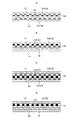
そして、図29に示すように、着色不織布100は、複数の層が積層された積層不織布であるとともに、最も外側の層101以外に、白色以外の第1明度の色に着色された着色層110を有し、かつ最も外側の層101は、第1明度よりも高い第2明度の色を有すると好ましい。この場合、着色不織布100を外部から視認したとき、着色層110は最も外側の層101を透過して見ることになるため、着色層110の色が薄まって(明るくなって)見える。しかも、最も外側の層101も当然に地合いムラを有するため、着色層110の視認色の薄まり加減にもムラを生じる。その結果、着色層110の外観上の色が単に薄くなるだけでなく、色むらが細分化することにより、下シートの外面の色の明度が第1明度より高い(つまり、着色不織布100の色ムラが目立ちやすい)第3明度を有する場合でも、着色層110の色ムラが予想外に目立ちにくくなる。したがって、下シート120に着色を施すか否かに関係なく、着色不織布100の外観上の色ムラを目立ちにくくすることができる。
As shown in FIG. 29, the colored
特に、本使い捨て着用物品のような弾性シート伸縮構造20Xで、第2シート層20Bを着色不織布100とする場合、弾性シート伸縮構造20Xを有する領域では弾性シート30が着色不織布100の内側に隣接する下シート120となる。この場合、弾性シート30の接合孔31も、着色不織布100を透過して視認可能となるため、これが見栄えを悪化させるおそれがある。例えば、異なる大きさの接合孔31を有すると、人によっては色ムラと同様に外観に不均一な模様に見えるおそれがある。よって、本弾性シート伸縮構造20Xにおいて、前述の色ムラ防止構造を有すると、着色不織布100の色ムラだけでなく、接合孔31も目立ちにくくなるため特に好ましい。
In particular, in the elastic sheet
着色不織布100は、同一の色に着色された着色部分を有する限り、厚み方向と直交する方向においてその全体が着色されているほか、一部の領域、例えば露出部分のみや、下シート120と重なる部分を含む領域のみが着色されているだけでもよい。弾性シート伸縮構造20Xを有する領域に着色部分を設ける場合、着色部分は、伸縮領域80であっても、非伸縮領域70であっても良い。ただし、不織布の地合いのムラに起因する色ムラが特に目立ち始めるのは、着色部分の面積が概ね25cm2程度からであるため、これ以上の面積の着色部分を有する場合に前述の色ムラ防止構造を有すると、特に技術的意義が大きいものとなる。また、図示しないが、着色不織布100には、同一色の着色部分を間隔を空けて複数個所に設けたり、異なる色の着色部分を間隔を空けて又は隣接して複数個所に設けたりすることもできる。例えば、幅方向WDの中間部L及び両側部を異なる色に着色したり、ウエスト端部23領域とそれ以外の領域とを異なる色に着色したりすることができる。
As long as the colored
着色不織布100の製造方法は特に限定されないが、単一の素材を複数色に着色する場合には印刷や後染めにより行うことができ、素材全体を単一色に着色する場合には、印刷や後染めを採用することもできるが、原材料に染料又は顔料を混合する手法(例えば不織布の場合、紡糸前の原液に染料又は顔料を混ぜて着色した原液着色繊維により不織布を形成する)を採用することが望ましい。後者の手法は、積層不織布の各層の原料に対して着色の有無を選択することにより、各層の着色の有無を容易に選択できる点で好ましいが、製造される着色不織布100は、必然的に全体が同一の色に着色されることになる。もちろん、着色成分が最も外側の層101に達しないように、積層不織布の内面にのみ印刷を行う手法も可能であり、この場合、一部のみ着色部分を有する着色不織布100や、異なる色に着色された複数の着色部分を有する着色不織布100を製造することができる。
The method for producing the colored
着色不織布100の積層構造は、最も外側の層101以外に、白色以外の第1明度の色に着色された着色層110を有し、かつ最も外側の層101は、第1明度よりも高い第2明度の色を有する限り、特に限定されるものではない。例えば、着色不織布100が三層構造の場合、図29(a)に示すように、2層目102を着色層110とし、最も外側の層101及び最も内側の層103は第2明度の色を有する非着色層としたり、図29(b)に示すように、最も内側の層103を着色層110とし、最も外側の層101及び2層目102は第2明度の色を有する非着色層としたりすることができる。また、着色不織布100が四層構造の場合、図30(a)に示すように、外側から数えて2層目102及び4層目104を着色層110とし、1層目(最も外側の層101)及び3層目103を第2明度を有する非着色層としたり、図30(b)に示すように、外側から数えて2層目102及び3層目103を着色層110とし、1層目(最も外側の層101)及び4層目104を第2明度を有する非着色層としたりすることもできる。また、図30(c)に示すように、最も外側の層以外のすべての層102~104を着色層110としたり、図30(d)に示すように、4層以上の構造において一層110のみ着色層110とすることもできる。つまり、着色層110の数及び非着色層の数は限定されるものではない。
In addition to the
第1明度の色、第2明度の色、第3明度の色は特に限定されるものではないが、例えば第1明度の色は、CIELABのL*値が20~90であり、かつa*値及びb*値の少なくとも一方の絶対値が0~40であると好ましい。具体的には、着色層110は、明度がある程度低い、ベージュ、グレー、ピンク、ブルー、パープル、イエロー等に着色することができる。
The color of the first lightness, the color of the second lightness, and the color of the third lightness are not particularly limited. The absolute value of at least one of the value and the b* value is preferably between 0 and 40. Specifically, the
また、第2明度の色は、それぞれCIELABのL*値が60~100であることが好ましい。第2明度の色は白色又はこれに近いことが好ましい。具体的には、第2明度の色のa*値及びb*値の少なくとも一方の絶対値が0~5であると好ましい。着色不織布100の最も外側の層101は、非着色の状態の色(つまり材質そのものの色)が上記範囲内であることが望ましい。しかし、着色不織布100の最も外側の層101及び下シート120の色が、非着色の状態で上記範囲内にない場合、白色顔料等を含有させる等により、着色不織布100の最も外側の層101の色の明度を上記範囲内に調整することもできる。
In addition, it is preferable that each of the colors of the second lightness has a CIELAB L* value of 60 to 100. Preferably, the second lightness color is white or close to it. Specifically, the absolute value of at least one of the a* value and the b* value of the second lightness color is preferably 0-5. The
また、第3明度の色は、それぞれCIELABのL*値が60~100である場合に、着色不織布100の色ムラが目立ちやすくなる。第3明度の色は白色又はこれに近い場合、例えば第3明度の色のa*値及びb*値の少なくとも一方の絶対値が0~5である場合には、特に着色不織布100の色ムラが目立つようになる。よって、特にこのような場合に前述の色ムラ防止構造を有すると、特に技術的意義が大きいものとなる。なお、本例のように、下シート120が複数ある場合には、そのうちの一部のシートが第3明度を有するだけでも、技術的意義があり、すべてが第3明度を有する場合には技術的意義が大きくなることはいうまでもない。
In addition, when the CIELAB L* value is 60 to 100 for each of the third lightness colors, color unevenness of the colored
第2明度の色と第3明度の色は、異なる色であっても同系の色であってもよいが、特に、着色不織布100の最も外側の層101の色と、下シート120の色とが近いと色ムラ防止効果が高いものとなる。よって、第2明度の色及び第3明度の色の色差ΔEが30以下であると好ましい。 The color of the second lightness and the color of the third lightness may be different colors or similar colors. is close, the effect of preventing color unevenness is high. Therefore, it is preferable that the color difference ΔE between the color with the second lightness and the color with the third lightness is 30 or less.
肌触りを柔軟なものとするためには、着色不織布100は繊度が1.5~5.0dtex、目付けが10~20g/m2の、2~4層の積層不織布であると好ましいが、この場合、不織布の地合いが色ムラとなって現れやすい。しかし、前述の色ムラ防止構造を有すると、柔軟でありながら、色ムラが少ないものとなる。
In order to make the touch soft, the colored
<明細書中の用語の説明>
明細書中の以下の用語は、明細書中に特に記載がない限り、以下の意味を有するものである。
<Description of terms in the specification>
The following terms in the specification have the following meanings unless otherwise specified in the specification.
・「前身頃」「後身頃」は、パンツタイプ使い捨ておむつの前後方向中央を境としてそれぞれ前側及び後側の部分を意味する。また、股間部は、パンツタイプ使い捨ておむつの前後方向中央を含む前後方向範囲を意味し、吸収体が括れ部を有する場合には当該括れ部を有する部分の前後方向範囲を意味する。 - "Front body" and "rear body" refer to the front and rear portions of the underpants-type disposable diaper, respectively, with respect to the center in the front-rear direction. In addition, the crotch part means the front-rear direction range including the front-rear direction center of the pants-type disposable diaper, and means the front-rear direction range of the portion having the constricted part when the absorbent body has the constricted part.
・「前後方向」とは図中に符号LDで示す方向(縦方向)を意味し、「幅方向」とは図中にWDで示す方向(左右方向)を意味し、前後方向と幅方向とは直交するものである。 ・"Front-back direction" means the direction (longitudinal direction) indicated by symbol LD in the figure, and "width direction" means the direction (left-right direction) indicated by WD in the figure. are orthogonal.
・「弾性限界伸び」とは、伸縮方向EDにおける弾性限界(換言すれば第1シート層及び第2シート層が完全に展開した状態)の伸びを意味し、弾性限界時の長さを自然長を100%としたときの百分率で表すものである。 ・"Elastic limit elongation" means the elongation at the elastic limit (in other words, the state in which the first sheet layer and the second sheet layer are completely unfolded) in the stretching direction ED, and the length at the elastic limit is the natural length. is expressed as a percentage when the is 100%.
・「面積率」とは単位面積に占める対象部分の割合を意味し、対象領域(例えば伸縮領域80、非伸縮領域70)における対象部分(例えば接合部40、接合孔31の開口、通気孔)の総和面積を当該対象領域の面積で除して百分率で表すものであり、特に伸縮構造を有する領域における「面積率」とは、伸縮方向EDに弾性限界まで伸ばした状態の面積率を意味するものである。対象部分が間隔を空けて多数設けられる場合、対象部分が10個以上含まれるような大きさに対象領域を設定して、面積率を求めることが望ましい。
- "Area ratio" means the ratio of the target portion to the unit area, and the target portion (for example, the joint 40, the opening of the
・「伸長率」は、自然長を100%としたときの値を意味する。例えば、伸長率が200%とは、伸長倍率が2倍であることと同義である。 - "Elongation rate" means a value when the natural length is taken as 100%. For example, an elongation rate of 200% is synonymous with an elongation ratio of 2 times.
・「目付け」は次のようにして測定されるものである。試料又は試験片を予備乾燥した後、標準状態(試験場所は、温度23±1℃、相対湿度50±2%)の試験室又は装置内に放置し、恒量になった状態にする。予備乾燥は、試料又は試験片を温度100℃の環境で恒量にすることをいう。なお、公定水分率が0.0%の繊維については、予備乾燥を行わなくてもよい。恒量になった状態の試験片から、試料採取用の型板(100mm×100mm)を使用し、100mm×100mmの寸法の試料を切り取る。試料の重量を測定し、100倍して1平米あたりの重さを算出し、目付けとする。
- "Matsuke" is measured as follows. After pre-drying the sample or test piece, it is left in a test room or apparatus under standard conditions (test location:
・上記以外の「厚み」は、自動厚み測定器(KES-G5 ハンディ圧縮計測プログラム)を用い、荷重:0.098N/cm2、及び加圧面積:2cm2の条件下で自動測定する。 • "Thickness" other than the above is automatically measured using an automatic thickness gauge (KES-G5 handy compression measurement program) under the conditions of a load of 0.098 N/cm 2 and a pressurized area of 2 cm 2 .
・「引張強度」及び「引張伸度(破断伸び)」は、試験片を幅35mm×長さ80mmの長方形状とする以外は、JIS K7127:1999「プラスチック-引張特性の試験方法-」に準じて、初期チャック間隔(標線間距離)を50mmとし、引張速度を300mm/minとして測定される値を意味する。引張試験機としては、例えばSHIMADZU社製のAUTOGRAPH AGS-G100Nを用いることができる。 ・ "Tensile strength" and "tensile elongation (breaking elongation)" are in accordance with JIS K7127: 1999 "Plastics - Test method for tensile properties -" except that the test piece is a rectangular shape with a width of 35 mm and a length of 80 mm. means a value measured with an initial chuck interval (distance between gauge lines) of 50 mm and a tensile speed of 300 mm/min. As a tensile tester, for example, AUTOGRAPH AGS-G100N manufactured by SHIMADZU can be used.
・「伸長応力」とは、JIS K7127:1999「プラスチック-引張特性の試験方法-」に準じて、初期チャック間隔(標線間距離)を50mmとし、引張速度を300mm/minとする引張試験により、弾性領域内で伸長するときに測定される引張応力(N/35mm)を意味し、伸長の程度は試験対象により適宜決定することができる。試験片は幅35mm、長さ80mm以上の長方形状とすることが好ましいが、幅35mmの試験片を切り出すことができない場合には、切り出し可能な幅で試験片を作成し、測定値を幅35mmに換算した値とする。また、対象領域が小さく、十分な試験片を採取できない場合であっても、伸長応力の大小を比較するのであれば、適宜小さい試験片でも同寸法の試験片を用いる限り少なくとも比較は可能である。引張試験機としては、例えばSHIMADZU社製のAUTOGRAPH AGS-G100Nを用いることができる。 ・"Elongational stress" is determined according to JIS K7127:1999 "Plastics - Tensile property test method -" by a tensile test with an initial chuck interval (marked line distance) of 50 mm and a tensile speed of 300 mm / min. , means the tensile stress (N/35 mm) measured when stretching in the elastic region, and the degree of stretching can be appropriately determined depending on the test subject. It is preferable that the test piece has a rectangular shape with a width of 35 mm and a length of 80 mm or more. converted to In addition, even if the target area is small and sufficient test pieces cannot be collected, if the magnitude of the tensile stress is compared, it is possible to at least compare even small test pieces as long as the test pieces of the same size are used. . As a tensile tester, for example, AUTOGRAPH AGS-G100N manufactured by SHIMADZU can be used.
・「CIELAB」のL*値、a*値及びb*値は、例えば日本電色工業社製のNF555により測定することができる。 - The L* value, a* value and b* value of "CIELAB" can be measured, for example, with NF555 manufactured by Nippon Denshoku Industries Co., Ltd.
・「展開状態」とは、収縮や弛み無く平坦に展開した状態を意味する。 - "Unfolded state" means a flat unfolded state without contraction or slack.
・各部の寸法は、特に記載が無い限り、自然長状態ではなく展開状態における寸法を意味する。特に接合部の寸法は、限界まで展開した状態(第1シート層及び第2シート層が破断する前の状態)における寸法であって、アンビルロールにおける接合部パターン寸法と実質的に一致する。 ・Unless otherwise specified, the dimensions of each part mean the dimensions in the unfolded state, not in the natural length state. In particular, the dimensions of the joints are the dimensions in the fully developed state (the state before the first sheet layer and the second sheet layer are broken), and substantially match the joint pattern dimensions on the anvil roll.
・試験や測定における環境条件についての記載が無い場合、その試験や測定は、標準状態(試験場所は、温度23±1℃、相対湿度50±2%)の試験室又は装置内で行うものとする。
・If there is no description about environmental conditions for testing and measurement, the test and measurement shall be performed in a laboratory or equipment under standard conditions (test location:
本発明は、上記例のようなパンツタイプ使い捨ておむつの他、テープタイプ、パッドタイプ等の各種使い捨ておむつ、生理用ナプキン、スイミングや水遊び用の使い捨て着用物品等、使い捨て着用物品全般に利用できるものである。 INDUSTRIAL APPLICABILITY The present invention can be applied to general disposable wearable articles such as various types of disposable diapers such as tape type and pad type, sanitary napkins, and disposable wearable articles for swimming and playing in the water, in addition to pants-type disposable diapers as described above. be.
10…内装体、10B…内外固定領域、11…トップシート、12…液不透過性シート、13…吸収体、13N…括れ部分、14…包装シート、17…無吸収体側部、20…外装体、20A…第1シート層、20B…第2シート層、20C…折り返し部分、20X…弾性シート伸縮構造、21…サイドシール部、23…ウエスト端部、24…ウエスト部弾性部材、25F,25f…襞、29…脚周りライン、30…弾性シート、31…接合孔、40,40A,40B…接合部(第1接合部)、41…第2接合部、42…第3接合部、43…第4接合部、50,51…カバーシート、70…非伸縮領域、80…伸縮領域、82…縁部伸縮領域、90…立体ギャザー、93…倒伏部分、94…自由部分、95…ギャザーシート、96…ギャザー弾性部材、B…後身頃、ED…伸縮方向、F…前身頃、L…中間部、XD…直交方向、LD…前後方向、T…胴周り部、sf…小プリーツ、bf…大プリーツ、100…着色不織布、101…最も外側の層、110…着色層、120…下シート。
DESCRIPTION OF
Claims (5)
前記着色不織布の内側に隣接する下シートと、
を備えた、使い捨て着用物品において、
前記着色不織布は、複数の層が積層された積層不織布であり、
前記着色不織布は、最も外側の層以外に、白色以外の第1明度の色に着色された着色層を有し、
前記着色不織布における最も外側の層は、前記第1明度よりも高い第2明度の色を有し、
前記下シートの外面は、前記第1明度よりも高い第3明度の色を有する、
ことを特徴とする、使い捨て着用物品。 a colored nonwoven fabric having an exposed portion;
a lower sheet adjacent to the inner side of the colored nonwoven fabric;
In a disposable wearing article comprising
The colored nonwoven fabric is a laminated nonwoven fabric in which a plurality of layers are laminated,
The colored nonwoven fabric has, in addition to the outermost layer, a colored layer colored with a first lightness color other than white,
The outermost layer in the colored nonwoven fabric has a color with a second lightness higher than the first lightness,
the outer surface of the lower sheet has a color of a third lightness higher than the first lightness;
A disposable wearing article characterized by:
前記第2明度の色及び第3明度の色は、それぞれCIELABのL*値が60~100であり、
前記第2明度の色及び第3明度の色の色差ΔEが30以下である、
請求項1記載の使い捨て着用物品。 The first lightness color other than white has a CIELAB L* value of 20 to 90 and an absolute value of at least one of a* value and b* value of 0 to 40,
The second lightness color and the third lightness color each have a CIELAB L* value of 60 to 100,
The color difference ΔE between the color of the second lightness and the color of the third lightness is 30 or less.
The disposable wearing article according to claim 1.
請求項1又は2記載の使い捨て着用物品。 The colored nonwoven fabric is a 2 to 4-layer laminated nonwoven fabric having a fineness of 1.5 to 5.0 dtex and a basis weight of 10 to 20 g/m 2 .
The disposable wearing article according to claim 1 or 2.
前記着色不織布は、前記第2シート層であり、
前記下シートは、前記弾性シートである、
請求項1~3のいずれか1項に記載の使い捨て着用物品。 An elastic sheet is laminated between the first sheet layer and the second sheet layer facing the outer surface of the product, and the first sheet layer and the second sheet layer are arranged at intervals. It has an elastic sheet elastic structure that is joined through a joint hole that penetrates the elastic sheet at the joint of
The colored nonwoven fabric is the second sheet layer,
The lower sheet is the elastic sheet,
The disposable wearing article according to any one of claims 1 to 3.
前記着色不織布は、前記外装不織布であり、
前記下シートは、前記液不透過性シートである、
請求項1~4のいずれか1項に記載の使い捨て着用物品。 Having an absorbent body, a liquid-impermeable sheet covering the back side of the absorbent body, and an exterior nonwoven fabric covering the back side of the liquid-impermeable sheet,
The colored nonwoven fabric is the exterior nonwoven fabric,
The lower sheet is the liquid-impermeable sheet,
The disposable wearing article according to any one of claims 1-4.
Priority Applications (6)
| Application Number | Priority Date | Filing Date | Title |
|---|---|---|---|
| JP2019050235A JP7121679B2 (en) | 2019-03-18 | 2019-03-18 | Disposable wearing article |
| TW109105298A TWI807168B (en) | 2019-03-18 | 2020-02-19 | Disposable clothing items |
| EP20773043.3A EP3906909A4 (en) | 2019-03-18 | 2020-02-21 | Disposable wearable article |
| PCT/JP2020/007035 WO2020189177A1 (en) | 2019-03-18 | 2020-02-21 | Disposable wearable article |
| CN202080009418.2A CN113301876B (en) | 2019-03-18 | 2020-02-21 | Disposable wearing article |
| US17/422,985 US20220071817A1 (en) | 2019-03-18 | 2020-02-21 | Disposable wearable article |
Applications Claiming Priority (1)
| Application Number | Priority Date | Filing Date | Title |
|---|---|---|---|
| JP2019050235A JP7121679B2 (en) | 2019-03-18 | 2019-03-18 | Disposable wearing article |
Publications (3)
| Publication Number | Publication Date |
|---|---|
| JP2020151025A JP2020151025A (en) | 2020-09-24 |
| JP2020151025A5 JP2020151025A5 (en) | 2021-11-18 |
| JP7121679B2 true JP7121679B2 (en) | 2022-08-18 |
Family
ID=72520201
Family Applications (1)
| Application Number | Title | Priority Date | Filing Date |
|---|---|---|---|
| JP2019050235A Active JP7121679B2 (en) | 2019-03-18 | 2019-03-18 | Disposable wearing article |
Country Status (6)
| Country | Link |
|---|---|
| US (1) | US20220071817A1 (en) |
| EP (1) | EP3906909A4 (en) |
| JP (1) | JP7121679B2 (en) |
| CN (1) | CN113301876B (en) |
| TW (1) | TWI807168B (en) |
| WO (1) | WO2020189177A1 (en) |
Families Citing this family (1)
| Publication number | Priority date | Publication date | Assignee | Title |
|---|---|---|---|---|
| JP2023150076A (en) * | 2022-03-31 | 2023-10-16 | ユニ・チャーム株式会社 | Absorbent article |
Citations (1)
| Publication number | Priority date | Publication date | Assignee | Title |
|---|---|---|---|---|
| JP2014226216A (en) | 2013-05-20 | 2014-12-08 | 株式会社リブドゥコーポレーション | Absorbent article |
Family Cites Families (22)
| Publication number | Priority date | Publication date | Assignee | Title |
|---|---|---|---|---|
| JPS5918877B2 (en) | 1976-05-31 | 1984-05-01 | 宏 柊元 | optical semiconductor device |
| JPS6049228B2 (en) | 1977-06-28 | 1985-10-31 | 株式会社日本触媒 | Method for producing a new crystalline ρ-type copper phthalocyanine |
| CA2045283A1 (en) * | 1991-02-05 | 1992-08-06 | Pi-Chu Nien Hsu | Slat with changing color capability |
| JP2001329473A (en) * | 2000-05-19 | 2001-11-27 | Kanebo Ltd | Method for producing obverse/reverse heterocolor-dyed fabric |
| WO2003013409A1 (en) * | 2001-08-03 | 2003-02-20 | Battelle Memorial Institute | Products with color masking properties |
| US20030044578A1 (en) * | 2001-08-14 | 2003-03-06 | Nissing Nicholas James | Printed substrate with variable local attributes |
| US8273066B2 (en) * | 2003-07-18 | 2012-09-25 | Kimberly-Clark Worldwide, Inc. | Absorbent article with high quality ink jet image produced at line speed |
| JP4750557B2 (en) * | 2003-12-02 | 2011-08-17 | 大王製紙株式会社 | Manufacturing method of colored sanitary thin paper |
| JP2012170577A (en) * | 2011-02-21 | 2012-09-10 | Nippon Paper Crecia Co Ltd | Underpants type absorbent article |
| WO2014028362A1 (en) * | 2012-08-13 | 2014-02-20 | The Procter & Gamble Company | Multilayered nonwoven webs with visually distinct bond sites and method of making |
| JP6364213B2 (en) * | 2014-03-27 | 2018-07-25 | ユニ・チャーム株式会社 | Absorbent articles |
| JP6571323B2 (en) * | 2014-10-07 | 2019-09-04 | ユニ・チャーム株式会社 | Disposable wearing articles |
| JP5695789B1 (en) * | 2014-10-10 | 2015-04-08 | ユニ・チャーム株式会社 | Disposable wearing articles |
| JP6418637B2 (en) * | 2014-11-18 | 2018-11-07 | 株式会社リブドゥコーポレーション | Absorbent articles |
| JP5980355B2 (en) | 2015-01-30 | 2016-08-31 | 大王製紙株式会社 | Stretch structure of absorbent article and pants-type disposable diaper using the same |
| JP5980367B1 (en) | 2015-03-31 | 2016-08-31 | 大王製紙株式会社 | Method for manufacturing absorbent article |
| JP6226434B2 (en) * | 2015-09-30 | 2017-11-08 | 大王製紙株式会社 | Disposable diapers |
| JP2017070587A (en) * | 2015-10-08 | 2017-04-13 | 花王株式会社 | Disposable pants-type diaper |
| US9913763B2 (en) * | 2015-10-30 | 2018-03-13 | Kimberly-Clark Worldwide, Inc. | Absorbent article with channels |
| US20170290713A1 (en) * | 2016-04-07 | 2017-10-12 | The Procter & Gamble Company | Absorbent articles comprising graphics |
| JP6723087B2 (en) | 2016-06-20 | 2020-07-15 | 大王製紙株式会社 | Disposable wearing articles |
| JP6381588B2 (en) * | 2016-07-07 | 2018-08-29 | ユニ・チャーム株式会社 | Absorbent articles |
-
2019
- 2019-03-18 JP JP2019050235A patent/JP7121679B2/en active Active
-
2020
- 2020-02-19 TW TW109105298A patent/TWI807168B/en active
- 2020-02-21 US US17/422,985 patent/US20220071817A1/en active Pending
- 2020-02-21 WO PCT/JP2020/007035 patent/WO2020189177A1/en unknown
- 2020-02-21 EP EP20773043.3A patent/EP3906909A4/en active Pending
- 2020-02-21 CN CN202080009418.2A patent/CN113301876B/en active Active
Patent Citations (1)
| Publication number | Priority date | Publication date | Assignee | Title |
|---|---|---|---|---|
| JP2014226216A (en) | 2013-05-20 | 2014-12-08 | 株式会社リブドゥコーポレーション | Absorbent article |
Also Published As
| Publication number | Publication date |
|---|---|
| EP3906909A1 (en) | 2021-11-10 |
| EP3906909A4 (en) | 2022-09-07 |
| CN113301876A (en) | 2021-08-24 |
| JP2020151025A (en) | 2020-09-24 |
| CN113301876B (en) | 2022-04-19 |
| TW202034880A (en) | 2020-10-01 |
| WO2020189177A1 (en) | 2020-09-24 |
| US20220071817A1 (en) | 2022-03-10 |
| TWI807168B (en) | 2023-07-01 |
Similar Documents
| Publication | Publication Date | Title |
|---|---|---|
| KR102512662B1 (en) | Stretchable member and disposable wearable article having the stretchable member | |
| JP6331199B2 (en) | Absorbent articles | |
| JP6723087B2 (en) | Disposable wearing articles | |
| KR102516436B1 (en) | Stretchable member and disposable wearable article having the stretchable member | |
| JP2017064225A5 (en) | ||
| JP6240701B2 (en) | Pants-type disposable diaper | |
| EP3473225B1 (en) | Pants-type disposable diaper | |
| JP2017176494A5 (en) | ||
| CN113316439B (en) | Stretchable member and disposable wearing article having the stretchable member | |
| JP7121679B2 (en) | Disposable wearing article | |
| JP2020151868A5 (en) | ||
| JP6276215B2 (en) | Pants-type disposable diaper | |
| JP5956667B1 (en) | Pants-type disposable diaper | |
| JP6681866B2 (en) | Elastic member and pants-type disposable wearing article having the elastic member | |
| JP7105620B2 (en) | Disposable wearing article | |
| JP7169759B2 (en) | Pants type disposable wearing article | |
| JP2016187387A5 (en) | ||
| JP2019166217A (en) | Disposable wearing article | |
| KR102519499B1 (en) | Stretchable member and disposable wearable article having the stretchable member | |
| JP6546310B1 (en) | Telescopic member and disposable wearing article having the telescopic member | |
| JP7161438B2 (en) | Stretchable member and underpants-type disposable wearing article having this stretchable member | |
| JP2023032122A5 (en) |
Legal Events
| Date | Code | Title | Description |
|---|---|---|---|
| A521 | Request for written amendment filed |
Free format text: JAPANESE INTERMEDIATE CODE: A523 Effective date: 20211005 |
|
| A621 | Written request for application examination |
Free format text: JAPANESE INTERMEDIATE CODE: A621 Effective date: 20211005 |
|
| TRDD | Decision of grant or rejection written | ||
| A01 | Written decision to grant a patent or to grant a registration (utility model) |
Free format text: JAPANESE INTERMEDIATE CODE: A01 Effective date: 20220729 |
|
| A61 | First payment of annual fees (during grant procedure) |
Free format text: JAPANESE INTERMEDIATE CODE: A61 Effective date: 20220805 |
|
| R150 | Certificate of patent or registration of utility model |
Ref document number: 7121679 Country of ref document: JP Free format text: JAPANESE INTERMEDIATE CODE: R150 |