JP7120540B2 - Ion irradiation apparatus, ion irradiation method, film formation apparatus, and film formation method - Google Patents
Ion irradiation apparatus, ion irradiation method, film formation apparatus, and film formation method Download PDFInfo
- Publication number
- JP7120540B2 JP7120540B2 JP2018121004A JP2018121004A JP7120540B2 JP 7120540 B2 JP7120540 B2 JP 7120540B2 JP 2018121004 A JP2018121004 A JP 2018121004A JP 2018121004 A JP2018121004 A JP 2018121004A JP 7120540 B2 JP7120540 B2 JP 7120540B2
- Authority
- JP
- Japan
- Prior art keywords
- film
- nitride
- ion irradiation
- forming
- plasma
- Prior art date
- Legal status (The legal status is an assumption and is not a legal conclusion. Google has not performed a legal analysis and makes no representation as to the accuracy of the status listed.)
- Active
Links
Images

Description
本発明は、イオン照射装置、イオン照射方法、成膜装置、及び成膜方法に関する。 The present invention relates to an ion irradiation apparatus, an ion irradiation method, a film forming apparatus, and a film forming method.
従来、半導体素子に用いられる基板として様々な種類の基板が用いられている。例えば、特許文献1には、発光ダイオードの製造に用いられる基板として、GaN基板が使用されている。 2. Description of the Related Art Conventionally, various types of substrates have been used as substrates for semiconductor devices. For example, in Patent Literature 1, a GaN substrate is used as a substrate used for manufacturing light emitting diodes.
ここで、次世代の半導体素子として、AlN基板の使用が望まれている。AlNは、GaNよりもバンドギャップが広く、熱伝導性が高く、且つ、静電破壊電界が高いという特性を有している。その一方、AlN基板は欠陥が多く、誤作動などによって半導体素子としての性能を適切に出すことが難しい場合がある。 Here, use of an AlN substrate is desired as a next-generation semiconductor device. AlN has characteristics such as a wider bandgap, higher thermal conductivity, and a higher electrostatic breakdown field than GaN. On the other hand, the AlN substrate has many defects, and it may be difficult to obtain proper performance as a semiconductor device due to malfunction.
そこで本発明は、半導体素子として使用可能なAlN基板を製造できるイオン照射装置、成膜装置、イオン照射方法、及び成膜方法を提供することを課題とする。 Accordingly, an object of the present invention is to provide an ion irradiation apparatus, a film formation apparatus, an ion irradiation method, and a film formation method that can manufacture an AlN substrate that can be used as a semiconductor element.
上記課題を解決するため、本発明に係るイオン照射装置は、AlN基板にイオンを照射するイオン照射装置であって、窒化物イオンを生成して、AlN基板に窒化物イオンを照射する窒化物イオン照射部を備える。 In order to solve the above problems, an ion irradiation apparatus according to the present invention is an ion irradiation apparatus for irradiating an AlN substrate with ions, which generates nitride ions and irradiates the AlN substrate with nitride ions. Equipped with an irradiation unit.
本発明に係るイオン照射装置は、窒化物イオンを生成して、AlN基板に窒化物イオンを照射する窒化物イオン照射部を備える。このように、AlN基板に窒化物イオンを照射すると、窒化物イオンは、AlN中の空孔内に入り込むことができる。従って、AlN中に入り込んだ窒化物イオンにより、AlN基板の欠陥を低減することができる。以上により、半導体素子として使用可能なAlN基板を製造できる。 An ion irradiation apparatus according to the present invention includes a nitride ion irradiation unit that generates nitride ions and irradiates an AlN substrate with the nitride ions. In this way, when the AlN substrate is irradiated with nitride ions, the nitride ions can enter the pores in AlN. Therefore, the defects of the AlN substrate can be reduced by the nitride ions entering the AlN. As described above, an AlN substrate that can be used as a semiconductor element can be manufactured.
イオン照射装置において、窒化物イオン照射部は、窒化物イオンとして、水素の窒化物イオンを生成してよい。例えば、窒化物の負イオンを生成し、AlN基板へ負イオンを照射した後に窒素以外の元素を離脱させる際、水素であればAlN基板から離脱させ易くなる。 In the ion irradiation apparatus, the nitride ion irradiation section may generate nitride ions of hydrogen as the nitride ions. For example, when generating negative ions of nitride and irradiating the AlN substrate with the negative ions and desorbing the elements other than nitrogen, hydrogen makes it easier to desorb from the AlN substrate.
イオン照射装置は、窒化物イオン照射部による窒化物イオンの照射中、又は照射後に、AlN基板を加熱する加熱部を更に備えてよい。この場合、AlNの格子間に入り込んだ窒化物イオンをアニールすることによって、AlNの空孔に入り込ませることができる。また、水素の窒化物イオンを照射した場合は、AlNから水素を外部へ出すことができる。 The ion irradiation apparatus may further include a heating unit that heats the AlN substrate during or after irradiation with nitride ions by the nitride ion irradiation unit. In this case, annealing the nitride ions that have entered between the lattices of AlN allows them to enter the vacancies of AlN. Further, when hydrogen nitride ions are irradiated, hydrogen can be released from AlN.
イオン照射装置において、窒化物イオン照射部は、窒化物イオンとして、負イオンを生成してよい。この場合、エネルギーの低い負イオンをAlN基板に照射することで、AlN基板に対するダメージを低減することができる。 In the ion irradiation apparatus, the nitride ion irradiation section may generate negative ions as nitride ions. In this case, by irradiating the AlN substrate with low-energy negative ions, damage to the AlN substrate can be reduced.
本発明に係るイオン照射方法は、AlN基板にイオンを照射するイオン照射方法であって、窒化物イオンを生成して、AlN基板に窒化物イオンを照射する工程を備える。 An ion irradiation method according to the present invention is an ion irradiation method for irradiating an AlN substrate with ions, and includes a step of generating nitride ions and irradiating the AlN substrate with the nitride ions.
本発明に係るイオン照射方法によれば、上述のイオン照射装置と同様な作用・効果を得ることができる。 According to the ion irradiation method according to the present invention, it is possible to obtain the same functions and effects as those of the ion irradiation apparatus described above.
本発明に係る成膜装置は、成膜対象物に成膜材料の膜を形成する成膜装置であって、成膜対象物を収容し成膜を行うチャンバーと、チャンバー内でプラズマを生成するプラズマガンと、チャンバー内でAl又はAlNを含む成膜材料を保持する成膜材料保持部と、窒化物ガスをチャンバー内へ供給する窒化物ガス供給部と、成膜装置を制御する制御部と、を備え、制御部は、プラズマガンで生成したプラズマを成膜材料又は成膜材料保持部へ照射し、成膜対象物に成膜材料の膜を形成し、プラズマガンでプラズマを生成すると共に、窒化物ガス供給部から窒化物ガスをチャンバー内へ供給することで窒化物イオンを生成し、成膜材料の膜に窒化物イオンを照射する。 A film forming apparatus according to the present invention is a film forming apparatus for forming a film of a film forming material on a film forming object, and includes a chamber for housing the film forming object for film formation and plasma generation in the chamber. a plasma gun, a film forming material holding unit that holds a film forming material containing Al or AlN in the chamber, a nitride gas supply unit that supplies nitride gas into the chamber, and a control unit that controls the film forming apparatus , the control unit irradiates the film-forming material or the film-forming material holding unit with the plasma generated by the plasma gun, forms a film of the film-forming material on the film-forming object, and generates the plasma with the plasma gun. The nitride gas is supplied from the nitride gas supply unit into the chamber to generate nitride ions, and the film of the deposition material is irradiated with the nitride ions.
本発明に係る成膜装置では、制御部は、プラズマガンで生成したプラズマを成膜材料又は成膜材料保持部へ照射し、成膜対象物に成膜材料の膜を形成する。これにより、成膜対象物にAlNの膜が形成される。また、制御部は、プラズマガンでプラズマを生成すると共に、窒化物ガス供給部から窒化物ガスをチャンバー内へ供給することで窒化物イオンを生成し、成膜材料の膜に窒化物イオンを照射する。これにより、成膜装置は、AlNの膜に対して窒化物イオンを照射することができる。従って、上述のイオン照射装置と同様の作用・効果を得ることができる。更に、成膜装置は、成膜とイオン照射を同一のチャンバー内で行うことができる。 In the film forming apparatus according to the present invention, the control unit irradiates the film forming material or the film forming material holding unit with the plasma generated by the plasma gun to form a film of the film forming material on the film forming object. As a result, an AlN film is formed on the object to be film-formed. In addition, the control unit generates plasma with a plasma gun and supplies nitride gas into the chamber from the nitride gas supply unit to generate nitride ions, and irradiates the film of the deposition material with the nitride ions. do. Thus, the film forming apparatus can irradiate the AlN film with nitride ions. Therefore, it is possible to obtain the same functions and effects as those of the ion irradiation apparatus described above. Furthermore, the film deposition apparatus can perform film deposition and ion irradiation in the same chamber.
本発明に係る成膜方法は、成膜対象物に成膜材料の膜を形成する成膜方法であって、チャンバー内にプラズマガンで生成したプラズマをAl又はAlNを含む成膜材料又は当該成膜材料を保持する成膜材料保持部へ照射し、成膜対象物に成膜材料の膜を形成する工程と、プラズマガンでプラズマを生成すると共に、窒化物ガス供給部から窒化物ガスをチャンバー内へ供給することで窒化物イオンを生成し、成膜材料の膜に窒化物イオンを照射する工程と、を備える。 A film formation method according to the present invention is a film formation method for forming a film of a film formation material on a film formation target, wherein plasma generated by a plasma gun in a chamber is applied to a film formation material containing Al or AlN or the film formation material. A process of forming a film of the film-forming material on the object to be film-formed by irradiating a film-forming material holding part holding the film material, generating plasma with a plasma gun, and supplying nitride gas from the nitride gas supply part to the chamber and a step of generating nitride ions by supplying to the inside, and irradiating the film of the deposition material with the nitride ions.
本発明に係る成膜方法によれば、上述の成膜装置と同様の作用・効果を得ることができる。 According to the film forming method of the present invention, it is possible to obtain the same functions and effects as those of the film forming apparatus described above.
本発明によれば、半導体素子として使用可能なAlN基板を製造できるイオン照射装置、イオン照射方法、成膜装置、及び成膜方法を提供することができる。 ADVANTAGE OF THE INVENTION According to this invention, the ion irradiation apparatus, ion irradiation method, film-forming apparatus, and film-forming method which can manufacture the AlN substrate which can be used as a semiconductor element can be provided.
以下、添付図面を参照しながら本発明の一実施形態に係る成膜装置について説明する。なお、図面の説明において同一の要素には同一の符号を付し、重複する説明を省略する。 A film forming apparatus according to an embodiment of the present invention will be described below with reference to the accompanying drawings. In the description of the drawings, the same elements are denoted by the same reference numerals, and overlapping descriptions are omitted.
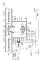
まず、図1及び図2を参照して、本発明の実施形態に係る成膜装置の構成について説明する。図1及び図2は、本実施形態に係る成膜装置の構成を示す概略断面図である。図1は、成膜処理モードにおける動作状態を示し、図2は、窒化物イオン照射モードにおける動作状態を示している。ここで、成膜処理モードとは、真空チャンバー10内で成膜対象物11に対して成膜処理を行うモードである。窒化物イオン照射モードは、真空チャンバー10内で窒化物イオンを生成し、成膜対象物11に形成された膜の表面に照射するモードである。なお、成膜処理モード及び窒化物イオン照射モードの詳細については後述する。
First, the configuration of a film forming apparatus according to an embodiment of the present invention will be described with reference to FIGS. 1 and 2. FIG. 1 and 2 are schematic cross-sectional views showing the configuration of a film forming apparatus according to this embodiment. FIG. 1 shows the operating state in the film formation processing mode, and FIG. 2 shows the operating state in the nitride ion irradiation mode. Here, the film-forming processing mode is a mode in which the film-forming processing is performed on the film-forming
図1及び図2に示すように、本実施形態の成膜装置1は、いわゆるイオンプレーティング法に用いられるイオンプレーティング装置である。成膜装置1は、窒化物イオンを生成するイオン照射装置100としても機能する。以降の説明においては、特段の事情がない限り、イオン照射装置100と成膜装置1とをまとめて「成膜装置1」と説明する場合がある。なお、説明の便宜上、図1及び図2には、XYZ座標系を示す。Y軸方向は、後述する成膜対象物が搬送される方向である。X軸方向は、成膜対象物と後述するハース機構とが対向する位置である。Z軸方向は、Y軸方向とX軸方向とに直交する方向である。 As shown in FIGS. 1 and 2, the film forming apparatus 1 of this embodiment is an ion plating apparatus used for so-called ion plating. The film forming apparatus 1 also functions as an ion irradiation apparatus 100 that generates nitride ions. In the following description, unless there are special circumstances, the ion irradiation apparatus 100 and the film forming apparatus 1 may be collectively referred to as the "film forming apparatus 1". For convenience of explanation, FIGS. 1 and 2 show an XYZ coordinate system. The Y-axis direction is the direction in which an object to be film-formed, which will be described later, is transported. The X-axis direction is the position where the object to be film-formed faces a hearth mechanism, which will be described later. The Z-axis direction is a direction orthogonal to the Y-axis direction and the X-axis direction.
成膜装置1は、成膜対象物11の板厚方向がX軸方向となるように、成膜対象物11を配置させた状態で、成膜対象物11が真空チャンバー10内に配置されて搬送される横型の成膜装置である。この場合には、X軸方向は鉛直方向且つ成膜対象物11の板厚方向であり、Y軸方向は水平方向であり、Z軸方向は水平方向となる。なお、本発明の一実施形態に係る成膜装置は、成膜対象物の板厚方向が略水平方向となるように成膜対象物が真空チャンバー内に配置されて搬送されるいわゆる縦型の成膜装置であってもよい。この場合には、X軸及びY軸方向は水平方向であり、Z軸方向は鉛直方向となる。以下、横型の成膜装置を例として説明する。
In the film forming apparatus 1, the
成膜装置1は、真空チャンバー10、搬送機構3、成膜部14、窒化物イオン照射部24、磁場発生コイル30、及び加熱部160を備えている。
The film forming apparatus 1 includes a
真空チャンバー10は、成膜対象物11を収納し成膜処理を行う。真空チャンバー10は、成膜材料Maの膜が形成される成膜対象物11を搬送するための搬送室10aと、成膜材料Maを拡散させる成膜室10bと、プラズマガン7からビーム状に照射されるプラズマPを真空チャンバー10に受け入れるプラズマ口10cとを有している。搬送室10a、成膜室10b、及びプラズマ口10cは互いに連通している。搬送室10aは、所定の搬送方向(図中の矢印A)に(Y軸に)沿って設定されている。また、真空チャンバー10は、導電性の材料からなり接地電位に接続されている。
A
成膜室10bは、壁部10Wとして、搬送方向(矢印A)に沿った一対の側壁と、搬送方向(矢印A)と交差する方向(Z軸方向)に沿った一対の側壁10h,10iと、X軸方向と交差して配置された底面壁10jと、を有する。
The
搬送機構3は、成膜材料Maと対向した状態で成膜対象物11を保持する成膜対象物保持部材16を搬送方向(矢印A)に搬送する。例えば成膜対象物保持部材16は、成膜対象物11の外周縁を保持するトレイである。搬送機構3は、搬送室10a内に設置された複数の搬送ローラ15によって構成されている。搬送ローラ15は、搬送方向(矢印A)に沿って等間隔に配置され、成膜対象物保持部材16を支持しつつ搬送方向(矢印A)に搬送する。なお、成膜対象物11は、例えばガラス基板やプラスチック基板などの板状部材が用いられる。
The transport mechanism 3 transports the film-forming
続いて、成膜部14の構成について詳細に説明する。成膜部14は、イオンプレーティング法により成膜材料Maの粒子を成膜対象物11に付着させる。成膜部14は、プラズマガン7と、ステアリングコイル5と、ハース機構2と、輪ハース6とを有している。
Next, the configuration of the
プラズマガン7は、例えば圧力勾配型のプラズマガンである。プラズマガン7は、アーク放電によってプラズマPを生成する。プラズマガン7の本体部分は、成膜室10bの側壁に設けられたプラズマ口10cを介して成膜室10bに接続されている。プラズマガン7は、真空チャンバー10内でプラズマPを生成する。プラズマガン7において生成されたプラズマPは、プラズマ口10cから成膜室10b内へビーム状に出射される。これにより、成膜室10b内にプラズマPが生成される。
The
プラズマガン7は、陰極60により一端が閉塞されている。陰極60とプラズマ口10cとの間には、第1の中間電極(グリッド)61と、第2の中間電極(グリッド)62とが同心的に配置されている。第1の中間電極61内にはプラズマPを収束するための環状永久磁石61aが内蔵されている。第2の中間電極62内にもプラズマPを収束するため電磁石コイル62aが内蔵されている。なお、プラズマガン7は、後述する窒化物イオン照射部24としての機能も有する。この詳細については、窒化物イオン照射部24の説明において後述する。
The
ステアリングコイル5は、プラズマガンが装着されたプラズマ口10cの周囲に設けられている。ステアリングコイル5は、プラズマPを成膜室10b内に導く。ステアリングコイル5は、ステアリングコイル用の電源(不図示)により励磁される。
A
ハース機構2は、成膜材料Maを保持する。ハース機構2は、真空チャンバー10の成膜室10b内に設けられ、搬送機構3から見てX軸方向の負方向に配置されている。ハース機構2は、プラズマガン7から出射されたプラズマPを成膜材料Maに導く主陽極又はプラズマガン7から出射されたプラズマPが導かれる主陽極である主ハース17を有している。
The
主ハース17は、成膜材料Maが充填されたX軸方向の正方向に延びた筒状の充填部17aと、充填部17aから突出したフランジ部17bとを有している。主ハース17は、真空チャンバー10が有する接地電位に対して正電位に保たれている。また、プラズマPは負電位である。従って、主ハース17は、プラズマPを吸引する。このプラズマPが入射する主ハース17の充填部17aには、成膜材料Maを充填するための貫通孔17cが形成されている。そして、成膜材料Maの先端部分が、この貫通孔17cの一端において成膜室10bに露出している。
The
成膜材料Maには、導電材料や、絶縁材料が例示される。成膜材料Maが絶縁性物質からなる場合、主ハース17にプラズマPが照射されると、プラズマPからの電流によって主ハース17が加熱され、成膜材料Maの先端部分が蒸発又は昇華し、プラズマPによりイオン化された成膜材料粒子(蒸発粒子)Mbが成膜室10b内に拡散する。また、成膜材料Maが導電性物質からなる場合、主ハース17にプラズマPが照射されると、プラズマPが成膜材料Maに直接入射し、成膜材料Maの先端部分が加熱されて蒸発又は昇華し、プラズマPによりイオン化された成膜材料粒子Mbが成膜室10b内に拡散する。成膜室10b内に拡散した成膜材料粒子Mbは、成膜室10bのX軸正方向へ移動し、搬送室10a内において成膜対象物11の表面に付着する。なお、成膜材料Maは、所定長さの円柱形状に成形された固体物であり、一度に複数の成膜材料Maがハース機構2に充填される。そして、最先端側の成膜材料Maの先端部分が主ハース17の上端との所定の位置関係を保つように、成膜材料Maの消費に応じて、成膜材料Maがハース機構2のX負方向側から順次押し出される。本実施形態では、成膜材料Maとして、Al、AlN、又はAlxN1-xを含有した材料が採用される。その結果、成膜対象物11に成膜材料Maを成膜することで、AlN膜151を有するAlN基板150が形成される(図2、図4及び図5参照)。
The film-forming material Ma is exemplified by a conductive material and an insulating material. When the film-forming material Ma is made of an insulating material, when the
輪ハース6は、プラズマPを誘導するための電磁石を有する補助陽極である。輪ハース6は、成膜材料Maを保持する主ハース17の充填部17aの周囲に配置されている。輪ハース6は、環状のコイル9と環状の永久磁石部20と環状の容器12とを有し、コイル9及び永久磁石部20は容器12に収容されている。本実施形態では、搬送機構3から見てX負方向にコイル9、永久磁石部20の順に設置されているが、X負方向に永久磁石部20、コイル9の順に設置されていてもよい。輪ハース6は、コイル9に流れる電流の大きさに応じて、成膜材料Maに入射するプラズマPの向き、または、主ハース17に入射するプラズマPの向きを制御する。
The
続いて、窒化物イオン照射部24の構成について詳細に説明する。窒化物イオン照射部24は、プラズマガン7と、窒化物ガス供給部40と、制御部50と、回路部34とを有している。なお、制御部50及び回路部34に含まれる一部の機能は、前述の成膜部14にも属する。窒化物イオン照射部24は、窒化物イオンを生成する。また、窒化物イオン照射部24は、生成した窒化物イオンをAlN基板150に照射する(図4参照)。窒化物イオン照射部24は、窒化物イオンとして、負イオンを生成する。窒化物イオンとして、水素の窒化物イオン(NH2
-)が挙げられる。なお、窒化物イオン照射部24は、例えば、N+、N2
+などの窒素の陽イオンを生成してもよい。
Next, the configuration of the nitride
プラズマガン7は、前述の成膜部14が有するプラズマガン7と同様のものが用いられる。すなわち、本実施形態において、成膜部14のプラズマガン7は、窒化物イオン照射部24のプラズマガン7と兼用されている。プラズマガン7は、成膜部14として機能すると共に、窒化物イオン照射部24としても機能する。なお、成膜部14と窒化物イオン照射部24とで、互いに異なる別箇のプラズマガンを有していてもよい。
The
プラズマガン7は、成膜室10b内において間欠的にプラズマPを生成する。具体的には、プラズマガン7は、後述の制御部50によって成膜室10b内において間欠的にプラズマPを生成するように制御されている。この制御については、後述の制御部50の説明において詳述する。
The
窒化物ガス供給部40は、真空チャンバー10の外部に配置されている。窒化物ガス供給部40は、成膜室10bの側壁(例えば、側壁10h)に設けられたガス供給口41を通し、真空チャンバー10内へ窒化物イオンの原料ガスである窒化物ガスを供給する。窒化物ガスとして、例えば、NH3ガス、NH2ガス等が用いられる。窒化物ガス供給部40は、例えば成膜処理モードから窒化物イオン照射モードに切り替わると、窒化物ガスの供給を開始する。また、窒化物ガス供給部40は、成膜処理モード及び窒化物イオン照射モードの両方において窒化物ガスの供給を行い続けてもよい。
The nitride
例えば、成膜材料としてAlを採用する場合、窒化物ガス供給部40は、成膜処理モード時にN2ガスを供給する。これにより、N2をプラズマPと反応させてN+またはN 2
+とし、昇華したAlとN+またはN 2
+によって、AlN膜を形成する。そして、窒化物ガス供給部40は、窒化物イオン照射モード時には、N2ガス(正イオンを作る場合)、またはNH3ガス若しくはNH2ガス(負イオンを作る場合)を供給する。このような場合、窒化物ガス供給部40は、供給するガスの種類に応じた複数のガス貯留部と接続され、使用するガスに応じてガス貯留部からガスを引き出してよい。
For example, when Al is employed as the film forming material, the nitride
ガス供給口41の位置は、成膜室10bと搬送室10aとの境界付近の位置が好ましい。この場合、窒化物ガス供給部40からの窒化物ガスを、成膜室10bと搬送室10aとの境界付近に供給することができるので、当該境界付近において後述する窒化物イオンの生成が行われる。よって、生成した窒化物イオンを、搬送室10aにおける成膜対象物11に好適に付着させることができる。なお、ガス供給口41の位置は、成膜室10bと搬送室10aとの境界付近に限られない。
The position of the
制御部50は、真空チャンバー10の外部に配置されている。制御部50は、回路部34が有する切替部を切り替える切替制御部として機能する。この制御部50による切替部の切り替えについては、以下、回路部34の説明と併せて詳述する。また、制御部50は、窒化物ガス供給部40を制御する窒化物ガス供給制御部として機能する。また、制御部50は、磁場発生コイル30による磁場の発生を制御するコイル制御部として機能する。
The
より詳細には、制御部50は、プラズマガン7で生成したプラズマPを成膜材料Ma又は主ハースへ照射し、成膜対象物11に成膜材料Maの膜を形成する。また、制御部50は、プラズマガン7でプラズマPを生成すると共に、窒化物ガス供給部40から窒化物ガスを真空チャンバー10内へ供給することで窒化物イオンを生成し、成膜材料Maの膜、すなわちAlN基板150に窒化物イオンを照射する。
More specifically, the
回路部34は、可変電源80と、第1の配線71と、第2の配線72と、抵抗器R1~R4と、短絡スイッチSW1,SW2と、を有している。
The
可変電源80は、接地電位にある真空チャンバー10を挟んで、負電圧をプラズマガン7の陰極60に、正電圧をハース機構2の主ハース17に印加する。これにより、可変電源80は、プラズマガン7の陰極60とハース機構2の主ハース17との間に電位差を発生させる。
A
第1の配線71は、プラズマガン7の陰極60を、可変電源80の負電位側と電気的に接続している。第2の配線72は、ハース機構2の主ハース17(陽極)を、可変電源80の正電位側と電気的に接続している。
A
抵抗器R1は、一端がプラズマガン7の第1の中間電極61と電気的に接続されていると共に、他端が第2の配線72を介して可変電源80と電気的に接続されている。すなわち、抵抗器R1は、第1の中間電極61と可変電源80との間において直列接続されている。
The resistor R1 has one end electrically connected to the first
抵抗器R2は、一端がプラズマガン7の第2の中間電極62と電気的に接続されていると共に、他端が第2の配線72を介して可変電源80と電気的に接続されている。すなわち、抵抗器R2は、第2の中間電極62と可変電源80との間において直列接続されている。
The resistor R2 has one end electrically connected to the second
抵抗器R3は、一端が成膜室10bの壁部10Wと電気的に接続されていると共に、他端が第2の配線72を介して可変電源80と電気的に接続されている。すなわち、抵抗器R3は、成膜室10bの壁部10Wと可変電源80との間において直列接続されている。
The resistor R3 has one end electrically connected to the
抵抗器R4は、一端が輪ハース6と電気的に接続されていると共に、他端が第2の配線72を介して可変電源80と電気的に接続されている。すなわち、抵抗器R4は、輪ハース6と可変電源80との間において直列接続されている。
The resistor R4 has one end electrically connected to the
短絡スイッチSW1,SW2は、それぞれ前述の制御部50からの指令信号を受信することにより、ON/OFF状態に切り替えられる切替部である。
The short-circuit switches SW1 and SW2 are switching units that are switched between ON/OFF states by receiving command signals from the
短絡スイッチSW1は、抵抗器R2に並列接続されている。短絡スイッチSW1は、成膜処理モードであるか窒化物イオン照射モードであるかに応じて、制御部50によってON/OFF状態が切り替えられる。短絡スイッチSW1は、成膜処理モードにおいてはOFF状態とされる。これにより、成膜処理モードにおいては、第2の中間電極62と可変電源80とが抵抗器R2を介して互いに電気的に接続されるので、第2の中間電極62と可変電源80との間には電流が流れにくい。その結果、プラズマガン7からのプラズマPが真空チャンバー10内に出射され、成膜材料Maに入射する(図1参照)。なお、プラズマガン7からのプラズマPを真空チャンバー10内に出射する場合、第2の中間電極62への電流を流れにくくする事に代えて、第1の中間電極61への電流を流れにくくしてもよい。この場合、短絡スイッチSW1は、第2の中間電極62側に代えて、第1の中間電極61側に接続される。
The short-circuit switch SW1 is connected in parallel with the resistor R2. The ON/OFF state of the short-circuit switch SW1 is switched by the
一方、短絡スイッチSW1は、窒化物イオン照射モードにおいては、プラズマガン7からのプラズマPを真空チャンバー10内で間欠的に生成するため、制御部50によってON/OFF状態が所定間隔で切り替えられる。短絡スイッチSW1がON状態に切り替えられると、第2の中間電極62と可変電源80との間の電気的な接続が短絡するので、第2の中間電極62と可変電源80との間に電流が流れる。すなわち、プラズマガン7に短絡電流が流れる。その結果、プラズマガン7からのプラズマPが真空チャンバー10内に出射されなくなる。
On the other hand, in the nitride ion irradiation mode, the short-circuit switch SW1 intermittently generates the plasma P from the
短絡スイッチSW1がOFF状態に切り替えられると、第2の中間電極62と可変電源80とが抵抗器R2を介して互いに電気的に接続されるので、第2の中間電極62と可変電源80との間には電流が流れにくい。その結果、プラズマガン7からのプラズマPが真空チャンバー10内に出射される。このように、短絡スイッチSW1のON/OFF状態が制御部50によって所定間隔で切り替えられることにより、プラズマガン7からのプラズマPが真空チャンバー10内において間欠的に生成される。すなわち、短絡スイッチSW1は、真空チャンバー10内へのプラズマPの供給と遮断とを切り替える切替部である。
When the short-circuit switch SW1 is switched to the OFF state, the second
短絡スイッチSW2は、抵抗器R4に並列接続されている。短絡スイッチSW2は、例えば成膜処理モードになる前の成膜対象物11の搬送前の状態であるスタンバイモードであるか成膜処理モードであるかに応じて、制御部50によってON/OFF状態が切り替えられる。短絡スイッチSW2は、スタンバイモードではON状態とされる。これにより、輪ハース6と可変電源80との間の電気的な接続が短絡するので、主ハース17よりも輪ハース6に電流を流しやすくなり、成膜材料Maの無駄な消費を防ぐことができる。
The short-circuit switch SW2 is connected in parallel with the resistor R4. The short-circuit switch SW2 is turned ON/OFF by the
一方、短絡スイッチSW2は、成膜処理モードではOFF状態とされる。これにより、輪ハース6と可変電源80が抵抗器R4を介して電気的に接続されるので、輪ハース6よりも主ハース17に電流を流しやすくなり、プラズマPの出射方向を好適に成膜材料Maに向けることができる。なお、短絡スイッチSW2は、窒化物イオン照射モードではON状態又はOFF状態のいずれの状態とされてもよい。
On the other hand, the short-circuit switch SW2 is turned off in the film forming process mode. As a result, the
磁場発生コイル30は、真空チャンバー10内であって、成膜室10bと搬送室10aとの間に設けられている。磁場発生コイル30は、例えばハース機構2と搬送機構3との間に配置されている。より具体的には、磁場発生コイル30は、成膜室10bの搬送室10a側の端部と、搬送室10aの成膜室10b側の端部とに介在するように位置している。磁場発生コイル30は、互いに対向する一対のコイル30a,30bを有している。各コイル30a,30bは、例えば成膜室10bから搬送室10aへ向かう方向(ハース機構2から搬送機構3へ向かう方向)に交差する方向で互いに対向している。
The magnetic
磁場発生コイル30は、成膜処理モードにおいては励磁されず、窒化物イオン照射モードにおいて磁場発生コイル30用の電源(不図示)により励磁される。磁場発生コイル30は、窒化物イオン照射モードにおいて励磁されることにより、成膜室10bから搬送室10aへ向かう方向(ハース機構2から搬送機構3へ向かう方向)と交差する方向に伸びる磁力線を有する封止磁場Mを真空チャンバー10内に形成する(図2参照)。磁場発生コイル30は、このような封止磁場Mを発生させることにより、成膜室10b内の電子が搬送室10a内へ流入するのを抑制する。封止磁場Mが有する磁力線は、例えば成膜対象物11の搬送方向(矢印A)に略平行な方向に伸びる部分を有していてもよい。なお、磁場発生コイル30用の電源のON/OFF状態の切り替えは、制御部50によって制御されてもよい。磁場発生コイル30は、成膜材料Maが堆積しないようケース31で覆われている。なお、磁場発生コイル30はケース31で覆われていなくてもよい。
The magnetic
加熱部160は、窒化物イオン照射部24による窒化物イオンの照射中、又は照射後に、AlN基板150を加熱する。加熱部160は、制御部50からの制御信号に基づいて、加熱のON/OFFを切り替える。加熱部160は、電熱線等によって構成される。なお、図1及び図2では、加熱部160は、搬送機構3のうち真空チャンバー10に対応する位置に一つ設けられているが、当該位置よりも下流側に設けてもよく、二つ以上設けてもよい。
The
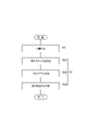
次に、図3を参照して、成膜装置1における成膜方法について詳細に説明する。図3は、成膜装置1における成膜方法を示すフローチャートである。 Next, with reference to FIG. 3, the film forming method in the film forming apparatus 1 will be described in detail. FIG. 3 is a flow chart showing a film forming method in the film forming apparatus 1. As shown in FIG.
図3に示すように、まず、成膜装置1は、制御部50によって成膜処理モードに切り替えられると、成膜対象物11に成膜材料Maの膜を形成する(S1:成膜工程)。このとき、制御部50によって短絡スイッチSW1がOFF状態とされている。また、成膜処理モードにおいて、ステアリングコイル5が励磁されている一方、磁場発生コイル30は励磁されていない。これにより、プラズマガン7によって成膜室10b内でプラズマPが生成され、当該プラズマPが主ハース17に照射される(図1参照)。その結果、主ハース17における成膜材料MaがプラズマPによりイオン化されて成膜材料粒子Mbとなり、成膜室10b内に拡散し、搬送室10a内の成膜対象物11の表面に付着する。このようにして、成膜対象物11に成膜材料Maの膜が形成され、成膜工程S1が終了する。
As shown in FIG. 3, first, when the film forming apparatus 1 is switched to the film forming processing mode by the
続いて、成膜装置1では、窒化物イオン照射モードにおいて、AlN基板150に窒化物イオンを照射する(S2:窒化物イオン照射工程)。以下、窒化物イオン照射工程S2について具体的に説明する。まず、窒化物ガス供給部40によって、成膜室10b内に窒化物ガスが供給される(S21:窒化物ガス供給工程)。
Subsequently, in the film forming apparatus 1, the
続いて、制御部50によって、プラズマガン7からのプラズマPを成膜室10b内で間欠的に生成するようにプラズマガン7が制御される(S22:プラズマ生成工程)。例えば、制御部50によって、短絡スイッチSW1のON/OFF状態が所定間隔で切り替えられることにより、プラズマガン7からのプラズマPが成膜室10b内で間欠的に生成される。
Subsequently, the
短絡スイッチSW1がON状態とされているときは、プラズマガン7からのプラズマPが成膜室10b内に出射されないので成膜室10b内におけるプラズマPの電子温度が急激に低下する。このため、前述の窒化物ガス供給工程S21において成膜室10b内に供給された窒化物ガスの粒子に、プラズマPの電子が付着し易くなる。これにより、成膜室10b内には、窒化物イオンが効率的に生成される。
When the short-circuit switch SW1 is in the ON state, the plasma P from the
続いて、制御部50によって、真空チャンバー10内に封止磁場Mが形成される(S23:封止磁場形成工程)。例えば、磁場発生コイル30が励磁されることにより、真空チャンバー10内で成膜室10bと搬送室10aとの間に介在するように封止磁場Mが形成される(図2参照)。封止磁場Mは、成膜室10bから搬送室10aへ向かう方向(ハース機構2から搬送機構3へ向かう方向)に交差する方向に伸びる磁力線を有している。なお、封止電場形成工程S23は省略されてもよい。この場合、プラズマPの生成を止めた後、所定時間(例えば2msec)経過した後に、AlN基板150にバイアス電圧をかけてAlN基板150に負イオンを照射する。このようにプラズマPを止めてから所定時間が経過することで電子の多くが消失するため、電子の流入を抑制しつつ負イオンをAlN基板150に照射することが可能となる。
Subsequently, the
前述のプラズマ生成工程S22において生成された成膜室10b内におけるプラズマPの電子は、封止磁場形成工程S23において形成された封止磁場Mの磁力線に阻害され、搬送室10aへの流入が抑制される。これにより、成膜室10b内の窒化物ガスの粒子に、プラズマPの電子が付着し易くなり、より効率的に窒化物イオンを生成することができる。そして、プラズマ生成工程S22において生成された窒化物イオンが成膜室10bのX軸正方向へ移動し、搬送室10a内において、成膜処理によってAlN基板150のAlN膜151の表面に付着する。なお、AlN基板150に正のバイアス電圧をかけることによって、より積極的に窒化物イオンをAlN基板150に形成されたAlN膜151の表面に付着させてもよい。以上のようにして、窒化物イオン照射工程S2が終了すると、図3に示す成膜方法が終了する。
The electrons of the plasma P in the
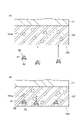
ここで、図4及び図5を参照して、AlN基板150に窒化物イオンを照射したときの窒化物イオンの挙動等について説明する。ここでは、窒化物イオン85として、水素の負イオンである「NH2
-」を照射するものとする。また、成膜対象物11にAlN膜151を形成したものをAlN基板150と称する。まず、図4(a)に示すように、AlN基板150に対して、加速された窒化物イオン85を照射する。これにより、図4(b)に示すように、窒化物イオン85がAlN膜151中に注入される。このとき、窒化物イオン85の電子はAlN膜151との衝突時に、窒化物イオン85から取れる。
Here, the behavior of nitride ions when the
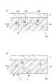
次に、図5(a)に示すように、一部の窒素81は、AlN膜151の空孔151a内に入り(例えば窒素81A)、他の一部はAlN膜151の格子間に入り込む(例えば窒素81B)。また、水素82の一部もAlN膜151の格子間に残存する。次に、AlN基板150を加熱部160で加熱することにより、水素82はAlN膜151から外部へ出て行く。加熱によってアニールされることで、格子間に入り込んでいた窒素81が、空孔151aに入り込む。以上により、AlN膜151の空孔151aに窒素81が入り込むことにより、AlN膜151の強度が向上し、AlN基板150の欠陥が抑制される。
Next, as shown in FIG. 5A, part of the
次に、本実施形態に係るイオン照射装置100、イオン照射方法、成膜装置1、及び成膜方法の作用・効果について説明する。 Next, functions and effects of the ion irradiation apparatus 100, the ion irradiation method, the film forming apparatus 1, and the film forming method according to this embodiment will be described.
本実施形態に係るイオン照射装置100は、窒化物イオンを生成して、AlN基板に窒化物イオンを照射する窒化物イオン照射部24を備える。このように、AlN基板に窒化物イオンを照射すると、窒化物イオンは、AlN膜151中の空孔151a内に入り込むことができる(図5参照)。従って、AlN膜151中に入り込んだ窒化物イオンにより、AlN基板150の欠陥を低減することができる。以上により、半導体素子として使用可能なAlN基板150を製造できる。
The ion irradiation apparatus 100 according to this embodiment includes a nitride
イオン照射装置100において、窒化物イオン照射部24は、窒化物イオンとして、水素の窒化物イオンを生成してよい。例えば、窒化物の負イオンを生成し、AlN基板150へ負イオンを照射した後に窒素以外の元素を離脱させる際、水素であればAlN基板150から離脱させ易くなる。より詳細に説明すると、N2ガスからは直接N-を作ることができないため、NH2
-などの状態で窒化物の負イオンを生成する。このとき、NH2
-をAlN基板150に注入した後、AlN基板150を加熱処理することでサイズが小さな水素はAlN基板150から離脱することができる。なお、水素以外の他の元素の場合、サイズが大きいため、AlN基板150から脱離させにくくなる。
In the ion irradiation apparatus 100, the nitride
イオン照射装置100は、窒化物イオン照射部24による窒化物イオンの照射中、又は照射後に、AlN基板150を加熱する加熱部160を更に備えてよい。この場合、AlN膜151の格子間に入り込んだ窒化物イオン(及び窒化物(中性))をアニールすることによって、AlN膜151の空孔151aに入り込ませることができる(図5(b)参照)。また、水素の窒化物イオンを照射した場合は、AlN膜151から水素を外部へ出すことができる(図5(b)参照)。
The ion irradiation apparatus 100 may further include a
イオン照射装置100において、窒化物イオン照射部24は、窒化物イオンとして、負イオンを生成してよい。この場合、エネルギーの低い負イオンをAlN基板150に照射することで、AlN基板150に対するダメージを低減することができる。
In the ion irradiation apparatus 100, the nitride
本実施形態に係るイオン照射方法は、AlN基板150にイオンを照射するイオン照射方法であって、窒化物イオンを生成して、AlN基板150に窒化物イオンを照射する工程を備える。
The ion irradiation method according to the present embodiment is an ion irradiation method for irradiating the
このイオン照射方法によれば、上述のイオン照射装置100と同様な作用・効果を得ることができる。 According to this ion irradiation method, the same actions and effects as those of the ion irradiation apparatus 100 described above can be obtained.
本発明に係る成膜装置1では、制御部50は、プラズマガン7で生成したプラズマを成膜材料Ma又は主ハース17へ照射し、成膜対象物11に成膜材料Maの膜を形成する。これにより、成膜対象物11にAlNの膜が形成される。また、制御部50は、プラズマガン7でプラズマを生成すると共に、窒化物ガス供給部40から窒化物ガスを真空チャンバー10内へ供給することで窒化物イオンを生成し、成膜材料の膜に窒化物イオンを照射する。これにより、成膜装置1は、AlN膜151に対して窒化物イオンを照射することができる。従って、上述のイオン照射装置100と同様の作用・効果を得ることができる。更に、成膜装置1は、成膜とイオン照射を同一のチャンバー内で行うことができる。
In the film forming apparatus 1 according to the present invention, the
本実施形態に係る成膜方法は、成膜対象物11に成膜材料Maの膜を形成する成膜方法であって、真空チャンバー10内にプラズマガン7で生成したプラズマをAl又はAlNを含む成膜材料Ma又は当該成膜材料Maを保持する主ハース17へ照射し、成膜対象物11に成膜材料Maの膜を形成する工程と、プラズマガン7でプラズマを生成すると共に、窒化物ガス供給部40から窒化物ガスをチャンバー内へ供給することで窒化物イオンを生成し、成膜材料Maの膜に窒化物イオンを照射する工程と、を備える。
The film formation method according to the present embodiment is a film formation method for forming a film of the film formation material Ma on the
この成膜方法によれば、上述の成膜装置1と同様の作用・効果を得ることができる。 According to this film forming method, it is possible to obtain the same actions and effects as those of the film forming apparatus 1 described above.
本発明は、上述の実施形態に限定されるものではない。 The invention is not limited to the embodiments described above.
例えば、上述の実施形態では、一つのチャンバー内で成膜と窒化物イオンの照射を行った。これに代えて、成膜を行うチャンバーと、窒化物イオンの照射を行うチャンバーを分けてもよい。 For example, in the above-described embodiments, film formation and nitride ion irradiation are performed in one chamber. Alternatively, a chamber for film formation and a chamber for nitride ion irradiation may be separated.
上記実施形態に係る成膜装置は、イオンプレーティング法を用いて成膜を行う装置であるとしたが、これに限られない。例えば、スパッタリング法、又は化学蒸着法等を用いて成膜を行ってもよい。 Although the film forming apparatus according to the above embodiment is an apparatus that forms a film using an ion plating method, the present invention is not limited to this. For example, a sputtering method, a chemical vapor deposition method, or the like may be used for film formation.
1…成膜装置、7…プラズマガン、10…真空チャンバー(チャンバー)、11…成膜対象物、14…成膜部、17…主ハース(成膜材料保持部)、24…窒化物イオン照射部、50…制御部、100…イオン照射装置。
DESCRIPTION OF SYMBOLS 1... Film-forming apparatus, 7... Plasma gun, 10... Vacuum chamber (chamber), 11... Film-forming object, 14... Film-forming part, 17... Main hearth (film-forming material holding part), 24... Nitride
Claims (6)
窒化物負イオンを生成して、前記AlN基板に窒化物負イオンを照射する窒化物負イオン照射部を備える、イオン照射装置。 An ion irradiation apparatus for irradiating an AlN substrate with ions,
An ion irradiation apparatus comprising a nitride negative ion irradiation unit that generates nitride negative ions and irradiates the AlN substrate with the nitride negative ions.
窒化物負イオンを生成して、前記AlN基板に窒化物負イオンを照射する工程を備える、イオン照射方法。 An ion irradiation method for irradiating an AlN substrate with ions,
An ion irradiation method comprising the step of generating nitride negative ions and irradiating the AlN substrate with the nitride negative ions.
前記成膜対象物を収容し成膜を行うチャンバーと、
前記チャンバー内でプラズマを生成するプラズマガンと、
前記チャンバー内でAl又はAlNを含む前記成膜材料を保持する成膜材料保持部と、
少なくとも窒化物ガスを前記チャンバー内へ供給するガス供給部と、
前記成膜装置を制御する制御部と、を備え、
前記制御部は、
前記プラズマガンで生成したプラズマを前記成膜材料又は前記成膜材料保持部へ照射し、前記成膜対象物に前記成膜材料の膜を形成し、
前記プラズマガンで前記プラズマを生成すると共に、前記ガス供給部から少なくとも前記窒化物ガスを前記チャンバー内へ供給することで窒化物負イオンを生成し、前記成膜材料の膜に前記窒化物負イオンを照射する、成膜装置。 A film forming apparatus for forming a film of a film forming material on a film forming object,
a chamber for housing the film-forming object and for film-forming;
a plasma gun that generates a plasma within the chamber;
a film forming material holder that holds the film forming material containing Al or AlN in the chamber;
a gas supply unit that supplies at least a nitride gas into the chamber;
A control unit that controls the film forming apparatus,
The control unit
irradiating the film-forming material or the film-forming material holder with plasma generated by the plasma gun to form a film of the film-forming material on the film-forming object;
The plasma is generated by the plasma gun, and at least the nitride gas is supplied into the chamber from the gas supply unit to generate nitride negative ions, and the nitride is formed on the film of the film-forming material. A film forming apparatus that irradiates negative ions .
チャンバー内にプラズマガンで生成したプラズマをAl又はAlNを含む前記成膜材料又は当該成膜材料を保持する成膜材料保持部へ照射し、前記成膜対象物に前記成膜材料の膜を形成する工程と、
前記プラズマガンで前記プラズマを生成すると共に、ガス供給部から少なくとも窒化物ガスを前記チャンバー内へ供給することで窒化物負イオンを生成し、前記成膜材料の膜に前記窒化物負イオンを照射する工程と、を備える、成膜方法。
A film formation method for forming a film of a film formation material on a film formation object,
Plasma generated by a plasma gun in a chamber is irradiated to the film-forming material containing Al or AlN or a film-forming material holding unit holding the film-forming material to form a film of the film-forming material on the film-forming object. and
The plasma is generated by the plasma gun, and at least the nitride gas is supplied into the chamber from the gas supply unit to generate nitride negative ions, and the nitride negative ions are formed on the film of the film-forming material. and irradiating with ion.
Priority Applications (1)
| Application Number | Priority Date | Filing Date | Title |
|---|---|---|---|
| JP2018121004A JP7120540B2 (en) | 2018-06-26 | 2018-06-26 | Ion irradiation apparatus, ion irradiation method, film formation apparatus, and film formation method |
Applications Claiming Priority (1)
| Application Number | Priority Date | Filing Date | Title |
|---|---|---|---|
| JP2018121004A JP7120540B2 (en) | 2018-06-26 | 2018-06-26 | Ion irradiation apparatus, ion irradiation method, film formation apparatus, and film formation method |
Publications (3)
| Publication Number | Publication Date |
|---|---|
| JP2020002400A JP2020002400A (en) | 2020-01-09 |
| JP2020002400A5 JP2020002400A5 (en) | 2021-06-17 |
| JP7120540B2 true JP7120540B2 (en) | 2022-08-17 |
Family
ID=69098860
Family Applications (1)
| Application Number | Title | Priority Date | Filing Date |
|---|---|---|---|
| JP2018121004A Active JP7120540B2 (en) | 2018-06-26 | 2018-06-26 | Ion irradiation apparatus, ion irradiation method, film formation apparatus, and film formation method |
Country Status (1)
| Country | Link |
|---|---|
| JP (1) | JP7120540B2 (en) |
Citations (2)
| Publication number | Priority date | Publication date | Assignee | Title |
|---|---|---|---|---|
| JP2000087227A (en) | 1998-09-15 | 2000-03-28 | Japan Science & Technology Corp | Formation of nitride by gaseous nitrogen compound cluster ion beam |
| JP2017025407A (en) | 2015-07-21 | 2017-02-02 | 住友重機械工業株式会社 | Film deposition apparatus |
Family Cites Families (2)
| Publication number | Priority date | Publication date | Assignee | Title |
|---|---|---|---|---|
| JPH0784640B2 (en) * | 1987-12-11 | 1995-09-13 | 理化学研究所 | Method for producing crystalline aluminum nitride |
| JPH07221018A (en) * | 1994-01-31 | 1995-08-18 | Sanyo Electric Co Ltd | Method for forming nitric compound semiconductor |
-
2018
- 2018-06-26 JP JP2018121004A patent/JP7120540B2/en active Active
Patent Citations (2)
| Publication number | Priority date | Publication date | Assignee | Title |
|---|---|---|---|---|
| JP2000087227A (en) | 1998-09-15 | 2000-03-28 | Japan Science & Technology Corp | Formation of nitride by gaseous nitrogen compound cluster ion beam |
| JP2017025407A (en) | 2015-07-21 | 2017-02-02 | 住友重機械工業株式会社 | Film deposition apparatus |
Also Published As
| Publication number | Publication date |
|---|---|
| JP2020002400A (en) | 2020-01-09 |
Similar Documents
| Publication | Publication Date | Title |
|---|---|---|
| JP6584982B2 (en) | Deposition equipment | |
| WO2017014278A1 (en) | Film-forming apparatus | |
| JP7120540B2 (en) | Ion irradiation apparatus, ion irradiation method, film formation apparatus, and film formation method | |
| TWI757771B (en) | Negative ion irradiation device | |
| TWI823563B (en) | Negative ion irradiation device and control method of negative ion irradiation device | |
| JP7246628B2 (en) | Film formation/ion irradiation system and film formation/ion irradiation method | |
| JP6009220B2 (en) | Deposition equipment | |
| JP5456716B2 (en) | Deposition equipment | |
| TW202103200A (en) | Anion generation device avoiding anions from being radiated to a film forming object when a great number of electrons are radiated on an object | |
| JP7209572B2 (en) | Negative ion generator | |
| JP2010132939A (en) | Ion plating apparatus and film-forming method | |
| TWI700967B (en) | Negative ion generator | |
| JP2007009309A (en) | Film deposition method, and film deposition system | |
| JP2022025333A (en) | Plasma gun, film forming device, and negative ion generating device | |
| JP2020037717A (en) | Film deposition apparatus and apparatus for manufacturing film structure | |
| JP2012172261A (en) | Film-forming apparatus | |
| US20190035604A1 (en) | Solid-state source of atomic specie for etching | |
| JP2020190028A (en) | Film deposition apparatus | |
| JP2005042157A (en) | Ion plating system, and method therefor | |
| JPS6167766A (en) | Ion plating device | |
| JP2007056353A (en) | Plasma generation module, and plasma generation method | |
| JP2005044604A (en) | Plasma treatment device and its treatment method | |
| JP2014231618A (en) | Evaporation furnace, and evaporator |
Legal Events
| Date | Code | Title | Description |
|---|---|---|---|
| A521 | Request for written amendment filed |
Free format text: JAPANESE INTERMEDIATE CODE: A523 Effective date: 20210428 |
|
| A621 | Written request for application examination |
Free format text: JAPANESE INTERMEDIATE CODE: A621 Effective date: 20210513 |
|
| A977 | Report on retrieval |
Free format text: JAPANESE INTERMEDIATE CODE: A971007 Effective date: 20220127 |
|
| A131 | Notification of reasons for refusal |
Free format text: JAPANESE INTERMEDIATE CODE: A131 Effective date: 20220208 |
|
| A521 | Request for written amendment filed |
Free format text: JAPANESE INTERMEDIATE CODE: A523 Effective date: 20220407 |
|
| TRDD | Decision of grant or rejection written | ||
| A01 | Written decision to grant a patent or to grant a registration (utility model) |
Free format text: JAPANESE INTERMEDIATE CODE: A01 Effective date: 20220705 |
|
| A61 | First payment of annual fees (during grant procedure) |
Free format text: JAPANESE INTERMEDIATE CODE: A61 Effective date: 20220726 |
|
| R150 | Certificate of patent or registration of utility model |
Ref document number: 7120540 Country of ref document: JP Free format text: JAPANESE INTERMEDIATE CODE: R150 |