JP7119084B2 - Slide rack gripper device - Google Patents
Slide rack gripper device Download PDFInfo
- Publication number
- JP7119084B2 JP7119084B2 JP2020524845A JP2020524845A JP7119084B2 JP 7119084 B2 JP7119084 B2 JP 7119084B2 JP 2020524845 A JP2020524845 A JP 2020524845A JP 2020524845 A JP2020524845 A JP 2020524845A JP 7119084 B2 JP7119084 B2 JP 7119084B2
- Authority
- JP
- Japan
- Prior art keywords
- slide rack
- gripper
- finger
- slide
- rack
- Prior art date
- Legal status (The legal status is an assumption and is not a legal conclusion. Google has not performed a legal analysis and makes no representation as to the accuracy of the status listed.)
- Active
Links
Images


Classifications
-
- G—PHYSICS
- G02—OPTICS
- G02B—OPTICAL ELEMENTS, SYSTEMS OR APPARATUS
- G02B21/00—Microscopes
- G02B21/34—Microscope slides, e.g. mounting specimens on microscope slides
-
- B—PERFORMING OPERATIONS; TRANSPORTING
- B25—HAND TOOLS; PORTABLE POWER-DRIVEN TOOLS; MANIPULATORS
- B25J—MANIPULATORS; CHAMBERS PROVIDED WITH MANIPULATION DEVICES
- B25J15/00—Gripping heads and other end effectors
- B25J15/0028—Gripping heads and other end effectors with movable, e.g. pivoting gripping jaw surfaces
-
- B—PERFORMING OPERATIONS; TRANSPORTING
- B25—HAND TOOLS; PORTABLE POWER-DRIVEN TOOLS; MANIPULATORS
- B25J—MANIPULATORS; CHAMBERS PROVIDED WITH MANIPULATION DEVICES
- B25J15/00—Gripping heads and other end effectors
- B25J15/0033—Gripping heads and other end effectors with gripping surfaces having special shapes
- B25J15/0042—V-shaped gripping surfaces
-
- B—PERFORMING OPERATIONS; TRANSPORTING
- B25—HAND TOOLS; PORTABLE POWER-DRIVEN TOOLS; MANIPULATORS
- B25J—MANIPULATORS; CHAMBERS PROVIDED WITH MANIPULATION DEVICES
- B25J15/00—Gripping heads and other end effectors
- B25J15/02—Gripping heads and other end effectors servo-actuated
- B25J15/0253—Gripping heads and other end effectors servo-actuated comprising parallel grippers
-
- B—PERFORMING OPERATIONS; TRANSPORTING
- B25—HAND TOOLS; PORTABLE POWER-DRIVEN TOOLS; MANIPULATORS
- B25J—MANIPULATORS; CHAMBERS PROVIDED WITH MANIPULATION DEVICES
- B25J15/00—Gripping heads and other end effectors
- B25J15/08—Gripping heads and other end effectors having finger members
-
- B—PERFORMING OPERATIONS; TRANSPORTING
- B25—HAND TOOLS; PORTABLE POWER-DRIVEN TOOLS; MANIPULATORS
- B25J—MANIPULATORS; CHAMBERS PROVIDED WITH MANIPULATION DEVICES
- B25J9/00—Program-controlled manipulators
- B25J9/0093—Program-controlled manipulators co-operating with conveyor means
-
- B—PERFORMING OPERATIONS; TRANSPORTING
- B25—HAND TOOLS; PORTABLE POWER-DRIVEN TOOLS; MANIPULATORS
- B25J—MANIPULATORS; CHAMBERS PROVIDED WITH MANIPULATION DEVICES
- B25J9/00—Program-controlled manipulators
- B25J9/02—Program-controlled manipulators characterised by movement of the arms, e.g. cartesian coordinate type
- B25J9/023—Cartesian coordinate type
-
- B—PERFORMING OPERATIONS; TRANSPORTING
- B65—CONVEYING; PACKING; STORING; HANDLING THIN OR FILAMENTARY MATERIAL
- B65G—TRANSPORT OR STORAGE DEVICES, e.g. CONVEYORS FOR LOADING OR TIPPING, SHOP CONVEYOR SYSTEMS OR PNEUMATIC TUBE CONVEYORS
- B65G29/00—Rotary conveyors, e.g. rotating discs, arms, star-wheels or cones
-
- B—PERFORMING OPERATIONS; TRANSPORTING
- B65—CONVEYING; PACKING; STORING; HANDLING THIN OR FILAMENTARY MATERIAL
- B65G—TRANSPORT OR STORAGE DEVICES, e.g. CONVEYORS FOR LOADING OR TIPPING, SHOP CONVEYOR SYSTEMS OR PNEUMATIC TUBE CONVEYORS
- B65G47/00—Article or material-handling devices associated with conveyors; Methods employing such devices
- B65G47/74—Feeding, transfer, or discharging devices of particular kinds or types
- B65G47/90—Devices for picking-up and depositing articles or materials
- B65G47/902—Devices for picking-up and depositing articles or materials provided with drive systems incorporating rotary and rectilinear movements
-
- B—PERFORMING OPERATIONS; TRANSPORTING
- B65—CONVEYING; PACKING; STORING; HANDLING THIN OR FILAMENTARY MATERIAL
- B65G—TRANSPORT OR STORAGE DEVICES, e.g. CONVEYORS FOR LOADING OR TIPPING, SHOP CONVEYOR SYSTEMS OR PNEUMATIC TUBE CONVEYORS
- B65G47/00—Article or material-handling devices associated with conveyors; Methods employing such devices
- B65G47/74—Feeding, transfer, or discharging devices of particular kinds or types
- B65G47/90—Devices for picking-up and depositing articles or materials
- B65G47/905—Control arrangements
-
- G—PHYSICS
- G01—MEASURING; TESTING
- G01N—INVESTIGATING OR ANALYSING MATERIALS BY DETERMINING THEIR CHEMICAL OR PHYSICAL PROPERTIES
- G01N21/00—Investigating or analysing materials by the use of optical means, i.e. using sub-millimetre waves, infrared, visible or ultraviolet light
- G01N21/62—Systems in which the material investigated is excited whereby it emits light or causes a change in wavelength of the incident light
- G01N21/63—Systems in which the material investigated is excited whereby it emits light or causes a change in wavelength of the incident light optically excited
- G01N21/64—Fluorescence; Phosphorescence
- G01N21/645—Specially adapted constructive features of fluorimeters
-
- G—PHYSICS
- G01—MEASURING; TESTING
- G01N—INVESTIGATING OR ANALYSING MATERIALS BY DETERMINING THEIR CHEMICAL OR PHYSICAL PROPERTIES
- G01N35/00—Automatic analysis not limited to methods or materials provided for in any single one of groups G01N1/00 - G01N33/00; Handling materials therefor
- G01N35/00029—Automatic analysis not limited to methods or materials provided for in any single one of groups G01N1/00 - G01N33/00; Handling materials therefor provided with flat sample substrates, e.g. slides
-
- G—PHYSICS
- G01—MEASURING; TESTING
- G01N—INVESTIGATING OR ANALYSING MATERIALS BY DETERMINING THEIR CHEMICAL OR PHYSICAL PROPERTIES
- G01N35/00—Automatic analysis not limited to methods or materials provided for in any single one of groups G01N1/00 - G01N33/00; Handling materials therefor
- G01N35/0099—Automatic analysis not limited to methods or materials provided for in any single one of groups G01N1/00 - G01N33/00; Handling materials therefor comprising robots or similar manipulators
-
- G—PHYSICS
- G01—MEASURING; TESTING
- G01N—INVESTIGATING OR ANALYSING MATERIALS BY DETERMINING THEIR CHEMICAL OR PHYSICAL PROPERTIES
- G01N35/00—Automatic analysis not limited to methods or materials provided for in any single one of groups G01N1/00 - G01N33/00; Handling materials therefor
- G01N35/02—Automatic analysis not limited to methods or materials provided for in any single one of groups G01N1/00 - G01N33/00; Handling materials therefor using a plurality of sample containers moved by a conveyor system past one or more treatment or analysis stations
- G01N35/04—Details of the conveyor system
-
- G—PHYSICS
- G02—OPTICS
- G02B—OPTICAL ELEMENTS, SYSTEMS OR APPARATUS
- G02B21/00—Microscopes
-
- G—PHYSICS
- G02—OPTICS
- G02B—OPTICAL ELEMENTS, SYSTEMS OR APPARATUS
- G02B21/00—Microscopes
- G02B21/36—Microscopes arranged for photographic purposes or projection purposes or digital imaging or video purposes including associated control and data processing arrangements
- G02B21/365—Control or image processing arrangements for digital or video microscopes
-
- G—PHYSICS
- G01—MEASURING; TESTING
- G01N—INVESTIGATING OR ANALYSING MATERIALS BY DETERMINING THEIR CHEMICAL OR PHYSICAL PROPERTIES
- G01N35/00—Automatic analysis not limited to methods or materials provided for in any single one of groups G01N1/00 - G01N33/00; Handling materials therefor
- G01N35/00029—Automatic analysis not limited to methods or materials provided for in any single one of groups G01N1/00 - G01N33/00; Handling materials therefor provided with flat sample substrates, e.g. slides
- G01N2035/00089—Magazines
-
- G—PHYSICS
- G01—MEASURING; TESTING
- G01N—INVESTIGATING OR ANALYSING MATERIALS BY DETERMINING THEIR CHEMICAL OR PHYSICAL PROPERTIES
- G01N35/00—Automatic analysis not limited to methods or materials provided for in any single one of groups G01N1/00 - G01N33/00; Handling materials therefor
- G01N35/00029—Automatic analysis not limited to methods or materials provided for in any single one of groups G01N1/00 - G01N33/00; Handling materials therefor provided with flat sample substrates, e.g. slides
- G01N2035/00099—Characterised by type of test elements
- G01N2035/00138—Slides
-
- G—PHYSICS
- G01—MEASURING; TESTING
- G01N—INVESTIGATING OR ANALYSING MATERIALS BY DETERMINING THEIR CHEMICAL OR PHYSICAL PROPERTIES
- G01N35/00—Automatic analysis not limited to methods or materials provided for in any single one of groups G01N1/00 - G01N33/00; Handling materials therefor
- G01N35/02—Automatic analysis not limited to methods or materials provided for in any single one of groups G01N1/00 - G01N33/00; Handling materials therefor using a plurality of sample containers moved by a conveyor system past one or more treatment or analysis stations
- G01N35/04—Details of the conveyor system
- G01N2035/0401—Sample carriers, cuvettes or reaction vessels
- G01N2035/0412—Block or rack elements with a single row of samples
-
- G—PHYSICS
- G01—MEASURING; TESTING
- G01N—INVESTIGATING OR ANALYSING MATERIALS BY DETERMINING THEIR CHEMICAL OR PHYSICAL PROPERTIES
- G01N35/00—Automatic analysis not limited to methods or materials provided for in any single one of groups G01N1/00 - G01N33/00; Handling materials therefor
- G01N35/02—Automatic analysis not limited to methods or materials provided for in any single one of groups G01N1/00 - G01N33/00; Handling materials therefor using a plurality of sample containers moved by a conveyor system past one or more treatment or analysis stations
- G01N35/04—Details of the conveyor system
- G01N2035/0439—Rotary sample carriers, i.e. carousels
- G01N2035/0441—Rotary sample carriers, i.e. carousels for samples
Landscapes
- Engineering & Computer Science (AREA)
- Physics & Mathematics (AREA)
- General Physics & Mathematics (AREA)
- Chemical & Material Sciences (AREA)
- Analytical Chemistry (AREA)
- Health & Medical Sciences (AREA)
- Immunology (AREA)
- General Health & Medical Sciences (AREA)
- Biochemistry (AREA)
- Life Sciences & Earth Sciences (AREA)
- Pathology (AREA)
- Robotics (AREA)
- Mechanical Engineering (AREA)
- Optics & Photonics (AREA)
- Nuclear Medicine, Radiotherapy & Molecular Imaging (AREA)
- Multimedia (AREA)
- Computer Vision & Pattern Recognition (AREA)
- Microscoopes, Condenser (AREA)
Description
関連出願の相互参照
本願は、2017年11月30日に出願された米国仮特許出願第62/593,135号の優先権を主張するものであり、完全に記載されているかのように参照により本明細書に援用される。
CROSS-REFERENCE TO RELATED APPLICATIONS This application claims priority to U.S. Provisional Patent Application No. 62/593,135, filed November 30, 2017, which is incorporated by reference as if fully set forth. incorporated herein by reference.
本発明は、概してデジタルスライド走査装置に関し、具体的には、デジタルスライド走査装置による処理のためにカルーセルから走査ステージにスライドガラスをバルク搬送する内部スライドラックグリッパ装置に関する。 The present invention relates generally to digital slide scanning devices, and more particularly to an internal slide rack gripper device for bulk transport of glass slides from a carousel to a scanning stage for processing by a digital slide scanning device.
デジタルパソロジーは、物理的なスライドから生成される情報の管理を可能にするコンピュータ技術により可能にされる画像ベースの情報環境である。デジタルパソロジーは、物理的なスライドガラス上で検体を走査し、記憶、観察、管理、およびコンピュータモニタ上での分析が可能であるデジタルスライド画像を作成する技法である仮想顕微鏡法により部分的に可能になる。スライドガラス全体を撮像する機能により、デジタルパソロジーの分野は爆発的に拡大し、現在では、がん等の重要な病気のより良く、より迅速、かつより安価な診断、予後診断、および予測をも達成するために診断医学の最も有望な達成方法の1つと見なされている。 Digital pathology is an image-based information environment enabled by computer technology that allows the management of information generated from physical slides. Digital pathology is partly through virtual microscopy, the technique of scanning a specimen on a physical glass slide to create a digital slide image that can be stored, viewed, managed, and analyzed on a computer monitor. be possible. With the ability to image whole slides, the field of digital pathology has exploded and is now enabling better, faster and cheaper diagnosis, prognosis and prediction of important diseases such as cancer. is regarded as one of the most promising approaches in diagnostic medicine to achieve
一部のデジタルスライド走査装置は、デジタルスライド走査装置が中断することなく数十または数百のスライドガラスを順次処理できるように複数のスライドラックを保持するように改良されてきた。しかしながら、個々のスライドガラスをスライドラックから走査ステージに搬送することは、依然として重要な課題のままである。したがって、必要なのは、上記に説明する従来のシステムにおいて発見されたこれらの重要な課題を克服するシステムおよび方法である。 Some digital slide scanners have been modified to hold multiple slide racks so that tens or hundreds of slides can be processed sequentially without interruption by the digital slide scanner. However, transporting individual slides from the slide rack to the scanning stage remains a significant challenge. What is needed, therefore, is a system and method that overcomes these significant challenges found in the conventional systems described above.
したがって、本明細書に説明するのは、バルクで、かつデジタルスライド走査装置の中のスライドラックの保護下でスライドガラスを搬送するスライドラックグリッパ装置である。スライドラックグリッパは、基部に取り付けられ、第1のモータがフィンガマウントを第1の直線フィンガマウント軸に沿って動かすように、基部に固定されたフィンガマウントに動作可能に結合された第1のモータを含む。また、スライドラックグリッパ装置は、フィンガマウントにより支持され、フィンガマウントに動作可能に結合され、第2の直線グリッパフィンガ軸に沿って対向するグリッパフィンガを動かすように構成された第2のモータも含む。また、第2のモータは、第3のリニア軸に沿って個々のグリッパフィンガを動かして、グリッパフィンガを互いに向かっておよび互いから離して移動させて、スライドラックを把持または解放するように構成されてもよい。 Accordingly, described herein is a slide rack gripper apparatus for transporting glass slides in bulk and under the protection of a slide rack in a digital slide scanner. A slide rack gripper is mounted on the base and has a first motor operably coupled to a finger mount fixed to the base such that the first motor moves the finger mount along a first linear finger mount axis. including. The slide rack gripper apparatus also includes a second motor supported by the finger mount and operably coupled to the finger mount and configured to move opposing gripper fingers along a second linear gripper finger axis. . Also, the second motor is configured to move the individual gripper fingers along the third linear axis to move the gripper fingers toward and away from each other to grip or release the slide rack. may
一実施形態では、方法は、デジタルスライドスキャナ装置と動作可能に結合されたスライドラックカルーセルに複数のスライドラックを保管することであって、各スライドラックが複数のスライドガラスを支持する、保管することと、スライドラックグリッパのフィンガマウントに取り付けられた第1のグリッパフィンガおよびフィンガマウントに取り付けられた第2のグリッパフィンガを、直線グリッパフィンガ把持軸に沿って、第1のグリッパフィンガのスライドラック係合面と第2のグリッパフィンガのスライドラック係合面との間の所定の距離に動かすこと、ならびに第1のグリッパフィンガを第1のスライドを支持する第1のスライドラックの第1の側面上の第1のラックスペーサ凹部に配置するために、および第2のグリッパフィンガを第1のスライドラックの第2の側面上の第2のラックスペーサ凹部に配置するために、フィンガマウントを第1の直線フィンガマウント軸に沿って動かすことによって、第1のスライドガラスをデジタルスライドスキャナ装置の走査ステージに搬送することを含む。第1のグリッパフィンガおよび第2のグリッパフィンガが第1のスライドラックのそれぞれの第1の側面および第2の側面に配置された後に、方法は、第1のグリッパフィンガおよび第2のグリッパフィンガを直線グリッパフィンガ把持軸に沿って互いに向かって動かして、第1のグリッパフィンガのスライドラック係合面を第1のスライドラックの第1の面と接触させ、第2のグリッパフィンガのスライドラック係合面を第1のスライドラックの第2の面と接触させることを含む。第1のグリッパフィンガおよび第2のグリッパフィンガのそれぞれのスライドラック係合面と、第1のスライドラックの第1の面および第2の面との間の接触の後に、方法は、第1のスライドラックをスライドラックカルーセルから取り除くために、フィンガマウントを第1の直線フィンガマウント軸に沿って動かすこと、および第1のスライドラックをスライドラックカルーセルから取り除いた後に、第1のスライドラックを走査ステージに向けて搬送することを含む。 In one embodiment, the method comprises storing a plurality of slide racks in a slide rack carousel operably coupled to a digital slide scanner device, each slide rack supporting a plurality of glass slides. and the first gripper finger attached to the finger mount of the slide rack gripper and the second gripper finger attached to the finger mount along the linear gripper finger gripping axis into the slide rack engagement of the first gripper finger. moving the first gripper finger a predetermined distance between the surface and the slide rack engaging surface of the second gripper finger on the first side of the first slide rack supporting the first slide; The finger mount is aligned in a first straight line for positioning in the first rack spacer recess and for positioning the second gripper finger in the second rack spacer recess on the second side of the first slide rack. It includes transporting the first glass slide to the scanning stage of the digital slide scanner device by moving it along the finger mount axis. After the first gripper finger and the second gripper finger are positioned on the respective first side and second side of the first slide rack, the method moves the first gripper finger and the second gripper finger to The linear gripper fingers are moved toward each other along the gripping axis to bring the slide rack engagement surface of the first gripper finger into contact with the first surface of the first slide rack and the slide rack engagement of the second gripper finger. Contacting the surface with the second surface of the first slide rack. After contact between the respective slide rack engaging surfaces of the first and second gripper fingers and the first and second surfaces of the first slide rack, the method includes: moving the finger mount along the first linear finger mount axis to remove the slide rack from the slide rack carousel; and after removing the first slide rack from the slide rack carousel, moving the first slide rack to the scanning stage. including transporting to
一実施形態では、スライドラックグリッパ装置は、基部と、基部に取り付けられ、第1のリニア軸に沿って移動するように構成されたフィンガマウントと、基部に取り付けられ、フィンガマウントを第1のリニア軸に沿って動かすように構成された第1のモータと、フィンガマウントに取り付けられ、第2のリニア軸および第3のリニア軸に沿って移動するように構成された複数のグリッパフィンガであって、各グリッパフィンガが、スライドラック係合面を含み、第1のグリッパフィンガのスライドラック係合面が第3のリニア軸に沿って第2のグリッパフィンガのスライドラック係合面に対向する、複数のグリッパフィンガと、フィンガマウントに取り付けられ、第2のリニア軸に沿って複数のグリッパフィンガを動かすように構成された第2のモータであって、第1のグリッパフィンガおよび第2のグリッパフィンガを第3のリニア軸に沿って反対方向に動かして、スライドラックを把持または解放するようにさらに構成された第2のモータとを含む。 In one embodiment, the slide rack gripper device includes a base, a finger mount attached to the base and configured to move along a first linear axis, and a finger mount attached to the base and configured to move the finger mount to the first linear axis. A first motor configured to move along an axis and a plurality of gripper fingers mounted on a finger mount and configured to move along a second linear axis and a third linear axis, , each gripper finger including a slide rack engaging surface, the slide rack engaging surface of the first gripper finger opposing the slide rack engaging surface of the second gripper finger along the third linear axis; and a second motor mounted to the finger mount and configured to move the plurality of gripper fingers along a second linear axis, the first and second gripper fingers being and a second motor further configured to move in the opposite direction along the third linear axis to grip or release the slide rack.
本発明の他の特徴および利点は、以下の発明を実施するための形態および添付図面を再考した後、当業者にとってさらに容易に明らかになる。 Other features and advantages of the present invention will become more readily apparent to those skilled in the art after reviewing the following detailed description and accompanying drawings.
本発明の構造および動作は、以下の発明を実施するための形態および添付図面を再考することから理解され、図面では同一の参照符号は同一の部分を指す。 The structure and operation of the present invention will be understood from a review of the following detailed description and the accompanying drawings, in which like reference numerals refer to like parts.
本明細書に開示される特定の実施形態は、異なるサイズのスライドラックをスライドラックカルーセルから取り除き、デジタル走査装置によるさらなる処理のために取り除いたスライドラックを配置するスライドラックグリッパを提供する。また、スライドラックグリッパは、処理した異なるサイズのスライドラックを取得し、処理したスライドラックをスライドラックカルーセルに挿入する。この説明を読んだ後には、さまざまな代替実施形態および代替応用例において本発明をどのように実施するのかが当業者に明らかになる。しかしながら、本発明のさまざまな実施形態が本明細書で説明されるが、これらの実施形態が、制限ではなく例としてのみ提示されることが理解される。したがって、さまざまな代替実施形態のこの発明を実施するための形態は、添付の特許請求の範囲に記載される本発明の範囲または広さを限定すると解釈されるべきではない。 Certain embodiments disclosed herein provide a slide rack gripper that removes different sized slide racks from a slide rack carousel and positions the removed slide racks for further processing by a digital scanning device. The slide rack gripper also retrieves the processed slide racks of different sizes and inserts the processed slide racks into the slide rack carousel. After reading this description, it will become apparent to one skilled in the art how to implement the invention in various alternative embodiments and alternative applications. However, while various embodiments of the present invention are described herein, it is understood that these embodiments are presented by way of example only and not limitation. Therefore, this detailed description of various alternative embodiments should not be construed as limiting the scope or breadth of the invention as set forth in the appended claims.
1.スライドラックカルーセルの例
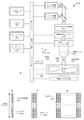
図1Aは、本発明の一実施形態によるラックスペーサ20を有する例示的なスライドラック30カルーセル10、およびスライドガラス40を有するスライドラック30を示す斜視図である。示される実施形態では、カルーセル10は、カルーセル基部50の上面に取り付けられ、カルーセル基部50の上面から上方に延在する複数のラックスペーサ20を含む。一実施形態では、各ラックスペーサ20は、オペレータの手がスライドラック30をカルーセル10に挿入し、カルーセル10から取り除くことを可能にする、および/またはスライドラック30グリッパの部分が、スライドラック30をカルーセル10に挿入し、カルーセル10から取り除くことを可能にするように構成されたラックスペーサ凹部60を含む。隣接する複数のラックスペーサ20は、スライドラック30がおもにカルーセル基部50の上面に載るように、スライドラック30を中に配置できるラックスロット70を画定する。一実施形態では、カルーセル基部50の上面は、カルーセル基部50の外部領域からカルーセル基部50の中心領域に向かって下方に傾斜する。スライドガラス40は、スライドラック30内でさまざまなスロットを占有し、一実施形態では、スライドガラス40は、有利なことにカルーセル基部50の上面の角度およびスライドラック30の対応する角度に従って斜めに配置される。さらに、カルーセル10は、複数のラックスペーサ20のそれぞれの上部に固定される中心リングを含む。
1. Example Slide Rack Carousel FIG. 1A is a perspective view showing an
図1Bは、本発明の一実施形態によるスライドラック30カルーセル基部50の片側の例示的な断面を示す側面図である。示される実施形態では、カルーセル基部50の上面の一部分は平坦である。上面のこの部分は、カルーセル基部50の上面の外周に近い。さらに、カルーセル基部50の上面の異なる部分は、θ°の角度で傾斜している。有利なことに、カルーセル基部50の上面の少なくとも一部分は傾斜しており、角度θ°の度は1~10°の範囲に及ぶ、または45°までさらに高くなる場合がある。有利なことに、スライドラック30が基部50の傾斜した上面90に配置されるとき、スライドラック30の任意の誘発される振動または他の移動は、スライドラック30ストッパがスライドラック30のさらなる移動を防ぐカルーセル10の中心に向かって偏向される。さらに、スライドラック30内の個々のスライドは、振動に誘発される移動または他の移動も経験し、個々のスライドが配置されるスライドラック30の傾いた位置も、個々のスライドの移動が、スライドラック30の端部がスライドラック30のさらなる移動を防ぐ、カルーセル10の中心に向かって偏向されるように個々のスライドを斜めに配置する。
FIG. 1B is a side view showing an exemplary cross-section of one side of
2.スライドラック30の例
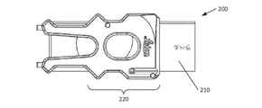
図2は、一実施形態による第1の製造業者からのスライドガラス210を有する例示的な1x3スライドラック200を示す上面図である。示される実施形態では、1x3のスライドラック200は、1x3スライドラック200の側面から外向きに延在する1つ以上のスライドラック突起部220を含む。
2.
図3は、本発明の一実施形態による第1の製造業者からのスライドガラス260を有する例示的な2x3スライドラック250を示す上面図である。示される実施形態では、2x3のスライドラック250は、2x3スライドラック250から外向きに延在する1つ以上のスライドラック突起部270を含む。
FIG. 3 is a top view showing an exemplary 2×3
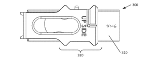
図4は、本発明の一実施形態による第2の製造業者からのスライドガラス310を有する例示的な1x3スライドラック300を示す上面図である。示される実施形態では、1x3のスライドラック300は、1x3スライドラック300の側面から外向きに延在する1つ以上のスライドラック突起部330を含む。
FIG. 4 is a top view showing an exemplary 1×3
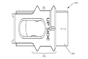
図5は、本発明の一実施形態による第2の製造業者からのスライドガラス360を有する例示的な2x3スライドラック350を示す上面図である。示される実施形態では、2x3のスライドラック350は、2x3スライドラック350から外向きに延在する1つ以上のスライドラック突起部370を含む。
FIG. 5 is a top view showing an exemplary 2×3
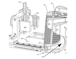
3.グリッパ装置の例
図6Aは、本発明の一実施形態による例示的なスライドラックグリッパ装置400を示す斜視図である。示されている実施形態では、スライドラックグリッパ装置400は、基部に取り付けられる(本明細書ではグリッパモータと呼ぶ)第1のモータ410を含む。基部420は、基部420から上方に延在するフィンガマウント430を支持する。グリッパモータ410は、フィンガマウント430を直線フィンガマウント430軸に沿って移動させるように構成され、直線フィンガマウント430軸により、フィンガマウント430は、複数のスライドラック30を収容するカルーセルに向かっておよびカルーセルから離れて移動する。
3. Example Gripper Apparatus FIG. 6A is a perspective view illustrating an exemplary slide
フィンガマウント430は、(本明細書ではフィンガモータと呼ぶ)第2のモータ440を支持する。フィンガモータ440は、スライドラック30をカルーセル10の中に挿入するための、またはカルーセル10内のスライドラック30に係合し、スライドラック30をカルーセル10から取り除くためのグリッパフィンガ450の高さを適切に配置するために、直線グリッパフィンガ450高さ軸に沿ってグリッパフィンガ450を移動させるように構成される。また、フィンガモータ440は、グリッパフィンガ450を直線グリッパフィンガ450把持軸に沿って移動させるように構成される。有利なことには、グリッパフィンガ450を直線グリッパフィンガ450把持軸に沿って移動させるとき、各グリッパフィンガ450は、グリッパフィンガ450間の距離を増加または減少させるために、他のグリッパフィンガ450に向かってまたは他のグリッパフィンガ450から離れて移動する。各グリッパフィンガ450はスライドラック30係合面を含み、各スライドラック30係合面は、スライドラック30の側面から延在する1つ以上の対応するスライドラック30突起部に係合するように構成された1つ以上のフィンガ突起部465を含む。一実施形態では、スライドラック30はスライドラック30内で斜めに配置され、1つ以上のフィンガ突起部465は、スライドラック30が斜めに配置されるときも、スライドラック30の側面から延在する1つ以上の対応するスライドラック30突起部に係合するように構成される。
また、フィンガマウント430は、2つのグリッパフィンガ450の間に配置され、グリッパフィンガ450の上方および下方のグリッパフィンガ450高さ軸に沿って延在するスライドリテーナ470も支持する。一実施形態では、スライドリテーナ470の長さは、少なくともスライドラック30の高さと同じくらいである。より正確な長さは、スライドラック30の中の最上部のスライドガラス40からスライドラック30の中の最下部のスライドガラス40までの範囲の長さであってよい。スライドリテーナ470は、搬送中にスライドラック30内にスライドガラス40を保持するように構成される。例えば、スライドリテーナは、スライドラック30カルーセル10からのスライドラック30の除去中に、およびスライドラック30カルーセル10の中へのスライドラック30の挿入中に、スライドガラス40がスライドラック30から出てしまうのを防ぐ。
The
また、フィンガマウント430は、グリッパフィンガ450の間のスライドラック30の存在を検知するように配置され、構成される1つ以上のスライドラックセンサ480も支持する。一実施形態では、プロセッサは、スライドラック30のタイプ(例えば、製造業者およびサイズ)を決定し、決定されたタイプのスライドラック30が支持されるかどうかを判断するためにスライドラックセンサ480(複数可)からの信号(複数可)を分析する。
Finger mounts 430 also support one or more
図6Bは、本発明の一実施形態による、グリッパフィンガ450をカルーセル内のスライドラック30に向かって動かす例示的なスライドラック30グリッパ装置を示す斜視図である。示される実施形態では、グリッパモータ410は、グリッパフィンガ450およびスライドリテーナ470を支持するフィンガマウント430をカルーセル10に向かって動かす。グリッパフィンガ450の高さは、グリッパモータ410がフィンガマウント430をカルーセル10の近位に配置するときに把持されるスライドラック30のどちらかの側面上のそれぞれのラックスペーサ凹部60の中にグリッパフィンガ450を配置するために、必要に応じて、フィンガモータ440により調整される。スライドリテーナ470の高さは、搬送中にスライドラック30内のスライドガラス40のすべてを固定するために同様に配置される。
FIG. 6B is a perspective view illustrating an
一実施形態では、プロセッサは、カルーセル基部50の傾斜した上面90部分に配置されるスライドラック30を把持するためにグリッパ装置を制御する。グリッパ装置は、最初にスライドラック30を所定の把持圧力の100%未満で把持し、平らな上面100部分を有するカルーセル基部50の領域にカルーセル10の中から一定の距離、スライドラック30を引っ張るように制御される。この位置で、プロセッサは、所定の把持圧力の100%でスライドラック30を把持し、次いでカルーセル10の中からの残りの経路、スライドラック30を引っ張って、デジタルスライド走査装置によるさらなる処理のためにスライドラック30をスライドラックプラットフォーム490の上に配置するためにグリッパ装置を制御する。
In one embodiment, the processor controls the gripper device to grip the slide racks 30 located on the inclined
図6Cは、本発明の一実施形態による、スライドラックプラットフォーム490上に配置されたスライドラック30と係合したグリッパフィンガ450を有する例示的なスライドラック30グリッパ装置を示す斜視図である。示される実施形態では、スライドラックプラットフォーム490上に位置するスライドラック30は、スライドラック30カルーセル10から取り除かれたばかりであるか、またはスライドラック30カルーセル10の中に挿入されるところかのどちらかである。スライドラック30のスロット内にスライドガラス40は示されていないが、スライドリテーナ470は、搬送中にスライドラック30内にスライドガラス40を固定するために配置される。示されている実施形態に図示するように、グリッパフィンガ450の係合面上のフィンガ突起部465は、スライドラック30の側面突起部と係合して、スライドラック30をカルーセル10の中に挿入するとき、またはスライドラック30をカルーセル10から取り除くときに、対向するグリッパフィンガ450の間にスライドラック30をしっかりと固締する。
6C is a perspective view illustrating an
有利なことには、デジタルスライド走査装置によるスライドラック30内のスライドの処理後、スライドラック30はスライドラックプラットフォーム490に戻される。グリッパ装置のグリッパフィンガ450は、スライドラックプラットフォーム490上に水平に配置されるスライドラック30を把持するように構成される。特に、グリッパフィンガ450は、スライドラック30カルーセル基部50の傾斜した上面90部分に斜めに配置されるスライドラック30を把持するように構成され、スライドラックプラットフォーム490の平らな表面上に水平に配置されるスライドラック30を把持するようにも構成される。
Advantageously, after processing the slides in
4.例示的な実施形態
一実施形態では、デジタルスライドスキャナ装置のスライドラック30グリッパ装置は、基部および基部420に取り付けられたフィンガマウント430を含む。フィンガマウント430は、フィンガマウント430軸と呼ぶ場合がある第1のリニア軸に沿って移動するように構成される。また、スライドラック30グリッパ装置は、基部420に取り付けられ、フィンガマウント430を第1のリニア軸に沿って動かすように構成された第1のモータ410を含む。また、スライドラック30グリッパ装置は、フィンガマウント430に取り付けられた複数のグリッパフィンガ450も含む。グリッパフィンガ450は、第2のリニア軸と第3のリニア軸に沿って移動するように構成される。第2のリニア軸は、グリッパフィンガ450高さ軸と呼ばれる場合があり、第3のリニア軸は、グリッパフィンガ450把持軸と呼ばれる場合がある。本実施形態では、各グリッパフィンガ450はスライドラック30係合面を含み、第1のグリッパフィンガ450のスライドラック30係合面は、第3のリニア軸に沿って第2のグリッパフィンガ450のスライドラック30係合面に対向する。また、スライドラック30グリッパ装置は、フィンガマウント430に取り付けられ、複数のグリッパフィンガ450を第2のリニア軸に沿って動かすように構成され、第1のグリッパフィンガ450および第2のグリッパフィンガ450を第3のリニア軸に沿って反対方向で動かして、スライドラック30を把持または解放するようにさらに構成された第2のモータ440も含む。
4. Exemplary Embodiment In one embodiment, the
一実施形態では、グリッパフィンガ450のスライドラック30係合面は、スライドラック30の第1の側面から延在する1つ以上のスライドラック30突起部に係合するように構成された1つ以上のフィンガ突起部465を含む。この同じ実施形態では、第2のグリッパフィンガ450のスライドラック30係合面は、スライドラック30の第2の側面から延在する1つ以上のスライドラック30突起部に係合するように構成された1つ以上のフィンガ突起部465を含む。一実施形態では、複数のグリッパフィンガ450のそれぞれは、そのそれぞれのスライドラック30係合面上に1つ以上のフィンガ突起部465を含む。有利なことには、一実施形態では、複数のグリッパフィンガ450のそれぞれの1つ以上のフィンガ突起部465は、第1のスライドラック30がカルーセル10内で斜めに配置されるときスライドラック30の側面から延在する1つ以上のスライドラック30突起部を把持するように構成される。
In one embodiment, the
一実施形態では、第1のリニア軸は、第2のリニア軸および第3のリニア軸に直交する。一実施形態では、第2のリニア軸は、第1のリニア軸および第3のリニア軸に直交する。一実施形態では、第3のリニア軸は、第1のリニア軸および第2のリニア軸に直交する。一実施形態では、各リニア軸は、他の2つのリニア軸に直交する。 In one embodiment, the first linear axis is orthogonal to the second linear axis and the third linear axis. In one embodiment, the second linear axis is orthogonal to the first linear axis and the third linear axis. In one embodiment, the third linear axis is orthogonal to the first linear axis and the second linear axis. In one embodiment, each linear axis is orthogonal to the other two linear axes.
一実施形態では、第1のスライドをスライドラック30カルーセル10からデジタルスライド走査装置内でスライド走査ステージに搬送する方法は、複数のスライドラック30をスライドラック30カルーセル10に保管することを含む。スライドラック30カルーセル10は、デジタルスライドスキャナ装置と統合される、および/または動作可能に結合される。有利なことには、各スライドラック30は複数のスライドガラス40を支持し、第1のスライドは、スライドラック30カルーセル10内の第1のスライドラック30により支持される。
In one embodiment, a method of transporting a first slide from a
さらに、方法は、スライドラック30グリッパのフィンガマウント430に取り付けられた第1のグリッパフィンガ450、およびフィンガマウント430に取り付けられた第2のグリッパフィンガ450を、直線グリッパフィンガ450把持軸に沿って、第1のグリッパフィンガ450のスライドラック30係合面と第2のグリッパフィンガ450のスライドラック30係合面との間の所定の距離に動かすことによって、第1のスライドガラス40をデジタルスライドスキャナ装置の走査ステージに搬送することを含む。また、方法は、第1のグリッパフィンガ450を第1のスライドを支持する第1のスライドラック30の第1の側面上の第1のラックスペーサ凹部60に配置するために、および第2のグリッパフィンガ450を第1のスライドラック30の第2の側面上の第2のラックスペーサ凹部60内に配置するために、フィンガマウント430を第1の直線フィンガマウント430軸に沿って動かすことも含む。第1のグリッパフィンガ450および第2のグリッパフィンガ450が、第1のスライドラック30のそれぞれの第1の側面および第2の側面上に配置された後に、方法は、第1のグリッパフィンガ450および第2のグリッパフィンガ450を互いに向かって、直線グリッパフィンガ450把持軸に沿って動かして、第1のグリッパフィンガ450のスライドラック30係合面を第1のスライドラック30の第1の面と接触させ、第2のグリッパフィンガ450のスライドラック30係合面を第1のスライドラック30の第2の面と接触させることも含む。
Further, the method moves the
第1のグリッパフィンガおよび第2のグリッパフィンガ450のそれぞれのスライドラック30係合面と、第1のスライドラック30の第1の面および第2の面との間の接触の後に、方法は、フィンガマウント430を第1の直線フィンガマウント430軸に沿って動かして、第1のスライドラック30をスライドラック30カルーセル10から取り除くことも含む。そして、第1のスライドラック30をスライドラック30カルーセル10から取り除いた後に、方法は、第1のスライドラック30を走査ステージに向けて搬送することも含む。
After contact between the
一実施形態では、2つ以上のグリッパフィンガ450をグリッパフィンガ450把持軸に沿って動かすことは、2つ以上のグリッパフィンガ450を互いに向かって動かすことも含む。一実施形態では、2つ以上のグリッパフィンガ450をグリッパフィンガ450把持軸に沿って動かすことは、2つ以上のグリッパフィンガ450を互いから離して動かすことを含む。
In one embodiment, moving the two or more
5.デジタルスライド走査装置の例
本明細書に説明されるさまざまな実施形態は、図7A~図7Dに関連して説明するようなデジタルパソロジー走査装置を使用し、実施し得る。
5. Examples of Digital Slide Scanning Devices Various embodiments described herein may be implemented using a digital pathology scanning device such as that described in connection with FIGS. 7A-7D.
図7Aは、本明細書で説明するさまざまな実施形態と関連して使用してよい例示的なプロセッサ使用可能デバイス550を示すブロック図である。デバイス550の代替形式も当業者によって理解されるように使用してよい。示される実施形態では、デバイス550は、1つ以上のプロセッサ555、1つ以上のメモリ565、1つ以上のモーションコントローラ570、1つ以上のインタフェースシステム575、1つ以上の試料590を有する1つ以上のスライドガラス585をそれぞれが支持する1つ以上の可動ステージ580、試料を照明する1つ以上の照明システム595、光学軸に沿って移動する光学経路605をそれぞれが画定する1つ以上の対物レンズ600、1つ以上の対物レンズポジショナ630、(例えば、蛍光スキャナシステムに含まれる)1つ以上の任意選択の落射照明システム635、1つ以上のフォーカシング光学系610、そのそれぞれが試料590および/またはスライドガラス585上の別個の視野625を画定する1つ以上のライン走査カメラ615および/または1つ以上のエリア走査カメラ620を含む、(デジタルスライド走査装置、デジタルスライドスキャナ、スキャナ、スキャナシステム、またはデジタル撮像デバイス等とも呼ぶ)デジタル撮像デバイスとして提示される。スキャナシステム550のさまざまな要素は、1つ以上の通信バス560を介して通信で結合される。スキャナシステム550のさまざまな要素のそれぞれの1つ以上がある場合があるが、説明を簡単にするために、これらの要素は、適切な情報を伝達するために複数形で説明する必要がある場合を除いて単数形で説明する。
FIG. 7A is a block diagram illustrating an exemplary processor-enabled
1つ以上のプロセッサ555が、例えば、命令を並列に処理できる中央処理装置(「CPU」)および別々のグラフィックスプロセシングユニット(「GPU」)を含む場合もあれば、1つ以上のプロセッサ555が、命令を並列に処理できるマルチコアプロセッサを含む場合もある。また、追加の別々のプロセッサが、特定の構成要素を制御する、または画像処理等の特定の機能を実行するために提供されてもよい。例えば、追加のプロセッサは、データ入力を管理する補助プロセッサ、浮動小数点演算を実行する補助プロセッサ、信号処理アルゴリズムの高速実行に適切なアーキテクチャを有する特殊目的プロセッサ(例えば、デジタルシグナルプロセッサ)、メインプロセッサに従属するスレーブプロセッサ(例えば、バックエンドプロセッサ)、ライン走査カメラ615、ステージ580、対物レンズ225、および/またはディスプレイ(図示せず)を制御する追加のプロセッサを含んでもよい。係る追加のプロセッサは、別々の離散プロセッサである場合もあれば、プロセッサ555と統合されている場合もある。
One or
メモリ565は、プロセッサ555によって実行できるプログラムのためのデータおよび命令の記憶装置を提供する。メモリ565は、例えば、ランダムアクセスメモリ、読み取り専用メモリ、ハードディスクドライブ、取り外し可能記憶ドライブ等を含む、データおよび命令を記憶する1つ以上の揮発性および/または不揮発性のコンピュータ可読記憶媒体を含んでよい。プロセッサ555は、メモリ565に記憶される命令を実行し、スキャナシステム550の全体的な機能を実施するために、通信バス560を介してスキャナシステム550のさまざまな要素と通信するように構成される。
Memory 565 provides data and instruction storage for programs that may be executed by
1つ以上の通信バス560は、アナログ電気信号を伝達するように構成される通信バス560を含んでよく、デジタルデータを伝達するように構成される通信バス560を含んでよい。したがって、1つ以上の通信バス560を介したプロセッサ555、モーションコントローラ570、および/またはインタフェースシステム575からの通信は、電気信号とデジタルデータの両方を含んでよい。また、プロセッサ555、モーションコントローラ570、および/またはインタフェースシステム575は、無線通信リンクを介して、走査システム550のさまざまな要素のうちの1つ以上と通信するように構成されてもよい。
The one or more communication buses 560 may include communication buses 560 configured to communicate analog electrical signals and may include communication buses 560 configured to communicate digital data. Accordingly, communications from
モーションコントロールシステム570は(例えば、対物レンズポジショナ630を介して)ステージ580および対物レンズ600のXYZの移動を正確に制御および調整するように構成される。また、モーションコントロールシステム570は、スキャナシステム550における任意の他の移動部分の移動を制御するようにも構成される。例えば、蛍光発光スキャナの実施形態では、モーションコントロールシステム570は、落射照明システム635において光学フィルタ等の移動を調整するように構成される。
インタフェースシステム575は、スキャナシステム550が他のシステムおよび人間のオペレータと連動することを可能にする。例えば、インタフェースシステム575は、情報をオペレータに直接的に提供する、および/またはオペレータからの直接入力を可能にするためにユーザインタフェースを含んでよい。インタフェースシステム575はまた、走査システム550と、直接的に接続される1つ以上の外部デバイス(例えば、プリンタ、取り外し可能記憶媒体等)またはネットワーク(図示せず)を介してスキャナシステム550に接続される画像サーバシステム、オペレータステーション、ユーザーステーション、および管理サーバシステム等の外部デバイスとの間の通信およびデータ転送を促進するように構成される。
照明システム595は、試料590の一部分を照明するように構成される。照明システム595は、例えば、光源および照明光学系を含んでよい。光源は、光出力を最大化する凹型反射ミラーおよび熱を抑制するKG-1フィルタを有する可変強度ハロゲン光源であり得る。また、光源は、任意のタイプのアークランプ、レーザー、または他の光源であってもよい。一実施形態では、照明システム595は、ライン走査カメラ615および/またはエリア走査カメラ620が試料590を透過する光エネルギーを検知するように、透過モードで試料590を照明する。代替的にまたは追加的に、照明システム595は、ライン走査カメラ615および/またはエリア走査カメラ620が試料590から反射される光エネルギーを検知するように、反射モードで試料590を照明するように構成されてもよい。全体的に、照明システム595は、光学顕微鏡検査の任意の既知のモードでの顕微鏡の試料590の検査に適切であるように構成される。
Illumination system 595 is configured to illuminate a portion of
一実施形態では、スキャナシステム550は、任意選択で、蛍光走査のためにスキャナシステム550を最適化するための落射照明システム635を含む。蛍光発光走査は、蛍光発光分子を含む試料590の走査であり、蛍光発光分子は、特定の波長で光を吸収する(励起)ことができる光子敏感分子である。また、これらの光子敏感分子はより高い波長で光を放射する(発光)。このフォトルミネセンス現象の効率は非常に低いため、放射される光の量は多くの場合非常に少ない。この少ない量の放射光は、通常、試料590を走査およびデジタル化するための従来の技術(例えば、透過モード顕微鏡検査)を妨げる。有利なことに、スキャナシステム550の任意選択の蛍光発光スキャナシステムの実施形態では、複数のリニアセンサアレイを含むライン走査カメラ615(例えば、時間遅延統合(「TDI」)ライン走査カメラ)の使用は、ライン走査カメラ615の複数のリニアセンサアレイのそれぞれに試料590の同一の領域を暴露することによって、ライン走査カメラの光への感度を増大させる。これは特に、少ない放射光でわずかな蛍光発光試料を走査するときに役立つ。
In one embodiment,
したがって、蛍光発光スキャナシステムの実施形態では、ライン走査カメラ615は、好ましくは白黒TDIライン走査カメラである。有利なことに、白黒画像は、それらが試料に存在するさまざまなチャネルからの実信号のより正確な表現を提供するため、蛍光発光顕微鏡検査において理想である。当業者により理解されるように、蛍光発光試料590は、「チャネル」とも呼ぶ異なる波長で光を放射する複数の蛍光染料によりラベル付けされる場合がある。
Thus, in a fluorescence scanner system embodiment, line scan camera 615 is preferably a black and white TDI line scan camera. Advantageously, black and white images are ideal in fluorescence microscopy as they provide a more accurate representation of the real signals from the various channels present in the sample. As will be appreciated by those skilled in the art, the
さらに、最低の信号レベルおよび最高の信号レベルのさまざまな蛍光発光試料が、ライン走査カメラ615が検知するために広いスペクトルの波長を提示するため、ライン走査カメラ615が検知できる最低の信号レベルおよび最高の信号レベルが同様に広いことが望ましい。したがって、蛍光発光スキャナの実施形態では、蛍光発光走査システム550で使用されるライン走査カメラ615は、白黒10ビット64リニアアレイTDIライン走査カメラである。ライン走査カメラ615のためのさまざまなビット深度が、走査システム550の蛍光発光スキャナの実施形態とともに使用するために利用できることに留意されたい。
In addition, the lowest and highest signal levels that line-scan camera 615 can detect, because various fluorescence-emitting samples with the lowest and highest signal levels present a broad spectrum of wavelengths for line-scan camera 615 to detect. It is desirable that the signal levels of are similarly wide. Thus, in the fluorescence scanner embodiment, the line scan camera 615 used in the
可動ステージ580は、プロセッサ555またはモーションコントローラ570の制御下での正確なXーY軸移動のために構成される。また、可動ステージは、プロセッサ555またはモーションコントローラ570の制御下でのZ軸での移動のために構成されてもよい。可動ステージは、ライン走査カメラ615および/またはエリア走査カメラによる画像データ取り込み中に試料を所望の位置に配置するように構成される。また、可動ステージは、走査方向で実質的に一定の速度に試料590を加速させ、次いで、ライン走査カメラ615による画像データ取り込み中に実質的に一定の速度を維持するように構成される。一実施形態では、スキャナシステム550は、可動ステージ580上の試料590の位置を補助するために、高精度および密接に調整されたX-Yグリッドを利用してよい。一実施形態では、可動ステージ580は、X軸とY軸の両方で利用される高精度エンコーダを備えるリニアモータベースのX-Yステージである。例えば、非常に正確なナノメートルエンコーダは、走査方向の軸上で、および走査方向に垂直な方向の軸上で、かつ走査方向と同一平面上で使用される場合がある。また、ステージは、試料590がその上に配置されるスライドガラス585を支持するように構成される。
試料590は、光学顕微鏡検査によって検査され得る任意のものであってよい。例えば、顕微鏡スライドガラス585は、組織および細胞、染色体、DNA、タンパク質、血液、骨髄、尿、バクテリア、気泡、生検材料、または死亡しもしくは生存している、着色されているもしくは着色されていない、ラベル付けされているもしくはラベル付けされていないかのどちらかである任意の他のタイプの生物材料または生物学的物質を含む標本のための観察用基板として頻繁に使用される。また、試料590はまた、マイクロアレイとして一般的に知られているありとあらゆる試料を含む、任意のタイプのスライドまたは他の基板上に配置されるcDNA、RNA、もしくはタンパク質等の任意のタイプのDNAまたはDNA関連材料のアレイであってもよい。試料590は、例えば、96ウェルプレート等のマイクロタイタープレートであってよい。試料590の他の例は、集積回路基板、電気泳動レコード、ペトリ皿、フィルム、半導体材料、フォレンジック材料、および機械加工部品を含んでもよい。
対物レンズ600は、対物レンズポジショナ630上に取り付けられ、対物レンズポジショナ630は、一実施形態では、対物レンズ600によって画定された光学軸に沿って対物レンズ600を移動させる非常に緻密なリニアモータを利用してよい。例えば、対物レンズポジショナ630のリニアモータは、50ナノメートルのエンコーダを含んでよい。XYZ軸でのステージ580と対物レンズ600との相対位置は、走査システム550の全体的な動作のためのコンピュータ実行可能なプログラムされたステップを含む、情報および命令を記憶するためのメモリ565を利用するプロセッサ555の制御下で、モーションコントローラ570を使用し、閉ループ方式で調整および制御される。
The objective lens 600 is mounted on an objective lens positioner 630, which in one embodiment employs a very fine linear motor that moves the objective lens 600 along the optical axis defined by the objective lens 600. may be used. For example, the linear motor of objective lens positioner 630 may include a 50 nanometer encoder. The relative positions of
一実施形態では、対物レンズ600は、所望の最も高い空間分解能に相当する開口数を有する平面アポクロマート(「APO」)無限補正対物レンズであり、対物レンズ600は、透過モード照明顕微鏡検査、反射モード照明顕微鏡検査、および/または落射照明モード蛍光顕微鏡検査(例えば、Olympus 40X、0.75NAまたは20X、0.75NA)に適している。有利なことに、対物レンズ600は、色収差および球面収差を補正できる。対物レンズ600は無限補正されるため、フォーカシング光学系610は、対物レンズを通過する光線が平行光線となる対物レンズ600上方の光学経路605内に配置される場合がある。フォーカシング光学系610は、対物レンズ600によって取り込まれた光信号をライン走査カメラ615および/またはエリア走査カメラ620の光応答性素子の上にフォーカシングさせ、フィルタ、倍率変換器レンズ等の光学部品を含む場合がある。フォーカシング光学系610と結合された対物レンズ600は、走査システム550に総合倍率を提供する。一実施形態では、フォーカシング光学系610は、チューブレンズおよび任意選択の2X倍率変換器を含んでよい。有利なことに、2X倍率変換器は、本来の20X対物レンズ600が40Xの倍率で試料590を走査できるようにする。
In one embodiment, objective lens 600 is a planar apochromatic (“APO”) infinity-corrected objective lens with a numerical aperture corresponding to the highest spatial resolution desired; Suitable for illumination microscopy and/or epi-illumination mode fluorescence microscopy (eg Olympus 40X, 0.75NA or 20X, 0.75NA). Advantageously, the objective lens 600 can correct for chromatic and spherical aberrations. Since the objective lens 600 is infinitely corrected, the focusing
ライン走査カメラ615は、画像素子(「ピクセル」)の少なくとも1つのリニアアレイを含む。ライン走査カメラは、白黒またはカラーであってよい。カラーライン走査カメラは、通常少なくとも3つのリニアアレイを有する。一方、白黒ライン走査カメラは、単一のリニアアレイまたは複数のリニアアレイを有する場合がある。カメラの一部として実装されるのか、それとも撮像電子モジュールにカスタム統合されるのかに関わらず、任意のタイプの単数または複数のリニアアレイも使用できる。例えば、3リニアアレイ(「赤-緑-青」すなわち「RGB」)カラーライン走査カメラまたは96リニアアレイ白黒TDIも使用されてよい。TDIライン走査カメラは、通常、標本の以前に撮像された領域から強度データを合計することによって、出力信号で実質的により良好な信号対雑音比(「SNR」)をもたらし、統合ステージの数の平方根に比例するSNRの増大を生じさせる。TDIライン走査カメラは、多数のリニアアレイを含む。例えば、TDIライン走査カメラは24、32、48、64、96、またはそれ以上のリニアアレイでも利用可能である。また、スキャナシステム550は、512個のピクセルを有するもの、1024個のピクセルを有するもの、および4096個のピクセルと同数のピクセルを有する他を含む、さまざまなフォーマットで製造されるリニアアレイを支持する。同様に、スキャナシステム550では、さまざまなピクセルサイズを有するリニアアレイも使用できる。任意のタイプのライン走査カメラ615の選択のための顕著な要件は、ステージ580が、試料590のデジタル画像の取り込み中にライン走査カメラ615に対して動くことができるように、ステージ580の動きをライン走査カメラ615のライン速度と同期できることである。
Line scan camera 615 includes at least one linear array of picture elements (“pixels”). Line scan cameras may be black and white or color. A color line scan camera usually has at least three linear arrays. Black and white line scan cameras, on the other hand, may have a single linear array or multiple linear arrays. Any type of linear array or arrays can be used, whether implemented as part of the camera or custom integrated into the imaging electronics module. For example, a 3 linear array (“red-green-blue” or “RGB”) color line scan camera or a 96 linear array black and white TDI may also be used. TDI line scan cameras typically yield a substantially better signal-to-noise ratio (“SNR”) in the output signal by summing intensity data from previously imaged regions of the specimen, and the number of integration stages Resulting in an SNR increase proportional to the square root. A TDI line scan camera contains multiple linear arrays. For example, TDI line scan cameras are available with linear arrays of 24, 32, 48, 64, 96, or more.
ライン走査カメラ615によって生成された画像データは、メモリ565の一部分に記憶され、試料590の少なくとも一部分の連続デジタル画像を生成するためにプロセッサ555によって処理される。連続デジタル画像は、プロセッサ555によってさらに処理される場合があり、処理された連続デジタル画像はメモリ565に記憶される場合もある。
Image data generated by line scan camera 615 is stored in a portion of memory 565 and processed by
2つ以上のライン走査カメラ615を有する一実施形態では、ライン走査カメラ615の少なくとも1つは、撮像センサとして機能するように構成される少なくとも1つのライン走査カメラ615と組み合わせて動作するフォーカシングセンサとして機能するように構成される場合がある。フォーカシングセンサは撮像センサと同じ光軸に論理的に配置される場合もあれば、フォーカシングセンサは、スキャナシステム550の走査方向に関して撮像センサの前または後に論理的に配置されてもよい。フォーカシングセンサとして機能する少なくとも1つのライン走査カメラ615を有する一実施形態では、フォーカシングセンサによって生成された画像データは、メモリ565の一部分に記憶され、1つ以上のプロセッサ555によって処理されて焦点情報を生成し、スキャナシステム550が、試料590と対物レンズ600との間の相対距離を調整して、走査中に試料に対する焦点を維持することを可能にする。さらに、一実施形態では、フォーカシングセンサとして機能する少なくとも1つのライン走査カメラ615は、フォーカシングセンサの複数の個々のピクセルのそれぞれが、光学経路605に沿って異なる論理的な高さに配置されるように配向されてよい。
In an embodiment having two or more line scan cameras 615, at least one of the line scan cameras 615 is a focusing sensor operating in combination with at least one line scan camera 615 configured to function as an imaging sensor. may be configured to work. The focusing sensor may be logically placed on the same optical axis as the imaging sensor, or the focusing sensor may be logically placed before or after the imaging sensor with respect to the scan direction of
動作中、スキャナシステム550のさまざまな構成要素およびメモリ565に記憶されたプログラムされたモジュールは、スライドガラス585に配置される試料590の自動的な走査およびデジタル化を可能にする。スライドガラス585は、試料590を走査するためのスキャナシステム550の可動ステージ580にしっかりと配置される。プロセッサ555の制御下、可動ステージ580は、ライン走査カメラ615による検知のために実質的に一定の速度に試料590を加速させ、ステージの速度は、ライン走査カメラ615のライン速度と同期される。画像データのストリップを走査した後、可動ステージ580は、試料590を減速させ、実質的に完全停止に至らせる。可動ステージ580は次いで、画像データの後続のストリップ、例えば、隣接するストリップの走査のために試料590を位置付けるように走査方向に直角に移動する。追加のストリップはその後、試料590の全体部分または試料590の全体が走査されるまで走査される。
In operation, the various components of
例えば、試料590のデジタル走査の間、試料590の連続デジタル画像は、画像ストリップを形成するように互いに結合される複数の連続する視野として取得される。複数の隣接する画像ストリップは、同様に互いに結合されて、試料590の一部分または試料590全体の連続デジタル画像を形成する。試料590の走査は、垂直画像ストリップまたは水平画像ストリップを取得することを含んでよい。試料590の走査は、上から下、下から上、または両方(双方向)のいずれかであってよく、試料の任意の点で開始してよい。代わりに、試料590の走査は、左から右、右から左、またはその両方(双方向)のいずれかであってもよく、試料の任意の点で開始してよい。加えて、画像ストリップが隣接してまたは連続して取得される必要はない。さらに、試料590の結果として生じる画像は、試料590全体または試料590の一部分のみの画像であってもよい。
For example, during digital scanning of
一実施形態では、コンピュータ実行可能命令(例えば、プログラムされたモジュールまたは他のソフトウェア)はメモリ565に記憶され、実行されると、走査システム550が本明細書に説明するさまざまな機能を実行できるようにする。この説明では、用語「コンピュータ可読記憶媒体」は、コンピュータ実行可能命令を記憶し、プロセッサ555による実行のために走査システム550に提供するために使用される任意の媒体を指すために使用される。これらの媒体の例は、メモリ565、および直接的または間接的(例えば、ネットワークを介して)のいずれかで走査システム550と通信で結合された任意の取り外し可能記憶媒体または外部記憶媒体(図示せず)を含む。
In one embodiment, computer-executable instructions (eg, programmed modules or other software) are stored in memory 565 and executed to enable
図7Bは、電荷結合素子(「CCD」)アレイとして実装されてよい単一のリニアアレイ640を有するライン走査カメラを示す。単一のリニアアレイ640は、複数の個々のピクセル645を含む。示される実施形態では、単一のリニアアレイ640は、4096個のピクセルを有する。代替実施形態では、リニアアレイ640は、より多くのまたはより少ないピクセルを有する場合がある。例えば、リニアアレイの共通フォーマットは、512個、1024個、および4096個のピクセルを含む。ピクセル645は、リニアアレイ640のための視野625を画定するためにリニア方式で配置される。視野のサイズは、スキャナシステム550の倍率に従って変化する。
FIG. 7B shows a line scan camera with a single linear array 640 that may be implemented as a charge-coupled device (“CCD”) array. A single linear array 640 includes multiple
図7Cは、それぞれがCCDアレイとして実装されてよい3つのリニアアレイを有するライン走査カメラを示す。3つのリニアアレイは結合して、カラーアレイ650を形成する。一実施形態では、カラーアレイ650のそれぞれの個々のリニアアレイは、異なる色の強度(例えば、赤、緑、または青)を検出する。カラーアレイ650のそれぞれの個々のリニアアレイからのカラー画像データが結合されて、カラー画像データの単一の視野625を形成する。
FIG. 7C shows a line scan camera with three linear arrays, each of which may be implemented as a CCD array. The three linear arrays combine to form color array 650 . In one embodiment, each individual linear array of color array 650 detects a different color intensity (eg, red, green, or blue). The color image data from each individual linear array of color array 650 are combined to form a single field of
図7Dは、それぞれがCCDアレイとして実装されてよい複数のリニアアレイを有するライン走査カメラを示す。複数のリニアアレイは結合して、TDIアレイ655を形成する。有利なことに、TDIライン走査カメラは、標本の以前に撮像された領域から強度データを合計することによって、その出力信号での実質的により良好なSNRを提供し、(統合ステージとも呼ぶ)リニアアレイの数の平方根に比例するSNRの増大を生じさせる。TDIライン走査カメラは、より多くのさまざまな数のリニアアレイを含む場合がある。例えば、TDIライン走査カメラの共通フォーマットは、24個、32個、48個、64個、96個、120個、およびよりに多くのリニアアレイも含む。
FIG. 7D shows a line scan camera with multiple linear arrays, each of which may be implemented as a CCD array. Multiple linear arrays combine to form a
開示された実施形態の上記説明は、当業者が本発明を作成または使用することを可能にするために提供される。これらの実施形態に対するさまざまな修正は当業者にとって容易に明らかとなり、本明細書に説明する一般的な原理は、本発明の精神または範囲から逸脱することなく他の実施形態に適用できる。よって、本明細書に提示する説明および図面は、本発明の現時点で好ましい実施形態を表し、したがって、本発明によって広く意図される主題を表すことを理解されたい。さらに、本発明の範囲は、当業者にとって明白になり得る他の実施形態を完全に包含し、したがって本発明の範囲は限定されないことを理解されたい。 The previous description of the disclosed embodiments is provided to enable any person skilled in the art to make or use the present invention. Various modifications to these embodiments will be readily apparent to those skilled in the art, and the generic principles described herein may be applied to other embodiments without departing from the spirit or scope of the invention. It is to be understood, therefore, that the description and drawings presented herein represent presently preferred embodiments of the invention and, therefore, represent the broadly contemplated subject matter of the invention. Moreover, it is to be understood that the scope of the invention fully encompasses other embodiments that may become apparent to those skilled in the art, and thus the scope of the invention is not limited.
Claims (20)
基部と、
前記基部に取り付けられ、第1のリニア軸に沿って移動するように構成されたフィンガマウントと、
前記基部に取り付けられ、前記フィンガマウントを前記第1のリニア軸に沿って動かすように構成された第1のモータと、
前記フィンガマウントに取り付けられ、第2のリニア軸および第3のリニア軸に沿って移動するように構成された複数のグリッパフィンガと、
前記フィンガマウントに取り付けられ、前記第2のリニア軸に沿って前記複数のグリッパフィンガを動かすように構成された第2のモータと、
を備え、
各グリッパフィンガは、前記第2のリニア軸を横切る方に延在し、スライドラック係合面を備え、第1のグリッパフィンガの前記スライドラック係合面は、前記第3のリニア軸に沿って第2のグリッパフィンガの前記スライドラック係合面に対向し、
前記第2のモータは、前記第1のグリッパフィンガおよび前記第2のグリッパフィンガを、前記第3のリニア軸に沿って反対方向で動かして、前記スライドラックカルーセル内に配置されているスライドラックを把持または解放するようにさらに構成される、
スライドラックグリッパ装置。 A slide rack gripper device for transporting a slide rack from a slide rack carousel to a scanning stage of a digital slide scanner device, said slide rack gripper device comprising:
a base;
a finger mount attached to the base and configured to move along a first linear axis;
a first motor mounted to the base and configured to move the finger mount along the first linear axis;
a plurality of gripper fingers attached to the finger mount and configured to move along a second linear axis and a third linear axis;
a second motor attached to the finger mount and configured to move the plurality of gripper fingers along the second linear axis;
with
Each gripper finger extends transversely to said second linear axis and includes a slide rack engaging surface, said slide rack engaging surface of the first gripper finger extending along said third linear axis. facing the slide rack engaging surface of the second gripper finger;
The second motor moves the first gripper finger and the second gripper finger in opposite directions along the third linear axis to move a slide rack disposed within the slide rack carousel. further configured to grasp or release;
Slide rack gripper device.
請求項1に記載のスライドラックグリッパ装置。 The slide rack engaging surface of the first gripper finger has one or more finger projections configured to engage one or more slide rack projections extending from the first side of the slide rack. having a department,
A slide rack gripper device according to claim 1.
請求項2に記載のスライドラックグリッパ装置。 The one or more finger projections of the first gripper fingers extend from the first side surface of the slide rack when the slide rack is disposed obliquely with respect to a horizontal plane. configured to grip the slide rack protrusion;
A slide rack gripper device according to claim 2.
請求項2に記載のスライドラックグリッパ装置。 The slide rack engaging surface of the second gripper finger has one or more finger projections configured to engage one or more slide rack projections extending from the second side of the slide rack. having a department,
A slide rack gripper device according to claim 2.
請求項4に記載のスライドラックグリッパ装置。 The one or more finger projections of the second gripper fingers extend from the second side surface of the slide rack when the slide rack is disposed obliquely with respect to a horizontal plane. configured to grip the slide rack protrusion;
A slide rack gripper device according to claim 4.
請求項1に記載のスライドラックグリッパ装置。 Each of said plurality of gripper fingers includes one or more finger projections on its respective slide rack engaging surface, said one or more finger projections having one or more extending from a side of said slide rack. configured to engage the slide rack protrusions of
A slide rack gripper device according to claim 1.
請求項6に記載のスライドラックグリッパ装置。 The one or more finger projections of each of the plurality of gripper fingers extend from the side surface of the slide rack when the slide rack is disposed obliquely with respect to a horizontal plane. configured to grip the protrusion;
A slide rack gripper device according to claim 6.
請求項1に記載のスライドラックグリッパ装置。 the first linear axis is orthogonal to the second linear axis and the third linear axis;
A slide rack gripper device according to claim 1.
請求項1に記載のスライドラックグリッパ装置。 the second linear axis is orthogonal to the first linear axis and the third linear axis;
A slide rack gripper device according to claim 1.
請求項1に記載のスライドラックグリッパ装置。 the third linear axis is orthogonal to the first linear axis and the second linear axis;
A slide rack gripper device according to claim 1.
請求項1に記載のスライドラックグリッパ装置。 each linear axis is orthogonal to the other two linear axes,
A slide rack gripper device according to claim 1.
請求項1に記載のスライドラックグリッパ装置。 The slide rack gripper apparatus further comprises a slide retainer extending along the second linear axis and configured to secure one or more glass slides within the slide rack.
A slide rack gripper device according to claim 1.
請求項1に記載のスライドラックグリッパ装置。 The slide rack gripper device further comprises a slide rack platform configured to support the slide rack after removal of the slide rack from the slide rack carousel.
A slide rack gripper device according to claim 1.
請求項1に記載のスライドラックグリッパ装置。 The slide rack gripper device further comprises one or more slide rack sensors secured to the finger mounts, the slide rack sensors configured to detect the presence of a slide rack.
A slide rack gripper device according to claim 1.
複数のスライドラックを、デジタルスライドスキャナ装置と動作可能に結合されたスライドラックカルーセル内に保管するステップであって、各スライドラックが複数のスライドガラスを支持するステップと、
第1のスライドガラスを前記デジタルスライドスキャナ装置の走査ステージに搬送するステップと、
を含み、
前記搬送するステップは、
スライドラックグリッパのフィンガマウントに取り付けられた第1のグリッパフィンガおよび前記フィンガマウントに取り付けられた第2のグリッパフィンガを、直線グリッパフィンガ把持軸に沿って、前記第1のグリッパフィンガのスライドラック係合面と、前記第2のグリッパフィンガのスライドラック係合面と、の間の所定の距離に動かすことと、
前記第1のグリッパフィンガを前記第1のスライドガラスを支持する第1のスライドラックの第1の側面上の第1のラックスペーサ凹部に配置するために、および、前記第2のグリッパフィンガを前記第1のスライドラックの第2の側面上の第2のラックスペーサ凹部に配置するために、前記フィンガマウントを第1の直線フィンガマウント軸に沿って動かすことと、
前記第1のグリッパフィンガおよび前記第2のグリッパフィンガが、前記第1のスライドラックのそれぞれの第1の側面および第2の側面に配置された後に、前記第1のグリッパフィンガおよび前記第2のグリッパフィンガを互いに向けて、前記直線グリッパフィンガ把持軸に沿って動かして、前記第1のグリッパフィンガの前記スライドラック係合面を前記第1のスライドラックの第1の面と接触させ、前記第2のグリッパフィンガの前記スライドラック係合面を前記第1のスライドラックの第2の面と接触させることと、
前記第1のグリッパフィンガおよび前記第2のグリッパフィンガの前記それぞれのスライドラック係合面と、前記第1のスライドラックの前記第1の面および前記第2の面と、の間の接触の後に、前記フィンガマウントを前記第1の直線フィンガマウント軸に沿って動かして、前記第1のスライドラックを前記スライドラックカルーセルから取り除くことと、
前記第1のスライドラックを前記スライドラックカルーセルから取り除いた後に、前記第1のスライドラックを前記走査ステージに向けて搬送することと、
によって行われる、
方法。 A method, the method comprising:
storing a plurality of slide racks in a slide rack carousel operably coupled to a digital slide scanner device, each slide rack supporting a plurality of glass slides;
transporting a first glass slide to a scanning stage of the digital slide scanner device;
including
The conveying step includes:
a first gripper finger attached to a finger mount of a slide rack gripper and a second gripper finger attached to said finger mount along a linear gripper finger gripping axis into slide rack engagement of said first gripper finger; moving a predetermined distance between a surface and a slide rack engaging surface of said second gripper finger;
for positioning said first gripper fingers in a first rack spacer recess on a first side of a first slide rack supporting said first glass slide; moving the finger mount along a first linear finger mount axis for positioning in a second rack spacer recess on the second side of the first slide rack;
After the first gripper finger and the second gripper finger are positioned on the respective first side and second side of the first slide rack, the first gripper finger and the second gripper finger moving the gripper fingers toward each other along the linear gripper finger gripping axis to bring the slide rack engaging surface of the first gripper finger into contact with the first surface of the first slide rack; contacting the slide rack engaging surfaces of two gripper fingers with the second surface of the first slide rack;
after contact between the respective slide rack engaging surfaces of the first and second gripper fingers and the first and second surfaces of the first slide rack; removing the first slide rack from the slide rack carousel by moving the finger mount along the first linear finger mount axis;
transporting the first slide rack toward the scanning stage after removing the first slide rack from the slide rack carousel;
performed by
Method.
請求項15に記載の方法。 moving two or more gripper fingers along the linear gripper finger gripping axis includes moving the two or more gripper fingers toward each other;
16. The method of claim 15.
請求項15に記載の方法。 moving the two or more gripper fingers along the linear gripper finger gripping axis includes moving the two or more gripper fingers away from each other;
16. The method of claim 15.
複数のスライドラックを、デジタルスライドスキャナ装置と動作可能に結合されたスライドラックカルーセル内に保管するステップであって、各スライドラックが複数のスライドガラスを支持するステップと、
第1のスライドガラスを前記デジタルスライドスキャナ装置の走査ステージに搬送するステップと、
を実行させ、
前記搬送するステップは、
スライドラックグリッパのフィンガマウントに取り付けられた第1のグリッパフィンガおよび前記フィンガマウントに取り付けられた第2のグリッパフィンガを、直線グリッパフィンガ把持軸に沿って、前記第1のグリッパフィンガのスライドラック係合面と、前記第2のグリッパフィンガのスライドラック係合面と、の間の所定の距離に動かすことと、
前記第1のグリッパフィンガを前記第1のスライドガラスを支持する第1のスライドラックの第1の側面上の第1のラックスペーサ凹部に配置するために、および、前記第2のグリッパフィンガを前記第1のスライドラックの第2の側面上の第2のラックスペーサ凹部に配置するために、前記フィンガマウントを第1の直線フィンガマウント軸に沿って動かすことと、
前記第1のグリッパフィンガおよび前記第2のグリッパフィンガが、前記第1のスライドラックのそれぞれの第1の側面および第2の側面に配置された後に、前記第1のグリッパフィンガおよび前記第2のグリッパフィンガを互いに向けて、前記直線グリッパフィンガ把持軸に沿って動かして、前記第1のグリッパフィンガの前記スライドラック係合面を前記第1のスライドラックの第1の面と接触させ、前記第2のグリッパフィンガの前記スライドラック係合面を前記第1のスライドラックの第2の面と接触させることと、
前記第1のグリッパフィンガおよび前記第2のグリッパフィンガの前記それぞれのスライドラック係合面と、前記第1のスライドラックの前記第1の面および前記第2の面と、の間の接触の後に、前記フィンガマウントを前記第1の直線フィンガマウント軸に沿って動かして、前記第1のスライドラックを前記スライドラックカルーセルから取り除くことと、
前記第1のスライドラックを前記スライドラックカルーセルから取り除いた後に、前記第1のスライドラックを前記走査ステージに向けて搬送することと、
によって行う、
非一時的コンピュータ可読媒体。 A non-transitory computer-readable medium storing one or more sequences of instructions, said one or more sequences of instructions for causing one or more processors to:
storing a plurality of slide racks in a slide rack carousel operably coupled to a digital slide scanner device, each slide rack supporting a plurality of glass slides;
transporting a first glass slide to a scanning stage of the digital slide scanner device;
and
The conveying step includes:
a first gripper finger attached to a finger mount of a slide rack gripper and a second gripper finger attached to said finger mount along a linear gripper finger gripping axis into slide rack engagement of said first gripper finger; moving a predetermined distance between a surface and a slide rack engaging surface of said second gripper finger;
for positioning said first gripper fingers in a first rack spacer recess on a first side of a first slide rack supporting said first glass slide; moving the finger mount along a first linear finger mount axis for positioning in a second rack spacer recess on the second side of the first slide rack;
After the first gripper finger and the second gripper finger are positioned on the respective first side and second side of the first slide rack, the first gripper finger and the second gripper finger moving the gripper fingers toward each other along the linear gripper finger gripping axis to bring the slide rack engaging surface of the first gripper finger into contact with the first surface of the first slide rack; contacting the slide rack engaging surfaces of two gripper fingers with the second surface of the first slide rack;
after contact between the respective slide rack engaging surfaces of the first and second gripper fingers and the first and second surfaces of the first slide rack; removing the first slide rack from the slide rack carousel by moving the finger mount along the first linear finger mount axis;
transporting the first slide rack toward the scanning stage after removing the first slide rack from the slide rack carousel;
do by
Non-Transitory Computer-Readable Medium.
請求項18に記載の媒体。 moving two or more gripper fingers along the linear gripper finger gripping axis includes moving the two or more gripper fingers toward each other;
19. The medium of claim 18.
請求項18に記載の媒体。 moving the two or more gripper fingers along the linear gripper finger gripping axis includes moving the two or more gripper fingers away from each other;
19. The medium of claim 18.
Applications Claiming Priority (3)
| Application Number | Priority Date | Filing Date | Title |
|---|---|---|---|
| US201762593135P | 2017-11-30 | 2017-11-30 | |
| US62/593,135 | 2017-11-30 | ||
| PCT/US2018/063461 WO2019109028A1 (en) | 2017-11-30 | 2018-11-30 | Slide rack gripper apparatus |
Publications (2)
| Publication Number | Publication Date |
|---|---|
| JP2021503098A JP2021503098A (en) | 2021-02-04 |
| JP7119084B2 true JP7119084B2 (en) | 2022-08-16 |
Family
ID=66664282
Family Applications (1)
| Application Number | Title | Priority Date | Filing Date |
|---|---|---|---|
| JP2020524845A Active JP7119084B2 (en) | 2017-11-30 | 2018-11-30 | Slide rack gripper device |
Country Status (6)
| Country | Link |
|---|---|
| US (2) | US11597612B2 (en) |
| EP (1) | EP3625571B1 (en) |
| JP (1) | JP7119084B2 (en) |
| CN (2) | CN111344574A (en) |
| AU (1) | AU2018374379B2 (en) |
| WO (1) | WO2019109028A1 (en) |
Families Citing this family (21)
| Publication number | Priority date | Publication date | Assignee | Title |
|---|---|---|---|---|
| WO2019109028A1 (en) | 2017-11-30 | 2019-06-06 | Leica Biosystems Imaging, Inc. | Slide rack gripper apparatus |
| WO2019109032A1 (en) * | 2017-12-01 | 2019-06-06 | Leica Biosystems Imaging, Inc. | Fixed reference edge system for slide loading and unloading |
| FR3093020A1 (en) * | 2019-02-25 | 2020-08-28 | Valeo Systemes Thermiques | Method for assembling a heating, ventilation and / or air conditioning device for a motor vehicle |
| CN110271861B (en) * | 2019-06-27 | 2020-12-15 | 安徽智汇和科技服务有限公司 | Transfer manipulator |
| EP4010791A1 (en) * | 2019-08-06 | 2022-06-15 | Leica Biosystems Imaging, Inc. | Graphical user interface for slide-scanner control |
| WO2021026276A1 (en) | 2019-08-06 | 2021-02-11 | Leica Biosystems Imaging, Inc. | Slide-scanner control |
| US12422448B2 (en) * | 2019-08-06 | 2025-09-23 | Leica Biosystems Imaging, Inc. | Stall detection for autoloader axes |
| US11465151B2 (en) * | 2020-02-07 | 2022-10-11 | Mikroscan Technologies Inc. | Method and apparatus for handling slides |
| CN115943201A (en) * | 2020-07-15 | 2023-04-07 | 深圳华大智造科技股份有限公司 | Automatic database building system |
| CN111977353B (en) * | 2020-07-23 | 2022-03-04 | 金华科生物技术河北有限公司 | Adjustable test paper sample conveying device |
| US20240010448A1 (en) * | 2020-12-08 | 2024-01-11 | Sony Group Corporation | Glass slide conveyance device and glass slide image capturing system |
| US20240286297A1 (en) * | 2021-07-06 | 2024-08-29 | Hitachi High-Tech Corporation | Glass slide transport device |
| CN113624684B (en) * | 2021-08-04 | 2022-06-24 | 杭州医派智能科技有限公司 | Pathological section scanner |
| CN114132750B (en) * | 2022-01-28 | 2022-04-22 | 儒克生物科技常州有限公司 | Fluorescence detection system conveying system |
| CN114268729B (en) * | 2022-03-03 | 2022-04-29 | 立川(深圳)智能科技设备有限公司 | A large area AOI line scan camera mechanism |
| WO2023196256A2 (en) * | 2022-04-05 | 2023-10-12 | Ventana Medical Systems, Inc. | Pathology slide automation system and method |
| CN114770564B (en) * | 2022-06-16 | 2022-09-02 | 江苏俊超电动车配件制造有限公司 | Rotation type electric motor car wheel hub cools off manipulator |
| CN115922777B (en) * | 2023-03-15 | 2023-06-09 | 西安蜂鸟中试科技有限公司 | Transferring and conveying mechanical arm for intelligent equipment pilot production line |
| CN119246192A (en) * | 2024-04-10 | 2025-01-03 | 青岛优瑞达生物科技有限公司 | A cell detection device |
| KR20260006363A (en) | 2024-07-04 | 2026-01-13 | 주식회사 뷰웍스 | Slide scanner and auto-teaching method of slide scanner |
| CN121632967A (en) * | 2026-02-05 | 2026-03-10 | 杭州迪英加科技有限公司 | Multifunctional pathological section scanning tablet arranging machine |
Citations (3)
| Publication number | Priority date | Publication date | Assignee | Title |
|---|---|---|---|---|
| JP2012177803A (en) | 2011-02-25 | 2012-09-13 | Olympus Corp | Slide glass carrying device |
| JP2012242384A (en) | 2011-05-13 | 2012-12-10 | Leica Biosystems Nussloch Gmbh | Sample slide processor provided with linear transport mechanism for transporting rack |
| JP2014526712A (en) | 2011-09-09 | 2014-10-06 | ベンタナ メディカル システムズ, インコーポレイテッド | Imaging system, cassette, and method of using the same |
Family Cites Families (19)
| Publication number | Priority date | Publication date | Assignee | Title |
|---|---|---|---|---|
| JPS5971018A (en) | 1982-10-15 | 1984-04-21 | Ikegami Tsushinki Co Ltd | Automatic microscope device |
| US6395554B1 (en) * | 1999-09-03 | 2002-05-28 | Packard Instrument Company | Microarray loading/unloading system |
| US6592324B2 (en) | 2001-02-26 | 2003-07-15 | Irm, Llc | Gripper mechanism |
| AU2002336856A1 (en) * | 2001-10-31 | 2003-05-12 | Thermo Crs Ltd. | Robotic arm provided with a gripping head having a constant orientation |
| NO20045625D0 (en) | 2004-12-23 | 2004-12-23 | Torstein Ljungmann | Slide holding device with tissue samples |
| US20060246576A1 (en) | 2005-04-06 | 2006-11-02 | Affymetrix, Inc. | Fluidic system and method for processing biological microarrays in personal instrumentation |
| DE102005042214A1 (en) | 2005-09-05 | 2007-03-22 | Leica Microsystems Nussloch Gmbh | Receiving and transfer station for covered slides |
| JP2013501633A (en) * | 2009-08-07 | 2013-01-17 | シーメンス・ヘルスケア・ダイアグノスティックス・インコーポレーテッド | Method, system and apparatus adapted to transport sample containers |
| US8360355B2 (en) | 2010-08-04 | 2013-01-29 | The Boeing Company | Wing-to-body fairing with spray-on foam and noise reduction method |
| DE102010054360B4 (en) * | 2010-12-13 | 2018-09-20 | Leica Biosystems Nussloch Gmbh | Device, rack turning module, system and method for turning racks |
| DE102010061611B3 (en) | 2010-12-29 | 2012-02-16 | Leica Biosystems Nussloch Gmbh | Identification of slides |
| DE102011110250B4 (en) | 2011-05-13 | 2019-05-16 | Leica Biosystems Nussloch Gmbh | Gripping device for transporting racks |
| DE102012007134B3 (en) | 2012-04-10 | 2013-05-16 | Märzhäuser Wetzlar GmbH & Co. KG | Slide storage and retrieval device |
| DE102012008242A1 (en) * | 2012-04-25 | 2013-10-31 | Giesecke & Devrient Gmbh | Gripping device for gripping sheet material |
| JP6171984B2 (en) | 2014-03-07 | 2017-08-02 | 株式会社ダイフク | Article support device |
| CN205600546U (en) * | 2016-03-23 | 2016-09-28 | 新昌新天龙纽尚精密轴承有限公司 | Movable axie holds clamping device |
| US10338365B2 (en) * | 2016-08-24 | 2019-07-02 | Optrascan, Inc. | Slide storage, retrieval, transfer, and scanning system for a slide scanner |
| CN107081521B (en) * | 2017-06-15 | 2019-11-05 | 武汉天琪激光设备制造有限公司 | It is a kind of to lift blanking tubing device for laser pipe cutter |
| WO2019109028A1 (en) | 2017-11-30 | 2019-06-06 | Leica Biosystems Imaging, Inc. | Slide rack gripper apparatus |
-
2018
- 2018-11-30 WO PCT/US2018/063461 patent/WO2019109028A1/en not_active Ceased
- 2018-11-30 CN CN201880069815.1A patent/CN111344574A/en active Pending
- 2018-11-30 JP JP2020524845A patent/JP7119084B2/en active Active
- 2018-11-30 CN CN202510154026.XA patent/CN120039621A/en active Pending
- 2018-11-30 EP EP18884764.4A patent/EP3625571B1/en active Active
- 2018-11-30 US US16/624,196 patent/US11597612B2/en active Active
- 2018-11-30 AU AU2018374379A patent/AU2018374379B2/en active Active
-
2023
- 2023-01-30 US US18/102,993 patent/US20230174321A1/en active Pending
Patent Citations (3)
| Publication number | Priority date | Publication date | Assignee | Title |
|---|---|---|---|---|
| JP2012177803A (en) | 2011-02-25 | 2012-09-13 | Olympus Corp | Slide glass carrying device |
| JP2012242384A (en) | 2011-05-13 | 2012-12-10 | Leica Biosystems Nussloch Gmbh | Sample slide processor provided with linear transport mechanism for transporting rack |
| JP2014526712A (en) | 2011-09-09 | 2014-10-06 | ベンタナ メディカル システムズ, インコーポレイテッド | Imaging system, cassette, and method of using the same |
Also Published As
| Publication number | Publication date |
|---|---|
| CN111344574A (en) | 2020-06-26 |
| AU2018374379A1 (en) | 2020-07-16 |
| AU2018374379B2 (en) | 2021-03-04 |
| US11597612B2 (en) | 2023-03-07 |
| US20200109015A1 (en) | 2020-04-09 |
| JP2021503098A (en) | 2021-02-04 |
| EP3625571B1 (en) | 2024-04-10 |
| EP3625571A1 (en) | 2020-03-25 |
| US20230174321A1 (en) | 2023-06-08 |
| WO2019109028A1 (en) | 2019-06-06 |
| EP3625571A4 (en) | 2021-03-03 |
| CN120039621A (en) | 2025-05-27 |
Similar Documents
| Publication | Publication Date | Title |
|---|---|---|
| JP7119084B2 (en) | Slide rack gripper device | |
| US11422141B2 (en) | Slide rack clamp apparatus | |
| JP7288115B2 (en) | Slide inventory and reinsertion system | |
| JP7004813B2 (en) | Fixed reference edge system for slide loading and unloading | |
| CN110799880B (en) | Adjustable slide holder for slides of different sizes | |
| JP7119085B2 (en) | Impact rescan system | |
| JP2020535478A (en) | Double-pass macro image | |
| CN111279200A (en) | Carrier Carousel | |
| CN111149000B (en) | Carousel for 2×3 and 1×3 slides |
Legal Events
| Date | Code | Title | Description |
|---|---|---|---|
| A621 | Written request for application examination |
Free format text: JAPANESE INTERMEDIATE CODE: A621 Effective date: 20200507 |
|
| A131 | Notification of reasons for refusal |
Free format text: JAPANESE INTERMEDIATE CODE: A131 Effective date: 20210628 |
|
| A601 | Written request for extension of time |
Free format text: JAPANESE INTERMEDIATE CODE: A601 Effective date: 20210924 |
|
| A521 | Request for written amendment filed |
Free format text: JAPANESE INTERMEDIATE CODE: A523 Effective date: 20211110 |
|
| A131 | Notification of reasons for refusal |
Free format text: JAPANESE INTERMEDIATE CODE: A131 Effective date: 20220328 |
|
| RD03 | Notification of appointment of power of attorney |
Free format text: JAPANESE INTERMEDIATE CODE: A7423 Effective date: 20220603 |
|
| A521 | Request for written amendment filed |
Free format text: JAPANESE INTERMEDIATE CODE: A523 Effective date: 20220609 |
|
| TRDD | Decision of grant or rejection written | ||
| A01 | Written decision to grant a patent or to grant a registration (utility model) |
Free format text: JAPANESE INTERMEDIATE CODE: A01 Effective date: 20220705 |
|
| A61 | First payment of annual fees (during grant procedure) |
Free format text: JAPANESE INTERMEDIATE CODE: A61 Effective date: 20220803 |
|
| R150 | Certificate of patent or registration of utility model |
Ref document number: 7119084 Country of ref document: JP Free format text: JAPANESE INTERMEDIATE CODE: R150 |
|
| R250 | Receipt of annual fees |
Free format text: JAPANESE INTERMEDIATE CODE: R250 |