JP7118830B2 - Resin molding die and method for manufacturing resin molded product - Google Patents
Resin molding die and method for manufacturing resin molded product Download PDFInfo
- Publication number
- JP7118830B2 JP7118830B2 JP2018172361A JP2018172361A JP7118830B2 JP 7118830 B2 JP7118830 B2 JP 7118830B2 JP 2018172361 A JP2018172361 A JP 2018172361A JP 2018172361 A JP2018172361 A JP 2018172361A JP 7118830 B2 JP7118830 B2 JP 7118830B2
- Authority
- JP
- Japan
- Prior art keywords
- runner
- resin
- molding die
- solidified
- resin molding
- Prior art date
- Legal status (The legal status is an assumption and is not a legal conclusion. Google has not performed a legal analysis and makes no representation as to the accuracy of the status listed.)
- Active
Links
Images


Description
本発明は、キャビティと、ホットランナーブロックと、キャビティとホットランナーブロックを接続するコールドランナーを備える樹脂成形金型に関する。特に、コールドランナーにおいて固化する樹脂、すなわち成形品そのものには用いられないまま固化してしまう樹脂を少なくできる樹脂成形金型、およびそれを用いた樹脂成形品の製造方法に関する。 TECHNICAL FIELD The present invention relates to a resin molding die provided with a cavity, a hot runner block, and a cold runner connecting the cavity and the hot runner block. In particular, the present invention relates to a resin molding die that can reduce the amount of resin that solidifies in a cold runner, that is, resin that solidifies without being used in the molded article itself, and a method for producing a resin molded article using the same.
プラスチック等の熱可塑性樹脂を射出成形する樹脂成形金型として、コールドランナー金型とホットランナー金型が知られている。コールドランナー金型は、構造が単純だという利点はあるが、ランナー部で固化する樹脂が廃材となるため、経済性向上及び環境負荷低減の観点から、樹脂廃材が少ないホットランナー金型を用いることが望まれる。ランナー部がすべて加熱されているホットランナー金型を使用すれば、樹脂廃材をほとんど発生させることなく樹脂成形品を得ることができる。 Cold runner dies and hot runner dies are known as resin molding dies for injection molding thermoplastic resins such as plastics. Cold runner molds have the advantage of having a simple structure, but since the resin that solidifies in the runner section becomes waste material, it is recommended to use hot runner molds, which produce less resin waste material, from the perspective of improving economic efficiency and reducing environmental impact. is desired. If a hot runner mold in which the entire runner portion is heated is used, a resin molded product can be obtained with almost no waste resin material.
しかしながら、ホットランナー部には加熱機構を設けるため所定の大きさが必要であり、用いる上で制約があった。例えば、樹脂成形品の形状が小さい時には、ホットランナー部を設置して接続するだけの面積がキャビティに確保できない場合がある。また、複雑な凹凸形状がある樹脂成形品を作成する場合には、ホットランナー部が成形金型の凹凸形状と干渉するため、キャビティに直接ホットランナー部を接続することが困難な場合があった。 However, since the hot runner section is provided with a heating mechanism, a predetermined size is required, which limits its use. For example, when the shape of the resin molded product is small, the cavity may not have enough area to install and connect the hot runner portion. In addition, when creating a resin molded product with a complex concave-convex shape, the hot runner part interferes with the concave-convex shape of the molding die, making it difficult to directly connect the hot runner part to the cavity. .
そこで、特許文献1に示すような、ランナーの一部をコールドランナーで構成したホットランナー金型が提案されている。特許文献1の金型では、ホットランナーの構成部品であるスプルブッシュをキャビティ毎に設け、その先端外周部にアンダーカット形状を付与している。このアンダーカット形状部分に溶融樹脂が流入し固化することで、コールドランナー部で固化した樹脂を、ホットランナーのスプルブッシュで保持することができる。特許文献1の方法は、従来はコールドランナーで形成されていたランナー枝をホットランナー化することにより、コールドランナー部で固化する樹脂の容積を低減している。
Therefore, a hot runner mold has been proposed in which a part of the runner is composed of a cold runner, as shown in
しかしながら、特許文献1の方法では、コールドランナー部で固化した樹脂をスプルブッシュの先端で保持するため、固化した樹脂はスプルブッシュの外形と等しいかまたは大きいものとなり、固化した樹脂の容積が未だに大きい。
また、ホットランナーのスプルブッシュは、ホットランナーに極めて近い位置にあるため、高温になっているのが一般的である。そのため、スプルブッシュ先端のアンダーカット部と接する樹脂が十分に固化せず、成形品から分離する際に十分な保持力を発揮できずに破断し、樹脂の一部が型内に取り残されてしまう懸念がある。
However, in the method of
Also, since the hot runner sprue bushing is located very close to the hot runner, it is generally at a high temperature. As a result, the resin in contact with the undercut part at the tip of the sprue bushing does not solidify sufficiently, and when it is separated from the molded product, it fails to exhibit sufficient holding power and breaks, leaving part of the resin behind in the mold. I have concerns.
したがって、ランナーの一部をコールドランナーで構成するが、この部分で固化する樹脂の量を低減でき、しかも固化物を安定して取り出すことができる金型が求められていた。 Therefore, there is a demand for a mold that can reduce the amount of resin that solidifies in this part of the cold runner and that can stably eject the solidified material.
本発明は、ホットランナーが設けられた第1金型と、樹脂成形品に応じたキャビティを形成する第2金型と、前記第1金型と前記第2金型との間に配され、前記ホットランナーと前記キャビティとを接続し、前記ホットランナーよりも低温なコールドランナーが設けられた中間金型と、バルブピンと、を備えた樹脂成形金型であって、前記バルブピンは、前記バルブピンの軸方向に進退することで、前記ホットランナーから前記キャビティに至る溶融樹脂の流路を開閉することが可能であり、前記バルブピンは、前記コールドランナーで固化した樹脂を保持可能なランナーロック部を備える、ことを特徴とする樹脂成形金型である。 The present invention comprises a first mold provided with a hot runner, a second mold forming a cavity corresponding to a resin molded product, and a mold disposed between the first mold and the second mold, A resin molding die comprising: an intermediate die provided with a cold runner that connects the hot runner and the cavity and has a lower temperature than the hot runner; By advancing and retreating in the axial direction, it is possible to open and close the flow path of the molten resin from the hot runner to the cavity, and the valve pin has a runner lock portion capable of holding the resin solidified by the cold runner. , is a resin molding die characterized by:
本発明は、ランナーの一部をコールドランナーで構成するが、この部分で固化する樹脂の量を低減でき、しかも固化物を安定して取り出すことができる金型を提供できる。 Although part of the runner is composed of a cold runner, the present invention can reduce the amount of resin that solidifies in this part, and can provide a mold that can stably take out the solidified material.
[第一の実施形態]
以下、図面を参照して、本発明の第一の実施形態である樹脂成形金型及び樹脂成形品の製造方法について説明する。
[First embodiment]
BEST MODE FOR CARRYING OUT THE INVENTION A resin molding die and a method for manufacturing a resin molded product according to a first embodiment of the present invention will be described below with reference to the drawings.
(金型の構成)
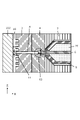
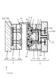
図1は、第一の実施形態である樹脂成形金型の構成を示すための簡易断面図である。図1において、1は固定側金型、2は可動側金型、3は第1中間金型、4は第2中間金型である。固定側金型1は、固定側ダイセットA部110、固定側ダイセットB部111、固定側取付板112を備えている。可動側金型2は、可動側取付板220、スペーサーブロック221、可動側ダイセット222を備えている。
10はキャビティで、本実施形態の金型は成形品を2個取りするため、2箇所にキャビティ10を備えているが、キャビティの数はこれに限るものではない。
201はキャビティ10に形成された樹脂成形品を離型する際に突出させるエジェクターピン、202はエジェクタープレートである。101は溶融樹脂を射出する射出装置に対して金型を位置決めするためのロケートリング、14は金型各部の接離動作を行うための引っ張りリンクである。
(Mold configuration)
FIG. 1 is a simplified cross-sectional view showing the configuration of the resin molding die of the first embodiment. In FIG. 1, 1 is a stationary mold, 2 is a movable mold, 3 is a first intermediate mold, and 4 is a second intermediate mold. The
201 is an ejector pin that protrudes when releasing the resin molded product formed in the
固定側金型1には、溶融樹脂を供給するためのホットランナー部が設けられ、第2中間金型4と第1中間金型3には、ホットランナーから供給される樹脂をキャビティ10に導入するためのコールドランナーが設けられている。5はホットランナー、6はバルブピン、7はホットランナーのブッシュ、8はコールドランナー、500はホットランナーのマニホールド部である。
図中右側からホットランナー部に供給される溶融樹脂は、マニホールド500を介して2箇所のキャビティ10に向けて分配される。各キャビティ10に向かうホットランナー5は、先端部がブッシュ7に挟持されて固定側ダイセットA部110に固定されている。バルブピン6は、ホットランナー5内からコールドランナー8に向けて進退可能に、バルブ駆動機構100により保持されている。
The fixed
Molten resin supplied to the hot runner section from the right side of the drawing is distributed toward two
図1中に点線で囲んで示した領域1Aの拡大断面図を、図2に示す。尚、図2に限らず拡大断面を示す際には、図示の便宜のため、ホットランナー、ブッシュ、バルブピン等の部材相互の間隔を広げて示す場合があるが、実際には溶融樹脂が漏れるような隙間が存在するわけではない。 FIG. 2 shows an enlarged cross-sectional view of the region 1A enclosed by the dotted line in FIG. It should be noted that, not only in FIG. 2, but when showing an enlarged cross section, for convenience of illustration, there are cases where the distance between members such as hot runners, bushes, valve pins, etc. is widened. gap does not exist.
図2は、キャビティ10に溶融樹脂20の注入を開始する前の状態を示している。すなわち、バルブピン6の先端がブッシュ7からコールドランナー8内に突出し、コールドランナー8の内側面と密接してコールドランナー8を閉塞している状態を示している。
バルブピン6は、コールドランナー8内の所定位置まで進出すると溶融樹脂の流路を閉じることができ、逆に所定位置よりもX方向側すなわちホットランナー5の内側にまで後退すると流路を開くことができる。流路を開くと、ホットランナー5内の溶融樹脂をコールドランナーを介してキャビティに充填することができる。
FIG. 2 shows the state before starting injection of the
When the
キャビティ10に溶融樹脂を充填した後、バルブピン6はコールドランナー8を閉塞するが、バルブピン6の先端は、高温なホットランナー5やブッシュ7から遠ざかり、しかも低温な第2中間金型と密着するため、温度が低下する。このため、コールドランナー8内の樹脂の固化に支障をきたすことはない。
バルブピン6の先端には、図中の点線で囲んだ領域61に示すようにアンダーカット形状部が設けられているが、コールドランナー8内で固化した樹脂とバルブピン6の先端部に噛合い構造を形成することができる。以後の説明では、この噛合い構造の部分をランナーロック部と呼ぶことがある。バルブピン6は、例えば鋼材を用いて作られている。ランナーロック部のアンダーカット形状部では、第1の位置においてバルブピンの軸方向と直交する面に沿って切った断面の断面積よりも、第1の位置よりもキャビティに近い位置においてバルブピンの軸方向と直交する面に沿って切った断面の断面積が大きい。
After the
The tip of the
11はキャビティに樹脂を注入するゲートである。コールドランナー8は、バルブピン6が流路を閉塞する所定位置からゲート11に向かって先細り、すなわち流路断面積が減少してゆくような形状に形成されている。本実施形態では、コールドランナー8の流路断面形状を円形としているが、その所定位置における直径をD1、ゲート11側をD2とした時、コールドランナー8の直径はD1からD2に向かうにつれ広義単調減少している。ここで、広義単調減少するとは、ゲートに向かって増加する部分は存在せずに減少してゆくが、一部に減少率が0(すなわち流路断面積が一定)の領域が含まれていてもよいことを意味する。D1はコールドランナーの中で最大直径であり、その直径はバルブピン6の直径以下である。
11 is a gate for injecting resin into the cavity. The
かかる先細り形状のコールドランナー8を採用することにより、成形品の形状が凹凸を有する複雑な形状であったとしても、キャビティにコールドランナーを容易に接続することが可能である。また、コールドランナー内で固化する樹脂の体積を抑制することができ、樹脂廃材を低減することができる。また、第1中間金型3と第2中間金型4を離間させたときに、コールドランナー8内で固化した樹脂を、最も細いゲート部にて簡単に切断することができ、樹脂成形品から容易に切り離すことができる。
By adopting such a tapered
(金型の動作)
次に、図1、図4、図5乃至図10を用いて本実施形態の金型装置の一連の動作について説明する。
まず第1の工程は、図1に示す樹脂成形金型に、不図示の射出装置から供給される溶融樹脂を射出充填させる工程である。まず、バルブピン6をX方向に移動させてコールドランナー8の流路を開き、マニホールド500を経由してホットランナー5に注入された溶融樹脂をコールドランナー8、ゲート11を介して各々のキャビティ10に射出する。キャビティ10に溶融樹脂が充填されたらバルブピン6をコールドランナー8に進出させ、コールドランナー8を閉塞する。図4に、キャビティ10に溶融樹脂20が充填された後、バルブピン6がコールドランナー8を閉塞している状態の拡大断面図を示す。
(movement of mold)
Next, a series of operations of the mold apparatus of this embodiment will be described with reference to FIGS.
The first step is to inject and fill the resin mold shown in FIG. 1 with molten resin supplied from an injection device (not shown). First, the
キャビティ10およびコールドランナー8に充填された樹脂は、冷却されて固化する。尚、以後の説明では、コールドランナー8内で固化した樹脂部分とキャビティ10内で固化した樹脂部分とを区別するため、前者をランナー固化物48と呼び、後者を樹脂成形品9と呼ぶ場合がある。
The resin filled in the
先述したように、バルブピン6の先端部は、高温なホットランナー5やブッシュ7から遠ざかり、しかも低温な第2中間金型の内面と密着することで温度が低下するため、コールドランナー8内の樹脂の固化に支障をきたすことはない。そして、バルブピン6の先端部のランナーロック部により、コールドランナー8内で固化した樹脂とバルブピン6とは噛合い構造を形成する。この噛合い構造により、ランナーロック部はランナー固化物48をバルブピンの軸方向に拘束可能である。図5は、樹脂をキャビティ10内に射出充填させ、固化させた状態を示す断面図である。尚、バルブピン6はコールドランナー8内に突出してこれを閉塞しているため、ランナー固化物48が直接的にブッシュ7に接触することはない。
As described above, the tip of the
次に、第2の工程は、第1中間金型3と第2中間金型4とを分離する工程である。図6は、第1中間金型3と第2中間金型4が離間機構13の作用により離間した状態を示す断面図である。
第1中間金型3と第2中間金型4が離間しようとすると、第2中間金型4のテーパー面とバルブピン6のランナーロック部とにより保持されたランナー固化物48はX方向に牽引され、最細部であるゲート11の位置でランナー固化物48は切断される。切断されたランナー固化物48は、第1中間金型3からは離型するが、第2中間金型4のテーパー面とランナーロック部により、引き続き保持される。
The second step is to separate the first
When the first
次に、第3の工程は、可動側金型2と第1中間金型3とを分離する工程である。図7は可動側金型2と第1中間金型3が分離した状態を示す断面図である。この工程において、切断されたランナー固化物48は、第2中間金型4のテーパー面とランナーロック部により、引き続き保持されている。
The third step is to separate the
次に、第4の工程は、固定側金型1と第2中間金型4とを分離する工程である。図8は、固定側金型1と第2中間金型4が分離した状態を示す断面図である。この工程において、樹脂成形品から切断されたランナー固化物48は、ランナーロック部により引き続き保持されてX方向に牽引されるため、第2中間金型4からは離型する。
The fourth step is to separate the
次に、第5の工程は、ランナー固化物48を金型から取り出す工程である。図9は、ランナー固化物48がバルブピン6から分離して取り出されている状態を示す断面図である。
図2に示したように、バルブピン6の先端のランナーロック部にはアンダーカット形状部が設けられているが、ランナー固化物48は、第2中間金型4から離型した後は、バルブピン6の軸方向(X方向)以外の力を受ければバルブピン6から簡単に脱離する。すなわち、重力により脱落し、自然落下により金型外に取り出し可能である。また、重力を利用しなくても、バルブピン6の軸方向(X方向)と交差する方向にオートハンドなどを用いて力を加えれば、簡単に取り出し可能である。
Next, the fifth step is the step of taking out the solidified
As shown in FIG. 2, the runner lock portion at the tip of the
次に、第6の工程は、樹脂成形品9が樹脂成形金型から離型される工程である。固化した樹脂成形品9は、エジェクターピン201により可動側ダイセット222から離型される。図10は、樹脂成形品9が離型された状態を示す断面図である。
以上の工程を繰り返すことにより、本金型を用いて樹脂成形品を連続して製造することが可能である。
Next, the sixth step is the step of releasing the resin molded
By repeating the above steps, it is possible to continuously manufacture resin molded products using the present mold.
本実施形態によれば、第1の工程において、バルブピン6の先端をコールドランナー8の金型内面と接触させてコールドランナーを閉塞するため、閉塞時のバルブピン6のランナーロック部の温度をホットランナーブッシュよりも低くすることができる。このため、工程の繰り返し速度を比較的早くしても、コールドランナー8内の樹脂を十分に固化させることができ、ランナー固化物をランナーロック部で確実に保持できる。
According to this embodiment, in the first step, the tip of the
また、キャビティに向かって先細りになるコールドランナーを採用しているため、ランナー固化物の体積を小さくすることができる。そして、第2の工程において、最細部であるゲート11の位置でランナー固化物48を樹脂成形品9から確実に切断することができる。さらに、第3の工程において、ランナー固化物48を、第2中間金型4のコールドランナーのテーパー面とランナーロック部により、引き続き保持することができる。
In addition, since a cold runner that tapers toward the cavity is used, the volume of solidified material on the runner can be reduced. Then, in the second step, the solidified
ランナーロック部には、ランナー固化物をバルブピンの軸方向に拘束するアンダーカット形状部が設けられているため、第4の工程ではランナー固化物を第2中間金型から離型し、第5の工程ではランナー固化物をバルブピンから開放することができる。
以上のように、本実施形態によれば、ランナー固化物の容積を小さくできるとともに、ランナー固化物をランナーロック部で確実に保持して破断することなく簡単に型外に取り出すことができる。
Since the runner lock portion is provided with an undercut-shaped portion that constrains the solidified runner material in the axial direction of the valve pin, the solidified runner material is released from the second intermediate mold in the fourth step, and is removed in the fifth step. The process allows the runner cake to be released from the valve pin.
As described above, according to the present embodiment, the volume of the solidified runner can be reduced, and the solidified runner can be reliably held by the runner lock portion and easily removed from the mold without breaking.
[第二の実施形態]
第二の実施形態の樹脂成形金型の基本構成は、図1を参照して説明した第一の実施形態と同様であるが、第一の実施形態とはバルブピンの形態が異なる。また、第二の実施形態の樹脂成形金型の基本動作は、図5乃至図10を参照して説明した第一の実施形態と同様である。第一の実施形態と共通する部分については、説明を省略する。
図24及び図25は、第二の実施形態の樹脂成形金型の一部を拡大した断面図で、第一の実施形態と同一の部品については同一の参照番号を付して示している。
[Second embodiment]
The basic configuration of the resin molding die of the second embodiment is the same as that of the first embodiment described with reference to FIG. 1, but differs from the first embodiment in the form of the valve pin. Also, the basic operation of the resin molding die of the second embodiment is the same as that of the first embodiment described with reference to FIGS. The description of the parts common to the first embodiment is omitted.
24 and 25 are cross-sectional views enlarging a part of the resin molding die of the second embodiment, and the same parts as those of the first embodiment are indicated by the same reference numerals.
本実施形態のバルブピン6は、ランナーロック部6a、ブッシュ当接部6b、主軸部6cを有している。バルブピン6の先端にあるランナーロック部6aには、ランナー固化物をバルブピンの軸方向に拘束して保持するアンダーカット形状部が設けられている。ランナーロック部6aは、ホットランナー5の出口開口およびブッシュ7の開口を通り抜け可能な形状を有している。バルブピン6がX+方向に移動すれば、ランナーロック部6aは図24に示すようにホットランナー内に位置し、バルブピン6がX-方向に移動すれば、ランナーロック部6aは図25に示すようにコールドランナー内に位置する。
The
図24は、バルブピン6がX+方向に移動してホットランナー内に位置し、ホットランナー5の出口開口、ブッシュ7の開口、コールドランナー8、ゲート11を通じて、溶融樹脂20がキャビティ10に注入されている時の状態を示している。図25は、キャビティ10への樹脂の注入が完了した後、バルブピン6がX-方向に移動し、溶融樹脂の流路を閉塞した状態を示している。図25において、バルブピン6のブッシュ当接部6bはブッシュ7の開口と当接し、主軸部6cの角部はホットランナー5のテーパー面と当接しており、溶融樹脂の流路を閉塞している。すなわち、バルブピン6は、コールドランナー8側に所定位置まで進出すると溶融樹脂の流路を閉じることができ、逆にX+方向側すなわちホットランナー5の内側にまで後退すると溶融樹脂の流路を開くことができる。
24, the
図25に示す状態において、キャビティ10内及びコールドランナー8内の溶融樹脂が冷却されると、キャビティ10内には樹脂成形物が形成され、コールドランナー8内にはランナー固化物が形成される。本実施形態では、第2中間金型4内のコールドランナーに、テーパー面だけでなく段差部を設けており、図6を参照して説明した第2の工程においてランナー固化物をX+方向に強く牽引することができる。このため、コールドランナー8の最細部であるゲート11の位置でランナー固化物は確実に切断される。
また、本実施形態では、後述する実施例7のように、バルブピンの軸と直交する方向におけるランナー固化物の最大径が、バルブピンのブッシュ当接部6bの径よりも大きくなる。これにより、ランナーロック部6aと噛合する部分のランナー固化物の構造強度を大きくすることができ、図8を参照して説明した第4の工程においてランナー固化物をX+方向に強く牽引することができる。このため、ランナー固化物を第2中間金型4から確実に離型することができる。
以上のように、本実施形態においても、ランナー固化物の容積を小さくできるとともに、ランナー固化物をランナーロック部で確実に保持して破断することなく簡単に型外に取り出すことができる。
In the state shown in FIG. 25 , when the molten resin inside the
Also, in this embodiment, the maximum diameter of the solidified runner in the direction orthogonal to the axis of the valve pin is larger than the diameter of the bush contact portion 6b of the valve pin, as in Example 7 described later. This makes it possible to increase the structural strength of the solidified runner at the portion that meshes with the runner lock portion 6a, and to strongly pull the solidified runner in the X+ direction in the fourth step described with reference to FIG. can. Therefore, the runner solidified product can be reliably released from the second
As described above, also in this embodiment, the volume of the solidified runner can be reduced, and the solidified runner can be reliably held by the runner lock portion and easily removed from the mold without breaking.
[実施例]
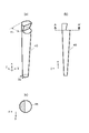
以下、本発明の実施例と比較例を説明する。実施例と比較例では、図3に外観形状を示す樹脂成形品9を作成し、その際に生じたランナー固化物を比較した。
[Example]
Examples of the present invention and comparative examples will be described below. In the example and the comparative example, a resin molded
樹脂成形品9は、板状の基部上面に6本のリブ12が平行に配置された形状を有する。具体的には、板状の基部の形状は、外寸が100mm×80mm、肉厚2mmで、リブ間距離Lは10mmであり、部品重量は22gである。樹脂成形品9を成形する金型には、図中の31で示す位置に対応してゲートが設けられている。すなわち、2本のリブの中間に対応する位置から、コールドランナーを介してキャビティに樹脂を注入する。
実施例および比較例は、全て表1に示す成形条件で樹脂成形品9を作成した。
The resin molded
In the examples and comparative examples, resin molded

(実施例1)
実施例1では、図1の樹脂成形金型を用いて成形した。樹脂はPBTを用いた。図2に断面形状を示したバルブピン6およびコールドランナー8を用いた。コールドランナーの最大直径D1は4mm、ゲート側の直径D2は1.2mmであり、バルブピンの直径は4mmである。コールドランナーはD1を最大とし、D2に向かうにつれ直径は広義単調減少している。すなわち、コールドランナーの直径はバルブピンの直径以下である。
実施例1では、前述した実施形態の第1の工程から第6の工程を実施し、樹脂成形品を作成した。第1の工程において図4に示すように樹脂を注入すると、コールドランナー8内にはランナー固化物48が生ずる。
(Example 1)
In Example 1, molding was performed using the resin molding die shown in FIG. PBT was used as the resin. A
In Example 1, the first to sixth steps of the above-described embodiment were carried out to produce a resin molded product. When the resin is injected in the first step as shown in FIG.
図11(a)乃至図11(c)に、実施例1のランナー固化物48の形状を示す。図11(a)はランナー固化物48の全体形状を示す外観斜視図、図11(b)はXZ平面図、図11(c)は図11(b)中のA-A’に沿って切断した断面図である。図11(a)に示すように、ランナー固化物48は、コールドランナーの最大直径D1及びD2を反映した先細りの形状を有している。図11(b)において、X方向はバルブピンの軸方向に対応するが、ランナー固化物48の端部はX方向に見たときアンダーカットされた形状となっており、バルブピンのランナーロック部と噛み合って保持され得る。図11(c)において、-Z方向およびY方向は、アンダーカット形状で拘束されない方向であり、ランナー固化物48がバルブピン6から容易に抜ける方向である。ランナーロックから抜ける方向を鉛直方向と一致させれば、取り出し時にランナー固化物48は自然落下する。また鉛直方向以外の任意の方向に設定した場合には、オートハンド等を用いれば簡単に取り出しできる。実施例1におけるランナー固化物の重量は、0.23gであった。
11(a) to 11(c) show the shape of the solidified
(実施例2)
実施例2では、バルブピンの先端部のランナーロック部の形状を除き、実施例1と同様の方法で樹脂成形品9を作成した。すなわち、実施例1と同様に図1の樹脂成形金型を用いて成形し、樹脂はPBTを用いた。コールドランナーの最大直径D1は4mm、ゲート側の直径D2は1.2mmであり、バルブピンの直径は4mmである。コールドランナーはD1を最大とし、D2に向かうにつれ直径は広義単調減少している。また、コールドランナーの直径はバルブピンの直径以下である。
実施例2においても、前述した実施形態の第1の工程から第6の工程を実施し、成形物を作成した。第1の工程において図4に示すように樹脂を注入すると、コールドランナー8内にはランナー固化物48が生ずる。
(Example 2)
In Example 2, a resin molded
Also in Example 2, the first to sixth steps of the above-described embodiment were carried out to prepare a molding. When the resin is injected in the first step as shown in FIG.
図12(a)乃至図12(c)に、実施例2のランナー固化物48の形状を示す。図12(a)はランナー固化物48の全体形状を示す外観斜視図、図12(b)はXZ平面図、図12(c)は図12(b)中のB-B’に沿って切断した断面図である。図12(a)に示すように、ランナー固化物48は、コールドランナーの最大直径D1及びD2を反映した先細りの形状を有している。図12(b)において、X方向はバルブピンの軸方向に対応するが、ランナー固化物48の端部はX方向に見たときアンダーカットされた斜面を有する形状となっており、バルブピンのランナーロック部と噛み合って保持され得る。
12(a) to 12(c) show the shape of the solidified
実施例2においては、実施例1と異なり、ランナー固化物48はX方向だけでなくY方向にもバルブピンのランナーロック部に拘束される。したがって、実施例2においては、図12(c)の-Z方向が、ランナーロック部で拘束されない方向であり、ランナー固化物48がバルブピン6から容易に抜ける方向である。ランナーロックから抜ける方向を鉛直方向と一致させれば、取り出し時にランナー固化物48は自然落下する。また鉛直方向以外の任意の方向に設定した場合には、オートハンド等を用いれば簡単に取り出しできる。
実施例2におけるランナー固化物の重量は、0.23gであった。
In the second embodiment, unlike the first embodiment, the solidified
The weight of the solidified runner material in Example 2 was 0.23 g.
(実施例3)
実施例3では、第1中間金型3および第2中間金型4に形成された樹脂流路であるコールドランナーの形状を除き、実施例1と同様の方法で樹脂成形品9を作成した。すなわち、実施例1と同様に図1の樹脂成形金型を用いて成形し、樹脂はPBTを用いた。
図13は、実施例3のコールドランナーの形状を示す断面図である。コールドランナーの最大直径D1は4mm、ゲート側の直径D2は1.2mmであり、バルブピンの直径は4mmである。また、コールドランナーの直径はバルブピンの直径以下である。
(Example 3)
In Example 3, a resin molded
13 is a cross-sectional view showing the shape of the cold runner of Example 3. FIG. The maximum diameter D1 of the cold runner is 4 mm, the diameter D2 on the gate side is 1.2 mm, and the diameter of the valve pin is 4 mm. Also, the diameter of the cold runner is less than or equal to the diameter of the valve pin.
実施例3においても、コールドランナーは、ランナーロック部からゲートに向かって先細り、すなわち流路断面積が減少する形状を有している。ただし、実施例3においては、第2中間金型4内のコールドランナー部に段差部81を設けている。
実施例3においても、前述した実施形態の第1の工程から第6の工程を実施し、成形物を作成した。第1の工程において図4に示すように樹脂を注入すると、コールドランナー8内にはランナー固化物48が生ずる。
Also in Example 3, the cold runner tapers from the runner lock portion toward the gate, that is, has a shape in which the flow passage cross-sectional area decreases. However, in Example 3, a stepped
Also in Example 3, the first to sixth steps of the above-described embodiment were carried out to prepare a molding. When the resin is injected in the first step as shown in FIG.
実施例3では、第2中間金型4内のコールドランナー部に段差部81を設けたことにより、第2の工程において第1中間金型3と第2中間金型4とを分離する際に、ランナー固化物48は第2中間金型4によってX方向に強く牽引される。このため、ランナー固化物48は、最細部であるゲート11の位置で確実に切断されるとともに、第1中間金型3からの離型が、実施例1よりも更に容易になる。
実施例3におけるランナー固化物の重量は、0.25gであった。
In Example 3, by providing the stepped
The weight of the solidified runner material in Example 3 was 0.25 g.
(実施例4)
実施例4では、バルブピンの先端部のランナーロック部の形状及び樹脂流路であるコールドランナーの形状を除き、実施例1と同様の方法で樹脂成形品9を作成した。すなわち、実施例1と同様に図1の樹脂成形金型を用いて成形し、樹脂はPBTを用いた。
コールドランナーの最大直径D1は4mm、ゲート側の直径D2は1.2mmであり、バルブピンの直径は4mmである。コールドランナーはD1を最大とし、D2に向かうにつれ直径は広義単調減少している。すなわち、コールドランナーの直径はバルブピンの直径以下である。実施例4においても、前述した実施形態の第1の工程から第6の工程を実施し、成形物を作成した。第1の工程において図4に示すように樹脂を注入するとコールドランナー8内にはランナー固化物48が生ずる。
(Example 4)
In Example 4, a resin molded
The maximum diameter D1 of the cold runner is 4 mm, the diameter D2 on the gate side is 1.2 mm, and the diameter of the valve pin is 4 mm. The cold runner has a maximum at D1, and the diameter is broadly monotonically decreasing toward D2. That is, the diameter of the cold runner is less than or equal to the diameter of the valve pin. Also in Example 4, the first to sixth steps of the above-described embodiment were carried out to produce a molding. When the resin is injected in the first step as shown in FIG.
図17(a)~図17(c)に、実施例4のランナー固化物48の形状を示す。図17(a)はランナー固化物48の全体形状を示す外観斜視図、図17(b)はXY平面図、図17(c)はC-C’に沿って切断した断面図である。実施例4においては、実施例1と異なりランナー固化物はX方向だけでなくY方向にも拘束される。―Z方向がランナーロック部の拘束されない方向であり、ランナー固化物48は自然落下する。ランナーロック部の向き次第で、鉛直方向の内、上向きか下向きのいずれか一方向にのみ離間可能とすることができる。この場合、コールドランナーで固化した樹脂の内、離間可能な前記一方向の直径はバルブピンの直径未満であり、一方向と交差する方向の直径はバルブピンの直径以上である。また、拘束されない方向を鉛直方向以外の任意の方向に設定した場合には、オートハンド等を用いれば簡単に取り出しできる。
17(a) to 17(c) show the shape of the solidified
実施例4では、第2中間金型4内のコールドランナー部に段差部81を設けたことにより、第2の工程において第1中間金型3と第2中間金型4とを分離する際に、ランナー固化物48は第2中間金型4によってX方向に強く牽引される。このため、ランナー固化物48は、最細部であるゲート11の位置で確実に切断されるとともに、第1中間金型3からの離型が、実施例1よりも更に容易になる。実施例4におけるランナー固化物の重量は、0.23gであった。
In Example 4, by providing the stepped
(実施例5)
図18(a)~図18(c)に、実施例5のランナー固化物48の形状を示す。図18(a)はランナー固化物48の全体形状を示す外観斜視図、図18(b)はXY平面図、図18(c)は上面図である。実施例5では、バルブピンの先端部のランナーロック部の形状を除き、実施例4と同様の方法で樹脂成形品9を作成した。すなわち、実施例4と同様に図1の樹脂成形金型を用いて成形し、樹脂はPBTを用いた。コールドランナーの内離間可能な方向の最大直径D1は4mm、離間可能な方向以外の領域での最大直径Dmaxは6mm、ゲート側の直径D2は1.2mmであり、バルブピンの直径は4mmである。これら以外は実施例4と同様である。
(Example 5)
18(a) to 18(c) show the shape of the solidified
実施例4と比べランナー固化物48を厚肉にすることができ、強度向上が図れる。ランナー固化物48の前記離間可能な方向以外の領域はホットランナーのブッシュ7に接触するが、接触範囲が十分に小さいため、ランナー固化物48の冷却への影響は無い。実施例5におけるランナー固化物の重量は、0.53gであった。
As compared with the fourth embodiment, the thickness of the solidified
(実施例6)
図19(a)~図19(d)に、実施例6のランナー固化物48の形状を示す。図19(a)はランナー固化物48の全体形状を示す外観斜視図、図19(b)はXY平面図、図19(c)はE-E’に沿って切断した断面図、図19(d)はランナー固化物とバルブピンの噛合状態を示す図である。
実施例6では、バルブピンの先端部のランナーロック部の形状を除き、実施例4と同様の方法で樹脂成形品9を作成した。すなわち、実施例4と同様に図1の樹脂成形金型を用いて成形し、樹脂はPBTを用いた。
コールドランナーの直径D1は2mm、ゲート側の直径D2は1.2mmであり、バルブピンの直径は2mmである。これら以外は実施例4と同様である。
(Example 6)
19(a) to 19(d) show the shape of the solidified
In Example 6, a resin molded
The diameter D1 of the cold runner is 2 mm, the diameter D2 on the gate side is 1.2 mm, and the diameter of the valve pin is 2 mm. Other than these, it is the same as the fourth embodiment.
ランナー固化物48の溝部はバルブピン先端のランナーロック部に対応しており、ランナー固化物はバルブピン側から樹脂成形品9に接続するゲート側に向け、溝部内径が増加している円錐台形状をしている。これにより、バルブピンの軸に交差する方向にランナー固化物48を拘束しているとともに、ランナー固化物の溝部がX方向にアンダーカットとなり、離型の際バルブピンによってランナー固化物48はX方向により強く牽引される。実施例6におけるランナー固化物の重量は、0.15gであった。
The groove of the solidified
(実施例7)
図20(a)~図20(d)に、実施例7のランナー固化物48の形状を示す。図20(a)はランナー固化物48の全体形状を示す外観斜視図、図20(b)はXY平面図、図20(c)はF-F’に沿って切断した断面図、図20(d)はランナー固化物とバルブピンの噛合状態を示す図である。
実施例7では、バルブピンの先端部のランナーロック部の大きさを除き実施例6と同様である。コールドランナーの直径D1は3.3mm、ゲート側の直径D2は1.2mmであり、バルブピンの直径は2mmである。これら以外は実施例6と同様である。
(Example 7)
20(a) to 20(d) show the shape of the solidified
Example 7 is the same as Example 6 except for the size of the runner lock portion at the tip of the valve pin. The cold runner diameter D1 is 3.3 mm, the gate side diameter D2 is 1.2 mm, and the valve pin diameter is 2 mm. Other than these, it is the same as the sixth embodiment.
ランナー固化物48は実施例6と比べ厚肉にすることができ、強度向上が図れる。ランナー固化物48の直径D1はバルブピンの直径より大きいため、ごく一部がブッシュ7に接触するが、接触範囲が十分に小さいため、ランナー固化物48の冷却への影響は無い。実施例7におけるランナー固化物の重量は、0.17gであった。
The solidified
(実施例8)
図21(a)~図21(c)に、実施例8のランナー固化物48の形状を示す。図21(a)はランナー固化物48の全体形状を示す外観斜視図、図21(b)はXY平面図、図21(c)はG-G’に沿って切断した断面図である。
実施例8は、バルブピンの先端部のランナーロック部の形状を除き、実施例6と同様である。コールドランナーの直径D1は3.3mm、ゲート側の直径D2は1.2mmであり、バルブピンの直径は2mmである。これら以外は実施例6と同様である。
(Example 8)
21(a) to 21(c) show the shape of the solidified
Example 8 is the same as Example 6 except for the shape of the runner lock portion at the tip of the valve pin. The cold runner diameter D1 is 3.3 mm, the gate side diameter D2 is 1.2 mm, and the valve pin diameter is 2 mm. Other than these, it is the same as the sixth embodiment.
ランナー固化物48の溝部はバルブピン先端のランナーロック部に対応しており、ランナー固化物はバルブピン側から樹脂成形品9に接続するゲート側に向け、溝部内径が周期的に増減している。周期的な溝はピッチが0.3mm、切り込み深さが0.3mmである。これにより、バルブピンの軸に交差する方向にランナー固化物48を拘束しているとともに、ランナー固化物の溝部がX方向に複数のアンダーカットとなり、離型の際、実施例6と比較し、バルブピンによってランナー固化物48はX方向により強く牽引される。ランナー固化物48の直径D1はバルブピンの直径より大きいため、ごく一部がブッシュ7に接触するが、接触範囲が十分に小さいため、ランナー固化物48の冷却への影響は無い。実施例8におけるランナー固化物の重量は、0.17gであった。
The groove of the solidified
(実施例9)
図22(a)~図22(c)に、実施例9のランナー固化物48の形状を示す。図22(a)はランナー固化物48の全体形状を示す外観斜視図、図22(b)はXY平面図、図22(c)はH-H’に沿って切断した断面図である。
実施例9では、バルブピンの先端部のランナーロック部の形状を除き実施例6と同様である。コールドランナーの直径D1は3.3mm、ゲート側の直径D2は1.2mmであり、バルブピンの直径は2mmである。これら以外は実施例6と同様である。
(Example 9)
22(a) to 22(c) show the shape of the solidified
The ninth embodiment is the same as the sixth embodiment except for the shape of the runner lock portion at the tip of the valve pin. The cold runner diameter D1 is 3.3 mm, the gate side diameter D2 is 1.2 mm, and the valve pin diameter is 2 mm. Other than these, it is the same as the sixth embodiment.
ランナー固化物48の溝部はバルブピン先端のランナーロック部に対応しており、ランナー固化物はバルブピン側から樹脂成形品9に接続するゲート側に向け、溝部が螺旋状に伸びる形状を有している。すなわち、バルブピン先端のランナーロック部がボルトのねじ溝のような形状を有し、ランナー固化物がナットのねじ溝のような形状を有している。螺旋形状のピッチは0.3mm切り込み深さは0.3mmである。これにより、バルブピンの軸に交差する方向にランナー固化物48を拘束しているとともに、ランナー固化物の溝部がX方向に複数のアンダーカットとなり、離型の際、実施例6と比較し、バルブピンによってランナー固化物48はX方向により強く牽引される。
また、バルブピンからの離形の際には、噛合したボルトとナットを開放させるときのように、ランナー固化物48を溝部螺旋形状に沿って回転することで簡単に離型することができる。ランナー固化物48の直径D1はバルブピンの直径より大きいため、ごく一部がブッシュ7に接触するが、接触範囲が十分に小さいため、ランナー固化物48の冷却への影響は無い。実施例9におけるランナー固化物の重量は、0.17gであった。
The groove of the solidified
In addition, when releasing from the valve pin, it can be easily released by rotating the solidified
(実施例10)
実施例10では、ランナー固化物の直径以外は実施例7と同様である。コールドランナーの直径D1は6mm、ゲート側の直径D2は1.2mmであり、バルブピンの直径は2mmである。これら以外は実施例6と同様である。実施例10におけるランナー固化物の重量は、0.45gであった。
(Example 10)
Example 10 is the same as Example 7 except for the diameter of the solidified runner. The cold runner diameter D1 is 6 mm, the gate side diameter D2 is 1.2 mm, and the valve pin diameter is 2 mm. Other than these, it is the same as the sixth embodiment. The weight of the solidified runner material in Example 10 was 0.45 g.
(実施例11)
図23(a)~図23(d)に、実施例11のランナー固化物48の形状を示す。図23(a)はランナー固化物48の全体形状を示す外観斜視図、図23(b)はXY平面図、図23(c)はI-I’に沿って切断した断面図、図23(d)はランナー固化物とバルブピンの噛合状態を示す図である。
実施例11では、ランナー固化物の直径とバルブピンの直径を除き、実施例6と同様である。
コールドランナーの直径D1は3.3mm、ゲート側の直径D2は1.2mmであり、バルブピンの直径は4mmである。これら以外は実施例6と同様である。実施例11におけるランナー固化物の重量は、0.17gであった。
(Example 11)
23(a) to 23(d) show the shape of the solidified
Example 11 is the same as Example 6 except for the diameter of the solidified runner and the diameter of the valve pin.
The cold runner diameter D1 is 3.3 mm, the gate side diameter D2 is 1.2 mm, and the valve pin diameter is 4 mm. Other than these, it is the same as the sixth embodiment. The weight of the solidified runner material in Example 11 was 0.17 g.
(比較例1)
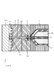
比較例1に用いた金型は、特許文献1において第4図を参照して説明されている樹脂成形金型と類似の金型である。すなわち、比較例1として、図14に示す樹脂成形金型を用いて樹脂成形品9を作成した。実施例と同様に、樹脂はPBTを用いた。
(Comparative example 1)
The mold used in Comparative Example 1 is similar to the resin molding mold described in
図14において、601は固定金型、602は可動金型、603は中間金型である。固定金型601には、幹コールドランナー604が設けられ、図示外のホットランナーから溶融樹脂が注入される。中間金型603には、幹コールドランナー604に注入された溶融樹脂を各キャビティに向けて分配するコールドランナー溝605と、各キャビティに直結する枝コールドランナー606が設けられている。幹コールドランナー604とコールドランナー溝605と枝コールドランナー606とは、互いに連通して全体としてコールドランナー部を構成している。
In FIG. 14, 601 is a fixed mold, 602 is a movable mold, and 603 is an intermediate mold. A fixed
固定金型には、コールドランナー部に突出したランナーロックピン607が設けられており、コールドランナー部で固化したランナー固化物648を保持することができる。ただし、比較例1のランナーロックピンは、実施例のバルブピンと異なり、コールドランナーの流路を開閉する機能は備えていない。また、ホットランナーのブッシュからコールドランナー内に向けて進退可能でない点も、実施例のバルブピンとは異なる。
比較例1では、コールドランナー部の流路容積が大きいため、ランナー固化物648の容積も大きくなり、ランナー固化物の重量は、4.0gであった。
The fixed mold is provided with a
In Comparative Example 1, since the flow passage volume of the cold runner portion was large, the volume of the solidified
(比較例2)
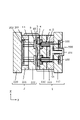
比較例2に用いた金型は、特許文献1において第1図を参照して説明されている樹脂成形金型と類似の金型である。すなわち、比較例2として、図15に示す樹脂成形金型を用いて樹脂成形品9を作成した。実施例と同様に、樹脂はPBTを用いた。
(Comparative example 2)
The mold used in Comparative Example 2 is similar to the resin molding mold described in
図15において、701は固定金型、702は可動金型、703は中間金型である。固定金型701内には、ホットランナー705およびホットランナーのブッシュ707が、中間金型703とは距離を開けて配置されている。ホットランナーのブッシュ707と中間金型703の間の空間も樹脂の流路、すなわちコールドランナーの一部として機能する。ホットランナー705には、ホットランナーの出口を開閉するためのホットランナーピン706が設けられている。中間金型703には、コールドランナー708が設けられている。
In FIG. 15, 701 is a fixed mold, 702 is a movable mold, and 703 is an intermediate mold. A
比較例2のホットランナーのブッシュ707には、コールドランナー部で固化したランナー固化物748を保持するための突起761が設けられており、ランナーロック部として機能する。ホットランナーのブッシュ707の直径は40mmであるが、突起761と嵌合して保持されるランナー固化物748の直径も40mmとなる。比較例2では、コールドランナー部の容積が大きいため、ランナー固化物748の容積も大きくなり、ランナー固化物の重量は、2.2gであった。また、ホットランナーのブッシュ707の温度が比較的高いため、実施例と同一の冷却時間では突起761の周辺で十分に樹脂が固化せず、ランナー固化物748の取出しに支障が出る場合もあった。
The
(結果)
実施例1~実施例11、比較例1~2の結果を表2に示す。
(result)
Table 2 shows the results of Examples 1 to 11 and Comparative Examples 1 and 2.

表2に示す通り、比較例に対して本発明の実施例では、ランナー固化物の発生量を大幅に低減することが可能である。比較例1を基準に削減比率を計算すれば、86%~96%もの大幅な削減が可能であることがわかる。
また、ランナー固化物の離型性の欄に記載された数字は、金型からランナー固化物を離型する際の離型しやすさを示す指標である。数字が1、2、3と大きくなるにつれ、離型が適切に行われる確実性が高いと言いかえることができる。言い換えれば、数字が大きいほどランナーロック部がランナー固化物を保持する保持力が大きく、ランナー固化物はゲート部で切断されやすいといえる。尚、比較例1と比較例2は、ランナー固化物の取り出しにしばしば支障が生じたため、数字は記載していない。
本発明の実施形態は、上述した実施形態および実施例に限られるものではなく、適宜変更したり、組み合わせたりすることが可能である。
As shown in Table 2, in the examples of the present invention, it is possible to significantly reduce the amount of runner solidified matter generated as compared with the comparative examples. If the reduction ratio is calculated based on Comparative Example 1, it can be seen that a significant reduction of 86% to 96% is possible.
In addition, the numbers described in the column of releasability of the runner solidified product are indexes showing the ease of releasing the runner solidified product from the mold. It can be said that the higher the numbers are from 1, 2, and 3, the higher the certainty that the mold release will be properly performed. In other words, it can be said that the larger the number, the greater the holding power of the runner lock portion to hold the solidified runner material, and the more easily the solidified runner material is cut at the gate portion. Incidentally, in Comparative Examples 1 and 2, since trouble often occurred in taking out the solidified runner material, numbers are not shown.
Embodiments of the present invention are not limited to the embodiments and examples described above, and can be modified or combined as appropriate.
実施例では、表1の成形条件のもとでPBT樹脂を用いて成形したが、これ以外の樹脂材料を用いる場合においても、本発明を実施すればランナー固化物の発生量を大幅に低減することができる。例えば、PS、ABS、PC+ABS、POMなどの樹脂でも本発明は実施可能であり、材料に応じて成形条件を適宜調整すればよく、例えば金型温度については30℃~80℃の範囲で調整すれば好適である。 In the examples, PBT resin was used for molding under the molding conditions shown in Table 1, but even when other resin materials are used, if the present invention is carried out, the amount of runner solidified matter generated can be greatly reduced. be able to. For example, the present invention can be practiced with resins such as PS, ABS, PC+ABS, and POM, and the molding conditions may be appropriately adjusted according to the material. is preferred.
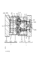
先端にランナーロック構造を有するバルブピンでコールドランナーを開閉する機構は、図2や図13の例に限られるわけではない。例えば、図16に示すように、バルブピン6をコールドランナー8の突き当て段差部91に突き当てることで閉塞するものであってもよい。この場合には、コールドランナーの最大直径は、バルブピンの直径未満になる。要は、ランナー固化物を保持可能なランナーロック部を先端に備えたバルブピンをコールドランナー側に進/退させ、金型内面に当接/離間させることでコールドランナーを閉/開できるものであればよい。
また、コールドランナーの流路断面の形状は円形に限らず、例えば楕円形や多角形であってもよい。
The mechanism for opening and closing the cold runner with a valve pin having a runner lock structure at its tip is not limited to the examples shown in FIGS. 2 and 13 . For example, as shown in FIG. 16, the
Further, the shape of the cross section of the cold runner is not limited to circular, and may be, for example, elliptical or polygonal.
1・・・固定側金型/2・・・可動側金型/3・・・第1中間金型/4・・・第2中間金型/5・・・ホットランナー/6・・・バルブピン/7・・・ブッシュ/8・・・コールドランナー/9・・・樹脂成形品/10・・・キャビティ/11・・・ゲート/12・・・リブ/14・・・引っ張りリンク/20・・・溶融樹脂/48・・・ランナー固化物/81・・・段差部/91・・・突き当て段差部/100・・・バルブ駆動機構/110・・・固定側ダイセットA部/111・・・固定側ダイセットB部/112・・・固定側取付板/201・・・エジェクターピン/220・・・可動側取付板/221・・・スペーサーブロック/222・・・可動側ダイセット/500・・・ホットランナーのマニホールド部
1 Fixed side mold/2 Movable side mold/3 First intermediate mold/4 Second intermediate mold/5 Hot runner/6 Valve pin /7... Bush/8... Cold runner/9... Resin molded product/10... Cavity/11... Gate/12... Rib/14... Pull link/20... Molten resin/48 Runner solidified product/81 Step portion/91 Strike step portion/100 Valve drive mechanism/110 Fixed side die set A portion/111... Fixed side die set B part/112 Fixed side mounting plate/201 Ejector pin/220 Movable side mounting plate/221 Spacer block/222 Movable side die set/500・・・Hot runner manifold
Claims (20)
樹脂成形品に応じたキャビティを形成する第2金型と、 a second mold for forming a cavity corresponding to the resin molded product;
前記第1金型と前記第2金型との間に配され、前記ホットランナーと前記キャビティとを接続し、前記ホットランナーよりも低温なコールドランナーが設けられた中間金型と、 an intermediate mold disposed between the first mold and the second mold, connecting the hot runner and the cavity, and provided with a cold runner having a lower temperature than the hot runner;
バルブピンと、を備えた樹脂成形金型であって、 A resin molding die comprising a valve pin,
前記バルブピンは、前記バルブピンの軸方向に進退することで、前記ホットランナーから前記キャビティに至る溶融樹脂の流路を開閉することが可能であり、 The valve pin advances and retreats in the axial direction of the valve pin to open and close the flow path of the molten resin from the hot runner to the cavity,
前記バルブピンは、前記コールドランナーで固化した樹脂を保持可能なランナーロック部を備える、 The valve pin has a runner lock portion capable of holding the resin solidified by the cold runner,
ことを特徴とする樹脂成形金型。 A resin molding die characterized by:
前記コールドランナーは、前記第1中間金型に設けられた第1コールドランナーと、前記第2中間金型に設けられた第2コールドランナーと、を含み、 The cold runner includes a first cold runner provided in the first intermediate mold and a second cold runner provided in the second intermediate mold,
前記バルブピンが前記流路を閉じたときに、前記ランナーロック部は、前記第2コールドランナーに位置する、 When the valve pin closes the flow path, the runner lock portion is positioned on the second cold runner.
ことを特徴とする請求項1に記載の樹脂成形金型。 The resin molding die according to claim 1, characterized in that:
ことを特徴とする請求項2に記載の樹脂成形金型。 The resin molding die according to claim 2, characterized in that:
ことを特徴とする請求項3に記載の樹脂成形金型。 The resin molding die according to claim 3, characterized in that:
ことを特徴とする請求項3または4に記載の樹脂成形金型。 The resin molding die according to claim 3 or 4, characterized in that:
ことを特徴とする請求項2乃至5のいずれか1項に記載の樹脂成形金型。 The resin molding die according to any one of claims 2 to 5, characterized in that:
ことを特徴とする請求項2乃至6のいずれか1項に記載の樹脂成形金型。 The resin molding die according to any one of claims 2 to 6, characterized in that:
ことを特徴とする請求項2乃至7のいずれか1項に記載の樹脂成形金型。 The resin molding die according to any one of claims 2 to 7, characterized in that:
ことを特徴とする請求項2乃至8のいずれか1項に記載の樹脂成形金型。 The resin molding die according to any one of claims 2 to 8, characterized in that:
ことを特徴とする請求項2乃至9のいずれか1項に記載の樹脂成形金型。 The resin molding die according to any one of claims 2 to 9, characterized in that:
ことを特徴とする請求項1乃至10のいずれか1項に記載の樹脂成形金型。 The resin molding die according to any one of claims 1 to 10, characterized in that:
ことを特徴とする請求項1乃至11のいずれか1項に記載の樹脂成形金型。 The resin molding die according to any one of claims 1 to 11, characterized in that:
ことを特徴とする請求項1乃至12の中のいずれか1項に記載の樹脂成形金型。 The resin molding die according to any one of claims 1 to 12, characterized in that:
ことを特徴とする請求項1乃至13の中のいずれか1項に記載の樹脂成形金型。 The resin molding die according to any one of claims 1 to 13, characterized in that:
前記軸方向における前記ランナーロック部の前記第1の位置よりも前記キャビティに近い第2の位置の、前記軸方向と直交する面での断面積が大きい、 A second position closer to the cavity than the first position of the runner lock portion in the axial direction has a larger cross-sectional area in a plane perpendicular to the axial direction,
ことを特徴とする請求項1乃至14の中のいずれか1項に記載の樹脂成形金型。 The resin molding die according to any one of claims 1 to 14, characterized in that:
ことを特徴とする請求項15に記載の樹脂成形金型。 The resin molding die according to claim 15, characterized by:
前記バルブピンは、前記軸方向における前記ランナーロック部よりも前記キャビティから離れた第4の位置に、前記軸方向と直交する面での第2の断面積を有する部分を含み、 the valve pin includes a portion having a second cross-sectional area in a plane perpendicular to the axial direction at a fourth position further away from the cavity than the runner lock portion in the axial direction;
前記第2の断面積は、前記第1の断面積と異なる、the second cross-sectional area is different than the first cross-sectional area;
ことを特徴とする請求項1乃至16のいずれか1項に記載の樹脂成形金型。 The resin molding die according to any one of claims 1 to 16, characterized in that:
ことを特徴とする請求項17に記載の樹脂成形金型。 The resin molding die according to claim 17, characterized by:
ことを特徴とする請求項1乃至18のいずれか1項に記載の樹脂成形金型。 The resin molding die according to any one of claims 1 to 18, characterized in that:
ことを特徴とする樹脂成形品の製造方法。 A method of manufacturing a resin molded product characterized by:
Priority Applications (2)
| Application Number | Priority Date | Filing Date | Title |
|---|---|---|---|
| US16/152,665 US11179872B2 (en) | 2017-10-24 | 2018-10-05 | Resin shaping mold and method of producing resin molded product |
| CN201811233190.6A CN109693341B (en) | 2017-10-24 | 2018-10-23 | Resin molding die and method for producing resin molded product |
Applications Claiming Priority (2)
| Application Number | Priority Date | Filing Date | Title |
|---|---|---|---|
| JP2017205561 | 2017-10-24 | ||
| JP2017205561 | 2017-10-24 |
Publications (3)
| Publication Number | Publication Date |
|---|---|
| JP2019077174A JP2019077174A (en) | 2019-05-23 |
| JP2019077174A5 JP2019077174A5 (en) | 2021-10-28 |
| JP7118830B2 true JP7118830B2 (en) | 2022-08-16 |
Family
ID=66627140
Family Applications (1)
| Application Number | Title | Priority Date | Filing Date |
|---|---|---|---|
| JP2018172361A Active JP7118830B2 (en) | 2017-10-24 | 2018-09-14 | Resin molding die and method for manufacturing resin molded product |
Country Status (1)
| Country | Link |
|---|---|
| JP (1) | JP7118830B2 (en) |
Citations (4)
| Publication number | Priority date | Publication date | Assignee | Title |
|---|---|---|---|---|
| JP2004209904A (en) | 2003-01-08 | 2004-07-29 | Ricoh Co Ltd | Injection molding apparatus |
| JP2007007925A (en) | 2005-06-29 | 2007-01-18 | Toyota Boshoku Corp | Mold for stack molding |
| JP2012061827A (en) | 2010-09-17 | 2012-03-29 | Olympus Corp | Injection molding die and injection molding machine, and injection molding method |
| WO2016084134A1 (en) | 2014-11-25 | 2016-06-02 | ファンテック株式会社 | Multi-piece injection molding method and mold |
-
2018
- 2018-09-14 JP JP2018172361A patent/JP7118830B2/en active Active
Patent Citations (4)
| Publication number | Priority date | Publication date | Assignee | Title |
|---|---|---|---|---|
| JP2004209904A (en) | 2003-01-08 | 2004-07-29 | Ricoh Co Ltd | Injection molding apparatus |
| JP2007007925A (en) | 2005-06-29 | 2007-01-18 | Toyota Boshoku Corp | Mold for stack molding |
| JP2012061827A (en) | 2010-09-17 | 2012-03-29 | Olympus Corp | Injection molding die and injection molding machine, and injection molding method |
| WO2016084134A1 (en) | 2014-11-25 | 2016-06-02 | ファンテック株式会社 | Multi-piece injection molding method and mold |
Also Published As
| Publication number | Publication date |
|---|---|
| JP2019077174A (en) | 2019-05-23 |
Similar Documents
| Publication | Publication Date | Title |
|---|---|---|
| US3018519A (en) | Apparatus for molding plastic insert in threaded lock nut blanks | |
| CN102596533A (en) | A method and system for operating an injection molding machine | |
| JP2009045896A (en) | Injection-molding method of bowl-like article with undercut part | |
| US11179872B2 (en) | Resin shaping mold and method of producing resin molded product | |
| JP5794242B2 (en) | Mold | |
| JP7118830B2 (en) | Resin molding die and method for manufacturing resin molded product | |
| KR101602734B1 (en) | Injection mold having a fixing protumerance for preventing rotation | |
| CN102858513A (en) | Injection molding apparatus | |
| US10843393B2 (en) | Injection molding apparatus and method of use | |
| CN203649363U (en) | Die for delay parting of swing hook | |
| KR101909810B1 (en) | Injection mold for molding products with thread | |
| CN109551719B (en) | Mould with self-lubricating demoulding mechanism for turntable helical gear | |
| KR20150090608A (en) | Injection mold | |
| US11192178B2 (en) | Mold | |
| KR20160094630A (en) | Two-stage extraction device when the runner gate entry for molded prevent damage | |
| KR100582818B1 (en) | Slide Core Structure for Extracting Undercut of Dual Angle | |
| CN220638766U (en) | Injection mold with high molding quality | |
| JP2003245957A (en) | Injection mold | |
| CN211054303U (en) | Injection mold for perforated shell product | |
| CN212241908U (en) | Injection mold for producing plastic products with dense side holes | |
| CN211616433U (en) | Injection mold | |
| JP3701229B2 (en) | Injection molding equipment | |
| JP2009178916A (en) | Mold for forming resin | |
| JP2003025392A (en) | Method for injection molding plastic product | |
| CN115401829A (en) | Die for preventing inclined core component from breaking |
Legal Events
| Date | Code | Title | Description |
|---|---|---|---|
| RD02 | Notification of acceptance of power of attorney |
Free format text: JAPANESE INTERMEDIATE CODE: A7422 Effective date: 20200206 |
|
| RD04 | Notification of resignation of power of attorney |
Free format text: JAPANESE INTERMEDIATE CODE: A7424 Effective date: 20200207 |
|
| A521 | Request for written amendment filed |
Free format text: JAPANESE INTERMEDIATE CODE: A523 Effective date: 20210913 |
|
| A621 | Written request for application examination |
Free format text: JAPANESE INTERMEDIATE CODE: A621 Effective date: 20210913 |
|
| A977 | Report on retrieval |
Free format text: JAPANESE INTERMEDIATE CODE: A971007 Effective date: 20220623 |
|
| TRDD | Decision of grant or rejection written | ||
| A01 | Written decision to grant a patent or to grant a registration (utility model) |
Free format text: JAPANESE INTERMEDIATE CODE: A01 Effective date: 20220705 |
|
| A61 | First payment of annual fees (during grant procedure) |
Free format text: JAPANESE INTERMEDIATE CODE: A61 Effective date: 20220803 |
|
| R151 | Written notification of patent or utility model registration |
Ref document number: 7118830 Country of ref document: JP Free format text: JAPANESE INTERMEDIATE CODE: R151 |