JP7116321B2 - light emitting device - Google Patents
light emitting device Download PDFInfo
- Publication number
- JP7116321B2 JP7116321B2 JP2019095441A JP2019095441A JP7116321B2 JP 7116321 B2 JP7116321 B2 JP 7116321B2 JP 2019095441 A JP2019095441 A JP 2019095441A JP 2019095441 A JP2019095441 A JP 2019095441A JP 7116321 B2 JP7116321 B2 JP 7116321B2
- Authority
- JP
- Japan
- Prior art keywords
- light
- phosphor
- less
- emitting device
- light emitting
- Prior art date
- Legal status (The legal status is an assumption and is not a legal conclusion. Google has not performed a legal analysis and makes no representation as to the accuracy of the status listed.)
- Active
Links
Images


Landscapes
- Luminescent Compositions (AREA)
- Led Device Packages (AREA)
Description
本発明は、発光装置に関する。 The present invention relates to light emitting devices.
発光ダイオード(Light emitting diode、以下、「LED」とも記載する。)のような発光素子として、青色に発光する発光素子と、発光素子からの光に励起されて黄色発光する蛍光体を用いて白色系の混色光を発光する発光装置が知られている。このような発光装置は、380nm以上780nm以下の人間の可視光領域における放射強度が強く、発光効率は高いが、青緑色領域及び赤色領域における放射強度が十分に得られない場合がある。そのため、照射物の見え方(以下、「演色性」と呼ぶ。)には改良の余地がある。 As a light emitting element such as a light emitting diode (hereinafter also referred to as "LED"), a light emitting element that emits blue light and a phosphor that emits yellow light when excited by the light from the light emitting element are used to emit white light. A light-emitting device that emits mixed-color light of a system is known. Such a light-emitting device has high radiant intensity in the human visible light range of 380 nm to 780 nm and high luminous efficiency, but may not provide sufficient radiant intensity in the blue-green and red regions. Therefore, there is room for improvement in the appearance of the illuminated object (hereinafter referred to as "color rendering").
ここで、光源の演色性の評価手順は、JIS Z8726によって、所定の反射率特性を有する試験色(R1からR15)を、試験光源と基準光源とでそれぞれ測色した場合の色差ΔEi(iは1から15の整数)を数値計算して演色評価数を算出して行うと定められている。演色評価数Ri(iは1から15の整数)の上限は100である。つまり、試験光源とそれに対応する色温度の基準光源の色差が小さいほど、演色評価数は100に近づき高くなる。演色評価数のうち、R1からR8の平均値は平均演色評価数(以下、Raとも記載する。)と呼ばれ、R9からR15は特殊演色評価数と呼ばれる。特殊演色評価数について、R9は赤色、R10は黄色、R11は緑色、R12は青色、R13は西洋人の肌の色、R14は木の葉の色、R15は日本人の肌の色とされている。演色性を高めるために、例えば、特許文献1には、緑色から黄色に発光する蛍光体に加え、赤色に発光する蛍光体を用いた発光装置が提案されている。
Here, the procedure for evaluating the color rendering properties of a light source is the color difference ΔEi (where i is Integers from 1 to 15) are numerically calculated to calculate the color rendering index. The upper limit of the color rendering index Ri (i is an integer from 1 to 15) is 100. That is, the smaller the color difference between the test light source and the corresponding color temperature reference light source, the higher the color rendering index, approaching 100. Of the color rendering indices, the average value of R1 to R8 is called a general color rendering index (hereinafter also referred to as Ra), and R9 to R15 are called special color rendering indices. As for the special color rendering index, R9 is red, R10 is yellow, R11 is green, R12 is blue, R13 is Western skin color, R14 is leaf color, and R15 is Japanese skin color. In order to improve the color rendering properties, for example,
発光装置は、使用する場所によって、殺菌効果のある光を放射させ、使用環境において菌数を低減させる除菌効果が求められる場合がある。例えば、一般に細菌のDNA(デオキシリボ核酸)の光の吸収スペクトルは、260nm波長付近に吸収帯があり、300nm以下の紫外線放射は、殺菌効果を有することが知られている。しかしながら、300nm以下の紫外線は、人間や動物のDNAにも影響を及ぼすことも知られている。細菌の種類によっては、可視領域である380nm以上420nm以下の波長範囲内の紫色領域の光によっても菌数が低減され、除菌効果があることも知られている。可視領域の光は、人間や動物に及ぼす影響が300nm以下の波長範囲の紫外線領域の光よりも少なく、安全であるため、380nm以上420nm以下の波長範囲内の光を利用して、菌の増殖を抑制する試みがなされている。 Depending on the place where the light emitting device is used, there are cases where it is required to emit light having a sterilizing effect and to have a sterilization effect of reducing the number of bacteria in the usage environment. For example, the light absorption spectrum of bacterial DNA (deoxyribonucleic acid) generally has an absorption band near a wavelength of 260 nm, and ultraviolet radiation of 300 nm or less is known to have a bactericidal effect. However, it is also known that ultraviolet rays of 300 nm or less also affect the DNA of humans and animals. It is also known that, depending on the type of bacteria, even light in the violet region within the wavelength range of 380 nm to 420 nm, which is the visible region, reduces the number of bacteria and has a sterilization effect. Light in the visible region has less effect on humans and animals than light in the ultraviolet region with a wavelength range of 300 nm or less, and is safe. Attempts have been made to curb
例えば、特許文献2には、400nmから410nmの波長範囲内に光強度の極大を有する光(近紫外光)を照射することで人体に悪影響を及ぼさず、殺菌する表面殺菌方法が提案されている。
For example,
しかしながら、除菌効果がある380nm以上420nm以下の波長範囲内の光を放出する発光素子を用いた場合、白色系の混色光を発光する発光装置に用いられている、例えば450nm付近に発光ピーク波長を有する発光素子と比べて、紫色領域の放射強度が大きくなり、青色領域の放射強度が十分に得られなくなり、演色性に更なる改良が必要となる。
そこで、本発明の一態様は、除菌効果を有し、人間の視環境においても快適に使用できる高い演色性を有する発光装置を提供することを目的とする。
However, when a light-emitting element that emits light within the wavelength range of 380 nm or more and 420 nm or less, which has a sterilizing effect, is used, the emission peak wavelength is around 450 nm, which is used in a light-emitting device that emits mixed white light. , the radiant intensity in the violet region is increased, and sufficient radiant intensity in the blue region cannot be obtained, and further improvement in color rendering is required.
Therefore, an object of one embodiment of the present invention is to provide a light-emitting device that has a sterilization effect and high color rendering properties that can be comfortably used even in a human visual environment.
本発明は、以下の態様を包含する。
本発明の第一の態様は、380nm以上420nm以下の範囲内に発光ピーク波長を有する発光素子と、前記発光素子からの光により励起されて発光する少なくとも一種の蛍光体を含む蛍光部材と、を備え、前記発光素子の光と前記蛍光体の光による混色光の相関色温度が、JIS Z8725に準拠した測定で2000K以上7500K以下であり、前記発光装置の分光分布において、380nm以上780nm以下の波長範囲の積分値を100%として、380nm以上420nm以下の波長範囲の積分値の割合が15%以上であり、以下の式(1)により定義される比率aが、0.9以上1.6以下の範囲内である、発光装置である。
The present invention includes the following aspects.
A first aspect of the present invention includes a light-emitting element having an emission peak wavelength in the range of 380 nm or more and 420 nm or less, and a fluorescent member containing at least one phosphor that emits light when excited by light from the light-emitting element. The correlated color temperature of the mixed color light of the light of the light emitting element and the light of the phosphor is 2000 K or more and 7500 K or less as measured in accordance with JIS Z8725, and the spectral distribution of the light emitting device has a wavelength of 380 nm or more and 780 nm or less. When the integrated value of the range is 100%, the ratio of the integrated value in the wavelength range of 380 nm to 420 nm is 15% or more, and the ratio a defined by the following formula (1) is 0.9 to 1.6 is within the range of

本発明によれば、除菌効果を有し、人間の視環境においても快適に使用できる高い演色性を有する発光装置を提供することができる。 According to the present invention, it is possible to provide a light-emitting device that has a sterilizing effect and high color rendering properties that can be comfortably used even in a human visual environment.
以下、本発明に係る発光装置を一実施形態に基づいて説明する。ただし、以下に示す実施形態は、本発明の技術思想を具体化するための例示であって、本発明は、以下の発光装置に限定されない。なお、色名と色度座標との関係、光の波長範囲と単色光の色名との関係等は、JIS Z8110に従う。 A light-emitting device according to the present invention will be described below based on one embodiment. However, the embodiments shown below are examples for embodying the technical idea of the present invention, and the present invention is not limited to the following light-emitting devices. The relationship between the color name and chromaticity coordinates, the relationship between the wavelength range of light and the color name of monochromatic light, etc. conform to JIS Z8110.
発光装置は、380nm以上420nm以下の範囲内に発光ピーク波長を有する発光素子と、前記発光素子からの光により励起されて発光する少なくとも一種の蛍光体を含む蛍光部材と、を備え、前記発光素子の光と前記蛍光体の光による混色光の相関色温度(correlated color temperature、以下「Tcp」と記載する場合がある。)が、JIS Z8725に準拠した測定で2000K以上7500K以下であり、前記発光装置の分光分布において、380nm以上780nm以下の波長範囲の積分値を100%として、380nm以上420nm以下の波長範囲の積分値の割合が15%以上であり、以下の式(1)により定義される比率aが、0.9以上1.6以下である。 A light-emitting device includes a light-emitting element having an emission peak wavelength in the range of 380 nm or more and 420 nm or less, and a fluorescent member containing at least one phosphor that emits light when excited by light from the light-emitting element, and the light from the phosphor has a correlated color temperature (hereinafter sometimes referred to as "Tcp") of 2000 K or more and 7500 K or less as measured in accordance with JIS Z8725, and the light emission In the spectral distribution of the device, the integrated value in the wavelength range of 380 nm to 780 nm is 100%, and the ratio of the integrated value in the wavelength range of 380 nm to 420 nm is 15% or more, and is defined by the following formula (1) The ratio a is 0.9 or more and 1.6 or less.

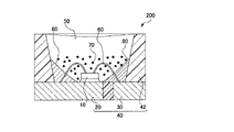
本発明の一実施態様の発光装置の一例を図面に基づいて説明する。図1は、発光装置100を示す概略断面図である。
An example of a light-emitting device according to one embodiment of the present invention will be described with reference to the drawings. FIG. 1 is a schematic cross-sectional view showing a
発光装置100は、図1に示されるように、380nm以上420nm以下の範囲内に発光ピーク波長を有する発光素子10と、発光素子10からの光により励起されて発光する少なくとも一種の蛍光体70を含む蛍光部材50を備える。
As shown in FIG. 1, the
発光装置100は、例えば、成形体40と、発光素子10と、蛍光部材50とを備える。成形体40は、第一のリード20及び第二のリード30と、熱可塑性樹脂又は熱硬化性樹脂を含む樹脂部42とが一体的に成形されてなるものである。成形体40は底面と側面を持つ凹部を形成しており、凹部の底面に発光素子10が載置されている。発光素子10は一対の正負の電極を有しており、その一対の正負の電極はそれぞれ第一のリード20及び第二のリード30とそれぞれワイヤ60を介して電気的に接続されている。発光素子10は蛍光部材50により被覆されている。蛍光部材50は、発光素子10からの光を波長変換する蛍光体70と封止材料を含む。蛍光体70は、発光素子からの光により励起されて特定の波長範囲に少なくとも一つの発光ピーク波長を有し、発光ピーク波長の波長範囲の異なる2種以上の蛍光体が含まれていてもよい。発光素子10の正負一対の電極に接続された第一のリード20及び第二のリード30は、発光装置100を構成するパッケージの外方に向けて、第一のリード20及び第二のリード30の一部が露出されている。これらの第一のリード20及び第二のリード30を介して、外部から電力の供給を受けて発光装置100を発光させることができる。
The
発光装置に用いられる蛍光部材50は、蛍光体70及び封止材料を含むものであることが好ましい。封止材料は、熱可塑性樹脂及び熱硬化性樹脂から選ばれる樹脂を用いることができる。製造のし易さを考慮すると、封止材料として用いられる樹脂は、例えば、シリコーン樹脂、エポキシ樹脂が挙げられる。蛍光部材は、蛍光体70及び封止材料の他に、フィラー、光安定剤、着色剤等のその他の成分を含んでいてもよい。フィラーとしては、例えばシリカ、チタン酸バリウム、酸化チタン、酸化アルミニウム等を挙げることができる。蛍光部材中の、蛍光体及び封止材料以外のその他の成分の含有量は、目的とする発光装置の大きさ、相関色温度、色調に基づいて、好適範囲に設定することができる。例えば、蛍光部材中の蛍光体及び封止材料以外のその他の成分の含有量は、封止材料100質量部に対して、0.01質量部以上20質量部以下とすることができる。
The
発光素子10は、励起光源として用いられる。発光素子10は、380nm以上420nm以下の範囲内に発光ピーク波長を有する。発光素子10の発光ピーク波長の範囲は、好ましくは385nm以上415nm以下の範囲内であり、より好ましくは390nm以上410nm以下の範囲内であり、さらに好ましくは400nm以上410nm以下の範囲内である。発光素子10が、380nm以上420nm以下の範囲内に発光ピーク波長を有するものであると、発光装置から環境雰囲気中の細菌に対して殺菌効果を有する波長範囲の光を放射させ、環境雰囲気中の細菌の菌数を低減させて、除菌効果を有する発光装置を提供することができる。本明細書において、「除菌」とは、対象となる環境雰囲気中の細菌を殺菌し、菌数を低減させることをいう。発光素子10の発光スペクトルの半値幅は、例えば30nm以下でもよく、25nm以下でもよく、20nm以下でもよい。半値幅は、発光スペクトルにおける発光ピークの半値全幅(Full Width at Half Maximum:FWHM)をいい、各発光スペクトルにおける発光ピークの最大値の50%の値を示す発光ピークの波長幅をいう。発光素子10は、例えば、窒化物系半導体(InxAlYGa1-X-YN、0≦X、0≦Y、X+Y≦1)を用いた半導体発光素子であることが好ましい。発光素子として、半導体発光素子を用いることによって、高効率で入力に対するリニアリティが高く機械的衝撃にも強い安定した発光装置を得ることができる。380nm未満の範囲に発光ピーク波長を有する発光素子は、殺菌効果は高くなるものの、人間や動物にも影響を及ぼし、演色性も低下するため好ましくない。420nmを超える範囲に発光ピーク波長を有する発光素子は、殺菌効果が低くなり、除菌効果が低くなるため、好ましくない。
The
発光装置は、発光素子から放射される光と蛍光体からの光による混色光の相関色温度が、JIS Z8725に準拠した測定で2000K以上7500K以下の範囲内である。JIS Z9112では、発光装置の光源色と相関色温度の範囲の関係について、2600Kから3250Kを電球色、3250Kから3800Kを温白色、3800Kから4500Kを白色、4600Kから5500Kを昼白色、5700Kから7100Kを昼光色と定義している。発光装置の相関色温度が2000K以上7500K以下の範囲であると、JIS Z9112で定義された、電球色、温白色、白色、昼白色、昼光色の光源色の光を発する発光装置とすることができる。発光装置から発せられる混色光の相関色温度は、2700K以上7000K以下の範囲内であってもよく、2700K以上6500K以下の範囲内であってもよい。 In the light emitting device, the correlated color temperature of the mixed color light of the light emitted from the light emitting element and the light from the phosphor is within the range of 2000K or more and 7500K or less as measured according to JIS Z8725. According to JIS Z9112, regarding the relationship between the light source color of the light emitting device and the range of the correlated color temperature, 2600K to 3250K is warm white, 3250K to 3800K is warm white, 3800K to 4500K is white, 4600K to 5500K is neutral white, and 5700K to 7100K is warm white. Defined as daylight. When the correlated color temperature of the light emitting device is in the range of 2000 K or more and 7500 K or less, it can be a light emitting device that emits light of light source colors such as warm white, warm white, white, neutral white, and daylight color defined by JIS Z9112. . The correlated color temperature of the mixed color light emitted from the light emitting device may be in the range of 2700K or more and 7000K or less, or may be in the range of 2700K or more and 6500K or less.
発光装置は、発光装置の分光分布において、380nm以上780nm以下の積分値を100%として、380nm以上420nm以下の波長範囲の積分値の割合が15%以上である。発光装置の分光分布において、380nm以上780nm以下の積分値100%に対して、380nm以上420nm以下の波長範囲の積分値の割合が15%以上であると、発光装置から発せられる混色光のうち、殺菌効果のある波長範囲の光成分を15%以上有することとなり、発光装置の除菌効果を高めることができる。発光装置から発せられる混色光のうち、殺菌効果のある波長範囲の光成分が多い方が除菌には有効であるが、殺菌効果のある波長範囲の光成分が多くなりすぎると、ヒトの標準比視感度(標準分光視感効率)のピークから離れた発光が多くなる為、発光効率が低下する。発光装置は、発光装置の分光分布において、380nm以上780nm以下の波長範囲の積分値を100%として、380nm以上420nm以下の波長範囲の積分値の割合が、除菌効果の観点から、好ましくは16%以上であり、より好ましくは17%以上であり、発光効率の観点から、好ましくは50%以下であり、より好ましくは40%以下であり、さらに好ましくは35%以下であり、よりさらに好ましくは30%以下である。以下、本明細書において、発光装置の分光分布において、380nm以上420nm以下の波長範囲の積分値を「380nm-420nm発光量」と記載する場合があり、380nm以上780nm以下の波長範囲の積分値を「全発光量」と記載する場合がある。 In the spectral distribution of the light emitting device, the ratio of the integrated value in the wavelength range of 380 nm to 420 nm is 15% or more, with the integrated value of 380 nm to 780 nm being 100%. In the spectral distribution of the light emitting device, if the ratio of the integrated value in the wavelength range of 380 nm to 420 nm is 15% or more with respect to the integrated value of 100% in the wavelength range of 380 nm to 780 nm, the mixed color light emitted from the light emitting device: It has 15% or more of the light component in the wavelength range with the sterilization effect, so that the sterilization effect of the light-emitting device can be enhanced. Of the mixed-color light emitted from the light emitting device, the more light components in the wavelength range with sterilization effect are more effective for sterilization. Since the amount of light emitted away from the peak of the relative luminous efficiency (standard spectral luminous efficiency) increases, the luminous efficiency decreases. In the light-emitting device, in the spectral distribution of the light-emitting device, the ratio of the integrated value in the wavelength range of 380 nm to 420 nm is preferably 16, with the integrated value in the wavelength range of 380 nm to 780 nm being 100%. % or more, more preferably 17% or more, and from the viewpoint of luminous efficiency, preferably 50% or less, more preferably 40% or less, even more preferably 35% or less, and even more preferably 30% or less. Hereinafter, in this specification, in the spectral distribution of the light-emitting device, the integrated value in the wavelength range of 380 nm or more and 420 nm or less may be described as "380 nm-420 nm light emission amount", and the integrated value of the wavelength range of 380 nm or more and 780 nm or less may be described. It may be described as "total luminescence amount".
発光装置は、式(1)において定義される比率aが0.9以上1.6以下の範囲内である。式(1)において定義される比率aは、発光装置が有する相関色温度における基準光源の分光分布において、430nm以上485nm未満の波長範囲の青色光の最大発光強度BSに対する、485nm以上548nm以下の波長範囲の緑色光の最大発光強度GSの比GS/BSを分母とし、発光装置の分光分布において、430nm以上485nm未満の波長範囲の青色光の最大発光強度BLに対する、485nm以上548nm以下の波長範囲の緑色光の最大発光強度GLの比GL/BLを分子とした比率である。発光装置の式(1)において定義される比率aが0.9以上1.6以下の範囲内であると、基準光源から発せられる光の青色成分に対する緑色成分の比率に対して、発光装置から発せられる混色光の青色成分に対する緑色成分の比率がほぼ同じか、緑色成分が補充された混色光が、発光装置から発せられることとなる。発光装置の式(1)において定義される比率aが0.9以上1.6以下の範囲内であると、発光装置は、除菌効果を有するとともに、演色性も高くなる。発光装置から発せられる混色光の相関色温度が2000K以上4000K未満の範囲内である場合には、発光装置から発せられる混色光の式(1)において定義される比率aは、除菌効果及び演色性の点から、好ましくは1.0以上1.6以下の範囲内であり、より好ましくは1.1以上1.6以下の範囲内である。発光装置から発せられる混色光の相関色温度が4000K以上7500K以下の範囲内である場合には、発光装置から発せられる混色光の式(1)において定義される比率aは、除菌効果及び演色性の観点から、さらに好ましくは1.1以上であり、好ましくは1.5以下である。JIS Z8726によれば、基準の光は、試料光源の相関色温度が5000K未満のときは、原則として完全放射体を用い、試料光源の相関色温度が5000K以上のときは、原則としてCIE(国際照明委員会:Commission International de l’ Eclairage)昼光を用いるとされている。本明細書において、基準光源は、JIS Z8726に規定された基準の光に準拠する。 In the light emitting device, the ratio a defined in formula (1) is within the range of 0.9 or more and 1.6 or less. The ratio a defined in formula (1) is the maximum emission intensity BS of blue light in the wavelength range of 430 nm or more and less than 485 nm in the spectral distribution of the reference light source at the correlated color temperature of the light emitting device. With the ratio G S /B S of the maximum emission intensity G S of green light in the wavelength range as the denominator, in the spectral distribution of the light emitting device, the maximum emission intensity B L of blue light in the wavelength range of 430 nm or more and less than 485 nm is 485 nm or more and 548 nm. It is a ratio in which the ratio G L /B L of the maximum emission intensity G L of green light in the following wavelength range is used as a numerator. When the ratio a defined in the formula (1) of the light emitting device is in the range of 0.9 or more and 1.6 or less, the ratio of the green component to the blue component of the light emitted from the reference light source is Mixed-color light in which the ratio of the green component to the blue component of the emitted mixed-color light is substantially the same, or in which the green component is supplemented, is emitted from the light-emitting device. When the ratio a defined in the formula (1) of the light-emitting device is within the range of 0.9 or more and 1.6 or less, the light-emitting device has a sterilizing effect and high color rendering properties. When the correlated color temperature of the mixed color light emitted from the light emitting device is within the range of 2000 K or more and less than 4000 K, the ratio a defined in the formula (1) of the mixed color light emitted from the light emitting device is the sterilization effect and color rendering. From the viewpoint of properties, it is preferably in the range of 1.0 or more and 1.6 or less, more preferably in the range of 1.1 or more and 1.6 or less. When the correlated color temperature of the mixed color light emitted from the light emitting device is in the range of 4000 K or more and 7500 K or less, the ratio a defined in the formula (1) of the mixed color light emitted from the light emitting device is the sterilization effect and color rendering. From the viewpoint of sexuality, it is more preferably 1.1 or more and preferably 1.5 or less. According to JIS Z8726, when the correlated color temperature of the sample light source is less than 5000K, as a rule, a perfect radiator is used as the reference light. Lighting Commission: Commission International de l'Eclairage) daylight is supposed to be used. In this specification, the reference light source conforms to the reference light specified in JIS Z8726.
式(1)において定義される比率aを1から差し引いた値の絶対値Aは、0.6以下であることが好ましい。ここで、比率aを1から差し引いた値の絶対値Aは、発光装置が有する相関色温度における基準光源の分光分布における比GS/BSと、発光装置から発せられる混色光の分光分布における比GL/BLが同じ値である場合を1とし、比率aを1から差し引いた値の絶対値Aである。比率aを1から差し引いた値の絶対値Aが、発光装置が有する相関色温度の基準光源により近いと、青色成分と緑色成分のバランスがよい混色光が発光装置から発せられる。比率aを1から差し引いた値の絶対値Aが0.6以下であると、殺菌効果のある青色成分の光が発せられる発光装置であっても、発光装置が有する相関色温度の基準光源の混色光により近く、青色成分と緑色成分のバランスがよい混色光が、発光装置から発せられる。比率aを1から差し引いた値の絶対値Aは、0.5以下であってもよく、0.4以下であってもよい。 The absolute value A of the value obtained by subtracting the ratio a defined in formula (1) from 1 is preferably 0.6 or less. Here, the absolute value A obtained by subtracting the ratio a from 1 is the ratio G S /B S in the spectral distribution of the reference light source at the correlated color temperature of the light emitting device and the spectral distribution of the mixed color light emitted from the light emitting device. It is the absolute value A of the value obtained by subtracting the ratio a from 1 when the ratio G L /B L is the same value. When the absolute value A obtained by subtracting the ratio a from 1 is closer to the reference light source of the correlated color temperature of the light emitting device, the light emitting device emits mixed color light with well-balanced blue and green components. If the absolute value A of the value obtained by subtracting the ratio a from 1 is 0.6 or less, even if the light emitting device emits light of a blue component that has a sterilizing effect, it is a reference light source of the correlated color temperature of the light emitting device. Mixed-color light that is closer to mixed-color light and has a good balance of blue and green components is emitted from the light-emitting device. The absolute value A of the value obtained by subtracting the ratio a from 1 may be 0.5 or less, or may be 0.4 or less.
発光装置は、平均演色評価数Raが80以上である。JIS Z9112の蛍光ランプ・LEDの光源色及び演色性による区分によれば、LEDの演色性は、普通形と高演色形に区分され、高演色形の平均演色評価数Raが80以上であることが規定されている。CIEの指針によれば、使用される場所に応じた好ましい平均演色評価数Raは、一般作業を行う工場では60以上80未満、住宅、ホテル、レストラン、店舗、オフィス、学校、病院、精密作業を行う工場などでは80以上90未満、高い演色性が求められる美術館、博物館、臨床検査を行う場所などでは90以上とされている。発光装置の平均演色評価数Raが80以上であると、例えば、住宅、ホテル、レストラン、店舗などの人間の生活環境において快適に使用できる演色性を有する照明として使用可能である。発光装置の平均演色評価数Raは、除菌効果を有するものであれば、平均演色評価数Raがより高い数値であってもよく、平均演色評価数Raが81以上であってもよく、85以上であってもよく、90以上であってもよい。平均演色評価数Raが90以上であれば、より厳密な色の見え方が要求される色検査、美術館、博物館、臨床検査を行う場所などで使用可能である。 The light emitting device has a general color rendering index Ra of 80 or more. According to JIS Z9112 classification of fluorescent lamps and LEDs by light source color and color rendering properties, the color rendering properties of LEDs are classified into normal type and high color rendering type, and the general color rendering index Ra of the high color rendering type must be 80 or more. is stipulated. According to the CIE guidelines, the preferred general color rendering index Ra according to the place of use is 60 or more and less than 80 for factories that perform general work, residences, hotels, restaurants, stores, offices, schools, hospitals, and precision work. It is 80 or more and less than 90 in factories where it is performed, and 90 or more in art galleries, museums, places where clinical examinations are performed, etc. where high color rendering is required. When the general color rendering index Ra of the light emitting device is 80 or more, it can be used as lighting having a color rendering property that can be comfortably used in human living environments such as houses, hotels, restaurants, and shops. The general color rendering index Ra of the light-emitting device may be a value with a higher general color rendering index Ra, as long as it has a sterilization effect, and the general color rendering index Ra may be 81 or more. It may be 90 or more. If the general color rendering index Ra is 90 or more, it can be used in places such as color examinations, art galleries, museums, and clinical examinations where stricter color appearance is required.
発光装置は、特殊演色評価数R12が50以上であることが好ましい。特殊演色評価数R12は青色を表す。発光装置の特殊変色評価数R12が50以上であれば、380nm以上420nm以下の範囲内に発光ピーク波長を有する、可視領域において青紫色の光を発する発光素子を励起光源として用いた場合であっても、発光装置から発せられる光が、420nmを超えて500nm以下の青色成分から青緑色成分が少なくなることなく、発光装置から発せられる目的とする相関色温度の光のうち、各色成分のバランスを維持した混色光を得ることができる。発光装置の特殊演色評価数R12は、発光装置に照らされたものの見え方をより改善する観点から、より好ましくは55以上、さらに好ましくは60以上である。 The light emitting device preferably has a special color rendering index R12 of 50 or more. The special color rendering index R12 represents blue. If the special discoloration evaluation number R12 of the light emitting device is 50 or more, a light emitting element that emits blue-violet light in the visible region and has an emission peak wavelength in the range of 380 nm or more and 420 nm or less is used as the excitation light source. Also, the light emitted from the light emitting device does not have a blue component of more than 420 nm but 500 nm or less, and the blue green component does not decrease, and the balance of each color component is balanced among the light of the target correlated color temperature emitted from the light emitting device. Maintained mixed color light can be obtained. The special color rendering index R12 of the light-emitting device is more preferably 55 or more, still more preferably 60 or more, from the viewpoint of further improving the appearance of objects illuminated by the light-emitting device.
発光装置は、青色を表す特殊演色評価数R12以外の特殊演色評価数R9、R10、R11、R13、R14、R15については、発光装置を用いる場所によって求められる視認性及び識別性が異なるため、特に限定されない。発光装置は、赤色を表す特殊演色評価数R9がマイナスの数値であってもよく、特殊演色評価数R9が10以上であってもよい。例えば、赤色を確認することが多い手術室などで、除菌効果を高めるために発光装置を用いる場合には、特殊演色評価数R9の数値が高い方が好ましい。赤色を確認する必要が少ない場所で用いる場合には、発光装置の特殊演色評価数R9の数値は特に限定されない。 Regarding the special color rendering index R9, R10, R11, R13, R14, and R15 other than the special color rendering index R12 representing blue, the visibility and distinguishability required for the light emitting device differ depending on the location where the light emitting device is used. Not limited. The light-emitting device may have a negative special color rendering index R9 representing red, or may have a special color rendering index R9 of 10 or more. For example, when a light-emitting device is used to enhance the sterilization effect in an operating room where red is often observed, a higher value of the special color rendering index R9 is preferable. If the light emitting device is used in a place where there is little need to confirm red, the value of the special color rendering index R9 of the light emitting device is not particularly limited.
発光装置は、式(1)、及び以下の式(2)から式(3)により定義される比率a、比率b、及び比率cの合計が、2.5以上4.5以下であることが好ましい。 In the light-emitting device, the sum of ratio a, ratio b, and ratio c defined by formula (1) and formulas (2) to (3) below is 2.5 or more and 4.5 or less. preferable.

式(2)中、BSは、発光装置が有する相関色温度における基準光源の分光分布において、430nm以上485nm未満の波長範囲の最大発光強度であり、YSは、580nm以上610nm未満の波長範囲の最大発光強度であり、式(2)の分母は、前記BSに対する前記YSの比YS/BSである。式(2)中、BLは、発光装置の分光分布において、430nm以上485nm未満の波長範囲の最大発光強度であり、YLは、580nm以上610nm未満の波長範囲の最大発光強度であり、式(2)の分子は、前記BLに対する前記YLの比YL/BLである。 In formula (2), B S is the maximum emission intensity in the wavelength range of 430 nm or more and less than 485 nm in the spectral distribution of the reference light source at the correlated color temperature of the light emitting device, and Y S is the wavelength range of 580 nm or more and less than 610 nm. and the denominator of equation (2) is the ratio Ys / Bs of said Ys to said Bs . In formula (2), BL is the maximum emission intensity in the wavelength range of 430 nm or more and less than 485 nm in the spectral distribution of the light emitting device, YL is the maximum emission intensity in the wavelength range of 580 nm or more and less than 610 nm, and The numerator of (2) is the ratio Y L /B L of said Y L to said BL .

式(3)中、BSは、発光装置が有する相関色温度における基準光源の分光分布において、430nm以上485nm未満の波長範囲の最大発光強度であり、RSは、610nm以上780nm以下の波長範囲の最大発光強度であり、式(3)の分母は、前記BSに対する前記RSの比RS/BSである。式(3)中、BLは、発光装置の分光分布において、430nm以上485nm未満の波長範囲の最大発光強度であり、RLは、610nm以上780nm以下の波長範囲の最大発光強度であり、式(3)の分子は、前記BLに対する前記RLの比RL/BLである。 In formula (3), B S is the maximum emission intensity in the wavelength range of 430 nm or more and less than 485 nm in the spectral distribution of the reference light source at the correlated color temperature of the light emitting device, and R S is the wavelength range of 610 nm or more and 780 nm or less. and the denominator of equation (3) is the ratio R S /B S of said R S to said B S . In formula (3), BL is the maximum emission intensity in the wavelength range of 430 nm or more and less than 485 nm in the spectral distribution of the light emitting device, and RL is the maximum emission intensity in the wavelength range of 610 nm or more and 780 nm or less, and The numerator of (3) is the ratio RL / BL of said RL to said BL .
式(2)において定義される比率bは、発光装置が有する相関色温度における基準光源の分光分布において、430nm以上485nm未満の波長範囲の青色光の最大発光強度BSに対する、580nm以上610nm未満の波長範囲の黄色光の最大発光強度YSの比YS/BSを分母とし、発光装置の分光分布において、430nm以上485nm未満の波長範囲の青色光の最大発光強度BLに対する、580nm以上610nm未満の波長範囲の黄色光の最大発光強度YLの比YL/BLを分子とした比率である。また、式(3)において定義される比率cは、発光装置が有する相関色温度における基準光源の分光分布において、430nm以上485nm未満の波長範囲の青色光の最大発光強度BSに対する、610nm以上780nm以下の波長範囲の赤色光の最大発光強度RSの比RS/BSを分母とし、発光装置の分光分布において、430nm以上485nm未満の波長範囲の青色光の最大発光強度BLに対する、610nm以上780nm以下の波長範囲の赤色光の最大発光強度RLの比RL/BLを分子とした比率である。 The ratio b defined in formula (2) is the maximum emission intensity B S of blue light in the wavelength range of 430 nm or more and less than 485 nm in the spectral distribution of the reference light source at the correlated color temperature of the light emitting device. With the ratio Y S /B S of the maximum emission intensity Y S of yellow light in the wavelength range as the denominator, in the spectral distribution of the light emitting device, the maximum emission intensity B L of blue light in the wavelength range of 430 nm or more and less than 485 nm is 580 nm or more and 610 nm. It is a ratio in which the ratio Y L /B L of the maximum emission intensity Y L of yellow light in the wavelength range of less than 100 nm is used as the numerator. Further, the ratio c defined in Equation (3) is 610 nm or more and 780 nm with respect to the maximum emission intensity B S of blue light in the wavelength range of 430 nm or more and less than 485 nm in the spectral distribution of the reference light source at the correlated color temperature of the light emitting device. With the ratio R S /B S of the maximum emission intensity R S of red light in the following wavelength range as the denominator, in the spectral distribution of the light emitting device, the maximum emission intensity B L of blue light in the wavelength range of 430 nm or more and less than 485 nm is 610 nm. It is a ratio using the ratio R L /B L of the maximum emission intensity R L of red light in the wavelength range of 780 nm or less as a numerator.
発光装置は、式(1)で定義される比率a、式(2)で定義される比率b、及び式(3)で定義される比率cの合計が、好ましくは2.5以上4.5以下の範囲内であり、より好ましくは2.6以上4.5以下の範囲内であり、さらに好ましくは2.8以上4.4以下の範囲内である。比率a、比率b及び比率cの合計が、2.5から4.5以下の範囲内である発光装置は、発光装置の相関色温度における基準光源の青色光に対する緑色光、黄色光、赤色光に対して、発光装置の青色光に対する緑色光、黄色光、赤色光の各色成分の光のバランスがよく、除菌効果を有するとともに、高い演色性を有する。 In the light-emitting device, the sum of ratio a defined by formula (1), ratio b defined by formula (2), and ratio c defined by formula (3) is preferably 2.5 or more and 4.5 It is within the following range, more preferably within the range of 2.6 or more and 4.5 or less, and further preferably within the range of 2.8 or more and 4.4 or less. A light-emitting device in which the sum of ratio a, ratio b, and ratio c is in the range of 2.5 to 4.5 or less emits green light, yellow light, and red light with respect to blue light of a reference light source at the correlated color temperature of the light-emitting device. On the other hand, the color components of green light, yellow light, and red light are well balanced with respect to the blue light of the light emitting device, and it has a sterilization effect and high color rendering properties.
比率bの範囲及び比率cの範囲は、特に限定されない。比率a、比率b、及び比率cの合計が2.5以上4.5以下の範囲内を満たしていることが好ましく、この範囲を満たしたうえで、比率bは、0.8以上1.7以下の範囲内であることが好ましく、比率cは、0.7以上1.5以下の範囲内であることが好ましい。 The range of the ratio b and the range of the ratio c are not particularly limited. It is preferable that the sum of the ratio a, the ratio b, and the ratio c satisfies the range of 2.5 to 4.5, and after satisfying this range, the ratio b is 0.8 to 1.7 The ratio c is preferably within the range of 0.7 or more and 1.5 or less.
式(1)で定義される比率a、式(2)で定義される比率b及び式(3)で定義される比率cの合計を3から差し引いた値の絶対値Bは、1.5以下であることが好ましい。ここで、比率a、比率b及び比率cの合計を3から差し引いた値の絶対値Bとは、比率a、比率b及び比率cにおいて、各波長範囲において、発光装置から発せられる混色光の分光分布における比GL/BL、比YL/BL、比RL/BLのそれぞれが、発光装置が有する相関色温度における基準光源の分光分布における比GS/BS、比YS/BS、比RS/BSのそれぞれと、同じ値である場合の合計値を3とし、比率a、比率b及び比率cの合計を3から差し引いた値の絶対値Bである。比率a、比率b及び比率cの合計を3から差し引いた値の絶対値Bは、発光装置が有する相関色温度の基準光源により近いと、青色成分、緑色成分、黄色成分及び赤色成分のバランスがよい混色光が発光装置から発せられる。比率a、比率b及び比率cを3から差し引いた値の絶対値Bが1.5以下であると、殺菌効果のある青色成分の光が発せられる発光装置であっても、発光装置が有する相関色温度の基準光源の混色光により近く、青色成分、緑色成分、黄色成分及び赤色成分のバランスがよい混色光が、発光装置から発せられる。比率a、比率b及び比率cを3から差し引いた値の絶対値Bは、1.4以下であってもよく、1.3以下であってもよい。 The absolute value B of the value obtained by subtracting the sum of the ratio a defined by formula (1), the ratio b defined by formula (2), and the ratio c defined by formula (3) from 3 is 1.5 or less. is preferably Here, the absolute value B of the value obtained by subtracting the sum of the ratio a, the ratio b, and the ratio c from 3 is the spectrum of the mixed color light emitted from the light emitting device in each wavelength range at the ratio a, the ratio b, and the ratio c. The ratio G L /B L , the ratio Y L /B L , and the ratio R L /B L in the distribution correspond to the ratio G S /B S and the ratio Y S in the spectral distribution of the reference light source at the correlated color temperature of the light emitting device. /B S , the ratio R S /B S , and the absolute value B obtained by subtracting the sum of the ratio a, the ratio b, and the ratio c from 3, where the total value when they are the same value is 3. If the absolute value B obtained by subtracting the sum of the ratios a, b, and c from 3 is closer to the reference light source of the correlated color temperature of the light emitting device, the balance of the blue, green, yellow, and red components will be balanced. Good mixed color light is emitted from the light emitting device. If the absolute value B of the value obtained by subtracting the ratio a, the ratio b, and the ratio c from 3 is 1.5 or less, even if the light emitting device emits light of a blue component that has a sterilizing effect, the correlation that the light emitting device has The light-emitting device emits mixed-color light that is closer to the mixed-color light of the reference light source in color temperature and has well-balanced blue, green, yellow, and red components. The absolute value B obtained by subtracting the ratios a, b, and c from 3 may be 1.4 or less, or may be 1.3 or less.
発光装置において、蛍光部材に含まれる蛍光体は、380nm以上420nm以下の範囲内に発光ピーク波長を有する発光素子からの光により励起されて430nm以上485nm未満の範囲内に発光ピーク波長を有する第一蛍光体、発光素子からの光により励起されて485nm以上610nm未満の範囲内に発光ピーク波長を有する第二蛍光体、及び発光素子からの光により励起されて610nm以上780nm以下の範囲内に発光ピーク波長を有する第三蛍光体、からなる群から選ばれる少なくとも一種の蛍光体を含むことが好ましい。 In the light-emitting device, the phosphor contained in the fluorescent member is excited by light from a light-emitting element having an emission peak wavelength in the range of 380 nm or more and 420 nm or less, and has an emission peak wavelength in the range of 430 nm or more and less than 485 nm. A phosphor, a second phosphor that is excited by the light from the light emitting element and has an emission peak wavelength in the range of 485 nm or more and less than 610 nm, and a light emission peak that is excited by the light from the light emitting element and is in the range of 610 nm or more and 780 nm or less It is preferable to include at least one phosphor selected from the group consisting of a third phosphor having a wavelength.
第一蛍光体は、発光素子からの光により励起されて、430nm以上485nm未満の範囲内に発光ピーク波長を有し、青紫色から青色の光を発する。第一蛍光体を含む発光装置は、発光装置から発せられる混色光が、380nm以上420nm以下の範囲内に発光ピークを有する発光素子からの光には不足している青色成分の光が第一蛍光体によって補なわれる。発光装置は、発光素子から発せられる光によって除菌効果を有し、演色性の高い混色光が発光装置から発せられる。 The first phosphor is excited by the light from the light emitting element, has an emission peak wavelength in the range of 430 nm or more and less than 485 nm, and emits blue-violet to blue light. In the light emitting device containing the first phosphor, the mixed color light emitted from the light emitting device is insufficient for the light from the light emitting element having an emission peak in the range of 380 nm or more and 420 nm or less. complemented by the body. The light-emitting device has a sterilizing effect by light emitted from the light-emitting element, and emits mixed-color light with high color rendering properties from the light-emitting device.
第一蛍光体は、アルカリ土類金属元素からなる群から選ばれる少なくとも一種の元素と、ハロゲンからなる群から選ばれる少なくとも一種の元素を組成に含み、Euで賦活されるハロゲン含有アルカリ土類金属リン酸塩を含む蛍光体、Ba、Sr及びCaからなる群から選ばれる少なくとも一種の元素と、Mgとを組成に含み、Euで賦活されるアルカリ土類金属ケイ酸塩を含む蛍光体からなる群から選ばれる少なくとも一種の第一蛍光体を含むことが好ましく、二種以上の第一蛍光体を含んでいてもよい。第一蛍光体は、アルカリ土類金属元素からなる群から選ばれる少なくとも一種の元素と、ハロゲンからなる群から選ばれる少なくとも一種の元素を組成に含み、Euで賦活されるハロゲン含有アルカリ土類金属リン酸塩を含む蛍光体を含むことがより好ましい。 The first phosphor contains in its composition at least one element selected from the group consisting of alkaline earth metal elements and at least one element selected from the group consisting of halogens, and is a halogen-containing alkaline earth metal activated by Eu. A phosphor containing a phosphate, a phosphor containing at least one element selected from the group consisting of Ba, Sr and Ca and Mg in its composition and containing an alkaline earth metal silicate activated by Eu. It preferably contains at least one first phosphor selected from the group, and may contain two or more first phosphors. The first phosphor contains in its composition at least one element selected from the group consisting of alkaline earth metal elements and at least one element selected from the group consisting of halogens, and is a halogen-containing alkaline earth metal activated by Eu. More preferably, it contains a phosphate-containing phosphor.
第一蛍光体が、下記式(I)で表される組成を含む蛍光体及び下記式(II)で表される組成を含む蛍光体からなる群から選ばれる少なくとも一種の蛍光体を含むことが好ましく、二種以上の蛍光体を含んでいてもよい。第一蛍光体が、下記式(I)で表される組成を含む蛍光体を含むことがより好ましい。
(Ca,Sr,Ba,Mg)10(PO4)6(F,Cl,Br,I)2:Eu (I)
(Ba,Sr,Ca)3MgSi2O8:Eu (II)
本明細書において、蛍光体の組成を表す式中、カンマ(,)で区切られて記載されている複数の元素は、これら複数の元素のうち少なくとも一種の元素を組成中に含むことを意味する。組成式中のカンマ(,)で区切られて記載されている複数の元素は、組成中にカンマで区切られた複数の元素から選ばれる少なくとも一種の元素を含み、前記複数の元素から二種以上を組み合わせて含んでいてもよい。また、本明細書において、蛍光体の組成を表す式中、コロン(:)の前は母体結晶を構成する元素及びそのモル比を表し、コロン(:)の後は賦活元素を表す。
The first phosphor may contain at least one phosphor selected from the group consisting of a phosphor containing a composition represented by the following formula (I) and a phosphor containing a composition represented by the following formula (II): Preferably, two or more phosphors may be included. More preferably, the first phosphor contains a phosphor having a composition represented by formula (I) below.
(Ca, Sr, Ba, Mg) 10 (PO 4 ) 6 (F, Cl, Br, I) 2 :Eu (I)
(Ba, Sr, Ca) 3 MgSi 2 O 8 :Eu (II)
In this specification, in the formula representing the composition of the phosphor, multiple elements separated by commas (,) mean that at least one of these multiple elements is included in the composition. . The plurality of elements described separated by commas (,) in the composition formula includes at least one element selected from the plurality of elements separated by commas in the composition, and two or more elements from the plurality of elements may be included in combination with In this specification, in the formula representing the composition of the phosphor, before the colon (:) represents the elements constituting the host crystal and their molar ratio, and after the colon (:) represents the activating element.
第二蛍光体は、発光素子からの光により励起されて、485nm以上610nm未満の範囲内に発光ピーク波長を有し、青緑色から橙色の光を発する。第二蛍光体を含む発光装置は、発光装置から発せられる混色光が、発光素子からの光及び第一蛍光体からの光には不足している色成分の光が第二蛍光体によって補われる。発光装置は、発光素子から発せられる光によって除菌効果を有し、演色性の高い混色光が発光装置から発せられる。 The second phosphor is excited by the light from the light emitting element, has an emission peak wavelength in the range of 485 nm or more and less than 610 nm, and emits light of blue-green to orange color. In the light-emitting device containing the second phosphor, the mixed color light emitted from the light-emitting device is supplemented by the second phosphor for light of a color component that is lacking in the light from the light-emitting element and the light from the first phosphor. . The light-emitting device has a sterilizing effect by light emitted from the light-emitting element, and emits mixed-color light with high color rendering properties from the light-emitting device.
第二蛍光体が、Ceを除く希土類元素からなる群から選ばれる少なくとも一種の元素と、Alと、必要に応じてGaとを組成に含み、Ceで賦活される希土類アルミン酸塩を含む蛍光体、Ca、Sr及びBaからなる群から選ばれる少なくとも一種のアルカリ土類金属元素と、F、Cl及びBrからなる群から選ばれる少なくとも一種のハロゲン元素を組成に含み、Euで賦活されるハロゲン含有アルカリ土類金属ケイ酸塩を含む蛍光体、Euで賦活されるβサイアロンを含む蛍光体、並びにLa、Y及びGdからなる群から選ばれる少なくとも一種の希土類元素と、Siを組成に含み、Ceで賦活される希土類窒化物を含む蛍光体、Euで賦活されるアルカリ土類金属ケイ酸塩を含む蛍光体からなる群から選ばれる少なくとも一種の第二蛍光体を含むことが好ましく、二種以上の第二蛍光体を含んでいてもよい。 A phosphor in which the second phosphor contains at least one element selected from the group consisting of rare earth elements excluding Ce, Al, and Ga as necessary, and a rare earth aluminate activated by Ce. , Ca, Sr and Ba, and at least one halogen element selected from the group consisting of F, Cl and Br in the composition, and containing halogen activated by Eu A phosphor containing an alkaline earth metal silicate, a phosphor containing β-sialon activated with Eu, and at least one rare earth element selected from the group consisting of La, Y and Gd, and Si in the composition, and Ce It preferably contains at least one second phosphor selected from the group consisting of a phosphor containing a rare earth nitride activated with and a phosphor containing an alkaline earth metal silicate activated with Eu, and two or more of the second phosphor may be included.
第二蛍光体が、下記式(III)で表される組成を含む蛍光体、下記式(IV)で表される組成を含む蛍光体、下記式(V)で表される組成を含む蛍光体、下記式(VI)で表される組成を含む蛍光体、及び下記式(VII)で表される組成を含む蛍光体からなる群から選ばれる少なくとも一種の蛍光体を含むことが好ましく、二種以上の蛍光体を含んでいてもよい。
(Lu,Y,Gd,Tb)3(Al,Ga)5O12:Ce (III)
(Ca,Sr,Ba)8MgSi4O16(F,Cl,Br)2:Eu (IV)
Si6-zAlzOzN8-z:Eu(0<z<4.2) (V)
(La,Y,Gd)3Si6N11:Ce (VI)
(Ba,Sr,Ca,Mg)2SiO4:Eu (VII)
The second phosphor is a phosphor containing a composition represented by the following formula (III), a phosphor containing a composition represented by the following formula (IV), and a phosphor containing a composition represented by the following formula (V) , a phosphor containing a composition represented by the following formula (VI), and a phosphor containing a composition represented by the following formula (VII). It may contain the above phosphors.
(Lu, Y, Gd, Tb) 3 (Al, Ga) 5 O 12 :Ce (III)
(Ca, Sr ,Ba) 8MgSi4O16 (F,Cl,Br) 2 :Eu ( IV )
Si6 -zAlzOzN8 - z : Eu (0<z<4.2) (V)
(La, Y, Gd) 3 Si 6 N 11 :Ce (VI)
(Ba, Sr, Ca, Mg) 2 SiO 4 :Eu (VII)
第三蛍光体は、発光素子からの光により励起され、610nm以上780nm以下の範囲内に発光ピーク波長を有し、赤色の光を発する。第三蛍光体を含む発光装置は、発光装置から発せられる混色光が、発光素子からの光、並びに第一蛍光体及び第二蛍光体からの光には不足している色成分の光が第三蛍光体によって補われる。発光装置は、発光素子から発せられる光によって除菌効果を有し、演色性の高い混色光が発光装置から発せられる。 The third phosphor is excited by light from the light emitting element, has an emission peak wavelength in the range of 610 nm or more and 780 nm or less, and emits red light. In the light emitting device containing the third phosphor, the mixed color light emitted from the light emitting device includes the light of the color component that is lacking in the light from the light emitting element and the light from the first phosphor and the second phosphor. Complemented by three phosphors. The light-emitting device has a sterilizing effect by light emitted from the light-emitting element, and emits mixed-color light with high color rendering properties from the light-emitting device.
第三蛍光体が、アルカリ土類金属元素からなる群より選択される少なくとも一種の元素と、Alと、Siと、を組成に含み、Euで賦活される窒化物を含む蛍光体、アルカリ土類金属元素からなる群より選択される少なくとも一種の元素と、Siを組成に含み、Euで賦活される窒化物を含む蛍光体、アルカリ土類金属元素からなる群より選択される少なくとも一種の元素と、Liと、Alと、を組成に含み、Euで賦活される窒化物を含む蛍光体からなる群から選ばれる少なくとも一種の第三蛍光体を含むことが好ましく、二種以上の第三蛍光体を含んでいてもよい。第三蛍光体は、アルカリ土類金属元素からなる群より選択される少なくとも一種の元素と、Alと、Siと、を組成に含み、Euで賦活される窒化物を含む蛍光体を含むことがより好ましい。 A phosphor containing a nitride activated by Eu, wherein the third phosphor contains at least one element selected from the group consisting of alkaline earth metal elements, Al, and Si in its composition, and an alkaline earth At least one element selected from the group consisting of metal elements, and at least one element selected from the group consisting of a phosphor containing a nitride that contains Si in its composition and is activated by Eu, and an alkaline earth metal element , Li, and Al in the composition, and preferably contains at least one third phosphor selected from the group consisting of phosphors containing nitrides activated by Eu, and two or more third phosphors may contain The third phosphor may include a phosphor containing a nitride activated by Eu, containing in its composition at least one element selected from the group consisting of alkaline earth metal elements, Al, and Si. more preferred.
第三蛍光体が、下記式(VIII)で表される組成を含む蛍光体、下記式(IX)で表される組成を含む蛍光体、及び下記式(X)で表される組成を含む蛍光体からなる群から選ばれる少なくとも一種の蛍光体を含むことが好ましく、二種以上の蛍光体を含んでいてもよい。第三蛍光体が、下記式(VIII)で表される組成を含む蛍光体を含むことがより好ましい。
(Sr,Ca)AlSiN3:Eu (VIII)
(Ca,Sr,Ba)2Si5N8:Eu (IX)
(Sr,Ca)LiAl3N4:Eu (X)
The third phosphor is a phosphor containing a composition represented by the following formula (VIII), a phosphor containing a composition represented by the following formula (IX), and a fluorescence containing a composition represented by the following formula (X) It preferably contains at least one phosphor selected from the group consisting of substances, and may contain two or more phosphors. More preferably, the third phosphor contains a phosphor having a composition represented by formula (VIII) below.
(Sr, Ca) AlSiN3 :Eu(VIII)
( Ca, Sr, Ba) 2Si5N8 :Eu ( IX)
(Sr, Ca) LiAl3N4 :Eu ( X)
蛍光体の総質量中、第一蛍光体の含有率が1.0質量%以上50.0質量%以下の範囲内であり、第二蛍光体の含有率が45.0質量%以上99.0質量%以下の範囲内であり、第三蛍光体の含有率が0質量%以上50.0質量%以下の範囲内であることが好ましい。蛍光体の総質量中、第一蛍光体、第二蛍光体、及び第三蛍光体の各蛍光体の含有率が前記範囲内であれば、発光装置は、380nm以上420nm以下の範囲内に発光ピーク波長を有する発光素子からの光によって除菌効果を有するとともに、演色性をより高くすることができる。第三蛍光体は、目的とする相関色温度を有する発光装置において、目的とする演色性を満たす発光装置が得られるのであれば、蛍光体中に含まれていなくてもよい。蛍光体の総質量中、第一蛍光体の含有率が1.0質量%以上49.0質量%以下の範囲内であり、第二蛍光体の含有率が45.0質量%以上98.0質量%以下の範囲内であり、第三蛍光体の含有率が1.0質量%以上49.0質量%以下の範囲内であることがより好ましい。蛍光体の総質量中、第一蛍光体の含有率が2.0質量%以上48.0質量%以下の範囲内であり、第二蛍光体の含有率が45.0質量%以上96.0質量%以下の範囲内であり、第三蛍光体の含有率が2.0質量%以上48.0質量%以下の範囲内であることがさらに好ましい。 The content of the first phosphor is in the range of 1.0% by mass or more and 50.0% by mass or less, and the content of the second phosphor is 45.0% by mass or more and 99.0% by mass in the total mass of the phosphors. % by mass or less, and the content of the third phosphor is preferably in the range of 0% by mass or more and 50.0% by mass or less. If the content ratio of each phosphor of the first phosphor, the second phosphor, and the third phosphor in the total mass of the phosphor is within the above range, the light emitting device emits light within the range of 380 nm or more and 420 nm or less. The light from the light-emitting element having a peak wavelength has a sterilizing effect and can further improve the color rendering properties. The third phosphor may not be contained in the phosphor as long as a light emitting device having a desired correlated color temperature and satisfying a desired color rendering property can be obtained. In the total mass of the phosphor, the content of the first phosphor is in the range of 1.0% by mass or more and 49.0% by mass or less, and the content of the second phosphor is 45.0% by mass or more and 98.0% by mass. % by mass or less, and the content of the third phosphor is more preferably in the range of 1.0% by mass or more and 49.0% by mass or less. The content of the first phosphor is in the range of 2.0% by mass or more and 48.0% by mass or less, and the content of the second phosphor is 45.0% by mass or more and 96.0% by mass in the total mass of the phosphors. % by mass or less, and more preferably the content of the third phosphor is in the range of 2.0% by mass or more and 48.0% by mass or less.
図2は、発光装置の第二の例を示す概略断面図である。図2に示すように、発光装置200は、発光素子10及び蛍光部材50を配置させる成形体40を備え、成形体40に配置された発光素子10の側面方向に、405nmにおける反射率が50%以上の酸化物と樹脂を含む反射部材80が成形体40の凹部の底面から内壁面にかけて配置されている。反射部材80が、成形体40に配置された発光素子10の側面方向に配置されていることによって、発光素子10から発せられた380nm以上420nm以下の範囲内に発光ピーク波長を有する発光素子10から発せられた光が反射部材80によって効率よく反射され、殺菌効果の高い380nm以上420nm以下の範囲内に発光ピーク波長を有する光を発光装置から効率よく放射させて、除菌効果を高めることができる。
FIG. 2 is a schematic cross-sectional view showing a second example of the light emitting device. As shown in FIG. 2, the light-emitting
反射部材80に含まれる405nmにおける反射率が50%以上の酸化物は、イットリウム、ジルコニウム、アルミニウム、チタンからなる群から選択される少なくとも一種を含む酸化物であることが好ましい。このような酸化物が反射部材80に含まれることによって、効率よく発光素子から発せられた光を発光装置から放射させ、除菌効果を高めることができる。
The oxide having a reflectance of 50% or more at 405 nm contained in the reflecting
反射部材80に含まれる樹脂は、熱可塑性樹脂又は熱硬化性樹脂が挙げられる。反射部材80に含まれる樹脂は、成形体40を構成する樹脂部42に含まれる樹脂と同一の樹脂であってもよく、樹脂部42に含まれる樹脂と異なる樹脂であってもよい。
The resin contained in the reflecting
図3は、発光装置の第三の例を示す概略断面図である。図3に示すように、発光装置300は、蛍光部材51が、発光素子10の上面に配置され、発光素子10の側面が蛍光部材51及び反射部材80から露出されている。発光素子10の上面に蛍光部材51が配置され、発光素子10の側面が蛍光部材51及び反射部材80から露出されていると、発光素子10の側面から、殺菌効果を有する380nm以上420nm以下の範囲内に発光ピーク波長を有する光が、蛍光体71によって波長変換されることなく、直接発光素子10から発光装置300の外部へ放射させることができ、除菌効果を高めることができる。発光素子10から放射される光の一部は、発光素子10の上面に配置された蛍光部材51に含まれる蛍光体71によって波長変換され、発光素子10から発せられる光と、蛍光部材51に含まれる蛍光体71によって波長変換された光とが、発光装置300から放射され、所望の演色性を有する混色光が放射される。発光素子10は、蛍光部材51及び反射部材80から露出されていればよく、成形体40の底面と側面を持つ凹部内には、発光素子10、蛍光部材51、反射部材80、ワイヤ60が配置されている部分以外の部分に封止材料からなる封止部材90を配置することができる。封止部材90は、蛍光体70を含まない。封止材料は、例えば、シリコーン樹脂、エポキシ樹脂が挙げられる。封止部材90に含まれる樹脂は、成形体40の樹脂部42に含まれる樹脂、反射部材80に含まれる樹脂、蛍光部材51に含まれる樹脂と同一の樹脂であってもよく、異なる樹脂であってもよい。また、封止部材90には、蛍光部材50、51と同様に、封止材料の他に、フィラー、光安定剤、着色剤等のその他の成分を含んでいてもよい。フィラーとしては、例えばシリカ、チタン酸バリウム、酸化チタン、酸化アルミニウム等を挙げることができる。
FIG. 3 is a schematic cross-sectional view showing a third example of the light emitting device. As shown in FIG. 3 , in the
発光素子10の上面に配置される蛍光部材51は、蛍光体で波長変換されない光が発光装置から放射されるように、発光素子10の上面に配置され、発光素子10の上面以外には配置されないようにすることができる。
The
図4は、発光装置の第四の例を示す概略断面図である。図4に示すように、発光装置400は、405nmにおける反射率が1%以上50%以下の範囲内の蛍光体71を含む第一の蛍光部材51と、この第一の蛍光部材51に含まれる蛍光体71よりも405nmにおける反射率が高い蛍光体72を含む第二の蛍光部材52と、を備える。発光素子10の上面に第一の蛍光部材51が配置され、第一の蛍光部材51の上に、第二の蛍光部材52が配置されている。図4に示す発光装置400は、第一の蛍光部材51に含まれる405nmにおける反射率が1%以上50%以下の蛍光体によって、発光素子10から放射された光の一部が効率的に波長変換され、さらに発光素子10から放射された光と蛍光体71によって波長変換された光の混色光によって、人間の視環境においても快適に使用可能な、目的とする発光効率及び演色性を有する光を放射することができる。第二の蛍光部材52に含まれる蛍光体72は、第一の蛍光部材51に含まれる蛍光体71よりも405nmにおける反射率が高いため、発光素子10から放射された光よりも、第一の蛍光部材51から放射された光の方がより効率的に波長変換され、目的とする発光効率及び演色性を有する光を放射することができる。第二の蛍光部材52に含まれる蛍光体72は、第一の蛍光部材51に含まれる405nmにおける反射率が1%以上50%以下の蛍光体71よりも、405nmにおける反射率が高い蛍光体であればよい。例えば第一の蛍光部材51に含まれる蛍光体71が、405nmにおける反射率が1%の蛍光体71である場合には、第二の蛍光部材52に含まれる蛍光体72は、405nmにおける反射率が1%を超える蛍光体72であればよく、405nmにおける反射率が50%以下の蛍光体であってもよい。例えば第一の蛍光部材51に含まれる蛍光体71が、405nmにおける反射率が50%の蛍光体71である場合には、第二の蛍光部材52に含まれる蛍光体72は、405nmにおける反射率が50%を超える蛍光体72であればよい。
FIG. 4 is a schematic cross-sectional view showing a fourth example of the light emitting device. As shown in FIG. 4, the
第一の蛍光部材51に含まれる蛍光体71は、405nmにおける反射率が1%以上50%以下の蛍光体であればよい。第一の蛍光部材51に含まれる蛍光体71は、第一蛍光体、第二蛍光体、及び第三蛍光体、からなる群から選ばれる少なくとも一種の蛍光体を含むことが好ましく、二種以上の蛍光体を含んでいてもよい。第二の蛍光部材52に含まれる蛍光体72は、405nmにおける反射率が第一の蛍光部材51に含まれる蛍光体71よりも高い蛍光体であればよい。第二の蛍光部材52に含まれる蛍光体72は、第一蛍光体、第二蛍光体、及び第三蛍光体からなる群から選ばれる少なくとも一種の蛍光体を含むことが好ましく、二種以上の蛍光体を含んでいてもよい。
The
第一の蛍光部材51は、発光素子10から放射される光が、第一の蛍光部材51に含まれる蛍光体71で波長変換されて発光装置400から放射されるように、発光素子10の主面となる上面に配置される。また、図4に示すように、第二の蛍光部材52は、第一の蛍光部材51の上に配置される。発光素子10から放射される光が、第一の蛍光部材51に含まれる蛍光体71及び第二の蛍光部材52に含まれる蛍光体72で波長変換されずに発光装置400から放射されるように、発光素子10の側面は、第一の蛍光部材51、第二の蛍光部材52及び反射部材80から露出されていてもよい。
The
図5は、発光装置の第五の例を示す概略断面図である。図5に示す発光装置500のように、第二の蛍光部材52が第一の蛍光部材51及び反射部材80の上に配置され、発光素子10の側面を覆うことで、発光素子10の側面が第二の蛍光部材52から露出されていなくてもよい。
FIG. 5 is a schematic cross-sectional view showing a fifth example of the light emitting device. As in the
図6は、発光装置の第六の例を示す概略断面図である。図6に示す発光装置600は、発光素子10の上面及び側面を覆うように第一の蛍光部材51が配置され、第一の蛍光部材51の上に、第二の蛍光部材52が配置されていてもよい。図6に示す発光装置600において、第一の蛍光部材51に含まれる蛍光体71は、405nmにおける反射率が1%以上50%以下であり、この蛍光体71によって、発光素子10から放射された光が効率よく波長変換される。さらに発光装置600において、第一の蛍光部材51に含まれる蛍光体71によって波長変換された光が、第二の蛍光部材52に含まれる405nmにおける反射率が蛍光体71よりも高い蛍光体72によって、効率よく波長変換される。発光装置600において、発光素子10から放射された光と、蛍光体71によって波長変換された光と、蛍光体72によって波長変換された光との混色光が放射され、この混色光は、人間の視環境においても快適に使用可能な、目的とする発光効率及び演色性を有する。第二の蛍光部材52に含まれる蛍光体72は、第一の蛍光部材51に含まれる蛍光体71よりも405nmにおける反射率が高いため、発光素子10から放射された光よりも、第一の蛍光部材51に含まれる蛍光体71によって波長変換された光の方が、第二の蛍光部材52に含まれる蛍光体72によって、効率よく波長変換される。
FIG. 6 is a schematic cross-sectional view showing a sixth example of the light emitting device. In a
図7は、発光装置の第七の例を示す概略断面図である。図7に示す発光装置700は、発光素子10の側面を第一の蛍光部材51が配置され、発光素子10の上面及び第一の蛍光部材51を覆うように第二の蛍光部材52が配置される。発光装置700における発光素子10の上面は、第一の蛍光部材51から露出され、第二の蛍光部材52で覆われる。発光装置700における発光素子10の上面が、第一の蛍光部材51から露出されていることで、発光素子10から放射される光が発光装置700から取り出されやすく、殺菌効果のある光成分が発光装置700から取り出されやすくしている。発光装置700から殺菌効果のある光成分が放射されると、除菌効果を高めることができるとともに、発光素子10の側面を覆う第一の蛍光部材51に含まれる蛍光体71と、発光素子10の上面及び第一の蛍光部材51の上面を覆う第二の蛍光部材52に含まれる蛍光体72によって、発光素子10から放射される光が波長変換され、人間の視環境においても快適に使用可能な、目的とする発光効率及び演色性を有する光が、発光装置700から放射される。
FIG. 7 is a schematic cross-sectional view showing a seventh example of the light emitting device. In a
以下、本発明を実施例により具体的に説明する。本発明は、これらの実施例に限定されるものではない。 EXAMPLES Hereinafter, the present invention will be specifically described with reference to Examples. The invention is not limited to these examples.
蛍光体
実施例及び比較例で使用する第一蛍光体、第二蛍光体、及び第三蛍光体を表1に記載した。
Phosphors Table 1 lists the first phosphors, the second phosphors, and the third phosphors used in Examples and Comparative Examples.
蛍光体の平均粒径
蛍光体の平均粒径として、フィッシャー・サブ・シーブ・サイザー(Fisher Suv Sieve Sizer)を用いる空気透過法で得られるフィッシャー・サブ・シーブ・サイザーズ・ナンバー(Fisher Sub Sieve Sizer’s Number)を各蛍光体について測定した。具体的には、1cm3分の試料を計り取り、専用の管状容器にパッキングした後、一定圧力の乾燥空気を流し、差圧から比表面積を読み取り、平均粒径に換算した値である。
Average Particle Size of Phosphor The average particle size of the phosphor is the Fisher Sub Sieve Sizer' s Number) was measured for each fluorophore. Specifically, a sample of 1 cm 3 is weighed, packed in a dedicated tubular container, dried air of a constant pressure is flowed, the specific surface area is read from the differential pressure, and the value is converted to the average particle size.
発光ピーク波長
各蛍光体の発光ピーク波長は、分光蛍光光度計(製品名:QE-2000、大塚電子株式会社製、もしくは製品名:F-4500、株式会社日立ハイテクノロジーズ製)を用いて測定した発光スペクトルから求めた。第一蛍光体は、励起波長405nmの光を照射して発光スペクトル測定した。第二蛍光体と第三蛍光体は励起波長450nmの光を照射して発光スペクトルを測定した。
Emission peak wavelength The emission peak wavelength of each phosphor was measured using a spectrofluorometer (product name: QE-2000, manufactured by Otsuka Electronics Co., Ltd., or product name: F-4500, manufactured by Hitachi High-Technologies Corporation). Obtained from the emission spectrum. The first phosphor was irradiated with light having an excitation wavelength of 405 nm and the emission spectrum was measured. The second phosphor and the third phosphor were irradiated with light having an excitation wavelength of 450 nm, and their emission spectra were measured.

実施例1
発光装置200は、発光ピーク波長が405nmである発光素子10として用いた。蛍光部材50を構成する封止材料としてシリコーン樹脂を用いた。第一蛍光体としてハロゲン含有アルカリ土類金属リン酸塩を含む蛍光体、第二蛍光体として、希土類アルミン酸塩を含む蛍光体、第三蛍光体として、窒化物を含む蛍光体を用いた。実施例及び比較例で使用する第一蛍光体、第二蛍光体、及び第三蛍光体を表1に記載した。発光素子10からの光と、第一蛍光体、第二蛍光体、及び第三蛍光体を含む蛍光体70の光による混色光の相関色温度が3500K付近となるように、第一蛍光体、第二蛍光体及び第三蛍光体を配合した。第一蛍光体、第二蛍光体及び第三蛍光体の総質量100%に対する各蛍光体の含有率を表2に示す。第一蛍光体、第二蛍光体、及び第三蛍光体を含む蛍光体70をシリコーン樹脂に添加し、混合分散した後、脱泡して蛍光部材を構成する蛍光部材用組成物を得た。また、シリコーン樹脂に405nmにおける反射率が56.5%である酸化チタンを添加し、混合分散した後、脱泡して反射部材用組成物を製造した。成形体40の凹部内に、反射部材用組成物を注入し、発光素子10の側面方向が反射部材用組成物から露出されるように反射部材用組成物を配置して硬化させ、反射部材80を形成した。得られた蛍光部材用組成物を成形体40の凹部の反射部材80及び発光素子の10上に注入して、成形体40の凹部に充填し、さらに150℃で3時間加熱し、蛍光部材用組成物を硬化させ、蛍光部材50を形成し、図2に示されるような発光装置200を製造した。酸化チタンについて、分光蛍光光度計(製品名:F-4500、株式会社日立ハイテクノロジーズ製)を用いて、波長405nmの反射率を測定した。具体的には、リン酸水素カルシウム(CaHPO4)を基準として、酸化チタンの反射率を求めた。
Example 1
The
実施例2から10
第一蛍光体、第二蛍光体、及び第三蛍光体の種類と、蛍光体の総質量に対する各蛍光体の含有率を、表2に示すようにして、第一蛍光体、第二蛍光体、及び第三蛍光体を配合したこと以外は、実施例1と同様にして、実施例2から10の発光装置を製造した。
Examples 2 to 10
As shown in Table 2, the types of the first phosphor, the second phosphor, and the third phosphor, and the content of each phosphor with respect to the total mass of the phosphor, the first phosphor, the second phosphor , and the third phosphor were blended in the same manner as in Example 1, to manufacture light-emitting devices of Examples 2 to 10.
比較例1
発光ピーク波長が450nmである発光素子を用い、第一蛍光体を使用することなく、第二蛍光体、及び第三蛍光体の種類と、蛍光体の総質量に対する各蛍光体の含有率を、表2に示すようにして、第二蛍光体、及び第三蛍光体を配合したこと以外は、実施例1と同様にして、比較例1の発光装置を製造した。
Comparative example 1
Using a light-emitting element with an emission peak wavelength of 450 nm, without using the first phosphor, the types of the second phosphor and the third phosphor, and the content of each phosphor relative to the total mass of the phosphor, A light-emitting device of Comparative Example 1 was manufactured in the same manner as in Example 1, except that the second phosphor and the third phosphor were blended as shown in Table 2.
比較例2から3
第一蛍光体を使用することなく、第二蛍光体及び第三蛍光体の種類と、蛍光体の総質量に対する各蛍光体の含有率を、表2に示すようにして、第二蛍光体及び第三蛍光体を配合したこと以外は、実施例1と同様にして、比較例2及び3の発光装置を製造した。
Comparative Examples 2 to 3
Without using the first phosphor, the types of the second phosphor and the third phosphor and the content rate of each phosphor with respect to the total mass of the phosphor are shown in Table 2, and the second phosphor and Light-emitting devices of Comparative Examples 2 and 3 were manufactured in the same manner as in Example 1, except that the third phosphor was added.
各実施例及び比較例の発光装置について、以下の評価を行った。 The following evaluations were performed on the light-emitting devices of each example and comparative example.
発光スペクトル(分光分布)
各実施例及び各比較例の発光装置から発せられる混色光の発光スペクトル(分光分布)をマルチチャンネル分光器と積分球を組み合わせた光計測システムを用いて測定した。得られた結果を図14、15、18、21、24に示す。図14、15、18及び24は、基準光源のスペクトルとして、2000K以上5000K以下の範囲の各発光装置の相関色温度における完全放射体のスペクトルを記載した。図21は、基準光源のスペクトルとして、5000Kを超える範囲の実施例12の相関色温度におけるCIE昼光のスペクトルを記載した。
Emission spectrum (spectral distribution)
The emission spectrum (spectral distribution) of the mixed color light emitted from the light emitting device of each example and each comparative example was measured using an optical measurement system combining a multichannel spectroscope and an integrating sphere. The results obtained are shown in FIGS. Figures 14, 15, 18 and 24 describe the spectrum of the perfect radiator at the correlated color temperature of each light emitting device in the range of 2000K to 5000K as the spectrum of the reference light source. FIG. 21 describes the spectrum of CIE daylight at the correlated color temperature of Example 12 in the range over 5000K as the spectrum of the reference light source.
380nm-420nm発光量/全発光量
各実施例及び比較例の発光装置の分光分布において、380nm以上780nm以下の波長範囲の積分値を100%(全発光量)として、380nm以上420nm以下の波長範囲の積分値(380nm-420nm発光量)の割合を算出した。結果を表2から表5に示す。
380 nm-420 nm light emission amount/total light emission amount In the spectral distribution of the light emitting device of each example and comparative example, the wavelength range of 380 nm to 420 nm, with the integrated value of the wavelength range of 380 nm to 780 nm being 100% (total light emission amount). The ratio of the integrated value (380 nm-420 nm emission amount) was calculated. Tables 2 to 5 show the results.
比率a、比率b、比率c、及びこれらの合計
各実施例及び比較例の発光装置の発光スペクトル(分光分布)から、式(1)、式(2)、式(3)により定義される比率a、比率b、比率c及びこれらの合計(比率a+b+c)を求めた。また、比率aを1から差し引いた値の絶対値Aと、比率a、比率b及び比率cの合計を3から差し引いた値の絶対値Bを求めた。結果を表2から表9に示す。図8、16、19及び22は、横軸を比率aとし、縦軸を平均演色評価数Raとして、各実施例及び比較例の発光装置から発せられる混色光の発光スペクトルから得られる比率a及び平均演色評価数Raをプロットした図である。図9、17、20及び23は、横軸を比率a、比率b及び比率cの合計とし、縦軸を平均演色評価数Raとして、各実施例及び比較例の発光装置から発せられる混色光の発光スペクトルから得られる比率a、比率b及び比率cの合計と、平均演色評価数Raとをプロットした図である。図10及び11は、横軸を比率aを1から差し引いた値の絶対値Aとし、縦軸を平均演色評価数Raとして、各実施例及び比較例の発光装置から発せられる混色光の発光スペクトルから得られる絶対値Aと平均演色評価数Raをプロットした図である。図12及び図13は、横軸を比率a、比率b及び比率cの合計を3から差し引いた値の絶対値Bとし、縦軸を平均演色評価数Raとして、各実施例及び比較例の発光装置から発せられる混色光の発光スペクトルから得られる絶対値Bと平均演色評価数Raをプロットした図である。
Ratio a, ratio b, ratio c, and the sum thereof Ratio defined by formula (1), formula (2), formula (3) from the emission spectrum (spectral distribution) of the light emitting device of each example and comparative example a, ratio b, ratio c, and the sum of these (ratio a+b+c) were obtained. Also, an absolute value A obtained by subtracting the ratio a from 1 and an absolute value B obtained by subtracting the sum of the ratios a, b, and c from 3 were obtained. Results are shown in Tables 2 to 9. 8, 16, 19 and 22, with the horizontal axis representing the ratio a and the vertical axis representing the general color rendering index Ra, the ratios a and It is the figure which plotted the general color rendering index Ra. 9, 17, 20 and 23, the horizontal axis is the sum of ratio a, ratio b and ratio c, and the vertical axis is general color rendering index Ra. It is the figure which plotted the sum of the ratio a, the ratio b, and the ratio c obtained from the emission spectrum, and the general color rendering index Ra. 10 and 11, the absolute value A of the value obtained by subtracting the ratio a from 1 is plotted on the horizontal axis, and the general color rendering index Ra is plotted on the vertical axis. 1 is a diagram plotting the absolute value A and the general color rendering index Ra obtained from . 12 and 13, the absolute value B obtained by subtracting the sum of the ratio a, the ratio b, and the ratio c from 3 is plotted on the horizontal axis, and the general color rendering index Ra is plotted on the vertical axis. FIG. 3 is a diagram plotting the absolute value B and the general color rendering index Ra obtained from the emission spectrum of mixed-color light emitted from the device.
相関色温度、平均演色評価数Ra、特殊演色評価数R9、R12
各実施例及び比較例の発光装置について、マルチチャンネル分光器と積分球を組み合わせた光計測システムで、JIS Z8725に準拠して相関色温度(Tcp;K)、JIS Z8726に準拠して平均演色評価数Ra、特殊演色評価数R9、R12を測定した。結果を表2から表9に示す。
Correlated color temperature, general color rendering index Ra, special color rendering index R9, R12
Correlated color temperature (Tcp; K) in accordance with JIS Z8725 and average color rendering evaluation in accordance with JIS Z8726 using an optical measurement system combining a multichannel spectroscope and an integrating sphere for the light emitting devices of each example and comparative example. A number Ra and special color rendering indices R9 and R12 were measured. Results are shown in Tables 2 to 9.
相対発光効率(%)
各実施例及び比較例の発光装置について、積分球を使用した全光束測定装置を用いて単位電力当たりの全光束で表される発光効率(lm/W)を測定した。各相関色温度における発光ピーク波長が450nmである発光素子を使用した各比較例の発光装置の発光効率を100%として、他の実施例及び比較例の相対発光効率(%)を算出した。その結果を表2から表9に示す。
Relative luminous efficiency (%)
The luminous efficiency (lm/W) represented by the total luminous flux per unit power was measured for the light-emitting devices of the respective examples and comparative examples using a total luminous flux measuring device using an integrating sphere. The relative luminous efficiency (%) of the other examples and comparative examples was calculated with the luminous efficiency of each comparative example using a light emitting element having an emission peak wavelength of 450 nm at each correlated color temperature set to 100%. The results are shown in Tables 2 to 9.


表3及び図8に示すように、相関色温度が3500K付近である実施例1から10の発光装置は、380nm以上780nm以下の波長範囲の積分値を100%として、380nm以上420nm以下の波長範囲の積分値の割合(380nm-420nm発光量/全発光量)が17%から30%であり、比率aが1.1から1.6であり、殺菌効果のある380nm以上420nm以下の波長範囲の光を多く含む混色光が放射され、除菌効果を有していた。実施例1から10の発光装置は、特殊演色評価R12が60以上であり、450nmに発光ピーク波長を有する発光素子を用いた比較例1の特殊演色評価数R12の数値とほぼ同等であり、第一蛍光体を用いていない比較例2及び3の発光装置の特殊演色評価数R12よりも数値が大きくなっていた。この結果から、実施例1から10の発光装置に照らされたものは、青の見え方が改善された。 As shown in Table 3 and FIG. 8, the light-emitting devices of Examples 1 to 10 having a correlated color temperature of about 3500 K are in the wavelength range of 380 nm to 420 nm, with the integrated value of the wavelength range of 380 nm to 780 nm being 100%. The ratio of the integrated value (380 nm-420 nm light emission amount / total light emission amount) is 17% to 30%, the ratio a is 1.1 to 1.6, and the wavelength range of 380 nm to 420 nm which has a sterilizing effect Mixed color light containing a lot of light was emitted and had a sterilization effect. The light emitting devices of Examples 1 to 10 have a special color rendering index R12 of 60 or more, which is almost the same as the value of the special color rendering index R12 of Comparative Example 1 using a light emitting element having an emission peak wavelength of 450 nm. The numerical value was larger than the special color rendering index R12 of the light emitting devices of Comparative Examples 2 and 3 in which one phosphor was not used. From this result, the appearance of blue was improved in the objects illuminated by the light emitting devices of Examples 1 to 10.
表3及び図9に示すように、実施例1から10の発光装置は、比率a、比率b及び比率cの合計が3.4以上4.4以下の範囲であり、殺菌効果のある青紫色成分の光を含むとともに、青色成分、緑色成分、黄色成分、赤色成分などの各色成分をバランスよく含む混色光が得られていた。実施例1から10の発光装置は、平均演色評価数Raが80以上の演色性を有していた。一般的に、発光効率と演色性はトレードオフの関係にあり、発光装置から発せられる混色光のうち、殺菌効果のある波長範囲の光成分が多い方が除菌効果には有効であるが、殺菌効果のある波長範囲の光成分が多くなりすぎると、ヒトの標準比視感度(標準分光視感効率)のピークから離れた波長の発光が多くなるため、発光効率が低下する。そのため、実施例1から10の相対発光効率は、比較例1に比べて低下するものの、比較例2及び3と比べると高かった。 As shown in Table 3 and FIG. 9, in the light emitting devices of Examples 1 to 10, the sum of ratio a, ratio b, and ratio c is in the range of 3.4 or more and 4.4 or less. A mixed color light was obtained that contains light components of different colors and also contains each color component such as a blue component, a green component, a yellow component, and a red component in a well-balanced manner. The light-emitting devices of Examples 1 to 10 had color rendering properties with a general color rendering index Ra of 80 or more. In general, there is a trade-off relationship between luminous efficiency and color rendering properties, and among the mixed light emitted from the light emitting device, the more light components in the wavelength range with the sterilizing effect, the more effective the sterilizing effect. If the light component in the wavelength range with the bactericidal effect increases too much, the luminous efficiency will decrease because the luminescence of wavelengths away from the peak of human standard relative luminous efficiency (standard spectral luminous efficiency) will increase. Therefore, although the relative luminous efficiencies of Examples 1 to 10 were lower than that of Comparative Example 1, they were higher than those of Comparative Examples 2 and 3.
図10に示すように、実施例1から10の発光装置の発光スペクトルから得られる比率aを1から差し引いた値の絶対値Aは、0.6以下であり、殺菌効果のある光成分を発することができる発光装置においても、発光装置が有する相関色温度の基準光源により近く、青色光と緑色光のバランスがよい混色光を発することができた。図11に示すように、実施例1、6及び9の発光装置の発光スペクトルから得られる比率aを1から差し引いた値の絶対値Aが小さいほど平均演色評価数Raは大きくなる傾向があった。この結果から、比率aを1から差し引いた値の絶対値Aが小さくなると、殺菌効果を有する青色光を発し除菌効果を高めた発光装置であっても、青色光と緑色光のバランスがよく、発光装置が有する相関色温度の基準光源により近い混色光を発することができ、人間の生活環境において快適に使用できる平均演色評価数Raが高くなることが確認できた。 As shown in FIG. 10, the absolute value A of the value obtained by subtracting the ratio a obtained from the emission spectra of the light emitting devices of Examples 1 to 10 from 1 is 0.6 or less, and a light component with a sterilizing effect is emitted. Even in the light emitting device capable of achieving this, it was possible to emit mixed color light with a good balance between blue light and green light, which is closer to the reference light source of the correlated color temperature possessed by the light emitting device. As shown in FIG. 11, the general color rendering index Ra tended to increase as the absolute value A obtained by subtracting the ratio a obtained from the emission spectra of the light emitting devices of Examples 1, 6, and 9 from 1 decreased. . From this result, when the absolute value A, which is the value obtained by subtracting the ratio a from 1, becomes small, the balance between blue light and green light is good even in a light-emitting device that emits blue light having a sterilizing effect and enhances the sterilizing effect. , it was confirmed that mixed color light closer to the reference light source of correlated color temperature possessed by the light emitting device can be emitted, and the general color rendering index Ra that can be used comfortably in the living environment of humans is increased.
図12に示すように、実施例1から10の発光装置の発光スペクトルから得られる比率a、比率b及び比率cの合計を3から差し引いた値の絶対値Bは、1.5未満であり、殺菌効果のある光成分を発することができる発光装置においても、発光装置が有する相関色温度の基準光源により近く、青色光、緑色光、黄色光及び赤色光のバランスがよい混色光を発することができた。図13に示すように、実施例1、6及び9の発光装置の発光スペクトルから得られる比率a、比率b及び比率cの合計を3から差し引いた値の絶対値Bが小さいほど平均演色評価数Raは大きくなる傾向があった。この結果から、比率a、比率b及び比率cの合計を3から差し引いた値の絶対値Bが小さくなると、殺菌効果を有する青色光を発し除菌効果を高めた発光装置であっても、青色光、緑色光、黄色光及び赤色光のバランスがよく、発光装置が有する相関色温度の基準光源により近い混色光を発することができ、人間の生活環境において快適に使用できる平均演色評価数Raが高くなることが確認できた。 As shown in FIG. 12, the absolute value B of the value obtained by subtracting the sum of ratio a, ratio b, and ratio c obtained from the emission spectra of the light emitting devices of Examples 1 to 10 from 3 is less than 1.5, Even in a light emitting device capable of emitting a light component having a sterilizing effect, it is possible to emit mixed color light with a good balance of blue, green, yellow and red light, which is closer to the reference light source of the correlated color temperature possessed by the light emitting device. did it. As shown in FIG. 13, the smaller the absolute value B obtained by subtracting the sum of the ratios a, b, and c obtained from the emission spectra of the light emitting devices of Examples 1, 6, and 9 from 3, the lower the average color rendering index. Ra tended to increase. From this result, when the absolute value B obtained by subtracting the sum of the ratio a, the ratio b, and the ratio c from 3 becomes small, even a light emitting device that emits blue light having a sterilizing effect and enhances the sterilizing effect does not emit blue light. Light, green light, yellow light, and red light are well balanced, can emit mixed color light closer to the reference light source of the correlated color temperature possessed by the light emitting device, and has a general color rendering index Ra that can be used comfortably in a human living environment. confirmed to be higher.
表3に示すように、比較例1の発光装置は、殺菌効果のある380nm以上420nm以下の波長範囲の積分値の割合が0%であり、除菌効果を有していない。比較例2及び3の発光装置は、全発光量に対する380nm以上420nm以下の発光量の割合(380nm-420nm発光量/全発光量)が15%以上であるが、比率aが1.6を超えて大きく、混色光の色バランスが崩れていた。比較例2及び3の発光装置は、比率aが1.6を超えて大きく、青色の見え方を表す特殊演色評価数R12の数値が低くなった。 As shown in Table 3, the light-emitting device of Comparative Example 1 has no sterilization effect because the ratio of the integrated value in the wavelength range of 380 nm or more and 420 nm or less, which has the sterilization effect, is 0%. In the light-emitting devices of Comparative Examples 2 and 3, the ratio of the amount of light emitted from 380 nm to 420 nm to the total amount of light emitted (380 nm-420 nm light amount/total light amount) was 15% or more, but the ratio a exceeded 1.6. and large, and the color balance of the mixed light was broken. In the light-emitting devices of Comparative Examples 2 and 3, the ratio a was large exceeding 1.6, and the value of the special color rendering index R12 representing how blue was seen was low.
図14に示すように、実施例1から3の発光装置は、各発光装置の発光スペクトル(分光分布)において、380nm以上420nm以下の範囲内に発光素子の発光ピーク波長があり、殺菌効果を有する波長範囲の光が発光素子から放射されるとともに、比較例2及び3の発光装置の発光スペクトルと比べて、430nm以上680nm以下の波長範囲において基準光源の発光スペクトルにより近い発光スペクトルを有しており、各色成分のバランスがよい混色光が放射されていた。 As shown in FIG. 14, the light-emitting devices of Examples 1 to 3 have an emission peak wavelength of the light-emitting element within the range of 380 nm or more and 420 nm or less in the emission spectrum (spectral distribution) of each light-emitting device, and have a sterilizing effect. Light in the wavelength range is emitted from the light emitting element, and compared with the emission spectra of the light emitting devices of Comparative Examples 2 and 3, the emission spectrum is closer to the emission spectrum of the reference light source in the wavelength range of 430 nm or more and 680 nm or less. , mixed color light with well-balanced color components was radiated.
図15に示すように、実施例4から10の発光装置は、各発光装置の発光スペクトル(分光分布)において、380nm以上420nm以下の範囲内に発光素子の発光ピーク波長があり、殺菌効果を有する波長範囲の光が発光素子から放射されるとともに、430nm以上680nm以下の波長範囲において基準光源の発光スペクトルにより近い発光スペクトルを有しており、各色成分のバランスがよい混色光が放射されていた。 As shown in FIG. 15, the light-emitting devices of Examples 4 to 10 have an emission peak wavelength of the light-emitting element within the range of 380 nm or more and 420 nm or less in the emission spectrum (spectral distribution) of each light-emitting device, and have a sterilizing effect. Light in the wavelength range was emitted from the light emitting element, and the emission spectrum was closer to the emission spectrum of the reference light source in the wavelength range of 430 nm to 680 nm, and mixed color light with well-balanced color components was emitted.
実施例11
第一蛍光体、第二蛍光体、及び第三蛍光体の種類と、蛍光体の総質量に対する各蛍光体の含有率を、表4に示すようにして、発光素子10からの光と、第一蛍光体、第二蛍光体、及び第三蛍光体を含む蛍光体70の光による混色光の相関色温度が4000K付近となるように、第一蛍光体、第二蛍光体及び第三蛍光体を配合したこと以外は、実施例1と同様にして、実施例11の発光装置を製造した。
Example 11
Table 4 shows the types of the first phosphor, the second phosphor, and the third phosphor, and the content ratio of each phosphor relative to the total mass of the phosphors. The first phosphor, the second phosphor, and the third phosphor are adjusted so that the correlated color temperature of the mixed color light of the
比較例4
発光ピーク波長が450nmである発光素子を用い、第一蛍光体を使用することなく、第二蛍光体及び第三蛍光体の種類と、蛍光体の総質量に対する各蛍光体の含有率を、表4に示すようにして、第二蛍光体及び第三蛍光体を配合したこと以外は、実施例11と同様にして、比較例4の発光装置を製造した。
Comparative example 4
Using a light emitting element with an emission peak wavelength of 450 nm, without using the first phosphor, the types of the second phosphor and the third phosphor, and the content of each phosphor with respect to the total mass of the phosphors are shown. A light-emitting device of Comparative Example 4 was manufactured in the same manner as in Example 11, except that the second phosphor and the third phosphor were blended as shown in FIG.
比較例5
第一蛍光体を使用することなく、第二蛍光体及び第三蛍光体の種類と、蛍光体の総質量に対する各蛍光体の含有率を、表4に示すようにして、第二蛍光体及び第三蛍光体を配合したこと以外は、実施例11と同様にして、比較例5の発光装置を製造した。
Comparative example 5
Without using the first phosphor, the types of the second phosphor and the third phosphor and the content rate of each phosphor with respect to the total mass of the phosphor are shown in Table 4, and the second phosphor and A light-emitting device of Comparative Example 5 was manufactured in the same manner as in Example 11, except that the third phosphor was blended.


表5及び図16に示すように、相関色温度が4000K付近である実施例11の発光装置は、全発光量に対する380nm以上420nm以下の発光量の割合(380nm-420nm発光量/全発光量)が30%であり、比率aが1.4であり、殺菌効果のある380nm以上420nm以下の波長範囲の光を多く含む混色光が放射され、除菌効果を有していた。実施例11の発光装置は、青色の見え方を表す特殊演色評価数R12が75であり、実施例11の発光装置は、特殊演色評価R12が60以上であり、450nmに発光ピーク波長を有する発光素子を用いた比較例4の特殊演色評価数R12の数値よりも大きなっており、発光装置に照らされたものの青の見え方が改善された。 As shown in Table 5 and FIG. 16, the light emitting device of Example 11 having a correlated color temperature of around 4000 K has a ratio of light emission amount of 380 nm or more and 420 nm or less to the total light emission amount (380 nm-420 nm light emission amount/total light emission amount). was 30%, the ratio a was 1.4, and mixed-color light containing a large amount of light in the wavelength range of 380 nm or more and 420 nm or less, which has a sterilizing effect, was radiated and had a sterilizing effect. The light-emitting device of Example 11 has a special color rendering index R12, which indicates how blue is seen, of 75, and the light-emitting device of Example 11 has a special color rendering index R12 of 60 or more, and emits light having an emission peak wavelength of 450 nm. The value of the special color rendering index R12 was larger than that of Comparative Example 4 using the element, and the appearance of blue was improved when illuminated by the light emitting device.
表5及び図17に示すように、実施例11の発光装置は、比率a、比率b及び比率cの合計が4.4であり、殺菌効果のある青紫色成分の光を含むとともに、青色成分、緑色成分、黄色成分、赤色成分をバランスよく含む混色光が得られていた。実施例11の発光装置は、平均演色評価数Raが90であり、高い演色性を有していた。発光効率と演色性はトレードオフの関係にあり、発光装置から発せられる混色光のうち、殺菌効果のある波長範囲の光成分が多い方が除菌効果には有効であるが、殺菌効果のある波長範囲の光成分が多くなりすぎると、ヒトの標準比視感度(標準分光視感効率)のピークから離れた波長の発光が多くなるため、発光効率が低下する。そのため、実施例11の発光装置の相対発光効率は、比較例4に比べて低下するものの、比較例5と比べると高くなった。 As shown in Table 5 and FIG. 17, the light-emitting device of Example 11 had a total of ratio a, ratio b, and ratio c of 4.4, and contained light of a blue-violet component that has a sterilizing effect and a blue component. , green, yellow, and red components in good balance. The light-emitting device of Example 11 had a general color rendering index Ra of 90 and had high color rendering properties. There is a trade-off between luminous efficiency and color rendering. If there are too many light components in the wavelength range, the luminous efficiency will decrease because more light will be emitted at wavelengths away from the peak of human standard spectral luminous efficiency (standard spectral luminous efficiency). Therefore, although the relative luminous efficiency of the light emitting device of Example 11 was lower than that of Comparative Example 4, it was higher than that of Comparative Example 5.
表5に示すように、比較例4の発光装置は、殺菌効果のある380nm以上420nm以下の波長範囲の積分値の割合が0%であり、比率aも0.5と低く、除菌効果を有していない。比較例5の発光装置は、全発光量に対する380nm以上420nm以下の発光量の割合(380nm-420nm発光量/全発光量)が15%以上であるが、比率aが1.6を超えて大きく、混色光の色バランスが崩れていた。比較例5の発光装置は、比率aが2.6と大きく、青色の見え方を表す特殊演色評価数R12の数値が低く、相対発光効率も低くなった。 As shown in Table 5, in the light-emitting device of Comparative Example 4, the ratio of the integrated value in the wavelength range of 380 nm to 420 nm, which has a sterilizing effect, is 0%, and the ratio a is as low as 0.5, indicating that the sterilizing effect is low. do not have In the light emitting device of Comparative Example 5, the ratio of the amount of light emitted from 380 nm to 420 nm to the total amount of light emitted (380 nm-420 nm light amount/total light amount) was 15% or more, but the ratio a exceeded 1.6 and was large. , the color balance of the mixed light was broken. The light emitting device of Comparative Example 5 had a large ratio a of 2.6, a low special color rendering index R12 indicating how blue is seen, and a low relative luminous efficiency.
図18に示すように、実施例11の発光装置は、発光スペクトル(分光分布)において、380nm以上420nm以下の波長範囲に発光素子の発光ピーク波長があり、殺菌効果を有する波長範囲の光が発光素子から放射されるとともに、比較例5の発光装置の発光スペクトルと比べて、430nm以上680nm以下の波長範囲において基準光源の発光スペクトルにより近い発光スペクトルを有しており、各色成分のバランスがよい混色光が放射されていた。 As shown in FIG. 18, the light emitting device of Example 11 has an emission peak wavelength of the light emitting element in the wavelength range of 380 nm or more and 420 nm or less in the emission spectrum (spectral distribution), and emits light in the wavelength range having a sterilizing effect. In addition to being emitted from the element, compared to the emission spectrum of the light emitting device of Comparative Example 5, it has an emission spectrum closer to that of the reference light source in the wavelength range of 430 nm or more and 680 nm or less, and the color components are well-balanced color mixture. Light was radiating.
実施例12
第一蛍光体、第二蛍光体、及び第三蛍光体の種類と、蛍光体の総質量に対する各蛍光体の含有率を、表6に示すようにして、発光素子10からの光と、第一蛍光体、第二蛍光体、及び第三蛍光体を含む蛍光体70の光による混色光の相関色温度が6500K付近となるように、第一蛍光体、第二蛍光体及び第三蛍光体を配合したこと以外は、実施例1と同様にして、実施例12の発光装置を製造した。
Example 12
Table 6 shows the types of the first phosphor, the second phosphor, and the third phosphor, and the content ratio of each phosphor relative to the total mass of the phosphors. The first phosphor, the second phosphor, and the third phosphor are adjusted so that the correlated color temperature of the mixed color light of the light of the
比較例6
発光ピーク波長が450nmである発光素子を用い、第一蛍光体を使用することなく、第二蛍光体及び第三蛍光体の種類と、蛍光体の総質量に対する各蛍光体の含有率を、表6に示すようにして、第二蛍光体及び第三蛍光体を配合したこと以外は、実施例12と同様にして、比較例6の発光装置を製造した。
Comparative example 6
Using a light emitting element with an emission peak wavelength of 450 nm, without using the first phosphor, the types of the second phosphor and the third phosphor, and the content of each phosphor with respect to the total mass of the phosphors are shown. 6, a light-emitting device of Comparative Example 6 was manufactured in the same manner as in Example 12, except that the second phosphor and the third phosphor were blended.
比較例7
第一蛍光体を使用することなく、第二蛍光体及び第三蛍光体の種類と、蛍光体の総質量に対する各蛍光体の含有率を、表6に示すようにして、第二蛍光体及び第三蛍光体を配合したこと以外は、実施例12と同様にして、比較例7の発光装置を製造した。
Comparative example 7
Without using the first phosphor, the types of the second phosphor and the third phosphor and the content rate of each phosphor with respect to the total mass of the phosphor are shown in Table 6. A light-emitting device of Comparative Example 7 was manufactured in the same manner as in Example 12, except that the third phosphor was blended.


表7及び図19に示すように、相関色温度が6500K付近である実施例12の発光装置は、全発光量に対する380nm以上420nm以下の発光量の割合(380nm-420nm発光量/全発光量)が24%であり、比率aが1.0であり、殺菌効果のある380nm以上420nm以下の波長範囲の光を多く含む混色光が放射され、除菌効果を有していた。実施例12の発光装置は、特殊演色評価R12が60以上であり、450nmに発光ピーク波長を有する発光素子を用いた比較例6の特殊演色評価数R12の数値よりも大きなっており、発光装置に照らされたものの青の見え方が改善された。 As shown in Table 7 and FIG. 19, the light-emitting device of Example 12 having a correlated color temperature of around 6500 K has a ratio of the light emission amount of 380 nm to 420 nm to the total light emission amount (380 nm-420 nm light emission amount/total light emission amount). was 24%, the ratio a was 1.0, and mixed-color light containing a large amount of light in the wavelength range of 380 nm or more and 420 nm or less, which had a sterilizing effect, was radiated and had a sterilizing effect. The light emitting device of Example 12 has a special color rendering index R12 of 60 or more, which is larger than the value of the special color rendering index R12 of Comparative Example 6 using a light emitting element having an emission peak wavelength of 450 nm. improved the appearance of blue in bright light.
表7及び図20に示すように、実施例12の発光装置は、比率a、比率b及び比率cの合計が2.8であり、殺菌効果のある青紫色成分の光を含むとともに、青色成分、緑色成分、黄色成分、赤色成分などの各色成分をバランスよく含む混色光が得られていた。実施例12の発光装置は、平均演色評価数Raが97であり、高い演色性を有していた。発光効率と演色性はトレードオフの関係にあり、発光装置から発せられる混色光のうち、殺菌効果のある波長範囲の光成分が多い方が除菌効果には有効であるが、殺菌効果のある波長範囲の光成分が多くなりすぎると、ヒトの標準比視感度(標準分光視感効率)のピークから離れた波長の発光が多くなるため、発光効率が低下する。そのため、実施例12の発光装置の相対発光効率は、比較例6に比べて低下するものの、比較例7と比べると高くなった。 As shown in Table 7 and FIG. 20, the light-emitting device of Example 12 had a total of ratio a, ratio b, and ratio c of 2.8, and included light of a blue-violet component with a sterilizing effect, and a blue component. , a green component, a yellow component, and a red component in a well-balanced manner. The light-emitting device of Example 12 had a general color rendering index Ra of 97 and had high color rendering properties. There is a trade-off between luminous efficiency and color rendering. If there are too many light components in the wavelength range, the luminous efficiency will decrease because more light will be emitted at wavelengths away from the peak of human standard spectral luminous efficiency (standard spectral luminous efficiency). Therefore, although the relative luminous efficiency of the light emitting device of Example 12 was lower than that of Comparative Example 6, it was higher than that of Comparative Example 7.
表7に示すように、比較例6の発光装置は、殺菌効果のある380nm以上420nm以下の波長範囲の積分値の割合が0%であり、比率aも0.4と低く、除菌効果を有していない。比較例7の発光装置は、全発光量に対する380nm以上420nm以下の発光量の割合(380nm-420nm発光量/全発光量)が70%であり、比率aが1.8と大きく、混色光の色バランスが崩れていた。比較例7の発光装置は、青色の見え方を表す特殊演色評価数R12の数値が低く、相対発光効率も低くなった。 As shown in Table 7, in the light-emitting device of Comparative Example 6, the ratio of the integrated value in the wavelength range of 380 nm to 420 nm, which has a sterilizing effect, is 0%, and the ratio a is as low as 0.4, indicating that the sterilizing effect is low. do not have In the light-emitting device of Comparative Example 7, the ratio of the amount of light emitted from 380 nm to 420 nm to the total amount of light emitted (380 nm-420 nm light amount/total light amount) was 70%, and the ratio a was as large as 1.8. The color balance was broken. The light-emitting device of Comparative Example 7 had a low special color rendering index R12, which indicates how blue is seen, and a low relative luminous efficiency.
図21に示すように、実施例12の発光装置は、発光スペクトル(分光分布)において、380nm以上420nm以下の範囲内に発光素子の発光ピーク波長があり、殺菌効果を有する波長範囲の光が発光素子から放射されるとともに、比較例7の発光装置の発光スペクトルと比べて、430nm以上680nm以下の波長範囲において基準光源の発光スペクトルにより近い発光スペクトルを有しており、各色成分のバランスがよい混色光が放射されていた。 As shown in FIG. 21, the light emitting device of Example 12 has an emission peak wavelength of the light emitting element within the range of 380 nm or more and 420 nm or less in the emission spectrum (spectral distribution), and emits light in a wavelength range having a sterilizing effect. It is emitted from the element and has an emission spectrum closer to that of the reference light source in the wavelength range of 430 nm or more and 680 nm or less than the emission spectrum of the light emitting device of Comparative Example 7, and the color components are well-balanced color mixture. Light was radiating.
実施例13及び14
第一蛍光体、第二蛍光体、及び第三蛍光体の種類と、蛍光体の総質量に対する各蛍光体の含有率を、表8に示すようにして、発光素子10からの光と、第一蛍光体、第二蛍光体、及び第三蛍光体を含む蛍光体70の光による混色光の相関色温度が2700K付近となるように、第一蛍光体、第二蛍光体及び第三蛍光体を配合したこと以外は、実施例1と同様にして、各実施例の発光装置を製造した。
Examples 13 and 14
Table 8 shows the types of the first phosphor, the second phosphor, and the third phosphor, and the content of each phosphor relative to the total mass of the phosphors. The first phosphor, the second phosphor, and the third phosphor are adjusted so that the correlated color temperature of the mixed color light of the
比較例8
発光ピーク波長が450nmである発光素子を用い、第一蛍光体を使用することなく、第二蛍光体及び第三蛍光体の種類と、蛍光体の総質量に対する各蛍光体の含有率を、表8に示すようにして、第二蛍光体及び第三蛍光体を配合したこと以外は、実施例12と同様にして、比較例8の発光装置を製造した。
Comparative example 8
Using a light emitting element with an emission peak wavelength of 450 nm, without using the first phosphor, the types of the second phosphor and the third phosphor, and the content of each phosphor with respect to the total mass of the phosphors are shown. A light-emitting device of Comparative Example 8 was manufactured in the same manner as in Example 12, except that the second phosphor and the third phosphor were blended as shown in Example 8.
比較例9
第一蛍光体を使用することなく、第二蛍光体及び第三蛍光体の種類と、蛍光体の総質量に対する各蛍光体の含有率を、表8に示すようにして、第二蛍光体及び第三蛍光体を配合したこと以外は、実施例12と同様にして、比較例9の発光装置を製造した。
Comparative example 9
Without using the first phosphor, the types of the second phosphor and the third phosphor, and the content rate of each phosphor with respect to the total mass of the phosphor, as shown in Table 8, the second phosphor and A light-emitting device of Comparative Example 9 was manufactured in the same manner as in Example 12, except that the third phosphor was blended.


表9及び図22に示すように、相関色温度が2700K付近である実施例13及び14の発光装置は、全発光量に対する380nm以上420nm以下の発光量の割合(380nm-420nm発光量/全発光量)が16%であり、比率aが1.3であり、殺菌効果のある380nm以上420nm以下の波長範囲の光を多く含む混色光が放射され、除菌効果を有していた。実施例13及び14の発光装置は、特殊演色評価R12が60以上であり、450nmに発光ピーク波長を有する発光素子を用いた比較例8の特殊演色評価数R12の数値よりも大きなっており、発光装置に照らされたものの青の見え方が改善された。 As shown in Table 9 and FIG. 22, in the light-emitting devices of Examples 13 and 14 having a correlated color temperature of around 2700 K, the ratio of the light emission amount from 380 nm to 420 nm to the total light emission amount (380 nm-420 nm light emission amount/total light emission amount Amount) was 16%, the ratio a was 1.3, and mixed-color light containing a large amount of light in the wavelength range of 380 nm to 420 nm, which has a sterilizing effect, was emitted, and had a sterilizing effect. The light emitting devices of Examples 13 and 14 have a special color rendering index R12 of 60 or more, which is larger than the special color rendering index R12 of Comparative Example 8 using a light emitting element having an emission peak wavelength of 450 nm, Improved the appearance of blue under light-emitting devices.
表9及び図23に示すように、実施例13及び14の発光装置は、比率a、比率b及び比率cの合計が3.3又は3.5であり、殺菌効果のある青紫色成分の光を含むとともに、青色成分、緑色成分、黄色成分、赤色成分などの各色成分をバランスよく含む混色光が得られていた。実施例13の発光装置は、平均演色評価数Raが94であり、高い演色性を有していた。実施例14の発光装置は、平均演色評価数Raが81であり、高い演色性を有していた。発光効率と演色性はトレードオフの関係にあり、発光装置から発せられる混色光のうち、殺菌効果のある波長範囲の光成分が多い方が除菌効果には有効であるが、殺菌効果のある波長範囲の光成分が多くなりすぎると、ヒトの標準比視感度(標準分光視感効率)のピークから離れた波長の発光が多くなるため、発光効率が低下する。そのため、実施例13及び14の発光装置の相対発光効率は、比較例8に比べて低下するものの、比較例9と比べると高くなった。 As shown in Table 9 and FIG. 23, in the light-emitting devices of Examples 13 and 14, the sum of ratio a, ratio b, and ratio c is 3.3 or 3.5, and light of blue-violet component having a sterilizing effect. , and a mixed color light containing each color component such as a blue component, a green component, a yellow component, and a red component in a well-balanced manner was obtained. The light-emitting device of Example 13 had a general color rendering index Ra of 94 and had high color rendering properties. The light-emitting device of Example 14 had a general color rendering index Ra of 81 and had high color rendering properties. There is a trade-off between luminous efficiency and color rendering. If there are too many light components in the wavelength range, the luminous efficiency will decrease because more light will be emitted at wavelengths away from the peak of human standard spectral luminous efficiency (standard spectral luminous efficiency). Therefore, the relative luminous efficiency of the light-emitting devices of Examples 13 and 14 was lower than that of Comparative Example 8, but higher than that of Comparative Example 9.
表9に示すように、比較例8の発光装置は、殺菌効果のある380nm以上420nm以下の波長範囲の積分値の割合が0%であり、比率aも0.6と低く、除菌効果を有していない。比較例9の発光装置は、全発光量に対する380nm以上420nm以下の発光量の割合(380nm-420nm発光量/全発光量)が44%であり、比率aが2.7と大きく、混色光の色バランスが崩れていた。比較例9の発光装置は、青色の見え方を表す特殊演色評価数R12の数値が低く、相対発光効率も低くなった。 As shown in Table 9, in the light-emitting device of Comparative Example 8, the ratio of the integral value in the wavelength range of 380 nm to 420 nm, which has a sterilizing effect, is 0%, and the ratio a is as low as 0.6, indicating that the sterilizing effect is low. do not have In the light emitting device of Comparative Example 9, the ratio of the amount of light emitted from 380 nm to 420 nm to the total amount of light emitted (380 nm-420 nm light amount/total amount of light emitted) was 44%, and the ratio a was as large as 2.7. The color balance was broken. The light-emitting device of Comparative Example 9 had a low special color rendering index R12, which indicates how blue is seen, and a low relative luminous efficiency.
図24に示すように、実施例13及び14の発光装置は、発光スペクトル(分光分布)において、380nm以上420nm以下の範囲内に発光素子の発光ピーク波長があり、殺菌効果を有する波長範囲の光が発光素子から放射されるとともに、比較例9の発光装置の発光スペクトルと比べて、430nm以上680nm以下の波長範囲において基準光源の発光スペクトルにより近い発光スペクトルを有しており、各色成分のバランスがよい混色光が放射されていた。 As shown in FIG. 24, in the light-emitting devices of Examples 13 and 14, the emission spectrum (spectral distribution) of the light-emitting element has an emission peak wavelength in the range of 380 nm or more and 420 nm or less, and the light in the wavelength range having a sterilizing effect. is emitted from the light emitting element, and compared with the emission spectrum of the light emitting device of Comparative Example 9, it has an emission spectrum closer to that of the reference light source in the wavelength range of 430 nm or more and 680 nm or less, and the balance of each color component is A good mixed color light was emitted.
本発明の一実施形態の発光装置は、照明器具、特に高い演色性と、使用環境における細菌の増殖を抑制する除菌効果が求められる医療用の照明器具、食品用の照明器具として利用することができる。 The light-emitting device of one embodiment of the present invention can be used as lighting fixtures, particularly medical lighting fixtures and food lighting fixtures that require high color rendering properties and antibacterial effects that suppress the growth of bacteria in the usage environment. can be done.
10:発光素子、40:成形体、50、51、52:蛍光部材、70、71、72:蛍光体、80:反射部材、90:封止部材、100、200、300、400、500、600、700:発光装置。 10: Light-emitting element, 40: Molded body, 50, 51, 52: Fluorescent member, 70, 71, 72: Phosphor, 80: Reflective member, 90: Sealing member, 100, 200, 300, 400, 500, 600 , 700: Light-emitting device.
Claims (14)
前記発光素子からの光により励起されて発光する、第一蛍光体、第二蛍光体及び第三蛍光体を含む蛍光部材と、を備え、
前記第一蛍光体は、下記式(I)で表される組成を含む蛍光体及び下記式(II)で表される組成を含む蛍光体からなる群から選ばれる少なくとも一種の第一蛍光体を含み、
(Ca,Sr,Ba,Mg)10(PO4)6(F,Cl,Br,I)2:Eu (I)
(Ba,Sr,Ca)3MgSi2O8:Eu (II)
前記第二蛍光体は、下記式(III)で表される組成を含む蛍光体、下記式(IV)で表される組成を含む蛍光体、下記式(V)で表される組成を含む蛍光体、下記式(VI)で表される組成を含む蛍光体、及び下記式(VII)で表される組成を含む蛍光体からなる群から選ばれる少なくとも一種の蛍光体を含み、
(Lu,Y,Gd,Tb)3(Al,Ga)5O12:Ce (III)
(Ca,Sr,Ba)8MgSi4O16(F,Cl,Br)2:Eu (IV)
Si6-zAlzOzN8-z:Eu(0<z<4.2) (V)
(La,Y,Gd)3(Al,Si)6N11:Ce (VI)
(Ba,Sr,Ca,Mg)2SiO4:Eu (VII)
前記第三蛍光体は、下記式(VIII)で表される組成を含む蛍光体、下記式(IX)で表される組成を含む蛍光体、及び下記式(X)で表される組成を含む蛍光体からなる群から選ばれる少なくとも一種の蛍光体を含み、
(Sr,Ca)AlSiN3:Eu (VIII)
(Ca,Sr,Ba)2Si5N8:Eu (IX)
(Sr,Ca)LiAl3N4:Eu (X)
前記発光素子の光と前記蛍光体の光による混色光の相関色温度が、JIS Z8725に準拠した測定で2000K以上7500K以下であり、
発光 装置の分光分布において、380nm以上780nm以下の波長範囲の積分値を100%として、380nm以上420nm以下の波長範囲の積分値の割合が15%以上であり、
以下の式(1)により定義される比率aが、0.9以上1.6以下である、発光装置。

Excited by light from the light emitting element to emit light, the first phosphor, the second phosphor and the third phosphora fluorescent member including
The first phosphor is at least one first phosphor selected from the group consisting of a phosphor containing a composition represented by the following formula (I) and a phosphor containing a composition represented by the following formula (II): including
(Ca, Sr, Ba, Mg) 10 (PO 4 ) 6 (F, Cl, Br, I) 2 :Eu (I)
(Ba,Sr,Ca) 3MgSi2O8 :Eu ( II )
The second phosphor includes a phosphor containing a composition represented by the following formula (III), a phosphor containing a composition represented by the following formula (IV), and a fluorescent substance containing a composition represented by the following formula (V) body, a phosphor containing a composition represented by the following formula (VI), and at least one phosphor selected from the group consisting of a phosphor containing a composition represented by the following formula (VII),
(Lu, Y, Gd, Tb) 3 (Al, Ga) 5 O 12 :Ce (III)
(Ca, Sr ,Ba) 8MgSi4O16 (F,Cl,Br) 2 :Eu ( IV )
Si6 -zAlzOzN8 - z : Eu (0<z<4.2) (V)
(La, Y, Gd) 3 (Al, Si) 6 N 11 :Ce (VI)
(Ba, Sr, Ca, Mg) 2SiO4 :Eu ( VII)
The third phosphor includes a phosphor containing a composition represented by the following formula (VIII), a phosphor containing a composition represented by the following formula (IX), and a composition represented by the following formula (X) containing at least one phosphor selected from the group consisting of phosphors,
(Sr, Ca) AlSiN3 :Eu(VIII)
(Ca, Sr, Ba) 2 Si 5 N 8 :Eu (IX)
(Sr, Ca) LiAl3N4 :Eu ( X)
The correlated color temperature of the mixed color light of the light of the light emitting element and the light of the phosphor is 2000 K or more and 7500 K or less as measured according to JIS Z8725,
luminescence In the spectral distribution of the device, the ratio of the integrated value in the wavelength range of 380 nm to 420 nm is 15% or more, with the integrated value in the wavelength range of 380 nm to 780 nm being 100%;
A light-emitting device, wherein a ratio a defined by the following formula (1) is 0.9 or more and 1.6 or less.


前記発光素子を配置させる成形体と、を準備することと、
前記成形体に前記発光素子を載置した後、前記発光素子上に蛍光部材用組成物を配置して硬化させ、
前記発光素子の光と前記蛍光体の光による混色光の相関色温度が、JIS Z8725に準拠した測定で2000K以上7500K以下となり、
以下の式(1)により定義される比率aが、0.9以上1.6以下となるように、 蛍光部材を形成することと、を含み、

前記第一蛍光体は、下記式(I)で表される組成を有する蛍光体及び下記式(II)で表される組成を有する蛍光体からなる群から選ばれる少なくとも一種の第一蛍光体を含み、
(Ca,Sr,Ba,Mg)10(PO4)6(F,Cl,Br,I)2:Eu (I)
(Ba,Sr,Ca)3MgSi2O8:Eu (II)
前記第二蛍光体は、下記式(III)で表される組成を含む蛍光体、下記式(IV)で表される組成を含む蛍光体、下記式(V)で表される組成を含む蛍光体、下記式(VI)で表される組成を含む蛍光体、及び下記式(VII)で表される組成を含む蛍光体からなる群から選ばれる少なくとも一種の蛍光体を含み、
(Lu,Y,Gd,Tb)3(Al,Ga)5O12:Ce (III)
(Ca,Sr,Ba)8MgSi4O16(F,Cl,Br)2:Eu (IV)
Si6-zAlzOzN8-z:Eu(0<z<4.2) (V)
(La,Y,Gd)3(Al,Si)6N11:Ce (VI)
(Ba,Sr,Ca,Mg)2SiO4:Eu (VII)
前記第三蛍光体は、下記式(VIII)で表される組成を含む蛍光体、下記式(IX)で表される組成を含む蛍光体、及び下記式(X)で表される組成を含む蛍光体からなる群から選ばれる少なくとも一種の蛍光体を含む、発光装置の製造方法。
(Sr,Ca)AlSiN3:Eu (VIII)
(Ca,Sr,Ba)2Si5N8:Eu (IX)
(Sr,Ca)LiAl3N4:Eu (X)
A first phosphor, a second phosphor, and a third phosphor that emit light when excited by light from a light-emitting element having an emission peak wavelength in the range of 380 nm or more and 420 nm or less, wherein the first phosphor, the third In the total mass of the two phosphors and the third phosphor, the content of the first phosphor is 1.0% by mass or more and 50.0% by mass or less, and the content of the second phosphor is 45.0% by mass. % or more and 99.0 mass % or less, and the content of the third phosphor is 0 mass % or more and 50.0 mass % or less, and in the spectral distribution of the obtained light emitting device, the integrated value of the wavelength range of 380 nm or more and 780 nm or less 100%, the resin and the first phosphor, the second phosphor so that the ratio of the integrated value in the wavelength range of 380 nm to 420 nm is 15% or moreand beforea composition for a fluorescent member containing the third phosphor;
preparing a molded body on which the light emitting element is arranged;
After placing the light emitting element on the molded body, a composition for a fluorescent member is placed on the light emitting element and cured,
The correlated color temperature of the mixed color light of the light of the light emitting element and the light of the phosphor is 2000 K or more and 7500 K or less as measured according to JIS Z8725,
So that the ratio a defined by the following formula (1) is 0.9 or more and 1.6 or less, forming a fluorescent member;
The first phosphor is at least one first phosphor selected from the group consisting of a phosphor having a composition represented by the following formula (I) and a phosphor having a composition represented by the following formula (II): including
(Ca, Sr, Ba, Mg)10(PO4)6(F, Cl, Br, I)2: Eu (I)
(Ba, Sr, Ca)3MgSi2O.8: Eu (II)
The second phosphor includes a phosphor containing a composition represented by the following formula (III), a phosphor containing a composition represented by the following formula (IV), and a fluorescent substance containing a composition represented by the following formula (V) body, a phosphor containing a composition represented by the following formula (VI), and at least one phosphor selected from the group consisting of a phosphor containing a composition represented by the following formula (VII),
(Lu, Y, Gd, Tb)3(Al, Ga)5O.12: Ce (III)
(Ca, Sr, Ba)8MgSi4O.16(F, Cl, Br)2: Eu (IV)
Si6-zAlzO.zN.8-z: Eu (0<z<4.2) (V)
(La, Y, Gd)3(Al, Si)6N.11: Ce (VI)
(Ba, Sr, Ca, Mg)2SiO4: Eu (VII)
The third phosphor includes a phosphor containing a composition represented by the following formula (VIII), a phosphor containing a composition represented by the following formula (IX), and a composition represented by the following formula (X) A method for manufacturing a light-emitting device containing at least one phosphor selected from the group consisting of phosphors.
(Sr, Ca)AlSiN3: Eu (VIII)
(Ca, Sr, Ba)2Si5N.8: Eu (IX)
(Sr, Ca) LiAl3N.4: Eu (X)
Priority Applications (5)
| Application Number | Priority Date | Filing Date | Title |
|---|---|---|---|
| EP19177197.1A EP3576168B1 (en) | 2018-05-31 | 2019-05-29 | Light emitting device |
| CN201910466750.0A CN110556465B (en) | 2018-05-31 | 2019-05-30 | Light emitting device |
| US16/426,918 US10770628B2 (en) | 2018-05-31 | 2019-05-30 | Light emitting device |
| US16/983,470 US11502226B2 (en) | 2018-05-31 | 2020-08-03 | Light emitting device |
| US17/929,870 US11990571B2 (en) | 2018-05-31 | 2022-09-06 | Light emitting device |
Applications Claiming Priority (2)
| Application Number | Priority Date | Filing Date | Title |
|---|---|---|---|
| JP2018105560 | 2018-05-31 | ||
| JP2018105560 | 2018-05-31 |
Publications (3)
| Publication Number | Publication Date |
|---|---|
| JP2019212905A JP2019212905A (en) | 2019-12-12 |
| JP2019212905A5 JP2019212905A5 (en) | 2021-04-22 |
| JP7116321B2 true JP7116321B2 (en) | 2022-08-10 |
Family
ID=68845494
Family Applications (1)
| Application Number | Title | Priority Date | Filing Date |
|---|---|---|---|
| JP2019095441A Active JP7116321B2 (en) | 2018-05-31 | 2019-05-21 | light emitting device |
Country Status (1)
| Country | Link |
|---|---|
| JP (1) | JP7116321B2 (en) |
Families Citing this family (1)
| Publication number | Priority date | Publication date | Assignee | Title |
|---|---|---|---|---|
| KR102615929B1 (en) * | 2021-02-26 | 2023-12-21 | (주)올릭스 | Sterilization lighting device including high color rendering white LED virus sterilization element including 405nm light |
Citations (9)
| Publication number | Priority date | Publication date | Assignee | Title |
|---|---|---|---|---|
| JP2006140207A (en) | 2004-11-10 | 2006-06-01 | Hitachi Chem Co Ltd | Thermosetting resin composition for light reflection, optical semiconductor loading substrate using the same, its manufacturing method and optical semiconductor device |
| WO2010131402A1 (en) | 2009-05-15 | 2010-11-18 | 株式会社小糸製作所 | Light-emitting module, method of producing light-emitting module, and lighting fixture unit |
| JP2013045896A (en) | 2011-08-24 | 2013-03-04 | Mitsubishi Chemicals Corp | Light-emitting device |
| JP2016111190A (en) | 2014-12-05 | 2016-06-20 | 日亜化学工業株式会社 | Light emitting device |
| US20170030555A1 (en) | 2015-07-30 | 2017-02-02 | Vital Vio, Inc. | Single diode disinfection |
| WO2017135255A1 (en) | 2016-02-01 | 2017-08-10 | 東芝マテリアル株式会社 | Light source for myopia-suppressing article and method for using light source for myopia-suppressing article |
| US20170368210A1 (en) | 2016-06-24 | 2017-12-28 | Soraa, Inc. | Bactericidal light source with high quality of light |
| CN107546312A (en) | 2017-08-24 | 2018-01-05 | 欧普照明股份有限公司 | A kind of light source module group and the lighting device including the light source module group |
| WO2018043237A1 (en) | 2016-09-05 | 2018-03-08 | 東レ株式会社 | Color conversion composition, color conversion sheet, light emitting body comprising same, lighting device, backlight unit and display |
-
2019
- 2019-05-21 JP JP2019095441A patent/JP7116321B2/en active Active
Patent Citations (9)
| Publication number | Priority date | Publication date | Assignee | Title |
|---|---|---|---|---|
| JP2006140207A (en) | 2004-11-10 | 2006-06-01 | Hitachi Chem Co Ltd | Thermosetting resin composition for light reflection, optical semiconductor loading substrate using the same, its manufacturing method and optical semiconductor device |
| WO2010131402A1 (en) | 2009-05-15 | 2010-11-18 | 株式会社小糸製作所 | Light-emitting module, method of producing light-emitting module, and lighting fixture unit |
| JP2013045896A (en) | 2011-08-24 | 2013-03-04 | Mitsubishi Chemicals Corp | Light-emitting device |
| JP2016111190A (en) | 2014-12-05 | 2016-06-20 | 日亜化学工業株式会社 | Light emitting device |
| US20170030555A1 (en) | 2015-07-30 | 2017-02-02 | Vital Vio, Inc. | Single diode disinfection |
| WO2017135255A1 (en) | 2016-02-01 | 2017-08-10 | 東芝マテリアル株式会社 | Light source for myopia-suppressing article and method for using light source for myopia-suppressing article |
| US20170368210A1 (en) | 2016-06-24 | 2017-12-28 | Soraa, Inc. | Bactericidal light source with high quality of light |
| WO2018043237A1 (en) | 2016-09-05 | 2018-03-08 | 東レ株式会社 | Color conversion composition, color conversion sheet, light emitting body comprising same, lighting device, backlight unit and display |
| CN107546312A (en) | 2017-08-24 | 2018-01-05 | 欧普照明股份有限公司 | A kind of light source module group and the lighting device including the light source module group |
Also Published As
| Publication number | Publication date |
|---|---|
| JP2019212905A (en) | 2019-12-12 |
Similar Documents
| Publication | Publication Date | Title |
|---|---|---|
| US11011684B2 (en) | Light emitting device | |
| CN110556465B (en) | Light emitting device | |
| JP7239841B2 (en) | light emitting device | |
| US9070843B2 (en) | Semiconductor light-emitting device, exhibit-irradiating illumination device, meat-irradiating illumination device, vegetable-irradiating illumination device, fresh fish-irradiating illumination device, general-purpose illumination device, and semiconductor light-emitting system | |
| US10505081B2 (en) | Light emitting device | |
| JP7303437B2 (en) | Light-emitting device and lamp equipped with the same | |
| US11063188B2 (en) | Light emitting device | |
| JP2023036729A (en) | Light-emitting device | |
| JP2023109753A (en) | Light-emitting device and lightning fixture having the same | |
| JP6460040B2 (en) | Light emitting device | |
| JP7116321B2 (en) | light emitting device | |
| JP7004892B2 (en) | Luminescent device | |
| JP7451078B2 (en) | light emitting device | |
| WO2023188921A1 (en) | Light-emitting apparatus and illumination apparatus | |
| JP2023152701A (en) | Light-emitting apparatus and illumination apparatus |
Legal Events
| Date | Code | Title | Description |
|---|---|---|---|
| A521 | Request for written amendment filed |
Free format text: JAPANESE INTERMEDIATE CODE: A523 Effective date: 20210224 |
|
| A621 | Written request for application examination |
Free format text: JAPANESE INTERMEDIATE CODE: A621 Effective date: 20210224 |
|
| A977 | Report on retrieval |
Free format text: JAPANESE INTERMEDIATE CODE: A971007 Effective date: 20220119 |
|
| A131 | Notification of reasons for refusal |
Free format text: JAPANESE INTERMEDIATE CODE: A131 Effective date: 20220201 |
|
| A521 | Request for written amendment filed |
Free format text: JAPANESE INTERMEDIATE CODE: A523 Effective date: 20220317 |
|
| TRDD | Decision of grant or rejection written | ||
| A01 | Written decision to grant a patent or to grant a registration (utility model) |
Free format text: JAPANESE INTERMEDIATE CODE: A01 Effective date: 20220628 |
|
| A61 | First payment of annual fees (during grant procedure) |
Free format text: JAPANESE INTERMEDIATE CODE: A61 Effective date: 20220711 |
|
| R151 | Written notification of patent or utility model registration |
Ref document number: 7116321 Country of ref document: JP Free format text: JAPANESE INTERMEDIATE CODE: R151 |