JP7116243B2 - Glass-ceramic article with improved properties and method of making same - Google Patents
Glass-ceramic article with improved properties and method of making same Download PDFInfo
- Publication number
- JP7116243B2 JP7116243B2 JP2021502861A JP2021502861A JP7116243B2 JP 7116243 B2 JP7116243 B2 JP 7116243B2 JP 2021502861 A JP2021502861 A JP 2021502861A JP 2021502861 A JP2021502861 A JP 2021502861A JP 7116243 B2 JP7116243 B2 JP 7116243B2
- Authority
- JP
- Japan
- Prior art keywords
- glass
- ceramic article
- temperature
- mass
- ceramic
- Prior art date
- Legal status (The legal status is an assumption and is not a legal conclusion. Google has not performed a legal analysis and makes no representation as to the accuracy of the status listed.)
- Active
Links
Images


Classifications
-
- C—CHEMISTRY; METALLURGY
- C03—GLASS; MINERAL OR SLAG WOOL
- C03C—CHEMICAL COMPOSITION OF GLASSES, GLAZES OR VITREOUS ENAMELS; SURFACE TREATMENT OF GLASS; SURFACE TREATMENT OF FIBRES OR FILAMENTS MADE FROM GLASS, MINERALS OR SLAGS; JOINING GLASS TO GLASS OR OTHER MATERIALS
- C03C10/00—Devitrified glass ceramics, i.e. glass ceramics having a crystalline phase dispersed in a glassy phase and constituting at least 50% by weight of the total composition
- C03C10/0018—Devitrified glass ceramics, i.e. glass ceramics having a crystalline phase dispersed in a glassy phase and constituting at least 50% by weight of the total composition containing SiO2, Al2O3 and monovalent metal oxide as main constituents
- C03C10/0027—Devitrified glass ceramics, i.e. glass ceramics having a crystalline phase dispersed in a glassy phase and constituting at least 50% by weight of the total composition containing SiO2, Al2O3 and monovalent metal oxide as main constituents containing SiO2, Al2O3, Li2O as main constituents
-
- C—CHEMISTRY; METALLURGY
- C03—GLASS; MINERAL OR SLAG WOOL
- C03C—CHEMICAL COMPOSITION OF GLASSES, GLAZES OR VITREOUS ENAMELS; SURFACE TREATMENT OF GLASS; SURFACE TREATMENT OF FIBRES OR FILAMENTS MADE FROM GLASS, MINERALS OR SLAGS; JOINING GLASS TO GLASS OR OTHER MATERIALS
- C03C10/00—Devitrified glass ceramics, i.e. glass ceramics having a crystalline phase dispersed in a glassy phase and constituting at least 50% by weight of the total composition
- C03C10/0009—Devitrified glass ceramics, i.e. glass ceramics having a crystalline phase dispersed in a glassy phase and constituting at least 50% by weight of the total composition containing silica as main constituent
-
- B—PERFORMING OPERATIONS; TRANSPORTING
- B32—LAYERED PRODUCTS
- B32B—LAYERED PRODUCTS, i.e. PRODUCTS BUILT-UP OF STRATA OF FLAT OR NON-FLAT, e.g. CELLULAR OR HONEYCOMB, FORM
- B32B17/00—Layered products essentially comprising sheet glass, or glass, slag, or like fibres
- B32B17/06—Layered products essentially comprising sheet glass, or glass, slag, or like fibres comprising glass as the main or only constituent of a layer, next to another layer of a specific material
-
- C—CHEMISTRY; METALLURGY
- C03—GLASS; MINERAL OR SLAG WOOL
- C03C—CHEMICAL COMPOSITION OF GLASSES, GLAZES OR VITREOUS ENAMELS; SURFACE TREATMENT OF GLASS; SURFACE TREATMENT OF FIBRES OR FILAMENTS MADE FROM GLASS, MINERALS OR SLAGS; JOINING GLASS TO GLASS OR OTHER MATERIALS
- C03C10/00—Devitrified glass ceramics, i.e. glass ceramics having a crystalline phase dispersed in a glassy phase and constituting at least 50% by weight of the total composition
- C03C10/0018—Devitrified glass ceramics, i.e. glass ceramics having a crystalline phase dispersed in a glassy phase and constituting at least 50% by weight of the total composition containing SiO2, Al2O3 and monovalent metal oxide as main constituents
-
- C—CHEMISTRY; METALLURGY
- C03—GLASS; MINERAL OR SLAG WOOL
- C03C—CHEMICAL COMPOSITION OF GLASSES, GLAZES OR VITREOUS ENAMELS; SURFACE TREATMENT OF GLASS; SURFACE TREATMENT OF FIBRES OR FILAMENTS MADE FROM GLASS, MINERALS OR SLAGS; JOINING GLASS TO GLASS OR OTHER MATERIALS
- C03C10/00—Devitrified glass ceramics, i.e. glass ceramics having a crystalline phase dispersed in a glassy phase and constituting at least 50% by weight of the total composition
- C03C10/0054—Devitrified glass ceramics, i.e. glass ceramics having a crystalline phase dispersed in a glassy phase and constituting at least 50% by weight of the total composition containing PbO, SnO2, B2O3
-
- C—CHEMISTRY; METALLURGY
- C03—GLASS; MINERAL OR SLAG WOOL
- C03C—CHEMICAL COMPOSITION OF GLASSES, GLAZES OR VITREOUS ENAMELS; SURFACE TREATMENT OF GLASS; SURFACE TREATMENT OF FIBRES OR FILAMENTS MADE FROM GLASS, MINERALS OR SLAGS; JOINING GLASS TO GLASS OR OTHER MATERIALS
- C03C21/00—Treatment of glass, not in the form of fibres or filaments, by diffusing ions or metals in the surface
- C03C21/001—Treatment of glass, not in the form of fibres or filaments, by diffusing ions or metals in the surface in liquid phase, e.g. molten salts, solutions
- C03C21/002—Treatment of glass, not in the form of fibres or filaments, by diffusing ions or metals in the surface in liquid phase, e.g. molten salts, solutions to perform ion-exchange between alkali ions
-
- C—CHEMISTRY; METALLURGY
- C03—GLASS; MINERAL OR SLAG WOOL
- C03C—CHEMICAL COMPOSITION OF GLASSES, GLAZES OR VITREOUS ENAMELS; SURFACE TREATMENT OF GLASS; SURFACE TREATMENT OF FIBRES OR FILAMENTS MADE FROM GLASS, MINERALS OR SLAGS; JOINING GLASS TO GLASS OR OTHER MATERIALS
- C03C3/00—Glass compositions
- C03C3/04—Glass compositions containing silica
- C03C3/076—Glass compositions containing silica with 40% to 90% silica, by weight
- C03C3/097—Glass compositions containing silica with 40% to 90% silica, by weight containing phosphorus, niobium or tantalum
-
- C—CHEMISTRY; METALLURGY
- C03—GLASS; MINERAL OR SLAG WOOL
- C03C—CHEMICAL COMPOSITION OF GLASSES, GLAZES OR VITREOUS ENAMELS; SURFACE TREATMENT OF GLASS; SURFACE TREATMENT OF FIBRES OR FILAMENTS MADE FROM GLASS, MINERALS OR SLAGS; JOINING GLASS TO GLASS OR OTHER MATERIALS
- C03C4/00—Compositions for glass with special properties
- C03C4/0092—Compositions for glass with special properties for glass with improved high visible transmittance, e.g. extra-clear glass
-
- C—CHEMISTRY; METALLURGY
- C03—GLASS; MINERAL OR SLAG WOOL
- C03C—CHEMICAL COMPOSITION OF GLASSES, GLAZES OR VITREOUS ENAMELS; SURFACE TREATMENT OF GLASS; SURFACE TREATMENT OF FIBRES OR FILAMENTS MADE FROM GLASS, MINERALS OR SLAGS; JOINING GLASS TO GLASS OR OTHER MATERIALS
- C03C4/00—Compositions for glass with special properties
- C03C4/18—Compositions for glass with special properties for ion-sensitive glass
-
- H—ELECTRICITY
- H05—ELECTRIC TECHNIQUES NOT OTHERWISE PROVIDED FOR
- H05K—PRINTED CIRCUITS; CASINGS OR CONSTRUCTIONAL DETAILS OF ELECTRIC APPARATUS; MANUFACTURE OF ASSEMBLAGES OF ELECTRICAL COMPONENTS
- H05K5/00—Casings, cabinets or drawers for electric apparatus
- H05K5/02—Details
- H05K5/03—Covers
-
- B—PERFORMING OPERATIONS; TRANSPORTING
- B32—LAYERED PRODUCTS
- B32B—LAYERED PRODUCTS, i.e. PRODUCTS BUILT-UP OF STRATA OF FLAT OR NON-FLAT, e.g. CELLULAR OR HONEYCOMB, FORM
- B32B2307/00—Properties of the layers or laminate
- B32B2307/40—Properties of the layers or laminate having particular optical properties
- B32B2307/412—Transparent
-
- B—PERFORMING OPERATIONS; TRANSPORTING
- B32—LAYERED PRODUCTS
- B32B—LAYERED PRODUCTS, i.e. PRODUCTS BUILT-UP OF STRATA OF FLAT OR NON-FLAT, e.g. CELLULAR OR HONEYCOMB, FORM
- B32B2457/00—Electrical equipment
-
- C—CHEMISTRY; METALLURGY
- C03—GLASS; MINERAL OR SLAG WOOL
- C03C—CHEMICAL COMPOSITION OF GLASSES, GLAZES OR VITREOUS ENAMELS; SURFACE TREATMENT OF GLASS; SURFACE TREATMENT OF FIBRES OR FILAMENTS MADE FROM GLASS, MINERALS OR SLAGS; JOINING GLASS TO GLASS OR OTHER MATERIALS
- C03C2204/00—Glasses, glazes or enamels with special properties
-
- H—ELECTRICITY
- H05—ELECTRIC TECHNIQUES NOT OTHERWISE PROVIDED FOR
- H05K—PRINTED CIRCUITS; CASINGS OR CONSTRUCTIONAL DETAILS OF ELECTRIC APPARATUS; MANUFACTURE OF ASSEMBLAGES OF ELECTRICAL COMPONENTS
- H05K5/00—Casings, cabinets or drawers for electric apparatus
- H05K5/0017—Casings, cabinets or drawers for electric apparatus with operator interface units
Description
本願は、2018年7月16日に出願された米国仮特許出願第62/698,532号明細書、2018年9月26日に出願された米国仮特許出願第62/736,682号明細書、2018年7月16日に出願された米国仮特許出願第62/698,563号明細書、2018年10月24日に出願された米国仮特許出願第62/749,815号明細書、2018年7月16日に出願された米国仮特許出願第62/698,582号明細書、2018年10月24日に出願された米国仮特許出願第62/749,808号明細書、2018年7月16日に出願された米国仮特許出願第62/698,595号明細書、2018年10月24日に出願された米国仮特許出願第62/749,800号明細書、2018年7月16日に出願された米国仮特許出願第62/698,623号明細書、および2018年11月19日に出願された米国仮特許出願第62/769,253号明細書の優先権を主張する。これらの出願のそれぞれの全体を参照により本明細書に援用するものとする。 This application is subject to U.S. Provisional Application No. 62/698,532, filed July 16, 2018, U.S. Provisional Application No. 62/736,682, filed September 26, 2018. , U.S. Provisional Application No. 62/698,563 filed July 16, 2018, U.S. Provisional Application No. 62/749,815 filed October 24, 2018, 2018 U.S. Provisional Application No. 62/698,582 filed July 16, 2018; U.S. Provisional Application No. 62/749,808 filed October 24, 2018; U.S. Provisional Patent Application No. 62/698,595 filed Oct. 16, U.S. Provisional Patent Application No. 62/749,800 filed Oct. 24, 2018, Jul. 16, 2018 No. 62/698,623, filed on Nov. 19, 2018, and U.S. Provisional Patent Application No. 62/769,253, filed November 19, 2018. The entirety of each of these applications is incorporated herein by reference.
本明細書は、概してガラスセラミックス物品に関し、特に、低撓み、低応力、低ヘイズ、高透過性、高破壊靭性、および高硬度などの改善された特性を有するガラスセラミックス物品に関する。 TECHNICAL FIELD This specification relates generally to glass-ceramic articles, and more particularly to glass-ceramic articles having improved properties such as low deflection, low stress, low haze, high permeability, high fracture toughness, and high hardness.
ポータブル電子デバイス向け高強度ガラスに対する需要がある。ガラス、ジルコニア、プラスチック、金属、およびガラスセラミックスなど、いくつかの材料が市場で現在利用されている。 There is a demand for high strength glass for portable electronic devices. Several materials are currently available on the market, such as glass, zirconia, plastics, metals, and glass-ceramics.
ガラスセラミックスは、他の材料と比べて一定の利点を有するが、高強度ポータブルデバイスに必要な特性を有するガラスセラミックスの生成が難しいことがある。したがって、改善された特性を有するガラスセラミックス物品およびそのガラスセラミックス物品の製造方法が必要とされている。 Although glass-ceramics have certain advantages over other materials, producing glass-ceramics with the properties required for high-strength portable devices can be difficult. Accordingly, there is a need for glass-ceramic articles having improved properties and methods of making the glass-ceramic articles.
第1の態様は、ガラスセラミックス物品であって、二ケイ酸リチウム結晶相と、ペタライト結晶相と、残留ガラス相とを含み、撓み(μm)<(3.65×10 -9 /μm×対角線2)(式中、対角線は、μm単位のガラスセラミックス物品の対角線測定値である)と、ガラスセラミックス物品厚さ1mm当たり30nm未満のリタデーションの応力と、ヘイズ(%)<0.0994t+0.12(式中、tは、mm単位のガラスセラミックス物品の厚さである)と、450nm~800nmの電磁放射波長の光透過(%)>0.91×10(2-0.03t)(式中、tは、mm単位のガラスセラミックス物品の厚さである)とを有する、ガラスセラミックス物品を含む。
A first aspect is a glass-ceramic article comprising a lithium disilicate crystalline phase, a petalite crystalline phase, and a residual glass phase, and having deflection (μm)<(3.65×10 −9 /μm×diagonal line 2 ) (wherein the diagonal is the diagonal measurement of the glass-ceramic article in μm), the stress of the retardation of less than 30 nm per mm of the glass-ceramic article thickness, and the haze (%) < 0.0994t + 0.12 ( where t is the thickness of the glass-ceramic article in mm) and light transmission (%) for electromagnetic radiation wavelengths between 450 nm and 800 nm>0.91×10 (2−0.03 t) t is the thickness of the glass-ceramic article in mm).
第2の態様は、1.0MPa√m~2.0MPa√mの範囲内の破壊靭性を有する、第1の態様のガラスセラミックス物品を含む。 A second aspect includes the glass-ceramic article of the first aspect having a fracture toughness in the range of 1.0 MPa√m to 2.0 MPa√m.
第3の態様は、荷重200gにおいてビッカース圧子により測定された680kgf(約6.67kN)超の硬度を有する、先行する態様のいずれかのガラスセラミックス物品を含む。 A third aspect includes the glass-ceramic article of any of the preceding aspects having a hardness of greater than 680 kgf (about 6.67 kN) measured with a Vickers indenter at a load of 200 g.
第4の態様は、強化されており、かつ175MPa超の圧縮応力を有する、先行する態様のいずれかのガラスセラミックス物品を含む。 A fourth aspect includes the glass-ceramic article of any of the preceding aspects that is reinforced and has a compressive stress of greater than 175 MPa.
第5の態様は、80MPa以上の中央張力を有する、第4の態様のガラスセラミックス物品を含む。 A fifth aspect includes the glass-ceramic article of the fourth aspect having a central tension of 80 MPa or greater.
第6の態様は、0*t~0.3*t(式中、tは、ガラスセラミックス物品の厚さである)の圧縮深さを有する、第4または第5の態様のガラスセラミックス物品を含む。 A sixth aspect is the glass-ceramic article of the fourth or fifth aspect, having a compression depth of 0*t to 0.3*t, where t is the thickness of the glass-ceramic article. include.
第7の態様は、20質量%超の二ケイ酸リチウム結晶相を含む、先行する態様のいずれかのガラスセラミックス物品を含む。 A seventh aspect includes the glass-ceramic article of any of the preceding aspects comprising greater than 20% by weight lithium disilicate crystalline phase.
第8の態様は、20質量%超のペタライト結晶相を含む、先行する態様のいずれかのガラスセラミックス物品を含む。 An eighth aspect includes the glass-ceramic article of any of the preceding aspects comprising greater than 20% by weight petalite crystalline phase.
第9の態様は、5質量%~30質量%の残留ガラス相を含む、先行する態様のいずれかのガラスセラミックス物品を含む。 A ninth aspect comprises the glass-ceramic article of any of the preceding aspects comprising from 5% to 30% by weight of residual glass phase.
第10の態様は、156mm×76mmガラス物品について測定された100μm未満の撓みを有する、先行する態様のいずれかのガラスセラミックス物品を含む。 A tenth aspect includes the glass-ceramic article of any of the preceding aspects having a deflection of less than 100 μm measured on a 156 mm×76 mm glass article.
第11の態様は、ガラスセラミックス物品厚さ1mm当たり25nm未満のリタデーションの応力を有する、先行する態様のいずれかのガラスセラミックス物品を含む。 An eleventh aspect includes the glass-ceramic article of any of the preceding aspects having a retardation stress of less than 25 nm per millimeter of thickness of the glass-ceramic article.
第12の態様は、厚さ0.8mmにおいて測定された0.20未満のヘイズを有する、先行する態様のいずれかのガラスセラミックス物品を含む。 A twelfth aspect includes the glass-ceramic article of any of the preceding aspects having a haze of less than 0.20 measured at a thickness of 0.8 mm.
第13の態様は、厚さ0.8mmにおいて測定された450nm~800nmの電磁放射波長の85%超の光透過を有する、先行する態様のいずれかのガラスセラミックス物品を含む。 A thirteenth aspect includes the glass-ceramic article of any of the preceding aspects having a light transmission of greater than 85% for electromagnetic radiation wavelengths between 450 nm and 800 nm measured at a thickness of 0.8 mm.
第14の態様は、0.3mm~1.0mmの厚さを有する、先行する態様のいずれかのガラスセラミックス物品を含む。 A fourteenth aspect includes the glass-ceramic article of any of the preceding aspects having a thickness of 0.3 mm to 1.0 mm.
第15の態様は、リン酸リチウム結晶相を含む、先行する態様のいずれかのガラスセラミックス物品を含む。 A fifteenth aspect includes the glass-ceramic article of any of the preceding aspects comprising a lithium phosphate crystalline phase.
第16の態様は、透明な表面を備える電子デバイスであって、透明な表面が、0.3mm~1.0mmの厚さを有するガラスセラミックス物品を含み、ガラスセラミックス物品が、二ケイ酸リチウム結晶相と、ペタライト結晶相と、残留ガラス相とを含み、ガラスセラミックス物品が、撓み(μm)<(3.65×10 -9 /μm×対角線2)(式中、対角線は、μm単位のガラスセラミックス物品の対角線測定値である)と、ガラスセラミックス物品厚さ1mm当たり30nm未満のリタデーションの応力と、ヘイズ(%)<0.0994t+0.12(式中、tは、mm単位のガラスセラミックス物品の厚さである)と、450nm~800nmの電磁放射波長の光透過(%)>0.91×10(2-0.03t)(式中、tは、mm単位のガラスセラミックス物品の厚さである)とを有する、電子デバイスを含む。
A sixteenth aspect is an electronic device with a transparent surface, the transparent surface comprising a glass-ceramic article having a thickness of 0.3 mm to 1.0 mm, the glass-ceramic article comprising lithium disilicate crystals phase, a petalite crystal phase, and a residual glass phase, and the glass-ceramic article has a deflection (μm)<(3.65×10 −9 /μm×diagonal 2 ) (where the diagonal is the glass in μm). (which is a diagonal measurement of the ceramic article), the stress of the retardation of less than 30 nm per 1 mm of the glass-ceramic article thickness, and the haze (%) < 0.0994t + 0.12 (where t is the thickness of the glass-ceramic article in mm). thickness) and light transmission (%) for electromagnetic radiation wavelengths between 450 nm and 800 nm > 0.91 x 10 (2-0.03t) , where t is the thickness of the glass-ceramic article in mm. a), including electronic devices.
第17の態様は、ガラスセラミックス物品が、1.0MPa√m~2.0MPa√mの範囲内の破壊靭性を有する、第16の態様の電子デバイスを含む。 A seventeenth aspect includes the electronic device of the sixteenth aspect, wherein the glass-ceramic article has a fracture toughness in the range of 1.0 MPa√m to 2.0 MPa√m.
第18の態様は、ガラスセラミックス物品が、荷重200gにおいてビッカース圧子により測定された680kgf(約6.67kN)超の硬度を有する、第16または第17の態様の電子デバイスを含む。 An eighteenth aspect includes the electronic device of the sixteenth or seventeenth aspect, wherein the glass-ceramic article has a hardness of greater than 680 kgf (about 6.67 kN) measured with a Vickers indenter at a load of 200 g.
第19の態様は、ガラスセラミックス物品が、強化されており、かつ175MPa超の圧縮応力を有する、第16から第18までの態様のいずれか1つの電子デバイスを含む。 A nineteenth aspect includes the electronic device of any one of the sixteenth through eighteenth aspects, wherein the glass-ceramic article is reinforced and has a compressive stress of greater than 175 MPa.
第20の態様は、ガラスセラミックス物品が、80MPa以上の中央張力を有する、第19の態様の電子デバイスを含む。 A twentieth aspect includes the electronic device of the nineteenth aspect, wherein the glass-ceramic article has a central tension of 80 MPa or more.
第21の態様は、ガラスセラミックス物品が、0*t~0.3*t(式中、tは、ガラスセラミックス物品の厚さである)の圧縮深さを有する、第19または第20の態様の電子デバイスを含む。 A twenty-first aspect is the nineteenth or twentieth aspect, wherein the glass-ceramic article has a compression depth of 0*t to 0.3*t, where t is the thickness of the glass-ceramic article. electronic devices.
第22の態様は、ガラスセラミックス物品が、20質量%超の二ケイ酸リチウム結晶相を含む、第16から第21までの態様のいずれか1つの電子デバイスを含む。 A twenty-second aspect includes the electronic device of any one of the sixteenth to twenty-first aspects, wherein the glass-ceramic article comprises greater than 20% by weight of the lithium disilicate crystalline phase.
第23の態様は、ガラスセラミックス物品が、20質量%超のペタライト結晶相を含む、第16から第22までの態様のいずれか1つの電子デバイスを含む。 A twenty-third aspect includes the electronic device of any one of the sixteenth to twenty-second aspects, wherein the glass-ceramic article comprises greater than 20% by weight petalite crystal phase.
第24の態様は、ガラスセラミックス物品が、5質量%~30質量%の残留ガラス相を含む、第16から第23までの態様のいずれか1つの電子デバイスを含む。 A twenty-fourth aspect includes the electronic device of any one of the sixteenth through twenty-third aspects, wherein the glass-ceramic article comprises from 5% to 30% by weight of residual glass phase.
第25の態様は、ガラスセラミックス物品が、156mm×76mmシートについて測定された100μm未満の撓みを有する、第16から第24までの態様のいずれか1つの電子デバイスを含む。 A twenty-fifth aspect includes the electronic device of any one of the sixteenth through twenty-fourth aspects, wherein the glass-ceramic article has a deflection of less than 100 μm measured on a 156 mm×76 mm sheet.
第26の態様は、ガラスセラミックス物品が、シート厚さ1mm当たり25nm未満のリタデーションの応力を有する、第16から第25までの態様のいずれか1つの電子デバイスを含む。 A twenty-sixth aspect includes the electronic device of any one of the sixteenth to twenty-fifth aspects, wherein the glass-ceramic article has a retardation stress of less than 25 nm per millimeter of sheet thickness.
第27の態様は、ガラスセラミックス物品が、厚さ0.8mmにおいて測定された0.20未満のヘイズを有する、第16から第26までの態様のいずれか1つの電子デバイスを含む。 A twenty-seventh aspect includes the electronic device of any one of the sixteenth to twenty-sixth aspects, wherein the glass-ceramic article has a haze of less than 0.20 measured at a thickness of 0.8 mm.
第28の態様は、ガラスセラミックス物品が、厚さ0.8mmにおいて測定された450nm~800nmの電磁放射波長の85%超の光透過を有する、第16から第27までの態様のいずれか1つの電子デバイスを含む。 A twenty-eighth aspect is any one of the sixteenth to twenty-seventh aspects, wherein the glass-ceramic article has a light transmission of greater than 85% of electromagnetic radiation wavelengths between 450 nm and 800 nm measured at a thickness of 0.8 mm. Including electronic devices.
第29の態様は、ガラスセラミックス物品が、0.3mm~1.0mmの厚さを有する、第16から第28までの態様のいずれか1つの電子デバイスを含む。 A twenty-ninth aspect includes the electronic device of any one of the sixteenth to twenty-eighth aspects, wherein the glass-ceramic article has a thickness of 0.3 mm to 1.0 mm.
第30の態様は、ガラス物品をガラス-セラミックスにセラミックス化するための方法であって、ガラス物品を加熱装置内に置くステップと、ガラス物品を第1の保持温度まで第1の所定の加熱速度で加熱するステップと、ガラス物品を第1の保持温度で第1の所定の持続時間の間保持するステップであって、ガラス物品の粘度が、第1の所定の持続時間の間、目標粘度の粘度log±1.0ポアズ(±0.10Pa・s)以内に維持される、ステップと、ガラス物品を第1の保持温度から第2の保持温度まで第2の所定の加熱速度で加熱するステップと、ガラス物品を第2の保持温度で第2の持続時間の間保持するステップであって、ガラス物品を第1の保持温度から加熱するステップから第2の持続時間を通じてガラス物品の密度が監視されるステップと、ガラス物品の密度変化速度の絶対値が0.10(g/cm3)/分以下であるとき第2の持続時間を終了するステップとを含む方法を含む。 A thirtieth aspect is a method for ceramming a glass article into a glass-ceramic comprising the steps of placing the glass article in a heating apparatus and heating the glass article to a first holding temperature at a first predetermined heating rate. and holding the glass article at a first holding temperature for a first predetermined duration, wherein the viscosity of the glass article is reduced below the target viscosity for the first predetermined duration. maintaining a viscosity within log ±1.0 poise (±0.10 Pa·s); and heating the glass article from the first holding temperature to the second holding temperature at a second predetermined heating rate. and holding the glass article at the second holding temperature for a second duration, wherein the density of the glass article is monitored over the second duration from the step of heating the glass article from the first holding temperature. and terminating the second time duration when the absolute value of the rate of change in density of the glass article is less than or equal to 0.10 (g/cm 3 )/min.
第31の態様は、ガラス物品の密度変化速度の絶対値が0.00(g/cm3)/分であるとき第2の持続時間を終了するステップが起こる、第30の態様の方法を含む。 A thirty-first aspect includes the method of the thirtieth aspect, wherein the step of terminating the second duration occurs when the absolute value of the rate of change in density of the glass article is 0.00 (g/cm 3 )/min. .
第32の態様は、第1の所定の持続時間の間、ガラス物品の粘度が目標粘度の粘度log±0.1ポアズ(±0.01Pa・s)以内に維持される、第31の態様の方法を含む。 A thirty-second aspect of the thirty-first aspect, wherein the viscosity of the glass article is maintained within the viscosity log ±0.1 poise (±0.01 Pa·s) of the target viscosity for the first predetermined duration of time. including methods.
第33の態様は、ガラス物品の粘度が、ガラス物品を第1の保持温度から第2の保持温度まで加熱するステップの少なくとも一部の間、目標粘度の粘度log±1.0ポアズ(±0.10Pa・s)以内に維持される、第31または第32の態様の方法を含む。 A thirty-third aspect provides that the viscosity of the glass article decreases from the viscosity log of the target viscosity ±1.0 poise (±0) during at least a portion of the step of heating the glass article from the first hold temperature to the second hold temperature. .10 Pa·s) or less.
第34の態様は、ガラス物品の粘度が、自動粘度制御を用いて第1の所定の持続時間の間、目標粘度のlog粘度±1.0ポアズ(±0.10Pa・s)以内に維持される、第31から第33までの態様のいずれか1つの方法を含む。 A thirty-fourth aspect is that the viscosity of the glass article is maintained within the log viscosity of the target viscosity ±1.0 poise (±0.10 Pa·s) for the first predetermined duration using automatic viscosity control. the method of any one of the thirty-first through thirty-third aspects.
第35の態様は、ガラス物品を第1の保持温度から第2の保持温度まで加熱するステップおよびガラス物品を第2の保持温度で第2の持続時間の間保持するステップの間、ガラス物品の密度がin-situで監視される、第31から第34までの態様のいずれか1つの方法を含む。
A thirty-fifth aspect provides, during the steps of heating the glass article from the first holding temperature to the second holding temperature and holding the glass article at the second holding temperature for the second duration of time, including the method of any one of
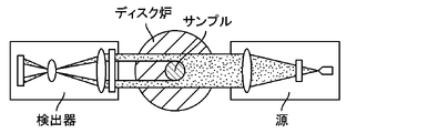
第36の態様は、ガラス物品を第1の保持温度から第2の保持温度まで第2の所定の加熱速度で加熱するステップおよびガラス物品を第2の保持温度で第2の持続時間の間保持するステップの間、ガラス物品の密度が膨張計を用いてin-situで監視される、第34の態様の方法を含む。 A thirty-sixth aspect comprises heating the glass article from the first hold temperature to the second hold temperature at a second predetermined heating rate and holding the glass article at the second hold temperature for a second duration of time. The method of the thirty-fourth aspect, wherein the density of the glass article is monitored in-situ using a dilatometer during the step of performing.
第37の態様は、ガラス物品の密度が少なくとも50分間一定であるとき第2の持続時間が終了される、第31から第36までの態様のいずれか1つの方法を含む。 A thirty-seventh aspect includes the method of any one of the thirty-first through thirty-sixth aspects, wherein the second time duration is terminated when the density of the glass article remains constant for at least 50 minutes.
第38の態様は、ガラス物品の密度が少なくとも100分間一定であるとき第2の持続時間が終了される、第31から第37までの態様のいずれか1つの方法を含む。 A thirty-eighth aspect includes the method of any one of the thirty-first through thirty-seventh aspects, wherein the second time duration is terminated when the density of the glass article remains constant for at least 100 minutes.
第39の態様は、第1の所定の加熱速度が、自動粘度制御システムの性能に少なくとも部分的に基づいて決定される、第31から第38までの態様のいずれか1つの方法を含む。 A thirty-ninth aspect includes the method of any one of the thirty-first through thirty-eighth aspects, wherein the first predetermined heating rate is determined based at least in part on the performance of the automatic viscosity control system.
第40の態様は、第2の所定の加熱速度が、自動粘度制御システムの性能に少なくとも部分的に基づいて決定される、第31から第39までの態様のいずれか1つの方法を含む。 A fortieth aspect includes the method of any one of the thirtieth through thirty-ninth aspects, wherein the second predetermined heating rate is determined based at least in part on the performance of the automatic viscosity control system.
第41の態様は、重量拘束力をガラス物品に印加するステップをさらに含む、第31から第40までの態様のいずれか1つの方法を含む。 A forty-first aspect includes the method of any one of the thirty-first through fortieth aspects, further comprising applying a weight restraining force to the glass article.
第42の態様は、ガラス物品が、ガラス積層体の部分である、第31から第41までの態様のいずれか1つの方法を含む。 A forty-second aspect includes the method of any one of the thirty-first through forty-first aspects, wherein the glass article is part of a glass laminate.
第43の態様は、ガラス積層体が、第1のセッターと、第1のセッター上に置かれた複数のガラスシートと、ガラスシートの積層体上の第2のセッターとを含む、第42の態様の方法を含む。 The forty-third aspect is the forty-second aspect, wherein the glass stack comprises a first setter, a plurality of glass sheets placed on the first setter, and a second setter on the stack of glass sheets. Including the method of the embodiment.
第44の態様は、複数のガラスシートが、少なくとも10枚のガラスシートを含む、第42または第43の態様の方法を含む。 A forty-fourth aspect includes the method of the forty-second or forty-third aspect, wherein the plurality of glass sheets comprises at least ten glass sheets.
第45の態様は、複数のガラスシートが、少なくとも20枚のガラスシートを含む、第42から第44までの態様のいずれか1つの方法を含む。 A forty-fifth aspect includes the method of any one of the forty-second through forty-fourth aspects, wherein the plurality of glass sheets comprises at least twenty glass sheets.
第46の態様は、第1の所定の持続時間内のプログラムされた温度からのガラス物品の温度差が±8℃以内である、第31から第45までの態様のいずれか1つの方法を含む。 A forty-sixth aspect includes the method of any one of the thirty-first to forty-fifth aspects, wherein the temperature difference of the glass article from the programmed temperature within the first predetermined duration is within ±8°C. .
第47の態様は、第1の所定の持続時間内のプログラムされた温度からのガラス物品の温度差が±5℃以内である、第31から第46までの態様のいずれか1つの方法を含む。 A forty-seventh aspect includes the method of any one of the thirty-first to forty-sixth aspects, wherein the temperature difference of the glass article from the programmed temperature within the first predetermined duration is within ±5°C. .
第48の態様は、第2の持続時間内のプログラムされた温度からのガラス物品の温度差が±8℃以内である、第31から第47までの態様のいずれか1つの方法を含む。 A forty-eighth aspect includes the method of any one of the thirty-first to forty-seventh aspects, wherein the temperature difference of the glass article from the programmed temperature within the second duration is within ±8°C.
第49の態様は、第2の持続時間内のプログラムされた温度からのガラス物品の温度差が±5℃以内である、第31から第48までの態様のいずれか1つの方法を含む。 A forty-ninth aspect includes the method of any one of the thirty-first to forty-eighth aspects, wherein the temperature difference of the glass article from the programmed temperature within the second duration is within ±5°C.
第50の態様は、ガラス物品を第1の保持温度まで第1の所定の加熱速度で加熱するステップが多段階加熱を含む、第31から第49までの態様のいずれか1つの方法を含む。 A fiftieth aspect includes the method of any one of the thirty-first through forty-ninth aspects, wherein heating the glass article to the first holding temperature at the first predetermined heating rate comprises multi-step heating.
第51の態様は、ガラス物品を第1の保持温度まで第1の所定の加熱速度で加熱するステップの間、ガラス物品の粘度がlog粘度11.0ポアズ(1.10Pa・s)以上に維持される、第31から第50までの態様のいずれか1つの方法を含む。 A fifty-first aspect maintains the viscosity of the glass article at a log viscosity of 11.0 poise (1.10 Pa·s) or greater during the step of heating the glass article to the first holding temperature at the first predetermined heating rate. comprising the method of any one of the thirty-first through fiftieth aspects, wherein:
第52の態様は、第1の所定の持続時間の間、ガラス物品の粘度がlog粘度11.0ポアズ(1.10Pa・s)以上に維持される、第31から第51までの態様のいずれか1つの方法を含む。 A fifty-second aspect is any of the thirty-first through fifty-first aspects, wherein the viscosity of the glass article is maintained at a log viscosity of 11.0 poise (1.10 Pa·s) or greater for the first predetermined duration of time. or one method.
第53の態様は、第1の保持温度から第2の保持温度までガラス物品を加熱するステップの間、ガラス物品の粘度がlog粘度11.0ポアズ(1.10Pa・s)以上に維持される、第31から第52までの態様のいずれか1つの方法を含む。 A fifty-third aspect is that the viscosity of the glass article is maintained at a log viscosity of 11.0 poise (1.10 Pa·s) or greater during the step of heating the glass article from the first hold temperature to the second hold temperature. , the method of any one of the thirty-first through fifty-second aspects.
第54の態様は、ガラス物品の粘度が、前記方法の全持続時間の間、log粘度11.0ポアズ(1.10Pa・s)以上に維持される、第31から第53までの態様のいずれか1つの方法を含む。 A fifty-fourth aspect is any of the thirty-first through fifty-third aspects, wherein the viscosity of the glass article is maintained at a log viscosity of 11.0 poise (1.10 Pa·s) or greater for the entire duration of the method. or one method.
第55の態様は、第1の所定の持続時間の間、ガラス物品の粘度がlog粘度11.0ポアズ(1.10Pa・s)未満に維持される、第31から第54までの態様のいずれか1つの方法を含む。 A fifty-fifth aspect is any of the thirty-first through fifty-fourth aspects, wherein the viscosity of the glass article is maintained at a log viscosity of less than 11.0 poise (1.10 Pa·s) for the first predetermined duration of time. or one method.
第56の態様は、ガラス-セラミックス物品であって、第1の表面と、第1の表面に対向する第2の表面と、1つ以上の結晶相と、残留ガラス相と、第1の表面から圧縮深さ(DOC)まで延びる圧縮応力層と、90MPa超の最大中央張力と、22J/m2超の貯蔵引張エネルギーと、1.0MPa√m超の破壊靭性と、0.2未満のヘイズとを有するガラス-セラミックス物品を含む。 A fifty-sixth aspect is a glass-ceramic article comprising a first surface, a second surface opposite the first surface, one or more crystalline phases, a residual glass phase, and the first surface to the depth of compression (DOC), a maximum central tension greater than 90 MPa, a stored tensile energy greater than 22 J/ m2 , a fracture toughness greater than 1.0 MPa√m, and a haze of less than 0.2 and a glass-ceramic article.
第57の態様は、95GPa超のヤング率をさらに有する、第56の態様のガラスセラミックス物品を含む。 A fifty-seventh aspect includes the glass-ceramic article of the fifty-sixth aspect, further having a Young's modulus greater than 95 GPa.
第58の態様は、破壊靭性が1.0MPa√m超~2.0MPa√mの範囲内である、第56または第57の態様のガラスセラミックス物品を含む。 A fifty-eighth aspect includes the glass-ceramic article of the fifty-sixth or fifty-seventh aspect, wherein the fracture toughness is in the range of greater than 1.0 MPa√m to 2.0 MPa√m.
第59の態様は、ガラス-セラミックス物品であって、第1の表面と、第1の表面に対向する第2の表面と、1つ以上の結晶相と、残留ガラス相と、第1の表面から圧縮深さ(DOC)まで延びる圧縮応力層と、90MPa超の最大中央張力と、22J/m2超の貯蔵引張エネルギーと、95GPa超のヤング率と、0.2未満のヘイズとを有するガラス-セラミックス物品を含む。 A fifty-ninth aspect is a glass-ceramic article comprising: a first surface; a second surface opposite the first surface; one or more crystalline phases; a residual glass phase; to the depth of compression (DOC), a maximum central tension greater than 90 MPa, a stored tensile energy greater than 22 J/ m2 , a Young's modulus greater than 95 GPa, and a haze less than 0.2. - Including ceramic articles.
第60の態様は、ヤング率が95GPa超~110GPaの範囲内である、第59の態様のガラスセラミックス物品を含む。 A sixtieth aspect includes the glass-ceramic article of the fifty-ninth aspect, wherein the Young's modulus is in the range of greater than 95 GPa to 110 GPa.
第61の態様は、Li2O(モル%)/R2O(モル%)(式中、R2Oは、アルカリ金属酸化物の和である)の比が0.85超である、第56から第60までの態様のいずれか1つのガラスセラミックス物品を含む。 A sixty - first aspect is the A glass-ceramic article of any one of the fifty-sixth through sixtieth aspects.
第62の態様は、1.7モル%~4.5モル%の範囲内のZrO2をさらに含む、第59から第61までの態様のいずれか1つのガラスセラミックス物品を含む。 A sixty-second aspect includes the glass-ceramic article of any one of the fifty-ninth through sixty-first aspects, further comprising ZrO 2 within the range of 1.7 mol % to 4.5 mol %.
第63の態様は、ガラス-セラミックス物品であって、第1の表面と、第1の表面に対向する第2の表面と、1つ以上の結晶相と、残留ガラス相と、第1の表面から圧縮深さ(DOC)まで延びる圧縮応力層と、90MPa超の最大中央張力と、22J/m2超の貯蔵引張エネルギーと、1.7モル%~4.5モル%の範囲内のZrO2とを有し、Li2O(モル%)/R2O(モル%)(式中、R2Oは、アルカリ金属酸化物の和である)の比が0.85超である、ガラス-セラミックス物品を含む。 A sixty-third aspect is a glass-ceramic article comprising a first surface, a second surface opposite the first surface, one or more crystalline phases, a residual glass phase, and the first surface to the depth of compression (DOC), a maximum central tension greater than 90 MPa, a stored tensile energy greater than 22 J/m 2 and ZrO 2 in the range of 1.7 mol % to 4.5 mol %. and wherein the ratio of Li 2 O (mol %)/R 2 O (mol %) (wherein R 2 O is the sum of alkali metal oxides) is greater than 0.85 Includes ceramic articles.
第64の態様は、残留ガラス相が、ガラス-セラミックス物品の50質量%以下である、第56から第63までの態様のいずれか1つのガラスセラミックスを含む。 A sixty-fourth aspect includes the glass-ceramic of any one of the fifty-sixth through sixty-third aspects, wherein the residual glass phase is 50% or less by weight of the glass-ceramic article.
第65の態様は、1つ以上の結晶相がペタライトを含む、第56から第64までの態様のいずれか1つのガラスセラミックスを含む。 A sixty-fifth aspect includes the glass-ceramic of any one of the fifty-sixth through sixty-fourth aspects, wherein one or more of the crystalline phases comprises petalite.
第66の態様は、1つ以上の結晶相が二ケイ酸リチウムを含む、第56から第65までの態様のいずれか1つのガラスセラミックスを含む。 A sixty-sixth aspect includes the glass-ceramic of any one of the fifty-sixth through sixty-fifth aspects, wherein one or more of the crystalline phases comprises lithium disilicate.
第67の態様は、二ケイ酸リチウムおよびペタライト以外の結晶相の和が、ガラス-セラミックス物品の1質量%未満である、第56から第66までの態様のいずれか1つのガラスセラミックスを含む。 A sixty-seventh aspect includes the glass-ceramic of any one of the fifty-sixth through sixty-sixth aspects, wherein the sum of crystalline phases other than lithium disilicate and petalite is less than 1% by weight of the glass-ceramic article.
第68の態様は、ガラス-セラミックス物品が透明であり、かつ1mmの厚さにおいて450nm~800nmの波長範囲内で少なくとも85%の光の透過率を有する、第56から第67までの態様のいずれか1つのガラスセラミックスを含む。 A sixty-eighth embodiment is any of the fifty-sixth through sixty-seventh embodiments, wherein the glass-ceramic article is transparent and has a transmittance of at least 85% of light within a wavelength range of 450 nm to 800 nm at a thickness of 1 mm. or one glass-ceramic.
第69の態様は、ガラス-セラミックス物品が、破片試験に供されたとき5個未満の破片に割れる、第56から第68までの態様のいずれか1つのガラスセラミックスを含む。 A sixty-ninth aspect includes the glass-ceramic of any one of the fifty-sixth through sixty-eighth aspects, wherein the glass-ceramic article breaks into less than 5 fragments when subjected to a fragment test.
第70の態様は、最大中央張力が90MPa超~180MPaの範囲内である、第56から第69までの態様のいずれか1つのガラスセラミックスを含む。 A seventieth aspect includes the glass-ceramic of any one of the fifty-sixth through sixty-ninth aspects, wherein the maximum central tension is in the range of greater than 90 MPa to 180 MPa.
第71の態様は、貯蔵引張エネルギーが22J/m2超~60J/m2の範囲内である、第56から第70までの態様のいずれか1つのガラスセラミックスを含む。 A seventy-first aspect includes the glass-ceramic of any one of the fifty-sixth through seventieth aspects, wherein the stored tensile energy is in the range of greater than 22 J/m 2 and 60 J/m 2 .
第72の態様は、150nm以下の最長寸法を有する結晶粒をさらに含む、第56の態様のガラスセラミックスを含む。 A seventy-second aspect includes the glass-ceramic of the fifty-sixth aspect, further comprising grains having a longest dimension of 150 nm or less.
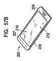
第73の態様は、消費者電子製品であって、前面、背面および側面を備えるハウジングと、少なくとも部分的にハウジング内にある電気部品であって、少なくともコントローラと、メモリと、ハウジングの前面にあるまたは隣接するディスプレイとを含む、電気部品と、ディスプレイ全体にわたって配置されたカバー基板とを含み、ハウジングの一部またはカバー基板のうちの少なくとも1つが、先行する態様のいずれかのガラス-セラミックス物品を含む、消費者電子製品を含む。 A seventy-third aspect is a consumer electronic product, a housing having a front surface, a back surface and sides, and electrical components at least partially within the housing, the at least controller, memory, and front surface of the housing. or an adjacent display, and a cover substrate disposed over the display, at least one of the housing portion or the cover substrate comprising the glass-ceramic article of any of the preceding aspects. Including, including consumer electronic products.
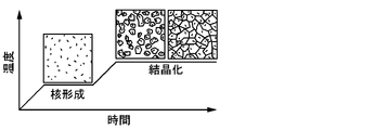
第74の態様は、ガラス-セラミックス物品を形成する方法であって、核形成された結晶化可能なガラス組成物を生成するためにガラス組成物を核形成温度まで加熱するステップと、核形成された結晶化可能なガラス組成物を結晶化温度まで加熱するステップと、ガラス-セラミックス物品を生産するために結晶化温度を所定の時間の間維持するステップとを含み、ガラス-セラミックス物品が、1.0MPa√m超の破壊靭性と、0.2未満のヘイズとを有する方法を含む。 A seventy-fourth aspect is a method of forming a glass-ceramic article comprising the steps of heating a glass composition to a nucleation temperature to produce a nucleated crystallizable glass composition; heating the crystallizable glass composition to a crystallization temperature; and maintaining the crystallization temperature for a predetermined period of time to produce a glass-ceramic article, the glass-ceramic article comprising: A method having a fracture toughness greater than 0.0 MPa√m and a haze of less than 0.2.
第75の態様は、核形成された結晶化可能なガラス組成物を生産するために核形成温度を所定の時間の間維持するステップをさらに含む、第74の態様の方法を含む。 A seventy-fifth aspect includes the method of the seventy-fourth aspect, further comprising maintaining the nucleation temperature for a predetermined amount of time to produce the nucleated crystallizable glass composition.
第76の態様は、核形成温度を維持するための時間が1分~6時間の範囲内である、第75の態様の方法を含む。 A seventy-sixth aspect includes the method of the seventy-fifth aspect, wherein the time for maintaining the nucleation temperature is in the range of 1 minute to 6 hours.
第77の態様は、ガラス組成物が核形成温度に維持されない、第74から第76までの態様のいずれか1つの方法を含む。 A seventy-seventh aspect includes the method of any one of the seventy-fourth through seventy-sixth aspects, wherein the glass composition is not maintained at a nucleation temperature.
第78の態様は、核形成された結晶化可能なガラス組成物を中間温度まで加熱するステップであって、中間温度が核形成温度より高く、かつ結晶化温度より低い、ステップと、核形成された結晶化可能なガラス組成物を中間温度から結晶化温度まで加熱するステップとをさらに含む、第74から第77までの態様のいずれか1つの方法を含む。 A seventy-eighth aspect is the step of heating the nucleated crystallizable glass composition to an intermediate temperature, wherein the intermediate temperature is above the nucleation temperature and below the crystallization temperature; heating the crystallizable glass composition from the intermediate temperature to the crystallization temperature.
第79の態様は、中間温度を所定の時間の間維持するステップをさらに含む、第78の態様の方法を含む。 A seventy-ninth aspect includes the method of the seventy-eighth aspect, further comprising maintaining the intermediate temperature for a predetermined amount of time.
第80の態様は、核形成された結晶化可能なガラス組成物を核形成温度から中間温度まで加熱するための加熱速度が、核形成された結晶化可能なガラス組成物を中間温度から結晶化温度まで加熱するための加熱速度とは異なる、第78または第79の態様の方法を含む。 An eightieth aspect is the heating rate for heating the nucleated crystallizable glass composition from the nucleation temperature to the intermediate temperature is such that the nucleated crystallizable glass composition crystallizes from the intermediate temperature. Including the method of the seventy-eighth or seventy-ninth aspects, wherein the heating rate for heating to the temperature is different.
第81の態様は、核形成結晶化可能なガラス組成物が中間温度に維持されない、第80の態様の方法を含む。 An eighty-first aspect includes the method of the eightieth aspect, wherein the nucleation-crystallizable glass composition is not maintained at the intermediate temperature.
第82の態様は、ガラス-セラミックス物品の第1の表面から圧縮深さ(DOC)まで延びる圧縮応力層を生成するためにガラス-セラミックス物品をイオン交換処理に供するステップをさらに含み、イオン交換処理後、ガラス-セラミックス物品が、90MPa超の最大中央張力と、22J/m2超の貯蔵引張エネルギーとを有する、第78から第81までの態様のいずれか1つの方法を含む。 An eighty-second aspect further comprises subjecting the glass-ceramic article to an ion exchange treatment to produce a compressive stress layer extending from the first surface of the glass-ceramic article to a depth of compression (DOC), wherein the ion exchange treatment Then comprising the method of any one of aspects 78 through 81, wherein the glass-ceramic article has a maximum central tension of greater than 90 MPa and a stored tensile energy of greater than 22 J/m 2 .
第83の態様は、核形成温度が550℃~650℃の範囲内である、第78から第82までの態様のいずれか1つの方法を含む。 An eighty-third aspect includes the method of any one of the seventy-eighth through eighty-second aspects, wherein the nucleation temperature is in the range of 550°C to 650°C.
第84の態様は、核形成温度まで加熱するステップが、室温から核形成温度まで0.01℃/分~50℃/分の範囲内の加熱速度で加熱するステップを含む、第78から第83までの態様のいずれか1つの方法を含む。 The eighty-fourth aspect, wherein the step of heating to the nucleation temperature comprises heating from room temperature to the nucleation temperature at a heating rate within the range of 0.01° C./min to 50° C./min. A method of any one of the aspects up to.
第85の態様は、結晶化温度が680℃~800℃の範囲内である、第78から第84までの態様のいずれか1つの方法を含む。 An eighty-fifth aspect includes the method of any one of the seventy-eighth through eighty-fourth aspects, wherein the crystallization temperature is within the range of 680°C to 800°C.
第86の態様は、結晶化温度を維持するための所定の時間が1分~4時間の範囲内である、第78から第85までの態様のいずれか1つの方法を含む。 An eighty-sixth aspect includes the method of any one of the seventy-eighth through eighty-fifth aspects, wherein the predetermined time for maintaining the crystallization temperature is within the range of 1 minute to 4 hours.
第87の態様は、結晶化温度まで加熱するステップが、核形成温度から結晶化温度まで0.01℃/分~50℃/分の範囲内の加熱速度で加熱するステップを含む、第78から第86までの態様のいずれか1つの方法を含む。 The eighty-seventh aspect, wherein the step of heating to the crystallization temperature comprises heating from the nucleation temperature to the crystallization temperature at a heating rate within the range of 0.01° C./min to 50° C./min. A method of any one of the eighty-sixth aspects.
第86の態様は、第1の冷却段階において、ガラス-セラミックス物品を結晶化温度から第1の温度まで第1の冷却速度で冷却するステップと、第2の冷却段階において、ガラス-セラミックス物品を第1の温度から第2の温度まで第2の冷却速度で冷却するステップとをさらに含み、第1の冷却速度が第2の冷却速度よりも低い、第78から第87までの態様のいずれか1つの方法を含む。 An eighty-sixth aspect is, in a first cooling stage, cooling the glass-ceramic article from the crystallization temperature to a first temperature at a first cooling rate; and cooling from the first temperature to the second temperature at a second cooling rate, wherein the first cooling rate is less than the second cooling rate. Includes one method.
第87の態様は、第1の冷却段階において、ガラス-セラミックス物品を結晶化温度から第1の温度まで第1の冷却速度で冷却するステップと、中間冷却段階において、ガラス-セラミックス物品を第1の温度から第2の温度まで第2の冷却速度で冷却するステップと、第2の冷却段階において、ガラス-セラミックス物品を第2の温度から第3の温度まで第3の冷却速度で冷却するステップとをさらに含み、(i)第1の冷却速度が第2の冷却速度および第3の冷却速度よりも低く、(ii)第2の冷却速度が第3の冷却速度よりも低い、第78から第86までの態様のいずれか1つの方法を含む。 An eighty-seventh aspect includes, in a first cooling stage, cooling the glass-ceramic article from the crystallization temperature to a first temperature at a first cooling rate; from a temperature of to a second temperature at a second cooling rate; and in the second cooling stage, cooling the glass-ceramic article from the second temperature to a third temperature at a third cooling rate. and (i) the first cooling rate is lower than the second cooling rate and the third cooling rate, and (ii) the second cooling rate is lower than the third cooling rate. A method of any one of the eighty-sixth aspects.
第88の態様は、ガラス-セラミックスが、厚さ1mm当たり15nm未満の光学リタデーションを有する、第78から第87までの態様のいずれか1つの方法を含む。 An eighty-eighth aspect includes the method of any one of the seventy-eighth through eighty-seventh aspects, wherein the glass-ceramic has an optical retardation of less than 15 nm per mm of thickness.
第89の態様は、ガラス-セラミックス物品を形成する方法であって、ガラス組成物を核形成温度(TN)まで加熱するステップと、核形成された結晶化可能なガラス組成物を生産するために核形成温度を第1の所定の時間(tN)の間維持するステップと、核形成された結晶化可能なガラス組成物を結晶化温度(TC)まで加熱するステップと、ガラス-セラミックス物品を生産するために結晶化温度を第2の所定の時間(tC)の間維持するステップとを含み、(103-0.260TN+0.000203(TN)2-7.96tN+0.1532(tN)2-0.019TC-0.000008(TC)2-10.03tC+0.00597TN*tN+0.00463tN*TC+0.01342TC*tC)<0.2である方法を含む。 An eighty-ninth aspect is a method of forming a glass-ceramic article, comprising: heating a glass composition to a nucleation temperature (T N ); for a first predetermined time (t N ); heating the nucleated crystallizable glass composition to a crystallization temperature (T C ); maintaining the crystallization temperature for a second predetermined time ( t C ) to produce an article ; .1532(t N ) 2 −0.019T C −0.000008(T C ) 2 −10.03t C +0.00597T N *t N +0.00463t N *T C +0.01342T C *t C )<0 .2.
第90の態様は、ガラス-セラミックス物品のヘイズを制御するための方法であって、(103-0.260TN+0.000203(TN)2-7.96tN+0.1532(tN)2-0.019TC-0.000008(TC)2-10.03tC+0.00597TN*tN+0.00463tN*TC+0.01342TC*tC)<0.2であるように核形成温度(TN)、第1の所定の時間(tN)、結晶化温度(TC)、および第2の所定の時間(tC)を選択するステップを含む方法を含む。 A ninetieth aspect is a method for controlling haze in a glass-ceramic article, comprising: (103-0.260T N +0.000203(T N ) 2 -7.96t N +0.1532(t N ) 2 −0.019T C −0.000008(T C ) 2 −10.03t C +0.00597 T N *t N +0.00463t N *T C +0.01342 T C *t C )<0.2 The method includes selecting a formation temperature (T N ), a first predetermined time (t N ), a crystallization temperature (T C ), and a second predetermined time (t C ).
第91の態様は、ガラス組成物を核形成温度(TN)まで加熱するステップと、核形成された結晶化可能なガラス組成物を生産するために核形成温度を第1の所定の時間(tN)の間維持するステップと、核形成された結晶化可能なガラス組成物を結晶化温度(TC)まで加熱するステップと、ガラス-セラミックス物品を生産するために結晶化温度を第2の所定の時間(tC)の間維持するステップとをさらに含む、第90の態様の方法を含む。 A ninety-first aspect comprises the steps of heating the glass composition to a nucleation temperature (T N ), and increasing the nucleation temperature for a first predetermined time ( t N ), heating the nucleated crystallizable glass composition to a crystallization temperature (T C ), and bringing the crystallization temperature to a second temperature to produce a glass-ceramic article. maintaining for a predetermined time (t C ) of the 90th aspect.
第92の態様は、複数のガラスシートをセラミックス化する方法であって、第1のセッタープレートと第2のセッタープレートの間に第1の積層体内の複数のガラスシートの第1の部分を、そして第1の積層体の上の第2のセッタープレートと第3のセッタープレートの間に第2の積層体内の複数のガラスシートの第2の部分をガラス積層構成体で配置するステップと、複数のガラスシートをセラミックス化するためのセラミングサイクルにガラス積層構成体を曝すステップとを含み、ガラスシートがセラミングサイクルの間、核形成温度まで所定の時間の間加熱されるとき、第1の積層体または第2の積層体のΔTが10℃未満である、またはガラスシートがセラミングサイクルの間、結晶化温度まで所定の時間の間加熱されるとき、第1の積層体または第2の積層体のΔTが10℃未満である方法を含む。 A ninety-second aspect is a method of ceramming a plurality of glass sheets, comprising: placing a first portion of the plurality of glass sheets in a first laminate between a first setter plate and a second setter plate; and placing a second portion of the plurality of glass sheets in the second laminate between a second setter plate and a third setter plate on the first laminate in a glass laminate configuration; exposing the glass laminate construction to a ceraming cycle to ceramize the glass sheet of the first When the ΔT of the laminate or the second laminate is less than 10° C. or the glass sheet is heated to the crystallization temperature for a predetermined time during the ceramicing cycle, the first laminate or the second laminate Includes a method wherein the ΔT of the laminate is less than 10°C.
第93の態様は、複数のガラスシートが、21μm以下の最大厚さ変動を有する、第92の態様の方法を含む。 A ninety-third aspect includes the method of the ninety-second aspect, wherein the plurality of glass sheets has a maximum thickness variation of 21 μm or less.
第94の態様は、複数のガラスシートそれぞれの上のエッジビードを除去するステップをさらに含む、第92または第93の態様の方法を含む。 A ninety-fourth aspect includes the method of the ninety-second or ninety-third aspects, further comprising removing an edge bead on each of the plurality of glass sheets.
第95の態様は、複数のガラスシートのうちの1つと、複数のガラスシートのうちの隣接する1つの間に窒化ホウ素とコロイド状無機結合剤の水性分散物から剥離剤層を形成するステップをさらに含む、第92から第94までの態様のいずれか1つの方法を含む。 A ninety-fifth aspect comprises forming a release agent layer from an aqueous dispersion of boron nitride and a colloidal inorganic binder between one of the plurality of glass sheets and an adjacent one of the plurality of glass sheets. The method of any one of aspects ninety-second through ninety-fourth, further comprising.
第96の態様は、複数のガラスシートのうちの1つと、第1のセッタープレート、第2のセッタープレート、または第3のセッタープレートのうちの隣接する1つの間に窒化ホウ素とコロイド状無機結合剤の水性分散物から剥離剤層を形成するステップをさらに含む、第92から第95までの態様のいずれか1つの方法を含む。 A ninety-sixth aspect includes boron nitride and a colloidal inorganic bond between one of the plurality of glass sheets and an adjacent one of the first setter plate, the second setter plate, or the third setter plate. 95. The method of any one of aspects 92-95, further comprising forming a release agent layer from an aqueous dispersion of an agent.
第97の態様は、ガラスシートが核形成温度に維持される所定の時間の間、ガラス積層構成体が、第1のセッタープレートに近接する第1の積層体の底部と第3のセッタープレートに近接する第2の積層体の上部の間で2.2℃以下のΔTを有する、第92から第96までの態様のいずれか1つの方法を含む。 A ninety-seventh aspect provides that the glass laminate construction is placed on the bottom of the first laminate adjacent to the first setter plate and on the third setter plate for a predetermined amount of time that the glass sheets are maintained at the nucleation temperature. The method of any one of aspects 92 through 96, having a ΔT of 2.2° C. or less between tops of adjacent second laminates.
第98の態様は、セラミングプロセスが、セラミングプロセス中の最高温度から約450℃の温度までの約4℃/分の速度の制御された冷却と、その後に続くほぼ室温の温度までのクエンチングステップとを含む、第92から第97までの態様のいずれか1つの方法を含む。 A ninety-eighth aspect is the method wherein the ceramming process comprises controlled cooling at a rate of about 4°C/min from a maximum temperature during the ceraming process to a temperature of about 450°C, followed by quenching to a temperature of about room temperature. the method of any one of the ninety-second through ninety-seventh aspects comprising the step of
第99の態様は、第1のセッタープレート、第2のセッタープレート、および第3のセッタープレートのそれぞれが反応結合炭化ケイ素を含む、第92から第98までの態様のいずれか1つの方法を含む。 A ninety-ninth aspect includes the method of any one of the ninety-second through ninety-eighth aspects, wherein each of the first setter plate, the second setter plate, and the third setter plate comprises reaction-bonded silicon carbide. .
第100の態様は、第1のセッタープレート、第2のセッタープレート、および第3のセッタープレートのそれぞれが、約100μm以下の最大平坦度を有する、第92から第99までの態様のいずれか1つの方法を含む。 A hundredth aspect is any one of the ninety-second through ninety-ninth aspects, wherein each of the first setter plate, the second setter plate, and the third setter plate has a maximum flatness of about 100 μm or less including one method.
第101の態様は、第1のセッタープレート、第2のセッタープレート、および第3のセッタープレートのそれぞれが、約25μm以下の最大平坦度を有する、第92から第100までの態様のいずれか1つの方法を含む。 A 101st aspect is any one of the 92nd through 100th aspects, wherein each of the first setter plate, the second setter plate, and the third setter plate has a maximum flatness of about 25 μm or less including one method.
第102の態様は、第1のセッタープレート、第2のセッタープレート、および第3のセッタープレートのそれぞれが、約6.5mm~約10mmの厚さtを有する、第92から第101までの態様のいずれか1つの方法を含む。 A 102nd aspect is the 92nd through 101st aspects, wherein each of the first setter plate, the second setter plate, and the third setter plate has a thickness t of from about 6.5 mm to about 10 mm any one method of
第103の態様は、ガラス積層構成体が、開いたグリッド構成の鋼を含むキャリアプレート上に支持されている、第92から第102までの態様のいずれか1つの方法を含む。 A 103rd aspect includes the method of any one of the 92nd through 102nd aspects, wherein the glass laminate construction is supported on a carrier plate comprising steel in an open grid configuration.
第104の態様は、複数のガラスシートをセラミックス化する方法であって、複数のガラスシートにおける厚さ変動を低減するステップと、第1のセッタープレートと第2のセッタープレートの間に複数のガラスシートをガラス積層構成体で配置するステップと、複数のガラスシートをセラミックス化するためのセラミングサイクルにガラス積層構成体を曝すステップとを含む方法を含む。 A hundred-fourth aspect is a method of ceramming a plurality of glass sheets, comprising the steps of: reducing thickness variations in the plurality of glass sheets; The method includes arranging the sheets in a glass laminate construction and exposing the glass laminate construction to a ceraming cycle to ceramize the plurality of glass sheets.
第105の態様は、複数のガラスシートにおける厚さ変動を低減するステップが、複数のガラスシートにおける厚さ変動を21μm以下の最大厚さ変動に低減するステップを含む、第104の態様の方法を含む。 The 105th aspect the method of the 104th aspect, wherein reducing thickness variation in the plurality of glass sheets comprises reducing thickness variation in the plurality of glass sheets to a maximum thickness variation of 21 μm or less. include.
第106の態様は、複数のガラスシートそれぞれの上のエッジビードを除去するステップをさらに含む、第104または第105の態様の方法を含む。 A one hundred sixth aspect includes the method of the one hundred fourth or one hundred fifth aspect, further comprising removing an edge bead on each of the plurality of glass sheets.
第107の態様は、複数のガラスシートのうちの1つと、複数のガラスシートのうちの隣接する1つの間に窒化ホウ素とコロイド状無機結合剤の水性分散物から剥離剤層を形成するステップをさらに含む、第104から第106までの態様のいずれか1つの方法を含む。
A one hundred seventh aspect comprises forming a release agent layer from an aqueous dispersion of boron nitride and a colloidal inorganic binder between one of the plurality of glass sheets and an adjacent one of the plurality of glass sheets. The method of any one of
第108の態様は、ガラスシートが核形成温度に維持される所定の時間の間、ガラス積層構成体が、第1のセッタープレートに近接するガラスシートと第2のセッタープレートに近接するガラスシートの間で2.2℃以下のΔTを有する、第104から第107までの態様のいずれか1つの方法を含む。
The one hundred eighth aspect is that the glass laminate construction comprises a glass sheet proximate the first setter plate and a glass sheet proximate the second setter plate for a predetermined amount of time during which the glass sheets are maintained at the nucleation temperature. comprising the method of any one of
第109の態様は、セラミングプロセスが、セラミングプロセス中の最高温度から約450℃の温度までの約4℃/分の速度の制御された冷却と、その後に続くほぼ室温の温度までのクエンチングステップとを含む、第104から第108までの態様のいずれか1つの方法を含む。 A one hundred ninth aspect is that the ceramicming process comprises controlled cooling at a rate of about 4°C/minute from a maximum temperature during the ceramicming process to a temperature of about 450°C, followed by quenching to a temperature of about room temperature. the method of any one of the 104th through 108th aspects, comprising the step of
第110の態様は、第1のセッタープレートおよび第2のセッタープレートのそれぞれが、約25μm以下の最大平坦度を有する、第104から第109までの態様のいずれか1つの方法を含む。
A 110th aspect includes the method of any one of
第111の態様は、ガラス積層構成体が、開いたグリッド構成の鋼を含むキャリアプレート上に支持されている、第104から第110までの態様のいずれか1つの方法を含む。 A 111th aspect includes the method of any one of the 104th to 110th aspects, wherein the glass laminate construction is supported on a carrier plate comprising steel in an open grid configuration.
第112の態様は、複数のガラスシートをセラミックス化する方法であって、第1のセッタープレートと第2のセッタープレートの間に積層体内の複数のガラスシートをガラス積層構成体で配置するステップと、複数のガラスシートをセラミックス化するためのセラミングサイクルにガラス積層構成体を曝すステップとを含み、第1のセッタープレートおよび第2のセッタープレートがそれぞれ、室温でASTM E1461にしたがって測定された約670J/kg*K~約850J/kg*Kの比熱容量、ASTM C20にしたがって測定された約2500kg/m3超の嵩密度、または約2.50×10-5m2/s超の熱拡散率を有する方法を含む。 A one-hundred-second aspect is a method of ceramming a plurality of glass sheets comprising the steps of placing the plurality of glass sheets in a laminate between a first setter plate and a second setter plate in a glass laminate configuration. and exposing the glass laminate construction to a ceraming cycle to ceramize the plurality of glass sheets, wherein the first setter plate and the second setter plate each have a temperature of about Specific heat capacity from 670 J/kg*K to about 850 J/kg*K, bulk density greater than about 2500 kg/m 3 measured according to ASTM C20, or heat diffusion greater than about 2.50×10 −5 m 2 /s Including methods with rates.
第113の態様は、第1のセッタープレートおよび第2のセッタープレートがそれぞれ、室温でASTM E1461にしたがって測定された約670J/kg*K~約850J/kg*Kの比熱容量と、ASTM C20にしたがって測定された約2500kg/m3超の嵩密度とを有する、第112の態様の方法を含む。 A one-hundred-thirteenth aspect provides that the first setter plate and the second setter plate each have a specific heat capacity of about 670 J/kg*K to about 850 J/kg*K measured according to ASTM E1461 at room temperature and a specific heat capacity according to ASTM C20. and a measured bulk density of greater than about 2500 kg/m 3 .
第114の態様は、第1のセッタープレートおよび第2のセッタープレートがそれぞれ、室温でASTM E1461にしたがって測定された約670J/kg*K~約850J/kg*Kの比熱容量と、約2.50×10-5m2/s超の熱拡散率とを有する、第112または第113の態様の方法を含む。 A one-hundred-fourth aspect provides that the first setter plate and the second setter plate each have a specific heat capacity of about 670 J/kg*K to about 850 J/kg*K measured according to ASTM E1461 at room temperature, and about 2.0 J/kg*K. and a thermal diffusivity greater than 50×10 −5 m 2 /s.
第115の態様は、第1のセッタープレートおよび第2のセッタープレートがそれぞれ、ASTM C20にしたがって測定された約2500kg/m3超の嵩密度と、約2.50×10-5m2/s超の熱拡散率とを有する、第112から第114までの態様のいずれか1つの方法を含む。
A one-hundred-fifth aspect provides that the first setter plate and the second setter plate each have a bulk density greater than about 2500 kg/m 3 measured according to ASTM C20 and a bulk density of about 2.50×10 −5 m 2 /s 114. The method of any one of
第116の態様は、第1のセッタープレートおよび第2のセッタープレートのうちの少なくとも1つが、少なくとも85質量%の反応結合炭化ケイ素を含む、第112から第115までの態様のいずれか1つの方法を含む。 A 116th aspect is the method of any one of the 112th through 115th aspects, wherein at least one of the first setter plate and the second setter plate comprises at least 85 wt% reaction-bonded silicon carbide. including.
第117の態様は、第1のセッタープレートおよび第2のセッタープレートのうちの少なくとも1つが、約1%未満の気孔率を有する、第112から第116までの態様のいずれか1つの方法を含む。 A 117th aspect includes the method of any one of the 112th through 116th aspects, wherein at least one of the first setter plate and the second setter plate has a porosity of less than about 1%. .
第118の態様は、第1のセッタープレートおよび第2のセッタープレートのうちの少なくとも1つが、約100μm以下の最大平坦度を有する、第112から第117までの態様のいずれか1つの方法を含む。 A 118th aspect includes the method of any one of the 112th through 117th aspects, wherein at least one of the first setter plate and the second setter plate has a maximum flatness of about 100 μm or less. .
第119の態様は、第1のセッタープレートおよび第2のセッタープレートのうちの少なくとも1つが、約75μm以下の最大平坦度を有する、第112から第118までの態様のいずれか1つの方法を含む。 A 119th aspect includes the method of any one of the 112th through 118th aspects, wherein at least one of the first setter plate and the second setter plate has a maximum flatness of about 75 μm or less. .
第120の態様は、第1のセッタープレートおよび第2のセッタープレートのうちの少なくとも1つが、約50μm以下の最大平坦度を有する、第112から第119までの態様のいずれか1つの方法を含む。 A 120th aspect includes the method of any one of the 112th through 119th aspects, wherein at least one of the first setter plate and the second setter plate has a maximum flatness of about 50 μm or less. .
第121の態様は、第1のセッタープレートおよび第2のセッタープレートのうちの少なくとも1つが、約25μm以下の最大平坦度を有する、第112から第120までの態様のいずれか1つの方法を含む。 A 121st aspect includes the method of any one of the 112th through 120th aspects, wherein at least one of the first setter plate and the second setter plate has a maximum flatness of about 25 μm or less. .
第122の態様は、第1のセッタープレートおよび第2のセッタープレートがそれぞれ、約6.5mm~約10mmの厚さtを有する、第112から第121までの態様のいずれか1つの方法を含む。 A 122nd aspect includes the method of any one of the 112th through 121st aspects, wherein the first setter plate and the second setter plate each have a thickness t of about 6.5 mm to about 10 mm. .
第123の態様は、第1のセッタープレートおよび第2のセッタープレートがそれぞれ、室温でASTM E1461にしたがって測定された約670J/kg*K~約700J/kg*Kの比熱容量を有する、第112から第122までの態様のいずれか1つの方法を含む。 A 123rd embodiment is the 112th embodiment, wherein the first setter plate and the second setter plate each have a specific heat capacity of about 670 J/kg*K to about 700 J/kg*K measured according to ASTM E1461 at room temperature. through the 122nd aspect.
第124の態様は、第1のセッタープレートおよび第2のセッタープレートがそれぞれ、ASTM C20にしたがって測定された約3000kg/m3~約3500kg/m3の嵩密度を有する、第112から第123までの態様のいずれか1つの方法を含む。 A one hundred and twenty - fourth aspect is the A method of any one of the aspects of
第125の態様は、第1のセッタープレートおよび第2のセッタープレートがそれぞれ、約7.50×10⁻⁵m2/s~約1.50×10-4m2/sの熱拡散率を有する、第112から第124までの態様のいずれか1つの方法を含む。
The one hundred and twenty-fifth aspect provides that the first setter plate and the second setter plate each have a thermal diffusivity of about 7.50×10 −5 m 2 /s to about 1.50×10 −4 m 2 /s. The method of any one of
第126の態様は、第1のセッタープレートおよび第2のセッタープレートがそれぞれ、室温でASTM E1461にしたがって測定された約180W/m-K~約250W/m-Kの熱伝導率を有する、第112から第125までの態様のいずれか1つの方法を含む。
A one hundred and twenty-sixth aspect comprises the first setter plate and the second setter plate each having a thermal conductivity of about 180 W/mK to about 250 W/mK measured according to ASTM E1461 at room temperature. including the method of any one of
第127の態様は、複数のガラスシートをセラミックス化するためのシステムであって、セラミングプロセスの間、複数のガラスシートを支持するキャリアプレートと、キャリアプレートにより支持された少なくとも1つのセッタープレートであって、反応結合炭化ケイ素を含み、かつ約100μm以下の最大平坦度を有する、少なくとも1つのセッタープレートとを含むシステムを含む。 A one hundred and twenty-seventh aspect is a system for ceramming a plurality of glass sheets, comprising: a carrier plate supporting the plurality of glass sheets during a ceramicing process; and at least one setter plate supported by the carrier plate. at least one setter plate comprising reaction-bonded silicon carbide and having a maximum flatness of about 100 μm or less.
第128の態様は、セッタープレートが、約25μm以下の最大平坦度を有する、第127の態様の方法を含む。 The 128th aspect includes the method of the 127th aspect, wherein the setter plate has a maximum flatness of about 25 μm or less.
第129の態様は、セッタープレートが、室温でASTM E1461にしたがって測定された約670J/kg*K~約850J/kg*Kの比熱容量、ASTM C20にしたがって測定された約2500kg/m3超の嵩密度、または約2.50×10-5m2/s超の熱拡散率を有する、第127または第128の態様の方法を含む。 A one hundred and twenty-ninth aspect provides that the setter plate has a specific heat capacity of about 670 J/kg*K to about 850 J/kg*K measured according to ASTM E1461 at room temperature, a specific heat capacity of greater than about 2500 kg/m3 measured according to ASTM C20. comprising the method of the 127th or 128th aspects, having a bulk density or thermal diffusivity greater than about 2.50×10 −5 m 2 /s.
第130の態様は、キャリアプレートが、開いたグリッド構成の鋼を含む、第127から第129までの態様のいずれか1つの方法を含む。 The 130th aspect includes the method of any one of the 127th through 129th aspects, wherein the carrier plate comprises steel in an open grid configuration.
第131の態様は、セッタープレートが、約6.5mm~約10mmの厚さtを有する、第127から第130までの態様のいずれか1つの方法を含む。 A 131st aspect includes the method of any one of the 127th through 130th aspects, wherein the setter plate has a thickness t of about 6.5 mm to about 10 mm.
第132の態様は、コーティングされたガラス物品であって、その上に剥離剤層を有するガラス基板を含み、剥離剤層が、窒化ホウ素とコロイド状無機結合剤とを含む水性分散物から形成されている、コーティングされたガラス物品を含む。 A one hundred and thirty-second embodiment is a coated glass article comprising a glass substrate having a release agent layer thereon, the release agent layer formed from an aqueous dispersion comprising boron nitride and a colloidal inorganic binder. including coated glass articles.
第133の態様は、コロイド状無機結合剤が酸化アルミニウムを含む、第132の態様のコーティングされたガラス物品を含む。 The 133rd aspect includes the coated glass article of the 132nd aspect, wherein the colloidal inorganic binder comprises aluminum oxide.
第134の態様は、窒化ホウ素が、約2μm~約4μmの平均粒径を有する凝集粒子の形態で存在する、第132または第133の態様のコーティングされたガラス物品を含む。 A 134th aspect includes the coated glass article of the 132nd or 133rd aspect, wherein the boron nitride is present in the form of agglomerated particles having an average particle size of about 2 μm to about 4 μm.
第135の態様は、水性分散物が揮発性有機溶媒を実質的に含まない、第132から第134までの態様のいずれか1つのコーティングされたガラス物品を含む。 A 135th aspect includes the coated glass article of any one of the 132nd through 134th aspects, wherein the aqueous dispersion is substantially free of volatile organic solvents.
第136の態様は、水性分散物が、少なくとも1つの分散剤をさらに含む、第132から第135までの態様のいずれか1つのコーティングされたガラス物品を含む。 A 136th aspect includes the coated glass article of any one of the 132nd through 135th aspects, wherein the aqueous dispersion further comprises at least one dispersing agent.
第137の態様は、剥離剤層が、約2gsm~約6gsm(約2g/m2~約6g/m2)の乾燥コート重量を有する、第132から第136までの態様のいずれか1つのコーティングされたガラス物品を含む。 A 137th embodiment is the coating of any one of the 132nd through 136th embodiments, wherein the release agent layer has a dry coat weight of from about 2 gsm to about 6 gsm (from about 2 g/m 2 to about 6 g/m 2 ) glass articles.
第138の態様は、ガラス基板がガラスセラミックス基板を含む、第132から第137までの態様のいずれか1つのコーティングされたガラス物品を含む。 The 138th aspect includes the coated glass article of any one of the 132nd through 137th aspects, wherein the glass substrate comprises a glass-ceramic substrate.
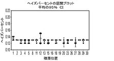
第139の態様は、コーティングされたガラス基板が、ASTM D1003にしたがって測定された約76%~約83%の透過パーセントを有する、第132から第138までの態様のいずれか1つのコーティングされたガラス物品を含む。 A 139th embodiment is the coated glass of any one of the 132nd through 138th embodiments, wherein the coated glass substrate has a percent transmission of about 76% to about 83% measured according to ASTM D1003. Including goods.
第140の態様は、コーティングされたガラス基板が、ASTM D1044にしたがって測定された約25%~約38%のヘイズパーセントを有する、第138または第139の態様のコーティングされたガラス物品を含む。 A 140th aspect includes the coated glass article of the 138th or 139th aspect, wherein the coated glass substrate has a percent haze of about 25% to about 38% measured according to ASTM D1044.
第141の態様は、複数のガラスシートをセラミックス化する方法であって、セッタープレートのうちの少なくとも1つおよび複数のガラスシートのうちの1つ以上の上に、窒化ホウ素とコロイド状無機結合剤とを含む水性分散物をスプレーコーティングするステップと、少なくとも2枚のセッタープレートの間に複数のガラスシートをガラス積層構成体で配置するステップと、複数のガラスシートをセラミックス化するのに十分なセラミングサイクルにガラス積層構成体を曝すステップとを含む方法を含む。 A one hundred and forty-first aspect is a method of ceramming a plurality of glass sheets comprising, on at least one of a setter plate and one or more of a plurality of glass sheets, boron nitride and a colloidal inorganic binder; placing a plurality of glass sheets in a glass laminate configuration between at least two setter plates; and applying sufficient ceramic to ceramify the plurality of glass sheets. exposing the glass laminate construction to a mining cycle.
第142の態様は、コロイド状無機結合剤が酸化アルミニウムを含む、第141の態様の方法を含む。 A 142nd aspect includes the method of the 141st aspect, wherein the colloidal inorganic binder comprises aluminum oxide.
第143の態様は、窒化ホウ素が、約2μm~約4μmの平均粒径を有する凝集粒子の形態で存在する、第141または第142の態様の方法を含む。 A 143rd aspect includes the method of the 141st or 142nd aspect, wherein the boron nitride is present in the form of agglomerated particles having an average particle size of about 2 μm to about 4 μm.
第144の態様は、水性分散物が揮発性有機溶媒を実質的に含まない、第141から第143までの態様のいずれか1つの方法を含む。 A 144th aspect includes the method of any one of the 141st to 143rd aspects, wherein the aqueous dispersion is substantially free of volatile organic solvents.
第145の態様は、水性分散物が、約1.0~約1.2の比重を有する、第141から第143までの態様のいずれか1つの方法を含む。 A 145th aspect includes the method of any one of 141st to 143rd aspects, wherein the aqueous dispersion has a specific gravity of about 1.0 to about 1.2.
第146の態様は、水性分散物が、約120cP~約160cP(約120mPa・s~約160mPa・s)の粘度を有する、第141から第145までの態様のいずれか1つの方法を含む。 A 146th aspect includes the method of any one of 141st to 145th aspects, wherein the aqueous dispersion has a viscosity of about 120 cP to about 160 cP (about 120 mPa·s to about 160 mPa·s).
第147の態様は、水性分散物が、約3~約5のpHを有する、第141から第146までの態様のいずれか1つの方法を含む。 The 147th aspect includes the method of any one of the 141st through 146th aspects, wherein the aqueous dispersion has a pH of about 3 to about 5.
第148の態様は、剥離剤層を形成するために複数のガラスシートのうちの1つの表面上に水性分散物がスプレーコーティングされ、少なくとも2枚のセッタープレートの間に複数のガラスシートを配置するステップが、剥離剤層がガラスシートの表面と、隣接するガラスシートの間にあるように、その上に剥離剤層を有するガラスシートを隣接するガラスシートの下方に配置するステップを含む、第141から第147までの態様のいずれか1つの方法を含む。 A one hundred and forty-eighth embodiment spray-coates the aqueous dispersion onto the surface of one of the plurality of glass sheets to form a release agent layer, and disposes the plurality of glass sheets between at least two setter plates. 141. The step includes placing a glass sheet having a release agent layer thereon under the adjacent glass sheet such that the release agent layer is between the surface of the glass sheet and the adjacent glass sheet; through the 147th aspect.
第149の態様は、剥離剤層が、約2gsm~約6gsm(約2g/m2~約6g/m2)の乾燥コート重量を有する、第141から第148までの態様のいずれか1つの方法を含む。 A 149th embodiment is the method of any one of 141st to 148th embodiments, wherein the release agent layer has a dry coat weight of about 2 gsm to about 6 gsm (about 2 g/m 2 to about 6 g/m 2 ). including.
第150の態様は、セラミングサイクルにガラス積層構成体を曝すステップの後、その上に剥離剤層を有するガラスシートが、ASTM D1003にしたがって測定された約76%~約83%の透過パーセントを有する、第141から第149までの態様のいずれか1つの方法を含む。 A one hundred and fiftieth aspect is that after the step of exposing the glass laminate construction to a ceramicing cycle, the glass sheet having a release agent layer thereon exhibits a percent transmission of from about 76% to about 83% measured according to ASTM D1003. The method of any one of aspects 141 through 149, comprising:
これより、セラミックス化されたガラス物品、ガラス物品をセラミックス化するための方法、および有利な特性を有するガラス物品をセラミックス化するためのシステムの実施形態を詳細に参照し、これらの実施形態は添付図面に示される。添付図面を特に参照して、様々な実施形態を本明細書において説明する。 Reference will now be made in detail to embodiments of ceramized glass articles, methods for ceramizing glass articles, and systems for ceramizing glass articles having advantageous properties, which embodiments are incorporated herein by reference. Shown in the drawing. Various embodiments are described herein with particular reference to the accompanying drawings.
定義および測定法
本明細書において用いられるとき、「ガラス-セラミックス」という用語は、前駆体ガラスの制御された結晶化により製造された固体であり、1つ以上の結晶相および残留ガラス相を有する。
Definitions and Methods of Measurement As used herein, the term "glass-ceramics" are solids produced by controlled crystallization of precursor glasses, having one or more crystalline and residual glass phases. .
本明細書において用いられるとき、「圧縮深さ」または「DOC」は、圧縮応力(CS)層の深さを指し、ガラス-セラミックス物品内の応力が圧縮応力から引張応力へと変化し、かつゼロの応力値を有する深さである。当技術分野において通常使用される慣例にしたがって、圧縮応力は負(<0)の応力として表され、引張応力は正(>0)の応力として表される。しかし、本説明全体にわたって特に記載のない限り、CSは、正の値または絶対値-すなわち、本明細書に記載されるとき、CS=|CS|として表される。 As used herein, “compression depth” or “DOC” refers to the depth of the compressive stress (CS) layer at which the stress in the glass-ceramic article changes from compressive to tensile, and It is the depth that has a stress value of zero. Compressive stress is expressed as negative (<0) stress and tensile stress is expressed as positive (>0) stress, according to the convention commonly used in the art. However, unless stated otherwise throughout this description, CS is expressed as a positive value or an absolute value—that is, CS=|CS| as described herein.
DOC値および最大中央張力(CT)値は、エストニアのタリンにあるGlasStress Ltd.から入手可能な散乱光偏光器(SCALP)型番号SCALP-04を使用して測定される。 DOC and maximum central tension (CT) values were obtained from GlasStress Ltd., Tallinn, Estonia. Measured using a Scattered Light Polarizer (SCALP) Model No. SCALP-04 available from Epson.
表面CS測定方法は、イオン交換中にガラス-セラミックス物品の表面においてガラス質領域またはガラス質層が形成されるかどうかに依存する。ガラス質層またはガラス質領域が存在しない場合は、折原製作所(日本)により製造されたFSM-6000などの市販の測定器を使用して表面応力計(FSM)により表面CSが測定される。表面応力測定は、ガラスの複屈折に関連する応力光学係数(SOC)の正確な測定に依拠する。そしてSOCは、“Standard Test Method for Measurement of Glass Stress-Optical Coefficient”と題するASTM規格C770-16に記載のProcedure C(Glass Disc Method)にしたがって測定され、その内容全体を参照により本明細書に援用するものとする。ガラス質領域またはガラス質層が形成される場合は、プリズム結合測定においてガラス質領域の第1の透過(結合)共鳴の複屈折により表面CS(およびガラス質層またはガラス質領域のCS)が測定され、これは、第1の透過共鳴と第2の透過共鳴の間の間隔または第1の透過共鳴の幅によりガラス質領域の層の深さを示す。 The surface CS measurement method depends on whether a vitreous region or layer is formed on the surface of the glass-ceramic article during ion exchange. In the absence of a vitreous layer or region, the surface CS is measured by a surface stress meter (FSM) using a commercial instrument such as the FSM-6000 manufactured by Orihara Seisakusho (Japan). Surface stress measurements rely on accurate measurement of the stress optical coefficient (SOC), which is related to the birefringence of the glass. and SOC is measured according to Procedure C (Glass Disc Method) described in ASTM Standard C770-16 entitled "Standard Test Method for Measurement of Glass Stress-Optical Coefficient", the entire contents of which are incorporated herein by reference. It shall be. If a vitreous region or layer is formed, the birefringence of the first transmission (coupling) resonance of the vitreous region measures the surface CS (and the CS of the vitreous layer or vitreous region) in prism coupling measurements. , which indicates the layer depth of the vitreous region by the spacing between the first and second transmission resonances or the width of the first transmission resonance.
CS領域の残部中のCSは、“Systems and methods for measuring a profile characteristic of a glass sample”と題する米国特許第8,854,623号明細書に記載の屈折近接場(RNF)法により測定され、その全体を参照により本明細書に援用するものとする。RNF測定は、SCALP測定により得られた最大CT値に対して力平衡され、校正される。特に、RNF法は、基準ブロックに隣接してガラス物品を置くステップと、1Hz~50Hzの速度で直交偏光間で切り替えられる偏光切替光線を発生するステップと、偏光切替光線の出力量を測定するステップと、偏光切替基準信号を発生するステップとを含み、直交偏光のそれぞれの測定される出力量は互いの50%以内である。この方法はさらに、ガラスサンプル中の異なる深さについてガラスサンプルおよび基準ブロックに偏光切替光線を透過させ、次いで、リレー光学系を使用して、透過した偏光切替光線を信号光検出器に中継するステップを含み、信号光検出器は偏光切替検出器信号を発生する。この方法はまた、正規化された検出器信号を生成するために検出器信号を基準信号で割るステップと、正規化された検出器信号からガラスサンプルに特徴的なプロファイルを決定するステップとを含む。 CS in the remainder of the CS region is measured by the refractive near-field (RNF) method described in U.S. Pat. No. 8,854,623 entitled "Systems and methods for measuring a profile characteristic of a glass sample"; It is hereby incorporated by reference in its entirety. RNF measurements are force-balanced and calibrated against the maximum CT values obtained by SCALP measurements. In particular, the RNF method involves the steps of placing a glass article adjacent to a reference block, generating a polarization-switched light beam that is switched between orthogonal polarizations at a rate of 1 Hz to 50 Hz, and measuring the amount of output of the polarization-switched light beam. and generating a polarization switching reference signal, wherein the respective measured output quantities of orthogonal polarizations are within 50% of each other. The method further includes transmitting the polarization-switched light beam through the glass sample and the reference block for different depths in the glass sample, and then using relay optics to relay the transmitted polarization-switched light beam to the signal photodetector. and a signal photodetector for generating a polarization-switched detector signal. The method also includes dividing the detector signal by a reference signal to produce a normalized detector signal, and determining from the normalized detector signal a profile characteristic of the glass sample. .
応力プロファイルは、内部CSのためのRNF、CT領域のためのSCALP、および表面CSを測定するために使用される方法の組合せを用いて測定することができる。 Stress profiles can be measured using a combination of methods used to measure RNF for internal CS, SCALP for CT regions, and surface CS.
(J/m2)単位の貯蔵引張エネルギーが以下の式(1)を用いて計算される:
貯蔵引張エネルギー(J/m2)=[(1-ν)/E]∫(σ2)(dt) (1)
(式中、νはポアソン比であり、Eはヤング率であり、σは応力であり、tは厚さであり、積分は、引張領域のみの厚さにわたって計算される)。
Stored tensile energy in (J/m 2 ) is calculated using the following equation (1):
Stored tensile energy (J/m 2 ) = [(1-ν)/E] ∫ (σ 2 ) (dt) (1)
(where ν is Poisson's ratio, E is Young's modulus, σ is stress, t is thickness, and the integral is calculated over the thickness of the tensile region only).
破壊靭性は、シェブロンノッチショートバー(CNSB)ASTM E1304-97法にしたがって測定される。測定されるサンプルは、箱形炉内で関心のあるセラミングサイクル(示される例の「COR」)によりセラミックス化された、所望の組成のガラスの厚いパティから製造される。 Fracture toughness is measured according to Chevron Notch Short Bar (CNSB) ASTM E1304-97 method. The samples to be measured are produced from thick patties of glass of desired composition cerammed by the ceraming cycle of interest ("COR" in the example shown) in a box furnace.
硬度は、ビッカース圧子を備えたMITUTOYO HM 114硬度試験機を使用して、押込み荷重200gで測定される(保持時間は15秒である)。押込み対角線の測定は、校正済みの光学顕微鏡法を用いて実施される。値は、1サンプル当たり5回の押込みによる測定値の平均である。試験は、平行平面を有する光学研磨されたサンプルに対して実施される。 Hardness is measured using a MITUTOYO HM 114 hardness tester equipped with a Vickers indenter with an indentation load of 200 g (holding time is 15 seconds). Indentation diagonal measurements are performed using calibrated optical microscopy. Values are the average of measurements from 5 indentations per sample. The test is performed on an optically polished sample with parallel planes.
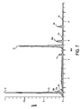
結晶相集合(イオン交換前)ならびに結晶相および残留ガラス相の質量百分率は、リートベルト解析を用いてx線回折(XRD)に基づいて決定される。 Crystalline phase aggregation (before ion exchange) and mass percentages of crystalline and residual glassy phases are determined based on x-ray diffraction (XRD) using Rietveld analysis.
破壊時にガラス-セラミックス物品が割れる破片の数を決定するために、本明細書において「破片試験」と呼ぶ以下の手順が使用される。50mm×50mm×0.8mmの寸法を有する、イオン交換されたガラス-セラミックス物品が、鋼表面上に置かれる。40gの重量を有する、炭化タングステン先端を有するスタイラス(TOSCO(登録商標)の商標および製造者識別番号No.13-378でFisher Scientific Industriesから入手可能、60°の円錐球形先端を有する)が、スタイラスを上下に動かす歯車駆動機構のクランプに接続される。スタイラスの先端はガラス-セラミックス物品と接触して置かれ、次いで、ガラス-セラミックス物品が割れるまで歯車機構が徐々に回転される。次いで、破片の数が数えられる。 To determine the number of shards that a glass-ceramic article splits upon fracture, the following procedure, referred to herein as the "shard test", is used. An ion-exchanged glass-ceramic article having dimensions of 50 mm x 50 mm x 0.8 mm is placed on the steel surface. A stylus with a tungsten carbide tip weighing 40 g (available from Fisher Scientific Industries under the TOSCO® trademark and manufacturer identification number 13-378, with a 60° conical-spherical tip) was It is connected to a gear drive clamp that moves up and down. The tip of the stylus is placed in contact with the glass-ceramic article and then the gear mechanism is gradually rotated until the glass-ceramic article breaks. The number of fragments is then counted.
破壊靭性値(K1C)は、Reddy,K.P.R.et al,“Fracture Toughness Measurement of Glass and Ceramic Materials Using Chevron-Notched Specimens,”J.Am.Ceram.Soc.,71[6],C-310-C-313(1988)に開示のシェブロンノッチ付きショートバー(CNSB)法により測定された。ただし、Bubsey,R.T.et al.,“Closed-Form Expressions for Crack-Mouth Displacement and Stress Intensity Factors for Chevron-Notched Short Bar and Short Rod Specimens Based on Experimental Compliance Measurements,”NASA Technical Memorandum 83796,pp.1-30(October 1992)の式5を用いてY*mが計算されることを除く。薄いシートについては、破壊靭性は、Nihara et al.に示された方法にしたがって荷重500gf(約4.90N)においてビッカース圧子を使用して測定することができる。
Fracture toughness values (K 1C ) are obtained from Reddy, K.; P. R. et al, "Fracture Toughness Measurement of Glass and Ceramic Materials Using Chevron-Notched Specimens,"J. Am. Ceram. Soc. , 71[6], C-310-C-313 (1988). However, Bubsey, R. T. et al. ,“Closed-Form Expressions for Crack-Mouth Displacement and Stress Intensity Factors for Chevron-Notched Short Bar and Short Rod Specimens Based on Experimental Compliance Measurements,”NASA Technical Memorandum 83796,pp. 1-30 (October 1992), Y* m is calculated using
本開示に記載のヤング率値は、ASTM E2001-13に記載の一般的なタイプの共鳴超音波スペクトロスコピー法により測定される値を指す。 Young's modulus values described in this disclosure refer to values determined by resonant ultrasonic spectroscopy methods of the general type described in ASTM E2001-13.
ガラス-セラミックス物品のヘイズは、ASTM D1003またはASTM D1044にしたがうなど、BYK Gardner Haze-Gard Iなどのヘイズメーターを使用して測定される。 Haze of glass-ceramic articles is measured using a haze meter such as the BYK Gardner Haze-Gard I, such as according to ASTM D1003 or ASTM D1044.
透過率は、本明細書において用いられるとき、全透過率を指し、150mm積分球を備えたPerkin Elmer Lambda 950 UV/VIS/NIR分光光度計を用いて測定される。広角散乱光の収集を可能にする積分球の入口ポートにサンプルが取り付けられた。積分球の出口ポート上の基準Spectralon反射ディスクにより全透過率データが収集された。全透過率のパーセント(%T)を開いたビームベースライン測定に対して計算した。
Transmittance, as used herein, refers to total transmittance and is measured using a
応力は、セラミング後のガラス-セラミックスのリタデーションとして測定され、ウィスコンシン州マディソンのStress Photonics Inc.により販売されているGFP1400(GFP=Grey Field Polarizer)により測定される。 Stress is measured as the retardation of the glass-ceramic after ceraming, available from Stress Photonics Inc., Madison, Wisconsin. GFP1400 (GFP=Gray Field Polarizer) marketed by the company.
市販のシステム(Axometrics,Inc.により販売されているシステム)またはカスタムメイドのシステムなどの他のシステムにより同様の測定が行われてよい。応力は、典型的には、セラミング後のフルシートについて測定される。測定領域は、フルシート(フルシートは、所与の例において約245×641(+/-10mm)の寸法を有する)の寸法から内向きに約5mmの領域に対応する。あるいは、応力は、セラミング後のフルシートから切り出された部品について測定することができる。シートの表面上に残っている剥離剤は、報告されるより高い応力値をもたらし得る。この剥離剤は、測定前に除去することができる(表面のブラッシングまたは洗浄)。 Similar measurements may be made by other systems, such as commercially available systems (systems sold by Axometrics, Inc.) or custom-made systems. Stress is typically measured on a full sheet after ceraming. The measurement area corresponds to an area about 5 mm inward from the dimensions of the full sheet (which in the given example has dimensions of about 245×641 (+/-10 mm)). Alternatively, stress can be measured on parts cut from the full sheet after ceraming. Release agent remaining on the surface of the sheet can result in higher stress values reported. This release agent can be removed (brushing or washing the surface) prior to measurement.
光透過は、平行平面を有する光学研磨されたサンプルに対してPerkin Elmer Lambda 950分光光度計を使用して、250~1000nmの範囲内で2nmのデータ間隔で測定される。この透過は、任意のコーティングまたは他の応用を含まないガラスセラミックス物品自体について測定される。
Light transmission is measured in the range 250-1000 nm with 2 nm data intervals using a
X線回折(XRD)は、Bruker D4 EndeavorならびにCu線およびLynxEye検出器を使用して測定される。リートベルトは、BrukerのTopasソフトウェアパッケージを使用して行われる。 X-ray diffraction (XRD) is measured using a Bruker D4 Endeavor and Cu radiation and LynxEye detectors. Rietveld is performed using Bruker's Topas software package.
ラマンデータは、Thermo Fisher製DXR2 SmartRamanを使用して測定される。 Raman data are measured using a Thermo Fisher DXR2 SmartRaman.
熱容量は、室温ならびにその間のすべての範囲および部分範囲でASTM E1461にしたがって測定される。 Heat capacity is measured according to ASTM E1461 at room temperature and all ranges and subranges therebetween.
密度は、ASTM C20にしたがって測定される。 Density is measured according to ASTM C20.
熱伝導率は、室温でASTM E1461にしたがって測定される。 Thermal conductivity is measured according to ASTM E1461 at room temperature.
光学的リタデーションは、ASTM F218-13にしたがって測定することができる。 Optical retardation can be measured according to ASTM F218-13.
特に明記されていない限り、本明細書に記載の任意の方法について、そのステップがある特定の順序で実施される必要があると解釈されることも、任意の器具に対して特定の向きが必要であることも決して意図されない。したがって、そのステップがしたがうべき順序が方法の請求項に実際に記載されていない場合、または個々の構成要素に対して順序もしくは向きが任意の器具の請求項に実際に記載されていない場合、またはある特定の順序にステップが限定されるべきであることが特許請求の範囲もしくは説明に特に具体的に記載されていない場合、または器具の構成要素に対してある特定の順序もしくは向きが記載されていない場合、いかなる点においても順序または向きが推論されることは決して意図されない。これは、解釈のための可能性のある任意の非明示的な根拠に当てはまり、この根拠には、ステップの配列に関する論理の問題、操作の流れ、構成要素の順序または構成要素の向き、文法構成または句読法から導かれる明白な意味、および本明細書に記載の実施形態の数またはタイプが含まれる。 Unless otherwise specified, any method described herein is not to be construed as requiring the steps to be performed in any particular order nor requiring a particular orientation for any instrument. It is never intended to be. Thus, if the order to be followed by the steps is not actually set forth in a method claim, or if the order or orientation for individual components is not actually set forth in any instrument claim, or Unless the claims or description specifically state that the steps are to be limited to a particular order, or that a particular order or orientation for the instrument components is stated. No order or orientation is ever intended to be inferred at any point. This applies to any possible implicit basis for interpretation, including logic issues regarding the sequence of steps, flow of operations, order or orientation of constituents, grammatical constructions. or explicit meaning derived from punctuation, and the number or type of embodiments described herein.
本明細書において用いられるとき、単数形「a」、「an」および「the」は、文脈により特に明確に定められていない限り、複数の指示対象を含む。したがって、例えば、「a」構成要素への言及は、文脈により特に明確に示されていない限り、2つ以上のそのような構成要素を有する態様を含む。 As used herein, the singular forms "a," "an," and "the" include plural referents unless the context clearly dictates otherwise. Thus, for example, reference to an "a" component includes aspects with two or more such components, unless the context clearly dictates otherwise.
本明細書において用いられる方向を示す用語-例えば上、下、右、左、前、後、上部、底部、垂直、水平-は、特に明記されていない限り、描かれている図を参照して記載されているにすぎず、絶対的な向きを意味するものではない。 Directional terms used herein--e.g., top, bottom, right, left, front, rear, top, bottom, vertical, horizontal--refer to the drawing figures, unless otherwise specified. Absolute orientation is not implied.
本明細書において用いられるとき、「撓み」および「平坦度」という用語-ならびにその任意の変形-は同義で使用され、同じ意味を有する。 As used herein, the terms "deflection" and "flatness" - and any variations thereof - are used interchangeably and have the same meaning.
本明細書において用いられる任意の範囲は、特に明示的に記載されていない限り、すべての範囲および部分範囲ならびにその間の任意の値を含む。 Any range as used herein includes all ranges and subranges and any values therebetween, unless expressly stated otherwise.
ガラス-セラミックス物品の一般的な概要
これより、(1つ以上の)好ましい本実施形態を詳細に参照し、その例は添付図面に示されている。可能な場合は常に、同じ部品または同様の部品を指すために、図面全体にわたって同じ参照番号が使用される。
GENERAL OVERVIEW OF GLASS-CERAMIC ARTICLE Reference will now be made in detail to the present preferred embodiment(s), examples of which are illustrated in the accompanying drawings. Wherever possible, the same reference numbers will be used throughout the drawings to refer to the same or like parts.
ガラス-セラミックス物品は、携帯電子デバイス用のカバー基板および/またはハウジングとしての使用のために調整することができる属性を有する。例えば、理論に縛られるものではないが、高い破壊靭性および/またはヤング率を有するガラス-セラミックス物品は、亀裂貫通に対する耐性および落下性能を与えることができる。そのようなガラス-セラミックス物品が、例えばイオン交換により、化学的に強化されると、亀裂貫通に対する耐性および落下性能をさらに向上させることができる。さらに、高い破壊靭性および/またはヤング率は、破壊時のガラス-セラミックス物品の望ましい破片化を維持しながら、化学的焼戻しによりガラス-セラミックス物品に与えることができる貯蔵引張エネルギーの量および最大中央張力を増加させることもできる。別の例として、ガラス物品をガラス-セラミックス物品に変えるために使用される加熱/セラミングスケジュールを調整することにより、ならびにガラス-セラミックス物品の特性を設計または制御するために、イオン交換によるなどして化学強化することにより、透過性およびヘイズなどのガラス-セラミックス物品の光学的特性を調整することができる。 Glass-ceramic articles have attributes that can be tailored for use as cover substrates and/or housings for portable electronic devices. For example, without being bound by theory, glass-ceramic articles having high fracture toughness and/or Young's modulus can provide resistance to crack penetration and drop performance. When such glass-ceramic articles are chemically strengthened, eg, by ion exchange, crack penetration resistance and drop performance can be further improved. In addition, high fracture toughness and/or Young's modulus increase the amount of stored tensile energy and maximum central tension that can be imparted to a glass-ceramic article by chemical tempering while maintaining desirable fragmentation of the glass-ceramic article upon fracture. can also be increased. As another example, by adjusting the heating/ceraming schedule used to transform the glass article into a glass-ceramic article, and to design or control the properties of the glass-ceramic article, such as by ion exchange. The optical properties of the glass-ceramic article, such as transparency and haze, can be adjusted by chemically strengthening with.
ガラスセラミックス物品を形成するための積層構成体
総じて、ガラス-セラミックスを生成するためのプロセスは、ガラス物品を形成するステップと、ガラス物品をガラス-セラミックス形態に変換するためにガラス物品をセラミックス化するステップとを含む。図1を参照すると、セラミングのための例の積層構成体100が示されている。積層構成体100は、2枚のセッタープレート104を支持するキャリアプレート102と、セッタープレート104の間に配置されたガラス積層体106とを含む。
LAMINATED CONSTRUCTIONS FOR FORMING GLASS- CERAMIC ARTICLES Generally, the process for producing glass-ceramics comprises the steps of forming a glass article and ceramming the glass article to convert the glass article into a glass-ceramic form. step. Referring to FIG. 1, an
いくつかの実施形態において、絶縁層(図示せず)が上側セッタープレート104の上面上および下側セッタープレート104の底面上に位置してよい。絶縁層は、低熱伝導率を有する任意の材料から形成されてよく、ガラス積層体106の上部上および底部上のガラスシート108の軸方向の温度勾配を低減またはさらに排除することができる。
In some embodiments, an insulating layer (not shown) may be located on the top surface of the
図1に示す通り、ガラス積層体106は複数のガラスシート108を含み、各ガラスシート108は、隣接するガラスシート108から剥離剤層110により分離されている。剥離剤層110は、セラミングプロセスの間、ガラス積層体106内のガラスシート108のくっつきを低減またはさらに排除する。図1に示されていないが、いくつかの実施形態において、ガラス積層体106は、ガラスシート108とセッタープレート104の間に剥離剤層110をさらに含んでよい。以下に記載の様々な実施形態においてなど、他の実施形態において、セッタープレート104は、ガラスシート108と反応しない材料から作製されており、ガラスシート108とセッタープレート104の間の相互作用を防ぐために剥離剤層110は必要ではない。
As shown in FIG. 1, the
総じて、ガラス-セラミックスを生成するために、ガラス積層体106は、その徐冷点を上回る温度で、結晶核を生じるのに十分な時間加熱される(「核形成」とも呼ばれる)。この熱処理は、例えば徐冷窯内または炉内で実施することができる。その徐冷点を上回って加熱された後、次いで、ガラスは、結晶相を生じるために、通常はガラス徐冷点とガラス軟化点の間のより高い温度で、さらに加熱される(「成長」または「結晶化」とも呼ばれる)。様々な実施形態において、この熱処理、またはセラミングプロセスは、ガラス積層体を核形成温度まで加熱するステップと、核形成温度を所定の時間の間維持するステップと、ガラス積層体を結晶化温度まで加熱するステップと、結晶化温度を所定の時間の間維持するステップとを含む。
In general, to produce a glass-ceramic, the
ガラスシート108は、ガラス-セラミックス物品の形成に適している任意のガラス組成物から作製されてよいが、ガラスシート108のガラス組成物はガラス-セラミックス物品の機械的特性および光学的特性に影響を与える可能性があることが理解されるべきである。様々な実施形態において、得られるガラス-セラミックス物品がペタライト結晶相とケイ酸リチウム結晶相とを有し、かつペタライト結晶相およびケイ酸リチウム結晶相が、ガラス-セラミックス物品中に存在する他の結晶相よりも高い質量百分率を有するようにガラス組成物は選択される。
積層構成体100について全般的に説明したが、これより、積層構成体100の構成要素に関してさらなる詳細を記載する。
Having generally described the
キャリアプレート
様々な実施形態において、キャリアプレート102は、2枚以上のセッタープレート104を支持する。キャリアプレート102の構造および材料は、積層構成体100内のその上に負荷されたガラスシートの熱均一性を制御するように選択されてよい。いくつかの実施形態では、キャリアプレート102は(図2に示された)開いたキャリア設計を有するが、他の実施形態では、キャリアプレート102は(図3に示された)閉じたキャリア設計を有する。図2に示された実施形態では、キャリアプレート102は、およそ17%の固体金属(例えば、鋼)であるが、図3に示された実施形態では、キャリアプレート102は、およそ45%の固体金属を含む反応結合炭化ケイ素ビームで作製された中空プレートである。
Carrier Plate In various embodiments,
キャリアプレートの熱影響を評価するため、キャリアプレート上の9個の積層体および各積層体内の23枚のガラスシートならびに反応結合炭化ケイ素から作製された8mmセッタープレートに対して生産スケールの能力を仮定した熱モデルが実行された。図4のモデル化されたデータに示す通り、中空キャリアプレート上のガラス積層体は、熱伝達によって、開いた鋼キャリアプレート上のガラス積層体と比べて低い熱均一性を示す。特に、炭化ケイ素ビームで作製されたキャリア(図3)については、ガラス温度が低いごく初期の加熱段階を除いて、開いた鋼グリッド設計で作製されたキャリア(図2)と比べてより大きいガラス積層体温度変動が予想される。加えて、キャリアプレートによる直接放射の遮断は、反応結合炭化ケイ素が鋼よりも良い熱伝導体であるにも関わらず、全加熱時間を増加させる。 To evaluate the thermal effects of the carrier plate, assume production scale capability for 9 laminates on the carrier plate and 23 glass sheets in each laminate and an 8 mm setter plate made from reaction-bonded silicon carbide. A thermal model was run. As shown in the modeled data in FIG. 4, glass laminates on hollow carrier plates exhibit lower thermal uniformity due to heat transfer than glass laminates on open steel carrier plates. In particular, for carriers made with silicon carbide beams (Fig. 3), except for the very initial heating stage when the glass temperature is low, the glass is larger than the carrier made with the open steel grid design (Fig. 2). Laminate temperature fluctuations are to be expected. In addition, blocking direct radiation by the carrier plate increases the total heating time even though reaction-bonded silicon carbide is a better heat conductor than steel.
したがって、様々な設計および材料がキャリアプレート102に使用されてよいが、様々な実施形態において、キャリアプレートは鋼から作製されており、図2に示す通り開いたグリッド設計を有する。
Accordingly, although various designs and materials may be used for the
セッタープレート
図1に示す通り、様々な実施形態において、キャリアプレート102は、少なくとも2枚のセッタープレート104を支持する。例えば、図1に示された実施形態は、単一のガラス積層体106、ならびにガラス積層体106の上方のセッタープレート104と、ガラス積層体106とキャリアプレート102の間のセッタープレート104とを含むが、ガラス積層体106内に配置されるように、かつ/または各ガラス積層体106がガラス積層体106の上方の少なくとも1枚のセッタープレート104と、ガラス積層体106とキャリアプレート102の間のセッタープレート104とを有する複数のガラス積層体106をキャリアプレート102上に配置することにより、追加のセッタープレート104が含まれてよいことが企図される。
Setter Plates As shown in FIG. 1, in various embodiments,
従来のセラミックス化プロセスのほとんどは、セッタープレートを形成するためにセラミックスの耐熱材料を利用するが、そのような材料には熱伝達および熱容量に限界があり、それによってそのような材料は、ある種の用途に望ましい、または必要な高い光学的品質を生み出すのに不適当になる。加えて、そのような材料から作製されたセッタープレートは、熱膨張、酸化、およびクリープを経る可能性があり、これがひいてはガラスセラミックス物品内の撓みにつながる可能性がある。 Most conventional ceramization processes utilize ceramic refractory materials to form the setter plate, but such materials have heat transfer and heat capacity limitations whereby such materials are are unsuitable for producing the high optical quality desired or required for applications such as In addition, setter plates made from such materials can undergo thermal expansion, oxidation, and creep, which in turn can lead to deflection within the glass-ceramic article.
さらに、ガラス積層体106を結合するセッタープレート104は、加熱要素からの放射熱を拡散する水平方向の熱伝達経路を提供し、これは、面内のガラスシート温度変動を低減し得る。温度変動の最小化は、ひいてはガラスセラミックス物品内の面内応力および撓みの減少につながり得る。したがって、様々な実施形態において、セッタープレート104は、ガラスシート温度変動の減少を最大化するように選択される。特に、セッタープレート104は、特定の比熱容量、密度、および熱拡散率を有するように選択される。
In addition, the
様々な実施形態によれば、セッタープレートは、室温でASTM E1461にしたがって測定された約670J/kg*K~約850J/kg*Kの比熱容量(cp)を有する。例えば、セッタープレートは、室温でASTM E1461にしたがって測定された約670J/kg*K~約850J/kg*K、約670J/kg*K~約800J/kg*K、約670J/kg*K~約750J/kg*K、または約670J/kg*K~約700J/kg*Kならびにその間のすべての範囲および部分範囲の比熱容量を有してよい。理論に縛られるものではないが、比熱容量がこの範囲外であるとき、この材料は適切な速度で熱を放出したり熱を受け取ったりすることができず、これは、積層構成体内のガラス内に応力、および撓みを引き起こすと考えられる。 According to various embodiments, the setter plate has a specific heat capacity (c p ) of about 670 J/kg*K to about 850 J/kg*K measured according to ASTM E1461 at room temperature. For example, the setter plate has a strength of about 670 J/kg*K to about 850 J/kg*K, about 670 J/kg*K to about 800 J/kg*K, about 670 J/kg*K to about 670 J/kg*K, measured according to ASTM E1461 at room temperature. It may have a specific heat capacity of about 750 J/kg*K, or from about 670 J/kg*K to about 700 J/kg*K and all ranges and subranges therebetween. Without wishing to be bound by theory, when the specific heat capacity is outside this range, the material cannot release or receive heat at an adequate rate, which is the is thought to cause stress and deflection in the
様々な実施形態におけるセッタープレートは追加的または代替的に、ASTM C20にしたがって測定された約2500kg/m3超の嵩密度を有するように選択されてよい。例えば、セッタープレートは、ASTM C20にしたがって測定された約2500kg/m3~約4000kg/m3、約2750kg/m3~約3750kg/m3、または約3000kg/m3~約3500kg/m3ならびにその間のすべての範囲および部分範囲の嵩密度を有してよい。理論に縛られるものではないが、この範囲内の嵩密度を有する材料は低気孔率を有し、積層体内の重量を著しく増加させないと考えられる。低すぎる嵩密度が、経時的な材料劣化および材料の使用寿命の短縮につながる可能性があるのに対し、高すぎる嵩密度は、ガラスに対する力の増加によって、積層体内の応力をもたらす可能性がある。 The setter plate in various embodiments may additionally or alternatively be selected to have a bulk density greater than about 2500 kg/m 3 measured according to ASTM C20. For example, the setter plate can weigh from about 2500 kg/m 3 to about 4000 kg/m 3 , from about 2750 kg/m 3 to about 3750 kg/m 3 , or from about 3000 kg/m 3 to about 3500 kg/m 3 measured according to ASTM C20 and It may have bulk densities in all ranges and subranges therebetween. While not wishing to be bound by theory, it is believed that materials with bulk densities within this range have low porosity and do not significantly add weight within the laminate. A bulk density that is too low can lead to material degradation over time and a shortened useful life of the material, whereas a bulk density that is too high can lead to stress in the laminate due to increased forces on the glass. be.
さらに、様々な実施形態において、セッタープレートは、約2.50×10-5m2/s超の熱拡散率を有する。例えば、セッタープレートは、約2.50×10-5m2/s~約5.50×10-4m2/s、約3.0×10-5m2/s~約5.00×10-4m2/s、約4.0×10-5m2/s~約4.50×10-4m2/s、約4.50×10-5m2/s~約4.00×10-4m2/s、約5.00×10-5m2/s~約3.50×10-4m2/s、約5.50×10-5m2/s~約3.00×10-4m2/s、約6.00×10-5m2/s~約2.50×10-4m2/s、約6.50×10-5m2/s~約2.0×10-4m2/s、約7.00×10-5m2/s~約2.00×10-4m2/s、または約7.50×10-5m2/s~約1.50×10-4m2/sならびにその間のすべての範囲および部分範囲の熱拡散率を有してよい。理論に縛られるものではないが、熱拡散率が低すぎる場合、材料は、加熱および冷却にかかる時間が長くなりすぎて積層体内に温度勾配を引き起こし、これは、応力および撓みをもたらすことになる。しかし、熱拡散率が高すぎる場合、積層体内に温度勾配を与えるため、これも応力をもたらし得る。セッタープレートと接触したガラスシートは、積層体の中心にあるガラスシートとは対照的に、異なる速度で熱伝達により影響されるであろう。熱拡散率αは、以下の式にしたがって定義することができる:
a=k/ρcp
(式中、kは熱伝導率(W/m*K)であり、ρは密度(kg/m3)であり、cpは比熱容量(J/kg*K)である)。
Further, in various embodiments, the setter plate has a thermal diffusivity greater than about 2.50×10 −5 m 2 /s. For example, the setter plate can be from about 2.50×10 −5 m 2 /s to about 5.50×10 −4 m 2 /s, from about 3.0×10 −5 m 2 /s to about 5.00× 10 −4 m 2 /s, about 4.0×10 −5 m 2 /s to about 4.50×10 −4 m 2 /s, about 4.50×10 −5 m 2 /s to about 4.50×10 −4
a=k/ρc p
where k is the thermal conductivity (W/m*K), ρ is the density (kg/m 3 ), and cp is the specific heat capacity (J/kg*K).
したがって、様々な実施形態において、セッタープレートは、室温でASTM E1461にしたがって測定された約100W/m-K超、約125W/m-K超、約150W/m-K超、約175W/m-K超、またはさらに約180W/m-K超の熱伝導率(k)を有する。例えば、セッタープレートは、室温でASTM E1461にしたがって測定された約100W/m-K~約350W/m-K、約125W/m-K~約325W/m-K、約150W/m-K~約300W/m-K、約175W/m-K~約275W/m-K、または約180W/m-K~約250W/m-Kならびにその間のすべての範囲および部分範囲の熱伝導率を有してよい。理論に縛られるものではないが、高すぎる、または低すぎる熱伝導率は、積層体内の温度勾配を誘起して応力および撓みをもたらす可能性がある。 Thus, in various embodiments, the setter plate has a power of greater than about 100 W/m-K, greater than about 125 W/m-K, greater than about 150 W/m-K, greater than about 175 W/m-K, measured according to ASTM E1461 at room temperature. It has a thermal conductivity (k) greater than K, or even greater than about 180 W/m-K. For example, the setter plate may be about 100 W/m-K to about 350 W/m-K, about 125 W/m-K to about 325 W/m-K, about 150 W/m-K to about 150 W/m-K measured according to ASTM E1461 at room temperature. having a thermal conductivity of about 300 W/m-K, about 175 W/m-K to about 275 W/m-K, or about 180 W/m-K to about 250 W/m-K and all ranges and subranges therebetween; You can Without wishing to be bound by theory, too high or too low a thermal conductivity can induce temperature gradients within the laminate, resulting in stresses and deflections.
所望の比熱容量、密度、および熱拡散率を有する様々な材料は、本明細書に記載のセッタープレートの形成における使用に適しているであろう。使用に特に適している一例の材料は反応結合炭化ケイ素(SiSiC)である。実施形態において、セッタープレート104は、約85質量%~約90質量%の反応結合炭化ケイ素を含んでよい。セッタープレート104は、約10質量%~約15質量%のケイ素金属(Si)と、結合剤とをさらに含んでよい。セッタープレート104の形成における使用に適しているであろう市販の反応結合炭化ケイ素製品には、限定ではなく例として、Saint-Gobain Ceramic Materialsから入手可能なCRYSTAR RB(商標)が含まれ得る。
A variety of materials having the desired specific heat capacity, density, and thermal diffusivity would be suitable for use in forming the setter plates described herein. One material that is particularly suitable for use is reaction-bonded silicon carbide (SiSiC). In embodiments, the
セッタープレートを形成するために使用される材料の熱特性の影響を確認する目的で、8mmの厚さを有するセッタープレートを形成するために3つの異なる材料が使用された。特に、実施例Aは反応結合炭化ケイ素から形成され、比較例1は窒化物結合炭化ケイ素を使用して形成され、比較例2はケイ素耐火ボードを使用して形成された。これらの材料のそれぞれの熱特性は表1に記載されている。 Three different materials were used to form setter plates having a thickness of 8 mm in order to ascertain the effect of the thermal properties of the materials used to form the setter plates. Specifically, Example A was formed from reaction-bonded silicon carbide, Comparative Example 1 was formed using nitride-bonded silicon carbide, and Comparative Example 2 was formed using silicon refractory board. The thermal properties of each of these materials are listed in Table 1.

加熱ランプアップの間のガラス積層体のΔTが測定された。結果は図5に示されている。特に、図5に示す通り、反応結合炭化ケイ素は、プロセスの間の加熱時間の減少およびΔTの減少を示す。ケイ素耐火ボードから形成されたセッタープレートを使用した比較例2は、より著しく大きい温度変動を示した。その理由は、ほぼ間違いなくこれが不十分な熱伝導体であるからである。しかし、実施例Aおよび比較例1(窒化物結合炭化ケイ素)のより大きい熱拡散率は、より均一な温度を示した。 The ΔT of the glass laminate during heat ramp-up was measured. Results are shown in FIG. In particular, as shown in FIG. 5, reaction-bonded silicon carbide exhibits reduced heating time and reduced ΔT during the process. Comparative Example 2, which used a setter plate formed from silicon refractory board, showed significantly greater temperature fluctuations. The reason is most likely that it is a poor heat conductor. However, the higher thermal diffusivities of Example A and Comparative Example 1 (nitride-bonded silicon carbide) indicated a more uniform temperature.
ガラス積層体内の温度変動の減少に加えて、様々な実施形態のセッタープレート104は、従来の材料と比べてより低い応力を与える材料から作製されている。例えば、反応結合炭化ケイ素の熱拡散率は、セラミング熱処理後のガラスセラミックス物品内に、従来のセッタープレート材料と比べてより低い応力を与える。図6に示す通り、反応結合炭化ケイ素は、積層体(グラフの左手側)に対して、ケイ素耐火ボードセッタープレートと接触した積層体(グラフの右手側)と比べてより低い最大応力を生じた。理論に縛られるものではないが、反応結合炭化ケイ素の熱拡散率の結果生じる温度デルタの減少は、ガラスセラミックス物品内で結晶を成長させ、相転移が起こるため、ガラスセラミックス物品内の応力を減少させると考えられる。応力減少は、ガラスセラミックス物品内の撓みに直接影響を与える。特に、応力の増加は、ガラスセラミックス物品内のより大きい撓みを誘起し、それによってガラスセラミックス物品が、ハンドヘルド電子ディスプレイなどのある種の用途には使用不能になる可能性がある。しかし、反応結合炭化ケイ素の使用は、ガラスセラミックス物品内の応力を減少させ、それによって最終製品内の低撓みを実現する。
In addition to reducing temperature fluctuations within the glass laminate, the
様々な実施形態において、セッタープレート104を形成するために使用される材料は、キャリアプレート102とガラスセラミックス物品の両方との反応性がその材料にないことに基づいてさらに選択される。反応結合炭化ケイ素は、キャリアプレート102を形成するために典型的に使用される材料との低反応を示すまたはさらに無反応の一例の材料である。特に、ステンレス鋼合金およびNi基超合金金属キャリアプレートと接触した、反応結合炭化ケイ素から作製されたセッタープレートが空気中、最高800℃まで24時間および100時間試験された。図7に示す通り、SEM(走査電子顕微鏡)およびEDX試験は、反応結合炭化ケイ素とのこれらの金属の反応がないことを示した。具体的には、キャリアプレート表面上に見出されるSiがないことは、反応結合炭化ケイ素ミクロ構造内の遊離Siとの反応がないことを示した。
In various embodiments, the material used to form the
さらに、熱的セラミングプロセスの間の反応結合炭化ケイ素材料と接触したLi基ガラスセラミックスは、XRD相集合特性評価によれば、いかなる表皮効果も示さない。例えば、図8に示す通り、反応結合炭化ケイ素セッタープレートと接触したガラス(A)は、バルクガラス(B)と相が似ている。 Furthermore, Li-based glass-ceramics in contact with reaction-bonded silicon carbide materials during the thermal ceraming process do not exhibit any skin effect according to XRD phase aggregation characterization. For example, as shown in FIG. 8, glass (A) in contact with a reaction-bonded silicon carbide setter plate is similar in phase to bulk glass (B).
他の材料と比べて熱特性を改善したことに加えて、反応結合炭化ケイ素は低気孔率(<1%)を有し、これは、他の要素および材料による拡散を通じた酸化、亀裂、および反応性に対する耐性の向上によって、熱サイクルの間のセッタープレートの寿命を延ばすことができる。 In addition to improved thermal properties compared to other materials, reaction-bonded silicon carbide has a low porosity (<1%), which is resistant to oxidation, cracking, and cracking through diffusion by other elements and materials. Improved resistance to reactivity can extend setter plate life during thermal cycling.
様々な実施形態において、セッタープレート104はまた、ガラスセラミックス物品内の撓みを減少させる寸法にされる。特に、セッタープレート104の厚さおよびセッタープレート104の平坦度は、ガラスセラミックス内の撓みと応力の両方を減少させるように制御される。
In various embodiments, the
セラミングプロセスの間、セッタープレート104と接触している、ガラス積層体106を形成するガラスシート108は、移動して、セッタープレート104の平坦度に沿う。様々な実施形態において、セッタープレート104は、形成後に特定の平坦度を得るために機械加工されてよい。本明細書において用いられるとき、「平坦度」という用語は、その中に表面が存在する2つの平行な平面により画定される許容域を指す。例えば、100μmの平坦度は、100μm以下離れている2つの平行な平面の間に表面全体が存在しなければならないことを意味する。ガラスセラミックス物品の平坦度に対するセッタープレート104の平坦度の影響が図9に示されている。具体的には、図9に示す通り、700μmの平坦度を有するセッタープレートと比べて100μmの平坦度を有するセッタープレートについて、ガラスセラミックス物品の最大撓みは減少する。
During the ceramicming process, the
図9はさらに、追加の重量(例えば、サンプルセット1において使用された重量の2倍)を使用しても撓みがさほど減少しないことを示す。例えば、サンプルセット1、サンプルセット2、およびサンプルセット3のそれぞれについて、各セットの最初の5つのサンプルは、100μmの平坦度を有するセッターを使用して実施されたが、各セットの最後の5つのサンプルは、700μmの平坦度を有するセッターを使用して実施された。2倍の重量を有していたサンプルセット1を、そのそれぞれが等しい重量を有するサンプルセット2および3と比べることによって示される通り、より平坦なセッターは、重量とは無関係にほぼ同じ量まで撓みを減少させた。 FIG. 9 further shows that using additional weight (eg, twice the weight used in sample set 1) does not significantly reduce deflection. For example, for each of sample set 1, sample set 2, and sample set 3, the first 5 samples of each set were run using a setter with a flatness of 100 μm, whereas the last 5 samples of each set One sample was run using a setter with a flatness of 700 μm. As shown by comparing sample set 1, which had twice the weight, with sample sets 2 and 3, each of which had an equal weight, the flatter setter deflected to about the same amount regardless of weight. decreased.
様々な実施形態において、セッタープレート104は、約100μm以下、約75μm以下、約50μm以下、約45μm以下、約40μm以下、約35μm以下、約30μm以下、またはさらに約25μm以下の最大平坦度を有する。
In various embodiments, the
平坦度は、CMMならびに接触および/または非接触プローブを使用して測定することができる。様々な実施形態において、測定密度は、掃引軌道全体にわたって1点/mmであり、測定領域は、セッタープレートの側部から内向きに約10mmである。アラインメントの起点は、図10に示す通り、より短い縁部の中央にある。起点の位置を決めるために、CMMはセッタープレート104のコーナーを見つけ、2つのコーナー間の距離を計算する。起点は、この距離を2で割ったものである。検査の領域を決定するために、プローブは、起点のセッタープレートの縁部から内向きに水平に10mm移動する。次いで、プローブは、開始点まで上向きに約325mm移動する。掃引は、その点から始まる。各ライン間の間隔は約15mmであり、セッタープレートは、図10に示す通り、蛇行パターンで走査される。平坦度は、最小領域法を使用してCMMにより評価される。
Flatness can be measured using a CMM and contact and/or non-contact probes. In various embodiments, the measured density is 1 point/mm over the sweep trajectory and the measured area is about 10 mm inward from the side of the setter plate. The origin of alignment is in the middle of the shorter edge as shown in FIG. To locate the origin, the CMM finds the corners of the
(図1に示された)セッタープレート104の厚さtは、ガラス積層体106上のセッタープレート104の熱効果を撓みの誘起と少なくとも部分的に釣り合わせるように選択される。特に、この厚さは、熱伝達および均一性のためには最小化されるべきであるが、強度および耐撓み性のためには最大化されるべきである。したがって、様々な実施形態において、セッタープレート104は、約6.5mm~約10mm、または約7mm~約9.5mm、または約7.5mm~約9mm、または約7.9mm~約8.2mmならびにその間のすべての範囲および部分範囲の厚さtを有する。
The thickness t of the setter plate 104 (shown in FIG. 1) is selected to at least partially balance the thermal effects of the
セッタープレート104を形成するために使用される材料の密度およびセッタープレート104の厚さはさらに、ガラス積層体106に対する印加力に基づいて選択されてよい。図11は、ガラス積層体に対する追加の力がガラスセラミックス物品内の応力の増加にどのように寄与し得るかを示す。特に、図11に示す通り、重量の追加は、撓みを改善しなかった(例えば、最大撓みを減少させなかった)だけでなく、ガラス積層体内の様々な点において最大応力をさらに増加させた。理論に縛られるものではないが、追加の力の付加は、収縮が起こるセラミングプロセスの間、ガラスシートを拘束すると考えられる。したがって、セラミングプロセスの間自由に移動する材料の能力は、ガラスセラミックス物品内の撓みを減少させると考えられる。様々な実施形態において、反応結合炭化ケイ素から作製されたセッタープレート104は、低印加力を維持しながら良好な熱伝達を実現し、それによってガラスセラミックス物品内の低撓みおよび低応力をもたらすことができる。
The density of the material used to form the
剥離剤層
本明細書で上述の通り、様々な実施形態において、剥離剤層110は、ガラス積層体106内の隣接するガラスシート108の間に堆積される。いくつかの実施形態において、剥離剤層110は、セッタープレート104とガラス積層体106の間に堆積されてもよい。例えば、剥離剤層110は、セッタープレート104の上にコーティングされてよく、またはガラス積層体106の上部および/または底部にあるガラスシート108の表面上に堆積されてよい。
Release Agent Layer As described herein above, in various embodiments, a
様々な実施形態において、剥離剤層110は、剥離剤組成物から形成され、剥離剤組成物は、窒化ホウ素とコロイド状無機結合剤とを含む水性分散物を含む。実施形態において、剥離剤組成物は揮発性有機溶媒を実質的に含まない。したがって、剥離剤組成物を使用するプロセスは、アルコール系製品を使用する従来のプロセスよりも有害でない廃棄物を生じ得る。
In various embodiments, the
様々な実施形態によれば、剥離剤組成物は、潤滑剤として窒化ホウ素を含む。窒化ホウ素の使用は、高温(例えば、>500℃)用途において剥離剤組成物が使用されることを可能にし、これは、代替の潤滑剤では可能ではないことがある。加えて、窒化ホウ素は、その潤滑特性をセラミングプロセス全体にわたって維持するため、様々な実施形態における潤滑剤としての使用に特に非常に適していることがある。様々な実施形態の剥離剤組成物中、窒化ホウ素は、約2μm~約4μmの平均粒径を有する凝集粒子の形態で存在する。この粒径は、使用される特定の実施形態に応じて様々であってよいが、総じて、表面粗さを低減し、超薄(例えば、乾燥重量2gsm(2g/m2))コーティング層の形成を可能にするために約4μmを超えるべきではない。 According to various embodiments, the release agent composition includes boron nitride as a lubricant. The use of boron nitride allows the release agent composition to be used in high temperature (eg, >500° C.) applications, which may not be possible with alternative lubricants. In addition, boron nitride may be particularly well suited for use as a lubricant in various embodiments as it maintains its lubricating properties throughout the ceraming process. Boron nitride is present in the release agent composition of various embodiments in the form of agglomerated particles having an average particle size of about 2 μm to about 4 μm. This particle size may vary depending on the particular embodiment used, but generally reduces surface roughness and forms ultra-thin (e.g., 2 gsm dry weight (2 g/m 2 )) coating layers. should not exceed about 4 μm to allow for
上述の通り、剥離剤組成物はコロイド状無機結合剤をさらに含む。コロイド状無機結合剤には、限定ではなく例として、酸化アルミニウム(AlOx)が含まれてよい。熱処理(例えば、セラミング)プロセスの間に完全に分解しないことを条件として他のコロイド状無機結合剤が使用されてよい。 As noted above, the release agent composition further comprises a colloidal inorganic binder. Colloidal inorganic binders may include, by way of example and not limitation, aluminum oxide (AlOx). Other colloidal inorganic binders may be used provided they do not completely decompose during the heat treatment (eg, ceraming) process.
いくつかの実施形態において、剥離剤組成物は、任意選択で、1つ以上の分散剤または他の添加剤を含んでよい。例えば、抗菌添加剤が使用されてよい。適した分散剤には、硝酸または当技術分野において使用される既知の他の分散剤が含まれる。しかし、他の実施形態において、剥離剤層110とガラスシート108および/またはセッタープレート104の間の反応の可能性を低減するために、剥離剤組成物は、追加の成分を実質的に含まなくてよい。
In some embodiments, the release agent composition may optionally contain one or more dispersants or other additives. For example, antimicrobial additives may be used. Suitable dispersants include nitric acid or other known dispersants used in the art. However, in other embodiments, the release agent composition is substantially free of additional components to reduce the likelihood of reactions between the
剥離剤組成物は、シリンジを使用して所定の体積の剥離剤組成物を抜き取り、その体積を秤量して測定された約1.0~約1.2の比重を有する。具体的には、比重を測定するために、20mLシリンジを使用して約10mLの剥離剤組成物をシリンジに引き入れ、押し戻して気泡を排除する。次いで、シリンジをきれいに拭き、秤の上に置き、秤をゼロにする。次いで、ちょうど20mLの剥離剤組成物をシリンジに引き入れ、シリンジをきれいに拭き、秤の上に置いて、シリンジ内のg単位の重量を得る。次いで、重量を20で割って比重を得る。 The release agent composition has a specific gravity of about 1.0 to about 1.2, measured by drawing a predetermined volume of the release agent composition using a syringe and weighing the volume. Specifically, to measure the specific gravity, a 20 mL syringe is used to draw approximately 10 mL of the stripper composition into the syringe and push back to eliminate air bubbles. The syringe is then wiped clean, placed on a scale, and the scale is zeroed. Then, draw exactly 20 mL of the stripper composition into the syringe, wipe the syringe clean, and place it on a scale to obtain the weight in grams in the syringe. The weight is then divided by 20 to obtain the specific gravity.
追加的または代替的に、様々な実施形態において、剥離剤組成物は、Brookfield DV2TLV粘度計、4スピンドルで測定された約120センチポアズ(cP)~約160cP(約120mPa・s~約160mPa・s)ならびにその間のすべての範囲および部分範囲の粘度を有する。粘度は、特定の実施形態に応じて様々であってよいが、160cP(160mPa・s)超または120cP(120mPa・s)未満の粘度は、ガラスシートへのこの組成物の塗布に悪影響を与えることがあり、むらのある剥離剤層につながる恐れがある。 Additionally or alternatively, in various embodiments, the release agent composition has a viscosity of about 120 centipoise (cP) to about 160 cP (about 120 mPa·s to about 160 mPa·s) measured with a Brookfield DV2TLV viscometer, 4 spindles. and all ranges and subranges of viscosity therebetween. Viscosity may vary depending on the particular embodiment, but viscosities greater than 160 cP (160 mPa-s) or less than 120 cP (120 mPa-s) may adversely affect application of the composition to glass sheets. , which can lead to an uneven release agent layer.
様々な実施形態において、剥離剤組成物は、約3~約5ならびにその間のすべての範囲および部分範囲のpHを有する。特に、剥離剤組成物がこの範囲内のpHを有するとき、この組成物は、表面のピッティングまたはエッチングに対する懸念なく、ガラスシートの表面への塗布と適合する。適した市販の剥離剤には、Zyp Coatings(テネシー州)から入手可能な剥離剤が含まれる。 In various embodiments, the stripper composition has a pH of about 3 to about 5 and all ranges and subranges therebetween. In particular, when the stripper composition has a pH within this range, the composition is compatible with application to the surface of glass sheets without concern for surface pitting or etching. Suitable commercially available release agents include release agents available from Zyp Coatings (Tennessee).
上述の通り、剥離剤組成物は、剥離剤層110を形成するためにガラスシート108および/またはセッタープレート104の1つ以上の表面に塗布されてよい。様々な実施形態において、剥離剤組成物は、回転噴霧および/またはエアアシストスプレー分散などのスプレー分散法により塗布される。理論に縛られるものではないが、ローラーコーティング、ディッピング、および超音波粉末塗布を含むがこれらに限定されない他の塗布法は、様々な実施形態により所望の層厚さおよび所望の均一性を実現することができないと考えられる。したがって、様々な実施形態において、約2gsm~約6gsm(約2g/m2~約6g/m2)ならびにその間のすべての範囲および部分範囲の乾燥コート重量を有する剥離剤層110を形成するために剥離剤組成物は乾燥される。剥離剤層110の厚さは、特定の実施形態に応じて様々であり得るが、約2gsm(約2g/m2)未満の乾燥コート重量は、くっつきのリスクを増加させ得ることが総じて予想される。加えて、様々な実施形態において、剥離剤層110は、ガラスシート108および/またはセッタープレート104の表面上で実質的に均一な分布を有する。
As noted above, a release agent composition may be applied to one or more surfaces of
本明細書に記載の実施形態において、コーティング均一性は、Paul N.Gardner Company,Inc.製BYK Haze-Gard Plus測定器を使用して、ASTM D1003(透過)およびASTM D1044(ヘイズ)にしたがってヘイズパーセントおよび透過率パーセントによって特徴付けられた。Haze-Gard Plusは、全透過率、ヘイズおよび透明性を直接決定することができる。この測定器は、6774Kの相関色温度を有する平均昼光に相当するイルミナントC光源を利用する。様々な実施形態において、その1つの表面上に剥離剤層110を有するセラミックス化されたガラスシート100は、ASTM D1003にしたがって測定された約76%~約83%の透過パーセントと、ASTM D1044にしたがって測定された約25%~約38%のヘイズパーセントとを有する。
In embodiments described herein, coating uniformity is measured by Paul N. et al. Gardner Company, Inc. It was characterized by percent haze and percent transmission according to ASTM D1003 (transmittance) and ASTM D1044 (haze) using a BYK Haze-Gard Plus instrument manufactured by Epson. Haze-Gard Plus can directly determine total transmittance, haze and transparency. This instrument utilizes an Illuminant C light source that corresponds to average daylight with a correlated color temperature of 6774K. In various embodiments, the
図12は、サンプルの許容性(x軸)に対する透過パーセント(y軸)のプロットである。特に、透過パーセントは、剥離剤層を含むLi基ガラスセラミックス物品について示されている。図12に示す通り、厚すぎる(例えば、約6gsm(約6g/m2)超の)コーティングは、70%未満の透過パーセントを示す一方、薄すぎる(例えば、約2gsm(約2g/m2)未満の)コーティングは、約85%の透過パーセントを示すが、ガラスは、隣接するガラスシートにくっつく。しかし、その他の点では許容されるサンプルは、ASTM D1003にしたがって測定された約76%~約83%の透過パーセントを示した。 FIG. 12 is a plot of percent transmission (y-axis) against sample acceptability (x-axis). In particular, percent transmission is shown for Li-based glass-ceramic articles that include a release agent layer. As shown in FIG. 12, coatings that are too thick (e.g., greater than about 6 gsm (about 6 g/m 2 )) exhibit a percent transmission of less than 70%, while coatings that are too thin (e.g., about 2 gsm (about 2 g/m 2 ) less) coating shows a percent transmission of about 85%, but the glass sticks to the adjacent glass sheet. However, the otherwise acceptable samples exhibited a percent transmission of about 76% to about 83% measured according to ASTM D1003.
図13は、サンプルの許容性(x軸)に対するヘイズパーセント(y軸)のプロットである。厚すぎる(例えば、約6gsm(約6g/m2)超の)コーティングを有するサンプルについては、ヘイズパーセントは約40%超であったが、薄すぎる(例えば、約2gsm(約2g/m2)未満の)コーティングを有していたサンプルについては、ヘイズパーセントは約25%未満であり、このサンプルはくっつきを示した。しかし、その他の点では許容されるサンプルは、ASTM D1044にしたがって測定された約25%~約38%のヘイズパーセントを示した。 FIG. 13 is a plot of percent haze (y-axis) against sample acceptability (x-axis). For samples with coatings that were too thick (e.g., greater than about 6 gsm (about 6 g/m 2 )), the percent haze was greater than about 40%, but too thin (e.g., about 2 gsm (about 2 g/m 2 )). For the sample that had the coating (less than 25%), the percent haze was less than about 25%, indicating sticking. However, the otherwise acceptable samples exhibited percent haze of about 25% to about 38% measured according to ASTM D1044.
様々な実施形態において、剥離剤層110を含むガラスセラミックス物品は、剥離剤層110を含まずに形成されたガラスセラミックス物品よりも小さい撓みを示す。言い換えれば、ガラスシート108と、隣接するガラスシート108および/またはセッタープレート104の間のくっつきを低減することに加えて、剥離剤層110は、最終ガラスセラミックス物品内の撓みを減少させることができる。理論に縛られるものではないが、本明細書に記載の剥離剤層110の塗布は、ガラスセラミックス物品内の撓みに寄与する局部的なくっつきを防ぐことができると考えられる。特に、セラミングプロセスの間、ガラスは、相変化および結晶成長の間に収縮を経て、剥離剤層110の存在は、ガラスがガラス積層体106内を拘束されずに自由に移動することを可能にする。
In various embodiments, glass-ceramic articles including
図14は、ガラス積層位置(x軸)に応じた最大撓み(μm単位;y軸)のグラフである。コーティングは、スプレーヘッド間隔1.5インチ(約3.8cm)(実線)およびスプレーヘッド間隔3.0インチ(約7.6cm)(点線)で塗布された。図14は、ガラス積層体の底部(左)からガラス積層体の上部(右)へと最大撓みが増加することを示す。加えて、コーティング層の厚さおよび均一性のわずかな分散を伴ってコーティングが塗布された実施形態(スプレーヘッド間隔3.0インチ(約7.6cm))では、スプレーヘッド間隔1.5インチ(約3.8cm)で約2gsm(約2g/m2)の乾燥コート重量のコーティング層の均一な塗布と比べて、ガラス積層体の厚さ全体にわたって最大撓みが増加する。したがって、図14に示されたデータにより示されるように、くっつきは、ガラスセラミックス物品のより低い収率および物理的劣化の原因となり、局部的なスティクションはガラスを拘束し、これは最終製品内の撓みを増加させる。 FIG. 14 is a graph of maximum deflection (in μm; y-axis) as a function of glass lamination position (x-axis). The coatings were applied with a spray head spacing of 1.5 inches (about 3.8 cm) (solid line) and a spray head spacing of 3.0 inches (about 7.6 cm) (dotted line). FIG. 14 shows that the maximum deflection increases from the bottom of the glass laminate (left) to the top of the glass laminate (right). In addition, in the embodiment where the coating was applied with slight variance in coating layer thickness and uniformity (3.0 inch spray head spacing), 1.5 inch (about 7.6 cm) spray head spacing The maximum deflection is increased across the thickness of the glass laminate compared to uniform application of a coating layer with a dry coat weight of about 2 gsm (about 2 g/m 2 ) at about 3.8 cm). Thus, as shown by the data presented in FIG. 14, sticking causes lower yields and physical degradation of the glass-ceramic article, and local stiction binds the glass, which in the final product. increase the deflection of the
ガラスセラミックス物品の撓みの減少に加えて、本明細書に記載の様々な実施形態の剥離剤層110は、ガラスセラミックス物品の相集合を変化させないままにしておくことが明らかになった。図8は、セラミックス化されたまま(C)および研磨後(D)の剥離剤層110を含むガラスセラミックス物品のXRDである。表面層効果は約1μm未満と測定される。
In addition to reducing deflection of the glass-ceramic article, the
したがって、様々な実施形態において、剥離剤層110は、ガラスシート108とセッタープレート104の間のCTEミスマッチを低減し、スカッフィングを低減し、摩耗を低減することによりセッタープレート104の寿命を延ばすことができる。例えば、ガラスシート108とセッタープレート104の間のCTEミスマッチは、ガラスシート108がセッタープレート104にくっつくとスカッフィングにつながる可能性があると考えられる。しかし、剥離剤組成物の様々な実施形態、および特にコロイド状バインダーは、熱プロセスの間に完全に分解しない。したがって、剥離剤組成物を使用して、セッタープレート104の再コーティングが必要になる前に複数回使用(例えば、約25サイクル超)するためにセッタープレート104をコーティングすることができる。したがって、様々な実施形態において、剥離剤層110は、超薄かつ均一な層として塗布されたとき、高温ガラス-ガラス積層構成体内のくっつきを防ぎ、これはひいては最終ガラスセラミックス物品の撓みを減少させることができる。
Thus, in various embodiments, the
ガラス積層構成体
本明細書に記載の様々な実施形態において、複数のガラスシート108が、セラミングプロセスのためにガラス積層体106内に配列される。最終ガラスセラミックス物品の撓みおよび応力に影響を与える上述の変数に加えて、ガラス-積層構成体の様々な要素がガラスセラミックス物品の撓みおよび応力に影響を与えることがさらに発見された。
Glass Laminate Construction In various embodiments described herein,
したがって、様々な実施形態において、図15に示す通り、中間層セッタープレート112がガラス積層体106内に置かれてよい。中間層セッタープレート112の含有は、熱伝達を増加させ、ガラス積層体の上部からガラス積層体の底部までの温度のずれを低減することができる。図16に示す通り、セラミングプロセスの核形成段階の間に3枚の中間層セッタープレートを含む積層体内の各ガラスシートの温度が測定されると、上部積層体の上層と底部積層体の底層の間に2.2℃の変動性が存在する。さらに、図17に示す通り、セラミングプロセスのランピング期間の間に温度差が残っているものの、ガラス積層体内の中間層セッタープレートの含有は、ソーキング期間の間にガラス積層体全体にわたる温度均一性を達成する。
Thus, in various embodiments, an
加えて、図18に示す通り、中間層セッタープレート112の含有は、撓みを減少させ、ガラスセラミックス物品内の応力に著しい影響を与えない。具体的には、図18は、中間層セッタープレートを含まないガラス積層体(グラフの左側)の撓みの増加と比べて、中間層セッタープレート112の含有(グラフの右側)は、各中間層セッタープレートにおける追加的な撓みをリセットできることを示す。最大応力は折れ線グラフとして図18に示されており、中間層セッタープレートの追加に伴って増加しない。
Additionally, as shown in FIG. 18, the inclusion of the
ガラス積層体106内に中間層セッタープレート112を含むことに加えて、ガラス積層体に組み込まれるガラスシートの数を制限することにより、ガラスセラミックス物品内の撓みおよび応力をさらに制御したり、減少させたりすることができる。例えば、いくつかの実施形態において、ガラス積層体は、セッタープレート104からセッタープレート104まで6~24枚のガラスシート、または10~20枚のガラスシートであり得る。中間層セッタープレートがガラス積層体内に配置されている実施形態において、各中間層セッタープレート間のガラスシートの数は、5枚のガラスシート~15枚のガラスシート、または6枚のガラスシート~10枚のガラスシートでよい。
In addition to including the
積層体質量
以下で論じるように、ガラスセラミックスを生成するときのガラスの結晶化は、ガラス積層体106内で局部加熱を引き起こし得る発熱過程である。この局部加熱は、積層体内で積層体のすべての方向に温度勾配を引き起こし得る。以下でより詳しく示す通り、これらの温度勾配は、積層体中に存在するガラスシート内の撓み、または平坦度の低下につながる可能性がある。実施形態によれば、ガラスの結晶化によって引き起こされる温度勾配を制御するために、例えばガラス積層体の高さを変更することによるなどして、ガラス積層体内のガラスの質量を制御することができる。
As discussed below under laminate mass , crystallization of the glass when producing glass-ceramics is an exothermic process that can cause localized heating within the
実施形態によれば、セラミングサイクルは、所与の温度の核形成ステップと、その後に続くより高い温度の成長ステップとを含むことになる。前駆体ガラス組成物およびセラミングサイクルが最終製品内の相集合を決定することになる。実施形態によれば、セラミングのための記録のサイクル(COR)は、前駆体ガラス組成物を570℃まで加熱するステップと、その温度で4時間保持し、続いて740℃まで加熱するステップと、その温度で1時間保持するステップとを含んでいた。 According to embodiments, a ceramicing cycle will include a nucleation step at a given temperature followed by a growth step at a higher temperature. The precursor glass composition and the ceraming cycle will determine the phase aggregation within the final product. According to an embodiment, the Cycle of Record (COR) for ceraming comprises heating the precursor glass composition to 570° C., holding at that temperature for 4 hours, followed by heating to 740° C.; and holding at that temperature for 1 hour.
図19に示す通り、前駆体ガラスがCORによりセラミックス化されるとき、このガラスは、およそ620℃で始まる析出した結晶相の量の増加と共に、範囲680℃~700℃の温度範囲内の結晶相の急増を示し、これは、核形成から成長までのランプと一致する。570℃~740℃に、材料内の結晶相の量は10質量%未満から70質量%超になる(CORのセラミングの間のサンプルの表面の高温XRD分析により測定、リートベルト法により解析)。この現象は、図19に結晶相の質量%の急増により、特に約660℃~約710℃の急な増加でグラフで示されている。同様に、図20は、温度に対する示差走査熱量測定を示し、これは、セラミングサイクル内のある温度で結晶化により放出されたエネルギーを示す。図20に示す通り、実施形態によれば、結晶化により放出されたエネルギーは、およそ700℃の温度で急速に増加し、ここで、結晶相の生成が(図20に示す通り)急速に増加する。したがって、図19および図20は、結晶生成が、上述の通り、ガラス積層体内に温度勾配を引き起こし得る発熱過程であることを示す。
As shown in FIG. 19, when the precursor glass is cerammed by COR, the glass exhibits crystalline phases within the
ここで図21Aおよび図21Bを参照すると、核形成から成長までのランプの間に温度勾配(ΔT)がガラスシート中に存在すると、実施形態におけるセラミングサイクルの間にガラスシートが重量下で拘束されない場合、形成されたガラスセラミックスシート内で撓みが発生し得ることが示されている。さらに、セラミングサイクルの間にガラスシートが重量下で拘束されると、ガラスシートは撓まない可能性があるが、内部応力がΔTによって引き起こされ得る。これは、2つのサンプルが低ΔTで形成され、2つのサンプルが高ΔTで形成された(合計4つのサンプル)図21Aおよび図21Bにおいて分かる。高ΔTの1つのサンプルおよび低ΔTの1つのサンプルはガラスシートに力が印加された。これらは図21Aおよび図21Bにおいて「力接触」と表示されている。加えて、高ΔTの1つのサンプルおよび低ΔTの1つのサンプルは、ガラスシートに力を印加しない構成要素を有していたが、ガラスシートの表面から所定の距離だけ離れて置かれたセッターを有し、それによってガラスシート内の撓みの量を抑制していた。これらのサンプルは図21Aおよび図21Bにおいて「遮蔽」と表示されている。 21A and 21B, the presence of a temperature gradient (ΔT) in the glass sheet during the nucleation-to-growth ramp constrains the glass sheet under weight during the ceramicing cycle in an embodiment. If not, it has been shown that deflection can occur within the formed glass-ceramic sheet. Additionally, when the glass sheet is constrained under weight during the ceramicing cycle, the glass sheet may not flex, but internal stresses may be caused by ΔT. This can be seen in Figures 21A and 21B where two samples were formed with a low ΔT and two samples were formed with a high ΔT (four samples total). One sample with high ΔT and one sample with low ΔT had force applied to the glass sheet. These are labeled "force contacts" in Figures 21A and 21B. In addition, one sample with a high ΔT and one sample with a low ΔT had a component that applied no force to the glass sheet, but a setter placed a predetermined distance away from the surface of the glass sheet. , thereby limiting the amount of deflection in the glass sheet. These samples are labeled "shielded" in Figures 21A and 21B.
図21Aおよび図21Bは、力接触であるガラスシートおよび遮蔽されているガラスシートの低ΔTについてのセラミックス化前条件を示す。図21Aおよび図21Bは、それらのガラスシートにおける撓みおよび応力も示す。遮蔽ガラスシートの撓みは20μmであり、遮蔽ガラスシート中に3.34MPaの平均応力が存在し、力接触ガラスシートの撓みは37μmであり、力接触ガラスシート中に2.10MPaの平均応力が存在する。図21Aおよび図21Bは、力接触であるガラスシートおよび遮蔽されているガラスシートの低ΔTについてのセラミックス化後条件を示す。図21Aおよび図21Bは、それらのガラスシートにおける撓みおよび応力も示す。遮蔽ガラスシートの撓みは110μmであり、遮蔽ガラスシート中に1.06MPaの平均応力が存在し、力接触ガラスシートの撓みは111μmであり、力接触ガラスシート中に0.87MPaの平均応力が存在する。図21Aおよび図21Bは、セラミックス化後遮蔽ガラスシートおよびセラミックス化後力接触ガラスシートの撓みをグラフで示す。 Figures 21A and 21B show the pre-ceramization conditions for low ΔT of glass sheets in force contact and shielded. Figures 21A and 21B also show the deflection and stress in those glass sheets. The deflection of the shielding glass sheet is 20 μm and there is an average stress of 3.34 MPa in the shielding glass sheet and the deflection of the force contact glass sheet is 37 μm and there is an average stress of 2.10 MPa in the force contact glass sheet. do. Figures 21A and 21B show the post-ceramization conditions for low ΔT of glass sheets in force contact and shielded. Figures 21A and 21B also show the deflection and stress in those glass sheets. The deflection of the shielding glass sheet is 110 μm and there is an average stress of 1.06 MPa in the shielding glass sheet and the deflection of the force contact glass sheet is 111 μm and there is an average stress of 0.87 MPa in the force contact glass sheet. do. Figures 21A and 21B graphically illustrate the deflection of a post-ceramization shielding glass sheet and a post-ceramization force contact glass sheet.
図21Aおよび図21Bは、力接触であるガラスシートおよび遮蔽されているガラスシートの高ΔTについてのセラミックス化前条件を示す。図21Aおよび図21Bは、それらのガラスシートにおける撓みおよび応力も示す。遮蔽ガラスシートの撓みは33μmであり、遮蔽ガラスシート中に2.02MPaの平均応力が存在し、力接触ガラスシートの撓みは56μmであり、力接触ガラスシート中に1.98MPaの平均応力が存在する。図21Aおよび図21Bは、力接触であるガラスシートおよび遮蔽されているガラスシートの高ΔTについてのセラミックス化後条件を示す。図21Aおよび図21Bは、それらのガラスシートにおける撓みおよび応力も示す。遮蔽ガラスシートの撓みは1517μmであり、遮蔽ガラスシート中に8.10MPaの平均応力が存在し、力接触ガラスシートの撓みは34μmであり、力接触ガラスシート中に12.43MPaの平均応力が存在する。図21Aおよび図21Bは、セラミックス化後遮蔽ガラスシートおよびセラミックス化後力接触ガラスシートの撓みをグラフで示す。 Figures 21A and 21B show the pre-ceramming conditions for high ΔT for glass sheets in force contact and shielded glass sheets. Figures 21A and 21B also show the deflection and stress in those glass sheets. The deflection of the shielding glass sheet is 33 μm and there is an average stress of 2.02 MPa in the shielding glass sheet and the deflection of the force contact glass sheet is 56 μm and there is an average stress of 1.98 MPa in the force contact glass sheet. do. Figures 21A and 21B show post-ceramization conditions for high ΔT of glass sheets in force contact and shielded. Figures 21A and 21B also show the deflection and stress in those glass sheets. The deflection of the shielding glass sheet is 1517 μm and there is an average stress of 8.10 MPa in the shielding glass sheet and the deflection of the force contact glass sheet is 34 μm and there is an average stress of 12.43 MPa in the force contact glass sheet. do. Figures 21A and 21B graphically illustrate the deflection of a post-ceramization shielding glass sheet and a post-ceramization force contact glass sheet.
図21Aおよび図21Bに示す通り、セラミングの間のガラスシート内の温度勾配(ΔT)は、ガラスシート内に撓みおよび/または応力を引き起こし得る。いかなる特定の理論にも縛られるものではないが、これらの温度勾配は、セラミングプロセスの間の発熱結晶化によって引き起こされ得る。 As shown in FIGS. 21A and 21B, temperature gradients (ΔT) within the glass sheet during ceramicming can cause deflection and/or stress within the glass sheet. Without being bound by any particular theory, these temperature gradients may be caused by exothermic crystallization during the ceramicming process.
ガラスシートの積層体のセラミングの間、核形成段階から結晶化段階までの加熱の間のガラス積層体内の温度上昇は、ガラス積層体を取り囲む加熱チャンバ内の雰囲気中の温度上昇を超える。図22は、ガラス積層体内の熱電対2~6の配置を示す。すなわち、熱電対2および6はそれぞれ、積層体の左側および右側に配置されており、熱電対3~5はそれぞれ、積層体の底部、中間部、および上部の積層体の中心に配置されている。加えて、熱電対1および7が積層体の外側の加熱チャンバの雰囲気中に置かれた。図23は、セラミングサイクルの間の熱電対の温度読み取り値を示す。図23を見て分かる通り、ガラス積層体内の熱電対(熱電対2~6)により、結晶化ステップの間、加熱チャンバの雰囲気中の積層体の外側の熱電対(熱電対1および7)よりも著しく高い温度が読み取られた。これはおよそ7:20~およそ7:30である。結晶化ステップ中の温度保持の間、ガラス積層体内の熱電対の温度読み取り値は、ガラスの外側の熱電対の温度読み取り値に近づき、これは、ガラスシートの発熱結晶化が核形成ステップから結晶化ステップまでの加熱の間の積層体温度の急上昇を引き起こすことを示す。
During ceraming of a stack of glass sheets, the temperature rise within the glass stack during heating from the nucleation stage to the crystallization stage exceeds the temperature rise in the atmosphere within the heating chamber surrounding the glass stack. FIG. 22 shows the arrangement of thermocouples 2-6 within the glass laminate. That is,
ガラス積層体と加熱チャンバの雰囲気の間のこの温度差は、積層体高さが高くなるにつれて大きくなり、または言い換えれば、積層体内のガラスの質量が増加するにつれて大きくなる。表2は、異なる積層体高さを有し、それに対応して、異なる質量指数(質量指数は、ガラスシートの厚さに積層体内のシートの数を掛けたものである)を有する6つの積層構成体を示す。 This temperature difference between the glass stack and the heating chamber atmosphere increases as the stack height increases, or in other words, as the mass of the glass in the stack increases. Table 2 shows six laminate configurations having different laminate heights and correspondingly different mass indices (mass index is the thickness of the glass sheets multiplied by the number of sheets in the laminate). Show body.

上記の表2に開示した構成を有する積層体に対して、上記で開示したCORセラミングサイクルを試験した。図24は、この試験の結果をグラフで示し、この試験は、260mm×680mmの寸法-厚さ以外-を有するシート上で実施された。上記で開示した通り、CORセラミングサイクルは、例えば徐冷窯またはオーブンなどの加熱チャンバの雰囲気を約540℃の核形成保持から740℃の結晶成長温度まで加熱し、ここで、加熱チャンバの雰囲気は740℃で、ある持続時間の間保持される。したがって、発熱結晶化の最小の効果を有するガラス積層体は、740℃に最も近い最高温度を有することになる。図24に示す通り、より低い質量指数を有するガラス積層体は、最高温度を有することになる。特に、それぞれ11.0および16.5の質量指数を有する積層体を含む表2の試験3および4は、23の質量指数を有する積層体をすべてが含む試験1、2、および5よりも740℃に近い最高温度を有する。このデータは、より低い質量指数を有する積層体が、発熱結晶化のより小さい効果を有することになり、それによって、より小さい温度勾配およびより小さい撓みを有することになることを示す。
Laminates having the configurations disclosed in Table 2 above were tested for the COR ceramicing cycle disclosed above. FIG. 24 graphically shows the results of this test, which was performed on a sheet having dimensions—other than thickness—of 260 mm×680 mm. As disclosed above, the COR ceramicing cycle heats the atmosphere of a heating chamber, such as a lehr or oven, from a nucleation hold of about 540° C. to a crystal growth temperature of 740° C., where the heating chamber atmosphere is 740° C. and held for a certain duration. Therefore, a glass laminate with minimal effect of exothermic crystallization will have a maximum temperature closest to 740°C. As shown in FIG. 24, glass laminates with lower mass indices will have the highest temperatures. In particular, Tests 3 and 4 of Table 2, which contain laminates with mass indices of 11.0 and 16.5, respectively, show 740 more than
発熱結晶化の影響は、上記の表2の試験6の構成を使用した2つのサイクルの比較によりさらに確認される。第1のサイクルにおいて、核形成および結晶化を経たガラスシートが使用され、第2のサイクルにおいて、第1のサイクルに使用された同じ結晶化されたガラスシートがこのサイクルに再び供された。このようにして、第1のサイクルにおいて結晶化を経るシートと、第2のサイクルにおいて結晶化を経ないシートとの比較が行われる-なぜなら、これらのシートは第1のサイクルにおいて既に結晶化されたからである。したがって、これらのシートは既に結晶化を経ており、もう一度結晶化することはないため、発熱結晶化は第2のサイクルにおいてほとんどまたは全く予想されない。これは図25に示す通り確認され、この図は、サイクルの間の積層体温度の結果をグラフで示す。図25において、ガラスシートは、サイクルの間(特に結晶化ステップの間)の温度の上昇を示したが、結晶化されたシートは、サイクルの間の温度の上昇を示さなかった。しかし、ガラス積層体の温度と結晶化された積層体の温度は、サイクルの他の部分の間比較的似ており、核形成ステップから成長ステップまで(すなわち、著しい結晶化事象および発熱反応が起こることが既知である温度範囲)の加熱の間のみ著しく異なる。図26は、図22に開示の熱電対構成を使用した積層体内の熱電対および積層体の外側の熱電対の温度読み取り値をグラフで比較している。図26に示す通り、これらの結晶化されたシートについて、積層体内の温度は、積層体を取り囲む空気中の温度を超えない。
The effect of exothermic crystallization is further confirmed by comparing the two cycles using the configuration of
発熱結晶化は、積層体にわたって温度勾配をもたらすこともある。図22に開示の熱電対構成を使用して、積層体内の複数の位置の温度がサイクルの間に測定される。結晶化されたシートの積層体について、温度は、図26に示す通り積層体全体にわたってより均一である。したがって、積層体全体にわたる温度勾配の大きさは、オーバーシュートの大きさが大きくなると共に大きくなる。この熱処理の間の結晶化によって発熱反応を経るガラスシートの積層体は、700℃を上回る温度勾配の増加を示す。上記で示した通り、ガラスシート内の温度勾配は、このシート内の撓みおよび/または応力の増加につながる可能性がある。 Exothermic crystallization may also result in a temperature gradient across the stack. Using the thermocouple configuration disclosed in FIG. 22, the temperature at multiple locations within the stack is measured during the cycle. For stacks of crystallized sheets, the temperature is more uniform throughout the stack as shown in FIG. Therefore, the magnitude of the temperature gradient across the stack increases with the magnitude of the overshoot. A stack of glass sheets undergoing an exothermic reaction by crystallization during this heat treatment exhibits an increasing temperature gradient above 700°C. As indicated above, temperature gradients within the glass sheet can lead to increased deflection and/or stress within the sheet.
実施形態において、セラミングサイクルの間に発生する温度勾配を緩和するために、ガラスシートの積層体は、34以下、33以下、32以下、31以下、30以下、29以下、28以下、27以下、26以下、25以下、24以下、23以下、22以下、21以下、20以下、19以下、18以下、17以下、16以下、15以下、14以下、13以下、12以下、11以下、または10以下などの35以下の質量指数を有する。最小質量指数は限定されず、0超の任意の数値であり得ることが理解されるべきである。 In embodiments, the stack of glass sheets has a thickness of 34 or less, 33 or less, 32 or less, 31 or less, 30 or less, 29 or less, 28 or less, 27 or less to moderate the temperature gradients generated during the ceramicing cycle. , 26 or less, 25 or less, 24 or less, 23 or less, 22 or less, 21 or less, 20 or less, 19 or less, 18 or less, 17 or less, 16 or less, 15 or less, 14 or less, 13 or less, 12 or less, 11 or less, or It has a mass index of 35 or less, such as 10 or less. It should be understood that the minimum mass index is not limited and can be any number greater than zero.
シート構成体
本明細書の様々な実施形態によれば、ガラスセラミックス物品の撓みを減少させるために、ガラスシート108の厚さ均一性が制御される。図27において、圧延されたままのガラスとラップ仕上げされたガラスの両方について、10枚のガラスシートおよび24枚のガラスシートのガラス積層体の最大撓みが示されている。図27に示す通り、64μmの最大厚さ変動を有する圧延されたままのガラスシートを含むガラス積層体について、21μmの最大厚さ変動を有するラップ仕上げされたガラスシートを含むガラス積層体と比べて最大撓みが著しく増加した。加えて、図28のデータにより示される通り、(上述の)セッタープレート104の平坦度は、ガラスシートの厚さの変動性により限定される影響を与える。特に、図28は、圧延されたままのガラスの10枚ガラスシート積層構成体について、セッタープレートの平坦度の78μmの減少が、ガラスセラミックス物品の撓みに限定的な影響を与えることを示す。したがって、シート形成後、様々な実施形態において、ガラスシートの厚さ変動性を低減するために、ガラスシートは機械加工あるいは別様に加工されてよい。
Sheet Construction According to various embodiments herein, the thickness uniformity of the
様々な実施形態において、ガラスセラミックス物品内に観察される撓みの量を減少させるために、ガラスシートからエッジビードが除去されてよい。エッジビードは、より高い厚さ不均一性を有し、したがって、セラミングプロセスの間の撓みに寄与すると考えられる。特に、ガラスの単一シートがセラミングプロセスに供される(例えば、ガラス積層体に組み込まれない)実施形態において、エッジビードの除去は、ガラスシート内の撓みを減少させることができる。図29Aに示す通り、エッジビード(ガラスシートの各側部のおよそ10mm)の除去は、エッジビードを除去していないガラスシート(図29B)と比べて最大平坦度を56μm低下させる。加えて、図30に示す通り、ガラスセラミックス物品内の応力は、ビードを含むガラスセラミックス物品がセラミックス化されたとき(上)と比べて、ビードが除去されたとき(下)減少する。しかし、予想外にも、セラミングプロセスの間にガラス積層体に組み込まれたガラスシートからのエッジビードの除去は、剥離剤層もガラス積層体に組み込まれない実施形態において撓みの増加につながる。理論に縛られるものではないが、隣接するガラスシートのエッジビードを除去した結果増加した表面積接触は、くっつきが起こる面積を追加すると考えられる。したがって、エッジビードが除去され、かつガラスシートがガラス積層体に組み込まれるべき実施形態では、剥離剤層が組み込まれる。 In various embodiments, edge beads may be removed from the glass sheet to reduce the amount of deflection observed in the glass-ceramic article. Edge beads have higher thickness non-uniformity and are therefore believed to contribute to deflection during the ceramicming process. Particularly in embodiments where a single sheet of glass is subjected to a ceramicing process (eg, not incorporated into a glass laminate), removal of the edge bead can reduce deflection in the glass sheet. As shown in FIG. 29A, removal of the edge bead (approximately 10 mm on each side of the glass sheet) reduces the maximum flatness by 56 μm compared to the glass sheet without the edge bead removed (FIG. 29B). Additionally, as shown in FIG. 30, the stress in the glass-ceramic article is reduced when the bead is removed (bottom) compared to when the glass-ceramic article containing the bead is cerammed (top). Unexpectedly, however, the removal of the edge bead from the glass sheets incorporated into the glass laminate during the ceramicing process leads to increased deflection in embodiments in which the release agent layer is also not incorporated into the glass laminate. While not wishing to be bound by theory, it is believed that the increased surface area contact resulting from the removal of the edge bead of adjacent glass sheets provides additional area for sticking to occur. Therefore, in embodiments where the edge bead is removed and the glass sheet is to be incorporated into a glass laminate, a release agent layer is incorporated.
様々な実施形態において、部品サイズも、ガラスセラミックス物品内の撓みおよび応力を制御するために考慮される。図31に示す通り、臨界ΔTは、部品サイズと共に減少する。特に、臨界ΔTは、様々な部品長さおよび幅について応力および撓みが誘起され得るΔTである。したがって、より大きい部品については、撓みまたは座屈を最終ガラスセラミックス物品に導入することなく、より大きいΔTが許容され得る。 In various embodiments, part size is also considered to control deflection and stress within the glass-ceramic article. As shown in FIG. 31, the critical ΔT decreases with part size. Specifically, the critical ΔT is the ΔT at which stresses and deflections can be induced for various part lengths and widths. Therefore, for larger parts, a larger ΔT can be tolerated without introducing deflection or buckling into the final glass-ceramic article.
したがって、様々な実施形態において、ガラスセラミックス物品に与えられた撓みおよび応力を減少させるために、エッジビード除去およびラップ仕上げによるなどして、ガラスシートの厚さ変動をガラス積層体全体にわたって個々に制御することができる。 Accordingly, in various embodiments, the thickness variations of the glass sheets are individually controlled throughout the glass laminate, such as by edge bead removal and lapping, to reduce the deflection and stress imparted to the glass-ceramic article. be able to.
ガラスまたはガラスセラミックス前駆体の組成
ガラスまたはガラスセラミックス前駆体成分の実施形態は、以下で質量パーセント(質量%)とモルパーセント(モル%)の両方で記載される。組成は、酸化物基準のそのそれぞれの百分率で記載される。
Glass or Glass-Ceramic Precursor Compositions Embodiments of glass or glass-ceramic precursor components are described below in both percent by weight (wt.%) and mole percent (mol.%). Compositions are listed in their respective percentages on an oxide basis.
質量パーセント単位の組成
ガラスシート108は、ガラスセラミックス物品の形成に適している任意のガラス組成物から作製されてよいが、ガラスシート108のガラス組成物はガラスセラミックス物品の機械的特性および光学的特性に影響を与える可能性があることが理解されるべきである。様々な実施形態において、得られるガラスセラミックス物品がペタライト結晶相とケイ酸リチウム結晶相とを有し、かつペタライト結晶相およびケイ酸リチウム結晶相が、ガラスセラミックス物品中に存在する他の結晶相よりも高い質量百分率を有するようにガラス組成物は選択される。
Composition in weight
限定ではなく例として、様々な実施形態において、ガラスシート108は、約55質量%~約80質量%のSiO2と、約0質量%~約20質量%のAl2O3と、約5質量%~約20質量%のLi2Oと、約0質量%~約10質量%のB2O3と、約0質量%~約5質量%のNa2Oと、約0質量%~約10質量%のZnOと、約0.5質量%~約6質量%のP2O5と、約0.2質量%~約15質量%のZrO2とを含むガラス組成物から形成されてよい。実施形態において、ガラスまたはガラスセラミックス前駆体は、K2O、Rb2O、またはCs2Oなどのアルカリ塩を含んでよい。
By way of example and not limitation, in various embodiments, the
ガラスの生成に関与する酸化物であるSiO2は、ガラスおよびガラス-セラミックスの網目化構造を安定化するように機能することができる。様々なガラス組成物において、ガラスシートが熱処理されてガラス-セラミックスに変換するときペタライト結晶相を生成するために、SiO2の濃度は十分に高くあるべきである。純粋なSiO2ガラスまたは高SiO2ガラスの溶融温度は望ましくなく高いため、ガラスの溶融温度を制御するためにSiO2の量が制限されてよい。いくつかの実施形態において、ガラスまたはガラス-セラミックス組成物は、約55質量%~約80質量%のSiO2を含む。いくつかの実施形態において、ガラスまたはガラス-セラミックス組成物は、約69質量%~約80質量%のSiO2を含む。いくつかの実施形態において、ガラスまたはガラス-セラミックス組成物は、約55質量%~約80質量%、約55質量%~約77質量%、約55質量%~約75質量%、約55質量%~約73質量%、約60質量%~約80質量%、約60質量%~約77質量%、約60質量%~約75質量%、約60質量%~約73質量%、約69質量%~約80質量%、約69質量%~約77質量%、約69質量%~約75質量%、約69質量%~約73質量%、約70質量%~約80質量%、約70質量%~約77質量%、約70質量%~約75質量%、約70質量%~約73質量%、約73質量%~約80質量%、約73質量%~約77質量%、約73質量%~約75質量%、約75質量%~約80質量%、約75質量%~約77質量%、または約77質量%~約80質量%のSiO2を含むことができる。 SiO 2 , an oxide involved in the formation of glass, can function to stabilize the network structure of glasses and glass-ceramics. In various glass compositions, the concentration of SiO 2 should be high enough to produce a petalite crystalline phase when the glass sheet is heat treated to transform into a glass-ceramic. Since the melting temperature of pure SiO2 glass or high SiO2 glass is undesirably high, the amount of SiO2 may be limited to control the melting temperature of the glass. In some embodiments, the glass or glass-ceramic composition comprises about 55% to about 80% by weight SiO 2 . In some embodiments, the glass or glass-ceramic composition comprises about 69 wt% to about 80 wt% SiO 2 . In some embodiments, the glass or glass-ceramic composition is about 55 wt% to about 80 wt%, about 55 wt% to about 77 wt%, about 55 wt% to about 75 wt%, about 55 wt% ~ about 73 mass%, about 60 mass% to about 80 mass%, about 60 mass% to about 77 mass%, about 60 mass% to about 75 mass%, about 60 mass% to about 73 mass%, about 69 mass% ~ about 80% by mass, about 69% by mass to about 77% by mass, about 69% by mass to about 75% by mass, about 69% by mass to about 73% by mass, about 70% by mass to about 80% by mass, about 70% by mass ~ about 77 mass%, about 70 mass% to about 75 mass%, about 70 mass% to about 73 mass%, about 73 mass% to about 80 mass%, about 73 mass% to about 77 mass%, about 73 mass% from about 75 wt%, from about 75 wt% to about 80 wt%, from about 75 wt% to about 77 wt%, or from about 77 wt% to about 80 wt% of SiO 2 .
Al2O3も網目を安定化することができ、かつ改善された機械的特性および化学的耐久性も与える。しかし、Al2O3の量が多すぎる場合、ケイ酸リチウム結晶の割合が、おそらく噛合い構造が形成できないために、低下することがある。Al2O3の量は、粘度を制御するように調整することができる。さらに、Al2O3の量が多すぎる場合、溶融物の粘度はまた、総じて上昇する。いくつかの実施形態において、ガラスまたはガラス-セラミックス組成物は、約0質量%~約20質量%のAl2O3を含むことができる。いくつかの実施形態において、ガラスまたはガラス-セラミックス組成物は、約6質量%~約9質量%のAl2O3を含むことができる。いくつかの実施形態において、ガラスまたはガラス-セラミックス組成物は、約2質量%~約20質量%、約2質量%~約18質量%、約2質量%~約15質量%、約2質量%~約12質量%、約2質量%~約10質量%、約2質量%~約9質量%、約2質量%~約8質量%、約2質量%~約5質量%、約5質量%~約20質量%、約5質量%~約18質量%、約5質量%~約15質量%、約5質量%~約12質量%、約5質量%~約10質量%、約5質量%~約9質量%、約5質量%~約8質量%、6質量%~約20質量%、約6質量%~約18質量%、約6質量%~約15質量%、約6質量%~約12質量%、約6質量%~約10質量%、約6質量%~約9質量%、8質量%~約20質量%、約8質量%~約18質量%、約8質量%~約15質量%、約8質量%~約12質量%、約8質量%~約10質量%、10質量%~約20質量%、約10質量%~約18質量%、約10質量%~約15質量%、約10質量%~約12質量%、約12質量%~約20質量%、約12質量%~約18質量%、または約12質量%~約15質量%のAl2O3を含むことができる。 Al 2 O 3 can also stabilize the network and also provide improved mechanical properties and chemical durability. However, if the amount of Al 2 O 3 is too high, the proportion of lithium silicate crystals may decrease, possibly due to the inability to form an intermeshing structure. The amount of Al 2 O 3 can be adjusted to control viscosity. Moreover, if the amount of Al 2 O 3 is too high, the viscosity of the melt also generally increases. In some embodiments, the glass or glass-ceramic composition can include about 0 wt% to about 20 wt% Al 2 O 3 . In some embodiments, the glass or glass-ceramic composition can include about 6 wt% to about 9 wt% Al 2 O 3 . In some embodiments, the glass or glass-ceramic composition is about 2 wt% to about 20 wt%, about 2 wt% to about 18 wt%, about 2 wt% to about 15 wt%, about 2 wt% ~ about 12 mass%, about 2 mass% to about 10 mass%, about 2 mass% to about 9 mass%, about 2 mass% to about 8 mass%, about 2 mass% to about 5 mass%, about 5 mass% ~ about 20 mass%, about 5 mass% to about 18 mass%, about 5 mass% to about 15 mass%, about 5 mass% to about 12 mass%, about 5 mass% to about 10 mass%, about 5 mass% ~ about 9 mass%, about 5 mass% to about 8 mass%, 6 mass% to about 20 mass%, about 6 mass% to about 18 mass%, about 6 mass% to about 15 mass%, about 6 mass% ~ about 12 wt%, about 6 wt% to about 10 wt%, about 6 wt% to about 9 wt%, 8 wt% to about 20 wt%, about 8 wt% to about 18 wt%, about 8 wt% to about 15 wt%, about 8 wt% to about 12 wt%, about 8 wt% to about 10 wt%, 10 wt% to about 20 wt%, about 10 wt% to about 18 wt%, about 10 wt% to about 15 wt% about 10 wt% to about 12 wt%, about 12 wt% to about 20 wt%, about 12 wt% to about 18 wt%, or about 12 wt% to about 15 wt% Al2O3 be able to.
本明細書のガラスおよびガラス-セラミックスにおいて、Li2Oは、ペタライト結晶相とケイ酸リチウム結晶相の両方の生成を助ける。実際、ペタライトとケイ酸リチウムを主結晶相として得るために、組成物中に少なくとも約7質量%のLi2Oを有することが望ましい。加えて、Li2Oが多くなりすぎると(約15質量%超)、組成物が非常に流動的になることが明らかになった。したがって、いくつかの実施形態において、ガラスまたはガラス-セラミックス組成物は、約5質量%~約20質量%のLi2Oを含むことができる。他の実施形態において、ガラスまたはガラス-セラミックス組成物は、約10質量%~約14質量%のLi2Oを含むことができる。いくつかの実施形態において、ガラスまたはガラス-セラミックス組成物は、約5質量%~約20質量%、約5質量%~約18質量%、約5質量%~約16質量%、約5質量%~約14質量%、約5質量%~約12質量%、約5質量%~約10質量%、約5質量%~約8質量%、約7質量%~約20質量%、約7質量%~約18質量%、約7質量%~約16質量%、約7質量%~約14質量%、約7質量%~約12質量%、約7質量%~約10質量%、約10質量%~約20質量%、約10質量%~約18質量%、約10質量%~約16質量%、約10質量%~約14質量%、約10質量%~約12質量%、約12質量%~約20質量%、約12質量%~約18質量%、約12質量%~約16質量%、約12質量%~約14質量%、約14質量%~約20質量%、約14質量%~約18質量%、約14質量%~約16質量%、約16質量%~約20質量%、約16質量%~約18質量%、または約18質量%~約20質量%のLi2Oを含むことができる。 In the glasses and glass-ceramics herein, Li 2 O assists in the formation of both petalite and lithium silicate crystalline phases. In fact, it is desirable to have at least about 7% by weight Li 2 O in the composition in order to obtain petalite and lithium silicate as the predominant crystalline phases. In addition, it was found that too much Li 2 O (greater than about 15% by weight) makes the composition very fluid. Accordingly, in some embodiments, the glass or glass-ceramic composition can include about 5% to about 20% Li 2 O by weight. In other embodiments, the glass or glass-ceramic composition can include about 10% to about 14% Li 2 O by weight. In some embodiments, the glass or glass-ceramic composition is about 5 wt% to about 20 wt%, about 5 wt% to about 18 wt%, about 5 wt% to about 16 wt%, about 5 wt% ~ about 14 mass%, about 5 mass% to about 12 mass%, about 5 mass% to about 10 mass%, about 5 mass% to about 8 mass%, about 7 mass% to about 20 mass%, about 7 mass% ~ about 18 mass%, about 7 mass% to about 16 mass%, about 7 mass% to about 14 mass%, about 7 mass% to about 12 mass%, about 7 mass% to about 10 mass%, about 10 mass% ~ about 20% by mass, about 10% by mass to about 18% by mass, about 10% by mass to about 16% by mass, about 10% by mass to about 14% by mass, about 10% by mass to about 12% by mass, about 12% by mass ~ about 20 mass%, about 12 mass% to about 18 mass%, about 12 mass% to about 16 mass%, about 12 mass% to about 14 mass%, about 14 mass% to about 20 mass%, about 14 mass% from about 18 wt%, from about 14 wt% to about 16 wt%, from about 16 wt% to about 20 wt%, from about 16 wt% to about 18 wt%, or from about 18 wt% to about 20 wt% Li2O can include
上述の通り、Li2Oは様々なガラス-セラミックスの生成に一般に有用であるが、他のアルカリ酸化物は、ガラス-セラミックス生成を低減し、ガラス-セラミックス中でアルミノシリケート残留ガラスを生成する傾向がある。約5質量%超のNa2OもしくはK2O、またはそれらの組合せは、望ましくない量の残留ガラスをもたらし、これは、結晶化の間の変形および機械的特性の観点から望ましくないミクロ構造につながる可能性があることが明らかになった。変形もしくは望ましくない熱膨張を最小化しながら結晶化の間の粘度を制御したり、またはミクロ構造特性を制御したりするように残留ガラスの組成が調整されてよい。したがって、総じて、ガラスシートは、少量の非リチウムアルカリ酸化物を有するガラス組成物から作製されてよい。いくつかの実施形態において、ガラスまたはガラス-セラミックス組成物は、約0質量%~約5質量%のR2O(式中、Rは、アルカリカチオンNaおよびKのうちの1つ以上である)を含むことができる。いくつかの実施形態において、ガラスまたはガラス-セラミックス組成物は、約1質量%~約3質量%のR2O(式中、Rは、アルカリカチオンNaおよびKのうちの1つ以上である)を含むことができる。いくつかの実施形態において、ガラスまたはガラス-セラミックス組成物は、0質量%~約5質量%、0質量%~約4質量%、0質量%~約3質量%、0質量%~約2質量%、0質量%~約1質量%、>0質量%~約5質量%、>0質量%~約4質量%、>0質量%~約3質量%、>0質量%~約2質量%、>0質量%~約1質量%、約1質量%~約5質量%、約1質量%~約4質量%、約1質量%~約3質量%、約1質量%~約2質量%、約2質量%~約5質量%、約2質量%~約4質量%、約2質量%~約3質量%、約3質量%~約5質量%、約3質量%~約4質量%、もしくは約4質量%~約5質量%のNa2O、K2O、またはそれらの組合せを含むことができる。 As mentioned above, Li 2 O is generally useful in the production of various glass-ceramics, but other alkali oxides tend to reduce glass-ceramic production and produce aluminosilicate residual glass in the glass-ceramics. There is More than about 5% by weight Na 2 O or K 2 O, or combinations thereof, lead to undesirable amounts of residual glass, which lead to undesirable microstructures in terms of deformation and mechanical properties during crystallization. It turned out that they could be connected. The composition of the residual glass may be adjusted to control viscosity during crystallization or to control microstructural properties while minimizing deformation or undesirable thermal expansion. Thus, in general, glass sheets may be made from glass compositions having minor amounts of non-lithium alkaline oxides. In some embodiments, the glass or glass-ceramic composition comprises from about 0% to about 5% by weight R 2 O, where R is one or more of the alkali cations Na and K. can include In some embodiments, the glass or glass-ceramic composition comprises from about 1% to about 3% by weight R 2 O, where R is one or more of the alkali cations Na and K. can include In some embodiments, the glass or glass-ceramic composition is 0 wt% to about 5 wt%, 0 wt% to about 4 wt%, 0 wt% to about 3 wt%, 0 wt% to about 2 wt% %, 0 wt% to about 1 wt%, >0 wt% to about 5 wt%, >0 wt% to about 4 wt%, >0 wt% to about 3 wt%, >0 wt% to about 2 wt% , >0 wt% to about 1 wt%, about 1 wt% to about 5 wt%, about 1 wt% to about 4 wt%, about 1 wt% to about 3 wt%, about 1 wt% to about 2 wt% , about 2% to about 5% by weight, about 2% to about 4% by weight, about 2% to about 3% by weight, about 3% to about 5% by weight, about 3% to about 4% by weight , or from about 4% to about 5% by weight of Na 2 O, K 2 O, or combinations thereof.
ガラスおよびガラス-セラミックス組成物はP2O5を含むことができる。P2O5は、バルク核形成をもたらす核形成剤として機能することができる。P2O5の濃度が低すぎる場合、前駆体ガラスは結晶化するが、(より低い粘度によって)より高い温度で表面から内向きにのみ結晶化し、弱い、しばしば変形した本体を与える。しかし、P2O5の濃度が高すぎる場合、ガラスシートの形成の間の冷却時、失透の制御が難しいことがある。実施形態は、>0質量%~約6質量%のP2O5を含むことができる。他の実施形態は、約2質量%~約4質量%のP2O5を含むことができる。さらに他の実施形態は、約1.5質量%~約2.5質量%のP2O5を含むことができる。いくつかの実施形態において、ガラスまたはガラス-セラミックス組成物は、0質量%~約6質量%、0質量%~約5.5質量%、0質量%~5質量%、0質量%~約4.5質量%、0質量%~約4質量%、0質量%~約3.5質量%、0質量%~約3質量%、0質量%~約2.5質量%、0質量%~約2質量%、0質量%~約1.5質量%、0質量%~約1質量%、>0質量%~約6質量%、>0質量%~約5.5質量%、>0質量%~5質量%、>0質量%~約4.5質量%、>0質量%~約4質量%、>0質量%~約3.5質量%、>0質量%~約3質量%、>0質量%~約2.5質量%、0質量%~約2質量%、>0質量%~約1.5質量%、>0質量%~約1質量%、約0.5質量%~約6質量%、約0.5質量%~約5.5質量%、約0.5質量%~5質量%、約0.5質量%~約4.5質量%、約0.5質量%~約4質量%、約0.5質量%~約3.5質量%、約0.5質量%~約3質量%、約0.5質量%~約2.5質量%、約0.5質量%~約2質量%、約0.5質量%~約1.5質量%、約0.5質量%~約1質量%、約1質量%~約6質量%、約1質量%~約5.5質量%、約1質量%~5質量%、約1質量%~約4.5質量%、約1質量%~約4質量%、約1質量%~約3.5質量%、約1質量%~約3質量%、約1質量%~約2.5質量%、約1質量%~約2質量%、約1質量%~約1.5質量%、約1.5質量%~約6質量%、約1.5質量%~約5.5質量%、約1.5質量%~5質量%、約1.5質量%~約4.5質量%、約1.5質量%~約4質量%、約1.5質量%~約3.5質量%、約1.5質量%~約3質量%、約1.5質量%~約2.5質量%、約1.5質量%~約2質量%、約2質量%~約6質量%、約2質量%~約5.5質量%、約2質量%~5質量%、約2質量%~約4.5質量%、約2質量%~約4質量%、約2質量%~約3.5質量%、約2質量%~約3質量%、約2質量%~約2.5質量%、約2.5質量%~約6質量%、約2.5質量%~約5.5質量%、約2.5質量%~5質量%、約2.5質量%~約4.5質量%、約2.5質量%~約4質量%、約2.5質量%~約3.5質量%、約2.5質量%~約3質量%、約3質量%~約6質量%、約3質量%~約5.5質量%、約3質量%~5質量%、約3質量%~約4.5質量%、約3質量%~約4質量%、約3質量%~約3.5質量%、約3.5質量%~約6質量%、約3.5質量%~約5.5質量%、約3.5質量%~5質量%、約3.5質量%~約4.5質量%、約3.5質量%~約4質量%、約4質量%~約6質量%、約4質量%~約5.5質量%、約4質量%~5質量%、約4質量%~約4.5質量%、約4.5質量%~約6質量%、約4.5質量%~約5.5質量%、約4.5質量%~約5質量%、約5質量%~約6質量%、約5質量%~約5.5質量%、または約5.5質量%~約6質量%のP2O5を含むことができる。 Glasses and glass-ceramic compositions can contain P 2 O 5 . P2O5 can function as a nucleating agent leading to bulk nucleation. If the concentration of P 2 O 5 is too low, the precursor glass will crystallize, but at higher temperatures (due to lower viscosity) it will crystallize only inward from the surface, giving a weak and often deformed body. However, if the concentration of P2O5 is too high , devitrification can be difficult to control during cooling during formation of the glass sheet. Embodiments can include >0 wt % to about 6 wt % P 2 O 5 . Other embodiments can include from about 2 wt% to about 4 wt% P 2 O 5 . Still other embodiments can include about 1.5 wt% to about 2.5 wt% P 2 O 5 . In some embodiments, the glass or glass-ceramic composition is 0 wt% to about 6 wt%, 0 wt% to about 5.5 wt%, 0 wt% to 5 wt%, 0 wt% to about 4 wt% .5 wt%, 0 wt% to about 4 wt%, 0 wt% to about 3.5 wt%, 0 wt% to about 3 wt%, 0 wt% to about 2.5 wt%, 0 wt% to about 2 wt%, 0 wt% to about 1.5 wt%, 0 wt% to about 1 wt%, >0 wt% to about 6 wt%, >0 wt% to about 5.5 wt%, >0 wt% ~5 wt%, >0 wt% to about 4.5 wt%, >0 wt% to about 4 wt%, >0 wt% to about 3.5 wt%, >0 wt% to about 3 wt%, > 0 wt% to about 2.5 wt%, 0 wt% to about 2 wt%, >0 wt% to about 1.5 wt%, >0 wt% to about 1 wt%, about 0.5 wt% to about 6 wt%, about 0.5 wt% to about 5.5 wt%, about 0.5 wt% to 5 wt%, about 0.5 wt% to about 4.5 wt%, about 0.5 wt% to about 4 wt%, about 0.5 wt% to about 3.5 wt%, about 0.5 wt% to about 3 wt%, about 0.5 wt% to about 2.5 wt%, about 0.5 wt% % to about 2% by weight, about 0.5% to about 1.5% by weight, about 0.5% to about 1% by weight, about 1% to about 6% by weight, about 1% to about 5% by weight .5 wt%, about 1 wt% to about 5 wt%, about 1 wt% to about 4.5 wt%, about 1 wt% to about 4 wt%, about 1 wt% to about 3.5 wt%, about 1 % to about 3% by weight, about 1% to about 2.5% by weight, about 1% to about 2% by weight, about 1% to about 1.5% by weight, about 1.5% to about 6 wt%, about 1.5 wt% to about 5.5 wt%, about 1.5 wt% to 5 wt%, about 1.5 wt% to about 4.5 wt%, about 1.5 wt% to about 4 wt%, about 1.5 wt% to about 3.5 wt%, about 1.5 wt% to about 3 wt%, about 1.5 wt% to about 2.5 wt%, about 1.5 wt% % to about 2% by weight, about 2% to about 6% by weight, about 2% to about 5.5% by weight, about 2% to 5% by weight, about 2% to about 4.5% by weight, About 2% to about 4% by weight, about 2% to about 3.5% by weight, about 2% to about 3% by weight, about 2% to about 2.5% by weight, about 2.5% by weight ~ about 6 wt%, about 2.5 wt% to about 5.5 wt%, about 2.5 wt% to about 5 wt%, about 2.5 wt% to about 4.5 wt%, about 2.5 wt% % to about 4%, about 2.5% to about 3.5%, about 2.5% to about 3%, about 3% to about 6%, about 3% to about 5% .5% by weight, about 3% to 5% by weight, about 3% to about 4.5% by weight, about 3% to about 4% by weight, about 3 wt% to about 3.5 wt%, about 3.5 wt% to about 6 wt%, about 3.5 wt% to about 5.5 wt%, about 3.5 wt% to 5 wt%, about 3 .5 wt% to about 4.5 wt%, about 3.5 wt% to about 4 wt%, about 4 wt% to about 6 wt%, about 4 wt% to about 5.5 wt%, about 4 wt% ~5 wt%, about 4 wt% to about 4.5 wt%, about 4.5 wt% to about 6 wt%, about 4.5 wt% to about 5.5 wt%, about 4.5 wt% ~ About 5 wt%, about 5 wt% to about 6 wt%, about 5 wt% to about 5.5 wt%, or about 5.5 wt% to about 6 wt% P 2 O 5 can be included.
様々なガラスおよびガラス-セラミックス組成物において、ZrO2は、形成の間のガラス失透を著しく低減し、液相線温度を低下させることにより、Li2O-Al2O3-SiO2-P2O5ガラスの安定性を改善できることが一般に明らかである。8質量%を上回る濃度において、ZrSiO4は高温で主要な液相線相を生成することができ、これは液相線粘度を著しく低下させる。2質量%を超えるZrO2をガラスが含むとき、透明なガラスを生成することができる。ZrO2の添加はペタライト粒度を減少させるのを助けることもできて、これは透明なガラス-セラミックスの生成を助ける。いくつかの実施形態において、ガラスまたはガラス-セラミックス組成物は、約0.2質量%~約15質量%のZrO2を含むことができる。いくつかの実施形態において、ガラスまたはガラス-セラミックス組成物は、約2質量%~約4質量%のZrO2を含むことができる。いくつかの実施形態において、ガラスまたはガラス-セラミックス組成物は、約0.2質量%~約15質量%、約0.2質量%~約12質量%、約0.2質量%~約10質量%、約0.2質量%~約8質量%、約0.2質量%~約6質量%、約0.2質量%~約4質量%、約0.5質量%~約15質量%、約0.5質量%~約12質量%、約0.5質量%~約10質量%、約0.5質量%~約8質量%、約0.5質量%~約6質量%、約0.5質量%~約4質量%、約1質量%~約15質量%、約1質量%~約12質量%、約1質量%~約10質量%、約1質量%~約8質量%、約1質量%~約6質量%、約1質量%~約4質量%、約2質量%~約15質量%、約2質量%~約12質量%、約2質量%~約10質量%、約2質量%~約8質量%、約2質量%~約6質量%、約2質量%~約4質量%、約3質量%~約15質量%、約3質量%~約12質量%、約3質量%~約10質量%、約3質量%~約8質量%、約3質量%~約6質量%、約3質量%~約4質量%、約4質量%~約15質量%、約4質量%~約12質量%、約4質量%~約10質量%、約4質量%~約8質量%、約4質量%~約6質量%、約8質量%~約15質量%、約8質量%~約12質量%、約8質量%~約10質量%、約10質量%~約15質量%、約10質量%~約12質量%、または約12質量%~約15質量%のZrO2を含むことができる。 In various glasses and glass-ceramics compositions, ZrO 2 significantly reduces glass devitrification during formation and lowers the liquidus temperature, thereby reducing the Li 2 O—Al 2 O 3 —SiO 2 —P It is generally clear that the stability of 2O5 glasses can be improved. At concentrations above 8 wt%, ZrSiO4 can form a major liquidus phase at high temperatures, which significantly reduces the liquidus viscosity. Transparent glasses can be produced when the glass contains more than 2 % by weight of ZrO2. The addition of ZrO 2 can also help reduce petalite grain size, which aids in the production of transparent glass-ceramics. In some embodiments, the glass or glass-ceramic composition can include from about 0.2 wt% to about 15 wt% ZrO 2 . In some embodiments, the glass or glass-ceramic composition can contain ZrO 2 from about 2% to about 4% by weight. In some embodiments, the glass or glass-ceramic composition is about 0.2 wt% to about 15 wt%, about 0.2 wt% to about 12 wt%, about 0.2 wt% to about 10 wt% %, about 0.2 wt% to about 8 wt%, about 0.2 wt% to about 6 wt%, about 0.2 wt% to about 4 wt%, about 0.5 wt% to about 15 wt%, about 0.5 wt% to about 12 wt%, about 0.5 wt% to about 10 wt%, about 0.5 wt% to about 8 wt%, about 0.5 wt% to about 6 wt%, about 0 .5 wt% to about 4 wt%, about 1 wt% to about 15 wt%, about 1 wt% to about 12 wt%, about 1 wt% to about 10 wt%, about 1 wt% to about 8 wt%, about 1 wt% to about 6 wt%, about 1 wt% to about 4 wt%, about 2 wt% to about 15 wt%, about 2 wt% to about 12 wt%, about 2 wt% to about 10 wt%, about 2% to about 8% by weight, about 2% to about 6% by weight, about 2% to about 4% by weight, about 3% to about 15% by weight, about 3% to about 12% by weight, about 3% to about 10% by weight, about 3% to about 8% by weight, about 3% to about 6% by weight, about 3% to about 4% by weight, about 4% to about 15% by weight, about 4% to about 12% by weight, about 4% to about 10% by weight, about 4% to about 8% by weight, about 4% to about 6% by weight, about 8% to about 15% by weight, about 8% to about 12%, about 8% to about 10%, about 10% to about 15%, about 10% to about 12%, or about 12% to about 15% by weight of ZrO2 .
B2O3は、ガラスシートに低い溶融温度を与える助けになる。さらに、ガラスシート内、したがってガラス-セラミックス物品内のB2O3の添加は、噛合い結晶ミクロ構造の実現を助け、ガラス-セラミックス物品の耐損傷性を改善することもできる。アルカリ酸化物または二価カチオン酸化物により残留ガラス中のホウ素の電荷平衡が保たれていないとき、このホウ素は三方配位状態(すなわち三配位ホウ素)になり、これはガラスの構造を開く。この三配位ホウ素の周囲の網目は四面体配位(すなわち四配位)ホウ素ほど剛性ではない。理論に縛られるものではないが、三配位ホウ素を含むガラスシートおよびガラス-セラミックスは、亀裂形成までに、ある程度の変形に耐えることができると考えられる。一定の変形に耐えることにより、ビッカース押込み亀裂開始値は上昇する。三配位ホウ素を含むガラスシートおよびガラス-セラミックスの破壊靭性も上昇し得る。理論に縛られるものではないが、ガラス-セラミックス(およびガラスシート)の残留ガラス中のホウ素の存在により残留ガラス(またはガラスシート)の粘度が低下し、これが、ケイ酸リチウム結晶、特に高アスペクト比を有する大きい結晶の成長を促進すると考えられる。(四配位ホウ素に対して)より多量の三配位ホウ素は、より大きいビッカース押込み亀裂発生荷重を示すガラス-セラミックスをもたらすと考えられる。いくつかの実施形態において、(全B2O3のパーセントとしての)三配位ホウ素の量は、約40%以上、50%以上、75%以上、85%以上、またはさらに95%以上でよい。ホウ素の量は一般に、セラミックス化されたバルクガラス-セラミックスの化学的耐久性および機械的強度を維持するように制御されるべきである。 B 2 O 3 helps provide a low melting temperature to the glass sheet. Additionally, the addition of B 2 O 3 within the glass sheet, and thus within the glass-ceramic article, can also help achieve an intermeshing crystal microstructure and improve the damage resistance of the glass-ceramic article. When the boron in the residual glass is not charge-balanced by alkali oxides or divalent cation oxides, it becomes trigonally coordinated (ie tricoordinated boron), which opens up the structure of the glass. The network around this tricoordinated boron is not as rigid as tetrahedrally coordinated (ie, tetracoordinated) boron. Without wishing to be bound by theory, it is believed that glass sheets and glass-ceramics containing three-coordinated boron can withstand some degree of deformation before crack formation. By withstanding constant deformation, the Vickers indentation crack initiation value increases. The fracture toughness of glass sheets and glass-ceramics containing tricoordinated boron can also be increased. Without wishing to be bound by theory, it is believed that the presence of boron in the residual glass of glass-ceramics (and glass sheets) reduces the viscosity of the residual glass (or glass sheet), which is useful for lithium silicate crystals, especially with high aspect ratios. is believed to promote the growth of large crystals with Higher amounts of tricoordinated boron (relative to tetracoordinated boron) are believed to result in glass-ceramics exhibiting higher Vickers indentation crack initiation loads. In some embodiments, the amount of tricoordinated boron (as a percentage of total B 2 O 3 ) can be about 40% or greater, 50% or greater, 75% or greater, 85% or greater, or even 95% or greater. . The amount of boron should generally be controlled to maintain the chemical durability and mechanical strength of the cerammed bulk glass-ceramic.
1つ以上の実施形態において、ガラスまたはガラス-セラミックス組成物は、0質量%~約10質量%または0質量%~約2質量%のB2O3を含む。いくつかの実施形態において、ガラスまたはガラス-セラミックス組成物は、0質量%~約10質量%、0質量%~約9質量%、0質量%~約8質量%、0質量%~約7質量%、0質量%~約6質量%、0質量%~約5質量%、0質量%~約4質量%、0質量%~約3質量%、0質量%~約2質量%、0質量%~約1質量%、>0質量%~約10質量%、>0質量%~約9質量%、>0質量%~約8質量%、>0質量%~約7質量%、>0質量%~約6質量%、>0質量%~約5質量%、>0質量%~約4質量%、>0質量%~約3質量%、>0質量%~約2質量%、>0質量%~約1質量%、約1質量%~約10質量%、約1質量%~約8質量%、約1質量%~約6質量%、約1質量%~約5質量%、約1質量%~約4質量%、約1質量%~約2質量%、約2質量%~約10質量%、約2質量%~約8質量%、約2質量%~約6質量%、約2質量%~約4質量%、約3質量%~約10質量%、約3質量%~約8質量%、約3質量%~約6質量%、約3質量%~約4質量%、約4質量%~約5質量%、約5質量%~約8質量%、約5質量%~約7.5質量%、約5質量%~約6質量%、または約5質量%~約5.5質量%のB2O3を含むことができる。 In one or more embodiments, the glass or glass-ceramic composition comprises 0 wt% to about 10 wt% or 0 wt% to about 2 wt% B 2 O 3 . In some embodiments, the glass or glass-ceramic composition is 0 wt% to about 10 wt%, 0 wt% to about 9 wt%, 0 wt% to about 8 wt%, 0 wt% to about 7 wt% %, 0% to about 6% by weight, 0% to about 5% by weight, 0% to about 4% by weight, 0% to about 3% by weight, 0% to about 2% by weight, 0% by weight to about 1% by weight, >0% to about 10% by weight, >0% to about 9% by weight, >0% to about 8% by weight, >0% to about 7% by weight, >0% by weight to about 6% by weight, >0% to about 5% by weight, >0% to about 4% by weight, >0% to about 3% by weight, >0% to about 2% by weight, >0% by weight ~ about 1% by mass, about 1% by mass to about 10% by mass, about 1% by mass to about 8% by mass, about 1% by mass to about 6% by mass, about 1% by mass to about 5% by mass, about 1% by mass ~ about 4 mass%, about 1 mass% to about 2 mass%, about 2 mass% to about 10 mass%, about 2 mass% to about 8 mass%, about 2 mass% to about 6 mass%, about 2 mass% ~ about 4 mass%, about 3 mass% to about 10 mass%, about 3 mass% to about 8 mass%, about 3 mass% to about 6 mass%, about 3 mass% to about 4 mass%, about 4 mass% to about 5 wt%, about 5 wt% to about 8 wt%, about 5 wt% to about 7.5 wt%, about 5 wt% to about 6 wt%, or about 5 wt% to about 5.5 wt% of B 2 O 3 .
MgOは、部分固溶体においてペタライト結晶に入ることができる。1つ以上の実施形態において、ガラスまたはガラス-セラミックス組成物は、0質量%~約8質量%のMgOを含むことができる。いくつかの実施形態において、ガラスまたはガラス-セラミックス組成物は、0質量%~約8質量%、0質量%~約7質量%、0質量%~約6質量%、0質量%~約5質量%、0質量%~約4質量%、0質量%~約3質量%、0質量%~約2質量%、0質量%~約1質量%、約1質量%~約8質量%、約1質量%~約7質量%、約1質量%~約6質量%、約1質量%~約5質量%、約1質量%~約4質量%、約1質量%~約3質量%、約1質量%~約2質量%、約2質量%~約8質量%、約2質量%~約7質量%、約2質量%~約6質量%、約2質量%~約5質量%、約2質量%~約4質量%、約2質量%~約3質量%、約3質量%~約8質量%、約3質量%~約7質量%、約3質量%~約6質量%、約3質量%~約5質量%、約3質量%~約4質量%、約4質量%~約8質量%、約4質量%~約7質量%、約4質量%~約6質量%、約4質量%~約5質量%、約5質量%~約8質量%、約5質量%~約7質量%、約5質量%~約6質量%、約6質量%~約8質量%、約6質量%~約7質量%、または約7質量%~約8質量%のMgOを含むことができる。 MgO can enter petalite crystals in partial solid solution. In one or more embodiments, the glass or glass-ceramic composition can include 0 wt% to about 8 wt% MgO. In some embodiments, the glass or glass-ceramic composition is 0 wt% to about 8 wt%, 0 wt% to about 7 wt%, 0 wt% to about 6 wt%, 0 wt% to about 5 wt% %, 0 wt% to about 4 wt%, 0 wt% to about 3 wt%, 0 wt% to about 2 wt%, 0 wt% to about 1 wt%, about 1 wt% to about 8 wt%, about 1 % to about 7% by weight, about 1% to about 6% by weight, about 1% to about 5% by weight, about 1% to about 4% by weight, about 1% to about 3% by weight, about 1 wt% to about 2 wt%, about 2 wt% to about 8 wt%, about 2 wt% to about 7 wt%, about 2 wt% to about 6 wt%, about 2 wt% to about 5 wt%, about 2 % to about 4% by weight, about 2% to about 3% by weight, about 3% to about 8% by weight, about 3% to about 7% by weight, about 3% to about 6% by weight, about 3 wt% to about 5 wt%, about 3 wt% to about 4 wt%, about 4 wt% to about 8 wt%, about 4 wt% to about 7 wt%, about 4 wt% to about 6 wt%, about 4 % to about 5% by weight, about 5% to about 8% by weight, about 5% to about 7% by weight, about 5% to about 6% by weight, about 6% to about 8% by weight, about 6 It may contain from about 7 wt% to about 7 wt%, or from about 7 wt% to about 8 wt% MgO.
ZnOは、部分固溶体においてペタライト結晶に入ることができる。1つ以上の実施形態において、ガラスまたはガラス-セラミックス組成物は、0質量%~約10質量%のZnOを含むことができる。いくつかの実施形態において、ガラスまたはガラス-セラミックス組成物は、0質量%~約10質量%、0質量%~約9質量%、0質量%~約8質量%、0質量%~約7質量%、0質量%~約6質量%、0質量%~約5質量%、0質量%~約4質量%、0質量%~約3質量%、0質量%~約2質量%、0質量%~約1質量%、約1質量%~約10質量%、約1質量%~約9質量%、約1質量%~約8質量%、約1質量%~約7質量%、約1質量%~約6質量%、約1質量%~約5質量%、約1質量%~約4質量%、約1質量%~約3質量%、約1質量%~約2質量%、約2質量%~約10質量%、約2質量%~約9質量%、約2質量%~約8質量%、約2質量%~約7質量%、約2質量%~約6質量%、約2質量%~約5質量%、約2質量%~約4質量%、約2質量%~約3質量%、約3質量%~約10質量%、約3質量%~約9質量%、約3質量%~約8質量%、約3質量%~約7質量%、約3質量%~約6質量%、約3質量%~約5質量%、約3質量%~約4質量%、約4質量%~約10質量%、約4質量%~約9質量%、約4質量%~約8質量%、約4質量%~約7質量%、約4質量%~約6質量%、約4質量%~約5質量%、約5質量%~約10質量%、約5質量%~約9質量%、約5質量%~約8質量%、約5質量%~約7質量%、約5質量%~約6質量%、約6質量%~約10質量%、約6質量%~約9質量%、約6質量%~約8質量%、約6質量%~約7質量%、約7質量%~約10質量%、約7質量%~約9質量%、約7質量%~約8質量%、約8質量%~約10質量%、約8質量%~約9質量%、または約9質量%~約10質量%のZnOを含むことができる。 ZnO can enter petalite crystals in partial solid solution. In one or more embodiments, the glass or glass-ceramic composition can contain 0% to about 10% by weight ZnO. In some embodiments, the glass or glass-ceramic composition is 0 wt% to about 10 wt%, 0 wt% to about 9 wt%, 0 wt% to about 8 wt%, 0 wt% to about 7 wt% %, 0% to about 6% by weight, 0% to about 5% by weight, 0% to about 4% by weight, 0% to about 3% by weight, 0% to about 2% by weight, 0% by weight ~ about 1% by mass, about 1% by mass to about 10% by mass, about 1% by mass to about 9% by mass, about 1% by mass to about 8% by mass, about 1% by mass to about 7% by mass, about 1% by mass ~ about 6 mass%, about 1 mass% to about 5 mass%, about 1 mass% to about 4 mass%, about 1 mass% to about 3 mass%, about 1 mass% to about 2 mass%, about 2 mass% ~ about 10 mass%, about 2 mass% to about 9 mass%, about 2 mass% to about 8 mass%, about 2 mass% to about 7 mass%, about 2 mass% to about 6 mass%, about 2 mass% ~ about 5 mass%, about 2 mass% to about 4 mass%, about 2 mass% to about 3 mass%, about 3 mass% to about 10 mass%, about 3 mass% to about 9 mass%, about 3 mass% ~ about 8 mass%, about 3 mass% to about 7 mass%, about 3 mass% to about 6 mass%, about 3 mass% to about 5 mass%, about 3 mass% to about 4 mass%, about 4 mass% ~ about 10 mass%, about 4 mass% to about 9 mass%, about 4 mass% to about 8 mass%, about 4 mass% to about 7 mass%, about 4 mass% to about 6 mass%, about 4 mass% ~ about 5 mass%, about 5 mass% to about 10 mass%, about 5 mass% to about 9 mass%, about 5 mass% to about 8 mass%, about 5 mass% to about 7 mass%, about 5 mass% ~ about 6 mass%, about 6 mass% to about 10 mass%, about 6 mass% to about 9 mass%, about 6 mass% to about 8 mass%, about 6 mass% to about 7 mass%, about 7 mass% to about 10%, about 7% to about 9%, about 7% to about 8%, about 8% to about 10%, about 8% to about 9%, or about 9% by weight % to about 10% by weight of ZnO.
様々な実施形態において、ガラスまたはガラス-セラミックス組成物は、限定ではなく例として、TiO2、CeO2、およびSnO2など、1つ以上の構成成分をさらに含んでよい。追加的または代替的に、抗菌成分がガラスまたはガラス-セラミックス組成物に加えられてよい。ガラスまたはガラス-セラミックスに加えられてよい抗菌成分には、Ag、AgO、Cu、CuO、Cu2O、および同種のものが含まれてよいが、これらに限定されない。いくつかの実施形態において、ガラスまたはガラス-セラミックス組成物は化学清澄剤をさらに含んでよい。そのような清澄剤には、SnO2、As2O3、Sb2O3、F、Cl、およびBrが含まれるが、これらに限定されない。様々な実施形態における使用に適したガラスおよび/またはガラス-セラミックス組成物に関するさらなる詳細は、例えば、2015年10月8日に出願された“High Strength Glass-Ceramics Having Petalite and Lithium Silicate Structures”と題する米国特許出願公開第2016/0102010号明細書に見出すことができて、その全体を参照により本明細書に援用するものとする。 In various embodiments, the glass or glass-ceramic composition may further comprise one or more constituents such as, by way of example and not limitation, TiO 2 , CeO 2 and SnO 2 . Additionally or alternatively, an antimicrobial component may be added to the glass or glass-ceramic composition. Antimicrobial components that may be added to the glass or glass-ceramics may include, but are not limited to Ag, AgO, Cu, CuO, Cu 2 O, and the like. In some embodiments, the glass or glass-ceramic composition may further include chemical fining agents. Such fining agents include, but are not limited to SnO2, As2O3 , Sb2O3 , F, Cl, and Br. Further details regarding glass and/or glass-ceramic compositions suitable for use in various embodiments can be found, for example, in "High Strength Glass-Ceramics Having Petalite and Lithium Silicate Structures," filed Oct. 8, 2015. US Patent Application Publication No. 2016/0102010, which is hereby incorporated by reference in its entirety.
モルパーセント単位の組成
実施形態において、ガラスまたはガラスセラミックス組成は、上述の通り質量%ではなくモル%で表すことができる。そのような実施形態において、本明細書に記載の前駆体ガラスおよびガラス-セラミックスは、リチウム含有アルミノケイ酸ガラスまたはガラス-セラミックスとして一般に記載されることがあり、SiO2、Al2O3、およびLi2Oを含んでよい。SiO2、Al2O3、およびLi2Oに加えて、本明細書において具体化されるガラスおよびガラス-セラミックスは、Na2O、K2O、Rb2O、またはCs2Oなどのアルカリ塩、ならびにP2O5、およびZrO2ならびに以下に記載のいくつかの他の成分をさらに含んでよい。いくつかの実施形態において、(セラミング前の)前駆体ガラスおよび/または(セラミング後の)ガラス-セラミックスは、酸化物基準のモル百分率単位の以下の組成を有してよい:
SiO2:60~72%;
Al2O3:0~6%;
Li2O:20~32%;
B2O3:0~2%;
Na2O:0~2%;
K2O:0~2%;
P2O5:0.7~2.2%;および
ZrO2:1.7~4.5%。
Composition in Mole Percent In embodiments, the glass or glass-ceramic composition can be expressed in mole percent rather than weight percent as described above. In such embodiments, the precursor glasses and glass-ceramics described herein may be generally described as lithium-containing aluminosilicate glasses or glass-ceramics, and include SiO 2 , Al 2 O 3 , and Li 2 O may be included. In addition to SiO 2 , Al 2 O 3 , and Li 2 O, the glasses and glass-ceramics embodied herein contain alkalis such as Na 2 O, K 2 O, Rb 2 O, or Cs 2 O. It may further include salts, and P 2 O 5 and ZrO 2 and some other ingredients described below. In some embodiments, the precursor glass (before ceraming) and/or the glass-ceramic (after ceraming) may have the following composition in mole percentages on an oxide basis:
SiO2 : 60-72%;
Al 2 O 3 : 0-6%;
Li 2 O: 20-32%;
B2O3 : 0-2 %;
Na 2 O: 0-2%;
K2O : 0-2%;
P 2 O 5 : 0.7-2.2%; and ZrO 2 : 1.7-4.5%.
いくつかの実施形態において、前駆体ガラスおよび/またはガラス-セラミックスは、酸化物基準のモル百分率単位の以下の任意選択の追加の成分を有してよい:
SnO2:0.05~0.5%;
Fe2O3:0~0.5%;
MgO:0~1%;
ZnO:0~1%;
BaO:0~1%;
SrO:0~1%;
La2O3:0~1%;
GeO2:0~1%;および
Ta2O5:0~1%。
In some embodiments, the precursor glass and/or glass-ceramic may have the following optional additional components in mole percentages on an oxide basis:
SnO2 : 0.05-0.5%;
Fe 2 O 3 : 0-0.5%;
MgO: 0-1%;
ZnO: 0-1%;
BaO: 0-1%;
SrO: 0-1%;
La 2 O 3 : 0-1%;
GeO 2 : 0-1%; and Ta 2 O 5 : 0-1%.
金属酸化物基準のモル%単位の例示的な前駆体ガラスおよびガラス-セラミックス組成を以下の表3に挙げる。 Exemplary precursor glass and glass-ceramic compositions in mol % on a metal oxide basis are listed in Table 3 below.


いくつかの実施形態において、ガラスまたはガラス-セラミックス組成物は、約60~約72モル%のSiO2を含む。いくつかの実施形態において、ガラスまたはガラス-セラミックス組成物は、約60~約72モル%、約60~約70モル%、約60~約67モル%、約60~約65モル%、65~約72モル%、約65~約70モル%、約65~約67モル%、ならびにその間のすべての範囲および部分範囲のSiO2を含むことができる。いくつかの実施形態において、ガラスまたはガラス-セラミックス組成物は、約60、61、62、63、64、65、66、67、68、69、70、71、または72モル%のSiO2を含む。 In some embodiments, the glass or glass-ceramic composition comprises about 60 to about 72 mol % SiO 2 . In some embodiments, the glass or glass-ceramic composition comprises from about 60 to about 72 mol%, from about 60 to about 70 mol%, from about 60 to about 67 mol%, from about 60 to about 65 mol%, from 65 to about 72 mol%. SiO 2 of about 72 mol %, about 65 to about 70 mol %, about 65 to about 67 mol %, and all ranges and subranges therebetween. In some embodiments, the glass or glass-ceramic composition comprises about 60, 61, 62, 63, 64, 65, 66, 67, 68, 69, 70, 71, or 72 mol% SiO2 .
いくつかの実施形態において、ガラスまたはガラス-セラミックス組成物は、約0~約6モル%のAl2O3ならびにその間のすべての範囲および部分範囲を含むことができる。いくつかの実施形態において、ガラスまたはガラス-セラミックス組成物は、約1、2、3、4、5、または6モル%のAl2O3を含むことができる。 In some embodiments, the glass or glass-ceramic composition can include about 0 to about 6 mol % Al 2 O 3 and all ranges and subranges therebetween. In some embodiments, the glass or glass-ceramic composition can include about 1, 2, 3, 4, 5, or 6 mol % Al 2 O 3 .
いくつかの実施形態において、ガラスまたはガラス-セラミックス組成物は、約20~約32モル%、約20~約30モル%、約20~約27モル%、約20~約25モル%、約25~約32モル%、約25~約30モル%、ならびにその間のすべての範囲および部分範囲のLi2Oを含むことができる。いくつかの実施形態において、ガラスまたはガラス-セラミックス組成物は、約20、21、22、23、24、25、26、27、28、29、30、31、または32モル%のLi2Oを含むことができる。 In some embodiments, the glass or glass-ceramic composition is about 20 to about 32 mol%, about 20 to about 30 mol%, about 20 to about 27 mol%, about 20 to about 25 mol%, about 25 to about 32 mol %, about 25 to about 30 mol %, and all ranges and subranges therebetween. In some embodiments, the glass or glass-ceramic composition contains about 20, 21, 22, 23, 24, 25, 26, 27, 28, 29, 30, 31, or 32 mol % Li2O . can contain.
上述の通り、Li2Oは具体化されるガラス-セラミックスの生成に一般に有用であるが、他のアルカリ酸化物は、ガラス-セラミックス生成を低減し、ガラス-セラミックス中でアルミノシリケート残留ガラスを生成する傾向がある。Na2O、K2O、Rb2O、Cs2Oなどの他のアルカリ金属酸化物の量が多すぎる場合、望ましくない量の残留ガラスが存在する可能性があり、これは、結晶化の間の変形および機械的特性の観点から望ましくないミクロ構造につながる可能性があることが明らかになった。変形もしくは望ましくない熱膨張を最小化しながら結晶化の間の粘度を制御したり、またはミクロ構造特性を制御したりするように残留ガラスの組成が調整されてよい。したがって、総じて、本明細書に記載の組成物は、少量の非リチウムアルカリ酸化物を有する。いくつかの実施形態において、ガラスまたはガラス-セラミックス組成物は、約0.85超~1.0、0.85超~0.97、0.85超~0.95、0.86~1.0、0.86~0.97、0.86~0.95、0.87~1.0、0.87~0.97、0.87~0.95、0.88~1.0、0.88~0.97、0.88~0.95、0.89~1.0、0.89~0.97、0.89~0.95、0.9~1.0、0.9~0.97、0.9~0.95、0.91~1.0、0.91~0.97、0.91~0.95、0.92~1.0、0.92~0.97、0.93~1.0、0.93~0.97、0.94~1.0、0.95~1.0、0.96~1.0、0.97~1.0ならびにその間のすべての範囲および部分範囲のLi2O(モル%)/R2O(モル%)の比を有することができる。R2Oは、Li2O、Na2O、K2O、Rb2O、およびCs2Oを含むすべてのアルカリ金属酸化物の和である。いくつかの実施形態において、ガラスまたはガラス-セラミックス組成物は、約0.85、0.86、0.87、0.88、0.89、0.9、0.91、0.92、0.93、0.94、0.95、0.96、0.97、0.98、または0.99以上のLi2O(モル%)/R2O(モル%)の比を有することができる。 As mentioned above, Li 2 O is generally useful in the formation of embodied glass-ceramics, but other alkali oxides reduce glass-ceramic formation and produce aluminosilicate residual glass in the glass-ceramics. tend to If the amount of other alkali metal oxides such as Na 2 O, K 2 O, Rb 2 O, Cs 2 O is too high, there may be an undesirable amount of residual glass, which may hinder crystallization. It has been found that this can lead to undesirable microstructures in terms of deformation and mechanical properties. The composition of the residual glass may be adjusted to control viscosity during crystallization or to control microstructural properties while minimizing deformation or undesirable thermal expansion. Overall, therefore, the compositions described herein have small amounts of non-lithium alkaline oxides. In some embodiments, the glass or glass-ceramic composition has about greater than 0.85 to 1.0, greater than 0.85 to 0.97, greater than 0.85 to 0.95, 0.86 to 1.00. 0, 0.86-0.97, 0.86-0.95, 0.87-1.0, 0.87-0.97, 0.87-0.95, 0.88-1.0, 0.88-0.97, 0.88-0.95, 0.89-1.0, 0.89-0.97, 0.89-0.95, 0.9-1.0, 0.88-0.97 9-0.97, 0.9-0.95, 0.91-1.0, 0.91-0.97, 0.91-0.95, 0.92-1.0, 0.92- 0.97, 0.93-1.0, 0.93-0.97, 0.94-1.0, 0.95-1.0, 0.96-1.0, 0.97-1. 0 and all ranges and subranges therebetween. R2O is the sum of all alkali metal oxides including Li2O , Na2O , K2O , Rb2O and Cs2O . In some embodiments, the glass or glass-ceramic composition is about 0.85, 0.86, 0.87, 0.88, 0.89, 0.9, 0.91, 0.92, having a Li2O ( mol%)/R2O ( mol%) ratio of 0.93, 0.94, 0.95, 0.96, 0.97, 0.98, or 0.99 or greater can.
ガラスおよびガラス-セラミックス組成物はP2O5を含むことができる。P2O5は、バルク核形成をもたらす核形成剤として機能することができる。P2O5の濃度が低すぎる場合、前駆体ガラスは結晶化するが、(より低い粘度によって)より高い温度で表面から内向きにのみ結晶化し、弱い、しばしば変形した本体を与える。しかし、P2O5の濃度が高すぎる場合、前駆体ガラス生成の間の冷却時、失透の制御が難しいことがある。具体化される組成物は、0.7~約2.2モル%、0.7~約2モル%、0.7~約1.5モル%、0.7~約1モル%、約1~約2.2モル%、約1~約2モル%、約1.5~約2.2モル%、ならびにその間のすべての範囲および部分範囲のP2O5を含むことができる。いくつかの実施形態において、ガラスまたはガラス-セラミックス組成物は、約0.7、0.8、0.9、1.0、1.1、1.2、1.3、1.4、1.5、1.6、1.7、1.8、1.9、2.0、2.1、または2.2モル%のP2O5を含むことができる。 Glasses and glass-ceramic compositions can contain P 2 O 5 . P2O5 can function as a nucleating agent leading to bulk nucleation. If the concentration of P 2 O 5 is too low, the precursor glass will crystallize, but at higher temperatures (due to lower viscosity) it will crystallize only inward from the surface, giving a weak and often deformed body. However, if the concentration of P2O5 is too high , devitrification can be difficult to control during cooling during precursor glass formation. The embodied compositions have 0.7 to about 2.2 mol %, 0.7 to about 2 mol %, 0.7 to about 1.5 mol %, 0.7 to about 1 mol %, about 1 from about 2.2 mol %, from about 1 to about 2 mol %, from about 1.5 to about 2.2 mol %, and all ranges and subranges therebetween. In some embodiments, the glass or glass-ceramic composition is about 0.7, 0.8, 0.9, 1.0, 1.1, 1.2, 1.3, 1.4, 1 .5 , 1.6, 1.7, 1.8, 1.9, 2.0, 2.1, or 2.2 mol % of P2O5.
本明細書のガラスおよびガラス-セラミックスにおいて、ZrO2は、形成の間のガラス失透を著しく低減し、液相線温度を低下させることにより、Li2O-Al2O3-SiO2-P2O5ガラスの安定性を改善できることが一般に明らかである。ZrO2の添加は、結晶の粒度を減少させるのを助けることもできて、これは透明なガラス-セラミックスの生成を助ける。いくつかの実施形態において、ガラスまたはガラス-セラミックス組成物は、約1.7~約4.5モル%、約1.7~約4モル%、約1.7~約3.5モル%、約1.7~約3モル%、約1.7~2.5モル%、約2~約4.5モル%、2~約4モル%、約2~約3.5モル%、約2~約3モル%、約2.5~約4.5モル%、約2.5~4モル%、約2.5~約3.5モル%、ならびにその間のすべての範囲および部分範囲のZrO2を含むことができる。いくつかの実施形態において、ガラスまたはガラス-セラミックス組成物は、約1.7、1.8、1.9、2.0、2.1、2.2、2.3、2.4、2.5、2.6、2.7、2.8、2.9、3.0、3.1、3.2、3.3、3.4、3.5、3.6、3.7、3.8、3.9、4.0、4.1、4.2、4.3、4.4、または4.5モル%のZrO2を含むことができる。 In the glasses and glass-ceramics herein, ZrO 2 significantly reduces glass devitrification during formation and lowers the liquidus temperature, thereby reducing Li 2 O—Al 2 O 3 —SiO 2 —P It is generally clear that the stability of 2O5 glasses can be improved. The addition of ZrO 2 can also help reduce the grain size of the crystals, which aids in the production of transparent glass-ceramics. In some embodiments, the glass or glass-ceramic composition comprises about 1.7 to about 4.5 mol%, about 1.7 to about 4 mol%, about 1.7 to about 3.5 mol%, about 1.7 to about 3 mol%, about 1.7 to about 2.5 mol%, about 2 to about 4.5 mol%, about 2 to about 4 mol%, about 2 to about 3.5 mol%, about 2 ZrO from to about 3 mol %, from about 2.5 to about 4.5 mol %, from about 2.5 to 4 mol %, from about 2.5 to about 3.5 mol %, and all ranges and subranges therebetween 2 can be included. In some embodiments, the glass or glass-ceramic composition is about 1.7, 1.8, 1.9, 2.0, 2.1, 2.2, 2.3, 2.4, 2 .5, 2.6, 2.7, 2.8, 2.9, 3.0, 3.1, 3.2, 3.3, 3.4, 3.5, 3.6, 3.7 , 3.8, 3.9, 4.0, 4.1, 4.2, 4.3, 4.4 , or 4.5 mol % ZrO2.
B2O3は、前駆体ガラスに低い溶融温度を与える助けになる。さらに、前駆体ガラス内、したがってガラス-セラミックス内のB2O3の添加は、噛合い結晶ミクロ構造の実現を助け、ガラス-セラミックスの耐損傷性を改善することもできる。アルカリ酸化物または二価カチオン酸化物により残留ガラス中のホウ素の電荷平衡が保たれていないとき、このホウ素は三方配位状態(すなわち三配位ホウ素)になり、これはガラスの構造を開く。この三配位ホウ素の周囲の網目は四面体配位(すなわち四配位)ホウ素ほど剛性ではない。理論に縛られるものではないが、三配位ホウ素を含む前駆体ガラスおよびガラス-セラミックスは、亀裂形成までに、ある程度の変形に耐えることができると考えられる。一定の変形に耐えることにより、ビッカース押込み亀裂開始値は上昇する。三配位ホウ素を含む前駆体ガラスおよびガラス-セラミックスの破壊靭性も上昇し得る。理論に縛られるものではないが、ガラス-セラミックス(および前駆体ガラス)の残留ガラス中のホウ素の存在により残留ガラス(または前駆体ガラス)の粘度が低下し、これが、ケイ酸リチウム結晶、特に高アスペクト比を有する大きい結晶の成長を促進すると考えられる。(四配位ホウ素に対して)より多量の三配位ホウ素は、より大きいビッカース押込み亀裂発生荷重を示すガラス-セラミックスをもたらすと考えられる。いくつかの実施形態において、(全B2O3のパーセントとしての)三配位ホウ素の量は、約40%以上、50%以上、75%以上、約85%以上またはさらに約95%以上でよい。ホウ素の量は総じて、セラミックス化されたバルクガラス-セラミックスの化学的耐久性および機械的強度を維持するように制御されるべきである。 B 2 O 3 helps provide a low melting temperature to the precursor glass. Furthermore, the addition of B 2 O 3 within the precursor glass, and thus within the glass-ceramic, can also help achieve an intermeshing crystal microstructure and improve the damage resistance of the glass-ceramic. When the boron in the residual glass is not charge-balanced by alkali oxides or divalent cation oxides, it becomes trigonally coordinated (ie tricoordinated boron), which opens up the structure of the glass. The network around this tricoordinated boron is not as rigid as tetrahedrally coordinated (ie, tetracoordinated) boron. Without wishing to be bound by theory, it is believed that precursor glasses and glass-ceramics containing three-coordinated boron can withstand some degree of deformation before crack formation. By withstanding constant deformation, the Vickers indentation crack initiation value increases. The fracture toughness of precursor glasses and glass-ceramics containing tricoordinated boron can also be increased. Without wishing to be bound by theory, it is believed that the presence of boron in the residual glass of glass-ceramics (and precursor glasses) reduces the viscosity of the residual glass (or precursor glass), which is responsible for lithium silicate crystals, especially high It is believed to promote the growth of large crystals with aspect ratios. Higher amounts of tricoordinated boron (relative to tetracoordinated boron) are believed to result in glass-ceramics exhibiting higher Vickers indentation crack initiation loads. In some embodiments, the amount of tricoordinated boron (as a percentage of total B2O3) is about 40% or greater, 50% or greater, 75% or greater, about 85% or greater, or even about 95% or greater. good. Overall, the amount of boron should be controlled to maintain the chemical durability and mechanical strength of the cerammed bulk glass-ceramic.
1つ以上の実施形態において、本明細書のガラスおよびガラス-セラミックスは、0~約2モル%ならびにその間のすべての範囲および部分範囲のB2O3を含むことができる。いくつかの実施形態において、ガラスまたはガラス-セラミックス組成物は、約0、>0、0.1、0.2、0.3、0.4、0.5、0.6、0.7、0.8、0.9、1.0、1.1、1.2、1.3、1.4、1.5、1.6、1.7、1.8、1.9、または2モル%のB2O3を含むことができる。 In one or more embodiments, the glasses and glass-ceramics herein can contain B 2 O 3 from 0 to about 2 mol % and all ranges and subranges therebetween. In some embodiments, the glass or glass-ceramic composition has about 0, >0, 0.1, 0.2, 0.3, 0.4, 0.5, 0.6, 0.7, 0.8, 0.9, 1.0, 1.1, 1.2, 1.3, 1.4, 1.5, 1.6, 1.7, 1.8, 1.9, or 2 mol % B 2 O 3 may be included.
1つ以上の実施形態において、本明細書のガラスおよびガラス-セラミックスは、0~約0.5モル%のSnO2を含むことができる。いくつかの実施形態において、ガラスまたはガラス-セラミックス組成物は、0~約0.5モル%、0~約0.4モル%、0~約0.3モル%、0~約0.2モル%、0~約0.1モル%、約0.05~約0.5モル%、0.05~約0.4モル%、0.05~約0.3モル%、0.05~約0.2モル%、0.05~約0.1モル%、約0.1~約0.5モル%、約0.1~約0.4モル%、約0.1~約0.3モル%、約0.1~約0.2モル%、約0.2~約0.5モル%、約0.2~約0.4モル%、約0.2~約0.3モル%、約0.3~約0.5モル%、約0.3~約0.4モル%、約0.4~約0.5モル%、ならびにその間のすべての範囲および部分範囲のSnO2を含むことができる。いくつかの実施形態において、ガラスまたはガラス-セラミックス組成物は、約0、>0、0.05、0.1、0.2、0.3、0.4、または0.5モル%のSnO2を含むことができる。 In one or more embodiments, the glasses and glass-ceramics herein can contain 0 to about 0.5 mol % SnO 2 . In some embodiments, the glass or glass-ceramic composition is 0 to about 0.5 mol %, 0 to about 0.4 mol %, 0 to about 0.3 mol %, 0 to about 0.2 mol %, 0 to about 0.1 mol %, about 0.05 to about 0.5 mol %, 0.05 to about 0.4 mol %, 0.05 to about 0.3 mol %, 0.05 to about 0.2 mol %, 0.05 to about 0.1 mol %, about 0.1 to about 0.5 mol %, about 0.1 to about 0.4 mol %, about 0.1 to about 0.3 mol %, about 0.1 to about 0.2 mol %, about 0.2 to about 0.5 mol %, about 0.2 to about 0.4 mol %, about 0.2 to about 0.3 mol % , from about 0.3 to about 0.5 mol %, from about 0.3 to about 0.4 mol %, from about 0.4 to about 0.5 mol %, and all ranges and subranges therebetween. can contain. In some embodiments, the glass or glass-ceramic composition contains about 0, >0, 0.05, 0.1, 0.2, 0.3, 0.4, or 0.5 mol % SnO 2 can be included.
遷移金属酸化物、例えばFe2O3の量が多すぎると、これがガラス-セラミックスの色に影響し、それによって、ガラス-セラミックスの透過性に影響する可能性がある。いくつかの実施形態において、ガラスおよび/またはガラス-セラミックス組成物は、0.5モル%、0.4モル%、0.3モル%、0.2モル%、0.1モル%、または0.05モル%未満のFe2O3を含むことができる。 If the amount of transition metal oxides such as Fe 2 O 3 is too high, this can affect the color of the glass-ceramic and thereby affect the transparency of the glass-ceramic. In some embodiments, the glass and/or glass-ceramic composition contains 0.5 mol%, 0.4 mol%, 0.3 mol%, 0.2 mol%, 0.1 mol%, or 0 It may contain less than 0.05 mol % Fe2O3 .
様々な実施形態において、ガラス組成物は、スロットドロー、フロート、圧延、および当業者に既知の他のシート形成プロセスを含むがこれらに限定されないプロセスによってシートに製造することができる。特に明示的に記載されていない限り、本明細書に開示の組成は-質量%単位かモル%単位かを問わず-セラミングプロセス前の前駆体ガラスまたはガラスセラミックス組成の酸化物を基準とすることも理解されるべきである。 In various embodiments, the glass composition can be manufactured into sheets by processes including, but not limited to, slot draw, float, rolling, and other sheet forming processes known to those skilled in the art. Unless explicitly stated otherwise, the compositions disclosed herein - whether in % by weight or in % by moles - are based on the oxide of the precursor glass or glass-ceramic composition prior to the ceraming process. should also be understood.
ガラスセラミックス物品を形成するための加熱条件
1つ以上の実施形態において、ガラス-セラミックスを製造するためのプロセスは、ガラスの均質化ならびに(例えば、1つ以上の組成、量、モルフォロジー、サイズまたはサイズ分布などを有する)1つ以上の結晶相の結晶化(すなわち、核形成および成長)を誘発するために前駆体ガラスを1つ以上の事前に選択された温度で1つ以上の事前に選択された時間熱処理するステップを含む。いくつかの実施形態において、この熱処理は、(i)前駆体ガラスを核形成温度(Tn)まで0.01~50℃/分の速度で加熱するステップと、(ii)核形成された結晶化可能なガラス組成物を生産するために結晶化可能なガラスを核形成温度で第1の所定の時間(tN)の間維持するステップと、(iii)核形成された結晶化可能なガラスを結晶化温度(Tc)まで約0.01℃/分~約50℃/分の範囲内の速度で加熱するステップと、(iv)本明細書に記載のガラス-セラミックス物品を生産するために、核形成された結晶化可能なガラスを結晶化温度で第2の所定の時間(tC)の間維持するステップと、(v)生成されたガラス-セラミックスを室温まで冷却するステップとを含んでよい。先行する実施形態において、「セラミックス化」または「セラミング」という用語は、ステップ(iii)、(iv)および任意選択で(v)をまとめて指すために用いられることがある。いくつかの実施形態において、核形成温度は、500℃~650℃の範囲内(例えば、500℃、510℃、520℃、530℃、540℃、550℃、560℃、570℃、580℃、590℃、600℃、610℃、620℃、630℃、640℃、または650℃)ならびにその間のすべての範囲内および部分範囲内であり得、かつ/または結晶化温度は、680℃~800℃の範囲内(例えば、680℃、690℃、700℃、710℃、720℃、730℃、740℃、750℃、760℃、770℃、780℃、790℃、または800℃)ならびにその間のすべての範囲内および部分範囲内であり得る。いくつかの実施形態において、核形成温度を維持するための第1の所定の時間は、1分~6時間の範囲内(例えば1分、5分、10分、20分、30分、40分、50分、1時間、1.5時間、2時間、2.5時間、3時間、3.5時間、4時間、4.5時間、5時間、5.5時間、または6時間)ならびにその間のすべての範囲内および部分範囲内であり得る。いくつかの実施形態において、結晶化温度を維持するための第2の所定の時間は、1分~4時間の範囲内(例えば1分、5分、10分、20分、30分、40分、50分、1時間、1.5時間、2時間、2.5時間、3時間、3.5時間、または4時間)ならびにその間のすべての範囲内および部分範囲内であり得る。いくつかの実施形態において、結晶化温度は、透明または半透明/不透明なガラス-セラミックスが望ましいかどうかに応じる。いくつかの実施形態において、約750℃以下の結晶化温度は透明なガラス-セラミックスをもたらすことになり、約750℃を上回る結晶化温度は半透明/不透明なガラス-セラミックスをもたらすことになる。いくつかの実施形態では、ガラスを室温から570℃の核形成温度まで5℃/分の速度で加熱し、核形成温度で4時間維持し、次いで、740℃の結晶化温度まで5℃/分の速度で加熱し、結晶化温度で1時間維持することができる。
Heating Conditions for Forming the Glass-Ceramic Article In one or more embodiments, the process for making the glass-ceramic includes homogenization of the glass as well as (e.g., one or more compositions, amounts, morphologies, sizes or sizes). The precursor glass is subjected to one or more preselected temperatures at one or more preselected temperatures to induce crystallization (i.e., nucleation and growth) of one or more crystalline phases). heat-treating for a period of time. In some embodiments, this heat treatment comprises (i) heating the precursor glass to a nucleation temperature (Tn) at a rate of 0.01-50° C./min; (iii) maintaining the crystallizable glass at the nucleation temperature for a first predetermined time (t N ) to produce a possible glass composition; (iv) heating to a crystallization temperature (Tc) at a rate within the range of about 0.01° C./min to about 50° C./min; and (iv) to produce the glass-ceramic articles described herein, maintaining the nucleated crystallizable glass at the crystallization temperature for a second predetermined time (t C ); and (v) cooling the produced glass-ceramic to room temperature. good. In the preceding embodiments, the term "ceramizing" or "ceraming" may be used to collectively refer to steps (iii), (iv) and optionally (v). In some embodiments, the nucleation temperature is in the range of 500°C to 650°C (eg, 500°C, 510°C, 520°C, 530°C, 540°C, 550°C, 560°C, 570°C, 580°C 590° C., 600° C., 610° C., 620° C., 630° C., 640° C., or 650° C.) and all ranges and subranges therebetween, and/or the crystallization temperature is from 680° C. to 800° C. (e.g., 680°C, 690°C, 700°C, 710°C, 720°C, 730°C, 740°C, 750°C, 760°C, 770°C, 780°C, 790°C, or 800°C) and everything in between may be within the range and subranges of In some embodiments, the first predetermined time period for maintaining the nucleation temperature is in the range of 1 minute to 6 hours (eg, 1 minute, 5 minutes, 10 minutes, 20 minutes, 30 minutes, 40 minutes , 50 minutes, 1 hour, 1.5 hours, 2 hours, 2.5 hours, 3 hours, 3.5 hours, 4 hours, 4.5 hours, 5 hours, 5.5 hours, or 6 hours) and during within all ranges and subranges of In some embodiments, the second predetermined time to maintain the crystallization temperature is in the range of 1 minute to 4 hours (eg, 1 minute, 5 minutes, 10 minutes, 20 minutes, 30 minutes, 40 minutes , 50 minutes, 1 hour, 1.5 hours, 2 hours, 2.5 hours, 3 hours, 3.5 hours, or 4 hours) and all ranges and subranges therebetween. In some embodiments, the crystallization temperature depends on whether a transparent or translucent/opaque glass-ceramic is desired. In some embodiments, crystallization temperatures below about 750° C. will result in transparent glass-ceramics, and crystallization temperatures above about 750° C. will result in translucent/opaque glass-ceramics. In some embodiments, the glass is heated from room temperature to a nucleation temperature of 570°C at a rate of 5°C/min, held at the nucleation temperature for 4 hours, and then to a crystallization temperature of 740°C at 5°C/min. and maintained at the crystallization temperature for 1 hour.
いくつかの実施形態において、核形成温度と結晶化温度の間に1回以上の追加の温度保持が存在してよい。したがって、いくつかの実施形態では、物品を核形成温度で維持するステップの後、物品が1つ以上の中間温度(ここで、中間温度は核形成温度と結晶化温度の間の範囲内である)まで加熱され、1つ以上の中間温度で所定の時間(例えば、1時間~4時間ならびにその間のすべての範囲および部分範囲の間)保持され、次いで、結晶化温度まで加熱されてよい。以下の実施例5は、中間温度保持を伴う例示的な3ステップ熱処理サイクルを示す。 In some embodiments, there may be one or more additional temperature holds between the nucleation temperature and the crystallization temperature. Thus, in some embodiments, after the step of maintaining the article at the nucleation temperature, the article is subjected to one or more intermediate temperatures (where the intermediate temperature is within the range between the nucleation temperature and the crystallization temperature). ), held at one or more intermediate temperatures for a predetermined time (eg, between 1 hour and 4 hours and all ranges and subranges therebetween), and then heated to the crystallization temperature. Example 5 below shows an exemplary three-step heat treatment cycle with an intermediate temperature hold.
いくつかの実施形態において、組成物が核形成温度まで加熱されると、組成物は核形成温度に維持されないが、その代わり、結晶化温度に達するまで1つ以上の中間温度まで連続的に加熱される(すなわち、温度が中間温度または核形成温度のいずれかに維持されない)。いくつかの実施形態において、室温から核形成温度までの加熱速度、核形成温度から中間温度までの加熱速度、中間温度から結晶化温度までの加熱速度は様々である。複数の中間温度が存在する実施形態では、個々の中間温度の間の加熱速度も様々であってよい。以下の実施例6は、そのような例示的な熱処理スケジュールを示す。いくつかの実施形態において、加熱速度は様々であってよく、約0.01℃/分~約50℃/分、約0.01℃/分、約0.1℃/分、約0.5℃/分、約1℃/分、約2℃/分、約3℃/分、約4℃/分、約5℃/分、約10℃/分、約15℃/分、約20℃/分、約25℃/分、約30℃/分、約40℃/分、約45℃/分、約50℃/分の範囲内、ならびにその間のすべての範囲内および部分範囲内でよい。いくつかの実施形態において、加熱速度は、1つの加熱速度から別の加熱速度まで増加してよい。他の実施形態において、加熱速度は、1つの加熱速度から別の加熱速度まで減少してよい。 In some embodiments, once the composition is heated to the nucleation temperature, the composition is not maintained at the nucleation temperature, but instead is continuously heated to one or more intermediate temperatures until the crystallization temperature is reached. (ie, the temperature is not maintained at either the intermediate temperature or the nucleation temperature). In some embodiments, the heating rate from room temperature to the nucleation temperature, the heating rate from the nucleation temperature to the intermediate temperature, and the heating rate from the intermediate temperature to the crystallization temperature are varied. In embodiments where there are multiple intermediate temperatures, the heating rate between individual intermediate temperatures may also vary. Example 6 below provides such an exemplary heat treatment schedule. In some embodiments, the heating rate may vary from about 0.01° C./min to about 50° C./min, about 0.01° C./min, about 0.1° C./min, about 0.5 °C/min, about 1 °C/min, about 2 °C/min, about 3 °C/min, about 4 °C/min, about 5 °C/min, about 10 °C/min, about 15 °C/min, about 20 °C/min minutes, about 25° C./minute, about 30° C./minute, about 40° C./minute, about 45° C./minute, about 50° C./minute, and all ranges and subranges therebetween. In some embodiments, the heating rate may increase from one heating rate to another heating rate. In other embodiments, the heating rate may decrease from one heating rate to another heating rate.
いくつかの実施形態において、ガラス-セラミックス物品は、結晶化温度で保持された後、冷却される。いくつかの実施形態において、ガラス-セラミックス物品は、一定の冷却速度で1段階で、異なる冷却速度をそれぞれ有する2つの段階で、または異なる冷却速度をそれぞれ有する3つ以上の段階で室温まで冷却されてよい。いくつかの実施形態において、ガラス-セラミックス物品は、この物品にわたる温度勾配ならびにこの物品にわたる残留応力を最小化するために、結晶化温度から制御された速度で冷却される。温度勾配および残留応力の差は、冷却の間に撓む物品をもたらし得る。したがって、温度勾配および残留応力を制御するための冷却の制御は、ガラス-セラミックス物品の撓みを最小化することもできる。 In some embodiments, the glass-ceramic article is cooled after being held at the crystallization temperature. In some embodiments, the glass-ceramic article is cooled to room temperature in one stage with a constant cooling rate, in two stages each with different cooling rates, or in three or more stages each with different cooling rates. you can In some embodiments, the glass-ceramic article is cooled from the crystallization temperature at a controlled rate to minimize temperature gradients across the article as well as residual stresses across the article. Differences in temperature gradients and residual stresses can result in the article flexing during cooling. Therefore, controlling cooling to control temperature gradients and residual stresses can also minimize deflection of the glass-ceramic article.
いくつかの実施形態において、例えば図32に示す通り、冷却は2つの冷却段階で行われてよい。そのような実施形態では、第1の冷却段階において、温度は、Tmax(すなわち、TC-結晶化温度)からT1まで第1の冷却速度で下がる。第2の冷却段階において、温度は、T1からほぼ室温(TRoom)まで第2の冷却速度で下がる。図32に示す通り、第1の冷却速度は第2の冷却速度よりも低い。第1の段階の間の第1の冷却速度は、ガラス-セラミックス物品にわたる温度勾配を最小化するために低い。いくつかの実施形態において、第1の冷却段階から第2の冷却段階への移行が起こる温度T1は、それを下回るとガラス-セラミックス物品が弾性材料として振る舞う温度に基づいて決定される。理論に縛られるものではないが、それを下回ると弾性材料として振る舞う温度にガラス-セラミックス物品が達するまで温度勾配を制御するためだけに第1の冷却段階のより低い冷却速度は必要とされると考えられる。いくつかの実施形態において、温度T1は、450℃~550℃の範囲内ならびにその間のすべての範囲内および部分範囲内でよい。いくつかの実施形態において、温度T1は、550℃、540℃、530℃、520℃、510℃、500℃、490℃、480℃、470℃、460℃、または450℃以下でよい。いくつかの実施形態において、第1の冷却段階における温度低下(Tmax-T1)は、第2の冷却段階における温度低下(T1-TRoom)よりも小さい。理論に縛られるものではないが、第1の冷却段階において生じる温度勾配は、(光学リタデーションの形態で)室温に達したときのガラス-セラミックス物品内の残留応力(したがって撓み)に対して、第2の冷却段階において生じる温度勾配よりも大きい効果を有すると考えられる。したがって、いくつかの実施形態において、第1の冷却段階における制御された冷却の後、ガラス-セラミックス物品は、制御されない冷却環境中で室温まで徐冷されてよい。 In some embodiments, cooling may occur in two cooling stages, eg, as shown in FIG. In such embodiments, in the first cooling phase, the temperature is decreased from T max (ie, T C -crystallization temperature) to T 1 at a first cooling rate. In the second cooling stage, the temperature is lowered from T 1 to about room temperature (T Room ) at a second cooling rate. As shown in Figure 32, the first cooling rate is lower than the second cooling rate. The first cooling rate during the first stage is low to minimize temperature gradients across the glass-ceramic article. In some embodiments, the temperature T1 at which the transition from the first cooling stage to the second cooling stage occurs is determined based on the temperature below which the glass-ceramic article behaves as an elastic material. Without wishing to be bound by theory, it is believed that the lower cooling rate of the first cooling stage is required only to control the temperature gradient until the glass-ceramic article reaches a temperature below which it behaves as an elastic material. Conceivable. In some embodiments, temperature T 1 may be in the range of 450° C. to 550° C. and all ranges and subranges therebetween. In some embodiments, temperature T1 may be 550° C , 540°C, 530°C, 520°C, 510°C, 500°C, 490°C, 480°C, 470°C, 460°C, or 450°C or less. In some embodiments, the temperature drop in the first cooling stage (T max −T 1 ) is less than the temperature drop in the second cooling stage (T 1 −T Room ). Without wishing to be bound by theory, it is believed that the temperature gradient that occurs in the first cooling stage (in the form of optical retardation) is a th It is believed to have a greater effect than the temperature gradient that occurs in the two cooling stages. Thus, in some embodiments, after controlled cooling in the first cooling stage, the glass-ceramic article may be slowly cooled to room temperature in an uncontrolled cooling environment.
いくつかの実施形態において、例えば図33に示す通り、冷却サイクルは、第1の冷却段階と第2の冷却段階の間の中間冷却段階、合計で3つの冷却段階を有してよい。そのような実施形態では、第1の冷却段階において、温度は、Tmax(すなわち、TC-結晶化温度)からT1まで第1の冷却速度で下がる。中間冷却段階において、温度は、T1からT2まで第2の冷却速度で下がる。第2の段階において、温度は、T2からほぼ室温(TRoom)まで第3の冷却速度で下がる。図34に示す通り、(i)第1の冷却段階の間の第1の冷却速度が、中間冷却段階の間の第2の冷却速度および第2の冷却段階の間の第3の冷却速度よりも小さく、かつ(ii)中間冷却段階の間の第2の冷却速度が、第2の冷却段階の間の第3の冷却速度よりも小さいように、冷却速度は各段階と共に増加する。いくつかの実施形態において、(i)第1の冷却段階における温度低下(Tmax-T1)は、中間冷却段階における温度低下(T1-T2)および第2の冷却段階における温度低下(T2-TRoom)よりも小さく、かつ(ii)中間冷却段階における温度低下(T1-T2)は、第2の冷却段階における温度低下(T2-TRoom)よりも小さい。中間冷却段階は、依然として温度勾配および残留応力を最小化しながら、より速い冷却サイクルを可能にする。いくつかの実施形態において、Tmaxは約740℃でよく、T1は約640℃でよく、T2は約580℃でよい。 In some embodiments, for example, as shown in FIG. 33, the cooling cycle may have three cooling stages in total, with intermediate cooling stages between the first cooling stage and the second cooling stage. In such embodiments, in the first cooling phase, the temperature is decreased from T max (ie, T C -crystallization temperature) to T 1 at a first cooling rate. In the intermediate cooling stage, the temperature decreases from T1 to T2 at a second cooling rate. In the second stage, the temperature is lowered from T2 to about room temperature (T Room ) at a third cooling rate. As shown in FIG. 34, (i) the first cooling rate during the first cooling stage is higher than the second cooling rate during the intermediate cooling stage and the third cooling rate during the second cooling stage; and (ii) the cooling rate increases with each stage such that the second cooling rate during the intermediate cooling stages is less than the third cooling rate during the second cooling stages. In some embodiments, (i) the temperature drop in the first cooling stage (T max −T 1 ) is equal to the temperature drop in the intermediate cooling stage (T 1 −T 2 ) and the temperature drop in the second cooling stage ( T 2 −T Room ), and (ii) the temperature drop in the intermediate cooling stage (T 1 −T 2 ) is less than the temperature drop in the second cooling stage (T 2 −T Room ). Intermediate cooling stages allow faster cooling cycles while still minimizing temperature gradients and residual stresses. In some embodiments, T max can be about 740°C, T1 can be about 640° C , and T2 can be about 580°C.
いくつかの実施形態において、冷却サイクルにおいて複数の冷却段階を有するとき、第1の冷却段階の間のガラス-セラミックス物品にわたる温度勾配は、15℃未満、14℃未満、13℃未満、12℃未満、11℃未満、10℃未満、9℃未満、8℃未満、7℃未満、6℃未満、5℃未満、4℃未満、もしくは3℃未満、および/または厚さ1mm当たり15nm未満、厚さ1mm当たり14nm未満、厚さ1mm当たり13nm未満、厚さ1mm当たり12nm未満、厚さ1mm当たり11nm未満、厚さ1mm当たり10nm未満、厚さ1mm当たり9nm未満、厚さ1mm当たり8nm未満、厚さ1mm当たり7nm未満、厚さ1mm当たり6nm未満、厚さ1mm当たり5nm未満、厚さ1mm当たり4nm未満、もしくは厚さ1mm当たり3nm未満の室温における光学リタデーションでよい。光学的リタデーションは、ASTM F218-13にしたがって測定することができる。 In some embodiments, when having multiple cooling stages in the cooling cycle, the temperature gradient across the glass-ceramic article during the first cooling stage is less than 15°C, less than 14°C, less than 13°C, less than 12°C. , less than 11°C, less than 10°C, less than 9°C, less than 8°C, less than 7°C, less than 6°C, less than 5°C, less than 4°C, or less than 3°C, and/or less than 15 nm per mm of thickness, thickness less than 14 nm per mm less than 13 nm per mm thickness less than 12 nm per mm thickness less than 11 nm per mm thickness less than 10 nm per mm thickness less than 9 nm per mm thickness less than 8 nm per mm thickness less than 1 mm thickness optical retardation at room temperature of less than 7 nm per mm, less than 6 nm per mm thickness, less than 5 nm per mm thickness, less than 4 nm per mm thickness, or less than 3 nm per mm thickness. Optical retardation can be measured according to ASTM F218-13.
上記の熱処理を前駆体ガラスに対して実施すると、得られるガラス-セラミックスは、1つ以上の結晶相と残留ガラス相とを有する。いくつかの実施形態において、ガラス-セラミックスは、以下の例示的な結晶相を含む:二ケイ酸リチウム、ペタライト、β-スポジュメン固溶体、β-石英固溶体、メタケイ酸リチウム、バージライト、クリストバライト、リン酸リチウム、バデレアイトおよびジルコニアならびに任意のそれらの組合せ。 When the above heat treatment is performed on the precursor glass, the resulting glass-ceramic has one or more crystalline phases and a residual glassy phase. In some embodiments, the glass-ceramics include the following exemplary crystalline phases: lithium disilicate, petalite, β-spodumene solid solution, β-quartz solid solution, lithium metasilicate, vergilite, cristobalite, phosphoric acid. Lithium, baddeleyite and zirconia and any combination thereof.
いくつかの実施形態において、二ケイ酸リチウムが、最も高い質量百分率を有する結晶相である。二ケイ酸リチウムLi2Si2O5は、{Si2O5}四面体配置の波状シートに基づく斜方晶である。この結晶は、典型的には平板状またはラス状の形状であり、顕著な劈開面を有する。二ケイ酸リチウムに基づくガラス-セラミックスは、ランダムに配向した噛合い結晶のそのミクロ構造-これらの結晶の周囲の曲がりくねった経路を介して材料内に亀裂を伝播させる結晶構造によって、高い本体強度および破壊靭性を含む非常に望ましい機械的特性を与える。いくつかの実施形態において、ガラス-セラミックス組成物中の二ケイ酸リチウム結晶相の質量百分率は、約20~約60質量%、約20~約55質量%、約20~約50質量%、約20~約45質量%、約20~約40質量%、約20~約35質量%、約20~約30質量%、約20~約25質量%、約25~約60質量%、約25~約55質量%、約25~約50質量%、約25~約45質量%、約25~約40質量%、約25~約35質量%、約25~約30質量%、約30~約60質量%、約30~約55質量%、約30~約50質量%、約30~約45質量%、約30~約40質量%、約30~約35質量%、約35~約60質量%、約35~約55質量%、約35~約50質量%、約35~約45質量%、約35~約40質量%、約40~約60質量%、約40~約55質量%、約40~約50質量%、約40~約45質量%、約45~約60質量%、約45~約55質量%、約45~約50質量%、約50~約60質量%、約50~約55質量%、または約55~約60質量%の範囲内であり得る。いくつかの実施形態において、ガラス-セラミックスは、20、21、22、23、24、25、26、27、28、29、30、31、32、33、34、35、36、37、38、39、40、41、42、43、44、45、46、47、48、49、50、51、52、53、54、55、56、57、58、59、または60質量%の二ケイ酸リチウム結晶相を有する。 In some embodiments, lithium disilicate is the crystalline phase with the highest weight percentage. Lithium disilicate Li 2 Si 2 O 5 is orthorhombic based on corrugated sheets of {Si 2 O 5 } tetrahedral arrangement. The crystals are typically tabular or lath-like in shape and have prominent cleavage planes. Lithium disilicate-based glass-ceramics have high bulk strength and high bulk strength due to their microstructure of randomly oriented intermeshing crystals—a crystalline structure that allows cracks to propagate through the material through tortuous paths around these crystals. It provides highly desirable mechanical properties, including fracture toughness. In some embodiments, the weight percentage of the lithium disilicate crystalline phase in the glass-ceramic composition is about 20 to about 60 weight percent, about 20 to about 55 weight percent, about 20 to about 50 weight percent, about 20 to about 45 wt%, about 20 to about 40 wt%, about 20 to about 35 wt%, about 20 to about 30 wt%, about 20 to about 25 wt%, about 25 to about 60 wt%, about 25 to about 55 wt%, about 25 to about 50 wt%, about 25 to about 45 wt%, about 25 to about 40 wt%, about 25 to about 35 wt%, about 25 to about 30 wt%, about 30 to about 60 wt% % by weight, about 30 to about 55% by weight, about 30 to about 50% by weight, about 30 to about 45% by weight, about 30 to about 40% by weight, about 30 to about 35% by weight, about 35 to about 60% by weight , about 35 to about 55 wt%, about 35 to about 50 wt%, about 35 to about 45 wt%, about 35 to about 40 wt%, about 40 to about 60 wt%, about 40 to about 55 wt%, about 40 to about 50% by weight, about 40 to about 45% by weight, about 45 to about 60% by weight, about 45 to about 55% by weight, about 45 to about 50% by weight, about 50 to about 60% by weight, about 50% by weight It can be about 55% by weight, or within the range of about 55 to about 60% by weight. In some embodiments, the glass-ceramics are 39, 40, 41, 42, 43, 44, 45, 46, 47, 48, 49, 50, 51, 52, 53, 54, 55, 56, 57, 58, 59, or 60% by weight disilicic acid It has a lithium crystal phase.
いくつかの実施形態において、ペタライトが、最も高い質量百分率を有する結晶相である。ペタライトLiAlSi4O10は、LiおよびAlの四面体により連結された折り畳まれたSi2O5層を有する層構造を含む三次元骨格構造を持つ単斜晶である。Liは酸素と四面体配位している。鉱物ペタライトはリチウム源であり、ガラス-セラミックスまたはセラミックス部品の耐熱衝撃性を改善する低熱膨張相として使用される。さらに、ペタライト相に基づくガラス-セラミックス物品は、塩浴中で化学的に強化することができ、その間にNa+(および/またはK+)がペタライト構造中のLi+を置き換え、これが表面圧縮および強化を引き起こす。いくつかの実施形態において、ガラス-セラミックス組成物中のペタライト結晶相の質量百分率は、約20~約70質量%、約20~約65質量%、約20~約60質量%、約20~約55質量%、約20~約50質量%、約20~約45質量%、約20~約40質量%、約20~約35質量%、約20~約30質量%、約20~約25質量%、約25~約70質量%、約25~約65質量%、約25~約60質量%、約25~約55質量%、約25~約50質量%、約25~約45質量%、約25~約40質量%、約25~約35質量%、約25~約30質量%、約30~約70質量%、約30~約65質量%、約30~約60質量%、約30~約55質量%、約30~約50質量%、約30~約45質量%、約30~約40質量%、約30~約35質量%、約35~約70質量%、約35~約65質量%、約35~約60質量%、約35~約55質量%、約35~約50質量%、約35~約45質量%、約35~約40質量%、約40~約70質量%、約40~約65質量%、約40~約60質量%、約40~約55質量%、約40~約50質量%、約40~約45質量%、約45~約70質量%、約45~約65質量%、約45~約60質量%、約45~約55質量%、約45~約50質量%、約50~約70質量%、約50~約65質量%、約50~約60質量%、約50~約55質量%、約55~約70質量%、約55~約65質量%、約55~約60質量%、約60~約70質量%、約60~約65質量%、または約65~約70質量%の範囲内であり得る。いくつかの実施形態において、ガラス-セラミックスは、約20、21、22、23、24、25、26、27、28、29、30、31、32、33、34、35、36、37、38、39、40、41、42、43、44、45、46、47、48、49、50、51、52、53、54、55、56、57、58、59、60、61、62、63、64、65、66、67、68、69、または70質量%のペタライト結晶相を有する。 In some embodiments, petalite is the crystalline phase with the highest mass percentage. Petalite LiAlSi 4 O 10 is a monoclinic crystal with a three-dimensional framework structure comprising a layered structure with folded Si 2 O 5 layers connected by Li and Al tetrahedra. Li is tetrahedrally coordinated with oxygen. The mineral petalite is a source of lithium and is used as a low thermal expansion phase to improve the thermal shock resistance of glass-ceramics or ceramic parts. Additionally, glass-ceramic articles based on the petalite phase can be chemically strengthened in a salt bath, during which Na + (and/or K + ) replaces Li + in the petalite structure, leading to surface compaction and cause reinforcement. In some embodiments, the weight percentage of the petalite crystalline phase in the glass-ceramic composition is from about 20 to about 70 weight percent, from about 20 to about 65 weight percent, from about 20 to about 60 weight percent, from about 20 to about 55 wt%, about 20 to about 50 wt%, about 20 to about 45 wt%, about 20 to about 40 wt%, about 20 to about 35 wt%, about 20 to about 30 wt%, about 20 to about 25 wt% %, about 25 to about 70% by weight, about 25 to about 65% by weight, about 25 to about 60% by weight, about 25 to about 55% by weight, about 25 to about 50% by weight, about 25 to about 45% by weight, about 25 to about 40% by weight, about 25 to about 35% by weight, about 25 to about 30% by weight, about 30 to about 70% by weight, about 30 to about 65% by weight, about 30 to about 60% by weight, about 30 to about 55% by weight, about 30 to about 50% by weight, about 30 to about 45% by weight, about 30 to about 40% by weight, about 30 to about 35% by weight, about 35 to about 70% by weight, about 35 to about 65 wt%, about 35 to about 60 wt%, about 35 to about 55 wt%, about 35 to about 50 wt%, about 35 to about 45 wt%, about 35 to about 40 wt%, about 40 to about 70 wt% %, about 40 to about 65% by weight, about 40 to about 60% by weight, about 40 to about 55% by weight, about 40 to about 50% by weight, about 40 to about 45% by weight, about 45 to about 70% by weight, about 45 to about 65 wt%, about 45 to about 60 wt%, about 45 to about 55 wt%, about 45 to about 50 wt%, about 50 to about 70 wt%, about 50 to about 65 wt%, about 50 to about 60% by weight, about 50 to about 55% by weight, about 55 to about 70% by weight, about 55 to about 65% by weight, about 55 to about 60% by weight, about 60 to about 70% by weight, about 60 to about 65% by weight, or within the range of about 65 to about 70% by weight. In some embodiments, the glass-ceramic is about , 39, 40, 41, 42, 43, 44, 45, 46, 47, 48, 49, 50, 51, 52, 53, 54, 55, 56, 57, 58, 59, 60, 61, 62, 63 , 64, 65, 66, 67, 68, 69, or 70% by weight petalite crystal phase.
したがって、実施形態において、ガラスセラミックスは、42質量%以上、44質量%以上、46質量%以上、48質量%以上、50質量%以上、52質量%以上、54質量%以上、56質量%以上、58質量%以上、60質量%以上、62質量%以上、64質量%以上、66質量%以上、68質量%以上、70質量%以上、72質量%以上、74質量%以上、76質量%以上、78質量%以上、80質量%以上、82質量%以上、84質量%以上、または85質量%以上など、40質量%以上である合計質量パーセントの二ケイ酸リチウムおよびペタライト結晶相を含んでよい。いくつかの実施形態において、二ケイ酸リチウムおよびペタライト以外の結晶相は、ガラス-セラミックス物品中に5質量%未満、4質量%未満、3質量%未満、2質量%未満、または1質量%未満の全質量%を有する。 Therefore, in embodiments, the glass-ceramics are 42% by mass or more, 44% by mass or more, 46% by mass or more, 48% by mass or more, 50% by mass or more, 52% by mass or more, 54% by mass or more, 56% by mass or more, 58% by mass or more, 60% by mass or more, 62% by mass or more, 64% by mass or more, 66% by mass or more, 68% by mass or more, 70% by mass or more, 72% by mass or more, 74% by mass or more, 76% by mass or more, It may comprise a total weight percent lithium disilicate and petalite crystalline phase that is 40% or more, such as 78% or more, 80% or more, 82% or more, 84% or more, or 85% or more. In some embodiments, crystalline phases other than lithium disilicate and petalite are less than 5 wt%, less than 4 wt%, less than 3 wt%, less than 2 wt%, or less than 1 wt% in the glass-ceramic article. has a total mass % of
実施形態において、ガラスセラミックスは、第3の結晶相としてリン酸リチウムを含んでよい。実施形態において、ガラスセラミックス中に存在するリン酸塩の少なくとも85%、少なくとも90%、または少なくとも95%など、少なくとも80%がリン酸リチウムとして存在する。リン酸リチウムに対するペタライトのラマンピーク高さ比は、実施形態において、1.1~1.3であり、リン酸リチウムに対する二ケイ酸リチウムのラマンピーク高さ比は1.0~1.2である。 In embodiments, the glass-ceramic may contain lithium phosphate as the third crystalline phase. In embodiments, at least 80%, such as at least 85%, at least 90%, or at least 95%, of the phosphate present in the glass-ceramic is present as lithium phosphate. The Raman peak height ratio of petalite to lithium phosphate is, in embodiments, 1.1 to 1.3, and the Raman peak height ratio of lithium disilicate to lithium phosphate is 1.0 to 1.2. be.
いくつかの実施形態において、ガラス-セラミックスは、約5~約30質量%、約5~約25質量%、約5~約20質量%、約5~約15質量%、約5~約10質量%、約10~約50質量%、約10~約45質量%、約10~約40質量%、約10~約35質量%、約10~約30質量%、約10~約25質量%、約10~約20質量%、約10~約15質量%、約15~約50質量%、約15~約45質量%、約15~約40質量%、約15~約35質量%、約15~約30質量%、約15~約25質量%、約15~約20質量%、約20~約50質量%、約20~約45質量%、約20~約40質量%、約20~約35質量%、約20~約30質量%、約20~約25質量%、約25~約30質量%、ならびにその間のすべての範囲および部分範囲の残留ガラス含有量を有する。いくつかの実施形態において、残留ガラス含有量は、30、25、20、19、18、17、16、15、14、13、12、11、10、9、8、7、6、5、4、3、2、または1質量%以下であり得る。 In some embodiments, the glass-ceramic is about 5 to about 30 wt%, about 5 to about 25 wt%, about 5 to about 20 wt%, about 5 to about 15 wt%, about 5 to about 10 wt% %, about 10 to about 50% by weight, about 10 to about 45% by weight, about 10 to about 40% by weight, about 10 to about 35% by weight, about 10 to about 30% by weight, about 10 to about 25% by weight, about 10 to about 20 wt%, about 10 to about 15 wt%, about 15 to about 50 wt%, about 15 to about 45 wt%, about 15 to about 40 wt%, about 15 to about 35 wt%, about 15 to about 30% by weight, about 15 to about 25% by weight, about 15 to about 20% by weight, about 20 to about 50% by weight, about 20 to about 45% by weight, about 20 to about 40% by weight, about 20 to about It has a residual glass content of 35 wt%, from about 20 to about 30 wt%, from about 20 to about 25 wt%, from about 25 to about 30 wt%, and all ranges and subranges therebetween. In some embodiments, the residual glass content is 30,25,20,19,18,17,16,15,14,13,12,11,10,9,8,7,6,5,4 , 3, 2, or 1% by weight or less.
いくつかの実施形態において、ガラス-セラミックスは、20質量%超~100質量%、20質量%超~90質量%、20質量%超~80質量%、20質量%超~70質量%、30質量%~100質量%、30質量%~90質量%、30質量%~80質量%、30質量%~70質量%、40質量%~100質量%、40質量%~90質量%、40質量%~80質量%、40質量%~70質量%、50質量%~100質量%、50質量%~90質量%、50質量%~80質量%、50質量%~70質量%の範囲内、ならびにその間のすべての範囲内および部分範囲内の結晶の質量百分率を有してよい。いくつかの実施形態において、内部領域は、20質量%、25質量%、30質量%、35質量%、40質量%、45質量%、50質量%、55質量%、60質量%、65質量%、70質量%、75質量%、80質量%、85質量%、または90質量%超の結晶の質量百分率を有してよい。 In some embodiments, the glass-ceramic is greater than 20 wt% to 100 wt%, greater than 20 wt% to 90 wt%, greater than 20 wt% to 80 wt%, greater than 20 wt% to 70 wt%, 30 wt% % ~ 100 mass%, 30 mass% ~ 90 mass%, 30 mass% ~ 80 mass%, 30 mass% ~ 70 mass%, 40 mass% ~ 100 mass%, 40 mass% ~ 90 mass%, 40 mass% ~ 80 wt%, 40 wt% to 70 wt%, 50 wt% to 100 wt%, 50 wt% to 90 wt%, 50 wt% to 80 wt%, 50 wt% to 70 wt%, and in between All ranges and subranges may have crystalline mass percentages. In some embodiments, the interior region is 20 wt%, 25 wt%, 30 wt%, 35 wt%, 40 wt%, 45 wt%, 50 wt%, 55 wt%, 60 wt%, 65 wt% , 70%, 75%, 80%, 85%, or greater than 90% by weight of the crystals.
結晶相中の結晶の粒度は、ガラス-セラミックスの透過性に影響する要因である。いくつかの実施形態において、結晶粒は、約5nm~約150nm、約5nm~約125nm、約5nm~約100nm、約5nm~約75nm、約5nm~約50nm、約25nm~約150nm、約25nm~約125nm、約25nm~約100nm、約25nm~約75nm、約50nm~約150nm、約50nm~約125nm、約50nm~約100nmの範囲内、ならびにその間のすべての範囲内および部分範囲内の最長寸法を有する。いくつかの実施形態において、結晶粒の最長寸法は、150nm未満、125nm未満、100nm未満、75nm未満、50nm未満、または25nm未満である。結晶粒の最長寸法は、走査電子顕微鏡(SEM)を使用して測定される。 The grain size of the crystals in the crystalline phase is a factor that affects the transparency of glass-ceramics. In some embodiments, the grains are from about 5 nm to about 150 nm, from about 5 nm to about 125 nm, from about 5 nm to about 100 nm, from about 5 nm to about 75 nm, from about 5 nm to about 50 nm, from about 25 nm to about 150 nm, from about 25 nm to longest dimension within the ranges of about 125 nm, about 25 nm to about 100 nm, about 25 nm to about 75 nm, about 50 nm to about 150 nm, about 50 nm to about 125 nm, about 50 nm to about 100 nm, and all ranges and subranges therebetween have In some embodiments, the longest dimension of a grain is less than 150 nm, less than 125 nm, less than 100 nm, less than 75 nm, less than 50 nm, or less than 25 nm. The longest dimension of the grains is measured using scanning electron microscopy (SEM).
いくつかの実施形態において、相集合および熱処理条件は、透過性および低ヘイズなど、携帯電子デバイス用のカバーガラスとしての使用に適した光学的特性を有するガラス-セラミックス物品を生成するように選ばれる。いくつかの実施形態において、ガラス-セラミックス物品は、1mmの厚さを有するガラス-セラミックス物品について450nm~600nmの波長範囲にわたって光の85%以上、86%以上、87%以上、88%以上、89%以上、90%以上、91%以上、92%以上、93%以上(表面反射損失を含む)の平均透過率を有するという点で透明である。他の実施形態において、ガラス-セラミックスは、450nm~600nmの波長範囲にわたって半透明でよい。いくつかの実施形態において、半透明なガラス-セラミックスは、1mmの厚さを有するガラス-セラミックス物品について約450nm~約800nmの波長範囲にわたって光の約20%~約85%未満の範囲内の平均透過率を有することができる。いくつかの実施形態において、ガラス-セラミックス物品は、0.2、0.19、0.18、0.17、0.16、0.15、0.14、0.13、0.12、0.11、または0.1未満のヘイズを有する。 In some embodiments, phase aggregation and heat treatment conditions are selected to produce glass-ceramic articles with optical properties suitable for use as cover glasses for portable electronic devices, such as transparency and low haze. . In some embodiments, the glass-ceramic article transmits 85% or more, 86% or more, 87% or more, 88% or more, 89% or more of the light over the wavelength range of 450 nm to 600 nm for a glass-ceramic article having a thickness of 1 mm. % or higher, 90% or higher, 91% or higher, 92% or higher, 93% or higher (including surface reflection loss). In other embodiments, the glass-ceramic may be translucent over the wavelength range of 450 nm to 600 nm. In some embodiments, the translucent glass-ceramic averages within about 20% to less than about 85% of light over a wavelength range of about 450 nm to about 800 nm for a glass-ceramic article having a thickness of 1 mm. can have transmittance. In some embodiments, the glass-ceramic article is 0.2, 0.19, 0.18, 0.17, 0.16, 0.15, 0.14, 0.13, 0.12, 0 .11, or have a haze of less than 0.1.
以下の式(2)は、核形成温度(TN)、核形成保持時間(tN)、結晶化温度(TC)、および結晶化保持時間(tC)に基づいてガラス-セラミックス物品のヘイズを推定する。 Equation (2) below estimates the haze of a glass-ceramic article based on nucleation temperature (TN), nucleation retention time (tN), crystallization temperature (TC), and crystallization retention time (tC). .
推定ヘイズ=103-0.260TN+0.000203(TN)2-7.96tN+0.1532(tN)2-0.019TC-0.000008(TC)2-10.03tC+0.00597TN*tN+0.00463tN*TC+0.01342TC*tC(2)
いくつかの実施形態において、熱処理サイクルの核形成温度(TN)、核形成保持時間(tN)、結晶化温度(TC)、および結晶化保持時間(tC)は、式(2)により与えられた推定ヘイズに基づいて0.2、0.19、0.18、0.17、0.16、0.15、0.14、0.13、0.12、0.11、または0.1未満の推定ヘイズを有するように選択することができる。いくつかの実施形態において、この熱処理は、式(2)の値が0.2、0.19、0.18、0.17、0.16、0.15、0.14、0.13、0.12、0.11、または0.1未満であるように、(i)前駆体ガラスを核形成温度(Tn)まで0.01~50℃/分の速度で加熱するステップと、(ii)核形成された結晶化可能なガラス組成物を生産するために結晶化可能なガラスを核形成温度で第1の所定の時間(tN)の間維持するステップと、(iii)核形成された結晶化可能なガラスを結晶化温度(Tc)まで約0.01℃/分~約50℃/分の範囲内の速度で加熱するステップと、(iv)本明細書に記載のガラス-セラミックス物品を生産するために、核形成された結晶化可能なガラスを結晶化温度で第2の所定の時間(tC)の間維持するステップと、(v)生成されたガラス-セラミックスを室温まで冷却するステップとを含んでよい。
Estimated haze = 103-0.260 T N +0.000203 (T N ) 2 -7.96 t N +0.1532 (t N ) 2 -0.019 T C -0.000008 (T C ) 2 -10.03 t C +0 .00597T N *tN + 0.00463tN *T C + 0.01342T C *tC (2)
In some embodiments, the nucleation temperature (TN), nucleation holding time (tN), crystallization temperature (TC), and crystallization holding time (tC) of the heat treatment cycle are given by equation (2) Less than 0.2, 0.19, 0.18, 0.17, 0.16, 0.15, 0.14, 0.13, 0.12, 0.11, or 0.1 based on estimated haze can be selected to have an estimated haze of In some embodiments, the heat treatment reduces the value of formula (2) to (i) heating the precursor glass to a nucleation temperature (Tn) at a rate of 0.01-50° C./min such that it is less than 0.12, 0.11, or 0.1; ) maintaining the crystallizable glass at the nucleation temperature for a first predetermined time (t N ) to produce a nucleated crystallizable glass composition; (iv) heating the crystallizable glass to a crystallization temperature (Tc) at a rate within the range of about 0.01° C./min to about 50° C./min; and (iv) the glass-ceramic described herein. (v) maintaining the nucleated crystallizable glass at the crystallization temperature for a second predetermined time (t C ) to produce an article; and (v) cooling the produced glass-ceramic to room temperature. and cooling.
セラミングサイクルを決定するための方法
制御されたバルク核形成および成長が、所望のガラス-セラミックス製品を生産するために必要である。バルク核形成(均質および不均質の両方)は、図35Aに示す通り高温で一定の時間行われる。歴史的に、核形成温度および時間は、図35Bに示す通りガラス転移温度(Tg)または徐冷温度を上回って経験的に選ばれる。同様に、成長温度および時間も、核形成温度を上回って経験的に選ばれる。最適化された時間および温度は、加工の核形成段階および成長段階の時間ならびに温度の両方を変更することにより実現することができる。核形成事象および結晶成長事象はしばしば重なり合う。したがって、粘度などの物理特性は、核形成ステップおよび成長ステップの両方において時間に応じて推移する。しかし、核形成段階から成長段階へ移行するとき密度および/または粘度の上昇速度は変化する。密度および/または粘度の上昇速度が大幅に変化すると、セラミングプロセスは、所望の最終ガラス-セラミックス製品を与えないであろう。
Methods for Determining the Ceramic Cycle Controlled bulk nucleation and growth are necessary to produce the desired glass-ceramic products. Bulk nucleation (both homogeneous and heterogeneous) is performed at elevated temperature for a period of time as shown in Figure 35A. Historically, the nucleation temperature and time were empirically chosen above the glass transition temperature (Tg) or anneal temperature as shown in Figure 35B. Similarly, the growth temperature and time are chosen empirically above the nucleation temperature. Optimized times and temperatures can be achieved by varying both the times and temperatures of the nucleation and growth stages of processing. Nucleation and crystal growth events often overlap. Therefore, physical properties such as viscosity shift with time during both the nucleation and growth steps. However, the rate of increase in density and/or viscosity changes when transitioning from the nucleation stage to the growth stage. If the rate of increase in density and/or viscosity changes significantly, the ceraming process will not give the desired final glass-ceramic product.
垂れ、くっつき、または粘性変形を回避するために、サイクルの時間および温度は制御されるべきである。従来の方法のほとんどは、直感的に設計された熱サイクルの試行錯誤に基づく試験からなり、この熱サイクルは、材料特性評価法により改善される。その特性評価法のいくつかの例は、示差走査熱量測定による徐冷時間に応じた結晶化ピークの熱流の測定、または時間に対するX線回折ピークのin-situ分析である。これらの方法のほとんどは、寸法安定性の最適条件を見出そうとする開発者の役に立たず、非常に労働集約的であり、時間がかかる。それらの欠点をすべて克服するために、本明細書に開示および記載のガラス物品をセラミックス化するための実施形態は、所望のガラス-セラミックス物品をもたらすことになるセラミングサイクルを自動的に決定する。セラミックス化するための方法の実施形態は、次の2つの分析ツールを含む:(1)核形成ステップおよび核形成から結晶成長までの移行加熱ステップにおけるサイクルを決定する自動粘度コントローラ(AVC)、および(2)結晶成長の持続時間を決定する非接触in-situ密度測定法。セラミングサイクルの全体が、これら2つの方法を使用して直接得られる。 Cycle time and temperature should be controlled to avoid sagging, sticking, or viscous deformation. Most of the conventional methods consist of trial-and-error based tests of intuitively designed thermal cycles, which are improved by material characterization methods. Some examples of such characterization methods are measurement of the heat flow of the crystallization peak as a function of annealing time by differential scanning calorimetry, or in-situ analysis of the X-ray diffraction peaks versus time. Most of these methods are unhelpful to the developer trying to find the dimensional stability optimum and are very labor intensive and time consuming. To overcome all of these shortcomings, embodiments for ceramizing glass articles disclosed and described herein automatically determine the ceraming cycle that will result in the desired glass-ceramic article. . Embodiments of the method for ceramizing include two analytical tools: (1) an automatic viscosity controller (AVC) that determines cycles in the nucleation step and the transition heating step from nucleation to crystal growth, and (2) non-contact in-situ densitometry to determine the duration of crystal growth; A complete ceramicing cycle is obtained directly using these two methods.
自動粘度制御(AVC)の目的は、ガラスセラミングサイクルの間の時間-温度サイクルを最小の垂れで定義するために、ガラスを一定粘度で保持することである。この実施においては、a)3点ビーム曲げ装置内で一定応力下のガラスビームの撓み率を用いて瞬間粘度を計算し、b)炉に与えられる電力出力を定義する比例-積分-微分(PID)制御ループを用いて加熱/冷却速度を動的に変更することにより一定粘度が維持される。ガラス物品の粘度が上昇すると、PIDロジックは温度を自動的に上昇させ、ガラス物品の粘度が低下すると、PIDロジックは温度を低下させる。PID制御ループは、オーバーシュートが回避されるように、目標粘度からのずれに応じて変動する電力出力を保証する。図34は、AVCソフトウェアロジックの実施のある実施形態を示す。図34は、現在の測定粘度に対する目標粘度に対してPID制御ループを用いて瞬間ランプ速度がまず計算されることを示すPIDフローチャートである。続いて、PIDロジックは、ランプ速度を計算して、コントローラ設定値を計算する。次に、先に計算された設定値が最後の設定から変わったかどうか判断される。計算された設定値が変わった場合は、コントローラ設定値が変更され、PIDロジックが終了し、リセットされる。計算された設定値が変わっていない場合は、PIDロジックが終了し、リセットされる。 The purpose of Automatic Viscosity Control (AVC) is to keep the glass at a constant viscosity in order to define the time-temperature cycle with minimal sag during the glass ceramicing cycle. In this implementation, a) the instantaneous viscosity is calculated using the deflection rate of the glass beam under constant stress in a three-point beam bending apparatus, and b) the proportional-integral-derivative (PID) that defines the power output delivered to the furnace. ) A constant viscosity is maintained by dynamically changing the heating/cooling rate using a control loop. When the viscosity of the glass article increases, the PID logic automatically increases the temperature, and when the viscosity of the glass article decreases, the PID logic decreases the temperature. The PID control loop ensures a power output that varies with deviations from the target viscosity such that overshoot is avoided. FIG. 34 illustrates one embodiment of the AVC software logic implementation. FIG. 34 is a PID flow chart showing that the instantaneous ramp rate is first calculated using the PID control loop for target viscosity relative to current measured viscosity. The PID logic then calculates the ramp speed and calculates the controller set point. Next, it is determined whether the previously calculated setting has changed since the last setting. If the calculated setpoint has changed, the controller setpoint is changed and the PID logic is terminated and reset. If the calculated setpoint has not changed, the PID logic is terminated and reset.
図36は、実施形態によるソフトウェアロジック-炉と測定装置の間の通信を示す。この方法は、一定応力、既知の幾何形状および変動する炉温度という考えに基づいて3点曲げ粘度計に適用された。図36に示す通り、PCなどのコンピュータが炉コントローラとアナログ入力装置の両方に接続される。炉コントローラは、PCから受け取る入力に基づいて、例えば温度など、炉内のパラメータを変更する。温度、粘度などに関連する出力など、炉からの出力を収集して、このデータをアナログ入力装置に転送する線形可変差動コントローラ(LVDT)にも炉は接続される。先に記載した通り、PCは、アナログ入力装置からのデータを受け取り、温度設定値などの設定値を計算して、炉コントローラに送る。そのような制御を用いて、核形成段階の間、ガラス物品の粘度を比較的一定(log粘度±1.0ポアズ(±0.10Pa・s)以内など)に保つことができる。 FIG. 36 illustrates communication between software logic-furnace and measurement device according to an embodiment. This method was applied to a 3-point bending viscometer based on the idea of constant stress, known geometry and varying furnace temperature. As shown in Figure 36, a computer such as a PC is connected to both the furnace controller and the analog input device. The furnace controller changes parameters within the furnace, such as temperature, based on inputs received from the PC. The furnace is also connected to a linear variable differential controller (LVDT) that collects outputs from the furnace, such as outputs related to temperature, viscosity, etc., and transfers this data to an analog input device. As previously described, the PC receives data from the analog input device and calculates setpoints, such as temperature setpoints, to send to the furnace controller. Such control can be used to keep the viscosity of the glass article relatively constant (such as log viscosity within ±1.0 Poise (±0.10 Pa·s)) during the nucleation stage.
時間-温度サイクルは、ガラス物品が保持されることになる一定の目標粘度を定義することにより得られる。このステップにおいて-かつ実施形態によれば-最高温度、最大加熱速度、目標粘度、サンプル形状、サンプル寸法、サンプル密度、全印加荷重、3点曲げ装置のスパンサイズのみがソフトウェアへの入力である。次いで、ソフトウェアロジックに続いて、図34を参照して説明される通り、AVCは、ビーム撓み(ガラス粘度)が測定範囲外になるまで時間-温度スケジュールを自動的に定義する。粘度測定範囲は、典型的には、核形成ステップおよび核形成ステップから結晶成長ステップへの移行(加熱範囲変更)を捉えるのに十分に良好である。しかし、粘度測定は、結晶成長段階自体を正確に捉えない。 A time-temperature cycle is obtained by defining a constant target viscosity at which the glass article will be held. In this step--and according to embodiments--the only inputs to the software are the maximum temperature, maximum heating rate, target viscosity, sample geometry, sample dimensions, sample density, total applied load, span size of the 3-point bender. Following software logic, AVC then automatically defines a time-temperature schedule until the beam deflection (glass viscosity) falls outside the measurement range, as described with reference to FIG. The viscosity measurement range is typically good enough to capture the nucleation step and the transition from the nucleation step to the crystal growth step (heating range change). However, viscosity measurements do not accurately capture the crystal growth stage itself.
3つの異なる粘度についてAVCによって定義された方法のある実施形態が図37に示されている。目標粘度(例えば、図37ではおよそ11.00)に達した後、結晶成長速度が増加される(例えば、およそ305分)まで粘度はAVCによって維持される。結晶成長段階では、AVC加熱速度は一定粘度を維持することができず、粘度は上昇し始める。撓みが測定可能な範囲を下回って減少すると、粘度データの信頼性が限られるため、粘度の振れが観察される。したがって、AVCによって定義される時間-温度サイクルは、粘度を維持することができない場合、時間に限定されるべきである。 An embodiment of the method defined by AVC for three different viscosities is shown in FIG. After reaching the target viscosity (eg, approximately 11.00 in FIG. 37), the viscosity is maintained by AVC until the crystal growth rate is increased (eg, approximately 305 minutes). During the crystal growth stage, the AVC heating rate cannot maintain a constant viscosity and the viscosity starts to rise. Viscosity swings are observed as the deflection decreases below the measurable range, limiting the reliability of the viscosity data. Therefore, the time-temperature cycle defined by AVC should be limited in time if the viscosity cannot be maintained.
図38は、10.7、10.8、10.9、11.0、および11.1の5つの異なるlog粘度についてAVCによって定義された時間-温度サイクルの一例を示す。図38では、ソフトウェアに800℃が最高温度として入力されたため、すべてのサイクルが同じ最高温度に達する。この温度を上回るとAVCが粘度を制御することは予想されないであろうから、AVCは実施形態において監視または制御されない。同様に、移行が完了した後、加熱速度は直線的であり、各組成物について同じ値である。これは、撓み率(粘度)が測定範囲外であるときに過熱を回避するためにソフトウェアに提供された最大加熱速度値と一致する。したがって、AVCから得られるデータは、初期核形成中の範囲および非直線的な移行範囲に限定される。やはり、このデータは、結晶成長段階の間のプロセスを正確に表さない。結晶成長段階の間のプロセスを測定するために、in-situ密度が監視される。 FIG. 38 shows an example of the time-temperature cycle defined by AVC for five different log viscosities of 10.7, 10.8, 10.9, 11.0 and 11.1. In FIG. 38, 800° C. was entered as the maximum temperature in the software, so all cycles reach the same maximum temperature. AVC is not monitored or controlled in embodiments, as AVC would not be expected to control viscosity above this temperature. Likewise, after the transfer is complete, the heating rate is linear and the same for each composition. This is consistent with the maximum heating rate value provided to the software to avoid overheating when the deflection (viscosity) is outside the measured range. Therefore, the data obtained from AVC are limited to the range during initial nucleation and the non-linear transition range. Again, this data does not accurately represent the process during the crystal growth stage. In-situ density is monitored to measure the process during the crystal growth stage.
1つ以上の実施形態にしたがって、時間および温度の関数として一次元における歪みを測定し、ガラスセラミングプロセスが等方性であると仮定することにより、in-situ密度が計算された。したがって、体積と一次元の歪みの間に直線的な相関が存在すると考えられる。TA Instrumentsから購入された光学膨張計モデルDIL806を使用して非接触膨張計測定が実施された。図39は測定装置を概略的に示し、この測定装置は、ディスク炉内およびガラスサンプルに光を発する光源を含む。発せられた光は、ガラスサンプルに接触した後、その中に受けた光の変化を決定することができる検出器に伝送され、この検出器を引き続き使用してサンプルの密度を測定することができる。基本的には、この方法は、サンプルが炉内で熱処理されている間に両端でサンプルの影を測定するものである。光源は、炉を挟んで検出器の反対側にあり、影の動きは、結晶成長プロセスの間の密度変化と相関する。従来の膨張計測とは異なり、サンプルはサンプルホルダー上に自立しており、外力は印加されない。実施形態によるセラミングプロセスは、引力による粘性流がプロセスの時間スケールで無視できるlog粘度9~12ポアズ(0.9~1.2Pa・s)の粘度範囲内でしばしば行われる。 According to one or more embodiments, the in-situ density was calculated by measuring the strain in one dimension as a function of time and temperature and assuming that the glass ceramic process is isotropic. Therefore, it is believed that there is a linear correlation between volume and one-dimensional strain. Non-contact dilatometer measurements were performed using an optical dilatometer model DIL806 purchased from TA Instruments. FIG. 39 shows schematically a measuring device, which includes a light source that emits light into the disc furnace and onto the glass sample. After contacting the glass sample, the emitted light is transmitted to a detector that can determine the change in light received therein, which can be subsequently used to measure the density of the sample. . Basically, this method measures the shadow of the sample at both ends while the sample is heat treated in the furnace. The light source is on the opposite side of the detector from the furnace, and shadow movement correlates with density changes during the crystal growth process. Unlike conventional dilatometric measurements, the sample is free-standing on the sample holder and no external force is applied. Ceraming processes according to embodiments are often conducted within a viscosity range of log viscosity 9-12 Poise (0.9-1.2 Pa·s) where attractive viscous flow is negligible on the time scale of the process.
実施形態によれば、AVC定義の核形成および移行時間-温度サイクルが光学膨張計ソフトウェアに提供される。次いで、最終結晶成長温度が変更され、確実に結晶成長プロセスが完了するように、予想されるいかなる結晶成長持続時間よりも長い等温ステップ入力が提供される。密度上昇が飽和点に達すると、結晶サイズに著しい変化はなく、したがって、粘度および密度は時間に対して一定であると考えられる。このステップは、必要以上に高い成長温度での何らかの望まれない結晶生成または粘度の予想外の低下を確認するのに役立つ。ガラス-セラミックスの最終的な集合および相を決定し、密度測定により収集されたデータと比較して、プロセスがガラス-セラミックスの集合および相にどのように影響するのか判断することができる。 According to embodiments, AVC-defined nucleation and transition time-temperature cycles are provided to the optical dilatometer software. The final crystal growth temperature is then changed to provide an isothermal step input longer than any expected crystal growth duration to ensure completion of the crystal growth process. When the density rise reaches a saturation point, there is no significant change in crystallite size, and thus viscosity and density are considered constant over time. This step helps identify any undesired crystal formation or unexpected drop in viscosity at unnecessarily high growth temperatures. The final population and phase of the glass-ceramic can be determined and compared to the data collected from the densitometry to determine how the process affects the population and phase of the glass-ceramic.
本明細書において用いられるとき、一定の密度は、0.09(g/cm3)/分以下、0.08(g/cm3)/分以下、0.07(g/cm3)/分以下、0.06(g/cm3)/分以下、0.05(g/cm3)/分以下、0.04(g/cm3)/分以下、0.03(g/cm3)/分以下、0.02(g/cm3)/分以下、0.01(g/cm3)/分以下、または0.00(g/cm3)/分など、0.10(g/cm3)/分以下である密度変化速度の絶対値を指す。これらの範囲は、広く開示された範囲に含まれるすべての範囲および部分範囲を含む。 As used herein, constant density is 0.09 (g/cm 3 )/min or less, 0.08 (g/cm 3 )/min or less, 0.07 (g/cm 3 )/min Below, 0.06 (g/cm 3 )/min or less, 0.05 (g/cm 3 )/min or less, 0.04 (g/cm 3 )/min or less, 0.03 (g/cm 3 ) 0.10 ( g / cm 3 )/min or less. These ranges include all ranges and subranges falling within the broadly disclosed range.
図40は、ある実施形態による6つの異なる成長温度における密度の推移を示す。密度がプラトーに達すると、プロセスは完了した、または完了に近いと考えられ、x線回折(XRD)などの他の特性評価法を利用してセラミングプロセスの最後のステップの持続時間として確認および使用することができる。高温(すなわち、780℃および800℃)では、おそらく望まれない相の生成または相分離のために、密度が非単調に変化する。 FIG. 40 shows density evolution at six different growth temperatures according to an embodiment. Once the density reaches a plateau, the process is considered complete or near-completion, and other characterization methods such as x-ray diffraction (XRD) are utilized to confirm and confirm the duration of the last step in the ceraming process. can be used. At higher temperatures (ie 780° C. and 800° C.) the density changes non-monotonically, possibly due to unwanted phase formation or phase separation.
実施形態によれば、最小撓みを実現するようにガラス-セラミックスセラミングサイクルを変更することが望ましい。様々なセラミングスケジュールについて、セラミングプロセスの間のガラス-セラミックスのin-situ密度測定が図41に示されている。図41には、(y軸上に示された)g/cm3単位の密度が(x軸上に示された)分単位の時間に対してプロットされている。この図は、核形成段階、ランピング段階、および成長段階の間にガラス物品が温度依存の熱膨張および収縮を経るだけでなく、動的な時間依存の非熱収縮も経ることを示す。図41に示す通り、一定温度の核形成保持の間(すなわち、約100分から約350分まで)、部品は、密度上昇によって示される材料変化のために収縮している。核形成から成長までのランピングの間、密度がまず低下し、次いで速やかに上昇するのが見られ、後者は、速い結晶化により誘起された材料収縮を受けたものである。 According to embodiments, it is desirable to modify the glass-ceramic ceramics cycle to achieve minimal deflection. In-situ density measurements of the glass-ceramic during the ceraming process are shown in FIG. 41 for various ceraming schedules. In FIG. 41, density in g/cm 3 (shown on the y-axis) is plotted against time in minutes (shown on the x-axis). This figure shows that the glass article undergoes not only temperature dependent thermal expansion and contraction during the nucleation, ramping and growth stages, but also dynamic time dependent non-thermal contraction. As shown in FIG. 41, during the constant temperature nucleation hold (ie, from about 100 minutes to about 350 minutes), the part shrinks due to material changes indicated by an increase in density. During the ramping from nucleation to growth, the density is seen to first decrease and then rise rapidly, the latter undergoing material shrinkage induced by fast crystallization.
図42は、図41に記載の実施形態による様々なセラミングサイクルについて、セラミングプロセスの間のガラス-セラミックスのin-situ粘度測定を示す。図42において、y軸はlog粘度(log10)ポアズを示し、x軸は分単位の試験時間を示す。粘度は、核形成段階の間、同様の温度依存および時間依存の非熱的挙動を有する。一定温度の核形成保持の間、粘度は、核形成温度に依存する速度と共に上昇している。ランピングの間、粘度はまず低下し、次いで上昇し、急降下および局所極小を生じる。前駆体ガラスおよびセラミックス化のビーム曲げ粘度(BBV)測定データがin-situ粘度測定データと一緒に使用されて、図43に示す通り、統合されたセラミング粘度モデルができる。図42に示されたガラスの組成は、以下の表4に示されている。 FIG. 42 shows in-situ viscosity measurements of glass-ceramics during the ceraming process for various ceraming cycles according to the embodiment illustrated in FIG. In FIG. 42, the y-axis shows log viscosity (log10) poise and the x-axis shows test time in minutes. Viscosity has similar temperature- and time-dependent non-thermal behavior during the nucleation stage. During the constant temperature nucleation hold, the viscosity increases with a rate that depends on the nucleation temperature. During ramping, the viscosity first drops and then rises, producing a steep drop and a local minimum. Precursor glass and ceramization beam bending viscosity (BBV) measurement data are used together with in-situ viscometry data to create an integrated ceraming viscosity model, as shown in FIG. The compositions of the glasses shown in FIG. 42 are shown in Table 4 below.

次いで、撓みに対するこれらの粘度変化の影響を理解するために、粘弾性数値シミュレーションが実施形態において実施される。この数値モデリングにより、ランピングの間に発生した面内温度勾配と組み合わさった局所極小粘度が、粘性座屈を誘発し、撓みを引き起こす可能性があることが発見された。図44A~44Cは、3つの仮定のサイクル(A、B、C)における撓みを示す。サイクルAは基本ケースであり、サイクルBは、核形成の間のより高い粘度上昇速度を有し、かつランピングの間のより高い最小粘度を有し、サイクルCは、核形成の間のより低い粘度上昇速度を有し、かつランピングの間のより低い最小粘度を有する。これらのケースの撓み値はC>A>Bである(それぞれ図44C、図44A、および図44Bに示されている)。より低い最小粘度は、より大きい粘性座屈撓みを発生させることになる。言い換えれば、最小粘度の上昇は、座屈撓みの減少に有益である。 Numerical viscoelastic simulations are then performed in embodiments to understand the effect of these viscosity changes on deflection. This numerical modeling found that local minimum viscosities combined with in-plane temperature gradients generated during ramping can induce viscous buckling and cause deflection. Figures 44A-44C show the deflection in three hypothetical cycles (A, B, C). Cycle A is the base case, cycle B has a higher rate of viscosity rise during nucleation and a higher minimum viscosity during ramping, and cycle C has a lower It has a rate of viscosity rise and a lower minimum viscosity during ramping. The deflection values for these cases are C>A>B (shown in FIGS. 44C, 44A, and 44B, respectively). A lower minimum viscosity will produce a larger viscous buckling deflection. In other words, increasing the minimum viscosity is beneficial in reducing buckling deflection.
図45A~45Cは、±10℃の核形成温度および成長温度に対応する3つのセラミングサイクルについて撓みを示す。サイクルAは核形成温度560℃で4時間、成長温度730℃で1時間実施され(図45Aに示されている)、サイクルDは核形成温度570℃で4時間、成長温度740℃で1時間実施され(図45Bに示されている)、サイクルEは核形成温度580℃で4時間、成長温度750℃で1時間実施される(図45Cに示されている)。これらのケースの撓み値はE<D<Aである。やはり、これは、最小粘度の上昇が座屈撓みを減少させることになるという同じ傾向を示す。ランピングの間の最小粘度がlog粘度11.0ポアズ(1.10Pa・s)を上回って保たれるサイクルEでは、生じた撓みは<1μmのように非常に小さい。 Figures 45A-45C show the deflection for three ceraming cycles corresponding to nucleation and growth temperatures of ±10°C. Cycle A was performed at a nucleation temperature of 560° C. for 4 hours and a growth temperature of 730° C. for 1 hour (shown in FIG. 45A), and cycle D was performed at a nucleation temperature of 570° C. for 4 hours and a growth temperature of 740° C. for 1 hour. (shown in FIG. 45B), and cycle E is carried out at a nucleation temperature of 580° C. for 4 hours and a growth temperature of 750° C. for 1 hour (shown in FIG. 45C). The deflection values for these cases are E<D<A. Again, this shows the same trend that increasing the minimum viscosity will decrease the buckling deflection. Cycle E, where the minimum viscosity during ramping is kept above a log viscosity of 11.0 poise (1.10 Pa·s), causes very little deflection, <1 μm.
目的が、最小撓みを有する平坦なガラス片をセラミックス化することであるとき、成長ランプの間の最小粘度の値が低いために、他のサイクルよりも、いくつかの実施形態において、サイクルEが好ましいであろう。核形成相の間のサイクルEのより低い粘度は、(温度ランプの期間と比べて)温度保持の期間の間のより小さいΔTのために、座屈を引き起こす可能性が低いことに留意されたい。 When the goal is to ceramize a flat piece of glass with minimal deflection, cycle E is preferred in some embodiments over other cycles because of the lower value of minimum viscosity during the growth ramp. would be preferable. Note that the lower viscosity of cycle E during the nucleation phase is less likely to cause buckling due to the smaller ΔT during the temperature hold period (compared to the temperature ramp period). .
より一般的には、座屈に関連する撓みを最小化するために、いくつかの実施形態において、「成長までのランプ」段階-ここで最も大きいΔTが観察される-の間により高い「最小粘度」を発生させるサイクルが好ましいであろう。これは、ランプ段階の間の「最小粘度」と呼ぶこともでき、最終撓みに対するその最小値の影響を予測するためにスクリーニングツールとしてこのモデリングを使用することもできる。 More generally, to minimize buckling-related deflection, in some embodiments a higher "minimum A cycle that develops a "viscosity" would be preferred. This can also be referred to as the "minimum viscosity" during the ramp phase, and this modeling can be used as a screening tool to predict the effect of that minimum on the final deflection.
座屈撓みを減少させるための局所極小粘度の上昇に加えて、座屈閾値を上昇させるために何らかの重量拘束力を印加することも可能である。積層構成体において、最上部のガラス片の座屈を防ぐのに十分な重量を積層体の上部上に有すると、下の層も座屈しないことが保証されるであろう。 In addition to increasing the local minimum viscosity to reduce buckling deflection, it is also possible to apply some weight restraint force to increase the buckling threshold. In a laminate construction, having enough weight on the top of the laminate to prevent buckling of the top piece of glass would ensure that the layers below would not buckle either.
部品はセッター材料上に水平に置かれるため、セッターが平坦でない場合、粘性座屈により誘起された撓みに加えて、重力も撓みを発生させる可能性がある。粘性垂れ分析が図46に示されている。直径30mmの区域内では、log粘度11.0ポアズ(1.10Pa・s)および0.5時間で、粘性垂れは約100μmに達することになる。図46は、より大きい区域(直径>30mm)/より低粘度(log粘度<11ポアズ(1.10Pa・s))/より長い持続時間(>0.5時間)は、粘性垂れ>100μmを発生させることになることを示唆する。セッターが、100μmよりも良い平坦度を有する場合、ガラスがそれらの条件で垂れて、セッターに沿うことになる。セッターが、100μmよりも大きい平坦度を有する場合、粘性垂れも100μmよりも大きくなることになる。したがって、重力により誘起される撓みが最小になるためには、セッターが平坦(例えば、100μm以下)である必要がある。 Since the part is laid horizontally on the setter material, gravity can also cause deflection in addition to the deflection induced by viscous buckling if the setter is not flat. A viscous sag analysis is shown in FIG. Within a 30 mm diameter area, at a log viscosity of 11.0 Poise (1.10 Pa·s) and 0.5 hours, the viscous sag will reach approximately 100 μm. FIG. 46 shows that larger areas (>30 mm diameter)/lower viscosity (log viscosity <11 Poise (1.10 Pa s))/longer duration (>0.5 hours) produce viscous sag >100 μm. It suggests that If the setter has a flatness better than 100 μm, the glass will sag under those conditions and follow the setter. If the setter has a flatness greater than 100 μm, the viscous sag will also be greater than 100 μm. Therefore, the setter should be flat (eg, 100 μm or less) to minimize gravity-induced deflection.
目的が、ガラスを3D形状に成形することであるとき、いくつかの実施形態において、より低い粘度を有するサイクルが好ましいであろうし、成形圧力の印加は、サイクルの間の低粘度の期間と同時に行われるであろう。3D成形は、核形成前、核形成の間、核形成から成長までのランプの間に、場合によっては成長保持段階の間にも行われてよい。正しい選択は、成形されるべき3D形状、各段階の間の粘度(温度、時間およびランプ速度に依存する)、および撓みなど、様々な要因に依存し得る。例えば、3D成形されたガラスのセラミングは、かなりの撓みにつながる可能性があるため、予備核形成されたガラスの生成は、3D物品の最終セラミックス化後撓みを減少する手段であり得る。 When the goal is to mold the glass into a 3D shape, in some embodiments cycles with lower viscosities may be preferred, and the application of molding pressure may be combined with periods of low viscosity between cycles. will be done. 3D shaping may be performed before nucleation, during nucleation, during the nucleation-to-growth ramp, and possibly also during the growth hold phase. The correct choice can depend on various factors such as the 3D shape to be molded, the viscosity during each stage (depending on temperature, time and ramp speed), and deflection. For example, ceraming of 3D formed glass can lead to significant deflection, so the production of pre-nucleated glass can be a means of reducing post-final ceramization deflection of the 3D article.
3D成形が核形成保持の間に行われるべきとき、サイクルEは、核形成保持の最初から始まる約100分間、他のサイクルよりも低い粘度を有するため、サイクルAおよびDよりも、いくつかの実施形態において、(図45A~45Cを参照して上述した)サイクルEが好ましいであろう。図46の結果は、曲線Eについて、粘度が重力下で60分以内に数mmの垂れを引き起こすのに十分に低いことを示す。したがって、核形成保持段階の間に追加の成形圧力を利用して、これらの条件下で多くの3D形状を成形することができる。1個取り型成形の場合、そのような圧力は、型の側が部分真空または完全真空の形態であり得、または成形型の反対側が正のガス圧(典型的にはN2または空気)であり得る。2個取り(または多数個取り)型プレスの場合、圧力は両側から印加される。 When 3D molding is to be performed during the nucleation hold, cycle E has a lower viscosity than the other cycles for about 100 minutes starting from the beginning of the nucleation hold, so some In embodiments, cycle E (described above with reference to FIGS. 45A-45C) may be preferred. The results in Figure 46 show that for curve E the viscosity is low enough to cause sagging of a few mm within 60 minutes under gravity. Therefore, many 3D shapes can be molded under these conditions using additional molding pressure during the nucleation and holding phase. In the case of single-cavity molding, such pressure can be in the form of partial or full vacuum on the side of the mold, or positive gas pressure (typically N2 or air) on the opposite side of the mold. obtain. For a two-cavity (or multi-cavity) type press, pressure is applied from both sides.
あるいは実施形態において、3D成形は、核形成から成長までのランプ段階中に完全に行われてよい。そのような場合、サイクルDおよびEよりも、いくつかの実施形態においてサイクルAが好ましいであろう。その場合には、型接触/成形圧力拘束力のために、座屈リスクが依然として管理される。 Alternatively, in embodiments, 3D shaping may occur entirely during the ramp phase from nucleation to growth. In such cases, cycle A may be preferred over cycles D and E in some embodiments. In that case, the buckling risk is still managed because of the mold contact/molding pressure restraint forces.
核形成の間の成形のために新しいサイクルも想起されるであろう。一例として、サイクルの最後の最終結晶含有量が基本サイクルAのものと同じままであるように、核形成温度をサイクルの第1の部分の間、590℃、600℃、またはさらに610℃までなど、さらに上昇させ、3D成形を完了させるのにちょうど十分な時間保持し、次いで、残りのサイクルの間(必要に応じて核形成保持の持続時間を短縮して)低下させることができる。より高い温度は、初めにより低い粘度を生じ、より困難な形状の成形をより短い時間量で可能にするであろう。基本ケースと同じ結晶含有量を有することは、相の望ましい分布を有することに加えて、成長までのランプの間の曲線Aの低粘度が繰り返されて、3D成形を完了する別の機会を与え得ることを意味するであろう。 New cycles may also be envisioned for shaping during nucleation. As an example, the nucleation temperature is increased to 590° C., 600° C., or even 610° C., etc. during the first part of the cycle such that the final crystal content at the end of the cycle remains the same as that of basic cycle A. , can be raised further, held just long enough to complete 3D shaping, and then lowered (with reduced duration of nucleation hold if necessary) for the remainder of the cycle. Higher temperatures will result in lower viscosities initially, allowing molding of more difficult shapes in a shorter amount of time. Having the same crystalline content as the base case, in addition to having the desired distribution of phases, the low viscosity of curve A during the ramp to growth is repeated to give another opportunity to complete the 3D molding. would mean to get
3D成形およびセラミングは、同じサイクルまたは複数のサイクルにおいて行われてよい。例えば、1つの実施形態では、前駆体ガラスを3D形状に成形することができ、次いで、別個のサイクルを使用して、3D物品をセラミックス化することができる。別の実施形態では、ガラスプリフォームを第1のサイクルにおいて部分的または完全に「予備核形成」し、次いで、第2のサイクルにおいて3D成形することができ、次いで、第2のサイクルまたは第3の別個のサイクルのいずれかにおいてセラミングを完了することができる。3D成形は一度に1つのガラス物品にのみ行うことができるため、ガラスプリフォームの予備核形成は-同じサイクルにおける核形成および3D成形に対して-核形成中の積層構成体を可能にすることによりスループットを向上させることができる。 3D molding and ceramicing may be performed in the same cycle or in multiple cycles. For example, in one embodiment, the precursor glass can be formed into a 3D shape and then a separate cycle can be used to ceramify the 3D article. In another embodiment, the glass preform can be partially or fully "pre-nucleated" in a first cycle and then 3D shaped in a second cycle, followed by a second or third cycle. Ceraming can be completed in any of the separate cycles of . Since 3D molding can only be done on one glass article at a time, pre-nucleation of the glass preform—versus nucleation and 3D molding in the same cycle—enables laminate construction during nucleation. Throughput can be improved by
ガラスプリフォームが完全に予備核形成されるとき、成長までの温度ランプが3D成形には自然な選択である。先に記載した通り、そのような場合、成長までのランプの間のより低い粘度のため、サイクルDまたはEよりも、いくつかの実施形態においてサイクルAが好ましいであろう。ガラスが部分的にのみ予備核形成されるとき、3D成形は、核形成の間、成長までのランプの間、または核形成の間に部分的にかつ成長までのランプの間に部分的に行われてよい。 A temperature ramp to growth is a natural choice for 3D molding when the glass preform is fully prenucleated. As noted above, in such cases cycle A may be preferred in some embodiments over cycles D or E due to lower viscosity during the ramp to growth. When the glass is only partially pre-nucleated, the 3D shaping takes place during the nucleation, during the ramp to growth, or partially during the nucleation and partially during the ramp to growth. can be broken
セラミングサイクルの間の3D物品の撓みを防ぐために、セラミングは型(一体型、二分割型、または三分割型)で行われてよく、温度勾配は、(例えばグラファイトまたはSiCなどの高熱伝導率材料の型を使用することにより)小さく保たれるべきであり、荷重は、セラミングの間、3D物品を型に沿ったままにさせるよう印加されるべきである。 To prevent deflection of the 3D article during the ceraming cycle, the ceraming may be performed in a mold (one-piece, two-piece, or three-piece) and the temperature gradient applied (e.g. high thermal conductivity such as graphite or SiC (by using a mold of the material) and the load should be applied to force the 3D article to remain conforming to the mold during ceramicming.
上記で開示した通り、ガラス物品温度の精密な制御が、所望のガラス-セラミックス物品を実現するのに必要である。したがって、実施形態によれば、例えば徐冷窯または炉などの加熱装置内およびガラス積層体内の熱均一性は、プロセスの重要な属性である。例えば、実施形態において、積層体に与えられる温度は、±7℃以下、±6℃以下、±5℃以下、または±4℃以下など、±8℃以下変化し、ここで、温度は、ガラスシート自体について測定される。 As disclosed above, precise control of the glass article temperature is necessary to achieve the desired glass-ceramic article. Thus, according to embodiments, thermal uniformity within a heating device, such as a lehr or furnace, and within the glass laminate is an important attribute of the process. For example, in embodiments, the temperature applied to the laminate varies by ±8° C. or less, such as ±7° C. or less, ±6° C. or less, ±5° C. or less, or ±4° C. or less, where the temperature is Measured on the sheet itself.
上述の熱均一性を実現するために、フィクスチャ(キャリア、セッター、およびガラス積層体など)を加熱装置に挿入する前に空の加熱装置の内部チャンバに対してサーマルマッピングが実施される。空の加熱装置チャンバのサーマルマッピングは、所望の許容範囲内の熱均一性を維持することができる空間を画定することにより加熱装置チャンバ内の使用可能な加熱空間を決定するために実施される。例えば、プログラムされたサイクル温度から±8℃以下の熱均一性を維持することができない加熱装置チャンバの部分は、ガラス積層体を置くことができる加熱空間から除外されることになる。使用可能な加熱空間を決定するための空の加熱装置チャンバのマッピングに続いて、プログラムされたサイクル温度の所望の温度許容範囲内に所与のガラス積層体内のガラスシートを維持することができるのか判断するために、現在画定されている加熱空間内にフィクスチャが置かれ、ガラス積層体に対する熱均一性が測定される。熱均一性が決定されたら、得られた熱均一性測定値を利用するようにガラス積層体を構成して、加熱空間内に置くことができる。 To achieve the thermal uniformity described above, thermal mapping is performed on the interior chamber of an empty heating device prior to inserting fixtures (such as carriers, setters, and glass laminates) into the heating device. Thermal mapping of an empty heater chamber is performed to determine the available heating space within the heater chamber by defining the space capable of maintaining thermal uniformity within desired tolerances. For example, portions of the heater chamber that cannot maintain thermal uniformity of ±8° C. or less from the programmed cycle temperature will be excluded from the heating space in which the glass laminate can be placed. Is it possible to maintain the glass sheets in a given glass laminate within the desired temperature tolerance of the programmed cycle temperature following mapping of an empty heater chamber to determine the available heating space? To determine, the fixture is placed within the currently defined heating space and the thermal uniformity for the glass laminate is measured. Once the thermal uniformity is determined, the glass laminate can be configured and placed in the heated space to take advantage of the thermal uniformity measurements obtained.
これより、加熱装置の内部チャンバ内の熱均一性を決定するための方法を図47Aおよび図47Bを参照して説明する。加熱装置のチャンバ内の測定デバイス(例えば熱電対など)の配置により、実施形態において、加熱装置のチャンバの、例えば壁、扉、加熱要素、ベントなどのような加熱装置設計が説明されるべきである。測定デバイスは、そのような設計要素によって引き起こされるいかなる熱不均一性もサーマルマッピングプロセスの間に改善されるように設計要素から離れた位置に置かれるべきである。加えて、測定デバイスは、加熱空間全体の熱均一性を決定することができるように加熱装置のチャンバ内に置かれるべきである。例えば、いかなる「デッドスポット」、すなわち測定値が存在しない位置も最少にするために加熱装置のチャンバ内の多数の位置で測定が行われるように、測定デバイスは加熱装置チャンバ内に置かれるべきである。 A method for determining thermal uniformity within an internal chamber of a heating device will now be described with reference to FIGS. 47A and 47B. By the placement of measuring devices (e.g. thermocouples, etc.) in the heating device chamber, in embodiments the heating device design, e.g. walls, doors, heating elements, vents, etc. of the heating device chamber should be described. be. The measurement device should be placed away from the design elements so that any thermal non-uniformities caused by such design elements are ameliorated during the thermal mapping process. Additionally, the measuring device should be placed in the chamber of the heating apparatus so that the thermal uniformity throughout the heating space can be determined. For example, the measurement device should be placed in the heater chamber such that measurements are taken at multiple locations within the heater chamber to minimize any "dead spots", i.e. locations where there are no measurements. be.
図47Aおよび図47Bは、加熱装置のチャンバ内の測定デバイスの水平および垂直配置をそれぞれ示す。初めに、加熱装置のチャンバの設計要素を考慮して、(図47Aおよび図47Bに破線内の空間で示された)予想される加熱空間310が見積もられる。図47Aおよび図47Bに示す通り、予想される加熱空間310は、加熱装置のチャンバの上壁、底壁、および側壁の間に空間が存在するように選択される。図47Aは、実施形態による測定デバイスの水平配置(すなわち、加熱装置のチャンバの上部または底部からの図)を示す。図47Aに示す通り、加熱装置のチャンバの各水平断面に間隔を空けた構成で置かれた15個の測定デバイス(要素1~15)が存在する。図47Aに示された実施形態による加熱装置のチャンバ内の測定デバイス1~15の水平配置は、加熱装置のチャンバの水平空間の十分なサーマルマッピングを提供すると予想される。しかし、測定デバイスの他の水平構成が代替の実施形態において使用されてよいことが理解されるべきである。
Figures 47A and 47B respectively show the horizontal and vertical arrangement of the measuring device within the chamber of the heating apparatus. First, the expected heating space 310 (indicated by the space within the dashed line in FIGS. 47A and 47B) is estimated considering the design factors of the chamber of the heating device. As shown in Figures 47A and 47B, the
同様に、図47Bは、加熱装置のチャンバ内の測定デバイスの垂直配置(すなわち、側面図)を示す。図47Aに示す通り、3列の測定デバイス-図47Bに「T」、「M」、および「B」でそれぞれ表された上部、中間部、および底部-が、加熱装置のチャンバ内に間隔を空けた構成で置かれる。図47Bに示された実施形態による加熱装置のチャンバ内の上部、中間部、および底部の列の測定デバイスの垂直配置は、加熱装置のチャンバの垂直空間の十分なサーマルマッピングを提供すると予想される。しかし、測定デバイスの他の垂直構成が代替の実施形態において使用されてよいことが理解されるべきである。合わせて見ると、図47Aおよび図47Bは、予想される加熱空間310の熱特性を十分にマッピングすると予想される、間隔を空けた構成の45個の測定デバイス(3列-上部、中間部、および底部-の15個の測定デバイス)を示す。しかし、測定デバイスの他の構成が代替の実施形態において使用されてよいことが理解されるべきである。 Similarly, Figure 47B shows a vertical placement (ie side view) of the measuring device within the chamber of the heating apparatus. As shown in FIG. 47A, three rows of measurement devices--top, middle, and bottom denoted by "T," "M," and "B," respectively in FIG. 47B--are spaced within the chamber of the heating apparatus. Placed in an empty configuration. The vertical placement of the top, middle, and bottom rows of measurement devices within the heating apparatus chamber according to the embodiment shown in FIG. 47B is expected to provide sufficient thermal mapping of the vertical space of the heating apparatus chamber. . However, it should be understood that other vertical configurations of the measuring device may be used in alternate embodiments. Taken together, FIGS. 47A and 47B show a spaced configuration of 45 measuring devices (three rows—top, middle, and bottom- 15 measuring devices) are shown. However, it should be understood that other configurations of measurement devices may be used in alternate embodiments.
実施形態において、測定デバイスは、予想される加熱空間内の少なくとも各コーナー、すべての中心線、および体積点のすべての中心に配列される。熱的に不均一な設計要素が存在する場合、熱均一性に対するこの要素の効果をマッピングし、この熱的に不均一な設計要素に加熱空間がどのくらい近づいてもよいかを決定するために、そのような要素の近くに追加の測定デバイスが置かれてよい。測定デバイスの垂直配置により、加熱装置のチャンバ内に置かれてよいガラス積層体および/またはフィクスチャの高さが説明されるべきであり、実施形態において、この高さが規定されることになる。加熱装置のチャンバの上面または底面が加熱されるまたは加熱されない場合、隣接する測定デバイスにより、ヒーター要素位置、ならびに測定デバイスの熱応答を乱すまたは妨げる恐れのあるその他の任意の非平面状の表面が説明されるべきである。加熱装置の空のチャンバの垂直間隔は、1つ以上の実施形態において、加熱装置のチャンバの底部320から、加熱装置のチャンバの上部330から50~100mmの距離まで25mm毎である。
In embodiments, a measuring device is arranged at least at each corner, at every centerline, and at the center of every volume point within the expected heating space. If a thermally non-uniform design element exists, to map the effect of this factor on thermal uniformity and determine how close the heating space may be to this thermally non-uniform design element: Additional measuring devices may be placed near such elements. The vertical arrangement of the measuring device should describe the height of the glass laminate and/or fixture that may be placed in the chamber of the heating device, and in embodiments this height will be defined. . If the top or bottom of the chamber of the heating apparatus is heated or unheated, the adjacent measuring device may cause the heater element position, as well as any other non-planar surface that may disrupt or interfere with the thermal response of the measuring device. should be explained. The vertical spacing of the empty chamber of the heating device is, in one or more embodiments, every 25 mm from the
加熱装置の空のチャンバ内に測定デバイスが置かれたら、加熱サイクルが実施される。実施形態によれば、加熱サイクルは、ガラス物品をセラミックス化するためのサイクルと同じ加熱条件を含んでよい。この加熱サイクルの間、測定デバイスは、加熱装置のチャンバ内のそのそれぞれの位置で温度を周期的にまたは一貫して測定する。次いで、加熱装置のチャンバ内の1つ以上の位置が、プログラムされたサイクル温度の所望の許容範囲内、例えば±8℃などに入らないかどうか判断するために、測定デバイスにより測定されるこれらの温度を分析および比較することができる。加熱装置のチャンバの1つ以上の位置が所望の許容範囲内に入らない場合、加熱装置のチャンバのそれらの位置は、セラミングサイクルにおいて使用することができる加熱空間から除外されることになる。実施形態において、加熱装置のチャンバの1つ以上の位置が所望の許容範囲内に入らない場合、測定デバイスを移動させて所望の許容範囲内に入らなかった加熱装置のチャンバ内の位置を除外し、1つ以上の追加の加熱サイクルを実行することにより、追加のサーマルマッピングが実施されてよい。所望の許容範囲内に保つことができる加熱装置のチャンバ内の加熱空間を決定するために、このプロセスは任意の回数繰り返されてよい。 Once the measuring device has been placed in the empty chamber of the heating apparatus, a heating cycle is performed. According to embodiments, the heating cycle may include the same heating conditions as the cycle for ceramming the glass article. During this heating cycle, the measuring device periodically or consistently measures the temperature at its respective location within the chamber of the heating apparatus. These are then measured by the measuring device to determine if one or more locations within the chamber of the heating apparatus fall outside the desired tolerance of the programmed cycle temperature, such as ±8°C. Temperatures can be analyzed and compared. If one or more locations of the heating device chamber do not fall within the desired tolerances, those locations of the heating device chamber will be excluded from the heating space available for use in the ceramicming cycle. In embodiments, if one or more locations in the chamber of the heating device do not fall within the desired tolerance, the measurement device is moved to exclude locations within the chamber of the heating device that did not fall within the desired tolerance. , by performing one or more additional heating cycles, additional thermal mapping may be performed. This process may be repeated any number of times to determine the heating space within the chamber of the heating device that can be kept within the desired tolerances.
加熱装置のチャンバのすべての測定された位置が所望の許容範囲内に入るような位置に測定デバイスがあれば、測定デバイスにより画定された加熱装置のチャンバ内の空間が加熱空間と見なされることになる。実施形態において、加熱空間が決定されたら、ガラス積層体およびフィクスチャ(例えばキャリアなど)が加熱空間内に収まるようにこれらを設計および/または構成することができる。次いで、設計されたガラス積層体およびフィクスチャが加熱装置のチャンバ内の加熱空間に入れられ、フィクスチャを収容するために、加熱空間の中心にある測定デバイスは取り出される。加熱空間内の熱均一性に対してフィクスチャが有する効果を決定するために、加熱空間を決定するために使用された加熱サイクルと実施形態において同じである加熱サイクルが実施される。次いで、フィクスチャおよびガラス積層体の効果に対応するように、プログラムされた熱プロファイルに調整を加えることができる。 The space within the heating apparatus chamber defined by the measuring device is to be considered the heating space if the measuring device is positioned such that all measured positions of the heating apparatus chamber fall within the desired tolerance. Become. In embodiments, once the heating space is determined, the glass laminate and fixtures (eg, carriers, etc.) can be designed and/or configured to fit within the heating space. The designed glass laminate and fixture are then placed into the heating space within the chamber of the heating apparatus, and the measuring device in the center of the heating space is removed to accommodate the fixture. To determine the effect that the fixture has on the thermal uniformity within the heating space, a heating cycle that is identical in embodiments to the heating cycle used to determine the heating space is performed. Adjustments can then be made to the programmed thermal profile to accommodate fixture and glass laminate effects.
実施形態によれば、加熱装置のチャンバ内の加熱空間ならびに熱応答に対するガラス積層体およびフィクスチャの効果が決定された後、ガラス積層体内に測定デバイスを置き、加熱空間ならびに熱応答性に対するガラス積層体およびフィクスチャの効果を決定する先のステップにおいて使用されたあらゆる測定デバイスを取り出すことにより、ガラス積層体内の熱均一性を見出すことができる。 According to an embodiment, after the effect of the glass laminate and fixture on the heating space and thermal response within the chamber of the heating apparatus is determined, a measuring device is placed within the glass laminate to measure the heating space and the glass laminate on the thermal response. Thermal uniformity within the glass laminate can be found by taking out any measuring devices used in the previous steps of determining body and fixture effects.
実施形態によれば、ガラス積層体内の測定デバイス配置は、信頼性の高い再現可能なデータを提供するために重要である。ガラスの熱伝導率は各層内で説明されるはずであり、したがって、セッターと測定デバイスの間にただ1枚のガラスシートを有することは、ガラスシートの十分な熱特性評価を提供することになり、かつ積層体上のセッターの熱影響を捉えることになる。したがって、ガラス積層体の物理的寸法およびサーマルマッピングの所望の詳細による実施形態において、ガラス積層体に含まれる測定デバイスの数は変化することになる。例えば、1つ以上の実施形態において、9個の測定デバイスが積層体内に置かれてよく、ここで、3個の測定デバイスが、上部セッターの下方にあるガラスシートの中心線に沿って置かれ、3個の測定デバイスが、ガラス積層体の幾何学的中心にあるガラスシートの中心線に沿って置かれ、3個の測定デバイスが、底部セッターの上方の1枚のシートであるガラスシートの中心線に沿って置かれる。中心線は、この例において用いられるとき、ガラスシートの2つの縁部に対して実質的に平行であり、かつガラスシートの他の2つの縁部に対して実質的に垂直であり、かつガラスシートの幾何学的中心を横切る、ガラスシートにわたって長手方向に引かれた線である。本明細書において使用される「実質的に平行」および「実質的に垂直」は、製造による縁部の不規則性を考慮したそのような縁部に対して中心線がそれぞれ平行または垂直であることを意味することが理解されるべきである。3個の測定デバイスがガラスシートの中心線に沿って置かれる上記で開示した実施形態では、ある測定デバイス(例えば熱電対など)が、ガラスシートの左側に近い中心線上に置かれ、ある測定デバイスが、ガラスシートの幾何学的中心に置かれ、ある測定デバイスが、ガラスシートの右側に近いガラスシートの中心線に沿って置かれる。当該3枚のガラスシートすべてについて、この構成にしたがう。積層体の中層は典型的には、全積層体の中央値基準を提供する。上記で開示した測定デバイスの構成は単なる例示であり、所望のサーマルマッピングの所望の特異性に応じて他の構成が実施形態において使用されてよいことが理解されるべきである。例えば、熱均一性が厳密に制御されるべき実施形態では、より詳しいサーマルマッピングを得るために、より多くの測定デバイスが各ガラスシート上に置かれることになる。測定デバイスの数がガラスシートの熱プロファイルに実質的に干渉しない限り、任意の数の測定デバイスがガラス積層体内で使用されてよい。次いで、以下でより詳しく論じるように、プログラムされた熱プロファイルに対するガラス応答の熱プロファイルを理解するために、測定のすべての層を測定することができる。 According to embodiments, the placement of the measurement device within the glass laminate is important for providing reliable and reproducible data. The thermal conductivity of the glass should be accounted for within each layer, so having just one glass sheet between the setter and the measuring device would provide a full thermal characterization of the glass sheet. , and to capture the thermal effects of the setter on the laminate. Accordingly, the number of measuring devices included in the glass laminate will vary in embodiments depending on the physical dimensions of the glass laminate and the desired details of the thermal mapping. For example, in one or more embodiments, nine measuring devices may be placed in the stack, with three measuring devices placed along the centerline of the glass sheet below the upper setter. , the three measuring devices are placed along the centerline of the glass sheet at the geometric center of the glass laminate, and the three measuring devices are one sheet above the bottom setter. placed along the center line. A centerline, as used in this example, is substantially parallel to two edges of the glass sheet and substantially perpendicular to the other two edges of the glass sheet, and A line drawn longitudinally across the glass sheet, intersecting the geometric center of the sheet. As used herein, "substantially parallel" and "substantially perpendicular" are centerlines parallel or perpendicular, respectively, to such edges to allow for irregularities in the edges due to manufacturing. should be understood to mean In the embodiments disclosed above where three measuring devices are placed along the centerline of the glass sheet, one measuring device (such as a thermocouple) is placed on the centerline near the left side of the glass sheet and one measuring device is placed at the geometric center of the glass sheet and a measuring device is placed along the centerline of the glass sheet near the right side of the glass sheet. This configuration is followed for all three glass sheets. The middle layer of the laminate typically provides the median reference for the entire laminate. It should be understood that the configurations of the measurement device disclosed above are merely exemplary and that other configurations may be used in embodiments depending on the desired specificity of the desired thermal mapping. For example, in embodiments where thermal uniformity is to be tightly controlled, more measurement devices will be placed on each glass sheet to obtain a more detailed thermal mapping. Any number of measuring devices may be used in the glass laminate so long as the number of measuring devices does not substantially interfere with the thermal profile of the glass sheets. All layers of the measurement can then be measured to understand the thermal profile of the glass response to the programmed thermal profile, as discussed in more detail below.
図48は、それぞれのガラスシートの幾何学的中心またはその近くに配置された測定デバイスにより測定された、ガラス積層体の上部(すなわち、上部セッターの下方のガラスシート)と、中間部(すなわち、ガラス積層体の幾何学的中心にあるガラスシート)と、底部(すなわち、底部セッターの上方のガラスシート)との間の積層体ガラス温度差(ΔT)を示す。そのようなグラフを使用して、温度のずれの大きさおよび位置を理解することができる。図48は、2枚のそれぞれのセッターの間に6枚のガラスシートが存在するように18枚のガラスシートと、ガラス積層体内に分散された3枚のセッターとを有するガラス積層体の温度を示す。図48に示す通り、ガラス積層体の底部の近くに位置するガラスシートは、ガラス積層体の中間部の近くに位置するガラスシートと、ガラス積層体の上部の近くに位置するガラスシートの両方よりも低い温度を有する。色、ヘイズ、応力、相集合などのような予想される属性のセラミング後の計測変動性は、ガラス物品がセラミックス化される時間および温度による影響を受ける可能性があるため、この測定は不可欠になる。したがって、ガラス積層体内のガラスシート間の温度差の理解および制御は、ガラス-セラミックス物品の最終特性に影響を与える。 FIG. 48 shows the top (i.e., the glass sheet below the upper setter) and middle (i.e., Shown is the laminate glass temperature difference (ΔT) between the glass sheet at the geometric center of the glass laminate) and the bottom (ie, the glass sheet above the bottom setter). Such graphs can be used to understand the magnitude and location of temperature deviations. FIG. 48 shows the temperature of a glass laminate with 18 glass sheets and 3 setters dispersed within the glass laminate such that there are 6 glass sheets between each setter of the two. show. As shown in FIG. 48, the glass sheets located near the bottom of the glass laminate are more dense than both the glass sheets located near the middle of the glass laminate and the glass sheets located near the top of the glass laminate. also has a lower temperature. This measurement is essential because the post-ceraming metrological variability of expected attributes such as color, haze, stress, phase aggregation, etc. can be affected by the time and temperature at which the glass article is ceramized. Become. Understanding and controlling the temperature differential between the glass sheets in a glass laminate therefore influences the final properties of the glass-ceramic article.
予想された熱プロファイルとの温度差は、実施形態において、垂直面内と水平面内の両方で測定および分析される。垂直ΔTは、典型的には、セッター材料選択、ガラス積層体高さ、ならびにプロセス設備の加熱速度および冷却速度による影響を受ける。水平ΔTは、典型的には、プロセス設備の不均一性、加熱空間内のガラス積層体の配置、および加熱設計(熱がどのようにガラス積層体に導かれるか)による影響を受ける。実施形態によれば、積層体内のΔTの制御は、高スループットでガラスシートの均一性を得るために重要である。ΔTの許容範囲はガラス組成物ならびに最終ガラス-セラミックス物品の所望の属性に応じて変化することになることが理解されるべきである。 Temperature differences from the expected thermal profile are measured and analyzed in both vertical and horizontal planes in embodiments. Vertical ΔT is typically affected by setter material selection, glass laminate height, and heating and cooling rates of process equipment. Horizontal ΔT is typically affected by process equipment non-uniformity, placement of the glass laminate within the heating space, and heating design (how heat is directed to the glass laminate). According to embodiments, control of ΔT within the stack is important to obtain uniformity of glass sheets at high throughput. It should be understood that the acceptable range for ΔT will vary depending on the glass composition as well as the desired attributes of the final glass-ceramic article.
ガラス物品が本明細書に開示および記載のガラス組成物を有する実施形態において、セラミングプロセスの等温保持(「ソーク」とも呼ばれる)段階(すなわち、核形成段階および成長段階に対応する段階)の間、プログラムされた温度プロファイルの±5℃以内にガラス積層体内のΔTを維持することができる。核形成段階および成長段階の間の等温保持中にΔTがこの許容範囲外であるとき、生じるセラミングプロセスからの様々なガラス-セラミックスシートは、撓み、湾曲、ヘイズなどのような望ましくない属性を有する可能性がある。図49は、18個の測定デバイスを含むガラス積層体による結果を示す。図49において、x軸は、秒単位で測定された時間であり、右y軸は、℃単位のΔTであり、左y軸は、℃単位のガラスシートの温度である。プロットされた線の密な群は、ガラスシートの温度(左y軸に対応)を表し、プロットされた線のより広い群は、ガラスシートのΔT(右y軸に対応)を示す。図49に示す通り、ガラス積層体が周囲温度付近から約570℃まで加熱される第1のランピングサイクルの間、ガラス積層体内の数枚のガラスシートのΔT-プログラムされたセラミング温度から測定される-は40℃を超える。しかし、ランピングサイクルが完了し、等温保持が始まった後、ガラスシートのΔTは減少し、等温保持の間、±5℃またはそれ未満に維持される。実施形態において、セラミングサイクルは、得られたΔT測定値に基づいて変更される。 During the isothermal holding (also called "soak") stage of the ceramicing process (i.e., stages corresponding to the nucleation and growth stages), in embodiments in which the glass article comprises the glass composition disclosed and described herein. , the ΔT in the glass laminate can be maintained within ±5° C. of the programmed temperature profile. Various glass-ceramic sheets from the resulting ceramics process exhibit undesirable attributes such as warping, bowing, haze, etc. when ΔT is outside this tolerance during the isothermal hold between nucleation and growth steps. may have. FIG. 49 shows results with a glass laminate containing 18 measuring devices. In FIG. 49, the x-axis is time measured in seconds, the right y-axis is ΔT in degrees Celsius, and the left y-axis is the temperature of the glass sheet in degrees Celsius. The dense group of plotted lines represents the temperature of the glass sheet (corresponding to the left y-axis) and the broader group of plotted lines shows the ΔT of the glass sheet (corresponding to the right y-axis). As shown in FIG. 49, during the first ramping cycle in which the glass laminate is heated from near ambient temperature to about 570° C., the ΔT of several glass sheets in the glass laminate is measured from the programmed ceramicing temperature. - is greater than 40°C. However, after the ramping cycle is completed and the isothermal hold begins, the ΔT of the glass sheet decreases and is maintained at ±5° C. or less during the isothermal hold. In embodiments, the serumming cycle is modified based on the ΔT measurements obtained.
例えば、1つ以上の実施形態において、ΔTが±5℃以内である場合に、プログラムされた等温保持の持続時間が実施されることが望ましい。図49に示す通り、ガラス積層体のΔTが、プログラムされたセラミングサイクルの±5℃以内である前に、約570℃の等温保持が始まる。したがって、ΔTが±℃以内である場合に当初の持続時間の等温保持が実施されるように、プログラムされた等温保持が延長されてよい。非限定的な例として、約570℃の等温保持が4時間の持続時間を有するように当初プログラムされた場合、ガラス積層体を±5℃以内のΔTで4時間の持続時間の間保持する(すなわち、当初プログラムされた等温保持持続時間と整合する)ことが望ましいであろう。これを実現するために、ガラス積層体が±5℃以内のΔTに達するのにかかる時間を補うために、等温保持が4時間を越えて延長されなければならないこともある。等温保持が変更される時間量は、図49に示されたように収集されたデータを使用し、全ガラス積層体のΔTが±5℃以内になるのにかかる時間量を決定して決定することができる。1つ以上の実施形態において、核形成段階の間の等温保持の持続時間は、+9%、+8%、+7%、+6%、+5%、+4%、+3%、+2%、または+1%など、+10%まで変更されてよい。 For example, in one or more embodiments, it is desirable to implement the programmed duration of isothermal hold when ΔT is within ±5°C. As shown in FIG. 49, the isothermal hold at about 570° C. begins before the ΔT of the glass laminate is within ±5° C. of the programmed ceramicming cycle. Therefore, the programmed isothermal hold may be extended such that the initial duration isothermal hold is performed when ΔT is within ±°C. As a non-limiting example, if an isothermal hold of about 570° C. was originally programmed to have a duration of 4 hours, hold the glass laminate at a ΔT within ±5° C. for a duration of 4 hours ( ie matching the originally programmed isothermal hold duration). To achieve this, the isothermal hold may have to be extended beyond 4 hours to compensate for the time it takes for the glass laminate to reach a ΔT within ±5°C. The amount of time the isothermal hold is changed is determined using the data collected as shown in FIG. 49 and determining the amount of time it takes for the ΔT of the entire glass laminate to be within ±5° C. be able to. In one or more embodiments, the duration of isothermal hold during the nucleation stage is +9%, +8%, +7%, +6%, +5%, +4%, +3%, +2%, or +1%, etc. May be changed up to +10%.
上述の説明と同様に、図49は、約570℃~約750℃のランプサイクルの間のΔTが±5℃を超え、ガラス積層体内の特定のガラスシート内では20℃超に達することがあることを示す。しかし、約570℃の核形成段階の間の等温保持のケースでもそうであったが、ΔTはしばらくすると、成長段階の間の約750℃の等温保持で±5℃以内に戻る。約570℃の等温保持のケースでもそうであったが、実施形態において、ガラス積層体を±5℃以内のΔTで成長段階の間の等温保持の当初のプログラム持続時間の間維持することが望ましいであろう。したがって、ガラス積層体が±5℃以内のΔTで成長段階等温保持の当初プログラムされた持続時間の間維持されるように、成長段階等温保持の持続時間を上述の通り変更することができる。1つ以上の実施形態において、成長段階の間の等温保持の持続時間は、+9%、+8%、+7%、+6%、+5%、+4%、+3%、+2%、または+1%など、+10%まで変更されてよい。 Similar to the discussion above, FIG. 49 shows that the ΔT during a lamp cycle from about 570° C. to about 750° C. exceeds ±5° C., and can reach greater than 20° C. within certain glass sheets within a glass laminate. indicates that However, ΔT after some time returns to within ±5° C. with an isothermal hold of about 750° C. during the growth step, as was the case with an isothermal hold during the nucleation step of about 570° C. In embodiments, it is desirable to maintain the glass laminate at a ΔT within ±5° C. for the initial programmed duration of the isothermal hold during the growth phase, as was the case with the isothermal hold of about 570° C. Will. Thus, the duration of the growth stage isothermal hold can be varied as described above such that the glass laminate is maintained at a ΔT within ±5° C. for the originally programmed duration of the growth stage isothermal hold. In one or more embodiments, the duration of isothermal holding during the growth phase is +10, such as +9%, +8%, +7%, +6%, +5%, +4%, +3%, +2%, or +1%. % can be changed.
図50は、実施形態によるガラス積層体の熱応答を詳細に見た図である。様々なランピングサイクルおよび冷却サイクルの間のガラス積層体内の個々のシートの温度の差が図50のグラフ内の拡大図に示されている。この情報は、プログラムされた加熱プロファイルにガラス積層体がどのように熱応答するのか理解するのを助ける。移行の間のプログラムされた加熱プロファイルからのガラスシートの測定温度のずれは、ガラスの属性に影響を与えることも、与えないこともあるが、所望の熱プロファイルを実現するために熱加工設備が電力出力100%またはその近くで稼働している場合、このずれがプロセスを制限することがある。このデータを使用して、最終ガラス-セラミックス物品の属性を改善または維持する目的で熱プロファイルを微調整することができる。 FIG. 50 is a detailed view of the thermal response of glass laminates according to embodiments. Differences in temperature of individual sheets within the glass laminate during various ramping and cooling cycles are shown in magnified views within the graph of FIG. This information helps understand how the glass laminate thermally responds to the programmed heating profile. Deviations in the measured temperature of the glass sheet from the programmed heating profile during transition may or may not affect the properties of the glass, but the thermal processing equipment must be adjusted to achieve the desired thermal profile. This deviation can limit the process when operating at or near 100% power output. This data can be used to fine tune the thermal profile for the purpose of improving or maintaining the attributes of the final glass-ceramic article.
加熱装置のチャンバ内およびガラス積層体内の温度プロファイルは、セラミングサイクルの間に使用されるプログラムされた加熱プロファイルを変更するために様々な実施形態において使用することができる重要な情報を提供する。いくつかの実施形態において、プログラムされた加熱プロファイルに対するこれらの変更は、例えば撓み、湾曲、ヘイズ、透明性などのような最終ガラス-セラミックス物品の属性を改善することになる。しかし、他の実施形態において、プログラムされた加熱サイクルに対するこれらの変更は、最終ガラス-セラミックス物品の属性に影響しないことがあるが、セラミングプロセスのスループットを改善することがある。しかし、他の実施形態において、プログラムされた加熱サイクルを測定される温度均一性に基づいて変更する必要はないことがある。例えば、一部の最終製品は、非常に透明で平坦なガラス物品を必要とする、要求が非常に厳しい許容範囲を有する。そのような製品については、プログラムされた加熱サイクルを変更することが望ましいであろう。しかし、他の最終製品は、ガラスの透明性、色、平坦度、および応力に対してより広い許容範囲を有することがある。そのような製品については、プログラムされた加熱サイクルをガラス積層体内の熱均一性に基づいて変更することは望ましくないであろう。 The temperature profile within the chamber of the heating device and within the glass laminate provides important information that can be used in various embodiments to modify the programmed heating profile used during the ceramicming cycle. In some embodiments, these changes to the programmed heating profile will improve attributes of the final glass-ceramic article such as deflection, curvature, haze, transparency, and the like. However, in other embodiments, these changes to the programmed heating cycle may not affect the attributes of the final glass-ceramic article, but may improve the throughput of the ceramicming process. However, in other embodiments, it may not be necessary to change the programmed heating cycle based on the measured temperature uniformity. For example, some end products have very demanding tolerances requiring very clear and flat glass articles. For such products it may be desirable to change the programmed heating cycle. However, other final products may have wider tolerances for glass clarity, color, flatness, and stress. For such products, it would be undesirable to alter the programmed heating cycle based on thermal uniformity within the glass laminate.
上記で詳しく論じた通り、実施形態において、プログラムされた加熱サイクルを収集された熱均一性データに鑑みて変更することが望ましいであろう。しかし、ガラス積層体内の熱均一性を制御することも可能であろう。上述の通り、積層構成体、セッター材料、セッター構成(セッター材料で作製された中間層を上部セッターと底部セッターの間に挿入するなど)などを改変することにより、垂直ΔTを制御することができる。ガラス積層体内の熱均一性を制御することができる別の方法は、セラミングサイクルにおいて多段階加熱を使用することによる。多段階加熱を使用することによる核形成段階および/または成長段階の間のランプ速度の減速により、ガラス積層体はよりゆっくり加熱され、したがって、ガラスシートの熱均一性は向上されることになる。多段階加熱の例示的な実施形態は以下で開示される。 As discussed in detail above, in embodiments it may be desirable to alter the programmed heating cycle in view of the thermal uniformity data collected. However, it would also be possible to control the thermal uniformity within the glass laminate. As noted above, the vertical ΔT can be controlled by modifying the laminate structure, setter material, setter configuration (such as inserting an intermediate layer made of the setter material between the top and bottom setters), etc. . Another method by which thermal uniformity within a glass laminate can be controlled is by using multiple heating steps in the ceramicming cycle. Decreasing the ramp rate during the nucleation and/or growth stages by using multi-stage heating will heat the glass laminate more slowly and thus improve the thermal uniformity of the glass sheet. Exemplary embodiments of multi-stage heating are disclosed below.
ガラスシートの熱均一性は、加熱速度緩和によって加熱の間に加熱源(例えば輻射ヒーター、対流ヒーターなど)を複数の中間レベルに設定することにより改善することができる。この多段階加熱操作の有効性は、単一のキャリア上の9個の積層体および各積層体内の23枚のガラスシートに対して能力を仮定したフルスケールの徐冷窯熱モデルを使用して評価することができる。室温から核形成条件までの加熱について、9段階加熱スキームが研究され、各段階における制御されたヒーター温度レベルが表5にまとめられている。ガラスシート温度変動の著しい減少が、ヒーターが570℃の核形成温度に設定されている1段階加熱と比較して図51に示されている。多段階加熱については、加熱速度が低減され、より長い加熱時間が、目標核形成温度を達成するのに必要である。述べた9段階加熱については、核形成温度に達するのに180分かかるが、1段階加熱は100分間実施される。多段階加熱を最適化して、著しい量の加熱時間を追加せずに望ましいレベル未満に熱変動を低減することができる。 The thermal uniformity of the glass sheet can be improved by setting the heating source (eg, radiant heater, convective heater, etc.) at multiple intermediate levels during heating through heating rate relaxation. The effectiveness of this multi-step heating operation was evaluated using a full-scale lehr thermal model assuming capacity for 9 laminates on a single carrier and 23 glass sheets in each laminate. can be evaluated. A nine-step heating scheme was investigated for heating from room temperature to nucleation conditions, and the controlled heater temperature levels at each step are summarized in Table 5. A significant reduction in glass sheet temperature variation is shown in FIG. 51 compared to single stage heating where the heater was set to a nucleation temperature of 570°C. For multi-step heating, the heating rate is reduced and longer heating times are required to achieve the target nucleation temperature. For the 9-step heating mentioned, it takes 180 minutes to reach the nucleation temperature, whereas the 1-step heating is performed for 100 minutes. Multi-stage heating can be optimized to reduce thermal fluctuations below desired levels without adding a significant amount of heating time.

多段階ヒーター設定を成長段階加熱にも適用して、ガラスシート上の熱変動性を低減することができる。同じ効果が図52に示されており、この図は、3段階ヒーター設定により最大ガラスシート温度変動が40℃超から約25℃まで低減されることを示す。3段階加熱の実際のヒーター温度設定は620℃、680℃、および740℃である一方、1段階加熱については、ヒーターは740℃の一定レベルに設定される。 Multi-stage heater settings can also be applied to growth stage heating to reduce thermal variability on the glass sheet. The same effect is shown in Figure 52, which shows that the three-step heater setting reduces the maximum glass sheet temperature variation from over 40°C to about 25°C. The actual heater temperature settings for three stage heating are 620°C, 680°C and 740°C, while for one stage heating the heater is set at a constant level of 740°C.
ガラス-セラミックス製品の応力要件および撓み要件を満たすために、実施形態において、成長後冷却の間の熱変動性を低いレベルに維持することは重要である。高温のガラス積層体から熱が放射される熱環境を制御することにより、冷却速度を緩和することができ、これは、潜在的にガラスシート熱変動性を低減する。徐冷窯操作において、これは、冷却段階の間、ヒーターを複数の中間レベルに設定することにより実施することができる。多段階の冷却の有効性は、大量生産能力を仮定したフルスケールの徐冷窯熱モデルを使用して評価される。1段階冷却と比較して図53に示す通り、ガラスシート温度変動性の著しい減少が達成される。多段階冷却は4段階で行われ、ヒーターは、それぞれ665℃、590℃、515℃および440℃に制御される。1段階冷却については、ヒーターは300℃に設定される。多段階冷却の1つのトレードオフは、冷却速度がより低いこと、またはより長い時間が、目標出口温度を達成するのに必要であることである。述べた4段階の冷却については、平均冷却速度は、1段階冷却のケースの5.3℃より低い3.3℃である。 It is important in embodiments to maintain a low level of thermal variability during post-growth cooling to meet the stress and deflection requirements of the glass-ceramic article. By controlling the thermal environment in which heat is radiated from the hot glass laminate, the cooling rate can be moderated, which potentially reduces glass sheet thermal variability. In lehr operations, this can be accomplished by setting the heaters to multiple intermediate levels during the cooling phase. The effectiveness of multi-stage cooling is evaluated using a full-scale slow-cooling kiln thermal model assuming high production capacity. A significant reduction in glass sheet temperature variability is achieved as shown in FIG. 53 compared to single stage cooling. Multistage cooling is performed in four stages and the heaters are controlled at 665°C, 590°C, 515°C and 440°C respectively. For single stage cooling, the heater is set at 300°C. One trade-off of multi-stage cooling is that a lower cooling rate or longer time is required to achieve the target outlet temperature. For the four-stage cooling mentioned, the average cooling rate is 3.3°C, which is lower than 5.3°C for the one-stage cooling case.
上記の開示に鑑みて、ガラス積層体の熱均一性は、ガラス積層体、セッター、および中間層の構成により部分的に制御することができる。加えて、ガラス積層体の熱均一性は、核形成温度および成長温度までガラス積層体を加熱するために使用される加熱サイクルにより部分的に制御することができる。ΔTを±5℃以内に制御することが望ましいときなど、熱均一性に対する許容範囲が狭いセラミングサイクルにおいて、これらの制御のうちの1つ以上が使用されてよい。 In view of the above disclosure, the thermal uniformity of a glass laminate can be controlled in part by the construction of the glass laminate, setters, and interlayers. Additionally, the thermal uniformity of the glass laminate can be partially controlled by the heating cycles used to heat the glass laminate to the nucleation and growth temperatures. One or more of these controls may be used in ceraming cycles with tight tolerances on thermal uniformity, such as when it is desirable to control ΔT to within ±5°C.
図54は、様々な目標粘度に対するAVCサイクルと比べた、2つの等温ステップおよび直線的な加熱速度を有する従来得られたセラミングサイクル(CORと表示)を示す。重なり合う核形成ステップおよび成長ステップによって示される通り、AVC法には等温ステップが存在せず、温度は、移行ステップよりも比較的低い速度で上昇する。これは、全セラミング持続時間を短縮するのにも役立つ。 FIG. 54 shows a conventionally obtained ceramicing cycle (labeled COR) with two isothermal steps and a linear heating rate compared to the AVC cycle for various target viscosities. As shown by the overlapping nucleation and growth steps, there is no isothermal step in the AVC process and the temperature rises at a relatively slower rate than the transition step. This also helps reduce the total serumming duration.
図55は、図54に示す同じ従来のCORサイクルおよびAVCサイクルについて密度の推移を示す。予想される通り、密度は核形成ステップの間一定のままであり、したがって、結晶が成長し始めるまで最小の変形/流れ勾配が観察される。次いで、移行は、避けられない非単調な挙動が密度の急な低下と共に観察される従来の方法とは異なり、より滑らかな傾向にしたがう。 FIG. 55 shows the density evolution for the same conventional COR and AVC cycles shown in FIG. As expected, the density remains constant during the nucleation step, thus minimal deformation/flow gradients are observed until the crystal begins to grow. The transition then follows a smoother trend, unlike conventional methods where an inevitable non-monotonic behavior is observed with a sharp drop in density.
ガラスセラミックス物品の特性
実施形態において、ガラスセラミックス物品が、その1つ以上の表面上に圧縮応力層を有するために強化されてよい。ここで図56を参照すると、第1の表面102と、厚さ(t)だけ離れた対向する第2の表面104とを有する強化ガラス-セラミックス物品100の例示的な側断面図が示されている。実施形態において、強化ガラス-セラミックス物品100はイオン交換されており、かつ第1の表面102から圧縮深さ(DOC)まで延びる圧縮応力(CS)層106(または第1の領域)を有する。いくつかの実施形態において、図56.1に示す通り、このガラス-セラミックス物品100は、第2の表面104から圧縮深さDOC’まで延びる圧縮応力(CS)層108も有する。DOCとDOC’の間には引張応力下の中央張力領域110も存在する。いくつかの実施形態において、DOCおよびDOC’は、0*t超~0.3*t、0*t~0.25*t、0*t~0.2*t、0*t~0.15*t、0*t~0.1*t、0*t~0.05*t、0.05*t~0.3*t、0.05*t~0.25*t、0.05*t~0.2*t、0.05*t~0.15*t、0.05*t~0.1*t、0.1*t~0.3*t、0.1*t~0.25*t、0.1*t~0.2*t、0.1*t~0.15*t(式中、tは、ガラスセラミックス物品100の厚さである)の範囲内、ならびにその間のすべての範囲内および部分範囲内でよい。例えば、圧縮応力層の深さ(DOC、DOC’)は、0.05*t、0.06*t、0.07*t、0.08*t、0.09*t、0.1*t、0.11*t、0.12*t、0.13*t、0.14*t、0.15*t、0.16*t、0.17*t、0.18*t、0.19*t、0.2*t、0.21*t、0.22*t、0.23*t、0.24*t、0.25*t、0.26*t、0.27*t、0.28*t、0.29*t、または0.3*t超であり得る。他の実施形態において、圧縮応力層の深さ(DOC、DOC’)は、0.05mm~0.6mm、0.05mm~0.5mm、0.05mm~0.4mm、0.05mm~0.3mm、0.05mm~0.2mm、0.05mm~0.1mm、0.1mm~0.6mm、0.1mm~0.5mm、0.1mm~0.4mm、0.1mm~0.3mm、0.2mm~0.6mm、0.2mm~0.5mm、0.2mm~0.4mmの範囲内、ならびにその間のすべての範囲内および部分範囲内である。いくつかの実施形態において、圧縮応力層の深さは、0.05mm、0.06mm、0.07mm、0.08mm、0.09mm、0.1mm、0.15mm、0.2mm、0.25mm、0.3mm、0.35mm、0.4mm、0.45mm、0.5mm、0.55mmまたは0.6mm以上である。いくつかの実施形態において、DOCはDOC’と同じでよい。他の実施形態において、DOCはDOC’と異なっていてよい。
Glass-Ceramic Article Properties In embodiments, the glass-ceramic article may be reinforced to have a compressive stress layer on one or more surfaces thereof. Referring now to FIG. 56, an exemplary cross-sectional side view of a toughened glass-
実施形態において、ガラスセラミックス物品は、180MPa超、185MPa超、190MPa超、195MPa超、200MPa超、205MPa超、210MPa超、215MPa超、220MPa超、225MPa超、230MPa超、235MPa超、240MPa超、245MPa超、または250MPa超など、175MPa超の圧縮応力(CS)を有してよい。実施形態において、ガラスセラミックス物品は、180MPa~250MPa、185MPa~250MPa、190MPa~250MPa、195MPa~250MPa、200MPa~250MPa、205MPa~250MPa、210MPa~250MPa、215MPa~250MPa、220MPa~250MPa、225MPa~250MPa、230MPa~250MPa、235MPa~250MPa、240MPa~250MPa、または245MPa~250MPaなど、175MPa~250MPaのCSを有してよい。実施形態において、ガラスセラミックス物品は、200MPa~250MPa、200MPa~245MPa、200MPa~240MPa、200MPa~235MPa、200MPa~230MPa、200MPa~225MPa、200MPa~220MPa、200MPa~215MPa、200MPa~210MPa、または200MPa~205MPaなど、175MPa~250MPaのCSを有してよい。 In embodiments, the glass-ceramic article is greater than 180 MPa, greater than 185 MPa, greater than 190 MPa, greater than 195 MPa, greater than 200 MPa, greater than 205 MPa, greater than 210 MPa, greater than 215 MPa, greater than 220 MPa, greater than 225 MPa, greater than 230 MPa, greater than 235 MPa, greater than 240 MPa, greater than 245 MPa , or may have a compressive stress (CS) greater than 175 MPa, such as greater than 250 MPa. In embodiments, the glass-ceramic article is 180 MPa to 250 MPa, 185 MPa to 250 MPa, 190 MPa to 250 MPa, 195 MPa to 250 MPa, 200 MPa to 250 MPa, 205 MPa to 250 MPa, 210 MPa to 250 MPa, 215 MPa to 250 MPa, 220 MPa to 250 MPa, 225 MPa to 250 MPa. It may have a CS of 175 MPa to 250 MPa, such as 250 MPa, 235 MPa to 250 MPa, 240 MPa to 250 MPa, or 245 MPa to 250 MPa. In embodiments, the glass-ceramic article is 200 MPa to 250 MPa, 200 MPa to 245 MPa, 200 MPa to 240 MPa, 200 MPa to 235 MPa, 200 MPa to 230 MPa, 200 MPa to 225 MPa, 200 MPa to 220 MPa, 200 MPa to 215 MPa, 200 MPa to 210 MPa, or 2050 MPa to 2050 MPa. , from 175 MPa to 250 MPa.
いくつかの実施形態において、最大中央張力(CT)は、80MPa超~180MPaの範囲内である。いくつかの実施形態において、最大CTは、80MPa、90MPa、100MPa、110MPa、120MPa、130MPa、140MPa、150MPa、160MPa、または170MPa以上である。いくつかの実施形態において、最大CTは、80MPa超~180MPa、80MPa超~170MPa、80MPa超~160MPa、80MPa超~150MPa、80MPa超~140MPa、100MPa~180MPa、100MPa~170MPa、100MPa~160MPa、100MPa~150MPa、100MPa~140MPa、110MPa~180MPa、110MPa~170MPa、110MPa~160MPa、110MPa~150MPa、110MPa~140MPa、120MPa~180MPa、120MPa~170MPa、120MPa~160MPa、120MPa~150MPa、120MPa~140MPa、130MPa~180MPa、130MPa~170MPa、130MPa~1500MPaの範囲内またはその間の任意の範囲内および部分範囲内であり得る。 In some embodiments, the maximum central tension (CT) is in the range of greater than 80 MPa to 180 MPa. In some embodiments, the maximum CT is 80 MPa, 90 MPa, 100 MPa, 110 MPa, 120 MPa, 130 MPa, 140 MPa, 150 MPa, 160 MPa, or 170 MPa or greater. In some embodiments, the maximum CT is greater than 80 MPa to 180 MPa, greater than 80 MPa to 170 MPa, greater than 80 MPa to 160 MPa, greater than 80 MPa to 150 MPa, greater than 80 MPa to 140 MPa, 100 MPa to 180 MPa, 100 MPa to 170 MPa, 100 MPa to 160 MPa, 100 MPa to 150MPa、100MPa~140MPa、110MPa~180MPa、110MPa~170MPa、110MPa~160MPa、110MPa~150MPa、110MPa~140MPa、120MPa~180MPa、120MPa~170MPa、120MPa~160MPa、120MPa~150MPa、120MPa~140MPa、130MPa~180MPa、 It can be within the range of 130 MPa to 170 MPa, 130 MPa to 1500 MPa, or within any ranges and subranges therebetween.
いくつかの実施形態において、ガラス-セラミックス物品の貯蔵引張エネルギーは、22J/m2超~60J/m2、22J/m2超~55J/m2、22J/m2超~50J/m2、22J/m2超~45J/m2、22J/m2超~40J/m2、22J/m2超~35J/m2、22J/m2超~30J/m2、25J/m2~60J/m2、25J/m2~55J/m2、25J/m2~50J/m2、25J/m2~45J/m2、25J/m2~40J/m2、25J/m2~35J/m2、25J/m2~30J/m2、30J/m2~60J/m2、30J/m2~55J/m2、30J/m2~50J/m2、30J/m2~45J/m2、30J/m2~40J/m2、30J/m2~35J/m2、35J/m2~60J/m2、35J/m2~55J/m2、35J/m2~50J/m2、35J/m2~45J/m2、35J/m2~40J/m2、40J/m2~60J/m2、40J/m2~55J/m2、40J/m2~50J/m2、40J/m2~45J/m2、45J/m2~60J/m2、45J/m2~55J/m2、45J/m2~50J/m2の範囲内、ならびにその間のすべての範囲内および部分範囲内である。いくつかの実施形態において、貯蔵引張エネルギーは、22J/m2、23J/m2、24J/m2、25J/m2、30J/m2、35J/m2、40J/m2、45J/m2、50J/m2、または55J/m2以上であり得る。 In some embodiments, the stored tensile energy of the glass-ceramic article is greater than 22 J/m 2 to 60 J/m 2 , greater than 22 J/m 2 to 55 J/m 2 , greater than 22 J/m 2 to 50 J/m 2 , More than 22 J/m 2 to 45 J/m 2 , more than 22 J/m 2 to 40 J/m 2 , more than 22 J/m 2 to 35 J/m 2 , more than 22 J/m 2 to 30 J/m 2 , 25 J/m 2 to 60 J /m 2 , 25 J/m 2 to 55 J/m 2 , 25 J/m 2 to 50 J/m 2 , 25 J/m 2 to 45 J/m 2 , 25 J/m 2 to 40 J/m 2 , 25 J/m 2 to 35 J /m 2 , 25 J/m 2 to 30 J/m 2 , 30 J/m 2 to 60 J/m 2 , 30 J/m 2 to 55 J/m 2 , 30 J/m 2 to 50 J/m 2 , 30 J/m 2 to 45 J /m 2 , 30 J/m 2 to 40 J/m 2 , 30 J/m 2 to 35 J/m 2 , 35 J/m 2 to 60 J/m 2 , 35 J/m 2 to 55 J/m 2 , 35 J/m 2 to 50 J /m 2 , 35 J/m 2 to 45 J/m 2 , 35 J/m 2 to 40 J/m 2 , 40 J/m 2 to 60 J/m 2 , 40 J/m 2 to 55 J/m 2 , 40 J/m 2 to 50 J /m 2 , 40 J/m 2 to 45 J/m 2 , 45 J/m 2 to 60 J/m 2 , 45 J/m 2 to 55 J/m 2 , 45 J/m 2 to 50 J/m 2 , and in between Within all ranges and subranges. In some embodiments, the stored tensile energy is 22 J/m 2 , 23 J/m 2 , 24 J/m 2 , 25 J/m 2 , 30 J/m 2 , 35 J/m 2 , 40 J/m 2 , 45 J/m 2 , 50 J/m 2 , or 55 J/m 2 or more.
いくつかの実施形態において、ガラス-セラミックス物品は、0.2mm~4mm、0.2mm~3mm、0.2mm~2mm、0.2mm~1.5mm、0.2mm~1mm、0.2mm~0.9mm、0.2mm~0.8mm、0.2mm~0.7mm、0.2mm~0.6mm、0.2mm~0.5mm、0.3mm~4mm、0.3mm~3mm、0.3mm~2mm、0.3mm~1.5mm、0.3mm~1mm、0.3mm~0.9mm、0.3mm~0.8mm、0.3mm~0.7mm、0.3mm~0.6mm、0.3mm~0.5mm、0.4mm~4mm、0.4mm~3mm、0.4mm~2mm、0.4mm~1.5mm、0.4mm~1mm、0.4mm~0.9mm、0.4mm~0.8mm、0.4mm~0.7mm、0.4mm~0.6mm、0.5mm~4mm、0.5mm~3mm、0.5mm~2mm、0.5mm~1.5mm、0.5mm~1mm、0.5mm~0.9mm、0.5mm~0.8mm、0.5mm~0.7mm、0.8mm~4mm、0.8mm~3mm、0.8mm~2mm、0.8mm~1.5mm、0.8mm~1mm、1mm~2mm、1mm~1.5mmの範囲内、ならびにその間のすべての範囲内および部分範囲内の厚さtを有する。いくつかの実施形態において、ガラス-セラミックス物品は、実質的に平面状かつ平坦でよい。他の実施形態において、ガラス-セラミックス物品は成形されてよく、例えば、2.5Dまたは3D形状を有してよい。いくつかの実施形態において、ガラス-セラミックス物品は、均一な厚さを有してよく、他の実施形態において、ガラス-セラミックス物品は、均一な厚さを有さなくてよい。 In some embodiments, the glass-ceramic article is 0.2 mm to 4 mm, 0.2 mm to 3 mm, 0.2 mm to 2 mm, 0.2 mm to 1.5 mm, 0.2 mm to 1 mm, 0.2 mm to 0 .9mm, 0.2mm-0.8mm, 0.2mm-0.7mm, 0.2mm-0.6mm, 0.2mm-0.5mm, 0.3mm-4mm, 0.3mm-3mm, 0.3mm ~2mm, 0.3mm~1.5mm, 0.3mm~1mm, 0.3mm~0.9mm, 0.3mm~0.8mm, 0.3mm~0.7mm, 0.3mm~0.6mm, 0 .3mm-0.5mm, 0.4mm-4mm, 0.4mm-3mm, 0.4mm-2mm, 0.4mm-1.5mm, 0.4mm-1mm, 0.4mm-0.9mm, 0.4mm ~0.8mm, 0.4mm~0.7mm, 0.4mm~0.6mm, 0.5mm~4mm, 0.5mm~3mm, 0.5mm~2mm, 0.5mm~1.5mm, 0.5mm ~1mm, 0.5mm~0.9mm, 0.5mm~0.8mm, 0.5mm~0.7mm, 0.8mm~4mm, 0.8mm~3mm, 0.8mm~2mm, 0.8mm~1 0.5 mm, 0.8 mm to 1 mm, 1 mm to 2 mm, 1 mm to 1.5 mm, and all ranges and subranges therebetween. In some embodiments, the glass-ceramic article can be substantially planar and flat. In other embodiments, the glass-ceramic article may be molded, eg, having a 2.5D or 3D shape. In some embodiments, the glass-ceramic article may have a uniform thickness, and in other embodiments the glass-ceramic article may not have a uniform thickness.
いくつかの実施形態において、ガラス-セラミックス物品の破壊靭性は、1.0MPa√m~2.0MPa√m、1.1MPa√m~2.0MPa√m、1.2MPa√m~2.0MPa√m、1.3MPa√m~2.0MPa√m、1.4MPa√m~2.0MPa√m、1.5MPa√m~2.0MPa√m、1.0MPa√m~1.9MPa√m、1.1MPa√m~1.9MPa√m、1.2MPa√m~1.9MPa√m、1.3MPa√m~1.9MPa√m、1.4MPa√m~1.9MPa√m、1.5MPa√m~1.9MPa√m、1.0MPa√m~1.8MPa√m、1.1MPa√m~1.8MPa√m、1.2MPa√m~1.8MPa√m、1.3MPa√m~1.8MPa√m、1.4MPa√m~1.8MPa√m、1.5MPa√m~1.8MPa√mの範囲内、ならびにその間のすべての範囲内および部分範囲内である。いくつかの実施形態において、ガラス-セラミックス物品の破壊靭性は、1.0MPa√m、1.1MPa√m、1.2MPa√m、1.3MPa√m、1.4MPa√m、1.5MPa√m、1.6MPa√m、1.7MPa√m、1.8MPa√m、または1.9MPa√m以上である。 In some embodiments, the fracture toughness of the glass-ceramic article is from 1.0 MPa√m to 2.0 MPa√m, from 1.1 MPa√m to 2.0 MPa√m, from 1.2 MPa√m to 2.0 MPa√m. m, 1.3 MPa √m to 2.0 MPa √m, 1.4 MPa √m to 2.0 MPa √m, 1.5 MPa √m to 2.0 MPa √m, 1.0 MPa √m to 1.9 MPa √m, 1.1 MPa √m to 1.9 MPa √m, 1.2 MPa √m to 1.9 MPa √m, 1.3 MPa √m to 1.9 MPa √m, 1.4 MPa √m to 1.9 MPa √m,1. 5 MPa √m to 1.9 MPa √m, 1.0 MPa √m to 1.8 MPa √m, 1.1 MPa √m to 1.8 MPa √m, 1.2 MPa √m to 1.8 MPa √m, 1.3 MPa √ m to 1.8 MPa √m, 1.4 MPa √m to 1.8 MPa √m, 1.5 MPa √m to 1.8 MPa √m, and within all ranges and subranges therebetween. In some embodiments, the fracture toughness of the glass-ceramic article is 1.0 MPa√m, 1.1 MPa√m, 1.2 MPa√m, 1.3 MPa√m, 1.4 MPa√m, 1.5 MPa√m. m, 1.6 MPa√m, 1.7 MPa√m, 1.8 MPa√m, or 1.9 MPa√m or more.
いくつかの実施形態において、ガラス-セラミックス物品のヤング率は、95GPa~110GPa、95GPa~105GPa、95GPa~100GPa、100GPa~110GPa、100GPa~105GPa、105GPa~110GPaの範囲内ならびにその間のすべての範囲内および部分範囲内である。いくつかの実施形態において、ガラス-セラミックス物品のヤング率は、95GPa、96GPa、97GPa、98GPa、99GPa、100GPa、101GPa、102GPa、103GPa、104GPa、105GPa、106GPa、107GPa、108GPa、または109GPa以上である。 In some embodiments, the Young's modulus of the glass-ceramic article is in the range of 95 GPa to 110 GPa, 95 GPa to 105 GPa, 95 GPa to 100 GPa, 100 GPa to 110 GPa, 100 GPa to 105 GPa, 105 GPa to 110 GPa and all ranges in between and Within the subrange. In some embodiments, the Young's modulus of the glass-ceramic article is 95 GPa, 96 GPa, 97 GPa, 98 GPa, 99 GPa, 100 GPa, 101 GPa, 102 GPa, 103 GPa, 104 GPa, 105 GPa, 106 GPa, 107 GPa, 108 GPa, or 109 GPa or greater.
いくつかの実施形態において、上述の破片試験(50mm×50mm×0.8mmサンプルに基づく)の適用時、ガラス-セラミックス物品は、5個未満の破片、4個未満の破片、または3個未満の破片に割れる。 In some embodiments, the glass-ceramic article has less than 5 shards, less than 4 shards, or less than 3 Crack into pieces.
いくつかの実施形態において、ガラス-セラミックス物品は、1つ以上のイオン交換法を使用して化学的に強化することができる。これらの実施形態において、(1つ以上の)圧縮応力層を有する1つ以上の表面を与えるために、ある特定の組成および温度を有する1つ以上のイオン交換媒体(例えば溶融塩浴)に、そのようなガラス-セラミックス物品の1つ以上の表面をある指定の期間供することにより、イオン交換を行うことができる。いくつかの実施形態において、イオン交換媒体は、ガラス-セラミックス物品中に存在するイオン(例えばアルカリ金属イオン)よりも大きいイオン(例えばアルカリ金属イオン)を含む溶融浴であり、ここで、溶融浴由来のより大きいイオンは、ガラス-セラミックス物品内のより小さいイオンと交換されて、ガラス-セラミックス物品内に圧縮応力を与え、それによってガラス-セラミックス物品の強度を向上させる。 In some embodiments, the glass-ceramic article can be chemically strengthened using one or more ion exchange methods. In these embodiments, one or more ion exchange media (e.g., molten salt baths) having a particular composition and temperature to provide one or more surfaces with compressive stress layer(s), Ion exchange can be effected by subjecting one or more surfaces of such glass-ceramic articles for a specified period of time. In some embodiments, the ion exchange medium is a molten bath comprising ions (eg, alkali metal ions) larger than those present in the glass-ceramic article (eg, alkali metal ions), wherein Larger ions exchange with smaller ions within the glass-ceramic article to impart compressive stress within the glass-ceramic article, thereby improving the strength of the glass-ceramic article.
いくつかの実施形態において、1ステップイオン交換プロセスを使用することができ、他の実施形態において、多ステップイオン交換プロセスを使用することができる。いくつかの実施形態において、1ステップイオン交換プロセスと多ステップイオン交換プロセスの両方について、イオン交換媒体(例えば溶融浴)は、100質量%のナトリウム含有塩(例えば、NaNO3)を含むことができ、または混合塩浴、例えばナトリウム含有塩(例えば、NaNO3)とカリウム含有塩(例えばKNO3)の組合せを含むことができる。いくつかの実施形態において、溶融塩浴が、3質量%~100質量%、3質量%~95質量%、3質量%~90質量%、3質量%~85質量%、3質量%~80質量%、3質量%~75質量%、5質量%~100質量%、5質量%~95質量%、5質量%~90質量%、5質量%~85質量%、5質量%~80質量%、5質量%~75質量%、10質量%~100質量%、10質量%~95質量%、10質量%~90質量%、10質量%~85質量%、10質量%~80質量%、10質量%~75質量%、20質量%~100質量%、20質量%~95質量%、20質量%~90質量%、20質量%~85質量%、20質量%~80質量%、20質量%~75質量%、30質量%~100質量%、30質量%~95質量%、30質量%~90質量%、30質量%~85質量%、30質量%~80質量%、30質量%~75質量%の範囲内、ならびにその間のすべての範囲内および部分範囲内のナトリウム含有塩(例えば、NaNO3)を含むとき。いくつかの実施形態において、他のナトリウム塩およびカリウム塩、例えばナトリウムもしくはカリウムの亜硝酸塩、リン酸塩、または硫酸塩などがイオン交換溶液中で使用されてよい。 In some embodiments, a one-step ion exchange process can be used, and in other embodiments a multi-step ion exchange process can be used. In some embodiments, for both the one-step ion exchange process and the multi-step ion exchange process, the ion exchange medium (e.g., molten bath) can comprise 100% by weight sodium-containing salt (e.g., NaNO3 ). or a mixed salt bath, such as a combination of sodium containing salts (eg NaNO 3 ) and potassium containing salts (eg KNO 3 ). In some embodiments, the molten salt bath is 3 wt% to 100 wt%, 3 wt% to 95 wt%, 3 wt% to 90 wt%, 3 wt% to 85 wt%, 3 wt% to 80 wt% %, 3% to 75% by weight, 5% to 100% by weight, 5% to 95% by weight, 5% to 90% by weight, 5% to 85% by weight, 5% to 80% by weight, 5% to 75% by mass, 10% to 100% by mass, 10% to 95% by mass, 10% to 90% by mass, 10% to 85% by mass, 10% to 80% by mass, 10% by mass % ~ 75 mass%, 20 mass% ~ 100 mass%, 20 mass% ~ 95 mass%, 20 mass% ~ 90 mass%, 20 mass% ~ 85 mass%, 20 mass% ~ 80 mass%, 20 mass% ~ 75 mass%, 30 mass% to 100 mass%, 30 mass% to 95 mass%, 30 mass% to 90 mass%, 30 mass% to 85 mass%, 30 mass% to 80 mass%, 30 mass% to 75 mass% %, and all ranges and subranges therebetween (eg, NaNO 3 ). In some embodiments, other sodium and potassium salts such as sodium or potassium nitrites, phosphates, or sulfates may be used in the ion exchange solution.
イオン交換プロセスが実施された後、ガラス-セラミックスの表面の組成は、生成されたままのガラス-セラミックス(すなわち、イオン交換プロセスを経る前のガラス-セラミックス)の組成とは異なり得ることが理解されるべきである。これは、生成されたままのガラス-セラミックス中の1つのタイプのアルカリ金属イオン、例えばLi+またはNa+などが、より大きいアルカリ金属イオン、例えばそれぞれNa+またはK+などで置き換えられた結果として起こる。しかし、ガラス-セラミックス物品の深さの中心またはその近くのガラス-セラミックスの組成は、実施形態において、生成されたままのガラス-セラミックスの組成を依然として有することになる。 It is understood that after the ion exchange process has been performed, the composition of the surface of the glass-ceramic may differ from the composition of the as-produced glass-ceramic (i.e., the glass-ceramic prior to undergoing the ion exchange process). should. This is a result of one type of alkali metal ion in the as-formed glass-ceramic, such as Li + or Na + , being replaced by a larger alkali metal ion, such as Na + or K + , respectively. Occur. However, the glass-ceramic composition at or near the center of depth of the glass-ceramic article will, in embodiments, still have the as-produced glass-ceramic composition.
実施形態において、ガラスセラミックス物品の撓みは、撓みが決定されるべきガラスセラミックス物品の対角線測定値の関数として測定することができる。対角線は、ガラスセラミックス物品の最大表面積を有する表面上で測定される。例えば、ガラスセラミックス物品が、実質的に長方形(例えば、丸みを帯びた角を有する長方形または同種のもの)を有する場合、撓み測定において言及した対角線が、実質的に長方形の表面の対角線として測定されることになる。別の例として、ガラス物品が、円形の表面を有する場合、対角線は、円の直径である。さらなる例として、ガラス物品が、長円形の表面を有する場合、対角線は、長円形の表面の円周上の1つの点から長円形の表面上の別の点まで引くことができる最も長い直線である。したがって、本明細書に開示および記載のセラミングサイクル、ガラス前駆体成分、セッター構成、および積層構成体を使用する実施形態において、形成されたガラスセラミックス物品は、以下を満たす撓みを有することができる:
撓み(μm)<(3.65×10 -9 /μm×対角線2)。
撓み値の単位はμmなど、対角線が測定される単位に基づくことになることが理解されるべきである。
In embodiments, the deflection of the glass-ceramic article can be measured as a function of diagonal measurements of the glass-ceramic article for which the deflection is to be determined. The diagonal is measured over the surface with the largest surface area of the glass-ceramic article. For example, if the glass-ceramic article has a substantially rectangular shape (e.g., a rectangle with rounded corners or the like), then the diagonal referred to in the deflection measurement is measured as the diagonal of the substantially rectangular surface. will be As another example, if the glass article has a circular surface, the diagonal is the diameter of the circle. As a further example, if the glass article has an oblong surface, the diagonal is the longest straight line that can be drawn from one point on the circumference of the oblong surface to another point on the oblong surface. be. Thus, in embodiments using the ceraming cycles, glass precursor components, setter compositions, and laminate constructions disclosed and described herein, the glass-ceramic article formed can have a deflection that satisfies the following: :
Deflection (μm)<(3.65×10 −9 /μm×diagonal 2 ).
It should be understood that the units of deflection values will be based on the units in which the diagonal is measured, such as μm.
ガラスセラミックス物品の対角線に基づく撓みの上記の測定に合わせて、実施形態において、本明細書に開示および記載のセラミングサイクル、ガラス前駆体成分、セッター構成、および積層構成体を使用することにより、形成されたガラスセラミックス物品は、156mm×76mmシートについて測定された105μm未満、100μm未満、95μm未満、90μm未満、85μm未満、80μm未満、75μm未満、70μm未満、65μm未満、60μm未満、55μm未満、または50μm未満など、110μm未満の撓みを有することができる。実施形態において、形成されたガラスセラミックス物品は、156mm×76mmシート上で50μm~100μm、55μm~100μm、60μm~100μm、65μm~100μm、70μm~100μm、75μm~100μm、80μm~100μm、85μm~100μm、50μm~90μm、または95μm~100μmなど、45μm~100μmの撓みを有することができる。実施形態において、形成されたガラスセラミックス物品は、156mm×76mmシート上で45μm~90μm、45μm~85μm、45μm~80μm、45μm~75μm、45μm~70μm、45μm~65μm、45μm~60μm、45μm~55μm、または45μm~50μmなど、45μm~95μmの撓みを有することができる。 Consistent with the above measurement of diagonal deflection of a glass-ceramic article, in embodiments, by using the ceraming cycle, glass precursor components, setter configuration, and laminate configuration disclosed and described herein, The glass-ceramic article formed is less than 105 μm, less than 100 μm, less than 95 μm, less than 90 μm, less than 85 μm, less than 80 μm, less than 75 μm, less than 70 μm, less than 65 μm, less than 60 μm, less than 55 μm measured on a 156 mm×76 mm sheet, or It can have a deflection of less than 110 μm, such as less than 50 μm. In embodiments, the glass-ceramic article formed is 50 μm-100 μm, 55 μm-100 μm, 60 μm-100 μm, 65 μm-100 μm, 70 μm-100 μm, 75 μm-100 μm, 80 μm-100 μm, 85 μm-100 μm, on a 156 mm×76 mm sheet. It can have a deflection of 45 μm to 100 μm, such as 50 μm to 90 μm, or 95 μm to 100 μm. In embodiments, the glass-ceramic article formed is 45 μm to 90 μm, 45 μm to 85 μm, 45 μm to 80 μm, 45 μm to 75 μm, 45 μm to 70 μm, 45 μm to 65 μm, 45 μm to 60 μm, 45 μm to 55 μm, on a 156 mm x 76 mm sheet. Or it can have a deflection of 45 μm to 95 μm, such as 45 μm to 50 μm.
実施形態において、本明細書に開示および記載のセラミングサイクル、ガラス前駆体成分、セッター構成、および積層構成体を使用することにより、形成されたガラスセラミックス物品は、シート厚さ1mm当たり28nm未満のリタデーション、シート厚さ1mm当たり26nm未満のリタデーション、シート厚さ1mm当たり25nm未満のリタデーション、シート厚さ1mm当たり24nm未満のリタデーション、シート厚さ1mm当たり22nm未満のリタデーション、シート厚さ1mm当たり20nm未満のリタデーション、シート厚さ1mm当たり18nm未満のリタデーション、シート厚さ1mm当たり16nm未満のリタデーション、またはシート厚さ1mm当たり15nm未満のリタデーションなど、シート厚さ1mm当たり30nm未満のリタデーションの応力を有することができる。実施形態において、形成されたガラスセラミックス物品は、シート厚さ1mm当たり18nm~30nmのリタデーション、シート厚さ1mm当たり20nm~30nmのリタデーション、シート厚さ1mm当たり22nm~30nmのリタデーション、シート厚さ1mm当たり24nm~30nmのリタデーション、またはシート厚さ1mm当たり28nm~30nmのリタデーションなど、シート厚さ1mm当たり15nm~30nmのリタデーションの応力を有することができる。実施形態において、形成されたガラスセラミックス物品は、シート厚さ1mm当たり15nm~25nmのリタデーション、シート厚さ1mm当たり18nm~25nmのリタデーション、シート厚さ1mm当たり20nm~25nmのリタデーション、またはシート厚さ1mm当たり22nm~25nmのリタデーションの応力を有することができる。 In embodiments, the glass-ceramic articles formed by using the ceraming cycles, glass precursor components, setter compositions, and laminate constructions disclosed and described herein have a thickness of less than 28 nm per mm of sheet thickness. retardation, retardation of less than 26 nm per mm of sheet thickness, retardation of less than 25 nm per mm of sheet thickness, retardation of less than 24 nm per mm of sheet thickness, retardation of less than 22 nm per mm of sheet thickness, retardation of less than 20 nm per mm of sheet thickness retardation, retardation of less than 18 nm per mm of sheet thickness, retardation of less than 16 nm per mm of sheet thickness, or retardation of less than 15 nm per mm of sheet thickness, or retardation of less than 30 nm per mm of sheet thickness. . In embodiments, the glass-ceramic article formed has a retardation of 18 nm to 30 nm per mm of sheet thickness, a retardation of 20 nm to 30 nm per mm of sheet thickness, a retardation of 22 nm to 30 nm per mm of sheet thickness, and a retardation of 22 nm to 30 nm per mm of sheet thickness. It can have a stress retardation of 15 nm to 30 nm per mm of sheet thickness, such as a retardation of 24 nm to 30 nm, or a retardation of 28 nm to 30 nm per mm of sheet thickness. In embodiments, the glass-ceramic article formed has a retardation of 15 nm to 25 nm per mm of sheet thickness, a retardation of 18 nm to 25 nm per mm of sheet thickness, a retardation of 20 nm to 25 nm per mm of sheet thickness, or a retardation of 1 mm of sheet thickness. It can have a retardation stress of 22 nm to 25 nm per layer.
実施形態において、本明細書に開示および記載のセラミングサイクル、ガラス前駆体成分、セッター構成、および積層構成体を使用することにより、形成されたガラスセラミックス物品は、以下の式を満たすヘイズを有することができる:
ヘイズ(%)<0.0994t+0.12。
上記の式中、tは、ガラスセラミックス物品の厚さ(mm)である。
In embodiments, the glass-ceramic articles formed by using the ceraming cycles, glass precursor components, setter compositions, and laminate constructions disclosed and described herein have a haze that satisfies the following formula: be able to:
Haze (%) <0.0994t+0.12.
In the above formula, t is the thickness (mm) of the glass-ceramic article.
上記の式は、図89に示す通り実験的に決定された。実施形態によれば、本明細書に開示および記載のセラミングサイクル、ガラス前駆体成分、セッター構成、および積層構成体を使用することにより、形成されたガラスセラミックス物品は、厚さ0.8mmにおいて0.28未満、厚さ0.8mmにおいて0.26未満、厚さ0.8mmにおいて0.24未満、厚さ0.8mmにおいて0.22未満、厚さ0.8mmにおいて0.20未満、厚さ0.8mmにおいて0.18未満、厚さ0.8mmにおいて0.16未満、厚さ0.8mmにおいて0.14未満、厚さ0.8mmにおいて0.12未満、または厚さ0.8mmにおいて0.10未満など、厚さ0.8mmにおいて0.30未満のヘイズを有することができる。実施形態において、形成されたガラスセラミックス物品は、厚さ0.8mmにおいて0.10~0.26、厚さ0.8mmにおいて0.10~0.24、厚さ0.8mmにおいて0.10~0.22、厚さ0.8mmにおいて0.10~0.20、厚さ0.8mmにおいて0.10~0.18、厚さ0.8mmにおいて0.10~0.16、厚さ0.8mmにおいて0.10~0.14、または厚さ0.8mmにおいて0.10~0.12など、厚さ0.8mmにおいて0.10~0.28のヘイズを有することができる。実施形態において、形成されたガラスセラミックス物品は、厚さ0.8mmにおいて0.10~0.20のヘイズを有することができる。ガラスセラミックス物品のヘイズは、コーティングまたは他の改変を含まないガラスセラミックス物品自体について測定される。 The above equation was determined experimentally as shown in FIG. According to embodiments, the glass-ceramic article formed by using the ceraming cycle, glass precursor components, setter construction, and laminate construction disclosed and described herein has a thickness of less than 0.28 less than 0.26 at 0.8 mm thickness less than 0.24 at 0.8 mm thickness less than 0.22 at 0.8 mm thickness less than 0.20 at 0.8 mm thickness less than 0.18 at 0.8 mm thickness, less than 0.16 at 0.8 mm thickness, less than 0.14 at 0.8 mm thickness, less than 0.12 at 0.8 mm thickness, or at 0.8 mm thickness It can have a haze of less than 0.30 at a thickness of 0.8 mm, such as less than 0.10. In embodiments, the glass-ceramic article formed has a thickness of 0.10 to 0.26 at a thickness of 0.8 mm, a thickness of 0.10 to 0.24 at a thickness of 0.8 mm, and a thickness of 0.10 to 0.8 mm at a thickness of 0.8 mm. 0.22, 0.10-0.20 at a thickness of 0.8 mm, 0.10-0.18 at a thickness of 0.8 mm, 0.10-0.16 at a thickness of 0.8 mm, 0.16 at a thickness of 0.8 mm. It may have a haze of 0.10-0.28 at 0.8 mm thickness, such as 0.10-0.14 at 8 mm, or 0.10-0.12 at 0.8 mm thickness. In embodiments, the glass-ceramic article formed can have a haze of 0.10 to 0.20 at a thickness of 0.8 mm. The haze of a glass-ceramic article is measured on the glass-ceramic article itself, without coatings or other modifications.
実施形態において、本明細書に開示および記載のセラミングサイクル、ガラス前駆体成分、セッター構成、および積層構成体を使用することにより、形成されたガラスセラミックス物品は、以下の式を満たすヘイズを有することができる:
透過(%)>0.91×10(2-0.03t)。
上記の式中、tは、ガラスセラミックス物品の厚さ(mm単位)である。
In embodiments, the glass-ceramic articles formed by using the ceraming cycles, glass precursor components, setter compositions, and laminate constructions disclosed and described herein have a haze that satisfies the following formula: be able to:
Transmission (%)>0.91×10 (2−0.03t) .
In the above formula, t is the thickness (in mm) of the glass-ceramic article.
実施形態によれば、本明細書に開示および記載のセラミングサイクル、ガラス前駆体成分、セッター構成、および積層構成体を使用することにより、形成されたガラスセラミックス物品は、0.8mmの厚さにおいて測定された450nm~800nmの電磁放射波長の85%超、88%超、90%超、93%超、95%超、または98%超の光透過を有することができる。実施形態において、形成されたガラスセラミックス物品は、0.8mmの厚さにおいて測定された450nm~800nmの電磁放射波長の75%超~93%、75%超~90%、75%超~88%、75%超~85%、75%超~83%、75%超~80%、または75%超~78%など、75%超~95%の光透過を有することができる。本明細書において先に論じた通り、ガラスセラミックス物品の透過は、コーティングまたは他の改変を含まないガラスセラミックス物品自体について測定される。加えて、本明細書に開示の透過百分率は、450nm~800nmの範囲内の電磁放射の各波長における電磁放射の透過のパーセントである。 According to embodiments, the glass-ceramic article formed by using the ceraming cycle, glass precursor components, setter construction, and laminate construction disclosed and described herein has a thickness of 0.8 mm. It can have a light transmission of greater than 85%, 88%, 90%, 93%, 95%, or 98% of electromagnetic radiation wavelengths from 450 nm to 800 nm measured at. In embodiments, the glass-ceramic article formed has greater than 75% to 93%, greater than 75% to 90%, greater than 75% to 88% of the electromagnetic radiation wavelength between 450 nm and 800 nm measured at a thickness of 0.8 mm. , greater than 75% to 85%, greater than 75% to 83%, greater than 75% to 80%, or greater than 75% to 78%, or greater than 75% to 95% light transmission. As previously discussed herein, the transmission of the glass-ceramic article is measured on the glass-ceramic article itself, without coatings or other modifications. Additionally, the percentage transmission disclosed herein is the percentage of transmission of electromagnetic radiation at each wavelength of electromagnetic radiation within the range of 450 nm to 800 nm.
実施形態において、本明細書に開示および記載のセラミングサイクル、ガラス前駆体成分、セッター構成、および積層構成体を使用することにより、形成されたガラスセラミックス物品は、荷重200gにおいてビッカース圧子により測定された685kgf(約6.77kN)超、690kgf(約6.82kN)超、695kgf(約6.86kN)超、700kgf(約6.86kN)超、705kgf(約6.91kN)超、710kgf(約6.96kN)超、715kgf(約7.01kN)超、720kgf(約7.06kN)超、725kgf(約7.11kN)超、730kgf(約7.16kN)超、735kgf(約7.21kN)超、740kgf(約7.26kN)超、745kgf(約7.31kN)超、または750kgf(約7.35kN)超など、680kgf(約6.67kN)超の硬度を有することができる。実施形態において、形成されたガラスセラミックス物品は、荷重200gにおいてビッカース圧子により測定された685kgf~750kgf(約6.77kN~約7.35kN)、690kgf~750kgf(約6.82kN~約7.35kN)、695kgf~750kgf(約6.86kN~約7.35kN)、700kgf~750kgf(約6.86kN~約7.35kN)、705kgf~750kgf(約6.91kN~約7.35kN)、710kgf~750kgf(約6.96kN~約7.35kN)、715kgf~750kgf(約7.01kN~約7.35kN)、720kgf~750kgf(約7.06kN~約7.35kN)、720kgf~750kgf(約7.06kN~約7.35kN)、725kgf~750kgf(約7.11kN~約7.35kN)、730kgf~750kgf(約7.16kN~約7.35kN)、735kgf~750kgf(約7.21kN~約7.35kN)、740kgf~750kgf(約7.26kN~約7.35kN)、または745kgf~750kgf(約7.31kN~約7.35kN)など、680kgf超~750kgf(約6.67kN超~約7.35kN)の硬度を有することができる。 In embodiments, a glass-ceramic article formed by using the ceramicing cycle, glass precursor components, setter construction, and laminate construction disclosed and described herein is measured with a Vickers indenter at a load of 200 g. exceeding 685 kgf (approximately 6.77 kN), exceeding 690 kgf (approximately 6.82 kN), exceeding 695 kgf (approximately 6.86 kN), exceeding 700 kgf (approximately 6.86 kN), exceeding 705 kgf (approximately 6.91 kN), exceeding 710 kgf (approximately 6 .96 kN), greater than 715 kgf (about 7.01 kN), greater than 720 kgf (about 7.06 kN), greater than 725 kgf (about 7.11 kN), greater than 730 kgf (about 7.16 kN), greater than 735 kgf (about 7.21 kN), It can have a hardness greater than 680 kgf (about 6.67 kN), such as greater than 740 kgf (about 7.26 kN), greater than 745 kgf (about 7.31 kN), or greater than 750 kgf (about 7.35 kN). In embodiments, the glass-ceramic article formed has a strength of 685 kgf to 750 kgf (about 6.77 kN to about 7.35 kN), 690 kgf to 750 kgf (about 6.82 kN to about 7.35 kN) measured with a Vickers indenter at a load of 200 g. , 695 kgf to 750 kgf (about 6.86 kN to about 7.35 kN), 700 kgf to 750 kgf (about 6.86 kN to about 7.35 kN), 705 kgf to 750 kgf (about 6.91 kN to about 7.35 kN), 710 kgf to 750 kgf ( about 6.96 kN to about 7.35 kN), 715 kgf to 750 kgf (about 7.01 kN to about 7.35 kN), 720 kgf to 750 kgf (about 7.06 kN to about 7.35 kN), 720 kgf to 750 kgf (about 7.06 kN to 7.35 kN), 725 kgf to 750 kgf (about 7.11 kN to about 7.35 kN), 730 kgf to 750 kgf (about 7.16 kN to about 7.35 kN), 735 kgf to 750 kgf (about 7.21 kN to about 7.35 kN) , 740 kgf to 750 kgf (about 7.26 kN to about 7.35 kN), or 745 kgf to 750 kgf (about 7.31 kN to about 7.35 kN). can have hardness.
最終製品
本明細書に開示のガラス-セラミックス物品は、ディスプレイを有する物品(またはディスプレイ物品)(例えば、携帯電話、タブレット、コンピュータ、ナビゲーションシステム、ウェアラブルデバイス(例えば、腕時計)および同種のものを含む民生用電子機器)、建築物品、輸送物品(例えばインテリアディスプレイカバー、窓、またはフロントガラスとしての使用のための、例えば、自動車、列車、航空機、航洋船など)、器具物品、または一定の透過性、耐引掻性、耐摩耗性もしくはそれらの組合せを必要とする任意の物品などの別の物品に組み込まれてよい。本明細書に開示の強化ガラス-セラミックス物品のいずれかを取り込んでいる例示的な物品が図57Aおよび図57Bに示されている。具体的には、図57Aおよび図57Bは、前面204、背面206、および側面208を有するハウジング202と、少なくとも部分的にまたは全体的にハウジング内にあり、かつ少なくともコントローラと、メモリと、ハウジングの前面にあるまたは隣接するディスプレイ210とを含む電気部品(図示せず)と、ディスプレイの上にあるようにハウジングの前面にあるまたはその上にあるカバー基板212とを含む民生用電子デバイス200を示す。いくつかの実施形態において、カバー基板212またはハウジング202の一部のうちの少なくとも1つは、本明細書に開示のガラス-セラミックス強化物品のいずれかを含んでよい。
End Products The glass-ceramic articles disclosed herein can be used in consumer applications including articles with displays (or display articles) such as mobile phones, tablets, computers, navigation systems, wearable devices (e.g. wristwatches) and the like. electronic equipment for applications), architectural articles, transportation articles (e.g., for use as interior display covers, windows, or windshields, e.g., automobiles, trains, aircraft, marine vessels, etc.), fixture articles, or certain transmissivity , into another article such as any article requiring scratch resistance, abrasion resistance, or a combination thereof. An exemplary article incorporating any of the toughened glass-ceramic articles disclosed herein is shown in FIGS. 57A and 57B. Specifically, FIGS. 57A and 57B illustrate a
したがって、本明細書に記載の様々な実施形態を使用して、従来法にしたがってセラミックス化されたガラス物品と比べてガラスセラミックス物品内の応力に悪影響を与えずに、またはガラスセラミックス物品内の応力をさらに改善しながら、優れた光学的品質および減少した撓みを有するガラスセラミックス物品を生産することができる。そのようなガラスセラミックス物品は、その強度性能および高い透過値のために、ポータブル電子デバイスにおける使用に特に非常に適しているであろう。 Accordingly, the various embodiments described herein can be used to reduce stress in the glass-ceramic article without adversely affecting or reducing the stress in the glass-ceramic article as compared to glass articles cerammed according to conventional methods. Glass-ceramic articles with excellent optical quality and reduced deflection can be produced while further improving the . Such glass-ceramic articles would be particularly well suited for use in portable electronic devices due to their strength performance and high transmission values.
様々な実施形態が以下の実施例によりさらに明らかにされる。 Various embodiments are further clarified by the following examples.
実施例1
上記の表3に挙げた組成物3の組成を有する、0.8mmの厚さを有する前駆体ガラスサンプルを生成した。サンプルを室温からおよそ560℃まで5℃/分の加熱速度で加熱し、4時間保持した。次いで、サンプルを730℃まで5℃/分の加熱速度で加熱し、1時間保持し、ガラス-セラミックス物品を形成した。次いで、95質量%のNaNO3と5質量%のKNO3とを含む470℃の溶融塩浴中でガラス-セラミックスサンプルをイオン交換した。第1のサンプルを2時間イオン交換し、第2のサンプルを4時間イオン交換し、第3のサンプルを7時間イオン交換し、第4のサンプルを16時間イオン交換し、第5のサンプルを24時間イオン交換した。サンプルのそれぞれの応力プロファイルが図58に示されており、CTは正の応力として示されており、CSは負の応力として示されている。16時間イオン交換されたサンプルは、約135MPaの最大CT、約37J/m2の貯蔵引張応力を有しており、破片試験に供されたとき2個の破片に割れた。
Example 1
A precursor glass sample having a thickness of 0.8 mm was produced having the composition of
実施例2
表3に挙げた組成物3および以下の表6に挙げる比較組成物1の組成を有する、0.8mmの厚さを有する前駆体ガラスサンプルを生成した。
Example 2
Precursor glass samples having a thickness of 0.8 mm were produced having the compositions of

次いで、ガラスサンプルを室温からおよそ560℃まで5℃/分の加熱速度で加熱し、4時間保持した。次いで、サンプルを730℃まで5℃/分の加熱速度で加熱し、1時間保持し、ガラス-セラミックス物品を形成した。次いで、95質量%のNaNO3と5質量%のKNO3とを含む470℃の溶融塩浴中でガラス-セラミックスサンプルをイオン交換した。第1のセットのサンプルを2時間イオン交換し、第2のセットのサンプルを4時間イオン交換し、第3のセットのサンプルを7時間イオン交換し、第4のセットのサンプルを16時間イオン交換し、第5のサンプル(組成物3のみ)を24時間イオン交換した。図59は、x軸上のイオン交換時間に対するy軸上の各サンプルの最大CTを示すプロットである。組成物3から作製されたガラス-セラミックス物品は、およそ135MPaの最大CTを達成したのに対し、比較組成物1から作製されたガラス-セラミックス物品は、90MPa超の所望の最大CTを達成しなかった(これは約70MPaに達した)。理論に縛られるものではないが、組成物3中のより高いモル%のZrO2により、組成物3から作製されたガラス-セラミックスは、より高いCTを達成することができたと考えられる。理論に縛られるものではないが、1.7モル%以上のZrO2濃度は、90MPa超の最大CTおよび22J/m2超の貯蔵引張エネルギーを有するイオン交換されたガラス-セラミックス物品をもたらすと考えられる。
The glass sample was then heated from room temperature to approximately 560° C. at a heating rate of 5° C./min and held for 4 hours. The sample was then heated to 730° C. at a heating rate of 5° C./min and held for 1 hour to form a glass-ceramic article. The glass-ceramic samples were then ion-exchanged in a 470° C. molten salt bath containing 95 wt % NaNO 3 and 5 wt % KNO 3 . A first set of samples was ion-exchanged for 2 hours, a second set of samples was ion-exchanged for 4 hours, a third set of samples was ion-exchanged for 7 hours, and a fourth set of samples was ion-exchanged for 16 hours. and a fifth sample (
実施例3
上記の表3に挙げた組成物1の組成を有する、0.8mmの厚さを有する前駆体ガラスサンプルを生成した。サンプルを室温からおよそ570℃まで5℃/分の加熱速度で加熱し、4時間保持した。次いで、サンプルを740℃まで5℃/分の加熱速度で加熱し、1時間保持し、ガラス-セラミックス物品を形成した。ガラス-セラミックス物品を室温まで5℃/分の冷却速度で冷却した。ガラス-セラミックス物品の相集合は、約12+/-2質量%の残留ガラス;44+/-2質量%のペタライト結晶相、および44+/-2質量%の二ケイ酸リチウム結晶相であった。すべての他の結晶相(例えば、ペタライトおよび二ケイ酸リチウム以外)の和は1質量%未満であった。図60は、相集合のリートベルト解析を用いたX線回折(XRD)結果である。図61に示す通り可視波長内のガラス-セラミックスの透過は90%であった。
Example 3
A precursor glass sample having a thickness of 0.8 mm was produced having the composition of
実施例4
上記の表3に挙げた組成物1の組成を有する、0.8の厚さを有する前駆体ガラスサンプルを生成した。相集合およびヘイズと共に以下の表7に示す熱処理サイクルにサンプルを供した。見て分かる通り、熱処理サイクルは相集合およびヘイズに影響する。特に、二ケイ酸リチウムおよびペタライト以外の結晶相の質量%がガラス-セラミックス物品の1質量%未満であるとき、ヘイズは0.2を下回る。
Example 4
A precursor glass sample having a thickness of 0.8 was produced having the composition of

実施例5
上記の表3に挙げた組成物1の組成を有する、0.8の厚さを有する前駆体ガラスサンプルを生成した。以下の表8に示す熱処理サイクルにサンプルを供した。相集合は以下の表9に示す。この実施例の熱処理サイクルは、2ステップ熱サイクルの代わりに3ステップ熱サイクルが存在するという点で実施例4の熱処理サイクルとは異なる。特に、サンプルは、核形成温度より高く、かつ結晶化温度より低い中間温度で保持される。この実施例は、所望の相集合-二ケイ酸リチウムおよびペタライト以外の結晶相の質量%がガラス-セラミックス物品の1質量%未満である-を2ステップ熱処理サイクルの代わりに3ステップ熱処理サイクルにより実現できることを示す。
Example 5
A precursor glass sample having a thickness of 0.8 was produced having the composition of


実施例6
上記の表3に挙げた組成物1の組成を有する、0.8の厚さを有する前駆体ガラスサンプルを生成した。以下の表10に示す熱処理サイクルにサンプルを供した。相集合は以下の表11に示す。この実施例の熱処理サイクルは、サンプルが核形成温度で保持されず、結晶化温度に達するまで様々な温度まで様々な加熱速度で加熱されるという点で実施例4の熱処理サイクルとは異なる。この実施例は、所望の相集合-二ケイ酸リチウムおよびペタライト以外の結晶相の質量%がガラス-セラミックス物品の1質量%未満である-をこの代替の熱処理サイクルにより実現できることを示す。
Example 6
A precursor glass sample having a thickness of 0.8 was produced having the composition of


実施例7
ガラスシートを重ねて積層した後、ペタライトおよび二ケイ酸リチウムの少なくとも2つの主結晶相と可能性のある副結晶相ならびに残留ガラス相を含むガラス-セラミックスの生成につながる「セラミングサイクル」によりその積層体を熱処理することによりガラス-セラミックスシートを生産した。本明細書に開示および記載の底部セッターと、重ねたガラスシートと、上部セッターとを含む積層体内の平坦なセッターの間にガラスシートが積層されるプロセスを使用して、このガラス-セラミックスシートを生産した。積層体は、1つまたはいくつかの中間層(すなわち、本明細書に記載のガラスシートの間に置かれた追加のセッター)を含んでもよい。熱処理プロセスの間のガラスシート間のくっつきを回避し、かつセラミング後の低応力および低撓みを可能にするために、ガラスシートは、積層される前に本明細書に開示の剥離剤でコーティングされる。熱処理パラメータ(セラミングの間に関与する異なるステップの時間および温度)、ならびにセラミングの間の積層体全体にわたる熱均一性も、低撓みおよび低応力、ならびに光学的および機械的属性の所望の組合せを有するシートの生産にとって極めて重要である。
Example 7
After stacking the glass sheets on top of each other, a "ceraming cycle" leads to the formation of a glass-ceramic containing at least two major crystalline phases and possible minor crystalline phases of petalite and lithium disilicate, as well as a residual glassy phase. A glass-ceramic sheet was produced by heat treating the laminate. The glass-ceramic sheets are laminated using a process in which the glass sheets are laminated between flat setters in a laminate comprising a bottom setter, a stacked glass sheet, and a top setter disclosed and described herein. produced. The laminate may include one or several intermediate layers (ie, additional setters interposed between the glass sheets described herein). To avoid sticking between the glass sheets during the heat treatment process and to allow for low stress and low deflection after ceraming, the glass sheets are coated with the release agent disclosed herein prior to lamination. be. The heat treatment parameters (time and temperature of the different steps involved during ceramicming), as well as the thermal uniformity throughout the laminate during ceramicming, also have the desired combination of low deflection and stress, as well as optical and mechanical attributes. It is extremely important for sheet production.
本明細書に記載のガラス-セラミックスの属性の組合せは、サイクル「COR」(上述の570℃/4時間+740℃/1時間)により高さ10枚のシートの積層体にセラミックス化された、以下の表12に示す組成物のシートについて示されている。積層構成体は、底部セッターと、10枚のシートと、上部セッターとを含む。これらの結果を示すため、シートに底部(シート1)から上部(シート10)まで番号を付与する。この実施例において、キャリア上に3個のガラス積層体を置き、上記で論じたセラミングサイクル「COR」にしたがうように設定された徐冷窯にこのキャリアを通すことによりセラミングを行った。セラミング前の初期のガラスシート寸法は640×250×1.11mmである。図62に示す通り積層体から異なる位置からサンプルを採取し、平坦度(撓み)、ヘイズ、XRDによる相集合および硬度について測定した。 The combination of glass-ceramic attributes described herein was cerammed into a stack of 10 sheets high by the cycle "COR" (570°C/4hr + 740°C/1hr as above). of the composition shown in Table 12 of Table 12. The laminate construction includes a bottom setter, ten sheets, and a top setter. To indicate these results, the sheets are numbered from the bottom (sheet 1) to the top (sheet 10). In this example, ceraming was performed by placing three glass laminates on a carrier and passing the carrier through a lehr set to follow the ceraming cycle "COR" discussed above. The initial glass sheet dimensions before ceramicing are 640 x 250 x 1.11 mm. Samples were taken from different positions from the laminate as shown in FIG. 62 and measured for flatness (deflection), haze, phase aggregation by XRD and hardness.

EMDゲージを使用して、生産されたシートの平坦度を部品サイズで測定した。セラミング後のガラス-セラミックスシートは、図63に示されたパターンにしたがって寸法156×76mm(厚さは、セラミックス化されたシートの初期厚さに依存する)の12個の部品に切断される。積層体内の異なる位置のシートについて部品1、3、5、10および12上で(積層体の底部から上部へ)測定された部品サイズ平坦度(PSF)が図64および図65に示されている。
An EMD gauge was used to measure the flatness of the produced sheets by part size. The glass-ceramic sheet after ceraming is cut into 12 parts of dimensions 156×76 mm (thickness depends on the initial thickness of the ceramized sheet) according to the pattern shown in FIG. The measured part size flatness (PSF) on
図63に示された異なる位置から採取されたサンプルを厚さ0.8mmまで研磨した。ヘイズメーター(BYK Gardner Haze-Gard i)を使用して部品について測定されたヘイズは、図66に示す通り、積層体内の異なる位置のすべての部品について0.2を下回った。 Samples taken from different positions shown in Figure 63 were polished to a thickness of 0.8 mm. The haze measured on the parts using a haze meter (BYK Gardner Haze-Gard i) was below 0.2 for all parts at different positions in the laminate, as shown in FIG.
サンプルを積層体内のこれらの異なる位置からさらに採取し、粉末に砕き、X線回折(XRD)により測定した。リートベルト法を適用して、結晶相集合を定量化した。積層体全体にわたって、ガラス-セラミックスは、10質量%~20質量%の残留ガラス相(図67)と、39質量%を上回る二ケイ酸リチウム(図68)と、ペタライト(図69)と、上述の3質量%未満の他の何らかの結晶相とを含む。この実施例に記載のガラス-セラミックスのXRD回折パターンは図70に示されている。 Samples were also taken from these different locations within the laminate, ground into powder and measured by X-ray diffraction (XRD). The Rietveld method was applied to quantify the crystalline phase assemblage. Throughout the laminate, the glass-ceramics consisted of 10% to 20% by weight of residual glass phase (Fig. 67), more than 39% by weight of lithium disilicate (Fig. 68), petalite (Fig. 69), and with any other crystalline phase of less than 3% by weight of The XRD diffraction pattern of the glass-ceramic described in this example is shown in FIG.
図62に示された位置から採取され、厚さ0.8mmまで研磨されたサンプルをイオン交換し、圧縮応力(CS)、中央張力(CT)、および圧縮層の深さ(DOC)を測定した(405nmで動作するOrihara SLP 2000)。結果は、それぞれ図71~73に示されており、270MPaを上回るCS、90MPaを上回るCTおよび130μmを上回るDOCを示す。
Samples taken from the locations shown in FIG. 62 and polished to a thickness of 0.8 mm were ion exchanged and the compressive stress (CS), central tension (CT), and depth of compressive layer (DOC) were measured. (
CORサイクルによりセラミックス化された積層体内の異なる位置から採取されたサンプルについて、厚さ0.8mmのイオン交換されたサンプルについて測定されたビッカース硬度(ビッカース圧子、荷重200g)は、図74に示す通り、すべてのサンプルについて700kgf(約6.86kN)を上回る。 The Vickers hardness (Vickers indenter, load 200 g) measured on 0.8 mm thick ion-exchanged samples taken from different positions in the laminate cerammed by COR cycle is shown in FIG. , above 700 kgf (about 6.86 kN) for all samples.
GFP光学ゲージを使用して、nmのリタデーションとして表される複屈折による応力を積層体内のセラミックス化されたフルシート内で測定した。450枚の厚さ1.1mmのシートについて測定された最大および平均応力の結果が図75に示されており、最大応力値は典型的には、その厚さで<25nmである。 Using a GFP optical gauge, the stress due to birefringence, expressed as retardation in nm, was measured within the ceramized full sheets within the laminate. The measured maximum and average stress results for 450 1.1 mm thick sheets are shown in FIG. 75, with maximum stress values typically <25 nm at that thickness.
組成物aから製造され、箱形炉内で「COR」サイクルによりセラミックス化されたガラス-セラミックスサンプルについてシェブロンノッチ付きショートバー(CNSB)(ロードセル:50ポンド(約23kg)を備えたMTS Sintech 2/G装置)により測定された破壊靭性(臨界応力強度、KIC)は、表13に示す通り、平均で1.14MPa*m1/2である。

別の例において、上記で開示した中間層構成を有する、セラミングサイクルSC20(図76参照)によりセラミックス化された組成物aのシートの積層体から異なる位置からサンプルを採取した。厚さ0.8mmまで研磨されたサンプルのヘイズ(図77)をBYK Gardner Haze-gard)を使用して測定し、すべてのサンプルについてヘイズ<0.2を示した。リートベルト法を用いて粉末状サンプルのXRDを測定して、生産されたガラス-セラミックスシート中の残留ガラス相(図78)、二ケイ酸リチウム(図79)、およびペタライト(図80)を定量化した。異なるセラミングサイクルについてイオン交換前に厚さ0.8mmまで研磨されたサンプルについて測定された硬度が図81に示されている。異なるシート、および異なるセラミングサイクルによりセラミックス化されたガラス-セラミックスシートの積層体内のシート内の異なる位置から採取されたイオン交換されたサンプルについての硬度が図82および図83に示されており、すべてビッカース硬度>700kgf(約6.86kN)(ビッカース圧子、荷重200g)を示す。積層構成体で生産されたすべてのこれらのガラス-セラミックスは、本開示に記載の属性の組合せを示す。 In another example, samples were taken from different locations from a stack of sheets of composition a cerammed by ceraming cycle SC20 (see Figure 76) having the interlayer configuration disclosed above. The haze (FIG. 77) of the samples ground to a thickness of 0.8 mm was measured using a BYK Gardner Haze-gard) and showed haze <0.2 for all samples. The Rietveld method was used to measure the XRD of powdered samples to quantify the residual glassy phase (Figure 78), lithium disilicate (Figure 79), and petalite (Figure 80) in the produced glass-ceramic sheets. turned into The hardness measured on samples ground to a thickness of 0.8 mm before ion exchange for different ceraming cycles is shown in FIG. Hardness for different sheets and ion-exchanged samples taken from different locations within the sheets within a stack of glass-ceramic sheets cerammed by different ceraming cycles are shown in FIGS. All exhibit a Vickers hardness >700 kgf (approximately 6.86 kN) (Vickers indenter, load 200 g). All these glass-ceramics produced in laminated constructions exhibit the combination of attributes described in this disclosure.
上述のすべての属性に加えて、生産されたガラス-セラミックスは、450~800nmの範囲内の光透過>85%によって特徴付けられる高い光透過性を示す(図84参照)。 In addition to all the attributes mentioned above, the produced glass-ceramics exhibit high optical transmission characterized by >85% optical transmission in the range of 450-800 nm (see Figure 84).
厚さ2.55mmのガラスシートから生産された、CORサイクルにより高さ4枚のシートの積層体に積層されたガラス-セラミックスシートについて測定された部品サイズ平坦度、(厚さ2.3mmにおける)ヘイズ、および複屈折による応力が、それぞれ図85~87に示されている。 Part size flatness measured on glass-ceramic sheets laminated in stacks of 4 sheets high by COR cycle, produced from 2.55 mm thick glass sheets, (at 2.3 mm thickness) Haze and stress due to birefringence are shown in FIGS. 85-87, respectively.
それらのガラス-セラミックスにおけるヘイズは、測定されたサンプルの厚さに依存し、SC32サイクル(図76参照)により中間層8+6構成(底部セッター/シート8枚/中間層セッター/シート6枚/上部セッター)を有する積層体にセラミックス化された厚さ1.82mmのシートから採取されたサンプルのヘイズ値を示す図88に示す通り、ヘイズ%は、サンプルの厚さと共に増加する。サンプルを厚さ1.5mmでまず製造し、ヘイズを測定し、次いで厚さ0.8mmまで薄くし、ヘイズを再測定した。明らかに、より薄いサンプルについて測定されるとヘイズがより低くなることが分かる。本発明に記載のガラス-セラミックスのヘイズは、図89に示された傾向曲線よりも低く、これは、これらの材料の厚さに伴うヘイズの推移を示す(ここで厚さは、ヘイズを測定するために使用された研磨されたサンプルの厚さに対応する)。異なるセラミングサイクルについて、異なる厚さで測定されたヘイズが図90に示されている。
The haze in those glass-ceramics depends on the thickness of the measured sample, and the
本開示にしたがって生産されたガラス-セラミックスについて測定された他の特性も厚さ依存性であることに留意されたい。特に、複屈折による応力は、測定されたサンプルの厚さに比例する。本発明の場合、この応力は、測定されたシート厚さ1mm当たり25nmを下回るリタデーションのままである。 Note that other properties measured for glass-ceramics produced according to the present disclosure are also thickness dependent. In particular, the stress due to birefringence is proportional to the measured sample thickness. For the present invention, this stress remains at a retardation of less than 25 nm per mm of measured sheet thickness.
さらなる例として、サイクルSC32により積層構成12+12(底部セッター/シート12枚/中間層セッター/シート12枚/上部セッター)で1.11mm厚のシートを積層することによりセラミックス化されたサンプルの部品サイズ平坦度データが図76に示されている。平坦度は、図91に示す通り100μm(=0.1mm)を下回ったままである。0.8mm厚の研磨されたサンプルについてのヘイズは、積層体内の異なる位置において<0.2のままであり(図92A~92C)、相集合は、XRDにより測定された10質量%~20質量%の残留ガラス相と、>39質量%の相1および相2のそれぞれ(それぞれ二ケイ酸リチウムおよびペタライト)と、<3質量%の他の何らかの相とを含んだままである(図93)。このサイクルによりセラミックス化されたサンプルの硬度データが図81~83に示されている。
As a further example, part size flattening of a sample cerammed by stacking 1.11 mm thick sheets in a stacking configuration of 12+12 (bottom setter/12 sheets/middle setter/12 sheets/top setter) by cycle SC32. The power data are shown in FIG. The flatness remains below 100 μm (=0.1 mm) as shown in FIG. The haze for the 0.8 mm thick polished samples remained <0.2 at different locations within the laminate (FIGS. 92A-92C), and the phase aggregation ranged from 10 wt% to 20 wt% as measured by XRD. % residual glassy phase, >39% by weight of each of
異なるセラミックス化サイクルおよびスズ含有または非含有ガラス組成物変種(組成物aおよびb)のXRDリートベルトの結果の他の例が図94に示されている。すべてのこれらのケースにおいて、ペタライト相および二ケイ酸リチウム相は>39質量%に達し、他の結晶相は<3質量%に、残留ガラス相は10~20質量%になる(粉末状サンプルについて測定)。 Other examples of XRD Rietveld results for different ceramization cycles and glass composition variants with or without tin (compositions a and b) are shown in FIG. In all these cases, the petalite and lithium disilicate phases reach >39% by weight, the other crystalline phases to <3% by weight, and the residual glassy phase to 10-20% by weight (for powdery samples measurement).
ラマン分光法も使用して、得られたガラス-セラミックス内の相集合の特性決定を行った。異なるセラミングサイクルにより生産されたガラス-セラミックスについて測定された、ペタライト、二ケイ酸リチウム(LS2)、ケイ酸リチウム(LS)およびリン酸リチウム(Li3PO4)の結晶相の特徴的なピークを示すスペクトルの一例が図95に示されている。リン酸リチウム相は、これらのガラス-セラミックス上でXRD法により検出されないが、ラマンにより明らかにされる。ラマンスペクトルを使用して、得られた結晶相に特徴的なピークのピーク高さおよびその比を用いて、製造されたガラス-セラミックス中の異なる相を定量化することができる。ピーク高さ測定の一例が図96に示されている。図97に示されたセラミングサイクルを用いて製造されたガラス-セラミックスは、1.1~1.3のリン酸リチウムに対するペタライトのラマンピーク高さ比、および1~1.2のリン酸リチウムに対する二ケイ酸リチウムのラマンピーク高さ比を有する(図97参照)。 Raman spectroscopy was also used to characterize the phase aggregation within the resulting glass-ceramics. Characteristic peaks of crystal phases petalite, lithium disilicate (LS2), lithium silicate (LS) and lithium phosphate (Li 3 PO 4 ) measured on glass-ceramics produced by different ceraming cycles. An example of a spectrum showing is shown in FIG. The lithium phosphate phase is not detected by XRD methods on these glass-ceramics, but is revealed by Raman. Raman spectra can be used to quantify the different phases in the produced glass-ceramics using peak heights and their ratios characteristic of the resulting crystalline phases. An example of peak height measurement is shown in FIG. The glass-ceramics produced using the ceraming cycle shown in FIG. (see Figure 97).
本開示に記載のガラス-セラミックスの機械的性能が図98~100に示されている。1000グリット、180グリットおよび80グリットにおいて表面衝撃装置を使用して損傷導入後の4点で決定された印加破壊応力は、0.75mmの厚さにおいて比較ガラスと比べて、これらのガラスセラミックスの改善された性能を示した(図98)。180および80グリット上の漸増平面落下(図99)は、Corning ClubMehd落下試験パックを使用した180グリットと80グリットの両方のサンドペーパー上の厚さ0.6mmおよび0.65mmにおけるこれらのガラス-セラミックスの性能が、0.75mmにおける比較例の性能を超えることを示す。生産されたガラス-セラミックスは、図100に示す通り、Corning ClubMehdパックを使用した80グリットのサンドペーパー上の落下性能において、比較ガラスと比べて>50%の改善を示し、この比較ガラスは、より小さい厚さについては本実施例よりも高いCTを有していた。 The mechanical performance of the glass-ceramics described in this disclosure are shown in Figures 98-100. The applied fracture stress, determined at four points after damage induction using a surface impact apparatus at 1000 grit, 180 grit and 80 grit, shows an improvement of these glass-ceramics compared to the comparative glass at a thickness of 0.75 mm. (Fig. 98). Incremental plane drops on 180 and 80 grit (FIG. 99) tested these glass-ceramics at thicknesses of 0.6 mm and 0.65 mm on both 180 and 80 grit sandpaper using a Corning ClubMehd drop test pack. exceeds that of the comparative example at 0.75 mm. The glass-ceramics produced showed >50% improvement in drop performance on 80 grit sandpaper using the Corning Club Mehd pack compared to the comparative glass, which is more For smaller thicknesses it had a higher CT than this example.
9726を上回る高破壊靭性およびCTを有するガラスとMaxwell GCを比較する、高強度を有するより薄いカバーガラスを可能にする改善された落下性能およびスラッパー性能を示すイオン交換条件、応力プロファイル特性および機械的な結果が表14および15に示されている。 Ion exchange conditions, stress profile properties and mechanical properties showing improved drop and slapper performance enabling thinner cover glasses with high strength comparing Maxwell GC with glasses with high fracture toughness and CT greater than 9726 Results are shown in Tables 14 and 15.


特許請求される主題の趣旨および範囲から逸脱することなく本明細書に記載の実施形態に対して様々な修正および変形を行うことができることが当業者には明らかになるであろう。したがって、本明細書に記載の様々な実施形態の修正および変形が添付の特許請求の範囲およびその均等物の範囲内であるならば、本明細書がそのような修正および変形を包含することが意図される。 It will become apparent to those skilled in the art that various modifications and variations can be made to the embodiments described herein without departing from the spirit and scope of the claimed subject matter. It is therefore intended that this specification cover modifications and variations of the various embodiments described herein provided they come within the scope of the appended claims and their equivalents. intended.
以下、本発明の好ましい実施形態を項分け記載する。 Hereinafter, preferred embodiments of the present invention will be described item by item.
実施形態1
ガラスセラミックス物品であって、
二ケイ酸リチウム結晶相と、
ペタライト結晶相と、
残留ガラス相と
を含み、
撓み(μm)<(3.65×10 -9 /μm×対角線2)(式中、対角線は、μm単位の前記ガラスセラミックス物品の対角線測定値である)と、
ガラスセラミックス物品厚さ1mm当たり30nm未満のリタデーションの応力と、
ヘイズ(%)<0.0994t+0.12(式中、tは、mm単位の前記ガラスセラミックス物品の前記厚さである)と、
450nm~800nmの電磁放射波長の光透過(%)>0.91×10(2-0.03t)(式中、tは、mm単位の前記ガラスセラミックス物品の前記厚さである)と
を有する、ガラスセラミックス物品。
A glass-ceramic article,
a lithium disilicate crystalline phase;
a petalite crystal phase;
comprising a residual glass phase and
deflection (μm)<(3.65×10 −9 /μm×diagonal 2 ) (where the diagonal is the diagonal measurement value of the glass-ceramic article in μm);
a stress at a retardation of less than 30 nm per mm thickness of the glass-ceramic article;
Haze (%) < 0.0994t + 0.12, where t is the thickness of the glass-ceramic article in mm;
Light transmission (%) for electromagnetic radiation wavelengths between 450 nm and 800 nm>0.91×10 (2−0.03t) , where t is the thickness of the glass-ceramic article in mm. , glass-ceramic articles.
実施形態2
1.0MPa√m~2.0MPa√mの範囲内の破壊靭性を有する、実施形態1記載のガラスセラミックス物品。
2. The glass-ceramic article of
実施形態3
荷重200gにおいてビッカース圧子により測定された680kgf(約6.67kN)超の硬度を有する、実施形態1記載のガラスセラミックス物品。
2. The glass-ceramic article of
実施形態4
強化されており、かつ175MPa超の圧縮応力を有する、実施形態1記載のガラスセラミックス物品。
2. The glass-ceramic article of
実施形態5
80MPa以上の中央張力を有する、実施形態4記載のガラスセラミックス物品。
5. The glass-ceramic article of
実施形態6
0*t~0.3*t(式中、tは、前記ガラスセラミックス物品の厚さである)の圧縮深さを有する、実施形態4記載のガラスセラミックス物品。
5. The glass-ceramic article of
実施形態7
20質量%超の前記二ケイ酸リチウム結晶相を含む、実施形態1記載のガラスセラミックス物品。
2. The glass-ceramic article of
実施形態8
20質量%超の前記ペタライト結晶相を含む、実施形態1記載のガラスセラミックス物品。
2. The glass-ceramic article of
実施形態9
5質量%~30質量%の前記残留ガラス相を含む、実施形態1記載のガラスセラミックス物品。
2. The glass-ceramic article of
実施形態10
156mm×76mmガラス物品について測定された100μm未満の撓みを有する、実施形態1記載のガラスセラミックス物品。
2. The glass-ceramic article of
実施形態11
ガラスセラミックス物品厚さ1mm当たり25nm未満のリタデーションの応力を有する、実施形態1記載のガラスセラミックス物品。
2. The glass-ceramic article of
実施形態12
厚さ0.8mmにおいて測定された0.20未満のヘイズを有する、実施形態1記載のガラスセラミックス物品。
2. The glass-ceramic article of
実施形態13
厚さ0.8mmにおいて測定された450nm~800nmの電磁放射波長の85%超の光透過を有する、実施形態1記載のガラスセラミックス物品。
2. The glass-ceramic article of
実施形態14
0.3mm~1.0mmの厚さを有する、実施形態1記載のガラスセラミックス物品。
2. The glass-ceramic article of
実施形態15
リン酸リチウム結晶相を含む、実施形態1記載のガラスセラミックス物品。
2. The glass-ceramic article of
実施形態16
透明な表面を備える電子デバイスであって、前記透明な表面が、0.3mm~1.0mmの厚さを有するガラスセラミックス物品を含み、前記ガラスセラミックス物品が、
二ケイ酸リチウム結晶相と、
ペタライト結晶相と、
残留ガラス相と
を含み、前記ガラスセラミックス物品が、
撓み(μm)<(3.65×10 -9 /μm×対角線2)(式中、対角線は、μm単位の前記ガラスセラミックス物品の対角線測定値である)と、
ガラスセラミックス物品厚さ1mm当たり30nm未満のリタデーションの応力と、
ヘイズ(%)<0.0994t+0.12(式中、tは、mm単位の前記ガラスセラミックス物品の前記厚さである)と、
450nm~800nmの電磁放射波長の光透過(%)>0.91×10(2-0.03t)(式中、tは、mm単位の前記ガラスセラミックス物品の前記厚さである)と
を有する、電子デバイス。
An electronic device comprising a transparent surface, said transparent surface comprising a glass-ceramic article having a thickness of 0.3 mm to 1.0 mm, said glass-ceramic article comprising:
a lithium disilicate crystalline phase;
a petalite crystal phase;
and a residual glass phase, wherein the glass-ceramic article comprises:
deflection (μm)<(3.65×10 −9 /μm×diagonal 2 ) (where the diagonal is the diagonal measurement value of the glass-ceramic article in μm);
a stress at a retardation of less than 30 nm per mm thickness of the glass-ceramic article;
Haze (%) < 0.0994t + 0.12, where t is the thickness of the glass-ceramic article in mm;
Light transmission (%) for electromagnetic radiation wavelengths between 450 nm and 800 nm>0.91×10 (2−0.03t) , where t is the thickness of the glass-ceramic article in mm. , electronic devices.
実施形態17
1.0MPa√m~2.0MPa√mの範囲内の破壊靭性を有する、実施形態16記載のガラスセラミックス物品。
17. The glass-ceramic article of
実施形態18
荷重200gにおいてビッカース圧子により測定された680kgf(約6.67kN)超の硬度を有する、実施形態16記載のガラスセラミックス物品。
17. The glass-ceramic article of
実施形態19
強化されており、かつ175MPa超の圧縮応力を有する、実施形態16記載のガラスセラミックス物品。
17. The glass-ceramic article of
実施形態20
80MPa以上の中央張力を有する、実施形態19記載のガラスセラミックス物品。
20. A glass-ceramic article according to
実施形態21
0*t~0.3*t(式中、tは、前記ガラスセラミックス物品の厚さである)の圧縮深さを有する、実施形態19記載のガラスセラミックス物品。
Embodiment 21
20. The glass-ceramic article of
実施形態22
20質量%超の前記二ケイ酸リチウム結晶相を含む、実施形態16記載のガラスセラミックス物品。
Embodiment 22
17. The glass-ceramic article of
実施形態23
20質量%超の前記ペタライト結晶相を含む、実施形態16記載のガラスセラミックス物品。
17. The glass-ceramic article of
実施形態24
5質量%~30質量%の前記残留ガラス相を含む、実施形態16記載のガラスセラミックス物品。
17. The glass-ceramic article of
実施形態25
156mm×76mmシートについて測定された100μm未満の撓みを有する、実施形態16記載のガラスセラミックス物品。
17. The glass-ceramic article of
実施形態26
シート厚さ1mm当たり25nm未満のリタデーションの応力を有する、実施形態16記載のガラスセラミックス物品。
17. The glass-ceramic article of
実施形態27
厚さ0.8mmにおいて測定された0.20未満のヘイズを有する、実施形態16記載のガラスセラミックス物品。
17. The glass-ceramic article of
実施形態28
厚さ0.8mmにおいて測定された450nm~800nmの電磁放射波長の85%超の光透過を有する、実施形態16記載のガラスセラミックス物品。
17. The glass-ceramic article of
実施形態29
0.3mm~1.0mmの厚さを有する、実施形態16記載のガラスセラミックス物品。
17. The glass-ceramic article of
Claims (29)
二ケイ酸リチウム結晶相と、
ペタライト結晶相と、
残留ガラス相と
を含み、
撓み(μm)<(3.65×10⁻⁹/μm×対角線2)(式中、対角線は、μm単位の前記ガラスセラミックス物品の対角線測定値である)と、
ガラスセラミックス物品厚さ1mm当たり30nm未満のリタデーションの応力と、
ヘイズ(%)<0.0994t+0.12(式中、tは、mm単位の前記ガラスセラミックス物品の厚さである)と、
450nm~800nmの電磁放射波長の光透過(%)>0.91×10(2-0.03t)(式中、tは、mm単位の前記ガラスセラミックス物品の厚さである)と
を有する、ガラスセラミックス物品。 A glass-ceramic article,
a lithium disilicate crystalline phase;
a petalite crystal phase;
comprising a residual glass phase and
deflection (μm)<(3.65×10 −9 /μm×diagonal 2 ) (where the diagonal is the diagonal measurement value of the glass-ceramic article in μm);
a stress at a retardation of less than 30 nm per mm thickness of the glass-ceramic article;
haze (%) < 0.0994t + 0.12, where t is the thickness of the glass-ceramic article in mm;
light transmission (%) for electromagnetic radiation wavelengths between 450 nm and 800 nm>0.91×10 (2−0.03 t) , where t is the thickness of the glass-ceramic article in mm; Glass-ceramic articles.
二ケイ酸リチウム結晶相と、
ペタライト結晶相と、
残留ガラス相と
を含み、前記ガラスセラミックス物品が、
撓み(μm)<(3.65×10⁻⁹/μm×対角線2)(式中、対角線は、μm単位の前記ガラスセラミックス物品の対角線測定値である)と、
ガラスセラミックス物品厚さ1mm当たり30nm未満のリタデーションの応力と、
ヘイズ(%)<0.0994t+0.12(式中、tは、mm単位の前記ガラスセラミックス物品の前記厚さである)と、
450nm~800nmの電磁放射波長の光透過(%)>0.91×10(2-0.03t)(式中、tは、mm単位の前記ガラスセラミックス物品の前記厚さである)と
を有する、電子デバイス。 An electronic device comprising a transparent surface, said transparent surface comprising a glass-ceramic article having a thickness of 0.3 mm to 1.0 mm, said glass-ceramic article comprising:
a lithium disilicate crystalline phase;
a petalite crystal phase;
and a residual glass phase, wherein the glass-ceramic article comprises:
deflection (μm)<(3.65×10 −9 /μm×diagonal 2 ) (where the diagonal is the diagonal measurement value of the glass-ceramic article in μm);
a stress at a retardation of less than 30 nm per mm thickness of the glass-ceramic article;
Haze (%) < 0.0994t + 0.12, where t is the thickness of the glass-ceramic article in mm;
Light transmission (%) for electromagnetic radiation wavelengths between 450 nm and 800 nm>0.91×10 (2−0.03t) , where t is the thickness of the glass-ceramic article in mm. , electronic devices.
Applications Claiming Priority (21)
| Application Number | Priority Date | Filing Date | Title |
|---|---|---|---|
| US201862698595P | 2018-07-16 | 2018-07-16 | |
| US201862698563P | 2018-07-16 | 2018-07-16 | |
| US201862698582P | 2018-07-16 | 2018-07-16 | |
| US201862698623P | 2018-07-16 | 2018-07-16 | |
| US201862698532P | 2018-07-16 | 2018-07-16 | |
| US62/698,563 | 2018-07-16 | ||
| US62/698,532 | 2018-07-16 | ||
| US62/698,582 | 2018-07-16 | ||
| US62/698,623 | 2018-07-16 | ||
| US62/698,595 | 2018-07-16 | ||
| US201862736682P | 2018-09-26 | 2018-09-26 | |
| US62/736,682 | 2018-09-26 | ||
| US201862749808P | 2018-10-24 | 2018-10-24 | |
| US201862749815P | 2018-10-24 | 2018-10-24 | |
| US201862749800P | 2018-10-24 | 2018-10-24 | |
| US62/749,800 | 2018-10-24 | ||
| US62/749,808 | 2018-10-24 | ||
| US62/749,815 | 2018-10-24 | ||
| US201862769253P | 2018-11-19 | 2018-11-19 | |
| US62/769,253 | 2018-11-19 | ||
| PCT/US2019/041737 WO2020018393A1 (en) | 2018-07-16 | 2019-07-12 | Glass ceramic articles having improved properties and methods for making the same |
Publications (3)
| Publication Number | Publication Date |
|---|---|
| JP2021531229A JP2021531229A (en) | 2021-11-18 |
| JP2021531229A5 JP2021531229A5 (en) | 2022-01-04 |
| JP7116243B2 true JP7116243B2 (en) | 2022-08-09 |
Family
ID=67480392
Family Applications (1)
| Application Number | Title | Priority Date | Filing Date |
|---|---|---|---|
| JP2021502861A Active JP7116243B2 (en) | 2018-07-16 | 2019-07-12 | Glass-ceramic article with improved properties and method of making same |
Country Status (8)
| Country | Link |
|---|---|
| US (3) | US11014848B2 (en) |
| EP (1) | EP3823935A1 (en) |
| JP (1) | JP7116243B2 (en) |
| KR (2) | KR102356026B1 (en) |
| CN (1) | CN113195424A (en) |
| AU (1) | AU2019308175B2 (en) |
| CA (1) | CA3129655C (en) |
| WO (1) | WO2020018393A1 (en) |
Families Citing this family (18)
| Publication number | Priority date | Publication date | Assignee | Title |
|---|---|---|---|---|
| US11834363B2 (en) | 2018-07-16 | 2023-12-05 | Corning Incorporated | Methods for ceramming glass with nucleation and growth density and viscosity changes |
| WO2020018432A1 (en) * | 2018-07-16 | 2020-01-23 | Corning Incorporated | Glass substrates including uniform parting agent coatings and methods of ceramming the same |
| CN112437759A (en) * | 2018-07-16 | 2021-03-02 | 康宁股份有限公司 | Method for ceramming glass articles with improved warpage |
| CA3129655C (en) | 2018-07-16 | 2023-01-03 | Corning Incorporated | Glass ceramic articles having improved properties and methods for making the same |
| TWI725603B (en) * | 2018-11-05 | 2021-04-21 | 美商康寧公司 | Methods of making three dimensional glass ceramic articles |
| WO2020102231A2 (en) | 2018-11-13 | 2020-05-22 | Corning Incorporated | Chemically strengthened lithium disilicate-petalite glass- ceramics |
| CN114988704A (en) * | 2019-02-08 | 2022-09-02 | Agc株式会社 | Glass ceramics, chemically strengthened glass, and semiconductor support substrate |
| US20210009459A1 (en) * | 2019-07-12 | 2021-01-14 | Corning Incorporated | Methods for forming glass ceramic articles |
| WO2022081457A1 (en) * | 2020-10-12 | 2022-04-21 | Corning Incorporated | Glass-based articles and properties thereof |
| CN113831020A (en) * | 2021-01-28 | 2021-12-24 | 成都光明光电股份有限公司 | Glass ceramics, glass ceramics product and manufacturing method thereof |
| US20220317340A1 (en) * | 2021-04-01 | 2022-10-06 | Corning Incorporated | Transparent glass-ceramic articles with retained strength and display devices with the same |
| CN113387586A (en) * | 2021-08-06 | 2021-09-14 | 成都光明光电股份有限公司 | Glass ceramics, glass ceramics product and manufacturing method thereof |
| CN113402172B (en) * | 2021-08-06 | 2023-09-22 | 成都光明光电有限责任公司 | Glass ceramic and glass ceramic article |
| WO2023032937A1 (en) * | 2021-09-02 | 2023-03-09 | Agc株式会社 | Crystallized glass, method for producing same, chemically strengthened glass, and electronic device |
| CN114195392A (en) * | 2021-12-24 | 2022-03-18 | 深圳市新旗滨科技有限公司 | Glass composition, microcrystalline glass, and preparation method and application thereof |
| CN114195393B (en) * | 2021-12-24 | 2022-06-28 | 深圳市新旗滨科技有限公司 | Glass composition, microcrystalline glass, and preparation method and application thereof |
| WO2024004965A1 (en) * | 2022-06-30 | 2024-01-04 | Agc株式会社 | Crystallized glass, chemically toughened glass, and method for producing crystallized glass |
| CN115073010B (en) * | 2022-07-22 | 2023-09-15 | 重庆鑫景特种玻璃有限公司 | Reinforced glass ceramics, glass device and electronic equipment |
Citations (5)
| Publication number | Priority date | Publication date | Assignee | Title |
|---|---|---|---|---|
| JP2001097740A (en) | 1999-09-29 | 2001-04-10 | Ngk Insulators Ltd | Crystallized glass, substrate for magnetic disk and magnetic disk |
| WO2012121116A1 (en) | 2011-03-04 | 2012-09-13 | 旭硝子株式会社 | Crystallized glass for display devices |
| JP2014515722A (en) | 2011-04-20 | 2014-07-03 | ストラウマン ホールディング アーゲー | Method for preparing glass ceramic body |
| JP2017530933A (en) | 2014-10-08 | 2017-10-19 | コーニング インコーポレイテッド | High strength glass ceramic with petalite and lithium silicate structure |
| CN107902909A (en) | 2017-12-01 | 2018-04-13 | 成都光明光电股份有限公司 | Devitrified glass and its substrate |
Family Cites Families (136)
| Publication number | Priority date | Publication date | Assignee | Title |
|---|---|---|---|---|
| BE557975A (en) | 1956-06-04 | 1957-11-30 | ||
| US3129087A (en) | 1961-05-15 | 1964-04-14 | Corning Glass Works | Apparatus for controlled heat treatment of glass |
| DE1596858B1 (en) | 1967-06-29 | 1970-05-14 | Jenaer Glaswerk Schott & Gen | Glass offsets for the production of transparent ss-eucryptite solid solution containing glass ceramics |
| US3817732A (en) | 1970-10-12 | 1974-06-18 | Owens Illinois Inc | Method of making glass-ceramic pump parts |
| GB1383201A (en) | 1971-02-19 | 1975-02-05 | Pilkington Brothers Ltd | Glass ceramic material |
| US3972704A (en) | 1971-04-19 | 1976-08-03 | Sherwood Refractories, Inc. | Apparatus for making vitreous silica receptacles |
| US3809599A (en) | 1971-06-03 | 1974-05-07 | Owens Illinois Inc | Method for forming glass-ceramic articles |
| US3931438A (en) | 1971-11-08 | 1976-01-06 | Corning Glass Works | Differential densification strengthening of glass-ceramics |
| US4042362A (en) | 1976-05-18 | 1977-08-16 | Corning Glass Works | Production of glass-ceramic articles |
| US4191583A (en) | 1978-04-24 | 1980-03-04 | Corning Glass Works | Manganese cordierite glass-ceramics |
| US4219344A (en) | 1979-05-21 | 1980-08-26 | Corning Glass Works | Method of producing manganese cordiertie glass-ceramics |
| US4248925A (en) | 1979-06-25 | 1981-02-03 | Corning Glass Works | Encapsulation in glass and glass-ceramic materials |
| US4222760A (en) | 1979-08-02 | 1980-09-16 | Corning Glass Works | Preparation of oxynitride glass-ceramics |
| US4274857A (en) | 1979-11-02 | 1981-06-23 | Ppg Industries, Inc. | Treating covers for press bending molds, and method of press bending glass sheets |
| JPS6270239A (en) | 1985-09-21 | 1987-03-31 | Nippon Sheet Glass Co Ltd | Method of molding glass product |
| US5389582A (en) | 1985-11-06 | 1995-02-14 | Loxley; Ted A. | Cristobalite reinforcement of quartz glass |
| US5296294A (en) | 1987-02-03 | 1994-03-22 | Nippon Sheet Glass Co., Ltd. | Glass panel resistant to coloring when irradiated with electron rays |
| US4786305A (en) | 1987-08-03 | 1988-11-22 | Corning Glass Works | Heat treatment of flat photochromic sheet glass |
| NL8800559A (en) | 1988-03-07 | 1989-10-02 | Philips Nv | CERAMIC MULTI-LAYER CAPACITOR. |
| US5030433A (en) | 1988-07-18 | 1991-07-09 | International Minerals & Chemical Corp. | Process for producing pure and dense amorphous synthetic silica particles |
| JPH02116639A (en) | 1988-10-21 | 1990-05-01 | Nippon Electric Glass Co Ltd | Production of crystallized glass product |
| US5814262A (en) | 1989-08-11 | 1998-09-29 | Corning Incorporated | Method for producing thin flexible sintered structures |
| US5073181A (en) | 1990-08-09 | 1991-12-17 | Corning Incorporated | Method of protecting glass surfaces using submicron refractory particles |
| US5147436A (en) | 1991-04-09 | 1992-09-15 | Corning Incorporated | Method for forming flat glass-ceramic articles |
| JPH0543263A (en) | 1991-08-14 | 1993-02-23 | Olympus Optical Co Ltd | Method for heat-treating and producing ceramic cast |
| JPH0712860B2 (en) | 1991-08-19 | 1995-02-15 | 株式会社リコー | Image forming device |
| US5588979A (en) | 1993-11-08 | 1996-12-31 | Kabushiki Kaisya Ohara | Apparatus for continuously forming and processing a glass-ceramic |
| CZ156997A3 (en) | 1994-11-22 | 1997-10-15 | Saint Gobain Ind Ceramics | Novel framework of firing aids |
| US5603147A (en) | 1995-06-07 | 1997-02-18 | Microelectronic Packaging, Inc. | Method of making a high energy multilayer ceramic capacitor |
| US5680685A (en) | 1995-06-07 | 1997-10-28 | Microelectronic Packaging, Inc. | Method of fabricating a multilayer ceramic capacitor |
| US5840221A (en) | 1996-12-02 | 1998-11-24 | Saint-Gobain/Norton Industrial Ceramics Corporation | Process for making silicon carbide reinforced silicon carbide composite |
| US6055151A (en) | 1997-03-06 | 2000-04-25 | Sarnoff Corp | Multilayer ceramic circuit boards including embedded components |
| DE19744666C1 (en) | 1997-10-10 | 1999-06-17 | Schott Glas | Process for pre-compacting flat glass |
| JP2000072489A (en) * | 1998-09-04 | 2000-03-07 | Ngk Insulators Ltd | Manufacture of glass substrate |
| GB9908844D0 (en) | 1999-04-19 | 1999-06-16 | Seneca Tech Ltd | Piston-connecting rod retention |
| US6409813B1 (en) | 1999-05-18 | 2002-06-25 | Durga P. Beesabathina | Glass-release coating, coating process, and coated parts for manufacturing glass |
| JP2001266329A (en) | 2000-03-16 | 2001-09-28 | Minolta Co Ltd | Glass substrate for disk medium |
| JP4430806B2 (en) * | 2000-09-14 | 2010-03-10 | Hoya株式会社 | Method for producing crystallized glass, method for producing crystallized glass substrate, and method for producing information recording medium |
| RU2206502C2 (en) | 2000-11-21 | 2003-06-20 | Акционерное общество закрытого типа "Карбид" | Composite material |
| US6410892B1 (en) | 2001-06-19 | 2002-06-25 | Bsh Home Appliances Corporation | Cooktop having a flat glass ceramic cooking surface |
| JP3716783B2 (en) | 2001-11-22 | 2005-11-16 | 株式会社村田製作所 | Method for manufacturing ceramic multilayer substrate and semiconductor device |
| CN1161296C (en) | 2002-01-18 | 2004-08-11 | 北京盛康宁科技开发有限公司 | Production method of devitrified glass plate |
| US6827800B2 (en) | 2003-01-30 | 2004-12-07 | E. I. Du Pont De Nemours And Company | Process for the constrained sintering of asymmetrically configured dielectric layers |
| US7054136B2 (en) | 2002-06-06 | 2006-05-30 | Avx Corporation | Controlled ESR low inductance multilayer ceramic capacitor |
| CN101714504B (en) | 2002-09-27 | 2012-07-04 | 株式会社日立国际电气 | Thermal treatment apparatus, method for manufacturing semiconductor device, and method for manufacturing substrate |
| JP2004203677A (en) | 2002-12-25 | 2004-07-22 | Nippon Sheet Glass Co Ltd | Method for quench toughened glass plate and apparatus therefor |
| JP4369695B2 (en) | 2003-07-25 | 2009-11-25 | 大享容器工業股▲分▼有限公司 | Continuous forming equipment for crystallized glass |
| US8444756B2 (en) | 2003-08-07 | 2013-05-21 | Ivoclar Vivadent Ag | Lithium silicate materials |
| US7125319B2 (en) | 2003-10-27 | 2006-10-24 | Corning Incorporated | Apparatus and method for grinding and/or polishing an edge of a glass sheet |
| US7410716B2 (en) | 2003-11-03 | 2008-08-12 | Corning Incorporated | Electrolyte sheet with protruding features having undercut angles and method of separating such sheet from its carrier |
| US7871735B2 (en) | 2004-10-29 | 2011-01-18 | Nextech Materials, Ltd. | Ceramic laminate structures |
| JP4977372B2 (en) | 2005-01-31 | 2012-07-18 | 株式会社オハラ | Crystallized glass and method for producing the same |
| US7641736B2 (en) | 2005-02-22 | 2010-01-05 | Hitachi Metals, Ltd. | Method of manufacturing SiC single crystal wafer |
| JP4528153B2 (en) | 2005-02-23 | 2010-08-18 | 日本碍子株式会社 | Method for manufacturing plugged honeycomb structure |
| US7312154B2 (en) | 2005-12-20 | 2007-12-25 | Corning Incorporated | Method of polishing a semiconductor-on-insulator structure |
| US20070154666A1 (en) | 2005-12-31 | 2007-07-05 | Coonan Everett W | Powder injection molding of glass and glass-ceramics |
| DE102007005556B4 (en) | 2006-02-01 | 2011-06-22 | Schott Ag, 55122 | Process for the production of glass ceramic with texture |
| FR2904704B1 (en) | 2006-08-04 | 2008-12-05 | Saint Gobain | ELECTROCHEMICAL DEVICE, AND / OR ELELCTROCOMMANDABLE OF THE GLAZING TYPE AND HAVING VARIABLE OPTICAL AND / OR ENERGY PROPERTIES |
| ITFI20060231A1 (en) | 2006-09-18 | 2008-03-19 | Colorobbia Italia S P S | PROCESS FOR THE PREPARATION OF CERAMIC GLASS MATERIAL SLABS, SHEETS SO OBTAINED AND THEIR USE |
| JP2008303073A (en) | 2007-06-05 | 2008-12-18 | Nippon Electric Glass Co Ltd | Setter for heat-treatment of glass substrate |
| EP2323955A1 (en) | 2008-07-03 | 2011-05-25 | Corning Inc. | Durable glass-ceramic housings/enclosures for electronic devices |
| EP2559533B1 (en) | 2008-09-26 | 2020-04-15 | United Technologies Corporation | Casting |
| JP5677966B2 (en) | 2008-10-31 | 2015-02-25 | コーニング インコーポレイテッド | Method and apparatus for casting ceramic sheets |
| JP5168096B2 (en) | 2008-11-12 | 2013-03-21 | Tdk株式会社 | Method for manufacturing ceramic substrate and electronic component |
| DE102009015089B4 (en) | 2009-03-31 | 2012-05-24 | Schott Ag | Method and device for ceramizing glasses, glass ceramic articles and its use |
| US10265660B2 (en) | 2009-05-21 | 2019-04-23 | Battelle Memorial Institute | Thin-sheet zeolite membrane and methods for making the same |
| US20100304953A1 (en) | 2009-05-21 | 2010-12-02 | Battelle Memorial Institute | Zeolite Membranes for Separation of Mixtures Containing Water, Alcohols, or Organics |
| JP4815002B2 (en) | 2009-06-04 | 2011-11-16 | 株式会社オハラ | Crystallized glass substrate for information recording medium and manufacturing method thereof |
| EP2314551A1 (en) | 2009-10-26 | 2011-04-27 | AGC Glass Europe | Phase separated soda-lime glass |
| JP5322965B2 (en) | 2010-02-02 | 2013-10-23 | 日本碍子株式会社 | Gas sensor and manufacturing method thereof |
| CN102812522B (en) | 2010-03-17 | 2014-04-02 | 新日铁住金株式会社 | Metal tape material, and interconnector for solar cell collector |
| DE102010027461B4 (en) | 2010-07-17 | 2019-08-22 | Schott Ag | Lithium-containing, transparent glass ceramic with low thermal expansion, a largely amorphous, lithium-depleted, predominantly glassy surface zone and high transmission, their preparation and use |
| JP5465216B2 (en) | 2010-08-11 | 2014-04-09 | 日本碍子株式会社 | Setter for firing |
| JP6202775B2 (en) | 2010-08-11 | 2017-09-27 | 日本電気硝子株式会社 | Li2O-Al2O3-SiO2 based crystallized glass |
| CN101962295A (en) | 2010-09-30 | 2011-02-02 | 河南新大新材料股份有限公司 | Novel silicon carbide ceramic and preparation method thereof |
| US20220267205A1 (en) | 2010-11-03 | 2022-08-25 | Tseng-Lu Chien | Wired and Detachable Charging-Unit of Electric Product |
| US9878944B1 (en) | 2015-08-25 | 2018-01-30 | National Technology & Engineering Solutions Of Sandia, Llc | Engineered high expansion glass-ceramics having near linear thermal strain and methods thereof |
| JP2012240857A (en) | 2011-05-16 | 2012-12-10 | Huzhou Daikyo Hari Seihin Yugenkoshi | Method and device of continuously molding crystallized glass |
| JP5835654B2 (en) | 2011-08-31 | 2015-12-24 | 日本電気硝子株式会社 | Method for producing tempered glass substrate |
| JPWO2013145043A1 (en) | 2012-03-27 | 2015-08-03 | パナソニックIpマネジメント株式会社 | Build-up substrate, manufacturing method thereof, and semiconductor integrated circuit package |
| US9206086B2 (en) | 2012-04-18 | 2015-12-08 | Nitto Denko Corporation | Method and apparatus for sintering flat ceramics |
| JP2015515897A (en) | 2012-05-11 | 2015-06-04 | イフォクレール ヴィヴァデント アクチェンゲゼルシャフトIvoclar Vivadent AG | Pre-sintered blank for dental purposes |
| ES2687653T3 (en) | 2012-05-11 | 2018-10-26 | Ivoclar Vivadent Ag | Preset blank for dental purposes |
| CN104349894B (en) | 2012-05-29 | 2016-06-08 | 旭硝子株式会社 | The manufacture method of glass laminate and electronic device |
| JP5910366B2 (en) | 2012-07-04 | 2016-04-27 | 日本電気硝子株式会社 | Method for producing crystallized glass plate |
| WO2014015304A1 (en) | 2012-07-19 | 2014-01-23 | University Of Houston System | Methods of controlling polymorphism in organic-free synthesis of na-zeolites and zeolite crystals formed therefrom |
| EP2890652B1 (en) | 2012-08-28 | 2022-09-14 | Corning Incorporated | Colored and opaque glass-ceramic(s), associated colorable and ceramable glass(es), and associated process(es) |
| JP6549987B2 (en) | 2012-10-04 | 2019-07-24 | コーニング インコーポレイテッド | Laminated glass article compressively stressed through photosensitive glass and method of manufacturing the article |
| WO2014054169A1 (en) | 2012-10-05 | 2014-04-10 | イビデン株式会社 | Cutting method for honeycomb dried body and production method for honeycomb structure |
| US8854623B2 (en) | 2012-10-25 | 2014-10-07 | Corning Incorporated | Systems and methods for measuring a profile characteristic of a glass sample |
| US9604871B2 (en) | 2012-11-08 | 2017-03-28 | Corning Incorporated | Durable glass ceramic cover glass for electronic devices |
| JP6026926B2 (en) | 2012-11-16 | 2016-11-16 | 株式会社オハラ | Crystallized glass and crystallized glass substrate for information recording medium |
| DE102013101687B3 (en) | 2013-02-20 | 2014-05-22 | Heraeus Quarzglas Gmbh & Co. Kg | Quartz glass optical component for use in ArF excimer laser lithography and method of making the component |
| FR3002530A1 (en) | 2013-02-28 | 2014-08-29 | Centre Nat Rech Scient | GLASSES AND VITROCERAMICS TRANSPARENT NANOSTRUCTURES IN VISIBLE AND INFRARED |
| US20140309793A1 (en) | 2013-04-15 | 2014-10-16 | General Cybernation Group, Inc. | Method and apparatus of self-organizing actuation and control |
| US9540279B2 (en) | 2013-05-24 | 2017-01-10 | Corning Incorporated | Method of producing glass-ceramic |
| US10202300B2 (en) | 2013-08-23 | 2019-02-12 | Corning Incorporated | Strengthened glass articles, edge-strengthened laminated glass articles, and methods for making the same |
| KR102634877B1 (en) | 2013-08-30 | 2024-02-08 | 코닝 인코포레이티드 | Ion Exchangeable Glass, Glass-Ceramics and Methods for Making The Same |
| US9701573B2 (en) * | 2013-09-06 | 2017-07-11 | Corning Incorporated | High strength glass-ceramics having lithium disilicate and beta-spodumene structures |
| JP6238282B2 (en) | 2013-09-29 | 2017-11-29 | Hoya株式会社 | Method for manufacturing glass blank for magnetic disk and method for manufacturing glass substrate for magnetic disk |
| US9701574B2 (en) | 2013-10-09 | 2017-07-11 | Corning Incorporated | Crack-resistant glass-ceramic articles and methods for making the same |
| JP6149813B2 (en) | 2013-10-28 | 2017-06-21 | 株式会社村田製作所 | Gravure plate manufacturing method, gravure printing method, and electronic component manufacturing method |
| US9260337B2 (en) | 2014-01-09 | 2016-02-16 | Corning Incorporated | Methods and apparatus for free-shape cutting of flexible thin glass |
| KR102353030B1 (en) | 2014-01-27 | 2022-01-19 | 코닝 인코포레이티드 | Articles and methods for controlled bonding of thin sheets with carriers |
| JP6285234B2 (en) | 2014-03-25 | 2018-02-28 | 日本碍子株式会社 | Manufacturing method of honeycomb structure |
| US9359243B2 (en) | 2014-05-13 | 2016-06-07 | Corning Incorporated | Transparent glass-ceramic articles, glass-ceramic precursor glasses and methods for forming the same |
| US9751798B2 (en) | 2014-06-30 | 2017-09-05 | Corning Incorporated | White, opaque,β-spodumene glass-ceramic articles with inherent damage resistance and methods for making the same |
| DE102014110923B4 (en) | 2014-07-31 | 2016-06-02 | Schott Ag | Shaped glass or glass ceramic article |
| US10730791B2 (en) | 2014-10-08 | 2020-08-04 | Corning Incorporated | Glasses and glass ceramics including a metal oxide concentration gradient |
| DE102014222645A1 (en) | 2014-11-06 | 2016-05-12 | Schott Ag | Highly crystalline lithium aluminum silicate glass-ceramic and its use |
| DE102014226986B9 (en) | 2014-12-23 | 2017-01-12 | Schott Ag | Glass-ceramic substrate made of a transparent, colored LAS glass-ceramic and process for its production |
| US11267747B2 (en) | 2015-03-24 | 2022-03-08 | Corning Incorporated | High strength, scratch resistant and transparent glass-based materials |
| US10663791B2 (en) | 2015-06-02 | 2020-05-26 | Corning Incorporated | Material system having multiple appearance states for a display surface of a display unit |
| US9701569B2 (en) | 2015-07-21 | 2017-07-11 | Corning Incorporated | Glass articles exhibiting improved fracture performance |
| CN108367961A (en) | 2015-12-17 | 2018-08-03 | 日本电气硝子株式会社 | The manufacturing method of support glass substrate |
| FR3045596B1 (en) | 2015-12-17 | 2018-01-19 | Saint-Gobain Glass France | CHEMICALLY REINFORCED COLORED THIN GLASS |
| FR3045595B1 (en) | 2015-12-17 | 2017-12-22 | Saint Gobain | ASYMMETRIC GLASS GLASS |
| WO2017177114A1 (en) | 2016-04-08 | 2017-10-12 | Corning Incorporated | Glass-based articles including a metal oxide concentration gradient |
| CN105731808A (en) | 2016-04-20 | 2016-07-06 | 昆明理工大学 | Method for preparing glass ceramics |
| CN105884184B (en) | 2016-06-22 | 2018-06-12 | 武汉理工大学 | A kind of blast furnace cinder prepares the controlled micro crystallization method of devitrified glass |
| CN107619193A (en) | 2016-07-14 | 2018-01-23 | 蒋寿悟 | A kind of production method of crystallizing glass sheet material |
| US10693032B2 (en) | 2016-09-30 | 2020-06-23 | Toyoda Gosei Co., Ltd. | Method for producing Group III nitride semiconductor, seed substrate and Group III nitride semiconductor crystal |
| US20180169826A1 (en) | 2016-12-21 | 2018-06-21 | Corning Incorporated | Polishing extremely thin silica sheets and polished sheets |
| JP6841036B2 (en) | 2016-12-28 | 2021-03-10 | Tdk株式会社 | Multilayer ceramic electronic components |
| US10933679B2 (en) | 2017-03-27 | 2021-03-02 | Taiyo Yuden Co., Ltd. | Screen printing plate and manufacturing method of electronic component |
| CN206683413U (en) | 2017-04-06 | 2017-11-28 | 南京云启金锐新材料有限公司 | Sintering load bearing board |
| US10676391B2 (en) | 2017-06-26 | 2020-06-09 | Free Form Fibers, Llc | High temperature glass-ceramic matrix with embedded reinforcement fibers |
| WO2019022033A1 (en) | 2017-07-26 | 2019-01-31 | Agc株式会社 | Glass for chemical strengthening, chemically strengthened glass, and electronic device case |
| US10611666B2 (en) | 2017-12-01 | 2020-04-07 | Apple Inc. | Controlled crystallization of glass ceramics for electronic devices |
| US11066322B2 (en) | 2017-12-01 | 2021-07-20 | Apple Inc. | Selectively heat-treated glass-ceramic for an electronic device |
| DE102018110908A1 (en) | 2017-12-22 | 2018-06-21 | Schott Ag | Transparent, colored lithium aluminum silicate glass ceramic and method for producing and using the glass ceramic |
| WO2019191358A1 (en) | 2018-03-29 | 2019-10-03 | Corning Incorporated | Ion exchanged glass-ceramic articles |
| JP7104151B2 (en) | 2018-07-16 | 2022-07-20 | コーニング インコーポレイテッド | Glass-ceramic articles with high fracture resistance and their manufacturing methods |
| CA3129655C (en) | 2018-07-16 | 2023-01-03 | Corning Incorporated | Glass ceramic articles having improved properties and methods for making the same |
| JP7221493B2 (en) | 2019-02-18 | 2023-02-14 | 国立大学法人大阪大学 | Method for producing group III nitride crystal |
| CN113896410A (en) | 2021-10-21 | 2022-01-07 | 河北光兴半导体技术有限公司 | Method for crystallizing glass original sheet |
-
2019
- 2019-07-12 CA CA3129655A patent/CA3129655C/en active Active
- 2019-07-12 KR KR1020217004617A patent/KR102356026B1/en active IP Right Grant
- 2019-07-12 KR KR1020227002218A patent/KR102618611B1/en active IP Right Grant
- 2019-07-12 WO PCT/US2019/041737 patent/WO2020018393A1/en unknown
- 2019-07-12 CN CN201980058951.5A patent/CN113195424A/en active Pending
- 2019-07-12 EP EP19746324.3A patent/EP3823935A1/en active Pending
- 2019-07-12 US US16/510,850 patent/US11014848B2/en active Active
- 2019-07-12 JP JP2021502861A patent/JP7116243B2/en active Active
- 2019-07-12 AU AU2019308175A patent/AU2019308175B2/en active Active
-
2021
- 2021-04-22 US US17/237,272 patent/US11649187B2/en active Active
-
2023
- 2023-04-11 US US18/133,106 patent/US20230242438A1/en active Pending
Patent Citations (5)
| Publication number | Priority date | Publication date | Assignee | Title |
|---|---|---|---|---|
| JP2001097740A (en) | 1999-09-29 | 2001-04-10 | Ngk Insulators Ltd | Crystallized glass, substrate for magnetic disk and magnetic disk |
| WO2012121116A1 (en) | 2011-03-04 | 2012-09-13 | 旭硝子株式会社 | Crystallized glass for display devices |
| JP2014515722A (en) | 2011-04-20 | 2014-07-03 | ストラウマン ホールディング アーゲー | Method for preparing glass ceramic body |
| JP2017530933A (en) | 2014-10-08 | 2017-10-19 | コーニング インコーポレイテッド | High strength glass ceramic with petalite and lithium silicate structure |
| CN107902909A (en) | 2017-12-01 | 2018-04-13 | 成都光明光电股份有限公司 | Devitrified glass and its substrate |
Also Published As
| Publication number | Publication date |
|---|---|
| CA3129655A1 (en) | 2020-01-23 |
| CA3129655C (en) | 2023-01-03 |
| JP2021531229A (en) | 2021-11-18 |
| WO2020018393A1 (en) | 2020-01-23 |
| US20200017398A1 (en) | 2020-01-16 |
| CN113195424A (en) | 2021-07-30 |
| AU2019308175A1 (en) | 2021-03-18 |
| KR102356026B1 (en) | 2022-02-08 |
| US20230242438A1 (en) | 2023-08-03 |
| KR20220014912A (en) | 2022-02-07 |
| KR102618611B1 (en) | 2023-12-27 |
| US11649187B2 (en) | 2023-05-16 |
| US20210238083A1 (en) | 2021-08-05 |
| US11014848B2 (en) | 2021-05-25 |
| EP3823935A1 (en) | 2021-05-26 |
| KR20210081321A (en) | 2021-07-01 |
| AU2019308175B2 (en) | 2022-07-28 |
Similar Documents
| Publication | Publication Date | Title |
|---|---|---|
| JP7116243B2 (en) | Glass-ceramic article with improved properties and method of making same | |
| KR102435835B1 (en) | Glass-Based Articles Containing a Metal Oxide Concentration Gradient | |
| KR102273284B1 (en) | High strength glass-ceramics having lithium disilicate and beta-spodumene structures | |
| US10781131B2 (en) | White, opaque, β-spodumene glass-ceramic articles with inherent damage resistance and methods for making the same | |
| TWI713962B (en) | Crack-resistant glass-ceramic articles and methods for making the same | |
| KR20170130498A (en) | High strength, scratch resistant, and clear glass-based materials | |
| KR20210032925A (en) | Glass-ceramic article with increased resistance to fracture and method for manufacturing the same | |
| JP6694399B2 (en) | Color-tunable white opaque β-spodumene glass-ceramic article and method of making same | |
| US20210009459A1 (en) | Methods for forming glass ceramic articles | |
| TW202132232A (en) | 3d glass-ceramic articles and methods for making the same | |
| US20240124349A1 (en) | 3d forming of lithium silicate glass ceramics with alkali-earth metal containing residual glass phase | |
| US20230150869A1 (en) | Glass-ceramic articles with improved mechanical properties and low haze | |
| WO2024086021A1 (en) | 3d forming of lithium silicate glass ceramics with residual glass phase |
Legal Events
| Date | Code | Title | Description |
|---|---|---|---|
| A521 | Request for written amendment filed |
Free format text: JAPANESE INTERMEDIATE CODE: A523 Effective date: 20211112 |
|
| A621 | Written request for application examination |
Free format text: JAPANESE INTERMEDIATE CODE: A621 Effective date: 20211112 |
|
| A871 | Explanation of circumstances concerning accelerated examination |
Free format text: JAPANESE INTERMEDIATE CODE: A871 Effective date: 20211112 |
|
| A977 | Report on retrieval |
Free format text: JAPANESE INTERMEDIATE CODE: A971007 Effective date: 20220317 |
|
| A131 | Notification of reasons for refusal |
Free format text: JAPANESE INTERMEDIATE CODE: A131 Effective date: 20220323 |
|
| A521 | Request for written amendment filed |
Free format text: JAPANESE INTERMEDIATE CODE: A523 Effective date: 20220616 |
|
| TRDD | Decision of grant or rejection written | ||
| A01 | Written decision to grant a patent or to grant a registration (utility model) |
Free format text: JAPANESE INTERMEDIATE CODE: A01 Effective date: 20220629 |
|
| A61 | First payment of annual fees (during grant procedure) |
Free format text: JAPANESE INTERMEDIATE CODE: A61 Effective date: 20220728 |
|
| R150 | Certificate of patent or registration of utility model |
Ref document number: 7116243 Country of ref document: JP Free format text: JAPANESE INTERMEDIATE CODE: R150 |